SINUMERIK 840D sl. Service - Functions. Manual (2018-2020) - page 56

Interface signals
19.1 Interface signals - overview
Note
• For 10-decade T numbers, only the signal DBB61, DBX0 "T fct.1 change" is available.
• For 5-decade D numbers, only the signal DBB62, DBX0 "D fct.1 change" is available.
19.1.12.6
DB21 - DB30, transferred M and S functions:
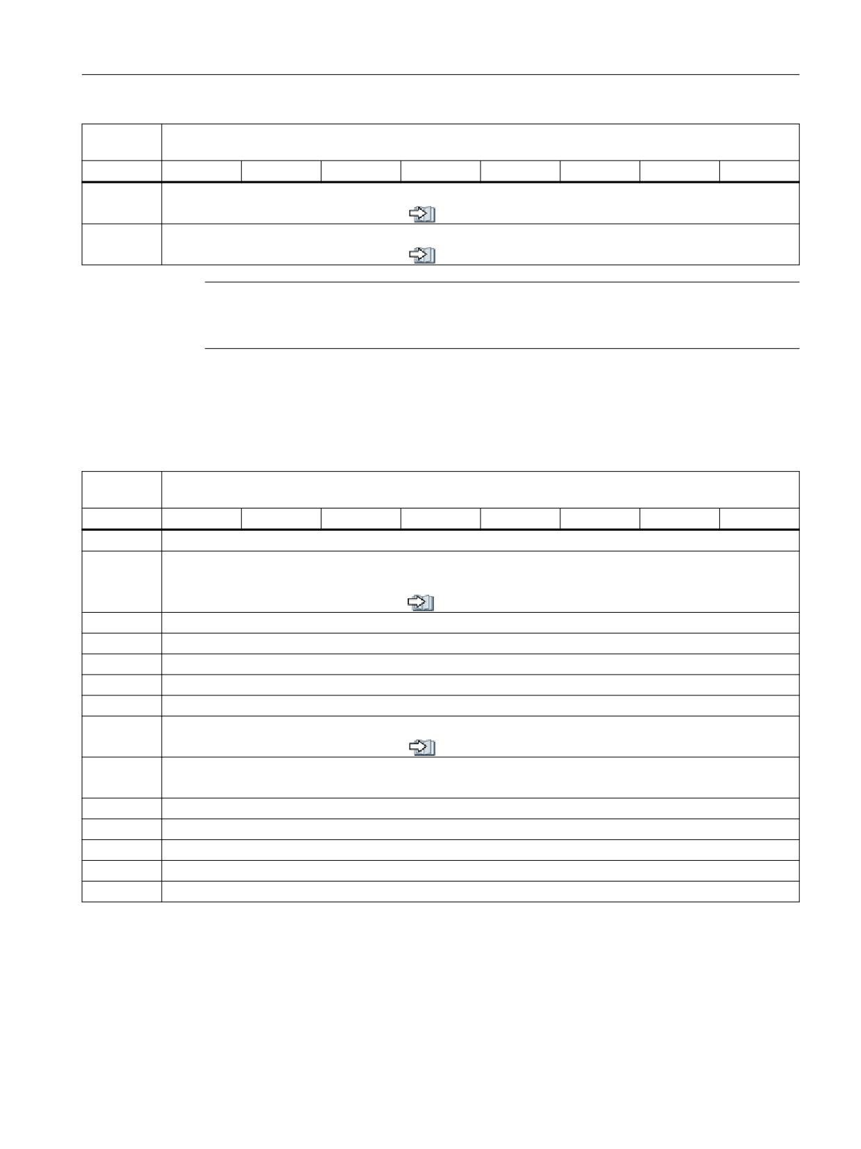
Table 19-82
DB21 - DB30, transferred M and S functions:
DB21 -
Signals from the channel (NC → PLC)
DB30
Byte
Bit 7
Bit 6
Bit 5
Bit 4
Bit 3
Bit 2
Bit 1
Bit 0
DBW68
Extended address, M function 1 (16-bit INT)
see also (Page 585)
DBD70
M function 1 (DINT)
see also (Page 585)
DBW74
Extended address, M function 2 (16-bit INT)
see also (Page 585)
DBD76
M function 2 (DINT)
see also (Page 585)
DBW80
Extended address, M function 3 (16-bit INT)
see also (Page 585)
DBD82
M function 3 (DINT)
see also (Page 585)
DBW86
Extended address, M function 4 (16-bit INT)
see also (Page 585)
DBD88
M function 4 (DINT)
see also (Page 585)
DBW92
Extended address, M function 5 (16-bit INT)
see also (Page 585)
DBD94
M function 5 (DINT)
see also (Page 585)
DBW98
Extended address, S function 1 (16-bit INT)
see also (Page 586)
DBD100
S function 1 (REAL format)
see also (Page 586)
DBW104
Extended address, S function 2 (16-bit INT)
see also (Page 586)
DBD106
S function 2 (REAL format)
see also (Page 586)
PLC
406
Function Manual, 10/2020, 6FC5397-0HP40-0BA1
Interface signals
19.1 Interface signals - overview
DB21 -
Signals from the channel (NC → PLC)
DB30
Byte
Bit 7
Bit 6
Bit 5
Bit 4
Bit 3
Bit 2
Bit 1
Bit 0
DBW110
Extended address, S function 3 (16-bit INT)
see also (Page 586)
DBD112
S function 3 (REAL format)
see also (Page 586)
Note
M functions are programmed in the part program in the INTEGER format (8 decades plus leading
sign).
19.1.12.7
DB21 - DB30, transferred T/D/DL functions
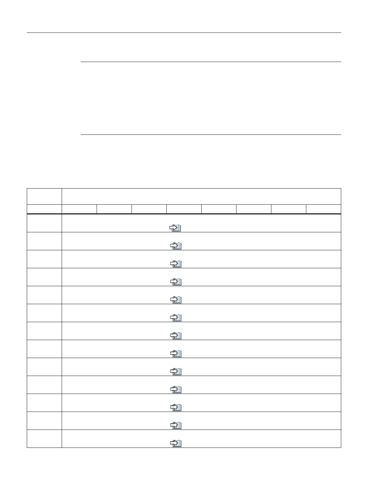
Table 19-83 DB21 - DB30, transferred T/D/DL functions
DB21 -
Signals from the channel (NC → PLC)
DB30
Byte
Bit 7
Bit 6
Bit 5
Bit 4
Bit 3
Bit 2
Bit 1
Bit 0
DBW116
Extended address, T function 1 (16-bit INT)
DBW118
T function 1 (dual) /
DBD118
For 8-decade T No., DBD118 is used as T function 1 (32-bit INT) (see note below)
see also (Page 586)
DBW120
Extended address, T function 2 (16-bit INT)
DBW122
T function 2 (INT)
DBW124
Extended address, T function 3 (16-bit INT)
DBW126
T function 3 (INT)
DBB128
Extended address D function 1 (8-bit INT)
DBB129
D function 1 (binary)
see also (Page 587)
DBW130
For 5-decade D No., DBW130 is used as D function 1 (16-bit INT)
DBB130
Extended address D function 2 (8-bit INT)
DBB131
D function 2 (8-bit INT)
DBB132
Extended address D function 3 (8-bit INT)
DBB133
D function 3 (8-bit INT)
DBW134
Extended address DL function (16-bit INT)
DBD136
DL function (REAL)
PLC
Function Manual, 10/2020, 6FC5397-0HP40-0BA1
407
Interface signals
19.1 Interface signals - overview
Note
• Programmed T functions are not output to the PLC when tool management is active.
•
8 decade T numbers are only available under DBD118 "T function 1".
• Programmed D functions with names (e.g. D=CUTTING EDGE_1) cannot be output to the PLC
in ASCII format.
•
5-decade D numbers are only available as DBW130 "D function 1".
• The REAL format corresponds to the floating-point representation in STEP 7 (24-bit mantissa
and 8-bit exponent). This floating point format supplies a maximum of 7 valid places.
19.1.12.8
DB21 - DB30, transferred H/F functions
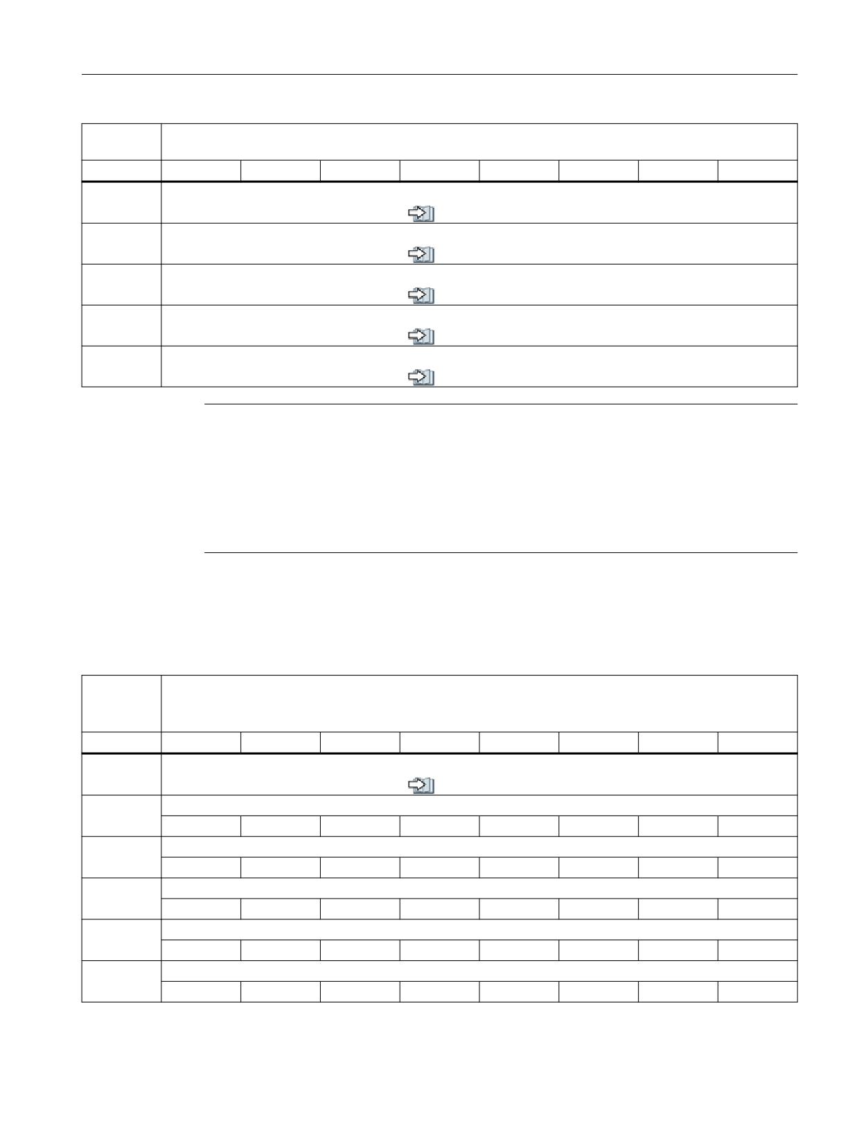
Table 19-84
DB21 - DB30, transferred H/F functions
DB21 -
Signals from the channel (NC → PLC)
DB30
Byte
Bit 7
Bit 6
Bit 5
Bit 4
Bit 3
Bit 2
Bit 1
Bit 0
DBW140
Extended address, H function 1 (16-bit INT)
see also (Page 587)
DBD142
H function 1 (REAL or DINT)
see also (Page 587)
DBW146
Extended address, H function 2 (16-bit INT)
see also (Page 587)
DBD148
H function 2 (REAL or DINT)
see also (Page 587)
DBW152
Extended address, H function 3 (16-bit INT)
see also (Page 587)
DBD154
H function 3 (REAL or DINT)
see also (Page 587)
DBW158
Extended address F function 1 (16-bit INT)
see also (Page 587)
DBD160
F function 1 (REAL format)
see also (Page 587)
DBW164
Extended address F function 2 (16-bit INT)
see also (Page 587)
DBD166
F function 2 (REAL format)
see also (Page 587)
DBW170
Extended address F function 3 (16-bit INT)
see also (Page 587)
DBD172
F function 3 (REAL format)
see also (Page 587)
DBW176
Extended address F function 4 (16-bit INT)
see also (Page 587)
PLC
408
Function Manual, 10/2020, 6FC5397-0HP40-0BA1
Interface signals
19.1 Interface signals - overview
DB21 -
Signals from the channel (NC → PLC)
DB30
Byte
Bit 7
Bit 6
Bit 5
Bit 4
Bit 3
Bit 2
Bit 1
Bit 0
DBD178
F function 4 (REAL format)
see also (Page 587)
DBW182
Extended address F function 5 (16-bit INT)
see also (Page 587)
DBD184
F function 5 (REAL format)
see also (Page 587)
DBW188
Extended address F function 6 (16-bit INT)
see also (Page 587)
DBD190
F function 6 (REAL format)
see also (Page 587)
Note
• F functions are programmed in the part program in the REAL data format.
• The extended address of the F function contains an identifier with the following meaning:
-
0: Path feedrate
-
1 - 31: Machine axis number for feedrate for positioning axes
• The data type of the H function depends on machine data: MD22110
$MC_AUXFU_H_TYPE_INT
19.1.12.9
DB21 - DB30, decoded M signals
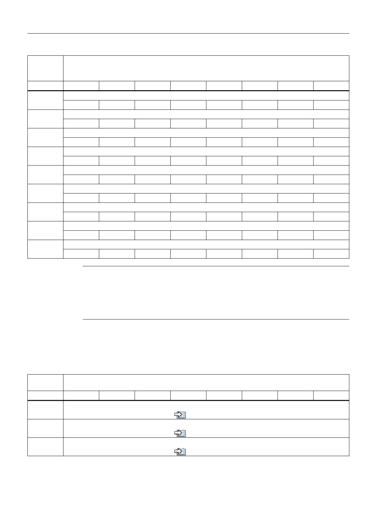
Table 19-85 DB21 - DB30, decoded M signals
DB21 -
Signals from the channel (M0 - M99) (NC → PLC)
DB30
Byte
Bit 7
Bit 6
Bit 5
Bit 4
Bit 3
Bit 2
Bit 1
Bit 0
Dynamic M functions
see also (Page 588)
DBB194
M07
M06
M05 #
M04 #
M03 #
M02
M01
M00
DBB195
M15
M14
M13
M12
M11
M10
M09
M08
DBB196
M23
M22
M21
M20
M19
M18
M17
M16
DBB197
M31
M30
M29
M28
M27
M26
M25
M24
DBB198
M39
M38
M37
M36
M35
M34
M33
M32
PLC
Function Manual, 10/2020, 6FC5397-0HP40-0BA1
409
Interface signals
19.1 Interface signals - overview
DB21 -
Signals from the channel (M0 - M99) (NC → PLC)
DB30
Byte
Bit 7
Bit 6
Bit 5
Bit 4
Bit 3
Bit 2
Bit 1
Bit 0
DBB199
M47
M46
M45
M44
M43
M42
M41
M40
DBB200
M55
M54
M53
M52
M51
M50
M49
M48
DBB201
M63
M62
M61
M60
M59
M58
M57
M56
DBB202
M71
M70 #
M69
M68
M67
M66
M65
M64
DBB203
M79
M78
M77
M76
M75
M74
M73
M72
DBB204
M87
M86
M85
M84
M83
M82
M81
M80
DBB205
M95
M94
M93
M92
M91
M90
M89
M88
DBB206
M99
M98
M97
M96
DBB207
Note
•
#: the M function is not displayed here, if a spindle is parameterized in the channel. In this
case, the M function is displayed as extended M function under DB21,... DBB68 ff. and axial
under DB31,... DBB86 ff. displayed.
• Dynamic M functions (M00 - M99) are decoded by the basic PLC program.
Static M functions must be generated in the PLC user program from dynamic M functions.
19.1.12.10
DB21 - DB30, active G functions
Table 19-86 DB21 - DB30, active G functions
DB21 -
Signals from the channel (NC → PLC)
DB30
Byte
Bit 7
Bit 6
Bit 5
Bit 4
Bit 3
Bit 2
Bit 1
Bit 0
DBB208
Number of the active G function of G function group 1 (8-bit INT)
see also (Page 588)
DBB209
Number of the active G function of G function group 2 (8-bit INT)
see also (Page 588)
DBB210
Number of the active G function of G function group 3 (8-bit INT)
see also (Page 588)
PLC
410
Function Manual, 10/2020, 6FC5397-0HP40-0BA1
Interface signals
19.1 Interface signals - overview
DB21 -
Signals from the channel (NC → PLC)
DB30
Byte
Bit 7
Bit 6
Bit 5
Bit 4
Bit 3
Bit 2
Bit 1
Bit 0
DBB211
Number of the active G function of G function group 4 (8-bit INT)
see also (Page 588)
DBB212
Number of the active G function of G function group 5 (8-bit INT)
see also (Page 588)
DBB213
Number of the active G function of G function group 6 (8-bit INT)
see also (Page 588)
DBB214
Number of the active G function of G function group 7 (8-bit INT)
see also (Page 588)
DBB215
Number of the active G function of G function group 8 (8-bit INT)
see also (Page 588)
DBB270
Number of the active G function of G function group n-1 (8-bit INT)
see also (Page 588)
DBB271
Number of the active G function of G function group n (8-bit INT)
see also (Page 588)
Note
• The active G functions of the group, for each programming of a G function or a mnemonic
identifier (e.g. SPLINE), are updated.
• G functions within a G group are output as binary value, starting with 1. A G function with
the value 0 means that for this G group, no G function is active.
19.1.12.11
DB21 - DB30, protection areas from the channel
Table 19-87 DB21 - DB30, signals for the protection zones from the channel
DB21 -
Signals from the channel (NC → PLC)
DB30
Byte
Bit 7
Bit 6
Bit 5
Bit 4
Bit 3
Bit 2
Bit 1
Bit 0
DBB272
Machine-related protection zone preactivated
see also (Page 589)
8
7
6
5
4
3
2
1
DBB273
Machine-related protection zone preactivated
see also (Page 589)
10
9
DBB274
Channel-specific protection zone preactivated
see also (Page 590)
8
7
6
5
4
3
2
1
DBB275
Channel-specific protection zone preactivated
see also (Page 590)
10
9
PLC
Function Manual, 10/2020, 6FC5397-0HP40-0BA1
411
Interface signals
19.1 Interface signals - overview
DB21 -
Signals from the channel (NC → PLC)
DB30
Byte
Bit 7
Bit 6
Bit 5
Bit 4
Bit 3
Bit 2
Bit 1
Bit 0
DBB276
Machine-related protection zone violated
see also (Page 590)
8
7
6
5
4
3
2
1
DBB277
Machine-related protection zone violated
see also (Page 590)
10
9
DBB278
Channel-specific protection zone violated
see also (Page 591)
8
7
6
5
4
3
2
1
DBB279
Channel-specific protection zone violated
see also (Page 591)
10
9
19.1.12.12
DB21 - DB30, synchronous actions, signals from/to the channel
Note
The request signals should be set in the PLC user program. After data transfer, they are reset by
the basic PLC program.
Table 19-88 DB21 - DB30, job-controlled signals from/to the channel
DB21 -
Signals to the channel (PLC ←→ NC)
DB30
/FBSY/
Byte
Bit 7
Bit 6
Bit 5
Bit 4
Bit 3
Bit 2
Bit 1
Bit 0
DBB280
Require-
Reserved
ment
PLC → NC
Disable
synchron-
ized actions
DBB281
Acknowl-
edgment
NC → PLC
Synchron-
ized actions
disabled
DBW282 -
Reserved
DBW298
DBB300
Lock synchronized action
PLC → NC
8
7
6
5
4
3
2
1
PLC
412
Function Manual, 10/2020, 6FC5397-0HP40-0BA1
Interface signals
19.1 Interface signals - overview
DB21 -
Signals to the channel (PLC ←→ NC)
DB30
/FBSY/
Byte
Bit 7
Bit 6
Bit 5
Bit 4
Bit 3
Bit 2
Bit 1
Bit 0
DBB301
Lock synchronized action
PLC → NC
16
15
14
13
12
11
10
9
DBB302
Lock synchronized action
PLC → NC
24
23
22
21
20
19
18
17
DBB303
Lock synchronized action
PLC → NC
32
31
30
29
28
27
26
25
DBB304
Lock synchronized action
PLC → NC
40
39
38
37
36
35
34
33
DBB305
Lock synchronized action
PLC → NC
48
47
46
45
44
43
42
41
DBB306
Lock synchronized action
PLC → NC
56
55
54
53
52
51
50
49
DBB307
Lock synchronized action
PLC → NC
64
63
62
61
60
59
58
57
DBB308
Synchronized action can be locked
NC → PLC
8
7
6
5
4
3
2
1
DBB309
Synchronized action can be locked
NC → PLC
16
15
14
13
12
11
10
9
DBB310
Synchronized action can be locked
NC → PLC
24
23
22
21
20
19
18
17
DBB311
Synchronized action can be locked
NC → PLC
32
31
30
29
28
27
26
25
DBB312
Synchronized action can be locked
NC → PLC
40
39
38
37
36
35
34
33
DBB313
Synchronized action can be locked
NC → PLC
48
47
46
45
44
43
42
41
DBB314
Synchronized action can be locked
NC → PLC
56
55
54
53
52
51
50
49
DBB315
Synchronized action can be locked
NC → PLC
64
63
62
61
60
59
58
57
19.1.12.13
DB21 - DB30, control signals from/to the channel
Note
The request signals should be set in the PLC user program. After data transfer, they are reset by
the basic PLC program.
PLC
Function Manual, 10/2020, 6FC5397-0HP40-0BA1
413
Interface signals
19.1 Interface signals - overview
Table 19-89 DB21 - DB30, job-controlled signals from/to the channel
DB21 -
Signals from/to the channel (PLC ←→ NC)
DB30
Byte
Bit 7
Bit 6
Bit 5
Bit 4
Bit 3
Bit 2
Bit 1
Bit 0
DBB316
Active G functions
G00 geo.
DBB317
Tool miss-
PTP travers-
Drive test
Target num-
External
ing
ing active
travel re-
ber of work-
language
quest
pieces
mode active
see al-
see al-
reached
so
so
(Page 593)
(Page 593)
see al-
so
(Page 592)
DBB318
Overstore
Dry run fee-
M01 associ-
Delayed
TOFF mo-
TOFF active
Block
ASUB stop-
active
drate active
ated with
stop
tion active
search via
ped
see al-
PLC active
program
/F1-A2/
/FB1-V1/
see al-
so
see al-
test, SERU-
see al-
so
(Page 594)
so
PRO, is ac-
so
(Page 594)
(Page 593)
tive
(Page 595)
see al-
so
(Page 594)
DBB319
No tool
Feedrate
REPOS delay
Feedrate
Active REPOS mode
Acknowl-
change
stop
stop
edgment of
see al-
see also (Page 596)
commands
the REPOS
Delay
so
Delay
C
B
A
active
mode
(Page 597)
Suppress
change
see al-
so
(Page 595)
19.1.12.14
DB21 - DB30, signals to the orientation axes
Table 19-90 DB21 - DB30, signals to the orientation axes
DB21 -
Signals to the channel (PLC → NC)
DB30
Byte
Bit 7
Bit 6
Bit 5
Bit 4
Bit 3
Bit 2
Bit 1
Bit 0
Orientation axis 1
DBB320
Traversing keys
Rapid tra-
Traversing
Feedrate
Activate handwheel
verse over-
key disable
stop
see also (Page 599)
see also (Page 597)
ride
see al-
Plus
Minus
C
B
A
see al-
so
so
(Page 598)
(Page 599)
DBB321
Requested machine function
see also (Page 601)
Continuous
var. INC
10000 INC
1000 INC
100 INC
10 INC
1 INC
traversing
PLC
414
Function Manual, 10/2020, 6FC5397-0HP40-0BA1
Interface signals
19.1 Interface signals - overview
DB21 -
Signals to the channel (PLC → NC)
DB30
Byte
Bit 7
Bit 6
Bit 5
Bit 4
Bit 3
Bit 2
Bit 1
Bit 0
DBB322
OEM signals
DBB323
Handwheel
direction of
rotation in-
verted
see al-
so
(Page 602)
Orientation axis 2
DBB324
Traversing keys
Rapid tra-
Traversing
Feedrate
Activate handwheel
verse over-
key disable
stop
see also (Page 603)
see also (Page 602)
ride
see al-
Plus
Minus
C
B
A
see al-
so
so
(Page 602)
(Page 603)
DBB325
Requested machine function
see also (Page 603)
Continuous
var. INC
10000 INC
1000 INC
100 INC
10 INC
1 INC
traversing
DBB326
OEM signals
DBB327
Handwheel
direction of
rotation in-
verted
see al-
so
(Page 603)
Orientation axis 3
DBB328
Traversing keys
Rapid tra-
Traversing
Feedrate
Activate handwheel
verse over-
key disable
stop
see also (Page 604)
see also (Page 603)
ride
see al-
Plus
Minus
C
B
A
see al-
so
so
(Page 603)
(Page 603)
DBB329
Requested machine function
see also (Page 604)
Continuous
var. INC
10000 INC
1000 INC
100 INC
10 INC
1 INC
traversing
PLC
Function Manual, 10/2020, 6FC5397-0HP40-0BA1
415
Interface signals
19.1 Interface signals - overview
DB21 -
Signals to the channel (PLC → NC)
DB30
Byte
Bit 7
Bit 6
Bit 5
Bit 4
Bit 3
Bit 2
Bit 1
Bit 0
DBB330
OEM signals
DBB331
Handwheel
direction of
rotation in-
verted
see al-
so
(Page 604)
19.1.12.15
DB21 - DB30, signals from the orientation axes
Table 19-91
DB21 - DB30, signals from the orientation axes
DB21 -
Signals from the channel (NC → PLC)
DB30
Byte
Bit 7
Bit 6
Bit 5
Bit 4
Bit 3
Bit 2
Bit 1
Bit 0
Orientation axis 1
DBB332
Traversing command
Travel request
Handwheel active
see also (Page 605)
see also (Page 605)
see also (Page 604)
Plus
Minus
Plus
Minus
C
B
A
DBB333
Active machine function
see also (Page 606)
Continuous
INCvar
INC10000
INC1000
INC100
INC10
INC1
traversing
active
DBB334
OEM signals
DBB335
Handwheel
direction of
rotation in-
version ac-
tive
Orientation axis 2
DBB336
Traversing command
Travel request
Handwheel active
see also (Page 607)
see also (Page 607)
see also (Page 607)
Plus
Minus
Plus
Minus
C
B
A
DBB337
Active machine function
see also (Page 607)
Continuous
INCvar
INC10000
INC1000
INC100
INC10
INC1
traversing
active
DBB338
OEM signals
PLC
416
Function Manual, 10/2020, 6FC5397-0HP40-0BA1
Interface signals
19.1 Interface signals - overview
DB21 -
Signals from the channel (NC → PLC)
DB30
Byte
Bit 7
Bit 6
Bit 5
Bit 4
Bit 3
Bit 2
Bit 1
Bit 0
DBB339
Handwheel
direction of
rotation in-
version ac-
tive
Orientation axis 3
DBB340
Traversing command
Travel request
Handwheel active
see also (Page 608)
see also (Page 607)
see also (Page 607)
Plus
Minus
Plus
Minus
C
B
A
DBB341
Active machine function
see also (Page 608)
Continuous
INCvar
INC10000
INC1000
INC100
INC10
INC1
traversing
active
DBB342
OEM signals
DBB343
Handwheel
direction of
rotation in-
version ac-
tive
19.1.12.16
DB21 - DB30, tool management functions from the channel
Table 19-92 DB21 - DB30, tool management functions from the channel
DB21 -
Signals from the channel (NC → PLC)
DB30
Byte
Bit 7
Bit 6
Bit 5
Bit 4
Bit 3
Bit 2
Bit 1
Bit 0
Change signals, tool management functions
DBB344
Last re-
Transition
Tool limit
Tool pre-
placement
to new re-
value
warning
tool of the
placement
reached
limit
tool group
tool
reached
see al-
see al-
see al-
so
see al-
so
so
(Page 608)
so
(Page 609)
(Page 609)
(Page 608)
DBB345 -
DBB347
Transferred tool management functions
DBD348
T number for tool prewarning limit (DINT)
DBD352
T number for tool limit value (DINT)
DBD356
T number of new replacement tool (DINT)
DBD360
T number of last replacement tool (DINT)
PLC
Function Manual, 10/2020, 6FC5397-0HP40-0BA1
417

Interface signals
19.1 Interface signals - overview
19.1.12.17
DB21 - DB30, control signals from/to the channel (2)
Table 19-93
DB21 - DB30, signals from the channel
DB21 -
Signals from the channel (NC → PLC)
DB30
Byte
Bit 7
Bit 6
Bit 5
Bit 4
Bit 3
Bit 2
Bit 1
Bit 0
DBB364
CH_CYCLES_SIG_IN (1)
8
7
6
5
4
3
2
1
DBB365
CH_CYCLES_SIG_IN (2)
16
15
14
13
12
11
10
9
DBB366
CH_CYCLES_SIG_OUT (1)
8
7
6
5
4
3
2
1
DBB367
CH_CYCLES_SIG_OUT (2)
16
15
14
13
12
11
10
9
DBB368
CH_OEM_TECHNO_SIG_IN (1)
8
7
6
5
4
3
2
1
DBB369
CH_OEM_TECHNO_SIG_IN (2)
16
15
14
13
12
11
10
9
DBB370
CH_OEM_TECHNO_SIG_IN (3)
24
23
22
21
20
19
18
17
DBB371
CH_OEM_TECHNO_SIG_IN (4)
32
31
30
29
28
27
26
25
DBB372
CH_OEM_TECHNO_SIG_OUT (1)
8
7
6
5
4
3
2
1
DBB373
CH_OEM_TECHNO_SIG_OUT (2)
16
15
14
13
12
11
10
9
DBB374
CH_OEM_TECHNO_SIG_OUT (3)
24
23
22
21
20
19
18
17
DBB375
CH_OEM_TECHNO_SIG_OUT (4)
32
31
30
29
28
27
26
25
DBB376
Display of the triggering event in case of event-driven program call
ProgEventDisplay
see also (Page 609)
DBB377
Jog circle
Retraction
JOG retract
Stop condi-
Collision
active
data availa-
active
tion
avoidance:
ble
see al-
see al-
Stop
so
see al-
so
see al-
(Page 611)
so
(Page 610)
so
(Page 610)
(Page 610)
PLC
418
Function Manual, 10/2020, 6FC5397-0HP40-0BA1
Interface signals
19.1 Interface signals - overview
DB21 -
Signals from the channel (NC → PLC)
DB30
Byte
Bit 7
Bit 6
Bit 5
Bit 4
Bit 3
Bit 2
Bit 1
Bit 0
DBB378
"Silent"
ASUB is ac-
ASUB is ac-
tive
tive
see al-
see al-
so
so
(Page 611)
(Page 611)
DBB379
DBB380
Reserved ASUB
DBB381
Reserved ASUB
DBB382
Reserved ASUB
DBB383
Reserved ASUB
Table 19-94 DB21 - DB30, signals to the channel
DB21 -
Signals to the channel (PLC → NC)
DB30
Byte
Bit 7
Bit 6
Bit 5
Bit 4
Bit 3
Bit 2
Bit 1
Bit 0
DBB384
Enable
GOTOS
see al-
so
(Page 612)
DBB385
Grinding: Input signals 1 ... 8
($AC_IN_KEY_G[1 ... 8])
8
7
6
5
4
3
2
1
DBB386
Grinding: Disable input signals 1 ... 8
8
7
6
5
4
3
2
1
DBB387
Grinding: Status of the grinding functions 1 ... 8
($AC_IN_KEY_G_RUN_IN[1...8])
8
7
6
5
4
3
2
1
PLC
Function Manual, 10/2020, 6FC5397-0HP40-0BA1
419

Interface signals
19.1 Interface signals - overview
Table 19-95
DB21 - DB30, signals from/to channel
DB21 -
Signals from/to the channel (NC ↔ PLC)
DB30
Byte
Bit 7
Bit 6
Bit 5
Bit 4
Bit 3
Bit 2
Bit 1
Bit 0
DBB388
Index number of the active transformation in the channel
NC → PLC
see also (Page 613)
DBB389
Reserved
DBB390
Grinding: Enable status of input signals 1 ... 8
PLC → NC
($AC_IN_KEY_G_ISENABLE[1...8])
8
7
6
5
4
3
2
1
DBB391
Grinding: Status of the grinding functions 1 ... 8
NC → PLC
($AC_IN_KEY_G_RUN_OUT[1...8])
8
7
6
5
4
3
2
1
DBB392
Selection of the coordinate system for Cartesian manual traversing and handwheel override in the automatic
mode in the tool direction (DRF)
PLC → NC
see also (Page 614)
DBB393
Reserved
DBB394
Reserved
DBB395
Reserved
DBB396
H function 1 (DInt), also in DBD142
DBB400
H function 2 (DInt), also in DBD146
DBB404
H function 3 (DInt), also in DBD150
Interface operating software -> PLC
DBB 408
Axis selection type: 0: Machine axis, 1: Geo axis
HMI -> PLC
DBB 409
Axis number: Machine/geo axis
HMI -> PLC
DBB 410
Key
HMI -> PLC
Axis selec-
tion
DBB 411
Interface PLC -> HMI
DBB 412
Active axis selection (feedback message to the HMI)
PLC -> HMI
0: Machine axis, 1: Geo axis
DBB 413
Active axis number (feedback message to the HMI):
PLC -> HMI
Machine/geo axis
PLC
420
Function Manual, 10/2020, 6FC5397-0HP40-0BA1
Interface signals
19.1 Interface signals - overview
19.1.13
Axis/spindle signals
19.1.13.1
DB31 - DB61, signals to the axis/spindle
Table 19-96 DB31 - DB61, signals to the axis/spindle
DB31 - DB61
Signals to the axis/spindle (PLC → NC)
Byte
Bit 7
Bit 6
Bit 5
Bit 4
Bit 3
Bit 2
Bit 1
Bit 0
DBB0
Feedrate override, axis-specific
see also (Page 615)
Bit 7
Bit 6
Bit 5
Bit 4
Bit 3
Bit 2
Bit 1
Bit 0
DBB1
Override
Position measuring sys-
Follow-up
Axis/spin-
Sensor for
Acknowl-
Drive test
active
tem 1 - 2
mode
dle disable
fixed stop
edge fixed
travel ena-
Axis and spin-
stop
ble
dle
see
see also (Page 623)
see al-
see al-
see al-
reached
also
so
so
so
see al-
Bit 2
Bit 1
(Page 625)
(Page 622)
(Page 619)
(Page 618)
see al-
so
so
(Page 617)
(Page 618)
DBB2
Reference point value 1 - 4
Clamping in
Delete dis-
Controller
Cam activa-
progress
tance-to-
enable
tion
Axis and spin-
see also (Page 630)
go / spindle
dle
see al-
see al-
see al-
Bit 4
Bit 3
Bit 2
Bit 1
reset
so
so
so
(Page 630)
see al-
(Page 626)
(Page 626)
so
(Page 628)
DBB3
Program
Velocity /
Activate fixed feedrate
Travel to
Accept off-
test axis/
spindle
fixed stop
set external
Axis and spin-
see also (Page 632)
spindle en-
speed limi-
enabled
WO
dle
Bit 4
Bit 3
Bit 2
Bit 1
able
tation
see al-
see al-
see al-
so
so
so
(Page 631)
(Page 631)
(Page 632)
DBB4
Traversing keys
Rapid tra-
Traversing
Feedrate
Activate handwheel
verse over-
key disable
stop / spin-
Axis and spin-
see also (Page 635)
see also (Page 633)
ride
dle stop
dle
see al-
Plus
Minus
Bit 3
Bit 2
Bit 1
see al-
so
see al-
so
(Page 634)
so
(Page 635)
(Page 634)
DBB5
Machine function
Axis and spin-
see also (Page 636)
dle
Continuous
INCvar
INC10000
INC1000
INC100
INC10
INC1
manual
travel
DBB6
OEM signals
Bit 7
Bit 6
Bit 5
Bit 4
Bit 3
Bit 2
Bit 1
Bit 0
PLC
Function Manual, 10/2020, 6FC5397-0HP40-0BA1
421
Interface signals
19.1 Interface signals - overview
DB31 - DB61
Signals to the axis/spindle (PLC → NC)
Byte
Bit 7
Bit 6
Bit 5
Bit 4
Bit 3
Bit 2
Bit 1
Bit 0
DBB7
OEM signals
Bit 7
Bit 6
Bit 5
Bit 4
Bit 3
Bit 2
Bit 1
Invert hand-
wheel direc-
tion of rota-
tion
see al-
so
(Page 637)
DBB8
Request
Channel as-
NC axis / spindle channel assignment
PLC axis/
signment
see also (Page 638)
spindle
changed
Bit 3
Bit 2
Bit 1
Bit 0
DBB9
Parameter
Controller parameter set
set change
see also (Page 639)
inhibited
Bit 2
Bit 1
Bit 0
see al-
so
(Page 639)
DBB10
REPOS delay
see al-
so
(Page 639)
DBB11
SI:
Start brake
test
DBB12
Delay ref-
Modulo ro-
2nd software limit switch
Hardware limit switch
erence
tary axes:
Axis
Plus
Minus
Plus
Minus
point ap-
Activate
see al-
see al-
see al-
see al-
proach
traversing
so
so
so
so
range limits
see
(Page 641)
(Page 641)
(Page 640)
(Page 640)
also
see al-
(Page 641)
so
(Page 641)
DBB13
JOG to posi-
JOG fixed point approach
tion
Axis
see also (Page 642)
see al-
Bit 2
Bit 1
Bit 0
so
(Page 642)
DBB14
Program test
Axis
Activate
Suppress
see al-
see al-
so
so
(Page 644)
(Page 643)
DBB15
Axis
PLC
422
Function Manual, 10/2020, 6FC5397-0HP40-0BA1
Interface signals
19.1 Interface signals - overview
DB31 - DB61
Signals to the axis/spindle (PLC → NC)
Byte
Bit 7
Bit 6
Bit 5
Bit 4
Bit 3
Bit 2
Bit 1
Bit 0
DBB16
Delete S
No speed
Resynchronize
Gear is
Actual gear stage
value
monitoring
spindle
changed
Spindle
see also (Page 644)
during gear
over
see
Measuring
Measuring
Bit 2
Bit 1
Bit 0
change
also
see al-
system 2
system 1
(Page 646)
so
see al-
see al-
(Page 646)
so
so
(Page 645)
(Page 645)
DBB17
Invert
Resynchronize spindle
Feedrate
M3/M4
during positioning
correction
Spindle
spindle val-
see al-
Measuring
Measuring
id
so
system 2
system 1
(Page 647)
see al-
see al-
so
so
(Page 647)
(Page 646)
DBB18
Oscillation direction of
Oscillation
Oscillation
rotation
enable
controlled
Spindle
by PLC
Links
Right
see al-
so
see al-
see
see al-
(Page 648)
so
also
so
(Page 647)
(Page 649)
(Page 649)
DBB19
Speed override, spindle-specific
Spindle
see also (Page 650)
Bit 7
Bit 6
Bit 5
Bit 4
Bit 3
Bit 2
Bit 1
Bit 0
DBB20
Open motor
Ramp-func-
holding
tion genera-
Drive
brake
tor disable 1)
see al-
so
(Page 652)
DBB21
Pulse ena-
Integrator
Motor be-
Motor/drive data set: Selection
ble
disable,
ing selected
Drive
(interface definition: DB31, …DBX130.0 - 4 (Page 426))
speed con-
see
see al-
see also (Page 653)
troller
also
so
Bit 4
Bit 3
Bit 2
Bit 1
Bit 0
(Page 654)
see al-
(Page 653)
so
(Page 654)
DBB22
SI: SG selection
SI: Acknowl-
SI:
SI:
edgment,
Safety Inte-
see also (Page 655)
SBH dese-
SBH/SG de-
communi-
grated
lection
selection
Bit 1
Bit 0
cation fail-
see al-
see al-
ure
so
so
(Page 655)
(Page 655)
DBB23
SI:
SINAMICS
SI:
SI: Gear ratio selection
Safety Inte-
Test stop
Close brake
SE selection
see also (Page 656)
grated
selection
see al-
Bit 2
Bit 1
Bit 0
so
(Page 656)
PLC
Function Manual, 10/2020, 6FC5397-0HP40-0BA1
423
Interface signals
19.1 Interface signals - overview
DB31 - DB61
Signals to the axis/spindle (PLC → NC)
Byte
Bit 7
Bit 6
Bit 5
Bit 4
Bit 3
Bit 2
Bit 1
Bit 0
DBB24
Master/
Setpoint
Master/
MCS cou-
MCS cou-
Control axis
Stepping
slave:
switchover
slave:
pling:
pling:
motor:
switch on
Accept
Activate
Activate col-
deactivate
Rotation
drive control
torque
lision pro-
or do not
monitoring
see
equaliza-
tection
permit
also
see al-
tion con-
(Page 658)
so
see al-
see al-
troller
(Page 658)
so
so
see al-
(Page 657)
(Page 657)
so
(Page 658)
DBB25
Dynam. Ac-
tivate back-
lash com-
pensation
DBB26
Override
Compensa-
Enable
tory con-
Grinding
troller on
see al-
so
(Page 659)
DBB27
Stop
Resume
Grinding
HIAxMove
Corr.
DEPBCS
DEPMCS
HIAxMove
Corr.
DEPBCS
DEPMCS
DBB28
PLC con-
PLC-control-
PLC-control-
Alter rever-
Set reversal
PLC-control-
PLC-control-
Oscillation
trols axis
led axis:
led axis:
sal point
point
led axis:
led axis:
reversal
Grinding: Os-
from exter-
cillation
see
Stop along
Stop at next
see al-
see al-
Continue
Reset
nal
also
braking
reversal
so
so
see al-
see al-
(Page 663)
ramp
point
(Page 662)
(Page 661)
see al-
so
so
so
see al-
see al-
(Page 660)
(Page 660)
(Page 659)
so
so
(Page 662)
(Page 662)
DBB29
Disable au-
Start gan-
tomatic syn-
try synchro-
Couplings
chroniza-
nization
tion
DBB30
Spindle-
Select gear
Spindle
Spindle
Spindle stop
start posi-
stage
start, coun-
start, clock-
Technology
tioning
ter-clock-
wise rota-
wise rota-
tion
tion
DBB31
Delete syn-
Correct syn-
Disable syn-
Re-
REPOS for
chronism
chronous
chronous
synchron-
transforma-
Technology
correction
operation
operation
ize
tion with
PTP
see al-
so
(Page 664)
DBB32
SI: Deselect
SI: Deselect
SI: Deselect
SI: Deselect
external
external
external
external
Safety Inte-
STOP_E
STOP_D
STOP_C
STOP_A
grated
PLC
424
Function Manual, 10/2020, 6FC5397-0HP40-0BA1

Interface signals
19.1 Interface signals - overview
DB31 - DB61
Signals to the axis/spindle (PLC → NC)
Byte
Bit 7
Bit 6
Bit 5
Bit 4
Bit 3
Bit 2
Bit 1
Bit 0
DBB33
SI: SG override selection/override
Safety Inte-
Bit 3
Bit 2
Bit 1
Bit 0
grated
DBB34
Setpoint limitation
Bit 1
Bit 0
DBB35
DBB36
Technology
DBB37
DBB38
DBB39
DBB40 -
DBB55
DBB56
Spindle in-
Spindle
Separate
ternal
speed dis-
feedrate
PLC → HMI
clamping
play
drive cou-
pled as C ax-
is
DBB57
DBB58
Reserved
DBB59
DBB188
DBB189
Motor over-
DYNEGMA:
tempera-
Disable de-
ture: Disa-
rating
ble current
reduction
1)
Only when cyclic interface between NC and drive is operated in the "611U compatibility mode".
Note
DBX8.4 is automatically reset after the assignment is executed
PLC
Function Manual, 10/2020, 6FC5397-0HP40-0BA1
425
Interface signals
19.1 Interface signals - overview
19.1.13.2
DB31 - DB61, signals from the axis/spindle
Table 19-97
DB31 - DB61, signals from the axis/spindle
DB31 -
Signals from the axis/spindle (NC → PLC)
DB61
Byte
Bit 7
Bit 6
Bit 5
Bit 4
Bit 3
Bit 2
Bit 1
Bit 0
DBB60
Position reached with ex-
Referenced/synchronized
Encoder limit frequency
NCU link:
Spindle / ro-
act stop
exceeded, measuring sys-
tary axis
Axis / spin-
Position measuring sys-
Axis active
tem
dle
tem
see al-
see al-
so
fine
coarse
2
1
2
1
so
(Page 665)
(Page 665)
see al-
see al-
see al-
see al-
see al-
see al-
so
so
so
so
so
so
(Page 668)
(Page 668)
(Page 667)
(Page 667)
(Page 666)
(Page 666)
DBB61
Current
Speed con-
Position
Axis/spin-
Follow-up
Axis ready
Axis-specif-
Drive test
controller
troller ac-
controller
dle station-
mode active
ic alarm
travel re-
Axis / spin-
see al-
active
tive
active
ary (n <
quest
dle
see al-
so
see al-
nmin)
see al-
see al-
see al-
so
(Page 670)
so
see al-
so
so
so
see al-
(Page 670)
(Page 669)
so
(Page 672)
(Page 672)
(Page 671)
so
(Page 669)
(Page 671)
DBB62
Axis con-
Travel to
Travel to
Travel to
Measure-
Revolution-
Handwheel
Software
tainer:
fixed stop:
fixed stop:
fixed stop:
ment active
al feedrate
override ac-
cams active
active
tive
Rotation ac-
Force limit-
Fixed stop
Activating
see al-
see al-
tive
ing active
reached
the function
so
see al-
see al-
so
(Page 674)
so
so
(Page 673)
see al-
see al-
see al-
(Page 674)
(Page 673)
so
so
so
(Page 675)
(Page 675)
(Page 674)
DBB63
Stop
Axis/spin-
Axis stop ac-
PLC-control-
Reset exe-
dle disable
tive
led axis
cuted
HIAxMove
Corr. active
DEPBCS ac-
DEPMCS ac-
active
active
tive
tive
see al-
see al-
see al-
so
so
so
(Page 676)
(Page 676)
(Page 675)
DBB64
Traversing command
Travel request
Handwheel active
Axis / spin-
see also (Page 678)
see also (Page 678)
see also (Page 677)
dle
Plus
Minus
Plus
Minus
Bit 2
Bit 1
Bit 0
DBB65
Active machine function
Axis / spin-
see also (Page 679)
dle
Continuous
INCvar
INC10000
INC1000
INC100
INC10
INC1
manual
travel
DBB66
MCS cou-
pling:
Axis / spin-
dle
Collision
protection
active
see al-
so
(Page 679)
PLC
426
Function Manual, 10/2020, 6FC5397-0HP40-0BA1
Interface signals
19.1 Interface signals - overview
DB31 -
Signals from the axis/spindle (NC → PLC)
DB61
Byte
Bit 7
Bit 6
Bit 5
Bit 4
Bit 3
Bit 2
Bit 1
Bit 0
DBB67
Handwheel
direction of
rotation in-
version ac-
tive
see al-
so
(Page 680)
DBB68
Status axis/spindle replacement
see also (Page 680)
PLC axis/
Neutral ax-
Axis inter-
New type
NC axis / spindle channel assignment
spindle
is/spindle
change pos-
requested
Bit 3
Bit 2
Bit 1
Bit 0
sible
from PLC
DBB69
NCU number in the NCU link group
Controller parameter set servo
see also (Page 680)
Bit 4
Bit 3
Bit 2
Bit 1
Bit 0
Bit 2
Bit 1
Bit 0
DBB70
DRV Safety
NC Safety
REPOS de-
REPOS off-
REPOS off-
Integrated
Integrated
lay ac-
set valid
set
active with
active
knowledg-
see al-
see al-
SIC/SCC
ment
so
so
see al-
(Page 681)
(Page 681)
so
(Page 682)
DBB71
PLC axis per-
Position restored
Brake test
manently
active
Encoder 2
Encoder 1
assigned
see al-
see al-
so
so
(Page 683)
(Page 683)
DBB72
REPOS de-
lay active
HMI → PLC
see al-
so
(Page 683)
DBB73
HMI → PLC
DBB74
Modulo ro-
tary axes:
Axis
Traversing
range limits
active
see al-
so
(Page 684)
PLC
Function Manual, 10/2020, 6FC5397-0HP40-0BA1
427
Interface signals
19.1 Interface signals - overview
DB31 -
Signals from the axis/spindle (NC → PLC)
DB61
Byte
Bit 7
Bit 6
Bit 5
Bit 4
Bit 3
Bit 2
Bit 1
Bit 0
DBB75
JOG posi-
JOG travel
JOG approach fixed point reached
JOG approach fixed point active
tion
to position
Axis
see also (Page 685)
see also (Page 684)
reached
active
Bit 2
Bit 1
Bit 0
Bit 2
Bit 1
Bit 0
see al-
see al-
so
so
(Page 685)
(Page 685)
DBB76
Rounding
Indexing ax-
Positioning
Path axis
Lubrication
axis in posi-
is in posi-
axis
pulse
Axis
see al-
tion
tion
see al-
so
see al-
see al-
so
(Page 686)
so
so
(Page 687)
(Page 686)
(Page 687)
DBB77
Collision
avoidance:
Axis
Velocity re-
duction
see al-
so
(Page 688)
DBD78
F value (REAL) for positioning axis
Axis
see also (Page 688)
DBB82
Change
Setpoint gear stage
gear stage
Spindle
see also (Page 688)
see al-
Bit 2
Bit 1
Bit 0
so
(Page 689)
DBB83
Actual di-
Speed mon-
Spindle in
Support
Geometry
Speed setpoint
Speed limit
rection of
itoring
setpoint
range limits
monitoring
exceeded
Spindle
Increased
limited
rotation
range
violated
see al-
see al-
see al-
see al-
see al-
clockwise
so
see al-
so
so
so
so
see al-
(Page 692)
so
(Page 692)
(Page 691)
(Page 690)
(Page 689)
so
(Page 692)
(Page 693)
DBB84
Active spindle mode
Tapping
CLGON ac-
GWPS active
Const. cut-
without
tive
ting veloci-
Spindle
Control
Oscillation
Positioning
Synchro-
see al-
compensat-
ty active
mode
mode
mode
nous opera-
so
ing chuck
tion
(Page 693)
see al-
see al-
see al-
active
so
so
so
see al-
see al-
(Page 695)
(Page 695)
(Page 694)
so
so
(Page 694)
(Page 693)
DBB85
Spindle ac-
Tool with
tually
dynamic re-
Spindle
reached po-
sponse limi-
sition
tation
see al-
see al-
so
so
(Page 696)
(Page 695)
PLC
428
Function Manual, 10/2020, 6FC5397-0HP40-0BA1
Interface signals
19.1 Interface signals - overview
DB31 -
Signals from the axis/spindle (NC → PLC)
DB61
Byte
Bit 7
Bit 6
Bit 5
Bit 4
Bit 3
Bit 2
Bit 1
Bit 0
DBW86
M function (INT) for spindle (M3, M4, M5, M19, M70 or defined via MD)
Spindle
see also (Page 696)
DBD88
S function (REAL) for spindle
Spindle
see also (Page 697)
DBB92
Enable
Motor hold-
Independ-
Ramp-func-
drive opera-
ing brake
ent drive
tion-gener-
Drive
tion
opened
motion ac-
ator disable
tive1)
active
see al-
see al-
so
so
(Page 698)
(Page 697)
DBB93
Pulse ena-
Integrator
Drive ready
Motor/drive data set: Display
ble
disable,
Drive
see al-
(interface definition: DB31, …DBX130.0 - 4 (Page 665))
speed con-
see al-
so
see also (Page 698)
troller
so
(Page 699)
Bit 4
Bit 3
Bit 2
Bit 1
Bit 0
(Page 700)
see al-
so
(Page 699)
DBB94
Variable sig-
nact = nset
|nact| < nx
|nact| < nmin
Md < Mdx
Run-up
Temperature pre-alarm
naling func-
completed
Drive
see al-
see al-
see al-
see al-
Heat sink
Motor
tion2)
so
so
so
so
see al-
see al-
see al-
see al-
(Page 704)
(Page 703)
(Page 703)
(Page 702)
so
so
so
so
(Page 701) (Page 701)
(Page 700)
(Page 704)
DBB95
Alarm of
ESR: Gener-
ESR: Re-
ESR: DC link
UDC link <
alarm class
ator opera-
sponse trig-
undervolt-
warning
Drive
C is active
tion mini-
gered or
age
threshold
mum speed
generator
(p1248)
see al-
fallen be-
operation
so
see al-
low
active
(Page 705)
so
(p2161)
(r0887.12)
(Page 704)
see al-
see al-
so
so
(Page 705)
(Page 705)
DBB96
Master/
Setpoint
Master-slave:
Control axis
Stepping
slave:
switchover:
active
motor: Ro-
Compensa-
Coarse
Fine speed
drive con-
tation mon-
Coupling
tory con-
speed dif-
difference
trol active
itoring error
active
troller ac-
ference
see al-
see al-
tive
see al-
see al-
so
so
so
see al-
so
(Page 706)
(Page 707)
(Page 707)
so
(Page 706)
(Page 706)
DBB97
MCS coupling:
Offset
Mirroring
Coupling
Following
change
active
active
axis
see al-
see al-
see al-
see al-
so
so
so
so
(Page 709)
(Page 708)
(Page 708)
(Page 708)
PLC
Function Manual, 10/2020, 6FC5397-0HP40-0BA1
429
Interface signals
19.1 Interface signals - overview
DB31 -
Signals from the axis/spindle (NC → PLC)
DB61
Byte
Bit 7
Bit 6
Bit 5
Bit 4
Bit 3
Bit 2
Bit 1
Bit 0
DBB98
ESR re-
Accelera-
Velocity
Superim-
Actual val-
Synchronous operation
sponse initi-
tion warn-
warning
posed mo-
ue coupling
Synchro-
coarse
fine
ated
ing thresh-
threshold
tion
nous spin-
see al-
see al-
see al-
old reached
reached
dle
see al-
so
so
so
see al-
see al-
so
(Page 710)
(Page 710)
(Page 709)
so
so
(Page 711)
(Page 712)
(Page 711)
DBB99
Max. accel-
Max. veloci-
Synchroni-
Axis accel-
Synchron-
Following
Leading
eration
ty reached
zation in
erating
ism correc-
spindle ac-
spindle ac-
Synchro-
reached
progress
tion imple-
tive
tive
nous spin-
see al-
mented
dle
so
see al-
see al-
(Page 713)
so
so
(Page 713)
(Page 712)
DBB100
Oscillation
Oscillation
Sparking-
Fault dur-
Oscillation
Oscillation
active
motion ac-
out active
ing oscilla-
cannot be
reversal
Oscillation
tive
tion motion
started
from exter-
grinding
see al-
see al-
work for
nal active
so
see al-
so
see al-
now I get
(Page 715)
so
(Page 714)
so
see al-
why you
(Page 714)
(Page 714)
so
see al-
(Page 713)
so
(Page 714)
DBB101
Gantry axis
Gantry
Gantry
Gantry syn-
Gantry
Gantry
guide axis
grouping is
chroniza-
alarm limit
shutdown
Gantry
synchro-
tion ready
exceeded
limit excee-
nous
to start
ded
DBB102
Position measuring sys-
Clamping
Dynam.
tem activated
tolerance
Backlash
exceeded
compensa-
2
1
tion active
see al-
see al-
so
so
(Page 715)
(Page 715)
DBB103
Synchronous operation 2
Synchron-
ism correc-
coarse
fine
tion is taken
into ac-
count
DBB104
Active infeed axis
Grinding
see also (Page 716)
8
7
6
5
4
3
2
1
DBB105
Active infeed axis
Grinding
16
15
14
13
12
11
10
9
DBB106
Active infeed axis
Grinding
24
23
22
21
20
19
18
17
DBB107
Active infeed axis
Grinding
31
30
29
28
27
26
25
PLC
430
Function Manual, 10/2020, 6FC5397-0HP40-0BA1

Interface signals
19.1 Interface signals - overview
DB31 -
Signals from the axis/spindle (NC → PLC)
DB61
Byte
Bit 7
Bit 6
Bit 5
Bit 4
Bit 3
Bit 2
Bit 1
Bit 0
DBB108
SI:
SI:
SI:
SI:
SI:
SI:
Safety Inte-
Axis safely
Communi-
CRC error
Status, pul-
CRC or sign-
SBH/SG ac-
grated
referenced
cation fail-
ses are can-
of-life error
tive
ure not ac-
celed
knowl-
edged
DBB109
SI: Output cam position
Safety Inte-
SN 4-
SN 4+
SN 3-
SN 3+
SN 2-
SN 2+
SN 1-
SN 1+
grated
DBB110
n < nx
SI: Active SG
SI:
Safety Inte-
B
A
SBH active
grated
DBB111
SI: Stop A - E
Safety Inte-
Stop E
Stop D
Stop C
Stop A/B
grated
Active
Active
Active
Active
DBB112
Output cam range for cam track 1
Safety Inte-
grated
DBB113
Output cam range for cam track 2
Safety Inte-
grated
DBB114
Output cam range for cam track 3
Safety Inte-
grated
DBB115
Output cam range for cam track 4
Safety Inte-
grated
DBB116
Reserved
Safety Inte-
grated
DBB117
Reserved
Output cam track
Safety Inte-
4
3
2
1
grated
DBB118
SI: Cam range bit for cam track 1
Safety Inte-
7
6
5
4
3
2
1
0
grated
DBB119
SI: Cam range bit for cam track 1
Safety Inte-
14
13
12
11
10
9
8
grated
DBB120
SI: Cam range bit for cam track 2
Safety Inte-
7
6
5
4
3
2
1
0
grated
DBB121
SI: Cam range bit for cam track 2
Safety Inte-
14
13
12
11
10
9
8
grated
PLC
Function Manual, 10/2020, 6FC5397-0HP40-0BA1
431
Interface signals
19.1 Interface signals - overview
DB31 -
Signals from the axis/spindle (NC → PLC)
DB61
Byte
Bit 7
Bit 6
Bit 5
Bit 4
Bit 3
Bit 2
Bit 1
Bit 0
DBB122
SI: Cam range bit for cam track 3
Safety Inte-
7
6
5
4
3
2
1
0
grated
DBB123
SI: Cam range bit for cam track 3
Safety Inte-
14
13
12
11
10
9
8
grated
DBB124
SI: Cam range bit for cam track 4
Safety Inte-
7
6
5
4
3
2
1
0
grated
DBB125
SI: Cam range bit for cam track 4
Safety Inte-
14
13
12
11
10
9
8
grated
DBB126
DBB127
DBB128
Program test
HMI → PLC
Activate
Suppress
see al-
see al-
so
so
(Page 716)
(Page 716)
DBB129
DBB130
Motor/drive
Motor/drive data set: Formatting
data set:
(interface definition: DB31, …DBX21.0 ... 4 (Page 421),
Formatting
DB 31
DBX93.0 ... 4 (Page 698))
is valid
see also (Page 717)
Bit 4
Bit 3
Bit 2
Bit 1
Bit 0
DBB131
DBB132
Sensor configuration
Weiss spin-
Sensor S6
Sensor S5
Sensor S4
Sensor S1
Sensors
dle
available
available
available
available
available
(angular po-
(piston end
(clamped
see al-
sition, mo-
position)
state)
so
tor shaft)
see al-
see al-
(Page 717)
see al-
so
so
so
(Page 718)
(Page 718)
(Page 718)
PLC
432
Function Manual, 10/2020, 6FC5397-0HP40-0BA1
Interface signals
19.1 Interface signals - overview
DB31 -
Signals from the axis/spindle (NC → PLC)
DB61
Byte
Bit 7
Bit 6
Bit 5
Bit 4
Bit 3
Bit 2
Bit 1
Bit 0
DBB133
Sensor configuration
Weiss spin-
Status val-
dle
ue is gener-
ated, speed
limitation
p5043 is ac-
tive
see al-
so
(Page 719)
DBW134
Clamping state (sensor S1) status value
Weiss spin-
see also (Page 719)
dle
DBW136
Clamping state (sensor S1) analog value
Weiss spin-
see also (Page 720)
dle
DBB138
Status digital sensors
Weiss spin-
Sensor S5
Sensor S4,
dle
angular po-
piston end
sition, mo-
position
tor shaft
see al-
see al-
so
so
(Page 720)
(Page 720)
DBB139
Status digital sensors
Weiss spin-
dle
DBB190
Encoder
servicing re-
quired
DBB191
OR opera-
AND opera-
Pole posi-
Motor overtemperature
DYNEGMA:
tion: Condi-
tion: Condi-
tion identifi-
Torque limit
Motor tem-
Current re-
tion fulfilled
tion fulfilled
cation with
applied
perature
duction ac-
encoder
model
tive
successful-
warning
ly carried
pending
out
1)
With SINAMICS valid for NC 62.07 and higher when using a 611U telegram type
2)
With SINAMICS valid for SW2.6 and higher
PLC
Function Manual, 10/2020, 6FC5397-0HP40-0BA1
433
Interface signals
19.1 Interface signals - overview
19.1.14
Safety Integrated
19.1.14.1
DB31 - DB61, Safety Control Channel (SCC)
Table 19-98 DB31 - DB61, axis signals: Safety Control Channel (SCC)
DB31 -
Signals to the axis/spindle
DB61
/FBSIsl/
Byte
Bit 7
Bit 6
Bit 5
Bit 4
Bit 3
Bit 2
Bit 1
Bit 0
SCC (PLC → drive)
DBB140
Closing an
Test stops
internal
for exten-
brake
ded func-
tions
DBB141
DBB142
DBB143
External
Test se-
Direction of
Test with
Start brake
Select safe
brake
quence 1 or
rotation
brake 1 or 2
test
brake test
closed
2
(SBT)
(SBT)
(SBT)
(SBC)
DBB144 ...
DBB163
19.1.14.2
DB31 - DB61, Safety Info Channel (SIC)
Table 19-99 DB31 - DB61, axis signals: Safety Info Channel (SIC)
DB31 -
Signals from axis/spindle
DB61
/FBSIsl/
Byte
Bit 7
Bit 6
Bit 5
Bit 4
Bit 3
Bit 2
Bit 1
Bit 0
SIC (drive → PLC)
DBB164
Safety error
ESR reques-
Bit 1 limit
Bit 0 limit
Safely-limi-
active
ted
value
value
ted acceler-
ation
Safely-limi-
Safely-limi-
ted speed
ted speed
(SLA)
(SLS)
(SLS)
DBB165
Internal
Safely-limi-
Safe operat-
Safely-limi-
Safe operat-
Safe stop 2
Safe stop 1
Safe torque
event
ted speed
ing stop se-
ted speed
ing stop ac-
off
(SS2)
(SS1)
selected
lected
active
tive
(STO)
(SLS)
(SOS)
(SLS)
(SOS)
DBB166
Acceptance
Acceptance
Safe direc-
Safe direc-
test stop re-
test stop ac-
tion nega-
tion positive
quested
tive
tive
(SDI)
(SDI)
PLC
434
Function Manual, 10/2020, 6FC5397-0HP40-0BA1
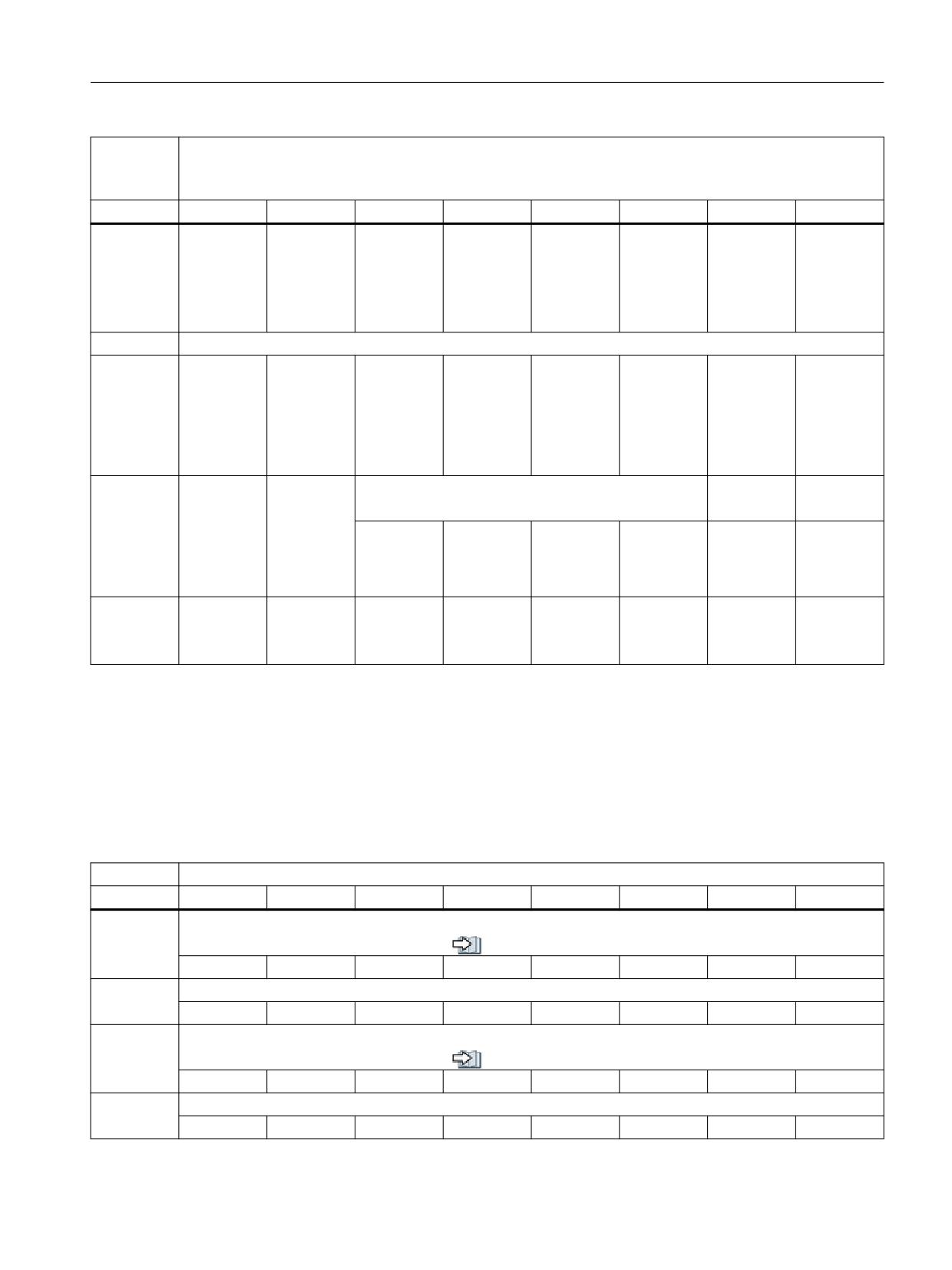
Interface signals
19.1 Interface signals - overview
DB31 -
Signals from axis/spindle
DB61
/FBSIsl/
Byte
Bit 7
Bit 6
Bit 5
Bit 4
Bit 3
Bit 2
Bit 1
Bit 0
DBB167
Safely-limi-
Bit 0
ted position
For area
is selected
Safely-limi-
(SLP)
ted position
(SLP)
DBD168
Speed limit
DBB172
Acceptance
Acceptance
SS2 ESR ac-
SS2E_AC-
test:
test:
tive
TIVE
Safely-limi-
Safely-limi-
ted position
ted position
selected
active
(SLP)
(SLP)
DBB173
Load torque
Close exter-
Brake test
negative
nal brake
(SBT)
sign
(SBC)
completed
OK
Active
with brake 2
Setpoint in-
Safe Brake
put during
Test (SBT)
SBT in the
drive
DBB174 ...
DBB187
19.1.15
Tool management
19.1.15.1
DB71, interface for loading/unloading the magazine
Table 19-100 DB71, interface for loading/unloading the magazine
DB71
Loading/unloading positions (NC → PLC)
Byte
Bit 7
Bit 6
Bit 5
Bit 4
Bit 3
Bit 2
Bit 1
Bit 0
DBB0
Interface (SS) active
see also (Page 721)
SS8
SS7
SS6
SS5
SS4
SS3
SS2
SS1
DBB1
SS16
SS15
SS14
SS13
SS12
SS11
SS10
SS9
DBB2
Standard end acknowledgement
see also (Page 721)
SS8
SS7
SS6
SS5
SS4
SS3
SS2
SS1
DBB3
SS16
SS15
SS14
SS13
SS12
SS11
SS10
SS9
PLC
Function Manual, 10/2020, 6FC5397-0HP40-0BA1
435
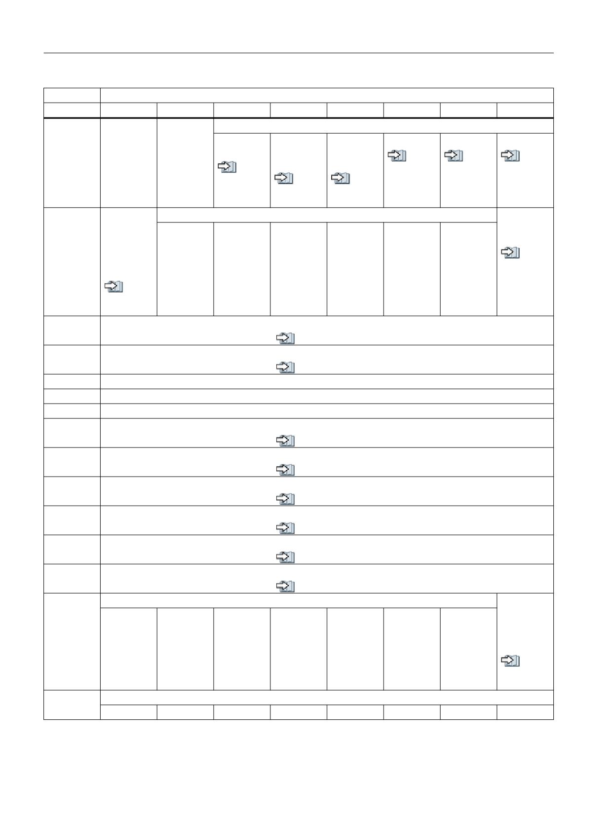
Interface signals
19.1 Interface signals - overview
DB71
Loading/unloading positions (NC → PLC)
Byte
Bit 7
Bit 6
Bit 5
Bit 4
Bit 3
Bit 2
Bit 1
Bit 0
DBBn + 0
Reserved
Command:
Multitool
NC progr.
Positioning
Relocating
Unloading
Loading
positioning
positions
to the load-
see al-
see al-
see al-
magazine
ing point
see al-
so
so
so
so
see al-
see al-
(Page 722)
(Page 722)
(Page 721)
(Page 724)
so
so
(Page 723)
(Page 723)
DBBn + 1
Command:
Reserved
Acknowl-
Data in ex-
edgement
tended
status = 3
Area
see al-
(DB1071
so
(Page 451))
(Page 724)
see al-
so
(Page 725)
DBBn + 2
Assigned channel (8-bit INT)
see also (Page 725)
DBBn + 3
Tool management no. (8-bit INT)
see also (Page 725)
DBBn + 4
Reserved (free parameter 1 (DWord))
DBBn + 8
Reserved (free parameter 2 (DWord))
DBDn + 12
Reserved (free parameter 3 (DWord))
DBWn + 16
Identifier for loading/unloading point (INT), (fixed value 9999)
see also (Page 726)
DBWn + 18
Location no. of load/unload point (INT)
see also (Page 726)
DBWn + 20
Magazine no. (Source) for unloading/relocating/positioning (INT)
see also (Page 726)
DBWn + 22
Location no. (Source) for unloading/relocating/positioning (INT)
see also (Page 727)
DBWn + 24
Magazine no. (Target) for loading/relocating/positioning (INT)
see also (Page 727)
DBWn + 26
Location no. (Target) for loading/relocating/positioning (INT)
see also (Page 727)
DBWn + 28
Reserved
Loading/
unloading
without
moving
magazine
see al-
so
(Page 728)
DBWn + 29
Reserved
PLC
436
Function Manual, 10/2020, 6FC5397-0HP40-0BA1
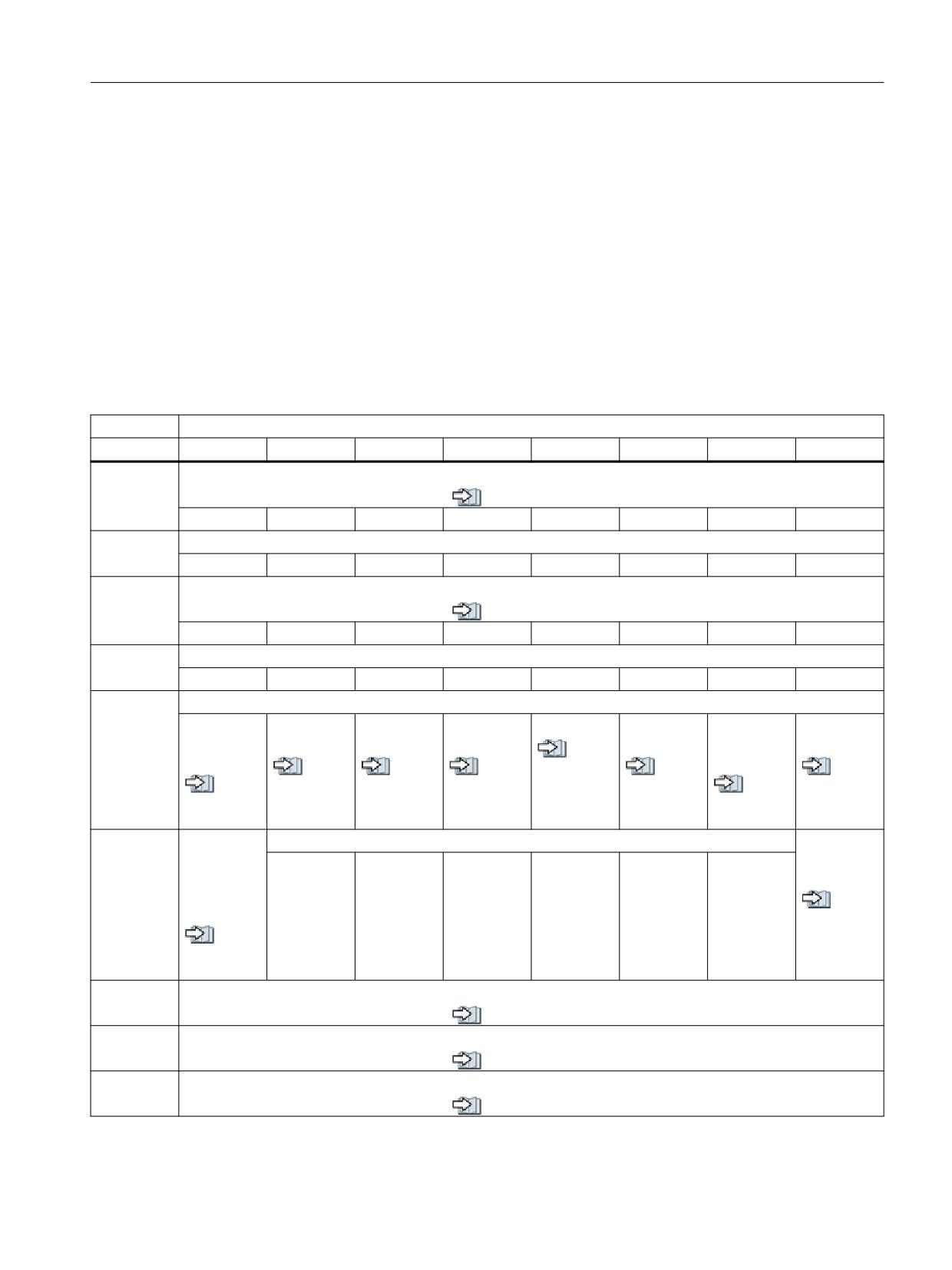
Interface signals
19.1 Interface signals - overview
Starting addresses of loading/unloading points:
Loading/unloading point 1: n = 4
Loading/unloading point 3: n = 64
Loading/unloading point 2: n = 34
Loading/unloading point 4: n = 94
Loading interface 1 is responsible for loading/unloading in (all) spindles/toolholders and for
relocating tools and for positioning at any locations (e.g. buffer location).
Loading and unloading manual tools is always realized via loading interface 1.
19.1.15.2
DB72, interface for the spindle as change position
Table 19-101
DB72, interface for the spindle as change position
DB72
Signals from the spindle (NC → PLC)
Byte
Bit 7
Bit 6
Bit 5
Bit 4
Bit 3
Bit 2
Bit 1
Bit 0
DBB0
Interface (SS) active
see also (Page 728)
SS8
SS7
SS6
SS5
SS4
SS3
SS2
SS1
DBB1
SS16
SS15
SS14
SS13
SS12
SS11
SS10
SS9
DBB2
Standard end acknowledgment
see also (Page 729)
SS8
SS7
SS6
SS5
SS4
SS3
SS2
SS1
DBB3
SS16
SS15
SS14
SS13
SS12
SS11
SS10
SS9
DBBn + 0
Command code:
Spindle tool
Replace
Insert man-
Old T in buf-
T0
Prepare
Perform
Obligatory
remains in
manual tool
ual tool
fer
change
change (ini-
change
see al-
the spindle
tiate: M06)
see al-
see al-
see al-
so
see al-
see al-
see al-
so
so
so
(Page 730)
so
see al-
so
so
(Page 732)
(Page 731)
(Page 731)
(Page 730)
so
(Page 729)
(Page 732)
(Page 729)
DBBn + 1
Data in ex-
Reserved
Acknowl-
tended
edgment
Area
status = 3
(DB1072
see al-
(Page 451))
so
see al-
(Page 733)
so
(Page 733)
DBBn + 2
Assigned channel (8-bit INT)
see also (Page 733)
DBBn + 3
Tool management No. (8-bit INT)
see also (Page 734)
DBDn + 4
User parameter 0 (DWord)
see also (Page 734)
PLC
Function Manual, 10/2020, 6FC5397-0HP40-0BA1
437

Interface signals
19.1 Interface signals - overview
DB72
Signals from the spindle (NC → PLC)
Byte
Bit 7
Bit 6
Bit 5
Bit 4
Bit 3
Bit 2
Bit 1
Bit 0
DBDn + 8
User parameter 1 (DWord)
see also (Page 734)
DBDn + 12
User parameter 2 (DWord)
see also (Page 735)
DBWn + 16
Buffer identifier (INT), (fixed value 9998)
(corresponds to "Target position for new tool")
see also (Page 735)
DBWn + 18
Relative location (target) in buffer magazine (INT)
see also (Page 735)
DBWn + 20
Magazine No. (Source) for new tool (INT)
see also (Page 736)
DBWn + 22
Location No. (Source) for new tool (INT)
see also (Page 736)
DBWn + 24
Magazine No. (Target) for old tool (INT)
see also (Page 736)
DBWn + 26
Location No. (Target) for old tool (INT)
see also (Page 737)
DBWn + 28
Tool new: Location type (INT)
see also (Page 737)
DBWn + 30
Tool new: Size left (INT)
see also (Page 737)
DBWn + 32
Tool new: Size right (INT)
see also (Page 738)
DBWn + 34
Tool new: Size top (INT)
see also (Page 738)
DBWn + 36
Tool new: Size bottom (INT)
see also (Page 738)
DBBn + 38
Tool status for new tool
see also (Page 739)
Manual tool
1:1 ex-
Reserved
Master tool
Tool to be
Tool to be
Disabled,
Tool in the
change
loaded
unloaded
but ignore
buffer
DBBn + 39
Tool status for new tool
see also (Page 739)
Tool has
Tool fixed-
Tool being
Prewarning
Measure
Tool disa-
Enable tool
Active tool
been in use
location-co-
changed
limit
tool
bled
ded
reached
DBWn + 40
Tool new: Internal T No. (INT)
see also (Page 739)
DBWn + 42
Buffer location of the old tool
see also (Page 740)
DBWn + 44
Original magazine of the new tool
see also (Page 740)
PLC
438
Function Manual, 10/2020, 6FC5397-0HP40-0BA1
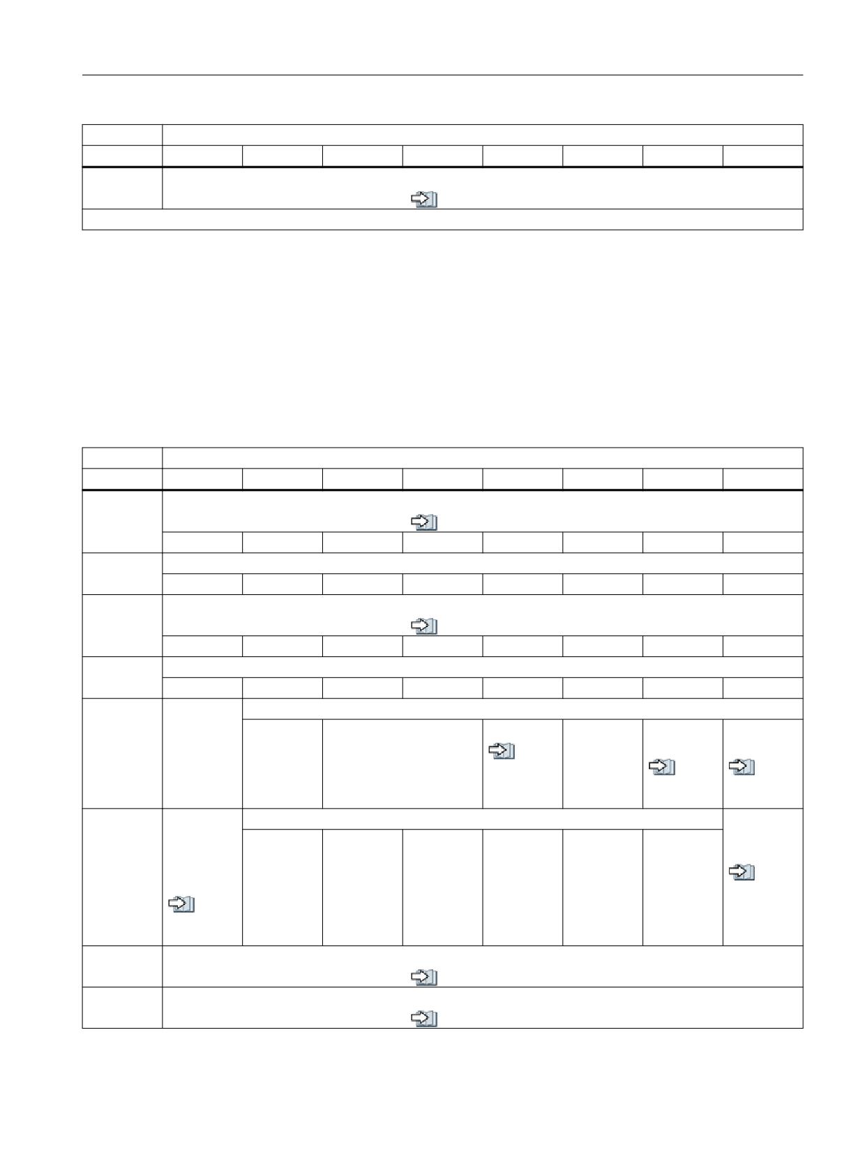
Interface signals
19.1 Interface signals - overview
DB72
Signals from the spindle (NC → PLC)
Byte
Bit 7
Bit 6
Bit 5
Bit 4
Bit 3
Bit 2
Bit 1
Bit 0
DBWn + 46
Original location of the new tool
see also (Page 740)
Start addresses of the buffer
Spindle 1:
n = 4
Spindle 2:
n = 52
19.1.15.3
DB73, interface for the turret
Table 19-102
DB73, interface for the turret
DB73
Signals for the turret (NC → PLC)
Byte
Bit 7
Bit 6
Bit 5
Bit 4
Bit 3
Bit 2
Bit 1
Bit 0
DBB0
Interface (SS) active
see also (Page 741)
SS8
SS7
SS6
SS5
SS4
SS3
SS2
SS1
DBB1
SS16
SS15
SS14
SS13
SS12
SS11
SS10
SS9
DBB2
Standard end acknowledgment
see also (Page 741)
SS8
SS7
SS6
SS5
SS4
SS3
SS2
SS1
DBB3
SS16
SS15
SS14
SS13
SS12
SS11
SS10
SS9
DBBn
Reserved
Command code:
Unload
Reserved
T0
Reserved
Perform
Obligatory
manual tool
change
change
see al-
so
see al-
see al-
(Page 742)
so
so
(Page 742)
(Page 742)
DBBn + 1
Data in ex-
Reserved
Acknowl-
tended
edgment
Area
status = 3
(DB1073
see al-
(Page 453))
so
see al-
(Page 743)
so
(Page 743)
DBBn + 2
Assigned channel (8-bit INT)
see also (Page 743)
DBBn + 3
Tool management No. (8-bit INT)
see also (Page 744)
PLC
Function Manual, 10/2020, 6FC5397-0HP40-0BA1
439

Interface signals
19.1 Interface signals - overview
DB73
Signals for the turret (NC → PLC)
Byte
Bit 7
Bit 6
Bit 5
Bit 4
Bit 3
Bit 2
Bit 1
Bit 0
DBDn + 4
User parameter 1 (DWord)
see also (Page 744)
DBDn + 8
User parameter 2 (DWord)
see also (Page 744)
DBDn + 12
User parameter 3 (DWord)
see also (Page 745)
DBWn + 16
Reserved
DBWn + 18
Reserved
DBWn + 20
Magazine No. of the turret (INT)
see also (Page 745)
DBWn + 22
Location No. of new tool (INT)
see also (Page 745)
DBWn + 24
Magazine No. of old tool
see also (Page 746)
DBWn + 26
Location No. of old tool (INT)
see also (Page 746)
DBWn + 28
Tool new: Location type (INT)
see also (Page 746)
DBWn + 30
Tool new: Size left (INT)
see also (Page 747)
DBWn + 32
Tool new: Size right (INT)
see also (Page 747)
DBWn + 34
Tool new: Size top (INT)
see also (Page 747)
DBWn + 36
Tool new: Size bottom (INT)
see also (Page 748)
DBBn + 38
Tool status for new tool
see also (Page 748)
Manual tool
1:1 ex-
Reserved
Master tool
Tool to be
Tool to be
Disabled,
Tool in the
change
loaded
unloaded
but ignore
buffer
DBBn + 39
Tool status for new tool
see also (Page 748)
Tool has
Tool fixed-
Tool being
Prewarning
Measure
Tool disa-
Enable tool
Active tool
been in use
location-co-
changed
limit
tool
bled
ded
reached
DBWn + 40
Tool new: Internal T No. (INT)
see also (Page 749)
DBWn + 42
Original location of new tool in this circular magazine
see also (Page 749)
PLC
440
Function Manual, 10/2020, 6FC5397-0HP40-0BA1
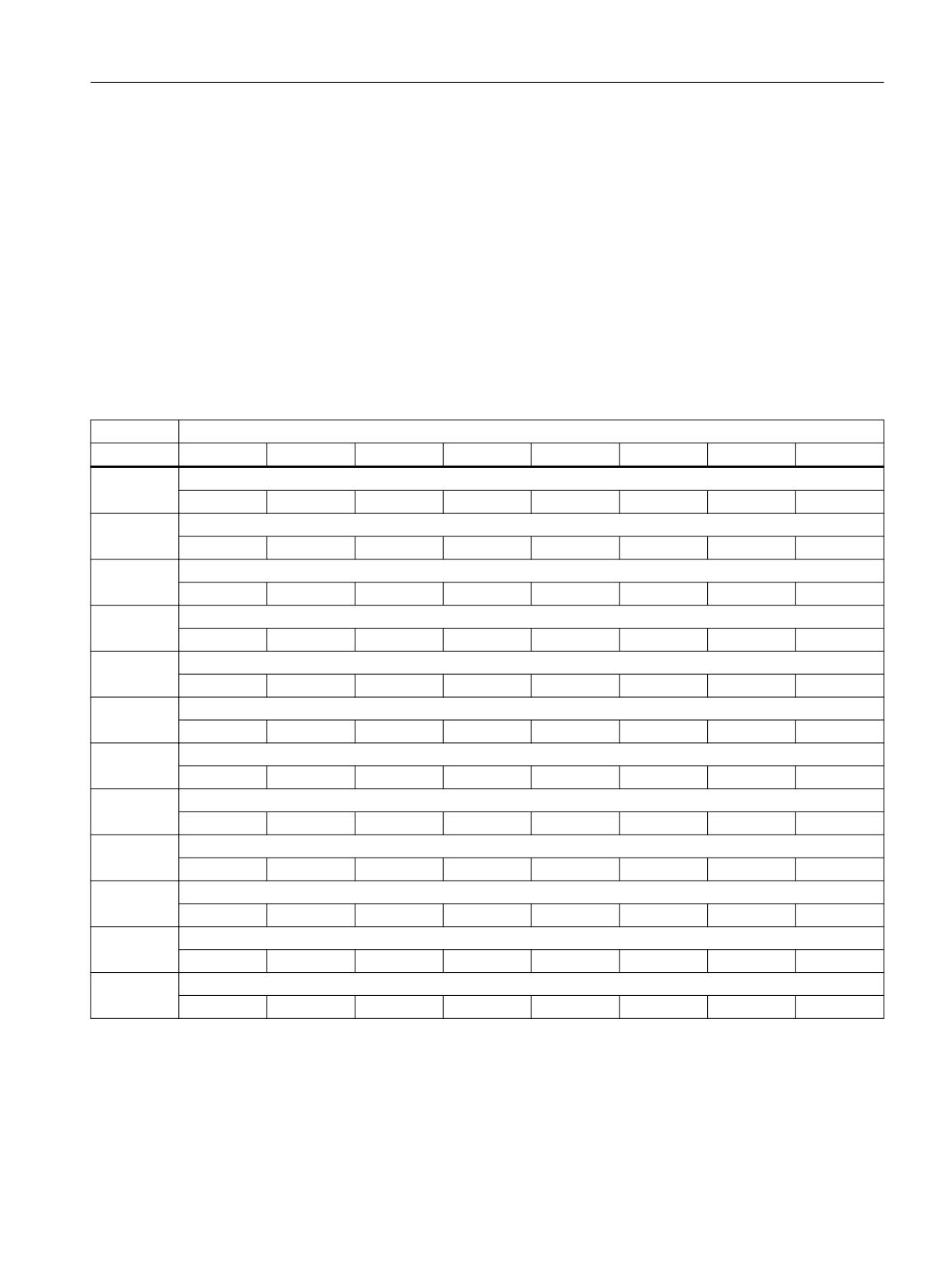
Interface signals
19.1 Interface signals - overview
Start addresses of the turret:
Turret, 1:
n = 4
Turret, 2:
n = 48
19.1.16
Signals from/to the machine control panel and the handheld unit
19.1.16.1
DB77, signals from/to the MCP and the HHU
Table 19-103 DB77, signals from/to the MCP and the HHU
DB77
Signals from/to MCP and HHU (GD communication)
Byte
Bit 7
Bit 6
Bit 5
Bit 4
Bit 3
Bit 2
Bit 1
Bit 0
DBB0 -
Input signals from MCP1 to the PLC, MPI bus
DBB7
DBB8 -
Output signals from MCP1 to the PLC, MPI bus
DBB15
DBD16
Status, send MCP1, MPI bus
DBD20
Status, receive MCP1, MPI bus
DBB24 -
Input signals from MCP2 to the PLC, MPI bus
DBB31
DBB32 -
Output signals from MCP2 to the PLC, MPI bus
DBB39
DBD40
Status, send MCP2, MPI bus
DBD44
Status, receive MCP2, MPI bus
DBB48 -
Input signals from the HHU to the PLC, MPI bus
DBB53
DBB60 -
Output signals from the HHU to the PLC, MPI bus
DBB79
DBD80
Status, send HHU, MPI bus
DBD84
Status, receive HHU, MPI bus
PLC
Function Manual, 10/2020, 6FC5397-0HP40-0BA1
441
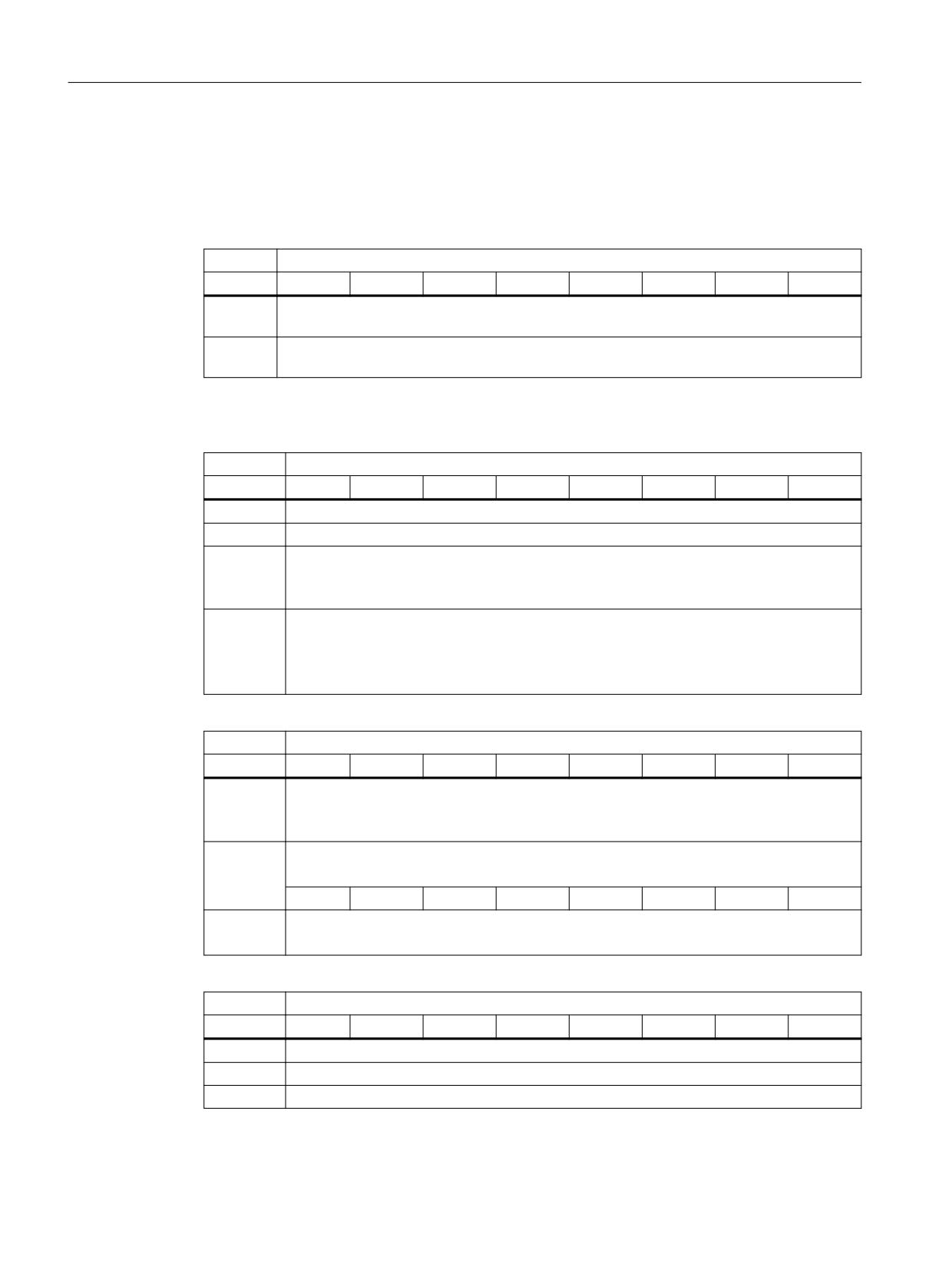
Interface signals
19.1 Interface signals - overview
19.1.17
Powerride
19.1.17.1
DB78: PowerrideConfig
DB78
Preconfigured response for FB21 "Powerride"
Byte
Bit 7
Bit 6
Bit 5
Bit 4
Bit 3
Bit 2
Bit 1
Bit 0
DBB0 -
configFeed - feed configuration
DBB223
DBB224 -
configSpindle - spindle configuration
DBB447
Structure of the configuration
DB78
UDT78 configuration "typePowerrideConfig"
Byte
Bit 7
Bit 6
Bit 5
Bit 4
Bit 3
Bit 2
Bit 1
Bit 0
DBW0
pos100 - switch position that represents the override factor 100% [1 ... 36]
DBW2
posMax - switch position that represents the maximum override factor [1 ... 36]
DBD4
delay100 - time delay for exceeding the 100% override factor
When the switch position for "pos100" is reached, the time delay is started. Only after the
time has expired can you increase the switch position further.
DBW8 -
switchPos -definition of switch positions 1 … 36
DBW222
Each data record in the array represents a switch position. Define the corresponding prop-
erties for the respective switch position.
UDT79 "typePowerrideConfigPos"
DB78
Switch position 1 - UDT79 "typePowerrideConfigPos"
Byte
Bit 7
Bit 6
Bit 5
Bit 4
Bit 3
Bit 2
Bit 1
Bit 0
DBW8
value - override factor [0 ... 200]
The value represents the override factor for a specific switch position. 100 corresponds to
100 %, for example
DBW10
ledColor - color of the LEDs from the LED strip of the Powerride
(color combinations (Page 236) are possible)
Blue
Green
Red
DBW12
vibrationIndex - vibration pattern [0 ... 7]
(at 0 no vibration)
DB78
Switch position 2 - UDT79 "typePowerrideConfigPos"
Byte
Bit 7
Bit 6
Bit 5
Bit 4
Bit 3
Bit 2
Bit 1
Bit 0
DBW14
value - override factor
DBW16
ledColor - color of the LEDs from the LED strip of the Powerride
DBW18
vibrationIndex - vibration pattern
PLC
442
Function Manual, 10/2020, 6FC5397-0HP40-0BA1

Interface signals
19.1 Interface signals - overview
…
DB78
Switch position 36 - UDT79 "typePowerrideConfigPos"
Byte
Bit 7
Bit 6
Bit 5
Bit 4
Bit 3
Bit 2
Bit 1
Bit 0
DBW218
value - override factor
DBW220
ledColor - color of the LEDs from the LED strip of the Powerride
DBW222
vibrationIndex - vibration pattern
Note
Activating changes to the configuration
The configuration is read in again with a positive edge on parameter "enable". To do this, set the
parameter to FALSE and then back to TRUE.
Note
User-specific configurations
Use a separate data block for user-specific configurations. The configurations in this data block
are overwritten by updates.
See also
FB21: Powerride - rotary/push control dial (Page 232)
19.1.18
Signals for Ctrl-Energy
19.1.18.1
DB1000, energy-saving profiles
Table 19-104 DB1000, energy-saving profiles
DB1000
Ctrl-Energy (operating software → PLC)
/SCE/
Byte
Bit 7
Bit 6
Bit 5
Bit 4
Bit 3
Bit 2
Bit 1
Bit 0
DBBn + 0
Control signals
Set time to
Immediate-
prewarning
ly activate
limit
energy-sav-
ing profile
PLC
Function Manual, 10/2020, 6FC5397-0HP40-0BA1
443
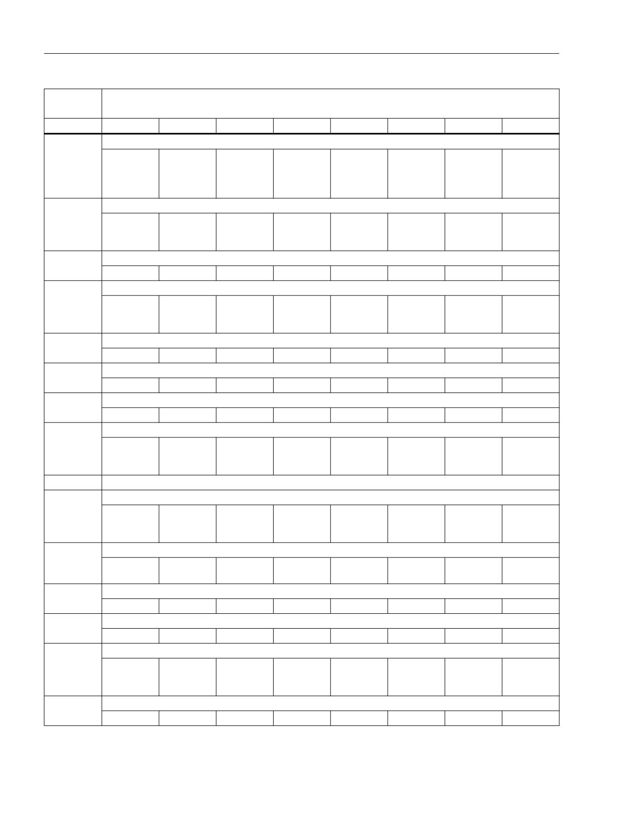
Interface signals
19.1 Interface signals - overview
DB1000
Ctrl-Energy (operating software → PLC)
/SCE/
Byte
Bit 7
Bit 6
Bit 5
Bit 4
Bit 3
Bit 2
Bit 1
Bit 0
DBBn + 1
Control signals
Directly ac-
tivate ener-
gy-saving
profile
DBBn + 2
Signals to check/test the energy-saving profile
PLC user sig-
Master
nal
computer
signal
DBBn + 3
Reserved
DBBn + 4
Status signal
Activation
Energy-sav-
time T1 has
ing profile
expired
active
DBBn + 5
Reserved
DBWn + 6
Actual value: Actual value T1
DBWn + 8
Actual value: Actual value T2
DBBn + 10
Effectiveness, profile
Disable en-
Energy-sav-
ergy-saving
ing profile
profile
configured
State conditions
DBBn + 11
Screen
Data trans-
Keyboard
change ac-
fer active
has been
tive
used
DBBn + 12
MP used for
operation
DBBn + 13
NC channel in reset
8
7
6
5
4
3
2
1
DBBn + 14
NC channel in reset
10
9
DBBn + 15
PLC user sig-
Master
nal
computer
signal
DBWn + 16
Activation time T1
PLC
444
Function Manual, 10/2020, 6FC5397-0HP40-0BA1

Interface signals
19.1 Interface signals - overview
DB1000
Ctrl-Energy (operating software → PLC)
/SCE/
Byte
Bit 7
Bit 6
Bit 5
Bit 4
Bit 3
Bit 2
Bit 1
Bit 0
DBWn + 18
Pre-warning time T2
Additional profile instances
Energy profile 2: DB1000 DBB20…DBB39
Energy profile 3: DB1000 DBB40…DBB59
Energy profile 4: DB1000 DBB60…DBB79
Energy profile 5: DB1000 DBB80…DBB99
Energy profile 6: DB1000 DBB100…DBB119
Energy profile 7: DB1000 DBB120…DBB139
Energy profile 8: DB1000 DBB140…DBB159
19.1.19
SENTRON PAC
19.1.19.1
DB1001, SENTRON PAC
Table 19-105 DB1001, signals for SENTRON PAC
DB1001
SENTRON PAC
/SCE/
Byte
Bit 7
Bit 6
Bit 5
Bit 4
Bit 3
Bit 2
Bit 1
Bit 0
DBB0
Regenera-
Regenera-
Regenera-
Energy fed
SENTRON
Display
tive energy:
tive energy:
tive energy
in is read by
PAC repre-
manual val-
PLC → oper-
Integration
Integration
is read by
SENTRON
sents the
ue
ating soft-
using FW
using FW
SENTRON
PAC
machine
ware
PAC
DBB1
GP should
perform
GP
measure-
ment
DBB2
Operating
Measure-
soft-
ment in pro-
ware → PLC
gress
DBB3
Power dis-
play on
PLC → oper-
ating soft-
ware
PLC
Function Manual, 10/2020, 6FC5397-0HP40-0BA1
445

Interface signals
19.1 Interface signals - overview
DB1001
SENTRON PAC
/SCE/
Byte
Bit 7
Bit 6
Bit 5
Bit 4
Bit 3
Bit 2
Bit 1
Bit 0
DBD4
Manual value (REAL) to operating software
PLC → oper-
ating soft-
ware
DBD8
Total active power (REAL) to operating software
PLC → oper-
ating soft-
ware
DBD12
Measured drawn active energy in kWh (REAL) to the operating software
PLC → oper-
ating soft-
ware
DBD16
Measured supplied active energy in kWh (REAL) to the operating software
PLC → oper-
ating soft-
ware
DBD20
Total active power in watts (REAL) from SENTRON
GP
DBD24
Drawn active energy at tariff 1 (F) in Wh (REAL) from SENTRON
GP
DBD28
Supplied active energy at tariff 1 (F) in Wh (REAL) from SENTRON
GP
DBD32
Drawn active energy in kWh per day (REAL) to the operating software
DBD36
Supplied active energy in kWh day (REAL) to the operating software
DBD40
Drawn active energy in kWh previous day (REAL) to the operating software
DBD44
Supplied active energy in kWh previous day (REAL) to the operating software
DBD48
Drawn active energy in kWh month (REAL) to the operating software
DBD52
Supplied active energy in kWh month (REAL) to the operating software
DBD56
Drawn active energy in kWh previous month (REAL) to the operating software
DBD60
Supplied active energy in kWh previous month (REAL) to the operating software
DBD64
Drawn active energy in kWh year (REAL) to the operating software
DBD68
Supplied active energy in kWh year (REAL) to the operating software
PLC
446
Function Manual, 10/2020, 6FC5397-0HP40-0BA1
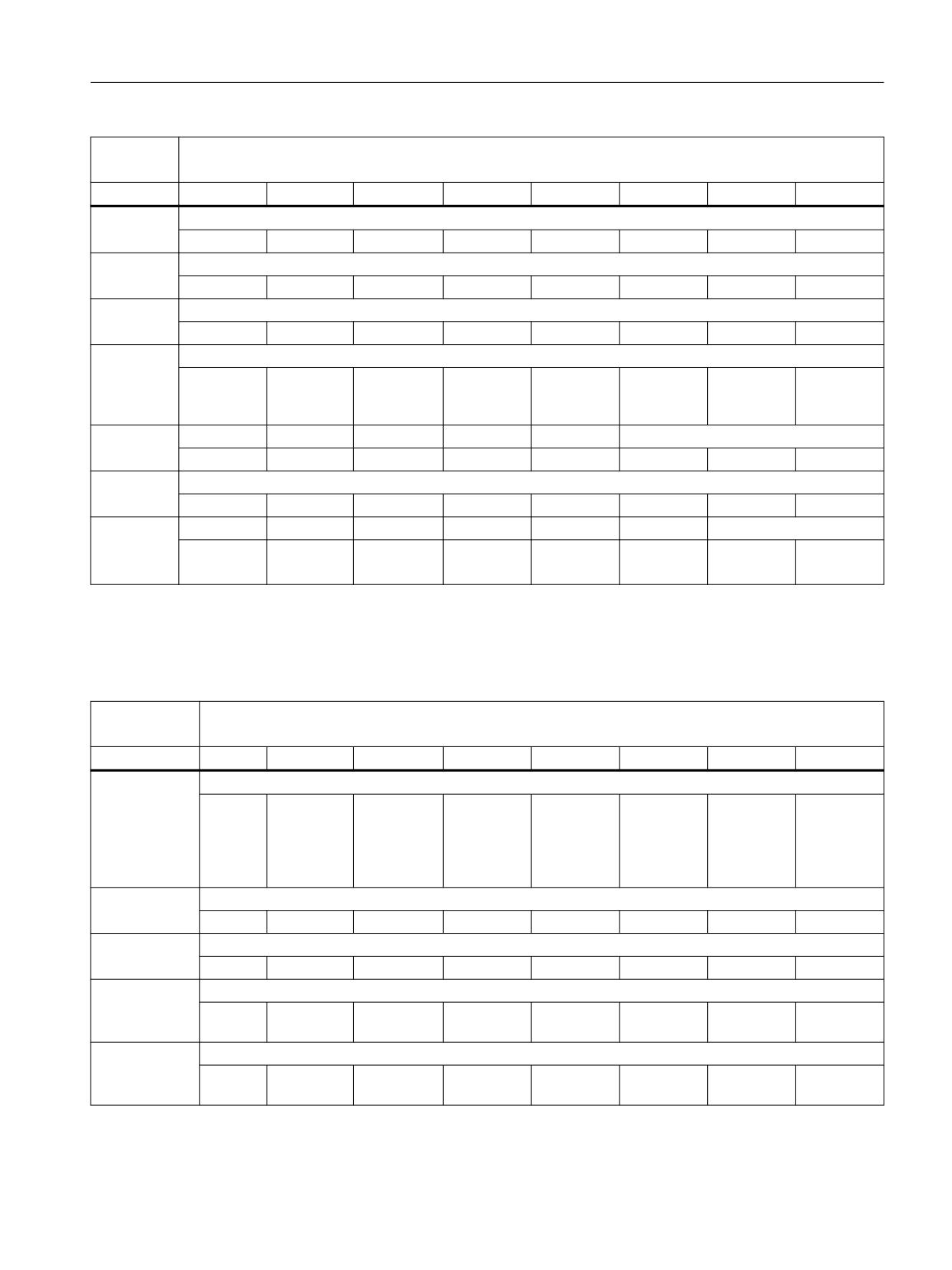
Interface signals
19.1 Interface signals - overview
DB1001
SENTRON PAC
/SCE/
Byte
Bit 7
Bit 6
Bit 5
Bit 4
Bit 3
Bit 2
Bit 1
Bit 0
DBD72
Drawn active energy in kWh previous year (REAL) to the operating software
DBD76
Supplied active energy in kWh previous year (REAL) to the operating software
DBB80 ...
Reserved
DBB95
DBB96
ProductionAct
PLC→GP/
operating
software
DBB97
Values invalid in
GP
DBD28
DBD24
DBD20
DBB98
Values invalid in
GP
DBD384
DBD344
DBD304
DBD264
DBD224
DBD184
DBD144
DBD104
DBB99
Values invalid in
GP
DBD464
DBD424
19.1.19.2
DB1001, SENTRON PAC, auxiliary devices
Table 19-106 DB1001, signals for SENTRON PAC
DB1001
SENTRON PAC
/SCE/
Byte
Bit 7
Bit 6
Bit 5
Bit 4
Bit 3
Bit 2
Bit 1
Bit 0
DBBn+100
Control/command bits
PLC → GP oper-
Reset da-
Input
Different
Energy
Read ener-
Process de-
ating software
ta struc-
mode: (en-
values
measure-
gy actual
vice
ture
ergy or
when meas-
ment run-
value up-
power)
uring ener-
ning
date
gy
DBBn+101
Reserved
DBBn+102
Reserved
DBBn+104
Active power or active energy of the auxiliary unit [kW] or [kWh]
PLC → GP oper-
ating software
DBDn+108
Drawn active energy of the auxiliary unit [kWh]
PLC → operat-
ing software
PLC
Function Manual, 10/2020, 6FC5397-0HP40-0BA1
447

Interface signals
19.1 Interface signals - overview
DB1001
SENTRON PAC
/SCE/
Byte
Bit 7
Bit 6
Bit 5
Bit 4
Bit 3
Bit 2
Bit 1
Bit 0
DBDn+112
Active energy supplied by the auxiliary unit [kWh]
GP → operat-
ing software
DBDn+116
Active energy drawn by the auxiliary unit at the measurement start [kWh]
GP → operat-
ing software
DBDn+120
Active energy supplied by the auxiliary unit at the measurement start [kWh]
GP → operat-
ing software
DBDn+124
Active energy drawn by the auxiliary unit at the measurement end [kWh]
GP → operat-
ing software
DBDn+128
Active energy supplied by the auxiliary unit at the measurement end [kWh]
GP → operat-
ing software
DBDn+132
Reserved
DBDn+136
Reserved
Auxiliary unit instances:
Auxiliary unit 1
(n=0):
DB1001 DBB100…DBB139
Auxiliary unit 2
(n=40):
DB1001 DBB140…DBB179
Auxiliary unit 3
(n=80):
DB1001 DBB180…DBB219
Auxiliary unit 4
(n=120):
DB1001 DBB220…DBB259
Auxiliary unit 5
(n=160):
DB1001 DBB260…DBB299
Auxiliary unit 6
(n=200):
DB1001 DBB300…DBB339
Auxiliary unit 7
(n=240):
DB1001 DBB340…DBB379
Auxiliary unit 8
(n=280):
DB1001 DBB380…DBB419
Auxiliary unit 9
(n=320):
DB1001 DBB420…DBB459
Auxiliary unit 10
(n=360):
DB1001 DBB460…DBB499
PLC
448
Function Manual, 10/2020, 6FC5397-0HP40-0BA1
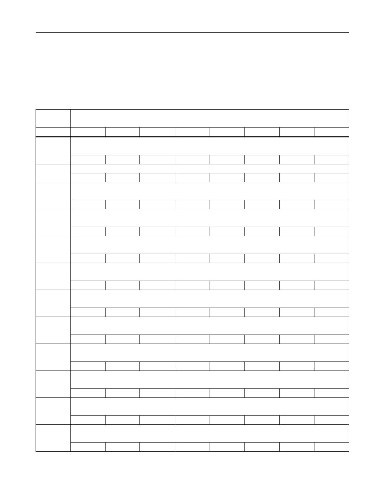
Interface signals
19.1 Interface signals - overview
19.1.20
Spindle temperature sensor
19.1.20.1
DB1002: spindle temperature sensors
Table 19-107
DB1002, signals for spindle temperature sensors
DB1002
SENTRON PAC
/SCE/
Byte
Bit 7
Bit 6
Bit 5
Bit 4
Bit 3
Bit 2
Bit 1
Bit 0
DBWn + 0
Sensor n
Sensor installation location
DBWn + 2
Reserved
DBDn + 4
Sensor n
Temperature sensor actual value [°C]
DBDn + 8
Sensor n
Temperature sensor warning threshold value [°C]
DBWn + 12
Sensor n
Number of alarm limit value violations
DBBn + 14
Sensor n
Last alarm limit value violation: Year total active power (REAL) to the operating software
DBBn + 15
Sensor n
Last alarm limit value violation: Month
DBBn + 16
Sensor n
Last alarm limit value violation: Day
DBBn + 17
Sensor n
Last alarm limit value violation: Hour
DBBn + 18
Sensor n
Last alarm limit value violation: Minute
DBBn + 19
Sensor n
Last alarm limit value violation: Seconds
DBBn + 20
Sensor n
Duration of the warning limit value violations
PLC
Function Manual, 10/2020, 6FC5397-0HP40-0BA1
449

Interface signals
19.1 Interface signals - overview
DB1002
SENTRON PAC
/SCE/
Byte
Bit 7
Bit 6
Bit 5
Bit 4
Bit 3
Bit 2
Bit 1
Bit 0
DBBn + 24
Sensor n
Temperature sensor fault threshold value [°C]
DBBn + 28
Sensor n
Number of fault limit value violations
DBBn + 30
Sensor n
Last alarm limit value violation: Year
DBBn + 31
Sensor n
Last alarm limit value violation: Month
DBBn + 32
Sensor n
Last alarm limit value violation: Day
DBBn + 33
Sensor n
Last alarm limit value violation: Hour
DBBn + 34
Sensor n
Last alarm limit value violation: Minute
DBBn + 35
Sensor n
Last alarm limit value violation: Seconds
DBDn + 36
Sensor n
Duration of the fault limit value violation
Spindle/temperature sensor instances
Spindle_1, Temperature_sensor_1
(n=0):
DB1002 DBB00…DBB39
Spindle_1, Temperature_sensor_2
(n=40):
DB1002 DBB40…DBB79
Spindle_1, Temperature_sensor_3
(n=80):
DB1002 DBB80…DBB119
Spindle_1, Temperature_sensor_4
(n=120):
DB1002 DBB120…DBB159
Spindle_1, Temperature_sensor_5
(n=160):
DB1002 DBB160…DBB199
Spindle_1, Temperature_sensor_6
(n=200):
DB1002 DBB200…DBB239
Spindle_2, Temperature_sensor_1
(n=240):
DB1002 DBB240…DBB279
Spindle_2, Temperature_sensor_2
(n=280):
DB1002 DBB280…DBB319
Spindle_2, Temperature_sensor_3
(n=320):
DB1002 DBB320…DBB359
Spindle_2, Temperature_sensor_4
(n=360):
DB1002 DBB360…DBB399
PLC
450
Function Manual, 10/2020, 6FC5397-0HP40-0BA1
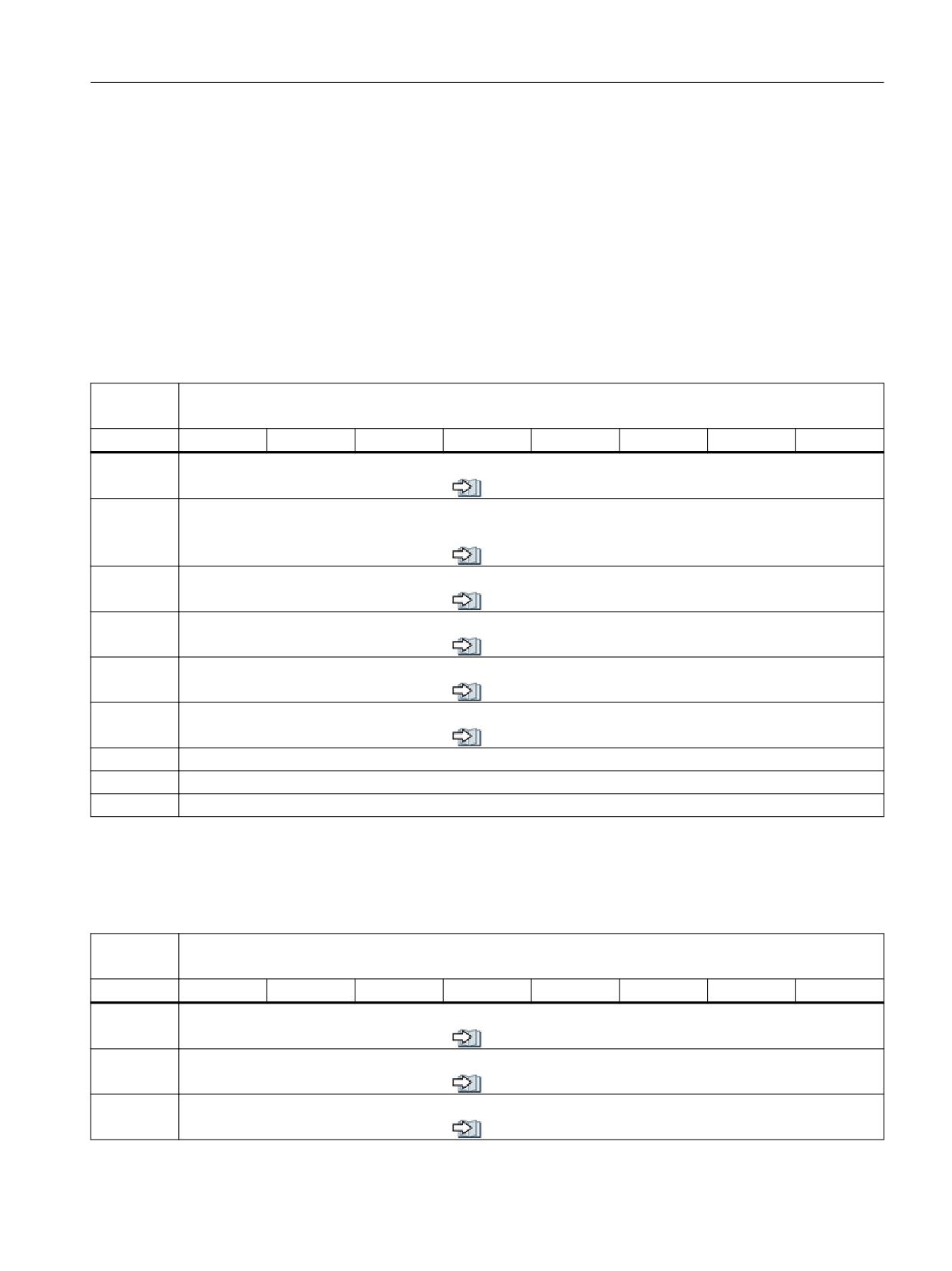
Interface signals
19.1 Interface signals - overview
Spindle_2, Temperature_sensor_5 (n=400):
DB1002 DBB400…DBB439
Spindle_2, Temperature_sensor_6 (n=440):
DB1002 DBB440…DBB479
19.1.21
Interface to the tool management, extended area
19.1.21.1
DB1071, interface for loading/unloading the magazine Multitool
Table 19-108 DB1071, interface for loading/unloading the magazine Multitool
DB1071
Loading/unloading positions (NC → PLC)
/FBWsl/
Byte
Bit 7
Bit 6
Bit 5
Bit 4
Bit 3
Bit 2
Bit 1
Bit 0
DBWn + 0
Type of distance coding of the multitool (corresponds to $TC_MTP_KD)
see also (Page 749)
DBWn + 2
Multitool location number
Number of locations of the multitool
see also (Page 750)
DBWn + 4
Multitool location distance
see also (Page 750)
DBWn + 8
Multitool number
see also (Page 751)
DBWn + 10
Multitool location number
see also (Page 751)
DBWn + 12
Tool holder
see also (Page 751)
DBWn + 14
Reserved
DBWn + 16
Reserved
DBWn + 18
Reserved
19.1.21.2
DB1072, interface for the spindle: Multitool
Table 19-109 DB1072, interface for the spindle: Multitool
DB1072
Spindle (NC → PLC)
/FBWsl/
Byte
Bit 7
Bit 6
Bit 5
Bit 4
Bit 3
Bit 2
Bit 1
Bit 0
DBWn + 0
Distance coding (corresponds to to $TC_MTP_KD)
see also (Page 752)
DBWn + 2
Multitool location number
see also (Page 752)
DBWn + 4
Multitool location distance
see also (Page 752)
PLC
Function Manual, 10/2020, 6FC5397-0HP40-0BA1
451
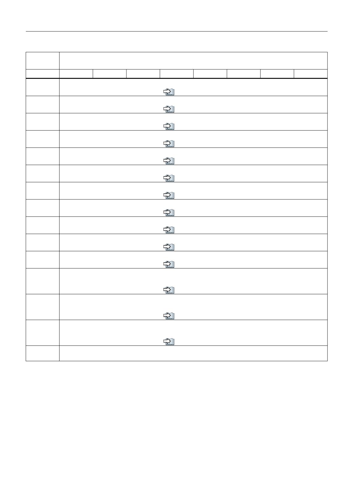
Interface signals
19.1 Interface signals - overview
DB1072
Spindle (NC → PLC)
/FBWsl/
Byte
Bit 7
Bit 6
Bit 5
Bit 4
Bit 3
Bit 2
Bit 1
Bit 0
DBWn + 8
Multitool number (new tool)
see also (Page 753)
DBWn + 10
Multitool location number (new tool)
see also (Page 753)
DBWn + 12
Multitool number (old tool)
see also (Page 753)
DBWn + 14
Multitool location number (old tool)
see also (Page 754)
DBWn + 16
New tool: Location type
see also (Page 754)
DBWn + 18
New tool: Size left
see also (Page 754)
DBWn + 20
New tool: Size right
see also (Page 755)
DBWn + 22
New tool: Size top
see also (Page 755)
DBWn + 24
New tool: Size bottom
see also (Page 755)
DBWn + 26
Tool status for new tool (corresponds to $TC_TP8[T_Nr])
see also (Page 756)
DBWn + 28
New tool: Internal T number of the NC
see also (Page 756)
DBWn + 30
Tool holder
Spindle or toolholder number to which the change refers
see also (Page 757)
DBWn + 32
Original magazine of new tool (corresponds to NC variables $A_MYMN[T No])
If the new tool is located in the magazine, this value is identical with DB72 DBW(n + 20 (Page 437)).
see also (Page 757)
DBWn + 34
Original location of new tool (corresponds to NC variables $A_MYMLN[T No])
If the new tool is located in the magazine, this value is identical with DB72 DBW(n + 22).
see also (Page 757)
DBWn + 36
Reserved
- DBWn + 48
PLC
452
Function Manual, 10/2020, 6FC5397-0HP40-0BA1
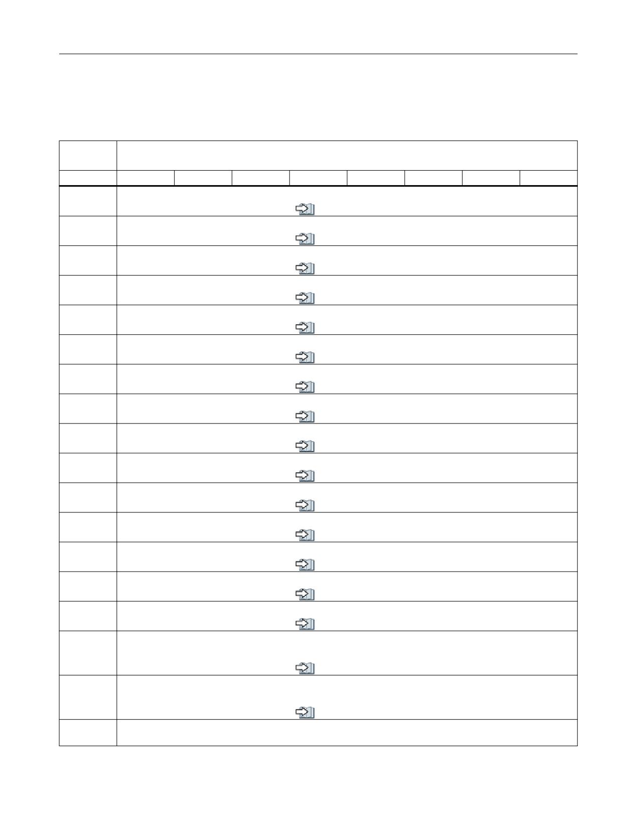
Interface signals
19.1 Interface signals - overview
19.1.21.3
DB1073, interface for the turret: Multitool
Table 19-110
DB1073, interface for the turret: Multitool
DB1073
Turret (NC → PLC)
/FBWsl/
Byte
Bit 7
Bit 6
Bit 5
Bit 4
Bit 3
Bit 2
Bit 1
Bit 0
DBWn + 0
Distance coding (corresponds to to $TC_MTP_KD)
see also (Page 758)
DBWn + 2
Multitool location number
see also (Page 758)
DBWn + 4
Multitool location distance
see also (Page 759)
DBWn + 8
Multitool number (new tool)
see also (Page 759)
DBWn + 10
Multitool location number (new tool)
see also (Page 759)
DBWn + 12
Multitool number (old tool)
see also (Page 760)
DBWn + 14
Multitool location number (old tool)
see also (Page 760)
DBWn + 16
Location type
see also (Page 760)
DBWn + 18
New tool: Size left
see also (Page 761)
DBWn + 20
New tool: Size right
see also (Page 761)
DBWn + 22
New tool: Size top
see also (Page 761)
DBWn + 24
New tool: Size bottom
see also (Page 762)
DBWn + 26
Tool status for new tool (corresponds to parameter $TC_TP8[T_No])
see also (Page 762)
DBWn + 28
New tool: Internal T number of the NC
see also (Page 763)
DBWn + 30
Tool holder
see also (Page 763)
DBWn + 32
Original magazine of new tool (corresponds to NC variables $A_MYMN[T No])
If the new tool is located in the magazine, this value is identical with DB73 DBW (Page 439)(n + 20).
see also (Page 763)
DBWn + 34
Original location of new tool (corresponds to NC variables $A_MYMN[T No])
If the new tool is located in the magazine, this value is identical with DB73 DBW (Page 439)(n + 22).
see also (Page 764)
DBWn + 36
Reserved
- DBWn + 48
PLC
Function Manual, 10/2020, 6FC5397-0HP40-0BA1
453
Interface signals
19.2 Interface signals - detailed description
19.2
Interface signals - detailed description
19.2.1
DB10: NC, PLC and HMI
19.2.1.1
DB10 DBX0.0 - 7 (digital NC inputs 1 - 8: Lock)
DB10 DBX0.0 - 7
Digital NC inputs 1 - 8: Lock
Signal flow
PLC → NC
Update
Cyclic
Signal state 1
The digital NC input is locked.
Signal state 0
The digital NC input is enabled.
Further information
Bit 7
Bit 6
Bit 5
Bit 4
Bit 3
Bit 2
Bit 1
Bit 0
Input 8 2)
Input 7 2)
Input 6 2)
Input 5 2)
Input 4 1)
Input 3 1)
Input 2 1)
Input 1 1)
1) Onboard inputs of the NCU
2) Inputs without hardware
Note
When read, a locked input supplies a value of 0.
Corresponds to
DB10 DBX0, 122, 124, 126, 128 (digital NC inputs 1 - 8: Lock)
DB10 DBB1, 123, 125, 127, 129 (digital NC inputs 1 - 8: Set)
DB10 DBB60, 186, 187, 188, 189 (digital NC inputs 1 - 8: Actual value)
MD10350 $MN_FASTIO_DIG_NUM_INPUTS
Further information
Function Manual Basic Functions
19.2.1.2
DB10 DBX1.0 - 7 (digital NC inputs 1 - 8: Set)
DB10 DBX1.0 - 7
Digital NC inputs 1 - 8: Set
Signal flow
PLC → NC
Update
Cyclic
Signal state 1
Set NC input value to a defined value of 1.
Signal state 0
Do not influence NC input value.
Further information
Bit 7
Bit 6
Bit 5
Bit 4
Bit 3
Bit 2
Bit 1
Bit 0
Input 8 2)
Input 7 2)
Input 6 2)
Input 5 2)
Input 4 1)
Input 3 1)
Input 2 1)
Input 1 1)
1) Onboard inputs of the NCU
2) Inputs without hardware
If the PLC user program sets the NC input to a value of 1, then the signal state at the onboard
input of the NCU - as well as the lock of the NC input - have no effect.
Corresponds to
DB10 DBX0, 122, 124, 126, 128 (digital NC inputs 1 - 8: Lock)
DB10 DBB1, 123, 125, 127, 129 (digital NC inputs 1 - 8: Set)
DB10 DBB60, 186, 187, 188, 189 (digital NC inputs 1 - 8: Actual value)
MD10350 $MN_FASTIO_DIG_NUM_INPUTS
Further information
Function Manual Basic Functions
PLC
454
Function Manual, 10/2020, 6FC5397-0HP40-0BA1
Interface signals
19.2 Interface signals - detailed description
19.2.1.3
DB10 DBX4.0 - 7 (digital NC outputs 1 - 8: Lock)
DB10 DBX4.0 - 7
Digital NC outputs 1 - 8: Lock
Signal flow
PLC → NC
Update
Cyclic
Signal state 1
The digital NC output is locked.
Signal state 0
The digital NC output is enabled.
Further information
Bit 7
Bit 6
Bit 5
Bit 4
Bit 3
Bit 2
Bit 1
Bit 0
Output 8
Output 7
Output 6
Output 5
Output 4
Output 3
Output 2
Output 1
If the digital NC output is locked, then 0 V (defined) is output at the hardware output.
If the digital NC output is not locked, then the value specified in the NC program or by the PLC
program is output at the hardware output.
Corresponds to
DB10 DBB5, 131, 135, 139, 143 (digital NC outputs 1 - 8: Overwrite screen form)
DB10 DBB6, 132, 136, 140, 144 (digital NC outputs: Setting value from the PLC)
DB10 DBB7, 133, 137, 141, 145 (digital NC outputs: Target screen form)
MD10360 $MN_FASTIO_DIG_NUM_OUTPUTS
Further information
Function Manual Basic Functions
19.2.1.4
DB10 DBX5.0 - 7 (digital NC outputs 1 - 8: Overwrite)
DB10 DBX5.0 - 7
Digital NC outputs 1 - 8: Overwrite
Signal flow
PLC → NC
Update
Cyclic
Edge change 0 → 1
The associated "setting value" is activated.
Edge change 1 → 0
No effect.
Further information
Bit 7
Bit 6
Bit 5
Bit 4
Bit 3
Bit 2
Bit 1
Bit 0
Output 8
Output 7
Output 6
Output 5
Output 4
Output 3
Output 2
Output 1
For a positive edge change 0 → 1, then for the corresponding output, instead of the value
written using system variables $A_OUT, the setting value specified from the PLC user program
is used. The value written via system variables $A_OUT is then lost.
For a negative edge change 1 → 0, for the corresponding output, the actual value at the
hardware output is kept.
Note
The NC/PLC interface DBB6, ... (Digital NC outputs: setting value) is jointly used by:
• DB10 DBB5, ... (overwrite) for edge change 0 → 1
• DB10 DBB7, ... (target) for signal state 1
Activating the two interfaces simultaneously should be avoided.
Corresponds to
DB10 DBB4, 130, 134, 138, 142 (digital NC outputs: Lock)
DB10 DBB5, 131, 135, 139, 143 (digital NC outputs 1 - 8: Overwrite)
DB10 DBB6, 132, 136, 140, 144 (digital NC outputs: Setting value from the PLC)
MD10360 $MN_FASTIO_DIG_NUM_OUTPUTS
Further information
Function Manual Basic Functions
PLC
Function Manual, 10/2020, 6FC5397-0HP40-0BA1
455
Interface signals
19.2 Interface signals - detailed description
19.2.1.5
DB10 DBX6.0 - 7 (digital NC outputs 1 - 8: Setting value)
DB10 DBX6.0 - 7
Digital NC outputs 1 - 8: Setting value
Signal flow
PLC → NC
Update
Cyclic
Signal state 1
Value of the setting value is 1.
Signal state 0
Value of the setting value is 0.
Further information
Bit 7
Bit 6
Bit 5
Bit 4
Bit 3
Bit 2
Bit 1
Bit 0
Output 8
Output 7
Output 6
Output 5
Output 4
Output 3
Output 2
Output 1
Using the setting value, the PLC user program can specify a defined output value. In order that
the setting value becomes active, it must be activated from the overwrite screen form or the
setting screen form.
Note
The NC/PLC interface DBB6, ... (Digital NC outputs: setting value) is jointly used by:
• DB10 DBB5, ... (overwrite) for edge change 0 → 1
• DB10 DBB7, ... (target) for signal state 1
Activating the two interfaces simultaneously should be avoided.
Corresponds to
DB10 DBB4, 130, 134, 138, 142 (digital NC outputs: Lock)
DB10 DBB5, 131, 135, 139, 143 (digital NC outputs 1 - 8: Overwrite)
DB10 DBB6, 132, 136, 140, 144 (digital NC outputs: Setting value from the PLC)
MD10360 $MN_FASTIO_DIG_NUM_OUTPUTS
Further information
Function Manual Basic Functions
19.2.1.6
DB10 DBX7.0 - 7 (digital NC outputs 1 - 8: Target)
DB10 DBX7.0 - 7
Digital NC outputs 1 - 8: Target
Signal flow
PLC → NC
Update
Cyclic
Signal state 1
The target is active.
Signal state 0
The target is not active.
Further information
Bit 7
Bit 6
Bit 5
Bit 4
Bit 3
Bit 2
Bit 1
Bit 0
Output 8
Output 7
Output 6
Output 5
Output 4
Output 3
Output 2
Output 1
If a bit is set, then for the corresponding output, instead of the NC output value, the setting
value specified by the PLC user program is used. The actual NC output value is kept.
If a bit is reset, then for the corresponding output, the last NC output value becomes active
again.
Note
The NC/PLC interface DBB6, ... (Digital NC outputs: setting value) is jointly used by:
• DB10 DBB5, ... (overwrite) for edge change 0 → 1
• DB10 DBB7, ... (target) for signal state 1
Activating the two interfaces simultaneously should be avoided.
PLC
456
Function Manual, 10/2020, 6FC5397-0HP40-0BA1

Interface signals
19.2 Interface signals - detailed description
DB10 DBX7.0 - 7
Digital NC outputs 1 - 8: Target
Corresponds to
DB10 DBB4, 130, 134, 138, 142 (digital NC outputs: Lock)
DB10 DBB5, 131, 135, 139, 143 (digital NC outputs 1 - 8: Overwrite)
DB10 DBB6, 132, 136, 140, 144 (digital NC outputs: Setting value from the PLC)
MD10360 $MN_FASTIO_DIG_NUM_OUTPUTS
Further information
Function Manual Basic Functions
19.2.1.7
DB10 DBX56.1 (Emergency Stop)
DB10 DBX56.1
Emergency Stop
Signal flow
PLC → NC
Update
Cyclic
Signal state 1
Emergency Stop is requested.
Signal state 0
Emergency Stop is not requested.
Further information
All machine axes are braked in the relevant axis-specific parameterized time:
MD36610 $MA_AX_EMERGENCY_STOP_TIME
Corresponds to
DB10 DBX56.2 (acknowledge Emergency Stop)
DB10 DBX106.1 (Emergency Stop active)
MD36610 $MA_AX_EMERGENCY_STOP_TIME (time of braking ramp in event of errors)
Further information
Function Manual Basic Functions
19.2.1.8
DB10 DBX56.2 (acknowledge Emergency Stop)
DB10 DBX56.2
Acknowledge Emergency Stop
Signal flow
PLC → NC
Update
Cyclic
Signal state 1
Acknowledgment of the "Emergency Stop" state is requested.
Signal state 0
Acknowledgment of the "Emergency Stop" state is not requested.
Further information
To acknowledge the "Emergency Stop" state of the NC, the following interface signals must
remain set until interface signal DB10 DBX106.1 (Emergency Stop active) has been reset:
• DB10 DBX56.2 = 1 (acknowledge Emergency Stop)
• DB11, ... DBX0.7 = 1 (mode group reset) for all mode groups of the NC
Corresponds to
DB10 DBX56.1 (Emergency Stop)
DB10 DBX106.1 (Emergency Stop active)
DB11 DBX0.7 (mode group reset)
Further information
Function Manual Basic Functions
PLC
Function Manual, 10/2020, 6FC5397-0HP40-0BA1
457
Interface signals
19.2 Interface signals - detailed description
19.2.1.9
DB10 DBX56.4 - 7 (key-operated switch position 0 - 3)
DB10 DBX56.4 - 7
Key-operated switch position 0 - 3
Signal flow
PLC → NC
Update
Cyclic
Additional information
Depending on the key-operated switch position, access to certain elements in the NC can be
enabled or disabled.
• Key-operated switch position 0 represents the lowest access rights
• Key-operated switch position 3 represents the highest access rights
The interface signals of key-operated switch positions 1 to 3 can either be directly specified
from the key-operated switch on the machine control panel or from the PLC user program.
It is only permissible to set one bit. If several bits are set simultaneously, the control internally
activates switch position 3.
Key-operated switch posi-
Bit 7
Bit 6
Bit 5
Bit 4
tion
0
0
0
0
1
1
0
0
1
0
2
0
1
0
0
3
1
0
0
0
Corresponds with ...
Machine data for access levels: MD11612, MD51044 - MD51064, MD51070 - MD51073,
MD51199 - MD51211, MD51215 - MD51225, MD51235
Disabling using a password
19.2.1.10
DB10 DBX58.0 - 7 (collision avoidance: Deactivate protection area group)
DB10 DBX58.0 - 7
Collision avoidance: Deactivate protection area group
Signal flow
PLC → NC
Update
Cyclic
Signal state 1
The deactivation of all protection areas of the protection area type in the selected operating
mode is requested.
Signal state 0
The deactivation of all protection areas of the protection area type in the selected operating
mode is not requested.
PLC
458
Function Manual, 10/2020, 6FC5397-0HP40-0BA1
Interface signals
19.2 Interface signals - detailed description
DB10 DBX58.0 - 7
Collision avoidance: Deactivate protection area group
Further information
Bit
Operating mode
Protection area type 1)
0
AUTOMATIC
Machine
1
Tool
2
Workholder
3
Workpiece
4
JOG
Machine
5
Tool
6
Workholder
7
Workpiece
1) Type of a protection area ($NP_PROT_TYPE)
Note
The deactivation of a protection area group is selected from the SINUMERIK Operate user
interface in the operating area "AUTOMATIC", "JOG" or "MDI" > "ETC key (">")" > "Settings" >
"Collision avoidance" > "Switch collision avoidance on and off" by setting the HMI/PLC interface
signal DB10 DBX93.0 ... 7 of the protection area group.
The interface signal is transferred according to the value of the FB1 parameter MMCToIf by the
basic PLC program into the NC/PLC interface signal DB10 DBX58.0 ... 7:
• "TRUE": Transmission
• "FALSE": No transmission
The default value of the parameter is "TRUE".
Note
If manual traversing has been enabled in AUTOMATIC mode (MD10735 with bit 0 == 1: allow
jogging in the automatic mode) the settings for the JOG mode also apply in AUTOMATIC mode
during manual traversing.
Corresponds to
DB10 DBX93.0 - 7 (deactivate collision avoidance)
$NP_PROT_TYPE (type of protection area)
MD10735 $MN_JOG_MODE_MASK (settings for the JOG mode)
Further information
• Operating Manual Turning or Milling
• Function Manual Monitoring and Compensating
• Function Manual Monitoring and Compensating
19.2.1.11
DB10 DBX60.0 - 7 (digital NC inputs 1 - 8: Actual value)
DB10 DBX60.0 - 7
Digital NC inputs 1 - 8: Actual value
Signal flow
NC → PLC
Update
Cyclic
Signal state 1
The actual value is 1.
Signal state 0
The actual value is 0.
PLC
Function Manual, 10/2020, 6FC5397-0HP40-0BA1
459
Interface signals
19.2 Interface signals - detailed description
DB10 DBX60.0 - 7
Digital NC inputs 1 - 8: Actual value
Further information
Bit 7
Bit 6
Bit 5
Bit 4
Bit 3
Bit 2
Bit 1
Bit 0
Input 8
Input 7
Input 6
Input 5
Input 4
Input 3
Input 2
Input 1
The actual NC output value can be read in the PLC user program via the actual value.
Note
The value in the "Actual value" interface can, as a result of the various subsequent influencing
possibilities "Lock" and "Set", have a different value than that available at the NC output.
Corresponds to
DB10 DBX0, 122, 124, 126, 128 (digital NC inputs 1 - 8: Lock)
DB10 DBB1, 123, 125, 127, 129 (digital NC inputs 1 - 8: Set)
DB10 DBB60, 186, 187, 188, 189 (digital NC inputs 1 - 8: Actual value)
MD10350 $MN_FASTIO_DIG_NUM_INPUTS
Further information
Function Manual Basic Functions
19.2.1.12
DB10 DBX64.0 - 7 (digital NC outputs 1 - 8: Setpoint)
DB10 DBX64.0 - 7
Digital NC outputs 1 - 8: Setpoint
Signal flow
NC → PLC
Update
Cyclic
Signal state 1
The setpoint is 1.
Signal state 0
The setpoint is 0.
Further information
Bit 7
Bit 6
Bit 5
Bit 4
Bit 3
Bit 2
Bit 1
Bit 0
Output 8
Output 7
Output 6
Output 5
Output 4
Output 3
Output 2
Output 1
The actual NC output value can be read in the PLC user program via the setpoint.
Note
The value in the "Setpoint" interface can, as a result of the various subsequent influencing
possibilities "Target" and "Lock", have a different value than that available at the NC output.
Corresponds to
DB10 DBB4, 130, 134, 138, 142 (digital NC outputs: Lock)
DB10 DBB5, 131, 135, 139, 143 (digital NC outputs 1 - 8: Overwrite)
DB10 DBB6, 132, 136, 140, 144 (digital NC outputs: Setting value from the PLC)
MD10360 $MN_FASTIO_DIG_NUM_OUTPUTS
Further information
Function Manual Basic Functions
19.2.1.13
DB10 DBX93.0 ... 7 (collision avoidance: Deactivate protection area group)
DB10 DBX93.0 ... 7
Collision avoidance: Deactivate protection area group
Signal flow
HMI → PLC
Update
Cyclic
Signal state 1
The deactivation of all protection areas of the protection area type in the selected operating
mode is requested.
Signal state 0
The deactivation of all protection areas of the protection area type in the selected operating
mode is not requested.
PLC
460
Function Manual, 10/2020, 6FC5397-0HP40-0BA1
Interface signals
19.2 Interface signals - detailed description
DB10 DBX93.0 ... 7
Collision avoidance: Deactivate protection area group
Further information
Bit
Operating mode
Protection area type 1)
0
AUTOMATIC
Machine
1
Tool
2
Workholder
3
Workpiece
4
JOG
Machine
5
Tool
6
Workholder
7
Workpiece
1) Type of a protection area ($NP_PROT_TYPE)
Note
The deactivation of a protection area group is selected from the SINUMERIK Operate user
interface in the operating area "AUTOMATIC", "JOG" or "MDI" > "ETC key (">")" > "Settings" >
"Collision avoidance" > "Switch collision avoidance on and off" by setting the HMI/PLC interface
signal DB10 DBX93.0 ... 7 of the protection area group.
The interface signal is transferred according to the value of the FB1 parameter MMCToIf by the
basic PLC program into the NC/PLC interface signal DB10 DBX58.0 ... 7:
• "TRUE": Transmission
• "FALSE": No transmission
The default value of the parameter is "TRUE".
Note
If manual traversing has been enabled in AUTOMATIC mode (MD10735 with bit 0 == 1: allow
jogging in the automatic mode) the settings for the JOG mode also apply in AUTOMATIC mode
during manual traversing.
Corresponds to
DB10 DBX58.0 ... 7 (collision avoidance: Deactivate protection area group)
$NP_PROT_TYPE (type of protection area)
MD10735 $MN_JOG_MODE_MASK (settings for the JOG mode)
Further information
• Operating Manual Turning or Milling
• Function Manual Monitoring and Compensating
• Function Manual Monitoring and Compensating
19.2.1.14
DB10 DBX97.0 - 3 (channel number geometry axis handwheel 1)
DB10 DBX97.0 - 3
Channel number for geometry axis, handwheel 1
Signal flow
HMI → PLC
Update
Cyclic
PLC
Function Manual, 10/2020, 6FC5397-0HP40-0BA1
461
Interface signals
19.2 Interface signals - detailed description
DB10 DBX97.0 - 3
Channel number for geometry axis, handwheel 1
Further information
The operator can assign an axis to the handwheel (1, 2, 3) directly at the operator panel. If this
axis is a geometry axis (interface signal "Machine axis handwheel <n>" = 0), then the basic PLC
program provides the corresponding channel number at the HMI interface as binary-coded
value.
Example:
Bit 3
Bit 2
Bit 1
Bit 0
Channel number
0
0
1
0
2
Note
For machine axes (interface signal "Machine axis handwheel <n>" = 1), interface signal "Chan-
nel number geometry axis handwheel <n>" has no significance.
Corresponds to
DB10 DBX98.0 - 3 (channel number geometry axis handwheel 2)
DB10 DBX99.0 - 3 (channel number geometry axis handwheel 3)
DB10 DBX100.0 - 4 (axis number handwheel 1)
DB10 DBX101.0 - 4 (axis number handwheel 2)
DB10 DBX102.0 - 4 (axis number handwheel 3)
DB10 DBX100.6 (handwheel 1 selected)
DB10 DBX101.6 (handwheel 2 selected)
DB10 DBX102.6 (handwheel 3 selected)
DB10 DBX100.7 (machine axis handwheel 1)
DB10 DBX101.7 (machine axis handwheel 2)
DB10 DBX102.7 (machine axis handwheel 3)
DB21, ... DBX12.0 - 2 (geometry axis 1: activate handwheel)
DB21, ... DBX16.0 - 2 (geometry axis 2: activate handwheel)
DB21, ... DBX20.0 - 2 (geometry axis 3: activate handwheel)
DB31, ... DBX4.0 - 2 (activate handwheel)
Further information
Function Manual Axes and Spindles
19.2.1.15
DB10 DBX98.0 - 3 (channel number geometry axis handwheel 2)
DB10 DBX98.0 - 3
Channel number for geometry axis, handwheel 2
Additional information
See DB10 DBB97 (channel number geometry axis handwheel 1) (Page 461).
19.2.1.16
DB10 DBX99.0 - 3 (channel number geometry axis handwheel 3)
DB10 DBX99.0 - 3
Channel number for geometry axis, handwheel 3
Additional information
See DB10 DBB97 (channel number geometry axis handwheel 1) (Page 461).
PLC
462
Function Manual, 10/2020, 6FC5397-0HP40-0BA1
Interface signals
19.2 Interface signals - detailed description
19.2.1.17
DB10 DBX100.0 - 4 (axis number handwheel 1)
DB10 DBX100.0 - 4
Axis number handwheel 1
Signal flow
HMI → PLC
Update
Cyclic
Further information
The operator can assign an axis to the handwheel (1, 2, 3) directly at the operator panel. To do
this, it specifies the requested axis (e.g. X). The basic PLC program provides the axis number,
associated with the axis, at the HMI interface as binary-coded value.
Example:
Bit 4
Bit 3
Bit 2
Bit 1
Bit 0
Axis number
0
0
1
0
1
5
The following applies when assigning the axis identifier to the axis number:
• Machine axis (interface signal "Machine axis" = 1):
→ The assignment is realized using machine data MD10000.
• Geometry axis (interface signal "Machine axis" = 0):
→ The assignment is realized using machine data MD20060.
Corresponds to
DB10 DBX101.0 - 4 (axis number handwheel 2)
DB10 DBX102.0 - 4 (axis number handwheel 3)
DB10 DBX97.0 - 3 (channel number geometry axis handwheel 1)
DB10 DBX98.0 - 3 (channel number geometry axis handwheel 2)
DB10 DBX99.0 - 3 (channel number geometry axis handwheel 3)
DB10 DBX100.6 (handwheel 1 selected)
DB10 DBX101.6 (handwheel 2 selected)
DB10 DBX102.6 (handwheel 3 selected)
DB10 DBX100.7 (machine axis handwheel 1)
DB10 DBX101.7 (machine axis handwheel 2)
DB10 DBX102.7 (machine axis handwheel 3)
DB21, ... DBX12.0 - 2 (geometry axis 1: activate handwheel)
DB21, ... DBX16.0 - 2 (geometry axis 2: activate handwheel)
DB21, ... DBX20.0 - 2 (geometry axis 3: activate handwheel)
DB31, ... DBX4.0 - 2 (activate handwheel)
MD10000 $MN_AXCONF_MACHAX_NAME_TAB [<n>] (machine axis name)
MD20060 $MC_AXCONF_GEOAX_NAME_TAB [<n>] (name of the geometry axis in the chan-
nel)
Further information
Function Manual Axes and Spindles
19.2.1.18
DB10 DBX100.5 (define handwheel 1 as contour handwheel)
DB10 DBX100.5
Define handwheel 1 as contour handwheel
Signal flow
HMI → PLC
Update
Cyclic
Signal state 1
The handwheel is defined as contour handwheel via the operator interface.
Signal state 0
The handwheel is not defined as contour handwheel.
PLC
Function Manual, 10/2020, 6FC5397-0HP40-0BA1
463

Interface signals
19.2 Interface signals - detailed description
DB10 DBX100.5
Define handwheel 1 as contour handwheel
Further information
In order that the handwheel defined via the user interface is also active as contour handwheel,
signal "Define handwheel <n> as contour handwheel" must be linked to signal "Activate hand-
wheel <n> as contour handwheel".
Note
Depending on the settings of parameter HWheelMMC in FB1 of the basic PLC program, these
signals are either supplied by the basic program or must be supplied by the PLC user program.
Corresponds to
DB10 DBX101.5 (define handwheel 2 as contour handwheel)
DB10 DBX102.5 (define handwheel 3 as contour handwheel)
DB21 ... DBX30.0 - 2 (activate contour handwheel)
FB1 parameter "HWheelMMC"
Further information
Function Manual Axes and Spindles
19.2.1.19
DB10 DBX100.6 (handwheel 1 selected)
DB10 DBX100.6
Handwheel 1 selected
Signal flow
HMI → PLC
Update
Cyclic
Signal state 1
Enable handwheel for activation.
Signal state 0
Lock handwheel.
Further information
The basic PLC program provides this interface signal at the HMI interface if, at the operator
panel, the operator selects or deselects handwheel 1 for the specified axis, i.e. enables or locks
for activation. The information is transferred from the basic PLC program to the PLC (precon-
dition: FB1 parameter "HWheelMMC" == "TRUE") and the interface signal "Activate handwheel"
appropriately set for the specified axis. Depending on the setting in the HMI interface signal
"machine axis", either the interface for the geometry axis or for the machine axis is used.
Corresponds to
DB10 DBX101.6 (handwheel 2 selected)
DB10 DBX102.6 (handwheel 3 selected)
DB10 DBX97.0 - 2 (channel number geometry axis handwheel 1)
DB10 DBX98.0 - 2 (channel number geometry axis handwheel 2)
DB10 DBX99.0 - 2 (channel number geometry axis handwheel 3)
DB10 DBX100.0 - 4 (axis number handwheel 1)
DB10 DBX101.0 - 4 (axis number handwheel 2)
DB10 DBX102.0 - 4 (axis number handwheel 3)
DB10 DBX100.7 (machine axis handwheel 1)
DB10 DBX101.7 (machine axis handwheel 2)
DB10 DBX102.7 (machine axis handwheel 3)
DB21, ... DBX12.0 - 2 (geometry axis 1: activate handwheel)
DB21, ... DBX16.0 - 2 (geometry axis 2: activate handwheel)
DB21, ... DBX20.0 - 2 (geometry axis 3: activate handwheel)
DB31, ... DBX4.0 - 2 (activate handwheel)
FB1 parameter "HWheelMMC"
Further information
Function Manual Axes and Spindles
PLC
464
Function Manual, 10/2020, 6FC5397-0HP40-0BA1

Interface signals
19.2 Interface signals - detailed description
19.2.1.20
DB10 DBX100.7 (machine axis handwheel 1)
DB10 DBX100.7
Machine axis handwheel 1
Signal flow
HMI → PLC
Update
Cyclic
Signal state 1
Axis is a machine axis.
Signal state 0
Axis is a geometry axis.
Further information
The basic PLC program provides this interface signal at the HMI interface if the operator has
assigned an axis to the handwheel (1, 2, 3) directly at the operator panel.
Corresponds to
DB10 DBX101.7 (machine axis handwheel 2)
DB10 DBX102.7 (machine axis handwheel 3)
DB10 DBX97.0 - 2 (channel number geometry axis handwheel 1)
DB10 DBX98.0 - 2 (channel number geometry axis handwheel 2)
DB10 DBX99.0 - 2 (channel number geometry axis handwheel 3)
DB10 DBX100.0 - 4 (axis number handwheel 1)
DB10 DBX101.0 - 4 (axis number handwheel 2)
DB10 DBX102.0 - 4 (axis number handwheel 3)
DB10 DBX100.6 (handwheel 1 selected)
DB10 DBX101.6 (handwheel 2 selected)
DB10 DBX102.6 (handwheel 3 selected)
Further information
Function Manual Axes and Spindles
19.2.1.21
DB10 DBX101.0 - 4 (axis number handwheel 2)
DB10 DBX101.0 - 4
Axis number handwheel 2
Additional information
See DB10 DBX100.0 - 4 (axis number handwheel 1) (Page 463).
19.2.1.22
DB10 DBX101.5 (define handwheel 2 as contour handwheel)
DB10 DBX101.5
Define handwheel 2 as contour handwheel
Additional information
See DB10 DBX100.5 (define handwheel 1 as contour handwheel) (Page 463).
19.2.1.23
DB10 DBX101.6 (handwheel 2 selected)
DB10 DBX101.6
Handwheel 2 selected
Additional information
See DB10 DBX100.6 (handwheel 1 selected) (Page 464).
PLC
Function Manual, 10/2020, 6FC5397-0HP40-0BA1
465

Interface signals
19.2 Interface signals - detailed description
19.2.1.24
DB10 DBX101.7 (machine axis handwheel 2)
DB10 DBX101.7
Machine axis handwheel 2
Additional information
See DB10 DBX100.7 (machine axis handwheel 1) (Page 465).
19.2.1.25
DB10 DBX102.0 - 4 (axis number handwheel 3)
DB10 DBX102.0 - 4
Axis number handwheel 3
Additional information
See DB10 DBX100.0 - 4 (axis number handwheel 1) (Page 463).
19.2.1.26
DB10 DBX102.5 (define handwheel 3 as contour handwheel)
DB10 DBX102.5
Define handwheel 3 as contour handwheel
Additional information
See DB10 DBX100.5 (define handwheel 1 as contour handwheel) (Page 463).
19.2.1.27
DB10 DBX102.6 (handwheel 3 selected)
DB10 DBX102.6
Handwheel 3 selected
Additional information
See DB10 DBX100.6 (handwheel 1 selected) (Page 464).
19.2.1.28
DB10 DBX102.7 (machine axis handwheel 3)
DB10 DBX102.7
Machine axis handwheel 3
Additional information
See DB10 DBX100.7 (machine axis handwheel 1) (Page 465).
19.2.1.29
DB10 DBX103.0 (remote diagnosis active)
DB10 DBX103.0
Remote diagnosis active
Signal flow
HMI → PLC
Update
Cyclically
Signal state 1
Remote diagnosis (optional) is active, i.e. the control is operated via an external PC.
Signal state 0
Remote diagnosis is not active.
19.2.1.30
DB10 DBX103.5 (AT box ready)
DB10 DBX103.5
AT box ready
Signal flow
HMI → PLC
Update
Cyclically
PLC
466
Function Manual, 10/2020, 6FC5397-0HP40-0BA1
Interface signals
19.2 Interface signals - detailed description
DB10 DBX103.5
AT box ready
Signal state 1
The AT box for expansion modules is ready.
Signal state 0
The AT box is not ready. An expansion module conforming to the AT specification has either no
functionality or restricted functionality.
19.2.1.31
DB10 DBX103.6 (HMI temperature limit)
DB10 DBX103.6
HMI temperature limit
Signal flow
HMI → PLC
Update
Cyclically
Signal state 1
The temperature is within the permissible tolerance range from 5 to 55 °C.
Signal state 0
The temperature is outside the permissible tolerance range from 5 to 55 °C.
The temperature monitoring has responded and the PCU has been disabled.
19.2.1.32
DB10 DBX103.7 (HMI battery alarm)
DB10 DBX103.7
HMI battery alarm
Signal flow
HMI → PLC
Update
Cyclic
Signal state 1
The battery monitor has responded. Power failure can cause the loss of recently changed data
and a correct device configuration. An appropriate alarm is issued. The buffer battery should be
checked. An insufficient battery voltage also affects the current time on the user interface.
Signal state 0
No HMI battery alarm is present.
Further information
Operator Components Manual (PCU)
19.2.1.33
DB10 DBX104.7 (NC-CPU ready)
DB10 DBX104.7
NC CPU ready
Signal flow
NC → PLC
Update
Cyclic
Signal state 1
The NC CPU is ready and registers itself cyclically with the PLC.
After a correct initial start and the first complete OB1 cycle, the PLC and NC continuously
exchange sign-of-life signals.
Signal state 0
NC CPU is not ready for operation.
The following measures are started by the basic PLC program:
• The status signals of the NC to the PLC (user interface) are deleted
• The change signals of auxiliary functions are deleted
• Cyclic processing of the user interface PLC to NC is terminated.
Further information
• Diagnostics Manual
PLC
Function Manual, 10/2020, 6FC5397-0HP40-0BA1
467

Interface signals
19.2 Interface signals - detailed description
19.2.1.34
DB10 DBX106.1 (Emergency Stop active)
DB10 DBX106.1
Emergency Stop active
Signal flow
NC → PLC
Update
Cyclic
Signal state 1
Emergency Stop is active.
Signal state 0
Emergency Stop is not active.
Further information
To acknowledge the "Emergency Stop" state of the NC, the following interface signals must
remain set until interface signal DB10 DBX106.1 (Emergency Stop active) has been reset:
• DB10 DBX56.2 = 1 (acknowledge Emergency Stop)
• DB11, ... DBX0.7 = 1 (mode group reset) for all mode groups of the NC
Corresponds to
DB10 DBX56.1 (Emergency Stop)
DB10 DBX56.2 (acknowledge Emergency Stop)
DB11 DBX0.7 (mode group reset)
Further information
Function Manual Basic Functions
19.2.1.35
DB10 DBX107.0 - 1 (probe actuated)
DB10 DBX107.0 - 1
Probe actuated
Signal flow
NC → PLC
Update
Cyclic
Signal state 1
Probe deflected.
Signal state 0
Probe not deflected.
Further information
Bit 0
Probe 1
Bit 1
Probe 2
Further information
Function Manual Technologies
19.2.1.36
DB10 DBX107.6 (NCU link active)
DB10 DBX107.6
NCU link: Active
Signal flow
NC → PLC
Update
Cyclic
Signal state 1
NCU link communication is active.
Signal state 0
NCU link communication is not active.
Further information
The signal is irrelevant for a system with an NCU.
Further information
• Function Manual Basic Functions
• NCU Equipment Manual
PLC
468
Function Manual, 10/2020, 6FC5397-0HP40-0BA1

Interface signals
19.2 Interface signals - detailed description
19.2.1.37
DB10 DBX108.3 (operating software ready)
DB10 DBX108.3
Operating software ready
Signal flow
NC → PLC
Update
Cyclic
Signal state 1
SINUMERIK Operate is ready and registers itself cyclically with the NC.
Signal state 0
SINUMERIK Operate is not ready.
Further information
Diagnostics Manual
19.2.1.38
DB10 DBX108.5 (drives in cyclic operation)
DB10 DBX108.5
Drives in cyclic operation
Signal flow
NC → PLC
Update
Cyclically
Signal state 1
For all machine axes of the NC, the corresponding drives are in cyclic operation, i.e. they
cyclically exchange PROFIdrive telegrams with the NC.
Signal state 0
For at least one machine axis of the NC, the corresponding drive is not in cyclic operation, i.e.
it is not cyclically exchanging PROFIdrive telegrams with the NC.
19.2.1.39
DB10 DBX108.6 (drive ready)
DB10 DBX108.6
Drive ready
Signal flow
NC → PLC
Update
Cyclically
Signal state 1
For all machine axes of the NC, the corresponding drives are ready:
DB31, ... DBX93.5 == 1 (DRIVE ready)
Signal state 0
For at least one machine axis of the NC, the corresponding drive is not ready:
DB31, ... DBX93.5 == 0 (DRIVE ready)
Corresponds with
DB31, ... DBX93.5 (DRIVE ready)
19.2.1.40
DB10 DBX108.7 (NC ready)
DB10 DBX108.7
NC ready
Signal flow
NC → PLC
Update
Cyclic
Signal state 1
The control is ready.
The interface signal is an image of the relay contact "NC Ready".
The signal is set when:
• Relay contact "NC Ready": closed
• All internal control voltages have been established
• Control state: Cyclic operation
PLC
Function Manual, 10/2020, 6FC5397-0HP40-0BA1
469

Interface signals
19.2 Interface signals - detailed description
DB10 DBX108.7
NC ready
Signal state 0
The control is not ready.
The signal is set when:
• Relay contact "NC Ready": open
Possible causes:
• The undervoltage or overvoltage monitoring function has responded
• Individual components are not ready (NC CPU ready)
• The NC CPU watchdog has responded
If still possible, the following internal control responses occur:
• NC: The controller enable signals are withdrawn ⇒ the drives stop
• PLC basic program:
- The status signals from the NC to the PLC (user interface) are deleted
- The change signals of the auxiliary functions are deleted
- Cyclic processing of the user interface PLC to NC is terminated
Remedy:
A warm restart must be initiated to exit the fault state.
Corresponds to
DB10 DBX104.7(NC CPU ready)
Further information
Diagnostics Manual
19.2.1.41
DB10 DBX109.0 (NC alarm active)
DB10 DBX109.0
NC alarm is active
Signal flow
NC → PLC
Update
Cyclic
Signal state 1
At least one NC alarm is active.
Signal state 0
No NC alarm is active.
Further information
The interface signal is a combination of interface signals of all of the existing channels:
DB21, ... DBX36.6 (channel-specific NC alarm active)
Corresponds to
DB21, ... DBX36.6 (channel-specific NC alarm active)
DB21, ... DBX36.7 (NC alarm with machining stop active)
Further information
Diagnostics Manual
19.2.1.42
DB10 DBX109.5 (heat sink temperature alarm, NCU)
DB10 DBX109.5
NCU heat sink temperature alarm
Signal flow
NC → PLC
Update
Cyclically
Signal state 1
The heat sink temperature limit of the NCU has been exceeded. Continuous NCU operation can
no longer be guaranteed.
Signal state 0
The heat sink temperature limit of the NCU has not been exceeded.
PLC
470
Function Manual, 10/2020, 6FC5397-0HP40-0BA1

Interface signals
19.2 Interface signals - detailed description
19.2.1.43
DB10 DBX109.6 (air temperature alarm)
DB10 DBX109.6
Air temperature alarm
Signal flow
NC → PLC
Update
Cyclic
Signal state 1
The monitoring of the ambient temperature and/or the fan monitoring has responded.
Possible causes:
• Ambient temperature too high
• The speed monitoring of the 24 VDC fan used to cool the module has responded.
Possible remedy: Replace the fan and/or ensure that additional ventilation/cooling is provided.
Signal state 0
The monitoring of the ambient temperature and the fan monitoring has not responded.
Corresponds to
Relay contacts of the infeed/regenerative feedback unit: Terminal 5.1, 5.2 or 5.1, 5.3)
Further information
Diagnostics Manual
19.2.1.44
DB10 DBX109.7 (NC battery alarm)
DB10 DBX109.7
NC battery alarm
Signal flow
NC → PLC
Update
Cyclic
Signal state 1
The NC battery voltage monitoring function has responded.
This may be due to the following causes:
• The battery voltage is within the pre-warning limit range (approx. 2.7 to 2.9 V).
• The battery voltage is below the pre-warning limit range (≤ 2.6 V).
• When the controller powered-up, it was identified that the battery voltage was below the
pre-warning limit range (≤ 2.6 V).
Signal state 0
The battery voltage is higher than the lower limit value (normal situation).
Further information
The NC battery should only be replaced while the NC is switched on to avoid data loss as there
is no memory backup.
Further information
• Diagnostics Manual
• NCU Equipment Manual
19.2.1.45
DB10 DBX110.0 - 113.7 (software cams: minus cam signal 1 to 32)
DB10 DBX110.0 - 113.7
Software cams: minus cam signal 1 to 32
Signal flow
NC → PLC
Update
Cyclic
Signal state 1
Linear axis
The minus cam signal switches from 0 to 1 when the axis passes over the minus cam in the
negative direction.
Modulo rotary axis
The minus cam signal changes level in response to every positive edge of the plus cam signal.
PLC
Function Manual, 10/2020, 6FC5397-0HP40-0BA1
471

Interface signals
19.2 Interface signals - detailed description
DB10 DBX110.0 - 113.7
Software cams: minus cam signal 1 to 32
Signal state 0
Linear axis
The minus cam signal switches from 1 to 0 when the axis passes over the minus cam in the
positive axis direction.
Modulo rotary axis
The minus cam signal changes level in response to every positive edge of the plus cam signal.
Additional information
The switching edge of the minus cam signal 1 to 32 is generated depending on the traversing
direction of the (round) axis, and is transferred in the IPO clock cycle to the PLC interface.
Corresponds with
DB10 DBX114.0 - 117.7 (software cams: plus cam signal 1 to 32)
DB31, ... DBX2.0 (software cams: activation)
Additional information
Function Manual Axes and Spindles
19.2.1.46
DB10 DBX114.0 - 117.7 (software cams: plus cam signal 1 to 32)
DB10 DBX114.0 - 117.7
Software cams: plus cam signal 1 to 32
Signal flow
NC → PLC
Update
Cyclic
Signal state 1
Linear axis
The plus cam signal switches from 0 to 1 when the axis traverses the plus cam in the positive
direction.
Modulo rotary axis
When passing over the minus cam in the positive axis direction, the plus cam signal switches
from 0 to 1.
Signal state 0
Linear axis
The plus cam signal switches from 1 to 0 when the axis traverses the plus cam in the negative
direction.
Modulo rotary axis
When passing over the plus cam in the positive axis direction, the plus cam signal switches back
from 1 to 0.
Further information
The switching edge of the plus cam signal 1 to 32 is generated depending on the traversing
direction of the (round) axis, and is transferred in the IPO clock cycle to the PLC interface.
Note
The described response of the plus cam for modulo rotary axes applies under the condition:
plus cam - minus cam < 180 degrees
If this condition is not fulfilled or if the minus cam is set to a greater value than the plus cam,
then the behavior of the plus cam signal is inverted. The response of the minus cam signal
remains unchanged.
Corresponds to
DB10 DBX110.0 - 113.7 (software cams: minus cam signal 1 to 32)
DB31, ... DBX2.0 (software cams: activation)
Further information
Function Manual Axes and Spindles
PLC
472
Function Manual, 10/2020, 6FC5397-0HP40-0BA1
Interface signals
19.2 Interface signals - detailed description
19.2.1.47
DB10 DBX122.0 - 7 (digital NC inputs 9 - 16: Lock)
DB10 DBX122.0 - 7
Digital NC inputs 9 - 16: Lock
Signal flow
PLC → NC
Update
Cyclic
Signal state 1
The digital NC input is locked.
Signal state 0
The digital NC input is enabled.
Further information
Bit 7
Bit 6
Bit 5
Bit 4
Bit 3
Bit 2
Bit 1
Bit 0
Input 16
Input 15
Input 14
Input 13
Input 12
Input 11
Input 10
Input 9
Note
When read, a locked input supplies a value of 0.
Corresponds to
DB10 DBB1, 123, 125, 127, 129 (digital NC inputs set from the PLC)
DB10 DBB60, 186, 187, 188, 189 (actual value of the digital NC inputs)
MD10350 $MN_FASTIO_DIG_NUM_INPUTS
Further information
Function Manual Basic Functions
19.2.1.48
DB10 DBX123.0 - 7 (digital NC inputs 9 - 16: Set)
DB10 DBX123.0 - 7
Digital NC inputs 9 - 16: Set
Signal flow
PLC → NC
Update
Cyclic
Signal state 1
Set NC input value to a defined value of 1.
Signal state 0
Do not influence NC input value.
Further information
Bit 7
Bit 6
Bit 5
Bit 4
Bit 3
Bit 2
Bit 1
Bit 0
Input 16
Input 15
Input 14
Input 13
Input 12
Input 11
Input 10
Input 9
If the PLC user program sets the NC input to a value of 1, then the signal state at the onboard
input of the NCU - as well as the lock of the NC input - have no effect.
Corresponds to
DB10 DBX0, 122, 124, 126, 128 (digital NC inputs 1 - 8: Lock)
DB10 DBB1, 123, 125, 127, 129 (digital NC inputs 1 - 8: Set)
DB10 DBB60, 186, 187, 188, 189 (digital NC inputs 1 - 8: Actual value)
MD10350 $MN_FASTIO_DIG_NUM_INPUTS
Further information
Function Manual Basic Functions
19.2.1.49
DB10 DBX124.0 - 7 (digital NC inputs 17 - 24: Lock)
DB10 DBX124.0 - 7
Digital NC inputs 17 - 24: Lock
Signal flow
PLC → NC
Update
Cyclic
Signal state 1
The digital NC input is locked.
Signal state 0
The digital NC input is enabled.
PLC
Function Manual, 10/2020, 6FC5397-0HP40-0BA1
473
Interface signals
19.2 Interface signals - detailed description
DB10 DBX124.0 - 7
Digital NC inputs 17 - 24: Lock
Further information
Bit 7
Bit 6
Bit 5
Bit 4
Bit 3
Bit 2
Bit 1
Bit 0
Input 24
Input 23
Input 22
Input 21
Input 20
Input 19
Input 18
Input 17
Note
When read, a locked input supplies a value of 0.
Corresponds to
DB10 DBB1, 123, 125, 127, 129 (digital NC inputs set from the PLC)
DB10 DBB60, 186, 187, 188, 189 (actual value of the digital NC inputs)
MD10350 $MN_FASTIO_DIG_NUM_INPUTS
Further information
Function Manual Basic Functions
19.2.1.50
DB10 DBX125.0 - 7 (digital NC inputs 17 - 24: Set)
DB10 DBX125.0 - 7
Digital NC inputs 17 - 24: Set
Signal flow
PLC → NC
Update
Cyclic
Signal state 1
Set NC input value to a defined value of 1.
Signal state 0
Do not influence NC input value.
Further information
Bit 7
Bit 6
Bit 5
Bit 4
Bit 3
Bit 2
Bit 1
Bit 0
Input 24
Input 23
Input 22
Input 21
Input 20
Input 19
Input 18
Input 17
If the PLC user program sets the NC input to a value of 1, then the signal state at the onboard
input of the NCU - as well as the lock of the NC input - have no effect.
Corresponds to
DB10 DBX0, 122, 124, 126, 128 (digital NC inputs 1 - 8: Lock)
DB10 DBB1, 123, 125, 127, 129 (digital NC inputs 1 - 8: Set)
DB10 DBB60, 186, 187, 188, 189 (digital NC inputs 1 - 8: Actual value)
MD10350 $MN_FASTIO_DIG_NUM_INPUTS
Further information
Function Manual Basic Functions
19.2.1.51
DB10 DBX126.0 - 7 (digital NC inputs 25 - 32: Lock)
DB10 DBX126.0 - 7
Digital NC inputs 25 - 32: Lock
Signal flow
PLC → NC
Update
Cyclic
Signal state 1
The digital NC input is locked.
Signal state 0
The digital NC input is enabled.
Further information
Bit 7
Bit 6
Bit 5
Bit 4
Bit 3
Bit 2
Bit 1
Bit 0
Input 32
Input 31
Input 30
Input 29
Input 28
Input 27
Input 26
Input 25
Note
When read, a locked input supplies a value of 0.
Corresponds to
DB10 DBB1, 123, 125, 127, 129 (digital NC inputs set from the PLC)
DB10 DBB60, 186, 187, 188, 189 (actual value of the digital NC inputs)
MD10350 $MN_FASTIO_DIG_NUM_INPUTS
Further information
Function Manual Basic Functions
PLC
474
Function Manual, 10/2020, 6FC5397-0HP40-0BA1