SINUMERIK 840D sl. Service - Functions. Manual (2018-2020) - page 54
Block descriptions
17.22 FC13: BHGDisp - display control for handheld unit
Signal
Type
Type
Value range
Meaning
DataType:
I
BYTE
1, 2, 3 ... 8,
Data type of the tag
B#16#13,
1: BOOL, 1 character
B#16#30
2: BYTE, 3 characters
3: CHAR, 1 character
4: WORD, 5 characters
5: INT, 6 characters
6: DWORD, 7 characters
7: DINT, 8 characters
8: REAL, 9 characters
(7 digits plus a sign and a decimal point;
for places after the decimal point, refer to
the Digits Parameter)
B#16#13: String, up to 32/64 characters,
"Addr" must be a pointer to a STRING.
B#16#30: REAL64,
(12 characters: 10 digits plus a sign and a
decimal point; for places after the decimal
point, refer to the Digits Parameter)
StringAddr :
I
INT
1 ... 32 / 64
Right-justified address within variable
from "ChrArray"
Digits :
I
BYTE
1, 2, 3 ... 9
Number of places after the decimal point:
1 ... 4: DataType REAL
1 ... 9: DataType REAL64
Error:
O
BOOL
0 (FALSE), 1
Error
(TRUE)
1: An error occurred
Ranges of values
Ranges of values of data types
Data type
Representable numerical range
BOOL
0, 1
BYTE
0 ... 255
WORD
0 ... 65535
INT
- 32768 ... 32767
DWORD
0 ... 9999999
DINT
-9999999 ... 9999999
REAL (Digits := 1)
-999999.9 ... 999999.9
REAL (Digits := 2)
-99999.99 ... 99999.99
REAL (Digits := 3)
-9999.999 ... 9999.999
REAL (Digits := 9)
-0.9999999 ... 0.9999999
PLC
268
Function Manual, 10/2020, 6FC5397-0HP40-0BA1
Block descriptions
17.23 FC17: YDelta - star-delta switchover
Call example
// DB with name strdat in the simple table, data element disp is declared as String[32] (for HT 2:
// String[64]) and completely assigned with characters
CALL FC13(
Row :=
MB 26,
ChrArray :=
"strdat".disp
,
Convert :=
M 90.1,
Addr :=
P#M 20.0,
// Number to be converted
DataType :=
MB 28,
// Data type of the variables
StringAddr := MW 30,
Digits :=
B#16#3,
// 3 decimal places
Error :=
M 90.2);
17.23
FC17: YDelta - star-delta switchover
Function
Block FC17 is used for star-delta changeover for digital main spindle drives. The changeover can
be made in both directions (star > delta or delta > star).
Prerequisite
The prerequisite is two isolated contactors. The contactors are controlled via the peripheral
output signals configured at the FC17 outputs: "Y" or "Delta".
Internal sequence
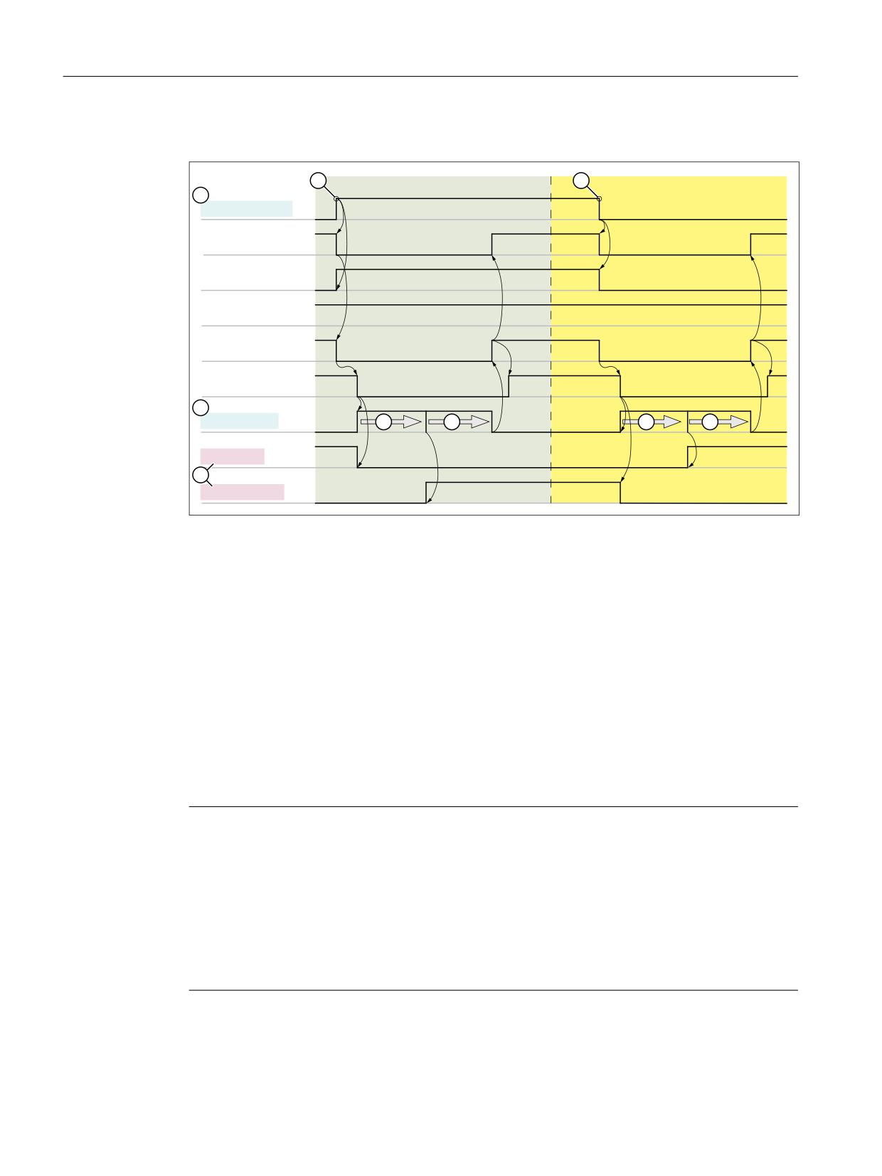
The internal sequence when changing over between star and delta after switching over the
FC17 control signal is described in the following: "YDelta" displayed.
1. DB31,
DBX21.5 = 0 (reset feedback signal "motor selected")
DB31,
DBX21.x = 1 (set request "2nd motor data set" corresponding to the interface
parameterization DB31,
DBX130.0 - 4)
2. DB31,
DBX93.7 == 0 (feedback signal "pulses enabled" was reset) ⇒
- Start FC17 timer
- FC17: "Y" = 0 (reset output for star contactor)
3. After the FC17 timer elapses (FC17: "TimeVal") ⇒
- FC17: "Y" = 1 (set output for delta contactor)
4. After the FC17 timer elapses again (FC17: "TimeVal") ⇒
- The pulses are again internally set
- DB31,
DBX93.7 == 1 (feedback signal "pulses enabled" was set)
- DB31,
DBX21.5 = 0 (feedback signal "motor selected" was set)
PLC
Function Manual, 10/2020, 6FC5397-0HP40-0BA1
269
Block descriptions
17.23 FC17: YDelta - star-delta switchover
Signal flow
6ZLWFKRYHU 6WDU ! GHOWD
6ZLWFKRYHU 'HOWD ! VWDU Z\H
① FC17 input: Signal for star-delta changeover
②
- Changeover: Star > delta
③
- Changeover: Delta > star
④ FC17 input: Parameterizable changeover time ""TimeVal"
⑤
- Wait time until the control of the output signal: "Y" or "delta"
⑥
- Wait time until pulse enable
⑦ FC17 output: Signals for contactor control
Further information
For additional explanations of motor speed adjustments, see:
• Function Manual Axes and Spindles; spindles; configurable gear adaptations
• Function Manual Axes and Spindles; speeds, setpoint/target value syst., closed-loop control
Note
Drive parameters
The following drive parameters must be considered for a star-delta changeover:
• p833 (dataset changeover configuration)
- Bit 0 = 1 (contactor switchover via application)
- Bit 1 = 0 (pulse cancellation by drive)
• p826 (motor changeover motor number)
• p827 (motor changeover status word bit number)
PLC
270
Function Manual, 10/2020, 6FC5397-0HP40-0BA1

Block descriptions
17.23 FC17: YDelta - star-delta switchover
Boundary conditions
• Block FC17 must be called absolutely and separately for each spindle.
• The drive pulses are deactivated during a star-delta changeover. The feedback signal to the
PLC is realized using:
- DB31,
DBX93.7 == 0 (pulses enabled)
- DB31,
DBX61.7 == 0 (current controller active)
– DB31,
DBX61.6 == 0 (speed controller active)
• For a spindle which is located in an axis mode such as M70 or SPOS, a start-delta changeover
is not carried out.
• For a closed-loop position controlled spindle (DB31,
DBX61.5 == 1 (position control
active) ), while the spindle is moving it is not permissible to carry out a star-delta changeover.
In the case of a fault, Alarm 25050 "Contour monitoring" is displayed, and the star-delta
changeover is not executed.
• Once the star-delta changeover has been initiated using FC17, it cannot be delayed by the
user, e.g. by waiting until the star-delta contactors change over during the course of
operation. A delay such as this must be implemented by the user in the PLC user program.
Declaration of the function
VAR_INPUT
YDelta:
BOOL;
SpindleIFNo:
INT;
TimeVal:
S5TIME ;
TimerNo :
INT;
END_VAR
VAR_OUTPUT
Y:
BOOL;
Delta:
BOOL;
END_VAR
VAR_IN_OUT
Ref:
WORD;
END_VAR
Description of formal parameters
Signal
Type
Type
Value range
Meaning
YDelta:
I
BOOL
0 (FALSE), 1 (TRUE)
Input signal for star-delta changeover
The changeover is initiated by a signal
change:
•
0 (FALSE): Star
•
1 (TRUE): Delta
SpindleIFNo:
I
INT
1 ...
Number of the spindle interface (number of
the associated machine axis)
PLC
Function Manual, 10/2020, 6FC5397-0HP40-0BA1
271
Block descriptions
17.24 FC18: SpinCtrl - spindle control
Signal
Type
Type
Value range
Meaning
TimeVal:
I
S5time
0, 50 ms ...
Switchover time
Configured
Internally effective
0
100
< 50
50
TimerNo:
I
INT
10 ...
Number of the timer being used
Y:
O
BOOL
0 (FALSE), 1 (TRUE)
Peripheral output for controlling the star
contactor
Delta:
O
BOOL
0 (FALSE), 1 (TRUE)
Peripheral output for controlling the delta
contactor
Ref:
I/O
WORD
Instance for status information. Internal use
Call example
CALL FC17 (
YDelta :=
I 45.7,
// Accept star/delta changeover from
input 45.7
SpindleIFNo :=
4,
// Spindle interface number: 4
// (Number of the associated machine
axis)
TimeVal :=
S5T#150ms,
// Changeover time: 150 ms
TimerNo :=
10,
// Timer: 10
Y :=
O 52.3,
// Control of the star contactor:
Output 52.3
Delta :=
O 52.4,
// Control of the delta contactor:
Output 52.4
Ref :=
MW 50
// Bit memory word 50
};
17.24
FC18: SpinCtrl - spindle control
Function
Block FC18 "SpinCtrl" can be used to control spindles and axes from the PLC. The block supports
the following functions:
• Position spindle
• Rotate spindle
• Oscillate spindle
• Traverse indexing axis
• Traverse positioning axis
Each function is activated by the positive edge of the appropriate initiation signal (start, stop).
This signal must remain at a logical "1" until the function has been acknowledged positively or
PLC
272
Function Manual, 10/2020, 6FC5397-0HP40-0BA1
Block descriptions
17.24 FC18: SpinCtrl - spindle control
negatively by InPos="1" or Error = "1". The output parameters are deleted when the relevant
trigger signal is reset and the function has been completed.
To be able to control an axis or spindle via the PLC, it must be activated for the PLC. This can, for
example, be achieved by calling the block with activation of the "Start" or "Stop" parameter.
When you do this, the block requests control of the spindle/axis from the NC.
The NC signals the status of the spindle/axis in the associated axis-specific interface DB31, ...
DBX68.4 - 7. Once the axis/spindle is operating under PLC control, the travel command for the
active status can be evaluated via the relevant axis-specific interface.
Upon completion ("InPos" is True, "Start" changes to zero), the axis/spindle check function is
switched to a neutral status using block FC18.
Alternatively, the PLC user program can also request control for the PLC before calling FC18.
By calling this function several times in succession, a better response by the spindle/axis can be
obtained as the changeover process in the FC can be omitted.
Activation through the PLC user program is executed in the corresponding spindle interface in
byte 8.
After return of the check, the spindle can again be programmed by the NC program.
Further information
• Function Manual Axes and Spindles; spindles
• Function Manual Axes and Spindles; positioning axes
• Function Manual Axes and Spindles; indexing axes
WARNING
Changed response behavior of the axis/spindle
If several block calls (FC18) have been programmed for the same axis/spindle in the PLC user
program, then the functions concerned must be interlocked by conditional calls in the user
program. The conditional call of a started block (parameter Start or Stop = TRUE) must be called
cyclically until the signal state of output parameter "Active" or "InPos" changes from 1 to 0.
PLC
Function Manual, 10/2020, 6FC5397-0HP40-0BA1
273

Block descriptions
17.24 FC18: SpinCtrl - spindle control
Note
Call note
FC18 must be called cyclically until signal "InPos" or, in the case of an error "Error", produces an
edge transition of 1 to 0. An additional "Start" or "Stop" is only possible for this spindle/axis when
the "InPos"/"Error" signal has supplied a value of 0. (the system must wait for at least one PLC
cycle with the next "Start" or "Stop"). This also applies when the assignment in data byte 8 on the
axial interface has been changed.
Abort
The function cannot be aborted by means of parameter "Start" or "Stop", but only by means of
the axial interface signals (e.g. delete distance-to-go). The axial interface also returns status
signals of the axis that may need to be evaluated (e.g. exact stop, traverse command).
Simultaneity
Several axes can be traversed simultaneously or subject to a delay by FC18 blocks. The upper
limit is only limited by the maximum number of axes of the NC.
Axis disable
For a set axis inhibit (DB31,
DBX1.4 == 1), the axis controlled via FC18 does not move. Only
a simulated actual value is generated. Same behavior as when traversing the axis for an axis
inhibit by the NC.
Functions
Function 1: Position spindle
Parameter
Meaning
Start :
0 → 1: Start the function
Funct :
1: Function number for "Position spindle"
Mode :
Positioning modes 1, 2, 3, 4 (refer to the paragraph below, "Explanation of the
formal parameters"
AxisNo :
Number of machine axis
Pos :
Position
FRate :
FRate ≠ 0: Positioning velocity
FRate = 0: Velocity corresponding to MD35300 $MA_SPIND_POSCTRL_VELO
InPos :
1: Position reached with "Exact stop fine"
Error :
1: Positioning error
State :
Error code
Function 2: Rotate spindle
Parameter
Meaning
Start :
0 → 1: Start the function
Stop :
0 → 1: Stop the function
Funct :
2: Function number for "Rotate spindle"
Mode :
Mode = 5: direction of rotation M4
Mode ≠ 5: direction of rotation M3
PLC
274
Function Manual, 10/2020, 6FC5397-0HP40-0BA1
Block descriptions
17.24 FC18: SpinCtrl - spindle control
Parameter
Meaning
AxisNo :
Number of machine axis
FRate :
Spindle speed
InPos :
1: Setpoint speed is output, also see DB31, ... DBX83.5 (spindle in the setpoint
range)
Error :
1: Positioning error
State :
Error code
Function 3: Oscillate spindle
Parameter
Meaning
Start :
0 → 1: Start the function
Stop :
0 → 1: Stop the function
Funct :
3: Function number for "Oscillate spindle"
AxisNo :
Number of machine axis
Pos :
Set gear stage
InPos :
1: Setpoint speed is output, also see DB31, ... DBX83.5 (spindle in the setpoint
range)
Error :
1: Positioning error
State :
Error code
Parameterized oscillation speed: MD35400 $MA_SPIND_OSCILL_DES_VELO
The function of the parameter "Pos" depends on the setting in MD35010
$MA_GEAR_STEP_CHANGE_ENABLE = <value>
<Val-
Pos
Function
ue>
0
0, 1, 2, ... 5
Oscillation
1
0
Oscillation with gear stage change M40
1
Oscillation with gear stage change M41
2
Oscillation with gear stage change M42
3
Oscillation with gear stage change M43
4
Oscillation with gear stage change M44
5
Oscillation with gear stage change M45
Function 4: Traverse indexing axes
Note
The modulo conversion can be compared with approaching the indexing position via POS[AX]
= CIC (value) in the part program.
Parameter
Meaning
Start :
0 → 1: Start the function
Funct :
4: Function number for "Indexing axis"
Mode :
Positioning mode 0, 1, 2, 3, 4
PLC
Function Manual, 10/2020, 6FC5397-0HP40-0BA1
275

Block descriptions
17.24 FC18: SpinCtrl - spindle control
Parameter
Meaning
AxisNo :
Number of machine axis
Pos :
Indexing position
FRate :
FRate ≠ 0: Positioning velocity
FRate = 0: Velocity corresponding to MD32060 $MA_POS_AX_VEL
InPos :
1: Position reached with "Exact stop fine"
Error :
1: Positioning error
State :
Error code
Function 5, 6, 7, 8: Position axes
Parameter
Meaning
Start :
0 → 1: Start the function
Funct :
5, 6, 7, 8: Function number for "Position axes"
Mode :
Positioning mode 0, 1, 2, 3, 4
AxisNo :
Number of machine axis
Pos :
Position
FRate :
FRate ≠ 0: Positioning velocity
FRate = 0: Velocity corresponding to MD32060 $MA_POS_AX_VELO
InPos :
1: Position reached with "Exact stop fine"
Error :
1: Positioning error
State :
Error code
Function 9: Rotate spindle with automatic gear stage selection:
Parameter
Meaning
Start :
0 → 1: Start the function
Stop :
0 → 1: Stop the function
Funct :
9: Function number for "Rotate spindle with gear stage selection"
Mode :
Mode = 5: direction of rotation M4
Mode ≠ 5: direction of rotation M3
AxisNo :
Number of machine axis
FRate :
Spindle speed
InPos :
1: Setpoint speed is output
Error :
1: Positioning error
State :
Error code
Function 10, 11: Rotate spindle with constant cutting rate
The "Constant cutting rate" function (G96) must be active in the NC.
Parameter
Meaning
Start :
0 → 1: Start the function
Stop :
0 → 1: Stop the function
Funct :
10: Function number for "Constant cutting rate (m/min)"
11: Function number for "Constant cutting rate (feet/min)"
PLC
276
Function Manual, 10/2020, 6FC5397-0HP40-0BA1
Block descriptions
17.24 FC18: SpinCtrl - spindle control
Parameter
Meaning
Mode :
Mode = 5: direction of rotation M4
Mode ≠ 5: direction of rotation M3
AxisNo :
Number of machine axis
FRate :
Cutting rate
InPos :
1: Setpoint speed is output
Error :
1: Positioning error
State :
Error code
Declaration of the function
FUNCTION FC18: VOID
//SpinCtrl
VAR_INPUT
Start :
BOOL;
Stop :
BOOL;
Funct :
BYTE ;
Mode :
BYTE ;
AxisNo :
INT;
Pos :
REAL;
FRate :
REAL;
END_VAR
VAR_OUTPUT
InPos :
BOOL;
Error :
BOOL;
State :
BYTE ;
END_VAR
Description of formal parameters
Signal
Type
Type
Value range
Meaning
Start:
I
BOOL
0 (FALSE),
0 → 1: Start the function
1 (TRUE)
Stop:
I
BOOL
0 (FALSE),
0 → 1: Stop the function
1 (TRUE)
PLC
Function Manual, 10/2020, 6FC5397-0HP40-0BA1
277
Block descriptions
17.24 FC18: SpinCtrl - spindle control
Signal
Type
Type
Value range
Meaning
Funct:
I
BYTE
1, 2, 3, ... 11
1: Position spindle
2: Rotate spindle
3: Oscillate spindle
4: Indexing axis
5: Positioning axis metric
6: Positioning axis inch
7: PosAxis metric with handwheel override
8: PosAxis inch with handwheel override
9: Rotate spindle with automatic gear
stage selection
10: Rotate spindle with constant cutting
rate (m/min)
11: Rotate spindle with constant cutting
rate (feet/min)
Mode:
I
BYTE
0, 1, 2, ... 5
0: Positioning to absolute position
1: Positioning incremental
2: Positioning along the shortest path
3: Positioning absolute, positive approach
direction
4: Positioning absolute, negative ap-
proach direction
5: Direction of rotation as for M4
AxisNo:
I
INT
1, 2, 3, ... 31
Number of the axis/spindle to be traversed
Pos:
I
REAL
∓ 0.1469368 I
Rotary axis: Degrees
-38 to
Indexing axis: Indexing position
∓ 0.1701412 I
Linear axis: mm or inches
+39
FRate:
I
REAL
∓ 0.1469368 I
Rotary axis and spindle: [rev/min]
-38 to
Linear axes: [m/min] or [ft/min]
∓ 0.1701412 I
+39
InPos:
O
BOOL
0 (FALSE),
1: Position reached or function executed
1 (TRUE)
Error:
O
BOOL
0 (FALSE),
1: Error
1 (TRUE)
State:
O
BYTE
0, 1, 2, ... 255
Error code
Error identifiers
An error is active, if: Parameter "Error" == 1 (TRUE)
The cause of the error is displayed in: Parameter "State"
State
Meaning
Cause of the error on the PLC side
1
Several functions of the axis/spindle were activated simultaneously
20
A function was started without the position being reached
PLC
278
Function Manual, 10/2020, 6FC5397-0HP40-0BA1

Block descriptions
17.24 FC18: SpinCtrl - spindle control
State
Meaning
30
The axis/spindle was transferred to the NC while still in motion
40
The axis is programmed by the NC program, NC internal error
50
Permanently assigned PLC axis: Traverses (JOG) or references
60
Permanently assigned PLC axis: Channel status does not permit a start
Cause of the error on the NC side
100
Incorrect position programmed for axis/spindle (corresponds to alarm 16830)
101
Programmed speed is too high
102
Incorrect value range for constant cutting rate (corresponds to alarm 14840)
104
Following spindle: Illegal programming (corresponds to alarm 22030)
105
No measuring system available (corresponds to alarm 16770)
106
Axis positioning still active (corresponds to alarm 22052)
107
Reference mark not found (corresponds to alarm 22051)
108
No transition from speed control to position control (corresponds to alarm 22050)
109
Reference mark not found (corresponds to alarm 22051)
110
Velocity/speed is negative
111
Setpoint speed == zero
112
Invalid gear stage
115
Programmed position has not been reached
117
G96/G961 is not active in the NC
118
G96/G961 is still active in the NC
120
Axis is not an indexing axis (corresponds to alarm 20072)
121
Indexing position error (corresponds to alarm 17510)
125
DC (shortest distance) not possible (corresponds to alarm 16800)
126
Absolute value minus not possible (corresponds to alarm 16820)
127
Absolute value plus not possible (corresponds to alarm 16810)
128
No transverse axis available for diameter programming (corresponds to alarm 16510)
130
Software limit switch plus (corresponds to alarm 20070)
131
Software limit switch minus (corresponds to alarm 20070)
132
Working area limit plus (corresponds to alarm 20071)
133
Working area limit minus (corresponds to alarm 20071)
134
Frame not permitted for indexing axis
135
Indexing axis with "Hirth joint" is active (corresponds to alarm 17501)
136
Indexing axis with "Hirth joint" is active and axis not referenced (corresponds to alarm 17503)
137
Spindle operation not possible for transformed spindle/axis (corresponds to alarm 22290)
138
Axis: Coordinate system-specific working area plus violated (corresponds to alarm 20082)
139
Axis: Coordinate system-specific working area minus violated (corresponds to alarm 20082)
System error
200
corresponds to alarm 450007
Alarm numbers: Further information Diagnostics Manual
PLC
Function Manual, 10/2020, 6FC5397-0HP40-0BA1
279
Block descriptions
17.24 FC18: SpinCtrl - spindle control
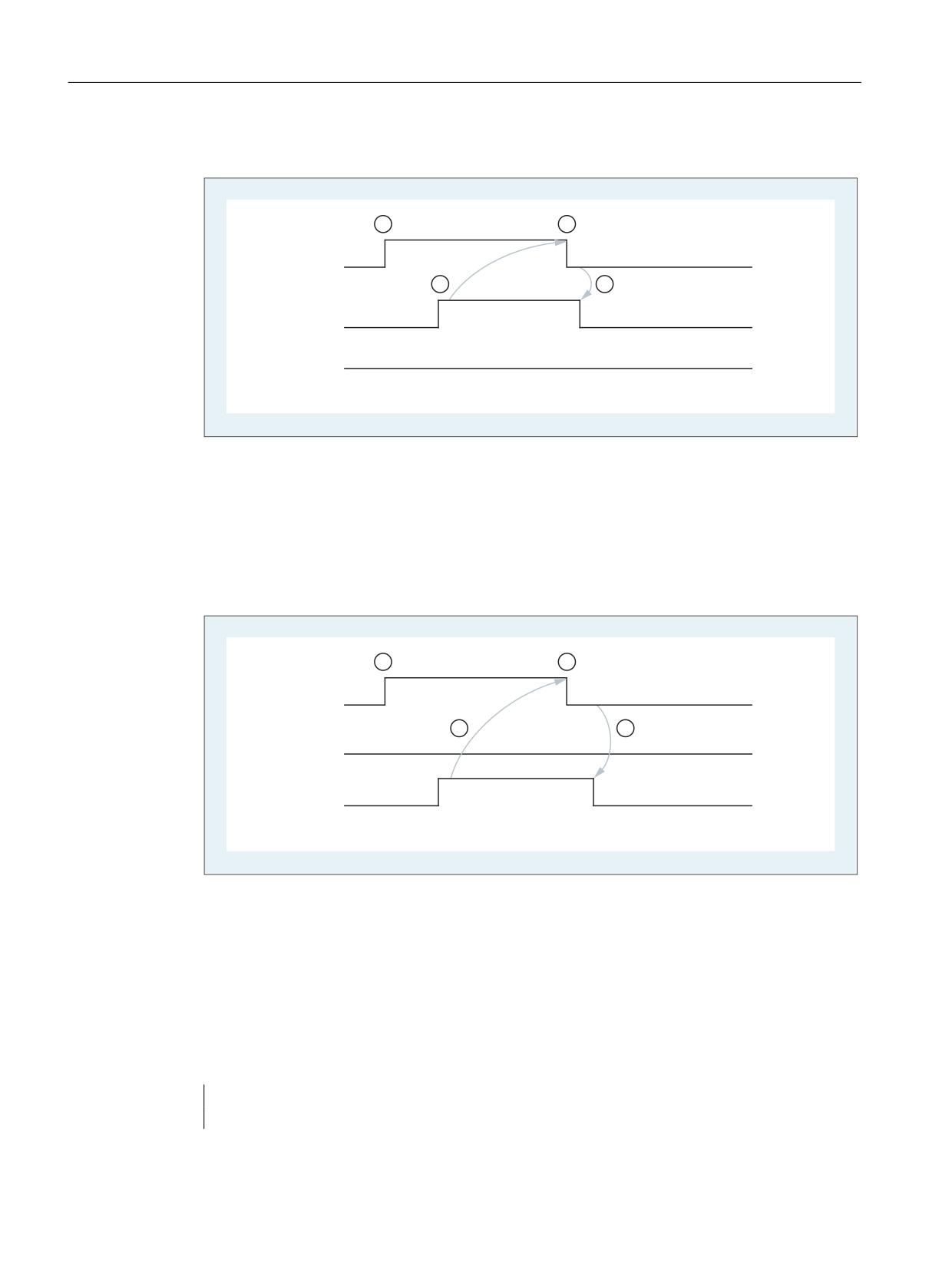
Signal sequence: Normal case
6WDUW
,Q3RV
(UURU
6WDUW(UU
① PLC user program: Function start using a positive edge: 0 → 1
② NC: Positive acknowledgment, function executed / position reached
③ PLC user program: Reset after detecting the positive acknowledgment
④ FC18: Reset of the positive acknowledgment
Signal sequence: Error case
6WDUW
,Q3RV
(UURU
6WDUW(UU
① PLC user program: Function start using a positive edge: 0 → 1
② NC: Negative acknowledgment, error occurred
③ PLC user program: Reset after detecting the negative acknowledgment
④ FC18: Reset of the negative acknowledgment
Call examples
Example 1: Position spindle:
//Positive acknowledgment resets Start:
U M112.0;
//InPos
PLC
280
Function Manual, 10/2020, 6FC5397-0HP40-0BA1
Block descriptions
17.24 FC18: SpinCtrl - spindle control
R M 100.0;
//Start
//Negative acknowledgment, after error evaluation (state: MB114) reset with T12 start
U M113.0;
// Error
U E 6.4;
//Key T12
R M 100.0;
//Start
//Start with T13
U E 6.3;
//Key T13
UN M 112.0;
//Restart only when InPos or Error = 0
UN M 113.0;
S M 100.0;
CALL FC18(
Start := M100.0,
Stop := FALSE,
Funct := B#16#1,
//Position spindle
Mode := B#16#2,
//Shortest path
AxisNo :=
5,
Pos := MD104,
FRate := MD108,
InPos := M112.0,
Error := M113.0,
State := MB114);
Example 2: Start spindle rotation:
CALL FC18(
Start := M100.0,
Stop := FALSE,
Funct := B#16#2,
//Rotate spindle
Mode := B#16#5,
//Direction of rotation as for M4
AxisNo :=
5,
Pos :=
0.0,
FRate := MD108,
InPos := M112.0,
Error := M113.0,
State := MB114);
Example 3: Start spindle oscillation
CALL FC18(
Start := M100.0,
Stop := FALSE,
Funct := B#16#3,
//Oscillate spindle
Mode := B#16#0,
AxisNo :=
5,
Pos :=
0.0,
PLC
Function Manual, 10/2020, 6FC5397-0HP40-0BA1
281
Block descriptions
17.25 FC19: MCP_IFM - transfer of MCP signals to interface
FRate := MD108,
InPos := M112.0,
Error := M113.0,
State := MB114);
Example 4: Traverse indexing axis
CALL FC18(
Start := M100.0,
Stop := FALSE,
//Not used
Funct := B#16#4,
//Traverse indexing axis
Mode := B#16#0,
//Absolute positioning
AxisNo :=
4,
Pos := MD104,
//Default setting in REAL: 1.0;2.0;..
FRate := MD108,
InPos := M112.0,
Error := M113.0,
State := MB114);
Example 5: Position axes
CALL FC18(
Start := M100.0,
Stop := FALSE,
//Not used
Funct := B#16#5,
//Position axes
Mode := B#16#1,
//Position incrementally
AxisNo :=
6,
Pos := MD104,
FRate := MD108,
InPos := M112.0,
Error := M113.0,
State := MB114);
17.25
FC19: MCP_IFM - transfer of MCP signals to interface
Function
Block FC19 "MCP_IFM" (M version e.g. MCP 483) is used to transfer data from the machine
control panel to the NC/PLC interface:
• Modes
• Axis selections
• WCS/MCS switchover
• Traversing keys
• Spindle and feedrate override
PLC
282
Function Manual, 10/2020, 6FC5397-0HP40-0BA1
Block descriptions
17.25 FC19: MCP_IFM - transfer of MCP signals to interface
• Program control
• Keyswitch
The following specifications apply to the feedrate override, axis travel keys and INC keys
depending on the active mode or on the coordinate system selected:
• Feedrate override
- The feedrate override is transferred to the interface of the selected channel (DB21,
… .DBB4) and to the interface of all axes (DB31, … .DBB0).
- The feedrate override signals are transferred to the NC channel in addition to the "Rapid
traverse override" (DBB5) interface byte if the "Feedrate override for rapid traverse
effective" HMI signal is set (exception: Switch setting "Zero"). "Rapid traverse override
effective" is also set with this HMI signal.
• Axis traversing keys
- When the MCS is selected, the signals are transferred to the interface of the selected
machine axis.
- When the WCS is selected, the signals are transferred to the geometry axis interface of the
parameterized channel.
- When the system is switched between MCS and WCS, the active axes are generally
deselected.
The LEDs on the machine control panel derived from the selections in the feedback.
Feedrate and spindle Start/Stop are not transferred to the interface, but output modally as a
"FeedHold" or "SpindleHold" signal. The user can link these signals to other signals leading to a
feed or spindle stop (this can be implemented, e.g. using the appropriate input signals in FC10:
AL_MSG). The associated LEDs are activated at the same time.
If the machine control panel fails, the signals it outputs are preset to zero; this also applies to
"FeedHold" and "SpindleHold" output signals.
FC19 or also FC24, FC25, FC26 can be called a multiple number of times in a single PLC cycle. In
this case, the first call in the cycle drives the LED displays. Furthermore, all actions of the
parameterized block are carried out in the first call:
• Provisioning of the mode group interface in accordance with parameter "BAGNo" (mode
group number)
• Provisioning of the channel interface in accordance with parameter "ChanNo"
• Provisioning of the axis interface of all axes up to the maximum configured axis number
• Provisioning of the spindle interface in accordance with parameter "SpindleIFNo"
In the following calls, only a reduced level of processing of the channel and mode group
interface takes place. The geometry axes are supplied with directional data only in the first block
call in the cycle.
Single block processing can be selected/deselected only in the first call in the cycle.
The second machine control panel can be processed if parameter "ModeGroupNo" has been
increased by B#16#10. When parameterizing, the mode group number is contained in the lower
nibble.
"BAGNo" = 0 or B#16#10 ⇒ mode group signals are not processed.
PLC
Function Manual, 10/2020, 6FC5397-0HP40-0BA1
283
Block descriptions
17.25 FC19: MCP_IFM - transfer of MCP signals to interface
"ChanNo" = 0 ⇒ no processing of the channel signals.
The INC selections are transferred to the mode group interface. The activation for this
specification is done via the DB10.DBX57.0 (INC inputs in BAG area active) through this block
once after power up.
Furthermore, two machine control panels can still be handled in parallel by the FC19 block. The
first call of the block transfers the keyswitch position to the NC interface signals. Mutual locking
of the axis selections for equally assigned axes is not supported. The same applies to
provisioning the channel, mode group, and spindle interfaces.
Cartesian manual traversing
The R11 direction key on the machine control panel (at the left next to WCS/MCS) makes the
"Manual traversing in tool orientation" function available. This requires activation via the FB1
input parameter "MCP_IF_TCS" in DB7.
For "MCP_IF_TCS" = TRUE, the R11 key switches to "Manual traversing in tool orientation". In this
case, the Z key (R3) is permanently selected with FC19. The direction keys are effective for the
3rd geometry axis of the respective channel.
Flexible axis configuration
Each axis selection key can be assigned to an arbitrary machine axis. FC19 can select up to 9
machine axes using the keys of the R key group. If machine axes with a number greater than 9
are to be selected using the axis selection keys, the assignment can be dynamically changed. The
new assignment only takes effect when the axis selection is changed.
The preset machine axes 1 to 9 correspond to the axis selection keys 1 to 9 (R1 to R9 in the R key
group). The number of usable axis selection keys can be limited by the value in DB10.DBW30
(symbolic name MCP1MaxAxis or MCP2MaxAxis). If the value 0 (default setting) is used, all 9
axis selection keys that are assigned a machine axis via an axis table can be used.
The assignment or modification of axis selection keys for the machine axes is explained in the
PLC manual in Chapter "Flexible axis configuration".
Example
Machine axes 10 to 18 are to be selected on the axis selection keys R1 to R9 using a free key of
the MCP. We recommend that you proceed as follows:
• Reserve free key on MCP
• Evaluate this key as a flip-flop
• Evaluate the flip-flop output as positive and negative edge
• On a positive edge, enter axis numbers 10 to 18 (remember to enter hexadecimal values) in
the axis table DB10.DBB8 - 16 (symbolic name MCP1AxisTbl[1..9]) and activate the LED via
this key
• On a negative edge, enter the preset axis numbers 1 to 9 in the axis table DB10.DBB8 - 16
(symbolic name MCP1AxisTbl[1..9]) again and deactivate the LED via this key
PLC
284
Function Manual, 10/2020, 6FC5397-0HP40-0BA1
Block descriptions
17.25 FC19: MCP_IFM - transfer of MCP signals to interface
Axis selection from the HMI
In addition to the 9 axis selection keys of the MCP, the active axis can also be selected in the HMI.
The axis selection from the HMI is then only taken over for the MCP if the selected channel in the
HMI matches that at FC19. With axis selection from the HMI, an initial attempt is made, as with
axis selection using the axis selection keys of the MCP, to find an assignment between the
selected axis number and the actual machine axis in the axis table of the NC-DB, refer to section
"Flexible axis configuration".
This will ensure that the same machine axis is selected with axis selection from the HMI as would
have been if the corresponding axis selection key of the MCP had been selected. If an assignment
is not possible, the axis number selected from the HMI is directly used as machine axis. As a
consequence it is possible to select axes that cannot be selected via the MCP.
Single block mode
Pressing the single block key activates the single block mode and, if the key is pressed again, the
single block mode is deactivated. If the mode is called several times for one MCP, the block
transfers single block mode state from the channel of the first call to the channels of the
subsequent calls.
Axis selections via the function "Selection of JOG axis via HMI"
FC19 supports the function "Selection of JOG axis via HMI" from software version 4.92. This
functionality can be used as an alternative to or as extended operation of the axis selection keys
of the MCP.
The prerequisite for supporting this function is explained in the PLC manual in chapter "Selecting
the JOG axis via HMI".
FC19 then only takes over a machine axis selected via HMI if the channel view of the HMI
matches the input parameter (parameter "ChanNo" of FC19). Only this can ensure that axis
selection is performed.
If a selection is made via HMI, axis selection is performed and the associated LED on the MCP axis
selection keys is activated in accordance with the axis table in DB10 (symbolic name "NC")
(alternative operation). If assignment is not possible, the axis is selected with FC19 and all LEDs
of the axis selection keys (R1 to R9) are deactivated (supplementary operation). In this case,
feedback from the selected axis is performed only via the corresponding channel DB or the view
in the HMI.
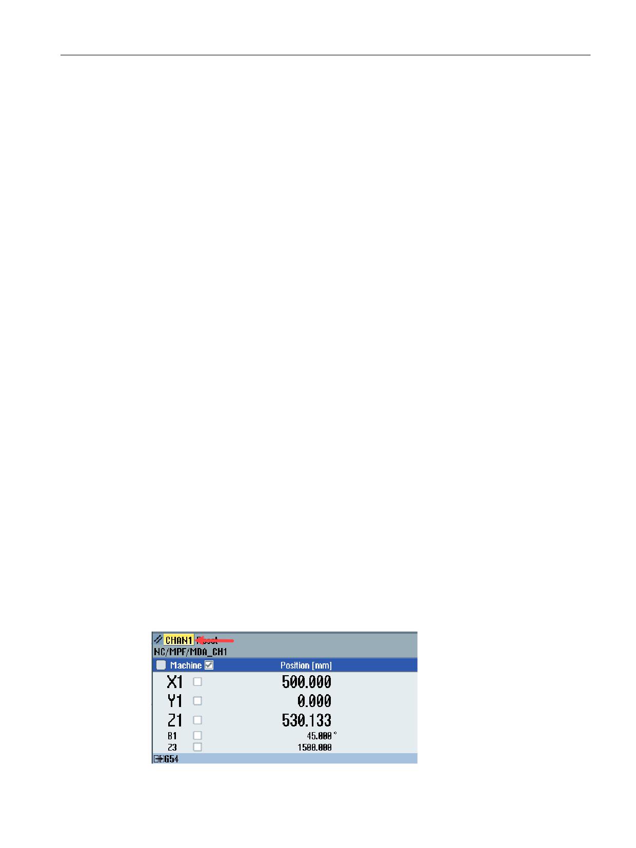
The following figure shows SINUMERIK Operate with channel 1 by way of example. The setting
of parameter "ChanNo" of FC19 for this is "ChanNo := B#16#1".
PLC
Function Manual, 10/2020, 6FC5397-0HP40-0BA1
285
Block descriptions
17.25 FC19: MCP_IFM - transfer of MCP signals to interface
Selection of geometry axes
Geometry axes are only processed in the first block call in the cycle. Special attention must be
paid to this, in particular, when the block is called multiple times for a number of channels. For
example, if 2 channels are programmed in one cycle with multiple calls, it must be ensured that
the block call that will implement the selection of geometry axes is called first in the cycle.
Call examples
Single call
Call of the block for the 1st MCP, mode group 1, channel 1, spindle: Axis 4
CALL FC19(
// Signals to interface
BAGNo :=
B#16#1,
// Mode group no. 1
ChanNo :=
B#16#1,
// Channel no. 1
SpindleIFNo :=
B#16#4,
// Spindle interface number = 4
FeedHold :=
m30.0,
// Feed stop signal modal
SpindleHold :=
m30.1);
// Spindle stop modal
Multiple call
Call of the block for the 1st MCP, mode group 1, channel 1, spindle: Axis 4
CALL FC19(
// Signals to interface
BAGNo :=
B#16#1,
// Mode group no. 1
ChanNo :=
B#16#1,
// Channel no. 1
SpindleIFNo :=
B#16#4,
// Spindle interface number = 4
FeedHold :=
m30.0,
// Feed stop signal modal
SpindleHold :=
m30.1);
// Spindle stop modal
Call of the block for the 1st MCP, without mode group, channel 2, without spindle
CALL FC19(
// Signals to interface
BAGNo :=
B#16#0,
// No provision of the mode group
signals
ChanNo :=
B#16#2,
// Channel no. 2
SpindleIFNo :=
B#16#0,
// No provision of spindle signals
FeedHold :=
m30.0,
// Feed stop signal modal
SpindleHold :=
m30.1);
// Spindle stop modal
Call for 2 MCPs (1st MCP responsible for channel 1, 2nd MCP responsible for channel 2)
Call of the block for the 1st MCP, mode group 1, channel 1, spindle: Axis 4
CALL FC19(
// Signals to interface
BAGNo :=
B#16#1,
// Mode group no. 1
ChanNo :=
B#16#1,
// Channel no. 1
SpindleIFNo :=
B#16#4,
// Spindle interface number = 4
FeedHold :=
m30.0,
// Feed stop signal modal
SpindleHold :=
m30.1);
// Spindle stop modal
PLC
286
Function Manual, 10/2020, 6FC5397-0HP40-0BA1

Block descriptions
17.25 FC19: MCP_IFM - transfer of MCP signals to interface
Call of the block for the 2nd MCP, Mode Group 1, Channel 2, without spindle
CALL FC19(
// Signals to interface
BAGNo :=
B#16#11,
// Mode group no. 1
ChanNo :=
B#16#2,
// Channel no. 2
SpindleIFNo :=
B#16#0,
// No provision of spindle signals
FeedHold :=
m40.0,
// Feed stop signal modal
SpindleHold :=
m40.1);
// Spindle stop modal
Declaration of the function
FUNCTION FC19: VOID
//Symbolic name: MCP_IFM
VAR_INPUT
BAGNo :
BYTE ;
ChanNo:
BYTE ;
SpindleIFNo:
BYTE ;
END_VAR
VAR_OUTPUT
FeedHold :
BOOL;
SpindleHold :
BOOL;
END_VAR
BEGIN
END_FUNCTION
Description of formal parameters
Signal
Type
Type
Value range
Meaning
BAGNo :
I
BYTE
B#16#00 -
1st MCP: Number of mode group to which
B#16#0A
the mode signals are transferred
B#16#10 -
2nd MCP: Number of mode group to
B#16#1A
which the mode signals are transferred
ChanNo:
I
BYTE
B#16#00 -
Number of the channel to which the chan-
B#16#0A
nel signals are transferred
SpindleIFNo:
I
BYTE
0 - 31
Number of the axis/spindle to which the
(B#16#1F)
spindle data is transferred (number of the
associated machine axis)
FeedHold:
O
BOOL
0 (FALSE),
Feed stop from MCP, modal
1 (TRUE)
SpindleHold:
O
BOOL
0 (FALSE),
Spindle stop from MCP, modal
1 (TRUE)
PLC
Function Manual, 10/2020, 6FC5397-0HP40-0BA1
287
Block descriptions
17.25 FC19: MCP_IFM - transfer of MCP signals to interface
MCP selection signals to the user interface
Keyswitch
The signals are transmitted for the very first call, irrespective of whether it is for MCP1 or MCP2.
Source:
Target:
MCP switches
Interface DB
Position 0
DB10.DBX56.4
Position 1
DB10.DBX56.5
Position 2
DB10.DBX56.6
Position 3
DB10.DBX56.7
Operating modes and machine functions
Transmission is performed after each call. If multiple calls have the same BagNo (mode group
number) parameter, the last call wins. If multiple calls have different BagNo (mode group
number) parameters, the key values to all corresponding mode group ranges are entered in the
DB11.
Source:
Target:
MCP keys
Interface DB (parameter BAGNo)
Display for BAG 1
AUTOMATIC
DB11.DBX0.0
MDI
DB11.DBX0.1
JOG
DB11.DBX0.2
REPOS
DB11.DBX1.1
REF
DB11.DBX1.2
TEACH IN
DB11.DBX1.0
INC 1 ... 10 000, INC Var.
DB11.DBX2.0 - 2.5
Direction keys and rapid traverse override
The signals are transmitted only in the first call for each MCP called if WCS is active for the
geometry axis selected at the time. The interface signals are zeroed for the geometry axes that
are not selected.
Source:
Target:
MCP keys
Interface DB (parameter ChanNo)
Direction key +
DB21,
DBX12.7
Direction key -
DB21,
DBX12.6
Rapid traverse override
DB21,
DBX12.5
Direction key +
DB21,
DBX16.7
Direction key -
DB21,
DBX16.6
Rapid traverse override
DB21,
DBX16.5
Direction key +
DB21,
DBX20.7
Direction key -
DB21,
DBX20.6
Rapid traverse override
DB21,
DBX20.5
PLC
288
Function Manual, 10/2020, 6FC5397-0HP40-0BA1

Block descriptions
17.25 FC19: MCP_IFM - transfer of MCP signals to interface
The signals are transmitted only in the first call for each MCP called if MCS is active for the
machine axis selected at the time. The interface signals are zeroed for the deselected machine
axes.
Source:
Target:
MCP keys
Interface DB (all axis DBs)
Direction key +
DB31,
DBX4.7
Direction key -
DB31,
DBX4.6
Rapid traverse override
DB31,
DBX4.5
Override
The signals are transmitted in each call for each called MCP to the channel DB in accordance with
the ChanNo parameter.
Source:
Target:
MCP switches
Interface DB (parameter ChanNo)
Feedrate override
DB21,
DBB4
Source:
Target:
MCP switches
Interface DB (all axis DBs)
Feedrate override
DB31,
DBB0
The signals are transmitted only in the first call for
each MCP called if MCS is active for the machine
axis selected at the time. For MCP1, the signals are
also transmitted to all other machine axes.
Spindle override
DB31,
DBB19 (parameter SpindleIFNo)
The signals are transmitted in each call for each
called MCP in accordance with the SpindleIFNo
parameter.
Channel signals
The signals are transmitted in each call for each called MCP to the channel DB in accordance with
the ChanNo parameter.
Pressing the single block key activates single block mode and pressing the key again deactivates
single block mode. If the mode is called several times for one MCP, the block transfers single
block mode state from the channel of the first call to the channels of the subsequent calls.
Source:
Target:
MCP keys
Interface DB (parameter ChanNo)
NC start
DB21,
DBX7.1
NC stop
DB21,
DBX7.3
RESET
DB21,
DBX7.7
Single block
DB21,
DBX0.4
PLC
Function Manual, 10/2020, 6FC5397-0HP40-0BA1
289

Block descriptions
17.25 FC19: MCP_IFM - transfer of MCP signals to interface
Feedrate, spindle signals
The signals are only transmitted in the first call for each MCP called.
Source:
Target:
MCP keys
FC output parameters
Feed stop
Parameter: "FeedHold" linked with memory, LEDs
Feed enable
are controlled
Spindle stop
Parameter: "SpindleHold" linked with memory, LEDs
Spindle enable
are controlled
Cartesian manual traversing
In TCS mode, the signals are always transmitted for each call to geometry axis 3 in accordance
with the ChanNo parameter.
Source:
Target:
MCP keys
Interface DB (parameter ChanNo)
R11 direction key
DB21,
DBB392
Direction key +
DB21,
DBX20.7
Direction key -
DB21,
DBX20.6
Checkback signals from user interface for controlling displays
Operating modes and machine functions
The signals are transmitted on each call for each called MCP from the interface DB in accordance
with the BagNo (mode group number) parameter. Depending on the MCP, the last call wins to
display its BagNo (mode group number) parameter on the LEDs.
Target:
Source:
MCP LEDs
Interface DB (parameter BAGNo)
Display for BAG 1
AUTOMATIC
DB11.DBX6.0
MDI
DB11.DBX6.1
JOG
DB11.DBX6.2
REPOS
DB11.DBX7.1
REF
DB11.DBX7.2
TEACH IN
DB11.DBX7.0
The signals are transmitted accordingly on the first call for each called MCP from the range of the
BagNo (mode group number) parameter.
Target:
Source:
MCP LEDs
Interface DB (parameter BAGNo)
Display for BAG 1
INC 1 ... 10 000, INC Var.
DB11.DBX8.0 - 8.5
PLC
290
Function Manual, 10/2020, 6FC5397-0HP40-0BA1

Block descriptions
17.25 FC19: MCP_IFM - transfer of MCP signals to interface
Channel signals
The signals are transmitted on each call for each called MCP from the interface DB in accordance
with the ChanNo parameter. Depending on the MCP, the last call wins to display its ChanNo
parameter on the LEDs.
Target:
Source:
MCP LEDs
Interface DB (parameter ChanNo)
NC start
DB21,
DBX35.0
NC stop
DB21,
DBX35.2 or DB21,
DBX35.3
Single block
DB21,
DBX0.4
Note
Direction key LEDs are controlled by operating the direction keys.
The axis selection LED is set after successful selection.
The WCS/MCS LED indicates the current mode: LED on --> WCS active, LED off --> MCS active.
The LEDs of rapid traverse and reset are not activated.
Call example
CALL FC19(
//Machine control panel M variants signals to interface
BAGNo :=
B#16#1,
// Mode group no. 1
ChanNo :=
B#16#1,
// Channel no. 1
SpindleIFNo :=
B#16#4,
// Spindle interface number = 4
FeedHold :=
m22.0,
// Feed stop signal modal
SpindleHold :=
db2.dbx151.0);
//Spindle stop modal in
//message DB
With these parameter settings, the signals are sent to the first mode group, the first channel and
all axes. In addition, the spindle override is transferred in the 4th axis/spindle interface. The feed
hold signal is passed to bit memory 22.0 and the spindle stop signal to data block DB2, data bit
151.0.
Reconnecting the axis selections
To ensure a flexible assignment of the axis selection keys to the appropriate axis or spindle,
FC19 needs not be modified or reprogrammed. The axis number simply has to be entered in
axis table starting from DB10.DBB8 as required.
Example
The spindle is defined as the 4th machine axis and is to be selected via axis key 9 (key R9 of the
R key group).
Solution:
PLC
Function Manual, 10/2020, 6FC5397-0HP40-0BA1
291
Block descriptions
17.26 FC21: Transfer - data exchange NC/PLC
The value 4 must be entered in DB10 byte16 (symbolic name MCP1AxisTbl[9]) for the 4th axis.
CALL FC19(
// Signals to interface
BAGNo :=
B#16#1,
// Mode group no. 1
ChanNo :=
B#16#1,
// Channel no. 1
SpindleIFNo :=
B#16#4,
// Spindle interface number = 4
FeedHold :=
m30.0,
// Feed stop signal modal
SpindleHold :=
m30.1);
// Spindle stop modal
See also
Flexible axis configuration (Page 103)
Selection of JOG axis via HMI (Page 104)
17.26
FC21: Transfer - data exchange NC/PLC
17.26.1
Function
Block FC21 is used to exchange data between the PLC and NC. The data are immediately
transferred when FC21 is called - not waiting until the next basic PLC program cycle starts.
The data transfer is activated by calling the block FC21 with parameter "Enable" =1
Functions
The block provides the following functions:
• Synchronized action signals: PLC → NC channel
• Synchronized action signals: NC channel → PLC
• Fast data exchange PLC-NC (read function in NC)
• Fast data exchange PLC-NC (write function in NC)
• Update signals to the NC channel
• Update signals to axes (data byte 2 of the user interface)
• Update signals to axes (data byte 4 of the user interface)
17.26.2
Declaration of the function
Declaration of the function
VAR_INPUT
Enable : BOOL;
Funct : BYTE ;
PLC
292
Function Manual, 10/2020, 6FC5397-0HP40-0BA1
Block descriptions
17.26 FC21: Transfer - data exchange NC/PLC
S7Var : ANY ;
IVar1 : INT ;
IVar2 : INT ;
END_VAR
VAR_OUTPUT
Error : BOOL;
ErrCode : INT ;
END_VAR
17.26.3
Explanation of formal parameters
Explanation of formal parameters
Signal
Type
Type
Value range
Description
Enable:
I
BOOL
0 (FALSE), 1 (TRUE)
1:
Transferring data
Funct:
I
BYTE
1, 2, 3, ... 7
1:
Synchronized actions at channel
2:
Synchronized actions from
channel
3:
Read data
4:
Write data
5:
Control signals to channel
6:
Control signals to axis
7:
Control signals to axis
S7Var :
I
ANY
S7 data storage area
Depends on "Funct"
IVAR1:
I
INT
---
Depends on "Funct"
IVAR2:
I
INT
---
Depends on "Funct"
Error:
O
BOOL
0 (FALSE), 1 (TRUE)
1:
An error is active
ErrCode:
O
INT
---
Depends on "Funct"
17.26.4
Function 1, 2: Signals synchronized actions to / from Channel
Synchronized actions can be disabled or enabled by the PLC.
The data area is stored on the user interface in DB21,
DBB300 ...307 (to channel) and
DB21,
DBB308 ...315 (from channel). The parameter "S7Var" is not evaluated for this
function, but must be assigned an actual parameter (see call example). The data are transferred
to/from the NC as soon as FC21 is processed.
Signal
Type
Type
Value range
Description
Enable:
I
BOOL
0 (FALSE), 1 (TRUE)
1:
Transferring data
Funct:
I
BYTE
1, 2
1:
to channel
2:
from channel
PLC
Function Manual, 10/2020, 6FC5397-0HP40-0BA1
293

Block descriptions
17.26 FC21: Transfer - data exchange NC/PLC
Signal
Type
Type
Value range
Description
S7Var :
I
ANY
S7 data storage area
Not used
IVAR1:
I
INT
1, 2, ... max. channel number
Channel number
Error:
O
BOOL
0 (FALSE), 1 (TRUE)
1:
An error is active
ErrCode:
O
INT
1, 10
1:
"Funct" invalid
10:
Channel number invalid
Call example:
FUNCTION FC100: VOID
VAR_TEMP
myAny: ANY ;
END_VAR
BEGIN
NETWORK
//Deactivate synchronized actions with ID3, ID10 and ID31 in NC channel 1 :
SYAK:
AUF
DB21;
SET;
S
DBX300
//ID3
.2;
S
DBX301
//ID10
.1;
S
DBX303
//ID31
.6;
L
B#16#1
;
T
MB11;
SPA
TRAN;
//Synchronized actions from NCK channel 1:
SYVK:
L B#16#2;
T MB11;
TRAN:
CALL FC21 (
Enable
:= M 10.0,
//if TRUE, FC 21 active
Funct
:= MB 11,
S7Var
:= #myAny,
//Not used
IVAR1
:= 1,
//Channel no.
IVAR2
:= 0,
Error
:= M 10.1,
ErrCode
:= MW 12);
END_FUNCTION
PLC
294
Function Manual, 10/2020, 6FC5397-0HP40-0BA1
Block descriptions
17.26 FC21: Transfer - data exchange NC/PLC
17.26.5
Function 3, 4: Fast data exchange PLC-NC
General
A separate, internal data area is provided as interface to allow the fast exchange of data between
the NC and the PLC. The interface encompasses 4096 bytes. PLC access operations (reading/
writing) are realized via FC21. The internal structure of the interface is solely defined by the user,
and must have precisely the same definition on the NC and PLC sides.
This data can be accessed by the NC program with the commands $A_DBB[x], $A_DBW[x],
$A_DBD[x], $A_DBR[x] (further information: List Manual, System Variables).
The concrete address in the data array is specified by a byte offset (0 to 4095) in parameter
"IVAR1". In this case, the alignment must be selected according to the data format, i.e. a DWORD
starts at a 4byte limit and a WORD at a 2byte limit. Bytes can be located at any offset within the
data field. Individual bits cannot be accessed. FC21 converts them over to a byte access. Data
type information and quantity of data are taken from the ANY parameter, transferred via S7Var.
Without additional programming-related measures, data consistency is only ensured for 1 and
2 byte access operations - both from the NCU and from the PLC. For 2-byte consistency this is true
only for the data type WORD or INT, but not for the data type BYTE.
In the case of longer data types or transfer of arrays which should be transferred consistently, the
semaphore byte must be used in parameter "IVAR2", which can be used by FC21 to determine
the validity or consistency of a block. This handling must be supported by the NC, i.e. in the NC
program, by writing or deleting the semaphore byte. The semaphore byte is stored in the same
data field as the user data.
The semaphore byte is identified by a value between 0 and 4095 in "IVAR2".
The PLC reads and writes to the semaphore byte via FC21 in the same call, in which the user data
should be transferred. The PLC programmer only has to define the semaphore variable in the
interface. For access from the NC via the NC program, the semaphore mechanism must be
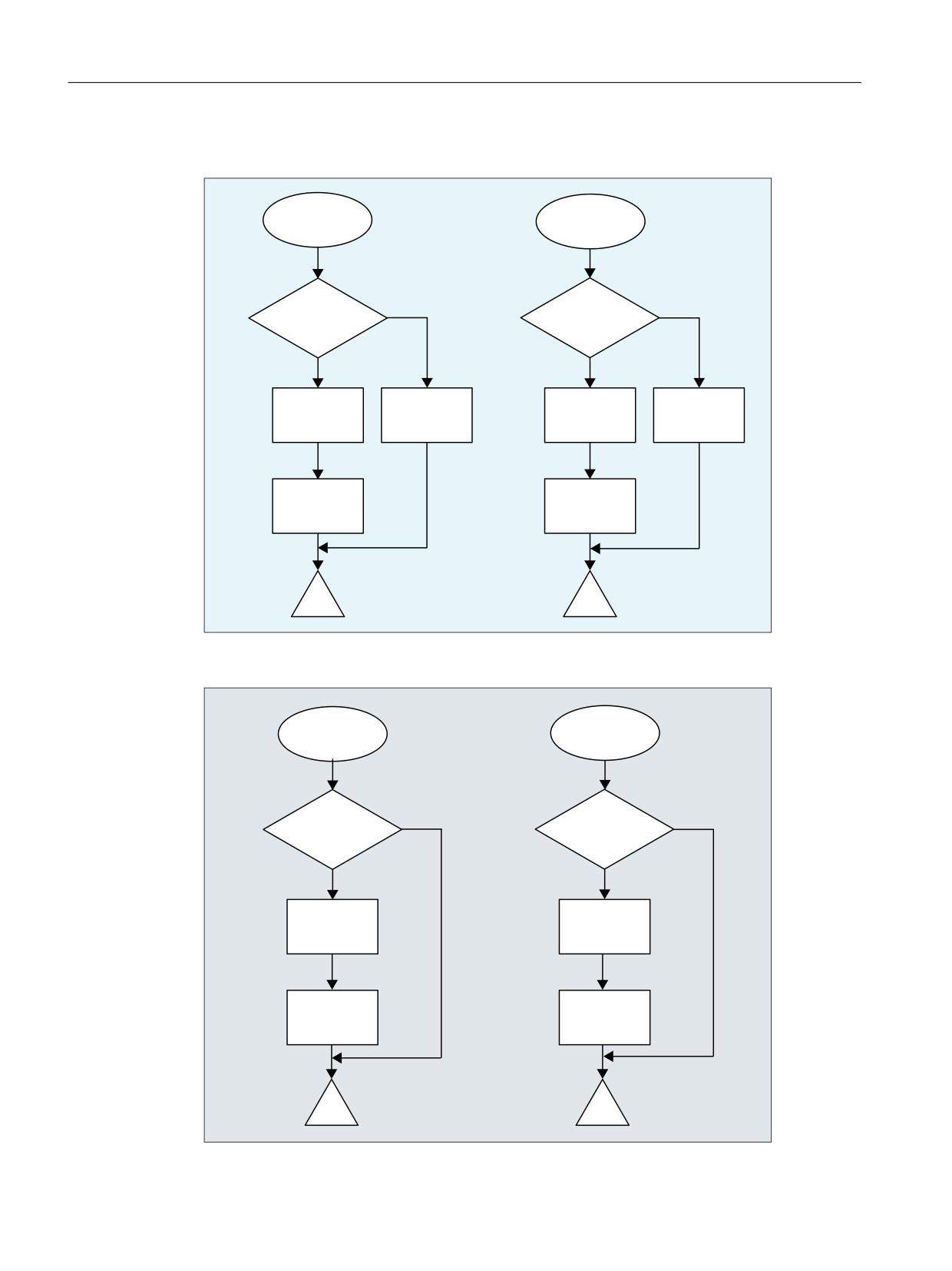
programmed using individual instructions according to the flow chart shown below. The
sequence is different for reading and writing variables.
Only individual variables or arrays (fields) can be supported directly using the semaphore
technique. Transferring structures must be split up into individual jobs. Here, the user must
ensure data consistency of this structure by programming the appropriate semaphore
mechanism.
If "IVAR2" = -1 is set, data are transferred without a semaphore.
PLC
Function Manual, 10/2020, 6FC5397-0HP40-0BA1
295
Block descriptions
17.26 FC21: Transfer - data exchange NC/PLC
Data exchange with semaphore in PLC (schematic of FC21)
)XQFW
)XQFW
UHDG
:ULWH
1R
1R
6HPDSKRU "
6HPDSKRU "
<HV
<HV
7UDQVIHU GDWD
'DWHQ YRQ
(UURU
(UURU
IURP 1& WR
3/& ]XU 1&
(UU&RGH
(UU&RGH
3/&
¾EHUWUDJHQ
6HPDSKRU
6HPDSKRU
(UURU
(UURU
(UU&RGH
(UU&RGH
Basic structure in the NC:
5HDG
:ULWH LQ WKH
LQ WKH 1&.
1&.
1R
1R
6HPDSKRU "
6HPDSKRU "
<HV
<HV
5HDG
7UDQVIHU
GDWD
GDWD WR 3/&
IURP 3/&
6HPDSKRU
6HPDSKRU
PLC
296
Function Manual, 10/2020, 6FC5397-0HP40-0BA1
Block descriptions
17.26 FC21: Transfer - data exchange NC/PLC
Variable value ranges
Signal
Typ
Type
Value range
Meaning
e
Enable:
I
BOOL
0 (FALSE), 1 (TRUE)
1:
Transferring data
Funct:
I
BYTE
3, 4
3:
Read data
4:
Write data
S7Var :
I
ANY
S7 data area, except local
Source/destination data storage area
data
IVAR1:
I
INT
0 ... 4095
Position offset
IVAR2:
I
INT
-1 ... 4095
Semaphore byte
Transfer without semaphore: -1
Error:
O
BOOL
0 (FALSE), 1 (TRUE)
1:
An error is active
ErrCode:
O
INT
20, 21, 22, 23, 24, 25
20:
Alignment error
21:
illegal position offset
22:
Illegal semaphore byte
23:
No new data to be read
24:
Cannot write data
25:
Local data parameterized for
S7Var
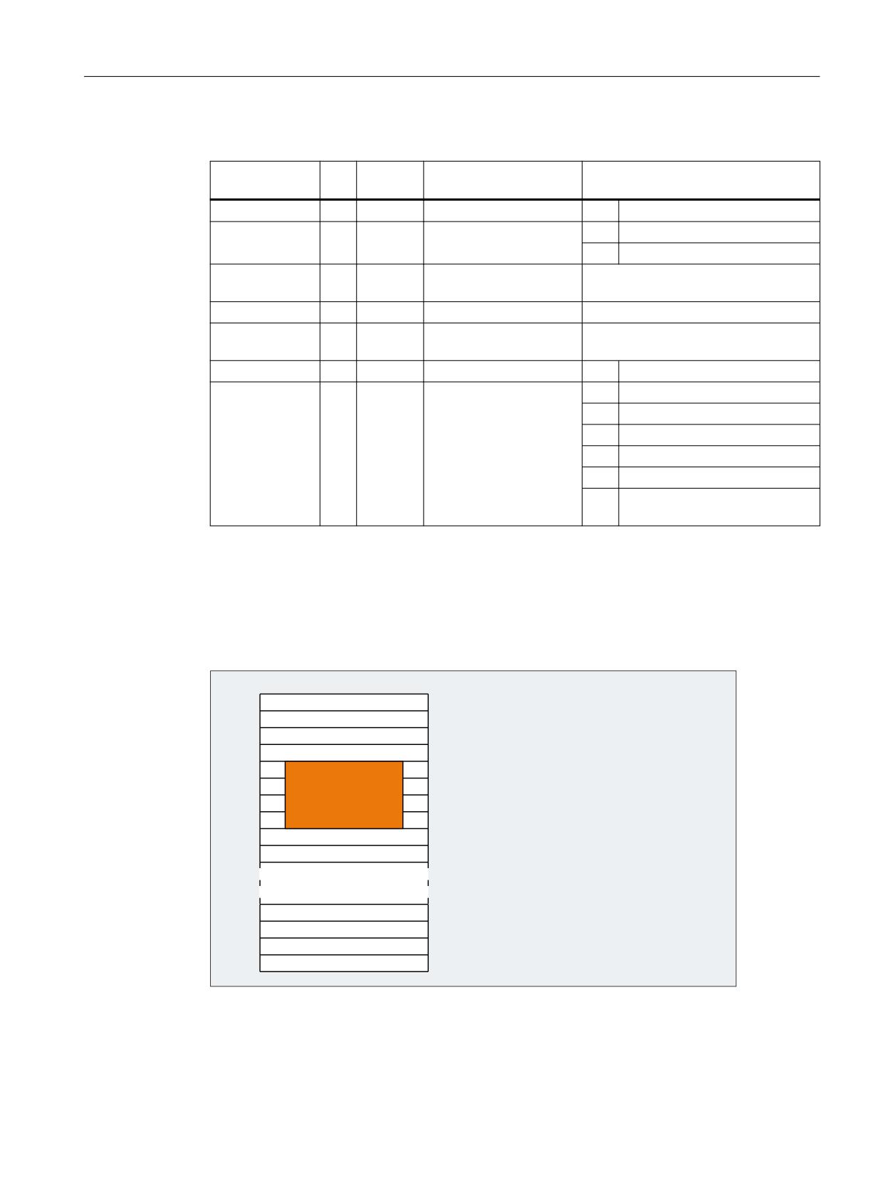
Example 1: Reading a DWORD from position offset 4 using a semaphore in byte 0 - and saving in
memory double word 100
• Data type Dword (4 bytes)
• Position offset 4
6HPDSKRU
'ZRUG
'DWD W\SH 'ZRUG
E\WHV
3RVLWLRQ RIIVHW
PLC
Function Manual, 10/2020, 6FC5397-0HP40-0BA1
297

Block descriptions
17.26 FC21: Transfer - data exchange NC/PLC
PLC programming
CALL FC21(
Enable
:= M 10.0,
// if TRUE, FC 21 is active
Funct
:= B#16#3,
//Read data
S7Var
:= P#M 100.0 DWORD 1,
IVAR1
:= 4,
IVAR2
:= 0,
Error
:= M 10.1,
ErrCode
:= MW12);
UN
M10.1;
//Enable while 1, until value is read
R
M10.0;
Programming the NC with synchronized actions
• Writing the data to the PLC - byte 0 serves as semaphore:
ID=1 WHENEVER $A_DBB[0] == 0 DO $A_DBR[4] = $AA_IM[X] $A_DBB[0] = 1
• Reading the data from the PLC - byte 1 serves as semaphore:
ID=2 WHENEVER $A_DBB[1] == 1 DO $R1 = $A_DBR[12] $A_DBB[1] = 0
Example 2: Reading a WORD from position offset 8 without semaphore, and saving in memory word
104
CALL FC21(
Enable
:=M 10.0,
// if TRUE, FC 21 is active
Funct
:=B#16#3,
//Read data
S7Var
:=P#M 104.0 WORD 1,
IVAR1
:=8,
IVAR2
:=-1,
Error
:=M 10.1,
ErrCode
:=MW12);
17.26.6
Function 5: Update control signals to channel
The purpose of this function is to transmit important control signals at high speed in between
cyclic data transfers. Data bytes 6 and 7 of user interfaces DB21, ... are transferred to the NC. The
channel is specified in parameter "IVAR1". This enable, for example, the feed disable, read-in
disable to be transferred outside of the PLC cycle.
Signal
Type
Type
Value range
Description
Enable:
I
BOOL
0 (FALSE), 1 (TRUE)
1:
Transferring data
Funct:
I
BYTE
5
5:
Control signals to channel
S7Var :
I
ANY
S7 data storage area
Not used
IVAR1:
I
INT
1. Maxchannel
Channel number
Error:
O
BOOL
0 (FALSE), 1 (TRUE)
1:
An error is active
PLC
298
Function Manual, 10/2020, 6FC5397-0HP40-0BA1
Block descriptions
17.27 FC22: TM_DIR - direction selection for tool management
Signal
Type
Type
Value range
Description
ErrCode:
O
INT
1, 10
1:
"Funct" invalid
10:
Channel no. invalid
17.26.7
Function 6: Update control signals to axes
The purpose of function 6 is to transmit important control signals at high speed in between cyclic
data transfers. The data byte 2 of application interface DB31, ... is transferred to the NC. The
transfer is performed for all activated axes. This allows the controller enable to be transferred
outside the PLC cycle, for example.
Signal
Type
Type
Value range
Description
Enable:
I
BOOL
0 (FALSE), 1 (TRUE)
1:
Transferring data
Funct:
I
BYTE
6
6:
Control signals to axes
S7Var :
I
ANY
S7 data storage area
Not used
IVAR1:
I
INT
0
Error:
O
BOOL
0 (FALSE), 1 (TRUE)
1:
An error is active
ErrCode:
O
INT
1
1:
"Funct" invalid
17.26.8
Function 7: Update control signals to axes
The purpose of function 7 is to transmit important control signals at high speed in between cyclic
data transfers. The data byte 4 of application interface DB31, ... is transferred to the NC. The
transfer is performed for all activated axes. This enables, for example, the feed stop to be
transferred outside the PLC cycle.
Signal
Type
Type
Value range
Description
Enable:
I
BOOL
0 (FALSE), 1 (TRUE)
Funct:
I
BYTE
7
7:
Control signals to axes
S7Var :
I
ANY
S7 data storage area
Not used
IVAR1:
I
INT
0
Error:
O
BOOL
0 (FALSE), 1 (TRUE)
1:
An error is active
ErrCode:
O
INT
1
1:
"Funct" invalid
17.27
FC22: TM_DIR - direction selection for tool management
NOTICE
Use
Block FC22 "TM_DIR" may only be used in conjunction with the tool management.
PLC
Function Manual, 10/2020, 6FC5397-0HP40-0BA1
299
Block descriptions
17.27 FC22: TM_DIR - direction selection for tool management
Function
Referred to the location numbers, e.g. a tool magazine or revolver (indexing axis) block FC22
"TM_DIR" supplies the shortest path and direction of motion for positioning, based on the target
and current position.
Outputs
• Input FC22: "Start" = 1 ⇒ the outputs are cyclically updated.
• Input FC22: "Start" = 0 ⇒ the outputs are undefined.
Special positioning
For direction selection with special positioning (input FC22: "Offset" > 0) a new target position
is calculated from the target position, the offset for special positioning as well as the number of
magazines locations:
New_target position = ( target position - ( special position -1 ) ) neg. MODULO
number_of_magazine locations
The new target position corresponds to the location number at which the magazine must be
positioned so that the target position requested by the user corresponds to the location number
of the special position.
The directional optimization is active both with and without special positioning.
Call
The block must be called once with the appropriate parameter settings for each magazine.
Further information
• Further PI services for tool management:
- FB4: PI_SERV - request PI service (Page 180)
- FC7: TM_REV - transfer block for tool change with revolver (Page 250)
- FC8: TM_TRANS - transfer block for tool management (Page 253)
• Function Manual, Tool Management
Declaration of the function
FUNCTION FC22: VOID
// NAME:
TM_DIR
VAR_INPUT
MagNo:
INT;
ReqPos:
INT;
ActPos:
INT;
Offset:
BYTE ;
Start :
BOOL;
END_VAR
VAR_OUTPUT
Cw:
BOOL;
PLC
300
Function Manual, 10/2020, 6FC5397-0HP40-0BA1

Block descriptions
17.27 FC22: TM_DIR - direction selection for tool management
Ccw:
BOOL;
InPos :
BOOL;
Diff:
INT;
Error :
BOOL;
END_VAR
BEGIN
END_FUNCTION
Description of formal parameters
Signal
Type
Type
Value range
Meaning
MagNo:
I
INT
1, 2, 3, ...
Magazine number
ReqPos:
I
INT
1, 2, 3, ...
Target position (magazine location num-
ber)
ActPos:
I
INT
1, 2, 3, ...
Actual position (magazine location num-
ber)
Offset:
I
BYTE
0, 1, 2, ...
Offset for special positioning
Start:
I
BOOL
0 (FALSE), 1
1 = start of calculation
(TRUE)
Cw:
O
BOOL
0 (FALSE), 1
1 = Move magazine clockwise
(TRUE)
Ccw:
O
BOOL
0 (FALSE), 1
1 = Move magazine
(TRUE)
counterclockwise
InPos:
O
BOOL
0 (FALSE), 1
1 = In position
(TRUE)
Diff:
O
INT
0, 1, 2, ...
Absolute value of the differential path
(shortest path)
Error:
O
BOOL
0 (FALSE), 1
1 = error
(TRUE)
Call example
CALL FC22(
// Tool management direction selection
// Inputs
MagNo :=
2,
// Magazine number
ReqPos :=
mw 20,
//Target position
ActPos :=
mw 22,
// Current position
Offset :=
b#16#0,
// Offset for special positioning
Start :=
m 30.4,
// Start trigger
// Outputs
Cw :=
m 30.0,
// Move magazine clockwise
Ccw :=
m 30.1,
// Move magazine counterclockwise
InPos :=
m 30.2,
// Magazine in position
Diff :=
mw 32,
// Differential path
Error :=
m 30.3
// Error has occurred
);
PLC
Function Manual, 10/2020, 6FC5397-0HP40-0BA1
301
Block descriptions
17.28 FC24: MCP_IFM2 - transferring MCP signals to the interface
17.28
FC24: MCP_IFM2 - transferring MCP signals to the interface
Function
Block FC24 "MCP_IFM2" (M variant, e.g. MCP 310) is used for transferring data from the machine
control panel to the NC/PLC interface:
• Modes
• Axis selections
• WCS/MCS switchover
• Traversing keys
• Overrides or override simulation signals
• Key-operated switch position
The following specifications apply to the feedrate override, axis travel keys and INC keys
depending on the active mode or on the coordinate system selected:
• Feedrate override:
- The feedrate override is transferred to the interface of the selected channel and to the
interface of the axes.
- The feedrate override signals are transferred to the NC channel in addition to the "Rapid
traverse override" (DBB 5) interface byte if the "Feedrate override for rapid traverse
effective" HMI signal is set (exception: Switch setting "Zero"). "Rapid traverse override
effective" is also set with this HMI signal.
• Machine functions for INC and axis travel keys:
- When the MCS is selected, the signals are transferred to the interface of the selected
machine axis.
- When the WCS is selected, the signals are transferred to the geometry axis interface of the
parameterized channel.
- When the system is switched between MCS and WCS, the active axes are generally
deselected.
The associated LEDs on the machine control panel are derived from the acknowledgments from
the relevant selections.
Feedrate and spindle Start/Stop are not transferred to the interface, but output modally as a
"FeedHold" or "SpindleHold" signal. The user can link these signals to other signals leading to a
feed or spindle stop (this can be implemented, e.g. using the appropriate input signals in FC10:
AL_MSG). The associated LEDs are activated at the same time.
The spindle direction (+, -) is not switched directly either, but made available as output
parameter "SpindleDir". permitting, for example, FC18 to be parameterized. A spindle enable
signal is also switched via parameter "SpindleHold". One possible method of moving a spindle
directly is to preselect it as an axis so that it can be traversed via (axis) direction keys.
If the machine control panel fails, the signals it outputs are preset to zero; this also applies to
"FeedHold" and "SpindleHold" output signals.
FC24 or also FC19, FC25, FC26 can be called a multiple number of times in a single PLC cycle. In
this case, the first call in the cycle drives the LED displays. Furthermore, all actions of the
PLC
302
Function Manual, 10/2020, 6FC5397-0HP40-0BA1
Block descriptions
17.28 FC24: MCP_IFM2 - transferring MCP signals to the interface
parameterized block are carried out in the first call. In the following calls, only a reduced level of
processing of the channel and mode group interface takes place. The geometry axes are
supplied with directional data only in the first block call in the cycle.
Single block processing can be selected/deselected only in the first call in the cycle.
The second machine control panel can be processed if parameter "ModeGroupNo" has been
increased by B#16#10. When parameterizing, the HHU number is contained in the lower nibble
(lower 4 bits).
"BAGNo" = 0 or B#16#10 ⇒ mode group signals are not processed.
"ChanNo" = 0 ⇒ no processing of the channel signals.
The INC selections are transferred to the mode group interface. The activation for this
specification is done via the DB10.DBX57.0 (INC inputs in BAG area active) through this block
once after power up.
Furthermore, two machine control panels can be handled in parallel by this block. The block call
for the 2nd machine control panel in OB1 cycle must be set after the call of the 1st MCP. Support
for two MCPs is provided in the control panel blocks up to certain limits (support is not provided
as standard for mutual interlocking of axis selections with identical assignments on two MCPs).
Key-operated switch position
As of software version 4.5 SP2, the key-operated switch signals in the FC24 are also transferred
to the user interface (DBX56.5 to 7). This transfer is made independent of whether a keyswitch
is mounted on the MCP.
Note
For further information see "FC19: MCP_IFM - transfer of MCP signals to interface (Page 282)".
Flexible axis configuration
It is possible to be flexible in the assignment of axis selections or direction keys for machine axis
numbers.
Better support is now provided by the MCP blocks for the use of two MCPs, which are to run in
parallel, in particular for an application using two channels and two mode groups. Note that the
axis-numbers are also specified in the parameterized mode group number of the MCP block in
the axis tables of the relevant MCP.
To provide this flexibility, tables for axis numbers are stored in DB10.
For the 1st machine control panel (MCP) the table starts at byte 8 (symbolic name:
MCP1AxisTbl[1..22]) and for the second machine control panel (MCP) starting at byte 32
(symbolic name: MCP2AxisTbl[1..22]). The machine axis numbers must be entered byte by byte
here. It is permissible to enter a value of 0 in the axis table. Checks are not made to find illegal
axis numbers, meaning that false entries can lead to a PLC Stop.
For FC24, the maximum possible number of axis selections can also be restricted.
This upper limit is set for the first machine control panel in DB10.DBW30 (symbolic name:
MCP1MaxAxis) or for the second machine control panel in DB10.DBW54 (symbolic name:
MCP2MaxAxis) for the respective MCP.
The default setting is 0, corresponding to the maximum number of configured axes. The axis
numbers and the limit can also be adapted dynamically. Afterwards, a new axis must be selected
PLC
Function Manual, 10/2020, 6FC5397-0HP40-0BA1
303
Block descriptions
17.28 FC24: MCP_IFM2 - transferring MCP signals to the interface
for FC24. Axis numbers may not be switched over while the axes are traversing the relevant
direction keys. The compatibility mode is preset with axis numbers 1 to 6 for both MCPs and
restricted to the configured number of axes.
Axis selection from the HMI
In addition to the 6 axis selection keys of the MCP, the active axis can also be selected in the HMI.
If an axis is being selected from the HMI, then no axes can be traversed using the direction keys.
Axis selection from the HMI is then only adopted for the MCP if the selected channel in the HMI
correlates with that at FC25. With axis selection from the HMI, an initial attempt is made as with
axis selection using the axis selection keys of the MCP, to find an assignment between the
selected axis number and the actual machine axis in the axis table of the NC-DB, refer to section
"Flexible axis configuration".
This means that when an axis is selected from the HMI, the same machine axis is selected as if
the corresponding axis selection key of the MCP had been selected. If an assignment is not
possible, then the axis number selected from the HMI is directly used as machine axis. As a
consequence it is possible to select axes that cannot be selected via the MCP.
Single block mode
Pressing the single block key activates the single block mode and, if the key is pressed again, the
single block mode is deactivated. If the mode is called several times for one MCP, the block
transfers single block mode state from the channel of the first call to the channels of the
subsequent calls.
Declaration of the function
FUNCTION FC24: VOID
// NAME:
MCP_IFM2
VAR_INPUT
BAGNo :
BYTE ;
ChanNo:
BYTE ;
SpindleIFNo:
BYTE ;
END_VAR
VAR_OUTPUT
FeedHold :
BOOL;
SpindleHold :
BOOL;
SpindleDir:
BOOL;
END_VAR
BEGIN
END_FUNCTION
PLC
304
Function Manual, 10/2020, 6FC5397-0HP40-0BA1
Block descriptions
17.29 FC25: MCP_IFT - transfer of MCP/OP signals to interface
Description of formal parameters
Signal
Type
Type
Value range
Meaning
BAGNo :
I
BYTE
B#16#00 -
1st MCP: Number of mode group to
B#16#0A
which the mode signals are transferred
B#16#10 -
2nd MCP: Number of mode group to
B#16#1A
which the mode signals are transferred
ChanNo:
I
BYTE
B#16#00 -
Number of the channel to which the
B#16#0A
channel signals are transferred
SpindleIFNo:
I
BYTE
0 - 31
Number of the axis/spindle to which the
(B#16#1F)
spindle data is transferred (number of
the associated machine axis)
FeedHold:
O
BOOL
0 (FALSE), 1 (TRUE)
Feed stop from MCP, modal
SpindleHold:
O
BOOL
0 (FALSE), 1 (TRUE)
Spindle stop from MCP, modal
SpindleDir:
O
BOOL
0 (FALSE), 1 (TRUE)
Direction of spindle rotation
0:
Direction of rotation + (left)
1:
Direction of rotation - (right)
Call example
CALL FC24(
// Slimline machine control panel M
variant
// Signals to interface
BAGNo :=
B#16#1,
// Mode group no. 1
ChanNo :=
B#16#1,
// Channel no. 1
SpindleIFNo : B#16#4,
// Spindle interface number = 4
=
FeedHold :=
m22.0,
// Feed stop signal modal
SpindleHold : db2.dbx151.0,
// Spindle stop modal in message data block
=
SpindleDir:= m22.1);
// Spindle direction return
With these parameter settings, the signals are sent to the first mode group, the first channel and
all axes. In addition, the spindle override is transferred in the 4th axis/spindle interface. The feed
hold signal is passed to bit memory 22.0 and the spindle stop signal to data block DB2, data bit
151.0. The spindle direction feedback signal supplied via parameter "SpindleDir" can be used as
a direction input for an additional FC18 call.
17.29
FC25: MCP_IFT - transfer of MCP/OP signals to interface
Function
Block FC25 "MCP_IFT" (T variant, e.g. MCP 483) is used for transferring data from the machine
control panel to the NC/PLC interface:
• Modes
• Direction keys of four axes
PLC
Function Manual, 10/2020, 6FC5397-0HP40-0BA1
305
Block descriptions
17.29 FC25: MCP_IFT - transfer of MCP/OP signals to interface
• WCS/MCS switchover
• Overrides
• Keyswitch
The following specifications apply to the feedrate override, axis travel keys and INC keys
depending on the active mode or on the coordinate system selected:
• Feedrate override:
- The feedrate override is transferred to the interface of the selected channel and to the
interface of the axes.
- The feedrate override signals are transferred to the NC channel in addition to the "Rapid
traverse override" (DBB 5) interface byte if the "Feedrate override for rapid traverse
effective" HMI signal is set (exception: Switch setting "Zero"). "Rapid traverse override
effective" is also set with this HMI signal.
• Machine functions for INC and axis travel keys:
- When the MCS is selected, the signals are transferred to the interface of the selected
machine axis.
- When the WCS is selected, the signals are transferred to the geometry axis interface of the
parameterized channel.
The associated LEDs on the machine control panel derived from the acknowledgments of the
relevant selections.
Feedrate and spindle Start/Stop are not transferred to the interface, but output modally as a
"FeedHold" or "SpindleHold" signal. The user can link these signals to other signals leading to a
feed or spindle stop (this can be implemented, e.g. using the appropriate input signals in FC10:
AL_MSG). The associated LEDs are activated at the same time.
If the machine control panel fails, the signals it outputs are preset to zero; this also applies to
"FeedHold" and "SpindleHold" output signals.
FC25 or also FC19, FC24, FC26 can be called a multiple number of times in a single PLC cycle. In
this case, the first call in the cycle drives the LED displays. Furthermore, all actions of the
parameterized block are carried out in the first call. In the following calls, only a reduced level of
processing of the channel and mode group interface takes place. The geometry axes are
supplied with directional data only in the first block call in the cycle.
Single block processing can be selected/deselected only in the first cycle.
The second machine control panel can be processed if parameter "ModeGroupNo" has been
increased by B#16#10. When parameterizing, the HHU number is contained in the lower nibble
(lower 4 bits).
"BAGNo" = 0 or B#16#10 ⇒ mode group signals are not processed.
"ChanNo" = 0 ⇒ no processing of the channel signals.
Flexible axis configuration
It is possible to be flexible in the assignment of axis selections or direction keys for machine axis
numbers.
Support is now provided by the MCP blocks for the use of two MCPs, which are operated
simultaneously, in particular for an application using two channels and two mode groups. The
PLC
306
Function Manual, 10/2020, 6FC5397-0HP40-0BA1

Block descriptions
17.29 FC25: MCP_IFT - transfer of MCP/OP signals to interface
block call for the second machine control panel in OB1 cycle must be set after the call for the 1st
MCP. Note that the axis numbers are also specified in the parameterized mode group number of
the MCP block in the axis tables of the relevant MCP.
To provide this flexibility, tables for axis numbers are stored in DB10.
For the 1st machine control panel (MCP) the table starts at byte 8 (symbolic name:
MCP1AxisTbl[1..22]) and for the 2nd machine control panel (MCP) it starts at byte 32 (symbolic
name: MCP2AxisTbl[1..22]). The machine axis numbers are entered here byte-by-byte. It is
permissible to enter a value of 0 in the axis table. Checks are not made to find illegal axis
numbers, meaning that false entries can lead to a PLC Stop.
The restriction of the possible number of axes at FC25 is realized using the 0-values in the axis
table. The axis numbers can also be adapted dynamically. During the manual traversing of axes
using the direction keys, the axis numbers must not be switched over. The compatibility mode
is preset with axis numbers 1 to 4 for both MCPs and restricted to the configured number of axes.
Note
For further information see "FC19: MCP_IFM - transfer of MCP signals to interface (Page 282) ".
Declaration of the function
FUNCTION FC25: VOID
// NAME:
MCP_IFT
VAR_INPUT
BAGNo :
BYTE ;
ChanNo:
BYTE ;
SpindleIFNo:
BYTE ;
END_VAR
VAR_OUTPUT
FeedHold :
BOOL;
SpindleHold :
BOOL;
END_VAR
BEGIN
END_FUNCTION
Description of formal parameters
Signal
Type
Type
Value range
Meaning
BAGNo :
I
BYTE
B#16#00 -
1st MCP: Number of mode group to which
B#16#0A
the mode signals are transferred
B#16#10 -
2nd MCP: Number of mode group to
B#16#1A
which the mode signals are transferred
ChanNo:
I
BYTE
B#16#00 -
Number of the channel to which the chan-
B#16#0A
nel signals are sent
PLC
Function Manual, 10/2020, 6FC5397-0HP40-0BA1
307

Block descriptions
17.30 FC26: HPU_MCP - Transfer of the HT 8/HT 10 signals to the interface
Signal
Type
Type
Value range
Meaning
SpindleIFNo:
I
BYTE
B#16#00 -
Number of the axis/spindle to which the
B#16#1F
spindle data is transferred (number of the
associated machine axis)
FeedHold:
O
BOOL
0 (FALSE), 1
Feed stop from MCP, modal
(TRUE)
SpindleHold:
O
BOOL
0 (FALSE), 1
Spindle stop from MCP, modal
(TRUE)
Call example
With these example parameter settings, the signals are sent to the 1st mode group, the 1st
channel, and all axes. The spindle override is transferred to the 4th axis/spindle interface. Feed
stop is sent to bit memory 22.0 and spindle stop is sent to the data block DB2, DBX151.0.
CALL FC25(
//Machine control panel T variants
// Signals to interface
BAGNo :=
B#16#1,
// Mode group no. 1
ChanNo :=
B#16#1,
// Channel no. 1
SpindleIFNo := B#16#4,
// Spindle interface number = 4
FeedHold :=
m22.0,
// Feed stop signal modal
SpindleHold := db2.dbx151.0)
// Spindle stop modal in message data block
;
17.30
FC26: HPU_MCP - Transfer of the HT 8/HT 10 signals to the interface
General description of functions
Function FC26 "HPU_MCP (machine control panel signals of the handheld terminal HT 8)"
transfers the HT-specific signals of the following functions between the HT input/output data
areas parameterized in function block FB1 (Parameter: MCPxIn and MCPxOut) and the NC/PLC-
interface:
• Operating modes and machine function INC
• Program control
• Coordinate system WCS or MCS
PLC
308
Function Manual, 10/2020, 6FC5397-0HP40-0BA1
Block descriptions
17.30 FC26: HPU_MCP - Transfer of the HT 8/HT 10 signals to the interface
• Axis traversing signals
• Feedrate override
Note
Mode switchover through HT and/or HMI
The function FC2 "GP_HP Basic program, cyclic part" transfers the signals of the mode
switchover in such a way that alternative selection from the MCP of the HT and of the HMI is
possible. The transfer of the HMI signals to the NC/PLC interface can also be deactivated in the
function block FB1 with the parameter "MMCToIF" = FALSE .
Active axes
Using HT 8 a maximum of 6 axes can be addressed at the same time. The selection of the axes
is to be realized by the user/machine manufacturer in the PLC user program.
Bit 6.7 in the input image is used to differentiate between the HT 8 and HT 10. This bit is set
for an HT 10 (see Manual).
Bit 6.7 in the input image is used to differentiate between the HT 8 and HT 10. This bit is set for
an HT 10.
Note
Please note the following constraints:
• A check of the permissible machine axis numbers is not done. Invalid machine axis numbers
can lead to a PLC stop.
• The machine axis numbers can be changed dynamically. The table may not be written, if
currently a machine axis is being moved via a traversing key.
Flexible axis configuration for the HT 8
The assignment of axis traversing keys to machine axes can be configured flexibly. Each pair of
axis traversing keys can be assigned any machine axis. If more than six machine axes are to be
used, the assignment can be changed dynamically. The assignment must not be changed while
axes are traversing. The assignment is made via the data block DB10. The number of the
machine axis that is to be selected by the ith axis traversing key pair of the first HT 8 is entered
in the assignment table starting from DBB8. The assignment for the key pairs of the second HT 8
is entered in DB10 from DBB32. If an entry of the assignment tables is set to 0, this means that
no axis can be moved using the associated key pair. The number of usable axis traversing key
pairs can be limited by the value DB10.DBW30 or DB10.DBW54. If the value 0 (default setting)
is used, all axis traversing key pairs to which a machine axis has been assigned can be used. The
machine axes 1 to 6 are preset for the axis traversing key pairs 1 to 6 (see PLC manual, Chapter
"Flexible axis configuration").
Flexible axis configuration for the HT 10
Contrary to the HT 8, the HT 10 only has one plus and one minus key for traversing. There is also
a key for rapid traversing. The active axis, to which these traversing signals refer, must be
selected at the HMI (Smart Operate).
PLC
Function Manual, 10/2020, 6FC5397-0HP40-0BA1
309

Block descriptions
17.30 FC26: HPU_MCP - Transfer of the HT 8/HT 10 signals to the interface
If an axis is being selected from the HMI, then no axis can be traversed using the direction keys.
Axis selection from the HMI is then only adopted for the MCP if the selected channel in the HMI
correlates with that at FC26.
If FC26 is called for an HT 10 with ChanNo := 0, no axes can be traversed as the current axis
cannot be determined from the channel DB. (See PLC manual chapter "Selection of JOG axis via
HMI")
Declaration of the function
FUNCTION FC26: VOID
// NAME:
HPU_MCP
VAR_INPUT
BAGNo :
BYTE ;
ChanNo:
BYTE ;
END_VAR
BEGIN
END_FUNCTION
Description of formal parameters
Signal
Type
Type
Value range
Meaning
BAGNo :
I
BYTE
B#16#00 -
1st MCP: Number of mode group to which
B#16#0A
the mode signals are transferred
B#16#10 -
2nd MCP: Number of mode group to
B#16#1A
which the mode signals are transferred
ChanNo:
I
BYTE
B#16#00 -
Number of the channel to which the chan-
B#16#0A
nel signals are transferred
0: No transfer of channel signals
(and thus no axis can be traversed in JOG
mode for HT 10)
Call examples
Calling FC26 for the first MCP, the first mode group and the first channel of the NC.
CALL FC26(
//Machine control panel of HT
BAGNo :=
B#16#01,
//1.MCP, 1.BAG
ChanNo :=
B#16#01);
//Channel 1
Calling FC26 for the second MCP, the second mode group and the third channel of the NC.
CALL FC26(
//Machine control panel of HT
BAGNo :=
B#16#12,
//2.MCP, 2.BAG
ChanNo :=
B#16#03 );
//Channel 3
PLC
310
Function Manual, 10/2020, 6FC5397-0HP40-0BA1
Block descriptions
17.30 FC26: HPU_MCP - Transfer of the HT 8/HT 10 signals to the interface
Transfer of the traversing key signals depending upon the active coordinate system
The traversing key signals for 6 axes lie in the HT 8 input data area below:
• IB n + 2, Bit 0 - Bit 5 (positive traversing direction)
• IB n + 3, Bit 0 - Bit 5 (negative traversing direction)
The switchover of the coordinate system is done via the input signal:
• IB n + 0, Bit 0 (MCS/WCS)
The input signal is evaluated in FC26 with the help of the edge trigger flag. The active coordinate
system is shown in the following output signal:
• QB n + 0, Bit 0 (MCS/WCKS) with 0 = MCS, 1 = WCS
In case of active MCS the traversing key signals of the axes 1 - 6 are transferred in the axis-
specific interfaces (DB31,
DBX4.6 and DBX4.7 (traversing key +/-)) of the axes specified in the
machine axis tables (DB10.DBB8 to DBB13 or DBB32 to DBB37).
For HT 8 with active WCS, it is assumed that the axes 1 - 3 of the machine axis table are geometry
axes. For the traverse key signals with HT 8, the following applies:
• The traverse key signals of axes 1 - 3 (EB n + 2 / 3, bit 0 - bit 2) are transferred into the interface
of the geometry axes in DB21,
DBB12 + (n * 4), with n = 0, 1, 2), bit 6 and bit 7 (traverse
keys +/-) of the channel specified with parameter "ChanNo".
The assignment of the traversing key signals of axes 1, 2 and 3 to the geometric axes 1, 2 and
3 of the channel is permanent and may not be changed.
• The traverse key signals of axes 4 - 6 (EB n + 2 / 3, bit 3 - bit 5) are transferred into the axis-
specific interfaces (DB31,
DBX4.6 and DBX4.7 (traverse keys +/-)) of axes 4 - 6 entered in
the machine axis table (DB10.DBB11 to DBB13 or DBB35 to DBB37).
For HT 10, only one geometry axis which was selected from the HMI can be traversed
respectively.
The axis traverse signals (+/- and rapid traverse) for HT 10 relate to a machine axis or a geometry
axis, depending on which axis was selected in the HMI and whether WCS or MCS is active. See
also "Flexible axis configuration for the HT 10".
No traversing of machine axes in WCS
In case of active WCS (AB n + 0, Bit 0 = 1) the traversing of the machine axes can be locked. For
this, the following output signals are to be set in the PLC user program:
• QB n + 3, Bit 7 = 1 (For WCS: no machine axes)
Requirement to the FC26, not to transfer any traversing key signals for the machine axes. The
traversing key signals for the axes 1 - 3 of the machine axis table are transferred to the
geometric axes 1 - 3 of the specified channel. The traversing key signals for the axes 4 - 6 of
the machine axis table are not transferred.
• QB n + 2, Bit 6 (axes 7 - n selected)
Requirement to the FC26 not to transfer any traversing key signals, since the axes 1 - 6 of the
machine axis table are switched over. The axes 1 - 3 are thus not geometric axes but machine
axes.
PLC
Function Manual, 10/2020, 6FC5397-0HP40-0BA1
311
Block descriptions
17.30 FC26: HPU_MCP - Transfer of the HT 8/HT 10 signals to the interface
Feedrate override
The value of the HT 8 override switch is transferred as feedrate override in the channel-specific
interface DB21,
DBB4 (feedrate override) of the programmed channel (parameter: "ChanNo")
and in the axis-specific interfaces DB31,
DBB0 (feedrate override) of the axes programmed in
the table DB10.DBB8 to DBB13 (machine axis number).
Rapid traverse override
If for the programmed channel (parameter: "ChanNo") the signal DB21,
DBX25.3 = 1
(feedrate override for rapid traverse) is set, the value of the HT 8 override switch is sent as a rapid
traverse override to its channel-specific interface in DB21,
DBB5 (rapid traverse override) and
the signal DB21,
DBX6.6 = 1 (rapid traverse override active) is also set.
Machine function INC
The HT signals of the machine function INC are transferred differently depending upon the active
coordinate system MCS or WCS:
• Active coordinate system: MCS
The selected machine function INC is transferred for all 6 axes in the axis-specific interfaces
in DB31,
DBX5.0 to DBX5.5 (machine function) of the axes programmed in the table in
DB10.DBB8 to DBB13 (machine axis numbers) .
• Active coordinate system: WCS
For the axes 1 to 3 the signals of the machine function INC are transferred in the channel-
specific. Interface in DB21,
DBX13.0 to DBX13.5 (machine function) of the programmed
channel (Parameter: "ChanNo").
For the axes 4 to 6 the signals of the machine function INC are transferred in the channel-
specific. interfaces in DB31,
DBX5.0 to DBX5.5 (machine function) of the axes
programmed in the table in DB10.DBB11 to DBB13 (machine axis numbers).
The selection signals of the INC machine functions are transferred in the mode group-specific
interface DB11.DBB 2 + (n * 20), bit 0 to bit 5 (with n = 0, 1, 2, ...). The FC26 informs the NC about
the activation of the mode group interface for the INC machine functions once after power-up
with DB10.DBX57.0 (INC inputs active in the mode group area).
Handwheel selection
The hand-wheel selection signals are evaluated by HMI and transferred to the corresponding NC/
PLC interface signals of the machine or geometric axes:
• Geometry axes: DB21, ... DBB 12 + (n * 4), bit 0 to bit 2 (with n = 0, 1, 2)
• Machine axes: DB31,
DBX4.0 to DBX4.2
Requirement: FB1 parameters: "HWheelMMC" = TRUE
Multiple call in one PLC cycle
To transfer signals to multiple mode groups, channels or axes, the block can be called multiple
times with the corresponding parameters, "BAGNo" and "ChanNo".
PLC
312
Function Manual, 10/2020, 6FC5397-0HP40-0BA1
Block descriptions
17.30 FC26: HPU_MCP - Transfer of the HT 8/HT 10 signals to the interface
In the first call of the block for an HT 8 or the HT 10, all signals are transferred to the data blocks
of the NC/PLC interface and the output signals are controlled. Only the signals to mode groups
and channels are now transferred for the following calls in the same PLC cycle.
Processing of two MCP
If the function FC26 is called twice for two MCP in the cyclic sequence of the PLC program
(organization block OB1), the call for the second MCP must be made after the call for the first
MCP.
Note
If an axis can be traversed from two MCP, then the implementation of a mutual interlocking is
the responsibility of the user (machine manufacturer).
Failure of the MCP of the HT
In case of failure of the MCP of the HT, all the input signals are set to the value 0. That means that
a current traversing movement is stopped and automatically continued when the HT is
connected again. It is the responsibility of the user (machine manufacturer) to comply with
safety regulations, e.g. by triggering a PLC stop when a failure of the MCP of the HT is detected.
See also
Flexible axis configuration (Page 103)
Selection of JOG axis via HMI (Page 104)
17.30.1
Overview of the NC/PLC interface signals of HT
Operating modes and machine functions
Source: MCP
Target: Programmed mode group (Parameter BAGNo)
Display for BAG 1
AUTOMATIC
DB11.DBX0.0
MDI
DB11.DBX0.1
JOG
DB11.DBX0.2
REPOS
DB11.DBX1.1
REF
DB11.DBX1.2
TEACH IN
DB11.DBX1.0
INC 1 ... 10 000, INC Var.
DB11.DBX2.0 - DBX 2.5
PLC
Function Manual, 10/2020, 6FC5397-0HP40-0BA1
313

Block descriptions
17.30 FC26: HPU_MCP - Transfer of the HT 8/HT 10 signals to the interface
Traversing keys and rapid traverse override on the HT 8
Source: MCP
Target: Geometry axes of the prog. channel (parameter: Chan-
No)
1st traversing key +
DB21,
DBX12.7
1st traversing key -
DB21,
DBX12.6
2nd traversing key +
DB21,
DBX16.7
2nd traversing key -
DB21,
DBX16.6
3rd traversing key +
DB21,
DBX20.7
3rd traversing key -
DB21,
DBX20.6
Source: MCP
Target: Prog. axes according to the table in DB10,
DBB8 - 13 (1st MCP) or DBB32 - 37 (2nd MCP)
Traversing key +
DB31,
DBX4.7
Traversing key -
DB31,
DBX4.6
Traversing keys and rapid traverse override on the HT 10
Source: MCP
Target: Depending on the geometry axis selected in the HMI
(Smart Operate)
WCS is active
Traversing key +
DB21,
DBX12.7, .DBX16.7, .DBX20.7
Traversing key -
DB21,
DBX12.6, .DBX16.6, .DBX20.6
Rapid traverse override key
DB21,
DBX12.5, .DBX16.5, .DBX20.5
MCS is active
Traversing key +
DB31,
DBX4.7
Traversing key -
DB31,
DBX4.6
Rapid traverse override key
DB31,
DBX4.5
Override
Source: MCP
Target: Programmed channel (Parameter: ChanNo)
Feedrate override
DB21,
DBB4
Source: MCP
Target: Prog. axes according to the table in DB10,
DBB8 - 13 (1st MCP) or DBB32 - 37 (2nd MCP)
Feedrate override
DB31,
DBB0
Channel signals
Source: MCP
Target: Programmed channel (Parameter: ChanNo)
NC start
DB21,
DBX7.1
NC stop
DB21,
DBX7.3
PLC
314
Function Manual, 10/2020, 6FC5397-0HP40-0BA1

Block descriptions
17.30 FC26: HPU_MCP - Transfer of the HT 8/HT 10 signals to the interface
Source: MCP
Target: Programmed channel (Parameter: ChanNo)
RESET
DB21,
DBX7.7
Single block
DB21,
DBX0.4
17.30.2
Overview of the NC/PLC interface signals to HT
Operating modes and machine functions
Target: MCP
Source: Interface-DB (parameter BAGNo)
Display for BAG 1
AUTOMATIC
DB11.DBX6.0
MDI
DB11.DBX6.1
JOG
DB11.DBX6.2
REPOS
DB11.DBX7.1
REF
DB11.DBX7.2
TEACH IN
DB11.DBX7.0
INC Var
DB11.DBX8.5
Note
Unlike other MCP models, the HT 8 does not indicate the feedback messages via output signals
with LEDs.
Output signals from the axis traversing key pairs are not switched.
Output signals from the WCS and single block are switched after the keys have been pressed
(toggle mode).
The output signal from Reset is not switched. (HT 8)
The LEDs of the traversing keys +/- and rapid traverse are directly controlled by pressing the keys
in question.
Program control
Target: MCP
Source: Programmed channel (Parameter: ChanNo)
NC start
DB21,
DBX35.0
NC stop
DB21,
DBX35.3
RESET
DB21,
DBX35.7 (only for HT10)
Single block
DB21,
DBX0.4 (same signal as softkey)
PLC
Function Manual, 10/2020, 6FC5397-0HP40-0BA1
315

Block descriptions
17.31 FC27: OpUnitWriteRecord - write data record to MCP
17.31
FC27: OpUnitWriteRecord - write data record to MCP
Function
The block writes a data record to a modular MCP (as with WR_REC for PROFINET devices).
Description of formal parameters
Signal
Type
Type
Value range
Meaning
Req
I
BOOL
---
Write data record, see pulse diagram
MCPNum
I
INT
1 … 2
Number of the MCP to be written to.
SlotNum
I
INT
---
Slot of the MCP to which the transmitted
data record relates.
RecNum
I
INT
---
Data record number of the data record to
be written.
128 for configuration data of the modular
MCP
Busy
O
BOOL
---
Data record is written, see pulse diagram
Done
O
BOOL
---
Writing completed, see pulse diagram
Error
O
BOOL
---
Indication whether an error is present
The cause of the error is displayed in the
parameter "Status".
TRUE on error
Status
O
WORD
---
See table Status and error IDs
Record
I/O
ANY
---
Data record to be transmitted
PLC
316
Function Manual, 10/2020, 6FC5397-0HP40-0BA1
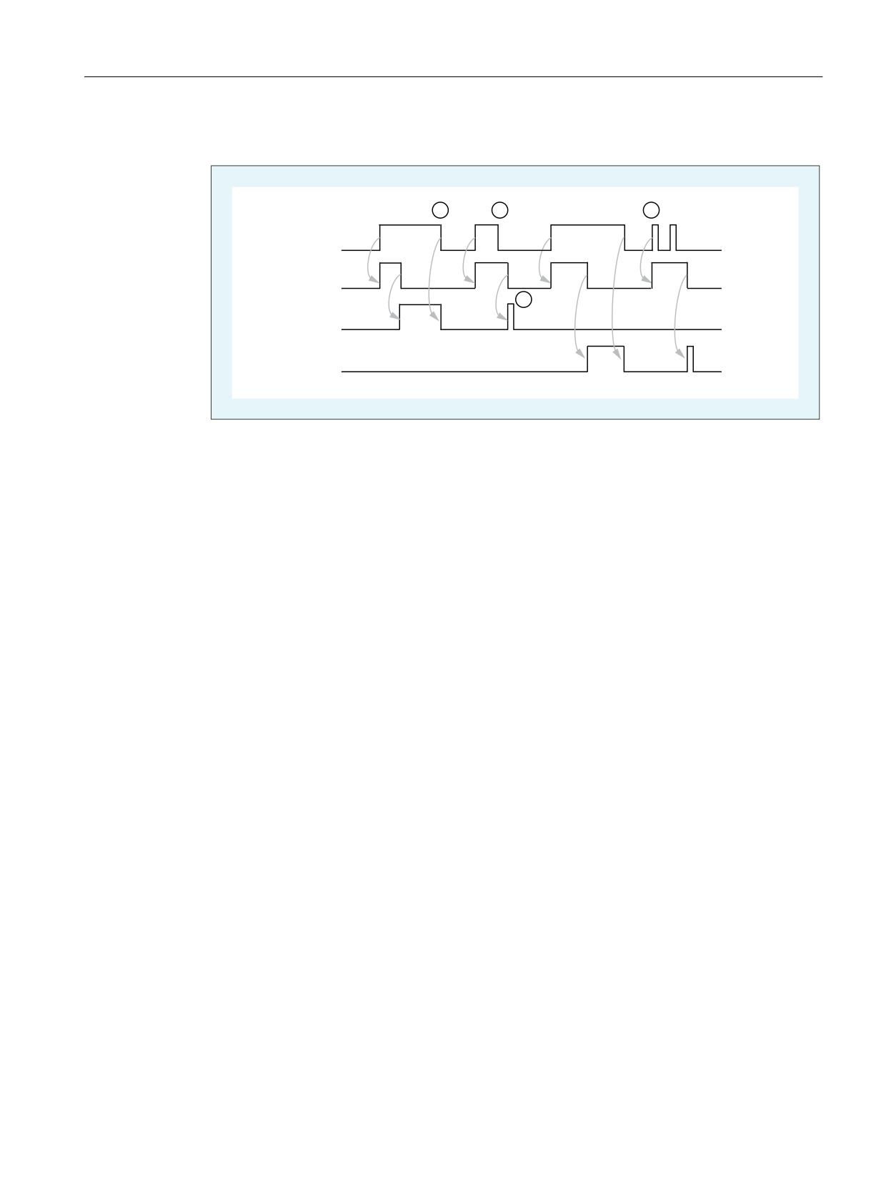
Block descriptions
17.31 FC27: OpUnitWriteRecord - write data record to MCP
Pulse diagram
5HT ,1
%XV\ 287
'RQH 287
(UURU
287
The job is started with a rising edge at parameter "Req". The values at the input parameters are
applied and remain valid for the entire duration of the job.
The block must be called until it reports "done" or "error".
The job cannot be aborted.
After the end of the job, a rising edge at "Req" is required to start a new job.
Multiple, parallel calls are not allowed, even for different MCPs.
① "Done" and "Error" are reset with a falling edge at "Req".
② The functionality of the FB is not stopped with a falling edge at "Req". If the input "Req" is reset
before the output "Done" is set, the output "Done" is only set for one cycle.
③ If "Req" is already FALSE, then "Done" and "Error" are only active for one cycle.
④ A new job is requested with a rising edge at "Req" while the block is still being processed ("Busy"
= TRUE).
The old job is ended with the parameters active at the beginning of the job.
Application example: Setting the key color of a modular MCP
Colors that depend on the status can be assigned to the keys of a modular MCP. Possible statuses
are active and inactive.
The data record passed on to parameter "Record" must correspond to the format expected for the
configuration of the modular MCP. For this purpose, use the data type
"ModularMcpKeypadRecord" provided in the library. The hardware and data assignment of the
MCP are described in the Operating Components Manual Modular MCPs.
To assign a color to the keys, follow these steps:
• Transfer the value 128 at parameter "RecNum".
• Configure the variables of the data record that you transfer to parameter "Record".
"Version" must be set to 16#10
Specify keys using the index referring to specific keypad
Colors for the relevant key as RGB code (0 to 255)
• Specify the number of the keypad that you want to configure at parameter "SlotNum".
• Configure the remaining parameters of the FB.
PLC
Function Manual, 10/2020, 6FC5397-0HP40-0BA1
317

Block descriptions
17.32 FC1005: AG_SEND - transfers data to Ethernet CP
A successfully transferred configuration remains active during operation of the MCP.
If more than 21 keys are to be configured, the configuration can be transferred in multiple calls
with up to 21 keys.
Status and error IDs
The following table lists the status and error IDs of the block.
Number
Type1)
Explanation
16#0000
S
No error
16#7001
S
Waiting for start of job
16#7002
S
Job in progress
16#8001
F
Invalid MCP number (parameter "McpNum")
16#8003
F
MCP is not configured as IE (parameter "McpNum")
16#8004
F
Record data too long (parameter "Record")
16#8005
F
Illegal record version
16#8006
F
Illegal record number (parameter "RecNum")
16#8100 -
F
For "RecNum" :=128: impermissible configuration for key
16#81FE
The last two digits of the error number correspond to the impermissible key
index.
16#81FF
F
Impermissible configuration
16#8401
F
MCP did not respond within the specified time
16#8402
F
MCP has denied the request
16#8403
F
MCP has rejected the connection establishment
16#8602
F
Internal error
1) S = Status, F = Fault or error
17.32
FC1005: AG_SEND - transfers data to Ethernet CP
Function
The AG_SEND function block transfers the data to be transferred via a configured connection to
the Ethernet CP. Together with the AG_RECV function block, data exchange can be established
with another station via the integrated "CP 840D sl." This station must be configured in STEP 7,
"NetPro."
In the basic program, this function is available as a function block FC1005. This is roughly
equivalent to function block FC5 in the "SIMATIC_NET_CP" library.
The TCP, UDP, and ISO-on-TCP protocols are supported.
Note
Smaller volume of transmittable data with SINUMERIK CP and UDP or ISO-on-TCP protocol
For SINUMERIK CP, only 240 bytes can be transmitted when function block FC1005 and the UDP
or ISO-on-TCP protocol are used.
PLC
318
Function Manual, 10/2020, 6FC5397-0HP40-0BA1

Block descriptions
17.33 FC1006: AG_RECV - receives data from the Ethernet CP
Description of formal parameters
Signal
Type
Type
Value range
Meaning
ACT:
I
BOOL
0 (FALSE), 1
Job initiation 1)
(TRUE)
ID:
I
INT
1, 2, 3 ...16
Connection ID
LADDR:
I
WORD
-
Module start address 2)
SEND:
I
ANY
-
Specifies the address and length. The ad-
dress of the data area alternatively refers
to:
• Bit memory address area
• Data block area
LEN:
I
INT
TCP: 1, 2, ... 8192
Number of bytes that are transmitted
UDP: 1, 2, ... 240
ISO-on-TCP: 1,
2
240
DONE:
O
BOOL
0 (FALSE), 1
0: Job running
(TRUE)
1: Job executed
ERROR:
O
BOOL
0 (FALSE), 1
0: No error
(TRUE)
1: An error is active
STATUS:
O
WORD
-
Status display
1) Parameter ACT must be TRUE long enough until the following applies: (DONE == 1) OR (ERROR == 1)
2) For SINUMERIK 840D sl: Parameter LADDR := W#16#8110
Documentation
A detailed module description can be found in:
• SINUMERIK user interfaces: Online help
• SIMATIC Programming Manual: Program blocks for SIMATIC NET S7-CPs
Chapter: "Program blocks for Industrial Ethernet" > "Program blocks for open communication
services (SEND/RECEIVE interface)" > "AG_SEND / AG_LSEND / AG_SSEND"
17.33
FC1006: AG_RECV - receives data from the Ethernet CP
Function
The function block AG_RECV receives data transferred via a configured connection from the
Ethernet CP. Together with the AG_SEND function block, data exchange can be established with
another station via the integrated "CP 840D sl." This station must be configured in STEP 7,
"NetPro."
In the basic program, this function is available as a function block FC1006. This is roughly
equivalent to function block FC6 in the "SIMATIC_NET_CP" library.
PLC
Function Manual, 10/2020, 6FC5397-0HP40-0BA1
319

Block descriptions
17.33 FC1006: AG_RECV - receives data from the Ethernet CP
The TCP, UDP, and ISO-on-TCP protocols are supported.
Note
Smaller volume of transmittable data with SINUMERIK CP and UDP or ISO-on-TCP protocol
For SINUMERIK CP, only 240 bytes can be transmitted when function block FC1006 and the UDP
or ISO-on-TCP protocol are used.
Formal parameters
Signal
Type
Type
Value range
Meaning
ID:
I
INT
1, 2 ...16
Connection ID
LADDR:
I
WORD
-
Module start address 1)
RECV:
I
ANY
-
Specifies the address and length. The ad-
dress of the data area alternatively refers
to:
• Bit memory address area
• Data block area
NDR :
O
BOOL
0 (FALSE), 1
0: Job running
(TRUE)
1: New data accepted
ERROR:
O
BOOL
0 (FALSE), 1
0: No error
(TRUE)
1: An error is active
STATUS:
O
WORD
-
Status display
LEN:
O
INT
TCP: 1, 2, ... 8192
Number of bytes that are transmitted
UDP: 1, 2, ... 240
ISO-on-TCP: 1,
2
240
1) For SINUMERIK 840D sl: Parameter LADDR := W#16#8110.
Documentation
A detailed module description can be found in:
• SINUMERIK user interfaces: Online help
• SIMATIC Programming Manual: Program blocks for SIMATIC NET S7-CPs
Chapter: "Program blocks for Industrial Ethernet" > "Program blocks for open communication
services (SEND/RECEIVE interface)" > "AG_RECV / AG_LRECV / AG_SRECV"
PLC
320
Function Manual, 10/2020, 6FC5397-0HP40-0BA1

Data lists
18
18.1
Machine data
18.1.1
Display machine data
Number
Identifier: $MM_
Description
9032
HMI_MONITOR
Determining the PLC data for HMI monitor information
18.1.2
NC-specific machine data
Number
Identifier: $MN_
Description
10100
PLC_CYCLIC_TIMEOUT
Cyclic PLC monitoring time
14504
MAXNUM_USER_DATA_INT
Number of user data (INT)
14506
MAXNUM_USER_DATA_HEX
Number of user data (HEX)
14508
MAXNUM_USER_DATA_FLOAT
Number of user data (FLOAT)
14510
USER_DATA_INT
User data (INT)
14512
USER_DATA_HEX
User data (HEX)
14514
USER_DATA_FLOAT[n]
User data (FLOAT)
Note
Machine data in integer/hex format is operated in the NC as DWORD. A machine data in floating
point format is managed in the NC as FLOAT (8-byte IEEE). They are stored only in the NC/PLC
interface and can be read by the PLC user program from DB20 even when the PLC boots.
18.1.3
Channelspecific machine data
Number
Identifier: $MC_
Description
28150
MM_NUM_VDIVAR_ELEMENTS
Number of elements for writing PLC variables
PLC
Function Manual, 10/2020, 6FC5397-0HP40-0BA1
321
Data lists
18.1 Machine data
PLC
322
Function Manual, 10/2020, 6FC5397-0HP40-0BA1
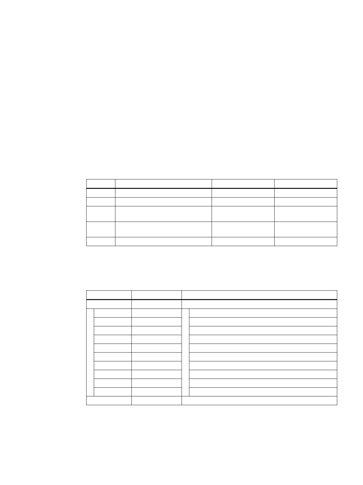
Interface signals
19
19.1
Interface signals - overview
19.1.1
Overview of the PLC blocks
19.1.1.1
Organization blocks (OBs)
Table 19-1
Assignment of the organization blocks (OBs)
OB No.
Designation
Meaning
Package
1
CYCLE
Cyclic execution
GP
40
ALARM
Process alarms
GP
82
DIAGNOSTIC ALARM
Asynchronous error
GP
alarm
86
RACK FAILURE
Asynchronous error
GP
alarm
100
RESTART
Startup/restart
GP
19.1.1.2
Function blocks (FBs)
Table 19-2
Assignment of the function blocks (FBs)
Number
Designation
Meaning
0 - 29
---
Reserved for Siemens
1
RUN_UP
Basic program start-up
2
GET
Read NC variables
3
PUT
Write NC variables
4
PI_SERV
PI services
5
GETGUD
Read GUD variable
7
PI_SERV2
General PI services
9
M2N
M to N transition block
10
SI_relay
Safety Integrated relay
11
SI_Braketest
Safety Integrated brake test
29
Diagnostics
Signal recorder and data trigger diagnostics
30 - 999*
---
Free for user assignment
PLC
Function Manual, 10/2020, 6FC5397-0HP40-0BA1
323

Interface signals
19.1 Interface signals - overview
Number
Designation
Meaning
1000 - 1023
---
Reserved for Siemens
1024 - upper lim-
---
Free for user assignment
it
* The actual upper limit of the block number depends on the PLC CPU contained in the selected NCU.
19.1.1.3
Function blocks (FCs)
Table 19-3
Assignment of the function blocks (FCs)
Number
Designation
Meaning
0 - 29
---
Reserved for Siemens
2
GP_HP
Basic program cyclic part
3
GP_PRAL
Basic program alarm-controlled part
5
GP_DIAG
Basic program diagnostic alarm and module failure
6
TM_TRANS2
Transfer block for tool management and multitool
7
TM_REV
Transfer block for tool change with turret
8
TM_TRANS
Transfer block for tool management
9
ASUB
Asynchronous subprograms
10
AL_MSG
Alarms/messages
12
AUXFU
Call interface for user auxiliary functions
13
BHG_DISP
Display control for the handheld unit
17
YDelta
Star-delta changeover
18
SpinCtrl
Spindle control for PLC
19
MCP_IFM
Distribution of MCP and operating software signals at the
interface (milling machine)
21
Transfer
PLC-NC data exchange
22
TM_DIR
Direction selection for tool management
24
MCP_IFM2
Transferring MCP signals to the NC/PLC interface
25
MCP_IFT
Transferring MCP/BT signals to the NC/PLC interface
26
HPU_MCP
Transmission of the HT 8 signals to the interface
30 - 999*
---
Free for user assignment
1005
AG_SEND
Transferring data to the Ethernet CP
1006
AG_RECV
Receiving data from the Ethernet CP
1000 - 1023
---
Reserved for Siemens
1024 - upper lim-
---
Free for user assignment
it
* The actual upper limit of the block number depends on the PLC CPU contained in the selected NCU.
PLC
324
Function Manual, 10/2020, 6FC5397-0HP40-0BA1

Interface signals
19.1 Interface signals - overview
19.1.1.4
Data blocks (DBs)
Note
The number of DBs to be set up depends on the parameterization made in the NC machine data.
Note
Data blocks of channels, axes/spindles and tool management that have not been activated are
available for the user.
Table 19-4
Overview of the data blocks (DBs)
DB No.
Designation
Interface for
1
---
Reserved for Siemens
2 - 5
PLC-MELD
PLC messages
6 - 8
---
Basic program
9
NC-COMPILE
NC compile cycles
10
NC INTERFACE
Central NC
11
Mode group
Mode group
12
---
Computer link and transport system
13
---
Reserved for Hymnos
14
---
Reserved for basic program
15
---
Basic program
16
---
PI Service definitions
17
---
Version identifier
18
---
Reserved for basic program (SPL interface (Safety In-
tegrated))
19
---
Operating software
20
---
PLC machine data
21 - 30
CHANNEL 1 ... CHANNEL 10
NC channels
31 - 61
AXIS 1 ... AXIS 31
Axes/spindle
62 - 70
---
Free for user assignment
71 - 74
---
User tool management
75 - 76
---
M group decoding
77
---
MCP, HHU signals (for SDB210)
78
PowerrideConfig
Data sets with preconfigured response for
Powerride
79 - 80
---
Reserved for Siemens
81 - 127
---
Free for user assignment
1000
---
Ctrl-Energy
1001
---
SENTRON PAC
1002 … 1070
---
Reserved for Siemens
1071
---
Multitool: Loading/unloading magazine
PLC
Function Manual, 10/2020, 6FC5397-0HP40-0BA1
325
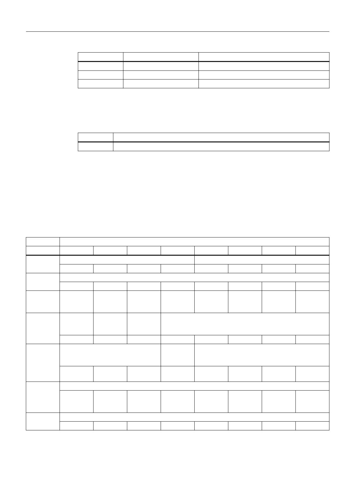
Interface signals
19.1 Interface signals - overview
DB No.
Designation
Interface for
1072
---
Multitool: Spindle
1073
---
Multitool: Revolver
1074 - 1099
---
Reserved for Siemens
19.1.1.5
Timer block
Table 19-5
Assigned times
Timer No.
Meaning
0 - 512*
Free for user assignment
* The actual upper limit of the timer number (DB) depends on the PLC CPU contained in the selected NCU.
19.1.2
Signals from/to the machine control panel
19.1.2.1
M version, signals from the MCP: Input image
Table 19-6
M version, signals from the MCP: Input image
Signals from the MCP (keys) (MCP → PLC)
Byte
Bit 7
Bit 6
Bit 5
Bit 4
Bit 3
Bit 2
Bit 1
Bit 0
EB n + 0
Spindle override
Operating mode
D
C
B
A
JOG
TEACH IN
MDI
AUTO
EB n + 1
Machine function
REPOS
REF
INCvar
INC10000
INC1000
INC100
INC10
INC1
EB n + 2
Key-operat-
Key-operat-
Spindle
*Spindle
Feedrate
*Feedrate
NC start
*NC stop
ed switch
ed switch
start
stop
start
stop
position 0
position 2
EB n + 3
Key-operat-
Feedrate override
ed switch
position 1
Reset
Single block
E
D
C
B
A
EB n + 4
Direction keys
Key-operat-
Axis selection
ed switch
position 3
+R15
-R13
Rapid tra-
X R1
4th axis R4
7th axis R7
R10
verse R14
EB n + 5
Axis selection
Y R2
Z R3
5th axis R5
Travel com-
R11
9th axis R9
8th axis R8
6th axis R6
mand
MCS/WCS
EB n + 6
Freely assignable customer keys
T9
T10
T11
T12
T13
T14
T15
PLC
326
Function Manual, 10/2020, 6FC5397-0HP40-0BA1
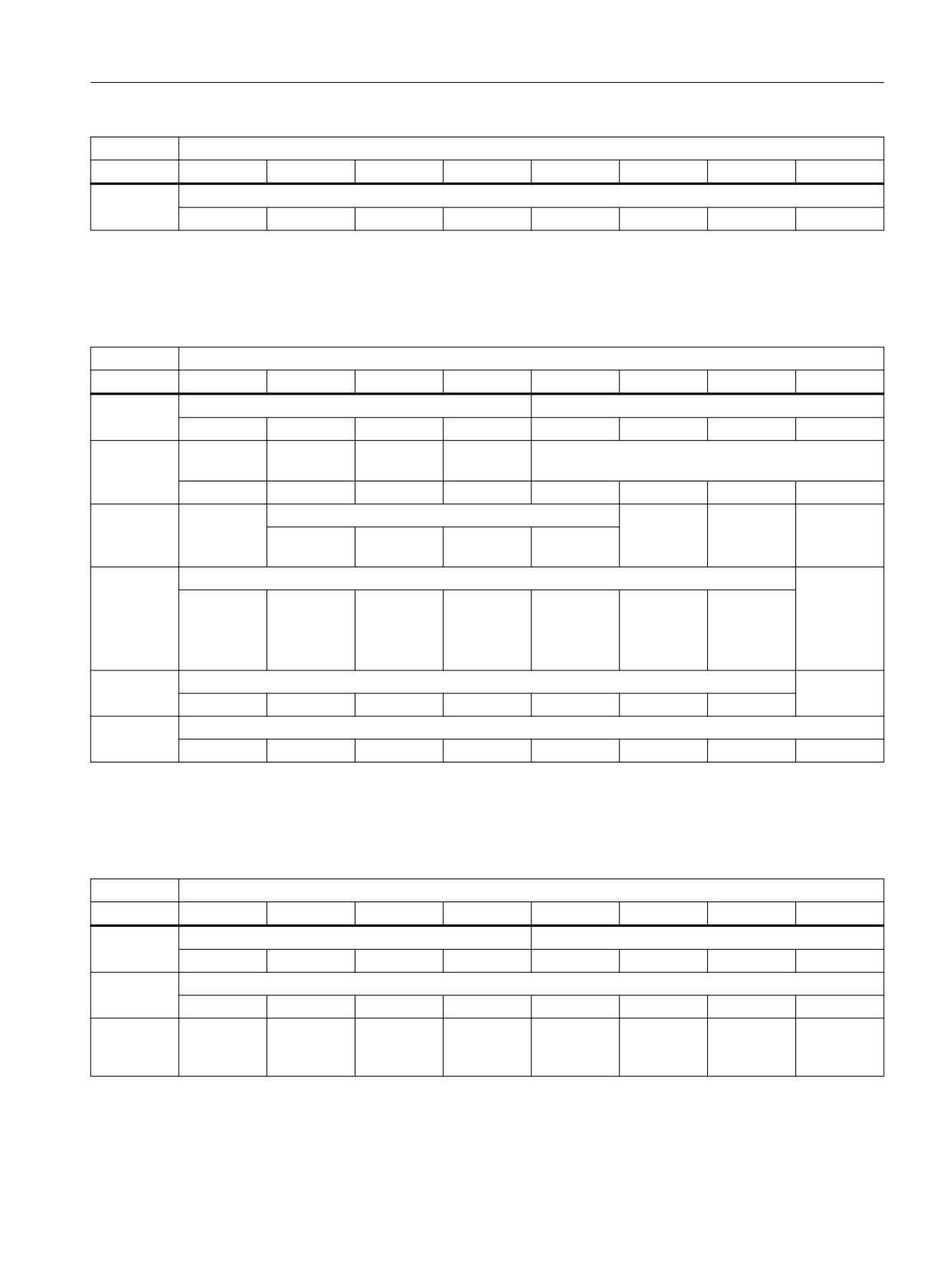
Interface signals
19.1 Interface signals - overview
Signals from the MCP (keys) (MCP → PLC)
Byte
Bit 7
Bit 6
Bit 5
Bit 4
Bit 3
Bit 2
Bit 1
Bit 0
EB n + 7
Freely assignable customer keys
T1
T2
T3
T4
T5
T6
T7
T8
19.1.2.2
M version, signals to the MCP: Output image
Table 19-7
M version, signals to the MCP: Output image
Signals to the MCP (LED) (PLC → MCP)
Byte
Bit 7
Bit 6
Bit 5
Bit 4
Bit 3
Bit 2
Bit 1
Bit 0
AB n + 0
Machine function
Operating mode
INC1000
INC100
INC10
INC1
JOG
TEACH IN
MDI
AUTO
AB n + 1
Feedrate
*Feedrate
NC start
*NC stop
Machine function
start
stop
REPOS
REF
INCvar
INC10000
AB n + 2
Direction
Axis selection
Single block
Spindle
*Spindle
key
start
stop
X R1
4th axis R4
7th axis R7
R10
-R13
AB n + 3
Axis selection
Direction
key
Z R3
5th axis R5
Travel com-
R11
9th axis R9
8th axis R8
6th axis R6
mand
+R15
MCS/WCS
R12
AB n + 4
Freely assignable customer keys
Y R2
T9
T10
T11
T12
T13
T14
T15
AB n + 5
Freely assignable customer keys
T1
T2
T3
T4
T5
T6
T7
T8
19.1.2.3
T version, signals from the MCP: Input image
Table 19-8
T version, signals from the MCP: Input image
Signals from the MCP (keys) (MCP → PLC)
Byte
Bit 7
Bit 6
Bit 5
Bit 4
Bit 3
Bit 2
Bit 1
Bit 0
EB n + 0
Spindle override
Operating mode
D
C
B
A
JOG
TEACH IN
MDI
AUTO
EB n + 1
Machine function
REPOS
REF
INCvar
INC10000
INC1000
INC100
INC10
INC1
EB n + 2
Key-operat-
Key-operat-
Spindle
*Spindle
Feedrate
*Feedrate
NC start
*NC stop
ed switch
ed switch
start
stop
start
stop
position 0
position 2
PLC
Function Manual, 10/2020, 6FC5397-0HP40-0BA1
327
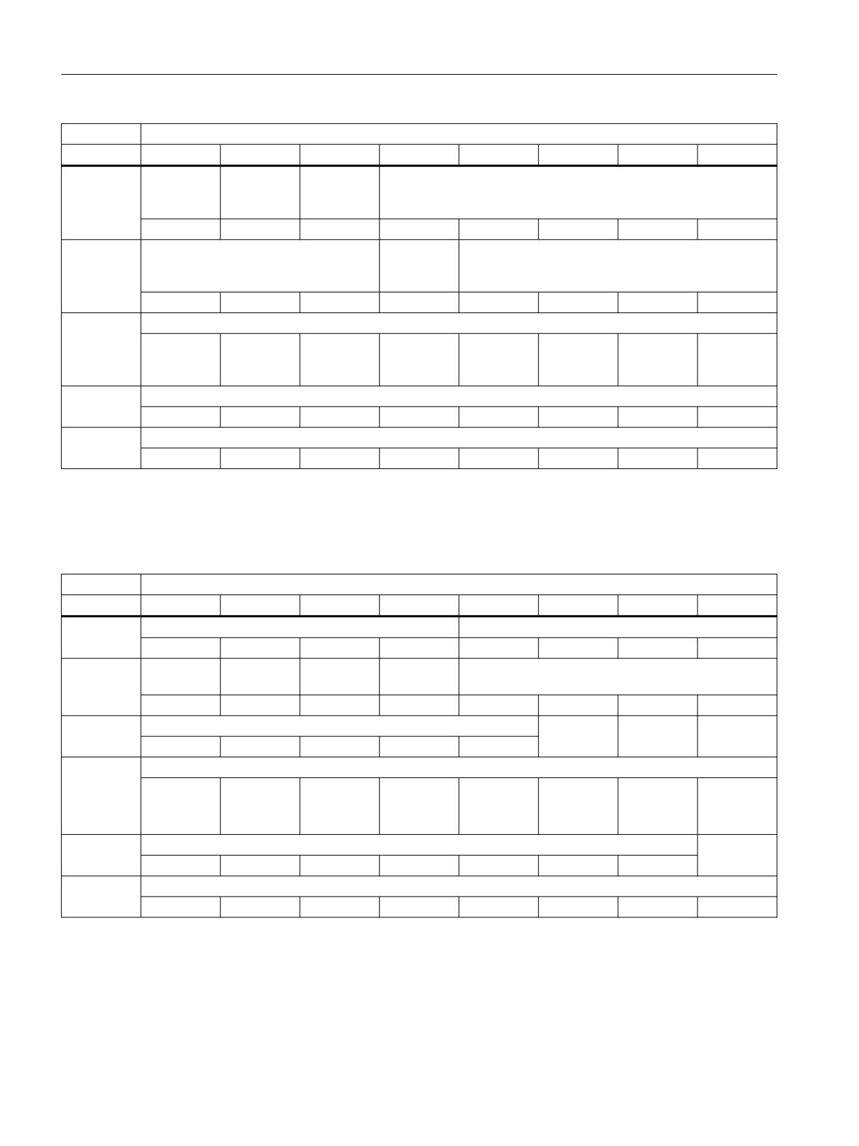
Interface signals
19.1 Interface signals - overview
Signals from the MCP (keys) (MCP → PLC)
Byte
Bit 7
Bit 6
Bit 5
Bit 4
Bit 3
Bit 2
Bit 1
Bit 0
EB n + 3
Key-operat-
Feedrate override
ed switch
position 1
Reset
Single block
E
D
C
B
A
EB n + 4
Direction keys
Key-operat-
Direction keys
ed switch
position 3
R15
R13
R14
+Y R1
-Z R4
-C R7
R10
EB n + 5
Direction keys
+X R2
+C R3
Rapid tra-
Travel com-
R11
-Y R9
-X R8
+Z R6
verse over-
mand MCS/
ride R5
WCS R12
EB n + 6
Freely assignable customer keys
T9
T10
T11
T12
T13
T14
T15
EB n + 7
Freely assignable customer keys
T1
T2
T3
T4
T5
T6
T7
T8
19.1.2.4
T version, signals to the MCP: Output image
Table 19-9
T version, signals to the MCP: Output image
Signals to the MCP (LED) (PLC → MCP)
Byte
Bit 7
Bit 6
Bit 5
Bit 4
Bit 3
Bit 2
Bit 1
Bit 0
AB n + 0
Machine function
Operating mode
INC1000
INC100
INC10
INC1
JOG
TEACH IN
MDI
AUTO
AB n + 1
Feedrate
*Feedrate
NC start
*NC stop
Machine function
start
stop
REPOS
REF
INCvar
INC10000
AB n + 2
Direction keys
Single block
Spindle
*Spindle
start
stop
R13
+Y R1
-Z R4
-C R7
R10
AB n + 3
Direction keys
R3
R5
Travel com-
R11
-Y R9
-X R8
+Z R6
R15
mand
MCS/WCS
AB n + 4
Freely assignable customer keys
Direction
key +X R2
T9
T10
T11
T12
T13
T14
T15
AB n + 5
Freely assignable customer keys
T1
T2
T3
T4
T5
T6
T7
T8
PLC
328
Function Manual, 10/2020, 6FC5397-0HP40-0BA1
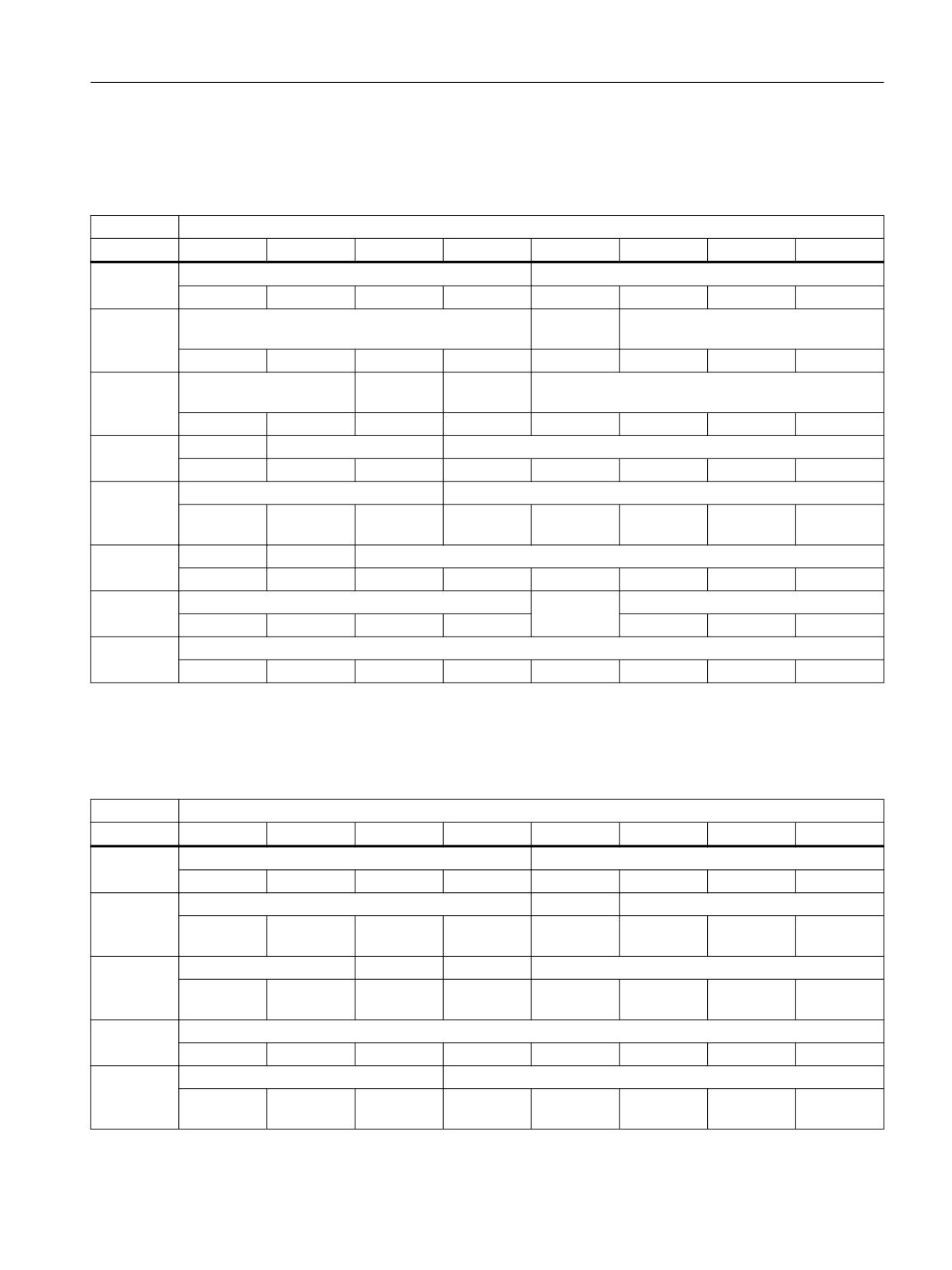
Interface signals
19.1 Interface signals - overview
19.1.2.5
Slimline version, signals from the MCP: Input image
Table 19-10
Slimline version, signals from the MCP: Input image
Signals from the slimline MCP (switches and keys) (MCP → PLC)
Byte
Bit 7
Bit 6
Bit 5
Bit 4
Bit 3
Bit 2
Bit 1
Bit 0
EB n + 0
Spindle override
Operating mode
*NC stop
SP -
SP 100%
SP +
SINGLEB
JOG
MDI
AUTO
EB n + 1
Spindle
Key-operat-
Machine function
ed switch
NC start
SP right
*SP stop
SP left
INT 3
REF
REPOS
TEACH IN
EB n + 2
Feedrate
Key-operat-
Machine functions
ed switch
Start
*Stop
INCvar
INT 0
INC1000
INC100
INC10
INC1
EB n + 3
Key-operated switch
Feedrate override
Reset
INT 2
INT 1
E
D
C
B
A
EB n + 4
Direction keys
Optional customer keys
+R15
-R13
Rapid tra-
KT4
KT3
KT2
KT1
KT0
verse R14
EB n + 5
Axis selection
T17
KT5
6
5
4
Z
Y
X
EB n + 6
Freely assignable customer keys
MCS/WCS
Freely assignable customer keys
T9
T10
T11
T12
T14
T15
T16
EB n + 7
Freely assignable customer keys
T1
T2
T3
T4
T5
T6
T7
T8
19.1.2.6
Slimline version, signals to the MCP: Output image
Table 19-11 Slimline version, signals to the MCP: Output image
Signals to the slimline MCP (LED) (PLC → MCP)
Byte
Bit 7
Bit 6
Bit 5
Bit 4
Bit 3
Bit 2
Bit 1
Bit 0
EB n + 0
Spindle override
Operating mode
NC stop
SP -
SP 100%
SP +
SINGLEB
JOG
MDI
AUTO
EB n + 1
Spindle
Machine function
NC start
SP right
SP stop
SP left
Not as-
REF
REPOS
TEACH IN
signed
EB n + 2
Feedrate
Machine functions
Start
Stop
INCvar
Not as-
INC1000
INC100
INC10
INC1
signed
EB n + 3
Not assigned
EB n + 4
Direction keys
Optional customer keys
+R15
-R13
Rapid tra-
KT4
KT3
KT2
KT1
KT0
verse R14
PLC
Function Manual, 10/2020, 6FC5397-0HP40-0BA1
329
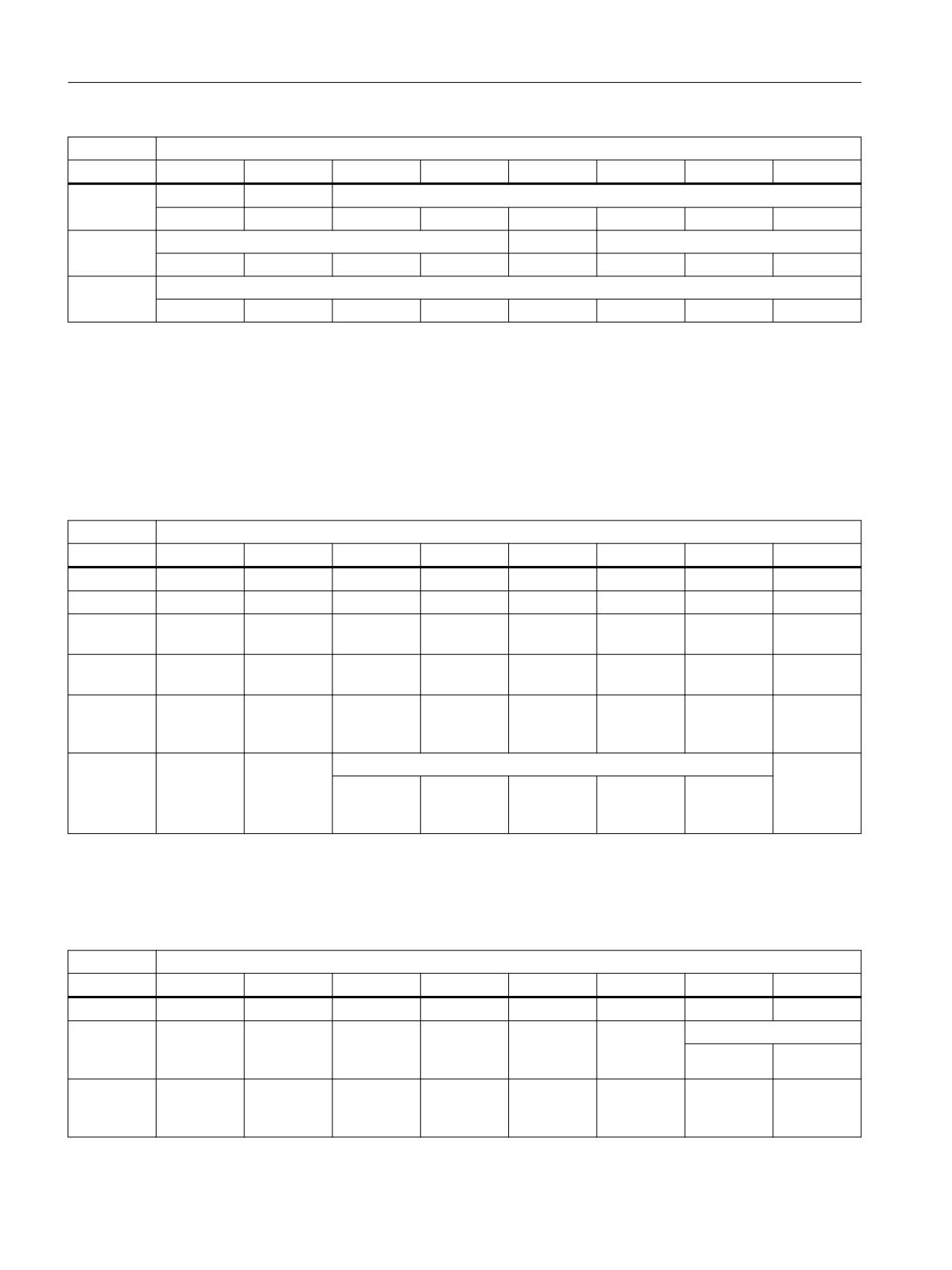
Interface signals
19.1 Interface signals - overview
Signals to the slimline MCP (LED) (PLC → MCP)
Byte
Bit 7
Bit 6
Bit 5
Bit 4
Bit 3
Bit 2
Bit 1
Bit 0
EB n + 5
Axis selection
T17
KT5
6
5
4
Z
Y
X
EB n + 6
Freely assignable customer keys
Freely assignable customer keys
T9
T10
T11
T12
MCS/WCS
T14
T15
T16
EB n + 7
Freely assignable customer keys
T1
T2
T3
T4
T5
T6
T7
T8
19.1.3
Signals from/to the handheld unit HT 2
19.1.3.1
Signals from the handheld unit: Input image
Table 19-12 Signals from the handheld unit: Input image
Signals from the handheld unit (keys) (HHU / HT 2 → PLC)
Byte
Bit 7
Bit 6
Bit 5
Bit 4
Bit 3
Bit 2
Bit 1
Bit 0
IB m + 0
Reserved
Reserved
Reserved
Reserved
Reserved
Reserved
Reserved
Reserved
IB m + 1
Reserved
Reserved
Reserved
Reserved
Reserved
Reserved
Reserved
Reserved
IB m + 2
Feedrate
Free T2 key
AUTO
NC stop
Spindle stop
Feed stop
Free T1 key
JOG
start
IB m + 3
Free T3 key
Handwheel
4th axis
Z
Y
X
NC start
Spindle
start
IB m + 4
Direction
Rapid tra-
Direction
Free T4 key
key
verse over-
key +
ride
IB m + 5
Acknowl-
Key-operat-
Rapid traverse/feedrate override switch
edgement
ed switch
E
D
C
B
A
Digital dis-
play
19.1.3.2
Signals to the handheld unit: Output image
Table 19-13 Signals to the handheld unit: Output image
Signals to the handheld unit (LED) (PLC → HHU / HT 2)
Byte
Bit 7
Bit 6
Bit 5
Bit 4
Bit 3
Bit 2
Bit 1
Bit 0
QB m + 0
Always 1
Free T4 key
Free T3 key
Free T2 key
Free T1 key
QB m + 1
New data
Selecting the line
for selected
3 and 4
1 and 2
line
QB m + 2
Feedrate
Rapid tra-
AUTO
NC stop
Spindle stop
Feed stop
Direction
JOG
start
verse over-
key +
ride
PLC
330
Function Manual, 10/2020, 6FC5397-0HP40-0BA1

Interface signals
19.1 Interface signals - overview
Signals to the handheld unit (LED) (PLC → HHU / HT 2)
Byte
Bit 7
Bit 6
Bit 5
Bit 4
Bit 3
Bit 2
Bit 1
Bit 0
QB m + 3
Direction
Handwheel
4th axis
Z
Y
X
NC start
Spindle
key +
start
Digital display of the handheld unit
QB m + 4
Default setting of 1st character (right) of selected line
QB m + 5
Default setting of 2nd character of selected line
QB m + 6
Default setting of 3rd character of selected line
QB m + 7
Default setting of 4th character of selected line
QB m + 8
Default setting of 5th character of selected line
QB m + 9
Default setting of 6th character of selected line
QB m + 10
Default setting of 7th character of selected line
QB m + 11
Default setting of 8th character of selected line
QB m + 12
Default setting of 9th character of selected line
QB m + 13
Default setting of 10th character of selected line
QB m + 14
Default setting of 11th character of selected line
QB m + 15
Default setting of 12th character of selected line
QB m + 16
Default setting of 13th character of selected line
QB m + 17
Default setting of 14th character of selected line
QB m + 18
Default setting of 15th character of selected line
QB m + 19
Default setting of 16th character (left) of selected line
Note
The parameterization or configuration of the various MCP/HHU versions is described in:
Further information
• Manual, Operator Components and Networking
PLC
Function Manual, 10/2020, 6FC5397-0HP40-0BA1
331
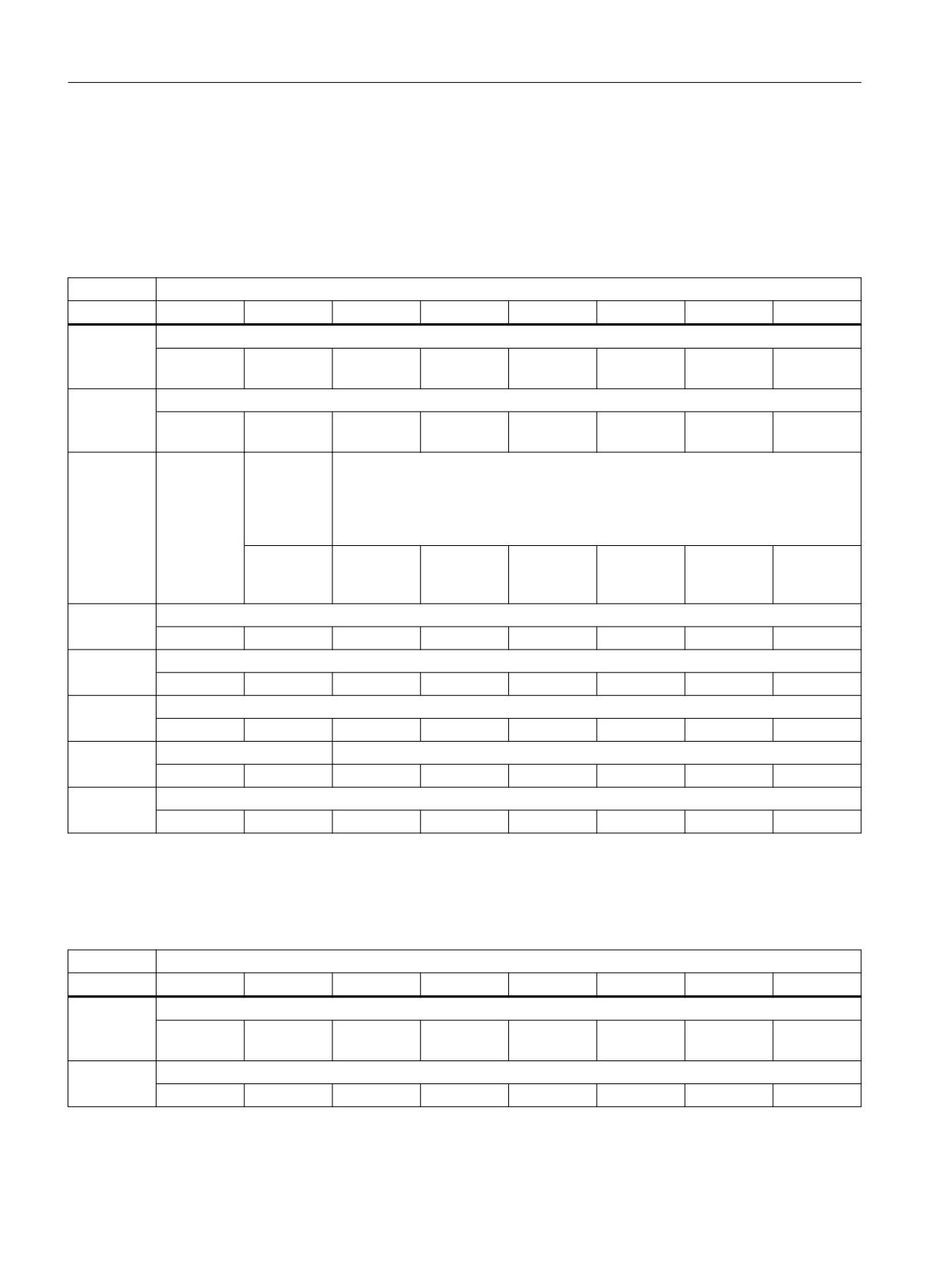
Interface signals
19.1 Interface signals - overview
19.1.4
Signals from/to the handheld unit HT 8
19.1.4.1
Signals from the handheld unit HT 8: Input image
Table 19-14
Signals from the handheld unit HT 8: Input image
Signals from the MCP simulation (HT 8 → PLC)
Byte
Bit 7
Bit 6
Bit 5
Bit 4
Bit 3
Bit 2
Bit 1
Bit 0
EB n + 0
Function key block
REF
TEACH
AUTO
MDI
JOG
QUIT
Reset
Work/
Machine
EB n + 1
Function key block
CPF
U4
U3
BigFct
U2
U1
INC
REPOS
(U key)
EB n + 2
Change-
Traversing keys (JOG) positive direction
over axes
(HMI Ad-
vanced on-
ly)
Ax7-Ax12
Ax6
Ax5
Ax4
Ax3
Ax2
Ax1
instead of
Ax1-Ax6
EB n + 3
Traversing keys (JOG) negative direction
Ax6
Ax5
Ax4
Ax3
Ax2
Ax1
EB n + 4
U9
U10
U11
U12
U13
U14
U15
U16
EB n + 5
U8
U7
U6
U5
SBL
EB n + 6
Start key block
Reserved
HT 8
SF2
SF1
SF4
SF3
Start
Stop
EB n + 7
Feedrate override
E
D
C
B
A
19.1.4.2
Signals to handheld terminal HT 8: Output image
Table 19-15 Signals from the handheld unit HT 8: Output image
Signals to the MCP simulation (PLC → HT 8)
Byte
Bit 7
Bit 6
Bit 5
Bit 4
Bit 3
Bit 2
Bit 1
Bit 0
AB n + 0
Function key block
REF
TEACH
AUTO
MDI
JOG
QUIT
Reset
Work/
Machine
AB n + 1
Function key block
U4
U3
U2
U1
INC
REPOS
PLC
332
Function Manual, 10/2020, 6FC5397-0HP40-0BA1
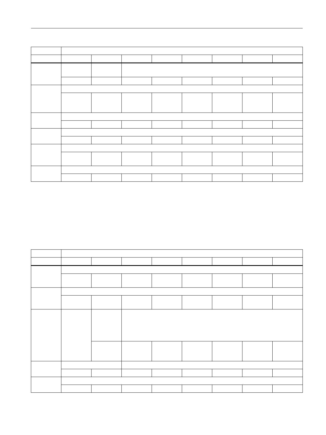
Interface signals
19.1 Interface signals - overview
Signals to the MCP simulation (PLC → HT 8)
Byte
Bit 7
Bit 6
Bit 5
Bit 4
Bit 3
Bit 2
Bit 1
Bit 0
AB n + 2
Axes 7 - n
Traversing keys (JOG) positive direction
selected
Ax6
Ax5
Ax4
Ax3
Ax2
Ax1
AB n + 3
Traversing keys (JOG) negative direction
For WCS: no
Ax6
Ax5
Ax4
Ax3
Ax2
Ax1
machine ax-
es
AB n + 4
U9
U10
U11
U12
U13
U14
U15
U16
AB n + 5
U8
U7
U6
U5
SBL
AB n + 6
Start key block
Display tra-
SF2
SF1
SF4
SF3
Start
Stop
versing keys
AB n + 7
19.1.5
Signals from/to the handheld unit HT 10
19.1.5.1
Signals from the handheld unit HT 10: Input image
Table 19-16 Signals from the handheld unit HT 10: Input image
Signals from the MCP simulation (HT 10 → PLC)
Byte
Bit 7
Bit 6
Bit 5
Bit 4
Bit 3
Bit 2
Bit 1
Bit 0
EB n + 0
Function key block
REF
TEACH
AUTO
MDI
JOG
QUIT
Reset
Work/
Machine
EB n + 1
Function key block
CPF
U4
U3
BigFct
U2
U1
INC
REPOS
(U key)
EB n + 2
Change-
Traversing keys (JOG) HT 8, positive direction
over axes
(HMI Ad-
vanced on-
ly)
Ax7-Ax12
Ax6
Ax5
Ax4
Ax3
Ax2
Ax1
instead of
Ax1-Ax6
EB n + 3
JOG keys HT 10
Traversing keys (JOG) HT 8, negative direction
Plus
Minus
Ax6
Ax5
Ax4
Ax3
Ax2
Ax1
EB n + 4
U16
U15
U14
U13
U12
U11
U10
U9
PLC
Function Manual, 10/2020, 6FC5397-0HP40-0BA1
333
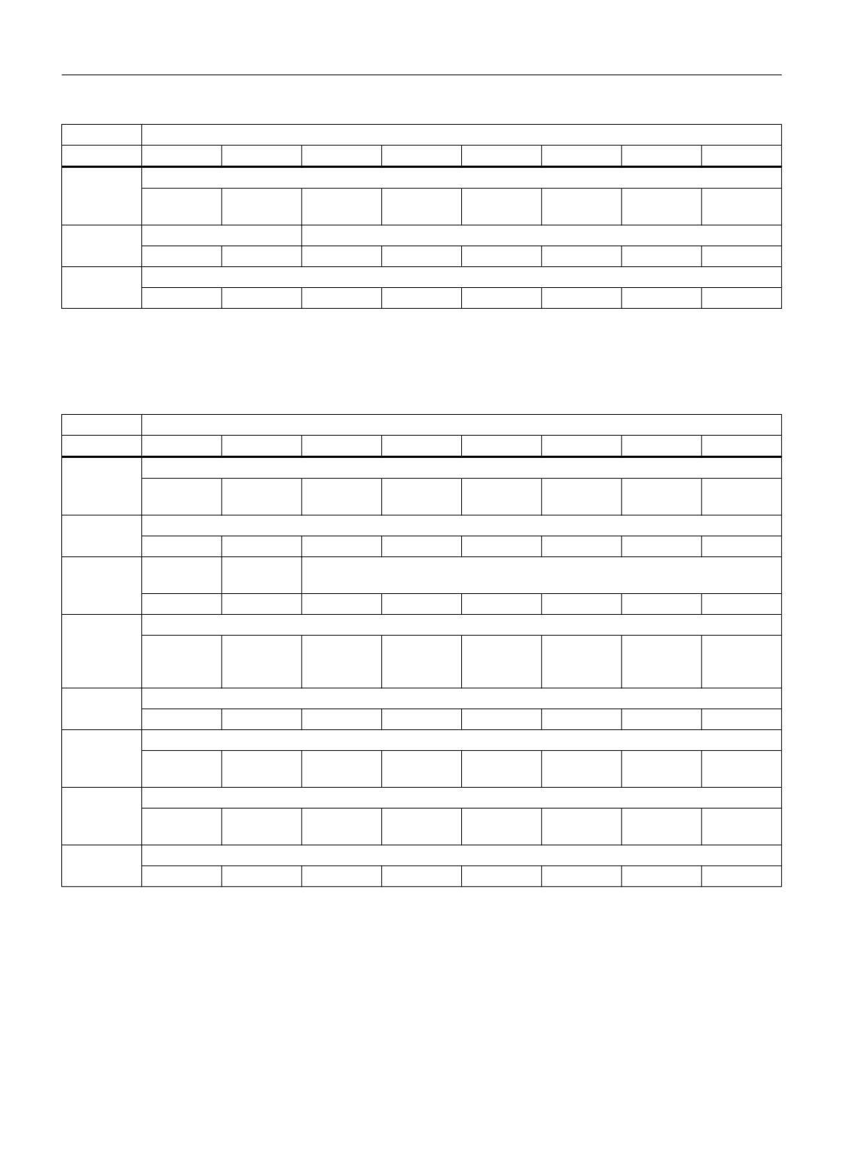
Interface signals
19.1 Interface signals - overview
Signals from the MCP simulation (HT 10 → PLC)
Byte
Bit 7
Bit 6
Bit 5
Bit 4
Bit 3
Bit 2
Bit 1
Bit 0
EB n + 5
U8
U7
U6
U5
SBL
Rapid tra-
verse
EB n + 6
Start key block
HT 10
HT 8
SF2
SF1
SF4
SF3
Start
Stop
EB n + 7
Feedrate override
E
D
C
B
A
19.1.5.2
Signals to handheld terminal HT 10: Output image
Table 19-17 Signals from the handheld unit HT 10: Output image
Signals to the MCP simulation (PLC → HT 10)
Byte
Bit 7
Bit 6
Bit 5
Bit 4
Bit 3
Bit 2
Bit 1
Bit 0
AB n + 0
Function key block
REF
TEACH
AUTO
MDI
JOG
QUIT
Reset
Work/
Machine
AB n + 1
Function key block
U4
U3
U2
U1
INC
REPOS
AB n + 2
JOG +
Axes 7 - n
Traversing keys (JOG) HT 8, positive direction
(HT 10)
selected
Ax6
Ax5
Ax4
Ax3
Ax2
Ax1
AB n + 3
Traversing keys (JOG) HT 8, negative direction
For WCS: no
JOG -
Ax6
Ax5
Ax4
Ax3
Ax2
Ax1
machine ax-
(HT 10)
es
AB n + 4
U9
U10
U11
U12
U13
U14
U15
U16
AB n + 5
U8
U7
U6
U5
SBL
Rapid tra-
verse
AB n + 6
Start key block
Display tra-
SF2
SF1
SF4
SF3
Start
Stop
versing keys
AB n + 7
PLC
334
Function Manual, 10/2020, 6FC5397-0HP40-0BA1
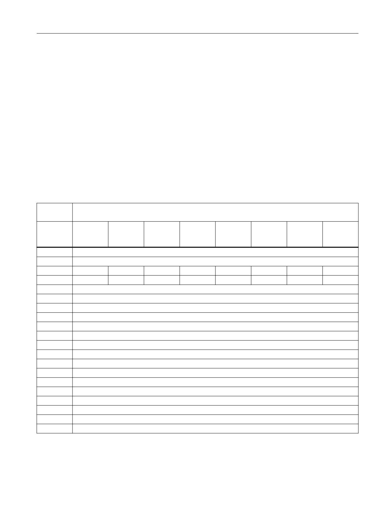
Interface signals
19.1 Interface signals - overview
19.1.6
PLC alarms/messages
19.1.6.1
FC 10 alarms in the DB2 (FB1: "ExtendAIMsg" = FALSE)
Message type
• FM: A fault message with the associated event number as fault number is triggered by the
signal.
• OM: An operating message with the associated event number as message number is
triggered by the signal.
Further information
A detailed description regarding error and system status messages can be obtained in:
FC10: AL_MSG - error and operating messages (Page 262)
Table 19-18
DB2, channel range 1
DB2
Signals for PLC events (PLC → HMI)
FB1 parameter "ExtendAIMsg" = FALSE
Byte
Bit 7
Bit 6
Bit 5
Bit 4
Bit 3
Bit 2
Bit 1
Bit 0
(message
type)
Channel 1
Feedrate disable (event no.: 510000-510015)
0 (FM)
510007
510006
510005
510004
510003
510002
510001
510000
1 (OM)
510015
510014
510013
510012
510011
510010
510009
510008
2 (FM)
Feedrate and read-in disable, byte 1 (event no.: 510100-510107)
3 (FM)
Feedrate and read-in disable, byte 2 (event no.: 510108-510115)
4 (OM)
Feedrate and read-in disable, byte 3 (event no.: 510116-510123)
5 (OM)
Feedrate and read-in disable, byte 4 (event no.: 510124-510131)
6 (FM)
Read-in disable, byte 1 (event no.: 510200-510207)
7 (FM)
Read-in disable, byte 2 (event no.: 510208-510215)
8 (OM)
Read-in disable, byte 3 (event no.: 510216-510223)
9 (OM)
Read-in disable, byte 4 (event no.: 510224-510231)
10 (FM)
NC start disable, byte 1 (event no.: 510300-510307)
11 (OM)
NC start disable, byte 2 (event no.: 510308-510315)
12 (FM)
Feedrate stop, geo axis 1, byte 1 (event no.: 511100-511107)
13 (OM)
Feedrate stop, geo axis 1, byte 2 (event no.: 511108-511115)
14 (FM)
Feedrate stop, geo axis 2, byte 1 (event no.: 511200-511207)
15 (OM)
Feedrate stop, geo axis 2, byte 2 (event no.: 511208-511215)
16 (FM)
Feedrate stop, geo axis 3, byte 1 (event no.: 511300-511307)
17 (OM)
Feedrate stop, geo axis 3, byte 2 (event no.: 511308-511315)
PLC
Function Manual, 10/2020, 6FC5397-0HP40-0BA1
335
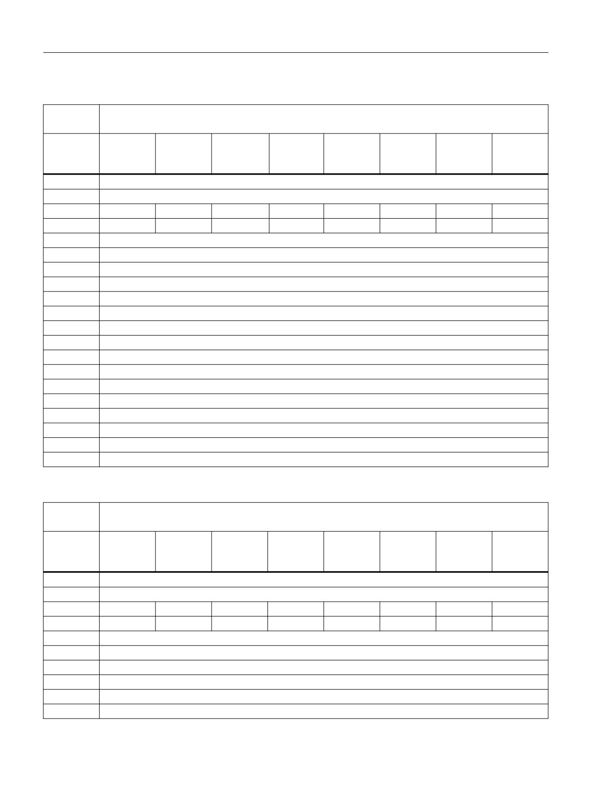
Interface signals
19.1 Interface signals - overview
Table 19-19
DB2, channel range 2
DB2
Signals for PLC events (PLC → HMI)
FB1 parameter "ExtendAIMsg" = FALSE
Byte
Bit 7
Bit 6
Bit 5
Bit 4
Bit 3
Bit 2
Bit 1
Bit 0
(message
type)
Channel 2
Feedrate disable (event no.: 520000-520015)
18 (FM)
520007
520006
520005
520004
520003
520002
520001
520000
19 (OM)
520015
520014
520013
520012
520011
520010
520009
520008
20 (FM)
Feedrate and read-in disable, byte 1 (event no.: 520100-520107)
21 (FM)
Feedrate and read-in disable, byte 2 (event no.: 520108-520115)
22 (OM)
Feedrate and read-in disable, byte 3 (event no.: 520116-520123)
23 (OM)
Feedrate and read-in disable, byte 4 (event no.: 520124-520131)
24 (FM)
Read-in disable, byte 1 (event no.: 520200-520207)
25 (FM)
Read-in disable, byte 2 (event no.: 520208-520215)
26 (OM)
Read-in disable, byte 3 (event no.: 520216-520223)
27 (OM)
Read-in disable, byte 4 (event no.: 520224-520231)
28 (FM)
NC start disable, byte 1 (event no.: 520300-520307)
29 (OM)
NC start disable, byte 2 (event no.: 520308-520315)
30 (FM)
Feedrate stop, geo axis 1, byte 1 (event no.: 521100-521107)
31 (OM)
Feedrate stop, geo axis 1, byte 2 (event no.: 521108-521115)
32 (FM)
Feedrate stop, geo axis 2, byte 1 (event no.: 521200-521207)
33 (OM)
Feedrate stop, geo axis 2, byte 2 (event no.: 521208-521215)
34 (FM)
Feedrate stop, geo axis 3, byte 1 (event no.: 521300-521307)
35 (OM)
Feedrate stop, geo axis 3, byte 2 (event no.: 521308-521315)
Table 19-20
DB2, channel range 3
DB2
Signals for PLC events (PLC → HMI)
FB1 parameter "ExtendAIMsg" = FALSE
Byte
Bit 7
Bit 6
Bit 5
Bit 4
Bit 3
Bit 2
Bit 1
Bit 0
(message
type)
Channel 3
Feedrate disable (event no.: 530000-530015)
36 (FM)
530007
530006
530005
530004
530003
530002
530001
530000
37 (OM)
530015
530014
530013
530012
530011
530010
530009
530008
38 (FM)
Feedrate and read-in disable, byte 1 (event no.: 530100-530107)
39 (FM)
Feedrate and read-in disable, byte 2 (event no.: 530108-530115)
40 (OM)
Feedrate and read-in disable, byte 3 (event no.: 530116-530123)
41 (OM)
Feedrate and read-in disable, byte 4 (event no.: 530124-530131)
42 (FM)
Read-in disable, byte 1 (event no.: 530200-530207)
43 (FM)
Read-in disable, byte 2 (event no.: 530208-530215)
PLC
336
Function Manual, 10/2020, 6FC5397-0HP40-0BA1