SINUMERIK 840D sl. Service - Functions. Manual (2018-2020) - page 53

Block descriptions
17.11 FB21: Powerride - rotary/push control dial
Description of formal parameters
Parameter
Type
Type
Value range
Meaning
enable
I
BOOL
---
Edit Powerride function
Only set the parameter to TRUE after Pow-
er On (control startup) has been comple-
ted.
TRUE
Configuration data are checked and pro-
cessing of the FBs is started if the check is
successful.
With Power On, the last "switchPos" be-
comes active if the instance DB is retentive.
FALSE
No processing of the FB; output values are
retained.
preset
I
BOOL
---
Change "switchPos"
On the positive edge, "presetValue" is ac-
cepted as the current "switchPos". The "pre-
setValue" parameterization must be valid
for this.
The displays in "grayCode" and "ovrFactor"
are updated.
forceSwitchPos1
I
BOOL
---
Set switch to position 1
On the positive edge, the switch is set to
position 1 and the override factor "config-
uration.switchPos[1].value" is output.
pushButtonLED
I
BYTE
0 ... 7
Trigger LED of the switch
See LED color palette (Page 236)
presetValue
I
BYTE
1 ... 36
New value for "switchPos"
With a positive edge of "preset", the value
is accepted as the new "switchPos".
Special case 1
"presetValue" is between "configura-
tion.pos100" and "configuration.posMax"
and "switchPos" (current position) is less
than "configuration.pos100"
For safety reasons, in this case the value of
"configuration.pos100" is accepted with
"preset".
Special case 2
"presetValue" is greater than "configura-
tion.posMax" and less than 36
With "preset", the value of "configura-
tion.posMax" is accepted.
valid
O
BOOL
---
Display whether the block is being pro-
cessed and the configuration is valid
TRUE if "enable" = TRUE and
"error" = FALSE if "enable" = FALSE or "er-
ror" = TRUE
PLC
234
Function Manual, 10/2020, 6FC5397-0HP40-0BA1

Block descriptions
17.11 FB21: Powerride - rotary/push control dial
Parameter
Type
Type
Value range
Meaning
error
O
BOOL
---
Indication whether an error is present
The cause of the error is displayed in the
parameter "status".
TRUE if an error occurs, in which case the
other outputs are reset
FALSE if "enable" = FALSE or "valid" = TRUE
pushButton
O
BOOL
---
Indication whether the switch is pressed
The output is supplied if "valid" = TRUE.
ovrFactor1)
O
BYTE
0 ... 200
Display of the override factor as integer
The value parameterized under "configu-
ration.switchPos[1..36].value" is output
for the current switch position.
The output is supplied if "valid" = TRUE.
grayCode1)
O
BYTE
---
Display of the override factor as Gray code
The value parameterized under "configu-
ration.switchPos[1..36].value" is output
for the current switch position.
The output is supplied if "valid" = TRUE.
switchPos
O
BYTE
1 ... configura-
Display of the current switch position of
tion.posMax
the Powerride
The output is supplied if "valid" = TRUE.
statusId
O
BYTE
---
Display of the function to which the status
refers
See Status and error IDs (Page 239)
status
O
WORD
---
Status and error IDs (Page 239)
deviceIn
I/O
Type
---
Signals to the PLC
Powerri-
See Signal transfer between Powerride
deIn
and PLC (Page 235)
deviceOut
I/O
Type
---
Signals from the PLC to the Powerride
Powerri-
See Signal transfer between Powerride
deOut
and PLC (Page 235)
configuration
I/O
Type
---
Configuration data
Powerri-
See "DB78: PowerrideConfig"
deConfig
1) You set the interpretation of the override factor in the machine date (e.g.:
MD12020 $MN_OVR_FEED_IS_GRAY_CODE).
See also
DB78: PowerrideConfig (Page 442)
17.11.1
Signal transfer between Powerride and PLC
The signals of the Powerride are transferred via a USB interface. The PLC is connected via an MCP
or its COM board.
PLC
Function Manual, 10/2020, 6FC5397-0HP40-0BA1
235

Block descriptions
17.11 FB21: Powerride - rotary/push control dial
Signals to the PLC
The following table lists signals that are transferred from the Powerride to the PLC:
Byte
Bit 7
Bit 6
Bit 5
Bit 4
Bit 3
Bit 2
Bit 1
Bit 0
0
-
-
-
-
-
-
-
Switch
pressed =
TRUE
1
Position of the rotary wheel [0..255]
(modulo, 256 notches at 36 notches per revolution)
Signals to the Powerride
The following table lists signals that are transferred from the PLC to the Powerride:
Byte
Bit 7
Bit 6
Bit 5
Bit 4
Bit 3
Bit 2
Bit 1
Bit 0
0
-
-
-
-
-
-
-
LED strip1)
24
1
LED strip1)
LED strip1)
LED strip1)
LED strip1)
LED strip1)
LED strip1)
LED strip1)
LED strip1)
23
22
21
20
19
18
17
16
2
LED strip1)
LED strip1)
LED strip1)
LED strip1)
LED strip1)
LED strip1)
LED strip1) 9
LED strip1) 8
15
14
13
12
11
10
3
LED strip1) 7
LED strip1) 6
LED strip1) 5
LED strip1) 4
LED strip1) 3
LED strip1) 2
LED strip1) 1
LED strip1) 0
4
-
-
Color of the switch LED
Color of the LED strip
(color combinations (Page 236) possi-
(color combinations (Page 236) possi-
ble)
ble)
Blue
Green
Red
Blue
Green
Red
5
-
-
-
-
-
Vibration pattern [0..7]
(at 0 no vibration)
1) With TRUE the respective LED of the LED strip is lit
17.11.2
LED color palette
The following table shows the possible color combinations depending on the individual colors
blue, green and red:
Combined color
Blue (bit 2)
Green (bit 1)
Red (bit 0)
-
-
-
-
Red
-
-
x
Green
-
x
-
Yellow
-
x
x
Blue
x
-
-
Magenta
x
-
x
Cyan
x
x
-
White
x
x
x
PLC
236
Function Manual, 10/2020, 6FC5397-0HP40-0BA1
Block descriptions
17.11 FB21: Powerride - rotary/push control dial
17.11.3
Examples
17.11.3.1
Integrate Powerride via an MCP during start-up
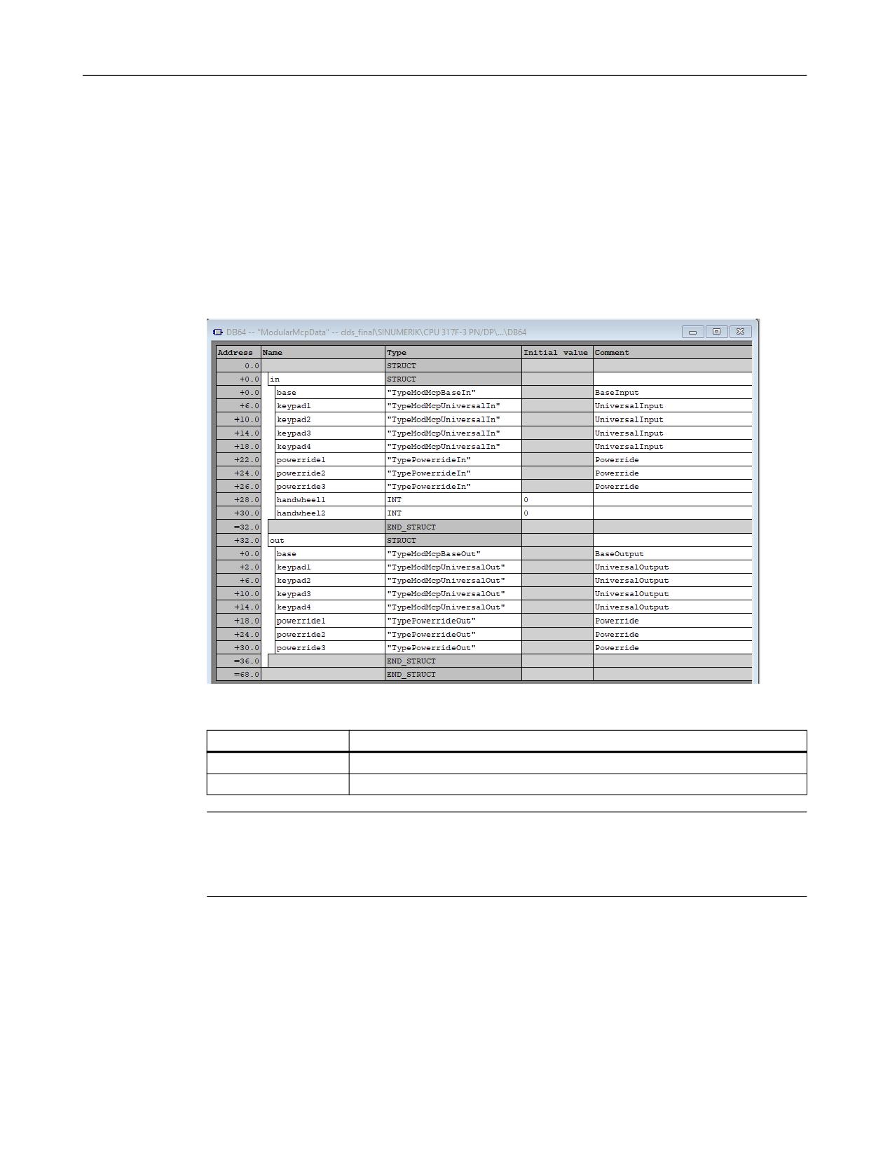
In the example the Powerride is a hardware component of a modular MCP. This MCP is used as
second MCP. The global data block "ModularMcpData" is available for the input and output
image. The block is not included in the library. Using "ModularMCPData" as an example, it is
shown how the input and output image can be mapped for a modular MCP using data types
supplied in the library, and how this DB can be used.
The following table shows an example of the input and output addresses:
Byte numbers of the data
Input data
"ModularMcpData".in.powerride1 and "ModularMcoData".in.powerride2
Output data
"ModularMcpData".out.powerride1 and "ModularMcpData".out.powerride2
Note
The addresses of the Powerride data in the input and output image of the MCP can change with
the firmware version. The current address assignment is described in the Operating Components
Manual Modular MCPs.
The code example shows the relevant part of the call of FB1 "RUN_UP" in OB100:
CALL "RUN_UP" , "gp_par"
//FB1 / DB7
MCPNum
:=2
MCP1In
:=P#E 0.0
MCP1Out
:=P#A 0.0
PLC
Function Manual, 10/2020, 6FC5397-0HP40-0BA1
237
Block descriptions
17.11 FB21: Powerride - rotary/push control dial
MCP1StatSend
:=P#M100.0
MCP1StatRec
:=P#M104.0
MCP1BusAdr
:=192
MCP1Timeout
:=
MCP1Cycl
:=
MCP2In
:="ModularMcpData".in
//
P#DB64.DBX0.0
MCP2Out
:="ModularMcpData".out
//
P#DB64.DBX40.0
MCP2StatSend
:=P#M 108.0
MCP2StatRec
:=P#M 112.0
MCP2BusAdr
:=193
MCP12Timeout
:=
MCP2Cycl
:=
MCPMPI
:=
MCP1Stop
:=
MCP2Stop
:=
MCP1NotSend
:=
MCP2NotSend
:=
MCPSDB210
:=
MCPCopyDB77
:=
MCPBusType
:=B#16#55
…
17.11.3.2
Calling Powerride
The example shows the call of "Powerride". The input and output image of the MCP must be
assigned previously during startup and is described in example "Integrate Powerride via an MCP
during start-up (Page 237)". The global data block DB64 "ModularMcpData" contains the input
and output image in the example. You can also find information on this in the Operating
Components Manual Modular MCPs.
The following code shows the call of "Powerride" in OB1:
CALL "Powerride" ,
"InstPr1"
enable
:=#tempEnable
preset
:=#tempPreset
forceSwitchPos1
:=#tempForceSwitchPos1
pushButtonLED
:=#tempPushButtonLED
presetValue
:=#tempPresetValue
valid
:=#tempValid
error
:=#tempError
pushButton
:=#tempPushButton
ovrFactor
:=#tempOvrFactor
PLC
238
Function Manual, 10/2020, 6FC5397-0HP40-0BA1

Block descriptions
17.11 FB21: Powerride - rotary/push control dial
grayCode
:=#tempGrayCode
switchPos
:=#tempSwitchPos
status
:=#tempStatus
statusId
:=#tempStatusID
deviceIn
:="ModularMcpData".in.powerride1
deviceOut
:="ModularMcpData".out.powerrride1
configuration
:="PowerrideConfig".configFeed
17.11.4
Status and error IDs
The following table lists the status and error codes of the "Powerride" if "statusId" = 1.
Number
Type1)
Explanation
0000
-
No error
0007
M
Configuration is valid
7000
M
"enable" parameter is FALSE
7005
M
Settings are checked
7104
F
The "pushButtonLED" parameter is outside the valid range (0 ... 7)
7105
M
"configuration.switchPos[x].ledColor" parameter is outside the valid range (0 … 7) in
one or more data records
7106
M
"configuration.switchPos[x].vibrationIndex" parameter is outside the valid range
(0 … 7) in one or more data records
8102
F
"presetValue" parameter is greater than 36
8103
F
"presetValue" parameter is less than 1
8212
F
Configuration error: The parameter "configuration" - "posMax" is greater than 36
8221
F
Configuration error: The parameter "configuration" - "pos100" is less than 1
8222
F
Configuration error: The parameter "configuration" - "posMax" is less than 1
8223
F
Configuration error: The "configuration" - "pos100" parameter is greater than "pos-
Max"
8231
F
"configuration.switchPos[x].value" parameter is outside the valid range (0 … 200%)
in one or more data records
1) M = message, F = fault
The following table lists the status and error codes of the "Powerride" if "statusId" = 2, 3 or 4.
Number
Type1)
Explanation
0000
-
No error
8092
F
The source or target area is only available in load memory
8xyy
F
You can obtain further information on errors by evaluating the return parameter
RET_VAL.
1) M = message, F = fault
PLC
Function Manual, 10/2020, 6FC5397-0HP40-0BA1
239
Block descriptions
17.12 FB29: Signal recorder and data trigger diagnostics
17.12
FB29: Signal recorder and data trigger diagnostics
Function
Signal recorder
FB29 "Diagnostics" allows various diagnostic routines to be performed on the PLC user program.
A diagnostic routine logs signal states and signal changes. In this diagnostic routine, function
number 1 is assigned to the "Func" parameter. Up to 8 signals of the parameters "Signal_1" to
"Signal_8" are recorded in a ring buffer each time one of the signals changes. The current
information of parameters "Var1" as BYTE value, and "Var2" and "Var3" as INTEGER values are also
stored in the ring buffer.
The number of past OB1 cycles is also stored in the buffer as additional information. This
information enables the graphical evaluation of signals and values in OB1 cycle grid.
Call rule
First call of FB29 in OB1 cycle: Parameter "NewCycle" = 1
All other calls of FB29 in the same OB1 cycle: Parameter "NewCycle" = 0
Ring buffer
The ring buffer, which must be defined by the user, must have an ARRAY structure specified as
in the source code. The array can have any number of elements. A size of 250 elements is
recommended. The "ClearBuf" parameter is used to clear the ring buffer and set the "BufAddr"
pointer to the start. The instance DB related to the FB29 is a DB from the user area and is to be
transferred to the FB Diagnostics with the parameter "BufDB".
Data trigger
The "data trigger" function is intended to allow triggering on specific values (or bits) at any
permissible memory cell. The cell to be triggered is "rounded" with a bit mask ("AndMask"
parameter) before the "TestVal" parameter is compared in the diagnostic block.
Note
The source code for the function is available in the source container of the basic-program library
under the name "Diagnose.awl". The instance DB and the ring buffer DB are also defined in this
source block. The function call is also described in the function. The DB numbers and the call
must be modified.
Declaration of the function
FUNCTION_BLOCK FB29
VAR_INPUT
Func
: INT;
Signal_1
: BOOL;
Signal_2
: BOOL;
Signal_3
: BOOL;
Signal_4
: BOOL;
PLC
240
Function Manual, 10/2020, 6FC5397-0HP40-0BA1
Block descriptions
17.12 FB29: Signal recorder and data trigger diagnostics
Signal_5
: BOOL;
Signal_6
: BOOL;
Signal_7
: BOOL;
Signal_8
: BOOL;
NewCycle
: BOOL;
Var1
: BYTE ;
Var2
: INT;
Var3
: INT;
BufDB
: INT;
ClearBuf
: BOOL;
DataAdr
: POINTER;
TestVal
: WORD;
AndMask
: WORD;
END_VAR
VAR_OUTPUT
TestIsTrue
: BOOL;
END_VAR
VAR_IN_OUT
BufAddr
: INT;
END_VAR
Structure of the ring buffer
TITLE =
//Ring buffer DB for FB29
VERSION : 1.0
STRUCT
Field: ARRAY [0 .. 249 ] OF
//can be any size of this struct
STRUCT
Cycle : INT;
//Delta cycle to last storage in buffer
Signal_1 : BOOL;
//Signal names same as FB29
Signal_2 : BOOL;
Signal_3 : BOOL;
Signal_4 : BOOL;
Signal_5 : BOOL;
Signal_6 : BOOL;
Signal_7 : BOOL;
Signal_8 : BOOL;
Var1 : BYTE ;
Var2 : WORD;
Var3 : WORD;
END_STRUCT;
PLC
Function Manual, 10/2020, 6FC5397-0HP40-0BA1
241

Block descriptions
17.12 FB29: Signal recorder and data trigger diagnostics
END_STRUCT;
BEGIN
END_DATA_BLOCK
Description of formal parameters
Signal
Type
Type
Value range
Meaning
Func:
I
INT
0, 1, 2
Function
0: Switch off
1: Signal recorder
2: Data trigger
Parameters for function 1
Signal_1 ...
I
BOOL
0 (FALSE),
Bit signals checked for change
Signal_8:
1 (TRUE)
NewCycle:
I
BOOL
0 (FALSE),
See paragraph "Function" above
1 (TRUE)
Var1 :
I
BYTE
Additional value
Var2 :
I
INT
Additional value
Var3 :
I
INT
Additional value
BufDB:
I
INT
Ring buffer DB no.
ClearBuf:
I
BOOL
0 (FALSE),
Delete ring buffer DB and reset pointer Bu-
1 (TRUE)
fAddr
BufAddr:
I/O
INT
Target area for read data
Parameters for function 2
DataAdr:
I
POINTER
Pointer to word to be tested
TestVal:
I
WORD
Comparison value
AndMask:
I
WORD
See paragraph "Function" above
TestIsTrue:
O
BOOL
0 (FALSE),
Result of comparison
1 (TRUE)
Configuration steps
• Select function of diagnostics block.
• Define suitable data for the recording as signal recorder or data triggering.
• Find a suitable point or points in the user program for calling the diagnostics FB.
• Create a data block for the ring buffer, see call example.
• Call the diagnostics FB with parameters in the user program.
In function 1, it is advisable to clear the ring buffer with the "ClearBuf" parameter. When the
recording phase with function 1 is completed, read out the ring buffer DB in STEP7 with the
function "opening the data block in the data view". The content of the ring buffer DB can now be
analyzed.
PLC
242
Function Manual, 10/2020, 6FC5397-0HP40-0BA1
Block descriptions
17.13 FC2 : GP_HP - basic program, cyclic section
Call example
FUNCTION FC99: VOID
TITLE =
VERSION : 0.0
BEGIN
NETWORK
TITLE = NETWORK
CALL FB29, DB80(
Func
:= 1,
Signal_1
:=M
100.0,
Signal_2
:=M
100.1,
Signal_3
:=M
100.2,
Signal_4
:=M
100.3,
Signal_5
:=M
10.4,
Signal_6
:=M
100.5,
Signal_7
:=M
100.6,
Signal_8
:=M
100.7,
NewCycle
:= TRUE,
Var1
:= MB
100,
BufDB
:= 81,
ClearBuf
:=M
50.0);
END_FUNCTION
17.13
FC2 : GP_HP - basic program, cyclic section
Function
The NC/PLC interface is processed by the basic program in cyclic mode (OB1). To keep the
runtime to a minimum, only the control and state signals are cyclically transferred. The transfer
of auxiliary and G commands is processed only on request from the NC.
Furthermore, the data for handwheel selection, modes, and other operating signals are
transferred from the operator panel (HMI) to the NC/PLC interface so that the modes support the
selection from the MCP or HMI as required.
The transfer of HMI signals to the NC/PLC interface can be deactivated by setting the value of the
parameter "MMCToIF" to "FALSE" in FB1 (DB7).
Handwheel selection signals
Requirement: FB1, parameter "HWheelMMC == "TRUE"
The handwheel selection signals from the HMI are decoded and activated in the respective
machine or geometry axis of the respective handwheel.
PLC
Function Manual, 10/2020, 6FC5397-0HP40-0BA1
243
Block descriptions
17.13 FC2 : GP_HP - basic program, cyclic section
Declaration
FUNCTION FC2: VOID
// No parameters
Call example
As far as the time is concerned, the basic program must be executed before the user program.
It is, therefore, called first in OB1.
The following example contains the standard declarations for OB1 and the calls for the basic
program (FC2), the transfer of the MCP signals (FC19), and the acquisition of error and
operational messages (FC10).
ORGANIZATION_BLOCK OB1
VAR_TEMP
OB1_EV_CLASS :
BYTE ;
OB1_SCAN_1 :
BYTE ;
OB1_PRIORITY :
BYTE ;
OB1_OB_NUMBR :
BYTE ;
OB1_RESERVED_1 : BYTE ;
OB1_RESERVED_2 : BYTE ;
OB1_PREV_CYCLE : INT;
OB1_MIN_CYCLE :
INT;
OB1_MAX_CYCLE :
INT;
OB1_DATE_TIME :
DATE_AND_TIME;
END_VAR
BEGIN
CALL FC2;
// Call basic program as 1st FC
//INSERT USER PROGRAM HERE
CALL FC19(
//MCP signals to interface
BAGNo :=
B#16#1,
// Mode group no. 1
ChanNo :=
B#16#1,
// Channel no. 1
SpindleIFNo :=
B#16#4,
//Spindle interface number = 4
// (Number of the associated machine
axis)
FeedHold :=
m22.0,
//Feed stop signal
//Modal
SpindleHold := db2.dbx151.0);
//Spindle stop modal
//in message DB
CALL FC10(
// Error and operational messages
ToUserIF := TRUE,
//Signals transferred from DB2
//to interface
Ackn :=
I6.1);
//Acknowledgment of error messages
//via I6.1
END_ORGANIZATION_BLOCK
PLC
244
Function Manual, 10/2020, 6FC5397-0HP40-0BA1
Block descriptions
17.14 FC3: GP_PRAL - basic program, interruptdriven section
17.14
FC3: GP_PRAL - basic program, interruptdriven section
Function
Block-synchronized transfers from the NC to the PLC (auxiliary and G commands) are processed
in the alarm-driven part of the basic program. Auxiliary functions are subdivided into normal
and highspeed auxiliary functions.
The highspeed functions of an NC block are buffered and the transfer acknowledged to the NC.
These are transferred to the application interface at the start of the next OB1 cycle.
Highspeed auxiliary functions programmed immediately one after the other, are not lost for the
user program. This is ensured by a mechanism in the basic program.
Normal auxiliary functions are acknowledged to the NC only after one completed cycle duration.
This allows the application to issue a read disable to the NC.
The G commands are evaluated immediately and passed to the application interface.
NC process alarms
If the interrupt is triggered by the NC (possible in each IPO cycle), a bit in the local data of OB40
("GP_IRFromNCK") is set by the basic program, only when the FB1 parameter "UserIR" is TRUE.
This data is not set on other events (process alarms through I/Os). This information makes it
possible to branch into the associated interrupt routine in the user program in order to initiate
the necessary action.
To be able to implement highspeed, jobdriven processing of the user program for the machine,
the following NC functions are available in the interrupt processing routine (OB40 program
section) for the PLC user program:
• Selected auxiliary functions
• Tool-change function for tool-management option
• Position reached for positioning axes, indexing axes and spindles with activation via PLC
The functions listed above can or must be evaluated by the user program in OB40 in order to
initiate reactions on the machine. As an example, the revolver switching mechanism can be
activated when a T command is programmed on a turning machine.
For further details on programming process alarms (time delay, interruptibility, etc.) refer to the
corresponding SIMATIC documentation.
Auxiliary functions
Generally, high-speed or acknowledging auxiliary functions are processed with or without
interrupt control independently of any assignment.
Basic-program parameters in FB1 can be set to define which auxiliary functions (T, H, DL) must
be processed solely on an interruptdriven basis by the user program.
Functions which are not assigned via interrupts are only made available by the cyclic basic
program as in earlier versions. The change signals of these functions are available in a PLC cycle.
Even if the selection for the auxiliary function groups (T, H, DL) is made using interrupt control,
only one interrupt can be processed by the user program for the selected functions.
PLC
Function Manual, 10/2020, 6FC5397-0HP40-0BA1
245
Block descriptions
17.14 FC3: GP_PRAL - basic program, interruptdriven section
A bit is set for a specific channel in the local data "GP_AuxFunction" for the user program (if
"GP_AuxFunction[1]" is set, an auxiliary function is available for the 1st channel).
In the related channel-DB the change signal and the function value are available for the user. The
request signal of this interrupt-driven function is reset to zero in the cyclic basic program section
after the execution of at least one full OB1 cycle (max. approx. two OB1 cycles).
Tool change
With the tool-management option, the tool-change command for revolver and the tool change
in the spindle is supported by an interrupt. The local data bit "GP_TM" in OB40 is set for this
purpose. The PLC user program can thus check the tool management DB (DB72 or DB73) for the
tool change function and initiate the tool change operation.
Position reached
In the bit structure, "GP_InPosition" of the local data of OB40 is specific to the machine axis (each
bit corresponds to an axis/spindle, e.g. GP_InPosition[5] corresponds to the 5th axis).
If a function has been activated via FC18 (spindle control, positioning axis, indexing axis) for an
axis or spindle, the associated "GP_InPosition" bit can be used to implement instantaneous
evaluation of the "InPos" signal of the FCs listed above. This feature can be used, for example, to
obtain immediate activation of clamps for an indexing axis.
Declaration
FUNCTION FC3: VOID
// No parameters
Call example
As far as the time is concerned, the basic program must be executed before other alarm-driven
user programs. It is, therefore, called first in OB40.
The following example contains the standard declarations for OB40 and the call for the basic
program.
ORGANIZATION_BLOCK OB40
VAR_TEMP
OB40_EV_CLASS :
BYTE ;
OB40_STRT_INF :
BYTE ;
OB40_PRIORITY :
BYTE ;
OB40_OB_NUMBR :
BYTE ;
OB40_RESERVED_1 :
BYTE ;
OB40_MDL_ID :
BYTE ;
OB40_MDL_ADDR :
INT;
OB40_POINT_ADDR :
DWORD;
OB40_DATE_TIME :
DATE_AND_TIME;
PLC
246
Function Manual, 10/2020, 6FC5397-0HP40-0BA1
Block descriptions
17.15 FC5: GP_DIAG - basic program, diagnostic alarm and module failure
//Assigned to basic program
GP_IRFromNCK : BOOL;
//Interrupt by NC for user
GP_TM : BOOL;
//Tool management
GP_InPosition : ARRAY [1..3] OF BOOL;
//Axis-oriented for positioning,
//Indexing axes, spindles
GP_AuxFunction : ARRAY [1..10] OF BOOL; //Channel-oriented for auxiliary
functions
GP_FMBlock : ARRAY [1..10] OF BOOL;
//Currently not used
//Further local user data may be defined from this point onwards
END_VAR
BEGIN
CALL FC3;
//INSERT USER PROGRAM HERE
END_ORGANIZATION_BLOCK
17.15
FC5: GP_DIAG - basic program, diagnostic alarm and module failure
Function
The block FC5 "GP_DIAG" is used to record assembly disruptions and failures.
A PLC stop can be triggered via the parameter "PlcStop". The PLC stop is only triggered for
incoming events. The MCPs connected to the parameterized PROFIBUS (DP1) at FB1 are
excluded from this.
Declaration
FUNCTION FC5: VOID
VAR_INPUT
PlcStop: BOOL:= TRUE;
END_VAR
Call example
The basic program should be run through after processing of the user programs. This is
recommended because a PLC stop can be triggered by the FC5.
The example contains the standard declaration for OB82 and OB86 and the call of the FC5.
ORGANIZATION_BLOCK OB82
VAR_TEMP
OB82_EV_CLASS : BYTE ;
OB82_FLT_ID : BYTE ;
OB82_PRIORITY : BYTE ;
OB82_OB_NUMBR : BYTE ;
OB82_RESERVED_1 : BYTE ;
PLC
Function Manual, 10/2020, 6FC5397-0HP40-0BA1
247
Block descriptions
17.15 FC5: GP_DIAG - basic program, diagnostic alarm and module failure
OB82_IO_FLAG : BYTE ;
OB82_MDL_ADDR : INT ;
OB82_MDL_DEFECT : BOOL;
OB82_INT_FAULT : BOOL;
OB82_EXT_FAULT : BOOL;
OB82_PNT_INFO : BOOL;
OB82_EXT_VOLTAGE : BOOL;
OB82_FLD_CONNCTR : BOOL;
OB82_NO_CONFIG : BOOL;
OB82_CONFIG_ERR : BOOL;
OB82_MDL_TYPE : BYTE ;
OB82_SUB_NDL_ERR : BOOL;
OB82_COMM_FAULT : BOOL;
OB82_MDL_STOP : BOOL;
OB82_WTCH_DOG_FLT : BOOL;
OB82_INT_PS_FLT : BOOL;
OB82_PRIM_BATT_FLT : BOOL;
OB82_BCKUP_BATT_FLT : BOOL;
OB82_RESERVED_2 : BOOL;
OB82_RACK_FLT : BOOL;
OB82_PROC_FLT : BOOL;
OB82_EPROM_FLT : BOOL;
OB82_RAM_FLT : BOOL;
OB82_ADU_FLT : BOOL;
OB82_FUSE_FLT : BOOL;
OB82_HW_INTR_FLT : BOOL;
OB82_RESERVED_3 : BOOL;
OB82_DATE_TIME : DATE_AND_TIME;
END_VAR
BEGIN
CALL FC5
(PlcStop := FALSE) ;
END_ORGANIZATION_BLOCK
ORGANIZATION_BLOCK OB86
VAR_TEMP
OB86_EV_CLASS : BYTE ;
OB86_FLT_ID : BYTE ;
OB86_PRIORITY : BYTE ;
OB86_OB_NUMBR : BYTE ;
OB86_RESERVED_1 : BYTE ;
OB86_RESERVED_2 : BYTE ;
OB86_MDL_ADDR : WORD;
OB86_RACKS_FLTD : ARRAY [0 .. 31]OF BOOL;
OB86_DATE_TIME : DATE_AND_TIME;
PLC
248
Function Manual, 10/2020, 6FC5397-0HP40-0BA1
Block descriptions
17.16 FC6: TM_TRANS2 - transfer block for tool management and multitool
END_VAR
BEGIN
CALL FC5
(PlcStop := TRUE) ;
END_ORGANIZATION_BLOCK
17.16
FC6: TM_TRANS2 - transfer block for tool management and
multitool
Function
The block FC6 "TM_TRANS2" is used for position changes of the tools, state changes, and
multitool.
The FC6 block has the same functionality as the FC8 block, plus the multitool functionality.
The description of FC6 only contains the multitool functionality.
The functionality of FC8 is described in "FC8: TM_TRANS - transfer block for tool management
(Page 253)".
Declaration of the function
FUNCTION FC6: VOID
VAR_INPUT
Start:
BOOL;
TaskIdent:
BYTE ;
TaskIdentNo:
BYTE ;
NewToolMag:
INT;
NewToolLoc:
INT;
OldToolMag:
INT;
OldToolLoc:
INT;
Status:
INT;
MtoolPlaceNum:
INT;
END_VAR
VAR_OUTPUT
Ready:
BOOL;
Error:
INT;
END_VAR
BEGIN
END_FUNCTION
PLC
Function Manual, 10/2020, 6FC5397-0HP40-0BA1
249

Block descriptions
17.17 FC7: TM_REV - transfer block for tool change with revolver
Description of formal parameters
Signal
Type
Type
Value range
Meaning
Start:
I
BOOL
0 (FALSE),
See block description FC8
1 (TRUE)
TaskIdent:
I
BYTE
See block description FC8
TaskIdentNo:
I
BYTE
See block description FC8
NewToolMag:
I
INT
See block description FC8
NewToolLoc:
I
INT
See block description FC8
OldToolMag:
I
INT
See block description FC8
OldToolLoc:
I
INT
See block description FC8
Status:
I
INT
See block description FC8
MtoolPlaceNum:
I
INT
Multitool location No.
Ready:
O
BOOL
0 (FALSE),
See block description FC8
1 (TRUE)
Error:
O
INT
See block description FC8
17.17
FC7: TM_REV - transfer block for tool change with revolver
Function
After a revolver has been changed, the user calls block FC7 "TM_REV". The revolver number
corresponding to interface number in DB73 must be specified in parameter "ChgdRevNo" for this
purpose. As this block is called, the associated "Interface active" bit in data block DB73.DBW0 of
FC7 is reset after parameter "Ready" == TRUE is returned.
Job executed correctly
If the job was executed correctly, then "Ready" == 1. The user must then set the parameter "Start"
= 0 or no longer call FC7.
Job executed with errors
If the job was executed with errors, then parameter "Ready" == 0 and parameter "Error" == 1. The
job must be repeated in the next PLC cycle. Since the parameter "Start" does not need a positive
edge for a subsequent job, "Start" = 1 remains, because the job has not yet been completed. See
"Call example" and "Pulse diagram" below.
General conditions
• Block FC7 may only be started with parameter "Start" = 1 if an activation signal for the
associated interface (DB73.DBW0) for this transfer has been supplied by the tool
management function.
• A cancellation of a transfer, e.g. by a channel reset, is not permitted.
• Parameter "Start" = 1, until parameter "Ready" == 1 or "Error" == 1
PLC
250
Function Manual, 10/2020, 6FC5397-0HP40-0BA1
Block descriptions
17.17 FC7: TM_REV - transfer block for tool change with revolver
More information
• For detailed information about tool management, refer to the Function Manual Tool
Manager.
• PLC blocks for tool management, see:
- FB4: PI_SERV - request PI service (Page 180)
- FC6: TM_TRANS2 - transfer block for tool management and multitool (Page 249)
- FC8: TM_TRANS - transfer block for tool management (Page 253)
- FC22: TM_DIR - direction selection for tool management (Page 299)
Manual revolver switching
If the revolver is rotated in manual operation, neither a tool change nor an offset selection is
associated with this operation. The first step is the removal of the tool from the toolholder back
to its location in the revolver. An asynchronous transfer must be performed with FC8
(alternative: FC6). The associated parameter settings are shown below:
TaskIdent = 4
TaskIdentNo = Channel no.
NewToolMag = Magazine no. of the revolver
NewToolLoc = Original location of the tool
OldToolMag = Magazine no. of the buffer storage (spindle) = 9998
OldToolLoc = Buffer storage no. of the spindle
Status = 1
If the revolver is now turned to an arbitrary position at which a tool is located, this tool must be
activated. This is done easiest by the new T programming in the part program. However, if this
should take place, for example, at the end of revolver switching from the PLC user program, an
ASUP must be started for this purpose. The current revolver position must be transferred to the
ASUP. In this way, the tool at this location is determined in the ASUP and is selected (see Jobshop
example in the toolbox).
Declaration of the function
FUNCTION FC7:
VOID
//NAME :TM_REV
VAR_INPUT
Start :
BOOL;
ChgdRevNo :
BYTE ;
END_VAR
VAR_OUTPUT
Ready :
BOOL;
Error :
INT;
END_VAR
BEGIN
END_FUNCTION
PLC
Function Manual, 10/2020, 6FC5397-0HP40-0BA1
251
Block descriptions
17.17 FC7: TM_REV - transfer block for tool change with revolver
Description of formal parameters
Signal
Type
Type
Value range
Meaning
Start:
I
BOOL
0 (FALSE),
1 = start transfer
1 (TRUE)
ChgdRevNo:
I
BYTE
1, 2, 3, ...
Number of revolver interface
Ready:
O
BOOL
0 (FALSE),
1 = Transfer complete
1 (TRUE)
Error:
O
INT
0, 1 , 2, 3
Error checkback
0: No error has occurred
1: No revolver present
2: Illegal revolver number in parameter
"ChgdRevNo"
3: Illegal job ("interface active" signal for
selected revolver = "FALSE")
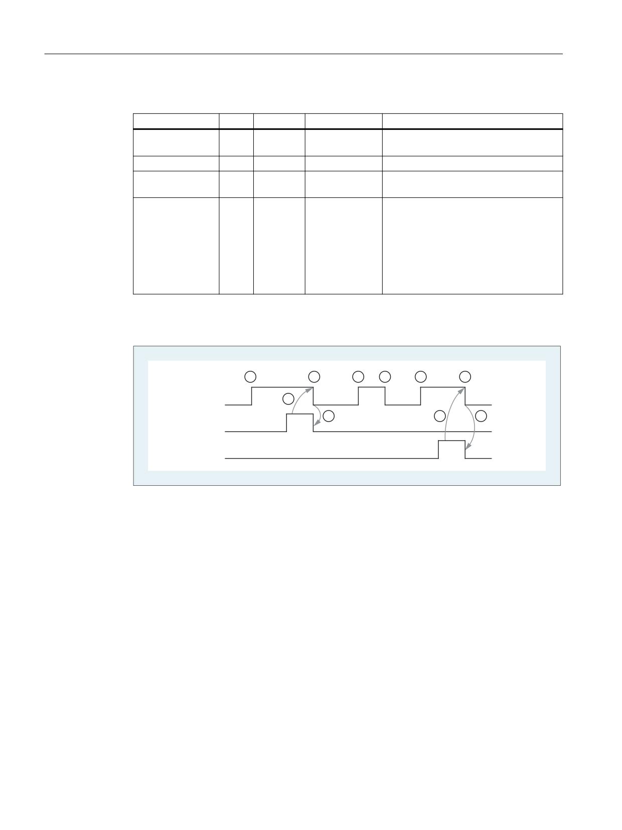
Pulse diagram
6WDUW
5HDG\
(UURU
!
① User: Set request, Start = 0 → 1
② FB4: PI service successfully completed, Ready = 1
User: Reset request, IF Ready == 1 THEN Start = 0
③ User: IF Ready == 1 THEN reset request: 1 → 0
④ FB4: Reset job confirmation, Ready = 0
⑤ User: IF Ready == 0 AND Error == 0 THEN reset request Start = 1 → 0 not permissible
⑥ FB4: PI service completed with errors, Error = 1
User: Reset request, IF Ready == 1 OR Error == 1 THEN Start = 0, possible further error handling
Call example
CALL
// Tool management: Transfer block for revolver
FC7(
Start :=
m 20.5,
// Start := "1 " => initiate the
transfer
ChgdRevNo :=
DB61.DBB1,
Ready :=
m 20.6,
PLC
252
Function Manual, 10/2020, 6FC5397-0HP40-0BA1
Block descriptions
17.18 FC8: TM_TRANS - transfer block for tool management
Error :=
DB61.DBW12
};
u
m 20.6;
// Poll ready
r
m 20.5;
// Reset start
spb
m001;
// Jump, if everything OK
l
db61.dbw 12;
// Error information
ow
w#16#0;
// Evaluate error
spn
error;
// Jump to troubleshooting, if <> 0
m001:
// Start of another program
error :
r
m 20.5;
// Start reset, if an error has
occurred
17.18
FC8: TM_TRANS - transfer block for tool management
Function
The user calls the FC TM-TRANS block when the position of the tools or the status of the transfer
operation changes. The "TaskIdent" parameter specifies the transfer job for the FC8 block at the
tool management interface:
• For loading/unloading positions
• For spindle replacement positions
• For turret replacement positions as transfer identifier
• Asynchronous transfer
• Asynchronous transfer with location reservation
The interface number is indicated in the "TaskIdentNo" parameter.
Example for load location 5:
Parameter "TaskIdent":= 1 and "TaskIdentNo":= 5.
Furthermore, the current tool positions and status information (see "Status" parameter list
below) are also transferred for this transfer function.
Note
FC8 informs the NC of the current positions of the old tool.
The NC knows where the old and the new tool were located until the position change.
In the case of a transfer without a socalled "old tool" (e.g. on loading), the value 0 is assigned to
the "OldToolMag" and "OldToolLoc" parameters.
The transfer block may only be started with the "Start" = TRUE parameter if an activation signal
for the associated interface (DB71, DB72, DB73 in word 0) for this transfer has been supplied by
the tool management function.
PLC
Function Manual, 10/2020, 6FC5397-0HP40-0BA1
253
Block descriptions
17.18 FC8: TM_TRANS - transfer block for tool management
When this job is executed correctly, the output parameter "Ready" contains the value TRUE.
The user must then set the "Start" parameter to FALSE or not call the block again.
If the "Ready" parameter = FALSE, the error code in the "Error" parameter must be interpreted
(see example FC8 call and pulse diagram).
If the error code = 0, then this job must be repeated in the next PLC cycle (e.g. "Start" remains set
to TRUE). This means that the transfer operation has not yet been completed.
If the user assigns a value of less than 100 to the "Status" parameter, then the associated
interface in data block DB71 or DB72 or DB73, word 0 is deactivated (process completed). The
appropriate bit for the interface is set to 0 by the FC8 block.
The "Start" parameter does not need an edge for a subsequent job. This means that new
parameters can be assigned with "Start = TRUE" immediately when "Ready = TRUE" is received.
Asynchronous transfer
To ensure that changes in the position of a tool are automatically signaled from the PLC to the
tool management (e.g. voltage interruption during an active command or independent changes
in the position by the PLC), FC8 is called with "TaskIdent" = 4 or 5. This call does not require
interface activation by the tool management.
If parameter "TaskIdent" = 5, the tool management reserves the location in addition to changing
the position. The location is only reserved if the tool has been transported from a real magazine
to a buffer storage.
The associated NC channel must be parameterized in the "TaskIdentNo" parameter.
The previous location of the tool is specified in the parameters "OldToolMag" and "OldToolLoc".
The current location of the tool is specified in the parameters "NewToolMag" and "NewToolLoc".
"Status" = 1 must be specified.
With "Status" = 5, the specified tool remains at the "OldToolMag", "OldToolLoc" location. This
location must be a buffer (e.g. spindle). The real magazine and location must be specified in the
parameters "NewToolMag", "NewToolLoc"; the location is at the position of the buffer. This
procedure must always be used if the tool management is to be informed of the position of a
specific magazine location. This procedure is used for alignment in search strategies.
Constraints
• Cancellation of a transfer, e.g. by a channel reset, is not permissible.
• Parameter "Start" = 1, until parameter "Ready" == 1 or "Error" == 1
More information
• For detailed information about tool management, refer to
the Tool Management Function Manual.
• PLC blocks for tool management
- FB4: PI_SERV - request PI service (Page 180)
- FC6: TM_TRANS2 - transfer block for tool management and multitool (Page 249)
- FC7: TM_REV - transfer block for tool change with revolver (Page 250)
- FC22: TM_DIR - direction selection for tool management (Page 299)
PLC
254
Function Manual, 10/2020, 6FC5397-0HP40-0BA1

Block descriptions
17.18 FC8: TM_TRANS - transfer block for tool management
Declaration of the function
FUNCTION FC8: VOID
//NAME :TM_TRANS
VAR_INPUT
Start :
BOOL;
TaskIdent :
BYTE;
TaskIdentNo :
BYTE;
NewToolMag :
INT;
NewToolLoc :
INT;
OldToolMag :
INT;
OldToolLoc :
INT;
Status :
INT;
END_VAR
VAR_OUTPUT
Ready :
BOOL;
Error :
INT;
END_VAR
BEGIN
END_FUNCTION
Description of formal parameters
Signal
Type
Type
Value range
Meaning
Start:
I
BOOL
0 (FALSE),
1: Start transfer
1 (TRUE)
TaskIdent:
I
BYTE
1, 2, 3, 4, 5
Interface or task identifier
1: Loading/unloading location
2: Spindle replacement position
3: Turret replacement position
4: Asynchronous transfer
5: Asynchronous transfer with location res-
ervation
TaskIdentNo:
I
BYTE
1, 2, 3 ... 10
Number of the associated interface or
channel number.
NewToolMag:
I
INT
-1, 0, 1, 2 ...
Current magazine number of tool to be re-
placed
-1: Tool remains at its location.
NewToolLoc = any value
Only permissible if TaskIdent = 2.
NewToolLoc:
I
INT
-1, 0, 1, 2 … max.
Current location number of new tool
location no.
PLC
Function Manual, 10/2020, 6FC5397-0HP40-0BA1
255
Block descriptions
17.18 FC8: TM_TRANS - transfer block for tool management
Signal
Type
Type
Value range
Meaning
OldToolMag:
I
INT
-1, 0 ...
Current magazine number of tool to be re-
placed
-1: The tool remains at its location. "Old-
ToolLoc" = <any value>. Only permissible if
"TaskIdent" = 2.
OldToolLoc:
I
INT
-1 ... max. loca-
Current location number of tool to be re-
tion number
placed
Status:
I
INT
1, 2, 3 ... 7, 103,
Status information about transfer opera-
104, 105
tion
Ready:
Q
BOOL
0 (FALSE),
1: Transfer completed
1 (TRUE)
Error:
Q
INT
0 ... 65535
Error checkback
0: No error has occurred
1: Unknown "TaskIdent"
2: Unknown "TaskIdentNo"
3: Impermissible job, ("Interface active"
signal for selected turret == 0)
Other value: The number corresponds to
the error message of the tool manage-
ment function in the NC caused by this
transfer.
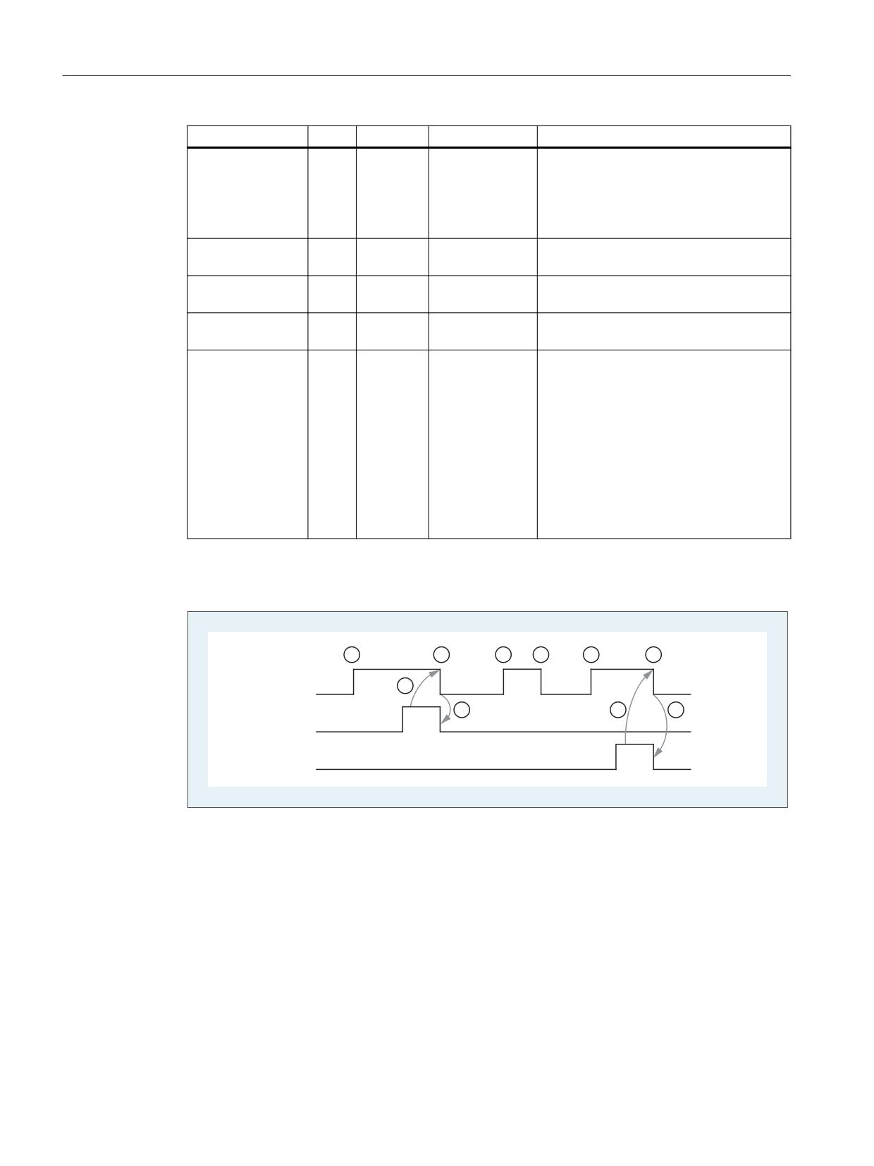
Pulse diagram
6WDUW
5HDG\
(UURU
!
① Activation of function by means of a positive edge
② Positive acknowledgment: Tool management has been transferred
③ Reset function activation after receipt of acknowledgment
④ Signal change by FC
⑤ This signal sequence is not permitted. The job must generally be terminated since the new tool
positions must be conveyed to the tool management in the NC.
⑥ Negative acknowledgment: Error occurred, error code in the output parameter Error
PLC
256
Function Manual, 10/2020, 6FC5397-0HP40-0BA1

Block descriptions
17.18 FC8: TM_TRANS - transfer block for tool management
Status
Sta-
Description
tus
1
The tool management job has been completed
The parameters "NewToolMag", "NewToolLoc", "OldToolMag", and "OldToolLoc" of the FC8 block
should be parameterized to the actual positions of the tools involved. Except in the case of
preparing the replacement, they are normally the specified target positions of the tools of the
associated tool management interface, see also "Explanations of the formal parameters".
1. In the case of loading/unloading/reloading, the tool has arrived at the required destination
address. If the bit in the interface in DB 71.DBX (n+0).3 "Position to load location" is enabled,
status 1 cannot be used for the function termination. Status 5 must be used for correct
termination.
2. In the case of "Prepare replacement", the new tool is now available. The tool may, for
example, be positioned in a buffer (gripper). In some cases, the target (magazine, location)
of the old tool has been moved to the toolchange position after placement of the new tool
in a buffer. However, the old tool still remains in the spindle. The preparations for a tool
replacement are thus complete. After this acknowledgment, the "Replacement" command
can be received. The positions in the "NewToolMag", "NewToolLoc", "OldToolMag" and "Old-
ToolLoc" parameters correspond to the current tool positions.
3. In the case of "Replacement" (in the spindle or turret), the tools addressed in the interface
have now reached the required destination addresses.
The tool change operation is thus completed.
2
The "new" tool cannot be made available
This status is only permissible in conjunction with the "Prepare replacement" command. When
this status is applied, the PLC must be prevented from making a replacement with the proposed
tool. The proposed (new) tool is disabled by the tool management function in the NC. A new
command is then output by the tool management with a replacement tool. The positions in the
"NewToolMag", "NewToolLoc", "OldToolMag", and "OldToolLoc" parameters correspond to the
original tool positions.
3
An error has occurred
The tool positions must not have been changed. Any changes to the magazine positions of the
tools that have taken place in the meantime must be notified beforehand, for example, with
status = 105 via the FC8 transfer block. Only then will the tool positions be taken into account
by the tool management function.
4
It would be better to position the "old" tool in the magazine position specified in the "Old-
ToolMag" and "OldToolLoc" parameters
This status is permissible only in conjunction with preparation for tool change (replacement in
spindle). The magazine location specified for the "old" tool must be free. Once this status has
been passed to the tool management in the NC, a new preparation command is generated
(Status_4 = final acknowledgment) and output to the DB72, for which the requested magazine
position of the old tool is considered.
No new tool search is performed explicitly since the positions for "NewToolMag" and "NewTool-
Loc" are taken from the original preparation command. But this only occurs when this position
is free. The "NewToolMag" and "NewToolLoc" parameters are not taken into account.
PLC
Function Manual, 10/2020, 6FC5397-0HP40-0BA1
257

Block descriptions
17.18 FC8: TM_TRANS - transfer block for tool management
Sta-
Description
tus
5
The operation is complete
The "new" tool is in the position specified in parameters "NewToolMag", "NewToolLoc". In this
case, the specified tool is not really in this position, but is still in the same magazine location.
However, this magazine location has been moved to the position set in the parameters (e.g. tool
replacement position). This status may be used only for turrets, and chain-type and disk maga-
zines. The status enables the tool management function to align the current magazine position
and to improve the search strategy for subsequent commands. This status is permissible only in
conjunction with loading, unloading, and reloading operations and with preparations for tool
replacement. The "OldToolMag" and "OldToolLoc" parameters must be parameterized with the
data of a buffer.
• Loading, reloading:
On loading or reloading, a location for the tool is already reserved in the NC. The machine
operator must then insert the tool at the target location. Notice: The location reservation is
canceled when the control system is switched on again.
• Tool-replacement preparation:
Tool motions still to be executed are not carried out until after tool replacement.
• Positioning to the load location:
If the bit in the interface in DB 71.DBX (n+0).3 "Position to load location" is enabled, then only
status 5 may be used for the function termination (not status 1).
6
The tool management job has been completed
This status has the same function as status 1, but, in addition, a reservation of the source
location is carried out. This status is only permitted when reloading. The command is ended and
the source location of the tool is reserved if the target location is in a buffer magazine.
7
Initiate repetition of the "Prepare Tool" command
This status is only permissible in conjunction with the "Prepare replacement" command. This
status is intended for use when the "new" tool has changed its position (e.g. via an asynchronous
command of the "new" tool). After "Ready = 1" has been provided by FC8, the "Prepare replace-
ment" command is repeated automatically with the same tool. A new tool search is carried out
for the automatic repetition. The positions in parameters "NewToolMag", "NewToolLoc", "Old-
ToolMag", and "OldToolLoc" correspond to the original tool positions.
103
The "new" tool can be inserted
This status is permissible only in the tool replacement preparation, when the PLC may reject the
new tool (e.g. in case of MD20310 $MC_TOOL_MANAGEMENT_MASK, bit 4 = 1 for the possibility
of requesting changed parameters from the PLC once again). The tool positions have remained
unchanged. This status is therefore necessary when preprocessing is to be continued in the NC
without an unnecessary stop.
104
The "new" tool is in the position specified in parameters "NewToolMag", "NewToolLoc"
This status is only permissible if the tool is still in the magazine in the same location. The "old"
tool is in the position (buffer) specified in parameters "OldToolMag", "OldToolLoc". In this case,
however, the new tool is not really in this position, but is still in the same magazine location.
However, this magazine location has been moved to the position set in the parameters (e.g. tool
replacement position). This status may be used only in conjunction with turrets, and chaintype
and disk magazines for the "Tool replacement preparation" phase. The status enables the tool
management to align the current position of a magazine and to improve the search strategy for
subsequent commands.
105
The specified buffer location has been reached by all tools involved
Standard case if the operation has not yet been completed.
The tools are in the specified tool positions (parameters "NewToolMag", "NewToolLoc", "Old-
ToolMag", "OldToolLoc").
PLC
258
Function Manual, 10/2020, 6FC5397-0HP40-0BA1
Block descriptions
17.19 FC9: ASUP - start of asynchronous subprograms
Status definition
A general rule for the acknowledgment status is that the status information 1 to 7 leads to the
termination of the command. If FC8 receives status information, the "Interface active bit" of the
interface specified in FC8 is reset to "0" (see also interface lists DB71 to DB73), thus completing
the operation. The behavior is different in the case of status information 103 to 105. If status
information is transferred to the FC8, the "Interface active bit" of this interface remains at "1".
Further processing is required by the user program in the PLC (e.g. continuation of magazine
positioning). This status information is generally used to transfer changes in position of one or
both tools while the operation is still in progress.
Call example
CALL FC8(
//Tool management transfer block
Start :=
m 20.5,
// Start := "1 " => transfer initiation
TaskIdent :=
DB61.DBB0,
TaskIdentNo :=
DB61.DBB1,
NewToolMag :=
DB61.DBW2,
// Current position of new tool
NewToolLoc :=
DB61.DBW4,
OldToolMag :=
DB61.DBW6,
// Current position of old tool
OldToolLoc :=
DB61.DBW8,
Status :=
DB61.DBW10,
// Status
Ready :=
m 20.6,
Error :=
DB61.DBW12);
u m 20.6;
// Poll ready
r m 20.5;
// Reset start
spb m001;
// Jump if everything OK
l DB61.dbw12;
// Error information
ow w#16#0;
// Evaluate error
spn error;
// Jump to troubleshooting
m001:
// Normal branch
error :
//Troubleshooting
r m 20.5 :
// Reset start
17.19
FC9: ASUP - start of asynchronous subprograms
Function
The block FC9 "ASUP" can be used to trigger any functions in the NC. Before an ASUP can be
started from the PLC, it must have been selected and parameterized by an NC program or by FB4
(PI service ASUP). In this case, the channel and the interrupt numbers must match the
parameters in FC9.
PLC
Function Manual, 10/2020, 6FC5397-0HP40-0BA1
259
Block descriptions
17.19 FC9: ASUP - start of asynchronous subprograms
Once prepared in this way, it can be started at any time from the PLC. The NC program running
on the channel in question is interrupted by the asynchronous subprogram.
Only one ASUP can be started in the same channel at a time. If several ASUPs are started in one
PLC cycle, the ASUPs are started in this order in the NC.
Parameter "Start" = 0 must be set by the user if the ASUP has been terminated ("Done" == 1) or
an error has occurred ("Error" == 1).
For processing jobs, each FC9 needs its own parameter "Ref" from the global user area. This
parameter is for internal use only and must not be changed by the user. The parameter "Ref" is
initialized with the value 0 in the first OB1 cycle and, for this reason, every FC9 must be called
absolutely. Alternatively, the user can initialize parameter "Ref" with a value of 0 during startup.
This option makes conditional calls possible. A conditional call requires parameter "Start" = 1
during activation of FC9 until a negative edge change has occurred at parameter "Done" (1 → 0).
General conditions
• The function block FB4 must be terminated before the block FC9 is started.
• The block FC9 cannot be started if DB10, DBX56.1 == 1 (emergency stop).
• Block FC9 must not be started if channel reset is active in the channel in which the ASUP is
to be started.
Declaration of the function
FUNCTION FC9: VOID
//NAME :ASUP
VAR_INPUT
Start :
BOOL;
ChanNo:
INT;
IntNo:
INT;
END_VAR
VAR_OUTPUT
Active:
BOOL;
Done :
BOOL;
Error :
BOOL;
StartErr:
BOOL;
END_VAR
VAR_IN_OUT
Ref:
WORD;
END_VAR
PLC
260
Function Manual, 10/2020, 6FC5397-0HP40-0BA1
Block descriptions
17.19 FC9: ASUP - start of asynchronous subprograms
Description of formal parameters
The table below lists all formal parameters of the ASUP function.
Signal
Type
Type
Value range
Meaning
Start:
I
BOOL
0 (FALSE),
Job start with positive signal edge
1 (TRUE)
ChanNo:
I
INT
1, 2, 3 ... 10
Channel number
IntNo:
I
INT
1, 2, 3 ... 8
Interrupt number
Active:
O
BOOL
0 (FALSE),
1: Active
1 (TRUE)
Done:
O
BOOL
0 (FALSE),
1: ASUP completed
1 (TRUE)
Error:
O
BOOL
0 (FALSE),
1: Interrupt switched off
1 (TRUE)
StartErr:
O
BOOL
0 (FALSE),
1: Interrupt number not assigned or de-
1 (TRUE)
leted
Ref:
I/O
WORD
Global variable
1 word per FC9 (for internal use)
(MW, DBW,..)
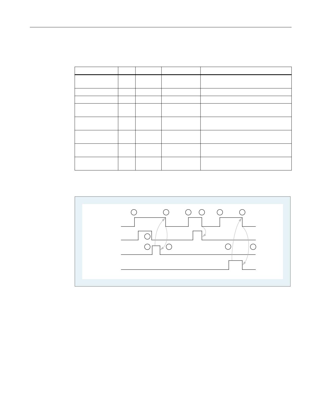
Pulse diagram
6WDUW
$FWLY
'RQH
(UURU
(1)
Activation of function
(2)
ASUP is active
(3)
Positive acknowledgment: ASUP completed
(4)
Reset function activation after receipt of acknowledgment
(5)
Signal change using FC
(6)
Not permitted If function activation is reset prior to receipt of acknowledgement, the output
signals are not updated without the operational sequence of the activated function being affected.
(7)
Negative acknowledgment: An error occurred
PLC
Function Manual, 10/2020, 6FC5397-0HP40-0BA1
261
Block descriptions
17.20 FC10: AL_MSG - error and operating messages
Call example
CALL FC9(
//Start an asynchronous subprogram
//in channel 1 interrupt number 1
Start :=
I 45.7,
ChanNo :=
1,
IntNo :=
1,
Active :=
M 204.0,
Done :=
M204.1,
Error :=
M 204.4,
StartErr :=
M 204.5,
Ref :=
MW 200);
17.20
FC10: AL_MSG - error and operating messages
Function
With block FC10 "AL_MSG", the signals entered in DB2 are evaluated and displayed as incoming
or outgoing error messages and operational messages on the user interface.
The incoming signals (positive edge) are displayed immediately in the case of both error and
operational messages.
Outgoing signals (negative edge) are deleted immediately only for operational messages. In the
event of error messages, the messages that are no longer pending are only deleted with the
parameter "Quit", i.e. errors remain displayed on the user interface until they have been
acknowledged by the user even if the signals are no longer pending.
The "ToUserIF" parameter can be used to transfer the group signals for the feed, read and NC start
disabling signals and feed stop signal to the existing axis, spindle and channel interfaces. The
group signals are transferred to the user interface directly from the status information in DB2
irrespective of an alarm acknowledgment.
1. If parameter "ToUserIF" = 0, there is no transfer of the signals to the user interface. In this
case, the user must take measures in his PLC program to ensure that these signals are
influenced in the interface. The FB1 parameter "ExtendChanAxMsg" is evaluated and so
avoids the limitation of the usable message ranges by configuring the NCK machine data.
2. If parameter "ToUserIF" = 1, all signals listed above are sent to the user interface as a group
signal in each case. The user PLC program can, therefore, influence these signals only via DB2
in conjunction with a message or alarm output. The appropriate information is overwritten
in the user interface.
Alternatively to the response described in paragraph 2, the disable and hold signals can be
influenced without a message being output by influencing the interface signals with a disable
or stop signal state after FC10 is called.
The following program illustrates this method:
CALL FC10(
ToUserIF :=
TRUE,
PLC
262
Function Manual, 10/2020, 6FC5397-0HP40-0BA1
Block descriptions
17.20 FC10: AL_MSG - error and operating messages
Ackn :=
I 6.1);
u m 50.0;
// Feed disable for channel 1
to DB 21;
s dbx 6.0;
// Setting the blocking condition
// Resetting is done via FC AL_MSG
// if M 50.0 outputs the signal "0".
FB1 parameter "ExtendAlMsg"
With FB1 parameter "ExtendAlMsg" = TRUE, the new DB2 structure becomes effective (see PLC
manual "PLC/HMI interface"). For the activation, bit fields for the lock and stop signals are
available for 10 channels, 31 axes and maximum 64 user areas (the number of user areas is
entered in the FB1 parameter "MsgUser"). The associated functionality is obtained automatically
by simply setting/resetting signals in DB2.
The error and operational messages in data block DB2 must be provided in a user-specific way.
FB1 parameter "ExtendChanAxMsg"
With the activation of this parameter, a channel- or axis-number independent acquisition of
alarms and messages acts. All DB2 areas are available for users. Group signals cannot be
transferred to the user interface. The parameter is evaluated only when the FC10 parameter
"ToUserIF" is deactivated.
Display on HMI
In DB2, a "1" signal must be present for several OB1 cycles to ensure that a message can also be
displayed on the HMI.
There is an upper limit for the number of alarms and messages that can be pending at the same
time. This upper limit is dependent on the PLC CPU. On PLC 317-2DP, the upper limit for
messages pending simultaneously is 60.
Further information:
See PLC manual "PLC alarms/messages"
Declaration of the function
FUNCTION FC10:
VOID
// NAME:
AL_MSG
VAR_INPUT
ToUserIF :
BOOL;
Ackn :
BOOL;
END_VAR
END_FUNCTION
PLC
Function Manual, 10/2020, 6FC5397-0HP40-0BA1
263

Block descriptions
17.21 FC12: AUXFU - call interface for user with auxiliary functions
Description of formal parameters
Signal
Type
Type
Value range
Meaning
ToUserIF :
I
BOOL
0 (FALSE),
1: Transfer of the signals to the user inter-
1 (TRUE)
face in each cycle
Ackn:
I
BOOL
0 (FALSE),
1: Acknowledgment of error messages
1 (TRUE)
Call example
CALL FC10(
// Error and operational messages
ToUserIF :=
TRUE,
// Signals from DB2 are transferred to interface.
Ackn :=
E6.1
// Acknowledgment of error message via input I6.1
);
See also
Interface PLC/HMI (Page 64)
PLC alarms/messages (Page 335)
17.21
FC12: AUXFU - call interface for user with auxiliary functions
Function
The block FC12 "AUXFU" is called on an eventdriven basis in the basic program if the channel
transferred in the input parameter contains new auxiliary functions. The PLC user can extend FC
AUXFU with program instructions for processing his auxiliary function to avoid cyclic polling of
the channel DBs. This mechanism permits auxiliary functions to be processed on a jobdriven
basis. FC AUXFU is supplied as a compiled empty block in the basic program. In this case, the
basic program supplies parameter "Chan" with the channel number. The PLC user knows which
channel has new auxiliary functions available. The new auxiliary functions can be determined
by the auxiliary-function change signals in the channel concerned.
Declaration of the function
FUNCTION FC12: VOID
// Event control of auxiliary functions
VAR_INPUT
Chan:
BYTE ;
END_VAR
BEGIN
BE;
END_FUNCTION
PLC
264
Function Manual, 10/2020, 6FC5397-0HP40-0BA1

Block descriptions
17.22 FC13: BHGDisp - display control for handheld unit
Explanation of formal parameters
Signal
Type
Type
Value range
Meaning
Chan:
I
BYTE
0, 1, 2 ... 9
Index of the channel = channel number -1
Example
FUNCTION FC12: VOID
// Event control of auxiliary functions
VAR_INPUT
Chan:
BYTE ;
// Parameter is supplied by basic program
END_VAR
VAR_TEMP
ChanDB:
INT;
END_VAR
BEGIN
L Chan;
// Channel index
+ 21;
// Channel DB offset
T ChanDB;
// Save channel DB no.
TO DB[ChanDB];
// Channel DB is opened indirectly
// Auxiliary-function change signals are now scanned, etc.
BE;
END_FUNCTION
17.22
FC13: BHGDisp - display control for handheld unit
Function
Block FC13 "BHGDisp" handles the display control for the handheld unit (HHU or HT 2). The
information that is to appear on the display must be saved to a string variable. The pointer to the
string is specified in the parameter "ChrArray". To do this, a fixed text assignment of 32 characters
(HHU) or 64 characters (HT 2) is needed when the data block for this string is created.
16 characters are sent to the HHU per job. The assignment of the characters in the "ChrArray" for
the respective line is unambiguous. For line 1, characters 1 to 16 and for line 2, characters 17 to
32 of the string data "ChrArray" are transferred. In addition, for HT 2 line 3 with characters 33 to
48 is displayed and line 4 with characters 49 to 64. A job takes several OB1 cycles.
Display
Block FC13 checks whether the necessary minimum length of the "ChrArray" exists for operating
the handheld unit. If fewer characters exist in the string variables than should be displayed, the
line is filled with blank spaces. If several variables are to be entered in the string in one or more
PLC cycles without a display output, the display output can be suppressed by parameter
"Row" = 0. The transfer of the characters to the rows takes several OB1 cycles. If several rows are
to be updated "simultaneously" (parameter "Row" > 1), the rows are updated successively with
16 characters per row.
PLC
Function Manual, 10/2020, 6FC5397-0HP40-0BA1
265
Block descriptions
17.22 FC13: BHGDisp - display control for handheld unit
Variable portions
Variable components within the string can be inserted using the optional number converter
functionality with the parameter "Convert" = 1. The variable to be displayed is referenced via the
parameter "Addr". The format of the variables is described in the parameter "DataType". The
number of bytes of the variable is linked to the format description. The address justified to the
right within the string is specified by parameter "StringAddr". The number of written characters
is shown in the parameter table.
High display resolution
If, for example, the axis value is to be displayed with a higher resolution, the following must be
observed:
• The variables are read as before with FB2 or FB5. Instead of anypointer BYTE 8 as criterion for
output as 64-bit floating point number, REAL 2 is used (e.g.: P#M100.0 REAL 2).
• When specifying the 64-bit floating point number on the HHU/HT 2, you can select the output
format with up to 14 places, distributed freely before and after the decimal point, instead of
fixed, specified formats.
HHU output signals
Byte 1 is used by the HHU output signals and the character specifications are used by the block
FC13. These may not be written by the PLC user program.
Relevant FB1 parameters
Handheld unit HHU
In OB100, the FB1 parameters must be set for the input and output data of the handheld unit:
• Parameter "BHGIn" corresponds to the input data of the PLC from the handheld unit (data
received by PLC)
• Parameter "BHGOut" corresponds to the output data of the PLC to the handheld unit (data
transmitted by PLC).
The two pointers must be set to the starting point of the relevant data area, which is also
parameterized in SDB 210 with an MPI link.
The FB1 parameter "HHU" = 2 must be set for operating an HHU.
HT 2 handheld terminal
If HT 2 is used, FB1 parameter "HHU" = 5 must be set. The parameters of the input and output
data must be set, as described in the above paragraph "Handheld Unit HHU".
The value that was configured at S2 of the DIP-Fix switch (rotary coding switch) of the
connecting module of the HT 2 must be assigned to the parameters "BHGRecGDNo" and
"BHGRecGBZNo".
Declaration of the function
DATA_BLOCK "strdat"
STRUCT
disp:
STRING [32]:= 'character_line1 character_line2';
PLC
266
Function Manual, 10/2020, 6FC5397-0HP40-0BA1

Block descriptions
17.22 FC13: BHGDisp - display control for handheld unit
END_STRUCT;
BEGIN
END_DATA_BLOCK
FUNCTION FC13: VOID
VAR INPUT
Row :
BYTE ;
ChrArray : STRING ;
Convert :
BOOL;
Addr:
POINTER;
DataType : BYTE ;
StringAddr INT;
:
Digits :
BYTE ;
END VAR
VAR OUTPUT
Error :
BOOL;
END VAR
Description of formal parameters
Signal
Type
Type
Value range
Meaning
Row :
I
BYTE
0, 1, 2, ... 8
Display line "binary" evaluation
B#16#F
0: no display output
1: Line 1
2: Line 2
3: Line 1 and line 2 to be changed
4: Line 3
5: Line 1 and line 3 to be changed
8: Line 4
B#16#F automatic change of all 4 lines
ChrArray :
I
STRING
"DBName".<Var-
Display content as pointer to string
Name>
string[32]: not HT 2
string[64]: HT 2
Convert :
I
BOOL
0 (FALSE), 1
Activation of numerical conversion
(TRUE)
Addr:
I
Pointer
Pointer to the variable to be converted
PLC
Function Manual, 10/2020, 6FC5397-0HP40-0BA1
267