SINUMERIK 840D sl. Service - Functions. Manual (2018-2020) - page 52

Block descriptions
17.5 FB4: PI_SERV - request PI service
Signal
Type
Value range
Description
WVar11:
INT
Number of required location type
WVar12:
INT
0, 1, 2, 3, 4
Specifies the required search direction
0: Search strategy as set in $TC_MAMP2
1: Forward
2: Backward
3: Symmetrical
1)
: The reference location/reference magazine is a buffer location/buffer store, i.e. a tool location from the
buffer magazine or from the internal loading magazine, e.g. swapping station, gripper, loading station.
Examples: Setting the search range
Fro
Lo-
To
Lo-
Description
m
cati-
cati-
on
on
WVa
WVa
WVa
WVa
r1
r2
r3
r4
#M1
#P1
#M1
#P1
Only location #P1 in magazine #M1 is checked
#M1
#P1
#M2
#P2
Locations starting at magazine #M1, location #P1 up to magazine #M2,
location #P2 are searched
#M1
-1
#M1
-1
All locations in magazine #M1 - and no others - are searched
#M1
-1
-1
-1
All locations starting at magazine #M1 are searched
#M1
#P1
-1
-1
All locations starting at magazine #M1 and location #P1 are searched
#M1
#P1
#M1
-1
Locations in magazine #M1 starting at magazine #M1 and location #P1 in
this magazine are searched
#M1
#P1
#M2
-1
Locations starting at magazine #M1, location #P1 up to magazine #M2 are
searched
#M1
-1
#M2
#P2
Locations starting at magazine #M1 up to magazine #M2, location #P2 are
searched
#M1
-1
#M2
-1
Locations starting at magazine #M1 up to and including magazine #M2 are
searched
-1
-1
-1
-1
All magazine locations are searched
17.5.26
PI service: TMGETT
Function: Determine T number for the specified tool name with duplo number
The PI service determines the T number of a tool via the tool name and duplo number.
The result is written in OPI variables in the TF block (parameterization, return parameters from
TMGETT, TSEARC):
• resultNrOfTools
- resultNrOfTools == 0: The specified tool was not found
- resultNrOfTools == 1: The specified tool was found
• resultToolNr: T number of the specified tool with "resultNrOfTools" == 1
PLC
Function Manual, 10/2020, 6FC5397-0HP40-0BA1
199

Block descriptions
17.5 FB4: PI_SERV - request PI service
Note
Before and after this PI service, the PI service MMCSEM with parameter "WVar1" must be called
with function number 5 for TMGETT. See Chapter "PI service: MMCSEM (Page 194)".
Description of formal parameters
Signal
Type
Range of values
Meaning
PIService:
ANY
"PI".TMGETT
Determining the T number
Unit:
INT
1, 2, 3 ... 10
TOA
Addr1:
STRING
Max. 31 characters
Tool name
WVar1:
INT
Duplo number
17.5.27
PI service: TMMVTL
Function: Prepare magazine location for loading, unload tool
The PI service loads, unloads and relocates tools:
1. Loading and unloading: Loading point ↔ magazine
2. Loading and unloading: Loading point ↔ buffer storage, e.g. spindle
3. Relocation within a magazine
4. Relocation between different magazines
5. Relocation between magazine and buffer storage
6. Relocation within buffer storage
Cases 1, 3, 4 and 5: The following OPI variables of the TM block (magazine data: general data)
are written:
• magCmd (area no. = TO unit, line = magazine number)
• magCmdState ← "acknowledgment"
Cases 2 and 6: The following OPI variables of the TMC block (magazine data: configuration data)
are written:
• magCBCmd (area no. = TO unit)
• magCBCmdState ← "acknowledgment"
Loading
• "WVar2" LocationNumber_From, "WVar3" MagazineNumber_From
The tool location of the magazine is moved to the loading station/location for loading and the
tool is loaded.
• "WVar4" LocationNumber_To== -1
First, an empty location for the tool is searched for in the magazine. The empty location of the
magazine is then moved to the loading station/location for loading and the tool is loaded.
PLC
200
Function Manual, 10/2020, 6FC5397-0HP40-0BA1

Block descriptions
17.5 FB4: PI_SERV - request PI service
Unload
• "WVar4" LocationNumber_To, "WVar5" MagazineNumber_To
• The tool location of the magazine is moved to the loading station for loading and the tool is
unloaded.
In the OPI block TP (magazine data: location data), the magazine location of the removed tool
is designated as free.
Addressing the tool
The tool can be addressed either by T number or by the location and magazine numbers. The
value -1 is to be assigned to unused parameters.
Note
Before and after this PI service, the PI service MMCSEM with parameter "WVar1" must be called
with function number 3 for TMMVTL. See Chapter "PI service: MMCSEM (Page 194)".
Description of formal parameters
Signal
Type
Range of values
Meaning
PIService:
ANY
"PI".TMMVTL
Make magazine location ready for load-
ing, unload tool
Unit:
INT
1, 2, 3 ... 10
TOA
WVar1:
INT
T number
WVar2:
INT
LocationNumber_From (source)
WVar3:
INT
MagazineNumber_From (source)
WVar4:
INT
LocationNumber_To (target)
WVar5:
INT
MagazineNumber_To (target)
17.5.28
PI service: TMPOSM
Function: Position magazine location or tool according to the parameter assignment
This PI service can traverse a magazine to position a magazine location at a specified position
(e.g. at a loading position). The magazine location can be specified directly or via a tool at the
location.
The destination, e.g. the loading location, is specified in the parameters:
• "WVar5" LocationNumber_Ref
• "WVar6" MagazineNumber_Ref
PLC
Function Manual, 10/2020, 6FC5397-0HP40-0BA1
201

Block descriptions
17.5 FB4: PI_SERV - request PI service
The magazine location to be positioned is specified in the following parameters according to the
respective specification:
• "WVar1" T number of the tool
The following parameters are irrelevant here:
- "Addr1" tool name = ""
- "WVar2" duplo number = -1
- "WVar3" LocationNumber_From = -1
- "WVar4" MagazineNumber_From = -1
• "Addr1" tool name, "WVar2" duplo number
The following parameters are irrelevant here:
- "WVar1" T number of the tool = -1
- "WVar3" LocationNumber_From = -1
- "WVar4" MagazineNumber_From = -1
• "WVar3" LocationNumber_From, "WVar4" MagazineNumber_From
The following parameters are irrelevant here:
- "Addr1" tool name = ""
- "WVar1" T number of the tool = -1
- "WVar2" duplo number = -1
Description of formal parameters
Signal
Type
Range of values
Meaning
PIService:
ANY
"PI".TMPOSM
Position magazine location or tool
Unit:
INT
1, 2, 3 ... 10
TOA
Addr1:
STRING
Max. 31 characters
Tool name
WVar1:
INT
T number of the tool
WVar2:
INT
Duplo number
WVar3:
INT
LocationNumber_From (source)
WVar4:
INT
MagazineNumber_From (source)
WVar5:
INT
LocationNumber_Ref
WVar6:
INT
MagazineNumber_Ref
17.5.29
PI service: TMPCIT
Function: Set increment value for workpiece counter
Incrementing the workpiece counter of the spindle tool
PLC
202
Function Manual, 10/2020, 6FC5397-0HP40-0BA1

Block descriptions
17.5 FB4: PI_SERV - request PI service
Description of formal parameters
Signal
Type
Value range
Description
PIService:
ANY
"PI".TMPCIT
Set increment value for workpiece coun-
ter
Unit:
INT
1, 2, 3 ... 10
TOA
WVar1:
WORD
0, 1, 2, ... max.
Spindle number; corresponds to the type
index in the location data with "Spindle"
location type of the buffer magazine in
channel.
0: Main spindle
WVar2:
WORD
0 ... max.
Increment value; indicates the number of
spindle revolutions after which the work-
piece counter is incremented
17.5.30
PI service: TMRASS
Function: Resetting the tool status "active"
The PI service sets the status to "inactive" for all tools with a tool status "active" and "blocked".
The following events are sensible times to reset the tool status:
• A negative edge of the NC/PLC interface signal "tool disable ineffective"
• End of program
• Channel reset.
The PI service is intended for the PLC, as there it is known when the disabled tool is no longer to
be used.
Description of formal parameters
Signal
Type
Range of values
Meaning
PIService:
ANY
"PI". TMRASS
Reset active status
Unit:
INT
1, 2, 3 ... 10
TO area
17.5.31
PI service: TRESMO
Function: Reset monitoring values
This PI service resets the monitoring values of the designated cutting edges of the designated
tools to their setpoints (initial values).
This is only performed for tools with active monitoring.
See also the RESETMON command.
PLC
Function Manual, 10/2020, 6FC5397-0HP40-0BA1
203

Block descriptions
17.5 FB4: PI_SERV - request PI service
Description of formal parameters
Signal
Type
Range of values
Meaning
PIService:
ANY
"PI".TRESMO
Reset monitoring values
Unit:
INT
1, 2, 3 ... 10
TO area
WVar1:
WORD
- max ... max
Tool number
0: Process all tools
>0: Process specified tool
<0: Process all sister tools
WVar2:
WORD
0, 1, 2, ... max.
D number
>0: Reset the monitoring of the specified
cutting edge
0: Reset the monitoring of all cutting
edges
WVar3:
WORD
Monitoring mode that is to be reset (all
combinations are possible):
Bit 0 = 1: Tool-life monitoring
Bit 1 = 1: Quantity monitoring
Bit 2 = 1: Wear monitoring
Bit 3 = 1: Sum-offset monitoring
0: Reset all active tool-monitoring func-
tions ($TC_TP9).
17.5.32
PI service: TSEARC
Function: Complex search using search screen form, depending on the parameter
assignment
The PI service is used to search for tools with specific properties within a search range in one or
more magazines, beginning with a specific location, up to a specific location.
Note
Active tool management
The PI service is only available if tool management is activated.
Specification options
• Search direction
• Search for next tool with the specified property
• Search for all tools with the specified property
Result
As a result, a list with the internal T-numbers of the tools that are found is created.
PLC
204
Function Manual, 10/2020, 6FC5397-0HP40-0BA1

Block descriptions
17.5 FB4: PI_SERV - request PI service
Logic operations
For filtering properties, only one AND link is available as a linking option. An OR link must be
achieved by the user via several calls of the PI service and subsequent evaluation of the
individual results.
Parameterization of the tool properties
The properties of the searched for tools are set in the BTSS block TF (parameterization, return
parameters from TMGETT, TSEARC ) via the following variables:
• "parMask<X>" parameterization mask
• "parData<X>" comparison values
With <X> = TAD, TAO, TAS, TD
Result list
After completion of the PI service without errors, the search result is located in the BTSS block
TF (parameterization, return parameter from TMGETT, TSEARC) in the following variables:
• "resultCuttingEdgeNrUsed" D numbers of cutting edges used since last quantity count
• "resultNrOfCutEdgesUsed" Number of cutting edges since last quantity count
• "resultNrOfTools" Number of found tools
• "resultToolNr" T numbers of found tools
• "resultToolNrUsed" T numbers of cutting edges used since last quantity count
If no tool was found, the number of found tools is zero ("resultNrOfTools" == 0).
Search range specifications
From mag.
From loca-
To mag.
To location
Description
number
tion num-
number
number
The following magazine locations are
ber
WVar1
WVar3
WVar4
searched:
WVar2
#M<a>
#L<b>
#M<x>
#L<y>
From: Magazine #M<a>, location #L<b>
to: Magazine #M<x>, location #L<y>
#M<a>
-1
#M<a>
-1
From: Magazine #M<a>, first location
to: Magazine #M<a>, last location
#M<a>
-1
-1
-1
From: Magazine #M<a>, first location
to: Last magazine, last location
#M<a>
#L<b>
-1
-1
From: Magazine #M<a>, location #L<b>
to: Last magazine, last location
#M<a>
#L<b>
#M<a>
-1
From: Magazine #M<a>, location #L<b>
to: Magazine #M<a>, last location
#M<a>
#L<b>
#M<x>
-1
From: Magazine #M<a>, location #L<b>
to: Magazine #M<b>, last location
#M<a>
-1
#M<x>
#L<y>
From: Magazine #M<a>, first location
to: Magazine #M<b>, location #L<y>
PLC
Function Manual, 10/2020, 6FC5397-0HP40-0BA1
205

Block descriptions
17.5 FB4: PI_SERV - request PI service
From mag.
From loca-
To mag.
To location
Description
number
tion num-
number
number
The following magazine locations are
ber
WVar1
WVar3
WVar4
searched:
WVar2
#M<a>
-1
#M<x>
-1
From: Magazine #M<a>, first location
to: Magazine #M<b>, last location
-1
-1
-1
-1
From: First magazine, first location
to: Last magazine, last location
Symmetrical search
A symmetrical search, relative to a magazine location, can only be performed if the following
conditions have been met:
• The search range must encompass only one magazine: "WVar1" (from: Magazine number) ==
"WVar3" (to: magazine number)
• Specification of a reference location, i.e. a magazine location for which a symmetrical search
is to be performed: "WVar5" (number of the reference magazine) and "WVar6" (number of the
reference location)
• For the reference location, a multiple assignment to the magazine to be searched must have
been configured in the TPM block.
• "WVar7" (search direction) = 3
The reference location is a buffer location, i.e. a tool location from the buffer magazine or from
the internal loading magazine, e.g. swapping station, gripper, loading station. The symmetrical
search is made in relation to the magazine location in front of the reference location.
If the magazine location is upstream of the reference location outside of the search range, the
PI service will respond as if no suitable location had been found.
Note
Before and after this PI service, the MMCSEM PI service must be called up with the associated
parameter WVar1 for this PI service. See Chapter "PI service: MMCSEM (Page 194)".
Description of formal parameters
Signal
Type
Value range
Description
PIService:
ANY
"PI".TSEARC
Complex search using search screen forms
Unit:
INT
1, 2, 3 ... 10
TOA
WVar1:
INT
-1, 1, …
From: Magazine number
WVar2:
INT
-1, 1, …
From: Location number
WVar3:
INT
-1, 1, …
to: Magazine number
WVar4:
INT
-1, 1, …
to: Location number
WVar5:
INT
-1, 1, …
Number of the reference magazine
(only relevant for symmetrical search:
Search direction ==3)
PLC
206
Function Manual, 10/2020, 6FC5397-0HP40-0BA1

Block descriptions
17.5 FB4: PI_SERV - request PI service
Signal
Type
Value range
Description
WVar6:
INT
-1, 1, …
Number of the reference location
(only relevant for symmetrical search:
Search direction ==3)
WVar7:
INT
1, 2, 3
Search direction:
1: Forwards from the first location of the
search domain
2: Backwards from the last location of the
search domain
3: Symmetrical to the real magazine location,
which is located upstream of the location
specified under "WVar5" (number of the refer-
ence magazine) and "WVar6" (number of the
reference location)
WVar8:
INT
0, 1, 2, 3
Properties of the tools:
0: all tools, cutting edge-specific
1: first tool, cutting edge-specific
2: all tools, via all cutting edges
3: first tool, via all cutting edges
17.5.33
PI service: TMCRMT
Function: Create multitool
The PI service creates a new multitool with a defined identifier, an optionally specifiable multitool
number, the number of tool locations, and the type of distance coding.
Note
Before and after this PI service, the PI service MMCSEM with parameter "WVar1" =1 (TMCRTO)
must be called. See Chapter: "PI service: MMCSEM (Page 194)".
Description of formal parameters
Signal
Type
Value range
Meaning
PIService:
ANY
"PI".TMCRMT
Create multitool
Unit:
INT
1, 2, 3, ... 10
TOA
Addr1:
STRING
Multitool identifier (max. 31 characters)
WVar1:
INT
0
Reserved
WVar2:
INT
-1, 1, 2, ... 32000
Multitool number
-1: Automatic assignment of the multi-
tool number by NC
1, 2, 3 ... 32000: Multitool number,
note: The multitool number must be
unique
PLC
Function Manual, 10/2020, 6FC5397-0HP40-0BA1
207

Block descriptions
17.5 FB4: PI_SERV - request PI service
Signal
Type
Value range
Meaning
WVar3:
INT
2, 3, 4, ... MAX
Number of tool locations
MAX = Parameterized number in
MD17504 $MN_MAX_TOOLS_PER_MUL-
TITOOL
WVar4:
INT
1, 2, 3
Type of distance coding
17.5.34
PI service: TMDLMT
Function: Delete multitool
The PI service deletes a multitool in all the data blocks in which it is saved. Tools loaded onto the
multitool are not subsequently equipped or loaded, however, continue to be defined if they are
not also to be deleted.
Description of formal parameters
Signal
Type
Range of values
Meaning
PIService:
ANY
"PI".TMDLMT
Delete multitool
Unit:
INT
1, 2, 3 ... 10
TOA
Addr1:
STRING
Multitool identifier (max. 31 characters)
WVar1:
INT
0
Reserved, always 0
WVar2:
INT
-1, 1, 2, ... 32000
Multitool number
-1: Delete the multitool with the name
specified in "Addr1"
1, 2, 3 ... 32000: Delete the multitool with
the specified multitool number;
Note: Parameter "Addr1" is not evaluated
WVar3:
INT
0, 1
Tools contained in the multitool:
0: Do not delete
1: Delete
17.5.35
PI service: POSMT
Function: Position multitool
The PI service positions a multitool at the programmed location or alternatively at the
programmed tool, which is located in one of the locations of the multitool. The tool itself can
either be specified by its T number or by its name and duplo number. A multitool can only be
positioned if it is on a tool carrier (e.g. spindle) and if no tool offset is active with regard to this
tool carrier.
PLC
208
Function Manual, 10/2020, 6FC5397-0HP40-0BA1

Block descriptions
17.5 FB4: PI_SERV - request PI service
Position specification
The position specification can be specified as one of three variants:
No
Addr1
WVar1
WVar2
WVar3
WVar4
1
Empty string
Number of the
Tool number
-1
-1
tool carrier
2
Tool name
Number of the
-1
Duplo number
-1
tool carrier
3
Empty string
Number of the
-1
-1
Multitool location
tool carrier
number
Description of formal parameters
Signal
Type
Value range
Meaning
PIService:
ANY
"PI".POSMT
Position multitool
Unit:
INT
1, 2, 3, ... 10
TOA
Addr1:
STRING
Tool name of the tool to be positioned in
the multitool (max. 31 characters)
WVar1:
INT
1, 2, 3, ... 999
Number of the tool carrier
WVar2:
INT
-1, 1, 2, 3, ... 32000
Tool number (T number) of the tool to be
positioned in the multitool
-1: The tool number is irrelevant (Addr1
and WVar3 must then be programmed)
WVar3:
INT
-1, 1, 2, 3, ... 32000
Duplo number of the tool to be posi-
tioned in the multitool
-1: Duplo number is irrelevant (then
WVar2 must be programmed)
WVar4:
INT
-1, 1, 2, 3, ... 999
Multitool location number of the tool car-
rier location at which the system should
be positioned
-1: Multitool location number is irrelevant
17.5.36
PI service: FDPLMT
Function: Searching for or checking an empty location within the multitool
The PI service searches for a free tool location in a multitool to hold the specified tool or to check
whether the specified tool location in the multitool is free to hold the specified tool. The tool can
be specified by the T number or the identifier and the duplo number.
Note
Before and after this PI service, the PI service MMCSEM with parameter "WVar1" = 2 (TMFDPL)
must be called. See Chapter "PI service: MMCSEM (Page 194)".
PLC
Function Manual, 10/2020, 6FC5397-0HP40-0BA1
209

Block descriptions
17.6 FB5: GETGUD - read GUD variable
Position specification
The tool to be positioned in the multitool can be specified as one of the following variants:
• "Addr1" = <Tool name>, "WVar1" = -1 and "WVar2" = <Duplo number>
• "Addr1" = <Empty string>, "WVar1" = <Tool number> and "WVar2" = -1
The position specification can be assigned via:
• "WVar4" = <Multitool location number>
Description of formal parameters
Signal
Type
Range of values
Meaning
PIService:
ANY
"PI".FDPLMT
Search/check an empty tool location with-
in a multitool
Unit:
INT
1, 2, 3 ... 10
TOA
Addr1:
STRING
Tool name of the tool to be positioned in
the multitool (max. 31 characters)
WVar1:
INT
-1, 1, 2, 3, ... 32000
Tool number (T number) of the tool to be
positioned in the multitool
-1: "Addr1" (tool name) and "WVar2" (du-
plo number) are used.
1, 2, 3 ... 32000: Tool number
WVar2:
INT
-1, 1, 2, 3, ... 32000
Duplo number of the tool to be posi-
tioned in the multitool
1, 2, 3, ... 32000: Duplo number
-1: "WVar1" (T number) is used
WVar3:
INT
-1, 1, 2, 3, ... 32000
Number of the multitool
1, 2, 3, ... 32000: Number of the multitool
-1: Search across all multitools for an
empty location or check across all multi-
tools whether in one of them the speci-
fied tool location is free to hold the tool.
WVar4:
INT
-1, 1, 2, 3, ...
Multitool location number of the tool lo-
cation at which the system should be
positioned
>0: Multitool location number
-1: Search for any empty tool location
within the multitool
17.6
FB5: GETGUD - read GUD variable
Function
The function block FB5 "GETGUD" is used for reading global user data (GUD) in the NC or channel
area.
PLC
210
Function Manual, 10/2020, 6FC5397-0HP40-0BA1
Block descriptions
17.6 FB5: GETGUD - read GUD variable
Request for reading NC variables
Call of FB5 with positive edge change, parameter "Req" = 0 → 1
Parameter "Addr": The pointer to the name of the GUD variables, symbolically with "<Data
block>".<Variable name>
Parameters "Area", "Unit", "Index1", and "Index2": Additional information for addressing the
variables
When the parameter "CnvtToken" is activated, the user receives a token (variable pointer) for the
GUD variable to be read. Using this, the GUD variables can then be read or written via FB2 and
FB3 with parameter "Addr1" ... "Addr8" = "<Token>". Addressing by means of a token is
mandatory for writing GUD variables. If the token is used to address GUD variable arrays, the
parameter "Line1" ... "Line8" = "<array index>" of the FB2/FB3 must also be provided with values.
To read a GUD variable of the DOUBLE type without adapting the format, an ANY pointer of the
REAL2 type must be specified in the target area. E.g. P#M100.0 REAL 2. The value of the GUD
variables of the DOUBLE type is then adopted in the PLC data area as a 64-bit floating point
number.
Completion of the read request
Read request successfully completed: Parameter "Done" == 1.
Read request completed with error: Parameter "Error" == 1, error cause in parameter "State"
Requirements
• Release of the NC/PLC communication by OB100, FB1 parameter "NCKomm" = 1
• For the data block that will contain the string with the name of the GUD variable, the S7
Symbol Editor must be used to assign a symbol in the S7 symbol table of the S7 project (cf.
call example 1 below: DB_GUDVAR). In the data block, a string of suitable length must be
created to contain the name of the GUD variable (cf. call example 1 below:
"DB_GUDVAR".GUDVar1). This symbol is then passed on to parameter "Addr" of FB5, e.g.
Addr := "DB_GUDVAR".GUDVar1. If the token for the GUD variable is required for the following
calls of the FB2/FB3, the 10-byte token structure must be created in a DB, e.g. the same DB
(cf. call example 1 below: "DB_GUDVAR".GUDVar1Token). This structure is specified in
parameter VarToken of the FB5, cf. call example 1 below: FB5, VarToken :=
"DB_GUDVAR".GUDVar1Token. This token is then specified in parameters "Addr1" … "Addr8"
when FB2/FB3 is called, cf. call example 1 below: FB3, Addr1 := "GUDVar1Token".
General conditions
• FB5 has multi-instance capability.
• Every call of FB5 must be assigned a separate instance DB from the user area.
• Reading of a GUD variable (FB5 call with Req = 1) is only permitted in the cyclic part of the PLC
basic program (OB1). If the job is not started (FB5 call with Req = 0), the parameters can also
be written in the start-up part of the PLC basic program (OB100). The job can then be
executed using the already written parameters in the cyclic part of the PLC basic program
(OB1) by calling FB5 with Req = 1.
• Only capital letters may be used for the names of GUD variables.
• Reading of a GUD variable generally extends over several PLC cycles.
PLC
Function Manual, 10/2020, 6FC5397-0HP40-0BA1
211
Block descriptions
17.6 FB5: GETGUD - read GUD variable
Note
Error case
When variables from different channels are read, the following feedback message is output:
• "Error" == TRUE
• "State" == W#16#02
Note
To read a variable of the DOUBLE type from NC without adapting the format, an ANY pointer of
the REAL2 type must be specified in the target area (e.g.: P#M100.0 REAL 2). If the basic program
recognizes REAL 2 as the target type when reading a variable of the DOUBLE type, the data is
applied to the PLC data area as a 64-bit floating-point number.
Declaration of the function
FUNCTION_BLOCK FB5
//Server name
KNOW_HOW_PROTECT
VERSION : 3.0
VAR_INPUT
Req :
BOOL;
Addr:
ANY;
// Variable name
Area
BYTE ;
//Area: NCK = 0, channel = 2
Unit :
BYTE ;
Index1:
INT;
// Array index 1
Index2:
INT;
// Array index 2
CnvtToken:
BOOL;
// Conversion into 10-byte token
VarToken
ANY;
// Struct with 10 bytes for the variable token
END_VAR
VAR_OUTPUT
Error :
BOOL;
Done :
BOOL;
State :
WORD;
END_VAR
VAR_IN_OUT
RD:
ANY;
END_VAR
BEGIN
END_FUNCTION_BLOCK
PLC
212
Function Manual, 10/2020, 6FC5397-0HP40-0BA1

Block descriptions
17.6 FB5: GETGUD - read GUD variable
Description of formal parameters
Signal
Type
Type
Value range
Meaning
Req:
I
BOOL
Job start with positive signal edge
Addr:
I
ANY
"<DBName>".<V
Variable name in a variable of the type
arName>
STRING
Area:
I
BYTE
0, 2
Range:
0: NC
2: Channel
Unit:
I
BYTE
1, 2, 3, ... 10
Area == NC: Unit:=1
Area == Channel: Channel number
Index1:
I
INT
0, 1, 2, ... < max.
Array index 1
Array index>
For variables without array index: Index1 =
0
Index2:
I
INT
0, 1, 2, ... < max.
Array index 2
Array index>
For variables without 2nd array index: In-
dex2 = 0
CnvtToken:
I
BOOL
0 (FALSE), 1
Activate generation of a 10 byte variable
(TRUE)
token
VarToken:
I
ANY
"<DBName>".<V
Address of a 10byte token (see example)
arName>
Error:
O
BOOL
0 (FALSE), 1
Negative acknowledgement of job or exe-
(TRUE)
cution of job impossible
Done:
O
BOOL
0 (FALSE), 1
Job successfully executed.
(TRUE)
State:
O
WORD
---
See paragraph "Error identifiers"
RD:
I/O
ANY
P#Mm.n BYTE
Target area for read data
x ...
P#DBnr.dbxm.n
BYTE x
Error identifiers
State
Meaning
Note
WORD H 1)
WORD L
0
1
Access error
0
2
Error in job
Incorrect compilation of Var. in a job
0
3
Negative acknowledgment,
Internal error, poss. remedy:
job not executable
NC RESET
0
4
Data areas or data types do
Check data to be
not tally
read in RD
1
4
Insufficient local user memo-
read variable is longer than specified in RD
ry available
0
6
FIFO full
Job must be repeated,
since queue is full
0
7
Option not set
BP parameter "NCKomm" is not set
0
8
Incorrect target area (SD)
RD may not be local data
PLC
Function Manual, 10/2020, 6FC5397-0HP40-0BA1
213
Block descriptions
17.6 FB5: GETGUD - read GUD variable
State
Meaning
Note
WORD H 1)
WORD L
0
9
Transmission occupied
Job must be repeated
0
10
Error in addressing
Unit contains value 0
0
11
Address of variable invalid
Check addr (or variable name), area, unit
1 - 8
13
ANY data reference incorrect
String/NcVar data required has not been para-
meterized
0
15
String more than 32 charac-
GUD variable name too long
ters
1) High byte > 0 ⇒ Number of the variable in which the error occurred
Configuration steps
To be able to read a GUD variable, its name must be stored in a string variable. The data block
with this string variable must be defined in the symbol table so that the "Addr" parameter can be
assigned symbolically for FB GETGUD. A structure variable can be defined optionally in any data
area of the PLC to receive the variable pointer (see specification in following example).
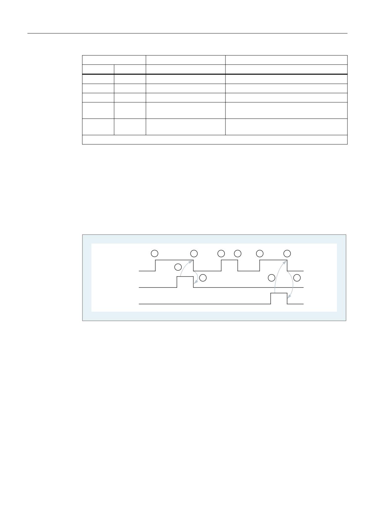
Pulse diagram
5HT
'RQH
(UURU
① User: Set request, Req = 0 → 1
② FB5 successfully completed, Done = 1
User: Reset request, IF Done == 1 THEN Req = 0
③ User: IF Done == 1 THEN reset request: 1 → 0
④ FB5 reset job confirmation, Done = 0
⑤ User: IF Done == 0 AND Error == 0 THEN reset request Req = 1 → 0 not permissible
⑥ FB5 completed with errors, Error = 1
User: Reset request, IF Done == 1 OR Error == 1 THEN Req = 0, possible further error handling
Call example 1
Read a GUD variable from channel 1:
• Name "GUDVAR1"
• Type: INTEGER
PLC
214
Function Manual, 10/2020, 6FC5397-0HP40-0BA1
Block descriptions
17.6 FB5: GETGUD - read GUD variable
Conversion to a 10 byte variable pointer. See table "Assignment of the data types" in Chapter
"FB2: GET - read NC variable (Page 164)"
Reading the GUD variables: FB5 with instance DB111
// Data block for GUD variable
DATA_BLOCK DB_GUDVAR
// Assignment in symbol table
STRUCT
GUDVar1 : STRING[32] := 'GUDVAR1';
// Name is defined by
user
GUDVar1Token :
STRUCT
SYNTAX_ID : BYTE ;
area_and_unit : BYTE ;
column : WORD;
line : WORD;
block type : BYTE ;
NO. OF LINES : BYTE ;
type : BYTE ;
length : BYTE ;
END_STRUCT;
END_STRUCT;
BEGIN
END_DATA_BLOCK
// Unassigned user DB, as instance for FB5
DATA_BLOCK DB111
FB5
BEGIN
END_DATA_BLOCK
// Unassigned user DB, as instance for FB3
DATE_BLOCK DB112
FB3
BEGIN
END_DATA_BLOCK
// Reading of a channel-specific GUD variable from channel 1, with
conversion to a variable pointer
Function FC "VariablenCall" : VOID
U
I 7.7;
// Unassigned machine control panel key
S
M 100.0;
// Activate req.
U
M 100.1;
// Done completed message
PLC
Function Manual, 10/2020, 6FC5397-0HP40-0BA1
215
Block descriptions
17.6 FB5: GETGUD - read GUD variable
R
M 100.0;
// Terminate job
U
I 7.6;
// Manual error acknowledgment
U
M 102.0;
// Error pending
R
M 100.0;
// Terminate job
CALL FB5, DB111(
Req
:= M 100.0,
// Starting edge for reading
Addr
:= "DB_GUDVAR".GUDVar1, // Name of the GUD
Area
:= B#16#2,
// Channel variable
Unit
:= B#16#1,
// Channel 1
Index1
:= 0,
// No array index 1
Index2
:= 0,
// No array index 2
CnvtToken
:= TRUE,
// Request: Conversion into
10-byte token
VarToken
:= "DB_GUDVAR".GUDVar1Token, // Address of the token
Error
:= M 102.0,
Done
:= M 100.1,
State
:= MW 104
RD
:= P#DB99.DBX0.0 DINT 1 // free memory area
);
Writing the GUD variables: FB3 with instance DB112
GUD variable token from FB5, parameter: "VarToken" for writing with FB3, parameter "Addr1"
CALL FB3, DB112(
Req
:= M 200.0,
NumVar
:= 1,
// one GUD variable
Addr1
:=
// Token
"DB_GUDVAR".GUDVar1Token,
Error
:= M 102.0,
Done
:= M 100.1,
State
:= MW 104
SD1
:= P#DB99.DBX0.0 DINT 1
);
Call example 2
Read a GUD variable from channel 1:
• Name "GUD_STRING"
• Type: STRING[32]
Conversion to a 10 byte variable pointer.
Reading the GUD variables: FB5 with instance DB111
// Data block for GUD variable
DATA_BLOCK DB_GUDVAR
// Assignment in symbol table
PLC
216
Function Manual, 10/2020, 6FC5397-0HP40-0BA1
Block descriptions
17.6 FB5: GETGUD - read GUD variable
STRUCT
GUDVarS : STRING[32] := 'GUD_STRING';
// Name defined by user
GUDVarSToken :
STRUCT
SYNTAX_ID : BYTE ;
area_and_unit : BYTE ;
column : WORD;
line : WORD;
block type : BYTE ;
NO. OF LINES : BYTE ;
type : BYTE ;
length : BYTE ;
END_STRUCT;
string_of_GUD : STRING[30];
// must at least be so long as
// the definition of 'GUD_STRING'!
new_name : STRING[30] := 'GUD_123';
END_STRUCT;
BEGIN
END_DATA_BLOCK
// Unassigned user DB, as instance for FB5
DATA_BLOCK DB111
FB5
BEGIN
END_DATA_BLOCK
// Unassigned user DB, as instance for FB3
DATE_BLOCK DB112
FB3
BEGIN
END_DATA_BLOCK
// Reading of a channel-specific GUD variable from channel 1, with
conversion to a variable pointer
Function FC "VariablenCall" : VOID
U
I 7.7;
// Unassigned machine control panel key
S
M 100.0;
// Activate req.
U
M 100.1;
// Done completed message
R
M 100.0;
// Terminate job
U
I 7.6;
// Manual error acknowledgment
U
M 102.0;
// Error pending
PLC
Function Manual, 10/2020, 6FC5397-0HP40-0BA1
217
Block descriptions
17.7 FB7: PI_SERV2 - request PI service
R
M 100.0;
// Terminate job
CALL FB5, DB111(
Req
:= M 100.0,
// Starting edge for reading
Addr
:= "DB_GUDVAR".GUDVarS,
Area
:= B#16#2,
// Channel variable
Unit
:= B#16#1,
// Channel 1
Index1
:= 0,
// No array index
Index2
:= 0,
// No array index
CnvtToken
:= TRUE,
// Request: Conversion into 10-byte
token
VarToken
:= "DB_GUDVAR".GUDVarSToken, // Address of the token
Error
:= M 102.0,
Done
:= M 100.1,
State
:= MW 104
RD
:= "DB_GUDVAR".string_of_GUD
);
Writing the GUD variables: FB3 with instance DB112
GUD variable token from FB5, parameter: "VarToken" for writing with FB3, parameter "Addr1"
CALL FB3, DB112(
Req
:= M 200.0,
NumVar
:= 1,
// one GUD variable
Addr1
:= "DB_GUDVAR".GUDVarSToken, // Token
Error
:= M 102.0,
Done
:= M 100.1
State
:= MW 104
SD1
:= "DB_GUDVAR".new_name
);
Classification of data types
See table "Assignment of the data types" in Chapter "FB2: GET - read NC variable (Page 164)"
17.7
FB7: PI_SERV2 - request PI service
Function
With the exception of a higher number of "WVar" parameters ("WVar11" - "WVar16"), function
block FB7 has the same functionality as function block FB4. It is recommended that function
block FB7 be used instead of function block FB4.
For a detailed description, refer to Chapter "FB4: PI_SERV - request PI service (Page 180)".
PLC
218
Function Manual, 10/2020, 6FC5397-0HP40-0BA1
Block descriptions
17.8 FB9: MtoN - operator panel switchover
Declaration of the function
FUNCTION_BLOCK FB7
Var_INPUT
Req:
BOOL;
PIService:
ANY;
Unit:
INT;
Addr1:
ANY;
Addr2:
ANY;
Addr3:
ANY;
Addr4:
ANY;
WVar1:
WORD;
WVar2:
WORD;
WVar3:
WORD;
WVar4:
WORD;
WVar5:
WORD;
WVar6:
WORD;
WVar7:
WORD;
WVar8:
WORD;
WVar9:
WORD;
WVar10:
WORD;
WVar11:
WORD;
WVar12:
WORD;
WVar13:
WORD;
WVar14:
WORD;
WVar15:
WORD;
WVar16:
WORD;
END_VAR
VAR_OUTPUT
Error :
BOOL;
Done :
BOOL;
State :
WORD;
END_VAR
17.8
FB9: MtoN - operator panel switchover
Function
The function block FB9 "MzuN" is used for switching over operating components (MCP/OP),
which are connected via a bus system to one or more NCU control modules.
The interface between the individual operating units (operator panels) and the NCU (PLC) is the
M : N interface in data block DB19. FB9 uses the signals of these interfaces.
PLC
Function Manual, 10/2020, 6FC5397-0HP40-0BA1
219

Block descriptions
17.8 FB9: MtoN - operator panel switchover
Apart from initialization, sign-of-life monitoring and error routines, the following basic
functions are also performed by the block for control unit switchover:
Tabulated overview of functions:
Basic function
Meaning
HMI queuing
HMI wants to go online with an NCU
HMI coming
HMI is connecting to an NCU
HMI going
HMI is disconnecting from an NCU
Forced break
HMI must break connection with an NCU
Operating focus changeover to server
Change operating focus from one NCU to the other
mode
Active/passive operating mode:
Operator control and monitoring/monitoring only
MCP switchover
As an option, MCP can be switched over with the HMI
Note
The block must be called by the user program. The user must provide an instance DB with any
number for this purpose. The call is multi-instance-capable.
Brief description of a few important functions
Active/passive operating mode:
An online HMI can operate in two different modes:
Active mode:
Operator can control and monitor
Passive mode:
Operator can monitor (HMI header only)
After switchover to an NCU, this initially requests active operating mode in the PLC of the online
NCU. If two HMIs are linked online simultaneously to an NCU, one of the two is always in active
mode and the other in passive mode. The operator can request active mode on the passive HMI
at the press of a button.
MCP switchover
As an option, an MCP assigned to the HMI can be switched over at the same time. To achieve this,
the MCP address must be entered in the "mstt_adress" parameter of the NETNAMES.INI
configuration file on the HMI and "MCPEnable" must be set to TRUE. The MCP of the passive HMI
is deactivated so that there is only ever one active MCP on an NCU at one time.
Boot condition
In order to prevent, that for an NCU restart, the previously selected MCP is activated, when
calling FB1 in OB100, input parameter "MCP1BusAdr" must be set = 255 (address 1st MCP) and
"MCP1Stop" must be set = TRUE (switch off 1st MCP).
PLC
220
Function Manual, 10/2020, 6FC5397-0HP40-0BA1
Block descriptions
17.8 FB9: MtoN - operator panel switchover
Approvals
When one MCP is switched over to another, any active feed or axis enables will be retained.
Note
Keys actuated at the moment of switchover remain operative until the new MCP is activated (by
the HMI, which is subsequently activated). The override settings for feedrate and spindle also
remain valid. To deactivate actuated keys, the input image of the machine control signals must
be switched to nonactuated signal level on a falling edge of DB10.DBX104.0 (MCP 1 ready). The
override settings should remain unchanged. Measures for deactivating keys must be
implemented in the PLC user program (see example "Override Changeover").
The call is permitted only in cyclic program OB1.
Declaration of the function
FUNCTION_BLOCK FB9
VAR_INPUT
Ackn:
BOOL;
// Acknowledge interrupts
OPMixedMode:
BOOL:= FALSE;
// Mixed operation with non-M-to-N-
enabled OP // deactivated
ActivEnable:
BOOL:=TRUE;
// Not supported
MCPEnable:
BOOL:=TRUE;
// Activate MCP switchover
END_VAR
VAR_OUTPUT
Alarm1:
BOOL;
// Interrupt: Error in HMI bus address,
bus type!
Alarm2:
BOOL;
// Interrupt: No confirmation HMI 1
offline!
Alarm3 :
BOOL;
// Interrupt: HMI 1 is not going
offline!
Alarm4 :
BOOL;
// Interrupt: No confirmation HMI 2
offline!
Alarm5 :
BOOL;
// Interrupt: HMI 2 is not going
offline!
Alarm6 :
BOOL;
// Interrupt: Queuing HMI is not going
online!
Report :
BOOL;
// Message: Signoflife monitoring
ErrorMMC :
BOOL;
// Error detection HMI
END_VAR
PLC
Function Manual, 10/2020, 6FC5397-0HP40-0BA1
221

Block descriptions
17.8 FB9: MtoN - operator panel switchover
Description of formal parameters
Signal
Type
Type
Value range
Meaning
Ackn:
I
BOOL
0 (FALSE), 1
Acknowledge interrupts
(TRUE)
OPMixedMode:
I
BOOL
0 (FALSE), 1
Mixed operation deactivated for OP with-
(TRUE)
out M:N capability
ActivEnable:
I
BOOL
0 (FALSE), 1
Function is not supported. Operator panel
(TRUE)
switchover Interlocking using
MMCx_SHIFT_LOCK in DB19
MCPEnable:
I
BOOL
0 (FALSE), 1
Activate MCP switchover
(TRUE)
1: MCP is switched over with operator pan-
el.
0: MCP is not switched over with operator
panel. This can be used to permanently
link an MCP. See also
MMCx_MSTT_SHIFT_LOCK in DB19.
Alarm1:
O
BOOL
0 (FALSE), 1
Interrupt: Error in HMI bus address, bus
(TRUE)
type!
Alarm2:
O
BOOL
0 (FALSE), 1
Interrupt: No confirmation HMI 1 offline!
(TRUE)
Alarm3 :
O
BOOL
0 (FALSE), 1
Interrupt: HMI 1 is not going offline!
(TRUE)
Alarm4 :
O
BOOL
0 (FALSE), 1
Interrupt: No confirmation HMI 2 offline!
(TRUE)
Alarm5 :
O
BOOL
0 (FALSE), 1
Interrupt: HMI 2 is not going offline!
(TRUE)
Alarm6 :
O
BOOL
0 (FALSE), 1
Interrupt: Queuing HMI is not going online!
(TRUE)
Report :
O
BOOL
0 (FALSE), 1
Message: Sign-of-life monitoring HMI
(TRUE)
ErrorMMC :
O
BOOL
0 (FALSE), 1
Error detection HMI
(TRUE)
Example of calling FB9
CALL FB9, DB109(
Ackn
:= Error_ack,
//e.g., MCP RESET
OPMixedMode
:= FALSE,
ActivEnable
:= TRUE,
MCPEnable
:= TRUE);
// Enable for MCP switchover
Note
Input parameter "MCPEnable" must be set to TRUE to enable the MCP switchover. The default
value of these parameters is set in this way and need not be specially assigned when the function
is called.
PLC
222
Function Manual, 10/2020, 6FC5397-0HP40-0BA1
Block descriptions
17.8 FB9: MtoN - operator panel switchover
Interrupts, errors
The output parameters "Alarm1" to "Alarm6" and "Report" exist as information in the PLC and are
output in the event of M:N errors visualized on the HMI by the appearance of alarms 410900 -
410906.
If execution of an HMI function has failed (and an appropriate error message cannot be
displayed), status parameter "ErrorMMC" is set to 'logical 1' (e.g., booting error, when no
connection is made).
Example of a call for FB (call in the OB100)
CALL "RUN_UP", "gp_par" (
MCPNum
:= 1,
MCP1In
:= P#I 0.0,
MCP1Out
:= P#Q 0.0,
MCP1StatSend
:= P#Q 8.0,
MCP1StatRec
:= P#Q 12.0,
MCP1BusAdr
:= 255,
// address 1st MCP
MCP1Timeout
:= S5T#700MS,
MCP1Cycl
:= S5T#200MS,
MCP1Stop
:= TRUE,
// MCP switched off
NCCyclTimeout
:= S5T#200MS,
NCRunupTimeout
:= S5T#50S);
Example: Override switchover
// Auxiliary flags used M100.0, M100.1, M100.2, M100.3
//Edge positive of MCP1Ready must check the override
//and measures for activation
// Initiate MCP block
//This example applies to the feedrate override;
//The interface and input bytes must be exchanged for spindle override.
U
DB10.DBX104.0;
// MCP1Ready
EN
M
100.0;
// Edge memory bit 1
JCN smth1;
S
M
100.2;
// Set auxiliary memory bit 1
R
M
100.3;
//Reset auxiliary flag 2
// Save override
L DB21.DBB4;
//Feed override interface
T EB28;
//Buffer storage (freely input
// or flag byte)
wei1:
U
M
100.2;
//Switchover takes place
PLC
Function Manual, 10/2020, 6FC5397-0HP40-0BA1
223
Block descriptions
17.9 FB10: Safety relay (SI relay)
O
DB10.DBX104.0;
// MCP1Ready
JCN smth2;
U
DB10.DBX104.0;
// MCP1Ready
FP
M
100.1;
// Edge memory bit 2
JC smth2;
U
M
100.2;
//Switchover takes place
R
M
100.2;
//Reset auxiliary flag 1
JC smth2;
U
M
100.3;
//Comparison has taken place
SPB MCP;
//Call MCP program
// Route the stored override to the interface of the switched MCP
// until the override values match
L EB28;
//Buffer storage open
T DB21.DBB4;
//Route override interface
L EB3;
//Override input byte for feed
<>i;
//Match?
JC smth2;
//No, jump
S
M
100.3;
//Yes, set auxiliary flag 2
// When override values match, call the MCP program again
MCP: CALL "MCP_IFM"(
// FC19
BAGNo
:= B#16#1,
ChanNo
:= B#16#1,
SpindleIFNo
:= B#16#0,
FeedHold
:= M 101.0,
SpindleHold
:= M 101.1);
wei2: NOP
0;
17.9
FB10: Safety relay (SI relay)
Function
The SPL function block FB10 "Safety relay" for "Safety Integrated" is the PLC equivalent of the NC
function of the same name. The standard SPL "Safety relay" block is designed to support the
implementation of an emergency stop function with safe programmable logic. However, it can
also be used to implement other similar safety functions, e.g., control of a protective door.
The function contains 3 input parameters ("In1", "In2", "In3"). On switchover of one of these
parameters to the value 0, the output "Out0" is deactivated without delay and outputs "Out1",
"Out2", and "Out3" are deactivated via the parameterized timer values (parameters
"TimeValue1", "TimeValue2", "TimeValue3"). The outputs are activated again without delay if
inputs "In1" to "In3" take on value 1 and a positive edge change is detected at one of the
acknowledgment inputs "Ack1", "Ack2".
Call bit memory
To bring the outputs to their basic setting (values = 0) after booting, the parameter "FirstRun"
must be configured as follows. The parameter "FirstRun" must be switched to the value TRUE via
PLC
224
Function Manual, 10/2020, 6FC5397-0HP40-0BA1
Block descriptions
17.9 FB10: Safety relay (SI relay)
a retentive data (memory bit, bit in data block) on the 1st run after control booting. This data can
be preset, e.g., in OB100. The parameter "FirstRun" is reset to FALSE when FB10 is executed for
the first time. Separate data must be used for parameter "FirstRun" for each call with its own
instance.
General conditions
• FB10 has multi-instance capability
• After the start of the SPL program, FB10 is called once per SI relay in the cyclic part of the PLC
basic program (OB1).
• Every call of FB10 must be assigned a separate instance DB from the user area.
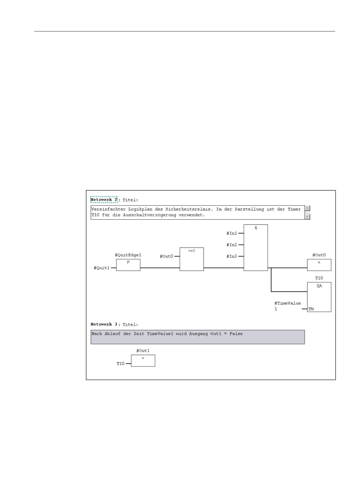
Simplified block diagram in CSF
The figure below shows only one acknowledgment input "Ack1" and one delayed deactivation
output "Out1". The circuit for "Ack2" and the other delayed outputs are identical. The parameter
"FirstRun" is also missing in the function diagram. The mode of operation is described above.
Declaration of the function
FUNCTION_BLOCK FB10
VAR_INPUT
In1 :
BOOL;
PLC
Function Manual, 10/2020, 6FC5397-0HP40-0BA1
225

Block descriptions
17.9 FB10: Safety relay (SI relay)
In2 :
BOOL;
In3 :
BOOL;
Ackn1 :
BOOL;
Ackn2 :
BOOL;
TimeValue1 :
TIME;
TimeValue2 :
TIME;
TimeValue3 :
TIME;
END_VAR
VAR_OUTPUT
Out0 :
BOOL;
Out1 :
BOOL;
Out2 :
BOOL;
Out3 :
BOOL;
END_VAR
VAR_INOUT
FirstRun:
BOOL;
END_VAR
Description of formal parameters
Parameter
Type
Type
Value range
Meaning
In1:
I
BOOL
0 (FALSE), 1
Input 1
(TRUE)
In2:
I
BOOL
0 (FALSE), 1
Input 2
(TRUE)
In3:
I
BOOL
0 (FALSE), 1
Input 3
(TRUE)
Ackn1 :
I
BOOL
0 (FALSE), 1
Acknowledgment input 1
(TRUE)
Ackn2 :
I
BOOL
0 (FALSE), 1
Acknowledgment input 2
(TRUE)
TimeValue1 :
I
S5TIME
Time value 1 for OFF delay
TimeValue2 :
I
S5TIME
Time value 2 for OFF delay
TimeValue3 :
I
S5TIME
Time value 3 for OFF delay
Out0 :
O
BOOL
0 (FALSE), 1
Output, instantaneous
(TRUE)
Out1 :
O
BOOL
0 (FALSE), 1
Output, delayed by TimeValue1
(TRUE)
Out2 :
O
BOOL
0 (FALSE), 1
Output, delayed by TimeValue2
(TRUE)
Out3 :
O
BOOL
0 (FALSE), 1
Output, delayed by TimeValue3
(TRUE)
FirstRun:
I/O
BOOL
0 (FALSE), 1
Call bit memory
(TRUE)
PLC
226
Function Manual, 10/2020, 6FC5397-0HP40-0BA1
Block descriptions
17.10 FB11: Brake test
17.10
FB11: Brake test
Function
The braking operation check should be used for all axes, which must be prevented from moving
in an uncontrolled manner by a holding brake. "Vertical axes" are the main application.
The machine manufacturer can use the PLC user program to regularly close the brake at a
suitable instant (e.g. every 8 hours) and have the drive exert torque/force in addition to the
weight of the axis. In errorfree operation, the brake can produce the necessary braking torque/
braking force. The axis will hardly move during this.
When an error occurs, the actual position value exits the parameterizable monitoring window.
The position controller prevents sagging of the axis. The function test of the brake mechanical
system is negatively acknowledged.
Further information
A detailed description of the parameterization of the NC and drive within the framework of the
"Safety Integrated" function can be found in:
Function Manual for Safety Integrated
Starts the brake test
The brake test must always be started when the axis is at a standstill. For the entire duration of
the brake test, the enable signals of the parameterized axis must be set to enable (e.g. controller
inhibit, feed enable). Furthermore, the signal at the axis/spindle DB31,
DBX28.7 (PLC-
controlled axis) is to be set to status 1 by the user program for the complete duration of the test.
Before activating the NC/PLC interfaces DB31,
DBX28.7 (axis controlled from the PLC
program), the axis must be switched as "neutral axis". For example, DB31,
DBX8.0 - 8.3
(assign NC axis channel) can be set to channel 0 - and DB31,
DBX8.4 can be set (activation
signal when this byte changes).
The return message:
• about the current status can be queried in DB31, ... DBB68.
• the Nc via the signal DB31,
DBX63.1 (PLC controls axis) is to be awaited before the block
is started. The direction in which the drive must produce its torque/force is specified by the
PLC in the form of a "traversing motion" (e.g., via FC18).
The axis must be able to reach the destination of this movement without risk of collision if the
brake is unable to produce the necessary torque/force.
Note
Note on FC18
If FC18 is called over the further course of the user program for the same axis, the calls must be
mutually interlocked. For example, this can be achieved via a common call of this function with
an interlocked common data interface for the FC18 parameters. A 2nd option is to call the FC18
repeatedly, in which case the inactive FC18 will not be processed by the program. A multiple-use
interlock must be provided.
PLC
Function Manual, 10/2020, 6FC5397-0HP40-0BA1
227

Block descriptions
17.10 FB11: Brake test
Structure of a brake test
Step
Expected feedback
Monitoring time value
1
Start brake test
DBX71.0 = 1
TV_BTactiv
2
Close brake
Bclosed = 1
TV_Bclose
3
Output traversing command
DBX64.6 OR DBX64.7
TV_FeedCommand
4
Issue test travel command
DBX62.5 = 1
TV_FXSreached
5
Wait for the holding time
DBX62.5 = 1
TV_FXShold
6
Deselect brake test / open brake
DBX71.0 = 0
TV_BTactiv
7
Output test ok
---
---
General conditions
• FB2 has multi-instance capability.
• Every call of FB11 must be assigned a separate instance DB from the user area.
Declaration of the function
Function_BLOCK FB11
VAR_INPUT
Start
BOOL;
Ackn :
BOOL;
Bclosed :
BOOL;
Axis :
INT;
TimerNo :
TIMER ;
TV_BTactiv :
S5TIME ;
TV_Bclose :
S5TIM;
TV_FeedCommand : S5TIME ;
TV_FXSreached :
S5TIME ;
TV_FXShold :
S5TIME ;
END_VAR
VAR_OUTPUT
CloseBrake : BOOL;
MoveAxis :
BOOL;
Done :
BOOL;
Error :
BOOL;
State :
BYTE ;
END_VAR
Description of formal parameters
Signal
Type
Type
Meaning
Start
I
BOOL
Starts the brake test
Ackn
I
BOOL
Acknowledge fault
PLC
228
Function Manual, 10/2020, 6FC5397-0HP40-0BA1

Block descriptions
17.10 FB11: Brake test
Signal
Type
Type
Meaning
Bclosed
I
BOOL
Checkback input whether Close Brake is activated (single-
channel - PLC)
Axis
I
INT
Axis number of axis to be tested
TimerNo
I
TIMER
Timer from user program
TV_BTactiv
I
S5TIME
Monitoring time value → brake test active, check of axis signal
DBX71.0
TV_Bclose
I
S5TIME
Monitoring time value → close brake. Check of input signal
Bclosed after output CloseBrake has been set
TV_FeedCommand
I
S5TIME
Monitoring time value → Travel command given Check travel
command after MoveAxis has been set
TV_FXSreched
I
S5TIME
Monitoring time value → fixed stop reached
TV_FXShold
I
S5TIME
Monitoring time value → test brake
CloseBrake
O
BOOL
Request, close brake
MoveAxis
O
BOOL
Request, initiate traversing motion
Done
O
BOOL
Test successfully completed
Error
O
BOOL
An error occurred
State
O
BYTE
See paragraph "Error identifiers"
Fault IDs
State
Meaning
0
No error
1
Start conditions not fulfilled, e.g. the axis is not in closed-loop control / brake closed / axis
inhibited
2
No NC checkback in "Brake test active" signal on selection of brake test
3
No "Brake applied" checkback by input signal Bclosed
4
No travel command output (e.g., axis motion has not been started)
5
Fixed end stop will not be reached → axis RESET was initiated.
6
Traversing inhibit/Approach too slow → fixed stop cannot be reached. TV FXSreached moni-
toring timeout.
7
Brake is not holding at all (the end position is reached)/approach speed is too high
8
Brake opens during the holding time
9
Error when deselecting the brake test
10
Internal error
11
"PLC-controlled axis" signal not enabled in the user program
Example of calling FB11:
UN
M
111.1;
//Request to close brake, Z axis of FB
=
O
85.0;
//Brake control, Z axis
AUF
Axis3";
//Brake test, Z axis
O
I
73.0;
//Brake test trigger, Z axis
O
M
110.7;
//Brake test running
FP
M
110.0;
PLC
Function Manual, 10/2020, 6FC5397-0HP40-0BA1
229
Block descriptions
17.10 FB11: Brake test
UN
M
111.4;
//Error has occurred
S
M
110.7;
//Brake test running
S
M
110.6;
//Next step
JCN
m001
L
DBB
68;
AW
W#16#F;
T
MB
115;
//flag channel state
L
B#16#10
T
DBB
8;
//Request neutral axis
m001: U
DBX
68.6;
//Checkback signal, axis is neutral
U
M
110.6;
FP
M
110.1;
R
M
110.6;
S
M
110.5;
//Next step
S
DBX
28.7;
//Request PLC-monitored axis
U
DBX
63.1;
//Checkback signal, axis monitored by PLC
U
M
110.5;
FP
M
110.2;
R
M
110.5;
S
M
111.0;
//Start brake test for FB
CALL FB11, DB211 (//brake test block
Start
:=M
111.0,
//Start brake test
Ackn
:= I
3.7,
//Acknowledge error with RESET
key
Bclosed
:= I
54.0,
//Return message close brakes
//controlled
Axis
:= 3,
//Axis number of axis to be
tested
//Z axis
TimerNo
:= T
110,
//Timer number
TV_BTactiv
:= S5T#200MS,
//Monitoring time value:
//Brake test active DBX71.0
TV_Bclose
:= S5T#1S,
//Monitoring time value:
//Brake closed
TV_FeedCommand
:= S5T#1S,
//Monitoring time value:
//Traversing command output
TV_FXSreache
:= S5T#1S,
//Monitoring time value:
//Fixed stop reached
TV_FXShold
:= S5T#2S,
//Monitoring time value:
//Brake test time
CloseBrake
:=M
111.1,
//Request to close brake
MoveAxis
:=M
111.2,
Initiate //Request traversing
motion //
Done
:=M
111.3,
//Test successfully completed
PLC
230
Function Manual, 10/2020, 6FC5397-0HP40-0BA1
Block descriptions
17.10 FB11: Brake test
Error
:=M
111.4,
//Error has occurred
State
:= MB 112);
//Error status
AUF
"Axis3"
//Brake test, Z axis
;
U
M
111.2;
//Moveaxis
FP
M
111.5;
//FC18 Start
S
M
111.7;
//Start FC18
O
M
111.3;
//Test successfully completed
O
M
111.4;
//Error has occurred
FP
M
110.3;
R
DBX
28.7;
//Request, PLC-monitored axis
UN
DBX
63.1;
//Checkback signal, axis monitored by PLC
U
M
111.0;
//Start brake test for FB
U
M
110.7;
//Brake test running
FP
M
110.4;
R
M
111.0;
//Start brake test for FB
R
M
110.7;
//Brake test running
//optional begin
JCN
m002;
L
MB
115;
//old channel status
OW
W#16#10
;
T
DBB
8;
//Request channel axis
m002: NOP
0;
//optional end
CALL "SpinCtrl" (//Traverse Z axis
Start
:=M
111.2,
//Start traversing motion
Stop
:= FALSE,
Funct
:= B#16#5,
//Mode: Axis mode
Mode
:= B#16#1,
//Procedure: Incremental
AxisNo
:= 3,
//Axis number of axis to be
traversed
//axis Z-axis
Pos
:= -5.000000e+000, //Traversing distance: Minus 5 mm
FRate
:= 1.000000e+003,
//Feedrate: 1000 mm/min
InPos
:=M
113.0,
//Position reached
Error
:=M
113.1,
//Error has occurred
State
:= MB
114);
//Error status
PLC
Function Manual, 10/2020, 6FC5397-0HP40-0BA1
231
Block descriptions
17.11 FB21: Powerride - rotary/push control dial
AUF
"Axis3"
//Brake test, Z axis
;
U
M
113.0;
//Position reached
O
M
113.1;
//Error has occurred
FP
M
113.2;
R
M
111.7;
//Start FC18
17.11
FB21: Powerride - rotary/push control dial
Function
The function block FB21 "Powerride" integrates a rotary/push control dial (SINUMERIK
Powerride) into the SINUMERIK environment.
With the Powerride, the operator can change the feed rate in percent with immediate effect on
the machine. To do this, multiply the override factor of the Powerride by the programmed feed
rates.
Interfaces for the feed rate change:
• Individually in the channel DB
• Individually in the axis DB
The hardware of the Powerride is described in the Operating Components Manual Modular
MCPs.
Querying and adjusting properties of the Powerride
At the parameters of the FB and in the data records of "DB78: PowerrideConfig" you can query
data and adjust the behavior of the Powerride.
Summary of the query and setting options:
• Query current switch position (between 1 and 36)
"switchPos" parameter
• Query override factor for the current switch position
"ovrFactor" and "grayCode" parameters
• Define override factor for the respective switch position
"configuration.switchPos[x].value" parameter
• Evaluate whether switch is pressed
"pushButton" parameter
• Colors and limit values for controlling the LEDs
"pushButtonLED" and "configuration.switchPos[x].ledColor" parameters
• Vibration pattern
"configuration.switchPos[x].vibrationIndex" parameter
• Change value for the current switch position (between 1 and 36)
"preset" or "forceSwitchPos1" parameter
PLC
232
Function Manual, 10/2020, 6FC5397-0HP40-0BA1
Block descriptions
17.11 FB21: Powerride - rotary/push control dial
• Set switch positions for 100 % and the end position
"configuration.pos100" and "configuration.posMax" parameters
• Time delay for exceeding 100 %
"configuration.delay100" parameter
Using default settings or configuring individually
Ready-to-use configurations in the "PowerrideConfig" data block permit you to use the Powerride
immediately. Transfer the desired configuration to the FB at the "configuration" parameter.
Create your own data block with your configuration settings for individual adaptations.
If you want to program the behavior of the Powerride yourself, you can query and control the
signals directly with the parameters "deviceIn" and "deviceOut".
Behavior of the Powerride
The following list briefly describes the behavior of the Powerride using the example of the
configuration "PowerrideConfig.configFeed":
• An edge transition 0 → 1 of the parameter "enable" triggers the configuration check. An error-
free configuration is copied into the instance DB.
• Turning clockwise increases the values of the parameters "switchPos", "grayCode" and
"ovrFactor".
• Turning counterclockwise decreases the values of the parameters "switchPos", "grayCode"
and "ovrFactor".
• The value in the "switchPos" parameter is never less than 1 or higher than
"configuration.posMax".
• When counterclockwise rotation reaches position 1, no further reduction takes place.
Vibration index 1 becomes noticeable.
• Between position 1 and "configuration.pos100", the LED strip lights up white as far as the
current position.
• The number of activated LEDs corresponds to the value in the "switchPos" parameter.
• When clockwise rotation reaches position "configuration.pos100", the LED strip turns green,
the position value is recorded, and vibration index 2 becomes noticeable.
• An increase of the value of 100 % is possible again after a time delay
"configuration.delay100".
• Between position "configuration.pos100" and "configuration.posMax", the LED color is
yellow.
• When clockwise rotation reaches position "configuration.posMax", the position value is
recorded. Vibration index 3 becomes noticeable and the LED strip lights up red.
PLC
Function Manual, 10/2020, 6FC5397-0HP40-0BA1
233