SINUMERIK 840D sl. Service - Functions. Manual (2018-2020) - page 50
Interface structure
9.2 PLC/NCK interface
• Tool management signals
• NC functions
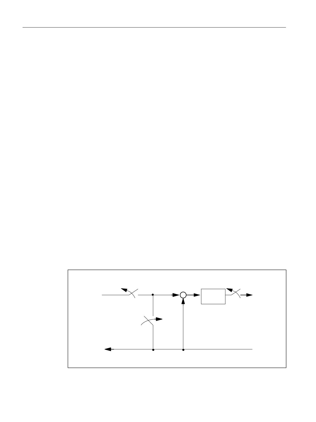
The control/status signals are transferred cyclically at the start of OB1. The signals entered in
the channel-specific interface by the HMI (HMI signals are entered by the PLC operating system)
are also transferred at this time if they have been defined on the HMI operator panel, not on the
MCP.
Auxiliary commands and G commands are entered in the interface data blocks in two ways.
First, they are entered with the change signals.
• The M signals M00 - M99 (they are transferred from the NC with extended address 0) are also
decoded and the associated interface bits set for the duration of one cycle.
• For G commands, only the groups selected via machine data are entered in the interface
data block.
• The S values are also entered together with the related M signals (M03, M04, M05) in the
spindle-specific interface. The axis-specific feedrates are also entered in the appropriate axis-
specific interface.
When the tool management (magazine management) function is activated in the NC, the
assignment of spindle or revolver and the loading/unloading locations are entered in separate
interface DBs (DB71-73).
The triggering and parameter assignment of NC functions is performed by means of PLC
function calls.
The following function calls are available:
• Position a linear axis or rotary axis
• Position an indexing axis
• Start a prepared asynchronous subprogram (ASUP)
• Read/write NC variables
• Update magazine and tool motion
Some of the above functions are described in their own function documentation.
3RVLWLRQ VHWSRLQW IURP
WKH ,32
3RVLWLRQ
FRQWUROOHU
&ORVHG ORRS
FRQWUROOHU HQDEOH
FDQFHOHG
8SGDWH VHWSRLQW
$FWXDO SRVLWLRQ
YDOXH
Figure 9-4
PLC/NC channel interface
PLC
62
Function Manual, 10/2020, 6FC5397-0HP40-0BA1
Interface structure
9.2 PLC/NCK interface
PLC/axis, spindle, drive signals
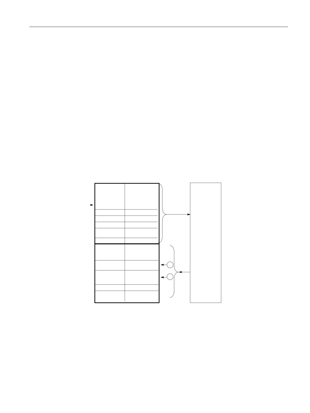
The axis-specific and spindle-specific signals are divided into the following groups:
• Shared axis/spindle signals
• Axis signals
• Spindle signals
• Drive signals
The signals are transferred cyclically at the start of OB1 with the following exceptions.
Exceptions include:
• axis-specific F value
• M value
• S value
An axis-specific F value is entered via the M, S, F distributor of the basic program if it is
transferred to the PLC during the NC program processing.
The M and S value are also entered via the M, S, F distributor of the basic program if one or both
values require processing.
)HHGUDWH
&RPPRQ
6SLQGOH VSHHG
%\WH
D[LV VSLQGOH
RYHUULGH
VLJQDOV
&RQWURO VLJQDOV
7UDYHUVH VLJQDOV
$[LV VLJQDOV
/LPLW VZLWFKHV
6SLQGOH VLJQDOV
&RQWURO VLJQDOV
'ULYH VLJQDOV
&RQWURO VLJQDOV
7HFKQRORJ\
&RQWURO VLJQDOV
*ULQGLQJ
$[LV
5HVHUYHG
VSLQGOH
GULYH
&RPPRQ
6WDWXV VLJQDOV
D[LV VSLQGOH
$FWLYH ,1& PRGH
VLJQDOV
$[LV VLJQDOV
6WDWXV VLJQDOV
$[LDO ) YDOXH
6HW JHDU VWDJH
6SLQGOH
6WDWXV VLJQDOV
VLJQDOV
0 6 :HUW
'ULYH VLJQDOV
6WDWXV VLJQDOV
7HFKQRORJ\
6WDWXV VLJQDOV
*ULQGLQJ
1&.
YDOXH IURP 0 6 ) GLVWULEXWRU RI EDVLF SURJUDP
Figure 9-5
Interface PLC / axes/spindles/drives (DB31, …)
PLC
Function Manual, 10/2020, 6FC5397-0HP40-0BA1
63
Interface structure
9.3 Interface PLC/HMI
9.3
Interface PLC/HMI
General
The following groups of functions are required for the PLC/HMI interface:
• Control signals
• Machine operation
• PLC messages
• PLC status display
Control signals
Some control signals are signal inputs, for example, via the machine control panel, which have
to be taken into account by the HMI. This group of signals includes, for example, display actual
values in MCS or WCS, key disable, etc. These are exchanged with the HMI via a separate
interface data block (DB19).
Machine operation
All operator inputs, which lead to response actions on the machine, are monitored by the PLC.
Operator actions are usually performed on the machine control panel (MCP). However, it is also
possible to perform some operator actions on the HMI, e.g. mode selection.
The PLC operating system enters the operating signals sent by the HMI directly into the interface
data blocks. As standard, the basic program routes these operating signals in such a way that,
provided equivalent operator actions are available, these can be performed either on the HMI or
on the MCP. If required, the user can switch off operation via HMI using an FB1 parameter
"MMCToIF".
PLC messages
The signaling functions are based on the system diagnostic functions integrated in the
operating system of the AS 300. These have the following characteristics:
• The PLC operating system enters all important system states and state transitions in
a diagnostics status list. Communication events and I/O module diagnostics data (for
modules with diagnostic functions) are also entered.
• Diagnostics events, which lead to a system stop, are also entered with a time stamp in
a diagnostic buffer (circular buffer) in the chronological order of their occurrence.
• The events entered in the diagnostic buffer are automatically transmitted to human machine
interface systems (OP or HMI) via the bus systems once these have issued a ready signal
(message service). "Transfer to the node ready" is a function of the PLC operating system.
Receipt and interpretation of the messages are executed by the HMI software.
• The PLC user program can also use SFCs (System Function Calls) to enter messages in the
diagnostic buffer or ALARM S/ALARM SQ buffer.
• The events are entered in the alarm buffer.
The associated message texts must be stored on the OP or HMI.
PLC
64
Function Manual, 10/2020, 6FC5397-0HP40-0BA1
Interface structure
9.3 Interface PLC/HMI
An FC (FC10) for message acquisition is prepared in conjunction with the basic program. This FC
records events, subdivides them into signal groups and reports them to the HMI via the alarm
buffer.
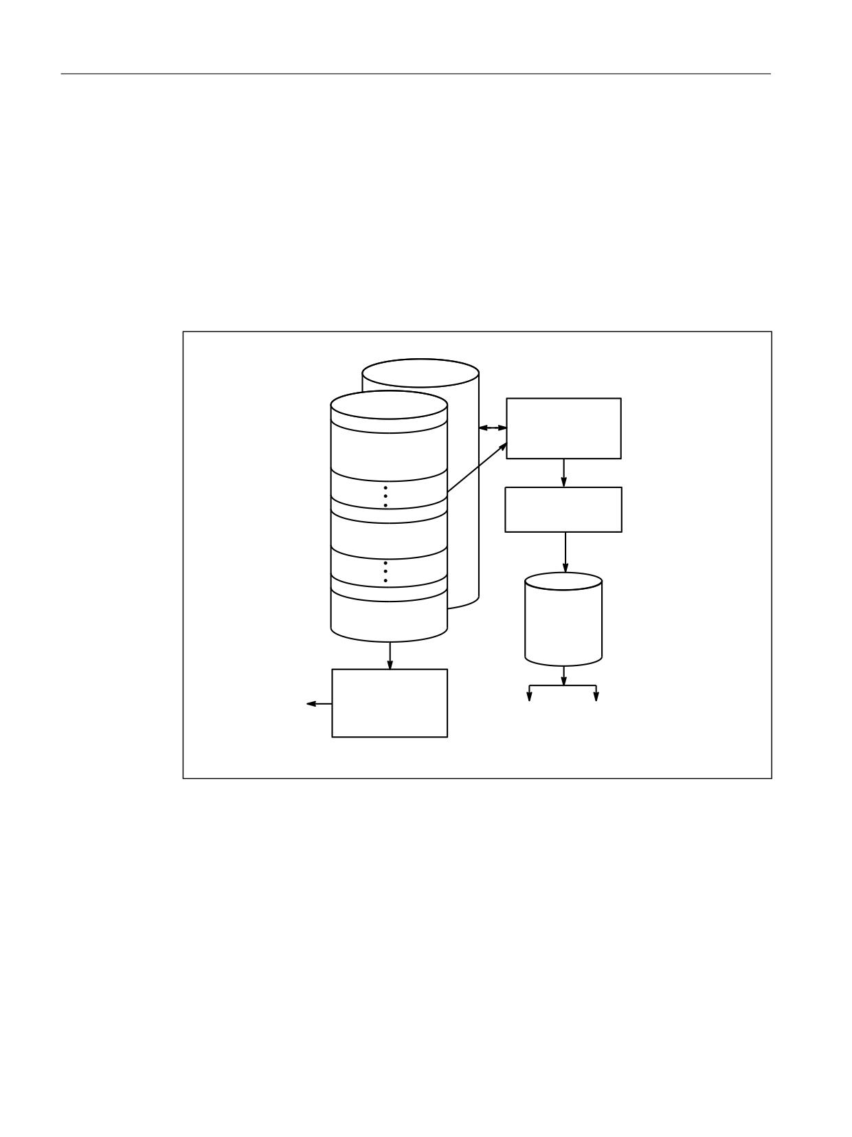
The message acquisition structure is shown in the figure "Acquisition and signaling of PLC
events". The features include:
• Bit fields for events related to the NC/PLC interface are combined in a single data block (DB2)
with bit fields for user messages.
• Bit fields are evaluated at several levels by FC10.
- Evaluation 1; acquisition of group signals
A group signal is generated for each group of signals if at least one bit signal is set to "1".
This signal is generally linked to the disable signal of the NC/PLC interface (on modules
with diagnostic functions). The group signals are acquired completely in cycles.
- Evaluation 2; acquisition of alarm messages
A fixed specification exists to define which signals in a group generate an alarm message
when they change from "0" to "1".
- Evaluation 3; acquisition of operating signals
A fixed specification exists to define which signals in a group generate an operational
message.
• The scope of the user bit fields (user area) is set by default to 10 areas with 8 bytes each, but
the number of areas can also be adjusted to suit the requirements of the machine
manufacturer via basic program parameters in FB1.
Acknowledgement concept
The following acknowledgement procedures are implemented for error and operational
messages:
Operating messages are intended for the display of normal operating states as information for
the user. Acknowledgement signals are, therefore, not required for this type of message. An
entry is made in the diagnostic status list for incoming and outgoing messages. The HMI
maintains an up-to-date log of existing operating messages using the identifiers "operating
message arrived" and "operating message gone".
Alarm messages display error states on the machine, which will usually lead to the machine
being stopped. Where several errors occur in rapid succession, it is important to be able to
distinguish their order of occurrence for troubleshooting purposes. This is indicated, on the one
hand, by the order in which they are entered in the diagnostic buffer and on the other, by the
time stamp, which is assigned to every entry.
If the cause of the error disappears, the associated alarm message is only deleted if the user has
acknowledged it (e.g. by pressing a key on the MCP). In response to this signal, the "Message
acquisition" FC examines which of the reported errors have disappeared and enters these in the
diagnostic buffer with the entry "Alarm gone". This enables the HMI to also maintain an up-to-
date log of pending alarm messages. The time of day indicating the time at which the error
occurred is maintained for messages, which are still pending (in contrast to a received
interrogation).
PLC
Function Manual, 10/2020, 6FC5397-0HP40-0BA1
65
Interface structure
9.3 Interface PLC/HMI
STEP 7
A tool can be started in the SIMATIC Manager via menu item "Target system" > "CPU messages".
Alarms and messages can be displayed by number using this tool. To do this, acivate the "Alarm"
tab and enter a check mark under "A" in the upper half of the screen.
User program
The user PLC program only has to call the basic program block FC10 with appropriate parameter
settings in the cyclic program section and set or reset the bit fields in DB2. Everything else is
handled by the basic program and the HMI.
&KDQJH VLJQDOV
%LW DUUD\V
0HVVDJH
DFTXLVLWLRQ
&KDQQHO
)HHG GLVDEOH
5HDG LQ GLVDEOH
1& 6WDUW GLVDEOH
$/$50B6
&KDQQHO Q
6)&
$/$50B64
$[LV VSLQGOH
)HHGUDWH VSLQGOH
GLVDEOH
$[LV VSLQGOH Q
8VHU DUHD
,QWHUUXSW
EXIIHU
0HVVDJH VHUYLFH
$FTXLVLWLRQ
*URXS VLJQDOV
RI JURXS VLJQDOV
GLVDEOH VLJQDOV
IRU FKDQQHO DQG
3*
+0, 23
D[LV '%
Figure 9-6
Acquisition and signaling of PLC events
Extensions of the PLC alarms via block FC10
The FB1 parameter "ExtendAlMsg" selects the PLC alarm mechanism.
If "ExtendAlMsg:= FALSE" the earlier process of the FC10 with the DB2 is active as bit array data
block. The known restrictions regarding the number of channels and axes are applicable.
On the other hand, in case of "ExtendAlMsg:= TRUE" the extension of the FC10 becomes active.
DB2 and DB3 are created just as before. The user must set or reset the bits in DB2. The parameter
setting via message and alarm and a parameter setting of the numeric value of the 2nd decade
of the user alarms are contained in DB5.
PLC
66
Function Manual, 10/2020, 6FC5397-0HP40-0BA1
Interface structure
9.3 Interface PLC/HMI
The extensions are:
• Support for 10 channels, 31 axes, 64 user areas (the number of user areas should be entered
in the FB1 parameter "MsgUser").
• Areas for feed stop, read-in disable, etc. are available without messages. The information
from this area is stored on the interface in DB21, DB31 depending on FC10 parameter
"ToUserIF" together with the related message bits as group signals. As such, the previous
cumbersome handling of the signals is omitted.
• The alarms / messages also get the 16-bit integer additional value (%Z parameter in the alarm
text) in addition to the alarm number for the user area 0. The user must write the 16-bit
integer values in the DB2 in the array variable ZInfo0 parallel to setting an alarm bit. An
integer value is available for each bit in the user area 0, see UDT1002 in the basic program.
• The user messages can be parameteized in the second decade of the message number in the
numerical range 0 to 9. The display value of the second decade must be written by the user
in the DB5 in the array variable UserDek2No. A number can be defined for each user area, see
DB5 in the basic program.
The value 0 is set by default for the second decade.
The structuring of the DB2 in UDT1002 can be recognized (basic program). In case of new alarm
functions, the UDT1002 must be assigned symbolically to the DB2.
At the start of DB2 there are bit arrays for signals without alarm generation. This is followed by
an array of size 64 integer values for additional info about the user area 0.
Thereafter follow the areas, which also trigger alams / messages (see List manual) These areas
are extended to 10 channels, 31 axes.
Switching over a user program from the small DB2 layout to the large DB2 layout (UDT2 → UDT1002)
With the small DB2 layout, i.e. if DB2 is derived from UDT2 - and FB1 parameter "ExtendAlMsg
= FALSE" is used - then a max. of 8 channel areas, max. of 18 axis areas and a max. of 31 user
areas (depending on FB1 parameter "MsgUser") can be used. As default setting, 10 user areas are
defined in the UDT2. When using more than 10 user areas (FB1 parameter "MsgUser" > 10), then
users must extend UDT2 if DB2 is to be symbolically accessed.
With the large DB2 layout, i.e. if DB2 is derived from UDT1002 - and FB1 parameter "ExtendAlMsg
= TRUE" is used - then you can generate alarms for 10 channels, 31 axes and 64 user areas.
If it is no longer possible to generate alarms with the restrictions of the small DB2 layout, then
it may be necessary to switch over an already existing project to the large layout. The switchover
procedure depends on how DB2 is accessed in the project. The various procedures are described
in the following.
Switchover for symbolic programming
The source container of the basic program contains the "udt2_for_Convert.awl" file, which
contains the following structural element from UDT1002:
• ChanA as array of 1 ... 8 for switching over the 8 channel ranges.
• AxisA as array of 1 ... 18 for switching over the 18 axis/spindle ranges
• UserA as array from 0 ... 31 for switching over user areas
PLC
Function Manual, 10/2020, 6FC5397-0HP40-0BA1
67
Interface structure
9.3 Interface PLC/HMI
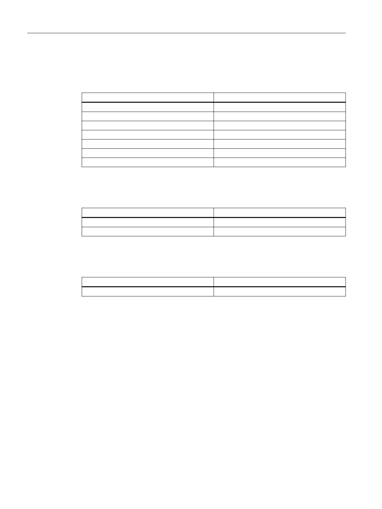
From this STL file, a UDT can be generated that assigns the offsets of the small DB2 version to the
symbolic names of the large DB2 version.
Table 9-1
Symbolic signal designator from the channel area
DB2 without alarm extension
DB2 with alarm extension
Cj.FDD_5j00xx[i]
ChanA[j].FDD_5C00xx[i]
Cj.FDD_RID_5j01xx[i]
ChanA[j].FDD_RID_5C01xx[i]
Cj.RID_5j02xx[i]
ChanA[j].RID_5C02xx[i]
Cj.NCSD_5j03xx[i]
ChanA[j].NCSD_5C03xx[i]
Cj.FdStop_1_5j11xx[i]
ChanA[j].FdStop_1_5C11xx[i]
Cj.FdStop_2_5j12xx[i]
ChanA[j].FdStop_2_5C12xx[i]
Cj.FdStop_3_5j13xx[i]
ChanA[j].FdStop_3_5C13xx[i]
j (shown bold): Channel number (1 … 8)
Table 9-2
Symbolic signal designator from the axis/spindle area
DB2 without alarm extension
DB2 with alarm extension
_jFdStop600jxx[i]
AxisA[j].AAFdStop60AAxx[i]
_jjFdStop60jjxx[i]
AxisA[jj].AAFdStop60AAxx[i]
j or jj (shown bold): Axis/spindle number (1 ... 9 or 10 … 18)
Table 9-3
Symbolic signal designator from the user area
DB2 without alarm extension
DB2 with alarm extension
A70jjxx[i]
UserA[jj].A70UUxx[i]
jj (shown bold): User range (00 … 31)
Procedure:
1. Select the block folder and under "Object properties" > "Operand priority" ensure that
"Absolute value has priority" is active.
2. Compile source "udt2_for_Convert.awl".
The new symbols of the large layout are now already available in UDT2.
3. Generate sources of blocks, which contain symbolic assignments to the DB2. To do this, in the
LAD/STL/FBD KOP/AWL/FUP editor, under "File" > "Generate source", select the required blocks
and create an STL source.
4. In the symbol table, assign UDT1002 to the DB2.
5. In the SIMATIC Manager under "Sources" compile the currently generated source.
Now all the alarm allocations are assigned to the new data areas in the DB2 and now only the
parameter "ExtendAlMsg" at FB1 must be set to True.
Switchover for direct absolute access to the DB2
For instance, this is the case if the user first opens the DB2 in the program code, and then directly
accesses it (at "ALMSG_DB"; S DBX180.0;).
PLC
68
Function Manual, 10/2020, 6FC5397-0HP40-0BA1

Interface structure
9.3 Interface PLC/HMI
Procedure:
1. Using the cross reference list (menu command "Tools" > "Reference data" > "Display"), search
for blocks in the user program that's contain DB2 access operations.
2. Open the program locations involved one after the other and switchover the offset addresses
of the relevant DB2 signals.
The new offset address results from the sum of the previous address and the "offset".
Note
Searching for DB2 accesses in the user program
Not all DB2 access operations are found via the reference data. Accesses via BLK_DB or pointer
are not detected.
A comparison of the particular offset addresses and/or the address offset are listed in the
following table.
Table 9-4
Addresses in the DB2 versions
Alarm
DB2 without alarm extension
Off-
DB2 with alarm extension
number
set
Area
Offset
Offset
Area
-
0
Chan
(Channel 1 ... 10)
-
120
Axis
(Axis/spindle 1 ... 31)
Addition-
182
As of V6.0: AddValU-
al value
serA0 (AddValU-
serA0 0 ... 63)
(Up to V4.8: ZInfo0
0 ... 63)
5C0000 ..
(C1 ... C8)
Byte 0 ... <last byte
310
Byte 310 ... <last
ChanA
. 5C1315
for channel area>
byte for channel
Channel 1 ... 8
Channel 1 ... 10
area>
60AA00 ..
(Axis areas)
Byte 144 ... <last
346
Byte 490 ... <last
AxisA
. 60AA15
byte for axis area>
byte for axis area>
Axis/spindle
Axis/spindle 1 ... 31
1 ... 18
70UU00 ..
(User area)
Byte 180 ... <last
374
Byte 554 ... <last
UserA
. 70UU63
byte for user area>
User area
byte for user area>
User area 0 ... 63
0 ... 31
Conversion for indirect access via BLKMOV
The following adaptations are required if DB2 is not directly accessed, but instead BLKMOV is
used, for example to copy memory areas of its own data blocks to DB2.
Within the individual DB2 areas, the offset addresses of both DB2 versions are offset by a specific
value. This offset is, however, different for each DB2 area.
PLC
Function Manual, 10/2020, 6FC5397-0HP40-0BA1
69
Interface structure
9.4 PLC/MCP/HHU interface
A check has to be made whether BLKMOV copy operations are used that copy a memory area
that is larger than a DB2 area. If this is the case, then copying must be split up over several
operations. The new offset address must then be considered and adapted depending on the
particular DB2 area.
9.4
PLC/MCP/HHU interface
General
There are different connection options for the machine control panel (MCP) and the handheld
unit (HHU). This is in part due to the history of the MCP and HHU. This description focuses
primarily on the connection of the Ethernet components.
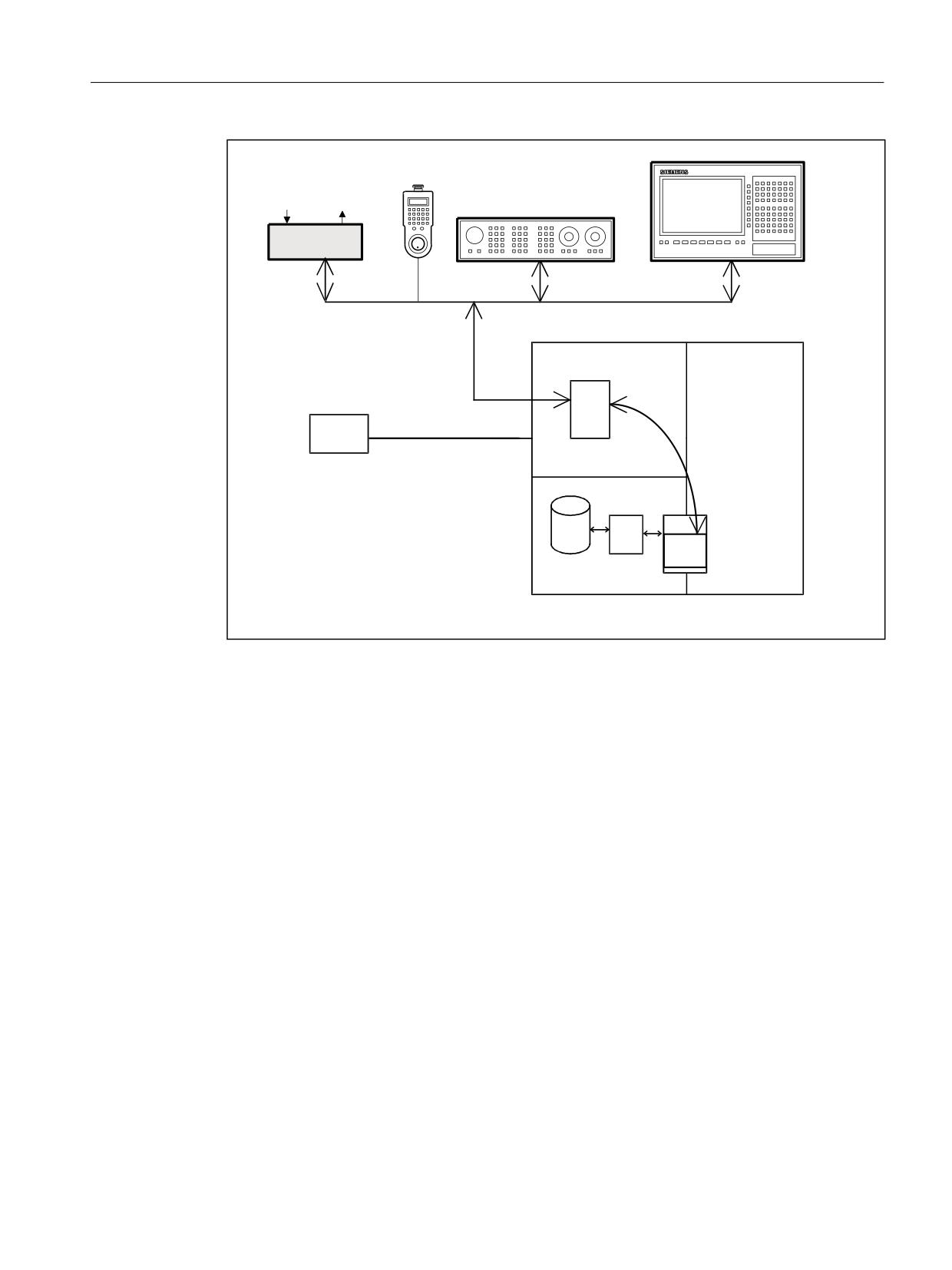
On the SINUMERIK 840D sl, the machine control panel (MCP) and handheld unit (HHU) are
connected via the Ethernet bus, which also links the TCU to the NCU. The advantage of this is that
only one bus cable is required to connect the operating unit.
Topology SINUMERIK 840D sl
On the 840 D, the machine control panel and the handheld unit are connected to the CP 840D
sl Ethernet bus (see Figure below). Where the connection of further keys and displays is required
for customized operator panels, an additional keyboard interface (machine control panel
without operating unit) can be used. For each keyboard interface, 64 pushbuttons, switches,
etc. and 64 display elements can be connected via ribbon cable.
The signals sent from the MCP are copied to the PLC's DPR (Dual-Port RAM) by the integrated
Ethernet CP-840D sl. The basic program of the PLC enters the incoming signals in the input
image configured at FB1. The NC-related signals are generally distributed by the basic program
to the NC/PLC interface. If required, the signals can be modified by the user.
The signals from the PLC to the MCP (displays) are transferred in the opposite direction.
PLC
70
Function Manual, 10/2020, 6FC5397-0HP40-0BA1
Interface structure
9.4 PLC/MCP/HHU interface
%+*
&XVWRPHU
7&8
NH\V GLVSOD\V
0&3
(WKHUQHW EXV
&3
' VO
1&.
+0,
):
3*
(QJLQHHULQJ
(WKHUQHW EXV
'35
)%
0&3
6LJ
3/&
Figure 9-7
Connection of the machine control panel on 840D sl
Bus addresses
On Ethernet components, MAC and IP addresses or logic names are determining factors in
respect of communication. The control system's system programs convert logic names into MAC
or IP addresses. On the PLC, the numeric component of the logic name is used for
communication. This numeric part is specified by the user to the FB1 using parameter
"MCPxBusAdr".
The logical name of an MCP or HHU always begins with "DIP". This is followed by a number
corresponding to the switch position of the MCP component (e.g. DIP192, DIP17).
MCP interface in the PLC
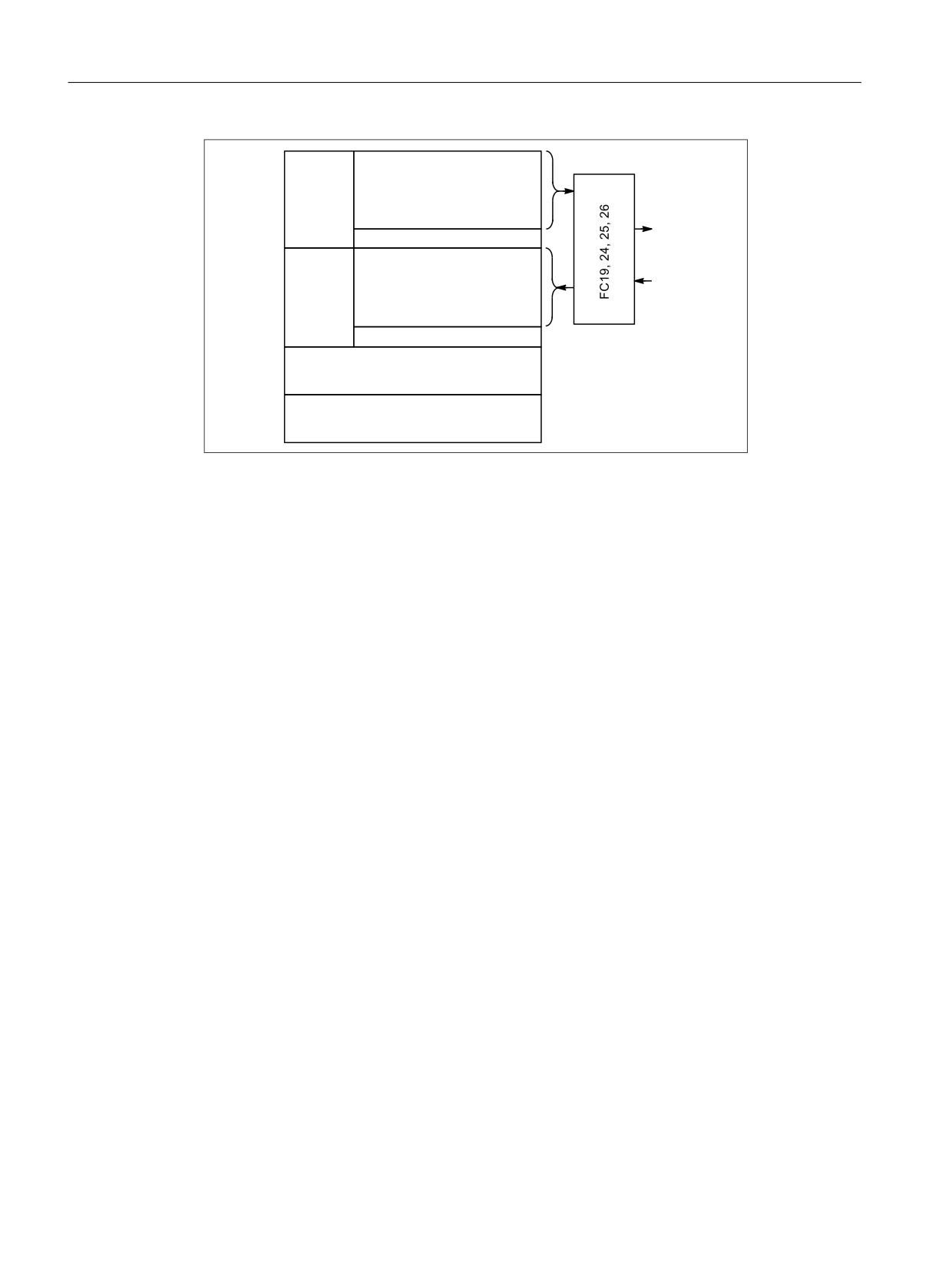
The signals from the machine control panel are routed by default via the I/O interface to the PLC
area. A distinction must be made between NC and machine-specific signals. NC-specific key
signals are distributed to the relevant mode-group-, NC-, axis- and spindle-specific interface by
FC19 (or FC24, FC25, FC26, depending on the type of MCP) by default. The reverse applies to the
associated status signals which are routed to the MCP interface. For this purpose, FC19 or the
other blocks mentioned above must be called in the user program.
Customized keys, which can be used to trigger a wide range of machine functions, must be
evaluated directly by the user program. The user program also routes the status signals to the
output area for the LEDs.
PLC
Function Manual, 10/2020, 6FC5397-0HP40-0BA1
71
Interface structure
9.4 PLC/MCP/HHU interface
2SHUDWLQJ PRGHV
,1& PRGH
)HHGUDWH VSLQGOH RYHUULGH
(% Q
.H\ VLJQDOV
$UURZ NH\V
.H\ RSHUDWHG VZLWFK
0RGH
&XVWRPHU NH\V
JURXS
1&. D[LV
&XUUHQW PRGH
VSLQGOH
/('V
&XUUHQW ,1& PRGH
LQWHUIDFH
$% P
)HHGUDWH VSLQGOH 1& VWDWXV
$FWLYH DUURZ NH\
6WDWXV RI FXVWRPHU NH\V
0RQLWRULQJ
$' R
7UDQVPLW GDWD
0RQLWRULQJ
$' S
5HFHLYH GDWD
Figure 9-8
Interface to and from machine control panel
PLC
72
Function Manual, 10/2020, 6FC5397-0HP40-0BA1
Structure and functions of the basic program
10
General
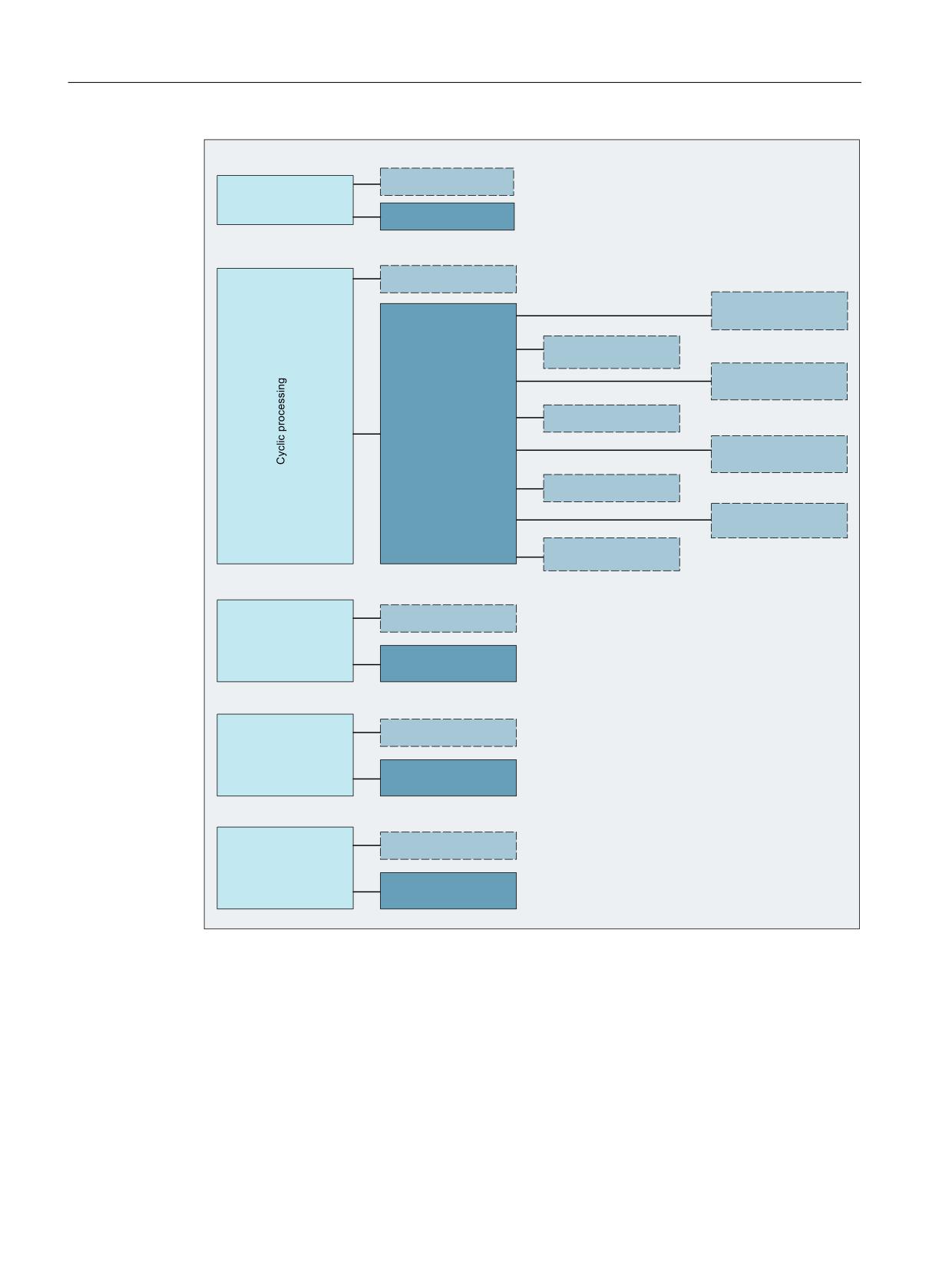
The PLC program has a modular structure. The organization blocks (OB) form the interface
between the operating system and the basic and user programs.
• Restart (warm restart) with start-up and synchronization (OB100)
• Cyclic operation (OB1)
• Process alarms (OB40)
• Asynchronous errors: Diagnostics alarm (OB82), module failure (OB86)
The calls of the function blocks of the basic and user programs must be programmed by the user
in the organization blocks (OB).
PLC
Function Manual, 10/2020, 6FC5397-0HP40-0BA1
73
Structure and functions of the basic program
)%
2%
%DVLF SURJUDP
5HVWDUW
8VHU SURJUDP
2%
)&
%DVLF SURJUDP
)&
)&
)&
)&
0&3 VLJQDOV
+7b VLJQDOV
)&
)&
)&
7RRO PDQDJHPHQW
)&
6SLQGOH FRQWURO
)&
6WDUW $683
)%
)%
)%
)%
8VHU SURJUDP
5HDG ZULWH WDJ
3, VHUYLFHV
)&
6WDU GHOWD
)&
'LVSOD\ FRQWURO
)&
+7
)DXOW DQG RSHUDWLQJ
PHVVDJHV
2%
)&
%DVLF SURJUDP
+DUGZDUH LQWHUUXSW
8VHU SURJUDP
2%
)&
%DVLF SURJUDP
'LDJQRVWLF LQWHUUXSW
8VHU SURJUDP
2%
)&
%DVLF SURJUDP
0RGXOH UDFN IDLOXUH
8VHU SURJUDP
Figure 10-1
Structure of the basic program (principle)
PLC
74
Function Manual, 10/2020, 6FC5397-0HP40-0BA1
Structure and functions of the basic program
10.2 Cyclic operation (OB1)
10.1
Startup and synchronization of NCK PLC
Loading the basic program
The basic program must be loaded with the S7 tool when the PLC is in the Stop state. This ensures
that all blocks in the basic program will be initiated correctly the next time they are called.
Otherwise, undefined states can occur in the PLC (e.g. blinking of all PLC LEDs).
Startup,
The synchronization of NC and PLC is performed during start-up. The system and user data
blocks are checked for integrity and the most important basic program parameters are verified
for plausibility. In cases of errors, the basic program produces an alarm (visible on HMI) and
switches the PLC to the Stop state.
A warm restart is not provided, i.e. following system initialization, the operating system runs
organization block OB100 and always commences cyclic execution at the start of OB1.
Synchronization
The PLC is synchronized with the HMI, NC and CP during power-up.
Sign-of-life
After a correct initial start and the first complete OB1 cycle (basic setting cycle) the PLC and NC
continuously exchange sign-of-life signals. If the sign of life from the NC fails to materialize, the
PLC/NC interface is initialized and the signal "NC CPU ready" in DB10 is set to FALSE.
10.2
Cyclic operation (OB1)
General
The NC/PLC interface is processed completely in cyclic mode. From a chronological viewpoint,
the basic program runs ahead of the user program. In order to minimize the execution time of
the basic program, only the control/status signals are transferred cyclically; transfer of the
auxiliary commands and G commands takes place only on request.
The following functions are performed in the cyclic part of the basic program:
• Transmission of the control/status signals
• Distribution of the auxiliary functions
• M decoding (M00 - M99),
• M, S, F distribution
• Transfer the MCP signals via NC
• Acquisition and conditioning of the user errors and operational messages.
PLC
Function Manual, 10/2020, 6FC5397-0HP40-0BA1
75

Structure and functions of the basic program
10.2 Cyclic operation (OB1)
Control/status signals
A shared feature of the control and status signals is that they are bit fields. The basic program
updates them at the start of OB1.
The signals can be subdivided into the following groups:
• General signals
• Mode-group-specific signals (such as modes)
• Channel-specific signals (such as program and feed modifications)
• Axis- and spindle-specific signals (such as feed disable)
Auxiliary and G commands
The auxiliary and G commands have the following characteristics:
• Transfer to the PLC is block-synchronous (referred to a part program block)
• Transfer is acknowledge-driven.
• The acknowledgment times have an immediate effect on the execution time of NC blocks
containing auxiliary functions requiring acknowledgment.
The value range is presented in the table below:
Function
Structure
Value range
Data type
1st value
2nd value
1st value
2nd value
1st value
2nd value
G command
G command
2551)
Byte
M word
M group
M word
99
99.999.999
Word
DWord
S word
Spindle no.
S word
6
Floating
Word
DWord
point2)
T word
Magazine
T word
99
65535
Word
Word
no.
D word
-
D word
99
255
Byte
Byte
H word
H group
H word
99
Floating
Word
DWord
point
F word
Axis no.
F word
18
Floating
Word
DWord
point
1)
relative number, transferred for each G group
2)
corresponding STEP 7 format (24-bit mantissa, 8-bit exponent)
The M, S, T, H, D and F values sent by the NC are output together with the accompanying change
signals to the CHANNEL DB interface via the auxiliary/G command distributor (see List Manual).
The two values of the auxiliary function are transferred to the appropriate data word. The
accompanying change signal is activated to 1 for one PLC cycle. When the change signal is reset,
the acknowledgment is passed to the NC. The acknowledgment of high-speed auxiliary
functions is performed when the basic program detects the auxiliary function.
In addition to distribution of the auxiliary and G commands, selected signals are processed as
described below.
PLC
76
Function Manual, 10/2020, 6FC5397-0HP40-0BA1
Structure and functions of the basic program
10.3 Time-interrupt processing (OB35)
M decoder
M functions can be used to transfer switching commands and fixed-point values. Decoded
dynamic signals are output to the CHANNEL DB interface for standard M functions (range M00
- M99) (signal duration = 1 cycle time).
G group decoders
In the case of G commands sent by the NC, the related groups are decoded and the current G
number is entered in the corresponding interface byte of the CHANNEL DB, i.e. all active G
commands are entered in the channel DBs. The entered G commands are retained even after the
NC program has terminated or aborted.
Note
During system start-up, all G group bytes are initialized with the value "0".
M, S, F distributor
The M, S, F, distributor is used to enter spindle-specific M words M(1...6)=[3,4,5], S words and
F words for axial feeds in the appropriate spindle and axis data blocks. The criterion for
distribution is the extended address which is passed to the PLC for M words, S words and axial
F words.
MCP signal transmission
Depending on the bus connection, the MCP signals are either transferred directly to the PLC or
indirectly to the parameterized I/O areas via an internal procedure using the basic program.
User messages
The acquisition and processing of the user error messages and operational messages is
performed by an FC in the basic program.
10.3
Time-interrupt processing (OB35)
The user must program OB35 for time-interrupt processing. The default time base setting of OB
35 is 100 ms. A different time base can be selected using the STEP7 "HW Config" tools. However,
the OB35 time setting must be at least 3 ms in order to avoid a PLC CPU stop. The stop is caused
by reading of the HMI system state list during powerup of the HMI. This reading process blocks
priority class control for approx. 2 ms. The OB35 with a time base set to a rather lower value is
then no longer processed correctly.
PLC
Function Manual, 10/2020, 6FC5397-0HP40-0BA1
77
Structure and functions of the basic program
10.5 Diagnostic alarm, module failure processing (OB82, OB86)
10.4
Process-interrupt processing (OB 40)
A process interrupt OB40 (interrupt) can, for example, be triggered by appropriately configured
I/Os or by certain NC functions. Due to the different origin of the interrupt, the PLC user program
must first interpret the cause of the interrupt in OB40. The cause of the interrupt is contained in
the local data of OB40.
Further information
SIMATIC STEP 7 Description or Online Help of STEP 7
10.5
Diagnostic alarm, module failure processing (OB82, OB86)
General
In the event of a diagnostic alarm or failure of an I/O module, basic program block OB82 or OB86
is called. The basic program block FC5 "Diagnostic alarm and module failure" is called from these
blocks.
Bus diagnostics
The status of the DP slave modules at PROFIBUS connections MPI/DP, DP1 - or the PROFINET
connection PN - is signaled to the user program by the basic program using the "Slaves OK" group
signal of the particular bus system:
• DB10.DBX92.0 == 1 (MPI/DP bus: Slaves OK)
• DB10.DBX92.1 == 1 (DP1 bus: Slaves OK)
• DB10.DBX92.2 == 1 (PN bus: Slaves OK)
The group signal is derived from the LED status of the respective bus system (system state list SZL
0x174).
Alarm output
If an error or a failure of a slave is detected at the particular bus system, the following alarm is
displayed:
• Alarm 400551 (MPI/DP bus)
• Alarm 400552 (DP1 bus)
• Alarm 400553 (PN bus)
The alarm is automatically deleted again when the error is removed.
Suppression of the alarm output 400551, 400552, 400553
By setting one of the following signals, the alarm is suppressed for the particular bus system:
• DB10.DBX92.4 = 1 (suppress alarm 400551)
• DB10.DBX92.5 = 1 (suppress alarm 400552)
• DB10.DBX92.6 = 1 (suppress alarm 400553)
PLC
78
Function Manual, 10/2020, 6FC5397-0HP40-0BA1
Structure and functions of the basic program
10.6 Response to NCK failure
The alarm is immediately suppressed as soon as the signal is set. Before the fault occurs or while
a fault is already active.
When the signal is reset, in the case of a fault, the corresponding alarm is displayed.
The signals are reset when the control system powers up.
Note
By setting the signal, the fault monitoring for the complete bus line is deactivated!
10.6
Response to NCK failure
General
During cyclic operation, the PLC continuously monitors NC availability by querying the sign-of-
life. If the NC is no longer reacting, the NC/PLC interface is initialized, and the NC-CPU ready
signal in the area of the signals from NC (DB 10.DBX 104.7) is reset. Furthermore, the signals
sent from the NC to the PLC and vice versa are set to an initial state.
The PLC itself remains active so that it can continue to control machine functions. However, it
remains the responsibility of the user program to set the machine to a safe state.
NC → PLC signals
The signals sent by the NC to the PLC are divided into the following groups:
• Status signals from the NC, channels, axes and spindles
• Modification signals of the auxiliary functions
• Values of the auxiliary functions
• Values of the G commands
Status signals:
The status signals from the NC, channels, axes, and spindles are reset.
Auxiliary function change signals:
Auxiliary function change signals are also reset.
Auxiliary function values:
Auxiliary function values are retained so that it is possible to trace the last functions triggered by
the NC.
G command values:
G command values are reset (i.e. each initialized with the value 0).
PLC
Function Manual, 10/2020, 6FC5397-0HP40-0BA1
79
Structure and functions of the basic program
10.7 Functions of the basic program called from the user program
PLC → NC signals
The signals sent by the PLC to the NC are divided into control signals and tasks that are
transferred by FCs to the NC.
Control signals:
The control signals from the PLC to the NC are frozen; cyclic updating by the PLC basic program
is suspended.
Jobs from PLC to NC:
The FCs and FBs, which are used to pass jobs to the NC, must no longer be processed by the PLC
user program, as this could lead to incorrect checkback signals. During power-up of the control,
a job (e.g. read NC data) must not be activated in the user program until the NC-CPU ready signal
is set.
10.7
Functions of the basic program called from the user program
General
In addition to the modules of the basic program, which are called at the start of OB1, OB40 and
OB100, functions are also provided which have to be called and supplied with parameters at a
suitable point in the user program.
These functions can be used, for example, to pass the following jobs from the PLC to the NC:
• Traversing concurrent axes (FC18)
• Start asynchronous subprograms (ASUPs) (FC9),
• Select NC programs (FB4)
PLC
80
Function Manual, 10/2020, 6FC5397-0HP40-0BA1

Structure and functions of the basic program
10.7 Functions of the basic program called from the user program
• Control spindle (FC18),
• Read and write variables (FB2, FB3)
Note
Checking and diagnostics of a function call of the basic PLC program
To simplify the checking and diagnostics of a function call (FB or FC) of the basic PLC program
that is controlled via a trigger (e.g. via Req, Start parameters) and that provide an execution
acknowledgment as output parameter (e.g. via Done, NDR, Error parameters), proceed as
follows.
A variable compiled of other signals which produce the trigger for the function call should be
set. Start conditions may be reset only as a function of the states of parameters Done, NDR
and Error.
The appropriate control mechanism can be placed in front of or behind the function call. If
the mechanism is placed after the call, the output variables can be defined as local variables
(advantage: Reduction of global variables, markers, data variables and time-related
advantages over data variables).
The trigger parameter must be a global variable (e.g. marker, data variable).
Jobs that are still active must be reset from the user program in OB100 (Req, Start,
parameters,
etc. from TRUE ⇒ FALSE). A POWER OFF/ON could result in a state in which jobs are still active.
Concurrent axes
The distinguishing features of concurrent axes are as follows:
• They must be defined as such via the NC machine data.
• They can be traversed either from the PLC or from the NC by means of the JOG keys.
• Starting from the PLC is possible in the NC operating modes MDI and AUTOMATIK via FC.
• The start is independent of NC block boundaries.
Function calls are available for positioning axes, indexing axes and spindles (FC18).
)&
6SLQ&WUO
6WDUW
,Q3RV
6WRS
(UURU
)XQFW
6WDWH
0RGH
$[LV1R
3RV
)5DWH
Figure 10-2
FC18 input/output parameters
PLC
Function Manual, 10/2020, 6FC5397-0HP40-0BA1
81

Structure and functions of the basic program
10.7 Functions of the basic program called from the user program
Asynchronous subprograms (ASUPs)
The ASUP can be used to trigger any functions in the NC. Before an asynchronous subprogram
can be started from the PLC, it must be ensured that it is available and prepared by the NC
program or by FB4 PI services (ASUP).
Once prepared in this way, it can be started at any time from the PLC. The NC program running
in one of the parameterized channels of FC9 is interrupted by the asynchronous subprogram. An
ASUP is started by calling FC9 from the user program by setting the start parameter to 1.
)&
$683
6WDUW
$FWLY
&KDQ1R
'RQH
,QW1R
(UURU
6WDUW(UU
5HI
Note
If an asynchronous subprogram has not been prepared by an NC program or by FB4 (ASUP) (e.g.
if no interrupt no. has been assigned), a start error is output (StartErr = TRUE).
Read/Write NC variables
NC variables can be read with FB GET while values can be entered in NC variables with FB PUT.
The NC variables are addressed via identifiers at inputs Addr1 to Addr8. The identifiers (symbols)
point to address data which must be stored in a global DB. To allow generation of this DB, a PC
software (NC-Var-Selector) is supplied with the basic program with which the required variables
can be selected from a table, which is also supplied. The selected variables are first collected in
a second, project-related list. Command Generate DB creates a "*.AWL" file which must be
linked to the program file for the machine concerned and compiled together with the machine
program.
1 to 8 values can be read or written with a read or write job. If necessary, the values are converted
[e.g. NC floating-point values (64-bit) are converted to PLC format (32-bit with 24-bit mantissa
and 8-bit exponent) and vice versa]. A loss of accuracy results from the conversion from 64-bit
to 32-bit REAL. The maximum precision of 32-bit REAL numbers is approximately 10 to the
power of 7.
PLC
82
Function Manual, 10/2020, 6FC5397-0HP40-0BA1

Structure and functions of the basic program
10.8 Symbolic programming of user program with interface DB
)%
)%
*(7
387
5HT
(UURU
5HT
(UURU
1XP9DU
1'5
1XP9DU
'RQH
$GGU
6WDWH
$GGU
6WDWH
8QLW
8QLW
&ROXPQ
&ROXPQ
/LQH
/LQH
5'
6'
AG_SEND/AG_RECV functions
The AG_SEND/AG_RECV functions correspond to the functions of the library "SIMATIC_NET_CP"
of the S7-300 CPU in STEP 7. Generally, the online help is valid for these functions.
The AG_SEND/AG_RECV functions can be used for data exchange with another station via the
integrated "CP 840D sl". A description of the functions is provided in Section "Block descriptions
(Page 155)".
Note
Other communication blocks (e.g. BSEND, USEND) which possess a CP343-1 are not supported
in SINUMERIK 840D sl.
10.8
Symbolic programming of user program with interface DB
General
Note
The basic program library on the CD supplied with SINUMERIK 840D sl STEP 7 Toolbox V16
contains files NST_UDTB.AWL and TM_UDTB.AWL.
The compiled UDT blocks from these two files are stored in the CPU program of the basic
program.
A UDT is a data type defined by the user that can, for example, be assigned to a data block
generated in the CPU.
Symbolic names of virtually all the interface signals are defined in these UDT blocks.
UDT numbers 2, 10, 11, 19, 21, 31, 71, 72, 73, 77, 78, 79, 1002, 1071, 1072, 1073 are used.
PLC
Function Manual, 10/2020, 6FC5397-0HP40-0BA1
83

Structure and functions of the basic program
10.8 Symbolic programming of user program with interface DB
The following assignments have been made:
UDT assignments
UDT number
Assignment to interface DB
Meaning
UDT2
DB2
Alarms/messages
UDT10
DB10
NCK signals
UDT11
DB11
Mode group signals
UDT19
DB19
HMI signals
UDT21
DB21 to DB30
Channel signal
UDT31
DB31 to 61
Axis/spindle signals
UDT71
DB71
Tool management: Load/unload locations
UDT72
DB72
Tool management: Change in spindle
UDT73
DB73
Tool management: Change in revolver
UDT77
DB77
MCP and HHU signals with standard SDB 210
UDT78
DB78
Powerride configuration
UDT79
UDT80
--
Data types for inputs/outputs of the modular MCP
including Powerride
UDT91
UDT1002
DB2
Extended alarms / messages (FB1 parameter "Exten-
dAlMsg:=TRUE")
UDT 1071
DB 1071
Tool management: Loading/unloading points (mul-
titool)
UDT 1072
DB 1072
Tool management: Change in spindle (multitool)
UDT 1073
DB 1073
Tool management: Change in turret (multitool)
To symbolically program the interface signals, the interface data blocks must first be
symbolically assigned using the symbol editor.
For example, symbol "AxisX" is assigned to operand DB31 with data type UDT31 in the symbol
file.
After this input, the STEP 7 program can be programmed in symbols for this interface.
Note
Programs generated with an earlier software version that utilize the interface DBs described
above can also be converted into symbol programs. A fully qualified command for data access
e.g. "U DB31.DBX60.0" (spindle / rotary axis) is necessary in the program previously created. This
command is converted upon activation of the symbolics in the editor "AxisX.E_SpKA".
Description
Abbreviated symbolic names of the interface signals are defined in the two STL files
NST_UDTB.AWL and TM_UDTB.AWL.
In order to create the reference to the names of the interface signals, the name is included in the
comment after each signal.
The names are based on the English language. The comments are in English.
PLC
84
Function Manual, 10/2020, 6FC5397-0HP40-0BA1
Structure and functions of the basic program
10.9 M decoding acc. to list
The symbolic names, commands and absolute addresses can be viewed by means of a STEP 7
editor command when the UDT block is opened.
Note
Unused bits and bytes are listed, for example, with the designation "f56_3".
• "56": Byte address of the relevant data block
• "3": Bit number in this byte
10.9
M decoding acc. to list
Function description
Up to 256 M functions with extended address can be decoded from the basic program using the
"M decoding according to list" function. The function is activated using FB1 parameter
"ListMDecGrp" (number of M groups for decoding). The assignment of the M function with
extended address and a signal in the signal list is defined in the decoding list. The signals are also
grouped for this purpose.
Decoding list (DB75)
The source file for the decoding list (MDECLIST.AWL) is supplied with the basic program. Data
block DB75 is created when the STL source is compiled. Before the function is activated, the
decoding list (DB75) must be transferred to the PLC followed by a restart.
An M function is decoded if it is in the decoding list. When decoding the M function, the
corresponding signal is set in the signal list as a function of the specific group. When setting a
signal in the signal list, the interface signal "Read in inhibit" is set by the basic program in the
associated channel of the NC. The interface signal is reset again for the channel as soon as the
user resets all of the signals output from this channel in the signal list; i.e. after they have been
acknowledged.
Signal list (DB76)
When activating the function in data block DB76, the basic program creates the signal list. From
then, for each M signal decoded according to the list, a signal is set in the signal list (DB76) in the
corresponding group. At the same time, the "Readin inhibit" interface signal is set in the channel
in which the M function has been output. The interface signal is reset again for the channel as
soon as the user resets all of the signals output from this channel in the signal list; i.e. after they
have been acknowledged.
Highspeed auxiliary functions
When an M function contained in the decoding list is output as "fast help function", no read-in
inhibit is set for the corresponding channel of the NC.
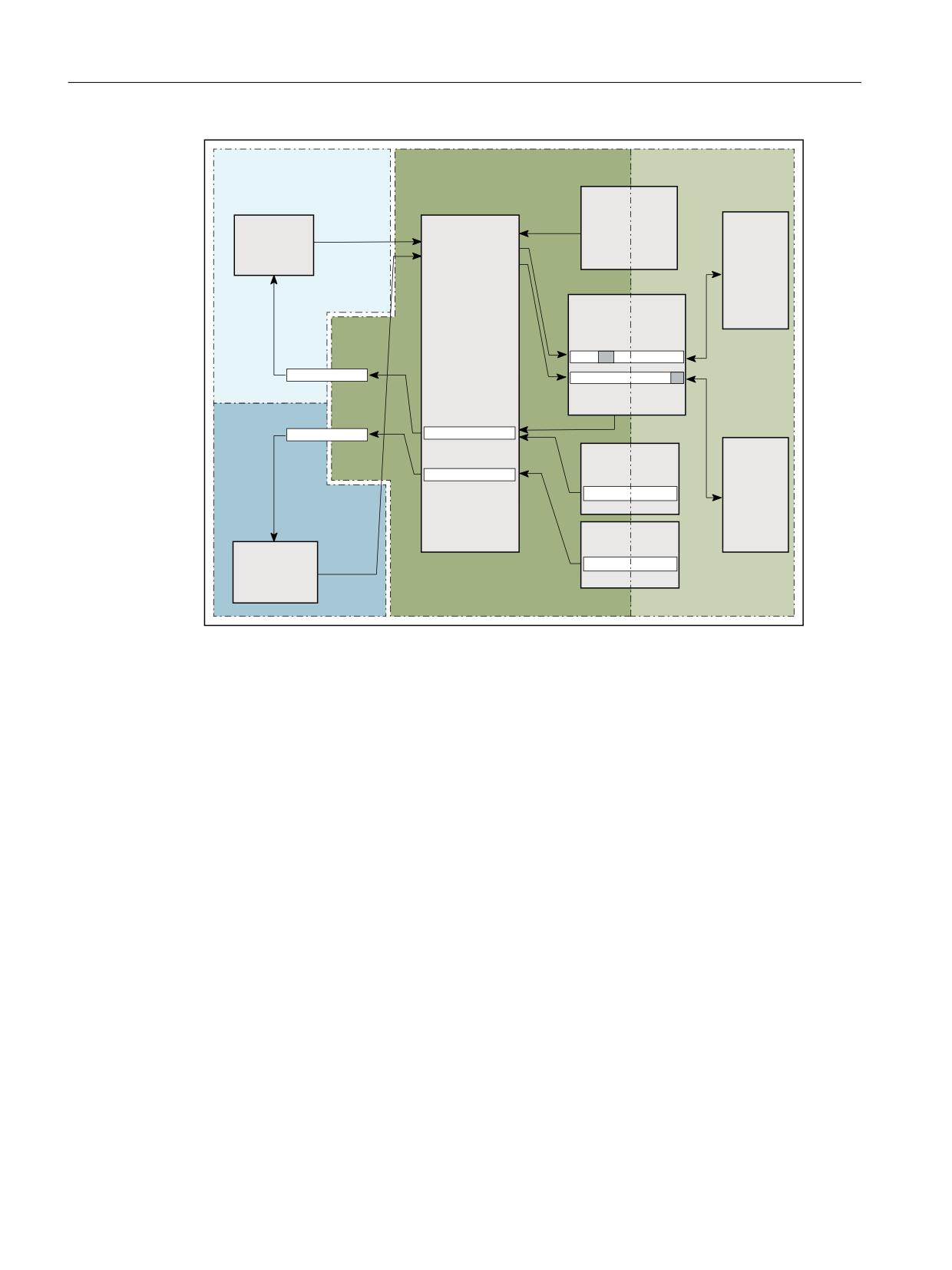
The figure below shows the structure of the M decoding according to list:
PLC
Function Manual, 10/2020, 6FC5397-0HP40-0BA1
85
Structure and functions of the basic program
10.9 M decoding acc. to list
1&
3/&
%DVLF 3/& SURJUDP
8VHU SURJUDP
&KDQQHO
3DUW SURJUDP
'%
)& ;
'HFRGLQJ OLVW
1
0
0 GHFRGLQJ DFF
WR OLVW
'%
6LJQDOV
WR 1&
6LJQDO
OLVW
5HDG LQ GLVDEOH
0DFKLQLQJ
6WDWXV FRQWURO
VLJQDO
5HDG LQ GLVDEOH
ฺ
)& <
'%
ฺ
5HDG LQ
GLVDEOH
&KDQ
QHO
3DUW SU
RJUDP
'%
5HDG LQ
GLVDEOH
1
0
Figure 10-3
M decoding acc. to list
Activation
M decoding is activated using FB1 parameter "ListMDecGrp"
The number of M groups to the evaluated and/or decoded is specified using the appropriate
parameter. The function is active for a parameter value = 1 ... 16.
• Basic program, OB100, FB1 parameter ListMDecGrp = <number of M groups> (also see
" FB1: RUN_UP - basic program, start section (Page 156) ").
Properties and structure of the decoding list (DB75)
Properties of the decoding list (DB75):
• There is only one decoding list independent of the channel.
• The decoding list can include a maximum of 16 groups.
• A group has a maximum of 16 signals
PLC
86
Function Manual, 10/2020, 6FC5397-0HP40-0BA1

Structure and functions of the basic program
10.9 M decoding acc. to list
• There must be an entry in the decoding list for every group of M functions to be decoded.
• The assignment between the M function with extended address and the signal to be set in
the signal list is specified in the decoding list using the first and last M function of the
associated group.
- First M function: Parameter: "MFirstAdr" ≙ signal or bit 0
- Last M function: Parameter: "MLastAdr" ≙ dependent on the difference to the first M
function maximum signal or bit 15
Structure of the decoding list (DB75):
An entry in the decoding lists consists of 3 parameters, each of which is assigned to a group.
Group
Extended M address
First M address of the group
Last M address of the group
1
MSigGrp[1].MExtAdr
MSigGrp[1].MFirstAdr
MSigGrp[1].MLastAdr
2
MSigGrp[2].MExtAdr
MSigGrp[2].MFirstAdr
MSigGrp[2].MLastAdr
16
MSigGrp[16].MExtAdr
MSigGrp[16].MFirstAdr
MSigGrp[16].MLastAdr
Type and value range of the signals:
Signal
Type
Value range
Meaning
MExtAdr
INT
0 ... 99
Extended M address
MFirstAdr
DINT
0 to 99.999.999
First M address in group
MLastAdr
DINT
0 to 99.999.999
Last M address in group
Properties of the signal list (DB76)
The signal list (DB76) has the following properties:
• There is only one signal list independent of the channel.
• The signal list can include a maximum of 16 signals for each M group.
Example
3 groups of M functions are to be decoded:
• Group 1: M2 = 1 to M2 = 5
• Group 2: M3 = 12 to M3 = 23
• Group 3: M40 = 55
Structure of the decoding and signal list
Group
Decoding list (DB75)
Signal list (DB76)
Extended
First M address
Last M address
M address
of the group
of the group
1
2
1
5
DB76.DBX0.0 ... DBX0.4
2
3
12
23
DB76.DBX2.0 ... DBX3.3
3
40
55
55
DB76.DBX4.0
PLC
Function Manual, 10/2020, 6FC5397-0HP40-0BA1
87
Structure and functions of the basic program
10.9 M decoding acc. to list
Program code
DATA_BLOCK DB 75
TITLE =
VERSION : 0.0
STRUCT
MSigGrp : ARRAY [1 .. 16 ] OF STRUCT
MExtAdr : INT;
MFirstAdr : DINT;
MLastAdr : DINT;
END_STRUCT ;
BEGIN
MSigGrp[1].MExtAdr
:=
2; extended M address of the 1st group
MSigGrp[1].MFirstAdr := L#1; first M address of the group
MSigGrp[1].MLastAdr
:= L#5; last M address of the group
MSigGrp[2].MExtAdr
:=
3; extended M address of the 2nd group
MSigGrp[2].MFirstAdr := L#12; first M address of the group
MSigGrp[2].MLastAdr
:= L#23; last M address of the group
MSigGrp[3].MExtAdr
:=
40; extended M address of the 3rd group
MSigGrp[3].MFirstAdr := L#55; first M address of the group
MSigGrp[3].MLastAdr
:= L#55; last M address of the group
END_DATA_BLOCK
Structure of FB1 in OB100
To activate the function, insert the parameter for the number of M groups to be decoded
"ListMDecGrp".
Call FB 1, DB 7(
ListMDecGrp := 3;
//M decoding of three groups
);
Description
A restart must be performed after the entry has been made in OB100 and the decoding list
(DB75) has been transferred to the PLC. The basic program creates the signal list (DB76) when
it restarts.
An NC program is then started, for instance in the 1st channel. An extended M function is
included in this (M3=17). When decoding the M function (M3 ≙ group 2), the associated signal
(DBW1.5) is set in the signal list (DB76) and the interface signal "Read-inhibit" in the 1st channel.
The execution of the NC program is stopped. Further, the "Extended address M function" and the
"M function number" are displayed in the channel DB of the 1st channel.
The "Read-in inhibit" signal in the 1st channel is reset once the user has reset all of the signals
output from this channel in the signal list (DB76), and has therefore acknowledged them.
PLC
88
Function Manual, 10/2020, 6FC5397-0HP40-0BA1
Structure and functions of the basic program
10.10 PLC machine data
10.10
PLC machine data
General information
The user has the option of storing PLC-specific machine data in the NC. These machine data can
then be processed during power-up of the PLC (OB100). This enables, for example, user options,
machine expansion levels, machine configurations, etc., to be implemented.
The interface to read this data is in DB20. However, DB20 is only created by the basic program
during power-up when user machine data is used, i.e. sum of GP parameters "UDInt", "UDHex"
and "UDReal" is greater than ZERO.
Size of the data areas
The sizes of the individual areas, and thus the total length of the DB20, is set by the following PLC
machine data:
• MD14504 $MN_MAXNUM_USER_DATA_INT
• MD14506 $MN_MAXNUM_USER_DATA_HEX
• MD14508 $MN_MAXNUM_USER_DATA_FLOAT
User-relevant basic PLC program parameters
The machine data settings are provided to the user via the following basic PLC program
parameters:
• "UDInt"
• "UDHex"
• "UDReal"
Note
User machine data as ARRAY
The user machine data is always handled internally as an ARRAY. ARRAY variables occupy the
memory in the PLC up to the next word limit, i.e. at a BYTE with an even address.
A filler byte is therefore added internally when there is an odd number in MD14506
$MN_MAXNUM_USER_DATA_HEX. This filler byte is included in the FB1 output parameter
"UDHex" (number of hexadecimal machine data).
Example:
MD14506 $MN_MAXNUM_USER_DATA_HEX = 3 ⇒ UDHex = 4, although only three hex values
can be read.
Data storage
The data is seamlessly stored in the DB20 by the basic PLC program in the following sequence:
1. INT values
2. HEX values (bit arrays)
3. FLOAT values
PLC
Function Manual, 10/2020, 6FC5397-0HP40-0BA1
89
Structure and functions of the basic program
10.10 PLC machine data
INT and FLOAT values are saved in S7 format.
The hexadecimal values are stored in DB20 in the order in which they are input (use as bit arrays).
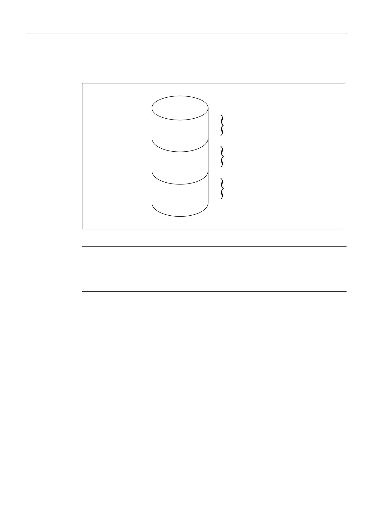
'%
8VHU PDFKLQH GDWD
1XPEHU RI 8',QW
W\SH ,17
1XPEHU RI 8'+H[
8VHU PDFKLQH GDWD
W\SH %<7(
1XPEHU RI
8VHU PDFKLQH GDWD
8'5HDO
W\SH 5($/
Figure 10-4
User data in DB20
Note
If the number of PLC machine data used is increased later, then DB20 must be deleted
beforehand. To prevent such extensions in use having any effect on the existing user program,
the data in DB20 should be accessed in symbolic form wherever possible, e.g. by means of a
structure definition in the UDT.
Example
For the project in the example, four INT values, two HEX values for bit information, and one
FLOAT value are needed.
Machine data:
MD14510 $MN_USER_DATA_INT[0] =
123
MD14510 $MN_USER_DATA_INT[1] =
456
MD14510 $MN_USER_DATA_INT[2] =
789
MD14510 $MN_USER_DATA_INT[3] =
1011
MD14512 $MN_USER_DATA_HEX[0] =
12
MD14512 $MN_USER_DATA_HEX[1] =
AC
MD14514 $MN_USER_DATA_FLOAT[0] = 123.456
PLC
90
Function Manual, 10/2020, 6FC5397-0HP40-0BA1

Structure and functions of the basic program
10.10 PLC machine data
Basic PLC program parameters (OB100):
CALL FB1, DB7(
MCPNum :=
1,
MCP1In :=
P#E0.0,
MCP1Out :=
P#A0.0,
MCP1StatSend :=
P#A8.0,
MCP1StatRec :=
P#A12.0,
MCP1BusAdr :=
6,
MCP1Timeout :=
S5T#700MS,
MCP1Cycl :=
S5T#200MS,
NCCyclTimeout :=
S5T#200MS,
NCRunupTimeout :=
S5T#50S;
Basic PLC program parameters (scan at
runtime):
l gp_par.UDInt;
//=4,
l gp_par.UDHex;
//=2,
l gp_par.UDReal;
//=1 )
During PLC power-up, DB20 was generated with a length of 28 bytes:
DB20
Address
Data
0.0
123
2.0
456
4.0
789
6.0
1011
8.0
b#16#12
9.0
b#16#AC
10.0
1.234560e+02
The structure of the machine data used is specified in a UDT:
TYPE UDT20
STRUCT
UDInt :
ARRAY [0 .. 3] OF INT;
UDHex0 : ARRAY [0 .. 15]OF BOOL;
UDReal : ARRAY [0 .. 0] OF REAL;
//Description as field, for
later expansions
END_STRUCT;
END_TYPE
PLC
Function Manual, 10/2020, 6FC5397-0HP40-0BA1
91

Structure and functions of the basic program
10.10 PLC machine data
Note
ARRAY OF BOOL are always sent to even-numbered addresses. For this reason, an array range of
0 to 15 must generally be selected in the UDT definition or all Boolean variables specified
individually.
Although only a REAL value is used initially in the example, a field (with one element) has been
created for the variable. This ensures that extensions can be made easily in the future without
the symbolic address being modified.
Symbolic accesses
An entry is made in the symbol table to allow data access in symbolic form:
Symbol
Operand
Data type
UData
DB20
UDT20
Access operations in user program (list includes only symbolic read access):
L
"UData".UDInt[0];
L
"UData".UDInt[1];
L
"UData".UDInt[2];
L
"UData".UDInt[3];
U
"UData".UDHex0[0];
U
"UData".UDHex0[1];
U
"UData".UDHex0[2];
U
"UData".UDHex0[3];
U
"UData".UDHex0[4];
U
"UData".UDHex0[5];
U
"UData".UDHex0[6];
U
"UData".UDHex0[7];
U
"UData".UDHex0[15];
L
"UData".UDReal[0];
PLC
92
Function Manual, 10/2020, 6FC5397-0HP40-0BA1
Structure and functions of the basic program
10.11 Configuration machine control panel, handheld unit, direct keys
10.11
Configuration machine control panel, handheld unit, direct keys
General
Up to two machine control panels and one handheld unit can be operated at the same time.
There are various connection options (Ethernet/PROFINET, PROFIBUS) for the machine control
panel (MCP) and handheld unit (HHU). It is possible to connect two MCPs to different bus
systems (mixed operation is only possible on Ethernet and PROFIBUS). This can be achieved
using FB1 parameter "MCPBusType". In this parameter, the right-hand decade (units position) is
responsible for the 1st MCP and the left-hand decade (tens position) for the 2nd MCP.
Parameterization of components is always performed by calling the basic program block FB1 in
OB100. FB1 saves its parameters in the associated instance data block (DB7, symbolic "gp_par").
Separate parameter sets are provided for each machine control panel and the handheld unit. The
input/output addresses of the user must be defined in these parameter sets. These input and
output addresses are also used in FC19, FC24, FC25, FC26 and FC13. Further, the addresses for
status information, PROFIBUS or Ethernet/PROFINET are also to be defined. The default time
settings for timeout and cyclic forced retriggering should not be changed. Please refer to the
Operator Components manual for further information on MCP and HHU components.
Activation
Each component is activated either via the number of machine control panels ("MCPNum"
parameter) or, in the case of the handheld unit, via the "HHU" parameter. The MCP and HHU
connection settings are entered in FB1 parameters "MCPMPI", "MCPBusType" or "BHG", "BHGMPI".
Handheld unit (HT 2)
In the handheld unit the addressing is done via a parameter of the GD parameter set. This was
necessary for reasons of compatibility of the parameter names.
Configuration
Essentially, there are various communication mechanisms for transferring data between the
MCP/HHU and PLC. These mechanisms are characterized by the bus connection of the MCP and
HHU. In one case (Ethernet), data is transported via the "CP 840D sl".
Parameterization is completely realized via the MCP/HHU parameters in FB1.
In the other case the data transfer is via the PLC operating system through the PROFIBUS
configuration.
The parameterization is performed via STEP 7 in HW-Config. To enable the basic program to
access this data and failure monitoring of MCP/HHU, the addresses set in the FB1 parameters
must be made known to the basic program.
An overview of the various coupling mechanisms is shown below. Mixed operation can also be
configured.
If an error is detected due to a timeout, an entry is made in the alarm buffer of the PLC CPU
(alarms 400260 to 400262). In this case, the input signals from the MCP or from the handheld
PLC
Function Manual, 10/2020, 6FC5397-0HP40-0BA1
93
Structure and functions of the basic program
10.11 Configuration machine control panel, handheld unit, direct keys
unit (MCP1In/MCP2In or BHGIn) are reset to 0. If it is possible to resynchronize the PLC and MCP/
HHU, communication is resumed automatically and the error message deleted by the GP.
Note
The abbreviation "(n.r.)" in the tables below means "not relevant".
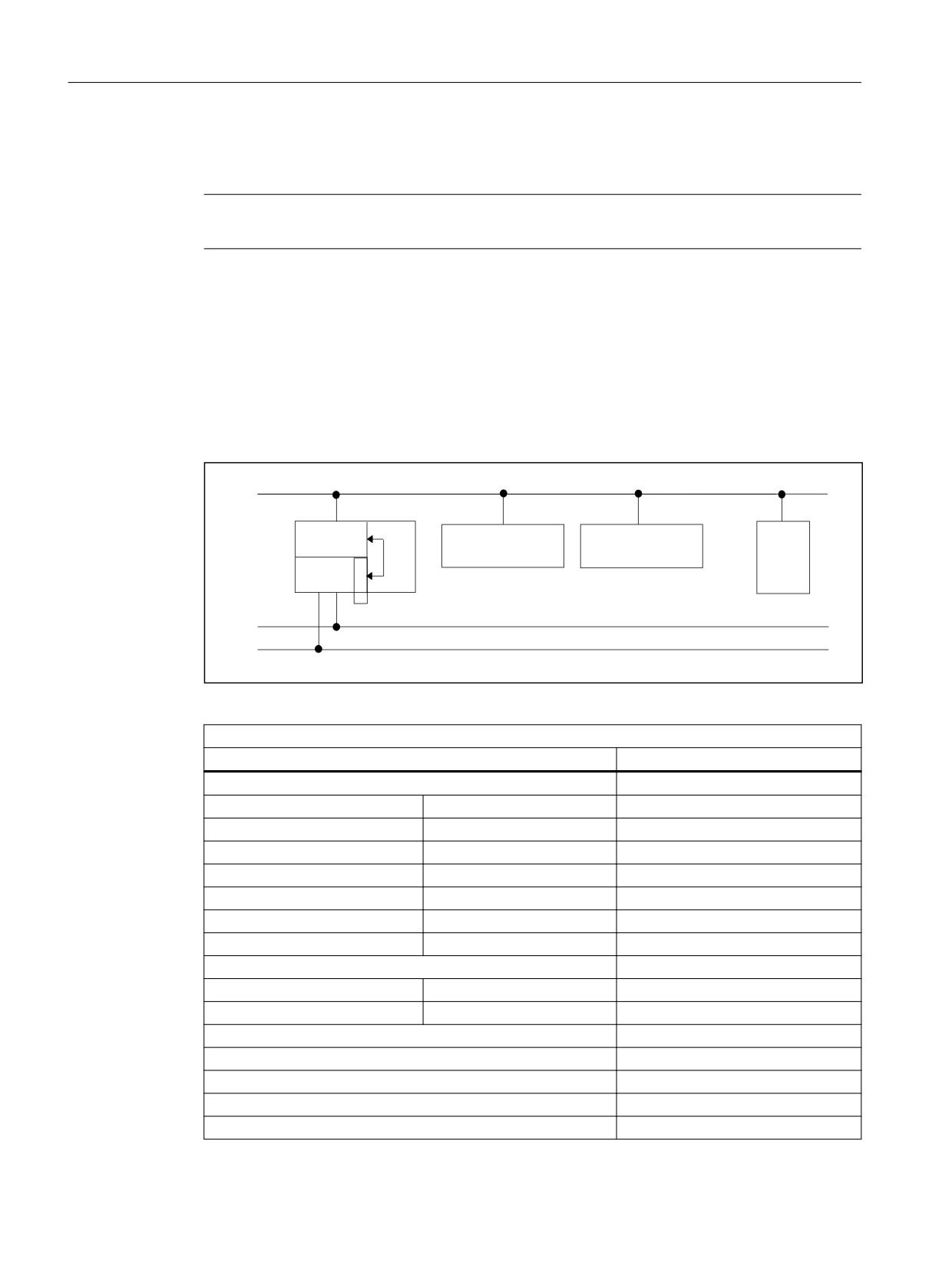
Ethernet connection (MCPBusType = 5)
Without further configuration settings being made, communication takes place directly from
the PLC GP via the CP 840D sl. The FB1 parameters listed below are used for parameterization.
The numeric part of the logical name of the component must be entered in "MCP1 BusAdr",
"MCP2 BusAdr" or "BHGRecGDNo" (corresponds to the bus address of the node). The logical
name is defined via switches on the MCP or terminal box.
(WKHUQHW
&3
1&
' VO
0&3
0&3
%+*
LQW
'
3/&
3
5
03, '3
'3
Figure 10-5
Ethernet connection
Relevant parameters (FB1)
MCP
HHU
MCPNum=1 or 2 (number of MCPs)
HHU = 5 (via CP 840D sl)
MCP1In
MCP2In
BHGIn
MCP1Out
MCP2Out
BHGOut
MCP1StatSend
MCP2StatSend
BHGStatSend
MCP1StatRec (n.r.)
MCP2StatRec (n.r.)
BHGStatRec
MCP1BusAdr
MCP2BusAdr
BHGInLen (n.r.)
MCP1Timeout (n.r.)
MCP2Timeout (n.r.)
BHGOutLen (n.r.)
MCP1Cycl (n.r.)
MCP2Cycl (n.r.)
BHGTimeout (n.r.)
MCPMPI = FALSE
BHGCycl (n.r.)
MCP1Stop
MCP2Stop
BHGRecGDNo
MCP1NotSend
MCP2NotSend
BHGRecGBZNo (n.r.)
BHGRecObjNo (n.r.)
MCPBusType = b#16#55 (via CP 840D sl)
BHGSendGDNo (n.r.)
BHGSendGBZNo (n.r.)
MCPSDB210 = FALSE
BHGSendObjNo (n.r.)
MCPCopyDB77 = FALSE
BHGMPI = FALSE
PLC
94
Function Manual, 10/2020, 6FC5397-0HP40-0BA1

Structure and functions of the basic program
10.11 Configuration machine control panel, handheld unit, direct keys
Relevant parameters (FB1)
MCP
HHU
BHGStop
BHG NotSend
An error entry is also made in the PLC alarm buffer for timeouts. As a result, the following error
messages are output at the HMI:
•
400260: MCP 1 failure
or
•
400261: MSST 2 failed
•
400262: HHU failure
An MCP or HHU failure is detected immediately after a cold restart even if no data has yet been
exchanged between the MCP/HHU and PLC.
The monitoring function is activated as soon as all components have signaled "Ready" after
power-up.
OP with direct keys
The direct keys of the OPs at the Ethernet bus should be transferred to the PLC. Previously, the
direct keys have been transferred to the PLC via the PROFIBUS or via a special cable connection
between OP and MCP.
For connecting the direct keys via the Ethernet, this involves e.g. the "OP 08T", there is a
parameterization in the basic program for activating the data transport. The associated
parameters lie in the instance DB of the FB 1 (OpKeyNum to OpKeyBusType, see data table). The
parameters are provided by the user in the start OB100 by connecting the parameter at the FB1
call. The bus address and Op1/2KeyStop can also be modified in the cyclic operation by writing
the FB1 instance DB DB 7.
The transport of the user data of the direct keys runs in the same way as in the case of Ethernet
MCP. The data transport can also be stopped and restarted by writing the DB7-parameter
"Op1/2KeyStop". During the Stop phase the address of the direct key module (TCU-index or the
MCP-address) can also be changed.
After resetting the Stop signal, a connection to the new address is established.
The status of the respective direct-key interfaces can be read in the interface signal:
DB10.DBX104.3 (OP1Key ready)
or
DB10.DBX104.4 (OP2Key ready)
Address direct keys
For the parameter Op1/2KeyBusAdr, the TCU index is normally to be used. This affects the OPs,
such as OP 08T, OP 12T, which for the direct keys do not have special cable connection to an
Ethernet MCP.
If OPs with direct keys have a special cable connection and these are connected to an Ethernet-
MCP, then for the parameter Op1/2KeyBusAdr the address of the MCP (DIP-switch setting of the
MCP) is to be used. Only the data stream of the direct keys (2 bytes) is transferred via the direct
key interface.
PLC
Function Manual, 10/2020, 6FC5397-0HP40-0BA1
95

Structure and functions of the basic program
10.11 Configuration machine control panel, handheld unit, direct keys
Warning of connection termination
To ensure a quick response to an impending termination of the connection between PLC and
direct keys, signals are set shortly after the cyclic communicating between PLC and direct keys
has failed. If there is still no cyclic communication between PLC and direct keys, the connection
is terminated.
The signals for issuing an alarm regarding an interrupted connection are set in DB10.
• DB10.DBX94.3 (alarm direct keys 1 communication error)
• DB10.DBX94.4 (alarm direct keys 2 communication error)
The signals are reset after a connection is interrupted or when there is a new connection.
Alarm direct keys
An error entry is also made in the PLC alarm buffer for timeouts. As a result, the following error
messages are output at the HMI:
•
400274: Direct key 1 failed
or
•
400275: Direct key 2 failed
Control unit switching for direct keys
The user connects Op1/2KeyBusAdr with 0xFF and stop = TRUE in startup block OB100. The
direct key address of the M-to-N interface is connected to parameter "Op1KeyBusAdr" via the M-
to-N block FB9.
Relevant parameters (FB1)
direct keys
e.g. direct keys OP 08T
OpKeyNum = 1 or 2 (number of OPs with direct keys)
Op1KeyIn
Op2KeyIn
Op1KeyOut
Op2KeyOut
OpKey1BusAdr
Op2KeyBusAdr
Address: TCU index
Op1KeyStop
Op2KeyStop
Op1KeyNotSend
Op2KeyNotSend
OpKeyBusType = b#16#55 (via CP 840D sl)
MCP identification
Via the identify interface in DB7 it is possible to query the type of the Ethernet component (MCP,
HT 2, HT 8 or direct keys) with the relevant parameters at the input/output in cyclic operation:
• Relevant parameters at the input:
"IdentMcpBusAdr", "IdentMcpProfilNo", "IdentMcpBusType", "IdentMcpStrobe"
• Relevant parameters at the output:
"IdentMcpType", "IdentMcpLengthIn", "IdentMcpLengthOut"
Here the DIP device address or the TCU index at the parameter "IdentMcpBusAdr" is activated by
the user program together with setting of the Strobe signal.
PLC
96
Function Manual, 10/2020, 6FC5397-0HP40-0BA1

Structure and functions of the basic program
10.11 Configuration machine control panel, handheld unit, direct keys
The input parameter "IdentMcpProfilNo" is normally to be set to the value 0. This parameter is to
be set to the value 1 only in the identification of the direct keys. The parameter
"IdentMcpBusType" currently has no significance for a user program and is to be left in its default
value.
After resetting the Strobe signal by the basic program, valid output information becomes
available to the user. The resetting of the Strobe signals by the basic program can last for several
PLC cycles (up to two seconds).
The output parameters should show the user the size of the data areas for the addressed device.
Furthermore, it can be defined here whether an HT 2 or an HT 8 or no device is connected to the
terminal box. With this information, the MCP channel or the HHU channel can be activated. In
cyclic operation the parameters can be written symbolically by the user program and read via the
symbol names of the DB7 (gp_par).
Relevant parameters (FB1)
MCP device identification
Input parameters, e.g. OP 08T
Input
Output
Values for direct keys
IdentMcpBusAdr
IdentMcpType
IdentMcpBusAdr = TCU index
IdentMcpBusProfilNo
IdentMcpLengthIn
IdentMcpBusProfilNo = Value 1
IdentMcpBusType
IdentMcpLengthOut
IdentMcpBusType = Default value
IdentMcpStrobe
IdentMcpBusProfilNo
Value
MCP, HHU, HT 8, HT 2
B#16#0
Direct keys such as e.g. OP 08T, OP 12T
B#16#1
IdentMcpType (Mcp-Type)
No device connected
0
MCP 483C IE (Compact)
B#16#80
MCP 483C IE
B#16#81
MCP 310
B#16#82
MCP OEM
B#16#83
MCP DMG
B#16#84
HT 8
B#16#85
TCU_DT (direct keys)
B#16#86
MCP_MPP
B#16#87
HT 2
B#16#88
OP 08T (direct keys)
B#16#89
MCP Modular
B#16#A0
PLC
Function Manual, 10/2020, 6FC5397-0HP40-0BA1
97
Structure and functions of the basic program
10.11 Configuration machine control panel, handheld unit, direct keys
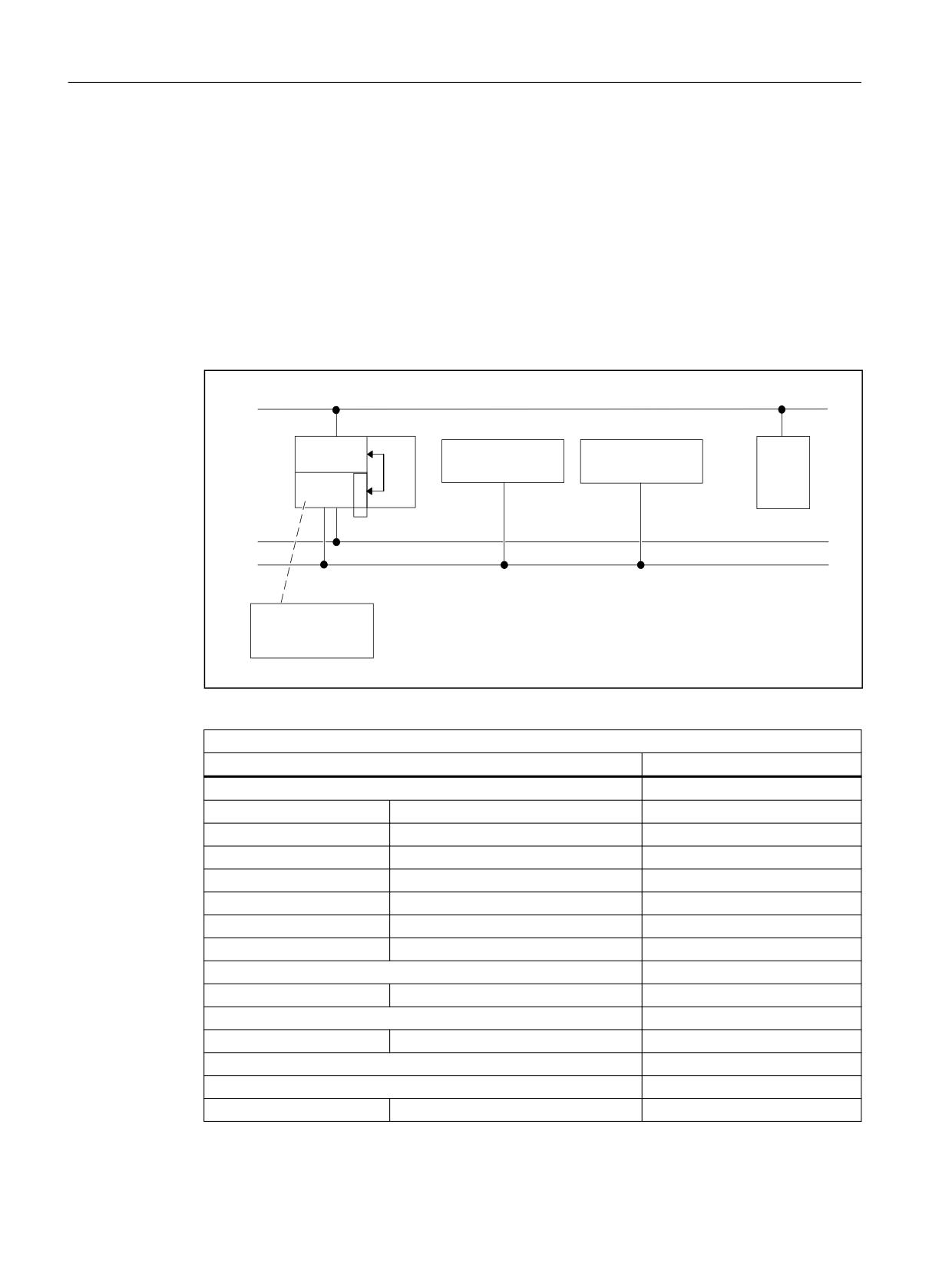
PROFIBUS connection at the DP port (MCPBusType = 3)
In case of PROFIBUS connection of the MCP, this component must be considered in the hardware
configuration setting of STEP 7. The MCP is connected to the standard DP bus of the PLC (not to
MPI/DP). The addresses must be stored in the input and output mapping area. These start
addresses must also be stored in the pointer parameters of the FB1. The FB1 parameters listed
below are used for further parameterization.
There is no PROFIBUS variant of the HHU. For this reason, an Ethernet connection is shown for
the HHU in this figure. The PROFIBUS slave address must be stored in the parameters
"MCP1BusAdr" and "MCP2BusAdr". Enter the pointer to the configured diagnostic address (e.g.
P#A8190.0) in "MCPxStatRec".
(WKHUQHW
&3
1&.
' VO
0&3
0&3
%+*
'
LQW 3/&
3
5
03, '3
'3
352),%86 FRQILJ
IRU 0&3 ++8
Figure 10-6
PROFIBUS connection
Relevant parameters (FB1)
MCP
HHU
MCPNum = 1 or 2 (number of MCPs)
HHU = 5 (via CP 840D sl)
MCP1In
MCP2In
BHGIn
MCP1Out
MCP2Out
BHGOut
MCP1StatSend (n.r.)
MCP2StatSend (n.r.)
BHGStatSend
MCP1StatRec
MCP2StatRec
BHGStatRec
MCP1BusAdr
MCP2BusAdr
BHGInLen
MCP1Timeout
MCP2Timeout
BHGOutLen
MCP1Cycl (n.r.)
MCP2Cycl (n.r.)
BHGTimeout (n.r.)
MCPMPI = FALSE
BHGCycl (n.r.)
MCP1Stop
MCP2Stop
BHGRecGDNo
MCPBusType = b#16#33
BHGRecGBZNo (n.r.)
BHGRecObjNo (n.r.)
MCPSDB210 = FALSE
BHGSendGDNo (n.r.)
MCPCopyDB77 = FALSE
BHGSendGBZNo (n.r.)
BHGSendObjNo (n.r.)
PLC
98
Function Manual, 10/2020, 6FC5397-0HP40-0BA1
Structure and functions of the basic program
10.11 Configuration machine control panel, handheld unit, direct keys
Relevant parameters (FB1)
MCP
HHU
BHGMPI = FALSE
BHGStop
MCP failure normally switches the PLC to the STOP state. If this is undesirable, OB 82, OB 86 can
be used to avoid a stop. The basic program has, as standard, the OB82 and OB86 call. FC5 is
called in these OBs. This FC5 checks whether the failed slave is an MCP. If this is the case, no PLC
stop is triggered. Setting "MCPxStop" := TRUE causes the basic program to deactivate the MCP as
a slave via SFC12. If the PLC does not switch to the stop state following the failure or fault of the
MCP, an alarm message will be generated via the basic program. The interrupt is deleted when
the station recovers.
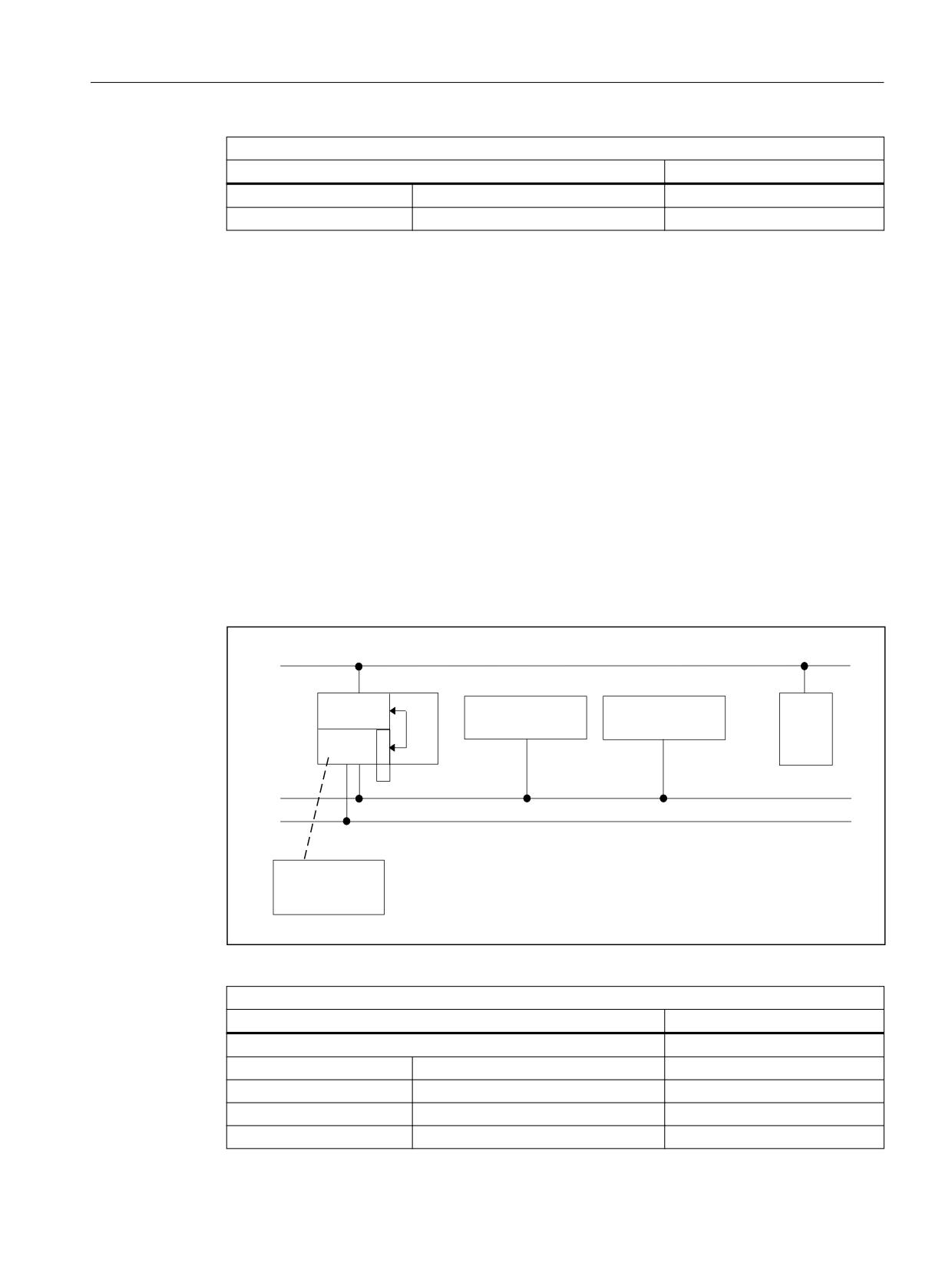
PROFIBUS connection on the MPI/DP port (MCPBusType = 4)
With the PROFIBUS connection of the MCP, this component must be considered in the STEP 7
hardware configuration. The MCP is connected on the MPI/DP bus of the PLC.
The addresses must be stored in the input and output mapping area. These start addresses must
also be stored in the pointer parameters of the FB1. The FB1 parameters listed below are used
for further parameterization. There is no PROFIBUS variant of the HHU. For this reason, an
Ethernet connection is shown for the HHU in this diagram. The PROFIBUS slave address must be
stored in the parameters MCP1BusAdr and MCP2BusAdr. Enter the pointer to the configured
diagnostic address (e.g. P#A8190.0) in MCPxStatRec.
(WKHUQHW
&3
1&.
' VO
0&3
0&3
%+*
LQW 3/&
'
3
5
03, '3
'3
352),%86
FRQILJ IRU 0&3
Figure 10-7
PROFIBUS connection on the MPI/DP port
Relevant parameters (FB1)
MCP
HHU
MCPNum = 1 or 2 (number of MCPs)
HHU = 5 (via CP 840D sl)
MCP1In
MCP2In
BHGIn
MCP1Out
MCP2Out
BHGOut
MCP1StatSend (n.r.)
MCP2StatSend (n.r.)
BHGStatSend
MCP1StatRec
MCP2StatRec
BHGStatRec
PLC
Function Manual, 10/2020, 6FC5397-0HP40-0BA1
99

Structure and functions of the basic program
10.11 Configuration machine control panel, handheld unit, direct keys
Relevant parameters (FB1)
MCP
HHU
MCP1BusAdr
MCP2BusAdr
BHGInLen
MCP1Timeout
MCP2Timeout
BHGOutLen
MCP1Cycl (n.r.)
MCP2Cycl (n.r.)
BHGTimeout (n.r.)
MCPMPI = FALSE
BHGCycl (n.r.)
MCP1Stop
MCP2Stop
BHGRecGDNo
MCPBusType = b#16#44
BHGRecGBZNo (n.r.)
BHGRecObjNo (n.r.)
MCPSDB210 = FALSE
BHGSendGDNo (n.r.)
MCPCopyDB77 = FALSE
BHGSendGBZNo (n.r.)
BHGSendObjNo (n.r.)
BHGMPI = FALSE
BHGStop
MCP failure normally switches the PLC to the STOP state. If this is undesirable, then OB82 and
OB86 can be used to avoid a PLC stop. The basic program has, as standard, the OB82 and OB86
call. FC5 is called in these OBs. This FC5 checks whether the failed slave is an MCP. If this is the
case, no PLC stop is triggered. Setting MCPxStop:= TRUE causes the basic program to deactivate
the MCP as a slave via SFC12. If the PLC does not switch to the stop state following the failure or
fault of the MCP, an alarm message will be generated via the basic program. The alarm is deleted
when the station returns.
PROFINET connection (MCPBusType = 6)
In case of PROFINET connection of the MCP, this component must be parameterized in the
hardware configuration setting of STEP 7. The MCP is coupled with the PROFINET module of the
CPU.
When parameterizing the MCP in HW Config, the addresses should be placed in the input and
output mapping area. These start addresses must also be stored in the pointer parameters
(MCPxIn and MCPxOut) of FB1. This is because signals are transferred between the MCP and
basic program via these parameters. The MCP is also monitored using parameter MCPxIn. This
is the reason why parameter MCPxBusAdr is not relevant for this MCP variant.
Enter the pointer to the configured diagnostic address (e.g. P#A8190.0) in MCPxStatRec.
The PROFINET MCP has its own type that should be applied to parameter MCPBusType.
The FB1 parameters listed below are used for further parameterization. There is no Profibus
variant of the HHU. An Ethernet port for the HHU is shown in the diagram.
PLC
100
Function Manual, 10/2020, 6FC5397-0HP40-0BA1
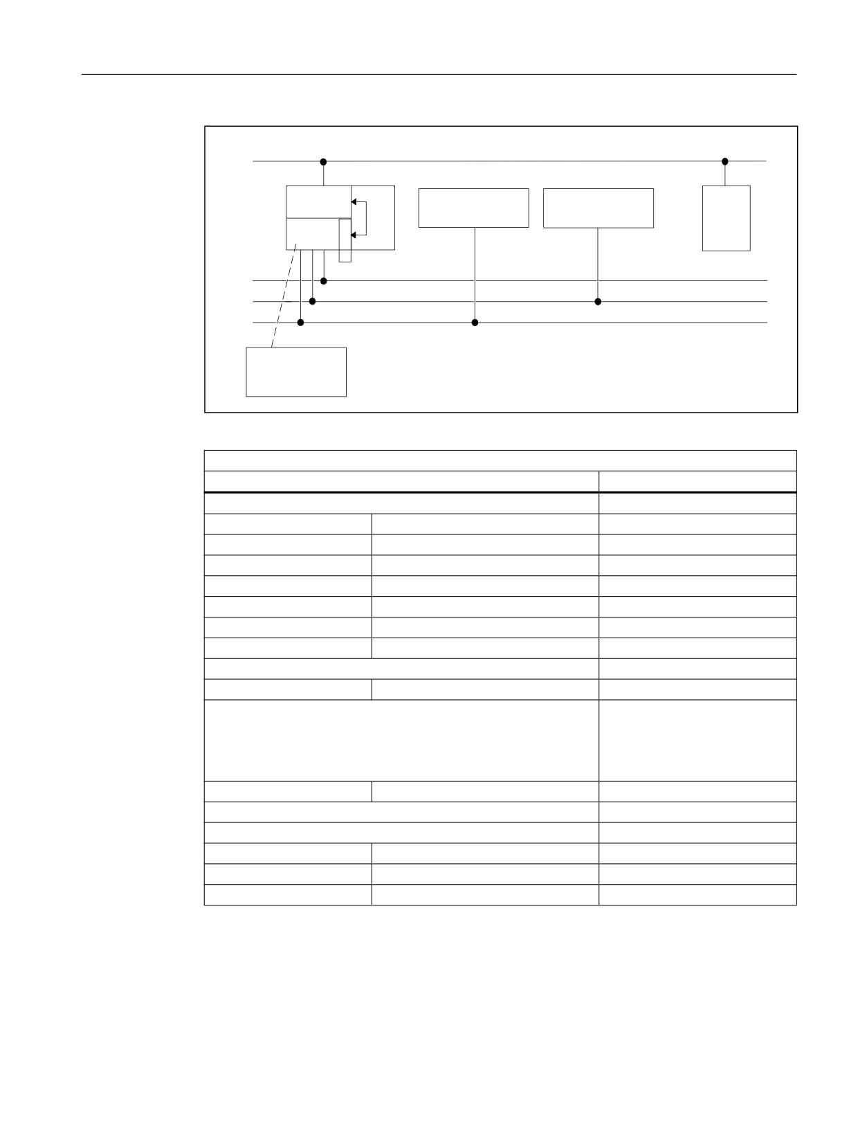
Structure and functions of the basic program
10.11 Configuration machine control panel, handheld unit, direct keys
(WKHUQHW
&3
1&.
' VO
0&3
0&3
%+*
LQW 3/&
'
3
5
03, '3
'3
352),1(7
352),1(7
FRQILJ IRU 0&3
Figure 10-8
PROFINET connection
Relevant parameters (FB1)
MCP
HHU
MCPNum = 1 or 2 (number of MCPs)
HHU = 5 (via CP 840D sl)
MCP1In
MCP2In
BHGIn
MCP1Out
MCP2Out
BHGOut
MCP1StatSend (n.r.)
MCP2StatSend (n.r.)
BHGStatSend
MCP1StatRec
MCP2StatRec
BHGStatRec
MCP1BusAdr (n.r.)
MCP2BusAdr (n.r.)
BHGInLen
MCP1Timeout
MCP2Timeout
BHGOutLen
MCP1Cycl
MCP2Cycl
BHGTimeout (n.r.)
MCPMPI = FALSE
BHGCycl (n.r.)
MCP1Stop
MCP2Stop
BHGRecGDNo
MCPBusType = b#16#36
BHGRecGBZNo (n.r.)
(as in the figure as example)
(6 = PROFINET for MCP1)
(3 = PROFIBUS for MCP2)
BHGRecObjNo (n.r.)
MCPSDB210 = FALSE
BHGSendGDNo (n.r.)
MCPCopyDB77 = FALSE
BHGSendGBZNo (n.r.)
BHGSendObjNo (n.r.)
BHGMPI = FALSE
BHGStop
MCP failure normally switches the PLC to the STOP state. If this is undesirable, then OB82 and
OB86 can be used to avoid a PLC stop. The basic program has, as standard, the OB82 and OB86
call. FC5 is called in these OBs. This FC5 checks whether the failed slave is an MCP. If this is the
case, no PLC stop is triggered. The input address at parameter MCPxIn is of significance when
monitoring for MCPxIn failure.
PLC
Function Manual, 10/2020, 6FC5397-0HP40-0BA1
101
Structure and functions of the basic program
10.12 Switchover of machine control panel, handheld unit
Setting MCPxStop := True causes the basic program to deactivate the MCP as a slave via SFC12.
If the PLC does not switch to the stop state following the failure or fault of the MCP, an alarm
message will be generated via the basic program. The alarm is deleted when the station returns.
10.12
Switchover of machine control panel, handheld unit
Only Ethernet variants support switchover/deactivation of an operator component (MCP or
HHU) as standard.
PROFIBUS variant
With PROFIBUS variants, this functionality is only possible to a limited extent and with additional
user effort.
With the PROFIBUS variant of the MCP, the data area of the DB77 for specified MCP1, MCP2 or
HHU can be used for the MCP pointer on FB1. The MCP slave bus address must be set correctly
under MCPxBusAdr as this is used as the basis for monitoring. A user program copy routine must
copy the signals of the active MCP from the I/O area configured in HW Config to DB77. This
enables a number of MCPs on the PROFIBUS to be switched via signals. Set the MCPxStop
parameter to TRUE for the switchover phase from one MCP to another.
Control signals
Parameters MCP1Stop, MCP2Stop and BHGStop can be used to stop communication with
individual components (parameter setting = 1). This stop or activation of communication can
be applied in the current cycle. However, the change in value must be implemented through the
symbolic notation of the parameters and not by means of another FB1 call.
Example: Stopping the transfer from the 1st machine control panel:
SET;
S gp_par.MCP1Stop;
Setting parameters MCP1Stop, MCP2Stop, BHGStop also results in a suppression or deletion
of alarms 400260 to 400262.
Switchover of the bus address
If an existing communication connection to an operator component (MCP or HHU) is to be
cancelled and a new communication connection established to a different component (MCP or
HHU) with a different communication address, proceed as follows:
1. Stop the communication of the operator component to be disconnected:
Parameter MCP1Stop, MCP2Stop or BHGStop = 1
2. The communication is stopped when the following applies: DB10, DBX104.0, .1 or .2 == 0
3. Change the bus address:
- MCP: FB1 parameter MCP1BusAdr or MCP2BusAdr = <bus address of the new operator
component>
- HHU (Ethernet variant): FB1 parameter BHGRecGDNo = <bus address of the new operator
component>
PLC
102
Function Manual, 10/2020, 6FC5397-0HP40-0BA1
Structure and functions of the basic program
10.13 Flexible axis configuration
4. Enable the communication (possible in the same PLC cycle as point 3): Parameter MCP1Stop,
MCP2Stop or BHGStop = 0
5. The communication with the new component is active when the following applies: : DB10,
DBX104.0, .1 or .2 == 1
Switching off the LED flashing of an Ethernet MCP
After a Power On, MCPs generally indicate the completion of the power-up and waiting for a
connection to be established by flashing LEDs. The flashing of the LEDs can be switched off as
described in the following. Presently, this behavior cannot be retentively stored on the MCP.
Requirement
MCP firmware as of V02.02.04
Setting for switching off the flashing
The Send status must be set in MCPxStop before the start of communication with the MCP.
Before the start of communication means either during power-up (OB100) or during cyclic
operation (OB1) before the setting of DB7 parameter MCPxStop = FALSE
Setting the Send status: FB1 parameter MCPxStatSend, bit 30 = 0 and bit 31 = 1
There is no feedback of the current status.
Example
Extract from OB100: (based on the example for MCP1)
CALL "RUN_UP" , "gp_par"
MCP1StatSend := P#E 8.0
//deactivate MCP flashing
SET
R
A 11.6
S
A
11.7
10.13
Flexible axis configuration
The assignment of axis selection keys to machine axes for the MCP variants FC19 (symbolic
name MCP_IFM) M variant, FC24 (symbolic name MCP_IFM2) narrow M variant, and FC26
(symbolic name HPU_MCP) can be configured flexibly.
This flexibility is implemented with tables for axis numbers in DB10. The parameterization for
the 1st machine control panel (MCP) starts from byte 8 (symbolic name MCP1AxisTbl[1..22])
and for the 2nd machine control panel (MCP) from byte 32 (symbolic name
MCP2AxisTbl[1..22]). The required machine axis numbers must be entered byte by byte here.
The axis numbers are not checked for validity, meaning that incorrect entries can result in a PLC
Stop. It is permissible to enter a value of 0 in the axis table and does not result in axis selection
by the associated key. In this way, gaps in the assignment of axis selection keys can be left.
PLC
Function Manual, 10/2020, 6FC5397-0HP40-0BA1
103
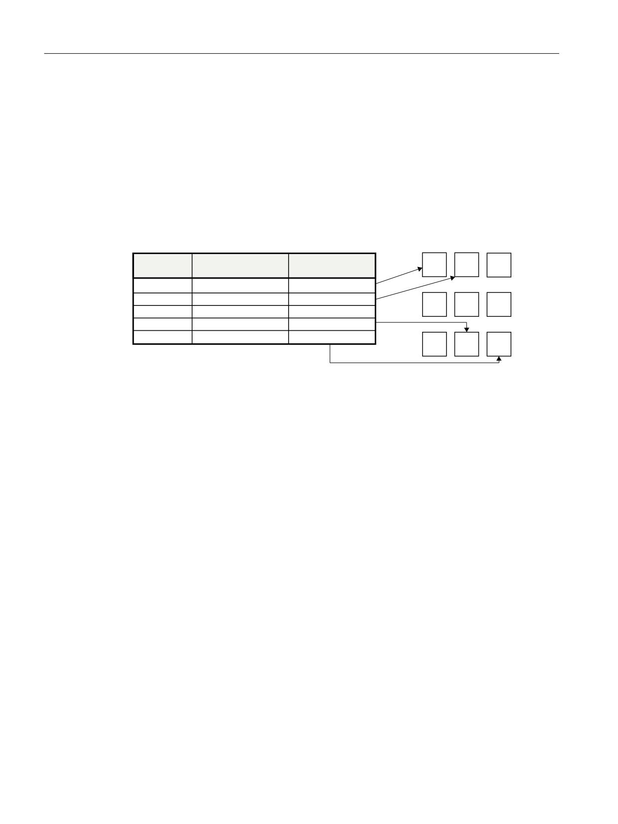
Structure and functions of the basic program
10.14 Selection of JOG axis via HMI
The value entered for the 1st machine control panel in DB10.DBW30 (symbolic name
MCP1MaxAxis) or for the 2nd machine control panel in DB10.DBW54 (symbolic name
MCP2MaxAxis) defines the maximum possible number of axis selection keys. If the value 0
(default setting) is used, all axis selection keys assigned a machine axis can be used, depending
on the MCP variant used. The number of available axis selection keys is determined by the design
of the MCP variant.
The value in DB 10 can also be dynamically adjusted. After this, the axis must be selected again
on the MCP in question. Axis numbers may not be switched over while the axes are traversing
the relevant direction keys.
The following figure is intended to illustrate the principle using the example of a MCP483 (call
of FC19) with 9 axis selection keys.
0DFKLQH D[LV
;
<
=
$GGUHVV
6\PERO
QXPEHU
5
5
5
'% '%%
1& 0&3 $[LV7EO> @
'% '%%
1& 0&3 $[LV7EO> @
5
5
5
'% '%%
1& 0&3 $[LV7EO> @
'% '%%
1& 0&3 $[LV7EO> @
5
5
5
The 8th axis selection key (R8) selects the machine axis with machine axis number 12.
10.14
Selection of JOG axis via HMI
General
From software version 4.92, the user can select machine or geometry axes using operating
software (for example: HMI Operate). This permits implementation of operating concepts on
touch operator panels, such as the HT 10.
Activation of the function when using SINUMERIK Operate
This function is activated by setting the channel machine data $MCS_FUNCTION_MASK_DISP Bit
16 (MD52210).
It is also necessary to define for each axis in machine data $MC_DISPLAY_AXIS (MD20098)
whether or not the axis will be displayed in the corresponding channel.
You will find further information in the descriptions "Commissioning Manual - SINUMERIK
Operate (IM9)".
Activation of the function by the PLC basic program
Activation is performed via the FB1 parameter "HMIAxisSel":
Basic program, OB100, FB1 parameter HMIAxisSel = True (see also FB1: RUN_UP - basic program,
start section (Page 156)).
PLC
104
Function Manual, 10/2020, 6FC5397-0HP40-0BA1
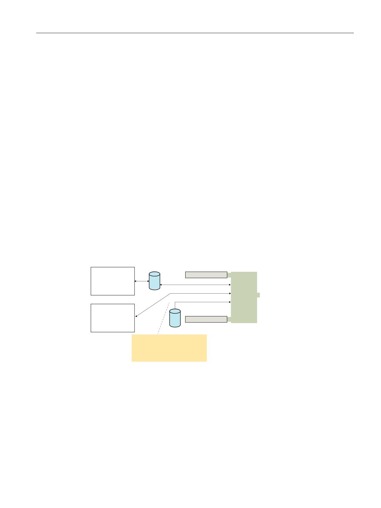
Structure and functions of the basic program
10.14 Selection of JOG axis via HMI
FB1 saves this parameter in the associated instance data block (DB7, symbolic name gp_par).
To support the PLC basic program, depending on the MCP variant used, blocks FC19 (symbolic
name MCP_IFM) M variant, FC24 (symbolic name MCP_IFM2) narrow M variant, and FC26
(symbolic name HPU_MCP) handheld terminals HT 8 and HT 10 are required.
Configuration of the devices is described in Configuration machine control panel, handheld unit,
direct keys (Page 93).
General method of operation
In addition to the configurable axis selection keys of the MCPs ("flexible axis configuration"), an
axis can be selected by SINUMERIK HMI Operate or customer operating software. Axis selection
is then only taken over onto the MCP if the interface DB of the channel and the configured
channel on the corresponding MCP block of the basic program match.
Example:
The MCP block of the basic program has been configured in the PLC user program for processing
channel 1. A JOG axis must therefore be selected via the interface DB for channel 1 (DB21).
When a JOG axis is selected via HMI, the machine axis number is transferred directly into the
corresponding channel interface. In addition, a check is made in the DB10 axis table to see which
R key of the MCP is configured in order to set the corresponding LED.
This ensures that, when the HMI is selected, the same machine axis is selected as corresponds
to an axis selection key of the MCP. In this way, alternative operation via HMI is possible, that is,
parallel with axis selection via the keys of the MCP.
The following figure illustrates the function "Selection of JOG axis via HMI":
+0,
0RGH JURXS QXPEHU
$[LV VHOHFWLRQ IURP +0,
$[LV VHOHFWLRQ
0&3 D[LV VHOHFWLRQ
)&
'%
)&
'%%
$[LV WDEOHV
RU )&
0&3
&KDQQHO QXPEHU
,QSXWV RXWSXWV
'%
)OH[LEOH D[LV FRQILJXUDWLRQ
$VVLJQPHQW RI WKH D[LV VHOHFWLRQ RU
GLUHFWLRQ NH\V WR PDFKLQH D[LV
QXPEHUV
If assignment of the selection by flexible axis assignment is not possible, all LEDs are deactivated
on the axis selection keys of the MCP. This means that it is possible to select axes that cannot be
selected via the keys of the MCP. This is supplementary operation in addition to axis selection via
the keys of the MCP.
PLC
Function Manual, 10/2020, 6FC5397-0HP40-0BA1
105
Structure and functions of the basic program
10.15 Mixed operation from the machine control panel and the handheld terminal
10.15
Mixed operation from the machine control panel and the
handheld terminal
General
The PLC basic program supports simultaneous operation of up to two machine control panels
and one handheld terminal. Different PLC basic program blocks are available for the machine
control panel (MCP) and the handheld terminal (HT)
This permits implementation of many possible applications. The blocks of the MCP variants FC19
(symbolic name "MCP_IFM") M variant, FC24 (symbolic name "MCP_IFM2") narrow M variant,
and FC26 (symbolic name "HPU_MCP") provide support with operation of multiple channels,
multiple mode groups (BAG), and different axis configurations.
Configuration
Parameterization of components is always performed by calling the basic program block FB1 in
OB100. FB1 saves its parameters in the associated instance data block, DB7 (symbolic name
gp_par).
These parameterizations are used by the individual blocks FC19, FC24, FC25, and FC26. Each
individual MCP or HT block itself has input and output parameters that are used for the channel,
mode group, and spindle interfaces to be provisioned.
The exception is block FC13 (symbolic name BHGDisp). This block does not support provisioning
of channel, mode group, or spindle signals. For this reason, it is not referred to in the following
application examples.
Typical application examples
In the following sections, only a few of the possible application examples for mixed operation of
MCP and HT are described. You will find detailed descriptions of the methods for blocks FC19,
FC24, FC25, and FC26 in the relevant block descriptions.
For example, multiple channels with an MCP (FC19) and HT (FC26) with the same mode group
In this example, the MCP is to provision channel 1 and the HT is to provision channel 2 of a
system. The two channels are assigned to the same mode group (BAG). This means that
channels 1 and 2 can be run separately. The MCP is exclusively responsible for provisioning the
mode group signals.
Call of FC19 for 1st MCP, mode group 1, channel 1, spindle: Axis 4
CALL FC19
// Signals to interface
BAGNo :=
B#16#1
// Mode group no. 1
ChanNo :=
B#16#1
// Channel no. 1
SpindleIFNo :=
B#16#4
// Spindle interface number = 4
FeedHold :=
m30.0
// Feed stop signal modal
SpindleHold :=
m30.1
// Spindle stop modal
PLC
106
Function Manual, 10/2020, 6FC5397-0HP40-0BA1
Structure and functions of the basic program
10.15 Mixed operation from the machine control panel and the handheld terminal
Call of the FC26 for channel 2
CALL FC26
// Signals to interface
BAGNo :=
B#16#0
// No provision of the mode group
ChanNo :=
B#16#2
// Channel no. 2
Example of multiple channels with alternative operation by MCP or HT with the same mode group
In this example, the MCP is to provision channels 1 and 2 and the HT is to provision channels 1
and 2 of a system. The two channels are assigned to the same mode group (BAG).
The calls of blocks FC19 and FC26 are programmed to be mutually exclusive. Otherwise, the
blocks called last would overwrite the signal states of the previous blocks. Moreover, the
spindles, the feed stop and spindle stop signal are only provisioned when FC19 processing is
active. While the FC19 call is skipped, the signals remain in the state of the last FC19 run.
U M40.0
// HT processing active?
SPB fc26
// Jump label for HT block
CALL FC19
// Signals to interface
BAGNo :=
B#16#1
// Mode group no. 1
ChanNo :=
B#16#1
// Channel no. 1
SpindleIFNo B#16#4
// Spindle interface number = 4
:=
FeedHold := m30.0
// Feed stop signal modal
SpindleHold m30.1
// Spindle stop modal
:=
CALL FC19
// Signals to interface
BAGNo :=
B#16#1
// Mode group no. 1
ChanNo :=
B#16#2
// Channel no. 2
SpindleIFNo B#16#4
// Spindle interface number = 4
:=
FeedHold := m30.0
// Feed stop signal modal
SpindleHold m30.1
// Spindle stop modal
:=
fc26: UN M40.0
// HT processing active?
SPB ende
// Jump label end of network
CALL FC26
// Signals to interface
BAGNo :=
B#16#1
// Mode group no. 1
ChanNo :=
B#16#1
// Channel no. 1
CALL FC26
// Signals to interface
BAGNo :=
B#16#1
// Mode group no. 1
ChanNo :=
B#16#2
// Channel no. 2
ende: Nop 0
PLC
Function Manual, 10/2020, 6FC5397-0HP40-0BA1
107
Structure and functions of the basic program
10.15 Mixed operation from the machine control panel and the handheld terminal
PLC
108
Function Manual, 10/2020, 6FC5397-0HP40-0BA1
SPL for Safety Integrated
11
Rather than being a function of the basic program, SPL is a user function. The basic program
makes a data block (DB18) available for Safety SPL signals and runs a data comparison to ensure
the consistency of SPL program data in the NC.
Further information
Function Manual Safety Integrated
PLC
Function Manual, 10/2020, 6FC5397-0HP40-0BA1
109
SPL for Safety Integrated
PLC
110
Function Manual, 10/2020, 6FC5397-0HP40-0BA1

Assignment overview
12
12.1
Block address range for PLC user program
From the following block number assignment overview, you can find out whether a specific
block number (or block address) is assigned or reserved by the basic PLC program, or whether it
can be used for the PLC user program.
Table 12-1
Assignment overview of the DB numbers
DB number
Availability
Occupied by
1
Reserved
Siemens
2 … 3
Occupied
Siemens (basic PLC program)
4 … 7
Reserved
Siemens
8
Occupied
Siemens (basic PLC program)
9
Reserved
Siemens
10 … 11
Occupied
Siemens (basic PLC program)
12
Occupied
Computer link and transport system
interface
13 … 15
Reserved
Siemens
16
Occupied
Siemens (basic PLC program)
17 … 18
Reserved
Siemens (basic PLC program)
19
Occupied
Siemens (basic PLC program)
20
Reserved
Siemens
21 … 30
Occupied¹
Siemens (basic PLC program: inter-
face for NC channels)
31 … 61
Occupied¹
Siemens (basic PLC program: inter-
face for axes/spindles)
62 … 70
Freely available (user program)
-
71...73
Occupied¹
Siemens (basic PLC program: tool
management)
74
Reserved
Siemens
75 … 76
Occupied
Siemens (M group decoding)
77 … 80
Reserved
Siemens
81 … 499
Occupied or reserved
Siemens (ShopMill, ManualTurn)
500 … 599
Occupied or reserved
Siemens (Transline)
600 … 999
Occupied or reserved
Siemens (ShopMill, ManualTurn)
1000 … 1019
Reserved
Siemens
1020
Occupied or reserved
Siemens (basic PLC program)
1021 … 1099
Reserved
Siemens
1100 … 24999
Freely available (user program)
-
25000 … 29999
Reserved
Siemens
PLC
Function Manual, 10/2020, 6FC5397-0HP40-0BA1
111

Assignment overview
12.1 Block address range for PLC user program
DB number
Availability
Occupied by
30000 … 59999
Reserved²
Standard number range for generated
F-system blocks
60000 … 60999
Occupied or reserved
CPU DBs
¹Not recommended for use, but possible with limitations. Data blocks of channels, axes/spindles
and tool management functions that have not been activated can be used by the user, but this
can result in conflicts when upgrading or migrating the PLC basic program.
²If you use SINUMERIK Safety Integrated plus (F-PLC), this number range is used for
automatically generated F-blocks by default. You can adapt the number range used by the F-
system, but you must select a sufficiently wide range of numbers.
Table 12-2
Assignment overview of the FB numbers
FB number
Availability
Occupied by
0
Reserved
Siemens
1
Reserved
Siemens (basic PLC program)
2 … 3
Occupied
Siemens (basic PLC program)
4
Reserved
Siemens
5
Occupied
Siemens (basic PLC program)
6
Reserved
Siemens
7
Occupied
Siemens (basic PLC program)
8
Reserved
Siemens
9
Occupied
Siemens (basic PLC program)
10 … 29
Reserved
Siemens
15
Reserved
Siemens (basic PLC program)
16…28
Reserved
Siemens
29
Reserved
Siemens (basic PLC program)
30…999
Freely available (user program)
-
1000 … 1009
Reserved
Siemens
1010 … 1019
Reserved
Exclusively available for F blocks of
Safety Integrated plus (F-PLC)
1020
Occupied
Siemens (basic PLC program)
1021 … 1023
Reserved
Siemens
1024 … 24999
Freely available (user program)
-
25000 … 32766
Reserved
Siemens (basic PLC program)
32767 … 65535
Reserved²
Standard number range for generated
F-system blocks
²If you use SINUMERIK Safety Integrated plus (F-PLC), this number range is used for
automatically generated F-blocks by default. You can adapt the number range used by the F-
system, but you must select a sufficiently wide range of numbers.
PLC
112
Function Manual, 10/2020, 6FC5397-0HP40-0BA1

Assignment overview
12.1 Block address range for PLC user program
Table 12-3
Assignment overview of the FC numbers
FC number
Availability
Occupied by
0
Reserved
Siemens
1 … 3
Occupied
Siemens (basic PLC program)
4
Reserved
Siemens
5
Reserved
Siemens (basic PLC program)
6 … 29
Reserved
Siemens
30 … 999
Freely available (user program)
-
1000 … 1023
Reserved
Siemens
1024 … 24999
Freely available (user program)
-
25000
Occupied
Siemens (basic PLC program)
25001 … 32766
Reserved
Siemens (basic PLC program)
32767 … 65535
Reserved²
Standard number range for generated
F-system blocks
²If you use SINUMERIK Safety Integrated plus (F-PLC), this number range is used for
automatically generated F-blocks by default. You can adapt the number range used by the F-
system, but you must select a sufficiently wide range of numbers.
PLC
Function Manual, 10/2020, 6FC5397-0HP40-0BA1
113
Assignment overview
12.1 Block address range for PLC user program
PLC
114
Function Manual, 10/2020, 6FC5397-0HP40-0BA1

PLC functions for HMI (DB19)
13
13.1
Channel selection
Function
The channel displayed on the HMI, e.g. in the machine start screen, can be selected from the PLC
user program via the HMI/PLC interface.
Requirement
More than one channel is parameterized in the NC.
Job and acknowledgment interface
DB19
Meaning
DBX32.0 - .5
PLC → HMI
Function number: 1 = channel selection
DBX32.6
PLC → HMI
Function request
DBX32.7
HMI → PLC
Status: 1 = "function being executed"
DBB33
PLC → HMI
Channel number: 1, 2, 3, ... maximum number of channels
Next channel: FFH
DBB36
HMI → PLC
Error identification:
•
0: No error
•
1: Invalid function number (DBX32.0 - .5)
•
2: Invalid parameter (DBB33 - DBB35)
•
3: Error when writing the HMI-internal variable
•
10: Channel not present (DBB33)
Functional sequence
PLC → HMI
The PLC user program must maintain the following execution sequence:
1. Check whether the interface is free for a new job:
- DB19.DBX32.6 == 0 (function request)
- DB19.DBX32.7 == 0 (status)
2. If the interface is free, the job data must be entered and the function request set:
- DB19.DBB33 = <channel number>
- DB19.DBX32.0 - .5 = 1 (function number)
- DB19.DBX32.6 = 1 (function request)
PLC
Function Manual, 10/2020, 6FC5397-0HP40-0BA1
115
PLC functions for HMI (DB19)
13.2 Program selection
HMI → PLC
The HMI makes the following responses for error-free parameterization:
1. Once the HMI has recognized the function request for channel selection, the status is set to
"function being performed" and the function request reset:
- DB19.DBX32.7 = 1 (status)
- DB19.DBX32.6 = 0 (function request)
2. Once the channel selection has been performed, the status is reset again and value 0 is set
as error identification:
- DB19.DBX32.7 = 0 (status)
- DB19.DBX36 = 0 (error identification)
The HMI makes the following responses for faulty parameterization:
• The function request is reset and the appropriate error identification is set:
- DB19.DBX32.6 = 0 (function request)
- DB19.DBX36 = <error identification>
13.2
Program selection
Function
Preselected programs/workpieces can be selected for machining by the NC via the PLC/HMI
interface.
The preselection is implemented by entering programs/workpiece in files, these are known as
PLC program lists (*.ppl).
Requirements
The following machine data must be set to allow the HMI to process tasks:
MD9106 $MM_SERVE_EXTCALL_PROGRAMS
In order to activate a sector-specific PLC program list, you must set the appropriate machine data
and at least the protection level password:
• Area User
- MD51041 $MN_ENABLE_PROGLIST_USER = 1
- Protective level password: 3 (users)
- Program list: /user/sinumerik/hmi/plc/programlist/plc_proglist_user.ppl
• Area Manufacturer (OEM)
- MD51043 $MN_ENABLE_PROGLIST_MANUFACT = 1
- Protective level password: 1 (manufacturer)
- Program list: /oem/sinumerik/hmi/plc/programlist/plc_proglist_manufacturer.ppl
PLC
116
Function Manual, 10/2020, 6FC5397-0HP40-0BA1

PLC functions for HMI (DB19)
13.2 Program selection
Structure of a program list
A program list is a text file. Each line contains the following information:
<program number> <program path><program name> [CH=<channel number>]
• Program number
The program numbers which may be used in a program list depend on the sector:
- user: 1 - 100
- Manufacturer (OEM): 201 - 255
• Program path
The program path must be completely specified in absolute terms.
For specifying the program path, see:
Further information
Programming Manual NC Programming, Section "File and program management" > "
Program memory" > "Addressing of program memory files"
• Channel number
Specifying the channel number "CH=<channel number>" is optional. It is only required if the
NC has more than one channel.
The following excerpt as example shows the structure of the user program list:
Program list: plc_proglist_user.ppl
1 //DEV2:/MPFDir/PROG_01.MPF CH=1
2 //DEV2:/MPFDir/PROG_01.MPF CH=2
Generating entries in a program list
The entries in a program list (*.ppl) can be directly edited in the file or entered in screen forms
in the user interface.
• Via the user interface for the user area
Operating area "Program Manager" > "ETC key (">")" > "Prog. list"
• Via the user interface for the Manufacturer area
Operating area "Commissioning" > "System data" > "ETC key (">")" > "Prog. list"
Program selection: Job interface
Note
The PLC may only request a new job if the last job has been acknowledged by the HMI:
DB19.DBB26 == 0
Program list
DB19.DBB16 = <number of the program list>
Number
Program list
129
/user/sinumerik/hmi/plc/programlist/plc_proglist_user.ppl
131
/oem/sinumerik/hmi/plc/programlist/plc_proglist_manufacturer.ppl
PLC
Function Manual, 10/2020, 6FC5397-0HP40-0BA1
117

PLC functions for HMI (DB19)
13.2 Program selection
Program number
The program number refers to the programs contained in the selected program list.
DB19.DBB17 = <program number>
• user area: 1 - 100
• oem area: 201 - 255
Requesting program selection
DB19.DBX13.7 = 1
Program selection: Acknowledgment interface
Job acknowledgment
• DB19.DBX26.7 == 1 (selection identified)
• DB19.DBX26.3 == 1 (program is selected)
• DB19.DBX26.2 == 1 (error when selecting the program, see error ID DB19.DBB27)
• DB19.DBX26.1 == 1 (job completed)
Error code
DB19.DBB27 == <value>
<Value>
Meaning
0
No error
1
Invalid program list number (DB19.DBB16)
3
User-specific program list plc_proglist_main.ppl not found (for DB19.DBB16 ≠ 129, 131 only)
4
Invalid program number (DB19.DBB17)
5
The job list in the selected workpiece could not be opened
6
Error in job list (Job list Interpreter returns error)
7
No instructions were found in the job list
8
HMI could not execute the selection (SELECT)
9
An error with no further details occurred upon selection
10
An error occurred during analysis of the job list
11
The instruction is not available
12
Invalid instruction (LOAD, UNLOAD, SELECT only)
13
Not all channels have the Reset status
14
The channel number is invalid
Program selection: Job processing
A job to select a program is executed as follows:
1. Checking the acknowledgment byte: DB19.DBB26 == 0
If the acknowledgment byte is not 0, then the last job has still not been completed.
2. Specifying the program list: DB19.DBB16
PLC
118
Function Manual, 10/2020, 6FC5397-0HP40-0BA1

PLC functions for HMI (DB19)
13.5 Screen numbers
3. Specifying the program number: DB19.DBB17
4. Setting the request to select a program: DB19.DBX13.7 = 1
5. Evaluating the acknowledgment and error interface: DB19.DBB26 and DBB27
The order is still not completed on the HMI side as long as: DB19.DBX26.3 == 1 (active)
The order has been completed on the HMI side if one of the two signals has been set:
- DB19.DBX26.1 == 1 (OK)
- DB19.DBX26.2 == 1 (error)
6. To complete the order, the program selection request must be reset: DB19.DBX13.7 = 0
7. The HMI signals that it is ready to accept a new order by resetting the acknowledgment byte:
DB19.DBB26 == 0
13.3
Activating the key lock
The operator panel keyboard and a keyboard directly connected to the HMI can be locked using
the following interface signal
•
1. HMI: DB19.DBX0.2 = <value>
•
2. HMI: DB19.DBX50.2 = <value>
Value
Meaning
0
Key lock inactive
1
Key lock active
13.4
Operating area numbers
The number of the active operating area is normally displayed in: DB19.DBB21
If the HMI monitor is active, the number of the active operating area is no longer displayed in
DB19.DBB21, but instead in the user-specific configured area of the HMI monitor (Page 129).
Operating area
Number
Machine
201
Parameters
205
Programming
203
Program Manager
202
Diagnostics
204
Commissioning
206
13.5
Screen numbers
The current screen number is normally displayed in: DB19.DBW24
PLC
Function Manual, 10/2020, 6FC5397-0HP40-0BA1
119

PLC functions for HMI (DB19)
13.5 Screen numbers
If the HMI monitor is active, the current screen number is no longer displayed in DB19.DBW24,
but instead in the user-specific configured area of the HMI monitor (Page 129).
Screen number ranges
The following screen number ranges are available:
• JOG, manual machine (Page 120)
• Reference point approach (Page 125)
• MDA (Page 125)
• AUTOMATIC (Page 126)
• Parameters operating area (Page 126)
• Program operating area (Page 128)
• Program manager operating area (Page 128)
• Diagnostics operating area (Page 128)
13.5.1
Screen numbers: JOG, manual machine
JOG mode
Screen
Number
Turning technology
Cycle start screen for all screens that can be taken over
81
Milling technology
Cycle start screen for all screens that can be taken over
3
Turning/milling
Start screen
1900
T,S,M
2
Set WO
21
Positioning
4
Face milling
18
Stock removal
80
Cycle start screen for all user screens
91
General settings
1
Multi-channel function settings
106
Collision avoidance settings
107
Measurement log settings
108
Swiveling
60
All G commands
100
Actual zoom value (MCS/WCS)
101
Thread synchronizing
102
Retract
103
PLC
120
Function Manual, 10/2020, 6FC5397-0HP40-0BA1

PLC functions for HMI (DB19)
13.5 Screen numbers
Screen
Number
Handwheel
104
Action synchronization
105
Turning technology: Workpiece zero
Workpiece zero (main menu)
30
User screen
31
User screen
34
User screen
35
User screen
36
User screen
37
User screen
38
User screen
40
Measure edge Z
5
Turning technology: Workpiece, measurement
Measure tool (main menu)
50
Manual X or user screen
51
Manual Y
71
Manual Z or user screen
52
Zoom or user screen
53
User screen
54
User screen
55
Probe calibration X or user screen
56
Probe calibration Z or user screen
57
Automatic length in Z
58
Automatic length in Y
73
Automatic length in X
59
Milling technology: Workpiece zero
Workpiece zero (main menu)
30
Measure edge X
5
Measure edge X
22
Measure edge Z
23
User screen
7
Align edge or user screen
31
Distance 2 edges or user screen
32
Right-angled corner
33
Any corner or user screen
8
Rectangular pocket
34
1 hole or user screen
9
2 holes
35
3 holes
36
4 holes
37
Rectangular spigot
38
1 circular spigot or user screen
10
2 circular spigots
39
PLC
Function Manual, 10/2020, 6FC5397-0HP40-0BA1
121

PLC functions for HMI (DB19)
13.5 Screen numbers
Screen
Number
3 circular spigots
40
4 circular spigots
41
Set up level
42
Probe length calibration or user screen
11
Probe radius calibration
12
Milling technology: Workpiece, measurement
Measure tool (main menu)
50
- Measure length, manual (with milling tool) or
16
- Measure length in X, manual (with turning tool) or
- User screen
Measure length in Y, manual (with turning tool)
74
Measure length in Z, manual (with turning tool)
24
Measure diameter, manual or user screen
17
- Measure length, automatic (with milling tool) or
13
- Measure length in X, automatic (with turning tool) or
- User screen
Measure length in Y, automatic (with turning tool)
75
Measure length in Z, automatic (with turning tool)
25
Measure diameter, automatic or user screen
14
User screen
51
Probe calibration or user screen
15
Fixed point calibration or user screen
52
RunMyScreens (only for set JobShopIntegration)
User screen for the 1st horizontal softkey
96
User screen for the 2nd horizontal softkey
98
User screen for the 3rd horizontal softkey
99
User screen for the 4th horizontal softkey
94
User screen for the 5th horizontal softkey
95
User screen for the 6th horizontal softkey
92
User screen for the 7th horizontal softkey
97
User screen for the 8th horizontal softkey
90
User screen for the 9th horizontal softkey
83
User screen for the 10th horizontal softkey
82
User screen for the 11th horizontal softkey
93
User screen for the 12th horizontal softkey
84
User screen for the 13th horizontal softkey
85
User screen for the 14th horizontal softkey
86
User screen for the 15th horizontal softkey
87
User screen for the 16th horizontal softkey
88
PLC
122
Function Manual, 10/2020, 6FC5397-0HP40-0BA1

PLC functions for HMI (DB19)
13.5 Screen numbers
JOG mode, manual machine
DB19.DBB24
Screen
Screen number
Turning/milling
Taper turning
61
Angle milling
62
Stop
63
Straight line
1300
Straight line all axes
1330
Straight line X alpha
1340
Straight line Z alpha
1350
Circle
1360
Drilling
1400
Center drilling
1410
Drilling, thread centered
1420
Drilling, centering
1433
Drilling, drilling
1434
Drilling, reaming
1435
Drilling, boring
1436
Drilling, deep hole drilling
1440
Drilling, deep hole drilling 2
1441
Drilling, tapping
1453
Drill thread milling
1455
Positions
1473
Position row
1474
Position grid
1477
Position frame
1478
Position circle
1475
Position pitch circle
1479
Obstacle
1476
Turning
1500
Turning, stock removal 1
1513
Turning, stock removal 2
1514
Turning, stock removal 3
1515
Turning, groove 1
1523
Turning, groove 2
1524
Turning, groove 3
1525
Turning, undercut form E
1533
Turning, undercut form F
1534
Turning, undercut thread DIN
1535
Turning, undercut thread
1536
Turning, thread, longitudinal
1543
Turning, thread, taper
1544
PLC
Function Manual, 10/2020, 6FC5397-0HP40-0BA1
123

PLC functions for HMI (DB19)
13.5 Screen numbers
DB19.DBB24
Screen
Screen number
Turning, thread, facing
1545
Turning, thread, chain
1546
Turning, cut-off
1550
Milling
1600
Milling, face milling
1610
Milling, rectangular pocket
1613
Milling, circular pocket
1614
Milling, rectangular spigot
1623
Milling, circular spigot
1624
Milling, longitudinal groove
1633
Milling, circumferential groove
1634
Milling, open groove
1635
Milling, multi-edge
1,640
Milling, thread milling
1454
Milling, engraving
1670
Contour turning
1,200
Contour turning, new contour / last contour
1210
Contour turning, stock removal along contour
1220
Contour turning, contour grooving
1230
Contour turning, contour plunge turning
1240
Contour milling
1100
Contour milling, new contour / last contour
1110
Contour milling, path milling
1120
Contour milling, centering
1130
Contour milling, rough drilling
1140
Contour milling, contour pocket
1150
Turning technology: Simulation
Side view
1740
Front view
1750
3D view
1760
2-window view
1770
Half section
1780
Turning technology: Simultaneous recording
Side view
1741
Front view
1751
3D view
1761
2-window view
1771
Machine space
1791
Half section
1781
Milling technology: Simulation
Top view
1742
3D view
1760
PLC
124
Function Manual, 10/2020, 6FC5397-0HP40-0BA1

PLC functions for HMI (DB19)
13.5 Screen numbers
DB19.DBB24
Screen
Screen number
From the front
1744
From the rear
1746
From the Left
1748
From the right
1752
Half section
1780
Turning view
1782
Milling technology: Simultaneous recording
Top view
1743
3D view
1761
From the front
1745
From the rear
1747
From the Left
1749
From the right
1753
Machine space
1791
Half section
1781
Turning view
1783
13.5.2
Screen numbers: Reference point approach
Screen
Number
Actual zoom value MCS/WCS
101
13.5.3
Screen numbers: MDA
Screen
Number
MDI
20
All G commands
100
Actual zoom value MCS/WCS
101
Handwheel
104
Action synchronization
105
Program control
210
Settings
250
PLC
Function Manual, 10/2020, 6FC5397-0HP40-0BA1
125

PLC functions for HMI (DB19)
13.5 Screen numbers
13.5.4
Screen numbers: AUTOMATIC
Screen
Number
Automatic
200
Overstore
202
Program control
210
Block search
220
General settings
250
Multi-channel function settings
106
Collision avoidance settings
107
All G commands
100
Actual zoom value MCS/WCS
101
Handwheel
104
Action synchronization
105
Turning technology: Simultaneous recording
Side view
243
Front view
244
3D view
245
2-window view
246
Machine space
247
Half section
253
Milling technology: Simultaneous recording
Top view
242
3D view
244
From the front
248
From the rear
249
From the Left
251
From the right
252
Machine space
247
Half section
253
Turning view
254
13.5.5
Screen numbers: Parameters operating area
Screen
Number
Tool list
600
Tool wear
610
User tool list
620
Magazine
630
Work offset
Work offset, active
642
Work offset, overview
643
PLC
126
Function Manual, 10/2020, 6FC5397-0HP40-0BA1

PLC functions for HMI (DB19)
13.5 Screen numbers
Screen
Number
Work offset, basic
644
Work offset, G54 - G509
645
Details of work offset, active, overview, basic or G54 - G509
647
User variable
R parameters
650
Global GUD 1 (SGUD)
660
Global GUD 2 (MGUD)
661
Global GUD 3 (UGUD)
662
Global GUD 4
663
Global GUD 5
664
Global GUD 6
665
Global GUD 7
666
Global GUD 8
667
Global GUD 9
668
Channel GUD 1 (SGUD)
690
Channel GUD 2 (MGUD)
691
Channel GUD 3 (UGUD)
692
Channel GUD 4
693
Channel GUD 5
694
Channel GUD 6
695
Channel GUD 7
696
Channel GUD 8
697
Channel GUD 9
698
Local LUD
681
Local LUD/PUD
684
Setting data
Working area limitation
671
Spindle data
670
Spindle chuck data
672
Ctrl-Energy
Ctrl-Energy, main menu
6170
Ctrl-Energy, analysis
6171
Ctrl-Energy, profiles
6172
Ctrl-Energy, analysis graphic
6176
Ctrl-Energy, analysis long-term measurement
6177
Ctrl-Energy, analysis details
6179
Ctrl-Energy, compare measurements
6178
PLC
Function Manual, 10/2020, 6FC5397-0HP40-0BA1
127

PLC functions for HMI (DB19)
13.5 Screen numbers
13.5.6
Screen numbers: Program operating area
Screen
Number
Turning technology: Simulation
Side view
413
Front view
414
3D view
415
2-window view
416
Half section
423
Milling technology: Simulation
Top view
412
3D view
414
From the front
418
From the rear
419
From the Left
421
From the right
422
Half section
423
Turning view
424
13.5.7
Screen numbers: Program manager operating area
Screen
Number
NC directory
300
Local drive
325
USB / configured drive1
330
Configured drive2
340
Configured drive3
350
Configured drive4
360
Configured drive5
383
Configured drive6
384
Configured drive7
385
Configured drive8
386
13.5.8
Screen numbers: Diagnostics operating area
Screen
Number
Alarm list
500
Messages
501
Alarm log
502
NC/PLC variable
503
PLC
128
Function Manual, 10/2020, 6FC5397-0HP40-0BA1

PLC functions for HMI (DB19)
13.6 HMI monitor
13.6
HMI monitor
Function
The HMI monitor is an 8-byte data area in a freely selectable data block, in which the HMI can
provide the following data for the PLC user program:
• Operating area numbers (Page 119)
• Screen numbers (Page 119)
Parameterization
The data area is configured using the following display machine data:
MD9032 $MM_HMI_MONITOR = "string"
with "string" = "DB<DB number>.DBB<byte address>"
Note
Even byte address
The data area must start at an even byte address.
Structure of the data area
Byte
Meaning
EB n + 0
Active SINUMERIK operating area
EB n + 1
Reserved
EB n + 2
Current screen number
EB n + 3
EB n + 4
Reserved
EB n + 7
Reserved
Supplementary conditions
When the HMI monitoring is active, the following PLC/HMI interface signals are no longer
processed:
• DB19.DBB10 (PLC hardkeys)
• DB19.DBB21 (active SINUMERIK operating area)
• DB19.DBW24 (current screen number)
PLC
Function Manual, 10/2020, 6FC5397-0HP40-0BA1
129