SINUMERIK 840D sl. Service - Functions. Manual (2018-2020) - page 49
Compensations
9.10 Friction compensation with adaptive characteristics
9.10.2.4
Velocity setpoint pulse
Determination of the characteristic parameters for the velocity setpoint pulses and calculation
of the corresponding machine data is fully supported by the user interface (Page 315). We
therefore advise against determining the characteristic parameters or writing the machine data
manually.
Axis-specific machine data
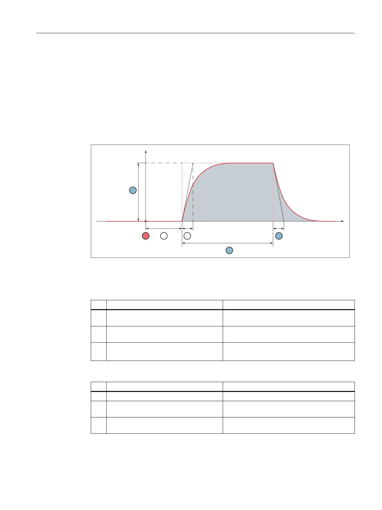
Velocity setpoint pulse
PP PLQ _ PLQ
W
Figure 9-29
Basic pulse shape
The numbers (①, ②, ...) stated in the following tables refer to the figure above.
Acceleration-independent parameters
No.
Machine data
Description
①
-
Trigger time or acceleration of the axes from stand-
still
③
MD32572 $MA_FRICT_V_PULSE_DE-
Delay time
LAY_TIME
④
MD32575
Time constant T of the rise time,
$MA_FRICT_V_PULSE_SMOOTH_TIME
after 5 * T ⇒ output value ≈ input value
Maximum values of the acceleration-dependently adaptable parameters
No.
Machine data
Description
②
MD32571 $MA_FRICT_VELO_STEP
Amplitude
⑤
MD32573
Active time
$MA_FRICT_V_PULSE_CONST_TIME
⑥
MD32574 $MA_FRICT_V_PULSE_DE-
Decay time
CAY_TIME
Monitoring and compensating
Function Manual, 10/2020, 6FC5397-7GP40-0BA1
319

Compensations
9.10 Friction compensation with adaptive characteristics
Weighting factors for acceleration-dependent adaptation of the maximum values
Table 9-1
Lower reversal point
Machine data
Description
MD32582 $MA_FRICT_ADAPT_V_STEP_PLUS[ 0 ...
Weighting factor for the amplitude
9 ]
MD32584
Weighting factor for the action time
$MA_FRICT_ADAPT_V_CONST_PLUS[ 0 ... 9 ]
MD32586 $MA_FRICT_ADAPT_V_DE-
Weighting factor for the decay time
CAY_PLUS[ 0 ... 9 ]
Table 9-2
Upper reversal point
Machine data
Description
MD32583 $MA_FRICT_ADAPT_V_STEP_MI-
Weighting factor for the amplitude
NUS[ 0 ... 9 ]
MD32585 $MA_FRICT_ADAPT_V_CONST_MI-
Weighting factor for the action time
NUS[ 0 ... 9 ]
MD32587 $MA_FRICT_ADAPT_V_DECAY_MI-
Weighting factor for the decay time
NUS[ 0 ... 9 ]
Calculation of the characteristic parameters
The commissioning engineer must determine the optimum values for amplitude, action time,
and decay time for the velocity setpoint pulse for different acceleration values during
the circularity test (Page 315). On completion of the circularity test, the control will calculate the
resulting characteristic parameters (maximum values, characteristic interpolation points, and
weighting factors) and write them into the corresponding machine data.
Monitoring and compensating
320
Function Manual, 10/2020, 6FC5397-7GP40-0BA1
Compensations
9.10 Friction compensation with adaptive characteristics
Example: Amplitude characteristic for the lower reversal point
• Maximum value
0'
PD[^$PSOLWXGH $PSOLWXGH
$PSOLWXGH
`
0$B)5,&7B9(/2B67(3
• Weighting factors
0'
$PSOLWXGH> Q @
0$B)5,&7B$'$37B9B67(3B3/86> Q @
0'
0$B)5,&7B9(/2B67(3
• Effective interpolation points
The effective interpolation points of the amplitude characteristics are the interpolation
points to which the following applies:
- MD32581 $MA_FRICT_ADAPT_TABLE_ACCEL[ <interpolation point> ] ≠ 0 (acceleration)
- MD32582 $MA_FRICT_ADAPT_V_STEP_PLUS[ <interpolation point> ] ≠ 0 (weighting
factor)
The amplitude of the velocity setpoint pulse of an effective interpolation point is calculated
as:
$PSOLWXGH> Q @
0D[LPXP YDOXH ZHLJKWLQJ IDFWRU> Q @
0'
0$B)5,&7B9(/2B67(3
0'
0$B)5,&7B$'$37B9B67(3B3/86> Q @
Note
Vertical offset of a characteristic
Subsequent vertical displacement of a characteristics is most easily achieved by changing the
corresponding maximum value in the machine data.
9.10.2.5
Torque setpoint pulse
Determination of the characteristic parameters for the torque setpoint pulses and calculation of
the corresponding machine data is not supported directly by the user interface. We therefore
advise determining the characteristic parameters or writing the machine data manually
Monitoring and compensating
Function Manual, 10/2020, 6FC5397-7GP40-0BA1
321
Compensations
9.10 Friction compensation with adaptive characteristics
Axis-specific machine data
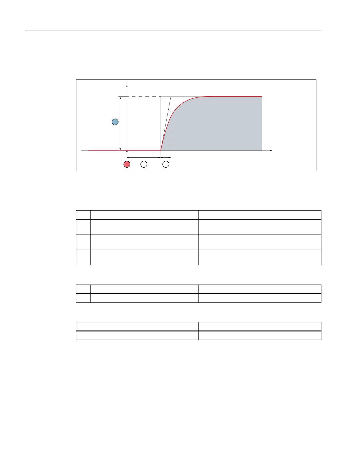
Torque setpoint pulse
1P
W
Figure 9-30
Basic pulse shape
The numbers (①, ②, ...) stated in the following tables refer to the figure above.
Acceleration-independent parameters
No.
Machine data
Description
①
-
Trigger time or acceleration of the axes from stand-
still
③
MD32577 $MA_FRICT_T_PULSE_DE-
Delay time
LAY_TIME
④
MD32578
Rise time
$MA_FRICT_T_PULSE_SMOOTH_TIME
Maximum values of the acceleration-dependently adaptable amplitude
No.
Machine data
Description
②
MD32576 $MA_FRICT_TORQUE_STEP
Amplitude
Weighting factors for acceleration-dependent adaptation of the maximum value
Machine data
Description
MD32588 $MA_FRICT_ADAPT_T_STEP[ 0 ... 9 ]
Weighting factor for the amplitude
Monitoring and compensating
322
Function Manual, 10/2020, 6FC5397-7GP40-0BA1
Compensations
9.10 Friction compensation with adaptive characteristics
Commissioning (manual)
Requirement
The circularity test (Page 315) for determining the characteristic parameter was already been
successfully performed completely or at least for the current measuring step.
Note
Determining the characteristic parameters
• The characteristic parameters for the torque setpoint pulse are most simply determined in
the circularity test (Page 315) of the user interface:
• Operating area: "Commissioning" > "NC" > "Friction compensation"
• The machine data are most simply set via the data list of the circularity test:
Operating area: "Commissioning" > "NC" > "Friction compensation" > "Data list" vertical
softkey
Assumption
The circularity tests has been started, measuring step 1 is active.
Recommended procedure
1. Initialization of the weighting factors:
- MD32588 $MA_FRICT_ADAPT_T_STEP[ 0 ] = 1
- MD32588 $MA_FRICT_ADAPT_T_STEP[ 1 ... 9 ] = 0
Note: For all measuring steps, the weighting factor with index 0 is used.
2. Setting the amplitude for the current measuring step:
- MD32576 $MA_FRICT_TORQUE_STEP = <amplitude>
3. Determining the changed contour deviation in the circle diagram.
4. Optimization of the amplitude value by changing in MD32576 $MA_FRICT_TORQUE_STEP
and checking in the circle diagram.
5. Recording the amplitude value for this measuring step for subsequent determination of the
maximum value or the weighting factor of the measuring step.
6. Switching on to the next measuring step and continuing with point 2 until the amplitude
values have been determined for all measuring steps.
7. Determining the maximum value from the recorded amplitude values and entering them in
the machine data:
0'
0$B)5,&7B72548(B67(3 PD[^$PSOLWXGH $PSOLWXGH
$PSOLWXGH
`
8. Calculation of the weighting factors for all active interpolation points from the recorded
amplitude values and entering them in the machine data:
0'
$PSOLWXGH> Q @
0$B)5,&7B$'$37B7B67(3> Q @
0'
0$B)5,&7B72548(B67(3
That completes commissioning of the amplitude characteristic for the torque setpoint pulse.
Monitoring and compensating
Function Manual, 10/2020, 6FC5397-7GP40-0BA1
323
Compensations
9.10 Friction compensation with adaptive characteristics
Optional
Setting the parameters that are independent of acceleration:
• MD32577 $MA_FRICT_T_PULSE_DELAY_TIME
• MD32578 $MA_FRICT_T_PULSE_SMOOTH_TIME
Effective interpolation points
The effective interpolation points of the amplitude characteristics are the interpolation points to
which the following applies:
• MD32581 $MA_FRICT_ADAPT_TABLE_ACCEL[ <interpolation point> ] ≠ 0 (acceleration)
• MD32583 $MA_FRICT_ADAPT_T_STEP[ <interpolation point> ] ≠ 0 (weighting factor)
The amplitude of the torque setpoint pulse of an effective interpolation point is calculated as:
$PSOLWXGH> Q @ 0D[LPXP YDOXH ZHLJKWLQJ IDFWRU> Q @
0'
0'
0$B)5,&7B72548(B67(3
0$B)5,&7B$'$37B7B67(3> Q @
Note
Vertical offset of the characteristic
Subsequent vertical displacement of the amplitude characteristic is most easily achieved by
changing the corresponding maximum value in the machine data.
Monitoring and compensating
324
Function Manual, 10/2020, 6FC5397-7GP40-0BA1
Compensations
9.11 Compensation functions for suspended axes
9.11
Compensation functions for suspended axes
9.11.1
Electronic counterweight
Axis without counterweight
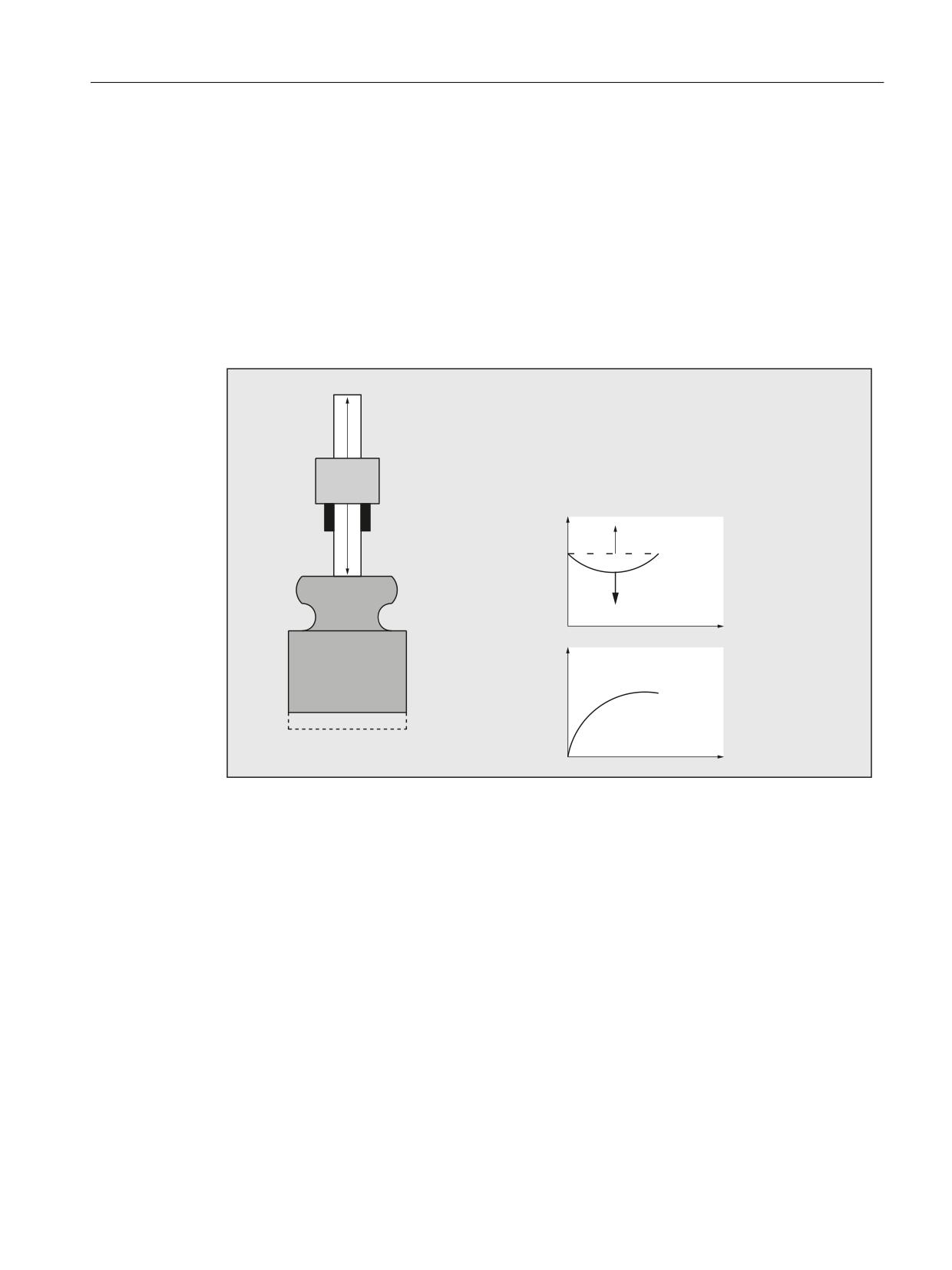
For axes that have a weight load without counterweight, then after the brake is released, the
hanging (suspended) axis drops and the following response is obtained:
=
%UDNH KROGV =
%UDNH UHOHDVHV FRQWUROOHU HQDEOH SXOVH HQDEOH
$[LV = VDJV
$IWHU VRPH WLPH WKH FRQWURO PDLQWDLQV WKH D[LV DW
WKH SRVLWLRQ
)HHG GULYH
%UDNH
=
'LVWDQFH
=
G]
W
=
7RUTXH
:HLJKW
G]
W
Figure 9-31
Drop of a hanging axis without counterweight
"Electronic counterweight" function
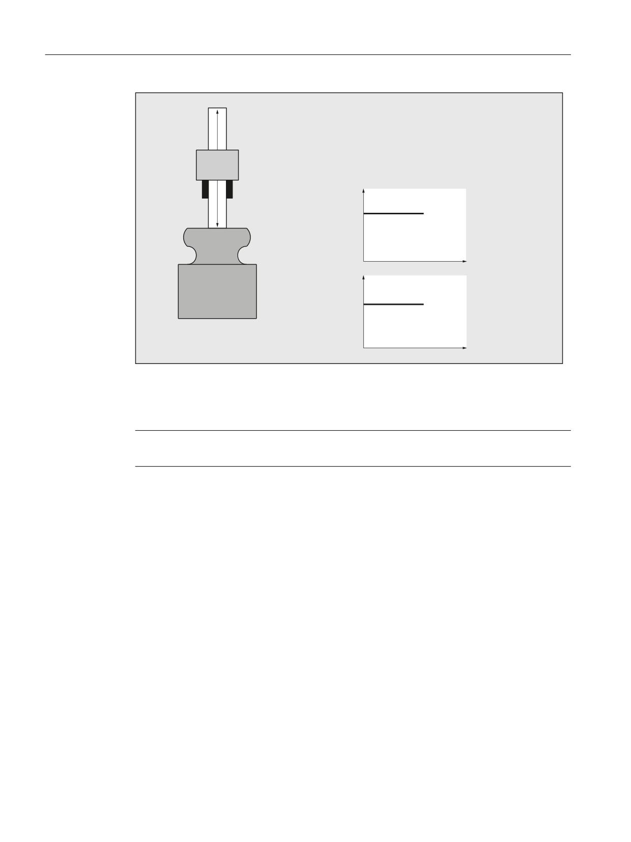
A hanging (suspended) axis can almost be completely prevented from dropping (sagging) using
the "electronic counterweight" function.
The electronic counterweight prevents axes with a weight load from sagging when the closed-
loop control is switched on. After releasing the brake, the constant counterweight torque
maintains the position of the vertical axis.
Monitoring and compensating
Function Manual, 10/2020, 6FC5397-7GP40-0BA1
325
Compensations
9.11 Compensation functions for suspended axes
=
%UDNH KROGV =
%UDNH UHOHDVHV FRQWUROOHU HQDEOH SXOVH HQDEOH
FRXQWHUZHLJKW WRUTXH
$[LV = VWD\V LQ SRVLWLRQ
)HHG GULYH
%UDNH
=
'LVWDQFH
=
G] a
W
=
7RUTXH
:HLJKW
G] a
W
Figure 9-32
Lowering of a vertical axis with electronic weight compensation
Commissioning
Note
The "electronic counterweight" is commissioned through the drive!
Further information
For additional information, see the following:
Function Manual Drive Functions SINAMICS S120
9.11.2
Special function: Reboot delay
Function
For changes, for example, to machine data values to become effective, the NC must be restarted.
This is done, for example, on the user interface by triggering an NC reset. If there are suspended
axes on the machine, failure of the closed-loop control while the control is starting will result in
the axes failing to maintain height.
With the "Reboot delay" function, the request to reboot the NC (NC reset) is communicated to the
NC via the operator interface as previously. Rebooting, during which the closed-loop control of
the axes is deactivated, is then delayed on the NC by a time that can be parameterized. During
Monitoring and compensating
326
Function Manual, 10/2020, 6FC5397-7GP40-0BA1
Compensations
9.11 Compensation functions for suspended axes
this time, user-specific actions, such engaging the holding brakes of the suspended axes, are
performed.
Note
The reboot delay is only effective on a request to reboot the NC (NC reset) via the user
interface.
In the case of a power-on reset by switching the control off and on again, pressing the reset
button on the front of the NCU, or power failure, a parameterized reboot delay time will have no
effect.
Alarm 2900 "Reboot after a delay"
When a reboot request is detected, alarm 2900 "Reboot after a delay" is triggered.
Alarm responses
The following responses are triggered by the alarm 2900:
• The NC/PLC interface signals are reset:
- DB11 DBX6.3 = 0 (mode group ready); all mode groups
- DB21, … DBX36.5 = 0 (channel ready) for all channels
- DB31, … DBX61.2 = 0 (axis ready) for all axes
• Braking the axis / spindles at the current limit.
For further details, see machine data:
- MD36610 $MA_AX_EMERGENCY_STOP_TIME (braking ramp time when errors occur)
- MD36620 $MA_SERVO_DISABLE_DELAY_TIME (OFF delay of the controller enable)
The NC/PLC interface signal "NC ready" remains set:
DB10 DBX108.7 == 1
Alarm suppression
With the machine data, display of the alarm 2900 "Reboot after a delay" will be suppressed on
the user interface:
MD11410 $MN_SUPPRESS_ALARM_MASKBit 20 = 1
The alarm responses are not affected by this.
Controlling holding brakes
During the reboot operation of the PLC, the PLC outputs defined as 0 are reset. Control of the
holding brakes must therefore be connected on the user side in such a way that the brakes
engage or remain engaged on a control signal == 0 and are released or remain released on a
control signal == 1.
Parameter assignment
The reboot delay time is set in machine data:
MD10088 $MN_REBOOT_DELAY_TIME = <reboot delay time>
Monitoring and compensating
Function Manual, 10/2020, 6FC5397-7GP40-0BA1
327

Compensations
9.12 Data lists
If the parameterized reboot delay time is 0.0, the function is deactivated.
System variables
The time remaining until the NC is rebooted can be read in the system variable:
$AN_REBOOT_DELAY_TIME
While no request for a reboot of the NC (NC reset) has been triggered from the user interface,
the system variable has the value 0.0.
A value greater than 0.0 indicates that a reboot request (NC reset) has been triggered from the
user interface and also the time remaining in the NC or PLC until the reboot.
Application example
Evaluating the system variables in a static synchronized action
Condition part: Check for a value greater than 0.0 because then a request for a reboot of the NC
(NC reset) has been made from the user interface.
Action part: e.g. triggering "safe standstill" as part of the "Safety Integrated" function.
9.12
Data lists
9.12.1
Machine data
9.12.1.1
General machine data
Number
Identifier: $MN_
Description
10050
SYSCLOCK_CYCLE_TIME
Basic system clock cycle
10070
IPO_SYSCLOCK_TIME_RATIO
Factor for interpolator clock cycle
10082
CTRLOUT_LEAD_TIME
Shift of setpoint transfer time
10083
CTRLOUT_LEAD_TIME_MAX
Maximum permissible setting for shift of setpoint trans-
fer time
10088
REBOOT_DELAY_TIME
Reboot delay
18342
MM_CEC_MAX_ POINTS[t]
Maximum number of interpolation points of sag com-
pensation
9.12.1.2
Channelspecific machine data
Number Identifier: $MC_
Description
20150
GCODE_RESET_VALUES
Reset G groups
Monitoring and compensating
328
Function Manual, 10/2020, 6FC5397-7GP40-0BA1

Compensations
9.12 Data lists
9.12.1.3
Axis/spindlespecific machine data
Number
Identifier: $MA_
Description
32450
BACKLASH
Backlash
32452
BACKLASH_FACTOR
Weighting factor for backlash
32454
BACKLASH_MODE
Backlash compensation mode
32456
BACKLASH_DYN
Compensation value for the dynamic backlash compen-
sation
32457
BACKLASH_DYN_MAX_VELO
Limitation of the dynamic backlash compensation value
change
32490
FRICT_COMP_MODE
Type of friction compensation
32500
FRICT_COMP_ENABLE
Friction compensation active
32510
FRICT_COMP_ADAPT_ENABLE
Friction compensation adaptation active
32520
FRICT_COMP_CONST_MAX
Maximum friction compensation value
32530
FRICT_COMP_CONST_MIN
Minimum friction compensation value
32540
FRICT_COMP_TIME
Friction compensation time constant
32550
FRICT_COMP_ACCEL1
Adaptation acceleration value 1
32560
FRICT_COMP_ACCEL2
Adaptation acceleration value 2
32570
FRICT_COMP_ACCEL3
Adaptation acceleration value 3
32610
VELO_FFW_WEIGHT
Feedforward control factor for velocity/speed feedfor-
ward control
32620
FFW_MODE
Feedforward control mode
32630
FFW_ACTIVATION_MODE
Activate feedforward control from program
32650
AX_INERTIA
Inertia for torque feedforward control
32700
ENC_COMP_ENABLE
Interpolatory compensation
32710
CEC_ENABLE
Enabling of sag compensation
32711
CEC_SCALING_SYSTEM_METRIC
System of units for sag compensation
32720
CEC_MAX_SUM
Maximum compensation value for sag compensation
32730
CEC_MAX_VELO
Change of velocity during sag compensation
32750
TEMP_COMP_TYPE
Temperature compensation type
32760
COMP_ADD_VELO_FACTOR
Velocity increase as a result of compensation
32711
CEC_SCALING_SYSTEM_METRIC
System of units for sag compensation
32800
EQUIV_CURRCTRL_TIME
Equivalent time constant current control loop for feed-
forward control
32810
EQUIV_SPEEDCTRL_TIME
Equivalent time constant speed control loop for feed-
forward control
32910
DYN_MATCH_TIME
Time constant for dynamic response adaptation
36500
ENC_CHANGE_TOL
Maximum tolerance for position actual value switchover
37302
NOCO_FILTER_TIME
Time constant for smoothing nodding compensation
values
37310
NOCO_INPUT_AX_1
Compensation relationship 1:
Machine axis that causes nodding motion
Monitoring and compensating
Function Manual, 10/2020, 6FC5397-7GP40-0BA1
329

Compensations
9.12 Data lists
Number
Identifier: $MA_
Description
37312
NOCO_ADAPT_AX_1
Compensation relationship 1:
Machine axis, whose position influences nodding mo-
tion
37314
NOCO_ADAPT_NUM_1
Compensation relationship 1:
Number of positions, adaptation characteristic of the
nodding compensation
37316
NOCO_ADAPT_POS_1
Compensation relationship 1:
Positions, adaptation characteristic of the nodding com-
pensation
37318
NOCO_COMPLIANCE_1
Compensation relationship 1:
Compliance factor for nodding compensation
37320
NOCO_INPUT_AX_2
Compensation relationship 2:
Machine axis that causes nodding motion
37322
NOCO_ADAPT_AX_2
Compensation relationship 2:
Machine axis, whose position influences nodding mo-
tion
37324
NOCO_ADAPT_NUM_2
Compensation relationship 2:
Number of positions, adaptation characteristic of the
nodding compensation
37326
NOCO_ADAPT_POS_2
Compensation relationship 2:
Positions, adaptation characteristic of the nodding com-
pensation
37328
NOCO_COMPLIANCE_2
Compensation relationship 2:
Compliance factor for nodding compensation
37330
NOCO_INPUT_AX_3
Compensation relationship 3:
Machine axis that causes nodding motion
37332
NOCO_ADAPT_AX_3
Compensation relationship 3:
Machine axis, whose position influences nodding mo-
tion
37334
NOCO_ADAPT_NUM_3
Compensation relationship 3:
Number of positions, adaptation characteristic of the
nodding compensation
37336
NOCO_ADAPT_POS_3
Compensation relationship 3:
Positions, adaptation characteristic of the nodding com-
pensation
37338
NOCO_COMPLIANCE_3
Compensation relationship 3:
Compliance factor for nodding compensation
38000
MM_ENC_COMP_MAX_POINTS
Number of interpolation points with interpolatory com-
pensation
Monitoring and compensating
330
Function Manual, 10/2020, 6FC5397-7GP40-0BA1

Compensations
9.12 Data lists
9.12.2
Setting data
9.12.2.1
General setting data
Number
Identifier: $SN_
Description
41300
CEC_TABLE_ENABLE[t]
Enable evaluation of beam sag compensation
table
41310
CEC_TABLE_WEIGHT[t]
Weighting factor for beam sag compensation ta-
ble
9.12.2.2
Axis/spindle-specific setting data
Number
Identifier: $SA_
Description
43900
TEMP_COMP_ABS_VALUE
Position-independent temperature compensation value
43910
TEMP_COMP_SLOPE
Gradient for position-dependent temperature compen-
sation
43920
TEMP_COMP_REF_POSITION
Reference position for position-dependent temperature
compensation
Monitoring and compensating
Function Manual, 10/2020, 6FC5397-7GP40-0BA1
331

Preface
1
Introduction
Fundamental safety
2
instructions
SINUMERIK
Overview
3
4
PLC mode selector
SINUMERIK 840D sl
Reserve resources (timers,
5
PLC
counters, FC, FB, DB, I/O)
Commissioning hardware
6
configuration of the PLC CPU
7
Function Manual
Starting up the PLC program
8
Coupling of the PLC CPU
9
Interface structure
Structure and functions of
10
the basic program
11
SPL for Safety Integrated
12
Assignment overview
PLC functions for HMI
13
(DB19)
PLC functions for drive
components on the
14
integrated PROFIBUS
Memory requirements of
15
the basic PLC program
16
NC VAR selector
17
Block descriptions
Valid for
18
Data lists
Control system
19
Interface signals
SINUMERIK 840D sl / 840DE sl
CNC software Version 4.94
A
Appendix
10/2020
6FC5397-0HP40-0BA1
Table of contents
Preface
3
1
Introduction
27
1.1
About this documentation
27
2
Fundamental safety instructions
29
2.1
General safety instructions
29
2.2
Warranty and liability for application examples
29
2.3
Security information
29
3
Overview
31
3.1
Brief description
31
3.2
Key data of the PLC CPU
33
3.3
PLC operating system version
34
4
PLC mode selector
35
5
Reserve resources (timers, counters, FC, FB, DB, I/O)
37
6
Commissioning hardware configuration of the PLC CPU
39
7
Starting up the PLC program
41
7.1
Installation of the basic program
41
7.2
Application of the basic program
41
7.3
Version codes
42
7.4
Machine program
43
7.5
Data backup
43
7.6
PLC series startup, PLC archive
44
7.7
Software upgrade
49
7.8
I/O modules (FM, CP modules)
50
7.9
Troubleshooting
51
8
Coupling of the PLC CPU
53
8.1
General information
53
8.2
Properties of the PLC CPU
53
8.3
Interface with integrated PLC
53
8.4
Diagnostic buffer on PLC
55
9
Interface structure
57
9.1
Interface
57
PLC
Function Manual, 10/2020, 6FC5397-0HP40-0BA1
5
Table of contents
9.2
PLC/NCK interface
57
9.3
Interface PLC/HMI
64
9.4
PLC/MCP/HHU interface
70
10
Structure and functions of the basic program
73
10.1
Startup and synchronization of NCK PLC
75
10.2
Cyclic operation (OB1)
75
10.3
Time-interrupt processing (OB35)
77
10.4
Process-interrupt processing (OB 40)
78
10.5
Diagnostic alarm, module failure processing (OB82, OB86)
78
10.6
Response to NCK failure
79
10.7
Functions of the basic program called from the user program
80
10.8
Symbolic programming of user program with interface DB
83
10.9
M decoding acc. to list
85
10.10
PLC machine data
89
10.11
Configuration machine control panel, handheld unit, direct keys
93
10.12
Switchover of machine control panel, handheld unit
102
10.13
Flexible axis configuration
103
10.14
Selection of JOG axis via HMI
104
10.15
Mixed operation from the machine control panel and the handheld terminal
106
11
SPL for Safety Integrated
109
12
Assignment overview
111
12.1
Block address range for PLC user program
111
13
PLC functions for HMI (DB19)
115
13.1
Channel selection
115
13.2
Program selection
116
13.3
Activating the key lock
119
13.4
Operating area numbers
119
13.5
Screen numbers
119
13.5.1
Screen numbers: JOG, manual machine
120
13.5.2
Screen numbers: Reference point approach
125
13.5.3
Screen numbers: MDA
125
13.5.4
Screen numbers: AUTOMATIC
126
13.5.5
Screen numbers: Parameters operating area
126
13.5.6
Screen numbers: Program operating area
128
13.5.7
Screen numbers: Program manager operating area
128
13.5.8
Screen numbers: Diagnostics operating area
128
13.6
HMI monitor
129
PLC
6
Function Manual, 10/2020, 6FC5397-0HP40-0BA1
Table of contents
14
PLC functions for drive components on the integrated PROFIBUS
131
14.1
Overview
131
14.2
Performing a start-up
131
14.3
Example
132
15
Memory requirements of the basic PLC program
135
16
NC VAR selector
139
16.1
Overview
139
16.2
Using NC VAR selector
141
16.2.1
NC VAR selector user interface
141
16.2.2
Description of functions
143
16.2.3
Editing projects
144
16.2.4
Filtering the variable list
145
16.2.5
Specifying the project list
147
16.2.6
Deleting a variable from the project list
148
16.2.7
Alias name
149
16.2.8
Generating code
149
16.2.9
Transfer to STEP 7
151
16.2.10
Using TIA Portal
152
16.2.11
Using SINAMICS parameters
152
16.2.12
Importing variables and parameters
153
16.2.13
Startup, installation
154
17
Block descriptions
155
17.1
Available blocks
155
17.2
FB1: RUN_UP - basic program, start section
156
17.3
FB2: GET - read NC variable
164
17.4
FB3: PUT - write NC variables
172
17.5
FB4: PI_SERV - request PI service
180
17.5.1
List of available Pl services
185
17.5.2
PI service: ASUP
186
17.5.3
PI service: CANCEL
187
17.5.4
PI service: CONFIG
187
17.5.5
PI service: DIGION
187
17.5.6
PI service: DIGIOF
187
17.5.7
PI service: FINDBL
188
17.5.8
PI service: LOGIN
188
17.5.9
PI service: LOGOUT
189
17.5.10
PI service: NCRES
189
17.5.11
PI service: SELECT
189
17.5.12
PI service: SETUDT
190
17.5.13
PI service: SETUFR
190
17.5.14
PI service: RETRAC
191
17.5.15
PI service: CRCEDN
192
17.5.16
PI service: CREACE
192
17.5.17
PI service: CREATO
193
17.5.18
PI service: DELECE
193
PLC
Function Manual, 10/2020, 6FC5397-0HP40-0BA1
7
Table of contents
17.5.19
PI service: DELETO
194
17.5.20
PI service: MMCSEM
194
17.5.21
PI service: TMCRAD
195
17.5.22
PI service: TMCRTO
196
17.5.23
PI service: TMDLAD
196
17.5.24
PI service: TMFDPL
197
17.5.25
PI service: TMFPBP
198
17.5.26
PI service: TMGETT
199
17.5.27
PI service: TMMVTL
200
17.5.28
PI service: TMPOSM
201
17.5.29
PI service: TMPCIT
202
17.5.30
PI service: TMRASS
203
17.5.31
PI service: TRESMO
203
17.5.32
PI service: TSEARC
204
17.5.33
PI service: TMCRMT
207
17.5.34
PI service: TMDLMT
208
17.5.35
PI service: POSMT
208
17.5.36
PI service: FDPLMT
209
17.6
FB5: GETGUD - read GUD variable
210
17.7
FB7: PI_SERV2 - request PI service
218
17.8
FB9: MtoN - operator panel switchover
219
17.9
FB10: Safety relay (SI relay)
224
17.10
FB11: Brake test
227
17.11
FB21: Powerride - rotary/push control dial
232
17.11.1
Signal transfer between Powerride and PLC
235
17.11.2
LED color palette
236
17.11.3
Examples
237
17.11.3.1
Integrate Powerride via an MCP during start-up
237
17.11.3.2
Calling Powerride
238
17.11.4
Status and error IDs
239
17.12
FB29: Signal recorder and data trigger diagnostics
240
17.13
FC2 : GP_HP - basic program, cyclic section
243
17.14
FC3: GP_PRAL - basic program, interruptdriven section
245
17.15
FC5: GP_DIAG - basic program, diagnostic alarm and module failure
247
17.16
FC6: TM_TRANS2 - transfer block for tool management and multitool
249
17.17
FC7: TM_REV - transfer block for tool change with revolver
250
17.18
FC8: TM_TRANS - transfer block for tool management
253
17.19
FC9: ASUP - start of asynchronous subprograms
259
17.20
FC10: AL_MSG - error and operating messages
262
17.21
FC12: AUXFU - call interface for user with auxiliary functions
264
17.22
FC13: BHGDisp - display control for handheld unit
265
17.23
FC17: YDelta - star-delta switchover
269
17.24
FC18: SpinCtrl - spindle control
272
PLC
8
Function Manual, 10/2020, 6FC5397-0HP40-0BA1
Table of contents
17.25
FC19: MCP_IFM - transfer of MCP signals to interface
282
17.26
FC21: Transfer - data exchange NC/PLC
292
17.26.1
Function
292
17.26.2
Declaration of the function
292
17.26.3
Explanation of formal parameters
293
17.26.4
Function 1, 2: Signals synchronized actions to / from Channel
293
17.26.5
Function 3, 4: Fast data exchange PLC-NC
295
17.26.6
Function 5: Update control signals to channel
298
17.26.7
Function 6: Update control signals to axes
299
17.26.8
Function 7: Update control signals to axes
299
17.27
FC22: TM_DIR - direction selection for tool management
299
17.28
FC24: MCP_IFM2 - transferring MCP signals to the interface
302
17.29
FC25: MCP_IFT - transfer of MCP/OP signals to interface
305
17.30
FC26: HPU_MCP - Transfer of the HT 8/HT 10 signals to the interface
308
17.30.1
Overview of the NC/PLC interface signals of HT
313
17.30.2
Overview of the NC/PLC interface signals to HT
315
17.31
FC27: OpUnitWriteRecord - write data record to MCP
316
17.32
FC1005: AG_SEND - transfers data to Ethernet CP
318
17.33
FC1006: AG_RECV - receives data from the Ethernet CP
319
18
Data lists
321
18.1
Machine data
321
18.1.1
Display machine data
321
18.1.2
NC-specific machine data
321
18.1.3
Channelspecific machine data
321
19
Interface signals
323
19.1
Interface signals - overview
323
19.1.1
Overview of the PLC blocks
323
19.1.1.1
Organization blocks (OBs)
323
19.1.1.2
Function blocks (FBs)
323
19.1.1.3
Function blocks (FCs)
324
19.1.1.4
Data blocks (DBs)
325
19.1.1.5
Timer block
326
19.1.2
Signals from/to the machine control panel
326
19.1.2.1
M version, signals from the MCP: Input image
326
19.1.2.2
M version, signals to the MCP: Output image
327
19.1.2.3
T version, signals from the MCP: Input image
327
19.1.2.4
T version, signals to the MCP: Output image
328
19.1.2.5
Slimline version, signals from the MCP: Input image
329
19.1.2.6
Slimline version, signals to the MCP: Output image
329
19.1.3
Signals from/to the handheld unit HT 2
330
19.1.3.1
Signals from the handheld unit: Input image
330
19.1.3.2
Signals to the handheld unit: Output image
330
19.1.4
Signals from/to the handheld unit HT 8
332
19.1.4.1
Signals from the handheld unit HT 8: Input image
332
19.1.4.2
Signals to handheld terminal HT 8: Output image
332
19.1.5
Signals from/to the handheld unit HT 10
333
PLC
Function Manual, 10/2020, 6FC5397-0HP40-0BA1
9
Table of contents
19.1.5.1
Signals from the handheld unit HT 10: Input image
333
19.1.5.2
Signals to handheld terminal HT 10: Output image
334
19.1.6
PLC alarms/messages
335
19.1.6.1
FC 10 alarms in the DB2 (FB1: "ExtendAIMsg" = FALSE)
335
19.1.6.2
FC 10 alarms in the DB2 (FB1: "ExtendAIMsg" = TRUE)
344
19.1.7
Signals from/to the NC, PLC and operating software
357
19.1.7.1
DB10, onboard inputs and outputs of the NC
357
19.1.7.2
DB10, general signals to the NC
358
19.1.7.3
DB10, onboard inputs and outputs from the NC/operating software
359
19.1.7.4
DB10, selection and status signals from the operating software
360
19.1.7.5
DB10, general signals from the NC
362
19.1.7.6
DB10, external digital NC inputs
363
19.1.7.7
DB10, external digital NC outputs
364
19.1.7.8
DB10, external analog NC inputs
365
19.1.7.9
DB10, external analog NC outputs
366
19.1.7.10
DB10, external digital NC inputs and outputs
367
19.1.7.11
DB10, analog NC inputs and outputs
368
19.1.7.12
DB10, collision avoidance: Protection area active
369
19.1.7.13
DB10, collision avoidance: Activate protection area
369
19.1.7.14
DB10, extension, handwheel signals from the NC
370
19.1.7.15
DB10, extension, handwheel signals from the HMI
371
19.1.7.16
DB10, interface robot status
371
19.1.7.17
DB10, interface robot status
371
19.1.8
Mode group-specific signals
372
19.1.8.1
DB11, mode signals 1 to the NC
372
19.1.8.2
DB11, mode signals 1 from the NC
372
19.1.8.3
DB11, mode signals 2 to the NC
373
19.1.8.4
DB11, mode signals 2 from NC
374
19.1.9
Safety Integrated (SPL)
375
19.1.9.1
DB18, parameterization part
375
19.1.9.2
DB18, data area / errors
375
19.1.9.3
DB18, additional data areas
377
19.1.9.4
DB18, F_SENDDP sender
378
19.1.9.5
DB18, F_SENDDP receiver
378
19.1.9.6
DB18, SPL user data
379
19.1.9.7
DB18, data area / errors: Extended data area
380
19.1.9.8
DB18, additional data areas: Extended data area
382
19.1.9.9
DB18, F_SENDDP sender
383
19.1.9.10
DB18, F_RECDP receiver
385
19.1.10
Control/status signals to/from operator panel (OP)
389
19.1.10.1
DB19, signals to the operator panel (OP)
389
19.1.10.2
DB19, signals from the operator panel (OP)
390
19.1.10.3
DB19, sidescreen - interface for the MCP function
394
19.1.10.4
DB19, sidescreen - interface for the MCP function
395
19.1.11
Defining PLC alarms
396
19.1.11.1
DB20, NC machine data
396
19.1.12
Channel-specific signals
397
19.1.12.1
DB21 - DB30, control signals to the channel (1)
397
19.1.12.2
DB21 - DB30, control signals to the geometry axes
399
19.1.12.3
DB21 - DB30, HMI signals to channel / OEM signals from/to channel
401
19.1.12.4
DB21 - DB30, control signals from the geometry axes
403
19.1.12.5
DB21 - DB30, change signals for auxiliary function transfer from the channel
405
PLC
10
Function Manual, 10/2020, 6FC5397-0HP40-0BA1
Table of contents
19.1.12.6
DB21 - DB30, transferred M and S functions:
406
19.1.12.7
DB21 - DB30, transferred T/D/DL functions
407
19.1.12.8
DB21 - DB30, transferred H/F functions
408
19.1.12.9
DB21 - DB30, decoded M signals
409
19.1.12.10
DB21 - DB30, active G functions
410
19.1.12.11
DB21 - DB30, protection areas from the channel
411
19.1.12.12
DB21 - DB30, synchronous actions, signals from/to the channel
412
19.1.12.13
DB21 - DB30, control signals from/to the channel
413
19.1.12.14
DB21 - DB30, signals to the orientation axes
414
19.1.12.15
DB21 - DB30, signals from the orientation axes
416
19.1.12.16
DB21 - DB30, tool management functions from the channel
417
19.1.12.17
DB21 - DB30, control signals from/to the channel (2)
418
19.1.13
Axis/spindle signals
421
19.1.13.1
DB31 - DB61, signals to the axis/spindle
421
19.1.13.2
DB31 - DB61, signals from the axis/spindle
426
19.1.14
Safety Integrated
434
19.1.14.1
DB31 - DB61, Safety Control Channel (SCC)
434
19.1.14.2
DB31 - DB61, Safety Info Channel (SIC)
434
19.1.15
Tool management
435
19.1.15.1
DB71, interface for loading/unloading the magazine
435
19.1.15.2
DB72, interface for the spindle as change position
437
19.1.15.3
DB73, interface for the turret
439
19.1.16
Signals from/to the machine control panel and the handheld unit
441
19.1.16.1
DB77, signals from/to the MCP and the HHU
441
19.1.17
Powerride
442
19.1.17.1
DB78: PowerrideConfig
442
19.1.18
Signals for Ctrl-Energy
443
19.1.18.1
DB1000, energy-saving profiles
443
19.1.19
SENTRON PAC
445
19.1.19.1
DB1001, SENTRON PAC
445
19.1.19.2
DB1001, SENTRON PAC, auxiliary devices
447
19.1.20
Spindle temperature sensor
449
19.1.20.1
DB1002: spindle temperature sensors
449
19.1.21
Interface to the tool management, extended area
451
19.1.21.1
DB1071, interface for loading/unloading the magazine Multitool
451
19.1.21.2
DB1072, interface for the spindle: Multitool
451
19.1.21.3
DB1073, interface for the turret: Multitool
453
19.2
Interface signals - detailed description
454
19.2.1
DB10: NC, PLC and HMI
454
19.2.1.1
DB10 DBX0.0 - 7 (digital NC inputs 1 - 8: Lock)
454
19.2.1.2
DB10 DBX1.0 - 7 (digital NC inputs 1 - 8: Set)
454
19.2.1.3
DB10 DBX4.0 - 7 (digital NC outputs 1 - 8: Lock)
455
19.2.1.4
DB10 DBX5.0 - 7 (digital NC outputs 1 - 8: Overwrite)
455
19.2.1.5
DB10 DBX6.0 - 7 (digital NC outputs 1 - 8: Setting value)
456
19.2.1.6
DB10 DBX7.0 - 7 (digital NC outputs 1 - 8: Target)
456
19.2.1.7
DB10 DBX56.1 (Emergency Stop)
457
19.2.1.8
DB10 DBX56.2 (acknowledge Emergency Stop)
457
19.2.1.9
DB10 DBX56.4 - 7 (key-operated switch position 0 - 3)
458
19.2.1.10
DB10 DBX58.0 - 7 (collision avoidance: Deactivate protection area group)
458
19.2.1.11
DB10 DBX60.0 - 7 (digital NC inputs 1 - 8: Actual value)
459
19.2.1.12
DB10 DBX64.0 - 7 (digital NC outputs 1 - 8: Setpoint)
460
19.2.1.13
DB10 DBX93.0 ... 7 (collision avoidance: Deactivate protection area group)
460
PLC
Function Manual, 10/2020, 6FC5397-0HP40-0BA1
11
Table of contents
19.2.1.14
DB10 DBX97.0 - 3 (channel number geometry axis handwheel 1)
461
19.2.1.15
DB10 DBX98.0 - 3 (channel number geometry axis handwheel 2)
462
19.2.1.16
DB10 DBX99.0 - 3 (channel number geometry axis handwheel 3)
462
19.2.1.17
DB10 DBX100.0 - 4 (axis number handwheel 1)
463
19.2.1.18
DB10 DBX100.5 (define handwheel 1 as contour handwheel)
463
19.2.1.19
DB10 DBX100.6 (handwheel 1 selected)
464
19.2.1.20
DB10 DBX100.7 (machine axis handwheel 1)
465
19.2.1.21
DB10 DBX101.0 - 4 (axis number handwheel 2)
465
19.2.1.22
DB10 DBX101.5 (define handwheel 2 as contour handwheel)
465
19.2.1.23
DB10 DBX101.6 (handwheel 2 selected)
465
19.2.1.24
DB10 DBX101.7 (machine axis handwheel 2)
466
19.2.1.25
DB10 DBX102.0 - 4 (axis number handwheel 3)
466
19.2.1.26
DB10 DBX102.5 (define handwheel 3 as contour handwheel)
466
19.2.1.27
DB10 DBX102.6 (handwheel 3 selected)
466
19.2.1.28
DB10 DBX102.7 (machine axis handwheel 3)
466
19.2.1.29
DB10 DBX103.0 (remote diagnosis active)
466
19.2.1.30
DB10 DBX103.5 (AT box ready)
466
19.2.1.31
DB10 DBX103.6 (HMI temperature limit)
467
19.2.1.32
DB10 DBX103.7 (HMI battery alarm)
467
19.2.1.33
DB10 DBX104.7 (NC-CPU ready)
467
19.2.1.34
DB10 DBX106.1 (Emergency Stop active)
468
19.2.1.35
DB10 DBX107.0 - 1 (probe actuated)
468
19.2.1.36
DB10 DBX107.6 (NCU link active)
468
19.2.1.37
DB10 DBX108.3 (operating software ready)
469
19.2.1.38
DB10 DBX108.5 (drives in cyclic operation)
469
19.2.1.39
DB10 DBX108.6 (drive ready)
469
19.2.1.40
DB10 DBX108.7 (NC ready)
469
19.2.1.41
DB10 DBX109.0 (NC alarm active)
470
19.2.1.42
DB10 DBX109.5 (heat sink temperature alarm, NCU)
470
19.2.1.43
DB10 DBX109.6 (air temperature alarm)
471
19.2.1.44
DB10 DBX109.7 (NC battery alarm)
471
19.2.1.45
DB10 DBX110.0 - 113.7 (software cams: minus cam signal 1 to 32)
471
19.2.1.46
DB10 DBX114.0 - 117.7 (software cams: plus cam signal 1 to 32)
472
19.2.1.47
DB10 DBX122.0 - 7 (digital NC inputs 9 - 16: Lock)
473
19.2.1.48
DB10 DBX123.0 - 7 (digital NC inputs 9 - 16: Set)
473
19.2.1.49
DB10 DBX124.0 - 7 (digital NC inputs 17 - 24: Lock)
473
19.2.1.50
DB10 DBX125.0 - 7 (digital NC inputs 17 - 24: Set)
474
19.2.1.51
DB10 DBX126.0 - 7 (digital NC inputs 25 - 32: Lock)
474
19.2.1.52
DB10 DBX127.0 - 7 (digital NC inputs 25 - 32: Set)
475
19.2.1.53
DB10 DBX128.0 - 7 (digital NC inputs 33 - 40: Lock)
475
19.2.1.54
DB10 DBX129.0 - 7 (digital NC inputs 33 - 40: Set)
475
19.2.1.55
DB10 DBX130.0 - 7 (digital NC outputs 9 - 16: Lock)
476
19.2.1.56
DB10 DBX131.0 - 7 (digital NC outputs 9 - 16: Overwrite)
476
19.2.1.57
DB10 DBX132.0 - 7 (digital NC outputs 9 - 16: Setting value)
477
19.2.1.58
DB10 DBX133.0 - 7 (digital NC outputs 9 - 16: Target)
478
19.2.1.59
DB10 DBX134.0 - 7 (digital NC outputs 17 - 24: Lock)
478
19.2.1.60
DB10 DBX135.0 - 7 (digital NC outputs 17 - 24: Overwrite)
479
19.2.1.61
DB10 DBX136.0 - 7 (digital NC outputs 17 - 24: Setting value)
479
19.2.1.62
DB10 DBX137.0 - 7 (digital NC outputs 17 - 24: Target)
480
19.2.1.63
DB10 DBX138.0 - 7 (digital NC outputs 25 - 32: Lock)
480
19.2.1.64
DB10 DBX139.0 - 7 (digital NC outputs 25 - 32: Overwrite)
481
19.2.1.65
DB10 DBX140.0 - 7 (digital NC outputs 25 - 32: Setting value)
482
PLC
12
Function Manual, 10/2020, 6FC5397-0HP40-0BA1
Table of contents
19.2.1.66
DB10 DBX141.0 - 7 (digital NC outputs 25 - 32: Target)
482
19.2.1.67
DB10 DBX142.0 - 7 (digital NC outputs 33 - 40: Lock)
483
19.2.1.68
DB10 DBX143.0 - 7 (digital NC outputs 33 - 40: Overwrite)
483
19.2.1.69
DB10 DBX144.0 - 7 (digital NC outputs 33 - 40: Setting value)
484
19.2.1.70
DB10 DBX145.0 - 7 (digital NC outputs 33 - 40: Target)
485
19.2.1.71
DB10 DBX146.0 - 7 (analog NC inputs 1 - 8: Lock)
485
19.2.1.72
DB10 DBX147.0 - 7 (analog NC inputs 1 - 8: Target)
486
19.2.1.73
DB10 DBW148 - 162 (analog NC outputs 1 - 8: Setting value)
486
19.2.1.74
DB10 DBX166.0 - 7 (analog NC outputs 1 - 8: Overwrite)
486
19.2.1.75
DB10 DBX167.0 - 7 (analog NC outputs 1 - 8: Target)
487
19.2.1.76
DB10 DBX168.0 - 7 (analog NC outputs 1 - 8: Lock)
488
19.2.1.77
DB10 DBW170 - 184 (analog NC outputs 1 - 8: Setting value)
488
19.2.1.78
DB10 DBX186.0 - 7 (digital NC inputs 9 - 16: Actual value)
489
19.2.1.79
DB10 DBX187.0 - 7 (digital NC inputs 17 - 24: Actual value)
489
19.2.1.80
DB10 DBX188.0 - 7 (digital NC inputs 25 - 32: Actual value)
490
19.2.1.81
DB10 DBX189.0 - 7 (digital NC inputs 33 - 40: Actual value)
490
19.2.1.82
DB10 DBX190.0 - 7 (digital NC outputs 9 - 16: Setpoint)
491
19.2.1.83
DB10 DBX191.0 - 7 (digital NC outputs 17 - 24: Setpoint)
491
19.2.1.84
DB10 DBX192.0 - 7 (digital NC outputs 25 - 32: Setpoint)
492
19.2.1.85
DB10 DBX193.0 - 7 (digital NC outputs 33 - 40: Setpoint)
492
19.2.1.86
DB10 DBW194 - 208 (analog NC inputs 1 - 8: Actual value)
493
19.2.1.87
DB10 DBW210 - 224 (analog NC outputs 1 - 8: Setpoint)
493
19.2.1.88
DB10 DBX226.0 - 233.7 (collision avoidance: Protection area active)
494
19.2.1.89
DB10 DBX234.0 - 241.7 (collision avoidance: Activate protection area)
494
19.2.1.90
DB10 DBX245.0 - 5 (Ethernet handwheel stationary)
495
19.2.1.91
DB10 DBX246.0 - 5 (handwheel active)
496
19.2.2
DB11: Mode group
496
19.2.2.1
DB11 DBX0.0 (AUTOMATIC mode)
496
19.2.2.2
DB11 DBX0.1 (MDI mode)
496
19.2.2.3
DB11 DBX0.2 (JOG mode)
497
19.2.2.4
DB11 DBX0.4 (mode change inhibit)
497
19.2.2.5
DB11 DBX0.5 (mode group stop)
497
19.2.2.6
DB11 DBX0.6 (mode group stop, axes plus spindles)
498
19.2.2.7
DB11 DBX0.7 (mode group reset)
499
19.2.2.8
DB11 DBX1.0 (TEACH IN machine function)
499
19.2.2.9
DB11 DBX1.1 (REPOS machine function)
500
19.2.2.10
DB11 DBX1.2 (REF machine function)
500
19.2.2.11
DB11 DBX1.6 (single block, type B)
500
19.2.2.12
DB11 DBX1.7 (single block, type A)
501
19.2.2.13
DB11 DBX4.0 (AUTOMATIC mode selected)
502
19.2.2.14
DB11 DBX4.1 (MDI mode selected)
502
19.2.2.15
DB11 DBX4.2 (JOG mode selected)
502
19.2.2.16
DB11 DBX5.0 (TEACH IN machine function selected)
502
19.2.2.17
DB11 DBX5.1 (REPOS machine function selected)
503
19.2.2.18
DB11 DBX5.2 (REF machine function selected)
503
19.2.2.19
DB11 DBX6.0 (AUTOMATIC mode active)
503
19.2.2.20
DB11 DBX6.1 (active MDI mode)
503
19.2.2.21
DB11 DBX6.2 (JOG mode active)
504
19.2.2.22
DB11 DBX6.3 (mode group ready)
504
19.2.2.23
DB11 DBX6.7 (all channels in the "Reset" state)
504
19.2.2.24
DB11 DBX7.0 (TEACH IN machine function active)
505
19.2.2.25
DB11 DBX7.1 (REPOS machine function active)
505
PLC
Function Manual, 10/2020, 6FC5397-0HP40-0BA1
13
Table of contents
19.2.2.26
DB11 DBX7.2 (REF machine function active)
505
19.2.3
DB18: Safety Integrated, SPL
506
19.2.3.1
DB18 DBB36.0 (SPL_READY)
506
19.2.3.2
DB18 DBB36.1 (STOP_E)
506
19.2.3.3
DB18 DBB38 - 41 (SPL inputs, SPL_DATA.INSEP[1...32])
506
19.2.3.4
DB18 DBB42.0 - 45.7 (SPL inputs, SPL_DATA.INSEP[33...64])
507
19.2.3.5
DB18 DBB46.0 - 49.7 (SPL outputs, SPL_DATA.OUTSEP[1...32]
507
19.2.4
DB19: Operator panel
508
19.2.4.1
DB19 DBX0.0 (brighten screen)
508
19.2.4.2
DB19 DBX0.1 (darken screen)
508
19.2.4.3
DB19 DBX0.2 (key lock)
508
19.2.4.4
DB19 DBX0.3 (delete cancel alarms)
509
19.2.4.5
DB19 DBX0.4 (delete recall alarms)
509
19.2.4.6
DB19 DBX0.7 (actual values in the WCS)
509
19.2.4.7
DB19 DBB6 (analog spindle 1, utilization as a percentage)
510
19.2.4.8
DB19 DBB7 (analog spindle 2, utilization as a percentage)
510
19.2.4.9
DB19 DBB8 (channel number)
510
19.2.4.10
DB19 DBB10 (PLC hardkeys)
510
19.2.4.11
DB19 DBX13.5 (NC program: unload)
511
19.2.4.12
DB19DBX13.6 (NC program: load)
511
19.2.4.13
DB19 DBX13.7 (NC program: selection)
511
19.2.4.14
DB19 DBX14.0 - 6 (PLC index)
511
19.2.4.15
DB19 DBX14.7 (selects the file system)
512
19.2.4.16
DB19 DBB15 (PLC line offset)
512
19.2.4.17
DB19 DBB16 (program selection from the PLC: Index of the program list)
512
19.2.4.18
DB19 DBB17 (program selection from the PLC: Program index in the program list)
513
19.2.4.19
DB19 DBX20.1 (screen is dark)
513
19.2.4.20
DB19 DBX20.2 (Cancel key actuated)
514
19.2.4.21
DB19 DBX20.3 (cancel alarms deleted)
514
19.2.4.22
DB19 DBX20.4 (recall alarms deleted)
514
19.2.4.23
DB19 DBX20.6 (simulation active)
514
19.2.4.24
DB19 DBX20.7 (switch MCS/WCS)
515
19.2.4.25
DB19 DBB22 (actual channel number)
515
19.2.4.26
DB19 DBW24 (current screen number)
515
19.2.4.27
DB19 DBX26.1 (program selection from the PLC: Job completed)
515
19.2.4.28
DB19 DBX26.2 (program selection from the PLC: Error)
516
19.2.4.29
DB19 DBX26.3 (program selection from the PLC: Active)
516
19.2.4.30
DB19 DBX26.5 (program selection from the PLC: Unload)
517
19.2.4.31
DB19 DBX26.6 (program selection from the PLC: Load)
517
19.2.4.32
DB19 DBX26.7 (program selection from the PLC: Selection)
518
19.2.4.33
DB19 DBB27 (program selection from the PLC: Error detection)
518
19.2.4.34
DB19 DBX32.0 - 5 (function number)
519
19.2.4.35
DB19 DBX32.6 (function request)
520
19.2.4.36
DB19 DBX32.7 (status)
520
19.2.4.37
DB19 DBB33 - 35 (parameter 1 - 3)
520
19.2.4.38
DB19 DBB36 (error identification)
521
19.2.5
DB21, ...: Channel
521
19.2.5.1
DB21, ... DBX0.1 (RESU: backward/forward)
521
19.2.5.2
DB21, ... DBX0.2 (RESU: start retrace support)
522
19.2.5.3
DB21, ... DBX0.3 (activate handwheel offset (DRF))
522
19.2.5.4
DB21, ... DBX0.4 (activate single block)
522
19.2.5.5
DB21, ... DBX0.5 (activate M01)
523
PLC
14
Function Manual, 10/2020, 6FC5397-0HP40-0BA1
Table of contents
19.2.5.6
DB21, ... DBX0.6 (activate dry run feedrate)
523
19.2.5.7
DB21, ... DBX1.0 (activate referencing)
524
19.2.5.8
DB21, ... DBX2.1 (disable all synchronized actions)
525
19.2.5.9
DB21, ... DBX1.3 (time monitoring active)
525
19.2.5.10
DB21, ... DBX1.4 (clearance control (CLC): stop)
525
19.2.5.11
DB21, ... DBX1.5 (clearance control (CLC): Override)
526
19.2.5.12
DB21, ... DBX1.6 (PLC action completed)
526
19.2.5.13
DB21, ... DBX1.7 (activate program test (PRT))
527
19.2.5.14
DB21, ... DBX2.0 ... 7 (activate "skip block" (SKP))
527
19.2.5.15
DB21, ... DBX3.0 (stroke enable)
528
19.2.5.16
DB21, ... DBX3.1 (punch interface 1: Manual stroke initiation)
528
19.2.5.17
DB21, ... DBX3.2 (stroke suppression)
529
19.2.5.18
DB21, ... DBX3.3 (delayed stroke)
529
19.2.5.19
DB21, ... DBX3.4 (stroke inoperative)
529
19.2.5.20
DB21, ... DBX3.5 (punch interface 2: Manual stroke initiation)
530
19.2.5.21
DB21, ... DBB4 (path feedrate override)
530
19.2.5.22
DB21, ... DBB5 (path rapid traverse override)
532
19.2.5.23
DB21, ... DBX6.0 (feedrate disable)
534
19.2.5.24
DB21, ... DBX6.1 (read-in disable)
535
19.2.5.25
DB21, ... DBX6.2 (delete distance-to-go, channel-specific)
535
19.2.5.26
DB21, ... DBX6.4 (program level abort)
536
19.2.5.27
DB21, ... DBX6.6 (path rapid traverse override active)
536
19.2.5.28
DB21, ... DBX6.7 (path feedrate override active)
537
19.2.5.29
DB21, ... DBX7.0 (NC start disable)
537
19.2.5.30
DB21, ... DBX7.1 (NC Start)
538
19.2.5.31
DB21, ... DBX7.2 (NC Stop at the block limit)
538
19.2.5.32
DB21, ... DBX7.3 (NC Stop)
539
19.2.5.33
DB21, ... DBX7.4 (NC Stop axes plus spindles)
539
19.2.5.34
DB21, ... DBX7.6 (activate configured stop)
540
19.2.5.35
DB21, ... DBX7.7 (reset)
540
19.2.5.36
DB21, ... DBX8.0 - 9.1 (activate machine-related protection zone 1 - 10)
541
19.2.5.37
DB21, ... DBX10.0 - 11.1 (activate channel-specific protection zone 1 - 10)
541
19.2.5.38
DB21, ... DBX12.0 - 2 (geometry axis 1: activate handwheel)
542
19.2.5.39
DB21, ... DBX12.3, 16.3, 20.3 (feedrate stop, geometry axes 1 / 2 / 3)
543
19.2.5.40
DB21, ... DBX12.4 (geometry axis 1: traversing key lock)
543
19.2.5.41
DB21, ... DBX12.5 (geometry axis 1: rapid traverse override)
544
19.2.5.42
DB21, ... DBX12.6 - 7 (geometry axis 1: traversing keys "Plus" / "Minus")
544
19.2.5.43
DB21, ... DBX13.0 - 6 (geometry axis 1: machine function request)
546
19.2.5.44
DB21, ... DBX15.0 (geometry axis 1: invert handwheel direction of rotation)
547
19.2.5.45
DB21, ... DBX16.0 - 2 (geometry axis 2: activate handwheel)
547
19.2.5.46
DB21, ... DBX16.4 (geometry axis 2: traversing key lock)
548
19.2.5.47
DB21, ... DBX16.5 (geometry axis 2: rapid traverse override)
548
19.2.5.48
DB21, ... DBX16.6 - 7 (geometry axis 2: traversing keys "Plus" / "Minus")
548
19.2.5.49
DB21, ... DBX17.0 - 6 (geometry axis 2: machine function request)
548
19.2.5.50
DB21, ... DBX19.0 (geometry axis 2: invert handwheel direction of rotation)
548
19.2.5.51
DB21, ... DBX20.0 - 2 (geometry axis 3: activate handwheel)
548
19.2.5.52
DB21, ... DBX20.4 (geometry axis 3: traversing key lock)
548
19.2.5.53
DB21, ... DBX20.5 (geometry axis 3: rapid traverse override)
549
19.2.5.54
DB21, ... DBX20.6 - 7 (geometry axis 3: traversing keys "Plus" / "Minus")
549
19.2.5.55
DB21, ... DBX21.0 - 6 (geometry axis 3: machine function request)
549
19.2.5.56
DB21, ... DBX23.0 (geometry axis 3: invert handwheel direction of rotation)
549
19.2.5.57
DB21, ... DBX24.1 (activate configured stop (CST) using the operating software)
549
PLC
Function Manual, 10/2020, 6FC5397-0HP40-0BA1
15
Table of contents
19.2.5.58
DB21, ... DBX24.3 (handwheel offset (DRF) requested)
550
19.2.5.59
DB21, ... DBX24.4 (select NC-associated M01)
550
19.2.5.60
DB21, ... DBX24.5 (M01 requested)
551
19.2.5.61
DB21, ... DBX24.6 (dry run feedrate selected)
551
19.2.5.62
DB21, ... DBX25.3 (feedrate override selected for rapid traverse)
552
19.2.5.63
DB21, ... DBX25.7 (program test (PRT) requested)
552
19.2.5.64
DB21, ... DBX26.0 ... 7 ("Skip block" (SKP) selected)
553
19.2.5.65
DB21, ... DBX29.0 - 3 (activate fixed feedrate 1 - 4, path/geometry axes)
554
19.2.5.66
DB21, ... DBX29.4 (activate PTP travel)
555
19.2.5.67
DB21, ... DBX29.5 (tool manager: Deactivate workpiece counter)
555
19.2.5.68
DB21, ... DBX29.6 (tool manager: Deactivating wear monitoring)
555
19.2.5.69
DB21, ... DBX29.7 (tool manager: Tool lock not active)
556
19.2.5.70
DB21 ... DBX30.0 - 2 (activate contour handwheel)
556
19.2.5.71
DB21, ... DBX30.3 (simulation contour handwheel: Activate)
557
19.2.5.72
DB21, ... DBX30.4 (simulation contour handwheel: Negative direction)
558
19.2.5.73
DB21, ... DBX30.5 (activate M0 / M1 associated with NC)
558
19.2.5.74
DB21, ... DBX30.6 (JOG circular travel)
558
19.2.5.75
DB21, ... DBX31.0 - 2 (REPOS mode)
559
19.2.5.76
DB21, ... DBX31.4 (REPOS activation)
560
19.2.5.77
DB21, ... DBX31.5 (contour handwheel: invert handwheel direction of rotation)
560
19.2.5.78
DB21, ... DBX32.1 (RESU: retrace mode active)
560
19.2.5.79
DB21, ... DBX32.2 (retrace support active)
561
19.2.5.80
DB21, ... DBX32.3 (action block active)
561
19.2.5.81
DB21, ... DBX32.4 (approach block active)
561
19.2.5.82
DB21, ... DBX32.5 (M00/M01 active)
562
19.2.5.83
DB21, ... DBX32.6 (last action block active)
562
19.2.5.84
DB21, ... DBX33.0 (referencing active)
563
19.2.5.85
DB21, ... DBX33.2 (revolutional feedrate active)
563
19.2.5.86
DB21, ... DBX33.3 (handwheel override active)
563
19.2.5.87
DB21, ... DBX33.4 (block search active)
564
19.2.5.88
DB21, ... DBX33.5 (M02 / M30 active)
564
19.2.5.89
DB21, … DBX33.6 (transformation active)
565
19.2.5.90
DB21, ... DBX33.7 (program test active)
565
19.2.5.91
DB21, ... DBX35.0 (program state "running")
566
19.2.5.92
DB21, ... DBX35.1 (program state "wait")
567
19.2.5.93
DB21, ... DBX35.2 (program state "stopped")
568
19.2.5.94
DB21, ... DBX35.3 (program state "interrupted")
568
19.2.5.95
DB21, ... DBX35.4 (program state "aborted")
569
19.2.5.96
DB21, ... DBX35.5 (channel state "active")
570
19.2.5.97
DB21, ... DBX35.6 (channel state "interrupted")
570
19.2.5.98
DB21, ... DBX35.7 (channel state "reset")
571
19.2.5.99
DB21, ... DBX36.2 (all axes that have to be referenced have been referenced)
571
19.2.5.100
DB21, ... DBX36.3 (all axes stationary)
572
19.2.5.101
DB21, ... DBX36.4 (interrupt handling active)
572
19.2.5.102
DB21, ... DBX36.5 (channel ready)
572
19.2.5.103
DB21, ... DBX36.6 (channel-specific NC alarm active)
573
19.2.5.104
DB21, ... DBX36.7 (NC alarm with machining stop active)
573
19.2.5.105
DB21, ... DBX37.0 - 2 (contour handwheel active)
573
19.2.5.106
DB21, ... DBX37.3 (clearance control (CLC): Active)
574
19.2.5.107
DB21, ... DBX37.4 (clearance control (CLC): Stop at the lower motion limit)
575
19.2.5.108
DB21, ... DBX37.5 (clearance control (CLC): Stop at the upper motion limit)
575
19.2.5.109
DB21, ... DBX37.6 (read-in disable is ignored)
576
PLC
16
Function Manual, 10/2020, 6FC5397-0HP40-0BA1
Table of contents
19.2.5.110
DB21, ... DBX37.7 (stop at block end is ignored during single block (SBL))
576
19.2.5.111
DB21, ... DBX38.0 (stroke initiation active)
577
19.2.5.112
DB21, ... DBX38.1 (manual stroke initiation: Acknowledgment)
577
19.2.5.113
DB21, ... DBX39.1 (NC alarm with program stop)
578
19.2.5.114
DB21, ... DBX39.4 (stop at block end due to single block)
578
19.2.5.115
DB21, ... DBX39.5 (Contour handwheel: handwheel direction of rotation inversion active)... 578
19.2.5.116
DB21, ... DBX39.6 (configured stop is activated)
579
19.2.5.117
DB21, ... DBX39.7 (stop at block end due to configured stop)
579
19.2.5.118
DB21, ... DBX40.0 - 2 (geometry axis 1: handwheel active)
579
19.2.5.119
DB21, ... DBX40.4 - 5 (geometry axis 1: traversing request "Plus" / "Minus")
580
19.2.5.120
DB21, ... DBX40.6 - 7 (geometry axis 1: traversing command "Plus" / "Minus")
581
19.2.5.121
DB21, ... DBX41.0 - 6 (geometry axis 1: active machine function)
582
19.2.5.122
DB21, ... DBX43.0 (geometry axis 1: handwheel direction of rotation inversion active)
582
19.2.5.123
DB21, ... DBX46.0 - 2 (geometry axis 2: handwheel active)
583
19.2.5.124
DB21, ... DBX46.4 - 5 (geometry axis 2: traversing request "Plus" / "Minus")
583
19.2.5.125
DB21, ... DBX46.6 - 7 (geometry axis 2: traversing command "Plus" / "Minus")
583
19.2.5.126
DB21, ... DBX47.0 - 6 (geometry axis 2: active machine function)
583
19.2.5.127
DB21, ... DBX49.0 (geometry axis 2: handwheel direction of rotation inversion active)
583
19.2.5.128
DB21, ... DBX52.0 - 2 (geometry axis 3: handwheel active)
584
19.2.5.129
DB21, ... DBX52.4 - 5 (geometry axis 3: traversing request "Plus" / "Minus")
584
19.2.5.130
DB21, ... DBX52.6 - 7 (geometry axis 3: traversing command "Plus" / "Minus")
584
19.2.5.131
DB21, ... DBX53.0 - 6 (geometry axis 3: active machine function)
584
19.2.5.132
DB21, ... DBX55.0 (geometry axis 3: handwheel direction of rotation inversion active)
584
19.2.5.133
DB21, ... DBB58, DBB60 - 65 (M-, S-, T-, D-, H-, F fct. change)
584
19.2.5.134
DB21, ... DBX59.0 - 4 (M fct. 1-5 not decoded)
585
19.2.5.135
DB21, ... DBB60 - 64, ... DBB66 - 67 (M-, S-, T-, D-, H-, F fct. Additional quick information
(quick acknowledgment)
585
19.2.5.136
DB21, ... DBB68 - 97 (M function 1 - 5 and extended address M function 1 - 5 )
585
19.2.5.137
DB21, ... DBB98 - 115 (S function 1 - 3 and extended address S function 1 - 3 )
586
19.2.5.138
DB21, ... DBB118 (T function 1)
586
19.2.5.139
DB21, ... DBB129 (D function 1)
587
19.2.5.140
DB21, ... DBB140 - 157 (H function 1 - 3 and extended address H function 1 - 3 )
587
19.2.5.141
DB21, ... DBB158 - 193 (F function 1 - 6 and extended address F function 1 - 6 )
587
19.2.5.142
DB21, ... DBB194 - 206 (dynamic M functions: M0 - M99)
588
19.2.5.143
DB21, ... DBB208 - 271 (active G command of group 1 to 60)
588
19.2.5.144
DB21, ... DBX272.0 - 273.1 (machine-related protection zone 1 - 10 preactivated)
589
19.2.5.145
DB21, ... DBX274.0 - 275.1 (channel-specific protection zone 1 - 10 preactivated)
590
19.2.5.146
DB21, ... DBX276.0 - 277.1 (machine-related protection zone 1 - 10 violated)
590
19.2.5.147
DB21, ... DBX278.0 - 279.1 (channel-specific protection zone 1 - 10 violated)
591
19.2.5.148
DB21, ... DBX280.1 (request disabling of synchronized actions)
591
19.2.5.149
DB21, ... DBX281.1 (acknowledgement of synchronized actions disabled)
591
19.2.5.150
DB21, … DBX300.0 - 307.7 (disable synchronized action ID/IDS)
592
19.2.5.151
DB21, ... DBX308.0 - 315.7 (synchronized actions ID/IDS can be disabled)
592
19.2.5.152
DB21, ... DBB317.1 (workpiece setpoint reached)
592
19.2.5.153
DB21, ... DBX317.6 (PTP traversing active)
593
19.2.5.154
DB21, ... DBX317.7 (TOOLMAN: Tool missing)
593
19.2.5.155
DB21, ... DBX318.0 (ASUB is stopped)
593
19.2.5.156
DB21, ... DBX318.1 (block search via program test is active (SERUPRO))
594
19.2.5.157
DB21, ... DBX318.2 (online tool length compensation (TOFF) active)
594
19.2.5.158
DB21, ... DBX318.3 (online tool length compensation (TOFF): Compensation motion
active)
594
19.2.5.159
DB21, ... DBX318.5 (associated M0 / M1 active)
595
PLC
Function Manual, 10/2020, 6FC5397-0HP40-0BA1
17
Table of contents
19.2.5.160
DB21, ... DBX319.0 (REPOS mode change acknowledgment)
595
19.2.5.161
DB21, ... DBX319.1 - 3 (active REPOS mode)
596
19.2.5.162
DB21, ... DBX319.5 (REPOS delay)
597
19.2.5.163
DB21, ... DBX320.0 - 2 (orientation axis 1: activate handwheel)
597
19.2.5.164
DB21, ... DBX320.4 (orientation axis 1: traversing key lock)
598
19.2.5.165
DB21, ... DBX320.5 (orientation axis 1: rapid traverse override)
599
19.2.5.166
DB21, ... DBX320.6 - 7 (Orientierungsachse 1: traversing keys "Plus" / "Minus")
599
19.2.5.167
DB21, ... DBX321.0 - 6 (orientation axis 1: machine function request)
601
19.2.5.168
DB21, … DBX323.0 (orientation axis 1: invert handwheel direction of rotation)
602
19.2.5.169
DB21, ... DBX324.0 - 2 (orientation axis 2: activate handwheel)
602
19.2.5.170
DB21, ... DBX324.4 (orientation axis 2: traversing key lock)
602
19.2.5.171
DB21, ... DBX324.5 (orientation axis 2: rapid traverse override)
603
19.2.5.172
DB21, ... DBX324.6 - 7 (orientation axis 2: traversing keys "Plus" / "Minus")
603
19.2.5.173
DB21, ... DBX325.0 - 6 (orientation axis 2: machine function request)
603
19.2.5.174
DB21, … DBX327.0 (orientation axis 2: invert handwheel direction of rotation)
603
19.2.5.175
DB21, ... DBX328.0 - 2 (orientation axis 3: activate handwheel)
603
19.2.5.176
DB21, ... DBX328.4 (orientation axis 3: traversing key lock)
603
19.2.5.177
DB21, ... DBX328.5 (orientation axis 3: rapid traverse override)
603
19.2.5.178
DB21, ... DBX328.6 - 7 (orientation axis 3: traversing keys "Plus" / "Minus")
604
19.2.5.179
DB21, ... DBX329.0 - 6 (orientation axis 3: machine function request)
604
19.2.5.180
DB21, … DBX331.0 (orientation axis 3: invert handwheel direction of rotation)
604
19.2.5.181
DB21, ... DBX332.0 - 2 (orientation axis 1: handwheel active)
604
19.2.5.182
DB21, ... DBX332.4 - 5 (orientation axis 1: traversing request "Plus" / "Minus")
605
19.2.5.183
DB21, ... DBX332.6 - 7 (orientation axis 1: traversing command "Plus" / "Minus"
605
19.2.5.184
DB21, ... DBX333.0 - 6 (orientation axis 1: active machine function)
606
19.2.5.185
DB21, ... DBX336.0 - 2 (orientation axis 2: handwheel active)
607
19.2.5.186
DB21, ... DBX336.4 - 5 (orientation axis 2: traversing request "Plus" / "Minus")
607
19.2.5.187
DB21, ... DBX336.6 - 7 (orientation axis 2: traversing command "Plus" / "Minus"
607
19.2.5.188
DB21, ... DBX337.0 - 6 (orientation axis 2: active machine function)
607
19.2.5.189
DB21, ... DBX340.0 - 2 (orientation axis 3: handwheel active)
607
19.2.5.190
DB21, ... DBX340.4 - 5 (orientation axis 3: traversing request "Plus" / "Minus")
607
19.2.5.191
DB21, ... DBX340.6 - 7 (orientation axis 3: traversing command "Plus" / "Minus"
608
19.2.5.192
DB21, ... DBX341.0 - 6 (orientation axis 3: active machine function)
608
19.2.5.193
DB21, ... DBX344.0 (TM: tool prewarning limit reached)
608
19.2.5.194
DB21, ... DBX344.1 (TM: Tool limit value reached)
608
19.2.5.195
DB21, ... DBX344.2 (TM: Transition to new replacement tool)
609
19.2.5.196
DB21, ... DBX344.3 (TM: Last replacement tool of the tool group)
609
19.2.5.197
DB21, ... DBB376 (PROG_EVENT trigger event)
609
19.2.5.198
DB21, ... DBX377.0 (collision avoidance: stop)
610
19.2.5.199
DB21, ... DBX377.4 (JOG retract active)
610
19.2.5.200
DB21, ... DBX377.5 (JOG retract retraction data available)
610
19.2.5.201
DB21, ... DBX377.6 (JOG circular travel active)
611
19.2.5.202
DB21, … DBX378.0 (ASUB active)
611
19.2.5.203
DB21, … DBX378.1 (stopped ASUB active)
611
19.2.5.204
DB21, ... DBX384.0 (enable GOTOS)
612
19.2.5.205
DB21, ... DBX385.0 - 7 (input signal 1 - 8)
612
19.2.5.206
DB21, ... DBX386.0 - 7 (disabling of input signal 1 - 8)
612
19.2.5.207
DB21, ... DBX387.0 - 7 (status of action 1 - 8)
613
19.2.5.208
DB21, ... DBB388 (index active transformation)
613
19.2.5.209
DB21, ... DBX390.0 - 7 (enable status of input signal 1 - 8)
613
19.2.5.210
DB21, ... DBX391.0 - 7 (enable request for action 1 - 8)
614
PLC
18
Function Manual, 10/2020, 6FC5397-0HP40-0BA1
Table of contents
19.2.5.211
DB21, ... DBB392 (selection: Coordinate system for Cartesian manual traversing and
handwheel override in automatic mode in the tool direction (DRF))
614
19.2.6
DB31, ...: Axis/spindle
615
19.2.6.1
DB31, ... DBB0 (feedrate override, axis-specific)
615
19.2.6.2
DB31, ... DBX1.0 (drive test travel enable)
617
19.2.6.3
DB31, ... DBX1.1 (acknowledge fixed stop reached)
618
19.2.6.4
DB31, ... DBX1.2 (fixed stop sensor)
618
19.2.6.5
DB31, ... DBX1.3 (axis/spindle disable)
619
19.2.6.6
DB31, ... DBX1.4 (follow-up mode)
622
19.2.6.7
DB31, ... DBX1.5 - 6 (position measuring system 1 (PMS1) / position measuring system 2
(PMS2))
623
19.2.6.8
DB31, ... DBX1.7 (override active)
625
19.2.6.9
DB31, ... DBX2.0 (software cams: activation)
626
19.2.6.10
DB31, ... DBX2.1 (controller enable)
626
19.2.6.11
DB31, ... DBX2.2 (spindle reset/delete distance to go)
628
19.2.6.12
DB31, ... DBX2.3 (clamping in progress)
630
19.2.6.13
DB31, ... DBX2.4 - 7 (reference point value 1 - 4)
630
19.2.6.14
DB31, ... DBX3.0 (accept external work offset)
631
19.2.6.15
DB31, ... DBX3.1 (enable travel to fixed stop)
631
19.2.6.16
DB31, ... DBX3.2 - 5 (activate fixed feedrate 1 - 4, machine axes)
632
19.2.6.17
DB31, ... DBX3.6 (velocity/spindle speed limiting)
632
19.2.6.18
DB31, ... DBX4.0 - 2 (activate handwheel)
633
19.2.6.19
DB31, ... DBX4.3 (feedrate/spindle stop, axis-specific)
634
19.2.6.20
DB31, ... DBX4.4 (traversing key disable)
634
19.2.6.21
DB31, ... DBX4.5 (rapid traverse override)
635
19.2.6.22
DB31, ... DBX4.6 - 7 ("Plus" / "Minus" traversing keys)
635
19.2.6.23
DB31, ... DBX5.0 - 6 (machine function request)
636
19.2.6.24
DB31, ... DBX7.0 (invert handwheel direction of rotation)
637
19.2.6.25
DB31, ... DBB8 (request axis/spindle replacement)
638
19.2.6.26
DB31, ... DBX9.0 - (2 select: position controller parameter set)
639
19.2.6.27
DB31, ... DBX9.3 (parameter set definitions disabled by NC)
639
19.2.6.28
DB31, ... DBX10.0 (REPOS delay)
639
19.2.6.29
DB31, ... DBX12.0 (hardware limit switch minus)
640
19.2.6.30
DB31, ... DBX12.1 (hardware limit switch plus)
640
19.2.6.31
DB31,... DBX12.2 (second software limit switch minus)
641
19.2.6.32
DB31, ... DBX12.3 (second software limit switch plus)
641
19.2.6.33
DB31, ... DBX12.4 (modulo rotary axis: activate traversing range limits)
641
19.2.6.34
DB31, ... DBX12.7 (reference point approach deceleration)
641
19.2.6.35
DB31, ... DBX13.0 - 2 (JOG approach fixed point)
642
19.2.6.36
DB31, ... DBX13.3 (JOG travel to position)
642
19.2.6.37
DB31, ... DBX14.0 (suppress program test)
643
19.2.6.38
DB31, ... DBX14.1 (activate program test)
644
19.2.6.39
DB31, ... DBX16.0 - 2 (actual gear stage)
644
19.2.6.40
DB31, ... DBX16.3 (gear stage has been changed)
645
19.2.6.41
DB31, ... DBX16.4 (resynchronize spindle, measuring system 1)
645
19.2.6.42
DB31, ... DBX16.5 (resynchronize spindle, measuring system 2)
646
19.2.6.43
DB31, ... DBX16.7 (delete S value)
646
19.2.6.44
DB31, ... DBX17.4 (resynchronizing the spindle before positioning, measuring system 1)... 646
19.2.6.45
DB31, ... DBX17.5 (resynchronizing the spindle before positioning, measuring system 2)... 647
19.2.6.46
DB31, ... DBX17.6 (invert M3 / M4)
647
19.2.6.47
DB31, ... DBX18.4 (oscillation controlled by the PLC)
647
19.2.6.48
DB31, ... DBX18.5 (oscillation enable)
648
PLC
Function Manual, 10/2020, 6FC5397-0HP40-0BA1
19
Table of contents
19.2.6.49
DB31, ... DBX18.6 (oscillation: Clockwise direction of rotation)
649
19.2.6.50
DB31, ... DBX18.7 (oscillation: Counterclockwise direction of rotation)
649
19.2.6.51
DB31, ... DBB19 (speed override, spindle-specific)
650
19.2.6.52
DB31, ... DBX20.1 (ramp-function generator disable)
652
19.2.6.53
DB31, ... DBX21.0 - 4 (motor/drive data set: selection)
653
19.2.6.54
DB31, ... DBX21.5 (motor has been selected)
653
19.2.6.55
DB31, ... DBX21.6 (integrator disable, speed controller)
654
19.2.6.56
DB31, ... DBX21.7 (pulse enable)
654
19.2.6.57
DB31, ... DBB22.0 (SI: SBH/SG deselection)
655
19.2.6.58
DB31, ... DBB22.1 (SI: SBH deselection)
655
19.2.6.59
DB31, ... DBB22.3 - 4 (SI: SG selection)
655
19.2.6.60
DB31, ... DBB23.0 - 2 (gear ratio selection)
656
19.2.6.61
DB31, ... DBB23.4 (SI: SE selection)
656
19.2.6.62
DB31, ... DBB24.1 (control axis)
656
19.2.6.63
DB31, …DBX24.2 (MCS coupling: deactivate or do not permit)
657
19.2.6.64
DB31, ... DBX24.3 (MCS coupling: activate collision protection)
657
19.2.6.65
DB31, ... DBX24.4 (master-slave: activate torque compensatory controller)
658
19.2.6.66
DB31, ... DBX24.5 (setpoint switchover: request drive control)
658
19.2.6.67
DB31, ... DBX24.7 (master-slave: activate coupling)
658
19.2.6.68
DB31, ... DBX26.4 (enable following axis override)
659
19.2.6.69
DB31, ... DBX28.0 (oscillation reversal from external)
659
19.2.6.70
DB31, ... DBX28.1 (PLC-controlled axis: Reset)
660
19.2.6.71
DB31, ... DBX28.2 (PLC-controlled axis: Resume)
660
19.2.6.72
DB31, ... DBX28.3 (set reversal point)
661
19.2.6.73
DB31, ... DBX28.4 (change reversal point)
662
19.2.6.74
DB31, ... DBX28.5 (PLC-controlled axis: Stop at the next reversal point)
662
19.2.6.75
DB31, ... DBX28.6 (PLC-controlled axis: Stop along braking ramp)
662
19.2.6.76
DB31, ... DBX28.7 (request, PLC-controlled axis)
663
19.2.6.77
DB31, ... DBX31.5 (disable synchronization)
664
19.2.6.78
DB31, ... DBX34.0 - 1 (setpoint limitation)
664
19.2.6.79
DB31, ... DBX60.0 (spindle / rotary axis)
665
19.2.6.80
DB31, ... DBX60.1 (NCU link axis active)
665
19.2.6.81
DB31, ... DBX60.2 (encoder limit frequency exceeded 1)
666
19.2.6.82
DB31, ... DBX60.3 (encoder frequency limit exceeded, measuring system 2)
666
19.2.6.83
DB31, ... DBX60.4 (referenced/synchronized 1)
667
19.2.6.84
DB31, ... DBX60.5 (referenced/synchronized 2)
667
19.2.6.85
DB31,... DBX60.6 (position reached with exact stop coarse)
668
19.2.6.86
DB31, ... DBX60.7 (position reached with exact stop fine)
668
19.2.6.87
DB31, ... DBX61.0 (drive test travel request)
669
19.2.6.88
DB31, ... DBX61.1 (axis-specific alarm)
669
19.2.6.89
DB31, ... DBX61.2 (axis ready)
670
19.2.6.90
DB31, ... DBX61.3 (follow-up active)
670
19.2.6.91
DB31, ... DBX61.4 (axis/spindle stationary (n < nmin))
671
19.2.6.92
DB31, ... DBX61.5 (position controller active)
671
19.2.6.93
DB31, ... DBX61.6 (speed controller active)
672
19.2.6.94
DB31, ... DBX61.7 (current controller active)
672
19.2.6.95
DB31, ... DBX62.0 (software cams active)
673
19.2.6.96
DB31, ... DBX62.1 (handwheel override active)
673
19.2.6.97
DB31, ... DBX62.2 (revolutional feedrate active)
674
19.2.6.98
DB31, ... DBX62.3 (measurement active)
674
19.2.6.99
DB31, ... DBX62.4 (activate travel to fixed stop)
674
19.2.6.100
DB31, ... DBX62.5 (fixed stop reached)
675
PLC
20
Function Manual, 10/2020, 6FC5397-0HP40-0BA1
Table of contents
19.2.6.101
DB31, ... DBX62.7 (axis container rotation active)
675
19.2.6.102
DB31, ... DBX63.0 (reset executed)
675
19.2.6.103
DB31, ... DBX63.1 (PLC-controlled axis)
676
19.2.6.104
DB31, ... DBX63.2 (axis stop active)
676
19.2.6.105
DB31, ... DBX63.3 (axis/spindle disable active)
676
19.2.6.106
DB31, ... DBX64.0 - 2 (handwheel active)
677
19.2.6.107
DB31, ... DBX64.4 - 5 ("Plus" / "Minus" traversing request)
678
19.2.6.108
DB31, ... DBX64.6 - 7 ("Plus" / "Minus" traversing command)
678
19.2.6.109
DB31, ... DBX65.0 - 6 (active machine function)
679
19.2.6.110
DB31, ... DBX66.0 (MCS coupling: collision protection active)
679
19.2.6.111
DB31, ... DBX67.0 (handwheel direction of rotation inversion active)
680
19.2.6.112
DB31, ... DBB68 (status axis/spindle replacement)
680
19.2.6.113
DB31, ... DBX69.0 - 2 (active position controller parameter set)
680
19.2.6.114
DB31, ... DBX70.0 (REPOS offset)
681
19.2.6.115
DB31, ... DBX70.1 (REPOS offset valid)
681
19.2.6.116
DB31, ... DBX70.2 (REPOS delay acknowledgment)
682
19.2.6.117
DB31, ... DBX71.4 (position restored measuring system 1)
683
19.2.6.118
DB31, ... DBX71.5 (position restored, measuring system 2)
683
19.2.6.119
DB31, ... DBX72.0 (REPOS delay)
683
19.2.6.120
DB31, ... DBX74.4 (modulo rotary axis: traversing range limits active)
684
19.2.6.121
DB31, ... DBX75.0 - 2 (JOG approach fixed point active)
684
19.2.6.122
DB31, ... DBX75.3 - 5 (JOG approach fixed point reached)
685
19.2.6.123
DB31, ... DBX75.6 (JOG travel to position active)
685
19.2.6.124
DB31, ... DBX75.7 (JOG position reached)
685
19.2.6.125
DB31, ... DBX76.0 (lubrication pulse)
686
19.2.6.126
DB31, ... DBX76.4 (path axis)
686
19.2.6.127
DB31, ... DBX76.5 (positioning axis)
687
19.2.6.128
DB31, ... DBX76.6 (indexing axis in position)
687
19.2.6.129
DB31, ... DBX77.0 (collision avoidance: Velocity reduction)
688
19.2.6.130
DB31, ... DBD78 (feedrate, positioning axis)
688
19.2.6.131
DB31, ... DBX82.0 - 2 (set gear stage)
688
19.2.6.132
DB31, ... DBX82.3 (change over gear stage)
689
19.2.6.133
DB31, ... DBX83.0 (speed limit exceeded)
689
19.2.6.134
DB31, ... DBX83.1 (speed setpoint limited)
690
19.2.6.135
DB31, ... DBX83.2 (speed setpoint increased)
691
19.2.6.136
DB31, ... DBX83.3 (geometry monitoring)
692
19.2.6.137
DB31, ... DBX83.5 (spindle in setpoint range)
692
19.2.6.138
DB31, ... DBX83.6 (speed monitoring)
692
19.2.6.139
DB31, ... DBX83.7 (clockwise actual direction of rotation)
693
19.2.6.140
DB31, ... DBX84.1 (grinding wheel peripheral speed active)
693
19.2.6.141
DB31, ... DBX84.3 (tapping without compensating check active)
693
19.2.6.142
DB31, ... DBX84.4 (active spindle operating mode: Synchronous operation)
694
19.2.6.143
DB31, ... DBX84.5 (active spindle mode: positioning mode)
694
19.2.6.144
DB31, ... DBX84.6 (active spindle mode: oscillating mode)
695
19.2.6.145
DB31, ... DBX84.7 (active spindle mode: control mode)
695
19.2.6.146
DB31, ... DBX85.0 (tool with dynamic response limitation)
695
19.2.6.147
DB31, ... DBX85.5 (spindle in position)
696
19.2.6.148
DB31, ... DBW86 (M function for spindle)
696
19.2.6.149
DB31, ... DBD88 (S function for spindle)
697
19.2.6.150
DB31, ... DBX92.1 (ramp-function generator disable active)
697
19.2.6.151
DB31, ... DBX92.4 (drive-autonomous motion active)
698
19.2.6.152
DB31, ... DBX93.0 - 4 (motor/drive data set: display)
698
PLC
Function Manual, 10/2020, 6FC5397-0HP40-0BA1
21
Table of contents
19.2.6.153
DB31, ... DBX93.5 (drive ready)
699
19.2.6.154
DB31, ... DBX93.6 (integrator disable, speed controller)
699
19.2.6.155
DB31, ... DBX93.7 (pulses enabled)
700
19.2.6.156
DB31, ... DBX94.0 (motor temperature prewarning)
700
19.2.6.157
DB31, ... DBX94.1 (heat sink temperature prewarning)
701
19.2.6.158
DB31, ... DBX94.2 (run-up completed)
701
19.2.6.159
DB31, ... DBX94.3 (|Md| < Mdx)
702
19.2.6.160
DB31, ... DBX94.4 (|nact| < nmin)
703
19.2.6.161
DB31, ... DBX94.5 (|nact| < nx)
703
19.2.6.162
DB31, ... DBX94.6 (nact = nset)
704
19.2.6.163
DB31, ... DBX94.7 (variable signaling function)
704
19.2.6.164
DB31, ... DBX95.1 (ESR: DC link undervoltage)
704
19.2.6.165
DB31, ... DBX95.2 (ESR: Response initiated or generator operation active)
705
19.2.6.166
DB31, … DBX95.3 (generator operation minimum speed fallen below)
705
19.2.6.167
DB31, ... DBX95.7 (alarm of alarm class C is active)
705
19.2.6.168
DB31, ... DBX96.2 (master-slave: fine differential speed)
706
19.2.6.169
DB31, ... DBX96.3 (master-slave: coarse speed difference)
706
19.2.6.170
DB31, ... DBX96.4 (master-slave: compensatory controller active)
706
19.2.6.171
DB31, ... DBX96.5 (setpoint switchover: drive control active)
707
19.2.6.172
DB31, ... DBX96.7 (master-slave: coupling active)
707
19.2.6.173
DB31, ... DBX97.0 (MCS coupling: slave axis)
708
19.2.6.174
DB31, … DBX97.1 (MCS coupling: coupling active)
708
19.2.6.175
DB31, ... DBX97.2 (MCS coupling: mirroring active)
708
19.2.6.176
DB31, ... DBX97.3 (MCS coupling: offset change)
709
19.2.6.177
DB31, ... DBX98.0 (fine synchronous operation)
709
19.2.6.178
DB31, ... DBX98.1 (coarse synchronous operation)
710
19.2.6.179
DB31, ... DBX98.2 (actual value coupling)
710
19.2.6.180
DB31, ... DBX98.4 (overlaid movement)
711
19.2.6.181
DB31, ... DBX98.5 (speed alarm threshold reached)
711
19.2.6.182
DB31, ... DBX98.6 (acceleration alarm threshold reached)
712
19.2.6.183
DB31, ... DBX99.0 (leading spindle active)
712
19.2.6.184
DB31, ... DBX99.1 (following spindle active)
713
19.2.6.185
DB31, ... DBX99.3 (axis accelerates)
713
19.2.6.186
DB31, ... DBX100.2 (oscillation reversal from external active)
713
19.2.6.187
DB31, ... DBX100.3 (oscillation cannot be started)
714
19.2.6.188
DB31, ... DBX100.4 (error during oscillation)
714
19.2.6.189
DB31, …DBX100.5 (sparking-out active)
714
19.2.6.190
DB31, ... DBX100.6 (oscillation active)
714
19.2.6.191
DB31, ... DBX100.7 (oscillation active)
715
19.2.6.192
DB31, ... DBX102.5 (position measuring system 1 activated)
715
19.2.6.193
DB31, ... DBX102.6 (position measuring system 2 activated)
715
19.2.6.194
DB31, ... DBX104.0 - 107.6 (active infeed axes)
716
19.2.6.195
DB31, ... DBX128.0 (suppress program test)
716
19.2.6.196
DB31, ... DBX128.1 (activate program test)
716
19.2.6.197
DB31, ... DBX130.0 - 4 (motor/drive data set: formatting)
717
19.2.6.198
DB31, ... DBX132.0 (sensors available)
717
19.2.6.199
DB31, ... DBX132.1 (sensor S1 available (clamped state))
718
19.2.6.200
DB31, … DBX132.4 (sensor S4 available (piston end position))
718
19.2.6.201
DB31, ... DBX132.5 (sensor S5 available (angular position of the motor shaft))
718
19.2.6.202
DB31, ... DBX133.2 (state value is generated, speed limitation p5043 is active)
719
19.2.6.203
DB31, … DBW134 (state of the clamping system (sensor S1))
719
19.2.6.204
DB31, ... DBW136 (analog measured value: of the clamping system)
720
PLC
22
Function Manual, 10/2020, 6FC5397-0HP40-0BA1
Table of contents
19.2.6.205
DB31, … DBX138.4 (sensor S4, piston end position)
720
19.2.6.206
DB31, ... DBX138.5 (sensor S5 angular position of the motor shaft)
720
19.2.7
DB71. Tool management, loading/unloading points
721
19.2.7.1
DB71 DBX0.0 - 1.7 (active status of interfaces 1 - 16)
721
19.2.7.2
DB71 DBX2.0 - 3.7 ("auto" acknowledgment of interfaces 1 - 16)
721
19.2.7.3
DB71 DBX(n+0).0 (command: Loading)
721
19.2.7.4
DB71 DBX(n+0).1 (command: Unload)
722
19.2.7.5
DB71 DBX(n+0).2 (command: Relocate)
722
19.2.7.6
DB71 DBX(n+0).3 (command: Position to load point)
723
19.2.7.7
DB71 DBX(n+0).4 (command: Job/task comes from the NC program)
723
19.2.7.8
DB71 DBX(n+0).5 (command: Position a multitool)
724
19.2.7.9
DB71 DBX(n+1).0 ("auto" acknowledgment negative)
724
19.2.7.10
DB71 DBX(n+1).7 (command: data in the extended range)
725
19.2.7.11
DB71 DBB(n+2) (assigned channel)
725
19.2.7.12
DB71 DBB(n+3) (tool management No.)
725
19.2.7.13
DB71 DBW(n+16) (identifier for loading/unloading point (fixed value 9999))
726
19.2.7.14
DB71 DBW(n+18) (location number of the loading/unloading point)
726
19.2.7.15
DB71 DBW(n+20) (Magazine No. (Source) for unloading/relocating/positioning)
726
19.2.7.16
DB71 DBW(n+22) (Location No. (Source) for unloading/relocating/positioning)
727
19.2.7.17
DB71 DBW(n+24) (Magazine No. (Target) for unloading/relocating/positioning)
727
19.2.7.18
DB71 DBW(n+26) (location No. (Target) for unloading/relocating/positioning)
727
19.2.7.19
DB71 DBX(n+28).0 (loading/unloading without any magazine movement)
728
19.2.8
DB72: Tool management, change in the spindle
728
19.2.8.1
DB72 DBX0.0-1.7 (active status of interfaces 1-16)
728
19.2.8.2
DB72 DBX2.0-3.7 ("auto" acknowledgment of interfaces 1-16)
729
19.2.8.3
DB72 DBX(n+0).0 (command code: Obligatory change)
729
19.2.8.4
DB72 DBX(n+0).1 (command code: Perform change with M06)
729
19.2.8.5
DB72 DBX(n+0).2 (command code: Prepare change)
730
19.2.8.6
DB72 DBX(n+0).3 (command code: T0)
730
19.2.8.7
DB72 DBX(n+0).4 (command code: Old tool in buffer)
731
19.2.8.8
DB72 DBX(n+0).5 (command code: Load manual tool)
731
19.2.8.9
DB72 DBX(n+0).6 (command code: Unload manual tool)
732
19.2.8.10
DB72 DBX(n+0).7 (command code: Tool remains in spindle)
732
19.2.8.11
DB72 DBX(n+1).0 ("auto" acknowledgment negative)
733
19.2.8.12
DB72 DBX(n+1).7 (command: data in the extended range)
733
19.2.8.13
DB72 DBB(n+2) (assigned channel)
733
19.2.8.14
DB72 DBB(n+3) (tool management No.)
734
19.2.8.15
DB72 DBD(n+4) (user-definable parameter 0 (DInt))
734
19.2.8.16
DB72 DBD(n+8) (user-definable parameter 1 (DInt))
734
19.2.8.17
DB72 DBD(n+12) (user-definable parameter 2 (DInt))
735
19.2.8.18
DB72 DBW(n+16) (buffer magazine number (fixed value 9998))
735
19.2.8.19
DB72 DBW(n+18) (location in the buffer magazine (spindle))
735
19.2.8.20
DB72 DBW(n+20) (magazine No. (source) for new tool to be loaded)
736
19.2.8.21
DB72 DBW(n+22) (location No. (source) for new tool)
736
19.2.8.22
DB72 DBW(n+24) (magazine No. (target) for old tool to be removed)
736
19.2.8.23
DB72 DBW(n+26) (location No. (target) for old tool)
737
19.2.8.24
DB72 DBW(n+28) (new tool: Location type)
737
19.2.8.25
DB72 DBW(n+30) (new tool: Size left)
737
19.2.8.26
DB72 DBW(n+32) (new tool: Size right)
738
19.2.8.27
DB72 DBW(n+34) (new tool: Size top)
738
19.2.8.28
DB72 DBW(n+36) (new tool: Size bottom)
738
19.2.8.29
DB72 DBW(n+38) (tool status for new tool)
739
PLC
Function Manual, 10/2020, 6FC5397-0HP40-0BA1
23
Table of contents
19.2.8.30
DB72 DBW(n+40) (new tool: internal T number of NC)
739
19.2.8.31
DB72 DBW(n+42) (buffer location of the old tool)
740
19.2.8.32
DB72 DBW(n+44) (original magazine of the new tool)
740
19.2.8.33
DB72 DBW(n+46) (original location of the new tool)
740
19.2.9
DB73: Tool management, change in turret
741
19.2.9.1
DB73 DBX0.0 - 1.7 (active status of interfaces 1 - 16)
741
19.2.9.2
DB73 DBX2.0 - 3.7 ("auto" acknowledgment of interfaces 1 - 16)
741
19.2.9.3
DB73 DBX(n+0).0 (command code: Obligatory change)
742
19.2.9.4
DB73 DBX(n+0).1 (command code: Execute change)
742
19.2.9.5
DB73 DBX(n+0).3 (T0))
742
19.2.9.6
DB73 DBX(n+1).0 ("auto" acknowledgment negative)
743
19.2.9.7
DB73 DBX(n+1).7 (command: data in the extended range)
743
19.2.9.8
DB73 DBB(n+2) (assigned channel)
743
19.2.9.9
DB73 DBB(n+3) (tool management No.)
744
19.2.9.10
DB73 DBD(n+4) (user-definable parameter 0 (DInt))
744
19.2.9.11
DB73 DBD(n+8) (user-definable parameter 1 (DInt))
744
19.2.9.12
DB73 DBD(n+12) (user-definable parameter 2 (DInt))
745
19.2.9.13
DB73 DBW(n+20) (magazine number of the new tool)
745
19.2.9.14
DB73 DBW(n+22) (location number of the new tool to be loaded)
745
19.2.9.15
DB73 DBW(n+24) (magazine No. (target) for old tool to be removed)
746
19.2.9.16
DB73 DBW(n+26) (location number of the old tool to be removed)
746
19.2.9.17
DB73 DBW(n+28) (new tool: Location type)
746
19.2.9.18
DB73 DBW(n+30) (new tool: Size left)
747
19.2.9.19
DB73 DBW(n+32) (new tool: Size right)
747
19.2.9.20
DB73 DBW(n+34) (new tool: Size top)
747
19.2.9.21
DB73 DBW(n+36) (new tool: Size bottom)
748
19.2.9.22
DB73 DBW(n+38) (tool status for new tool)
748
19.2.9.23
DB73 DBW(n+40) (new tool: Internal T no. of the NC)
749
19.2.9.24
DB73 DBW(n+42) (original location of the new tool in this turret magazine)
749
19.2.10
DB1071: Tool management, load/unload magazine (multitool)
749
19.2.10.1
DB1071 DBW(n+0) (distance coding)
749
19.2.10.2
DB1071 DBW(n+2) (multitool location number)
750
19.2.10.3
DB1071 DBD(n+4) (multitool location distance)
750
19.2.10.4
DB1071 DBW(n+8) (multitool number)
751
19.2.10.5
DB1071 DBW(n+10) (multitool location number)
751
19.2.10.6
DB1071 DBW(n+12) (toolholder)
751
19.2.11
DB1072: Tool management, spindle (multitool)
752
19.2.11.1
DB1072 DBW(n+0) (distance coding)
752
19.2.11.2
DB1072 DBW(n+2) (multitool location number)
752
19.2.11.3
DB1072 DBW(n+4) (multitool location distance)
752
19.2.11.4
DB1072 DBW(n+8) (multitool number (new tool))
753
19.2.11.5
DB1072 DBW(n+10) (multitool location number (new tool))
753
19.2.11.6
DB1072 DBW(n+12) (multitool number (old tool))
753
19.2.11.7
DB1072 DBW(n+14) (multitool location number (old tool))
754
19.2.11.8
DB1072 DBW(n+16) (new tool: Location type)
754
19.2.11.9
DB1072 DBW(n+18) (new tool: Size left)
754
19.2.11.10
DB1072 DBW(n+20) (new tool: Size right)
755
19.2.11.11
DB1072 DBW(n+22) (new tool: Size top)
755
19.2.11.12
DB1072 DBW(n+24) (new tool: Size bottom)
755
19.2.11.13
DB1072 DBW(n+26) (new tool status)
756
19.2.11.14
DB1072 DBW(n+28) (new tool: internal T number of the NC)
756
19.2.11.15
DB1072 DBW(n+30) (tool holder)
757
PLC
24
Function Manual, 10/2020, 6FC5397-0HP40-0BA1
Table of contents
19.2.11.16 DB1072 DBW(n+32) (original magazine of the new tool)
757
19.2.11.17 DB1072 DBW(n+34) (original location of the new tool)
757
19.2.12
DB1073: Tool management, turret (multitool)
758
19.2.12.1
DB1073 DBW(n+0) (distance coding)
758
19.2.12.2
DB1073 DBW(n+2) (multitool location number)
758
19.2.12.3
DB1073 DBW(n+4) (multitool location distance)
759
19.2.12.4
DB1073 DBW(n+8) (multitool number (new tool))
759
19.2.12.5
DB1073 DBW(n+10) (multitool location number (new tool))
759
19.2.12.6
DB1073 DBW(n+12) (multitool number (old tool))
760
19.2.12.7
DB1073 DBW(n+14) (multitool location number (old tool))
760
19.2.12.8
DB1073 DBW(n+16) (new tool: Location type)
760
19.2.12.9
DB1073 DBW(n+18) (new tool: Size left)
761
19.2.12.10 DB1073 DBW(n+20) (new tool: Size right)
761
19.2.12.11 DB1073 DBW(n+22) (new tool: Size top)
761
19.2.12.12 DB1073 DBW(n+24) (new tool: Size bottom)
762
19.2.12.13 DB1073 DBW(n+26) (new tool status)
762
19.2.12.14 DB1073 DBW(n+28) (new tool: internal T number of the NC)
763
19.2.12.15 DB1073 DBW(n+30) (tool holder)
763
19.2.12.16 DB1073 DBW(n+32) (original magazine of the new tool)
763
19.2.12.17 DB1073 DBW(n+34) (original location of the new tool)
764
A
Appendix
765
A.1
Overview
765
Index
767
PLC
Function Manual, 10/2020, 6FC5397-0HP40-0BA1
25

Introduction
1
1.1
About this documentation
This documentation is part of the documentation category of SINUMERIK Function Manuals.
SINUMERIK Function Manuals
The SINUMERIK Function Manuals describe the NC functions of a SINUMERIK control.
The target group are configuring engineers, technologists, commissioning engineers and
programmers.
Each Function Manual covers a specific topic and contains all the function descriptions for this
topic.
The following table shows which Function Manuals are available for your SINUMERIK control and
which topics a Function Manual covers:
Function Manual
Topic
Basic functions
Basic functions of a CNC control
Axes and spindles
Axis and spindle functions, axis couplings
Transformations
Transformation functions
Monitoring and compensating
Axis monitoring and compensation functions, collision avoid-
ance
Tools
Functions for selection, correction and monitoring of tools
Synchronized actions
Functionality of synchronized actions
PLC
Structure and functions of the PLC
Tool management
Function, commissioning and programming of tool manage-
ment
Technologies (for SINUMERIK ONE
Extended technological functionalities
and SINUMERIK 840D sl only)
Overview of contents
You will find an overview of the main chapters of the descriptions of functions that are contained
in a Function Manual on the title page.
Validity
The title page also contains all data about the validity of a document, i.e. for which SINUMERIK
control and for which software version this edition of the Function Manual is valid.
PLC
Function Manual, 10/2020, 6FC5397-0HP40-0BA1
27
Introduction
1.1 About this documentation
PLC
28
Function Manual, 10/2020, 6FC5397-0HP40-0BA1

Fundamental safety instructions
2
2.1
General safety instructions
WARNING
Danger to life if the safety instructions and residual risks are not observed
If the safety instructions and residual risks in the associated hardware documentation are not
observed, accidents involving severe injuries or death can occur.
• Observe the safety instructions given in the hardware documentation.
• Consider the residual risks for the risk evaluation.
WARNING
Malfunctions of the machine as a result of incorrect or changed parameter settings
As a result of incorrect or changed parameterization, machines can malfunction, which in turn
can lead to injuries or death.
• Protect the parameterization against unauthorized access.
• Handle possible malfunctions by taking suitable measures, e.g. emergency stop or
emergency off.
2.2
Warranty and liability for application examples
Application examples are not binding and do not claim to be complete regarding configuration,
equipment or any eventuality which may arise. Application examples do not represent specific
customer solutions, but are only intended to provide support for typical tasks.
As the user you yourself are responsible for ensuring that the products described are operated
correctly. Application examples do not relieve you of your responsibility for safe handling when
using, installing, operating and maintaining the equipment.
2.3
Security information
Siemens provides products and solutions with industrial security functions that support the
secure operation of plants, systems, machines and networks.
In order to protect plants, systems, machines and networks against cyber threats, it is necessary
to implement - and continuously maintain - a holistic, state-of-the-art industrial security
concept. Siemens’ products and solutions constitute one element of such a concept.
Customers are responsible for preventing unauthorized access to their plants, systems,
machines and networks. Such systems, machines and components should only be connected to
PLC
Function Manual, 10/2020, 6FC5397-0HP40-0BA1
29
Fundamental safety instructions
2.3 Security information
an enterprise network or the internet if and to the extent such a connection is necessary and only
when appropriate security measures (e.g. firewalls and/or network segmentation) are in place.
For additional information on industrial security measures that may be implemented, please
visit
Siemens’ products and solutions undergo continuous development to make them more secure.
Siemens strongly recommends that product updates are applied as soon as they are available
and that the latest product versions are used. Use of product versions that are no longer
supported, and failure to apply the latest updates may increase customer’s exposure to cyber
threats.
To stay informed about product updates, subscribe to the Siemens Industrial Security RSS Feed
under
services/cert.html#Subscriptions).
Further information is provided on the Internet:
Industrial Security Configuration Manual (https://support.industry.siemens.com/cs/ww/en/
view/108862708)
WARNING
Unsafe operating states resulting from software manipulation
Software manipulations, e.g. viruses, Trojans, or worms, can cause unsafe operating states in
your system that may lead to death, serious injury, and property damage.
• Keep the software up to date.
• Incorporate the automation and drive components into a holistic, state-of-the-art industrial
security concept for the installation or machine.
• Make sure that you include all installed products into the holistic industrial security concept.
• Protect files stored on exchangeable storage media from malicious software by with suitable
protection measures, e.g. virus scanners.
• On completion of commissioning, check all security-related settings.
PLC
30
Function Manual, 10/2020, 6FC5397-0HP40-0BA1
Overview
3
3.1
Brief description
General
The PLC basic program organizes the exchange of signals and data between the PLC user
program and the NC, HMI and MCP areas. In the case of signals and data, a distinction is made
between the following groups:
• Cyclic signal exchange
• Event-driven signal exchange
• Messages
Cyclic signal exchange
The cyclically-exchanged signals consist primarily of bit arrays.
• They contain commands transferred from the PLC to the NC (such as start or stop) and status
information from the NC (such as program running, interrupted, etc.).
• The bit fields are organized into signals for:
- Mode group
- Channels
- Axes/spindles
- General NC signals
The cyclic exchange of data is performed by the basic program at the start of the PLC cycle (OB1).
This ensures, for example, that the signals from the NC remain constant throughout a cycle.
Event-driven signal exchange NC → PLC
PLC functions that have to be executed as a function of the workpiece program are triggered by
auxiliary functions in the workpiece program. If a block with auxiliary functions is executed, the
type of auxiliary function determines whether the NC has to wait for this function to execute
(e.g. tool change) or whether the function will be executed together with the workpiece
machining process (e.g. tool loading on milling machines with chain magazine).
Data transfer must be as fast and yet as reliable as possible, in order to minimize the effect on the
NC processing. Data transfer is, therefore, interrupt- and acknowledgment-driven. The basic
program evaluates the signals and data, acknowledges this to the NC and transfers the data to
the application interface at the start of the cycle. If the data does not require user
acknowledgment, this does not affect NC processing.
PLC
Function Manual, 10/2020, 6FC5397-0HP40-0BA1
31
Overview
3.1 Brief description
Event-driven signal exchange PLC → NC
An "event driven signal exchange PLC → NC" takes place whenever the PLC transfers a request
to the NC (e.g. traversing of an auxiliary axis). In this case, data transfer is also acknowledgment-
driven. When performed from the user program, this type of signal exchange is triggered using
a function block (FB) or function call (FC).
The associated FBs (Function Blocks) and FCs (Function Calls) are supplied together with the
basic program.
Messages
User messages are acquired and conditioned by the basic program. The message signals are
transferred to the basic program via a specified bit array. where they are evaluated and, if
message events occur, entered in the PLC's interrupt buffer by means of the ALARM S/SQ
functions. If an HMI (e.g. SINUMERIK Operate) is being used, the messages are transferred to the
HMI and displayed.
PLC/HMI data exchange
In this type of data exchange, the HMI takes the initiative, being referred to as the "client" on the
bus system. The HMI polls or writes data. The PLC processes these requests at the cycle control
point via the operating system. The PLC basic program is not involved in these exchanges.
Note
The function of the machine is largely determined by the PLC program. Every PLC program in the
RAM can be edited with the programming device.
Know-how protection for user blocks
To protect the know-how contained in the the user blocks (OB, FB and FC), they can be encoded
with the SBP tool (SIMATIC block protection) contained in SIMATIC STEP 7. These blocks can then
no longer be opened, debugged and modified without specifying the password for the encoding.
When encoding, the automation system on whose PLC-CPU the blocks are to be executed, must
be specified: SIMATIC and/or SINUMERIK PLC-CPU.
The handling of the blocks, e.g. loading to the CPU, is not affected by the encoding.
Requirement
SIMATIC STEP 7 as of Version 5.5 SP3
PLC
32
Function Manual, 10/2020, 6FC5397-0HP40-0BA1

Overview
3.2 Key data of the PLC CPU
3.2
Key data of the PLC CPU
Key data of the PLC CPU
For further information:
The overview of the key data of the PLC CPU integrated in the SINUMERIK NCU can be found in:
NCU 7x0.3 PN Manual, Section "Technical data"
Note
I/O addresses for integrated drives
The I/O addresses above 4096 are reserved for the integrated drives of the NCU and must not
assigned otherwise.
Functions of the basic PLC program
Scope
Axes/spindles
31
Channels
10
Mode groups
10
Functions
Status/control signals
+
M decoders (M00-99)
+
G group decoders
+
Aux. function distributors
+
Aux. function transfer, interrupt-driven
+
M decoding acc. to list
+
Move axes/spindles from PLC
+
ASUP interface
+
Error/operating messages
+
Transfer MCP and HHU signals
+
Display control handheld unit
+
Read/write NC variables and GUD
+
PI services
+
Tool management
+
Star/delta switchover
+
M to N
+
Safety Integrated
+
Program diagnostics
+
PLC
Function Manual, 10/2020, 6FC5397-0HP40-0BA1
33
Overview
3.3 PLC operating system version
3.3
PLC operating system version
The PLC operating system version is displayed at:
• User interface of SINUMERIK Operate: "Operating area switchover" > "Diagnostics" >
"Version" ⇒ version data / system software NCU: Selection "PLC" > "Details" ⇒ version data /
system software NCU/PLC: The PLC operating system version is displayed in the first line is at
"PLC 3xx…".
Note
The displayed version is SINUMERIK-specific. It is not compatible with the basic SIMATIC CPU.
• SIMATIC STEP 7, HW Config: In the properties of the PLC CPU in the SINUMERIK rack:
"Properties - CPU 3xx…" > "Order no. / firmware": xxxx / Vx.y.z
Note
The version of the basic SIMATIC CPU is displayed.
PLC
34
Function Manual, 10/2020, 6FC5397-0HP40-0BA1

PLC mode selector
4
The PLC mode selector is located on the front of the NCU module. The following PLC operating
modes can be set via the PLC mode selector:
S 1)
Meaning
Remark
0
RUN-P
The PLC program can be changed without activation of the password
1
RUN
Only read access operations are possible using a programming device (PG). It is
not possible to make changes to the PLC program until the password has been set.
2
STOP
Processing the PLC program is stopped and all PLC outputs are set to substitute
values.
3
MRES
The PLC is switched into the STOP state followed by a PLC general reset (default
data).
1) Switch position of the PLC mode selector
Further information
A detailed description of the position of the PLC mode selector on the front of the NCU module,
as well as its use in connection with NC and PLC general reset can be found in:
CNC Commissioning Manual: NC, PLC, Drive in chapter "Power-on and startup".
PLC
Function Manual, 10/2020, 6FC5397-0HP40-0BA1
35
PLC mode selector
PLC
36
Function Manual, 10/2020, 6FC5397-0HP40-0BA1
Reserve resources (timers, counters, FC, FB, DB, I/O)
5
Reserve resources (timers, counters, FC, FB, DB, I/O)
The components below are reserved for the basic program:
• Timer
No reservation
• Counter
No reservation
• FC, FB, DB
FC0 to FC29 and FB0 to FB29 are reserved for the basic program. The number range between
1000 and 1023 is also reserved for FCs and FBs. DB1 to DB61, DB71 to DB80 are reserved for
data blocks. The number range 1000 to 1099 is also reserved in addition for DB. The data
blocks of channels, axes/spindles and tool management functions that are not activated may
be assigned as desired by the user.
• I/O range
The PLC has an I/O address volume of 16384 bytes each for inputs and outputs. The address
ranges starting at 4096 are reserved for/occupied by integrated drives. However, diagnostic
addresses for modules can be assigned to the highest address range as proposed by STEP 7.
The address range between 4080 and 4097 is also assigned for the NC, CP and HMI in rack
0 of the SIMATIC 300 station (for NCU 7x0.3).
PLC
Function Manual, 10/2020, 6FC5397-0HP40-0BA1
37
Reserve resources (timers, counters, FC, FB, DB, I/O)
PLC
38
Function Manual, 10/2020, 6FC5397-0HP40-0BA1
Commissioning hardware configuration of the PLC
CPU
6
The commissioning of the PLC CPU is described in detail in:
Further information
CNC Commissioning Manual: NC, PLC, Drive:
• Chapter: "Commissioning PLC"
• Chapter: "Configuring PLC-controlled drives"
• Chapter: "Requirements for commissioning" > "Power-on and startup" > "Separate NC and PLC
general reset"
• Chapter: "Commissioning PLC" > "Configuring a network (NetPro) for PG/PC" > "Integrating PG/
PC into the network (NetPro)"
PLC
Function Manual, 10/2020, 6FC5397-0HP40-0BA1
39
Commissioning hardware configuration of the PLC CPU
PLC
40
Function Manual, 10/2020, 6FC5397-0HP40-0BA1
Starting up the PLC program
7
7.1
Installation of the basic program
The installation of the basic program is described in detail in:
Further information
CNC Commissioning Manual: NC, PLC, Drive; Section: "Commissioning PLC" > "Creating a PLC
program"
Note
Installation/update
Before installing SINUMERIK 840D sl STEP 7 Toolbox V16, SIMATIC STEP 7 must be installed.
It is recommended that the hardware expansions for STEP 7 be installed again from the toolbox
after an update of STEP 7.
Contents
The OB source programs, including standard parameterization, interface symbols and data-
block templates for the handheld unit and M decoding functions are included in the basic
program.
7.2
Application of the basic program
A new CPU program (e.g. "Turnma1") must be set up in a project by means of the STEP 7 software
for each installation (machine).
Remark
The catalog structures of a project and the procedure for creating projects and user programs are
described in the relevant SIMATIC documentation.
Procedure
The basic program blocks are copied using the SIMATIC Manager and "File" > "Open" > "Library".
The following components must be copied from the library:
• From the block container: FCs, FBs, DBs, OBs, SFC, SFB, UDT
• The source_files (from the source container): GPOB840D
• Possibly MDECLIST, HHU_DB and others
• The symbols table (from the symbols container)
PLC
Function Manual, 10/2020, 6FC5397-0HP40-0BA1
41
Starting up the PLC program
7.3 Version codes
Compatibility with STEP 7
There are no dependencies between the basic program and current STEP 7 versions.
7.3
Version codes
Basic program
The version of the basic program is displayed on the Version screen of the user interface along
with the control system type.
The control system type is encoded as follows:
Leftjustified decade of DB17.DBD0 (byte 0)
Control system type
03
SINUMERIK 840D sl (NCU 7x0)
User program version identifications
Users can also display their own PLC version codes on the HMI version screen. For this purpose,
a data of type STRING containing a maximum of 54 characters must be defined in any data block.
The version, however, is not interpreted, but rather the entered string is accepted. The
parameterization on this string is done via a pointer on FB1. For this, the data block must be
defined symbolically. See the FB1 block description for more information.
The version identification can be formatted in the string as follows:
• xx.yy
• xx.yy.zz
• ww.xx.yy.zz
• vv.ww.xx.yy.zzz
• x.y
• x.y.z
• w.x.y.z
• v.w.x.y.z
In addition to the version identification, a date can be entered in the string, which given the
appropriate formatting, is displayed in the HMI in the version screen. The date, however, is not
interpreted, but rather the entered string is accepted. A combination with version
identifications is possible. The following formats are currently supported:
•
00/00/0000
•
0000/00/00
•
00/00/00
PLC
42
Function Manual, 10/2020, 6FC5397-0HP40-0BA1
Starting up the PLC program
7.5 Data backup
Examples:
• "Test project version 01.02.03 01/01/2015"
• "1.2 2015/01/01 test project"
• "01/01/15 version 01.02 test project"
7.4
Machine program
The machine manufacturer creates the machine program using the library routines supplied
with the basic program. The machine program contains the logic operations and sequences on
the machine. The interface signals to the NC are also controlled in this program. More complex
communication functions with the NC, e.g. read/write NC data, tool-management
acknowledgments, etc., are activated and executed via the FCs and FBs blocks of the basic
program.
The machine program can be created in various STEP 7 creation languages, e.g. STL, LAD, FBD,
S7-HIGRAPH, S7GRAPH, SCL. The complete machine program must be generated and compiled
in the correct sequence.
This means that blocks that are called by other blocks must generally be compiled before these
blocks.
If blocks that are called by other blocks are subsequently modified in the interface (VAR_INPUT,
VAR_OUTPUT, VAR_IN_OUT, VAR) as the program is developed, then the call block and all blocks
associated with it must be compiled again. This general procedure applies analogously to
instance data blocks for FBs. If this sequence of operations is not observed, timestamp conflicts
occur when the data is retranslated into STEP 7. As such, the recompilability of the blocks is not
ensured and with the function "Status of block" unnecessary conflicts can also appear. It is,
moreover, advisable to generate blocks in ASCII-STL by means of the STEP 7 editor when they
have been created in Ladder Diagram or in single statements (incremental mode).
7.5
Data backup
The PLC-CPU does not save any symbolic names, but instead only the datatype descriptions of
the block parameters VAR_INPUT, VAR_OUTPUT, VAR_IN_OUT, VAR and the datatypes of the
global data blocks.
Note
No sensible recompilation is possible without the related project for this machine. This especially
affects, for instance the function status of the block or the necessary changes done in the PLC-
CPU programs later. It is, therefore, necessary to keep a backup copy of the STEP 7 project located
in the PLC CPU on the machine. This is a great help for the service case and saves unnecessary
consumption of time in restoring the original project.
If the STEP 7 project exists and has been created according to the instructions given above, then
symbols can be processed in the PLCCPU on this machine. It may also be advisable to store the
machine source programs as ".awl" files in case they are required for any future upgrade.
PLC
Function Manual, 10/2020, 6FC5397-0HP40-0BA1
43
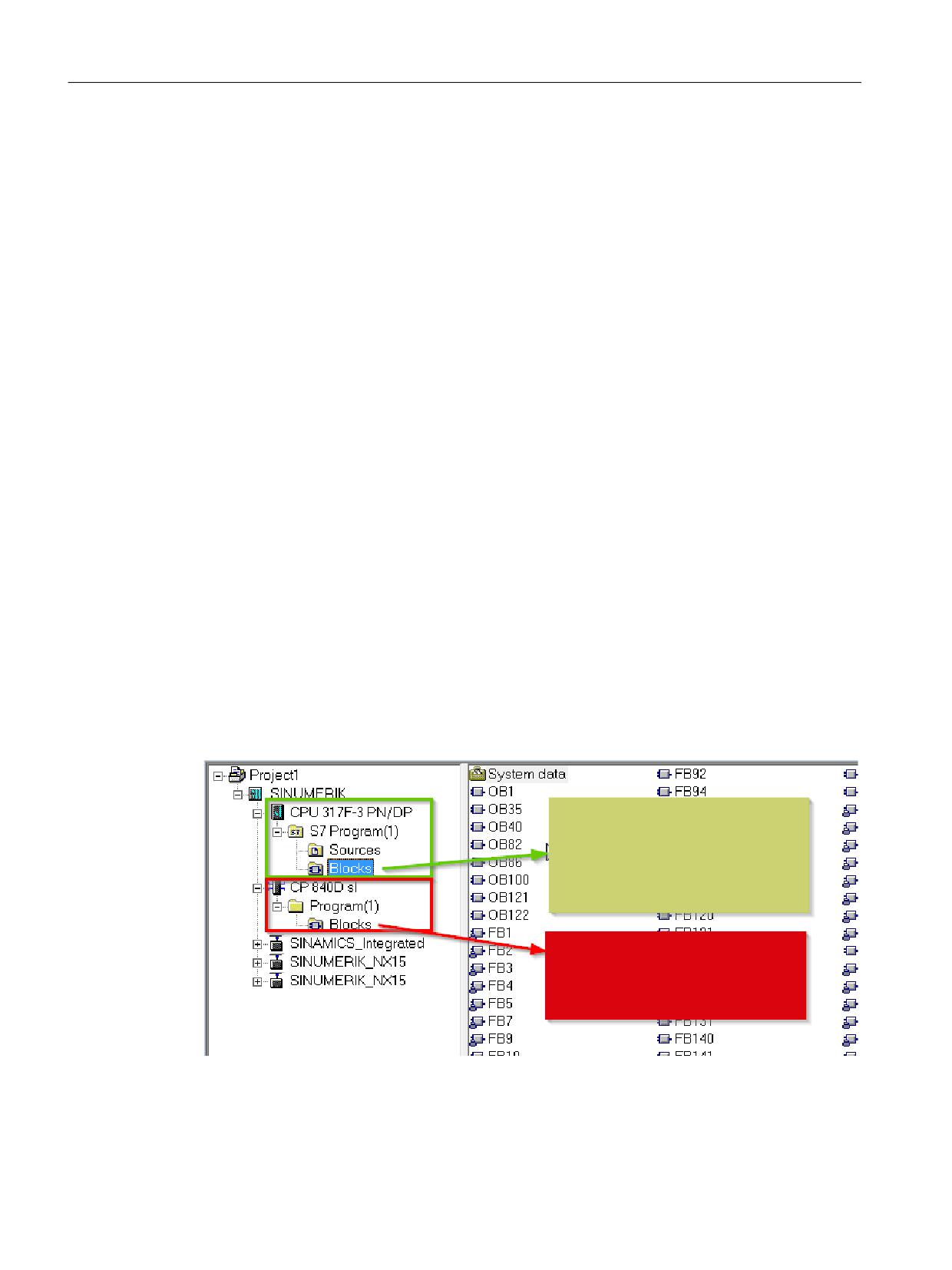
Starting up the PLC program
7.6 PLC series startup, PLC archive
The source programs of all organization blocks and all instance data blocks should always be
available.
7.6
PLC series startup, PLC archive
Once the blocks have been loaded to the PLC CPU, a series archive can be generated via the HMI
user interface to back up data on the machine. To ensure data consistency, this backup must be
created immediately after block loading when the PLC is in the Stop state. It does not replace the
SIMATIC project backup as the series archive saves binary data only. For instance, no symbolic
information is present here. In addition, no CPU DBs (SFC 22 DBs) or SDBs generated in the CPU
are saved.
Selection of the SINUMERIK archiving program
The PLC series archive can be generated directly from the SIMATIC project as an alternative:
1. In the SIMATIC Manager open dialog box "Settings": menu bar "Tools" > "Settings".
2. Open tab "Archiving".
3. In the "Preferred archiving program" drop-down list box, select the SINUMERIK archiving
program "SINUMERIK (*.arc)".
Start of the SINUMERIK archiving program
The SINUMERIK archiving program is started in the SIMATIC Manager via the menu command
"File" > "Archive".
After you have selected a project and assigned an archive name, the PLC archive is generated. If
a project contains several program paths, the S7 program for which the PLC archive will be
created can be selected in the dialog box. All blocks contained in folder "CPU ..." > ... > "Blocks"
at the selected program path are archived. Blocks in the folder "CP 840D sl" are not included in
the PLC archive:
7KH 6,180(5,. DUFKLYLQJ SURJUDP LQ WKH
6,0$7,& 0DQDJHU FUHDWHV D 3/& DUFKLYH
ZLWK WKH EORFNV ORFDWHG EHQHDWK IROGHU
&38 [[[ !
! %ORFNV
127,&(
%ORFNV ORFDWHG LQ IROGHU &3
' VO DUH
QRW LQFOXGHG LQ WKLV 3/& DUFKLYH
Data blocks that were created with SFC22 (online) in the CPU are also excluded from the archive.
The "Sdb archive" option can be activated or deactivated for the archiving program:
PLC
44
Function Manual, 10/2020, 6FC5397-0HP40-0BA1
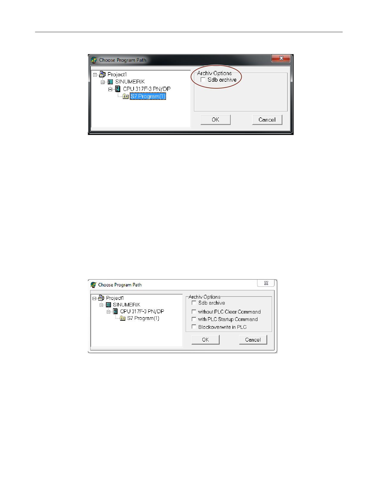
Starting up the PLC program
7.6 PLC series startup, PLC archive
If "Sdb archive" is activated, a PLC archive is created that only contains the system data blocks
(SDB) of the selected program path.
Creating application-specific PLC archives
Various archive options are available in Expert mode when creating a PLC archive.
Expert mode is activated with two parameters in the "MMCARC.INI" file:
• Parameter Option = 1
• Parameter Expert = 1
The "MMCARC.INI" file is available as standard via the path "C:\Program Files (x86)\Siemens
\Step7\S7bin\". Administrator rights are required in order to change the file.
The behavior and result when importing into the PLC varies depending on the respectively set
archive options.
The following figure shows the options for creation of a PLC archive in Expert mode:
PLC
Function Manual, 10/2020, 6FC5397-0HP40-0BA1
45

Starting up the PLC program
7.6 PLC series startup, PLC archive
PLC reload archive without overwriting
The following table displays the project with the data from which the archive is created and the
archive options to be activated:
Data in the PLC project
Archive options
• Program blocks
☑ "Without general PLC reset"
☑ "With PLC start command" (optional)
The program blocks must not exist in the PLC to be loaded.
The project must not include any system data.
Result when importing the archive:
• There is no general PLC reset.
• The program blocks are transferred.
• No blocks are overwritten.
• With the "With PLC start command" option selected, the PLC is started after loading.
PLC reload archive with overwriting
The following table displays the project with the data from which the archive is created and the
archive options to be activated:
Data in the PLC project
Archive options
• Program blocks
☑ "Overwrite block in PLC"
The project must not include any system data.
Result when importing the archive:
• There is no general PLC reset.
• The program blocks are transferred and available blocks overwritten in the PLC as necessary.
• Blocks which are only available in the PLC and not available in the archive remain unchanged.
• The PLC is always restarted after loading.
PLC hardware upgrade archive
The following table displays the project with the data from which the archive is created and the
archive options to be activated:
Data in the PLC project
Archive options
• System data
☑ "Sdb archive"
• Program blocks may be included, however, are
not transferred
PLC
46
Function Manual, 10/2020, 6FC5397-0HP40-0BA1
Starting up the PLC program
7.6 PLC series startup, PLC archive
Result when importing the archive:
• There is no general PLC reset.
• The system data is overwritten in the PLC.
• The PLC is always restarted after loading.
PLC commissioning archive
The following table displays the project with the data from which the archive is created and the
archive options to be activated:
Data in the PLC project
Archive options
• System data
☑ "With PLC start command" (optional)
• Program blocks
Result when importing the archive:
• There is a general PLC reset.
• System data and program blocks are transferred into the PLC.
• With the "With PLC start command" option selected, the PLC is started after loading.
Automation
The process of generating a series archive can be automated (comparable to the command
interface in STEP 7). In generating this series archive, the command interface is expanded.
The following functions are available for this expansion:
The functions (shown here in VB script) are not available until server instantiations and Magic
have been called:
Const S7BlockContainer = 1138689, S7PlanContainer = 17829889
Const S7SourceContainer = 1122308
set S7 = CreateObject("Simatic.Simatic.1")
rem Instantiate command interface of STEP 7
Set S7Ext = CreateObject("SimaticExt.S7ContainerExt")
Call S7Ext.Magic("")
Functions:
• Function Magic(bstrVal As String) As Long
• Function MakeSerienIB (FileName As String, Option As Long,
Container As S7Container) As Long
Description
Function Magic(bstrVal As String) As Long
PLC
Function Manual, 10/2020, 6FC5397-0HP40-0BA1
47

Starting up the PLC program
7.6 PLC series startup, PLC archive
The call provides access to certain functions. The function must be called once after server
instantiation. The value of bstrVal can be empty. This initiates a check of the correct STEP 7
version and path name in Autoexec. The functions are enabled with a return parameter of 0.
Return parameter (-1) = incorrect STEP 7 version
Return parameter (-2) = no entry in Autoexec.bat
Function MakeSerienIB(FileName As String, Option As Long, Container As S7Container) As
Long
Parameter "Option":
0:
Normal series startup file with general reset.
Bit 0 = 1:
Series startup file without general reset. When project contains SDBs, this option is
inoperative.
A general reset is then always executed.
Bit 1 = 1:
Series startup file with PLC restart
Return value:
0
= OK
-1
= Function unavailable, call Magic function beforehand
-2
= File name cannot be generated
-4
= Container parameter invalid or container block empty
-5
= Internal error (memory request rejected by Windows)
-6
= Internal error (problem in STEP 7 project)
-7
= Write error when generating series startup files (e.g. data storage medium full)
Use in script
Program code
If S7Ext.Magic("") < 0 Then
Wscript.Quit(1)
End If
Set Proj1 = s7.Projects("new")
set S7Prog = Nothing
Set s7prog = Proj1.Programs.Item(1) if there is only one program
For Each cont In s7prog.Next
If (Cont.ConcreteType = S7BlockContainer) Then
'Check block container
Exit For
End if
Cont = Nothing
Next
Error = S7Ext.MakeSerienIB("f:\dh\arc.dir\PLC.arc", 0, Cont)
'Now error analysis
PLC
48
Function Manual, 10/2020, 6FC5397-0HP40-0BA1
Starting up the PLC program
7.7 Software upgrade
The For Each ... Next block programmed above can be programmed in the Delphi
programming language as follows (The programming in the C, C++ programming languages is
similar):
Program code
Var
EnumVar: IEnumVariant;
rgvar: OleVariant;
fetched: Cardinal;
//For Each Next
EnumVar := (S7Prog.Next._NewEnum) as IEnumVariant;
While (EnumVar.Next(1,rgvar,fetched) = S_OK) Do Begin
Cont := IS7Container(IDispatch(rgvar)); // block container,
Check sources
If (Cont.ConcreteType = S7BlockContainer) Then Break;
Cont := NIL;
End;
7.7
Software upgrade
A general PLC reset should be performed to achieve a defined initial state before the PLC software
is upgraded. In this case, among other things, all user data (program and data blocks) will be
deleted. The PLC general reset is described in:
Further information:
Commissioning Manual IBN CNC: NC, PLC, Drive; section "Requirements for commissioning" >
"Power-on and startup"
Generating a new SIMATIC S7 project
In normal cases, the new PLC basic program is to be linked in for a new NCU software version.
The basic programs blocks must be loaded into the user project for this purpose. If the following
program and data blocks are already in the user project, these should not be transferred with the
blocks of the basic PLC program: OB1, OB40, OB82, OB86, OB100, FC12, and DB4. These may
have been changed by the user and should not be overwritten. The new basic program must be
linked with the user program. The following procedure must be taken into account:
1. Generate the text or source file of all user blocks before copying the basic PLC program.
2. Copy the new basic program blocks into the SIMATIC S7 project (described in Section
"Application of the basic program (Page 41)")
3. All user programs "*.awl" must be recompiled in the correct order! (See also "Machine
program (Page 43)")
4. This newly compiled SIMATIC S7 project should then be downloaded with STEP 7 into the PLC.
However, it is normally enough to recompile the organization blocks (OBs) and the instance data
blocks of the S7 project. Before upgrading, therefore, only the sources for the organization
blocks and the instance data blocks are generated.
PLC
Function Manual, 10/2020, 6FC5397-0HP40-0BA1
49
Starting up the PLC program
7.8 I/O modules (FM, CP modules)
NC variables
The latest NC VAR selector can be used for each NC software release (even older versions). The
variables can also be selected from the latest list for earlier NC software versions. The data
content in DB120 (default DB for variables) does not depend on the software version. This
means, variables selected in an older software version need not be reselected when the
software is upgraded.
7.8
I/O modules (FM, CP modules)
Additional packages for STEP 7 are generally required for more complex I/O modules (FM, CP
modules). Support blocks (FC/FB) are provided in these additional packets. The blocks contain
specific functions for operating the relevant module. These functions can be parameterized and
called in the user program.
Identical numbers
If handling and basic program blocks have identical numbers, the block numbers of the basic
program must remain unchanged. The block numbers of the handling blocks must be renamed
to free numbers via STEP 7.
PLC
50
Function Manual, 10/2020, 6FC5397-0HP40-0BA1

Starting up the PLC program
7.9 Troubleshooting
7.9
Troubleshooting
This section describes problems which may occur, their causes and remedies and should be read
carefully before hardware is replaced.
Errors, cause/description and remedy
Serial
Errors
Cause/description
To correct or avoid errors
no.
error in-
forma-
tion
1
No connec-
The MPI cable is not plugged in or
Test: Create a link with the programmer
tion via MPI to
is defective. Possibly, the STEP 7
in the STEP 7 editor by means of con-
PLC.
software is also not correctly con-
nection "Direct_PLC". A number of node
figured for the MPI card.
addresses must be displayed here. If
they do not appear, the MPI cable is de-
fective/not plugged in.
2
PLC cannot be
A system data block SDB 0 has
Disconnect all MPI cables to other com-
accessed in
been loaded with a modified MPI
ponents. Create the link "Direct_PLC"
spite of PLC
address. This has caused an MPI
with the programmer. Correct the MPI
general reset.
bus conflict due to dual assign-
address.
ment of addresses.
3
All four LEDs
A system error has occurred in the
Once the PLC program has been RESET
on the PLC
PLC.
or reloaded, the system may return to
flash (DI disas-
normal operation. Even in this case, the
Measures:
ter)
content of the diagnostic buffer should
The diagnostic buffer on the PLC
be sent to the Development Office.
must be read to analyze the sys-
tem error in detail. To access the
buffer, the PLC must be stopped
(e.g. set "PLC" switch to position
2). A hardware reset must then be
performed. The diagnostic buffer
can then be read out with STEP 7.
Relay the information from the di-
agnostic buffer to the Hotline / De-
velopment Service. A general re-
set must be carried out if reques-
ted after the hardware RESET. The
diagnostic buffer can then be read
with the PLC in the Stop state.
PLC
Function Manual, 10/2020, 6FC5397-0HP40-0BA1
51
Starting up the PLC program
7.9 Troubleshooting
PLC
52
Function Manual, 10/2020, 6FC5397-0HP40-0BA1
Coupling of the PLC CPU
8
8.1
General information
A CPU of the S7-300 automation system is used as PLC for the SINUMERIK 840D sl. The PLC-CPU
is integrated into the NCU component as a sub-module. A reference to the performance data of
the PLC CPU can be found in Section "Key data of the PLC CPU (Page 33)".
8.2
Properties of the PLC CPU
The PLC integrated in the SINUMERIK 840D sl generally has the same functionality as the
corresponding SIMATIC S7-300 PLC.
For differences, see reference in Section "Key data of the PLC CPU (Page 33)".
Owing to differences in their memory system as compared to a SIMATIC S7-300 PLC, certain
functions are not available (e.g. save blocks on memory card, save project on memory card).
Note
As with the PLC integrated in SINUMERIK, there is no automatic start of the PLC after power
failure and recovery for a SIMATIC S7-300 PLC when a "PLC stop" is triggered by an operator
action on the programming device. For safety reasons, the PLC remains in the stop state with an
appropriate diagnostic entry. You can start the PLC only by an operator action on the
programming device, "Execute a restart", or via the mode selector "Stop" > "Run" (warm restart).
8.3
Interface with integrated PLC
Physical interfaces
With the SINUMERIK 840D sl, the PLC integrated in the NCU offers the option of exchanging
signals between the NC and PLC directly via a dual-port RAM.
Data exchange with the operator panel
Data exchange with the operator panel (e.g. TCU/OP) can be performed via Ethernet or
PROFIBUS. With a connection via Ethernet, communication takes place via the integrated
communication processor (CP 840D sl).
Data exchange with the machine control panel (MCP) and handheld unit (HHU) can be
performed via MPI, PROFIBUS or Ethernet.
Programming devices should preferably be connected via Ethernet or via MPI (Multi-Point
Interface) directly to the PLC.
PLC
Function Manual, 10/2020, 6FC5397-0HP40-0BA1
53
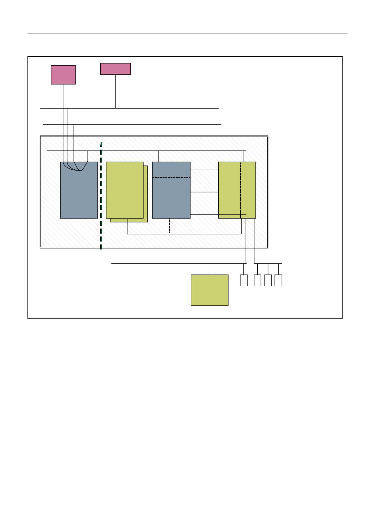
Coupling of the PLC CPU
8.3 Interface with integrated PLC
23 0&3
(6 3*
(WKHUQHW
,%1 3RUW
(WKHUQHW 3RUW
(WKHUQHW 7&3 ,3
IDFWRU\ EXV
LQWHUQDO EXV . %XV 5DFN
6
SURWRFRO
&
6
6
. %XV
6
&
(TXLYDOHQW
FRPP
&3
'ULYH
3/&
'
1&.
9',
8QLW V
VO
,QWHUIDFH
.5LVF
'3 'LUHFW
$FFHVV
,QWHUQDO YLUWXDO 352),%86
5HDO WLPH V\VWHP
6,180(5,. &RQWURO 8QLW 1&8
352),%86
03, 352),%86
([WHUQDO
'ULYH
(7
8QLW V
Figure 8-1
NC-PLC coupling on SINUMERIK 840D sl (integrated PLC)
Interface: NC/PLC
The data exchange between NC and PLC is organized by the basic program on the PLC side.
The status information, such as "Program running", stored by the NC in the NC/PLC interface is
copied to data blocks by the basic program at the beginning of the cycle (OB1) and can then be
accessed in the user program (user interface). The control signals for the NC (e.g. NC start)
entered in the interface data block by the user are also written to the internal DPR and transferred
to the NC at the start of the cycle.
Workpiece-program-specific auxiliary functions transferred to the PLC are first evaluated by the
basic program (alarmdriven) and then transferred to the user interface at the start of OB1. If the
relevant NC block contains auxiliary functions that require that NC processing is interrupted (e.g.
M06 for tool change), the basic program stops the decoding of the NC block initially for one PLC
cycle. The user can then use the "read disable" interface signal to halt the block execution until
the tool change has been completed. If, on the other hand, the relevant NC block only contains
auxiliary functions, which do not require interruption of the decoding (e.g. M08 for cooling
PLC
54
Function Manual, 10/2020, 6FC5397-0HP40-0BA1
Coupling of the PLC CPU
8.4 Diagnostic buffer on PLC
medium on), the transfer of these "fast" auxiliary functions is directly acknowledged in OB40, so
that decoding is only insignificantly influenced by the transfer to the PLC.
The evaluation and enabling of the G commands transferred from the NC are also alarm-driven
and acknowledged, however they are transferred directly to the user interface. If a G command
is evaluated at several points in the PLC program, differences in the information of the G
command within one PLC cycle may arise.
In the case of NC actions triggered and assigned with parameters by the PLC (e.g. traverse
concurrent axes), triggering and parameter assignment is performed using FCs and FBs, not
interface data blocks. The FCs and FBs belonging to the actions are supplied together with the
basic program. The FCs and FBs required must be loaded by the user and called in the PLC
program of the machine manufacturer (machine program). For an overview of FC, FB and data
blocks, sorted according to basic and extended functions, please refer to Section "Start-up of PLC
programs".
Interface: HMI/PLC
HMI/PLC data exchange is performed via the integrated CP, whereby the HMI is always the active
partner (client) and the PLC is always the passive partner (server). Data transferred or requested
by the HMI is read from and written to the HMI/PLC interface area by the PLC operating system
(timing: Cycle control point). From the viewpoint of the PLC application, the data is identical to
I/O signals.
Interface: MCP/PLC or HHU/PLC (connection: Ethernet)
MCP/PLC and HHU (HT 2) / PLC data is exchanged via the integrated CP. The CP transfers the MCP/
HHU signals to and fetches them from the PLC's internal DPR (Dual-Port RAM). On the PLC side,
the basic program handles communication with the user interface. The basic-program
parameters (FB1, DB7) define the operand areas (e.g. I/O areas) and the start addresses.
Interface: MCP/PLC (connection: PROFIBUS)
MCP/PLC data exchange takes place via the PLC's PROFIBUS. The MCP's I/O addresses are to be
placed in the PLC's process image area and via HW configuration in STEP 7. The MCP*In,
MCP*Out pointer variables must be set to the same addresses. The selected DP slave number
must be entered in MCP*BusAdr.
Interface: HHU/PLC (connection: MPI)
The HHU/PLC data exchange is performed via the MPI interface on the PLC. The "Communication
with global data (GD)" service is used for this purpose (see also STEP 7 User Manual). The PLC
operating system handles the transfer of signals from and to the user interface. The STEP 7
"Communication configuration" configuring tool is used to define both GD parameters as well as
operand areas (e.g. I/O areas) and their start addresses.
8.4
Diagnostic buffer on PLC
The diagnostic buffer of the PLC (readable using STEP 7) will enter diagnostic information on the
PLC operating system.
PLC
Function Manual, 10/2020, 6FC5397-0HP40-0BA1
55
Coupling of the PLC CPU
8.4 Diagnostic buffer on PLC
PLC
56
Function Manual, 10/2020, 6FC5397-0HP40-0BA1
Interface structure
9
9.1
Interface
Interface DBs
Mapping in interface DBs is necessary due to the large number of signals exchanged between
the NC and PLC. These are global DBs from the viewpoint of the PLC program.
9.2
PLC/NCK interface
General
The PLC/NC interface comprises a data interface on one side and a function interface on the
other. The data interface contains status and control signals, auxiliary and G commands, while
the function interface is used to transfer jobs from the PLC to the NC.
Data interface
The data interface is subdivided into the following groups:
• NC-specific signals
• Mode-group-specific signals
• Channel-specific signals
• Axis/spindle/drive-specific signals
PLC
Function Manual, 10/2020, 6FC5397-0HP40-0BA1
57
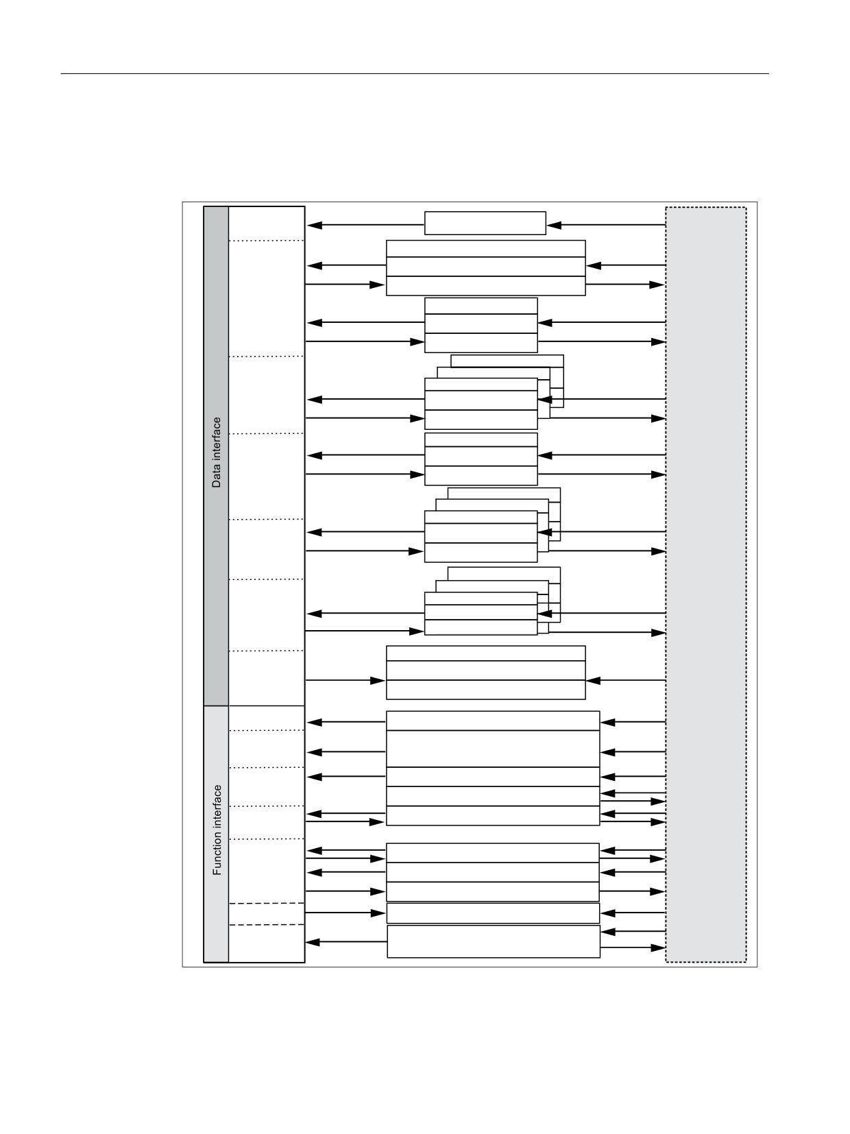
Interface structure
9.2 PLC/NCK interface
Function interface
The function interface is formed by FBs and FCs. The figure below illustrates the general
structure of the interface between the PLC and the NC.
'%
+0,
0HVVDJHV
1&
'%
6LJQDOV WR 1&. FRPSLOH F\FOHV
1&
6LJQDOV IURP 1&. FRPSLOH F\FOHV
'%
1&
6LJQDOV WR 1&
6LJQDOV IURP 1&
0RGH JURXS
'%
0RGH JURXS
'%
0RGH JURXS
%$*
6LJQDOV WR PRGH JURXS
6LJQDOV IURP PRGH JURXS
'%
+0,
+0,
6LJQDOV WR +0,
6LJQDOV IURP +0,
3/& XVHU
SURJUDP
'%
&KDQQHO
'%
&KDQQHO
'%
&KDQQHO
6LJQDOV WR FKDQQHO
1& FKDQQHO
6LJQDOV IURP FKDQQHO
'%
$[LV VSLQGOH
'%
$[LV VSLQGOH
$[LV
'%
$[LV VSLQGOH
VSLQGOH
6LJQDOV WR D[LV
GULYH
6LJQDOV IURP D[LV
'%
7RRO PDQDJHPHQW
7RRO
-RE IRU ORDG XQORDG ORFDWLRQ
PDQDJHPHQW
-RE IRU VSLQGOH DQG WXUUHW
)&
1& FKDQQHO
6WDUW $68%
$[LV
6WDUW FRPSHWLQJ D[LV VSLQGOH
VSLQGOH
3RVLWLRQLQJ D[LV LQGH[LQJ D[LV
7RRO
$FNQRZOHGJPHQW IRU WRRO PDQDJHPHQW
PDQDJHPHQW
'LUHFWLRQ VHOHFWLRQ IRU WRRO PDJD]LQH
6WDU Z\H GHOWD VZLWFKRYHU
'ULYH
)%
5HDG ZULWH 1&. YDULDEOH
1&
3, VHUYLFHV
5HDG *8'
+0,
0 WR 1
6, UHOD\ EUDNH WHVW
6DIHW\
,QWHJUDWHG
Figure 9-1
PLC-NC user interface
PLC
58
Function Manual, 10/2020, 6FC5397-0HP40-0BA1

Interface structure
9.2 PLC/NCK interface
Compile cycle signals
The user has the option of defining compile-cycle data for exchanging with the PLC. A data block
(DB9) with the following properties must be created as the PLC user interface for compile cycles:
Data block number:
9
Data block name:
freely selectable
Optimized block access:
no
Minimum size:
Sum of the input bytes and output bytes for compile cycles
($MN_CC_VDI_IN_DATA + $MN_CC_VDI_OUT_DATA)
The associated signals, which are dependent on the compile cycles, are transmitted cyclically at
the start of OB1. First, signals are transferred from the PLC to the NC, then from the NC to the PLC.
The signals from the PLC to the NC, whose length is specified by machine data
$MN_CC_VDI_IN_DATA, are defined at the beginning of DB9. Behind that in DB9, the signals
from the NC to the PLC, whose length is specified by machine data $MN_CC_VDI_OUT_DATA, are
defined.
To enable data exchange between the NC and PLC, the user may have to synchronize the NC and
PLC as necessary, e.g. using the semaphore technique. Signal transmission is asynchronous
between NC and PLC. This means, for example, that active NC data transmission can be
interrupted by the PLC. This can mean that data is not always consistent.
PLC/NC signals
The group of signals from the PLC to NC includes:
• Signals for modifying the high-speed digital I/O signals of the NC
• Keyswitch and emergency stop signals
PLC
Function Manual, 10/2020, 6FC5397-0HP40-0BA1
59
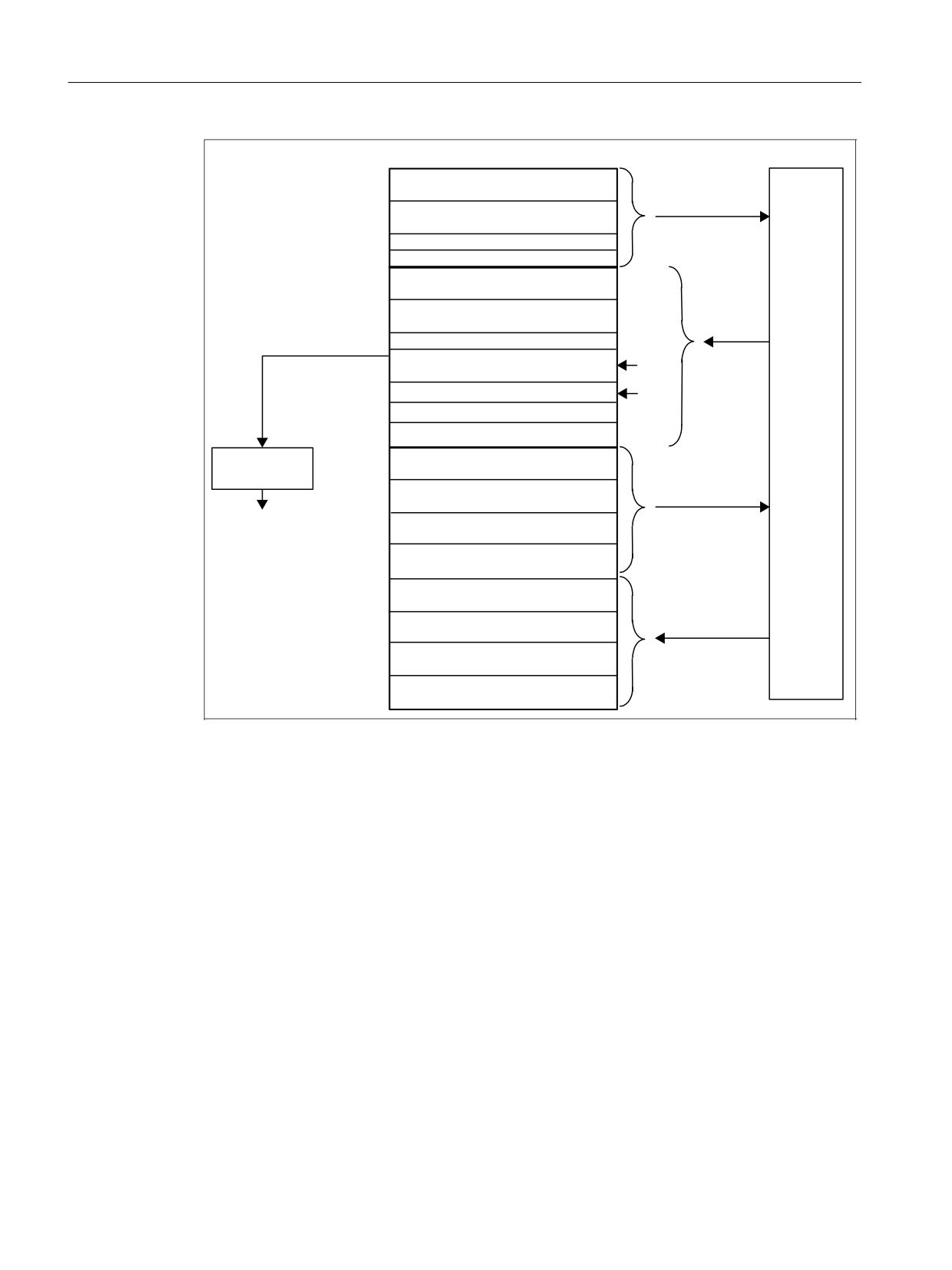
Interface structure
9.2 PLC/NCK interface
'%
%\WH
&RQWUROOLQJ GLJLWDO 1&. LQSXWV
2Q ERDUG LQSXWV
&RQWUROOLQJ GLJLWDO 1&. RXWSXWV
2Q ERDUG RXWSXWV
$[LV WDEOHV
.H\ RSHUDWHG VZLWFK HPHUJ RII
$FWXDO YDOXHV RI WKH GLJLWDO 1&. LQSXWV
2Q ERDUG LQSXWV
6HWSRLQWV RI WKH GLJLWDO 1&. RXWSXWV
2Q ERDUG RXWSXWV
9DULRXV VLJQDOV
+DQGZKHHO VHOHFWLRQ
+0,
+0, VWDWXV VLJQDOV
6WDWXV VLJQDOV RI WKH EDVLF SURJUDP
*3
6WDWXV VLJQDOV
1&.
6RIWZDUH FDPV
'HFRGLQJ
&RQWUROOLQJ GLJLWDO 1&. LQSXWV
+DQGZKHHO
([WHUQDO LQSXWV
VHOHFWLRQ
&RQWUROOLQJ GLJLWDO 1&. RXWSXWV
([WHUQDO RXWSXWV
$[LV LQWHUIDFH
&RQWUROOLQJ DQDORJ 1&. LQSXWV
*HR D[LV LQWHUIDFH LQ
([WHUQDO LQSXWV
WKH FKDQQHO
&RQWUROOLQJ DQDORJ 1&. RXWSXWV
([WHUQDO RXWSXWV
$FWXDO YDOXHV RI WKH GLJLWDO 1&. LQSXWV
([WHUQDO LQSXWV
6HWSRLQWV RI WKH GLJLWDO 1&. RXWSXWV
([WHUQDO RXWSXWV
$FWXDO YDOXHV RI WKH DQDORJ 1&. LQSXWV
([WHUQDO LQSXWV
6HWSRLQWV RI WKH DQDORJ 1&. RXWSXWV
([WHUQDO RXWSXWV
Figure 9-2
PLC/NC interface
NC/PLC signals
The group of signals from the NC to PLC includes:
• Actual values of the digital and analog I/O signals of the NC
• Ready and status signals of the NC
Also stored in this group are the HMI handwheel selection signals and the channel status signals.
The signals for handwheel selection are decoded by the basic program and entered in the
machine/axis-specific interface.
Digital/analog inputs/outputs of the NC
The following must be noted with respect to the digital and analog inputs and outputs of the NC:
PLC
60
Function Manual, 10/2020, 6FC5397-0HP40-0BA1
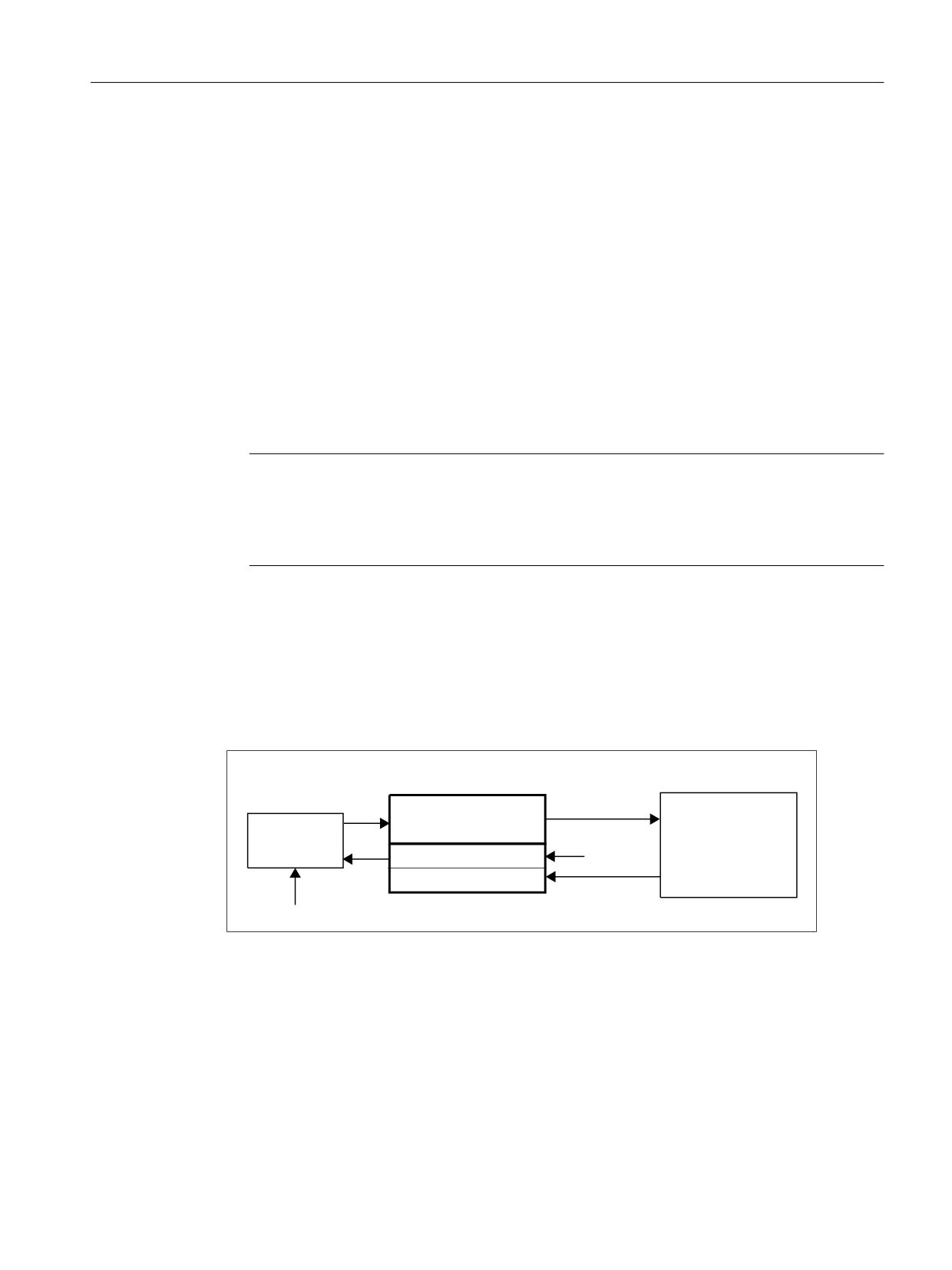
Interface structure
9.2 PLC/NCK interface
Inputs:
• All input signals or input values of the NC are also transferred to the PLC.
• The transfer of signals to the NC part program can be suppressed by the PLC. Instead, a signal
or value can be specified by the PLC.
• The PLC can also transfer a signal or value to the NC even if there is no hardware for this
channel on the NC side.
Outputs:
• All signals or values to be output are also transferred to the PLC.
• The NC can also transfer signals or values to the PLC even if there is no hardware for this
channel on the NC side.
• The values transferred by the NC can be overwritten by the PLC.
• Signals and values from the PLC can also be output directly via the NC I/O.
Note
When implementing the digital and analog NC I/O, the information contained in the
following documentation must be taken into account:
Further information
Function Manual Basic Functions; Digital and Analog NC I/O
PLC / mode group signals
The mode signals set by the machine control panel or the HMI are transferred to the operating
mode group of the NC. These apply to all NC channels. Several mode groups can be optionally
defined in the NC.
The mode group reports its current status to the PLC.
'%
%\WH
%DVLF SURJUDP
&RQWURO VLJQDOV
0RGH JURXS
0RGH VHOHFWLRQ
0RGH VHOHFWLRQ
6HOHFWLRQ VLJQDOV IURP +0,
+0,
PRGH JURXS
$FWLYH PRGH
0&3
1&.
Figure 9-3
PLC / mode group interface
PLC/NC signals
The signal groups below must be considered on the interface:
• Control/status signals
• Auxiliary commands / G commands
PLC
Function Manual, 10/2020, 6FC5397-0HP40-0BA1
61