SINUMERIK 840D sl. Service - Functions. Manual (2018-2020) - page 47
Axis monitoring functions
7.7 Working area limitation monitoring
The number of the working area limitation groups is set channel-specific in the machine data:
MD28600 $MC_MM_NUM_WORKAREA_CS_GROUPS
Maximum 10 working area limitation groups are possible per channel.
Set working area limits
The working area limits within a channel are set for each channel axis via the following system
variables:
• $P_WORKAREA_CS_LIMIT_PLUS[<WALimNo>, <Ax>]
• $P_WORKAREA_CS_LIMIT_MINUS[<WALimNo>, <Ax>]
wit <WALimNo> = Working area limitation group
h:
Value range:
0 (group 1) ... 9 (group 10)
<Ax>
= Channel axis name
Enable working area limits
The working area limits within a channel are enabled for each channel axis via the following
system variables:
• $P_WORKAREA_CS_PLUS_ENABLE[<WALimNo>, <Ax>]
• $P_WORKAREA_CS_MINUS_ENABLE[<WALimNo>, <Ax>]
wit <WALimNo> = Working area limitation group
h:
Value range:
0 (group 1) ... 9 (group 10)
<Ax>
= Channel axis name
Using the direction-specific enable, it is possible to limit the working range for an axis in just one
direction.
There is no activation through the enable.
Select reference system
The reference system for a working area limitation group within a channel is set via the following
system variable:
$P_WORKAREA_CS_COORD_SYSTEM[<WALimNo>] = <value>
wit <WALimNo> = Working area limitation group
h:
Value range:
0 (group 1) ... 9 (group 10)
Monitoring and compensating
Function Manual, 10/2020, 6FC5397-7GP40-0BA1
181

Axis monitoring functions
7.7 Working area limitation monitoring
<value>
Meaning
1
The reference system is the WCS.
3
The reference system is the SZS.
Activation of working area limits
The working area limits of a working area limitation group are activated in the part program with
the G command WALCS<n>.
wit <n> = Number of the working area limitation group
h:
Value range:
1 ... 10
Deactivation of working area limits
The working area limits of a working area limitation group active in the channel are deactivated
in the part program with the G command WALCS0.
Change working area limits
The working area limits can be changed at any time via the system variables mentioned above.
Changes take effect with the next activation of the working area limitation group (WALCSn).
Data storage
The system variables of the working area limits are stored retentively in the static memory of the
NC.
Note
For the storage of the limiting values for the linear axes, the default setting is considered for the
system of units (MD10240 $MN_SCALING_SYSTEM_IS_METRIC).
Data backup
The system variables of the working area limits can be backed up in separate files:
• _N_CHx_WAL
To save the system variable values for channel x.
• _N_COMPLETE_WAL
To save the system variable values for all channels.
Note
The system variables of the working area limits are part of the "_N_INITIAL_INI" file.
Monitoring and compensating
182
Function Manual, 10/2020, 6FC5397-7GP40-0BA1

Axis monitoring functions
7.7 Working area limitation monitoring
Behavior in JOG mode
Initial situation:
• In JOG mode, several geometry axes traverse simultaneously (e.g. using several
handwheels).
• A rotating frame is active between the basic coordinate system (BCS) and the reference
coordinate system of the working area limitation (WCS or SZS).
Behavior when a working area limitation responds:
• The traversing motions of the geometry axes that are not affected are continued.
• The affected geometry axis is stopped at the working area limit.
Setting the initial setting
The working area limitation group that is to take effect at ramp up, reset or part program end and
part program start is predefined channel-specifically via the machine data:
MD20150 $MC_GCODE_RESET_VALUE[59] = <n>
wit <n> = Number of the working area limitation group
h:
Value range:
1 ... 10
The following setting determines whether the pre-selected working area limitation acts for ramp
up and reset or part program end:
MD20152 $MC_GCODE_RESET_MODE[59] = <value>
<value>
Meaning
0
The working area group takes effect in accordance with MD20150 (default setting).
1
The last active working area group remains active.
7.7.4
Example: Working area limitation in WCS/SZS
Assumption
Channel axes
Four axes are defined in the channel:
• Linear axes: X, Y, Z
• Rotary axis: A (not modulo)
Monitoring and compensating
Function Manual, 10/2020, 6FC5397-7GP40-0BA1
183
Axis monitoring functions
7.7 Working area limitation monitoring
Requirements
Channel axes
Four axes are defined in the channel:
• Linear axes: X, Y, Z
• Rotary axis: A (not modulo)
Working area limitation groups
Three working area limitation groups should be available in the channel:
MD28600 $MC_MM_NUM_WORKAREA_CS_GROUP = 3
From these three working area limitation groups, two groups are defined in the following.
Coordinate systems
• Working area limitation group 1: Working area limitation in the adjustable zero system (AZS).
• Working area limitation group 2: Working area limitation in the workpiece coordinate system
(WCS).
Working area limitation group 1
• X axis in the plus direction: 10 mm
• X axis in the minus direction: No limitation
• Y axis in the plus direction: No limitation
• Y axis in the minus direction: 25 mm
• Z axis in the plus direction: No limitation
• Z axis in the minus direction: No limitation
• A axis in the plus direction: 10 degrees
• A axis in the minus direction: -40 degrees
Definitions via system variables in the NC program.
Program code
; Working area limitation group 1
$P_WORKAREA_CS_COORD_SYSTEM[1] = 3
; working area limitation in
the SZS
$P_WORKAREA_CS_PLUS_ENABLE[1,X] = TRUE
$P_WORKAREA_CS_LIMIT_PLUS[1,X] = 10
$P_WORKAREA_CS_MINUS_ENABLE[1,X] = FALSE
$P_WORKAREA_CS_PLUS_ENABLE[1,Y] = FALSE
$P_WORKAREA_CS_MINUS_ENABLE[1,Y] = TRUE
$P_WORKAREA_CS_LIMIT_MINUS[1,Y] = 25
$P_WORKAREA_CS_PLUS_ENABLE[1,Z] = FALSE
$P_WORKAREA_CS_MINUS_ENABLE[1,Z] = FALSE
$P_WORKAREA_CS_PLUS_ENABLE[1,A] = TRUE
Monitoring and compensating
184
Function Manual, 10/2020, 6FC5397-7GP40-0BA1
Axis monitoring functions
7.7 Working area limitation monitoring
Program code
$P_WORKAREA_CS_LIMIT_PLUS[1,A] = 10
$P_WORKAREA_CS_MINUS_ENABLE[1,A] = TRUE
$P_WORKAREA_CS_LIMIT_MINUS[1,A] = -40
Working area limitation group 2
• X axis in the plus direction: 10 mm
• X axis in the minus direction: No limitation
• Y axis in the plus direction: 34 mm
• Y axis in the minus direction: -25 mm
• Z axis in the plus direction: No limitation
• Z axis in the minus direction: -600 mm
• A axis in the plus direction: No limitation
• A axis in the minus direction: No limitation
Definitions via system variables in the NC program.
Program code
; Working area limitation group 2
$P_WORKAREA_CS_COORD_SYSTEM[2] = 1
; working area limitation in
the WCS
$P_WORKAREA_CS_PLUS_ENABLE[2,X] = TRUE
$P_WORKAREA_CS_LIMIT_PLUS[2,X] = 10
$P_WORKAREA_CS_MINUS_ENABLE[2,X] = FALSE
$P_WORKAREA_CS_PLUS_ENABLE[2,Y] = TRUE
$P_WORKAREA_CS_LIMIT_PLUS[2,Y] = 34
$P_WORKAREA_CS_MINUS_ENABLE[2,Y] = TRUE
$P_WORKAREA_CS_LIMIT_MINUS[2,Y] = -25
$P_WORKAREA_CS_PLUS_ENABLE[2,Z] = FALSE
$P_WORKAREA_CS_MINUS_ENABLE[2,Z] = TRUE
$P_WORKAREA_CS_LIMIT_PLUS[2,Z] = -600
$P_WORKAREA_CS_PLUS_ENABLE[2,A] = FALSE
$P_WORKAREA_CS_MINUS_ENABLE[2,A] = FALSE
Activation
The working area limitation groups are activated in the NC program using
command WALCS<x>, with x: Number of the working area limitation group
Monitoring and compensating
Function Manual, 10/2020, 6FC5397-7GP40-0BA1
185
Axis monitoring functions
7.8 Parking a machine axis
7.8
Parking a machine axis
If a machine axis is brought into the "Parking" state, then for this particular axis, no encoder
actual values are acquired, and all of the monitoring functions described in the preceding
sections (measuring system, standstill, clamping monitoring, etc.) are deactivated.
Activation / deactivation
Activate parking
The "Parking" function is activated for a machine axis by resetting the axis-specific NC/PLC
interface signals for the position measuring systems and the controller enable:
• DB31, ... DBX1.5 = 0 (position measuring system 1)
• DB31, ... DBX1.6 = 0 (position measuring system 2)
• DB31, ... DBX2.1 = 0 (controller enable)
The encoder status of the position measuring system of the axis is then set to "Not referenced":
• DB31, ... DBX60.4 = 0 (referenced / synchronized, position measuring system 1)
• DB31, ... DBX60.5 = 0 (referenced/synchronized, position measuring system 2)
The following further NC/PLC interface signals are also reset:
• DB31, ... DBX61.5 = 0 (position controller active)
• DB31, ... DBX61.6 = 0 (speed controller active)
• DB31, ... DBX61.7 = 0 (current controller active)
• DB31, ... DBX93.7 = 0 (pulses enabled)
• DB31, ... DBX102.5 = 0 (position measuring system 1 activated)
• DB31, ... DBX102.6 = 0 (position measuring system 2 activated)
Deactivate parking
The "Parking" function is deactivated for a machine axis by setting the axis-specific NC/PLC
interface signals for the position measuring system to be activated and the controller enable:
• DB31, ... DBX1.5 = 1 (position measuring system 1)
or
DB31, ... DBX1.6 = 1 (position measuring system 2) = 1
• DB31, ... DBX2.1 = 1 (controller enable) = 1
The position control for the machine axis becomes active again at the current position.
Monitoring and compensating
186
Function Manual, 10/2020, 6FC5397-7GP40-0BA1
Axis monitoring functions
7.8 Parking a machine axis
The encoder state of the position measuring systems depends on the measuring system type:
• Incremental position measuring system ⇒ "not referenced" state
- DB31, ... DBX60.4 = 0 (referenced / synchronized, position measuring system 1)
- DB31, ... DBX60.5 = 0 (referenced/synchronized, position measuring system 2)
• Absolute position measuring system ⇒ "referenced/synchronized" state
- DB31, ... DBX60.4 = 1 (referenced / synchronized, position measuring system 1)
- DB31, ... DBX60.5 = 1 (referenced/synchronized, position measuring system 2)
The following NC/PLC interface signals are also set again:
• DB31, ... DBX61.5 = 1 (position controller active)
• DB31, ... DBX61.6 = 1 (speed controller active)
• DB31, ... DBX61.7 = 1 (current controller active)
• DB31, ... DBX93.7 = 1 (pulses enabled)
• DB31, ... DBX102.5 = 1 (position measuring system 1 activated)
• DB31, ... DBX102.6 = 1 (position measuring system 2 activated)
Incremental position measuring systems
After deactivation of the "parking" state, incremental position measuring systems have to be
referenced before they have "referenced" encoder status.
WARNING
Incorrect synchronization of the position measuring system caused by offset of the actual
machine axis position
If changes have been made to the position measuring system during "parking" that require a
change to the parameterized machine data, for example, another encoder has been mounted,
the position measuring system must be completely remeasured and referenced See Function
Manual "Axes and Spindles", Section "R1: Referencing".
Machine axis without position measuring system
For a machine axis without a position measuring system (speed-controlled spindle), a status
equivalent to "parking" is activated by canceling the controller enable:
• DB31, ... DBX2.1 = 0 (controller enable)
Monitoring and compensating
Function Manual, 10/2020, 6FC5397-7GP40-0BA1
187
Axis monitoring functions
7.9 Parking the passive position measuring system
7.9
Parking the passive position measuring system
7.9.1
Function
Contrary to the "Parking a machine axis (Page 186)" function, for which all position measuring
systems of a machine axis are deactivated, using the "Park the passive position measuring
system" function, users have the option, of only "parking" the passive position measuring system
of a machine axis (i.e. to deactivate the encoder evaluation and monitoring in the drive and in
the control), while the active position measuring system can remain operational.
Note
For explanations regarding active/passive measuring system, see Function Manual "Axes and
Spindles", Section "Setpoint/actual value system".
Application
The "Park passive measuring system" function can, for example, be used in the following cases:
• Changing attachment heads with and without integrated encoder
Using the "Park passive position measuring system" function, it is possible to mount
attachment heads alternating with and without integrated encoder for different machining
tasks on the main spindle, without the missing encoder signals initiating drive and control
faults.
See also:
- Example: Changing an attachment head for a direct position measuring system
(Page 192)
- Example: Changing an attachment head for two direct position measuring systems
(Page 197)
• Using linear position measuring systems, which are not available over the complete
traversing range of a machine axis
Using the "Park passive position measuring system" function, it is possible to pass through the
range outside the linear position measuring system, without the missing encoder signals
initiating drive and control faults.
See also:
- "Example: Measuring system switchover when encoders are missing in certain parts of
the range (Page 201)".
Monitoring and compensating
188
Function Manual, 10/2020, 6FC5397-7GP40-0BA1
Axis monitoring functions
7.9 Parking the passive position measuring system
Activation / deactivation
Activation
The passive position measuring system of a machine axis is parked under the following
conditions:
• "Park passive position measuring system" function is active for the measuring system:
MD31046 $MA_ENC_PASSIVE_PARKING[<n>] = 1
with <n> = 0 (position measuring system 1) or 1 (position measuring system 2)
Note
MD31046 is not active:
• for axes with fewer than two encoders:
MD30200 $MA_NUM_ENCS < 2
• for simulated encoders:
MD30240 $MA_ENC_TYPE = 0
Note
For position measuring systems, which are used as motor measuring systems, the "Park
passive position measuring system" function should be deactivated (MD31046 = 0)!
and
• The user sets the following NC/PLC interface signal to "0":
DB31, ... DBX1.5 (position measuring system 1) = 0
or
DB31, ... DBX1.6 (position measuring system 2) = 0
The controller then sets the status for the activation state of the position measuring system to
"0":
DB31, ... DBX102.5 (position measuring system 1 activated) == 0
or
DB31, ... DBX102.6 (position measuring system 2 activated) == 0
The position measuring system is now no longer monitored and updated.
Deactivation
"Park" is deactivated if the user activates the position measuring system:
DB31, ... DBX1.5 (position measuring system 1) = 1
or
DB31, ... DBX1.6 (position measuring system 2) = 1
The controller then sets the status for the activation state of the position measuring system back
to "1":
DB31, ... DBX102.5 (position measuring system 1 activated) == 1
or
Monitoring and compensating
Function Manual, 10/2020, 6FC5397-7GP40-0BA1
189
Axis monitoring functions
7.9 Parking the passive position measuring system
DB31, ... DBX102.6 (position measuring system 2 activated) == 1
Note
Switching over to a parked position measuring system takes longer than to a non-parked
position measuring system. Because of the time taken, we recommend switching over while the
axes are stationary.
Position of the position measuring system
Absolute position measuring systems
For absolute position measuring systems, the position after deactivating "park" corresponds to
the actual absolute encoder position.
The position measuring system is referenced:
DB31, ... DBX60.4 (referenced/synchronized, position measuring system 1) == 1
or
DB31, ... DBX60.5 (referenced/synchronized, position measuring system 2) == 1
Incremental position measuring systems
For incremental position measuring systems, the position after deactivating "park" always
corresponds to the last deactivation position of the position measuring system.
Switching over to the parked position measuring system is only realized if the parameterized
permissible deviation between the actual values of the two position measuring systems (see
MD36500 $MA_ENC_CHANGE_TOL) is not exceeded. Otherwise, users must apply the "Park a
machine axis" function, in which case such a check is not made.
The position measuring system is not referenced:
DB31, ... DBX60.4 (referenced/synchronized, position measuring system 1) == 0
or
DB31, ... DBX60.5 (referenced/synchronized, position measuring system 2) == 0
Incremental position measuring systems with position transfer
Alternatively, for incremental position measuring systems, when the "Park passive position
measuring system" is active (MD31046 $MA_ENC_PASSIVE_PARKING[<n>] = 1) it is possible,
after deactivating "Park" to transfer the position, and where relevant, also the "Referenced"
status, from the previously active position measuring system.
For every position measuring system of a machine axis, this function can be activated using
machine data:
MD34210 $MA_ENC_REFP_STATE[<n>]
Monitoring and compensating
190
Function Manual, 10/2020, 6FC5397-7GP40-0BA1

Axis monitoring functions
7.9 Parking the passive position measuring system
with <n> = 0 (position measuring system 1) or 1 (position measuring system 2)
Value
Meaning
1
Only the position from the previous active position measuring system is transferred.
The position measuring system is not referenced:
DB31, ... DBX60.4 (referenced/synchronized, position measuring system 1) == 0
or
DB31, ... DBX60.5 (referenced/synchronized, position measuring system 2) == 0
2
Position and "Referenced" status are transferred from the previously active position measuring
system.
The position measuring system is referenced:
DB31, ... DBX60.4 (referenced/synchronized, position measuring system 1) == 1
or
DB31, ... DBX60.5 (referenced/synchronized, position measuring system 2) == 1
Note
Position and "Referenced" status of the previously active position measuring system are only
transferred for incremental position measuring systems, depending on MD34210
$MA_ENC_REFP_STATE[<n>] - and only when the "Park passive position measuring system"
function is active (MD31046 $MA_ENC_PASSIVE_PARKING[<n>] = 1).
The transferred position has the accuracy of the previous active position measuring system. The
position measuring system should be referenced if this accuracy is not adequate.
WARNING
Incorrect synchronization of the position measuring system caused by offset of the actual
machine axis position
If changes have been made to the position measuring system during "parking" that require a
change to the parameterized machine data, for example, another encoder has been mounted,
the position measuring system must be completely remeasured and referenced See Function
Manual "Axes and Spindles", Section "R1: Referencing".
7.9.2
Supplementary conditions
Interaction with "dual position feedback"
The "Park passive position measuring system" function cannot be used in conjunction with the
"dual position feedback" function (MD32960 $MA_POSCTRL_DUAL_FEEDBACK_TIME > 0).
Interaction with "position difference input"
The "Park passive position measuring system" function cannot be used in conjunction with the
"position difference input" function (MD32950 $MA_POSCTRL_DAMPING > 0).
Monitoring and compensating
Function Manual, 10/2020, 6FC5397-7GP40-0BA1
191
Axis monitoring functions
7.9 Parking the passive position measuring system
Interaction with APC (optional)
The "Park passive measuring system" function cannot be used in conjunction with the
"Advanced positioning control (APC)" drive function.
Interaction with encoder safety protection concept
Only the 1 encoder safety protection concept can be used in conjunction with the "Park passive
position measuring system" function.
Interaction when connecting and disconnecting at the DRIVE-CLiQ
If, instead of the encoder cable, the DRIVE-CLiQ cables, e.g. between the SMC and Motor Module
are unplugged and plugged, such encoders can only be unparked without fault via the "Parking
a machine axis (Page 186)" function.
7.9.3
Example: Changing an attachment head for a direct position measuring
system
Initial situation
• Attachment head "A" has an encoder E2.
• Attachment head "B" does not have an encoder.
• Spindle "SP" has an encoder E1.
• One of the following two telegram types is configured in MD13060
$MN_DRIVE_TELEGRAM_TYPE (standard telegram type for PROFIdrive):
- Telegram 116 (motor encoder + an external encoder)
or
- Telegram 136 (motor encoder + an external encoder, and torque precontrol)
• The following position measuring systems are configured in the spindle "SP":
- Motor encoder E1 as position measuring system 1
- Direct encoder E2 as position measuring system 2
• Attachment head "A" with encoder E2 is currently mounted on the spindle.
• Position measuring system 2 is the active measuring system:
DB31, ... DBX1.6 = 1
Position measuring system 1 is passive.
• The "Park passive position measuring system" function is:
- Not active for position measuring system 1:
MD31046 $MA_ENC_PASSIVE_PARKING [ 0 ] = 0
- Active for position measuring system 2:
MD31046 $MA_ENC_PASSIVE_PARKING [ 1 ] = 1
Monitoring and compensating
192
Function Manual, 10/2020, 6FC5397-7GP40-0BA1
Axis monitoring functions
7.9 Parking the passive position measuring system
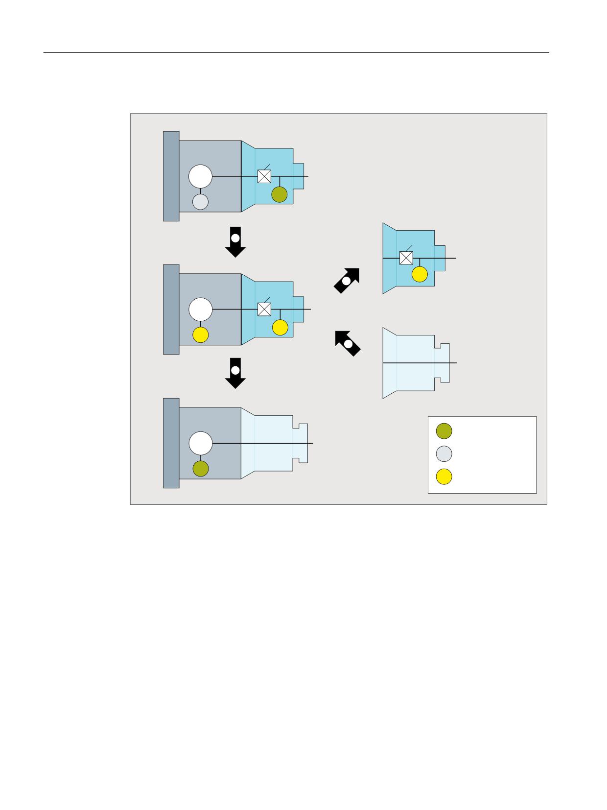
Objective
The user would like to change from attachment head "A" to attachment head "B."
Monitoring and compensating
Function Manual, 10/2020, 6FC5397-7GP40-0BA1
193
Axis monitoring functions
7.9 Parking the passive position measuring system
Execution
6SLQGOH 63
$GDSWHU KHDG $
*HDUER[
0RWRU
(
(
$GDSWHU KHDG $
*HDUER[
6SLQGOH 63
$GDSWHU KHDG $
(
*HDUER[
0RWRU
$GDSWHU KHDG %
(
(
6SLQGOH 63
$GDSWHU KHDG %
$FWLYH HQFRGHU
0RWRU
3DVVLYH HQFRGHU
(
3DUNHG HQFRGHU
① Before changing an attachment head, the user must deactivate all position measuring systems of
the machine axis using the "Parking a machine axis (Page 186)" function:
DB31, ... DBX1.5 (position measuring system 1) = 0
DB31, ... DBX1.6 (position measuring system 2) = 0
The controller then resets the status signals for the position measuring systems:
DB31, ... DBX102.5 (position measuring system 1 activated) == 0
DB31, ... DBX102.6 (position measuring system 2 activated) == 0
② The user waits for the status signals and only now removes the attachment head "A" from the
spindle. This electrically disconnects the encoder cable between the attachment head "A" and
coupling. The absence of encoder E2 does not generate any NC or drive faults.
Monitoring and compensating
194
Function Manual, 10/2020, 6FC5397-7GP40-0BA1
Axis monitoring functions
7.9 Parking the passive position measuring system
③ Attachment head "B" is now mounted on the spindle.
④ The user only activates position measuring system 1:
DB31, ... DBX1.5 (position measuring system 1) = 1
The control then sets the status signal:
DB31, ... DBX102.5 (position measuring system 1 activated) == 1
The "Park passive position measuring system" function is active for position measuring system 2.
This means that position measuring system 2 does not become passive, but remains in the "Park"
state.
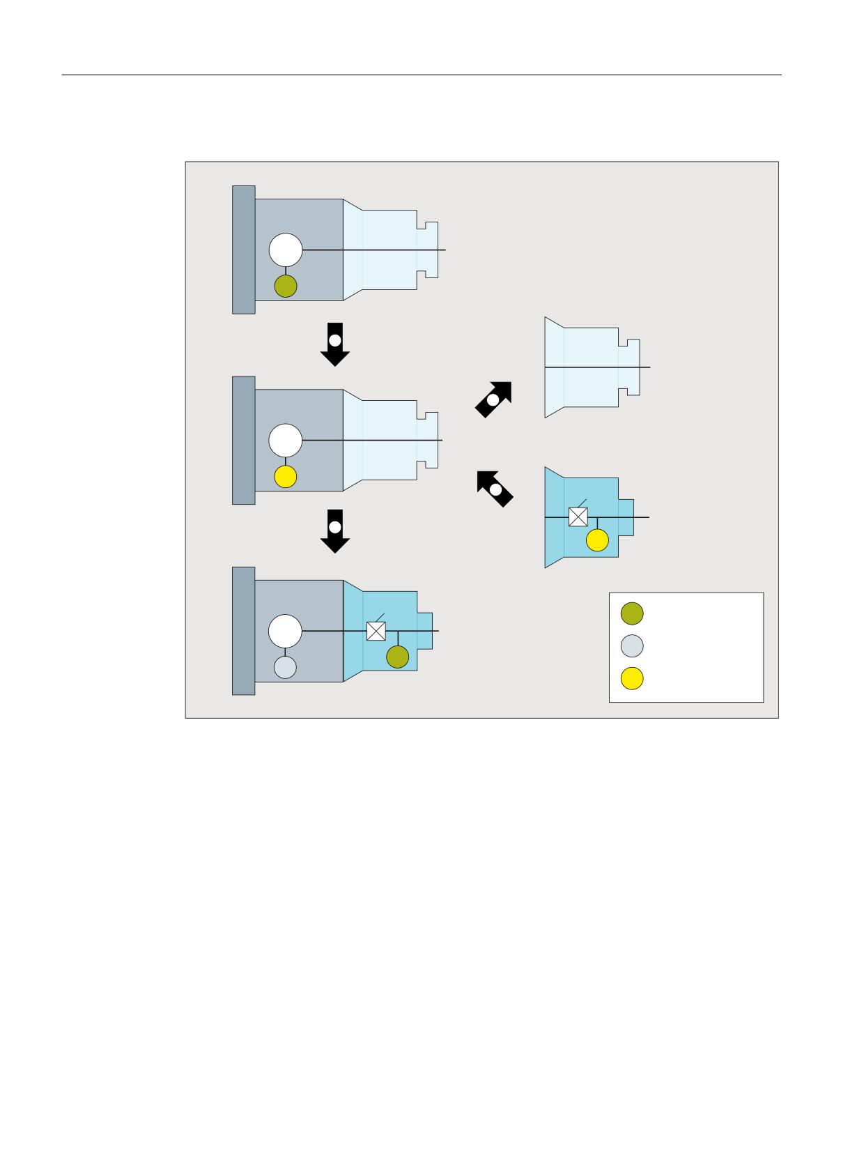
Objective
The user now wishes to remount attachment head "A" again.
Monitoring and compensating
Function Manual, 10/2020, 6FC5397-7GP40-0BA1
195
Axis monitoring functions
7.9 Parking the passive position measuring system
Execution
6SLQGOH 63
$GDSWHU KHDG %
0RWRU
(
$GDSWHU KHDG %
6SLQGOH 63
$GDSWHU KHDG %
0RWRU
$GDSWHU KHDG $
(
*HDUER[
(
6SLQGOH 63
$GDSWHU KHDG $
*HDUER[
$FWLYH HQFRGHU
0RWRU
3DVVLYH HQFRGHU
(
(
3DUNHG HQFRGHU
① Using the "Park machine axis" function, the user deactivates position measuring system 1:
DB31, ... DBX1.5 (position measuring system 1) = 0
The controller then resets the status signal for the position measuring system:
DB31, ... DBX102.5 (position measuring system 1 activated) == 0
② The user waits for the status signal and only now removes the attachment head "B" from the
spindle.
③ Attachment head "A" is now mounted on the spindle.
④ The user activates position measuring system 2:
DB31, ... DBX1.6 (position measuring system 2) = 1
As a consequence, position measuring system 1 is also simultaneously activated; This is because
the "Park passive position measuring system" function is not active for position measuring system
1 (motor measuring system!). Position measuring system 1 becomes a passive position measuring
system.
The controller then sets the status signals for the position measuring systems:
DB31, ... DBX102.5 (position measuring system 1 activated) == 1
DB31, ... DBX102.6 (position measuring system 2 activated) == 1
Monitoring and compensating
196
Function Manual, 10/2020, 6FC5397-7GP40-0BA1
Axis monitoring functions
7.9 Parking the passive position measuring system
7.9.4
Example: Changing an attachment head for two direct position measuring
systems
Initial situation
•
Attachment head "A" has an encoder E3.
•
Attachment head "B" does not have an encoder.
•
Spindle "SP" has two encoders E1 and E2.
•
One of the following two telegram types is configured in MD13060
$MN_DRIVE_TELEGRAM_TYPE (standard telegram type for PROFIdrive):
- Telegram 118 (two external encoders)
or
- Telegram 138 (two external encoders, plus torque precontrol)
Further information:
Information regarding encoder assignment, see:
Commissioning Manual CNC Commissioning: NC, PLC, drive; Communication between NC
and drive > Drives: Assign axis
•
The following position measuring systems are configured in the spindle "SP":
- Direct encoder E2 as position measuring system 1
- Direct encoder E3 as position measuring system 2
•
Attachment head "A" with encoder E3 is currently mounted on the spindle.
•
Position measuring system 2 is the active measuring system:
DB31, ... DBX1.6 = 1
Position measuring system 1 is passive.
•
The "Park passive position measuring system" function is:
- Not active for position measuring system 1:
MD31046 $MA_ENC_PASSIVE_PARKING [ 0 ] = 0
- Active for position measuring system 2:
MD31046 $MA_ENC_PASSIVE_PARKING [ 1 ] = 1
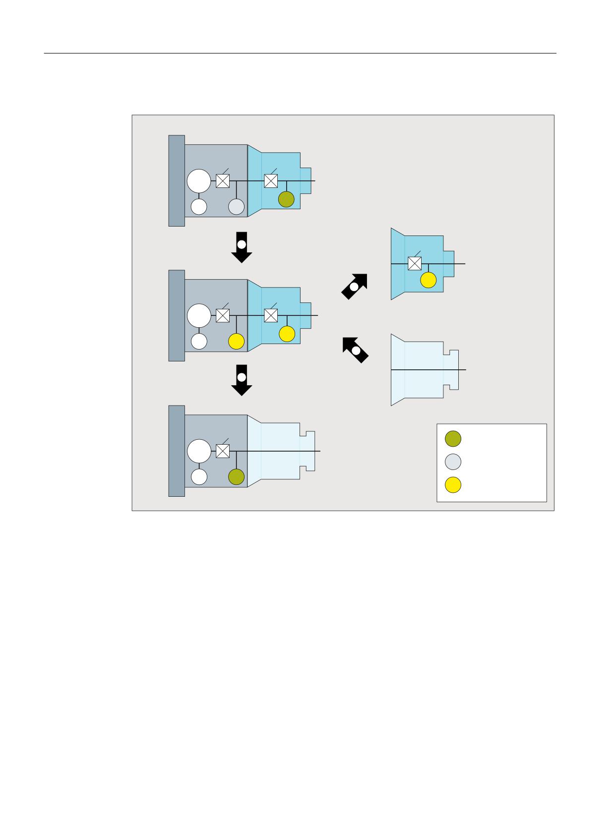
Objective
The user would like to change from attachment head "A" to attachment head "B."
Monitoring and compensating
Function Manual, 10/2020, 6FC5397-7GP40-0BA1
197
Axis monitoring functions
7.9 Parking the passive position measuring system
Execution
6SLQGOH 63
$GDSWHU KHDG $
*HDUER[
*HDUER[
0RWRU
(
(
(
$GDSWHU KHDG $
*HDUER[
6SLQGOH 63
$GDSWHU KHDG $
(
*HDUER[
*HDUER[
0RWRU
(
$GDSWHU KHDG %
(
(
6SLQGOH 63
$GDSWHU KHDG %
*HDUER[
$FWLYH HQFRGHU
0RWRU
3DVVLYH HQFRGHU
(
(
3DUNHG HQFRGHU
① Before changing an attachment head, the user must deactivate all position measuring systems of
the machine axis using the "Parking a machine axis (Page 186)" function:
DB31, ... DBX1.5 (position measuring system 1) = 0
DB31, ... DBX1.6 (position measuring system 2) = 0
The controller then resets the status signals for the position measuring systems:
DB31, ... DBX102.5 (position measuring system 1 activated) == 0
DB31, ... DBX102.6 (position measuring system 2 activated) == 0
② The user waits for the status signals and only now removes the attachment head "A" from the
spindle. This electrically disconnects the encoder cable between the attachment head "A" and
coupling. The absence of encoder E3 does not generate any NC or drive faults.
Monitoring and compensating
198
Function Manual, 10/2020, 6FC5397-7GP40-0BA1
Axis monitoring functions
7.9 Parking the passive position measuring system
③ Attachment head "B" is now mounted on the spindle.
④ The user only activates position measuring system 1:
DB31, ... DBX1.5 (position measuring system 1) = 1
The control sets the status signal:
DB31, ... DBX102.5 (position measuring system 1 activated) == 1
The "Park passive position measuring system" function is active for position measuring system 2.
This means that position measuring system 2 does not become passive, but remains in the "Park"
state.
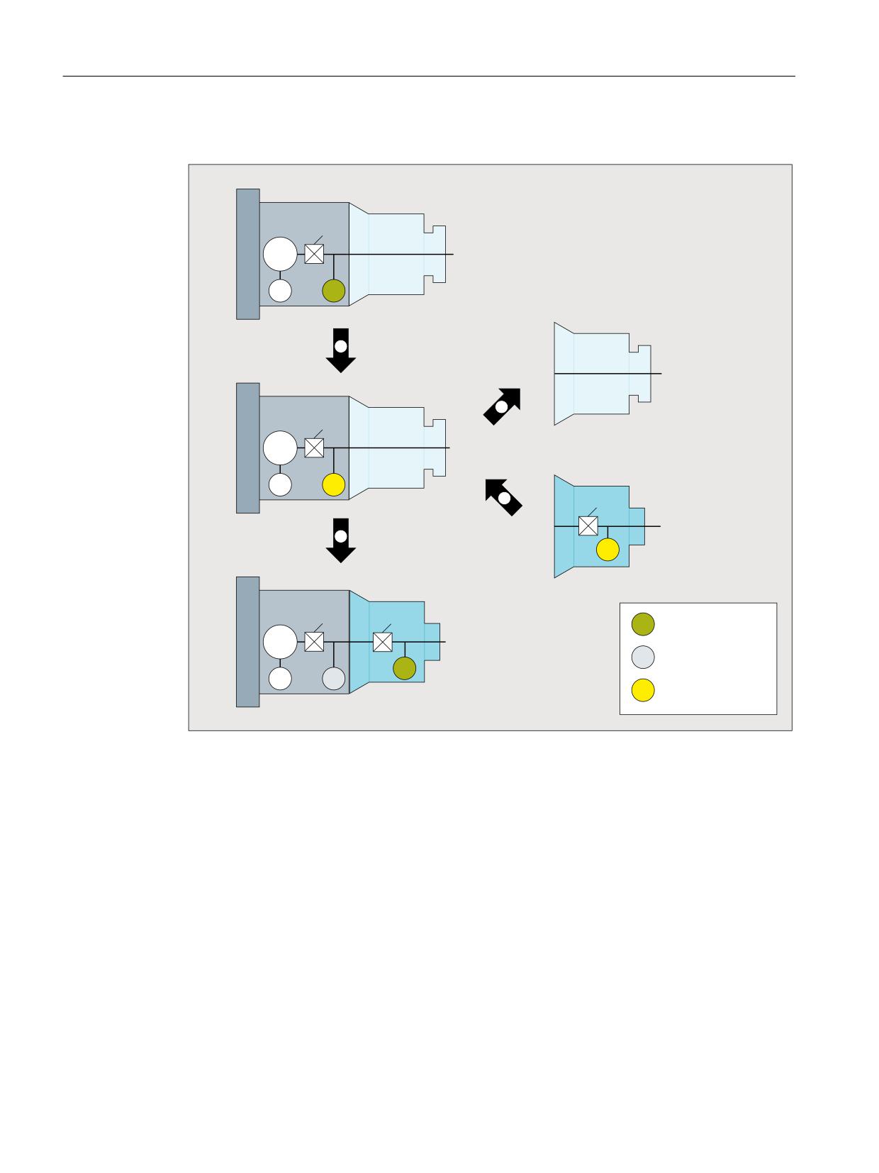
Objective
The user now wishes to remount attachment head "A" again.
Monitoring and compensating
Function Manual, 10/2020, 6FC5397-7GP40-0BA1
199
Axis monitoring functions
7.9 Parking the passive position measuring system
Execution
6SLQGOH 63
$GDSWHU KHDG %
*HDUER[
0RWRU
(
(
$GDSWHU KHDG %
6SLQGOH 63
$GDSWHU KHDG %
*HDUER[
0RWRU
$GDSWHU KHDG $
(
(
*HDUER[
(
6SLQGOH 63
$GDSWHU KHDG $
*HDUER[
*HDUER[
$FWLYH HQFRGHU
0RWRU
3DVVLYH HQFRGHU
(
(
(
3DUNHG HQFRGHU
① Using the "Park machine axis" function, the user deactivates position measuring system 1:
DB31, ... DBX1.5 (position measuring system 1) = 0
The controller then resets the status signal for the position measuring system:
DB31, ... DBX102.5 (position measuring system 1 activated) == 0
② The user waits for the status signal and only now removes the attachment head "B" from the
spindle.
③ Attachment head "A" is now mounted on the spindle.
④ The user activates position measuring system 2:
DB31, ... DBX1.6 (position measuring system 2) = 1
As a consequence, position measuring system 1 is also simultaneously activated; This is because
the "Park passive position measuring system" function is not active for position measuring system
1. Position measuring system 1 becomes a passive position measuring system.
The controller then sets the status signals for the position measuring systems:
DB31, ... DBX102.5 (position measuring system 1 activated) == 1
DB31, ... DBX102.6 (position measuring system 2 activated) == 1
Monitoring and compensating
200
Function Manual, 10/2020, 6FC5397-7GP40-0BA1
Axis monitoring functions
7.9 Parking the passive position measuring system
7.9.5
Example: Measuring system switchover when encoders are missing in certain
parts of the range
In the following example, the direct linear position measuring system is only available in the
machining zones, while only the motor measuring system is available outside the machining
zones.
Initial situation
•
Linear axis "X" has two incremental encoders:
- Motor encoder E1
- Direct linear encoder E2
•
Direct linear encoder E2 is only available in the machining range.
•
One of the following two telegram types is configured in MD13060
$MN_DRIVE_TELEGRAM_TYPE (standard telegram type for PROFIdrive):
- Telegram 116 (motor encoder + an external encoder)
or
- Telegram 136 (motor encoder + an external encoder, and torque precontrol)
•
The following position measuring systems are configured for the machine axis:
- Motor encoder E1 as position measuring system 1
- Direct linear encoder E2 as position measuring system 2
•
When the machine is switched on, the user activates both position measuring systems:
- DB31, ... DBX1.5 (position measuring system 1) = 1
- DB31, ... DBX1.6 (position measuring system 2) = 1
When both position measuring systems are simultaneously activated, then the control
selects position measuring system 1 as active position measuring system.
•
Position measuring system 2 is selected for machining:
- DB31, ... DBX1.5 (position measuring system 1) = 0
- DB31, ... DBX1.6 (position measuring system 2) = 1
•
The "Park passive position measuring system" function is:
- Not active for position measuring system 1:
MD31046 $MA_ENC_PASSIVE_PARKING [ 0 ] = 0
- Active for position measuring system 2:
MD31046 $MA_ENC_PASSIVE_PARKING [ 1 ] = 1
•
Transfer of the position and the "referenced" status is activated for position measuring
system 2:
MD34210 $MA_ENC_REFP_STATE[ 1 ] = 2
Monitoring and compensating
Function Manual, 10/2020, 6FC5397-7GP40-0BA1
201
Axis monitoring functions
7.9 Parking the passive position measuring system
Objective
When passing through the range outside linear position measuring system E2, the missing
encoder signals should not initiate any faults in the drive and in the control.
Monitoring and compensating
202
Function Manual, 10/2020, 6FC5397-7GP40-0BA1
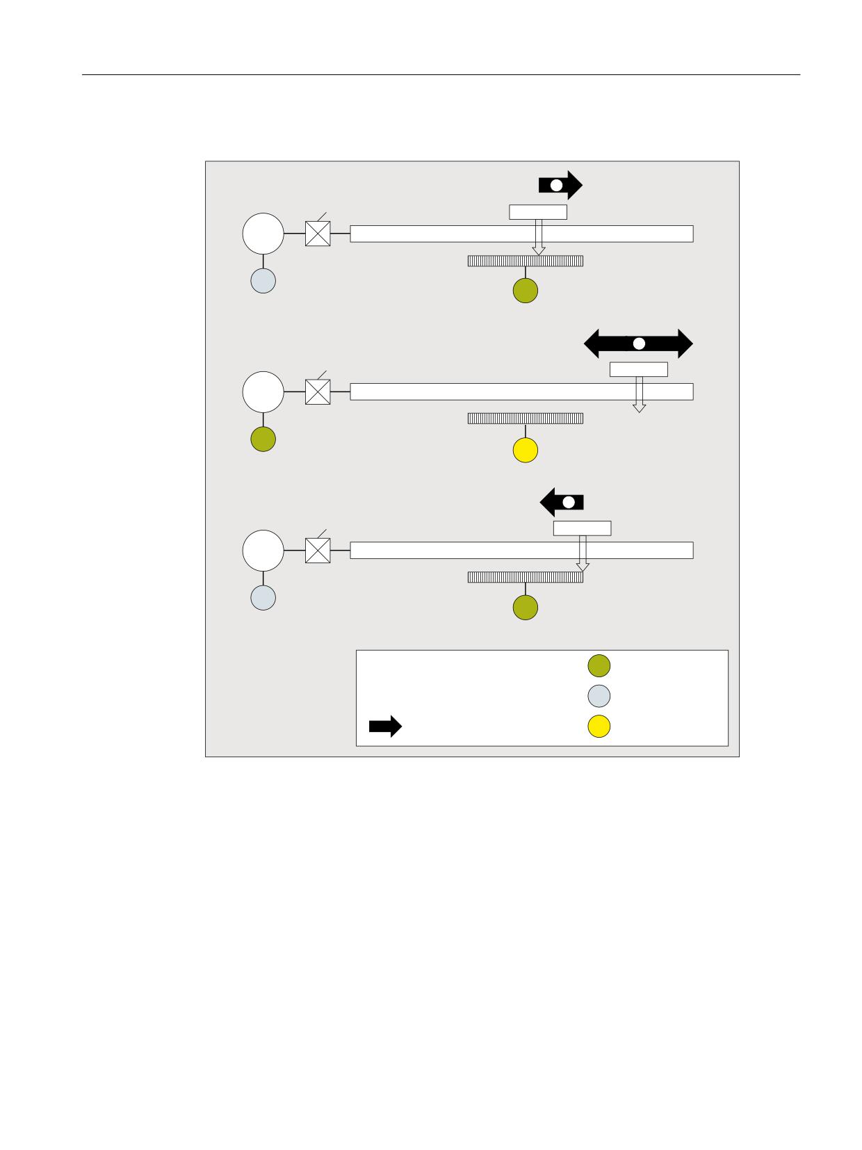
Axis monitoring functions
7.9 Parking the passive position measuring system
Execution
*HDUER[
7DEOH
0RWRU
%DOO VFUHZ
/LQHDU VFDOH
(
(
*HDUER[
7DEOH
0RWRU
%DOO VFUHZ
/LQHDU VFDOH
(
(
*HDUER[
7DEOH
0RWRU
%DOO VFUHZ
/LQHDU VFDOH
(
(
(
0RWRU HQFRGHU
$FWLYH HQFRGHU
(
'LUHFW OLQHDU HQFRGHU
3DVVLYH HQFRGHU
7UDYHUVLQJ PRWLRQ
3DUNHG HQFRGHU
① Before the table reaches the end of the linear position measuring system, a switchover must be
made to the motor measuring system. The user does this by activating both position measuring
systems:
DB31, ... DBX1.5 (position measuring system 1) = 1
DB31, ... DBX1.6 (position measuring system 2) = 1
Using the "Park passive position measuring system" function, the linear position measuring sys-
tem, which is passive after the measuring system switchover, is parked by the control.
The control resets the status signal:
DB31, ... DBX102.6 (position measuring system 2 activated) == 0
The user waits for the status signal before continuing to traverse in the range outside the linear
position measuring system.
② Traversing through the range outside the linear position measuring system with the motor meas-
uring system.
Monitoring and compensating
Function Manual, 10/2020, 6FC5397-7GP40-0BA1
203
Axis monitoring functions
7.10 Switching over encoder data sets
③ If the table returns to the linear position measuring system range, at standstill, the user switches
from the motor measuring system to the linear position measuring system:
DB31, ... DBX1.5 (position measuring system 1) = 0
DB31, ... DBX1.6 (position measuring system 2) = 1
The control sets the status signal:
DB31, ... DBX102.6 (position measuring system 2 activated) == 1
The motor measuring system becomes a passive position measuring system.
Result
Both position measuring systems are referenced. The position of the linear position measuring
system corresponds to the position of the motor measuring system at the switchover instant.
The linear position measuring system must be rereferenced if the position accuracy is not
sufficient.
7.10
Switching over encoder data sets
Application
Different attachment heads may be used in succession on one and the same power unit in order
to perform different machining tasks.
One motor data set (MDS) and one encoder data set (EDS) must be programmed for each
attachment head that is equipped with a motor or an encoder. These data sets must be switched
over in the PLC program whenever the attachment head is changed. An MDS/EDS switchover can
only be implemented indirectly in this regard via switchover of the drive data set (DDS).
Function
NOTICE
Machine damage
If the following drive parameters and machine data have different settings, the axis might not
traverse at the programmed speed or to the programmed position.
The machine data must be changed simultaneously and consistently with encoder data
switchover in the parked state.
Encoder data switchover in the control is limited to the following SINAMICS drive parameters.
• p0408 (rotary encoder pulse number)
• p0418 (fine resolution of encoder emulation Gx_XIST1 (in bits))
• p0419 (fine resolution absolute value Gx_XIST2 (in bits))
With these parameters, it is possible to switch over encoder data sets with the same encoder type
but a different number of encoder pulses.
Switchover in the control is activated in the following machine data:
Monitoring and compensating
204
Function Manual, 10/2020, 6FC5397-7GP40-0BA1

Axis monitoring functions
7.10 Switching over encoder data sets
MD31700 $MA_ENC_EDS_ACTIVE (activate EDS use)
Value
Meaning
0
Encoder data set switchover EDS is not used.
1.
Encoder data set switchover EDS is used.
A machine data item is provided for each of the drive parameters p0408, p0418, and p0419,
which must be parameterized in accordance with the active encoder data set:
• MD31710 $MA_ENC_RESOL_EDS (encoder pulses per revolution for EDS use)
• MD31720 $MA_ENC_PULSE_MULT_EDS (encoder multiplication (high resolution) for EDS
use)
• MD31730 $MA_ABS_INC_RATIO_EDS (absolute encoder: ratio between absolute resolution
and incremental resolution for EDS use)
Effectiveness
If MD31700 $MA_ENC_EDS_ACTIVE = 1, the following machine data no longer take effect:
• MD30260 $MA_ABS_INC_RATIO (absolute encoder: ratio between absolute resolution and
incremental resolution)
• MD31020 $MA_ENC_RESOL (encoder pulses per revolution)
• MD31025 $MA_ENC_PULSE_MULT (encoder multiplication (high resolution))
The drive data switchover in DB3x.DBX21.0 - 4 also switches over the encoder data sets.
Switchover is performed in the parked state (see chapters "Parking a machine axis (Page 186)"
and "Parking the passive position measuring system (Page 188)").
Note
If MD31700 $MA_ENC_EDS_ACTIVE = 1, no plausibility check between the values set in the drive
and control is performed.
NC/PLC interface signal:
• DB31, ... DBX21.7 (pulse enable)
• DB31, ... DBX21.6 (integrator inhibit, speed controller)
• DB31, ... DBX21.5 (motor selection)
• DB31, ... DBX21.0 - 4 (request for switchover of a motor and/or drive data set)
The interface can be flexibly parameterized using: DB31,
DBX130.0 - 4
Supplementary conditions
SINUMERIK supplementary conditions:
• Only machine data for rotary encoders are available.
• Traversing range extension for absolute-value encoders
MD30270 $MA_ENC_ABS_BUFFERING = 0 is not permissible.
Monitoring and compensating
Function Manual, 10/2020, 6FC5397-7GP40-0BA1
205

Axis monitoring functions
7.11 Data lists
Further information
Function Manual SINAMICS S120 Drive Functions;
Basic information about the drive system > Data sets
• DDS: Drive data set
• EDS: Encoder data set
Other machine data
In addition to the machine data of the axis monitoring function, the following additional
machine data should be set or checked:
All machine axes
• MD31030 $MA_LEADSCREW_PITCH (leadscrew pitch)
• MD31050 $MA_DRIVE_AX_RATIO_DENOM (denominator load gearbox)
• MD31060 $MA_DRIVE_AX_RATIO_NUMERA (numerator load gearbox)
• MD31070 $MA_DRIVE_ENC_RATIO_DENOM (denominator measuring gearbox)
• MD31080 $MA_DRIVE_ENC_RATIO_NUMERA (numerator measuring gearbox)
• MD32810 $MA_EQUIV_SPEEDCTRL_TIME (equivalent time constant speed control loop for
feedforward control)
• Encoder resolution: see Function Manual "Axes and Spindles", Section "G2: Velocities,
setpoint/actual value systems, closed-loop control".
Machine axes with analog speed setpoint interface
• MD32260 $MA_RATED_VELO (rated motor speed)
• MD32250 $MA_RATED_OUTVAL (rated output voltage)
7.11
Data lists
7.11.1
Machine data
7.11.1.1
NC-specific machine data
Number
Identifier: $MN_
Description
10604
WALIM_GEOAX_CHANGE_MODE
Working area limitation during switchover of geometry
axes
10710
PROG_SD_RESET_SAVE_TAB
Setting data to be updated
Monitoring and compensating
206
Function Manual, 10/2020, 6FC5397-7GP40-0BA1

Axis monitoring functions
7.11 Data lists
7.11.1.2
Channelspecific machine data
Number
Identifier: $MC_
Description
20150
GCODE_RESET_VALUES
Initial setting of the G groups
21020
WORKAREA_WITH_TOOL_RADIUS
Allowance for tool radius with working area limitation
24130
TRAFO_INCLUDES_TOOL_1
Tool handling with active 1st transformation
24230
TRAFO_INCLUDES_TOOL_2
Tool handling with active 2nd transformation
24330
TRAFO_INCLUDES_TOOL_3
Tool handling with active 3rd transformation
24426
TRAFO_INCLUDES_TOOL_4
Tool handling with active 4th transformation
24436
TRAFO_INCLUDES_TOOL_5
Tool handling with active 5th transformation
24446
TRAFO_INCLUDES_TOOL_6
Tool handling with active 6th transformation
24456
TRAFO_INCLUDES_TOOL_7
Tool handling with active 7th transformation
24466
TRAFO_INCLUDES_TOOL_8
Tool handling with active 8th transformation
24476
TRAFO_INCLUDES_TOOL_9
Tool handling with active 9th transformation
24486
TRAFO_INCLUDES_TOOL_10
Tool handling with active 10th transformation
25106
TRAFO_INCLUDES_TOOL_11
Tool handling with active 11th transformation
25116
TRAFO_INCLUDES_TOOL_12
Tool handling with active 12th transformation
25126
TRAFO_INCLUDES_TOOL_13
Tool handling with active 13th transformation
25136
TRAFO_INCLUDES_TOOL_14
Tool handling with active 14th transformation
25146
TRAFO_INCLUDES_TOOL_15
Tool handling with active 15th transformation
25156
TRAFO_INCLUDES_TOOL_16
Tool handling with active 16th transformation
25166
TRAFO_INCLUDES_TOOL_17
Tool handling with active 17th transformation
25176
TRAFO_INCLUDES_TOOL_18
Tool handling with active 18th transformation
25186
TRAFO_INCLUDES_TOOL_19
Tool handling with active 19th transformation
25196
TRAFO_INCLUDES_TOOL_20
Tool handling with active 20th transformation
28600
MM_NUM_WORKAREA_CS_GROUPS
Number of coordinate system-specific working area lim-
itations
7.11.1.3
Axis/spindlespecific machine data
Number
Identifier: $MA_
Description
30200
NUM_ENCS
Number of encoders
30240
ENC_TYPE
Encoder type of the actual value acquisition (actual position value)
30260
ABS_INC_RATIO
Absolute encoder: ratio between absolute value and incremental value
resolution
30270
ENC_ABS_BUFFERING
Absolute encoder: Traversing range extension
30310
ROT_IS_MODULO
Modulo conversion for rotary axis / spindle
30800
WORK_AREA_CHECK_TYPE
Type of checking of working area limits
31020
ENC_RESOL
Encoder pulses per revolution
31025
ENC_PULSE_MULT
Encoder multiplication (high resolution)
31046
ENC_PASSIVE_PARKING
Parking the passive position measuring system
31700
ENC_EDS_ACTIVE
Activate EDS use
Monitoring and compensating
Function Manual, 10/2020, 6FC5397-7GP40-0BA1
207

Axis monitoring functions
7.11 Data lists
Number
Identifier: $MA_
Description
31710
ENC_RESOL_EDS
Encoder pulses per revolution for EDS use
31720
ENC_PULSE_MULT_EDS
Encoder multiplication (high resolution) for EDS use
31730
ABS_INC_RATIO_EDS
Absolute encoder: Ratio between the absolute resolution and the in-
cremental resolution for EDS use
32200
POSCTRL_GAIN [n]
KV factor
32250
RATED_OUTVAL
Rated output voltage
32260
RATED_VELO
Rated motor speed
32300
MAX_AX_ACCEL
Maximum axis acceleration
32800
EQUIV_CURRCTRL_TIME
Equivalent time constant current control loop for feedforward control
32810
EQUIV_SPEEDCTRL_TIME
Equivalent time constant speed control loop for feedforward control
32910
DYN_MATCH_TIME [n]
Time constant for dynamic response adaptation
34210
ENC_REFP_STATE
Encoder status
35160
SPIND_EXTERN_VELO_LIMIT
Spindle speed limitation via PLCC
36000
STOP_LIMIT_COARSE
Exact stop coarse
36010
STOP_LIMIT_FINE
Exact stop fine
36020
POSITIONING_TIME
Delay time exact stop fine
36030
STANDSTILL_POS_TOL
Zero speed tolerance
36040
STANDSTILL_DELAY_TIME
Delay time zero-speed monitoring
36050
CLAMP_POS_TOL
Clamping tolerance with IS "Clamping active"
36052
STOP_ON_CLAMPING
Special functions for clamped axis
36060
STANDSTILL_VELO_TOL
Maximum velocity/speed "Axis/spindle stationary"
36100
POS_LIMIT_MINUS
1st software limit switch minus
36110
POS_LIMIT_PLUS
1st software limit switch plus
36120
POS_LIMIT_MINUS2
2nd software limit switch minus
36130
POS_LIMIT_PLUS2
2nd software limit switch plus
36200
AX_VELO_LIMIT
Threshold value for velocity monitoring
36210
CTRLOUT_LIMIT
Maximum speed setpoint
36220
CTRLOUT_LIMIT_TIME
Delay time for speed-setpoint monitoring
36300
ENC_FREQ_LIMIT
Encoder limit frequency
36302
ENC_FREQ_LIMIT_LOW
Encoder limit frequency for encoder resynchronization
36310
ENC_ZERO_MONITORING
Zero mark monitoring
36312
ENC_ABS_ZEROMON_WARNING
Zero-mark monitoring warning threshold
36400
CONTOUR_TOL
Tolerance band contour monitoring
36500
ENC_CHANGE_TOL
Maximum tolerance for position actual value switchover
36510
ENC_DIFF_TOL
Measuring system synchronism tolerance
36600
BRAKE_MODE_CHOICE
Braking behavior at hardware limit switch
36610
AX_EMERGENCY_STOP_TIME
Maximum duration of the braking ramp for faults
36620
SERVO_DISABLE_DELAY_TIME
Cutout delay controller enable
Monitoring and compensating
208
Function Manual, 10/2020, 6FC5397-7GP40-0BA1

Axis monitoring functions
7.11 Data lists
7.11.2
Setting data
7.11.2.1
Axis/spindlespecific setting data
Number
Identifier: $SA_
Description
43400
WORKAREA_PLUS_ENABLE
Working area limitation active in positive direction
43410
WORKAREA_MINUS_ENABLE
Working area limitation active in negative direction
43420
WORKAREA_LIMIT_PLUS
Working area limitation plus
43430
WORKAREA_LIMIT_MINUS
Working area limitation minus
Monitoring and compensating
Function Manual, 10/2020, 6FC5397-7GP40-0BA1
209
Axis monitoring functions
7.11 Data lists
Monitoring and compensating
210
Function Manual, 10/2020, 6FC5397-7GP40-0BA1
Contour tunnel monitoring
8
8.1
Brief description
8.1.1
Contour tunnel monitoring
Function
The absolute movement of the tool tip in space is monitored. The function operates channel
specific.
Model
A round tunnel with a definable diameter is defined around the programmed path of a
machining operation. Axis movements are stopped as an option if the path deviation of the tool
tip is greater than the defined tunnel as the result of axis errors.
Response
In the event of a recognized deviation, the system reacts as quick as possible. However, at least
one interpolator clock cycle will pass, before one of the following reactions will occur:
• An alarm is triggered when the tunnel is violated and the axes continue to traverse.
• Violation of the tunnel triggers an alarm and the axis movements are decelerated.
Braking methods
If the monitoring tunnel is violated, one of the following methods can be used to decelerate:
• Deceleration ramp
• Speed setpoint zero and follow-up mode
Use
The function can be used for 2D and 3D paths. For 2D the monitoring surface is defined by
parallel lines to the programmed path. The monitoring area is defined by 2 or 3 geometry axis.
Monitoring of synchronized axes, positioning axes, etc. that are not geometry axes is performed
directly on the machine axis plane with the "Contour monitoring".
Monitoring and compensating
Function Manual, 10/2020, 6FC5397-7GP40-0BA1
211
Contour tunnel monitoring
8.1 Brief description
Example
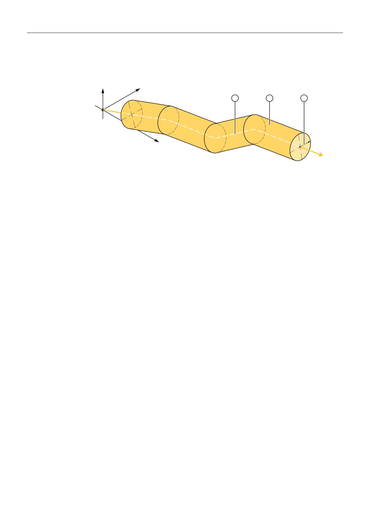
The following figure is a diagram of the monitoring area shown by way of a simple example.
<
=
;
① Contour (path of the tool tip
② "Tunnel" laid around the contour (tolerance tube)
③ Permissible tolerance
Figure 8-1
Position of the contour tunnel around the programmed path
As long as the calculated actual position of the tool tip remains inside the sketched tunnel,
motion continues in the normal way. If the calculated actual position violates the tunnel, an
alarm is triggered (in the default setting) and the axes are stopped by "Ramp Stop". This response
to the violation of the tunnel can be disabled (alarm triggered but movement continued) or
intensified (rapid stop) by means of a machine data setting.
Analysis
The calculated distance between the programmed path and the actual values can be routed to
an analog output to analyze the progression of the contour errors during normal operation
(quality control).
8.1.2
Programmable contour accuracy
Function
As an alternative to the function described in "Contour tunnel monitoring", i.e. monitoring of the
machining accuracy and stopping machining if excessive deviations occur, another function is
offered. With this function, the selected accuracy is always achieved with the path velocity being
reduced if necessary. Detailed information about this function can be found under the subject
"Programmable contour accuracy".
Monitoring and compensating
212
Function Manual, 10/2020, 6FC5397-7GP40-0BA1

Contour tunnel monitoring
8.2 Contour tunnel monitoring
8.2
Contour tunnel monitoring
Aim of the monitoring function
The aim of the monitoring function is to stop the movement of the axes if axis deviation causes
the distance between the tool tip (actual value) and the programmed path (setpoint) to exceed a
defined value (tunnel radius).
Tunnel size
The radius of the contour tunnel being monitored around the programmed path must be
defined to implement the monitoring function:
MD21050 $MC_CONTOUR_TUNNEL_TOL (Response threshold for Contour tunnel monitoring)
If the machine data is set to 0.0, monitoring is not performed. The value of the machine data is
transferred to the control for new configurations.
Parameterizable deceleration behavior
The deceleration behavior for the monitoring response can be set via the following machine
data:
MD21060 $MC_CONTOUR_TUNNEL_REACTION (Reaction upon response of contour tunnel
monitoring)
Value
Meaning
0
Display alarm and continue machining
1
Deceleration according to the deceleration ramps (default setting)
2
Rapid stop (speed setpoint = 0)
Encoder switchover
Switching between two encoder systems usually causes a sudden change in the actual position
of the tool tip. This change resulting from encoder switchover must not be so large as to cause
the tool tip to violate the monitoring tunnel. The radius defined in MD21050 must be higher
than the allowed tolerance on actual value switchover:
MD36500 $MA_ENC_CHANGE_TOL (Max. tolerance for position actual value switchover)
Activation
The monitoring will only become active if the following conditions are met:
• MD21050 is higher than 0.0.
• At least two geometry axes have been defined.
Shutting down
Monitoring can be stopped by enabling the machine data setting:
Monitoring and compensating
Function Manual, 10/2020, 6FC5397-7GP40-0BA1
213

Contour tunnel monitoring
8.3 Programmable contour accuracy
MD21050 = 0.0.
Analysis output
The values of deviation of the actual value of the tool tip from the programmed path can - for
analysis purposes - be output on a fast analog output (accuracy monitoring).
The assignment of an analog output to output the contour error is programmed in machine data:
MD21070 $MC_CONTOUR_ASSIGN_FASTOUT
Value
Meaning
0
No output (default setting)
1
Output to output 1
2
Output to output 2
…
…
8
Output to output 8
Scale
The tunnel radius set in MD21050 corresponds to a voltage of 10 V at the output.
8.3
Programmable contour accuracy
Function
The function "Programmable contour accuracy" limits the contour errors caused by control
behavior and jerk filter to a specified value by reducing the path velocity on curved contours by
the necessary amount. It allows the user to set a compromise between accuracy and productivity
of a machining.
Note
The "LookAhead" function ensures that the velocity necessary for maintaining the required
contour accuracy is not exceeded at any point along the path.
Configuration
The mode of operation and parameterization of the function is determined by the machine data:
Monitoring and compensating
214
Function Manual, 10/2020, 6FC5397-7GP40-0BA1

Contour tunnel monitoring
8.3 Programmable contour accuracy
MD20470 $MC_CPREC_WITH_FFW (programmable contour accuracy)
Value
Meaning
0
The "Programmable contour accuracy" function has no effect when feedforward control is also
active.
1
The "Programmable contour accuracy" function also acts for feedforward control.
With active feedforward control, the reduction of the path velocity is calculated on the basis of
the effective KV factor with feedforward control.
2
Like 1, the function, however, is parameterized with MD32415 $MA_EQUIV_CPREC_TIME (time
constant for the programmable contour accuracy).
The jerk filter is correctly taken into account. The SD42450 $SC_CONTPREC setting data deter-
mines the permissible contour errors (see "Parameterization").
3
Like for 2, but any contour accuracy programmed with CTOL has priority over SD42450
$SC_CONTPREC.
The jerk filter is correctly taken into account. The programmed CTOL contour tolerance deter-
mines the permissible contour errors (see "Parameterization"). $SC_CONTPREC is only relevant
if CTOL was not programmed.
4
The "Programmable contour accuracy" function is active irrespective of the feedforward control
and jerk filter. Only MD32415 $MA_EQUIV_CPREC_TIME is considered in the calculation of the
contour error. All time constants that affect the contour error must be added together and
entered in MD32415 $MA_EQUIV_CPREC_TIME.
5
Like for 4, but any programmed contour accuracy with CTOL has priority over SD42450
$SC_CONTPREC.
For the MD20470 = 2 or 3 functional versions, the control assumes that there is a jerk filter time
constant (MD32410 $MA_AX_JERK_TIME) for which the setting of the control section with
feedforward control produces a negligible contour error. This value must be entered in the
machine data MD32415 $MA_EQUIV_CPREC_TIME (see "Parameterization").
To calculate the contour error based on the set jerk filter type (MD32402 $MA_AX_JERK_MODE),
the following value is used:
• For active feedforward control, the difference:
MD32410 $MA_AX_JERK_TIME - MD32415 $MA_$MA_EQUIV_CPREC_TIME
• Without feedforward control, the complete value from MD32410 $MA_AX_JERK_TIME
This procedure allows the commissioning engineer to first change from an initially precise, but
possibly excessively hard, setting by increasing the jerk filter time constants to a softer setting
with a controlled loss of accuracy.
If function "Programmable contour accuracy" is used in combination with jerk filter type "FIR low
pass" (MD32402 $MA_AX_JERK_MODE = 5), memory space must be made available for the
characteristic curve approximation of FIR filters during commissioning with the memory-
configuring machine data MD38020 $MA_MM_CPREC_FIR_POINTS. If no memory is made
available (MD38020 = 0), the function cannot be executed and alarm 10990 is output.
Restrictions:
• The function does not use the "band stop" jerk filter type (MD32402 $MA_AX_JERK_MODE
= 3).
• The MD20470 = 2 or 3 functional versions are primarily intended for use with feedforward
control. If one of the two functional versions is active for switched off feedforward control,
a contour error that results from the Kv factor is added. This reduces the path velocity
significantly faster.
Monitoring and compensating
Function Manual, 10/2020, 6FC5397-7GP40-0BA1
215
Contour tunnel monitoring
8.3 Programmable contour accuracy
Note
The MD20470 = 0 or 1 functional versions are no longer recommended. They only provide
compatibility with older software versions.
Parameterization
Contour accuracy
The maximum contour error for the path of the geometry axes on curved contours is determined
by:
• For MD20470 $MC_CPREC_WITH_FFW = 2 with the setting data:
SD42450 $SC_CONTPREC (contour accuracy)
• For MD20470 $MC_CPREC_WITH_FFW = 3 with the contour tolerance programmed with
CTOL.
The smaller the value and the lower the Kv factor of the geometry axes, the greater the path
feedrate on curved contours is lowered.
Minimum path feedrate
The user can use the following setting data to specify a minimum path feedrate for the
"Programmable contour accuracy" function:
SD42460 $SC_MINFEED (minimum path feed with CPRECON)
The feedrate will not limited below this value, unless a lower F value has been programmed or
the dynamic limitations of the axes force a lower path velocity.
Time constant for the programmable contour accuracy
The equivalent time constant for the MD20470 = 2 or 3 functional versions (see
"Configuration") is entered in the machine data:
MD32415 $MA_EQUIV_CPREC_TIME (time constant for the programmable contour accuracy)
MD32415 must contain that jerk filter time constant (MD32410 $MA_AX_JERK_TIME) for which
the contour error for active feedforward control is negligibly small.
Programming
The "programmable contour accuracy" can be activated and deactivated in the part program
with the CPRECON and CPRECOF modal G commands.
Example:
Program code
Comment
N10 G0 X0 Y0
N20 CPRECON
; Activate the "programmable contour accuracy".
N30 G1 G64 X100 F10000
; Machining with 10 m/min in the continuous-path mode.
N40 G3 Y20 J10
; Automatic feed limitation in circular block.
N50 G1 X0
; Feedrate again without limitation (10 m/min).
Monitoring and compensating
216
Function Manual, 10/2020, 6FC5397-7GP40-0BA1
Contour tunnel monitoring
8.4 Constraints
Program code
Comment
N100 CPRECOF
; Deactivate the "programmable contour accuracy".
N110 G0 ...
The two CPRECON and CPRECOF modal G commands form G group 39 (programmable contour
accuracy).
Behavior for part program start and after reset / part program end
For part program start and after reset / part program end, the configured control initial setting
acts for the G group 39:
MD20110 $MC_RESET_MODE_MASK (definition of initial control settings after RESET / TP End)
MD20112 $MC_START_MODE_MASK (definition of the basic setting of the control after part
program start)
Supplementary conditions
Positioning axes
The function considers only the geometry axes of the path. It does not have any effect of the
velocities for the positioning axes.
Additional information
For information about MD32402 $MA_AX_JERK_MODE (filter type for axial jerk limitation) and
MD32410 $MA_AX_JERK_TIME (time constant for the axial jerk filter), see:
• Function Manual Axes and Spindles
For information about CTOL, see:
• Function Manual Basic Functions
8.4
Constraints
Availability of the "Contour tunnel monitoring" function
The function is an option ("Contour monitoring with tunnel function"), which must be assigned
to the hardware via the license management.
Coupled motion
If coupled motion between two geometry axes is programmed with contour tunnel monitoring,
this always results in activation of the contour tunnel monitoring. In this case, the contour
tunnel monitoring must be switched off before programming the coupled motion:
Monitoring and compensating
Function Manual, 10/2020, 6FC5397-7GP40-0BA1
217

Contour tunnel monitoring
8.5 Data lists
MD21050 $MC_CONTOUR_TUNNEL_TOL = 0.0
8.5
Data lists
8.5.1
Machine data
8.5.1.1
Channelspecific machine data
Number Identifier: $MC_
Description
20110
RESET_MODE_MASK
Determination of basic control settings after Reset / TP
End
20112
START_MODE_MASK
Definition of the initial control settings after part pro-
gram start
20470
CPREC_WITH_FFW
Programmable contour accuracy
21050
CONTOUR_TUNNEL_TOL
Response threshold for contour tunnel monitoring
21060
CONTOUR_TUNNEL_REACTION
Reaction to response of contour tunnel monitoring
21070
CONTOUR_ASSIGN_FASTOUT
Assignment of an analog output for output of the con-
tour error
8.5.1.2
Axis/spindlespecific machine data
Number
Identifier: $MA_
Description
32402
AX_JERK_MODE
Filter type for axial jerk limitation
32410
AX_JERK_TIME
Time constant for axial jerk filter
32415
EQUIV_CPREC_TIME
Time constant for the programmable contour accuracy
36500
ENC_CHANGE_TOL
Maximum tolerance for position actual value switchover
8.5.2
Setting data
8.5.2.1
Channelspecific setting data
Number Identifier: $SC_
Description
42450
CONTPREC
Contour accuracy
42460
MINFEED
Minimum path feed for CPRECON
Monitoring and compensating
218
Function Manual, 10/2020, 6FC5397-7GP40-0BA1
Compensations
9
9.1
Introduction
Accuracy errors
The accuracy of machine tools is impaired as a result of deviations from the ideal geometry,
power transmission faults and measuring system errors. Temperature differences and
mechanical forces often result in great reductions in precision when large workpieces are
machined.
Compensation functions
Some of these deviations can usually be measured during commissioning and then
compensated for during operation on the basis of values read by the positional actual-value
encoder and other sensory devices. State-of-the-art CNC controls have compensation functions
that are active on an axis for axis basis.
Parameterization
These compensation functions can be set for each machine individually with axis-specific
machine data.
Activation
The compensations are active in all operating modes of the control as soon as the input data are
available. Any compensations that require the position actual value are not activated until the
axis reaches the reference point.
Position display
The normal actual-value and setpoint position displays ignore the compensation values and
show the position values of an ideal machine. The compensation values are output in the
"Diagnosis" operating area of the "Axis/Spindle Service" window.
Monitoring and compensating
Function Manual, 10/2020, 6FC5397-7GP40-0BA1
219
Compensations
9.2 Temperature compensation
9.2
Temperature compensation
9.2.1
Function
Deformation due to temperature effects
Heat generated by the drive equipment or high ambient temperatures (e.g. caused by sunlight,
drafts) cause the machine base and parts of the machinery to expand. This expansion depends,
among other things, on the temperature and on the thermal conductivity of the machine parts.
Effects
Due to the thermal expansion of the machinery, the actual positions of the axes change
depending on temperature. This has a negative impact on the precision of the workpieces being
machined.
Temperature compensation
By activating the "temperature compensation" function, actual value changes due to
temperature effects can be compensated on an axis-by-axis basis.
Sensor equipment
To provide effective temperature compensation, a number of temperature sensors for acquiring
a temperature profile are needed in addition to the actual position data from existing encoders.
Since temperature-dependent changes occur relatively slowly, the PLC can acquire and
preprocess the temperature profile in a minutes cycle, for example.
Error curves
In order to implement temperature compensation, the actual-value offsets over the positioning
range of the axis must be measured at a given temperature (T) and plotted. This produces an
error curve for this temperature value. Error curves must be produced for different temperatures.
Error curve characteristic
If an axis position reference point P0 is selected, an offset in the reference point (corresponds to
the "position-independent component" of the temperature compensation) can be observed as
the temperature changes, and because of the change in length an additional offset in the other
position points, which increases with the distance to the reference point (corresponds to the
"position-dependent component" of the temperature compensation).
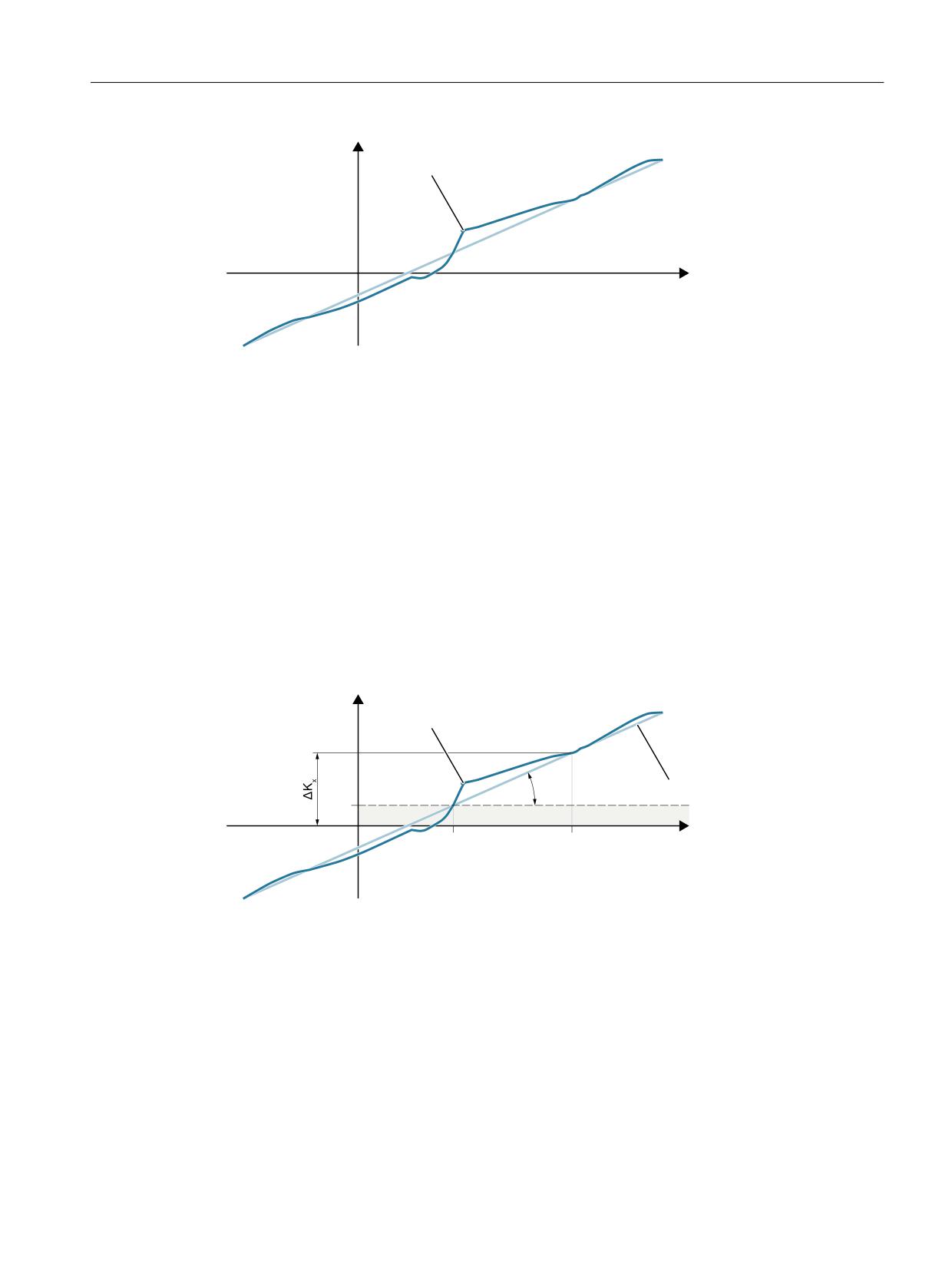
The error curve for a given temperature T can generally be represented with sufficient accuracy
by a straight line with a temperature dependent gradient and reference position:
Monitoring and compensating
220
Function Manual, 10/2020, 6FC5397-7GP40-0BA1
Compensations
9.2 Temperature compensation
(UURU GHYLDWLRQ
(UURU FXUYH IRU WHPSHUDWXUH 7
[
Compensation equation
The compensation value ∆Kx is calculated on the basis of current actual position Px of this axis
and temperature T according to the following equation:
ΔKx = K0 (T) + tanβ (T) * (Px - P0)
The meaning is as follows:
ΔKx:
Temperature compensation value of axis at position Px
K0:
Position-independent temperature compensation value of axis
Px:
Actual position of axis
P0:
Reference position of axis
tanβ:
Coefficient for the position-dependent temperature compensation (corresponds to
the gradient of the approximated error line)
(UURU GHYLDWLRQ
(UURU FXUYH IRU WHPSHUDWXUH 7
˟
$SSUR[LPDWHG HUURU OLQH
3
3[
[
Figure 9-1
Approximated error line for temperature compensation
Effectiveness
The following conditions must be fulfilled so that the temperature compensation can be
activated:
1. The compensation type is selected (MD32750, see "Commissioning (Page 223)").
2. The parameters for the compensation type are defined (see "Commissioning (Page 223)").
3. The axis is referenced.
DB31, ... DBX60.4 or 60.5 =1 (referenced/synchronized 1 or 2)
Monitoring and compensating
Function Manual, 10/2020, 6FC5397-7GP40-0BA1
221
Compensations
9.2 Temperature compensation
As soon as these conditions are fulfilled, the temperature compensation value for the position
actual value is added to the setpoint in all modes and the machine axis traverses through this
distance. If the compensation value ∆Kx is positive, the axis moves in the negative direction.
If the reference position is then lost, e.g. because the encoder frequency has been exceeded
(DB31, ... DBX60.4 or 60.5 = 0), compensation processing is deactivated.
Clock cycle
The compensation values are determined in the interpolator clock cycle.
Display
The total compensation value calculated from the temperature and sag compensation functions
belonging to the actual position is output in the "Diagnosis" operating area of the "Axis/Spindle
Service" window.
Parameter adaptation for temperature changes
Since the approximated error line applies only to the instantaneous temperature value, the
parameters of the error lines that are newly generated when the temperature rises or falls must
be sent to the NC again. Only in this way can expansion due to heat always be correctly
compensated.
When temperature T changes, the parameters which are temperature-dependent, i.e. (K0, tanβ
and P0) also change and can thus always be overwritten by the PLC or by means of a synchronized
action.
It is thus possible for the machine-tool manufacturer to emulate the mathematical and
technological relationship between the axis positions and temperature values via the PLC user
program and thus calculate the various parameters for the temperature compensation. The
temperature parameters are transferred to the NC using the variable services (FB2 (GET) "Read
data" and FB3 (PUT) "Write data").
For more detailed information regarding handling and supplying FB2 and FB3, see:
Further information:
Function Manual PLC
Smooth the compensation value
To prevent overloading of the machine or tripping of monitoring functions in response to step
changes in the temperature compensation parameters, the compensation values are distributed
over several IPO cycles by an internal control function as soon as they exceed the maximum
compensation value specified for each IPO cycle (MD32760, see "Commissioning (Page 223)").
Monitoring and compensating
222
Function Manual, 10/2020, 6FC5397-7GP40-0BA1

Compensations
9.2 Temperature compensation
9.2.2
Commissioning
Temperature-dependent parameters
Error curves for different temperatures can be defined for each axis. For each error curve the
following parameters must be determined and then entered in the setting data:
• Position-independent temperature compensation value K0:
SD43900 $SA_TEMP_COMP_ABS_VALUE
• Reference position P0 for position-dependent temperature compensation:
SD43920 $SA_TEMP_COMP_REF_POSITION
• Gradient tanβ for position-dependent temperature compensation:
SD43910 $SA_TEMP_COMP_SLOPE
Temperature compensation type and activation
The temperature compensation type is selected and the temperature compensation activated
using the axis-specific machine data:
MD32750 $MA_TEMP_COMP_TYPE (temperature compensation type)
Bit
Value
Meaning
Associated parameters
0
Position independent temperature compensation
SD43900
0
Not active
1
Active
1
Position-dependent temperature compensation
SD43920, SD43910
0
Not active
1
Active
2
Temperature compensation in tool direction
MD20390
$MC_TOOL_TEMP_COMP_ON (Ac-
0
Not active
tivate temperature compensation
1
Active
tool length)
Maximum compensation value per IPO clock cycle
The maximum possible compensation value per IPO cycle, i.e. the maximum distance that can
be traversed in an IPO cycle as a result of the temperature compensation, is limited using
machine data:
MD32760 $MA_COMP_ADD_VELO_FACTOR (velocity increase as a result of compensation)
The specified value acts as a factor and is referred to the maximum axis velocity (MD32000
$MA_MAX_AX_VELO).
MD32760 also limits the maximum gradient of the error line (tan ß) of the temperature
compensation.
Monitoring and compensating
Function Manual, 10/2020, 6FC5397-7GP40-0BA1
223
Compensations
9.2 Temperature compensation
9.2.3
Example
9.2.3.1
Commissioning the temperature compensation for the Z axis of a lathe
Commissioning of temperature compensation is described below using the example of a Z axis
on a lathe.
Determining the error characteristic of the Z axis
In order to determine the temperature-dependent error characteristic of the Z axis, proceed as
follows:
• Uniform temperature increase by traversing the axis across the whole Z axis traversing range
(in the example: from 500 mm to 1500 mm)
• Measuring the axis position in increments of 100 mm
• Measuring the actual temperature at the leadscrew
• Executing a traversing measuring cycle every 20 minutes
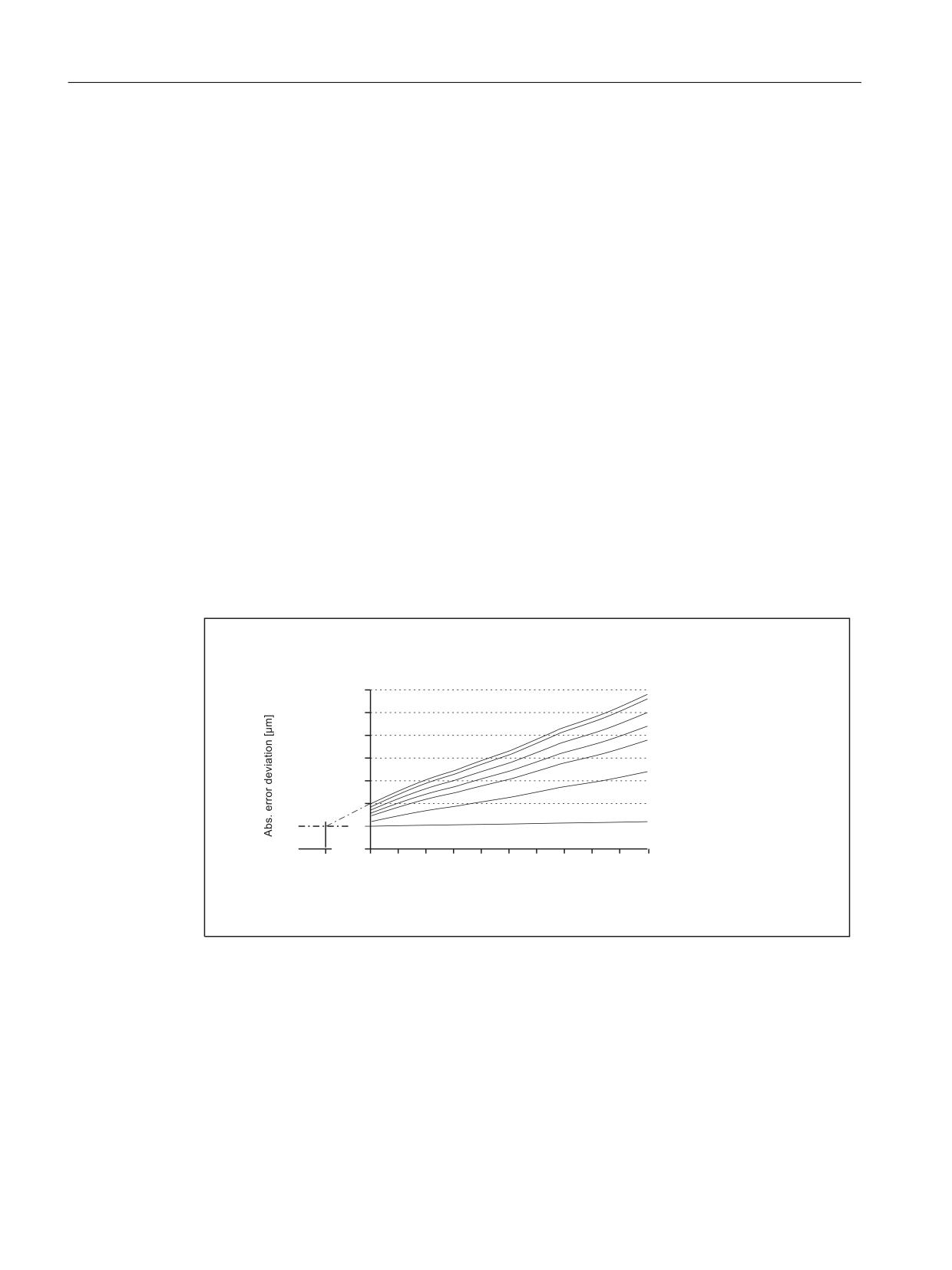
The mathematical and technological relationships and the resulting parameters for temperature
compensation are derived from the recorded data. The calculated deviation errors for a specific
temperature, which refer to the actual position of the Z axis displayed by the NC, are represented
in graphic form in the diagram below.
0HDVXUHG WHPSHUDWXUH
GHJUHHV
GHJUHHV
GHJUHHV
GHJUHHV
GHJUHHV
GHJUHHV
GHJUHHV
5HIHUHQFH
SRLQW 3
3RVLWLRQ RI WKH = D[LV >PP@
Figure 9-2
Error curves determined for the Z axis
Specifying parameters
The temperature compensation parameters must now be determined on the basis of the
measurement results (see diagram above).
Reference position P0
Monitoring and compensating
224
Function Manual, 10/2020, 6FC5397-7GP40-0BA1
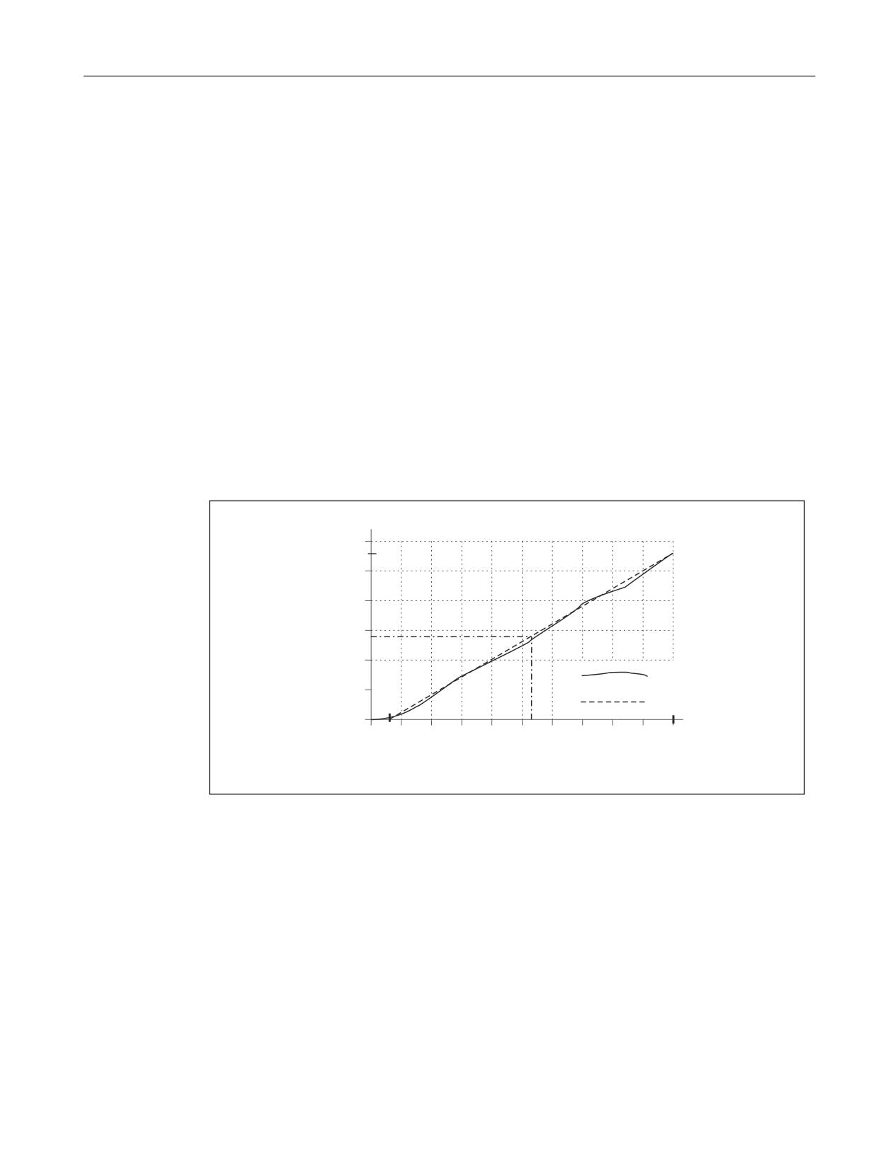
Compensations
9.2 Temperature compensation
As the diagram above illustrates, there are basically two methods of parameterizing reference
position P0:
1. P0 = 0 with position-independent temperature compensation value K0 ≠ 0
2. P0 ≠ 0 with position-independent temperature compensation value K0 = 0
In this case, version 2 is chosen, which means that the position-independent temperature
compensation value is always 0. The temperature compensation value therefore only consists
of the position-dependent component.
The following parameters are obtained:
• MD32750 $MA_TEMP_COMP_TYPE = 2
(only position-dependent temperature compensation active)
• P0 = 320 mm → SD43920 $SA_TEMP_COMP_REF_POSITION = 320
(reference position for position-dependent temperature compensation)
Coefficient tanβ (T)
In order to determine the dependency of coefficient tanβ of the position-dependent
temperature compensation on the temperature, the error curve gradient is plotted against the
measured temperature:
TC coefficient
300
[¥ m/1000mm]
TKmax
250
200
150
100
Measured curve
characteristic
50
Straight line
0
T0
Tmax
22
24
26
28
30
32
34
36
38
40
42
Absolute temperature [degrees]
Figure 9-3
Characteristic of coefficient tanβ as a function of measured temperature T
With the appropriate linearization, coefficient tanβ depends on T as follows:
tanβ(T) = (T - T0) * TKmax * 10-6/ (Tmax - T0)
with
T0 = temperature at which position-dependent error = 0; [degrees]
Tmax = maximum measured temperature; [degrees]
TKmax = temperature coefficient at Tmax; [µm/1000 mm]
Therefore, based on the values from the above diagram:
T0 = 23°
Tmax = 42°
Monitoring and compensating
Function Manual, 10/2020, 6FC5397-7GP40-0BA1
225
Compensations
9.3 Backlash compensation
TK
max
= 270 µm/1000 mm
and tanß (T) is therefore:
tanβ(T)
= (T - 23) [degrees] * 270 [µm/1000 mm] * 10-6 / (42 - 23) [degrees]
= (T - 23) [degrees] * 14.21 [µm/1000 mm] * 10-6
Example:
At a temperature of T = 32.3 degrees, therefore: tanβ = 0.000132
PLC user program
The formula given above must be used in the PLC user program to calculate the coefficient
tanβ (T) which corresponds to the measured temperature; this must then be written to the
following NC setting data:
SD43910 $SA_TEMP_COMP_SLOPE (gradient for position-dependent temperature
compensation)
According to the example above:
SD43910 $SA_TEMP_COMP_SLOPE = 0.000132
9.3
Backlash compensation
9.3.1
Mechanical backlash compensation
9.3.1.1
Function
Mechanical backlash can occur in moving machine parts in the drive train (machine axes), e.g.
at a ballscrew or in the connection to the measuring system.
Effects
For a machine axis with indirect measuring system, mechanical backlash results in a difference
between the actual position of the NC determined using the measuring system and the actual
Monitoring and compensating
226
Function Manual, 10/2020, 6FC5397-7GP40-0BA1
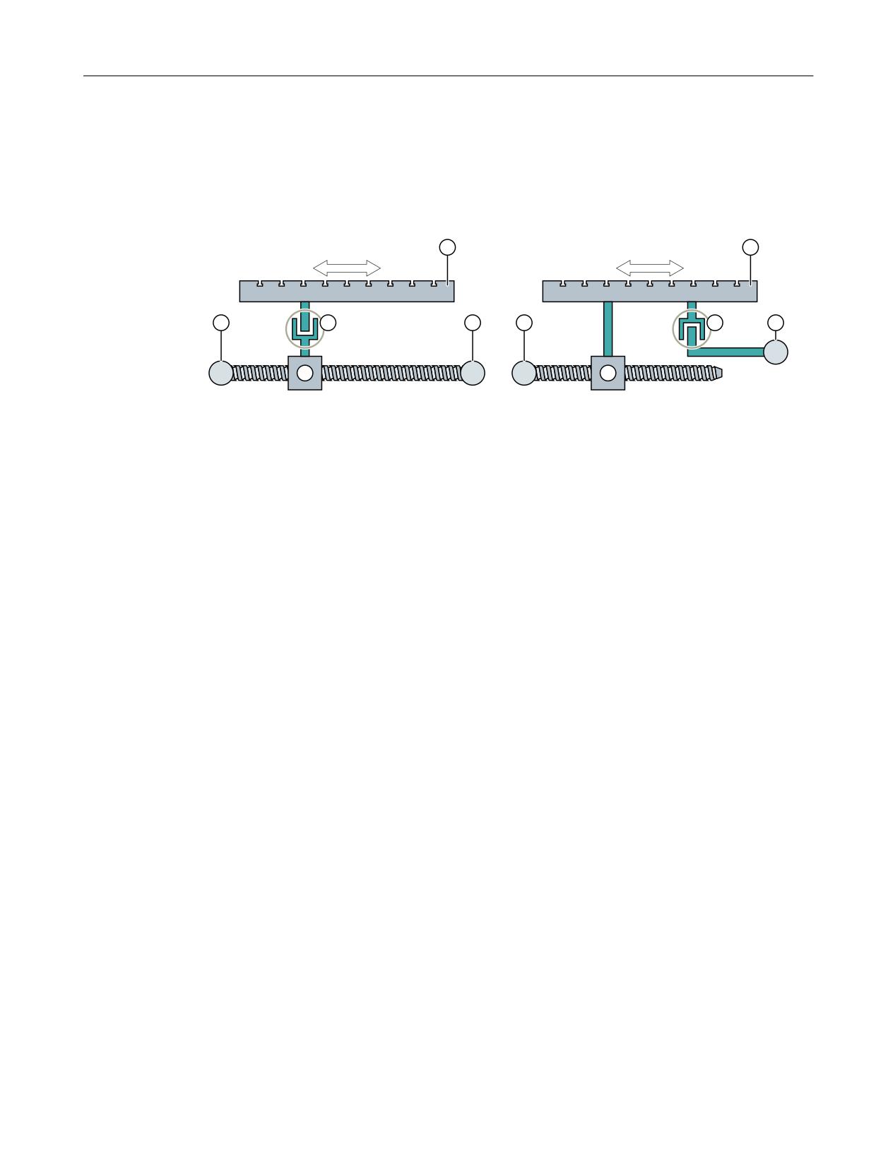
Compensations
9.3 Backlash compensation
position of the machine part. When the direction reverses, the machine axis traverses through
a distance that is incorrect by the amount of the backlash:
Positive backlash ⇒
Negative backlash ⇒
The encoder actual value leads the machine
The encoder actual value lags behind the
actual value
machine actual value
*
0
*
0
The table does not move far enough because
The table moves too far because the encoder
the encoder actual value has already changed
actual value has not yet changed (lagging) due
(leading) due to the backlash while the table
to the backlash while the table is already mov-
still remains stationary.
ing.
① Encoder
② moved machine part (table)
③ ballscrew
④ mechanical backlash
⑤ motor
Compensation
To compensate for the mechanical backlash, the actual value of the machine axis is corrected
every time the axis reverses by the axis-specific compensation value set during commissioning
(Page 228).
Effectiveness
The mechanical backlash compensation of a machine axis is active in all operating modes.
Requirement:
• Incremental measuring system: Encoder state == "referenced"
• Absolute encoder: Encoder state == "synchronized"
Displaying the compensation values
The compensation values active at the actual position of the machine axis are displayed on the
user interface for each individual axis.
SINUMERIK Operate: "Diagnostics" operating area > ETC key (">") > "Axis diagnostics" > "Service
axis" >
• "Absolute compensation value measuring system 1"
• "Absolute compensation value measuring system 2"
• "Compensation value from LEC"
Monitoring and compensating
Function Manual, 10/2020, 6FC5397-7GP40-0BA1
227
Compensations
9.3 Backlash compensation
9.3.1.2
Commissioning: Axis-specific machine data
Compensation value
The compensation value of the mechanical backlash is entered in the machine data.
MD32450 $MA_BACKLASH[ <active measuring system> ] = <compensation value>
Measurement
• Traversing the machine axis and/or the machine part to any measurement position at a high
velocity.
• Measuring the actual position of the machine part
• Calculating the backlash compensation value KL
KL = "displayed actual position of the machine axis" - "measured actual position of the
machine part"
- KL > 0 (positive backlash ) ⇒ positive compensation value
- KL < 0 (negative backlash ) ⇒ negative compensation value
Checking
To check the effect of the compensation, we recommend that the mechanical backlash is
measured after the machine data has been activated.
Circularity test
The circularity test integrated in the user interface can be used to visualize the mechanical
backlash.
SINUMERIK Operate: "Commissioning" operating area > "Optimization/Test" > "Circularity test"
Second measuring system
If an axis has a second measuring system, the compensation value must also be determined for
this and entered in the machine data:
MD32450 $MA_BACKLASH[ <measuring system 2> ]
When the measuring system is switched over, the associated compensation value is
automatically used.
Evaluation factor dependent on the parameter set
For a mechanical backlash dependent on the parameter set, the parameter set-specific factor is
entered into the following machine data, which is then applied to the compensation value of the
backlash (MD32450 $MA_BACKLASH).
MD32452 $MA_BACKLASH_FACTOR[ <parameter set 1 ... n> ] = <factor>
Effective compensation value
The effective compensation value KP of a parameter set is calculated as follows:
KP = ( MD32450 $MA_BACKLASH[ <active measuring system> ] ) * ( MD32452
$MA_BACKLASH_FACTOR[ <parameter set> ]
Monitoring and compensating
228
Function Manual, 10/2020, 6FC5397-7GP40-0BA1
Compensations
9.3 Backlash compensation
Backlash compensation mode
The response of mechanical backlash compensation of a machine axis is set using machine data:
MD32454 $MA_BACKLASH_MODE
Bit
Meaning
0
Restores the last effective backlash compensation after the control system has powered up
= 0
The backlash compensation value is not restored (default setting)
= 1
The backlash compensation is restored.
Precondition
The measuring system active after the control powers up must be adjusted and synchronized:
• MD34210 $MA_ENC_REFP_STATE[<active measuring system>] == 2
• DB31,
DBX60.4 - 5 == 1 (measuring system 1 / 2: Referenced, synchronized)
1
Effect of other compensation functions (temperature compensation, sag or angularity error
compensation)
= 0
The backlash compensation responds to other compensatory motion (default setting).
= 1
The backlash compensation does not respond to other compensatory motion (default
setting).
9.3.2
Dynamic backlash compensation
9.3.2.1
Function
Dynamic backlash
A dynamic backlash can occur for machine types with sliding guides. Depending on the axial
dynamic response (velocity, jerk, etc.) used to approach an end position, the machine slide
reaches the programmed end position or stops earlier because of the static friction. The
resulting position error is direction-symmetric.
Compensation
To compensate for the dynamic backlash, half the signed compensation value
(MD32456Commissioning: Axis-specific machine data (Page 230), see "") is applied in
accordance with the relevant traversing direction of the axis. Compensation value is applied as
ramp.
Activation
The dynamic backlash compensation is activated by the PLC only in required the situations:
Monitoring and compensating
Function Manual, 10/2020, 6FC5397-7GP40-0BA1
229
Compensations
9.3 Backlash compensation
DB31, ... DBX25.0 (activate dynamic backlash compensation)
Note
The machine tool manufacturer specifies in the PLC user program the "required" situations for
the activation of the dynamic backlash compensation. Such situations result with traversal of
the axes with G1, in the JOG mode or with the handwheel.
The NC uses the following interface to return the required activation to the PLC:
DB31, ... DBX102.0 (active dynamic backlash compensation)
Requirement
The axes to be compensated must be homed.
Display
The compensation value that belongs to the current actual position is displayed in the
"Diagnostics" operator area of the "Axis/Spindle Service" window as the total compensation
calculated from LEC, mechanical and dynamic backlash compensation.
9.3.2.2
Commissioning: Axis-specific machine data
Compensation value
As precondition to commission the dynamic backlash compensation, the mechanical backlash
compensation must have already been commissioned (see Chapter "Commissioning: Axis-
specific machine data (Page 228)").. To determine the compensation value for the dynamic
backlash compensation, the measurement described there should be repeated with low
traversing velocity. The compensation value determined in this way is entered in the machine
data for the corresponding measuring system:
MD32456 $MA_BACKLASH_DYN[ <active measuring system> ] = <compensation value for
dynamic backlash compensation>
Maximum tolerance for position actual value switchover
You are provided the option of applying the backlash compensation value gradually in several
increments when the relevant axis changes direction. This prevents a setpoint step change on
the axes from causing corresponding errors. The contents of the axis-specific machine data
determine the increment with which the backlash compensation value (MD32450) is applied:
MD36500 $MA_ENC_CHANGE_TOL (max. tolerance on actual position value switchover)
Please note that the backlash compensation is only fully calculated after <n> servo cycles (<n>
= MD32450 / MD36500). An excessive time span can cause the triggering of standstill
monitoring alarms. If MD36500 > MD32450, then the compensation is performed in one servo
cycle.
Monitoring and compensating
230
Function Manual, 10/2020, 6FC5397-7GP40-0BA1
Compensations
9.3 Backlash compensation
Compensation value change
Using the machine data, the velocity with which the compensation value is traversed through
is set as a percentage of the maximum axis velocity (MD32000 $MA_MAX_AX_VELO):
MD32457 $MA_BACKLASH_DYN_MAX_VELO = <percentage of the maximum axis velocity>
9.3.3
Dual position feedback
For the "Dual position feedback" function, contrary to conventional (mechanical or dynamic)
backlash compensation, two measuring systems, which are mechanically coupled through a
gearbox without backlash, are used for the closed-loop position control. The advantages of a
direct measuring system are combined with the advantages of an indirect measuring system:
• Direct measuring system: The closed-loop position control with direct, i.e. encoder on the
load side, "automatically" corrects the backlash.
• Indirect measuring system: The closed-loop position control with indirect, i.e. encoder on the
motor side, is "rugged" and "stable" regarding discontinuous backlash.
Each time the setpoint changes, initially only the encoder data from the indirect measuring
system is used for rugged control without oscillation. With a parameterizable delay time, the
closed-loop control smoothly transitions to monitor the direct measuring system, therefore,
achieving the required accuracy on the load side. The control operations should, at this point in
time, only involve short distances. This is because in the meantime the tooth flanks are in
contact with one another, and the backlash has been moved through.
When using the "Dual position feedback" function, it is not necessary to measure and
mathematically compensate the backlash.
Requirements
The following preconditions must be satisfied for an axis to be compensated:
• Direct and indirect measuring system, mechanically coupled:
- MD30200 $MA_NUM_ENCS = 2
- MD31040 $MA_ENC_IS_DIRECT[ 0 ] = 0 or 1
- MD31040 $MA_ENC_IS_DIRECT[ 1 ] = 1 or 0
• Measuring system calibration has been released:
MD34102 $MA_REFP_SYNC_ENCS = 1
• Both measuring systems are referenced:
- DB31, ... DBX60.4 (referenced/synchronized 1 / 2) = 1
- DB31, ... DBX60.5 (referenced/synchronized 1 / 2) = 1
Application
Typical applications include main spindles on turning machines which feature a mechanical
system without backlash between motor and main spindle (e.g. gear). Nevertheless, these axes
require a direct measuring system for precision in C-axis operation (on the load side).
Monitoring and compensating
Function Manual, 10/2020, 6FC5397-7GP40-0BA1
231
Compensations
9.3 Backlash compensation
Due to mechanical factors such as backlash and rigidity, however, the axis cannot traverse with
the same position control dynamic with encoder on the load side (in comparison to position
control with motor encoder). The solution here is provided by the dual position feedback.
The servo gain factor does not have to be reduced and it can nevertheless be positioned on the
direct encoder.
9.3.3.1
Commissioning: Axis-specific machine data
Delay time
The delay time, during which the closed-loop control smoothly transitions from the indirect to
the direct measuring system, is entered in the machine data.
MD32960 $MA_POSCTRL_DUAL_FEEDBACK_TIME = <delay time>
If the delay time is zero, then the function is inactive, and only the active measuring system
(DB31,
DBX1.5 / .6 (position measuring system 1 / 2) ) is active for the position control.
Note
After activating the "Dual position feedback" function, all of the existing measuring system
compensations and monitoring functions remain unchanged and active; this means that they
may have to be deactivated by the user (e.g. backlash compensation values deleted).
9.3.3.2
Supplementary conditions
Referencing and flying measurement
Also when the "Dual position feedback" function is active, the "Referencing" and "Measuring"
functions refer to the active measuring system (DB31,
DBX1.5 / .6 (position measuring
system 1 / 2) ).
Further information
• Function Manual Axes and Spindles; Referencing
• Function Manual Technologies, Measuring
Monitoring and compensating
232
Function Manual, 10/2020, 6FC5397-7GP40-0BA1
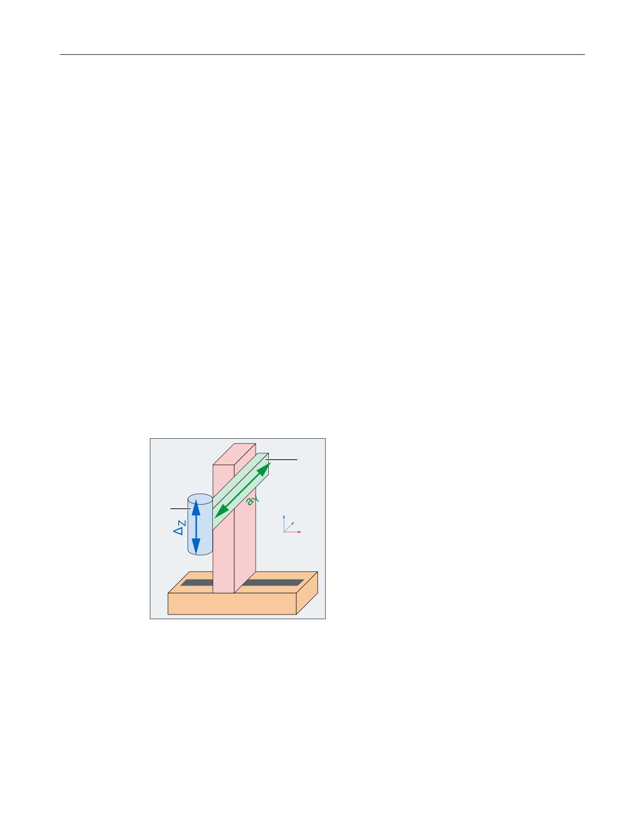
Compensations
9.4 Nodding compensation
9.4
Nodding compensation
9.4.1
Description of the function
9.4.1.1
Options
The "Nodding compensation" function is an option subject to license. The following versions are
available:
• Nodding compensation ECO: 6FC5800-0AS20-0YB0
Nodding compensation in one machine axis with one accelerating axis:
• Nodding compensation ADVANCED: 6FC5800-0AS21-0YB0
Nodding compensation in any arbitrary number of machine axes
9.4.1.2
Features
Nodding compensation is used to compensate dynamic position deviations in a machine axis
due to this or another machine axis accelerating. The position deviations are obtained as a result
of the mechanical compliance within the machine.
This is demonstrated in the following schematic of a 3-axis traveling column machine, as
example. If the Y axis is accelerated with aY, as a result of the mechanical compliance in the
machine, position deviations ΔZ occur in the Z axis.
<
=
=
<
;
Figure 9-4
3-axis traveling column machine
Monitoring and compensating
Function Manual, 10/2020, 6FC5397-7GP40-0BA1
233
Compensations
9.4 Nodding compensation
Definition of terms
•
Nodding compensation axes
The machine axes involved in the nodding compensation are designated as follows: //////
- Compensating axis
A machine axis, resulting from other machine axes accelerating, results in position
deviations, which can be compensated by nodding compensation. In the diagram:
Compensating axis ⇒ Z axis
- Accelerating axis
Machine axis, whose acceleration as a result of compliance in the machine, results in a
position deviation in the compensating axis. In the diagram: Accelerating axis ⇒ Y axis
- Adaptation axis
Machine axis, whose position when traversing the accelerating axis influences the
magnitude of the position deviation in the compensating axis. In the diagram: Adaptation
axis ⇒ X axis
•
Compliance factor
Compliance factor N defines the magnitude of the position deviation Δ of the compensating
axis for traversing motion of the accelerating axis with acceleration a. Compliance factor N
is the quotient of position deviation Δ of the compensating axis and the acceleration a of the
accelerating axis that actually causes the deviation: N = Δ / a
Note
Further information
Determining the compliance factor is described in detail in
• Commissioning Manual, CNC Commissioning: NC, PLC, drive; Commissioning NC >
Nodding compensation
• Online help
The online help for nodding compensation is called from the SINUMERIK Operate user
interface via: Commissioning > NC > Nodding compensation > Help button on the
operator panel front
•
Compensation value
The actual compensation value Δ is obtained by multiplying the actual compliance factor N
with the actual acceleration a of the axis causing the deviation
Monitoring and compensating
234
Function Manual, 10/2020, 6FC5397-7GP40-0BA1
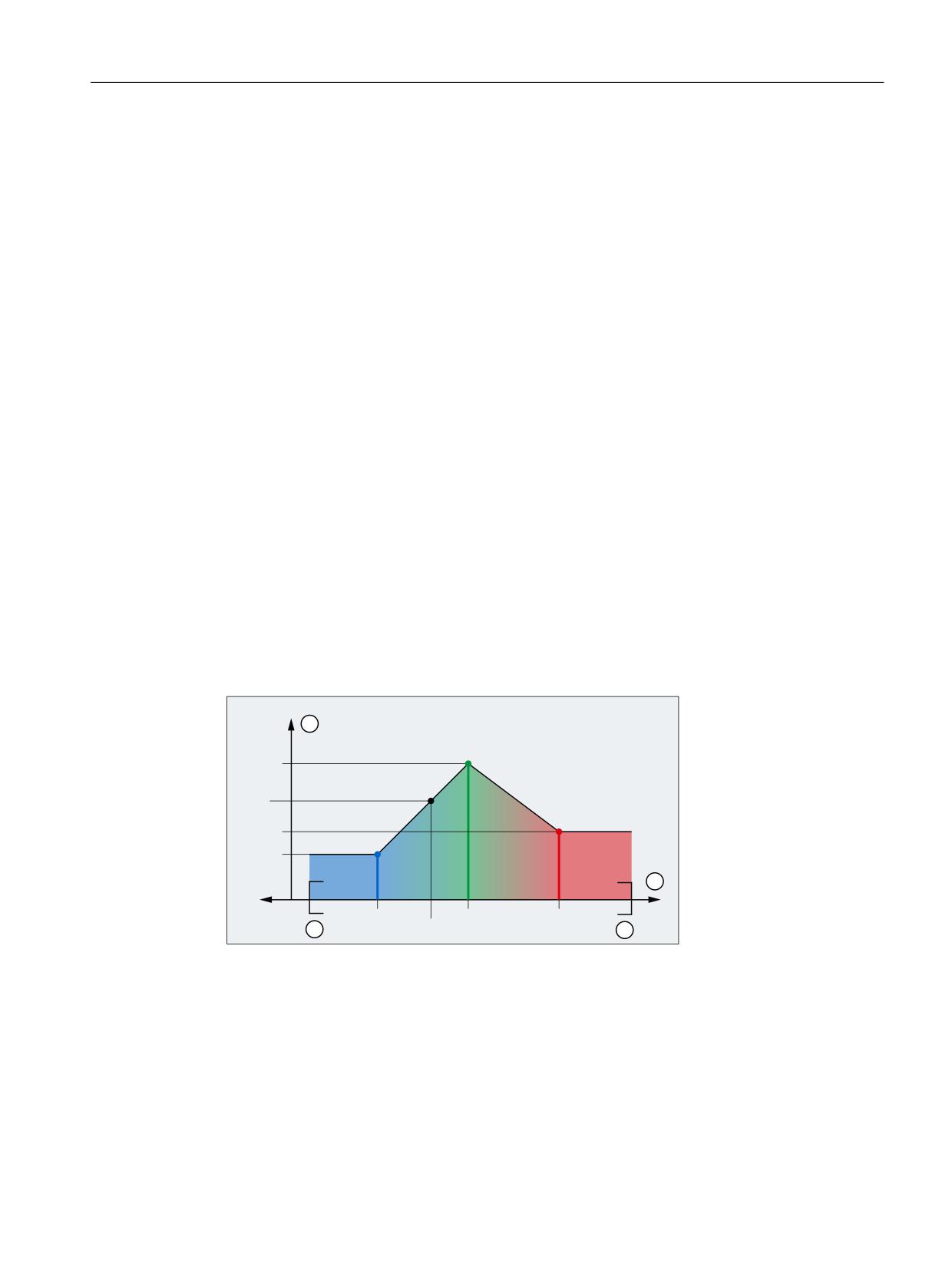
Compensations
9.4 Nodding compensation
Boundary conditions
• Rotary axes
It is not permissible for the compensating, the accelerating or the adaptation axis to be a
rotary axis.
• Differences to the compile cycle "RMCC/NOCO nodding compensation"
(6FC5800-0AN63-0YB0)
- The functionality of system function "Nodding compensation" is, contrary to compile
cycle "RMCC/NOCO", exclusively limited to compensating nodding motion. The functions
provided beyond this in the compile cycle, such as compensating centrifugal forces,
taking into account rotary axis positions as well as comprehensive position tables, are not
available with the system function.
- Either system function "Nodding compensation” can be used - or compile cycle "RMCC/
NOCO", but not together.
- It is not possible to use the parameterizing data of compile cycle "RMCC/NOCO" to
parameterize the "Nodding compensation" system function.
9.4.1.3
Position-dependent compliance factor
If the machine compliance depends on the position of another machine axis (adaptation axis),
then up to three different positions of the adaptation axis can be selected as interpolation points
of the adaptation characteristic; the effective compliance factors can then be determined from
the characteristic. Positions (P1, P2, P3) and the compliance factors effective there (N1, N2, N3)
must be saved in the machine data of the compensating axis. When traversing the accelerating
axis, the effective compliance factor is calculated depending on the position of the adaptation
axis by linearly interpolating between the interpolation points.
1
1
1
1
3
3
3
3
① Traversing range of the adaptation axis with P1 < P2 < P3
② Compliance factor of the compensating axis
③ Traversing range limit -
④ Traversing range limit +
Figure 9-5
Compensation characteristic
Monitoring and compensating
Function Manual, 10/2020, 6FC5397-7GP40-0BA1
235

Compensations
9.4 Nodding compensation
Actual position: P
Compliance factor: N
P less than P1 up to traversing range limit minus
N = N1
P between P1 and P2
N = linear interpolation between N1 and N2
P equal to P2
N = N2
P between P2 and P3
N = linear interpolation between N2 and N3
P greater than or equal to P3 - up to the traversing
N = N3
range limit plus
9.4.1.4
Compensation relationships
A compensation relationship defines the following dependencies of the compensation value:
• On the acceleration of the accelerating axis
• On the position of the adaptation axis
• On the machine compliance
Up to three compensation relationships can be parameterized in the machine data of a
compensating axis. The following data can be set for each compensation relationship:
• Accelerating axis
• Adaptation axis
• Number of positions of the adaptation axis
• Positioning the adaptation axis
• Compliance factors at the positions
Accelerating axes or adaptation axes
Any linear machine axis of the NC can be used as accelerating axis or adaptation axis. Even the
compensating axis itself.
Total compensation value
The total compensation value acting on the compensating axis is the sum of the compensation
values of the individual compensation relationships.
9.4.2
Commissioning: Machine data
9.4.2.1
Overview
The following table provides an overview with which machine data the nodding compensation
is parameterized.
Number
Name: $MA_
Meaning
MD37302
NOCO_FILTER_TIME
Time constant for smoothing nodding compensation
values (Page 237)
Compensation relationship 1
Monitoring and compensating
236
Function Manual, 10/2020, 6FC5397-7GP40-0BA1
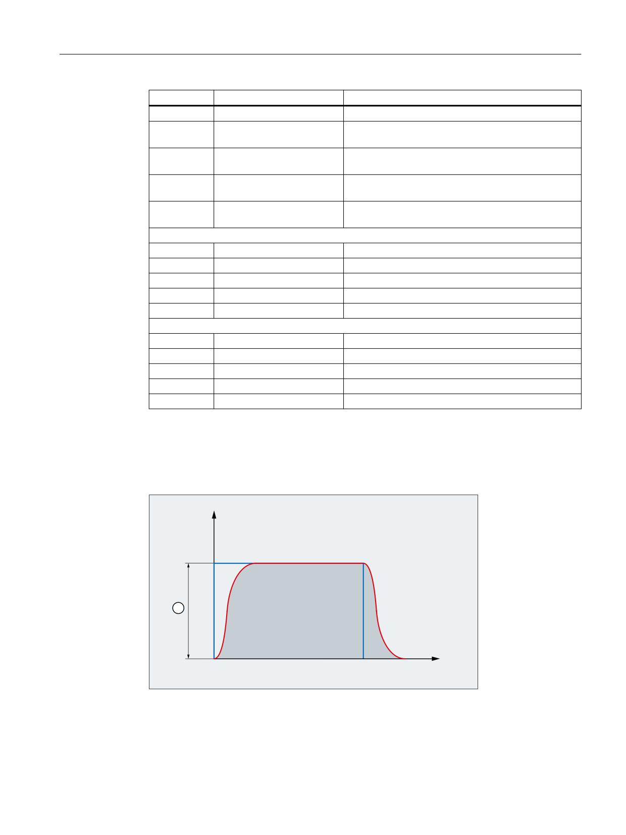
Compensations
9.4 Nodding compensation
Number
Name: $MA_
Meaning
MD37310
NOCO_INPUT_AX_1
Machine axis that causes nodding motion (Page 238)
MD37312
NOCO_ADAPT_AX_1
Machine axis, whose position influences nodding mo-
tion (Page 238)
MD37314
NOCO_ADAPT_NUM_1
Number of positions, adaptation characteristic of the
nodding compensation (Page 239)
MD37316
NOCO_ADAPT_POS_1
Positions, adaptation characteristic of the nodding com-
pensation (Page 240)
MD37318
NOCO_COMPLIANCE_1
Compliance factors for nodding compensation
(Page 241)
Compensation relationship 2
MD37320
NOCO_INPUT_AX_2
See MD37310
MD37322
NOCO_ADAPT_AX_2
See MD37312
MD37324
NOCO_ADAPT_NUM_2
See MD37314
MD37326
NOCO_ADAPT_POS_2
See MD37316
MD37328
NOCO_COMPLIANCE_2
See MD37318
Compensation relationship 3
MD37330
NOCO_INPUT_AX_3
See MD37310
MD37332
NOCO_ADAPT_AX_3
See MD37312
MD37334
NOCO_ADAPT_NUM_3
See MD37314
MD37336
NOCO_ADAPT_POS_3
See MD37316
MD37338
NOCO_COMPLIANCE_3
See MD37318
9.4.2.2
Time constant for smoothing nodding compensation values
Using the machine data, the time constant is set with which the total nodding compensation
value is smoothed when it is entered.
3RVLWLRQ
GHYLDWLRQ
>wP@
7LPH >PV@
① Position deviation
• Blue: Setpoint
• Red: Actual value
Monitoring and compensating
Function Manual, 10/2020, 6FC5397-7GP40-0BA1
237
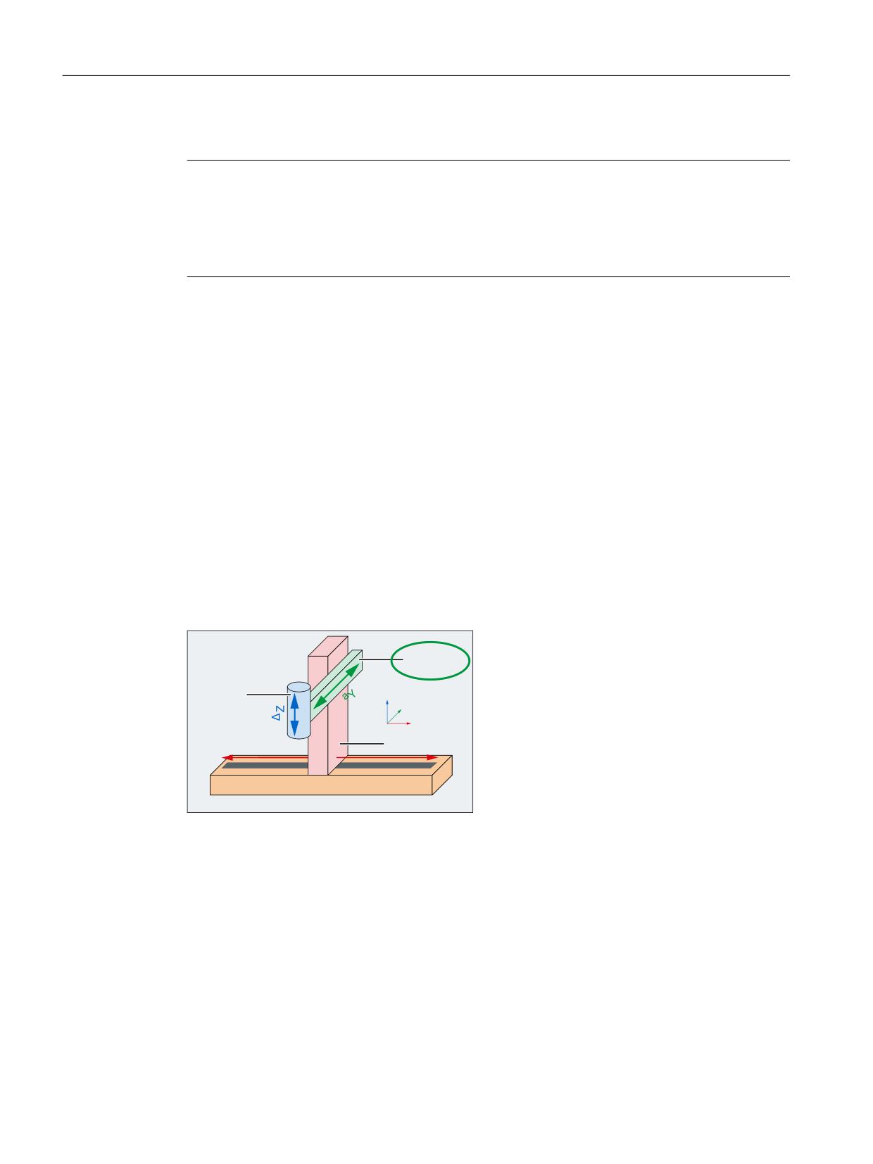
Compensations
9.4 Nodding compensation
MD37302 $MA_NOCO_FILTER_TIME[<comp. axis>] = <time constant>
Note
Deactivating smoothing
Smoothing is deactivated - or is not active - if the time constant is set to less than 10 % of the
position controller clock cycle:
Time constant < 0,1 * MD10061 $MN_POSCTRL_CYCLE_TIME
9.4.2.3
Accelerating axis
The number of the machine axis, whose acceleration causes position deviations in the
compensating axis, must be entered in the machine data.
The number of the accelerating axis refers to the machine axes of the NC parameterized in
machine data MD10002 $MN_AXCONF_LOGIC_MACHAX_TAB. The machine axis number is the
corresponding machine data index + 1.
MD37310 $MA_NOCO_INPUT_AX_1[<comp. Achse>] = <machine axis number>
Example
As a result of the machine compliance, when the Y axis accelerates, a position deviation occurs
in the Z axis.
• Compensating axis: AX3 (Z axis)
• Accelerating axis: AX2 (Y axis)
$;
<
$;
=
=
<
;
$;
;
Figure 9-6
Accelerating axis AX2 (Y axis)
MD10002 $MN_AXCONF_LOGIC_MACHAX_TAB[ 0 ] = "AX1"
; X axis
MD10002 $MN_AXCONF_LOGIC_MACHAX_TAB[ 1 ] = "AX2"
; Y axis
MD10002 $MN_AXCONF_LOGIC_MACHAX_TAB[ 2 ] = "AX3"
; Z axis
MD37310 $MA_NOCO_INPUT_AX_1[ AX3 ] = 2
; accelerating axis = Y axis
9.4.2.4
Adaptation axis
The number of the machine axis, whose actual position influences the position deviation in the
compensating axis, must be entered in the machine data.
Monitoring and compensating
238
Function Manual, 10/2020, 6FC5397-7GP40-0BA1
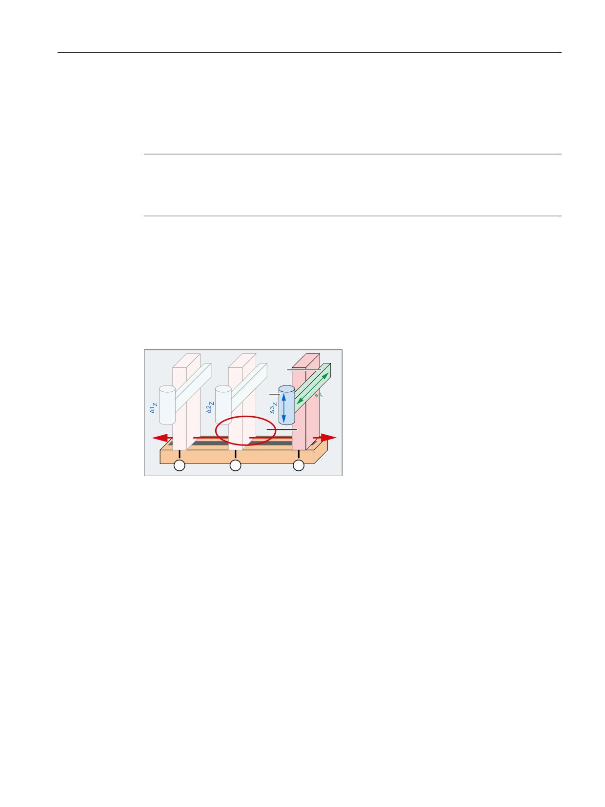
Compensations
9.4 Nodding compensation
The machine axis number refers to the machine axes of the NC parameterized in machine data
MD10002 $MN_AXCONF_LOGIC_MACHAX_TAB. The machine axis number is the corresponding
machine data index + 1.
MD37312 $MA_NOCO_ADAPT_AX_1[<comp. Achse>] = <machine axis number>
Note
Activating the position-dependent adaptation
The position-dependent adaptation only becomes active if one adaptation axis and more than
one position (MD37314 $MA_NOCO_ADAPT_NUM_1 (Page 239)) are parameterized.
Example
As a result of the machine compliance, when the Y axis accelerates, a position deviation occurs
in the Z axis. Further, the position deviation depends on the position of the X axis.
• Compensating axis: AX3 (Z axis)
• Accelerating axis: AX2 (Y axis)
• Adaptation axis: AX1 (X axis)
$;
<
$;
=
$;
;
①, ②, ③
Axis positions of the adaptation axis AX1 (X axis)
Figure 9-7
Adaptation axis AX1 (X axis)
MD10002 $MN_AXCONF_LOGIC_MACHAX_TAB[ 0 ] = "AX1"
; X axis
MD10002 $MN_AXCONF_LOGIC_MACHAX_TAB[ 1 ] = "AX2"
; Y axis
MD10002 $MN_AXCONF_LOGIC_MACHAX_TAB[ 2 ] = "AX3"
; Z axis
MD37312 $MA_NOCO_ADAPT_AX_1[ AX3 ] = 1
; adaptation axis = X axis
9.4.2.5
Number of positions of the adaptation characteristic
The number of axis positions, for which another compliance is effective, must be entered in the
machine data for the position-dependent adaptation.
Monitoring and compensating
Function Manual, 10/2020, 6FC5397-7GP40-0BA1
239
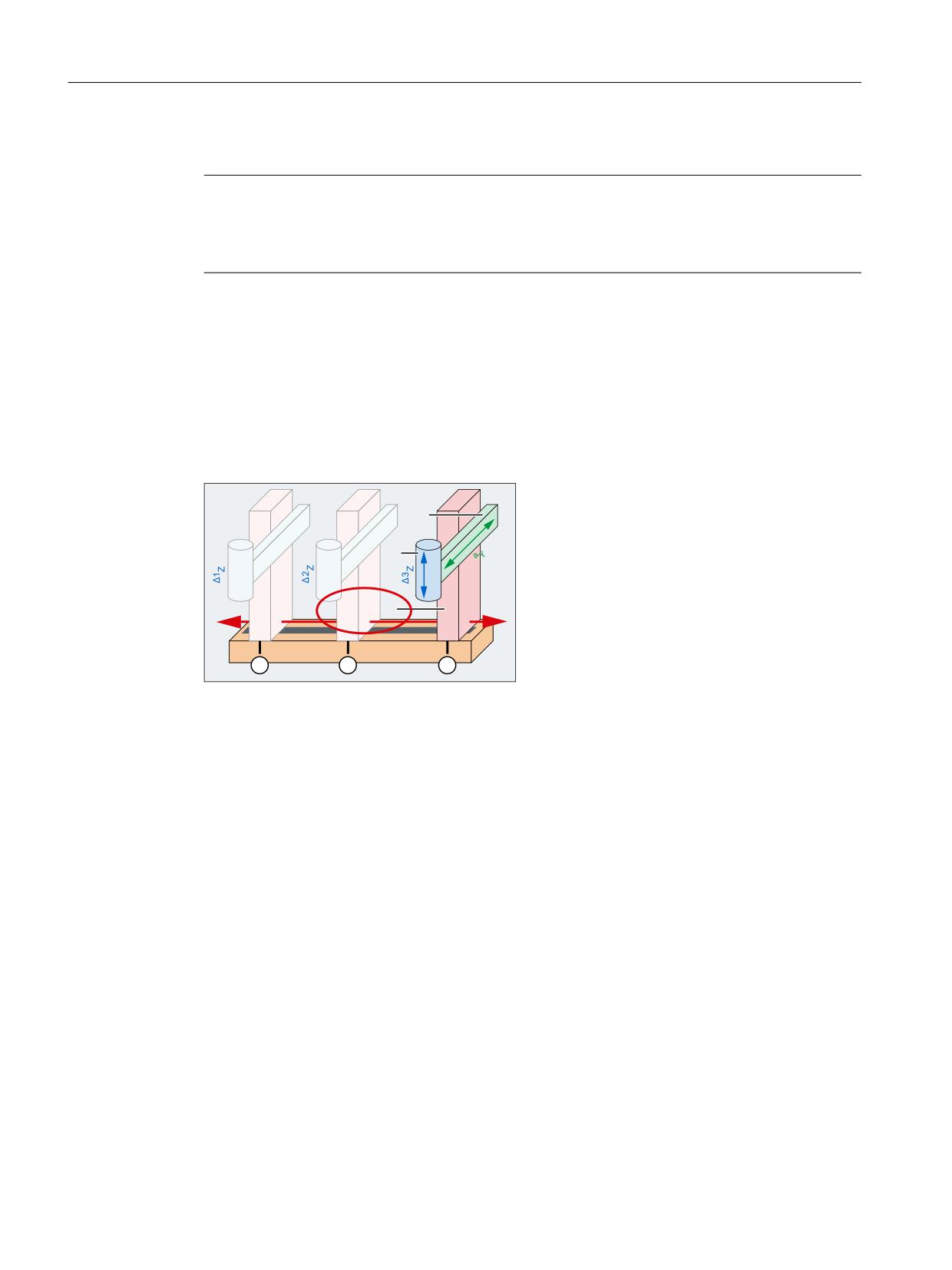
Compensations
9.4 Nodding compensation
MD37314 $MA_NOCO_ADAPT_NUM_1[<comp. Axis>] = <number>
Note
Activating the position-dependent adaptation
The position-dependent adaptation only becomes active if more than one position and one
adaptation axis (MD37312 $MA_NOCO_ADAPT_AX_1 (Page 238)) are parameterized.
Example
Interpolation points of the adaptation characteristic are to be parameterized at three positions
along the traversing range of the adaptation axis (X axis).
• Compensating axis: AX3 (Z axis)
• Accelerating axis: AX2 (Y axis)
• Adaptation axis: AX1 (X axis)
$;
<
$;
=
$;
;
①, ②, ③
Axis positions of the adaptation axis AX1 (X axis)
Figure 9-8
Number of axis positions of the adaptation axis AX1 (X axis)
MD10002 $MN_AXCONF_LOGIC_MACHAX_TAB[ 0 ] = "AX1"
; X axis
MD10002 $MN_AXCONF_LOGIC_MACHAX_TAB[ 1 ] = "AX2"
; Y axis
MD10002 $MN_AXCONF_LOGIC_MACHAX_TAB[ 2 ] = "AX3"
; Z axis
MD37314 $MA_NOCO_ADAPT_NUM_1[ AX3 ] = 3
; number of axis positions
See also:
• Axis positions: MD37316 $MA_NOCO_ADAPT_POS_1 (Page 240)
• Compliance factors: MD37318 $MA_NOCO_COMPLIANCE_1 (Page 241)
9.4.2.6
Positions of the adaptation characteristic
The positions of the adaptation axis, at which a dedicated compliance factor is parameterized,
must be entered in the machine data for the interpolation points of the adaptation characteristic:
MD37316 $MA_NOCO_ADAPT_POS_1[<index>, <comp. Axis>] = <position>
Monitoring and compensating
240
Function Manual, 10/2020, 6FC5397-7GP40-0BA1
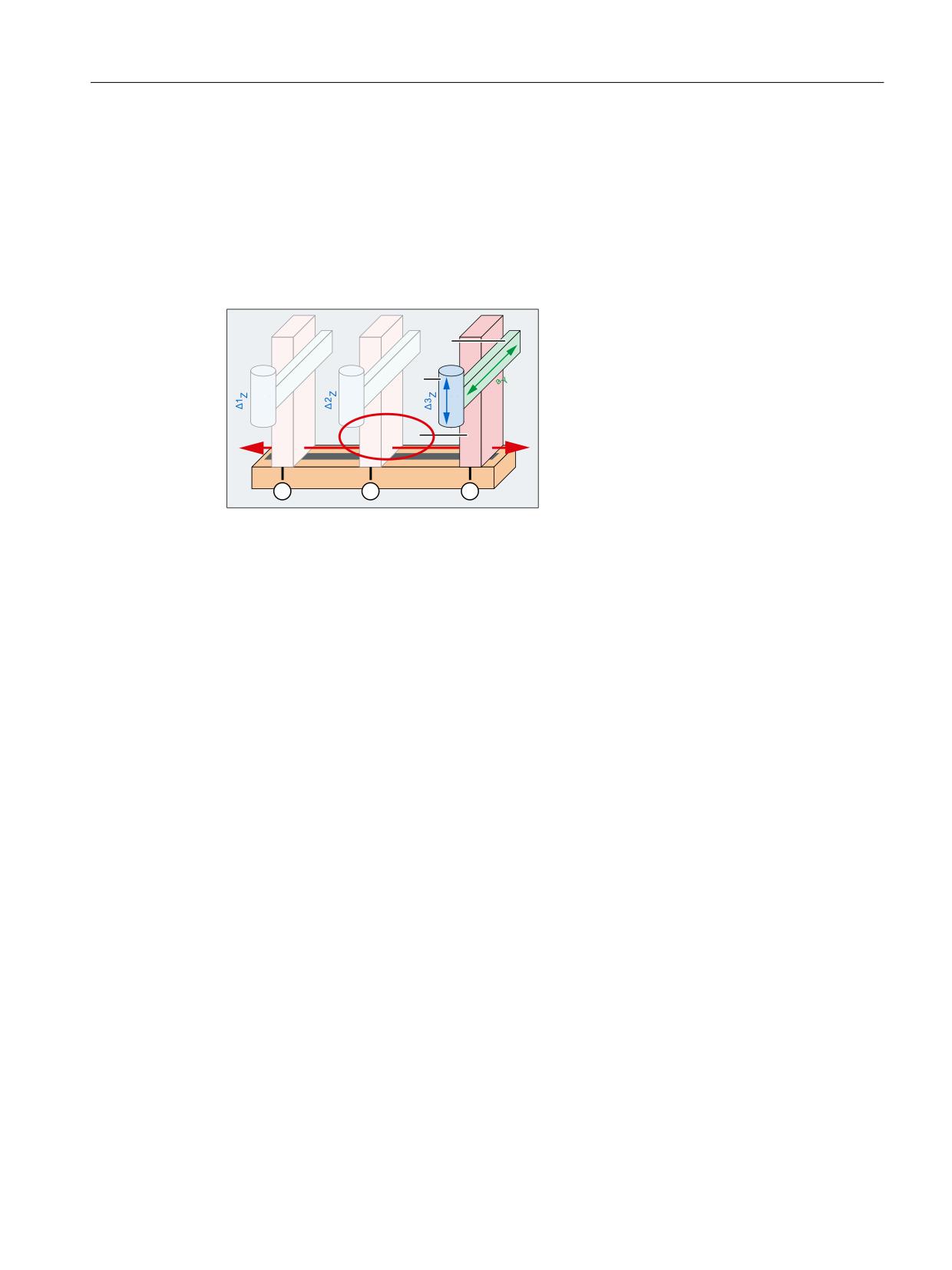
Compensations
9.4 Nodding compensation
Example
Interpolation points are parameterized at positions -100.0, 0.0, and 120.0 of adaptation axis
AX1 (X axis) for the adaptation characteristic.
• Compensating axis: AX3 (Z axis)
• Accelerating axis: AX2 (Y axis)
• Adaptation axis: AX1 (X axis)
$;
<
$;
=
$;
;
① Position 1: -100.0
② Position 2. 0.0
③ Position 3. 120.0
Figure 9-9
Axis positions of the adaptation axis AX1 (X axis)
MD10002 $MN_AXCONF_LOGIC_MACHAX_TAB[ 0 ] = "AX1"
; X axis
MD10002 $MN_AXCONF_LOGIC_MACHAX_TAB[ 1 ] = "AX2"
; Y axis
MD10002 $MN_AXCONF_LOGIC_MACHAX_TAB[ 2 ] = "AX3"
; Z axis
MD37316 $MA_NOCO_ADAPT_POS_1[ 0, AX3 ] = -100.0
MD37316 $MA_NOCO_ADAPT_POS_1[ 1, AX3 ] =
0.0
MD37316 $MA_NOCO_ADAPT_POS_1[ 2, AX3 ] =
120.0
See also:
• Number of axis positions: MD37314 $MA_NOCO_ADAPT_NUM_1 (Page 239)
• Compliance factors: MD37318 $MA_NOCO_COMPLIANCE_1 (Page 241)
9.4.2.7
Compliance factors
The compliance factors associated with the particular positions of the adaptation characteristic
(MD37316 $MA_NOCO_ADAPT_POS_1 (Page 240)) must be entered in the machine data.
MD37318 $MA_NOCO_COMPLIANCE_1[<index>, <comp. Achse>] = <compliance factor>
Without position-dependent adaptation
If no position-dependent adaptation is parameterized (MD37312 $MA_NOCO_ADAPT_AX_1
(Page 238) == 0), then the compliance factor must be entered into index 0:
MD37318 $MA_NOCO_COMPLIANCE_1[ 0, <comp. Achse>] = <compliance factor>
Monitoring and compensating
Function Manual, 10/2020, 6FC5397-7GP40-0BA1
241
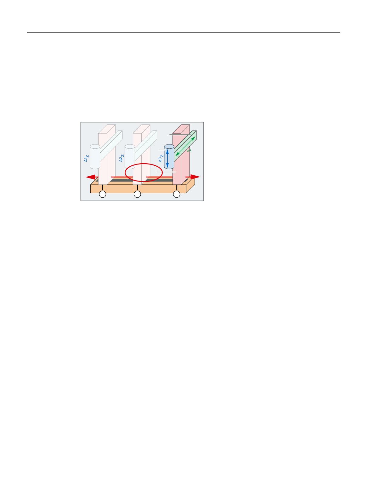
Compensations
9.4 Nodding compensation
Example
At positions -100.0, 0.0, and 120.0 of the traversing range of the adaptation axis (X axis), for the
compensating axis AX3 (Z axis) compliance factors -12 , -25 and -10 μm / m/s2 are determined.
• Compensating axis: AX3 (Z axis)
• Accelerating axis: AX2 (Y axis)
• Adaptation axis: AX1 (X axis)
$;
<
$;
=
$;
;
① Compliance factor at position 1: -12 μm / m/s2
② Compliance factor at position 2: -25 μm / m/s2
③ Compliance factor at position 3: -10 μm / m/s2
Figure 9-10
Adaptation axis: AX1 (X axis)
MD10002 $MN_AXCONF_LOGIC_MACHAX_TAB[ 0 ] = "AX1"
; X axis
MD10002 $MN_AXCONF_LOGIC_MACHAX_TAB[ 1 ] = "AX2"
; Y axis
MD10002 $MN_AXCONF_LOGIC_MACHAX_TAB[ 2 ] = "AX3"
; Z axis
MD37318 $MA_NOCO_COMPLIANCE_1[ 0, AX3 ] = -0.000012
MD37318 $MA_NOCO_COMPLIANCE_1[ 1, AX3 ] = -0.000025
MD37318 $MA_NOCO_COMPLIANCE_1[ 2, AX3 ] = -0.000010
See also:
• Number of axis positions: MD37314 $MA_NOCO_ADAPT_NUM_1 (Page 239)
Monitoring and compensating
242
Function Manual, 10/2020, 6FC5397-7GP40-0BA1
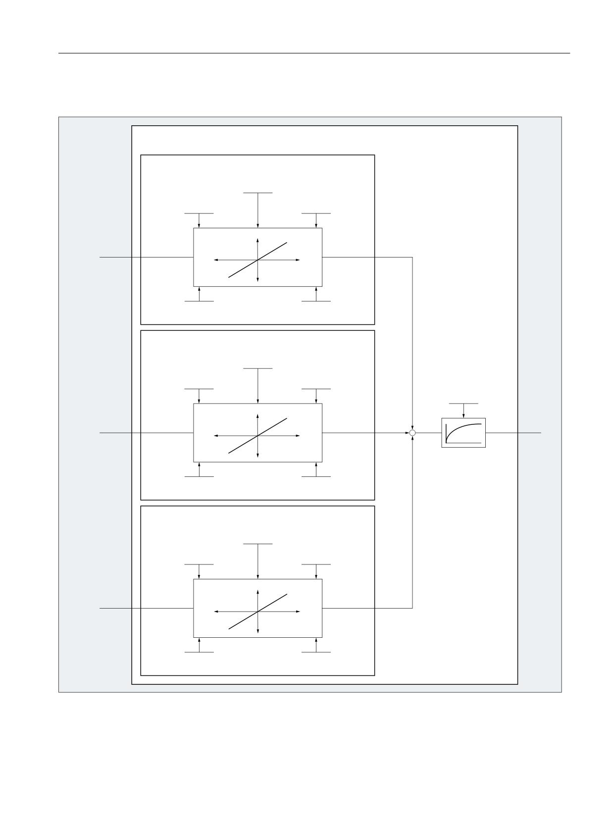
Compensations
9.4 Nodding compensation
9.4.2.8
Function diagram
1RGGLQJ FRPSHQVDWLRQ &RPSHQVDWLQJ D[LV
&RPSHQVDWLRQ UHODWLRQVKLS
0'
0$B12&2B$'$37B$;B
0'
0'
0$B12&2B,1387B$;B
0$B12&2B$'$37B180B
&RPSHQVDWLRQ FKDUDFWHULVWLF
D
V
˂
0'
0'
0$B12&2B$'$37B326B >
@
0$B12&2B&203/,$1&(B >
@
&RPSHQVDWLRQ UHODWLRQVKLS
0'
0$B12&2B$'$37B$;B
0'
0'
0$B12&2B,1387B$;B
0$B12&2B$'$37B180B
0'
0$B 12&2B),/7(5B7,0(
&RPSHQVDWLRQ FKDUDFWHULVWLF
D
V
˂
˂
0'
0'
0$B12&2B$'$37B326B >
@
0$B12&2B&203/,$1&(B >
@
&RPSHQVDWLRQ UHODWLRQVKLS
0'
0$B12&2B$'$37B$;B
0'
0'
0$B12&2B,1387B$;B
0$B12&2B$'$37B180B
&RPSHQVDWLRQ FKDUDFWHULVWLF
D
V
˂
0'
0'
0$B12&2B$'$37B326B >
@
0$B12&2B&203/,$1&(B >
@
Figure 9-11
Function diagram of a compensating axis
Monitoring and compensating
Function Manual, 10/2020, 6FC5397-7GP40-0BA1
243
Compensations
9.5 Interpolatory compensation
9.5
Interpolatory compensation
9.5.1
General properties
Function
With "interpolating compensation," deviations between the desired and the actual position of an
axis can be compensated by leadscrew, measuring system, sag and angularity errors. This is
done by determining the deviation by measurement and storing the corresponding
compensation values in one or more compensation tables in the NC. During operation, the
relevant compensation value is then determined from the compensation table or tables for a
compensation axis based on its current set position. Linear interpolation is performed between
the interpolation points of the compensation tables.
Within "interpolating compensation", a distinction is made between the two following
compensation methods:
• Compensation of leadscrew errors and measuring system errors
• Compensation of sag and angularity errors
Terms
• Compensation value
Additional setpoint that is applied to the compensation axis so that the difference between
the desired and actual axis position is zero.
• Basic axis
Axis, via whose set and actual position, the compensation value is determined from the
compensation value.
• Compensation axis
Axis, to whose set or actual position the compensation value is applied.
• Interpolation point
Value pair in a compensation table, consisting of a set and actual position of the basic axis
(interpolation point) and the associated compensation value (interpolation value).
• Compensation table
Defined number of interpolation points for a defined traversing range of the basic axis.
• Compensation relation
Unit comprising the basic axis, compensation axis, and compensation table.
Entering compensation tables
The size of the compensation table, i.e. the number of interpolation points, must first be
defined in a machine data. After the next POWER ON, the compensation tables are generated by
the NC and preassigned a value of "0".
Monitoring and compensating
244
Function Manual, 10/2020, 6FC5397-7GP40-0BA1
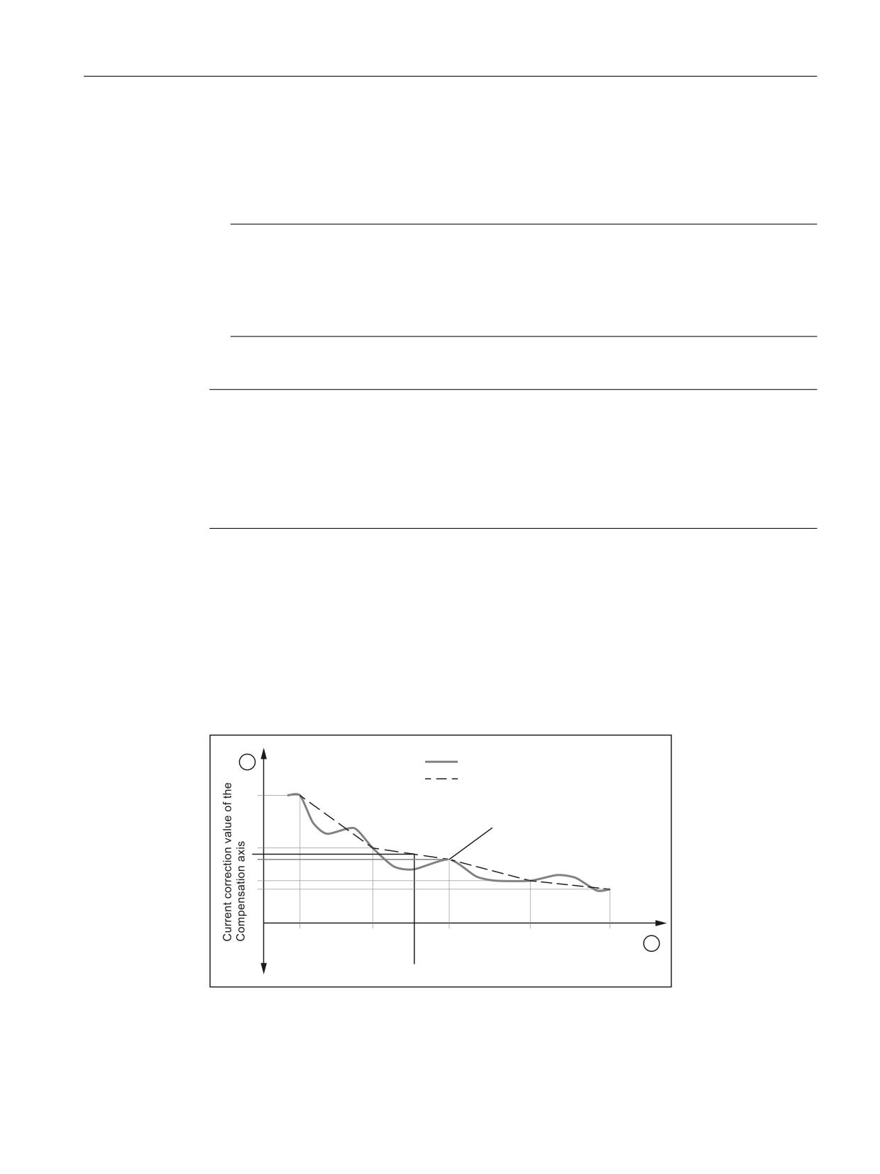
Compensations
9.5 Interpolatory compensation
The compensation values and additional table parameters are entered in the compensation
tables using special system variables. Data can be loaded in two different ways:
• By starting an NC program with the parameter values.
• By transferring the compensation tables from an external computer to the control.
Note
The respective compensation tables can only be loaded if the corresponding compensation
function is not active for all axes:
• MD32700 $MA_ENC_COMP_ENABLE[<axis>] == 0
• MD32710 $MA_CEC_ENABLE[<axis>] == 0
The compensation data is also retained when the control system is switched off.
Note
When changing machine data:
• MD18342 $MN_MM_CEC_MAX_POINTS
• MD38000 $MA_MM_ENC_COMP_MAX_POINTS
the static user memory is formatted the next time the system is booted (see Function Manual
"Basic Functions", Chapter "S7: Memory configuration").
Interim value calculation
The traversing distance defined via the start and end position within which compensation is to
apply, is divided into several sub-paths of equal size. The number of sub-paths is defined
depending on the error curve and the desired precision. The positions that limit these sub-paths
are referred to as interpolation points below. An interpolation and a compensation value must
be assigned to each interpolation point. Between two interpolation points, the effective
compensation value is determined by linear interpolation.
(UURU FXUYH
&RPSHQVDWLRQ FXUYH
,QWHUSRODWLRQ SRLQW
Q
Q
Q
Q
Q
&XUUHQW SRVLWLRQ RI EDVLF D[LV
① Compensation values of the compensation axis
② Position of basic axis
Figure 9-12
Intermediate value calculation by linear interpolation
Monitoring and compensating
Function Manual, 10/2020, 6FC5397-7GP40-0BA1
245
Compensations
9.5 Interpolatory compensation
Boundary conditions
Compensation value at reference point
It is recommended that a compensation table be structured in such a way that the compensation
value has the value "0" at the reference point of the axis.
9.5.2
Leadscrew error and measuring system error compensation
9.5.2.1
Measuring system error compensation (MSEC)
Leadscrew and measuring system errors
The measuring principle of "indirect measurement" on NC-controlled machines is based on the
assumption that the lead of the ball screw is constant at any point within the traversing range,
so that the actual position of the axis can be derived from the position of the drive spindle (ideal
case). However, manufacturing tolerances result in dimensional deviations of varying degrees
of severity on spindles (so-called leadscrew errors).
Added to this are the dimensional deviations (differences in reference division) caused by the
measuring system as well as its mounting on the machine (so-called measuring system errors),
plus any machine-dependent error sources.
Compensation
With "measuring system error compensation" (referred to below as MSEC), the base and
compensation axes are always identical. It is therefore an axial compensation for which a
definition of the base axis and compensation axis in the compensation table is not necessary.
Note
The leadscrew error compensation (LEC) is part of the measuring system error compensation.
The principle of the MSEC is to modify the axis-specific position actual value by the assigned
compensation value in the interpolator clock cycle and to apply this value to the machine axis for
immediate traversal. A positive compensation value causes the corresponding machine axis to
move in the negative direction.
The magnitude of the compensation value is not limited and is not monitored. In order to avoid
impermissibly high velocities and accelerations caused by compensation, small compensation
values must be selected. Large compensation values can cause other axis monitoring functions
to output alarms (e.g. contour monitoring, speed setpoint limitation).
If the axis to be compensated has a 2nd position measuring system, a separate compensation
table must be created and activated for each measuring system. The correct table is
automatically used when switching between measuring systems.
Monitoring and compensating
246
Function Manual, 10/2020, 6FC5397-7GP40-0BA1
Compensations
9.5 Interpolatory compensation
Preconditions / activation
The MSEC is only active until the following pre-conditions:
• The compensation values are stored in the static user memory and are active (after POWER
ON).
• The function has been activated for the relevant machine axis:
MD32700 $MA_ENC_COMP_ENABLE [<e>] = 1
with: <e>
= Position measuring system
<e> = 0
Measuring system 1
<e> = 1
Measuring system 2
• The axis has been referenced:
DB31, ... DBX60.4 or 60.5 =1 (referenced/synchronized 1 or 2)
As soon as these conditions have been fulfilled, the axis-specific actual value is modified by the
compensation value in all modes and traversed by the machine axis immediately.
If the reference is then lost, e.g. because the encoder frequency has been exceeded (DB31, ...
DBX60.4 or 60.5 = 0), compensation processing is deactivated.
9.5.2.2
Commissioning
Machine data
Number of compensation interpolation points
For each machine axis as well as for each measuring system (if a 2nd measuring system is
available), the number of reserved interpolation points must be specified for the compensation
table:
MD38000 $MA_MM_ENC_COMP_MAX_POINTS[<e>,<AXi>]
• <e>: Position measuring system
• <AXi>: axis
The number of interpolation points of a compensation table is calculated from the
accompanying system variables (see below):
• End position: $AA_ENC_COMP_MAX[...]
• Start position: $AA_ENC_COMP_MIN[...]
• Distance between interpolation points: $AA_ENC_COMP_STEP[...]
Number of interpolation points = ((end position - start position) / interpolation point distance)
+ 1
Monitoring and compensating
Function Manual, 10/2020, 6FC5397-7GP40-0BA1
247
Compensations
9.5 Interpolatory compensation
System variables
For each machine axis as well as for each measuring system (if a 2nd measuring system exists),
the position-related compensation values as well as additional table parameters should be saved
for every compensation relationship in the form of system variables:
• $AA_ENC_COMP_MIN[<e>,<AXi>] (initial position)
The initial position is the axis position at which the compensation table for the relevant axis
begins (≙ interpolation point 0).
The compensation value for the initial position is $AA_ENC_COMP[<e>,0,<AXi>)].
The compensation value of interpolation point 0 is used for all positions smaller than the
initial position (does not apply for tables with modulo function).
• $AA_ENC_COMP_MAX[<e>,<AXi>] (end position)
The end position is the axis position at which the compensation table for the relevant axis
ends (≙ interpolation point <k>).
The compensation value for the end position is $AA_ENC_COMP[<e>,<k>,<AXi>)].
The compensation value of interpolation point is used for all positions larger than the end
position (exception for table with modulo function).
The following supplementary conditions apply to interpolation point <k>:
- for k = MD38000 - 1:
The compensation table is fully utilized!
- for k < MD38000 - 1:
The compensation table is not fully utilized. Compensation values entered in the table
that are greater than k are ignored.
- for k > MD38000 - 1:
The compensation table is limited by a control function which reduces the end position.
Compensation values that are greater than k are ignored.
• $AA_ENC_COMP_STEP[<e>,<AXi>] (distance between interpolation points)
The distance between interpolation points defines the distance between the compensation
values in the relevant compensation table.
Monitoring and compensating
248
Function Manual, 10/2020, 6FC5397-7GP40-0BA1

Compensations
9.5 Interpolatory compensation
•
$AA_ENC_COMP[<e>,<N>,<AXi>] (correction value for interpolation point N of the
compensation table)
<N> = interpolation point (axis position)
For every individual interpolation point the compensation value must be entered in the table.
<N> is limited by the maximum number of interpolation points of the particular
compensation table (MD38000 $MA_MM_ENC_COMP_MAX_POINTS):
0 ≤ N ≤ MD38000 -1
The size of the compensation value is not limited.
Note
The first and last compensation values remain active over the entire traversing range;
i.e. these values should be set to "0" if the compensation table does not cover the entire
traversing range.
•
$AA_ENC_COMP_IS_MODULO[<e>,<AXi>] (compensation with modulo function)
System variable to activate/deactivate the compensation with modulo function:
- $AA_ENC_COMP_IS_MODULO[<e>,<AXi>] = 0: Compensation without modulo function
- $AA_ENC_COMP_IS_MODULO[<e>,<AXi>] = 1: Compensation with modulo function
When compensation with modulo function is activated, the compensation table is repeated
cyclically, i.e. the compensation value at position $AA_ENC_COMP_MAX (≙ interpolation
point $AA_ENC_COMP[<e>,<k>,<AXi>]) is immediately followed by the compensation value
at position $AA_ENC_COMP_MIN (≙ interpolation point $AA_ENC_COMP[<e>,<0>,<AXi>]).
For rotary axes with modulo 360° degrees it is therefore suitable to program 0°
($AA_ENC_COMP_MIN) as the initial position and 360° ($AA_ENC_COMP_MAX) as the end
position.
The compensation values entered for these two positions should be the same as otherwise
the compensation value jumps from MAX to MIN at the transition point and vice versa.
CAUTION
Wrong correction values
When writing the correction values for a correction table, it must be ensured that all
interpolation points within the parameterized range are assigned a value. Correction values
which are not described otherwise contain random values.
Note
Table parameters containing position information are automatically converted when the
system of units is changed (change from MD10240 $MN_SCALING_SYSTEM_IS_METRIC).
The position information is always interpreted in the current measuring system. Conversion
must be implemented externally.
Automatic conversion of the position data can be configured as follows:
MD10260 $MN_CONVERT_SCALING_SYSTEM = 1
External conversion is no longer necessary.
Further information
Function Manual Basic Functions; Velocities, setpoint/actual value systems, closed-loop
control
Monitoring and compensating
Function Manual, 10/2020, 6FC5397-7GP40-0BA1
249
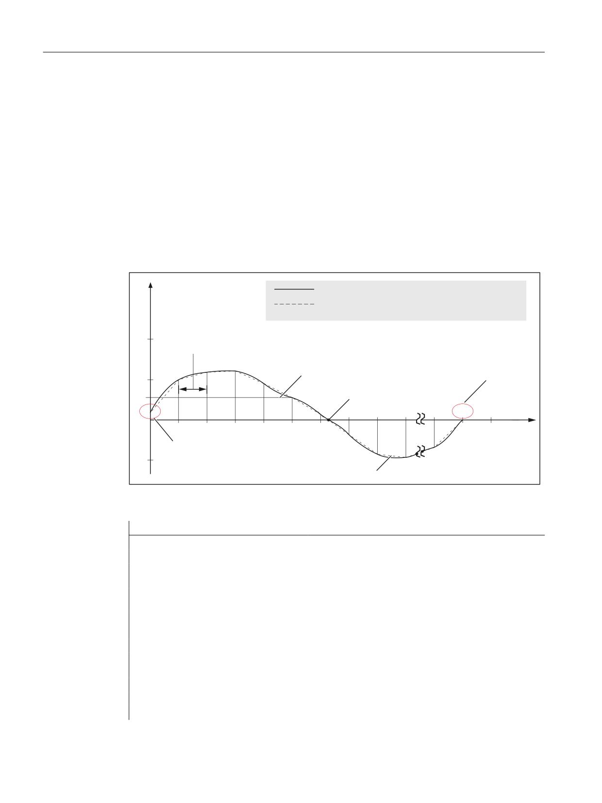
Compensations
9.5 Interpolatory compensation
9.5.2.3
Example
Sample parameterization of a compensation table:
• Machine axis: X1
• Measuring system: 1
• Starting position: -200 mm
• End position: 600 mm
• Distance between interpolation points: 1 mm
• Number of interpolation points: MD38000 $MA_MM_ENC_COMP_MAX_POINTS = ((600 -
-200) / 1) + 1 = 801
The memory requirement in the static user memory is: 801 * 8 Byte = 6408 Byte
(UURU FXUYH
2IIVHW YDOXH
&RPSHQVDWLRQ FXUYH
OLQHDU LQWHUSRODWLRQ EHWZHHQ LQWHUSRODWLRQ SRLQWV
,QWHUSRODWLRQ SRLQW GLVWDQFH
1XPEHU RI LQWHUSRODWLRQ SRLQWV
$$B(1&B&203
0'
0$B00B(1&B&203B0$;B32,176 ุ
2IIVHW YDOXH DW
(QG SRVLWLRQ
LQWHUSRODWLRQ SRLQW
$$B(1&B&203B0$;
2IIVHW YDOXH DW
UHIHUHQFH SRLQW
$[LV SRVLWLRQ
,QWHUSRODWLRQ
SRLQW
6WDUWLQJ SRVLWLRQ
$$B(1&B&203B0,1
OLQHDU LQWHUSRODWHG LQWHUPHGLDWH YDOXHV
Program for writing system variables
Program code
Comment
%_N_AX_EEC_INI
CHANDATA(1)
$AA_ENC_COMP[0,0,X1]=0.003
1st compensation value (interpolation point 0):
+3μm
$AA_ENC_COMP[0,1,X1]=0.01
2nd compensation value (interpolation point 1):
+10μm
$AA_ENC_COMP[0,2,X1]=0.012
3rd compensation value (interpolation point 2):
+12μm
$AA_ENC_COMP[0,800,X1]=-0.0
Last compensation value (interpolation point
800): 0μm
$AA_ENC_COMP_STEP[0,X1]=1.0
Distance between interpolation points 1.0 mm
$AA_ENC_COMP_MIN[0,X1]=-200.0
Compensation starts at -200.0 mm
$AA_ENC_COMP_MAX[0,X1]=600.0
Compensation ends at +600.0 mm
Monitoring and compensating
250
Function Manual, 10/2020, 6FC5397-7GP40-0BA1