SINUMERIK 840D sl. Service - Functions. Manual (2018-2020) - page 46

Protection areas
6.1 Function
The protection zone definitions are stored in the following files:
File
Blocks
_N_NCK_PRO
Data block for machine-specific protection zones
_N_CHAN1_PRO
Data block for channel-specific protection zones in channel 1
_N_CHAN2_PRO
Data block for channel-specific protection zones in channel 2
Data backup
The protection zone definitions are saved in the following files:
File
Blocks
_N_INITIAL_INI
All data blocks of the protection zones
_N_COMPLETE_PRO
All data blocks of the protection zones
_N_CHAN_PRO
All data blocks of the channel-specific protection zones
Activating, preactivating and deactivating protection zones
Activation state
The activation state of a protection zone can have the following values:
• Activated
• Preactivated
• Preactivated with conditional stop
• Deactivated
The activation state is always channel-specific even for machine specific protection zones.
Activating, preactivating and deactivating in the part program
The activation state of a protection zone can be changed in the part program at any time using
commands (see "Activating/deactivating protection zones (CPROT, NPROT) (Page 120)").
Note
A protection zone is only taken into account after the referencing of all geometry axes of the
channel in which it has been activated.
Protection zones that are to be activated at a later time from the PLC user program (see below)
must be preactivated in the part program:
Preactivated protection zones are displayed via the following NC/PLC interface signals:
• DB21, ... DBX272.0 - 273.1 (machine-specific protection zone 1 - 10 preactivated) == 1
• DB21, ... DBX274.0 - 275.1 (channel-specific protection zone 1 - 10 preactivated) ==== 1
Monitoring and compensating
Function Manual, 10/2020, 6FC5397-7GP40-0BA1
113

Protection areas
6.1 Function
Preactivated with conditional stop
NOTICE
Protection zone violation possible
If a preactivated protection zone with conditional stop is not activated in good time, the NC may
no longer be able to stop before the protection zone in good time because the braking distance
after the activation point has not been taken into account.
In the case of a preactivated protection zone with conditional stop, a traversing motion is not
stopped before this if the traversing motion goes into the protection zone. A stop is only
performed when the protection zone has been activated. This behavior is to enable
uninterrupted machining controlled by the user when the protection zone is only required
temporarily.
Activating using NC/PLC interface signals
Only protection zones that have been preactivated via the part program can be activated in the
PLC user program via the NC/PLC interface signals:
• DB21, ... DBX8.0 - 9.1 (activate machine-specific protection zone 1 - 10 ) = 1
• DB21, ... DBX10.0 - 11.1 (activate channel-specific protection zone 1 - 10) = 1
The activation of preactivated protection zones must be performed prior to the traversing
motion of the geometry axes! If the activation is performed during the traversing motion, these
protection zones are not taken into account in the current traversing motion. Response:
• Alarm "10704 "Protection zone monitoring is not guaranteed"
• DB21, ... DBX39.0 (protection-zone monitoring not guaranteed) = 1
Note
The activation of preactivated protection zones must be performed prior to the traversing
motion of the geometry axes!
Deactivating using NC/PLC interface signals
Only protection zones that have been preactivated via a part program and activated via the NC/
PLC interface signals, can be deactivated again via the NC/PLC interface signals:
• DB21, ... DBX8.0 to DBX9.1 (activate machine-specific protection zone 1 - 10 ) = 0
• DB21, ... DBX10.0 to DBX11.1 (activate channel-specific protection zone 1 - 10) = 0
Protection zones that have been activated directly via a part program cannot be deactivated
from the PLC user program.
Automatic deactivation for transformation change/geometry axis interchange
In the default setting, when changing a transformation, or for a geometry axis interchange, the
active protection zones are automatically deactivated. On the other hand, if active protection
zones should remain active, then the bit-coded machine data MD10618
$MN_PROTAREA_GEOAX_CHANGE_MODE must be correspondingly adapted (see "Machine
data (Page 116)").
Monitoring and compensating
114
Function Manual, 10/2020, 6FC5397-7GP40-0BA1
Protection areas
6.1 Function
Activation state in special system states
Block search with calculation
For block search with calculation, the last programmed activation state of a protection zone is
always taken into account.
Program test
In the AUTOMATIC and MDI modes, activated and preactivated protection zones are also
monitored in the "Program test" state.
NC RESET and end of program
The activation state of a protection zone is retained even after NC-RESET and program end.
Display of protection zone violations
Violations of activated protection zones or possible violations of preactivated protection zones,
if they would be activated, are displayed using the following NC/PLC interface signals:
• DB21, ... DBX276.0 - 277.1 (machine-specific protection zone 1 - 10 violated) == 1
• DB21, ... DBX278.0 - 279.1 (channel-specific protection zone 1 - 10 violated) == 1
Checking for protection zone violation
Function CALCPOSI can be used to check whether geometry axes can traverse a specified path
without violating a protection zone (see "Checking for protection zone violation, working area
limitation and software limit switches (CALCPOSI) (Page 123)").
Monitoring and compensating
Function Manual, 10/2020, 6FC5397-7GP40-0BA1
115

Protection areas
6.2 Commissioning
6.2
Commissioning
6.2.1
Machine data
Memory requirements
The memory required for protection zones is parameterized via the following machine data:
• Persistent memory
- MD18190 $MN_MM_NUM_PROTECT_AREA_NCK (number of available machine-specific
protection zones)
- MD28200 $MC_MM_NUM_PROTECT_AREA_CHAN (number of available channel-specific
protection zones)
• Dynamic memory
- MD28210 $MC_MM_NUM_PROTECT_AREA_ACTIVE (maximum number of protection
zones that can be activated simultaneously in the channel)
- MD28212 $MC_MM_NUM_PROTECT_AREA_CONTUR (maximum number of definable
contour elements per protection zone)
Response for a transformation change/geometry axis interchange
The following machine data can be used to define as to whether, when changing a
transformation or for a geometry axis interchange, active protection zones should be kept or
deactivated:
MD10618 $MN_PROTAREA_GEOAX_CHANGE_MODE
Bit
Value
Meaning
0
0
The active protection zones are deactivated during the transformation change.
1
The active protection zones remain active during the transformation change.
1
0
The active protection zones are deactivated during the geometry axis change.
1
The active protection zones remain active during the geometry axis change.
Monitoring and compensating
116
Function Manual, 10/2020, 6FC5397-7GP40-0BA1

Protection areas
6.3 Programming
6.3
Programming
6.3.1
Defining protection zones (CPROTDEF, NPROTDEF)
Protection zones, which protect machine elements against collisions, are defined in the part
program in blocks. These contain the following elements:
1. Definition of the machining plane
Before the actual protection zone definition, the machining plane must be selected, to which
the contour description of the protection zone refers.
2. Start of the definition
Depending on the particular NC command, either a channel-specific or machine-specific
protection zone is created.
3. Contour description of the protection zone
The contour of a protection zone is defined with traversing motion. These are not executed
and have no connection to previous or subsequent geometry descriptions. They only define
the protection zone.
4. End of definition
Syntax
DEF INT <Var>
G17/G18/G19
CPROTDEF/NPROTDEF(<n>,<t>,<AppLim>,<AppPlus>,<AppMinus>)
G0/G1/... X/Y/Z
EXECUTE(<Var>)
Meaning
DEF INT <Var>:
Definition of a local help variable, of the INTEGER data type
<Var>:
Name of the Help variable
G17/G18/G19:
Machining plane
Note:
It is not permissible to change the machining plane before the
end of the definition. Programming the applicate is not permit-
ted between start and end of the definition.
CPROTDEF():
Predefined procedure to define a channel-specific protection
zone
NPROTDEF():
Predefined procedure to define a machine-specific protection
zone
<n>:
Number of defined protection zone
Data type:
INT
Monitoring and compensating
Function Manual, 10/2020, 6FC5397-7GP40-0BA1
117
Protection areas
6.3 Programming
<t>:
Type of protection zone
Data type:
BOOL
Value:
TRUE
Tool-related protection zone
FALSE
Workpiece-related protection zone
<AppLim>:
Type of limitation in the third dimension
Data type:
INT
Value:
0
No limitation
1
Limit in plus direction
2
Limit in minus direction
3
Limit in positive and negative direction
<AppPlus>:
Value of the limit in the positive direction in the 3rd dimension
Data type:
REAL
<AppMinus>:
Value of the limit in the negative direction in the 3rd dimension
Data type:
REAL
G0/G1/... X/Y/Z
:
The contour of a protection zone is specified with up to 11 tra-
versing movements in the selected machining plane. The first
traversing movement is the movement to the contour. The last
point in the contour description must always coincide with the
first point of the contour description.
The valid protection zone is the zone left of the contour:
• Internal protection zone
The contour of an internal protection zone must described in
the counterclockwise direction.
• External protection zones (permitted only for workpiece-re-
lated protection zones)
The contour for an external protection zone must be descri-
bed in the clockwise direction.
The following contour elements are permissible:
• G0, G1 for straight contour elements
• G2 for circle segments in the clockwise direction
Permissible only for workpiece-related protection zones. Not
permissible for tool-related protection zones because they
must be convex.
• G3 for circular segments in the counter-clockwise direction
Note:
A protection zone cannot be described by a complete circle. A
complete circle must be divided into two semicircles.
Note:
The sequence G2 → G3 or G3 → G2 is not permissible! A short G1
block must be inserted between the two circular blocks.
EXECUTE(<Var>):
Predefined procedure that marks the end of the definition
A switch is made back to normal program processing
with EXECUTE.
Example
See example under "Activating/deactivating protection zones (CPROT, NPROT) (Page 120)".
Monitoring and compensating
118
Function Manual, 10/2020, 6FC5397-7GP40-0BA1
Protection areas
6.3 Programming
Additional information
Machine-specific protection zones
A machine-specific protection zone or its contour is defined using the geometry axis, i.e.
referenced to the basic coordinate system (BCS) of a channel. In order that correct protection-
zone monitoring can take place in all channels in which the machine-specific protection zone is
active, the basic coordinate system (BCS) of all of the channels involved must be identical:
• position of the coordinate origin referred to the machine zero
• Orientation of the coordinate axes
Reference point for contour description
• Tool-related protection zones
Coordinates for tool-related protection zones must be specified as absolute values referred
to the tool holder reference point F.
• Workpiece-related protection zones
Coordinates for workpiece-related protection zones must be specified as absolute values
referred to the zero point of the basic coordinate system (BCS).
Protection zones symmetrical around the center of rotation
For protection zones symmetrical around the axis or rotation (e.g. spindle chuck), you must
describe the complete contour and not only the contour up to the center of rotation.
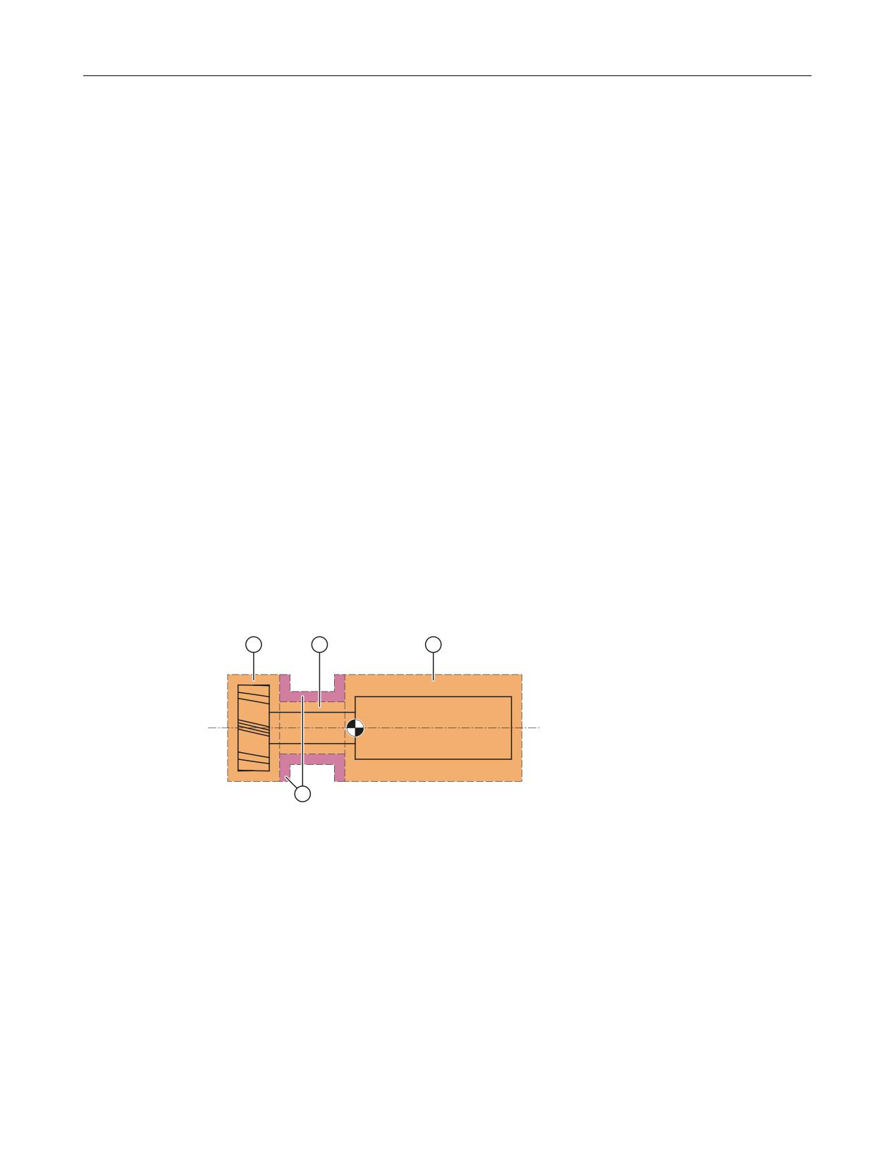
Tool-related protection zones
Tool-related protection zones must always be convex. If a concave protected zone is desired, this
should be subdivided into several convex protection zones.
)
① Convex protection zones
② Concave protection zones (not permissible!)
F
Toolholder reference point
General conditions
During the definition of a protection zone, the following functions must not be active or used:
• Tool radius compensation (cutter radius compensation, tool nose radius compensation)
• Transformation
• Reference point approach (G74)
• Fixed point approach (G75)
Monitoring and compensating
Function Manual, 10/2020, 6FC5397-7GP40-0BA1
119
Protection areas
6.3 Programming
• Dwell time (G4)
• Block search stop (STOPRE)
• End of program (M17, M30)
• M functions: M0, M1, M2
6.3.2
Activating/deactivating protection zones (CPROT, NPROT)
Protection zones previously defined in the part program can be activated at any time - or can be
preactivated for subsequent activation by the PLC user program. Active protection zones can be
deactivated at any time.
When activating or preactivating, it is also possible to relatively shift the reference point of the
protection zone.
Note
A protection zone is only taken into account after the referencing of all geometry axes of the
channel in which it has been activated.
Note
Monitoring protection zones
If a tool-related protection area is not active, the tool path is checked against the workpiece-
related protection zones.
If no workpiece-oriented protection zone is active, then there is no protection zone monitoring.
Syntax
CPROT(<n>,<Status>,<XMov>,<YMov>,<ZMov>)
NPROT(<n>,<Status>,<XMov>,<YMov>,<ZMov>)
Meaning
CPROT:
Predefined procedure to activate a channel-specific protection zone
NPROT:
Predefined procedure to activate a machine-specific protection
zone
<n>:
Number of the protection zone
Data type:
INT
<Status>:
The channel-specific activation status is set using this parameter
Data type:
INT
Value:
0
Deactivate protection zone
1
Preactivate protection zone
2
Activate protection zone
3
Preactivate protection zone with conditional
stop
Monitoring and compensating
120
Function Manual, 10/2020, 6FC5397-7GP40-0BA1
Protection areas
6.3 Programming
<XMov>,<YMov>,<ZMov>:
Additive offset values in the X/Y/Z direction
The offset can take place in 1, 2, or 3 dimensions. The offset values
refer to:
• The machine zero for a workpiece-related protection zone
• The tool carrier reference point F for a tool-specific protection
zone
Data type:
REAL
Example
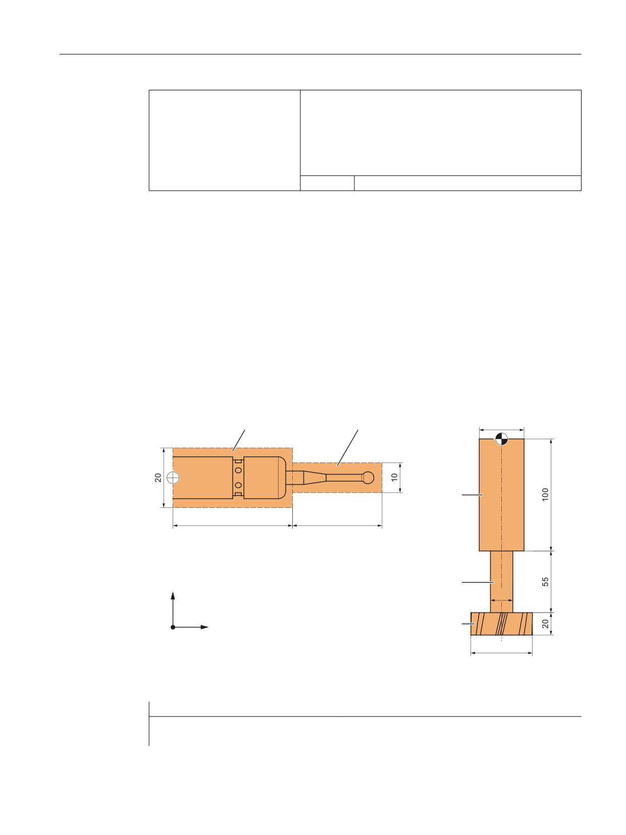
Possible collision of a milling cutter with the measuring probe is to be monitored on a milling
machine. The position of the measuring probe is to be defined by an offset when the function is
activated.
The following protection zones are defined for this:
• A machine-specific and a workpiece-related protection zone for both the measuring probe
holder (n-PZ1) and the measuring probe itself (n-PZ2).
• A channel-specific and a tool-related protection zone for the milling cutter holder (c-PZ1), the
cutter shank (c-PZ2) and the milling cutter itself (c-PZ3).
The orientation of all protection zones is in the Z direction.
The position of the reference point of the measuring probe on activation of the function must
be X = -120, Y = 60 and Z = 80.
Q 3=
Q 3=
)
F 3=
F 3=
=
F 3=
;
① Name for the protection zone of the probe
F
Toolholder reference point
Program code
Comment
DEF INT PROTZONE
; Definition of a Help variable
G17
; machining plane XY
Monitoring and compensating
Function Manual, 10/2020, 6FC5397-7GP40-0BA1
121
Protection areas
6.3 Programming
Program code
Comment
; defining protection zones:
NPROTDEF(1,FALSE,3,10,-10)
;
protection zone n-PZ1
G01 X0 Y-10
X40
Y10
X0
Y-10
EXECUTE(PROTZONE)
NPROTDEF(2,FALSE,3,5,-5)
;
protection zone n-PZ2
G01 X40 Y-5
X70
Y5
X40
Y-5
EXECUTE(PROTZONE)
CPROTDEF(1,TRUE,3,0,-100)
;
protection zone c-PZ1
G01 X-20 Y-20
X20
Y20
X-20
Y-20
EXECUTE(PROTZONE)
CPROTDEF(2,TRUE,3,-100,-150)
;
protection zone c-PZ2
G01 X0 Y-10
G03 X0 Y10 J10
X0 Y-10 J-10
EXECUTE(PROTZONE)
CPROTDEF(3,TRUE,3,-150,-170)
;
protection zone c-PZ3
G01 X0 Y-27.5
G03 X0 Y27.5 J27.5
X0 Y27.5 J-27.5
EXECUTE(PROTZONE)
; activating protection zones:
NPROT(1,2,-120,60,80)
;
activate protection zone n-PZ1 with offset
NPROT(2.2,-120,60,80)
;
activate protection zone n-PZ2 with offset
CPROT(1,2,0,0,0)
;
activate protection zone c-PZ1
CPROT(2,2,0,0,0)
;
activate protection zone c-PZ2
CPROT(3,2,0,0,0)
;
activate protection zone c-PZ3
Monitoring and compensating
122
Function Manual, 10/2020, 6FC5397-7GP40-0BA1
Protection areas
6.3 Programming
Further information
Activation status after the control powers up
A protection zone can already be active after the control system powers up and the axes have
been referenced. This is the case if, for the protection zone, the following system variable is set
to TRUE:
• $SN_PA_ACTIV_IMMED[<n>] (for machine-specific protection zone) or
• $SC_PA_ACTIV_IMMED[<n>] (for channel-specific protection zone)
Index "<n>" corresponds to the number of the protection zone: 0 = 1. Protection zone
The protection zone is activated with status = 2 - and without offset.
Multiple activation of a protection zone
A machine-specific protection zone can be active simultaneously in several channels (e.g.
protection zone of a tailstock where there are two opposite sides). The protection zones are only
monitored if all geometry axes have been referenced.
A protection zone cannot be activated simultaneously with different offsets in a single channel.
Protection zone monitoring for active tool radius compensation
For active tool radius compensation, a functioning protection zone monitoring is only possible
if the plane of the tool radius compensation is identical to the plane of the protection zone
definitions.
6.3.3
Checking for protection zone violation, working area limitation and software
limit switches (CALCPOSI)
Function
In the workpiece coordinate system (WCS), the CALCPOSI function checks whether, starting
from the starting position, the geometry axes can be traversed a specified distance without
violating active limits. For the case that the distance cannot be fully traversed because of limits,
a positive, decimal-coded status value and the maximum possible traversing distance are
returned.
Definition
INT CALCPOSI(VAR REAL[3] <Start>, VAR REAL[3] <Dist>, VAR REAL[5]
<Limit>, VAR REAL[3] <MaxDist>, BOOL <MeasSys>, INT <TestLim>)
Syntax
<Status> = CALCPOSI(VAR <Start>, VAR <Dist>, VAR <Limit>, VAR
<MaxDist>, <MeasSys>, <TestLim>)
Monitoring and compensating
Function Manual, 10/2020, 6FC5397-7GP40-0BA1
123
Protection areas
6.3 Programming
Meaning
CALCPOSI(...):
Predefined function for testing limit violations regarding the geometry axes
Preprocessing stop:
No
Alone in the block:
Yes
<status>:
Function return value. Negative values indicate error states.
(Part 1)
Data type:
INT
Value range:
-8 ≤ x ≤ 100000
Value:
0
The distance can be traversed completely.
-1
At least one component is negative in <Limit>.
-2
Error in a transformation calculation.
Example: The traversing distance passes through a singularity
so that the axis positions cannot be defined.
-3
The specified traversing distance <Dist> and the maximum
possible traversing distance <MaxDist> are linearly depend-
ent.
Note
Can only occur in conjunction with <TestLim>, bit 4 == 1.
-4
The projection of the traversing direction contained in <Dist>
on to the limitation surface is the zero vector, or the traversing
direction is perpendicular to the violated limitation surface.
Note
Can only occur in conjunction with <TestLim>, bit 5 == 1.
-5
In <TestLim>, bit 4 == 1 AND bit 5 == 1
-6
At least one machine axis that has to be considered for check-
ing the traversing limits has not been referenced.
-7
Collision avoidance function: Invalid definition of the kine-
matic chain or the protection zones.
-8
Collision avoidance function: This command cannot be exe-
cuted because of insufficient memory.
<status>:
Units digit
(Part 2)
Note
If several limits are violated simultaneously, the limit with the greatest restriction on
the specified traversing distance is signaled.
Value:
1
Software limit switches are limiting the traversing distance
2
Working area limits are limiting the traversing distance
3
Protection zones are limiting the traversing distance
4
Collision avoidance function: Protection zones are limiting the
traversing path
Tens digit
Value:
1x
The initial value violates the limit
2x
The specified straight line violates the limit.
This value is returned even if the end point does not violate
any limit itself, but the path from the starting point to the end
point would cause a limit value to be violated (e.g. by passing
through a protection zone, curved software limit switches in
the WCS for non-linear transformations, e.g. transmit).
Monitoring and compensating
124
Function Manual, 10/2020, 6FC5397-7GP40-0BA1
Protection areas
6.3 Programming
<status>:
Hundreds digit
(Part 3)
Value:
1xx
AND units digit == 1 or 2:
The positive limit value has been violated.
AND units digit == 3 1):
An NC-specific protection zone has been violated.
2xx
AND units digit == 1 or 2:
The negative limit value has been violated.
AND units digit == 3 1):
A channel-specific protection zone is violated.
<status>:
Thousands digit
(Part 4)
Value:
1xxx
AND units digit == 1 or 2:
Factor with which the axis number is multiplied that violates
the limit. Numbering of the axes begins with 1.
Reference:
• Software limit switches: Machine axes
• Working area limitation: Geometry axes
AND units digit == 3 1):
Factor with which the number of the violated protection zone
is multiplied.
<status>:
Hundred thousands digit
(Part 5)
Value:
0xxxxx
Hundred thousands digit == 0: <Dist> remains unchanged
1xxxxx
A direction vector is returned in <Dist>, which defines the
further motion direction on the limitation surface.
Can only occur with the following supplementary conditions:
• Software limit switch or working area limit violated (not in
the starting point)
• A transformation is not active
• <TestID>, bit 4 or bit 5 == 1
<Start>:
Reference to a vector with the start positions:
• <Start> [0]: 1st geometry axis
• <Start> [1]: 2nd geometry axis
• <Start> [2]: 3rd geometry axis
Parameter type:
Input
Data type:
VAR REAL [3]
Value range:
-max. REAL value ≤ x[<n>] ≤ +max. REAL value
Monitoring and compensating
Function Manual, 10/2020, 6FC5397-7GP40-0BA1
125
Protection areas
6.3 Programming
<Dist>:
Reference to a vector.
Input: Incremental traversing distance
• <Dist> [0]: 1st geometry axis
• <Dist> [1]: 2nd geometry axis
• <Dist> [2]: 3rd geometry axis
Output (only for set hundred thousands digit in <Status>):
<Dist> contains a unit vector v as output value which defines the further tra-
versing direction in the WCS.
Case 1: Formation of vector v for <TestID>, bit 4 == 1
The input vectors <Dist> and <MaxDist> span the motion plane. This plane is
cut by the violated limitation surface. The intersecting line of the two planes
defines the direction of vector v.The orientation (sign) is selected so that the
angle between the input vector <MaxDist> and v is not greater than 90 de-
grees.
Case 2: Formation of vector v for <TestID>, bit 5 == 1
Vector v is the unit vector in the projection direction of the traversing vector
contained in <Dist> on the limitation surface. If the projection of the traversing
vector on the limitation surface is the zero vector, an error is returned.
Parameter type:
Input/output
Data type:
VAR REAL [3]
Value range:
-max. REAL value ≤ x[<n>] ≤ +max. REAL value
<Limit>:
Reference to an array of length 5.
• <Limit> [0 - 2]: Minimum clearance of the geometry axes to the limits:
- <Limit> [0]: 1st geometry axis
- <Limit> [1]: 2nd geometry axis
- <Limit> [2]: 3rd geometry axis
The minimum clearances are observed with:
- Working area limitation: No restrictions
- Software limit switches: If no transformation is active, or a transformation is
active in which a clear assignment of the geometry axes to the linear ma-
chine axes is possible, e.g. 5-axis transformations.
• <Limit> [3]: Contains the minimum clearance for linear machine axes which, for
example, cannot be assigned a geometry axis because of a non-linear transfor-
mation. This value is also used as limit value for the monitoring of the conven-
tional protection zones and the collision avoidance protection zones.
• <Limit> [4]: Contains the minimum clearance for rotary machine axes which,
for example, cannot be assigned a geometry axis because of a non-linear trans-
formation.
Note
This value is only active for the monitoring of the software limit switches for
special transformations.
Parameter type:
Input
Data type:
VAR REAL [5]
Value range:
-max. REAL value ≤ x[n] ≤ +max. REAL value
Monitoring and compensating
126
Function Manual, 10/2020, 6FC5397-7GP40-0BA1
Protection areas
6.3 Programming
<MaxDist>:
Reference to a vector with the incremental traversing distance in which the speci-
fied minimum clearance of an axis limit is not violated by any of the relevant ma-
chine axes:
• <Dist> [0]: 1st geometry axis
• <Dist> [1]: 2nd geometry axis
• <Dist> [2]: 3rd geometry axis
If the traversing distance is not restricted, the contents of this return parameter are
the same as the contents of <Dist>.
For <TestID>, bit 4 == 1: <Dist> and <MaxDist>
<MaxDist> and <Dist> must contain vectors as input values that span a motion
plane. The two vectors must be mutually linearly independent. The absolute value
of <MaxDist> is arbitrary. For the calculation of the motion direction, see the de-
scription for <Dist>.
Parameter type:
Output
Data type:
VAR REAL [3]
Value range:
-max. REAL value ≤ x[<n>] ≤ +max. REAL value
<MeasSys>:
Measuring system (inch/metric) for position and distance specifications (optional)
Data type:
BOOL
Value:
FALSE
System of units corresponding to the currently active G com-
mand from the G group 13 (G70, G71, G700, G710).
(De-
fault)
Note
If G70 is active and the basic system is metric (or G71 is active
and the basic system is inch), the system variables $AA_IW
and $AA_MW are provided in the basic system and, if used,
must be converted for CALCPOSI.
TRUE
System of units according to the set basic system:
MD52806 $MN_ISO_SCALING_SYSTEM
<TestLim>:
Bit-coded selection of the limits to be monitored (optional)
Data type:
INT
Default value:
Bits 0, 1, 2, 3, 6, 7 == 1 (207)
Bit
Decimal
Meaning
0
1
Software limit switch
1
2
Working area limitation
2
4
Activated conventional protection zones
3
8
Preactivated conventional protection zones
4
16
With violated software limit switches or working area limits in
<Dist>, return the traversing direction as in Case 1 (see
above).
5
32
With violated software limit switches or working area limits in
<Dist>, return the traversing direction as in Case 2 (see
above).
6
64
Activated collision avoidance protection zones
7
128
Preactivated collision avoidance protection zones
8
256
Pairs of activated and preactivated collision avoidance protec-
tion zones
1) If several protection zones are violated, the protection zone with the greatest restriction on the speci-
fied traversing distance is returned.
Monitoring and compensating
Function Manual, 10/2020, 6FC5397-7GP40-0BA1
127
Protection areas
6.3 Programming
Example
Limitations
<
6RIWZDUH OLPLW VZLWFK
&
1
1
:RUNLQJ DUHD OLPLWDWLRQ
1
1
1
&
;
1
1
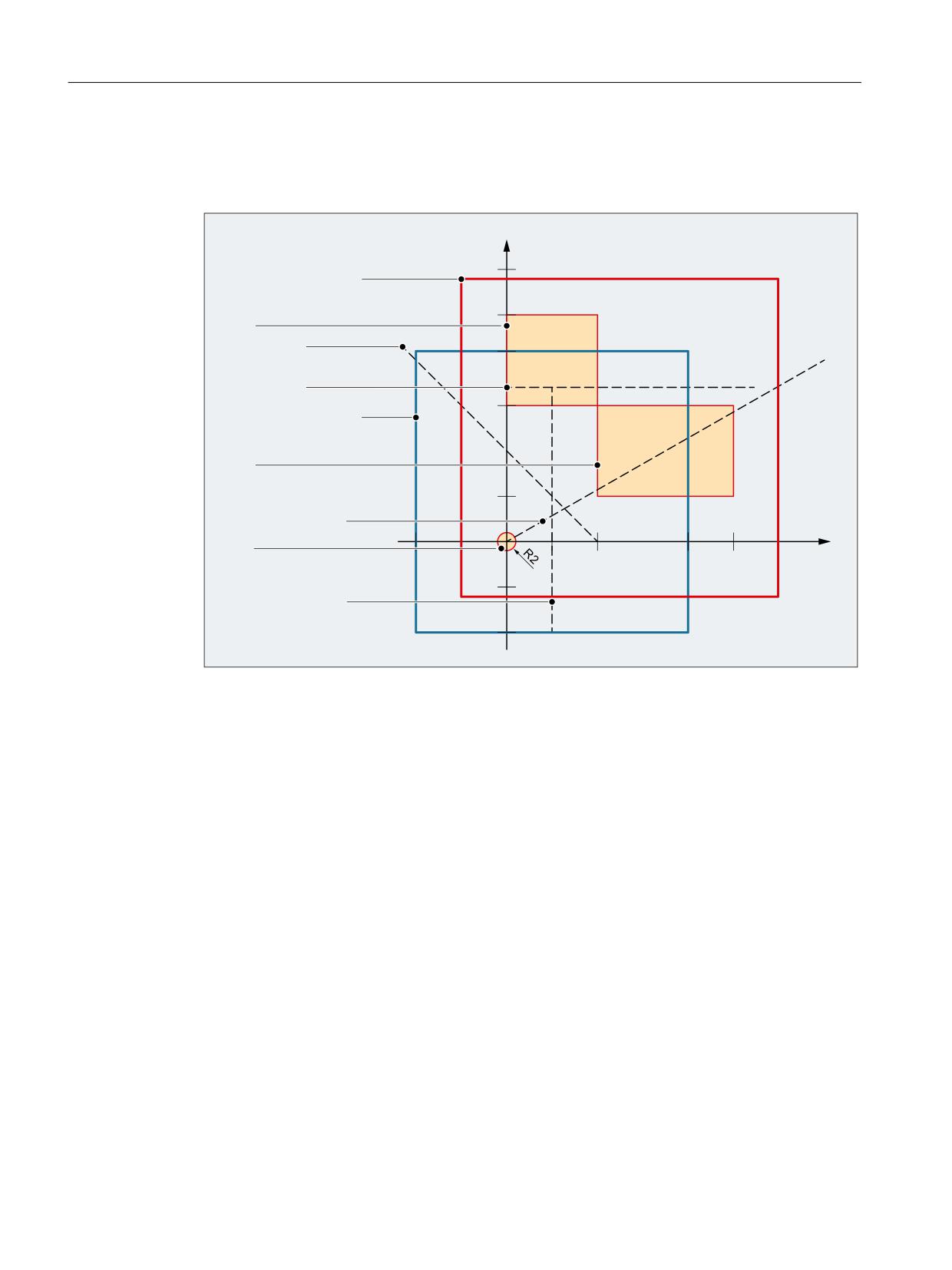
In the example, the active software limit switches and working area limits in the X-Y plane and
the following three protection zones are displayed:
• C2: Tool-related, channel-specific protection zone, active, circular, radius = 2 mm
• C4: Workpiece-related, channel-specific protection zone, preactivated, square, side length =
10 mm
• N3: Machine-specific protection zone, active, rectangular, side length = 10 mm x 15 mm
NC program
The protection zones and working area limits are defined first in the NC program. The
CALCPOSI() function is then called with different parameter assignments.
Program code
N10 DEF REAL _START[3]
N20 DEF REAL _DIST[3]
N30 DEF REAL _LIMIT[5]
N40 DEF REAL _MAXDIST[3]
N50 DEF INT _PA
N60 DEF INT _STATUS
Monitoring and compensating
128
Function Manual, 10/2020, 6FC5397-7GP40-0BA1
Protection areas
6.3 Programming
Program code
: toolrelated protection zone C2
N70 CPROTDEF(2, TRUE, 0)
N80 G17 G1 X-2 Y0
N90 G3 I2 X2
N100 I-2 X-2
N110 EXECUTE(_PA)
; workpiece-related protection zone C4
N120 CPROTDEF(4, FALSE, 0)
N130 G17 G1 X0 Y15
N140 X10
N150 Y25
N160 X0
N170 Y15
N180 EXECUTE(_PA)
; machine-specific protection zone N3
N190 NPROTDEF(3, FALSE, 0)
N200 G17 G1 X10 Y5
N210 X25
N220 Y15
N230 X10
N240 Y5
N250 EXECUTE(_PA)
; activate or preactivate protection zones
N260 CPROT(2, 2, 0, 0, 0)
N270 CPROT(4, 1, 0, 0, 0)
N280 NPROT(3, 2, 0, 0, 0)
; define working area limits
N290 G25 XX=-10 YY=-10
N300 G26 XX=20 YY=21
N310 _START[0] = 0.
N320 _START[1] = 0.
N330 _START[2] = 0.
N340 _DIST[0] = 35.
N350 _DIST[1] = 20.
N360 _DIST[2] =
0.
N370 _LIMIT[0] = 0.
N380 _LIMIT[1] = 0.
N390 _LIMIT[2] = 0.
N400 _LIMIT[3] = 0.
N410 _LIMIT[4] = 0.
N420 _STATUS = CALCPOSI(_START, _DIST, _LIMIT, _MAXDIST)
N430 _STATUS = CALCPOSI(_START, _DIST, _LIMIT, _MAXDIST,,3)
N440 _STATUS = CALCPOSI(_START, _DIST, _LIMIT, _MAXDIST,,1)
N450 _START[0] =
5.
N460 _START[1] = 17.
N470 _START[2] =
0.
N480 _DIST[0] =
0.
N490 _DIST[1] =-27.
N500 _DIST[2] =
0.
N510 _STATUS = CALCPOSI(_START, _DIST, _LIMIT, _MAXDIST,,14)
N520 _STATUS = CALCPOSI(_START, _DIST, _LIMIT, _MAXDIST,, 6)
N530 _LIMIT[1] = 2.
Monitoring and compensating
Function Manual, 10/2020, 6FC5397-7GP40-0BA1
129
Protection areas
6.3 Programming
Program code
N540 _STATUS = CALCPOSI(_START, _DIST, _LIMIT, _MAXDIST,, 6)
N550 _START[0] = 27.
N560 _START[1] = 17.1
N570 _START[2] =
0.
N580 _DIST[0] =-27.
N590 _DIST[1] =
0.
N600 _DIST[2] =
0.
N610 _LIMIT[3] = 2.
N620 _STATUS = CALCPOSI(_START, _DIST, _LIMIT, _MAXDIST,,12)
N630 _START[0] = 0.
N640 _START[1] = 0.
N650 _START[2] = 0.
N660 _DIST[0] =
0.
N670 _DIST[1] = 30.
N680 _DIST[2] =
0.
N690 TRANS X10
N700 AROT Z45
N710 _STATUS = CALCPOSI(_START,_DIST, _LIMIT, _MAXDIST)
; delete frames from N690 and N700 again
N720 TRANS
N730 _START[0] =
0.
N740 _START[1] = 10.
N750 _START[2] =
0.
; vectors_DIST and _MAXDIST define the motion plane
N760 _DIST[0] = 30.
N770 _DIST[1] = 30.
N780 _DIST[2] =
0.
N790 _MAXDIST[0] = 1.
N800 _MAXDIST[1] = 0.
N810 _MAXDIST[2] = 1.
N820 _STATUS = CALCPOSI(_START, _DIST, _LIMIT, _MAXDIST,,17)
N830 M30
Results of CALCPOSI()
N...
<status>
<MaxDist>[0] ≙ X
<MaxDist>[1] ≙ Y
Remarks
420
3123
8.040
4.594
N3 is violated.
430
1122
20.000
11.429
No protection zone monitoring,
working area limitation is violated.
440
1121
30.000
17.143
Only software limit monitoring is still active.
510
4213
0.000
0.000
Starting point violates C4
520
0000
0.000
-27.000
Preactivated C4 is not monitored. The speci-
fied distance can be traversed completely.
540
2222
0.000
-25.000
Because _LIMIT[1] = 2, the traversing dis-
tance is restricted by the working area limi-
tation.
Monitoring and compensating
130
Function Manual, 10/2020, 6FC5397-7GP40-0BA1

Protection areas
6.3 Programming
N...
<status>
<MaxDist>[0] ≙ X
<MaxDist>[1] ≙ Y
Remarks
620
4223
-13.000
0.000
Clearance to C4 is a total of 4 mm due to C2
and _LIMIT[3]. Clearance C2 → N3 of 0.1
mm does not result in limitation of the tra-
versing distance.
710
1221
0.000
21.213
Frame with translation and rotation active.
The permissible traversing distance in _DIST
applies in the shifted and rotated WCS.
820
102121
18.000
18.000
The software limit switch of the Y axis is
violated. The calculation of a further tra-
versing direction is requested with <_TES-
TLIM> = 17. This direction is in _DIST (0.707,
0.0, 0.707). It is valid because the hundred
thousands digit is set in <_STATUS>.
Additional information
"Referenced" axis status
All machine axes considered by CALCPOSI() must be homed.
Circle-related distance specifications
All circle-related distance specifications are always interpreted as radius specifications. This
must be taken into account particularly for transverse axes with activated diameter
programming (DIAMON/DIAM90).
Traversing distance reduction
If the specified traversing distance of an axis is limited, the traversing distance of the other axes
is also reduced proportionally in the <MaxDist> return value. The resulting end point is
therefore still on the specified path.
Rotary axes
Rotary axes are only monitored when they are not modulo rotary axes.
It is permissible that no software limit switches, working area limits or protection zones are
defined for one or more of the relevant axes.
Software limit switch and working area limitation status
Software limit switches and working area limits are only taken into account if they are active
during the execution of CALCPOSI(). The status can be influenced, for example, via:
• Machine data: MD21020 $MC_WORKAREA_WITH_TOOL_RADIUS
• Setting data: $AC_WORKAREA_CS_...
• NC/PLC interface signals DB31, ... DBX12.2 / 3
• Commands: WALIMON / WALIMOF
Software limit switches and transformations
With CALCPOSI(), the positions of the machine axes (MCS) cannot always be uniquely
determined from the positions of the geometry axes (WCS) during various kinematic
transformations (e.g. TRANSMIT) because of ambiguities at certain positions of the traversing
Monitoring and compensating
Function Manual, 10/2020, 6FC5397-7GP40-0BA1
131
Protection areas
6.4 Special situations
distance. In normal traversing operation, the uniqueness generally results from the history and
the condition that a continuous motion in the WCS must correspond to a continuous motion in
the MCS. Therefore, when monitoring the software limit switches, the machine position at the
time when CALCPOSI() is executed is used to resolve the ambiguity in such cases.
Note
Preprocessing stop
When using CALCPOSI() in conjunction with transformations, it is the sole responsibility of the
user to program a preprocessing stop (STOPRE) with the preprocessing before CALCPOSI() for
the synchronization of the machine axis positions.
Protection zone clearance and conventional protection zones
With conventional protection zones, there is no guarantee that the safety clearance set in
parameter <Limit>[3] is maintained for all protection zones during a traversing movement on
the specified path. It is only guaranteed that no protection zone will be violated when the end
point returned in <Dist> is extended by the safety clearance in the traversing direction.
However, the straight line can pass very close to a protection zone.
Protection zone clearance and collision avoidance protection zones
With collision avoidance protection zones, there is a guarantee that the safety clearance set in
parameter <Limit>[3] is maintained for all protection zones during a traversing movement on
the specified traversing path.
The safety clearance specified in parameter <Limit>[3] only takes effect when the following
applies:
<Limit>[3] > (MD10619 $MN_COLLISION_TOLERANCE)
If bit 4 is set in parameter <TestLim> (calculation of the ongoing traversing direction), then the
direction vector received in <DIST> is only valid when the hundred thousands digit is set in the
function return value (<status>). If a direction such as this cannot be determined, either
because protection zones were violated, or because a transformation is active, then the input
value in <DIST> remains unchanged. An additional error message is not output.
6.4
Special situations
6.4.1
Temporary enabling of protection zones
If a protection zone violation occurs when starting or during a traversing motion, under certain
circumstances, the protection zone can be enabled, i.e. for temporary traversing. In AUTOMATIC
and MDA mode as well as in JOG mode, the temporary enabling of protection zones is performed
via operator actions.
See also:
• Behavior in the AUTOMATIC and MDA modes (Page 133)
• Behavior in JOG mode (Page 134)
Monitoring and compensating
132
Function Manual, 10/2020, 6FC5397-7GP40-0BA1
Protection areas
6.4 Special situations
Note
Temporarily enabling protection zones is only possible for workpiece-related protection
zones. Tool-related protection zones must either be deactivated in the part program or via the
NC/PLC interface in the "Preactivated" state.
Temporary enabling of a protection zone is terminated after the following events:
• When the control system powers up
• AUTOMATIC or MDA mode: The end of the block is outside the protection zone
• JOG mode: The end of the traversing motion is outside the protection zone
• The protection zone is activated
6.4.2
Behavior in the AUTOMATIC and MDA modes
In AUTOMATIC and MDA mode, no traversing motion is enabled into or through active protection
zones:
• A traversing motion that would lead from outside into an active protection zone, is stopped
at the end of the last block located outside the protection zone.
• A traversing motion that begins within an active protection zone is not started.
Temporary enabling of protection zones
If a traversing motion is stopped in AUTOMATIC or MDA mode because of a protection zone
violation, this is indicated to the operator by an alarm. If the operator decides that the traversing
motion can be continued, the crossing of protection zones can be enabled.
The enabling is only temporarily and is performed by triggering NC start:
DB21, ... DBX7.1 (NC start) = 1
An alarm is displayed for each violated protection zone. An NC start signal must be triggered by
the operator for each protection zone to be enabled.
The traversing motion is continued when all protection zones that have resulted in the stopping
of the traversing motion, have been enabled.
Continuation of a traversing motion without temporary enabling
A traversing motion was stopped with an alarm because of a protection zone violation. If the
relevant protection zone is set to the "Preactivated" state via the NC/PLC interface, the traversing
motion can be continued with NC start, without the protection zone being temporarily enabled.
Increased protection against the enabling of protection zones
If the enabling of a protection zone is to be protected better than just by using an NC start, then
this must be realized by the machine manufacturer or user in the PLC user program.
Monitoring and compensating
Function Manual, 10/2020, 6FC5397-7GP40-0BA1
133
Protection areas
6.4 Special situations
6.4.3
Behavior in JOG mode
Simultaneous traversing of several geometry axes
In JOG mode, traversing motions can be performed simultaneously in several geometry axes.
The traversing range of every participating geometry axis is limited axis-specifically at the start
of the traversing motion with regard to the traversing range limits (software limit switches,
working area limitation, etc.) and active protection zones. However, safe monitoring of all active
protection zones cannot be guaranteed. The following is provided as feedback to the user:
• Alarm 10704 "Protection zone monitoring is not guaranteed"
• DB31, ... DBX39.0 (protection-zone monitoring not guaranteed) = 1
After the end of the traversing motion, the alarm is cleared automatically.
If the current position is within an activated or preactivated protection zone, then the following
actions are triggered:
• Alarm message 10702 "NC protection zone violated during manual mode" or 10703
"Channel-specific protection zone violated during manual mode" is output - specifying the
violated protection zone and the traversing axis.
• Further traversing motion is disabled.
• The following NC/PLC interface signal is set for the protection zone involved:
DB21, … DBX276.0 - 277.1 (machine-specific protection zone 1 - 10 violated) == 1
or
DB21, ... DBX278.0 - 279.1 (channel-specific protection zone 1 - 10 violated) == 1
To continue, see paragraph "Temporary enabling of protection zones".
Example:
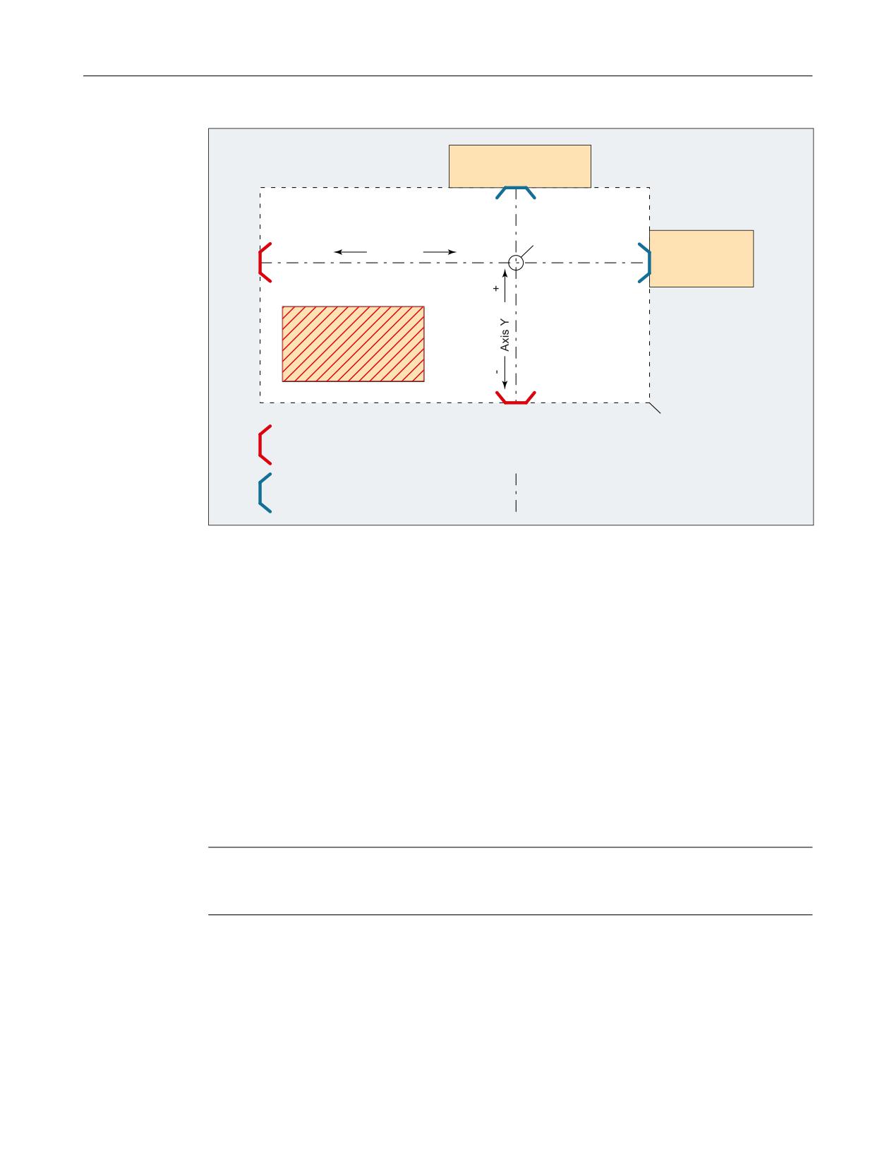
Three activated protection zones and simultaneous traversing of two geometry axes:
Monitoring and compensating
134
Function Manual, 10/2020, 6FC5397-7GP40-0BA1
Protection areas
6.4 Special situations
3URWHFWLRQ ]RQH
6WDUWLQJ SRLQW
$[LV ;
3URWHFWLRQ ]RQH
3URWHFWLRQ ]RQH
0D[LPXP WUDYHUVLQJ UDQJH
$W WKH VWDUW LQVWDQW
DEVROXWH WUDYHUVLQJ UDQJH OLPLW
5HODWLYH WUDYHUVLQJ UDQJH OLPLW
0D[LPXP D[LDO WUDYHUVLQJ UDQJH
DV D UHVXOW RI WKH SURWHFWLRQ ]RQH
$W WKH VWDUW LQVWDQW
Figure 6-2
Motion range of the geometry axes at the start time
At the start time of traversing motion of axes X and Y, the axis-specific traversing range limits are
determined from the start time:
• X axis
- Positive traversing direction: Protection zone 2
- Negative traversing direction: Absolute traversing range limit (e.g. software limit
switches)
• Y axis
- Positive traversing direction: Protection zone 1
- Negative traversing direction: Absolute traversing range limit (e.g. working area
limitation)
The resulting maximum traversing range at the start time does not take protection zone 3 into
account. As a consequence, protection zone 3 could be violated.
Note
Activated and preactivated protection zones are also monitored in the manual operating modes
JOG, INC and DRF.
Monitoring and compensating
Function Manual, 10/2020, 6FC5397-7GP40-0BA1
135
Protection areas
6.4 Special situations
Limiting the traversing motion of an axis
If the traversing motion of an axis is limited as a protection zone has been reached, then alarm
10706 "NC protection zone reached during manual mode" or 10707 "Channel-specific
protection zone reached during manual mode" is output, specifying the protection zone reached
and the traversing axis. It is assured that no protection zone will be violated when an axis is
traversing in JOG. (This response is analogous to approaching software limit switches or a
working area limitation.)
The alarm is reset:
• When an axis is traversed that does not lead into the protection zone.
• When the protection zone is enabled.
• When the control powers up.
If an axis starts to move towards a protection zone when it is at a protection zone limit, then
alarm 10706 or 10707 is output, and motion is not started.
Temporary enabling of protection zones
If traversing motion is started within an activated protection zone, or at the limit of an activated
protection zone, then alarm 10702 "NC protection zone violated during manual mode" or 10703
"Channel-specific protection zone violated during manual mode" is output - specifying the
violated protection zone and the traversing axis - and motion is not started. The traversing
motion can be performed when the relevant protection zone is temporarily enabled. The
following actions must be performed for this:
• Generate a positive edge at the NC/PLC interface signal:
DB21, ... DBX1.1 (enable protection zone)
• Start the same traversing motion again
Note
The NC/PLC interface signal "Protection zone violated" is set when the temporarily enabled
protection zone is traversed:
DB21, … DBX276.0 - 277.1 (machine-specific protection zone 1 - 10 violated) == 1
or
DB21, ... DBX278.0 - 279.1 (channel-specific protection zone 1 - 10 violated) == 1
The enable signal is reset if a motion is started that does not lead into the enabled protection
zone.
If further protection zones are affected by the traversing motion, additional alarms 10702 or
10703 are displayed for each protection zone. The protection zones displayed in the alarms can
be enabled by creating further positive edges on the NC/PLC interface signal DB21, ... DBX1.1:
Behavior at change of operating mode
The protection zones temporarily enabled in JOG mode are retained after a change to
AUTOMATIC or MDI mode. The temporary enable signals set the in the AUTOMATIC or MDI mode
are also retained after a change to JOG mode.
Monitoring and compensating
136
Function Manual, 10/2020, 6FC5397-7GP40-0BA1
Protection areas
6.5 Boundary conditions
Reset of an enable
The enable signal is reset internally and on the NC/PLC interface at the next standstill of a
geometry axis for which the temporarily enabled protection zone has been completely exited:
DB21, … DBX276.0 - 277.1 (machine-specific protection zone 1 - 10 violated) == 0
or
DB21, ... DBX278.0 - 279.1 (channel-specific protection zone 1 - 10 violated) == 0
6.5
Boundary conditions
Restrictions in protection-zone monitoring
In the following cases, protection area monitoring is notpossible:
• Traversing motion of orientation axes
• Fixed machine-specific protection zones for face transformation (TRANSMIT) or cylindrical
surface transformation (TRACYL).
Exception: Protection areas that are symmetrical around the axis of rotation of the spindle
axis. Here, no DRF offset must be active.
• Mutual monitoring of tool-related protection areas
Positioning axes
For positioning axes, only the programmed block end point is monitored. Alarm 10704
"Protection zone monitoring is not guaranteed" is output while a positioning axis traverses:
Axis interchange
With regard to the protection zones after an axis replacement, the starting position is the last
position approached in the relinquishing channel. Traversing motion in the channel taking over
is not taken into account. For this reason, you must ensure that an axis replacement is not
performed from a position with protection zone violation.
If an axis intended for the axis interchange is not active in a channel, the position of the axis last
approached in the channel is taken as the current position. If this axis has not yet been traversed
in the channel, 0.0 is taken as the position.
Behavior for superimposed motions
Superimposed motions that are included in the main run, cannot be taken into account by the
block preparation with regard to the active protection zones.
This results in the following reactions:
• Alarm 10704 "Protection zone monitoring is not guaranteed"
• DB31, ... DBX39.0 = 1 (protection area monitoring not guaranteed)
Monitoring and compensating
Function Manual, 10/2020, 6FC5397-7GP40-0BA1
137
Protection areas
6.6 Example
6.6
Example
6.6.1
Protection zone on a lathe
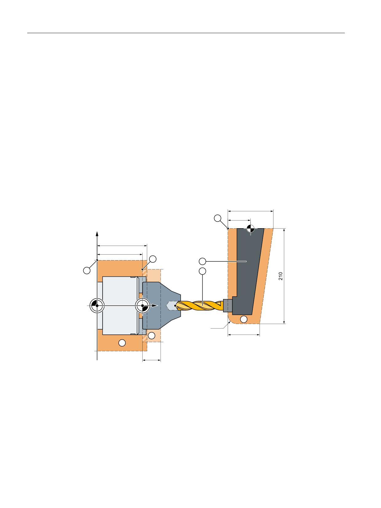
The following internal protection zones are to be defined for a turning machine:
• one machine-specific and workpiece-related protection zone for the spindle chuck, without
limitation in the 3rd dimension
• one channel-specific protection zone for the workpiece, without limitation in the 3rd
dimension
• one channel-specific, tool-related protection zone for the tool carrier, without limitation in
the 3rd dimension
The workpiece zero is placed at machine zero to define the protection zone for the workpiece.
When activated, the protection zone is then offset by 100 mm in the Z axis in the positive
direction.
)
;
3
=
0
:
5
① Starting point
② Protection zone for spindle chuck
③ Protection zone for workpiece
④ Protection area for tool carrier
⑤ Tool carrier
⑥ Drill
Monitoring and compensating
138
Function Manual, 10/2020, 6FC5397-7GP40-0BA1

Protection areas
6.6 Example
6.6.2
Protection zone definition in the part program
Part program excerpt for protection zone definition:
Program code
Comment
DEF INT AB
G18
; Working plane ZX
NPROTDEF(1,FALSE,0,0,0)
; Start of definition: Protection zone for spindle
chuck
G01 X100 Z0
; Contour description: Traversing motion along the
contour
G01 X-100 Z0
; Contour description: 1st Contour element
G01 X-100 Z110
; Contour description: 2nd Contour element
G01 X100 Z110
; Contour description: 3rd Contour element
G01 X100 Z0
; Contour description: 4th Contour element
EXECUTE(AB)
; End of definition: Protection zone for spindle
chuck
CPROTDEF(1,FALSE,0,0,0)
; Start of definition: Protection zone for work-
piece
G01 X80 Z0
; Contour description: Traversing motion along the
contour
G01 X-80 Z0
; Contour description: 1st Contour element
G01 X-80 Z40
; Contour description: 2nd Contour element
G01 X80 Z40
; Contour description: 3rd Contour element
G01 X80 Z0
; Contour description: 4th Contour element
EXECUTE(AB)
; End of definition: Protection zone for workpiece
CPROTDEF(2,TRUE,0,0,0)
; Start of definition: Protection zone for tool-
holder
G01 X0 Z-50
; Contour description: Traversing motion along the
contour
G01 X-190 Z-50
; Contour description: 1st Contour element
G03 X-210 Z-30 I-20
; Contour description: 2nd Contour element
G01 X-210 Z20
; Contour description: 3rd Contour element
G01 X0 Z50
; Contour description: 4th Contour element
G01 X0 Z-50
; Contour description: 5th Contour element
EXECUTE(AB)
; End of definition: Protection zone for toolholder
6.6.3
Protection zone definition with system variables
Machine-specific protection zone for the spindle chuck
System variable
Val-
Description
ue
$SN_PA_ACTIV_IMMED[0]
0
Protection zone for spindle chuck not immediately active
$SN_PA_T_W[0]
0
The protection zone for the spindle chuck is workpiece-related
$SN_PA_ORI[0]
1
Orientation of the protection zone: 1 = 3rd and 1st geometry axis
Monitoring and compensating
Function Manual, 10/2020, 6FC5397-7GP40-0BA1
139

Protection areas
6.6 Example
System variable
Val-
Description
ue
$SN_PA_LIM_3DIM[0]
0
Type of limitation in the 3rd dimension: 0 = No limit
$SN_PA_PLUS_LIM[0]
0
Value of the limit in the positive direction in the 3rd dimension
$SN_PA_MINUS_LIM[0]
0
Value of the limit in the minus direction in the 3rd dimension
$SN_PA_CONT_NUM[0]
4
Number of valid contour elements
$SN_PA_CONT_TYP[0,0]
1
Contour type[<i>] : 1 = G1 for straight line,
protection zone for spindle chuck, contour element 1
$SN_PA_CONT_TYP[0,1]
1
Contour type[<i>] : 1 = G1 for straight line,
protection zone for spindle chuck, contour element 2
$SN_PA_CONT_TYP[0,2]
1
Contour type[<i>] : 1 = G1 for straight line,
protection zone for spindle chuck, contour element 3
$SN_PA_CONT_TYP[0,3]
1
Contour type[<i>] : 1 = G1 for straight line,
protection zone for spindle chuck, contour element 4
$SN_PA_CONT_TYP[0,4]
1
Contour type[<i>] : 1 = G1 for straight line,
protection zone for spindle chuck, contour element 5
$SN_PA_CONT_TYP[0,5]
0
Contour type[<i>] : 0 = not defined,
protection zone for spindle chuck, contour element 6
$SN_PA_CONT_TYP[0,6]
0
Contour type[<i>] : 0 = not defined,
protection zone for spindle chuck, contour element 7
$SN_PA_CONT_TYP[0,7]
0
Contour type[<i>] : 0 = not defined,
protection zone for spindle chuck, contour element 8
$SN_PA_CONT_TYP[0,8]
0
Contour type[<i>] : 0 = not defined,
protection zone for spindle chuck, contour element 9
$SN_PA_CONT_TYP[0,9]
0
Contour type[<i>] : 0 = not defined,
protection zone for spindle chuck, contour element 10
$SN_PA_CONT_ORD[0,0]
-100
End point of contour[<i>], ordinate value
protection zone for spindle chuck, contour element 1
$SN_PA_CONT_ORD[0,1]
-100
End point of contour[<i>], ordinate value
protection zone for spindle chuck, contour element 2
$SN_PA_CONT_ORD[0,2]
100
End point of contour[<i>], ordinate value
protection zone for spindle chuck, contour element 3
$SN_PA_CONT_ORD[0,3]
100
End point of contour[<i>], ordinate value
protection zone for spindle chuck, contour element 4
$SN_PA_CONT_ORD[0,4]
0
End point of contour[<i>], ordinate value
protection zone for spindle chuck, contour element 5
$SN_PA_CONT_ORD[0,5]
0
End point of contour[<i>], ordinate value
protection zone for spindle chuck, contour element 6
$SN_PA_CONT_ORD[0,6]
0
End point of contour[<i>], ordinate value
protection zone for spindle chuck, contour element 7
$SN_PA_CONT_ORD[0,7]
0
End point of contour[<i>], ordinate value
protection zone for spindle chuck, contour element 8
$SN_PA_CONT_ORD[0,8]
0
End point of contour[<i>], ordinate value
protection zone for spindle chuck, contour element 9
$SN_PA_CONT_ORD[0,9]
0
End point of contour[<i>], ordinate value
protection zone for spindle chuck, contour element 10
$SN_PA_CONT_ABS[0,0]
0
End point of contour[<i>], abscissa value
protection zone for spindle chuck, contour element 1
Monitoring and compensating
140
Function Manual, 10/2020, 6FC5397-7GP40-0BA1

Protection areas
6.6 Example
System variable
Val-
Description
ue
$SN_PA_CONT_ABS[0,1]
110
End point of contour[<i>], abscissa value
protection zone for spindle chuck, contour element 2
$SN_PA_CONT_ABS[0,2]
110
End point of contour[<i>], abscissa value
protection zone for spindle chuck, contour element 3
$SN_PA_CONT_ABS[0,3]
0
End point of contour[<i>], abscissa value
protection zone for spindle chuck, contour element 4
$SN_PA_CONT_ABS[0,4]
0
End point of contour[<i>], abscissa value
protection zone for spindle chuck, contour element 5
$SN_PA_CONT_ABS[0,5]
0
End point of contour[<i>], abscissa value
protection zone for spindle chuck, contour element 6
$SN_PA_CONT_ABS[0,6]
0
End point of contour[<i>], abscissa value
protection zone for spindle chuck, contour element 7
$SN_PA_CONT_ABS[0,7]
0
End point of contour[<i>], abscissa value
protection zone for spindle chuck, contour element 8
$SN_PA_CONT_ABS[0,8]
0
End point of contour[<i>], abscissa value
protection zone for spindle chuck, contour element 9
$SN_PA_CONT_ABS[0,9]
0
End point of contour[<i>], abscissa value
protection zone for spindle chuck, contour element 10
$SN_PA_CENT_ORD[0,0]
0
Center point of circular contour[<i>], ordinate value
protection zone for spindle chuck, contour element 1
$SN_PA_CENT_ORD[0.1]
0
Center point of circular contour[<i>], ordinate value
protection zone for spindle chuck, contour element 2
$SN_PA_CENT_ORD[0,2]
0
Center point of circular contour[<i>], ordinate value
protection zone for spindle chuck, contour element 3
$SN_PA_CENT_ORD[0,3]
0
Center point of circular contour[<i>], ordinate value
protection zone for spindle chuck, contour element 4
$SN_PA_CENT_ORD[0,4]
0
Center point of circular contour[<i>], ordinate value
protection zone for spindle chuck, contour element 5
$SN_PA_CENT_ORD[0,5]
0
Center point of circular contour[<i>], ordinate value
protection zone for spindle chuck, contour element 6
$SN_PA_CENT_ORD[0,6]
0
Center point of circular contour[<i>], ordinate value
protection zone for spindle chuck, contour element 7
$SN_PA_CENT_ORD[0,7]
0
Center point of circular contour[<i>], ordinate value
protection zone for spindle chuck, contour element 8
$SN_PA_CENT_ORD[0,8]
0
Center point of circular contour[<i>], ordinate value
protection zone for spindle chuck, contour element 9
$SN_PA_CENT_ORD[0,9]
0
Center point of circular contour[<i>], ordinate value
protection zone for spindle chuck, contour element 10
$SN_PA_CENT_ABS[0,0]
0
Center point of circular contour[<i>], abscissa value
protection zone for spindle chuck, contour element 1
$SN_PA_CENT_ABS[0.1]
0
Center point of circular contour[<i>], abscissa value
protection zone for spindle chuck, contour element 2
$SN_PA_CENT_ABS[0,2]
0
Center point of circular contour[<i>], abscissa value
protection zone for spindle chuck, contour element 3
$SN_PA_CENT_ABS[0,3]
0
Center point of circular contour[<i>], abscissa value
protection zone for spindle chuck, contour element 4
Monitoring and compensating
Function Manual, 10/2020, 6FC5397-7GP40-0BA1
141

Protection areas
6.6 Example
System variable
Val-
Description
ue
$SN_PA_CENT_ABS[0,4]
0
Center point of circular contour[<i>], abscissa value
protection zone for spindle chuck, contour element 5
$SN_PA_CENT_ABS[0,5]
0
Center point of circular contour[<i>], abscissa value
protection zone for spindle chuck, contour element 6
$SN_PA_CENT_ABS[0,6]
0
Center point of circular contour[<i>], abscissa value
protection zone for spindle chuck, contour element 7
$SN_PA_CENT_ABS[0,7]
0
Center point of circular contour[<i>], abscissa value
protection zone for spindle chuck, contour element 8
$SN_PA_CENT_ABS[0,8]
0
Center point of circular contour[<i>], abscissa value
protection zone for spindle chuck, contour element 9
$SN_PA_CENT_ABS[0,9]
0
Center point of circular contour[<i>], abscissa value
protection zone for spindle chuck, contour element 10
Channel-specific protection zone for the workpiece
System variable
Val-
Remark
ue
$SC_PA_ACTIV_IMMED[0]
0
Protection zone for workpiece not immediately active
$SC_PA_TW[0]
0
Protection zone for workpiece is workpiece-related
$SC_PA_ORI[0]
1
Orientation of the protection zone: 1 = 3rd and 1st geometry axis
$SC_PA_LIM_3DIM[0]
0
Type of limitation in the 3rd dimension: 0 = no limitation
$SC_PA_PLUS_LIM[0]
0
Value of the limit in the positive direction in the 3rd dimension
$SC_PA_MINUS_LIM[0]
0
Value of the limit in the minus direction in the 3rd dimension
$SC_PA_CONT_NUM[0]
4
Number of valid contour elements
$SC_PA_CONT_TYP[0,0]
1
Contour type[<i>] : 1 = G1 for straight line,
protection zone workpiece, contour element 1
$SC_PA_CONT_TYP[0,1]
1
Contour type[<i>] : 1 = G1 for straight line,
protection zone workpiece, contour element 2
$SC_PA_CONT_TYP[0,2]
1
Contour type[<i>] : 1 = G1 for straight line,
protection zone workpiece, contour element 3
$SC_PA_CONT_TYP[0,3]
1
Contour type[<i>] : 1 = G1 for straight line,
protection zone workpiece, contour element 4
$SC_PA_CONT_TYP[0,4]
1
Contour type[<i>] : 1 = G1 for straight line,
protection zone workpiece, contour element 5
$SC_PA_CONT_TYP[0,5]
0
Contour type[<i>] : 0 = not defined,
protection zone for workpiece, contour element 6
$SC_PA_CONT_TYP[0,6]
0
Contour type[<i>] : 0 = not defined,
protection zone for workpiece, contour element 7
$SC_PA_CONT_TYP[0,7]
0
Contour type[<i>] : 0 = not defined,
protection zone for workpiece, contour element 8
$SC_PA_CONT_TYP[0,8]
0
Contour type[<i>] : 0 = not defined,
protection zone for workpiece, contour element 9
$SC_PA_CONT_TYP[0,9]
0
Contour type[<i>] : 0 = not defined,
protection zone for workpiece, contour element 10
$SC_PA_CONT_ORD[0,0]
-80
End point of contour[<i>], ordinate value
protection zone for workpiece, contour element 1
Monitoring and compensating
142
Function Manual, 10/2020, 6FC5397-7GP40-0BA1

Protection areas
6.6 Example
System variable
Val-
Remark
ue
$SC_PA_CONT_ORD[0,1]
-80
End point of contour[<i>], ordinate value
protection zone for workpiece, contour element 2
$SC_PA_CONT_ORD[0,2]
80
End point of contour[<i>], ordinate value
protection zone for workpiece, contour element 3
$SC_PA_CONT_ORD[0,3]
80
End point of contour[<i>], ordinate value
protection zone for workpiece, contour element 4
$SC_PA_CONT_ORD[0,4]
0
End point of contour[<i>], ordinate value
protection zone for workpiece, contour element 5
$SC_PA_CONT_ORD[0,5]
0
End point of contour[<i>], ordinate value
protection zone for workpiece, contour element 6
$SC_PA_CONT_ORD[0,6]
0
End point of contour[<i>], ordinate value
protection zone for workpiece, contour element 7
$SC_PA_CONT_ORD[0,7]
0
End point of contour[<i>], ordinate value
protection zone for workpiece, contour element 8
$SC_PA_CONT_ORD[0,8]
0
End point of contour[<i>], ordinate value
protection zone for workpiece, contour element 9
$SC_PA_CONT_ORD[0,9]
0
End point of contour[<i>], ordinate value
protection zone for workpiece, contour element 10
$SC_PA_CONT_ABS[0,0]
0
End point of contour[<i>], abscissa value
protection zone for workpiece, contour element 1
$SC_PA_CONT_ABS[0,1]
40
End point of contour[<i>], abscissa value
protection zone for workpiece, contour element 2
$SC_PA_CONT_ABS[0,2]
40
End point of contour[<i>], abscissa value
protection zone for workpiece, contour element 3
$SC_PA_CONT_ABS[0,3]
0
End point of contour[<i>], abscissa value
protection zone for workpiece, contour element 4
$SC_PA_CONT_ABS[0,4]
0
End point of contour[<i>], abscissa value
protection zone for workpiece, contour element 5
$SC_PA_CONT_ABS[0,5]
0
End point of contour[<i>], abscissa value
protection zone for workpiece, contour element 6
$SC_PA_CONT_ABS[0,6]
0
End point of contour[<i>], abscissa value
protection zone for workpiece, contour element 7
$SC_PA_CONT_ABS[0,7]
0
End point of contour[<i>], abscissa value
protection zone for workpiece, contour element 8
$SC_PA_CONT_ABS[0,8]
0
End point of contour[<i>], abscissa value
protection zone for workpiece, contour element 9
$SC_PA_CONT_ABS[0,9]
0
End point of contour[<i>], abscissa value
protection zone for workpiece, contour element 10
$SC_PA_CENT_ORD[0,0]
0
Center point of circular contour[<i>], ordinate value
protection zone for workpiece, contour element 1
$SC_PA_CENT_ORD[0,1]
0
Center point of circular contour[<i>], ordinate value
protection zone for workpiece, contour element 2
$SC_PA_CENT_ORD[0,2]
0
Center point of circular contour[<i>], ordinate value
protection zone for workpiece, contour element 3
$SC_PA_CENT_ORD[0,3]
0
Center point of circular contour[<i>], ordinate value
protection zone for workpiece, contour element 4
Monitoring and compensating
Function Manual, 10/2020, 6FC5397-7GP40-0BA1
143

Protection areas
6.6 Example
System variable
Val-
Remark
ue
$SC_PA_CENT_ORD[0,4]
0
Center point of circular contour[<i>], ordinate value
protection zone for workpiece, contour element 5
$SC_PA_CENT_ORD[0,5]
0
Center point of circular contour[<i>], ordinate value
protection zone for workpiece, contour element 6
$SC_PA_CENT_ORD[0,6]
0
Center point of circular contour[<i>], ordinate value
protection zone for workpiece, contour element 7
$SC_PA_CENT_ORD[0,7]
0
Center point of circular contour[<i>], ordinate value
protection zone for workpiece, contour element 8
$SC_PA_CENT_ORD[0,8]
0
Center point of circular contour[<i>], ordinate value
protection zone for workpiece, contour element 9
$SC_PA_CENT_ORD[0,9]
0
Center point of circular contour[<i>], ordinate value
protection zone for tool holder, contour element 10
$SC_PA_CENT_ABS[0,0]
0
Center point of circular contour[<i>], abscissa value
protection zone for workpiece, contour element 1
$SC_PA_CENT_ABS[0,1]
0
Center point of circular contour[<i>], abscissa value
protection zone for workpiece, contour element 2
$SC_PA_CENT_ABS[0,2]
0
Center point of circular contour[<i>], abscissa value
protection zone for workpiece, contour element 3
$SC_PA_CENT_ABS[0,3]
0
Center point of circular contour[<i>], abscissa value
protection zone for workpiece, contour element 4
$SC_PA_CENT_ABS[0,4]
0
Center point of circular contour[<i>], abscissa value
protection zone for workpiece, contour element 5
$SC_PA_CENT_ABS[0,5]
0
Center point of circular contour[<i>], abscissa value
protection zone for workpiece, contour element 6
$SC_PA_CENT_ABS[0,6]
0
Center point of circular contour[<i>], abscissa value
protection zone for workpiece, contour element 7
$SC_PA_CENT_ABS[0,7]
0
Center point of circular contour[<i>], abscissa value
protection zone for workpiece, contour element 8
$SC_PA_CENT_ABS[0,8]
0
Center point of circular contour[<i>], abscissa value
protection zone for workpiece, contour element 9
$SC_PA_CENT_ABS[0,9]
0
Center point of circular contour[<i>], abscissa value
protection zone for workpiece, contour element 10
Channel-specific protection zone for the tool holder
System variable
Val-
Remark
ue
$SC_PA_ACTIV_IMMED[1]
0
Protection zone for tool holder not immediately active
$SC_PA_TW[1]
3
Protection zone for the tool holder is tool-related
$SC_PA_ORI[1]
1
Orientation of the protection zone: 1 = 3rd and 1st geometry axis
$SC_PA_LIM_3DIM[1]
0
Type of limitation in the 3rd dimension: 0 = no limitation
$SC_PA_PLUS_LIM[1]
0
Value of the limit in the positive direction in the 3rd dimension
$SC_PA_MINUS_LIM[1]
0
Value of the limit in the minus direction in the 3rd dimension
$SC_PA_CONT_NUM[1]
5
Number of valid contour elements
$SC_PA_CONT_TYP[1,0]
1
Contour type[<i>] : 1 = G1 for straight line,
protection zone tool holder, contour element 1
Monitoring and compensating
144
Function Manual, 10/2020, 6FC5397-7GP40-0BA1

Protection areas
6.6 Example
System variable
Val-
Remark
ue
$SC_PA_CONT_TYP[1,1]
3
Contour type[<i>] : 3 = G3 for circle element, counter clockwise,
protection zone for tool holder, contour element 2
$SC_PA_CONT_TYP[1,2]
1
Contour type[<i>] : 1 = G1 for straight line,
protection zone for tool holder, contour element 3
$SC_PA_CONT_TYP[1,3]
1
Contour type[<i>] : 1 = G1 for straight line,
protection zone for tool holder, contour element 4
$SC_PA_CONT_TYP[1,4]
1
Contour type[<i>] : 1 = G1 for straight line,
protection zone for tool holder, contour element 5
$SC_PA_CONT_TYP[1,5]
0
Contour type[<i>] : 0 = not defined,
protection zone for tool holder, contour element 6
$SC_PA_CONT_TYP[1,6]
0
Contour type[<i>] : 0 = not defined,
protection zone for tool holder, contour element 7
$SC_PA_CONT_TYP[1,7]
0
Contour type[<i>] : 0 = not defined,
protection zone for tool holder, contour element 8
$SC_PA_CONT_TYP[1,8]
0
Contour type[<i>] : 0 = not defined,
protection zone for tool holder, contour element 9
$SC_PA_CONT_TYP[1,9]
0
Contour type[<i>] : 0 = not defined,
protection zone for tool holder, contour element 10
$SC_PA_CONT_ORD[1,0]
-190
End point of contour[<i>], ordinate value
protection zone for tool holder, contour element 1
$SC_PA_CONT_ORD[1,1]
-210
End point of contour[<i>], ordinate value
protection zone for tool holder, contour element 2
$SC_PA_CONT_ORD[1,2]
-210
End point of contour[<i>], ordinate value
protection zone for tool holder, contour element 3
$SC_PA_CONT_ORD[1,3]
0
End point of contour[<i>], ordinate value
protection zone for tool holder, contour element 4
$SC_PA_CONT_ORD[1,4]
0
End point of contour[<i>], ordinate value
protection zone for tool holder, contour element 5
$SC_PA_CONT_ORD[1,5]
0
End point of contour[<i>], ordinate value
protection zone for tool holder, contour element 6
$SC_PA_CONT_ORD[1,6]
0
End point of contour[<i>], ordinate value
protection zone for tool holder, contour element 7
$SC_PA_CONT_ORD[1,7]
0
End point of contour[<i>], ordinate value
protection zone for tool holder, contour element 8
$SC_PA_CONT_ORD[1,8]
0
End point of contour[<i>], ordinate value
protection zone for tool holder, contour element 9
$SC_PA_CONT_ORD[1,9]
0
End point of contour[<i>], ordinate value
protection zone for tool holder, contour element 10
$SC_PA_CONT_ABS[1,0]
-50
End point of contour[<i>], abscissa value
protection zone for tool holder, contour element 1
$SC_PA_CONT_ABS[1,1]
-30
End point of contour[<i>], abscissa value
protection zone for tool holder, contour element 2
$SC_PA_CONT_ABS[1,2]
20
End point of contour[<i>], abscissa value
protection zone for tool holder, contour element 3
$SC_PA_CONT_ABS[1,3]
50
End point of contour[<i>], abscissa value
protection zone for tool holder, contour element 4
Monitoring and compensating
Function Manual, 10/2020, 6FC5397-7GP40-0BA1
145
Protection areas
6.6 Example
System variable
Val-
Remark
ue
$SC_PA_CONT_ABS[1,4]
-50
End point of contour[<i>], abscissa value
protection zone for tool holder, contour element 5
$SC_PA_CONT_ABS[1,5]
0
End point of contour[<i>], abscissa value
protection zone for tool holder, contour element 6
$SC_PA_CONT_ABS[1,6]
0
End point of contour[<i>], abscissa value
protection zone for tool holder, contour element 7
$SC_PA_CONT_ABS[1,7]
0
End point of contour[<i>], abscissa value
protection zone for tool holder, contour element 8
$SC_PA_CONT_ABS[1,8]
0
End point of contour[<i>], abscissa value
protection zone for tool holder, contour element 9
$SC_PA_CONT_ABS[1,9]
0
End point of contour[<i>], abscissa value
protection zone for tool holder, contour element 10
$SC_PA_CENT_ORD[1,0]
0
Center point of circular contour[<i>], ordinate value
protection zone for tool holder, contour element 1
$SC_PA_CENT_ORD[1,1]
-190
Center point of circular contour[<i>], ordinate value
protection zone for tool holder, contour element 2
$SC_PA_CENT_ORD[1,2]
0
Center point of circular contour[<i>], ordinate value
protection zone for tool holder, contour element 3
$SC_PA_CENT_ORD[1,3]
0
Center point of circular contour[<i>], ordinate value
protection zone for tool holder, contour element 4
$SC_PA_CENT_ORD[1,4]
0
Center point of circular contour[<i>], ordinate value
protection zone for tool holder, contour element 5
$SC_PA_CENT_ORD[1,5]
0
Center point of circular contour[<i>], ordinate value
protection zone for tool holder, contour element 6
$SC_PA_CENT_ORD[1,6]
0
Center point of circular contour[<i>], ordinate value
protection zone for tool holder, contour element 7
$SC_PA_CENT_ORD[1,7]
0
Center point of circular contour[<i>], ordinate value
protection zone for tool holder, contour element 8
$SC_PA_CENT_ORD[1,8]
0
Center point of circular contour[<i>], ordinate value
protection zone for tool holder, contour element 9
$SC_PA_CENT_ORD[1,9]
0
Center point of circular contour[<i>], ordinate value
protection zone for tool holder, contour element 10
$SC_PA_CENT_ABS[1,0]
0
Center point of circular contour[<i>], abscissa value
protection zone for tool holder, contour element 1
$SC_PA_CENT_ABS[1,1]
-30
Center point of circular contour[<i>], abscissa value
protection zone for tool holder, contour element 2
$SC_PA_CENT_ABS[1,2]
0
Center point of circular contour[<i>], abscissa value
protection zone for tool holder, contour element 3
$SC_PA_CENT_ABS[1,3]
0
Center point of circular contour[<i>], abscissa value
protection zone for tool holder, contour element 4
$SC_PA_CENT_ABS[1,4]
0
Center point of circular contour[<i>], abscissa value
protection zone for tool holder, contour element 5
$SC_PA_CENT_ABS[1,5]
0
Center point of circular contour[<i>], abscissa value
protection zone for tool holder, contour element 6
$SC_PA_CENT_ABS[1,6]
0
Center point of circular contour[<i>], abscissa value
protection zone for tool holder, contour element 7
Monitoring and compensating
146
Function Manual, 10/2020, 6FC5397-7GP40-0BA1
Protection areas
6.7 Data lists
System variable
Val-
Remark
ue
$SC_PA_CENT_ABS[1,7]
0
Center point of circular contour[<i>], abscissa value
protection zone for tool holder, contour element 8
$SC_PA_CENT_ABS[1,8]
0
Center point of circular contour[<i>], abscissa value
protection zone for tool holder, contour element 9
$SC_PA_CENT_ABS[1,9]
0
Center point of circular contour[<i>], abscissa value
protection zone for tool holder, contour element 10
6.6.4
Activating protection zones
Part program excerpt for activating protection zones for spindle chuck, workpiece, and
tool holder:
Program code
Comment
NPROT(1,2,0,0,0)
; Protection zone: Spindle chuck
CPROT(1,2,0,0,100)
; Protection zone: Workpiece with 100 mm offset in the
Z axis
CPROT(2,2,0,0,0)
; Protection zone: Toolholder
6.7
Data lists
6.7.1
Machine data
6.7.1.1
NC-specific machine data
Number
Identifier: $MN_
Description
10618
PROTAREA_GEOAX_CHANGE_MODE
Response for a transformation change and geometry
axis interchange
18190
MM_NUM_PROTECT_AREA_NCK
Number of available machine-specific protection zones
6.7.1.2
Channelspecific machine data
Number
Identifier: $MC_
Description
28200
MM_NUM_PROTECT_AREA_CHAN (SRAM)
Number of available channel-specific protection zones
28210
MM_NUM_PROTECT_AREA_ACTIVE
Maximum number of protection zones that can be acti-
vated simultaneously in the channel
28212
MM_NUM_PROTECT_AREA_CONTUR
Maximum number of definable contour elements in the
channel
Monitoring and compensating
Function Manual, 10/2020, 6FC5397-7GP40-0BA1
147
Protection areas
6.7 Data lists
Monitoring and compensating
148
Function Manual, 10/2020, 6FC5397-7GP40-0BA1
Axis monitoring functions
7
7.1
Contour monitoring
7.1.1
Contour error
Contour errors are caused by signal distortions in the position control loop.
Signal distortions can be linear or non-linear.
Linear signal distortions
Linear signal distortions are caused by:
• Speed and position controller not being set optimally
• Unequal following errors of the axes involved in the path
In this regard, the feedforward control types, DSC setting and equivalent time constants of
the feedforward control should usually be set the same. Additional checks should include:
Position setpoint filter (e.g. AX_JERK_MODE and AX_JERK_TIME), as well as Kv (in particular
for FFWOF, FFW_MODE=0 or FFW_MODE=3).
• Unequal dynamic response of the feed drives
Unequal drive dynamic responses lead to path deviations especially on contour changes.
Circles are distorted into ellipses by unequal dynamic responses of the two feed drives.
Non-linear signal distortions
Non-linear signal distortions are caused by:
• Activation of the current limitation within the machining area
• Activation of the limitation of the speed setpoint
• Range of inversion within and/or outside of the position control loop
When traversing a circular path, contour errors occur primarily due to the reversal error and
friction.
During motion along straight lines, a contour error arises due to a reversal error outside the
position control loop, e.g. due to a tilting milling spindle. This causes a parallel offset
between the actual and the set contour. The shallower the gradient of the straight line, the
larger the offset.
• Nonlinear friction behavior of slide guides
Monitoring and compensating
Function Manual, 10/2020, 6FC5397-7GP40-0BA1
149
Axis monitoring functions
7.1 Contour monitoring
7.1.2
Following-error monitoring
Function
In control engineering terms, traversing along a machine axis always produces a certain
following error, i.e. a difference between the set and actual position.
The following error that arises depends on:
• Position control loop gain
MD32200 $MA_POSCTRL_GAIN (servo gain factor)
• Maximum acceleration
MD32300 $MA_MAX_AX_ACCEL (maximum axis acceleration)
• Maximum velocity
MD32000 $MA_MAX_AX_VELO (maximum axis velocity)
• With activated feedforward control:
Precision of the path model and the parameters:
MD32610 $MA_VELO_FFW_WEIGHT (factor for the velocity feedforward control)
MD32620 $MA_FFW_MODE (feedforward control mode)
MD32800 $MA_EQUIV_CURRCTRL_TIME (equivalent time constant current control loop for
feedforward control)
MD32810 $MA_EQUIV_SPEEDCTRL_TIME (equivalent time constant speed control loop for
feedforward control)
• Position setpoint filter
MD32402 $MA_AX_JERK_MODE (filter type for axial jerk limitation)
MD32410 $MA_AX_JERK_TIME (time constant for the axial jerk filter)
MD32910 4ma_dyn_match_TIME (time constant for dynamic response adaptation)
In the acceleration phase, the following error initially increases when traversing along a
machine axis. After a time depending on the parameterization of the position control loop, the
following error then remains constant in the ideal case. Due to external influences, more or less
large fluctuations in the following error always arise during a machining process. To prevent
these fluctuations in the following error from triggering an alarm, a tolerance range within
which the following error may change must be defined for the following-error monitoring:
MD36400 $MA_CONTOUR_TOL (Contour monitoring tolerance range)
Monitoring and compensating
150
Function Manual, 10/2020, 6FC5397-7GP40-0BA1
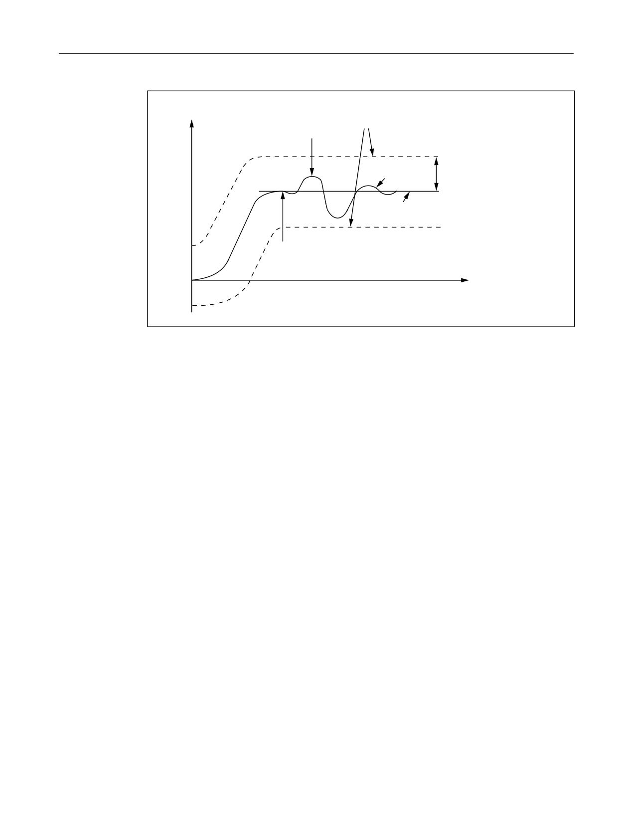
Axis monitoring functions
7.1 Contour monitoring
)ROORZLQJ HUURU
7ROHUDQFH EDQG
'V
)LUVW FXW
0HDVXUHG
IROORZLQJ HUURU
0'
0$B &217285B72/
&DOFXODWHG
IROORZLQJ HUURU PRGHO
%HJLQ PDFKLQLQJ
W
Figure 7-1
Following-error monitoring
Effectiveness
The following-error monitoring only operates with active position control and the following axis
types:
• Linear axes with and without feedforward control
• Rotary axes with and without feedforward control
• Position-controlled spindles
Fault
If the configured tolerance limit is exceeded, the following alarm appears:
25050 "Axis <Axis name> Contour monitoring"
The affected axis/spindle is stopped via the configured braking ramp in follow-up mode:
MD36610 $MA_AX_EMERGENCY_STOP_TIME
(maximum time for braking ramp when an error occurs)
Monitoring and compensating
Function Manual, 10/2020, 6FC5397-7GP40-0BA1
151
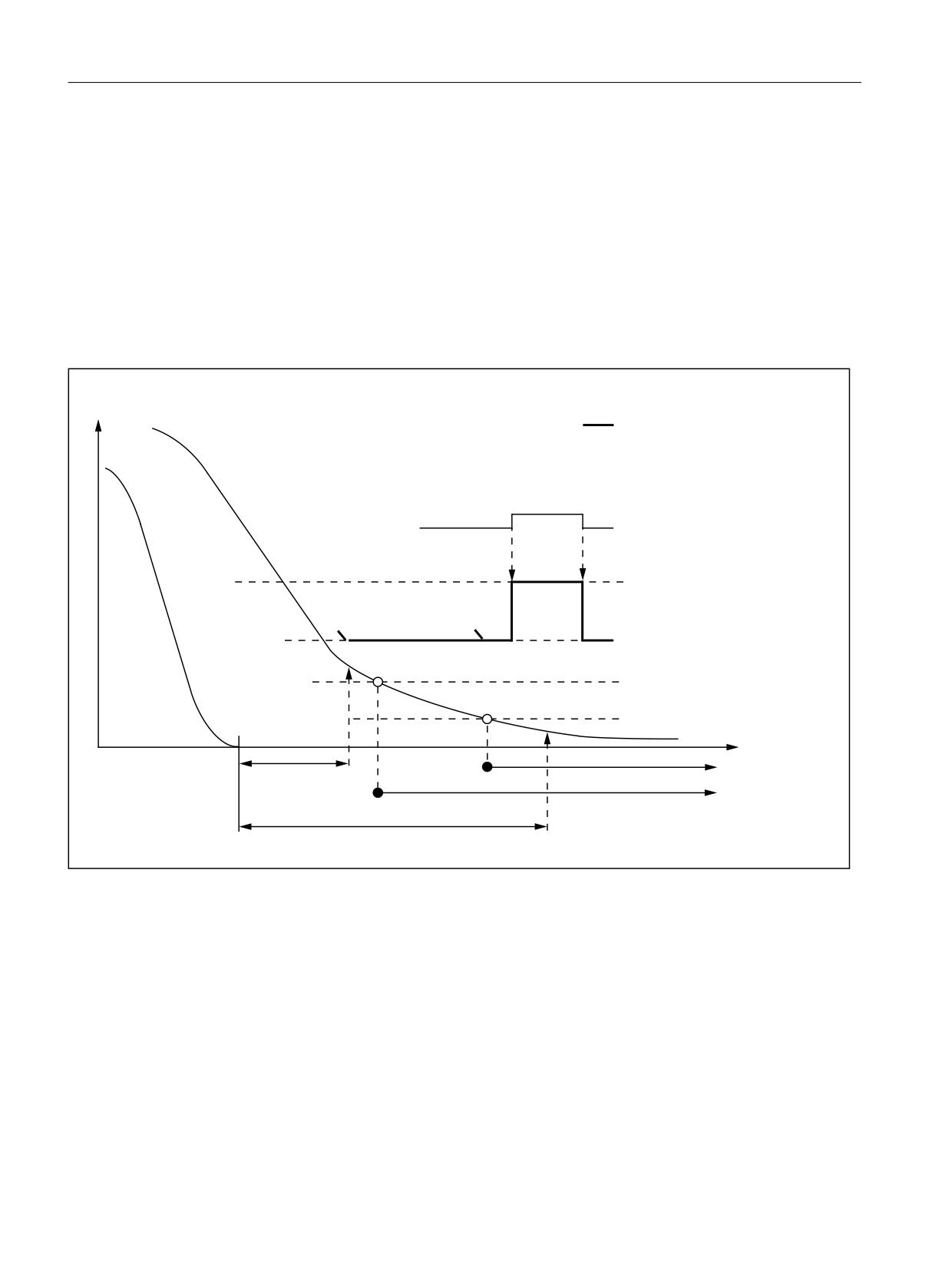
Axis monitoring functions
7.2 Positioning, zero speed and clamping monitoring
7.2
Positioning, zero speed and clamping monitoring
7.2.1
Correlation between positioning, zero-speed and clamping monitoring
Overview
The following overview shows the correlation between the positioning, zero speed and
clamping monitoring functions:
9 RU V
(IIHFWLYH WROHUDQFH
IRU GRZQWLPH RU FODPSLQJ
PRQLWRULQJ
$FWXDO YDOXH
'%
'%;
FODPSLQJ LQ SURJUHVV
0'
0$B&/$03B326B72/
6HWSRLQW
0'
0$B67$1'67,//B326B72/
0'
0$B6723B/,0,7B&2$56(
0'
0$B6723B/,0,7B),1(
0'
([DFW VWRS ILQH 6LJQDO
W
0$B67$1'67,//
B'(/$<B7,0(
([DFW VWRS FRDUVH 6LJQDO
0'
0$B326,7,21,1*B7,0(
7.2.2
Positioning monitoring
Function
At the end of a positioning operation:
• Set velocity = 0 AND
• DB31, ... DBX64.6/7 (motion command minus/plus) = 0
Monitoring and compensating
152
Function Manual, 10/2020, 6FC5397-7GP40-0BA1

Axis monitoring functions
7.2 Positioning, zero speed and clamping monitoring
checks the position monitoring to ensure that the following error of every participating machine
axis is smaller than the exact-stop fine tolerance during the delay time.
MD36010 $MA_STOP_LIMIT_FINE (exact stop fine)
MD36020 $MA_POSITIONING_TIME (delay time exact stop fine)
After reaching "Exact stop fine", the position monitoring is deactivated.
Note
The smaller the exact stop fine tolerance is, the longer the positioning operation takes and the
longer the time until block change.
Rules for MD setting
MD36010 $MA_STOP_LIMIT_FINE
MD36020 $MA_POSITIONING_TIME
Large
Can be selected relatively short
Small
Must be selected relatively long
MD32200 $MA_POSCTRL_GAIN
MD36020 $MA_POSITIONING_TIME
(servo gain factor)
Small
Must be selected relatively long
Large
Can be selected relatively short
Effectiveness
The position monitoring only operates with active position control and the following axis types:
• Linear axes
• Rotary axes
• Position-controlled spindles
Fault
If the configured position-monitoring time is exceeded, the following alarm appears:
25080 "Axis <Axis name> Position monitoring"
The affected axis is stopped via the configured braking ramp in follow-up mode:
MD36610 $MA_AX_EMERGENCY_STOP_TIME
(maximum time for braking ramp when an error occurs)
Monitoring and compensating
Function Manual, 10/2020, 6FC5397-7GP40-0BA1
153
Axis monitoring functions
7.2 Positioning, zero speed and clamping monitoring
7.2.3
Zero-speed monitoring
Function
At the end of a positioning operation:
• Set velocity = 0 AND
• DB31, ... DBX64.6/7 (motion command minus/plus) = 0
checks the zero-speed monitoring to ensure that the following error of every participating
machine axis is smaller than the standstill tolerance during the delay time.
MD36040 $MA_STANDSTILL_DELAY_TIME (zero-speed monitoring delay time)
MD36030 $MA_STANDSTILL_POS_TOL (standstill tolerance)
After reaching the required exact-stop state, the positioning operation is completed:
DB31, ... DBX60.6/7 (position reached with exact stop coarse/fine) = 1
The position-monitoring function is deactivated and is replaced by the zero-speed monitoring.
Zero-speed monitoring monitors the adherence to the standstill tolerance. If no new travel
request is received, the machine axis must not depart from the standstill tolerance.
Effectiveness
The zero-speed monitoring only operates with active position control and the following axis
types:
• Linear axes
• Rotary axes
• Position-controlled spindles
Fault
If the delay time and/or the standstill tolerance is exceeded, the following alarm appears:
25040 "Axis <Axis name> Zero-speed monitoring"
The affected axis is stopped via the configured braking ramp in follow-up mode:
MD36610 $MA_AX_EMERGENCY_STOP_TIME
(maximum time for braking ramp when an error occurs)
7.2.4
Parameter set-dependent exact stop and standstill tolerance
For adaptation to different machining situations and/or axis dynamics, e.g.:
• Operating state A: High precision, long machining time
• Operating state B: Lower precision, shorter machining time
• Changing of the mass relationships after gear change
Monitoring and compensating
154
Function Manual, 10/2020, 6FC5397-7GP40-0BA1
Axis monitoring functions
7.2 Positioning, zero speed and clamping monitoring
the positioning tolerances:
• MD36000 $MA_STOP_LIMIT_COARSE (exact stop coarse)
• MD36010 $MA_STOP_LIMIT_FINE (exact stop fine)
• MD36030 $MA_STANDSTILL_POS_TOL (standstill tolerance)
can be weighted with a common factor depending on the parameter set:
MD36012 $MA_STOP_LIMIT_FACTOR (exact stop coarse/fine and standstill factor)
Because the factor applies in common for all three position tolerances, the relationship between
the values remains constant.
7.2.5
Clamping monitoring
7.2.5.1
Function
For machine axes that are mechanically clamped upon completion of a positioning operation,
a displacement of the axis from the position setpoint can result from the clamping process.
Setting the NC/PLC interface signal DB31, ... DBX2.3 (clamping in progress) causes the clamping
tolerance (MD36050 $MA_CLAMP_POS_TOL) rather than the standstill tolerance (MD36030
$MA_STANDSTILL_POS_TOL) to be monitored for the duration of the clamping process. Alarm
26000 "clamping monitoring" is issued if the clamping tolerance is overshot.
Alarm delay time
If a time-limited overshooting of the clamping tolerance is permitted, an alarm delay time must
be specified via machine data MD36051 $MA_CLAMP_POS_TOL_TIME. The alarm is then output
only after expiration of the parameterized time when the clamping tolerance is overshot. No
alarm is output when the clamping tolerance is undershot again after expiration of the time. The
time is restarted when the clamping tolerance is overshoot again.
To permit a response to overshooting the clamping tolerance prior to expiration of the alarm
delay time, the axis-specific NC/PLC interface signal DB31, ... DBX102.3 (clamping tolerance
overshot) is set. The signal is reset again when the clamping tolerance is undershot.
7.2.5.2
Machine data
Clamping tolerance
The clamping tolerance, which is higher than the standstill tolerance, is entered in machine data:
MD36050 $MA_CLAMP_POS_TOL[<axis>] = <clamping tolerance>
Alarm delay time
If a time-limited overshooting of the clamping tolerance is tolerated, the maximum permissible
alarm delay time must be specified in the machine data.
MD36051 $MA_CLAMP_POS_TOL_TIME[<axis>] = <alarm delay time>
When the clamping tolerance is exceeded, alarm 26000 "Clamping monitoring" is only displayed
after the alarm delay time has elapsed.
Monitoring and compensating
Function Manual, 10/2020, 6FC5397-7GP40-0BA1
155

Axis monitoring functions
7.2 Positioning, zero speed and clamping monitoring
An alarm is not output, if the clamping tolerance is fallen below again before the alarm delay
time lapses.
The alarm delay time is restarted when the clamping tolerance is exceeded again.
Special clamping functions
The special clamping functions that automate the release and set of the part program execution
sequence are activated bit-by-bit using machine data:
MD36052 $MA_STOP_ON_CLAMPING[<Achse>], <bit> = <value>
<Bit>
<Val-
Meaning
ue>
0
Automatic stop to release the clamping
0
Not active
1
Active
1
Optimized clamping release
0
Not active
1
Active, precondition: Bit 0 == 1
2
Automatic stop to set the clamping
0
Not active
1
Active
7.2.5.3
NC/PLC interface signals
Activating the clamping monitoring
The clamping monitoring is activated by setting the NC/PLC interface signal:
DB31, ... DBX2.3 = 1 (clamping in progress)
Overshooting the clamping tolerance
Overshooting the clamping tolerance is indicated with the NC/PLC interface signal:
DB31, ... DBX102.3 == 1 (clamping tolerance overshot)
The signal is set when the clamping tolerance is overshot within the alarm delay time.
The signal is reset when the clamping tolerance is undershot within the alarm delay time or the
follow-up mode is activated for the axis.
7.2.5.4
Fault responses
Fault responses when the clamping tolerance is exceeded:
• Alarm 26000 "Clamping monitoring" is indicated
• The axis is brought to a standstill with the parameterized maximum acceleration:
MD32300 $MA_MAX_AX_ACCEL
Whereby, the maximum duration of the braking ramp for error states is monitored:
MD36610 $MA_AX_EMERGENCY_STOP_TIME
Monitoring and compensating
156
Function Manual, 10/2020, 6FC5397-7GP40-0BA1

Axis monitoring functions
7.2 Positioning, zero speed and clamping monitoring
• Follow-up mode is activated for the axis:
DB31, ... DBX61.3 == 1
• The "clamping tolerance exceeded" signal is reset:
DB31, ... DBX102.3 == 0
7.2.5.5
"Automatic stop to release the clamping" clamping function
The "Automatic stop to release the clamping" clamping function adds an NC-internal stop before
the traversing block of the clamping axis for continuous-path mode.
The stop is not effective or the continuous-path mode is not interrupted if the controller enable
signal (DB31, ... DBX2.1) of the clamping axis is set prior to the block change.
If the controller enable signal of the clamping axis is not set prior to the block change, the stop
acts.
Parameterization
MD36052 $MA_STOP_ON_CLAMPING[<clamping axis>] = 'H01'
Requirements/assumptions
• If, for the clamping axis there is a traversing command (DB31, ... DBX64.6 / .7), then the
clamping is released by the PLC user program.
• The following relationship must exist between the controller enable signal (DB31, ... DBX2.1)
and the clamping of the clamping axis:
Controller enable
⇒
Clamping axis
not set
⇒
Clamped
Set
⇒
Not clamped
Example:
Program code
Comment
N100 G0 X0 Y0 Z0 A0 G90 G54 F500
; Approach initial state
N101 G641 ADIS=.1 ADISPOS=5
; Activate continuous-path mode
N210 G1 X10
; Traversing block
N220 G1 X5 Y20
; "
N310 G0 Z50
; Positioning block
N410 G0 A90
; " (clamping axis)
N510 G0 X100
; "
N520 G0 Z2
; "
N610 G1 Z-4
; Traversing block
N620 G1 X0 Y-20
; "
Schematic change of the NC/PLC interface signals and states for the N310 and N410 blocks:
Monitoring and compensating
Function Manual, 10/2020, 6FC5397-7GP40-0BA1
157
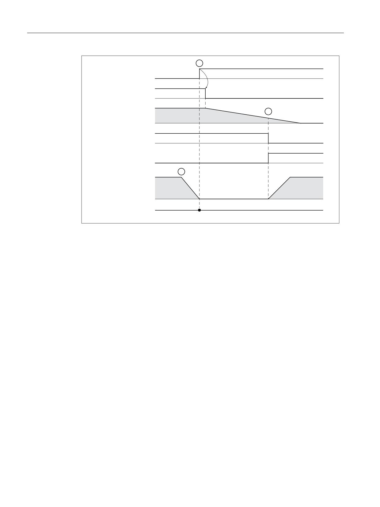
Axis monitoring functions
7.2 Positioning, zero speed and clamping monitoring
'%
'%;
WUDYHO FRPPDQG
'%
'%;
FODPSLQJ LQ SURJUHVV
&ODPSLQJ SUHVVXUH
'%
'%;
IHHGUDWH VWRS
'%
'%;
FRQWUROOHU HQDEOH
3DWK YHORFLW\
W >V@
7UDYHUVLQJ EORFNV
1
* =
1
* $
① NC: The automatically inserted stop causes a stop at the N310 block end.
② NC → PLC: After the block change, the travel command for the clamping axis is set.
PLC: The clamping is released based on the travel command.
③ PLC → NC: The clamping pressure is removed appropriately. The clamping axis is enabled for
traversal.
7.2.5.6
"Time-optimized release of the clamping" clamping function
The "Time-optimized release of the clamping" clamping function in conjunction with the
"Automatic stop to release the clamping" clamping function" for continuous-path mode requests
the release of the clamping NC-internal by the Look Ahead setting of the travel command for the
clamping axis. The travel command is set only when until the traversal of the clamping axis,
positioning (G0 blocks) but no processing (G1 blocks) is performed.
To obtain the reference to the traversing block of the clamping axis, the travel command
prefixes a maximum of two rapid traverse blocks (G0), including any internally generated
intermediate blocks, to the traversing block.
Activation
MD36052 $MA_STOP_ON_CLAMPING[<clamping axis>] = 'H03'
Requirements/assumptions
• If, for the clamping axis there is a traversing command (DB31, ... DBX64.6 / .7), then the
clamping is released by the PLC user program.
• While other axes are traversing with rapid traverse (G0), the clamping axis must not be
clamped.
Monitoring and compensating
158
Function Manual, 10/2020, 6FC5397-7GP40-0BA1
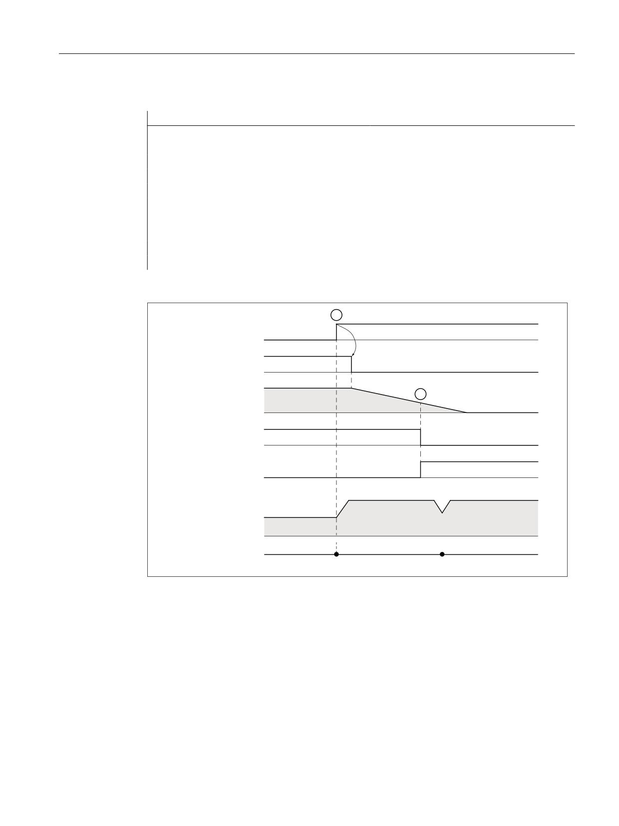
Axis monitoring functions
7.2 Positioning, zero speed and clamping monitoring
Example:
Program code
Comment
N100 G0 X0 Y0 Z0 A0 G90 G54 F500
; Approach initial state
N101 G641 ADIS=.1 ADISPOS=5
; Activate continuous-path mode
N210 G1 X10
; Machining block
N220 G1 X5 Y20
; "
N310 G0 Z50
; Positioning block
N410 G0 A90
; " (clamping axis)
N510 G0 X100
; "
N520 G0 Z2
; "
N610 G1 Z-4
; Machining block
N620 G1 X0 Y-20
; "
Schematic change of the NC/PLC interface signals and states for the N220 to N410 blocks:
'%
'%;
WUDYHO FRPPDQG
'%
'%;
FODPSLQJ LQ SURJUHVV
&ODPSLQJ SUHVVXUH
'%
'%;
IHHGUDWH VWRS
'%
'%;
FRQWUROOHU HQDEOH
3DWK YHORFLW\
W >V@
7UDYHUVLQJ EORFNV
1
* ; <
1
* =
1
* $
① NC → PLC: The travel command for the clamping axis is set because of the block change.
PLC: The clamping is released based on the travel command.
② PLC → NC: The clamping pressure is removed appropriately. The clamping axis is enabled for
traversal.
7.2.5.7
"Automatic stop to set the clamping" clamping function
The clamping process takes a while. In continuous-path mode, an explicit stop of the traversing
must be provided by programming, e.g. G09, G60 or auxiliary function output, so that the
clamping is reliably active before machining started.
Monitoring and compensating
Function Manual, 10/2020, 6FC5397-7GP40-0BA1
159
Axis monitoring functions
7.2 Positioning, zero speed and clamping monitoring
The "Automatic stop to set the clamping" clamping function stops the traversing automatically
in continuous-path mode. Clamping motion is stopped before or in the next machining block
(traversing block without rapid traverse G0), if the clamping axis has not clamped up until then.
The criterion that clamping has taken place and additional traversing motion has been enabled
is the setting of the channel-specific feedrate override by the PLC user program not equal to 0%
(DB21, ... DBB4 ≠ 0%)
Activation
MD36052 $MA_STOP_ON_CLAMPING[<clamping axis>] = 'H04'
Requirements/assumptions
• If, for the clamping axis, there is no traversing command (DB31, ... DBX64.6 / .7), then the
clamping isclosed by the PLC user program.
• While other axes are traversing with rapid traverse (G0), the clamping axis must not be
clamped.
• If the channel-specific feedrate override is not equal to 0% (DB21, ... DBB4 ≠ 0%), then the
clamping axis is clamped.
Example
Program code
Comment
N100 G0 X0 Y0 Z0 A0 G90 G54 F500
; Approach initial state
N101 G641 ADIS=.1 ADISPOS=5
; Activate continuous-path mode
N210 G1 X10
; Machining block
N220 G1 X5 Y20
; "
N310 G0 Z50
; Positioning block
N410 G0 A90
; " (clamping axis)
N510 G0 X100
; "
N520 G0 Z2
; "
N610 G1 Z-4
; Machining block
N620 G1 X0 Y-20
; "
Schematic change of the NC/PLC interface signals and states for the N410 to N610 blocks:
Monitoring and compensating
160
Function Manual, 10/2020, 6FC5397-7GP40-0BA1
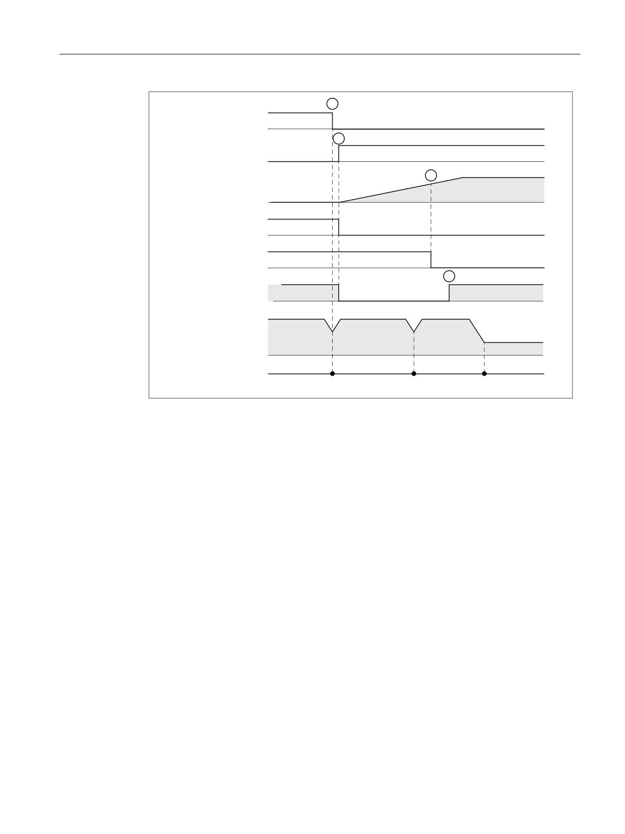
Axis monitoring functions
7.2 Positioning, zero speed and clamping monitoring
'%
'%;
WUDYHO FRPPDQG
'%
'%;
FODPSLQJ LQ SURJUHVV
&ODPSLQJ SUHVVXUH
'%
'%;
IHHGUDWH VWRS
'%
'%;
FRQWUROOHU HQDEOH
'%
'%%
IHHG UDWH RYHUULGH
3DWK YHORFLW\
W >V@
7UDYHUVLQJ EORFNV
1
* $
1
* ;
1
* =
1
* =
① NC → PLC: The travel command for the clamping axis is reset because of the block change.
② PLC: The clamping is initiated
③ PLC → NC: The clamping pressure is sufficiently large to reset the controller enable
④ PLC → NC: Enable the N610 machining by setting the channel-specific feedrate override not 0%.
7.2.5.8
Supplementary conditions
Interrupted continuous-path mode
If during the above-described clamping functions, the continuous-path mode and thus also the
"LookAhead" function is interrupted by blocks without traversing (e.g. output of an M function
M82/M83), the functions behave as follows:
• Clamping function: "Time-optimized release of the axis clamping"
(MD36052 $MA_STOP_ON_CLAMPING[<axis>] = 'B011')
The function no longer acts because the travel command is set in Look Ahead mode only for
blocks with active continuous-path mode. The output of the M function M82 in block N320
of the sample program below stops the traversing and so interrupts the continuous-path
mode.
The Look Ahead stopping on N410 by the function is not necessary because stopping occurs
anyway by N320.
• Clamping function: "Automatic stop to set the clamping":
(MD36052 $MA_STOP_ON_CLAMPING[<axis] = 'B100')
The function generates a stop irrespective of M83 that is executed as a function of "feedrate
override 0%". The axis is thus stopped before the first machining block.
Monitoring and compensating
Function Manual, 10/2020, 6FC5397-7GP40-0BA1
161
Axis monitoring functions
7.2 Positioning, zero speed and clamping monitoring
Note
Using clamping functions without clamping
The following clamping functions can also be used independent of clamping the axis:
• "Automatic stop to release the clamping":
MD36052 $MA_STOP_ON_CLAMPING[<axis>] = 'B001'
Behavior: A stop is made in the current block on the path when the controller enable
(DB31, ... DBX2.1) for the parameterized <axis> is not set, but it is traversed in one of the
following blocks.
• "Automatic stop to set the clamping":
MD36052 $MA_STOP_ON_CLAMPING[<axis>] = 'B100'
Behavior: A stop is made in the current block on the path when at the transition from rapid
traverse blocks (G0) to traversing blocks (G1), the channel-specific feedrate override
(DB21, ... DBB4) is 0%.
In both cases it is ensured that the path motion in continuous-path mode is already stopped
before the start of the relevant part program block and not just within the block.
Table 7-1
Sample program: Interrupted continuous-path mode
Program code
Comment
N100 G0 X0 Y0 Z0 A0 G90 G54 F500
; Approach initial state
N101 G641 ADIS=.1 ADISPOS=5
; Activate continuous-path mode
N210 G1 X10
; Traversing block
N220 G1 X5 Y20
; "
N310 G0 Z50
; Rapid traverse block
N320 M82
; Interrupt continuous-path mode
N410 G0 A90
; Rapid traverse block
N420 M83
; Interrupt continuous-path mode
N510 G0 X100
; Rapid traverse block
N520 G0 Z2
; "
N610 G1 Z-4
; Traversing block
N620 G1 X0 Y-20
; "
Block change criterion: Clamping tolerance
After activation of clamping monitoring (DB31, ... DBX2.3), the block change criterion for
traversing blocks in which the stop is made at the end of the block, the clamping tolerance rather
than the exact stop condition acts for the clamping axis:
MD36050 $MA_CLAMP_POS_TOL (clamping tolerance with interface signal "Clamping active")
Behavior for releasing the clamping
If the clamping axis was moved by the clamping process from the position setpoint, it is returned
by the NC to the position setpoint after releasing the clamping and setting the (DB31, ... DBX2.1)
Monitoring and compensating
162
Function Manual, 10/2020, 6FC5397-7GP40-0BA1
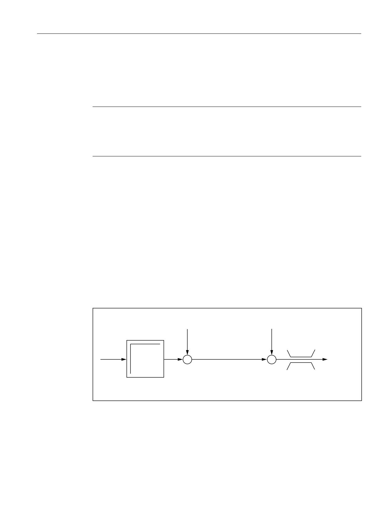
Axis monitoring functions
7.3 Speed-setpoint monitoring
controller enable signal. Repositioning depends on whether "Follow-up mode" was activated for
the axis during the clamping process:
• DB31, ... DBX1.4 == 0 (follow-up mode not active) ⇒ Abrupt by the position controller
• DB31, ... DBX1.4 == 1 (follow-up mode active) ⇒ interpolatory method
Note
The following data can be evaluated by the PLC user program as the criterion for activating the
follow-up mode (DB31, ... DBX1.4):
• DB31, ... DBX60.6/.7 (position reached with coarse/fine exact stop)
• Actual position of the clamping axis
Follow-up mode
The clamping monitoring is not active in follow-up mode
DB31, ... DBX1.4 == 1 (follow-up mode).
7.3
Speed-setpoint monitoring
Function
The speed setpoint comprises:
• Speed setpoint of the position controller
• Speed setpoint portion of the feedforward control (with active feedforward control only)
• Dift compensation (only for drives with analog setpoint interface)
'ULIW YDOXH
3UH FRQWURO YDOXH
RQO\ IRU DQDORJ GULYHV
7R VSHHG
.9
FRQWUROOHU
)ROORZLQJ
HUURU
6SHHG VHWSRLQW
PRQLWRULQJ
3RVLWLRQ
FRQWUROOHU
Figure 7-2
Speed setpoint calculation
The speed-setpoint monitoring ensures by limiting the control or output signal (10 V for analog
setpoint interface or rated speed for digital drives) that the physical limitations of the drives are
not exceeded:
MD36210 $MA_CTRLOUT_LIMIT (maximum speed setpoint)
Monitoring and compensating
Function Manual, 10/2020, 6FC5397-7GP40-0BA1
163
Axis monitoring functions
7.3 Speed-setpoint monitoring
6SHHG VHWSRLQW >
@
0'
0$B&75/287B/,0,7>Q@
0'
0$B&75/287B/,0,7>Q@
HJ
IRU WHVW PRGH
W
Figure 7-3
Speed setpoint limitation
Speed-setpoint monitoring delay
To prevent an error reaction from occurring in every speed-limitation instance, a delay time can
be configured:
MD36220 $MA_CTRLOUT_LIMIT_TIME (speed-setpoint monitoring delay)
Only if the speed limitation is required for longer than the configured time does the
corresponding error reaction occur.
Effectiveness
The speed-setpoint monitoring is only active for closed-loop position-controlled axes and cannot
be deactivated.
Fault
If the configured delay time is exceeded, the following alarm appears:
25060 "Axis <Axis name> Speed-setpoint limitation"
The affected axis is stopped via the configured braking ramp in follow-up mode:
MD36610 $MA_AX_EMERGENCY_STOP_TIME
(maximum time for braking ramp when an error occurs)
Note
Upon reaching the speed-setpoint monitoring, the position feedback loop of the axis becomes
non-linear due to the limitation. Contour errors result if the axis is involved in generating the
contour.
Monitoring and compensating
164
Function Manual, 10/2020, 6FC5397-7GP40-0BA1
Axis monitoring functions
7.5 Measuring system monitoring
7.4
Actual-velocity monitoring
Function
The actual-velocity monitoring checks that the actual velocity of a machine axis/spindle does not
exceed the configured threshold:
MD36200 $MA_AX_VELO_LIMIT (velocity-monitoring threshold)
The threshold should be 10-15% above the configured maximum velocity.
• For axes:
MD32000 $MA_MAX_AX_VELO (maximum axis velocity)
• For spindles:
MD35110 $MA_GEAR_STEP_MAX_VELO_LIMIT[n] (maximum speed of gear stage)
If you use this setting the speed will not normally exceed the velocity-monitoring threshold
(exception: Drive error).
Activation
The actual-velocity monitoring is activated as soon as the active measuring system returns valid
actual values (encoder limit frequency not exceeded).
Effectiveness
The actual-velocity monitoring only operates with active position control and the following axis
types:
• Linear axes
• Rotary axes
• Open-loop-controlled and position-controlled spindles
Fault
If the threshold is exceeded, the following alarm is displayed:
25030 "Axis <Axis name> Actual-velocity alarm limit"
The affected axis is stopped via the configured braking ramp in follow-up mode:
MD36610 $MA_AX_EMERGENCY_STOP_TIME
(maximum time for braking ramp when an error occurs)
7.5
Measuring system monitoring
The NC has no direct access to the measuring system hardware, therefore measuring system
monitoring is mainly performed by the drive software.
Monitoring and compensating
Function Manual, 10/2020, 6FC5397-7GP40-0BA1
165
Axis monitoring functions
7.5 Measuring system monitoring
Monitoring functions in the drive
• Monitoring of hardware faults (e.g. measuring system failure, wire breakage)
• Zero mark monitoring
Further information:
Function Manual Drive Functions SINAMICS S120
Measuring system monitoring functions carried out in the drive are mapped on the NC alarms
(alarm 25000 and following) or NC reactions (e.g. abort of referencing or on-the-fly measuring).
The exact behavior of the NC depends on the setting in the machine data:
MD36310 $MA_ENC_ZERO_MONITORING
Value
Meaning
= 0
Monitoring of HW faults:
ON
If a hardware fault is detected in the active measuring system, POW-
ER ON alarm 25000 is displayed:
"Axis <Axis name> Hardware fault active encoder"
The affected axis is stopped via the configured braking ramp in fol-
low-up mode:
MD36610 $MA_AX_EMERGENCY_STOP_TIME (maximum time for
braking ramp when a fault occurs)
If a hardware fault is detected in the passive measuring system,
alarm 25001 is displayed:
"Axis <Axis name> Hardware fault passive encoder"
There is no further alarm response.
Zero-mark monitoring:
OFF
Alarms 25020 and 25021 (see below) are suppressed.
= 100
No zero-mark monitoring as well as hiding of all encoder monitoring functions, i.e. in addition to alarm
25020 (25021), alarms 25000 (25001) and 25010 (25011) are suppressed.
> 0 but < 100
Monitoring of HW faults:
ON (see above)
Zero-mark monitoring:
ON
If zero-mark monitoring is tripped in the active measuring system,
alarm 25020 is displayed:
"Axis <Axis name> Zero-mark monitoring active encoder"
The affected axis is stopped via the configured braking ramp in fol-
low-up mode:
MD36610 $MA_AX_EMERGENCY_STOP_TIME (maximum time for
braking ramp when a fault occurs)
If zero-mark monitoring is tripped in the passive measuring system,
alarm 25021 is displayed:
"Axis <Axis name> Zero-mark monitoring passive encoder"
There is no further alarm response.
> 100
Monitoring of HW faults:
ON with attenuated error message:
The POWER ON alarm 25000 is replaced by the reset alarm 25010
and the reset alarm 25001 replaced by the cancel alarm 25011.
Zero-mark monitoring:
ON (see above)
For details on the alarms, see:
Monitoring and compensating
166
Function Manual, 10/2020, 6FC5397-7GP40-0BA1
Axis monitoring functions
7.5 Measuring system monitoring
Further information:
Diagnostics Manual
Note
For hardware faults, the referencing status of the machine axis is reset:
DB31, ... DBX60.4/5 (referenced/synchronized 1/2) = 0
Monitoring functions in the NC
• Encoder-limit-frequency monitoring
• Plausibility check for absolute encoders
7.5.1
Encoder-limit-frequency monitoring
Function
The NC encoder-limit-frequency monitoring is based on the configuration and telegram
information of the drive. It monitors that the encoder frequency does not exceed the configured
encoder limit frequency:
MD36300 $MA_ENC_FREQ_LIMIT (encoder limit frequency)
Encoder-limit-frequency monitoring always refers to the active measuring system selected in
the NC/PLC interface:
DB31, ... DBX1.5/1.6 (position measuring system 1/2)
Effectiveness
The encoder limit frequency is operative for:
• Linear axes
• Rotary axes
• Open-loop-controlled and position-controlled spindles
Monitoring and compensating
Function Manual, 10/2020, 6FC5397-7GP40-0BA1
167

Axis monitoring functions
7.5 Measuring system monitoring
Fault
Upon exceeding of the encoder limit frequency, the following occurs:
• Message to the PLC:
DB31, ... DBX60.2 or 60.3 = 1 (encoder limit frequency exceeded 1 or 2)
• Spindles
Spindles are not stopped but continue to turn with speed control.
If the spindle speed is reduced so much that the encoder frequency passes below the encoder
limit frequency, the actual value system of the spindle is automatically resynchronized.
• Axes
The following alarm is displayed:
21610 "Channel <Channel number> Axis <Axis name> Encoder <Encoder number >
Frequency exceeded"
The affected axis is stopped via the configured braking ramp in follow-up mode:
MD36610 $MA_AX_EMERGENCY_STOP_TIME
(maximum time for braking ramp when an error occurs)
Note
If the encoder limit frequency is exceeded, a position-controlled machine axis must be re-
referenced (see Function Manual "Axes and Spindles", Section "R1: Referencing").
7.5.2
Plausibility check for absolute encoders
Function
With absolute encoders (MD30240 $MA_ENC_TYPE = 4), absolute values supplied by the
measuring system are used to check the plausibility of the actual value.
During the check, the NC compares the cyclic position value held in the position control cycle
clock based on the incremental information from the encoder with a new position value
generated directly from the absolute and incremental information and checks that the
calculated position difference does not exceed the permissible deviation.
MD36310 $MA_ENC_ZERO_MONITORING (permissible deviation in 1/2 coarse increments
between the absolute and the incremental encoder track)
Note
The plausibility check of absolute encoders specifically detects all deviations caused by dirt on
the absolute track or by faults when transferring the absolute value. However, small errors in the
incremental track (burst interference, impulse errors) are not detected. In such instances the
plausibility check only responds to deviations in the millimeter range. This form of monitoring
should therefore serve as additional monitoring to assist the diagnosis of absolute-position
faults.
Monitoring and compensating
168
Function Manual, 10/2020, 6FC5397-7GP40-0BA1

Axis monitoring functions
7.5 Measuring system monitoring
Note
Rotary absolute encoders
If the plausibility check is to be used for a rotary absolute encoder, the SINAMICS parameter
p0979 must be taken into account when setting the modulo range (MD34220
$MA_ENC_ABS_TURNS_MODULO).
Note
Upgrading the NC software
If the plausibility check is activated in absolute encoders (MD36310 > 0), the existing MD36310
settings must be checked and, if necessary, increased during an upgrade of the NC software.
Zero mark diagnostics
With absolute encoders, the permissible deviation must be determined for the plausibility check
during commissioning. This can be performed via the machine data:
MD36312 $MA_ENC_ABS_ZEROMON_WARNING (zero-mark monitoring warning threshold)
Value
Meaning
0
No zero mark diagnostics
> 0
Permissible deviation in 1/2 coarse increments between the absolute and the incremental en-
coder track
Procedure when commissioning the system:
1. Deactivate zero-mark monitoring:
MD36310 $MA_ENC_ZERO_MONITORING = 0
2. Activate zero-mark diagnostics:
MD36312 $MA_ENC_ABS_ZEROMON_WARNING = 1
3. Move axis and monitor system variable $VA_ENC_ZERO_MON_ERR_CNT (number of
detected limit value violations).
4. If $VA_ENC_ZERO_MON_ERR_CNT ≠ 0:
Increase MD36312 value and repeat step 3.
5. If $VA_ENC_ZERO_MON_ERR_CNT = 0 (over a longer period of time!):
The correct value for MD36310 is located! Apply the value from MD36312 to MD36310 and
then set MD36312 to "0".
Note
Depending on the rigidity of the machine (minimal load masses / moments of inertia are
optimum) and the controller settings, the control play "oscillates" with varying degrees of
intensity. Account must be taken of this by entering machine-specific limit values in MD36310.
Monitoring and compensating
Function Manual, 10/2020, 6FC5397-7GP40-0BA1
169

Axis monitoring functions
7.5 Measuring system monitoring
Fault
Alarm 25020
If the plausibility check is tripped in the active measuring system, alarm 25020 is displayed:
"Axis <Axis name> Zero-mark monitoring active encoder"
The affected axis is stopped via the configured braking ramp in follow-up mode:
MD36610 $MA_AX_EMERGENCY_STOP_TIME
(maximum time for braking ramp when an error occurs)
Alarm 25021
If the plausibility check is tripped in the passive measuring system, alarm 25021 is displayed:
"Axis <Axis name> Zero-mark monitoring passive encoder"
There is no further alarm response.
Note
In the event of a fault, the adjustment of the absolute encoder is lost and the axis is no longer
referenced. The absolute encoder must be readjusted (see Function Manual "Axes and Spindles,
Section "Referencing for absolute encoders").
Note
Errors in the incremental track that cannot be detected with amplitude monitoring can cause
position deviations in the millimeter range. The deviation depends on the lattice pitch/line count
and the traversing velocity of the axis when the error occurs.
Complete position monitoring is only possible through redundancy, i.e. through comparison
with an independent second measuring system.
7.5.3
Customized error reactions
Customized zero-mark monitoring
The default alarm and reaction behavior of the zero-mark monitoring can be adapted in absolute
measuring systems (MD30240 $MA_ENC_TYPE = 4) with the aid of system variables. This allows
you to perform your own monitoring using a synchronized action or OEM application and to use
all of the reaction options available in this application, e.g.:
• Transmit alarm
• Use cycles (e.g. approach tool-change position)
• ...
Example:
Users can adjust the alarm and reaction behavior so that when machining an expensive
workpiece, which could be damaged if the axis is stopped as a result of an alarm, machining
Monitoring and compensating
170
Function Manual, 10/2020, 6FC5397-7GP40-0BA1

Axis monitoring functions
7.5 Measuring system monitoring
stops before the machining quality of the workpiece is assessed using appropriate synchronized
action commands.
Effectiveness
Customized monitoring can be activated in parallel to or as an alternative to standard zero-mark
monitoring, depending on the setting in machine data:
MD36310 $MA_ENC_ZERO_MONITORING
Value
Meaning
0
If only user-specific monitoring is to be implemented, the default zero-mark monitoring
must be deactivated:
MD36310 = 0
and
MD36312 = 0
> 0
Customized monitoring and standard zero-mark monitoring operate in parallel.
100
All encoder monitoring functions are deactivated.
If both monitoring functions are active (MD36310 > 0), you can perform cascaded monitoring.
Example:
If a value falls below the threshold specified in MD36310, customized monitoring triggers a
prewarning; standard zero-marking monitoring will only detect a fault if the threshold is
exceeded and will then deactivate automatically.
Monitoring and compensating
Function Manual, 10/2020, 6FC5397-7GP40-0BA1
171

Axis monitoring functions
7.5 Measuring system monitoring
System variables
You can implement customized error reactions using the following system variables:
System variable
Meaning
$VA_ENC_ZERO_MON_ERR_CNT[<n>,<axis>]
Number of detected limit value violations.
Contains the current number of detected limit value violations
when comparing the absolute and the incremental encoder
tracks.
The value is reset to 0 at:
• POWER ON
• Selection/deselection of parking
Reset does not cause a reset.
$VA_ABSOLUTE_ENC_DELTA_INIT[<n>,<axis>]
Initial difference for absolute encoders.
Contains the initial difference between the last buffered absolute
position in the static NC memory and the current absolute posi-
tion.
Format of the difference value: Number of internal increments
(see MD10200 $MN_INT_INCR_PER_MM or MD10210
$MN_INT_INCR_PER_DEG)
The value is updated at:
• POWER ON
• Warm restart
• Deselection of parking
• Return below the encoder limit frequency
There is no reset at reset.
<n>: Encoder number
<axis>: Axis name
Monitoring and compensating
172
Function Manual, 10/2020, 6FC5397-7GP40-0BA1
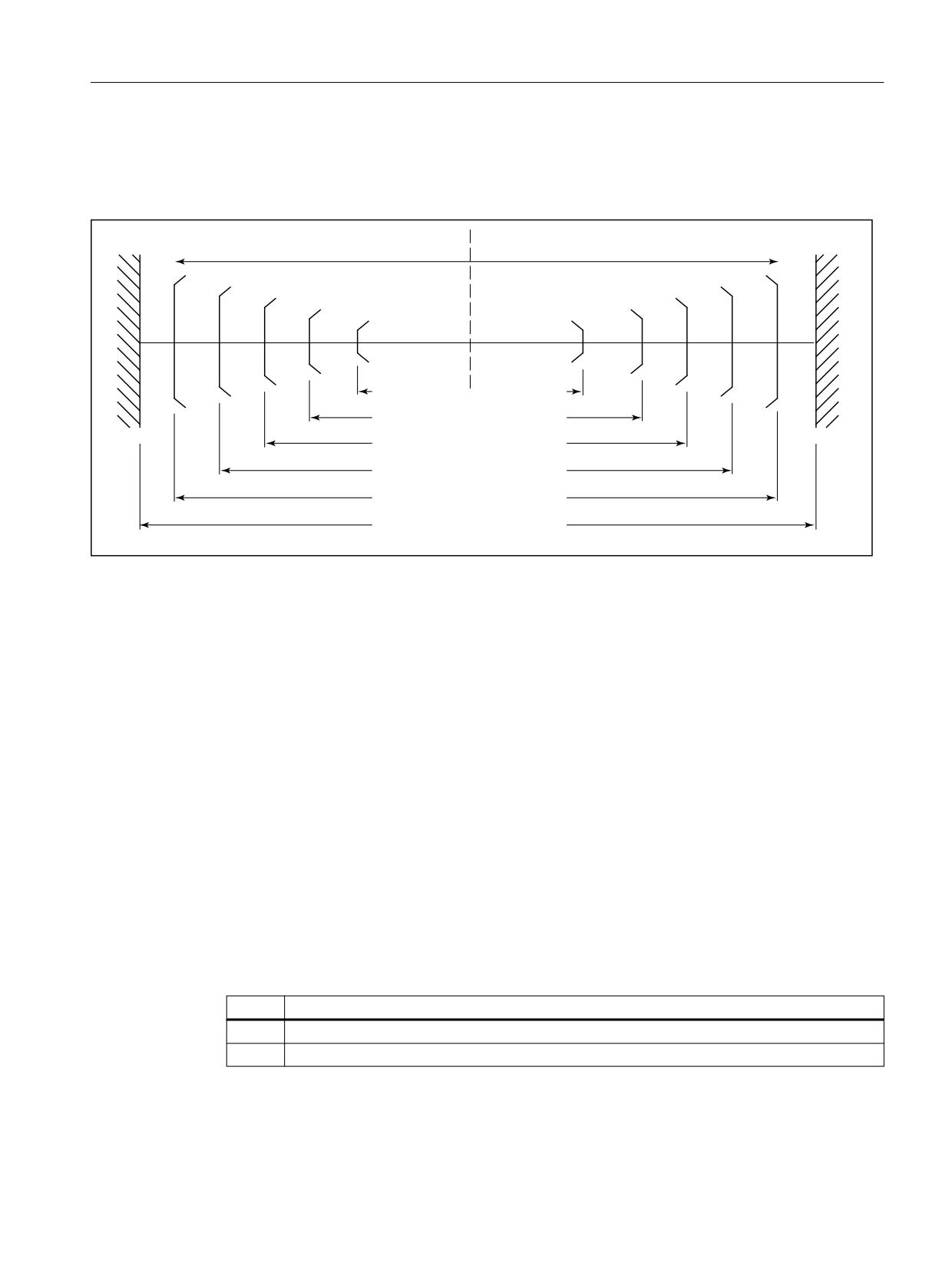
Axis monitoring functions
7.6 Limit switch monitoring
7.6
Limit switch monitoring
Overview of the end stops and possible limit-switch monitoring:
7UDYHUVLQJ UDQJH 0LQXV
7UDYHUVLQJ UDQJH 3OXV
:RUNLQJ DUHD OLPLWDWLRQ
QG VRIWZDUH OLPLW VZLWFK
VW VRIWZDUH OLPLW VZLWFK
+DUGZDUH OLPLW VZLWFK
(PHUJHQF\ VWRS
0HFKDQLFDO WUDYHUVLQJ OLPLW
7.6.1
Hardware limit switch
Function
A hardware limit switch is normally installed at the end of the traversing range of a machine axis.
It serves to protect against accidental overtravelling of the maximum traversing range of the
machine axis while the machine axis is not yet referenced.
If the hardware limit switch is triggered, the PLC user program created by the machine
manufacturer sets the corresponding interface signal:
DB31, ... DBX12.0/1 = 1 (hardware limit switch minus/plus)
Parameterization
The braking behavior of the machine axis upon reaching the hardware limit switch is
configurable via the machine data:
MD36600 $MA_BRAKE_MODE_CHOICE (braking behavior on hardware limit switch)
Value
Meaning
0
Braking with the configured axial acceleration
1
Rapid stop (set velocity = 0)
Monitoring and compensating
Function Manual, 10/2020, 6FC5397-7GP40-0BA1
173
Axis monitoring functions
7.6 Limit switch monitoring
Effectiveness
The hardware limit-switch monitoring is active after the controller has ramped up in all modes.
Effect
Upon reaching the hardware limit switch, the following occurs:
• Alarm 21614 "Channel <channel number> axis <axis name> hardware limit switch
<direction>"
• The machine axis is braked according to the configured braking behavior.
• If the axis/spindle is involved in interpolation with other axes/spindles, these are also braked
according to their configured braking behavior.
• The traversing keys of the affected machine axis are blocked based on the direction.
7.6.2
Software limit switch
Function
Software limit switches serve to limit the traversing range of a machine axis. Per machine axis
and per traversing direction, two (1st and 2nd) software limit switches are available:
MD36100 POS_LIMIT_MINUS (1st software limit switch minus)
MD36110 POS_LIMIT_PLUS (1st software limit switch plus)
MD36120 POS_LIMIT_MINUS2 (2nd software limit switch minus)
MD36130 POS_LIMIT_PLUS2 (2nd software limit switch plus)
By default, the 1st software limit switch is active. The 2nd software limit switch can be activated
for a specific direction with the PLC user program:
DB31, ... DBX12.2 / 12.3 (2nd software limit switch minus/plus)
Effectiveness
The software limit switches are active:
• Immediately after the successful referencing of the machine axis.
• In all operating modes.
Supplementary conditions
• The software limit switches refer to the machine coordinate system.
• The software limit switches must be inside the range of the hardware limit switches.
• The machine axis can be moved to the position of the active software limit switch.
Monitoring and compensating
174
Function Manual, 10/2020, 6FC5397-7GP40-0BA1
Axis monitoring functions
7.6 Limit switch monitoring
• PRESET
After use of the function PRESET, the software limit-switch monitoring is no longer active.
The machine must first be re-referenced.
• Endlessly rotating rotary axes
No software limit-switch monitoring takes place for endlessly rotating rotary axes:
MD30310 $MA_ROT_IS_MODULO == 1 (modulo conversion for rotary axis and spindle)
Exception: Setup-rotary axes
Effects
Automatic operating modes (AUTOMATIC, MDI)
• Without transformation, without overlaid motion, unchanged software limit switch:
A part program block with a programmed traversing motion that would lead to overrunning
of the software limit switch is not started.
• With transformation:
Different reactions occur depending on the transformation type:
- Behavior as above.
or
- The part program block with a programmed traversing motion that would lead to
overrunning of the software limit switch is started. The affected machine axis stops at the
active software limit switch. The other machine axes participating in the traversing
motion are braked. The programmed contour is left during this process.
• With overlaid motion
The part program block with a programmed traversing motion that would lead to
overrunning of the software limit switch is started. Machine axes that are traveling with
overlaid motion or have traveled with overlaid motion stop at the active software limit switch
in question. The other machine axes participating in the traversing motion are braked. The
programmed contour is left during this process.
Manual operating modes
• JOG without transformation
The machine axis stops at the software limit switch position.
• JOG with transformation
The machine axis stops at the software limit switch position. Other machine axes
participating in the traversing motion are braked. The preset path is left during this process.
General
• Changing of the software limit switch (1st ↔ 2nd software limit switch)
If the actual position of the machine axis after changing lies behind the software limit switch,
it is stopped with the maximum permissible acceleration.
• Overrunning the software limit switch in JOG mode
If the position of the software limit switch is reached and renewed pressing of the traversing
button should cause further travel in this direction, an alarm is displayed and the axis is not
traversed farther:
Alarm 10621 "Channel <channel number> axis <axis name> is at software limit switch
<direction>"
Monitoring and compensating
Function Manual, 10/2020, 6FC5397-7GP40-0BA1
175
Axis monitoring functions
7.7 Working area limitation monitoring
7.7
Working area limitation monitoring
7.7.1
General
Function
The "working area limitation" function can be used to limit the traversing range of a channel's
geometry and special axes to a permissible operating range. The function monitors compliance
with working area limits both in AUTOMATIC mode and in JOG mode.
The following versions are available:
• Working area limitation in the Basic Coordinate System (BCS)
The traversing range limits are specified relative to the Basic Coordinate System.
• Working area limitation in the workpiece coordinate system (WCS) or adjustable zero system
(AZS)
The traversing range limits are specified relative to the workpiece coordinate system or to the
adjustable zero system.
The two types of monitoring are independent of each other. If they are both active at the same
time, the traversing range limit which most restricts the access will take effect, depending on the
direction of travel.
Monitoring and compensating
176
Function Manual, 10/2020, 6FC5397-7GP40-0BA1
Axis monitoring functions
7.7 Working area limitation monitoring
Reference point at the tool
Taking into account the tool data (tool length and tool radius) and therefore the reference point
at the tool when monitoring the working area limitation depends on the status of the
transformation in the channel:
• Transformation inactive
Without transformations during traversing motion with an active tool the position of the tool
tip P is monitored, i.e. during the monitoring the tool length is considered automatically.
Consideration of the tool radius must be activated separately:
MD21020 $MC_WORKAREA_WITH_TOOL_RADIUS (Consideration of the tool radius in the
working area limitation)
• Transformation active
In the case of certain transformations the monitoring of the working area limitation may
differ from the behavior without transformation:
- The tool length is a component of the transformation
($MC_TRAFO_INCLUDES_TOOL_X = TRUE):
In this case the tool length is not considered, i.e. the monitoring refers to the tool carrier
reference point.
- Transformation with change in orientation:
In the case of transformations with changes in orientation, monitoring is always based on
the tool center point. MD21020 has no influence.
Note
The machine data $MC_TRAFO_INCLUDES_TOOL_... is analyzed only in certain
transformations. Condition for a possible evaluation is that the orientation of the tool
with respect to the base coordinate system cannot be changed by the transformation.
With standard transformations, the condition is only fulfilled for the "inclined axis" type of
transformation.
Response
Automatic operating modes
• With / without transformation
The parts program block with a programmed traversing motion that would lead to
overrunning of the working area limits is not executed.
• With superimposed motion
The axis, which would violate the working area limitation due to a superimposed motion, is
braked with maximum acceleration and without jerk limits (BRISK), and will come to a stop
in the position of the working area limitation. Other axes involved in the movement are
braked according to current acceleration behavior (e.g. SOFT). The path correlation may be
lost due to different braking accelerations (contour violation).
Manual operating modes
• JOG with / without transformation
The axis is positioned at the working area limitation and then stopped.
Monitoring and compensating
Function Manual, 10/2020, 6FC5397-7GP40-0BA1
177

Axis monitoring functions
7.7 Working area limitation monitoring
Powerup response
If an axis moves outside the permissible working area when activating the working area limits,
it will be immediately stopped with the maximum permissible acceleration.
Overrunning of the working area limitation in JOG mode
In JOG mode, an axis is moved to no further than its working area limit by the control system.
When the traverse button is pressed again, an alarm is displayed and the axis does not traverse
any further.
Geo-axis replacement
Through the following machine data it is adjustable, whether during geometry axis change the
active working area limitation is retained or deactivated:
MD10604 $MN_WALIM_GEOAX_CHANGE_MODE = <value>
<value>
Meaning
0
The working area limitation is deactivated during the geometry axis change.
1
The working area limitation remains activated during the geometry axis change.
7.7.2
Working area limitation in BCS
Application
Using the "working area limitation in BCS", the working area of a machine tool is limited so that
the surrounding devices (e.g. tool revolver, measuring stations) are protected against damage.
Working area limits
The lower and upper working area limits of each axes are adjusted through setting data or
programmed through part program commands:
Working area limitation through setting data
The adjustments are done through the immediately effective axis-specific setting data:
SD43420 $SA_WORKAREA_LIMIT_PLUS (working area limitation plus)
SD43430 $SA_WORKAREA_LIMIT_MINUS (working area limitation minus)
Programmed working area limitation
The programming is done using the G commands:
G25 X… Y… Z… lower working area limitation
G26 X… Y… Z… upper working area limitation
Monitoring and compensating
178
Function Manual, 10/2020, 6FC5397-7GP40-0BA1
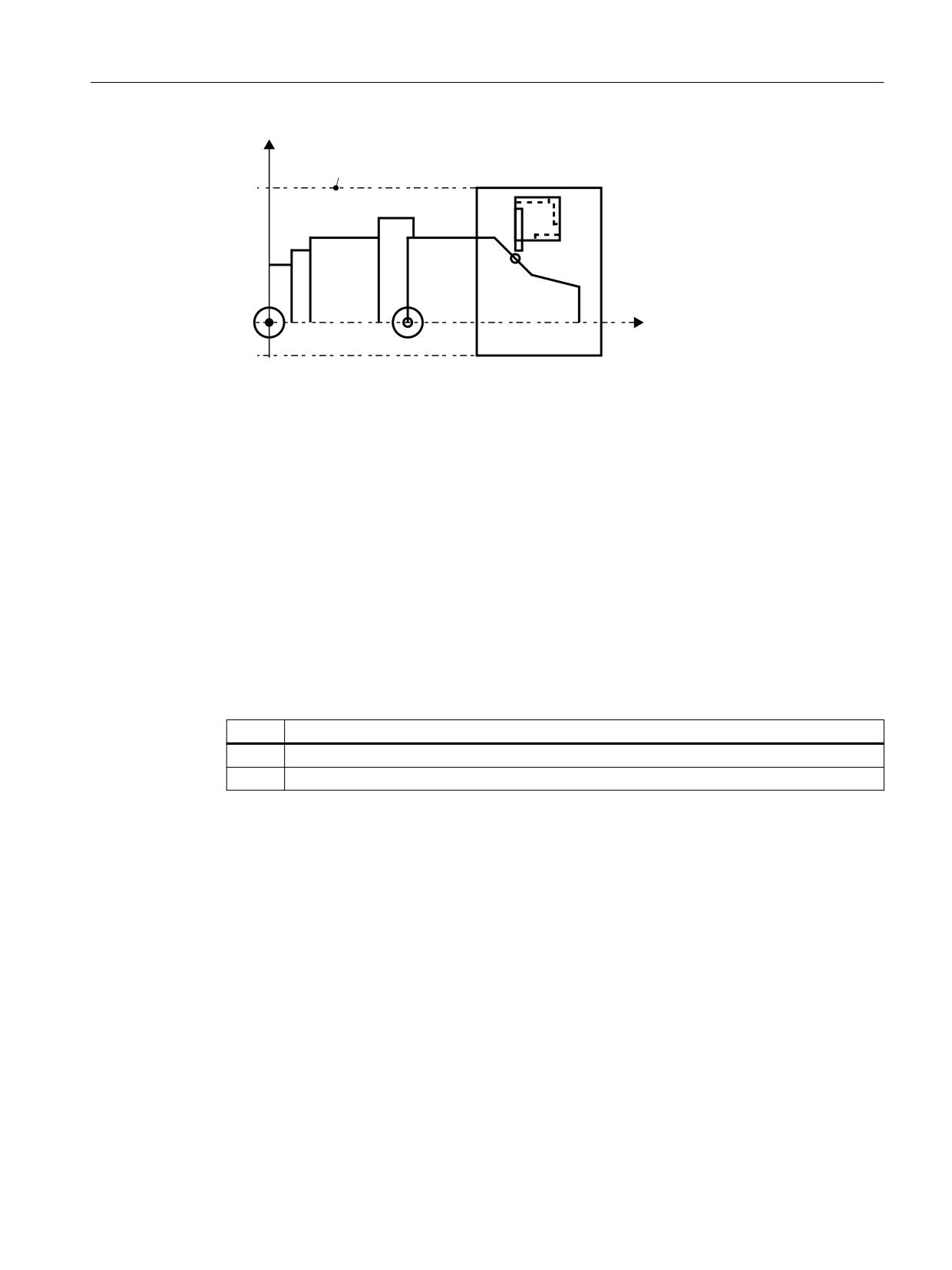
Axis monitoring functions
7.7 Working area limitation monitoring
3URJUDPPDEOH ZRUNLQJ
[
DUHD OLPLWDWLRQ
*
[PD[
3
:
]
[PLQ
*
*
]PLQ
]PD[
Figure 7-4
Programmed working area limitation
The programmed working area limitation has priority and overwrites the values entered in
SD43420 and SD43430.
Activation/Deactivation
Working area limitation through setting data
The activation/deactivation of the working area limitation for each axis takes place in a direction-
specific manner via the immediately effective setting data:
SD43400 $SA_WORKAREA_PLUS_ENABLE (working area limitation active in the positive
direction)
SD43410 $SA_WORKAREA_MINUS_ENABLE (working area limitation active in the negative
direction)
Value
Meaning
0
The working area limitation in positive or negative direction is switched off.
1
The working area limitation in positive or negative direction is active.
Programmed working area limitation
Activation or deactivation of the overall "working area limitation in the BCS" is arranged via part
program commands:
WALIMON
Working area limitation ON
or
WALIMOF
Working area limitation OFF
Changing the working area limitation
Working area limitation through setting data
Monitoring and compensating
Function Manual, 10/2020, 6FC5397-7GP40-0BA1
179
Axis monitoring functions
7.7 Working area limitation monitoring
HMI user interface: Operating area "Parameter"
• Automatic modes:
- Changes: Possible only in the RESET state
- Effectiveness: Immediately
• Manual operating modes:
- Changes: Always possible
- Effectiveness: At the start of the next traversing motion
Programmed working area limitation
The working area limitation can be changed in the part program via G25 or G26 <Axis name>
<value>. The change takes effect immediately.
The new working area limitation value is retained after NC RESET and POWER ON if the back-up
process has been activated in the NC's retentive data storage for SD43420 and SD43430:
MD10710 $MN_PROG_SD_RESET_SAVE_TAB[0] = 43420
MD10710 $MN_PROG_SD_RESET_SAVE_TAB[1] = 43430
Reset position
The reset position for the working area limitation (WALIMON or WALIMOF) is configurable via:
MD20150 $MC_GCODE_RESET_VALUES (reset setting of the G groups)
7.7.3
Working area limitation in WCS/SZS
Application
The "working area limitation" in the WCS/SZS enables a flexible workpiece-specific limitation of
the traversing range of the channel axes in the workpiece coordinate system (WCS) or settable
zero system (SZS). It is intended mainly for use in conventional lathes.
Requirement
The channel axes must be referenced.
Working area limitation group
In order that the axis-specific working area limits do not have to be rewritten for all channel axes
when switching axis assignments, e.g. when switching transformations or the active frame on/
off, working area limitation groups are available.
A working area limitation group comprises the following data:
• Working area limits for all channel axes
• Reference system of the working area limitation
Monitoring and compensating
180
Function Manual, 10/2020, 6FC5397-7GP40-0BA1