SINUMERIK 840D sl. Service - Functions. Manual (2018-2020) - page 44

Appendix
A.1 List of abbreviations
E
I
Input
EES
Execution from External Storage
I/O
Input/Output
ENC
Encoder: Actual value encoder
EFP
Compact I/O module (PLC I/O module)
ESD
Electrostatic Sensitive Devices
EMC
ElectroMagnetic Compatibility
EN
European standard
ENC
Encoder: Actual value encoder
EnDat
Encoder interface
EPROM
Erasable Programmable Read Only Memory: Erasable, electrically programmable
read-only memory
ePS Network Services
Services for Internet-based remote machine maintenance
EQN
Designation for an absolute encoder with 2048 sine signals per revolution
ES
Engineering System
ESR
Extended Stop and Retract
ETC
ETC key ">"; softkey bar extension in the same menu
F
FB
Function Block (PLC)
FC
Function Call: Function Block (PLC)
FEPROM
Flash EPROM: Read and write memory
FIFO
First In First Out: Memory that works without address specification and whose data is
read in the same order in which they was stored
FIPO
Fine interpolator
FPU
Floating Point Unit: Floating Point Unit
CRC
Cutter Radius Compensation
FST
Feed Stop: Feedrate stop
FBD
Function Block Diagram (PLC programming method)
FW
Firmware
G
GC
Global Control (PROFIBUS: Broadcast telegram)
GDIR
Global part program memory
GEO
Geometry, e.g. geometry axis
GIA
Gear Interpolation dAta: Gear interpolation data
GND
Signal Ground
GP
Basic program (PLC)
GS
Gear Stage
GSD
Device master file for describing a PROFIBUS slave
Extended Functions
Function Manual, 12/2018, A5E40874029B AB
901

Appendix
A.1 List of abbreviations
G
GSDML
Generic Station Description Markup Language: XML-based description language for
creating a GSD file
GUD
Global User Data: Global user data
H
HEX
Abbreviation for hexadecimal number
AuxF
Auxiliary function
HLA
Hydraulic linear drive
HMI
Human Machine Interface: SINUMERIK user interface
MSD
Main Spindle Drive
HW
Hardware
I
IBN
Commissioning
ICA
Interpolatory compensation
IM
Interface Module: Interconnection module
IMR
Interface Module Receive: Interface module for receiving data
IMS
Interface Module Send: Interface module for sending data
INC
Increment: Increment
INI
Initializing Data: Initializing data
IPO
Interpolator
ISA
Industry Standard Architecture
ISO
International Standardization Organization
J
JOG
Jogging: Setup mode
K
KV
Gain factor of control loop
Kp
Proportional gain
KÜ
Transformation ratio
LAD
Ladder Diagram (PLC programming method)
L
LAI
Logic Machine Axis Image: Logical machine axes image
LAN
Local Area Network
LCD
Liquid Crystal Display: Liquid crystal display
LED
Light Emitting Diode: Light-emitting diode
LF
Line Feed
Extended Functions
902
Function Manual, 12/2018, A5E40874029B AB

Appendix
A.1 List of abbreviations
L
PMS
Position Measuring System
LR
Position controller
LSB
Least Significant Bit: Least significant bit
LUD
Local User Data: User data (local)
M
MAC
Media Access Control
MAIN
Main program: Main program (OB1, PLC)
MB
Megabyte
MCI
Motion Control Interface
MCIS
Motion Control Information System
MCP
Machine Control Panel: Machine control panel
MD
Machine Data
MDA
Manual Data Automatic: Manual input
MDS
Motor Data Set: Motor data set
MSGW
Message Word
MCS
Machine Coordinate System
MM
Motor Module
MPF
Main Program File: Main program (NC)
MCP
Machine control panel
N
NC
Numerical Control: Numerical control with block preparation, traversing range, etc.
NCU
Numerical Control Unit: NC hardware unit
NRK
Name for the operating system of the NC
IS
Interface Signal
NURBS
Non-Uniform Rational B-Spline
WO
Work Offset
NX
Numerical Extension: Axis expansion board
O
OB
Organization block in the PLC
OEM
Original Equipment Manufacturer
OP
Operator Panel: Operating equipment
OPI
Operator Panel Interface: Interface for connection to the operator panel
OPT
Options: Options
OLP
Optical Link Plug: Fiber optic bus connector
OSI
Open Systems Interconnection: Standard for computer communications
Extended Functions
Function Manual, 12/2018, A5E40874029B AB
903

Appendix
A.1 List of abbreviations
P
PIQ
Process Image Output
PII
Process Image Input
PC
Personal Computer
PCIN
Name of the SW for data exchange with the control
PCMCIA
Personal Computer Memory Card International Association:
Plug-in memory card standardization
PCU
PC Unit: PC box (computer unit)
PG
Programming device
PKE
Parameter identification: Part of a PIV
PIV
Parameter identification: Value (parameterizing part of a PPO)
PLC
Programmable Logic Control: Adaptation control
PN
PROFINET
PNO
PROFIBUS user organization
PO
POWER ON
POU
Program Organization Unit
POS
Position/positioning
POSMO A
Positioning Motor Actuator: Positioning motor
POSMO CA
Positioning Motor Compact AC: Complete drive unit with integrated power and control
module as well as positioning unit and program memory; AC infeed
POSMO CD
Positioning Motor Compact DC: Like CA but with DC infeed
POSMO SI
Positioning Motor Servo Integrated: Positioning motor, DC infeed
PPO
Parameter Process data Object: Cyclic data telegram for PROFIBUS DP transmission
and "Variable speed drives" profile
PPU
Panel Processing Unit (central hardware for a panel-based CNC, e.g SINUMERIK
828D)
PROFIBUS
Process Field Bus: Serial data bus
PRT
Program Test
PSW
Program control word
PTP
Point-To-Point: Point-To-Point
PUD
Program global User Data: Program-global user variables
PZD
Process data: Process data part of a PPO
Q
QEC
Quadrant Error Compensation
R
RAM
Random Access Memory: Read/write memory
REF
REFerence point approach function
REPOS
REPOSition function
RISC
Reduced Instruction Set Computer: Type of processor with small instruction set and
ability to process instructions at high speed
ROV
Rapid Override: Input correction
Extended Functions
904
Function Manual, 12/2018, A5E40874029B AB

Appendix
A.1 List of abbreviations
R
RP
R Parameter, arithmetic parameter, predefined user variable
RPA
R Parameter Active: Memory area in the NC for R parameter numbers
RPY
Roll Pitch Yaw: Rotation type of a coordinate system
RTLI
Rapid Traverse Linear Interpolation: Linear interpolation during rapid traverse motion
RTS
Request To Send: Control signal of serial data interfaces
RTCP
Real Time Control Protocol
S
SA
Synchronized Action
SBC
Safe Brake Control: Safe Brake Control
SBL
Single Block: Single block
SBR
Subroutine: Subprogram (PLC)
SD
Setting Data
SDB
System Data Block
SEA
Setting Data Active: Identifier (file type) for setting data
SERUPRO
SEarch RUn by PROgram test: Block search, program test
SFB
System Function Block
SFC
System Function Call
SGE
Safety-related input
SGA
Safety-related output
SH
Safe standstill
SIM
Single in Line Module
SK
Softkey
SKP
Skip: Function for skipping a part program block
SLM
Synchronous Linear Motor
SM
Stepper Motor
SMC
Sensor Module Cabinet Mounted
SME
Sensor Module Externally Mounted
SMI
Sensor Module Integrated
SPF
Sub Routine File: Subprogram (NC)
PLC
Programmable Logic Controller
SRAM
Static RAM (non-volatile)
TNRC
Tool Nose Radius Compensation
SRM
Synchronous Rotary Motor
LEC
Leadscrew Error Compensation
SSI
Serial Synchronous Interface: Synchronous serial interface
SSL
Block search
STW
Control word
GWPS
Grinding Wheel Peripheral Speed
SW
Software
SYF
System Files: System files
SYNACT
SYNchronized ACTion: Synchronized Action
Extended Functions
Function Manual, 12/2018, A5E40874029B AB
905

Appendix
A.1 List of abbreviations
T
TB
Terminal Board (SINAMICS)
TCP
Tool Center Point: Tool tip
TCP/IP
Transport Control Protocol / Internet Protocol
TCU
Thin Client Unit
TEA
Testing Data Active: Identifier for machine data
TIA
Totally Integrated Automation
TM
Terminal Module (SINAMICS)
TO
Tool Offset: Tool offset
TOA
Tool Offset Active: Identifier (file type) for tool offsets
TRANSMIT
Transform Milling Into Turning: Coordination transformation for milling operations on
a lathe
TTL
Transistor-Transistor Logic (interface type)
TZ
Technology cycle
U
UFR
User Frame: Work offset
SR
Subprogram
USB
Universal Serial Bus
UPS
Uninterruptible Power Supply
V
VDI
Internal communication interface between NC and PLC
VDI
Verein Deutscher Ingenieure [Association of German Engineers]
VDE
Verband Deutscher Elektrotechniker [Association of German Electrical Engineers]
VI
Voltage Input
VO
Voltage Output
FDD
Feed Drive
W
SAR
Smooth Approach and Retraction
WCS
Workpiece Coordinate System
T
Tool
TLC
Tool Length Compensation
WOP
Workshop-Oriented Programming
WPD
Workpiece Directory: Workpiece directory
TRC
Tool Radius Compensation
T
Tool
TO
Tool Offset
TM
Tool Management
TC
Tool change
Extended Functions
906
Function Manual, 12/2018, A5E40874029B AB

Appendix
A.1 List of abbreviations
X
XML
Extensible Markup Language
Z
WOA
Work Offset Active: Identifier for work offsets
ZSW
Status word (of drive)
Extended Functions
Function Manual, 12/2018, A5E40874029B AB
907
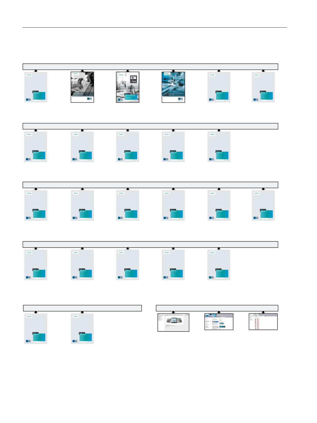
Appendix
A.2 Overview
A.2
Overview
*HQHUDO GRFXPHQWDWLRQ
6,180(5,.
6,180(5,.
6,180(5,.
' VO
' VO
'
$GYHUWLVLQJ EURFKXUH
&DWDORJ 1&
&DWDORJ 1&
&DWDORJ 30
6\VWHP 0DQXDO
6\VWHP 0DQXDO
6,180(5,.
' VO
6,180(5,.
' VO
6,180(5,.
'
6,027,21
,QWHOOLJHQW PDFKLQH
&WUO (QHUJ\
ದ 6,180(5,.
'
6,1$0,&6 6
WRRO RSHUDWLRQ
ದ 6,180(5,.
'
%$6,&
8VHU GRFXPHQWDWLRQ
6,180(5,.
6,180(5,.
6,180(5,.
6,180(5,.
6,180(5,.
' VO
' VO
' VO
' VO
'
'
'
'
6,1$0,&6
6,1$0,&6
6
6
2SHUDWLQJ 0DQXDO
3URJUDPPLQJ 0DQXDO
3URJUDPPLQJ 0DQXDO
'LDJQRVWLFV 0DQXDO
'LDJQRVWLFV 0DQXDO
ದ 8QLYHUVDO
ದ )XQGDPHQWDOV
ದ ,62 7XUQLQJ
$ODUPV
$ODUPV
ದ 7XUQLQJ
ದ -RE 3ODQQLQJ
ದ ,62 0LOOLQJ
ದ 0LOOLQJ
ದ 0HDVXULQJ &\FOHV
ದ *ULQGLQJ
0DQXIDFWXUHU VHUYLFH GRFXPHQWDWLRQ
6,180(5,.
6,180(5,.
6,180(5,.
6,180(5,.
6,180(5,.
6,180(5,.
' VO
'
' VO
' VO
'
' VO
6,1$0,&6
6,1$0,&6
6,1$0,&6
6
6
6
(TXLSPHQW 0DQXDO
(TXLSPHQW 0DQXDO
&RPPLVVLRQLQJ 0DQXDO
/LVWV 0DQXDO
/LVWV 0DQXDO
6\VWHP 0DQXDO
ದ 1&8
&RPPLVVLRQLQJ 0DQXDO
ದ &1& 1&. 3/&
ದ 0DFKLQH GDWD
ದ 0DFKLQH GDWD
*XLGHOLQHV IRU
ದ 2SHUDWRU FRPSRQHQWV
6HUYLFH 0DQXDO
'ULYH
ದ ,QWHUIDFH VLJQDOV
ದ ,QWHUIDFH VLJQDOV
FRQILJXULQJ
DQG QHWZRUNLQJ
ದ %DVH VRIWZDUH DQG
ದ 9DULDEOHV
ದ 3DUDPHWHUV
PDFKLQHV
ದ $',
RSHUDWLQJ VRIWZDUH
ದ 9DULDEOHV
0DQXIDFWXUHU VHUYLFH GRFXPHQWDWLRQ
6,180(5,.
6,180(5,.
6,180(5,.
6,180(5,.
6,180(5,.
' VO
' VO
' VO
'
'
6,1$0,&6
6,1$0,&6
6
6
)XQFWLRQ 0DQXDO
)XQFWLRQ 0DQXDO
)XQFWLRQ 0DQXDO
)XQFWLRQ 0DQXDO
&RQILJXUDWLRQ 0DQXDO
ದ %DVLF )XQFWLRQV
7RRO PDQDJHPHQW
6DIHW\ ,QWHJUDWHG
6DIHW\ ,QWHJUDWHG
ದ (0& LQVWDOODWLRQ
ದ ([WHQGHG )XQFWLRQV
JXLGHOLQH
ದ 6SHFLDO )XQFWLRQV
ದ ,QGXVWULDO VHFXULW\
ದ 6\QFKURQL]HG $FWLRQV
ದ ,62 'LDOHFWV
,QIR WUDLQLQJ
(OHFWURQLF GRFXPHQWDWLRQ
6,180(5,.
6,180(5,.
'2&RQ&'
,QGXVWU\ 2QOLQH
,QGXVWU\ 0DOO
6XSSRUW 6,26
7UDLQLQJ GRFXPHQWDWLRQ
0DQXDO
ದ 6LPSOH PLOOLQJ
7RRO DQG
ZLWK 6KRS0LOO
PROG PDNLQJ
ದ 6LPSOH WXUQLQJ
ZLWK 6KRS7XUQ
Extended Functions
908
Function Manual, 12/2018, A5E40874029B AB
Glossary
Absolute dimensions
A destination for an axis motion is defined by a dimension that refers to the origin of the currently
valid coordinate system. See → Incremental dimension
Acceleration with jerk limitation
In order to optimize the acceleration response of the machine whilst simultaneously protecting
the mechanical components, it is possible to switch over in the machining program between
abrupt acceleration and continuous (jerk-free) acceleration.
Address
An address is the identifier for a certain operand or operand range, e.g. input, output, etc.
Alarms
All → messages and alarms are displayed on the operator panel in plain text with date and time
and the corresponding symbol for the deletion criterion. Alarms and messages are displayed
separately.
1. Alarms and messages in the part program:
Alarms and messages can be displayed in plain text directly from the part program.
2. Alarms and messages from the PLC:
Alarms and messages for the machine can be displayed in plain text from the PLC program.
No additional function block packages are required for this purpose.
Archiving
Reading out of files and/or directories on an external memory device.
Asynchronous subprogram
Part program that can be started asynchronously to (independently of) the current program
status using an interrupt signal (e.g. "Rapid NC input" signal).
Automatic
Operating mode of the controller (block sequence operation according to DIN): Operating
mode for NC systems in which a → subprogram is selected and executed continuously.
Extended Functions
Function Manual, 12/2018, A5E40874029B AB
909
Glossary
Auxiliary functions
Auxiliary functions enable → part programs to transfer → parameters to the → PLC, which then
trigger reactions defined by the machine manufacturer.
Axes
In accordance with their functional scope, the CNC axes are subdivided into:
● Axes: Interpolating path axes
● Auxiliary axes: Non-interpolating feed and positioning axes with an axis-specific feedrate.
Auxiliary axes are not involved in actual machining, e.g. tool feeder, tool magazine.
Axis address
See → Axis name
Axis name
To ensure clear identification, all channel and → machine axes of the control system must be
designated with unique names in the channel and control system. The → geometry axes are
called X, Y, Z. The rotary axes rotating around the geometry axes → are called A, B, C.
Backlash compensation
Compensation for a mechanical machine backlash, e.g. backlash on reversal for ball screws.
Backlash compensation can be entered separately for each axis.
Backup battery
The backup battery ensures that the → user program in the → CPU is stored so that it is safe
from power failure and so that specified data areas and bit memory, timers and counters are
stored retentively.
Basic axis
Axis whose setpoint or actual value position forms the basis of the calculation of a
compensation value.
Basic Coordinate System
Cartesian coordinate system which is mapped by transformation onto the machine coordinate
system.
The programmer uses axis names of the basic coordinate system in the → part program. The
basic coordinate system exists parallel to the → machine coordinate system if no
→ transformation is active. The difference lies in the → axis names.
Extended Functions
910
Function Manual, 12/2018, A5E40874029B AB
Glossary
Baud rate
Rate of data transfer (bits/s).
Blank
Workpiece as it is before it is machined.
Block
"Block" is the term given to any files required for creating and processing programs.
Block search
For debugging purposes or following a program abort, the "Block search" function can be used
to select any location in the part program at which the program is to be started or resumed.
Booting
Loading the system program after power ON.
C axis
Axis around which the tool spindle describes a controlled rotational and positioning motion.
C spline
The C spline is the most well-known and widely used spline. The transitions at the interpolation
points are continuous, both tangentially and in terms of curvature. 3rd order polynomials are
used.
Channel
A channel is characterized by the fact that it can process a → part program independently of
other channels. A channel exclusively controls the axes and spindles assigned to it. Part
program runs of different channels can be coordinated through → synchronization.
Circular interpolation
The → tool moves on a circle between specified points on the contour at a given feedrate, and
the workpiece is thereby machined.
CNC
See → NC
Computerized Numerical Control: includes the components → NC, → PLC, HMI, → COM.
Extended Functions
Function Manual, 12/2018, A5E40874029B AB
911
Glossary
CNC
See → NC
Computerized Numerical Control: includes the components → NC, → PLC, HMI, → COM.
COM
Component of the NC for the implementation and coordination of communication.
Compensation axis
Axis with a setpoint or actual value modified by the compensation value
Compensation table
Table containing interpolation points. It provides the compensation values of the compensation
axis for selected positions on the basic axis.
Compensation value
Difference between the axis position measured by the encoder and the desired, programmed
axis position.
Continuous-path mode
The objective of continuous-path mode is to avoid substantial deceleration of the → path axes
at the part program block boundaries and to change to the next block at as close to the same
path velocity as possible.
Contour
Contour of the → workpiece
Contour monitoring
The following error is monitored within a definable tolerance band as a measure of contour
accuracy. An unacceptably high following error can cause the drive to become overloaded, for
example. In such cases, an alarm is output and the axes are stopped.
Coordinate system
See → Machine coordinate system, → Workpiece coordinate system
CPU
Central processing unit, see → PLC
Extended Functions
912
Function Manual, 12/2018, A5E40874029B AB
Glossary
CU
Transformation ratio
Curvature
The curvature k of a contour is the inverse of radius r of the nestling circle in a contour point
(k = 1/r).
Cycles
Protected subprograms for execution of repetitive machining operations on the → workpiece.
Data block
1. Data unit of the → PLC that → HIGHSTEP programs can access.
2. Data unit of the → NC: Data blocks contain data definitions for global user data. This data
can be initialized directly when it is defined.
Data word
Two-byte data unit within a → data block.
Diagnostics
1. Operating area of the control.
2. The control has a self-diagnostics program as well as test functions for servicing purposes:
status, alarm, and service displays
Dimensions specification, metric and inches
Position and pitch values can be programmed in inches in the machining program. Irrespective
of the programmable dimensions (G70/G71), the control is set to a basic system.
DRF
Differential Resolver Function: NC function which generates an incremental work offset in
Automatic mode in conjunction with an electronic handwheel.
Drive
The drive is the unit of the CNC that performs the speed and torque control based on the
settings of the NC.
Extended Functions
Function Manual, 12/2018, A5E40874029B AB
913
Glossary
Dynamic feedforward control
Inaccuracies in the → contour due to following errors can be practically eliminated using
dynamic, acceleration-dependent feedforward control. This results in excellent machining
accuracy even at high → path velocities. Feedforward control can be selected and deselected
on an axis-specific basis via the → part program.
Editor
The editor makes it possible to create, edit, extend, join, and import programs / texts / program
blocks.
Exact stop
When an exact stop statement is programmed, the position specified in a block is approached
exactly and, if necessary, very slowly. To reduce the approach time, → exact stop limits are
defined for rapid traverse and feed.
Exact stop limit
When all path axes reach their exact stop limits, the control responds as if it had reached its
precise destination point. A block advance of the → part program occurs.
External work offset
Work offset specified by the → PLC.
Fast retraction from the contour
When an interrupt occurs, a motion can be initiated via the CNC machining program, enabling
the tool to be quickly retracted from the workpiece contour that is currently being machined.
The retraction angle and the distance retracted can also be parameterized. An interrupt routine
can also be executed following the fast retraction.
Feed override
The programmed velocity is overriden by the current velocity setting made via the → machine
control panel or from the → PLC (0 to 200%). The feedrate can also be corrected by a
programmable percentage factor (1 to 200%) in the machining program.
Finished-part contour
Contour of the finished workpiece. See → Raw part.
Fixed machine point
Point that is uniquely defined by the machine tool, e.g. machine reference point.
Extended Functions
914
Function Manual, 12/2018, A5E40874029B AB
Glossary
Fixed-point approach
Machine tools can approach fixed points such as a tool change point, loading point, pallet
change point, etc. in a defined way. The coordinates of these points are stored in the control.
The control moves the relevant axes in → rapid traverse, whenever possible.
Frame
A frame is an arithmetic rule that transforms one Cartesian coordinate system into another
Cartesian coordinate system. A frame contains the following components: → work offset,
→ rotation, → scaling, → mirroring.
Geometry
Description of a → workpiece in the → workpiece coordinate system.
Geometry axis
The geometry axes form the 2 or 3-dimensional → workpiece coordinate system in which, in
→ part programs, the geometry of the workpiece is programmed.
Ground
Ground is taken as the total of all linked inactive parts of a device which will not become live
with a dangerous contact voltage even in the event of a malfunction.
Helical interpolation
The helical interpolation function is ideal for machining internal and external threads using form
milling cutters and for milling lubrication grooves.
The helix comprises two motions:
● Circular motion in one plane
● A linear motion perpendicular to this plane
High-level CNC language
The high-level language is used to write NC programs, → synchronized actions, and → cycles.
It provides: control structures → user-defined variables, → system variables, → macro
programming.
High-speed digital inputs/outputs
The digital inputs can be used for example to start fast CNC program routines (interrupt
routines). High-speed, program-driven switching functions can be initiated via the digital CNC
outputs
Extended Functions
Function Manual, 12/2018, A5E40874029B AB
915
Glossary
HIGHSTEP
Summary of programming options for → PLCs of the AS300/AS400 system.
HW Config
SIMATIC S7 tool for the configuration and parameterization of hardware components within
an S7 project
Identifier
In accordance with DIN 66025, words are supplemented using identifiers (names) for variables
(arithmetic variables, system variables, user variables), subprograms, key words, and words
with multiple address letters. These supplements have the same meaning as the words with
respect to block format. Identifiers must be unique. It is not permissible to use the same
identifier for different objects.
Inch measuring system
Measuring system which defines distances in inches and fractions of inches.
Inclined surface machining
Drilling and milling operations on workpiece surfaces that do not lie in the coordinate planes
of the machine can be performed easily using the function "inclined-surface machining".
Increment
Travel path length specification based on number of increments. The number of increments
can be stored as → setting data or be selected by means of a suitably labeled key (i.e. 10, 100,
1000, 10000).
Incremental dimension
Incremental dimension: A destination for axis traversal is defined by a distance to be covered
and a direction referenced to a point already reached. See → Absolute dimension.
Intermediate blocks
Motions with selected → tool offset (G41/G42) may be interrupted by a limited number of
intermediate blocks (blocks without axis motions in the offset plane), whereby the tool offset
can still be correctly compensated for. The permissible number of intermediate blocks which
the controller reads ahead can be set in system parameters.
Interpolator
Logic unit of the → NC that defines intermediate values for the motion to be carried out in
individual axes based on information on the end positions specified in the part program.
Extended Functions
916
Function Manual, 12/2018, A5E40874029B AB
Glossary
Interpolatory compensation
Mechanical deviations of the machine are compensated for by means of interpolatory
compensation functions, such as → leadscrew error, sag, angularity, and temperature
compensation.
Interrupt routine
Interrupt routines are special → subprograms that can be started by events (external signals)
in the machining process. A part program block which is currently being worked through is
interrupted and the position of the axes at the point of interruption is automatically saved.
Inverse-time feedrate
The time required for the path of a block to be traversed can also be programmed for the axis
motion instead of the feed velocity (G93).
JOG
Operating mode of the control (setup mode): The machine can be set up in JOG mode.
Individual axes and spindles can be traversed in JOG mode by means of the direction keys.
Additional functions in JOG mode include: → Reference point approach, → Repos, and → Preset
(set actual value).
Key switch
The key switch on the → machine control panel has four positions that are assigned functions
by the operating system of the controller. The key switch has three different colored keys that
can be removed in the specified positions.
Keywords
Words with specified notation that have a defined meaning in the programming language for
→ part programs.
KV
Servo gain factor, a control variable in a control loop.
Leading axis
The leading axis is the → gantry axis that exists from the point of view of the operator and
programmer and, thus, can be influenced like a standard NC axis.
Leadscrew error compensation
Compensation for the mechanical inaccuracies of a leadscrew participating in the feed. The
controller uses stored deviation values for the compensation.
Extended Functions
Function Manual, 12/2018, A5E40874029B AB
917
Glossary
Limit speed
Maximum/minimum (spindle) speed: The maximum speed of a spindle can be limited by
specifying machine data, the → PLC or → setting data.
Linear axis
In contrast to a rotary axis, a linear axis describes a straight line.
Linear interpolation
The tool travels along a straight line to the destination point while machining the workpiece.
Load memory
The load memory is the same as the → working memory for the CPU 314 of the → PLC.
Look Ahead
The Look Ahead function is used to achieve an optimal machining speed by looking ahead
over an assignable number of traversing blocks.
Machine axes
Physically existent axes on the machine tool.
Machine control panel
An operator panel on a machine tool with operating elements such as keys, rotary switches,
etc., and simple indicators such as LEDs. It is used to directly influence the machine tool via
the PLC.
Machine coordinate system
A coordinate system, which is related to the axes of the machine tool.
Machine zero
Fixed point of the machine tool to which all (derived) measuring systems can be traced back.
Machining channel
A channel structure can be used to shorten idle times by means of parallel motion sequences,
e.g. moving a loading gantry simultaneously with machining. Here, a CNC channel must be
regarded as a separate CNC control system with decoding, block preparation and interpolation.
Extended Functions
918
Function Manual, 12/2018, A5E40874029B AB
Glossary
Macro techniques
Grouping of a set of statements under a single identifier. The identifier represents the set of
consolidated statements in the program.
Main block
A block preceded with ":" that contains all information to start the operating sequence in a
→ part program.
Main program
The term "main program" has its origins during the time when part programs were split strictly
into main and → subprograms. This strict division no longer exists with today's SINUMERIK
NC language. In principle, any part program in the channel can be selected and started. It then
runs through in → program level 0 (main program level). Further part programs or → cycles as
subprograms can be called up in the main program.
MDI
Operating mode of the control: Manual Data Input. In the MDI mode, individual program blocks
or block sequences with no reference to a main program or subprogram can be input and
executed immediately afterwards through actuation of the NC start key.
Messages
All messages programmed in the part program and → alarms detected by the system are
displayed on the operator panel in plain text with date and time and the corresponding symbol
for the deletion criterion. Alarms and messages are displayed separately.
Metric measuring system
Standardized system of units: For length, e.g. mm (millimeters), m (meters).
Mirroring
Mirroring reverses the signs of the coordinate values of a contour, with respect to an axis. It
is possible to mirror with respect to more than one axis at a time.
Mode
An operating concept on a SINUMERIK control The following modes are defined: → Jog, → MDI,
→ Automatic.
Mode group
Axes and spindles that are technologically related can be combined into one mode group.
Axes/spindles of a mode group can be controlled by one or more → channels. The same
→ mode type is always assigned to the channels of the mode group.
Extended Functions
Function Manual, 12/2018, A5E40874029B AB
919
Glossary
NC
Numerical Control component of the → CNC that executes the → part programs and coordinates
the movements of the machine tool.
Network
A network is the connection of multiple S7-300 and other end devices, e.g. a programming
device via a → connecting cable. A data exchange takes place over the network between the
connected devices.
NRK
Numeric robotic kernel (operating system of → NC)
NURBS
The motion control and path interpolation that occurs within the control is performed based on
NURBS (Non Uniform Rational B-Splines). This provides a uniform procedure for all internal
interpolations.
OEM
The scope for implementing individual solutions (OEM applications) has been provided for
machine manufacturers, who wish to create their own user interface or integrate technology-
specific functions in the control.
Offset memory
Data range in the control, in which the tool offset data is stored.
Oriented spindle stop
Stops the workpiece spindle in a specified angular position, e.g. in order to perform additional
machining at a particular location.
Overall reset
In the event of an overall reset, the following memories of the → CPU are deleted:
●
→ Working memory
● Read/write area of → load memory
●
→ System memory
●
→ Backup memory
Extended Functions
920
Function Manual, 12/2018, A5E40874029B AB
Glossary
Override
Manual or programmable possibility of intervention that enables the user to override
programmed feedrates or speeds in order to adapt them to a specific workpiece or material.
Part program
Series of statements to the NC that act in concert to produce a particular → workpiece. Likewise,
this term applies to execution of a particular machining operation on a given → raw part.
Part program block
Part of a → part program that is demarcated by a line feed. There are two types: → main blocks
and → subblocks.
Part program management
Part program management can be organized by → workpieces. The size of the user memory
determines the number of programs and the amount of data that can be managed. Each file
(programs and data) can be given a name consisting of a maximum of 24 alphanumeric
characters.
Path axis
Path axes include all machining axes of the → channel that are controlled by the → interpolator
in such a way that they start, accelerate, stop, and reach their end point simultaneously.
Path feedrate
Path feedrate affects → path axes. It represents the geometric sum of the feedrates of the
→ geometry axes involved.
Path velocity
The maximum programmable path velocity depends on the input resolution. For example, with
a resolution of 0.1 mm the maximum programmable path velocity is 1000 m/min.
PCIN data transfer program
PCIN is a utility program for sending and receiving CNC user data (e.g. part programs, tool
offsets) via the serial interface. The PCIN program can run under MS-DOS on standard
industrial PCs.
Peripheral module
I/O modules represent the link between the CPU and the process.
Extended Functions
Function Manual, 12/2018, A5E40874029B AB
921
Glossary
I/O modules are:
●
→ Digital input/output modules
●
→ Analog input/output modules
●
→ Simulator modules
PLC
Programmable Logic Controller: → Programmable logic controller. Component of → NC:
Programmable control for processing the control logic of the machine tool.
PLC program memory
SINUMERIK 840D sl: The PLC user program, the user data and the basic PLC program are
stored together in the PLC user memory.
PLC programming
The PLC is programmed using the STEP 7 software. The STEP 7 programming software is
based on the WINDOWS standard operating system and contains the STEP 5 programming
functions with innovative enhancements.
Polar coordinates
A coordinate system which defines the position of a point on a plane in terms of its distance
from the origin and the angle formed by the radius vector with a defined axis.
Polynomial interpolation
Polynomial interpolation enables a wide variety of curve characteristics to be generated, such
as straight line, parabolic, exponential functions (SINUMERIK 840D sl).
Positioning axis
Axis that performs an auxiliary motion on a machine tool (e.g. tool magazine, pallet transport).
Positioning axes are axes that do not interpolate with → path axes.
Position-time cams
The term "position-time cam" refers to a pair of software cams that can supply a pulse of a
certain duration at a defined axis position.
Pre-coincidence
Block change occurs already when the path distance approaches an amount equal to a
specifiable delta of the end position.
Extended Functions
922
Function Manual, 12/2018, A5E40874029B AB
Glossary
Program block
Program blocks contain the main program and subprograms of → part programs.
Program level
A part program started in the channel runs as a → main program on program level 0 (main
program level). Any part program called up in the main program runs as a → subprogram on
a program level 1 ... n of its own.
Programmable frames
Programmable → frames enable dynamic definition of new coordinate system output points
while the part program is being executed. A distinction is made between absolute definition
using a new frame and additive definition with reference to an existing starting point.
Programmable logic controller
Programmable logic controllers (PLCs) are electronic controllers, the function of which is stored
as a program in the control unit. This means that the layout and wiring of the device do not
depend on the function of the controller. The programmable logic control has the same
structure as a computer; it consists of a CPU (central module) with memory, input/output
modules and an internal bus system. The peripherals and the programming language are
matched to the requirements of the control technology.
Programmable working area limitation
Limitation of the motion space of the tool to a space defined by programmed limitations.
Programming key
Characters and character strings that have a defined meaning in the programming language
for → part programs.
Protection zone
Three-dimensional zone within the → working area into which the tool tip must not pass.
Quadrant error compensation
Contour errors at quadrant transitions, which arise as a result of changing friction conditions
on the guideways, can be virtually entirely eliminated with the quadrant error compensation.
Parameterization of the quadrant error compensation is performed by means of a circuit test.
R parameters
Arithmetic parameter that can be set or queried by the programmer of the → part program for
any purpose in the program.
Extended Functions
Function Manual, 12/2018, A5E40874029B AB
923
Glossary
Rapid traverse
The highest traverse velocity of an axis. It is used, for example, when the tool approaches the
→ workpiece contour from a resting position or when the tool is retracted from the workpiece
contour. The rapid traverse velocity is set on a machine-specific basis using a machine data
item.
Reference point
Machine tool position that the measuring system of the → machine axes references.
Rotary axis
Rotary axes apply a workpiece or tool rotation to a defined angular position.
Rotation
Component of a → frame that defines a rotation of the coordinate system around a particular
angle.
Rounding axis
Rounding axes rotate a workpiece or tool to an angular position corresponding to an indexing
grid. When a grid index is reached, the rounding axis is "in position".
RS-232-C
Serial interface for data input/output. Machining programs as well as manufacturer and user
data can be loaded and saved via this interface.
Safety functions
The controller is equipped with permanently active monitoring functions that detect faults in
the → CNC, the → PLC, and the machine in a timely manner so that damage to the workpiece,
tool, or machine is largely prevented. In the event of a fault, the machining operation is
interrupted and the drives stopped. The cause of the malfunction is logged and output as an
alarm. At the same time, the PLC is notified that a CNC alarm has been triggered.
Scaling
Component of a → frame that implements axis-specific scale modifications.
Setting data
Data which communicates the properties of the machine tool to the NC as defined by the
system software.
Extended Functions
924
Function Manual, 12/2018, A5E40874029B AB
Glossary
Softkey
A key, whose name appears on an area of the screen. The choice of softkeys displayed is
dynamically adapted to the operating situation. The freely assignable function keys (softkeys)
are assigned defined functions in the software.
Software limit switch
Software limit switches limit the traversing range of an axis and prevent an abrupt stop of the
slide at the hardware limit switch. Two value pairs can be specified for each axis and activated
separately by means of the → PLC.
Spline interpolation
With spline interpolation, the controller can generate a smooth curve characteristic from only
a few specified interpolation points of a set contour.
Standard cycles
Standard cycles are provided for machining operations which are frequently repeated:
● For the drilling/milling technology
● For turning technology
The available cycles are listed in the "Cycle support" menu in the "Program" operating area.
Once the desired machining cycle has been selected, the parameters required for assigning
values are displayed in plain text.
Subblock
Block preceded by "N" containing information for a sequence, e.g. positional data.
Subprogram
The term "subprogram" has its origins during the time when part programs were split strictly
into →main and subprograms. This strict division no longer exists with today's SINUMERIK NC
language. In principle, any part program or any → cycle can be called up as a subprogram
within another part program. It then runs through in the next → program level (x+1) (subprogram
level (x+1)).
Synchronization
Statements in → part programs for coordination of sequences in different → channels at certain
machining points.
Extended Functions
Function Manual, 12/2018, A5E40874029B AB
925
Glossary
Synchronized actions
1. Auxiliary function output
During workpiece machining, technological functions (→ auxiliary functions) can be output
from the CNC program to the PLC. For example, these auxiliary functions are used to
control additional equipment for the machine tool, such as quills, grabbers, clamping
chucks, etc.
2. Fast auxiliary function output
For time-critical switching functions, the acknowledgement times for the → auxiliary
functions can be minimized and unnecessary hold points in the machining process can be
avoided.
Synchronized axes
Synchronized axes take the same time to traverse their path as the geometry axes take for
their path.
Synchronized axis
A synchronized axis is the → gantry axis whose set position is continuously derived from the
motion of the → leading axis and is, thus, moved synchronously with the leading axis. From
the point of view of the programmer and operator, the synchronized axis "does not exist".
System memory
The system memory is a memory in the CPU in which the following data is stored:
● Data required by the operating system
● The operands timers, counters, markers
System variable
A variable that exists without any input from the programmer of a → part program. It is defined
by a data type and the variable name preceded by the character $. See → User-defined variable.
Tapping without compensating chuck
This function allows threads to be tapped without a compensating chuck. By using the
interpolating method of the spindle as a rotary axis and the drilling axis, threads can be cut to
a precise final drilling depth, e.g. for blind hole threads (requirement: spindles in axis operation).
Text editor
See → Editor
TOA area
The TOA area includes all tool and magazine data. By default, this area coincides with the
→ channel area with regard to the access of the data. However, machine data can be used to
Extended Functions
926
Function Manual, 12/2018, A5E40874029B AB
Glossary
specify that multiple channels share one → TOA unit so that common tool management data
is then available to these channels.
TOA unit
Each → TOA area can have more than one TOA unit. The number of possible TOA units is
limited by the maximum number of active → channels. A TOA unit includes exactly one tool
data block and one magazine data block. In addition, a TOA unit can also contain a toolholder
data block (optional).
Tool
Active part on the machine tool that implements machining (e.g. turning tool, milling tool, drill,
LASER beam, etc.).
Tool nose radius compensation
Contour programming assumes that the tool is pointed. Because this is not actually the case
in practice, the curvature radius of the tool used must be communicated to the controller which
then takes it into account. The curvature center is maintained equidistantly around the contour,
offset by the curvature radius.
Tool offset
Consideration of the tool dimensions in calculating the path.
Tool radius compensation
To directly program a desired → workpiece contour, the control must traverse an equistant path
to the programmed contour taking into account the radius of the tool that is being used (G41/
G42).
Transformation
Additive or absolute zero offset of an axis.
Travel range
The maximum permissible travel range for linear axes is ± 9 decades. The absolute value
depends on the selected input and position control resolution and the unit of measurement
(inch or metric).
User interface
The user interface (UI) is the display medium for a CNC in the form of a screen. It features
horizontal and vertical softkeys.
Extended Functions
Function Manual, 12/2018, A5E40874029B AB
927
Glossary
User memory
All programs and data, such as part programs, subprograms, comments, tool offsets, and work
offsets / frames, as well as channel and program user data, can be stored in the shared CNC
user memory.
User program
User programs for the S7-300 automation systems are created using the programming
language STEP 7. The user program has a modular layout and consists of individual blocks.
The basic block types are:
● Code blocks
These blocks contain the STEP 7 commands.
● Data blocks
These blocks contain constants and variables for the STEP 7 program.
User-defined variable
Users can declare their own variables for any purpose in the → part program or data block
(global user data). A definition contains a data type specification and the variable name. See
→ System variable.
Variable definition
A variable definition includes the specification of a data type and a variable name. The variable
names can be used to access the value of the variables.
Velocity control
In order to achieve an acceptable traverse rate in the case of very slight motions per block, an
anticipatory evaluation over several blocks (→ Look Ahead) can be specified.
WinSCP
WinSCP is a freely available open source program for Windows for the transfer of files.
Extended Functions
928
Function Manual, 12/2018, A5E40874029B AB
Glossary
Work offset
Specifies a new reference point for a coordinate system through reference to an existing zero
point and a → frame.
1. Settable
A configurable number of settable work offsets are available for each CNC axis. The offsets
- which are selected by means of G commands - take effect alternatively.
2. External
In addition to all the offsets which define the position of the workpiece zero, an external
work offset can be overridden by means of the handwheel (DRF offset) or from the PLC.
3. Programmable
Work offsets can be programmed for all path and positioning axes using the TRANS
statement.
Working area
Three-dimensional zone into which the tool tip can be moved on account of the physical design
of the machine tool. See → Protection zone.
Working area limitation
With the aid of the working area limitation, the traversing range of the axes can be further
restricted in addition to the limit switches. One value pair per axis may be used to describe the
protected working area.
Working memory
The working memory is a RAM in the → CPU that the processor accesses when processing
the application program.
Workpiece
Part to be made/machined by the machine tool.
Workpiece contour
Set contour of the → workpiece to be created or machined.
Workpiece coordinate system
The workpiece coordinate system has its starting point in the → workpiece zero-point. In
machining operations programmed in the workpiece coordinate system, the dimensions and
directions refer to this system.
Workpiece zero
The workpiece zero is the starting point for the → workpiece coordinate system. It is defined
in terms of distances to the → machine zero.
Extended Functions
Function Manual, 12/2018, A5E40874029B AB
929

Preface
1
Introduction
Fundamental safety
2
instructions
SINUMERIK
Geometric machine
3
modeling
SINUMERIK 840D sl
Monitoring and compensating
4
Collision avoidance, internal
Collision avoidance,
5
external
Function Manual
6
Protection areas
7
Axis monitoring functions
8
Contour tunnel monitoring
9
Compensations
A
Appendix
Valid for
control system
SINUMERIK 840D sl / 840DE sl
CNC software Version 4.94
10/2020
6FC5397-7GP40-0BA1
Table of contents
Preface
3
1
Introduction
13
1.1
About this documentation
13
2
Fundamental safety instructions
15
2.1
General safety instructions
15
2.2
Warranty and liability for application examples
15
2.3
Security information
15
3
Geometric machine modeling
17
3.1
Function description
17
3.1.1
Features
17
3.1.2
Automatic tool protection areas
20
3.2
Commissioning
23
3.2.1
General
23
3.2.1.1
Overview
23
3.2.1.2
Structure of the system variables
23
3.2.1.3
Color chart
24
3.2.2
Machine data
25
3.2.2.1
Maximum number of protection areas
25
3.2.2.2
Maximum number of protection area elements for machine protection areas
26
3.2.2.3
Maximum number of protection area elements for automatic tool protection areas
26
3.2.2.4
Maximum number of NC/PLC interface signals for the preactivation of protection areas
26
3.2.2.5
Maximum number of triangles for machine protection areas
26
3.2.2.6
Maximum number of triangles for automatic tool protection areas
26
3.2.2.7
Creation mode for automatic tool protection areas
27
3.2.3
System variables: Protection areas
27
3.2.3.1
Overview
27
3.2.3.2
$NP_PROT_NAME
28
3.2.3.3
$NP_CHAIN_ELEM
29
3.2.3.4
$NP_PROT_TYPE
30
3.2.3.5
$NP_1ST_PROT
31
3.2.3.6
$NP_PROT_COLOR
32
3.2.3.7
$NP_PROT_D_LEVEL
33
3.2.3.8
$NP_BIT_NO
34
3.2.3.9
$NP_INIT_STAT
36
3.2.3.10
$NP_INDEX
37
3.2.4
System variables: Protection area elements for machine protection areas
39
3.2.4.1
Overview
39
3.2.4.2
$NP_NAME
40
3.2.4.3
$NP_NEXT
41
3.2.4.4
$NP_NEXTP
42
3.2.4.5
$NP_COLOR
43
3.2.4.6
$NP_D_LEVEL
44
Monitoring and compensating
Function Manual, 10/2020, 6FC5397-7GP40-0BA1
5
Table of contents
3.2.4.7
$NP_USAGE
45
3.2.4.8
$NP_TYPE
46
3.2.4.9
$NP_FILENAME
51
3.2.4.10
$NP_PARA
56
3.2.4.11
$NP_OFF
57
3.2.4.12
$NP_DIR
58
3.2.4.13
$NP_ANG
60
3.2.5
System variables: Protection area elements for automatic tool protection areas
61
3.2.6
Boundary conditions
62
3.3
Data lists
63
3.3.1
Machine data
63
3.3.1.1
NC-specific machine data
63
3.3.2
System variables
63
4
Collision avoidance, internal
65
4.1
Function description
65
4.1.1
Options
65
4.1.2
Characteristics
65
4.1.3
Reaction of the control to a risk of collision
67
4.1.4
State diagram: Protection area
70
4.1.5
Tools
71
4.1.6
Boundary conditions
73
4.2
Commissioning
75
4.2.1
General
75
4.2.1.1
Overview
75
4.2.1.2
Structure of the system variables
75
4.2.2
Machine data
77
4.2.2.1
Collision tolerance
77
4.2.2.2
Safety clearance
77
4.2.2.3
Maximum memory space
78
4.2.2.4
Maximum number of collision pairs
78
4.2.2.5
Protection levels for collision avoidance On/Off
79
4.2.3
System variables
79
4.2.3.1
Overview
79
4.2.3.2
$NP_COLL_PAIR
80
4.2.3.3
$NP_SAFETY_DIST
81
4.2.4
Extend system variables
82
4.2.4.1
Overview
82
4.2.4.2
State data
83
4.2.4.3
Memory requirement
83
4.2.4.4
Braking distance estimations
84
4.3
Programming
85
4.3.1
Check for collision pair (COLLPAIR)
85
4.3.2
Request recalculation of the machine model of the collision avoidance (PROTA)
86
4.3.3
Setting the protection zone status (PROTS)
87
4.3.4
Determining the clearance of two protection zones (PROTD)
88
4.4
Example
90
4.4.1
Specifications
90
4.4.2
Part program of the machine model
96
4.5
Data lists
104
Monitoring and compensating
6
Function Manual, 10/2020, 6FC5397-7GP40-0BA1
Table of contents
4.5.1
Machine data
104
4.5.1.1
NC-specific machine data
104
4.5.2
System variables
104
5
Collision avoidance, external
107
5.1
Function description
107
5.1.1
Options
107
5.1.2
Characteristics
107
5.2
Commissioning
107
5.2.1
Machine data
107
5.2.1.1
Functions of external collision avoidance
107
5.2.1.2
Preview time
108
5.2.1.3
Preview time step
108
5.2.1.4
Timeout time
108
6
Protection areas
109
6.1
Function
109
6.2
Commissioning
116
6.2.1
Machine data
116
6.3
Programming
117
6.3.1
Defining protection zones (CPROTDEF, NPROTDEF)
117
6.3.2
Activating/deactivating protection zones (CPROT, NPROT)
120
6.3.3
Checking for protection zone violation, working area limitation and software limit
switches (CALCPOSI)
123
6.4
Special situations
132
6.4.1
Temporary enabling of protection zones
132
6.4.2
Behavior in the AUTOMATIC and MDA modes
133
6.4.3
Behavior in JOG mode
134
6.5
Boundary conditions
137
6.6
Example
138
6.6.1
Protection zone on a lathe
138
6.6.2
Protection zone definition in the part program
139
6.6.3
Protection zone definition with system variables
139
6.6.4
Activating protection zones
147
6.7
Data lists
147
6.7.1
Machine data
147
6.7.1.1
NC-specific machine data
147
6.7.1.2
Channelspecific machine data
147
7
Axis monitoring functions
149
7.1
Contour monitoring
149
7.1.1
Contour error
149
7.1.2
Following-error monitoring
150
7.2
Positioning, zero speed and clamping monitoring
152
7.2.1
Correlation between positioning, zero-speed and clamping monitoring
152
7.2.2
Positioning monitoring
152
7.2.3
Zero-speed monitoring
154
7.2.4
Parameter set-dependent exact stop and standstill tolerance
154
Monitoring and compensating
Function Manual, 10/2020, 6FC5397-7GP40-0BA1
7
Table of contents
7.2.5
Clamping monitoring
155
7.2.5.1
Function
155
7.2.5.2
Machine data
155
7.2.5.3
NC/PLC interface signals
156
7.2.5.4
Fault responses
156
7.2.5.5
"Automatic stop to release the clamping" clamping function
157
7.2.5.6
"Time-optimized release of the clamping" clamping function
158
7.2.5.7
"Automatic stop to set the clamping" clamping function
159
7.2.5.8
Supplementary conditions
161
7.3
Speed-setpoint monitoring
163
7.4
Actual-velocity monitoring
165
7.5
Measuring system monitoring
165
7.5.1
Encoder-limit-frequency monitoring
167
7.5.2
Plausibility check for absolute encoders
168
7.5.3
Customized error reactions
170
7.6
Limit switch monitoring
173
7.6.1
Hardware limit switch
173
7.6.2
Software limit switch
174
7.7
Working area limitation monitoring
176
7.7.1
General
176
7.7.2
Working area limitation in BCS
178
7.7.3
Working area limitation in WCS/SZS
180
7.7.4
Example: Working area limitation in WCS/SZS
183
7.8
Parking a machine axis
186
7.9
Parking the passive position measuring system
188
7.9.1
Function
188
7.9.2
Supplementary conditions
191
7.9.3
Example: Changing an attachment head for a direct position measuring system
192
7.9.4
Example: Changing an attachment head for two direct position measuring systems
197
7.9.5
Example: Measuring system switchover when encoders are missing in certain parts of the
range
201
7.10
Switching over encoder data sets
204
7.11
Data lists
206
7.11.1
Machine data
206
7.11.1.1
NC-specific machine data
206
7.11.1.2
Channelspecific machine data
207
7.11.1.3
Axis/spindlespecific machine data
207
7.11.2
Setting data
209
7.11.2.1
Axis/spindlespecific setting data
209
8
Contour tunnel monitoring
211
8.1
Brief description
211
8.1.1
Contour tunnel monitoring
211
8.1.2
Programmable contour accuracy
212
8.2
Contour tunnel monitoring
213
8.3
Programmable contour accuracy
214
Monitoring and compensating
8
Function Manual, 10/2020, 6FC5397-7GP40-0BA1
Table of contents
8.4
Constraints
217
8.5
Data lists
218
8.5.1
Machine data
218
8.5.1.1
Channelspecific machine data
218
8.5.1.2
Axis/spindlespecific machine data
218
8.5.2
Setting data
218
8.5.2.1
Channelspecific setting data
218
9
Compensations
219
9.1
Introduction
219
9.2
Temperature compensation
220
9.2.1
Function
220
9.2.2
Commissioning
223
9.2.3
Example
224
9.2.3.1
Commissioning the temperature compensation for the Z axis of a lathe
224
9.3
Backlash compensation
226
9.3.1
Mechanical backlash compensation
226
9.3.1.1
Function
226
9.3.1.2
Commissioning: Axis-specific machine data
228
9.3.2
Dynamic backlash compensation
229
9.3.2.1
Function
229
9.3.2.2
Commissioning: Axis-specific machine data
230
9.3.3
Dual position feedback
231
9.3.3.1
Commissioning: Axis-specific machine data
232
9.3.3.2
Supplementary conditions
232
9.4
Nodding compensation
233
9.4.1
Description of the function
233
9.4.1.1
Options
233
9.4.1.2
Features
233
9.4.1.3
Position-dependent compliance factor
235
9.4.1.4
Compensation relationships
236
9.4.2
Commissioning: Machine data
236
9.4.2.1
Overview
236
9.4.2.2
Time constant for smoothing nodding compensation values
237
9.4.2.3
Accelerating axis
238
9.4.2.4
Adaptation axis
238
9.4.2.5
Number of positions of the adaptation characteristic
239
9.4.2.6
Positions of the adaptation characteristic
240
9.4.2.7
Compliance factors
241
9.4.2.8
Function diagram
243
9.5
Interpolatory compensation
244
9.5.1
General properties
244
9.5.2
Leadscrew error and measuring system error compensation
246
9.5.2.1
Measuring system error compensation (MSEC)
246
9.5.2.2
Commissioning
247
9.5.2.3
Example
250
9.5.3
Sag and angularity error compensation
251
9.5.3.1
General information
251
9.5.3.2
Commissioning: Machine data
253
Monitoring and compensating
Function Manual, 10/2020, 6FC5397-7GP40-0BA1
9
Table of contents
9.5.3.3
Commissioning: Setting data
254
9.5.3.4
Commissioning: System variable
255
9.5.3.5
Commissioning: Basic procedure
259
9.5.3.6
Commissioning: Overview diagram
261
9.5.3.7
Example 1: Sag compensation
262
9.5.3.8
Example 2: Compensation with table multiplication
263
9.5.3.9
Example 3: 2-dimensional array of compensation values
264
9.5.4
Extension of the sag compensation with NCU link
270
9.5.4.1
General parameter assignment
270
9.5.4.2
Parameterization with channel names
270
9.5.4.3
Parameterization with machine axis names
271
9.5.4.4
Axis container
271
9.5.4.5
Configuration example 1: NCU link with rigid coupling
272
9.5.4.6
Configuration example 2 NCU link with axis container
274
9.5.5
Direction-dependent leadscrew error compensation
278
9.5.5.1
Description of functions
278
9.5.5.2
Commissioning
279
9.5.5.3
Example
282
9.5.6
Cylinder error compensation
285
9.5.6.1
Options
285
9.5.6.2
Function
285
9.5.6.3
Commissioning
285
9.5.6.4
Examples
290
9.5.7
Supplementary conditions
293
9.6
Dynamic feedforward control (following error compensation)
295
9.6.1
General properties
295
9.6.2
Speed feedforward control
297
9.6.3
Torque feedforward control
298
9.6.4
Dynamic response adaptation
300
9.6.5
Forward feed control for command- and PLC axes
301
9.6.6
Secondary conditions
303
9.7
Friction compensation overview
304
9.8
Friction compensation with a constant compensation value
304
9.8.1
Description of functions
304
9.8.2
Commissioning
305
9.8.2.1
Circularity test
306
9.8.3
Supplementary conditions
309
9.9
Friction compensation with adaptive characteristic
310
9.9.1
Description of functions
310
9.9.2
commissioning
311
9.9.3
Supplementary conditions
313
9.10
Friction compensation with adaptive characteristics
313
9.10.1
Description of the function
313
9.10.2
Commissioning
315
9.10.2.1
Activating the function
315
9.10.2.2
Commissioning functions of the SINUMERIK Operate user interface
315
9.10.2.3
Parameterization of the acceleration at the characteristic interpolation points
317
9.10.2.4
Velocity setpoint pulse
319
9.10.2.5
Torque setpoint pulse
321
Monitoring and compensating
10
Function Manual, 10/2020, 6FC5397-7GP40-0BA1
Table of contents
9.11
Compensation functions for suspended axes
325
9.11.1
Electronic counterweight
325
9.11.2
Special function: Reboot delay
326
9.12
Data lists
328
9.12.1
Machine data
328
9.12.1.1
General machine data
328
9.12.1.2
Channelspecific machine data
328
9.12.1.3
Axis/spindlespecific machine data
329
9.12.2
Setting data
331
9.12.2.1
General setting data
331
9.12.2.2
Axis/spindle-specific setting data
331
A
Appendix
333
A.1
List of abbreviations
333
A.2
Documentation overview
338
Index
339
Monitoring and compensating
Function Manual, 10/2020, 6FC5397-7GP40-0BA1
11
Table of contents
Monitoring and compensating
12
Function Manual, 10/2020, 6FC5397-7GP40-0BA1

Introduction
1
1.1
About this documentation
This documentation is part of the documentation category of SINUMERIK Function Manuals.
SINUMERIK Function Manuals
The SINUMERIK Function Manuals describe the NC functions of a SINUMERIK control.
The target group are configuring engineers, technologists, commissioning engineers and
programmers.
Each Function Manual covers a specific topic and contains all the function descriptions for this
topic.
The following table shows which Function Manuals are available for your SINUMERIK control and
which topics a Function Manual covers:
Function Manual
Topic
Basic functions
Basic functions of a CNC control
Axes and spindles
Axis and spindle functions, axis couplings
Transformations
Transformation functions
Monitoring and compensating
Axis monitoring and compensation functions, collision avoid-
ance
Tools
Functions for selection, correction and monitoring of tools
Synchronized actions
Functionality of synchronized actions
PLC
Structure and functions of the PLC
Tool management
Function, commissioning and programming of tool manage-
ment
Technologies (for SINUMERIK ONE
Extended technological functionalities
and SINUMERIK 840D sl only)
Overview of contents
You will find an overview of the main chapters of the descriptions of functions that are contained
in a Function Manual on the title page.
Validity
The title page also contains all data about the validity of a document, i.e. for which SINUMERIK
control and for which software version this edition of the Function Manual is valid.
Monitoring and compensating
Function Manual, 10/2020, 6FC5397-7GP40-0BA1
13

Introduction
1.1 About this documentation
System data
In the descriptions of functions, the system data relevant for a function (machine data, setting
data, system variables, interface signals and alarms) are only described with the level of detail
that is strictly necessary to understand the function. You will find detailed information on this
data in the relevant List Manuals and for alarms in the Diagnostics Manual.
PLC blocks
The descriptions of functions often refer to the PLC function blocks (FB) and functions (FC). The
descriptions of these blocks apply to the SINUMERIK 840D sl and can only be applied in part to
other SINUMERIK controls.
Interface signals
In this document, only the absolute address valid for the SINUMERIK 840D sl is used to address
interface signals.
General graphical conventions
Examples
<signal address> (<signal name>)
DB31, ... DBX16.0-2 (actual gear stage A to C)
DB31, ... DBX16.3 (gear is changed)
Note
Quantity structure
Explanations concerning the NC/PLC interface are based on the absolute maximum number of
the following components:
• Mode groups (DB11)
• Channels (DB21, etc.)
• Axes/spindles (DB31, etc.)
Monitoring and compensating
14
Function Manual, 10/2020, 6FC5397-7GP40-0BA1

Fundamental safety instructions
2
2.1
General safety instructions
WARNING
Danger to life if the safety instructions and residual risks are not observed
If the safety instructions and residual risks in the associated hardware documentation are not
observed, accidents involving severe injuries or death can occur.
• Observe the safety instructions given in the hardware documentation.
• Consider the residual risks for the risk evaluation.
WARNING
Malfunctions of the machine as a result of incorrect or changed parameter settings
As a result of incorrect or changed parameterization, machines can malfunction, which in turn
can lead to injuries or death.
• Protect the parameterization against unauthorized access.
• Handle possible malfunctions by taking suitable measures, e.g. emergency stop or
emergency off.
2.2
Warranty and liability for application examples
Application examples are not binding and do not claim to be complete regarding configuration,
equipment or any eventuality which may arise. Application examples do not represent specific
customer solutions, but are only intended to provide support for typical tasks.
As the user you yourself are responsible for ensuring that the products described are operated
correctly. Application examples do not relieve you of your responsibility for safe handling when
using, installing, operating and maintaining the equipment.
2.3
Security information
Siemens provides products and solutions with industrial security functions that support the
secure operation of plants, systems, machines and networks.
In order to protect plants, systems, machines and networks against cyber threats, it is necessary
to implement - and continuously maintain - a holistic, state-of-the-art industrial security
concept. Siemens’ products and solutions constitute one element of such a concept.
Customers are responsible for preventing unauthorized access to their plants, systems,
machines and networks. Such systems, machines and components should only be connected to
Monitoring and compensating
Function Manual, 10/2020, 6FC5397-7GP40-0BA1
15
Fundamental safety instructions
2.3 Security information
an enterprise network or the internet if and to the extent such a connection is necessary and only
when appropriate security measures (e.g. firewalls and/or network segmentation) are in place.
For additional information on industrial security measures that may be implemented, please
visit
Siemens’ products and solutions undergo continuous development to make them more secure.
Siemens strongly recommends that product updates are applied as soon as they are available
and that the latest product versions are used. Use of product versions that are no longer
supported, and failure to apply the latest updates may increase customer’s exposure to cyber
threats.
To stay informed about product updates, subscribe to the Siemens Industrial Security RSS Feed
under
services/cert.html#Subscriptions).
Further information is provided on the Internet:
Industrial Security Configuration Manual (https://support.industry.siemens.com/cs/ww/en/
view/108862708)
WARNING
Unsafe operating states resulting from software manipulation
Software manipulations, e.g. viruses, Trojans, or worms, can cause unsafe operating states in
your system that may lead to death, serious injury, and property damage.
• Keep the software up to date.
• Incorporate the automation and drive components into a holistic, state-of-the-art industrial
security concept for the installation or machine.
• Make sure that you include all installed products into the holistic industrial security concept.
• Protect files stored on exchangeable storage media from malicious software by with suitable
protection measures, e.g. virus scanners.
• On completion of commissioning, check all security-related settings.
Monitoring and compensating
16
Function Manual, 10/2020, 6FC5397-7GP40-0BA1
Geometric machine modeling
3
3.1
Function description
3.1.1
Features
This section describes how the geometry of machine parts can be mapped based on protection
areas and parameterized in the control using system variables for NC functions such as "collision
avoidance".
The system variables are retentively saved in the NC and can be archived and/or read as "NC data"
via SINUMERIK Operate using the commissioning archive.
By assigning a protective area to an element of the kinematic chain described in the previous
section, the position and motion of the machine part can be clearly described within the
machine space.
Note
Graphical editor
As an alternative to writing the system variables in a part program, the machine can be modeled
from the SINUMERIK Operate user interface:
Operating area: "Commissioning" > "NC" > "Machine model"
Changes to the machine model
The direct changes to the machine model at the system variables only become visible at the user
interface after explicitly requesting that the machine model is recalculated by calling
the PROTA() (Page 86) or PROTS() (Page 87) function.
Changes to the machine model made at the user interface are immediately accepted in the
system variables of the NC. The changes only become active after explicitly requesting that the
machine model is recalculated by calling the PROTA() (Page 86) or PROTS() (Page 87) function.
Protection area
The protection areas are the central element when geometrically modeling a machine. The
geometric dimensions of a machine part, its reference to the kinematic chain and additional
general features are described by a protection area.
A protection area has the following parameters:
• Name of the protection area
• Name of the kinematic element to which the protection area is assigned
• Type of the protection area
• Name of the first protection area element
Monitoring and compensating
Function Manual, 10/2020, 6FC5397-7GP40-0BA1
17
Geometric machine modeling
3.1 Function description
• Color and transparency of the protection area
• Detail level for the protection area
• Number of NC/PLC interface bits of the protection area
• Initialization status of the protection area
• Address of the geometric data of the machine element to the protected
(only relevant for automatic protection areas)
Each parameter is mapped by a system variable. The individual parameters and/or system
variables are described in detail in Chapter "System variables: Protection areas (Page 27)".
Kinematic chain
The corresponding protection area is assigned to an element of the kinematic chain in order to
map the position and motion of a machine part. The geometric data of the protection area
relates then to the local coordinate system of this kinematic element.
Type of the protection area
The following types of protection areas are available:
• Machine protection areas (type: "MACHINE")
Machine protection areas are used for general machine modeling. They are used to map
stationary and moving machine parts whose geometry is defined once upon commissioning
and no longer changes when the machine is in operation.
• Automatic tool protection areas (type: "TOOL")
Automatic tool protection areas are used to map tools. The geometry of the tool is not
provided directly with this but is produced automatically by the control when the tool is
activated.
See Chapter "Automatic tool protection areas (Page 20)".
Protection area element
Using a protection area element, the geometrical element used is described regarding its
geometrical and general properties.
A protection area element has the following parameters:
• Name of the protection area element
• Name of the following protection area element
• Name of the following protection area element parallel to $NP_NEXT
• Color and transparency of the protection area element
• Detail level for the protection area element
• Usage of the protection area element
• Type of the protection area element
• File name of the STL file that contains the geometric data of the protection area element
(only relevant for type "FILE")
• Geometrical parameters of the protection area body
(only relevant for types, "BOX", "SPHERE" or "CYLINDER")
Monitoring and compensating
18
Function Manual, 10/2020, 6FC5397-7GP40-0BA1
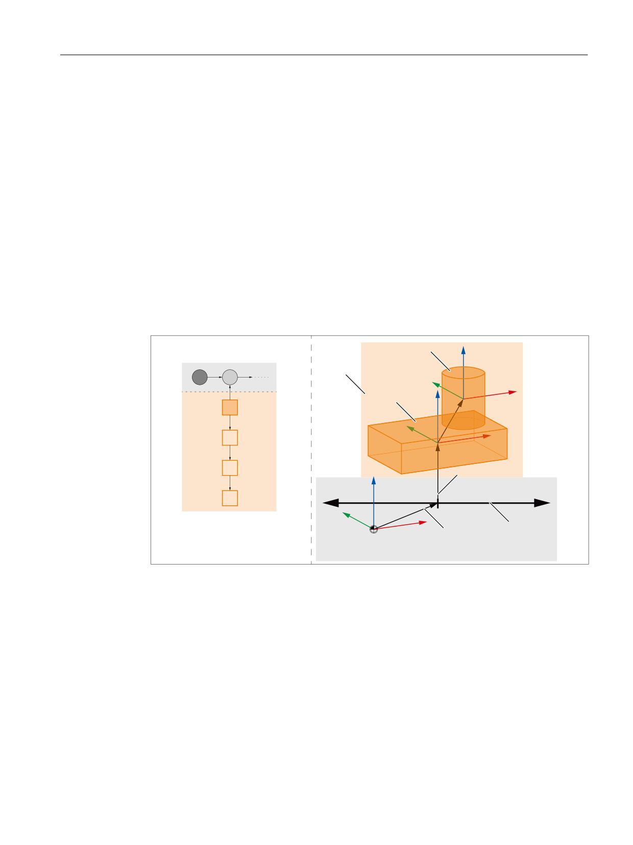
Geometric machine modeling
3.1 Function description
• Offset vector of the protection area element local coordinate system
• Direction vector for the rotation of the protection area element local coordinate system
• Angle for the rotation of the protection area element local coordinate system
Each parameter is mapped by a system variable. The individual parameters or system variables
are described in detail in:
• Chapter "System variables: Protection area elements for machine protection areas
(Page 39)"
• Chapter "System variables: Protection area elements for automatic tool protection areas
(Page 61)"
Protection area, protection area elements and kinematic chain
Using an example of a protection area with two protection area elements, the following diagram
shows the interrelationship between the protection area, its protection area elements and the
assignment to an element of the kinematic chain.
VH
.LQHPDWLF FKDLQ
]
V
H
H
\
VH
[
]
V
Y
VH
\
[
VH
VH
=
VH
*HRPHWULF PDFKLQH PRGHOLQJ
<
;
H
H
0DFKLQH FRRUGLQDWH V\VWHP
:RUOG FRRUGLQDWH V\VWHP
e1
Kinematic element 1, type "OFFSET", continuous offset
e2
Kinematic element 2, type "AXIS_LIN", machine axis AX1
s1
Protection area
se1
Protection area element 1, type "FRAME", offset
se2
Protection area element 2, type "BOX"
se3
Protection area element 3, type "CYLINDER"
Figure 3-1
Protection area, protection area elements and kinematic chain
Monitoring and compensating
Function Manual, 10/2020, 6FC5397-7GP40-0BA1
19
Geometric machine modeling
3.1 Function description
3.1.2
Automatic tool protection areas
Unlike machine protection areas whose geometry is defined once during the machine modeling
and then no longer changes, the geometry of a tool protection area can change with every tool
change. As a result the geometry of an automatic tool protection area is not described directly
when the machine model is created, and instead the address (magazine number, magazine
location, etc.) is provided under which the tool data is stored. The following actions are then
carried out automatically by the control.
1. The tool modeling (see "Tool modeling" section below) produces an STL file.
2. A protection area element of the "FILE" type is produced and assigns the STL file.
3. The protection area element is assigned to the protection area (type "TOOL").
Tool definition independent of the tool mounting position
Normally the parameter "$NP_1ST_PROT (Page 31)" remains empty for the definition of a tool
protection area. The name of the protection area element is only entered when the tool is
activated by the control (see above).
In order for there to be a tool definition independently of the tool mounting position, a
protection area element of the "FRAME (Page 46)" type can be assigned via the parameter
"$NP_1ST_PROT" (transformation element). The transformations to align the tool can be carried
out via this additional element. When a tool is activated the name of the internal protection area
element is entered in the parameter "$NP_NEXT (Page 41)" of the transformation element by
the control.
The following rules must be observed:
• The transformation element may only be of the "FRAME" type.
• Only one transformation element may be used for each tool protection area.
• The parameter "$NP_NEXTP" of the transformation element is not evaluated.
Tool reference point
The position of the tool reference point in the machine model is determined by the kinematic
element to which the tool protection area is assigned. In addition the tool reference point can be
offset within the tool protection area by an optional transformation element.
Kinematic transformations
The tool reference point may only be determined via the kinematic chain when defining a
kinematic transformation. Offsets by the transformation element of the tool protection area are
not taken into account.
NOTICE
Determination of the tool reference point for kinematic transformations
Offsets of the tool reference point by the transformation element of the tool protection area are
not taken into account by kinematic transformations.
Monitoring and compensating
20
Function Manual, 10/2020, 6FC5397-7GP40-0BA1
Geometric machine modeling
3.1 Function description
Tool modeling
The model of a tool is created by the control heuristically from the tool data. The tool data used
for this (L1, L2, L3, R) is always the the overall dimensions resulting from the individual
components, e.g. length plus wear, as is also entered in the program processing for tool offset.
Programmable tool offsets
Programmable tool offsets such as OFFN (offset to the programmed contour) are not taken into
account as they may change in any block, even without a tool change.
Monitoring and compensating
Function Manual, 10/2020, 6FC5397-7GP40-0BA1
21
Geometric machine modeling
3.1 Function description
Tool type-dependent model generation
The following tool types are distinguished for the model generation:
•
Milling tool and all other tools that are neither turning tools or grinding tools
- Modeling
The tool is modeled by a cylinder with the height L1 and radius R. If the length L1 is
negative the absolute value of L1 is used for the cylinder height. The sign L1 is taken into
account when positioning the cylinder in the machine model. The cylinder axis is parallel
to L1.
Tool type 110 (ball end mill cutter) and 111 (face cutter) are modeled using half a sphere
or sphere segments.
If the radius is negative the absolute value of the radius is used. If the value for the radius
is less than 1/3 mm, a radius of 1/3 mm is used.
- Positioning
The cylinder is positioned in the machine model using the tool length components L2 and
L3.
For milling tools (tool type 100 ... 199) and drilling tools (tool type 200 ... 299) on turning
machines, the cylinder is positioned using the cutting edge position.
Precondition: Cutting edge position == 5 ... 8
•
Grinding tools
- Modeling
Grinding tools (grinding wheel, tool type 400 ... 499) are modeled by a cylinder with the
tool length as the radius and double the tool radius as the height.
- Positioning
The cylinder is positioned in the machine model using the tool lengths L1, L2 and L3.
•
Turning tools
In the case of turning tools only the cutting tips are taken into account in the machine model
but not their connection to the tool reference point.
The following data is taken into account when modeling a cutting tip:
- Tool type
- Cutting edge position
- Cutting edge radius
- Clearance angle
- Holder angle
- Cutting tip length
- Cutting tip width
- Tip thickness (assumption: tip thickness = 10% tip length)
Tool model
A tool is modeled as standard with an accuracy of one third of the collision tolerance (Page 77).
The geometric data of the modeled tool is stored in an internal file in STL format:
• Directory: _N_PROT3D_DIR/_N_TOOL_DIR
• Identifiers: Name of the associated protection area with prefix _N_ and ending with _STL
Monitoring and compensating
22
Function Manual, 10/2020, 6FC5397-7GP40-0BA1
Geometric machine modeling
3.2 Commissioning
The coordinate system of the geometric data always has its origin at the point from which the
tool length offsets point to the tip of the tool.
System variable
All parameters for an automatic tool protection area can be read via System variable (Page 39).
3.2
Commissioning
3.2.1
General
3.2.1.1
Overview
The commissioning of the "Collision avoidance" function is performed using:
• Machine data
- Specifications for the quantity structure of protection areas, protection area elements, NC/
PLC interface signals, triangles for the geometry modelling
- Creation mode of the machine model
- Creation mode for automatic tool protection areas
• System variables
- Parameterization of the protection areas
- Parameterization of the protection area elements of a protection area
3.2.1.2
Structure of the system variables
The system variables are structured according to the following scheme:
• $NP_<name>[<index_1>]
• $NP_<name>[<index_1>, <index_2>]
General
The system variables to describe the protection areas or protection area elements have the
following properties:
• Prefix: $NP_, (N for NC, P for protection).
• They can be read and written via NC programs.
• They can be stored in archives and loaded to the NC again.
Monitoring and compensating
Function Manual, 10/2020, 6FC5397-7GP40-0BA1
23

Geometric machine modeling
3.2 Commissioning
Data type
STRING
All system variables of the STRING data type have the following properties:
• Maximum string length: 31 characters
• No distinction is made between upper and lower case
Example: "Axis1" is identical to "AXIS1"
• Spaces and special characters are permitted
Example: "Axis1" is not identical to "Axis 1"
• Names that start with two underscores "__" are reserved for system purposes and must not
be used for user-defined names.
Note
Leading space
Since spaces are valid and distinct characters, names that start with a space followed by two
underscores "__" can, in principle, be used for user-defined names. However, because they
can be easily mistaken for system names, this procedure is not recommended.
Index_1
System variables for protection areas
The individual protection areas are addressed via index_1. Index 0 → 1st protection area, index
1 → 2nd protection area, ... m → (m+1) protection area, where m =
($MN_MM_MAXNUM_3D_PROT_AREAS - 1)
All system variables of a protection area have the same index.
System variables for protection areas elements
The individual protection area elements are addressed via index_1. Index 0 → 1st protection area
element, index 1 → 2nd protection area element, ... n → (n+1)th protection area element, where
n = ($MN_MM_MAXNUM_3D_PROT_AREA_ELEM - 1)
All system variables of a protection area element have the same index.
Index_2
Depending on the respective system variables, index_2 has different meanings.
3.2.1.3
Color chart
The following color chart provides an overview of the RGB color values and the associated colors.
A RGB color value comprises three bytes. One byte per color:
3rd byte
2nd byte
1st byte
Color value for red
Color value for green
Color value for blue
0 - 255D or 0 - FFH
0 - 255D or 0 - FFH
0 - 255D or 0 - FFH
Monitoring and compensating
24
Function Manual, 10/2020, 6FC5397-7GP40-0BA1

Geometric machine modeling
3.2 Commissioning
&&
))
))
&&
))
))
))
))
))&&
))))
&&
))
))
&&
))
))
))
))
))&&
))))
&&
))
))
&&
))
))
))
))
))&&
))))
&&
))
))
&&
))
))
))
))
))&&
))))
&&
&&
&&
&&
&&&
))&&
))&&
&&&
&&
&&
&&
&&
)) &&
)) &&
)) &&
)) &&))&&&&
))))&&
))
))
))
))
&&))
))))
))))
&&))
))
))
))
))
))
))
))
))
))
))
))
))
))&&))
))))))
))
))
))
))
&&))
))))
))))
&&))
))
))
))
))
&&
))
&&
))
&&
))
&&
))
&&&&))
&&))))
&&
&&
&&
&&
&&&
))&&
))&&
&&&&
&&
&&
&&
&& && &&
&& &&
&& &&
&& &&
&&&&&&
&&))&&
&&
))
))
&&
&&
&&
&&
&&
&&&&
&&))
&&
))
))
&&
&&
&&
&&
&&
&&&&
&&))
&&
))
))
&&
&&
&&
&&
&&
&&&&
&&))
&&
))
))
&&
&&
&&
&&
&&
&&&&
&&))
3.2.2
Machine data
3.2.2.1
Maximum number of protection areas
The maximum number of all types of parameterizable protection areas (Page 30) is specified
with the machine data.
MD18890 $MN_MM_MAXNUM_3D_PROT_AREAS = <number>
Monitoring and compensating
Function Manual, 10/2020, 6FC5397-7GP40-0BA1
25
Geometric machine modeling
3.2 Commissioning
3.2.2.2
Maximum number of protection area elements for machine protection areas
The maximum number of parameterizable protection area elements for machine protection
areas is specified using machine data ($NP_PROT_TYPE == "MACHINE" (Page 30)).
MD18892 $MN_MM_MAXNUM_3D_PROT_AREA_ELEM = <number>
3.2.2.3
Maximum number of protection area elements for automatic tool protection areas
The maximum number of protection area elements for automatic tool protection areas is
specified with the machine data. For each automatic tool protection area the control precisely
creates one protection area element. As a consequence, using the value parameterized here, the
maximum possible number of parameterizable automatic tool protection areas
($NP_PROT_TYPE == "TOOL" (Page 30)) is also simultaneously defined.
MD18893 $MN_MM_MAXNUM_3D_T_PROT_ELEM = <number>
3.2.2.4
Maximum number of NC/PLC interface signals for the preactivation of protection
areas
The machine data communicates to the control the number of NC/PLC interface signals of
interface DB10, DBX234.0 - DBX241.7 actually used (collision avoidance: activate protection
area) with the machine data. The number of interface signals used increases the memory space
required for each part program block. Counting the number of used NC/PLC interface signal
starts at DB10, DBX234.0
MD18897 $MN_MM_MAXNUM_3D_INTERFACE_IN = <number>
Further information:
A detailed description of the interface signals is provided in the Function Manual PLC.
3.2.2.5
Maximum number of triangles for machine protection areas
With the machine data, the maximum number of triangles for protection area bodies ($NP_TYPE
== "FILE" (Page 46)) of machine protection areas ($NP_PROT_TYPE == "MACHINE" (Page 30))
to be provided by the control is defined.
MD18895 $MN_MM_MAXNUM_3D_FACETS = <number>
3.2.2.6
Maximum number of triangles for automatic tool protection areas
With the machine data, the maximum number of triangles for protection area bodies of
automatic tool protection areas to be provided by the control is defined.
MD18894 $MN_MM_MAXNUM_3D_FACETS_INTERN = <number>
The control system automatically models the protection area bodies based on the geometric
data of the tool active at the time of creation. The number of triangles correspondingly increases:
• as the geometric complexity of the tool increases.
• as the parameterized collision tolerance decreases.
Monitoring and compensating
26
Function Manual, 10/2020, 6FC5397-7GP40-0BA1
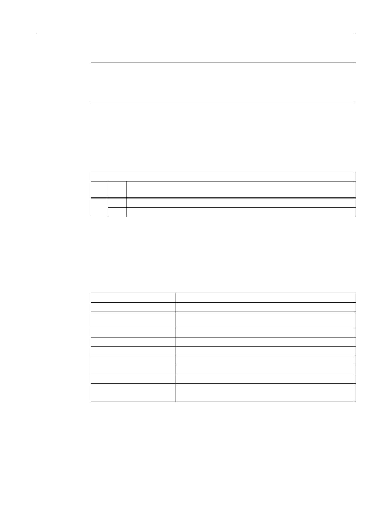
Geometric machine modeling
3.2 Commissioning
Note
Protection area bodies and collision tolerance
The protection area bodies of automatic tool protection areas are, as standard, created by the
control with a precision of 1/3 of the collision tolerance (Page 77).
3.2.2.7
Creation mode for automatic tool protection areas
The machine data defines how the control creates protection area bodies of automatic tool
protection areas.
MD18899 $MN_PROT_AREA_TOOL_MASK = <mode>
<Mode>
Bit
Val-
Meaning
ue
0
0
Do not apply heuristic model generation
1
Heuristic model generation using tool data
3.2.3
System variables: Protection areas
3.2.3.1
Overview
A protection area is parameterized with the following system variables:
Name
Meaning
$NP_PROT_NAME
Name of the protection area
$NP_CHAIN_ELEM
Name of the kinematic element to which the protection area is as-
signed
$NP_PROT_TYPE
Type of the protection area
$NP_1ST_PROT
Name of the first protection area element
$NP_PROT_COLOR
Color and transparency of the protection area.
$NP_PROT_D_LEVEL
Detail level for the protection area
$NP_BIT_NO
Number of NC/PLC interface bits of the protection area
$NP_INIT_STAT
Initialization status of the protection area
$NP_INDEX
Address of the geometric data of the machine element to be protected
(only relevant for automatic protection areas)
Monitoring and compensating
Function Manual, 10/2020, 6FC5397-7GP40-0BA1
27
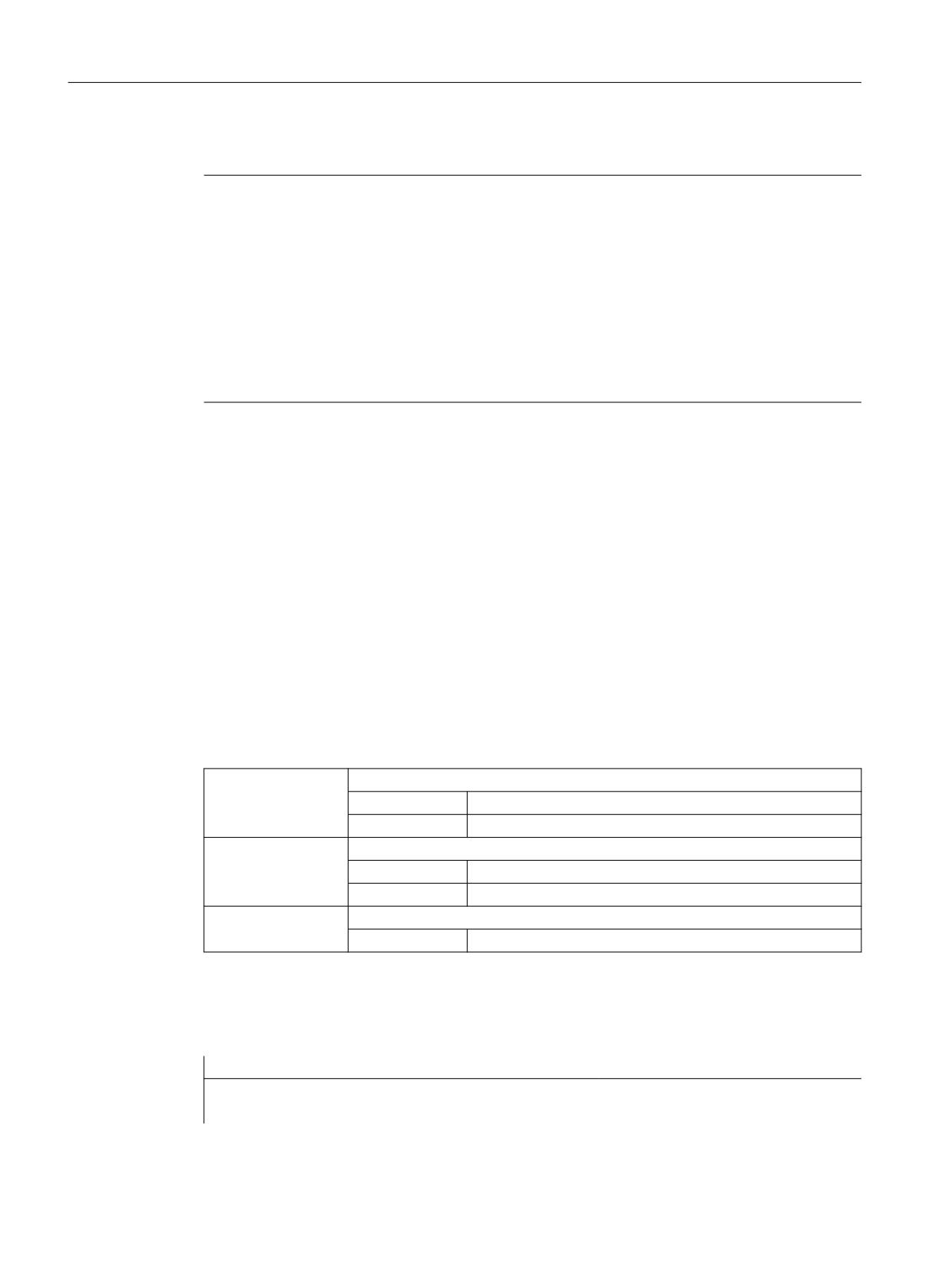
Geometric machine modeling
3.2 Commissioning
The system variables are described in detail in the following sections.
Note
Establish a defined initial state
It is recommended that a defined initial state be generated before parameterizing the protection
areas. To do this, set the system variables of the protection areas to their default values with the
DELOBJ() function.
Change system variable values
If the value of one of the system variables listed above is changed, the change becomes
immediately visible at the user interface, e.g. SINUMERIK Operate. The machine model of the NC
is only updated after explicitly requesting that the machine model is recalculated by calling
the PROTA() (Page 86) or PROTS() (Page 87) function.
3.2.3.2
$NP_PROT_NAME
Function
Enter the NC-wide unique protection area name in the system variable. The protection area is
referenced via this name, e.g. by a protection area element. The name is also displayed in the
graphical editor of SINUMERIK Operate.
Syntax
$NP_PROT_NAME[<m>] = "<name>"
Meaning
$NP_PROT_NAME:
Name of the protection area
Data type:
STRING
Default value:
"" (empty string)
<m>:
System variable or protection area index
Data type:
INT
Range of values:
0, 1, 2, ... ($MN_MM_3D_MAXNUM_PROT_AREAS - 1)
<name>:
Name of the protection area
Data type:
STRING
Example
The 6th protection area is assigned the name "Spindle":
Program code
Comment
N100 $NP_PROT_NAME[5] = "Spindle"
; 6. Protection area,
; name = "Spindle"
Monitoring and compensating
28
Function Manual, 10/2020, 6FC5397-7GP40-0BA1
Geometric machine modeling
3.2 Commissioning
3.2.3.3
$NP_CHAIN_ELEM
Function
Enter the name of the kinematic element to which the protection area will be connected in the
system variable.
Note
Reference coordinate system
The geometric data of the protection area, starting from the first protection area element
($NP_1ST_PROT (Page 31)), refer to the local coordinate system of the kinematic element, with
which the protection area is connected.
Syntax
$NP_CHAIN_ELEM[<m>] = "<Name>"
Meaning
$NP_CHAIN_ELEM:
Name of the kinematic element to which the protection area will be connected
Data type:
STRING
Default value:
"" (empty string)
<m>:
System variable or protection area index
Data type:
INT
Value range:
0, 1, 2, ... ($MN_MM_3D_MAXNUM_PROT_AREAS - 1)
<name>:
Name of the kinematic element
Data type:
STRING
Value range:
For names parameterized in $NK_NAME, refer to the Function
Manual "Basic Functions", Section "Kinematic chain".
Example
The 6th protection area is connected to the kinematic element with the name "Z axis":
Program code
Comment
N100 $NP_CHAIN_ELEM[5] = "Z ax-
; 6. Protection area,
is"
; name of the kin. element: "Z axis"
Monitoring and compensating
Function Manual, 10/2020, 6FC5397-7GP40-0BA1
29
Geometric machine modeling
3.2 Commissioning
3.2.3.4
$NP_PROT_TYPE
Function
The protection area type should be entered in the system variable:
• Machine protection area: "MACHINE"
The protection area body is defined using one or several protection area elements.
$NP_1ST_PROT (Page 31) refers to the first protection area element.
• Automatic tool protection area: "TOOL"
The control calculates the dimensions of the protection area body from the tool data.
$NP_INDEX (Page 37) refers to the tool.
• Workholder protection area: "FIXTURE"
• Workpiece protection area: "WORKPIECE"
Syntax
$NP_PROT_TYPE[<m>] = "<type>"
Meaning
$NP_PROT_TYPE:
Type of the protection area
Data type:
STRING
Range of values:
"MACHINE", "TOOL", "FIXTURE", "WORKPIECE"
Default value:
"" (empty string)
<m>:
System variable or protection area index
Data type:
INT
Range of values:
0, 1, 2, ... ($MN_MM_3D_MAXNUM_PROT_AREAS - 1)
<Type>:
Type
Data type:
STRING
Example
The 6th protection area is a machine protection area:
Program code
Comment
N100 $NP_PROT_TYPE[5] = "MACHINE"
; 6. Protection area,
; type = "MACHINE"
Monitoring and compensating
30
Function Manual, 10/2020, 6FC5397-7GP40-0BA1
Geometric machine modeling
3.2 Commissioning
3.2.3.5
$NP_1ST_PROT
Function
Enter the name of the first protection area element (Page 40) in the system variable.
1H[W SURWHFWLRQ DUHD HOHPHQW
13B1(;7
)LUVW SURWHFWLRQ DUHD HOHPHQW
13B 67B3527
6WDUW RI WKH HIIHFWLYH SURWHFWLRQ DUHD HOHPHQW FKDLQ
RI WKH SURWHFWLRQ DUHD
Syntax
$NP_1ST_PROT[<m>] = "<name>"
Meaning
$NP_1ST_PROT:
Name of the first protection area element of the protection area
Data type:
STRING
Range of values:
Names parameterized in $NP_NAME (Page 40)
Default value:
"" (empty string)
<m>:
System variable or protection area index
Data type:
INT
Range of values:
0, 1, 2, ... ($MN_MM_3D_MAXNUM_PROT_AREAS - 1)
<name>:
Protection area name
Data type:
STRING
Automatic tool protection areas, $NP_PROT_TYPE == "TOOL"
For automatic tool protection areas, only the following values are permissible for
$NP_1ST_PROT:
• "" (empty string)
• Name of a protection area element, type "FRAME"
Behavior for value == "" (empty string)
When activating the associated tool, the control creates a protection area element for the tool
with a unique, internal name and protection area body generated from the geometric data of the
tool. The name is assigned system variable $NP_1ST_PROT.
• Protection area "TOOL" : $NP_1ST_PROT = "<internal name>"
The coordinates of the tool protection area refer to the local coordinate system of the kinematic
element to which it is assigned.
Monitoring and compensating
Function Manual, 10/2020, 6FC5397-7GP40-0BA1
31

Geometric machine modeling
3.2 Commissioning
Behavior for value == name of a protection area element, type "FRAME"
When activating the associated tool, the control creates a protection area element for the tool
with a unique, internal name and protection area body generated from the geometric data of the
tool. The name is assigned a system variable $NP_NEXT of the protection area element, type
"FRAME", to which $NP_1ST_PROT refers.
• Protection area "TOOL" : $NP_1ST_PROT = "WKZ_Frame" →
- Protection area element "WKZ_Frame" : $NP_NEXT = "<internal name>"
The coordinates of the tool protection area refer to the local coordinate system of the protection
area element, type "FRAME".
Possible applications: Tool definition independent of the position where it is mounted on the
machine.
Example
The 1st protection area element which makes up the 6th protection area has the name "Spindle
head":
Program code
Comment
N100 $NP_1ST_PROT[5] = "Spindle head"
; 6. Protection area,
; 1. Protection area element =
"spindle box"
3.2.3.6
$NP_PROT_COLOR
Function
Enter the protection area element-specific value for alpha/transparency and color (ARGB) in the
system variable. This value is used for the display of the protection area or protection area
element on the user interface. If a separate value is entered for a protection area element
in $NP_COLOR (Page 43), this is used for the display of the protection area element.
Structure
Alpha/transparency and color are specified as a double word in hexadecimal format:
AARRGGBBH
•
1. - 3. Byte: RGB color value. See Chapter "Color chart (Page 24)".
•
4. Byte: Alpha channel or transparency value
Byte
Meaning
Range of values
OC
1
Blue
0 - 255D or 0 - FFH
GG
2
Green
RR
3
Red
AA
4
Alpha channel or transparency 1)
1) 0 = transparent or not visible, 255D = FFH = not transparent or filled
Monitoring and compensating
32
Function Manual, 10/2020, 6FC5397-7GP40-0BA1
Geometric machine modeling
3.2 Commissioning
Syntax
$NP_PROT_COLOR[<m>] = <value>
Meaning
$NP_PROT_COLOR:
Alpha/transparency and color value of the protection area
Data type:
DWORD
Range of values:
00000000H - FFFFFFFFH
Default value:
0000000H (black, not visible)
<m>:
System variable or protection area index
Data type:
INT
Range of values:
0, 1, 2, ... ($MN_MM_3D_MAXNUM_PROT_AREAS - 1)
<value>:
Transparency and color value
Data type:
DWORD
Example
The 6th protection area is to be displayed half transparent and in a green-blue color on the user
interface:
• AA = 7FH = 127D ≙ 50% transparency
• RR (red) = 00 ≙ no red component
• GG (green) = FFH = 255D ≙ 100% green color component
• BB (blue) = 33H = 51D ≙ 20% blue color component
Program code
Comment
N100 $NP_PROT_COLOR[5] = 'H7F00FF33'
; 6. Protection area,
; alpha/transparency and color
value = H7F00FF33
3.2.3.7
$NP_PROT_D_LEVEL
Function
The detail level as of which the protection area or the protection area elements are displayed on
the user interface is specified via the system variable. If a separate value is entered for a
protection area element in $NP_D_LEVEL (Page 44), this is used for the display of the protection
area element.
Detail level
• Lowest detail level: 0
• Highest detail level: 3
If the detail level x is selected for the display on the HMI, all protection areas and protection area
elements are displayed for which the following applies for the detail level D: D ≤ x
Monitoring and compensating
Function Manual, 10/2020, 6FC5397-7GP40-0BA1
33

Geometric machine modeling
3.2 Commissioning
Syntax
$NP_PROT_D_LEVEL[<m>] = <value>
Meaning
$NP_PROT_D_LEVEL:
Detail level for the protection area
Data type:
INT
Range of val-
0 ≤ D ≤ 3
ues:
Default value:
0
<m>:
System variable or protection area index
Data type:
INT
Range of val-
0, 1, 2, ... ($MN_MM_3D_MAXNUM_PROT_AREAS - 1)
ues:
<value>:
Detail level
Data type:
INT
Example
The 6th protection area is to be displayed as of detail level 3:
Program code
Comment
N100 $NP_PROT_D_LEVEL[5] = 3
; 6. Protection area,
; detail level = 3
3.2.3.8
$NP_BIT_NO
Function
Enter the bit number (0, 1, 2,
63) of the NC/PLC interface signal with which the protection
area is to be connected in system variable $NP_BIT_NO. If the protection area is not to be
connected to an NC/PLC interface signal, enter the value -1.
NC/PLC interface
Activation / deactivation of the protection area can be requested via NC/PLC interface signals
from the PLC user program or this can be used for feedback on the current status to the PLC user
program:
• Requirement: DB10, DBX234.0 - DBX241.7
• Feedback: DB10, DBX226.0 - DBX233.7
Requirement
The status of the protection area must be "preactivated" or "PLC-controlled" in order that the
assigned NC/PLC interface signal of the protection area is taken into account:
$NP_INIT_STAT (Page 36) == "P" (preactivated or PLC-controlled)
Monitoring and compensating
34
Function Manual, 10/2020, 6FC5397-7GP40-0BA1
Geometric machine modeling
3.2 Commissioning
Syntax
$NP_BIT_NO[<m>] = <bit number>
Meaning
$NP_BIT_NO:
Bit number of the interface signal to activate/deactivate the protection area
Data type:
INT
Value range:
-1, 0, 1, 2, ... ($MN_MM_MAXNUM_3D_INTERFACE_IN - 1)
Default value:
-1 (no interface signal selected)
<m>:
System variable or protection area index
Data type:
INT
Value range:
0, 1, 2, ... ($MN_MM_3D_MAXNUM_PROT_AREAS - 1)
<Bit number>:
Bit number (0, 1, 2, ... 63) of the 64-bit interface
Data type:
INT
Example
The 6th protection area is assigned to the 18th bit of interface (DB10.DBX236.1):
Program code
Comment
N100 $NP_BIT_NO[5] = 17
; 6. Protection area,
; DB10.DBX236.1
Assignment: Bit number to the interface signal
Bit
DB10
DB10
Bit
DB10
DB10
Bit
DB10
DB10
Bit
DB10
DB10
→
(PLC →
(NC →
→
(PLC →
(NC →
→
(PLC →
(NC →
→
(PLC →
(NC →
NC)
PLC)
NC)
PLC)
NC)
PLC)
NC)
PLC)
0
DBX234.0
DBX226.0
8
DBX235.0
DBX227.0
16
DBX236.0
DBX228.0
24
DBX237.0
DBX229.0
1
DBX234.1
DBX226.1
9
DBX235.1
DBX227.1
17
DBX236.1
DBX228.1
25
DBX237.1
DBX229.1
2
DBX234.2
DBX226.2
10
DBX235.2
DBX227.2
18
DBX236.2
DBX228.2
26
DBX237.2
DBX229.2
3
DBX234.3
DBX226.3
11
DBX235.3
DBX227.3
19
DBX236.3
DBX228.3
27
DBX237.3
DBX229.3
4
DBX234.4
DBX226.4
12
DBX235.4
DBX227.4
20
DBX236.4
DBX228.4
28
DBX237.4
DBX229.4
5
DBX234.5
DBX226.5
13
DBX235.5
DBX227.5
21
DBX236.5
DBX228.5
29
DBX237.5
DBX229.5
6
DBX234.6
DBX226.6
14
DBX235.6
DBX227.6
22
DBX236.6
DBX228.6
30
DBX237.6
DBX229.6
7
DBX234.7
DBX226.7
15
DBX235.7
DBX227.7
23
DBX236.7
DBX228.7
31
DBX237.7
DBX229.7
Bit
DB10
DB10
Bit
DB10
DB10
Bit
DB10
DB10
Bit
DB10
DB10
→
(PLC →
(NC →
→
(PLC →
(NC →
→
(PLC →
(NC →
→
(PLC →
(NC →
NC)
PLC)
NC)
PLC)
NC)
PLC)
NC)
PLC)
32
DBX238.0
DBX230.0
40
DBX239.0
DBX231.0
48
DBX240.0
DBX232.0
56
DBX241.0
DBX233.0
33
DBX238.1
DBX230.1
41
DBX239.1
DBX231.1
49
DBX240.1
DBX232.1
57
DBX241.1
DBX233.1
34
DBX238.2
DBX230.2
42
DBX239.2
DBX231.2
50
DBX240.2
DBX232.2
58
DBX241.2
DBX233.2
Monitoring and compensating
Function Manual, 10/2020, 6FC5397-7GP40-0BA1
35
Geometric machine modeling
3.2 Commissioning
Bit
DB10
DB10
Bit
DB10
DB10
Bit
DB10
DB10
Bit
DB10
DB10
→
(PLC →
(NC →
→
(PLC →
(NC →
→
(PLC →
(NC →
→
(PLC →
(NC →
NC)
PLC)
NC)
PLC)
NC)
PLC)
NC)
PLC)
35
DBX238.3
DBX230.3
43
DBX239.3
DBX231.3
51
DBX240.3
DBX232.3
59
DBX241.3
DBX233.3
36
DBX238.4
DBX230.4
44
DBX239.4
DBX231.4
52
DBX240.4
DBX232.4
60
DBX241.4
DBX233.4
37
DBX238.5
DBX230.5
45
DBX239.5
DBX231.5
53
DBX240.5
DBX232.5
61
DBX241.5
DBX233.5
38
DBX238.6
DBX230.6
46
DBX239.6
DBX231.6
54
DBX240.6
DBX232.6
62
DBX241.6
DBX233.6
39
DBX238.7
DBX230.7
47
DBX239.7
DBX231.7
55
DBX240.7
DBX232.7
63
DBX241.7
DBX233.7
Further information
A detailed description of the interface signals is provided in the Function Manual PLC.
3.2.3.9
$NP_INIT_STAT
Function
Enter the protection area initialization status in the system variable.
The status of a protection area is set to the parameterized initialization status in the following
situations:
• When the control ramps up
• When calling the PROTA (Page 86) function after the protection area has been recreated
during operation by writing the protection-area-specific system variables
• When calling the PROTA (Page 86) function with parameter "R"
• When calling the PROTS (Page 87) function with parameter "R"
Syntax
$NP_INIT_STAT[<m>] = "<status>"
Meaning
$NP_INIT_STAT:
Initialization status of the protection area
Data type:
STRING
Range of values:
"A", "a", "I", "i", "P", "p"
Value
Protection area status
"A"or "a"
Activated
"I"or "i"
Inactive
"P"or "p"
Preactivated or PLC-controlled1)
Default value:
"I" (inactive)
<m>:
System variable or protection area index
Data type:
INT
Range of values:
0, 1, 2, ... ($MN_MM_MAXNUM_3D_PROT_AREAS - 1)
Monitoring and compensating
36
Function Manual, 10/2020, 6FC5397-7GP40-0BA1
Geometric machine modeling
3.2 Commissioning
<Status>:
Initialization status
Data type:
STRING
1) The activation/deactivation is performed via: DB10.DBX234.0 - DBX241.7
Example
The initialization status of the 6th protection area is set to "P" (preactivated or PLC-controlled):
Program code
Comment
N100 $NP_INIT_STAT[5] = "P"
; 6. Protection area,
; initialization status = "P"
The current status depends on the state of the interface signal parameterized in $NP_BIT_NO
(Page 34).
3.2.3.10
$NP_INDEX
Function
For automatic protection areas ($NP_PROT_TYPE (Page 30)), the address, under which the
geometric data of the machine part, tool, etc. to be protected is saved, should be entered in the
system variable. The control then automatically creates the geometrical dimensions of the
protection area from the geometric data.
Example
For example, for an automatic tool protection area ($NP_PROT_TYPE == "TOOL") the geometrical
dimensions of the protection area are created based on the tool data.
Syntax
$NP_INDEX[<m>,<i>] = <value>
Meaning
$NP_INDEX:
Address of the geometric data for the automatic protection areas
Data type:
INT[ 3 ]
<m>:
System variable or protection area index
Data type:
INT
Range of values:
0, 1, 2, ... ($MN_MM_MAXNUM_3D_PROT_AREAS - 1)
<i>:
Index
The meaning of the system variables $NP_INDEX[<m>,<i>], with i = 0, 1, 2, ... is
dependent on the type ($NP_PROT_TYPE) of the automatic protection area. See
type-specific tables.
Data type:
INT
Range of values:
0, 1, 2
Monitoring and compensating
Function Manual, 10/2020, 6FC5397-7GP40-0BA1
37
Geometric machine modeling
3.2 Commissioning
<value>:
Address
Data type:
INT
Type: Automatic tool protection area ($NP_PROT_TYPE == "TOOL")
<i>
<value>
When tool management is active
Without tool management
0
Circular magazine: Tool location number
Spindle number
No circular magazine: Spindle number
1
Magazine number
---
2
TOA area 1)
1) TOA area "1" can be addressed with 0 as well as also with 1.
Example
The 6th protection area is an automatic tool protection area ($NP_PROT_TYPE == "TOOL"). The
geometrical dimensions of the protection area should be generated from the geometric data of
the tool at the following tool location:
• Tool location number: 1
• Magazine number: 9998 (spindle 1)
• TOA area: 1
Tool management is active.
Program code
Comment
; The dimensions of the 6th protection area are based on the tool data
; of the tool located at the following position:
N100 $NP_INDEX[5,0] = 1
; Tool location number = 1
N110 $NP_INDEX[5,1] = 9998
; magazine number = 9998 (spin-
dle 1)
N120 $NP_INDEX[5,2] = 1
; TOA area = 1
See also
$NP_PROT_TYPE (Page 30)
Monitoring and compensating
38
Function Manual, 10/2020, 6FC5397-7GP40-0BA1

Geometric machine modeling
3.2 Commissioning
3.2.4
System variables: Protection area elements for machine protection areas
3.2.4.1
Overview
A protection area element of a machine protection area is parameterized with the following
system variables:
Name
Meaning
$NP_NAME
Name of the protection area element
$NP_NEXT
Name of the following protection area element
$NP_NEXTP
Name of the following protection area element parallel to $NP_NEXT
$NP_COLOR
Color and transparency of the protection area element.
$NP_D_LEVEL
Detail level for the protection area element
$NP_USAGE
Usage of the protection area element
$NP_TYPE
Type of the protection area element
$NP_FILENAME
File name of the STL file that contains the geometric data of the pro-
tection area element
(only relevant for $NP_TYPE == "FILE")
$NP_PARA
Geometric parameters of the protection area body
(only relevant for $NP_TYPE == "BOX" or "SPHERE" or "CYLINDER")
$NP_OFF
Offset vector of the protection area element local coordinate system
$NP_DIR
Direction vector for the rotation of the protection area element local
coordinate system
$NP_ANG
Angle for the rotation of the protection area element local coordinate
system
The system variables are described in detail in the following sections.
Note
Establish a defined initial state
It is recommended that a defined initial state be generated before parameterizing the protection
area elements. To do this, set the system variables of the protection area elements to their
default values with the DELOBJ() function.
Change system variable values
If the value of one of the system variables listed above is changed, the change becomes
immediately visible at the user interface, e.g. SINUMERIK Operate. The machine model of the NC
is only updated after explicitly requesting that the machine model is recalculated by calling
the PROTA() (Page 86) or PROTS() (Page 87) function.
Monitoring and compensating
Function Manual, 10/2020, 6FC5397-7GP40-0BA1
39
Geometric machine modeling
3.2 Commissioning
3.2.4.2
$NP_NAME
Function
Enter the NC-wide unique protection area element name in the system variable. The protection
area element is referenced via this name. The name is also displayed in the graphical editor of
SINUMERIK Operate.
Syntax
$NK_NAME[<n>] = "<name>"
Meaning
$NP_NAME:
Name of the protection area element
Data type:
STRING
Default value:
"" (empty string)
<n>:
System variable or protection area element index
Data type:
INT
Range of values:
0, 1, 2, ... ($MN_MM_MAXNUM_3D_PROT_AREA_ELEM - 1)
<name>:
Name of the protection area element
Data type:
STRING
Example
The 19th protection area element is assigned the name "Spindle head":
Program code
Comment
N100 $NP_NAME[18] = "Spindle head"
; 19th protection area element,
; name = "Spindle head"
Monitoring and compensating
40
Function Manual, 10/2020, 6FC5397-7GP40-0BA1
Geometric machine modeling
3.2 Commissioning
3.2.4.3
$NP_NEXT
Function
If a protection area is made up of several protection area elements, they must be linked. To do
this, the name of the following protection area element must be entered in the system variable
$NP_NEXT in every protection area element.
1H[W SURWHFWLRQ DUHD HOHPHQW
13B1(;7
)LUVW SURWHFWLRQ DUHD HOHPHQW
13B 67B3527
6WDUW RI WKH HIIHFWLYH SURWHFWLRQ DUHD HOHPHQW FKDLQ
RI WKH SURWHFWLRQ DUHD
If there is no following protection area element, the name must be entered as an empty string
"".
Offset and rotation
An offset and/or rotation in the current protection area element ($NP_OFF (Page 57), $NP_DIR
(Page 58) and $NP_ANG (Page 60)) affects the following protection area element specified in
$NP_NEXT. This means that the specification of the spatial position and orientation of the
following protection area element is relative to the current protection area element.
Syntax
$NK_NEXT[<n>] = "<name>"
Meaning
$NP_NEXT:
Name of the following protection area element
Data type:
STRING
Range of values:
All names contained in $NP_NAME (Page 40)
Default value:
"" (empty string)
<n>:
System variable or protection area element index
Data type:
INT
Range of values:
0, 1, 2, ... ($MN_MM_MAXNUM_3D_PROT_AREA_ELEM - 1)
<name>:
Protection area name
Data type:
STRING
Monitoring and compensating
Function Manual, 10/2020, 6FC5397-7GP40-0BA1
41
Geometric machine modeling
3.2 Commissioning
Example
The following protection area element with the name "Coolant nozzle 1" is attached to the 19th
protection area element:
Program code
Comment
N100 $NP_NAME[18] = "Coolant nozzle 1"
; 19th protection area element,
; name of the following element:
"Coolant nozzle 1"
3.2.4.4
$NP_NEXTP
Function
The protection area element chain can be branched via the system variable $NP_NEXTP. To do
this, the following protection area elements must be specified in the system variables $NP_NEXT
and $NP_NEXTP in a protection area element. These protection area elements are then parallel
to one another in two separate subchains.
13B1(;73
13B1(;7
13B1(;73
13B1(;7
① Following parallel protection area element
② Following protection area element of the same subchain
Figure 3-2
Protection area elements in parallel subchains
Application example
The separate subchains can be used, for example, to model different machine parts of a
protection area for visualization or collision avoidance. Typically "C" (collision avoidance) is
specified for the protection area element referred to by $NP_NEXT for use in $NP_USAGE
(Page 45), and for the protection area element referred to in $NP_NEXTP, the value “V”
(visualization).
Offset and rotation
An offset and/or rotation in the current protection area element ($NP_OFF (Page 57), $NP_DIR
(Page 58) and $NP_ANG (Page 60)) affects the following protection area element specified in
$NP_NEXTP. This means that the specification of the spatial position and orientation of the
following protection area element is relative to the current protection area element.
Syntax
$NP_NEXTP[<n>] = "<name>"
Monitoring and compensating
42
Function Manual, 10/2020, 6FC5397-7GP40-0BA1