SINUMERIK 840D sl. Service - Functions. Manual (2018-2020) - page 42

R2: Rotary axes
14.2 Modulo 360 degrees
Note
Modulo partition axes
By aligning the two following machine data, indexing positions of 360° modulo indexing axes
can be implemented in the same way as for the 360° modulo range:
● MD30503 $MA_INDEX_AX_OFFSET
● MD30340 $MA_MODULO_RANGE_START
See the examples in Chapter "Indexing axes, "Example 3: Rotary modulo axis as equidistant
indexing axis (Page 859)" and the following chapters.
360° modulo rotary axis: Positioning behavior for G90 (modal absolute programming)
The standard behavior for G90 is set via the machine data:
MD30455 $MA_MISC_FUNCTION_MASK, bit 2 = <value>
<value>
Meaning
0
The 360° modulo rotary axis positions corresponding to AC as standard for G90 program-
ming:
● Target position > Current position: Move in positive traversing direction
● Target position < Current position: Move in negative traversing direction
1
For G90 programming, the 360° modulo rotary axis positions as standard corresponding
to DC, i.e. the shortest path.
Position display in the 360° modulo representation
Activating the position display at the user interface in the 360° modulo representation is realized
using the axis-specific machine data:
MD30320 $MA_DISPLAY_IS_MODULO = 1
NC/PLC interface signals
Activating the traversing range limits
In principle, the traversing range of a 360° modulo rotary axis is infinity. This is the reason that
axis-specific traversing range limits to not apply as standard, such as software limit switches
and working error limits. The traversing range limits of a 360° modulo rotary axis can be
activated using the subsequent absolute axis-specific NC/PLC interface signal, possibly
initiated via an M/H function in the NC program:
DB31, ... DBX12.4 = 1 (360° modulo rotary axes: Activate traversing range limits)
Extended Functions
Function Manual, 12/2018, A5E40874029B AB
763
R2: Rotary axes
14.2 Modulo 360 degrees
Preconditions:
● The 360° modulo rotary axis must be referenced.
● Software limit switch
Software limit switch 1 or 2 to be monitored must be active:
- DB31,
DBX12.2 / 3 (activation)
– MD36100 $MA_POS_LIMIT_MINUS / MD36110 $MA_POS_LIMIT_PLUS (software
limit switch 1)
- MD36120 $MA_POS_LIMIT_MINUS2 / MD36130 $MA_POS_LIMIT_PLUS2 (software
limit switch 2)
● Working area limitation
Both limits must be active, either via G26/G25 or setting data:
- SD43400 $SA_ WORKAREA_PLUS_ENABLE / SD43410
$SA_WORKAREA_MINUS_ENABLE (activation)
- SD43420 $SA_WORKAREA_LIMIT_PLUS / SD43430
$SA_WORKAREA_LIMIT_MINUS (limiting)
● Synchronization with STOPRE
If the traversing range limits are activated using the NC/PLC interface signal in an NC
program being executed, e.g. as a result of an M/H command at the PLC, then a
preprocessing strop must be programmed in the following block (STOPRE). Only then can
it be ensured that the activation of the traversing range limits are taken into account in the
subsequent traversing blocks.
NOTICE
User: Activation and effectiveness
If the traversing range limits of a 360° modulo rotary axis are activated by the NC/PLC
interface signal (DB31, ... DBX12.4) in a block in the main run, (e.g. using the M/H function),
under certain circumstances, as a result of the preprocessing of already subsequent
traversing blocks, the traversing range limits were not taken into account. As a consequence,
it is solely the responsibility of the user to apply suitable measures, e.g. by programming
STOPRE in the following block after activating the traversing range limits. This means that
from the activation time in the NC program, the traversing range limits are also effective in
all of the subsequent blocks.
Extended Functions
764
Function Manual, 12/2018, A5E40874029B AB
R2: Rotary axes
14.2 Modulo 360 degrees
r
r
r
r
r
r
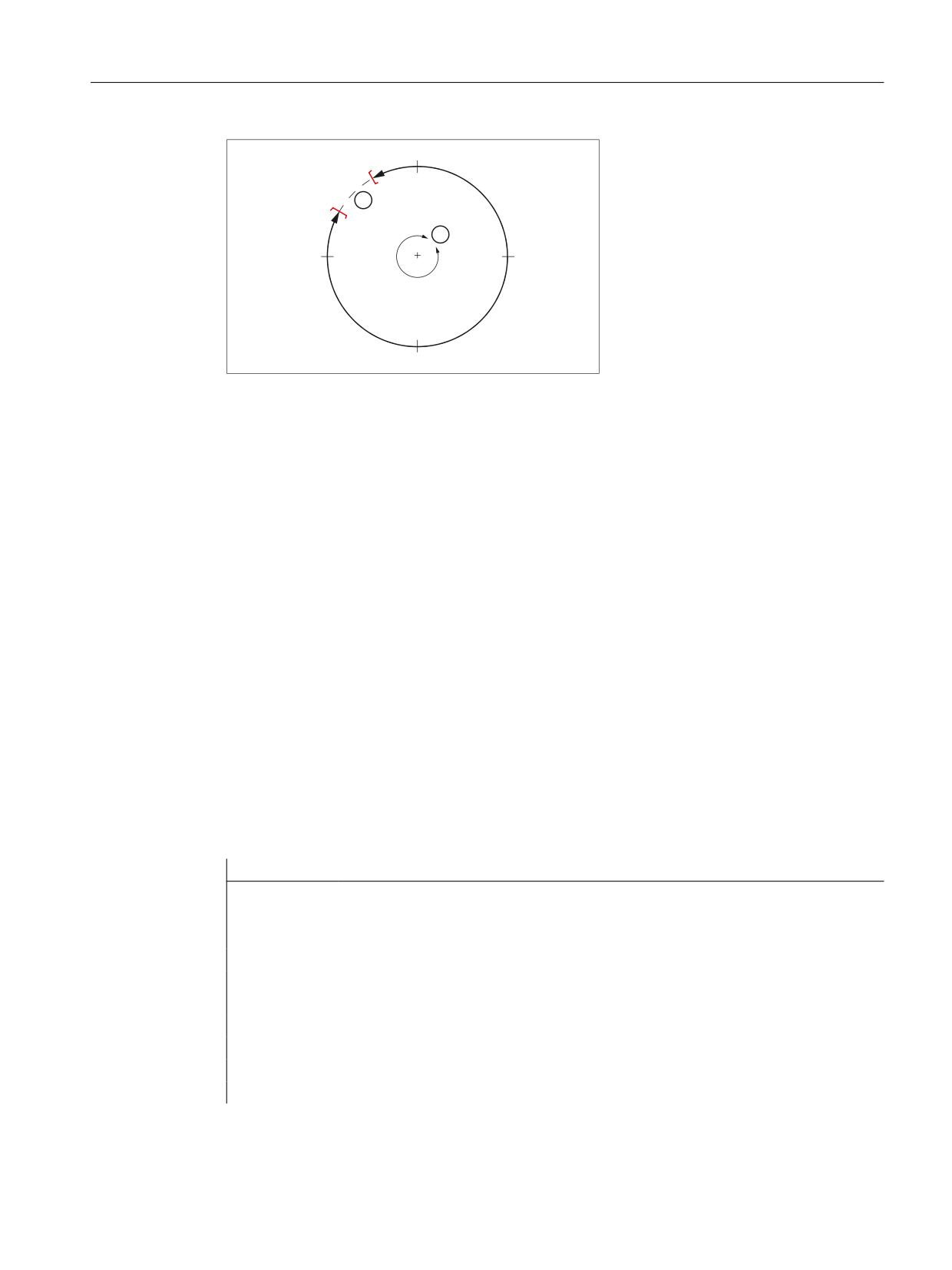
① Direction of rotation +/-
② Software limit switch +/-
Figure 14-4
360° modulo rotary axis with software limit switch
Feedback signal, activation of the traversing range limits
The feedback signal that the traversing range limits of a 360° modulo rotary axis are active in
the NC, is realized using the axis-specific NC/PLC interface signal:
DB31, ... DBX74.4 == 1 (modulo rotary axes: traversing range limits active)
Example: Changing the traversing range limits
Pallet 1 with several clamped workpieces is machined on a 360° modulo rotary axis. The pallet
1 is then swapped for a pallet 2 with a built-on axis. The traverse range now has to be monitored.
Parameterization:
● MD30300 $MA_IS_ROT_AX[ AX5 ] = 1
● MD30310 $MA_ROT_IS_MODULO[ AX5 ] = 1
● MD36110 $MA_POS_LIMIT_PLUS[ AX5 ] = 340
● MD36100 $MA_POS_LIMIT_MINUS[ AX5 ] = 350
Extract from part program:
Program code
Comment
M123
; Insert pallet 1 with quadruple clamping
; PLC: deactivate traversing range limits of the
; B axis => DB35, DBX12.4=0
STOPRE
; Trigger a preprocessing stop
S1000 M3
G4 F2
G1 X0 Y300 Z500 B0 F5000
CYCLE84(500,400,0,350,0,1,4,10,,0,500,1000) ; drilling cycle
G0 Z540 B0
Extended Functions
Function Manual, 12/2018, A5E40874029B AB
765
R2: Rotary axes
14.3 Programming rotary axes
Program code
Comment
M124
; Insert pallet 2 with built-on axis
; PLC: activate traversing range limits of the
; B axis => DB35, DBX12.4=1
STOPRE
; Trigger a preprocessing stop
B270
14.3
Programming rotary axes
14.3.1
General information
Note
General information about programming, see:
References:
Programming Manual Fundamentals
MD30310
Axis-specific machine data
MD30310 ROT_IS_MODULO (modulo conversion for rotary axis)
is used to define whether the rotary axis behaves as a linear axis during programming and
positioning or whether rotary-axis special features are taken into account.
These features and any differences (mainly with respect to absolute programming) are
explained on the following pages.
Modulo conversion for rotary axes and spindles
MD30310 "Modulo conversion for rotary axes and spindles“
MD30320 "Modulo display for rotary axes and spindles“
If MD30310 and MD30320 are set to "1", the change in Operate to a modulo display takes
place as soon as the actual value display changes between 0° and 359.999° - or exceeds
359.999° in the positive direction of rotation, or falls below 0° in the negative direction of rotation.
For internal setpoint and actual values, the behavior of rotary axes and spindles differ:
● For spindles, the modulo conversion takes place for each spindle programming (M3, M4
and M5).
● For rotary axes, the modulo conversion only takes place with a new traversing command.
If the setpoint and actual values are read out, these are the same as the display values in the
"Service overview" - "Service axis" under the selected axis. For rotating spindles or rotary axes,
these values can also lie below the modulo range of 0° to 359,999°
Extended Functions
766
Function Manual, 12/2018, A5E40874029B AB
R2: Rotary axes
14.3 Programming rotary axes
14.3.2
Rotary axis with modulo conversion (continuously-turning rotary axis).
Absolute programming (AC, ACP, ACN, G90)
Example of the absolute programming for a modulo rotary axis as positioning axis:
POS[<axis name>] = ACP(<value>)
● <value>: Target position of the modulo rotary axis in the range between 0° and 359.999°
Negative values are also possible if a range offset has been realized with the following
machine data:
- MD30340 $MA_ MODULO_RANGE_START
- MD30330 $MA_MODULO_RANGE
● ACP: Absolute programming of the target position in positive rotation direction (counter
clockwise).
● ACN: Absolute programming of the target position in negative rotation direction (clockwise).
● AC / G90: by block / modally valid absolute programming of the target position.
The direction of rotation depends on the current position of the modulo rotary axis.
- Target position > Current position: Travel in positive direction.
- Target position < Current position: Travel in negative direction.
Note
The G90 positioning behavior can be projected via MD30455
$MA_MISC_FUNCTION_MASK, Bit 2. See Section "Modulo 360 degrees (Page 761)".
Application example
ACP / ACN: Defined direction of rotation for asymmetric workpieces in order to exclude collisions
during rotation.
Programming examples
Starting position of modulo rotary axis C = 0° (see figure below).
Extended Functions
Function Manual, 12/2018, A5E40874029B AB
767
R2: Rotary axes
14.3 Programming rotary axes
1HJDWLYH GLUHFWLRQ
3RVLWLYH GLUHFWLRQ
RI URWDWLRQ
r
RI URWDWLRQ
r
r
r
r
r
r
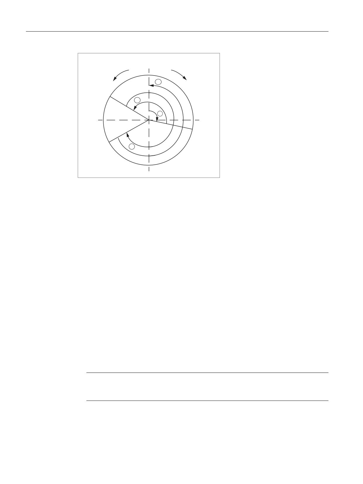
① POS[C] = ACP(100); Traverse in positive direction of rotation to
position 100°
② POS[C] = ACN(300); Traverse in negative direction of rotation to
position 300°
③ POS[C] = ACP(240); Traverse in positive direction of rotation to
position 240°
④ POS[C] = AC(0); Traverse in negative direction of rotation to position
0°
Figure 14-5
Absolute programming for modulo rotary axes
Absolute programming along the shortest path (DC)
Example of absolute programming on the shortest path for a modulo rotary axis as positioning
axis:
POS[<axis name>] = ACP(<value>)
● <value>: Target position of the modulo rotary axis in the range between 0° and 359.999°
Negative values are also possible if a range offset has been realized with the following
machine data:
- MD30340 $MA_ MODULO_RANGE_START
- MD30330 $MA_MODULO_RANGE
● DC: Absolute programming of the target position for moving by the shortest direction of
rotation.
Note
If the route is the same in both directions (180°), movement in in the positive direction of
rotation.
Programming examples
Starting position of modulo rotary axis C = 0° (see figure below).
Extended Functions
768
Function Manual, 12/2018, A5E40874029B AB
R2: Rotary axes
14.3 Programming rotary axes
1HJDWLYH GLUHFWLRQ RI
3RVLWLYH GLUHFWLRQ RI
r
URWDWLRQ
URWDWLRQ
r
r
r
r
r
r
r
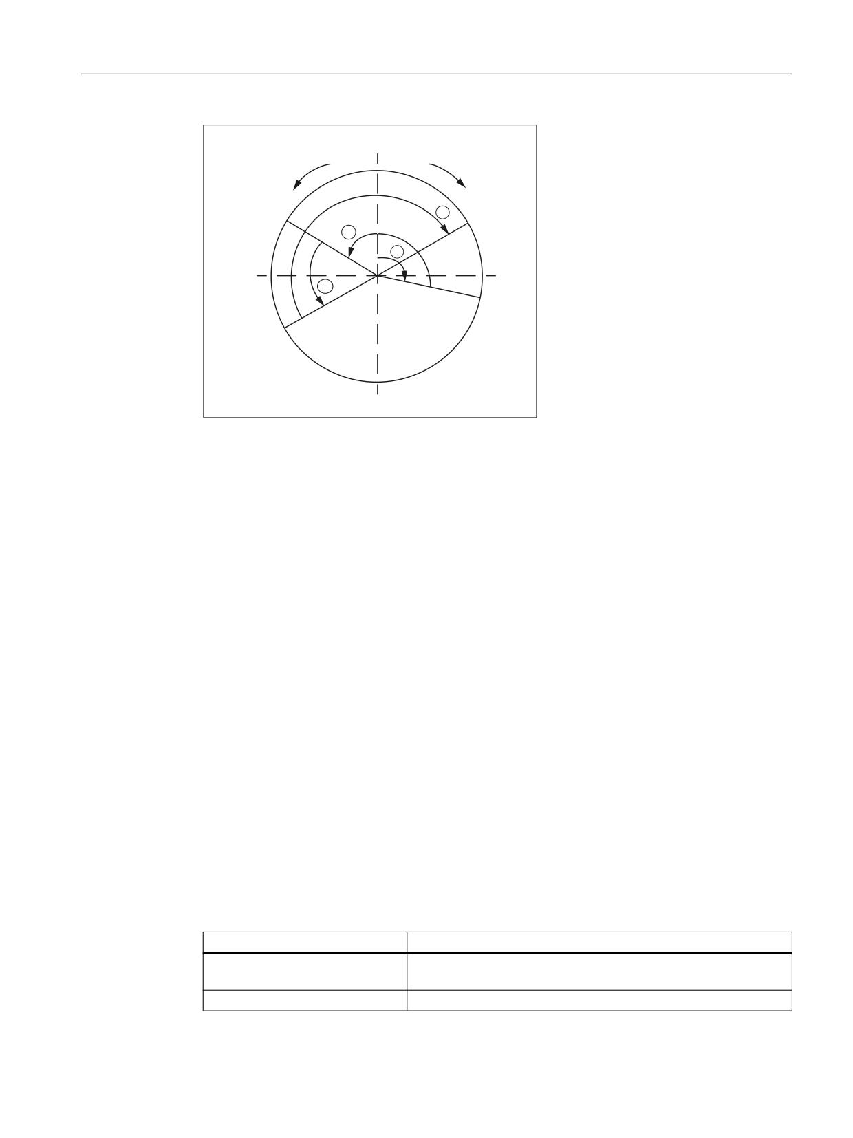
① POS[C] = DC(100); Traverse by shortest path to position 100°
② POS[C] = DC(300); Traverse by shortest path to position 300°
③ POS[C] = DC(240); Traverse by shortest path to position 240°
④ POS[C] = DC(60); Traverse by shortest path to position 60°
; in positive direction of rotation
Figure 14-6
Absolute programming with shortest path for modulo rotary axes
Block-search response
After block search with calculation, the collected search run positions can be read by modulo,
converted using the system variable $AC_RETPOINT[<axis>].
Supplementary conditions for ASUB after block search with calculation
In this instance, as well as with the cross-channel block-search tool SERUPRO, the modulo
conversion simulated in the block search must be performed in the part program.
Incremental programming (IC, G91)
Example for positioning axis: POS[axis name] = IC(+/-value)
● The value identifies the rotary-axis traversing distance. The value can be negative and ≥
+/-360°.
● The value's sign unequivocally defines the rotary-axis traversing direction.
● Application example: milling a spiral groove across several revolutions
Example
Programming
Effect
POS[C]=IC(720)
C axis traverses to 720° incrementally in the positive direction
(two revolutions)
POS[C]=IC(-180)
C axis traverses to 180° incrementally in the negative direction
Extended Functions
Function Manual, 12/2018, A5E40874029B AB
769

R2: Rotary axes
14.3 Programming rotary axes
Program example: Modulo rotary axes as endlessly rotating rotary axis
Program code
LOOP:
POS[C] = IC(720) ; Traverse as positioning axis by 270°
GOTOB LOOP
; Return to Label LOOP
14.3.3
Rotary axis without modulo conversion
Deactivating modulo conversion
→ set MD30310 $MA_ROT_IS_MODULO = 0.
Absolute programming (AC, G90)
Example for positioning axis: POS[axis name] = AC (+/- value)
● The value and its sign uniquely identify the rotary-axis target position. The value can be ≥
+/-360°. The position value is limited by the software limit switch positions.
● The traversing direction is defined by the control according to the signed rotary axis actual
position.
● If ACP or ACN is programmed, alarm 16810, "ACP traverse instruction cannot be used", or
alarm 16820 "ACN traverse instruction cannot be used", is output.
● Application example:
Linear motion (cam gear) are coupled to the rotary axis, thus certain end positions may not
be passed.
Example:
Programming
Effect
POS[C] = AC (-100)
Rotary axis C traverses to position -100°;
traversing direction depends on the starting position
POS[C] = AC (1500)
Rotary axis C traverses to position 1500°
Absolute programming along the shortest path (DC)
POS[axis name] = DC(value)
Even if the rotary axis is not defined as a modulo axis, the axis can still be positioned with DC
(Direct Control). The behavior is the same as that of a modulo axis.
Extended Functions
770
Function Manual, 12/2018, A5E40874029B AB

R2: Rotary axes
14.3 Programming rotary axes
● The value identifies the rotary axis target position in a range from 0° to 359.999° (modulo
360°). Alarm 16830, "Incorrect modulo position programmed", is output for values with a
negative sign or ≥ 360º.
● With DC (Direct Control), the rotary axis approaches the programmed absolute position
within one revolution along the shortest path (traversing movement max. ±180°).
● The control calculates the direction of rotation and the traverse path according to the current
actual position (in relation to modulo 360°). If the path to be traversed is the same in both
directions (180°), the positive direction of rotation has priority.
● DC application example: the rotary table is required to approach the changeover position
in the shortest time (and, therefore, via the shortest path) possible.
● If DC is programmed for a linear axis, alarm 16800, "DC traverse instruction cannot be
used", is output.
Example:
Programming
Effect
POS[C] = AC (7200)
Rotary axis C traverses to position 7200°;
traversing direction depends on the starting position
POS[C] = DC (300)
Rotary axis C approaches "modulo" position 300°
along the shortest path
Thus, C traverses through 60° with a negative direction of rotation
and stops at absolute position 7140°.
POS[C] = AC (7000)
Rotary axis C traverses to position 7000° absolute,
C traverses through 140° with a negative direction of rotation
Note
In this example, it would be advisable to activate the modulo 360º display (MD30320
$MA_DISPLAY_IS_MODULO = 1).
Incremental programming (IC, G91)
Example for positioning axis: POS[axis name] = IC(+/- value)
When programming with incremental dimensions, the rotary axis traverses along the same
path as for the modulo axis. In this case, however, the traversing range is limited by the
software limit switches.
● The value identifies the rotary axis traversing distance.
The value can be negative and ≥ +/-360°.
● The sign of the value defines the rotary axis traversing direction.
Extended Functions
Function Manual, 12/2018, A5E40874029B AB
771

R2: Rotary axes
14.4 Activating rotary axes
Limited traversing range
The traversing range is limited just the same as for linear axes. The range limits are defined
by the "plus" and "minus" software limit switches.
14.3.4
Other programming features relating to rotary axes
Offsets
TRANS (absolute) and ATRANS (additive) can be applied to rotary axes.
Scalings
SCALE or ASCALE are not suitable for rotary axes, since the control always bases its modulo
calculation on a 360º full circle.
Preset actual value memory
PRESETON is possible.
Indexing axes
See Section "T1: Indexing axes (Page 843)".
14.4
Activating rotary axes
Procedure
The procedure for activating rotary axes is the same as that for linear axes with a small number
of exceptions. It should be noted that, as soon as the axis is defined as a rotary axis (MD30300
$MA_IS_ROT_AX = 1), the axis-specific-machine-/setting-data units are interpreted by the
control as follows:
Positions
In "degrees"
Velocities
In "rev/min"
Accelerations
In "rev/sec2"
Jerk limitation
In "rev/sec3"
Extended Functions
772
Function Manual, 12/2018, A5E40874029B AB

R2: Rotary axes
14.4 Activating rotary axes
Special machine data
Special rotary-axis machine data may also have to be entered, depending on the application:
MD30310 $MA_ROT_IS_MODULO
Modulo conversion for positioning and program-
ming
MD30320 $MA_DISPLAY_IS_MODULO
Modulo conversion for position display
MD10210 $MN_INT_INCR_PER_DEG
Computational resolution for angular positions
The following overview lists the possible combinations of these machine data for a rotary axis:
Possible combinations of rotary-axis machine data
MD30300
MD30310
MD30320
Application
Comment
permitted
0
0
0
Yes
The axis is a linear axis (default).
1
0
0
Yes
The axis is a rotary axis; modulo conver-
sion is not used for positioning, i.e. the
software limit switches are active; the po-
sition display is absolute.
1
0
1
Yes
The axis is a rotary axis; modulo conver-
sion is not used for positioning, i.e. the
software limit switches are active; the po-
sition display is modulo;
application: for axes with an operating
range of +/-1000°, for example
1
1
1
Yes
The axis is a rotary axis; positioning is per-
formed with modulo conversion, i.e. the
software limit switches are inactive, the
operating range is unlimited; the position
display is modulo (setting most frequently
used for rotary axes); axis with/without
working-area limitation can be used.
1
1
0
Yes
The axis is a rotary axis; positioning is per-
formed with modulo conversion, i.e. the
software limit switches are inactive, the
operating range is unlimited; the position
display is absolute; axis with/without work-
ing-area limitation can be used.
0
0 or 1
0 or 1
Not recom-
Axis is not a rotary axis;
mended
therefore, the other MD are not evaluated.
JOG velocity for rotary axes
SD41130 $SN_JOG_ROT_AX_SET_VELO (JOG speed for rotary axes)
The above setting data can be used to define a valid JOG velocity for all rotary axes (see also
Section "H1: Manual traversing (Page 143)").
Extended Functions
Function Manual, 12/2018, A5E40874029B AB
773
R2: Rotary axes
14.5 Special features of rotary axes
If a value of 0 is entered in the setting data, the following axial machine data acts as JOG
velocity for the rotary axis:
MD21150 $MC_JOG_VELO (conventional axis velocity)
14.5
Special features of rotary axes
Software limit switch
The software limit switches and working-area limitations are active and are required for swivel
axes with a limited operating range. However, in the case of continuously rotating rotary axes
(MD30310 $MA_ROT_IS_MODULO = 1), the software limit switches and working area
limitations can be deactivated for individual axes.
A modulo rotary axis with/without working-area limitation can be used.
References:
Function Manual, Basic Functions; Axis Monitoring, Protection Zones (A3)
Mirroring of rotary axes
Mirroring can be implemented for rotary axes by programming MIRROR(C) or AMIRROR(C).
Reference point approach
References:
Function Manual Basic Functions; Reference Point Approach (R1)
Spindles as rotary axes
For notes concerning the use of spindles as rotary axes (C axis operation), please refer to:
References:
Function Manual Basic Functions; Spindles (S1)
Extended Functions
774
Function Manual, 12/2018, A5E40874029B AB
R2: Rotary axes
14.7 Data lists
14.6
Examples
Fork head, inclined-axis head
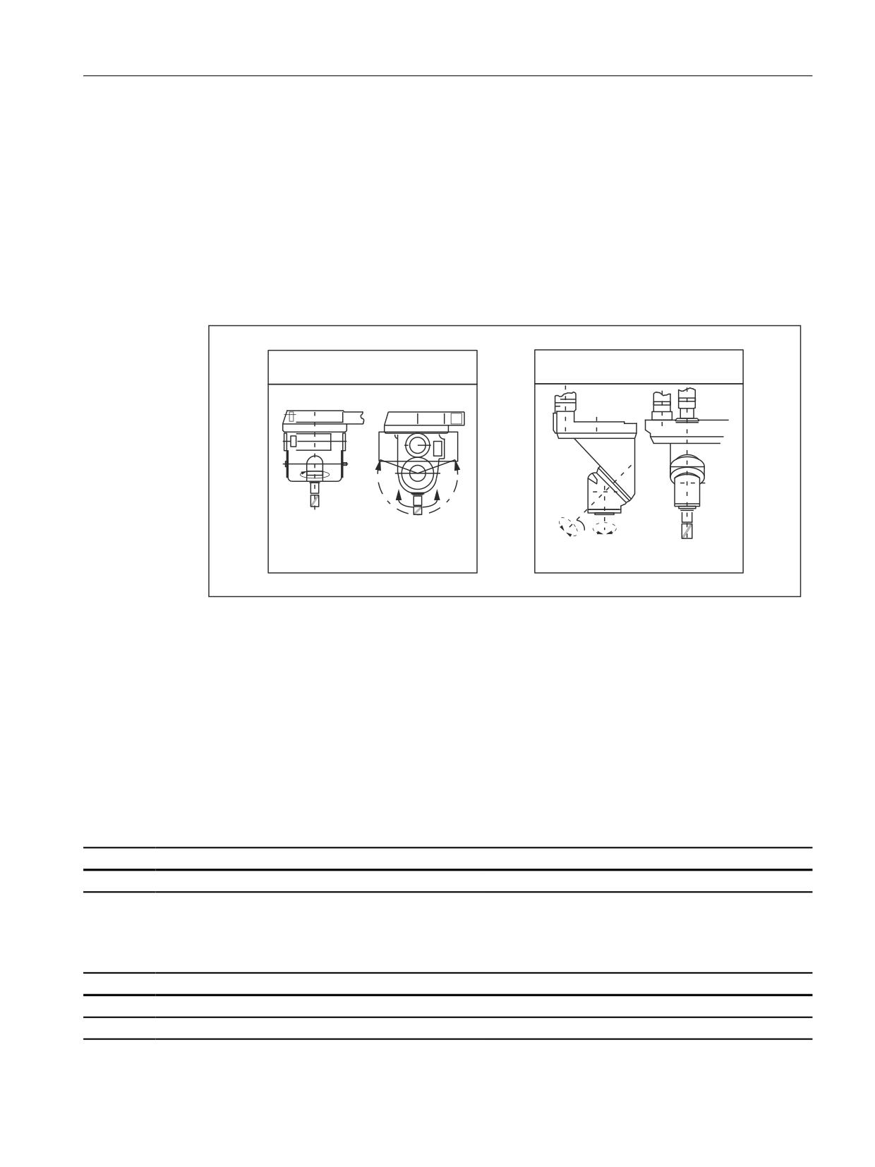
Rotary axes are frequently used on 5-axis milling machines to swivel the tool axis or rotate the
workpiece. These machines can position the tip of a tool on any point on the workpiece and
take up any position on the tool axis. Various milling heads are required, depending on the
application. The figure shows a fork head and an inclined-axis head as example rotary-axis
arrangements.
)RUN KHDG
,QFOLQHG D[LV KHDG
&
%
%
r
r
r
&
Figure 14-7
Fork head, inclined-axis head
14.7
Data lists
14.7.1
Machine data
14.7.1.1
General machine data
Number
Identifier: $MN_
Description
10210
INT_INCR_PER_DEG
Computational resolution for angular positions
14.7.1.2
Axis/spindlespecific machine data
Number
Identifier: $MA_
Description
30300
IS_ROT_AX
Axis is rotary axis
30310
ROT_IS_MODULO
Modulo conversion for rotary axis
Extended Functions
Function Manual, 12/2018, A5E40874029B AB
775

R2: Rotary axes
14.7 Data lists
Number
Identifier: $MA_
Description
30320
DISPLAY_IS_MODULO
Actual value display modulo
30330
MODULO_RANGE
Modulo-range size
30340
MODULO_RANGE_START
Modulo-range starting position
30455
MISC_FUNCTION_MASK
Axis functions
36100
POS_LIMIT_MINUS
Minus software limit switch
36110
POS_LIMIT_PLUS
Plus software limit switch
14.7.2
Setting data
14.7.2.1
General setting data
Number
Identifier: $SN_
Description
41130
JOG_ROT_AX_SET_VELO
JOG velocity for rotary axes
14.7.2.2
Axis/spindle-specific setting data
Number
Identifier: $SA_
Description
43420
WORKAREA_LIMIT_PLUS
Plus working-area limitation
43430
WORKAREA_LIMIT_MINUS
Minus working-area limitation
14.7.3
Signals
14.7.3.1
Signals to axis/spindle
Signal name
SINUMERIK 840D sl
SINUMERIK 828D
Traversing-range limitation for modulo axis
DB31,
DBX12.4
DB380x.DBX1000.4
14.7.3.2
Signals from axis/spindle
Signal name
SINUMERIK 840D sl
SINUMERIK 828D
Status of software limit switch monitoring for modulo axis
DB31,
DBX74.4
DB390x.DBX1000.4
Extended Functions
776
Function Manual, 12/2018, A5E40874029B AB
S3: Synchronous spindle
15
15.1
Brief description
15.1.1
Function
The "Synchronous spindle" function can be used to couple two spindles with synchronous
position or speed. One spindle is defined as leading spindle (LS), the second spindle is then
the following spindle (FS).
Speed synchronism:
nFS = kÜ * nLS
with kÜ = 1, 2, 3, ...
Position synchronism:
φFS = φLS + Δφ
with 0° ≤ Δφ < 360°
Possible applications
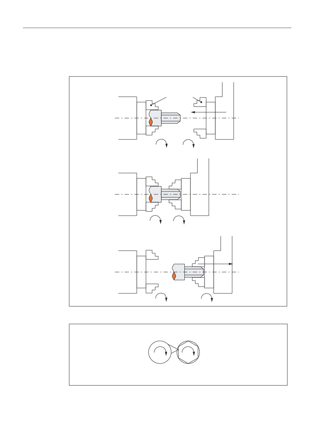
Rear side machining
One application option is, for example, the reverse side machining in a double-spindle lathe
with on-the-fly transfer of the workpiece from the position-synchronous LS to the FS (or vice
versa), without having to decelerate down to standstill.
Multi-edge machining (polygonal turning)
The "Synchronous spindle" function provides the basis for multi-edge machining (polygonal
turning) through specification of an integer gear ratio kÜ between LS and FS.
Number of FS
The number of FS's that can be operated synchronously to an LS is only restricted by the
performance capability of the NC used. In principle, any number of FS can be coupled
simultaneously to an LS in arbitrary channels of the NC.
2 pairs of synchronous spindles can be active simultaneously in each NC channel.
Definition
The assignment of FS to LS pair of synchronous spindles can be parameterized channel-
specifically via machine data or flexibly defined via part program commands.
Extended Functions
Function Manual, 12/2018, A5E40874029B AB
777
S3: Synchronous spindle
15.1 Brief description
Selecting/de-selecting
Part program commands are used to select/deselect the synchronous operation of a pair of
synchronous spindles.
&KXFNV
Q
Q
6SLQGOH
6SLQGOH
Q
Q
6SLQGOH
6SLQGOH
Q
Q
6SLQGOH
6SLQGOH
Figure 15-1
Synchronous operation: On-the-fly workpiece transfer from spindle 1 to spindle 2
Q
Q
6SLQGOH
6SLQGOH
Extended Functions
778
Function Manual, 12/2018, A5E40874029B AB

S3: Synchronous spindle
15.1 Brief description
Figure 15-2
Synchronous operation: Polygonal turning
15.1.2
Synchronous mode
Description
<axial expression>:
can be:
- Axis name
- Spindle name
<axis name>:
C (if spindle has the name "C" in axis operation.)
<spindle name>:
Sn, SPI(n) where n = spindle number
<Spindle number>:
1, 2, ... according to the spindle number defined in
MD35000 $MA_SPIND_ASSIGN_TO_MACHAX
(FS, LS, offset):
LS = Leading Spindle, FS = Following Spindle,Off-
set = read programmable offset of following spin-
dle using system variables
$P_COUP_OFFS[Sn]
Programmed position offset of the synchronous
spindle
Synchronous spindle pair
Synchronous operation involves a following spindle (FS) and a leading spindle (LS), referred
to as the synchronous spindle pair. The following spindle imitates the movements of the leading
spindle when a coupling is active (synchronous operation) in accordance with the defined
functional interrelationship.
Synchronous mode
Synchronous mode (also referred to as “Synchronous spindle operation”) is another spindle
operating mode. Before synchronous mode is activated, the following (slave) spindle must
have been switched to position control. Synchronous operation is activated for the following
spindle when the coupling is activated. As soon as the coupling is deactivated, the following
spindle switches back to open-loop control mode.
As soon as synchronous operation is active for the following spindle, the following interface
signal is reported to the PLC:
IS "Synchronous mode" (DB31, ... DBX84.4) = 1.
Number of synchronous spindles
It is possible to couple several following spindles to one leading spindle. The number of
following spindles on this leading spindle depends on the respective version of the appropriate
software versions.
Any number of following spindles in any channels of one NCU or a different NCU can be
coupled to this leading spindle.
Extended Functions
Function Manual, 12/2018, A5E40874029B AB
779
S3: Synchronous spindle
15.1 Brief description
Note that one spindle is always the master and the number of couplings results from the number
of axes less the master.
Options in synchronous mode
The following functions are available for synchronous mode:
● FS and LS turn at the same speed
(nFS = nLS; transformation ratio kÜ = 1)
● Rotation in the same or opposite direction between LS and FS
(can be defined positively or negatively using transformation ratio kÜ)
● Following and leading spindles rotate at different speeds
(nFS = kÜ · nLS; transformation ratio kÜ ≠ 1)
Application: Polygonal turning
● Settable angular position between FS and LS (φFS = φLS + Δφ)
The spindles run at synchronous speed with a defined angular offset between FS and LS
(position synchronous coupling).
Application: Shaped workpieces
● Activation of synchronous operation between LS and FS can take place when the spindles
are in motion or at standstill.
● The full functionality of the open-loop and position control modes is available for the leading
spindle.
● When synchronous mode is not active, the FS and LS can be operated in all other spindle
modes.
● The transformation ratio can also be altered when the spindles are in motion in active
synchronous mode.
● With synchronous spindle coupling switched on, the offset of the FS to the LS (overlaid
movement) can be altered.
Coupling options
Synchronous spindle couplings can be defined as
● Permanently configured via channel-specific machine data
(hereinafter referred to as "permanently configured coupling") as well as
● Freely defined using language commands (COUP...) in the part program
(hereafter referred to as "user defined coupling")
. The following variants are possible:
1. A fixed configuration for a coupling can be programmed via machine data. In addition, a
second coupling can be freely defined via the part program.
2. No coupling is configured via machine data. In this case, the couplings can be user-defined
and parameterized via the part program.
Extended Functions
780
Function Manual, 12/2018, A5E40874029B AB
S3: Synchronous spindle
15.1 Brief description
Separate following spindle interpolator
The separate following spindle interpolator allows a number of following spindles from different
channels or from another NCU to be coupled as defined by the user to a single leading spindle.
The following spindle interpolator is
● COUPON or COUPONC activated and
● COUPOF or COUPOFS deactivated
and is always located in the channel in which the COUPON, COUPONC command has been
programmed for the following spindle. If the following spindle to be activated was previously
programmed in another channel, COUPON/COUPONC initiates an axis replacement and fetches
the spindle into its own channel.
Certain synchronous spindle functions can be controlled from the PLC by means of coupling-
specific axial VDI interface signals. These signals act exclusively on the slave spindles and
do not affect the leading spindle (see Section "Controlling synchronous spindle coupling via
PLC (Page 789)").
Definition of synchronous spindles
Before synchronous operation is activated, the spindles to be coupled (FS, LS) must be
defined.
This can be done in two ways depending on the application in question:
1. Permanently configured coupling:
Machine axes that are to function as the following spindle (FS) and leading spindle (LS)
are defined in channel-specific MD 21300 $MC_COUPLE_AXIS_1[n].
The machine axes programmed as the LS and FS for this coupling configuration cannot be
altered by the NC part program.
If necessary, the coupling parameters can be modified with the NC part program.
2. User-defined coupling:
Couplings can be created and altered in the NC part program with language command
"COUPDEF(FS, LS, ...)". If a new coupling relationship is to be defined, it may be necessary
to delete an existing user-defined coupling beforehand (with language command
COUPDEL(FS, LS)).
The axis names (Sn, SPI(n)) for the following and leading spindles must be programmed
with FS and LS for every language command COUP..., thus ensuring that the synchronous
spindle coupling is unambiguously defined.
The valid spindle number must then be assigned axis-specific machine data of a machine
axis:
MD35000 $MA_SPIND_ASSIGN_TO_MACHAX.
IS "Following spindle active" (DB31, ... DBX99.1) and IS "Leading spindle active" (DB31, ...
DBX99.0) indicate to the PLC for each machine axis whether the axis is active as a leading or
following spindle.
The LS can be programmed either via a part program, PLC or also using synchronized actions.
Extended Functions
Function Manual, 12/2018, A5E40874029B AB
781
S3: Synchronous spindle
15.1 Brief description
Transformation ratio
The transformation ratio is programmed with separate numerical values for numerator and
denominator (transformation ratio parameters). It is therefore possible to specify the
transformation ratio very exactly, even with rational numbers.
In general:
kÜ = transformation ratio parameter for numerator Transformation ratio parameters for
denominator = Ünumerator : Üdenominator
The value range of the transformation ratio parameter (Ünumerator, Üdenominator) is virtually unlimited
in the control.
The transformation ratio parameters for the coupling configured via machine data can be
defined in channel-specific SD42300: COUPLE_RATIO_1[n]. In addition, the transformation
ratio can be altered with language command COUPDEF(FS, LS, Ünumerator, Üdenominator ,...). The
values entered in the setting data is not overwritten in this case (default settings).
The transformation ratio for the coupling defined via the NC part program can only be input
with language command COUPDEF (...).
The new transformation ratio parameters take effect as soon as the COUPDEF command has
been processed.
For further programming commands for synchronous spindle couplings, please see
"Programming of synchronous spindle couplings" Section .
Extended Functions
782
Function Manual, 12/2018, A5E40874029B AB
S3: Synchronous spindle
15.1 Brief description
Coupling characteristics
The following characteristics can be defined for every synchronous spindle coupling:
● Block change behavior
The condition to be fulfilled for a block change can be defined on activation of synchronous
operation or on alteration of the transformation ratio or the defined angular offset when the
coupling is active:
- Block change takes place immediately
- Block change in response to "Fine synchronism"
- Block change in response to "Coarse synchronism"
- Block change for IPOSTOP (i.e. after setpoint-end synchronism)
- Check of the synchronism conditions at an arbitrary moment with WAITC.
● Type of coupling between FS and LS
The position setpoint or the actual position value of the leading spindle can be used as the
reference value for the following spindle. The following coupling types can therefore be
selected:
- Setpoint coupling (DV)
Use in position controlled operation. The control dynamic response of both spindles
should coincide as far as possible. Preferably, the setpoint coupling should be used.
- Actual value coupling (AV)
Application if no position control of the LS is possible or with great deviation of the control
characteristics between FS and LS. The setpoints for the FS are derived from the actual
values of the LS. The quality of synchronism is worse with a varying spindle speed than
with the setpoint coupling.
- Speed coupling (VV)
Internally, the velocity coupling is a setpoint coupling. The requirements for FS and LS
are lower. Position control and measuring systems are not required for FS and LS.
The position offset between FS and LS is undefined.
The selection of the relevant coupling characteristics for the configured coupling is made using
machine data (see Section "Configuration (Page 801)") and for the user defined coupling using
the COUPDEF language command (see Section "Definition (COUPDEF) (Page 795)").
In addition, coupling characteristics Type of coupling and Block change response can be
altered for the permanently configured coupling by means of language command COUPDEF.
References:
Programming Manual, Production Planning ("Synchronous Spindles").
Change protection for coupling characteristics
The channel-specific MD21340 $MC_COUPLE_IS_WRITE_PROT_1 is used to define whether
or not the configured coupling parameters Transformation ratio, Type of coupling and Block
change response can be altered by the NC part program:
0: Coupling parameters can be altered by the NC part program via command COUPDEF
1: Coupling parameters cannot be altered by the NC part program. Attempts to make changes
will be rejected with an alarm message.
Extended Functions
Function Manual, 12/2018, A5E40874029B AB
783
S3: Synchronous spindle
15.1 Brief description
Superimposed motion
In synchronous operation, the synchronous spindle copies the movement of the leading spindle
in accordance with the programmed transformation ratio.
At the same time, the synchronous spindle can also be traversed with overlay so that the LS
and FS can operate at a specific angular position in relation to one another.
The overlaid traversing movement of the FS can be initiated in various ways:
● Programmable position offset of FS for AUTOMATIC and MDA:
- The COUPON and SPOS language commands can be used for active synchronous
operation to change the position reference between FS and LS (see Section "Selecting
synchronous mode for a part program (Page 786)").
● Manual position offset of FS:
- In JOG (JOG continuous or JOG incremental) mode
Superimposition of FS using the handwheel or with plus or minus traversing keys when
synchronous operation is active.
- In AUTOMATIC and MDA modes
Superimposition of FS with handwheel using DRF offset
As soon as the FS executes the overlaid traversing movement, IS "Overlaid movement"
(DB31, ... DBX98.4) is set to the 1 signal.
The overlaid movement is executed optimally in terms of time at the maximum possible FS
speed with COUPON. With an offset change by means of SPOS, the positioning velocity can
be specified with FA[Sn] and manipulated by an override (can be selected through IS "Feedrate
override valid for spindle" DB31, ... DBX17.0).
Note
For more information about specifying the position speed with FA[Sn]:
References:
Function Manual, Basic Functions; Spindles (S1), "Spindle modes, positioning operations"
section
Setpoint correction
The setpoint correction of the system variable $AA_COUP_CORR[Sn] impacts on all
subsequent following spindle programming in the same way as a position offset and
corresponds to a DRF offset in the MCS.
Example: establish correction value
If a coupling offset of 7° has been programmed using COUPON(
,77) and if a mechanical
offset of 81° has come about as a result of closing the workpiece support fixture, a correction
value of 4° is calculated:
The system variables return the following values for the following spindle:
$P_COUP_OFFS[S2] ; programmed position offset = 77°
Extended Functions
784
Function Manual, 12/2018, A5E40874029B AB
S3: Synchronous spindle
15.1 Brief description
$AA_COUP_OFFS[S2] ; setpoint position offset = 77°
$VA_COUP_OFFS[S2] ; actual value position offset approx. 77°
$AA_COUP_CORR[S2] ; correction value = 4°
15.1.3
Prerequisites for synchronous mode
Conditions on selection of synchronous mode
The following conditions must be fulfilled before the synchronous spindle coupling is activated
or else alarm messages will be generated.
● The synchronous spindle coupling must have been defined beforehand (either permanently
configured via machine data or according to user definition via part program using
COUPDEF).
● The spindles to be coupled must be defined in the NC channel in which the coupling is
activated.
Channel-spec. MD20070 $MC_AXCONF_MACHAX_USED
axis spec. MD35000 $MA_SPIND_ASSIGN_TO_MACHAX
● The following spindle must be assigned to the NC channel in which the coupling is activated.
Default setting with axis-specific MD30550 AXCONF_ASSIGN_MASTER_CHAN
● The following applies to setpoint and actual value couplings (DV, AV):
FS and LS must at least have a position measuring system for recording positions and
position controls must be started up.
Note
When position control is activated, the maximum setpoint speed of the LS is automatically
limited to 90% (control reserve) of the maximum speed. The limitation is signaled via IS
"Setpoint speed limited" (DB31, ... DBX83.1).
References:
Function Manual, Basic Functions; Spindles (S1)
● The following applies to setpoint couplings (DV):
To ensure more accurate synchronization characteristics, the LS should be in position
control mode (language instruction SPCON) before the coupling is activated.
● Before selecting the synchronous mode, the gear stage necessary for FS and LS must be
selected. In synchronous mode, gear stage changeover and therefore oscillation mode are
not possible for FS and LS. Upon request, an alarm message is generated.
Extended Functions
Function Manual, 12/2018, A5E40874029B AB
785
S3: Synchronous spindle
15.1 Brief description
Cross-channel coupling
The LS can be located in any channel.
● The LS can be exchanged between channels by means of "Axis exchange".
● When several following spindles are coupled to one leading spindle, the dynamic response
of the coupling is determined by the weakest response as a function of the coupling factor.
The acceleration rate and maximum speed are reduced for the leading spindle to such a
degree that none of the coupled following spindles can be overloaded.
● The following spindle is always located in the channel in which the coupling has been
activated using COUPON or COUPONC.
15.1.4
Selecting synchronous mode for a part program
Activate coupling COUPON, COUPONC
Language command COUPON activates the coupling in the part program between the
programmed spindles with the last valid parameters and thus also activates synchronous
mode. This coupling may be a fixed configuration or user-defined. The leading spindle and/or
following spindle may be at standstill or in motion at the instant of activation.
Certain preconditions must be fulfilled before synchronous operation can be activated (see
Section "Prerequisites for synchronous mode (Page 785)").
The COUPONC command adopts the previous programmed direction of spindle rotation and
spindle speed for the following and leading spindle in the part program. It is not possible to
specify an angular offset.
COUPON activation variants
Two different methods can be selected to activate synchronous mode:
1. Fastest possible activation of coupling with any angular reference between leading and
following spindles.
COUPON(FS, LS)
2. Activation of coupling with a defined angular offset POSFS between leading and following
spindle. With this method, the angular offset must be programmed on selection.
COUPON(FS, LS, POSFS)
Block change behavior
Before synchronous operation is selected, it must be determined under what conditions the
block change must occur when the synchronous mode is activated (see Section "Definition
(COUPDEF) (Page 795)").
Extended Functions
786
Function Manual, 12/2018, A5E40874029B AB
S3: Synchronous spindle
15.1 Brief description
Determine current coupling status
The $AA_COUP_ACT[<axial expression>] axial system variable can be used in the NC part
program to specify the current coupling status for the specified axis/spindle (see Section "Axial
system variables for synchronous spindle (Page 799)"). As soon as the synchronous spindle
coupling is active for the following spindle, bit 2 must be "1" when read.
Change defined angular offset
Language commands COUPON and SPOS allow the defined angular offset to be changed while
synchronous mode is active. The following spindle is positioned as an overlaid movement at
the angular offset programmed with POSFS. During this time, the IS "overlaid movement"
(DB31, ... DBX98.4) is set.
Angular offset POSFS
The defined angular offset POSFS must be specified as an absolute position referred to the
zero degrees position of the leading spindle in a positive direction of rotation.
The "0° position" of a position-controlled spindle is calculated as follows:
● From the zero mark or proximity sensor signal of the measurement system and
● From the reference values saved using axis-specific machine data:
MD34100 $MA_REFP_SET_POS, reference point value,
of no significance with interval-coded systems.
MD34080 $MA_REFP_MOVE_DIST reference point distance/target point
with interval-coded systems,
MD34090 $MA_REFP_MOVE_DIST_CORR reference point offset / absolute offset with
interval coding.
Range of POSFS: 0 ... 359.999°.
References:
Function Manual Basic Functions; Reference Point Travel (R1)
Read current angular offset
Using axial system variables, it is possible to read the current position offset between the FS
and LS in the NC part program. A distinction is made between:
● Current position offset of setpoint between FS and LS
$AA_COUP_OFFS [<axis name for FS>]
● Current position offset of actual value between FS and LS
$VA_COUP_OFFS [<axis name for FS>]
(Explanation of <axis name>, see Section "Synchronous mode (Page 779)")
Activation after power ON
Synchronous mode can also be activated with non-referenced/synchronized FS or LS (IS
"Referenced/synchronized 1 or 2" DB31, ... DBX60.4 or DBX60.5 = 0). In this case, a warning
message is displayed.
Extended Functions
Function Manual, 12/2018, A5E40874029B AB
787
S3: Synchronous spindle
15.1 Brief description
Example:
LS and FS are already coupled in a friction lock via a workpiece after power ON.
15.1.5
Deselecting the synchronous mode for the part program
Open coupling (COUPOF, COUPOFS)
Synchronous mode between the specified spindles is canceled by the parts program
instruction COUPOF. Three variants are possible.
If synchronous mode is canceled between the specified spindles using COUPOF, then it is
irrelevant whether this coupling is permanently configured or user defined. The leading and
following spindles can be at standstill or in motion when synchronous operation is deactivated.
On switching off the synchronous mode with COUPOF, the following spindle is put into control
mode. The originally programmed S-word is no longer valid for the FS, the following spindle
can be operated like any other normal spindle.
When the coupling is opened with COUPOF, a block preprocessing stop STOPRE is generally
initiated internally in the control.
The COUPOFS instruction can be used to open a coupling either as quickly as possible with a
stop and no position data or with a stop at the programmed position.
COUPOF variants
Three different methods can be used to deselect synchronous mode with COUPOF:
1. Deactivation of coupling as quickly as possible
The block change is enabled immediately.
COUPOF(FS, LS)
2. A coupling is not deselected until the following spindle has crossed the programmed
deactivation position POSFS.
The block change is then enabled.
COUPOF(FS, LS, POSFS)
3. A coupling is not deselected until the following spindle and leading spindle has crossed the
programmed deactivation positions POSFS and POSLS.
The block change is then enabled.
COUPOF(FS, LS, POSFS , POSLS)
POSFS, POSLS
Deactivation positions POSFS and POSLS match the actual positions of FS and LS respectively
referred to the defined reference point value.
Range of POSFS, POSLS: 0 ... 359,999°.
References:
Function Manual Basic Functions; Reference Point Approach (R1)
Extended Functions
788
Function Manual, 12/2018, A5E40874029B AB
S3: Synchronous spindle
15.1 Brief description
COUPOF during the motion
If synchronous mode is deselected while the spindles are in motion with COUPOF, the following
spindle continues to rotate at the current speed (nFS). The current speed can be read with
system variable $AA_S in the NC parts program.
The following spindle can then be stopped from the parts program with M05, SPOS, SPOSA or
from the PLC with the appropriate interface signal.
COUPOFS with stop of following spindle
Opening a synchronous spindle coupling is extended by a stop of the following spindle:
● Deactivating a coupling as quickly as possible and opening a coupling as quickly as
possible.
The block change is then enabled.
COUPOFS(FS, LS)
● Opening the coupling with stop of following spindle at the programmed position. The block
change is then enabled.
Condition:
COUPOFS(FS, LS) and COUPOFS(FS, LS, POSFS) have no meaning if a coupling was active.
15.1.6
Controlling synchronous spindle coupling via PLC
Controlling following spindle via PLC
Using the coupling-specific, axial VDI interface signals, it is possible to control synchronization
motions for the following spindle from the PLC program. This offers the option of utilizing the
PLC to disable, suppress or restore a synchronization motion for the following spindle specified
by offset programming.
These signals have no effect on the leading spindle. The following coupling-specific VDI signal
(PLC → NC) is available:
IS "Disable synchronization" (DB31, ... DBX31.5)
"Disable synchronization"
The synchronization motion for the following spindle is suppressed using the axial signal IS
"Disable synchronization" (DB31, ... DBX31.5).
When the main run advances to a block containing part program instruction COUPON (FS, LS,
offset), the following interface signal is evaluated for the following spindle:
Extended Functions
Function Manual, 12/2018, A5E40874029B AB
789
S3: Synchronous spindle
15.1 Brief description
IS "Disable synchronization" (DB31, ... DBX31.5).
● For IS "Disable synchronization" (DB31, ... DBX31.5) = 0, the position offset is traversed
through as before.
● For IS "Disable synchronization" (DB31, ... DBX31.5) = 1, only the continuous velocity
synchronism is established. The following spindle does not execute any additional
movement.
The coupling then responds analogously to a programmed COUPON(<FS>,<LS>).
Special features
For the IS "Disable synchronization" (DB31, ... DBX31.5) offset motion of the following spindle
cannot be controlled that was generated as follows:
● SPOS, POS
● Synchronized actions
● FC18 (for 840D sl)
● JOG
These functions are controlled by VDI signal IS "Feedrate stop/Spindle stop" (DB31, ...
DBX4.3).
Synchronized state reached
Whenever a state of synchronism has been reached, the following two VDI signals are set
regardless of whether synchronization has been disabled or not:
IS "Synchronism coarse" (DB31, ... DBX98.1) and
IS "Synchronism fine" (DB31, ... DBX98.0)
Further block changes after COUPON are not prevented by suppression of synchronization.
Example
Block change behavior after COUPON
Program code
Comment
; IS "Disable synchronization"
; set (DB31, ... DBX31.5) = 1 for S2
N51 SPOS=10 SPOS[2]=10
; positions correspond to an offset
; of 0°
N52 COUPDEF(S2,S1,1,1,"FINE","DV")
N53 COUPON(S2,S1,77)
; actual offset of 0 degrees is retained
; no following spindle movement,
; VDI signals
; IS "Synchronism coarse"
; (DB31, ... DBX98.1) and
; IS "Synchronism fine"
; (DB31, ... DBX98.0)
Extended Functions
790
Function Manual, 12/2018, A5E40874029B AB

S3: Synchronous spindle
15.1 Brief description
Program code
Comment
; are set and the block change
; is enabled.
N54 M0
N57 COUPOF(S2,S1)
N99 M30
Reset and recovery
Resetting the IS "Disable synchronization" (DB31, ... DBX31.5) has no effect on the following
spindle offset. If the offset motion of the following spindle has been suppressed by the VDI
interface signal, then the offset is not automatically applied when the VDI signal is reset.
Synchronization is recovered as follows:
● By repeating the part program operation COUPON (FS, LS, offset) with IS "Disable
synchronization" (DB31, ... DBX31.5) = 0.
COUPON (FS, LS, offset) can be written e.g. in an ASUB.
● By setting the IS "Resynchronize" (DB31, ... DBX31.4) = 1
Read offset
The following system variables can be used to read three different position offset values of the
following spindle from the part program and synchronized actions. The variable
$P_COUP_OFFS[Sn] is only available in the part program.
Description
NC variable
Programmed position offset of the synchronous spindle
$P_COUP_OFFS[Sn]
Position offset of synchronous spindle, setpoint end
$AA_COUP_OFFS[Sn]
Position offset of synchronous spindle, actual value end
$VA_COUP_OFFS[Sn]
"Feedrate stop/spindle stop"
By configuring bit 4 in MD30455 MISC_FUNCTION_MASK, the behavior of the axial IS
"Feedrate stop/Spindle stop" (DB31, ... DBX4.3) is defined for the following spindle.
Bit 4 = 0 compatibility method:
Canceling feed enable for the following spindle decelerates the coupling assembly.
Bit 4 = 1:
Feedrate enable refers only to the interpolation component (SPOS),..) and does not affect the
coupling.
Note
Other configuration options for axis functions using MD30455 $MA_MISC_FUNCTION_MASK:
References:
Function Manual, Basic Functions; Rotary Axes (R2), Section: Programming rotary axes
Extended Functions
Function Manual, 12/2018, A5E40874029B AB
791
S3: Synchronous spindle
15.1 Brief description
15.1.7
Monitoring of synchronous operation
Fine/coarse synchronism
In addition to conventional spindle monitoring operations, synchronous operation between the
FS and LS is also monitored in synchronous mode.
IS "Fine synchronism" (DB31, ... DBX98.0) or IS "Coarse synchronism" (DB31, ... DBX98.1)
is transmitted to the PLC to indicate whether the current position (AV, DV) or actual speed
(VV) of the following spindle lies within the specified tolerance window.
When the coupling is switched on, the signals "Coarse synchronism" and "Fine synchronism"
are updated when setpoint synchronism is reached.
Extended Functions
792
Function Manual, 12/2018, A5E40874029B AB
S3: Synchronous spindle
15.1 Brief description
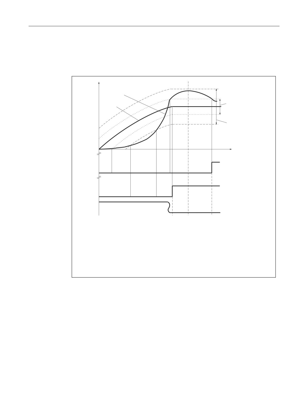
The size of the tolerance windows is set with machine data of the FS. Reaching of the
synchronism is influenced by the following factors:
● AV, DV: Position variance between FS and LS
● VV: Difference in speed between FS and LS
Q)6
Q)6DFW
7ROHUDQFH EDQG )LQH
Q)6VHW
V\QFKURQLVP
7ROHUDQFH EDQG &RDUVH
V\QFKURQLVP
W
6LJQDO
ಯ6\QFKURQLVP ILQHರ
6LJQDO
ಯ6\QFKURQLVP FRDUVHರ
1
6LJQDO
0
ಯ6\QFKURQLVP UXQQLQJರ
&28321
6HWSRLQW HQG
:$,7&
5HSODFHPHQW
V\QFKURQLVP
ZLWK WKH QH[W
([DPSOH RI SDUWV SURJUDP
EORFN 0
ແ
0 6
0
* 3
&28321 6
6
Q)6DFW
DFWXDO VSHHG RI IROORZLQJ VSLQGOH
=
Q)6VHW
VHWSRLQW VSHHG RI IROORZLQJ VSLQGOH
:$,7& 6
ಯ)LQHರ
Q)6
VSHHG RI IROORZLQJ VSLQGOH
0
ແ
Figure 15-3
Synchronism monitoring with COUPON and synchronism test mark WAITC with
synchronization on a turning leading spindle
Extended Functions
Function Manual, 12/2018, A5E40874029B AB
793

S3: Synchronous spindle
15.2 Programming
Threshold values
The relevant position or velocity tolerance range for the following spindle in relation to the
leading spindle must be specified in degrees or 1 rev/min.
● Threshold value for "Coarse synchronism"
axis spec. MD37200: AV, DV: COUPLE_POS_TOL_COARSE
MD37220: VV: COUPLE_VELO_TOL_COARSE
● Threshold value for "Fine synchronism"
axis spec. MD37210: AV,DV: COUPLE_POS_TOL_FINE
MD37230: VV: COUPLE_VELO_TOL_FINE
Speed/acceleration limits
In synchronous mode, the speed and acceleration limit values of the leading spindle are
adjusted internally in the control in such a way that the following spindle can imitate its
movement, allowing for the currently selected gear stage and effective speed ratio, without
violating its own limit values.
For example, the LS is automatically decelerated to prevent the FS from exceeding the
maximum speed in order to maintain synchronism between the spindles.
15.2
Programming
Coupling commands with leading-spindle programming
Command
Function
COUPDEF(FS, LS, ...)
Define coupling or change for configured coupling
COUPON(FS, LS, POSFS)
Switch the coupling on
COUPONC(FS, LS)
Activate coupling with transfer of the currently effective speed
of the following spindle
COUPOF(FS, LS, POSFS, POSLS)
Switch the coupling off
COUPOFS(FS, LS, POSFS)
Deactivate coupling with stop of the following spindle
COUPDEL (FS, LS)
Delete coupling
COUPRES (FS, LS)
Reactivate configured coupling data
Coupling commands without leading-spindle programming
Command
Function
COUPOF(FS, POSFS, POSLS)
Switch the coupling off
COUPOFS(FS, POSFS)
Deactivate coupling with stop of the following spindle
COUPDEL(FS)
Delete coupling
COUPRES(FS)
Reactivate configured coupling data
Extended Functions
794
Function Manual, 12/2018, A5E40874029B AB
S3: Synchronous spindle
15.2 Programming
See also
Definition (COUPDEF) (Page 795)
Switch the coupling (COUPON, COUPONC, COUPOF) on and off (Page 798)
15.2.1
Definition (COUPDEF)
Programmable couplings
The number of couplings can be programmed as often as desired depending on the axes
available. This number results from the number of axes/spindles less one for the master.
Furthermore, one coupling can also be configured via machine data as in earlier SW versions.
Permanently configured coupling
The coupling characteristics and transformation ratio for a permanently configured
synchronous spindle coupling can be altered by the NC part program provided that they are
not write-protected. The machine axes for LS and FS cannot be changed.
Define new couplings
Language command "COUPDEF" can be used to create new synchronous spindle couplings
(user-defined) and to modify the parameters for existing couplings.
When the coupling parameters are fully specified, the following applies:
COUPDEF(FS, LS, Tnumerator, Tdenominator, block change behavior, coupling type)
The synchronous spindle coupling is unambiguously defined with FS and LS
The other coupling parameters must only be programmed when they need to be changed. The
last valid status remains applicable for non-specified parameters.
The individual coupling parameters are explained below:
● FS, LS: Spindle name for following and leading spindles
e.g.: S1, SPI(1), S2, SPI(2)
The valid spindle number must be assigned in the axis-specific MD35000
$MA_SPIND_ASSIGN_TO_MACHAX of a machine axis.
● Tnumerator, Tdenominator: Transformation ratio parameters for numerator and denominator
The transformation ratio is specified in the form of numeric values for numerator and
denominator (see Section "Synchronous mode (Page 779)").
The numerator must always be programmed. If no denominator is specified, then its value
is always assumed to be "1.0".
● Block change behavior
This parameter allows you to select when the block change should take place when
synchronous operation is selected:
NOC: Block change is enabled immediately
FINE: Block change in response to "Fine synchronism"
Extended Functions
Function Manual, 12/2018, A5E40874029B AB
795
S3: Synchronous spindle
15.2 Programming
COARSE: Block change in response to "Coarse synchronism"
IPOSTOP: Block change for IPOSTOP (i.e. after setpoint-end synchronism)
The block change response is specified as a character string (i.e. with quotation marks).
The block change response can be specified simply by writing the letters in bold print. The
remaining letters can be entered to improve legibility of the part program but they are not
otherwise significant.
If no block change response is specified, then the currently selected response continues to
apply.
With the programmable synchronism test markers WAITC, the replacement with new blocks
is delayed until the parameterized synchronism is reached.
● Coupling type
DV (Desired Values): Setpoint coupling between FS and LS
AV (Actual Values): Actual value coupling between FS and LS
VV (Velocity Values): Speed coupling between FS and LS
If no coupling type is specified, then the currently selected type continues to apply.
Note
The coupling type may only be changed when synchronous operation is deactivated!
Examples
COUPDEF (SPI(2), SPI(1), 1.0, 1.0, "FINE", "DV")
COUPDEF (S2, S1, 1.0, 4.0)
COUPDEF (S2, SPI(1), 1.0)
Default settings
The following default settings apply to user-defined couplings:
● ÜNumerator=1.0
● ÜDenominator =1.0
● Block change response = IPOSTOP (block change enabled with setpoint synchronism)
● Type of coupling = DV (setpoint coupling)
Delete couplings
Language command "COUPDEL" is used to delete user-defined couplings.
Extended Functions
796
Function Manual, 12/2018, A5E40874029B AB

S3: Synchronous spindle
15.2 Programming
COUPDEL (FS, LS)
Note
COUPDEL impacts on an active coupling, deactivates it and deletes the coupling data. Alarm
16797 is therefore meaningless.
The following spindle adopts the last speed. This corresponds to the behavior associated with
COUPOF(FS, LS).
Activate original coupling parameters
Language command "COUPRES" can be used to re-activate the configured coupling
parameters.
COUPRES (FS, LS)
The parameters modified using COUPDEF (including the transformation ratio) are subsequently
deleted.
Language command "COUPRES" activates the parameters stored in the machine and setting
data (configured coupling) and activates the default settings (user-defined coupling).
Programmable block change
It is possible to mark a point in the NC program using the "WAITC" language command. The
system waits at this point for fulfillment of the synchronism conditions for the specified FS and
delays changes to new blocks until the specified state of synchronism is reached (see "Figure
15-3 Synchronism monitoring with COUPON and synchronism test mark WAITC with
synchronization on a turning leading spindle (Page 793)").
WAITC (FS)
Advantage: The time between activating the synchronous coupling and reaching synchronism
can be used in a meaningful way, technologically speaking.
Note
Basically, it is always possible to write WAITC. If the spindle indicated is not active as FS, the
command for this spindle is without effect.
If no synchronism condition is indicated, the check is always performed for the synchronism
condition programmed/configured on the respective coupling, at least for the setpoint
synchronism.
Examples:
WAITC(S2),
:
WAITC(S2, "Fine"),
:
WAITC(S2, ,S4, "Fine")
Extended Functions
Function Manual, 12/2018, A5E40874029B AB
797
S3: Synchronous spindle
15.2 Programming
Stop and block change
If "Stop" has been activated for the cancellation period of the axis enables for the leading or
following spindle, then the last setpoint positions with the setting of the axis enables from the
servo drive are approached again.
Commands COUPON and WAITC can influence the block change behavior. The block change
criterion is defined using COUPDEF or via the MD21320
$MC_COUPLE_BLOCK_CHANGE_CTRL_1.
15.2.2
Switch the coupling (COUPON, COUPONC, COUPOF) on and off
Activate synchronous mode
Language command COUPON is used to activate couplings and synchronous mode.
Two methods by which synchronous operation can be activated are available:
1. COUPON(FS, LS)
Fastest possible activation of synchronous operation with any angular reference between
the leading and following spindles.
2. COUPON(FS, LS, POSFS)
Activation of synchronous operation with a defined angular offset POSFS between the
leading and following spindles. This offset is referred to the zero degrees position of the
leading spindle in a positive direction of rotation. The block change is enabled according
to the defined setting. Range of POSFS: 0 ... 359.999 degrees.
3. COUPONC(FS, LS)
When activating with COUPONC, the previous programming of M3 S... or M4 S... is adopted.
A difference in speed is transferred immediately. An offset position cannot be programmed.
By programming COUPON(FS, LS, POSFS) or SPOS when synchronous operation is already
active, the angular offset between LS and FS can be changed.
Deactivate synchronous mode
Three different methods can be selected to deactivate synchronous mode:
1. COUPOF(FS, LS)
Fastest possible deactivation of synchronous operation. The block change is enabled
immediately.
2. COUPOF(FS, LS, POSFS)
Deselection of synchronous operation after deactivation position POSFS has been crossed.
Block change is not enabled until this position has been crossed.
3. COUPOF(FS, LS, POSFS, POSLS)
Deselection of synchronous operation after the two deactivation positions POSFS and
POSLS have been crossed. Block change is not enabled until both programmed positions
have been crossed.
Range of POSFS, POSLS: 0 ... 359,999°.
Extended Functions
798
Function Manual, 12/2018, A5E40874029B AB
S3: Synchronous spindle
15.2 Programming
If continuous path control (G64) is programmed, a non-modal stop is generated internally in
the control.
Examples:
COUPDEF (S2, S1, 1.0, 1.0, "FINE, "DV")
:
COUPON (S2, S1, 150)
:
COUPOF (S2, S1, 0)
:
COUPDEL (S2, S1)
1. COUPOFS(FS, LS)
Deactivating a coupling with stop of the following spindle. Block change is performed as
quickly as possible with immediate block change.
2. COUPOFS(FS, LS, POSFS)
After the programmed deactivation position that refers to the machine coordinate system
has been crossed, the block change is not enabled until the deactivation positions POSFS
have been crossed.
Value range 0 ... 359.999°.
15.2.3
Axial system variables for synchronous spindle
Determining current coupling status
The current coupling status of the following spindle can be read in the NC part program with
the following axial system variable:
$AA_COUP_ACT[<axial expression>]
For explanation of <axial expression>, see Section "Synchronous mode (Page 779)".
Example:
$AA_COUP_ACT[S2]
The value read has the following significance for the following spindle:
Byte = 0:
No coupling active
Bit 2 = 1:
Synchronous spindle coupling active
Bit 2 = 0:
Synchronized spindle coupling is not active
Read current angular offset
The current position offset between the FS and LS can be read in the NC part program by
means of the following axial system variables:
● Setpoint-based position offset between FS and LS:
$AA_COUP_OFFS[<axial expression>]
● Actual-value-based position offset between FS and LS:
$VA_COUP_OFFS[<axial expression>]
Extended Functions
Function Manual, 12/2018, A5E40874029B AB
799

S3: Synchronous spindle
15.2 Programming
Example:
$AA_COUP_OFFS[S2]
If an angular offset is programmed with COUPON, this coincides with the value read after reading
the setpoint synchronization.
Reading the programmed angular offset
The position offset last programmed between the FS and LS can be read in the NC part
program by means of the following axial system variables:
$P_COUP_OFFS[<axial expression>]
Note
After cancellation of the servo enable signal when synchronous operation and follow-up mode
are active, the position offset applied when the controller is enabled again is different to the
originally programmed value.
$P_COUP_OFFS only returns the value originally programmed. $AA_COUP_OFFS and
$VA_COUP_OFFS return the current value. The programmed offset can be recreated with
NST DB31, ... DBX31.4 (resynchronization).
15.2.4
Automatic selection and deselection of position control
Behavior in speed control mode
In DV coupling mode, program instructions COUPON, COUPONC and COUPOF, COUPOFS are
used to activate and/or deactivate position control for the leading spindle as required. If there
are several following spindles on the leading spindle, then in speed-controlled mode, the
first DV activates coupling position control for the leading spindle and the last DV coupling
deactivates coupling position control for the leading spindle if SPCON is not programmed.
The leading spindle does not need to be located in the same channel as the following spindle.
Automatic selection with COUPON and COUPONC
Depending on the coupling type, the effect of COUPON and COUPONC on the position control
for synchronous operation is as follows:
Coupling type
DV
AV
VV
Following spindle FS
Position control ON
Position control ON
No action
Leading spindle LS
Position control On 1
No action
No action
1 The position control is activated by a COUPON and COUPONC instruction if at least one
following spindle has been coupled to it with coupling type DV.
Extended Functions
800
Function Manual, 12/2018, A5E40874029B AB

S3: Synchronous spindle
15.3 Configuration
Automatic deselection with COUPOF and COUPOFS
Depending on the coupling type, the effect of COUPOF and COUPOFS on the position control
is as follows:
Coupling type
DV
AV
VV
Following spindle FS
Position control OFF 2
Position control OFF 2
No action 2
Leading spindle LS
Position control OFF 3
No action
No action
2COUPOF and COUPOFS without position specification
Speed control mode is activated for the following spindle. Positioning mode is activated with
COUPFS with a stop position. Position control is not deactivated if the following spindle was
located in position-controlled spindle mode using SPCON or COUPFS was programmed with
position.
3 With COUPOF position control is deactivated if there are no more couplings of the DV coupling
type for this leading spindle. Position control is retained if the leading spindle is in positioning
mode or axial mode or was in position-controlled spindle mode using SPCON.
15.3
Configuration
Note
One synchronous-spindle coupling can be configured for each channel.
Table 15-1
Machine data
Number
Name: $MC_
Function
MD21300
COUPLE_AXIS_1[<n>]
Machine axes of the synchronous-spindle coupling:
● <n> = 0: Machine axis number of the following spindle
● <n> = 1: Machine axis number of the leading spindle
Machine axis numbers in accordance with: MD20070 $MC_AXCONF_MA-
CHAX_USED (machine axes in the channel)
Machine axis numbers == 0: No coupling configured. The following system data
is then not relevant.
Note: The machine axes configured for the synchronous-spindle coupling cannot
be changed using program commands.
MD21320
COUPLE_BLOCK_
Block change release after activating the synchronous operation 1):
CHANGE_CTRL_1
● Immediately
● On reaching "Synchronism fine"
● On reaching "Synchronism coarse"
● On reaching "Synchronism setpoint"
Note: No change protection1), the block change release can be changed with the
COUPDEF command.
Extended Functions
Function Manual, 12/2018, A5E40874029B AB
801
S3: Synchronous spindle
15.3 Configuration
Number
Name: $MC_
Function
MD21310
COUPLING_MODE_1
Coupling type 1):
● Actual value coupling
● Setpoint value coupling
● Speed coupling
Note: No change protection1), the coupling type can be changed for deactivated
coupling with the COUPDEF command.
MD21330
COUPLE_RESET_
Behavior of the synchronous-spindle coupling with regard to NC Start, NC Stop
MODE_1
and Reset.
MD21340
COUPLE_IS_WRITE_
Change protection for coupling
PROT_1
1) See MD21340 $MC_COUPLE_IS_WRITE_PROT_1
Table 15-2
Setting data
Number
Name: $SC_
Function
SD42300
COUPLE_RATIO_1[<n>]
Speed transmission ratio: FS / LS = numerator / denominator 1):
● <n> = 0: Numerator (FS)
● <n> = 1: Denominator (LS)
Note: No change protection1), the transmission ratio can be changed with the
COUPDEF command.
1) See MD21340 $MC_COUPLE_IS_WRITE_PROT_1
15.3.1
Response of the synchronous-spindle coupling for NC Start
The behavior of the synchronous-spindle coupling during NC Start depends on the setting in
the following machine data:
Configured synchronous-spindle coupling
Response
MD21330 $MC_COUPLE_RESET_MODE_1
Maintain coupling
Bit 0 = 0
Deselect coupling
Bit 0 = 1
Activate configured data
Bit 5 = 1
Switch the coupling on
Bit 9 = 1
Programmed synchronous-spindle coupling
Response
MD20112 $MC_START_MODE_MASK
Maintain coupling
Bit 10 = 0
Deselect coupling
Bit 10 = 1
Extended Functions
802
Function Manual, 12/2018, A5E40874029B AB

S3: Synchronous spindle
15.4 Points to note
15.3.2
Behavior of the synchronous-spindle coupling for reset
The behavior of the synchronous operation for reset and at program end depends on the setting
in the following machine data:
Configured synchronous-spindle coupling
Response
MD21330 $MC_COUPLE_RE-
MD20110 $MC_RE-
SET_
SET_MODE_MASK
MODE_1
Maintain coupling
Bit 1 = 0
Bit 0 = 1
Deselect coupling
Bit 1 = 1
Bit 0 = 1
Activate configured data
Bit 6 = 1
Bit 0 = 1
Programmed synchronous-spindle coupling
MD20110 $MC_RESET_MODE_MASK
Maintain coupling
Bit 0 = 1, Bit 10 = 1
Deselect coupling
Bit 0 = 1, Bit 10 = 0
15.4
Points to note
15.4.1
Special features of synchronous mode in general
Control dynamics
When using the setpoint coupling, the position control parameters of FS and LS (e.g. KV factor)
should be matched with one another. If necessary, different parameter blocks should be
activated for speed control and synchronized mode. The control parameters of the following
spindle may differ from position control, feedforward control and parameter block, as also in
the uncoupled case, set using MD30455 $MA_MISC_FUNCTION_MASK (see Section
"Special points regarding start-up of a synchronous spindle coupling (Page 816)").
Precontrol
Due to the improved control system dynamic response it provides, feedforward control for the
following and leading spindles in synchronous mode is always active.
It can, however, be deselected for FS and LS with axis-specific MD32620 $MA_FFW_MODE.
If MD32620 $MA_FFW_MODE is set to zero, there are function limitations. Position control
can no longer be activated in motion with SPCON. SPOS, M19 or SPOSA are therefore not
possible. The NC part program cannot deactivate the feedforward control for LS and FS with
FFWOF.
The feedforward control mode (speed or torque feedforward control) is defined in axis-specific
MD32620 $MA_FFW_MODE (see also Section "K3: Compensations (Page 253)").
Extended Functions
Function Manual, 12/2018, A5E40874029B AB
803
S3: Synchronous spindle
15.4 Points to note
Speed and acceleration limits
The speed and acceleration limits of the spindles operating in synchronous mode are
determined by the "weakest" spindle in the synchronous spindle pair. The current gear stages,
the programmed acceleration and, for the leading spindle, the effective position control status
(On/Off) are taken into account for this purpose.
The maximum speed of the leading spindle is calculated internally in the control taking into
account the speed ratio and the spindle limitations of the following spindle.
Multiple couplings
If the system detects that a coupling is already active for an FS and LS when the synchronous
mode is activated, then the activation process is ignored and an alarm message is generated.
Examples of multiple couplings:
● A spindle is acting as the FS for several LS
● Coupling cascade (an FS is an LS of an additional coupling)
Number of configurable spindles per channel
Every axis in the channel can be configured as a spindle. The number of axes per channel
depends on the control version.
Cross-channel setpoint coupling
● Cross-channel synchronous spindle couplings can be implemented with no additional
restrictions for DV, AV, and VV.
● Any number of following spindles, corresponding to the number of all spindles minus one
spindle for the master, in any channels on an NCU can be coupled to one leading spindle.
Start synchronous mode using ASUB
When the PLC starts an ASUB, in the AUTOMATIC or MDI modes, synchronous operation
can be switched on and off - or terminated.
References:
Function Manual, Basic Functions, Mode Group, Channel, Program Operation, Reset Behavior
(K1)
Response to alarms
In the case of an alarm, which occurs during synchronous operation, and acts as alarm
response "withdraw control enable" and "activate follow-up mode" in the control, the ongoing
control behavior is the same as the behavior due to NC/PLC interface signals:
● DB31, ... DBX2.1 = 0 (controller enable)
● DB31, ... DBX1.4 = 1 (follow-up mode)
(See Section "Synchronous mode and NC/PLC interface signals (Page 807)")
Extended Functions
804
Function Manual, 12/2018, A5E40874029B AB
S3: Synchronous spindle
15.4 Points to note
By resynchronizing via the NC/PLC interface signal:
DB31, ... DBX31.4 = 0 → 1 (resynchronization)
If the programmed offset is restored (see Section "Restore synchronism of following spindle
(Page 805)").
Block search when synchronous operation is active
Note
When synchronous operation is active for a block search, then it is recommended that only
block search type 5, "Block search via program test" (SERUPRO), is used.
15.4.2
Restore synchronism of following spindle
Causes for a positional offset
When the coupling is reactivated after the drive enable signals have been canceled, a
positional offset can occur between the leading and following spindles if follow-up mode is
activated. A positional offset can be caused by:
● A part has been clamped or both spindles have been turned manually (machine area is
open, drives are disconnected from supply).
● After the spindle enable signals are canceled, the two spindles coast to standstill at different
speeds if they are not mechanically coupled.
● A drive alarm occurs (internal follow-up mode):
DB31, ... DBX61.3 (follow-up mode active) = 1
When the alarm is cleared, the NC must not trigger any synchronization motion.
● A synchronization was not executed due to a synchronization lock of the following spindle:
DB31, ... DBX29.5 (Disable synchronization)
Basic procedure
If the following and leading spindles have fallen out of synchronism, or failed to synchronize
at all, synchronism can be restored between them by the following measures:
1. Set the axis enable signals and cancel synchronization disable signal if this has been set.
2. Start following spindle resynchronization with the NC/PLC interface signal:
DB31, ... DBX31.4 (resynchronization)
Only after the resynchronization process is complete can the setpoint-end synchronism be
fully restored.
3. Wait until the coupled spindles have synchronized.
Extended Functions
Function Manual, 12/2018, A5E40874029B AB
805
S3: Synchronous spindle
15.4 Points to note
Enable resynchronization
Setting the enabling signals closes the coupling at the current actual positions. The two
following NC/PLC interface signals are set:
DB31, ... DBX98.1 (coarse synchronism)
DB31, ... DBX98.0 (fine synchronism)
The following requirements must be fulfilled for resynchronization to work:
● The axis enabling signal must be set for the following spindle.
● The PLC must not set any synchronization disables for the following spindle:
DB31, ... DBX31.5 (Disable synchronization)
Resynchronize following spindle
Resynchronization is started for the relevant following spindle and commences as soon as the
low-high edge of following interface signal is detected:
DB31, ... DBX31.4 (resynchronization)
The NC acknowledges the detection of the edge by outputting the NC/PLC interface signal:
DB31, ... DBX99.4 (synchronization running)
The interface signal "Synchronization running" is reset if:
● synchronization of the following spindle has been completed up to the stage at which there
is synchronism at the setpoint end.
● the NST DB31, ... DBX31.4 (resynchronization) was reset.
Response of synchronous signals during additional movements for the following spindle
The superimposed component is calculated to establish the synchronism signals.
Example
Program code
Comment
N51 SPOS=0 SPOS[2]=90
N52 OUPDEF(S2,S1,1,1,"FINE","DV")
N53 COUPON(S2,S1,77)
N54 M0
; Offset=77°, "coarse", "fine" synchro-
nous run signals exist.
N55 SPOS[2]=0 FA[S2]=3600
; Difference in speed, synchronism sig-
nals "coarse", "fine" are reported
N56 M0
; (note tolerances, see above)
; Offset=0°, "coarse", "fine" synchro-
nous run signals exist.
N60 M2=3 S2=500
; difference in speed, synchronism sig-
nals "coarse", "fine" are reported.
; offset undefined, synchronism signals
"coarse", "fine" are reported.
Extended Functions
806
Function Manual, 12/2018, A5E40874029B AB
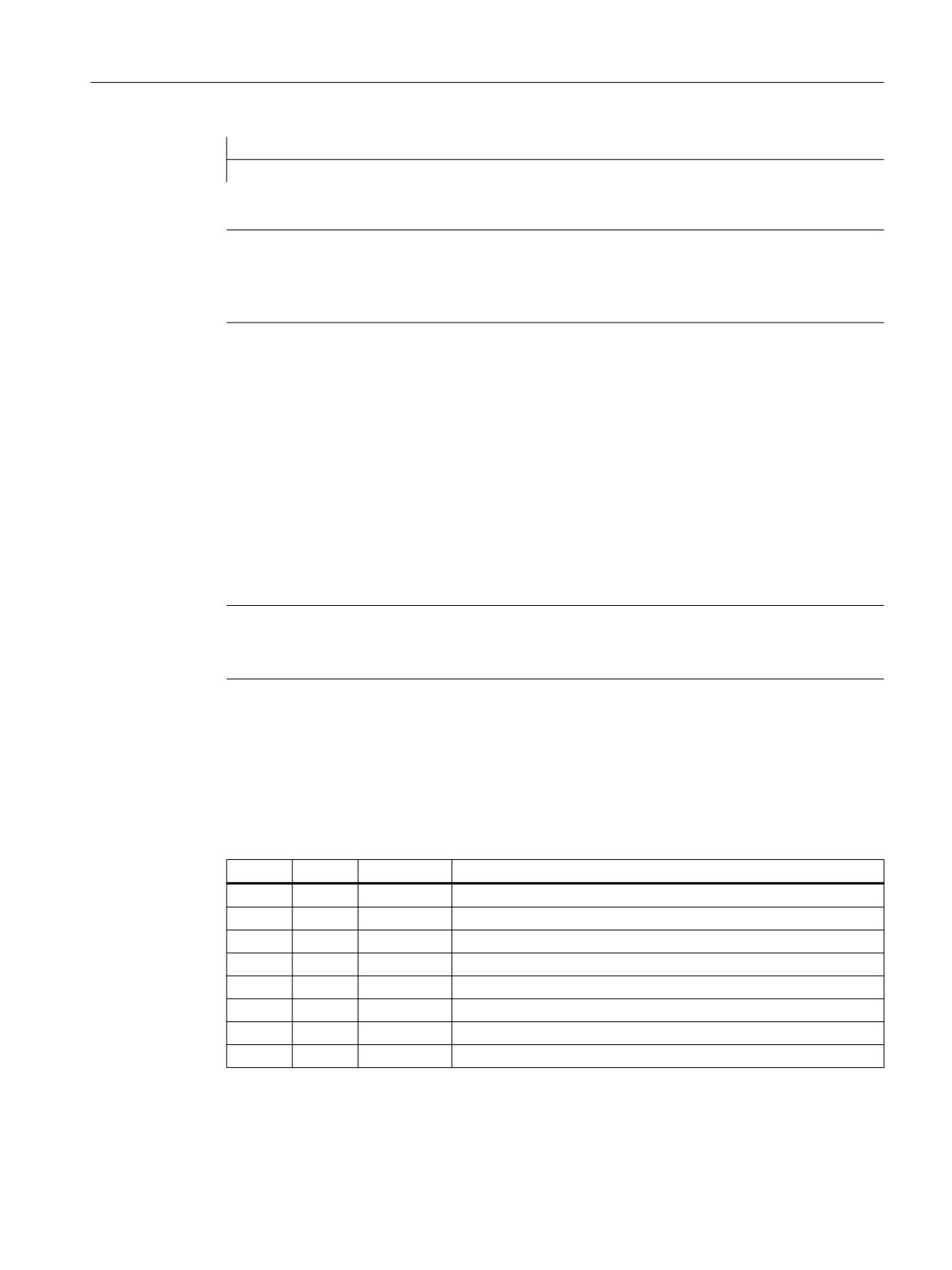
S3: Synchronous spindle
15.4 Points to note
Program code
Comment
N65 M0
; (Note tolerances, see above)
Note
The axis enable signals can be canceled to interrupt a movement overlaid on the following
spindle (e.g. SPOS). This component of the movement is not affected by IS "NC/PLC interface
signal" DB31, ... DBX31.4 (resynchronization), but is restored by the REPOS operation.
Supplementary condition
IS DB31, ... DBX31.4 (resynchronization) has any effect only if there is a defined offset
position between the following spindle and leading spindle.
This is the case following COUPON with offset positions such as COUPON(...,77) or SPOS,
SPOSA, M19 for the following spindle with a closed coupling..
15.4.3
Synchronous mode and NC/PLC interface signals
Note
During synchronous operation, the effect of the associated interface signal for the leading (LS)
or following spindle (FS) on the coupling must always be considered.
Spindle override (DB31, ... DBB19)
Only the spindle override value of the LS is active in synchronous operation.
Spindle disable (DB31, ... DBX1.3)
LS
FS
coupling
Response
0
0
off
Setpoints are output
0
1
off
No setpoint output for FS
1
0
off
No setpoint output for LS
1
1
off
No setpoint output for LS and FS
0
0
ON
Setpoints are output
0
1
ON
Spindle disable not effective for FS
1
0
ON
Spindle disable also effective for FS, no setpoint output
1
1
ON
No setpoint output for LS and FS
Extended Functions
Function Manual, 12/2018, A5E40874029B AB
807

S3: Synchronous spindle
15.4 Points to note
Controller enable (DB31, ... DBX2.1)
LS: Resetting the "controller enable" during synchronous operation
If the controller enable of the LS is reset during synchronous operation for active setpoint
coupling, a control-internal switching is made to the actual value coupling. If the controller
enable is reset while the LS is traversing, the LS is stopped and an alarm issued. Synchronous
operation remains active.
LS and FS: Selection of synchronous operation without controller enable
If the "controller enable" for LS and FS is not set for selected synchronous operation, it will be
activated. LS and FS, however, are not traversed until controller enable for LS and FS has
been granted.
LS and FS: Setting the "Controller enable"
The position assumed by a spindle with setting the "controller enable" depends on DB31, ...
DBX1.4 == <value> (follow-up operation):
<value>
Assumed spindle position
0
Position when controller enable is canceled
1
Current position
Note
It is recommended for synchronous spindles during a block search, to write the DB31, ...
DBX2.1 interface signal (controller enable) always together for FS and LS. If this is not done,
the block search, for example, stops after a FS machining because the controller enable of
the LS is not pending.
Note
Synchronism error
If the DB31, ... DBX2.1 interface signal (controller enable) is canceled for the FS after Spindle
Stop without the coupling being deactivated beforehand, then any synchronism error resulting
from external intervention will not be compensated when the "controller enable" is activated
again. This causes any programmed angular relationship between FS and LS to be lost.
The angular relationship can be restored by resynchronizing: DB31, ... DBX31.4 = 1
(resynchronization)
Follow-up mode (DB31, ... DBX1.4)
For follow-up operation, the set position is regularly set to the current actual position:
DB31, ... DBX1.4 == 1 (follow-up operation) AND DB31, ... DBX2.1 == 0 (controller enable)
Extended Functions
808
Function Manual, 12/2018, A5E40874029B AB
S3: Synchronous spindle
15.4 Points to note
⇒ Cyclic: Set position = actual position
Note
DB31, ... DBX1.4 (follow-up operation) is relevant only for DB31, ... DBX2.1 == 0 (controller
enable)
Position measuring system 1/2 (DB31, ... DBX1.5 and 1.6)
Switchover of the position measuring system for the FS and LS is possible during synchronous
operation. The coupling is retained.
Note
It is recommended to switchover the position measuring system for FS and LS only for
deselected synchronous operation.
Delete distance-to-go / spindle reset (DB31, ... DBX2.2)
LS: Setting spindle reset during synchronous operation
The setting of spindle reset causes the LS to be braked to standstill with the parameterized
acceleration. Synchronous operation remains active.
Any superimposed movement, other than together with COUPON / COUPONC, will be completed
as fast as possible.
Spindle stop (feed stop) (DB31, ... DBX4.3)
LS and FS: Setting spindle stop during synchronous operation
The setting of "spindle stop" for FS or LS causes both spindles to be braked synchronous to
standstill. Synchronous operation remains active.
Resetting spindle stop
Once "spindle stop" has been reset for both spindles, reacceleration is made to the last valid
speed setpoint.
Application example
Bring FS and LS to a standstill when a protection door is opened during synchronous operation.
Signal characteristic for LS and FS:
1. Stop: DB31, ... DBX4.3 = 1 (spindle stop)
2. Waiting for standstill: DB31, ... DBX61.4 == 1
3. Stopping: DB31, ... DBX2.1 = 0 (controller enable)
Extended Functions
Function Manual, 12/2018, A5E40874029B AB
809
S3: Synchronous spindle
15.4 Points to note
Delete S value (DB31, ... DBX16.7)
LS: Delete S value during synchronous operation
If "delete S value" is set, the LS is braked to a standstill using a ramp. Synchronous operation
remains active.
FS: Delete S value during synchronous operation
The control interface signal does not have any function for the FS in synchronous operation.
Resynchronize spindle 1/2 (DB31, ... DBX16.4 and 16.5)
LS: Resynchronizing the position measuring system during synchronous operation
Note
It is recommended to resynchronize the position measuring system of the LS only for
deselected synchronous operation.
Resynchronize (DB31, ... DBX31.4)
FS: Restoring the programmed angular offset
If synchronism between FS and LS is lost or not performed, the programmed angular offset
can be restored.
● Requirement: DB31, ... DBX31.4 = 1 (resynchronization)
● Acknowledgment: DB31, ... DBX99.4 == 1 (synchronization running)
Traverse keys for JOG (DB31, ... DBX4.6 and 4.7)
The "plus and minus traversing keys" for JOG are not disabled in the control for the FS in
synchronous operation, i.e. the FS executes a superimposed motion if one of these keys is
pressed.
Note
If superimposed traversing movements are to be precluded, they must be locked out by
measures in the PLC user program.
NC Stop axes plus spindles (DB21, ... DBX7.4)
"NC Stop axes plus spindles" in synchronous operation decelerates the coupled spindles in
accordance with the selected dynamic response. They continue to operate in synchronous
mode.
Extended Functions
810
Function Manual, 12/2018, A5E40874029B AB
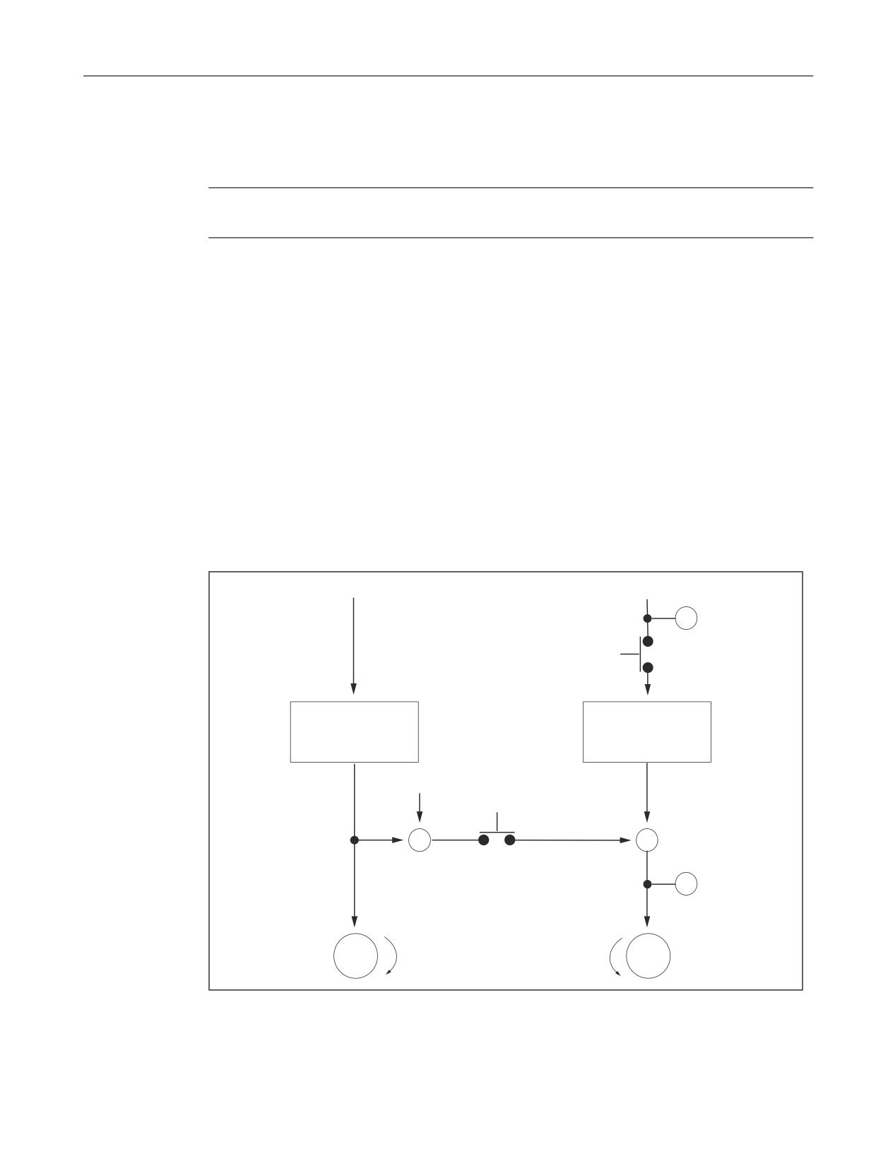
S3: Synchronous spindle
15.4 Points to note
NC Start (DB21, ... DBX7.1)
(See Section "Response of the synchronous-spindle coupling for NC Start (Page 802)")
Note
NC Start after NC Stop does not deselect synchronous operation.
15.4.4
Differential speed between leading and following spindles
When does a differential speed occur?
A differential speed develops, e.g. with turning machine applications, when two spindles
oppose one other. Through the signed addition of two speed sources, a speed component is
derived from the leading spindle via the coupling factor. In addition to this, for the following
spindle a speed (S...) and a direction of rotation (M3/M4) can be programmed.
Generally, to achieve synchronous operation, a coupling factor is used with a value of '-1'. This
sign reversal then results in a differential speed for the following spindle as compared to an
additional programmed speed.
This typical behavior in relation to the NC is illustrated in the following diagram.
6
OHDGLQJ VSLQGOH
6
IROORZLQJ VSLQGOH
0 6
0
6
6HW VSHHG
(QDEOH E\
3/&
6SHHG
6SHHG
LQWHUSRODWRU
LQWHUSRODWRU
&RXSOLQJ IDFWRU
&28321
USP
USP
USP
[
USP
$FWXDO
VSHHG
0
0
Extended Functions
Function Manual, 12/2018, A5E40874029B AB
811
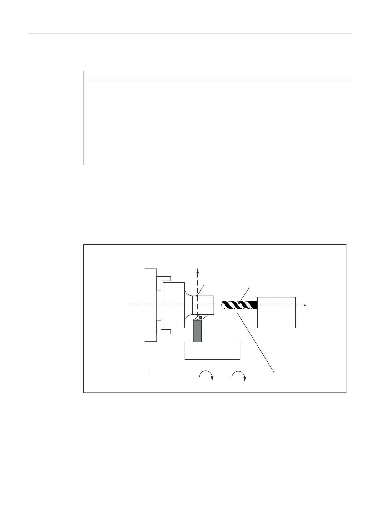
S3: Synchronous spindle
15.4 Points to note
Example
Program code
Comment
N01 M3 S500
; S1 rotates in the positive direction with 500 rpm
; the master spindle is spindle 1
N02 M2=3 S2=300
; S2 rotates in the positive direction with 300 rpm
N05 G4 F1
N10 COUPDEF(S2,S1,-1)
; Coupling factor -1:1
N11 COUPON(S2,S1)
; Activate coupling. The speed of the following spindle
S2 results from the speed of the leading spindle S1 and
the coupling factor.
N26 M2=3 S2=100
; Programming the differential speed, S2 is the follow-
ing spindle.
Application
Manufacturing operations with positioned leading spindle and rotating tools require exact
synchronism with the counter spindle which then functions like a following spindle. A turret
rotating about the following spindle allows parts to be machined with different tool types.
The following diagram shows an application in which the tool is positioned parallel to the main
spindle.
0DLQ VSLQGOH ZLWK ZRUNSLHFH
&RXQWHUVSLQGOH ZLWK GULYHQ
WRRO LQ UHYROYHU
;
:RUNSLHFH
7RRO
&KXFN
5HYROYHU
=
7XUQLQJ WRRO
6OLGH
Q
Q
/HDG VSLQGOH
)ROORZLQJ VSLQGOH
Figure 15-4
Single-slide lathe with revolver around the Z axis
Extended Functions
812
Function Manual, 12/2018, A5E40874029B AB
S3: Synchronous spindle
15.4 Points to note
Preconditions
Basic requirements for differential speed programming:
● Synchronous spindle functionality is required.
● The dynamic response of the following spindle must be at least as high as that of the leading
spindle. Otherwise, the system may suffer from reduced quality, for example, rigid tapping
without a compensating chuck G331/G332.
● The differential speed must be programmed in the channel in which the following spindle
is also configured. The leading spindle can be programmed in a different channel.
● The differential speed must be enabled for the following spindle by the PLC via IS "Enable
overlaid movement" (DB31, ... DBX26.4). If the enable signal has not been set, alarm 16771
"Channel% Following axis% Overlaid movement not enabled" is output. This alarm is
cleared when IS "Enable overlaid movement" (DB31, ... DBX26.4) is set or the coupling is
opened.
Note
Positioning motion such as SPOS, SPOSA, M19 and axis motion do not have to be enabled.
Note
The differential speed does not therefore affect the coupling process.
The following or leading spindle cannot change gear stages while a coupling is active.
Activate coupling with COUPONC
When the coupling is activated, the following spindle is accelerated, as before, to the leading
spindle speed through application of the coupling factor. If the following spindle is already
rotating (M3, M4) when the coupling is activated, it continues with this motion after coupling.
Deactivate coupling
If the coupling is deactivated, the following spindle continues to rotate at the speed
corresponding to the sum of both speed components. The spindle behaves as if it had been
programmed with the speed and direction transferred from the other spindle. When
deactivating, there are no differences to the previous behavior.
Differential speed
A differential speed results from the renewed programming of the following spindle (in the
example, S2=...) or M2=3, M2=4 in speed control mode during an active synchronous spindle
coupling or by adopting the speed of the following spindle for COUPONC.
Condition:
Speed S... must also be re-programmed with direction of rotation M3 or M4. Otherwise alarm
16111 "Channel% Block% Spindle% No speed programmed" is displayed.
Extended Functions
Function Manual, 12/2018, A5E40874029B AB
813
S3: Synchronous spindle
15.4 Points to note
Read offsets of following spindle
The current offset always changes when a differential speed is programmed. The current offset
can be read at the setpoint end with $AA_COUP_OFFS[Sn] and at the actual value end with
$VA_COUP_OFFS[Sn].
The last offset programmed returns the variable $P_COUP_OFFS[Sn].
Display differential speed
The programmed difference component is displayed as the speed setpoint for the programmed
differential speed (in our example, corresponds to 100 rpm).
The actual speed refers to the motor speed. In the example, the actual speed is 500 rev/min
* (-1) + 100 rpm = -400 rev/min.
IS, NC to the PLC
Following spindle in speed-controlled operation
The IS "Spindle in setpoint range" (DB31, ... DBX83.5) is set for the following spindle by the
NC if the programmed speed difference (see previous example, N26 with M2=3 S2=100) is
reached. If a differential speed is programmed and not enabled by the PLC, this VDI interface
signal is not set.
Even if a differential speed has been programmed, the following spindle remains under position
control if this is required by the coupling.
Note
The axial VDI interface signal NC → PLC IS "Superimposed motion" (DB31, ... DBX98.4) is set
when the differential speed programming creates setpoints in addition to the coupling
setpoints.
Actual direction of rotation clockwise (DB31, ... DBX83.7)
IS "Actual direction of rotation clockwise" (DB31, ... DBX83.7) refers to the resulting motor
direction.
IS PLC to the NC
Influence on following spindle via PLC interface
The effect of the axial VDI interface signals on the following spindle with differential speed in
speed control mode is described below:
Delete distance to go / Spindle Reset (DB31, ... DBX2.2)
The programmed differential speed and direction can be terminated by IS "Delete distance-to-
go / Spindle Reset" (DB31, ... DBX2.2). To delete the programmed speed only, it is possible
to set IS "Delete S value" (DB31, ... DBX16.7).
Extended Functions
814
Function Manual, 12/2018, A5E40874029B AB
S3: Synchronous spindle
15.4 Points to note
Resynchronize spindle 1/2 (DB31, ... DBX16.4 and 16.5)
The IS "Resynchronize spindle 1/2" (DB31, ... DBX16.4/16.5) are not locked. Any positional
offset is not compensated automatically by the coupling.
Invert M3/M4 (DB31, ... DBX17.6)
IS "Invert M3/M4" (DB31, ... DBX17.6) only inverts the additional programmed speed
component for the following spindle.
The motion component generated by the synchronous spindle coupling remains unaffected.
Spindle override (DB31, ... DBB19)
The "Spindle override" VDI interface (DB31, ... DBB19) only affects the additional programmed
speed component for the following spindle. If the spindle override switch is transferred to all
axial inputs, then any change in the spindle override value is applied twice to the following
spindle:
● once indirectly by a change in speed for the leading spindle and
● once in the programmed component of the following spindle.
The offset value can be adjusted accordingly in the PLC program.
Deselecting the coupling
If the coupling is deactivated, the following spindle continues to rotate at the speed
corresponding to the sum of both speed components. The motion transition upon coupling
deselection is at continuous speed.
With COUPOF , the spindle behaves as if it had been programmed with the speed and direction
transferred from the other spindle. In the example, this would be M4 S400.
When COUPOFS is programmed, the following spindle is decelerated to standstill from the
current speed.
Activate additional functions
The following spindle can also be a master spindle. In this case, it is capable of additional
functions.
● Rotational feedrate with G95, G96 and G97. With G96 S2=... the "constant cutting speed"
can be activated for the following spindle.
The speed dependent on the position of the transverse axis is the setpoint speed for the
speed interpolator of spindle 2 and is therefore included in the total speed of S2.
● Rigid tapping without compensating chuck with G331, G332.
Extended Functions
Function Manual, 12/2018, A5E40874029B AB
815
S3: Synchronous spindle
15.4 Points to note
15.4.5
Behavior of synchronism signals during synchronism correction
Effect of synchronism correction
New synchronism signals are produced by comparing the actual values with the corrected
setpoints. Once a correction process has been undertaken, the synchronism signals should
be present again.
15.4.6
Delete synchronism correction and NC reset
Variable $AA_COUP_CORR[Sn] returns the value zero for different situations in which the
synchronism correct is deleted:
● Once a synchronized spindle coupling has been activated for the following in question with
COUPON(..)/COUPONC(..), an existing synchronism correction is adopted in the setpoint
position.
● A synchronism correction active during NC reset but not at the parts program end is adopted
in the setpoint position. This does not affect the synchronism signals.
● At M30, an existing synchronism correction is retained
● At the user end, the correction value can also be deleted at any early point by describing
the variable $AA_COUP_CORR with the value zero. The synchronism correction is
removed immediately and using a ramp with reduced acceleration rate if larger values are
involved.
15.4.7
Special points regarding start-up of a synchronous spindle coupling
Spindle start-up
The leading and following spindles must be started up initially like a normal spindle. The
appropriate procedure is described in:
References:
CNC Commissioning Manual: NC, PLC, Drive
Function Manual Basic Functions; Spindles (S1)
Requirements
The following parameters must then be set for the synchronous spindle pair:
● The machine numbers for the leading and following spindles
(for permanently configured coupling with channel-specific machine data MD21300
$MC_COUPLE_AXIS_1[n])
● The required coupling mode (setpoint, actual value or speed coupling)
(for permanently configured coupling with channel-specific machine data
MD21310 $MC_COUPLING_MODE_1[n])
Extended Functions
816
Function Manual, 12/2018, A5E40874029B AB

S3: Synchronous spindle
15.4 Points to note
● The gear stage(s) of FS and LS for synchronous operation
● The following coupling properties are still applicable for permanently configured
synchronous spindle coupling:
- Block change response in synchronous spindle operation:
MD21320 $MC_COUPLE_BLOCK_CHANGE_CTRL_1
- Coupling cancellation response:
MD21330 $MC_COUPLE_RESET_MODE_1
- Write-protection for coupling parameters:
MD21340 $MC_COUPLE_IS_WRITE_PROT_1
- Transformation parameters for synchronous spindle coupling:
SD42300 $SC_COUPLE_RATIO_1[n]
Command behavior of FS and LS for setpoint coupling
In order to obtain the best possible synchronism in setpoint couplings, the FS and LS must
have the same dynamic response as the response to setpoint changes. The axial control loops
(position, speed and current controllers) should each be set to the optimum value so that
variances can be eliminated as quickly and efficiently as possible.
The dynamic response adaptation function in the setpoint branch is provided to adapt different
axis dynamic responses without loss of control quality (see also Section "K3: Compensations
(Page 253)"). The following control parameters must each be set optimally for the FS and LS:
● KV factor (MD32200 $MA_POSCTRL_GAIN)
● Feedforward control parameters
MD32620 $MA_FFW_MODE
MD32610 $MA_VELO_FFW_WEIGHT
MD32650 $MA_AX_INERTIA
MD32800 $MA_EQUIV_CURRCTRL_TIME
MD32810 $MA_EQUIV_SPEEDCTRL_TIME
Behavior during loss of synchronism:
● Axis-specific MD32620 $MA_FFW_MODE
We recommend setting the feedforward control mode of the following axis to speed
feedforward control with Tt symmetrization MD32620 = 3.
This feedforward control mode can be further optimized for a more secure symmetrization
process by changing the axis-specific machine data:
Machine data
Meaning
MD32810 EQUIV_SPEEDCTRL_TIME
Equivalent time constant speed control loop for
feedforward control
MD37200 COUPLE_POS_TOL_COURSE
Threshold value for "Coarse synchronism"
MD37210 COUPLE_POS_TOL_FINE
Threshold value for "Fine synchronism"
MD37220 COUPLE_VELO_TOL_COURSE
Velocity tolerance 'coarse'
MD37220 COUPLE_VELO_TOL_FINE
Velocity tolerance 'fine'
In such cases, higher threshold values for the synchronism signals and larger position and/or
speed tolerances result in more stable results.
Extended Functions
Function Manual, 12/2018, A5E40874029B AB
817
S3: Synchronous spindle
15.4 Points to note
Dynamic response adaptation
To obtain a good control behavior, FS and LS must have the same dynamic response. The
following error for FS and LS must be equal at any given speed. For dynamically different
spindles, a matching via the dynamic response adaptation can be achieved in the setpoint
branch. The difference of the equivalent time constants between the dynamic "weakest"
spindle to the associated other spindle must be entered as time constant of the dynamic
response adaptation.
Example
When the speed feedforward control is active, the dynamic response is primarily determined
by the equivalent time constant of the "slowest" speed control loop.
● Equivalent time constant LS: MD32810 $MA_EQUIV_SPEEDCTRL_TIME[<LS>] = 5 ms
● Equivalent time constant FS: MD32810 $MA_EQUIV_SPEEDCTRL_TIME[<FS>] = 3 ms
● Time constant of dynamic response adaptation for FS: MD32910
$MA_DYN_MATCH_TIME[<FS>] = 5 ms - 3 ms = 2 ms
● Activation of the dynamic response adaptation for FS: MD32900
$MA_DYN_MATCH_ENABLE[<FS>] = 1
The following error for FS and LS is identical for correctly set dynamic response adaptation:
Operating area "Diagnostics" > "Service axes"
For the optimization, it may be necessary to adjust servo gain factors or feedforward control
parameters slightly.
Position control parameter sets
In the case of spindles, each gear stage is assigned a position-control parameter set. These
parameter sets can be used to adapt the dynamic response for LS and FS in synchronous
operation. This requires that a different gear stage is used for speed and positioning operation
and synchronous operation. The associated gear stage must be switched before activating
the associated operating mode.
Control parameters
The following control parameters must be set identically for the FS and LS:
● MD33000 $MA_FIPO_TYPE (fine interpolator type)
● MD32400 $MA_AX_JERK_ENABLE (axial jerk limitation)
● MD32402 $MA_AX_JERK_MODE (filter type for axial jerk limitation)
● MD32410 $MA_AX_JERK_TIME (time constant for the axial jerk filter)
● MD32412 $MA_AX_JERK_FREQ (blocking frequency of the axial jerk filter)
● MD32414 $MA_AX_JERK_DAMP (damping of the axial jerk filter)
● MD32420 $MA_JOG_AND_POS_JERK_ENABLE (release jerk limitation)
● MD32430 $MA_JOG_AND_POS_MAX_JERK (axial jerk)
FS: Automatic parameterization of the control parameters
The control parameters of the following spindle can be set as follows using this machine data:
Extended Functions
818
Function Manual, 12/2018, A5E40874029B AB
S3: Synchronous spindle
15.4 Points to note
MD30455 $MA_MISC_FUNCTION_MASK
Bit 5=0: Synchronous spindle coupling, following spindle:
Position control, feedforward control and parameter block are set for the following spindle.
Bit 5=1: Synchronous spindle coupling:
The control parameters of the following spindle are set as in an uncoupled scenario.
References:
Function Manual Basic Functions; Velocities, Setpoint / Actual Value Systems, Closed-Loop
Control (G2)
Automatic transfer of the LS parameters for synchronous operation
For the automatic dynamic response adaptation for FS and LS, for synchronous operation, the
parameter values for the position control, feedforward control and parameter records of the
FS can be transferred from the LS:
MD30455 $MA_MISC_FUNCTION_MASK, Bit 5
Separate dynamic response for spindle and axis operations
In spindle and axis operations, dynamic programming FA, OVRA, ACC and VELOLIMA can
be set separately from one another with the following MD:
MD30455 $MA_MISK_FUNCTION_MASK Bit 6=0
Assignment is undertaken by the programmed axis or spindle name. For example, in spindle
operation, VELOLIMA[S1]=50 therefore only reduces the maximum speed to 50% and in axis
operation, VELOLIMA[C]=50 only reduces the maximum speed to 50%.
If, for example, VELOLIMA[S1]=50 and VELOLIMA[C]=50 are to have the same effect as
before with this machine data, the programming of FA, OVRA, ACC and VELOLIM have an
effect regardless of the programmed names:
MD30455 $MA_MISK_FUNCTION_MASK Bit 6=1
Knee-shaped acceleration characteristic
For the leading spindle, the effect of a knee-shaped acceleration characteristic on the following
spindle is identified by the following axis-specific machine data:
● MD35220 $MA_ACCEL_REDUCTION_SPEED_POINT (speed for reduced acceleration)
and
● MD35230 $MA_ACCEL_REDUCTION_FACTOR (reduced acceleration).
If MD35242 $MA_ACCEL_REDUCTION_TYPE is present, it is also used to configure the type
of acceleration reduction. Otherwise a hyperbolic drop in acceleration is assumed.
If the dynamic response of a following spindle is lower than that of the leading spindle when
the coupling factor is taken into account, the leading spindle dynamic response is reduced to
the required level while the coupling is active.
The acceleration should be constant over the entire speed range for the following spindle.
However, if a knee-shaped acceleration characteristic is also stored in the above-mentioned
Extended Functions
Function Manual, 12/2018, A5E40874029B AB
819
S3: Synchronous spindle
15.4 Points to note
machine data for the following spindle, this is only taken into account when the spindles are
coupled in. The setpoints of the following spindle are applied for the specified knee-shaped
acceleration characteristic.
References:
Function Manual, Basic Functions; Acceleration (B2),
Section: Knee-shaped acceleration characteristic
Actual value coupling
In an actual value coupling (AV), the drive for the FS must be considerably more dynamic than
the leading spindle drive. The individual drives in an actual value coupling are also set optimally
according to their dynamic response.
An actual value coupling should only be used in exceptional cases.
Speed coupling
The velocity coupling (VV) corresponds internally to a setpoint coupling (DV), but with lower
dynamic requirements of the FS and LS. A position control servo loop is not required for the
FS and/or LS. Measuring systems are not required.
Threshold values for coarse/fine synchronism
After controller optimization and feedforward control setting, the threshold values for coarse
and fine synchronism must be entered for the FS.
● Threshold value for "Coarse synchronism"
axis-specific MD7200: AV, DV: COUPLE_POS_TOL_COARSE
MD37220: VV: COUPLE_VELO_TOL_COARSE
● Threshold value for "Fine synchronism"
axis-specific MD37210: AV, DV: COUPLE_POS_TOL_FINE
MD37230: VV: COUPLE_VELO_TOL_FINE
The values of the FS must be calculated according to the accuracy requirements of the
machine manufacturer, and the PLC interface must be checked via the service display.
Angular offset LS/FS
If there must be a defined angular offset between the FS and LS, e.g. when synchronous
operation is activated, the "zero degree positions" of the FS and LS must be mutually adapted.
This can be done with the following machine data:
● MD34100 $MA_REFP_SET_POS
● MD34080 $MA_REFP_MOVE_DIST
● MD34090 $MA_REFP_ MOVE_DIST_CORR
References:
Function Manual Basic Functions; Reference Point Approach (R1)
Extended Functions
820
Function Manual, 12/2018, A5E40874029B AB
S3: Synchronous spindle
15.6 Examples
Service display for FS
In the "Diagnostics" operating area, when commissioning in the synchronous mode, the
following values are displayed for the following spindle:
● Actual deviation between setpoints of FS and LS
Value displayed: Position offset in relation to leading spindle (setpoint)
(value corresponds to angular offset between FS and LS that can be read with axis variable
$AA_COUP_OFFS in the part program)
● Actual deviation between actual values of FS and LS
Value displayed: Position offset in relation to leading spindle (actual value)
References:
Operating Manual
15.5
Boundary conditions
Availability of the "synchronous spindle" function
The function is an option ("synchronous spindle/multi-edge turning" or the corresponding
optional version of the generic coupling), which must be assigned to the hardware via the
license management.
Note
Information on the different versions of the generic coupling, refer to:
References:
Function Manual Special Functions; Coupled Axes (M3)
15.6
Examples
Programming example
Program code
Comment
; Leading spindle = master spindle = spindle 1
; Following spindle = spindle 2
N05 M3 S3000 M2=4 S2=500
; Master spindle rotates at 3000 rpm
; FS: 500 rpm
N10 COUPDEF (S2, S1, 1, 1, "No",
; Def. of coupling, can also
"Dv")
; be configured
N70 SPCON
; Include leading spindle in the position con-
trol
; (setpoint value coupling).
Extended Functions
Function Manual, 12/2018, A5E40874029B AB
821

S3: Synchronous spindle
15.7 Data lists
Program code
Comment
N75 SPCON(2)
; Bring following spindle into closed-loop po-
sition control
N80 COUPON (S2, S1, 45)
; On-the-fly coupling to offset position = 45
degrees
N200 FA [S2] = 100
; Positioning speed = 100 degrees/min
N205 SPOS[2] = IC(-90)
; Traverse with 90° overlay in negative direc-
tion
N210 WAITC(S2, "Fine")
; Wait for "fine" synchronism
N212 G1 X.., Y.. F...
; Machining
N215 SPOS[2] = IC(180)
; Traverse with 180° overlay in positive direc-
tion
N220 G4 S50
; Dwell time = 50 revolutions
; of master spindle
N225 FA [S2] = 0
; Activate configured velocity (MD)
N230 SPOS[2] = IC (-7200)
; 20 rev. with configured velocity
; in neg. direction
N350 COUPOF (S2, S1)
; On-the-fly decoupling, S = S2 = 3000
N355 SPOSA[2] = 0
; Stop FS at zero degrees
N360 G0 X0 Y0
N365 WAITS(2)
; Wait for spindle 2
N370 M5
; Stop FS
N375 M30
15.7
Data lists
15.7.1
Machine data
15.7.1.1
NC-specific machine data
Number
Identifier: $MN_
Description
10000
AXCONF_MACHAX_NAME_TAB
Machine axis name
15.7.1.2
Channelspecific machine data
Number
Identifier: $MC_
Description
20070
AXCONF_MACHAX_USED
Machine axis number valid in channel
21300
COUPLE_AXIS_1
Definition of synchronous spindle pair
21310
COUPLING_MODE_1
Type of coupling in synchronous spindle mode
Extended Functions
822
Function Manual, 12/2018, A5E40874029B AB

S3: Synchronous spindle
15.7 Data lists
Number
Identifier: $MC_
Description
21320
COUPLE_BLOCK_CHANGE_CTRL_1
Block change behavior in synchronous spindle opera-
tion
21330
COUPLE_RESET_MODE_1
Coupling abort behavior
21340
COUPLE_IS_WRITE_PROT_1
Coupling parameters are write-protected
15.7.1.3
Axis/spindlespecific machine data
Number
Identifier: $MA_
Description
30455
MISK_FUNCTION_MASK
Axis functions
30550
AXCONF_ASSIGN_MASTER_CHAN
Reset position of channel for axis change
32200
POSCTRL_GAIN
Servo gain factor (KV factor)
32400
AX_JERK_ENABLE
Axial jerk limitation
32410
AX_JERK_TIME
Time constant for axial jerk filter
32420
JOG_AND_POS_JERK_ENABLE
Initial setting for axial jerk limitation
32430
JOG_AND_POS_MAX_JERK
Axial jerk
32610
VELO_FFW_WEIGHT
Feedforward control factor for speed feedforward control
32620
FFW_MODE
Feedforward control mode
32650
AX_INERTIA
Moment of inertia for torque feedforward control
32800
EQUIV_CURRCTRL_TIME
Equivalent time constant current control loop for feed-
forward control
32810
EQUIV_SPEEDCTRL_TIME
Equivalent time constant speed control loop for feedfor-
ward control
34080
REFP_MOVE_DIST
Reference point approach distance
34090
REFP_MOVE_DIST_CORR
Reference point offset
34100
REFP_SET_POS
Reference point value
35000
SPIND_ASSIGN_TO_MACHAX
Assignment of spindle to machine axis
37200
COUPLE_POS_TOL_COARSE
Threshold value for "Coarse synchronism"
37210
COUPLE_POS_TOL_FINE
Threshold value for "Fine synchronism"
37220
COUPLE_VELO_TOL_COARSE
Speed tolerance "coarse" between leading and follow-
ing spindles
37230
COUPLE_VELO_TOL_FINE
Speed tolerance "fine" between leading and following
spindles
15.7.2
Setting data
15.7.2.1
Channelspecific setting data
Number
Identifier: $SC_
Description
42300
COUPLE_RATIO_1
Transmission parameters for synchronous spindle operation
Extended Functions
Function Manual, 12/2018, A5E40874029B AB
823

S3: Synchronous spindle
15.7 Data lists
15.7.3
Signals
15.7.3.1
Signals to channel
Signal name
SINUMERIK 840D sl
SINUMERIK 828D
NC Start
DB21,
DBX7.1
DB320x.DBX7.1
NC Stop axes plus spindle
DB21,
DBX7.4
DB320x.DBX7.4
15.7.3.2
Signals from channel
Signal name
SINUMERIK 840D sl
SINUMERIK 828D
Dry run feedrate selected
DB21,
DBX24.6
DB170x.DBX0.6
Feedrate override selected for rapid traverse
DB21,
DBX25.3
DB170x.DBX1.3
15.7.3.3
Signals to axis/spindle
Signal name
SINUMERIK 840D sl
SINUMERIK 828D
Axis/spindle disable
DB31,
DBX1.3
DB380x.DBX1.3
Follow-up mode
DB31,
DBX1.4
DB380x.DBX1.4
Position measuring system 1, position measuring system 2 DB31,
DBX1.5/6
DB380x.DBX1.5/6
Controller enable
DB31,
DBX2.1
DB380x.DBX2.1
Distance-to-go/Spindle RESET
DB31,
DBX2.2
DB380x.DBX2.2
Spindle stop/feed stop
DB31,
DBX4.3
DB380x.DBX4.3
Traversing keys for JOG
DB31,
DBX4.6/7
DB380x.DBX4.6/7
Re-synchronize spindle 1, re-synchronize spindle 2
DB31,
DBX16.4/5
DB380x.DBX2000.4/5
Delete S value
DB31,
DBX16.7
DB380x.DBX2000.7
Feedrate override valid
DB31,
DBX17.0
DB380x.DBX2001.0
Invert M3/M4
DB31,
DBX17.6
DB380x.DBX2001.6
Spindle override
DB31,
DBB19
DB380x.DBB2003
Re-synchronizing
DB31,
DBX31.4
-
Disable synchronization
DB31,
DBX31.5
-
15.7.3.4
Signals from axis/spindle
Signal name
SINUMERIK 840D sl
SINUMERIK 828D
Referenced/synchronized 1, referenced/synchronized 2
DB31,
DBX60.4/5
DB390x.DBX0.4/5
Synchronous mode
DB31,
DBX84.4
DB390x.DBX2002.4
Synchronism fine
DB31,
DBX98.0
DB390x.DBX5002.0
Synchronism coarse
DB31,
DBX98.1
DB390x.DBX5002.1
Extended Functions
824
Function Manual, 12/2018, A5E40874029B AB

S3: Synchronous spindle
15.7 Data lists
Signal name
SINUMERIK 840D sl
SINUMERIK 828D
Actual value coupling
DB31,
DBX98.2
DB390x.DBX5002.2
Superimposed motion
DB31,
DBX98.4
DB390x.DBX5002.4
Leading spindle LS/LA active
DB31,
DBX99.0
DB390x.DBX5003.0
Following spindle FS/FA active
DB31,
DBX99.1
DB390x.DBX5003.1
15.7.4
System variables
System variable
Description
$P_COUP_OFFS[following spindle]
Programmed offset of the synchronous spindle
$AA_COUP_OFFS[following spindle]
Position offset for synchronous spindle (setpoint)
$VA_COUP_OFFS[following spindle]
Position offset for synchronous spindle (actual value)
For a more detailed description of system variables, see:
References:
List Manual System Variables
Extended Functions
Function Manual, 12/2018, A5E40874029B AB
825
S3: Synchronous spindle
15.7 Data lists
Extended Functions
826
Function Manual, 12/2018, A5E40874029B AB
S7: Memory configuration
16
16.1
Introduction
Memory areas
The CF card of the NCU contains two memory areas for storing and managing the data of the
local persistent and non-persistent data of the NC:
● Static NC memory
That static NC memory contains the persistent NC data of the active and passive file
system (Page 827).
● Dynamic NC memory
The dynamic NC memory contains the non-persistent NC data, such as macros, local user
data, buffer memory, etc., generated dynamically by the NC.
Deterministic behavior
To ensure the behavior of the NC is deterministic in all machining situations, all memory areas
of the local static and dynamic NC memory have a settable, but permanent size.
Memory configuration
The memory areas of the local static and dynamic NC memory are set up when the control is
first started based on the standard settings of the machine data that configure the memory.
These settings are adequate in most cases.
Reconfiguration
If necessary, the memory configuration can be adapted to the user-specific requirements. The
necessary reconfiguration of the memory can result in loss of all user data in the static NC
memory. Therefore, after a change to memory-configuring machine data, the Alarm 4400: "MD
change results in reorganization of the buffered memory (loss of data!)" is displayed. Prior to
activating the machine data change or reconfiguration of the memory by an NC reset, a
commissioning archive should be created.
The memory configuration will be changed the next time the NC is started. Then the created
commissioning archive can be read-in for restoring the user data.
16.2
Active and passive file system
The user-specific data of the NC are stored in the local static NC memory. The memory area
contains the data of the active and passive file system.
Extended Functions
Function Manual, 12/2018, A5E40874029B AB
827
S7: Memory configuration
16.2 Active and passive file system
Active file system
The active file system contains system data used to parameterize the NC. Essentially, these
are:
● Machine data
● Setting data
● Option data
● Global user data (GUD)
● Tool-offset/magazine data
● Protection areas
● R parameters
● Work offsets/FRAME
● Sag compensations
● Quadrant error compensation
● Leadscrew error compensation
The data of the active file system represent the current work data of the NC.
The view of the active file system is data-oriented.
Passive file system
The passive file system contains all local files loaded in the NC:
● Main programs
● Subprograms
● Workpieces
● Global user data and macro definition files (*.DEF)
● Standard cycles
● User cycles
● Comments
● Binary files (e.g. pictures, PDF documents)
The view of the passive file system is file-oriented.
Extended Functions
828
Function Manual, 12/2018, A5E40874029B AB
S7: Memory configuration
16.3 Commissioning
16.3
Commissioning
16.3.1
Configuration
The configuration of the local static and dynamic NC memory is set and influenced by the
following machine data:
● Machine data that configure the memory:
- $MN_MM_... (NC-specific, memory-configuring machine data)
- $MC_MM_... (channel-specific memory-configuring machine data)
- $MA_MM_... (axis-specific memory-configuring machine data)
● Number of parameterized channels:
- MD10010 $MN_ASSIGN_CHAN_TO_MODE_GROUP (channel valid in mode group)
16.3.2
Reconfiguration
The first time the controller starts up, the sizes of the memory areas of the local NC memory
are set based on the default settings of the memory-configuring machine data. Generally, these
settings are sufficient for the operation of the control. If the memory areas of the local NC
memory are adapted because of special user-specific requirements, this results in
reconfiguration of the local NC memory. If the active and/or passive file system of the static
NC memory is affected, Alarm 4400 is displayed. The user should then back up the relevant
data by creating a commissioning archive on an external storage medium.
Alarm 4400 is displayed in the following cases:
● Memory-configuring machine data of the passive file system was changed
● Memory-configuring machine data of the active file system was changed and the function
"Automatic Memory Reconfiguration" (AMR) is not active
● Memory-configuring machine data of the active file system was changed, the AMR function
is active, but the data of the active file system cannot be buffered locally
NOTICE
Loss of data due to reconfiguration
A reconfiguration of the local static NC memory can result in the loss of the user data on the
active and/or passive file system. We therefore urgently recommend the back up of all relevant
data by creating a commissioning archive if Alarm 4400 is displayed, before activating the
changed memory configuration by an NC reset.
Extended Functions
Function Manual, 12/2018, A5E40874029B AB
829
S7: Memory configuration
16.4 Configuration of the static user memory
"Automatic memory reconfiguration" function (AMR)
Active file system
The AMR function enables the reconfiguration of memory areas of the active file system
(Page 827) without having to create and then read back a commissioning archive to prevent
the loss of user data.
If the function is active, and memory-configuring machine data that affects the active file system
is modified, it is first checked whether all data of the active file system can be buffered locally.
If this is the case, the data of the active file system will be first buffered locally on activation of
the modified memory configuration by triggering a warm restart. The memory of the active file
system is then reconfigured. Finally, the buffered data are read back to the newly configured
active file system.
If the data of the active file system cannot be buffered, Alarm 4400 is displayed. Then, before
activating the machine data change, a commissioning archive containing the relevant user
data should be created. Refer to the paragraph below "References"
Passive file system
If machine data that requires a reconfiguration of the passive file system is changed, Alarm
4400 will always be displayed, independent of the AMR function. Then, before activating the
machine data change, a commissioning archive containing the relevant user data should be
created.
If machine data that only requires a reconfiguration of the active file system is changed, the
data of the passive file system is retained.
Activation
The "Automatic memory reconfiguration" function (AMR) is activated via machine data:
MD17950 $MN_IS_AUTOMATIC_MEM_RECONFIG = TRUE
References
Creating a commissioning archive
Commissioning Manual: CNC commissioning: NC, PLC, Drive; Chapter "Saving and managing
data" > "Creating a commissioning archive"
16.4
Configuration of the static user memory
16.4.1
Division of the static NC memory
The static NC memory is used jointly by the system and by the user. The area available to the
user is defined as the static user memory. It contains the data from the active and passive file
system.
The figure below shows the principle division of the static NC memory for SINUMERIK 840D sl:
Extended Functions
830
Function Manual, 12/2018, A5E40874029B AB