SINUMERIK 840D sl. Service - Functions. Manual (2018-2020) - page 41
P2: Positioning axes
12.3 Motion behavior and interpolation functions
Boundary conditions
The axis/spindle must be operating under PLC control.
The NC confirms acceptance of an axis/spindle only if an axial alarm is not active.
Description of the sequence based on use cases
Requirement
The axis/spindle is controlled by the PLC
Relevant NC/PLC interface signals
One of the axes/spindles controlled by the PLC can be influenced by the following NC/PLC
interface signals independent of the NC program:
● DB21, ... DBX6.2 (delete distance-to-go)
● DB31, ... DBX28.1 (reset)
● DB31, ... DBX28.2 (continue)
● DB31, ... DBX28.6 (stop along braking ramp)
For signal flow between the NC and PLC at the NC/PLC interface during autonomous single
operations, see Section "Control by the PLC (Page 710)".
Use case 1: Cancel axis/spindle
The behavior when canceling the axis/spindle function is the same as for "delete distance-to-
go":
DB21, ... DBX6.2 = 1 (delete distance-to-go)
Use case 2: Stop axis/spindle
The following traversing motion of the axis/spindle controlled from the main run is stopped:
● PLC axis
● Asynchronous oscillating axis
● Command axis by static synchronized action
● Superimposed motion $AA_OFF,DRF handwheel traversal, online tool offset and external
work offset.
Following axis movements of the axis/spindle are not stopped.
Extended Functions
Function Manual, 12/2018, A5E40874029B AB
693
P2: Positioning axes
12.3 Motion behavior and interpolation functions
Description of the sequence:
● PLC → NC: Request to stop the axis/spindle
DB31, ... DBX28.6 = 1 (stop along braking ramp)
● NC: Brakes the axis along a ramp.
● NC confirms the execution:
- DB31, ... DBX60.6 = 1 (exact stop coarse)
- DB31, ... DBX60.7 = 1 (exact stop fine)
- DB31, ... DBX63.2 = 0 (axis stop active)
- DB31, ... DBX64.6 / 7 = 0 (traversing command minus/plus)
- Axis status interrupted with system variable $AA_SNGLAX_STAT == 3
Result: The axis/spindle is stopped.
Note
Following axis movements
Following axis movements can only be suppressed when the leading axis stops.
Retraction motion
Retraction motion triggered by the "Extended stop and retract" function cannot be stopped.
References
Function Description, Special Functions; Extended Stop and Retract (R3)
Use case 3: Continue axis/spindle
Traversing motion interrupted after Use case 2 "Stop axis" should be continued.
Description of the sequence:
● PLC → NC: Continue axis
DB31, ... DBX28.2 = 1 (continue)
● NC: Checks whether for the axis/spindle an axial alarm with delete criterion
"CANCELCLEAR" or "NCSTARTCLEAR" is present? If yes, then this is deleted.
● NC: Checks whether axis motion can be resumed? If yes, then the axis/spindle makes the
transition into the "active" state.
● NC confirms the execution:
- DB31, ... DBX60.6 = 0 (exact stop coarse)
- DB31, ... DBX60.7 = 0 (exact stop fine)
- DB31, ... DBX63.2 = 0 (axis stop active)
- DB31, ... DBX64.6 / 7 = 1 (traversing command minus/plus)
- Axis state active with system variable $AA_SNGLAX_STAT == 4.
Result: Traversing motion of the axis/spindle is continued.
Extended Functions
694
Function Manual, 12/2018, A5E40874029B AB
P2: Positioning axes
12.3 Motion behavior and interpolation functions
Boundary conditions
In the following cases, the request to continue is ignored:
● The axis/spindle is not controlled by the PLC.
● The axis/spindle is not in the stopped state.
● An alarm is pending for the axis/spindle.
Use case 4: Reset axis/spindle (reset)
Description of the sequence:
● PLC → NC: Reset request for this axis/spindle
DB31, ... DBX28.1 = 1 (reset)
● NC: Transitions the axis/spindle into the "stopped" state.
● NC: Interrupts the stopped sequences and signals to the PLC the interruption - essentially
the same as for "Delete distance-to-go".
● NC: The internal states for the axis/spindle are reset.
● NC: The axis-specific machine data, which become effective at reset, become active.
Note
In conjunction with a channel reset, no axs-specific machine data is active for axes
controlled from the PLC.
● NC confirms the execution:
- DB31, ... DBX63.0 = 1 (reset executed)
- DB31, ... DBX63.2 = 0 (axis stop active)
- System variable $AA_SNGLAX_STAT = 1
● NC exits this operation.
12.3.3
Autonomous single-axis functions with NC-controlled ESR
Extended stop numerically controlled
The numerically controlled extended stop and retract function is also available for single axes
and is configurable with axial machine data:
Delay time for ESR single axis with
MD37510 $MA_AX_ESR_DELAY_TIME1
ESR time for interpolatory braking of the single axis with
MD37511 $MA_AX_ESR_DELAY_TIME2
The values of these axial machine data are however effective only if the axis/spindle is a single
axis.
Extended Functions
Function Manual, 12/2018, A5E40874029B AB
695
P2: Positioning axes
12.3 Motion behavior and interpolation functions
The NC-controlled extended stop and retract is activated by the axial trigger
$AA_ESR_TRIGGER[axis]. It works analogously to $AC_ESR_TRIGGER and applies
exclusively to single axes.
References:
Function Manual, Special Functions; Coupled axes and ESR (M3)
Extended retract numerically controlled
For retracting single axes, the value must have been programmed via POLFA(axis, type, value)
and the following conditions must be met:
● The axis must be a single axis at the time of triggering
● $AA_ESR_ENABLE[axis]=1
● POLFA(axis, type, value) with type=1 or type=2 only
POLFA(axis, value, axis, type, axis type).
Note
NC-controlled extended stop for single axes:
The trigger is only effective if the axis is a single axis at the time of triggering, otherwise the
trigger is ignored and the axial stop for this axis is not executed.
NC-controlled extended retract for single axes:
The channel-specific NC-controlled extended retract function is not effective for single
axes. All axes that are single axes at the time of triggering $AC_ESR_TRIGGER will be
ignored for channel-specific retraction.
This also applies when all the parameters for retraction are set, such as:
MD37500 $MA_ESR_REACTION
$AA_ESR_ENABLE for the axis, etc.
Examples
Extended stopping of a single axis:
MD37500 $MA_ESR_REACTION[AX1]=22
MD37510 $MA_AX_ESR_DELAY_TIME1[AX1]=0.3
MD37511 $MA_AX_ESR_DELAY_TIME2[AX1]=0.06
$AA_ESR_ENABLE[AX1] = 1
$AA_ESR_TRIGGER[AX1]=1 ; axis begins to stop the process here
Extended retraction of a single axis:
MD37500 $MA_ESR_REACTION[AX1]=21
Extended Functions
696
Function Manual, 12/2018, A5E40874029B AB
P2: Positioning axes
12.4 Positioning axis dynamic response
$AA_ESR_ENABLE[AX1] = 1
POLFA(AX1, 1, 20.0); AX1 is assigned the axial retraction position 20.0 ; (absolute)
$AA_ESR_TRIGGER[AX1]=1 ; AX1 begins to retract here
POLFA(axis, type): permissible programming abbreviation
POLFA(axis, 0/1/2) ; quick deactivation/activation
WARNING
No preprocessing limitation
If abbreviated notation is used and only the type is changed, make sure that the value for the
retraction position or retraction path in the application is meaningful!
The abbreviated notation should only be used in exceptional circumstances.
This particularly applies after:
A power on, the retraction path or the retraction position must be reset.
POLFA(axis, 1, $AA_POLFA[axis]) ; causes a preprocessing stop
POLFA(axis, 1); does not cause a preprocessing stop
12.4
Positioning axis dynamic response
Velocity
The positioning axes traverse at the axis-specific feedrate programmed for them. As described
under "Motion behavior and interpolation functions (Page 690)", this feedrate is not influenced
by the path axes.
The feedrate is programmed as an axis-specific velocity in units of min/mm, inch/min or
degrees/min.
The axis-specific feedrate is always permanently assigned to a positioning axis by the axis
name.
If a positioning axis has no programmed feedrate, the control system automatically applies the
rate set in axis-specific machine data:
MD32060 $MA_POS_AX_VELO (initial setting for positioning axis velocity)
The programmed axis-specific feedrate is active until the end of the program.
Feedrate override
The path and positioning axes have separate feedrate overrides. Each positioning axis can
be influenced by its own axis-specific feedrate override.
Extended Functions
Function Manual, 12/2018, A5E40874029B AB
697

P2: Positioning axes
12.4 Positioning axis dynamic response
Rapid traverse override
Rapid traverse override applies only to path axes. Positioning axes have no rapid traverse
interpolation (only axial linear interpolation G01) and therefore no rapid traverse override.
Revolutional feedrate
In JOG mode the behavior of the axis/spindle also depends on the setting of SD41100
JOG_REV_IS_ACTIVE (revolutional feedrate when JOG active).
● If this setting data is active, an axis/spindle is always moved with revolutional feedrate
MD32050 $MA_JOG_REV_VELO (revolutional feedrate with JOG) or MD32040
$MA_JOG_REV_VELO_RAPID (revolutional feedrate with JOG with rapid traverse overlay)
as a function of the master spindle.
● If the setting data is not active, the behavior of the axis/spindle depends on SD43300
$SA_ASSIG_FEED_PER_REV_SOURCE (revolutional feedrate for positioning axes/
spindles)
● If the setting data is not active, the behavior of a geometry axis on which a frame with
rotation is effective depends on the channel-specific setting data SD42600
$SC_JOG_FEED_PER_REV_SOURCE. (In the operating mode JOG, revolutional feedrate
for geometry axes on which a frame with rotation is effective.)
Maximum axial acceleration
With positioning axis motions, one of the two following maximum values is effective depending
on the set positioning axis dynamic response mode:
● MD32300 $MA_MAX_AX_ACCEL [0] (maximum axial acceleration for path motions in the
dynamic response mode DYNNORM)
● MD32300 $MA_MAX_AX_ACCEL [1] (maximum axial acceleration for path motions in the
dynamic response mode DYNPOS)
The positioning axis dynamic response mode is set in the NC-specific machine data:
MD18960 $MN_POS_DYN_MODE = <mode>
<mode>
Meaning
0
Effective maximum axial acceleration: MD32300 $MA_MAX_AX_ACCEL[ 0 ]
1
Effective maximum axial acceleration: MD32300 $MA_MAX_AX_ACCEL[ 1 ]
Maximum axial jerk
When traversing positioning axes with active jerk limitation, the value from one of the following
machine data takes effect as maximum axial jerk:
● MD32430 $MA_JOG_AND_POS_MAX_JERK (maximum axial jerk for positioning axis
motions)
● MD32431 $MA_MAX_AX_JERK [0] (maximum axial jerk for path motions in the dynamic
response mode DYNNORM)
● MD32431 $MA_MAX_AX_JERK [1] (maximum axial jerk for path motions in the dynamic
response mode DYNPOS)
Extended Functions
698
Function Manual, 12/2018, A5E40874029B AB

P2: Positioning axes
12.5 Programming
The machine data to be used is determined by the set positioning axis dynamic response mode:
MD18960 $MN_POS_DYN_MODE = <mode>
<mode>
Meaning
The following is effective as maximum axial jerk for positioning axis motions:
0
MD32430 $MA_JOG_AND_POS_MAX_JERK
With active G75 (fixed-point approach): MD32431 $MA_MAX_AX_JERK[0]
1
MD32431 $MA_MAX_AX_JERK[1]
12.5
Programming
12.5.1
General
Note
For the programming of position axes, please observe the following documentation:
References:
Programming Manual Basics; Section: "feed rate control" and "spindle motion"
Note
The maximum number of positioning axes that can be programmed in a block is limited to the
maximum number of available channel axes.
Definition
Positioning axes are defined using the following parameters:
● Axis type: Positioning axis type 1, type 2 or type 3
● End point coordinates (in absolute dimensions or in incremental dimensions)
● Feedrate for linear axes in [mm/min], for rotary axes in [degrees/min]
Example: Positioning axis type 1
Program code
Comment
POS[Q1]=200 FA[Q1]=1000
; Axis Q1 with feedrate 1000mm/min at Position 200.
Example: Positioning axis type 2
Program code
Comment
POSA[Q2]=300 FA[Q2]=1500
; Axis Q2 with feedrate 1,500mm/min at Position 300.
Extended Functions
Function Manual, 12/2018, A5E40874029B AB
699
P2: Positioning axes
12.5 Programming
Note
Within a part program, an axis can be a path axis or a positioning axis. Within a movement
block, however, each axis must be assigned a unique axis type.
Programming in synchronized action
Axes can be positioned completely asynchronous to the part program from synchronized
actions.
Example:
Program code
Comment
ID=1 WHENEVER $R==1 DO POS[Q4]=10 FA[Q3]=990
; The axial feedrate is specified permanent-
ly.
References:
Function Manual, Synchronized Actions
Block change
The block change can be adjusted for positioning axis types 1 and 2 with:
FINEA=<axis name> or
FINEA[<axis name>]
COARSEA=<axis name> or
COARSEA[<axis name>]
IPOENDA=<axis name> or
IPOENDA[<axis name>]
In Type 3 positioning axis, the block change within the brake ramp of the single interpolation
can be set with:
IPOBRKA=<axis name> or
IPOBRKA(<axis name>[,<instant in time*>])
* Instant in time of the block change, referred to the braking ramp as a %
Absolute dimension / incremental dimension
The programming of the end point coordinates takes place in absolute dimension (G90) or in
incremental dimension (G91).
Example
Meaning
Programming the end point coordinates
G90 POS[Q1]=200
In absolute dimension
G91 POS[Q1]=AC(200)
In absolute dimension
G91 POS[Q1]=200
In incremental dimension
G90 POS[Q1]=IC(200)
In incremental dimension
Extended Functions
700
Function Manual, 12/2018, A5E40874029B AB
P2: Positioning axes
12.5 Programming
Reprogram type 2 positioning axes
With type 2 positioning axes (motion across block limits), you need to be able to detect in the
part program whether the positioning axis has reached its end position. Only then is it possible
to reprogram this positioning axis (otherwise an alarm is issued).
If POSA and then POSA again with IPOBRKA (block change in the braking ramp) is
programmed, an alarm is not issued. For more information, please refer to NC command
IPOBKA in Section "Settable block change time".
Coordination (WAITP)
The coordination command WAITP enables you to designate a position in the NC program
where the program is to wait until an axis programmed with POSA in a previous NC block has
reached its end position.
WAITP exists in an internal block.
An explicit reference must be made to any axis for which the program is to wait.
Example:
Program code
Comment
N10 G01 G90 X200 F1000 POSA[Q1]=200 FA[Q1]=500
N15 X400
N20 WAITP(Q1)
; The program processing
is stopped automatically
until Q1 is at position.
N25 X600 POS[Q1]=300
; Q1 is a positioning axis
of Type 1 (feedrate
FA[Q1] from block N10).
N30 X800 Q1=500
; Q1 is path axis (path
feed F1000 from block
N10).
Tool offset
A tool length compensation for positioning axes can be implemented by means of an axial zero
offset, allowing, for example, the positioning path of a loader to be altered. An example where
the axial zero offset might be used in place of the tool length compensation is where a loader
containing tools of various dimensions has to bypass an obstacle.
End of program
The program end (program status selected) is delayed until all axes (path axes + positioning
axes) have reached their programmed end points.
12.5.2
Revolutional feed rate in external programming
The two following setting data can be used to specify that the revolutional feed rate of a
positioning axis should be derived from another rotary axis/spindle:
Extended Functions
Function Manual, 12/2018, A5E40874029B AB
701

P2: Positioning axes
12.6 Block change
SD43300 $SA_ASSIGN_FEED_PER_REV_SOURCE(revolutional feed rate for position axes/
spindles)
SD42600 JOG_FEED_PER_REV_SOURCE (control of revolutional feed rate in JOG)
The following settings are possible:
Value
Description
0
No revolutional feed rate selected
>0
The revolutional feed rate is derived from the round axis/spindle with the machine axis index
specified here.
-1
The revolutional feed rate is derived from the master spindle of the channel in which the
axis/spindle is active.
-2
The revolutional feed rate is derived from the rotary axis/spindle with the machine axis index
0.
-3
The revolutional feed rate is derived from the master spindle of the channel in which the
axis/spindle is active. No revolutional feed rate is selected if the master spindle is at a
standstill.
12.6
Block change
Since path and positioning axes are interpolated separately, they reach their programmed end
positions at different instants in time. If path and positioning axes are programmed in a block
together, then the block change behavior depends on the programmable type of positioning
axes.
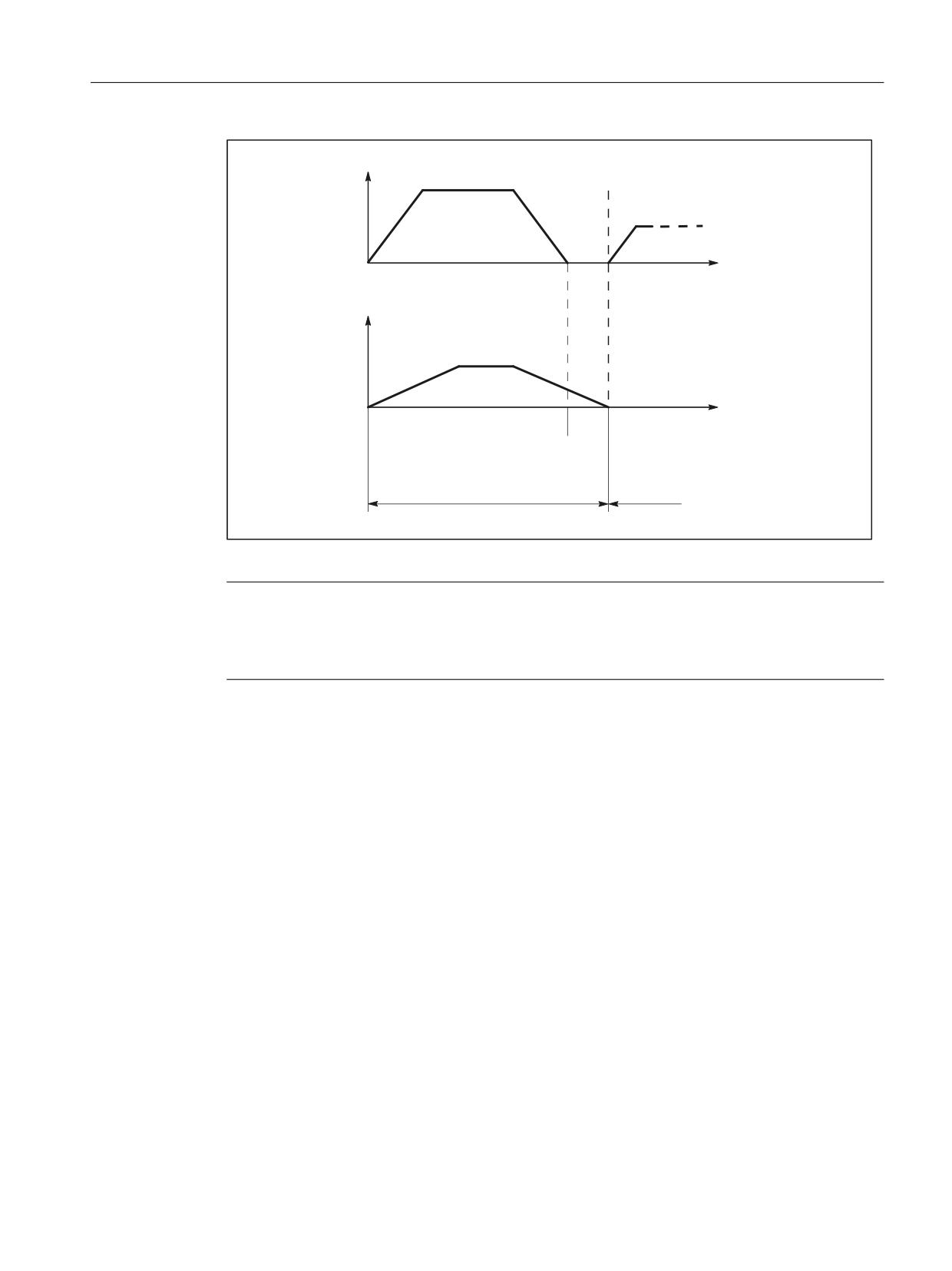
Type 1: Block-related positioning axis
Properties:
● The block change is performed as soon as all path and positioning axes have reached
their respective programmed end-of-motion criterion:
- Path axes: G601, G602, G603
- Positioning axes: FINEA, COARSA, IPOENDA
● Programming the positioning axis: POS[<axis>]
Extended Functions
702
Function Manual, 12/2018, A5E40874029B AB
P2: Positioning axes
12.6 Block change
9HORFLW\ SDWK D[HV
7LPH
9HORFLW\ SRVLWLRQLQJ D[LV
7LPH
3DWK D[HV KDYH UHDFKHG WKH
3RVLWLRQLQJ D[LV KDV UHDFKHG
SURJUDPPHG HQG SRVLWLRQ
SURJUDPPHG HQG SRVLWLRQ
1
1
%ORFN FKDQJH
Figure 12-1
Block change for path axis and positioning axis type 1
Note
Continuous path mode
Continuous path mode across block limits (G64) is only possible if the positioning axes reach
their end-of-motion criterion before the path axes (in the diagram above, this is not the case).
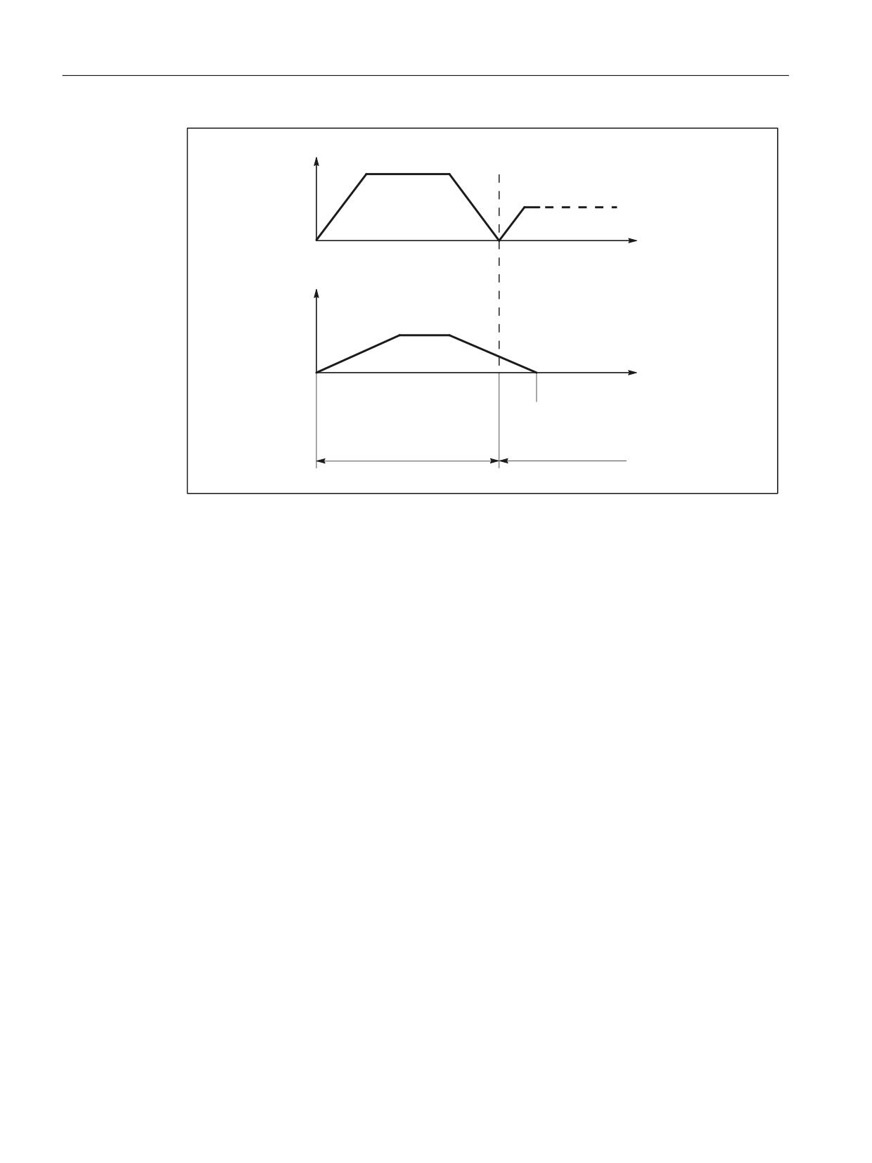
Type 2: Modal positioning axis (across blocks)
Properties:
● The block change is performed as soon as all path axes have reached their programmed
end-of-motion criterion (G601, G602, G603)
● Programming the positioning axis: POSA[<axis>]
● The positioning axis traverses beyond the block limits to its programmed end position. It is
not permissible that the positioning axis is programmed again before reaching its end-of-
motion criterion.
Extended Functions
Function Manual, 12/2018, A5E40874029B AB
703
P2: Positioning axes
12.6 Block change
9HORFLW\ SDWK D[HV
7LPH
9HORFLW\ SRVLWLRQLQJ D[LV
7LPH
3DWK D[HV KDYH UHDFKHG WKH
3RVLWLRQLQJ D[LV KDV UHDFKHG
SURJUDPPHG HQG SRVLWLRQ
SURJUDPPHG HQG SRVLWLRQ
1
1
%ORFN FKDQJH
Figure 12-2
Block change for path axis and positioning axis type 2
12.6.1
Settable block change time
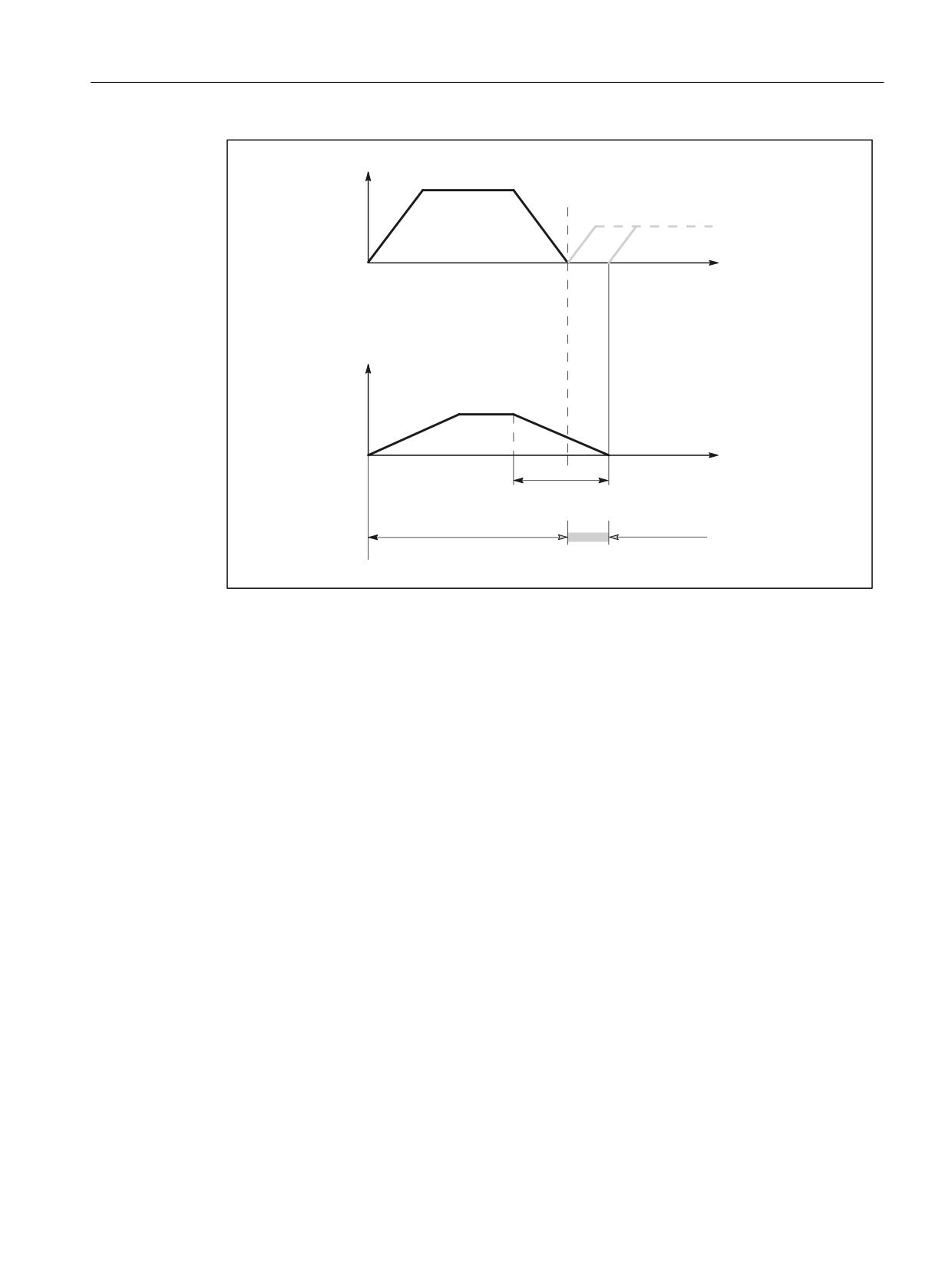
Type 3: Conditional block-related positioning axis
Properties:
● The block change is performed as soon as all path and positioning axes have reached
their respective programmed end-of-motion criterion:
- Path axes: G601, G602, G603
- Positioning axes: IPOBRKA
● Programming the positioning axis:
- N(x) IPOBRK(<axis>[,<instant in time>]) ;own block
- N(x+1) POS[<axis>]
Extended Functions
704
Function Manual, 12/2018, A5E40874029B AB
P2: Positioning axes
12.6 Block change
9HORFLW\ SDWK D[HV
7LPH
3DWK D[HV KDYH UHDFKHG WKH
SURJUDPPHG HQG SRVLWLRQ
9HORFLW\ SRVLWLRQLQJ D[LV
7LPH
%ORFN HQG FULWHULRQ
; RI WKH EUDNLQJ UDPS
1
1
%ORFN FKDQJH DUHD
GHSHQGHQW RQ [
Figure 12-3
Block change for path axis and positioning axis type 3
Block change criterion: "Braking ramp" (IPOBRKA)
If, when activating the block change criterion "brake ramp", a value is programmed for the
optional parameter <instant in time>, then this becomes effective for the next positioning
motion and is written into the setting data synchronized to the main run. If no value is specified
for the block change instant in time, then the actual value of the setting data is effective.
SD43600 $SA_IPOBRAKE_BLOCK_EXCHANGE
The time at which the block change can be realized is specified as a percentage of the braking
ramp:
●
100% = start of the braking ramp
●
0% = end of the braking ramp, the same significance as block change criterion IPOENDA
Programming
IPOBRKA(<axis>[,<instant in time>])
IPOBRKA:
Block change criterion: Deceleration ramp
Effective:
Modal
<axis>:
Channel axis name (X, Y,
)
Extended Functions
Function Manual, 12/2018, A5E40874029B AB
705
P2: Positioning axes
12.6 Block change
<instant in time>:
Time of the block change, referred to the braking ramp as a %:
●
100% = start of the braking ramp
●
0% = end of the braking ramp, the same significance as
IPOENDA
Type:
REAL
IPOBRKA is deactivated for the corresponding access when an axis end-of-motion criterion
(FINEA, COARSEA
, IPOENDA ) is next programmed for the axis.
Additional block change criterion: "Tolerance window" (ADISPOSA)
A tolerance window around the end of block (either as actual or setpoint position) can be
defined as additional block change criterion. Then, two conditions must be fulfilled for the block
change:
● Block change criterion: "Braking ramp"
● Block change criterion: "Tolerance window"
Programming
ADISPOSA(<axis>[,<mode>,<window size>])
ADISPOSA:
Tolerance window for end-of-motion criterion
Effective:
Modal
<axis>:
Channel axis name (X, Y,
)
<mode>:
Reference of the tolerance window
Type: INT
Value range:
0
Tolerance window not active
1
Tolerance window with respect to the set-
point position
2
Tolerance window with respect to actual po-
sition
<window size>:
Size of the tolerance window
Type: REAL
System variable for end-of-motion criterion
The effective end-of-motion criterion can be read using the system variable $AA_MOTEND.
Extended Functions
706
Function Manual, 12/2018, A5E40874029B AB

P2: Positioning axes
12.6 Block change
References: Parameter Manual, Book 2
Note
Information about other programmable end-of-motion criteria FINEA, COARESA, IPOENDA
can be found in:
References: Function Manual, Basic Functions
● Spindles (S1), Section "Spindle modes"
● Feedrates (V1), Programmable dynamic response of single axis section
Supplementary conditions
Premature block change
A premature block change is not possible in the following cases:
● Oscillating axis
During oscillation with partial infeed, the block-specific oscillation motion must remain active
until the axis with partial infeed has reached its final position.
● Handwheel
For handwheel input, the last set end-of-motion criterion applies.
Changing the axis state
The axis for which a block change occurred within the braking ramp can only be programmed
in the following block in the same axis state.
When the axis state changes, e.g. to POSfollowed by SPOS, the last programmed end-of-motion
criterion FINEA, COARSEA, IPOENDA is active. This also applies in the following cases:
● a positioning axis becomes a path axis
● if the program waits for the end of the positioning movement: WAITP, M30, end of the
technology cycle, preprocessing stop
● Velocity override is deactivated or activated
Note
For further information about programming positioning axes, see:
References:
Programming Manual, Fundamentals, Section "Feedrate control and spindle motion"
Programming Manual, Advanced, Section "Special motion commands"
Examples
Block change criteria "braking ramp" in the part program
Program code
Comment
; Default setting is effective.
Extended Functions
Function Manual, 12/2018, A5E40874029B AB
707

P2: Positioning axes
12.6 Block change
Program code
Comment
N10 POS[X]=100
; Positioning motion from X to position 100.
; Block change criterion: "Exact stop fine"
N20 IPOBRKA(X,100)
; Block change criterion: "Braking ramp", 100% = start of the
braking ramp.
N30 POS[X]=200
; The block is changed as soon as the X axis starts to brake.
N40 POS[X]=250
; Axis X does not brake at position 200, but moves further to
position 250. As soon as the axis starts to brake, the
block is changed.
N50 POS[X]=0
; Axis X brakes and returns to position 0,
the block change is realized at position 0 and "exact stop
fine".
N60 X10 F100
; Axis X traverses as path axis to position 10.
N70 M30
Block change criterion "braking ramp" in synchronized action
In the technology cycle:
Program code
Comment
FINEA
; End-of-motion criterion: "Exact stop fine"
N10 POS[X]=100
; The technology cycle block change is realized if the X axis
has reached position 100 and "exact stop fine" is reached.
N20 IPOBRKA(X,100)
; Block change criterion, activate "braking ramp",
100% = start of the braking ramp.
N30 POS[X]=200
; The technology cycle block is changed as soon as the X axis
starts to brake.
N40 POS[X]=250
; Axis X does not brake at position 200, but moves further to
position 250. As soon as the axis starts to brake, the
block change is realized in the technology cycle.
N50 POS[X]=0
; Axis X brakes and returns to position 0,
the block change is realized at position 0 and "exact stop
fine".
N60 M17
Block change criterion "braking ramp" and "tolerance window" in the part program
Program code
Comment
; Default setting is effective.
N10 POS[X]=100
; Positioning motion from X to position 100.
; Block change criterion: "Exact stop fine"
N20 IPOBRKA(X,100)
; Block change criterion: "Braking ramp", 100% = start of the
braking ramp.
N21 ADISPOSA(X,1,0.5)
; Tolerance window: 1 = setpoint position, tolerance = 0.5
N30 POS[X]=200
; The block is changed as soon as the X axis starts to brake.
N40 POS[X]=250
; Axis X does not brake at position 200, but moves further to
position 250. As soon as the axis starts to brake, the
block is changed.
Extended Functions
708
Function Manual, 12/2018, A5E40874029B AB
P2: Positioning axes
12.6 Block change
Program code
Comment
N50 POS[X]=0
; Axis X brakes and returns to position 0,
the block change is realized at position 0 and "exact stop
fine".
N60 X10 F100
N70 M30
Block change criterion "braking ramp" and "tolerance window" in synchronized action
In the technology cycle:
Program code
Comment
FINEA
; End-of-motion criterion: "Exact stop fine"
N10 POS[X]=100
; The technology cycle block change is realized if the X axis
has reached position 100 and "exact stop fine" is reached.
N20 IPOBRKA(X,100)
; Block change criterion, activate "braking ramp",100% =
start of the braking ramp.
N21 ADISPOSA(X,2,0.3)
; Tolerance window: 2 = actual position, tolerance = 0.3
N30 POS[X]=200
; Technology cycle block change is realized as soon as the X
axis starts to brake and the actual position of the X axis
>= 199.7.
N40 POS[X]=250
; X axis does not brake at position 200, but moves further to
position 250. As soon as the X axis starts to brake and the
position of the X axis >= 249.7, the block change is real-
ized in the technology cycle.
N50 POS[X]=0
; Axis X brakes and returns to position 0,
the block change is realized at position 0 and "exact stop
fine".
N60 M17
IPOBRKA(X) could also be written into the N20 blocks without specifying the instant in time,
if the corresponding value has already been entered into the setting data:
SD43600 $SA_IPOBRAKE_BLOCK_EXCHANGE[X] == 100
See also
Control by the PLC (Page 710)
12.6.2
End of motion criterion with block search
Last block serves as container
The last end-of-motion criterion programmed for an axis is collected and output in an action
block. The last block with a programmed motion end condition that was processed in the search
run serves as a container for setting all axes.
Extended Functions
Function Manual, 12/2018, A5E40874029B AB
709
P2: Positioning axes
12.7 Control by the PLC
Example
For two action blocks with end-of-motion criteria for three axes:
Program code
Comment
N01 G01 POS[X]=20 POS[Y]=30
IPOENDA[X]
; Last programmed IPOENDA end-of-mo-
tion criterion
N02 IPOBRKA(Y, 50)
; Second action block for the Y axis
IPOENDA
N03 POS[Z]=55 FINEA[Z]
; Second action block for the Z axis FI-
NEA
N04 $A_OUT[1]=1
; First action block for output as dig-
ital output
N05 POS[X]=100
;
N06 IPOBRKA(X, 100)
; Second action block for the X axis
IPOBRKA container
; For all programmed end-of-motion cri-
teria
TARGET:
; Block search target
The first action block contains the digital output:
$A_OUT[1] = 1.
The second action block contains the settings for the end-of-motion criteria:
for the X axis IPOBRKA / $SA_IPOBRAKE_BLOCK_EXCHANGE[AX1]=100
for the Y axis IPOBRKA / $SA_IPOBRAKE_BLOCK_EXCHANGE[AX2]=50
for the Z axis FINEA. The motion end condition IPOENDA last programmed is also stored for
the X axis.
12.7
Control by the PLC
PLC axes
PLC axes are traversed from the PLC and can move asynchronously to all other axes. The
travel motions are executed separate from the path and synchronized actions.
Reference:
Function Manual, Basic Functions; Basic PLC Program for SINUMERIK 840D sl (P3) or PLC
for SINUMERIK 828D (P4)
Concurrent positioning axes
Using function block FC18, for SINUMERIK 840D sl concurrent positioning axes can be started
from the PLC.
Extended Functions
710
Function Manual, 12/2018, A5E40874029B AB
P2: Positioning axes
12.7 Control by the PLC
Channel-specific signals
All channel-specific signals act to the same extent on path and positioning axes.
Only the following signals are an exception:
● NST DB21, ... DBB4 ("feedrate override")
● IS DB21, ... DBX6.2 ("Delete distance to go")
Axisspecific signals
Positioning axes have the following additional signals:
● IS DB31, ... DBX76.5 ("Positioning axis")
● Feedrate for positioning axes/spindles (FA)
● NST DB31, ... DBB0 ("feedrate override") - axis-specific
● IS DB31, ... DBX2.2 ("Distance to go/Spindle reset") Axis-specific deletion of distance to go
Single-axis functions of PLC-controlled axes
The behavior of individual PLC axes can be manipulated in the following way with machine
data:
MD30460 $MA_BASE_FUNCTION_MASK
:
● Bit 4 = 1
The axis is exclusively controlled by the PLC.
● Bit 5 = 1
The axis is a permanently assigned PLC axis.
● Bit 6 = 1
The channel-specific NC/PLC interface signal:
DB21, ... DBX6.0 ("feed disable")
is not active for the axis if this is a PLC-controlled axis.
● Bit 7= 1
The channel-specific NC/PLC interface signal:
DB21, ... DBX36.3 ("all axes stationary")
is setindependently of an axis if this is a PLC-controlled axis.
For a PLC-controlled axis:
● The channel-specific NC/PLC interface signal DB21, ... DBX6.0 ("feed disable"), is active
if bit 6 = 0 in machine data MD30460 $MA_BASE_FUNCTION_MASK.
● The channel-specific NC/PLC interface signal DB21, ... DBX36.3 ("all axes stationary") is
only set if bit 7 = 0 in machine data MD30460 $MA_BASE_FUNCTION_MASK.
If an attempt is made to assign an exclusively PLC-controlled axis to the NC program or to
request the axis for the NC program, then this is rejected with Alarm 26075. Alarm 26076 is
generated in the same way for a PLC axis with fixed assignment.
A PLC axis with fixed assignment is a "neutral axis" on power up. For a travel request via the
NC/PLC interface, a concurrent positioning axis automatically changes to a PLC axis without
being interchanged beforehand.
Extended Functions
Function Manual, 12/2018, A5E40874029B AB
711
P2: Positioning axes
12.7 Control by the PLC
Axis replacement via PLC
The type of an axis for axis replacement is transferred to the PLC with axial interface byte
NC→PLC NST DB31, ... DBB68 (see also Section "K5: Cross-channel program coordination
and channel-by-channel running-in (Page 367)"):
● IS DB31, ... DBX68.0-68.3 ("NC axis/spindle in channel") channels 1 to 10
● IS DB31, ... DBX68.4 ("new type requested by PLC")
● IS DB31, ... DBX68.5 ("axis can be replaced")
● IS DB31, ... DBX68.6 ("neutral axis/spindle")
● IS DB31, ... DBX68.7 ("PLC axis/spindle")
If IS DB31, ... DBX68.5 ("axis can be replaced") = 1, an axis replacement request can be issued
from the PLC.
12.7.1
Starting concurrent positioning axes from the PLC
Traversing an axis in the NC as competing positioning axes from the PLC user program is
realized using block FC18:
The following functions are defined:
● Linear interpolation (G01)
● Feedrate in mm/min or degrees/min (G94)
● Exact stop (G09)
● The active adjustable work offsets are taken into account
Since each axis is assigned to exactly one channel, the control can select the correct channel
from the axis name/axis number and start the concurrent positioning axis on this channel.
References
Function Manual Basic Functions; Chapter "P3: Basic PLC program for SINUMERIK 840D sl"
> Block descriptions" > "FC18: SpinCtrl Spindle control"
12.7.2
PLC-controlled axes
PLC actions
The table below compares the following PLC actions as response of the NC for a machine
axis:
● Start machine axis as PLC axis using FC18
● Initiate NC start or NC stop
● Axis-specific STOP, RESUME or RESET
● Trigger NC-RESET
Extended Functions
712
Function Manual, 12/2018, A5E40874029B AB

P2: Positioning axes
12.7 Control by the PLC
● Cancel or set controller enable for the machine axis
● Relinquish control of machine axis to NC
Examples of NC responses
PLC actions as response of the NC are listed in the table below.
PLC actions
NC response
Machine axis AX1 is the channel axis in channel
1, start as PLC axis using FC18
Initiate NC stop axes and spindles
AX1 is stopped.
DB21, ... DBX7.4 = 1 (NC stop axes plus spindle)
DB21, ... DBX7.1 = 1 initiate (NC start)
AX1 continues to traverse.
The PLC wants to control AX1,
Checking AX1 is relinquished to the PLC. DB31, ...
DBX63.1 = 1 (PLC controls the axis)
DB31, ... DBX28.7 = 1 (PLC controls axis)
Initiate NC stop for axes and spindles
AX1 is not stopped.
DB21, ... DBX7.4 = 1 ("NC stop axes plus spindle")
Initiate axial stop
AX1 is stopped
DB31, ... DBX63.2 ==1 (axis stop active)
DB31, ... DBX28.6 = 1 (stop along braking ramp)
Initiate axial continuation
AX1 traverses further
DB31, ... DBX63.2 == 0 (axis stop active)
DB31, ... DBX28.2 = 1 (continue)
Initiate NC RESET
No effect on AX1
DB21, ... DBX7.7 = 1 initiate (reset)
Initiate axial reset
AX1 is stopped and the traversing motion is inter-
rupted:
DB31, ... DBX28.1 = 1 (reset)
● DB31, ... DBX63.2 = 0 (axis stop active)
● Read-in axial machine data
● DB31, ... DBX63.0 = 1 (reset executed)
● DB31, ... DBX63.2 = 0 (axis stop active)
Start machine axis AX1 as PLC axis via FC 18
DB31, ... DBX63.0 = 0 (reset executed)
Withdraw controller enable for AX1:
Alarm 21612 "Axis %1 measuring system change"
is displayed
DB31, ... DBX2.1 = 0 (controller enable)
Initiate axial continuation
● Alarm 21612 "Axis %1 measuring system
DB31, ... DBX28.2 = 1 (continue)
change" is deleted
● DB21, ... DBX40.7 = 1(traversing command
plus)
● AX1 does not traverse due to a missing
controller enable signal.
Set controller enable for AX1
AX1 moves to the programmed end point.
DB31, ... DBX2.1 = 1 (controller enable)
Extended Functions
Function Manual, 12/2018, A5E40874029B AB
713

P2: Positioning axes
12.7 Control by the PLC
PLC actions
NC response
Initiate axial reset
● Stop AX1
DB31, ... DBX28.1 = 1 (reset)
● Read-in axial machine data
● DB31, ... DBX63.0 = 0 (reset)
PLC relinquishes control of AX1 to the NC from
● NC accepts control of machine axis
DB31, ... DBX28.7 = 0 (PLC controls axis)
● DB31, ... DBX63.1 = 0 (PLC controls the axis)
● DB31, ... DBX63.0 = 0 (reset)
12.7.3
Control response of PLC-controlled axes
Response for a channel reset, activate machine data, block search and MD30460
Table 12-1
Control response to
PLC-controlled axis
Mode change and NC program control
work independently of axis.
Channel RESET
No axial machine data are effective and a travers-
ing movement is not aborted.
NEWCONF
No axial machine data are effective.
Block search Type 5 SERUPRO
are processed during SERUPRO to simulate the
normal procedure, e.g. PLC takes over or relin-
quishes control of this axis which is also traversing
via the PLC.
All block search variants
The PLC takes over control of the axis before the
of types 1, 2, 4 and 5
approach block and is responsible for positioning
this axis.
NC-controlled retraction activated with
has no effect and acts only on the specified PLC-
$AC_ESR_TRIGGER.
controlled axis.
machine data:
which is not controlled
MD30460 $MA_BASE_FUNKTION_MASK
exclusively by the PLC
Bit 4 = 0
cannot be changed directly with axis replacement
command GET (axis) or AXTOCHAN(axis, chan-
nel) to an axis controlled by the NC program, see
* Note on axis replacement.
Bit 4 = 1
cannot be requested for the NC program. GET or
AXTOCHAN from the NC program or a synchron-
ized action, or programming the axis in the NC
program, are rejected with alarm 26075.
MD30460 $MA_BASE_FUNKTION_MASK
For the PLC-controlled axis
Extended Functions
714
Function Manual, 12/2018, A5E40874029B AB

P2: Positioning axes
12.8 Response with special functions
Control response to
PLC-controlled axis
Bit 6 = 1
channel-specific
IS DB 21, ... DBX6.0 ("feed disable") is not effec-
tive. This axis is not stopped when feed disable is
activated, but continues to move.
Bit 7 = 1
the axis is not taken into account when
IS DB 21, ... DBX36.3 ("all axes stationary") is
generated. This signal is output with 1 even if all
other axes in the channel are stationary and only
the PLC-controlled axis is active.
* Note on axis replacement
This replacement of a "neutral axis" by an "NC program axis" does not take place until the PLC
has really relinquished control of the axis in accordance with use case "Relinquish control of
axis". Waiting for this axis interchange is displayed on the HMI operator panel front.
12.8
Response with special functions
12.8.1
Dry run (DRY RUN)
The dry run feedrate is also effective for positioning axes unless the programmed feedrate is
larger than the dry run feedrate.
Activation of the dry run feed entered in SD42100 $SA_DRY_RUN_FEED can be controlled
with SD42101 $SA_DRY_RUN_FEED_MODE. See
References:
Function Manual, Basic Functions; Feedrates (V1)
12.8.2
Single block
Positioning axis type 1
Single-block mode is effective with positioning axes of type 1.
Positioning axis type 2
Positioning axes of type 2 also continue across block limits in single block mode.
Positioning axis type 3
Positioning axes of type 3 also continue across block limits in single block mode.
Extended Functions
Function Manual, 12/2018, A5E40874029B AB
715
P2: Positioning axes
12.9 Examples
12.9
Examples
12.9.1
Motion behavior and interpolation functions
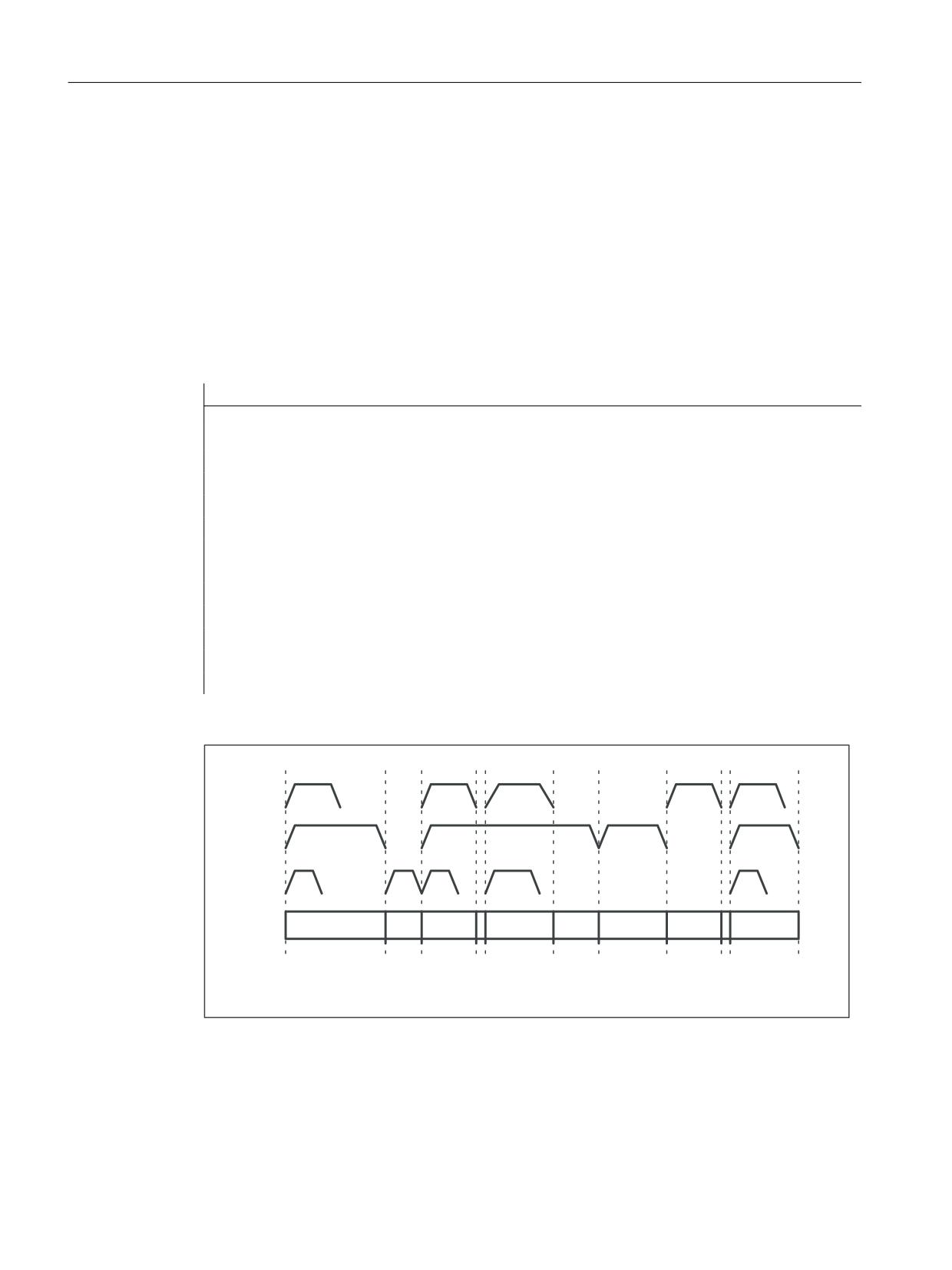
In the following example, the two positioning axes Q1 and Q2 represent two separate units of
movement. There is no interpolation relationship between the two axes. In the example, the
positioning axes are programmed as type 1 (e.g. in N20) and type 2 (e.g. in N40).
Program example
Program code
N10 G90 G01 G40 T0 D0 M3 S1000
N20 X100 F1000 POS[Q1]=200 POS[Q2]=50 FA[Q1]=500
FA[Q2]=2000
N30 POS[Q2]=80
N40 X200 POSA[Q1] = 300 POSA[Q2]=200] FA[Q1]=1500
N45 WAITP[Q2]
N50 X300 POSA[Q2]=300
N55 WAITP[Q1]
N60 POS[Q1]=350
N70 X400
N75 WAITP[Q1, Q2]
N80 G91 X100 POS[Q1]=150 POS[Q2]=80
N90 M30
;
4
4
1
1
1
1
1
1
1
1
1
; SDWK D[HV
4
4
SRVLWLRQLQJ D[HV
Figure 12-4
Timing of path axes and positioning axes
Extended Functions
716
Function Manual, 12/2018, A5E40874029B AB

P2: Positioning axes
12.10 Data lists
12.10
Data lists
12.10.1
Machine data
12.10.1.1
NC-specific machine data
Number
Identifier: $MN_
Description
18960
POS_DYN_MODE
Type of positioning axis dynamic response
12.10.1.2
Channelspecific machine data
Number
Identifier: $MC_
Description
20730
G0_LINEAR_MODE
Interpolation behavior with G0
20732
EXTERN_G0_LINEAR_MODE
Interpolation behavior with G00
22240
AUXFU_F_SYNC_TYPE
Output timing of F functions
12.10.1.3
Axis/spindlespecific machine data
Number
Identifier: $MA_
Description
30450
IS_CONCURRENT_POS_AX
Concurrent positioning axis
30460
BASE_FUNCTION_MASK
Axis functions
32060
POS_AX_VELO
Feedrate for positioning axis
32300
MAX_AX_ACCEL
Maximum axis acceleration
32430
JOG_AND_POS_MAX_JERK
Maximum axial jerk for positioning axis movements
32431
MAX_AX_JERK
Maximum axial jerk for path movements
37510
AX_ESR_DELAY_TIME1
Delay time for ESR single axis
37511
AX_ESR_DELAY_TIME2
ESR time for interpolatory braking of single axis
12.10.2
Setting data
12.10.2.1
Axis/spindle-specific setting data
Number
Identifier: $SA_
Description
43600
IPOBRAKE_BLOCK_EXCHANGE
Braking ramp block change condition
43610
ADISPOSA_VALUE
Braking ramp tolerance window
Extended Functions
Function Manual, 12/2018, A5E40874029B AB
717

P2: Positioning axes
12.10 Data lists
12.10.3
Signals
12.10.3.1
Signals to channel
Signal name
SINUMERIK 840D sl
SINUMERIK 828D
feed disable
DB21,
DBX6.0
DB320x.DBX6.0
NC Start
DB21,
DBX7.1
DB320x.DBX7.1
NC stop axes plus spindle
DB21,
DBX7.4
DB320x.DBX7.4
Reset
DB21,
DBX7.7
DB320x.DBX7.7
12.10.3.2
Signals from channel
Signal name
SINUMERIK 840D sl
SINUMERIK 828D
All axes stationary
DB21,
DBX36.3
DB330x.DBX4.3
Travel command minus
DB21,
DBX40.6
DB330x.DBX1000.6
Travel command plus
DB21,
DBX40.7
DB330x.DBX1000.7
12.10.3.3
Signals to axis/spindle
Signal name
SINUMERIK 840D sl
SINUMERIK 828D
Feedrate override, axis-specific
DB31,
DBB0
DB380x.DBB0
Controller enable
DB31,
DBX2.1
DB380x.DBX2.1
Delete distance-to-go spindle reset for specific axes
DB31,
DBX2.2
DB380x.DBX2.2
Reset
DB31,
DBX28.1
DB380x.DBX5004.1
Continue
DB31,
DBX28.2
DB380x.DBX5004.2
Stop along braking ramp
DB31,
DBX28.6
DB380x.DBX5004.6
PLC-controlled axis
DB31,
DBX28.7
DB380x.DBX5004.7
12.10.3.4
Signals from axis/spindle
Signal name
SINUMERIK 840D sl
SINUMERIK 828D
Exact stop coarse
DB31,
DBX60.6
DB390x.DBX0.6
Exact stop fine
DB31,
DBX60.7
DB390x.DBX0.7
Axial alarm
DB31,
DBX61.1
DB390x.DBX1.1
Axis ready (AX_IS_READY)
DB31,
DBX61.2
DB390x.DBX1.2
Axis container rotation active
DB31,
DBX62.7
-
Reset executed
DB31,
DBX63.0
DB390x.DBX3.0
PLC-controlled axis
DB31,
DBX63.1
DB390x.DBX3.1
Axis stop active
DB31,
DBX63.2
DB390x.DBX3.2
Extended Functions
718
Function Manual, 12/2018, A5E40874029B AB

P2: Positioning axes
12.10 Data lists
Signal name
SINUMERIK 840D sl
SINUMERIK 828D
Axis/spindle inhibit active
DB31,
DBX63.3
DB390x.DBX3.3
Travel command minus
DB31,
DBX64.6
DB390x.DBX4.6
Travel command plus
DB31,
DBX64.7
DB390x.DBX4.7
Positioning axis
DB31,
DBX76.5
DB390x.DBX1002.5
F function (feedrate) for positioning axis
DB31,
DBB78-81
-
Emergency retraction active
DB31,
DBX98.7
DB390x.DBX5002.7
Extended Functions
Function Manual, 12/2018, A5E40874029B AB
719
P2: Positioning axes
12.10 Data lists
Extended Functions
720
Function Manual, 12/2018, A5E40874029B AB
P5: Oscillation
13
13.1
Brief description
Definition
When the "Oscillation" function is selected, an oscillation axis oscillates backwards and
forwards at the programmed feedrate or a derived feedrate (revolutional feedrate) between
two reversal points. Several oscillation axes can be active at the same time.
Oscillation variants
Oscillation functions can be classified according to the axis response at reversal points and
with respect to infeed:
● Asynchronous oscillation across block boundaries
During reciprocating movement, other axes can interpolate at will. The oscillation axis can
act as the input axis for dynamic transformation or as the master axis for gantry or coupled-
motion axes. Oscillation is not automatically linked to the AUTOMATIC mode.
● Oscillation with continuous infeed.
Simultaneous infeed in multiple axes is possible. However, there is no interpolative
connection between the infeed and oscillation movements.
● Oscillation with infeed in both reversal points or only in the left-hand or right-hand reversal
point. The infeed can be initiated at a programmable distance from the reversal point.
● Sparking-out strokes after oscillation.
● Beginning and end of oscillation at defined positions.
Response at reversal points
The change in direction is initiated:
● without the exact stop limit being reached (exact stop fine or coarse)
● After reaching the programmed position or
● after the programmed position is reached and expiry of a dwell.
● by an external signal (from the PLC).
Control methods
Oscillation movements can be controlled by various methods:
● The oscillation movement and/or infeed can be interrupted by delete distance-to-go.
● The reversal points can be altered via NC program, PLC, HMI, handwheel or directional
keys.
Extended Functions
Function Manual, 12/2018, A5E40874029B AB
721
P5: Oscillation
13.2 Asynchronous oscillation
● The feedrate velocity of the oscillation axis can be altered through a value input in the NC
program, PLC, HMI or via an override. The feedrate can be programmed to be dependent
on a master spindle, rotary axis or spindle (revolutional feedrate).
References:
Function Manual, Basic Functions; Feedrates (V1)
● The oscillation movement can be controlled entirely by the PLC.
Methods of oscillation control
There are two modes of oscillation:
1. Asynchronous oscillation:
Is active across block boundaries and can also be started from the PLC/HMI.
2. Oscillation by synchronized movement actions:
In this case the asynchronous oscillation and an infeed movement are coupled via
synchronized actions. In this way, it is possible to program oscillation with infeed at the
reversal points which is active on a non-modal basis.
13.2
Asynchronous oscillation
Characteristics
The characteristics of asynchronous oscillation are as follows:
● The oscillation axis oscillates backwards and forwards between reversal points at the
specified feedrate until the oscillation movement is deactivated or until there is an
appropriate response to a supplementary condition. If the oscillation axis is not positioned
at reversal point 1 when the movement is started, then it traverses to this point first.
● Linear interpolation G01 is active for the oscillating axis regardless of the G command
currently valid in the program. Alternately, revolutional feedrate G95 can be activated.
● Asynchronous oscillation is active on an axis-specific basis beyond block limits.
● Several oscillation axes (i.e. maximum number of positioning axes) can be active at the
same time.
● During the oscillation movement, axes other than the oscillation axis can be freely
interpolated. A continuous infeed can be achieved via a path movement or with a positioning
axis. In this case, however, there is no interpolative connection between the oscillation and
infeed movements.
● If the PLC does not have control over the axis, then the axis is treated like a normal
positioning axis during asynchronous oscillation. In the case of PLC control, the PLC
program must ensure via the appropriate stop bits of the NC/PLC interface that the axis
reacts in the desired way to NC/PLC interface signals. These NC/PLC interface signals
also include end of program, operating mode change and single block.
● The oscillation axis can act as the input axis for the transformations (e.g. inclined axis, see
Section "M1: Kinematic transformation (Page 411)").
Extended Functions
722
Function Manual, 12/2018, A5E40874029B AB
P5: Oscillation
13.2 Asynchronous oscillation
● The oscillation axis can act as the master axis for gantry and coupled motion axes.
References:
Function Manual, Special Functions; Gantry Axes (G1)
● It is possible to traverse the axis with jerk limitation (SOFT) and/or with kneeshaped
acceleration characteristic (as for positioning axes).
● In addition to this, the oscillation movement can be activated in synchronism with the block
via the part program.
● The oscillation movement can likewise be started, influenced and stopped from the PLC/
HMI.
● Interpolatory oscillation is not possible (e.g. oblique oscillation).
13.2.1
Influences on asynchronous oscillation
Setting data
The setting data required for oscillation can be set with special language commands in the NC
part program, via the HMI and/or the PLC.
Feedrate
The feed velocity for the oscillation axis is selected or programmed as follows:
● The velocity defined for the axis as a positioning axis is used as the feed velocity. This
value can be programmed via FA[axis] and has a modal action. If no velocity is
programmed, then the value stored in machine data POS_AX_VELO is used (see also
Section "P2: Positioning axes (Page 683)").
● When an oscillation movement is in progress, the feed velocity of the oscillation axis can
be altered via setting data. It can be specified via the part program and setting data whether
the changed velocity must take effect immediately or whether it should be activated at the
next reversal point.
● The feedrate can be influenced by the override (axial NC/PLC interface signal and
programmable).
● If Dry Run is active, the dry run velocity setting is applied if it is higher than the currently
programmed velocity.
Activation of the dry run feed entered in SD42100 $SC_DRY_RUN_FEED can be controlled
with SD42101 $SC_DRY_RUN_FEED_MODE.
References:
Function Manual, Basic Functions; Feedrates (V1)
● The velocity overlay / path overlay can be influenced by the handwheel (see following table
and Section "H1: Manual traversing (Page 143)").
● The oscillation axis can be moved with reversal feed.
Extended Functions
Function Manual, 12/2018, A5E40874029B AB
723

P5: Oscillation
13.2 Asynchronous oscillation
Reversal feed
The reversal feed can also be used for oscillation axes.
Reversal points
The positions of the reversal points can be entered via setting data before an oscillation
movement is started or while one is in progress.
● The reversal point positions can be entered by means of manual travel (handwheel, JOG
keys) before or in the course of an oscillation movement, regardless of whether the
oscillation movement has been interrupted or not.
The following applies to alteration of a reversal point position: When an oscillation movement
is already in progress, the altered position of a reversal point does not become effective until
this point is approached again. If the axis is already approaching the position, the correction
will take effect in the next oscillation stroke.
Note
If a reversal point must be altered at the same time as NC/PLC interface signal DB21, …
DBX0.3 ("Activate DRF") is set, the handwheel signals are applied both to the DRF offset and
to the offset of the reversal point, i.e. the reversal point is shifted absolutely by an amount
corresponding to twice the distance.
Stop times
A stop time can be programmed via setting data for every reversal point.
The setting can be changed in the following blocks of the NC program. It is then effectively
block synchronous from the next reversal point.
Stop time can be changed asynchronously via setting data. It is then effective from the instant
that the appropriate reversal point is next traversed.
The following table explains the motional behavior in the exact stop range or at the reversal
point, depending on the stop time input.
Table 13-1
Effect of stop time
Stop time setting
Response
-2
Interpolation continues without wait for exact stop
-1
Wait for coarse exact stop at reversal point
0
Wait for fine exact stop at reversal point
>0
Wait for fine exact stop at reversal point, followed by wait for stop time.
Extended Functions
724
Function Manual, 12/2018, A5E40874029B AB

P5: Oscillation
13.2 Asynchronous oscillation
Deactivate oscillation
One of the following options can be set for termination of the oscillation movement when
oscillation mode is deactivated:
● Termination of oscillation movement at the next reversal point
● Termination of oscillation movement at reversal point 1
● Termination of oscillation movement at reversal point 2
Following this termination process, sparking-out strokes are processed and an end position
approached if programmed.
On switchover from asynchronous oscillation to spark-out and during spark-out, the response
at the reversal point regarding exact stop corresponds to the response determined by the stop
time programmed for the appropriate reversal point. A sparking-out stroke is the motion to the
other reversal point and back (see the table below):
Note
Oscillation with motion-synchronous actions and stop times "OST1/OST2"
Once the set stop times have expired, the internal block change is executed during oscillation
(indicated by the new distances-to-go of the axes). The deactivation function is checked when
the block changes. The deactivation function is defined according to the control setting for the
motional sequence "OSCTRL".
This dynamic response can be influenced by the feed override.
An oscillation stroke may then be executed before the sparking-out strokes are started or the
end position approached.
Although it appears as if the deactivation response has changed, this is not in fact the case.
Table 13-2
Operational sequence for deactivation of oscillation
Function
Inputs
Explanation
Deactivation at defined reversal
Number of sparking-out strokes
The oscillation movement is
point
equals 0,
stopped at the appropriate rever-
no end position active
sal point
Deactivation with specific num-
Number of sparking-out strokes
After the appropriate reversal
ber of sparking-out strokes
is not equal to 0,
point is reached, the number of
no end position is active
sparking-out strokes specified in
the command are processed.
Deactivation with sparking-out
Number of sparking-out strokes
After the appropriate reversal
strokes and defined end position
is not equal 0
point is reached, the number of
(optional)
end position active
sparking-out strokes specified in
the command are processed, fol-
lowed by approach to specified
end position.
Deactivation without sparking-
Number of sparking-out strokes
After the appropriate reversal
out strokes, but with defined end
is equal 0
point is reached, the axis is trav-
position (optional)
end position active
ersed to the specified end posi-
tion.
Extended Functions
Function Manual, 12/2018, A5E40874029B AB
725

P5: Oscillation
13.2 Asynchronous oscillation
NC language
The NC programming language allows asynchronous oscillation to be controlled from the part
program. The following functions allow asynchronous oscillation to be activated and controlled
as a function of NC program execution.
Note
If the setting data is directly written in the part program, then the data change takes effect
prematurely with respect to processing of the part program (at the preprocessing time). It is
possible to re-synchronize the part program and the oscillation function commands by means
of a preprocessing stop (STOPRE).
References:
Programming Guide
1) Activate, deactivate oscillation:
● OS[oscillation axis] = 1; Activate oscillation for oscillation axis
● OS[oscillation axis] = 0; Deactivate oscillation for oscillation axis
Note
Every axis may be used as an oscillation axis.
2) End of oscillation:
● WAITP(oscillation axis)
Positioning axis command - stops block until oscillation axis is at fine stop and synchronizes
preprocessing and main run. The oscillation axis is entered as positioning axis again and
can then be used normally.
If an axis is to be used for oscillation, it must be released with a WAITP(axis) command
beforehand.
This also applies if oscillation is initiated from the PLC/HMI. In this case, the WAITP(axis)
call is also needed if the axis was programmed beforehand via the NC program. As of SW
version 3.2 it is possible to select via machine data $MA_AUTO_GET_TYPE, whether
WAITP() shall be performed with programming or automatically.
Note
WAITP effectively implements a time delay until the oscillation movement has been
executed. Termination of the movement can be initiated, for example, through a
programmed deactivation command in the NC program or via the PLC or HMI by means
of deletion of distance-to-go.
3) Setting reversal points:
● OSP1[oscillation axis] = position of reversal point 1
● OSP2[oscillation axis] = position of reversal point 2
A position is entered into the appropriate setting data in synchronism with the block in the main
run and thus remains effective until the setting data is next changed.
If incremental traversal is active, then the position is calculated incrementally to the last
appropriate reversal point programmed in the NC program.
Extended Functions
726
Function Manual, 12/2018, A5E40874029B AB

P5: Oscillation
13.2 Asynchronous oscillation
4) Stopping times at reversal points:
● OST1[oscillation axis] = stop time at reversal point 1 in [s]
● OST2[oscillation axis] = stop time at reversal point 2 in [s]
A stop time is entered into the appropriate setting data in synchronism with the block in the
main run and thus remains effective until the setting data is next changed.
The unit for the stop time is identical to the unit selected for the stop time programmed with
G04.
5) Setting feedrate:
● FA[axis] = FValue
Positioning axis infeed.
The feedrate is transferred to the appropriate setting data in synchronism with the block in the
main run. If the oscillation axis is moved with reversal feed, the corresponding dependencies
must be indicated as described in Description of Functions V1.
6) Setting control settings for sequence of movements:
● OSCTRL[oscillating axis] = (set options, reset options)
The set options are defined as follows (the reset options deselect the settings):
Table 13-3
Set/reset options
Option value
Meaning
0
Stop at next reversal point on deactivation of the oscillation movement (default). Can
only be achieved by resetting option values 1 and 2.
1
Stop at reversal point 1 on deactivation of the oscillation movement
2
Stop at reversal point 2 on deactivation of the oscillation movement
3
On deactivation of oscillation movement, do not approach reversal point unless
sparking-out strokes are programmed
4
Approach an end position after spark-out process
8
If the oscillation movement is aborted by delete distance-to-go, the sparking-out
strokes must then be executed and the end position approached (if programmed)
16
If the oscillation movement is terminated by deletion of distance-to-go, the program-
med reversal point must be approached on deactivation of the oscillation movement.
32
Altered feedrate will only take effect from the next reversal point.
64
If feedrate setting is 0, path overlay is active, or otherwise velocity overlay
128
For rotary axis DC (shortest path)
256
Sparking-out stroke as single stroke
512
First approach start position
Note
The option values 0-3 encode the behavior at reversal points at Power OFF. You can choose
one of the alternatives 0-3. The other settings can be combined with the selected alternative
according to individual requirements. A + character can be inserted to create a string of options.
Extended Functions
Function Manual, 12/2018, A5E40874029B AB
727
P5: Oscillation
13.2 Asynchronous oscillation
Example: The oscillation movement for axis Z must stop at reversal point 1 on deactivation;
an end position must then be approached and a newly programmed feedrate take immediate
effect; the axis must stop immediately after deletion of distance-to-go.
OSCTRL[Z] = (1+4, 16+32+64)
The set/reset options are entered into the appropriate setting data in synchronism with the
block in the main run and thus remain effective until the setting data is next changed.
Note
The control evaluates the reset options, then the set options.
7) Sparking-out strokes:
● OSNSC[oscillation axis] = number of sparking-out strokes
The number of sparking-out strokes is entered into the appropriate setting data in synchronism
with the block in the main run and thus remains effective until the setting data is next changed.
8) End position to be approached after deactivation of oscillation:
● OSE[oscillation axis] = end position of oscillation axis
The end position is entered into the appropriate setting data in synchronism with the block in
the main run and thus remains effective until the setting data is next changed. Option value 4
is implicitly set so that the set end position is approached.
9) Start position to be approached prior to activation of oscillation:
● OSB [oscillation axis] = start position of oscillation axis
The start position is entered into the appropriate setting data SD43790
$SA_OSCILL_START_POS in synchronism with the block in the main run and thus remains
effective until the setting data is next changed. Bit 9 in setting data SD43770
$SA_OSCILL_CTRL_MASK must be set to initiate an approach to the start position. The start
position is approached before reversal point 1. If the start position coincides with reversal
position 1, reversal position 2 is approached next.
As an alternative to programming command OSB, it is also possible to enter the start position
directly in setting data SD43790 $SA_OSCILL_START_POS.
All positional information in the setting data and system variables refer to the basic coordinate
system (BCS). The positional data for OSB, OSE refer to the workpiece coordinate system
(WCS).
No halt time applies when the start position is reached, even if this position coincides with
reversal position 1; instead, the axis waits for the exact stop fine signal. Any configured exact
stop condition is fulfilled.
If a non-modal oscillation process does not require an infeed motion if the start position
coincides with reversal position 1, this option can be configured with another synchronized
action (see Section "Non-modal oscillation (starting position = reversal point 1) (Page 750)").
Programming example
An example that contains all the important elements for asynchronous oscillation can be found
in Section "Example of asynchronous oscillation (Page 743)".
Extended Functions
728
Function Manual, 12/2018, A5E40874029B AB
P5: Oscillation
13.2 Asynchronous oscillation
13.2.2
Asynchronous oscillation under PLC control
Activation
The function can be selected from the PLC using the following setting data in all operating
modes except for MDA Ref and JOG Ref.:
SD43780 OSCILL_IS_ACTIVE (switch-on oscillation motion)
Settings
The following criteria can be controlled from the PLC via setting data: Activation and
deactivation of oscillation movement, positions of reversal points, stop times at reversal points,
feedrate velocity, the options in the reversal points, the number of sparking-out strokes and
the end position after deactivation. However, these values can also be set beforehand as a
setting data via the HMI user interface directly or via an NC program. These settings remain
valid after power ON and the PLC can also start an oscillation movement set in this way directly
via setting data OSCILL_IS_ACTIVE (via variable service).
Supplementary conditions
A spindle which must act as an axis to execute an oscillation movement started via the PLC
must fulfill the conditions required to allow traversal as a positioning axis, i.e. the spindle must,
for example, have been switched to the position control (SPOS) beforehand.
The axes always respond to the following two stop bits - regardless of whether the axis is
controlled from the PLC or not:
● DB31, ... DBX28.5 (stop at the next reversal point)
● DB31, ... DBX28.6 (stop along braking ramp)
13.2.3
Special reactions during asynchronous oscillation
With PLC control
The PLC program can assume the control of an oscillation axis via NC/PLC signals. The NC/
PLC interface signals also include end of program, operating mode change and single block.
Using the NCU system software, an asynchronous reciprocating axis interpolated by the main
run reacts to NC STOP, alarm handling, end of program, program control and RESET.
The axis/spindle is controlled via the axial NC/PLC interface (PLC→NC) by means of IS
DB31, ... DBX28.7 (PLC controlled axis) = 1
For further information about axes with PLC control, see Section "P2: Positioning axes
(Page 683)".
Extended Functions
Function Manual, 12/2018, A5E40874029B AB
729

P5: Oscillation
13.2 Asynchronous oscillation
Without PLC control
If the PLC does not have control over the axis, then the axis is treated like a normal positioning
axis (POSA) during asynchronous oscillation.
Delete distance-to-go
Channel-specific delete distance-to-go is ignored.
Axial delete distance-to-go
● Without PLC control: Stop via braking ramp
● With PLC control: No stop (must be initiated from the PLC)
The following applies to both cases: After the axis is stopped, if necessary, the appropriate
reversal point is approached and the distance-to-go deleted. The sparking-out strokes are then
executed and the end position approached. Provided this has been set in
OSCILL_CTRL_MASK.
The oscillation movement is then completed.
Note
During grinding, the calipers can be put into action via axial delete distance-to-go.
Emergency stop
The emergency stop completes the oscillation movement that must be restarted.
Reset
The oscillation movement is interrupted and deselected with a braking ramp. The options
selected subsequently are not processed (sparking-out strokes, end point approach).
Working area limitation, limit switches
If it is detected during preprocessing that the oscillation movement would violate an active
limitation, then an alarm is output and the oscillation movement not started.
If during an active oscillation movement the oscillation axis overtravels a limitation that has
been activated in the meantime (e.g. 2nd software limit switch), then the axis is decelerated
along a ramp and an alarm output.
CAUTION
Protection areas
No protection areas act for a oscillation movement.
Extended Functions
730
Function Manual, 12/2018, A5E40874029B AB

P5: Oscillation
13.2 Asynchronous oscillation
Follow-up mode
There is no difference to positioning axes.
End of program
If the axis is not controlled by the PLC, then the program end is not reached until the oscillation
movement is terminated (reaction as for POSA:
Positioning across block boundaries).
If the axis is controlled by the PLC, then it continues to oscillate after program end.
Mode change
The following table shows the operating modes in which oscillation can be implemented.
Changeover to an operating mode which allows oscillation does not affect the oscillation
movement. Changeover to inadmissible operating modes is rejected with an alarm. It is not
possible to traverse an axis in oscillation mode while applying control commands from the NC
program or via operator inputs (JOG) simultaneously; an alarm is output if this is attempted.
The following applies: The type of movement first started has priority.
Table 13-4
Operating modes which allow oscillation
Operating mode
Allows oscillation
AUTO
Yes
MDA
Yes
MDA Repos
Yes
MDA Teachin
Yes
MDA Ref
No
JOG
Yes
JOG Ref
No
JOG Repos
Yes
Single-block processing
If the axis is not controlled by the PLC, then it responds to a single block in the same way as
a positioning axis (POSA), i.e. it continues the movement.
Override
The override is specified by the:
NC/PLC interface
Axial override acts on the oscillation axis.
Programming
The override acts on oscillation axes in the same way as on positioning axes.
Extended Functions
Function Manual, 12/2018, A5E40874029B AB
731
P5: Oscillation
13.3 Oscillation controlled by synchronized actions
Block search
In Block Search the last valid oscillation function is registered and the machine data
OSCILL_MODE_MASK is activated (default) accordingly, either directly after NC start (when
approaching the start position after block search) or after reaching the start position after block
search.
OSCILL_MODE_MASK Bit 0:
0: Oscillation starts after reaching the start position.
1: Oscillation starts immediately after NC start.
REORG
Reversal point 1 is always approached first before oscillation continues.
ASUB
The oscillation movement continues while an ASUB (asynchronous subprogram) is in progress.
13.3
Oscillation controlled by synchronized actions
General procedure
An asynchronous oscillation movement is coupled via synchronized actions with an infeed
motion and controlled accordingly.
The following description concentrates solely on the motion-synchronous actions associated
with the oscillation function.
References
Function Manual, Synchronized Actions
Functions
You can implement the following functions with the commands described in the following:
1. Infeed at the reversal point (see Section "Infeed at reversal point 1 or 2 (Page 735)").
2. Infeed at the reversal range (see Section "Infeed in reversal point range (Page 736)").
3. Infeed in both reversal points (see Section "Infeed at both reversal points (Page 737)").
4. Stop the oscillation movement at the reversal point until infeed is terminated (see Section
"Stop oscillation movement at the reversal point (Page 738)").
Extended Functions
732
Function Manual, 12/2018, A5E40874029B AB
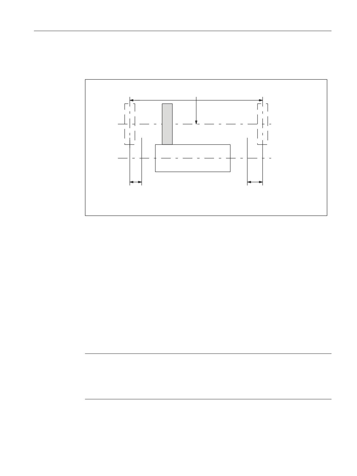
P5: Oscillation
13.3 Oscillation controlled by synchronized actions
5. Enable oscillation movement (see Section "Oscillation movement restarting (Page 739)").
6. Do not start partial infeed too early (see Section "Do not start partial infeed too early
(Page 740)").
[
2VFLOODWLRQ SDWK
,QIHHG
*ULQGLQJ GLVF
:RUNSLHFH
]
LL
LL
8
8
U1
Reversal point 1
U2
Reversal point 2
ii1
Reversal range 1
ii2
Reversal range 2
Figure 13-1
Arrangement oscillating axis, infeed axis
Programming
Before the motion block that contains the assignment between the infeed and the oscillating
axis (see Section "Assignment of oscillation and infeed axes OSCILL (Page 741)"), the infeed
definition (POSP) and the motion-synchronous actions, the parameters for the oscillation must
first be defined (see Section "Influences on asynchronous oscillation (Page 723)"):
Using a WAITP [oscillating axis] (see MD30552 $MA_AUTO_GET_TYPE), the axis for
oscillation is enabled. This means that the oscillating parameters are simultaneously
transferred into the setting data. The symbolic names, e.g. $SA_REVERSE_POS1 can then
be used to program the motion-synchronous actions.
Note
For motion-synchronous actions with $SA_REVERSE_POS values, the comparison values at
the time of interpretation are valid. If setting data is changed afterwards, this has no effect.
For motion-synchronous actions with $AA_REVERSE_POS values, the comparison values
within the interpolation are valid. This ensures a reaction to the modified reversal positions.
Extended Functions
Function Manual, 12/2018, A5E40874029B AB
733

P5: Oscillation
13.3 Oscillation controlled by synchronized actions
● Conditions for motion-synchronized actions (frequency WHEN / WHENEVER)
● Activation through motion block
- Assign oscillation axis and infeed axes to one another OSCILL
- Specify infeed response POSP
Note
By setting the axial override in the action component of the motion-synchronized action to zero
(DO $AA_OVR[<axis>]=0), then the oscillating/infeed axis can be stopped if the associated
condition (frequency WHEN / WHENEVER) is fulfilled.
An override of 100% automatically becomes active if the condition is no longer fulfilled.
Main run evaluation
It is possible to compare the synchronization conditions in the Interpolator clock cycle in the
main run with the current actual values ($$ variable on the right of comparison conditions).
With normal system variable comparison, the expressions are evaluated in the first run.
You can find a complete description of the synchronized actions in:
References
Function Manual, Synchronized Actions
Examples
Example 1: unchanged reversal positions
For motion-synchronized actions, the reversal positions $SA_OSCILL_REVERSE_POS are
used at the preprocessing level. If the corresponding setting data change, then the modified
values are not active in the program.
Program code
Comment
$SA_OSCILL_REVERSE_POS1[Z]=-10
; Preprocessing var.: reversal position 1
$SA_OSCILL_REVERSE_POS2[Z]=10
; Preprocessing var.: reversal position 2
G0 X0 Z0
WAITP(Z)
; Synchronized action 1: Reversal point 1 fallen below ≙
; Stop infeed axis with override 0%
; Preprocessing var. Reversal position 1 is used
ID=1 WHENEVER $AA_IM[Z] < $SA_OSCILL_REVERSE_POS1[Z] DO $AA_OVR[X]=0
; Synchronized action 2: Reversal point 2 exceeded ≙
; Stop infeed axis with override 0%
; Preprocessing var. reversal position 2 is used
ID=2 WHENEVER $AA_IM[Z] > $SA_OSCILL_REVERSE_POS2[Z] DO $AA_OVR[X]=0
OS[Z]=1 FA[X]=1000 POS[X]=40
; Activate oscillation
Extended Functions
734
Function Manual, 12/2018, A5E40874029B AB
P5: Oscillation
13.3 Oscillation controlled by synchronized actions
Program code
Comment
OS[Z]=0
; Deactivate oscillation
M30
Example 2: changing reversal positions
For the motion-synchronized actions, as reversal position, main run variable $
$AA_OSCILL_REVERSE_POSx is used. If the corresponding setting data change, then the
modified values are active in the program.
Program code
Comment
$SA_OSCILL_REVERSE_POS1[Z]=-10
; Preprocessing var.: reversal position 1
$SA_OSCILL_REVERSE_POS2[Z]=10
; Preprocessing var.: reversal position 2
G0 X0 Z0
WAITP(Z)
; Synchronized action 1: Reversal point 1 fallen below ≙
; Stop infeed axis with override 0%
; Main run var. Reversal position 1 is used
ID=1 WHENEVER $AA_IM[Z] < $$SA_OSCILL_REVERSE_POS1[Z] DO $AA_OVR[X]=0
; Synchronized action 2: Reversal point 2 exceeded ≙
; Stop infeed axis with override 0%
; Main run var. reversal position 2 is used
ID=2 WHENEVER $AA_IM[Z] > $$SA_OSCILL_REVERSE_POS2[Z] DO $AA_OVR[X]=0
OS[Z]=1 FA[X]=1000 POS[X]=40
; Activate oscillation
OS[Z]=0
; Deactivate oscillation
M30
13.3.1
Infeed at reversal point 1 or 2
Function
As long as the oscillation axis has not reached the reversal point, the infeed axis does not
move.
Application
Direct infeed in reversal point
Programming
Reversal point 1
WHENEVER $AA_IM[Z] <> $SA_OSCILL_REVERSE_POS1[Z]
DO $AA_OVR[X] = 0 $AA_OVR[Z] = 100
Extended Functions
Function Manual, 12/2018, A5E40874029B AB
735
P5: Oscillation
13.3 Oscillation controlled by synchronized actions
Reversal point 2
WHENEVER $AA_IM[Z] <> $SA_OSCILL_REVERSE_POS2[Z]
DO $AA_OVR[X] = 0 $AA_OVR[Z] = 100
Explanation of system variables
● $AA_IM[ Z ]: Current position of oscillating axis Z in the MCS
● $SA_OSCILL_REVERSE_POS1[ Z ]: Position of the reversal point1 of the oscillation axis
● $AA_OVR[ X ]: Axial override of the infeed axis
● $AA_OVR[ Z ]: Axial override of the oscillation axis
Infeed
The absolute infeed value is defined by the POSP instruction (see Section "Definition of infeeds
POSP (Page 741)").
Assignment
The assignment between the oscillation axis and the infeed axis is defined by the OSCILL
instruction (see Section "Assignment of oscillation and infeed axes OSCILL (Page 741)").
13.3.2
Infeed in reversal point range
Reversal range 1
Function
No infeed takes place provided the oscillation axis has not reached the reversal range (position
at reversal point 1 plus contents of variables ii1). This applies on the condition that reversal
point 1 is set to a lower value than reversal point 2. If this is not the case, then the condition
must be changed accordingly.
Application
The purpose of this synchronized action is to prevent the infeed movement from starting until
the oscillation movement has reached reversal range 1 (see "Figure 13-1 Arrangement
oscillating axis, infeed axis (Page 733)").
Programming
WHENEVER $AA_IM[Z] > $SA_OSCILL_REVERSE_POS1[Z] + ii1
DO $AA_OVR[X] = 0
Explanation of system variables:
● $AA_IM[ Z ]: Current position of oscillating axis Z
● $SA_OSCILL_REVERSE_POS1[ Z ]: Position of reversal point 1 of the oscillation axis
● $AA_OVR[ X ]: Axial override of the infeed axis
● ii1: Magnitude of reversal range (user variable)
Extended Functions
736
Function Manual, 12/2018, A5E40874029B AB
P5: Oscillation
13.3 Oscillation controlled by synchronized actions
Reversal range 2
Function
The infeed axis stops until the current position (value) of the oscillation axis is lower than the
position at reversal point2 minus the contents of variable ii2. This applies on condition that the
setting for reversal point position 2 is higher than that for reversal point position 1. If this is not
the case, then the condition must be changed accordingly.
Application
The purpose of this synchronized action is to prevent the infeed movement from starting until
the oscillation movement has reached reversal range 2 (see "Figure 13-1 Arrangement
oscillating axis, infeed axis (Page 733)").
Programming
WHENEVER $AA_IM[Z] < $SA_OSCILL_REVERSE_POS2[Z] - ii2
DO $AA_OVR[X] = 0
Explanation:
● $AA_IM[ Z ]: Current position of oscillating axis Z
● $SA_OSCILL_REVERSE_POS2[ Z ]: Position of reversal point 2 of the oscillation axis
● $AA_OVR[ X ]: Axial override of the infeed axis
● ii2: Magnitude of reversal range 2 (user variable)
Infeed
The absolute infeed value is defined by the POSP instruction (see Section "Definition of infeeds
POSP (Page 741)").
Assignment
The assignment between the oscillation axis and the infeed axis is defined by the OSCILL
instruction (see Section "Assignment of oscillation and infeed axes OSCILL (Page 741)").
See also
Oscillation controlled by synchronized actions (Page 732)
13.3.3
Infeed at both reversal points
General procedure
The functions described above for infeed at the reversal point and in the reversal range can
be freely combined.
Extended Functions
Function Manual, 12/2018, A5E40874029B AB
737
P5: Oscillation
13.3 Oscillation controlled by synchronized actions
Combinations
Infeed at two sides
● Reversal point 1 - reversal point 2
● Reversal point 1 - reversal range 2
● Reversal range 1 - reversal point 2
● Reversal range 1 - reversal range 2
One-sided infeed
● Reversal point 1
● Reversal point 2
● Reversal range 1
● Reversal range 2
(See Section "Infeed at reversal point 1 or 2 (Page 735)" and "Infeed in reversal point range
(Page 736)")
13.3.4
Stop oscillation movement at the reversal point
Function
Reversal point 1:
Every time the oscillation axis reaches reversal position 1, it must be stopped by means of the
override and the infeed movement started.
Application
The synchronized action is used to hold the oscillation axis stationary until partial infeed has
been executed. This synchronized action can be omitted if the oscillation axis need not wait
at reversal point 1 until partial infeed has been executed. At the same time, this synchronized
action can be used to start the infeed movement if this has been stopped by a previous
synchronized action which is still active.
Programming
WHENEVER $AA_IM[oscillation axis] ==
$SA_OSCILL_REVERSE_POS1[oscillation axis]
DO $AA_OVR[oscillation axis] = 0
$AA_OVR[infeed axis] = 100
Explanation of system variables
$AA_IM[ oscillation axis ]: Current position of oscillation axis
$SA_OSCILL_REVERSE_POS1[ oscillation axis ]: Reversal point 1 of the oscillation
axis
$AA_OVR[ oscillation axis]: Axial override of the oscillation axis
Extended Functions
738
Function Manual, 12/2018, A5E40874029B AB
P5: Oscillation
13.3 Oscillation controlled by synchronized actions
$AA_OVR[infeed axis ]: Axial override of the infeed axis
Function
Reversal point 2:
Every time the oscillation axis reaches reversal position 2, it must be stopped by means of the
override 0 and the infeed movement started.
Application
The synchronized action is used to hold the oscillation axis stationary until partial infeed has
been executed. This synchronized action can be omitted if the oscillation axis need not wait
at reversal point 2 until partial infeed has been executed. At the same time, this synchronized
action can be used to start the infeed movement if this has been stopped by a previous
synchronized action which is still active.
Programming
WHENEVER $AA_IM[oscillation axis] ==
$SA_OSCILL_REVERSE_POS2[oscillation axis]
DO $AA_OVR[oscillation axis] = 0
$AA_OVR[infeed axis] = 100
Explanation of system variables
● $AA_IM[ oscillation axis ]: Current position of oscillation axis
● $SA_OSCILL_REVERSE_POS2[ oscillation axis ]: Reversal point 2 of the
oscillation axis
● $AA_OVR[ oscillation axis ]: Axial override of the oscillation axis
● $AA_OVR[ infeed axis ]: Axial override of the infeed axis
13.3.5
Oscillation movement restarting
Function
The oscillation axis is started via the override whenever the distance-to-go for the currently
traversed path section of the infeed axis = 0, i.e. partial infeed has been executed.
Application
The purpose of this synchronized action is to continue the movement of the oscillation axis on
completion of the part infeed movement. If the oscillation axis need not wait for completion of
partial infeed, then the motion-synchronous action with which the oscillation axis is stopped at
the reversal point must be omitted.
Programming
WHENEVER $AA_DTEPW[infeed axis] == 0
Extended Functions
Function Manual, 12/2018, A5E40874029B AB
739
P5: Oscillation
13.3 Oscillation controlled by synchronized actions
DO $AA_OVR[oscillation axis]=100
Explanation of system variables
● $AA_DTEPW[ infeed axis ]: axial remaining travel distance for the infeed axis in the
workpiece coordinate system (WCS): Path distance of the infeed axis
● $AA_OVR[ oscillation axis ]: Axial override for oscillation axis
13.3.6
Do not start partial infeed too early
Function
The functions described above prevent any infeed movement outside the reversal point or the
reversal range. On completion of an infeed movement, however, restart of the next partial
infeed must be prevented.
Application
A channel-specific flag is used for this purpose. This flag is set at the end of the partial infeed
(partial distance-to-go == 0) and is deleted when the axis leaves the reversal range. The next
infeed movement is then prevented by a synchronized action.
Programming
WHENEVER $AA_DTEPW[infeed axis]==0 DO $AC_MARKER[index]=1
Reversal point 1
WHENEVER $AA_IM[Z] <> $SA_OSCILL_REVERSE_POS1[Z] DO
$AC_MARKER[index]=0
WHENEVER $AC_MARKER[index]==1 DO $AA_OVR[infeed axis]=0
Explanation of system variables
● $AA_DTEPW[ infeed axis ]: axial remaining travel distance for the infeed axis in the
workpiece coordinate system (WCS): Path distance of the infeed axis
● $AC_MARKER[ index ]: Channel-specific marker with index
● $AA_IM[ oscillation axis ]: Current position of oscillation axis
● $SA_OSCILL_REVERSE_POS1[ oscillation axis ]: Reversal point 1 of the
oscillation axis
● $AA_OVR[ infeed axis ]: Axial override for infeed axis
Extended Functions
740
Function Manual, 12/2018, A5E40874029B AB
P5: Oscillation
13.3 Oscillation controlled by synchronized actions
13.3.7
Assignment of oscillation and infeed axes OSCILL
Function
One or several infeed axes are assigned to the oscillation axis with command OSCILL.
Oscillation motion starts.
The PLC is informed of which axes have been assigned via the NC/PLC interface. If the PLC
is controlling the oscillation axis, it must now also monitor the infeed axes and use the signals
for the infeed axes to generate the reactions on the oscillation axis via 2 stop bits of the
interface.
Application
The axes whose response has already been defined by synchronous conditions are assigned
to one another for activation of oscillation mode. The oscillation movement is started.
Programming
OSCILL[oscillation axis] = (infeed axis1, infeed axis2, infeed axis3)
Infeed axis2 and infeed axis3 in brackets plus their delimiters can be omitted if they are not
required.
13.3.8
Definition of infeeds POSP
Function
The control receives the following data for the infeed axis:
● Total infeed
● Part infeed at reversal point/reversal point range
● Part infeed response at end
Application
This instruction must be given after activation of oscillation with OSCILL to inform the controller
of the required infeed values at the reversal points/reversal point ranges.
Programming
POSP[infeed axis] = (end position, part section, mode)
End position: End position for the infeed axis after all partial infeeds have been traversed.
Part section: Part infeed at reversal point/reversal point range
Mode 0: For the last two part steps, the remaining path up to the target point is divided into
two equally large residual steps (default setting).
Extended Functions
Function Manual, 12/2018, A5E40874029B AB
741
P5: Oscillation
13.3 Oscillation controlled by synchronized actions
Mode 1: The part length is adjusted such that the total of all calculated part lengths corresponds
exactly to the path up to the target point.
13.3.9
External oscillation reversal
For example, keys on the PLC can be used to change the oscillation area or instantaneously
reverse the direction of oscillation.
The edge-triggered PLC input signal DB31, ... DBX28.0 (oscillation reversal) is used to brake
the current oscillation motion and then traverse in the opposite direction. The braking phase
is signaled via the PLC output signal DB31, ... DBX100.2 (oscillation reversal active).
The braking position of the axis can be accepted as the new reversal position by means of the
PLC signal DB31, ... DBX28.4 (change reversal position).
The PLC input signal DB31, ... DBX28.3 (select reversal point) is ignored, but rather the change
affects the last initiated external oscillation reversal command.
No change in the reversal points applied via handwheel or JOG keys may be active for the
relevant axis. If handwheel or JOG key changes are currently active, display alarm 20081
(Braking position cannot be accepted as reversal position - handwheel active) will be
generated. The alarm is automatically reset when the conflict has been eliminated.
Hold time
No stop time is applied for a change of direction due to an external oscillation reversal. The
axis waits for the exact stop fine signal. Any configured exact stop condition is fulfilled.
Infeed motion
With non-modal oscillation, no infeed movement is performed for a change of direction due to
an external oscillation reversal as the reversal position has not been reached and consequently
the appropriate synchronized action is not fulfilled.
System variables
The braking position can be scanned via system variable $AA_OSCILL_BREAK_POS1, when
approach to reversal position 1 is aborted or via
$AA_OSCILL_BREAK_POS2 when approach to reversal position 2 is aborted.
If the relevant reversal point is approached again, the position of the reversal point can be
scanned in $AA_OSCILL_BREAK_POS1 or $AA_OSCILL_BREAK_POS2.
In other words, only after an External oscillation reversal command is there a difference
between the values in $AA_OSCILL_BREAK_POS1 and $AA_OSCILL_REVERSE_POS1 or
the values in $AA_OSCILL_BREAK_POS2 and $AA_OSCILL_REVERSE_POS2.
External oscillation reversal can therefore be detected by a synchronized action (see Section
"Examples (Page 743)").
Extended Functions
742
Function Manual, 12/2018, A5E40874029B AB
P5: Oscillation
13.5 Examples
Special cases
If the PLC input signal "oscillation reversal" is activated as the axis is approaching the start
position, the approach movement is aborted and the axis continues by approach interruption
position 1.
If the PLC input signal "oscillation reversal" is set during a stop period, the stop timer is
deactivated; if exact stop fine has not yet been reached, the axis waits for the exact stop fine
reached signal before continuing its motion.
If the PLC input signal "oscillation reversal" is activated as the axis is approaching the end
position, the approach movement is aborted and oscillation is terminated.
For an example of the external oscillation reversal command (see Section "Change reversal
position via synchronized action with "external oscillation reversal" (Page 753)").
13.4
Marginal conditions
Availability of the "Oscillation" function
The function is an option ("oscillation functions"), which must be assigned to the hardware
through the license management.
13.5
Examples
Requirements
The examples given below require components of the NC language specified in the sections
entitled:
● Asynchronous oscillation
and
● Oscillation controlled by synchronized actions.
13.5.1
Example of asynchronous oscillation
Task
The oscillation axis Z must oscillate between -10 and 10. Approach reversal point 1 with exact
stop coarse and reversal point 2 without exact stop. The oscillation axis feedrate must be 5000.
3 sparking-out strokes must be executed at the end of the machining operation followed by
approach by oscillation axis to end position 30. The feedrate for the infeed axis is 1000, end
of the infeed in X direction is at 15.
Extended Functions
Function Manual, 12/2018, A5E40874029B AB
743
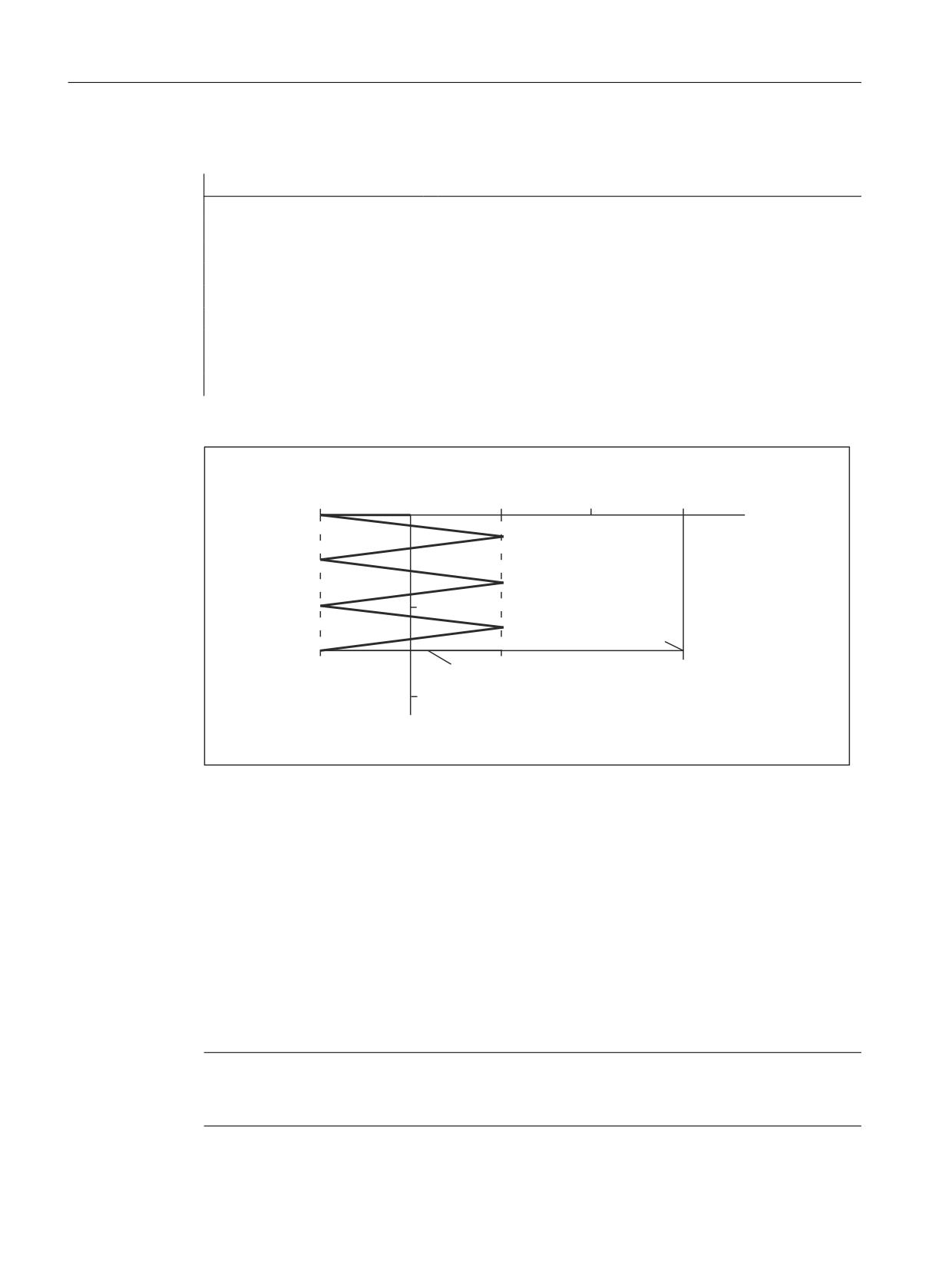
P5: Oscillation
13.5 Examples
Program section
Program code
Comment
OSP1[Z]=-10
; Reversal point 1
OSP2[Z]=10
; Reversal point 2
OST1[Z]=-1
; Stop time at reversal point 1: Exact stop coarse
OST2[Z]=-2
; Stop time at reversal point 2: without exact stop
FA[Z]=5000
; Infeed for oscillating axis
OSNSC[Z]=3
; three spark-out strokes
OSE[Z]=-3
; End position
OS1 F500 X15
; start oscillation, infeed X axis
; with infeed 500, feed target 15
= D[LV
(QG SRVLWLRQ
8
8
VSDUNLQJ RXW VWURNHV
; D[LV
Figure 13-2
Sequences of oscillation movements and infeed, example 1
13.5.2
Example 1 of oscillation with synchronized actions
Task
Direct infeed must take place at reversal point 1; the oscillation axis must wait until the partial
infeed has been executed before it can continue traversal. At reversal point 2, the infeed must
take place at a distance of -6 from reversal point 2; the oscillation axis must not wait at this
reversal point until partial infeed has been executed. Axis Z is the oscillation axis and axis X
is the infeed axis (see Section "Oscillation controlled by synchronized actions (Page 732)).
Note
The setting data OSCILL_REVERSE_POS_1/2 are values in the machine coordinate system;
therefore comparison is only suitable with $AA_IM[n].
Extended Functions
744
Function Manual, 12/2018, A5E40874029B AB
P5: Oscillation
13.5 Examples
Program section
Program code
Comment
; Example 1: Oscillation with synchronized actions
OSP1[Z]=10 OSP2[Z]=60
; explain reversal points 1 and 2
OST1[Z]=-2 OST2[Z]=0
; Reversal point 1: without exact stop
; Reversal point 2: Exact stop fine
FA[Z]=5000 FA[X]=250
; Feed for oscillating axis, feedrate, infeed axis
OSCTRL[Z]=(1+8+16,0)
; Switch off oscillation motion at reversal point 1
; After delete DTG spark-out and approach end position
; After DTG, approach relevant reversal position
;
OSNSC[Z]=3
; 3 sparking-out strokes
OSE[Z]=0
; End position = 0
WAITP(Z)
; enable oscillation for the Z axis
;
; motion-synchronous actions:
;
; always, when
the current position of the oscillating axis in the
;
Machine Coordinate System
; not equal to
reversal position 1
; then
set the marker with index 1 to value 0
;
(Reset marker 1)
WHENEVER $AA_IM[Z]<>$SA_OSCILL_REVERSE_POS1[Z] DO $AC_MARKER[1]=0
;
; always, when
the current position of the oscillating axis in the
;
Machine Coordinate System
; less than
the beginning of reversal range 2
;
(here: reversal point 2 -6),
; then
set the axial override of the infeed axis to 0%.
; and
set the marker with index 2 to value 0
;
(Reset marker 2)
WHENEVER $AA_IM[Z]<$SA_OSCILL_REVERSE_POS2[Z]-6 DO $AA_OVR[X]=0 $AC_MARKER[2]=0
;
; always, when
the current position of the oscillating axis in the
;
Machine Coordinate System
; equal to
reversal position 1,
; then
set the axial override of the oscillation axis to 0%
;
; and
Set the axial override of the infeed axis to
;
100% (so that the previous synchronized action
;
is cancelled!)
WHENEVER $AA_IM[Z]==$SA_OSCILL_REVERSE_POS1[Z] DO $AA_OVR[Z]=0 $AA_OVR[X]=100
;
; always, when
the distance-to-go of the partial infeed is
; equal to
0,
Extended Functions
Function Manual, 12/2018, A5E40874029B AB
745
P5: Oscillation
13.5 Examples
Program code
Comment
; then
set the marker with index 2 to value 1
; and
set the marker with index 1 to value 1
WHENEVER $AA_DTEPW[X]==0 DO $AC_MARKER[2]=1 $AC_MARKER[1]=1
;
; always, when
the flag with index 2 is
; equal to
1,
; then
Set the axial override of the infeed axis to
;
0%, this prevents a premature infeed
;
(oscillation axis has not exited the
;
reversal point 1).
;
WHENEVER $AC_MARKER[2]==1 DO $AA_OVR[X]=0
;
; always, when
the flag with index 1 is
; equal to
1,
; then
Set the axial override of the infeed axis to
;
0%, this prevents a premature infeed
;
(oscillation axis has not exited the
;
reversal point range 2).
; and
Set the axial override of the infeed axis to
;
100% ('Start' oscillation)
WHENEVER $AC_MARKER[1]==1 DO $AA_OVR[X]=0 $AA_OVR[Z]=100
;
; if the current position of the oscillating axis in the MCS is
; equal to
reversal position 1,
; then
Set the axial override of the infeed axis to
;
100%
; and
Set the axial override of the infeed axis to
;
0% (so that the second synchronized action
;
is cancelled once!)
WHEN $AA_IM[Z]==$SA_OSCILL_REVERSE_POS1[Z] DO $AA_OVR[Z]=100 $AA_OVR[X]=0
;
;------------------------------------------
OSCILL[Z]=(X)
; Assign axis X to the oscillation axis Z as
POSP[X]=(5,1,1)
; infeed axis, this should
; infeed to end position 5 in steps
; from 1 and the sum of all part lengths should
; give exactly the end position
M30
; End of program
Extended Functions
746
Function Manual, 12/2018, A5E40874029B AB
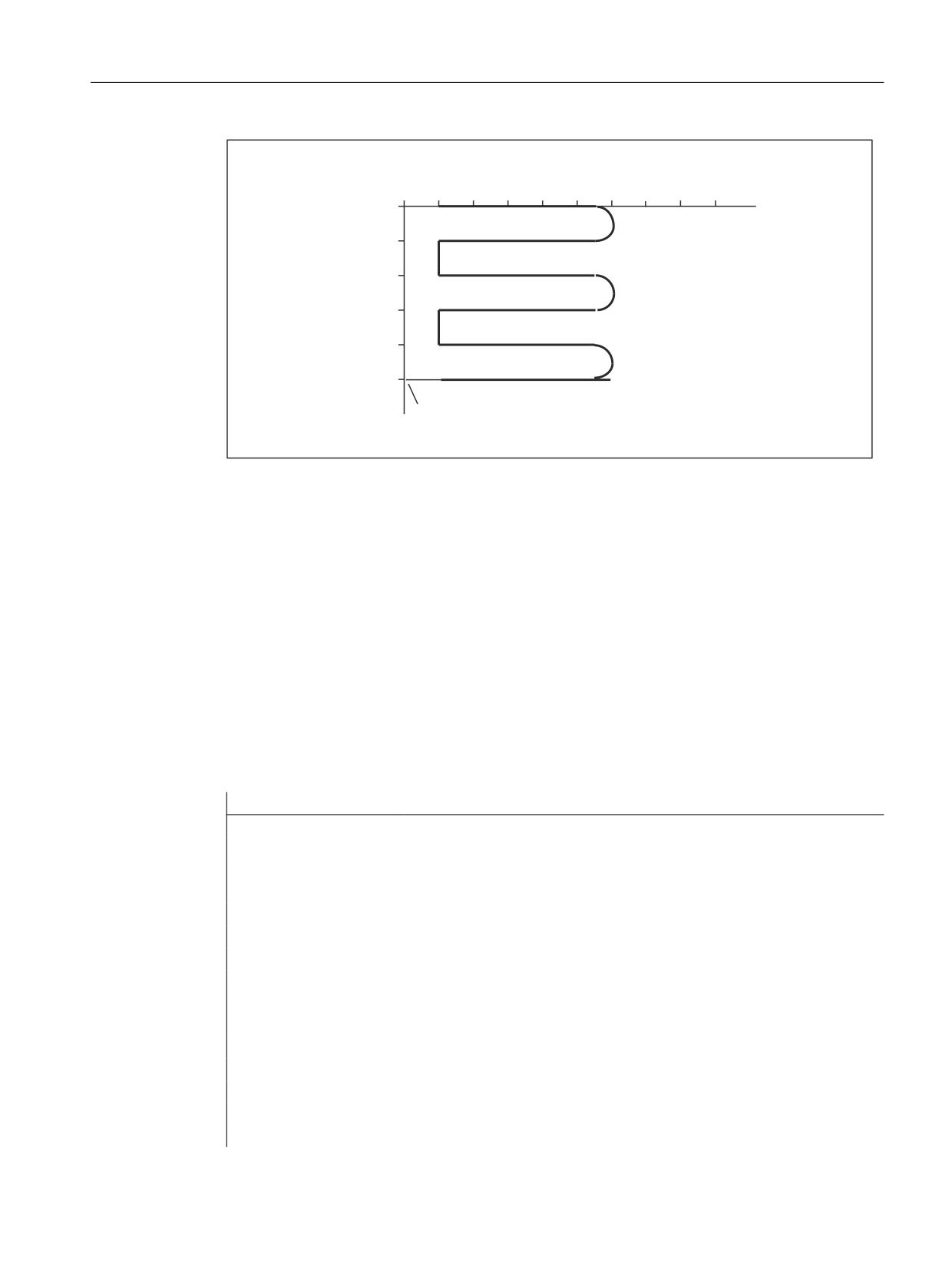
P5: Oscillation
13.5 Examples
= D[LV
; D[LV
$SSURDFK UHYHUVDO SRVLWLRQ DQG VSDUNLQJ RXW VWURNHV
$SSURDFK HQG SRVLWLRQ
Figure 13-3
Sequences of oscillation movements and infeed, example 1
13.5.3
Example 2 of oscillation with synchronized actions
Task
No infeed must take place at reversal point 1. At reversal point 2, the infeed must take place
at distance ii2 from reversal point 2; the oscillation axis must wait at this reversal point until
partial infeed has been executed. Axis Z is the oscillation axis and axis X the infeed axis.
Program section
Example 2: Oscillation with synchronized actions
Program code
Comment
DEF INT ii2
; Define variable for reversal area 2
;
OSP1[Z]=10 OSP2[Z]=60 ; explain reversal points 1 and 2
OST1[Z]=0 OST2[Z]=0
; Reversal point 1: Exact stop fine
;
Reversal point 2: Exact stop fine
FA[Z]=5000 FA[X]=100
; Feed for oscillating axis, feed for infeed axis
OSCTRL[Z]=(2+8+16,1)
; Switch off oscillation motion at reversal point 2
;
After delete distance-to-go, spark-out and end position
;
Approach appropriately after delete distance-to-go
;
Approach reversal position
OSNSC[Z]=3
; 3 sparking-out strokes
OSE[Z]=70
; End position = 70
ii2=2
; Set reversal point range
WAITP(Z)
; permit oscillation for Z axis
;
Extended Functions
Function Manual, 12/2018, A5E40874029B AB
747
P5: Oscillation
13.5 Examples
Program code
Comment
; motion-synchronous actions:
; always, when
the current position of the oscillating axis in the
;
Machine Coordinate System
; less than
the start of reversal area 2
; then
set the axial override of the feed axis
;
to 0%
; and
set the marker with index 0 to value 0
WHENEVER $AA_IM[Z]<$SA_OSCILL_REVERSE_POS2[Z]-ii2 DO $AA_OVR[X]=0 $AC_MARKER[0]=0
;
; always, when
the current position of the oscillating axis in the
;
Machine Coordinate System
; greater or equal to
reversal position 2
; then
set the axial override of the oscillating axis
;
to 0%
WHENEVER $AA_IM[Z]>=$SA_OSCILL_REVERSE_POS2[Z] DO $AA_OVR[Z]=0
;
; always, when
the distance-to-go of the partial infeed is
; equal to
0,
; then
set the marker with index 0 to value 1
WHENEVER $AA_DTEPW[X] == 0 DO $AC_MARKER[0]=1
;
; always, when
the flag with index 0 is
; equal to
1,
; then
set the axial override of the infeed axis to 0%
;
to prevent a new premature infeed
;
(oscillation axis has not yet exited the reversal point
range 2,
;
but the infeed axis is ready for a
;
new infeed)
; and
set the axial override of the oscillation axis to 100%
;
(this cancels the 2nd synchronized action)
;
WHENEVER $AC_MARKER[0]==1 DO $AA_OVR[X]=0 $AA_OVR[Z]=100
;
OSCILL[Z]=(X)
; Start the axes
POSP[X]=(5,1,1)
;
The oscillating axis Z is assigned axis X as
;
an infeed axis
;
Axis X should travel to end position 5 in
;
increments of 1
;
M30
Extended Functions
748
Function Manual, 12/2018, A5E40874029B AB
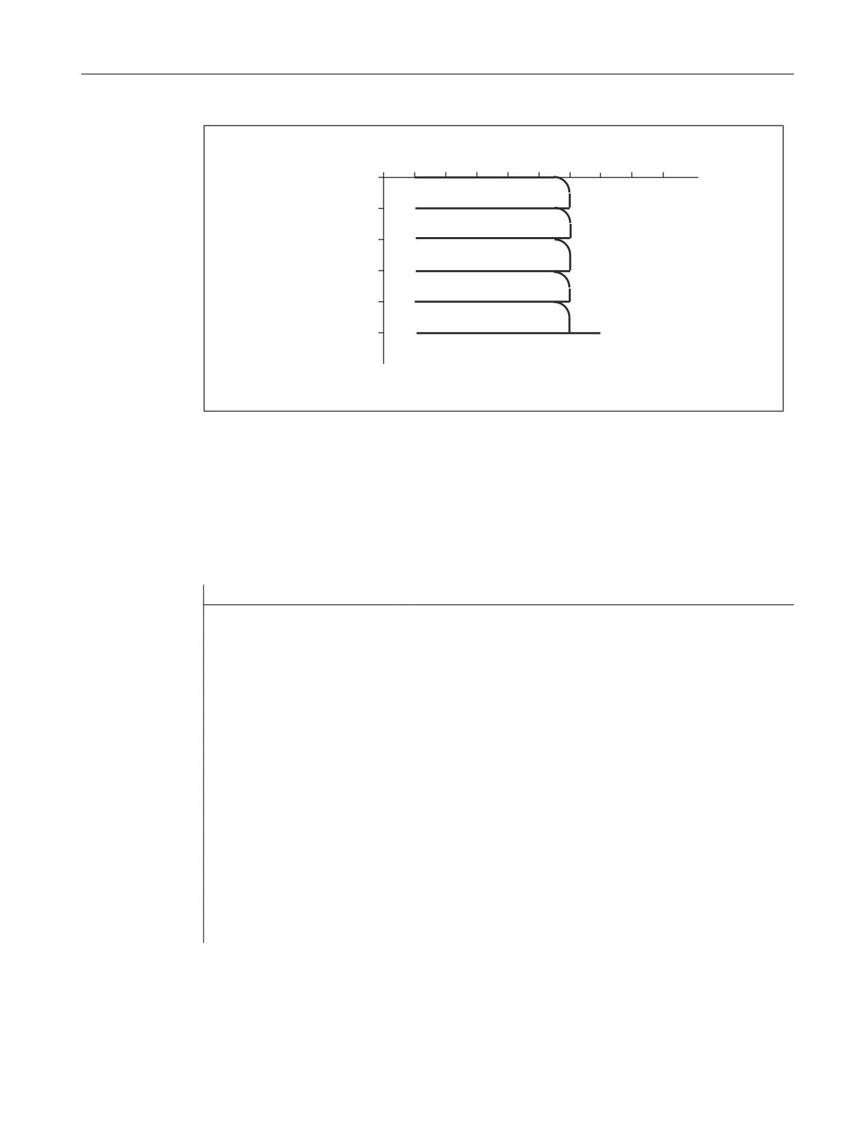
P5: Oscillation
13.5 Examples
= D[LV
$SSURDFK HQG SRVLWLRQ
$SSURDFK UHYHUVDO SRVLWLRQ DQG VSDUNLQJ RXW VWURNHV
; D[LV
Figure 13-4
Sequences of oscillation movements and infeed, example 2
13.5.4
Examples for starting position
13.5.4.1
Define starting position via language command
Program code
Comment
WAITP(Z)
; enable oscillation for the Z axis
OSP1[Z]=10 OSP2[Z]=60
; explain reversal points 1 and 2
OST1[Z]=-2 OST2[Z]=0
; Reversal point 1: without exact stop
; Reversal point 2: Exact stop fine
FA[Z]=5000 FA[X]=2000
; Infeed for oscillating axis,
; feedrate for infeed axis
OSCTRL[Z]=(1+8+16,0)
; Switch off oscillation motion at reversal point 1
; after delete DTG spark-out and approach end position,
; After DTG, approach relevant reversal position
;
OSNSC[Z]=3
; 3 sparking-out strokes
OSE[Z]=0
; End position = 0
OSB[Z]=0
; Start position = 0
OS[Z]=1 X15 F500
; Start oscillation, continuous infeed
OS[Z]=0
; Deactivate oscillation
WAITP(Z)
; wait for completion of the oscillation motion
M30
Extended Functions
Function Manual, 12/2018, A5E40874029B AB
749
P5: Oscillation
13.5 Examples
Explanation
When the Z axis starts oscillation, it first approaches the starting position (position = 0 in the
example) and then begins the oscillation motion between the reversal points 10 and 60. When
the X axis has reached its end position 15, the oscillation finishes with 3 sparking out strokes
and approach of end position 0.
13.5.4.2
Start oscillation via setting data
Program code
Comment
WAITP(Z)
STOPRE
$SA_OSCILL_REVERSE_POS1[Z]=-10
;
reversal position 1 = -10
$SA_OSCILL_REVERSE_POS2[Z]=30
;
reversal position 2 = 30
$SA_OSCILL_START_POS[Z] = -50
;
Start position = -50
$SA_OSCILL_CTRL_MASK[Z] = 512
;
Approach start position,
;
on switch-off, stop at the next
;
reversal point
;
do not approach any end position
;
no sparking-out strokes for DTG
$SA_OSCILL_VELO[ Z ] = 5000
;
Infeed for oscillating axis
$SA_OSCILL_IS_ACTIVE[ Z ] = 1
;
starting
$SA_OSCILL_DWELL_TIME1[ Z ] = -2
;
without wait for exact stop
$SA_OSCILL_DWELL_TIME2[ Z ] = 0
;
wait for fine exact stop
STOPRE
X30 F100
$SA_OSCILL_IS_ACTIVE[ Z ] = 0
;
Stop
WAITP(Z)
M30
Description
When the Z axis starts oscillation, it first approaches the starting position (position = -50 in the
example) and then begins the oscillation motion between the reversal points -10 and 30. When
the X axis has reached its end position 30, the oscillation finishes at the next approached
reversal point.
13.5.4.3
Non-modal oscillation (starting position = reversal point 1)
Oscillation with synchronized actions
Program code
Comment
N701
; Oscillation with synchronized actions,
; start position == reversal point 1
;
Extended Functions
750
Function Manual, 12/2018, A5E40874029B AB
P5: Oscillation
13.5 Examples
Program code
Comment
N702 OSP1[Z]=10 OSP2[Z]=60
; explain reversal points 1 and 2
N703 OST1[Z]=0 OST2[Z]=0
; Reversal point 1: Exact stop coarse
; Reversal point 2: Exact stop fine
N704 FA[Z]=5000 FA[X]=2000
; Infeed for oscillating axis,
; feedrate for infeed axis
N705 OSCTRL[Z]=(1+8+16.0)
; switch off oscillation motion at
; reversal point 1 after DTG spark-out
; and approach end position
; After DTG, approach relevant
; reversal position
;
N706 OSNSC[Z]=3
; 3 sparking-out strokes
N707 OSE[Z]=0
; End position = 0
N708 OSB[Z]=10
; Start position = 10
N709 WAITP(Z)
; enable oscillation for the Z axis
;
; motion-synchronous actions:
; set marker with index 2 on 1 (initialization)
WHEN TRUE DO $AC_MARKER[2]=1
;
; always, when
the marker with index 2 equals 0
;
and the current position of the oscillating axis
;
does not equal the reversal position 1
; then
set the marker with index 1 to 0.
;
WHENEVER ($AC_MARKER[2] == 0) AND $AA_IW[Z]>$SA_OSCILL_REVERSE_POS1[Z])
DO $AC_MARKER[1]=0
; always, when
the current position of the oscillating axis
;
is less than the start of reversal range 2
;
; then
set the axial override of the feed axis
;
to 0 and set the marker with index 0 to
;
0
WHENEVER $AA_IW[Z]<$SA_OSCILL_REVERSE_POS2[Z]-6 DO $AA_OVR[X]=0 $AC_MARKER[0]=0
;
; always, when
the current position of the oscillating axis
;
is equal to the reversal position 1,
; then
set the axial override of the oscillating axis
;
to 0 and set the axial override of the
;
infeed axis to 100% (so that the
;
previous synchronized action is cancelled!)
WHENEVER $AA_IW[Z]==$SA_OSCILL_REVERSE_POS1[Z] DO $AA_OVR[Z]=0 $AA_OVR[X]=100
;
; always, when
the distance-to-go of the partial infeed equals
0
Extended Functions
Function Manual, 12/2018, A5E40874029B AB
751
P5: Oscillation
13.5 Examples
Program code
Comment
;
; then
Set the marker with index 0 to 1 and
;
set the marker with index 1 to 1 and
WHENEVER $AA_DTEPW[X]==0 DO $AC_MARKER[0]=1 $AC_MARKER[1]=1
;
; always, when
the marker with index 0 equals 1,
; then
set the axial override of the feed axis
;
to 0 to prevent a new premature
;
infeed!
WHENEVER $AC_MARKER[0]==1 DO $AA_OVR[X]=0
;
; always, when
the marker with index 1 equals 1,
; then
set the axial override of the feed axis
;
to 0 (to prevent a new premature
;
infeed!) and set the
;
axial override of the oscillation axis to 100%
;
(so that the previous
;
synchronized action is canceled!)
WHENEVER $AC_MARKER[1]==1 DO $AA_OVR[X]=0 $AA_OVR[Z]=100
;
; When
the current position of the oscillating axis
;
is equal to the reversal position 1,
; then
reset the marker with index 2,
;
release the first synchronized action (no
;
infeed when reaching the start position
;
==
reversal position 1)
WHEN $AA_IW[Z]==$SA_OSCILL_REVERSE_POS1[Z] DO $AC_MARKER[2]=0
;
;----------------------------------
N750 OSCILL[Z]=(X) POSP[X]=(5,1,1)
; Assign axis X to the oscillation axis Z as infeed axis,
; this should infeed to end position 5
; in substeps of 1 and the sum of all sublengths
; should be exactly the same as the end position.
;
N780 WAITP(Z)
; release the Z axis
;
N790 X0 Z0
N799 M30
; End of program
Description
The starting position matches reversal point 1. The WHEN
synchronized actions (see
above) prevent an infeed when the starting position is reached.
Extended Functions
752
Function Manual, 12/2018, A5E40874029B AB

P5: Oscillation
13.6 Data lists
13.5.5
Example of external oscillation reversal
13.5.5.1
Change reversal position via synchronized action with "external oscillation reversal"
Program code
Comment
DEFINE BREAKPZ AS $AA_OSCILL_BREAK_POS1[Z]
DEFINE REVPZ AS $SA_OSCILL_REVERSE_POS1[Z]
WAITP(Z)
; enable oscillation for the Z axis
OSP1[Z]=10 OSP2[Z]=60
; explain reversal points 1 and 2
OSE[Z]=0
; End position = 0
OSB[Z]=0
; Start position = 0
; At external reversal of oscillation for
; oscillation reversal point 1, adapt this
WHENEVER BREAKPZ <> REVPZ DO $$SA_OSCILL_REVERSE_POS1 = BREAKPZ
OS[Z]=1 X150 F500
; Start oscillation, continuous infeed
OS[Z]=0
; Deactivate oscillation
WAITP(Z)
; wait for completion of the oscillation motion
M30
13.6
Data lists
13.6.1
Machine data
13.6.1.1
General machine data
Number
Identifier: $MN_
Description
10710
PROG_SD_RESET_SAVE_TAB
Oscillations to be saved from SD
11460
OSCILL_MODE_MASK
Control screen form for asynchronous oscillation
Extended Functions
Function Manual, 12/2018, A5E40874029B AB
753

P5: Oscillation
13.6 Data lists
13.6.2
Setting data
13.6.2.1
Axis/spindle-specific setting data
Number
Identifier: $SA_
Description
43700
OSCILL_REVERSE_POS1
Position at reversal point 1
43710
OSCILL_REVERSE_POS2
Position at reversal point 2
43720
OSCILL_DWELL_TIME1
Stop time at reversal point 1
43730
OSCILL_DWELL_TIME2
Stop time at reversal point 2
43740
OSCILL_VELO
Feed velocity of oscillation axis
43750
OSCILL_NUM_SPARK_CYCLES
Number of sparking-out strokes
43760
OSCILL_END_POS
Position after sparking-out strokes/at end of oscillation move-
ment
43770
OSCILL_CTRL_MASK
Control screen form for oscillation
43780
OSCILL_IS_ACTIVE
Oscillation movement ON/OFF
43790
OSCILL_START_POS
Position that is approached after oscillation before reversal
point 1, if activated in SD43770:
13.6.3
Signals
13.6.3.1
Signals to axis/spindle
Signal name
SINUMERIK 840D sl
SINUMERIK 828D
External oscillation reversal
DB31,
DBX28.0
DB380x.DBX5004.0
Set reversal point
DB31,
DBX28.3
DB380x.DBX5004.3
Alter reversal point
DB31,
DBX28.4
DB380x.DBX5004.4
Stop at next reversal point
DB31,
DBX28.5
DB380x.DBX5004.5
Stop along braking ramp
DB31,
DBX28.6
DB380x.DBX5004.6
PLC-controlled axis
DB31,
DBX28.7
DB380x.DBX5004.7
13.6.3.2
Signals from axis/spindle
Signal name
SINUMERIK 840D sl
SINUMERIK 828D
Oscillation reversal is active
DB31,
DBX100.2
DB390x.DBX5004.2
Oscillation cannot start
DB31,
DBX100.3
DB390x.DBX5004.3
Error during oscillation movement
DB31,
DBX100.4
DB390x.DBX5004.4
Sparking-out active
DB31,
DBX100.5
DB390x.DBX5004.5
Oscillation movement active
DB31,
DBX100.6
DB390x.DBX5004.6
Oscillation active
DB31,
DBX100.7
DB390x.DBX5004.7
Extended Functions
754
Function Manual, 12/2018, A5E40874029B AB

P5: Oscillation
13.6 Data lists
13.6.4
System variables
13.6.4.1
Main run variables for motion-synchronous actions
Main run variable_read
The following variables are provided for main run variable_read:
$A_IN[<arith. expression>]
digital input (Boolean)
$A_OUT[<arith. expression>]
digital output (Boolean)
$A_INA[<arith. expression>]
analog input (Boolean)
$A_OUTA[<arith. expression>]
analog output (Boolean)
$A_INCO[<arith. expression>]
comparator inputs (Boolean)
$AA_IW[<axial expression>]
actual position PCS axis (real)
$AA_IB[<axial expression>]
actual position BCS axis (real)
$AA_IM[<axial expression>]
Actual position MCS axis (IPO setpoints) (real)
With $AA_IM[S1] setpoints for spindles can be eval-
uated. Modulo calculation is used for spindles and
rotary axes, depending on machine data
$MA_ROT_IS_MODULO and $MA_DIS-
PLAY_IS_MODULO.
$AA_OSCILL_BREAK_POS1
Breaking position after external oscillation reversal
when approaching reversal point 1
$AA_OSCILL_BREAK_POS2
Breaking position after external oscillation reversal
when approaching reversal point 2
$AC_TIME
Time from the start of the block (real) in seconds
(including the times for the internally generated in-
termediate blocks)
$AC_TIMES
Time from the start of the block (real) in seconds
(without times for the internally generated intermedi-
ate blocks)
$AC_TIMEC
Time from the start of the block (real) in IPO steps
(including steps for the internally generated inter-
mediate blocks)
$AC_TIMESC
Time from the start of the block (real) in IPO steps
(without steps for the internally generated intermedi-
ate blocks)
$AC_DTBB
Distance from beginning of block in BCS
(Distance to begin, baseCoor) (real)
$AC_DTBW
Distance from beginning of block in PCS
(Distance to begin, workpieceCoor) (real)
$AA_DTBB[<axial expression>]
axial distance from beginning of block in BCS
(Distance to begin, baseCoor) (real)
$AA_DTBW[<axial expression>]
axial distance from beginning of block in PCS
(Distance to begin, workpieceCoor) (real)
$AC_DTEB
Distance to end of block in BCS (Distance to end)
(Distance to end, baseCoor) (real)
Extended Functions
Function Manual, 12/2018, A5E40874029B AB
755

P5: Oscillation
13.6 Data lists
$AC_DTEW
Distance to end of block in PCS
(Distance to end, workpieceCoor) (real)
$AA_DTEB[<axial expression>]
axial distance to end of movement in BCS
(Distance to end, baseCoor) (real)
$AA_DTEW[<axial expression>]
axial distance to end of movement in PCS
(Distance to end, workpieceCoor) (real)
$AC_PLTBB
Distance from beginning of block in BCS
(Path Length from begin, baseCoor) (real)
$AC_PLTEB
Distance to end of block in BCS (Distance to end)
(Path Length to end, baseCoor) (real)
$AC_VACTB
Path speed in BCS
(Velocity actual, baseCoor) (real)
$AC_VACTW
Path speed in PCS
(Velocity actual, workPieceCoor) (real)
$AA_VACTB[<axial expression>]
Axis velocity in BCS
(Velocity actual, baseCoor) (real)
$AA_VACTW[<axial expression>]
Axis velocity in PCS
(Velocity actual, workPieceCoor) (real)
$AA_DTEPB[<axial expression>]
axial distance-to-go for oscillation infeed in BCS
(Distance to end, pendulum, baseCoor) (real)
$AA_DTEPW[<axial expression>]
axial distance-to-go for oscillation infeed in PCS
(Distance to end, pendulum, workpieceCoor) (real)
$AC_DTEPB
Path distance-to-go for oscillation infeed in BCS
(not P2) (Distance to end, pendulum, baseCoor) (re-
al)
$AC_DTEPW
Path distance-to-go for oscillation infeed in PCS
(not P2) (Distance to end, pendulum, workpiece-
Coor) (real)
$AC_PATHN
(Path parameter normalized) (real)
Normalized path parameter: 0 for beginning of block
to 1 for end of block
$AA_LOAD[<axial expression>]
Drive utilization
$AA_POWER[<axial expression>]
Drive efficiency in W
$AA_TORQUE[<axial expression>]
Drive torque setpoint in Nm
$AA_CURR[<axial expression>]
Actual current value of axis
$AC_MARKER[<arithmetic_expression>] (int)
Flag variables: can be used to build complex condi-
tions in synchronous actions:
8 Markers (Index 0 - 7) are available.
Reset sets the markers to 0.
Example:
WHEN
DO $AC_MARKER[0]=2
WHEN
DO $AC_MARKER[0]=3
WHEN $AC_MARKER[0]==3 DO $AC_OVR=50
Can be read and written independently of synchro-
nous actions in the parts program:
IF $AC_MARKER == 4 GOTOF SPRUNG
$AC_PARAM[<arithmetic_expression>] (real)
Floating-decimal parameter for synchronous ac-
tions. Serves as intermediate saving and evaluation
in synchronous actions.
50 Parameters (Index 0 - 49) are available.
Extended Functions
756
Function Manual, 12/2018, A5E40874029B AB
P5: Oscillation
13.6 Data lists
$AA_OSCILL_REVERSE_POS1
[<axial expression>] (real)
$AA_OSCILL_REVERSE_POS2
current oscillation reversal points 1 and 2:
[<axial expression>] (real)
The current setting data from
$SA_OSCILL_REVERSE_POS1 or
$SA_OSCILL_REVERSE_POS2 is read.
This enables setting data changes at the reversal
positions during active oscillation, i.e. during an ac-
tive synchronous action.
Conditions
Conditions for motion-synchronous actions are formulated:
Main run variable comparison operator expression
For details see:
References:
Function Manual Synchronized Actions
Extended Functions
Function Manual, 12/2018, A5E40874029B AB
757
P5: Oscillation
13.6 Data lists
Extended Functions
758
Function Manual, 12/2018, A5E40874029B AB
R2: Rotary axes
14
14.1
Brief description
The following are typical applications for positioning axes:
●
5-axis machining (operating range limited or unlimited)
● Rotary axis for eccentric machining (unlimited operating range)
● Rotary axis for cylindrical or form grinding (unlimited operating range)
● C axis with TRANSMIT (unlimited operating range)
● Rotary axis on winding machines (unlimited operating range)
● Rotary workpiece axis (C) on hobbing machines (unlimited operating range)
● Round tool magazines and tool turrets (unlimited operating range)
● Rotary axis for peripheral surface transformation (limited operating range)
● Swivel axes for gripping (operating range 360°)
● Rotary axes for swiveling (operating range < 360°; e.g., 60°)
● Milling swivel axis (A) on hobbing machines (operating range, e.g., 90°)
Axis addresses
Linear axes, rotary axes and directions of movement of numerically-controlled machine tools
are designated according to DIN 66025 as follows:
● Linear axes: X, Y, Z
● Rotary axes: A, B, C
Extended Functions
Function Manual, 12/2018, A5E40874029B AB
759
R2: Rotary axes
14.1 Brief description
● Assignment: A rotates about X, B rotates about Y and C rotates about Z
● Direction of rotation: The positive rotary-axis direction of a rotation corresponds to a
clockwise rotation when looking in the positive axis direction of the corresponding linear
axis.
<
%
;
=
&
$
=
;
<
&DUWHVLDQ FRRUGLQDWH V\VWHP
Figure 14-1
Axis identifiers and directions of movement for rotary axes
Units of measurement
The following units of measurement apply as standard to inputs and outputs for rotary axes:
Units of measurement for rotary axes
Physical quantity
Unit
Angular position
Degrees
Programmed angular velocity
Degrees/min
Angular velocity
1) rev/min
Angular acceleration
1) rev/sec2
Angular jerk limit
1) rev/sec3
1) Unit of the axis-specific machine data for rotary axes.
References:
Function Manual Basic Functions; Velocities, Setpoint/Actual Value Systems, Closed-Loop
Control (G2)
Feedrate
The programmed feedrate F corresponds to an angular velocity (degrees/min) in the case of
rotary axes.
If rotary axes and linear axes traverse a common path with G94 or G95, the feedrate should
be interpreted in the linear-axis unit of measurement (e.g., mm/min, inch/min).
Extended Functions
760
Function Manual, 12/2018, A5E40874029B AB
R2: Rotary axes
14.2 Modulo 360 degrees
The tangential velocity of the rotary axis refers to diameter D
unit
(unit diameter Dunit=360/π). In
the case of unit diameter D=Dunit, the programmed angular velocity in degrees/min and the
tangential velocity in mm/min (or inch/min) are numerically identical.
In general, the following applies for tangential velocity:
F = Fangle * D/Dunit
F
= Tangential velocity [mm/min]
Fangle
= Angular velocity [degrees/min]
D
= Diameter acted on by F [mm]
With Dunit = 360/π
DE
= Unit diameter [mm]
π
= Circle constant Pi
JOG mode: Revolutional feedrate
In the JOG mode, the response of the rotary axis spindle also depends on the setting data:
SD41100 $SN_JOG_REV_IS_ACTIVE (revolutional feed rate for JOG active)
14.2
Modulo 360 degrees
A 360° modulo rotary axis is a rotary axis whose position is mapped to the range from 0° to
359.999°. As a consequence, in principle, the traversing range of a 360° modulo rotary axis is
infinity. The traversing range limits (software limit switch and working area limits) of 360°
modulo rotary axes are not effective.
In the diagram below, the absolute position of a rotary axis in the positive direction of rotation
is represented as a spiral. The pointer to the spiral indicates the absolute position of the rotary
axis (420°). The point where the pointer intersects with the modulo circle marks the
corresponding 360° modulo position (60°).
r
r
r
r
r
r
r
r
r
r
r
r
r
r
r
Figure 14-2
Modulo_mapping
Extended Functions
Function Manual, 12/2018, A5E40874029B AB
761
R2: Rotary axes
14.2 Modulo 360 degrees
Parameter assignment
Modulo function
The modulo function for a rotary axis is activated using the axis-specific machine data:
MD30310 $MA_ROT_IS_MODULO = 1
Note
For a 360° modulo rotary axis, it is recommended that the position display is also set to 360°
at the user interface.
Modulo range
For a 360° modulo rotary axis, the modulo range must be set to 360° using the axis-specific
machine data:
MD30330 $MA_MODULO_RANGE = 360.0
Starting position of the 360° modulo range
The starting position of the 360° modulo range can be set using the axis-specific machine data:
MD30340 $MA_MODULO_RANGE_START = <Starting position>
As a consequence, the parameterized starting position represents an offset of the modulo
function in the vertical axis. The modulo range still remains 360°.
Examples
● Standard starting position: 0° ⇒ modulo range: 0° - 360°
● Shifted starting position: -180° ⇒ modulo range: -180° to +180°
r
r
r
r
r
r
r
r
r
r
r
r
r
① Absolute position
② Modulo position
③ Shifted starting position (-180°)
Figure 14-3
Standard and shifted starting position (red)
Extended Functions
762
Function Manual, 12/2018, A5E40874029B AB