SINUMERIK 840D sl. Service - Functions. Manual (2018-2020) - page 39
M5: Measurement
9.5 Workpiece and tool measurement
The following output variables are written for measurement type 2:
Output variable
Meaning
$AC_MEAS_FRAME
Result frame with translation
$AC_MEAS_RESULTS[0]
Position of the measured edge
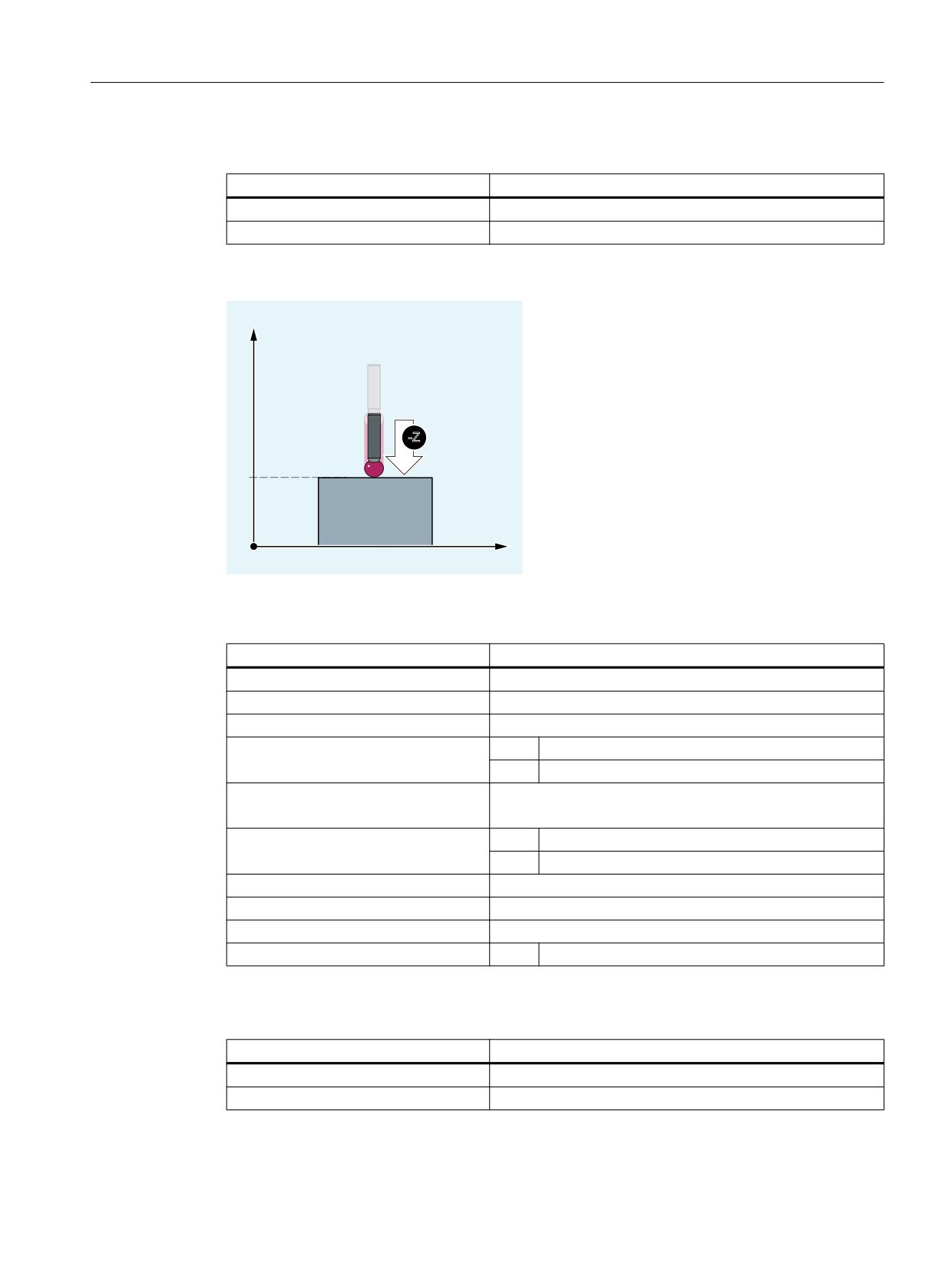
Measurement type 3: Measurement of a Z edge
=
<
=
=
;
Figure 9-3
Measurement of a Z edge
The values of the following system variables are evaluated for measurement type 3:
Input variable
Meaning
$AC_MEAS_VALID
Validity bits for the input variables
$AA_MEAS_POINT1[<Axis>]
Measuring point 1 for all channel axes
$AA_MEAS_SETPOINT[<Axis>] *)
Set position of the Z edge
$AC_MEAS_DIR_APPROACH
= 4
+ Z
= 5
- Z
$AC_MEAS_ACT_PLANE *)
Calculation with active plane unless otherwise specified.
Tool radius is only included in the calculation in G18 and G19.
$AC_MEAS_FINE_TRANS *)
= 0
Coarse offset
= 1
Fine offset
$AC_MEAS_FRAME_SELECT *)
Calculated as additive frame unless otherwise specified.
$AC_MEAS_T_NUMBER *)
Calculated with active T unless otherwise specified (T0).
$AC_MEAS_D_NUMBER *)
Calculated with active D unless otherwise specified (D0).
$AC_MEAS_TYPE
= 3
Measurement type 3: Measurement of a Z edge
*) Optional
The following output variables are written for measurement type 3:
Output variable
Meaning
$AC_MEAS_FRAME
Result frame with translation
$AC_MEAS_RESULTS[0]
Position of the measured edge
Extended Functions
Function Manual, 12/2018, A5E40874029B AB
555
M5: Measurement
9.5 Workpiece and tool measurement
Example
Measurement type 1: Measurement of an X edge
Program code
Comment
DEF INT RETVAL
DEF FRAME TMP
$TC_DP1[1,1]=120
;
Type
$TC_DP2[1,1]=20
;
0
$TC_DP3[1,1]=10
;
(Z) length compensation vector
$TC_DP4[1,1]=0
;
(Y)
$TC_DP5[1,1]=0
;
(X)
$TC_DP6[1,1]=2
;
Radius
T1 D1
G0 X0 Y0 Z0 F10000
G54
;
Measure X edge.
$AC_MEAS_VALID=0
;
Set all input values to invalid.
G1 X-1 Y-3
;
1. Approach measuring point.
$AA_MEAS_POINT1[X]=$AA_IW[X]
$AA_MEAS_POINT1[Y]=$AA_IW[Y]
$AA_MEAS_POINT1[Z]=$AA_IW[Z]
$AC_MEAS_DIR_APPROACH=0
;
Set approach direction +X.
$AA_MEAS_SETPOINT[X]=0
;
Set set position of the edge.
$AA_MEAS_SETPOINT[Y]=0
$AA_MEAS_SETPOINT[Z]=0
$AC_MEAS_ACT_PLANE=0
;
Measuring plane is G17.
$AC_MEAS_FRAME_SELECT=101
;
Select frame: IFRAME
$AC_MEAS_T_NUMBER=1
;
Select tool.
$AC_MEAS_D_NUMBER=1
$AC_MEAS_TYPE=1
;
Set measurement type for X edge.
RETVAL=MEASURE()
;
Start measuring process.
IF RETVAL <> 0
Extended Functions
556
Function Manual, 12/2018, A5E40874029B AB
M5: Measurement
9.5 Workpiece and tool measurement
Program code
Comment
SETAL(61043, << RETVAL)
ENDIF
$P_IFRAME=$AC_MEAS_FRAME
$P_UIFR[1]=$P_IFRAME
; Write system frames to the data management.
G1 X0 Y0
; Approach the edge.
M30
9.5.2.2
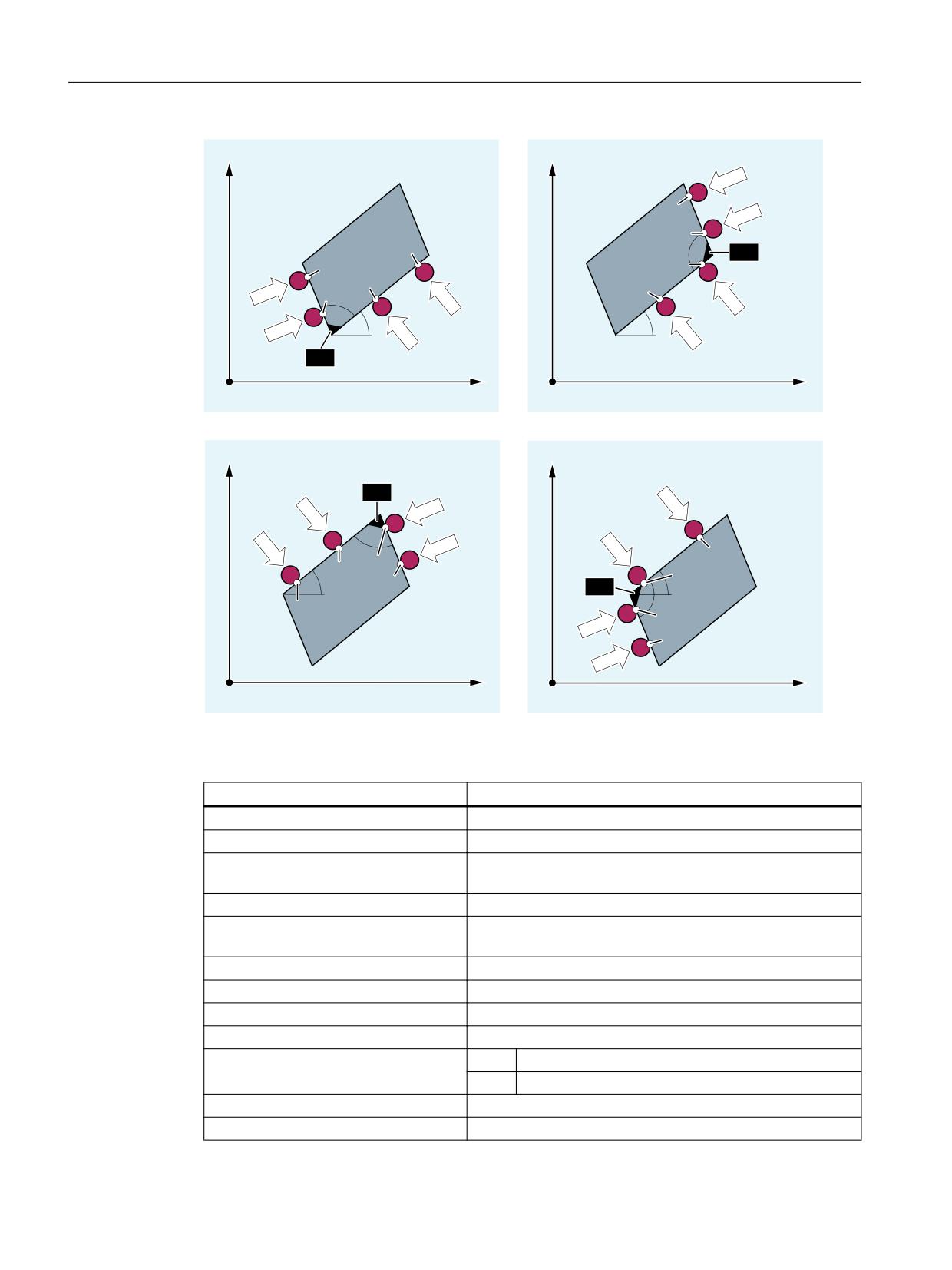
Measurement type 4, 5, 6, 7: Measurement of a corner
Function
A corner is uniquely defined by approaching four measuring points P1 to P4. Three measuring
points suffice for a known angle of intersection ϕ.
If the angle of intersection ϕ and the workpiece position angle α are known, two measurement
points P1 and P3 suffice.
Extended Functions
Function Manual, 12/2018, A5E40874029B AB
557
M5: Measurement
9.5 Workpiece and tool measurement
<
<
3
3
3
́
&
3
3
3
3
3
́
˞
˞
&
;
;
<
<
&
́
3
3
3
3
˞
3
&
˞
́
3
3
3
;
;
Figure 9-4
Measurement of a corner (C1, C2, C3 or C4)
The values of the following system variables are evaluated for measurement types 4 to 7:
Input variable
Meaning
$AC_MEAS_VALID
Validity bits for the input variables
$AA_MEAS_POINT1[<Axis>]
Measuring point 1
$AA_MEAS_POINT2[<Axis>]
Measuring point 2 (not relevant for $AC_MEAS_WP_SETAN-
GLE)
$AA_MEAS_POINT3[<Axis>]
Measuring point 3
$AA_MEAS_POINT4[<Axis>]
Measuring point 4 (not relevant for $AC_MEAS_COR-
NER_SETANGLE)
$AA_MEAS_WP_SETANGLE *)
Set workpiece position angle
$AA_MEAS_CORNER_SETANGLE *)
Set angle of intersection
$AA_MEAS_SETPOINT[<Axis>] *)
Set position of the corner
$AC_MEAS_ACT_PLANE *)
Calculation with active plane unless otherwise specified.
$AC_MEAS_FINE_TRANS *)
= 0
Coarse offset
= 1
Fine offset
$AC_MEAS_FRAME_SELECT *)
Calculated as additive frame unless otherwise specified.
$AC_MEAS_T_NUMBER *)
Calculated with active T unless otherwise specified (T0).
Extended Functions
558
Function Manual, 12/2018, A5E40874029B AB
M5: Measurement
9.5 Workpiece and tool measurement
Input variable
Meaning
$AC_MEAS_D_NUMBER *)
Calculated with active D unless otherwise specified (D0).
$AC_MEAS_INPUT[0] *)
= 0
Measurement for outer corner
= 1
Measurement for inner corner
The following applies unless otherwise specified: Measure-
ment for the outer corner
$AC_MEAS_TYPE
= 4
Measurement type 4: Measurement of a C1 corner
= 5
Measurement type 5: Measurement of a C2 corner
= 6
Measurement type 6: Measurement of a C3 corner
= 7
Measurement type 7: Measurement of a C4 corner
*) Optional
The following output variables are written for measurement types 4 to 7:
Output variable
Meaning
$AC_MEAS_FRAME
Result frame with translation and rotation
$AC_MEAS_WP_ANGLE
Calculated workpiece position angle
$AC_MEAS_CORNER_ANGLE
Calculated angle of intersection
$AC_MEAS_RESULTS[0]
Abscissa of the calculated corner point
$AC_MEAS_RESULTS[1]
Ordinate of the calculated corner point
$AC_MEAS_RESULTS[2]
Applicate of the calculated corner point
Example
Measurement type 4: Measurement of a C1 corner
Corner with three measuring points (P1, P3 and P4) and known angle of intersection ϕ (90°)
and unknown workpiece position angle α.
Program code
Comment
DEF INT RETVAL
DEF FRAME TMP
$TC_DP1[1,1]=120
; Type
$TC_DP2[1,1]=20
; 0
$TC_DP3[1,1]=10
; (Z) length compensation vector
$TC_DP4[1,1]=0
; (Y)
$TC_DP5[1,1]=0
; (X)
$TC_DP6[1,1]=2
; Radius
T1 D1
G0 X0 Y0 Z0 F10000
G54
$P_CHBFRAME[0]=CROT(Z,45)
$P_IFRAME[x,tr]= -SIN(45)
$P_IFRAME[y,tr]= -SIN(45)
Extended Functions
Function Manual, 12/2018, A5E40874029B AB
559
M5: Measurement
9.5 Workpiece and tool measurement
Program code
Comment
$P_PFRAME[z,tr]= -45
; Measure corner with three measuring
points:
$AC_MEAS_VALID=0
; Set all input values to invalid.
G1 X-1 Y-3
; 1. Approach measuring point.
$AC_MEAS_LATCH[0]=1
; Pick up measuring point P1.
G1 X-4 Y4
; 3. Approach measuring point.
$AC_MEAS_LATCH[2]=1
; Pick up measuring point P3.
G1 X-4 Y1
; 4. Approach measuring point.
$AC_MEAS_LATCH[3]=1
; Pick up measuring point P4.
$AA_MEAS_SETPOINT[X]=0
; Set set position of the corner to
(0,0,0).
$AA_MEAS_SETPOINT[Y]=0
$AA_MEAS_SETPOINT[Z]=0
$AC_MEAS_CORNER_SETANGLE=90
; Specify set angle of intersection ϕ.
$AC_MEAS_ACT_PLANE=0
; Measuring plane is G17.
$AC_MEAS_FRAME_SELECT=0
; Select frame: SETFRAME
$AC_MEAS_T_NUMBER=1
; Select tool.
$AC_MEAS_D_NUMBER=1
$AC_MEAS_TYPE=4
; Set measurement type on corner 1.
RETVAL=MEASURE()
; Start measuring process.
IF RETVAL <> 0
SETAL(61043, << RETVAL)
ENDIF
IF $AC_MEAS_CORNER_ANGLE <> 90
; Query known set angle of intersection ϕ.
SETAL(61043, << $AC_MEAS_CORNER_ANGLE)
ENDIF
$P_SETFRAME=$AC_MEAS_FRAME
$P_SETFR=$P_SETFRAME
; Write system frames to the data manage-
ment.
G1 X0 Y0
; Approach the corner.
Extended Functions
560
Function Manual, 12/2018, A5E40874029B AB
M5: Measurement
9.5 Workpiece and tool measurement
Program code
Comment
G1 X10
; Traverse the rectangle.
Y10
X0
Y0
M30
9.5.2.3
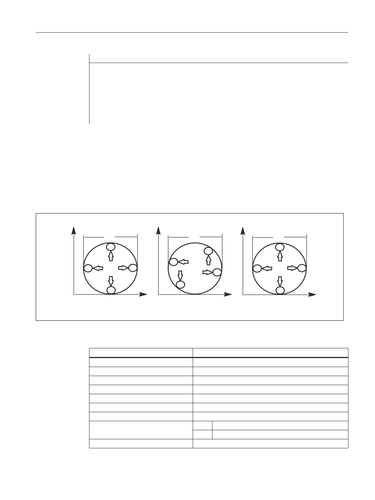
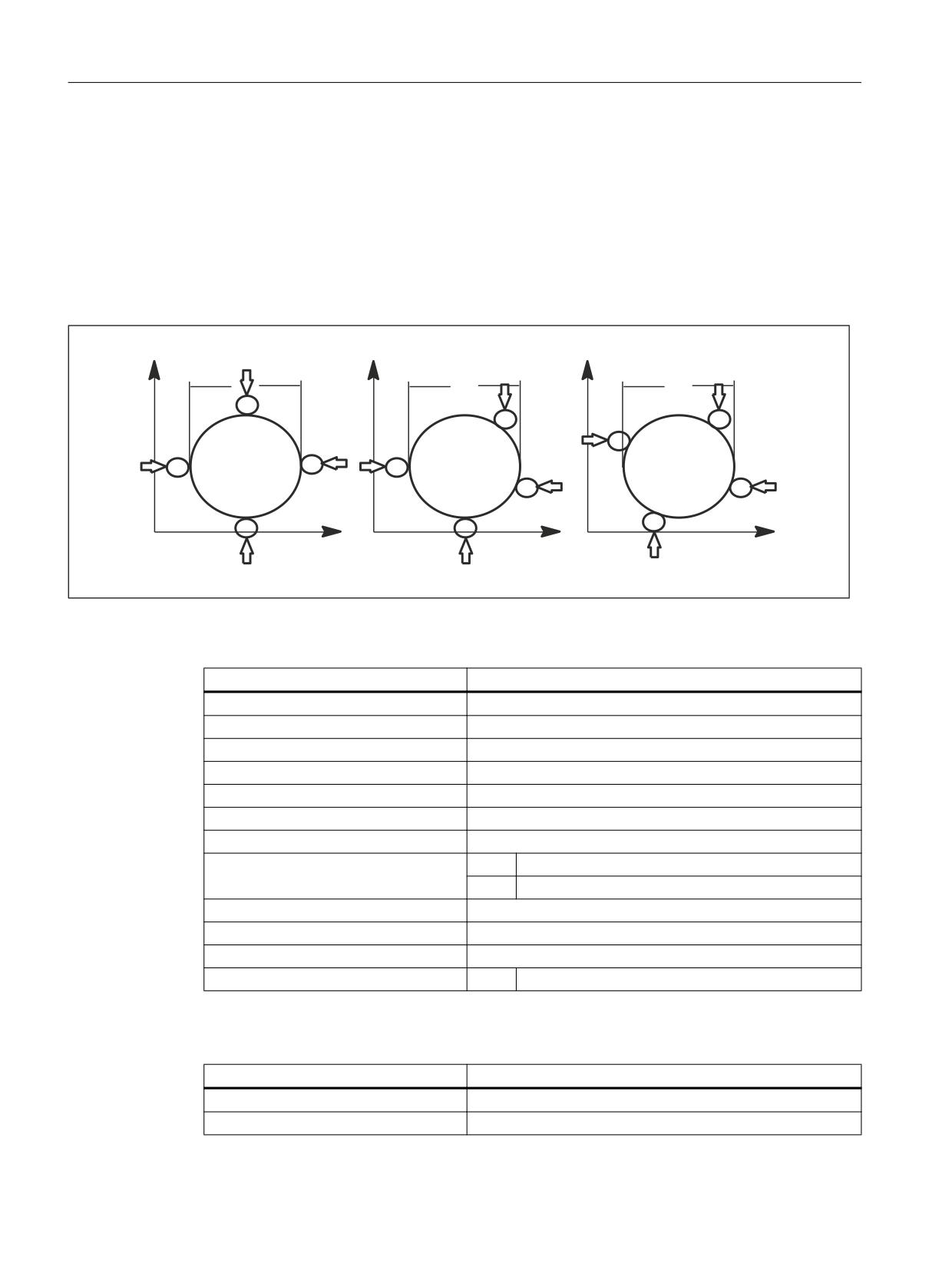
Measurement type 8: Measurement of a hole
Function
Three measuring points are needed to determine the center point and diameter. The three
points must all be different. When four points are specified, the circle is adjusted in accordance
with the least square method. The circle is determined so that the sum of the distance squares
of the resulting points to the circle is minimal. The quality of the adjustment can be read.
*
*
*
\
[
]
'
'
'
[
]
\
Figure 9-5
Measurement of a hole
The values of the following system variables are evaluated for measurement type 8:
Input variable
Meaning
$AC_MEAS_VALID
Validity bits for the input variables
$AA_MEAS_POINT1[<Axis>]
Measuring point 1
$AA_MEAS_POINT2[<Axis>]
Measuring point 2
$AA_MEAS_POINT3[<Axis>]
Measuring point 3
$AA_MEAS_POINT4[<Axis>] *)
When specified, the center is determined from four points.
$AA_MEAS_SETPOINT[<Axis>] *)
Set position of the hole center.
$AC_MEAS_ACT_PLANE *)
Calculation with active plane unless otherwise specified.
$AC_MEAS_FINE_TRANS *)
= 0
Coarse offset
= 1
Fine offset
$AC_MEAS_FRAME_SELECT *)
Calculated as additive frame unless otherwise specified.
Extended Functions
Function Manual, 12/2018, A5E40874029B AB
561

M5: Measurement
9.5 Workpiece and tool measurement
Input variable
Meaning
$AC_MEAS_T_NUMBER *)
Calculated with active T unless otherwise specified (T0).
$AC_MEAS_D_NUMBER *)
Calculated with active D unless otherwise specified (D0).
$AC_MEAS_TYPE
= 8
Measurement type 8: Measurement of a hole
*) Optional
The following output variables are written for measurement type 8:
Output variable
Meaning
$AC_MEAS_FRAME
Result frame with translation
$AC_MEAS_DIAMETER
Diameter of hole
$AC_MEAS_RESULTS[0]
Abscissa of the calculated center point
$AC_MEAS_RESULTS[1]
Ordinate of the calculated center point
$AC_MEAS_RESULTS[2]
Applicate of the calculated center point
$AC_MEAS_RESULTS[3]
Quality of the circle adjustment: Sum of the distance squares
Example
Program code
Comment
DEF INT RETVAL
DEF FRAME TMP
$TC_DP1[1,1]=120
; Type
$TC_DP2[1,1]=20
; 0
$TC_DP3[1,1]=10
; (Z) length compensation vector
$TC_DP4[1,1]=0
; (Y)
$TC_DP5[1,1]=0
; (X)
$TC_DP6[1,1]=2
; Radius
T1 D1
G0 X0 Y0 Z0 F10000
G54
; Measure hole
$AC_MEAS_VALID=0
; Set all input values to invalid.
G1 X-3 Y0
; 1. Approach measuring point.
$AA_MEAS_POINT1[X]=$AA_IW[X]
$AA_MEAS_POINT1[Y]=$AA_IW[Y]
$AA_MEAS_POINT1[Z]=$AA_IW[Z]
G1 X0 Y3
; 2. Approach measuring point.
$AA_MEAS_POINT2[X]=$AA_IW[X]
$AA_MEAS_POINT2[Y]=$AA_IW[Y]
$AA_MEAS_POINT2[Z]=$AA_IW[Z]
Extended Functions
562
Function Manual, 12/2018, A5E40874029B AB
M5: Measurement
9.5 Workpiece and tool measurement
Program code
Comment
G1 X3 Y0
;
3. Approach measuring point.
$AA_MEAS_POINT3[X]=$AA_IW[X]
$AA_MEAS_POINT3[Y]=$AA_IW[Y]
$AA_MEAS_POINT3[Z]=$AA_IW[Z]
$AA_MEAS_SETPOINT[X]=0
;
Set set position of the center.
$AA_MEAS_SETPOINT[Y]=0
$AA_MEAS_SETPOINT[Z]=0
$AC_MEAS_ACT_PLANE=0
;
Measuring plane is G17.
$AC_MEAS_FRAME_SELECT=0
;
Select frame - SETFRAME
$AC_MEAS_T_NUMBER=1
;
Select tool.
$AC_MEAS_D_NUMBER=1
$AC_MEAS_TYPE=8
;
Set measurement type on hole.
RETVAL=MEASURE()
;
Start measuring process.
If RETVAL <> 0
SETAL(61043, << RETVAL)
ENDIF
IF $AC_MEAS_DIAMETER <> 10
;
Query known diameter.
SETAL(61043, << $AC_MEAS_WP_ANGLE)
ENDIF
$P_SETFRAME=$AC_MEAS_FRAME
$P_SETFR=$P_SETFRAME
;
Describe system frames in the data manage-
ment.
G1 X-3 Y0
; Approach P1.
G2 I=$AC_MEAS_DIAMETER/2
; Traverse hole with regard to circle center
point.
M30
Extended Functions
Function Manual, 12/2018, A5E40874029B AB
563
M5: Measurement
9.5 Workpiece and tool measurement
9.5.2.4
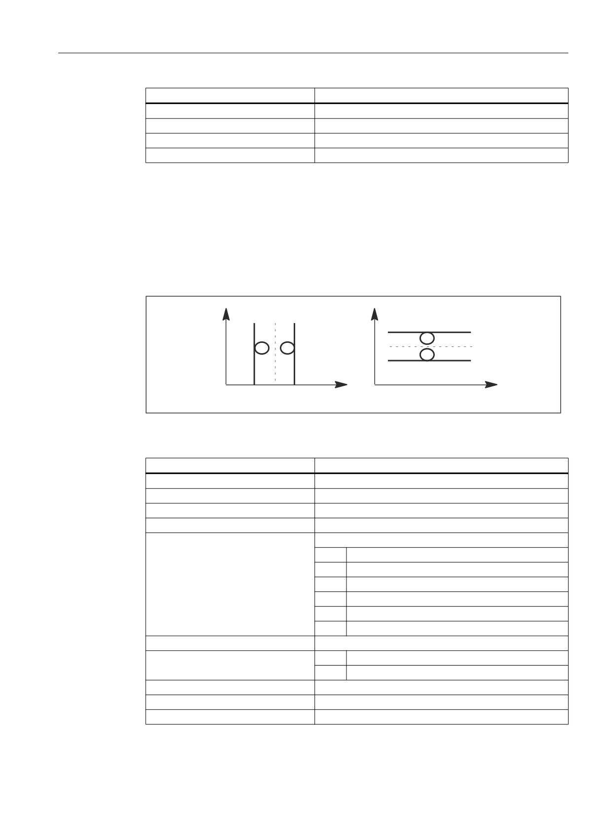
Measurement type 9: Measurement of a shaft
Function
Three measuring points are needed to determine the center point and diameter. The three
points must all be different. When four points are specified, the circle is adjusted in accordance
with the least square method. The circle is determined so that the sum of the distance squares
of the resulting points to the circle is minimal. The quality of the adjustment can be read.
*
*
*
\
[
]
'
'
'
[
]
\
Figure 9-6
Measurement of a shaft
The values of the following system variables are evaluated for measurement type 9:
Input variable
Meaning
$AC_MEAS_VALID
Validity bits for input variables
$AA_MEAS_POINT1[<Axis>]
Measuring point 1
$AA_MEAS_POINT2[<Axis>]
Measuring point 2
$AA_MEAS_POINT3[<Axis>]
Measuring point 3
$AA_MEAS_POINT4[<Axis>] *)
When specified, the center is determined from four points.
$AA_MEAS_SETPOINT[<Axis>] *)
Set position of the shaft center point.
$AC_MEAS_ACT_PLANE *)
Calculation with active plane unless otherwise specified.
$AC_MEAS_FINE_TRANS *)
= 0
Coarse offset
= 1
Fine offset
$AC_MEAS_FRAME_SELECT *)
Calculated as additive frame unless otherwise specified.
$AC_MEAS_T_NUMBER *)
Calculated with active T unless otherwise specified (T0).
$AC_MEAS_D_NUMBER *)
Calculated with active D unless otherwise specified (D0).
$AC_MEAS_TYPE
= 9
Measurement type 9: Measurement of a shaft
*) Optional
The following output variables are written for measurement type 9:
Output variable
Meaning
$AC_MEAS_FRAME
Result frame with translation
$AC_MEAS_DIAMETER
Diameter of hole
Extended Functions
564
Function Manual, 12/2018, A5E40874029B AB
M5: Measurement
9.5 Workpiece and tool measurement
Output variable
Meaning
$AC_MEAS_RESULTS[0]
Abscissa of the calculated center point
$AC_MEAS_RESULTS[1]
Ordinate of the calculated center point
$AC_MEAS_RESULTS[2]
Applicate of the calculated center point
$AC_MEAS_RESULTS[3]
Quality of the circle adjustment: Sum of the distance squares
9.5.2.5
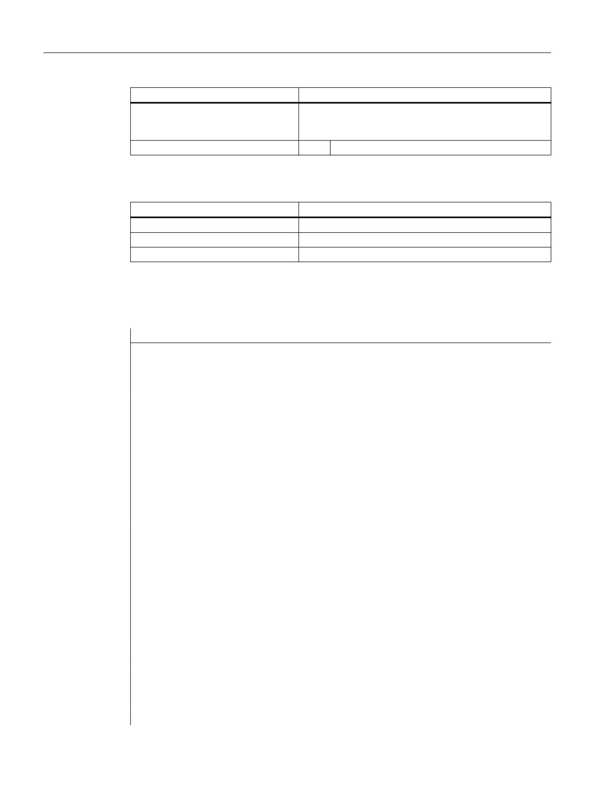
Measurement type 12: Measurement of a groove
Function
A groove is measured by approaching the two outside corners or inner edges. The groove
center can be set to a set position. The component of the approach direction determines the
groove position.
\
\
\
[
[
\
\
[
[
[
Figure 9-7
Measurement of a groove
The values of the following system variables are evaluated for measurement type 12:
Input variable
Meaning
$AC_MEAS_VALID
Validity bits for the input variables
$AA_MEAS_POINT1[<Axis>]
Measuring point 1
$AA_MEAS_POINT2[<Axis>]
Measuring point 2
$AA_MEAS_SETPOINT[<Axis>] *)
Set position of the groove center
$AC_MEAS_DIR_APPROACH
Direction of approach to the workpiece
= 0
+ X
= 1
- X
= 2
+ Y
= 3
- Y
= 4
+ Z
= 5
- Z
$AC_MEAS_ACT_PLANE *)
Calculation with active plane unless otherwise specified.
$AC_MEAS_FINE_TRANS *)
= 0
Coarse offset
= 1
Fine offset
$AC_MEAS_FRAME_SELECT *)
Calculated as additive frame unless otherwise specified.
$AC_MEAS_T_NUMBER *)
Calculated with active T unless otherwise specified (T0).
$AC_MEAS_D_NUMBER *)
Calculated with active D unless otherwise specified (D0).
Extended Functions
Function Manual, 12/2018, A5E40874029B AB
565
M5: Measurement
9.5 Workpiece and tool measurement
Input variable
Meaning
$AC_MEAS_INPUT[0] *)
Approach direction for 2nd measuring point for a recess
measurement. Must have the same coordinate as the ap-
proach direction of the 1st measuring point.
$AC_MEAS_TYPE
= 12
Measurement type 12: Measurement of a groove
*) Optional
The following output variables are written for measurement type 12:
Output variable
Meaning
$AC_MEAS_FRAME
Result frame with translation
$AC_MEAS_RESULTS[0]
Position of the calculated groove center (X0, Y0 or Z0)
$AC_MEAS_RESULTS[1]
Groove width in approach direction
Example
Groove measurement with approach direction in X.
Program code
Comment
DEF INT RETVAL
DEF FRAME TMP
$TC_DP1[1,1]=120
; Type
$TC_DP2[1,1]=20
; 0
$TC_DP3[1,1]=10
; (Z) length compensation vector
$TC_DP4[1,1]=0
; (Y)
$TC_DP5[1,1]=0
; (X)
$TC_DP6[1,1]=2
; Radius
T1 D1
G0 X0 Y0 Z0 F10000
G54
$P_CHBFRAME[0]= CROT(Z,45)
$P_IFRAME[X,TR]= -sin(45)
$P_IFRAME[Y,TR]= -sin(45)
$P_PFRAME[Z,RT]= -45
; Measure groove.
$AC_MEAS_VALID=0
; Set all input values to invalid.
G1 X-2
; 1. Approach measuring point.
$AA_MEAS_POINT1[X]=$AA_IW[X]
$AA_MEAS_POINT1[Y]=$AA_IW[Y]
$AA_MEAS_POINT1[Z]=$AA_IW[Z]
Extended Functions
566
Function Manual, 12/2018, A5E40874029B AB
M5: Measurement
9.5 Workpiece and tool measurement
Program code
Comment
G1 X4
;
2. Approach measuring point.
$AA_MEAS_POINT2[X]=$AA_IW[X]
$AA_MEAS_POINT2[Y]=$AA_IW[Y]
$AA_MEAS_POINT2[Z]=$AA_IW[Z]
$AA_MEAS_SETPOINT[X]=0
;
Set set position of the groove center.
$AA_MEAS_SETPOINT[Y]=0
$AA_MEAS_SETPOINT[Z]=0
$AC_MEAS_DIR_APPROACH=0
;
Set approach direction +X.
$AC_MEAS_ACT_PLANE=0
;
Measuring plane is G17.
$AC_MEAS_FRAME_SELECT=0
;
Select frame - SETFRAME
$AC_MEAS_T_NUMBER=1
;
Select tool.
$AC_MEAS_D_NUMBER=1
$AC_MEAS_TYPE=12
;
Set measurement type on groove.
RETVAL=MEASURE()
;
Start measuring process.
IF RETVAL <> 0 SETAL(61043, << RETVAL)
ENDIF
$P_SETFRAME=$AC_MEAS_FRAME
$P_SETFR=$P_SETFRAME
;
Write system frames to the data management.
G1 X0 Y0
;
Approach the groove center.
M30
Extended Functions
Function Manual, 12/2018, A5E40874029B AB
567
M5: Measurement
9.5 Workpiece and tool measurement
9.5.2.6
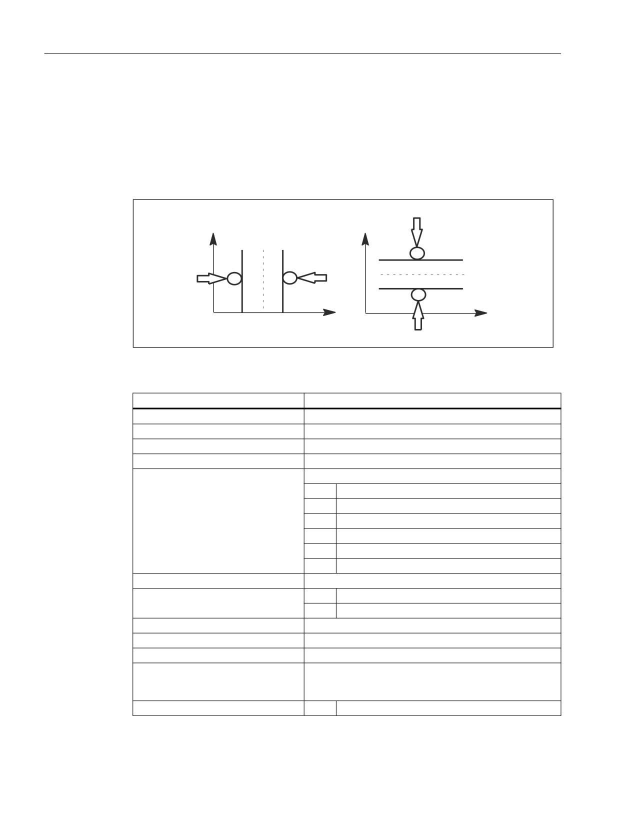
Measurement type 13: Measurement of a web
Function
A web is measured by approaching the two outside corners or inner edges. The web center
can be set to a set position. The component of the approach direction determines the web
position.
\
\
\
\
[
[
[
[
\
[
Figure 9-8
Measurement of a web
The values of the following system variables are evaluated for measurement type 13:
Input variable
Meaning
$AC_MEAS_VALID
Validity bits for input variables
$AA_MEAS_POINT1[<Axis>]
Measuring point 1
$AA_MEAS_POINT2[<Axis>]
Measuring point 2
$AA_MEAS_SETPOINT[<Axis>] *)
Set position of the web center
$AC_MEAS_DIR_APPROACH
Direction of approach to the workpiece
= 0
+ X
= 1
- X
= 2
+ Y
= 3
- Y
= 4
+ Z
= 5
- Z
$AC_MEAS_ACT_PLANE *)
Calculation with active plane unless otherwise specified.
$AC_MEAS_FINE_TRANS *)
= 0
Coarse offset
= 1
Fine offset
$AC_MEAS_FRAME_SELECT *)
Calculated as additive frame unless otherwise specified.
$AC_MEAS_T_NUMBER *)
Calculated with active T unless otherwise specified (T0).
$AC_MEAS_D_NUMBER *)
Calculated with active D unless otherwise specified (D0).
$AC_MEAS_INPUT[0] *)
Approach direction for 2nd measuring point for a recess
measurement. Must have the same coordinate as the ap-
proach direction of the 1st measuring point.
$AC_MEAS_TYPE
= 13
Measurement type 13: Measurement of a web
*) Optional
Extended Functions
568
Function Manual, 12/2018, A5E40874029B AB
M5: Measurement
9.5 Workpiece and tool measurement
The following output variables are written for measurement type 13:
Output variable
Meaning
$AC_MEAS_FRAME
Result frame with translation
$AC_MEAS_RESULTS[0]
Position of the calculated web center (X0, Y0 or Z0)
$AC_MEAS_RESULTS[1]
Web width in approach direction
9.5.2.7
Measurement type 14: Preset actual value for geometry and special axes
Function
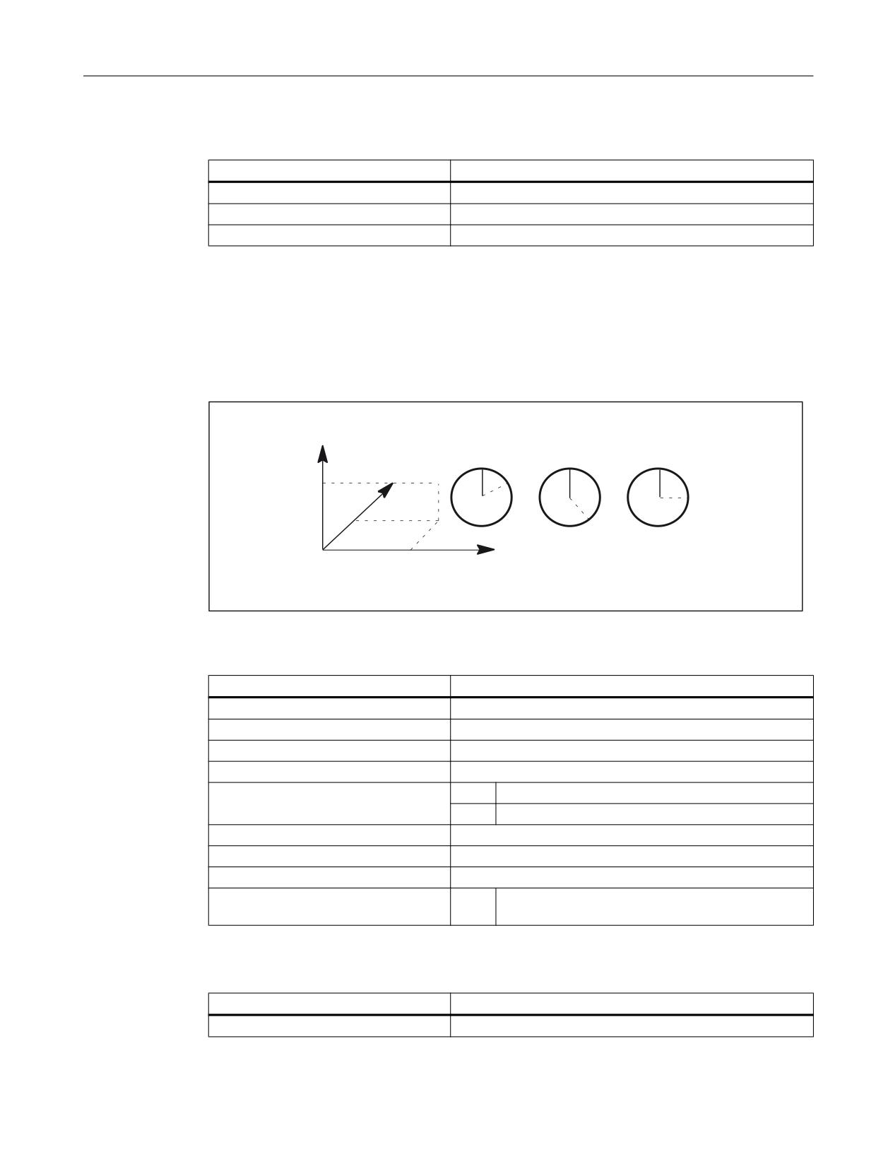
The measurement with measurement type 14 is performed via an HMI operator action.
6SHFLDO D[HV
]
$ 6HW
$ 6HW
$ 6HW
<
3
$FW
$
]L
$FW
$ $FW
\L
$ $FW
3
6HW
[V \V ]V
[L
[
Figure 9-9
Preset actual value for geometry and special axes
The values of the following system variables are evaluated for measurement type 14:
Input variable
Meaning
$AC_MEAS_VALID
Validity bits for input variables
$AA_MEAS_POINT1[<Axis>]
Actual values of the axes
$AA_MEAS_SETPOINT[<Axis>] *)
Set position of the individual axes
$AC_MEAS_ACT_PLANE *)
Calculation with active plane unless otherwise specified.
$AC_MEAS_FINE_TRANS *)
= 0
Coarse offset
= 1
Fine offset
$AC_MEAS_FRAME_SELECT *)
Calculated as additive frame unless otherwise specified.
$AC_MEAS_T_NUMBER *)
Calculated with active T unless otherwise specified (T0).
$AC_MEAS_D_NUMBER *)
Calculated with active D unless otherwise specified (D0).
$AC_MEAS_TYPE
= 14
Measurement type 14: Preset actual value for geom-
etry and special axes
*) Optional
The following output variables are written for measurement type 14:
Output variable
Meaning
$AC_MEAS_FRAME
Result frame with translations
Extended Functions
Function Manual, 12/2018, A5E40874029B AB
569

M5: Measurement
9.5 Workpiece and tool measurement
Example
Reference point setting in relative coordinate systems.
Program code
Comment
DEF INT RETVAL
T1 D1
; Activate probe.
G54
; Activate all frames and G54.
TRANS X=10
; Offset between WCS and SZS
G0 X0 F10000
; WCS(X)=0; SZS(X)=10
$AC_MEAS_VALID=0
; Set all input variables to invalid.
$AC_MEAS_TYPE=14
; Measurement type for preset actual value
$AC_MEAS_ACT_PLANE=0
; Measuring plane is G17.
$AC_MEAS_P1_COORD=5
; SZS_REL for 1st measuring point
$AC_MEAS_LATCH[0]=1
; Pick up all axis positions.
$AC_MEAS_SET_COORD=5
; Set position is relative to SZS.
$AA_MEAS_SETPOINT[X]=0
; Set position in the relative SZS coordinate
system
$AC_MEAS_FRAME_SELECT=2505
; $P_RELFR
RETVAL=MEASURE()
; Calculation of $P_RELFR, PI SETUDT(6)
IF RETVAL<>0 GOTOF ERROR
ENDIF $P_RELFR=$AC_MEAS_FRAME
; Activation, PI SETUDT(7)
9.5.2.8
Measurement type 15: Preset actual value for special axes only
Function
The measurement with measurement type 15 is performed via an HMI operator action.
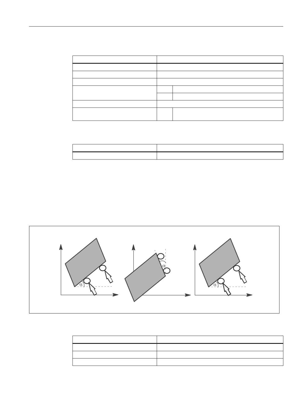
6SHFLDO D[HV
$ 6HW
$ 6HW
$ 6HW
$ $FW
$ $FW
$ $FW
Figure 9-10
Preset actual value for special axes only
Extended Functions
570
Function Manual, 12/2018, A5E40874029B AB
M5: Measurement
9.5 Workpiece and tool measurement
The values of the following system variables are evaluated for measurement type 15:
Input variable
Meaning
$AC_MEAS_VALID
Validity bits for input variables
$AA_MEAS_POINT1[<Axis>]
Actual values of the axes
$AA_MEAS_SETPOINT[<Axis>] *)
Set position of the individual axes
$AC_MEAS_FINE_TRANS *)
= 0
Coarse offset
= 1
Fine offset
$AC_MEAS_FRAME_SELECT *)
Calculated as additive frame unless otherwise specified.
$AC_MEAS_TYPE
= 15
Measurement type 14: Preset actual value for special
axes only
*) Optional
The following output variables are written for measurement type 15:
Output variable
Meaning
$AC_MEAS_FRAME
Result frame with translations
9.5.2.9
Measurement type 16: Measurement of an inclined edge
Function
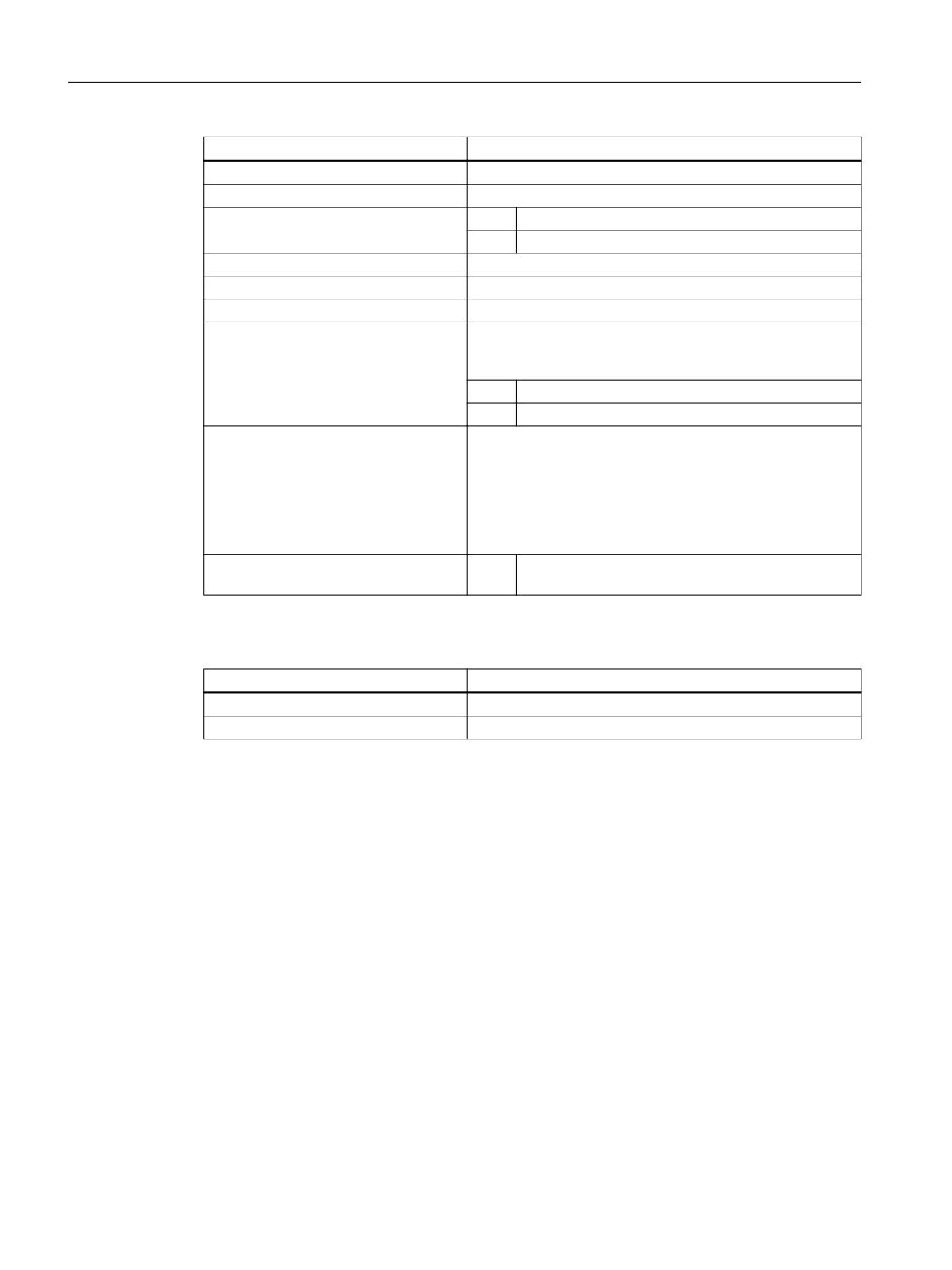
This measurement determines the position angle of the workpiece and enters it in the frame.
A set angle in the ± 90 degrees range can be specified. This can be interpreted as the resulting
rotation of the workpiece after the result frame for the active WCS has been activated.
*
*
*
<
[
5HIHUHQFH D[LV
]
3
3
3
3
3
3
[
]
<
Figure 9-11
Measurement of an inclined edge in planes G17/G18/G19
The values of the following system variables are evaluated for measurement type 16:
Input variable
Meaning
$AC_MEAS_VALID
Validity bits for input variables
$AA_MEAS_POINT1[<Axis>]
Measuring point 1
$AA_MEAS_POINT2[<Axis>]
Measuring point 2
Extended Functions
Function Manual, 12/2018, A5E40874029B AB
571
M5: Measurement
9.5 Workpiece and tool measurement
Input variable
Meaning
$AA_MEAS_SETANGLE *)
Set angle
$AC_MEAS_ACT_PLANE *)
Calculation with active plane unless otherwise specified.
$AC_MEAS_FINE_TRANS *)
= 0
Coarse offset
= 1
Fine offset
$AC_MEAS_FRAME_SELECT *)
Calculated as additive frame unless otherwise specified.
$AC_MEAS_T_NUMBER *)
Calculated with active T unless otherwise specified (T0).
$AC_MEAS_D_NUMBER *)
Calculated with active D unless otherwise specified (D0).
$AC_MEAS_INPUT[0] *)
Unless otherwise specified, the reference coordinate for the
alignment of the workpiece is always the abscissa of the se-
lected plane.
= 0
Reference coordinate is the abscissa
= 1
Reference coordinate is the ordinate
$AC_MEAS_INPUT[1] *)
Unless otherwise specified, the workpiece position angle is
entered in the frame as a rotation. Otherwise, a channel axis
index can be specified for a rotary axis whose translation is
set to the current rotary axis position plus the calculated ro-
tation. The workpiece is then aligned at rotary axis position
= 0. The current rotary axis value must be set in
$AA_MEAS_POINT[<Axis>].
$AC_MEAS_TYPE
= 16
Measurement type 16: Measurement of an inclined
edge
* optional
The following output variables are written for measurement type 16:
Output variable
Meaning
$AC_MEAS_FRAME
Result frame with rotation
$AC_MEAS_WP_ANGLE
Calculated workpiece position angle
Extended Functions
572
Function Manual, 12/2018, A5E40874029B AB
M5: Measurement
9.5 Workpiece and tool measurement
9.5.2.10
Measurement type 17: Measurement of an angle in an inclined plane
Function
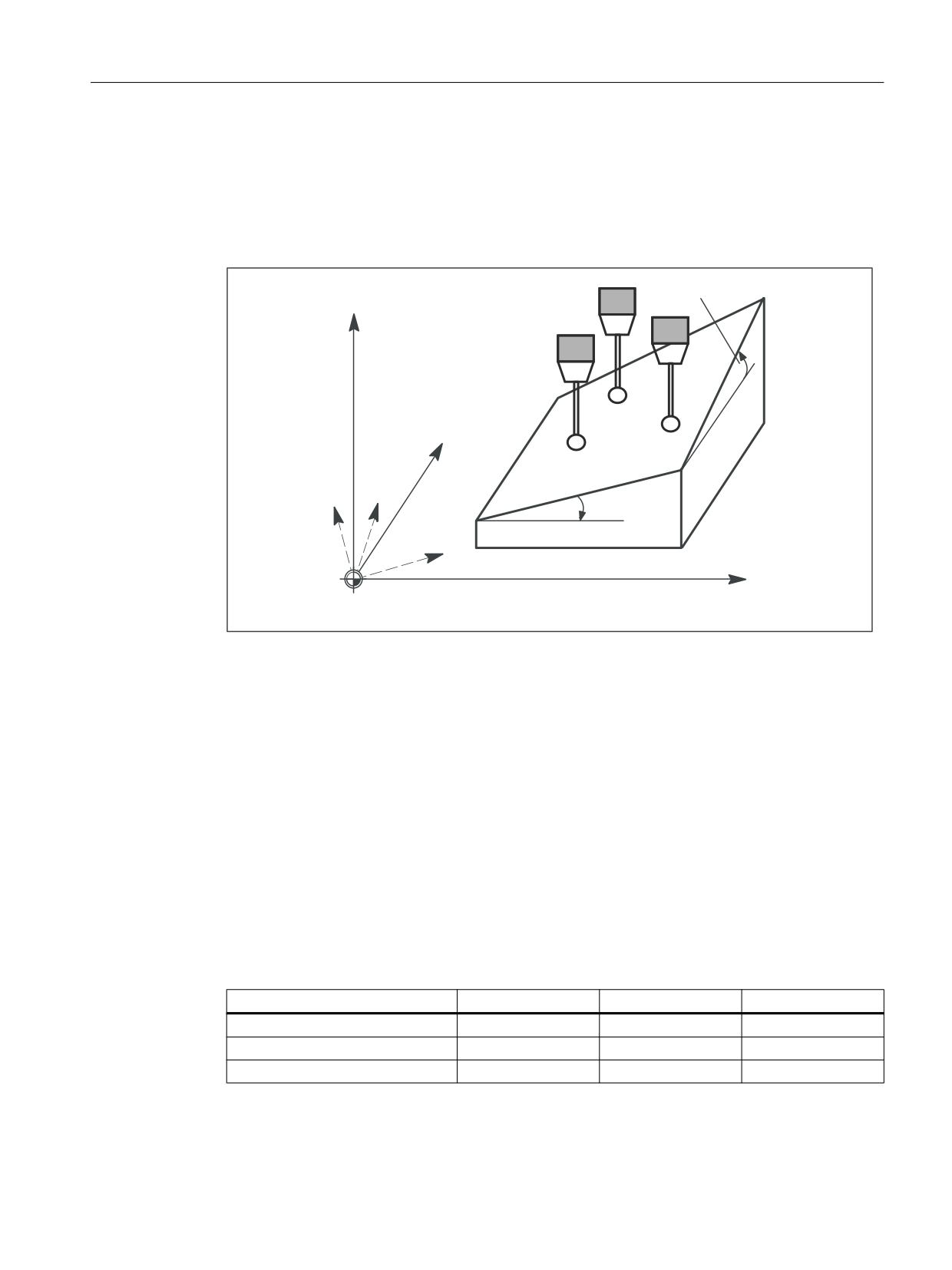
The inclined plane is determined using three measuring points P1, P2 and P3.
$&B0($6B5(68/76> @
]
˞
3
3
\
3
\ಬ
]ಬ
˞
$&B0($6B5(68/76> @
[ಬ
[
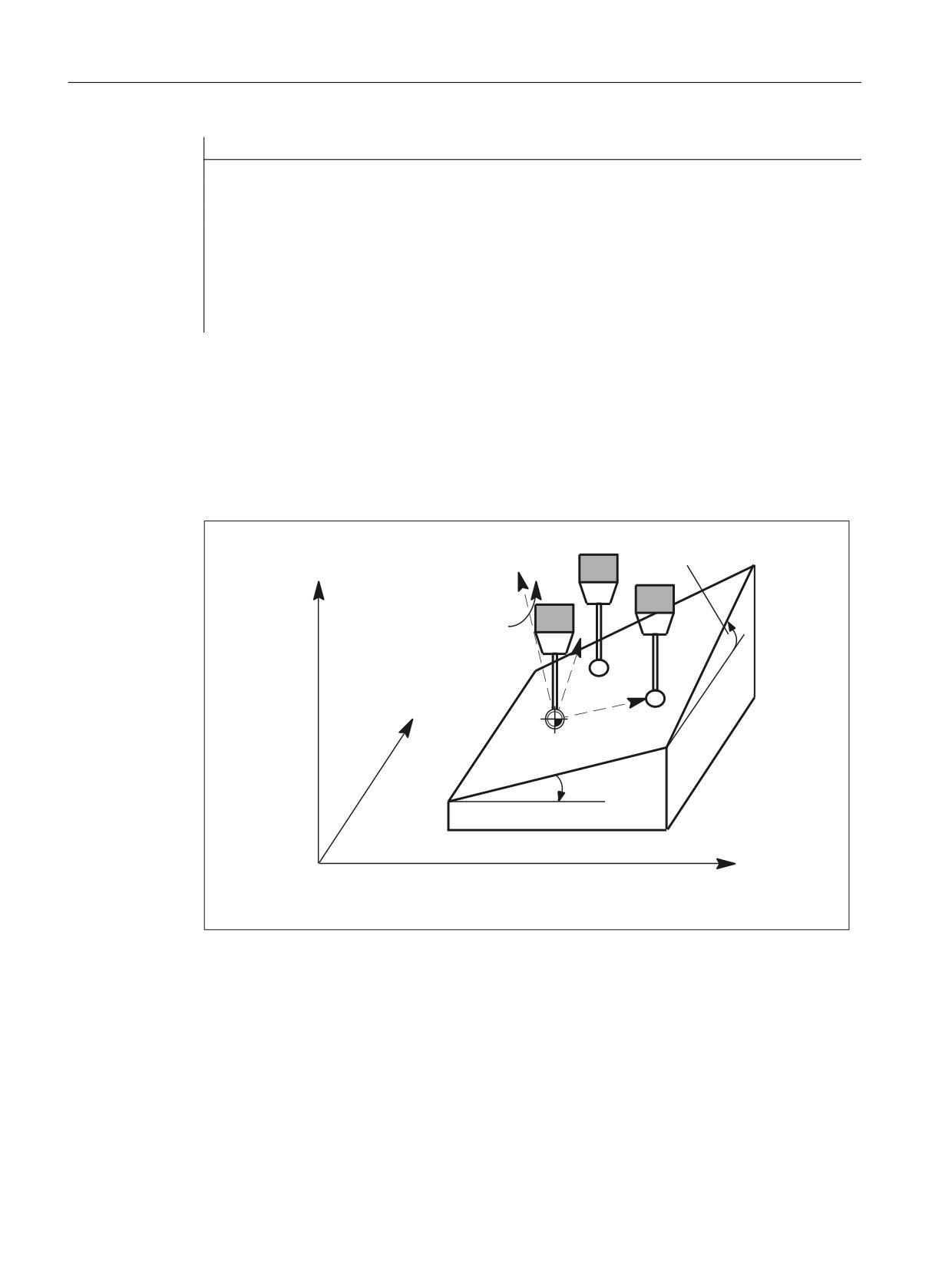
Figure 9-12
Measurement of an angle in an inclined plane in G17
With measurement type 17, two resulting angles α 0 and α 1 are determined for the skew of the
plane and entered in $AC_MEAS_RESULTS[0 ... 1]:
● $AC_MEAS_RESULTS[0] → Rotation around the abscissa
● $AC_MEAS_RESULTS[1] → Rotation around the ordinate
These angles are calculated with the three measuring points P1, P2 and P3.
With measurement type 17, the angle for the applicate ($AC_MEAS_RESULTS[2]) is always
preset with 0.
A set rotation that is entered in the result frame can be specified for the abscissa and/or the
ordinate. If only one angle is specified with a setpoint, the second angle is calculated so that
the three measuring points are on an inclined plane with the setpoint angle. Only rotations are
entered in the result frame, the WCS reference point is retained. The WCS is rotated so that
Z' is perpendicular to the inclined plane.
The following plane settings are defined for measurement type 17:
Axis identifier
G17
G18
G19
Abscissa
X axis
Z axis
Y axis
Ordinate
Y axis
X axis
Z axis
Applicate (infeed axis)
Z axis
Y axis
X axis
Extended Functions
Function Manual, 12/2018, A5E40874029B AB
573
M5: Measurement
9.5 Workpiece and tool measurement
The values of the following system variables are evaluated for measurement type 17:
Input variable
Meaning
$AC_MEAS_VALID
Validity bits for the input variables
$AA_MEAS_POINT1[<Axis>]
Measuring point 1
$AA_MEAS_POINT2[<Axis>]
Measuring point 2
$AA_MEAS_POINT3[<Axis>]
Measuring point 3
$AA_MEAS_SETANGLE[<Axis>] *)
Set rotations around abscissa and ordinate.
$AC_MEAS_ACT_PLANE *)
Calculation with active plane unless otherwise specified.
$AC_MEAS_FRAME_SELECT *)
Calculated as additive frame unless otherwise specified.
$AC_MEAS_T_NUMBER *)
Calculated with active T unless otherwise specified (T0).
$AC_MEAS_D_NUMBER *)
Calculated with active D unless otherwise specified (D0).
$AC_MEAS_INPUT[0] *)
Unless otherwise specified, the points are not projected in a
plane.
= 0
Points are not projected on a plane.
= 1
Points are projected in the active plane or in the se-
lected plane.
$AC_MEAS_TYPE
= 17
*) Optional
The following output variables are written for measurement type 17:
Output variable
Meaning
$AC_MEAS_FRAME
Result frame
$AC_MEAS_RESULTS[0]
Angles around abscissa from which three measuring points
are calculated
$AC_MEAS_RESULTS[1]
Angles around ordinate from which three measuring points
are calculated
$AC_MEAS_RESULTS[2]
Angles around applicate from which three measuring points
are calculated
$AC_MEAS_RESULTS[3]
Angle around abscissa which is entered in the result frame
$AC_MEAS_RESULTS[4]
Angle around ordinate which is entered in the result frame
$AC_MEAS_RESULTS[5]
Angle around applicate which is entered in the result frame
Example
Program code
Comment
DEF INT RETVAL
DEF AXIS _XX, _YY, _ZZ
T1 D1
; Activate probe.
G54
; Activate all frames and G54.
$AC_MEAS_VALID=0
; Set all input values to invalid.
$AC_MEAS_TYPE=17
; Set measurement type for inclined plane.
Extended Functions
574
Function Manual, 12/2018, A5E40874029B AB
M5: Measurement
9.5 Workpiece and tool measurement
Program code
Comment
$AC_MEAS_ACT_PLANE=0
;
Measuring plane is G17.
_XX=$P_AXN1
;
Specify axes according to the plane.
_YY=$P_AXN2
_ZZ=$P_AXN3
G17 G1 _XX=10 _YY=10 F1000
;
Approach 1st measuring point.
MEAS=1 _ZZ=...
$AA_MEAS_POINT1[_XX]=$AA_MW[_XX]
;
Assign measured value to abscissa.
$AA_MEAS_POINT1[_YY]=$AA_MW[_YY]
;
Assign measured value to ordinate.
$AA_MEAS_POINT1[_ZZ]=$AA_MW[_ZZ]
;
Assign measured value to applicate.
G1 _XX=20 _YY=10 F1000
;
Approach 2nd measuring point.
MEAS=1 _ZZ=...
$AA_MEAS_POINT2[_XX]=$AA_MW[_XX]
;
Assign measured value to abscissa.
$AA_MEAS_POINT2[_YY]=$AA_MW[_YY]
;
Assign measured value to ordinate.
$AA_MEAS_POINT2[_ZZ]=$AA_MW[_ZZ]
;
Assign measured value to applicate.
G1 _XX=20 _YY=20 F1000
;
Approach 3rd measuring point.
MEAS=1 _ZZ=...
$AA_MEAS_POINT3[_XX]=$AA_MW[_XX]
;
Assign measured value to abscissa.
$AA_MEAS_POINT3[_YY]=$AA_MW[_YY]
;
Assign measured value to ordinate.
$AA_MEAS_POINT3[_ZZ]=$AA_MW[_ZZ]
;
Assign measured value to applicate.
;
Specify setpoints for angles.
$AA_MEAS_SETANGLE[_XX]=12
;
Rotation around the abscissa.
$AA_MEAS_SETANGLE[_YY]=4
;
Rotation around the ordinate.
$AC_MEAS_FRAME_SELECT=102
;
Select target frame - G55
$AC_MEAS_T_NUMBER=1
;
Select tool.
$AC_MEAS_D_NUMBER=1
RETVAL=MEASURE()
;
Start measurement calculation.
IF RETVAL <> 0
SETAL(61043, << RETVAL)
ENDIF
IF $AC_MEAS_RESULTS[0] <> 12
SETAL(61043, << $AC_MEAS_RESULTS[0])
ENDIF
IF $AC_MEAS_RESULTS[1] <> 4
Extended Functions
Function Manual, 12/2018, A5E40874029B AB
575
M5: Measurement
9.5 Workpiece and tool measurement
Program code
Comment
SETAL(61043, << $AC_MEAS_RESULTS[1])
ENDIF
$P_UIFR[2]=$AC_MEAS_FRAME
; Write measurement frame to the data manage-
ment (G55).
G55 G0 AX[_XX]=10 AX[_YY]=10
; Activate frame and traverse.
M30
9.5.2.11
Measurement type 18: Redefining the WCS on the inclined plane
Function
The zero point of the new WCS is determined by measuring point P1 at surface normal on the
inclined plane.
$&B0($6B5(68/76> @
]
]
$&B0($6B5(68/76> @
˞
\
3
[
3
<
:&6
3
˞
$&B0($6B5(68/76> @
:&6
[
Figure 9-13
Redefining the WCS on the inclined plane in G17
Measurement of plane
The plane is measured in one measuring cycle. The cycle records the three measuring points
and passes the necessary values to the variable interface.
The MEASURE() function calculates the solid angles and translational offset of the new WCS'
on the basis of the input values.
Extended Functions
576
Function Manual, 12/2018, A5E40874029B AB
M5: Measurement
9.5 Workpiece and tool measurement
Transformation of measuring frame
The results of the calculation, i.e. the solid angles and translation, are entered in the
$AC_MEAS_FRAME measuring frame. The measuring frame is transformed according to the
selected frame in the frame chain. The solid angles are also stored in the
$AC_MEAS_RESULTS[0 ... 2] output values.
● $AC_MEAS_RESULTS[0]: Angle around the abscissa of the old WCS
● $AC_MEAS_RESULTS[1]: Angle around the ordinate
● $AC_MEAS_RESULTS[2]: Angle around the applicate
Specifying the new WCS' zero point
After performing the calculation, the measuring cycle can write and activate the selected frame
in the frame chain with the measuring frame. After activation, the new WCS' is positioned at
surface normal on the inclined plane, with measuring point P1 as the zero point of the new
WCS'.
The programmed positions then refer to the inclined plane.
Application
CAD systems often define inclined planes by specifying three points P1, P2 and P3 on this
plane. Whereby, the 1st measuring point P1 is used as the new WCS' reference point, the 2nd
measuring point P2 specifies the direction of the abscissa X' of the new rotated WCS'
coordinate system and the 3rd measuring point P3 is required to determine the solid angles.
Input/output variables
The values of the following system variables are evaluated for measurement type 18:
Input variable
Meaning
$AC_MEAS_VALID
Validity bits for the input variables
$AA_MEAS_POINT1[<Axis>]
Measuring point 1
$AA_MEAS_POINT2[<Axis>]
Measuring point 2
$AA_MEAS_POINT3[<Axis>]
Measuring point 3
$AA_MEAS_SETPOINT[<Axis>] *)
Set position of P1
$AC_MEAS_ACT_PLANE *)
Calculation with active plane unless otherwise specified.
$AC_MEAS_FRAME_SELECT *)
Calculated as additive frame unless otherwise specified.
$AC_MEAS_T_NUMBER *)
Calculated with active T unless otherwise specified (T0).
$AC_MEAS_D_NUMBER *)
Calculated with active D unless otherwise specified (D0).
$AC_MEAS_INPUT[0] *)
Unless otherwise specified, the points are not projected in a
plane.
= 0
Points are not projected on a plane.
= 1
Points are projected in the active plane or in the se-
lected plane.
$AC_MEAS_TYPE
= 18
Measurement type 18: Redefining the WCS on the
inclined plane
* optional
Extended Functions
Function Manual, 12/2018, A5E40874029B AB
577

M5: Measurement
9.5 Workpiece and tool measurement
The following output variables are written for measurement type 18:
Output variable
Meaning
$AC_MEAS_FRAME
Result frame with rotations and transformation
$AC_MEAS_RESULTS[0]
Calculated angle around the abscissa
$AC_MEAS_RESULTS[1]
Calculated angle around the ordinate
$AC_MEAS_RESULTS[2]
Calculated angle around the applicate
Example
Program code
Comment
DEF INT RETVAL
DEF AXIS _XX, _YY, _ZZ
T1 D1
;
Activate probe.
G54
;
Activate all frames and G54.
$AC_MEAS_VALID=0
;
Set all input values to invalid.
$AC_MEAS_TYPE=18
;
Set measurement type for inclined plane.
$AC_MEAS_ACT_PLANE=0
;
Measuring plane is G17.
_XX=$P_AXN1
;
Specify axes according to the plane.
_YY=$P_AXN2
_ZZ=$P_AXN3
G17 G1 _XX=10 _YY=10 F1000
;
Approach 1st measuring point.
MEAS=1 _ZZ=...
$AA_MEAS_POINT1[_XX]=$AA_MW[_XX]
;
Assign measured value to abscissa.
$AA_MEAS_POINT1[_YY]=$AA_MW[_YY]
;
Assign measured value to ordinate.
$AA_MEAS_POINT1[_ZZ]=$AA_MW[_ZZ]
;
Assign measured value to applicate.
G1 _XX=20 _YY=10 F1000
;
Approach 2nd measuring point.
MEAS=1 _ZZ=...
$AA_MEAS_POINT2[_XX]=$AA_MW[_XX]
;
Assign measured value to abscissa.
$AA_MEAS_POINT2[_YY]=$AA_MW[_YY]
;
Assign measured value to ordinate.
$AA_MEAS_POINT2[_ZZ]=$AA_MW[_ZZ]
;
Assign measured value to applicate.
G1 _XX=20 _YY=20 F1000
;
Approach 3rd measuring point.
MEAS=1 _ZZ=...
$AA_MEAS_POINT3[_XX]=$AA_MW[_XX]
;
Assign measured value to abscissa.
$AA_MEAS_POINT3[_YY]=$AA_MW[_YY]
;
Assign measured value to ordinate.
$AA_MEAS_POINT3[_ZZ]=$AA_MW[_ZZ]
;
Assign measured value to applicate.
Extended Functions
578
Function Manual, 12/2018, A5E40874029B AB

M5: Measurement
9.5 Workpiece and tool measurement
Program code
Comment
$AA_MEAS_SETPOINT[_XX]=10
; Specify setpoints for P1.
$AA_MEAS_SETPOINT[_YY]=10
$AA_MEAS_SETPOINT[_ZZ]=10
$AC_MEAS_FRAME_SELECT=102
; Select target frame - G55
$AC_MEAS_T_NUMBER=1
; Select tool.
$AC_MEAS_D_NUMBER=1
RETVAL=MEASURE()
; Start measurement calculation.
IF RETVAL <> 0
SETAL(61043, << RETVAL)
ENDIF
; Calculation results for the solid angles.
R0=$AC_MEAS_RESULTS[0]
; Angle around the abscissa of the old WCS
R1=$AC_MEAS_RESULTS[1]
; Angle around the ordinate
R2=$AC_MEAS_RESULTS[2]
; Angle around the applicate
$P_UIFR[2]=$AC_MEAS_FRAME
; Write measurement frame to the data manage-
ment (G55).
G55 G0 AX[_XX]=10 AX[_YY]=10
; Activate frame and traverse.
M30
9.5.2.12
Measurement type 19: 1-dimensional setpoint specification
Function
With this measurement method, it is possible to define exactly one setpoint for the abscissa,
the ordinate and the applicate. If two or three setpoints are defined, only the first is accepted
in the sequence abscissa, ordinate and applicate. The tool is not taken into account.
It is purely a preset actual value for the abscissa, the ordinate or the applicate.
The values of the following system variables are evaluated for measurement type 19:
Input variable
Meaning
$AC_MEAS_VALID
Validity bits for the input variables
$AA_MEAS_POINT1[<Axis>]
Measuring point 1 for the abscissa
$AA_MEAS_POINT1[<Axis>]
Measuring point 1 for the ordinate
$AA_MEAS_POINT1[<Axis>]
Measuring point 1 for the applicate
$AA_MEAS_SETPOINT[<Axis>]
Set position of the abscissa or ordinate or applicate
$AC_MEAS_ACT_PLANE *)
Calculation with active plane unless otherwise specified.
$AC_MEAS_FRAME_SELECT *)
Calculated as additive frame unless otherwise specified.
Extended Functions
Function Manual, 12/2018, A5E40874029B AB
579
M5: Measurement
9.5 Workpiece and tool measurement
Input variable
Meaning
$AC_MEAS_FINE_TRANS *)
Unless otherwise specified, written to the coarse offset.
= 0
Coarse offset
= 1
Fine offset
$AC_MEAS_TYPE
= 19
Measurement type 19: 1-dimensional setpoint speci-
fication
*) Optional
The following output variables are written for measurement type 19:
Output variable
Meaning
$AC_MEAS_FRAME
Result frame with rotations and translation
Example
Program code
Comment
DEF INT RETVAL
DEF REAL _CORMW_XX, CORMW_YY, _CORMW_ZZ
DEF AXIS _XX, _YY, _ZZ
T1 D1
; Activate probe.
G54
; Activate all frames and G54.
$AC_MEAS_VALID=0
; Set all input values to invalid.
$AC_MEAS_TYPE=19
; Set measurement type for 1-dimensional set-
point specification.
$AC_MEAS_ACT_PLANE=0
; Measuring plane is G17.
_XX=$P_AXN1
; Specify axes according to the plane.
_YY=$P_AXN2
_ZZ=$P_AXN3
; Assign measured values.
$AA_MEAS_POINT1[_XX]=$AA_MW[_XX]
; Assign measured value to abscissa.
$AA_MEAS_POINT1[_YY]=$AA_MW[_YY]
; Assign measured value to ordinate.
$AA_MEAS_POINT1[_ZZ]=$AA_MW[_ZZ]
; Assign measured value to applicate.
$AA_MEAS_SETPOINT[_XX]=10
; Specify setpoint for the abscissa.
$AC_MEAS_FRAME_SELECT=102
; Select target frame - G55
RETVAL=MEASURE()
; Start measurement calculation.
IF RETVAL <> 0
SETAL(61043, << RETVAL)
ENDIF
$P_UIFR[2]=$AC_MEAS_FRAME
; Write measurement frame to the data manage-
ment (G55).
G55 G0 AX[_XX]=10 AX[_YY]=10
; Activate frame and traverse.
M30
Extended Functions
580
Function Manual, 12/2018, A5E40874029B AB
M5: Measurement
9.5 Workpiece and tool measurement
9.5.2.13
Measurement type 20: 2-dimensional setpoint specification
Function
Setpoints for two dimensions can be defined using this measuring method. Any combination
of 2 out of 3 axes is permissible. If three setpoints are specified, only the values for the abscissa
and the ordinate are accepted. The tool is not taken into account.
This is a purely preset actual value.
The values of the following system variables are evaluated for measurement type 20:
Input variable
Meaning
$AC_MEAS_VALID
Validity bits for the input variables
$AA_MEAS_POINT1[<Axis>]
Measuring point 1 for the abscissa
$AA_MEAS_POINT1[<Axis>]
Measuring point 1 for the ordinate
$AA_MEAS_POINT1[<Axis>]
Measuring point 1 for the applicate
$AA_MEAS_SETPOINT[<Axis>]
Set position for the 1st dimension
$AA_MEAS_SETPOINT[<Axis>]
Set position for the 2nd dimension
$AC_MEAS_ACT_PLANE *)
Calculation with active plane unless otherwise specified.
$AC_MEAS_FRAME_SELECT *)
Calculated as additive frame unless otherwise specified.
$AC_MEAS_FINE_TRANS *)
Unless otherwise specified, written to the coarse offset.
= 0
Coarse offset
= 1
Fine offset
$AC_MEAS_TYPE
= 20
Measurement type 20: 2-dimensional setpoint speci-
fication
*) Optional
The following output variables are written for measurement type 20:
Output variable
Meaning
$AC_MEAS_FRAME
Result frame with rotations and translation
Example
Program code
Comment
DEF INT RETVAL
DEF REAL _CORMW_XX, CORMW_YY, _CORMW_ZZ
DEF AXIS _XX, _YY, _ZZ
T1 D1
; Activate probe.
G54
; Activate all frames and G54.
$AC_MEAS_VALID=0
; Set all input values to invalid.
$AC_MEAS_TYPE=20
; Set measurement type for 2-dimensional set-
point specification.
$AC_MEAS_ACT_PLANE=0
; Measuring plane is G17.
_XX=$P_AXN1
; Specify axes according to the plane.
_YY=$P_AXN2
Extended Functions
Function Manual, 12/2018, A5E40874029B AB
581
M5: Measurement
9.5 Workpiece and tool measurement
Program code
Comment
_ZZ=$P_AXN3
; Assign measured values.
$AA_MEAS_POINT1[_XX]=$AA_MW[_XX]
; Assign measured value to abscissa.
$AA_MEAS_POINT1[_YY]=$AA_MW[_YY]
; Assign measured value to ordinate.
$AA_MEAS_POINT1[_ZZ]=$AA_MW[_ZZ]
; Assign measured value to applicate.
$AA_MEAS_SETPOINT[_XX]=10
; Specify setpoint for the abscissa and ordi-
nate.
$AA_MEAS_SETPOINT[_YY]=10
$AC_MEAS_FRAME_SELECT=102
; Select target frame - G55
RETVAL=MEASURE()
; Start measurement calculation.
IF RETVAL <> 0
SETAL(61043, << RETVAL)
ENDIF
$P_UIFR[2]=$AC_MEAS_FRAME
; Write measurement frame to the data manage-
ment (G55).
G55 G0 AX[_XX]=10 AX[_YY]=10
; Activate frame and traverse.
M30
9.5.2.14
Measurement type 21: 3-dimensional setpoint specification
Function
Using this measurement method, it is possible to define a setpoint for the abscissa, the ordinate
and the applicate. The tool is not taken into account.
It is purely a preset actual value for the abscissa, ordinate and applicate.
The values of the following system variables are evaluated for measurement type 21:
Input variable
Meaning
$AC_MEAS_VALID
Validity bits for the input variables
$AA_MEAS_POINT1[<Axis>]
Measuring point 1 for the abscissa
$AA_MEAS_POINT1[<Axis>]
Measuring point 1 for the ordinate
$AA_MEAS_POINT1[<Axis>]
Measuring point 1 for the applicate
$AA_MEAS_SETPOINT[<Axis>]
Set position for the abscissa
$AA_MEAS_SETPOINT[<Axis>]
Set position for the ordinate
$AA_MEAS_SETPOINT[<Axis>]
Set position for the applicate
$AC_MEAS_ACT_PLANE *)
Calculation with active plane unless otherwise specified.
$AC_MEAS_FRAME_SELECT *)
Calculated as additive frame unless otherwise specified.
$AC_MEAS_FINE_TRANS *)
Unless otherwise specified, written to the coarse offset.
= 0
Coarse offset
= 1
Fine offset
$AC_MEAS_TYPE
= 21
Measurement type 21: 3-dimensional setpoint speci-
fication
*) Optional
Extended Functions
582
Function Manual, 12/2018, A5E40874029B AB

M5: Measurement
9.5 Workpiece and tool measurement
The following output variables are written for measurement type 21:
Output variable
Meaning
$AC_MEAS_FRAME
Result frame with rotations and translation
Example
Program code
Comment
DEF INT RETVAL
DEF REAL _CORMW_XX, CORMW_YY, _CORMW_ZZ
DEF AXIS _XX, _YY, _ZZ
T1 D1
; Activate probe.
G54
; Activate all frames and G54.
$AC_MEAS_VALID=0
; Set all input values to invalid.
$AC_MEAS_TYPE=21
; Set measurement type for 3-dimensional set-
point specification.
$AC_MEAS_ACT_PLANE=0
; Measuring plane is G17.
_XX=$P_AXN1
; Specify axes according to the plane.
_YY=$P_AXN2
_ZZ=$P_AXN3
; Assign measured values.
$AA_MEAS_POINT1[_XX]=$AA_MW[_XX]
; Assign measured value to abscissa.
$AA_MEAS_POINT1[_YY]=$AA_MW[_YY]
; Assign measured value to ordinate.
$AA_MEAS_POINT1[_ZZ]=$AA_MW[_ZZ]
; Assign measured value to applicate.
$AA_MEAS_SETPOINT[_XX]=10
; Specify setpoint for the abscissa, ordinate
and applicate.
$AA_MEAS_SETPOINT[_YY]=10
$AA_MEAS_SETPOINT[_ZZ]=10
$AC_MEAS_FRAME_SELECT=102
; Select target frame - G55
RETVAL=MEASURE()
; Start measurement calculation.
IF RETVAL <> 0
SETAL(61043, << RETVAL)
ENDIF
$P_UIFR[2]=$AC_MEAS_FRAME
; Write measurement frame to the data manage-
ment (G55).
G55 G0 AX[_XX]=10 AX[_YY]=10
; Activate frame and traverse.
M30
9.5.2.15
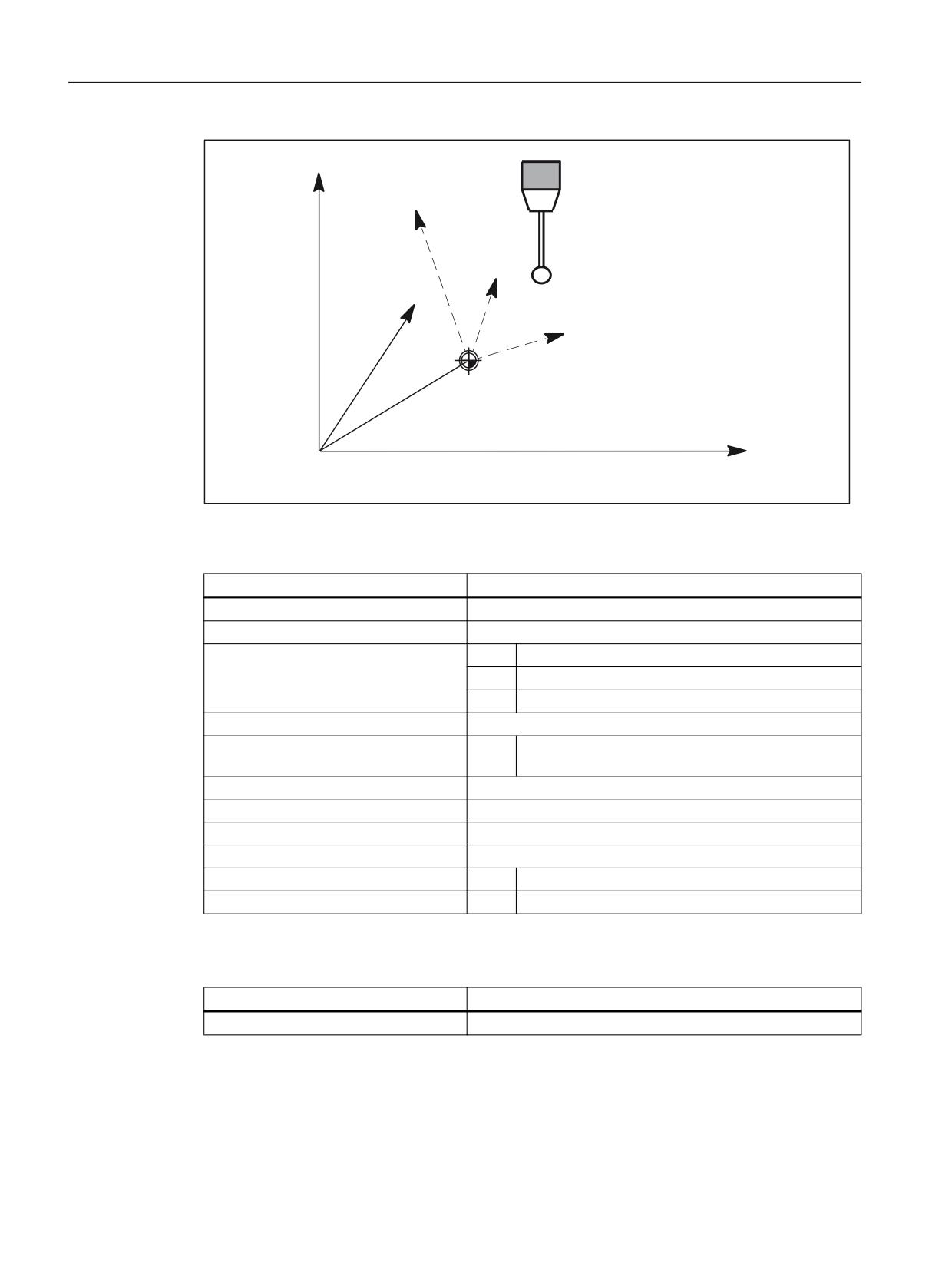
Measurement type 24: Coordinate transformation of a measuring point
Function
With this method of measurement, a measuring point in any coordinate system (WCS, BCS,
MCS) can be converted to a new coordinate system by coordinate transformation.
The new coordinate system is generated by specifying a desired frame chain.
Extended Functions
Function Manual, 12/2018, A5E40874029B AB
583
M5: Measurement
9.5 Workpiece and tool measurement
]
]
3
0&6
3
0&6
\
<
[
:&6
6SHFLILHG IUDPH
%&6
[
Figure 9-14
Coordinate transformation of a measuring point
The values of the following system variables are evaluated for measurement type 24:
Input variable
Meaning
$AC_MEAS_VALID
Validity bits for the input variables
$AA_MEAS_POINT1[<Axis>]
Position to be transformed
$AC_MEAS_P1:COORD *)
= 0
WCS (default)
= 1
BCS
= 2
MCS
$AC_MEAS_P2_COORD *)
Target coordinate system
$AC_MEAS_TOOL_MASK *)
0x20
Length of the active tool is included in the coordinate
transformation of a position.
$AC_MEAS_CHSFR *)
System frames from the data management
$AC_MEAS_NCBFR *)
Global basic frames from the data management
$AC_MEAS_CHBFR *)
Channel basic frames from the data management
$AC_MEAS_UIFR *)
Settable frame from the data management
$AC_MEAS_PFRAME *)
= 1
Programmable frame is not calaculated.
$AC_MEAS_TYPE
= 24
Measurement type 24:
*) Optional
The following output variables are written for measurement type 24:
Output variable
Meaning
$AC_MEAS_POINT2[axis]
Converted axis positions
Extended Functions
584
Function Manual, 12/2018, A5E40874029B AB
M5: Measurement
9.5 Workpiece and tool measurement
Example
WCS coordinate transformation of a measured position.
Program code
Comment
DEF INT RETVAL
DEF INT LAUF
DEF REAL_CORMW_XX, _CORMW_YY, _CORMW_ZZ
DEF AXIS _XX, _YY, _ZZ
$TC_DP1[1,1]=120
; Tool type, end mill
$TC_DP2[1,1]=20
$TC_DP3[1,1]=0
; (Z) length compensation vector
$TC_DP4[1,1]=0
; (Y) length compensation vector
$TC_DP5[1,1]=0
; (X) length compensation vector
$TC_DP6[1,1]=2
; Radius
T1 D1
; Activate probe.
G17
; Inclined plane G17
_XX=$P_AXN1 _YY=$P_AXN2 _ZZ=$P_AXN3
; Specify axes according to the plane.
; Entire frame results in
; CTRANS(_XX,10,_YY,-1,_ZZ,5,A,6,B,7)
$P_CHBFR[0]=CTRANS(_ZZ,5,A,6):CROT(_ZZ,45)
$P_UIFR[1]=CTRANS( )
$P_UIFR[1,_XX,TR]= -SIN(45)
$P_UIFR[1,_YY,TR]= -SIN(45)
$P_UIFR[2]=CTRANS( )
$P_PFRAME=CROT(_ZZ,-45)
$P_CYCFR=CTRANS(_XX,10,B,7)
G54
; Activate all frames and G54.
G0 X0 Y0 Z0 A0 B0 F1000
$AC_MEAS_VALID=0
; Set all input values to invalid.
$AC_MEAS_TYPE=24
; Set measurement type for coordinate trans-
formation.
$AC_MEAS_ACT_PLANE=0
; Measuring plane is G17.
; Assign measured values.
$AA_MEAS_POINT1[_XX]=$AA_IW[_XX]
; Assign measured value to abscissa.
$AA_MEAS_POINT1[_YY]=$AA_IW[_YY]
; Assign measured value to ordinate.
$AA_MEAS_POINT1[_ZZ]=$AA_IW[_ZZ]
; Assign measured value to applicate.
$AA_MEAS_POINT1[A]=$AA_IW[A]
$AA_MEAS_POINT1[B]=$AA_IW[B]
Extended Functions
Function Manual, 12/2018, A5E40874029B AB
585
M5: Measurement
9.5 Workpiece and tool measurement
Program code
Comment
$AC_MEAS_P1_COORD=0
; Converting a position from WCS to WCS'
$AC_MEAS_P2_COORD=0
; Set WCS.
; Entire frame results from
; CTRANS(_XX,0,_YY,0,_ZZ,5,A,6,B,0)
; Stop cycle frame
$AC_MEAS_CHSER=$MC_MM_SYSTEM_FRAME_MASK B_AND 'B1011111'
$AC_MEAS_NCBFR='B0'
; Stop global basic frame.
$AC_MEAS_CHBFR='B1'
; Channel basic frame 1 from data management
$AC_MEAS_UIFR=2
; Settable frame G55 from data management
$AA_MEAS_PFRAME=1
; Do not include programmable frame in calcu-
lation
RETVAL=MEASURE()
; Start measurement calculation.
IF RETVAL <> 0
SETAL(61043, << RETVAL)
ENDIF
IF $AA_MEAS_PIONT2[_XX] <> 10
SETAL(61043)
M0
STOPRE
ENDIF
IF $AA_MEAS_PIONT2[_YY] <> -1
SETAL(61043)
M0
STOPRE
IF $AA_MEAS_PIONT2[_ZZ] <> 0
SETAL(61043)
M0
STOPRE
IF $AA_MEAS_PIONT2[A] <> 0
SETAL(61043)
M0
STOPRE
IF $AA_MEAS_PIONT2[B] <> 7
SETAL(61043)
M0
STOPRE
M30
Extended Functions
586
Function Manual, 12/2018, A5E40874029B AB
M5: Measurement
9.5 Workpiece and tool measurement
9.5.2.16
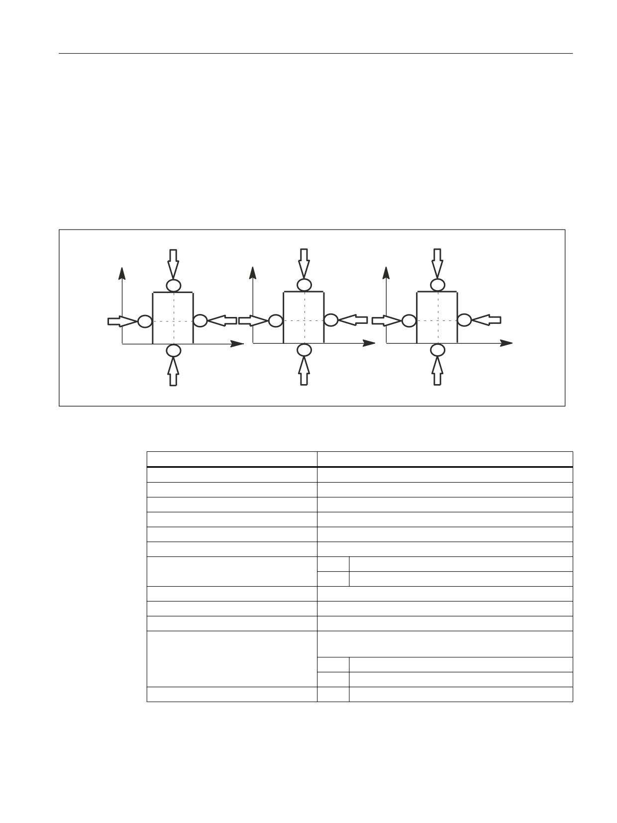
Measurement type 25: Measurement of a rectangle
Function
Four measuring points per rectangle are required to determine a rectangle (tool dimensions)
in the working plane G17 (working plane X/Y, infeed direction Z), G18 (working plane Z/X,
infeed direction Y) or G19 (working plane Y/Z, infeed direction X).
Measuring points can be specified in any desired order. The measuring points with the largest
ordinate distance correspond to points P3 and P4.
*
*
*
\
[
]
3
3
3
3
3
3
3
3
3
3
3
3
\
[
]
Figure 9-15
Measurement of a rectangle
The values of the following system variables are evaluated for measurement type 25:
Input variable
Meaning
$AC_MEAS_VALID
Validity bits for input variables
$AA_MEAS_POINT1[<Axis>]
Measuring point 1
$AA_MEAS_POINT2[<Axis>]
Measuring point 2
$AA_MEAS_POINT3[<Axis>]
Measuring point 3
$AA_MEAS_POINT4[<Axis>]
Measuring point 4
$AC_MEAS_ACT_PLANE *)
Calculation with active plane unless otherwise specified.
$AC_MEAS_FINE_TRANS *)
= 0
Coarse offset
= 1
Fine offset
$AC_MEAS_FRAME_SELECT *)
Calculated as additive frame unless otherwise specified.
$AC_MEAS_T_NUMBER *)
Calculated with active T unless otherwise specified (T0).
$AC_MEAS_D_NUMBER *)
Calculated with active D unless otherwise specified (D0).
$AC_MEAS_INPUT[0] *)
Unless otherwise specified, measurement is performed for
the outer corner.
= 0
Measurement for outer corner
= 1
Measurement for inner corner
$AC_MEAS_TYPE
= 25
Measurement type 25: Measurement of a rectangle
*) Optional
Extended Functions
Function Manual, 12/2018, A5E40874029B AB
587
M5: Measurement
9.5 Workpiece and tool measurement
The following output variables are written for measurement type 25:
Output variable
Meaning
$AC_MEAS_FRAME
Result frame with translation
$AC_MEAS_RESULTS[0]
Abscissa of the calculated center point
$AC_MEAS_RESULTS[1]
Ordinate of the calculated center point
$AC_MEAS_RESULTS[2]
Applicate of the calculated center point
$AC_MEAS_RESULTS[3]
Width of the rectangle P1/P2
$AC_MEAS_RESULTS[4]
Length of the rectangle P3/P4
9.5.2.17
Measurement type 26: Backup of data management frames
Function
This measurement type offers the option of saving some or all data management frames with
their current value assignments to a file. The measurement can be initiated by executing a
command or via the part program. The function can also be activated from different channels.
The files are saved in the "_N_SYF_DIR" directory.
A Restore operation deletes the backed-up data and a new Save operation overwrites the
existing back-up.
The data saved last can be deleted from the data management through a new backup with
the following settings:
● $AC_MEAS_CHSFR = 0 ; System frames
● $AC_MEAS_NCBFR = 0 ; Global basic frames
● $AC_MEAS_CHBFR = 0 ; Channel basic frames
● $AC_MEAS_UIFR = 0 ; Number of settable frames
Note
If you decide to create a backup of all data management frames, remember that 1 KB of
memory is needed to save each frame. If insufficient memory is available, the process is
aborted with an error message.
Remedy: Adapt the configuration of the static user memory.
References: See Section "S7: Memory configuration (Page 827)".
The values of the following system variables are evaluated for measurement type 26:
Input variable
Meaning
$AC_MEAS_VALID
Validity bits for input variables
$AC_MEAS_CHSFR *)
Bit mask of system frames from the data management.
If this variable is not written, all system frames are backed
up.
Extended Functions
588
Function Manual, 12/2018, A5E40874029B AB
M5: Measurement
9.5 Workpiece and tool measurement
Input variable
Meaning
$AC_MEAS_NCBFR *)
Bit mask of global basic frames from the data management.
If this variable is not written, all global basic frames are
backed up.
$AC_MEAS_CHBFR *)
Bit mask of channel basic frames from the data management.
If this variable is not written, all channel basic frames are
backed up.
$AC_MEAS_UIFR *)
Number of settable frames from the data management.
If this variable is not written, all settable frames are backed
up.
$AC_MEAS_TYPE
= 26
Measurement type 26: Backup of data management
frames
*) Optional
9.5.2.18
Measurement type 27: Restoration of backed up data management data
Function
This measurement type allows data management frames backed up by measurement type 26
to be restored to the dynamic user memory.
It is possible to restore either the frames backed up last or selected frames. If a frame that has
not been backed up is selected, the selection is ignored. The process is not aborted.
The values of the following system variables are evaluated for measurement type 27:
Input variable
Meaning
$AC_MEAS_VALID
Validity bits for input variables
$AC_MEAS_CHSFR *)
Bit mask of system frames from the data management.
If the variable is not written, all system frames are restored.
$AC_MEAS_NCBFR *)
Bit mask of global basic frames from the data management.
If the variable is not written, all global basic frames are re-
stored.
$AC_MEAS_CHBFR *)
Bit mask of channel basic frames from the data management.
If the variable is not written, all channel basic frames are re-
stored.
$AC_MEAS_UIFR *)
Number of settable frames from the data management.
If the variable is not written, all settable frames are restored.
$AC_MEAS_TYPE
= 27
Measurement type 27: Restoration of backed up data
management data
*) Optional
Extended Functions
Function Manual, 12/2018, A5E40874029B AB
589
M5: Measurement
9.5 Workpiece and tool measurement
9.5.2.19
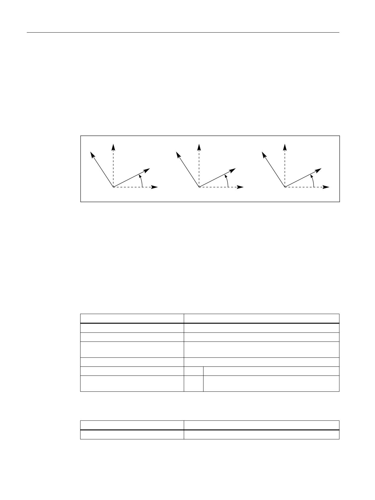
Measurement type 28: Specification of an additive rotation for taper turning
Function
Measuring type 28 can be used to specify an additive rotation through an angle α of the active
or a certain plane.
Value range: - 90 ° ≤ α ≤ + 90 °
The rotation takes place on the coordinate axis at right angles to the plane.
\
[
]
\
[
]
*
*
*
[
]
\
˞
˞
˞
[
]
\
Figure 9-16
Specification of an additive rotation (α = +30°) for taper turning in the G17/G18/G19 plane
Application
With taper turning, the active plane is rotated by the taper angle, whereby the rotation is written
in the active cycle frame. The cycle frame is deleted with reset. Re-activation may be
necessary. The selection of the cycle frame is made depending on the SZS position display.
If after activation of the rotation, e.g. with active plane G18, traversing is performed in the
direction of Z', the actual positions of the corresponding axes change simultaneously for X and
Z. Rotations with active planes G17 and G19 behave similarly and are displayed in the above
figure.
Input/output variables
The values of the following system variables are evaluated for measurement type 28:
Input variable
Meaning
$AC_MEAS_VALID
Validity bits for input variables
$AC_MEAS_WP_SETANGLE
Set angle
$AC_MEAS_ACT_PLANE *)
Rotation is around the active plane unless otherwise speci-
fied.
$AC_MEAS_FRAME_SELECT *)
Calculated as additive frame unless otherwise specified.
$AC_MEAS_INPUT[0] *)
= 1
Taper turning is active.
$AC_MEAS_TYPE
= 28
Measurement type 28: Specification of an additive
rotation for taper turning
*) Optional
The following output variables are written for measurement type 28:
Output variable
Meaning
$AC_MEAS_FRAME
Result with rotation
Extended Functions
590
Function Manual, 12/2018, A5E40874029B AB
M5: Measurement
9.5 Workpiece and tool measurement
9.5.3
Measuring types of the tool measurement
9.5.3.1
Overview
The following measurement types can be used to measure a tool loaded on a turning or milling
machine:
Measurement type
Type of measurement
$AC_MEAS_TYPE =
10
Measurement of the tool length (Page 591)
11
Measurement of the tool diameter (Page 593)
22
Measurement of tool lengths with zoom-in function (Page 595)
23
Measurement of a tool length with a stored or actual position
(Page 596)
Measurement of a tool length of two tools with orientation (Page 597)
9.5.3.2
Measurement type 10: Measurement of the tool length
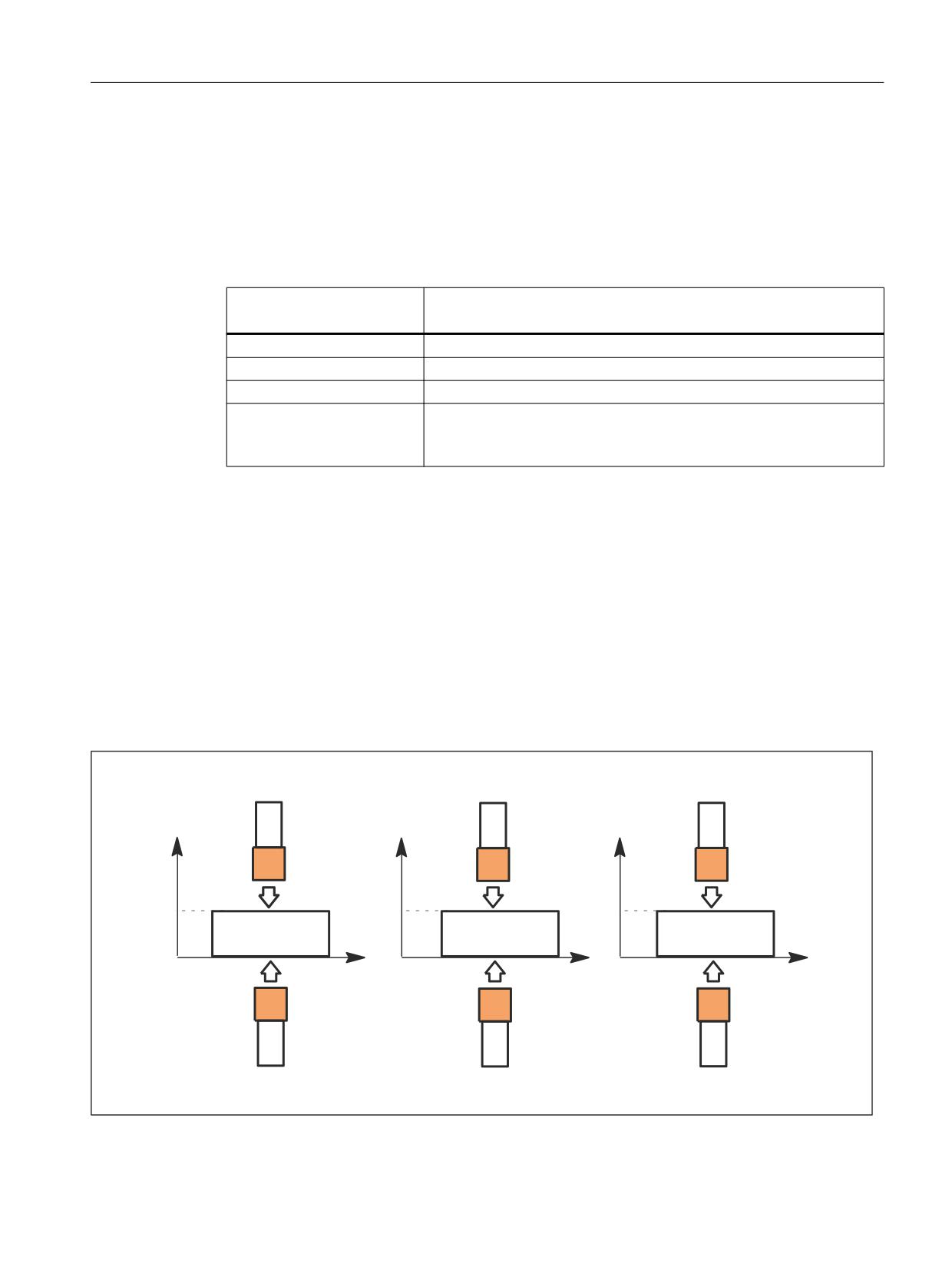
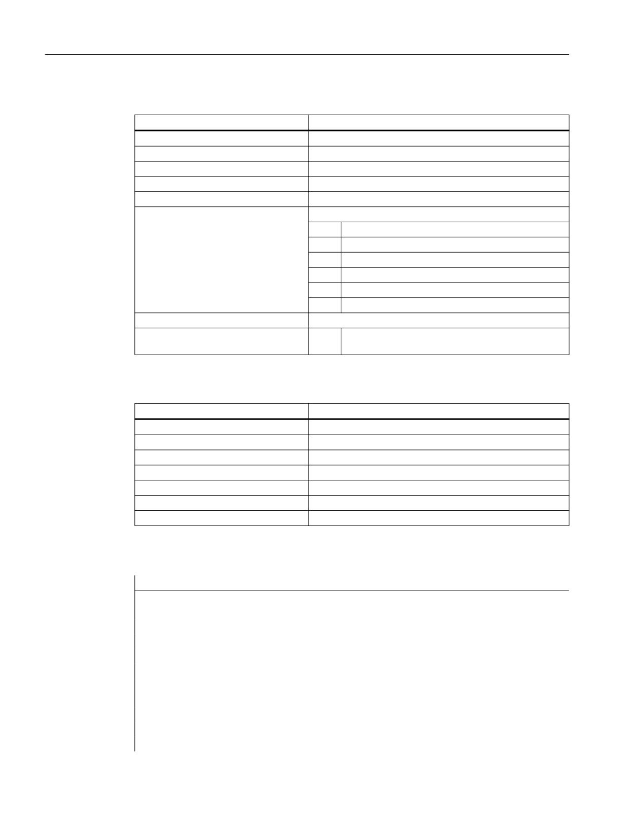
Function
The tool length can be measured on a previously measured reference part.
The plane selection depends on the position of the tool:
● G17 for tool position in the Z direction
● G18 for tool position in the Y direction
● G19 for tool position in the X direction
*
*
*
]
\
[
]
\
[
]
\
[
[
]
\
]
\
[
Figure 9-17
Measurement of the tool length in the G17/G18/G19 plane
Extended Functions
Function Manual, 12/2018, A5E40874029B AB
591
M5: Measurement
9.5 Workpiece and tool measurement
The values of the following system variables are evaluated for measurement type 10:
Input variable
Meaning
$AC_MEAS_VALID
Validity bits for the input variables
$AA_MEAS_POINT1[<Axis>]
Measuring point 1
$AC_MEAS_P1_COORD *)
Coordinate system of the measuring point
$AA_MEAS_SETPOINT[<Axis>]
Set position Z0
$AC_MEAS_SET_COORD *)
Coordinate system of the setpoint
$AC_MEAS_DIR_APPROACH
Direction of approach to the workpiece
= 0
+ X
= 1
- X
= 2
+ Y
= 3
- Y
= 4
+ Z
= 5
- Z
$AC_MEAS_ACT_PLANE *)
Calculation with active plane unless otherwise specified.
$AC_MEAS_TYPE
= 10
Measurement type 10: Measurement of the tool
length
*) Optional
The following output variables are written for measurement type 10:
Output variable
Meaning
$AC_MEAS_TOOL_LENGTH
Tool length
$AC_MEAS_RESULTS[0]
Tool length in X
$AC_MEAS_RESULTS[1]
Tool length in Y
$AC_MEAS_RESULTS[2]
Tool length in Z
$AC_MEAS_RESULTS[3]
Tool length L1
$AC_MEAS_RESULTS[4]
Tool length L2
$AC_MEAS_RESULTS[5]
Tool length L3
Example
Program code
Comment
DEF INT RETVAL
T0 D0
G0 X0 Y0 Z0 F10000
; Measure tool length.
$AC_MEAS_VALID=0
; Set all input values to invalid.
G1 Z10
; Traverse tool to reference part.
$AC_MEAS_LATCH[0]=1
; Pick up measuring point 1.
$AC_MEAS_DIR_APPROACH=5
; Set approach direction -Z
$AA_MEAS_SETPOINT[X]=0
; Set reference position.
$AA_MEAS_SETPOINT[Y]=0
Extended Functions
592
Function Manual, 12/2018, A5E40874029B AB
M5: Measurement
9.5 Workpiece and tool measurement
Program code
Comment
$AA_MEAS_SETPOINT[Z]=0
$AC_MEAS_ACT_PLANE=0
; Measuring plane is G17.
$AC_MEAS_T_NUMBER=0
; No tool has been selected.
$AC_MEAS_D_NUMBER=0
$AC_MEAS_TYPE=10
; Set measuring type on tool length.
RETVAL=MEASURE()
; Start measuring process.
IF RETVAL <> 0
SETAL(61043, << RETVAL)
ENDIF
IF $AC_MEAS_TOOL_LENGTH <> 10
; Query known tool length.
SETAL(61043, << $AC_MEAS_TOOL_LENGTH)
ENDIF
M30
9.5.3.3
Measurement type 11: Measurement of the tool diameter
Function
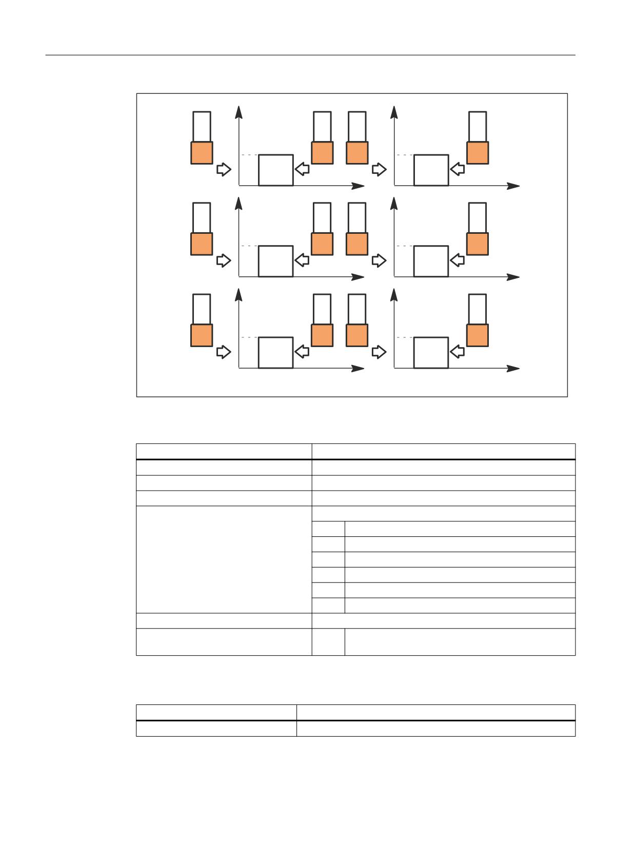
The tool diameter can be measured on a previously measured reference part.
The plane selection depends on the position of the tool:
● G17 for tool position in the Z direction
● G18 for tool position in the Y direction
● G19 for tool position in the X direction
Extended Functions
Function Manual, 12/2018, A5E40874029B AB
593
M5: Measurement
9.5 Workpiece and tool measurement
]
]
*
*
[
[
\
\
[
[
\
[
\
\
*
*
[
[
]
]
[
[
]
]
[
[
*
*
\
\
]
]
\
\
]
]
Figure 9-18
Measurement of the tool diameter in the G17/G18/G19 plane
The values of the following system variables are evaluated for measurement type 11:
Input variable
Meaning
$AC_MEAS_VALID
Validity bits for the input variables
$AA_MEAS_POINT1[<Axis>]
Measuring point 1
$AA_MEAS_SETPOINT[<Axis>]
Set position X0
$AC_MEAS_DIR_APPROACH
Direction of approach to the workpiece
= 0
+ X
= 1
- X
= 2
+ Y
= 3
- Y
= 4
+ Z
= 5
- Z
$AC_MEAS_ACT_PLANE *)
Calculation with active plane unless otherwise specified.
$AC_MEAS_TYPE
= 11
Measurement type 11: Measurement of the tool di-
ameter
*) Optional
The following output variables are written for measurement type 11:
Output variable
Meaning
$AC_MEAS_TOOL_DIAMETER
Tool diameter
Extended Functions
594
Function Manual, 12/2018, A5E40874029B AB
M5: Measurement
9.5 Workpiece and tool measurement
9.5.3.4
Measurement type 22: Measurement of tool lengths with zoom-in function
Function
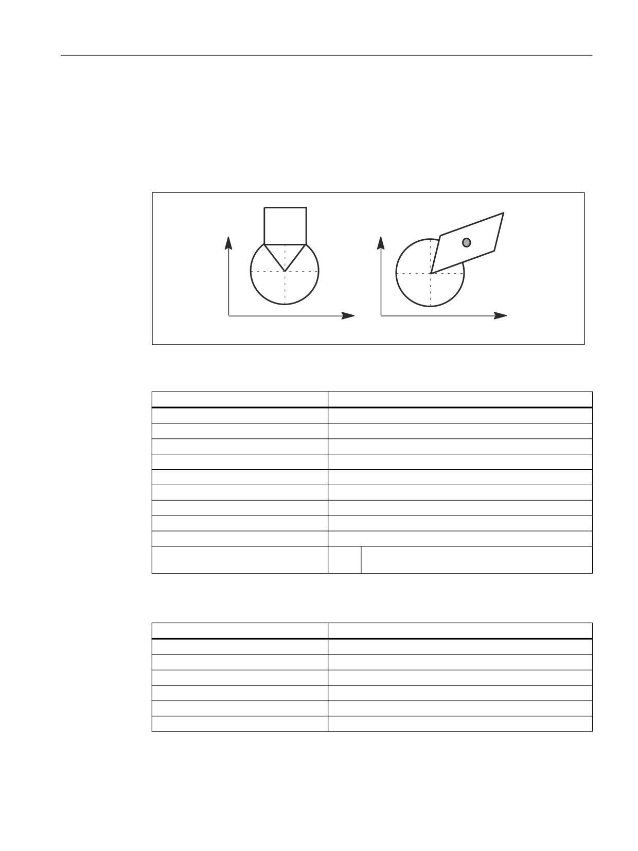
If a zoom-in function is available on the machine, it can also be used to determine the tool
lengths.
[
[
]
]
Figure 9-19
Measurement of tool lengths with zoom-in function
The values of the following system variables are evaluated for measurement type 22:
Input variable
Meaning
$AC_MEAS_VALID
Validity bits for the input variables
$AA_MEAS_POINT1[<Axis>]
Measuring point 1 for all channel axes
$AC_MEAS_P1_COORD *)
Coordinate system of the measuring point
$AA_MEAS_SETPOINT[<Axis>]
Zoom positions X and Z must be specified.
$AC_MEAS_SET_COORD *)
Coordinate system of the setpoint
$AC_MEAS_ACT_PLANE *)
Calculation with active plane unless otherwise specified.
$AC_MEAS_FRAME_SELECT *)
Calculated as additive frame unless otherwise specified.
$AC_MEAS_T_NUMBER *)
Calculated with active T unless otherwise specified (T0).
$AC_MEAS_D_NUMBER *)
Calculated with active D unless otherwise specified (D0).
$AC_MEAS_TYPE
= 22
Measurement type 22: Measurement of tool lengths
with zoom-in function
*) Optional
The following output variables are written for measurement type 22:
Output variable
Meaning
$AC_MEAS_RESULT[0]
Tool length in X
$AC_MEAS_RESULT[1]
Tool length in Y
$AC_MEAS_RESULT[2]
Tool length in Z
$AC_MEAS_RESULT[3]
Tool length L1
$AC_MEAS_RESULT[4]
Tool length L2
$AC_MEAS_RESULT[5]
Tool length L3
Extended Functions
Function Manual, 12/2018, A5E40874029B AB
595
M5: Measurement
9.5 Workpiece and tool measurement
9.5.3.5
Measurement type 23: Measurement of a tool length with a stored or actual position
Function
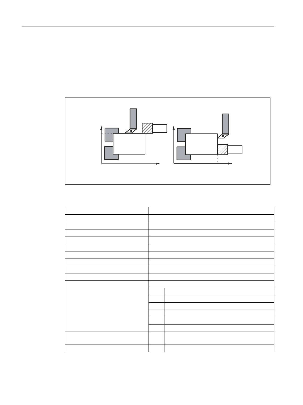
In the case of manual measurement, the tool dimensions can be determined in the X and Z
directions. ShopTurn then calculates the tool offset data from the known position of the tool
carrier reference point and the workpiece dimensions.
[
[
[
]
]
]
Figure 9-20
Measurement of a tool length with a stored or actual position
The values of the following system variables are evaluated for measurement type 23:
Input variable
Meaning
$AC_MEAS_VALID
Validity bits for the input variables
$AA_MEAS_POINT1[<Axis>]
Current or stored position
$AC_MEAS_P1_COORD *)
Coordinate system of the measuring point
$AA_MEAS_SETPOINT[<Axis>]
Set position (at least one geometry axis must be specified)
$AC_MEAS_SET_COORD *)
Coordinate system of the setpoint
$AC_MEAS_ACT_PLANE *)
Calculation with active plane unless otherwise specified.
$AC_MEAS_T_NUMBER *)
Calculated with active T unless otherwise specified (T0).
$AC_MEAS_D_NUMBER *)
Calculated with active D unless otherwise specified (D0).
$AC_MEAS_TOOL_MASK *)
Tool position, radius
$AC_MEAS_DIR_APPROACH *)
Direction of approach to the workpiece
= 0
+ X
= 1
- X
= 2
+ Y
= 3
- Y
= 4
+ Z
= 5
- Z
$AC_MEAS_INPUT[0] *)
= 1
The calculated tool lengths are written to the data
management.
$AC_MEAS_TYPE
= 23
Measurement type 23:
*) Optional
Extended Functions
596
Function Manual, 12/2018, A5E40874029B AB
M5: Measurement
9.5 Workpiece and tool measurement
The following output variables are written for measurement type 23:
Output variable
Meaning
$AC_MEAS_RESULT[0]
Tool length in X
$AC_MEAS_RESULT[1]
Tool length in Y
$AC_MEAS_RESULT[2]
Tool length in Z
$AC_MEAS_RESULT[3]
Tool length L1
$AC_MEAS_RESULT[4]
Tool length L2
$AC_MEAS_RESULT[5]
Tool length L3
9.5.3.6
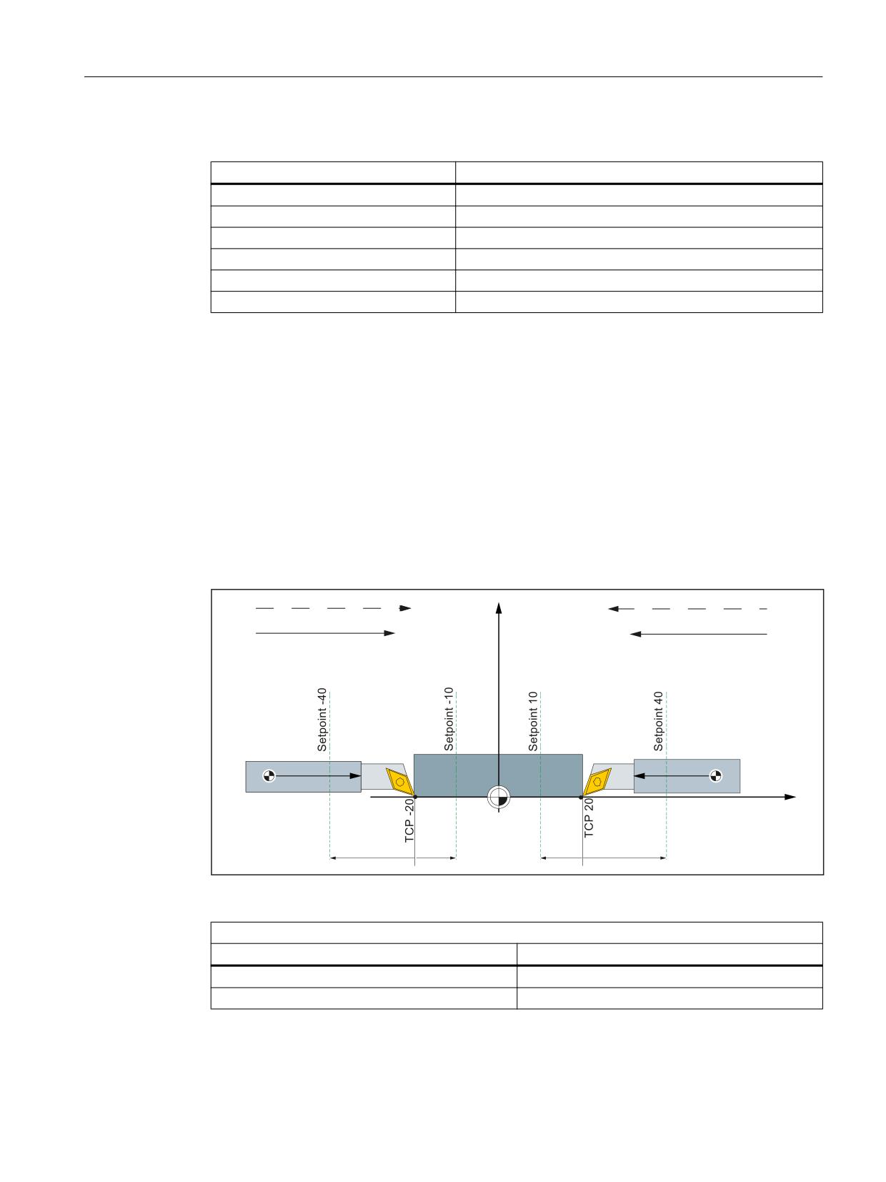
Measurement type 23: Measurement of a tool length of two tools with the following
orientation:
Tool orientation
For tools whose orientation points to the toolholder shows must be set in the system variables
$AC_MEAS_TOOL_MASK, bit 9 = 1 (0x200). The calculated tool lengths are then included
negatively.
Two turning tools each with their own reference point with a tool orientation in the approach direction
%&6
$SSURDFK GLUHFWLRQ
[
[
$SSURDFK GLUHFWLRQ
7RRO RULHQWDWLRQ
[
[
7RRO RULHQWDWLRQ
[
:=/ ದ
:=/ ದ
Settings in the system data:
Left-hand tool: Approach direction and tool orientation +x
System variable
Meaning
$AC_MEAS_TOOL_MASK = 0x2
Tool position in x direction (G19)
$AC_MEAS_DIR_APPROACH = 0
Approach direction +x
Extended Functions
Function Manual, 12/2018, A5E40874029B AB
597
M5: Measurement
9.5 Workpiece and tool measurement
Right-hand tool: Approach direction and tool orientation -x
$AC_MEAS_TOOL_MASK = 0x40
Tool position in the -x direction
$AC_MEAS_DIR_APPROACH = 1
Approach direction -x
For both tools
$AC_MEAS_Px_COORD = 1
Coordinate system of x-th measuring point = BCS
$AC_MEAS_SET_COORD = 1
Coordinate system of the setpoint = BCS
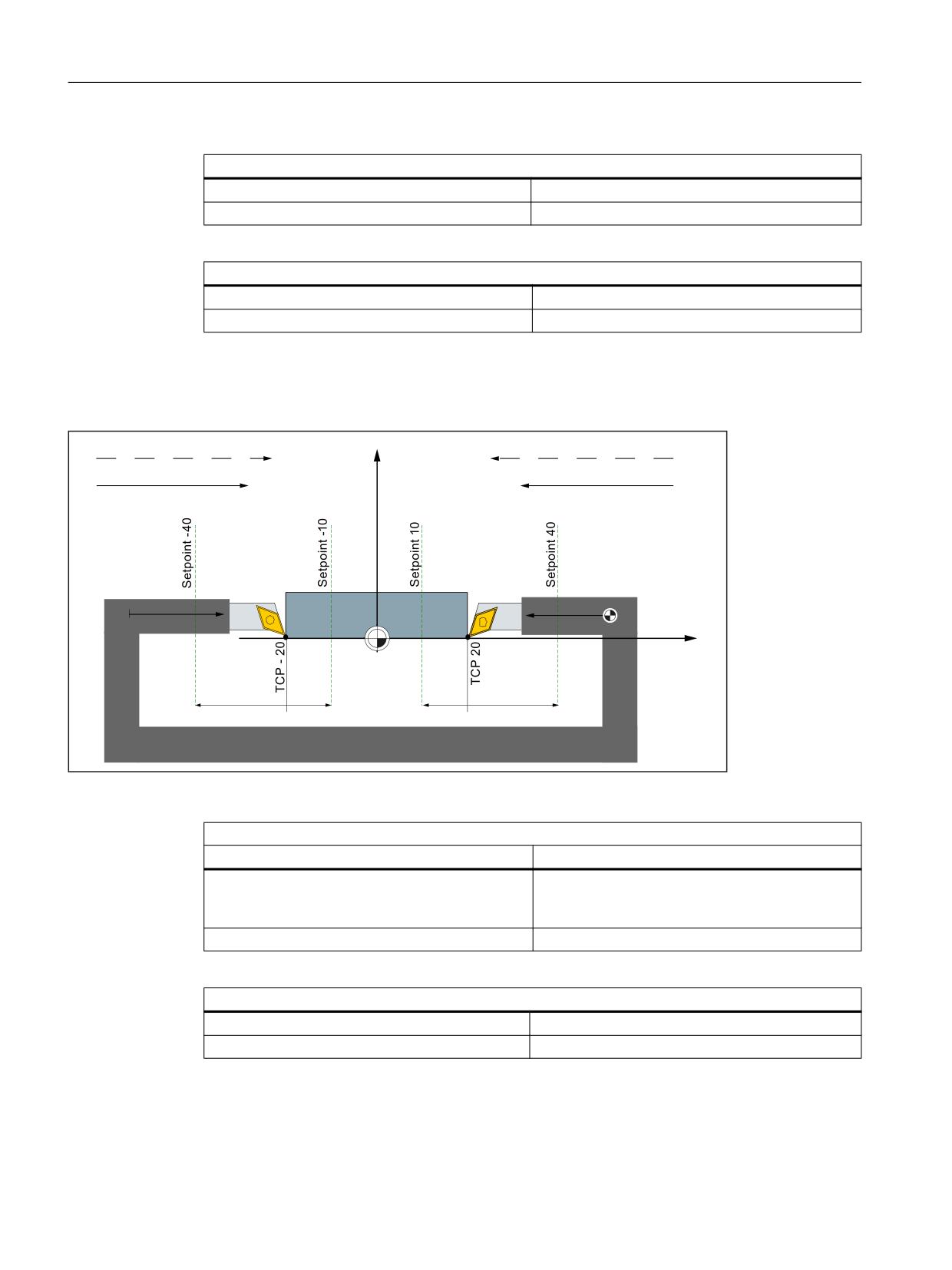
Two turning tools each with their own reference point with a tool counter-orientation in the approach
direction
%&6
$SSURDFK GLUHFWLRQ
[
[
$SSURDFK GLUHFWLRQ
7RRO RULHQWDWLRQ
[
[
7RRO RULHQWDWLRQ
[
:=/
:=/
Settings in the system data:
Left-hand tool: Approach direction and tool orientation +x
System variable
Meaning
$AC_MEAS_TOOL_MASK = 0x2 + 0x200
Tool position in x direction (G19) +
Tool length differential values are included nega-
tively
$AC_MEAS_DIR_APPROACH = 0
Approach direction +x
Right-hand tool: Approach direction and tool orientation -x
$AC_MEAS_TOOL_MASK = 0x40
Tool position in the -x direction
$AC_MEAS_DIR_APPROACH = 1
Approach direction -x
Extended Functions
598
Function Manual, 12/2018, A5E40874029B AB
M5: Measurement
9.5 Workpiece and tool measurement
For both tools
$AC_MEAS_Px_COORD = 1
Coordinate system of x-th measuring point = BCS
$AC_MEAS_SET_COORD = 1
Coordinate system of the setpoint = BCS
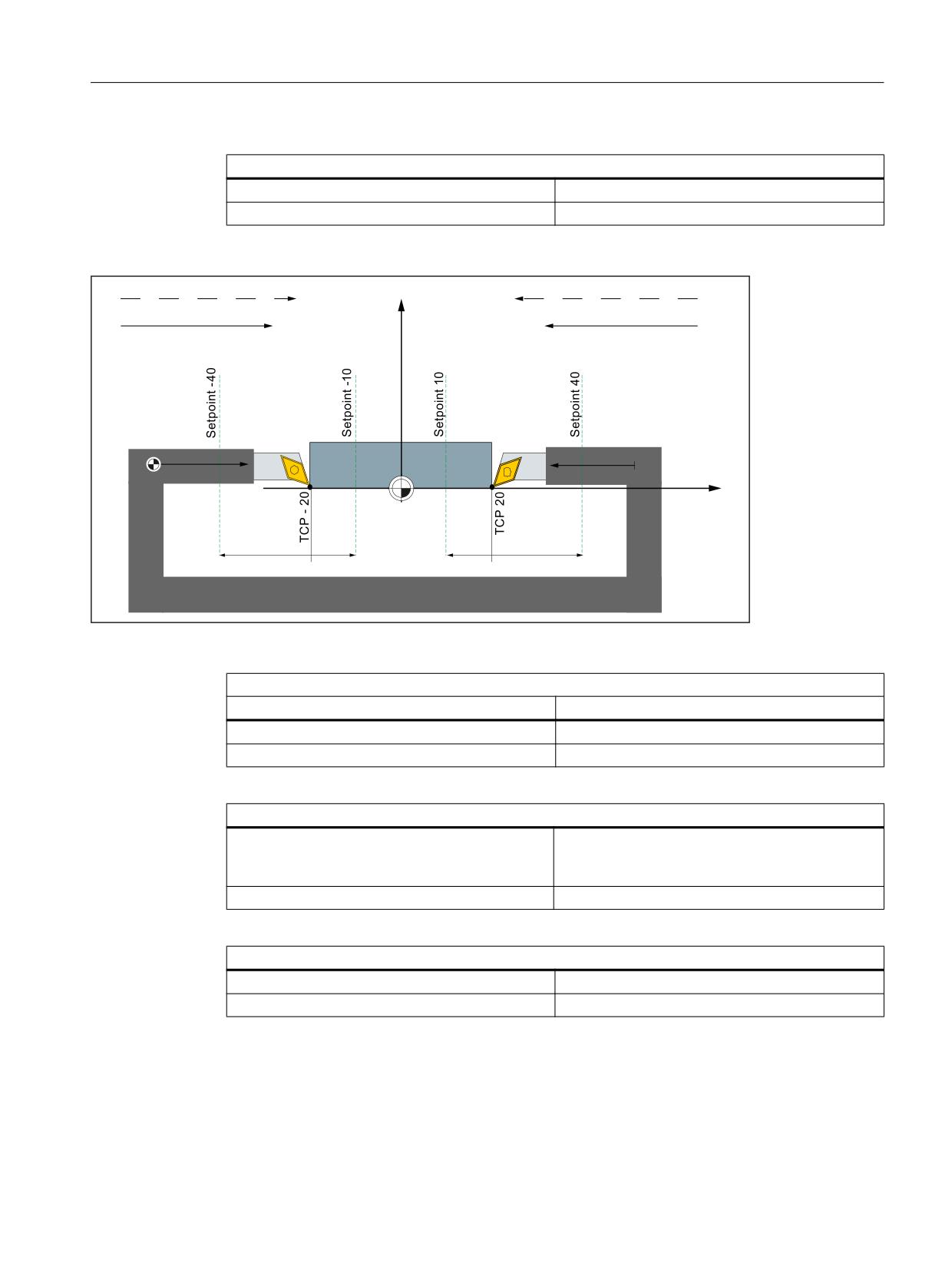
%&6
$SSURDFK GLUHFWLRQ
[
[
$SSURDFK GLUHFWLRQ
7RRO RULHQWDWLRQ
[
[
7RRO RULHQWDWLRQ
[
:=/ ದ
ದ
:=/
Settings in the system data:
Left-hand tool: Approach direction and tool orientation +x
System variable
Meaning
$AC_MEAS_TOOL_MASK = 0x2
Tool position in x direction (G19)
$AC_MEAS_DIR_APPROACH = 0
Approach direction +x
Right-hand tool: Approach direction and tool orientation -x
$AC_MEAS_TOOL_MASK = 0x40 + 0x200
Tool position in x direction +
Tool length differential values are included nega-
tively
$AC_MEAS_DIR_APPROACH = 1
Approach direction -x
For both tools
$AC_MEAS_Px_COORD = 1
Coordinate system of x-th measuring point = BCS
$AC_MEAS_SET_COORD = 1
Coordinate system of the setpoint = BCS
Extended Functions
Function Manual, 12/2018, A5E40874029B AB
599
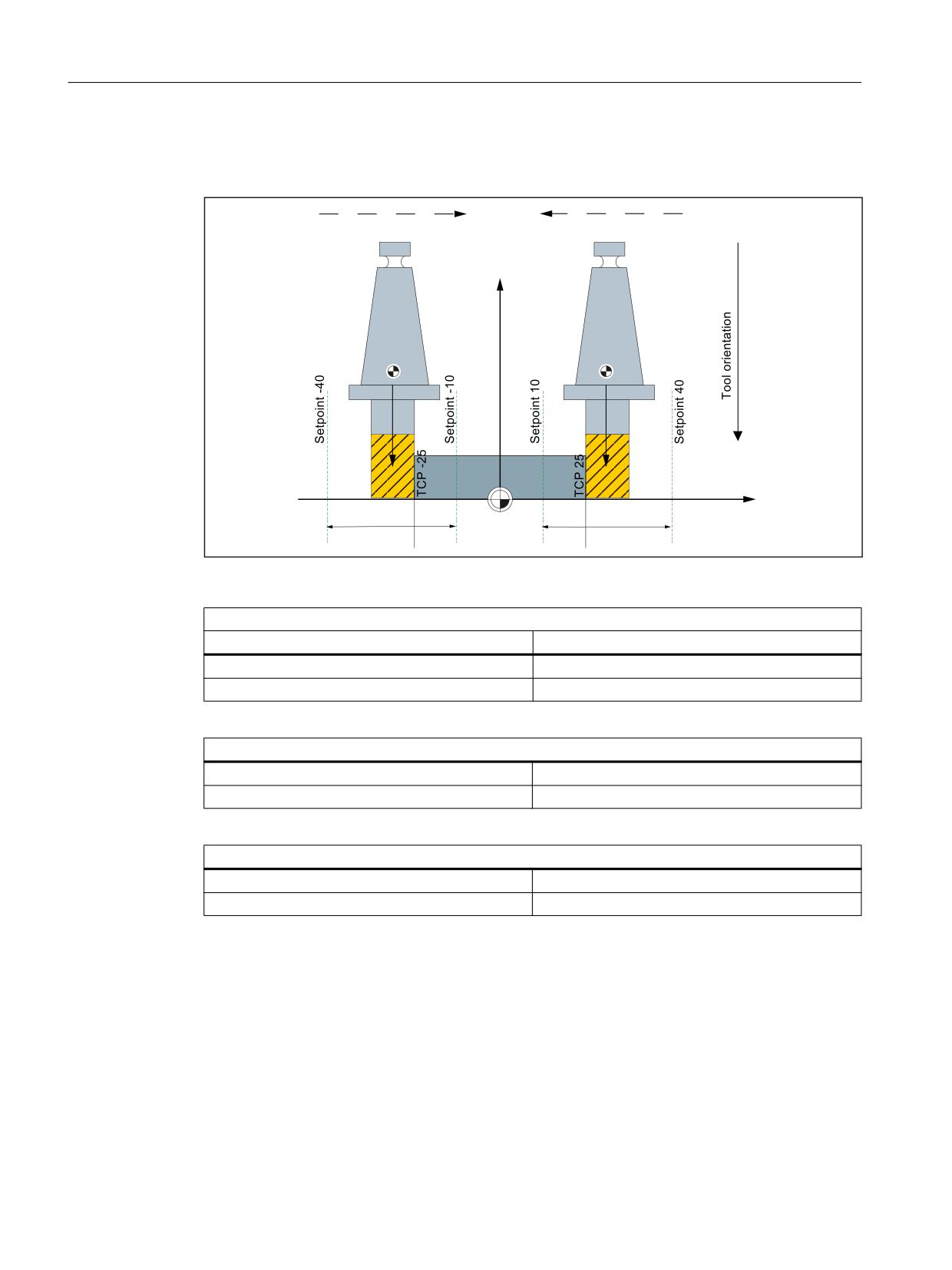
M5: Measurement
9.5 Workpiece and tool measurement
Two milling tools each with their own reference point, tool orientation perpendicular to the approach
direction
$SSURDFK GLUHFWLRQ
[
ದ[
$SSURDFK GLUHFWLRQ
%&6
\
:
[
ದ
ದ
Settings in the system data:
Left-hand tool: Approach direction +x and tool orientation -y
System variable
Meaning
$AC_MEAS_TOOL_MASK = 0x80
Tool position in -y direction
$AC_MEAS_DIR_APPROACH = 0
Approach direction +x
Right-hand tool: Approach direction -x and tool orientation -y
$AC_MEAS_TOOL_MASK = 0x80
Tool position in -y direction
$AC_MEAS_DIR_APPROACH = 1
Approach direction -x
For both tools
$AC_MEAS_Px_COORD = 1
Coordinate system of x-th measuring point = BCS
$AC_MEAS_SET_COORD = 1
Coordinate system of the setpoint = BCS
Extended Functions
600
Function Manual, 12/2018, A5E40874029B AB
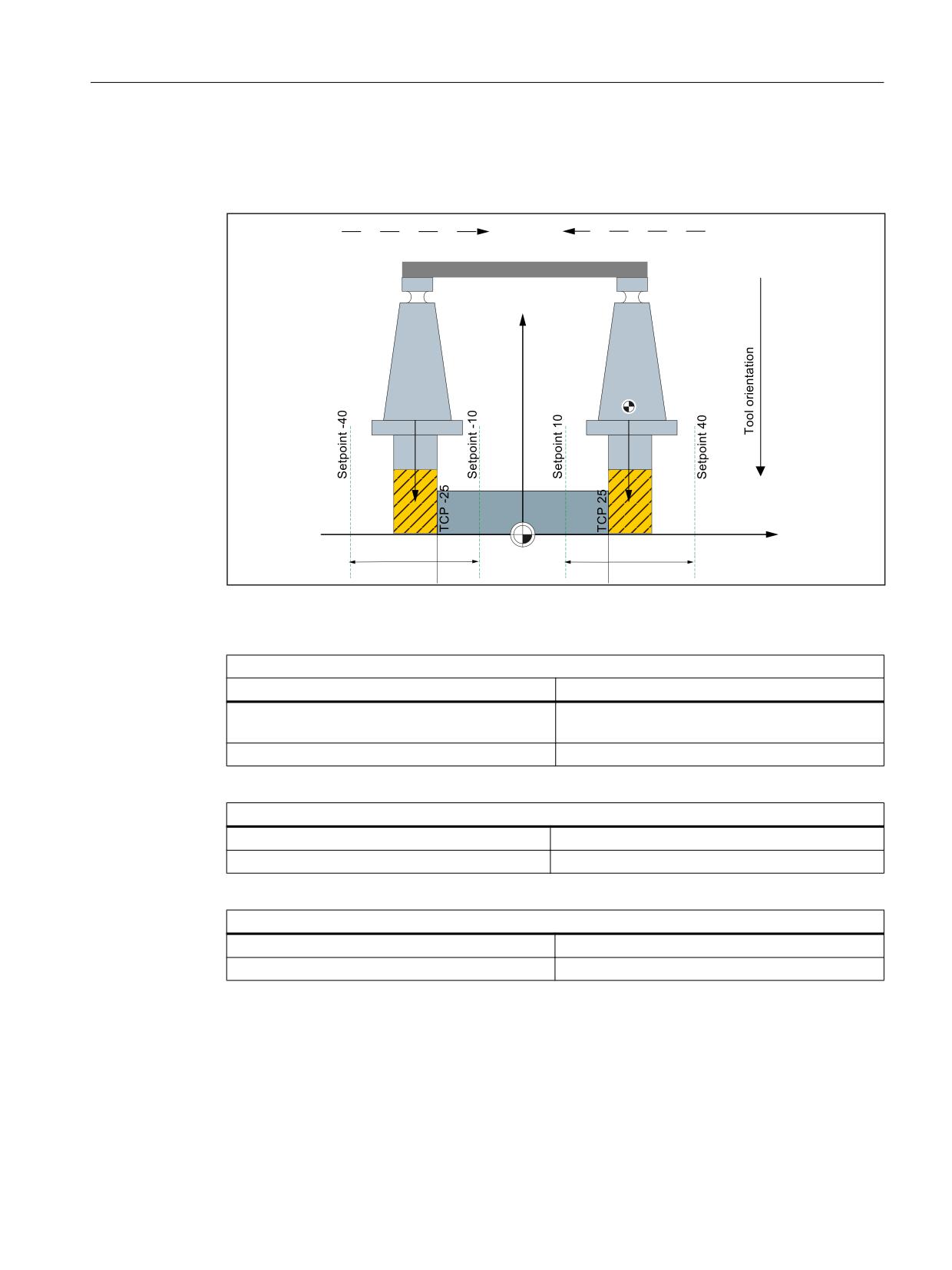
M5: Measurement
9.5 Workpiece and tool measurement
Two milling tools each with a reference point, tool orientation perpendicular to the approach direction
Two milling tools with one reference point with a tool orientation in -y
$SSURDFK GLUHFWLRQ
[
ದ[
$SSURDFK GLUHFWLRQ
%&6
\
:
[
ದ
In the present layout, the tool position $AC_MEAS_TOOL_MASK and approach direction to
the workpiece $AC_MEAS_DIR_APPROACH must be set as follows:
Left-hand tool: Approach direction +x and tool orientation -y
System variable
Meaning
$AC_MEAS_TOOL_MASK = 0x80 + 0x200
Tool position in -y direction + tool length differential
values are included negatively
$AC_MEAS_DIR_APPROACH = 0
Approach direction +x
Right-hand tool: Approach direction -x and tool orientation -y
$AC_MEAS_TOOL_MASK = 0x80
Tool position in -y direction
$AC_MEAS_DIR_APPROACH = 1
Approach direction -x
For both tools
$AC_MEAS_Px_COORD = 1
Coordinate system of x-th measuring point = BCS
$AC_MEAS_SET_COORD = 1
Coordinate system of the setpoint = BCS
Extended Functions
Function Manual, 12/2018, A5E40874029B AB
601
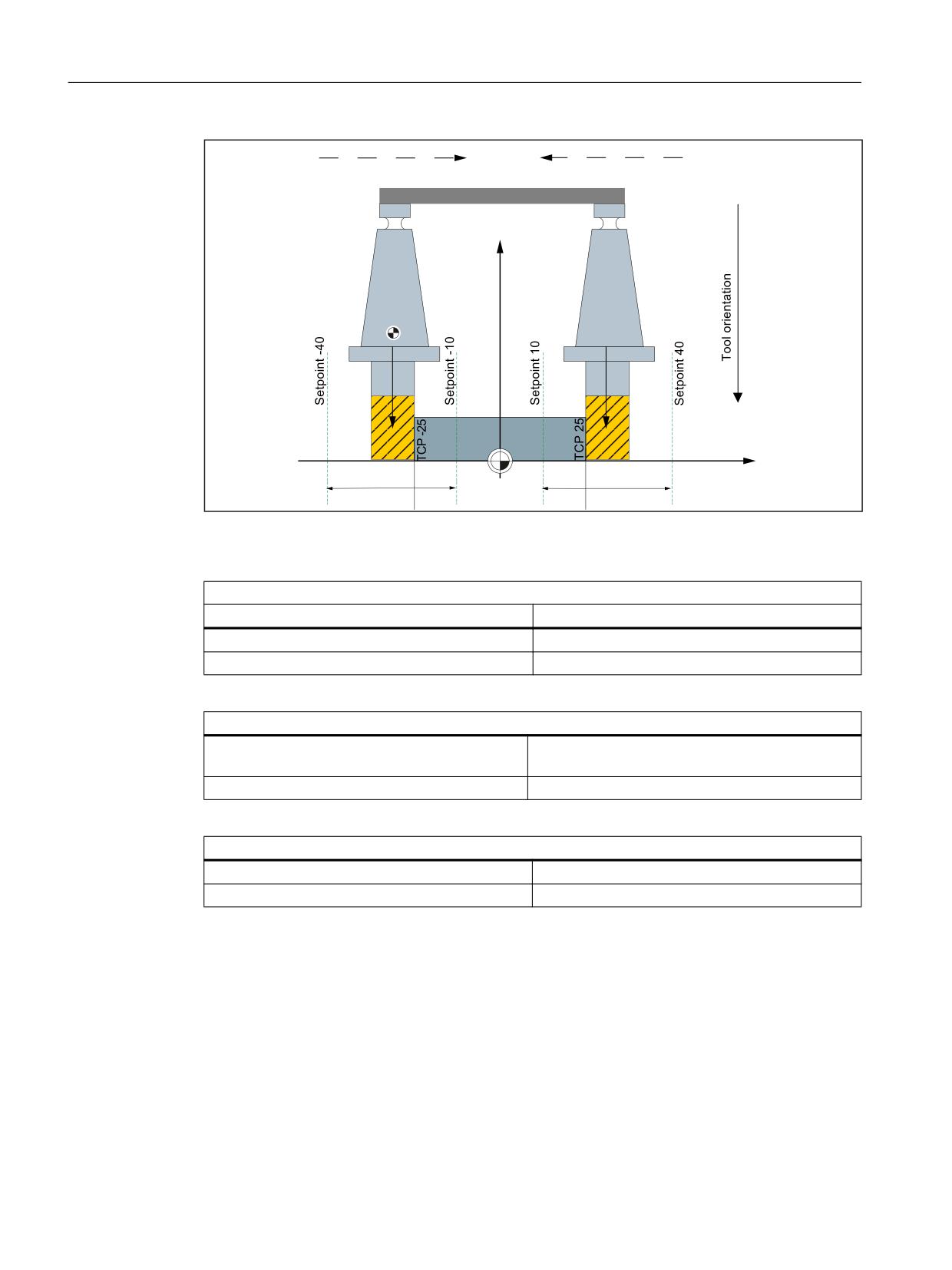
M5: Measurement
9.5 Workpiece and tool measurement
$SSURDFK GLUHFWLRQ
[
ದ[
$SSURDFK GLUHFWLRQ
%&6
\
:
[
In the present layout, the tool position $AC_MEAS_TOOL_MASK and approach direction to
the workpiece $AC_MEAS_DIR_APPROACH must be set as follows:
Left-hand tool: Approach direction +x and tool orientation -y
System variable
Meaning
$AC_MEAS_TOOL_MASK = 0x80
Tool position in -y direction
$AC_MEAS_DIR_APPROACH = 0
Approach direction +x
Right-hand tool: Approach direction -x and tool orientation -y
$AC_MEAS_TOOL_MASK = 0x80 + 0x200
Tool position in -y direction + tool length differential
values are included negatively
$AC_MEAS_DIR_APPROACH = 1
Approach direction -x
For both tools
$AC_MEAS_Px_COORD = 1
Coordinate system of x-th measuring point = BCS
$AC_MEAS_SET_COORD = 1
Coordinate system of the setpoint = BCS
Extended Functions
602
Function Manual, 12/2018, A5E40874029B AB
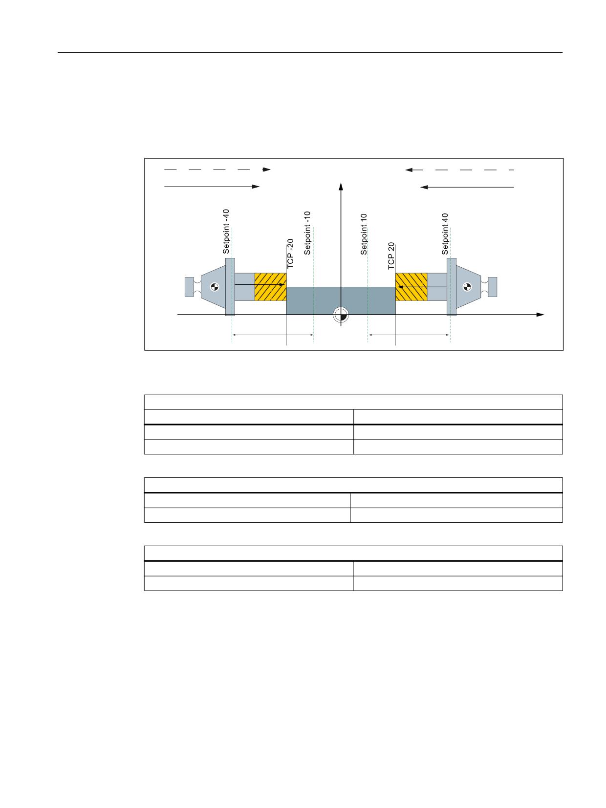
M5: Measurement
9.5 Workpiece and tool measurement
Two milling tools each with their own reference point with tool counter-orientation in the approach
direction
Two milling tools each with their own reference point with a tool orientation in the approach
direction
$SSURDFK GLUHFWLRQ
[
[
$SSURDFK GLUHFWLRQ
7RRO RULHQWDWLRQ
[
[
7RRO RULHQWDWLRQ
%&6
[
ದ
ದ
In the present layout, the tool position $AC_MEAS_TOOL_MASK and approach direction to
the workpiece $AC_MEAS_DIR_APPROACH must be set as follows:
Left-hand tool: Approach direction and tool orientation +x
System variable
Meaning
$AC_MEAS_TOOL_MASK = 0x2
Tool position in x direction (G19)
$AC_MEAS_DIR_APPROACH = 0
Approach direction +x
Right-hand tool: Approach direction and tool orientation -x
$AC_MEAS_TOOL_MASK = 0x40
Tool position in the -x direction
$AC_MEAS_DIR_APPROACH = 1
Approach direction -x
For both tools
$AC_MEAS_Px_COORD = 1
Coordinate system of x-th measuring point = BCS
$AC_MEAS_SET_COORD = 1
Coordinate system of the setpoint = BCS
Extended Functions
Function Manual, 12/2018, A5E40874029B AB
603
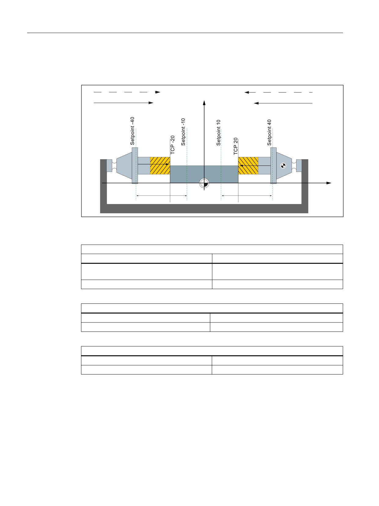
M5: Measurement
9.5 Workpiece and tool measurement
Two milling tools each with a reference point with tool counter-orientation in the approach direction
Two milling tools with one reference point with a tool position opposite to the orientation
$SSURDFK GLUHFWLRQ
[
[
$SSURDFK GLUHFWLRQ
7RRO RULHQWDWLRQ
[
[
7RRO RULHQWDWLRQ
%&6
[
ದ
In the present layout, the tool position $AC_MEAS_TOOL_MASK and approach direction to
the workpiece $AC_MEAS_DIR_APPROACH must be set as follows:
Left-hand tool: Approach direction and tool orientation +x
System variable
Meaning
$AC_MEAS_TOOL_MASK = 0x2 + 0x200
Tool position in x direction (G19) + tool length dif-
ferential values are included negatively
$AC_MEAS_DIR_APPROACH = 0
Approach direction +x
Right-hand tool: Approach direction and tool orientation -x
$AC_MEAS_TOOL_MASK = 0x40
Tool position in the -x direction
$AC_MEAS_DIR_APPROACH = 1
Approach direction -x
For both tools
$AC_MEAS_Px_COORD = 1
Coordinate system of x-th measuring point = BCS
$AC_MEAS_SET_COORD = 1
Coordinate system of the setpoint = BCS
Extended Functions
604
Function Manual, 12/2018, A5E40874029B AB
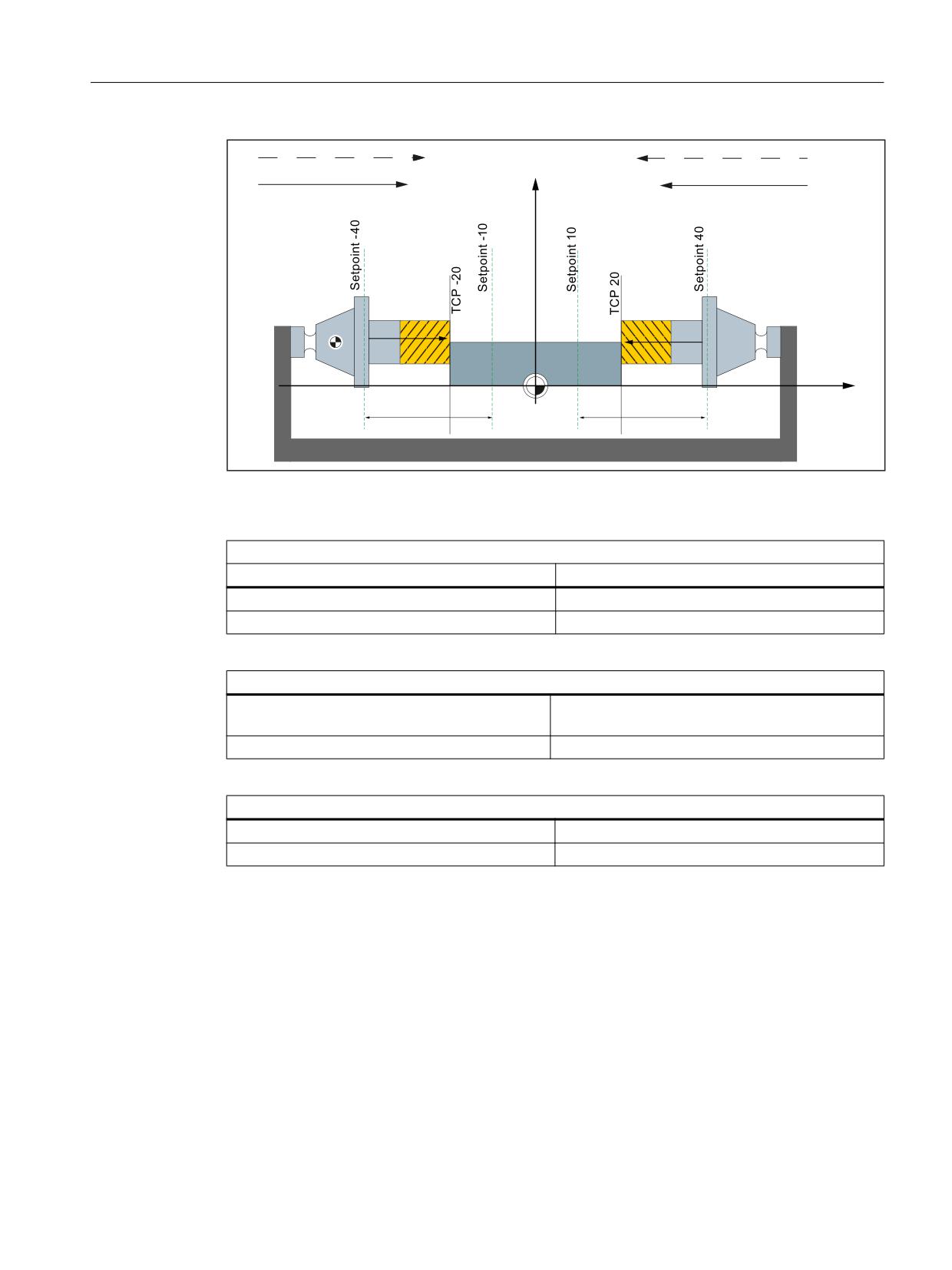
M5: Measurement
9.5 Workpiece and tool measurement
$SSURDFK GLUHFWLRQ
[
[
$SSURDFK GLUHFWLRQ
7RRO RULHQWDWLRQ
[
[
7RRO RULHQWDWLRQ
%&6
[
In the present layout, the tool position $AC_MEAS_TOOL_MASK and approach direction to
the workpiece $AC_MEAS_DIR_APPROACH must be set as follows:
Left-hand tool: Approach direction and tool orientation +x
System variable
Meaning
$AC_MEAS_TOOL_MASK = 0x2
Tool position in x direction (G19)
$AC_MEAS_DIR_APPROACH = 0
Approach direction +x
Right-hand tool: Approach direction and tool orientation -x
$AC_MEAS_TOOL_MASK = 0x40 + 0x200
Tool position in -x direction + tool length differential
values are included negatively
$AC_MEAS_DIR_APPROACH = 1
Approach direction -x
For both tools
$AC_MEAS_Px_COORD = 1
Coordinate system of x-th measuring point = BCS
$AC_MEAS_SET_COORD = 1
Coordinate system of the setpoint = BCS
Extended Functions
Function Manual, 12/2018, A5E40874029B AB
605
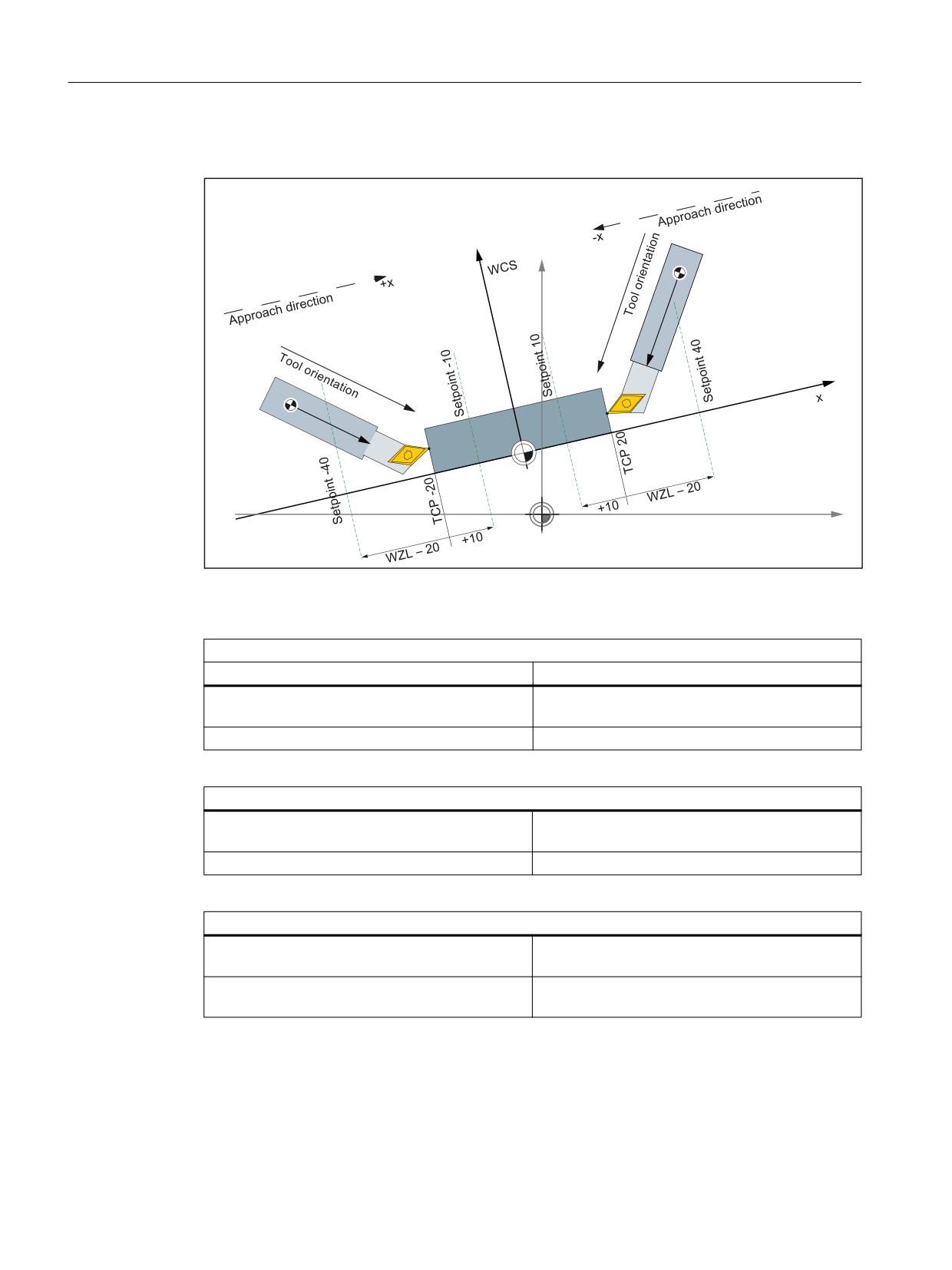
M5: Measurement
9.5 Workpiece and tool measurement
Different tools in the WCS
%&6
[
Figure 9-21
Two turning tools each with their own reference point
Settings in the system data:
Left-hand tool: Approach direction +x and tool orientation -y
System variable
Meaning
$AC_MEAS_TOOL_MASK = 0x0
All tool lengths are considered
(default setting)
$AC_MEAS_DIR_APPROACH = 0
Approach direction +x
Right-hand tool: Approach direction -x and tool orientation -y
$AC_MEAS_TOOL_MASK = 0x0
All tool lengths are considered
(default setting)
$AC_MEAS_DIR_APPROACH = 1
Approach direction -x
For both tools
$AC_MEAS_Px_COORD = 0
Coordinate system of x-th measuring point =
WCS (default setting)
$AC_MEAS_SET_COORD = 0
Coordinate system of the setpoint =
WCS (default setting)
Extended Functions
606
Function Manual, 12/2018, A5E40874029B AB
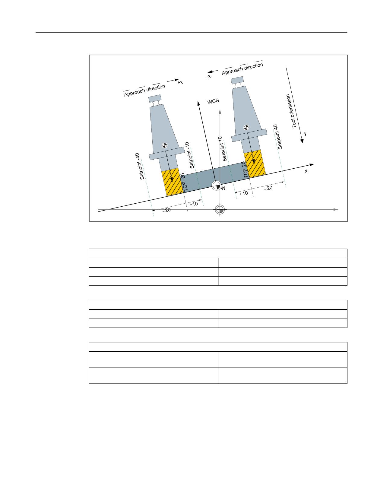
M5: Measurement
9.5 Workpiece and tool measurement
%&6
[
Figure 9-22
Two milling tools each with its own reference point
Settings in the system data:
Left-hand tool: Approach direction +x and tool orientation -y
System variable
Meaning
$AC_MEAS_TOOL_MASK = 0x80
Tool position in -y direction
$AC_MEAS_DIR_APPROACH = 0
Approach direction +x
Right-hand tool: Approach direction -x and tool orientation -y
$AC_MEAS_TOOL_MASK = 0x80
Tool position in -y direction
$AC_MEAS_DIR_APPROACH = 1
Approach direction -x
For both tools
$AC_MEAS_Px_COORD = 0
Coordinate system of x-th measuring point =
WCS (default setting)
$AC_MEAS_SET_COORD = 0
Coordinate system of the setpoint =
WCS (default setting)
Extended Functions
Function Manual, 12/2018, A5E40874029B AB
607
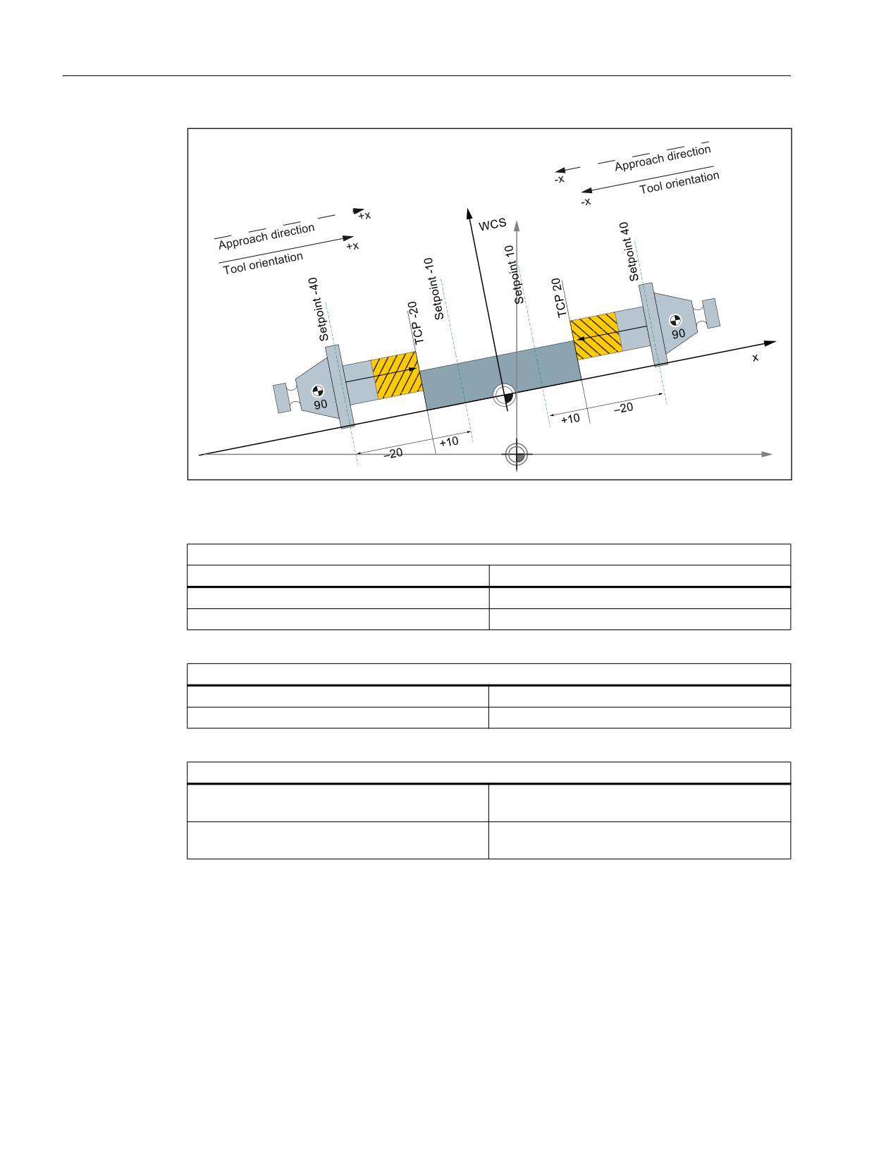
M5: Measurement
9.5 Workpiece and tool measurement
%&6
[
Figure 9-23
Two milling tools rotated at 90 degrees each with their own reference point
Settings in the system data:
Left-hand tool: Approach direction +x and tool orientation -y
System variable
Meaning
$AC_MEAS_TOOL_MASK = 0x2
Tool position in x direction (G19)
$AC_MEAS_DIR_APPROACH = 0
Approach direction +x
Right-hand tool: Approach direction -x and tool orientation -y
$AC_MEAS_TOOL_MASK = 0x40
Tool position in the -x direction
$AC_MEAS_DIR_APPROACH = 1
Approach direction -x
For both tools
$AC_MEAS_Px_COORD = 0
Coordinate system of x-th measuring point =
WCS (default setting)
$AC_MEAS_SET_COORD = 0
Coordinate system of the setpoint =
WCS (default setting)
Extended Functions
608
Function Manual, 12/2018, A5E40874029B AB
M5: Measurement
9.6 Measurement accuracy and functional testing
9.6
Measurement accuracy and functional testing
9.6.1
Measurement accuracy
The measuring accuracy is affected by the following parameters:
● Delay time of the measuring signal (TDelay)
● Traversal speed during the measurement (vM)
Delay time compensation of the measuring signal (TDelay)
The delay time of the measuring signal, i.e. the time from the initiation of the probe until the
saving of the measured value in the control depends on the response time of the probe and
the signal runtime of the control hardware. The control compensates for the delay time during
the measurement. This requires that the delay time is determined and entered in the following
machine data:
MD13220 $MN_MEAS_PROBE_DELAY_TIME = <determined delay time>
Note
Maximum compensated delay time TMaxDelay
TMaxDelay = 31 * position controller or DP cycle
The compensation of a delay time > TMaxDelay is not sensible from the control viewpoint. This
means larger values are limited to TMaxDelay.
Maximum traversal speed during the measurement (vM)
The maximum permitted traversal speed for a measurement depends on the number of
programmed measuring edges and the parameterized position-controller or DP cycle.
To receive correct results, the traversal speed during the measurement must be chosen so
that the following conditions are satisfied every two position-controller or DP cycles:
● Maximum one identical trigger signal, i.e. one positive or one negative edge of one probe
● Maximum four different identical trigger signals, i.e. one positive and one negative edge of
two probes
9.6.2
Probe function test
The function check of the probe is performed via an NC program according to the following
example:
Program code
Comment
%_N_PRUEF_MESSTASTER_MPF
;$PATH=/_N_MPF_DIR
;Testing program probe connection
N05 DEF INT MTSIGNAL
; Bit memory for control state.
Extended Functions
Function Manual, 12/2018, A5E40874029B AB
609
M5: Measurement
9.6 Measurement accuracy and functional testing
Program code
Comment
N10 DEF INT ME_NR=1
; Measuring input number.
N20 DEF REAL MESSWERT_IN_X
N30 G17 T1 D1
; Preselect tool offset for probe.
N40 _ANF: G0 G90 X0 F150
; Starting position and measuring
speed.
N50 MEAS=ME_NR G1 X100
; Measurement at measuring input 1 in
the X axis.
N60 STOPRE
N70 MTSIGNAL=$AC_MEA[1]
; Read software switching signal at
1st measuring input.
N80 IF MTSIGNAL==0 GOTOF _FEHL1
; Evaluation of the signal
N90 MESSWERT_IN_X=$AA_MW[X]
; Read in measured value in workpiece
coordinates.
N95 M0
N100 M02
N110 _FEHL1: MSG ("Probe not switching!")
N120 M0
N130 M02
The measuring signal can be checked at the end of the program via the diagnostics menu
"PLC status".
● DB10 DBX107.0 (probe 1 deflected)
● DB10 DBX107.1 (probe 2 deflected)
The current measuring status of an axis is shown with the following NC/PLC interface signal:
● DB31, ... DBX62.3 (measurement active)
This signal can be evaluated for all measurement functions and also be read via the
$AA_MEAACT[<Axis>] system variable in synchronized actions.
References:
Synchronized Actions Function Manual
9.6.3
Repeat accuracy
The measuring scatter (repeat accuracy) of the entire measuring system (machine probe signal
transmission to the NC) can be determined via an NC program according to the following
example.
In this program example, ten measurements are taken in the X axis and the measured value
recorded in the workpiece coordinates.
It is therefore possible to determine the random dimensional deviations which are not subject
to any trend.
Program code
Comment
%_N_PRUEF_GENAU_MPF;
$PATH=/_N_MPF_DIR
Extended Functions
610
Function Manual, 12/2018, A5E40874029B AB
M5: Measurement
9.7 Simulated measuring
Program code
Comment
DEF INT SIGNAL, II
; Variable definition
DEF REAL MESSWERT_IN_X[10]
G17 T1 D1
; Initial conditions,
: Tool compensation
; preselect for probe
_ANF: G0 X0 F150
; Prepositioning in the measured axis
MEAS=+1 G1 X100
; at 1st measurement input when
; switching signal not deflected,
; deflected in the X axis
STOPRE
; Stop decoding for this only after
; subsequent evaluation of the
; result
SIGNAL= $AC_MEA[1]
; Read software switching signal at the
; 1st measuring input
IF SIGNAL == 0 GOTOF_FEHL1
; Check switching signal
MESSWERT_IN_X[II]=$AA_MW[X]
; Read measured value in workpiece coordi-
nates
II=II+1
IF II<10 GOTOB_ANF
; Repeat 10 times
M0
M02
_FEHL1: MSG ("Probe not switching")
M0
M02
After the parameter display (user-defined variables) has been selected, the measurement
results can be read in the MEASVALUE_IN_X[10] field as long as the program execution is
still active.
9.7
Simulated measuring
9.7.1
General functionality
Brief description
To make measurements at real machines, probes must be connected which supply switching
signals at certain positions. Probes are not used when making measurements in simulated
environments - the switching positions are specified in a different way.
Simulated measuring supports two ways of entering switching positions:
● Position-related switch request: The switching position is derived from the axial end position
programmed in the measuring block.
● External switching request: The switching position is defined by controlling a digital output.
Extended Functions
Function Manual, 12/2018, A5E40874029B AB
611
M5: Measurement
9.7 Simulated measuring
Preconditions
For simulated measuring, all of the machine axes in the system must be parameterized as
simulated axes:
● MD30130 $MA_CTRLOUT_TYPE[axis] = 0 (simulated setpoint)
● MD30240 $MA_ENC_TYPE[axis] = 0 (simulated encoder)
9.7.2
Position-related switch request
Function
"Position-related switch request" is selected using the following NC-specific machine data:
● MD13230 $MN_MEAS_PROBE_SOURCE = 0
● MD13231 $MN_MEAS_PROBE_OFFSET = <position offset>
The axial switching position is calculated from the axial end position programmed in the
measuring block and the parameterized position offset:
Switching position[axis] = End position[axis] - position offset
During the measuring block, it is cyclically checked as to whether the switching position of the
axis is reached:
Setpoint position[axis] ≥ switching position[axis]
When the switching position is reached, the rising edge of the switching signal is generated
for probes 1 and 2. One position controller cycle later, the following edges.
3RVLWLRQ RIIVHW
6ZLWFKLQJ VLJQDO
3RVLWLYH
1HJDWLYH
6WDUW SRVLWLRQ
6ZLWFKLQJ SRVLWLRQ (QG SRVLWLRQ
0HDVXULQJ EORFN
Figure 9-24
Position-dependent switch request
The measured value is the actual value of the axis at the instant in time that the switching
signal programmed in the measuring block occurs (rising / falling edge).
Extended Functions
612
Function Manual, 12/2018, A5E40874029B AB
M5: Measurement
9.7 Simulated measuring
If several axes are programmed in a measuring block, then a dedicated switching position is
obtained for each axis by the position offset that is axially taken into consideration. The probe
signal is generated at the first axial switching position that is reached.
Note
Probe signals
The probe signals are always simultaneously generated for probes 1 and 2.
Negative offset values
The switching position is shifted behind the end position by entering a negative value for the
position offset. In this case, no probe signals are generated.
Examples
The position offset is set to 0.1 mm: MD13231 $MN_MEAS_PROBE_OFFSET = 0.1
Example 1: Channel-specific measuring in 2 axes
Program code
Comment
N10 G01 G90
N20 MEAS=1 X100 Y10 F100
; rising edge, probe 1
; switching position[X] = 99.9
; switching position[Y] = 9.9
Example 2: Axial measuring using synchronized action
Program code
Comment
N10 G01 G90
N15 WHEN TRUE DO MEASA[X]=(1,1)
; rising edge, probe 1
N20 X10 F100
; switching position[X] = 9.9
9.7.3
External switch request
Function
The "external switching request" is selected using the NC-specific machine data by entering
the number (1...8) of the digital output being used:
● MD13230 $MN_MEAS_PROBE_SOURCE = <number of the digital output>
The probe signal is triggered by controlling the configured digital output. It is not necessary to
hard-wire the digital output to a measuring input.
The rising edge of the switching signal for probes 1 and 2 is generated by setting the digital
output. The falling edges are generated by resetting the digital output.
Extended Functions
Function Manual, 12/2018, A5E40874029B AB
613
M5: Measurement
9.7 Simulated measuring
The measured value is the actual value of the axis at the instant in time that the switching
signal programmed in the measuring block occurs (rising / falling edge).
Digital output: Configuration
The following machine data must be set to be able to use digital outputs for simulated
measuring:
● MD10360 $MN_FASTIO_DIG_NUM_OUTPUTS = 1 (number of active digit. NC output
bytes)
● MD13120 $MN_CONTROL_UNIT_LOGIC_ADDRESS = 0 (logical address, SINAMICS-
CU)
Digital output: Setting
The configured digital output can be set in a synchronized action:
WHEN <condition> DO $A_OUT[<number of digital output>] = 1
Examples
Digital output used: MD13230 $MN_MEAS_PROBE_SOURCE = 1
Example 1: Channel-specific measuring in 2 axes
Program code
Comment
N10 G01 G90 $A_OUT[1]=0
; preassign digital output 1
N15 WHEN $AC_DETW<=10 DO $A_OUT[1]=1
; path distance-to-go <= 10 => dig. output 1 = 1
N20 MEAS=1 X100 Y10 F100
; rising edge, probe 1
Example 2: Axial measurement
Program code
Comment
N10 G01 G90 $A_OUT[1]=0
; preassign digital output 1
N15 WHEN $AA_IW[X]>=80 DO $A_OUT[1]=1
; axial setpoint >= 80 => dig. output 1 = 1
N20 MEASA[X]=(1,1) X100 F100
; rising edge, probe 1
9.7.4
System variable
For simulated measuring, the following system variables have the same functionality as for
real measuring:
● $AC_MEA (probe has responded)
● $AA_MEAACT (axial measuring active)
● $AA_MM (acquired probe position (MCS))
● $AA_MM1...4 (probe position 1st - 4th trigger (MCS))
Extended Functions
614
Function Manual, 12/2018, A5E40874029B AB

M5: Measurement
9.8 Data lists
● $AA_MW (acquired probe position (WCS))
● $AA_MW1...4 (probe position 1st trigger (WCS))
The following system variable does not supply sensible values:
● $A_PROBE (probe state)
9.8
Data lists
9.8.1
Machine data
9.8.1.1
General machine data
Number
Identifier: $MN_
Meaning
13200
MEAS_PROBE_LOW_ACTIVE
Switching characteristics of probe
13201
MEAS_PROBE_SOURCE
Measuring pulse simulation via digital output
13210
MEAS_TYPE
Type of measurement for PROFIBUS DP drives
13211
MEAS_CENTRAL_SOURCE
Central measuring data source with PROFIBUS DP
drives
9.8.1.2
Channel-specific machine data
Number
Identifier: $MC_
Meaning
20360
TOOL_PARAMETER_DEF_MASK
Definition of tool parameters
28264
LEN_AC_FIFO
Length of $AC_FIFO ... FIFO variables
9.8.2
System variables
Table of all the input values
Identifier
Meaning
$AC_FIFO1…10
FIFO variable 1 to 10
$AC_MEAS_SEMA
Interface assignment
$AC_MEAS_VALID
Validity bits for input values
$AA_MEAS_POINT1
1. Measuring point for all channel axes
$AA_MEAS_POINT2
2. Measuring point for all channel axes
$AA_MEAS_POINT3
3. Measuring point for all channel axes
$AA_MEAS_POINT4
4. Measuring point for all channel axes
Extended Functions
Function Manual, 12/2018, A5E40874029B AB
615

M5: Measurement
9.8 Data lists
Identifier
Meaning
$AA_MEAS_SETPOINT
Setpoint position for all channel axes
$AA_MEAS_SETANGLE
Setpoint angle for all channel axes
$AC_MEAS_P1_COORD
Coord. system for the 1st measuring point
$AC_MEAS_P2_COORD
Coord. system for the 2nd measuring point
$AC_MEAS_P3_COORD
Coord. system for the 3rd measuring point
$AC_MEAS_P4_COORD
Coord. system for the 4th measuring point
$AC_MEAS_SET_COORD
Coordinate system of the setpoint
$AC_MEAS_LATCH[0...3]
Pick up measuring points in the WCS
$AA_MEAS_P1_VALID
1. Pick up measuring point in the WCS
$AA_MEAS_P2_VALID
2. Pick up measuring point in the WCS
$AA_MEAS_P3_VALID
3. Pick up measuring point in the WCS
$AA_MEAS_P4_VALID
4. Pick up measuring point in the WCS
$AA_MEAS_SP_VALID
Set setpoint position of axis as valid
$AC_MEAS_WP_SETANGLE
Setpoint workpiece position angle
$AC_MEAS_CORNER_SETANGLE
Setpoint cutting angle of corner
$AC_MEAS_DIR_APPROACH
Approach direction
$AC_MEAS_ACT_PLANE
Working plane for the workpiece
$AC_MEAS_SCALEUNIT
Unit of measurement INCH / METRIC
$AC_MEAS_FINE_TRANS
Corrections in fine displacement
$AC_MEAS_FRAME_SELECT
Frame selection for the workpiece measurement
$AC_MEAS_CHSFR
Frame chain setting: System frames
$AC_MEAS_NCBFR
Frame chain setting: Global basic frames
$AC_MEAS_CHBFR
Frame chain setting: Channel basic frames
$AC_MEAS_UIFR
Frame chain setting: Settable frames
$AC_MEAS_PFRAME
Frame chain setting: Program frame
$AC_MEAS_T_NUMBER
Tool selection
$AC_MEAS_D_NUMBER
Cutting edge selection
$AC_MEAS_TOOL_MASK
Tool settings
$AC_MEAS_TYPE
Measuring type
$AC_MEAS_INPUT
Measurement input parameters
Table of all the output values
Identifier
Meaning
$A_PROBE[1,2]
Probe status
$A_PROBE_LIMITED[1,2]
Measuring velocity exceeded
$AC_MEA[1,2]
Probe has responded
$AA_MM
Acquired probe position (MCS)
$AA_MM1...4
Probe position 1st to 4th trigger event (MCS)
$AA_MW
Acquired probe position (WCS)
$AA_MW1...4
Probe position 1st to 4th trigger event (WCS)
Extended Functions
616
Function Manual, 12/2018, A5E40874029B AB

M5: Measurement
9.8 Data lists
Identifier
Meaning
$AC_MEAS_FRAME
Result frame
$AC_MEAS_WP_ANGLE
Calculated workpiece position angle
$AC_MEAS_CORNER_ANGLE
Calculated angle of intersection
$AC_MEAS_DIAMETER
Calculated diameter
$AC_MEAS_TOOL_LENGTH
Calculated tool length
$AC_MEAS_RESULTS
Measurement results (depending on measurement type)
Extended Functions
Function Manual, 12/2018, A5E40874029B AB
617
M5: Measurement
9.8 Data lists
Extended Functions
618
Function Manual, 12/2018, A5E40874029B AB
N3: Software cams, position switching cycles - only
840D sl
10
10.1
Brief Description
Function
The "Software cams" function generates position-dependent switching signals for axes that
supply an actual position value (machine axes) and for simulated axes.
These cam signals can be output to the PLC and also to the NC I/O.
The cam positions at which signal outputs are set can be defined and altered via setting data.
The setting data can be read and written via HMI, PLC and part program.
Activation
The "Software cams" function can be activated and used in all operating modes. The function
remains active in the event of reset or Emergency Stop.
Field of application
Output cam signals can be used, for example:
● To activate protection zones
● To initiate additional movements as a function of position
● As reversing signals for hydraulically controlled oscillation axes
Axis types
Software cams can be used on linear and modulo rotary axes that are defined as machine
axes.
Cam range/cam pair
Cams are always assigned in pairs to axes. A pair consists of a plus and a minus cam. 32 cam
pairs are available.
The plus and minus cams each simulate a mechanical cam which is actuated at a defined
point (cam position) in a specific approach direction when the axis reaches the cam position.
Cam ranges are assigned to the plus and minus cams as follows:
● Cam range plus:
All positions ≥ plus cam
● Cam range minus:
All positions ≤ minus cam
Extended Functions
Function Manual, 12/2018, A5E40874029B AB
619
N3: Software cams, position switching cycles - only 840D sl
10.2 Cam signals and cam positions
10.2
Cam signals and cam positions
10.2.1
Generation of cam signals for separate output
Separate output of the plus and minus cam signals makes it easy to detect whether the axis
is within or outside the plus or minus cam range.
Extended Functions
620
Function Manual, 12/2018, A5E40874029B AB
N3: Software cams, position switching cycles - only 840D sl
10.2 Cam signals and cam positions
Linear axes
The switching edges of the cam signals are generated as a function of the axis traversing
direction:
● The minus cam signal switches from 1 to 0 when the axis traverses the minus cam in the
positive axis direction.
● The plus cam signal switches from 0 to 1 when the axis traverses the plus cam in the positive
direction.
0DFKLQH D[LV>P@
0DFKLQH
FDP SRVLWLRQ
FDP SRVLWLRQ
0DFKLQH D[LV>Q@
]HUR
PLQXV FDP
SOXV FDP
>PP LQFK@
3OXV FDP VLJQDO
0LQXV FDP VLJQDO
&DP UDQJH
&DP UDQJH
PLQXV
SOXV
Figure 10-1
Software cams for linear axis (minus cam < plus cam)
Note
If the axis is positioned exactly at the output cam position (plus or minus), the defined output
flickers. If the axis moves one increment further, the output becomes a definite zero or one.
Flickering of the actual position causes the signals to flicker in this manner.
The actual position is evaluated.
Extended Functions
Function Manual, 12/2018, A5E40874029B AB
621
N3: Software cams, position switching cycles - only 840D sl
10.2 Cam signals and cam positions
0DFKLQH D[LV>P@
0DFKLQH
FDP SRVLWLRQ
FDP SRVLWLRQ
0DFKLQH D[LV>Q@
]HUR
SOXV FDP
PLQXV FDP
>PP LQFK@
3OXV FDP VLJQDO
0LQXV FDP VLJQDO
&DP UDQJH
&DP UDQJH
PLQXV
SOXV
Figure 10-2
Software cams for linear axis (plus cam < minus cam)
Extended Functions
622
Function Manual, 12/2018, A5E40874029B AB
N3: Software cams, position switching cycles - only 840D sl
10.2 Cam signals and cam positions
Modulo rotary axes
The switching edges of the cam signals are generated as a function of the rotary axis traversing
direction:
● The plus cam signal switches from 0 to 1 when the axis traverses the minus cam in a positive
axis direction and from 1 back to 0 when it traverses the plus cam.
● The minus cam signal changes level in response to every positive edge of the plus cam
signal.
Note
The described response of the plus cam applies on conditionthat:
plus cam - minus cam < 180 degrees
r
0DFKLQH D[LV>P@
0LQXV
3OXV
0LQXV
3OXV
FDP
FDP
FDP
FDP
0DFKLQH
r
r
r
r
r
r
0DFKLQH D[LV>Q@
]HUR
PRGXOR URWDU\
D[LV >GHJUHHV@
3OXV FDP
VLJQDO
0LQXV FDP
VLJQDO
Figure 10-3
Software cams for modulo rotary axis (plus cam - minus cam < 180 degrees)
The signal change of the minus cam makes it possible to detect traversal of the cam even if
the cam range is set so small that the PLC cannot detect it reliably.
Both cam signals can be output to the PLC and to the NC I/O. Separate output of the plus and
minus cam signals makes it easy to detect whether the axis is within or outside the plus or
minus cam range.
If this condition (plus cam - minus cam < 180 degrees) is not fulfilled or if the minus cam is set
to a greater value than the plus cam, then the response of the plus cam signal is inverted. The
response of the minus cam signal remains unchanged.
Extended Functions
Function Manual, 12/2018, A5E40874029B AB
623
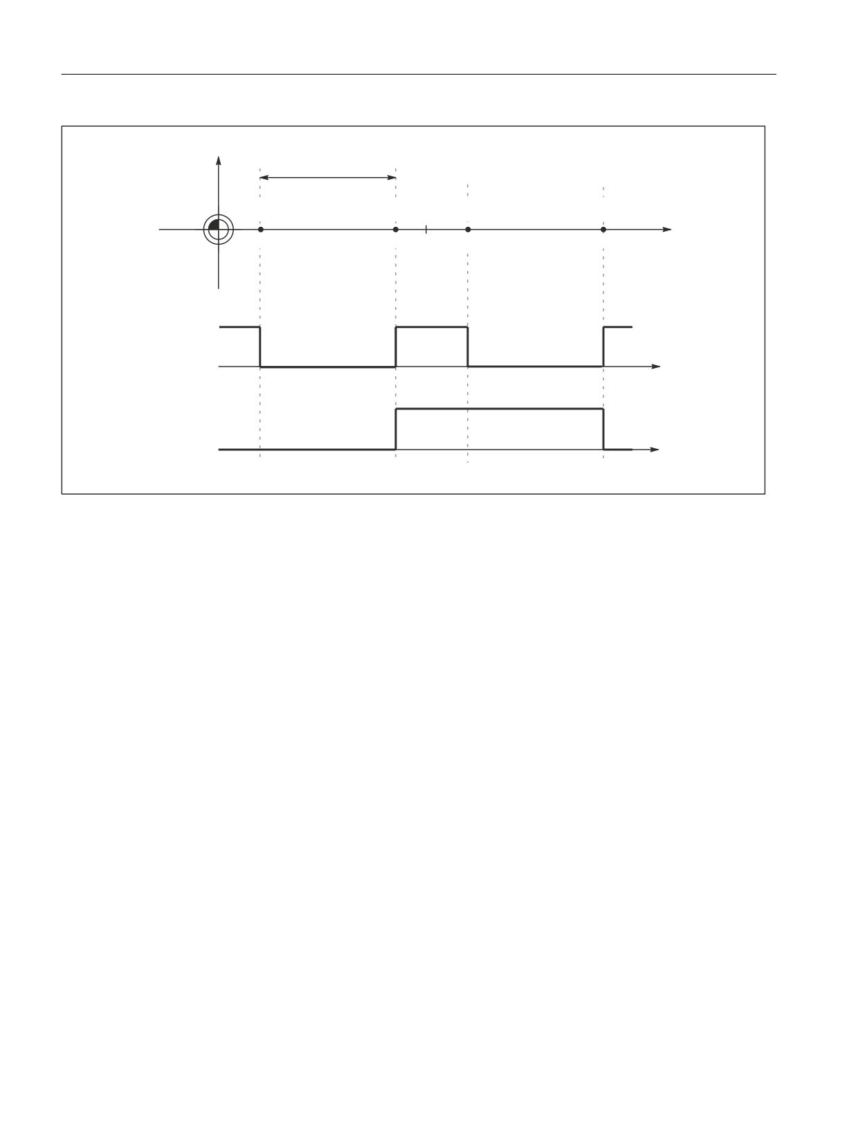
N3: Software cams, position switching cycles - only 840D sl
10.2 Cam signals and cam positions
0DFKLQH D[LV>P@
!
r
0LQXV
3OXV
0LQXV
3OXV
FDP
FDP
FDP
FDP
r
r
r
r
r
r
0DFKLQH D[LV>Q@
0DFKLQH
]HUR
PRGXOR URWDU\
D[LV >GHJUHHV@
3OXV
FDP VLJQDO
0LQXV
FDP VLJQDO
Figure 10-4
Software cams for modulo rotary axis (plus cam - minus cam > 180 degrees)
10.2.2
Generation of cam signals with gated output
The plus and minus cam output signals are gated in the case of:
● timer-controlled cam signal output to the four onboard outputs on the NCU
● Output to the NCK I/O, if the 2nd byte in the following machine data was not specified (=
"0"):
MD10470 SW_CAM_ASSIGN_FASTOUT_2
MD10473 SW_CAM_ASSIGN_FASTOUT_4
Extended Functions
624
Function Manual, 12/2018, A5E40874029B AB