SINUMERIK 840D sl. Service - Functions. Manual (2018-2020) - page 40
N3: Software cams, position switching cycles - only 840D sl
10.2 Cam signals and cam positions
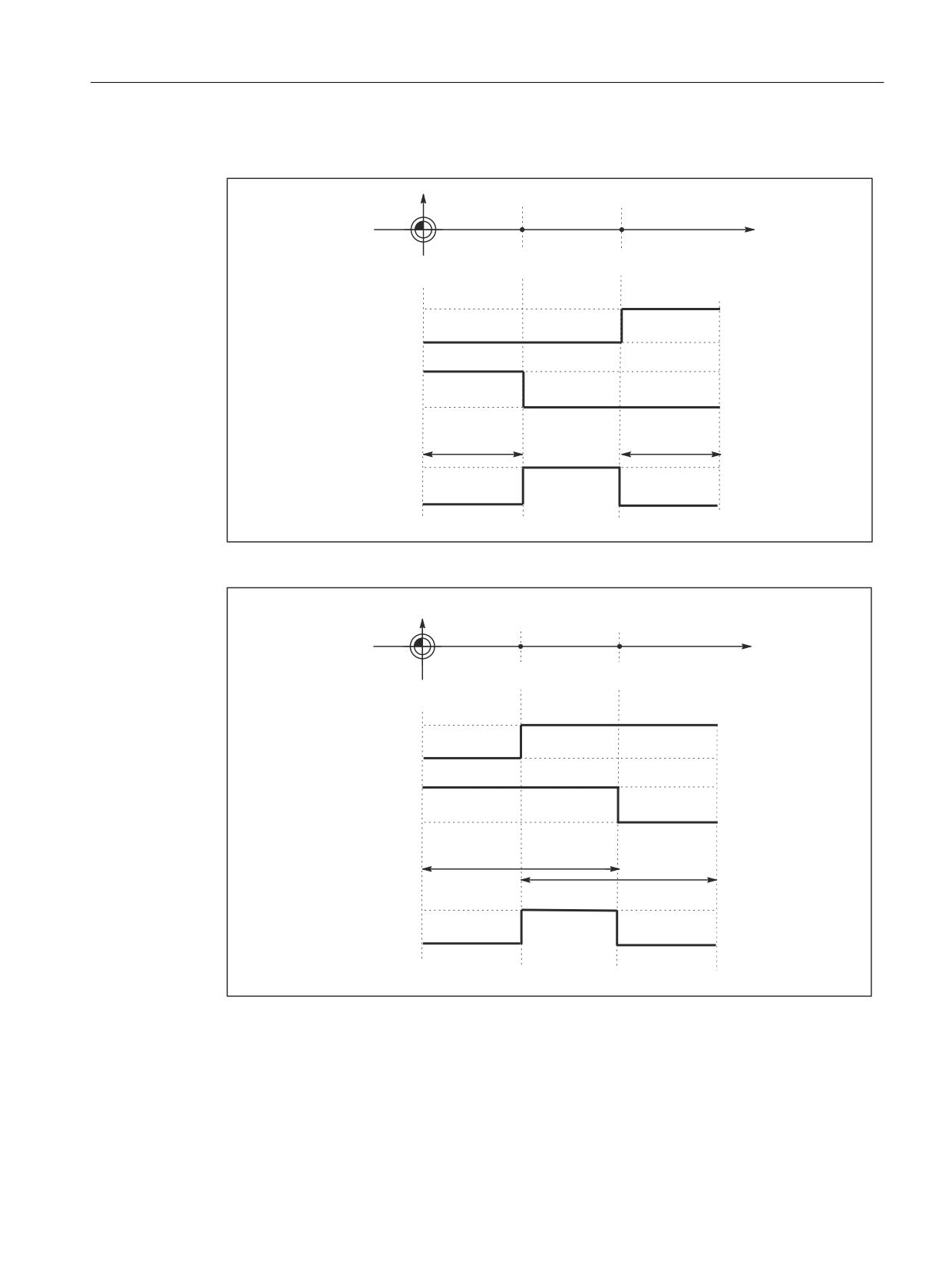
Linear axes
0DFKLQH D[LV
0DFKLQH ]HUR
FDP SRVLWLRQ
&DP SRVLWLRQ
0DFKLQH D[LV
PLQXV FDP
SOXV FDP
>PP LQFK@
3OXV FDP VLJQDO
0LQXV FDP VLJQDO
&DP UDQJH
&DP UDQJH
PLQXV
SOXV
'LJLWDO RXWSXW
Figure 10-5
Position switching signals for linear axis (minus cam < plus cam)
0DFKLQH D[LV
0DFKLQH ]HUR
&DP SRVLWLRQ
&DP SRVLWLRQ
0DFKLQH D[LV
SOXV FDP
PLQXV FDP
>PP LQFK@
3OXV FDP VLJQDO
0LQXV FDP VLJQDO
&DP UDQJH
&DP UDQJH
PLQXV
SOXV
'LJLWDO RXWSXW
Figure 10-6
Position switching signals for linear axis (plus cam < minus cam)
Extended Functions
Function Manual, 12/2018, A5E40874029B AB
625
N3: Software cams, position switching cycles - only 840D sl
10.2 Cam signals and cam positions
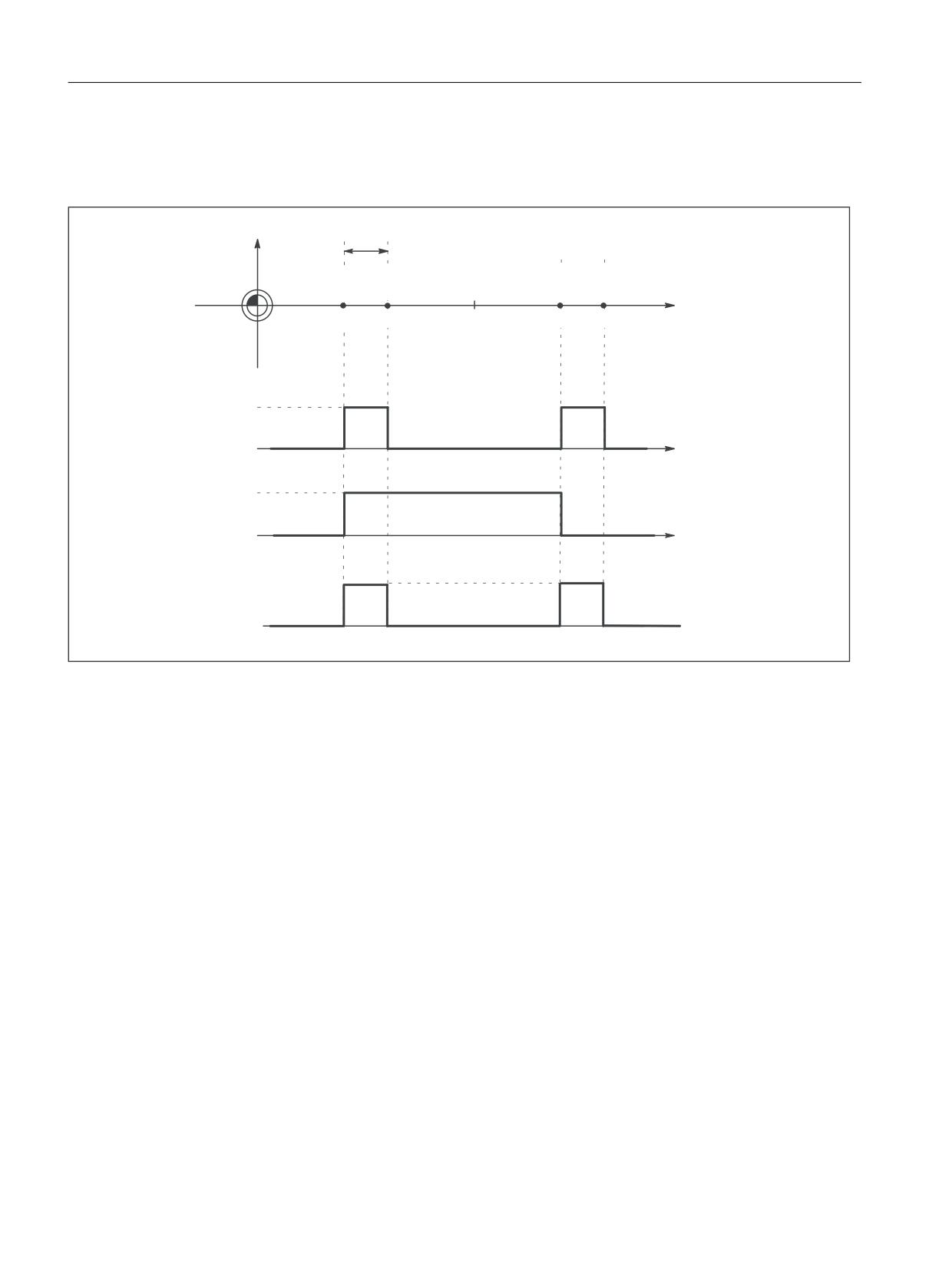
Modulo rotary axis
The default signal response for modulo rotary axes is dependent on the cam width:
r
0DFKLQH D[LV>P@
0LQXV
3OXV
0LQXV
3OXV
FDP
FDP
FDP
FDP
0DFKLQH
r
r
r
r
r
r
0DFKLQH D[LV>Q@
]HUR
PRGXOR URWDU\
D[LV >GHJUHHV@
3OXV
FDP VLJQDO
0LQXV
FDP VLJQDO
'LJLWDO
RXWSXW
Figure 10-7
Software cams for modulo rotary axis (plus cam - minus cam < 180 degrees)
Extended Functions
626
Function Manual, 12/2018, A5E40874029B AB
N3: Software cams, position switching cycles - only 840D sl
10.2 Cam signals and cam positions
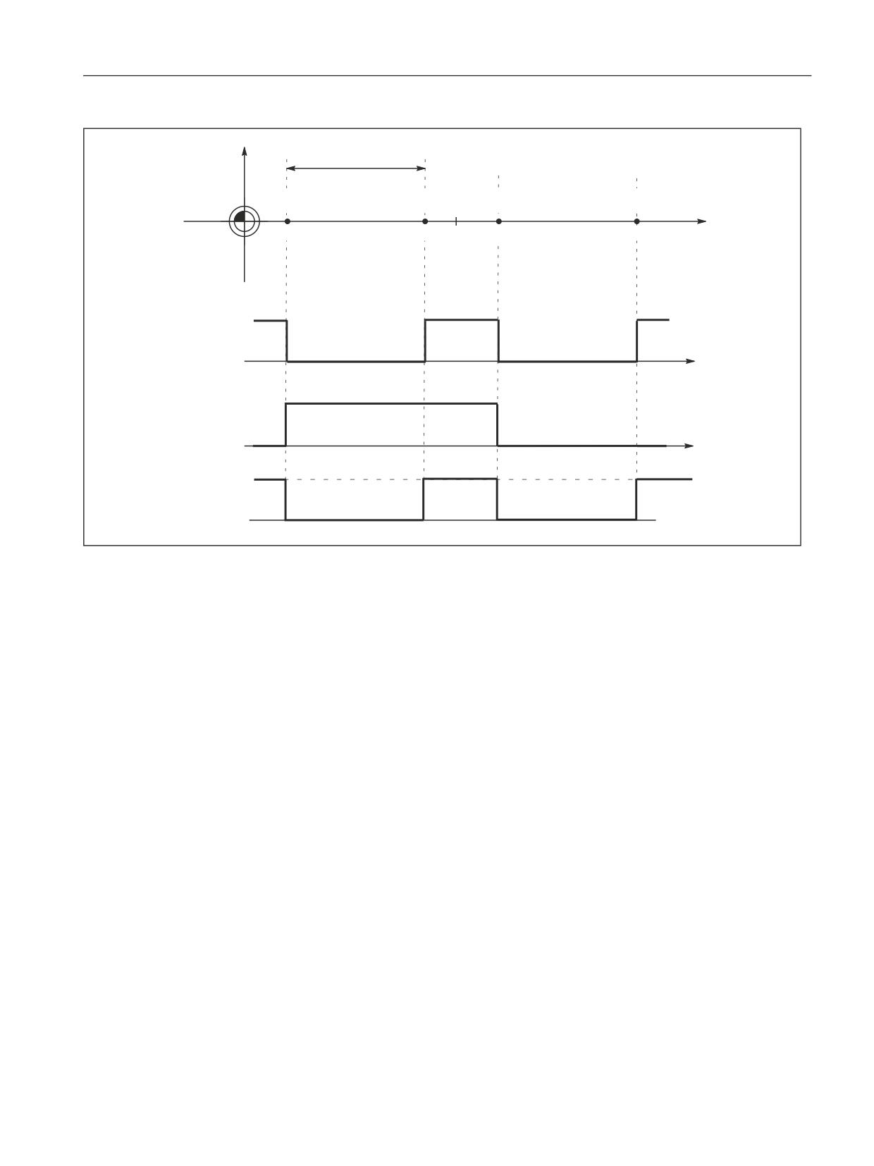
0DFKLQH D[LV>P@
!
r
0LQXV
3OXV
0LQXV
3OXV
FDP
FDP
FDP
FDP
r
r
r
r
r
r
0DFKLQH D[LV>Q@
0DFKLQH
PRGXOR URWDU\
]HUR
D[LV >GHJUHHV@
3OXV
FDP VLJQDO
0LQXV
FDP VLJQDO
'LJLWDO
RXWSXW
Figure 10-8
Software cams for modulo rotary axis (plus cam - minus cam > 180 degrees)
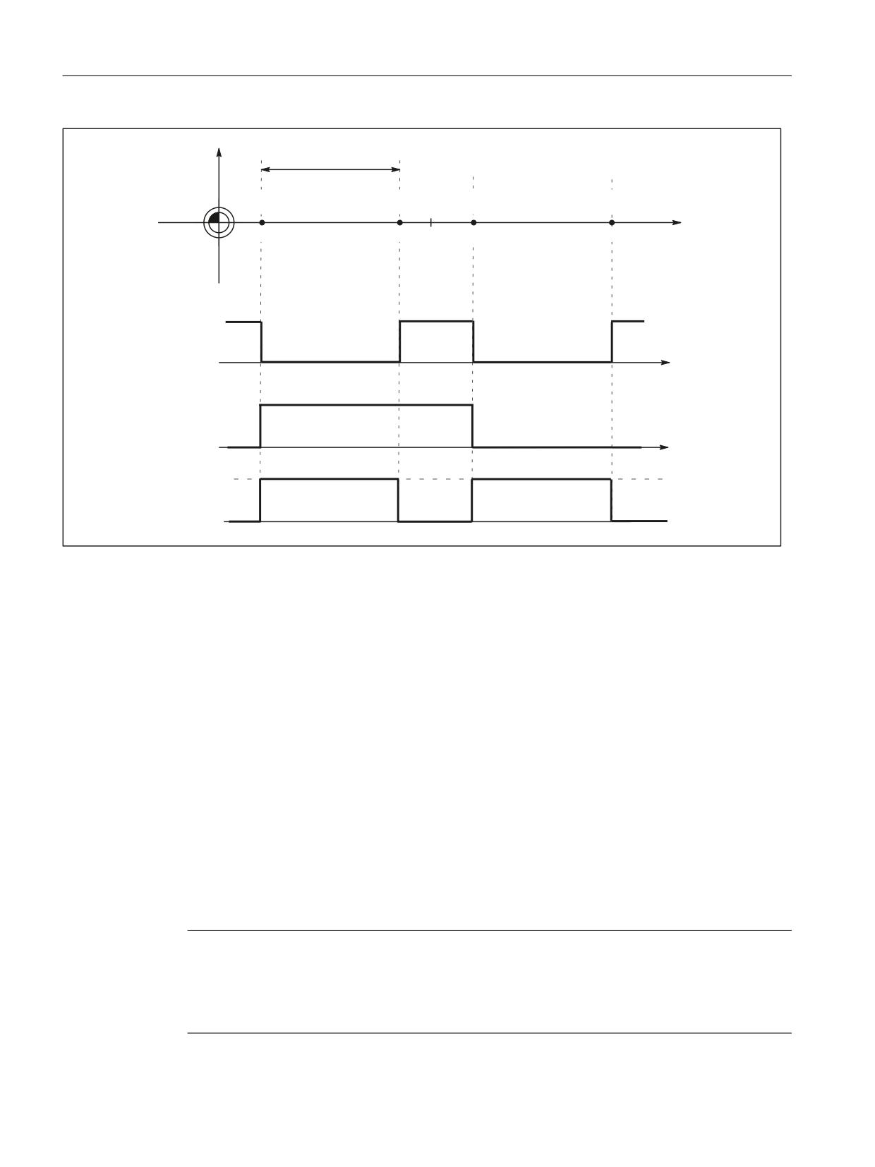
Suppression of signal inversion
With the following setting, selection of signal inversion for
"plus cam - minus cam > 180 degrees" can be suppressed.
MD10485 SW_CAM_MODE bit 1=1
Extended Functions
Function Manual, 12/2018, A5E40874029B AB
627
N3: Software cams, position switching cycles - only 840D sl
10.2 Cam signals and cam positions
0DFKLQH D[LV >P@
!
r
0LQXV
3OXV
0LQXV
3OXV
FDP
FDP
FDP
FDP
r
r
r
r
r
r
0DFKLQH D[LV
0DFKLQH
>Q@
]HUR SRLQW
PRGXOR URWDU\
D[LV >GHJUHHV@
3OXV
FDP VLJQDO
0LQXV
FDP VLJQDO
'LJLWDO
RXWSXW
Figure 10-9
Software cams for modulo rotary axis (plus cam - minus cam > 180 degrees) and suppression of signal inversion
10.2.3
Cam positions
Setting cam positions
The positions of the plus and minus cams are defined using general setting data:
● SD41500 SW_CAM_MINUS_POS_TAB_1[n]
Position of minus cams 1 - 8
● SD41501 SW_CAM_PLUS_POS_TAB_1[n]
Position of plus cams 1 - 8
● SD41502 SW_CAM_MINUS_POS_TAB_2[n]
Position of minus cams 9 - 16
● SD41503 SW_CAM_PLUS_POS_TAB_2[n]
Position of plus cams 9 - 16
● SD41504 SW_CAM_MINUS_POS_TAB_3[n]
Position of minus cams 17 - 24
● SD41505 SW_CAM_PLUS_POS_TAB_3[n]
Position of plus cams 17 - 24
● SD41506 SW_CAM_MINUS_POS_TAB_4[n]
Position of minus cams 25 - 32
● SD41507 SW_CAM_PLUS_POS_TAB_4[n]
Position of plus cams 25 - 32
Note
Owing to the grouping of cam pairs (eight in each group), it is possible to assign different
access authorization levels (e.g. for machine-related and workpiece-related cam positions).
The positions are entered in the machine coordinate system. No check is made with respect
to the maximum traversing range.
Extended Functions
628
Function Manual, 12/2018, A5E40874029B AB

N3: Software cams, position switching cycles - only 840D sl
10.2 Cam signals and cam positions
Dimension system metric/inch
With the setting:
MD10260 CONVERT_SCALING_SYSTEM = 1
, the cam positions no longer refer to the configured basic dimension system, but to the
dimension system set in the following machine data:
MD10270 POS_TAB_SCALING_SYSTEM (measuring system of position tables)
Value
Meaning
0
Metric
1
inch
MD10270 therefore defines the dimension system for position data from setting data SD41500
… SD41507.
A switchover with G70/G71 or G700/G710 has no effect.
Sensing of cam positions
To set the cam signals, the actual position of the axes is compared to the cam position.
Writing/reading of cam positions
The setting data can be read and written via HMI, PLC and part program.
Accesses from the part program are not synchronous to machining.
Synchronization can only be achieved by means of a programmed block preprocessing stop
(STOPRE command).
It is possible to read and write the cam positions with FB2 and FB3 in the PLC user program.
Axis/cam assignment
A cam pair is assigned to a machine axis using the general machine data:
MD10450 SW_CAM_ASSIGN_TAB[n] (assignment of software cams to machine axes)
Note
Changes to an axis assignment take effect after the next NC power-up.
Cam pairs to which no axis is assigned are not active.
A cam pair can only be assigned to one machine axis at a time.
Several cam pairs can be defined for one machine axis.
Extended Functions
Function Manual, 12/2018, A5E40874029B AB
629
N3: Software cams, position switching cycles - only 840D sl
10.2 Cam signals and cam positions
10.2.4
Lead/delay times (dynamic cam)
Function
To compensate for any delays, it is possible to assign two lead or delay times with additive
action to each minus and plus cam for the cam signal output.
The two lead or delay times are entered in a machine data and a setting data.
Note
The input of negative time values causes a delay in the output of cam signals.
Lead or delay time in machine data
The first lead or delay time is entered in the following general machine data:
● MD10460 SW_CAM_MINUS_LEAD_TIME[n]
(lead or delay time at the minus
cams)
● MD10461 SW_CAM_PLUS_LEAD_TIME[n]
(lead or delay time at the plus
cams)
For example, the following can be entered into the machine data:
● Constant internal delay times between actual value sensing and cam signal output (e.g. as
determined by an oscilloscope)
● Constant external delay times
Lead or delay time in setting data
The second lead or delay time is entered into the following general setting data:
● SD41520 SW_CAM_MINUS_TIME_TAB_1[n]
(lead or delay time at the minus
cams 1 - 8)
● SD41521 SW_CAM_PLUS_TIME_TAB_1[n]
(lead or delay time at the plus cams
1 - 8)
● SD41522 SW_CAM_MINUS_TIME_TAB_2[n]
(lead or delay time at the minus
cams 9 - 16)
● SD41523 SW_CAM_PLUS_TIME_TAB_2[n]
(lead or delay time at the plus cams
9 - 16)
● SD41524 SW_CAM_MINUS_TIME_TAB_3[n]
(lead or delay time at the minus
cams 17 - 24)
● SD41525 SW_CAM_PLUS_TIME_TAB_3[n]
Lead or delay time on plus cams
17 - 24
Extended Functions
630
Function Manual, 12/2018, A5E40874029B AB
N3: Software cams, position switching cycles - only 840D sl
10.3 Output of cam signals
● SD41526 SW_CAM_MINUS_TIME_TAB_4[n]
(lead or delay time at the minus
cams 25 - 32)
● SD41527 SW_CAM_PLUS_TIME_TAB_4[n]
(lead or delay time at the plus cams
25 - 32)
Delay times which may change during machining must, for example, be entered in the setting
data.
10.3
Output of cam signals
10.3.1
Activating
The status of the cam (cam signals) can be output to the PLC as well as to the NC I/O.
Activation of cam signal output
The output of cam signals of an axis is activated via the NC/PLC interface signal:
DB31, ... DBX2.0 (cam activation)
Check-back signal to PLC
The successful activation of all cams of an axis is signaled back to the PLC using the following
NC/PLC interface signal:
DB31, ... DBX62.0 (cams active)
Note
The activation can be linked with other conditions by the PLC user (e.g. axis referenced, reset
active).
10.3.2
Output of cam signals to PLC
Output to PLC
The status of the cam signals for all machine axes with activated software cams is output to
the PLC.
The status is output in the IPO cycle and is transferred to the PLC asynchronously.
Extended Functions
Function Manual, 12/2018, A5E40874029B AB
631
N3: Software cams, position switching cycles - only 840D sl
10.3 Output of cam signals
Minus cam signals
The status of the minus cam signals is entered into the following NC/PLC interface signals:
DB10 DBX110.0 to 113.7 (minus cam signal 1 to 32)
Plus cam signals
The status of the plus cam signals is entered into the following NC/PLC interface signals:
DB10 DBX114.0 to 117.7 (plus cam signals 1 to 32)
Note
If no measuring system has been selected or NC/PLC interface signal DB31, ... DBX2.0 (cam
activation) is set to 0, then the following NC/PLC interface signals are also set to 0:
● DB10 DBX110.0-113.7 (minus cam signals 1-32)
● DB10 DBX114.0-117.7 (plus cam signals 1-32)
● DB31, ... DBX62.0 (cams active)
10.3.3
Output of cam signals to NCK I/Os in position control cycle
Signal output in position control cycle
For cams assigned to an HW byte via machine data MD10470 to MD10473 (see Section
"Hardware assignment"), the signal is output in the position control cycle.
The four onboard outputs on the NCU and a total of 32 optional external NC outputs are
available as the digital outputs of the NC I/O (see Section "A4: Digital and analog NC I/O for
SINUMERIK 840D sl (Page 31)").
Hardware assignment
The assignment to the hardware bytes used is made for each eight cam pairs in the following
general machine data:
● MD10470 SW_CAM_ASSIGN_FASTOUT_1
Hardware assignment for the output of
cams1 - 8 to NC I/O
● MD10471 SW_CAM_ASSIGN_FASTOUT_2
Hardware assignment for the output of
cams 9 - 16 to NC I/O
● MD10472 SW_CAM_ASSIGN_FASTOUT_3
Hardware assignment for the output of
cams 17 - 24 to NC I/O
● MD10473 SW_CAM_ASSIGN_FASTOUT_4
Hardware assignment for the output of
cams 25 - 32 to NC I/O
Extended Functions
632
Function Manual, 12/2018, A5E40874029B AB
N3: Software cams, position switching cycles - only 840D sl
10.3 Output of cam signals
Note
It is possible to define one HW byte for the output of eight minus cam signals and one HW
byte for the output of eight plus cam signals in each machine data.
In addition, the output of the cam signals can be inverted with the two machine data.
If the 2nd byte is not specified (= "0"), then the 8 cams are output as a logic operation of the
minus and plus cam signals via the 1st inversion mask using the 1st hardware byte.
Status query in the part program
The status of the HW outputs can be read in the part program with main run variable
$A_OUT[n] (n = no. of output bit).
Switching accuracy
Signals are output to the NC I/O or onboard outputs in the position control cycle.
As a result of the time scale of the position control cycle, the switching accuracy of the cam
signals is limited as a function of the velocity.
The following applies:
Delta pos = Vact * position control cycle
with: Delta pos =
switching accuracy (depending on position control cycle)
Vact =
Current axis velocity
Example:
Vact = 20 m/min, PC cycle = 4 ms
Delta pos = 1.33 mm
Vact = 2000 rpm, PC cycle = 2 ms
Delta pos = 24 degrees
10.3.4
Timer-controlled cam signal output
Timer-controlled output
A significantly higher degree of accuracy can be achieved by outputting the cam signals
independently of the position control cycle using a timer interrupt.
The following machine data can be used to select the timer-controlled output to the 4 NCU
onboard outputs for 4 cam pairs:
MD10480 SW_CAM_TIMER_FASTOUT_MASK (screen form for the output of cam signals via
timer interrupts on the NCU)
Extended Functions
Function Manual, 12/2018, A5E40874029B AB
633

N3: Software cams, position switching cycles - only 840D sl
10.3 Output of cam signals
In this case, the minus and plus signals of a cam pair are logically combined for output as one
signal.
Signal generation
Previously, it had to be specified in which way the signals to be logically combined should be
generated. This is realized using bit 1 in machine data:
MD10485 SW_CAM_MODE (behavior of the software cams)
Bit
Value
Signal generation
1
0
Inversion of the signal behavior of the plus cam when:
plus cam - minus cam ≥ 180 degrees
1
No inversion of the signal behavior of the plus cam when:
plus cam - minus cam ≥ 180 degrees
Note
This function operates independently of the HW assignment selected in MD10470 ... MD10473.
The onboard byte may not be used a multiple number of times.
Restrictions
The following applies to the mutual position of the cam positions:
Only one timer-controlled output takes place per interpolation cycle.
If signal changes for more than one cam pair are active in the same interpolation cycle, the
output is prioritized:
The cam pair with the lowest number (1...32) determines the output time for all active signals,
i.e. the signal change of the other cam pairs takes place at the same time.
PLC interface
The NC image of the onboard outputs and the status of the plus and minus cams is displayed
at the PLC interface.
However, these signals are irrelevant or correspondingly inaccurate for the timer-controlled
cam output version, as described in the following paragraphs. The signals for the plus and
minus cams are generated (once) in synchronism with the interpolator clock cycle and
transmitted together to the PLC.
Pulses shorter than an interpolator clock cycle are therefore not visible in the PLC.
The onboard outputs are set and reset asynchronously to the interpolator clock cycle for each
interrupt. The status of the onboard outputs is detected and transmitted to the PLC in
synchronism with the update time of the PLC interface.
Depending on the current status at the moment the PLC interface is updated, pulses shorter
than one interpolator clock cycle are not visible or are displayed stretched by one or several
IPO cycles.
Extended Functions
634
Function Manual, 12/2018, A5E40874029B AB

N3: Software cams, position switching cycles - only 840D sl
10.3 Output of cam signals
Further settings
The following bit must be set to "0" if the behavior described here is to be activated:
MD10485 SW_CAM_MODE bit 0 = 0
10.3.5
Independent, timer-controlled output of cam signals
Independent, timer-controlled cam output
Each switching edge is output separately per interrupt due to the timer-controlled, independent
(of interpolator clock cycle) cam output.
The mutual influence of the cam signals is no longer applicable as a result of:
● single output per interpolator clock cycle
● output time determined by highest priority cam pair (lowest cam pair number)
A total of 8 timer-controlled cam outputs per interpolator clock cycle can be configured for
setting/resetting the 4 onboard outputs. The signal states of the plus and minus cams are also
made available as standard on the PLC interface for the timer-controlled variant. However,
these signals are not relevant or are correspondingly inaccurate with a timer-controlled output.
Signal generation
Previously, it had to be specified in which way the signals to be logically combined should be
generated. This is realized using bit 1 in machine data:
MD10485 SW_CAM_MODE (behavior of the software cams)
Bit
Value
Signal generation
1
0
Inversion of the signal behavior of the plus cam when:
plus cam - minus cam ≥ 180 degrees
1
No inversion of the signal behavior of the plus cam when:
plus cam - minus cam ≥ 180 degrees
Settings
Cam pairs are assigned to onboard outputs using machine data:
MD10480 SW_CAM_TIMER_FASTOUT_MASK (screen form for the output of cam signals via
timer interrupts on the NCU)
In addition, this type of processing must be explicitly selected:
MD10485 SW_CAM_MODE bit 0 = 1
Note
This function operates independently of the HW assignment selected in MD10470 … MD10473.
The onboard byte may not be used a multiple number of times.
Extended Functions
Function Manual, 12/2018, A5E40874029B AB
635
N3: Software cams, position switching cycles - only 840D sl
10.4 Position-time cams
10.4
Position-time cams
Position-time cams
The term "position-time cam" refers to a pair of software cams that can supply a pulse of a
certain duration at a defined axis position.
Solution
The position is defined by a pair of software cams.
The pulse duration is defined by the lead/delay time of the plus cam.
Machine data can be used to specify that cam pairs with "minus cam position = plus cam
position" should be processed as position-time cams.
Properties of position-time cams
● The pulse duration is independent of the axis velocity and travel direction reversal.
● The pulse duration is independent of changes in the axis position (Preset).
● Activation (rising signal edge) takes place only when the cam position is crossed.
Moving the axis position (e.g. preset) does not trigger activation.
● A lead/delay time is operative for the minus cam and causes a time displacement of the
pulse.
● Activation (ON edge) and pulse duration are independent of the travel direction.
● The cam is not deactivated if the cam position is crossed again when the cam is active
(direction reversal).
● The cam time (pulse width) is not interrupted and the cam time not restarted when the cam
position is crossed again.
This behavior is particularly relevant with respect to modulo axes, i.e. if the cam time is
greater than the modulo range crossing time, the cam is not switched in every revolution.
Settings
The following settings must be made to program a position-time cam:
● Position
The position must be defined by a cam pair with which the minus cam position is equal to
the plus cam position.
This is defined using setting data:
SD41500 SW_CAM_MINUS_POS_TAB_1
SD41507 SW_CAM_PLUS_POS_TAB_4.
● Pulse duration
The pulse duration is calculated by adding together the associated entries for the cam pair
in:
MD10461 SW_CAM_PLUS_LEAD_TIME[n]
SD41521 SW_CAM_PLUS_TIME_TAB_1[n]...
SD41527 SW_CAM_PLUS_TIME_TAB_4[n]
Extended Functions
636
Function Manual, 12/2018, A5E40874029B AB

N3: Software cams, position switching cycles - only 840D sl
10.6 Data lists
● Offset
The time displacement of the position-time cam is calculated by adding together the
associated entries for the cam pair in:
MD10460 SW_CAM_MINUS_LEAD_TIME[n]
SD41520 SW_CAM_MINUS_TIME_TAB_1[n]...
SD41526 SW_CAM_MINUS_TIME_TAB_4[n]
● Mode
MD10485 SW_CAM_MODE
Bit 2 = 1 must be set in the machine data to ensure that all cam pairs with the same values
for minus cam and plus cam positions are treated as position-time cams.
10.5
Supplementary Conditions
Availability of function "Software cams, position switching signals"
The function is an option ("position-switching signals/cam controller"), which must be assigned
to the hardware through the license management.
10.6
Data lists
10.6.1
Machine data
10.6.1.1
General machine data
Number
Identifier: $MN_
Description
10260
CONVERT_SCALING_SYSTEM
Basic system switchover active
10270
POS_TAB_SCALING_SYSTEM
System of units for positioning tables
10450
SW_CAM_ASSIGN_TAB[n]
Assignment of software cams to machine axes
10460
SW_CAM_MINUS_LEAD_TIME[n]
Lead or delay time at the minus cams 1-16
10461
SW_CAM_PLUS_LEAD_TIME[n]
Lead or delay time at the plus cams 1-16
10470
SW_CAM_ASSIGN_FASTOUT_1
Hardware assignment for the output of cams
1-8 to NC I/O
10471
SW_CAM_ASSIGN_FASTOUT_2
Hardware assignment for the output of cams
9-16 to NC I/O
10472
SW_CAM_ASSIGN_FASTOUT_3
Hardware assignment for the output of cams
17-24 to NC I/O
10473
SW_CAM_ASSIGN_FASTOUT_4
Hardware assignment for the output of cams
25-32 to NC I/O
Extended Functions
Function Manual, 12/2018, A5E40874029B AB
637

N3: Software cams, position switching cycles - only 840D sl
10.6 Data lists
Number
Identifier: $MN_
Description
10480
SW_CAM_TIMER_FASTOUT_MASK
Screen form for the output of the cam signals via timer
interrupts on the NCU
10485
SW_CAM_MODE
Behavior of the software cams
10.6.2
Setting data
10.6.2.1
General setting data
Number
Identifier: $SN_
Description
41500
SW_CAM_MINUS_POS_TAB_1[n]
Position of minus cams 1 -8
41501
SW_CAM_PLUS_POS_TAB_1[n]
Position of plus cams 1 -8
41502
SW_CAM_MINUS_POS_TAB_2[n]
Position of minus cams 9 -16
41503
SW_CAM_PLUS_POS_TAB_2[n]
Position of plus cams 9 -16
41504
SW_CAM_MINUS_POS_TAB_3[n]
Position of minus cams 17 -24
41505
SW_CAM_PLUS_POS_TAB_3[n]
Position of plus cams 17 -24
41506
SW_CAM_MINUS_POS_TAB_4[n]
Position of minus cams 25 -32
41507
SW_CAM_PLUS_POS_TAB_4[n]
Position of plus cams 25 -32
41520
SW_CAM_MINUS_TIME_TAB_1[n]
Lead or delay time on minus cams 1 -8
41521
SW_CAM_PLUS_TIME_TAB_1[n]
Lead or delay time on plus cams 1 -8
41522
SW_CAM_MINUS_TIME_TAB_2[n]
Lead or delay time on minus cams 9 -16
41523
SW_CAM_PLUS_TIME_TAB_2[n]
Lead or delay time on plus cams 9 -16
41524
SW_CAM_MINUS_TIME_TAB_3[n]
Lead or delay time on minus cams 17 -24
41525
SW_CAM_PLUS_TIME_TAB_3[n]
Lead or delay time on plus cams 17 -24
41526
SW_CAM_MINUS_TIME_TAB_4[n]
Lead or delay time on minus cams 25 -32
41527
SW_CAM_PLUS_TIME_TAB_4[n]
Lead or delay time on plus cams 25 -32
10.6.3
Signals
10.6.3.1
Signals to axis/spindle
Signal name
SINUMERIK 840D sl
SINUMERIK 828D
Cam activation
DB31,
DBX2.0
-
Extended Functions
638
Function Manual, 12/2018, A5E40874029B AB
N3: Software cams, position switching cycles - only 840D sl
10.6 Data lists
10.6.3.2
Signals from axis/spindle
Signal name
SINUMERIK 840D sl
SINUMERIK 828D
Cams active
DB31,
DBX62.0
-
Extended Functions
Function Manual, 12/2018, A5E40874029B AB
639
N3: Software cams, position switching cycles - only 840D sl
10.6 Data lists
Extended Functions
640
Function Manual, 12/2018, A5E40874029B AB
N4: Own channel - only 840D sl
11
11.1
Brief Description
Subfunctions
The functions specific to punching and nibbling operations comprise the following:
● Stroke control
● Automatic path segmentation
● Rotatable punch and die
● Clamp protection
They are activated and deactivated via language commands.
11.2
Stroke control
11.2.1
General information
Functionality
The stroke control is used in the actual machining of the workpiece. The punch is activated
via an NC output signal when the position is reached. The punching unit acknowledges its
punching motion with an input signal to the NC. No axis may move within this time period.
Repositioning takes place after the punching operation.
High-speed signals
"High-speed signals" are used for direct communication between the NC and punching unit.
Combined with the punch, they allow a large number of holes to be punched per minute since
the punch positioning times are interpreted as machining delays.
PLC signals
PLC interface signals are used for non-time-critical functions such as enabling and monitoring.
Extended Functions
Function Manual, 12/2018, A5E40874029B AB
641
N4: Own channel - only 840D sl
11.2 Stroke control
11.2.2
High-speed signals
Functionality
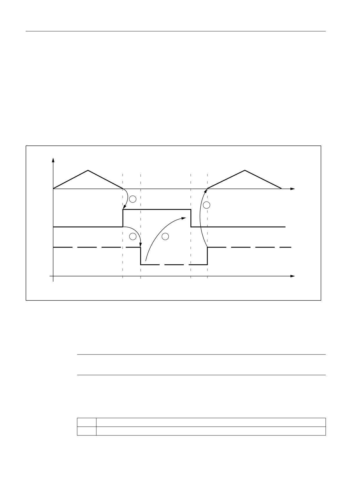
High-speed signals are used to synchronize the NC and punching unit. On the one hand, they
are applied via a high-speed output to ensure that the punch stroke is not initiated until the
metal sheet is stationary. On the other, they are applied via a high-speed input to ensure that
the sheet remains stationary while the punch is active.
The high-speed digital inputs and outputs on the control are used to drive the punching unit.
The following signal chart illustrates the signal sequence.
D
E
$
,
F
W
W
W
W
W
(a)
Axis motion of the machine as function v(t)
(b)
"Stroke initiation" signal
(c)
"Stroke active" signal
Figure 11-1
Signal chart
Note
The "Stroke active" signal is high-active for reasons relating to open-circuit monitoring.
The chronological sequence of events for punching and nibbling is controlled by the two signals
A0 and E0:
A0
Set by the NC and identical to stroke initiation.
E0
Defines the status of the punching unit and identical to the "Stroke active" signal.
Extended Functions
642
Function Manual, 12/2018, A5E40874029B AB

N4: Own channel - only 840D sl
11.2 Stroke control
The signal states characterize and define times t
1
to t4 in the following way:
t1
The motion of the workpiece (metal sheet) in relation to the punch is completed at instant t1.
Depending on the criterion defined for stroke initiation (see Section "Criteria for stroke initiation
(Page 643)"), the high-speed output O0 is set for punch initiation ①.
t2
The punching unit signals a punch movement via high-speed input E0 at instant t2.
This is triggered by signal A0②.
For safety reasons, signal E0 is high-active (in the case of an open circuit, "Stroke active" is
always set and the axes do not move).
The "Stroke active" signal is not reset again until the tool has moved away from the metal sheet
(t4).
t3
The NC reacts to the "Stroke active" signal at instant t3 by canceling the "Stroke initiation" signal
③. From this point in time onwards, the NC is in a waiting state. It simply waits for cancellation
of the "Stroke active" signal so it can initiate the next axis motion.
The next stroke can be initiated only after signal A0 has disappeared.
t4
The punching operation is complete at instant t4, i.e. the punch has exited from the metal sheet
again.
The NC reacts to a signal transition in signal E0 by starting an axis motion ④.
The reaction of the NC to a signal edge change ④ is described in the section headed "Axis start
after punching".
Note
The stroke time is determined by the period Δth = t4 - t1.
Reaction times at instant t4 between the signal transition of E0 and the start of the axis motion
must also be added.
11.2.3
Criteria for stroke initiation
Initiate a stroke
The stroke initiation must be set, at the earliest, for the point in time at which it can be
guaranteed that the axes have reached a standstill. This ensures that at the instant of punching,
there is absolutely no relative movement between the punch and the metal sheet in the
machining plane.
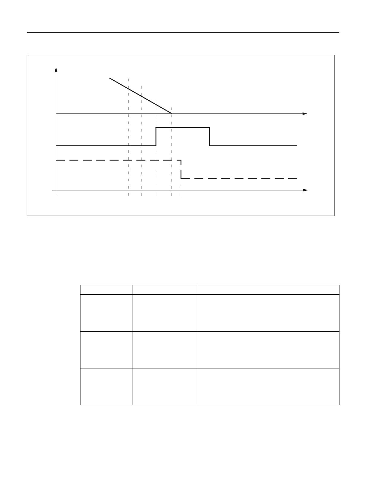
The following diagram shows the various criteria that can be applied to stroke initiation.
Extended Functions
Function Manual, 12/2018, A5E40874029B AB
643
N4: Own channel - only 840D sl
11.2 Stroke control
(QG RI LQWHUSRODWLRQ
([DFW VWRS FRDUVH
([DFW VWRS ILQH
W
$
,
W
W
W
W
W
Figure 11-2
Signal chart: Criteria for stroke initiation
The time interval between t1 and t2 is determined by the reaction of the punching unit to setting
of output A0. This cannot be altered, but can be utilized as a lead time for minimizing dead
times.
The diagram above shows the default setting with which the output is set when the "Exact stop
fine window" is reached (G601; default setting of G group 12). The punch initiation times t''1
and t'1 are programmed by means of G602 and G603 (see table below).
Programming
Activation
Description
G603
Stop interpolation
The interpolation reaches the block end. In this case,
the axes continue to move until the overtravel has been
traversed, i.e. the signal is output at an appreciable in-
terval before the axes have reached zero speed (see
t"1).
G602
Reach the coarse in-po-
The signal is output once the axes have reached the
sition window
coarse in-position window. If this criterion is selected for
stroke initiation output, then the instant of stroke initia-
tion can be varied through the size of interpolation win-
dow (see t'1).
G601
Reach the fine in-posi-
In this case, it can always be ensured that the machine
tion window
will have reached a standstill at the instant of punching
provided that the axis data are set appropriately.
However, this variant also results in a maximum dead
time (see t1).
Extended Functions
644
Function Manual, 12/2018, A5E40874029B AB
N4: Own channel - only 840D sl
11.2 Stroke control
Note
The initial setting of the G group with G601, G602 and G603 (G group 12) is defined via machine
data:
MD20150 $MC_GCODE_RESET_VALUES[11]
The default setting is G601.
G603
Depending on velocity and machine dynamics, approximately 3 - 5 interpolation cycles are
processed at the end of interpolation before the axes reach zero speed.
MD26018 $MC_NIBBLE_PRE_START_TIME
In conjunction with the above machine data, it is possible to delay, and therefore optimize, the
instant between reaching the end of interpolation and setting the high-speed output for "Stroke
ON".
The following setting data is available in addition to MD26018:
SD42402 $SC_NIBPUNCH_PRE_START_TIME
SD42402 can be changed from the part program and therefore adapted to the punching
process depending on the progress of the part program run.
The following applies to the delay time:
MD26018 = 0
→ SD42402 is operative
MD26018 ≠ 0
→ MD26018 is operative
If the "Punching with dwell time, PDELAYON" is active, then the dwell time programmed in
connection with this function is active. Neither MD26018 nor SD42402 is operative in this case.
Extended Functions
Function Manual, 12/2018, A5E40874029B AB
645
N4: Own channel - only 840D sl
11.2 Stroke control
11.2.4
Axis start after punching
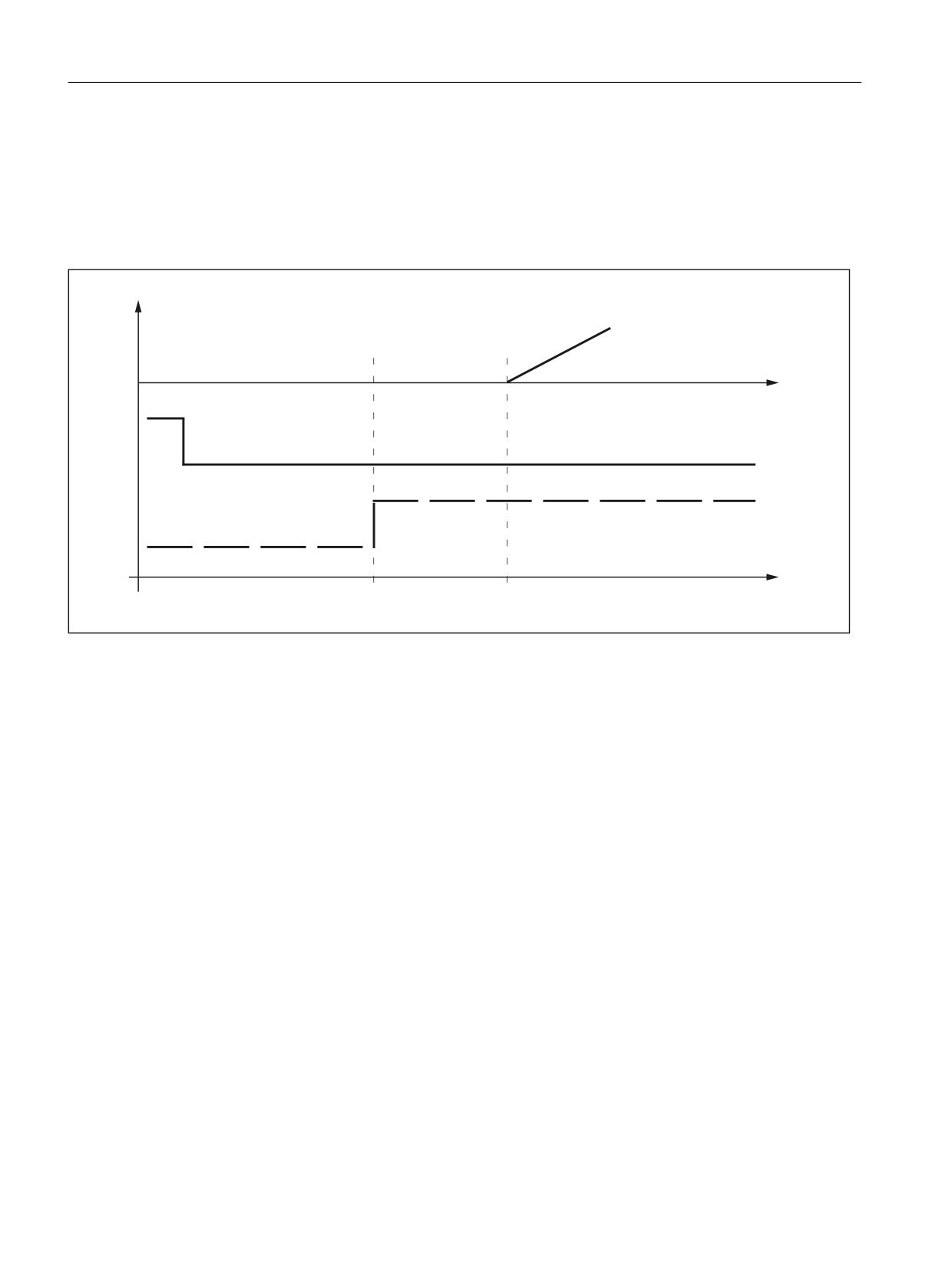
Input signal "Stroke ON"
The start of an axis motion after stroke initiation is controlled via input signal "Stroke ON".
t
$
,
W
W
t
Figure 11-3
Signal chart: Axis start after punching
In this case, the time interval between t4 and t'4 acts as a switching-time-dependent reaction
time. It is determined by the interpolation sampling time and the programmed punching/nibbling
mode.
PON/SON
When the punching unit is controlled via PON/SON, the maximum delay time is calculated to be:
|t'4 - t4| = 3 x interpolator clock cycle
PONS/SONS
If the punch is controlled by PONS/SONS, the delay time is determined by:
|t'4 - t4| ≤ 3 x position controller cycles
Prerequisites: Stroke time (t4 - t2) > 4 interpolator clock cycles
Extended Functions
646
Function Manual, 12/2018, A5E40874029B AB

N4: Own channel - only 840D sl
11.2 Stroke control
11.2.5
PLC signals specific to punching and nibbling
Function
In addition to the signals used for direct stroke control, channel-specific PLC interface signals
are also available. These are used both to control the punching process and to display
operational states.
Signals
Signal
Activation
DB21, ... DBX3.0 (no stroke enable)
Prevents the NC from initiating a punching operation.
The NC waits until the enable signal is available before
continuing the part program.
DB21, ... DBX3.2 (stroke suppression)
Allows the part program to be processed without initiat-
ing a punching operation (dry run).
With active path segmentation, the axes traverse in
"Stop and go" mode.
DB21, ... DBX3.4 (delayed stroke)
Activates delayed stroke output if permitted by
PDELAYON.
DB21, ... DBX3.1 (manual stroke suppres-
Enables the operator to initiate a punching operation
sion)
(controlled via the PLC) without executing the part pro-
gram.
Manual stroke initiation is acknowledged with signal:
DB21, .. DBX38.1 (acknowledgement of manual stroke
initiation)
11.2.6
Punching and nibbling-specific reactions to standard PLC signals
DB21, ... DBX12.3 (feed stop)
With interface signal:
DB21, ... DBX12.3 (feed stop)
, the NC reacts in the following way with respect to the stroke control:
Signal is detected in advance of instant t1:
Stroke initiation is suppressed.
The next stroke is not initiated until the next start or until
the "Feed stop" signal has been canceled.
Machining is then continued as if there had been no inter-
ruption.
Signal is detected at instant t1:
The current stroke is executed to completion.
The NC then dwells in the state characterized by t4.
To allow it to respond in this manner, time monitoring of the
"Stroke active" and "Stroke initiation" signals is dispensed
with.
Extended Functions
Function Manual, 12/2018, A5E40874029B AB
647

N4: Own channel - only 840D sl
11.3 Activation and deactivation
11.2.7
Signal monitoring
Oscillating signal
Owing to aging of the punch hydraulics, punch overshoot may cause the "Stroke active" signal
to oscillate at the end of a stroke.
In this case, an alarm can be generated (Alarm 22054 "undefined punching signal") as a
function of machine data:
MD26020 $MC_NIBBLE_SIGNAL_CHECK
Reset behavior
In the case of an NC reset, the interface signal:
DB21, ... DBX38.0 (stroke initiation active)
is canceled immediately without acknowledgement via the high-speed input.
A currently activated stroke cannot be suppressed.
11.3
Activation and deactivation
11.3.1
Language commands
Punching and nibbling functions are activated and deactivated via configurable language
commands. These replace the special M functions that were used in earlier systems.
References:
Programming Manual, Job Planning
Groups
The language commands are subdivided into the following groups:
Group 35
The actual punching and nibbling-specific functions are activated and deactivated by means of the
following language commands:
PON
= punching ON
SON
= nibbling ON
PONS
= punching ON, activated in the position controller
SONS
= nibbling ON, activated in the position controller
SPOF
= punching/nibbling OFF
Extended Functions
648
Function Manual, 12/2018, A5E40874029B AB

N4: Own channel - only 840D sl
11.3 Activation and deactivation
Group 36
This group includes the commands which have only a preparatory character and which determine the
real nature of the punching function:
PDELAYON
= punching with delay ON
PDELAYOF
= punching with delay OFF
Since the PLC normally needs to perform some preliminary tasks with respect to these preparatory
functions, they are programmed before the activating commands.
Group 38
This group contains the commands for switching over to a second punch interface. It can be used, for
example, for a second punching unit or set of hammer shears. A second I/O pair which can be used
for punching functionality is defined via machine data.
SPIF1
= first interface is active
SPIF2
= second interface is active
Note
Only one function at a time can be active within a G group (similar, for example, to the various
interpolation modes G0, G1, G2, G3, etc. which are also mutually exclusive).
SPOF
Punching and nibbling OFF
The SPOF function terminates all punching and nibbling functions. In this state, the NC
responds neither to the "Stroke active" signal nor to the PLC signals specific to punching and
nibbling functions.
If SPOF is programmed together with a travel command in one block (and in all further blocks
if punching/nibbling is not activated with SON or PON), the machine approaches the
programmed position without the initiation of a punching operation. SPOF deselects SON, SONS,
PON and PONS and corresponds to the Reset condition.
Programming example:
Program code
Comment
:
N20 G90 X100 SON
; Activate nibbling
N25 X50 SPOF
; Deactivate nibbling,
; Positioning without stroke initiation
:
SON
Nibbling ON
SON activates the nibbling function and deselects the other functions in G group35 (e.g. PON).
Extended Functions
Function Manual, 12/2018, A5E40874029B AB
649
N4: Own channel - only 840D sl
11.3 Activation and deactivation
In contrast to punching, the first stroke is made at the start point of the block with the activating
command, i.e. before the first machine motion.
SON has a modal action, i.e. it remains active until either SPOF or PON is programmed or until
the program end is reached.
The stroke initiation is suppressed in blocks without traversing information relating to the axes
designated as punching or nibbling axes (typically those in the active plane). If a stroke still
needs to be initiated, then one of the punching/nibbling axes must be programmed with a 0
traversing path. If the first block with SON is a block without traversing information of the type
mentioned, then only one stroke takes place in this block since the start and end points are
identical.
Programming example:
Program code
Comment
:
:
N70 X50 SPOF
; Positioning without punch initiation
N80 X100 SON
; Activate nibbling, initiate a stroke before the
; Motion (X=50) and at the end of the programmed
; motion (X=100)
:
:
SONS
Nibbling ON (in position control cycle)
SONS behaves in the same way as SON. The function is activated in the position control cycle,
thus allowing time-optimized stroke initiation and an increase in the punching rate per minute.
PON
Punching ON
PON activates the punching function and deactivates SON.
PON has a modal action like SON.
In contrast to SON, however, a stroke is not executed until the end of the block or, in the case
of automatic path segmentation, at the end of a path segment. PON has an identical action to
SON in the case of blocks which contain no traversing information.
Programming example:
Program code
Comment
:
N100 Y30 SPOF
; Positioning without punch initiation
N110 Y100 PON
; Activate punching, punch initiation at the end of the
; positioning operation (Y=100)
:
Extended Functions
650
Function Manual, 12/2018, A5E40874029B AB
N4: Own channel - only 840D sl
11.3 Activation and deactivation
PONS
Punching ON (in position control cycle)
PONS behaves in the same way as PON. For explanation, please refer to SONS.
PDELAYON
Punching with delay ON
PDELAYON is a preparatory function. This means that PDELAYON is generally programmed
before PON. The punch stroke is output with a delay when the programmed end position is
reached.
The delay time in seconds is programmed in setting data:
SD42400 $SC_PUNCH_DWELLTIME
If the defined value cannot be divided as an integer into the interpolator clock cycle, then it is
rounded to the next divisible integer value.
The function has a modal action.
PDELAYOF
Punching with delay OFF
PDELAYOF deactivates punching with delay function, i.e. the punching process continues
normally. PDELAYON and PDELAYOF form a G group.
Programming example:
SPIF2 activates the second punch interface. This means that the stroke is controlled via the
second pair of high-speed I/Os (see Section "Channelspecific machine data (Page 680)",
MD26004 and MD26006).
Program code
Comment
:
N170 PDELAYON X100 SPOF
; Position without punch initiation, activate delayed
punch initiation
:
:
N180 X800 PON
; Activate punching. The punch stroke is output with a
delay when the end position is reached
:
:
N190 PDELAYOF X700
; deactivate punching with delay, normal punch initia-
tion on. End of programmed motion
:
SPIF1
Activation of first punch interface
Extended Functions
Function Manual, 12/2018, A5E40874029B AB
651
N4: Own channel - only 840D sl
11.3 Activation and deactivation
SPIF1 activates the first punching interface. This means that the stroke is controlled via the
first pair of high-speed I/Os (see Section "Channelspecific machine data (Page 680)",
MD26004 and MD26006).
The first punch interface is always active after a reset or control system power up. If only one
interface is used, then it need not be programmed.
SPIF2
Activation of second punch interface
SPIF2 activates the second punch interface. This means that the stroke is controlled via the
second pair of high-speed I/Os (see Section "Channelspecific machine data (Page 680)",
MD26004 and MD26006).
Programming example:
Program code
Comment
:
N170 SPIF1 X100 PON
; At the end of the block, a stroke is initiated at the
first fast output. The "Stroke active" signal is monitored
at the first input.
:
:
N180 X800 SPIF2
; The second stroke is initiated at the second fast output.
The "Stroke active" signal is monitored at the second input.
:
:
N190 SPIF1 X700
; All further strokes are controlled with the first inter-
face.
:
11.3.2
Functional expansions
Alternate interface
Machines that alternately use a second punching unit or a comparable medium can be
switched over to a second I/O pair.
The second I/O pair can be defined via the following machine data:
MD26004 $MC_NIBBLE_PUNCH_OUTMASK
MD26006 $MC_NIBBLE_PUNCH_INMASK
The interface is switched by command SPIF1 or SPIF2.
Full punching/nibbling functionality is available on both interfaces.
Example:
Hardware assignment for stroke control
Extended Functions
652
Function Manual, 12/2018, A5E40874029B AB

N4: Own channel - only 840D sl
11.3 Activation and deactivation
Define the high-speed byte in each case on the CPU as a high-speed punch interface:
MD26000 $MC_PUNCHNIB_ASSIGN_FASTIN = 'H00030001' → Byte 1
MD26002 $MC_PUNCHNIB_ASSIGN_FASTOUT = 'H00000001'
Remark:
The first and second bits are inverted.
Screen form for high-speed input and output bits:
First interface output bit
MD26004 $MC_NIBBLE_PUNCH_OUTMASK[0]
= 1
→ Bit 1 SPIF1
Second interface output bit
MD26004 $MC_NIBBLE_PUNCH_OUTMASK[1]
= 2
→ Bit 2 SPIF2
First interface input bit
MD26006 $MC_NIBBLE_PUNCH_INMASK[0]
= 1
→ Bit 1 SPIF1
Second interface input bit
MD26006 $MC_NIBBLE_PUNCH_INMASK[1]
= 2
→ Bit 2 SPIF2
Automatically activated pre-initiation time
Dead times due to the reaction time of the punching unit can be minimized if the stroke can
be initiated before the interpolation window of the axes is reached. The reference time for this
is the interpolation end. The stroke is automatically initiated with G603 and delayed by the set
value in relation to the time that the end of interpolation is reached.
The delay time for stroke initiation can be adjusted in machine data:
MD26018 $MC_NIBBLE_PRE_START_TIME
Example:
With an IPO cycle of 5 ms, a stroke shall be released two cycles after reaching the interpolation
end:
⇒ MD26018 $MC_NIBBLE_PRE_START_TIME = 0.01 [s]
A pre-initiation time can also be programmed in setting data:
SD42402 $SC_NIBPUNCH_PRE_START_TIME
This setting takes effective only if MD26018 = 0 has been set.
Monitoring of the input signal
If the "stroke active" signal is fluctuating between strokes due to plunger overshoots, for
example, the message "undefined punching signal" can be also be output when interpolation
is stopped.
The message output is dependent on the setting in machine data:
MD26020 $MC_NIBBLE_SIGNAL_CHECK
MD26020 = 0
No alarm
MD26020 = 1
Alarm
Extended Functions
Function Manual, 12/2018, A5E40874029B AB
653
N4: Own channel - only 840D sl
11.3 Activation and deactivation
Minimum period between two strokes
A minimum time interval between two consecutive strokes can be programmed in setting data:
SD42404 $SC_MINTIME_BETWEEN_STROKES
Example:
There must be a minimum delay of at least 1.3 seconds between two stroke initiations
irrespective of physical distance:
⇒ SD42404 $SC_MINTIME_BETWEEN_STROKES = 1.3 [s]
If a punching dwell time (PDELAYON) is also programmed, then the two times are applied
additively.
If a pre-initiation time at G603 is programmed, it will be effective only if the end of interpolation
is reached before the time set in SD 42404:
The programmed time becomes operative immediately. Depending on the size of the block
buffer, strokes that have already been programmed can be executed with this minimum
interval. The following programming measures (example) can be taken to prevent this:
Program code
N...
N100 STOPRE
N110 $SC_ MINTIME_BETWEEN_STROKES = 1.3
The function is not active when SD42404 = 0.
Travel-dependent acceleration
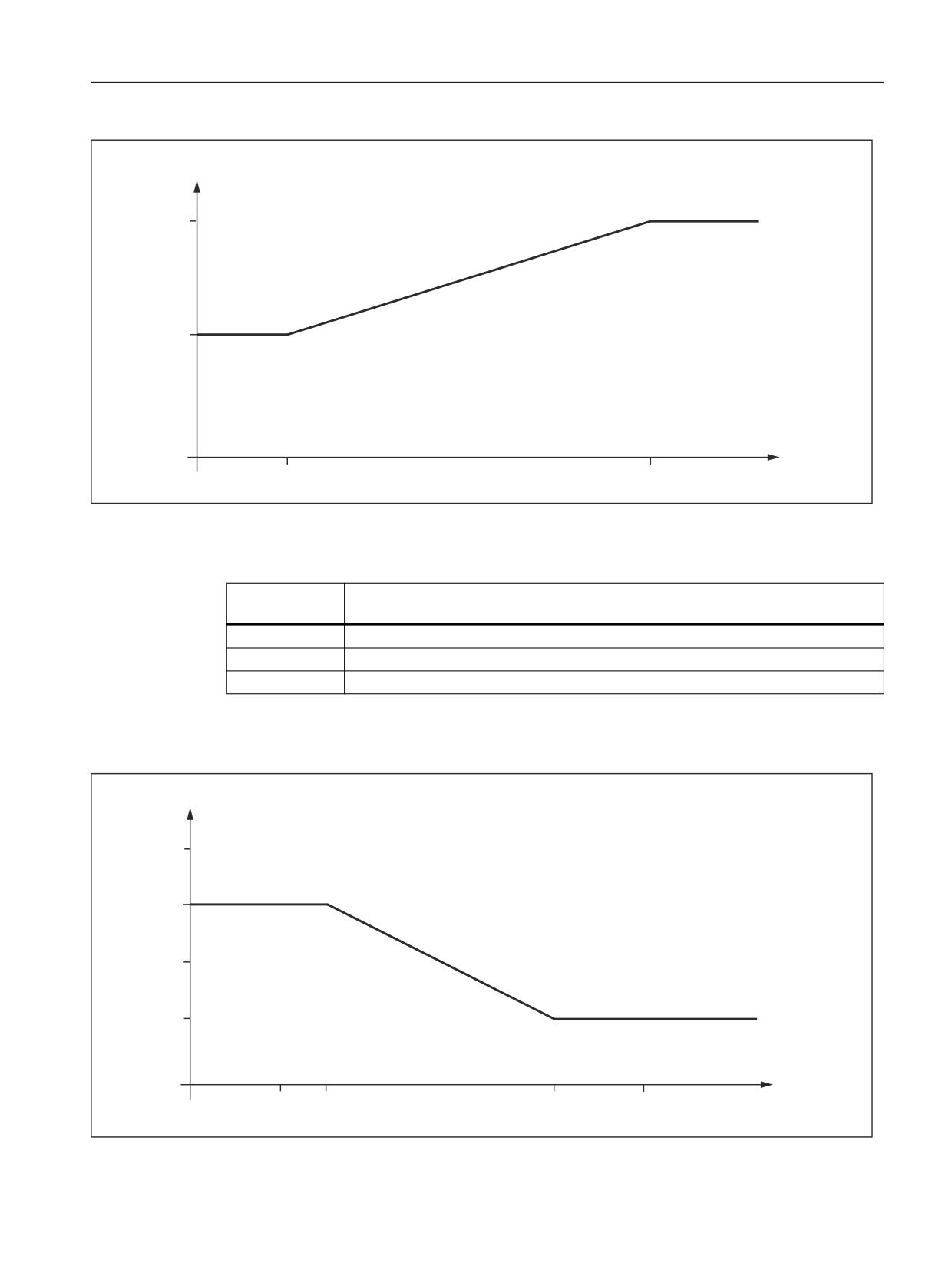
An acceleration characteristic can be defined with PUNCHACC (Smin, Amin, Smax,
Amax). This command can be used to define different acceleration rates depending on the
distance between holes.
Example 1:
Extended Functions
654
Function Manual, 12/2018, A5E40874029B AB
N4: Own channel - only 840D sl
11.3 Activation and deactivation
$>
@
381&+$&&
6 >PP@
The characteristic defines the following acceleration rates:
Distance be-
Acceleration
tween holes
< 2 mm
The axis accelerates at a rate corresponding to 50 % of maximum acceleration.
2 - 10 mm
Acceleration is increased to 100 %, proportional to the spacing.
> 10 mm
The axis accelerates at the maximum rate (100%).
Example 2:
$>
@
381&+$&&
6 >PP@
Extended Functions
Function Manual, 12/2018, A5E40874029B AB
655
N4: Own channel - only 840D sl
11.3 Activation and deactivation
The characteristic defines the following acceleration rates:
Distance be-
Acceleration
tween holes
< 3 mm
The axis accelerates at a rate corresponding to 75 % of maximum acceleration.
3 - 8 mm
Acceleration is reduced to 25 %, proportional to the spacing.
> 10 mm
The axis accelerates at the maximum rate (25 %).
If a reduced acceleration rate has already been programmed via ACC, then the acceleration
limits defined with PUNCHACC refer to the reduced acceleration rate.
The function is deselected with:
Smin = Smax = 0
The acceleration rate programmed beforehand with ACC remains operative.
Block search
In the case of a search for a block containing a nibbling function, it is possible to program
whether the punch stroke is executed at the block beginning or suppressed.
The setting is programmed in machine data:
MD11450 $MN_SEARCH_RUN_MODE
Bit
Value
Meaning
5
0
Punch stroke at beginning of block is suppressed.
1
Punch stroke at beginning of block is executed.
References:
Function Manual, Basic Functions; Mode Group, Channel, Program Operation, Reset
Response (K1), Section:
11.3.3
Compatibility with earlier systems
Use of M functions
As in earlier versions, macro technology allows special M functions to be used instead of
language commands (compatibility).
The M functions and equivalent language commands as used in earlier systems are as follows:
M20, M23
≙
SPOF
M22
≙
SON
Extended Functions
656
Function Manual, 12/2018, A5E40874029B AB
N4: Own channel - only 840D sl
11.3 Activation and deactivation
M25
≙
PON
M26
≙
PDELAYON
Note
M functions can be configured in machine data.
When M functions are assigned to language commands, it must be noted that M functions are
organized in auxiliary function groups.
Examples
DEFINE M20 AS SPOF
Punching/nibbling OFF
or
DEFINE M20 AS SPOF M=20
Punching with auxiliary function output
DEFINE M20 AS SPOF PDELAYOF Punching/nibbling OFF and punching with delay OFF
DEFINE M22 AS SON
Nibbling ON
or
DEFINE M22 AS SON M=22
Nibbling ON with auxiliary function output
DEFINE M25 AS PON
Punching ON
or
DEFINE M25 AS PON M=25
Punching ON with auxiliary function output
DEFINE M26 AS PDELAYON
Punching with delay ON
or
DEFINE M26 AS PDELAYON M=26 Punching and auxiliary function output
Programming example:
Program code
Comment
:
:
N100 X100 M20
; position without punch initiation
N110 X120 M22
; Activate nibbling, before and after motion
; stroke initiation
:
N120 X150 Y150 M25
; Activate punching, initiate stroke at end
; of the motion
:
Extended Functions
Function Manual, 12/2018, A5E40874029B AB
657
N4: Own channel - only 840D sl
11.4 Automatic path segmentation
Program code
Comment
:
11.4
Automatic path segmentation
11.4.1
General information
Function
One of the following two methods can be applied to automatically segment a programmed
traversing path:
● Path segmentation with maximum path segment programmed via language command SPP
● Path segmentation with a number of segments programmed via language command SPN
Both functions generate sub-blocks independently.
In earlier systems
● SPP<number> corresponds to E<number>
● SPN<number> corresponds to H<number>
Since addresses E and H now represent auxiliary functions, language commands SPP and
SPN are used to avoid conflicts. The new procedure is therefore not compatible with those
implemented in earlier systems. Both language commands (SPP and SPN) can be configured.
Note
The values programmed with SPP are either mm or inch settings depending on the initial setting
(analogous to axes).
The automatic path segmentation function ensures that the path is divided into equidistant
sections with linear and circle interpolation.
When the program is interrupted and automatic path segmentation is active (SPP/SPN), the
contour can be reentered only at the beginning of the segmented block. The first punch stroke
is executed at the end of this sub-block.
SPP and SPN can be activated only if geometry axes are configured.
SPP
The automatic path segmentation function SPP divides the programmed traversing path into
sections of equal size according to the segment specification.
Extended Functions
658
Function Manual, 12/2018, A5E40874029B AB
N4: Own channel - only 840D sl
11.4 Automatic path segmentation
The following conditions apply:
● Path segmentation is active only when SON or PON is active.
(Exception: MD26014 $MC_PUNCH_PATH_SPLITTING = 1)
● SPP is modally active, i.e. the programmed segment remains valid until it is programmed
again, but it can be suppressed on a block-by-block (non-modal) basis by means of SPN.
● The path segments are rounded off by the control system if required so that a total
programmed distance can be divided into an integral number of path sections.
● The path segment unit is either mm/stroke or inch/stroke (depending on axis settings).
● If the programmed SPP value is greater than the traversing distance, then the axis is
positioned on the programmed end position without path segmentation.
● SPP = 0, reset or program end delete the programmed SPP value. The SPP value is not
deleted when punching/nibbling is deactivated.
SPN
The automatic path segmentation function SPN divides the traversing path into the
programmed number of path segments.
The following conditions apply:
● Path segmentation is active only when SON or PON is active.
(Exception: MD26014 $MC_PUNCH_PATH_SPLITTING = 1)
● SPN has a non-modal action.
● Any previously programmed SPP value is suppressed for the block containing SPN, but is
re-activated again in the following blocks.
Supplementary conditions
● The path segmentation function is operative with linear and circular interpolation.
The interpolation mode remains unchanged, i.e. circles are traversed when circular
interpolation is selected.
● If a block contains both SPN (number of strokes) and SPP (stroke path), then the number
of blocks is activated in the current block while the stroke path is activated in all blocks that
follow.
● Path segmentation is active only in conjunction with punching or nibbling functions.
(Exception: MD26014 $MC_PUNCH_PATH_SPLITTING = 1).
● Any programmed auxiliary functions are output before, during the first or after the last sub-
block.
● In the case of blocks without traversing information, the rules which govern the
programming of SON and PON also apply to SPP and SPN. In other words, a stroke is initiated
only if an axis motion has been programmed.
Extended Functions
Function Manual, 12/2018, A5E40874029B AB
659
N4: Own channel - only 840D sl
11.4 Automatic path segmentation
11.4.2
Operating characteristics with path axes
MD26010
All axes defined and programmed via machine data:
MD26010 $MC_PUNCHNIB_AXIS_MASK
are traversed along path sections of identical size with SPP and SPN until the programmed
end point is reached. This also applies to rotatable tool axes if programmed. The response
can be adjusted for single axes.
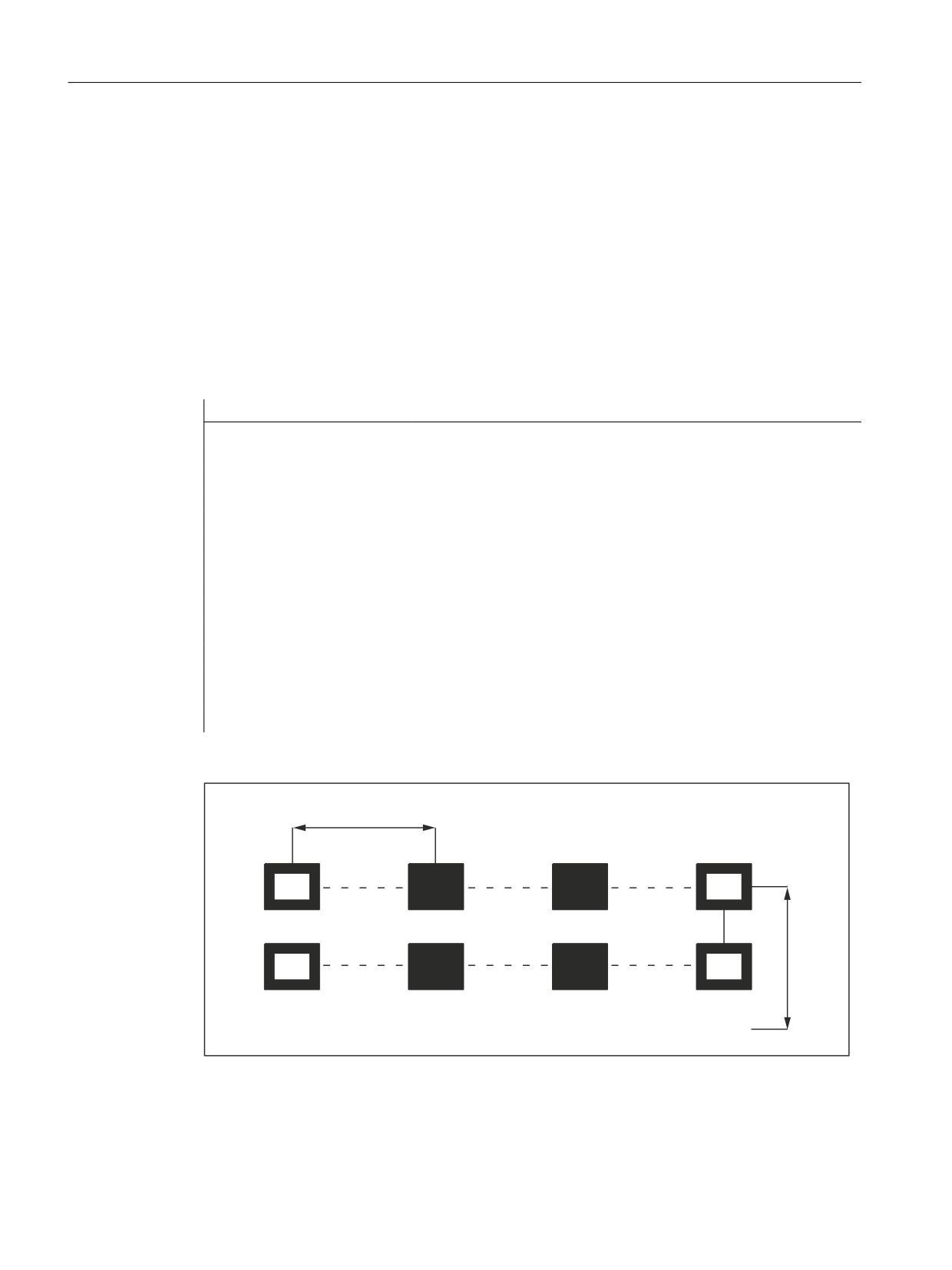
Example of SPP
Program code
Comment
N1 G01 X0 Y0 SPOF
; positioning without punch initiation
N2 X75 SPP=25 SON
; nibbling with feedrate value 25 mm; initiate punch
; before the first movement and after each
; path segment.
:
:
N3 Y10
; positioning with reduced SPP value, because
:
; traversing distance < SPP value, and initiate punch
; after the movement.
:
:
N4 X0
Reposition with punch initiation
after each path section.
:
633
633
If the programmed path segmentation is not an integral multiple of the total path, then the feed
path is reduced.
Extended Functions
660
Function Manual, 12/2018, A5E40874029B AB
N4: Own channel - only 840D sl
11.4 Automatic path segmentation
<
<
633ಬ
633
;
;
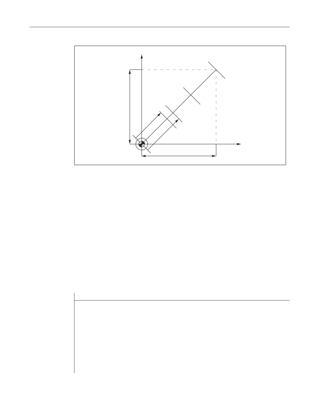
X2/Y2:
Programmed traversing distance
SPP:
Programmed SPP value
SPP':
Automatically rounded-off offset distance
Figure 11-4
Path segmentation
Example of SPN
The number of path segments per block is programmed via SPN.
A value programmed via SPN takes effect on a non-modal basis for both punching and nibbling
applications. The only difference between the two modes is with respect to the first stroke.
This is normally executed at the beginning of the first segment with nibbling operations and at
its end with punching operations. This means that when n segments are programmed, n
strokes are executed with punching operations but n+1 with nibbling. Furthermore, where no
travel information is available, only a single stroke is executed, even if several are programmed.
Should it be necessary to generate several strokes at one position, then the corresponding
number of blocks without traversing information must be programmed.
Program code
Comment
N1 G01 X0 Y0 SPOF
; positioning without punch initiation
N2 X75 SPN=3 SON
; activate nibbling. The total path is
; divided into 3 path segments. Before the first
; movement and at the end of each path segment, a
; stroke is initiated.
:
:
:
:
N3 Y10 SPOF
; positioning without punch initiation
Extended Functions
Function Manual, 12/2018, A5E40874029B AB
661
N4: Own channel - only 840D sl
11.4 Automatic path segmentation
Program code
Comment
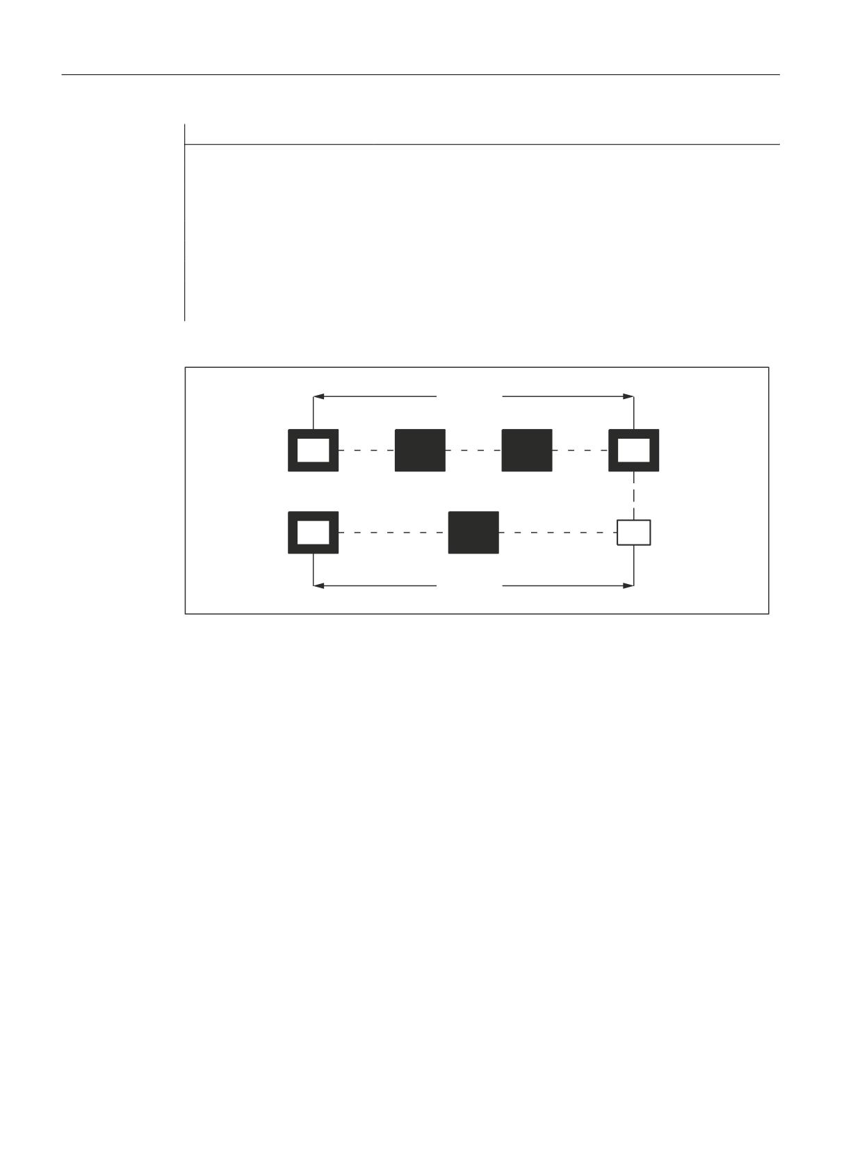
N4 X0 SPN=2 PON
; activate punching. The total path is divided into 2
; path segments. Because punching has been activated,
; the first stroke is initiated at the end of the first
path
; segment.
:
:
:
:
631
631
Extended Functions
662
Function Manual, 12/2018, A5E40874029B AB
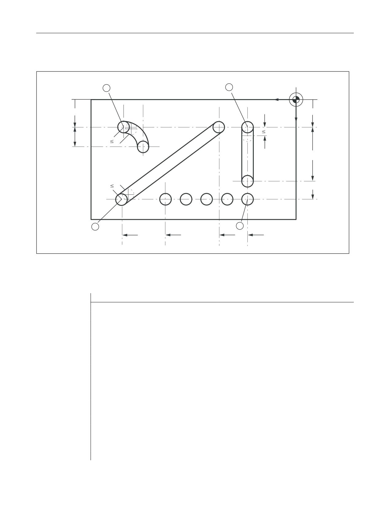
N4: Own channel - only 840D sl
11.4 Automatic path segmentation
Example
;
<
Figure 11-5
Workpiece
Extract from program
Program code
Comment
N100 G90 X130 Y75 F60 SPOF
; positioning to starting point (1) of the
; vertical nibbling path segments
N110 G91 Y125 SPP=4 SON
; end point coordinates (incremental)
; path segment: 4 mm, activate nibbling
N120 G90 Y250 SPOF
; absolute dimensioning, positioning at
; the start point (2) of the horizontal
; nibbling path segment
N130 X365 SPN=4 SON
; end point coordinates, 4 path segments,
; activate nibbling
N140 X525 SPOF
; positioning to starting point (3) of the
; inclined nibbling path
N150 X210 Y75 SPP=3 SON
; end point coordinates, path segment: 3
mm,
; activate nibbling
N160 X525 SPOF
; positioning to starting point (4) of the
; nibbling path on pitch circle path
N170 G02 G91 X-62.5 Y62.5 I0 J62.5 SON
; incremental circular interpolation with
; activate parameters,
Extended Functions
Function Manual, 12/2018, A5E40874029B AB
663
N4: Own channel - only 840D sl
11.4 Automatic path segmentation
Program code
Comment
; nibbling
N180 G00 G90 Y300 SPOF
; positioning
11.4.3
Response in connection with single axes
MD26016
The path of single axes programmed in addition to path axes is distributed evenly among the
generated intermediate blocks as standard.
In the following example, the additional rotary axis C is defined as a synchronous axis.
If this axis is programmed additionally as a "Punch-nibble axis":
MD26010 $MC_PUNCHNIB_AXIS_MASK = 1,
, then the behavior of the synchronous axis can be varied as a function of machine data:
MD26016 $MC_PUNCH_PARTITION_TYPE
Programming example:
Program code
N10 G90 G1 PON X10 Y10 C0 F10000
N20 SPP=5 X25 C45
N30 G3 SPN=3 X35 Y20 I0 J10 C90
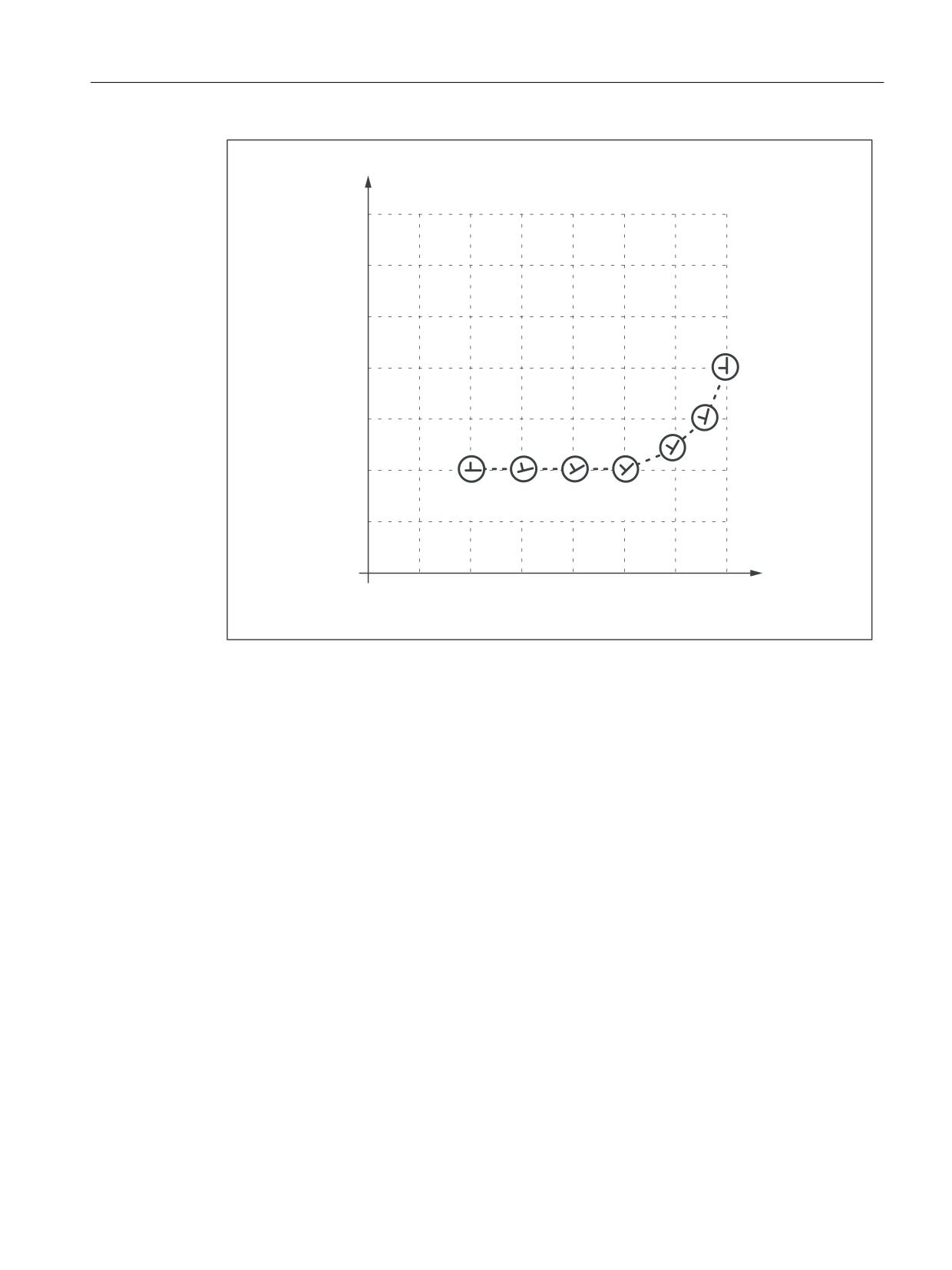
MD26016 $MC_PUNCH_PARTITION_TYPE=0 (default setting)
With this setting, the axes behave as standard, i.e. the programmed special axis motions are
distributed among the generated intermediate blocks of the active path segmentation function
in all interpolation modes.
In block N20, the C axis is rotated through 15° in each of the three intermediate blocks. The
axis response is the same in block N30, in the case of circular interpolation (three sub-blocks,
each with 15° axis rotation).
Extended Functions
664
Function Manual, 12/2018, A5E40874029B AB
N4: Own channel - only 840D sl
11.4 Automatic path segmentation
\
r
r
r
1
1
& r
r
r
r
[
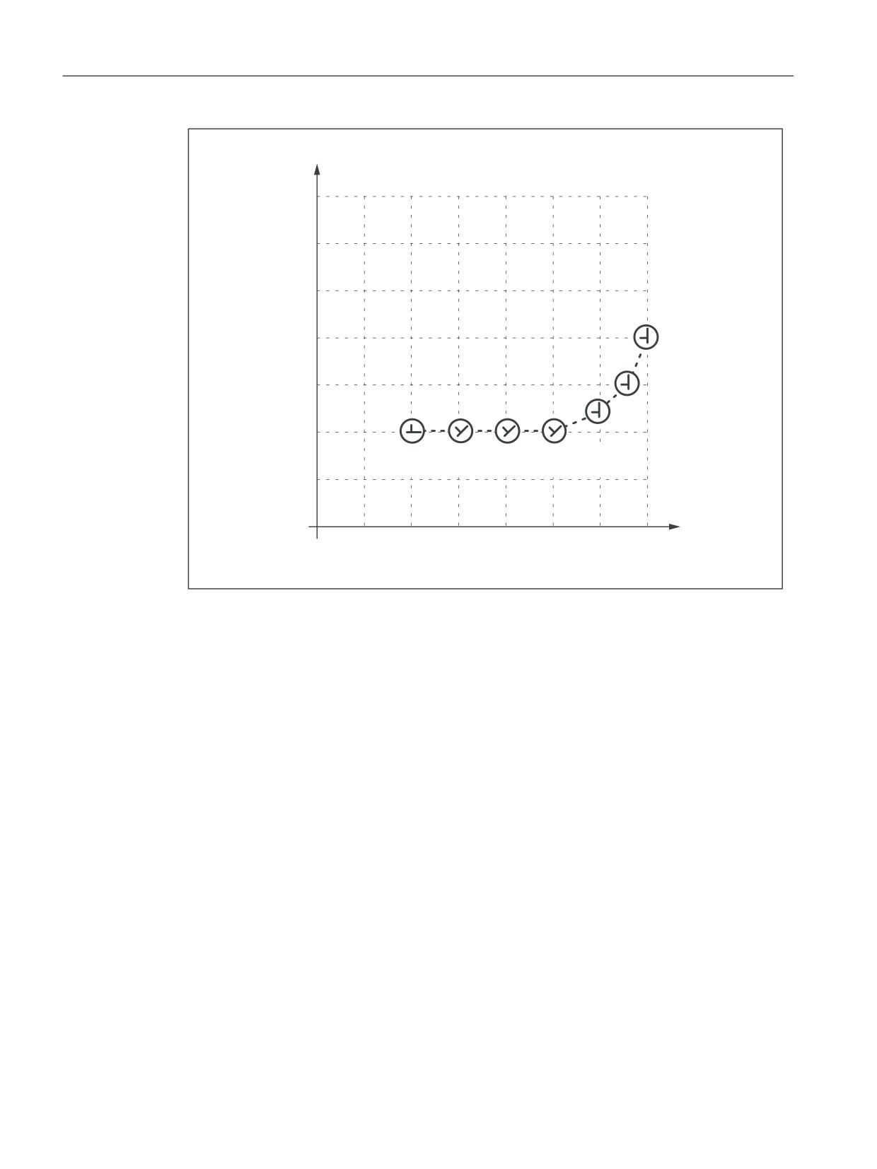
MD26016 $MC_PUNCH_PARTITION_TYPE=1
In contrast to the behavior described above, here the synchronous axis travels the entire
programmed rotation path in the first sub-block of the selected path segmentation function.
Applied to the example, the C axis already reaches the programmed end position C=45 when
it reaches X position X=15. It behaves in the same way in the circular interpolation block below.
Extended Functions
Function Manual, 12/2018, A5E40874029B AB
665
N4: Own channel - only 840D sl
11.4 Automatic path segmentation
\
r
r
r
1
1
1
& r
r
r
r
[
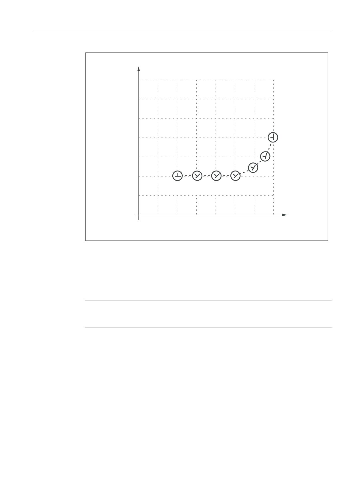
MD26016 $MC_PUNCH_PARTITION_TYPE=2
MD26016=2 is set in cases where the axis must behave as described above in linear
interpolation mode, but according to the default setting in circular interpolation mode (see 1st
case).
The axis behavior for the example is then as follows: In block N20, the C axis is rotated to
C=45° in the first sub-block. The following circular interpolation block rotates the C axis through
15° in every sub-block.
Extended Functions
666
Function Manual, 12/2018, A5E40874029B AB
N4: Own channel - only 840D sl
11.4 Automatic path segmentation
\
r
r
r
1
1
1
& r
r
r
r
[
The axis response illustrated in the diagram above can be particularly useful when applied to
the axis of a rotatable tool in cases where it is used to place the tool in a defined direction (e.g.
tangential) in relation to the contour, but where the tangential control function must not be
applied. However, it is not a substitute for the tangential control function since the start and
end positions of the rotary axis must always be programmed.
Note
Additional offset motions of special axes (in this case, rotary axis C) are implemented via a
zero offset.
Extended Functions
Function Manual, 12/2018, A5E40874029B AB
667
N4: Own channel - only 840D sl
11.4 Automatic path segmentation
Supplementary conditions
● If the C axis is not defined as a "Punch-nibble axis", then the C axis motion path is not
segmented in block N30 in the above example nor is a stroke initiated at the block end.
● If the functionality described above is to be implemented in a variant not specific to nibbling
applications, but with alignment of the special axis, then stroke initiation can be suppressed
by the following PLC interface signal:
DB 21, 22 DBX3.2 (stroke suppression)
(Application: e.g. alignment of electron beam during welding)
A similar response can be programmed with the following machine data setting:
MD26014 $MC_PUNCH_PATH_SPLITTING=1
In this case, the path is segmented irrespective of punching or nibbling functions.
Extended Functions
668
Function Manual, 12/2018, A5E40874029B AB
N4: Own channel - only 840D sl
11.5 Rotatable tool
11.5
Rotatable tool
11.5.1
General information
Function overview
The following two functions are provided for nibbling/punching machines with rotatable punch
and lower die:
● Coupled motion
for synchronous rotation of punch and die
● Tangential control
for normal alignment of rotary axes for punches in relation to workpiece
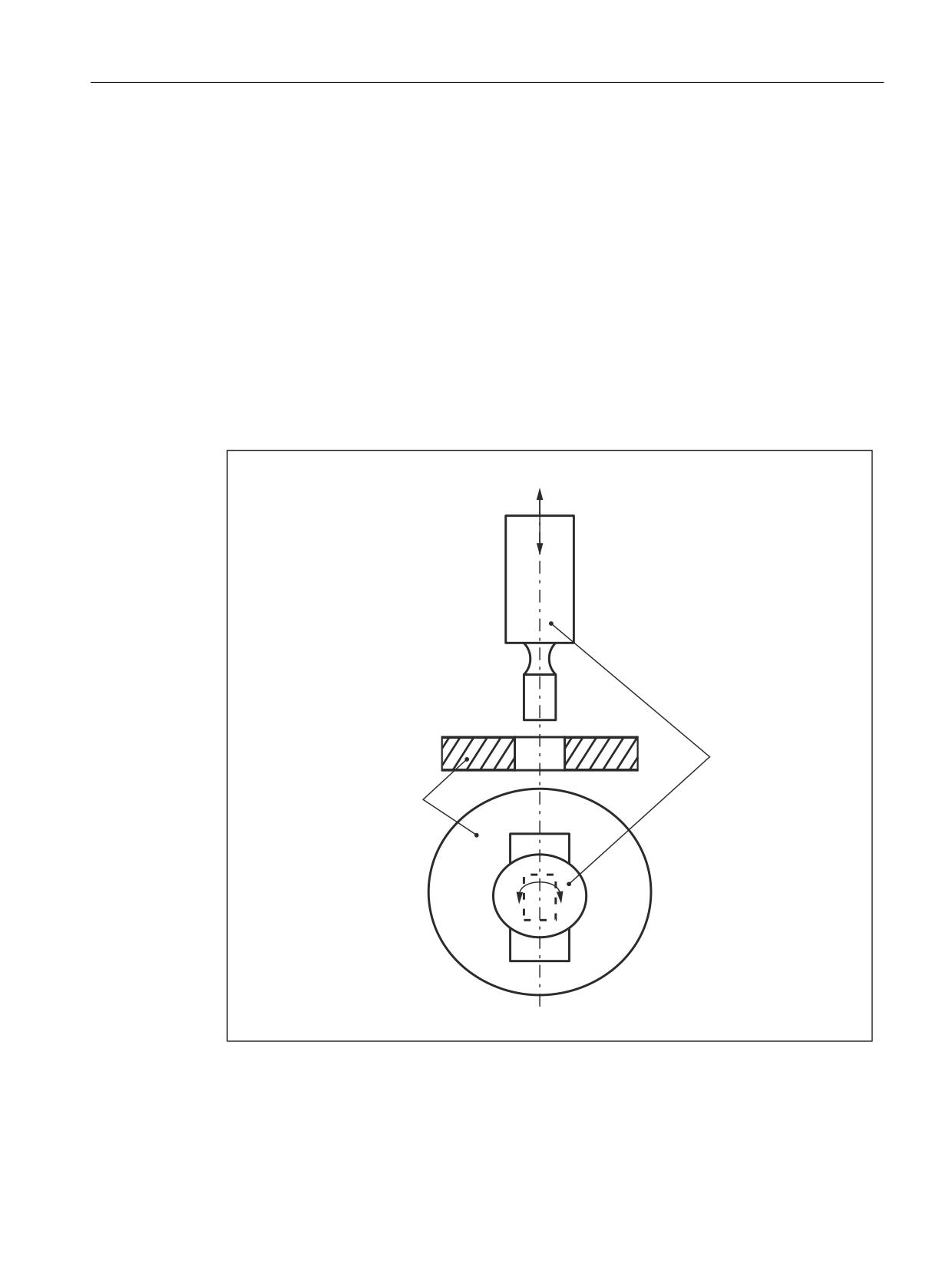
7RRO URWDU\ D[LV
6WDPS
'LH
Figure 11-6
Illustration of a rotatable tool axis
Extended Functions
Function Manual, 12/2018, A5E40874029B AB
669
N4: Own channel - only 840D sl
11.5 Rotatable tool
11.5.2
Coupled motion of punch and die
Function
Using the standard function "Coupled motion", it is possible to assign the axis of the die as a
coupled motion axis to the rotary axis of the punch.
Activation
The "Coupled motion" function is activated or deactivated with language commands
TRAILON and TRAILOF respectively.
References:
Function Manual, Special Functions; Coupled Motion and ESR (M3)
Example
Example of a typical nibbling machine with rotatable punches where C is the punch axis and
C1 the die axis:
Program code
Comment
:
:
TRAILON (C1, C, 1)
; Enabling the coupled-motion grouping
G01 X100 Y100 C0 PON
; Initiate stroke with C axis /
; C1 axis position C=0=C1
X150 C45
; Initiate stroke with C axis /
; C1 axis position C=45=C1
:
:
M30
Basic position
No coupled-motion groupings are active after power up. Once the two tool axes have
approached the reference point, the coupled-motion grouping is not generally separated again.
This can be achieved by:
● Program single activation of the coupled-motion grouping (see example above)
● Program MD setting:
MD20110 $MC_RESET_MODE_MASK, bit 8=1
In this way, the coupled-motion grouping remains active after RESET/part program start or
end.
Extended Functions
670
Function Manual, 12/2018, A5E40874029B AB
N4: Own channel - only 840D sl
11.5 Rotatable tool
11.5.3
Tangential control
Function
The "tangential control" function aligns the rotary axis used for positioning the punching/
nibbling tool so that it is tangential to the programmed path. In connection with tangential
control, this axis is called the tangential axis. The linear axes of the machining plane are the
leading axes of the tangential coupling. The tangential axis is the following axis that is aligned
to the path tangent of the lead axes. An additive offset angle for the tangent angle can also be
programmed for the tangential axis.
If the punching/nibbling tool (die and die plate) is moved via two separate rotary axes, the
second rotary axes can be coupled to the tangential axis via "coupled motion".
Note
Switch-on sequence
In the NC program, the tangential control must first be defined and then the coupled motion
must be activated.
References
A detailed description of the tangential control can be found in:
Function Manual, Special Functions, Chapter: "T3: Tangential control"
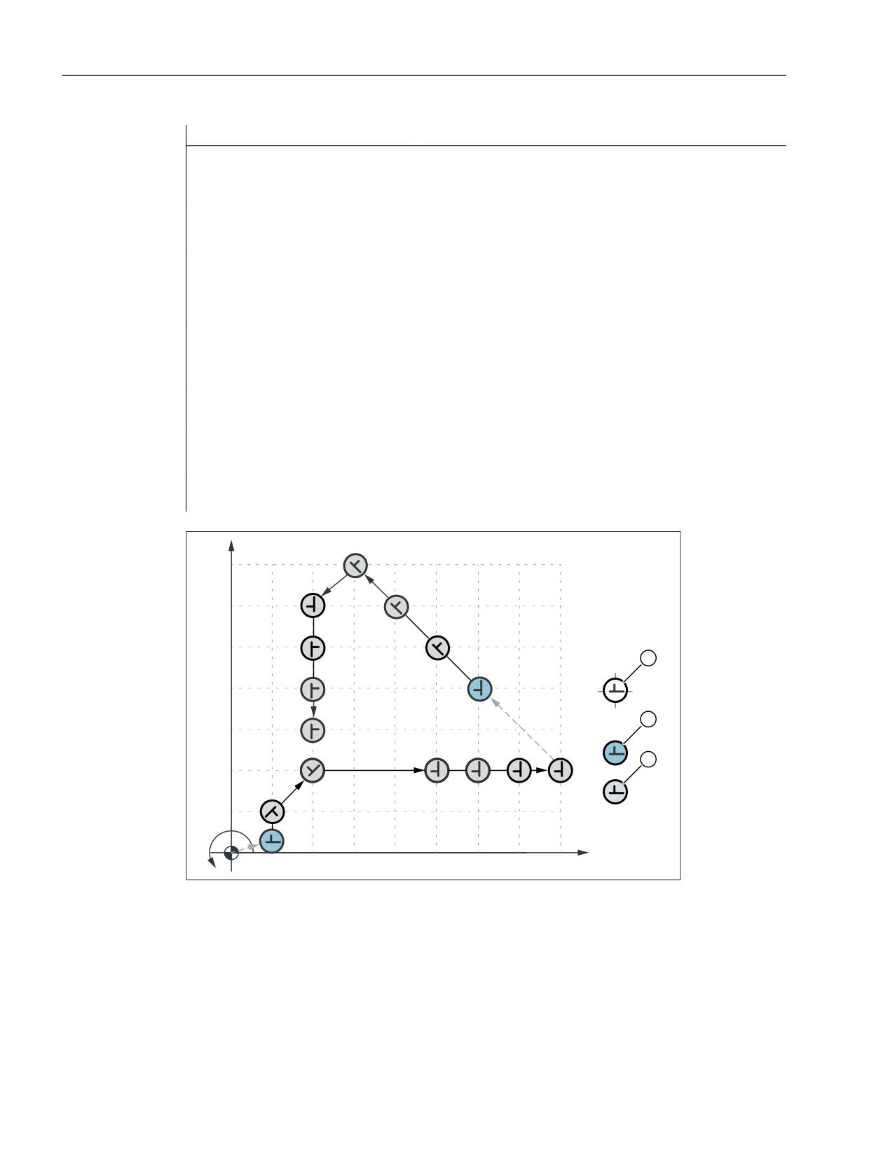
Example: Linear interpolation
Assumptions
● The punching/nibbling tool is subdivided into bottom and top tool
● The bottom tool and top tool are moved by different rotary axes (C/C1).
● The linear axes X and Y are the leading axes (machining plane G17)
Program code
Comment
N2 TANG (C, X, Y, 1, "B")
; definition tangential control
; leading axes: X, Y
; following axis: C
; coupling factor: 1
; basic coordinate system
N5 G0 X10 Y5
; starting position
N8 TRAILON (C1, C, 1)
; coupled motion ON
N10 Y10 C225 PON F60
; C/C1 axis → 225°
; nibbling initiation ON, → stroke
N15 X20 Y20 C45
; C/C1 axis → 45° → stroke
N20 X50 Y20 C90 SPOF
; C/C1 axis → 90°
; stroke initiation OFF
Extended Functions
Function Manual, 12/2018, A5E40874029B AB
671
N4: Own channel - only 840D sl
11.5 Rotatable tool
Program code
Comment
N25
X80 Y20 SPP=10 SON
;
path segmentation: ON
;
path segment: 10 mm → 4 lifts
;
punch initiation: ON
N30
X60 Y40 SPOF
;
positioning
;
stroke initiation: OFF
N32
TANGON (C, 180)
;
tangential control: ON
;
offset angle: 180°
N35
X30 Y70 SPN=3 PON
;
path segmentation: 3 path segments → lift
;
nibbling initiation: ON
N40
G91 C45 X-10 Y-10
;
C/C1: 90° (-135°+180°+45°) → lift
N42
TANGON (C, 0)
;
tangential control: ON
;
offset angle: 0°
N45
G90 Y30 SPN=3 SON
;
path segmentation → 3 lifts
;
punch initiation: ON
N50
SPOF TANGOF
;
stroke initiation OFF
;
tangential control: OFF
N55
TRAILOF (C1, C)
;
coupled motion: OFF
N60
M2
<
1
1
1
r
1
1
1
1
1
1
;
r
&
① Mounting position 0°
② Positioning
③ Stroke
Extended Functions
672
Function Manual, 12/2018, A5E40874029B AB
N4: Own channel - only 840D sl
11.5 Rotatable tool
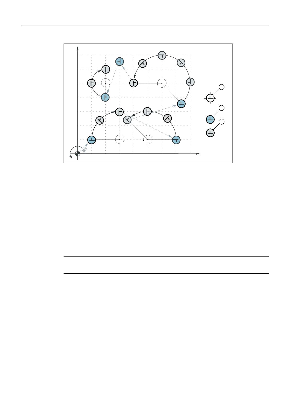
Example: Circular interpolation
In circular interpolation mode, particularly when path segmentation is active, the tool axes
rotate along a path tangentially aligned to the programmed path axes in each sub-block.
Program code
Comment
N2 TANG (C, X, Y, 1, "B")
;
definition tangential control
;
leading axes: X, Y
;
following axis: C
;
coupling factor: 1
;
basic coordinate system
N5 G0 F60 X10 Y10
;
starting position
N8 TRAILON (C1, C, 1)
;
coupled motion: ON
N9 TANGON (C, -90)
;
tangential control: ON
;
offset angle: -90° or 270°
N10
G02 X30 Y30 I20 J0 SPN=2 PON
;
circular interpolation
;
path segmentation → 2 lifts
N15
G0 X70 Y10 SPOF
;
positioning
;
stroke initiation OFF
N17
TANGON (C, 90)
;
tangential control: ON
;
offset angle: 90°
N20
G03 X35,86 Y24,14 CR=20 SPP=16 SON
;
circular interpolation
;
path segmentation → 4 lifts
;
punch initiation: ON
N25
G0 X74.14 Y35.86 C0 PON
;
positioning
;
C/C1 axis: 0°
;
nibbling initiation: ON
N27
TANGON (C, 0)
;
tangential control: ON
;
offset angle: 0°
N30
G03 X40 Y50 I-14,14 J14,14 SPN=5 SON
;
circular interpolation
;
path segmentation → 5 lifts
;
punch initiation: ON
N35
G0 X30 Y65 C90 SPOF
;
positioning
;
stroke initiation OFF
N40
G91 X-10 Y-25 C180
;
positioning, incremental
;
C/C1 axis: +180°
;
≙ 270° absolute
N43
TANGOF
;
tangential control: OFF
N45
G90 G02 Y60 I0 J10 SPP=2 PON
;
circular interpolation
;
path segmentation → 2 lifts
N50
SPOF
;
stroke initiation OFF
N55
TRAILOF (C1, C)
;
coupled motion: OFF
N60
M2
Extended Functions
Function Manual, 12/2018, A5E40874029B AB
673
N4: Own channel - only 840D sl
11.7 Supplementary conditions
;
1
1
1
1
r
1
1
1
1
<
r
&
① Mounting position 0°
② Positioning
③ Stroke
11.6
Protection zones
Clamping protection zone
The "clamping protection zone" function is contained as a subset in the "Protection zones"
function. Its purpose is to simply monitor whether clamps and tool could represent a mutual
risk.
Note
No by-pass strategies are implemented for cases where the clamp protection is violated.
References:
Function Manual, Basic Functions; Axis Monitoring, Protection Zones (A3)
11.7
Supplementary conditions
Availability of function "Punching and nibbling"
The function is an option ("Punching and nibbling functions"), which must be assigned to the
hardware through the license management.
Extended Functions
674
Function Manual, 12/2018, A5E40874029B AB
N4: Own channel - only 840D sl
11.8 Examples
11.8
Examples
11.8.1
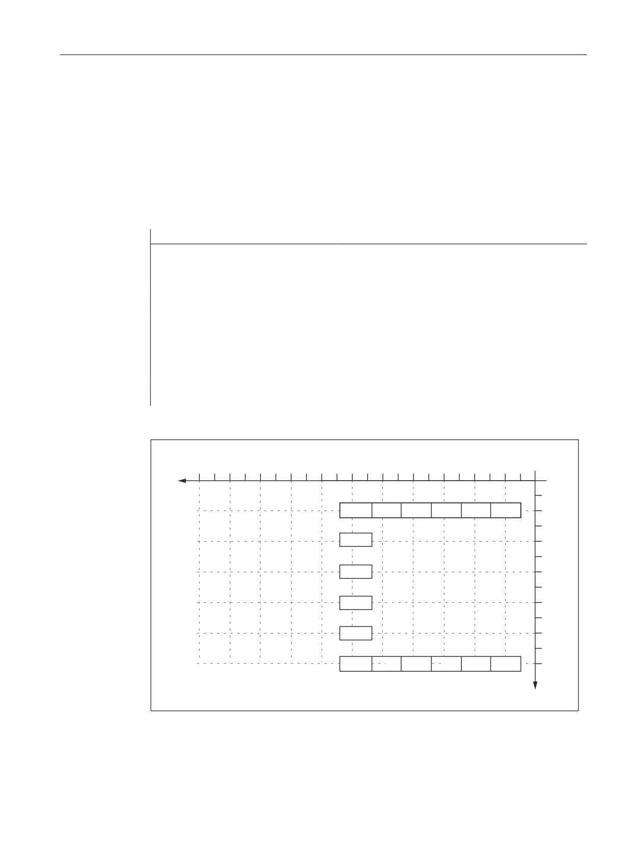
Examples of defined start of nibbling operation
Example 1
Example of defined start of nibbling operation
Program code
Comment
:
:
N10 G0 X20 Y120 SPP= 20
; Position 1 is approached
N20 X120 SON
; Defined start of nibbling, first stroke at
; "1", last stroke at "2"
N30 Y20
; Defined start of nibbling, first stroke at
; "3", last stroke at "4"
N40 X20
; Defined start of nibbling, first stroke at
; "5", last stroke at "6"
N50 SPOF
N60 M2
;
<
Extended Functions
Function Manual, 12/2018, A5E40874029B AB
675
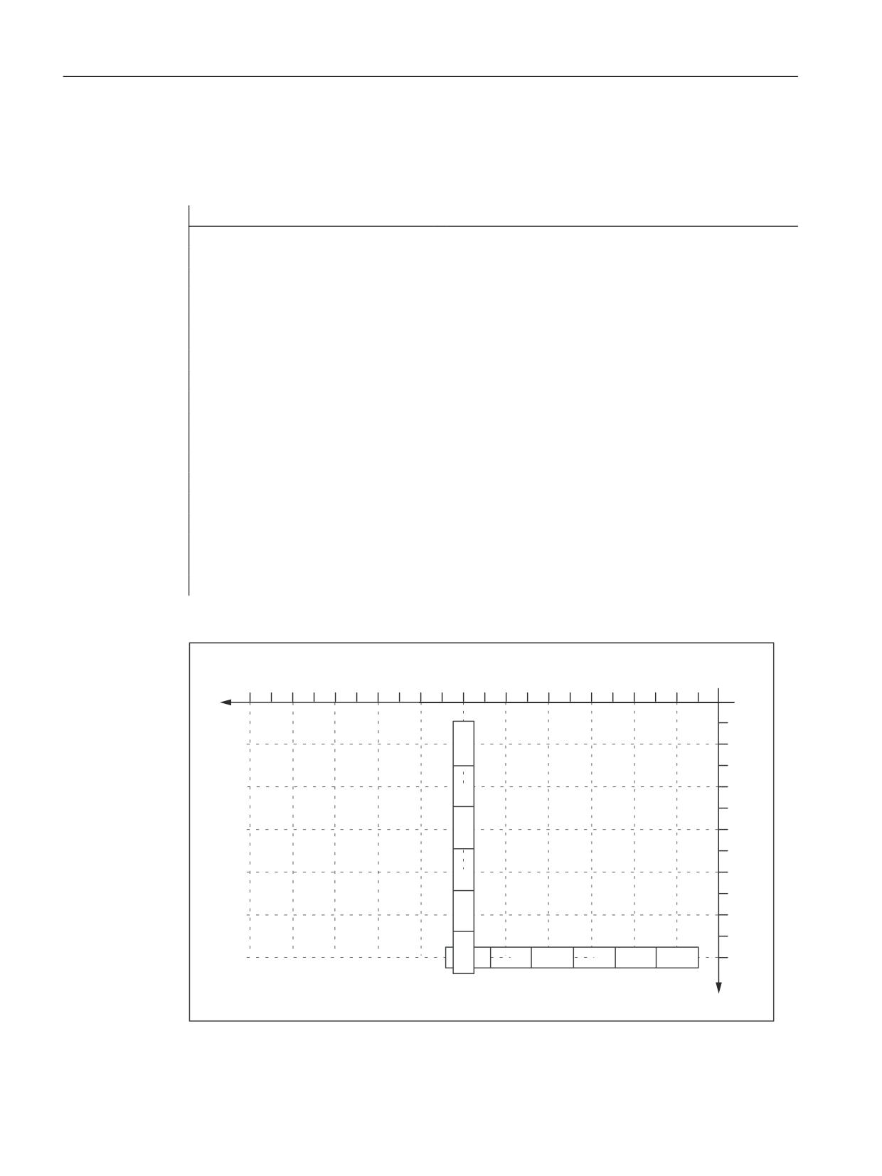
N4: Own channel - only 840D sl
11.8 Examples
Example 2
This example utilizes the "Tangential control" function. Z has been selected as the name of
the tangential axis.
Program code
Comment
:
:
N5 TANG (Z, X, Y, 1, "B")
; Define tangential axis
N8 TANGON (Z, 0)
; Select tangential control
N10 G0 X20 Y120
; Position 1 is approached
N20 X120 SPP=20 SON
; Defined start of nibbling,
; tangential control selected,
; first stroke at "1", last stroke at "2"
N30 SPOF TANGOF
; Deselect nibbling mode and deselect
; tangential control
N38 TANGON (Z, 90)
; Select tangential control
N40 Y20 SON
; Defined start of nibbling,
; tangential control selected,
; first stroke at "2" rotated 90 degrees to
; block N20, last stroke at "3"
N50 SPOF TANGOF
; Deselect nibbling mode and deselect
; tangential control
N60 M2
;
<
Extended Functions
676
Function Manual, 12/2018, A5E40874029B AB
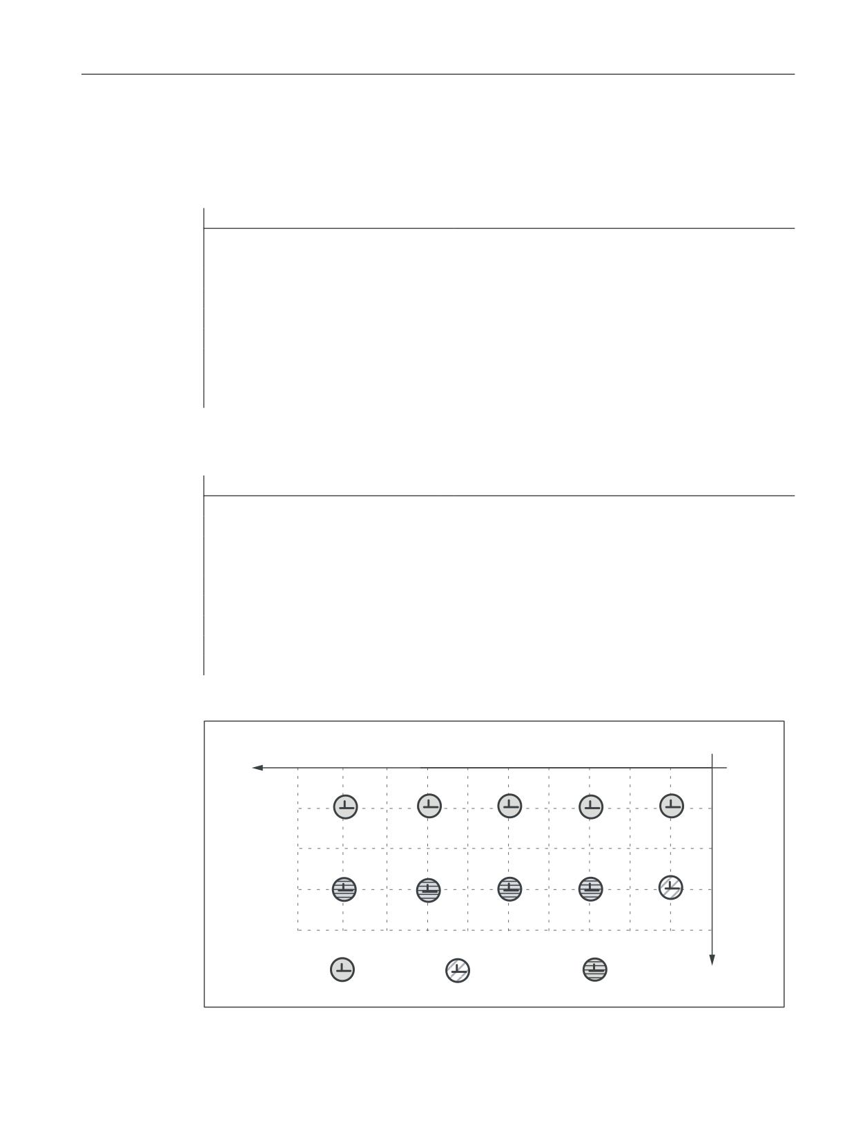
N4: Own channel - only 840D sl
11.8 Examples
Examples 3 and 4 for defined start of nibbling
Example 3: Programming of SPP
Program code
Comment
:
:
N5 G0 X10 Y10
; Positioning
N10 X90 SPP=20 SON
; Defined start of nibbling,
; 5 punches initiated
N20 X10 Y30 SPP=0
; One punch is initiated at the end of the path
N30 X90 SPP=20
; 4 punches initiated at intervals of 20 mm
N40 SPOF
N50 M2
Example 4 Programming of SPN
Program code
Comment
:
:
N5 G0 X10 Y10
; Positioning
N10 X90 SPN=4 SON
; Defined start of nibbling, 5
; 5 punches initiated
N20 X10 Y30 PON
; One punch is initiated at the end of the path
N30 X90 SPN=4
; 4 punches initiated
N40 SPOF
N50 M2
;
1
1
1
<
Figure 11-7
Examples 3 and 4 for defined start of nibbling
Extended Functions
Function Manual, 12/2018, A5E40874029B AB
677
N4: Own channel - only 840D sl
11.8 Examples
Examples 5 and 6 without defined start of nibbling
Example 5 Programming of SPP
Program code
Comment
:
:
N5 G0 X10 Y30
; Positioning
N10 X90 SPP=20 PON
; No defined start of nibbling,
; 4 punches initiated
N15 Y10
; One punch is initiated at the end of the path
N20 X10 SPP=20
; 4 punches initiated at intervals of 20 mm
N25 SPOF
N30 M2
Example 6 Programming of SPN
Program code
Comment
:
:
N5 G0 X10 Y30
; Positioning
N10 X90 SPN=4 PON
; No defined start of nibbling,
; 4 punches initiated
N15 Y10
; One punch is initiated at the end of the path
N20 X10 SPN=4
; 4 punches initiated
N25 SPOF
N30 M2
Extended Functions
678
Function Manual, 12/2018, A5E40874029B AB
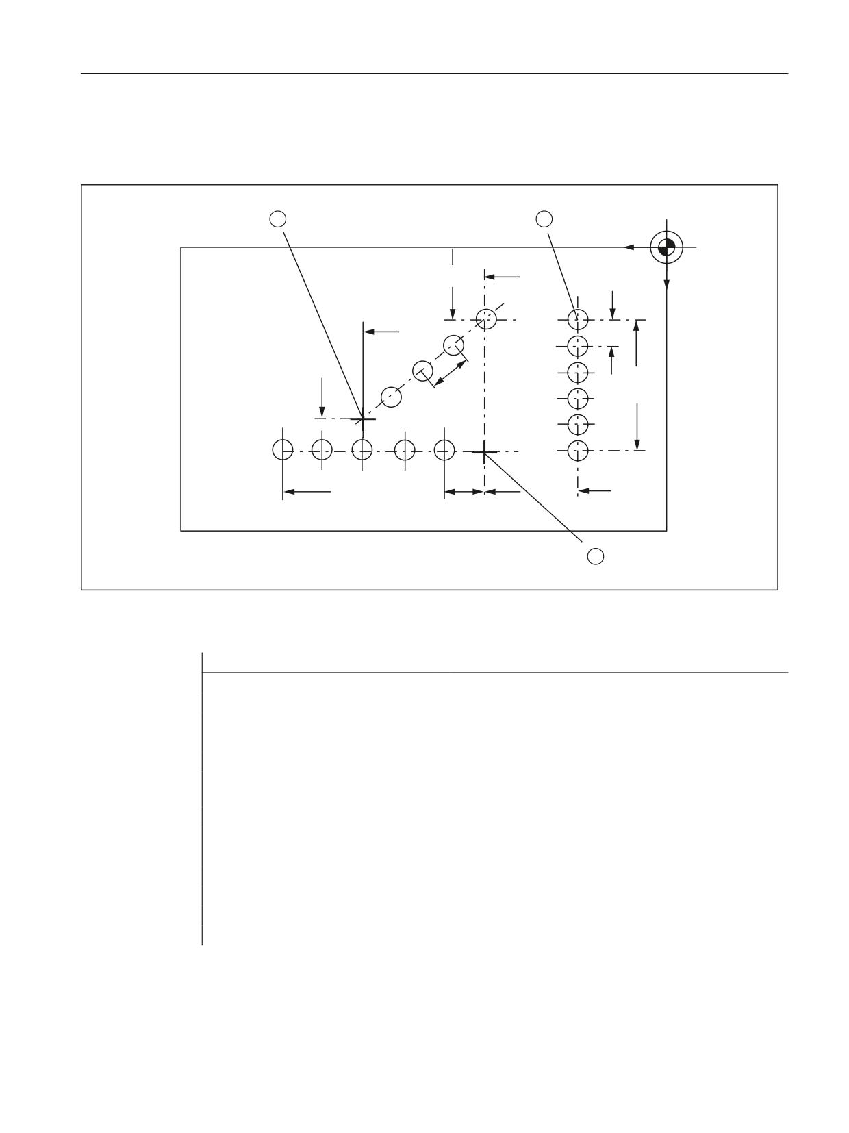
N4: Own channel - only 840D sl
11.8 Examples
Example 7 Application example of SPP programming
;
<
Figure 11-8
Workpiece
Extract from program:
Program code
Comment
N100 G90 X75 Y75 F60 PON
; Positioning to starting point (1) of the
; vertical line of holes, punch single hole
N110 G91 Y125 SPP=25 PON
; End point coordinates (incremental),
; path segment: 25 mm, activate punching
N120 G90 X150 SPOF
; Absolute dimensioning, position at
; the start point (2) of the horizontal line of
holes
N130 X375 SPP=45 PON
; End point coordinates, path segment: 45 mm
N140 X275 Y160 SPOF
; Positioning to starting point (3) of the
; oblique line of holes
N150 X150 Y75 SPP=40 PON
; End point coordinates, programmed
; path segment: 40 mm, calculated
; path segment: 37.39 mm
N160 G00 Y300 SPOF
; Positioning
Extended Functions
Function Manual, 12/2018, A5E40874029B AB
679

N4: Own channel - only 840D sl
11.9 Data lists
11.9
Data lists
11.9.1
Machine data
11.9.1.1
General machine data
Number
Identifier: $MN_
Description
11450
SEARCH_RUN_MODE
Block search parameter settings
11.9.1.2
Channelspecific machine data
Number
Identifier: $MC_
Description
20150
GCODE_RESET_VALUES[n]
Reset G groups
26000
PUNCHNIB_ASSIGN_FASTIN
Hardware assignment for input-byte with stroke control
26002
PUNCHNIB_ASSIGN_FASTOUT
Hardware assignment for output-byte with stroke con-
trol
26004
NIBBLE_PUNCH_OUTMASK[n])
Mask for quick output bits
26006
NIBBLE_PUNCH_INMASK[n]
Mask for quick input bits
26008
NIBBLE_PUNCH_CODE[n]
Determination of the M functions
26010
PUNCHNIB_AXIS_MASK
Definition of punching and nibbling axes
26012
PUNCHNIB_ACTIVATION
Activation of punching and nibbling functions
26014
PUNCH_PATH_SPLITTING
Activation of automatic path segmentation
26016
PUNCH_PARTITION_TYPE
Behavior of single axes with active automatic path seg-
mentation
26018
NIBBLE_PRE_START_TIME
Automatically activated pre-initiation time
26020
NIBBLE_SIGNAL_CHECK
Monitoring of the input signal
11.9.2
Setting data
11.9.2.1
Channelspecific setting data
Number
Identifier: $SC_
Description
42400
PUNCH_DWELL_TIME
Dwell time
42402
NIBPUNCH_PRE_START_TIME
Pre-start time
42404
MINTIME_BETWEEN_STROKES
Minimum time interval between two consecutive
strokes
Extended Functions
680
Function Manual, 12/2018, A5E40874029B AB

N4: Own channel - only 840D sl
11.9 Data lists
11.9.3
Signals
11.9.3.1
Signals to channel
Signal name
SINUMERIK 840D sl
SINUMERIK 828D
No stroke enable
DB21,
DBX3.0
-
Manual stroke initiation
DB21,
DBX3.1
-
Stroke suppression
DB21,
DBX3.2
-
Stroke inoperative
DB21,
DBX3.3
-
Delayed stroke
DB21,
DBX3.4
-
Manual stroke initiation
DB21,
DBX3.5
-
11.9.3.2
Signals from channel
Signal name
SINUMERIK 840D sl
SINUMERIK 828D
Stroke initiation active
DB21,
DBX38.0
-
Acknowledgement of manual stroke initiation
DB21,
DBX38.1
-
11.9.4
Language commands
G group
Language com-
Meaning
mand
35
SPOF
Stroke / Punch OFF
Punching and nibbling OFF
35
SON
Stroke ON
Nibbling ON
35
SONS
Stroke ON
Nibbling ON (position controller)
35
PON
Punch ON
Punching ON
35
PONS
Punch ON
Punching ON (position controller)
36
PDELAYON
Punch with Delay ON
Punching with delay ON
36
PDELAYOF
Punch with Delay OFF
Punching with delay OFF
Path segmentation
SPP
Path per stroke, modal action
SPN
Number of strokes per block, non-modal action
Extended Functions
Function Manual, 12/2018, A5E40874029B AB
681
N4: Own channel - only 840D sl
11.9 Data lists
Extended Functions
682
Function Manual, 12/2018, A5E40874029B AB
P2: Positioning axes
12
12.1
Product brief
Axes for auxiliary movements
In addition to axes for machining a workpiece, modern machine tools can also be equipped
with axes for auxiliary movements, e.g.:
● Axis for tool magazine
● Axis for tool turret
● Axis for workpiece transport
● Axis for pallet transport
● Axis for loader (also multi-axis)
● Axis for tool changer
● Axis for sleeve assembly / end support
The axes for the workpiece machining are called path axes. Within the channel they are guided
by the interpolator such that they start simultaneously, accelerate, reach the end point and
stop together.
Axes for auxiliary movements are traversed independently of the path axes at a separate, axis-
specific feedrate. In the past, many of these axes were moved hydraulically and started by an
auxiliary function in the part program. With the closed-loop axis control implemented in the
Extended Functions
Function Manual, 12/2018, A5E40874029B AB
683
P2: Positioning axes
12.1 Product brief
NC, the axis can be addressed by name in the part program and its actual position displayed
on the screen.
Note
"Positioning axis/Auxiliary spindle" option
Axes for auxiliary movements must not be interpolating ("full-value") NC axes. Auxiliary
movements may also be carried out using special axes, which can be obtained using the
"Positioning axis/Auxiliary spindle" option.
Functional restrictions
Optional positioning axes/auxiliary spindles have fewer functions. The following functions are
not possible:
● Using the axis as a path axis, geometry axis, or special path axis
● Incorporating the axis into the geometry axis grouping (GEOAX)
● Rigid thread cutting and tapping
Commissioning
As standard, axes are defined as interpolating axes:
MD30460 $MA_BASE_FUNCTION_MASK bit 8 = 0
If an axis is to be operated as a positioning axis/auxiliary spindle with reduced functionality,
the value for bit 8 must be set to "1":
MD30460 $MA_BASE_FUNCTION_MASK bit 8 = 1
Function
The "positioning axes" function makes it easier to integrate axes for auxiliary movement into
the control system:
● during programming:
The axes are programmed together with the axes for workpiece machining in the same part
program, without having to sacrifice valuable machining time.
There are special (POS, POSA) traversing instructions.
● during program testing/start-up:
Program testing and start-up are performed simultaneously for all axes.
● during operation:
Operation and monitoring of the machining process commence simultaneously for all axes.
● during PLC configuring/commissioning:
No allowance has to be made on PLC or external computers (PCs) for synchronization
between axes for machining and axes for auxiliary movements.
● during system configuring:
A second channel is not required.
Extended Functions
684
Function Manual, 12/2018, A5E40874029B AB
P2: Positioning axes
12.2 Own channel, positioning axis or concurrent positioning axis
Motions and interpolations
Each channel has one path interpolator and at least one axis interpolator with the following
interpolation functions:
● for path interpolator:
Linear interpolation (G1), circular interpolation (G2 / G3), spline interpolation, etc.
● for axis interpolator:
If a positioning axis is programmed, an axis interpolator starts in the control (with linear
interpolation G1).
● End-of-motion criterion:
The programmed end position of a positioning axis has been reached when the end-of-
motion criterion FINEA, COARSA or IPOENDA is fulfilled.
● Path axes with rapid traverse movement:
Path axes can be traversed in linear or non-linear interpolation mode with rapid traverse
movement (G0).
References:
Function Manual, Basic Functions; Chapter "B1: Continuous-path mode, Exact stop,
LookAhead"
● Autonomous singleaxis operations:
Single PLC axes, command axes started via static synchronized actions or asynchronous
reciprocating axes can be interpolated independently of the NC.
An axis/spindle interpolated by the main run then reacts independently of the NC program.
The channel response triggered by the program run is decoupled to transfer the control of
a certain axis / spindle to the PLC.
● Control by PLC:
All channel-specific signals normally act to the same extent on path and positioning axes.
Positioning axes can be controlled via additional, axis-specific signals.
PLC axes are traversed by the PLC via special function blocks in the basic program; their
movements can be asynchronous to all other axes. The travel motions are executed
separate from the path and synchronized actions.
12.2
Own channel, positioning axis or concurrent positioning axis
When axes are provided for auxiliary movements on a machine tool, the required properties
will decide whether the axis is to be:
● programmed in an internal part program (see Section "Own channel (Page 686)").
● programmed in the same part program as the machining operation (see Section
"Positioning axis (Page 686)").
● started exclusively by the PLC during machining (see Section "Concurrent positioning
axis (Page 689)").
Extended Functions
Function Manual, 12/2018, A5E40874029B AB
685
P2: Positioning axes
12.2 Own channel, positioning axis or concurrent positioning axis
12.2.1
Own channel
A channel represents a self-contained NC which, with the aid of a part program, can be used
to control the movement of axes, spindles and machine functions independently of other
channels.
Non-dependence between channels
Independence between channels is assured by means of the following provisions:
● An active part program per channel
● Channel-specific interface signals such as
- DB21, ... DBX7.1 (NC Start)
- DB21, ... DBX7.3 (NC stop)
- DB21, ... DBX7.7 (reset)
● one feedrate override per channel
● One rapid traverse override per channel
● Channel-specific evaluation and display of alarms
● Channel-specific display, e.g. for
- Actual axis positions
- Active G commands
- Active auxiliary functions
- Current program block
● Channel-specific testing and channel-specific control of programs:
- Single block
- Dry run (DRY RUN)
- Block search
- Program test
References
For more information on the channel functionality, please refer to:
Function Manual, Basic Functions; BAG, Channel, Program Operation, Reset Response (K1)
12.2.2
Positioning axis
Positioning axes are programmed together with path axes, i.e. with the axes that are
responsible for workpiece machining.
Commands for positioning axes and path axes can be included in the same NC block. Although
they are programmed in the same NC block, the path and positioning axes are not interpolated
Extended Functions
686
Function Manual, 12/2018, A5E40874029B AB

P2: Positioning axes
12.2 Own channel, positioning axis or concurrent positioning axis
together and do not reach their end point simultaneously (no direct time relationship, see also
Chapter "Motion behavior and interpolation functions (Page 690)").
Positioning axis types and block change
The block change time depends on the programmed positioning axis type (refer also to Chapter
"Block change (Page 702)"):
Type
Description
1
The block change occurs when all path and positioning axes have reached their programmed
end point.
2
The block change occurs when all path axes have reached their programmed end point.
With positioning axis type 2, it is possible to approach the programmed end point across sev-
eral block limits.
3
It is possible to set the block change within the braking ramp of the single axis interpolation if
the criteria for the motion end and the block change are fulfilled for the path interpolation.
Motion synchronization
Positioning axes permit movements to be activated from the same machining program and
such movements to be synchronized at block limits (type 1) or at explicit points by means of
a WAITP command (type 2).
Motion end criterion for block change in the brake ramp
For single-axis interpolation, it is also possible to set another end-of-motion criterion for the
block change in the braking ramp.
Traverse path axes in G0 as positioning axis
Each path axis can be traversed as positioning axis in rapid traverse movement (G0). Thus all
axes travel to their end point independently.
In this way, two sequentially programmed X and Z axes are treated like positioning axes in
conjunction with G0. The block change to axis Z can be initiated by axis X as a function of the
braking ramp time setting (100-0%). Axis Z starts to move while axis X is still in motion. Both
axes approach their end point independently of one another.
Axis types
Positioning axes can be linear axes and rotary axes.
Positioning axes can also be configured as indexing axes.
Independence of positioning axes and path axes
The mutual independence of positioning and path axes is ensured by the following measures:
● No shared interpolation
● Each positioning axis has a dedicated axis interpolator
Extended Functions
Function Manual, 12/2018, A5E40874029B AB
687
P2: Positioning axes
12.2 Own channel, positioning axis or concurrent positioning axis
● Dedicated feedrate override for each positioning axis
● Dedicated programmable feedrate
● Dedicated "axis-specific delete distance-to-go" interface signal
Dependencies
Positioning axes are dependent in the following respects:
● A shared part program
● Starting of positioning axes only at block boundaries in the part program
● With rapid traverse movement G0 path axes traverse as positioning axes in one of two
different modes
● No rapid traverse override
● The following interface signals act on the entire channel and therefore on positioning axes:
- DB21, ... DBX7.1 (NC start)
- DB21, ... DBX7.3 (NC stop)
- DB21, ... DBX7.7 (reset)
- DB21, ... DBX6.1 (read-in disable)
● Alarms specific to program and channel also deactivate positioning axes.
● Program control (dry run feed, program test, DRF, ... etc.) also act on positioning axes
● Block search and single block also act on positioning axes.
● The last block with a programmed end-of-motion criterion that was processed in the search
run serves as a container for setting all axes.
● Group 1 (modal movement commands) of the G commands (i.e. G0, G1, G2, ...) does not
apply to positioning axes.
References:
Programming Manual Fundamentals.
Applications
The following are typical applications for positioning axes:
● Single-axis loaders
● Multi-axis loaders without interpolation (PTP → point-to-point traversing)
● Workpiece feed and transport
Extended Functions
688
Function Manual, 12/2018, A5E40874029B AB
P2: Positioning axes
12.2 Own channel, positioning axis or concurrent positioning axis
Other applications are also possible:
● With G0 workpiece delivery and workpiece transport can travel to their end points
independently of one another.
● On machines with several machining processes in sequence: Significant reduction in
individual machining steps due to block change in the braking ramp of the single-axis
interpolation.
Note
Positioning axes are not suitable for multi-axis loaders that require interpolation between
the axes (path interpolator).
12.2.3
Concurrent positioning axis
Concurrent positioning axes are positioning axes with the following properties:
● Activation from the PLC need not take place at block limits, but can be implemented at any
time in any operating mode (even when a part program is already being processed in the
channel).
● Program command WAITP is required to move a concurrent positioning axis from the part
program immediately after power ON.
● The part program continues to run uninhibited, even if the concurrent positioning axis has
not reached the position defined by the PLC.
● An automatic axis change is possible, depending on the setting in the machine data
MD30552 $MA_AUTO_GET_TYPE.
● With programming commands:
- GET(<axis>) or WAITP(<axis>) becomes a concurrent positioning axis of the
channel axis again.
- "RELEASE (axis)" or WAITP(<axis>) is a channel axis that becomes a concurrent
axis under PLC control.
Activation from PLC
For SINUMERIK 840D sl, the concurrent positioning axis is activated via FC 18 from the PLC.
● Feedrate
For feedrate = 0, the feedrate is determined from the following machine data:
MD32060 $MA_POS_AX_VELO (initial setting for positioning axis velocity)
● Absolute dimensions (G90), incremental dimensions (G91)
Absolute dimensions along shortest path for rotary axes (<rotary axis
name>=DC(<value>))
The following functions are defined:
● Linear interpolation (G1)
● Feedrate in mm/min or degrees/min (G94)
Extended Functions
Function Manual, 12/2018, A5E40874029B AB
689
P2: Positioning axes
12.3 Motion behavior and interpolation functions
● Exact stop (G9)
● Settable zero offsets currently selected are valid
Applications
Typical applications for concurrent positioning axes include:
● Tool magazines with manual loading and unloading during machining
● Tool magazines with tool preparation during machining
12.3
Motion behavior and interpolation functions
12.3.1
Path interpolator and axis interpolator
Path interpolator
Every channel has a path interpolator for a wide range of interpolation modes such as linear
interpolation (G1), circular interpolation (G2/G3), spline interpolation etc.
Axis interpolator
Each channel has axis interpolators in addition to path interpolators. The maximum number
corresponds to the maximum number of existing channel axes.
If a positioning axis is programmed, an axis interpolator starts in the control with straight line
interpolation G1. This axis interpolator runs independently of the path interpolator until the
programmed end position of the positioning axis has been reached.
There is no time relationship between the path interpolator and the axis interpolator, nor
between the axis interpolators.
Path control mode (G64) is not possible with positioning axes.
The programmed end position of a positioning axis has been reached when the end-of-motion
criterion FINEA, COARSA or IPOENDA is fulfilled.
Extended Functions
690
Function Manual, 12/2018, A5E40874029B AB
P2: Positioning axes
12.3 Motion behavior and interpolation functions
12.3.2
Autonomous singleaxis operations
Functionality
Single PLC axes, command axes started via static synchronized actions or asynchronous
reciprocating axes can be interpolated independently of the NC. An axis/spindle interpolated
by the main run then reacts independently of the NC program with respect to:
● NC stop
● Alarm handling
● Program control
● End of program
● RESET
Boundary conditions
Axes/spindles currently operating according to the NC program are not controlled by the PLC.
Command axis movements cannot be started via non-modal or modal synchronized actions
for PLC-controlled axes/spindles. Alarm 20143 is signaled.
Transfer axis control to the PLC
Description of the sequence
1. PLC → NC: Request to control the axis
DB31, ... DBX28.7 = 1 (PLC controls axis)
2. NC: Checks whether the axis is a main run axis or a neutral axis.
3. NC: Checks whether an additional axis may be controlled from the PLC.
4. NC confirms the transfer:
- DB31, ... DBX63.1 = 1 (PLC controls the axis)
- System variable $AA_SNGLAX_STAT = 1
Result: The PLC controls the axis/spindle.
Extended Functions
Function Manual, 12/2018, A5E40874029B AB
691
P2: Positioning axes
12.3 Motion behavior and interpolation functions
Alternatives
Initial state: The axis is controlled by the PLC. As a result of a channel stop, the channel is in
the "interrupted" state.
● Axis state "inactive" ⇒
- The stop state is canceled.
- If the axis is started, this directly results in axis motion.
● Axis state "active" ⇒
- The stop state is not canceled.
- Generate the axis state according to Use case 2 "Stop axis".
- Resume axis motion according to Use case 3 "Continue axis motion".
● A reset is performed in the channel ⇒
This process is asynchronous to control acceptance by the PLC. The two previously
mentioned alternatives can occur or the axis is assigned to the channel and is reset.
Boundary conditions
Axes/spindles, traversed by an NC program, cannot be transferred to the PLC. Axes/spindles,
which are traversed by static synchronized actions or as oscillating axis, as neutral axis,
concurrent positioning axis or command axis, can be transferred.
Relinquish axis control by the PLC
Description of the sequence:
1. PLC → NC: The PLC returns axis control to the NC
DB31, ... DBX28.7 = 0 (PLC controls axis)
2. NC: Checks whether an axial alarm is present.
3. NC: Checks whether a movement has been activated that has still not been completed? If
yes, then the movement is stopped with an axial stop according to Use case 2 "Stop axis/
spindle".
4. NC: Carries out an axial reset corresponding to Use case 4 "Reset axis/spindle".
5. NC confirms the acceptance:
DB31, ... DBX63.0 = 0 (reset executed)
DB31, ... DBX63.1 = 0 (PLC controls the axis)
DB31, ... DBX63.2 = 0 (axis stop active)
System variable $AA_SNGLAX_STAT = 0
Result: The NC has now taken over control of the axis/spindle.
Alternatives
In the following cases the NC confirms the transfer - but internally sets the "stopped" channel
state for the axis/spindle:
● The channel is in the "interrupted" state
● A stop alarm is active for the channel
● A stop alarm is active for the mode group
Extended Functions
692
Function Manual, 12/2018, A5E40874029B AB