SINUMERIK 840D sl. Service - Functions. Manual (2018-2020) - page 38

M1: Kinematic transformation
8.6 Cartesian PTP travel
The following table lists which version can be practically used for which transformation:
transformation
PTP
PTPG0
PTPWOC
CP
TRAORI
+
+
+
+
TRANSMIT
+
+
-
+
RCTRA
+
+
-
+
ROBX
+
+
-
+
NOTICE
Risk of collision
For PTP travel it must be observed that in part there are significantly different tool movements
than with CP!
This must especially be considered for PTPG0, because subprograms can be created with
it independently of the active transformation. With active front-end transformation
(TRANSMIT), however, entirely different collision risks may occur than with an orientation
transformation (TRAORI).
For PTP travel with active front-end transformation (TRANSMIT), machine axes basically
travel the shortest path. Minor displacements of the block end point can cause the rotary axis
to rotate by +179.99° instead of + -179.99°. This results in a completely different motion, even
though the block end point has hardly changed.
PTP/CP switchover in the NC program
The switchover between the Cartesian path movement (CP) and the Cartesian PTP travel in
the NC program is done via the commands of the G group 49 (see "Activating/deactivating
Cartesian PTP travel (PTP, PTPG0, PTPWOC, CP) (Page 490)").
PTP/CP switchover in JOG mode
You can also switch between the Cartesian path movement (CP) and the Cartesian PTP travel
in JOG mode.
Switchover is carried out using the NC/PLC interface signal:
DB21, ... DBX29.4 (activate PTP travel)
Note
DB21, ... DBX29.4 is only effective in JOG mode when the transformation is active.
The active type of motion is reported via the following NC/PLC interface signal:
DB21, ... DBX317.6 (PTP travel active)
Extended Functions
Function Manual, 12/2018, A5E40874029B AB
487

M1: Kinematic transformation
8.6 Cartesian PTP travel
8.6.2
Commissioning
8.6.2.1
Response after POWER ON
After Power On, traversing mode CP is automatically effective for axis traversal with
transformation.
The default can be switched over to Cartesian PTP travel via the following machine data:
MD20150 $MC_GCODE_RESET_VALUES[48] (initial setting of G group 49)
Value
Meaning
1
CP (default setting)
2
PTP
3
PTPG0
4
PTPWOC
8.6.2.2
Response after reset/part program end
Which command from G group 49 takes effect after a reset/part program end depends on the
setting in the machine data:
MD20152 $MC_GCODE_RESET_MODE[48] (reset behavior of G group 49)
Value
Meaning
0
The default command in MD20150 $MC_GCODE_RESET_VALUES[48] becomes ef-
fective (default setting).
1
The command that was active before the reset/part program end remains effective.
8.6.2.3
Consideration of the SW limits during PTP travel
Function
With Cartesian PTP travel, a rotary axis is normally traversed according to the strategy
"shortest path" if no position information has been programmed via the operation TU
(Page 495). To prevent a software limit switch being overtraveled when the target position is
behind the software limit switch, the user can use the "Consideration of the SW limits during
PTP travel" function. The rotary axis is then traversed with the strategy "long path" instead of
"shortest path" if overtravel of the software limit switch would happen, i.e. the opposite
traversing direction as with the "shortest path" strategy.
Requirement
The function can only be used when the relevant axis has been referenced.
Extended Functions
488
Function Manual, 12/2018, A5E40874029B AB
M1: Kinematic transformation
8.6 Cartesian PTP travel
Activation
The "Consideration of the SW limits during PTP travel" function can be activated separately
for each axis.
This setting is made via bit 14 in the axial machine data:
MD30455 $MA_MISC_FUNCTION_MASK
Bit 14
= 0
With Cartesian PTP travel, the strategy "shortest path" is retained for software
limit switch overtravel of a rotary axis (basic setting).
= 1
The strategy "long path" is used when during Cartesian PTP travel a rotary axis
with the strategy "shortest path" would overtravel the software limit switch.
Supplementary conditions
Modulo rotary axes
With modulo rotary axes, the strategy "long path" can only be used when the software limit
switch monitoring has been selected for the relevant axis:
DB31, ... DBX12.4 (modulo rotary axis: Activate traversing range limits) = 1
Example
Axis 6 is to traverse from +150° t +240°. The software limit switch is at +200°.
If for axis 6, bit 14 in MD30455 $MA_MISC_FUNCTION_MASK is set to "1", axis 6 is traversed
to -120°.
8.6.2.4
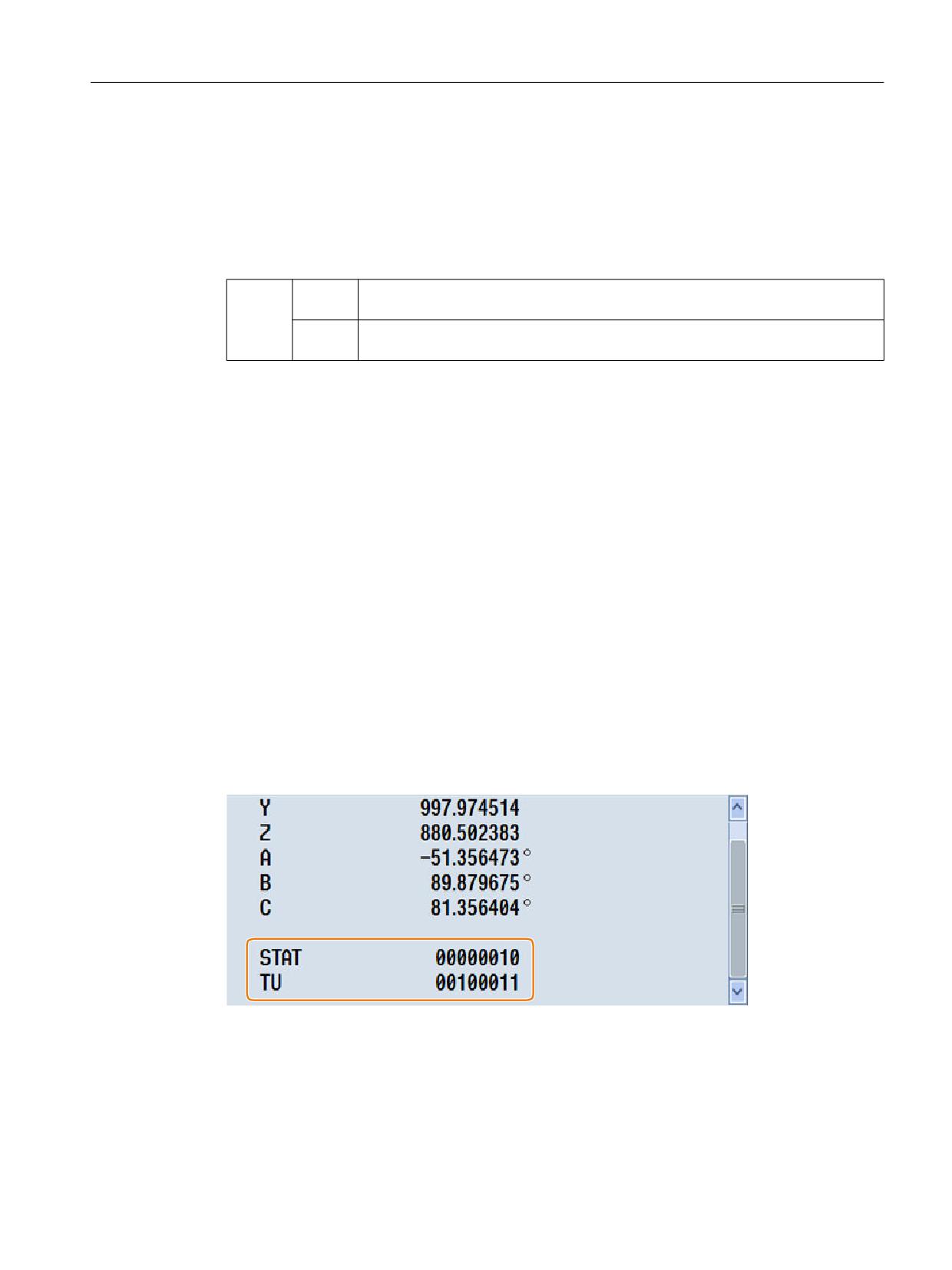
Displaying STAT and TU
In the SINUMERIK Operate user interface, in the "Machine" operating area, users can track
the actual values of STAT (Page 491) and TU (Page 495):
Precondition: The display of STAT and TU is activated when commissioning SINUMERIK
Operate.
References:
Commissioning Manual SINUMERIK Operate; Chapter "Adapt the Machine operating area" >
"Display STAT and TU"
Extended Functions
Function Manual, 12/2018, A5E40874029B AB
489

M1: Kinematic transformation
8.6 Cartesian PTP travel
8.6.3
Programming
8.6.3.1
Activating/deactivating Cartesian PTP travel (PTP, PTPG0, PTPWOC, CP)
The Cartesian point-to-point or PTP travel is activated/deactivated in the NC program using
G group 49 commands.
The commands are modal. The default setting is travel with Cartesian path motion (CP).
Contrary to CP, for active PTP travel, only the Cartesian target point is transformed, and the
machine axes are traversed in synchronism.
In order that the Cartesian target point can be uniquely converted into machine axis values,
in addition to position and angular data, information is also necessary that identifies the axis
positions. This data is retrieved from the adjustable addresses STAT (Page 491) andTU
(Page 495).
Precondition
Transformation TRAORI, TRANSMIT, RCTRA or ROBX is active.
Syntax
PTP / PTPG0 / PTPWOC
CP
Meaning
PTP:
Activating point-to-point motion PTP
The programmed Cartesian position in G0 and G1 blocks is approached with synchro-
nous axis motion.
PTPG0:
Activating point-to-point motion PTPG0
Only in G0 blocks is the programmed Cartesian position approached with synchronous
axis motion. In G1 blocks, a switchover is made to CP path motion.
PTPWOC:
Activate point-to-point movement PTPWOC (only possible if orientation transformation
is active)
Just the same as PTP, however, without any compensatory motion, which is caused
by motion of rotary axes and orientation axes.
CP:
Deactivating point-to-point motion and activating path motion CP
Cartesian path motion is executed with CP.
Note
PTPWOC
It does not make any sense to use PTPWOC in combination with a RCTRA or ROBX
transformation!
Extended Functions
490
Function Manual, 12/2018, A5E40874029B AB

M1: Kinematic transformation
8.6 Cartesian PTP travel
Examples
See:
● Example 1: PTP travel of a 6-axis robot with ROBX transformation (Page 498)
● Example 2: PTP travel for generic 5-axis transformation (Page 499)
● Example 3: PTPG0 and TRANSMIT (Page 499)
8.6.3.2
Specify the position of the joints (STAT)
Position data with Cartesian coordinates and specification of the tool orientation are not
sufficient to uniquely identify the machine position, as several joint positions are possible for
the same tool orientation. Depending on the kinematics involved, there can be as many as 8
different joint positions. These different joint positions are transformation-specific.
In an order to avoid any ambiguity, the joint positions are specified under the STAT address.
Note
The control takes into account programmed STAT values only for PTP motions. They are
ignored with CP motions because a change of position is not normally possible while traversing
with an active transformation. When traversing with active CP, the position for the target point
is taken from the starting point.
Syntax
STAT=<Value>
Meaning
STAT:
Adjustable address to specify joint positions
<Value>:
Binary or decimal value
Contains one bit for each possible position. The significance of the bits is defined by
the particular transformation.
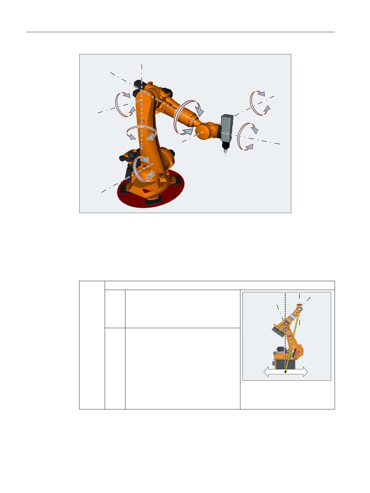
The use of STAT is to be illustrated by the example of a 6-axis articulated robot with milling
spindle. The kinematic transformation is to be realized using the ROBX robot transformation
(precondition: Compile cycle "RMCC/ROBX Transformation Extended Robotics" is loaded and
active).
Extended Functions
Function Manual, 12/2018, A5E40874029B AB
491
M1: Kinematic transformation
8.6 Cartesian PTP travel
$
$
$
$
$
$
Axes A1, A2 and A3 are the main axes of the articulated robot. The axes A4, A5 and A6, which
are also designated as head or hand/wrist axes, are positioned in the working area with the
main axes. The additional motion options of the hand/wrist axes enable the milling spindle to
be orientated in space as required for the particular machining task. Various articulated joint
positions are possible to achieve the same tool orientation.
The articulated joint positions required for machining are selected by programming bit 0 ... 2
of the adjustable STAT address:
Bit 0
Position of the intersection points of the hand/wrist axes (A4, A5, A6)
= 0
Basic range (shoulder right)
The robot is in the basic range if the X value
of the intersection point of the hand/wrist ax-
es is positive in relation to to the A1 coordi-
nate system.
= 1
Overhead range (shoulder left)
%LW
%LW
The robot is in the overhead range if the X
value of the intersection point of the hand/
wrist axes is negative in relation to the A1
coordinate system.
;
;
$
Example: The intersection point of
the hand/wrist axes lies in the basic
range
Extended Functions
492
Function Manual, 12/2018, A5E40874029B AB
M1: Kinematic transformation
8.6 Cartesian PTP travel
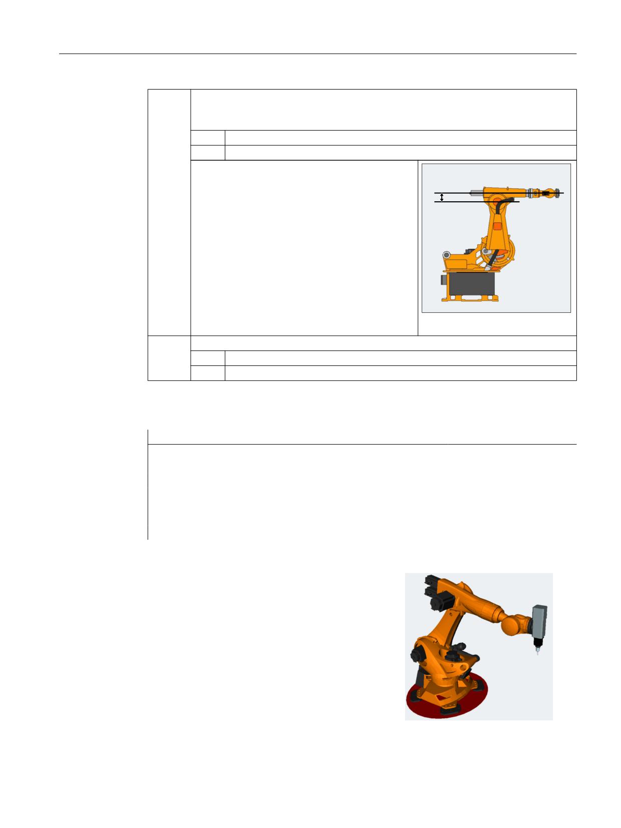
Bit 1
Position of axis 3
The angle at which the value of bit 1 changes depends on the particular robot type. The
following applies to robots whose axes 3 and 4 intersect:
= 0
A3 <0° (elbow down)
= 1
A3 ≥0° (elbow up)
Note:
For robots with an offset between axes 3 and 4, the
angle at which the value of bit 1 changes depends on
the magnitude of this offset.
Offset between A3 and A4
Bit 2
Position of axis 5
= 0
A5 ≥0° (no handflip)
= 1
A5 <0° (handflip)
Program example:
Program code
Comment
N14 T="T8MILLD20" D1
; $TC_DP3[1,1]=132.95
N16 ORIMKS
N17 G1 PTP X1665.67 Y0 Z1377.405 A=0 B=0 C=0 STAT=... F2000
; The STAT value defines
the articulated joint
positions (see below)
STAT=1 ('B001')
→ Shoulder left
→ Elbow down
→ No handflip
Extended Functions
Function Manual, 12/2018, A5E40874029B AB
493
M1: Kinematic transformation
8.6 Cartesian PTP travel
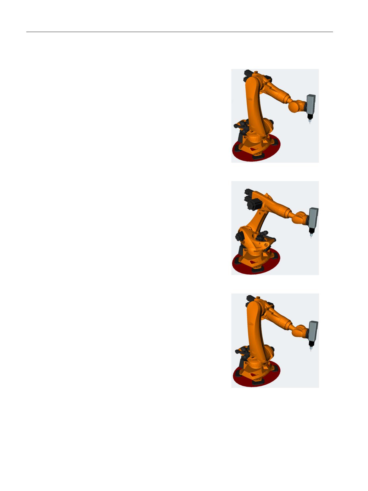
STAT=2 ('B010')
→ Shoulder right
→ Elbow up
→ No handflip
STAT=5 ('B101')
→ Shoulder left
→ Elbow down
→ Handflip
STAT=6 ('B110')
→ Shoulder right
→ Elbow up
→ Handflip
TRANSMIT
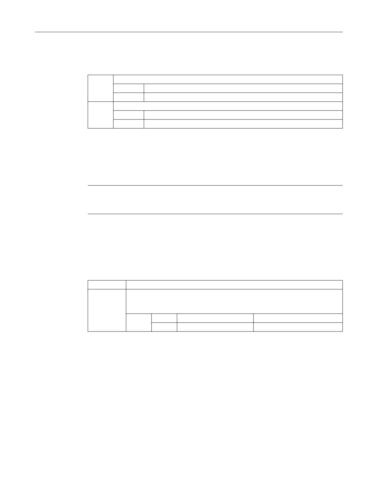
For TRANSMIT, the STAT address is used to initiate the equivocality regarding the pole.
Extended Functions
494
Function Manual, 12/2018, A5E40874029B AB
M1: Kinematic transformation
8.6 Cartesian PTP travel
The following applies if the rotary axis must rotate through 180º or the contour for CP would
go through the pole:
Bit 0
Only relevant for $MC_TRANSMIT_POLE_SIDE_FIX_1/2 = 1 or 2:
= 0
Rotary axis traverses through +180º or rotates clockwise.
= 1
Rotary axis rotates through -180º or rotates counterclockwise.
Bit 1
Only relevant for $MC_TRANSMIT_POLE_SIDE_FIX_1/2 = 0:
= 0
The axis traverses through the pole. The rotary axis does not rotate.
= 1
The axis rotates around the pole. Bit 0 of STAT is relevant.
8.6.3.3
Specify the sign of the axis angle (TU)
In order that rotary axes can also approach axis angles exceeding +180° or less than -180°
without requiring a special traversing strategy (e.g. intermediate point), the sign of the axis
angle must be specified under the adjustable address TU.
Note
The control only takes into account programmed TU values for PTP motion. CP motion is
ignored.
Syntax
TU=<Value>
Meaning
TU:
Adjustable address to specify axis angle signs
<Value>:
Binary or decimal value
For each axis that is involved in the transformation, there is a bit that indicates the sign
of the axis angle (θ), and therefore the traversing direction.
Bit
= 0
Axis angle sign: +
Axis angular range: 0° ≤ θ < 360°
= 1
Axis angle sign: -
Axis angular range: - 360° < θ < 0°
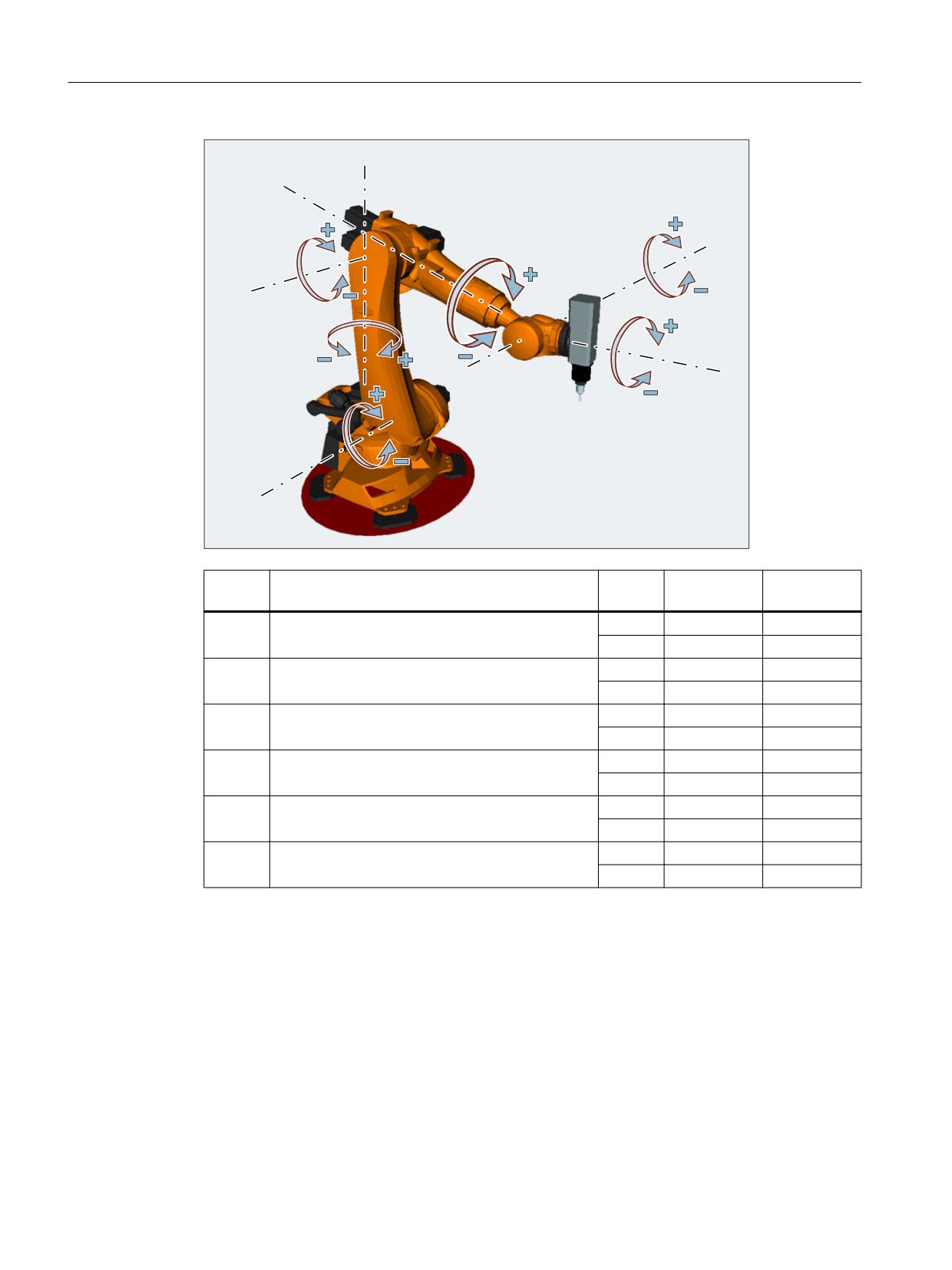
Example: 6-axis articulated robot
Extended Functions
Function Manual, 12/2018, A5E40874029B AB
495
M1: Kinematic transformation
8.6 Cartesian PTP travel
$
$
$
$
$
$
Bit
Meaning
Value
Axis angle
Axis angle
sign
Bit 0 1)
Sign for the axis angle of A1
= 0
+
≥ 0°
= 1
-
< 0°
Bit 1 1)
Sign for the axis angle of A2
= 0
+
≥ 0°
= 1
-
< 0°
Bit 2 1)
Sign for the axis angle of A3
= 0
+
≥ 0°
= 1
-
< 0°
Bit 3 1)
Sign for the axis angle of A4
= 0
+
≥ 0°
= 1
-
< 0°
Bit 4 1)
Sign for the axis angle of A5
= 0
+
≥ 0°
= 1
-
< 0°
Bit 5 1)
Sign for the axis angle of A6
= 0
+
≥ 0°
= 1
-
< 0°
1)
The actual TU bit numbers obtained from the channel axis numbers of the robot axes! In the example,
robot axes (A1 to A6) are the first six axes in the channel; as a consequence, TU bits 0 ... 5 are used.
For another channel axis assignment of the robot axes, the TU bit numbers of the robot axes would
correspondingly change (e.g.: robot axes are the 3rd to 8th channel axis, i.e. TU bits 2 ... 7 are used
for the robot axes).
TU=19 (corresponds to TU='B010011) would therefore signify:
Bit
Value
Axis angle
0
= 1
①
θA1 < 0°
1
= 1
①
θA2 < 0°
Extended Functions
496
Function Manual, 12/2018, A5E40874029B AB

M1: Kinematic transformation
8.6 Cartesian PTP travel
2
= 0
①
θA3 ≥ 0°
3
= 0
①
θA4 ≥ 0°
4
= 1
①
θA5 < 0°
5
= 0
①
θA6 ≥ 0°
Note
In the case of axes with a traversing range > ±360°, the axis always moves along the shortest
path because the axis position cannot be specified uniquely by the TU information.
If no TU is programmed for a position, then depending on MD30455
$MA_MISC_FUNCTION_MASK, the shorter or longer path is traversed (see Chapter "Taking
into account the software limits for PTP travel (Page 488)" in the Extended Functions Function
Manual).
TRANSMIT
For PTP travel with TRANSMIT active, the address of TU has no meaning!
Example
The rotary axis position shown in the following diagram can be approached in the negative or
positive direction. The angular position is programmed under address A1. The traversing
direction is only absolutely clear when TU is specified.
6WDUWLQJ SRVLWLRQ
1HJDWLYH GLUHFWLRQ
$
r 78 ELW
3RVLWLYH GLUHFWLRQ
$
r 78 ELW
7DUJHW SRVLWLRQ
Extended Functions
Function Manual, 12/2018, A5E40874029B AB
497
M1: Kinematic transformation
8.6 Cartesian PTP travel
8.6.3.4
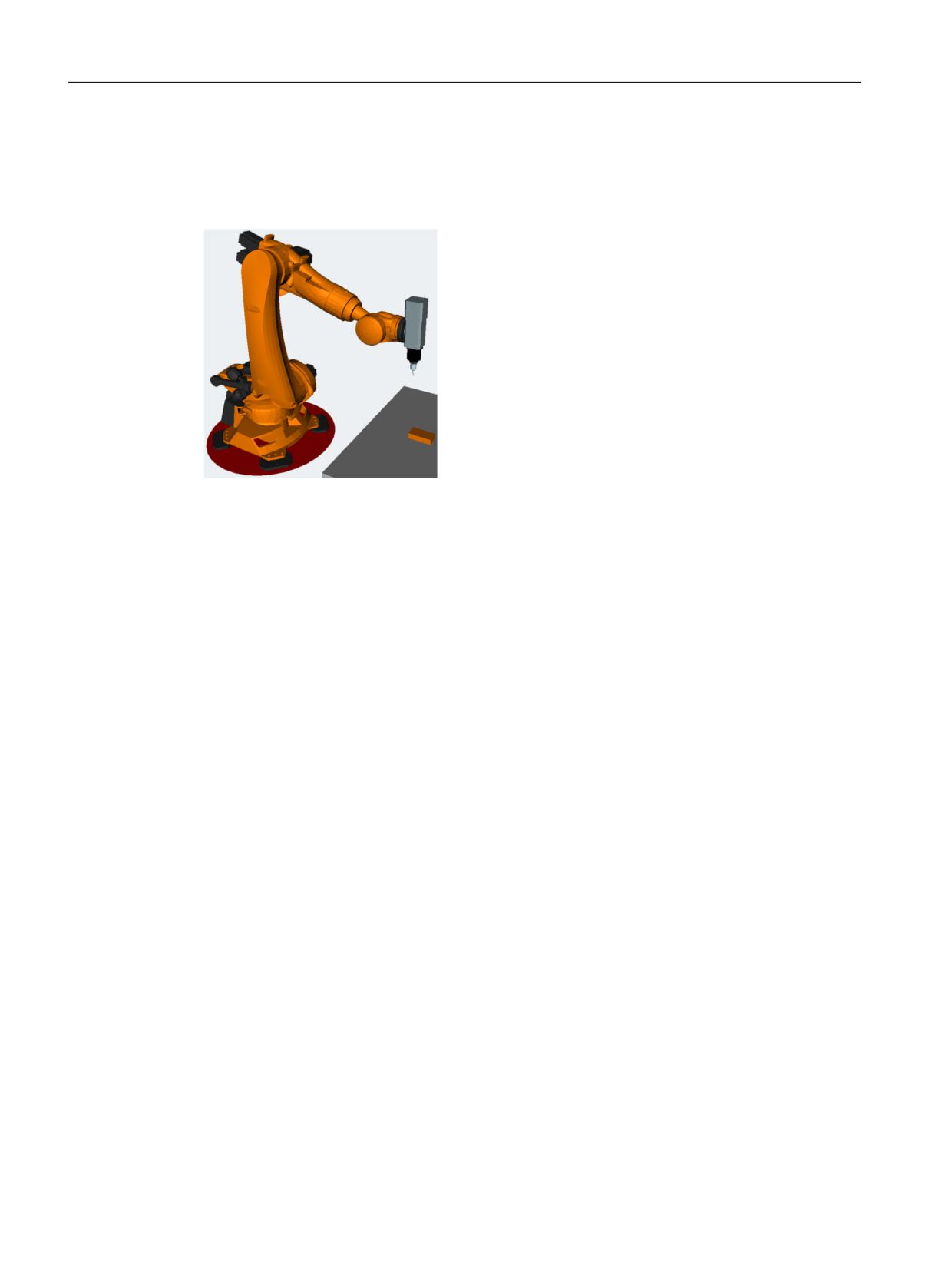
Example 1: PTP travel of a 6-axis robot with ROBX transformation
In the following application example, Cartesian PTP travel and the associated NC commands
are shown in the form of an example.
Figure 8-16
6-axis articulated robot with milling spindle
N1 G90
N2 T=“T8MILLD20“ D1 M6
N3 TRAORI
;$P_UIFR[1]=CTRANS(X,1500,Y,0,Z,400):CROT(X,0,Y,0,Z,-90)
N4 G54
N5 M3 S20000
N6 ORIWKS
N7 ORIVIRT1
N8 CYCLE832(0.01,_FINISH,1)
;HOME
N9 TRAFOOF
N10 G0 RA1=0.0000 RA2=-90.0000 RA3=90.0000 A=0.0000 B=90.0000 C=0.0000
N11 TRAORI
N12 G54
N13 G0 PTP X1369.2426 Y956.7528 Z502.5517 A=135.5761 B=-33.2223 C=161.1435
STAT='B010' TU='B001011'
N14 G0 X1355.1242 Y1014.9394 Z424.9695 A=135.8491 B=-33.1439 C=160.9941
STAT='B010' TU='B001011'
N15 G1 CP X1354.8361 Y1016.1269 Z423.3862 A=136.0635 B=-33.0819 C=160.8770
F1000
N16 G1 X1336.4283 Y1016.1269 Z426.6311 A=136.0484 B=-32.2151 C=160.9643
F2000
N17 G1 X1317.9831 Y1016.1269 Z429.6730 A=136.0175 B=-31.3394 C=161.0655
;HOME
N18 TRAFOOF
N19 G0 RA1=0.0000 RA2=-90.0000 RA3=90.0000 A=0.0000 B=90.0000 C=0.0000
N20 M30
Extended Functions
498
Function Manual, 12/2018, A5E40874029B AB
M1: Kinematic transformation
8.6 Cartesian PTP travel
8.6.3.5
Example 2: PTP travel for generic 5-axis transformation
Assumption: Right-angled CA kinematics used as basis.
Program code
Comment
TRAORI
;Transformation CA kinematics ON
PTP
; Activate PTP traversal
N10 A3=0 B3=0 C3=1
; rotary axis positions C=0 A=0
N20 A3=1 B3=0 C3=1
; rotary axis positions C=90 A=45
N30 A3=1 B3=0 C3=0
; rotary axis positions C=90 A=90
N40 A3=1 B3=0 C3=1 STAT=1
; rotary axis positions C=270 A=-45
Select clear approach position of rotary axis position:
In block N40, the rotary axes - as a result of the programming of STAT=1 - travel the longer
distance from their start point (C=90, A=90) to the end point (C=270, A=-45). On the other
hand, with STAT=0, the rotary axes would travel along the shortest path to the end point (C=90,
A=45).
8.6.3.6
Example 3: PTPG0 and TRANSMIT
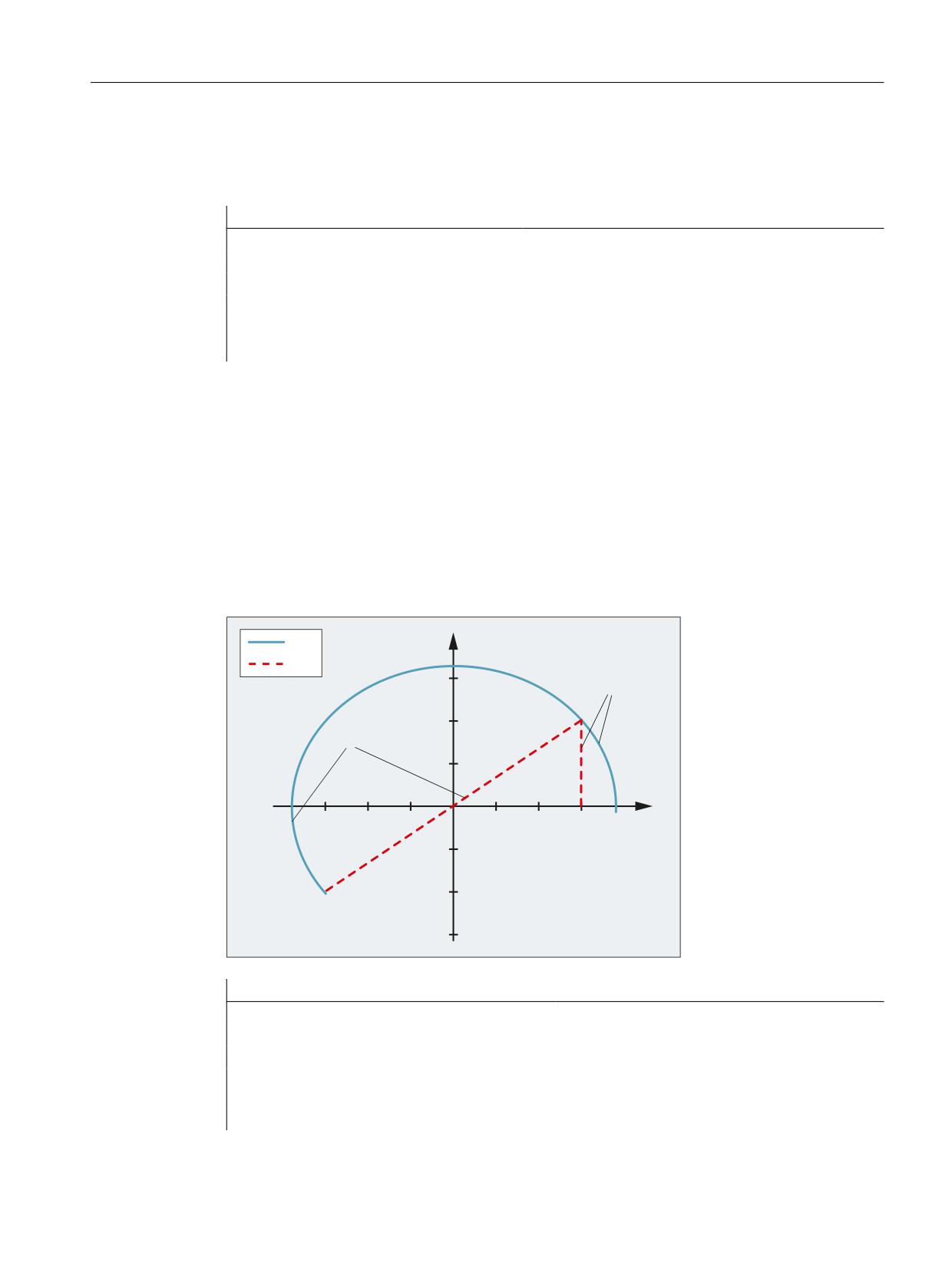
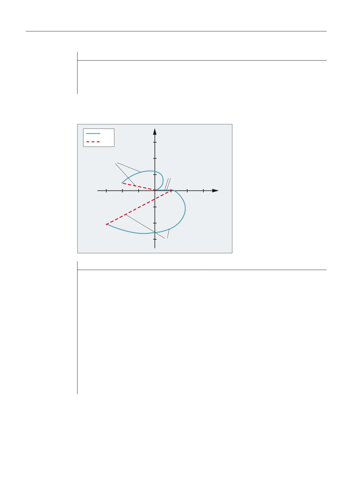
Traversing around the pole with PTPG0 and TRANSMIT
<
PTP
CP
1
* ;
<
1
;
<
;
Program code
Comment
N001 G0 X30 Z0 F10000 T1 D1 G90
;Initial setting absolute dimension
N002 SPOS=0
N003 TRANSMIT
;TRANSMIT transformation
N010 PTPG0
; for each G0 block, automatically PTP -
and then CP again.
N020 G0 X30 Y20
Extended Functions
Function Manual, 12/2018, A5E40874029B AB
499
M1: Kinematic transformation
8.6 Cartesian PTP travel
Program code
Comment
N030 X-30 Y-20
N120 G1 X30 Y20
N110 X30 Y0
M30
Traversing from the pole with PTPG0 and TRANSMIT
<
PTP
CP
30
N070 X20 Y2
20
10
N060 X0 Y0
-30
-20
-10
10
20
30
;
-10
-20
-30
N050 X10 Y0
Programming
Comment
N001 G0 X90 Z0 F10000 T1 D1 G90
;Initial setting
N002 SPOS=0
N003 TRANSMIT
;TRANSMIT transformation
N010 PTPG0
; for each G0 block, automatically PTP -
and then CP again.
N020 G0 X90 Y60
N030 X-90 Y-60
N040 X-30 Y-20
N050 X10 Y0
N060 X0 Y0
N070 X-20 Y2
N170 G1 X0 Y0
N160 X10 Y0
N150 X-30 Y-20
M30
Extended Functions
500
Function Manual, 12/2018, A5E40874029B AB
M1: Kinematic transformation
8.6 Cartesian PTP travel
8.6.4
Supplementary conditions
Tool radius compensation (TRC)
With PTP/PTPWOC, no tool radius compensation (TRC) can be active, because PTP/
PTPWOC creates contours other than those calculated by the TRC.
The response is different for PTPG0. Here, with active TRC, an internal switchover to CP takes
place so that the TRC is performed correctly.
Smooth approach and retraction (SAR)
If PTP/PTPWOC is active, SAR cannot be used, because SAR needs a contour to design the
approach and retraction and to be able to approach or retract tangentially.
With PTPG0, on the other hand, SAR is possible because the blocks required for SAR are
traversed with CP. The G0 blocks up to the actual approach contour are executed with PTP
travel and therefore quickly. The same applies to the retract blocks.
Chipping cycles
With active PTP/PTPWOC, chipping cycles such as CONTPRON or CONTDCON cannot be
applied because the chipping require a contour to be able to construct the cut segmentation.
With PTPG0, on the other hand, chipping cycles are possible because the blocks required for
the chipping cycles are traversed with CP.
Chamfer and rounding
Chamfer and rounding are ignored during PTP travel.
Axis overlay
An axis superimposing in the interpolation may not change during the PTP sequence. This
applies, for example, to LIFTFAST, fine tool offset, coupled motion TRAILON and tangential
follow-up TANGON.
NC block compression
In the PTP blocks, an active compressor function (COMPON, COMPCURV, COMPCAD or
COMPSURF) is automatically deselected.
Blending
Blending with G643 is not possible with the PTP travel. In the PTP blocks with an active G643,
there is an automatic switchover to G642.
Extended Functions
Function Manual, 12/2018, A5E40874029B AB
501
M1: Kinematic transformation
8.7 Cartesian manual traversing (option)
In addition, the following special features should be noted:
● Blending is always done in the machine coordinate system and it thus high-performance
in terms of time. The criteria for G642 is always interpreted in the machine coordinate
system and not as usual in the Cartesian basic coordinate system.
● Smoothing G641 is determined as a function of the fictitious path calculated from the
machine axis coordinates.
Path feedrate
An F value input with G1 refers to the fictitious path calculated from the machine axis
coordinates.
Mode change
Cartesian PTP travel only makes sense in the modes AUTOMATIC and MDI.
When changing the mode to JOG, the current setting is retained:
● If PTP travel is set, the axes will traverse in MCS.
● If CP is set, the axes will traverse in WCS.
After returning to the AUTOMATIC or MDI mode, the status that was active before the switch
to JOG mode is restored.
Block search
If the face end transformation (TRANSMIT) is active, different machine axis positions for the
same Cartesian position can result if a program section is executed with block search.
REPOS
The setting for Cartesian PTP travel is not altered during repositioning. If PTP was set in the
interruption block, then repositioning also takes place with PTP.
8.7
Cartesian manual traversing (option)
Note
The "Handling transformation package" option is necessary for the "Cartesian manual travel"
function.
Extended Functions
502
Function Manual, 12/2018, A5E40874029B AB

M1: Kinematic transformation
8.7 Cartesian manual traversing (option)
Function
The "Cartesian manual travel" function, as a reference system for JOG mode, allows axes to
be set independently of each other in the following Cartesian coordinate systems:
● Basic coordinate system (BCS)
● Workpiece coordinate system (WCS)
● Tool coordinate system (TCS)
Adjustment and activation is done using machine data:
MD21106 $MC_CART_JOG_SYSTEM (coordinate systems for Cartesian JOG)
Bit
Meaning
0
Basic coordinate system
1
Workpiece coordinate system
2
Tool coordinate system
Note
The workpiece coordinate system has been shifted and rotated compared to the basic
coordinate system via frames.
Reference:
Function Manual Basic Functions; Axes, Coordinate Systems, Frames (K2)
Representation of the reference points in the coordinate system:
Workpiece zero
Tool carrier reference point
Selecting reference systems
For JOG motion, one of the three reference systems can be specified separately not only for
the translation (coarse offset) with geometry axes, but also for the orientation with orientation
axes via the following setting data:
SD42650 $SC_CART_JOG_MODE
If more than one bit is set for the translation or orientation reference system, or when an attempt
is made to set a reference system which was not released by the MD21106
$MC_CART_JOG_SYSTEM, the alarm 14148 "Reference system for Cartesian manual travel
not allowed" will be generated.
Translation
A translation movement can be used to move the tool center point (TCP) in parallel and 3-
dimensional to the axes of the reference system. The traversing movement is made via the
VDI signals of the geometry axes.
Extended Functions
Function Manual, 12/2018, A5E40874029B AB
503
M1: Kinematic transformation
8.7 Cartesian manual traversing (option)
Machine data MD24120$MC_TRAFO_GEOAX_ASSIGN_TAB_x[n] is used to assign the
geometry axes. Simultaneous traversing in more than one direction permits the execution of
movements that lie parallel to the directions of the reference system.
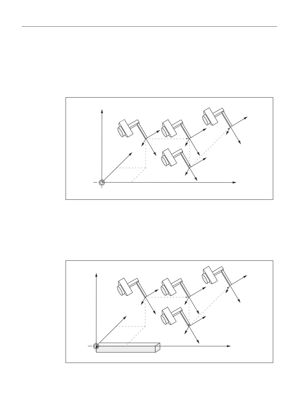
Translation in the BCS
The basic coordinate system (BCS) describes the Cartesian zero of the machine.
=
(QG SRVLWLRQ
=
<
=
=
6WDUW SRVLWLRQ
;
<
;
<
<
<
=
;
;
=
<
;
;
%&6
Figure 8-17
Cartesian manual travel in the basic coordinate system (translation)
Translation in the WCS
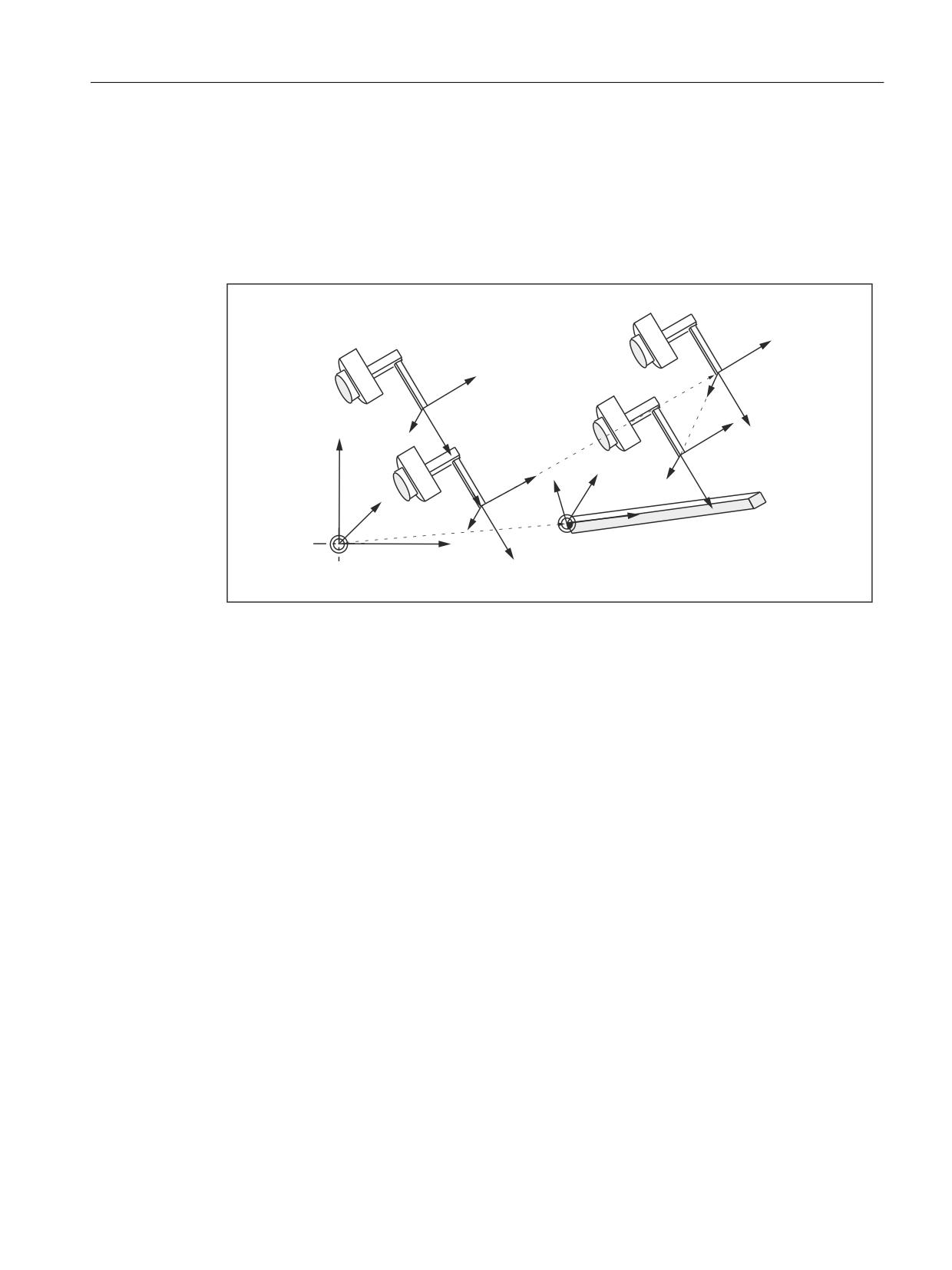
The workpiece coordinate system (WCS) lies in the workpiece zero. The workpiece coordinate
system can be shifted and rotated relative to the basic coordinate system via frames. As long
as no frame rotation is active, traversing motion corresponds to the translation of motion in the
basic coordinate system.
=
(QG SRVLWLRQ
=
<
=
=
<
;
6WDUW SRVLWLRQ
;
<
<
;
=
<
;
=
<
:RUNSLHFH
;
:&6
;
Extended Functions
504
Function Manual, 12/2018, A5E40874029B AB
M1: Kinematic transformation
8.7 Cartesian manual traversing (option)
Figure 8-18
Cartesian manual travel in the workpiece coordinate system (translation)
Translation in the TCS
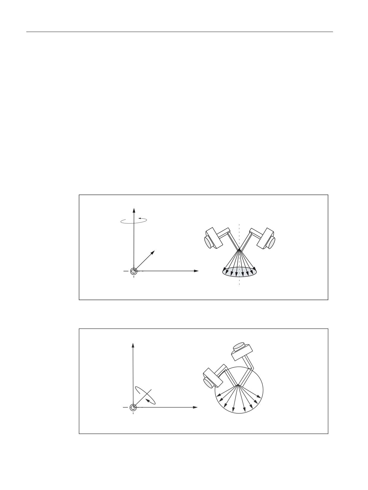
The tool coordinate system (TCS) is at the tool center point. Its direction depends on the current
setting of the machine, since the tool coordinate system moves during the motion.
(QG SRVLWLRQ
=
=
<
;
6WDUW SRVLWLRQ
<
<
;
=
=
<
;
=
<
;
=
<
)UDPH
<
:RUNSLHFH
;
;
%&6
:&6
;
Figure 8-19
Cartesian manual travel in the tool coordinate system (translation)
Translation and orientation simultaneously in the TCS
If translation and orientation movements are executed at the same time, the translation is
always traversed corresponding to the current orientation of the tool. This permits infeed
movements that are made directly in the tool direction or movements that run perpendicular
to tool direction.
Orientation
The tool can be aligned to the component surface via an orientation movement. The orientation
movement is given control from the PLC via the VDI signals of the orientation axes (DB21, ...
DBB321).
Several orientation axes can be traversed simultaneously. The virtual orientation axes execute
rotations around the fixed axes of the relevant reference system.
The rotations are identified according to the RPY angles.
● A angle: Rotation around the Z axis
● B angle: Rotation around the Y axis
● C angle: Rotation around the X axis
Programming rotations:
The user can define how rotations are to be executed using the current G commands of group
50 for orientation definition
Extended Functions
Function Manual, 12/2018, A5E40874029B AB
505
M1: Kinematic transformation
8.7 Cartesian manual traversing (option)
Specifying ORIEULER, ORIRPY, ORIVIRT1 and ORIVIRT2.
With ORIVIRT1, rotation is executed according to MD21120 $MC_ORIAX_TURN_TAB_1. The
orientation axes are assigned to the channel axes via machine data: MD24585
$MC_TRAFO5_ORIAX_ASSIGN_TAB_1.
The direction of rotation is determined according to the "right hand rule". The thumb points in
the direction of the rotary axis. The finger stipulates the positive direction of rotation.
Orientation in the WCS
The rotations are made around the defined directions of the workpiece coordinate system. If
frame rotation is active, the movements correspond to the rotations in the basic coordinate
system.
Orientation in the BCS
The rotations are made around the defined directions of the basic coordinate system.
=
(QG RULHQWDWLRQ
6WDUW RULHQWDWLRQ
$
<
;7.6
$
;
%&6
Figure 8-20
Cartesian manual travel in the basic coordinate system, orientation angle A
=
6WDUW RULHQWDWLRQ
(QG RULHQWDWLRQ
%
%
<
;7.6
;
%&6
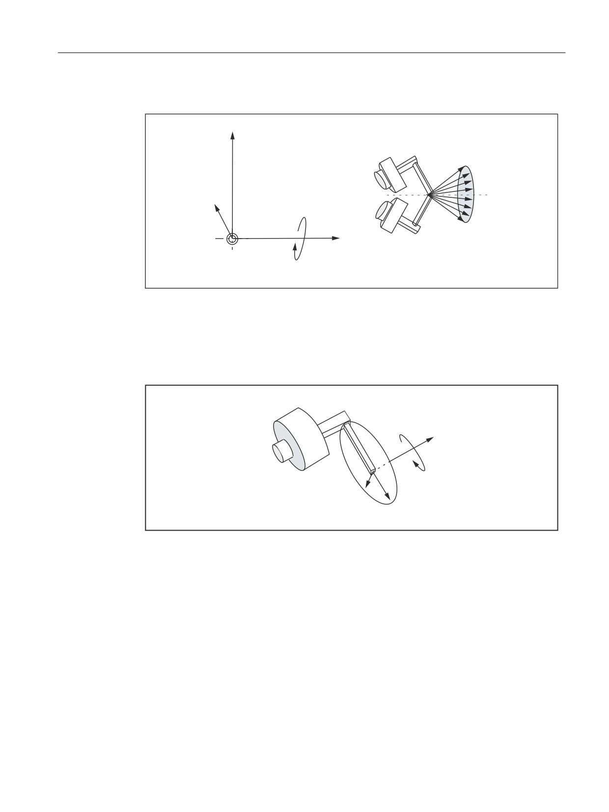
Figure 8-21
Cartesian manual travel in the basic coordinate system, orientation angle B
Extended Functions
506
Function Manual, 12/2018, A5E40874029B AB
M1: Kinematic transformation
8.7 Cartesian manual traversing (option)
=
(QG RULHQWDWLRQ
;7.6
&
<
6WDUW RULHQWDWLRQ
&
;
%&6
Figure 8-22
Cartesian manual travel in the basic coordinate system, orientation angle C
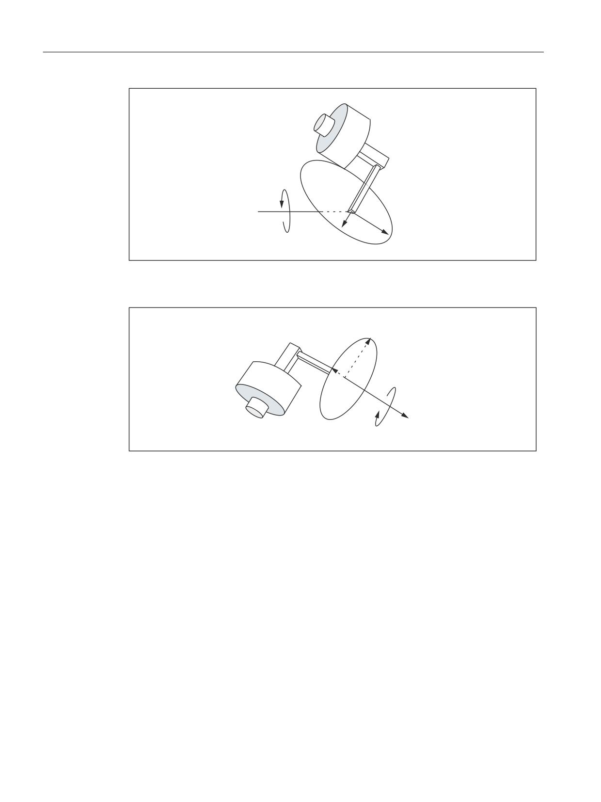
Orientation in the TCS
The rotations are around the moving directions in the tool coordinate system. The current
homing directions of the tool are always used as rotary axes.
=
$
<
;
Figure 8-23
Cartesian manual travel in the tool coordinate system, orientation angle A
Extended Functions
Function Manual, 12/2018, A5E40874029B AB
507
M1: Kinematic transformation
8.7 Cartesian manual traversing (option)
%
<
;
=
Figure 8-24
Cartesian manual travel in the tool coordinate system, orientation angle B
=
<
&
;
Figure 8-25
Cartesian manual travel in the tool coordinate system, orientation angle C
Supplementary conditions
The "Cartesian manual travel" function can only be executed if the transformation is active in
the NC: DB21, ... DBX33.6 == 1 ("transformation active")
The following supplementary conditions must be observed:
● "Handling transformation package" option with 5-axis or 6-axis transformation is set
● Virtual orientation axes must be defined via the following machine data:
MD24585 $MC_TRAFO5_ORIAX_ASSIGN_TAB_1[n]
● DB21, ... DBX29.4 == 0 (activate PTP travel)
● MD21106 $MC_CART_JOG_SYSTEM > 0
Extended Functions
508
Function Manual, 12/2018, A5E40874029B AB

M1: Kinematic transformation
8.7 Cartesian manual traversing (option)
Table 8-2
Conditions for Cartesian manual travel
Transformation in pro-
Prog. traversing type
DB21, ... DBX29.4
DB21, ... DBX33.6
gram active (TRAORI..)
"Activate PTP travel"
"Transformation active"
FALSE
Not active
Not active
0
TRUE
CP
0
1
TRUE
CP
1
0
TRUE
PTP
0
1
TRUE
PTP
1
0
The G command PTP/CP currently active in the program does not affect Cartesian manual
travel. The NC/PLC interface signals are interpreted in the channel DB for geometry and
orientation axes.
Activation
The reference system for Cartesian manual travel is set as follows:
● The Cartesian manual travel function is activated with the following machine data:
MD21106 $MC_CART_JOG_SYSTEM > 0
The BCS, WCS or TCS reference systems are enabled via MD21106
$MC_CART_JOG_SYSTEM.
● JOG traverse motion via SD42650 SC_CART_JOG_MODE
Standard behavior as before: Bits 0 to 2 = 0, bits 8 to 10 = 0.
Reference system for translation via bits 0-2 and the reference system for orientation via
bits 8-10.
If not all of the bits are set to 0, the process uses the new function. The reference systems
for translation and orientation may be set independently.
SD42650 $SC_CART_JOG_MODE (only set one bit):
SD42650 $SC_CART_JOG_MODE
Bit 11 -
Bit 10
Bit 9
Bit 8
Bit 7 -
Bit 2
Bit 1
Bit 0
bit 15
bit 3
Reserved
Orienta-
Orienta-
Orienta-
Reserved
Transla-
Transla-
Transla-
tion in the
tion in the
tion in the
tion in the
tion in the
tion in the
TCS
WCS
BCS
TCS
WCS
BCS
Combining reference systems
The table below shows all the combination options for reference systems.
SD42650 $SC_CART_JOG_MODE
Reference system for
Bit 10
Bit 9
Bit 8
Bit 2
Bit 1
Bit 0
Orientation
Translation
0
0
0
0/1
0/1
0/1
Standard
Standard
Standard
Standard
Standard
0
0
0
Standard
Standard
0
0
1
0
0
1
BCS
BCS
0
0
1
0
1
0
BCS
WCS
0
0
1
1
0
0
BCS
TCS
0
1
0
0
0
1
WCS
BCS
Extended Functions
Function Manual, 12/2018, A5E40874029B AB
509

M1: Kinematic transformation
8.8 Activating transformation machine data via part program/softkey
SD42650 $SC_CART_JOG_MODE
Reference system for
0
1
0
0
1
0
WCS
WCS
0
1
0
1
0
0
WCS
TCS
1
0
0
0
0
1
TCS
BCS
1
0
0
0
1
0
TCS
WCS
1
0
0
1
0
0
TCS
TCS
8.8
Activating transformation machine data via part program/softkey
8.8.1
Function
Transformation MD can now be activated by means of a program command softkey, i.e. these
can, for example, be written from the parts program, thus altering the transformation
configuration completely.
Up to ten different transformations can be set in the control system. The transformation type
is set in the following machine data:
MD24100 $MC_TRAFO_TYPE_1
up to
MD24460 $MC_TRAFO_TYPE_10.
Characteristics
The transformation MDs are activated using the "Setting machine data effective".
The protection level is now 7/7 (KEYSWITCH_0), which means that data can be modified from
the NC program without any particular authorization.
If the machine data are activated (regardless whether via the NEWCONF NC program
command, the HMI or implicitly following reset or end of program) - and no transformation has
been selected (activated) - then the machine data listed above can be altered without restriction
and then activated.
Of particular relevance is that new transformations can be configured or existing
transformations replaced by one of a different type or deleted, since the modification options
are not restricted to re-parameterization of existing transformations.
8.8.2
Constraints
Changing machine data
The machine data which involve an active transformation may not be altered; any attempt to
do so will generate an alarm.
Extended Functions
510
Function Manual, 12/2018, A5E40874029B AB
M1: Kinematic transformation
8.8 Activating transformation machine data via part program/softkey
Generally, these are all machine data, which are assigned a transformation via the associated
transformation data group. Machine data, which although contained in the group of an active
transformation, but are not used, can be changed (however, this could hardly be considered
an operation that makes sense). For example, it would be possible to change machine data
MD24564 $MC_TRAFO5_NUTATOR_AX_ANGLE_n for an active transformation with
MD24100 $MC_$MC_TRAFO_TYPE = 16 (5-axis transformation with rotatable tool and two
mutually perpendicular rotary axes A and B) since this particular machine data is not involved
in the transformation.
Please note that machine data MD21110 $MC_X_AXIS_IN_OLD_X_Z_PLANE may not be
altered for an active orientation transformation.
Note
For a program interruption (Repos, delete distance to go, ASUPs etc.) to restart, several blocks
are also required in the control, which were already executed. That it is prohibited to change
machine data of an active transformation also refers to these blocks.
Example:
Two orientation transformations are set via machine data, e.g. MD24100
$MC_TRAFO_TYPE_1 = 16, MD24200 $MC_TRAFO_TYPE_2 = 18.
When executing "Activate machine data", it is assumed that the second transformation is
active. In this case, all machine data that relate only to the first transformation may be changed,
e.g.:
MD24500 $MC_TRAFO5_PART_OFFSET_1
but not, for instance:
MD24650 $MC_TRAFO5_BASE_TOOL_2
or
MD21110 $MC_X_AXIS_IN_OLD_X_Z_PLANE
Furthermore, another transformation (TRANSMIT) can be set, for example with MD24300
$MC_TRAFO_TYPE_3 = 256 and can be parameterized with additional machine data.
Defining geometry axes
Geometry axes must be defined before the control system powers up using the following
machine data:
MD24120 $MC_TRAFO_GEOAX_ASSIGN_TAB_X[n]
or
MD20050 $MC_AXCONF_GEOAX_ASSIGN_TAB[n]
Changing the assignment
The assignment of a transformation data set to a transformation is determined by the sequence
of entries in MD24100 $MC_TRAFO_TYPE_X. The first entry in the table is assigned to the
first transformation data set, and accordingly the second entry to the second data set. It is not
permissible (and not possible) to change this assignment for an active transformation.
Extended Functions
Function Manual, 12/2018, A5E40874029B AB
511
M1: Kinematic transformation
8.8 Activating transformation machine data via part program/softkey
Example:
Three transformations are set. two orientation transformations and one transmit
transformation, e.g.
MD24100 $MC_TRAFO_TYPE_1 = 16
; orientation transformation 1: Orientation transformation data set
MD24200 $MC_TRAFO_TYPE_2 = 256 : Transmit transformations
MD24300 $MC_TRAFO_TYPE_3 = 18
; orientation transformation 2: Orientation transformation data set
The first data set for orientation transformations is assigned to the first transformation (at the
same time, the first orientation transformation) - and the second transformation data set to the
third transformation (at the same time, the the second orientation transformation).
If the third transformation is active when executing the "Activate machine data" function, then
it is not permissible to change the first transformation into a transformation of another group
(e.g. TRACYL) since, in this case, the third transformation would then not become the second
orientation transformation, but the first.
In the above example, however, it is permissible to set another orientation transformation for
the first transformation (e.g. using MD24100 $MC_TRAFO_TYPE_1 = 32) or a transformation
from another group as the first transformation (e.g. using $MD24100 $MC_TRAFO_TYPE_1
= 1024, TRAANG), if the second transformation is changed into an orientation transformation
at the same time, e.g. with MD24200 $MC_TRAFO_TYPE_2 = 48.
8.8.3
Control response to power ON, mode change, RESET, block search, REPOS
With the aid of the following machine data it is possible to select a transformation automatically
in response to RESET (i.e. at end of program as well) and/or on program start:
MD20110 $MC_RESET_MODE_MASK
MD20112 $MC_START_MODE_MASK
and
MD20140 $MC_TRAFO_RESET_VALUE
This may result in the generation of an alarm, for example, at the end or start of a program, if
the machine data of an active transformation has been altered.
To avoid this problem when re-configuring transformations via an NC program, we therefore
recommend that NC programs are structured as follows:
Program code
Comment
N10 TRAFOOF()
; Select a possibly still active trans-
formation
N20$MC_TRAFO5_BASE_TOOL_1[0]=0
; Enter machine data
N30$MC_TRAFO5_BASE_TOOL_1[0]=3
N40$MC_TRAFO5_BASE_TOOL_1[0]=200
N130 NEWCONF
; Newly entered machine data
; Transfer
Extended Functions
512
Function Manual, 12/2018, A5E40874029B AB
M1: Kinematic transformation
8.8 Activating transformation machine data via part program/softkey
Program code
Comment
N140 M30
8.8.4
List of machine data affected
The machine data that can be activated are listed below.
All transformations
Machine data which are relevant for all transformations:
● MD24100 $MC_TRAFO_TYPE_1 to MD24480 $MC_TRAFO_TYPE_10
● MD24110 $MC_TRAFO_AXES_IN_1 to MD24482 $MC_TRAFO_AXES_IN_10
● MD24120 $MC_TRAFO_GEOAX_ASSIGN_TAB_1 to
MD24484 $MC_TRAFO_GEOAX_ASSIGN_TAB_10
Orientation transformations
Machine data that are relevant for orientation transformations:
● MD24550 $MC_TRAFO5_BASE_TOOL_1 and
MD24650 $MC_TRAFO5_BASE_TOOL_2
● MD24558 $MC_TRAFO5_JOINT_OFFSET_1 and
MD24658 $MC_TRAFO5_JOINT_OFFSET_2
● MD24500 $MC_TRAFO5_PART_OFFSET_1 and
MD24600 $MC_TRAFO5_PART_OFFSET_2
● MD24510 $MC_TRAFO5_ROT_AX_OFFSET_1 and
MD24610 $MC_TRAFO5_ROT_AX_OFFSET_2
● MD24520 $MC_TRAFO5_ROT_SIGN_IS_PLUS_1 and
MD24620 $MC_TRAFO5_ROT_SIGN_IS_PLUS_2
● MD 24530: TRAFO5_NON_POLE_LIMIT_1 and
MD24630 $MC_TRAFO5_NON_POLE_LIMIT_2
● MD24540 $MC_TRAFO5_POLE_LIMIT_1 and
MD24640 $MC_TRAFO5_POLE_LIMIT_2
● MD24570 $MC_TRAFO5_AXIS1_1 and
MD24670 $MC_TRAFO5_AXIS1_2
● MD24572 $MC_RAFO5_AXIS2_1 and
MD24672 $MC_TRAFO5_AXIS2_2
● MD24574 $MC_TRAFO5_BASE_ORIENT_1 and
MD24674 $MC_TRAFO5_BASE_ORIENT_2
● MD24562 $MC_TRAFO5_TOOL_ROT_AX_OFFSET_1 and
MD24662 $MC_TRAFO5_TOOL_ROT_AX_OFFSET_2
Extended Functions
Function Manual, 12/2018, A5E40874029B AB
513
M1: Kinematic transformation
8.8 Activating transformation machine data via part program/softkey
● MD24564 $MC_TRAFO5_NUTATOR_AX_ANGLE_1 and
MD24664 $MC_TRAFO5_NUTATOR_AX_ANGLE_2
● MD24566 $MC_TRAFO5_NUTATOR_VIRT_ORIAX_1 and
MD24666 $MC_TRAFO5_NUTATOR_VIRT_ORIAX_2
Transmit transformations
Machine data that are relevant for transmit transformations:
● MD24920 $MC_TRANSMIT_BASE_TOOL_1 and
MD24970 $MC_TRANSMIT_BASE_TOOL_2
● MD24900 $MC_TRANSMIT_ROT_AX_OFFSET_1 and
MD24950 $MC_TRANSMIT_ROT_AX_OFFSET_2
● MD24910 $MC_TRANSMIT_ROT_SIGN_IS_PLUS_1 and
MD24960 $MC_TRANSMIT_ROT_SIGN_IS_PLUS_2
● MD24911 MC_RANSMIT_POLE_SIDE_FIX_1 and
MD24961 $MC_TRANSMIT_POLE_SIDE_FIX_2
Tracyl transformations
Machine data that are relevant for Tracyl transformations:
● MD24820 $MC_TRACYL_BASE_TOOL_1 and
MD24870 $MC_TRACYL_BASE_TOOL_2
● MD24800 $MC_TRACYL_ROT_AX_OFFSET_1 and
MD24850 $MC_TRACYL_ROT_AX_OFFSET_2
● MD24810 $MC_TRACYL_ROT_SIGN_IS_PLUS_1 and
MD24870 $MC_TRACYL_ROT_SIGN_IS_PLUS_2
● MD24808 $MC_TRACYL_DEFAULT_MODE_1 and
MD24858 $MC_TRACYL_DEFAULT_MODE_2
Inclined axis transformations
Machine data that are relevant for inclined axis transformations:
● MD24710 $MC_TRAANG_BASE_TOOL_1 and
MD24760 $MC_TRAANG_BASE_TOOL_2
● MD24700 $MC_TRAANG_ANGLE_1 and
MD24750 $MC_TRAANG_ANGLE_2
● MD24720 $MC_TRAANG_PARALLEL_VELO_RES_1 and
MD24770 $MC_TRAANG_PARALLEL_VELO_RES_2
● MD24721 $MC_TRAANG_PARALLEL_ACCEL_RES_1 and
MD24771 $MC_TRAANG_PARALLEL_ACCEL_RES_2
Extended Functions
514
Function Manual, 12/2018, A5E40874029B AB
M1: Kinematic transformation
8.8 Activating transformation machine data via part program/softkey
Chained transformations
Machine data that are relevant for chained transformations:
● MD24995 $MC_TRACON_CHAIN_1 and
MD24996 $MC_TRACON_CHAIN_2
● MD24997 $MC_TRACON_CHAIN_3 and
MD24998 $MC_TRACON_CHAIN_4
Persistent transformation
Machine data that are relevant for persistent transformations:
● MD20144 $MC_TRAFO_MODE_MASK
● MD20140 $MC_TRAFO_RESET_VALUE
● MD20110 $MC_RESET_MODE_MASK and
MD20112 $MC_START_MODE_MASK
Not transformation-specific
Machine data that are not transformation-specific. They are not uniquely assigned to a specific
transformation data set - or are also of significance outside an active transformation:
● MD21110 $MC_X_AXIS_IN_OLD_X_Z_PLANE
● MD21090 $MC_ MAX_LEAD_ANGLE
● MD21092 $MC_ MAX_TILT_ANGLE
● MD21100 $MC_ORIENTATION_IS_EULER
8.8.5
Example
It would be permissible in the following example to reconfigure (write) a machine data affecting
the second transformation (e.g. MD24650 $MC_TRAFO5_BASE_TOOL_2[2]) in block N90,
since writing a machine data alone does not activate it. However, if the program remained
otherwise unchanged, an alarm would occur in block N130, because an attempt would then
be made to modify an active transformation.
Example program:
Program code
Comment
N40 TRAORI(2)
; Select 2nd orientation transformation
N50 X0 Y0 Z0 F20000 T1 T1
N60 A50 B50
N70 A0 B0
N80 X10
N90 $MC_TRAFO5_BASE_TOOL_1[2] = 50
; Overwrite a machine data item of the
1st orientation transformation
N100 A20
N110 X20
Extended Functions
Function Manual, 12/2018, A5E40874029B AB
515

M1: Kinematic transformation
8.9 Data lists
Program code
Comment
N120 X0
N130 NEWCONF
; Accept new machine data
N140 TRAORI(1)
; Selection of the 1st orientation
transformation MD is effective
N150 G19 X0 Y0 Z0
N160 A50 B50
N170 A0 B0
N180 TRAFOOF
N190 M30
8.9
Data lists
8.9.1
Machine data
8.9.1.1
TRANSMIT
Channelspecific machine data
Number
Identifier: $MC_
Description
20110
RESET_MODE_MASK
Definition of control basic setting after run-up and RESET/part
program end
20140
TRAFO_RESET_VALUE
Basic transformation position
22534
TRAFO_CHANGE_M_CODE
M code for transformation changeover
24100
TRAFO_TYPE_1
Definition of the 1st transformation in channel
24110
TRAFO_AXES_IN_1
Axis assignment for the 1st transformation
24120
TRAFO_GEOAX_ASSIGN_TAB_1
Geo-axis assignment for 1st transformation
24200
TRAFO_TYPE_2
Definition of the 2nd transformation in channel
24210
TRAFO_AXES_IN_2
Axis assignment for the 2nd transformation
24220
TRAFO_GEOAX_ASSIGN_TAB_2
Geo-axis assignment for 2nd transformation
24300
TRAFO_TYPE_3
Definition of the 3rd transformation in channel
24310
TRAFO_AXES_IN_3
Axis assignment for the 3rd transformation
24320
TRAFO_GEOAX_ASSIGN_TAB_3
Geo-axis assignment for 3rd transformation
24400
TRAFO_TYPE_4
Definition of the 4th transformation in channel
24410
TRAFO_AXES_IN_4
Axis assignment for the 4th transformation
24420
TRAFO_GEOAX_ASSIGN_TAB_4
Geo-axis assignment for 4th transformation
24430
TRAFO_TYPE_5
Definition of the 5th transformation in channel
24432
TRAFO_AXES_IN_5
Axis assignment for the 5th transformation
24434
TRAFO_GEOAX_ASSIGN_TAB_5
Geo-axis assignment for 5th transformation
24440
TRAFO_TYPE_6
Definition of the 6th transformation in channel
Extended Functions
516
Function Manual, 12/2018, A5E40874029B AB

M1: Kinematic transformation
8.9 Data lists
Number
Identifier: $MC_
Description
24442
TRAFO_AXES_IN_6
Axis assignment for the 6th transformation
24444
TRAFO_GEOAX_ASSIGN_TAB_6
Geo-axis assignment for 6th transformation
24450
TRAFO_TYPE_7
Definition of the 7th transformation in channel
24452
TRAFO_AXES_IN_7
Axis assignment for the 7th transformation
24454
TRAFO_GEOAX_ASSIGN_TAB_7
Geo-axis assignment for 7th transformation
24460
TRAFO_TYPE_8
Definition of the 8th transformation in channel
24462
TRAFO_AXES_IN_8
Axis assignment for the 8th transformation
24464
TRAFO_GEOAX_ASSIGN_TAB_8
Geo-axis assignment for 8th transformation
24900
TRANSMIT_ROT_AX_OFFSET_1
Deviation of rotary axis from zero position in degrees (1st
TRANSMIT)
24910
TRANSMIT_ROT_SIGN_IS_PLUS_1
Sign of rotary axis for TRANSMIT (1st TRANSMIT)
24911
TRANSMIT_POLE_SIDE_FIX_1
Limitation of working range in front of/behind pole, 1st trans-
formation
24920
TRANSMIT_BASE_TOOL_1
Distance of tool zero point from origin of geo-axes (1st
TRANSMIT)
24950
TRANSMIT_ROT_AX_OFFSET_2
Deviation of rotary axis from zero position in degrees (2nd
TRANSMIT)
24960
TRANSMIT_ROT_SIGN_IS_PLUS_2
Sign of rotary axis for TRANSMIT (2nd TRANSMIT)
24961
TRANSMIT_POLE_SIDE_FIX_2
Limitation of working range in front of/behind pole, 2nd trans-
formation
24970
TRANSMIT_BASE_TOOL_2
Distance of tool zero point from origin of geo-axes (2nd
TRANSMIT)
8.9.1.2
TRACYL
Channelspecific machine data
Number
Identifier: $MC_
Description
20110
RESET_MODE_MASK
Definition of control basic setting after run-up and RESET/part
program end
20140
TRAFO_RESET_VALUE
Basic transformation position
20144
TRAFO_MODE_MASK
Selection of the kinematic transformation function
24100
TRAFO_TYPE_1
Definition of the 1st transformation in channel
24110
TRAFO_AXES_IN_1
Axis assignment for the 1st transformation
24120
TRAFO_GEOAX_ASSIGN_TAB_1
Geo-axis assignment for 1st transformation
24130
TRAFO_INCLUDES_TOOL_1
Tool handling with active transformation 1.
24200
TRAFO_TYPE_2
Definition of the 2nd transformation in channel
24210
TRAFO_AXES_IN_2
Axis assignment for the 2nd transformation
24220
TRAFO_GEOAX_ASSIGN_TAB_2
Geo-axis assignment for 2nd transformation
24230
TRAFO_INCLUDES_TOOL_2
Tool handling with active transformation 2.
24300
TRAFO_TYPE_3
Definition of the 3rd transformation in channel
24310
TRAFO_AXES_IN_3
Axis assignment for the 3rd transformation
Extended Functions
Function Manual, 12/2018, A5E40874029B AB
517

M1: Kinematic transformation
8.9 Data lists
Number
Identifier: $MC_
Description
24320
TRAFO_GEOAX_ASSIGN_TAB_3
Geo-axis assignment for 3rd transformation
24330
TRAFO_INCLUDES_TOOL_3
Tool handling with active transformation 3.
24400
TRAFO_TYPE_4
Definition of the 4th transformation in channel
24410
TRAFO_AXES_IN_4
Axis assignment for the 4th transformation
24420
TRAFO_GEOAX_ASSIGN_TAB_4
Geo-axis assignment for 4th transformation
24426
TRAFO_INCLUDES_TOOL_4
Tool handling with active transformation 4.
24430
TRAFO_TYPE_5
Definition of the 5th transformation in channel
24432
TRAFO_AXES_IN_5
Axis assignment for the 5th transformation
24434
TRAFO_GEOAX_ASSIGN_TAB_5
Geo-axis assignment for 5th transformation
24436
TRAFO_INCLUDES_TOOL_5
Tool handling with active transformation 5.
24440
TRAFO_TYPE_6
Definition of the 6th transformation in channel
24442
TRAFO_AXES_IN_6
Axis assignment for the 6th transformation
24444
TRAFO_GEOAX_ASSIGN_TAB_6
Assignment geometry axes for 6th transformation
24446
TRAFO_INCLUDES_TOOL_6
Tool handling with active transformation 6.
24450
TRAFO_TYPE_7
Definition of the 7th transformation in channel
24452
TRAFO_AXES_IN_7
Axis assignment for the 7th transformation
24454
TRAFO_GEOAX_ASSIGN_TAB_7
Geo-axis assignment for 7th transformation
24456
TRAFO_INCLUDES_TOOL_7
Tool handling with active transformation 7.
24460
TRAFO_TYPE_8
Definition of the 8th transformation in channel
24462
TRAFO_AXES_IN_8
Axis assignment for the 8th transformation
24464
TRAFO_GEOAX_ASSIGN_TAB_8
Geo-axis assignment for 8th transformation
24466
TRAFO_INCLUDES_TOOL_8
Tool handling with active transformation 8.
24470
TRAFO_TYPE_9
Definition of the 9th transformation in channel
24472
TRAFO_AXES_IN_9
Axis assignment for the 9th transformation
24474
TRAFO_GEOAX_ASSIGN_TAB_9
Geo-axis assignment for 9th transformation
24476
TRAFO_INCLUDES_TOOL_9
Tool handling with active transformation 9.
24480
TRAFO_TYPE_10
Definition of the 10th transformation in channel
24482
TRAFO_AXES_IN_10
Axis assignment for the 10th transformation
24484
TRAFO_GEOAX_ASSIGN_TAB_10
Geo-axis assignment for 10th transformation
24486
TRAFO_INCLUDES_TOOL_10
Tool handling with active transformation 10.
24800
TRACYL_ROT_AX_OFFSET_1
Deviation of rotary axis from zero position in degrees (1st
TRACYL)
24808
TRACYL_DEFAULT_MODE_1
Selection of TRACYL mode (1st TRACYL)
24810
TRACYL_ROT_SIGN_IS_PLUS_1
Sign of rotary axis for TRACYL (1st TRACYL)
24820
TRACYL_BASE_TOOL_1
Distance of tool zero point from origin of geo-axes (1st TRAC-
YL)
24850
TRACYL_ROT_AX_OFFSET_2
Deviation of rotary axis from zero position in degrees (2nd
TRACYL)
24858
TRACYL_DEFAULT_MODE_2
Selection of TRACYL mode (2nd TRACYL)
24860
TRACYL_ROT_SIGN_IS_PLUS_2
Sign of rotary axis for TRACYL (2nd TRACYL)
Extended Functions
518
Function Manual, 12/2018, A5E40874029B AB

M1: Kinematic transformation
8.9 Data lists
Number
Identifier: $MC_
Description
24870
TRACYL_BASE_TOOL_2
Distance of tool zero point from origin of geo-axes (2nd TRAC-
YL)
22534
TRAFO_CHANGE_M_CODE
M code for transformation changeover
8.9.1.3
TRAANG
Channelspecific machine data
Number
Identifier: $MC_
Description
20110
RESET_MODE_MASK
Definition of control basic setting after run-up and RESET/part
program end
20140
TRAFO_RESET_VALUE
Basic transformation position
20144
RAFO_MODE_MASK
Selection of the kinematic transformation function
20534
TRAFO_CHANGE_M_CODE
M code for transformation changeover
24100
TRAFO_TYPE_1
Definition of the 1st transformation in channel
24110
TRAFO_AXES_IN_1
Axis assignment for the 1st transformation
24120
TRAFO_GEOAX_ASSIGN_TAB_1
Geo-axis assignment for 1st transformation
24200
TRAFO_TYPE_2
Definition of the 2nd transformation in channel
24210
TRAFO_AXES_IN_2
Axis assignment for the 2nd transformation
24220
TRAFO_GEOAX_ASSIGN_TAB_2
Geo-axis assignment for 2nd transformation
24300
TRAFO_TYPE_3
Definition of the 3rd transformation in channel
24310
TRAFO_AXES_IN_3
Axis assignment for the 3rd transformation
24320
TRAFO_GEOAX_ASSIGN_TAB_3
Geo-axis assignment for 3rd transformation
24400
TRAFO_TYPE_4
Definition of the 4th transformation in channel
24410
TRAFO_AXES_IN_4
Axis assignment for the 4th transformation
24420
TRAFO_GEOAX_ASSIGN_TAB_4
Geo-axis assignment for 4th transformation
24430
TRAFO_TYPE_5
Definition of the 5th transformation in channel
24432
TRAFO_AXES_IN_5
Axis assignment for the 5th transformation
24434
TRAFO_GEOAX_ASSIGN_TAB_5
Geo-axis assignment for 5th transformation
24440
TRAFO_TYPE_6
Definition of the 6th transformation in channel
24442
TRAFO_AXES_IN_6
Axis assignment for the 6th transformation
24444
TRAFO_GEOAX_ASSIGN_TAB_6
Geo-axis assignment for 6th transformation
24450
TRAFO_TYPE_7
Definition of the 7th transformation in channel
24452
TRAFO_AXES_IN_7
Axis assignment for the 7th transformation
24454
TRAFO_GEOAX_ASSIGN_TAB_7
Geo-axis assignment for 7th transformation
24460
TRAFO_TYPE_8
Definition of the 8th transformation in channel
24462
TRAFO_AXES_IN_8
Axis assignment for the 8th transformation
24464
TRAFO_GEOAX_ASSIGN_TAB_8
Geo-axis assignment for 8th transformation
24700
TRAANG_ANGLE_1
Angle of inclined axis in degrees (1st TRAANG)
24710
TRAANG_BASE_TOOL_1
Distance of tool zero point from origin of geometry axes (1st
TRAANG)
Extended Functions
Function Manual, 12/2018, A5E40874029B AB
519

M1: Kinematic transformation
8.9 Data lists
Number
Identifier: $MC_
Description
24720
TRAANG_PARALLEL_VELO_RES_1
Velocity reserve of parallel axis for compensatory motion (1st
TRAANG)
24721
TRAANG_PARALLEL_VELO_RES_2
Velocity reserve of parallel axis for compensatory motion (2nd
TRAANG)
24750
TRAANG_ANGLE_2
Angle of inclined axis in degrees (2nd TRAANG)
24760
TRAANG_BASE_TOOL_2
Distance of tool zero point from origin of geometry axes (2nd
TRAANG)
24770
TRAANG_PARALLEL_ACCEL_RES_1
Axis acceleration reserve of parallel axis for compensatory
motion (1st TRAANG)
24771
TRAANG_PARALLEL_ACCEL_RES_2
Axis acceleration reserve of parallel axis for compensatory
motion (2nd TRAANG)
8.9.1.4
Chained transformations
Channelspecific machine data
Number
Identifier: $MC_
Description
24995
TRACON_CHAIN_1
Transformation chain of the first chained transformation
24996
TRACON_CHAIN_2
Transformation chain of the second chained transformation
24997
TRACON_CHAIN_3
Transformation chain of the third chained transformation
24998
TRACON_CHAIN_4
Transformation chain of the fourth chained transformation
8.9.1.5
Non transformation-specific machine data
Channelspecific machine data
Number
Identifier: $MC_
Description
21110
X_AXIS_IN_OLD_X_Z_PLANE
Coordinate system for automatic Frame definition
21090
MAX_LEAD_ANGLE
Maximum permissible lead angle for orientation programming
21092
MAX_TILT_ANGLE
Maximum permissible side angle for orientation programming
21100
ORIENTATION_IS_EULER
Angle definition for orientation programming
8.9.2
Signals
8.9.2.1
Signals to channel
Signal name
SINUMERIK 840D sl
SINUMERIK 828D
Activate PTP traversing
DB21, … .DBX29.4
-
Extended Functions
520
Function Manual, 12/2018, A5E40874029B AB

M1: Kinematic transformation
8.9 Data lists
8.9.2.2
Signals from channel
Signal name
SINUMERIK 840D sl
SINUMERIK 828D
Transformation active
DB21,
DBX33.6
DB330x.DBX1.6
PTP traversing active
DB21, … .DBX317.6
-
Extended Functions
Function Manual, 12/2018, A5E40874029B AB
521
M1: Kinematic transformation
8.9 Data lists
Extended Functions
522
Function Manual, 12/2018, A5E40874029B AB
M5: Measurement
9
9.1
Brief description
Measurement level 1: Channel-specific measurement
Function
Up to two switching probes can be connected simultaneously to the CNC. In the case of
channel-specific measurement, the measurement process for an NC channel is always
activated from the part program running in the relevant channel. All of the axes programmed
in the measurement block take part in the measurement process. It is possible to program a
trigger event (rising or falling edge) and a measurement mode with or without deletion of
distance-to-go for each measurement process. The results of measurements can be read in
the part program or with synchronized actions in both the machine and the workpiece
coordinate system. It is possible to test the deflection of the probe by scanning a system
variable and outputting it to the PLC interface and deriving responses in the part program. An
extended functionality is available with measurement level 2.
Benefits
● Influencing the process during machining
● Ensuring machining precision
Measurement level 2: Axis-specific measurement (option; order code M32)
Article no.: 6FC5800-0AM32-0YB0
Function
While the measurement function in motion blocks in the part program is limited to one block,
you can activate measurement functions from synchronized actions at any time, independent
of the part program. The measurement events can be assigned to the axes in the NC block
(axis-specific measurement). In the case of simultaneous measurement, up to four trigger
events can be evaluated per position controller cycle. Measured values are read as a function
of the three parameters: probe, axis and measuring edge.
In the case of continuous (cyclic) measurement, the measurement results are written to a FIFO
variable. Endless measurement can be achieved by reading out the FIFO values cyclically.
Measurement results can be logged in the form of a file.
Benefits
● Influencing the process during machining
● Ensuring machining precision
● Logging of the measurement results
Extended Functions
Function Manual, 12/2018, A5E40874029B AB
523
M5: Measurement
9.1 Brief description
Workpiece and tool measurement
Function
Measuring functions for the workpiece and tool measurement can execute either channel-
specifically including all axes programmed in the measurement block as well as axis-
specifically from the part program or from synchronized actions beyond NC block limits.
Additional properties:
● Measuring in JOG
● Two probes can be connected simultaneously
● Measuring in space with frame
● Adaptable measurement types with/without deletion of distance-to-go
● Display and logging of measurement parameters and results (with measuring cycles)
● Measurement results can be read in the machine or workpiece coordinate system
● Cyclic measurement with synchronized actions parallel to the workpiece machining
Benefits
● Ensuring machining precision
● Reduction of the idle times
● Elimination of error sources
● Automation of production processes
Measuring cycles (option; order code P28)
Article no.: 6FC5800-0AP28-0YB0
Function
Measuring cycles are subprograms for resolving specific measuring tasks on tools or
workpieces that can be adapted to specific measuring situations via predefined parameters.
Benefits
● Almost all measuring tasks that have to be resolved in a turning/milling machine can be
handled
● Reliable quality of the manufactured parts through automatic measurement directly in the
machine
● Fast programming even for complex measuring tasks thanks to input screens with graphic
support
● Superior workpiece accuracy and optimum transparency of the quality data
References
For detailed information on the measuring cycles, see Measuring Cycles Programming Manual.
Extended Functions
524
Function Manual, 12/2018, A5E40874029B AB
M5: Measurement
9.2 Probes that can be used
9.2
Probes that can be used
Hardware requirement
In order to measure tool and workpiece dimensions, a touch trigger probe is required that
supplies a constant bounce-free signal (rather than a pulse) when deflected.
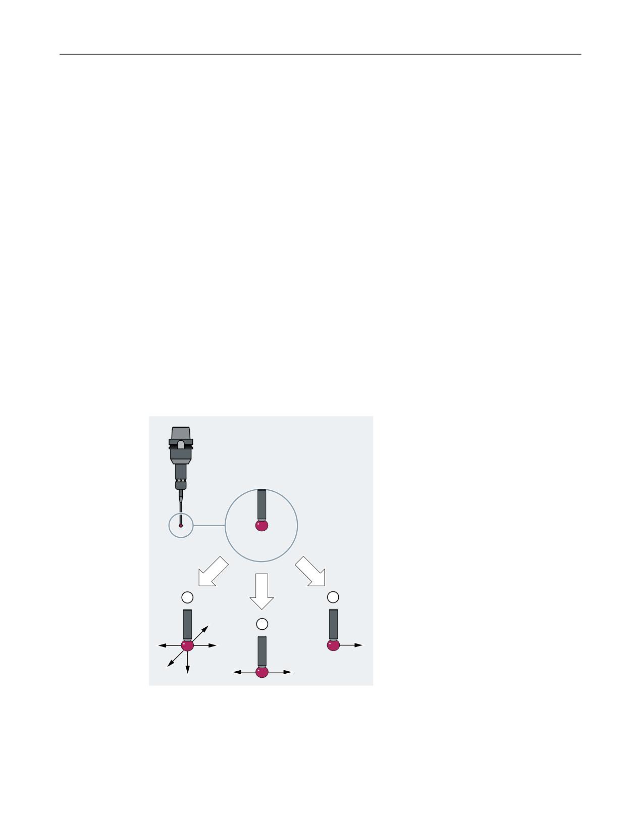
Probe types
A distinction is made between the following probe types according to the number of possible
deflection directions:
● Multidirectional probe (3D)
Suitable for all tool and workpiece measurements on turning and milling machines.
● Bidirectional probe
Suitable for workpiece measurement on milling machines and machining centers (treated
like monodirectional probes) and turning machines.
Not suitable for tool measurement.
● Monodirectional probe
Suitable for workpiece measurement on milling machines and machining centers with minor
restrictions.
Not suitable for workpiece measurement on turning machines.
Not suitable for tool measurement.
① Multidirectional probe (3D)
② Bidirectional probe
③ Monodirectional probe
Extended Functions
Function Manual, 12/2018, A5E40874029B AB
525

M5: Measurement
9.3 Measurement level 1: Channel-specific measurement
Requirements for the use of monodirectional probes
The following requirements apply for the use of monodirectional probes in milling machines
and machining centers:
● The spindle must be capable of being positioned with the SPOS function.
● The probe switching signal must be transmittable through 360°.
The probe must also be mechanically aligned in the spindle to permit measurements in the
following directions at the 0° spindle position:
Plane
Measuring direction
G17 (X-Y)
Positive X direction
G18 (Z-X)
Positive Z direction
G19 (Y-Z)
Positive Y direction
Note
The complete measurement takes longer because the spindle needs to be positioned several
times with SPOS during the measuring cycle.
9.3
Measurement level 1: Channel-specific measurement
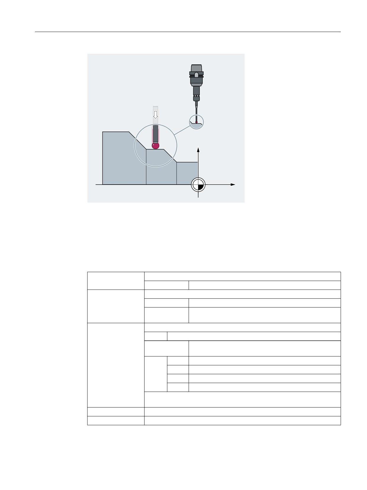
In the case of channel-specific measuring, the measuring process for an NC channel is always
activated from the part program running in the relevant channel. One trigger event (positive or
negative edge of the probe) and one measuring mode with deletion of distance-to-go (MEAS)
or without deletion of distance-to-go (MEAW) are programmed in a measuring block. All the
axes programmed in the measuring block then take part in the measuring process.
As soon as a measuring block becomes active, the probe is moved to the workpiece. On the
probe's switching edge, the positions for all axes programmed in the measuring block are
measured and written to the appropriate memory cell for each axis.
The results of measurements can be read in the part program or with synchronized actions in
both the machine and the workpiece coordinate systems.
Extended Functions
526
Function Manual, 12/2018, A5E40874029B AB
M5: Measurement
9.3 Measurement level 1: Channel-specific measurement
;
=
Syntax
MEAS=<TE> G... X... Y... Z...
MEAW=<TE> G... X... Y... Z...
Meaning
MEAS:
Measurement with delete distance-to-go
Effectiveness:
Non-modal
MEAW:
Measurement without delete distance-to-go
Effectiveness:
Non-modal
Application:
For measuring tasks in which the programmed position is to
be approached in every case.
<TE>:
Trigger event to initiate measurement
Type:
INT
Range of val-
-2, -1, 1, 2
ues:
Value:
(+)1
Positive edge of probe 1 (on measuring input 1)
-1
Negative edge of probe 1 (on measuring input 1)
(+)2
Positive edge of probe 2 (on measuring input 2)
-2
Negative edge of probe 2 (on measuring input 2)
Note:
There is a maximum of 2 probes (dependent on configuration level).
G...:
Type of interpolation, e.g. G0, G1, G2 or G3
X... Y... Z...:
End points in Cartesian coordinates
Extended Functions
Function Manual, 12/2018, A5E40874029B AB
527

M5: Measurement
9.3 Measurement level 1: Channel-specific measurement
Note
MEAS and MEAW are non-modal, and programmed together with motion operations. The
feedrate and interpolation type (G0, G1, etc.) as well as the number of axes must be adapted
for the respective measuring task.
Example
Program code
Comment
N10 MEAS=1 G1 F1000 X100 Y730 Z40
; Measuring block with probe at first
measuring input and linear interpola-
tion. A preprocessing stop is automati-
cally generated.
Further information
Query status
If an evaluation is required in the program, whether a probe has been deflected or has switched,
the status can be queried through the following system variables:
System variable
Meaning
Data type
Value
$A_PROBE[<n>]
Probe state
INT
0
Probe not deflected.
1
Probe deflected.
$AC_MEA[<n>]
Switching status of the probe
INT
0
Probe has not switch-
ed
$AC_MEA[<n>] is automati-
cally reset at the beginning of
1
Probe has switched.
a measurement.
<n> = number of the probe
Reading measured values
For channel-specific measuring, the positions of all traversing path and positioning axes of the
block are acquired (maximum number of axes depends on the control configuration). For
MEAS, the motion is braked in a defined fashion after the probe has been triggered.
Note
If a geometry axis is programmed in a measuring block, the measured values are stored for
all current geometry axes.
If an axis participating in a transformation is programmed in a measuring block, the measured
values are stored for all axes participating in this transformation.
Extended Functions
528
Function Manual, 12/2018, A5E40874029B AB

M5: Measurement
9.4 Measurement level 2: Axis-specific measurement (option)
Reading measurement results
The measured values of the axes acquired by probes can be read through the following system
variables in the part program and in synchronized actions.
System variable
Meaning
$AA_MM[<Axis>]
Probe measured value in the machine coordinate system
$AA_MW[<Axis>]
Probe measured value in the workpiece coordinate system
9.4
Measurement level 2: Axis-specific measurement (option)
With axis-specific measuring, activation can take place in the part program or in synchronized
actions. If two measuring systems are available for the axis, both can be used for the
measurement.
The following measuring methods are available:
● Measurement with delete distance-to-go (MEASA)
● Measurement without delete distance-to-go (MEAWA)
● Continuous measurement without delete distance-to-go (MEAC)
With MEASA or MEAWA for the programmed axis, up to four measured values are acquired
for each measurement and are then saved in system variables in accordance with the trigger
event.
With continuous measurement with MEAC, the measurement results are stored in FIFO
variables.
Syntax
MEASA[<Axis>]=(<Mode>,<TE1>,...,<TE4>)
MEAWA[<Axis>]=(<Mode>,<TE1>,...,<TE4>)
MEAC[<Axis>]=(<Mode>,<MeasMem>,<TE1>,...,<TE4>)
Note
MEASA and MEAWA are non-modal; and can be programmed together in one block. If, on
the contrary, MEASA/MEAWA are programmed with MEAS/MEAW in one block, there is an
error message.
Meaning
MEASA:
Axis-specific measurement with deletion of distance-to-go
Effectiveness:
Non-modal
MEAWA:
Axes-specific measurement without delete distance-to-go
Effectiveness:
Non-modal
MEAC:
Axis-specific, continuous measurement without delete distance-to-go
Effectiveness:
Non-modal
Extended Functions
Function Manual, 12/2018, A5E40874029B AB
529

M5: Measurement
9.4 Measurement level 2: Axis-specific measurement (option)
<Axis>:
Name of channel axis used for measurement
<Mode>:
Two-digit (xx) number indicating the operating mode (measuring mode and meas-
uring system)
Units decade: Measuring mode
Specifies whether the trigger events are to be activated in chronological or pro-
grammed order.
x0
Cancel measuring job.
x1
Up to 4 different trigger events can be activated simultaneously.
x2
Up to 4 trigger events that can be activated successively.
x3
Up to 4 different trigger events can be activated in succession, but there
is no monitoring of trigger event 1 at the start (alarms 21700/21703 are
suppressed).
Note:
MEAC does not support this mode.
Tens decade: Measuring system
Specifies the measuring system with which measuring is to be performed.
0x (or no specification)
Active measuring system
1x
Measuring system 1
2x
Measuring system 2
3x
Both measuring systems
<TE>:
Trigger event to initiate measurement
Type:
INT
Range of val-
-2, -1, 1, 2
ues:
(+)1
Positive edge of probe 1
-1
Negative edge of probe 1
(+)2
Positive edge of probe 2
-2
Negative edge of probe 2
Note:
If the measuring process is performed with two measuring systems, a maximum
of two trigger events can be programmed (positive or negative edge). The meas-
ured values of both measuring systems are acquired for both the trigger events.
<MeasMem>:
Number of FIFO (circular buffer)
Examples
Example 1: Axis-specific measurement with delete distance-to-go in mode 1 (evaluation in
chronological sequence)
a) Measuring with one measuring system
Program code
Comment
N100 MEASA[X]=(1,1,-1) G01 X100 F100
; Measuring in mode 1 with active measur-
ing system. Wait for measuring signal
with positive/negative edge from probe 1
for travel path to X=100.
Extended Functions
530
Function Manual, 12/2018, A5E40874029B AB

M5: Measurement
9.4 Measurement level 2: Axis-specific measurement (option)
Program code
Comment
N110 IF $AC_MEA[1]==FALSE GOTOF END
; Check that the measurement was success-
ful.
N120 R10=$AA_MM1[X]
; Save measured value acquired at the
first programmed trigger event (positive
edge).
N130 R11=$AA_MM2[X]
; Save measured value acquired at the sec-
ond programmed trigger event (negative
edge).
N140 END:
b) Measuring with two measuring systems
Program code
Comment
N200 MEASA[X]=(31,1,-1) G01 X100 F100
; Measuring in mode 1 with both measuring
systems. Wait for measuring signal with
positive/negative edge from probe 1 for
travel path to X=100.
N210 IF $AC_MEA[1]==FALSE GOTOF END
; Check that the measurement was success-
ful.
N220 R10=$AA_MM1[X]
; Save measured value of measuring system
1 at positive edge.
N230 R11=$AA_MM2[X]
; Save measured value of measuring system
2 at positive edge.
N240 R12=$AA_MM3[X]
; Save measured value of measuring system
1 at negative edge.
N250 R13=$AA_MM4[X]
; Save measured value of measuring system
2 at negative edge.
N260 END:
Example 2: Axis-specific measurement with delete distance-to-go in mode 2 (evaluation in
programmed sequence)
Program code
Comment
N100 MEASA[X]=(2,1,-1,2,-2) G01 X100 F100
; Measuring in mode 2 with active measur-
ing system. Wait for measuring signal in
the sequence positive edge probe 1, nega-
tive edge probe 1, positive edge probe 2,
negative edge probe 2 while traversing
path to X=100.
N110 IF $AC_MEA[1]==FALSE GOTOF PROBE2
; Check that the measurement with probe 1
is successful.
N120 R10=$AA_MM1[X]
; Save measured value acquired at the
first programmed trigger event (positive
edge of probe 1).
Extended Functions
Function Manual, 12/2018, A5E40874029B AB
531

M5: Measurement
9.4 Measurement level 2: Axis-specific measurement (option)
Program code
Comment
N130 R11=$AA_MM2[X]
; Save measured value acquired at the sec-
ond programmed trigger event (positive
edge of probe 1).
N140, PROBE2:
N150 IF $AC_MEA[2]==FALSE GOTOF END
; Check that the measurement with probe 2
is successful.
N160 R12=$AA_MM3[X]
; Save measured value acquired at the
third programmed trigger event (positive
edge of probe 2).
N170 R13=$AA_MM4[X]
; Save measured value acquired at the
fourth programmed trigger event (positive
edge of probe 2).
N180 END:
Example 3: Axis-specific, continuous measurement in mode 1 (evaluation in chronological
sequence)
a) Measurement of up to 100 measured values
Program code
Comment
N110 DEF REAL MEASVALUE[100]
N120 DEF INT loop=0
N130 MEAC[X]=(1,1,-1) G01 X1000 F100
; Measuring in mode 1 with active measur-
ing system, save measured values under
$AC_FIFO1, wait for measuring system with
negative edge from probe 1 on the travel
path to X=1000.
N135 STOPRE
N140 MEAC[X]=(0)
; Terminate measurement when axis posi-
tion is reached.
N150 R1=$AC_FIFO1[4]
; Save number of accumulated measured val-
ues in parameter R1.
N160 FOR loop=0 TO R1-1
N170 MEASURED VALUE[loop]=$AC_FIFO1[0]
; Read-out measured values from $AC_FIFO1
and save.
N180 ENDFOR
b) Measurement with delete distance-to-go after 10 measured values
Program code
Comment
N10 WHEN $AC_FIFO1[4]>=10 DO MEAC[x]=(0) DELDTG(x)
; Delete distance-to-go.
N20 MEAC[x]=(1,1,1,-1) G01 X100 F500
N30 MEAC [X]=(0)
N40 R1 = $AC_FIFO1[4]
; Number of measured values.
Extended Functions
532
Function Manual, 12/2018, A5E40874029B AB
M5: Measurement
9.4 Measurement level 2: Axis-specific measurement (option)
c) Measurement of a positive/negative tooth flank with 2 probes
Program code
Comment
N110 DEF REAL MEASVALUE[16]
N120 DEF INT loop=0
N130 MEAC[X]=(1,1,-1,2) G01 X100 F100
; Measurement in mode 1 with active meas-
uring system, save measured values under
$AC_FIFO1, wait for measuring signal in
the sequence negative edge of probe 1,
positive edge of probe 2 while traversing
the travel path to X=100.
N140 STOPRE
; Preprocessing stop.
N150 MEAC[X]=(0)
; Terminate measurement when axis posi-
tion is reached.
N160 R1=$AC_FIFO1[4]
; Save number of accumulated measured val-
ues in parameter R1.
N170 FOR loop=0 TO R1-1
N180 MEASURED VALUE[loop]=$AC_FIFO1[0]
; Read-out measured values from $AC_FIFO1
and save.
N190 ENDFOR
Further information
Measuring job
A measuring job can be programmed in the part program or from a synchronized action. Please
note that only one measuring job can be active at any given time for each axis.
Note
The feed must be adjusted to suit the particular measuring task
In the case of MEASA and MEAWA, the correctness of results can be only guaranteed for
feedrates at which no more than one trigger event of the same type and no more than 4 trigger
events of different types occur in each position control cycle.
In the case of continuous measurement with MEAC, the ratio between interpolator cycle and
the position control cycle must not exceed 1:8.
Trigger event
A trigger event comprises the number of the probe and the trigger criterion (positive or negative
edge) of the measuring signal.
Up to 4 trigger events of the addressed probe can be processed for each measurement; in
other words, up to two probes each with two measuring signal edges. The processing
sequence and the maximum number of trigger events depend on the selected mode.
Extended Functions
Function Manual, 12/2018, A5E40874029B AB
533
M5: Measurement
9.4 Measurement level 2: Axis-specific measurement (option)
If the measuring operation is performed with two measuring systems, a maximum of two trigger
events can be programmed (positive or negative edge). The measured values of both probes
are acquired for both of the trigger events.
Note
With the use of PROFIBUS telegram 391 (default setting for PROFIBUS communication) only
one measured value is possible for each trigger event and position control cycle.
For MEAC, the number of measured values per trigger event can be increased by using
PROFIBUS telegram 395 (Page 529) to a total of 8 measured values for a positive edge and
8 measured values for a negative edge for each trigger event and position control cycle:
● One probe: 8 measured values for a positive and 8 for a negative edge
● Two probes: 4 measured values for a positive and 4 for a negative edge for each probe
This means that higher feed rates or higher speeds can be reached by using PROFIBUS
telegram 395.
Operating mode
The first digit (tens decade) of the operating mode selects the required measuring system. If
only one measuring system is installed, but a second is programmed, the installed system is
automatically selected.
The second digit (units decade) selects the desired measuring mode. The measuring process
is thus adapted to the options supported by the relevant control:
● Mode 1
Trigger events are evaluated in the chronological sequence in which they occur. When this
mode is selected, only one trigger event can be programmed for six-axis modules. If more
than one trigger event is specified, the mode selection is switched automatically to mode
2 (without message).
● Mode 2
Trigger events are evaluated in the programmed sequence.
● Mode 3
Trigger events are evaluated in the programmed sequence but there is no monitoring of
trigger event 1 at the start.
Measurement with and without delete distance-to-go
When command MEASA is programmed, the distance-to-go is not deleted until all required
measured values have been acquired.
MEAWA is used for special measuring tasks in which a programmed position always has to
be approached.
Note
MEASA cannot be programmed in synchronized actions. As an alternative, MEAWA plus
delete distance-to-go can be programmed as a synchronized action.
If the measuring job with MEAWA is started from synchronized actions, the measured values
will only be available in the machine coordinate system.
Extended Functions
534
Function Manual, 12/2018, A5E40874029B AB

M5: Measurement
9.4 Measurement level 2: Axis-specific measurement (option)
Geometry axes/transformations
If axial measurement is to be started for a geometry axis, the same measuring job must be
programmed explicitly for all remaining geometry axes. The same applies to axes involved in
a transformation.
Examples:
N10 MEASA[Z]=(1,1) MEASA[Y]=(1,1) MEASA[X]=(1,1) G0 Z100
or
N10 MEASA[Z]=(1,1) POS[Z]=100
Query status
If an evaluation is required in the program, whether a probe has been deflected or has switched,
the status can be queried through the following system variables:
System variable
Meaning
Data type
Value
$A_PROBE[<n>]
Probe state
INT
0
Probe not deflected.
1
Probe deflected.
$AC_MEA[<n>]
Switching status of the probe
INT
0
Probe has not switch-
ed
$AC_MEA[<n>] is automati-
cally reset at the beginning of
1
Probe has switched
a measurement.
(all trigger events pro-
grammed in the
measuring block
have taken place).
<n> = number of the probe
Note
If measurement is started from synchronized actions, $AC_MEA is no longer updated. In this
case, the NC/PLC interface signal DB31, … DBX62.3 or the equivalent variable
$AA_MEAACT[<Axis>] must be queried.
$AA_MEAACT==1: Measurement active
$AA_MEAACT==0: Measurement not active
Probe limitation
In the NC program or synchronized action, the probe limiting status can be read using system
variable $A_PROBE_LIMITED when using PROFIBUS telegram 395:
$A_PROBE_LIMITED[<n>] == 0: Probe limitation inactive/reset
$A_PROBE_LIMITED[<n>] == 1: Probe limitation active
<n> = probe number
Extended Functions
Function Manual, 12/2018, A5E40874029B AB
535

M5: Measurement
9.4 Measurement level 2: Axis-specific measurement (option)
Measurement results for MEASA / MEAWA
The values measured by probes can be read through the following system variables in the part
program and in synchronized actions.
System variable
Meaning
$AA_MM1[<Axis>]
Probe measured value for trigger event 1 in the machine coordinate system
$AA_MM4[<Axis>]
Probe measured value for trigger event 4 in the machine coordinate system
$AA_MW1[<Axis>]
Probe measured value for trigger event 1 in the workpiece coordinate system
$AA_MW4[<Axis>]
Probe measured value for trigger event 4 in the workpiece coordinate system
<Axis> = measuring axis
If a measuring job is executed by two measuring systems, each of the two possible trigger
events is acquired from both measuring systems. The assignment of system variables is then
as follows:
$AA_MM1[<Axis>]
or
$AA_MW1[<Axis>]
Measured value from measuring sys-
tem 1 on trigger event 1
$AA_MM2[<Axis>]
or
$AA_MW2[<Axis>]
Measured value from measuring sys-
tem 2 on trigger event 1
$AA_MM3[<Axis>]
or
$AA_MW3[<Axis>]
Measured value from measuring sys-
tem 1 on trigger event 2
$AA_MM4[<Axis>]
or
$AA_MW4[<Axis>]
Measured value from measuring sys-
tem 2 on trigger event 2
Continuous measurement (MEAC)
The measured values for MEAC are available in the machine coordinate system and stored
in the programmed FIFO[<n>] memory (circular buffer). If two probes are configured for the
measurement, the measured values of the second probe are stored separately in the FIFO[<n>
+1] memory configured specifically for this purpose (defined in machine data).
The FIFO memory is a circular buffer in which measured values are written to $AC_FIFO
variables according to the circular principle.
Note
FIFO contents can be read only once from the circular buffer. If this measured data is to be
used several times, it must be buffered in the user data.
If the number of measured values for the FIFO memory exceeds the maximum value defined
in machine data, the measurement is automatically terminated.
An endless measuring process can be implemented by reading out measured values cyclically.
In this case, data must be read out at least with the same frequency as new measured values
are input.
References:
Function Manual Synchronized Actions; "Detailed description" Chapter > "Parameters
($AC_FIFO)"
Extended Functions
536
Function Manual, 12/2018, A5E40874029B AB
M5: Measurement
9.4 Measurement level 2: Axis-specific measurement (option)
Protection against programming errors
The following programming errors are detected and indicated as errors:
● MEASA/MEAWA programmed with MEAS/MEAW in the same block
Example:
N01 MEAS=1 MEASA[X]=(1,1) G01 F100 POS[X]=100
● MEASA/MEAWA with number of parameters <2 or >5
Example:
N01 MEAWA[X]=(1) G01 F100 POS[X]=100
● MEASA/MEAWA with trigger event not equal to 1/ -1/ 2/ -2
Example:
N01 MEASA[B]=(1,1,3) B100
● MEASA/MEAWA with invalid mode
Example:
N01 MEAWA[B]=(4,1) B100
● MEASA/MEAWA with trigger event programmed twice
Example:
N01 MEASA[B]=(1,1,-1,2,-1) B100
● MEASA/MEAWA and missing geometry axis
Example:
N01 MEASA[X]=(1,1) MEASA[Y]=(1,1) G01 X50 Y50 Z50 F100; GEO axis X/
Y/Z
● Inconsistent measuring job with geometry axes
Example:
N01 MEASA[X]=(1,1) MEASA[Y]=(1,1) MEASA[Z]=(1,1,2) G01 X50 Y50 Z50
F100
Telegram selection
By default, the axis-specific measurement is implemented with PROFIBUS telegram 391.
PROFIBUS telegram 395 is used for measuring with several measured values per trigger event
and the position controller cycle.
The telegram selection is made from the STEP 7 HW Config in the "DP Slave Properties" >
"Configuration" dialog.
The following settings are also required:
● Drive parameters:
CU: p0922 = 395; setting for the telegram selection
CU: p0684 = 16; setting of the measuring procedure
CU: p0680; configuration of the central probe terminal
● PROFIBUS connection:
MD13211 $MN_MEAS_CENTRAL_SOURCE = 2 (telegram integration without handshake)
Extended Functions
Function Manual, 12/2018, A5E40874029B AB
537
M5: Measurement
9.5 Workpiece and tool measurement
9.5
Workpiece and tool measurement
9.5.1
Fundamentals
9.5.1.1
Introduction
Preset actual value is performed via an HMI operator action or via measuring cycles. The
calculated frame should be written to SETFRAME system frame. The set position of an axis
in the WCS can be altered during preset actual value.
The term scratching refers to both the workpiece and tool measurement.
In workpiece measurement, a probe is moved to the clamped workpiece in the same way as
a tool and the measured values are acquired. Because of the broad selection of different
measurement types, all the measuring tasks to be resolved in a milling or turning machine can
be managed without a problem. For example, the position of the workpiece can be measured
in relation to an edge, a corner or a hole. To determine the zero position of the workpiece or
a hole, set positions can be added to the measured positions in the WCS. The resulting offsets
can be entered in a selected frame.
In the tool measurement, the length or radius of a tool can be measured using a measured
reference part.
The measurements can be performed via an HMI operator action or via measuring cycles.
The calculation is performed in the NC when a PI service is activated by means of an HMI
operator action or via an NC command from the measuring cycles. A tool and a plane can be
selected as a basis for the calculation. The calculated frame is entered in the result frame.
Communication with the NC takes place via predefined system variables. The input variables
must be written by the HMI or the cycles. The output variables contain the calculated results.
9.5.1.2
Input variables
Validity bits of the input variables
Each input variable implicitly sets the corresponding validity bit in $AC_MEAS_VALID system
variable when writing. If the validity bits are not reset, the variable values remain valid for the
next calculation. For this reason, the validity bits of all input variables should be declared as
invalid before each measurement by setting $AC_MEAS_VALID to 0:
$AC_MEAS_VALID = 0
Note
A channel reset or end of program reset does not reset the validity bits.
Extended Functions
538
Function Manual, 12/2018, A5E40874029B AB

M5: Measurement
9.5 Workpiece and tool measurement
Bit
System variable
Meaning
0
$AA_MEAS_POINT1[<Axis>]
1st measuring point for all channel axes
1
$AA_MEAS_POINT2[<Axis>]
2nd measuring point for all channel axes
2
$AA_MEAS_POINT3[<Axis>]
3rd measuring point for all channel axes
3
$AA_MEAS_POINT4[<Axis>]
4th measuring point for all channel axes
4
$AA_MEAS_SETPOINT[<Axis>]
Set position of an axis
5
$AC_MEAS_WP_SETANGLE
Set angle for the workpiece position angle; -90 <
α < 180
6
$AC_MEAS_CORNER_SETANGLE
Set angle of intersection of the workpiece corner;
0 < φ < 180
7
$AC_MEAS_T_NUMBER
Tool selection
7
$AC_MEAS_D_NUMBER
Cutting edge selection
9
$AC_MEAS_DIR_APPROACH
Direction of approach to the workpiece
10
$AC_MEAS_ACT_PLANE
Specification of the working plane and infeed di-
rection
11
$AC_MEAS_FRAME_SELECT
Frame selection for the workpiece measurement
12
$AC_MEAS_TYPE
Measurement type selection
13
$AC_MEAS_FINE_TRANS
Fine offset correction
14
$AA_MEAS_SETANGLE[<Axis>]
Set angle of an axis
15
$AA_MEAS_SCALEUNIT
Unit of measurement for input and output values
16
$AA_MEAS_TOOL_MASK
Tool position taking the tool lengths into account
17
$AA_MEAS_P1_COORD
Coordinate system of the 1st measuring point
18
$AA_MEAS_P2_COORD
Coordinate system of the 2nd measuring point
19
$AA_MEAS_P3_COORD
Coordinate system of the 3rd measuring point
20
$AA_MEAS_P4_COORD
Coordinate system of the 4th measuring point
21
$AA_MEAS_SET_COORD
Coordinate system of the set position
22
$AA_MEAS_CHSFR
Frame selection for system frames
23
$AA_MEAS_NCBFR
Frame selection for global basic frames
24
$AA_MEAS_CHBFR
Frame selection for channel basic frames
25
$AA_MEAS_UIFR
Frame selection for settable frames
26
$AA_MEAS_PFRAME
Frame selection for programmable frames
27
$AC_MEAS_INPUT[<n>]
Measuring input parameters
28
$AC_MEAS_GFR
Frame selection for grinding frames
29
$AC_MEAS_ORIWKS
Transformation behavior of the measuring inter-
face
Note
All axis actual values of the appropriate measuring point are invalidated by:
$AC_MEAS_LATCH = 0
Extended Functions
Function Manual, 12/2018, A5E40874029B AB
539

M5: Measurement
9.5 Workpiece and tool measurement
Measuring points
A maximum of four measuring points are available for all channel axes for the measurements:
System variable
Meaning
Data type
$AA_MEAS_POINT1[<Axis>]
1st measuring point for all chan-
REAL
nel axes
$AA_MEAS_POINT2[<Axis>]
2nd measuring point for all chan-
REAL
nel axes
$AA_MEAS_POINT3[<Axis>]
3rd measuring point for all chan-
REAL
nel axes
$AA_MEAS_POINT4[<Axis>]
4th measuring point for all chan-
REAL
nel axes
The measured points are normally available as actual values in the WCS. A measuring point
is marked as valid as soon as an axis value has been written from it. Each individual measuring
point can be written or picked up directly.
Some measurement types also support measuring points lying in a different coordinate system
(BCS, MCS). The entry in which coordinate system of the corresponding measuring point was
measured, can be performed via the following system variables:
System variable
Meaning
Data type
Value
$AA_MEAS_P1_COORD
Coordinate system of the 1st meas-
INT
0: WCS (default)
uring point
1: BCS
$AA_MEAS_P2_COORD
Coordinate system of the 2nd meas-
INT
2: MCS
uring point
3: SZS
$AA_MEAS_P3_COORD
Coordinate system of the 3rd meas-
INT
4: WCS_REL
uring point
5: SZS_REL
$AA_MEAS_P4_COORD
Coordinate system of the 4th meas-
INT
uring point
$AA_MEAS_SET_CO-
Coordinate system of the set position
INT
ORD
Picking up measuring points
The measuring points can be written with the current axis actual values. The positions are
picked up with reference to the selected coordinate system. The positions are picked up in the
WCS if no coordinate system is specified. The picked up measuring points are saved in
$AA_MEAS_POINT1[<Axis>] ... $AA_MEAS_POINT4[<Axis>].
Extended Functions
540
Function Manual, 12/2018, A5E40874029B AB

M5: Measurement
9.5 Workpiece and tool measurement
Picking up a measuring point of all axes
The pick up of all current axis actual values for one measuring point is specified via the
$AC_MEAS_LATCH[0 ... 3] system variable:
System variable
Meaning
Data type
Value
$AA_MEAS_LATCH[0]
Pick up 1st measuring point of all ax-
INT
0: Do not accept
es
axis actual values
for the measuring
$AA_MEAS_LATCH[1]
Pick up 2nd measuring point of all ax-
INT
point
es
1: Accept axis ac-
$AA_MEAS_LATCH[2]
Pick up 3rd measuring point of all ax-
INT
tual values for the
es
measuring point
$AA_MEAS_LATCH[3]
Pick up 4th measuring point of all ax-
INT
es
Picking up the measuring point of one axis
The pick up of individual axis actual values for one measuring point is specified via the
$AA_MEAS_P1_VALID[<Axis>] ... $AA_MEAS_P4_VALID[<Axis>] system variables:
System variable
Meaning
Data type
Value
$AA_MEAS_P1_VAL-
Pick up 1st measuring point of an axis
INT
0: Do not accept
ID[<Axis>]
axis actual value
for the measuring
$AA_MEAS_P2_VAL-
Pick up 2nd measuring point of an
INT
point
ID[<Axis>]
axis
1: Accept axis ac-
$AA_MEAS_P3_VAL-
Pick up 3rd measuring point of an axis
INT
tual value for the
ID[<Axis>]
measuring point
$AA_MEAS_P4_VAL-
Pick up 4th measuring point of an axis
INT
ID[<Axis>]
Setpoints
The resulting frame is calculated so that the measurement complies with the setpoints specified
by the user.
System variable
Meaning
Data type
Value
$AA_MEAS_SETPOINT[<Axis>]
Set position of an axis
REAL
$AA_MEAS_SETANGLE[<Axis>]
Set angle of an axis
REAL
$AA_MEAS_SP_VALID[<Axis>]
Set position of the axis invalid/valid
INT
0
Set po-
sition of
the axis
is invalid
1
Set po-
sition of
the axis
is valid
$AC_MEAS_WP_SETANGLE
Set angle for the workpiece posi-
REAL
-90 < α < 180
tion
$AC_MEAS_CORNER_SETAN-
Set angle of intersection of the
REAL
0 < φ < 180
GLE
workpiece corner
Extended Functions
Function Manual, 12/2018, A5E40874029B AB
541
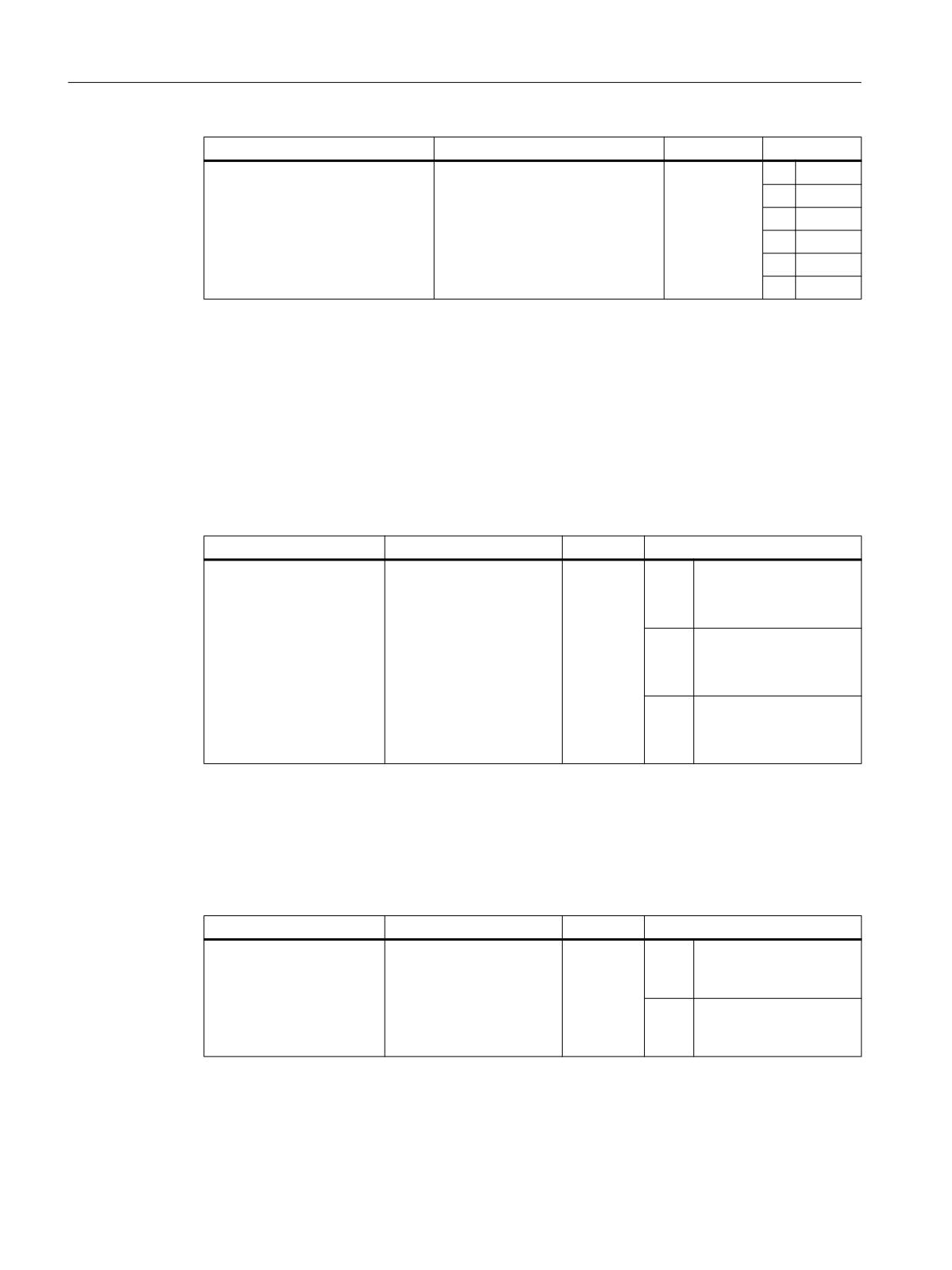
M5: Measurement
9.5 Workpiece and tool measurement
System variable
Meaning
Data type
Value
$AC_MEAS_DIR_APPROACH *)
Direction of approach to the work-
INT
0
+ X
piece
1
- X
2
+ Y
3
- Y
4
+ Z
5
- Z
*) The direction of approach is required only for the edge, groove, web and tool measurement.
The following measuring points are irrelevant and not evaluated:
● 2nd measuring point when entering the set angle for the workpiece position.
● 4th measuring point when entering the set angle of intersection
Plane setting
The specification of the working plane to define the tool orientation is performed via the
$AC_MEAS_ACT_PLANE system variable:
System variable
Meaning
Data type
Value
$AC_MEAS_ACT_PLANE
Specification of the work-
INT
0
● G17 - working plane
ing plane and infeed direc-
X/Y
tion
● Infeed direction Z
1
● G18 - working plane
Z/X
● Infeed direction Y
2
● G17 - working plane
Y/Z
● Infeed direction X
If no plane is specified, then the active plane is used for the calculation.
Translational offsets
When measuring workpieces, translational offsets can be entered in the fine offset component
of the selected frame. The $AC_MEAS_FINE_TRANS system variable is used for this purpose:
System variable
Meaning
Data type
Value
$AC_MEAS_FINE_TRAN
Fine offset correction
INT
0
Translational compen-
S
sation is entered in the
course offset.
1
Translational compen-
sation is entered in the
fine offset.
If the $AC_MEAS_FINE_TRANS variable is not written, the compensation value is entered in
the coarse offset and transformed in the time frame. There can also be a fine component in
the translation by virtue of the transformation.
Extended Functions
542
Function Manual, 12/2018, A5E40874029B AB

M5: Measurement
9.5 Workpiece and tool measurement
Irrespective of $AC_MEAS_FINE_TRANS, the compensation is always entered in the coarse
offset when:
MD18600 $MN_MM_FRAME_FINE_TRANS = 0
Frame selection during the workpiece measurement
When a workpiece is measured, the calculated frame is entered in the specified frame. The
frame selection is performed via the $AC_MEAS_FRAME_SELECT system variable:
System variable
Meaning
Data type
$AC_MEAS_FRAME_SELECT
Frame selection during the workpiece measure-
INT
ment
The $AC_MEAS_FRAME_SELECT system variable can assume the following values:
Value
Frame
Meaning
0
$P_SETFRAME
Active system frame
1
$P_PARTFRAME
Active system frame
2
$P_EXTFRAME
Active system frame
10 ... 25
$P_CHBFRAME[0 ... 15]
Active channel-specific basic frames
50 ... 65
$P_NCBFRAME[0 ... 15]
Active NCU-global basic frames
100 ... 199
$P_IFRAME
The calculation is performed with the active setta-
ble frame if the corresponding frame is selected.
If the selected frame is not active, the correspond-
ing data management frame is included in the cal-
culation.
500
$P_TOOLFRAME
Active system frame
501
$P_WPFRAME
Active system frame
502
$P_TRAFRAME
Active system frame
503
$P_PFRAME
Active current programmable frame
504
$P_CYCFRAME
Active system frame
505
$P_RELFRAME (WCS)
Active system frame
506
$P_RELFRAME (SZS)
Active system frame
1010 ... 1025
$P_CHBFRAME[0 ... 15]
Active channel-specific basic frames with active
G500
1050 ... 1065
$P_NCBFRAME[0 ... 15]
Active NCU-global basic frames with active G500
2000
$P_SETFR
System frame in the data management
2001
$P_PARTFR
System frame in the data management
2002
$P_EXTFR
System frame in the data management
2010 ... 2025
$P_CHBFR[0 ... 15]
Channel-specific basic frames in the data man-
agement
2050 ... 2065
$P_NCBFR[0 ... 15]
NCU-global basic frames in the data management
2100 ... 2199
$P_UIFR[0 ... 99]
Settable frames in the data management
2500
$P_TOOLFR
System frame in the data management
2501
$P_WPFR
System frame in the data management
2502
$P_TRAFR
System frame in the data management
2504
$P_CYCFR
System frame in the data management
Extended Functions
Function Manual, 12/2018, A5E40874029B AB
543

M5: Measurement
9.5 Workpiece and tool measurement
Value
Frame
Meaning
2505
$P_RELFR (WCS)
System frame in the data management
2506
$P_RELFR (SZS)
System frame in the data management
3010 ... 3025
$P_CHBFR[0 ... 15]
Channel-specific basic frames with active G500 in
the data management
3050 ... 3065
$P_NCBFR[0 ... 15]
NCU-global basic frames with active G500 in the
data management
The MEASURE( ) function calculates frame $AC_MEAS_FRAME according to the specified
frame.
For the values from 0 to 1065, the calculation is performed using the active frame.
From 2000 to 3065, the calculation is performed with reference to the selected frame in the
data management. The frame selection in the data management is not supported for
measurement types 14 and 15. A frame does not have to be active in order to select it in the
data management. In this case, the calculation is performed as if the frame were active in the
chain.
The measuring point is transformed in the selected system and the selected frame is
determined using the entire frame including the selected frame. Preset actual value is active
only after compensation and activation of the frame.
For the values with active G500 (1010 ... 1025, 1050 ... 1065, 3010 ... 3025, 3050 ... 3065),
the target frame is calculated so that G500 must also be active after this frame is selected in
order to reach the set position.
Conversion into another coordinate system
If a position is to be converted to a position in another coordinate system, the following system
variables can be used to specify the composition of the desired frame chain:
System variable
Meaning
Data type
Value
$AC_MEAS_CHSFR
Frame selection for system frames
INT
Bit mask correspond-
ing to MD28082
$MC_MM_
SYS-
TEM_FRAME_MASK
$AC_MEAS_NCBFR
Frame selection for global basic frames
INT
Bit mask (0 ... FFFF)
$AC_MEAS_CHBFR
Frame selection for channel basic
INT
Bit mask (0 ... FFFF)
frames
$AC_MEAS_UIFR
Frame selection for settable frames
INT
0 ... 99
$AC_MEAS_PFRAME
Frame selection for programmable
INT
0
Is included in
frames
the calculation.
1
Is not included
in the calcula-
tion.
The data management frames are read and a new frame is set up for the corresponding values
in the variables.
Extended Functions
544
Function Manual, 12/2018, A5E40874029B AB
M5: Measurement
9.5 Workpiece and tool measurement
If the system variables are not set, the active frames are retained.
Note
Values should only be written to those system variables whose data management frames are
also to be included in the new frame chain. In the case of the basic frames, only all of the
frames can be exchanged, and not just a particular frame. Active changes via
$P_NCBFRMASK and $P_CHBFRMASK are ignored.
Measuring input parameters
The array system variable $AC_MEAS_INPUT[<n>] is used for the input of further parameters
that are used in the various measurement types
System variable
Meaning
Data type
Value
$AC_MEAS_INPUT[<n>]
Measuring input parame-
INT
<n> = 0 ... 9
ters
The control action of the measuring input parameters is described in the measuring methods.
Tool and cutting edge selection
The tool and cutting edge number of the active tool must correspond to the selected tool. When
T0 and D0 are selected, the active tool is included in the calculation. If no tool is active, the
tool selected by T and D is included in the calculation. However, no tool other than the selected
tool must be active.
System variable
Meaning
Data type
$AC_MEAS_T_NUMBER
Tool selection
INT
$AC_MEAS_D_NUMBER
Cutting edge selection
INT
Measurements with 3D probe
When measuring with the 3D probe, the radius of the tool is already compensated via the
measuring point, and therefore the radius does not have to be included when calculating the
various measurement operations. This property can be specified via the
$AC_MEAS_TOOL_MASK system variable.
System variable
Meaning
Data type
$AC_MEAS_TOOL_MASK
Tool position taking the tool lengths into account
INT
The $AC_MEAS_TOOL_SCREEN system variable can assume the following values:
Value
Meaning
0x0
All tool lengths are considered (default).
0x1
Tool radius is not included in the calculation.
0x2
Tool position in the X direction (G19).
0x4
Tool position in the Y direction (G18).
Extended Functions
Function Manual, 12/2018, A5E40874029B AB
545

M5: Measurement
9.5 Workpiece and tool measurement
Value
Meaning
0x8
Tool position in the Z direction (G17).
0x10
Tool length is not included in the calculation.
0x20
Length of the active tool is included in the coordinate transformation of a position.
0x40
Tool position in the X direction.
0x80
Tool position in the Y direction.
0x100
Tool position in the Z direction.
0x200
Tool length differences are included negatively.
Whether or not the radius of a milling tool is included in the calculation can be determined from
the tool position and approach direction. If the approach direction is not specified explicitly, it
is determined by the selected plane:
Working plane
Approach direction
G17
-Z
G18
-Y
G19
-X
9.5.1.3
Selecting the measurement type
The $AC_MEAS_TYPE system variable is used to select the measurement type.
System variable
Meaning
Data type
$AC_MEAS_TYPE
Measurement type selection
INT
The $AC_MEAS_TYPE system variable can assume the following values:
Value
Meaning
0
Default setting
1
Measurement type 1: Measurement of an X edge
2
Measurement type 2: Measurement of a Y edge
3
Measurement type 3: Measurement of a Z edge
4
Measurement type 4: Measurement of a C1 corner
5
Measurement type 5: Measurement of a C2 corner
6
Measurement type 6: Measurement of a C3 corner
7
Measurement type 7: Measurement of a C4 corner
8
Measurement type 8: Measurement of a hole
9
Measurement type 9: Measurement of a shaft
10 *)
Measurement type 10: Measurement of the tool length
11 *)
Measurement type 11: Measurement of the tool diameter
12
Measurement type 12: Measurement of a groove
13
Measurement type 13: Measurement of a web
14
Measurement type 14: Preset actual value for geometry and special axes
15
Measurement type 15: Preset actual value for special axes only
16
Measurement type 16: Measurement of an inclined edge
17
Measurement type 17: Measurement of an angle in an inclined plane
Extended Functions
546
Function Manual, 12/2018, A5E40874029B AB

M5: Measurement
9.5 Workpiece and tool measurement
Value
Meaning
18
Measurement type 18: Redefining the WCS on the inclined plane
19
Measurement type 19: 1-dimensional setpoint specification
20
Measurement type 20: 2-dimensional setpoint specification
21
Measurement type 21: 3-dimensional setpoint specification
22 *)
Measurement type 22: ShopTurn - Measurement of tool lengths with zoom-in function
23 *)
Measurement type 23: ShopTurn - Measurement of a tool length with a stored or actual
position
24
Measurement type 24: Coordinate transformation of a measuring point
25
Measurement type 25: Measurement of a rectangle
26
Measurement type 26: Backup of data management frames
27
Measurement type 27: Restoration of backed up data management data
28
Measurement type 28: Specification of an additive rotation for taper turning
*) Measurement types of the tool measurement
The individual measurement types are shown more precisely in Section "Types of workpiece
measurement (Page 553)" or "Measuring types of the tool measurement (Page 591)" and
explained in more detail using an appropriate programming example.
9.5.1.4
Activating the calculation
Activating via an HMI operator action
The calculation is activated by an HMI operator action with PI service _N_SETUDT. This Pl
service can accept one of the following parameter types:
Parameter type
Meaning
1
Active tool offset
2
Active basic frames
3
Active settable frame
4
Global basic frames
5
Global settable frames
6
Calculate workpiece zero or tool lengths
7
Activate workpiece zero (write scratching)
8
Activate external work offset
9
Activate active tool carrier, TCOABS and PAROT
Extended Functions
Function Manual, 12/2018, A5E40874029B AB
547

M5: Measurement
9.5 Workpiece and tool measurement
The change is shown immediately in the Reset state. In the Stop state, the frame is executed
at the next start.
Note
The PI service can be executed only in the Reset and Stop states.
In the case of workpiece measurement, the calculated frame is activated immediately with
parameter type 7.
In the case of tool measurement, the PI service must not be sent with parameter type 7, since
a zero point does not have to be activated.
Activation in the Stop state
The new WCS positions are refreshed in the Stop state. With the continuation of the part
program, the distance-to-go of the interrupted block is deleted. Traversing is from the current
position to the end point of the next block. Therefore, it is also possible in the Stop state to
start a spindle in the MDI mode or in the part program and set and scratch an actual value with
M0. Another measurement can also be performed.
Measuring cycles
The activation of the calculation in the measuring cycles is performed via the predefined
MEASURE( ) function.
MEASURE() delivers a result frame that can be read via $AC_MEAS_FRAME. The result is
the translation and rotation from the setpoints recalculated on the selected frame. The result
frame is calculated so that the concatenated sum frame equals the concatenation of the entire
frame (prior to measurement) with the calculated translation and rotation.
NOTICE
No preprocessing limitation
MEASURE() does not trigger an implicit preprocessing stop. MEASURE( ) works with the
frames of the preprocessing block. The user must decide whether a preprocessing stop is
required prior to the calculation.
Note
If no frame is selected, the calculated frame is not transformed. This means that the translation
and rotation result from the specified setpoints and the calculated position of the edge, corner,
groove, etc. Where the function is used more than once, it is always added to the result frame.
The result frame may need to be deleted beforehand.
Synchronization of the measuring processes
The measurement variable occurs only once per channel. The measuring process can be
performed via an operator input in the Stop and Reset states. The operation can overlap with
the measuring cycles in the Stop state. The $AC_MEAS_SEMA variable (semaphore to the
measurement interface) serves to protect against mutual overwriting.
Extended Functions
548
Function Manual, 12/2018, A5E40874029B AB

M5: Measurement
9.5 Workpiece and tool measurement
The $AC_MEAS_SEMA semaphore variable is set to 1 by the measuring cycle at the start of
the cycle and reset to 0 at the end of the cycle.
HMI does not use the measurement interface when the $AC_MEAS_SEMA variable has the
value 1.
9.5.1.5
Output variables
Calculation results
If a set position has been specified, the resulting frame is entered in the $AC_MEAS_FRAME
result frame. This frame can be read and written in the part program. The result frame is
calculated according to the selected frame.
If no frame has been selected, the result frame determines the final translation and rotation in
the WCS. This frame can be entered in the selected frame using the PI service _N_SETUDT
and parameter type 7. Once it has been entered, the result frame is deleted.
The following output variables are available for the results of the calculation:
System variable
Meaning
Data type
$AC_MEAS_FRAME
Result frame
FRAME
$AC_MEAS_WP_ANGLE
Calculated workpiece position angle α
REAL
$AC_MEAS_CORNER_ANGLE
Calculated angle of intersection ϕ
REAL
$AC_MEAS_DIAMETER
Calculated diameter
REAL
$AC_MEAS_TOOL_LENGTH
Calculated tool length
REAL
$AC_MEAS_RESULTS[<n>]
Calculation results
DOUBLE
Which array element is written depends on the
measurement type ($AC_MEAS_TYPE).
9.5.1.6
System of units
System of units, inch/metric
The following input and output variables are evaluated with the inch or metric system of units:
System variable
Meaning
$AA_MEAS_POINT1[<Axis>]
Input variable: 1st measuring point for all channel axes
$AA_MEAS_POINT2[<Axis>]
Input variable: 2nd measuring point for all channel axes
$AA_MEAS_POINT3[<Axis>]
Input variable: 3rd measuring point for all channel axes
$AA_MEAS_POINT4[<Axis>]
Input variable: 4th measuring point for all channel axes
$AA_MEAS_SETPOINT[<Axis>]
Input variable: Set position of an axis
$AC_MEAS_DIAMETER
Output variable: Calculated diameter
$AC_MEAS_TOOL_LENGTH
Output variable: Calculated tool length
$AC_MEAS_RESULTS[<n>]
Output variable: Calculation results
Extended Functions
Function Manual, 12/2018, A5E40874029B AB
549

M5: Measurement
9.5 Workpiece and tool measurement
The system of units in which the input and output values can be read or written can be set via
the $AC_MEAS_SCALEUNIT system variable.
System variable
Meaning
Data type
Value
$AA_MEAS_SCALEUNIT
Unit of measurement
INT
0
Unit of measurement depends
for input and output
on the active G function of group
values
13:
● With active G70/G700: Inch
● With active G71/G710:
Metric
1
Unit of measurement unit corre-
sponds to the configuration (de-
fault setting).
The value 1 is always treated as the standard setting when $AC_MEAS_SCALEUNIT is not
written.
Example:
The following should apply for the example:
● $AC_MEAS_SCALEUNIT = 0
● Basic system: Metric
Program code
Comment
G70
$AC_MEAS_POINT1[X]=$AA_IW[X]
; $AA_IW[X] returns basic system
$AC_MEAS_POINT1[X]=10
; 10 mm
G71
$AC_MEAS_POINT1[X]=$AA_IW[X]
; $AA_IW[X] returns basic system
$AC_MEAS_POINT1[X]=10
; 10 mm
G700
$AC_MEAS_POINT1[X]=$AA_IW[X]
; $AA_IW[X] returns inch value
$AC_MEAS_POINT1[X]=10
; 10 inch
G710
$AC_MEAS_POINT1[X]=$AA_IW[X]
; $AA_IW[X] returns metric value
$AC_MEAS_POINT1[X]=10
; 10 mm
Diameter programming
The diameter programming is set via the machine data:
● MD20100 $MC_DIAMETER_AX_DEF (geometry axis with transverse axis function)
● MD20150 $MC_GCODE_RESET_VALUES (reset setting of the G groups)
● MD20360 $MC_TOOL_PARAMETER_DEF_MASK (definition of the tool parameters)
Extended Functions
550
Function Manual, 12/2018, A5E40874029B AB

M5: Measurement
9.5 Workpiece and tool measurement
Example:
MD20100 $MC_DIAMETER_AX_DEF = "X"
; Transverse axis is X.
MD20150 $MC_GCODE_RESET_VALUES[28] = 2 ; DIAMON
MD20360 $MC_TOOL_PARAMETER_DEF_MASK ; Tool length, frames and actual values
= 'B1001010'
in the diameter
The following must be taken into account:
● Axis positions in the MCS are not included in the calculation as diameter value.
● The calculated tool lengths and frame components do not depend on the active G command
DIAMON or DIAMOF.
● The measuring positions and set positions are read and written depending on DIAMON.
● The translations in the frames are included in the calculation as diameter value in the
transverse axis.
Arithmetic and display precision
Position values in mm, inches or degrees are accurately calculated and displayed to six
decimal places.
9.5.1.7
Diagnostics
Error messages
PI service _N_SETUDT
If the client is logged on through DIAGN:errCodeSetNrGent or DIAGN:errCodeSetNrPi,
PI_SETUDT provides the following error codes:
Error code
Meaning
EX_ERR_PI_REJ_MEASOK
Correct calculation.
EX_ERR_PI_REJ_MEASNOTYPE
Measurement type not specified.
EX_ERR_PI_REJ_MEASTOOLERROR
Error while determining the tool.
EX_ERR_PI_REJ_MEASNOPOINT1
Measuring point 1 not available.
EX_ERR_PI_REJ_MEASNOPOINT2
Measuring point 2 not available.
EX_ERR_PI_REJ_MEASNOPOINT3
Measuring point 3 not available.
EX_ERR_PI_REJ_MEASNOPOINT4
Measuring point 4 not available.
EX_ERR_PI_REJ_MEASNOSPECPOINT
No reference point available.
EX_ERR_PI_REJ_MEASNODIR
No approach direction.
EX_ERR_PI_REJ_MEASEQUALPOINTS
Measuring points are identical.
EX_ERR_PI_REJ_MEASWRONGALPHA
Alpha (α) is wrong.
EX_ERR_PI_REJ_MEASWRONGPHI
Phi (ϕ) is wrong.
EX_ERR_PI_REJ_MEASWRONGDIR
Wrong approach direction.
EX_ERR_PI_REJ_MEASNOCROSSING
Straight lines do not intersect.
EX_ERR_PI_REJ_MEASNOPLANE
Planes do not exist.
Extended Functions
Function Manual, 12/2018, A5E40874029B AB
551

M5: Measurement
9.5 Workpiece and tool measurement
Error code
Meaning
EX_ERR_PI_REJ_MEASWRONGFRAME
No frame or wrong frame selected.
EX_ERR_PI_REJ_MEASNOMEMORY
Insufficient memory available.
EX_ERR_PI_REJ_MEASINTERNALERROR
Internal error.
If the client does not log on, group error number 0xD003 is always generated.
MEASURE( )
The following return values are output via the predefined MEASURE() function:
No.
Return value
Meaning
0
MEAS_OK
Correct calculation.
1
MEAS_NO_TYPE
Measurement type not specified.
2
MEAS_TOOL_ERROR
Error while determining the tool.
3
MEAS_NO_POINT1
Measuring point 1 not available.
4
MEAS_NO_POINT2
Measuring point 2 not available.
5
MEAS_NO_POINT3
Measuring point 3 not available.
6
MEAS_NO_POINT4
Measuring point 4 not available.
7
MEAS_NO_SPECPOINT
No reference point available.
8
MEAS_NO_DIR
No approach direction.
9
MEAS_EQUAL_POINTS
Measuring points are identical.
10
MEAS_WRONG_ALPHA
Alpha (α) is wrong.
11
MEAS_WRONG_PHI
Phi (ϕ) is wrong.
12
MEAS_WRONG_DIR
Wrong approach direction.
13
MEAS_NO_CROSSING
Straight lines do not intersect.
14
MEAS_NO_PLANE
Planes do not exist.
15
MEAS_WRONG_FRAME
No frame or wrong frame selected.
16
MEAS_NO_MEMORY
Insufficient memory available.
17
MEAS_INTERNAL_ERROR
Internal error.
Error while determining the tool
In the case of error code EX_ERR_PI_REJ_MEASTOOLERROR or MEAS_TOOL_ERROR,
the system stores a more detailed specification of the error with the following values in the
$AC_MEAS_TOOL_LENGTH output variable:
No.
Return value
Meaning
1
TOOL_NO_BLOCK
No block available for the tool calculation.
2
TOOL_WRONG_T_NUMBER
Wrong T number.
3
TOOL_WRONG_D_NUMBER
Wrong D number.
4
TOOL_EVAL_WRONG_TYPE
The tool does not exist.
5
TOOL_NO_TOOLCORR_BODY
Memory problem.
6
TOOL_DATA_READ_ERROR
Error while reading the tool data.
7
TOOL_NO_TOOL_WITH_TRAFO
No tool is selected with an active transformation.
Extended Functions
552
Function Manual, 12/2018, A5E40874029B AB
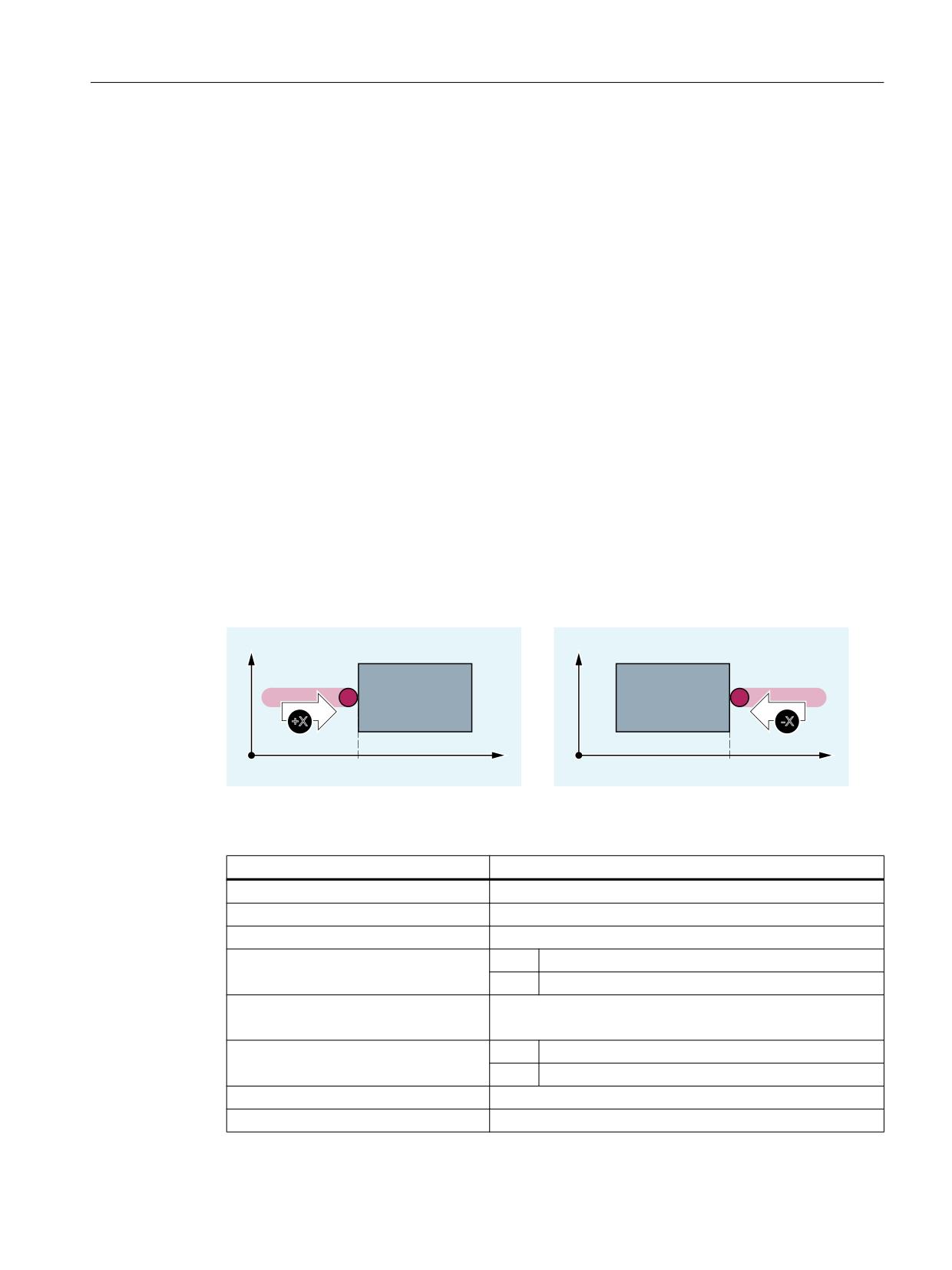
M5: Measurement
9.5 Workpiece and tool measurement
Further diagnostic options
Log
If the "/_N_MPF_DIR/_N_MEAS_DUMP_MPF" file is available, a log is written in the file that
should enable the reproduction of the problem. In order to use the log, an empty file with the
name "_N_MEAS_DUMP_MPF" must first be created in the "/_N_MPF_DIR" directory. The
content of the file is retained until it is deleted with $AC_MEAS_VALID = 0.
Trace
For runtime reasons, the trace should only be activated when a problem is detected.
9.5.2
Types of workpiece measurement
9.5.2.1
Measurement type 1, 2, 3: Measurement of an edge
Function
The edge of a clamped workpiece is measured by approaching this edge with a known tool.
Measurement type 1: Measurement of an X edge
<
<
;
;
;
;
;
;
Figure 9-1
Measurement of an X edge
The values of the following system variables are evaluated for measurement type 1:
Input variable
Meaning
$AC_MEAS_VALID
Validity bits for the input variables
$AA_MEAS_POINT1[<Axis>]
Measuring point 1 for all channel axes
$AA_MEAS_SETPOINT[<Axis>] *)
Set position of the X edge
$AC_MEAS_DIR_APPROACH
= 0
+ X
= 1
- X
$AC_MEAS_ACT_PLANE *)
Calculation with active plane unless otherwise specified.
Tool radius is only included in the calculation in G17 and G18.
$AC_MEAS_FINE_TRANS *)
= 0
Coarse offset
= 1
Fine offset
$AC_MEAS_FRAME_SELECT *)
Calculated as additive frame unless otherwise specified.
$AC_MEAS_T_NUMBER *)
Calculated with active T unless otherwise specified (T0).
Extended Functions
Function Manual, 12/2018, A5E40874029B AB
553
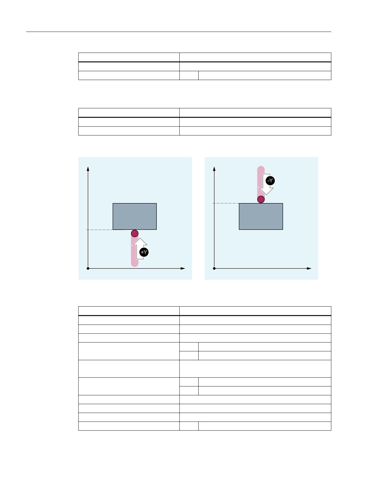
M5: Measurement
9.5 Workpiece and tool measurement
Input variable
Meaning
$AC_MEAS_D_NUMBER *)
Calculated with active D unless otherwise specified (D0).
$AC_MEAS_TYPE
= 1
Measurement type 1: Measurement of an X edge
*) Optional
The following output variables are written for measurement type 1:
Output variable
Meaning
$AC_MEAS_FRAME
Result frame with translation
$AC_MEAS_RESULTS[0]
Position of the measured edge
Measurement type 2: Measurement of a Y edge
<
<
<
<
<
<
<
;
;
Figure 9-2
Measurement of a Y edge
The values of the following system variables are evaluated for measurement type 2:
Input variable
Meaning
$AC_MEAS_VALID
Validity bits for the input variables
$AA_MEAS_POINT1[<Axis>]
Measuring point 1 for all channel axes
$AA_MEAS_SETPOINT[<Axis>] *)
Set position of the Y edge
$AC_MEAS_DIR_APPROACH
= 2
+ Y
= 3
- Y
$AC_MEAS_ACT_PLANE *)
Calculation with active plane unless otherwise specified.
Tool radius is only included in the calculation in G17 and G19.
$AC_MEAS_FINE_TRANS *)
= 0
Coarse offset
= 1
Fine offset
$AC_MEAS_FRAME_SELECT *)
Calculated as additive frame unless otherwise specified.
$AC_MEAS_T_NUMBER *)
Calculated with active T unless otherwise specified (T0).
$AC_MEAS_D_NUMBER *)
Calculated with active D unless otherwise specified (D0).
$AC_MEAS_TYPE
= 2
Measurement type 2: Measurement of a Y edge
*) Optional
Extended Functions
554
Function Manual, 12/2018, A5E40874029B AB