SINUMERIK 840D sl. Service - Functions. Manual (2018-2020) - page 36

K3: Compensations
5.10 Friction compensation with adaptive characteristics
5.10.2
Commissioning
5.10.2.1
Activating the function
Activating friction compensation
Friction compensation is activated axis-specifically with:
MD32500 $MA_FRICT_COMP_ENABLE[<axis>] = TRUE
Activating friction compensation with adaptive characteristics
Friction compensation with adaptive characteristics can be applied to the set or actual position
of the machine axis, depending on the dynamics of the axis. The function is activated axis-
specifically with:
MD32490 $MA_FRICT_COMP_MODE = <mode>
<mode>
Meaning
3
For axes with high dynamics and active feedforward control1).
The velocity or torque setpoint pulse is applied if the set position of the machine axis has
reached the trigger point.
4
For axes with low dynamics and inactive feedforward control1).
The velocity or torque setpoint pulse is applied if the actual position of the machine axis has
reached the trigger point.
1) Feedforward control: MD32620 FFW_MODE (feedforward control mode)
Note
Commissioning
We urgently recommend performing guided commissioning using the commissioning functions
of the SINUMERIK Operate user interface (Page 349) and not changing the generated values
in the machine data subsequently.
5.10.2.2
Commissioning functions of the SINUMERIK Operate user interface
Commissioning of the friction compensation with adaptive characteristics is performed in the
"friction compensation" window:
Operating area: "Commissioning" > "NC" > "Friction compensation"
Note
Softkey "Friction compensation"
The "friction compensation" softkey is only displayed if the friction compensation with adaptive
characteristics is active (Page 349) for at least one machine axis.
The parameters for the axis-specific velocity and torque setpoint pulses are determined and
stored retentively in machine data. Friction compensation by means of velocity setpoint pulse
is normally sufficient.
Extended Functions
Function Manual, 12/2018, A5E40874029B AB
349

K3: Compensations
5.10 Friction compensation with adaptive characteristics
Determination of the characteristic parameters for the velocity setpoint pulses is performed
with guidance by the operator interface.
The characteristic parameters for the torque setpoint pulse required only in exceptional cases
must be determined manually.
Note
Friction compensation - axis selection dialog
For the selection of an axis on an NCU other than the currently selected NCU, a switchover is
no longer possible once the "Friction compensation" dialog is opened.
To clear the switchover lock, you must first exit the "Friction compensation" dialog.
References
The description of friction compensation with adaptive characteristics via the SINUMERIK
Operate user interface can be found in: Commissioning Manual, CNC Commissioning: NC,
PLC, drive; Section "Commissioning NC" > "Friction compensation with adaptive
characteristics"
Function
The characteristic parameters are determined using a circularity test for up to nine different
acceleration values (Page 351). One or two machine axes are alternately continuously
traversed via an circularity test program generated automatically by the control and the result
is displayed in a circle diagram.
The traversing movements of the circularity program (radius, path velocity, and direction of
rotation) are already set in the following setting data. If necessary, they can be modified via
the data list (see below paragraph "Further parameters").
Parameters
Axis type
Setting Data
Radius
Linear axis
SD55820 $SCS_FRICT_OPT_RADIUS
Rotary axis
SD55821 $SCS_FRICT_OPT_RADIUS_ROT
Path velocity
Linear axis
SD55822$SCS_FRICT_OPT_FEED[ 0 ... 8 ]
Rotary axis
SD55823 $SCS_FRICT_OPT_FEED_ROT[ 0 ... 8 ]
Direction of rota-
---
SD55828 $SCS_FRICT_OPT_DIR_MINUS
tion 1)
1) Only effective in the circularity test with two axes
Measuring step
After the start of the circularity test program, in each of the up to nine measuring steps of a
measurement series, the axes are traversed with the path velocity that is defined in the setting
data or with the corresponding acceleration. The deviations of the actual positions from the
ideal path are acquired and displayed as a set or actual circular path. The parameters of the
velocity setpoint pulse can be varied by the commissioning engineering while the circularity
test continues to be performed constantly. The resulting changes are automatically updated
in the result graphics.
If the circularity tests is only performed with a single axis, the result is also displayed as a circle.
For this purpose, the determined contour deviations of the axis are displayed one horizontally
Extended Functions
350
Function Manual, 12/2018, A5E40874029B AB

K3: Compensations
5.10 Friction compensation with adaptive characteristics
and once vertically. If the circularity test is performed with two axes, both axes must be
geometry axes of the same channel.
Completion
After optimization of the compensation parameters for the entire measurement series has been
completed, the maximum values, characteristics interpolation points, and weighting factors
are calculated by the control and written into the following machine data:
Maximum value
Machine data
Amplitude
MD32571 $MA_FRICT_VELO_STEP
Decay time
MD32574 $MA_FRICT_V_PULSE_DECAY_TIME
Active time
MD32573 $MA_FRICT_V_PULSE_CONST_TIME
Characteristic interpolation points
Machine data
Acceleration of the friction compensa-
MD32581 $MA_FRICT_ADAPT_TABLE_ACCEL[ 0 ... 9 ]
tion characteristics
Weighting factors
Machine data
Amplitude upper / lower
MD32582 $MA_FRICT_ADAPT_V_STEP_PLUS[ 0 ... 9 ]
MD32583 $MA_FRICT_ADAPT_V_STEP_MINUS[ 0 ... 9 ]
Decay time upper / lower
MD32586 $MA_FRICT_ADAPT_V_DECAY_PLUS[ 0 ... 9 ]
MD32587 $MA_FRICT_ADAPT_V_DECAY_MINUS[ 0 ... 9 ]
Action time upper / lower
MD32584 $MA_FRICT_ADAPT_V_CONST_PLUS[ 0 ... 9 ]
MD32585 $MA_FRICT_ADAPT_V_CONST_MINUS[ 0 ... 9 ]
Additional parameters
With the vertical softkey "Data list," further machine and setting data are displayed for
parameterization of the friction compensation with adaptive characteristics, e.g. also the
parameters for the torque setpoint pulse. The setting these parameters is described in the
following sections.
5.10.2.3
Parameterization of the acceleration at the characteristic interpolation points
From the channel-specific setting data of the circularity test (circle radius and traversing
velocity), the control calculates the acceleration values of the characteristic interpolation points.
Channel-specific setting data
The channel-specific setting data for circle radius and velocities apply to all machine axes with
active friction compensation with adaptive characteristics that are channel axes of the channel
in question. They are already assigned typical values. In necessary, they can be adapted
machine-specifically.
Extended Functions
Function Manual, 12/2018, A5E40874029B AB
351
K3: Compensations
5.10 Friction compensation with adaptive characteristics
Circle radius
A circle is traversed with the parameterized radius in the automatically generated circularity
tests program:
● Linear axes
SD55820 $SCS_FRICT_OPT_RADIUS = <radius>
● Rotary axes
SD55821 $SCS_FRICT_OPT_RADIUS_ROT = <radius>
Traversing velocities
In the circularity test, the machine axes are traversed in each of the up to nine measurement
sections with the velocity parameterized in the setting data:
● Linear axes
SD55822$SCS_FRICT_OPT_FEED[ 0 ... 8 ] = <velocity 1 ... 9>
● Rotary axes
SD55823 $SCS_FRICT_OPT_FEED_ROT[ 0 ... 8 ] = <velocity 1 ... 9>
Note
● If fewer than nine characteristic interpolation points ( 1 ... n ) are required, the velocity zero
must be entered in each of the corresponding array elements for all unneeded characteristic
interpolation points ( (n+1) ... 9 ).
● If the velocity is equal to zero in an array element, no following array element must contain
a velocity that is not equal to zero.
Direction of rotation
In the circularity test with two axes, the direction of rotation of the circle is defined with:
SD55828 $SCS_FRICT_OPT_DIR_MINUS = <direction of rotation>
Axis-specific machine data
The acceleration a at the characteristic interpolation point n is calculated by the control from
the setting data for the circle radius r and the path velocity vn-1: an = vn-12 / r
0'
6'
6&6B)5,&7B237B)(('> Q
@
0$B)5,&7B$'$37B7$%/(B$&&(/> Q @
6'
6&6B)5,&7B237B5$',86
where n = 1, 2, 3, ... 9
For acceleration a at characteristic interpolation point n = 0, the value zero is always entered:
MD32581 $MA_FRICT_ADAPT_TABLE_ACCEL[ 0 ] = 0
Extended Functions
352
Function Manual, 12/2018, A5E40874029B AB
K3: Compensations
5.10 Friction compensation with adaptive characteristics
5.10.2.4
Velocity setpoint pulse
Determination of the characteristic parameters for the velocity setpoint pulses and calculation
of the corresponding machine data is fully supported by the user interface (Page 349). We
therefore advise against determining the characteristic parameters or writing the machine data
manually.
Axis-specific machine data
Velocity setpoint pulse
PP PLQ _ PLQ
W
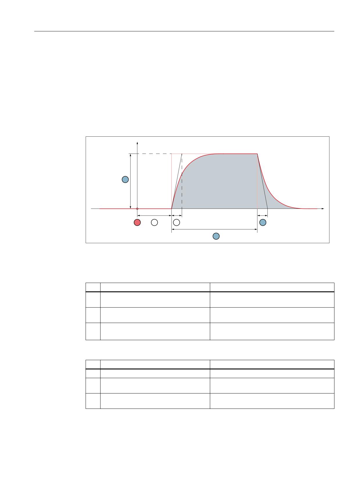
Figure 5-29
Basic pulse shape
The numbers (①, ②, ...) stated in the following tables refer to the figure above.
Acceleration-independent parameters
No.
Machine data
Description
①
-
Trigger time or acceleration of the axes from stand-
still
③
MD32572 $MA_FRICT_V_PULSE_DE-
Delay time
LAY_TIME
④
MD32575
Time constant T of the rise time,
$MA_FRICT_V_PULSE_SMOOTH_TIME
after 5 * T ⇒ output value ≈ input value
Maximum values of the acceleration-dependently adaptable parameters
No.
Machine data
Description
②
MD32571 $MA_FRICT_VELO_STEP
Amplitude
⑤
MD32573
Active time
$MA_FRICT_V_PULSE_CONST_TIME
⑥
MD32574 $MA_FRICT_V_PULSE_DE-
Decay time
CAY_TIME
Extended Functions
Function Manual, 12/2018, A5E40874029B AB
353

K3: Compensations
5.10 Friction compensation with adaptive characteristics
Weighting factors for acceleration-dependent adaptation of the maximum values
Table 5-1
Lower reversal point
Machine data
Description
MD32582
Weighting factor for the amplitude
$MA_FRICT_ADAPT_V_STEP_PLUS[ 0 ... 9 ]
MD32584
Weighting factor for the action time
$MA_FRICT_ADAPT_V_CONST_PLUS[ 0 ... 9 ]
MD32586 $MA_FRICT_ADAPT_V_DE-
Weighting factor for the decay time
CAY_PLUS[ 0 ... 9 ]
Table 5-2
Upper reversal point
Machine data
Description
MD32583 $MA_FRICT_ADAPT_V_STEP_MI-
Weighting factor for the amplitude
NUS[ 0 ... 9 ]
MD32585 $MA_FRICT_ADAPT_V_CONST_MI-
Weighting factor for the action time
NUS[ 0 ... 9 ]
MD32587 $MA_FRICT_ADAPT_V_DECAY_MI-
Weighting factor for the decay time
NUS[ 0 ... 9 ]
Calculation of the characteristic parameters
The commissioning engineer must determine the optimum values for amplitude, action time,
and decay time for the velocity setpoint pulse for different acceleration values during the
circularity test (Page 349). On completion of the circularity test, the control will calculate the
resulting characteristic parameters (maximum values, characteristic interpolation points, and
weighting factors) and write them into the corresponding machine data.
Extended Functions
354
Function Manual, 12/2018, A5E40874029B AB
K3: Compensations
5.10 Friction compensation with adaptive characteristics
Example: Amplitude characteristic for the lower reversal point
● Maximum value
0'
PD[^$PSOLWXGH $PSOLWXGH
$PSOLWXGH
`
0$B)5,&7B9(/2B67(3
● Weighting factors
0'
$PSOLWXGH> Q @
0$B)5,&7B$'$37B9B67(3B3/86> Q @
0'
0$B)5,&7B9(/2B67(3
● Effective interpolation points
The effective interpolation points of the amplitude characteristics are the interpolation points
to which the following applies:
- MD32581 $MA_FRICT_ADAPT_TABLE_ACCEL[ <interpolation point> ] ≠ 0
(acceleration)
- MD32582 $MA_FRICT_ADAPT_V_STEP_PLUS[ <interpolation point> ] ≠ 0 (weighting
factor)
The amplitude of the velocity setpoint pulse of an effective interpolation point is calculated
as:
$PSOLWXGH> Q @
0D[LPXP YDOXH ZHLJKWLQJ IDFWRU> Q @
0'
0$B)5,&7B9(/2B67(3
0'
0$B)5,&7B$'$37B9B67(3B3/86> Q @
Note
Vertical offset of a characteristic
Subsequent vertical displacement of a characteristics is most easily achieved by changing the
corresponding maximum value in the machine data.
5.10.2.5
Torque setpoint pulse
Determination of the characteristic parameters for the torque setpoint pulses and calculation
of the corresponding machine data is not supported directly by the user interface. We therefore
advise determining the characteristic parameters or writing the machine data manually
Extended Functions
Function Manual, 12/2018, A5E40874029B AB
355
K3: Compensations
5.10 Friction compensation with adaptive characteristics
Axis-specific machine data
Torque setpoint pulse
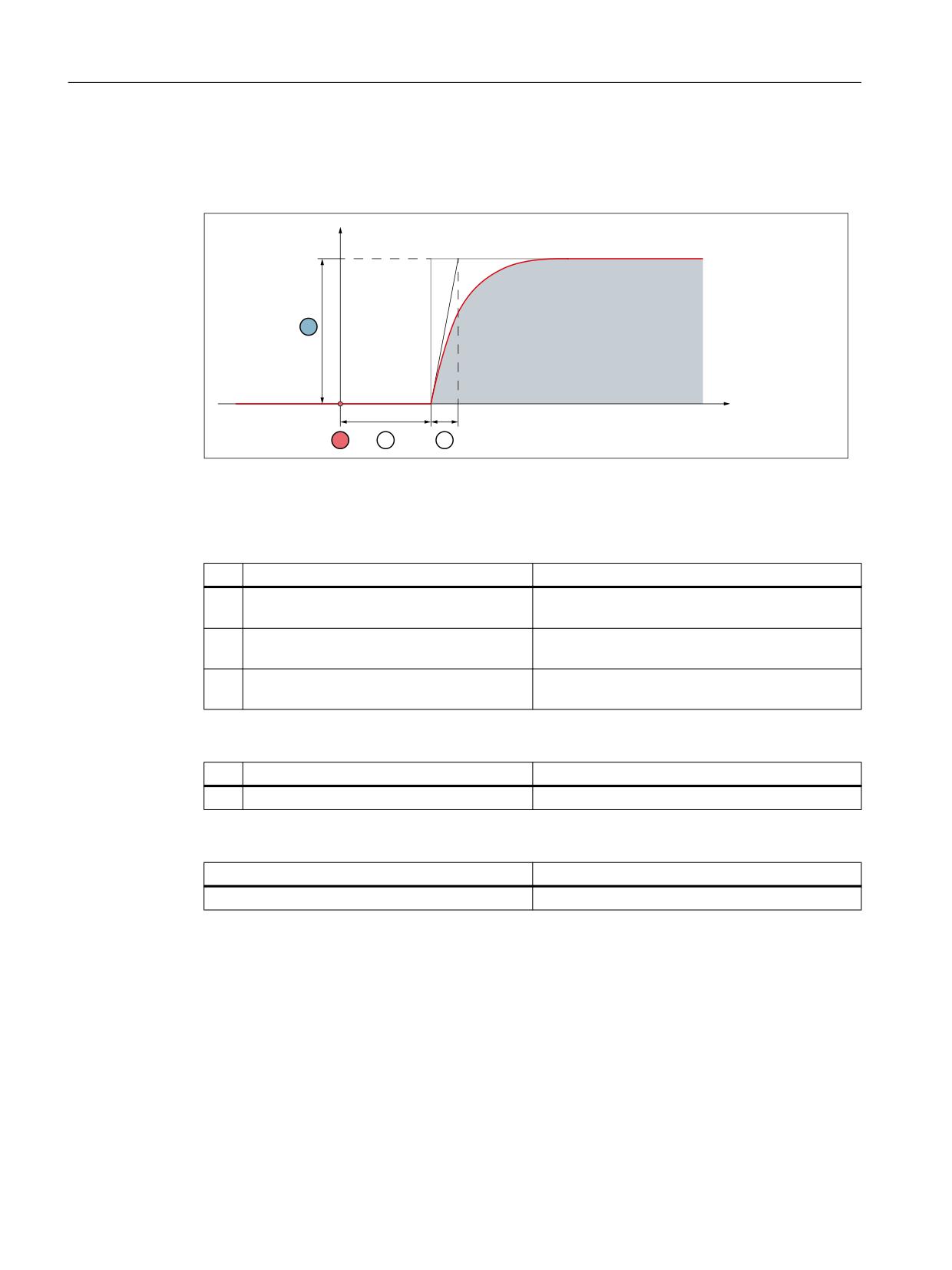
1P
W
Figure 5-30
Basic pulse shape
The numbers (①, ②, ...) stated in the following tables refer to the figure above.
Acceleration-independent parameters
No.
Machine data
Description
①
-
Trigger time or acceleration of the axes from stand-
still
③
MD32577 $MA_FRICT_T_PULSE_DE-
Delay time
LAY_TIME
④
MD32578
Rise time
$MA_FRICT_T_PULSE_SMOOTH_TIME
Maximum values of the acceleration-dependently adaptable amplitude
No.
Machine data
Description
②
MD32576 $MA_FRICT_TORQUE_STEP
Amplitude
Weighting factors for acceleration-dependent adaptation of the maximum value
Machine data
Description
MD32588 $MA_FRICT_ADAPT_T_STEP[ 0 ... 9 ]
Weighting factor for the amplitude
Extended Functions
356
Function Manual, 12/2018, A5E40874029B AB
K3: Compensations
5.10 Friction compensation with adaptive characteristics
Commissioning (manual)
Requirement
The circularity test (Page 349) for determining the characteristic parameter was already been
successfully performed completely or at least for the current measuring step.
Note
Determining the characteristic parameters
● The characteristic parameters for the torque setpoint pulse are most simply determined in
the circularity test (Page 349) of the user interface:
● Operating area: "Commissioning" > "NC" > "Friction compensation"
● The machine data are most simply set via the data list of the circularity test:
Operating area: "Commissioning" > "NC" > "Friction compensation" > "Data list" vertical
softkey
Assumption
The circularity tests has been started, measuring step 1 is active.
Recommended procedure
1. Initialization of the weighting factors:
- MD32588 $MA_FRICT_ADAPT_T_STEP[ 0 ] = 1
- MD32588 $MA_FRICT_ADAPT_T_STEP[ 1 ... 9 ] = 0
Note: For all measuring steps, the weighting factor with index 0 is used.
2. Setting the amplitude for the current measuring step:
- MD32576 $MA_FRICT_TORQUE_STEP = <amplitude>
3. Determining the changed contour deviation in the circle diagram.
4. Optimization of the amplitude value by changing in MD32576
$MA_FRICT_TORQUE_STEP and checking in the circle diagram.
5. Recording the amplitude value for this measuring step for subsequent determination of the
maximum value or the weighting factor of the measuring step.
6. Switching on to the next measuring step and continuing with point 2 until the amplitude
values have been determined for all measuring steps.
7. Determining the maximum value from the recorded amplitude values and entering them in
the machine data:
0'
0$B)5,&7B72548(B67(3 PD[^$PSOLWXGH $PSOLWXGH
$PSOLWXGH
`
8. Calculation of the weighting factors for all active interpolation points from the recorded
amplitude values and entering them in the machine data:
0'
$PSOLWXGH> Q @
0$B)5,&7B$'$37B7B67(3> Q @
0'
0$B)5,&7B72548(B67(3
That completes commissioning of the amplitude characteristic for the torque setpoint pulse.
Extended Functions
Function Manual, 12/2018, A5E40874029B AB
357
K3: Compensations
5.10 Friction compensation with adaptive characteristics
Optional
Setting the parameters that are independent of acceleration:
● MD32577 $MA_FRICT_T_PULSE_DELAY_TIME
● MD32578 $MA_FRICT_T_PULSE_SMOOTH_TIME
Effective interpolation points
The effective interpolation points of the amplitude characteristics are the interpolation points
to which the following applies:
● MD32581 $MA_FRICT_ADAPT_TABLE_ACCEL[ <interpolation point> ] ≠ 0 (acceleration)
● MD32583 $MA_FRICT_ADAPT_T_STEP[ <interpolation point> ] ≠ 0 (weighting factor)
The amplitude of the torque setpoint pulse of an effective interpolation point is calculated as:
$PSOLWXGH> Q @ 0D[LPXP YDOXH ZHLJKWLQJ IDFWRU> Q @
0'
0'
0$B)5,&7B72548(B67(3
0$B)5,&7B$'$37B7B67(3> Q @
Note
Vertical offset of the characteristic
Subsequent vertical displacement of the amplitude characteristic is most easily achieved by
changing the corresponding maximum value in the machine data.
Extended Functions
358
Function Manual, 12/2018, A5E40874029B AB
K3: Compensations
5.11 Compensation functions for suspended axes
5.11
Compensation functions for suspended axes
5.11.1
Electronic counterweight
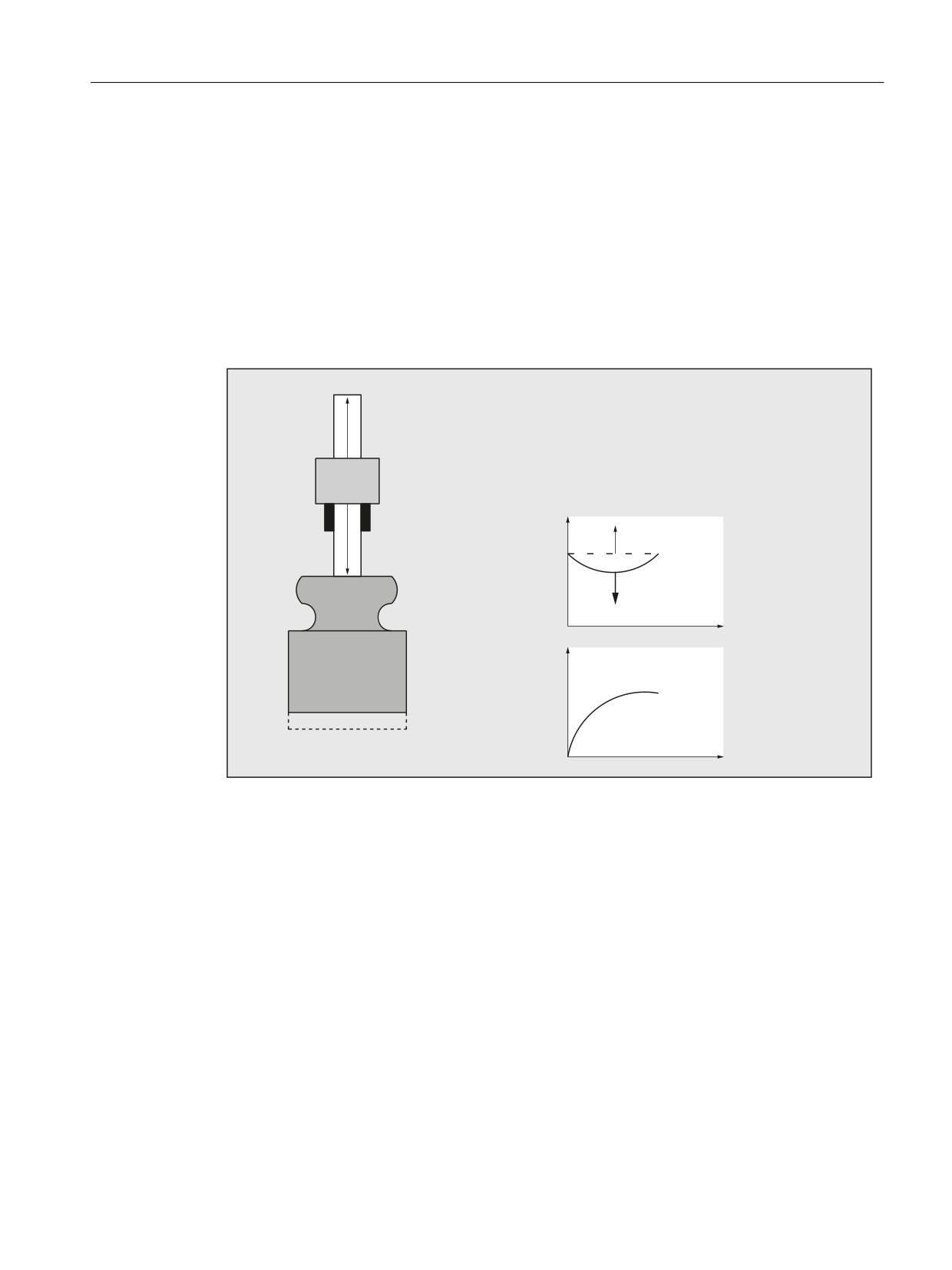
Axis without counterweight
For axes that have a weight load without counterweight, then after the brake is released, the
hanging (suspended) axis drops and the following response is obtained:
=
%UDNH KROGV =
%UDNH UHOHDVHV FRQWUROOHU HQDEOH SXOVH HQDEOH
$[LV = VDJV
$IWHU VRPH WLPH WKH FRQWURO PDLQWDLQV WKH D[LV DW
WKH SRVLWLRQ
)HHG GULYH
%UDNH
=
'LVWDQFH
=
G]
W
=
7RUTXH
:HLJKW
G]
W
Figure 5-31
Drop of a hanging axis without counterweight
"Electronic counterweight" function
A hanging (suspended) axis can almost be completely prevented from dropping (sagging)
using the "electronic counterweight" function.
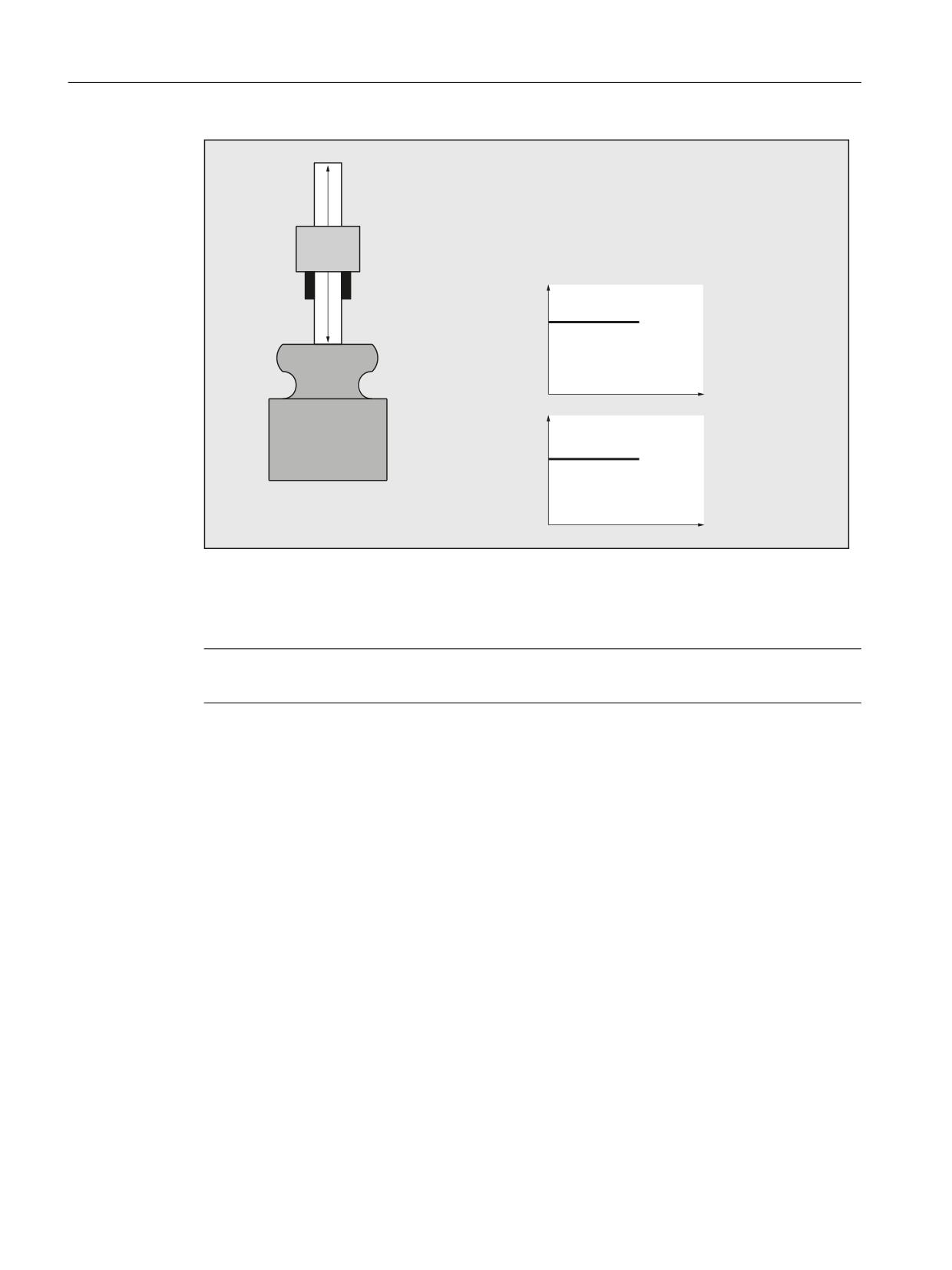
The electronic counterweight prevents axes with a weight load from sagging when the closed-
loop control is switched on. After releasing the brake, the constant counterweight torque
maintains the position of the vertical axis.
Extended Functions
Function Manual, 12/2018, A5E40874029B AB
359
K3: Compensations
5.11 Compensation functions for suspended axes
=
%UDNH KROGV =
%UDNH UHOHDVHV FRQWUROOHU HQDEOH SXOVH HQDEOH
FRXQWHUZHLJKW WRUTXH
$[LV = VWD\V LQ SRVLWLRQ
)HHG GULYH
%UDNH
=
'LVWDQFH
=
G] a
W
=
7RUTXH
:HLJKW
G] a
W
Figure 5-32
Lowering of a vertical axis with electronic weight compensation
Commissioning
Note
The "electronic counterweight" is commissioned through the drive!
Reference
For additional information, see the following:
SINAMICS S120 Function Manual Drive Functions
5.11.2
Special function: Reboot delay
Function
For changes, for example, to machine data values to become effective, the NC must be
restarted. This is done, for example, on the user interface by triggering an NC reset. If there
are suspended axes on the machine, failure of the closed-loop control while the control is
starting will result in the axes failing to maintain height.
With the "Reboot delay" function, the request to reboot the NC (NC reset) is communicated to
the NC via the operator interface as previously. Rebooting, during which the closed-loop control
of the axes is deactivated, is then delayed on the NC by a time that can be parameterized.
Extended Functions
360
Function Manual, 12/2018, A5E40874029B AB
K3: Compensations
5.11 Compensation functions for suspended axes
During this time, user-specific actions, such engaging the holding brakes of the suspended
axes, are performed.
Note
The reboot delay is only effective on a request to reboot the NC (NC reset) via the user
interface.
In the case of a power-on reset by switching the control off and on again, pressing the reset
button on the front of the NCU, or power failure, a parameterized reboot delay time will have
no effect.
Alarm 2900 "Reboot after a delay"
When a reboot request is detected, alarm 2900 "Reboot after a delay" is triggered.
Alarm responses
The following responses are triggered by the alarm 2900:
● The NC/PLC interface signals are reset:
- DB11 DBX6.3 = 0 (mode group ready); all mode groups
- DB21, … DBX36.5 = 0 (channel ready) for all channels
- DB31, … DBX61.2 = 0 (axis ready) for all axes
● Braking the axis / spindles at the current limit.
For further details, see machine data:
- MD36610 $MA_AX_EMERGENCY_STOP_TIME (braking ramp time when errors
occur)
- MD36620 $MA_SERVO_DISABLE_DELAY_TIME (OFF delay of the controller enable)
The NC/PLC interface signal "NC ready" remains set:
DB10 DBX108.7 == 1
Alarm suppression
With the machine data, display of the alarm 2900 "Reboot after a delay" will be suppressed
on the user interface:
MD11410 $MN_SUPPRESS_ALARM_MASKBit 20 = 1
The alarm responses are not affected by this.
Controlling holding brakes
During the reboot operation of the PLC, the PLC outputs defined as 0 are reset. Control of the
holding brakes must therefore be connected on the user side in such a way that the brakes
engage or remain engaged on a control signal == 0 and are released or remain released on
a control signal == 1.
Parameter assignment
The reboot delay time is set in machine data:
MD10088 $MN_REBOOT_DELAY_TIME = <reboot delay time>
Extended Functions
Function Manual, 12/2018, A5E40874029B AB
361

K3: Compensations
5.12 Data lists
If the parameterized reboot delay time is 0.0, the function is deactivated.
System variables
The time remaining until the NC is rebooted can be read in the system variable:
$AN_REBOOT_DELAY_TIME
While no request for a reboot of the NC (NC reset) has been triggered from the user interface,
the system variable has the value 0.0.
A value greater than 0.0 indicates that a reboot request (NC reset) has been triggered from
the user interface and also the time remaining in the NC or PLC until the reboot.
Application example
Evaluating the system variables in a static synchronized action
Condition part: Check for a value greater than 0.0 because then a request for a reboot of the
NC (NC reset) has been made from the user interface.
Action part: e.g. triggering "safe standstill" as part of the "Safety Integrated" function.
5.12
Data lists
5.12.1
Machine data
5.12.1.1
General machine data
Number
Identifier: $MN_
Description
10050
SYSCLOCK_CYCLE_TIME
Basic system clock cycle
10070
IPO_SYSCLOCK_TIME_RATIO
Factor for interpolator clock cycle
10082
CTRLOUT_LEAD_TIME
Shift of setpoint transfer time
10083
CTRLOUT_LEAD_TIME_MAX
Maximum permissible setting for shift of setpoint trans-
fer time
10088
REBOOT_DELAY_TIME
Reboot delay
18342
MM_CEC_MAX_ POINTS[t]
Maximum number of interpolation points of sag com-
pensation
5.12.1.2
Channelspecific machine data
Number
Identifier: $MC_
Description
20150
GCODE_RESET_VALUES
Reset G groups
Extended Functions
362
Function Manual, 12/2018, A5E40874029B AB

K3: Compensations
5.12 Data lists
5.12.1.3
Axis/spindlespecific machine data
Number
Identifier: $MA_
Description
32450
BACKLASH
Backlash
32452
BACKLASH_FACTOR
Weighting factor for backlash
32454
BACKLASH_MODE
Backlash compensation mode
32456
BACKLASH_DYN
Compensation value for the dynamic backlash com-
pensation
32457
BACKLASH_DYN_MAX_VELO
Limitation of the dynamic backlash compensation value
change
32490
FRICT_COMP_MODE
Type of friction compensation
32500
FRICT_COMP_ENABLE
Friction compensation active
32510
FRICT_COMP_ADAPT_ENABLE
Friction compensation adaptation active
32520
FRICT_COMP_CONST_MAX
Maximum friction compensation value
32530
FRICT_COMP_CONST_MIN
Minimum friction compensation value
32540
FRICT_COMP_TIME
Friction compensation time constant
32550
FRICT_COMP_ACCEL1
Adaptation acceleration value 1
32560
FRICT_COMP_ACCEL2
Adaptation acceleration value 2
32570
FRICT_COMP_ACCEL3
Adaptation acceleration value 3
32610
VELO_FFW_WEIGHT
Feedforward control factor for velocity/speed feedfor-
ward control
32620
FFW_MODE
Feedforward control mode
32630
FFW_ACTIVATION_MODE
Activate feedforward control from program
32650
AX_INERTIA
Inertia for torque feedforward control
32700
ENC_COMP_ENABLE
Interpolatory compensation
32710
CEC_ENABLE
Enabling of sag compensation
32711
CEC_SCALING_SYSTEM_METRIC
System of units for sag compensation
32720
CEC_MAX_SUM
Maximum compensation value for sag compensation
32730
CEC_MAX_VELO
Change of velocity during sag compensation
32750
TEMP_COMP_TYPE
Temperature compensation type
32760
COMP_ADD_VELO_FACTOR
Velocity increase as a result of compensation
32711
CEC_SCALING_SYSTEM_METRIC
System of units for sag compensation
32800
EQUIV_CURRCTRL_TIME
Equivalent time constant current control loop for feed-
forward control
32810
EQUIV_SPEEDCTRL_TIME
Equivalent time constant speed control loop for feed-
forward control
32910
DYN_MATCH_TIME
Time constant for dynamic response adaptation
36500
ENC_CHANGE_TOL
Maximum tolerance for position actual value switchover
37302
NOCO_FILTER_TIME
Time constant for smoothing nodding compensation
values
37310
NOCO_INPUT_AX_1
Compensation relationship 1:
Machine axis that causes nodding motion
Extended Functions
Function Manual, 12/2018, A5E40874029B AB
363

K3: Compensations
5.12 Data lists
Number
Identifier: $MA_
Description
37312
NOCO_ADAPT_AX_1
Compensation relationship 1:
Machine axis, whose position influences nodding mo-
tion
37314
NOCO_ADAPT_NUM_1
Compensation relationship 1:
Number of positions, adaptation characteristic of the
nodding compensation
37316
NOCO_ADAPT_POS_1
Compensation relationship 1:
Positions, adaptation characteristic of the nodding com-
pensation
37318
NOCO_COMPLIANCE_1
Compensation relationship 1:
Compliance factor for nodding compensation
37320
NOCO_INPUT_AX_2
Compensation relationship 2:
Machine axis that causes nodding motion
37322
NOCO_ADAPT_AX_2
Compensation relationship 2:
Machine axis, whose position influences nodding mo-
tion
37324
NOCO_ADAPT_NUM_2
Compensation relationship 2:
Number of positions, adaptation characteristic of the
nodding compensation
37326
NOCO_ADAPT_POS_2
Compensation relationship 2:
Positions, adaptation characteristic of the nodding com-
pensation
37328
NOCO_COMPLIANCE_2
Compensation relationship 2:
Compliance factor for nodding compensation
37330
NOCO_INPUT_AX_3
Compensation relationship 3:
Machine axis that causes nodding motion
37332
NOCO_ADAPT_AX_3
Compensation relationship 3:
Machine axis, whose position influences nodding mo-
tion
37334
NOCO_ADAPT_NUM_3
Compensation relationship 3:
Number of positions, adaptation characteristic of the
nodding compensation
37336
NOCO_ADAPT_POS_3
Compensation relationship 3:
Positions, adaptation characteristic of the nodding com-
pensation
37338
NOCO_COMPLIANCE_3
Compensation relationship 3:
Compliance factor for nodding compensation
38000
MM_ENC_COMP_MAX_POINTS
Number of interpolation points with interpolatory com-
pensation
Extended Functions
364
Function Manual, 12/2018, A5E40874029B AB

K3: Compensations
5.12 Data lists
5.12.2
Setting data
5.12.2.1
General setting data
Number
Identifier: $SN_
Description
41300
CEC_TABLE_ENABLE[t]
Enable evaluation of beam sag compensation
table
41310
CEC_TABLE_WEIGHT[t]
Weighting factor for beam sag compensation ta-
ble
5.12.2.2
Axis/spindle-specific setting data
Number
Identifier: $SA_
Description
43900
TEMP_COMP_ABS_VALUE
Position-independent temperature compensation value
43910
TEMP_COMP_SLOPE
Gradient for position-dependent temperature compen-
sation
43920
TEMP_COMP_REF_POSITION
Reference position for position-dependent temperature
compensation
5.12.3
Signals
5.12.3.1
Signals from NC
Signal name
SINUMERIK 840D sl
SINUMERIK 828D
NC Ready
DB10.DBX108.7
DB2700.DBX2.7
5.12.3.2
Signals from mode group
Signal name
SINUMERIK 840D sl
SINUMERIK 828D
Mode group ready
DB11.DBX6.3
DB3100.DBX0.3
5.12.3.3
Signals from channel
Signal name
SINUMERIK 840D sl
SINUMERIK 828D
Channel ready
DB21,
DBX36.5
DB330x.DBX4.5
Extended Functions
Function Manual, 12/2018, A5E40874029B AB
365

K3: Compensations
5.12 Data lists
5.12.3.4
Signals to axis/spindle
Signal name
SINUMERIK 840D sl
SINUMERIK 828D
Activate dynamic backlash compensation
DB31,
DBX25.0
DB380x.DBX5001.0
5.12.3.5
Signals from axis/spindle
Signal name
SINUMERIK 840D sl
SINUMERIK 828D
Referenced/synchronized 1
DB31,
DBX60.4
DB390x.DBX0.4
Referenced/synchronized 2
DB31,
DBX60.5
DB390x.DBX0.5
Axis ready
DB31,
DBX61.2
DB390x.DBX1.2
Dynamic backlash compensation active
DB31,
DBX102.0
DB390x.DBX5006.0
Extended Functions
366
Function Manual, 12/2018, A5E40874029B AB
K5: Cross-channel program coordination and channel-
by-channel running-in
6
6.1
Cross-channel program coordination
6.1.1
Coordination commands (INIT, START, WAITM, WAITMC, WAITE, SETM,
CLEARM)
In principle, a channel of the NC can execute the program started in it independently of other
channels in its mode group. If, however, several programs in several channels of the mode
group are involved in machining a workpiece, the program sequences in the various channels
must be coordinated with the following coordination commands.
Requirement
All the channels involved in the program coordination must belong to the same mode group:
MD10010 $MC_ASSIGN_CHAN_TO_MODE_GROUP[<Channel>] = <Mode group number>
Channel name instead of channel number
Instead of the channel numbers, the channel names entered in MD20000
$MC_CHAN_NAME[<Channel index>] can be used as parameters of the predefined
procedures for the program coordination. The use of the channel names in the NC programs
first has to be enabled:
MD10280 $MN_PROG_FUNCTION_MASK, bit 1 = TRUE
Note
Minimum distance between commands
At least two traversing block distances must be maintained between the commands INIT,
START, WAITE, WAITM, SETM, CLEARM and the command WAITMC. WAITMC is an executable
block, but is moved into the previous block for optimization, and then deleted as a block.
SETM for example is not an executable block, and is moved into the next block so that if there
were a distance of one block between two commands, both commands would be in the middle
block. As only one block is possible, optimization is not performed with a one block distance
for WAITMC.
This stops the program, and processing is briefly interrupted.
Syntax
INIT(<ChanNo>, <Prog>, <AckMode>)
START(<ChanNo>, <ChanNo>, ...)
WAITM(<MarkNo>, <ChanNo>, <ChanNo>, ...)
WAITE(<ChanNo>, <ChanNo>, ...)
Extended Functions
Function Manual, 12/2018, A5E40874029B AB
367
K5: Cross-channel program coordination and channel-by-channel running-in
6.1 Cross-channel program coordination
WAITMC(<MarkNo>, <ChanNo>, <ChanNo>, ...)
SETM(<MarkNo>, <MarkNo>, ...)
CLEARM(<MarkNo>, <MarkNo>, ...)
Meaning
INIT():
Predefined procedure for selecting the NC program that is to be executed in the speci-
fied channel
START():
Predefined procedure for starting the selected program in the respective channel
WAITM():
Predefined procedure to wait for a wait marker to be reached in the specified channels
The specified wait marker is set by WAITM in the same channel. The previous block is
terminated with exact stop. The wait marker is deleted after synchronization.
A maximum of 10 markers can be set simultaneously in each channel.
WAITE():
Predefined procedure to wait for the end of program in one or more other channels
WAITMC(): 1)
Predefined procedure to wait for a wait marker to be reached in the specified channels
In contrast to WAITM, the braking of the axes to exact stop is only initiated if the other
channels have not yet reached the wait marker.
SETM(): 1)
Predefined procedure to set one or more wait markers for the channel coordination
The processing in the own channel is not affected by this.
SETM remains valid after a channel reset and NC start.
CLEARM(): 1)
Predefined procedure to delete one or more wait markers for the channel coordination
The processing in the own channel is not affected by this.
CLEARM() deletes all wait markers in the channel.
CLEARM(0) only deletes wait marker "0".
CLEARM remains valid after a channel reset and NC start.
<ChanNo>:
Channel number
The number of the own channel does not have to be specified.
Type:
INT
<Prog>:
Absolute or relative path specification (optional) + program name
Type:
STRING
For the path specification, see:
References
Programming Manual, Work Planning, "File and Program Administration" Chapter >
"Program memory" > "Addressing the files of the program memory"
<AckMode>:
Acknowledgment mode (optional)
Type:
CHAR
Val-
"N"
Without acknowledgment
ues:
The program execution is continued after the command has been sent.
The sender is not informed if the command cannot be executed suc-
cessfully.
"S"
Synchronous acknowledgment
The program execution is stopped until the receiving component has
acknowledged the command. If the acknowledgment is positive, the
next command is executed. If the acknowledgment is negative, an error
message is output.
Extended Functions
368
Function Manual, 12/2018, A5E40874029B AB

K5: Cross-channel program coordination and channel-by-channel running-in
6.1 Cross-channel program coordination
<MarkNo>:
Number of the wait marker
Note
In a multi-channel system, a maximum of 100 wait markers are available (wait markers
0 ... 99).
Only wait marker 0 is available in a single-channel system.
1) For user-specific communication and/or coordination of channels, wait markers can be deployed
using SETM/CLEARM - and also without using the conditional wait command WAITMC. The wait markers
retain their values, even after a channel reset and NC start.
Examples
START using channel names from MD20000
● Parameter assignment
MD10280 $MN_PROG_FUNCTION_MASK, bit 1 = TRUE
$MC_CHAN_NAME[ 0 ] = "MACHINING"; Name of channel 1
$MC_CHAN_NAME[ 1 ] = "INFEED"; Name of channel 2
● Programming
Program code
Comment
START(MACHINING)
; Start of channel 1
START(INFEED)
; Start of channel 2
START using local "channel names" and user variables
Program code
Comment
DEF INT MACHINE = 1
; Definition of user variable for channel 1
DEF INT LOADER = 2
; Definition of user variable for channel 2
START(MACHINE)
; Start of channel 1
START(LOADER)
; Start of channel 2
START using local "channel names", user variables and parameterized channel names
Program code
Comment
DEF INT chanNo1
; Definition of user variable for channel 1
DEF INT chanNo2
; Definition of user variable for channel 2
chanNo1 = CHAN_1
; Assignment of parameterized channel name channel 1
chanNo2 = CHAN_2
; Assignment of parameterized channel name channel 2
START(ChanNo1)
; Start of channel 1
START(ChanNo2)
; Start of channel 2
INIT command with absolute path specification
Selection of program /_N_MPF_DIR/_N_ABSPAN1_MPF in channel 2.
Program code
INIT(2,"/_N_WCS_DIR/_N_SHAFT1_WPD/_N_CUT1_MPF")
Extended Functions
Function Manual, 12/2018, A5E40874029B AB
369

K5: Cross-channel program coordination and channel-by-channel running-in
6.1 Cross-channel program coordination
INIT command with program name
Selection of the program with the name "MYPROG". The control searches for the program
using the search path.
Program code
INIT(2,"MYPROG")
Program coordination with WAITM
● Channel 1: The program /_N_MPF_DIR/_N_MPF100_MPF has already been selected and
started.
Program code
Comment
; Program MPF100
N10 INIT(2,"MPF200","N")
; Selection of program MPF200, channel 2
N11 START(2)
; Start of channel 2
N80 WAITM(1,1,2)
; Wait for WAIT marker 1 in channels 1 and
2
N81 ...
; Channel 1, N81 and channel 2, N71 are
; started synchronously
N180 WAITM(2,1,2)
; Wait for WAIT marker 2 in channels 1 and
2
N181 ...
; Channel 1, N181 and channel 2, N271 are
; started synchronously
N200 WAITE(2)
; Wait for end of program in channel 2
N201 ...
; N201 is not started until the end of
program
; MPF200 started in channel 2
N201 M30
; End of program channel 1
● Channel 2: In channel 1, the program MPF200_MPF is selected and started for channel 2
using blocks N10 and N20.
Program code
Comment
;$PATH=/_N_MPF_DIR
; Program MPF200
N70 WAITM(1,1,2)
Wait for WAIT marker 1 in channels 1 and 2
N71 ...
; Channel 1, N81 and channel 2, N71 are
; started synchronously
N270 WAITM(2,1,2)
Wait for WAIT marker 2 in channels 1 and 2
N271 ...
; Channel 1, N181 and channel 2, N271 are
; started synchronously
N400 M30
End of program channel 2
Extended Functions
370
Function Manual, 12/2018, A5E40874029B AB
K5: Cross-channel program coordination and channel-by-channel running-in
6.1 Cross-channel program coordination
1
1
:$,70
:$,70
&KDQQHO
1
03)
1
0
:DLWLQJ
&KDQQHO
1
1
1
03)
:DLWLQJ
:DLWLQJ
0
1
1
1
67$57
:$,70
:$,70
:$,7(
6WDUW
67$57
0
0
(QG RI WLPH
Supplementary conditions
Non-synchronous start of execution of following blocks after WAIT markers
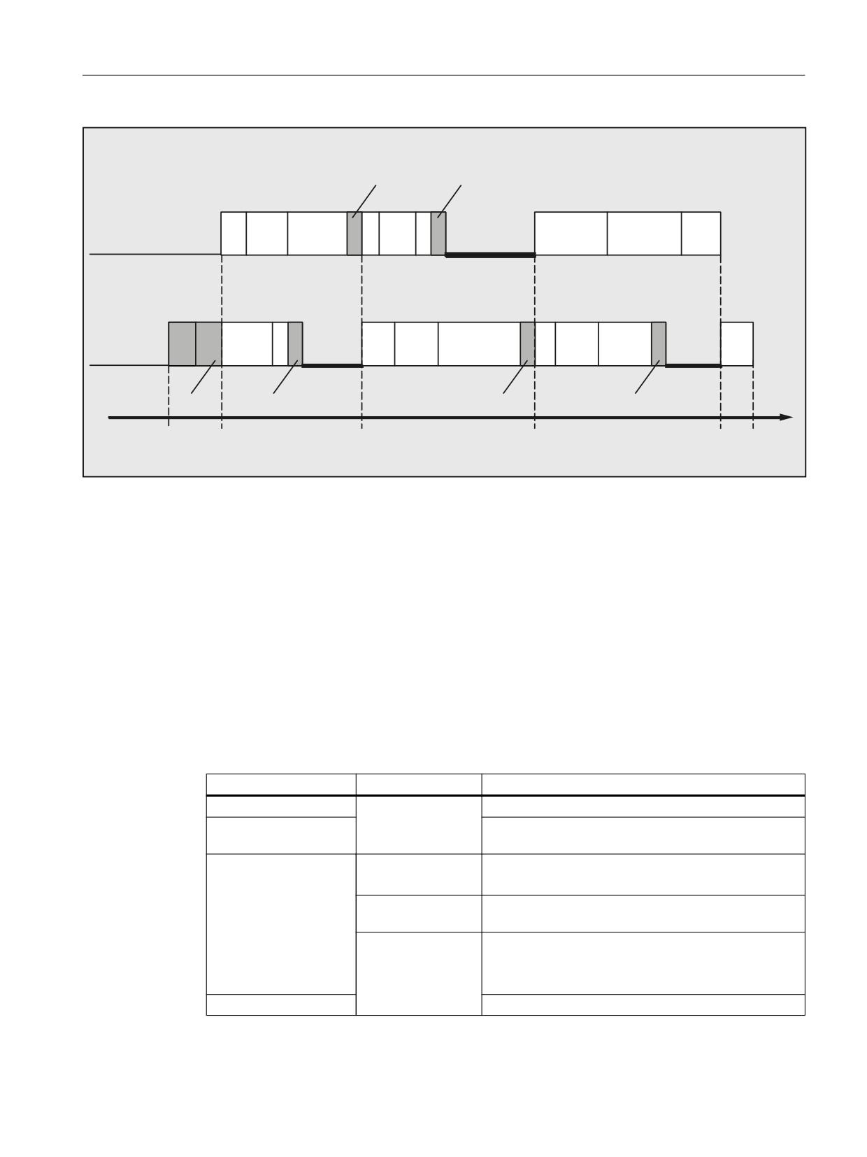
In the case of channel coordination using WAIT markers, execution of the following blocks
may start non-synchronously. This behavior occurs if an action is triggered in one of the
channels to be synchronized immediately before reaching the common WAIT marker; the
consequence of which is implicit repositioning (REPOSA) in this delete distance-to-go.
Assumption: Current axis assignment in channels 1 and 2
● Channel 1: Axes X1 and U
● Channel 2: Axis X2
Table 6-1
Time sequence in channels 1 and 2
Channel 1
Channel 2
Description
Arbitrary processing in channels 1 and 2
N100
Channel 1: reaches the WAIT marker and waits for
WAITM(20,1,2)
synchronization with channel 2
Start of the GETD(U)
N200 GETD(U)
Channel 2: Requests axis U from channel 1
processing:
Channel 1: Processing of GET(U) in the backg19round
● Axis interchange
N210
Channel 2: reaches the WAIT marker. ⇒ This com-
● Delete distance-to-
WAITM(20,1,2)
pletes the synchronization of channels 1 and 2
go
N220 G0 X2=100
Channel 2: Start of processing of N220
● REPOSA
End
N110 G0 X1=100
Channel 1: Staggered start of processing of N110
Extended Functions
Function Manual, 12/2018, A5E40874029B AB
371
K5: Cross-channel program coordination and channel-by-channel running-in
6.1 Cross-channel program coordination
See also
Conditional wait (WAITMC) in the continuous path mode (Page 372)
6.1.2
Conditional wait (WAITMC) in the continuous path mode
If in a channel, at the time that WAITMC is being processed, all of the required wait markers of
the other channels have already been received, then in this channel, traversing motion is not
braked, or the further program execution is not stopped, but continued with the processing of
the following block.
WAITMC is in separate block as function call. For the correct execution of WAITMC without
braking, a traversing block must be immediately before WAITMC. For traversing blocks with
G64x, the block with WAITMC is added to the previous block to avoid a drop in velocity. If there
are no traversing blocks, e.g. "IF loops", immediately before WAITMC, the command cannot
be assigned consistently and braking occurs.
Requirement
The following functions must be active in the channel:
● Continuous-path mode (G64, G641, G642, G643, G644 or G645)
● "LookAhead" function
Braking behavior
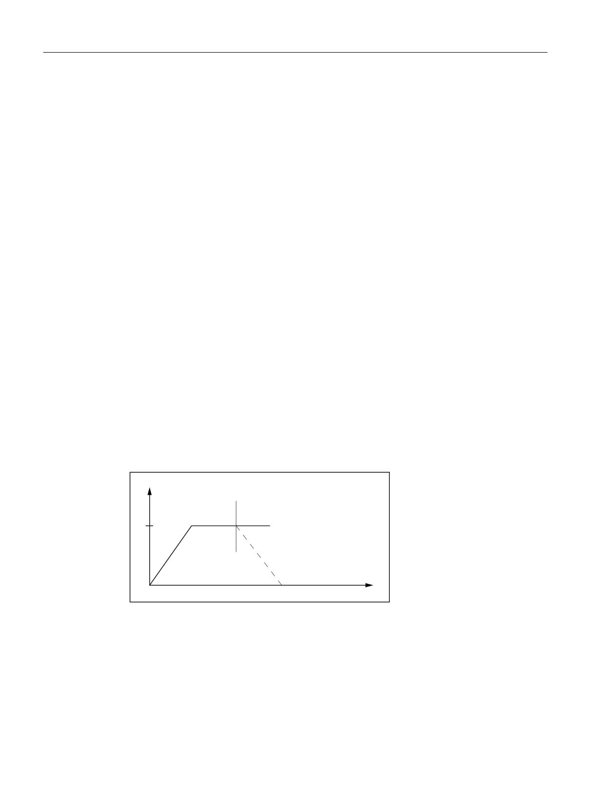
No braking
Starting with the motion block before the WAITMC call, the wait markers of the other channels
to be synchronized are checked. If these are already available, no braking is performed:
Y
:$,70&
W
Figure 6-1
Change of the path velocity for the conditional waiting with WAITCM: Wait markers for all
channels already available
Short-time braking
If the wait marker for a channel to be synchronized is missing, braking will be started. During
braking, a check is made in each interpolator cycle as to whether the still missing wait markers
have been received in the meantime. If this is the case, then the axis accelerates back to the
programmed velocity:
Extended Functions
372
Function Manual, 12/2018, A5E40874029B AB
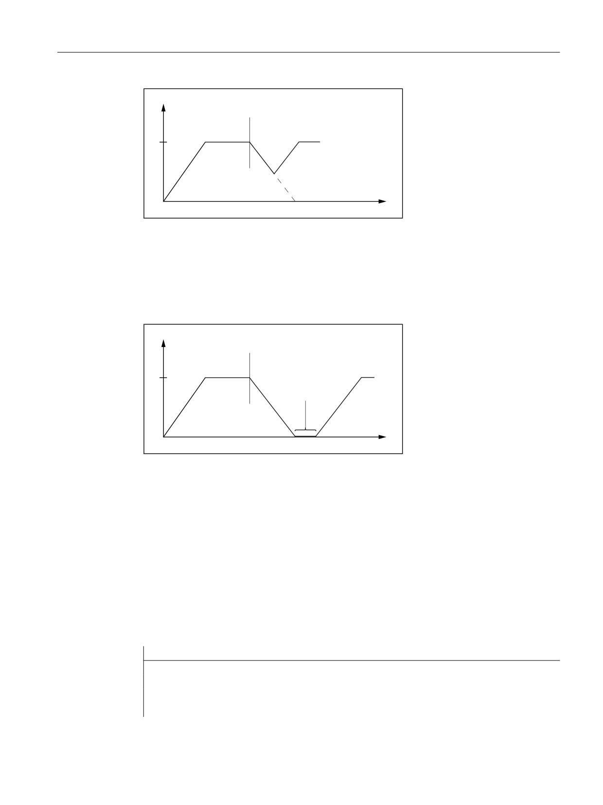
K5: Cross-channel program coordination and channel-by-channel running-in
6.1 Cross-channel program coordination
Y
:$,70&
W
Figure 6-2
Change of the path velocity for the conditional waiting with WAITCM: The last wait marker
arrives during braking
Braking down to standstill
If the wait marker is not received during the braking phase, then the axis is braked down to
standstill and the system waits. When the wait marker is received, the axis accelerates back
to the programmed velocity.
Y
:$,70&
6WDQGVWLOO
W
Figure 6-3
Change of the path velocity for the conditional waiting with WAITCM: The last wait marker
arrives after the braking
Block change while braking (IPOBRKA)
If the IPOBRKA (block change criterion "braking ramp") end of motion criterion is active, the
arrival of the last missing wait marker causes a transition to the next block and the axis is
accelerated.
Example 1: Conditional wait in continuous-path mode
The example is schematic, and shows only those commands that are relevant for the
synchronization.
Channel 1
Program code
Comment
N10 INIT(2, "_N_200_MPF","n")
; Select partner program channel 2.
N11 INIT(3,"_N_300_MPF","n")
; Select partner program channel 3.
N15 START(2,3)
; Start programs in channels 2, 3.
; Machining in channel 1.
Extended Functions
Function Manual, 12/2018, A5E40874029B AB
373

K5: Cross-channel program coordination and channel-by-channel running-in
6.1 Cross-channel program coordination
Program code
Comment
N20 WAITMC(7,2,3)
; Conditional wait for marker 7 from channels 2 and
3.
; Further machining in channel 1.
N40 WAITMC(8,2)
; Conditional wait for marker 8 from channel 2.
; Further machining in channel 1.
N70 M30
; End channel 1.
Channel 2
Program code
Comment
N200 ...
; Machining in channel 2.
N210 SETM(7)
; Channel 2 sets wait marker 7.
; Further machining in channel 2.
N250 SETM(8)
; Channel 2 sets wait marker 8.
N260 M30
; End channel 2.
Channel 3
Program code
Comment
N300 ...
; Machining in channel 3.
N350 WHEN <condition> DO SETM(7)
; Set wait marker in a synchronous action.
; Additional machining in channel 3.
N360 M30
; End channel 3.
Extended Functions
374
Function Manual, 12/2018, A5E40874029B AB
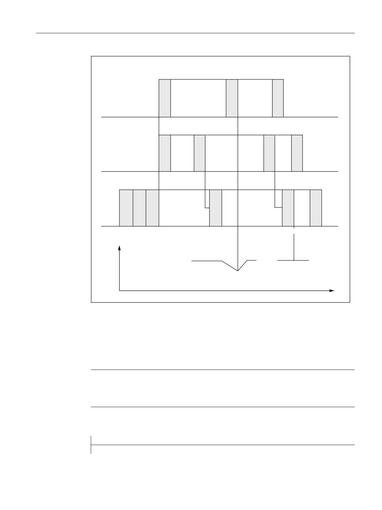
K5: Cross-channel program coordination and channel-by-channel running-in
6.1 Cross-channel program coordination
:+(1 FRQGLWLRQ!
&RQGLWLRQ IXOILOOHG
'2 6(70
&KDQQHO
1
1
1
&KDQQHO
6(70
6(70
1
1
1
1
&KDQQHO
1
1
1
1
1
1
:$,70&
:$,70&
Y
3DWK YHORFLW\
1R EUDNLQJ
&KDQQHO
W
Figure 6-4
Conditional wait in path-controlled operation with three involved channels (schematic)
Example 2: WAITMC and read-in disable
Auxiliary function M555 is output in channel 3 while the axis is traversing and creates a read-
in disable. As WAITMC is assigned block N312, the wait marker is set, and channel 2
progresses. The read-in disable causes the program execution in channel 3 to stop.
Note
For an active G64, WAITMC does not to create a dedicated block, but instead, is added to the
previous block. A drop in velocity must be prevented when continuous-path mode is active. A
WAITMC is therefore fulfilled if the preceding block is stopped, e.g. by a read-in disable.
Channel 2
Program code
Comment
N112 G18 G64 X200 Z200 F567
; Machining in channel 2
Extended Functions
Function Manual, 12/2018, A5E40874029B AB
375

K5: Cross-channel program coordination and channel-by-channel running-in
6.2 Running-in channel-by-channel
Program code
Comment
N120 WAITMC(1,2,3)
; Conditional wait for wait marker 1
; from channels 2 and 3
; Additional machining in channel 2, as
; WAITMC is added to block N312.
; Additional machining in channel 2
N170 M30
; End of channel 2
Channel 3
Comment
; During traversing read-in disable M555
N300
; Machining in channel 3
N312 G18 G64 D1 X180 Z300 M555
N320 WAITMC(1,2,3)
; Wait because of read-in inhibit
6.2
Running-in channel-by-channel
6.2.1
Function
The "channel-by-channel running-in" function is used to test or run-in the NC programs of one
or more channels that are synchronized with each other. The programmed traversing motion
of the channel axes and/or spindles in the channels, which are in the "Normal operating" state,
results in the machine axes traversing. The following applies to channels that are in the
"Program test" state:
● In the default setting, for axes for normal operation, identical setpoints are generated,
however, these are not output at the machine axes .
● In the default setting, the setpoints for spindles are output at the machine axes.
● The displayed actual values of the inhibited axes/spindles are internally generated from
setpoints.
● The commands for channel synchronization are processed normally.
● The NC/PLC interface signals are processed normally.
● The processing time of the program is the same as in normal operation.
Temporarily when required, the "Program test" state can be exited on an axis-for-axis basis.
The setpoints are then output again on the machine axes so that they are really traversed on
the machine.
See also
K10: Cross-channel axis interchange (Page 387)
Extended Functions
376
Function Manual, 12/2018, A5E40874029B AB
K5: Cross-channel program coordination and channel-by-channel running-in
6.2 Running-in channel-by-channel
6.2.2
Sequence
Normally, a channel moves a tool in the working area. If several channels are each moving a
tool in the same working area, the tool movements must be synchronized. The following
synchronizations are possible:
● Channel synchronization via the program coordination commands WAITM, WAITMC, WAITE,
START.
● Channel synchronization via the PLC user program and NC/PLC interface signals. For
example, via M function output from the channel to the PLC and read-in disable from the
PLC to the channel.
● Axis interchange: The channel waits until the other channel relinquishes the axis.
● Synchronization by means of global variables in the NC program.
● Cross-channel couplings
● Axis container rotation
● Testing the program including the parallel synchronized actions in the main run and
synchronization of the synchronized actions with the channel.
Under these general conditions, it is almost impossible to just start one channel - it would
remain stationary at the first synchronization location.
Using the "Channel-by-channel running-in", function, all of the required channels can be started
so that only those channels receive the traversing enable signals, whose interaction of the
programmed traversing motion are to be tested. The other channels are then in the "program
test" state.
To do this, before starting the channels, the machine operator must define the channels that
are to be traversed under "Program test". This is made from the user interface in the "Program
controls" menu.
6.2.3
Single-channel view
Selection
"Program test" (PRT) for the channel displayed in the "Machine" basic display is selected via
the user interface, e.g. SINUMERIK Operate:
1. Softkey: Operating area "Machine" > "Program control"
2. "Program controls" menu: Select check box "Program test (PRT)".
Extended Functions
Function Manual, 12/2018, A5E40874029B AB
377
K5: Cross-channel program coordination and channel-by-channel running-in
6.2 Running-in channel-by-channel
NC/PLC interface signals
After selecting program test (PRT), the following NC/PLC interface signals are set (see below
note "Automatic transfer of interface signals"):
● Channels
- DB21, ... DBX25.7 == 1 (from HMI: program test selected)
- DB21, ... DBX1.7 == 1 (from PLC: activate program test)
- DB21, ... DBX33.7 == 1 (from NC: program test active)
● Axes
- DB31, ... DBX128.0 == 0 (from HMI: suppress program test)
- DB31, ... DBX128.1 == 0 (activate program test from HMI)
- DB31, ... DBX14.0 == 0 (from PLC: suppress program test)
- DB31, ... DBX14.1 == 0 (from PLC: activate program test)
● Spindles
- DB31, ... DBX128.0 == 1 (from HMI: suppress program test)
- DB31, ... DBX128.1 == 0 (from HMI: activate program test)
- DB31, ... DBX14.0 == 1 (from PLC: suppress program test)
- DB31, ... DBX14.1 == 0 (from PLC: activate program test)
Note
Default state of traversing motion
The default state regarding traversing motion after selecting "Program test" in the channel is:
● Axes: Inhibited
● Spindles: Enabled
Note
Automatic transfer of the interface signals
The HMI request signals DB21, ... DBX128.0 / .1 are only transferred from the basic PLC
program to the PLC request signals DB21, ... DBX14.0 / .1 if FB1 parameter MMCToIF is set
to TRUE. If the parameters are not set, then the PLC request signals must be set by the PLC
user program.
Inhibiting spindle traversing motion
If, during "Program test" spindles are not to be traversed, then they must be explicitly inhibited/
locked via the PLC user program:
● DB31, ... DBX128.0 = 0 (suppress program test)
● DB31, ... DBX128.1 = 1 (activate program test)
● DB31, ... DBX14.0 = 0 (from PLC: suppress program test)
● DB31, ... DBX14.1 = 1 (from PLC: activate program test)
Extended Functions
378
Function Manual, 12/2018, A5E40874029B AB
K5: Cross-channel program coordination and channel-by-channel running-in
6.2 Running-in channel-by-channel
NOTICE
Spindle traversing motion
Traversing motion of the spindles of the channel is enabled in the "Program test" as default
setting.
Enabling traversing motion of the axes
If, during "Program test" channel axes are to be traversed, then they must be explicitly enabled
via the PLC user program:
● DB31, ... DBX14.0 = 1 (from PLC: suppress program test)
● DB31, ... DBX14.1 = 0 (from PLC: activate program test)
Permissible switching instants
● Channel
Interface signals to deactivate/activate the channel-specific "Program test" state (DB21, ...
DBX25.7 or DBX1.7), may only be switched in the "Reset" or "Interrupted" channel state.
● Axes/spindles
Interface signals to activate/deactivate the axis-specific "Program test" state (DB31, ...
DBX128.0 / .1 or DBX14.0 / .1) may always be switched.
6.2.4
Multi-channel view
Prerequisites
The following preconditions must be satisfied so that in the multi-channel view in menu
"Program controls", the channels and spindles can be displayed:
● Channels
- More than one channel is parameterized (MD10010
$MN_ASSIGN_CHAN_TO_MODE_GROUP[<channel>] ≠ 0)
- Option "programSYNC" (6FC5800-0AP05-0YB0) is set/licensed
● Spindles
- The significance of the spindle, parameterized in the channel, has been defined
(MD52206 $MC_AXIS_USAGE[<spindle>] ≠ 0)
Selection
"Program test" (PRT) for one or several channels parameterized in the control is selected via
the user interface, e.g. SINUMERIK Operate:
1. Softkey: Operating area "Machine" > "Program control"
2. Softkey: "Running-in"
3. "Program controls" menu: Deselect group "Running-in” > Check box "Channel x".
Extended Functions
Function Manual, 12/2018, A5E40874029B AB
379

K5: Cross-channel program coordination and channel-by-channel running-in
6.2 Running-in channel-by-channel
Check box channel/spindle
In menu "Program controls": The following behavior can be set for the "Running-in" group using
check box "Channel x" or "Spindle x":
Check box
Selected
Deselected
"Channel x"
Normal operation
Program is only calculated
(channel in test run)
"Spindle x"
Normal operation
No machining at spindle x
(spindle in test run)
NC/PLC interface signals
After deselecting the checkbox for "Channel x", the channel is in the "Program test (PRT)"
state. The following NC/PLC interface signals are set (see below note "Automatic transfer of
interface signals"):
● Channels
- DB21, ... DBX25.7 == 1 (from HMI: program test selected)
- DB21, ... DBX1.7 == 1 (from PLC: activate program test)
- DB21, ... DBX33.7 == 1 (from NC: program test active)
● Axes
- DB31, ... DBX128.0 == 0 (from HMI: suppress program test)
- DB31, ... DBX128.1 == 0 (activate program test from HMI)
- DB31, ... DBX14.0 == 0 (from PLC: suppress program test)
- DB31, ... DBX14.1 == 0 (from PLC: activate program test)
In the default setting, the control boxes for the spindles are selected, i.e. spindles are in normal
operation:
● Spindles
- DB31, ... DBX128.0 == 1 (from HMI: suppress program test)
- DB31, ... DBX128.1 == 0 (from HMI: activate program test)
- DB31, ... DBX14.0 == 1 (from PLC: suppress program test)
- DB31, ... DBX14.1 == 0 (from PLC: activate program test)
Note
Default state of traversing motion
The default state regarding traversing motion after selecting "Program test" in the channel is:
● Axes: Inhibited
● Spindles: Enabled
Extended Functions
380
Function Manual, 12/2018, A5E40874029B AB

K5: Cross-channel program coordination and channel-by-channel running-in
6.2 Running-in channel-by-channel
Note
Automatic transfer of the interface signals
The HMI request signals DB21, ... DBX128.0 / .1 are only transferred from the basic PLC
program to the PLC request signals DB21, ... DBX14.0 / .1 if FB1 parameter MMCToIF is set
to TRUE. If the parameters are not set, then the PLC request signals must be set by the PLC
user program.
Inhibiting spindle traversing motion
If, during "Program test" spindles of the channel are not to be traversed, then they must be
explicitly inhibited/locked via the PLC user program:
● DB31, ... DBX128.0 = 0 (suppress program test)
● DB31, ... DBX128.1 = 1 (activate program test)
● DB31, ... DBX14.0 = 0 (from PLC: suppress program test)
● DB31, ... DBX14.1 = 1 (from PLC: activate program test)
NOTICE
Spindle traversing motion
Traversing motion of the spindles of the channel is enabled in the "Program test" as default
setting.
Enabling traversing motion of the axes
If, during "Program test" channel axes are to be traversed, then they must be explicitly enabled
via the PLC user program:
● DB31, ... DBX14.0 = 1 (from PLC: suppress program test)
● DB31, ... DBX14.1 = 0 (from PLC: activate program test)
Permissible switching instants
● Channel
Interface signals to deactivate/activate the channel-specific "Program test" state (DB21, ...
DBX25.7 or DBX1.7), may only be switched in the "Reset" or "Interrupted" channel state.
● Axes/spindles
Interface signals to activate/deactivate the axis-specific "Program test" state (DB31, ...
DBX128.0 / .1 or DBX14.0 / .1) may always be switched.
Extended Functions
Function Manual, 12/2018, A5E40874029B AB
381

K5: Cross-channel program coordination and channel-by-channel running-in
6.2 Running-in channel-by-channel
6.2.5
System variables
The "program test" state can be interrogated using system variables:
● For the display in the user interface, in synchronized actions or with a preprocessing stop
in the part program via the system variables:
$AC_ISTEST
"Program test" state for the channel
Supplies TRUE (1), if the "program test" state for the channel is active.
$AA_ISTEST[<n>]
"Program test" state for the axis <n>
Supplies TRUE (1), if the "program test" state for axis <n> is active.
● Without preprocessing stop in the part program via the system variable:
$P_ISTEST
Supplies TRUE (1), if the "program test" state for the channel is active.
Example
The channel runs under "program test" and axis "C" was withdrawn using "suppress program
test". A query using system variables then supplies the following result:
● $AC_ISTEST == TRUE
● $P_ISTEST == TRUE
● $AA_ISTEST[C] == FALSE
6.2.6
Supplementary conditions
Axis interchange
The "axis interchange" function allows that an axis/spindle is known in several channels and
can be programmed by these alternately (see Section "K10: Cross-channel axis interchange
(Page 387)").
In conjunction with the functions "program test" and "channel-by-channel running-in", the
following must be observed for an axis interchange:
● If only one of the channels is in the "program test" state, then the interchanged axis is taken
from this channel and is inserted in a channel that is not in the "program test" state. For an
interchanged axis with active axis disable, for a change via the channels with/without
channel state "program test", then the state in the axis itself does not change (see example
3).
● For a program test, for end of part program/reset, for all axes/spindles that do not
interpolate, resynchronization is made at the actual position. As a consequence, for an axis
interchange that is first made after the end of the program, as the axis may only exit the
channel at the end of the program, the simulated position reached is not transferred to the
accepting channel.
Note
The programs should also include a WAIT tag at the end in order that they are
simultaneously exited.
Extended Functions
382
Function Manual, 12/2018, A5E40874029B AB
K5: Cross-channel program coordination and channel-by-channel running-in
6.2 Running-in channel-by-channel
6.2.7
Examples
Example 1: Channel 2 is to be tested in a 3-channel system.
Test option 1: Program test without SERUPRO
1. The user decides which axes/spindles should actually be physically traversed. "Suppress
program test" is set for these axes.
2. The "program test" state is selected for channels 1 and 3.
3. Channels 1, 2 and 3 are started via the PLC.
4. "Program test" can be selected again after the end of the program.
5. If the actual setting of "suppress program test" is also practical for other situations (channel
1 or channel 3 are to be tested), then this signal can remain set. This is certainly practical
in many cases.
Test option 2: Program test with SERUPRO
1. The user decides which axes/spindles should actually be physically traversed. "Suppress
program test" is set for these axes.
2. The "program test" state is selected for channels 1 and 3.
3. Channels 1, 2 and 3 are started via the PLC.
4. A fault or an alarm occurs, the user interrupts with RESET.
5. SERUPRO at the interruption location of all 3 channels.
6. Search destination has been reached in all 3 channels.
7. Start all 3 channels.
8. Channels 1 and 3 are now again in "program test" and "channel-by-channel running-in" is
continued.
Example 2: Activating "suppress program test"
A channel is in program test. In operation, "suppress program test" should be initiated for axis
"Y" (at block N1010).
Program code
Comment
N1000 G0 Y1000
N1010 G4 F10
N1020 G0 G91 Y=10
; Incremental traversing.
N1030 M30
With this sequence, the program moves to position 1010, i.e. the simulated component "1000"
of this axis is moved after activating "suppress program test".
Example 3: Program test and axis interchange
Axis X1 from channel 1 and axis X2 from channel 2 are assigned to the 1st machine axis AX1
of the NC.
Channel 1 with "Program test"
Channel 2 without "Program test"
N10010 G0 G90 X0
Extended Functions
Function Manual, 12/2018, A5E40874029B AB
383
K5: Cross-channel program coordination and channel-by-channel running-in
6.3 Supplementary conditions
Channel 1 with "Program test"
Channel 2 without "Program test"
N10020 X1=100
N10030 WAITM(91,1,2)
N10040 WAITM(92,1,2)
N10050 M0
N10060 M30
N20010 WAITM(91,1,2)
N20020 G91 G0 X2=10
N20030 WAITM(92,1,2)
N20040 M0
N20050 M30
In block N20040, machine axis AX1 is interchanged to channel 2, the last position of the axis
from channel 1 is taken over and the axis traversed to position 110.
6.3
Supplementary conditions
6.3.1
MDI mode: Path control mode and WAITMC
MDI mode: Continuous path mode and WAITMC
In the MDI mode, when starting to execute the MDI block buffer, it is not permissible that the
WAITMC in conjunction with the path control mode (G64 / G604), is located in the last block of
the MDI block buffer. Otherwise the program will stop with the last but one traversing block,
and can only be canceled with a reset.
Example
Before an NC start, the MDI block buffer contains the following blocks:
Program code
Comment
N10 G64 G1 G94 F5000 X100
; Continuous path mode in the first block of
the
; MDI block buffer
N20 X200
N30 X300
; Last but one traversing block
N40 X400
; Program execution stops here
N50 WAITMC(...)
; due to WAITMC in N50.
; Cancellation with reset required!
Extended Functions
384
Function Manual, 12/2018, A5E40874029B AB
K5: Cross-channel program coordination and channel-by-channel running-in
6.3 Supplementary conditions
6.3.2
Non-synchronous start of traversing motion after WAIT commands
In the case of channel coordination using WAIT commands, a non-synchronous start when
executing the following blocks can occur. This behavior occurs if an action is triggered in one
of the channels immediately before reaching the common synchronization location; the
consequence of which is implicit repositioning (REPOSA) in this delete distance-to-go.
Assumption: Current axis allocation in channels 1 and 2
● Channel 1: Axes Z1 and W
● Channel 2: Axis Z2
Example 1: Start of traversing motion with time offset
The following command sequences in channels 1 and 2 result in a possible problematical start
of traversing motion with time offset after the synchronization location N110 / N210:
Table 6-2
Sequence (time) in channels 1 and 2
Channel 1
Channel 2
Description
Any processing in channels 1 and 2
N100 W100
Channel 1: Traversing axis W
Arbitrary processing in channels 1 and 2
N110 WAITM(2,1,2)
N210 WAITM(2,1,2)
Channels 1 and 2: wait for synchronization
Start "AUTOGET(W)":
"AUTOGET(W)" and
wait for axis W from
● Axis replacement
channel 1
Channel 2: Start of traversing motion with time off-
● Delete distance-to-
N220 Z2=100 W100
set
go
● REPOSA
End
Channel 1: Start of traversing motion
N120 Z1=100
Example 2: Simultaneous start of traversing motion
Start of traversing motion with time offset (delay) in example 1 can be avoided by explicitly
enabling and requesting the axis W to be replaced and by inserting an additional
synchronization location. The following command sequences in channels 1 and 2 result in a
simultaneous start of traversing motion after the synchronization location N120 / N220:
Table 6-3
Sequence (time) in channels 1 and 2
Channel 1
Channel 2
Description
Arbitrary processing in channels 1 and 2
N100 W100
Channel 1: Traversing axis W
Arbitrary processing in channels 1 and 2
RELEASE(W)
Channel 1: Enable axis W ⇒ The axis replacement
in channel 2 no longer affects channel 1
N110 WAITM(2,1,2)
N210 WAITM(2,1,2)
Channels 1 and 2: wait for synchronization
N215 GET(W)
Channel 2: Request axis W. Axis replacement is
optimum from a time perspective, as axis W is al-
ready enabled
Extended Functions
Function Manual, 12/2018, A5E40874029B AB
385

K5: Cross-channel program coordination and channel-by-channel running-in
6.3 Supplementary conditions
Channel 1
Channel 2
Description
N120 WAITM(9,1,2)
N220 WAITM(9,1,2)
Channels 1 and 2: wait for synchronization
N130 Z1=100
N230 Z2=100 W100
Channels 1 and 2: simultaneous start of traversing
motion
Extended Functions
386
Function Manual, 12/2018, A5E40874029B AB
K10: Cross-channel axis interchange
7
7.1
Overview
Note
Spindles
The following statements and functions regarding the "axis replacement" function for axes also
apply to spindles.
Each axis must be assigned to a channel during control commissioning. The axis can only be
traversed, for example, by part programs or synchronized actions from the channel to which
the axis is assigned. With the "axis replacement" function, it is possible to enable an axis and
to allocate it to another channel, that is, to replace the axis. Only than can the axis be traversed
by another channel.
Axis states
As part of the "axis replacement" function, an axis can have the following states:
● "Channel axis"
A channel axis is an axis that is assigned to a channel. It can be traversed via a part program
or manually.
● "PLC axis"
A PLC axis is an axis that is assigned to the PLC. It can only be traversed by the PLC user
program or function block FC18.
● "Neutral axis"
A neutral axis is an axis that is not currently assigned to a channel or the PLC. Before
traversing, it must first be requested by a channel or the PLC.
● "Axis in another channel"
An axis is in this state if a channel has requested the axis. However, it could not yet be
assigned to it because it is still occupied by another channel.
7.2
Commissioning
Parameter assignment
NC-specific machine data
● General parameterization of the axis replacement form
MD10722 $MN_AXCHANGE_MASK
Extended Functions
Function Manual, 12/2018, A5E40874029B AB
387

K10: Cross-channel axis interchange
7.3 Programming: Releasing an axis (RELEASE)
Channel-specific machine data
● Parameterization of which axes belong to the channel or are channel axes:
MD20070 $MC_AXCONF_MACHAX_USED[<channel axis>] = <machine axis>
Note: Assignment of all axes used in the NC must be performed in any case as channel
axes of one or more channels, irrespective of the "axis replacement" function.
Axis-specific machine data
● If an axis is a channel axis in multiple channels, the machine data defines to which channel
the axis is assigned after control startup (power-on reset):
MD30550 $MA_AXCONF_ASSIGN_MASTER_CHAN[<channel>] = <channel number>
The parameterized channel is the master channel of the axis.
● Parameterization of the response if an axis is programmed in a part program and the axis
is not currently assigned to the channel:
- Display an alarm and do not traverse the axis.
- Automatically requesting the axis according to the command GET (Page 389)
- Automatically requesting the axis according to the command GETD (Page 389)
MD30552 $MA_AUTO_GET_TYPE[<axis>] = <response>
System variable
Axis-specific system variable
● Axis type in relation to axis replacement:
$AA_AXCHANGE_TYP[<axis>]
● Axis replacement status of the axis:
$AA_AXCHANGE_STAT[<axis>]
7.3
Programming: Releasing an axis (RELEASE)
Function
An axis that is assigned to the current channel is released for an axis interchange via the
predefined RELEASE() procedure and put into the "neutral axis" state for this purpose.
Syntax
RELEASE(<axis1>[, axis2 ... axis15])
Meaning
RELEASE:
Release axis for axis interchange
Preprocessing
Yes
stop:
Alone in the
Yes
block:
Extended Functions
388
Function Manual, 12/2018, A5E40874029B AB

K10: Cross-channel axis interchange
7.4 Programming: Fetching an axis (GET, GETD)
<axis>:
Axis: Channel axis name of the releasing axis
Spindle: Channel axis name of the releasing spindle or conversion of the spindle num-
ber in the channel axis names by means of SPI(<spindle number>)
Type:
AXIS
Supplementary conditions
No enable possible
● The axis is involved in a transformation.
● The axis belongs to an axis grouping.
Guide axis of a gantry grouping
If the guide axis of a gantry grouping is released, all synchronous axes are also released.
7.4
Programming: Fetching an axis (GET, GETD)
Requesting axis interchange (GET):
Function
With the predefined GET() procedure, an axis is requested for the same channel.
In the channel, to which the axis is currently assigned, the axis must be released in a part
program or synchronized action for axis interchange with RELEASE().
After axis interchange, the axis has "channel axis" status.
Syntax
GET(<axis1>[, axis2 ... axis15])
Meaning
GET:
Request of an axis for the current channel
Preprocessing
Yes
stop:
Alone in the
Yes
block:
<axis>:
Axis: Channel axis name of the requested axis
Spindle: Channel axis name of the requested spindle or conversion of the spindle num-
ber in the channel axis names by means of SPI(<spindle number>)
Type:
AXIS
Supplementary conditions
Axis interchange is delayed in the following situations:
● The axis has not yet been released with RELEASE by the channel to which it is assigned.
● A change of measuring system has not yet been completed.
Extended Functions
Function Manual, 12/2018, A5E40874029B AB
389

K10: Cross-channel axis interchange
7.4 Programming: Fetching an axis (GET, GETD)
● The change of status of the controller enable has not yet been completed (transition of rules
to follow-up/stop and vice versa).
● The NC/PLC interface signal "axis or spindle disable" is pending (DB31, ... DBX1.3 == 1)
● The current traversing movement (interpolation) of the axis has not yet been completed.
Fetching an axis directly (GETD)
Function
An axis that is not assigned to the current channel is required for the following machining
section of a part program. With the predefined procedure GETD(), the axis is fetched directly
from the channel to which the axis is assigned. For this purpose, the axis does not have to be
released by this channel with RELEASE().
After axis interchange, the axis has "channel axis" status.
Depending on the state of the axis in the relinquishing channel, a preprocessing stop is
triggered in this channel (STOPRE):
● "Channel axis" status ⇒ preprocessing stop
● "Neutral axis" status ⇒ no preprocessing stop
To coordinate transfer of the axis between the channels with GETD(), we recommend using
channel synchronization (Page 367) between the requesting and the relinquishing channel.
NOTICE
Preprocessing stop in the relinquishing channel
If the axis in the relinquishing channel has "channel axis" status, a preprocessing stop will be
triggered in this channel (STOPRE):
Syntax
GETD(<axis>)
Meaning
GETD:
Fetching an axis directly into the current channel
Preprocessing
Yes
stop:
Alone in the
Yes
block:
<axis>:
Axes: Channel axis name of the requested axis
Spindles: Channel axis name of the requested spindle or conversion of the spindle
number in the channel axis names by means of SPI(<spindle number>)
Supplementary condition
If the axis has "PLC axis" status in the relinquishing channel, the axis must be released for
axis interchange by the PLC user program.
Extended Functions
390
Function Manual, 12/2018, A5E40874029B AB
K10: Cross-channel axis interchange
7.5 Automatic axis replacement
Supplementary conditions
Channel reset
● If a channel reset is triggered in the channel that requested the axis, axis interchange is
canceled.
● A replaced axis remains assigned to the channel that last requested it even after a channel
reset.
7.5
Automatic axis replacement
Function
Automatic axis replacement or automatic fetching of an axis into the current channel is
performed if the axis is programmed in the part program or synchronized action, but it is not
assigned to the channel at the moment.
Requirement
Parameterization of automatic axis replacement by GET() or GETD():
MD30552 $MA_AUTO_GET_TYPE (Page 387)
Supplementary conditions
See Description (Page 389) of GETD().
Examples
Example 1
Program code
Comment
N1 M3 S1000
; Traversing the main spindle
N2 RELEASE (SPI(1))
; Release to neutral status
N3 S3000
; Programming the main spindle => automatic fetching
; Behavior depending on MD30552 $MA_AUTO_GET_TYPE:
; 0 => Alarm "Wrong axis type"
; 1 => implicit GET(SPI(1))
; 2 => implicit GETD(SPI(1))
Example 2
Program code
Comment
; Machine axis AX1 ≙ channel axis X
N1 RELEASE (AX1)
; Release to neutral status
N2 G04 F2
; Dwell time
N3 G0 X100 Y100
; Programming axis X as a path axis
; Behavior depending on MD30552 $MA_AUTO_GET_TYPE:
Extended Functions
Function Manual, 12/2018, A5E40874029B AB
391
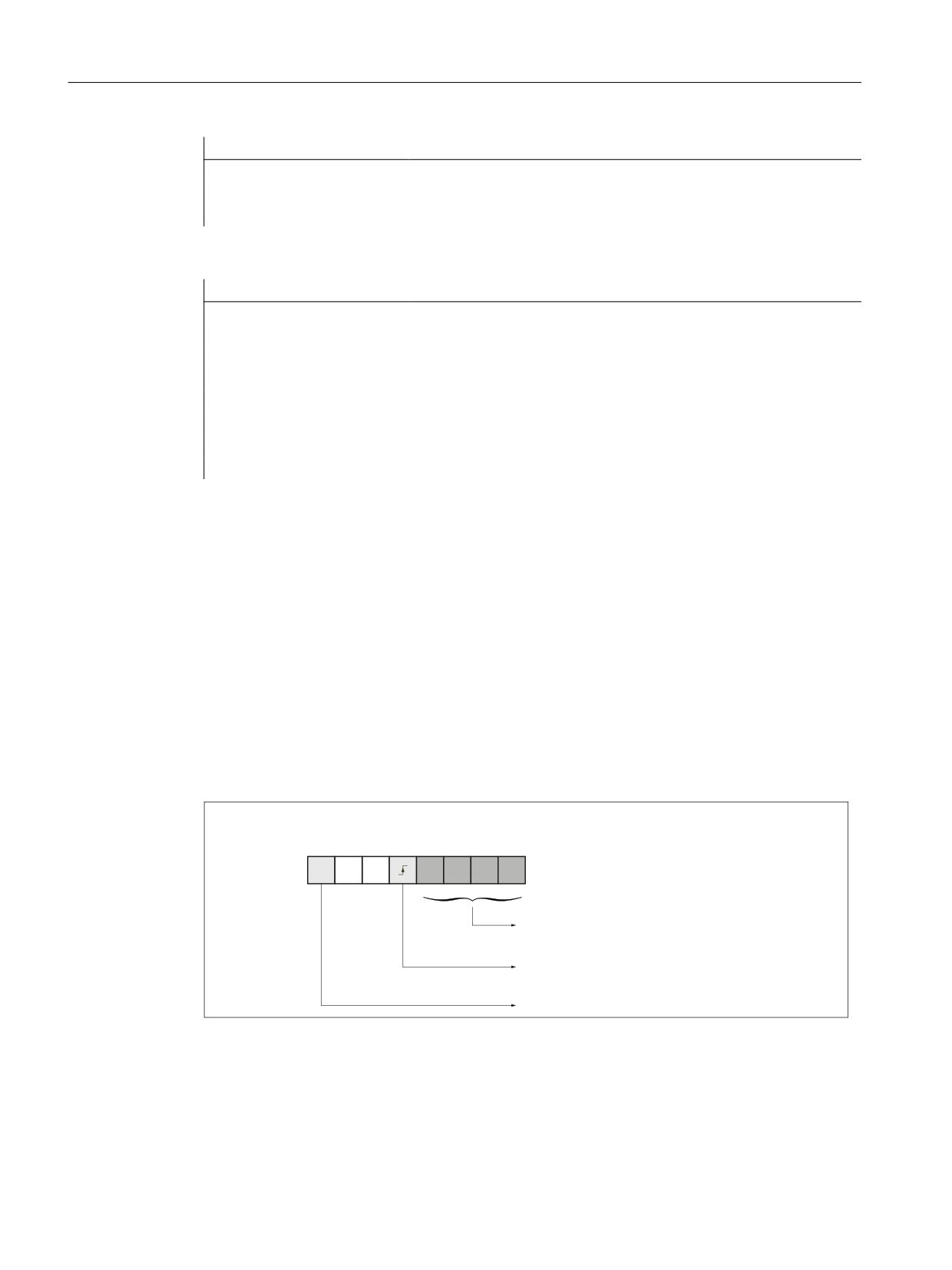
K10: Cross-channel axis interchange
7.6 Axis replacement via PLC
Program code
Comment
; 0 => Alarm "Wrong axis type"
; 1 => implicit GET(AX1)
; 2 => implicit GETD(AX1)
Example 3
Program code
Comment
; Machine axis AX1 ≙ channel axis X
N1 RELEASE (AX1)
; Release to neutral status
N2 G04 F2
; Dwell time
N3 POS (X) = 100
; Programming axis X as a positioning axis
; Behavior depending on MD30552 $MA_AUTO_GET_TYPE:
; 0 => Alarm "Wrong axis type"
; 1 => implicit GET(AX1) *)
; 2 => implicit GETD(AX1) *)
*) If the axis has not yet been synchronized, a separate block is generated for automatic
fetching of the axis using (GET() or GETD().
7.6
Axis replacement via PLC
Function
Axis replacement can be requested by the PLC user program via the NC/PLC interface:
● From an NC channel to the PLC
● From the PLC to an NC channel
● From an NC channel to another NC channel
'%
'%%
3/& ൺ 1&
%LW
5HTXLUHPHQW &KDQQHO QXPEHU RI WKH
FKDQQHO WR ZKLFK WKH D[LV LV WR EH DVVLJQHG
5HTXLUHPHQW 6ZLWFK RYHU D[LV
5HTXHVW IURP 3/& ൺ
$FNQRZOHGJPHQW E\ 1&
ൺ
5HTXLUHPHQW $[LV W\SH 3/& D[LV
Figure 7-1
Axis replacement request: DB31, ... DBB8 (PLC → NC)
Axis replacement status
The current status of an axis with regard to axis replacement can be read by the PLC user
program via the NC/PLC interface.
Extended Functions
392
Function Manual, 12/2018, A5E40874029B AB
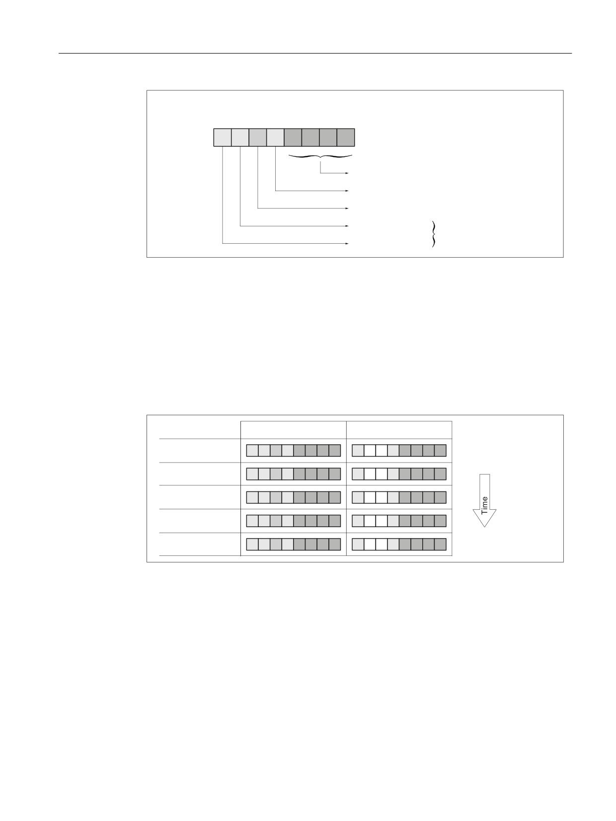
K10: Cross-channel axis interchange
7.6 Axis replacement via PLC
'%
'%%
1& ൺ 3/&
%LW
&KDQQHO QXPEHU RI WKH FKDQQHO WR
ZKLFK WKH D[LV LV DVVLJQHG
1HZ D[LV W\SH UHTXHVWHG E\ WKH 3/&
$[LV UHSODFHPHQW LV SRVVLEOH
1HXWUDO D[LV
$[LV W\SH
3/& D[LV
Figure 7-2
Axis replacement status: DB31, ... DBB68 (NC → PLC)
Examples
Example 1
Axis replacement of an axis from channel 1 to channel 2 by means of RELEASE() and
GET() in part programs that are executed in each channel:
● Channel 1: RELEASE(<axis>)
● Channel 2: GET(<axis>)
'%
'%%
'%
'%%
$IWHU SRZHU RQ
FKDQQHO D[LV LQ .
5(/($6( $;
*(7 $;
Example 2
Status change of an axis assigned to channel 1 from "NC axis" to "PLC axis" by the PLC user
program.
Extended Functions
Function Manual, 12/2018, A5E40874029B AB
393
K10: Cross-channel axis interchange
7.6 Axis replacement via PLC
'%
'%%
'%
'%%
$IWHU SRZHU RQ
FKDQQHO D[LV LQ .
5HTXHVW E\ 3/&
1HZ 7<3 3/& D[LV
5HTXHVW GHWHFWHG
$[LV UHSODFHPHQW SRVVLEOH
5HTXHVW E\ 1& UHVHW
3/& D[LV LQ .
Example 3
Status change of an axis assigned to channel 1 from "NC axis" via "PLC axis" to "neutral axis"
by the PLC user program.
'%
'%%
'%
'%%
$IWHU SRZHU RQ
FKDQQHO D[LV LQ .
5HTXHVW E\ 3/&
1HZ 7<3 3/& D[LV
5HTXHVW GHWHFWHG
$[LV UHSODFHPHQW SRVVLEOH
5HTXHVW E\ 1& UHVHW
3/& D[LV LQ .
5HTXHVW E\ 3/&
1HZ 7<3 1HXWUDO D[LV
5HTXHVW GHWHFWHG
$[LV UHSODFHPHQW SRVVLEOH
1HXWUDO D[LV LQ
5HTXHVW E\ 1& UHVHW
Extended Functions
394
Function Manual, 12/2018, A5E40874029B AB
K10: Cross-channel axis interchange
7.8 Axis replacement with and without preprocessing stop
7.7
Axis interchange via axis container rotation
Enabling axis container rotation
When an axis container rotation is enabled, all container axes that can be allocated to a channel
are allocated to this channel using implicitly generated GET or GETD. An axis can only be
relinquished, e.g. to another channel, after container rotation.
Note
The implicit assignment of an axis to a channel is notpossible if the axis in the state "main run
axis" (e.g. is a PLC axis). In order to be able to participate in the axis container rotation, the
axis must first exit the state.
For further explanations on the axis replacement of container axes (see Section "B3:
Distributed systems - 840D sl only (Page 73)").
Example: Axis container rotation with an implicit GET or GETD
Action Channel 1
Action Channel 2
SPOS = 180 positioned
AXCTSWE(CT 1)
; gets spindle in Channel 1
; and allows axis container rotation
Assumption:
The spindle is used in both channels and is also an axis in axis container CT 1.
Activation
Axis interchange using axis container rotation and implicit GET/GETD is activated using
machine data MD10722 $MN_AXCHANGE_MASK, bit 1=1.
7.8
Axis replacement with and without preprocessing stop
Axis replacement extension without preprocessing stop
Instead of a GET block with a preprocessing stop, this GET request only generates an
intermediate block. In the main run, when this block is executed, the system checks whether
the states of the axes in the block match the current axis states. If they do not match, forced
reorganization can be triggered.
The following states of an axis or positioned spindle are checked for:
● The mode, either for the axis or for positioned spindle
● Setpoint position
Extended Functions
Function Manual, 12/2018, A5E40874029B AB
395
K10: Cross-channel axis interchange
7.8 Axis replacement with and without preprocessing stop
The following states of a Spindle in speed mode are checked:
● Spindle mode: Speed mode
● Spindle speed S
● Direction of rotation M3, M4
● Gear stage M40, M41, M42, M43, M44, M45
● Master spindle at constant cutting rate.
In some instances, forced reorganization may be possible. Reorganization of the following
axes is forced in any case.
Activation
Replacement without preprocessing and checking of the current states is activated with
machine data MD10722 $MN_AXCHANGE_MASK, Bit 2=1.
Example
Activating an axis replacement without a preprocessing stop
Table 7-1
N010 M4 S1000
N011 G4 F2
N020 M5
N021 SPOS=0
N022 POS[B]=1
N023 WAITP(B)
; Axis b becomes the neutral axis
N030 X1 F10
N031 X100 F500
N032 X200
N040 M3 S500
N041 G4 F2
N050 M5
N099 M30
If the spindle (axis B) is traversed immediately after block N023 as a PLC axis to 180° and
back to 1°, and then again to the neutral axis, block N040 does not trigger a preprocessing
stop nor a reorganization.
Special case: Axis replacement with preprocessing stop
Without a GET or GETD instruction having previously occurred in the main run, the spindle or
the axis can be made available again by RELEASE (axis) or WAITP (axis), for example. A
subsequent GET leads to a GET with a preprocessing stop.
Extended Functions
396
Function Manual, 12/2018, A5E40874029B AB
K10: Cross-channel axis interchange
7.9 Axis exclusively controlled from the PLC
7.9
Axis exclusively controlled from the PLC
Function
After the control boots, the axis is in the "neutral axis" state. The PLC controls it. To traverse
the axis as competing positioning axis (from the PLC via function block FC18), the axis must
first be explicitly requested from the PLC.
Note
Per machine data, the axis interchange to the PLC can be exclusively restricted to PLC
controlled axes: MD10722 $MN_AXCHANGE_MASK, Bit 3 = 1
The axis cannot be traversed from an NC part program.
Parameter assignment
Parameterizing an axis as axis that is exclusively controlled from the PLC is realized using the
axis-specific machine data:
MD30460 $MA_BASE_FUNCTION_MASK, Bit 4 = 1
Control by PLC
The traversing behavior of an axis exclusively controlled from the PLC is only influenced by
the axial NC/PLC interface signals:
● DB31, ... DBX28.1 (reset)
● DB31, ... DBX28.2 (continue)
● DB31, ... DBX28.6 (stop along braking ramp)
Possible traversing functions
The following traversing functions are possible for axes exclusively controlled from the PLC:
1. Traversing in the JOG mode using the traversing keys and handwheel
2. Referencing the axis
3. Traversing as command axis via static synchronized actions
4. Traversing as asynchronous oscillating axis
5. Traversing as competing positioning axis from the PLC via FC18
After traversing functions 1. to 4. have been completed, the axis automatically goes back into
the "neutral axis" state. After traversing function 5. from the PLC has been completed, the axis
remains in the state "PLC axis". The axis only changes into the "Neutral axis" state after having
been explicitly released by the PLC.
Extended Functions
Function Manual, 12/2018, A5E40874029B AB
397
K10: Cross-channel axis interchange
7.10 Axis permanently assigned to the PLC
7.10
Axis permanently assigned to the PLC
Function
After the control has booted, the axis is in the "neutral axis" state and is controlled from the
NC channel. To traverse the axis as competing positioning axis (from the PLC via function
block FC18), the axis does not have to be explicitly requested from the PLC. Axis interchange
to the PLC is realized automatically using the traversing request via FC18. After the traversing
motion requested via FC18 has been completed, the axis again automatically changes into
the "neutral axis" state.
After the axis has been interchanged, and after the request from the PLC, the axis can also
be controlled from the PLC: "PLC axis" state.
Note
Per machine data, the axis interchange to the PLC can be exclusively restricted to axes that
are permanently assigned to the PLC: MD10722 $MN_AXCHANGE_MASK, Bit 3 = 1
Parameter assignment
Parameterizing an axis as axis that is permanently assigned to the PLC is realized using the
axis-specific machine data:
MD30460 $MA_BASE_FUNCTION_MASK, Bit 5 = 1
Control by the PLC or NC channel
The traversing behavior of an axis permanently assigned to the PLC can either be influenced
by the NC channel or by the PLC:
NC channel: Channel-specific NC/PLC interface signals (selection)
● DB21, ... DBXDBX7.1 (NC start)
● DB21, ... DBXDBX7.3 (NC stop)
● DB21, ... DBXDBX7.7 (reset)
PLC: Axial NC/PLC interface signals
● DB31, ... DBX28.1 (reset)
● DB31, ... DBX28.2 (continue)
● DB31, ... DBX28.6 (stop along braking ramp)
Possible traversing functions
The following traversing functions are possible for an axis permanently assigned to the PLC:
1. Traversing in the JOG mode using the traversing keys and handwheel
2. Referencing the axis
3. Traversing as competing positioning axis from the PLC via FC18
Extended Functions
398
Function Manual, 12/2018, A5E40874029B AB
K10: Cross-channel axis interchange
7.11 Geometry axis in rotated frame and axis replacement
After traversing functions 1. to 3. have been completed, the axis automatically goes back into
the "neutral axis" state.
7.11
Geometry axis in rotated frame and axis replacement
Replacement expansion via Frame with Rotation
In the JOG mode, a geometry axis with rotated WCS can be traversed as PLC axis or as a
command axis via static synchronized actions. For this purpose, the following machine data
must be set:
MD32074 $MA_FRAME_OR_CORRPOS_NOTALLOWED, bit 10 == 1
Note
Changing the operating mode in the JOG mode
Before changing the operating mode from JOG into another mode, all traversing motion of all
PLC and command axes, which have been linked as geometry axes in the rotated WCS, must
have been concluded. These axes must at least have become neutral axes again, otherwise
alarm 16908 will be output when the operating mode is changed. This alarm is also displayed
when only a single geometry axis is traversed as a PLC or command axis in the rotated
coordinate system.
Such an axis can only become a PLC or command axis within the channel. An axis replacement
in another channel is not permissible.
Prerequisite for changing from JOG to AUTOMATIC
When changing from the JOG to the AUTOMATIC mode, in the "Program interrupted" state,
the end point of geometry axis motion is only accepted if the following machine data is set:
MD 32074: FRAME_OR_CORRPOS_NOTALLOWED, bit 11 == 1
This positions the PLC or command axes in relation to the rotation of the frame.
All axes influenced by a rotating frame are considered as geometry axes grouping and are
handled collectively. In this way, all axes of the
● assigned to the NC program or
● all axes are neutral or
● all axes are active as main run axes (PLC, command, or oscillation axis).
For example, if one axis is programmed with a WAITP, the system waits for all further axes of
the geometry axis grouping, so that these axes can collectively become neutral axes. If one
of the axes becomes a PLC axis in the main run, then all other axes of this grouping become
neutral axes.
Extended Functions
Function Manual, 12/2018, A5E40874029B AB
399

K10: Cross-channel axis interchange
7.12 Axis replacement from synchronized actions
Supplementary conditions
If MD32074 $MA_FRAME_OR_CORRPOS_NOTALLOWED, bit 10 == 0 and ROT Z45 is
programmed in the NC program, then for the X and Y axes no axis interchange is possible.
This is also analogously valid for the Z axis for e.g. ROT X45 or ROT Y45 - and also in the
JOG operating mode - if a block was interrupted with this type of programming. Although in
this case the NC/PLC interface signals "Axis replacement possible" (DB31, ...DBX68.5) are
set for the X and Y axes, these are however reset.
Only if MD32074 $MA_FRAME_OR_CORRPOS_NOTALLOWED, Bit 10 == 1 and no block
with this programming is being currently traversed, then in the JOG mode, these types of axes
can be interchanged.
7.12
Axis replacement from synchronized actions
Function
As action of a synchronized action, an axis can be requested for the channel (GET(<axis>))
or released for axis replacement (RELEASE(<axis>)).
Note
The axis must be assigned as a channel axis via machine data.
An axis can be transferred directly between channels to a certain channel with command
AXTOCHAN via synchronized actions or in the part program. This axis does not have to be the
same channel and it is not necessary that this channel be in possession of the current
interpolation right for the axis.
Current state and interpolation right of the axis
With which axis type and interpolation right a possible axis replacement is to be performed,
can be read from the following system variable:
<Value> = $AA_AXCHANGE_TYP[<axis>]
<Value>
Meaning
0
The axis is assigned to the NC program
1
Axis assigned to PLC or active as command axis or oscillating axis
2
Another channel has the interpolation right.
3
Axis is neutral axis.
4
Neutral axis is controlled by the PLC.
5
Another channel has the interpolation right, axis is requested for NC program.
6
Another channel has the interpolation right, axis is requested as neutral axis.
7
Axis is PLC axis or active as a command axis/oscillating axis; the axis is requested for the
NC program.
8
Axis is PLC axis or active as a command axis/oscillating axis; the axis is requested as neutral
axis.
Extended Functions
400
Function Manual, 12/2018, A5E40874029B AB
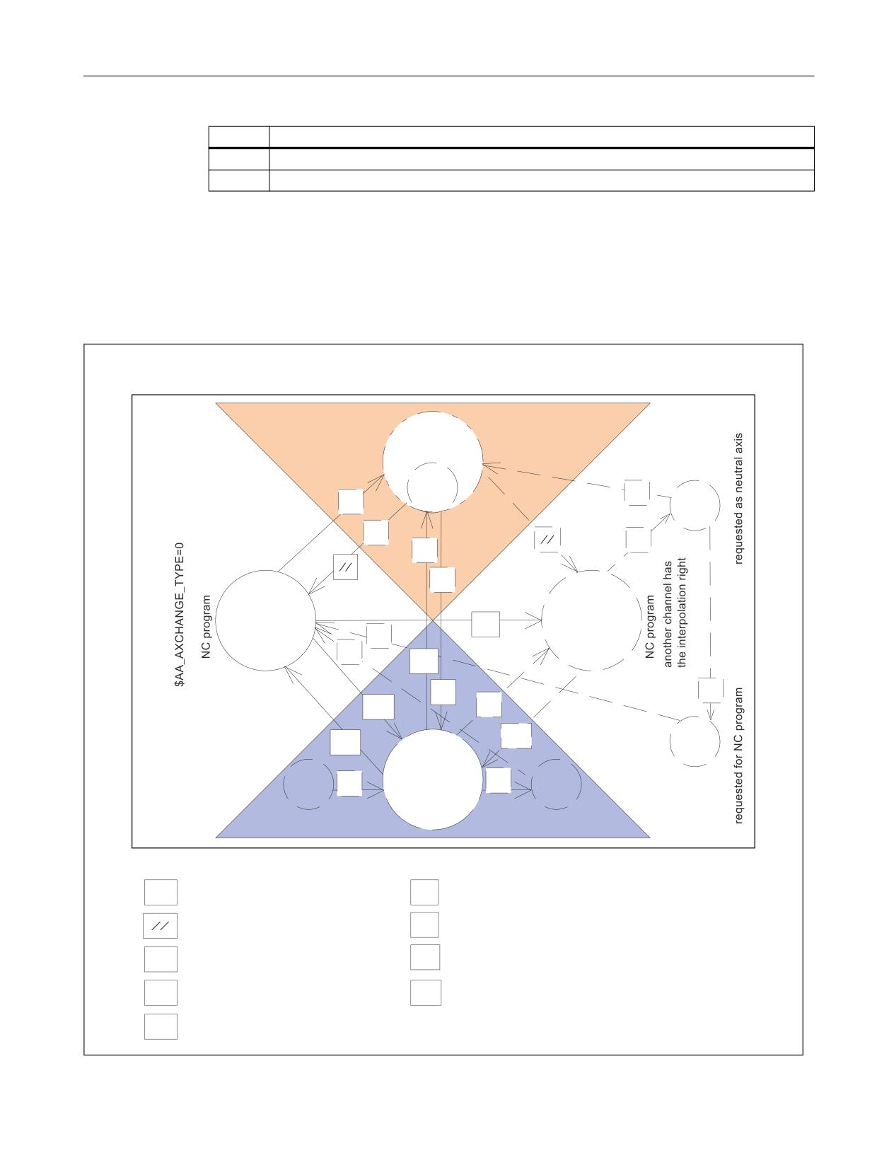
K10: Cross-channel axis interchange
7.12 Axis replacement from synchronized actions
<Value>
Meaning
9
Permanently assigned PLC axis, in the neutral axis state.
10
Permanently assigned PLC axis, controlled by PLC, in the neutral axis state.
A "permanently assigned PLC axis in the neutral axis state" (9) and a "permanently assigned
PLC axis controlled from the PLC in the neutral axis state" (10) is independent of GET and
RELEASE permanently assigned to the PLC. Whether the axis can also be replaced is
displayed in system variable $AA_AXCHANGE_STAT[axis].
State transitions GET, RELEASE from synchronous actions and when GET is completed
$$B$;&+$1*(B7<3
$$B$;&+$1*(B7<3
1HXWUDO D[LV
QHXWUDO D[LV LV
$[LV VSLQGOH
FRQWUROOHG E\ 3/&
$$B$;&+$1*(B7<3
*6I
56\
&KDQQHO
&KDQ
QHO
*6\
*6\
*6I
*6\
$[LV VSLQGOH
$[LV VSLQGOH
*'
$IWHU SRZHU 21
*6I
*6I
5
%3
*6\
5Q
%3
%3
5Q
3/& D[LV
VSLQGOH
3/&
3/&
$$B$;&+$1*(B7<3
*6\
*6\
UHTXHVWHG DV
QHXWUDO D[LV
3/&
3/& DVVLJQHG RU
DFWLYH DV +/ D[LV
UHTXHVWHG IRU 1& SURJUDP
5(/($6( $;
IURP V\QFKURQRXV DFWLRQV
*(7 $;
IURP V\QFKURQRXV DFWLRQV
56\
*6\
$$B$;&+$1*(B7<3
$$B$;&+$1*(B7<3 Q
5(6(7 NH\
*6I
*(7 LI IXOILOOHG LQ V\QFKURQRXV DFWLRQV
5
5HOHDVH LQ QHXWUDO VWDWH YLD 3/&
%3
*(7 YLD 3/&
5Q
5HOHDVH WR D VSHF FKDQQHO YLD 3/&
*'
*(7 GLUHFWO\ IURP 1& SURJUDP
3/& D[LV 3/& DVVLJQHG RU
3/&
DFWLYH DV +/ D[LV
Extended Functions
Function Manual, 12/2018, A5E40874029B AB
401
K10: Cross-channel axis interchange
7.14 State diagram
Figure 7-3
Transitions from synchronized actions
References
Function Manual, Synchronized Actions; Section: Actions in synchronized actions
7.13
Axis interchange for leading axes (gantry)
Function
A closed gantry grouping is treated regarding its axes always as a unit regarding axis
interchange. This is the reason why for an axis interchange of the leading axis, an axis
interchange is simultaneously made for all synchronous axes of the gantry grouping. In addition
to the preconditions for the leading axis described in the previous chapters, the appropriate
preconditions must also be fulfilled for all synchronous axes of the gantry grouping.
Axial machine data
For an axis interchange, the following axial machine data must be set the same for all axes of
a closed gantry group:
● MD30460 $MA_BASE_FUNCTION_MASK, Bit 4 (control executing components)
● MD30460 $MA_BASE_FUNCTION_MASK, Bit 5 (assignment to components)
Axial NC/PLC interface signals
Within the scope of the axis interchange function, the following axial NC/PLC interface signals
always have the same values for all axes of a closed gantry grouping:
● DB31, ... DBX63.0 (reset executed)
● DB31, ... DBX63.1 (PLC controlled axis)
● DB31, ... DBX63.2 (axis stop active)
Axial system variable
Within the scope of the axis interchange function, the following axial system variables always
have the same values for all axes of a closed gantry group:
● $AA_AXCHANGE_TYP (axis type regarding axis interchange)
● $AA_AXCHANGE_STAT (axis status regarding axis interchange)
● $AA_SNGLAX_STAT (axis type of the individual axis)
7.14
State diagram
The following figure shows the states, events, actions, and state transitions for an axis for
channel 1 in relation to the "axis replacement" function.
Extended Functions
402
Function Manual, 12/2018, A5E40874029B AB
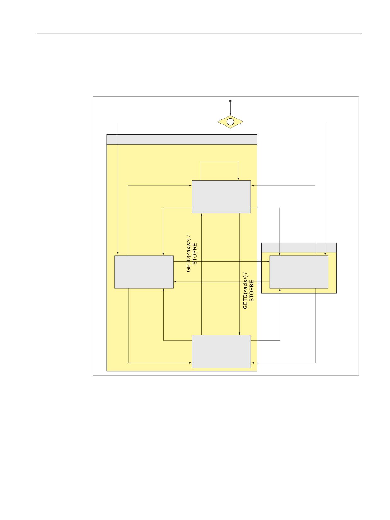
K10: Cross-channel axis interchange
7.14 State diagram
For channel 2, the sub-states "neutral axis" and "PLC axis" are not shown for clarity's sake.
Assumption: The axis is assigned to channel 1 by default:
MD30550 $MA_AXCONF_ASSIGN_MASTER_CHAN[<axis>] = 1
3RZH
U 2Q
&KDQQHO
:$,73
$1'
$[LV LV QRW V\QFKURQL]HG
$1'
$[LV QRW PDLQ UXQ D
[LV
67235(
5(/($6(
5(/($6(
25
25
:$,73
:$,73
1HXWUDO D[LV
*(7
*(7
25
2
5
&KDQQH
O UHVHW
&KDQQHO UHVHW
67235(
672
35(
5HTXHVW E\ 3/&
&KDQQHO
&KDQQHO D[LV
&KDQQHO D[LV
5HTXHVW E\ 3/&
5HTXHV
W E\ 3/&
5HOLQTXLVKP
HQW E\ 3/&
QHX
WUDO
5HOLQTXLVKP
HQW E\ 3/&
5HOLQTXLVKPHQW E\ 3/&
WR FKDQ
QHO
WR FKDQQHO
67235(
67235(
3/& D[LV
① MD30550 $MA_AXCONF_ASSIGN_MASTER_CHAN[<axis>]
Figure 7-4
State diagram: Axis replacement
Extended Functions
Function Manual, 12/2018, A5E40874029B AB
403
K10: Cross-channel axis interchange
7.15 Boundary conditions
7.15
Boundary conditions
On the transition of an axis from "PLC axis," "neutral axis," or "axis in another channel" status
to "channel axis" status, synchronization with preprocessing stop and synchronization in the
fetching channel are performed. This involves:
● Axis: Accept the actual axis position
● Spindle: Accepting the current speed and current gearbox stage
7.15.1
Axis replacement by PLC
If the part program of the channel is in one of the following sections at the time the axis
replacement (PLC → channel or channel → PLC) is requested by the PLC, axis replacement
will only be performed after this machining section has been exited:
● Continuous-path mode (G64/G640)
● Thread cutting/tapping (G33/G331/G332)
7.15.2
Block search with calculation
On a block search with calculation, only the commands GET, GETD, and RELEASE, which do
not cancel each other out, are output in the action block.
Example
Block search with calculation to target block N700:
Program code
Comment
N100 RELEASE(AX1)
; RELEASE(AX1) is collected
N110 GET(AX2)
; GET(AX2) is collected
N400 GET(AX1)
; GET(AX1) cancels RELEASE(AX1) =>
; RELEASE(AX1) and GET(AX1) are not saved
N700 ...
; Target block ≙ output: GET(AX2)
N710 RELEASE(AX2)
References
Basic Functions Function Manual; Section "K1: Mode Group, Channel, Program Operation,
Reset Response" > "Block search"
Extended Functions
404
Function Manual, 12/2018, A5E40874029B AB
K10: Cross-channel axis interchange
7.16 Example
7.16
Example
Assumptions
● Channel 1: The following axes are channel axes: 1, 2, 3, 4
● Channel 2: The following axes are channel axes: 4, 5, 6
● Default assignment: Axis 4 (AX4) is assigned to channel 1 by default
Parameter assignment
Channel 1
Axis names in the channel: MD20080
● $MC_AXCONF_CHANAX_NAME_TAB[<channel 1>][ 0 ] = "X" ; 1st channel axis
● $MC_AXCONF_CHANAX_NAME_TAB[<channel 1>][ 1 ] = "Y" ; 1st channel axis
● $MC_AXCONF_CHANAX_NAME_TAB[<channel 1>][ 2 ] = "Z" ; 1st channel axis
● $MC_AXCONF_CHANAX_NAME_TAB[<channel 1>][ 3 ] = "U" ; 1st channel axis
Machine axes used: MD20070
● $MC_AXCONF_MACHAX_USED[<channel 1>][ 0 ] = 1 ; 1st channel axis → axis 1
● $MC_AXCONF_MACHAX_USED[<channel 1>][ 1 ] = 2 ; 2nd channel axis → axis 2
● $MC_AXCONF_MACHAX_USED[<channel 1>][ 2 ] = 3 ; 3rd channel axis → axis 3
● $MC_AXCONF_MACHAX_USED[<channel 1>][ 3 ] = 4 ; 4th channel axis → axis 4
Channel 2
Axis names in the channel: MD20080
● $MC_AXCONF_CHANAX_NAME_TAB[<channel 2>][ 0 ] = "X" ; 1st channel axis
● $MC_AXCONF_CHANAX_NAME_TAB[<channel 2>][ 1 ] = "Y" ; 1st channel axis
● $MC_AXCONF_CHANAX_NAME_TAB[<channel 2>][ 2 ] = "U" ; 1st channel axis
Machine axes used: MD20070
● $MC_AXCONF_MACHAX_USED[<channel 2>][ 0 ] = 5 ; 1st channel axis → axis 5
● $MC_AXCONF_MACHAX_USED[<channel 2>][ 1 ] = 6 ; 2nd channel axis → axis 6
● $MC_AXCONF_MACHAX_USED[<channel 2>][ 2 ] = 4 ; 3rd channel axis → axis 4
Default assignment
Master channel of axis 4 (AX4) → channel 1
AX4 is the standard name of the 4th machine axis according to MD10000
$MN_AXCONF_MACHAX_NAME_TAB[ 3 ]
● MD30550 $MA_AXCONF_ASSIGN_MASTER_CHAN[ AX4 ] = 1
Extended Functions
Function Manual, 12/2018, A5E40874029B AB
405

K10: Cross-channel axis interchange
7.17 Data lists
Program example
Program in channel 1
Program in channel 2
; Traversing axis 4 (AX4)
; Synchronization point with channel 1
G01 F1000 U100
; WAITM(1,1,2)
; Release of AX4
; Request for AX4
RELEASE(AX4)
GET(AX4)
; Selection of program TAUSH2 in channel
; Traversing axis 4 (AX4)
2:
G0 U0
INIT (2,"_N_MPF_DIR\_N_TAUSH2_MPF","S")
; Start program TAUSH2 in channel 2
START(2)
; Synchronization point with channel 2
; Release of AX4
WAITM (1,1,2)
RELEASE(AX4)
M30
M30
7.17
Data lists
7.17.1
Machine data
7.17.1.1
General machine data
Number
Identifier: $MN_
Description
10010
ASSIGN_CHAN_TO_MODE_GROUP[n]
Channel valid in mode group [Channel No.]: 0, 1
10722
AXCHANGE_MASK
Parameterization of the axis replacement response
7.17.1.2
Channel-specific machine data
Basic machine data of channel
Number
Identifier: $MC_
Description
20000
CHAN_NAME
Channel name
20050
AXCONF_GEOAX_ASSIGN_TAB[n]
Assignment of geometry axis to channel axis
[GEOAxisNo.]: 0...2
20060
AXCONF_GEOAX_NAME_TAB[n]
Geometry axis name in the channel
[GEOAxisNo.]: 0...2
20070
AXCONF_MACHAX_USED[n]
Machine axis number valid in channel
[Channel axis No.]: 0...7
Extended Functions
406
Function Manual, 12/2018, A5E40874029B AB

K10: Cross-channel axis interchange
7.17 Data lists
Number
Identifier: $MC_
Description
20080
AXCONF_CHANAX_NAME_TAB[n]
Channel axis name in the channel
[Channel axis No.]: 0...7
20090
SPIND_DEF_MASTER_SPIND
Initial setting of master spindle in channel
20100
DIAMETER_AX_DEF
Geometry axis with transverse axis function
20110
RESET_MODE_MASK
Determination of basic control settings after Reset/TP
End
20112
START_MODE_MASK
Determination of basic control settings for NC start
20150
GCODE_RESET_VALUES[n]
Initial setting of the G groups
[G group No.]: 0...59
20160
CUBIC_SPLINE_BLOCKS
Number of blocks for C spline
20170
COMPRESS_BLOCK_PATH_LIMIT
Maximum traversing length of NC block for compression
20200
CHFRND_MAXNUM_DUMMY_BLOCKS
Empty blocks with phase/radii
20210
CUTCOM_CORNER_LIMIT
Max. angle for compensation blocks for tool radius com-
pensation
20220
CUTCOM_MAX_DISC
Maximum value for DISC
20230
CUTCOM_CURVE_INSERT_LIMIT
Maximum angle for intersection calculation with tool ra-
dius compensation
20240
CUTCOM_MAXNUM_CHECK_BLOCKS
Blocks for predictive contour calculation with tool radius
compensation
20250
CUTCOM_MAXNUM_DUMMY_BLOCKS
Number of blocks without traversing motion for tool ra-
dius compensation
20270
CUTTING_EDGE_DEFAULT
Initial state of tool cutting edge without programming
20400
LOOKAH_USE_VELO_NEXT_BLOCK
Look Ahead to programmed following block velocity
20430
LOOKAH_NUM_OVR_POINTS
Number of override switch corner values for Look Ahead
20440
LOOKAH_OVR_POINTS[n]
Override switch corner values for Look Ahead
[Corner value No.]: 0...1
20500
CONST_VELO_MIN_TIME
Minimum time with constant velocity
20600
MAX_PATH_JERK
Pathrelated maximum jerk
20610
ADD_MOVE_ACCEL_RESERVE
Acceleration reserve for overlaid motion
20650
THREAD_START_IS_HARD
Acceleration behavior of axis when thread cutting
20700
REFP_NC_START_LOCK
NC start inhibit without reference point
20750
ALLOW_GO_IN_G96
G0 logic in G96
20800
SPF_END_TO_VDI
Subprogram end to PLC
21000
CIRCLE_ERROR_CONST
Circle end point monitoring constant
21010
CIRCLE_ERROR_FACTOR
Circle end point monitoring factor
21100
ORIENTATION_IS_EULER
Angle definition for orientation programming
21110
X_AXIS_IN_OLD_X_Z_PLANE
Coordinate system for automatic frame definition
21200
LIFTFAST_DIST
Traversing path for fast retraction from the contour
21250
START_INDEX_R_PARAM
Number of first channel-specific R parameter
Extended Functions
Function Manual, 12/2018, A5E40874029B AB
407

K10: Cross-channel axis interchange
7.17 Data lists
Auxiliary function settings of the channel
Number
Identifier: $MC_
Description
22000
AUXFU_ASSIGN_GROUP[n]
Auxiliary function group
[aux. func. no. in channel]: 0...49
22010
AUXFU_ASSIGN_TYPE[n]
Auxiliary function type
[aux. func. no. in channel]: 0...49
22020
AUXFU_ASSIGN_EXTENSION[n]
Auxiliary function extension
[aux. func. no. in channel]: 0...49
22030
AUXFU_ASSIGN_VALUE[n]
Auxiliary function value
[aux. func. no. in channel]: 0...49
22200
AUXFU_M_SYNC_TYPE
Output timing of M functions
22210
AUXFU_S_SYNC_TYPE
Output timing of S functions
22220
AUXFU_T_SYNC_TYPE
Output timing of T functions
22230
AUXFU_H_SYNC_TYPE
Output timing of H functions
22240
AUXFU_F_SYNC_TYPE
Output timing of F functions
22250
AUXFU_D_SYNC_TYPE
Output timing of D functions
22260
AUXFU_E_SYNC_TYPE (available soon)
Output timing of E functions
22400
S_VALUES_ACTIVE_AFTER_RESET
S function active after RESET
22410
F_VALUES_ACTIVE_AFTER_RESET
F function active after reset
22500
GCODE_OUTPUT_TO_PLC
G commands to PLC
22550
TOOL_CHANGE_MODE
New tool offset for M function
22560
TOOL_CHANGE_M_CODE
M function for tool change
Channel-specific memory settings
Number
Identifier: $MC_
Description
25000
REORG_LOG_LIMIT
Percentage of IPO buffer for log file enable
28000
MM_REORG_LOG_FILE_MEM
Memory size for REORG (DRAM)
28010
MM_NUM_REORG_LUD_MODULES
Number of blocks for local user variables for REORG (DRAM)
28020
MM_NUM_LUD_NAMES_TOTAL
Number of local user variables (DRAM)
28030
MM_NUM_LUD_NAMES_PER_PROG
Number of local user variables per program (DRAM)
28040
MM_LUD_VALUES_MEM
Memory size for local user variables (DRAM)
28050
MM_NUM_R_PARAM
Number of channelspecific R parameters (SRAM)
28060
MM_IPO_BUFFER_SIZE
Number of NC blocks in IPO buffer (DRAM)
28070
MM_NUM_BLOCKS_IN_PREP
Number of blocks for block preparation (DRAM)
28080
MM_NUM_USER_FRAMES
Number of settable Frames (SRAM)
28090
MM_NUM_CC_BLOCK_ELEMENTS
Number of block elements for compile cycles (DRAM)
28100
MM_NUM_CC_BLOCK_USER_MEM
Size of block memory for compile cycles (DRAM)
28500
MM_PREP_TASK_STACK_SIZE
Stack size of preparation task (DRAM)
28510
MM_IPO_TASK_STACK_SIZE
Stack size of IPO task (DRAM)
Extended Functions
408
Function Manual, 12/2018, A5E40874029B AB

K10: Cross-channel axis interchange
7.17 Data lists
7.17.1.3
Axis/spindlespecific machine data
Number
Identifier: $MA_
Description
30460
BASE_FUNCTION_MASK
Axis functions
30550
AXCONF_ASSIGN_MASTER_CHAN
Reset position of channel for axis change
30552
AUTO_GET_TYPE
Definition of automatic GET
30600
FIX_POINT_POS
Fixed value positions of axes with G75
32074
FRAME_OR_CORRPOS_NOTALLOWED
Frame or HL offset are not allowed
33100
COMPRESS_POS_TOL
Maximum deviation with compensation
7.17.2
Setting data
7.17.2.1
Channelspecific setting data
Number
Identifier: $SC_
Description
42000
THREAD_START_ANGLE
Start angle for thread
42100
DRY_RUN_FEED
Dry run feedrate
7.17.3
Signals
7.17.3.1
Signals to channel
Signal name
SINUMERIK 840D sl
SINUMERIK 828D
Activate program test
DB21,
DBX1.7
DB320x.DBX1.7
NC start
DB21,
DBX7.1
DB320x.DBX7.1
NC stop
DB21,
DBX7.3
DB320x.DBX7.3
Reset
DB21,
DBX7.7
DB330x.DBX3.7
Suppress program test
DB21,
DBX14.0
-
7.17.3.2
Signals from channel
Signal name
SINUMERIK 840D sl
SINUMERIK 828D
Program test selected
DB21,
DBX25.7
DB170x.DBX1.7
Program test active
DB21,
DBX33.7
DB330x.DBX1.7
Extended Functions
Function Manual, 12/2018, A5E40874029B AB
409

K10: Cross-channel axis interchange
7.17 Data lists
7.17.3.3
Signals to axis/spindle
Signal name
SINUMERIK 840D sl
SINUMERIK 828D
Axis or spindle inhibit
DB31,
DBX1.3
DB380x.DBX1.3
Channel number of the target channel
DB31,
DBX8.0-3
-
Channel assignment changed
DB31,
DBX8.4
-
Request PLC axis/spindle
DB31,
DBX8.7
-
Suppress program test
DB31,
DBX14.0
DB3800.DBX1002.0
Reset
DB31,
DBX28.1
-
Continue
DB31,
DBX28.2
-
Stop along braking ramp
DB31,
DBX28.6
-
7.17.3.4
Signals from axis/spindle
Signal name
SINUMERIK 840D sl
SINUMERIK 828D
Reset executed
DB31,
DBX63.0
-
PLC-controlled axis
DB31,
DBX63.1
-
Axis stop active
DB31,
DBX63.2
DB390x.DBX3.2
Number of the actual channel
DB31,
DBX68.0-3
-
New type requested from PLC
DB31,
DBX68.4
-
Axis replacement possible
DB31,
DBX68.5
-
Neutral axis/spindle
DB31,
DBX68.6
-
PLC axis/spindle
DB31,
DBX68.7
-
Extended Functions
410
Function Manual, 12/2018, A5E40874029B AB
M1: Kinematic transformation
8
8.1
TRANSMIT face end transformation (option)
8.1.1
Function
8.1.1.1
Introduction
Note
The "TRANSMIT and peripheral surface transformation" option that is under license is required
for the function "End face transformation (TRANSMIT)."
The TRANSMIT transformation permits end face machining (drill holes, contours) on turning
machines.
A Cartesian coordinate system can be used to program these machining operations.
The controller transforms the programmed traversing movements of the Cartesian coordinate
system to the traversing movements of the real machine axes.
Standard case:
● Rotary axis
● Infeed axis, perpendicular to rotary axis
● Longitudinal axis, parallel to rotary axis
● The linear axes are perpendicular to one another.
Extended Functions
Function Manual, 12/2018, A5E40874029B AB
411
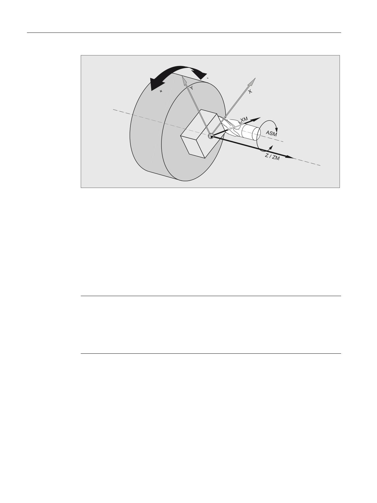
M1: Kinematic transformation
8.1 TRANSMIT face end transformation (option)
&0
X, Y, Z
Geometry axes
CM
Machine axis: Rotary axis
XM
Machine axis: Linear axis, perpendicular to rotary axis
ZM
Machine axis: Linear axis, parallel to rotary axis
ASM
Machine axis: Main spindle
Other options:
● A tool center offset relative to the turning center is permitted.
● The tool center point path can pass through the turning center point of the rotary axis.
● The rotary axis does not need to be a modulo axis.
Note
For active transformation, the names of the involved machine, channel and geometry axes are
different:
● MD10000 $MN_AXCONF_MACHAX_NAME_TAB (machine axis name)
● MD20080 $MC_AXCONF_CHANAX_NAME_TAB (channel axis name)
● MD20060 $MC_AXCONF_GEOAX_NAME_TAB (geometry axis name)
8.1.1.2
Machining options
The TRANSMIT transformation has a pole at the zero point of the TRANSMIT plane. The pole
is at the intersection of the radial linear axis and the rotary axis. In the vicinity of the pole, small
positional changes in the geometry axes generally result in large changes in position in the
machine rotary axis. The only exceptions are linear motions into or through the pole.
A tool center point path through the pole does not cause the parts program to be aborted.
There are no restrictions with respect to programmable traversing commands or active tool
Extended Functions
412
Function Manual, 12/2018, A5E40874029B AB
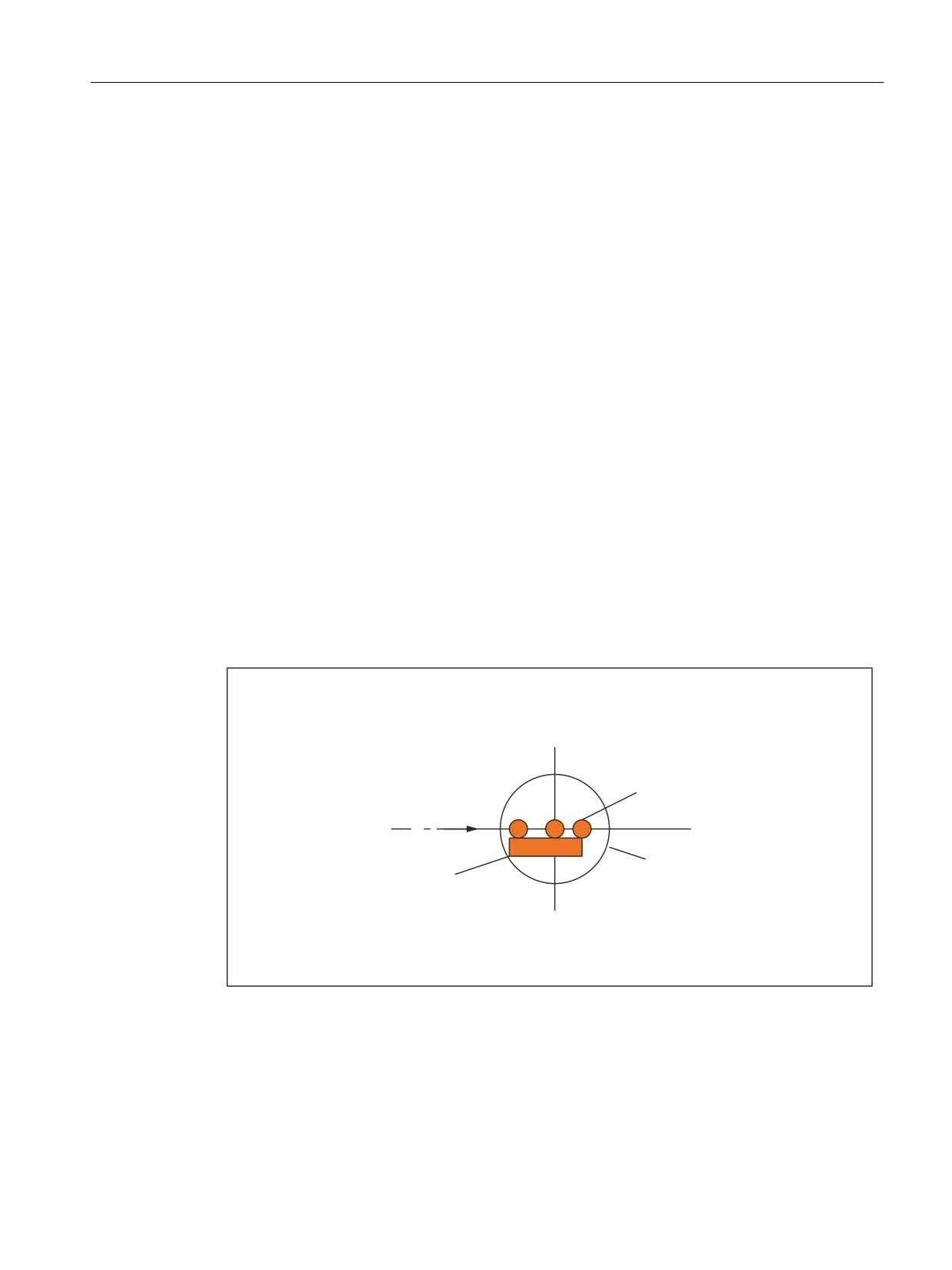
M1: Kinematic transformation
8.1 TRANSMIT face end transformation (option)
radius compensations. Nevertheless, workpiece machining operations close to the pole are
not recommended since these may require sharp feedrate reductions to prevent overloading
of the rotary axis.
New features
A pole is said to exist if the line described by the tool center point intersects the turning center
of the rotary axis.
The following cases are covered:
● Under what conditions and by what methods the pole can be traversed
● The response in pole vicinity
● The response with respect to working area limitations
● Monitoring of rotary axis rotations over 360°.
Pole traversal
The pole can be traversed by two methods:
● Traversal along linear axis
● Traversal into pole with rotation of rotary axis in pole
Traversal along linear axis
7RRO
[
7XUQHG
SDUW
&RQWRXU
Figure 8-1
Traversal of x axis through pole
Extended Functions
Function Manual, 12/2018, A5E40874029B AB
413
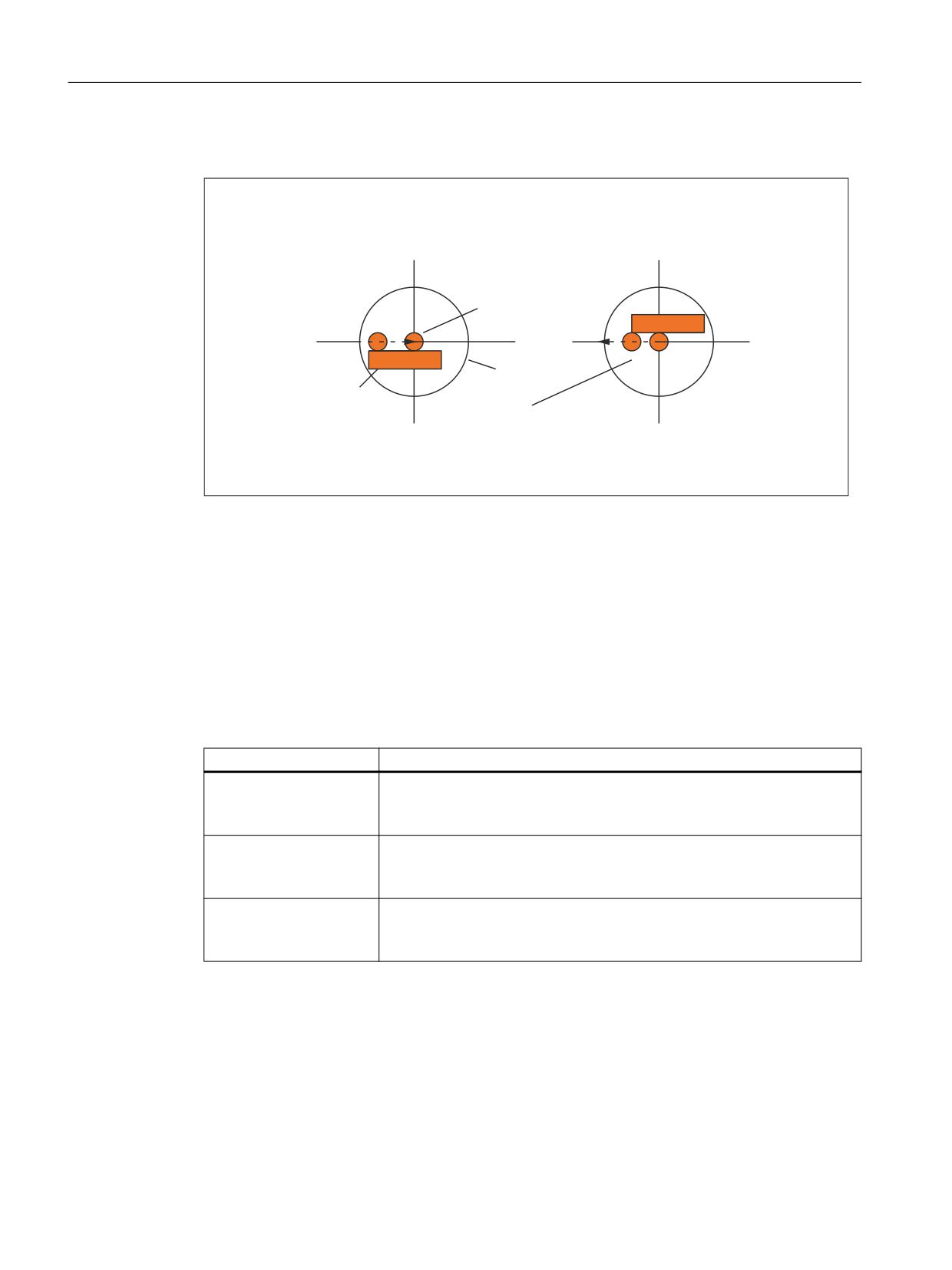
M1: Kinematic transformation
8.1 TRANSMIT face end transformation (option)
Rotation in pole
D 0RYHPHQW LQWR SROH
E 5RWDWLRQ
7RRO
[
7XUQHG
&RQWRXU
SDUW
F 0RYHPHQW RXW RI SROH
Figure 8-2
Traversal of x axis into pole (a), rotation (b), exit from pole (c)
Selection of method
The method must be selected according to the capabilities of the machine and the
requirements of the part to be machined. The method is selected by machine data:
MD24911 $MC_TRANSMIT_POLE_SIDE_FIX_1
MD24951 $MC_TRANSMIT_POLE_SIDE_FIX_2
The first MD applies to the first TRANSMIT transformation in the channel and the second MD
correspondingly to the second TRANSMIT transformation.
VALUE
Meaning
0
Pole traversal
The tool center point path (linear axis) must traverse the pole on a contin-
uous path.
1
Rotation around the pole.
The tool center point path must be restricted to a positive traversing range
of the linear axis (in front of turning center).
2
Rotation around the pole.
The tool center point path must be restricted to a negative traversing range
of the linear axis (behind turning center).
Special features relating to pole traversal
The method of pole traversal along the linear axis may be applied in the AUTOMATIC and
JOG modes.
Extended Functions
414
Function Manual, 12/2018, A5E40874029B AB

M1: Kinematic transformation
8.1 TRANSMIT face end transformation (option)
System response:
Table 8-1
Traversal of pole along the linear axis
Mode
State
Response
AUTOMATIC
All axes involved in the transforma-
High-speed pole traversal
tion are moved synchronously.
TRANSMIT active.
Not all axes involved in the transfor-
Traversal of pole at creep speed
mation are traversed synchronous-
ly (e.g. position axis).
TRANSMIT not active
An applied DRF (external zero off-
Abortion of machining, alarm
set) does not interfere with the op-
eration. Servo errors may occur
close to the pole during application
of a DRF.
JOG
-
Traversal of pole at creep speed
Special features relating to rotation in pole
Requirement: This method is only effective in the AUTOMATIC mode.
MD24911 $MC_TRANSMIT_POLE_SIDE_FIX_1 = 1 or 2
MD24951 $MC_TRANSMIT_POLE_SIDE_FIX_2 = 1 or 2
Value: 1 Linear axis remains within positive traversing range
Value: 2 Linear axis remains within negative traversing range
In the case of a contour that would require the pole to be traversed along the tool center point
path, the following three steps are taken to prevent the linear axis from traversing in ranges
beyond the turning center:
Step
Action
1
Linear axis traverses into pole
2
Rotary axis turns through 180°, the other axes involved in the transformation
remain stationary.
3
Execution of remaining block. The linear axis now exits from the pole again.
In JOG mode, the motion stops in the pole. In this mode, the axis may exit from the pole only
along the path tangent on which it approached the pole. All other motion instructions would
require a step change in the rotary axis position or a large machine motion in the cases of
minimum motion instructions. They are rejected with alarm 21619.
Traversal close to pole
If a tool center point traverses past the pole, the control system automatically reduces the
feedrate and path acceleration rate such that the settings of the machine axes (MD 32000
$MA_MAX_AX_VELO[AX*] and MD32300 $MA_ MAX_AX_ACCEL[AX*]) are not exceeded.
The closer the path is to the pole, the greater the reduction in the feedrate.
Extended Functions
Function Manual, 12/2018, A5E40874029B AB
415
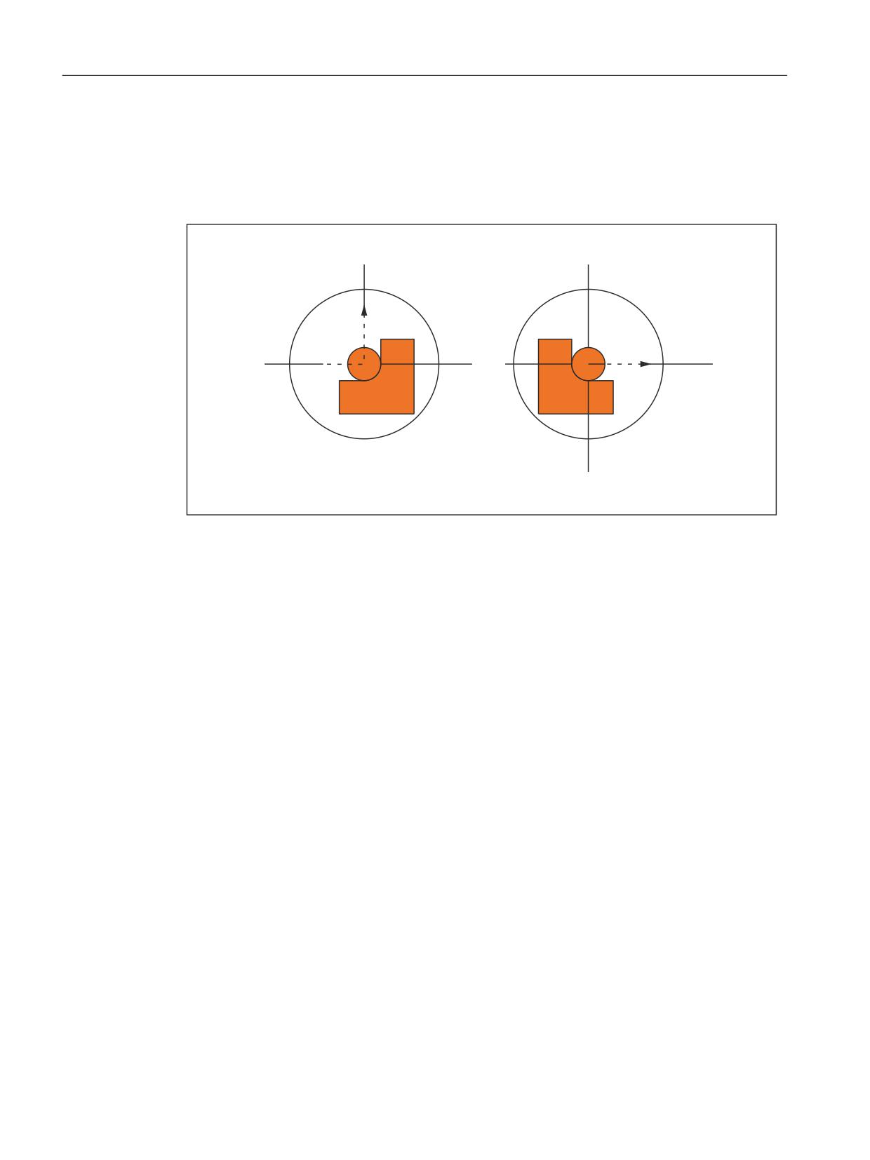
M1: Kinematic transformation
8.1 TRANSMIT face end transformation (option)
Tool center point path with corner in pole
A tool center point path which includes a corner in the pole will not only cause a step change
in axis velocities, but also a step change in the rotary axis position. These cannot be reduced
by decelerating.
&RUQHU
[
[
Figure 8-3
Pole traversal
Requirements:
AUTOMATIC mode,
MD24911 $MC_TRANSMIT_POLE_SIDE_FIX_1 = 0
or
MD24951 $MC_TRANSMIT_POLE_SIDE_FIX_2 = 0
The control system inserts a traversing block at the step change point. This block generates
the smallest possible rotation to allow machining of the contour to continue.
Extended Functions
416
Function Manual, 12/2018, A5E40874029B AB