SINUMERIK 840D sl. Service - Functions. Manual (2018-2020) - page 34
H1: Manual traversing
4.12 Retraction in the tool direction (JOG retract)
4.12.8
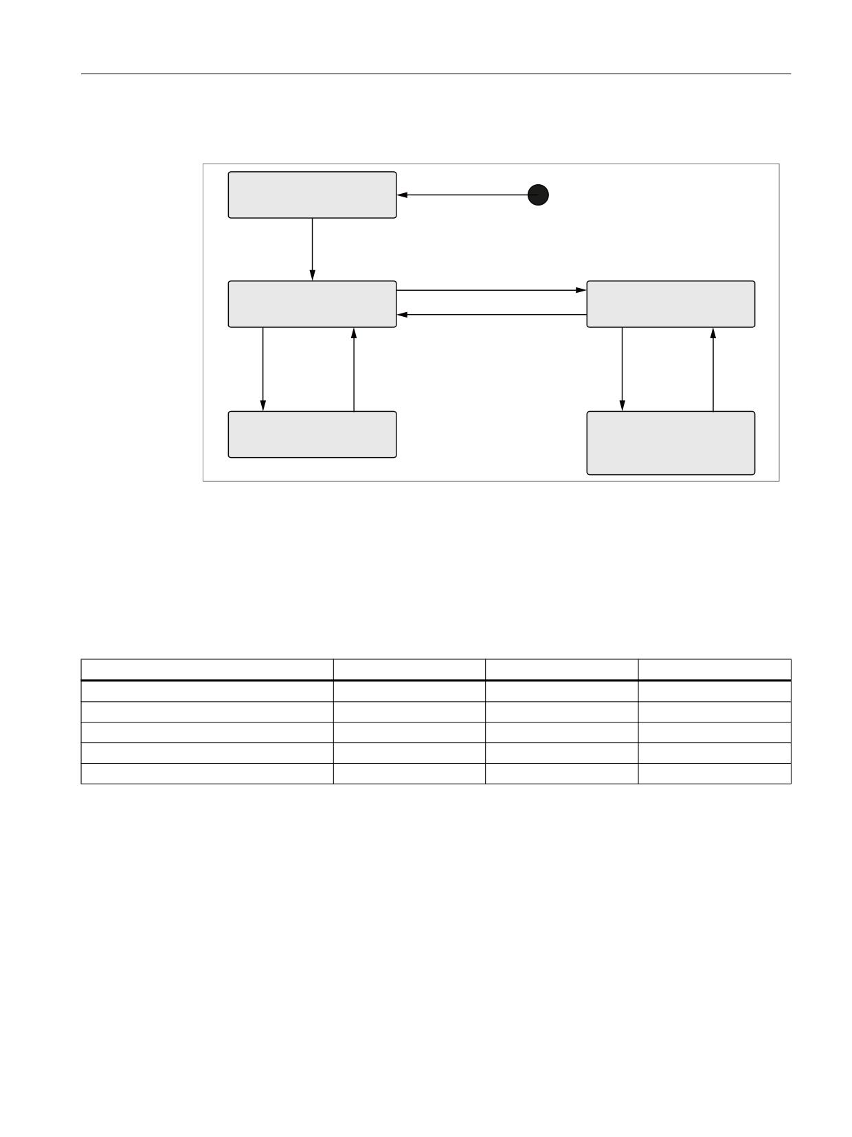
State diagram
%$ $8720$7,& RU 0'$
&KDQQHO VWDWXV 5HVHW
3RZHU 2Q
20& -2*
20& $8720$7,& RU 0'$
%$ -2*
%$ $8720$7,& RU 0'$
&KDQQHO VWDWXV 5HVHW
&KDQQHO VWDWXV 5HVHW
20& -2*
1& VWDUW
$FWLY
DWLRQ
-2* U
HWUDFW
&KDQQHO UHVHW
&KDQQHO
UHVHW
%$ $8720$7,& RU 0'$
%$ -2*
&KDQQHO VWDWXV DFWLYH
-2* UHWUDFW DFWLYH
5HWUDFWLRQ GDWD LV UHFRUGHG
OM
Operating mode
OMC Operating mode change
Figure 4-8
State diagram: JOG retract
4.12.9
System data
The following system data is available for JOG retract:
Meaning
System variable $VA_
NC/PLC interface
OPI variable
Retraction data available
-
DB21, ... DBX377.5
retractState, bit 0
JOG retract active
-
DB21, ... DBX377.4
retractState, bit 1
Retraction axis
-
-
retractState, bits 2 - 3
Position restored, 1st measuring system
$AA_POSRES
DB31, ... DBX71.4
aaPosRes
Position restored, 2nd measuring system
$AA_POSRES
DB31, ... DBX71.5
aaPosRes
References
OPI and system variable
Lists Book 2 List Manual, Section "Variables".
Extended Functions
Function Manual, 12/2018, A5E40874029B AB
211
H1: Manual traversing
4.12 Retraction in the tool direction (JOG retract)
4.12.10
Supplementary conditions
Incremental measuring systems
The user must ensure that machine axes with incremental measuring systems are clamped
with sufficient speed in the event of a power failure to prevent a change to the last position,
known and saved by the control. Otherwise the assumed position when the control is restarted
differs greatly to the actual position of the machine axis. Drive-autonomous retraction must
also not be activated for these axes.
A detailed description of the automatic restoration of actual positions after the next start of the
control (Power On) can be found in:
References:
Basic Functions Function Manual, Section "R1 Referencing" > "Automatic restoration of the
machine reference"
Drive-autonomous retraction
The "Drive-autonomous retraction" function must not be activated for machine axes involved
in the retraction movement.
Axis couplings
Axis couplings are not restored with the selection of JOG retract.
Tapping using G63
JOG retract is not possible for tapping with compensating chuck and speed-controlled spindle
without encoder (G63).
Transformations
If a transformation is selected through JOG retract, the active measuring systems of all
machine axes involved in the transformation must be in the "referenced" or "restored" state.
OEM transformations such as parallel kinematics for hexapods, can only be traversed with
referenced measuring systems. Traversing with restored axis positions is not possible.
Tool orientation via directly programmed orientation axes
JOG retract cannot generate a retraction movement in the tool direction if the tool orientation
is not performed via NC functions, but through direct programming of the orientation axes.
NCU link
JOG retract is also possible in conjunction with NCU-wide traversing of axes (see Section
"NCU link (Page 80)"). The state of axis containers is not changed through JOG retract. Any
adjustments required for a retraction in the tool direction must be made by the user, e.g. in
mode MDA, before the JOG retract movement.
Extended Functions
212
Function Manual, 12/2018, A5E40874029B AB

H1: Manual traversing
4.13 Use of handwheels in automatic mode
4.13
Use of handwheels in automatic mode
4.13.1
Handwheel override in automatic mode
4.13.1.1
General functionality
Function
With this function it is possible to traverse axes or to change their velocities directly with the
handwheel in automatic mode (Automatic, MDA).
The handwheel override is activated in the NC part program using the NC language elements
FD (for path axes) and FDA (for positioning axes) and is non-modal.
With positioning axes, it is possible to activate the handwheel override modally using traverse
command POSA. When the programmed target position is reached, the handwheel override
becomes inactive again.
Additional axes can be traversed simultaneously or using interpolation in the same NC block.
The concurrent-positioning-axes function can also be activated by the PLC user program.
Distinction
Depending on the programmed feedrate, a distinction is made between the following for
handwheel override:
● Path definition
Axis feedrate = 0 (FDA = 0)
● Velocity override
Axis feedrate > 0 (FD or FDA > 0)
The table below shows which axis types can be influenced by the "handwheel override in
automatic mode" function.
Axes that can be influenced by the "handwheel override in automatic mode" function
Axis type
Velocity override
Path definition
Positioning axis
FDA[AXi] > 0 ;
FDA[AXi] = 0
acts axially
Concurrent posi-
Parameter "Handwheel override active" = 1 and
Parameter "Handwheel over-
tioning axis
axis feedrate > 0 from FC18
ride active" = 1 and axis fee-
drate = 0 from FC18
Path axis
FD > 0 ;
Not possible
acts on path velocity
Extended Functions
Function Manual, 12/2018, A5E40874029B AB
213
H1: Manual traversing
4.13 Use of handwheels in automatic mode
Path definition
With axis feedrate = 0 (e.g. FDA[AXi] = 0), the traversing movement of the positioning axis
towards the programmed target position is controlled entirely by the user rotating the assigned
handwheel.
The direction in which the handwheel is turned determines the traversing direction of the axis.
The programmed target position cannot be exceeded during handwheel override. The axis
can also be moved toward the programmed target position from the opposite direction,
whereby the movement is only restricted by the axial position limitations.
A block change occurs when:
● The axis has reached the programmed target position
or
● The distance-to-go is deleted by axial interface signal
DB31, ... DBX2.2 (delete distance-to-go).
From this moment on, the path default is deactivated and any further handwheel pulses have
no effect.
After this, incrementally programmed positions refer to the point of interruption and not to the
last programmed position.
Velocity override
With regard to the velocity override, a distinction is made between axis feedrate and path
feedrate.
● Axis-velocity override (FDA[AXi] > 0):
The positioning axis is moved to the target position at the programmed axial feedrate. Using
the assigned handwheel, it is possible to increase the axis velocity or to reduce it to a
minimum of zero depending on the direction of rotation. The resulting axis feedrate is limited
by the maximum velocity. However, the axis cannot be traversed in the opposite direction
to that programmed.
The block change is performed as soon as the axis reaches the programmed target position.
This causes the velocity override to be deactivated automatically and any further handwheel
pulses have no effect.
Similarly, this also applies to concurrent positioning axes, where the target position and the
velocity are defined by the PLC.
● Path-velocity override (FD > 0):
The path axes programmed in the NC block traverse to the target position at the
programmed feedrate. If the velocity override is active, the programmed path velocity is
overridden by the velocity generated with the handwheel of the 1st geometry axis. The
block change is performed as soon as the programmed target position is reached.
The path velocity is increased or reduced to a minimum of zero depending on the direction
of rotation of the handwheel. However, it is not possible to reverse the direction of
movement with handwheel override.
Extended Functions
214
Function Manual, 12/2018, A5E40874029B AB
H1: Manual traversing
4.13 Use of handwheels in automatic mode
Application example
The "Handwheel override in automatic mode" function is frequently used on grinding machines.
For example, the user can position the reciprocating grinding wheel on the workpiece using
the handwheel (path default). After scratching, the traversing movement is terminated and the
block change is initiated (by activating DB31, ... DBX2.2 (delete distance-to-go)).
Preconditions
In order to activate "Handwheel override in automatic mode", the following requirements must
have been met:
● A handwheel must be assigned to the axis in question.
● Pulse weighting exists for the assigned handwheel.
Handwheel assignment
The assignment of the connected handwheels to the axes is analogous to the "Manual
traversing using a handwheel (Page 161)" via the user interface or via the PLC user interface
with one of the following interface signals:
● Machine axes:
- DB31, ... DBX4.0 - 2 (activate handwheel)
● Geometry axes:
- DB21, ... DBX12.0 - 2 (geometry axis 1: Activate handwheel)
- DB21, ... DBX16.0 - 2 (geometry axis 2: Activate handwheel)
- DB21, ... DBX20.0 - 2 (geometry axis 3: Activate handwheel)
If handwheel override is programmed for an axis to which no handwheel is assigned, a
distinction is made between the following cases:
● For velocity override:
The axes traverse at the programmed velocity.
A self-acknowledging alarm is output (without response).
● For path definition:
No traversing movement is performed because the velocity is zero.
A self-acknowledging alarm is output (without response).
Note
For the velocity override for path axes, only the handwheel of the 1st geometry axis is
applied to the path velocity.
Extended Functions
Function Manual, 12/2018, A5E40874029B AB
215
H1: Manual traversing
4.13 Use of handwheels in automatic mode
Handwheel weighting
The travel path of the axis that is generated by rotating the handwheel by one detent position
is dependent on several factors (see Section "Manual traversing using a handwheel
(Page 161)"):
● Selected increment size:
MD11330 $MN_JOG_INCR_SIZE_TAB[5] (increment size for INC/handwheel)
or
SD41010 $SN_JOG_VAR_INCR_SIZE (size of the variable increment for JOG)
● Weighting of an increment:
MD31090 $MA_JOG_INCR_WEIGHT
● Number of handwheel pulses per detent position:
MD11320 $MN_HANDWH_IMP_PER_LATCH
For example, the axis traverses by 0.001 mm per handwheel detent position if machine function
INC1 and the default setting of the above machine data are selected.
In the case of velocity override, the velocity results from the traverse path covered using the
handwheel within a certain period of time.
Example
Assumptions:
The operator turns the handwheel with 100 pulses/second.
The selected machine function is INC100.
The default setting is made for the above machine data for handwheel weighting.
⇒ Handwheel traverse path per second:
10 mm
⇒ Velocity override:
0.6 m/min
PLC interface signals
As soon as the handwheel override takes effect, the following interface signals to the PLC are
set to signal 1:
● For positioning axes / concurrent positioning axes / command axes / reciprocating axes:
DB31, ... DBX62.1 (handwheel override active)
● For path axes:
DB21, ... DBX33.3 (handwheel override active)
Extended Functions
216
Function Manual, 12/2018, A5E40874029B AB
H1: Manual traversing
4.13 Use of handwheels in automatic mode
For the path input, depending on the traversing direction, the appropriate interface signals are
output to the PLC:
● Machine axes:
- DB31, ... DBX64.6 / 7 (travel command "minus"/"plus")
● Geometry axes:
- DB21, ... DBX40.6 - 7 (geometry axis 1: Travel command "minus"/"plus")
- DB21, ... DBX46.6 - 7 (geometry axis 2: Travel command "minus"/"plus")
- DB21, ... DBX52.6 - 7 (geometry axis 3: Travel command "minus"/"plus")
Limitations
The axial limitations (software limit switch, hardware limit switch, working area limitation) are
effective in conjunction with handwheel override. With path default, the axis can be traversed
with the handwheel in the programmed traversing direction only as far as the programmed
target position.
The resulting velocity is limited by the axial machine data:
MD32000 $MA_MAX_AX_VELO(maximum axis velocity)
NC Stop/override = 0
If the feedrate override is set to 0% or an NC Stop is initiated while the handwheel override is
active, the following applies:
● For path definition:
The handwheel pulses arriving in the meantime are summated and stored. If NC Start or
the feedrate override > 0%, the saved handwheel pulses become effective (i.e. are
traversed).
However, if the handwheel is first deactivated [via IS DB21, ... DBX12/16/20.0-2 (geometry
axes 1/2/3: Activate handwheel)] then the stored handwheel pulses are deleted.
● For velocity specification:
The handwheel pulses arriving in the meantime are not summated and are not active.
4.13.1.2
Programming and activating handwheel override
General information
When the handwheel override is programmed with NC language elements FD (for path axes)
and FDA (for positioning axes), the following points must be observed:
● FDA and FD function non-modally.
Exception for positioning axes: If traverse instruction POSA is programmed, the handwheel
override can also act modally because this positioning axis does not affect the block
transition.
● When the handwheel override is activated with FDA or FD, a target position must be
programmed in the NC block for the positioning axis or for a path axis. When the
programmed target position is reached, the handwheel override becomes inactive again.
Extended Functions
Function Manual, 12/2018, A5E40874029B AB
217
H1: Manual traversing
4.13 Use of handwheels in automatic mode
● It is not possible to program FDA and FD or FA and F in the same NC block.
● The positioning axis must not be an indexing axis.
Positioning axis
Syntax for handwheel override:
FDA[AXi] = [feedrate value]
Example 1:
Activate velocity override
N10 POS[U]=10 FDA[U]=100 POSA[V]=20 FDA[V]=150 . . .
POS[U]=10
Target position of positioning axis U
FDA[U]=100
Activate velocity override for positioning axis U; axis velocity of U = 100 mm/
min
POSA[V]=20
Target position of positioning axis V (modally)
FDA[V]=150
Activate velocity override for positioning axis V; axis velocity of V = 150 mm/
min
Example 2:
Activate path default and velocity override in the same NC block
N20 POS[U]=100 FDA[U]= 0 POS[V]=200 FDA[V]=150 . . .
POS[U]=100
Target position of positioning axis U
FDA[U]= 0
Activate path default for positioning axis U;
POS [V]=200
Target position of positioning axis V
FDA[V]=150
Activate velocity override for positioning axis V; axis velocity of V =
150 mm/min
Path axis
Syntax for handwheel override:
FD = [feedrate value]
In order to activate "Handwheel override in automatic mode", the following requirements must
have been met:
● Active movement commands from group 1: G01, G02, G03, CIP
● Exact stop active (G60)
● Linear feedrate in mm/min or inch/min active (G94)
These requirements are checked by the control and an alarm is output if any of them is not
met.
Extended Functions
218
Function Manual, 12/2018, A5E40874029B AB
H1: Manual traversing
4.13 Use of handwheels in automatic mode
Example 3:
Activate velocity override
N10 G01 X10 Y100 Z200 FD=1500 . . .
X10 Y100 Z200
Target position of path axes X, Y and Z
FD=1500
Activate velocity override for path axes; path velocity = 1500 mm/
min
Concurrent positioning axis
The handwheel override for concurrent positioning axes is activated from the PLC via FC18
by setting the appropriate interface signal:
DB31, ... DBX62.1 (handwheel override active)
If the velocity parameter (F_Value) is transferred with the value 0, then the activated handwheel
override acts as distance input, i.e. in this case, the feed is not derived from the axial machine
data (see also Chapter "P2: Positioning axes (Page 683)"):
MD32060 $MA_POS_AX_VELO (initial setting for positioning axis velocity)
References:
Function Manual, Basic Functions, Basic PLC Program (P3)
4.13.1.3
Special features of handwheel override in automatic mode
Velocity display
The velocity display for handwheel override shows the following values:
● Set velocity
= programmed velocity
● Actual velocity
= resultant velocity including handwheel override
Effect on transverse axes
If the axis is defined as a transverse axis and DIAMON is active, the handwheel pulses are
interpreted and traversed as diameter values while handwheel override is active.
Dry-run feedrate
With active dry run
DB21, ... DBX0.6 (activate dry-run feedrate) = 1,
the dry-run feedrate is always effective
SD42100 $SC_DRY_RUN_FEED.
In this way, the axis is traversed to the programmed target position at dry-run feedrate without
any influence from the handwheel despite the active handwheel override with path default
(FDA[AXi] = 0), i.e., the path default is ineffective.
Extended Functions
Function Manual, 12/2018, A5E40874029B AB
219
H1: Manual traversing
4.13 Use of handwheels in automatic mode
DRF active
When "Handwheel override in automatic mode" is activated, it is important to check whether
the "DRF" function is active (DB21, ... DBX0.3 = 1).
If this were the case, the handwheel pulses would also cause a DRF offset of the axis. The
user must, therefore, first deactivate DRF.
Feedrate override
The feedrate override does not affect the velocity of the movements produced by the
handwheel (exception: 0%). It only affects the programmed feedrate.
With path default and fast handwheel movements, the axis may not be able to follow the
handwheel rotation synchronously (especially in the case of a large handwheel-pulse
weighting), causing the axis to overtravel.
4.13.2
Contour handwheel/path input using handwheel (option)
"Contour handwheel" function
When the function is activated, the path and synchronized axes can be controlled via a
handwheel in AUTOMATIC and MDI modes.
Preconditions
It is not permissible that fixed feedrate, dry run feedrate, thread cutting, or tapping are selected.
Availability
For SINUMERIK 840D sl and SINUMERIK 828D, the "contour handwheel" function is available
as an option that is under license.
Input mode (path or velocity input)
Either the distance or the velocity can be entered via the handwheel:
● Path definition
The traversing velocity obtained as a result of the path defined by the handwheel pulses
each IPO clock cycle, is limited by the control system to the maximum permissible velocity.
The handwheel pulses that are not immediately executed are collected, and traversed
through at a later point in time. As a consequence, it is possible that the axes continue to
run. No pulses are lost.
● Velocity specification
Based on the handwheel pulses for each IPO clock cycle, the velocity is specified at which
the axes will be traversed. Traversing motion is immediately stopped as soon as no pulses
are received from the handwheel in an IPO clock cycle. The axes do not continue to run .
The input mode is set with machine data:
MD11346 $MN_HANDWH_TRUE_DISTANCE
Extended Functions
220
Function Manual, 12/2018, A5E40874029B AB
H1: Manual traversing
4.13 Use of handwheels in automatic mode
Path velocity
The path velocity in mm/min depends on:
● Handwheel pulses in each IPO clock cycle
● Pulse evaluation of the handwheel using machine data:
MD11322 $MN_CONTOURHANDWH_IMP_PER_LATCH
● Active increment (INC1, 10, 100, ...)
● Distance weighting of an increment of the first available geometry axis:
MD31090 $MA_JOG_INCR_WEIGHT
The path velocity is independent of:
● Programmed feedrate mode (mm/min, mm/rev.)
● Programmed path velocity
● Rapid traverse velocity for G0 blocks
● Override (with the exception of 0% override)
Traversing direction
The traversing direction depends on the direction of rotation of the handwheel:
● Clockwise rotation: Traversing the axes in the programmed direction.
If the block change criterion (IPO end) is reached, the program advances to the next block
(response identical to G60).
● Counterclockwise: Traversing the axes opposite to the programmed direction.
In this case, traversing is only possible up to the start of the actual block. Pulses are not
collected if the handwheel continues to rotate.
Activation of the function
The function can be activated via interface signals or in the NC program:
● Activation via interface signal
DB21, ... DBX30.0 - 2
● Activation via the NC program
Command FD=0 . The contour handwheel is switched on non-modally. This means in the
following block, the programmed velocity F... from the block before the contour
handwheel again applies when the contour handwheel is activated.
Note
An alarm is displayed if no feedrate was programmed in the previous NC blocks.
"Simulated contour handwheel" function
When the "Contour handwheel" function is active, using the "Simulated contour handwheel"
function, the handwheel or the handwheel pulses are simulated.
Extended Functions
Function Manual, 12/2018, A5E40874029B AB
221
H1: Manual traversing
4.13 Use of handwheels in automatic mode
Activation
The function is activated via interface signal:
DB21, ... DBX30.3 = 1
The feedrate is then no longer specified by the handwheel pulses, but by feedrate F...
programmed in the NC program.
Specifying the direction of rotation
The direction of rotation of the simulated handwheel is specified using the interface signal:
DB21, ... DBX30.4
override
When the "Simulated contour handwheel" function is active, the override is effective as for NC
program execution.
Stopping traversing motion
If the "Simulated contour handwheel" function is deselected, or the direction of rotation
switched over, then the actual traversing motion is stopped along a braking ramp.
Supplementary conditions
● Velocity limiting
- When the "Contour handwheel" function is activated via interface signal (DB21, ...
DBX30.0 - 2), the path velocity that can be entered via the handwheel is limited to:
Max. path velocity = (programmed path velocity F...) * (MD12030
$MN_OVR_FACTOR_FEEDRATE[ 30 ] + reserve for dynamic operations)
- When the "Contour handwheel" function is activated using command FD=0 in the NC
program, the path velocity that can be entered via the handwheel is limited to the
maximum axis velocities defined in machine data (MD32000 $MA_MAX_AX_VELO).
● Acceleration and velocity limit values
When traversing the axes using the "Contour handwheel" function, the axis-specific limit
values for acceleration, defined in machine data (e.g. MD32300 $MA_MAX_AX_ACCEL),
and velocity (MD32000 $MA_MAX_AX_VELO) are maintained.
● Interruption of traversing movement
If, while traversing using the "Contour handwheel" function, an NC stop is initiated (DB21, ...
DBX7.3 or 4), then the function remains selected. The handwheel pulses received during
an NC stop are not evaluated. Requirement: MD32084
$MA_HANDWH_CHAN_STOP_COND, bit 2 == 1
● DRF
An active DRF function (DB21, ... DBX0.3) additionally has a path override action.
Extended Functions
222
Function Manual, 12/2018, A5E40874029B AB
H1: Manual traversing
4.13 Use of handwheels in automatic mode
● Channel-specific delete distance-to-go
Channel-specific delete distance-to-go (DB21, ... DBX6.2) causes the motion, initiated by
the contour handwheel, to be canceled. The axes are braked and the program is restarted
with the next NC block.
● Mold making
Executing mold making programs using the contour handwheel does not produce a suitable
surface quality or constant cutting speed.
4.13.3
DRF offset
4.13.3.1
DRF offset
Function
The "DRF offset" function (differential resolver function) can be used to set an additive
incremental zero offset in respect of geometry and auxiliary axes in the basic coordinate system
in AUTOMATIC mode via an electronic handwheel.
The handwheel assignment, i.e. the assignment of the handwheel from which the increments
for the DRF offset are to be derived, to the geometry or auxiliary axes that are to be moved by
this, must be performed via the appropriate machine axes. The appropriate machine axes are
those to which the geometry or auxiliary axis is mapped.
The DRF offset is not displayed in the axis actual-value display.
Applications
The DRF offset can be used, for example, in the following application cases:
● Offsetting tool wear within an NC block
Where NC blocks have very long processing times, it becomes necessary to offset tool
wear manually within the NC block (e.g. large surface-milling machines).
● Highly precise offset during grinding
● Simple temperature compensation
Note
The zero offset introduced via the DRF offset is always effective in all modes and after a
RESET. It can, however, be suppressed non-modally in the part program.
Velocity reduction
The velocity generated using the handwheel for DRF can be reduced with respect to the JOG
velocity:
MD32090 $MA_HANDWH_VELO_OVERLAY_FACTOR (ratio of JOG velocity to handwheel
velocity (DRF))
Extended Functions
Function Manual, 12/2018, A5E40874029B AB
223

H1: Manual traversing
4.13 Use of handwheels in automatic mode
DRF active
DRF must be active to allow the DRF offset to be modified by means of traversal with the
handwheel. The following requirements must be fulfilled:
● AUTOMATIC mode
● DB21, ... DBX0.3 (activate DRF) = 1
The DRF offset can be activated/deactivated for specific channels using the "program control"
function on the HMI user interface.
The HMI software then sets interface signal:
DB21, ... DBX24.3 (DRF selected) =1.
The PLC program (basic PLC program or user program) transfers this interface signal to
interface signal
DB21, ... DBX0.3 (activate DRF) once the corresponding logic operation has been performed.
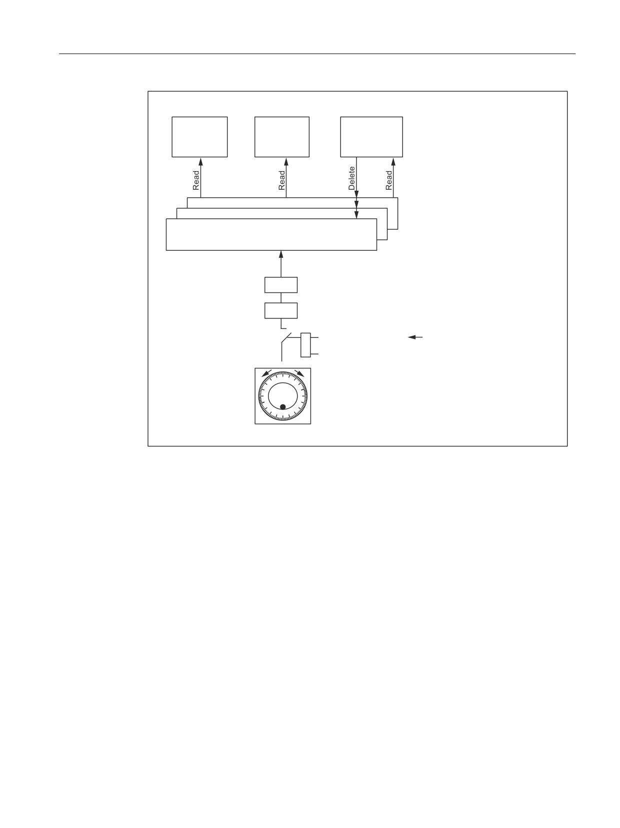
Control of DRF offset
The DRF offset can be modified, deleted or read:
User:
● Traversing with the handwheel
Part program:
● Reading via axis-specific system variable $AC_DRF[<axis>]
● Deleting via parts-program command (DRFOF) for all axes in a
channel
● Non-modal suppression via parts-program command (SUPA)
References:
Programming Manual, Fundamentals
PLC user program:
● Reading the DRF offset (axis-specific)
References:
Function Manual, Basic Machine; PLC Basic Program (P3)
HMI user interface:
● Display of the DRF offset (axis-specific)
Note
If DRF offset is deleted, the axis is not traversed!
Extended Functions
224
Function Manual, 12/2018, A5E40874029B AB
H1: Manual traversing
4.13 Use of handwheels in automatic mode
3/& XVHU
,6
1&
SURJUDP
RSHUDWRU
SDUW SURJUDP
+//
$[LV Q
$[LV
'5) RIIVHW
$[LV
0RGLI\ LQFUHPHQWDOO\
+DQGZKHHO SXOVHV
[
0'
01B+$1':+B,03B3(5B/$7&+
SHU ORFNLQJ SRVLWLRQ
6HOHFWHG LQFUHPHQW
$FWLYH PDFKLQH
,1&
0'
01B-2*B,1&5B6,=(B7$%
[
VL]H
IXQFWLRQ LQWHUIDFH
,1&YDU
6'
01B-2*B9$5B,1&5B6,=(
VLJQDO
$FWLYDWH '5)
+0, ,6
'5) VHOHFWHG
'5) DFWLYH
LQWHUIDFH VLJQDO
$XWRPDWLF DFWLYH PRGH
+DQGZKHHO
Figure 4-9
Control of DRF offset
Display
The axis actual-position display (ACTUAL POSITION) does not change while an axis is being
traversed with the handwheel via DRF. The current axis DRF offset can be displayed in the
DRF window.
Reference point approach
In phase 1 of the machine-axis reference point approach, the DRF offset for the corresponding
geometry or auxiliary axis is deleted.
During the machine-axis reference point approach, a DRF offset for the corresponding
geometry or auxiliary axis cannot be performed simultaneously.
Reset response
PowerOn-Reset: The DRF offset is deleted.
Extended Functions
Function Manual, 12/2018, A5E40874029B AB
225
H1: Manual traversing
4.13 Use of handwheels in automatic mode
4.13.3.2
Commissioning
Function
The "DRF offset" function (differential resolver function) can be used to set an additive
incremental zero offset in respect of geometry and auxiliary axes in the basic coordinate system
in AUTOMATIC mode via an electronic handwheel.
The handwheel assignment, i.e. the assignment of the handwheel from which the increments
for the DRF offset are to be derived, to the geometry or auxiliary axes that are to be moved by
this, must be performed via the appropriate machine axes. The appropriate machine axes are
those to which the geometry or auxiliary axis is mapped.
The DRF offset is not displayed in the axis actual-value display.
Applications
The DRF offset can be used, for example, in the following application cases:
● Offsetting tool wear within an NC block
Where NC blocks have very long processing times, it becomes necessary to offset tool
wear manually within the NC block (e.g. large surface-milling machines).
● Highly precise offset during grinding
● Simple temperature compensation
Note
The zero offset introduced via the DRF offset is always effective in all modes and after a
RESET. It can, however, be suppressed non-modally in the part program.
Velocity reduction
The velocity generated using the handwheel for DRF can be reduced with respect to the JOG
velocity:
MD32090 $MA_HANDWH_VELO_OVERLAY_FACTOR (ratio of JOG velocity to handwheel
velocity (DRF))
DRF active
DRF must be active to allow the DRF offset to be modified by means of traversal with the
handwheel. The following requirements must be fulfilled:
● AUTOMATIC mode
● DB21, ... DBX0.3 (activate DRF) = 1
The DRF offset can be activated/deactivated for specific channels using the "program control"
function on the HMI user interface.
The HMI software then sets interface signal:
DB21, ... DBX24.3 (DRF selected) =1.
Extended Functions
226
Function Manual, 12/2018, A5E40874029B AB

H1: Manual traversing
4.13 Use of handwheels in automatic mode
The PLC program (basic PLC program or user program) transfers this interface signal to
interface signal
DB21, ... DBX0.3 (activate DRF) once the corresponding logic operation has been performed.
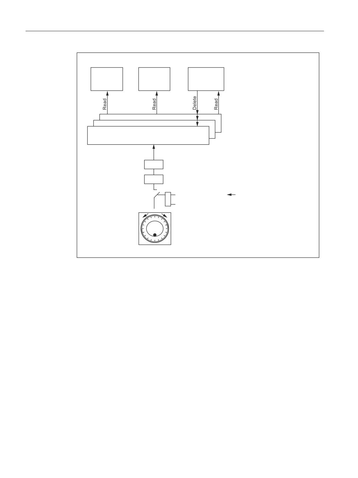
Control of DRF offset
The DRF offset can be modified, deleted or read:
User:
● Traversing with the handwheel
Part program:
● Reading via axis-specific system variable $AC_DRF[<axis>]
● Deleting via parts-program command (DRFOF) for all axes in a
channel
● Non-modal suppression via parts-program command (SUPA)
References:
Programming Manual, Fundamentals
PLC user program:
● Reading the DRF offset (axis-specific)
References:
Function Manual, Basic Machine; PLC Basic Program (P3)
HMI user interface:
● Display of the DRF offset (axis-specific)
Note
If DRF offset is deleted, the axis is not traversed!
Extended Functions
Function Manual, 12/2018, A5E40874029B AB
227
H1: Manual traversing
4.13 Use of handwheels in automatic mode
3/& XVHU
,6
1&
SURJUDP
RSHUDWRU
SDUW SURJUDP
+//
$[LV Q
$[LV
'5) RIIVHW
$[LV
0RGLI\ LQFUHPHQWDOO\
+DQGZKHHO SXOVHV
[
0'
01B+$1':+B,03B3(5B/$7&+
SHU ORFNLQJ SRVLWLRQ
6HOHFWHG LQFUHPHQW
$FWLYH PDFKLQH
,1&
0'
01B-2*B,1&5B6,=(B7$%
[
VL]H
IXQFWLRQ LQWHUIDFH
,1&YDU
6'
01B-2*B9$5B,1&5B6,=(
VLJQDO
$FWLYDWH '5)
+0, ,6
'5) VHOHFWHG
'5) DFWLYH
LQWHUIDFH VLJQDO
$XWRPDWLF DFWLYH PRGH
+DQGZKHHO
Figure 4-10
Control of DRF offset
Display
The axis actual-position display (ACTUAL POSITION) does not change while an axis is being
traversed with the handwheel via DRF. The current axis DRF offset can be displayed in the
DRF window.
Reference point approach
In phase 1 of the machine-axis reference point approach, the DRF offset for the corresponding
geometry or auxiliary axis is deleted.
During the machine-axis reference point approach, a DRF offset for the corresponding
geometry or auxiliary axis cannot be performed simultaneously.
Reset response
PowerOn-Reset: The DRF offset is deleted.
Extended Functions
228
Function Manual, 12/2018, A5E40874029B AB

H1: Manual traversing
4.13 Use of handwheels in automatic mode
4.13.3.3
Programming: Deselecting overlays axis-specifically (CORROF)
The following axis-specific overlays (overrides) are deleted with the CORROF procedure:
● Additive work offsets (DRF offsets) set via handwheel traversal
● Position offsets programmed via the $AA_OFF system variable
A preprocessing stop is initiated through the deletion of an overlay (override) value and the
position component of the deselected overlaid movement is transferred to the position in the
basic coordinate system. Whereby, no axis is traversed.
The position value that can be read via the $AA_IM system variable (current MCS setpoint of
the axis) does not change in the machine coordinate system.
The position value that can be read via the $AA_IW system variable (current WCS setpoint of
the axis) changes in the workpiece coordinate system because it now contains the deselected
component of the overlaid movement.
Note
CORROF can be programmed in an NC program.
CORROF must not be programmed in a synchronized action.
Syntax
CORROF(<Axis>,"<String>"[,<Axis>,"<String>"])
Meaning
CORROF:
Procedure for the deselection of the following offsets and overlays of an axis:
● DRF offset
● Position offsets ($AA_OFF)
Effective-
Modal
ness:
<Axis>:
Axis identifier (channel, geometry or machine axis identifier)
Data type:
AXIS
<String>:
Character string for the definition of the overlay type
Data type:
BOOL
Value
Meaning
DRF
DRF offset
AA_OFF
Position offset ($AA_OFF)
Extended Functions
Function Manual, 12/2018, A5E40874029B AB
229

H1: Manual traversing
4.13 Use of handwheels in automatic mode
Examples
Example 1: Axis-specific deselection of a DRF offset (1)
A DRF offset is generated in the X axis by DRF handwheel traversal. No DRF offsets are
operative for any other axes in the channel.
Program code
Comment
N10 CORROF(X,"DRF")
; CORROF has the same effect as DRFOF here.
Example 2: Axis-specific deselection of a DRF offset (2)
A DRF offset is generated in the X and Y axes by DRF handwheel traversal. No DRF offsets
are operative for any other axes in the channel.
Program code
Comment
; Only the DRF offset of the X axis is deselected; the DRF offset of the Y axis is
retained.
; With DRFOF, both offsets would have been deselected.
N10 CORROF(X,"DRF")
Example 3: Axis-specific deselection of a $AA_OFF position offset
Program code
Comment
; A position offset == 10 is interpolated for the X axis.
N10 WHEN TRUE DO $AA_OFF[X]=10 G4 F5
; The position offset of the X axis is deselected: $AA_OFF[X]=0
; The X axis is not traversed.
; The position offset is added to the current position of the X axis.
N80 CORROF(X,"AA_OFF")
Example 4: Axis-specific deselection of a DRF offset and a $AA_OFF position offset (1)
A DRF offset is generated in the X axis by DRF handwheel traversal. No DRF offsets are
operative for any other axes in the channel.
Program code
Comment
; A position offset of 10 is interpolated for the X axis.
N10 WHEN TRUE DO $AA_OFF[X]=10 G4 F5
; Only the DRF offset and the position offset of the X axis are deselected.
; The DRF offset of the Y axis is retained.
N70 CORROF(X,"DRF",X,"AA_OFF")
Extended Functions
230
Function Manual, 12/2018, A5E40874029B AB
H1: Manual traversing
4.13 Use of handwheels in automatic mode
Example 5: Axis-specific deselection of a DRF offset and a $AA_OFF position offset (2)
A DRF offset is generated in the X and Y axes by DRF handwheel traversal. No DRF offsets
are operative for any other axes in the channel.
Program code
Comment
; A position offset == 10 is interpolated for the X axis.
N10 WHEN TRUE DO $AA_OFF[X]=10 G4 F5
; The DRF offset of the Y axis and the position offset of the X axis are deselected.
; The DRF offset of the X axis is retained.
N70 CORROF(Y,"DRF",X,"AA_OFF")
Further information
$AA_OFF_VAL
Once the position offset has been deselected by means of $AA_OFF, system variable
$AA_OFF_VAL (integrated distance of axis overlay) for the corresponding axis will equal zero.
$AA_OFF in JOG mode
Also in JOG mode, if $AA_OFF changes, the position offset will be interpolated as an overlaid
movement if this function has been enabled via machine data MD 36750
$MA_AA_OFF_MODE.
$AA_OFF in synchronized action
If a synchronized action which immediately resets $AA_OFF
(DO $AA_OFF[<axis>]=<value>) is active when the position offset is deselected using the
CORROF(<axis>,"AA_OFF"), then $AA_OFF will be deselected and not reset, and alarm
21660 will be displayed. However, if the synchronized action becomes active later, e.g. in the
block after CORROF, $AA_OFF will remain set and a position offset will be interpolated.
Automatic channel axis exchange
If an axis that is active in another channel has been programmed for a CORROF, it will be fetched
into the channel with an axis exchange (requirement: MD30552 $MA_AUTO_GET_TYPE > 0)
and the position offset and/or the DRF offset deselected.
4.13.4
Double use of the handwheel
Alarm 14320
The double use of a handwheel for DRF and velocity or distance overlay, including contour
handwheel, is suppressed and is displayed using the self-clearing alarm 14320 (Handwheel
%1 used twice (%2) in channel %3 axis %4), if, different influences can act on an axis as a
result of the handwheel.
Extended Functions
Function Manual, 12/2018, A5E40874029B AB
231
H1: Manual traversing
4.13 Use of handwheels in automatic mode
This means that an overlaid movement can only be executed when no DRF offset (triggered
by the same handwheel) is active for the axes in the basic coordinate system that are involved
in the movement, i.e., the DRF movement must have been terminated.
If an overlaid movement has been started, no DRF offset can be started for any of the axes
involved that are supplied by the same handwheel. Such a DRF movement is only possible
when the movement with overlay has reached its end point or has been aborted by delete
distance-to-go or RESET.
If the handwheel override and DRF offset are to be active simultaneously, this is possible with
activation of two separate handwheels.
Example: Path override
Assumption:
Channel 1 and geometry axis X correspond to machine axis 3 and geometry axis Y
corresponds to machine axis 5 and handwheel 2 is selected for the first geometry axis.
If block X10 Y10 FD=0 is processed in the main run, neither machine axis 3 nor machine
axis 5 can be traversed with DRF via handwheel 2. If handwheel 2 is assigned to machine
axis 3 while the channel-specific DRF signal is active, then alarm 14320 (Handwheel 2 used
twice (8) in channel 1 axis X) is signaled.
If machine axis 3 or machine axis 5 is traversed with DRF using the 2nd handwheel, then
motion X10 Y10 FD=0 cannot be executed and alarm 14320 (handwheel 2 used twice (3) in
channel 1 axis X) or alarm 14320 (handwheel 2 used twice (3) in channel 1 axis Y) is signaled.
Example: Velocity override of positioning axis
Assumption:
Channel 1: Channel axis A corresponds to machine axis 4 and handwheel 1 is assigned to
this axis.
If block POS[A]=100 FDA[A]=0 is processed in the main run, machine axis 4 cannot be
traversed with DRF. This means that if the channel-specific DRF signal is active, alarm 14320
(Handwheel 1 used twice (6) in channel 1 axis A) is signaled.
If machine axis 4 is traversed with DRF, then no POS[A]=100 FDA[A]=0 movement can be
executed while a DRF movement is being performed. Alarm 14320 (Handwheel 1 used twice
(1) in channel 1 axis A) is signaled.
Example: Distance overlay PLC axis (840D sl)
Assumption:
Channel 1: Handwheel 2 is assigned to machine axis 4.
If an axis movement with path override of the 4th machine axis triggered by FC18 is processed
in the main run, machine axis 4 cannot be traversed with DRF. This means that if the channel-
specific DRF signal is active, alarm 14320 (Handwheel 2 used twice (9) in channel 1 axis A)
is signaled.
If machine axis 4 is traversed with DRF, then no axis movement with path override triggered
by FC18 can be executed while a DRF movement is being performed. Alarm 14320
(Handwheel 2 used twice (4) in channel 1 axis A) is signaled.
Extended Functions
232
Function Manual, 12/2018, A5E40874029B AB
H1: Manual traversing
4.14 Monitoring functions
4.14
Monitoring functions
Limitations
For manual traversing and manual traversing using a handwheel, the following limits apply:
● Working area limitation (the axis must be referenced).
● Software limit switches 1 and 2 (axis must be referenced)
● Hardware limit switches
The control ensures that the traversing movement is aborted as soon as the first valid limitation
has been reached. Velocity control ensures that deceleration is initiated early enough for the
axis to stop exactly at the limit position (e.g. software limit switch). Only when the hardware
limit switch is triggered does the axis stop abruptly with "rapid stop".
Alarms are triggered when the various limitations are reached (alarms 16016, 16017, 16020,
16021). The control automatically prevents further movement in this direction. The traversing
keys and the handwheel have no effect in this direction.
Note
The software limit switches and working-area limitations are only active if the axis has first
been referenced.
If a work offset (DRF offset) via handwheel is active for axes, the software limit switches for
these axes are monitored during the main run in JOG mode. This means that the jerk limitation
has no effect when the software limit switches are approached. After acceleration in
accordance with MD32300 $MA_MAX_AX_ACCEL (maximum axis acceleration) the velocity
is reduced at the software limit switch.
For further information on working area limitations and hardware and software limit switches,
see:
References:
Function Manual, Axis Monitoring, Protection Zones (A3)
Retract axis
The axis can be retracted from a limit position by moving it in the opposite direction.
Note
Machine manufacturer
The function for retracting an axis that has approached the limit position depends on the
machine manufacturer. Please refer to the machine manufacturer's documentation!
Maximum velocity and acceleration
The velocity and acceleration used when manually traversing are defined by the startup
engineer for specific axes using machine data. The control limits the values acting on the axes
to the maximum velocity and acceleration specifications.
Extended Functions
Function Manual, 12/2018, A5E40874029B AB
233

H1: Manual traversing
4.15 Start-up: Handwheels
References:
Function Manual Basic Functions; Velocities, Setpoint/Actual Value Systems, Closed-Loop
Controls (G2)
Function Manual Basic Functions; Acceleration (B2)
4.15
Start-up: Handwheels
4.15.1
General information
In order to operate handwheels of a SINUMERIK control system, they have to be
parameterized via NC machine data.
If the handwheels are not directly connected to the control, additional measures are required,
e.g. connection via PROFIBUS- or Ethernet-MCP or handwheel module, inserting and
configuring the module with SIMATIC STEP 7, HW-Config.
Note
Currently only six handwheels can be parameterized in a SINUMERIK control system.
Connection options
SINUMERIK 840D sl
For SINUMERIK 840D sl, handwheels can be connected via the following components:
● PROFIBUS (Page 237) module
● Ethernet (Page 239) module
Note
Several handwheels, which are connected via different components, can be connected to one
SINUMERIK 840D sl at the same time.
SINUMERIK 828D
For SINUMERIK 828D, handwheels can be connected via the following components:
● PPU (Page 235)
● Machine control panel (MCP) via PROFIBUS (Page 235)
Note
Several handwheels, which are connected via different components, can be connected to one
SINUMERIK 828D at the same time.
Extended Functions
234
Function Manual, 12/2018, A5E40874029B AB

H1: Manual traversing
4.15 Start-up: Handwheels
4.15.2
Connection via PPU (only 828D)
Parameter assignment
Handwheels directly connected to terminal X143 of the PPU are parameterized using the
following NC machine data:
● MD11350 $MN_HANDWHEEL_SEGMENT[<Handwheel_No._in_NCK - 1>] = 2
When directly connected to the PPU, a 2 (8xxD_HW) must always be entered as handwheel
segment.
● MD11351 $MN_HANDWHEEL_MODULE[< Handwheel_No._in_NCK - 1 >] = 1
When directly connected to the PPU, a 1 must always be entered.
● MD11352 $MN_HANDWHEEL_INPUT[< Handwheel_No_in_NCK - 1 >] = <Handwheel
connection >
The number of the handwheel has to be entered: 1 or 2
Note
Two handwheels can be connected to a PPU (terminal X143).
Example
Parameter assignment of two handwheels connected via terminal X143 of the PPU.
Machine data
Value
Meaning
1st handwheel:
MD11350 $MN_HANDWHEEL_SEGMENT[0]
2
Hardware segment: 8xxD_HW
MD11351 $MN_HANDWHEEL_MODULE[0]
1
---
MD11352 $MN_HANDWHEEL_INPUT[0]
1
1st handwheel connection of X143
2nd handwheel:
MD11350 $MN_HANDWHEEL_SEGMENT[1]
2
Hardware segment: 8xxD_HW
MD11351 $MN_HANDWHEEL_MODULE[1]
1
---
MD11352 $MN_HANDWHEEL_INPUT[1]
2
2nd handwheel connection of X143
4.15.3
Connection via PROFIBUS (828D)
Parameter assignment
For the SINUMERIK 828D, in addition to the connection of two handwheels to the PPU
interface, terminal X143, a third handwheel can also be connected via a machine control panel,
e.g. MCP 483C PN, interface X60.
Extended Functions
Function Manual, 12/2018, A5E40874029B AB
235

H1: Manual traversing
4.15 Start-up: Handwheels
The parameter assignment of the third handwheel is performed in the following NC machine
data:
● MD11350 $MN_HANDWHEEL_SEGMENT[ 2 ] = 5
● MD11351 $MN_HANDWHEEL_MODULE[ 2 ] = 1
● MD11352 $MN_HANDWHEEL_INPUT[ 2 ] = 1
Requirement
Operation of the control with default data (machine data, STEP 7 configuration).
Example
Parameterization of three handwheels, connected via PPU and an "MCP 483C PN" machine
control panel.
Handwheel number
Machine data set
Connection
in NC
(Index)
1
0
PPU, 1. Handwheel in handwheel slot
2
1
PPU, 2. Handwheel in handwheel slot
3
2
MCP, 1. Handwheel in handwheel slot
Parameterizing in the NC machine data:
Machine data
Val-
Meaning
ue
1st handwheel in the NC
MD11350 $MN_HANDWHEEL_SEGMENT[0]
2
Hardware segment: 8xxD_HW
MD11351 $MN_HANDWHEEL_MODULE[0]
1
---
MD11352 $MN_HANDWHEEL_INPUT[0]
1
1st handwheel in the handwheel slot
2nd handwheel in the NC
MD11350 $MN_HANDWHEEL_SEGMENT[1]
2
Hardware segment: 8xxD_HW
MD11351 $MN_HANDWHEEL_MODULE[1]
1
---
MD11352 $MN_HANDWHEEL_INPUT[1]
2
2nd handwheel in the handwheel slot
3rd handwheel in the NC
MD11350 $MN_HANDWHEEL_SEGMENT[2]
5
Hardware segment: PROFIBUS
MD11351 $MN_HANDWHEEL_MODULE[2]
1
Reference to logical base address of the handwheel slot of the
MCP
MD11352 $MN_HANDWHEEL_INPUT[2]
1
1st handwheel in the handwheel slot
Extended Functions
236
Function Manual, 12/2018, A5E40874029B AB

H1: Manual traversing
4.15 Start-up: Handwheels
4.15.4
Connection via PROFIBUS (840D sl)
Parameterization
The parameter assignment of handwheels connected via PROFIBUS modules (e.g. "MCP 483"
machine control panel) is performed with the following NC machine data:
● MD11350 $MN_HANDWHEEL_SEGMENT[<Handwheel_No._in_NCK - 1>] = 5
When connected via PROFIBUSmodule, the hardware segment has always to be entered
as 5 (PROFIBUS).
● MD11351 $MN_HANDWHEEL_MODULE[<Handwheel_No._in_NCK - 1>] = <Index + 1>
The reference to the MD11353 $MN_HANDWHEEL_LOGIC_ADDRESS[<Index>]
has to be entered, which contains the logical base address of the handwheel.
● MD11352 $MN_HANDWHEEL_INPUT[<Handwheel_No._in_NCK - 1>] =
<Number_in_handwheel_slot>
A handwheel slot can contain several handwheels. The number of the handwheel within
the handwheel slot has to entered: 1, 2, ...
● MD11353 $MN_HANDWHEEL_LOGIC_ADDRESS[<Index>] = <logical base address>
The logical base address of the handwheel slot, specified in SIMATIC STEP 7, HW Config,
has to be entered.
Handwheel slot
The PROFIBUS module must be configured in addition to the parameterization of handwheels
in the NC machine data in STEP 7. Among others the logical address of the handwheel slot
is specified.
The handwheel slot is situated at the following slot of the PROFIBUSmodule:
PROFIBUS module
Slot
Machine control panel MCP 483
2
Machine control panel MCP 310
2
Handwheel connection module
1
Example
Parameterization of five handwheels, connected via four machine control panels "MCP 483".
Two handwheels can be connected to a machine control panel"MCP 483".
Handwheel number
Machine data set
Connection
in NC
(Index)
1
0
1st MCP, 1. Handwheel in handwheel slot
2
1
1st MCP, 2. Handwheel in handwheel slot
3
2
2nd MCP, 1. Handwheel in handwheel slot
5
4
3rd MCP, 1. Handwheel in handwheel slot
6
5
4th MCP, 2. Handwheel in handwheel slot
Extended Functions
Function Manual, 12/2018, A5E40874029B AB
237

H1: Manual traversing
4.15 Start-up: Handwheels
The 4th handwheel in the NC is not used (gap in machine data).
Note
Machine data gaps are allowed when parameterizing handwheels in NC machine data.
Machine control panels have been configured in SIMATIC STEP 7, HW Config as follows:
Slot
DP ID
Article No./designation
I address
O address
1st MCP
1
55
Standard+Handwheel
0 ... 7
0 ... 7
2
2AE
→ standard+handwheel
288 ... 291
3
1
→ standard+handwheel
2nd MCP
1
55
Standard+Handwheel
8 ... 15
8 ... 15
2
2AE
→ standard+handwheel
304 ... 307
3
1
→ standard+handwheel
3rd MCP
1
55
Standard+Handwheel
16 ... 23
16 ... 23
2
2AE
→ standard+handwheel
320 ... 323
3
1
→ standard+handwheel
4th MCP
1
55
Standard+Handwheel
24 ... 29
24 ... 29
2
2AE
→ standard+handwheel
330 ... 333
3
1
→ standard+handwheel
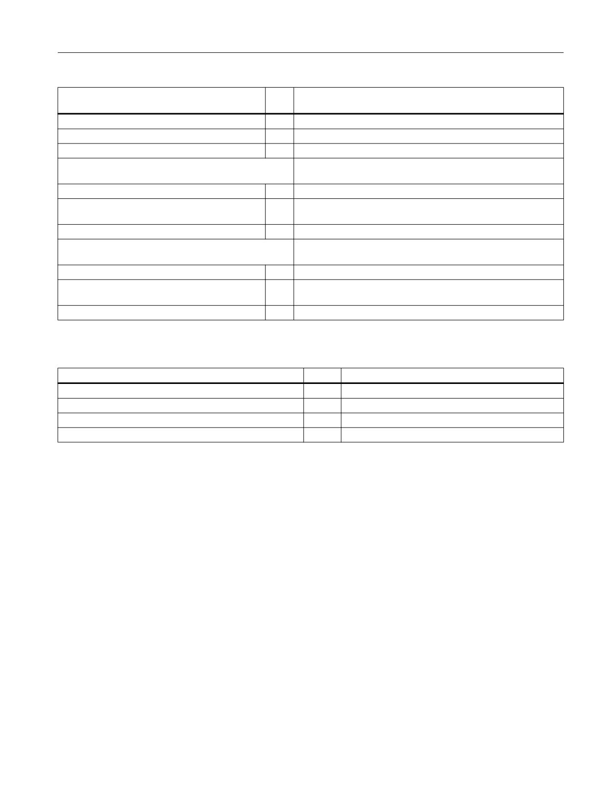
Parameterizing in the NC machine data:
Machine data
Val-
Meaning
ue
1st handwheel in the NC
MD11350 $MN_HANDWHEEL_SEGMENT[0]
5
Hardware segment: PROFIBUS
MD11351 $MN_HANDWHEEL_MODULE[0]
1
Reference to logical base address of the handwheel slot of the
1st MCP
MD11352 $MN_HANDWHEEL_INPUT[0]
1
1st handwheel in the handwheel slot
2nd handwheel in the NC
MD11350 $MN_HANDWHEEL_SEGMENT[1]
5
Hardware segment: PROFIBUS
MD11351 $MN_HANDWHEEL_MODULE[1]
1
Reference to logical base address of the handwheel slot of the
1st MCP
MD11352 $MN_HANDWHEEL_INPUT[1]
2
2nd handwheel in the handwheel slot
3rd handwheel in the NC
MD11350 $MN_HANDWHEEL_SEGMENT[2]
5
Hardware segment: PROFIBUS
MD11351 $MN_HANDWHEEL_MODULE[2]
2
Reference to logical base address of the handwheel slot of the
2nd MCP
MD11352 $MN_HANDWHEEL_INPUT[2]
1
1st handwheel in the handwheel slot
4th handwheel in the NC
Extended Functions
238
Function Manual, 12/2018, A5E40874029B AB
H1: Manual traversing
4.15 Start-up: Handwheels
Machine data
Val-
Meaning
ue
MD11350 $MN_HANDWHEEL_SEGMENT[3]
0
No handwheel parameterized
MD11351 $MN_HANDWHEEL_MODULE[3]
0
No handwheel parameterized
MD11352 $MN_HANDWHEEL_INPUT[3]
0
No handwheel parameterized
5th handwheel in the NC
MD11350 $MN_HANDWHEEL_SEGMENT[4]
5
Hardware segment: PROFIBUS
MD11351 $MN_HANDWHEEL_MODULE[4]
6
Reference to logical base address of the handwheel slot of the
3rd MCP
MD11352 $MN_HANDWHEEL_INPUT[4]
1
1st handwheel in the handwheel slot
6th handwheel in the NC
MD11350 $MN_HANDWHEEL_SEGMENT[5]
5
Hardware segment: PROFIBUS
MD11351 $MN_HANDWHEEL_MODULE[5]
5
Reference to logical base address of the handwheel slot of the
4th MCP
MD11352 $MN_HANDWHEEL_INPUT[5]
2
2nd handwheel in the handwheel slot
Logical base addresses:
Machine data
Value
Meaning
MD11353 $MN_HANDWHEEL_LOGIC_ADDRESS [0]
288
Logical base address handwheel slot 1st MCP
MD11353 $MN_HANDWHEEL_LOGIC_ADDRESS [1]
304
Logical base address handwheel slot 2nd MCP
MD11353 $MN_HANDWHEEL_LOGIC_ADDRESS [4]
330
Logical base address handwheel slot 4th MCP
MD11353 $MN_HANDWHEEL_LOGIC_ADDRESS [5]
320
Logical base address handwheel slot 3rd MCP
4.15.5
Connected via Ethernet (only 840D sl)
Parameter assignment
The parameters for handwheels connected via Ethernet modules, e.g. machine control panel
"MCP 483C IE", "HT 8", or "HT 2", are assigned in the following NC machine data:
● MD11350 $MN_HANDWHEEL_SEGMENT[< x - 1 >] = 7
When connected via Ethernet modules, the segment always has to be entered as 7
(Ethernet).
● MD11351 $MN_HANDWHEEL_MODULE[< x - 1 >] = 1
When connected via Ethernet modules, the module always has to be entered as 1.
● MD11352 $MN_HANDWHEEL_INPUT[< x - 1 >] = y
with y = 1, 2, 3, ... (handwheel interface at the Ethernet bus)
with x = 1, 2, 3, ... (handwheel number in the NC)
Extended Functions
Function Manual, 12/2018, A5E40874029B AB
239
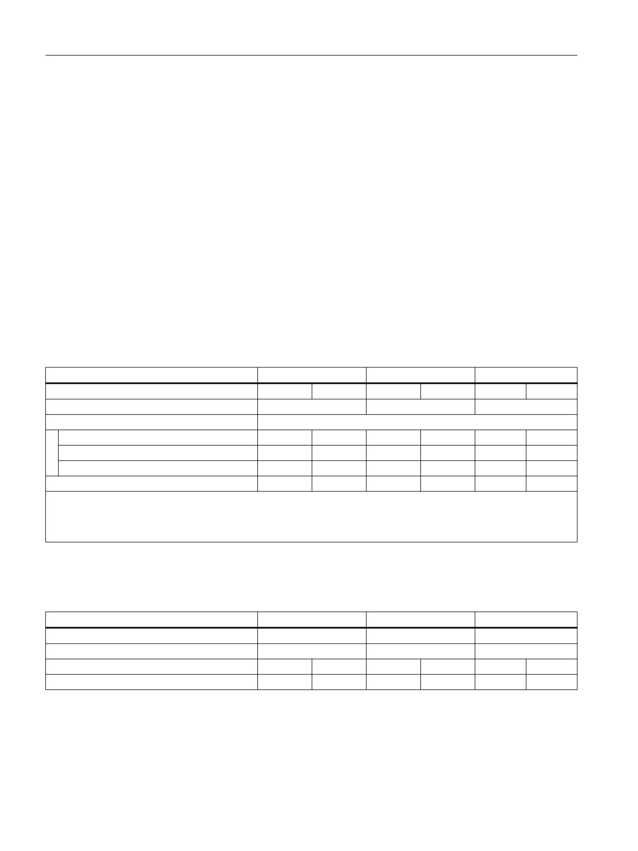
H1: Manual traversing
4.15 Start-up: Handwheels
Handwheel interfaces at the Ethernet Bus
The handwheel interfaces at the Ethernet bus are numbered on the basis of the following
definitions:
● The sequence of the operator component interfaces is: MCP1, MCP2, BHG
● Each operator component interface has two handwheel interfaces
● Operator components: MCP 483C IE
A maximum of two handwheels can be connected to an MCP 483C IE via connections
X60 and X61 . The assignment of the connections in the operator component interface is:
- Connection X60: 1st handwheel in the operator component interface MCP1 /MCP2
- Connection X61: 2nd handwheel in the operator component interface MCP1 /MCP2
● Operator components: HT 8
The handwheel of the HT 8 is always assigned to the 1st handwheel of operator component
interface MCP1 /MCP2 .
● Operator components: HT 2
The handwheel of the HT 2 is always assigned to the 1st handwheel in the operator
component interface BHG .
Operator component interface ->
MCP1
MCP2
BHG
Handwheel interface 1)
1
2
1
2
1
2
FB1 parameters 2)
MCP1BusAdr
MCP2BusAdr
BHGRecGDNo
Assignment of the handwheels 3)
MCP 483C IE
X60
X61
X60
X61
-
-
HT 8
x
-
x
-
-
-
HT 2
-
-
-
-
x
-
Handwheel interface at the Ethernet bus (y) 4) ->
1
2
3
4
5
6
1) Numbering of the handwheel interfaces within an operator component interface
2) Assignment of the operator component to the interface via the corresponding FB1 parameter
3) Assignment of the handwheels of the respective operator components to the handwheel interfaces
4) Numbering of the handwheel interfaces at the Ethernet bus -> MD11352 $MN_HANDWHEEL_INPUT[< x - 1 >] = y
Example
Parameterization of 3 handwheels, connected via the following operator components:
Operator component interface ->
MCP1
MCP2
BHG
Operator component
HT 8
MCP 483C
HT 2
FB1 parameters
MCP1BusAdr := 39
MCP2BusAdr := 192
BHGRecGDNo := 40
Handwheel interface
x
-
-
X61
x
-
Handwheel interface at Ethernet bus ->
1
2
3
4
5
6
Extended Functions
240
Function Manual, 12/2018, A5E40874029B AB

H1: Manual traversing
4.15 Start-up: Handwheels
Table 4-1
NC machine data for the handwheel assignment
Machine data
Value
Description
HT 8: Handwheel number in the NC = 1
MD11350 $MN_HANDWHEEL_SEGMENT[ 0 ]
7
Segment: Ethernet
MD11350 $MN_HANDWHEEL_MODULE[ 0 ]
1
Module: Ethernet
MD11350 $MN_HANDWHEEL_INPUT[ 0 ]
1
Handwheel interface at Ethernet bus
MCP 483C IE: Handwheel number in the NC = 2
MD11350 $MN_HANDWHEEL_SEGMENT[ 1 ]
7
Segment: Ethernet
MD11350 $MN_HANDWHEEL_ MODULE [ 1 ]
1
Module: Ethernet
MD11350 $MN_HANDWHEEL_ INPUT [ 1 ]
4
Handwheel interface at Ethernet bus
HT 2: Handwheel number in the NC = 3
MD11350 $MN_HANDWHEEL_SEGMENT[ 2 ]
7
Segment: Ethernet
MD11350 $MN_HANDWHEEL_ MODULE [ 2 ]
1
Module: Ethernet
MD11350 $MN_HANDWHEEL_ INPUT [ 2 ]
5
Handwheel interface at Ethernet bus
Table 4-2
FB1 parameters (excerpt)
Parameter
Value
Remark
MCPNum
:= 2
// Number of connected MCPs
// MCP1 = HT 8
MCP1In
// MCP1 parameters...
MCP1BusAdr
:= 39
// Via switches S1 and S2 on the connecting
device
// Set "IP address"
// MCP2 = MCP 483C IE
MCP2In
// MCP2 parameters...
MCP2BusAdr
:= 192
// Via switch S2 on the MCP 483C
// Set "IP address"
MCPBusType
:= b#16#55
// Bus type: Ethernet
// HHU = HT 2
HHU
:= 5
// Bus type: Ethernet
BHGIn
// HHU Parameter ...
BHGRecGDNo
:= 40
// Via switches S1 and S2 on the connecting
device
// Set "IP address"
Extended Functions
Function Manual, 12/2018, A5E40874029B AB
241

H1: Manual traversing
4.15 Start-up: Handwheels
Filter time
Since the handwheel pulses on the Ethernet bus are not transferred deterministically, filtering
(smoothing) of the handwheel pulse transfer process may be necessary for highly dynamic
drives. The filter time is parameterized using the following machine data:
● MD11354 $MN_HANDWHEEL_FILTER_TIME[< x - 1 >] = <filter time>
with x = 1, 2, 3, ... (handwheel number in the NC) and filter time = 0.0 ... 2.0 s
The filter time specifies the time it takes for the handwheel pulses transferred to the control to
be sent on to the interpolator for traversing purposes. With a filter time of 0.0 s, the handwheel
pulses are sent on to the interpolator within a single interpolation cycle. This can result in jerky
axis traversing.
The recommended filter time is: 0.2 - 0.5 s
Zero speed detection
A stationary state is detected by the Ethernet modules to which the handwheel is connected.
If a handwheel does not transfer any handwheel pulses for a defined period of time, the module
detects this to be a stationary state and transfers it to the NC/PLC interface:
NC/PLC interface signal
Value
Meaning
DB10, DBX245.0
0
Handwheel 1 is operated.
1
Handwheel 1 is stationary
DB10 DBX245.1
0
Handwheel 2 is operated.
1
Handwheel 2 is stationary.
DB10 DBX245.2
0
Handwheel 3 is operated.
1
Handwheel 3 is stationary.
DB10 DBX245.3
0
Handwheel 4 is operated.
1
Handwheel 4 is stationary.
DB10 DBX245.4
0
Handwheel 5 is operated.
1
Handwheel 5 is stationary.
DB10 DBX245.5
0
Handwheel 6 is operated.
1
Handwheel 6 is stationary.
By evaluating the signal, it is possible to reduce the overtravel of an axis traversed via the
handwheel, due to the handwheel pulses that have been collected in the control but not yet
transferred to the interpolator for traversing purposes. To do this, deletion of the distance-to-
go must be triggered for the relevant axis or in the channel when a stationary state is detected:
● DB31,... DBX2.2 = 1 (axial delete distance-to-go)
● DB21,... DBX6.2 = 1 (channel-specific deletion of distance-to-go)
Extended Functions
242
Function Manual, 12/2018, A5E40874029B AB

H1: Manual traversing
4.16 Data lists
4.16
Data lists
4.16.1
Machine data
4.16.1.1
General machine data
Number
Identifier: $MN_
Description
10000
AXCONF_MACHAX_NAME_TAB[n]
Machine axis name
10720
OPERATING_MODE_DEFAULT
Setting of the operating mode after Power On
10721
OPERATING_MODE_EXTENDED
Extended setting of the operating mode after Power On
10735
JOG_MODE_MASK
Settings for JOG mode
11300
JOG_INC_MODE_LEVELTRIGGRD
INC and REF in inching mode
11310
HANDWH_REVERSE
Defines movement in the opposite direction
11320
HANDWH_IMP_PER_LATCH[n]
Handwheel pulses per locking position
11324
HANDWH_VDI_REPRESENTATION
Coding of the handwheel number (NCK/PLC interface)
11330
JOG_INCR_SIZE_TAB[n]
Increment size for INC/handwheel
11340
ENC_HANDWHEEL_SEGMENT_NR
Third handwheel: Bus segment
11342
ENC_HANDWHEEL_MODULE_NR
Third handwheel: Logical drive number
11344
ENC_HANDWHEEL_INPUT_NR
Third handwheel: Encoder interface
11346
HANDWH_TRUE_DISTANCE
Handwheel path or velocity specification
11350
HANDWHEEL_SEGMENT[n]
Handwheel segment
11351
HANDWHEEL_MODULE[n]
Handwheel module
11352
HANDWHEEL_INPUT[n]
Handwheel connection
11353
HANDWHEEL_LOGIC_ADDRESS[n]
Logical handwheel slot address (STEP 7)
17900
VDI_FUNCTION_MASK
Function mask for VDI signals
4.16.1.2
Channel-specific machine data
Number
Identifier: $MC_
Description
20060
AXCONF_GEOAX_NAME_TAB
Geometry axis in channel
20100
DIAMETER_AX_DEF
Geometry axes with transverse axis functions
20110
RESET_MODE_MASK
Initial setting after reset / program end
20150
GCODE_RESET_VALUES
Reset position of the G groups
20151
GCODE_RESET_MODE
Reset behavior of the G groups
20360
TOOL_PARAMETER_DEF_MASK
Definition of the tool parameters
20620
HANDWH_GEOAX_MAX_INCR_SIZE
Limitation of the geometry axes
20622
HANDWH_GEOAX_MAX_INCR_VSIZE
Path-velocity override
20624
HANDWH_CHAN_STOP_COND
Definition of the manual traversing behavior using a
handwheel, channel-specific
20700
REFP_NC_START_LOCK
NC start disable without reference point
Extended Functions
Function Manual, 12/2018, A5E40874029B AB
243

H1: Manual traversing
4.16 Data lists
Number
Identifier: $MC_
Description
21150
JOG_VELO_RAPID_ORI
Conventional rapid traverse for orientation axes
21155
JOG_VELO_ORI
Conventional velocity for orientation axes
21158
JOG_JERK_ORI
Maximum jerk when manually traversing orientation ax-
es
21159
JOG_JERK_ORI_ENABLE
Jerk limitation for manual traversing of orientation axes
activated
21160
JOG_VELO_RAPID_GEO
Conventional rapid traverse for geometry axes
21165
JOG_VELO_GEO
Conventional speed for geometry axes
21166
JOG_ACCEL_GEO
Maximum acceleration when manually traversing ge-
ometry axes
21168
JOG_JERK_GEO
Maximum jerk when manually traversing geometry ax-
es
4.16.1.3
Axis/spindlespecific machine data
Number
Identifier: $MA_
Description
30450
IS_CONCURRENT_POS_AX
Default setting at reset: Neutral axis or channel axis
30600
FIX_POINT_POS[n]
Fixed point positions of the axis
30610
NUM_FIX_POINT_POS
Number of fixed point positions of an axis
31090
JOG_INCR_WEIGHT
Weighting of an increment for INC/handwheel
32000
MAX_AX_VELO
Maximum axis velocity
32010
JOG_VELO_RAPID
Rapid traverse in jog mode
32020
JOG_VELO
Axis velocity in job mode
32040
JOG_REV_VELO_RAPID
Revolutional feedrate in JOG mode with rapid traverse override
32050
JOG_REV_VELO
Revolutional feedrate for JOG
32060
POS_AX_VELO
Reset position for positioning-axis velocity
32080
HANDWH_MAX_INCR_SIZE
Limitation of the selected increment size
32082
HANDWH_MAX_INCR_VELO_SIZE
Limitation of the selected increment for velocity override
32084
HANDWH_STOP_COND
Behavior, handwheel travel
32090
HANDWH_VELO_OVERLAY_FACTOR
Ratio of JOG velocity to handwheel velocity (with DRF)
32300
MAX_AX_ACCEL
Maximum axis acceleration
32420
JOG_AND_POS_JERK_ENABLE
Basic setting of axis-specific jerk limitation
32430
JOG_AND_POS_MAX_JERK
Maximum axis-specific jerk for single-axis movements
32431
MAX_AX_JERK
Maximum axis-specific jerk during path movements
34210
ENC_REFP_STATE
Measuring system status
35130
GEAR_STEP_MAX_VELO_LIMIT[n]
Maximum velocity for gear stage
Extended Functions
244
Function Manual, 12/2018, A5E40874029B AB

H1: Manual traversing
4.16 Data lists
4.16.2
Setting data
4.16.2.1
General setting data
Number
Identifier: $SN_
Description
41010
JOG_VAR_INCR_SIZE
Size of the variable increment for incremental manual
traversing or manual traversing using a handwheel
41050
JOG_CONT_MODE_LEVELTRIGGRD
Jog/continuous mode for continuous manual traversing
41100
JOG_REV_IS_ACTIVE
JOG: Revolutional/linear feedrate
41110
JOG_SET_VELO
Axis velocity in JOG mode
41120
JOG_REV_SET_VELO
Revolutional feedrate of axes in JOG mode
41130
JOG_ROT_AX_SET_VELO
Axis velocity of the rotary axes in JOG mode
41200
JOG_SPIND_SET_VELO
Velocity for spindle in JOG mode
4.16.2.2
Channel-specific setting data
Number
Identifier: $SC_
Description
42690
JOG_CIRCLE_CENTRE
Center of circle
42691
JOG_CIRCLE_RADIUS
Circle radius
42692
JOG_CIRCLE_MODE
Jog circle mode
42693
JOG_CIRCLE_START_ANGLE
Start angle for circular travel in JOG
42694
JOG_CIRCLE_END_ANGLE
End angle for circular travel in JOG
4.16.2.3
Axis/spindle-specific setting data
Number
Identifier: $SA_
Description
43320
JOG_POSITION
JOG position
4.16.3
Signals
4.16.3.1
Signals from NC
Signal name
SINUMERIK 840D sl
SINUMERIK 828D
Handwheel 1 is operated
DB10.DBB68
DB2700.DBB12
Handwheel 2 is operated
DB10.DBB69
DB2700.DBB13
Handwheel 3 is operated
DB10.DBB70
DB2700.DBB14
Handwheel 4 is operated
DB10.DBB242
-
Handwheel 5 is operated
DB10.DBB243
-
Extended Functions
Function Manual, 12/2018, A5E40874029B AB
245

H1: Manual traversing
4.16 Data lists
Signal name
SINUMERIK 840D sl
SINUMERIK 828D
Handwheel 6 is operated
DB10.DBB244
-
Ethernet handwheel is stationary
DB10.DBX245.0 - 5
-
4.16.3.2
Signals from HMI
Signal name
SINUMERIK 840D sl
SINUMERIK 828D
Channel number for geometry axis, handwheel 1
DB10.DBX97.0 - 3
Channel number for geometry axis, handwheel 2
DB10.DBX98.0 - 3
Channel number for geometry axis, handwheel 3
DB10.DBX99.0 - 3
Axis number handwheel 1
DB10.DBX100.0 - 4
Define handwheel 1 as contour handwheel
DB10.DBX100.5
Handwheel 1 selected
DB10.DBX100.6
Machine axis handwheel 1
DB10.DBX100.7
Axis number handwheel 2
DB10.DBX101.0 - 4
Define handwheel 2 as contour handwheel
DB10.DBX101.5
Handwheel 2 selected
DB10.DBX101.6
Machine axis handwheel 2
DB10.DBX101.7
Axis number handwheel 3
DB10.DBX102.0 - 4
Define handwheel 3 as contour handwheel
DB10.DBX102.5
Handwheel 3 selected
DB10.DBX102.6
Machine axis handwheel 3
DB10.DBX102.7
4.16.3.3
Signals to mode group
Signal name
SINUMERIK 840D sl
SINUMERIK 828D
Mode Group1: JOG mode
DB11.DBX0.2
DB3000.DBX0.2
Mode group2: JOG mode
DB11.DBX20.2
-
Mode group3: JOG mode
DB11.DBX40.2
-
Mode group4: JOG mode
DB11.DBX60.2
-
Mode group5: JOG mode
DB11.DBX80.2
-
Mode group6: JOG mode
DB11.DBX100.2
-
Mode group7: JOG mode
DB11.DBX120.2
-
Mode group8: JOG mode
DB11.DBX140.2
-
Mode group9: JOG mode
DB11.DBX160.2
-
Mode group10: JOG mode
DB11.DBX180.2
-
Extended Functions
246
Function Manual, 12/2018, A5E40874029B AB

H1: Manual traversing
4.16 Data lists
4.16.3.4
Signals from mode group
Signal name
SINUMERIK 840D sl
SINUMERIK 828D
Mode Group1: Active mode JOG
DB11.DBX6.2
DB3100.DBX0.2
Mode group2: Active mode JOG
DB11.DBX26.2
-
Mode group3: Active mode JOG
DB11.DBX46.2
-
Mode group4: Active mode JOG
DB11.DBX66.2
-
Mode group5: Active mode JOG
DB11.DBX86.2
-
Mode group6: Active mode JOG
DB11.DBX106.2
-
Mode group7: Active mode JOG
DB11.DBX126.2
-
Mode group8: Active mode JOG
DB11.DBX146.2
-
Mode group9: Active mode JOG
DB11.DBX166.2
-
Mode group10: Active mode JOG
DB11.DBX186.2
-
4.16.3.5
Signals to channel
Signal name
SINUMERIK 840D sl
SINUMERIK 828D
Activate DRF
DB21,
DBX0.3
DB320x.DBX0.3
Geometry axis 1:
Activate handwheel
DB21,
DBX12.0 - 2
DB320x.DBX1000.0 - 2
Traversing key lock
DB21,
DBX12.4
DB320x.DBX1000.4
Rapid traverse override
DB21,
DBX12.5
DB320x.DBX1000.5
Travel key "minus"
DB21,
DBX12.6
DB320x.DBX1000.6
Travel key "plus"
DB21,
DBX12.7
DB320x.DBX1000.7
Request machine function
DB21,
DBX13.0 - 6
DB320x.DBX1001.0 - 6
Invert handwheel direction of ro-
DB21,
DBX15.0
DB320x.DBX1003.0
tation
Geometry axis 2:
Activate handwheel
DB21,
DBX16.0 - 2
DB320x.DBX1004.0 - 2
Traversing key lock
DB21,
DBX16.4
DB320x.DBX1004.4
Rapid traverse override
DB21,
DBX16.5
DB320x.DBX1004.5
Travel key "minus"
DB21,
DBX16.6
DB320x.DBX1004.6
Travel key "plus"
DB21,
DBX16.7
DB320x.DBX1004.7
Request machine function
DB21,
DBX17.0 - 6
DB320x.DBX1005.0 - 6
Invert handwheel direction of ro-
DB21,
DBX19.0
DB320x.DBX1007.0
tation
Geometry axis 3:
Activate handwheel
DB21,
DBX20.0 - 2
DB320x.DBX1008.0 - 2
Traversing key lock
DB21,
DBX20.4
DB320x.DBX1008.4
Rapid traverse override
DB21,
DBX20.5
DB320x.DBX1008.5
Travel key "minus"
DB21,
DBX20.6
DB320x.DBX1008.6
Travel key "plus"
DB21,
DBX20.7
DB320x.DBX1008.7
Request machine function
DB21,
DBX21.0 - 6
DB320x.DBX1009.0 - 6
Invert handwheel direction of ro-
DB21,
DBX23.0
DB320x.DBX1011.0
tation
Extended Functions
Function Manual, 12/2018, A5E40874029B AB
247

H1: Manual traversing
4.16 Data lists
Signal name
SINUMERIK 840D sl
SINUMERIK 828D
Activate contour handwheel
DB21,
DBX30.0 - 2
DB320x.DBX14.0 - 2
Simulation contour handwheel: Activation
DB21,
DBX30.3
DB320x.DBX14.3
Simulation contour handwheel: Negative direction
DB21,
DBX30.4
DB320x.DBX14.4
JOG circular travel
DB21,
DBX30.6
DB320x.DBX14.6
Invert contour handwheel direction of rotation
DB21,
DBX31.5
DB320x.DBX15.5
Orientation axis 1:
Activate handwheel
DB21,
DBX320.0 - 2
-
Traversing key lock
DB21,
DBX320.4
-
Rapid traverse override
DB21,
DBX320.5
-
Travel key "minus"
DB21,
DBX320.6
-
Travel key "plus"
DB21,
DBX320.7
-
Request machine function
DB21,
DBX321.0 - 6
-
Invert handwheel direction of ro-
DB21,
DBX323.0
-
tation
Orientation axis 2:
Activate handwheel
DB21,
DBX324.0 - 2
-
Traversing key lock
DB21,
DBX324.4
-
Rapid traverse override
DB21,
DBX324.5
-
Travel key "minus"
DB21,
DBX324.6
-
Travel key "plus"
DB21,
DBX324.7
-
Request machine function
DB21,
DBX325.0 - 6
-
Invert handwheel direction of ro-
DB21,
DBX327.0
-
tation
Orientation axis 3:
Activate handwheel
DB21,
DBX328.0 - 2
-
Traversing key lock
DB21,
DBX328.4
-
Rapid traverse override
DB21,
DBX328.5
-
Travel key "minus"
DB21,
DBX328.6
-
Travel key "plus"
DB21,
DBX328.7
-
Request machine function
DB21,
DBX329.0 - 6
-
Invert handwheel direction of ro-
DB21,
DBX331.0
-
tation
4.16.3.6
Signals from channel
Signal name
SINUMERIK 840D sl
SINUMERIK 828D
DRF selected
DB21,
DBX24.3
DB170x.DBX0.3
Handwheel override active (path axes)
DB21,
DBX33.3
DB330x.DBX1.3
Contour handwheel active
DB21,
DBX37.0-2
DB330x.DBX5.0-2
Contour handwheel: Handwheel direction of rotation inver- DB21,
DBX39.5
DB330x.DBX7.5
sion active
Extended Functions
248
Function Manual, 12/2018, A5E40874029B AB

H1: Manual traversing
4.16 Data lists
Signal name
SINUMERIK 840D sl
SINUMERIK 828D
Geometry axis 1:
Handwheel active
DB21,
DBX40.0 - 2
DB330x.DBX1000.0 - 1
Travel request "minus"
DB21,
DBX40.4
DB330x.DBX1000.4
Travel request "plus"
DB21,
DBX40.5
DB330x.DBX1000.5
Travel command "minus"
DB21,
DBX40.6
DB330x.DBX1000.6
Travel command "plus"
DB21,
DBX40.7
DB330x.DBX1000.7
Active machine function
DB21,
DBX41.0 - 6
DB330x.DBX1001.0 - 6
Handwheel direction of rotation
DB21,
DBX43.0
DB330x.DBX1003.0
inversion active
Geometry axis 2:
Handwheel active
DB21,
DBX46.0 - 2
DB330x.DBX1004.0 - 1
Travel request "minus"
DB21,
DBX46.4
DB330x.DBX1004.4
Travel request "plus"
DB21,
DBX46.5
DB330x.DBX1004.5
Travel command "minus"
DB21,
DBX46.6
DB330x.DBX1004.6
Travel command "plus"
DB21,
DBX46.7
DB330x.DBX1004.7
Active machine function
DB21,
DBX47.0 - 6
DB330x.DBX1005.0 - 6
Handwheel direction of rotation
DB21,
DBX49.0
DB330x.DBX1007.0
inversion active
Geometry axis 3:
Handwheel active
DB21,
DBX52.0 - 2
DB330x.DBX1008.0 - 1
Travel request "minus"
DB21,
DBX52.4
DB330x.DBX1008.4
Travel request "plus"
DB21,
DBX52.5
DB330x.DBX1008.5
Travel command "minus"
DB21,
DBX52.6
DB330x.DBX1008.6
Travel command "plus"
DB21,
DBX52.7
DB330x.DBX1008.7
Active machine function
DB21,
DBX53.0 - 6
DB330x.DBX1009.0 - 6
Handwheel direction of rotation
DB21,
DBX55.0
DB330x.DBX1011.0
inversion active
Orientation axis 1:
Handwheel active
DB21,
DBX332.0 - 2
-
Travel request "minus"
DB21,
DBX332.4
-
Travel request "plus"
DB21,
DBX332.5
-
Travel command "minus"
DB21,
DBX332.6
-
Travel command "plus"
DB21,
DBX332.7
-
Active machine function
DB21,
DBX333.0 - 6
-
Handwheel direction of rotation
DB21,
DBX335.0
-
inversion active
Orientation axis 2:
Handwheel active
DB21,
DBX336.0 - 2
-
Travel request "minus"
DB21,
DBX336.4
-
Travel request "plus"
DB21,
DBX336.5
-
Travel command "minus"
DB21,
DBX336.6
-
Travel command "plus"
DB21,
DBX336.7
-
Active machine function
DB21,
DBX337.0 - 6
-
Handwheel direction of rotation
DB21,
DBX339.0
-
inversion active
Extended Functions
Function Manual, 12/2018, A5E40874029B AB
249

H1: Manual traversing
4.16 Data lists
Signal name
SINUMERIK 840D sl
SINUMERIK 828D
Orientation axis 3:
Handwheel active
DB21,
DBX340.0 - 2
-
Travel request "minus"
DB21,
DBX340.4
-
Travel request "plus"
DB21,
DBX340.5
-
Travel command "minus"
DB21,
DBX340.6
-
Travel command "plus"
DB21,
DBX340.7
-
Active machine function
DB21,
DBX341.0 - 6
-
Handwheel direction of rotation
DB21,
DBX343.0
-
inversion active
JOG retract active
DB21,
DBX377.4
DB330x.DBX4005.4
JOG retract retraction data available
DB21,
DBX377.5
DB330x.DBX4005.5
JOG circular travel active
DB21,
DBX377.6
DB330x.DBX4005.6
4.16.3.7
Signals to axis/spindle
Signal name
SINUMERIK 840D sl
SINUMERIK 828D
Feedrate override
DB31,
DBB0
DB380x.DBB0
Override active
DB31,
DBX1.7
DB380x.DBX1.7
Delete distance-to-go/spindle reset
DB31,
DBX2.2
DB380x.DBX2.2
Activate handwheel
DB31,
DBX4.0 - 2
DB380x.DBX4.0 - 2
Traversing key lock
DB31,
DBX4.4
DB380x.DBX4.4
Rapid traverse override
DB31,
DBX4.5
DB380x.DBX4.5
Travel key "minus"
DB31,
DBX4.6
DB380x.DBX4.6
Travel key "plus"
DB31,
DBX4.7
DB380x.DBX4.7
Request machine function
DB31,
DBX5.0 - 6
DB380x.DBX5.0 - 6
Invert handwheel direction of rotation
DB31,
DBX7.0
DB380x.DBX7.0
JOG fixed point approach
DB31,
DBX13.0 - 2
DB380x.DBX1001.0 - 2
JOG travel to position
DB31,
DBX13.3
DB380x.DBX1001.3
4.16.3.8
Signals from axis/spindle
Signal name
SINUMERIK 840D sl
SINUMERIK 828D
Position reached with coarse/fine exact stop
DB31,
DBX60.6 - 7
DB390x.DBX0.6 - 7
Handwheel override active
DB31,
DBX62.1
DB390x.DBX2.1
Handwheel active
DB31,
DBX64.0 - 2
DB390x.DBX4.0 - 2
Travel request "minus"
DB31,
DBX64.4
DB390x.DBX4.4
Travel request "plus"
DB31,
DBX64.5
DB390x.DBX4.5
Travel command "minus"
DB31,
DBX64.6
DB390x.DBX4.6
Travel command "plus"
DB31,
DBX64.7
DB390x.DBX4.7
Active machine function
DB31,
DBX65.0 - 6
DB390x.DBX5.0 - 6
Handwheel direction of rotation inversion active
DB31,
DBX67.0
DB390x.DBX7.0
Extended Functions
250
Function Manual, 12/2018, A5E40874029B AB

H1: Manual traversing
4.16 Data lists
Signal name
SINUMERIK 840D sl
SINUMERIK 828D
Position restored, measuring system 1/2
DB31,
DBX71.4 - 5
DB390x.DBX11.4 - 5
JOG approach fixed point active
DB31,
DBX75.0 - 2
DB390x.DBX1001.0 - 2
JOG approach fixed point reached
DB31,
DBX75.3 - 5
DB390x.DBX1001.3 - 5
JOG travel to position active
DB31,
DBX75.6
DB390x.DBX1001.6
JOG position reached
DB31,
DBX75.7
DB390x.DBX1001.7
4.16.4
System variable
4.16.4.1
System variable
Identifier
Description
$AA_POSRES
Axis state "Position restored"
4.16.5
OPI variable
4.16.5.1
OPI variable
Identifier
Description
retractState, bit 0
Retraction data available
retractState, bit 1
JOG retract active
retractState, bits 2 - 3
Retraction axis
aaPosRes
Axis state "Position restored".
Extended Functions
Function Manual, 12/2018, A5E40874029B AB
251
H1: Manual traversing
4.16 Data lists
Extended Functions
252
Function Manual, 12/2018, A5E40874029B AB
K3: Compensations
5
5.1
Introduction
Accuracy errors
The accuracy of machine tools is impaired as a result of deviations from the ideal geometry,
power transmission faults and measuring system errors. Temperature differences and
mechanical forces often result in great reductions in precision when large workpieces are
machined.
Compensation functions
Some of these deviations can usually be measured during commissioning and then
compensated for during operation on the basis of values read by the positional actual-value
encoder and other sensory devices. State-of-the-art CNC controls have compensation
functions that are active on an axis for axis basis.
Parameterization
These compensation functions can be set for each machine individually with axis-specific
machine data.
Activation
The compensations are active in all operating modes of the control as soon as the input data
are available. Any compensations that require the position actual value are not activated until
the axis reaches the reference point.
Position display
The normal actual-value and setpoint position displays ignore the compensation values and
show the position values of an ideal machine. The compensation values are output in the
"Diagnosis" operating area of the "Axis/Spindle Service" window.
Extended Functions
Function Manual, 12/2018, A5E40874029B AB
253
K3: Compensations
5.2 Temperature compensation
5.2
Temperature compensation
5.2.1
Function
Deformation due to temperature effects
Heat generated by the drive equipment or high ambient temperatures (e.g. caused by sunlight,
drafts) cause the machine base and parts of the machinery to expand. This expansion
depends, among other things, on the temperature and on the thermal conductivity of the
machine parts.
Effects
Due to the thermal expansion of the machinery, the actual positions of the axes change
depending on temperature. This has a negative impact on the precision of the workpieces
being machined.
Temperature compensation
By activating the "temperature compensation" function, actual value changes due to
temperature effects can be compensated on an axis-by-axis basis.
Sensor equipment
To provide effective temperature compensation, a number of temperature sensors for acquiring
a temperature profile are needed in addition to the actual position data from existing encoders.
Since temperature-dependent changes occur relatively slowly, the PLC can acquire and
preprocess the temperature profile in a minutes cycle, for example.
Error curves
In order to implement temperature compensation, the actual-value offsets over the positioning
range of the axis must be measured at a given temperature (T) and plotted. This produces an
error curve for this temperature value. Error curves must be produced for different
temperatures.
Error curve characteristic
If an axis position reference point P0 is selected, an offset in the reference point (corresponds
to the "position-independent component" of the temperature compensation) can be observed
as the temperature changes, and because of the change in length an additional offset in the
other position points, which increases with the distance to the reference point (corresponds to
the "position-dependent component" of the temperature compensation).
The error curve for a given temperature T can generally be represented with sufficient accuracy
by a straight line with a temperature dependent gradient and reference position:
Extended Functions
254
Function Manual, 12/2018, A5E40874029B AB
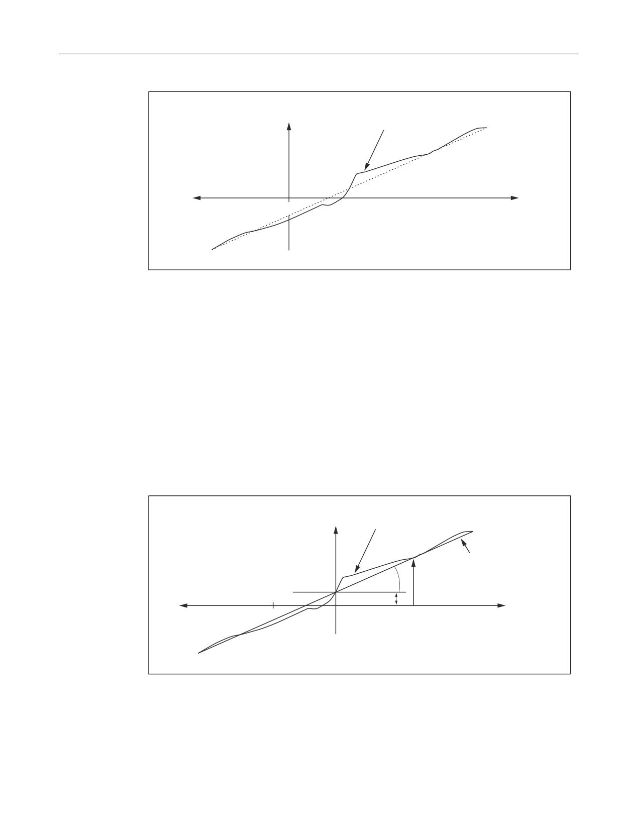
K3: Compensations
5.2 Temperature compensation
(UURU FXUYH IRU WHPSHUDWXUH 7
(UURU GHYLDWLRQ
[
[
Compensation equation
The compensation value ∆Kx is calculated on the basis of current actual position Px of this axis
and temperature T according to the following equation:
ΔKx = K0 (T) + tanβ (T) * (Px - P0)
The meaning is as follows:
ΔKx:
Temperature compensation value of axis at position Px
K0:
Position-independent temperature compensation value of axis
Px:
Actual position of axis
P0:
Reference position of axis
tanβ:
Coefficient for the position-dependent temperature compensation (corresponds to
the gradient of the approximated error line)
(UURU FXUYH IRU WHPSHUDWXUH 7
(UURU
GHYLDWLRQ
$SSUR[LPDWHG
HUURU OLQH
¡
˂.[
[
3[
[
3
Figure 5-1
Approximated error line for temperature compensation
Extended Functions
Function Manual, 12/2018, A5E40874029B AB
255
K3: Compensations
5.2 Temperature compensation
Activation
The following conditions must be fulfilled so that the temperature compensation can be
activated:
1. The compensation type is selected (MD32750, see "Commissioning (Page 257)").
2. The parameters for the compensation type are defined (see "Commissioning (Page 257)").
3. The axis is referenced.
DB31, ... DBX60.4 or 60.5 =1 (referenced/synchronized 1 or 2)
As soon as these conditions are fulfilled, the temperature compensation value for the position
actual value is added to the setpoint in all modes and the machine axis traverses through this
distance. If the compensation value ∆Kx is positive, the axis moves in the negative direction.
If the reference position is then lost, e.g. because the encoder frequency has been exceeded
(DB31, ... DBX60.4 or 60.5 = 0), compensation processing is deactivated.
Clock cycle
The compensation values are determined in the interpolator clock cycle.
Display
The total compensation value calculated from the temperature and sag compensation
functions belonging to the actual position is output in the "Diagnosis" operating area of the
"Axis/Spindle Service" window.
Parameter adaptation for temperature changes
Since the approximated error line applies only to the instantaneous temperature value, the
parameters of the error lines that are newly generated when the temperature rises or falls must
be sent to the NC again. Only in this way can expansion due to heat always be correctly
compensated.
When temperature T changes, the parameters which are temperature-dependent, i.e. (K0,
tanβ and P0) also change and can thus always be overwritten by the PLC or by means of a
synchronized action.
It is thus possible for the machine-tool manufacturer to emulate the mathematical and
technological relationship between the axis positions and temperature values via the PLC user
program and thus calculate the various parameters for the temperature compensation. The
temperature parameters are transferred to the NC using the variable services (FB2 (GET)
"Read data" and FB3 (PUT) "Write data").
For more information on handling and supplying FB2 and FB3 see:
Reference:
Function Manual Basic Functions; Basic PLC Program (P3)
Extended Functions
256
Function Manual, 12/2018, A5E40874029B AB
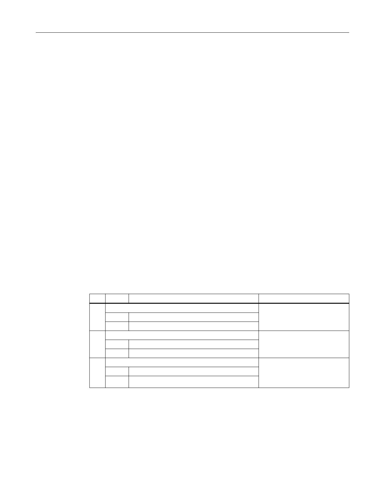
K3: Compensations
5.2 Temperature compensation
Smooth the compensation value
To prevent overloading of the machine or tripping of monitoring functions in response to step
changes in the temperature compensation parameters, the compensation values are
distributed over several IPO cycles by an internal control function as soon as they exceed the
maximum compensation value specified for each IPO cycle (MD32760, see "Commissioning
(Page 257)").
5.2.2
Commissioning
Temperature-dependent parameters
Error curves for different temperatures can be defined for each axis. For each error curve the
following parameters must be determined and then entered in the setting data:
● Position-independent temperature compensation value K0:
SD43900 $SA_TEMP_COMP_ABS_VALUE
● Reference position P0 for position-dependent temperature compensation:
SD43920 $SA_TEMP_COMP_REF_POSITION
● Gradient tanβ for position-dependent temperature compensation:
SD43910 $SA_TEMP_COMP_SLOPE
Temperature compensation type and activation
The temperature compensation type is selected and the temperature compensation activated
using the axis-specific machine data:
MD32750 $MA_TEMP_COMP_TYPE (temperature compensation type)
Bit
Value
Meaning
Associated parameters
0
Position independent temperature compensation
SD43900
0
Not active
1
Active
1
Position-dependent temperature compensation
SD43920, SD43910
0
Not active
1
Active
2
Temperature compensation in tool direction
MD20390
$MC_TOOL_TEMP_COMP_ON
0
Not active
(Activate temperature compensa-
1
Active
tion tool length)
Maximum compensation value per IPO clock cycle
The maximum possible compensation value per IPO cycle, i.e. the maximum distance that can
be traversed in an IPO cycle as a result of the temperature compensation, is limited using
machine data:
Extended Functions
Function Manual, 12/2018, A5E40874029B AB
257
K3: Compensations
5.2 Temperature compensation
MD32760 $MA_COMP_ADD_VELO_FACTOR (velocity increase as a result of
compensation)
The specified value acts as a factor and is referred to the maximum axis velocity (MD32000
$MA_MAX_AX_VELO).
MD32760 also limits the maximum gradient of the error line (tan ß) of the temperature
compensation.
5.2.3
Example
5.2.3.1
Commissioning the temperature compensation for the Z axis of a lathe
Commissioning of temperature compensation is described below using the example of a Z
axis on a lathe.
Determining the error characteristic of the Z axis
In order to determine the temperature-dependent error characteristic of the Z axis, proceed as
follows:
● Uniform temperature increase by traversing the axis across the whole Z axis traversing
range (in the example: from 500 mm to 1500 mm)
● Measuring the axis position in increments of 100 mm
● Measuring the actual temperature at the leadscrew
● Executing a traversing measuring cycle every 20 minutes
The mathematical and technological relationships and the resulting parameters for
temperature compensation are derived from the recorded data. The calculated deviation errors
for a specific temperature, which refer to the actual position of the Z axis displayed by the NC,
are represented in graphic form in the diagram below.
Extended Functions
258
Function Manual, 12/2018, A5E40874029B AB
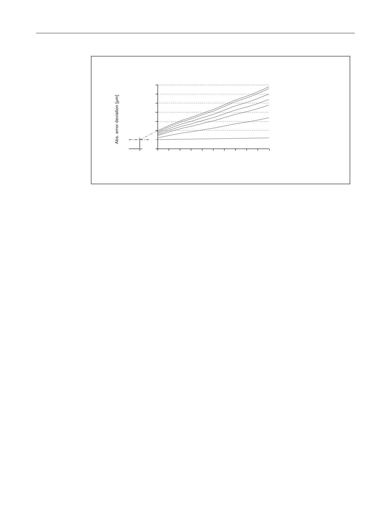
K3: Compensations
5.2 Temperature compensation
0HDVXUHG WHPSHUDWXUH
GHJUHHV
GHJUHHV
GHJUHHV
GHJUHHV
GHJUHHV
GHJUHHV
GHJUHHV
5HIHUHQFH
SRLQW 3
3RVLWLRQ RI WKH = D[LV >PP@
Figure 5-2
Error curves determined for the Z axis
Specifying parameters
The temperature compensation parameters must now be determined on the basis of the
measurement results (see diagram above).
Reference position P0
As the diagram above illustrates, there are basically two methods of parameterizing reference
position P0:
1. P0 = 0 with position-independent temperature compensation value K0 ≠ 0
2. P0 ≠ 0 with position-independent temperature compensation value K0 = 0
In this case, version 2 is chosen, which means that the position-independent temperature
compensation value is always 0. The temperature compensation value therefore only consists
of the position-dependent component.
The following parameters are obtained:
● MD32750 $MA_TEMP_COMP_TYPE = 2
(only position-dependent temperature compensation active)
● P0 = 320 mm → SD43920 $SA_TEMP_COMP_REF_POSITION = 320
(reference position for position-dependent temperature compensation)
Coefficient tanβ (T)
In order to determine the dependency of coefficient tanβ of the position-dependent temperature
compensation on the temperature, the error curve gradient is plotted against the measured
temperature:
Extended Functions
Function Manual, 12/2018, A5E40874029B AB
259
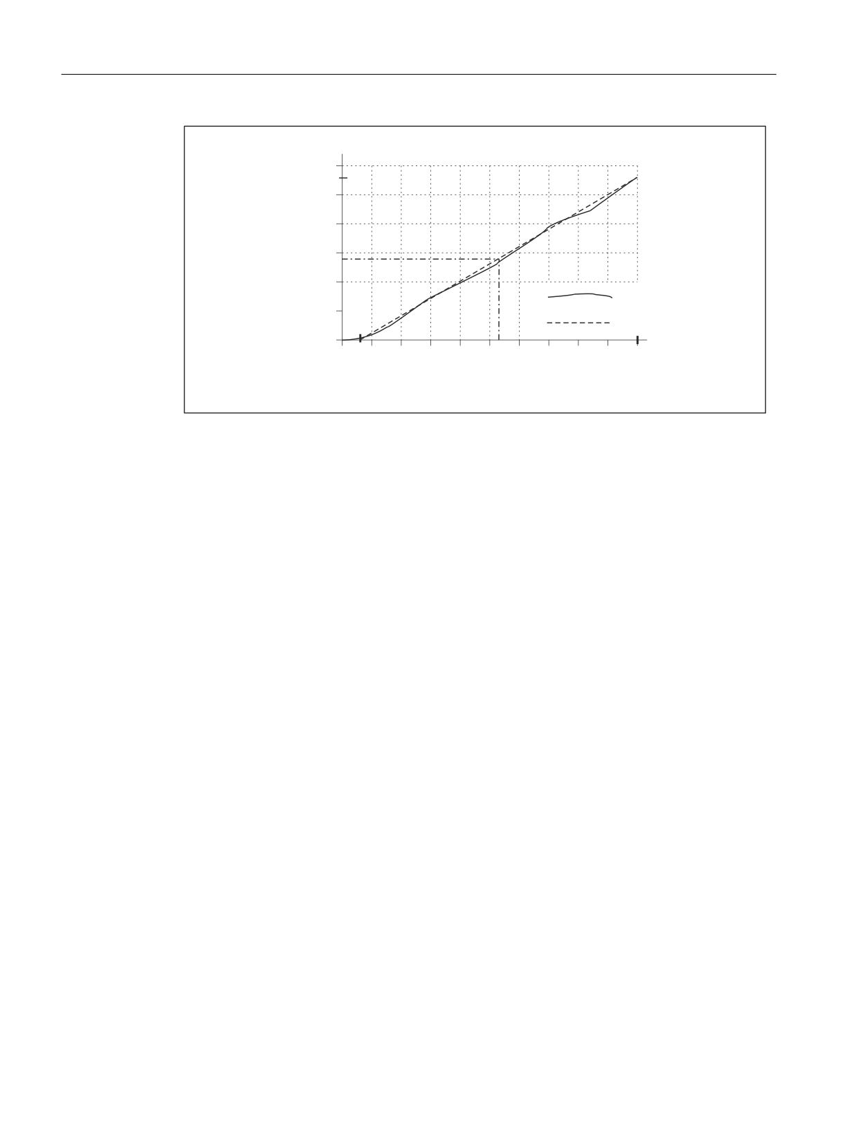
K3: Compensations
5.2 Temperature compensation
7& FRHIILFLHQW
>wP
PP@
7.PD[
0HDVXUHG FXUYH
FKDUDFWHULVWLF
6WUDLJKW OLQH
7
7PD[
$EVROXWH WHPSHUDWXUH >GHJUHHV@
Figure 5-3
Characteristic of coefficient tanβ as a function of measured temperature T
With the appropriate linearization, coefficient tanβ depends on T as follows:
tanβ(T) = (T - T0) * TKmax * 10-6/ (Tmax - T0)
with
T0 = temperature at which position-dependent error = 0; [degrees]
Tmax = maximum measured temperature; [degrees]
TKmax = temperature coefficient at Tmax; [µm/1000 mm]
Therefore, based on the values from the above diagram:
T0 = 23°
Tmax = 42°
TKmax = 270 µm/1000 mm
and tanß (T) is therefore:
tanβ(T)
= (T - 23) [degrees] * 270 [µm/1000 mm] * 10-6 / (42 - 23) [degrees]
= (T - 23) [degrees] * 14.21 [µm/1000 mm] * 10-6
Example:
At a temperature of T = 32.3 degrees, therefore: tanβ = 0.000132
PLC user program
The formula given above must be used in the PLC user program to calculate the coefficient
tanβ (T) which corresponds to the measured temperature; this must then be written to the
following NC setting data:
SD43910 $SA_TEMP_COMP_SLOPE (gradient for position-dependent temperature
compensation)
According to the example above:
Extended Functions
260
Function Manual, 12/2018, A5E40874029B AB
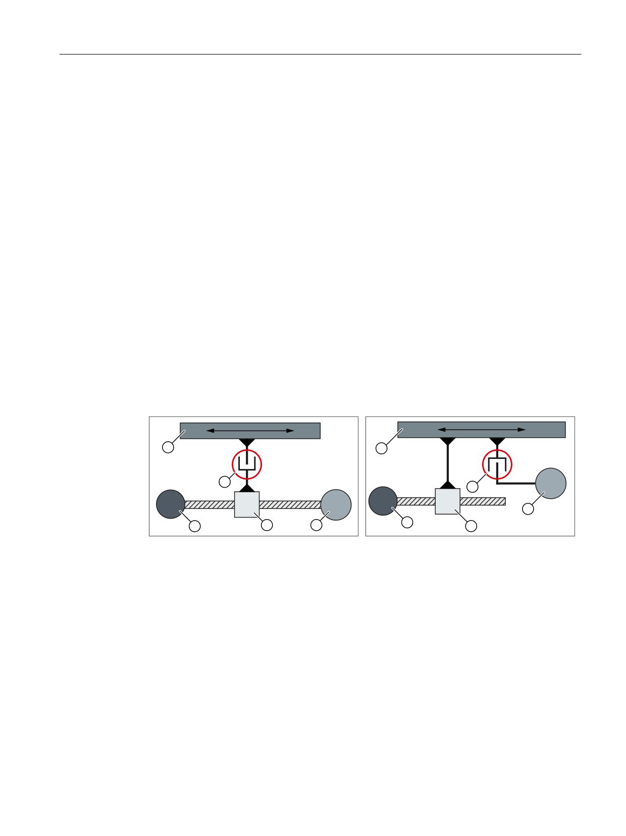
K3: Compensations
5.3 Backlash compensation
SD43910 $SA_TEMP_COMP_SLOPE = 0.000132
5.3
Backlash compensation
5.3.1
Mechanical backlash compensation
5.3.1.1
Function
Mechanical backlash can occur in moving machine parts in the drive train (machine axes), e.g.
at a ballscrew or in the connection to the measuring system.
Effects
For a machine axis with indirect measuring system, mechanical backlash results in a difference
between the actual position of the NC determined using the measuring system and the actual
position of the machine part. When the direction reverses, the machine axis traverses through
a distance that is incorrect by the amount of the backlash:
Positive backlash ⇒
Negative backlash ⇒
The encoder actual value leads the machine
The encoder actual value lags behind the ma-
actual value
chine actual value
*
0
0
*
The table does not move far enough because
The table moves too far because the encoder
the encoder actual value has already changed
actual value has not yet changed (lagging) due
(leading) due to the backlash while the table
to the backlash while the table is already mov-
still remains stationary.
ing.
① Encoder
② moved machine part (table
③ ballscrew
④ mechanical backlash
⑤ motor
Compensation
To compensate for the mechanical backlash, the actual value of the machine axis is corrected
every time the axis reverses by the axis-specific compensation value set during
commissioning (Page 262).
Extended Functions
Function Manual, 12/2018, A5E40874029B AB
261
K3: Compensations
5.3 Backlash compensation
Activation
The mechanical backlash compensation of a machine axis is active in all operating modes.
Precondition:
● Incremental measuring system: Encoder state == "referenced"
● Absolute encoder: Encoder state == "synchronized"
Displaying the compensation values
The compensation values active at the actual position of the machine axis are displayed on
the user interface for each individual axis.
SINUMERIK Operate: "Diagnostics" operating area > ETC key (">") > "Axis diagnostics" >
"Service axis" >
● "Absolute compensation value measuring system 1"
● "Absolute compensation value measuring system 2"
● "Compensation, sag + temperature"
5.3.1.2
Commissioning: Axis-specific machine data
Compensation value
The compensation value of the mechanical backlash is entered in the machine data.
MD32450 $MA_BACKLASH[ <active measuring system> ] = <compensation value>
Measurement
● Traversing the machine axis and/or the machine part to any measurement position at a
high velocity.
● Measuring the actual position of the machine part
● Calculating the backlash compensation value KL
KL = "displayed actual position of the machine axis" - "measured actual position of the
machine part"
- KL > 0 (positive backlash ) ⇒ positive compensation value
- KL < 0 (negative backlash ) ⇒ negative compensation value
Checking
To check the effect of the compensation, we recommend that the mechanical backlash is
measured after the machine data has been activated.
Circularity test
The circularity test integrated in the user interface can be used to visualize the mechanical
backlash.
SINUMERIK Operate: "Commissioning" operating area > "Optimization/Test" > "Circularity
test"
Extended Functions
262
Function Manual, 12/2018, A5E40874029B AB
K3: Compensations
5.3 Backlash compensation
Second measuring system
If an axis has a second measuring system, the compensation value must also be determined
for this and entered in the machine data:
MD32450 $MA_BACKLASH[ <measuring system 2> ]
When the measuring system is switched over, the associated compensation value is
automatically used.
Evaluation factor dependent on the parameter set
For a mechanical backlash dependent on the parameter set, the parameter set-specific factor
is entered into the following machine data, which is then applied to the compensation value of
the backlash (MD32450 $MA_BACKLASH).
MD32452 $MA_BACKLASH_FACTOR[ <parameter set 1 ... n> ] = <factor>
Effective compensation value
The effective compensation value KP of a parameter set is calculated as follows:
KP = ( MD32450 $MA_BACKLASH[ <active measuring system> ] ) * ( MD32452
$MA_BACKLASH_FACTOR[ <parameter set> ]
Backlash compensation mode
The response of mechanical backlash compensation of a machine axis is set using machine
data:
MD32454 $MA_BACKLASH_MODE
Bit
Meaning
0
Restores the last effective backlash compensation after the control system has powered up
= 0
The backlash compensation value is not restored (default setting)
= 1
The backlash compensation is restored.
Precondition
The measuring system active after the control powers up must be adjusted and synchronized:
● MD34210 $MA_ENC_REFP_STATE[<active measuring system>] == 2
● DB31,
DBX60.4 - 5 == 1 (measuring system 1 / 2: Referenced, synchronized)
1
Effect of other compensation functions (temperature compensation, sag or angularity error
compensation)
= 0
The backlash compensation responds to other compensatory motion (default setting).
= 1
The backlash compensation does not respond to other compensatory motion (default
setting).
Extended Functions
Function Manual, 12/2018, A5E40874029B AB
263
K3: Compensations
5.3 Backlash compensation
5.3.2
Dynamic backlash compensation
5.3.2.1
Function
Dynamic backlash
A dynamic backlash can occur for machine types with sliding guides. Depending on the axial
dynamic response (velocity, jerk, etc.) used to approach an end position, the machine slide
reaches the programmed end position or stops earlier because of the static friction. The
resulting position error is direction-symmetric.
Compensation
To compensate for the dynamic backlash, half the signed compensation value
(MD32456Commissioning: Axis-specific machine data (Page 265), see "") is applied in
accordance with the relevant traversing direction of the axis. Compensation value is applied
as ramp.
Activation
The dynamic backlash compensation is activated by the PLC only in required the situations:
DB31, ... DBX25.0 (activate dynamic backlash compensation)
Note
The machine tool manufacturer specifies in the PLC user program the "required" situations for
the activation of the dynamic backlash compensation. Such situations result with traversal of
the axes with G1, in the JOG mode or with the handwheel.
The NC uses the following interface to return the required activation to the PLC:
DB31, ... DBX102.0 (active dynamic backlash compensation)
Requirement
The axes to be compensated must be homed.
Display
The compensation value that belongs to the current actual position is displayed in the
"Diagnostics" operator area of the "Axis/Spindle Service" window as the total compensation
calculated from LEC, mechanical and dynamic backlash compensation.
Extended Functions
264
Function Manual, 12/2018, A5E40874029B AB
K3: Compensations
5.3 Backlash compensation
5.3.2.2
Commissioning: Axis-specific machine data
Compensation value
As precondition to commission the dynamic backlash compensation, the mechanical backlash
compensation must have already been commissioned (see Chapter "Commissioning: Axis-
specific machine data (Page 262)").. To determine the compensation value for the dynamic
backlash compensation, the measurement described there should be repeated with low
traversing velocity. The compensation value determined in this way is entered in the machine
data for the corresponding measuring system:
MD32456 $MA_BACKLASH_DYN[ <active measuring system> ] = <compensation value for
dynamic backlash compensation>
Compensation value change
Using the machine data, the velocity with which the compensation value is traversed through
is set as a percentage of the maximum axis velocity (MD32000 $MA_MAX_AX_VELO):
MD32457 $MA_BACKLASH_DYN_MAX_VELO = <percentage of the maximum axis velocity>
5.3.3
Dual position feedback
For the "Dual position feedback" function, contrary to conventional (mechanical or dynamic)
backlash compensation, two measuring systems, which are mechanically coupled through a
gearbox without backlash, are used for the closed-loop position control. The advantages of a
direct measuring system are combined with the advantages of an indirect measuring system:
● Direct measuring system: The closed-loop position control with direct, i.e. encoder on the
load side, "automatically" corrects the backlash.
● Indirect measuring system: The closed-loop position control with indirect, i.e. encoder on
the motor side, is "rugged" and "stable" regarding discontinuous backlash.
Each time the setpoint changes, initially only the encoder data from the indirect measuring
system is used for rugged control without oscillation. With a parameterizable delay time, the
closed-loop control smoothly transitions to monitor the direct measuring system, therefore,
achieving the required accuracy on the load side. The control operations should, at this point
in time, only involve short distances. This is because in the meantime the tooth flanks are in
contact with one another, and the backlash has been moved through.
When using the "Dual position feedback" function, it is not necessary to measure and
mathematically compensate the backlash.
Extended Functions
Function Manual, 12/2018, A5E40874029B AB
265
K3: Compensations
5.3 Backlash compensation
Preconditions
The following preconditions must be satisfied for an axis to be compensated:
● Direct and indirect measuring system, mechanically coupled:
- MD30200 $MA_NUM_ENCS = 2
- MD31040 $MA_ENC_IS_DIRECT[ 0 ] = 0 or 1
- MD31040 $MA_ENC_IS_DIRECT[ 1 ] = 1 or 0
● Measuring system calibration has been released:
MD34102 $MA_REFP_SYNC_ENCS = 1
● Both measuring systems are referenced:
- DB31, ... DBX60.4 (referenced/synchronized 1 / 2) = 1
- DB31, ... DBX60.5 (referenced/synchronized 1 / 2) = 1
5.3.3.1
Commissioning: Axis-specific machine data
Delay time
The delay time, during which the closed-loop control smoothly transitions from the indirect to
the direct measuring system, is entered in the machine data.
MD32960 $MA_POSCTRL_DUAL_FEEDBACK_TIME = <delay time>
If the delay time is zero, then the function is inactive, and only the active measuring system
(DB31,
DBX1.5 / .6 (position measuring system 1 / 2) ) is active for the position control.
Note
After activating the "Dual position feedback" function, all of the existing measuring system
compensations and monitoring functions remain unchanged and active; this means that they
may have to be deactivated by the user (e.g. backlash compensation values deleted).
5.3.3.2
Supplementary conditions
Referencing and flying measurement
Also when the "Dual position feedback" function is active, the "Referencing" and "Measuring"
functions refer to the active measuring system (DB31,
DBX1.5 / .6 (position measuring
system 1 / 2) ).
References
● Function Manual Basic functions, Chapter "R1 Referencing"
● Function Manual Extended Functions, Chapter "M5 measuring"
Extended Functions
266
Function Manual, 12/2018, A5E40874029B AB
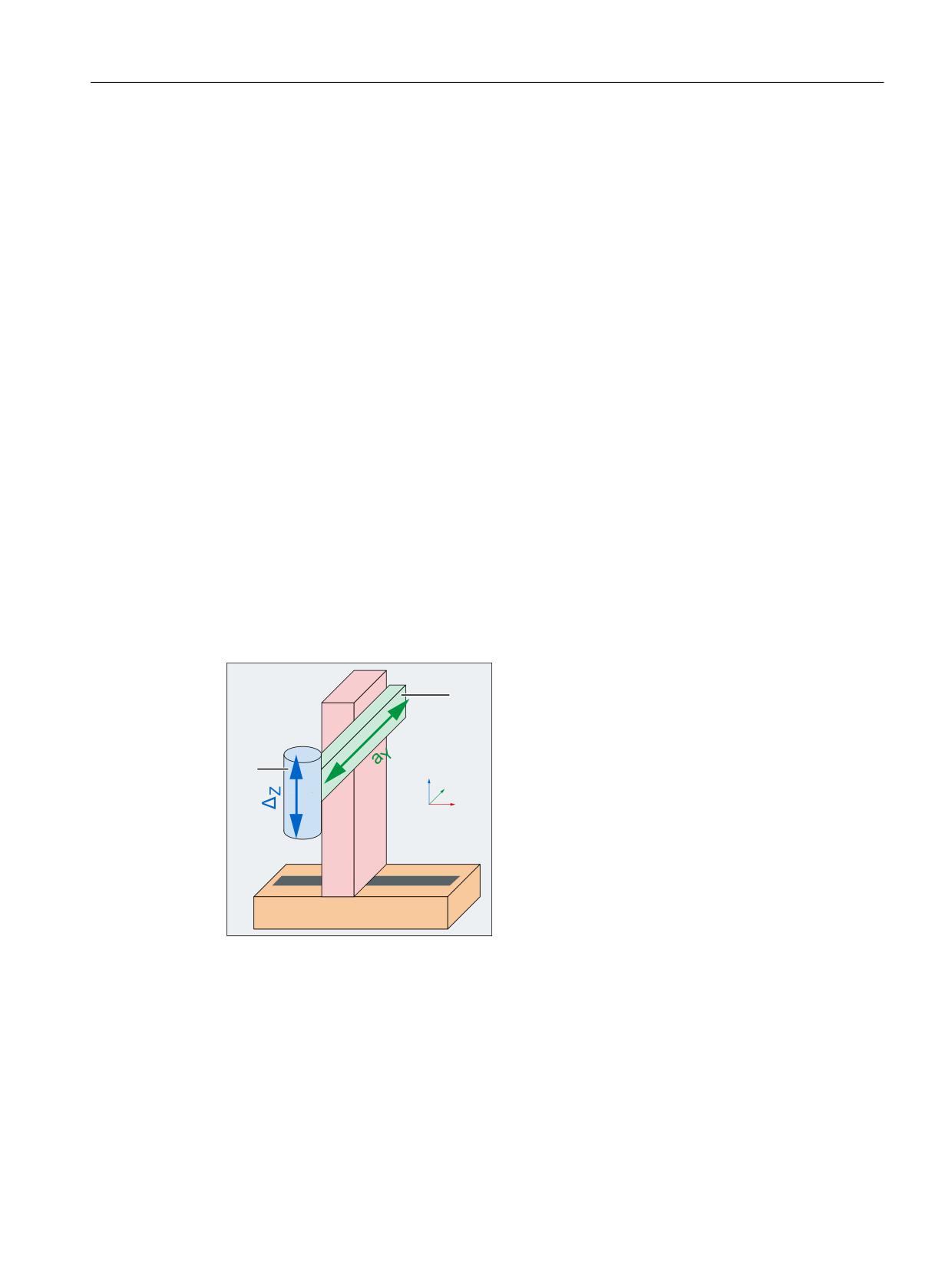
K3: Compensations
5.4 Nodding compensation
5.4
Nodding compensation
5.4.1
Description of the function
5.4.1.1
Options
The "Nodding compensation" function is an option subject to license. The following versions
are available:
● Nodding compensation ECO: 6FC5800-0AS20-0YB0
Nodding compensation in one machine axis with one accelerating axis:
● Nodding compensation ADVANCED: 6FC5800-0AS21-0YB0
Nodding compensation in any arbitrary number of machine axes
5.4.1.2
Features
Nodding compensation is used to compensate dynamic position deviations in a machine axis
due to this or another machine axis accelerating. The position deviations are obtained as a
result of the mechanical compliance within the machine.
This is demonstrated in the following schematic of a 3-axis traveling column machine, as
example. If the Y axis is accelerated with aY, as a result of the mechanical compliance in the
machine, position deviations ΔZ occur in the Z axis.
<
=
=
<
;
Figure 5-4
3-axis traveling column machine
Extended Functions
Function Manual, 12/2018, A5E40874029B AB
267
K3: Compensations
5.4 Nodding compensation
Definition of terms
●
Nodding compensation axes
The machine axes involved in the nodding compensation are designated as follows: //////
- Compensating axis
A machine axis, resulting from other machine axes accelerating, results in position
deviations, which can be compensated by nodding compensation. In the diagram:
Compensating axis ⇒ Z axis
- Accelerating axis
Machine axis, whose acceleration as a result of compliance in the machine, results in
a position deviation in the compensating axis. In the diagram: Accelerating axis ⇒ Y axis
- Adaptation axis
Machine axis, whose position when traversing the accelerating axis influences the
magnitude of the position deviation in the compensating axis. In the diagram: Adaptation
axis ⇒ X axis
●
Compliance factor
Compliance factor N defines the magnitude of the position deviation Δ of the compensating
axis for traversing motion of the accelerating axis with acceleration a. Compliance factor N
is the quotient of position deviation Δ of the compensating axis and the acceleration a of
the accelerating axis that actually causes the deviation: N = Δ / a
Note
References
Determining the compliance factor is described in detail in
● Commissioning Manual, "Commissioning CNC: NC, PLC, drive; Chapter
"Commissioning NC" > "Nodding compensation"
● Online help
The online help for nodding compensation is called from the SINUMERIK Operate user
interface via: "Commissioning" > "NC" > "Nodding compensation" > HELP button on the
front of the operator panel
●
Compensation value
The actual compensation value Δ is obtained by multiplying the actual compliance factor
N with the actual acceleration a of the axis causing the deviation
Extended Functions
268
Function Manual, 12/2018, A5E40874029B AB
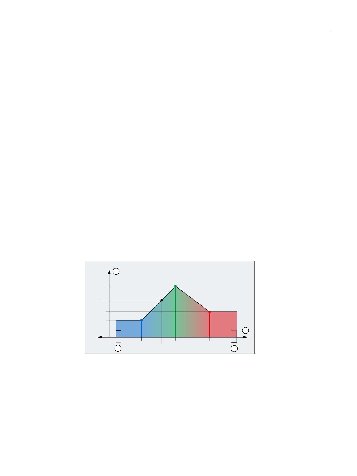
K3: Compensations
5.4 Nodding compensation
Supplementary conditions
● Rotary axes
It is not permissible for the compensating, the accelerating or the adaptation axis to be a
rotary axis.
● Differences to the compile cycle "RMCC/NOCO nodding compensation"
(6FC5800-0AN63-0YB0)
- The functionality of system function "Nodding compensation" is, contrary to compile
cycle "RMCC/NOCO", exclusively limited to compensating nodding motion. The
functions provided beyond this in the compile cycle, such as compensating centrifugal
forces, taking into account rotary axis positions as well as comprehensive position
tables, are not available with the system function.
- Either system function "Nodding compensation” can be used - or compile cycle "RMCC/
NOCO", but not together.
- It is not possible to use the parameterizing data of compile cycle "RMCC/NOCO" to
parameterize the "Nodding compensation" system function.
5.4.1.3
Position-dependent compliance factor
If the machine compliance depends on the position of another machine axis (adaptation axis),
then up to three different positions of the adaptation axis can be selected as interpolation points
of the adaptation characteristic; the effective compliance factors can then be determined from
the characteristic. Positions (P1, P2, P3) and the compliance factors effective there (N1, N2,
N3) must be saved in the machine data of the compensating axis. When traversing the
accelerating axis, the effective compliance factor is calculated depending on the position of
the adaptation axis by linearly interpolating between the interpolation points.
1
1
1
1
3
3
3
3
① Traversing range of the adaptation axis with P1 < P2 < P3
② Compliance factor of the compensating axis
③ Traversing range limit -
④ Traversing range limit +
Figure 5-5
Compensation characteristic
Extended Functions
Function Manual, 12/2018, A5E40874029B AB
269

K3: Compensations
5.4 Nodding compensation
Actual position: P
Compliance factor: N
P less than P1 up to traversing range limit minus
N = N1
P between P1 and P2
N = linear interpolation between N1 and N2
P equal to P2
N = N2
P between P2 and P3
N = linear interpolation between N2 and N3
P greater than or equal to P3 - up to the traversing
N = N3
range limit plus
5.4.1.4
Compensation relationships
A compensation relationship defines the following dependencies of the compensation value:
● On the acceleration of the accelerating axis
● On the position of the adaptation axis
● On the machine compliance
Up to three compensation relationships can be parameterized in the machine data of a
compensating axis. The following data can be set for each compensation relationship:
● Accelerating axis
● Adaptation axis
● Number of positions of the adaptation axis
● Positioning the adaptation axis
● Compliance factors at the positions
Accelerating axes or adaptation axes
Any linear machine axis of the NC can be used as accelerating axis or adaptation axis. Even
the compensating axis itself.
Total compensation value
The total compensation value acting on the compensating axis is the sum of the compensation
values of the individual compensation relationships.
5.4.2
Commissioning: Machine data
5.4.2.1
Overview
The following table provides an overview with which machine data the nodding compensation
is parameterized.
Number
Name: $MA_
Meaning
MD37302
NOCO_FILTER_TIME
Time constant for smoothing nodding compensation
values (Page 271)
Compensation relationship 1
Extended Functions
270
Function Manual, 12/2018, A5E40874029B AB
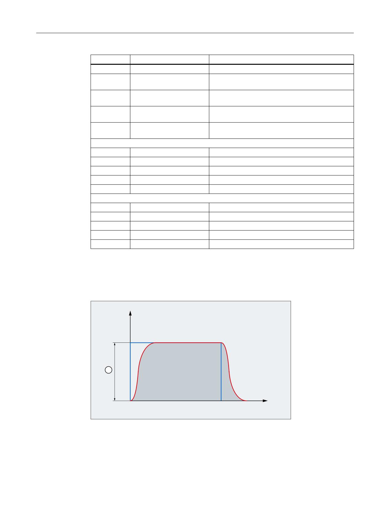
K3: Compensations
5.4 Nodding compensation
Number
Name: $MA_
Meaning
MD37310
NOCO_INPUT_AX_1
Machine axis that causes nodding motion (Page 272)
MD37312
NOCO_ADAPT_AX_1
Machine axis, whose position influences nodding mo-
tion (Page 272)
MD37314
NOCO_ADAPT_NUM_1
Number of positions, adaptation characteristic of the
nodding compensation (Page 273)
MD37316
NOCO_ADAPT_POS_1
Positions, adaptation characteristic of the nodding com-
pensation (Page 274)
MD37318
NOCO_COMPLIANCE_1
Compliance factors for nodding compensation
(Page 275)
Compensation relationship 2
MD37320
NOCO_INPUT_AX_2
See MD37310
MD37322
NOCO_ADAPT_AX_2
See MD37312
MD37324
NOCO_ADAPT_NUM_2
See MD37314
MD37326
NOCO_ADAPT_POS_2
See MD37316
MD37328
NOCO_COMPLIANCE_2
See MD37318
Compensation relationship 3
MD37330
NOCO_INPUT_AX_3
See MD37310
MD37332
NOCO_ADAPT_AX_3
See MD37312
MD37334
NOCO_ADAPT_NUM_3
See MD37314
MD37336
NOCO_ADAPT_POS_3
See MD37316
MD37338
NOCO_COMPLIANCE_3
See MD37318
5.4.2.2
Time constant for smoothing nodding compensation values
Using the machine data, the time constant is set with which the total nodding compensation
value is smoothed when it is entered.
3RVLWLRQ
GHYLDWLRQ
>wP@
7LPH >PV@
① Position deviation
● Blue: Setpoint
● Red: Actual value
Extended Functions
Function Manual, 12/2018, A5E40874029B AB
271
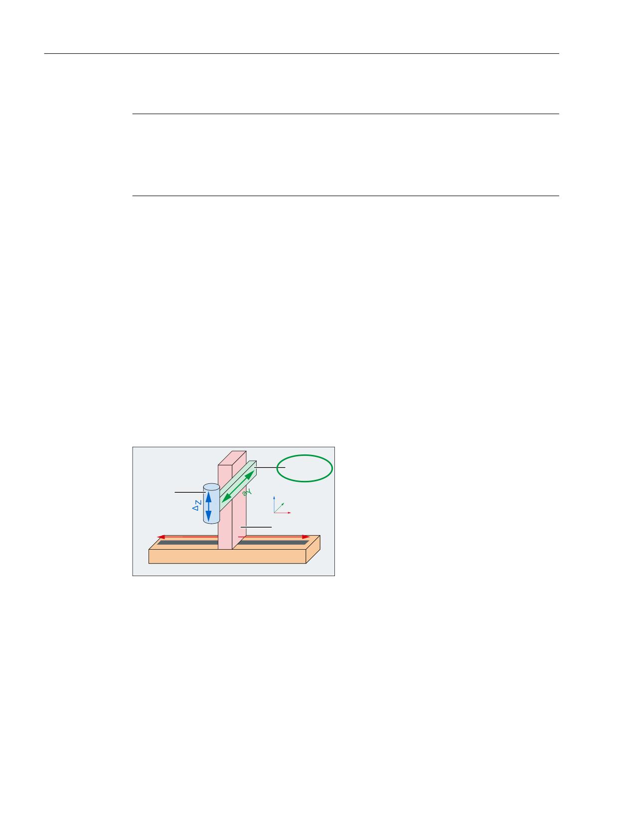
K3: Compensations
5.4 Nodding compensation
MD37302 $MA_NOCO_FILTER_TIME[<comp. axis>] = <time constant>
Note
Deactivating smoothing
Smoothing is deactivated - or is not active - if the time constant is set to less than 10 % of the
position controller clock cycle:
Time constant < 0,1 * MD10061 $MN_POSCTRL_CYCLE_TIME
5.4.2.3
Accelerating axis
The number of the machine axis, whose acceleration causes position deviations in the
compensating axis, must be entered in the machine data.
The number of the accelerating axis refers to the machine axes of the NC parameterized in
machine data MD10002 $MN_AXCONF_LOGIC_MACHAX_TAB. The machine axis number
is the corresponding machine data index + 1.
MD37310 $MA_NOCO_INPUT_AX_1[<comp. Achse>] = <machine axis number>
Example
As a result of the machine compliance, when the Y axis accelerates, a position deviation occurs
in the Z axis.
● Compensating axis: AX3 (Z axis)
● Accelerating axis: AX2 (Y axis)
$;
<
$;
=
=
<
;
$;
;
Figure 5-6
Accelerating axis AX2 (Y axis)
MD10002 $MN_AXCONF_LOGIC_MACHAX_TAB[ 0 ] = "AX1"
; X axis
MD10002 $MN_AXCONF_LOGIC_MACHAX_TAB[ 1 ] = "AX2"
; Y axis
MD10002 $MN_AXCONF_LOGIC_MACHAX_TAB[ 2 ] = "AX3"
; Z axis
MD37310 $MA_NOCO_INPUT_AX_1[ AX3 ] = 2
; accelerating axis = Y axis
5.4.2.4
Adaptation axis
The number of the machine axis, whose actual position influences the position deviation in the
compensating axis, must be entered in the machine data.
Extended Functions
272
Function Manual, 12/2018, A5E40874029B AB
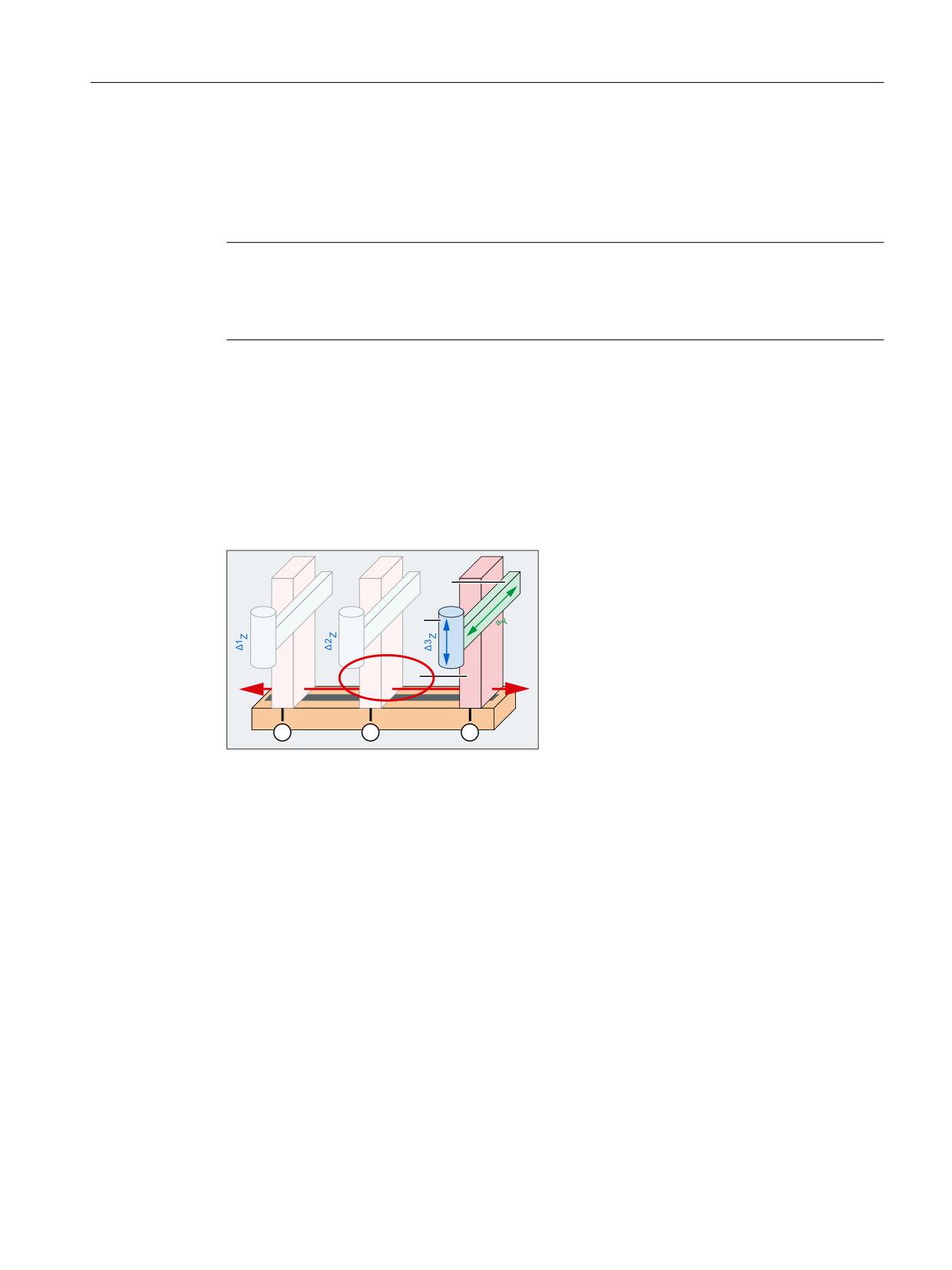
K3: Compensations
5.4 Nodding compensation
The machine axis number refers to the machine axes of the NC parameterized in machine
data MD10002 $MN_AXCONF_LOGIC_MACHAX_TAB. The machine axis number is the
corresponding machine data index + 1.
MD37312 $MA_NOCO_ADAPT_AX_1[<comp. Achse>] = <machine axis number>
Note
Activating the position-dependent adaptation
The position-dependent adaptation only becomes active if one adaptation axis and more than
one position (MD37314 $MA_NOCO_ADAPT_NUM_1 (Page 273)) are parameterized.
Example
As a result of the machine compliance, when the Y axis accelerates, a position deviation occurs
in the Z axis. Further, the position deviation depends on the position of the X axis.
● Compensating axis: AX3 (Z axis)
● Accelerating axis: AX2 (Y axis)
● Adaptation axis: AX1 (X axis)
$;
<
$;
=
$;
;
①, ②, ③
Axis positions of the adaptation axis AX1 (X axis)
Figure 5-7
Adaptation axis AX1 (X axis)
MD10002 $MN_AXCONF_LOGIC_MACHAX_TAB[ 0 ] = "AX1"
; X axis
MD10002 $MN_AXCONF_LOGIC_MACHAX_TAB[ 1 ] = "AX2"
; Y axis
MD10002 $MN_AXCONF_LOGIC_MACHAX_TAB[ 2 ] = "AX3"
; Z axis
MD37312 $MA_NOCO_ADAPT_AX_1[ AX3 ] = 1
; adaptation axis = X axis
5.4.2.5
Number of positions of the adaptation characteristic
The number of axis positions, for which another compliance is effective, must be entered in
the machine data for the position-dependent adaptation.
Extended Functions
Function Manual, 12/2018, A5E40874029B AB
273
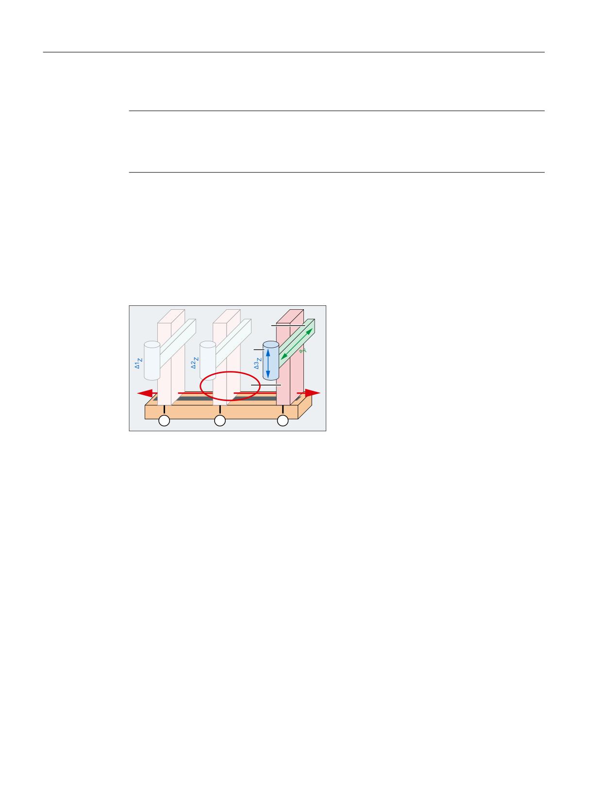
K3: Compensations
5.4 Nodding compensation
MD37314 $MA_NOCO_ADAPT_NUM_1[<comp. Axis>] = <number>
Note
Activating the position-dependent adaptation
The position-dependent adaptation only becomes active if more than one position and one
adaptation axis (MD37312 $MA_NOCO_ADAPT_AX_1 (Page 272)) are parameterized.
Example
Interpolation points of the adaptation characteristic are to be parameterized at three positions
along the traversing range of the adaptation axis (X axis).
● Compensating axis: AX3 (Z axis)
● Accelerating axis: AX2 (Y axis)
● Adaptation axis: AX1 (X axis)
$;
<
$;
=
$;
;
①, ②, ③
Axis positions of the adaptation axis AX1 (X axis)
Figure 5-8
Number of axis positions of the adaptation axis AX1 (X axis)
MD10002 $MN_AXCONF_LOGIC_MACHAX_TAB[ 0 ] = "AX1"
; X axis
MD10002 $MN_AXCONF_LOGIC_MACHAX_TAB[ 1 ] = "AX2"
; Y axis
MD10002 $MN_AXCONF_LOGIC_MACHAX_TAB[ 2 ] = "AX3"
; Z axis
MD37314 $MA_NOCO_ADAPT_NUM_1[ AX3 ] = 3
; number of axis positions
See also:
● Axis positions: MD37316 $MA_NOCO_ADAPT_POS_1 (Page 274)
● Compliance factors: MD37318 $MA_NOCO_COMPLIANCE_1 (Page 275)
5.4.2.6
Positions of the adaptation characteristic
The positions of the adaptation axis, at which a dedicated compliance factor is parameterized,
must be entered in the machine data for the interpolation points of the adaptation characteristic:
MD37316 $MA_NOCO_ADAPT_POS_1[<index>, <comp. Axis>] = <position>
Extended Functions
274
Function Manual, 12/2018, A5E40874029B AB
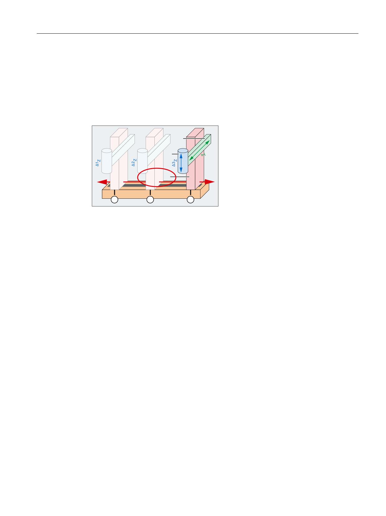
K3: Compensations
5.4 Nodding compensation
Example
Interpolation points are parameterized at positions -100.0, 0.0, and 120.0 of adaptation axis
AX1 (X axis) for the adaptation characteristic.
● Compensating axis: AX3 (Z axis)
● Accelerating axis: AX2 (Y axis)
● Adaptation axis: AX1 (X axis)
$;
<
$;
=
$;
;
① Position 1: -100.0
② Position 2. 0.0
③ Position 3. 120.0
Figure 5-9
Axis positions of the adaptation axis AX1 (X axis)
MD10002 $MN_AXCONF_LOGIC_MACHAX_TAB[ 0 ] = "AX1"
; X axis
MD10002 $MN_AXCONF_LOGIC_MACHAX_TAB[ 1 ] = "AX2"
; Y axis
MD10002 $MN_AXCONF_LOGIC_MACHAX_TAB[ 2 ] = "AX3"
; Z axis
MD37316 $MA_NOCO_ADAPT_POS_1[ 0, AX3 ] = -100.0
MD37316 $MA_NOCO_ADAPT_POS_1[ 1, AX3 ] =
0.0
MD37316 $MA_NOCO_ADAPT_POS_1[ 2, AX3 ] =
120.0
See also:
● Number of axis positions: MD37314 $MA_NOCO_ADAPT_NUM_1 (Page 273)
● Compliance factors: MD37318 $MA_NOCO_COMPLIANCE_1 (Page 275)
5.4.2.7
Compliance factors
The compliance factors associated with the particular positions of the adaptation characteristic
(MD37316 $MA_NOCO_ADAPT_POS_1 (Page 274)) must be entered in the machine data.
MD37318 $MA_NOCO_COMPLIANCE_1[<index>, <comp. Achse>] = <compliance factor>
Without position-dependent adaptation
If no position-dependent adaptation is parameterized (MD37312 $MA_NOCO_ADAPT_AX_1
(Page 272) == 0), then the compliance factor must be entered into index 0:
MD37318 $MA_NOCO_COMPLIANCE_1[ 0, <comp. Achse>] = <compliance factor>
Extended Functions
Function Manual, 12/2018, A5E40874029B AB
275
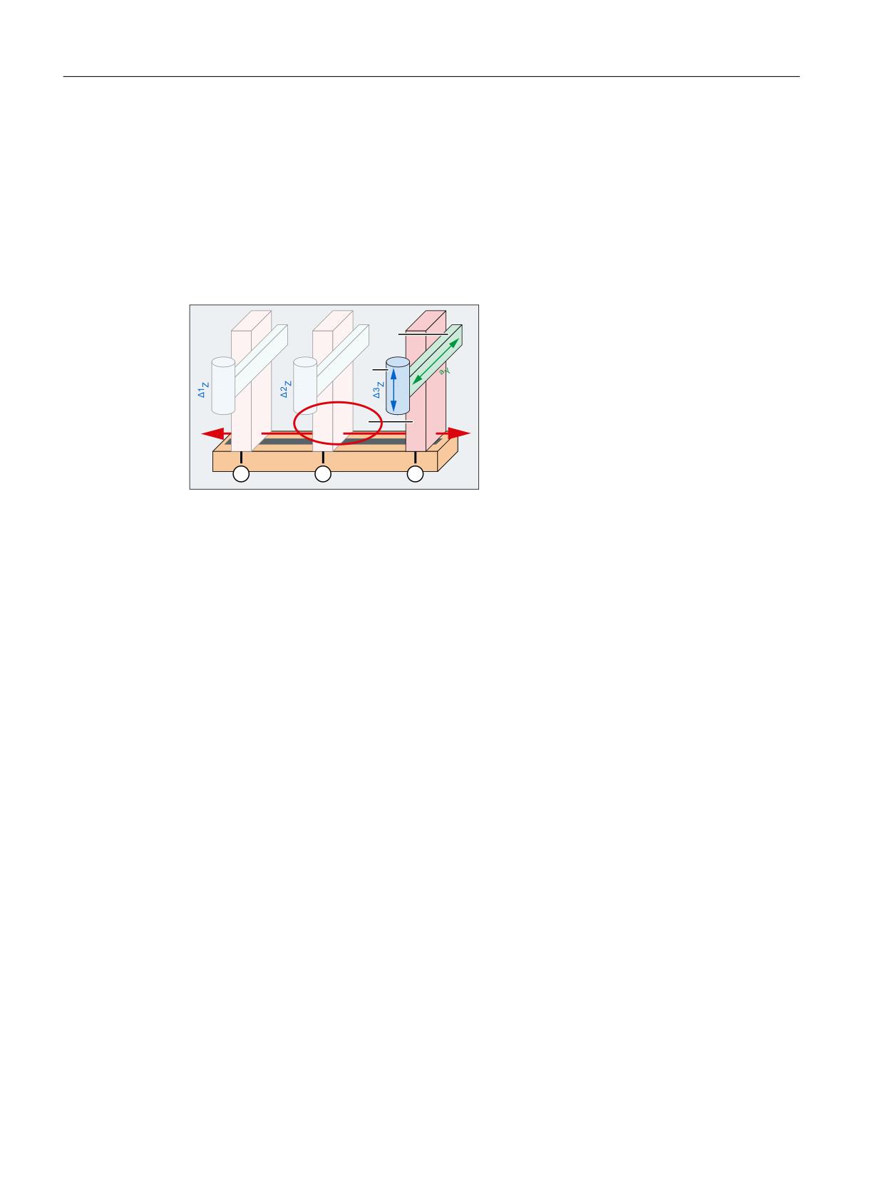
K3: Compensations
5.4 Nodding compensation
Example
At positions -100.0, 0.0, and 120.0 of the traversing range of the adaptation axis (X axis), for
the compensating axis AX3 (Z axis) compliance factors -12 , -25 and -10 μm / m/s2 are
determined.
● Compensating axis: AX3 (Z axis)
● Accelerating axis: AX2 (Y axis)
● Adaptation axis: AX1 (X axis)
$;
<
$;
=
$;
;
① Compliance factor at position 1: -12 μm / m/s2
② Compliance factor at position 2: -25 μm / m/s2
③ Compliance factor at position 3: -10 μm / m/s2
Figure 5-10
Adaptation axis: AX1 (X axis)
MD10002 $MN_AXCONF_LOGIC_MACHAX_TAB[ 0 ] = "AX1"
; X axis
MD10002 $MN_AXCONF_LOGIC_MACHAX_TAB[ 1 ] = "AX2"
; Y axis
MD10002 $MN_AXCONF_LOGIC_MACHAX_TAB[ 2 ] = "AX3"
; Z axis
MD37318 $MA_NOCO_COMPLIANCE_1[ 0, AX3 ] = -0.000012
MD37318 $MA_NOCO_COMPLIANCE_1[ 1, AX3 ] = -0.000025
MD37318 $MA_NOCO_COMPLIANCE_1[ 2, AX3 ] = -0.000010
See also:
● Number of axis positions: MD37314 $MA_NOCO_ADAPT_NUM_1 (Page 273)
Extended Functions
276
Function Manual, 12/2018, A5E40874029B AB
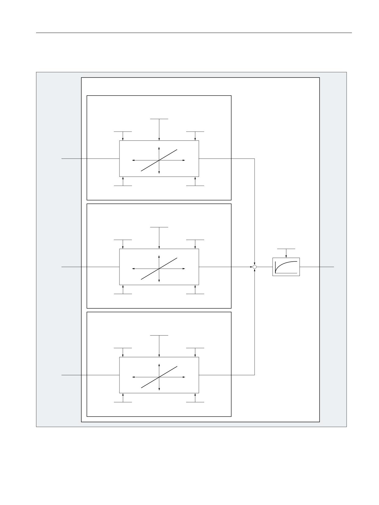
K3: Compensations
5.4 Nodding compensation
5.4.2.8
Function diagram
1RGGLQJ FRPSHQVDWLRQ &RPSHQVDWLQJ D[LV
&RPSHQVDWLRQ UHODWLRQVKLS
0'
0$B12&2B$'$37B$;B
0'
0'
0$B12&2B,1387B$;B
0$B12&2B$'$37B180B
&RPSHQVDWLRQ FKDUDFWHULVWLF
D
V
˂
0'
0'
0$B12&2B$'$37B326B >
@
0$B12&2B&203/,$1&(B >
@
&RPSHQVDWLRQ UHODWLRQVKLS
0'
0$B12&2B$'$37B$;B
0'
0'
0$B12&2B,1387B$;B
0$B12&2B$'$37B180B
0'
0$B 12&2B),/7(5B7,0(
&RPSHQVDWLRQ FKDUDFWHULVWLF
D
V
˂
˂
0'
0'
0$B12&2B$'$37B326B >
@
0$B12&2B&203/,$1&(B >
@
&RPSHQVDWLRQ UHODWLRQVKLS
0'
0$B12&2B$'$37B$;B
0'
0'
0$B12&2B,1387B$;B
0$B12&2B$'$37B180B
&RPSHQVDWLRQ FKDUDFWHULVWLF
D
V
˂
0'
0'
0$B12&2B$'$37B326B >
@
0$B12&2B&203/,$1&(B >
@
Figure 5-11
Function diagram of a compensating axis
Extended Functions
Function Manual, 12/2018, A5E40874029B AB
277
K3: Compensations
5.5 Interpolatory compensation
5.5
Interpolatory compensation
5.5.1
General properties
Function
With "interpolatory compensation," deviations between the desired and the actual position of
an axis can be compensated by leadscrew, measuring system, sag and angularity errors. This
is done by determining the deviation by measurement and storing the corresponding
compensation values in one or more compensation tables in the NC. During operation, the
relevant compensation value is then determined from the compensation table or tables for a
compensation axis based on its current set position. Linear interpolation is performed between
the interpolation points of the compensation tables.
Within "interpolatory compensation", a distinction is made between the two following
compensation methods:
● Compensation of leadscrew errors and measuring system errors
● Compensation of sag and angularity errors
Terms
● Compensation value
Additional setpoint that is applied to the compensation axis so that the difference between
the desired and actual axis position is zero.
● Basic axis
Axis, via whose set and actual position, the compensation value is determined from the
compensation value.
● Compensation axis
Axis, to whose set or actual position the compensation value is applied.
● Interpolation point
Value pair in a compensation table, consisting of a set and actual position of the basic axis
(interpolation point) and the associated compensation value (interpolation value).
● Compensation table
Defined number of interpolation points for a defined traversing range of the basic axis.
● Compensation relation
Unit comprising the basic axis, compensation axis, and compensation table.
Entering compensation tables
The size of the compensation table, i.e. the number of interpolation points, must first be defined
in a machine data. After the next POWER ON, the compensation tables are generated by the
NC and preassigned a value of "0".
Extended Functions
278
Function Manual, 12/2018, A5E40874029B AB