SINUMERIK 840D sl. Service - Functions. Manual (2018-2020) - page 33

B3: Distributed systems - 840D sl only
3.4 Data lists
Signal name
SINUMERIK 840D sl
MMC2_TYP
DB19.DBB132
PLC writes PAR_MMC_TYP to MMCx_TYP, if HMI goes
online.
MMC2_MSTT_ADR
DB19.DBB133
PLC writes PAR_MSTT_ADR to MMCx_MSTT_ADR, if HMI
goes online.
MMC2_STATUS
DB19.DBB134
Connection state, HMI and PLC write alternating, their re-
quests/acknowledgements.
MMC2_Z_INFO
DB19.DBB135
Additional information, connection state (pos./neg. acknowl-
edgement, error messages, ...)
MMC2_SHIFT_LOCK
DB19.DBX136.0
HMI switchover lock
MMC2_MSTT_SHIFT_LOCK
DB19.DBX136.1
MCP switchover lock
MMC2_ACTIVE_REQ
DB19.DBX136.2
HMI requests active operator mode
MMC2_ACTIVE_PERM
DB19.DBX136.3
Enable from PLC to change the operator mode
MMC2_ACTIVE_CHANGED
DB19.DBX136.4
HMI has changed the operator mode
MMC2_CHANGE_DENIED
DB19.DBX136.5
HMI active/passive switchover denied
3.4.3.4
Signals from axis/spindle
Signal name
SINUMERIK 840D sl
SINUMERIK 828D
NCU link: Axis active
DB31, ... DBX60.1
-
Axis-specific alarm
DB31, ... DBX61.1
DB390x, DBX1.1
Axis ready
DB31, ... DBX61.2
DB390x, DBX1.2
Axis container: Rotation active
DB31, ... DBX62.7
-
3.4.4
System variables
System variable
Description
$AN_AXCTSWE[axis]
Supplies the slots of the axis container of the specified axis which are en-
abled for the next axis container rotation
$AN_LAI_AX_IS_AXCTAX
Contains the container axes of the logical machine axis image as bit field
$AN_LAI_AX_IS_LINKAX
Contains the link axes of the logical machine axis image as bit field
$AN_LAI_AX_IS_LEADLINKAX
Contains the lead-link axes of the logical machine axis image as bit field
Extended Functions
Function Manual, 12/2018, A5E40874029B AB
141

B3: Distributed systems - 840D sl only
3.4 Data lists
System variable
Description
$AN_LAI_AX_TO_MACHAX[axis]
For the specified axis of the logical machine axis image, supplies the NCU-
ID and the axis number of the associated machine axis
$AN_LAI_AX_TO_IPO_NC_CHANAX[axis]
For the specified axis of the logical machine axis image, supplies the chan-
nel and channel axis number and/or the NCU and global axis number
$AN_IPO_CHANAX[global axis number]
For the specified global axis number, supplies the channel and channel
axis number
$AA_MACHAX[axis]
For the specified axis, supplies the NCU-ID and the machine axis number
$AA_IPO_NC_CHANAX[axis]
For the specified axis, supplies the channel and channel axis number or
NCU-ID and the global axis number
$VA_IPO_NC_CHANAX[axis]
For the specified machine axis, supplies the channel and channel axis
number or NCU-ID and global axis number
A more detailed description of system variables can be found in
References:
System Variables List Manual
Extended Functions
142
Function Manual, 12/2018, A5E40874029B AB
H1: Manual traversing
4
4.1
Overview
Application
Even on modern, numerically controlled machine tools, a facility must be provided that allows
the user to traverse the axes manually.
Examples:
● Setting up the machine
Especially when setting up a new machining program, a manual traversing of the machine
axes is required. Where coordinate offset or rotation is selected, manual travel can even
be performed in the transformed workpiece coordinate system.
● Retraction of the tool after a program abort
After a program abort due to a power failure or RESET, the operator must manually retract
the tool from its current machining position. The transformations and coordinate systems
used for machining must remain active while this is done.
JOG mode
Manual traversing of axes is performed in JOG mode.
If JOG mode is active for the current mode group, this is reported to the PLC via the
corresponding interface signal:
DB11 DBX6.2 (BAG1: operating mode JOG)
DB11 DBX26.2 (BAG2: operating mode JOG)
DB11 DBX186.2 (BAG10: operating mode JOG)
References:
Function Manual, Basic Functions; Mode Group, Channel, Program Operation, Reset
Response (K1)
Display
If JOG mode is active, the basic JOG screen is displayed on the operator interface. This main
screen contains values relating to position, feedrate, spindle, and tool.
Extended Functions
Function Manual, 12/2018, A5E40874029B AB
143
H1: Manual traversing
4.1 Overview
Manual traversing in the BCS and WCS
The user has the option of traversing axes in the basic coordinate system (BCS) or workpiece
coordinate system (WCS).
● Manual traversing in the BCS
Each axis can be traversed manually.
● Manual traversing in the WCS
Only the axes declared as geometry axes can be manually traversed in the WCS (channel-
specific). Any coordinate offsets or rotations that have been selected remain active.
Manual traversing of several axes
Several axes can be manually traversed at the same time in JOG mode. However, there is no
interpolatory relationship.
Control via the PLC interface
Manual traversing is controlled via the PLC interface.
See Chapter "Control via the PLC interface (Page 146)".
A separate PLC interface exists in each case for machine axes (axis-specific), geometry axes
(channel-specific), and orientation axes (channel-specific).
Parameter assignment (general)
For the manual traversing of axes, there are parameterizable properties, which are valid for
all JOG movements regardless of the traversing variant and the selected JOG function. These
are described under "Parameter assignment (general) (Page 147)".
Traversing variants
The following manual traversing variants are possible in JOG mode:
● Continuous traversing with the traversing keys of the machine control panel in jog or
continuous mode
See Chapter "Continuous manual traversing (Page 153)".
● Incremental traversing with the traversing keys of the machine control panel in jog or
continuous mode
See Chapter "Incremental manual traversing (Page 157)".
● Traversing of axes via electronic handwheels
See Chapter "Manual traversing using a handwheel (Page 161)".
Manual traversing of the spindle
Spindles can also be traversed manually in JOG mode. Essentially, the same conditions apply
as for manual traversing of axes. Spindles can be traversed in JOG mode using the traversing
keys continuously or incrementally, in jog or continuous mode, or using the handwheel. The
function is selected and activated via the axis-/spindle-specific PLC interface in the same way
as for the machine axes. The axis-specific machine data also applies to the spindles.
Extended Functions
144
Function Manual, 12/2018, A5E40874029B AB
H1: Manual traversing
4.1 Overview
Special features to be observed during manual traversing of spindles can be found in Chapter
"Manual traversing of the spindle (Page 176)".
Manual traversing of geometry axes
Manual traversing of geometry axes is used for traversing for which transformations and frames
have to be active. The geometry axes are traversed in the most recently valid coordinate
system.
Special features to be observed during manual traversing of geometry axes (and orientation
axes) can be found in Chapter "Manual traversing of geometry axes/orientation axes
(Page 178)".
Additional functions
In addition to various traversing variants, further functions can be selected in JOG mode:
● REF (reference point approach)
● REPOS (repositioning)
● Approach of configured fixed points
See Chapter "Approaching a fixed point in JOG (Page 180)".
● Approach of a definable position
See Chapter "Position travel in JOG (Page 188)".
● Traverse geometry axes along a circular arc
See Chapter "Circular travel in JOG (Page 193)".
● JOG retract (retraction movement in the tool direction after a program abort due to a power
failure or RESET)
See Chapter "Retraction in the tool direction (JOG retract) (Page 203)".
Use of handwheels in automatic mode
Handwheels can also be used in automatic mode:
● Handwheel override in AUTOMATIC mode with path specification and/or velocity override
(Page 213)
● Contour handwheel/path input using handwheel (option) (Page 220)
● Correction of the tool wear for machining in AUTOMATIC mode by means of additional
incremental work offset using the handwheel (DRF) (Page 213)
Monitoring
For manual traversing, limitations apply, which are monitored in the controller.
See Chapter "Monitoring functions (Page 233)".
Extended Functions
Function Manual, 12/2018, A5E40874029B AB
145
H1: Manual traversing
4.2 Control via the PLC interface
Switching from JOG mode to AUTOMATIC/MDI mode
It is only possible to switch operating modes from JOG to AUTOMATIC or MDI if all axes in
the channel have reached "coarse exact stop".
References:
Function Manual, Basic Functions; Mode Group, Channel, Program Operation, Reset
Response (K1)
Commissioning
For information on the commissioning of electronic handwheels, see Chapter "Start-up:
Handwheels (Page 234)".
4.2
Control via the PLC interface
The JOG functions in the NC are activated via the PLC interface from the machine control
panel (MCP). To do this, the input signals of the machine control panel from the PLC must be
transferred to the input interface of the NC in the NC/PLC interface. In this way, the machine
manufacturer can simply adapt the functionality of manual traversing to the machine tool
through the PLC user program. You can use this, for example, to change the assignment
between the direction keys of the machine control panel and the traversing requests to the NC
with regard to the machine and geometry axes.
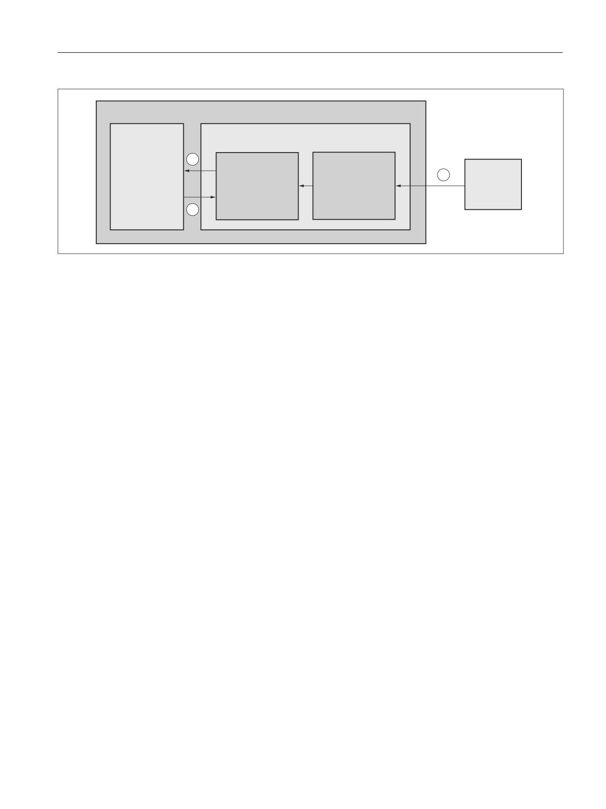
Basic procedure
The following figure shows the basic procedure for the selection of a JOG function from the
machine control panel (MCP) to the NC.
Extended Functions
146
Function Manual, 12/2018, A5E40874029B AB
H1: Manual traversing
4.3 Parameter assignment (general)
1&8
1&
3/&
2
%DVLF
3/&
1
3/&
XVHU
0&3
SURJUDP
SURJUDP
3
① The operator selects, for example, the "Continuous traversing" machine function on the machine control panel for a
machine axis.
The input signals of the MCP are transferred cyclically from the basic PLC program in the data blocks of the MCP
input interface.
② The PLC user program reads the input signals of the MCP. The input signals can be linked with any other signals in
accordance with the current machine or machining situation. Finally, the PLC user program writes the corresponding
request signals to the NC in the respective axis-specific NC/PLC interface.
The basic PLC program transfers the request signals in the internal input interface to the NC.
③ After activation of the requested function, the NC writes the feedback in the internal output interface to the PLC. The
basic PLC program cyclically transfers the output signals in the respective axis-specific NC/PLC interface
References
Detailed information on the configuration and integration of machine control panels in the PLC
user program can be found in the Basic Functions manual:
● SINUMERIK 840D sl: "P3: Basic PLC program for SINUMERIK 840D sl"
● SINUMERIK 828D: "P4: PLC for SINUMERIK 828D"
4.3
Parameter assignment (general)
Feedrate behavior
In JOG mode, it is possible to traverse an axis/spindle manually also at a revolutional feedrate
(as for G95) specific to the current speed of the master spindle.
The setting is made via the setting data:
Extended Functions
Function Manual, 12/2018, A5E40874029B AB
147

H1: Manual traversing
4.3 Parameter assignment (general)
SD41100 $SN_JOG_REV_IS_ACTIVE (JOG: revolutional/linear feedrate)
Bit
Value
Meaning
0
0
The behavior of the axis/spindle depends on the setting data:
SD43300 $SA_ASSIGN_FEED_PER_REV_SOURCE (revolutional feedrate for
positioning axes/spindles)
The behavior of a geometry axis on which a frame with rotation acts, or of an
orientation axis, depends on the channel-specific setting data:
SD42600 $SC_JOG_FEED_PER_REV_SOURCE (control of the revolutional fee-
drate in JOG)
1
For a JOG movement, it is always traversed with revolutional feedrate as a function
of the master spindle.
1
0
For rapid traverse as well, the axis/spindle, geometry axis or orientation axis is
traversed with revolutional feedrate (selection see Bit 0).
1
For rapid traverse, the axis/spindle, geometry axis or orientation axis is always
traversed without revolutional feedrate.
2
0
For manual traversing using the handwheel in the JOG mode, the axis/spindle,
geometry axis or orientation axis is traversed with the revolutional feedrate (se-
lection see bit 0).
1
For manual traversing using the handwheel in the JOG mode, the axis/spindle,
geometry axis or orientation axis is always traversed with the revolutional feedrate.
3
0
For manual traversing using the handwheel in the DRF mode, the axis/spindle is
traversed with the revolutional feedrate (selection see bit 0).
1
For manual traversing using the handwheel in the DRF mode, the axis/spindle is
always traversed without the revolutional feedrate.
Note
If a master spindle has not been defined and the axis is to be manually traversed at a
revolutional feedrate, alarm 20055 is output or alarm 20065 for geometry axes.
Velocity
The system data that determines the velocity of the manual traversing depends on the active
feedrate behavior.
Extended Functions
148
Function Manual, 12/2018, A5E40874029B AB
H1: Manual traversing
4.3 Parameter assignment (general)
Linear feedrate (G94) active
● Machine axes
The velocity is determined by the following setting data:
- For linear axes:
SD41110 $SN_JOG_SET_VELO (axis velocity for JOG)
- For rotary axes:
SD41130 $SN_JOG_ROT_AX_SET_VELO (JOG velocity for rotary axes)
If "0" is entered in SD41110/SD41130, the axis-specific machine data takes effect:
MD32020 $MA_JOG_VELO (conventional axis velocity)
The default setting for feedrate velocity unit is mm/min or rpm for rotary axes.
● Spindles
The velocity applied for the manual traversing of the spindles is defined by the setting data:
SD41200 $SN_JOG_SPIND_SET_VELO (speed of spindle in JOG mode)
If "0" is entered in SD41200, the axis-specific machine data takes effect:
MD32020 $_MA_JOG_VELO (conventional axis velocity)
The maximum speeds of the active gear stage are considered when manually traversing
a spindle.
References:
Function Manual Basic Functions; Spindles (S1)
● Geometry axes
The velocity applied for the manual traversing of geometry axes is defined by the channel-
specific machine data:
MD21165 $MC_JOG_VELO_GEO (conventional velocity for geometry axes)
● Orientation axes
The velocity applied for the manual traversing of orientation axes is defined by the channel-
specific machine data:
MD21155 $MC_JOG_VELO_ORI (conventional velocity for orientation axes)
Revolutional feedrate (G95) active
The feedrate value (in mm/rev.) is defined by the following setting data:
SD41120 $SN_JOG_REV_SET_VELO (revolutional feedrate of axes in JOG)
If "0" is entered in SD41120, the axis-specific machine data takes effect:
MD32050 $MD_JOG_REV_VELO (revolutional feedrate for JOG)
Extended Functions
Function Manual, 12/2018, A5E40874029B AB
149
H1: Manual traversing
4.3 Parameter assignment (general)
Rapid traverse override
If the traversing keys/handwheel are also actuated together with the rapid traverse override
key, the movement will be made with the configured rapid traverse velocity:
● Machine axes
- MD32010 $MA_JOG_VELO_RAPID (rapid traverse in jog mode)
- MD32040 $MA_JOG_REV_VELO_RAPID (revolutional feedrate for JOG with rapid
traverse override)
● Geometry axes
- MD21160 $MC_JOG_VELO_RAPID_GEO (rapid traverse in jog mode for geometry
axes)
● Orientation axes
- MD21150 $MC_JOG_VELO_RAPID_ORI (rapid traverse in jog mode for orientation
axes)
Feedrate override
The velocity applied for manual traversing can also be influenced using the axis-specific
feedrate override switch provided that the following NC/PLC interface signal is set:
DB31, ... DBX1.7 (axis-specific feedrate override active)
Percentages are assigned to the individual feedrate override switch positions via machine
data. For a switch position of 0 % the axis is not traversed, provided that 0 is entered in the
associated machine data.
The interface signal DB31, ... DBX1.7 (axis-specific feedrate override active) has no meaning
for switch position 0 %.
Instead of being set by the feedrate override switch position (gray code), the percentage value
(0 % to 200 %) can optionally be set directly by the PLC. Again, the selection is made via
machine data.
References:
Function Manual, Basic Functions; Feedrates (V1)
Spindle override
The velocity during manual traversing of the spindle can be influenced by the spindle override
switch.
References:
Function Manual Basic Functions; Spindles (S1)
Acceleration and jerk
The axis-specific acceleration and jerk limitation values also take effect in JOG mode.
It is also possible to limit acceleration and jerk channel-specifically for manual traversing of
geometry and orientation axes. This enables better handling of the kinematics that generate
Cartesian motions entirely via rotary axes (robots).
Extended Functions
150
Function Manual, 12/2018, A5E40874029B AB

H1: Manual traversing
4.3 Parameter assignment (general)
Maximum axis-specific acceleration for JOG motion
The maximum acceleration for manual traversing of an axis is defined in machine data:
MD32300 $MA_MAX_AX_ACCEL [0] (maximum axis-specific acceleration for path motions in
the dynamic response mode DYNNORM)
Note
Only the dynamic response mode DYNNORM is always effective for JOG mode.
Basic setting of axis-specific jerk limitation
Acceleration with jerk limitation can be specified as the axis-specific basic setting for JOG
mode:
MD32420 $MA_JOG_AND_POS_JERK_ENABLE== TRUE
Maximum axis-specific jerk
For JOG motions with active jerk limitation, the value from the following machine data takes
effect as maximum axis-specific jerk:
MD32430 $MA_JOG_AND_POS_MAX_JERK (maximum axis-specific jerk)
Note
MD32430 $MA_JOG_AND_POS_MAX_JERK acts only when the axis-specific jerk limitation
in JOG mode has been enabled for the machine axes to be traversed:
MD32420 $MA_JOG_AND_POS_JERK_ENABLE [<axis>] == TRUE
This is also possible by programming SOFTA(<Axis1>,<Axis2>, ...) in the part program.
Maximum acceleration when manually traversing spindles
As a spindle often uses many gear stages in speed-control mode and position-control mode,
the acceleration associated with the current gear stage is always applied to the spindle in JOG
mode.
References:
Function Manual Basic Functions; Spindles (S1)
Maximum acceleration when manually traversing geometry axes
The maximum acceleration when manually traversing geometry axes can be specified for each
channel via the machine data:
MD21166 $MC_JOG_ACCEL_GEO [<geometry axis>]
With <geometry axis> = 0, 1, 2
Note
With MD21166 $MC_JOG_ACCEL_GEO [<geometry axis>], there is no direct limitation to
MD32300 $MA_MAX_AX_ACCEL.
Extended Functions
Function Manual, 12/2018, A5E40874029B AB
151

H1: Manual traversing
4.3 Parameter assignment (general)
Note
When a transformation is active, MD32300 $MA_MAX_AX_ACCEL determines the maximum
possible axis-specific acceleration.
Maximum jerk when manually traversing geometry axes
The maximum jerk when manually traversing geometry axes in the SOFT acceleration mode
(acceleration with jerk limitation) can be specified for each channel via the machine data:
MD21168 $MC_JOG_JERK_GEO [<geometry axis>]
With <geometry axis> = 0, 1, 2
Note
MD21168 $MC_JOG_JERK_GEO acts only when the axis-specific jerk limitation in JOG mode
has been enabled for the base machine axes:
MD32420 $MA_JOG_AND_POS_JERK_ENABLE [<axis>] == TRUE
With MD21168 = 0, instead of the channel-specific jerk limitation, the axis-specific limit value
from MD32430 $MA_JOG_AND_POS_MAX_JERK is effective.
Maximum jerk when manually traversing orientation axes
The maximum jerk when manually traversing orientation axes can be specified for each
channel via the machine data:
MD21158 $MC_JOG_JERK_ORI [<orientation axis>]
For MD21158 to take effect, the channel-specific jerk limitation for the manual traversing of
orientation axes must be enabled via the following machine data:
MD21159 $MC_JOG_JERK_ORI_ENABLE == TRUE
See also
Manual traversing of geometry axes/orientation axes (Page 178)
Manual traversing of the spindle (Page 176)
Extended Functions
152
Function Manual, 12/2018, A5E40874029B AB

H1: Manual traversing
4.4 Continuous manual traversing
4.4
Continuous manual traversing
4.4.1
Function
For continuous manual traversing, the plus and minus traversing keys are selected to move
the relevant axis in the appropriate direction. If both traversing keys are pressed
simultaneously, there is no traversing movement, or, if an axis is in motion, it is stopped.
Note
When the control is switched on, axes can be traversed to the limits of the machine because
they have not yet been referenced. Hardware limit switches might be triggered as a result. The
software limit switches and the working-area limitation are not operative.
Continuous traversing in jog mode
In jog mode, the axis traverses as long as the traversing key is pressed. With the release of
the traversing key, the axis is decelerated to standstill. The movement is completed when the
parameterized exact stop criterion of the axis is reached.
If the axis reaches a traversing range limit before the traversing key is released (working area
limitation, software limit switch, etc.), the axis is stopped at the limit.
Continuous traversing in continuous mode
In continuous mode, traversing of the axis is started by pressing the traversing key. The
traversing movement is continued even after the traversing key is released.
WARNING
Risk of collision
In continuous mode, several axes can be started by pressing the respective traversing key.
Any interlocks must be implemented by the user / machine manufacturer via the PLC user
program.
The traversing movement can be interrupted and continued by the operator at any time or
aborted. If the axis reaches a traversing range limit before canceling the traversing movement
(working area limitation, software limit switch, etc.), the axis is stopped at the limit.
Interrupt traversing movement
The operator can interrupt traversing via the operator controls of the machine control panel
(MCP) in the following ways:
● Feedrate override = 0%
● Feedrate stop
● NC stop or NC stop axis/spindle
If the cause of the interruption is removed, the axis continues to traverse.
Extended Functions
Function Manual, 12/2018, A5E40874029B AB
153
H1: Manual traversing
4.4 Continuous manual traversing
Abort traversing movement
The operator can cancel traversing via the operator controls of the machine control panel
(MCP) in the following ways:
● Pressing the same traversing key again
● Pressing the traversing key for the opposite direction
● RESET
● Deselection of the JOG mode by changing the operating mode to AUTOMATIC or MDI
The traversing movement is canceled by the controller:
● If an active traversing range limit is reached (working area limitation, software limit switch,
etc.)
CAUTION
Traversing range limit inactive
Software limit switches and working-area limitations are only active after referencing of
the axis.
● If an alarm occurs with cancellation of the traversing movements
Interface signals
Selection
Continuous traversing in JOG mode must be activated via the PLC interface:
● Machine axes:
- DB31, ... DBX5.6 (request machine function "Continuous manual traversing")
● Geometry axes:
- DB21, ... DBX13.6 (geometry axis 1: Request machine function "Continuous manual
traversing")
- DB21, … DBX17.6 (geometry axis 2: Request machine function "Continuous manual
traversing")
- DB21, … DBX21.6 (geometry axis 3: Request machine function "Continuous manual
traversing")
● Orientation axes:
- DB21, ... DBX321.6 (orientation axis 1: Request machine function "Continuous manual
traversing")
- DB21, … DBX325.6 (orientation axis 2: Request machine function "Continuous manual
traversing")
- DB21, … DBX329.6 (orientation axis 3: Request machine function "Continuous manual
traversing")
Extended Functions
154
Function Manual, 12/2018, A5E40874029B AB
H1: Manual traversing
4.4 Continuous manual traversing
Feedback
Once the continuous procedure takes effect, a feedback is sent to the PLC:
● Machine axes:
- DB31, ... DBX65.6 (active machine function "Continuous manual traversing")
● Geometry axes:
- DB21, ... DBX41.6 (geometry axis 1: Active machine function "Continuous manual
traversing")
- DB21, … DBX47.6 (geometry axis 2: Active machine function "Continuous manual
traversing")
- DB21, … DBX53.6 (geometry axis 3: Active machine function "Continuous manual
traversing")
● Orientation axes:
- DB21, ... DBX333.6 (orientation axis 1: Active machine function "Continuous manual
traversing")
- DB21, … DBX337.6 (orientation axis 2: Active machine function "Continuous manual
traversing")
- DB21, … DBX341.6 (orientation axis 3: Active machine function "Continuous manual
traversing")
Travel command plus/minus
Once a traversing request for an axis is pending, the interface signal "Travel command minus"
or "Travel command plus" is output to the PLC depending on the direction of movement:
● Machine axes:
- DB31, ... DBX64.6 (travel command "minus") or
- DB31, ... DBX64.7 (travel command "plus")
● Geometry axis 1:
- DB21, … DBX40.6 (geometry axis 1: Travel command "minus") or
- DB21, … DBX40.7 (geometry axis 1: Travel command "plus")
● Geometry axis 2:
- DB21, … DBX46.6 (geometry axis 2: Travel command "minus") or
- DB21, … DBX46.7 (geometry axis 2: Travel command "plus")
● Geometry axis 3:
- DB21, … DBX52.6 (geometry axis 3: Travel command "minus") or
- DB21, … DBX52.7 (geometry axis 3: Travel command "plus")
● Orientation axis 1:
- DB21, … DBX332.6 (orientation axis 1: Travel command "minus") or
- DB21, … DBX332.7 (orientation axis 1: Travel command "plus")
Extended Functions
Function Manual, 12/2018, A5E40874029B AB
155
H1: Manual traversing
4.4 Continuous manual traversing
● Orientation axis 2:
- DB21, … DBX336.6 (orientation axis 2: Travel command "minus") or
- DB21, … DBX336.7 (orientation axis 2: Travel command "plus")
● Orientation axis 3:
- DB21, … DBX340.6 (orientation axis 3: Travel command "minus") or
- DB21, … DBX340.7 (orientation axis 3: Travel command "plus")
Note
A travel command set in JOG mode is canceled if the controller enable or pulse enable for the
axis to be traversed is missing. The travel command must therefore be set again after release
of the axis.
4.4.2
Parameter assignment
Jog or continuous mode
The selection of jog or continuous mode for the continuous procedure is performed NC-
specifically for all axes via the setting data:
SD41050 $SN_JOG_CONT_MODE_LEVELTRIGGRD (jog/continuous mode for JOG
continuous)
Jogging mode is the default setting.
4.4.3
Supplementary conditions
Indexing axis
An indexing axis always stops at an indexing position both in jog mode and in continuous
mode. In jog mode, the indexing axis traverses to the next indexing position in the direction of
travel, for example, when the traversing key is released
See also
T1: Indexing axes (Page 843)
Extended Functions
156
Function Manual, 12/2018, A5E40874029B AB
H1: Manual traversing
4.5 Incremental manual traversing
4.5
Incremental manual traversing
4.5.1
Function
With incremental traversing, the operator specifies the number of increments to be traversed
by the axis via the machine control panel.
In addition to five fixed increment sizes (default setting: INC1, INC10, INC100, INC1000 and
INC10000), a variable increment size (INCvar) that can be set via the setting data is also
available.
Incremental travel in jogging mode
If the traversing key for the required direction (e.g. +) is pressed, the axis begins to traverse
the increment that has been set. If the traversing key is released before the increment has
been fully traversed, the movement is interrupted and the axis stops. If the same traversing
key is pressed again, the axis traverses the remaining distance until it is zero. Up to this point,
the movement can still be interrupted by releasing the traversing key.
Pressing the traversing key for the opposite direction does not have any effect, unless the
increment has been fully traversed or the movement has been aborted.
Cancel traversing movement
If the increment should not travel to the end, the traversing movement can be interrupted as
follows:
● RESET
● DB31, ... DBX2.2 (delete distance-to-go)
Incremental travel in continuous mode
The axis traverses the entire set increment when the traversing key is pressed (first rising
edge). If the same traversing key is pressed again (second rising edge) before the axis has
finished traversing the increment, the traversing movement is aborted, i.e. not completed.
Interrupt traversing movement
Behavior as for continuous traversing (see "Continuous manual traversing (Page 153)").
Cancel traversing movement
The traversing movement can be stopped and aborted by means of the following operations
or monitoring functions:
● Pressing the same traversing key again
● Pressing the traversing key for the opposite direction
● RESET
● DB31, ... DBX2.2 (delete distance-to-go)
Extended Functions
Function Manual, 12/2018, A5E40874029B AB
157

H1: Manual traversing
4.5 Incremental manual traversing
● When the first valid limit is reached
CAUTION
Traversing range limit inactive
Software limit switches and working-area limitations are only activated after reference
point approach.
● Deselection or change of the current increment (e.g. change from INC100 to INC10)
● When faults occur (e.g. on cancellation of the servo enable)
WARNING
Risk of collision
If "continuous" mode is selected, several axes can by started by pressing and releasing the
relevant direction key. Any interlocks must be implemented via the PLC!
Note
While an axis is moving, a change of mode from JOG to AUTOMATIC or MDI is not permitted
within the control.
Interface signals
Selection
Incremental traversing in JOG mode must be activated via the PLC interface:
● Machine axes:
- DB31, ... DBX5.0 - 5 (request machine function "INC1" to "INCvar")
● Geometry axes:
- DB21, ... DBX13.0 - 5 (geometry axis 1: Request machine function "INC1" to "INCvar")
- DB21, ... DBX17.0 - 5 (geometry axis 2: Request machine function "INC1" to "INCvar")
- DB21, ... DBX21.0 - 5 (geometry axis 3: Request machine function "INC1" to "INCvar")
● Orientation axes:
- DB21, ... DBX321.0 - 5 (orientation axis 1: Request machine function "INC1" to
"INCvar")
- DB21, ... DBX325.0 - 5 (orientation axis 2: Request machine function "INC1" to
"INCvar")
- DB21, ... DBX329.0 - 5 (orientation axis 3: Request machine function "INC1" to "INCvar")
Extended Functions
158
Function Manual, 12/2018, A5E40874029B AB
H1: Manual traversing
4.5 Incremental manual traversing
Feedback
Once the incremental procedure takes effect, a feedback is sent to the PLC:
● Machine axes:
- DB31, ... DBX65.0 - 5 (active machine function "INC1" to "INCvar")
● Geometry axes:
- DB21, ... DBX41.0 - 5 (geometry axis 1: Active machine function "INC1" to "INCvar")
- DB21, ... DBX47.0 - 5 (geometry axis 2: Active machine function "INC1" to "INCvar")
- DB21, … DBX53.0 - 5 (geometry axis 3: Active machine function "INC1" to "INCvar")
● Orientation axes:
- DB21, ... DBX333.0 - 5 (orientation axis 1: Active machine function "INC1" to "INCvar")
- DB21, ... DBX337.0 - 5 (orientation axis 2: Active machine function "INC1" to "INCvar")
- DB21, ... DBX341.0 - 5 (orientation axis 3: Active machine function "INC1" to "INCvar")
Travel command plus/minus
Once a traversing request for an axis is pending, the interface signal "Travel command minus"
or "Travel command plus" is output to the PLC depending on the direction of movement:
● Machine axes:
- DB31, ... DBX64.6 (travel command "minus") or
- DB31, ... DBX64.7 (travel command "plus")
● Geometry axis 1:
- DB21, … DBX40.6 (geometry axis 1: Travel command "minus") or
- DB21, … DBX40.7 (geometry axis 1: Travel command "plus")
● Geometry axis 2:
- DB21, … DBX46.6 (geometry axis 2: Travel command "minus") or
- DB21, … DBX46.7 (geometry axis 2: Travel command "plus")
● Geometry axis 3:
- DB21, … DBX52.6 (geometry axis 3: Travel command "minus") or
- DB21, … DBX52.7 (geometry axis 3: Travel command "plus")
● Orientation axis 1:
- DB21, … DBX332.6 (orientation axis 1: Travel command "minus") or
- DB21, … DBX332.7 (orientation axis 1: Travel command "plus")
Extended Functions
Function Manual, 12/2018, A5E40874029B AB
159
H1: Manual traversing
4.5 Incremental manual traversing
● Orientation axis 2:
- DB21, … DBX336.6 (orientation axis 2: Travel command "minus") or
- DB21, … DBX336.7 (orientation axis 2: Travel command "plus")
● Orientation axis 3:
- DB21, … DBX340.6 (orientation axis 3: Travel command "minus") or
- DB21, … DBX340.7 (orientation axis 3: Travel command "plus")
Note
A travel command set in JOG mode is canceled if the controller enable or pulse enable for the
axis to be traversed is missing. The travel command must therefore be set again after release
of the axis.
4.5.2
Parameter assignment
Fixed increments
The parameter assignment of the fixed increment sizes is performed via NC-specific machine
data:
MD11330 $MN_JOG_INCR_SIZE_TAB[1 ... 5] = <number of increments 1 ... 5>
Variable increment
The parameter assignment of the variable increment size is performed via NC-specific setting
data:
SD41010 $SN_JOG_VAR_INCR_SIZE = <number of increments>
Distance evaluation of one increment
The distance evaluation of one increment for fixed and variable increment sizes is performed
via the axis-specific machine data:
MD31090 $MA_JOG_INCR_WEIGHT = <distance>
Note
Reversal of the direction evaluation
The input of a negative value causes a reversal of the direction evaluation of the traversing
keys or the handwheel direction of rotation.
Extended Functions
160
Function Manual, 12/2018, A5E40874029B AB
H1: Manual traversing
4.6 Manual traversing using a handwheel
Jog or continuous mode
The selection of jog or continuous mode is performed for the incremental procedure NC-
specifically for all axes via the machine data:
MD11300 $MN_JOG_INC_MODE_LEVELTRIGGRD (INC and REF in jog mode)
Jogging mode is the default setting.
4.5.3
Supplementary conditions
Indexing axis
Irrespective of the set increment value, an indexing axis traverses to the next indexing position
in the direction of travel after pressing the traversing key.
See also
T1: Indexing axes (Page 843)
4.6
Manual traversing using a handwheel
4.6.1
Function
The electronic handwheels (accessories) can be used to simultaneously traverse selected
axes manually. The weighting of the handwheel graduations is dependent on the increment-
size weighting. Where coordinate offset or rotation is selected, manual travel can even be
performed in the transformed workpiece coordinate system.
Commissioning
For information on the commissioning of electronic handwheels, see Chapter "Start-up:
Handwheels (Page 234)".
Select
JOG mode must be active. The user must also set the increment INC1, INC10, etc., which
applies to manual traversing using a handwheel. As with incremental travel, the required
machine function must be set at the PLC interface accordingly.
Extended Functions
Function Manual, 12/2018, A5E40874029B AB
161
H1: Manual traversing
4.6 Manual traversing using a handwheel
Traversing
When the electronic handwheel is turned, the associated axis is traversed either in the positive
or negative direction depending on the direction of rotation.
Note
If the axis is already being moved using the traversing keys, then manual traversing using the
handwheel is not possible.
Traversing distance
The traversing distance produced by rotating the handwheel is dependent on the following
factors:
● Number of handwheel pulses received at the interface
● Active increment (machine function INC1, INC10, INC100, ... INCvar)
● Pulse evaluation of the handwheel:
MD11320 $MN_HANDWH_IMP_PER_LATCH (handwheel pulses per detent position)
See Section "Parameter assignment (Page 168)".
● Distance of an increment:
MD31090 $MA_JOG_INCR_WEIGHT (evaluation of an increment for INC/handwheel)
See Section "Parameter assignment (Page 168)".
Handwheel connection
Up to six handwheels can be connected simultaneously. This means that up to six axes can
be traversed by handwheel simultaneously.
Representation of the handwheel number in the NC/PLC interface signals
Depending on the parameter assignment of MD11324, the representation of the handwheel
number in the NC/PLC interface signals is bit-coded (three handwheels can be represented)
or binary-coded (six handwheels can be represented). From the HMI, the handwheel number
is always transferred bit-coded, independent of the setting in MD11324.
See Chapter "Parameter assignment (Page 168)".
Handwheel assignment
The axis that is moved by turning the handwheel can be set via the via the PLC user interface
or via the user interface (HMI). The assignment is linked to the NC/PLC interface through the
PLC user program. In this way, several axes can be assigned to one handwheel
simultaneously.
Extended Functions
162
Function Manual, 12/2018, A5E40874029B AB
H1: Manual traversing
4.6 Manual traversing using a handwheel
Setting via the PLC user interface
The assignment is made using one of the following interface signals:
● Machine axes:
- DB31, ... DBX4.0 - 2 (activate handwheel)
● Geometry axes:
- DB21, ... DBX12.0 - 2 (geometry axis 1: Activate handwheel)
- DB21, ... DBX16.0 - 2 (geometry axis 2: Activate handwheel)
- DB21, ... DBX20.0 - 2 (geometry axis 3: Activate handwheel)
● Orientation axes:
- DB21, ... DBX320.0 - 2 (orientation axis 1: Activate handwheel)
- DB21, ... DBX324.0 - 2 (orientation axis 2: Activate handwheel)
- DB21, ... DBX328.0 - 2 (orientation axis 3: Activate handwheel)
Setting via the user interface (HMI).
Pressing the "Handwheel" softkey in the JOG-mode basic menu displays the "Handwheel"
window. Here, every handwheel can be assigned an axis and the handwheel can be enabled
or disabled.
Note
The handwheel assignment is not possible via the user interface (HMI) for more than three
connected handwheels and a binary-coded representation of the handwheel number in the
NC/PLC interface signals.
Handwheel selection by HMI
A separate user interface is provided between the HMI and PLC to allow activation of the
handwheel from the user interface. This interface supplied by the basic PLC program for
handwheels 1, 2 and 3 contains the following information:
● Axis number assigned to the handwheel (if, during the handwheel selection, a machine axis
was selected):
DB10 DBX100.0 - 4 (axis number handwheel 1)
DB10 DBX101.0 - 4 (axis number handwheel 2)
DB10 DBX102.0 - 4 (axis number handwheel 3)
● Channel number assigned to the handwheel (if during the handwheel selection a geometry
axis was selected):
DB10 DBX97.0 - 3 (channel number geometry axis handwheel 1)
DB10 DBX98.0 - 3 (channel number geometry axis handwheel 2)
DB10 DBX99.0 - 3 (channel number geometry axis handwheel 3)
Extended Functions
Function Manual, 12/2018, A5E40874029B AB
163
H1: Manual traversing
4.6 Manual traversing using a handwheel
● Additional information on the machine or geometry axis:
DB10 DBX100.7 (machine axis handwheel 1)
DB10 DBX101.7 (machine axis handwheel 2)
DB10 DBX102.7 (machine axis handwheel 3)
● The information that the handwheel is enabled or disabled:
DB10 DBX100.6 (handwheel 1 selected)
DB10 DBX101.6 (handwheel 2 selected)
DB10 DBX102.6 (handwheel 3 selected)
For the specified axis, the basic PLC program sets the associated interface signal either to "0"
(disable) or to "1" (enable):
● Machine axes:
- DB31, ... DBX4.0 - 2 (activate handwheel)
● Geometry axes:
- DB21, ... DBX12.0 - 2 (geometry axis 1: Activate handwheel)
- DB21, ... DBX16.0 - 2 (geometry axis 2: Activate handwheel)
- DB21, ... DBX20.0 - 2 (geometry axis 3: Activate handwheel)
Note
Orientation axes can only be activated via the associated PLC user interface signals:
● DB21, ... DBX320.0 - 2 (orientation axis 1: Activate handwheel)
● DB21, ... DBX324.0 - 2 (orientation axis 2: Activate handwheel)
● DB21, ... DBX328.0 - 2 (orientation axis 3: Activate handwheel)
Travel request
The following NC/PLC interface signal informs the PLC that an axis wants to travel or is
travelling:
● Machine axes:
- DB31, ... DBX64.4 (travel request "minus") or
- DB31, ... DBX64.5 (travel request "plus")
● Geometry axis 1:
- DB21, … DBX40.4 (geometry axis 1: Travel request "minus") or
- DB21, … DBX40.5 (geometry axis 1: Travel request "plus")
● Geometry axis 2:
- DB21, … DBX46.4 (geometry axis 2: Travel request "minus") or
- DB21, … DBX46.5 (geometry axis 2: Travel request "plus")
● Geometry axis 3:
- DB21, … DBX52.4 (geometry axis 3: Travel request "minus") or
- DB21, … DBX52.5 (geometry axis 3: Travel request "plus")
Extended Functions
164
Function Manual, 12/2018, A5E40874029B AB
H1: Manual traversing
4.6 Manual traversing using a handwheel
● Orientation axis 1:
- DB21, … DBX332.4 (orientation axis 1: Travel request "minus") or
- DB21, … DBX332.5 (orientation axis 1: Travel request "plus")
● Orientation axis 2:
- DB21, … DBX336.4 (orientation axis 2: Travel request "minus") or
- DB21, … DBX336.5 (orientation axis 2: Travel request "plus")
● Orientation axis 3:
- DB21, … DBX340.4 (orientation axis 3: Travel request "minus") or
- DB21, … DBX340.5 (orientation axis 3: Travel request "plus")
Note
A travel request is the sum of all sub-movements, i.e. the component from couplings and
correction values is also taken into account.
For the method of operation of the "Travel request" function, see Section "Travel request
(Page 173)".
Travel command
Depending on the setting in machine data MD17900 $MN_VDI_FUNCTION_MASK (see
Section "Parameter assignment (Page 168)"), the following interface signal is output to the PC
already when a travel request is present or not until the axis moves:
● Machine axes:
- DB31, ... DBX64.6 (travel command "minus") or
- DB31, ... DBX64.7 (travel command "plus")
● Geometry axis 1:
- DB21, … DBX40.6 (geometry axis 1: Travel command "minus") or
- DB21, … DBX40.7 (geometry axis 1: Travel command "plus")
● Geometry axis 2:
- DB21, … DBX46.6 (geometry axis 2: Travel command "minus") or
- DB21, … DBX46.7 (geometry axis 2: Travel command "plus")
● Geometry axis 3:
- DB21, … DBX52.6 (geometry axis 3: Travel command "minus") or
- DB21, … DBX52.7 (geometry axis 3: Travel command "plus")
● Orientation axis 1:
- DB21, … DBX332.6 (orientation axis 1: Travel command "minus") or
- DB21, … DBX332.7 (orientation axis 1: Travel command "plus")
Extended Functions
Function Manual, 12/2018, A5E40874029B AB
165
H1: Manual traversing
4.6 Manual traversing using a handwheel
● Orientation axis 2:
- DB21, … DBX336.6 (orientation axis 2: Travel command "minus") or
- DB21, … DBX336.7 (orientation axis 2: Travel command "plus")
● Orientation axis 3:
- DB21, … DBX340.6 (orientation axis 3: Travel command "minus") or
- DB21, … DBX340.7 (orientation axis 3: Travel command "plus")
Note
A travel command set in JOG mode is canceled if the controller enable or pulse enable for the
axis to be traversed is missing. The travel command must therefore be set again after release
of the axis.
Invert handwheel direction of rotation
The handwheel direction of rotation can be inverted, if the direction of movement of the
handwheel does not match the expected direction of motion of the axis. The adaptation can
be especially necessary, if a handwheel (HT2, HT8) can be assigned to various axes.
In addition to configuring the particular MD, handwheel direction of rotation inversion can be
activated by setting the IS "Invert the handwheel direction of rotation" belonging to the particular
axis:
● Machine axes:
- DB31, ... DBX7.0 (invert handwheel direction of rotation)
● Geometry axes:
- DB21, ... DBX15.0 (geometry axis 1: Invert handwheel direction of rotation)
- DB21, ... DBX19.0 (geometry axis 2: Invert handwheel direction of rotation)
- DB21, ... DBX23.0 (geometry axis 3: Invert handwheel direction of rotation)
● Orientation axes:
- DB21, … DBX323.0 (orientation axis 1: Invert handwheel direction of rotation)
- DB21, … DBX327.0 (orientation axis 2: Invert handwheel direction of rotation)
- DB21, … DBX331.0 (orientation axis 3: Invert handwheel direction of rotation)
● Contour handwheel:
- DB21, ... DBX31.5 (contour handwheel: Invert handwheel direction of rotation)
Note
The inversion signal should be set in the PLC user program at the same time as the handwheel
selection (IS "Activate handwheel").
Extended Functions
166
Function Manual, 12/2018, A5E40874029B AB

H1: Manual traversing
4.6 Manual traversing using a handwheel
The acknowledgement that the handwheel direction of rotation has been inverted by the NC
is realized for each axis using the IS "Handwheel direction of rotation inversion active":
● Machine axes:
- DB31, ... DBX67.0 (handwheel direction of rotation inversion active)
● Geometry axes:
- DB21, ... DBX43.0 (geometry axis 1: Handwheel direction of rotation inversion active)
- DB21, ... DBX49.0 (geometry axis 2: Handwheel direction of rotation inversion active)
- DB21, ... DBX55.0 (geometry axis 3: Handwheel direction of rotation inversion active)
● Orientation axes:
- DB21, ... DBX335.0 (orientation axis 1: Handwheel direction of rotation inversion active)
- DB21, ... DBX339.0 (orientation axis 2: Handwheel direction of rotation inversion active)
- DB21, ... DBX343.0 (orientation axis 3: Handwheel direction of rotation inversion active)
● Contour handwheel:
- DB21, ... DBX39.5 (contour handwheel: Handwheel direction of rotation inversion
active)
Note
It is only permissible to change the inversion signal at standstill. If the change is made while
motion setpoints are being output by the interpolator, then the signal change is rejected and
an alarm is output; further, motion is stopped taking into account the actual acceleration value.
Abort/interruption of the traversing motion
The following NC/PLC interface signals abort the traversing motion. The setpoint/actual-value
difference is deleted.
NC/PLC interface signal
Scope
Effect
DB21, ... DBX7.7 (NC reset)
Geometry axis / machine axis
Abort
DB21, ... DBX12.0 - 2 (geometry axis 1: Activate hand-
Geometry axis
1 → 0
Abort
wheel)
DB21, ... DBX16.0 - 2 (geometry axis 2: Activate hand-
wheel)
DB21, ... DBX20.0 - 2 (geometry axis 3: Activate hand-
wheel)
DB21, ... DBX6.2 (delete distance-to-go)
Geometry axis / machine axis
0 → 1
Abort
DB31, ... DBX2.2 (delete distance-to-go / spindle reset)
Geometry axis / machine axis
0 → 1
Abort
DB31, ... DBX4.2 (activate handwheel)
Machine axis
1 → 0
Abort
DB31, ... DBX1.3 (axis/spindle disable)
Geometry axis / machine axis
0 → 1
Abort
DB31, ... DBX1.5 (position measuring system 1)
Geometry axis / machine axis
0 → 1
Abort
DB31, ... DBX1.6 (position measuring system 2)
Geometry axis / machine axis
0 → 1
Abort
Extended Functions
Function Manual, 12/2018, A5E40874029B AB
167
H1: Manual traversing
4.6 Manual traversing using a handwheel
For other NC/PLC interface signals (hold signals), the influence of manually traversing using
the handwheel (cancellation or interruption of traversing motion) can be set (see Chapter
"Parameter assignment (Page 168)").
NC STOP only interrupts the traversing movement. Any setpoint/actual-value difference is
retained. The distance-to-go is then traversed using NC START.
See also
Monitoring functions (Page 233)
4.6.2
Parameter assignment
Distance or velocity specification
Either the distance or the velocity can be entered via the handwheel:
● Distance specification (default setting)
The distance specified by the handwheel is traversed and No pulses are lost.
Limiting the velocity to the maximum permissible value causes the axes to overtravel.
● Velocity specification
The handwheel only defines the traverse velocity. As soon as the handwheel stops, the
axes stop too. Motion is braked immediately if no pulses are supplied from the handwheel
in one IPO cycle, thus preventing overtravel by the axes. The handwheel pulses do not
supply a path default.
The input mode is set with machine data:
MD11346 $MN_HANDWH_TRUE_DISTANCE (handwheel distance or velocity specification)
Pulse evaluation of the handwheel
The number of pulses that are to be generated per handwheel detent position must be specified
for each handwheel:
MD11320 $MN_HANDWH_IMP_PER_LATCH [<n>] (handwheel pulses per detent position)
Note
Input of a negative value results in a reversal of the handwheel direction of rotation.
Increment size
The number of increments to be traversed by the axis per handwheel pulse is determined by
the selected increment size.
In addition to five fixed increment sizes (default setting: INC1, INC10, INC100, INC1000 and
INC10000), a variable increment size (INCvar) that can be set via the setting data is also
available.
Extended Functions
168
Function Manual, 12/2018, A5E40874029B AB

H1: Manual traversing
4.6 Manual traversing using a handwheel
Fixed increments
The parameter assignment of the fixed increment sizes is performed via NC-specific machine
data:
MD11330 $MN_JOG_INCR_SIZE_TAB[1 ... 5] = <number of increments 1 ... 5>
Variable increment
The parameter assignment of the variable increment size is performed via NC-specific setting
data:
SD41010 $SN_JOG_VAR_INCR_SIZE = <number of increments>
Distance evaluation of one increment
The distance evaluation of one increment for fixed and variable increment sizes is performed
via the axis-specific machine data:
MD31090 $MA_JOG_INCR_WEIGHT = <distance>
Note
Input of a negative value results in a reversal of the handwheel direction of rotation.
Limitation of the increment size
The machine operator can limit the size of the selected increment:
● For machine axes, using the axis-specific machine data:
MD32080 $MA_HANDWH_MAX_INCR_SIZE (limiting the selected increment)
● For geometry axes, using the channel-specific machine data:
MD20620 $MC_HANDWH_GEOAX_MAX_INCR_SIZE (limitation of handwheel increment
for geometry axes)
● For orientation axes, using the channel-specific machine data:
MD20621 $MC_HANDWH_ORIAX_MAX_INCR_SIZE (limitation of handwheel increment
for orientation axes)
Representation of the handwheel number in the NC/PLC interface signals
The representation of the handwheel number in the NC/PLC interface signals is defined using
machine data:
MD11324 $MN_HANDWH_VDI_REPRESENTATION
Value
Meaning
0
Bit-coded representation (basic setting)
→ Three handwheels can be represented.
1
Binary-coded representation
→ Six handwheels can be represented.
Extended Functions
Function Manual, 12/2018, A5E40874029B AB
169
H1: Manual traversing
4.6 Manual traversing using a handwheel
Output of the NC/PLC interface signals "travel command plus" / "travel command minus"
The output behavior of the NC/PLC interface signals "travel command plus" / "travel command
minus" is specified with the machine data:
MD17900 $MN_VDI_FUNCTION_MASK
Value
Meaning
0
The NC/PLC interface signals "Travel command plus" / "Travel command minus" are already
output when a travel request is active (default setting).
1
The NC/PLC interface signals "Travel command plus" / "Travel command minus" are only
output when the axis actually moves (i.e. if setpoints are output to the servo).
Velocity
The following axis velocities, effective during JOG, are also used for manually traversing using
the handwheel:
● SD41110 $SN_JOG_SET_VELO (axis velocity for JOG)
● SD41130 $SN_JOG_ROT_AX_SET_VELO (axis velocity for rotary axes for JOG mode)
● MD32020 $MA_JOG_VELO (conventional axis velocity)
Note
Because of the limited feedrate, the axis is not able to follow the handwheel rotation
synchronously, especially in the case of a large pulse weighting, and therefore overtravels.
Acceleration
As for manual travel (see "Parameter assignment (general) (Page 147) ").
Movement in the opposite direction
The behavior at a reversal of the traversing direction (by turning the handwheel in the opposite
direction) can be set in the machine data:
MD11310 $MN_HANDWH_REVERSE (threshold for direction change handwheel)
Value
Meaning
= 0
If the handwheel is moved in the opposite direction, the resulting distance is computed and
the calculated end point is approached as fast as possible.
If this end point is located before the point where the moving axis can decelerate in the current
direction of travel, the unit is decelerated and the end point is approached by moving in the
opposite direction. If this is not the case, the newly calculated end point is approached imme-
diately.
> 0
If the handwheel is moved in the opposite direction by at least the number of pulses indicated
in the machine data, the axis is decelerated as fast as possible and all pulses received until
the end of the interpolation are ignored.
This means that another movement takes place only after the axis reaches standstill (setpoint
side).
Extended Functions
170
Function Manual, 12/2018, A5E40874029B AB

H1: Manual traversing
4.6 Manual traversing using a handwheel
Response at software limit switches, working area limitation
When axes are traversed in JOG mode, they can traverse only up to the first active limitation
before the corresponding alarm is output.
Depending on the setting in the machine data:
MD11310 $MN_HANDWH_REVERSE (threshold for direction change, handwheel)
the behavior is then as follows (as long as the axis has still not arrived at the end point from
the setpoint side):
● The distance resulting from the handwheel pulses forms a fictitious end point which is used
for subsequent calculations.
If this fictitious end point is, for example, 10 mm behind the limit, these 10 mm must be
traversed in the opposite direction before the axis traverses again. If a movement in the
opposite direction is to be performed immediately after a limitation is reached, the fictitious
distance-to-go can be deleted via delete distance-to-go or deselection of the handwheel
assignment.
● All handwheel pulses leading to an end point behind the limitation are ignored. Any
movement of the handwheel in the opposite direction leads to an immediate movement in
the opposite direction, i.e. away from the limit.
Feedrate behavior
In JOG mode, the feedrate behavior of the axis/spindle also depends on the setting data:
SD41100 $SN_JOG_REV_IS_ACTIVE (JOG: Revolutional/linear feedrate)
SD41100 $SN_JOG_REV_IS_ACTIVE
Active
An axis/spindle is always traversed with revolutional feedrate
MD32050 $MA_JOG_REV_VELO (revolutional feedrate for JOG)
or
MD32040 $MA_JOG_REV_VELO_RAPID
(revolutional feedrate for JOG with rapid traverse override)
depending on the master spindle.
Not active
The behavior of the axis/spindle depends on the setting data:
SD43300 $SA_ASSIGN_FEED_PER_REV_SOURCE
(revolutional feedrate for positioning axes/spindles)
The behavior of a geometry axis on which a frame with rotation acts,
depends on the channel-specific setting data:
SD42600 $SC_JOG_FEED_PER_REV_SOURCE
(control of the revolutional feedrate in JOG)
Effect of the NC/PLC interface stop signals
The effect of the NC/PLC interface stop signals on manual traversing using a handwheel (abort
or interruption of the traversing motion) can be set using machine data:
MD20624 $MC_HANDWH_CHAN_STOP_COND (definition of the handwheel traversing
behavior, channel-specific)
Extended Functions
Function Manual, 12/2018, A5E40874029B AB
171

H1: Manual traversing
4.6 Manual traversing using a handwheel
MD32084 $MA_HANDWH_STOP_COND (behavior when manually traversing using a
handwheel)
NC/PLC interface signal
Scope
MD20624 $MC_HANDWH_CHAN_STOP_COND
Bit == 0
Bit == 1
DB11 DBX0.5 (mode group
Geometry axis / machine axis
Interruption until NC start
Abort
stop)
DB11 DBX0.6 (mode group
Geometry axis / machine axis
Interruption until NC start
Abort
stop, axes plus spindle)
DB21, ... DBX7.3 (NC Stop)
Geometry axis / machine axis
Interruption until NC start
Abort
DB21, ... DBX7.4 (NC stop,
Geometry axis / machine axis
Interruption until NC start
Abort
axes plus spindle)
DB21, ... DBX6.0 (feedrate
Geometry axis / machine axis
Interruption
Abort
disable)
DB21, ... DBB4 (feed rate
Geometry axes
Override == 0: Interruption if
Override == 0: Abort if rapid
override)
rapid traverse override is not
traverse override is not active
active
DB31, ... DBX4.5 (rapid tra-
verse override)
DB21, ... DBB5 (rapid tra-
Geometry axes
Rapid traverse override == 0:
Rapid traverse override == 0:
verse override)
Interruption if rapid traverse
Abort if rapid traverse over-
override is active
ride is active
DB31, ... DBX4.5 (rapid tra-
verse override)
DB21, ... DBX12/16/20.3 (ge-
Geometry axis
Interruption
Abort
ometry axis 1/2/3: Feedrate
stop)
NC/PLC interface signal
Scope
MD32084 $MC_HANDWH_CHAN_STOP_COND
Bit == 0
Bit == 1
DB31, ... DBB0 (feed rate
Machine axis, not spindle
Override == 0: Interruption
Override == 0: Abort
override, axial)
DB31, ... DBB19 (spindle
Spindle
Override == 0: Interruption
Override == 0: Abort
override)
DB31, ... DBX4.3 (feedrate
Geometry axis / machine axis
Interruption
Abort
stop / spindle stop)
DB31, ... DBX2.3 (clamping
Geometry axis / machine axis
No effect
Abort
in progress)
DB31, ... DBX2.1 (control sys-
Geometry axis / machine axis
Interruption
Abort
tem enable)
DB31, ... DBX21.7 (pulse en-
Geometry axis / machine axis
Interruption
Abort
able)
Note
Removal of the "Controller enable" and "Pulse enable" during traversing results in a rapid stop
of the axis and a reset alarm.
Extended Functions
172
Function Manual, 12/2018, A5E40874029B AB

H1: Manual traversing
4.6 Manual traversing using a handwheel
Interruption of a traversing motion
When a stop command is issued, the distance-to-go is saved and the handwheel pulses are
collected. When the stop condition no longer applies, the resulting distance is traversed.
Abort of a traversing motion
When a stop command is issued, the distance-to-go is deleted and the handwheel pulses are
ignored (i.e. not collected) until the stop condition no longer applies.
Behavior in the event of a safe operating stop
Analog to the NC/PLC interface stop signals, the behavior in the event of a stop can also be
adjusted by activating the safe operating stop (SBH):
Stop condition
Scope
MD20624 $MC_HANDWH_CHAN_STOP_COND
Bit 12 == 0
Bit 12 == 1
(Default setting)
Safe operating stop in
Machine axis
Interruption
Abort
the event of active tar-
get velocity limit
In the default setting, Bit 12 is set to "1", i.e. in the event of a stop resulting from activation of
the safe stop, current movements are aborted and new handwheel pulses ignored.
Prerequisite for an interpolatory stop is an active target velocity limit (i.e., MD36933
$MA_SAFE_DES_VELO_LIMIT > 0).
4.6.3
Travel request
The following examples are intended to illustrate the method of operation of the "Travel
request" NC/PLC interface signal.
Extended Functions
Function Manual, 12/2018, A5E40874029B AB
173
H1: Manual traversing
4.6 Manual traversing using a handwheel
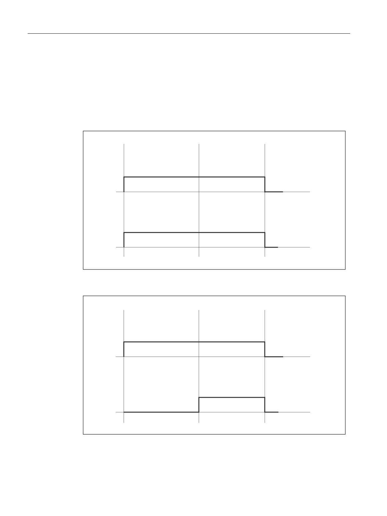
Example 1: Manual traversing using handwheel with distance input, the stop condition is no criterion
for cancellation
If, for manual traversing using a handwheel with distance input
(MD11346 $MN_HANDWH_TRUE_DISTANCE == 1 or == 3), an active stop condition is not
a criterion for cancellation (see MD32084 $MA_HANDWH_STOP_COND or
MD20624 $MC_HANDWH_CHAN_STOP_COND); then, the output of NC/PLC interface
signals "Travel request" and "Travel command" corresponds to the behavior shown in the
following diagrams.
$[LV VKRXOG
2YHUULGH VWRS
$[LV UHDFKHV
WUDYHUVH ZLWK
FRQGLWLRQ
HQG SRLQW
SHQGLQJ VWRS
FRQGLWLRQ
7UDYHO UHTXHVW VLJQDO
0RWLRQ FRPPDQG VLJQDO
Figure 4-1
Signal-time diagram:Manual traversing using the handwheel with distance input, stop
condition is not a cancellation criterionMD17900 $MN_VDI_FUNCTION_MASK bit 0 = 0
$[LV VKRXOG
2YHUULGH VWRS
$[LV UHDFKHV
WUDYHUVH ZLWK
FRQGLWLRQ
HQG SRLQW
SHQGLQJ VWRS
FRQGLWLRQ
7UDYHO UHTXHVW VLJQDO
0RWLRQ FRPPDQG VLJQDO
Figure 4-2
Signal-time diagram:Manual traversing using the handwheel with distance input, stop
condition is not a cancellation criterionMD17900 $MN_VDI_FUNCTION_MASK bit 0 = 1
Extended Functions
174
Function Manual, 12/2018, A5E40874029B AB
H1: Manual traversing
4.6 Manual traversing using a handwheel
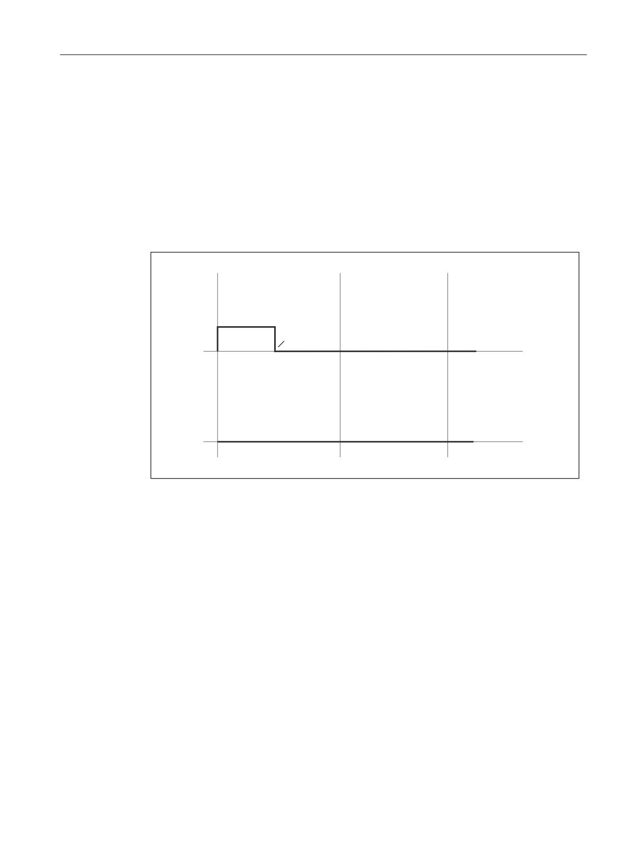
Example 2: Manual traversing using a handwheel, stop condition is a cancellation criterion
If a stop condition is selected as cancellation criterion via machine data
MD32084 $MA_HANDWH_STOP_COND or
MD20624 $MC_HANDWH_CHAN_STOP_COND during manual traversing using a
handwheel, no travel command is output, but the corresponding travel request is output.
When the stop condition is removed, the corresponding "Travel request" NC/PLC interface
signal is reset, as an abort is present. The stop condition is no longer active, but the axis cannot
be traversed as the stop condition has caused an abort.
In addition, either the distance specification (MD11346 $MN_HANDWH_TRUE_DISTANCE
== 1 or == 3) is active or the handwheel is moved continuously, i.e. it provides pulses.
$[LV VKRXOG WUDYHUVH
2YHUULGH VWRS FRQGLWLRQ
$[LV UHDFKHV HQG
ZLWK SHQGLQJ VWRS
SRLQW
FRQGLWLRQ
+DQGZKHHO
VWRSSHG
7UDYHO UHTXHVW VLJQDO
0RWLRQ FRPPDQG VLJQDO
Figure 4-3
Signal-time diagram:Manual traversing using a handwheel, stop condition is a cancellation
criterion
If a stop condition is activated during the handwheel travel, the motion is aborted and the
"Travel request" and "Travel command" NC/PLC interface signals are reset.
Example 3: Manual traversing using a handwheel with velocity setpoint, stop condition is a cancellation
criterion
If the handwheel is no longer moved for velocity specification
(MD11346 $MN_HANDWH_TRUE_DISTANCE == 0 or == 2), the "Travel request" NC/PLC
interface signal is reset.
The "Travel request" PLC signal is also reset when the handwheel is deselected.
Extended Functions
Function Manual, 12/2018, A5E40874029B AB
175
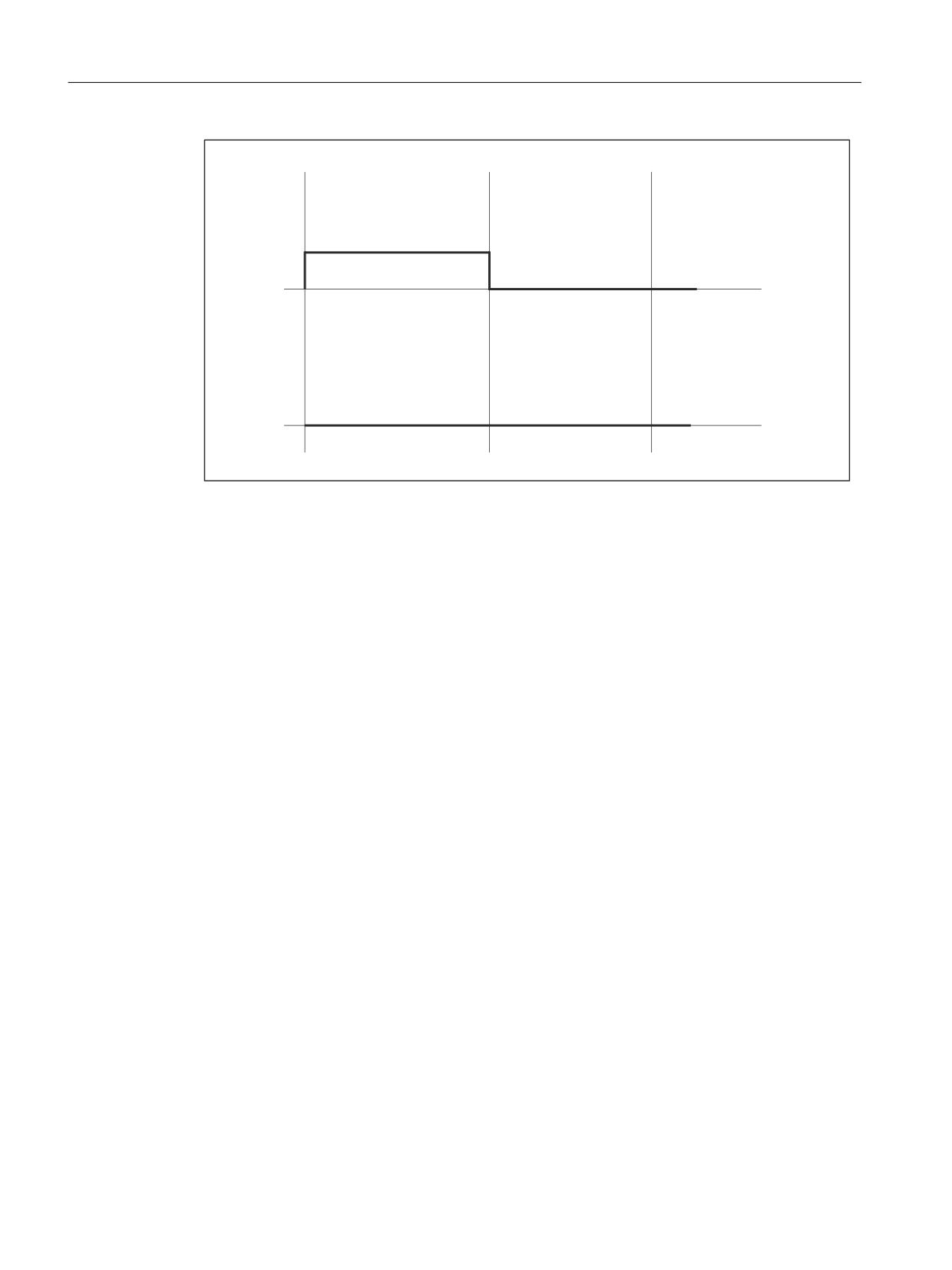
H1: Manual traversing
4.7 Manual traversing of the spindle
$[LV VKRXOG
2YHUULGH VWRS
$[LV UHDFKHV
WUDYHUVH ZLWK
FRQGLWLRQ
HQG SRLQW
SHQGLQJ VWRS
FRQGLWLRQ
7UDYHO UHTXHVW VLJQDO
0RWLRQ FRPPDQG VLJQDO
Figure 4-4
Signal-time diagram:Manual traversing using a handwheel with velocity setpoint, stop
condition is a cancellation criterion
Supplementary conditions
NC stop
With NC stop present, no travel command and, therefore, no travel request is output. There is
an exception with DRF travel: If DRF travel is permitted in the NC stop state via machine data
MD20624 $MC_HANDWH_CHAN_STOP_COND (bit 13 == 1), the behavior corresponds to
that of manual traversing using a handwheel.
4.7
Manual traversing of the spindle
Spindle mode
Manual traversing of the spindle is possible both in positioning mode (spindle is in position
control) and in open-loop control mode.
Velocity
The velocity applied for the manual traversing of the spindles is defined by the general setting
data:
SD41200 $SN_JOG_SPIND_SET_VELO (speed of spindle in JOG mode)
If "0" is entered in SD41200, the axis-specific machine data takes effect:
MD32020 $_MA_JOG_VELO (conventional axis velocity)
The maximum speeds of the active gear stage are also considered when manually traversing
a spindle.
Extended Functions
176
Function Manual, 12/2018, A5E40874029B AB
H1: Manual traversing
4.7 Manual traversing of the spindle
References:
Function Manual Basic Functions; Spindles (S1)
Spindle override
The velocity during manual traversing of the spindle can be influenced by the spindle override
switch.
Acceleration
As a spindle often uses many gear stages in speed-control and position-control modes, the
acceleration associated with the current gear stage is always applied to the spindle in JOG
mode.
References:
Function Manual Basic Functions; Spindles (S1)
Interface signals
When manually traversing the spindles, the interface signals between NC and PLC have the
same effect as for the machine axes.
The interface signals DB31, ... DBX60.7 or DBX60.6 (position reached with fine or coarse exact
stop) are only set if the spindle is in position control.
Spindle-specific interface signals
In JOG mode, the following interface signals to the spindle have no effect:
● DB31, ... DBX17.6 (invert M3/M4)
● DB31, ... DBX18.6 - 7 (oscillation rotation direction, right/left)
● DB31, ... DBX18.5 (oscillation enable)
● DB31, ... DBX16.7 (delete S value)
In JOG mode, the following interface signals from the spindle are not set:
● DB31, ... DBX83.7 (clockwise actual direction of rotation)
● DB31, ... DBX83.5 (spindle in set range)
Extended Functions
Function Manual, 12/2018, A5E40874029B AB
177
H1: Manual traversing
4.8 Manual traversing of geometry axes/orientation axes
4.8
Manual traversing of geometry axes/orientation axes
Note
Transformation package, handling
In the JOG mode, using the "Handling transformation package" for SINUMERIK 840D sl, the
translation of geometry axes in several valid references systems can be set separately from
one another.
Reference:
Function Manual, Special Functions; TE4: Transformation package, handling
See also Chapter "Cartesian manual traversing (option) (Page 502)".
Simultaneous travel
Only one geometry axis can be traversed continuously or incrementally at one time using the
traversing keys. Where an attempt is made to traverse more than one geometry axis, alarm
20062 "Axis already active" is output. However, three geometry axes can be traversed
simultaneously using handwheels 1 to 3.
Transverse axis
If a geometry axis is defined as transverse axis (see MD20100 $MC_DIAMETER_AX_DEF)
and radius programming has been selected, the following applies:
● Continuous travel:
There are no differences when a transverse axis is traversed continuously.
● Incremental travel:
Only half the distance of the selected increment size is traversed. For example, with INC10
the axis only traverses 5 increments when the traversing key is pressed.
● Traversing with the handwheel:
As for incremental travel, with the handwheel only half the distance is traversed per
handwheel pulse.
References:
Function Manual Basic Functions; Transverse Axes (P1)
PLC interface
For geometry axes/orientation axes, there is a separate PLC interface that contains the same
signals as the axis-specific PLC interface:
● Geometry axes:
DB21, ... DBB12 - 23 and
DB21, ... DBB40 - 56
● Orientation axes:
DB21, ... DBB320 - 331 and
DB21, ... DBB332 - 343
Extended Functions
178
Function Manual, 12/2018, A5E40874029B AB
H1: Manual traversing
4.8 Manual traversing of geometry axes/orientation axes
Velocity
● Geometry axes
The velocity applied for the manual traversing of geometry axes is defined by the channel-
specific machine data:
MD21165 $MC_JOG_VELO_GEO (conventional velocity for geometry axes)
● Orientation axes
The velocity applied for the manual traversing of orientation axes is defined by the channel-
specific machine data:
MD21155 $MC_JOG_VELO_ORI (conventional velocity for orientation axes)
Rapid traverse override
If the traversing keys/manual wheel are also actuated together with the rapid traverse override
key, the movement will be made with the configured rapid traverse velocity:
● Geometry axes
- MD21160 $MC_JOG_VELO_RAPID_GEO (conventional rapid traverse for geometry
axes)
● Orientation axes
- MD21150 $MC_JOG_VELO_RAPID_ORI (conventional rapid traverse for orientation
axes)
Feedrate override
The channel-specific feedrate override switch is active when manually traversing geometry
axes.
Acceleration and jerk
For the manual traversing of geometry axes/orientation axes, the acceleration and jerk can be
limited for specific channels. This enables better handling of the kinematics that generate
Cartesian motions entirely via rotary axes (robots).
Geometry axes
The maximum acceleration when manually traversing geometry axes can be specified for each
channel via the machine data:
MD21166 $MC_JOG_ACCEL_GEO [<geometry axis>]
With <geometry axis> = 0, 1, 2
The maximum jerk when manually traversing geometry axes in the SOFT acceleration mode
(acceleration with jerk limitation) can be specified for each channel via the machine data:
MD21168 $MC_JOG_JERK_GEO [<geometry axis>]
With <geometry axis> = 0, 1, 2
Orientation axes
The maximum jerk when manually traversing orientation axes can be specified for each
channel via the machine data:
Extended Functions
Function Manual, 12/2018, A5E40874029B AB
179
H1: Manual traversing
4.9 Approaching a fixed point in JOG
MD21158 $MC_JOG_JERK_ORI [<orientation axis>]
For MD21158 to take effect, the channel-specific jerk limitation for the manual traversing of
orientation axes must be enabled via the following machine data:
MD21159 $MC_JOG_JERK_ORI_ENABLE == TRUE
Alarms
Alarm 20060
If the axis is not defined as a geometry axis, alarm 20060, "Axis cannot be traversed as a
geometry axis", is output if you attempt to manually traverse it as a geometry axis in JOG mode.
Alarm 20062
Alarm 20062, "Axis already active", is triggered in the case that a geometry axis/orientation
axis is manually traversed under the following conditions:
● The axis is already being traversed in JOG mode via the axial PLC interface.
● A frame for a rotated coordinate system is already active and another geometry axis in this
coordinate system is traversed in JOG mode with the traversing keys.
4.9
Approaching a fixed point in JOG
4.9.1
Function
The machine user can use the "Approaching fixed point in JOG" function to approach axis
positions defined through machine data by actuating the traverse keys of the machine control
panel. The traveling axis comes to a standstill automatically on reaching the defined fixed point.
Note
Approaching a fixed point with G75
The process for approaching defined fixed points can also be activated from the part program
using the G75 command.
For more information on fixed point approach with G75 please refer to:
References:
Programming Manual, Fundamentals; Section: "Additional commands" > "Approach fixed point
(G75)".
Applications
Typical applications are, for example:
● Approaching a basic position before starting an NC program.
● Travel towards tool change points, loading points and pallet change points.
Extended Functions
180
Function Manual, 12/2018, A5E40874029B AB
H1: Manual traversing
4.9 Approaching a fixed point in JOG
Requirements
● The "Approaching fixed point in JOG" can be activated only in the JOG mode.
The function cannot be activated if the machine function JOG-REPOS or JOG-REF is active
and in JOG in AUTOMATIC.
● The axis to be traversed must be referenced.
● A kinematic transformation may not be active.
● The axis to be traversed may not be a following axis of an active coupling.
Procedure
Procedure in "Approaching fixed point in JOG"
1. Selection of JOG mode
2. Enabling the "Approach fixed point in JOG" function
3. Traversing of the machine axis with traverse keys or handwheel
Activation
After selecting the "Approach fixed point in JOG" function, the PLC outputs the number of the
fixed point to be approached binary coded to the NC using the following bits:
DB31, ... DBX13.0 - 2 (JOG approach fixed point)
The NC confirms the activation with the interface signal as soon as the function is effective:
DB31, ... DBX75.0 - 2 (JOG approach fixed point active)
Note
Activation is not possible:
● during an NC reset
● In case of impending emergency stop
● During processing of an ASUP
No alarm message occurs. Delayed activation takes place after closure or after
acknowledgement of the active function.
Sequence
The actual traversing is started with the traverse keys or the handwheel in the direction of the
approaching fixed point.
The selected machine axis traverses till it comes to an automatic standstill at the fixed point.
The corresponding NC/PLC interface signal is reported on reaching the fixed point with "Exact
stop fine":
DB31, ... DBX75.3 - 5 (JOG approach fixed point reached)
This display signal is also signaled if the axis reaches the fixed point position in the machine
coordinates system via other methods e.g. NC program, FC18 (for 840D sl) or synchronized
Extended Functions
Function Manual, 12/2018, A5E40874029B AB
181
H1: Manual traversing
4.9 Approaching a fixed point in JOG
action on the setpoint side and comes to a standstill on the actual value side within the "Exact
stop fine" tolerance window (MD36010 $MA_STOP_LIMIT_FINE).
Movement in the opposite direction
The response while traversing in the opposite direction, i.e. against the direction of the
approaching fixed point, depends on the setting of Bit 2 in the machine data:
MD10735 $MN_JOG_MODE_MASK (settings for the JOG mode)
Traverse in the opposite direction is possible only if the bit is set.
Traverse in the opposite direction is blocked if the bit is not set and the following channel status
message is output if an attempt is made with the traverse keys or with the handwheel to
traverse in the direction opposite the approaching fixed point:
"JOG: Direction blocked <axis>"
Approaching other fixed point
The axis motion is cancelled and the following alarm is output if a different fixed point is selected
while traversing to the fixed point:
Alarm 17812 "Channel %1 Axis %2 fixed point approach in JOG: Fixed point changed"
The message signal DB31, ... DBX75.0 - 2 (JOG - Approaching fixed point active) displays the
number of the newly selected fixed point. The JOG traverse must be triggered again to continue
traversing.
Note
To avoid the alarm message, the machine user should proceed as follows:
1. Cancel the current traverse movement with residual distance deletion.
2. Activate fixed point approach for another fixed point and start the operation after the axis
comes to a standstill.
Withdrawal from fixed point / deactivation
To withdraw from a fixed position, you must deactivate the "Approaching fixed point in JOG"
function. This is done by resetting the activation signal to "0".
DB31, ... DBX13.0 - 2 = 0
The message signals DB31, ... DBX75.0 - 2 (JOG - Approaching fixed point active) and
DB31, ... DBX75.3 - 5 (JOG - Approaching fixed point reached) are deleted on leaving the
fixed point position.
Special case: Axis is already on fixed point
The axis cannot be moved if, while starting the fixed point traverse, the axis is already at the
position of the fixed point to be approached. This is displayed through the following channel
status message:
Extended Functions
182
Function Manual, 12/2018, A5E40874029B AB

H1: Manual traversing
4.9 Approaching a fixed point in JOG
"JOG: position reached <axis>"
To withdraw from the fixed position, you must deactivate the "Approaching fixed point in JOG"
function.
Special features of incremental travel
If, during incremental travel, the fixed point is reached before the increment is completed, then
the increment is considered to have been completed fully. This is the case even when only
whole increments are traveled.
MD11346 $MN_HANDWH_TRUE_DISTANCE = 2 or 3
Special features of modulo rotary axes
Modulo rotary axes can approach the fixed point in both directions. The shortest path (DC) is
not observed during the travel.
Features of spindles
A spindle changes to the positioning mode on actuating the "Approaching fixed point in JOG"
function. The closed loop position control is active and the axis can traverse to the fixed point.
If no zero mark is detected the alarm message in the axis operation is output:
Alarm 17810 "Channel %1 Axis %2 not referenced"
As a spindle must also be a modulo rotary axis at all times, the same conditions apply for
direction observation as for modulo rotary axes (refer to the paragraph "Features of modulo
rotary axes")
4.9.2
Parameterization
Movement in the opposite direction
The behavior while traversing in the opposite direction - i.e. in the direction opposite to
approaching the fixed point - depends on the following setting:
MD10735 $MN_JOG_MODE_MASK, bit 2 (settings for the JOG mode)
Bit
Value
Meaning
2
0
Travel in the opposite direction is not possible (basic setting).
1
Movement in the opposite direction is possible.
Fixed point positions
Up to four fixed point positions can be defined for an axis:
MD30600 $MA_FIX_POINT_POS[0...3] = <fixed point position 1...4>
Extended Functions
Function Manual, 12/2018, A5E40874029B AB
183
H1: Manual traversing
4.9 Approaching a fixed point in JOG
Number of valid fixed point positions
The number of fixed point positions entered in MD30600 $MA_FIX_POINT_POS that are
actually valid, can be defined using:
MD30610 $MA_NUM_FIX_POINT_POS = <number of valid fixed point positions>
Note
Exception: G75
For compatibility reasons, the following parameter assignment is also possible for G75:
MD30610 $MA_NUM_FIX_POINT_POS = 0 (no valid fixed point positions)
it is assumed that there are two valid fixed point positions in MD30600
$MA_FIX_POINT_POS[0] and [1].
Fixed point positions 1 and 2 can be activated via the NC/PLC interface, however they can
only be approached via G75.
Extended Functions
184
Function Manual, 12/2018, A5E40874029B AB

H1: Manual traversing
4.9 Approaching a fixed point in JOG
Axis dynamics
The axis-specific acceleration and the axis-specific jerk for "Approaching fixed point in JOG"
are determined by the following machine data:
● When traversing with traverse keys or handwheel:
- MD32300 $MA_MAX_AX_ACCEL [0] (maximum axis-specific acceleration for path
motions in the dynamic response mode DYNNORM)
- MD32430 $MA_JOG_AND_POS_MAX_JERK (maximum axis-specific jerk)
Note
MD32430 $MA_JOG_AND_POS_MAX_JERK is only effective when the axis-specific
jerk limitation for single-axis movements has been enabled for the machine axes to be
traversed:
MD32420 $MA_JOG_AND_POS_JERK_ENABLE [<axis>] == TRUE
● During traversing via the G75 part program command:
- MD32300 $MA_MAX_AX_ACCEL [0/1] (maximum axis-specific acceleration for path
motions in the dynamic response mode DYNNORM/DYNPOS)
Note
The type of positioning axis dynamics (DYNNORM or DYNPOS) is defined by the
machine data:
MD18960 $MN_POS_DYN_MODE = <mode>
- MD32431 $MA_MAX_AX_JERK [0] (maximum axis-specific jerk for path motions in the
dynamic response mode DYNNORM)
Note
MD32431 $MA_MAX_AX_JERK is only effective when the axis-specific jerk limitation
for single-axis movements has been enabled for the machine axes to be traversed:
MD32420 $MA_JOG_AND_POS_JERK_ENABLE [<axis>] == TRUE
Reference:
Function Manual, Basic Functions; Acceleration (B2)
Extended Functions
Function Manual, 12/2018, A5E40874029B AB
185

H1: Manual traversing
4.9 Approaching a fixed point in JOG
4.9.3
Programming
System variables
The following system variables that can be read in the part program and in the synchronous
actions for the "Approach fixed point" function.
System variable
Description
$AA_FIX_POINT_SELECTED [<Axis>]
Number of fixed point to be approached
$AA_FIX_POINT_ACT [<Axis>]
Number of the fixed point on which the axis is cur-
rently located
4.9.4
Supplementary Conditions
Axis is indexing axis
The axis is not traversed and an alarm is output if the axis to be traversed is an indexing axis
and the fixed point position to be approached does not match an indexing position.
Frames active
All active frames are ignored. Traversing is performed in the machine coordinate system.
Offset values active
Active offset values (DRF, external zero offset, synchronized action offset $AA_OFF, online
tool offset) are also traversed. The fixed point is a position in the machine coordinates system.
An alarm is issued if an offset movement (DRF, external zero offset, synchronized action offset
$AA_OFF, online tool offset) is made during a fixed point approach in JOG. The position of
the fixed point to be approached in the machine coordinates system is not reached; instead a
position that would have been reached without active offset movement is reached. The NC/
PLC interface signal DB31, ... DBX75.3-5 corresponding to the fixed point is not output.
Working-area limitations
Working-area limitations (in BCS and WCS) are considered and the axis motion is stopped on
reaching the limits.
Extended Functions
186
Function Manual, 12/2018, A5E40874029B AB
H1: Manual traversing
4.9 Approaching a fixed point in JOG
4.9.5
Application example
Target
A rotary axis (machine axis 4 [AX4]) is to be moved to fixed point 2 (90 degrees) with the
"Approaching fixed point in JOG" function.
Parameter assignment
The machine data for the "Approaching fixed point" function of machine axis 4 are
parameterized as follows:
MD30610 $MA_NUM_FIX_POINT_POS[AX4] = 4
4 fixed points are defined for machine
axis 4.
MD30600 $MA_FIX_POINT_POS[0,AX4] = 0
1. Fixed point of AX4 = 0 degrees
MD30600 $MA_FIX_POINT_POS[1,AX4] = 90
2. Fixed point of AX4 = 90 degrees
MD30600 $MA_FIX_POINT_POS[2,AX4] = 180
3. Fixed point of AX4 = 180 degrees
MD30600 $MA_FIX_POINT_POS[3,AX4] = 270
4. Fixed point of AX4 = 270 degrees
Initial situation
Machine axis 4 is referenced and is at position of 0 degrees. This corresponds to the 1st fixed
position and is output through the NC/PLC interface signal:
DB31 DBX75.0 = 1 (bit 0 - 2 = 1)
Approaching fixed point 2
The control is switched into the JOG mode.
The "Approaching fixed point" function is activated at fixed point 2 via the NC/PLC interface
signal:
DB31 DBX13.1 = 1 (bit 0 - 2 = 2)
The actuation is confirmed via the NC/PLC interface signal:
DB31 DB75.1 = 1 (bit 0 - 2 = 2)
The plus travel key on the machine control panel is used to travel continuously to approach
fixed point 2.
The machine axis 4 stops at the 90 degree position. This is signaled via the NC/PLC interface
signal:
DB31 DBX75.4 = 1 (bit 3 - 5 = 2)
Extended Functions
Function Manual, 12/2018, A5E40874029B AB
187
H1: Manual traversing
4.10 Position travel in JOG
4.10
Position travel in JOG
4.10.1
Function
The "Position travel in JOG" function allows the machine operator to specify, via the setting
data, a position in the machine coordinate system, to which the selected machine axis can be
traversed using the traverse keys or the handwheel.
Applications
The function is used for machine tools that are exclusively operated manually, e.g. to approach
drill-holes in precise increments.
Preconditions
● The "Position travel in JOG" function can be activated only in the JOG mode.
The function cannot be activated if the machine function JOG-REPOS or JOG-REF is active
and in JOG in AUTOMATIC.
● The axis to be traversed must be referenced.
● A kinematic transformation may not be active.
● The axis to be traversed may not be a following axis of an active coupling.
Procedure
Procedure for position travel in JOG:
1. Selection of JOG mode
2. Specification of the position to be approached
3. Enabling the "Position travel in JOG" function
4. Traversing of the machine axis with traverse keys or handwheel
Specification of the position to be approached
The position to be approached is entered in the setting data:
SD43320 $SA_JOG_POSITION (JOG position)
Activating the function
The PLC sets the interface signal after the "Position travel in JOG" function has been selected:
DB31, ... DBX13.3 (JOG travel to position)
The NC confirms the activation with the interface signal as soon as the function is effective:
Extended Functions
188
Function Manual, 12/2018, A5E40874029B AB
H1: Manual traversing
4.10 Position travel in JOG
DB31, ... DBX75.6 (JOG JOG travel to position active)
Note
Activation is not possible:
● during an NC reset
● In case of impending emergency stop
● During processing of an ASUP
● if the "approaching fixed point JOG" function is already activated
No alarm message occurs. Delayed activation takes place after closure or after
acknowledgement of the active function.
Sequence
Approaching the position is started with the traverse keys or the handwheel.
The axis traverses until it comes to an automatic standstill at the position to be approached.
When the position is reached with "Exact stop fine", the following NC/PLC interface signal is
output:
DB31, ... DBX75.7 (JOG position reached)
Approach a different position
If the content of the setting data SD43320 is changed while approaching a position, then the
axis movement is canceled and the following alarm is output:
Alarm 17822 "Channel %1 Axis %2 jogging to position: position changed"
The JOG traverse must be triggered again to approach the new position.
Note
To avoid the alarm message, the machine user should proceed as follows:
1. Cancel the current traverse movement with residual distance deletion.
2. Enter a new position in SD43320 after axis has come to a standstill.
3. Restart the JOG motion.
Retraction from the position/deactivation
To retract from the position, the function "Position travel in JOG" must be deactivated. This is
done by resetting the activation signal to "0".
DB31, ... DBX13.3 = 0
The deactivation also resets the message signals DB31, ... DBX75.6 and DB31, ... DBX75.7.
Extended Functions
Function Manual, 12/2018, A5E40874029B AB
189
H1: Manual traversing
4.10 Position travel in JOG
Retraction in the opposite direction
The behavior when retracting from the position in the opposite direction depends on the setting
of bit 2 in the machine data:
MD10735 $MN_JOG_MODE_MASK (settings for the JOG mode)
Retraction in the opposite direction is possible only if the bit is set.
If the bit is not set, retraction in the opposite direction is blocked, and the following channel
status message is output if an attempt is made with the traverse keys or with the handwheel
to exit the approached position in the opposite direction:
"JOG: Direction blocked <axis>"
Special case: axis is already at position
The axis cannot be traversed if the axis is already at the position to be approached when
starting the JOG motion. This is displayed through the following channel status message:
"JOG: position reached <axis>"
To retract, the function "Position travel in JOG" must be deactivated.
Special features of incremental travel
If, during incremental travel, the position is reached before the increment is completed, then
the increment is considered to have been completed fully. This is the case even when only
whole increments are traveled.
MD11346 $MN_HANDWH_TRUE_DISTANCE = 2 or 3
Special features of modulo rotary axes
Modulo rotary axes can approach the position in both directions. The shortest path (DC) is not
observed during the travel.
Features of spindles
A spindle changes to the positioning mode on actuating the "Position travel in JOG" function.
The closed loop position control is active and the axis can be traversed to the position.
If no zero mark is detected the alarm message in the axis operation is output:
Alarm 17810 "Channel %1 Axis %2 not referenced"
As a spindle must also be a modulo rotary axis at all times, the same conditions apply for
direction observation as for modulo rotary axes (refer to the paragraph "Features of modulo
rotary axes")
See also
Parameter setting (Page 191)
Extended Functions
190
Function Manual, 12/2018, A5E40874029B AB

H1: Manual traversing
4.10 Position travel in JOG
4.10.2
Parameter setting
Consideration of axial frames and tool length compensation
The consideration of axial frames and, if an axis is configured as geometry axis, the tool length
compensation, depends on the setting of bit 1 in the machine data:
MD10735 $MN_JOG_MODE_MASK (settings for the JOG mode)
Bit
Value
Meaning
1
0
Axial frames and tool length compensation are not considered.
1
Axial frames and tool length compensation are considered.
Retraction in the opposite direction
The behavior when retracting from a position in the opposite direction depends on the setting
of bit 2 in the machine data:
MD10735 $MN_JOG_MODE_MASK (settings for the JOG mode)
Bit
Value
Meaning
2
0
Retraction in the opposite direction is not possible (default setting).
1
Retraction in the opposite direction is possible.
Position to be approached
The position to be approached is entered in the setting data:
SD43320 $SA_JOG_POSITION (JOG position)
4.10.3
Supplementary Conditions
Axis is indexing axis
The axis is not traversed and an alarm is output if the axis to be traversed is an indexing axis
and the position to be approached does not match an indexing position.
Frames active
All active frames are ignored. Traversing is performed in the machine coordinate system.
Correction values active
Active correction values (DRF, external zero offset, synchronized action offset $AA_OFF,
online tool offset) are also traversed.
An alarm is issued if an offset movement (DRF, external zero offset, synchronized action offset
$AA_OFF, online tool offset) is made during the approach of a variable position in JOG. The
Extended Functions
Function Manual, 12/2018, A5E40874029B AB
191
H1: Manual traversing
4.10 Position travel in JOG
position to be approached in the machine coordinate system is not reached; instead a position
that would have been reached without active offset movement is reached. The NC/PLC
interface signal DB31, ... DBX75.7 is not reported.
Working area limits
Working-area limitations (in BCS and WCS) are considered and the axis motion is stopped on
reaching the limits.
4.10.4
Application example
Objective
A rotary axis (machine axis 4 [AX4]) is to be moved to Position 100 degrees with the "Position
travel in JOG" function.
Parameter assignment
The position to be approached is specified via the user interface as follows:
SD43320 $SA_JOG_POSITION[AX4] = 100; position to be approached for machine axis 4 =
100
Initial situation
Axis 4 [AX4] is referred and is at Position 0 degree.
Approaching the position
The control is switched to JOG mode and machine axis 4 is selected.
The function "Position travel in JOG" is activated:
DB34 DBX13.3 = 1
The NC confirms the activation as soon as the function is effective:
DB34 DBX75.6 = 1
Approaching the position is started via continuous traversing and the JOG traverse key Plus
of the machine control panel.
The axis traverses until it comes to an automatic standstill at the position 100 degrees.
When the position is reached with "Exact stop fine", the following NC/PLC interface signal is
set:
DB34 DB75.7 = 1
Extended Functions
192
Function Manual, 12/2018, A5E40874029B AB

H1: Manual traversing
4.11 Circular travel in JOG
4.11
Circular travel in JOG
4.11.1
Function
With the "Circular travel in JOG" function, the machine operator can simultaneously traverse
the two geometry axes of the active plane along an arc using the traverse keys or handwheel.
Applications
This function is used for machine tools that are exclusively operated manually.
Preconditions
● The "Circular travel in JOG" function can be activated only in the JOG mode.
The function cannot be activated if the machine functions JOG-REPOS and JOG-REF are
active.
● The axes that participate in traversing must be homed.
● The active plane must not be inclined.
Procedure
Procedure for circular travel in JOG:
1. Plane selection
2. Selection of JOG mode
3. Specification of circle parameters
4. Activation of the function "Circular travel in JOG"
5. Traversing of the geometry axes with traverse keys or handwheel
Plane selection
The geometry axes of the active plane are selected by programming one of the following G
commands:
G command
1st geometry axis of the plane
2nd geometry axis of the plane
G17
X
Y
G18
Z
X
G19
Y
Z
Extended Functions
Function Manual, 12/2018, A5E40874029B AB
193
H1: Manual traversing
4.11 Circular travel in JOG
Specification of circle parameters
At least the following data is required for circular travel in JOG:
● Coordinates of the circle center point
● The maximum circle radius for internal machining or minimum circle radius for external
machining
● Machining mode (internal or external machining)
The specifications are made via the user interface in the channel-specific setting data:
SD42690 $SC_JOG_CIRCLE_CENTRE (circle center point)
SD42691 $SC_JOG_CIRCLE_RADIUS (circle radius)
SD42692 $SC_JOG_CIRCLE_MODE (jog circle mode)
For details, see Chapter "Parameter setting (Page 199)".
Activating the function
The PLC sets the interface signal after the "Circular travel in JOG" function has been selected:
DB21, ... DBX30.6 (JOG circular travel)
The NC confirms the activation with the interface signal as soon as the function is effective:
DB21, ... DBX377.6 (JOG circular travel active)
Note
Activation is not possible:
● during an NC reset
● In case of impending emergency stop
● During processing of an ASUP
● If at least one of the participating axes is already being traversed
● If PTP travel is active
● During active Cartesian manual traversing with generic transformation
No alarm message occurs. Delayed activation takes place after closure or after
acknowledgement of the active function.
Sequence
After activating the function, the tool can be traversed by means of a continuous or incremental
JOG motion using traverse keys or a handwheel:
● For a JOG movement request for the 1st geometry axis of the active plane, traversing is
done from the current position via a concentric arc with the same center point as for the
defined arc.
● For a JOG movement request for the 2nd geometry axis of the active plane, traversing is
done perpendicular to the defined arc. As a result, the circle radius changes.
Extended Functions
194
Function Manual, 12/2018, A5E40874029B AB

H1: Manual traversing
4.11 Circular travel in JOG
● Only one movement at a time can be carried out in the active plane: either on the arc or
perpendicular to it.
● Regardless of the movements in the active plane, the 3rd geometry axis can be traversed
perpendicular to the active plane.
Note
The radius can only be reduced to zero, i.e. to the center point of the circle. If the radius is then
enlarged again, traversing occurs back in the direction from where the reducing started.
Note
If the current position is the center point of the circle when the function is activated or after a
change to the center point of the circle, then the following applies:
● For a full circle, traversing takes place in the direction of the 2nd geometry axes.
● For a segment of a circle, travel is in the direction of the angle bisector.
Internal or external machining
Depending on the specification in the setting data SD42692 $SC_JOG_CIRCLE_MODE,
internal or external machining takes place:
● Internal machining
- Traversing is only possible within the defined circle.
- The circle radius in SD42691 $SA_CIRCLE_RADIUS is the maximum radius.
● External machining
- Traversing is only possible outside of the defined circle.
- The circle radius in SD42691 $SA_CIRCLE_RADIUS is the minimum radius.
Extended Functions
Function Manual, 12/2018, A5E40874029B AB
195
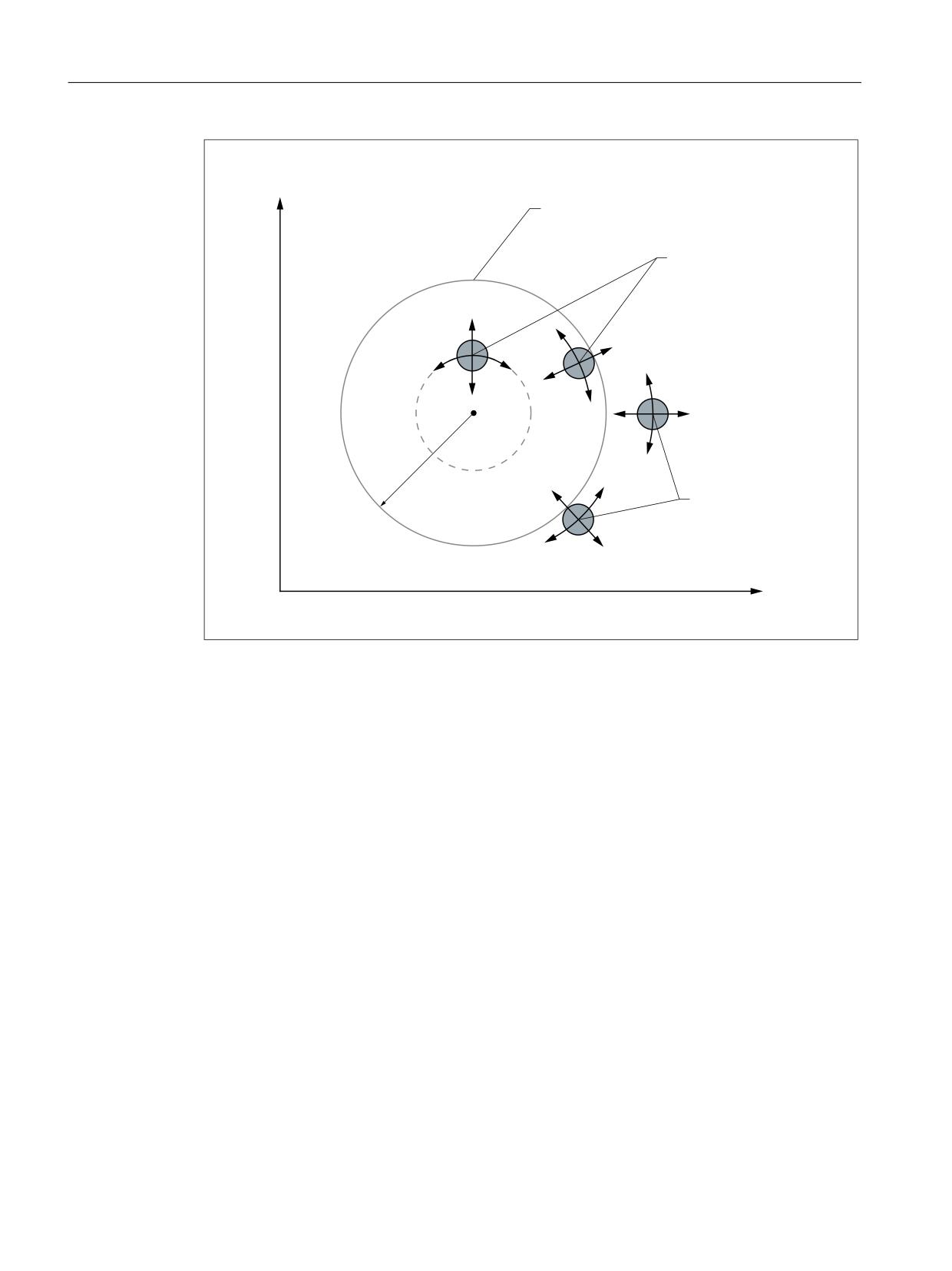
H1: Manual traversing
4.11 Circular travel in JOG
*HRPHWU\ D[LV
RI DFWLYH SODQH
'HILQHG FLUFXODU DUF
,QWHUQDO PDFKLQLQJ
6'
%LW
&HQWHU RI FLUFOH
6'
&LUFOH UDGLXV
([WHUQDO PDFKLQLQJ
6'
6'
%LW
*HRPHWU\ D[LV RI DFWLYH SODQH
Figure 4-5
Circular travel in JOG: Internal/external machining
Circle segment machining
By specifying a start and end angle, the working area for the 1st and 2nd geometry axis can
be limited to a circle segment:
SD42693 $SC_JOG_CIRCLE_START_ANGLE (circle start angle)
SD42694 $SC_JOG_CIRCLE_END_ANGLE (circle end angle)
Furthermore, the direction from the start to the end angle must be specified to permit the unique
definition of the circle segment:
SD42692 $SC_JOG_CIRCLE_MODE, bit 0
This bit also specifies the traversing direction along the circular path.
Extended Functions
196
Function Manual, 12/2018, A5E40874029B AB
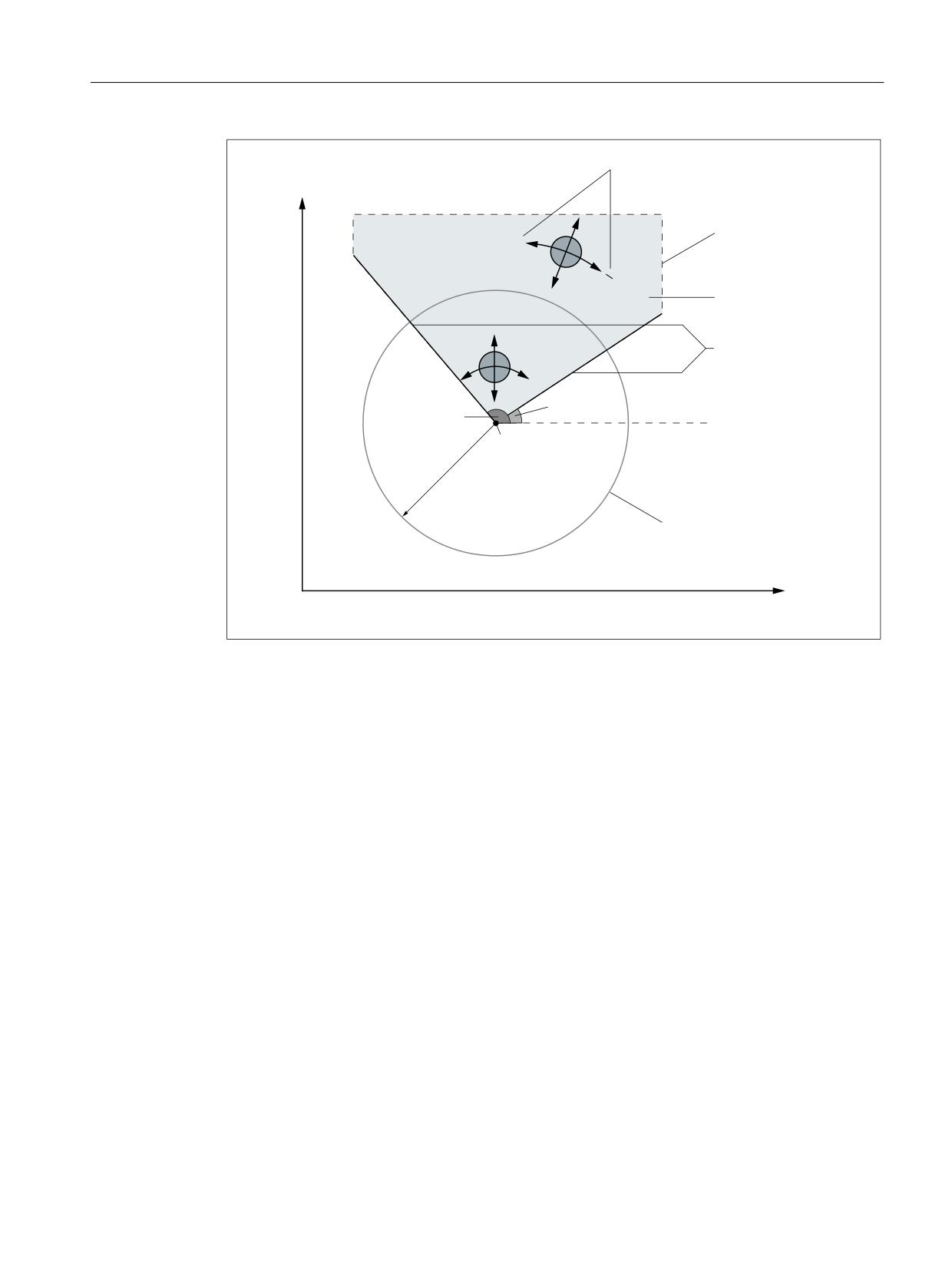
H1: Manual traversing
4.11 Circular travel in JOG
*HRPHWU\ D[LV
7UDYHUVLQJ GLUHFWLRQ 6'
ELW
RI DFWLYH SODQH
FRXQWHUFORFNZLVH
FORFNZLVH
0&6
ZRUNLQJ DUHD
OLPLWDWLRQ
2SHUDWLQJ UDQJH
$QJOH
OLPLWDWLRQV
6WDUW DQJOH 6'
+HUH IRU H[DPSOH
GHJUHHV
(QG DQJOH 6'
GHJUHH
+HUH IRU H[DPSOH
&HQWHU RI FLUFOH
GHJUHHV
&LUFOH UDGLXV
'HILQHG FLUFXODU DUF
*HRPHWU\ D[LV RI DFWLYH SODQH
Figure 4-6
Circular travel in JOG: Circle segment machining
Extended Functions
Function Manual, 12/2018, A5E40874029B AB
197
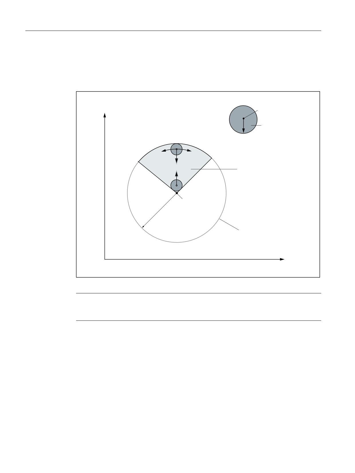
H1: Manual traversing
4.11 Circular travel in JOG
Allowance for tool radius
If bit 1 is set in the setting data SD42692 $SC_JOG_CIRCLE_MODE, then the tool radius is
considered when monitoring the operating range limits (define circular arc; for circle segment
machining also the limits that arise due to the start and end angle):
*HRPHWU\ D[LV
RI DFWLYH SODQH
&XWWLQJ HGJH FHQWHU SRLQW
7RRO UDGLXV
}
2SHUDWLQJ UDQJH
&HQWHU RI FLUFOH
&LUFOH UDGLXV
'HILQHG
FLUFXODU DUF
*HRPHWU\ D[LV RI DFWLYH SODQH
Figure 4-7
Circular travel in JOG: Circle segment internal machining with tool radius compensation
Note
By taking the tool radius into consideration, the smallest possible radius for the internal
machining in the vicinity of the center point of the circle is also limited.
Axis monitoring
If the current axis positions of the engaged axes are outside of the workspace limits when the
function is activated, then the axes are not traversed and an alarm is output.
Axis positions that are outside of the operating range limits are:
● For internal machining: positions outside of the defined circle
● For external machining: positions within the define circle
● For circle segment machining: Positions outside of the limits that result from the start and
end angles (segment borders)
● For active tool radius compensation: Positions too close to limiting circle
Extended Functions
198
Function Manual, 12/2018, A5E40874029B AB

H1: Manual traversing
4.11 Circular travel in JOG
● For active tool radius compensation and internal machining: Positions too close to center
of circle
● For active tool radius compensation and circle segment machining: Positions too close to
segment borders
Changes to the setting data
Changes in the function-relevant setting data SD42690 to SD42694 that are made during an
active JOG motion only take effect after ending the active JOG motion by triggering a new
JOG motion.
Note
To ensure that changes in the setting data take effect more quickly, the machine operator can
proceed as follows:
1. Cancel the current traverse movement with residual distance deletion.
2. Change setting data.
3. Restart the JOG motion.
Abort/deactivation
If during a JOG motion the function "Circular travel in JOG" is deactivated (DB21, ... DBX30.6
= 0), then the JOG motion is canceled and an alarm is output.
Note
To avoid the alarm message, the machine user should proceed as follows:
1. Cancel the current traverse movement with residual distance deletion.
2. Deactivating the function after axis standstill.
4.11.2
Parameter setting
Traversing direction of the second geometry axis
The traversing direction of the second geometry axis can be set via the following machine data:
MD10735 $MN_JOG_MODE_MASK (settings for the JOG mode)
Bit
Value
Meaning
6
0
Traversing of the 2nd geometry axis of the active plane to plus increases the radius,
traversing to minus decreases the radius. The traversing movement is independent of
7
0
whether internal or external machining is active.
Extended Functions
Function Manual, 12/2018, A5E40874029B AB
199
H1: Manual traversing
4.11 Circular travel in JOG
Bit
Value
Meaning
6
0
Traversing of the 2nd geometry axis of the active plane to plus always takes place in
the direction of the limiting circle. I.e. the radius is increased for internal machining and
7
1
decreased for external machining.
Bit
Value
Meaning
6
1
Traversing of the 2nd geometry axis of the active plane to minus always takes place
in the direction of the limiting circle. I.e. the radius is increased for internal machining
7
1
and decreased for external machining.
Coordinates of center of circle as radius value
In basic setting, the specified coordinate of an axis is always a diameter value when diameter
programming is active. This can be changed for specifying the center of circle coordinates for
circular traversing in JOG via the following machine data:
MD20360 $MC_TOOL_PARAMETER_DEF_MASK (definition of the tool parameters)
Bit
Value
Meaning
13
0
For circular travel in JOG, the center of circle coordinate is a diameter value (basic
setting).
1
For circular travel in JOG, the center of circle coordinate is always a radius value.
Center of circle
The center of the circle to be traversed is set in the setting data:
SD42690 $SC_JOG_CIRCLE_CENTRE (circle center point)
The coordinate data refers to the WCS. It can be a diameter or radius value (depending on
the setting in the MD20360 Bit 13).
Only the center point coordinates of the geometry axes of the active plane are evaluated, not
the coordinates of the geometry axis that is perpendicular to the plane.
Circle radius
The radius of the maximum circle for internal machining or of the minimum circle for external
machining is set in the setting data:
SD42691 $SC_JOG_CIRCLE_RADIUS (circle radius)
The radius that is specified refers to the WCS.
Internal or external machining
The machining mode (internal or external machining) is defined in the setting data:
Extended Functions
200
Function Manual, 12/2018, A5E40874029B AB

H1: Manual traversing
4.11 Circular travel in JOG
SD42692 $SC_JOG_CIRCLE_MODE (jog circle mode)
Bit
Value
Meaning
2
0
Internal machining takes place.
The circle radius in SD42691 is the maximum possible radius.
1
External machining takes place.
The circle radius in SD42691 is the minimum possible radius.
Circle segment machining
The start and end angles for defining a circle segment that limits the operating range are set
in the setting data:
SD42693 $SC_JOG_CIRCLE_START_ANGLE (circle start angle)
SD42694 $SC_JOG_CIRCLE_END_ANGLE (circle end angle)
The angle data refers to the abscissa of the active plane.
The direction from the start to the end angle is specified in the setting data:
SD42692 $SC_JOG_CIRCLE_MODE (jog circle mode)
Bit
Value
Meaning
0
0
The direction from the start to the end angle is counterclockwise.
1
The direction from the start to the end angle is clockwise.
Note
If the start and end angle are equal to zero, full circles can be traversed without limitation.
Allowance for tool radius
The consideration of the tool radius can be selected via the following setting data:
SD42692 $SC_JOG_CIRCLE_MODE (jog circle mode)
Bit
Value
Meaning
1
0
When monitoring the operating range limits (define circular arc; for circle segment
machining also the limits that result from the start and end angle), the tool radius is
not considered (basic setting).
1
When monitoring the operating range limits, the tool radius is considered.
Extended Functions
Function Manual, 12/2018, A5E40874029B AB
201
H1: Manual traversing
4.11 Circular travel in JOG
4.11.3
Supplementary Conditions
Diameter programming active
During incremental traversing and handwheel traversing of the geometry axes of the active
plane, traversing always takes place in the radius programming, even if diameter programming
is active for one of the two involved geometry axes.
Axis is not a geometry axis
Both axes of the active plane must be defined as geometry axes:
● Either by configuration of MD20050 $MC_AXCONF_GEOAX_ASSIGN_TAB
● or by programming GEOAX in the part program
If the axes of the active plane are not defined as geometry axes, then the axes are not traversed
and an alarm is output.
Axis is hirth axis
If an axis involved in the circular path is a hirth axis, then the axis is not traversed and an alarm
is output.
Protection zones
Protection zones are not monitored.
4.11.4
Application example
Initial situation
● The geometry axes are configured as follows:
MD20050 $MC_AXCONF_GEOAX_ASSIGN_TAB[0] = 1
1st geo. axis = 1st channel axis
MD20050 $MC_AXCONF_GEOAX_ASSIGN_TAB[1] = 2
2nd geo. axis = 2nd channel axis
MD20050 $MC_AXCONF_GEOAX_ASSIGN_TAB[2] = 3
3rd geo. axis = 3rd channel axis
● G17 is active (basic setting):
- X axis = 1st geometry axis of active plane
- Y axis = 2nd geometry axis of active plane
● The selected tool has a radius correction value of 0.02 mm.
Extended Functions
202
Function Manual, 12/2018, A5E40874029B AB
H1: Manual traversing
4.12 Retraction in the tool direction (JOG retract)
● The current axis positions are:
- X axis: 10
- Y axis: 10
● The axes are homed.
Parameter assignment
SD42690 $SC_JOG_CIRCLE_CENTRE[AX1] = 10Center of circle X axis to position 10 mm
SD42690 $SC_JOG_CIRCLE_CENTRE[AX2] = 20Center of circle Y axis to position 20 mm
SD42691 $SC_JOG_CIRCLE_RADIUS = 20
Circle radius 20 mm
SD42692 $SC_JOG_CIRCLE_MODE = 2
Traversing with the plus key:
traversing the circle counter-clockwise
Consideration of the tool radius compensa-
tion
Internal machining
SD42693 $SC_JOG_CIRCLE_START_ANGLE = 0No start angle active
SD42694 $SC_JOG_CIRCLE_END_ANGLE = 0 No end angle active
Result
Circle inside machining takes place.
With continuous traversing of the X axis using the plus traversing key, a counter-clockwise
(G2) circular movement can be initiated with a radius of 10 mm about the center point of the
circle (10, 20).
With the traversing of the Y axis, the circle radius can be changed between 0.02 and 19.98.
4.12
Retraction in the tool direction (JOG retract)
4.12.1
Overview
Function
The function "Retraction in the tool direction with the machine function JOG retract", called
"JOG retract" in the following, supports the manual tool retraction in the workpiece coordinate
system (WCS) after a program abort through a power off of the control or a channel reset in
the AUTOMATIC or MDI mode.
Extended Functions
Function Manual, 12/2018, A5E40874029B AB
203
H1: Manual traversing
4.12 Retraction in the tool direction (JOG retract)
In particular, the specific features of the following functions are taken into account:
● Tapping with compensating chuck and speed-controlled spindle with encoder (G33)
● Tapping without compensating chuck and position-controlled spindle (G331, G332)
● Machining with tool orientation with swivel cycle CYCLE800 or orientation transformation
Availability
JOG retract can only be selected if one of the following functions was interrupted as a result
of a channel reset or power off:
● Tapping using G33/G331/G332
● Machining using tool type 2xx (drilling tools)
Data to be restored
In order to be able to execute the retraction in the tool direction after a program abort, the
following data which was active in the channel before the program abort, is restored:
● Active tool offset
● Active machining plane
● Active tool carrier
● Active transformation data block with transformation parameters
● Data of the thread group with G33 or G331/G332
● Positions of the axes that are involved in the transformation
If this data is completely available after a program abort, it is restored in the channel when the
JOG retract machine function is selected. In this case, the workpiece coordinate system (WCS)
is aligned by the control in such a way that one of the geometry axes is in the direction of the
tool axis. The tool retraction can then be performed manually by traversing this geometry axis.
Note
Data backup
The specified data itself is not backed up, only the references to this data. If the data is changed
prior to the selection of JOG retract, the function is performed on the basis of the changed data.
Restrictions
Programs that can be started by interrupt signals are not executed in JOG retract.
Extended Functions
204
Function Manual, 12/2018, A5E40874029B AB

H1: Manual traversing
4.12 Retraction in the tool direction (JOG retract)
4.12.2
Parameterization
4.12.2.1
Automatic selection of JOG retract after Power On
After the control has run up (Power On), the channels of a BAG are as standard in the
parameterized default mode:
MD10720 $MN_OPERATING_MODE_DEFAULT[<mode group>] = <default mode>
The following NC-specific machine data can be used to set which operating mode is selected
after the control run up, if there is retraction data in a BAG channel.
MD10721 $MN_OPERATING_MODE_EXTENDED[<mode group>] = <value>
Value
Meaning
0
Selection of the operating mode corresponding to MD10720 $MN_OPERATING_MODE_DE-
FAULT
1
Selection of JOG mode, if: DB21, ... DBX377.5 == 1 (retraction data available)
4.12.2.2
Enable of the traversing direction
The retraction movement can be limited to the positive direction of travel or enabled for both
travel directions using the following NC-specific machine data:
MD10735 $MN_JOG_MODE_MASK, Bit 8 = <Value>
Value
Meaning
0
Release: Positive traverse direction
1
Release: Positive and negative traverse direction
4.12.2.3
Measuring system status
The current status of the measuring system is displayed via the following axis-specific machine
data or must be set to the desired behavior for selection:
MD34210 $MA_ENC_REFP_STATE[<Axis>] = <Value>
Value 1)
Meaning
Absolute encoder
2
Encoder is calibrated
Incremental encoder
1
Automatic referencing: Enabled, but encoder still not referenced
2
Automatic referencing: Encoder is referenced and in exact stop, automatic referencing
takes effect at next time encoder activation
3
Restoration of the actual position: The last axis position buffered before switching off is
restored, no automatic referencing
1) Only the values relevant for JOG-Retract are stated
Extended Functions
Function Manual, 12/2018, A5E40874029B AB
205
H1: Manual traversing
4.12 Retraction in the tool direction (JOG retract)
4.12.3
Selection
Function
Requirement
The selection of JOG retract is only possible, if valid retraction data is available for the relevant
channel, the channel is in JOG mode and in the "Reset" state:
● DB21, … DBX377.5 == 1 (retraction data available)
● DB11 DBX(n*20+6).2 == 1 (active mode: JOG, with n=0, 1, 2 ... for mode group 1, 2, ...)
● DB21, … DBX35.7 == 1 (channel state: Reset)
Axes and spindles
All active measuring systems of the machine axes involved in the retraction in the tool direction
must be in the "referenced" or "restored" state when the control is switched on again (Power
On).
A detailed description of the automatic restoration of actual positions after the next start of the
control (Power On) can be found in:
References:
Basic Functions Function Manual, Chapter "R1 Referencing" > "Automatic restoration of the
machine reference"
Axis interchange
If all the axes and spindles involved in the retraction are not assigned to the channel at the
time of selection, an implicit axis interchange is performed for the missing axes.
Coordinate system
With the selection of JOG retract, the workpiece coordinate system (WCS) is set for the
traversing of the channel axes. Axes involved in the retraction can only be traversed in the
WCS. All axes that are not involved in the retraction can also be traversed in the machine
coordinate system (MCS).
Selection options
The selection of JOG retract can be supported through automatic selection of the JOG mode
after Power On. The actual selection of JOG retract is performed through manual selection via
the user interface or via the PLC user program.
Automatic selection of JOG mode
If the automatic selection of JOG-Retract is parameterized (see Chapter: "Automatic selection
of JOG retract after Power On (Page 205)") and there is retraction data for a channel after
control run up (Power On), JOG mode is selected for the mode group.
Selection via the user interface
The selection of JOG retract is performed on the user interface via:
Extended Functions
206
Function Manual, 12/2018, A5E40874029B AB
H1: Manual traversing
4.12 Retraction in the tool direction (JOG retract)
"Machine operating area" > "ETC key (">")" > "Retract"
Note
The softkey "Retract" is only displayed if there is retraction data and an active tool.
Selection by PLC user program
The following actions must be performed to select JOG retract by the PLC user program:
● Channel-specific query whether retraction data is available
DB21, … DBX377.5 == 1 (retraction data available)
● Mode group-specific selection of JOG mode:
DB11, ... DBX(n*20+6).2 == 1 (active mode: JOG, with n=0, 1, 2 ... for mode group 1, 2, ...)
● Channel-specific selection of JOG retract via the PI service "RETRAC".
A detailed description of the activation of the PI service "RETRAC" via the function block
FB 4 can be found in:
References:
Basic functions Function Manual, Chapter "P3: Basic PLC program for SINUMERIK 840D
sl" > "Component descriptions" > "PI services" > "PI service: RETRAC"
● After confirmation of the selection of JOG retract (see below), select the workpiece
coordinate system:
- DB19.DBX0.7 (current coordinate system: 1 ⇒ WCS, 0 ⇒ MCS)
- DB19.DBX20.7 (Requirement: Switch over MCS/WCS)
Selection confirmation
After selecting JOG retract, the NC/PLC interface signal is set:
DB21, ... DBX377.4 = 1 (JOG retract active)
Thread cutting (G33 or G331/G332)
If the program execution was aborted during a thread cutting operation (G33 or G331/G332),
the axis grouping of tool axis and spindle is restored when JOG retract is selected. The
controller parameters and parameter sets for the axes involved are also set in accordance with
a programmed thread cutting in the part program.
4.12.4
Tool retraction
General retraction behavior
The tool is retracted by manually traversing the retraction axis (geometry axis) specified when
selecting JOG retract in the workpiece coordinate system (WCS). The retraction movement
can be performed via the traversing keys of the machine control panel (MCP) or via the
handwheel. Retraction is possible within the traversing range limits (working area limitation,
software limit switch, etc.).
The retraction movement can be stopped and started again with NC stop / NC start.
Extended Functions
Function Manual, 12/2018, A5E40874029B AB
207
H1: Manual traversing
4.12 Retraction in the tool direction (JOG retract)
The axes and spindles not involved in the tool retraction can be manually traversed as required.
Switching the coordinates systems is possible (MCS ⇔ WCS).
Traversing direction
The retraction movement is only enabled for the positive traversing direction by default. If
traversing in the negative direction is also to be possible, this must be explicitly enabled:
MD10735 $MN_JOG_MODE_MASK, bit 8 = 1
Retraction behavior dependent on processing type and tool type
The following retraction motion is possible depending on the machining type and the active
tool type:
● Thread cutting (G33) or tapping (G331,G332):
Irrespective of the tool type, traverse movements are only possible in the retraction axis
(tool axis)
● Tool type 2xx (drilling tools): traverse movements are only possible in the retraction axis
(tool axis)
● Tool type 4xx (grinding tools): No retraction motion possible
● Tool type 5xx (turning tools): No retraction motion possible
Retraction movement for thread processing
For thread cutting (G33) or tapping (G331,G332) the retraction movement is performed if either
the retraction axis or the spindle is moved.
Retraction using the handwheel
If one of the axes involved in the retraction movement is traversed by means of traversing key,
the handwheel pulses for other axes involved in the retraction movement are ignored.
If handwheels have been selected for several axes and these are moved, the handwheel
pulses are evaluated in the following order:
1. Retraction axis
2. Spindle
3. Axes/spindles not involved in the retraction movement
The pulses of the other handwheels are ignored and only evaluated at standstill of the
preceding handwheels.
Locked functions
During JOG retract, the following functions are blocked or are not performed:
● Spindle start via DB31, ... DBX30
● Traversing of a spindle or axis involved in the retraction via function block FC18
● Switchover of a spindle or an axis involved in the retraction to the PLC-controlled axis
Extended Functions
208
Function Manual, 12/2018, A5E40874029B AB
H1: Manual traversing
4.12 Retraction in the tool direction (JOG retract)
● Changing a spindle or axis involved in the retraction to another channel
● Using a spindle or axis involved in the retraction as main run axis (command axis, oscillating
axis, FC18 / concurrent axis)
4.12.5
Deselection
JOG retract is deselected channel-specifically via:
● Channel reset: DB21, … DBX7.7 = 1 (reset)
● User interface: "Back" ("<<") softkey
The following basic settings are active:
● MD20110 $MC_RESET_MODE_MASK[<channel>]
● MD20150 $MC_GCODE_RESET_VALUES[<channel>]
● MD20151 $MC_GCODE_RESET_MODE[<channel>]
After the deselection, the channel is in the JOG mode, channel state "Reset".
All channel axes can be moved manually again. The retraction data is retained. It is therefore
possible to select JOG retract again.
NC/PLC interface signal
With the deselection of JOG retract, the NC/PLC interface signal is reset:
DB21, ... DBX377.4 = 0 (JOG retract active)
4.12.6
Repeated selection
As long as there is retraction data, JOG retract can always be reselected:
DB21, ... DBX377.5 == 1 (retraction data available)
If selected again, the original retraction data is restored.
Changed axis positions
The channel axes can be traversed in JOG mode while JOG retract is deselected. If JOG
retract is selected again, the retraction movement is executed on the basis of the new axis
positions.
Extended Functions
Function Manual, 12/2018, A5E40874029B AB
209
H1: Manual traversing
4.12 Retraction in the tool direction (JOG retract)
4.12.7
Continuing machining
AUTOMATIC mode
Before the aborted part program is continued with NC start in AUTOMATIC mode, all machine
axes with active measuring systems in the state "restored" or "not referenced" must be
referenced.
NOTICE
Possible axis position displacement
After the control runs up after a power failure, the axis positions for incremental measuring
systems are synchronized or restored corresponding to the setting in machine data. Once
the tool has been retracted in JOG retract machine function, axes whose positions have been
restored are referenced.
MDI mode and overstore
In the MDI mode and for the overstore function, machining can also be performed, without
referencing the axes, with restored positions. To do this, NC start with restored positions must
be enabled explicitly for a specific channel:
MD20700 $MC_REFP_NC_START_LOCK = 2
Block search at interruption point
The processing of the part program can be continued from the interruption point via a block
search at the interruption point. The last block of the main program level before the interruption
is available as interruption point.
A detailed description of the function and for the operation of the block search can be found
in:
References
Basic Functions Function Manual; Section "K1: Mode group, channel, program operation, reset
response" > "Block search" or "Block search type 5 SERUPRO"
Turning or Milling Operating Manual; Section "Workpiece machining" > "Starting machining at
a specific point"
Continue with NC start
With NC start in the AUTOMATIC or MDI mode, the processing of the part program is continued
from the selected position. The following actions are performed with regard to JOG retract:
● The retraction data is deleted.
● The NC/PLC interface signal is reset:
DB21, … DBX377.5 = 0 (retraction data available)
● The current data environment is saved.
Extended Functions
210
Function Manual, 12/2018, A5E40874029B AB