SINUMERIK 840D sl. Service - Functions. Manual (2018-2020) - page 31

Memory configuration
16.7 Data lists
Number
Identifier: $MN_
Description
18086
MM_NUM_MAGAZINE_LOCATION
Number of magazine locations
18088
MM_NUM_TOOL_CARRIER
Maximum number of definable tool carriers
18090
MM_NUM_CC_MAGAZINE_PARAM
Compile-cycle tool management:
quantity of magazine data
18092
MM_NUM_CC_MAGLOC_PARAM
Compile-cycle tool management:
quantity of magazine-location data
18094
MM_NUM_CC_TDA_PARAM
Compile-cycle tool management: quantity of TDA data
18096
MM_NUM_CC_TOA_PARAM
Compile-cycle tool management: quantity of TOA data
18098
MM_NUM_CC_MON_PARAM
Compile-cycle tool management:
quantity of monitor data
18100
MM_NUM_CUTTING_EDGES_IN_TOA
Number of tool offsets in NC
18102
MM_TYPE_OF_CUTTING_EDGE
Type of D-number programming
18104
MM_NUM_TOOL_ADAPTER
Tool adapter in TO area
18105
MM_MAX_CUTTING_EDGE_NO
Maximum value of D number
18106
MM_MAX_CUTTING_EDGE_PERTOOL
Maximum number of D numbers per tool
18108
MM_NUM_SUMCORR
Additive offsets in the TO area
18110
MM_MAX_SUMCORR_PER_CUTTEDGE
Maximum number of sum offsets per cutting edge
18112
MM_KIND_OF_SUMCORR
Properties of additive offsets in the TO area
18114
MM_ENABLE_TOOL_ORIENT
Assign orientation to cutting edges
18116
MM_NUM_TOOL_ENV
Number of tool environments in TO area
18118
MM_NUM_GUD_MODULES
Number of GUD modules
18120
MM_NUM_GUD_NAMES_NCK
Number of global user variables
18130
MM_NUM_GUD_NAMES_CHAN
Number of channel-specific user variables
18150
MM_GUD_VALUES_MEM
Memory space for global user variables
18160
MM_NUM_USER_MACROS
Number of macros
18170
MM_NUM_MAX_FUNC_NAMES
Number of miscellaneous functions
18180
MM_NUM_MAX_FUNC_PARAM
Number of additional parameters
18190
MM_NUM_PROTECT_AREA_NCK
Number of protection zones in NC
18200
MM_NUM_CCS_MAGAZINE_PARAM
Number of Siemens OEM magazine data
18201
MM_TYPE_CCS_MAGAZINE_PARAM
Siemens OEM magazine data type
18202
MM_NUM_CCS_MAGLOC_PARAM
Number of Siemens OEM magazine location data
18203
MM_TYPE_CCS_MAGLOC_PARAM
Siemens OEM magazine location data type
18204
MM_NUM_CCS_TDA_PARAM
Number of Siemens OEM tool data
18205
MM_TYPE_CCS_TDA_PARAM
Siemens OEM tool data type
18206
MM_NUM_CCS_TOA_PARAM
Number of Siemens OEM data per cutting edge
18207
MM_TYPE_CCS_TOA_PARAM
Siemens OEM data type per cutting edge
18208
MM_NUM_CCS_MON_PARAM
Number of Siemens OEM monitor data
18209
MM_TYPE_CCS_MON_PARAM
Siemens OEM monitor data type
18210
MM_USER_MEM_DYNAMIC
User memory for non-persistent data
18220
MM_USER_MEM_DPR
User memory in dual-port RAM
18230
MM_USER_MEM_BUFFERED
User memory for persistent data
18231
MM_USER_MEM_BUFFERED_TYPEOF
Data-buffer technology
Basic functions
Function Manual, 10/2020, 6FC5397-2GP40-0BA1
895

Memory configuration
16.7 Data lists
Number
Identifier: $MN_
Description
18232
MM_ACTFILESYS_LOG_FILE_MEM
System: Log-file size
18238
MM_CC_MD_MEM_SIZE
Memory size for compile cycle machine data
18240
MM_LUD_HASH_TABLE_SIZE
Hash-table size for user variables
18242
MM_MAX_SIZE_OF_LUD_VALUE
Maximum LUD-variable array size
18250
MM_CHAN_HASH_TABLE_SIZE
Hash-table size for channel-specific data
18260
MM_NCK_HASH_TABLE_SIZE
Hash-table size for global data
18270
MM_NUM_SUBDIR_PER_DIR
Number of subdirectories
18280
MM_NUM_FILES_PER_DIR
Number of files per directory
18290
MM_FILE_HASH_TABLE_SIZE
Hash-table size for files in a directory
18300
MM_DIR_HASH_TABLE_SIZE
Hash-table size for subdirectories
18310
MM_NUM_DIR_IN_FILESYSTEM
Number of directories in passive file system
18320
MM_NUM_FILES_IN_FILESYSTEM
Number of files in passive file system
18332
MM_FLASH_FILE_SYSTEM_SIZE
Size of flash file system on PCNC
18342
MM_CEC_MAX_POINTS
Maximum table size for sag compensation
18350
MM_USER_FILE_MEM_MINIMUM
Minimum part-program memory
18352
MM_U_FILE_MEM_SIZE
User memory for part programs/cycles/files
18353
MM_M_FILE_MEM_SIZE
Memory size for cycles/files of the machine manufactur-
er
18354
MM_S_FILE_MEM_SIZE
Memory size for cycles/files of the NC manufacturer
18355
MM_T_FILE_MEM_SIZE
Memory size for temporary files
18356
MM_E_FILE_MEM_SIZE
Memory size for external files
18360
MM_EXT_PROG_BUFFER_SIZE
FIFO buffer size for execution from an external source
18362
MM_EXT_PROG_NUM
Number of program levels that can be processed simul-
taneously from external
18370
MM_PROTOC_NUM_FILES
Maximum number of log files
18371
MM_PROTOC_NUM_ETPD_STD_LIST
Number of standard ETPD data lists
18372
MM_PROTOC_NUM_ETPD_OEM_LIST
Number of ETPD OEM data lists
18373
MM_PROTOC_NUM_SERVO_DATA
Number of servo data for log
18374
MM_PROTOC_FILE_BUFFER_SIZE
Log-file buffer size
18375
MM_PROTOC_SESS_ENAB_USER
User-enabled for sessions
18390
MM_COM_COMPRESS_METHOD
Supported compression method
18400
MM_NUM_CURVE_TABS
Number of curve tables (persistent)
18402
MM_NUM_CURVE_SEGMENTS
Number of curve segments (persistent)
18403
MM_NUM_CURVE_SEG_LIN
Number of linear curve segments (persistent)
18404
MM_NUM_CURVE_POLYNOMS
Number of curve table polynomials (persistent)
18406
MM_NUM_CURVE_TABS_DRAM
Number of curve tables (non-persistent)
18408
MM_NUM_CURVE_SEGMENTS_DRAM
Number of curve segments (non-persistent)
18409
MM_NUM_CURVE_SEG_LIN_DRAM
Number of linear curve segments (non-persistent)
18410
MM_NUM_CURVE_POLYNOMS_DRAM
Number of curve table polynomials (non-persistent)
18450
MM_NUM_CP_MODULES
Maximum number of CP modules
18452
MM_NUM_CP_MODUL_LEAD
Maximum number of leading values per CP coupling
module
Basic functions
896
Function Manual, 10/2020, 6FC5397-2GP40-0BA1

Memory configuration
16.7 Data lists
Number
Identifier: $MN_
Description
18500
MM_EXTCOM_TASK_STACK_SIZE
Stack size of external communication task (non-persis-
tent)
18502
MM_COM_TASK_STACK_SIZE
Stack size in Kbytes of communication task (non-persis-
tent)
18510
MM_SERVO_TASK_STACK_SIZE
Stack size of servo task (non-persistent)
18512
MM_IPO_TASK_STACK_SIZE
Stack size of IPO task (non-persistent)
18520
MM_DRIVE_TASK_STACK_SIZE
Stack size of drive task (non-persistent)
18540
MM_PLC_TASK_STACK_SIZE
Stack size of the PLC task (non-persistent)
18600
MM_FRAME_FINE_TRANS
Fine offset for FRAME (persistent)
18601
MM_NUM_GLOBAL_USER_FRAMES
Number of globally predefined user frames (persistent)
18602
MM_NUM_GLOBAL_BASE_FRAMES
Number of global basic frames (persistent)
18660
MM_NUM_SYNACT_GUD_REAL
Number of configurable real-type GUD variables
18661
MM_NUM_SYNACT_GUD_INT
Number of configurable integer-type GUD variables
18662
MM_NUM_SYNACT_GUD_BOOL
Number of configurable Boolean-type GUD variables
18663
MM_NUM_SYNACT_GUD_AXIS
Number of configurable axis-type GUD variables
18664
MM_NUM_SYNACT_GUD_CHAR
Configurable char-type GUD variable
18665
MM_NUM_SYNACT_GUD_STRING
Configurable STRING-type GUD variable
18700
MM_SIZEOF_LINKVAR_DATA
Size of the NCU link variable memory
18710
MM_NUM_AN_TIMER
Number of global time variables for synchronized ac-
tions
18720
MM_SERVO_FIFO_SIZE
Setpoint for buffer size between IPO and closed-loop
position control
18780
MM_NCU_LINK_MASK
Activation of NCU link communication
18781
NCU_LINK_CONNECTIONS
Number of internal link connections
18782
MM_LINK_NUM_OF_MODULES
Number of NCU link modules
18790
MM_MAX_TRACE_LINK_POINTS
Size of trace data buffer for NCU link
18792
MM_TRACE_LINK_DATA_FUNCTION
Specifies the contents of NCU link files
18794
MM_TRACE_VDI_SIGNAL
Trace specification of VDI signals
18800
MM_EXTERN_LANGUAGE
Activation of external NC languages
18860
MM_MAINTENANCE_MON
Activate recording of maintenance data
18870
MM_MAXNUM_KIN_CHAINS
Maximum number of trains
18880
MM_MAXNUM_KIN_CHAIN_ELEM
Maximum number of train elements
18890
MM_MAXNUM_3D_PROT_AREAS
Maximum number of elements in 3D protection zones
18892
MM_MAXNUM_3D_PROT_AREA_ELEM
Maximum number of protection-zone elements
18894
MM_MAXNUM_3D_PROT_GROUPS
Maximum number of protection-zone groups
18896
MM_MAXNUM_3D_COLLISION
Maximum number of temporary memory locations for
collision check
Basic functions
Function Manual, 10/2020, 6FC5397-2GP40-0BA1
897

Memory configuration
16.7 Data lists
16.7.1.2
Channelspecific machine data
Number
Identifier: $MC_
Description
20096
T_M_ADDRESS_EXIT_SPINO
Spindle number as address extension
27900
REORG_LOG_LIMIT
Percentage of IPO buffer for log-file enable
28000
MM_REORG_LOG_FILE_MEM
Memory size for REORG
28010
MM_NUM_REORG_LUD_MODULES
Number of modules for local user variables with REORG
28020
MM_NUM_LUD_NAMES_TOTAL
Number of local user variables
28040
MM_LUD_VALUES_MEM
Memory size for local user variables
28050
MM_NUM_R_PARAM
Number of channel-specific R parameters
28060
MM_IPO_BUFFER_SIZE
Number of NC blocks in the IPO buffer
28070
MM_NUM_BLOCKS_IN_PREP
Number of blocks for block preparation
28080
MM_NUM_USER_FRAMES
Number of settable frames
28081
MM_NUM_BASE_FRAMES
Number of basic frames (persistent)
28082
MM_SYSTEM_FRAME_MASK
System frames (persistent)
28083
MM_SYSTEM_DATAFRAME_MASK
System frames (persistent)
28085
MM_LINK_TOA_UNIT
Allocation of a TO unit to a channel
28090
MM_NUM_CC_BLOCK_ELEMENTS
Number of block elements for compile cycles
28100
MM_NUM_CC_BLOCK_USER_MEM
Size of block memory for compile cycles
28105
MM_NUM_CC_HEAP_MEM
Heap memory in KB for compile cycle applications (non-
persistent)
28150
MM_NUM_VDIVAR_ELEMENTS
Number of elements for writing PLC variables
28160
MM_NUM_LINKVAR_ELEMENTS
Number of write elements for the NCU link variables
28180
MM_MAX_TRACE_DATAPOINTS
Size of trace data buffer
28200
MM_NUM_PROTECT_AREA_CHAN
Number of modules for channel-specific protection
zones
28210
MM_NUM_PROTECT_AREA_ACTIVE
Number of simultaneously active protection zones
28212
MM_NUM_PROTECT_AREA_CONTOUR
Elements for active protection zones (non-persistent)
28250
MM_NUM_SYNC_ELEMENTS
Number of elements for expressions in synchronized
actions
28252
MM_NUM_FCTDEF_ELEMENTS
Number of FCTDEF elements
28254
MM_NUM_AC_PARAM
Dimension of $AC_PARAM.
28255
MM_BUFFERED_AC_PARAM
$AC_PARAM[...] (persistent)
28256
MM_NUM_AC_MARKER
Dimension of $AC_MARKER
28257
MM_BUFFERED_AC_MARKER
$AC_MARKER[...] (persistent)
28258
MM_NUM_AC_TIMER
Number of $AC_TIMER time variables (non-persistent)
28274
MM_NUM_AC_SYSTEM_PARAM
Number of $AC_SYSTEM_ PARAM for motion-synchro-
nous actions
28276
MM_NUM_AC_SYSTEM_MARKER
Number of $AC_SYSTEM_ MARKER for motion-synchro-
nous actions
28290
MM_SHAPED_TOOLS_ENABLE
Enable tool-radius compensation for contour tools
28300
MM_PROTOC_USER_ACTIVE
Activate logging for a user
28301
MM_PROTOC_NUM_ETP_OEM_TYP
Number of ETP OEM event types
Basic functions
898
Function Manual, 10/2020, 6FC5397-2GP40-0BA1

Memory configuration
16.7 Data lists
Number
Identifier: $MC_
Description
28302
MM_PROTOC_NUM_ETP_STD_TYP
Number of ETP standard event types
28400
MM_ABSBLOCK
Activate block display with absolute values
28402
MM_ABSBLOCK_BUFFER_CONF
Dimension size of upload buffer
28450
MM_TOOL_DATA_CHG_BUFF_SIZE
Buffer for tool data changes (non-persistent)
28500
MM_PREP_TASK_STACK_SIZE
Stack size of preparatory task
28520
MM_MAX_AXISPOLY_PER_BLOCK
Maximum number of axis polynomials per block
28530
MM_PATH_VELO_SEGMENTS
Number of memory chips for limiting the tool-path ve-
locity
28535
MM_FEED_PROFILE_SEGMENTS
Number of memory chips for feed profiles
28540
MM_ARCLENGTH_SEGMENTS
Number of memory chips for displaying the arc length
function
28560
MM_SEARCH_RUN_RESTORE_MODE
Restore data after a simulation
28580
MM_ORIPATH_CONFIG
Setting for ORIPATH tool orientation trajectory referred
to path
16.7.1.3
Axis/spindlespecific machine data
Number
Identifier: $MA_
Description
38000
MM_ENC_COMP_MAX_POINTS
Number of interpolation points with interpolatory com-
pensation
38010
MM_QEC_MAX_POINTS
Number of values for quadrant-error compensation
38020
MM_CPREC_FIR_POINTS
Number of points for characteristic approximation of FIR
filters for CPRECON
Basic functions
Function Manual, 10/2020, 6FC5397-2GP40-0BA1
899

Preface
Fundamental safety
1
instructions
A4: Digital and analog NC I/O
2
for SINUMERIK 840D sl
B3: Distributed systems -
SINUMERIK
3
840D sl only
H1: Manual traversing
4
SINUMERIK 840D sl
5
Extended Functions
K3: Compensations
K5: Cross-channel program
coordination and channel-by-
6
channel running-in
Function Manual
K10: Cross-channel axis
7
interchange
8
M1: Kinematic transformation
9
M5: Measurement
N3: Software cams, position
switching cycles - only 840D
10
sl
N4: Own channel - only 840D
11
sl
12
P2: Positioning axes
13
P5: Oscillation
14
R2: Rotary axes
15
S3: Synchronous spindle
16
S7: Memory configuration
17
T1: Indexing axes
Valid for
W4: Grinding-specific tool
18
offset and tool monitoring
Control
SINUMERIK 840D sl / 840DE sl
19
Z2: NC/PLC interface signals
CNC software version 4.91
A
Appendix
12/2018
A5E40874029B AB
Table of contents
Preface
3
1
Fundamental safety instructions
27
1.1
General safety instructions
27
1.2
Warranty and liability for application examples
27
1.3
Industrial security
28
2
A4: Digital and analog NC I/O for SINUMERIK 840D sl
31
2.1
Introduction
31
2.2
Indirect I/O access via PLC
32
2.2.1
Brief description
32
2.2.2
Parameterization
33
2.2.3
System variables
36
2.2.4
Comparator inputs
36
2.2.5
Digital NC I/Os
36
2.2.5.1
Digital NC inputs
36
2.2.5.2
Digital NC outputs
38
2.2.5.3
Connection and logic operations of fast digital I/Os
40
2.2.6
Analog NC I/Os
42
2.2.6.1
Analog NC inputs
42
2.2.6.2
Analog NC outputs
44
2.2.6.3
Representation of the analog I/O values
47
2.2.7
Comparator inputs
49
2.3
Direct I/O access via PLC
53
2.3.1
Parameterization
53
2.3.2
Reading/writing: System variables
55
2.3.3
Supplementary conditions
56
2.3.4
Examples
56
2.3.4.1
Writing to PLC-I/Os
56
2.3.4.2
Reading from PLC-I/Os
57
2.4
Direct I/O access without PLC
58
2.4.1
Brief description
58
2.4.2
Parameter assignment
60
2.4.3
Reading/writing
61
2.4.3.1
System variables
61
2.4.4
Supplementary conditions
63
2.4.5
Examples
64
2.4.5.1
Writing to the NC I/O
64
2.4.5.2
Reading from the NC I/O
65
2.4.5.3
Writing of the NC I/O with status query
67
2.5
Data lists
68
2.5.1
Machine data
68
2.5.1.1
General machine data
68
Extended Functions
Function Manual, 12/2018, A5E40874029B AB
9
Table of contents
2.5.1.2
Channelspecific machine data
69
2.5.2
Setting data
69
2.5.2.1
General setting data
69
2.5.3
System variable
70
2.5.4
Signals
70
2.5.4.1
Signals to NC
70
2.5.4.2
Signals from NC
71
3
B3: Distributed systems - 840D sl only
73
3.1
Brief description
73
3.1.1
Several operator panels on several NCUs (T:M:N)
73
3.1.2
NCU link
75
3.1.2.1
Link communication
75
3.1.2.2
Link variables
76
3.1.2.3
Link axes
76
3.1.2.4
Lead link axes
77
3.1.2.5
Dependencies
77
3.1.2.6
Application example: Rotary indexing machine
78
3.2
NCU link
80
3.2.1
Link communication
80
3.2.1.1
General information
80
3.2.1.2
Link module
84
3.2.1.3
Parameter assignment: NC system cycles
84
3.2.1.4
Parameter assignment: Link communication
87
3.2.1.5
Configuration
87
3.2.1.6
Wiring the NCUs
87
3.2.1.7
Activation
88
3.2.2
Link variables
88
3.2.2.1
Properties of the link variables memory
89
3.2.2.2
Properties of the link variables
90
3.2.2.3
Write elements
91
3.2.2.4
Dynamic response during write
91
3.2.2.5
System variable
91
3.2.2.6
Synchronization of a write request
92
3.2.2.7
Example: Structure of the link variables memory
92
3.2.2.8
Example: Read drive data
94
3.2.3
Link axes
95
3.2.3.1
General information
95
3.2.3.2
Name of a link axis
97
3.2.3.3
Parameterization
97
3.2.3.4
Auxiliary function output for spindles
98
3.2.3.5
Supplementary conditions
99
3.2.4
Axis container
101
3.2.4.1
General information
101
3.2.4.2
Parameterization
104
3.2.4.3
Programming
110
3.2.4.4
System variable
112
3.2.4.5
Machining with axis container (schematic)
113
3.2.4.6
Behavior in different operating states
113
3.2.4.7
Behavior when withdrawing the release for axis container rotation
114
3.2.4.8
Supplementary conditions
116
3.2.5
Lead link axes
118
Extended Functions
10
Function Manual, 12/2018, A5E40874029B AB
Table of contents
3.2.5.1
General information
118
3.2.5.2
Parameterization
119
3.2.5.3
System variables to enter a leading value
121
3.2.5.4
Supplementary conditions
121
3.2.5.5
Example
121
3.2.6
System of units within a link group
121
3.3
Examples
122
3.3.1
Link axis
122
3.3.2
Axis container coordination
123
3.3.2.1
Axis container rotation without a part program wait
124
3.3.2.2
Axis container rotation with an implicit part program wait
124
3.3.2.3
Axis container rotation by one channel only (e.g. during power up)
124
3.3.3
Evaluating axis container system variables
124
3.3.3.1
Conditional branch
124
3.3.3.2
Static synchronized action with $AN_AXCTSWA
125
3.3.3.3
Wait for certain completion of axis container rotation
125
3.3.4
Configuration of a multi-spindle turning machine
126
3.3.5
Lead link axis
135
3.3.5.1
Configuration
135
3.3.5.2
Programming
136
3.4
Data lists
138
3.4.1
Machine data
138
3.4.1.1
General machine data
138
3.4.1.2
Channelspecific machine data
138
3.4.1.3
Axis/spindlespecific machine data
138
3.4.2
Setting data
139
3.4.2.1
General setting data
139
3.4.2.2
Axis/spindle-specific setting data
139
3.4.3
Signals
139
3.4.3.1
Signals from NC
139
3.4.3.2
Signals from HMI/PLC
139
3.4.3.3
General online interface
140
3.4.3.4
Signals from axis/spindle
141
3.4.4
System variables
141
4
H1: Manual traversing
143
4.1
Overview
143
4.2
Control via the PLC interface
146
4.3
Parameter assignment (general)
147
4.4
Continuous manual traversing
153
4.4.1
Function
153
4.4.2
Parameter assignment
156
4.4.3
Supplementary conditions
156
4.5
Incremental manual traversing
157
4.5.1
Function
157
4.5.2
Parameter assignment
160
4.5.3
Supplementary conditions
161
4.6
Manual traversing using a handwheel
161
4.6.1
Function
161
Extended Functions
Function Manual, 12/2018, A5E40874029B AB
11
Table of contents
4.6.2
Parameter assignment
168
4.6.3
Travel request
173
4.7
Manual traversing of the spindle
176
4.8
Manual traversing of geometry axes/orientation axes
178
4.9
Approaching a fixed point in JOG
180
4.9.1
Function
180
4.9.2
Parameterization
183
4.9.3
Programming
186
4.9.4
Supplementary Conditions
186
4.9.5
Application example
187
4.10
Position travel in JOG
188
4.10.1
Function
188
4.10.2
Parameter setting
191
4.10.3
Supplementary Conditions
191
4.10.4
Application example
192
4.11
Circular travel in JOG
193
4.11.1
Function
193
4.11.2
Parameter setting
199
4.11.3
Supplementary Conditions
202
4.11.4
Application example
202
4.12
Retraction in the tool direction (JOG retract)
203
4.12.1
Overview
203
4.12.2
Parameterization
205
4.12.2.1
Automatic selection of JOG retract after Power On
205
4.12.2.2
Enable of the traversing direction
205
4.12.2.3
Measuring system status
205
4.12.3
Selection
206
4.12.4
Tool retraction
207
4.12.5
Deselection
209
4.12.6
Repeated selection
209
4.12.7
Continuing machining
210
4.12.8
State diagram
211
4.12.9
System data
211
4.12.10
Supplementary conditions
212
4.13
Use of handwheels in automatic mode
213
4.13.1
Handwheel override in automatic mode
213
4.13.1.1
General functionality
213
4.13.1.2
Programming and activating handwheel override
217
4.13.1.3
Special features of handwheel override in automatic mode
219
4.13.2
Contour handwheel/path input using handwheel (option)
220
4.13.3
DRF offset
223
4.13.3.1
DRF offset
223
4.13.3.2
Commissioning
226
4.13.3.3
Programming: Deselecting overlays axis-specifically (CORROF)
229
4.13.4
Double use of the handwheel
231
4.14
Monitoring functions
233
4.15
Start-up: Handwheels
234
4.15.1
General information
234
Extended Functions
12
Function Manual, 12/2018, A5E40874029B AB
Table of contents
4.15.2
Connection via PPU (only 828D)
235
4.15.3
Connection via PROFIBUS (828D)
235
4.15.4
Connection via PROFIBUS (840D sl)
237
4.15.5
Connected via Ethernet (only 840D sl)
239
4.16
Data lists
243
4.16.1
Machine data
243
4.16.1.1
General machine data
243
4.16.1.2
Channel-specific machine data
243
4.16.1.3
Axis/spindlespecific machine data
244
4.16.2
Setting data
245
4.16.2.1
General setting data
245
4.16.2.2
Channel-specific setting data
245
4.16.2.3
Axis/spindle-specific setting data
245
4.16.3
Signals
245
4.16.3.1
Signals from NC
245
4.16.3.2
Signals from HMI
246
4.16.3.3
Signals to mode group
246
4.16.3.4
Signals from mode group
247
4.16.3.5
Signals to channel
247
4.16.3.6
Signals from channel
248
4.16.3.7
Signals to axis/spindle
250
4.16.3.8
Signals from axis/spindle
250
4.16.4
System variable
251
4.16.4.1
System variable
251
4.16.5
OPI variable
251
4.16.5.1
OPI variable
251
5
K3: Compensations
253
5.1
Introduction
253
5.2
Temperature compensation
254
5.2.1
Function
254
5.2.2
Commissioning
257
5.2.3
Example
258
5.2.3.1
Commissioning the temperature compensation for the Z axis of a lathe
258
5.3
Backlash compensation
261
5.3.1
Mechanical backlash compensation
261
5.3.1.1
Function
261
5.3.1.2
Commissioning: Axis-specific machine data
262
5.3.2
Dynamic backlash compensation
264
5.3.2.1
Function
264
5.3.2.2
Commissioning: Axis-specific machine data
265
5.3.3
Dual position feedback
265
5.3.3.1
Commissioning: Axis-specific machine data
266
5.3.3.2
Supplementary conditions
266
5.4
Nodding compensation
267
5.4.1
Description of the function
267
5.4.1.1
Options
267
5.4.1.2
Features
267
5.4.1.3
Position-dependent compliance factor
269
5.4.1.4
Compensation relationships
270
Extended Functions
Function Manual, 12/2018, A5E40874029B AB
13
Table of contents
5.4.2
Commissioning: Machine data
270
5.4.2.1
Overview
270
5.4.2.2
Time constant for smoothing nodding compensation values
271
5.4.2.3
Accelerating axis
272
5.4.2.4
Adaptation axis
272
5.4.2.5
Number of positions of the adaptation characteristic
273
5.4.2.6
Positions of the adaptation characteristic
274
5.4.2.7
Compliance factors
275
5.4.2.8
Function diagram
277
5.5
Interpolatory compensation
278
5.5.1
General properties
278
5.5.2
Leadscrew error and measuring system error compensation
280
5.5.2.1
Measuring system error compensation (MSEC)
280
5.5.2.2
Commissioning
281
5.5.2.3
Example
284
5.5.3
Sag and angularity error compensation
285
5.5.3.1
General information
285
5.5.3.2
Commissioning: Machine data
287
5.5.3.3
Commissioning: Setting data
289
5.5.3.4
Commissioning: System variable
290
5.5.3.5
Commissioning: Basic procedure
293
5.5.3.6
Commissioning: Overview diagram
295
5.5.3.7
Example 1: Sag compensation
296
5.5.3.8
Example 2: Compensation with table multiplication
297
5.5.3.9
Example 3: 2-dimensional array of compensation values
298
5.5.4
Extension of the sag compensation with NCU link - only 840D sl
304
5.5.4.1
General parameter assignment
304
5.5.4.2
Parameterization with channel names
304
5.5.4.3
Parameterization with machine axis names
305
5.5.4.4
Axis container
305
5.5.4.5
Configuration example 1: NCU link with rigid coupling
306
5.5.4.6
Configuration example 2 NCU link with axis container
308
5.5.5
Direction-dependent leadscrew error compensation
312
5.5.5.1
Description of functions
312
5.5.5.2
Commissioning
313
5.5.5.3
Example
316
5.5.6
Cylinder error compensation
319
5.5.6.1
Options
319
5.5.6.2
Function
319
5.5.6.3
Commissioning
320
5.5.6.4
Examples
324
5.5.7
Supplementary conditions
327
5.6
Dynamic feedforward control (following error compensation)
329
5.6.1
General properties
329
5.6.2
Speed feedforward control
330
5.6.3
Torque feedforward control
332
5.6.4
Dynamic response adaptation
334
5.6.5
Forward feed control for command- and PLC axes
335
5.6.6
Secondary conditions
336
5.7
Friction compensation overview
337
Extended Functions
14
Function Manual, 12/2018, A5E40874029B AB
Table of contents
5.8
Friction compensation with a constant compensation value
338
5.8.1
Description of functions
338
5.8.2
Commissioning
339
5.8.2.1
Circularity test
340
5.8.3
Supplementary conditions
343
5.9
Friction compensation with adaptive characteristic
344
5.9.1
Description of functions
344
5.9.2
commissioning
345
5.9.3
Supplementary conditions
347
5.10
Friction compensation with adaptive characteristics
347
5.10.1
Description of the function
347
5.10.2
Commissioning
349
5.10.2.1
Activating the function
349
5.10.2.2
Commissioning functions of the SINUMERIK Operate user interface
349
5.10.2.3
Parameterization of the acceleration at the characteristic interpolation points
351
5.10.2.4
Velocity setpoint pulse
353
5.10.2.5
Torque setpoint pulse
355
5.11
Compensation functions for suspended axes
359
5.11.1
Electronic counterweight
359
5.11.2
Special function: Reboot delay
360
5.12
Data lists
362
5.12.1
Machine data
362
5.12.1.1
General machine data
362
5.12.1.2
Channelspecific machine data
362
5.12.1.3
Axis/spindlespecific machine data
363
5.12.2
Setting data
365
5.12.2.1
General setting data
365
5.12.2.2
Axis/spindle-specific setting data
365
5.12.3
Signals
365
5.12.3.1
Signals from NC
365
5.12.3.2
Signals from mode group
365
5.12.3.3
Signals from channel
365
5.12.3.4
Signals to axis/spindle
366
5.12.3.5
Signals from axis/spindle
366
6
K5: Cross-channel program coordination and channel-by-channel running-in
367
6.1
Cross-channel program coordination
367
6.1.1
Coordination commands (INIT, START, WAITM, WAITMC, WAITE, SETM, CLEARM)
367
6.1.2
Conditional wait (WAITMC) in the continuous path mode
372
6.2
Running-in channel-by-channel
376
6.2.1
Function
376
6.2.2
Sequence
377
6.2.3
Single-channel view
377
6.2.4
Multi-channel view
379
6.2.5
System variables
382
6.2.6
Supplementary conditions
382
6.2.7
Examples
383
6.3
Supplementary conditions
384
6.3.1
MDI mode: Path control mode and WAITMC
384
Extended Functions
Function Manual, 12/2018, A5E40874029B AB
15
Table of contents
6.3.2
Non-synchronous start of traversing motion after WAIT commands
385
7
K10: Cross-channel axis interchange
387
7.1
Overview
387
7.2
Commissioning
387
7.3
Programming: Releasing an axis (RELEASE)
388
7.4
Programming: Fetching an axis (GET, GETD)
389
7.5
Automatic axis replacement
391
7.6
Axis replacement via PLC
392
7.7
Axis interchange via axis container rotation
395
7.8
Axis replacement with and without preprocessing stop
395
7.9
Axis exclusively controlled from the PLC
397
7.10
Axis permanently assigned to the PLC
398
7.11
Geometry axis in rotated frame and axis replacement
399
7.12
Axis replacement from synchronized actions
400
7.13
Axis interchange for leading axes (gantry)
402
7.14
State diagram
402
7.15
Boundary conditions
404
7.15.1
Axis replacement by PLC
404
7.15.2
Block search with calculation
404
7.16
Example
405
7.17
Data lists
406
7.17.1
Machine data
406
7.17.1.1
General machine data
406
7.17.1.2
Channel-specific machine data
406
7.17.1.3
Axis/spindlespecific machine data
409
7.17.2
Setting data
409
7.17.2.1
Channelspecific setting data
409
7.17.3
Signals
409
7.17.3.1
Signals to channel
409
7.17.3.2
Signals from channel
409
7.17.3.3
Signals to axis/spindle
410
7.17.3.4
Signals from axis/spindle
410
8
M1: Kinematic transformation
411
8.1
TRANSMIT face end transformation (option)
411
8.1.1
Function
411
8.1.1.1
Introduction
411
8.1.1.2
Machining options
412
8.1.1.3
Working area limitations
418
8.1.1.4
Overlaid motions with TRANSMIT
419
8.1.1.5
Monitoring of rotary axis rotations over 360º
419
8.1.2
Parameter assignment
420
8.1.2.1
Overview
420
Extended Functions
16
Function Manual, 12/2018, A5E40874029B AB
Table of contents
8.1.2.2
Axis configuration
421
8.1.2.3
Specific settings
423
8.1.3
Programming
425
8.1.4
Constraints
425
8.1.5
Example
427
8.2
TRACYL cylinder surface transformation (option)
430
8.2.1
Function
430
8.2.2
Parameter assignment
434
8.2.2.1
Overview
434
8.2.2.2
Axis configuration
435
8.2.2.3
Specific settings
437
8.2.3
Programming
441
8.2.4
Boundary conditions
444
8.2.5
Examples
447
8.2.5.1
Machining grooves on a cylinder surface with X-Y-Z-C kinematics
447
8.2.5.2
Machining grooves on a cylinder surface with X-Y-Z-A-C kinematics
452
8.3
Oblique angle transformation (inclined axis) TRAANG (option)
455
8.3.1
Function
455
8.3.2
Parameter assignment
457
8.3.2.1
Overview
457
8.3.2.2
Axis configuration
458
8.3.2.3
Specific settings
460
8.3.3
Programming
461
8.3.3.1
Activating an oblique angle transformation with programmable angle (TRAANG)
461
8.3.3.2
Activate oblique angle transformation with fixed angle (TRAANG)
462
8.3.3.3
Oblique plunge-cutting on grinding machines (G5, G7)
463
8.3.4
Boundary conditions
464
8.3.5
Example
466
8.4
Chained transformations
469
8.4.1
Function
469
8.4.1.1
Introduction
469
8.4.1.2
System variables
471
8.4.2
Programming
474
8.4.3
Examples
475
8.4.3.1
Application example of chained transformations
475
8.4.3.2
Determining the axis positions in the transformation chain
479
8.5
Persistent transformation
481
8.6
Cartesian PTP travel
485
8.6.1
Function
485
8.6.2
Commissioning
488
8.6.2.1
Response after POWER ON
488
8.6.2.2
Response after reset/part program end
488
8.6.2.3
Consideration of the SW limits during PTP travel
488
8.6.2.4
Displaying STAT and TU
489
8.6.3
Programming
490
8.6.3.1
Activating/deactivating Cartesian PTP travel (PTP, PTPG0, PTPWOC, CP)
490
8.6.3.2
Specify the position of the joints (STAT)
491
8.6.3.3
Specify the sign of the axis angle (TU)
495
8.6.3.4
Example 1: PTP travel of a 6-axis robot with ROBX transformation
498
8.6.3.5
Example 2: PTP travel for generic 5-axis transformation
499
Extended Functions
Function Manual, 12/2018, A5E40874029B AB
17
Table of contents
8.6.3.6
Example 3: PTPG0 and TRANSMIT
499
8.6.4
Supplementary conditions
501
8.7
Cartesian manual traversing (option)
502
8.8
Activating transformation machine data via part program/softkey
510
8.8.1
Function
510
8.8.2
Constraints
510
8.8.3
Control response to power ON, mode change, RESET, block search, REPOS
512
8.8.4
List of machine data affected
513
8.8.5
Example
515
8.9
Data lists
516
8.9.1
Machine data
516
8.9.1.1
TRANSMIT
516
8.9.1.2
TRACYL
517
8.9.1.3
TRAANG
519
8.9.1.4
Chained transformations
520
8.9.1.5
Non transformation-specific machine data
520
8.9.2
Signals
520
8.9.2.1
Signals to channel
520
8.9.2.2
Signals from channel
521
9
M5: Measurement
523
9.1
Brief description
523
9.2
Probes that can be used
525
9.3
Measurement level 1: Channel-specific measurement
526
9.4
Measurement level 2: Axis-specific measurement (option)
529
9.5
Workpiece and tool measurement
538
9.5.1
Fundamentals
538
9.5.1.1
Introduction
538
9.5.1.2
Input variables
538
9.5.1.3
Selecting the measurement type
546
9.5.1.4
Activating the calculation
547
9.5.1.5
Output variables
549
9.5.1.6
System of units
549
9.5.1.7
Diagnostics
551
9.5.2
Types of workpiece measurement
553
9.5.2.1
Measurement type 1, 2, 3: Measurement of an edge
553
9.5.2.2
Measurement type 4, 5, 6, 7: Measurement of a corner
557
9.5.2.3
Measurement type 8: Measurement of a hole
561
9.5.2.4
Measurement type 9: Measurement of a shaft
564
9.5.2.5
Measurement type 12: Measurement of a groove
565
9.5.2.6
Measurement type 13: Measurement of a web
568
9.5.2.7
Measurement type 14: Preset actual value for geometry and special axes
569
9.5.2.8
Measurement type 15: Preset actual value for special axes only
570
9.5.2.9
Measurement type 16: Measurement of an inclined edge
571
9.5.2.10
Measurement type 17: Measurement of an angle in an inclined plane
573
9.5.2.11
Measurement type 18: Redefining the WCS on the inclined plane
576
9.5.2.12
Measurement type 19: 1-dimensional setpoint specification
579
9.5.2.13
Measurement type 20: 2-dimensional setpoint specification
581
9.5.2.14
Measurement type 21: 3-dimensional setpoint specification
582
Extended Functions
18
Function Manual, 12/2018, A5E40874029B AB
Table of contents
9.5.2.15
Measurement type 24: Coordinate transformation of a measuring point
583
9.5.2.16
Measurement type 25: Measurement of a rectangle
587
9.5.2.17
Measurement type 26: Backup of data management frames
588
9.5.2.18
Measurement type 27: Restoration of backed up data management data
589
9.5.2.19
Measurement type 28: Specification of an additive rotation for taper turning
590
9.5.3
Measuring types of the tool measurement
591
9.5.3.1
Overview
591
9.5.3.2
Measurement type 10: Measurement of the tool length
591
9.5.3.3
Measurement type 11: Measurement of the tool diameter
593
9.5.3.4
Measurement type 22: Measurement of tool lengths with zoom-in function
595
9.5.3.5
Measurement type 23: Measurement of a tool length with a stored or actual position
596
9.5.3.6
Measurement type 23: Measurement of a tool length of two tools with the following
orientation:
597
9.6
Measurement accuracy and functional testing
609
9.6.1
Measurement accuracy
609
9.6.2
Probe function test
609
9.6.3
Repeat accuracy
610
9.7
Simulated measuring
611
9.7.1
General functionality
611
9.7.2
Position-related switch request
612
9.7.3
External switch request
613
9.7.4
System variable
614
9.8
Data lists
615
9.8.1
Machine data
615
9.8.1.1
General machine data
615
9.8.1.2
Channel-specific machine data
615
9.8.2
System variables
615
10
N3: Software cams, position switching cycles - only 840D sl
619
10.1
Brief Description
619
10.2
Cam signals and cam positions
620
10.2.1
Generation of cam signals for separate output
620
10.2.2
Generation of cam signals with gated output
624
10.2.3
Cam positions
628
10.2.4
Lead/delay times (dynamic cam)
630
10.3
Output of cam signals
631
10.3.1
Activating
631
10.3.2
Output of cam signals to PLC
631
10.3.3
Output of cam signals to NCK I/Os in position control cycle
632
10.3.4
Timer-controlled cam signal output
633
10.3.5
Independent, timer-controlled output of cam signals
635
10.4
Position-time cams
636
10.5
Supplementary Conditions
637
10.6
Data lists
637
10.6.1
Machine data
637
10.6.1.1
General machine data
637
10.6.2
Setting data
638
10.6.2.1
General setting data
638
Extended Functions
Function Manual, 12/2018, A5E40874029B AB
19
Table of contents
10.6.3
Signals
638
10.6.3.1
Signals to axis/spindle
638
10.6.3.2
Signals from axis/spindle
639
11
N4: Own channel - only 840D sl
641
11.1
Brief Description
641
11.2
Stroke control
641
11.2.1
General information
641
11.2.2
High-speed signals
642
11.2.3
Criteria for stroke initiation
643
11.2.4
Axis start after punching
646
11.2.5
PLC signals specific to punching and nibbling
647
11.2.6
Punching and nibbling-specific reactions to standard PLC signals
647
11.2.7
Signal monitoring
648
11.3
Activation and deactivation
648
11.3.1
Language commands
648
11.3.2
Functional expansions
652
11.3.3
Compatibility with earlier systems
656
11.4
Automatic path segmentation
658
11.4.1
General information
658
11.4.2
Operating characteristics with path axes
660
11.4.3
Response in connection with single axes
664
11.5
Rotatable tool
669
11.5.1
General information
669
11.5.2
Coupled motion of punch and die
670
11.5.3
Tangential control
671
11.6
Protection zones
674
11.7
Supplementary conditions
674
11.8
Examples
675
11.8.1
Examples of defined start of nibbling operation
675
11.9
Data lists
680
11.9.1
Machine data
680
11.9.1.1
General machine data
680
11.9.1.2
Channelspecific machine data
680
11.9.2
Setting data
680
11.9.2.1
Channelspecific setting data
680
11.9.3
Signals
681
11.9.3.1
Signals to channel
681
11.9.3.2
Signals from channel
681
11.9.4
Language commands
681
12
P2: Positioning axes
683
12.1
Product brief
683
12.2
Own channel, positioning axis or concurrent positioning axis
685
12.2.1
Own channel
686
12.2.2
Positioning axis
686
12.2.3
Concurrent positioning axis
689
Extended Functions
20
Function Manual, 12/2018, A5E40874029B AB
Table of contents
12.3
Motion behavior and interpolation functions
690
12.3.1
Path interpolator and axis interpolator
690
12.3.2
Autonomous singleaxis operations
691
12.3.3
Autonomous single-axis functions with NC-controlled ESR
695
12.4
Positioning axis dynamic response
697
12.5
Programming
699
12.5.1
General
699
12.5.2
Revolutional feed rate in external programming
701
12.6
Block change
702
12.6.1
Settable block change time
704
12.6.2
End of motion criterion with block search
709
12.7
Control by the PLC
710
12.7.1
Starting concurrent positioning axes from the PLC
712
12.7.2
PLC-controlled axes
712
12.7.3
Control response of PLC-controlled axes
714
12.8
Response with special functions
715
12.8.1
Dry run (DRY RUN)
715
12.8.2
Single block
715
12.9
Examples
716
12.9.1
Motion behavior and interpolation functions
716
12.10
Data lists
717
12.10.1
Machine data
717
12.10.1.1
NC-specific machine data
717
12.10.1.2
Channelspecific machine data
717
12.10.1.3
Axis/spindlespecific machine data
717
12.10.2
Setting data
717
12.10.2.1
Axis/spindle-specific setting data
717
12.10.3
Signals
718
12.10.3.1
Signals to channel
718
12.10.3.2
Signals from channel
718
12.10.3.3
Signals to axis/spindle
718
12.10.3.4
Signals from axis/spindle
718
13
P5: Oscillation
721
13.1
Brief description
721
13.2
Asynchronous oscillation
722
13.2.1
Influences on asynchronous oscillation
723
13.2.2
Asynchronous oscillation under PLC control
729
13.2.3
Special reactions during asynchronous oscillation
729
13.3
Oscillation controlled by synchronized actions
732
13.3.1
Infeed at reversal point 1 or 2
735
13.3.2
Infeed in reversal point range
736
13.3.3
Infeed at both reversal points
737
13.3.4
Stop oscillation movement at the reversal point
738
13.3.5
Oscillation movement restarting
739
13.3.6
Do not start partial infeed too early
740
13.3.7
Assignment of oscillation and infeed axes OSCILL
741
Extended Functions
Function Manual, 12/2018, A5E40874029B AB
21
Table of contents
13.3.8
Definition of infeeds POSP
741
13.3.9
External oscillation reversal
742
13.4
Marginal conditions
743
13.5
Examples
743
13.5.1
Example of asynchronous oscillation
743
13.5.2
Example 1 of oscillation with synchronized actions
744
13.5.3
Example 2 of oscillation with synchronized actions
747
13.5.4
Examples for starting position
749
13.5.4.1
Define starting position via language command
749
13.5.4.2
Start oscillation via setting data
750
13.5.4.3
Non-modal oscillation (starting position = reversal point 1)
750
13.5.5
Example of external oscillation reversal
753
13.5.5.1
Change reversal position via synchronized action with "external oscillation reversal"
753
13.6
Data lists
753
13.6.1
Machine data
753
13.6.1.1
General machine data
753
13.6.2
Setting data
754
13.6.2.1
Axis/spindle-specific setting data
754
13.6.3
Signals
754
13.6.3.1
Signals to axis/spindle
754
13.6.3.2
Signals from axis/spindle
754
13.6.4
System variables
755
13.6.4.1
Main run variables for motion-synchronous actions
755
14
R2: Rotary axes
759
14.1
Brief description
759
14.2
Modulo 360 degrees
761
14.3
Programming rotary axes
766
14.3.1
General information
766
14.3.2
Rotary axis with modulo conversion (continuously-turning rotary axis)
767
14.3.3
Rotary axis without modulo conversion
770
14.3.4
Other programming features relating to rotary axes
772
14.4
Activating rotary axes
772
14.5
Special features of rotary axes
774
14.6
Examples
775
14.7
Data lists
775
14.7.1
Machine data
775
14.7.1.1
General machine data
775
14.7.1.2
Axis/spindlespecific machine data
775
14.7.2
Setting data
776
14.7.2.1
General setting data
776
14.7.2.2
Axis/spindle-specific setting data
776
14.7.3
Signals
776
14.7.3.1
Signals to axis/spindle
776
14.7.3.2
Signals from axis/spindle
776
15
S3: Synchronous spindle
777
15.1
Brief description
777
Extended Functions
22
Function Manual, 12/2018, A5E40874029B AB
Table of contents
15.1.1
Function
777
15.1.2
Synchronous mode
779
15.1.3
Prerequisites for synchronous mode
785
15.1.4
Selecting synchronous mode for a part program
786
15.1.5
Deselecting the synchronous mode for the part program
788
15.1.6
Controlling synchronous spindle coupling via PLC
789
15.1.7
Monitoring of synchronous operation
792
15.2
Programming
794
15.2.1
Definition (COUPDEF)
795
15.2.2
Switch the coupling (COUPON, COUPONC, COUPOF) on and off
798
15.2.3
Axial system variables for synchronous spindle
799
15.2.4
Automatic selection and deselection of position control
800
15.3
Configuration
801
15.3.1
Response of the synchronous-spindle coupling for NC Start
802
15.3.2
Behavior of the synchronous-spindle coupling for reset
803
15.4
Points to note
803
15.4.1
Special features of synchronous mode in general
803
15.4.2
Restore synchronism of following spindle
805
15.4.3
Synchronous mode and NC/PLC interface signals
807
15.4.4
Differential speed between leading and following spindles
811
15.4.5
Behavior of synchronism signals during synchronism correction
816
15.4.6
Delete synchronism correction and NC reset
816
15.4.7
Special points regarding start-up of a synchronous spindle coupling
816
15.5
Boundary conditions
821
15.6
Examples
821
15.7
Data lists
822
15.7.1
Machine data
822
15.7.1.1
NC-specific machine data
822
15.7.1.2
Channelspecific machine data
822
15.7.1.3
Axis/spindlespecific machine data
823
15.7.2
Setting data
823
15.7.2.1
Channelspecific setting data
823
15.7.3
Signals
824
15.7.3.1
Signals to channel
824
15.7.3.2
Signals from channel
824
15.7.3.3
Signals to axis/spindle
824
15.7.3.4
Signals from axis/spindle
824
15.7.4
System variables
825
16
S7: Memory configuration
827
16.1
Introduction
827
16.2
Active and passive file system
827
16.3
Commissioning
829
16.3.1
Configuration
829
16.3.2
Reconfiguration
829
16.4
Configuration of the static user memory
830
16.4.1
Division of the static NC memory
830
16.4.2
Commissioning
833
Extended Functions
Function Manual, 12/2018, A5E40874029B AB
23
Table of contents
16.5
Configuration of the dynamic user memory
833
16.5.1
Division of the dynamic NC memory
833
16.5.2
Commissioning
835
16.6
Boundary conditions
836
16.6.1
Depending on the number of channels and tool carriers
836
16.6.2
Subsequent reduction of the number of channels and/or axes
836
16.7
Data lists
837
16.7.1
Machine data
837
16.7.1.1
General machine data
837
16.7.1.2
Channelspecific machine data
840
16.7.1.3
Axis/spindlespecific machine data
842
17
T1: Indexing axes
843
17.1
Brief Description
843
17.2
Detailed description
843
17.2.1
Traversing of indexing axes in the AUTOMATIC mode
843
17.2.2
Traversing of indexing axes in the JOG mode
843
17.2.3
Traversing of indexing axes by PLC
845
17.3
Commissioning
846
17.3.1
Machine data for indexing axes
846
17.3.2
Machine data for equidistant indexing intervals
849
17.3.2.1
Features
849
17.3.2.2
Hirth axis
850
17.3.3
Axis-specific system variables
851
17.3.4
NC/PLC interface signals
852
17.4
Programming
852
17.5
Supplementary conditions
855
17.6
Examples
858
17.6.1
Example 1: Rotary axis as indexing axis
858
17.6.2
Example 2: Indexing axis as linear axis
859
17.6.3
Example 3: Rotary modulo axis as equidistant indexing axis
859
17.6.4
Example 4: Rotary axes as equidistant indexing axis with restricted traversing range
860
17.6.5
Example 5: Linear axis as equidistant indexing axis
860
17.6.6
Example 6: "Hirth axis"
861
17.7
Data lists
862
17.7.1
Machine data
862
17.7.1.1
General machine data
862
17.7.1.2
Axis/spindlespecific machine data
862
17.7.2
Setting data
862
17.7.2.1
General setting data
862
17.7.3
Signals
863
17.7.3.1
Signals from axis/spindle
863
17.7.4
System variables
863
18
W4: Grinding-specific tool offset and tool monitoring
865
18.1
Grinding-specific tool data
865
18.1.1
Structure of tool data
865
18.1.2
Cutting edge-specific parameters
866
Extended Functions
24
Function Manual, 12/2018, A5E40874029B AB
Table of contents
18.1.2.1
List of cutting edge-specific parameters
866
18.1.2.2
$TC_DP1
868
18.1.2.3
Definition of additional parameters $TC_DPC1 ... 10
868
18.1.3
Tool-specific parameters
869
18.1.3.1
List of tool-specific parameters
869
18.1.3.2
$TC_TPG1
870
18.1.3.3
$TC_TPG2
870
18.1.3.4
$TC_TPG3, $TC_TPG4
871
18.1.3.5
$TC_TPG5
871
18.1.3.6
$TC_TPG6 and $TC_TPG7
872
18.1.3.7
$TC_TPG8
872
18.1.3.8
$TC_TPG9
873
18.1.3.9
$TC_TPG_DRSPATH and $TC_TPG_DRSPROG
873
18.1.3.10
Definition of additional parameters $TC_TPC1 ... 10
873
18.1.3.11
Access to tool-specific parameters
874
18.1.4
Planes and axis assignments
874
18.1.5
Examples
875
18.2
Online tool offset
878
18.2.1
Function
878
18.2.2
Commissioning
879
18.2.3
Programming
880
18.2.3.1
Defining a polynomial function (FCTDEF)
880
18.2.3.2
Write online tool offset continuously (PUTFTOCF)
881
18.2.3.3
Write online tool offset, discrete (PUTFTOC)
882
18.2.3.4
Activate/deactivate online tool offset (FTOCON/FTOCOF)
883
18.2.4
Supplementary conditions
883
18.2.5
Examples
885
18.2.5.1
Example: Write online tool offset continuously
885
18.3
Online tool radius compensation
887
18.4
Grinding-specific tool monitoring
888
18.4.1
Function
888
18.4.2
Commissioning
890
18.4.3
Programming
890
18.4.3.1
Activate/deactivate grinding-specific tool monitoring (TMON, TMOF)
890
18.5
Constant grinding wheel peripheral speed (GWPS)
891
18.5.1
Function
891
18.5.2
Commissioning
892
18.5.3
Programming
893
18.5.3.1
Switching constant grinding wheel peripheral speed (GWPSON, GWPSOF) on/off:
893
18.5.4
Example
894
18.6
Data lists
895
18.6.1
Machine data
895
18.6.1.1
General machine data
895
18.6.1.2
Channelspecific machine data
895
18.6.1.3
Axis/spindlespecific machine data
895
18.6.2
Signals
896
18.6.2.1
Signals from axis/spindle
896
Extended Functions
Function Manual, 12/2018, A5E40874029B AB
25
Table of contents
19
Z2: NC/PLC interface signals
897
A
Appendix
899
A.1
List of abbreviations
899
A.2
Overview
908
Glossary
909
Index
931
Extended Functions
26
Function Manual, 12/2018, A5E40874029B AB

Fundamental safety instructions
1
1.1
General safety instructions
WARNING
Danger to life if the safety instructions and residual risks are not observed
If the safety instructions and residual risks in the associated hardware documentation are not
observed, accidents involving severe injuries or death can occur.
● Observe the safety instructions given in the hardware documentation.
● Consider the residual risks for the risk evaluation.
WARNING
Malfunctions of the machine as a result of incorrect or changed parameter settings
As a result of incorrect or changed parameterization, machines can malfunction, which in turn
can lead to injuries or death.
● Protect the parameterization (parameter assignments) against unauthorized access.
● Handle possible malfunctions by taking suitable measures, e.g. emergency stop or
emergency off.
1.2
Warranty and liability for application examples
Application examples are not binding and do not claim to be complete regarding configuration,
equipment or any eventuality which may arise. Application examples do not represent specific
customer solutions, but are only intended to provide support for typical tasks.
As the user you yourself are responsible for ensuring that the products described are operated
correctly. Application examples do not relieve you of your responsibility for safe handling when
using, installing, operating and maintaining the equipment.
Extended Functions
Function Manual, 12/2018, A5E40874029B AB
27
Fundamental safety instructions
1.3 Industrial security
1.3
Industrial security
Note
Industrial security
Siemens provides products and solutions with industrial security functions that support the
secure operation of plants, systems, machines and networks.
In order to protect plants, systems, machines and networks against cyber threats, it is
necessary to implement - and continuously maintain - a holistic, state-of-the-art industrial
security concept. Siemens’ products and solutions constitute one element of such a concept.
Customers are responsible for preventing unauthorized access to their plants, systems,
machines and networks. Such systems, machines and components should only be connected
to an enterprise network or the Internet if and to the extent such a connection is necessary
and only when appropriate security measures (e.g. firewalls and/or network segmentation) are
in place.
For additional information on industrial security measures that may be implemented, please
visit:
Siemens’ products and solutions undergo continuous development to make them more secure.
Siemens strongly recommends that product updates are applied as soon as they are available
and that the latest product versions are used. Use of product versions that are no longer
supported, and failure to apply the latest updates may increase customer’s exposure to cyber
threats.
To stay informed about product updates, subscribe to the Siemens Industrial Security RSS
Feed at:
Further information is provided on the Internet:
Industrial Security Configuration Manual (https://support.industry.siemens.com/cs/ww/en/
view/108862708)
Extended Functions
28
Function Manual, 12/2018, A5E40874029B AB
Fundamental safety instructions
1.3 Industrial security
WARNING
Unsafe operating states resulting from software manipulation
Software manipulations (e.g. viruses, trojans, malware or worms) can cause unsafe operating
states in your system that may lead to death, serious injury, and property damage.
● Keep the software up to date.
● Incorporate the automation and drive components into a holistic, state-of-the-art industrial
security concept for the installation or machine.
● Make sure that you include all installed products into the holistic industrial security concept.
● Protect files stored on exchangeable storage media from malicious software by with
suitable protection measures, e.g. virus scanners.
● Protect the drive against unauthorized changes by activating the "know-how protection"
drive function.
Extended Functions
Function Manual, 12/2018, A5E40874029B AB
29
Fundamental safety instructions
1.3 Industrial security
Extended Functions
30
Function Manual, 12/2018, A5E40874029B AB
A4: Digital and analog NC I/O for SINUMERIK 840D sl
2
2.1
Introduction
Functions
I/O modules can be connected to a SINUMERIK 840D sl via PROFIBUS or PROFINET.
Normally, the PLC user program uses the appropriate digital or analog inputs and outputs for
access. The "Digital and analog NC I/O for SINUMERIK 840D sl" function enables access to
the inputs/outputs of the I/O modules via system variables of compile cycles directly from the
NC (part programs, synchronized actions and compile cycles). This I/O is referred to as the
NC I/O in the following.
Three different functions are available for compatibility reasons:
1. Direct I/O access without PLC (Page 58)
Avoiding the PLC, the control internal images of the inputs/outputs of the I/O modules can
be accessed directly from the NC.
This is currently the function with the highest performance with regard to the quantity
structure and response time.
2. Direct I/O access via PLC (Page 53)
The read and write requests of the inputs/outputs of the I/O modules are written from the
NC via the interface to the PLC. An interrupt is then triggered on the PLC. The requests
from the PLC are processed as part of the interrupt processing.
From the quantity structure, the function is equivalent to that described above. However,
the response time is not as good.
3. Indirect I/O access via PLC (Page 32)
The read and write requests of the inputs/outputs of the I/O modules are written from the
NC via the interface to the PLC. The requests are processed cyclically in the OB1 cycle.
This function has the lowest performance with regard to the quantity structure and response
time.
Requirements
● The PROFIBUS/PROFINET I/O modules of the NC I/O must be connected and ready to
use.
● The HW configuration of the PROFIBUS/PROFINET I/O modules of the NC I/O has been
performed with the SIMATIC S7 Manager or HW Config and loaded to the PLC.
Extended Functions
Function Manual, 12/2018, A5E40874029B AB
31
A4: Digital and analog NC I/O for SINUMERIK 840D sl
2.2 Indirect I/O access via PLC
Monitoring
The following monitoring functions are active for the NC I/Os:
● Ramp-up:
- Check for consistency of the I/Os detected on the PLC and the NC I/O parameterized
in the machine data.
● Cyclic operation:
- Sign-of-life monitoring in interpolation cycles
- Module monitoring in interpolation cycles
- Temperature monitoring
In the event of an error, the DB10.DBX104.7 "NC ready" signal is reset and an alarm is
displayed.
Response to faults
The digital and analog outputs of the NC I/O are switched to a safe status (0 V) in the event
of faults (e.g. NC ready = 0), for errors in the NCU or power failures.
Application
The NC I/O is used, for example, by the following NC functions:
● Several feedrate values or auxiliary functions in one block
● Rapid retraction on final dimension
● Axis-specific delete distance-to-go
● Program branches
● Rapid NC Start
● Analog calipers
● Position switching signals
● Punching/nibbling functions
● Analog-value control
2.2
Indirect I/O access via PLC
2.2.1
Brief description
There are three I/O interfaces (X122, X132 and X142) on the SINUMERIK 840D sl NCU.
Four digital inputs and outputs of the X142 interface are available as so-called fast NC I/O.
They can be read or written via the first address byte and via the $A_IN[1...4] and $A_OUT[1...4]
system variables.
Extended Functions
32
Function Manual, 12/2018, A5E40874029B AB

A4: Digital and analog NC I/O for SINUMERIK 840D sl
2.2 Indirect I/O access via PLC
I/O modules can also be connected to the PROFIBUS DP/MPI interfaces X126 and X136. This
enables the number of digital and analog NC inputs/outputs to be expanded by 32 digital and
8 analog inputs and outputs respectively. These NC inputs/outputs are called external NC I/
Os in the following.
Table 2-1
Maximum number of digital and analog NC I/Os
Onboard
NC I/O
Total
Digital inputs
4
32
36
Digital outputs
4
32
36
Analog inputs
-
8
8
Analog outputs
-
8
8
References
For detailed information about the hardware, refer to:
● SINUMERIK 840D sl NCU Manual
● SIMATIC ET 200S FC Operating Instructions
See also
Direct I/O access via PLC (Page 53)
2.2.2
Parameterization
Machine data
Number of active NC I/Os
The number of active or from the NC usable digital NC I/O bytes are set in the following machine
data:
● Number of digital NC input bytes
MD10350 $MN_FASTIO_DIG_NUM_INPUTS = <number>
● Number of digital NC output bytes
MD10360 $MN_FASTIO_DIG_NUM_OUTPUTS = <number>
The number of active or from the NC usable analog I/Os are set in the following machine data:
● Number of analog NC inputs
MD10300 $MN_FASTIO_ANA_NUM_INPUTS = <number>
● Number of the analog NC outputs
MD10310 $MN_FASTIO_ANA_NUM_OUTPUTS = <number>
The I/Os do not have to actually exist in the hardware. In this case, the signal states or the
analog values are set to "zero" in a defined way inside the NC.
The values present at the I/O inputs can be changed from the PLC user program before they
are read by the NC.
Extended Functions
Function Manual, 12/2018, A5E40874029B AB
33
A4: Digital and analog NC I/O for SINUMERIK 840D sl
2.2 Indirect I/O access via PLC
Slot addresses
Addressing of the digital I/Os:
● HW assignment for external digital inputs
MD10366 $MN_HW_ASSIGN_DIG_FASTIN[ <n> ] = <addressH>
● HW assignment for external digital outputs
MD10368 $MN_HW_ASSIGN_DIG_FASTOUT[ <n> ] = <addressH>
Addressing of the analog I/Os:
● HW assignment for external analog inputs
MD10362 $MN_HW_ASSIGN_ANA_FASTIN[ <n> ] = <addressH>
● HW assignment for external analog outputs
MD10364 $MN_HW_ASSIGN_ANA_FASTOUT[ <n> ] = <addressH>
<n>:
Index for addressing the external digital I/O bytes (0 ... 3) or the external ana-
log I/Os (0 ... 7)
<address>: Slot address of the PROFIBUS/PROFINET module with 05 00 xxxx
05
Identifier for PROFIBUS/PROFINET module
00
Permanently assigned
xxxxH
Hexadecimal logical start address of the slot
0000 = no active slot
The following must be taken into account for logical start addresses
within the PLC process image (see References):
● Input slots: Reading from the NC also possible
● Output slots: Writing from the NC not permitted ⇒ alarm after run-
up of the NC
References
NCU 7x0.3 PN, NCU 7x0.3B PN Manual, Section "Technical data" >
Subsection "PLC" > "Process image size"
Detailed information can be found at Address (http://
support.automation.siemens.com/WW/view/de/54058408)
Weighting factors for analog inputs/outputs
The weighting factor can be used to adapt each individual analog NC I/O to the AD or DA
converter of the analog I/O module used:
● Weighting factor for the analog NC inputs (see "Analog NC inputs (Page 42)"):
MD10320 $MN_FASTIO_ANA_INPUT_WEIGHT[<n>]
● Weighting factor for the analog NC outputs (see "Analog NC outputs (Page 44)"):
MD10330 $MN_FASTIO_ANA_OUTPUT_WEIGHT[<n>]
<n>:
Index for addressing the external analog I/Os (0 ... 7)
Assignment to NC functions
The I/Os are required by several NC functions. The assignment of the I/Os used is performed
function-specifically via machine data, e.g. for the "Multiple feedrates in one block" function
via the machine data:
Extended Functions
34
Function Manual, 12/2018, A5E40874029B AB
A4: Digital and analog NC I/O for SINUMERIK 840D sl
2.2 Indirect I/O access via PLC
MD21220 $MC_MULTFEED_ASSIGN_FASTIN = <byte address>
<byte address>
Digital NC I/Os
0
None
1
1 ... 4
Onboard inputs/outputs
5 ... 8
NC output without hardware
2
9 ... 16
External NC I/O
3
17 ... 24
External NC I/O
4
25 ... 32
External NC I/O
5
33 ... 40
External NC I/O
128
Inputs 1 to 8 of comparator byte 1
129
Inputs 9 to 16 of comparator byte 2
Note
Multiple assignments
Multiple assignments of inputs are not considered to be incorrect parameterization.
Multiple assignments of outputs are considered to be incorrect parameterization, are checked
during run-up and indicated by an alarm.
Example: Hardware assignment of external I/Os
Two input bytes and one output byte are parameterized for the reading/writing of digital I/Os
of a PROFIBUS module.
Number of active NC I/O bytes
MD10350 $MN_FASTIO_DIG_NUM_INPUTS ; 2 digital input bytes + 1 onboard byte
= 2 + 1 = 3
MD10360 $MN_FASTIO_DIG_NUM_OUT-
; 1 digital output byte + 1 onboard byte
PUTS = 1 + 1 = 2
Hardware assignment
MD10366 $MN_HW_ASSIGN_DIG_FAS-
; $A_IN[ 9 ] ... [ 16 ] from 1st I/O input byte
TIN[ 0 ] = 'H5000200'
MD10366 $MN_HW_ASSIGN_DIG_FAS-
; $A_IN[ 17 ] ... [ 24 ] from 2nd I/O input byte
TIN[ 1 ] = 'H5000201'
MD10368 $MN_HW_ASSIGN_DIG_FAST-
; $A_OUT[ 9 ] ... [ 16 ] in 1st I/O output byte
OUT[ 0 ] = 'H5000200'
The hexadecimal addresses 200H and 201H entered in the machine data correspond to those
assigned during the configuration in the SIMATIC S7 Manager, decimal logical start addresses
512D and 513D
Extended Functions
Function Manual, 12/2018, A5E40874029B AB
35

A4: Digital and analog NC I/O for SINUMERIK 840D sl
2.2 Indirect I/O access via PLC
2.2.3
System variables
Input data
System variable
Index or input number <n>
$A_IN[ <n> ]
1 ... 4 and 9 ... 40, see Digital NC inputs (Page 36)
$A_INA [<n>]
1 ... 8, see Analog NC inputs (Page 42)
A preprocessing stop is triggered in the channel when reading input data from a part program.
Output data
System variable
Index or output number <n>
$A_OUT [<n>]
1 ... 4 and 9 ... 40, see Digital NC outputs (Page 38)
$A_OUTA [<n>]
1 ... 8, see Analog NC outputs (Page 44)
A preprocessing stop is triggered in the channel when reading output data from a part program.
2.2.4
Comparator inputs
In addition to the I/O inputs, 16 control-internal comparator inputs are available.
The current signal state of a comparator input results from the comparison of an analog I/O
input with a threshold value specified in the setting data.
See "Comparator inputs (Page 49)".
2.2.5
Digital NC I/Os
2.2.5.1
Digital NC inputs
Function
Using system variables $A_IN, values of digital NC inputs can be read into an NC program or
synchronized action. The read value can be influenced via NC/PLC interface signals.
Application examples
Digital NC inputs are used, for example, for the following NC functions:
● Delete distance-to-go with positioning axes
● Fast program branching at the end of block
● Programmed read-in disable
● Several feedrates in one block
References
Function Manual, Synchronized Actions
Extended Functions
36
Function Manual, 12/2018, A5E40874029B AB
A4: Digital and analog NC I/O for SINUMERIK 840D sl
2.2 Indirect I/O access via PLC
NC/PLC interface signals
1& LQSXW
1&
3/&
$FWXDO YDOXH
'% '%%
'%%
/RFN
'% '%% '%%
6HW
'% '%% '%%
1& SURJUDP
$B,1>
@
1& LQSXW YDOXH
Actual value
The actual value of the NC input can be read in the PLC user program via the actual value
interface.
Note
Different values
The value in the "Actual value" interface can, as a result of the various subsequent influencing
possibilities, have a different value than that available at the NC input, which is read using
system variable $A_IN.
Lock
If a bit is set in the interface, for the corresponding input, a value of 0 is transferred.
Set
If a bit is set in the interface, for the corresponding input, a value of 1 is transferred.
Overview
Lock
Set
Actual value
NC input
DBX0.0 - 7
DBX1.0 - 7
DBX60.0 - 7
1 - 8
DBX122.0 - 7
DBX123.0 - 7
DBX186.0 - 7
9 - 16
DBX124.0 - 7
DBX125.0 - 7
DBX187.0 - 7
17 - 24
DBX126.0 - 7
DBX127.0 - 7
DBX188.0 - 7
25 - 32
DBX128.0 - 7
DBX129.0 - 7
DBX189.0 - 7
33 - 40
Extended Functions
Function Manual, 12/2018, A5E40874029B AB
37
A4: Digital and analog NC I/O for SINUMERIK 840D sl
2.2 Indirect I/O access via PLC
General conditions
Response after a warm restart and channel reset
The value at the hardware input is transferred, unchanged after a warm restart and channel
reset.
2.2.5.2
Digital NC outputs
Function
Using system variables $A_OUT, values of digital NC outputs can be written to an NC program
or synchronized action. The written value can be influenced using NC/PLC interface signals.
Application examples
● Position switching signals (see Section "N3: Software cams, position switching cycles - only
840D sl (Page 619)")
● Output of comparator signals
References
Function Manual, Synchronized Actions
NC/PLC interface signals
1&
3/&
1& SURJUDP
6HWWLQJ YDOXH
$B287>
@
'% '%% '%%
2YHUZULWH
'% '%% '%%
6HWSRLQW
1& RXWSXW YDOXH
'% '%%
'%%
7DUJHW
'% '%% '%%
/RFN
'% '%% '%%
1& RXWSXW
Extended Functions
38
Function Manual, 12/2018, A5E40874029B AB

A4: Digital and analog NC I/O for SINUMERIK 840D sl
2.2 Indirect I/O access via PLC
Overwrite
If, in the interface, a bit is set, then for the corresponding output, instead of the value written
using system variables $A_OUT, the setting value specified from the PLC user program is
used. The value written via system variables $A_OUT is then lost.
If the bit in the interface is reset, then the actual value is kept at the hardware output.
Setting value
Using the setting value, the PLC user program can specify a defined output value. In order
that the setting value becomes active, it must be activated via the interfaces for "Overwrite" or
"Target".
Setpoint
The actual NC output value can be read in the PLC user program via the setpoint.
Note
Different values
The value in the "Setpoint" interface can, as a result of the various subsequent influencing
possibilities, have a different value than that available at the NC output.
Target
If, in the interface, a bit is set, then for the corresponding output, instead of the NC output
value, the setting value specified by the PLC user program is used. The actual NC output value
is kept.
If a bit is reset in the interface, then the last NC output value becomes active again.
Lock
If a bit is set in the interface, for the corresponding output, a value of 0 is output.
Overview
Lock
Overwrite
Setting value
Target
Setpoint
NC output
DBX4.0 - 7
DBX5.0 - 7
DBX6.0 - 7
DBX7.0 - 7
DBX64.0 - 7
1 - 8
DBX130.0 - 7
DBX131.0 - 7
DBX132.0 - 7
DBX133.0 - 7
DBX190.0 - 7
9 - 16
DBX134.0 - 7
DBX135.0 - 7
DBX136.0 - 7
DBX137.0 - 7
DBX191.0 - 7
17 - 24
DBX138.0 - 7
DBX139.0 - 7
DBX140.0 - 7
DBX141.0 - 7
DBX192.0 - 7
25 - 32
DBX142.0 - 7
DBX143.0 - 7
DBX144.0 - 7
DBX145.0 - 7
DBX193.0 - 7
33 - 40
General conditions
NC outputs without hardware
An alarm is not displayed if NC outputs are written to, which were defined (MD10360
$MN_FASTIO_DIG_NUM_OUTPUTS), but the corresponding hardware is not available. The
setpoint can be read via the PLC user program.
Extended Functions
Function Manual, 12/2018, A5E40874029B AB
39

A4: Digital and analog NC I/O for SINUMERIK 840D sl
2.2 Indirect I/O access via PLC
Behavior at end of program reset/channel reset
From the PLC user program, via the interfaces for "Overwrite", "Target" or "Lock", at the end
of program or for a channel reset, every NC output can be set in defined fashion as a function
of the specific application.
Behavior for a warm restart
All NC outputs are set to "0" after a warm restart. From the PLC user program, using the
overwrite or setting screen form, every NC output can be set as a function of the specific
application.
2.2.5.3
Connection and logic operations of fast digital I/Os
Function
Fast NC I/O inputs can be set via the software depending on the fast-output signal states.
Overview:
2XWSXW
,QSXW
%\WH
%\WH
%LW
%LW
$OWHUQDWLYHV
,QWHUFRQQHFW
25 ORJLF RSHUDWLRQ
$1' ORJLF RSHUDWLRQ
Connecting
The NC I/O fast input is set to the signal state of the assigned fast output.
OR operation
The NC I/O fast input adopts the signal state as a result of the ORing of the output signal with
the assigned input signal.
AND operation
The NC I/O fast input adopts the signal state as a result of the ANDing of the output signal
with the assigned input signal.
Extended Functions
40
Function Manual, 12/2018, A5E40874029B AB

A4: Digital and analog NC I/O for SINUMERIK 840D sl
2.2 Indirect I/O access via PLC
Special cases
● If several output bits are assigned to the same input bit, then the one with the highest MD
index becomes effective.
● If inputs or outputs are specified which do not exist or are not activated, then the assignment
is ignored without an alarm. Checking of the active bytes of the NC I/Os is performed via
the entries in machine data:
MD10350 $MN_FASTIO_DIG_NUM_INPUTS
MD10360 $MN_FASTIO_DIG_NUM_OUTPUTS
Defining assignments
The assignments are specified via machine data:
MD10361 $MN_FASTIO_DIG_SHORT_CIRCUIT[n]
n: can accept values 0 to 9, so up to 10 assignments can be specified.
Two hexadecimal characters are provided for specifying the byte and bit of an output and an
input.
Specifying 0, A and B in input bits 12 - 15 results in the following logic operations:
0
Connecting
A
AND operation
B
OR operation
)$67,2B',*B6+257B&,5&8,7>Q@
2XWSXW
,QSXW
%LW
%\WH
%LW
%\WH
൹ 7\SH RI ORJLF RS
%LW
Examples
Connect:
MD10361 $MN_FASTIO_DIG_SHORT_CIRCUIT = '04010302H'
Output 4, byte 1, connect to
Input 3, byte 2
AND operation:
MD10361 $MN_FASTIO_DIG_SHORT_CIRCUIT = '0705A201H'
Output 7, byte 5 AND operation with
Input 2, byte 1
OR operation:
Extended Functions
Function Manual, 12/2018, A5E40874029B AB
41
A4: Digital and analog NC I/O for SINUMERIK 840D sl
2.2 Indirect I/O access via PLC
MD10361 $MN_FASTIO_DIG_SHORT_CIRCUIT = '0103B502H'
Output 1, byte 3 OR operation with
Input 5, byte 2
2.2.6
Analog NC I/Os
2.2.6.1
Analog NC inputs
Function
Using system variables $A_INA, values of analog NC inputs can be read into an NC program
or synchronized action. The read value can be influenced via NC/PLC interface signals.
Binary analog value display
NC/PLC interface signals
1& LQSXW
1&
3/&
$FWXDO YDOXH
'% '%:
'%:
/RFN
'% '%%
6HWWLQJ YDOXH
'% '%:
'%:
7DUJHW
'% '%%
1& SURJUDP
$B,1>
@
1& LQSXW YDOXH
Actual value
The actual value of the NC input can be read in the PLC user program via the actual value
interface.
Extended Functions
42
Function Manual, 12/2018, A5E40874029B AB

A4: Digital and analog NC I/O for SINUMERIK 840D sl
2.2 Indirect I/O access via PLC
The actual value is represented as a fixed point number (16 bit value including sign) in a 2's
complement.
See "Representation of the analog I/O values (Page 47)".
Note
Different values
The value in the "Actual value" interface can, as a result of the various subsequent influencing
possibilities, have a different value than that available at the NC input, which is read using
system variable $A_INA.
Lock
If a bit is set in the interface, for the corresponding input, a value of 0 is transferred.
Setting value
Using the setting value, the PLC user program can specify a defined input value. In order that
the setting value becomes active, it must be activated via the "Overwrite" interface.
The setting value must be specified as a fixed point number (16 bit value including sign) in 2's
complement.
See "Representation of the analog I/O values (Page 47)".
Target
If a bit is set in the interface, for the corresponding input, the associated "Setting value" is
transferred.
Overview
Lock
Target
Setting value
Actual value
NC input
DBX146.0 - 7
DBX147.0 - 7
DBW148 - 162
DBW194 - 209
1 - 8
Machine data
Weighting factor
Using the weighting factor, for each analog NC input, the DA converter of the I/O module being
used can be adapted by appropriately parameterizing it.
MD10320 $MN_FASTIO_ANAINTPUT_WEIGHT[<Output>]
Note
Analog NC inputs without hardware
With a weighting factor of 32767, the digitized analog values for the NC program and PLC user
program are identical. As a consequence, the NC output can be used for 1:1 communication
between the NC program and PLC user program.
Extended Functions
Function Manual, 12/2018, A5E40874029B AB
43
A4: Digital and analog NC I/O for SINUMERIK 840D sl
2.2 Indirect I/O access via PLC
Supplementary conditions
Analog NC inputs without hardware
An alarm is not displayed if NC outputs are written to, which were defined (MD10300
$MN_FASTIO_ANA_NUM_INPUTS), but the corresponding hardware is not available. The
actual value can be read via the PLC user program.
Behavior for a warm restart, end of program reset and channel reset
After a warm restart, end of program reset or channel reset, for all NC inputs, the analog value
present is transferred. Every NC input can be set as a function of the specific application from
the PLC user program.
2.2.6.2
Analog NC outputs
Function
Using system variables $A_OUTA, values of analog NC outputs can be written to an NC
program or synchronized action. The written value can be influenced using machine data and
NC/PLC interface signals.
References
Function Manual, Synchronized Actions
Extended Functions
44
Function Manual, 12/2018, A5E40874029B AB
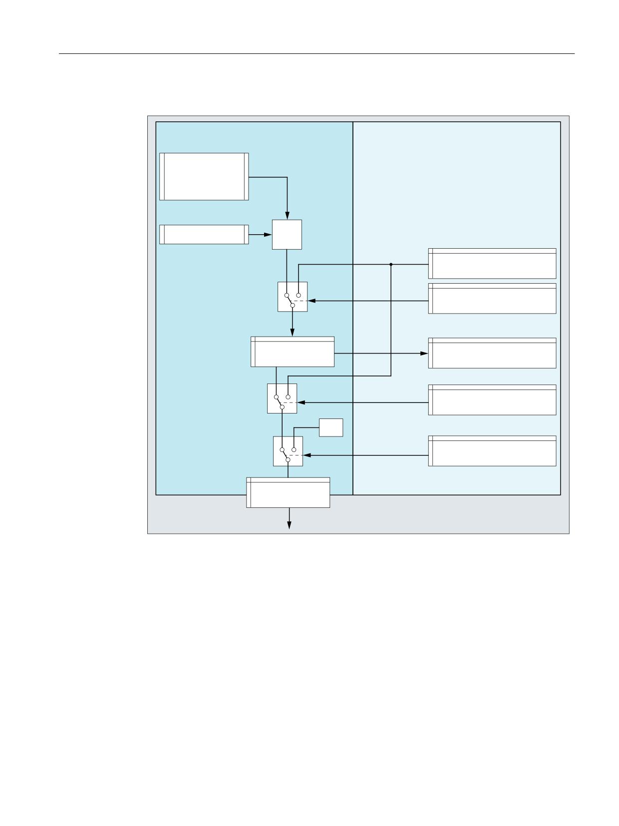
A4: Digital and analog NC I/O for SINUMERIK 840D sl
2.2 Indirect I/O access via PLC
NC/PLC interface signals
1&
3/&
1& SURJUDP
$B287$>
@
(YDOXDWLRQ
6HWWLQJ YDOXH IURP WKH 3/&
'% '%:
'%:
2YHUZULWH
'% '%%
6HWSRLQW
1& RXWSXW YDOXH
'% '%:
'%:
7DUJHW
'% '%%
/RFN
'% '%%
1& RXWSXW
1)
MD10330 $MN_FASTIO_ANA_OUTPUT_WEIGHT[<Output>]
Setting value
Using the setting value, the PLC user program can specify a defined output value. In order
that the setting value becomes active, it must be activated via the interfaces for "Overwrite" or
"Target".
The setting value must be specified as a fixed point number (16 bit value including sign) in 2's
complement.
See "Representation of the analog I/O values (Page 47)".
Overwrite
If a bit is set, then for the corresponding output, instead of the value written using system
variables $A_OUTA, the setting value specified from the PLC user program is used. The value
written via system variables $A_OUTA is then lost.
Extended Functions
Function Manual, 12/2018, A5E40874029B AB
45

A4: Digital and analog NC I/O for SINUMERIK 840D sl
2.2 Indirect I/O access via PLC
If a bit is reset, for the corresponding output, the actual value at the hardware output is kept.
Target
If a bit is set, then for the corresponding output, instead of the NC output value, the setting
value specified by the PLC user program is used. The actual NC output value is kept.
If a bit is reset, then for the corresponding output, the last NC output value becomes active
again.
Lock
If a bit is set in the interface, a value of 0 is output at the corresponding NC output.
Setpoint
The actual NC output value can be read in the PLC user program via the setpoint.
The setpoint is represented as a fixed point number (16 bit value including sign) in a 2's
complement.
See "Representation of the analog I/O values (Page 47)".
Note
Different values
The value in the "Setpoint" interface can, as a result of the various subsequent influencing
possibilities, have a different value than that available at the NC output.
Overview
Lock
Overwrite
Setting value
Target
Setpoint
NC output
DBX168.0 - 7
DBX166.0 - 7
DBW170 - 184
DBX167.0 - 7
DBW210 - 225
1 - 8
Machine data
Weighting factor
Using the weighting factor, for each analog NC output, the DA converter of the I/O module
being used can be adapted by appropriately parameterizing it.
MD10330 $MN_FASTIO_ANA_OUTPUT_WEIGHT[<Output>]
Program code
Comment
; Assumption: Analog value range
±10 V
; Parameterization: MD10330 $MN_FASTIO_ANA_OUTPUT_WEIGHT[<output>] = 10000
$A_OUTA[<output>] =
9500
; NC output: 9.5 V
$A_OUTA[<output>] = -4120
; NC output: -4.12 V
Extended Functions
46
Function Manual, 12/2018, A5E40874029B AB

A4: Digital and analog NC I/O for SINUMERIK 840D sl
2.2 Indirect I/O access via PLC
Note
Analog NC outputs without hardware
With a weighting factor of 32767, the digitized analog values for the NC program and PLC user
program are identical. As a consequence, the NC output can be used for 1:1 communication
between the NC program and PLC user program.
Supplementary conditions
Analog NC outputs without hardware
An alarm is not displayed if NC outputs are written to, which were defined (MD10310
$MN_FASTIO_ANA_NUM_OUTPUTS), but the corresponding hardware is not available. The
setpoint can be read via the PLC user program.
Behavior for a warm restart
All NC outputs are set to "0" after a warm restart. Every NC input can be set as a function of
the specific application from the PLC user program.
Behavior at end of program reset/channel reset
From the PLC user program, via the interfaces for "Overwrite", "Target" or "Lock", at the end
of program or for a channel reset, every NC output can be set in defined fashion as a function
of the specific application.
2.2.6.3
Representation of the analog I/O values
The digitized analog values are represented at the NC/PLC interface as fixed-point numbers
(16 bits including sign) in the two's complement.
Bit number
15
14
13
12
11
10
9
8
7
6
5
4
3
2
1
0
Signifi-
SG
214
213
212
211
210
29
28
27
26
25
24
23
22
21
20
cance
SG: Sign
Minimum value
Maximum value
-32768D
32767D
8000H
7FFFH
Increment
For a resolution of 16 bits and a nominal range of ±10 V, the increment is:
20 V / 216 = 20 V / 65536 ≈ 0.305 mV
Extended Functions
Function Manual, 12/2018, A5E40874029B AB
47

A4: Digital and analog NC I/O for SINUMERIK 840D sl
2.2 Indirect I/O access via PLC
Resolutions < 16 bits
If the resolution of an analog module is less than 16 bits including sign, then the digitized analog
value is entered in the interface starting from bit 14. The unused least significant bit positions
are filled with "0".
14-bit resolution
For a resolution of 14 bits including sign and a nominal range of ±10 V, the increment is:
20 V / 214 = 20 V / 16384 ≈ 1.22 mV
Bit 0 ... 1 are always "0".
12-bit resolution
For a resolution of 12 bits including sign and a nominal range of ±10 V, the increment is:
20 V / 212 = 20 V / 4096 ≈ 4.88 mV
Bit 0 ... 3 are always "0".
Representation of the maximum value for different resolutions
Bit number
15
14
13
12
11
10
9
8
7
6
5
4
3
2
1
0
Significance of the bits
SG
214
213
212
211
210
29
28
27
26
25
24
23
22
21
20
16-bit resolution: 32767D = 7FFFH
0
1
1
1
1
1
1
1
1
1
1
1
1
1
1
1
14-bit resolution: 8191D = 1FFFH
0
1
1
1
1
1
1
1
1
1
1
1
1
1
0
0
12-bit resolution: 2047D = 7FFH
0
1
1
1
1
1
1
1
1
1
1
1
0
0
0
0
Note
The data (resolution, nominal range) of the analog input/output module used can be taken
from the documentation of the particular module.
Examples
Digital representation of analog values at a resolution of 14 bits including sign and a nominal
range of ±10 V.
Example 1: Analog value = 9.5 V
Digitized analog value (decimal):
9.5 V / 20 V * 16384 = 7782
Digitized analog value 14-bit (binary):
01 1110 0110 0110
Digitized analog value 16-bit (binary):
0111 1001 1001 1000
Digitized analog value 16-bit (hex):
7998H
Example 2: Analog value = -4.12 V
Digitized analog value (decimal):
-4.12 V / 20 V * 16384 = -3375
Digitized analog value 14-bit (binary):
11 0010 1101 0001
Digitized analog value 16-bit (binary):
1100 1011 0100 0100
Digitized analog value 16-bit (hex):
CB44 H
Extended Functions
48
Function Manual, 12/2018, A5E40874029B AB
A4: Digital and analog NC I/O for SINUMERIK 840D sl
2.2 Indirect I/O access via PLC
2.2.7
Comparator inputs
Function
Two internal comparator input bytes, each with eight comparator inputs, are available in
addition to the digital and analog NC inputs. The signal state of the comparator inputs is
generated on the basis of a comparison between the analog values present at the fast analog
inputs and the threshold values parameterized in setting data.
The $A_INCO[<n>] system variable allows the signal state (i.e. the result of the comparison)
of comparator input [<n>] to be scanned directly in the part program.
Applies for index <n>:
<n> = 1 ... 8
For comparator byte 1
<n> = 9 ... 16
For comparator byte 2
Terms
In this description, the terms comparator inputs (with index <n>; value range of <n>: 1 ... 8 or
9 ... 16) and comparator input bits (with index <b>; value range of <b>: 0 ... 7) are used.
They are related as follows:
For <n> = 1 ... 8:
Comparator input <n> is equivalent to comparator input bit
<b> = <n> - 1.
For <n> = 9 ... 16:
Comparator input <n> is equivalent to comparator input bit
<b> = <n> - 9.
Example: Comparator input 1 is equivalent to comparator input bit 0.
Assignment of the analog inputs
The following machine data is used to assign an analog input to input bit <b> of comparator
byte 1:
MD10530 $MN_COMPAR_ASSIGN_ANA_INPUT_1[<b>]
Example:
MD10530 $MN_COMPAR_ASSIGN_ANA_INPUT_1[0] = 1
MD10530 $MN_COMPAR_ASSIGN_ANA_INPUT_1[1] = 1
MD10530 $MN_COMPAR_ASSIGN_ANA_INPUT_1[7] = 7
Analog input 1 acts on input bits 0 and 1 of comparator byte 1.
Analog input 7 acts on input bit 7 of comparator byte 1.
The analog inputs for comparator byte 2 are assigned with the machine data:
MD10531 $MN_COMPAR_ASSIGN_ANA_INPUT_2[<b>]
Extended Functions
Function Manual, 12/2018, A5E40874029B AB
49
A4: Digital and analog NC I/O for SINUMERIK 840D sl
2.2 Indirect I/O access via PLC
Comparator settings
The settings for the individual bits (0 to 7) of comparator byte 1 or 2 are parameterized via the
machine data:
MD10540 $MN_COMPAR_TYPE_1 (parameter assignment for comparator byte 1)
or
MD10541 $MN_COMPAR_TYPE_2 (parameter assignment for comparator byte 2)
The following settings are possible:
● Comparison type mask (bits 0 … 7)
The type of comparison condition is defined for each comparator input bit:
Bit = 1:
Associated comparator input bit is set to "1" if:
Analog value ≥ threshold value
Bit = 0:
Associated comparator input bit is set to "0" if:
Analog value < threshold value
● Output of the comparator input byte via digital NC outputs (bits 16 … 23)
The comparator bits can also be output directly via the digital NC outputs byte-by-byte. This
requires specification in this byte (bits 16 … 23) of the digital NC output byte to be used.
Byte = 0:
No output via digital NC outputs
Byte = 1:
Output via digital onboard NC outputs 9 … 16
Byte = 2:
Output via external digital NC outputs 17 … 24
Byte = 3:
Output via external digital NC outputs 25 … 32
Byte = 4:
Output via external digital NC outputs 33 … 40
● Inversion mask for output of the comparator input byte (bits 24 … 31)
For every comparator signal it is also possible to define whether the signal state to be output
at the digital NC output is to be inverted or not.
Bit = 1:
Associated comparator input bit is not inverted.
Bit = 0:
Associated comparator input bit is inverted.
Threshold values
The threshold values used for comparisons on comparator byte 1 or 2 must be stored as setting
data. A separate threshold value must be entered for each comparator input bit <b> (with <b>
= 0 … 7):
SD41600 $SN_COMPAR_THRESHOLD_1[<b>]
or
SD41601 $SN_COMPAR_THRESHOLD_2[<b>]
Extended Functions
50
Function Manual, 12/2018, A5E40874029B AB
A4: Digital and analog NC I/O for SINUMERIK 840D sl
2.2 Indirect I/O access via PLC
Comparator signals as digital NC inputs
All NC functions that are processed as a function of digital NC inputs can also be controlled
by the signal states of the comparators. The byte address for comparator byte 1 (HW byte 128)
or 2 (HW byte 129) must be entered in the machine data associated with the NC function
("Assignment of hardware byte used").
Example:
"Multiple feedrates in one block" NC function
Entry in channel-specific machine data:
MD21220 $MC_MULTFEED_ASSIGN_FASTIN = 129
This activates various feedrate values as a function of the status of comparator byte 2.
Extended Functions
Function Manual, 12/2018, A5E40874029B AB
51
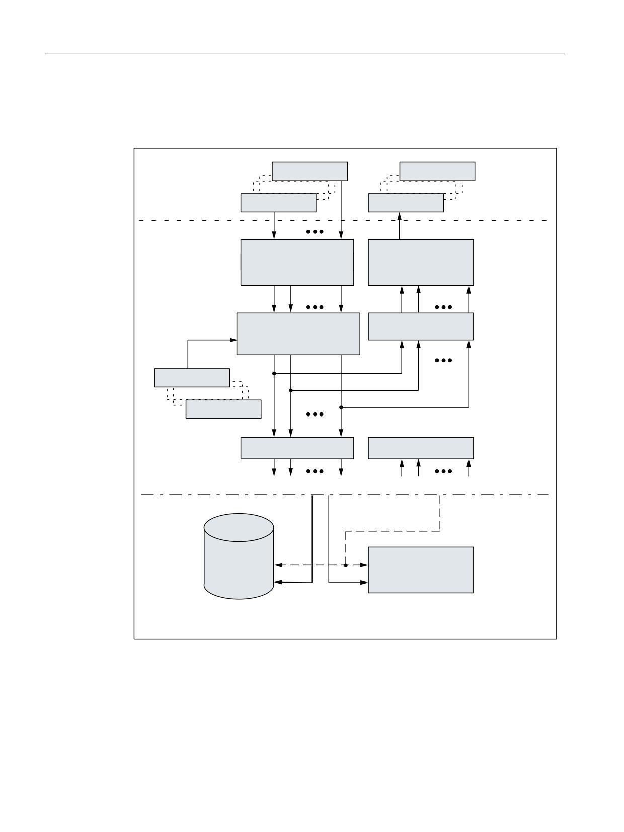
A4: Digital and analog NC I/O for SINUMERIK 840D sl
2.2 Indirect I/O access via PLC
Functional sequence
The functional sequence for comparator input byte 1 is represented schematically in the
following figure.
'LJLWDO
$QDORJ LQSXW
2XWSXW E\WH
$QDORJ LQSXW
0'
> E!@
Q!
$VVLJQPHQW RI DQDORJ LQSXW
'LJLWDO RXWSXWV
0'
%LW
Q! WR FRPSDUDWRU ELW
%\WH VSHFLILFDWLRQ
&RPSDULVRQ
0'
%LW
ELW
$QDORJ YDOXH WKUHVKROG YDOXH
,QYHUVLRQ PDVN
0'
%LW
RU
%LW
$QDORJ YDOXH ุ WKUHVKROG YDOXH
7KUHVKROG YDOXH
7KUHVKROG YDOXH
6'
&RPSDUDWRU LQSXW E\WH
&RPSDUDWRU LQSXW E\WH
&RPSDUDWRU LQSXW ELW
&RPSDUDWRU LQSXW
3DUW SURJUDP
$B,1&2 > Q!@
1& IXQFWLRQV
5HDGLQJ RI FRPSDUDWRU
$FFHVV WR FRPSDUDWRU LQSXW E\WH
LQSXW Q! Q!
b b
RU RI 1& IXQFWLRQV
)URP WKH SDUW SURJUDP
Extended Functions
52
Function Manual, 12/2018, A5E40874029B AB
A4: Digital and analog NC I/O for SINUMERIK 840D sl
2.3 Direct I/O access via PLC
2.3
Direct I/O access via PLC
2.3.1
Parameterization
Machine data
Length of the I/O ranges
● Number of PLC I/O input bytes that are read directly by the NC:
MD10394 $MN_PLCIO_NUM_BYTES_IN
● Number of PLC I/O output bytes that are written directly by the NC:
MD10396 $MN_PLCIO_NUM_BYTES_OUT
Logical start addresses
● Logical start address as of which the data is read from the PLC input I/O. The offset used
for the subsequent addressing, e.g. $A_PBB_IN[< offset >] refers to the start address
specified in the machine data:
MD10395 $MN_PLCIO_LOGIC_ADDRESS_IN
● Logical start address as of which the data is written to the PLC input I/O. The offset used
for the subsequent addressing, e.g. $A_PBB_OUT[< offset >] refers to the start address
specified in the machine data:
MD10397 $MN_PLCIO_LOGIC_ADDRESS_OUT
Update time
● Time within which the data that can be read by means of $A_PBx_IN is updated (see
Subsection "Transfer times" below).
MD10398 $MN_PLCIO_IN_UPDATE_TIME
Format display
● Format display of system variables $A_PBx_OUT and $A_PBx_IN (see Subsection
"Selection of the storage format (little/big endian)" below).
MD10399 $MN_PLCIO_TYPE_REPRESENTATION
Note
The logical PLC I/O addresses entered in the machine data and the number of bytes to be
transferred must be consistent with the PLC hardware configuration. In the configured areas,
there must not be any "address gaps" in the PLC I/O expanded configuration.
Extended Functions
Function Manual, 12/2018, A5E40874029B AB
53
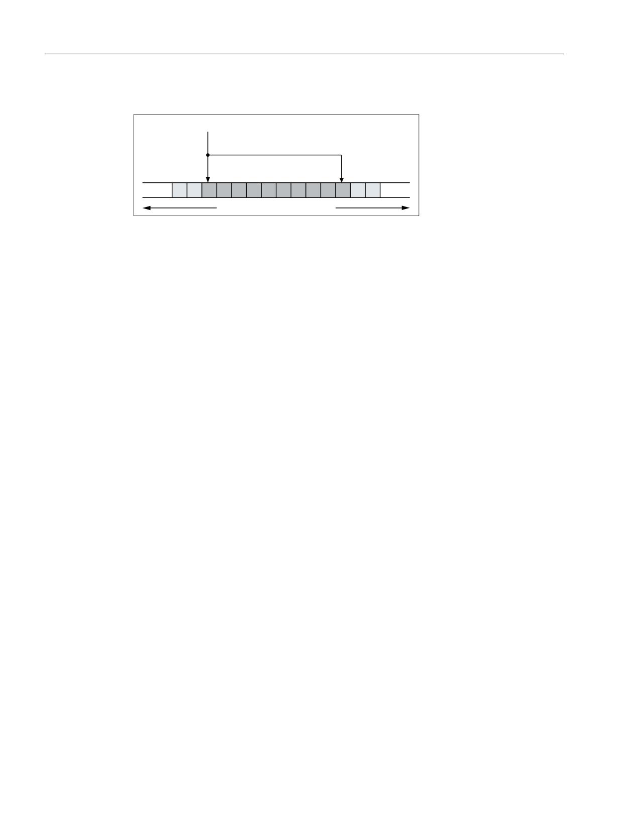
A4: Digital and analog NC I/O for SINUMERIK 840D sl
2.3 Direct I/O access via PLC
Principle of the parameterization of the NC I/O in the input area
0'
01B3/&,2B/2*,&B$''5(66B,1
0'
01B3/&,2B180B%<7(6B,1
3/& LQSXW LPDJH
Transfer times
● Transfer of the output data from the NC to the output modules
- The output data is transferred from the NC to the output modules at the end of the current
interpolator cycle.
- The transfer is only performed when at least one output data item has been written in
the current interpolator cycle.
● Transfer of the input data from the input modules to the NC
- Time within which the cyclic request for the update of the input data (input image of the
modules → NC input data) from the NC to the PLC is sent, can be set via the machine
data:
- MD10398 $MN_PLCIO_IN_UPDATE_TIME = <update time>
- The parameterized update time is rounded up internally to the next highest multiple of
an interpolator cycle. With update time = 0, the request is transferred to the PLC in each
interpolation cycle.
- The request for the update of the input data is sent to the PLC at the end of the
parameterized interpolation cycle.
- The updated input data is available at the earliest in the following interpolation cycle.
Selection of the storage format (little/big endian)
A total of 16 KB is available for the data transfer between the NC and PLC for all NC channels.
These areas have to be managed by the user (i.e. no overlapping of the variables, not even
across channel borders).
The display of the variables within these areas depends on the setting in the machine data:
Extended Functions
54
Function Manual, 12/2018, A5E40874029B AB
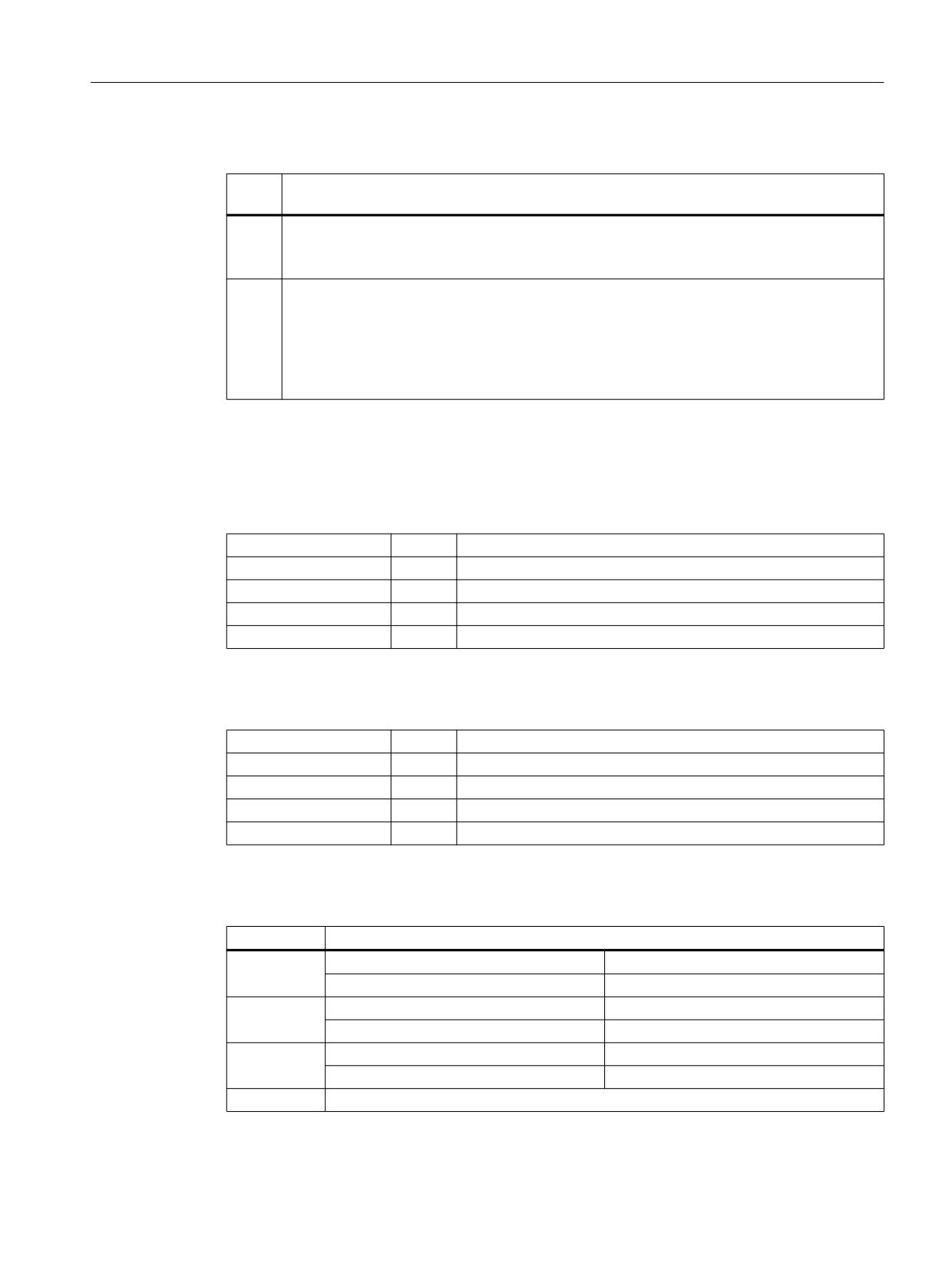
A4: Digital and analog NC I/O for SINUMERIK 840D sl
2.3 Direct I/O access via PLC
MD10399 $MN_PLCIO_TYPE_REPRESENTATION = <value>
<val-
Meaning
ue>
0
Little endian format (default setting)
System variables are displayed in little endian format ⇒ least significant byte at least significant
address
1
Big endian format (PLC standard format, recommended)
System variables are displayed in big endian format ⇒ most significant byte at least significant
address
Note
The big endian format is the format usually used in the PLC and PLC I/O. Therefore, it is
recommended that you use this setting.
2.3.2
Reading/writing: System variables
Input data
System variable
Type
Offset <n>
$A_PBB_IN[<n>]
Byte
0, 1, 2, ... (MD10394 $MN_PLCIO_NUM_BYTES_IN -1)
$A_PBW_IN[<n>]
Word
0, 2, 4, ... (MD10394 $MN_PLCIO_NUM_BYTES_IN - 2)
$A_PBD_IN[<n>]
Double
0, 4, 8, ... (MD10394 $MN_PLCIO_NUM_BYTES_IN - 4)
$A_PBR_IN[<n>]
Real
0, 4, 8, ... (MD10394 $MN_PLCIO_NUM_BYTES_IN - 4)
A preprocessing stop is triggered in the channel when reading from a part program.
Output data
System variable
Type
Offset <n>
$A_PBB_OUT[<n>]
Byte
0, 1, 2, ... (MD10396 $MN_PLCIO_NUM_BYTES_OUT - 1)
$A_PBW_OUT[<n>]
Word
0, 2, 4, ... (MD10396 $MN_PLCIO_NUM_BYTES_OUT - 2)
$A_PBD_OUT[<n>]
Double
0, 4, 8, ... (MD10396 $MN_PLCIO_NUM_BYTES_OUT - 4)
$A_PBR_OUT[<n>]
Real
0, 4, 8, ... (MD10396 $MN_PLCIO_NUM_BYTES_OUT - 4)
A preprocessing stop is triggered in the channel when reading output data from a part program.
Value ranges of the output data
Type
Value range
Byte
With sign:
-128 ... +127
Without sign:
0 ... 255
Word
With sign:
-32768 ... +32767
Without sign:
0 ... 65535
Double
With sign:
-2147483648 ... +2147483647
Without sign:
0 ... 4294967295
Real
-3.402823466*10+38 ... +3.402823466*10+38
Extended Functions
Function Manual, 12/2018, A5E40874029B AB
55
A4: Digital and analog NC I/O for SINUMERIK 840D sl
2.3 Direct I/O access via PLC
2.3.3
Supplementary conditions
Several slots
If several slots form an input or output range of the PLC I/O used directly by the NC, the address
range of the slots must be configured as a continuous range without gaps.
Parallel writing of the NC and PLC
Parallel writing of I/O outputs by the NC via direct access over the PLC and from the PLC user
program results in a random, mutual overwriting of the output values. The application is
therefore not permitted, but cannot be prevented on the control.
Time response
The time when the data is read in from the PLC I/Os is not synchronized with the time when
the data is made available to the part program via system variables!
Data transfer
● The output of the output data on the PLC I/O is always for all parameterized output data,
even when only one output data item was written for each system variable.
● If several system variables are assigned values simultaneously, it is not certain that they
are transferred in the same interpolation cycle.
2.3.4
Examples
2.3.4.1
Writing to PLC-I/Os
Specifications
● Decimal logical addresses of the output data to be written within the PLC I/O
-
521: 1-byte integer value
–
522: 2-byte integer value
● The output data is written to a part program via the R parameters R10 - R11.
● In order to only slow down the execution of the PLC user program (OB1) slightly, the update
cycle for write access should be 3-times the interpolator cycle of 12 ms.
● Data is to be output directly to the following PLC I/Os:
Parameterization
The machine data should be set as follows:
● Length of the NC I/O output data area: 2 + 1 = 3 bytes
MD10396 $MN_PLCIO_NUM_BYTES_OUT= 3
● Logical start address of the input data area: 521
MD10397 $MN_PLCIO_LOGIC_ADDRESS_OUT = 521
Extended Functions
56
Function Manual, 12/2018, A5E40874029B AB
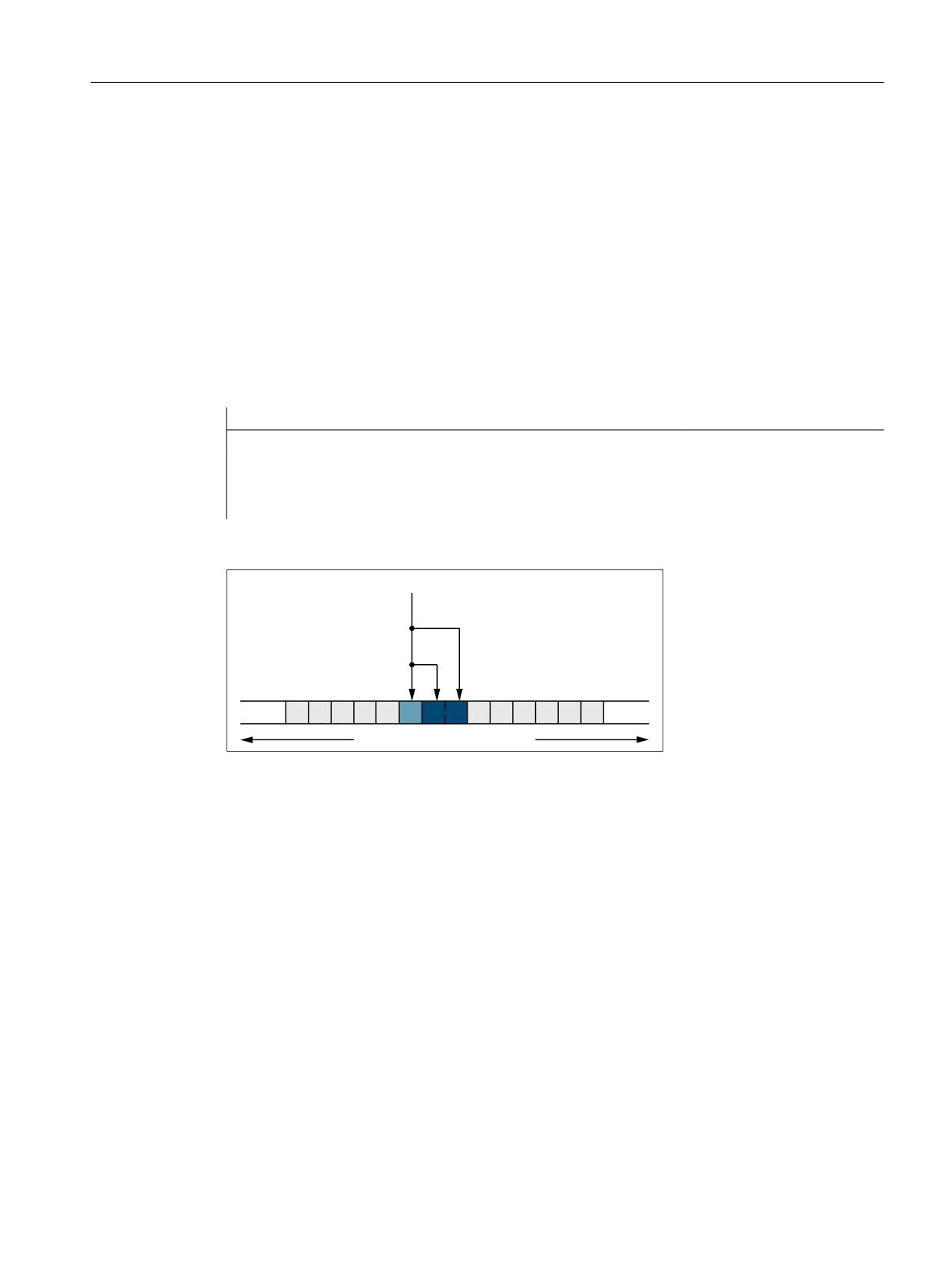
A4: Digital and analog NC I/O for SINUMERIK 840D sl
2.3 Direct I/O access via PLC
● Update cycle: I/O input data → system variables = 3 * interpolator cycle= 3 * 12 ms = 36 ms
MD10398 $MN_PLCIO_OUT_UPDATE_TIME = 3 * 0.012 = 0.036
● Data format: Big endian
MD10399 $MN_PLCIO_TYPE_REPRESENTATION = 1
Refreshing
The transfer of the system data to the PLC I/O is not performed until the PLC has detected the
PROFIBUS/PROFINET I/O error-free after the control startup. The transfer is then performed
in every third interpolation cycle.
Programming
Writing the NC I/O to synchronized actions with R parameters:
Program code
Comment
R10=123
R11='Habcd'
ID=1 WHENEVER TRUE DO $A_PBB_OUT[0]=R10
; 1-byte integer value
ID=2 WHEN $AA_IW[x] >= 5 DO $A_PBW_OUT[1]=R11
; 2-byte integer value
Addressing example: $PBW_OUT[ 1 ] = R11
0'
01B3/&,2B/2*,&B$''5(66B287
0'
01B3/&,2B180B%<7(6B287
$B3%
:B287>
@
3/& RXWSXW LPDJH
2.3.4.2
Reading from PLC-I/Os
Specifications
● Decimal logical addresses of the input data to be read within the PLC I/O
-
420: 2-byte integer value
–
422: 4-byte integer value
–
426: 4-byte real value
–
430: 1-byte integer value
● The input data should be stored in a part program in the R parameters R1 - R4.
● In order to only slow down the execution of the PLC user program (OB1) slightly, the update
cycle for read access should be 3-times the interpolator cycle of 12 ms.
Extended Functions
Function Manual, 12/2018, A5E40874029B AB
57
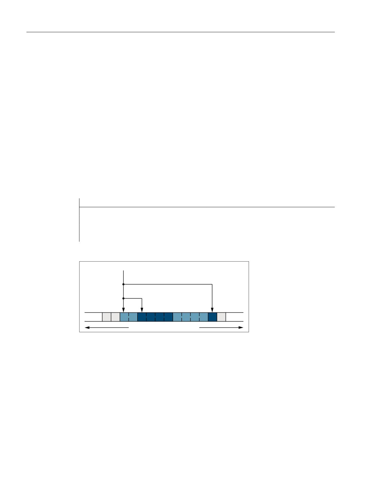
A4: Digital and analog NC I/O for SINUMERIK 840D sl
2.4 Direct I/O access without PLC
Parameterization
● Length of the NC I/O input data area: 2 + 4 + 4 + 1 = 11 bytes
MD10394 $MN_PLCIO_NUM_BYTES_IN = 11
● Logical start address of the input data area: 420
MD10395 $MN_PLCIO_LOGIC_ADRESS_IN = 420
● Update cycle: I/O input data → system variables = 3 * interpolator cycle= 3 * 12 ms = 36 ms
MD10398 $MN_PLCIO_IN_UPDATE_TIME = 3 * 0.012 = 0.036
● Data format: Big endian
MD10399 $MN_PLCIO_TYPE_REPRESENTATION = 1
Refreshing
The system variables are updated in every third interpolation cycle after the NC and PLC
startup.
Programming
Reading in the NC I/O in R parameters:
Program code
Comment
R1=$A_PBW_IN[0]
; 2-byte integer value
R2=$A_PBD_IN[2]
; 4-byte integer value
R3=$A_PBR_IN[6]
; 4-byte real value
R4=$A_PBB_IN[10]
; 1-byte integer value
Addressing example: R2 = $PBD_IN[ 2 ]
0'
01B3/&,2B/2*,&B$''5(66B,1
0'
01B3/&,2B180B%<7(6B,1
$B3%'B,1>
@
3/& LQSXW LPDJH
2.4
Direct I/O access without PLC
2.4.1
Brief description
Isochronous and non-isochronous PROFIBUS/PROFINET
The reading/writing of the PROFIBUS/PROFINET is possible with an isochronous and non-
isochronous PROFIBUS/PROFINET configuration.
Extended Functions
58
Function Manual, 12/2018, A5E40874029B AB
A4: Digital and analog NC I/O for SINUMERIK 840D sl
2.4 Direct I/O access without PLC
I/O range
If slots are configured for a PROFIBUS/PROFINET slave used for the NC I/O in such a way
that they are in ascending order without gaps, they are called the I/O range in the following.
An I/O range is therefore characterized by:
● Logical start address: Logical start address of the first slot of the PROFIBUS/PROFINET
slave
● Length: Total length of all slots used for the PROFIBUS/PROFINET slave
The parameterization of the logical start address and the length of the I/O range is performed
in the NC via machine data (see "Parameter assignment (Page 60)").
Reading/writing
Part programs / synchronized actions: System variables
The reading/writing of the NC I/O is performed in the NC via system variables in the interpolator
cycle. The writing on the NC I/O is performed after the interpolation cycle.
Data consistency: Interpolator cycle
See "System variables (Page 61)".
Parallel reading/writing
Reading
Parallel reading through compile cycles and part programs / synchronized actions on input
data of the same I/O range is possible. Write access to the NC I/O is performed in different
ways.
● The data consistency is ensured.
● The data equality during an interpolator cycle is not ensured.
Writing
Parallel writing through compile cycles and part programs / synchronized actions on output
data of the same I/O range is not possible.
Extended Functions
Function Manual, 12/2018, A5E40874029B AB
59
A4: Digital and analog NC I/O for SINUMERIK 840D sl
2.4 Direct I/O access without PLC
2.4.2
Parameter assignment
Machine data
Logical start addresses of the I/O ranges
The logical start addresses of the I/O ranges used are set via the following machine data:
● Logical start addresses of the input range 1, 2, ... m:
MD10500 $MN_DPIO_LOGIC_ADDRESS_IN[ <n>] = <logical start address> ; with <n> =
0, 1, 2, ... (m - 1)
● Logical start addresses of the output range 1, 2, ... m:
MD10510 $MN_DPIO_LOGIC_ADDRESS_OUT[ <n>] = <logical start address> ; with <n>
= 0, 1, 2, ... (m - 1)
The following must be taken into account for logical start addresses within the PLC process
image (see References):
- Input slots: Reading from the NC also possible
- Output slots: Writing from the NC not permitted ⇒ alarm after run-up of the NC
References
NCU 7x0.3 PN, NCU 7x0.3B PN Manual, Section "Technical data" > Subsection "PLC" >
"Process image size"
Detailed information can be found at Address (http://support.automation.siemens.com/WW/
view/de/54058408)
Note
I/O ranges for the write access (MD10510) on the PROFIBUS I/O must not be in the range
of the process image, e.g. PLC 317-3, output addresses 0 - 1023.
For PROFINET I/O, these I/O ranges must be assigned in the process image to "TPA 2";
the configuration is realized using the synchronous cycle interrupt "NC".
Lengths of the I/O ranges
The lengths of the I/O ranges used are set via the following machine data:
● Length of the input range 1, 2, ... m:
MD10501 $MN_DPIO_RANGE_LENGTH_IN[ <n> ] = <length>; with <n> = 0, 1, 2, ... (m -
1)
● Length of the output range 1, 2, ... m:
MD10511 $MN_DPIO_RANGE_LENGTH_OUT[ <n> ] = <length>; with <n> = 0, 1, 2, ... (m
- 1)
If the value 0 is entered as length, the length of the first user data slot found under the specified
start address (MD10500/MD10510) is set internally as the length of the I/O range.
Extended Functions
60
Function Manual, 12/2018, A5E40874029B AB

A4: Digital and analog NC I/O for SINUMERIK 840D sl
2.4 Direct I/O access without PLC
I/O range attributes
● Attribute of the input range 1, 2, ... m:
MD10502 $MN_DPIO_RANGE_ATTRIBUTE_IN[ <n> ] ; with <n> = 0, 1, 2, ... (m - 1)
Bit
Val-
Meaning
ue
0
Format display of system variables $A_DPx_IN[<n>,<m>]
0
Little endian format
1
Big endian format
2
Reading of input data
0
Reading possible via system variables and CC-binding
1
Reading possible only for CC-binding
3
Output of slot sign-of-life alarms
0
Slot sign-of-life alarms are issued
1
Slot sign-of-life alarms are suppressed
● Attribute of the output range 1, 2, ... m:
MD10512 $MN_DPIO_RANGE_ATTRIBUTE_OUT[ <n> ] ; with <n> = 0, 1, 2, ... (m - 1)
Bit
Value
Meaning
0
Format display of system variables $A_DPx_OUT[<n>,<m>]
0
Little endian format
1
Big endian format
1
Writing of output data
0
Writing only via system variable
1
Writing only via CC-binding
3
Output of slot sign-of-life alarms
0
Slot sign-of-life alarms are issued
1
Slot sign-of-life alarms are suppressed
2.4.3
Reading/writing
2.4.3.1
System variables
Input data
System variable
Type
Meaning
$A_DPB_IN[<n>,<b>]
8-bit unsigned
Reads a data byte (8-bit)
$A_DPW_IN[<n>,<b>]
16-bit unsigned
Reads a data word (16-bit)
$A_DPSB_IN[<n>,<b>]
8-bit signed
Reads a data byte (8-bit)
$A_DPSW_IN[<n>,<b>]
16-bit signed
Reads a data word (16-bit)
Extended Functions
Function Manual, 12/2018, A5E40874029B AB
61
A4: Digital and analog NC I/O for SINUMERIK 840D sl
2.4 Direct I/O access without PLC
System variable
Type
Meaning
$A_DPSD_IN[<n>,<b>]
32-bit signed
Reads a data double word (32-bit)
$A_DPR_IN[<n>,<b>]
32-bit REAL
Reads input data (32-bit REAL)
<n> = input range 1, 2, ... m; <b> = byte index within the input range: 0, 1, ... (length - 1)
Output data
System variable
Type
Meaning
$A_DPB_OUT[<n>,<b>]
8-bit unsigned
Writes a data byte (8-bit)
$A_DPW_OUT[<n>,<b>]
16-bit unsigned
Writes a data word (16-bit)
$A_DPSB_OUT[<n>,<b>]
8-bit signed
Writes a data byte (8-bit)
$A_DPSW_OUT[<n>,<b>]
16-bit signed
Writes a data word (16-bit)
$A_DPSD_OUT[<n>,<b>]
32-bit signed
Writes a data double word (32-bit)
$A_DPR_OUT[<n>,<b>]
32-bit REAL
Writes output data (32-bit REAL)
<n> = output range 1, 2, ... m; <b> = byte index within the output range: 0, 1, ... (length - 1)
Configured and parameterized I/O ranges for part programs / synchronized actions
Each system variable is a 32-bit bit array. Each bit is assigned to an I/O range.
Bit <n> ≙ machine data index <n> ≙ I/O range <n+1>
Bit <n> == 1 ⇒ The I/O range <n+1> is configured/parameterized.
System variable
Type
Meaning
$A_DP_IN_CONF
32-bit bit array
Reads all configured input ranges
$A_DP_OUT_CONF
32-bit bit array
Reads all configured output ranges
Valid I/O ranges for part programs / synchronized actions
Each system variable is a 32-bit bit array. Each bit is assigned to an I/O range.
Bit <n> ≙ machine data index <n> ≙ I/O range <n+1>
Bit <n> == 1 ⇒ The I/O range <n+1> is valid. Reading/writing via part programs / synchronized
actions
System variable
Type
Meaning
$A_DP_IN_VALID
32-bit bit array
Reads all valid input ranges
$A_DP_OUT_VALID
32-bit bit array
Reads all valid output ranges
State of an I/O range
The state of an I/O range can be read via the following system variables.
System variable
Type
Meaning
$A_DP_IN_STATE[<n>]
INT
Reads the state of the input range
$A_DP_OUT_STATE[<n>]
Reads the state of the output range
Extended Functions
62
Function Manual, 12/2018, A5E40874029B AB

A4: Digital and analog NC I/O for SINUMERIK 840D sl
2.4 Direct I/O access without PLC
System variable
Type
Meaning
<n> = index of the I/O range
State
0: I/O range has not been configured
1: I/O range could not be activated
2: I/O range is available
3: I/O range is currently not available
Length of an I/O range
The configured length of an I/O range can be read via the following system variables.
System variable
Meaning
$A_DP_IN_LENGTH[<n>]
Reading the length of the input data range
$A_DP_OUT_LENGTH[<n>]
Reading the length of the output data range
<n> = index of the I/O range
Supplementary conditions
● A preprocessing stop is triggered in the channel when reading/writing from a part program.
● To ensure data consistency during programming from the part program and the
synchronized actions, the PROFIBUS I/O data is accessed which is kept consistent for the
respective IPO cycle.
● If the same PROFIBUS I/O data is to be write-accessed several times within an interpolation
cycle (e.g. synchronized actions, access from different channels, etc.), then the data of the
last write access is valid.
● The PROFIBUS I/O data to be written is output at the PROFIBUS I/O only after the
corresponding IPO cycle.
● The <b> (RangeOffset) indicates the place (byte offset) within the I/O range as of which
the data access is to be started. Data types can be read/written at any byte offset within
the I/O range. Read/write accesses which exceed the configured limits of the respective I/
O range are rejected with the generation of an alarm (17030).
● Via the machine data MD10502 $MN_DPIO_RANGE_ATTRIBUTE_IN or MD10512
$MN_DPIO_RANGE_ATTRIBUTE_OUT (see "Parameter assignment (Page 60)"), the
display format (little/big endian) for $A_DPx_IN[<n>,<b>] or $A_DPx_OUT[<n>,<b>]
system variables can be defined for the read/write direction as well as for each individual
I/O range.
2.4.4
Supplementary conditions
Parallel writing of the NC and PLC
Parallel writing of I/O outputs by the NC via direct access and from the PLC user program
results in a random, mutual overwriting of the output values. The application is therefore not
permitted, but cannot be prevented on the control.
Extended Functions
Function Manual, 12/2018, A5E40874029B AB
63
A4: Digital and analog NC I/O for SINUMERIK 840D sl
2.4 Direct I/O access without PLC
Life beat monitoring
At the start of an interpolator cycle, a check is made for each I/O range whether the sign-of-
life of the associated slot or I/O range has failed. If this is the case, alarm 9050 or 9052 is
displayed.
Effects:
● The part program processing is not stopped.
● When the sign-of-life returns, the alarm is cleared automatically.
2.4.5
Examples
2.4.5.1
Writing to the NC I/O
Requirement
A valid configuration must already have been loaded to the PLC.
Parameterization for part programs / synchronized actions
Specifications
● Parameterization of the 6th data record: Machine data / system variable index = 5
● Configuration data:
- Logical start address = 334
- Slot length = 8 bytes
● Representation: Little endian format
Parameterization in the machine data
● MD10510 $MN_DPIO_LOGIC_ADDRESS_OUT[ 5 ] = 334 (logical start address)
● MD10511 $MN_DPIO_LENGTH_OUT[ 5 ] = 8 (length of the I/O-range in bytes)
● MD10512 $MN_DPIO_ATTRIBUTE_OUT[ 5 ]
- Bit0 = 0 (little endian format)
- Bit1 = 0 (writing only via system variable)
- Bit3 = 0 (issue slot sign-of-life alarms)
Examples
Program code
Comment
$A_DPB_OUT[5,6]=128
; Byte ≙ 8 bits, index=5, offset=6
$A_DPW_OUT[5,5]='B0110'
; Word ≙ 16 bits, index=5, offset=5
; Caution: Data on offset 6 will be overwritten
Extended Functions
64
Function Manual, 12/2018, A5E40874029B AB
A4: Digital and analog NC I/O for SINUMERIK 840D sl
2.4 Direct I/O access without PLC
Program code
Comment
$A_DPSD_OUT[5,3]=’H8F’
; Double ≙ 32 bits, index=5, offset=3
; Caution: Data on offsets 4, 5, 6 will be overwritten
$AC_MARKER[0]=5
; Index=5
$AC_MARKER[1]=3
; Offset=3
$A_DPSD_OUT[$AC_MARKER[0],$AC_MARKER[1]]=’H8F’ ; indirect addressing
; Double ≙ 32 bits, on index=5, offset=3
R1 = $A_DPB_OUT[5,6]
; Assignment to R parameter, byte ≙ 8 bits, index=5,
offset=6
;Result: R1 == 'HFF'
ID=1 WHENEVER TRUE DO $A_DPB_OUT[5,0]=123 ; cyclic writing per IPO cycle
; Byte ≙ 8 bits, index=5, offset=0
; Faulty programming
$A_DPB_OUT[5.255]=128
; ≙ Alarm 17030: Offset 255 > I/O range
$A_DPB_OUT[6.10]=128
; ≙ Alarm 17020: Index 6 reserved for compile cycle, see
below
$A_DPB_OUT[7.10]=128
; ≙ Alarm 17020: Index 7 not defined in the machine data
$A_DPB_OUT[16.6]=128
; ≙ Alarm 17020: Index 16 outside the value range
Configuration for programming via CompileCycles
Specifications
● Parameterization of the 7th data record: Machine data / system variable index = 6
● Configuration data:
- Logical start address = 444
- Slot length = 10 bytes
● Representation: Little endian format
Parameterization in the machine data
● MD10510 $MN_DPIO_LOGIC_ADDRESS_OUT[ 6 ] = 444 (logical start address)
● MD10511 $MN_DPIO_LENGTH_OUT[ 6 ] = 0 (only the first user data slot is used)
● MD10512 $MN_DPIO_ATTRIBUTE_OUT[ 6 ]
- Bit0 = 0 (little endian format)
- Bit1 = 1 (writing only via CC-binding)
- Bit3 = 1 (slot sign-of-life alarms are suppressed)
2.4.5.2
Reading from the NC I/O
Requirement
A valid configuration must already have been loaded to the PLC.
Extended Functions
Function Manual, 12/2018, A5E40874029B AB
65
A4: Digital and analog NC I/O for SINUMERIK 840D sl
2.4 Direct I/O access without PLC
Parameterization for part programs / synchronized actions
Specifications
● Parameterization of the 1st data record: Machine data / system variable index = 0
● Configuration data:
- Logical start address = 456
- Slot length = 32 bytes
● Representation: Big endian format
Parameterization in the machine data
● MD10500 $MN_DPIO_LOGIC_ADDRESS_IN[ 0 ] = 456 (logical start address)
● MD10501 $MN_DPIO_LENGTH_IN[ 0 ] = 32 (length of the I/O-range in bytes)
● MD1050ß2 $MN_DPIO_ATTRIBUTE_IN[ 0 ]
- Bit0 = 1 (big endian format)
- Bit2 = 0 (reading possible via system variables and CC-binding)
- Bit3 = 0 (slot sign-of-life alarms are issued)
Examples
Program code
Comment
$AC_MARKER[0]=
; Byte ≙ 8 bits, index=0, offset=0
$A_DPW_IN[0,0]
$AC_MARKER[1]=
; Signed double ≙ 32 bits, index=0, offset=1
$A_DPSD_IN[0,1]
$AC_MARKER[1]=
; Signed double ≙ 32 bits, index=0, offset=8
$A_DPSD_IN[0.8]
$AC_MARKER[2]=0
; Index=0
$AC_MARKER[3]=8
; Offset=8
$AC_MARKER[1]=$A_DPSD_IN[$AC_MARKER[2],$AC_MARKER[3]] ; indirect addressing
; Signed double ≙ 32 bits, index=0, offset=8
ID=2 WHEN $A_DPB_IN[0,11]>=5 DO $AC_MARKER[2]=$A_DPSD_IN[0,8]
; IF index 0, offset 11 >= 5
; THEN signed double ≙ 32 bits, index=0, offset=8
; Faulty programming
R1=$A_DPB_IN[0,255]
; ≙ Alarm 17030: Offset 255 > I/O range
R1=$A_DPB_IN[2.6]
; ≙ Alarm 17020: Index 2 not defined in the machine data
R1=$A_DPB_IN[1.10]
; ≙ Alarm 17020: Index 1 reserved for compile cycle, see
below
R1=$A_DPB_IN[16.6]
; ≙ Alarm 17020: Index 16 outside the value range
Extended Functions
66
Function Manual, 12/2018, A5E40874029B AB
A4: Digital and analog NC I/O for SINUMERIK 840D sl
2.4 Direct I/O access without PLC
Parameterization for programming via CompileCycles
Specifications
● Parameterization of the 2nd data record: Machine data / system variable index = 1
● Configuration data:
- Logical start address = 312
- Slot length = 32 bytes
● Representation: Big endian format
Parameterization in the machine data
● MD10500 $MN_DPIO_LOGIC_ADDRESS_IN[ 01 ] = 312 (logical start address)
● MD10501 $MN_DPIO_LENGTH_IN[ 1 ] = 32 (length of the I/O-range in bytes)
● MD10502 $MN_DPIO_ATTRIBUTE_IN[ 1 ]
- Bit0 = 1 (big endian format)
- Bit2 = 1 (reading possible only for CC-binding)
- Bit3 = 1 (suppress slot sign-of-life alarms)
2.4.5.3
Writing of the NC I/O with status query
Requirement
A valid configuration must already have been loaded to the PLC.
Parameterization for part programs / synchronized actions
Specifications
● Parameterization of the 6th data record: Machine data / system variable index = 5
● Configuration data:
- Logical start address = 1200
- Slot length = 32 bytes
● Representation: Big endian format
Parameterization in the machine data
● MD10510 $MN_DPIO_LOGIC_ADDRESS_OUT[ 5 ] = 1200 (logical start address)
● MD10511 $MN_DPIO_LENGTH_OUT[ 5 ] = 0 (length of the I/O-range in bytes)
● MD10512 $MN_DPIO_ATTRIBUTE_OUT[ 5 ]
- Bit0 = 1 (little endian format)
- Bit1 = 0 (writing only via system variable)
- Bit3 = 0 (issue slot sign-of-life alarms)
Extended Functions
Function Manual, 12/2018, A5E40874029B AB
67

A4: Digital and analog NC I/O for SINUMERIK 840D sl
2.5 Data lists
Examples
check:
; Jump marker
IF $A_DP_OUT_STATE[5]==2 GOTOF write
; If data range valid; => jump to
N15
GOTOB check
; Jump back to check
write:
; Jump marker
$A_DPB_OUT[5,6]=128
; Writing the data byte
check:
; Jump marker
IF $A_DP_OUT_CONF==$A_DP_OUT_VALID GOTOF write
; If data range valid
; => jump to N15
SETAL(61000)
; Set alarm no. 61000
write:
; Jump marker
$A_DPB_OUT[5,6]=128
; Writing the data byte
check:
; Jump marker
IF $A_DP_OUT_VALID B_AND ’B100000’ GOTOF write
; If data range valid
; => jump to N15
SETAL(61000)
; Set alarm no. 61000
write:
; Jump marker
$A_DPB_OUT[5,6]=128
; Writing the data byte
R1=$A_DP_OUT_LENGTH[5]
; Length of the I/O-range (slot) in bytes
;Result: R1 = 32
2.5
Data lists
2.5.1
Machine data
2.5.1.1
General machine data
Number
Identifier: $MN_
Description
10300
FASTIO_ANA_NUM_INPUTS
Number of active analog NC inputs
10310
FASTIO_ANA_NUM_OUTPUTS
Number of active analog NC outputs
10320
FASTIO_ANA_INPUT_WEIGHT
Weighting factor for analog NC inputs
10330
FASTIO_ANA_OUTPUT_WEIGHT
Weighting factor for analog NC outputs
10350
FASTIO_DIG_NUM_INPUTS
Number of active digital NC input bytes
10360
FASTIO_DIG_NUM_OUTPUTS
Number of active digital NC output bytes
Extended Functions
68
Function Manual, 12/2018, A5E40874029B AB

A4: Digital and analog NC I/O for SINUMERIK 840D sl
2.5 Data lists
Number
Identifier: $MN_
Description
10362
HW_ASSIGN_ANA_FASTIN
Hardware assignment of external analog NC inputs
10364
HW_ASSIGN_ANA_FASTOUT
Hardware assignment of external analog NC outputs
10366
HW_ASSIGN_DIG_FASTIN
Hardware assignment of external digital NC inputs
10368
HW_ASSIGN_DIG_FASTOUT
Hardware assignment of external digital NC outputs
10394
PLCIO_NUM_BYTES_IN
Number of directly readable input bytes of the PLC I/Os
10395
PLCIO_LOGIC_ADDRESS_IN
Start address of the directly readable input bytes of the PLC I/Os
10396
PLCIO_NUM_BYTES_OUT
Number of directly writeable output bytes of the PLC I/Os
10397
PLCIO_LOGIC_ADDRESS_OUT
Start address of the directly writeable output bytes of the PLC I/
Os
10398
PLCIO_IN_UPDATE_TIME
Update time for PLC I/O input cycle
10399
PLCIO_TYPE_REPRESENTATION
Little-/big-endian representation for PLC I/O
10500
DPIO_LOGIC_ADDRESS_IN
Logical slot address of the PROFIBUS I/O
10501
DPIO_RANGE_LENGTH_IN
Length of the PROFIBUS I/O range
10502
DPIO_RANGE_ATTRIBUTE_IN
Attributes of the PROFIBUS I/O
10510
DPIO_LOGIC_ADDRESS_OUT
Logical slot address of the PROFIBUS I/O
10511
DPIO_RANGE_LENGTH_OUT
Length of the PROFIBUS I/O range
10512
DPIO_RANGE_ATTRIBUTE_OUT
Attributes of the PROFIBUS I/O
10530
COMPAR_ASSIGN_ANA_INPUT_1
Hardware assignment of NC analog inputs for comparator byte 1
10531
COMPAR_ASSIGN_ANA_INPUT_2
Hardware assignment of NC analog inputs for comparator byte 2
10540
COMPAR_TYPE_1
Parameterization for comparator byte 1
10541
COMPAR_TYPE_2
Parameterization for comparator byte 2
2.5.1.2
Channelspecific machine data
Number
Identifier: $MC_
Description
21220
MULTFEED_ASSIGN_FASTIN
Assignment of input bytes of NC I/Os for "multiple fee-
drates in one block"
2.5.2
Setting data
2.5.2.1
General setting data
Number
Identifier: $SN_
Description
41600
COMPAR_THRESHOLD_1
Threshold values for comparator byte 1
41601
COMPAR_THRESHOLD_2
Threshold values for comparator byte 2
Extended Functions
Function Manual, 12/2018, A5E40874029B AB
69

A4: Digital and analog NC I/O for SINUMERIK 840D sl
2.5 Data lists
2.5.3
System variable
Identifier
Description
$A_IN
Digital NC input
$A_OUT
Digital NC output
$A_INA
Analog NC input
$A_OUTA
Analog NC output
$A_PBB_IN
Digital NC input data, byte
$A_PBW_IN
Digital NC input data, word
$A_PBD_IN
Digital NC input data, double
$A_PBR_IN
Digital NC input data, real
$A_PBB_OUT
Digital NC output data, byte
$A_PBW_OUT
Digital NC output data, word
$A_PBD_OUT
Digital NC output data, double
$A_PBR_OUT
Digital NC output data, real
2.5.4
Signals
2.5.4.1
Signals to NC
Signal name
SINUMERIK 840D sl
SINUMERIK 828D
Disable of the digital NC inputs
DB10.DBB0/122/124/126/128 DB2800.DBB0/1000
Setting of the digital NC inputs from the PLC
DB10.DBB1/123/125/127/129 DB2800.DBB1/1001
Disable of the digital NC outputs
DB10.DBB4/130/134/138/142 DB2800.DBB4/1008
Overwrite mask of the digital NC outputs
DB10.DBB5/131/135/139/143 DB2800.DBB5/1009
Setting value of the digital NC outputs from the PLC
DB10.DBB6/132/136/140/144 DB2800.DBB6/1010
Input mask of the digital NC outputs
DB10.DBB7/133/137/141/145 DB2800.DBB7/1011
Disable of analog NC inputs
DB10.DBB146
-
Input mask for analog NC inputs
DB10.DBB147
-
Setting value from PLC for the analog NC inputs
DB10.DBB148-163
-
Overwrite mask for the analog NC outputs
DB10.DBB166
-
Input mask for analog NC outputs
DB10.DBB167
-
Disable of NC outputs
DB10.DBB168
-
Setting value from PLC for the analog NC outputs
DB10.DBB170-185
-
Extended Functions
70
Function Manual, 12/2018, A5E40874029B AB

A4: Digital and analog NC I/O for SINUMERIK 840D sl
2.5 Data lists
2.5.4.2
Signals from NC
Signal name
SINUMERIK 840D sl
SINUMERIK 828D
Actual value for digital NCK inputs
DB10.DBB60/186-189
DB2900.DBB0/1000
Setpoint for digital NCK outputs
DB10.DBB64/190-193
DB2900.DBB4/1004
Actual value for analog NCK inputs
DB10.DBB194-209
-
Setpoint for analog NCK outputs
DB10.DBB210-225
-
Extended Functions
Function Manual, 12/2018, A5E40874029B AB
71
A4: Digital and analog NC I/O for SINUMERIK 840D sl
2.5 Data lists
Extended Functions
72
Function Manual, 12/2018, A5E40874029B AB