SINUMERIK 840D sl. Service - Functions. Manual (2018-2020) - page 30

Distributed systems
15.2 NCU link
15.2.1.3
Parameter assignment: NC system cycles
As basic requirement for link communication, the following system cycle clocks must be set the
same in all NCUs involved in the NCU group:
• Basic system cycle clock
• Position control cycle clock
• Interpolator cycle
Basic system cycle clock
The DP cycle set for isochronous communication in the STEP 7 project is used as basic system
cycle clock. The current basic system cycle clock is displayed in machine data:
MD10050 $MN_SYSCLOCK_CYCLE_TIME
Note
Manual alignment across several communications buses
If several isochronous communication buses (PROFIBUS 1 ... n, PROFINET 1 ... m) have been
configured on an NCU, the same DP cycle time in STEP 7 HW Config must be set for each
communication bus.
Depending on the position control cycle clock
For the SINUMERIK 840D sl, the ratio between the basic system cycle clock and the position
control cycle clocks is fixed (1:1) and cannot be changed. Because only certain position control
cycle clocks can be set for the NCU link, only these position control cycle clocks can be set as the
basic system cycle clock or DP cycle time. See the next paragraph "Position control cycle clock".
Position control cycle clock
The position control cycle clock is set as a ratio to the basic system cycle clock. For the SINUMERIK
840D sl, the ratio is fixed (1:1) and cannot be changed. The current position control cycle clock
is displayed in the machine data:
MD10061 $MN_POSCTRL_CYCLE_TIME
Note
Permitted position control cycle clocks
For the NCU link, depending on the number of NCUs in the link group, only the following
position control cycle clocks [ms] are set:
•
2 NCU: 2.0, 2.5, 3.0, 3.5, 4.0
•
3 NCU: 3.0, 3.5, 4.0
See Section "Configuration (Page 829)".
Basic functions
Function Manual, 10/2020, 6FC5397-2GP40-0BA1
827
Distributed systems
15.2 NCU link
Interpolator cycle
The interpolator cycle clock is set as a ratio of the basic system cycle clock. The setting is made
via the following machine data:
MD10070 $MN_IPO_SYSCLOCK_TIME_RATIO
The actual interpolator cycle clock is displayed in machine data:
MD10071 $MN_IPO_CYCLE_TIME
Notes on setting
Cycle clock settings
It is recommended that the following settings are made:
• The default 90% setting for the CPU time share of the NC should be retained:
MD10185 $MN_NCK_PCOS_TIME_RATIO
• The system cycle clocks must be set so that the average system utilization caused by the
interpolator and the position controller does not exceed 60% in normal program operation.
As maximum value, 90% should be not be exceeded.
Note:
In special circumstances, maximum values > 100% can be displayed.
Lowest cyclic communication load
The lowest cyclic communication load during the Link communication results for a cycle ratio of
interpolator clock to position controller clock cycle of 1: 1. With activated "Dynamic Servo
Control (DSC)" drive function, this is generally the most effective setting.
Disadvantage: No telegram repetitions are possible for the link communication.
Time frame of the NC/PLC interface update
The following setting is active during the run-up of all NCUs involved in the link group:
MD18000 $MN_VDI_UPDATE_IN_ONE_IPO_CYCLE = 1
This causes the NC/PLC interface to be read and written completely in just one interpolation
cycle.
System utilization
The system utilization is displayed on the SINUMERIK Operate user interface, under:
"Diagnostics" operating area > "ETC key (">") > "System utilization"
Basic functions
828
Function Manual, 10/2020, 6FC5397-2GP40-0BA1

Distributed systems
15.2 NCU link
Interpolator clock cycle and link variables
When parameterizing the system clock cycles, in addition to the maximum system utilization
values in the "worst-case" scenario, the expected maximum CPU time loading at the interpolator
level as a result of transferring link variables in productive operation must be taken into account.
WARNING
Open-loop control failure due to CPU time overflow at the interpolator level
If, when parameterizing the NC, the interpolator clock cycle was set to short, then as a result
of the additional CPU time load due to transferring link variables, in productive operation CPU
time overflow can occur at the interpolator level.
Further information: Diagnostics Manual; NC Alarms > Alarm 4240 level overflow at the IPO or
position controller level.
15.2.1.4
Parameter assignment: Link communication
NC-specific machine data
Number
Identifier $MN_
Meaning
MD12510
NCU_LINKNO
Unique numerical identification of the NCU within the link group. The
identifiers must be assigned without any gaps in ascending ordering start-
ing from 1.
Value range: 1, 2, ... Maximum NCU number
Note:
The NCU to which the value 1 is assigned as NCU identification is
the master NCU of the link group. The parameterization of link axes and
axis containers may only be made with the machine and setting data of
the master NCU.
MD18780
MM_NCU_LINK_MASK.Bit 0
Activation of the link communication
MD18781
NCU_LINK_CONNECTIONS
Number of internal link connections
Note:
It is recommended to retain the default value 0 (determination of the
number by the NC).
MD18782
MM_LINK_NUM_OF_MODULES
Number of NCUs to be connected with one another via NCU link.
15.2.1.5
Configuration
The NC system software supplies specific configurations for each supported combination of NCU
number and position controller cycle of a link group (see section "Parameter assignment: NC
system cycles (Page 827)").
During the system startup, the appropriate configuration will be loaded (as specified by the
values parameterized in the machine data):
• MD18782 $MN_MM_LINK_NUM_OF_MODULES (number of NCUs of the line group))
• MD10061 $MN_POSCTRL_CYCLE_TIME (position controller cycle)
Basic functions
Function Manual, 10/2020, 6FC5397-2GP40-0BA1
829
Distributed systems
15.2 NCU link
Note
For applications, in which the standard configurations that have been supplied cannot be used,
please contact your local Siemens sales person.
15.2.1.6
Wiring the NCUs
The numerical sequence of the NCUs within a link group is defined in the NCUs using the
following machine data:
MD12510 $MN_NCU_LINKNO = <NCU number>, with NCU number = 1 ... max. NCU number
Cabling
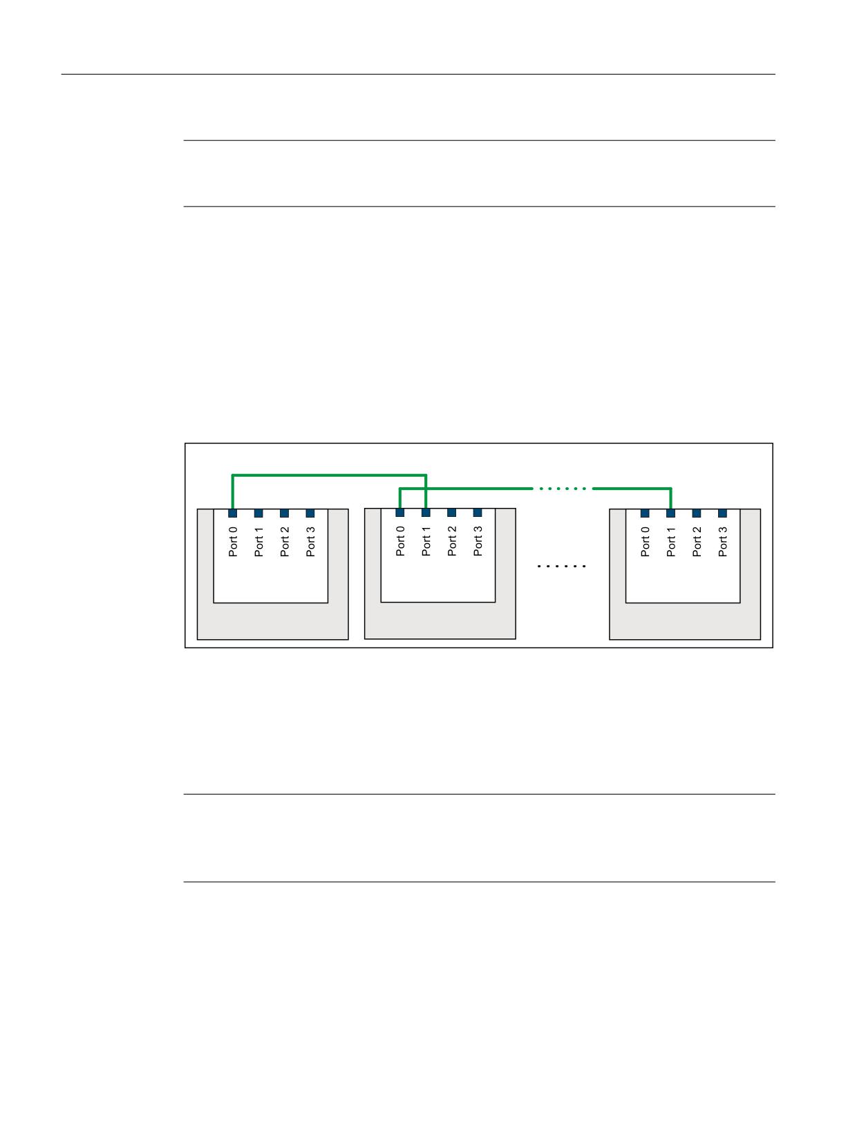
Starting from the NCU1, the NCU link modules should be wired up in the NCU number sequence
according to the following schematic: NCU(n), Port 0 → NCU(n+1), Port 1
1&8 /LQN YLD 352),1(7
1&8 /LQN YLD 352),1(7
1&8
1&8
1&8
/LQN PRGXOH
/LQN PRGXOH
/LQN PRGXOH
1&8
1&8
1&8Q
Figure 15-6
Wiring schematic, NCU link
15.2.1.7
Activation
The link communication is activated using the following machine data:
MD18780 $MN_ MM_NCU_LINK_MASK, Bit 0 = 1
Note
Activation time
It is recommended to activate the link communication only after complete commissioning of the
entire functionality on all participating NCUs has been done.
Basic functions
830
Function Manual, 10/2020, 6FC5397-2GP40-0BA1
Distributed systems
15.2 NCU link
15.2.2
Link variables
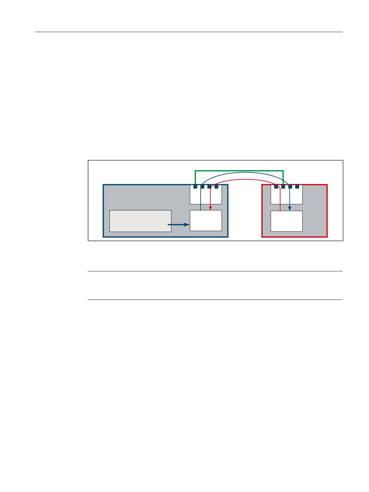
Complex systems with several NCUs require for the complete system coordination of the
manufacturing processes a cyclic exchange of user-specific data between the NCUs. The data
exchange is performed via the link communication and a special memory area, the link variables
memory available for each NCU.
The size and data structure of the link variables memory can be specified for each specific user.
The data stored in the link variables memory is addressed using a special $A_DLx link variables.
Link variables are therefore system-global user variables that can be read and written in part
programs and cycles by all NCUs involved in a link group if link communication has been
configured. Unlike global user variables (GUD), link variables can also be used in synchronized
actions.
1&8 /LQN YLD 352),1(7
1&8
1&8
1&8
1&8
/LQN
PRGXOH
/LQN PR
GXOH
&KDQQHO
/LQN YDULDEOH
/LQN YDULDEOH
PHPRU\
PHPRU\
1
$B'/[> @
Figure 15-7
Link variables
Link variabls as NCU-global user variables
Note
If an NCU Is not a node of a link group or the link variables are not required for communication
via NCU link, the link variables can be used as the NCU-global user variables.
15.2.2.1
Properties of the link variables memory
Parameterizing the memory size
The size of the link variables memory in bytes is set with the following machine data:
MD18700 $MN_MM_SIZEOF_LINKVAR_DATA (size of the link variables memory)
The setting for the size of the link variables memory should be identical for all NCUs involved in
the link group. If the memory sizes are different, the largest value assigned is used.
Initialization
After an NCU is powered up, the link variables memory is initialized with 0.
Structure
From the point of view of the system, the link variables memory is an unstructured memory area
that is available for link communication purposes. The link variables memory is structured by the
Basic functions
Function Manual, 10/2020, 6FC5397-2GP40-0BA1
831

Distributed systems
15.2 NCU link
user/machine manufacturer alone. Depending on how the data structure is defined, the link
variables memory is accessed by means of data format-specific link variables.
System-wide alignment
Once a link variables memory has been written to, the changes that have been made to the data
are transferred to the link variables memories of all other NCUs involved in the link group. The
link variables memories are usually updated by means of link communication within two
interpolation cycles.
15.2.2.2
Properties of the link variables
The link variables memory is accessed via the following data format-specific link variables:
Data type 1)
Designation
Data format 2)
Bytes 2)
Index i 3)
Value range
UINT
$A_DLB[ i ]
BYTE
1
i = n * 1
0 ... 255
INT
$A_DLW[ i ]
WORD
2
i = n * 2
-32768 ... 32767
INT
$A_DLD[ i ]
DWORD
4
i = n * 4
-2147483648 ... 2147483647
REAL
$A_DLR[ i ]
REAL
8
i = n * 8
±(2,2*10-308 … 1,8*10+308)
1) Data type of link variables when used in part program/cycle
2) Data format of link variables or number of bytes addressed by the link variables in the link variables memory
3) The following must be noted for index i:
• Index i is a byte index that relates to the beginning of the link variables memory.
• The index must be selected so that the bytes addressed in the link variables memory are located on a data format limit ⇒
index i = n * bytes, where n = 0, 1, 2, etc.
- $A_DLB[i]: i = 0, 1, 2, ...
- $A_DLW[i]: i = 0, 2, 4, ...
- $A_DLD[i]: i = 0, 4, 8, ...
- $A_DLR[i]: i = 0, 8, 16, ...
Write
A link variable is written with main-run synchronism.
Read
A preprocessing stop is initiated when a link variable is read.
Checks
The following checks are performed for the link variables and link variables memory:
• Observance of the value range limits
• Access to format limit
• Observance of defined memory area in link variables memory
The user/machine manufacturer is solely responsible for preventing the following errors:
• Accessing with incorrect data format
• Accessing the wrong address (index i)
Basic functions
832
Function Manual, 10/2020, 6FC5397-2GP40-0BA1

Distributed systems
15.2 NCU link
• Reciprocal overwriting of the same data item by multiple channels of a single NCU or
different NCUs
• Reading a data item before it has been updated by a channel of its own NCU or of a different
NCU
Note
Data consistency
The user/machine manufacturer is solely responsible for ensuring data consistency within
the link variables memory, both on a local-NCU basis and across NCUs.
15.2.2.3
Write elements
In the case of write access to the link variables memory (e.g. $A_DLB[4] = 21), what is known as
a link variables write element is required for managing the write process within the system. The
maximum number of write elements that are available for each interpolation cycle is set by
means of the following machine data:
MD28160 $MC_MM_NUM_LINKVAR_ELEMENTS
The maximum number of write elements thus restricts the number of link variables that can be
written during each interpolation cycle.
15.2.2.4
Dynamic response during write
The link variables are written with main-run synchronism. The new value may be read by the
other channels in its own NCU no later than the next interpolation cycle. It can be read in the next
part program block in its own channel.
The channels of the other NCUs in the link group normally see the new value after two
interpolation cycles. However, the limited bandwidth can lead to delays in transferring write
requests to the other NCUs in the link group (message delays). Causes for a message delay can
be:
• Writing a large number of link variables in an interpolation cycle
• Writing link variables and a the request for an axis container rotation in the same interpolator
cycle
• Writing link variables and transferring an alarm in the same interpolation cycle
15.2.2.5
System variable
NC-specific system variable
Identifier
Meaning
$AN_LINK_TRANS_RATE_LAST
The number of write requests that were still free in
the last interpolator cycle.
$AN_LINK_TRANS_RATE_LAST_SUM[<n>]
The number of write requests that were still free in
the last interpolator cycle in the send direction to
the specified NC <n> (NCU number).
Basic functions
Function Manual, 10/2020, 6FC5397-2GP40-0BA1
833

Distributed systems
15.2 NCU link
Identifier
Meaning
$AN_LINK_CONN_SIZE_LINKVAR
The number of bytes to be transferred for a write
request of a link variable.
$AN_LINK_CONN_SND[<n>]
The maximum number of bytes that can be trans-
ferred per interpolator cycle from the current NCU
to the specified NCU.
$AN_LINK_CONN_RCV[<n>]
The maximum number of bytes that can be trans-
ferred per interpolator cycle from the specified NCU
to the current NCU.
<n>: NCU number according to MD12510 $MN_NCU_LINKNO of the relevant NCU
Note for: $AN_LINK_CONN_SIZE_LINKVAR
The writing of a link variable causes the number of bytes specified in
$AN_LINK_CONN_SIZE_LINKVAR to be transferred via the not-cyclic link communication. The
number is independent of the format of the link variables.
The maximum number of write requests that can be transferred to the specified NCU for each
interpolator cycle is calculated as:
Max. number of write requests = $AN_LINK_CONN_SND[<n>] / $AN_LINK_CONN_SIZE_LINKVAR
Channelspecific system variable
Identifier
Meaning
$A_LINK_TRANS_RATE 1)
Number of write requests that still can be transfer-
red in the current interpolator cycle.
1) Application example, refer to Section: "Synchronization of a write request (Page 834)"
15.2.2.6
Synchronization of a write request
If certain applications require the new value of a link variable to be transferred to the other NCUs
in the link group in precisely two interpolation cycles, writing to the link variable must be made
in a synchronized action. In the synchronized action, writing to the link variable is only executed
if in the actual interpolator cycle, the write request can still be executed. The
$A_LINK_TRANS_RATE system variable contains the number of write requests that can still be
transferred in the current interpolator cycle.
In the following example, a link variable, data type WORD (2 bytes) and a link variable, data type
DWORD (4 bytes), are written:
Program example
N120 WHEN $A_LINK_TRANS_RATE > 0 DO $A_DLW[0] = 9
N125 WHEN $A_LINK_TRANS_RATE > 0 DO $A_DLD[2] = 7
N130 G4 F1
The synchronized action in N120 is performed only when the write request can be transferred
in the same interpolator cycle to the other NCU of the link group. In this case, the
$A_LINK_TRANS_RATE system variable is also decremented in the same interpolator cycle so
that the updated value is available for the synchronized action in the following N125 block.
Basic functions
834
Function Manual, 10/2020, 6FC5397-2GP40-0BA1
Distributed systems
15.2 NCU link
15.2.2.7
Example: Structure of the link variables memory
The following data are defined for the link communication:
Data format
Number
Bytes per data
Bytes required
BYTE
2
1
2
WORD
1
2
2
DWORD
3
4
12
REAL
1
8
8
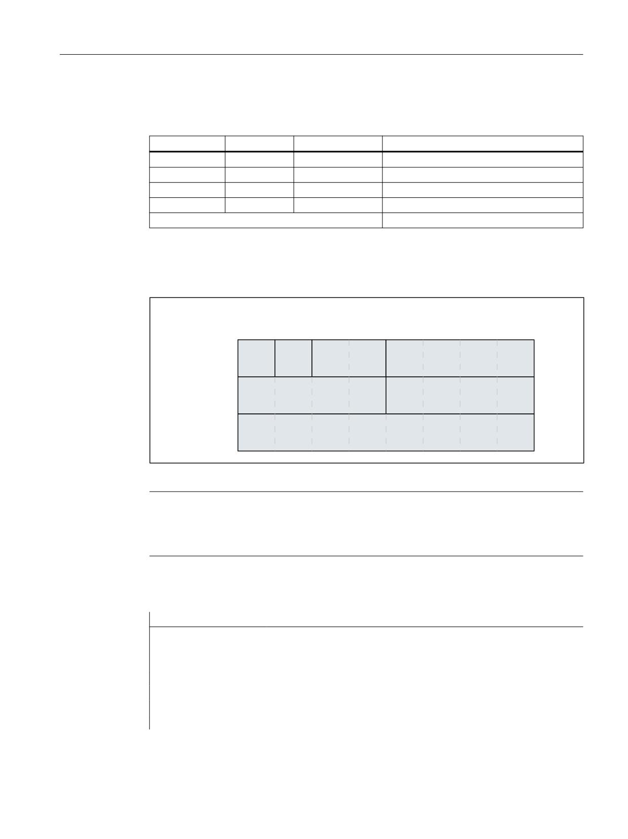
required size of the link variables memory:
24
Memory structure
The data is arranged in the link variables memory as follows, with the data format limits taken
into account:
/LQN YDULDEOH PHPRU\
0'
01B00B6,=(2)B/,1.9$5B'$7$
,QGH[
%<7(
%<7(
:25'
':25'
':25'
':25'
5(
$/
Figure 15-8
Example: Structure of the link variables memory
Note
Memory structure
The data in the link variables memory is always arranged randomly and may therefore appear
different (although the data format limits will still be taken into account).
Access via a link variable must be programmed as follows, in accordance with the memory
structure defined:
Program code
Description
$A_DLB[0]
;
BYTE(1)
$A_DLB[1]
;
BYTE(2)
$A_DLW[2]
;
WORD
$A_DLD[4]
;
DWORD(1)
$A_DLD[8]
;
DWORD(2)
$A_DLD[12]
;
DWORD(3)
$A_DLR[16]
;
REAL
Basic functions
Function Manual, 10/2020, 6FC5397-2GP40-0BA1
835
Distributed systems
15.2 NCU link
15.2.2.8
Example: Read drive data
Task
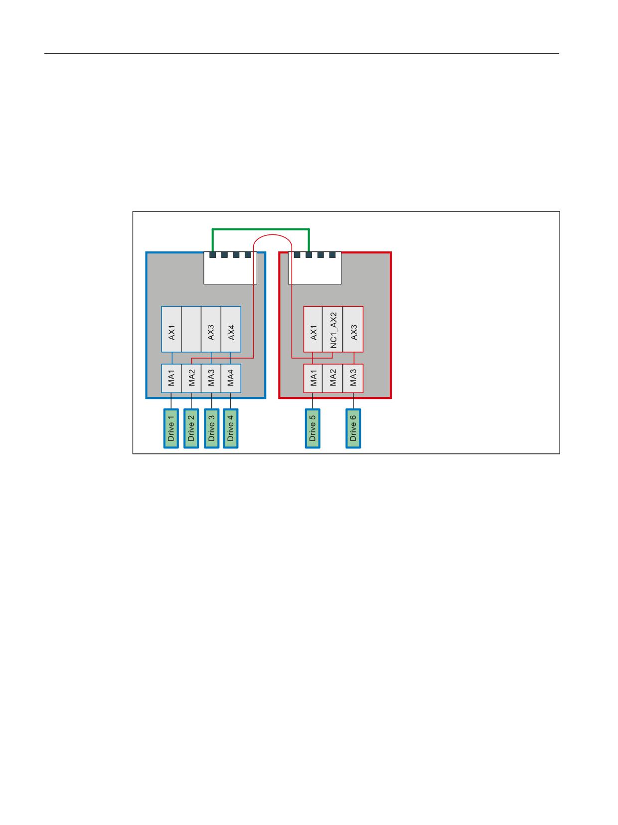
A system contains two NCUs (NCU1/NCU2). The NCUs are connected via the NCU link. The MA2
machine axis of NCU1 (drive 2) travels in interpolation mode as link axis for NCU2. The actual
current value of drive 2 should be transferred for evaluation from NCU1 to NCU2. The figure
below shows the basic design of the system.
1&8 OLQN YLD 352),1(7
1&8
1&8
1&8
1&8
/LQN PRGXOH
/LQN PRGXOH
/RJ PDFKLQH D[LV LPDJH
0'
01B$;&21)B/2*,&B0$&+$;B7$%
0DFKLQH D[HV
0'
01B$;&21)B0$&+$;B1$0(B7$%
Requirement
The actual current value for drive 2 (NCU1/MA2) can be read via the $VA_CURR system variable.
In the case of PROFIdrive-based drives, the following machine data item needs to be set for this
purpose:
MD36730 $MA_DRIVE_SIGNAL_TRACKING = 1 (acquisition of additional actual drive values)
Setting the machine data makes the following drive actual values available:
• $AA_LOAD, $VA_LOAD (drive capacity utilization in %)
• $AA_POWER, $VA_POWER (drive active power in W)
• $AA_TORQUE, $VA_TORQUE (drive torque setpoint in Nm)
• $AA_CURR, $VA_CURR (actual current value of axis or spindle in A)
Basic functions
836
Function Manual, 10/2020, 6FC5397-2GP40-0BA1
Distributed systems
15.2 NCU link
Programming
NCU1
A static synchronized action is used to write cyclically in the interpolation cycle the actual current
value $VA_CURR of axis 2 (NCU1/MA2) via the link variable $A_DLR[0] (REAL value) to the first
8 bytes of the link variables memory:
Program code
IDS=1 WHENEVER TRUE DO $A_DLR[0]=$VA_CURR[MA2]
NCU2
With a static synchronized action, the transferred actual current value is read cyclically in the
interpolator cycle via link variable $A_DLR[0]. If the actual current value is greater than 23 A,
alarm 61000 is displayed.
Program code
IDS=1 WHEN $A_DLR[0] > 23.0 DO SETAL(61000)
15.2.3
Link axes
15.2.3.1
General information
A link axis is designated as a machine axis for which the setpoints are generated by a different
NCU than that to which the machine axis is physically connected. Link axes in conjunction with
axis containers (see Section "Axis container (Page 843)") permit in complex plants, such as
rotary indexing machines with several NCUs, the alternate use of machine axes of the NCU of the
link group.
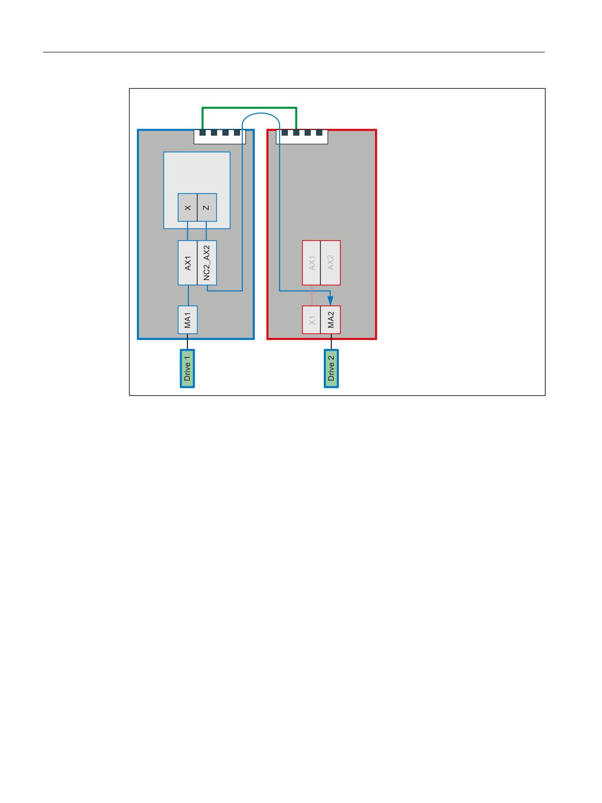
The following figure shows as example an MA1 machine axis connected to the NCU1. The MA2
machine axis is connected to the NCU2. The X and Z channel axes travel in interpolation mode
by a part program that runs in a channel of NCU1. The setpoints are generated in the NCU1
interpolator. For machine axis MA1, they are forwarded to the position control of the NCU1. For
machine axis MA2, they are transferred via the NCU link to the position control of the NCU2 and
output there to the drive.
Basic functions
Function Manual, 10/2020, 6FC5397-2GP40-0BA1
837
Distributed systems
15.2 NCU link
1&8 OLQN
1&8
1&8
&KDQQHO
1
*
)
1
;
=
&KDQQHO D[HV
0'
0&B$;&21)B&+$1$;B1$0(B7$%
/RJ PDFKLQH D[LV LPDJH
0'
01B$;&21)B/2*,&B0$&+$;B7$%
0DFKLQH D[HV
0'
01B$;&21)B0$&+$;B1$0(B7$%
/RFDO D[LV
/LQN D[LV
Figure 15-9
Link axes
Requirement
The use of link axes requires a link communication defined in accordance with "Section Link
communication (Page 822)".
Home NCU
The home NCU of a link axis is the NCU on which it is physically connected as machine axis. The
position control and the exchange of axial NC/PLC interface signals of a link axis always occurs
on the home NCU. The generation of the setpoint can in principle be performed on any NCU of
the link group.
In the above figure:
• NCU1: Home NCU of machine axis MA1
• NCU2: Home NCU of machine axis MA2
Basic functions
838
Function Manual, 10/2020, 6FC5397-2GP40-0BA1

Distributed systems
15.2 NCU link
15.2.3.2
Name of a link axis
The name of a link axis is composed of the identifier for the home NCU on which the machine
axis is physically connected and the general machine axis name AXn:
NC<ID>_<axis>
<ID>:
Identification of the NCU of the link group in accordance with:
MD12510 $MN_NCU_LINKNO
See Section "Parameter assignment: Link communication (Page 829)"
<axis>:
General machine axis name: AX1, AX2, AX3, ...
15.2.3.3
Parameterization
Assignment: Geometry axis or special axis to link axis
Direct assignment
A geometry or special axis can be assigned directly to a link axis in the logical machine axis image
by specification of the link axis name:
MD10002 $MA_AXCONF_LOGIC_MACHAX_TAB[ <axis>] = <link axis>
Parameters
Meaning
<axis>:
Machine axis index: 0, 1, 2, … (max. number of machine axes - 1)
<link axis>:
Name of the link axis: NCx_AXy, see Section "Name of a link axis (Page 839)"
Indirect assignment
A geometry or special axis can be assigned to a link axis indirectly in the logical machine axis
image by specification of a container slot. The container slot then contains the actual name of
the link axis, as described above. This is called a container-link axis. See also Section: "Axis
container (Page 843)".
Synchronous setpoint output
A delay of one interpolator cycle results during the transfer of the setpoints of a link axis for the
setpoint-generating NCU to the home NCU. To ensure that the setpoints for the interpolation of
local axes and link axes are output to the drives at exactly the same time, this delay must be
compensated. To do this, on the setpoint-generating NCU, the number of buffer elements of the
buffer between the interpolator and the position controller must be set one element larger than
the number of buffer elements of the home NCU:
MD18720 $MN_MM_SERVO_FIFO_SIZE= 3
Basic functions
Function Manual, 10/2020, 6FC5397-2GP40-0BA1
839
Distributed systems
15.2 NCU link
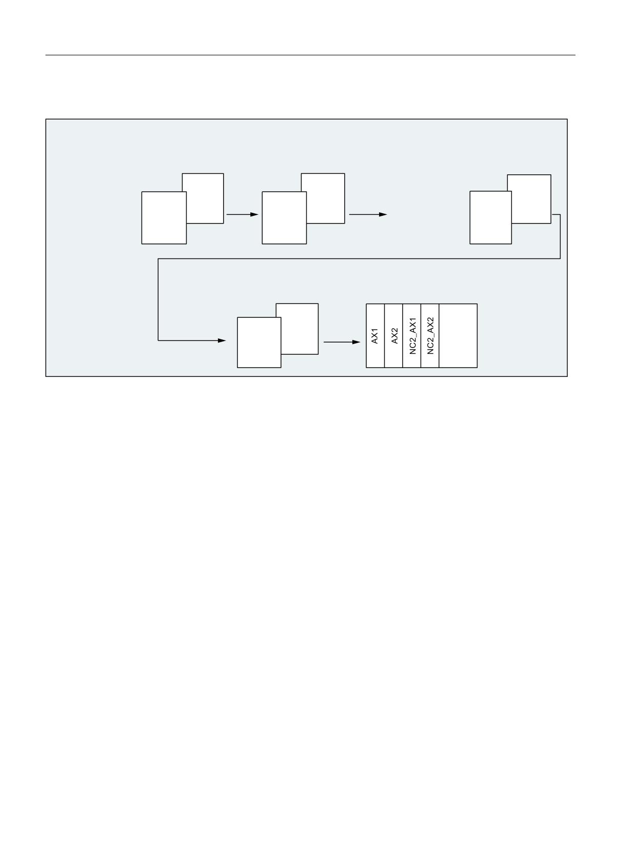
Example
1&8
*HRPHWU\ D[LV QDPH
*HRPHWU\ D[HV XVHG LQ WKH FKDQQHO
&KDQQHO D[LV QDPH
0'
0'
0'
0&B$;&21)B*(2$;B1$0(B7$%
0&B$;&21)B*(2$;B$66,*1B7$%
0&B$;&21)B&+$1$;B1$0(B7$%
&KDQQHO
&KDQQHO
&KDQQHO
;
;
&KDQQHO
&KDQQHO
&KDQQHO
=
=
VW JHRPHWU\ D[LV > @
;
VW FKDQQHO D[LV > @
;
QG JHRPHWU\ D[LV > @
=
QG FKDQQHO D[LV > @
=
UG FKDQQHO D[LV > @
UG JHRPHWU\ D[LV > @
0DFKLQH D[HV XVHG LQ WKH FKDQQHO
/RJLFDO PDFKLQH D[LV LPDJH
0'
0&B$;&21)B0$&+$;B86('
0'
01B$;&21)B/2*,&B0$&+$;B7$%
&KDQQHO
&KDQQHO
Figure 15-10
Example: Parameterization of link axes
Channel 1
The local AX1/AX2 machine axes of the NCU1 are assigned to the X/Z geometry axes.
Channel 2
The NC2_AX1/NC2_AX2 link axes of the NCU2 are assigned to the X/Z geometry axes.
15.2.3.4
Auxiliary function output for spindles
Description
During program execution and after block search with "search via program test" (SERUPRO), the
pre-defined auxiliary functions S, M3, M4, M5, M19 and M70 are output channel-specific on the
NCU on which the spindle has been programmed and also axis-specific on the home NCU.
Output of the channel-specific auxiliary functions
• DB21, ... DBW68 (extended address of the M function)
• DB21, ... DBD70 (M function 1)
• DB21, ... DBW98 (extended address of S function 1)
• DB21, ... DBD100 (S function 1)
Basic functions
840
Function Manual, 10/2020, 6FC5397-2GP40-0BA1
Distributed systems
15.2 NCU link
Output of the axis-specific auxiliary functions
• DB31, ... DBD78 (F function for axis)
• DB31, ... DBW86 (M function for spindle)
• DB31, ... DBD88 (S function for spindle)
Further information
Detailed information regarding the auxiliary function output can be obtained in:
Function Manual Basic Functions, Auxiliary function outputs to PLC
15.2.3.5
Supplementary conditions
Maximum number of machine axes
Even for the use of link axes, as previously, the maximum number of concurrently-usable
geometry and special axes as well as machine axes are still available for each NCU type.
"Lead link axes and "link axes" functions
As the functions "lead link axes" and "link axes" require different settings in machine data
MD18720 $MN_MM_SERVO_FIFO_SIZE, they cannot be used within a link group at the same
time.
Alarms: General behavior
If an error is detected at the position control level of the home NCU of a link axis and the relevant
alarm does not have "NC not ready" as response, the alarm is transferred via the NCU link to the
setpoint-generating NCU and then output.
Alarms: Behavior for emergency stop
If an emergency stop request is activated for an NCU via the NC/PLC interface, all axes physically
connected to this NCU will be switched to the "follow-up" mode. This also affects link axes whose
setpoints are currently generated by other NCUs. Under the assumption that no further practical
machining operations are then possible on these NCUs, an additional alarm will be generated
that stops all dependent axis movements.
Alarm acknowledgement
This additional alarm must be acknowledged by an NC reset. If the original alarm is still active at
this time, although the additional alarm can be acknowledged, an additional self-clearing alarm
will be generated that prevents a traversal of the axes or a program start until the original alarm
has been acknowledged.
Basic functions
Function Manual, 10/2020, 6FC5397-2GP40-0BA1
841
Distributed systems
15.2 NCU link
Alarms: Response for "NC not ready" alarm response
If an error is detected at the position control level of the home NCU of a link axis and the relevant
alarm does not have "NC not ready" as response, the alarm is transferred to the setpoint-
generating NCU via the NCU link and output there. The alarm output is also made on the home
NCU.
Under the assumption that no further practical machining operations are then possible on the
setpoint-generating NCU, an additional alarm will be generated that stops all dependent axis
movements.
Alarm acknowledgement
See alarm acknowledgement under "Alarms: Behavior for Emergency Stop"
Alarms: Behavior for "Mode group not ready" alarm response
If an error is detected within a mode group with several channels and the relevant alarm has
"Mode group not ready" as response, this causes the traversing movements in all channels of the
mode group to stop. If the traversing movements are generally independent of each other, the
response via the following machine data item can be changed to "Channel not ready":
MD11412 $MN_ALARM_REACTION_CHAN_NOREADY = TRUE
Effect
In the NC/PLC interface, instead of signal DB11 DBX26.3 (mode group ready), the signal DB21,
DBX36.5 (channel ready), is reset.
Advantage
The alarm response remains limited to the channel in which the error is detected. If required, the
PLC user program can initiate further responses.
Requirement
There is no higher-priority alarm response than "Mode group not ready".
Compensations
The following compensations are not available:
• Link axes: Quadrant error compensation (QEC)
• Container link axes: Sag compensation (CEC)
Switch-off an NCU in a link group
If an NCU in a link group is switched off, the machining on all other NCUs of the link group will
be cancelled and an alarm issued.
Powering up an NCU group
If an NC reset is triggered on an NCU in a link group, it will also be transferred to all other NCUs
of the link group so that all NCUs of the link group perform a warm restart.
Basic functions
842
Function Manual, 10/2020, 6FC5397-2GP40-0BA1

Distributed systems
15.2 NCU link
Nibbling and punching technologies
The fast inputs/outputs required for the nibbling and punching must be connected and
parameterized on the NCU on which the part program is processed and the axes interpolated.
The commands for "High-speed nibbling and punching", e.g. PONS and SONS, are not available
for link axes.
Frames
A link axis is permitted in a Frame command only when it is a geometry axis. The Frame
command changes only the geometry in the channel to which the link axis is currently assigned.
Speed/torque coupling, master-slave
The drives of all axes/spindles of a master-slave group must be connected to the same NCU. The
master axis can, however, be traversed as link axis for the channel of another NCU.
15.2.4
Axis container
15.2.4.1
General information
An axis container is a circular data structure with a parameterized number of elements. These
elements together with axis containers, are designated as slots (Slot 1, Slot 2, ... Slot n). The slots
allow a variable assignment of geometry and/or special axes to machine axes. The entry in a slot
can reference an NCU-local machine axis (container axis) or a link axis (container-link axis).
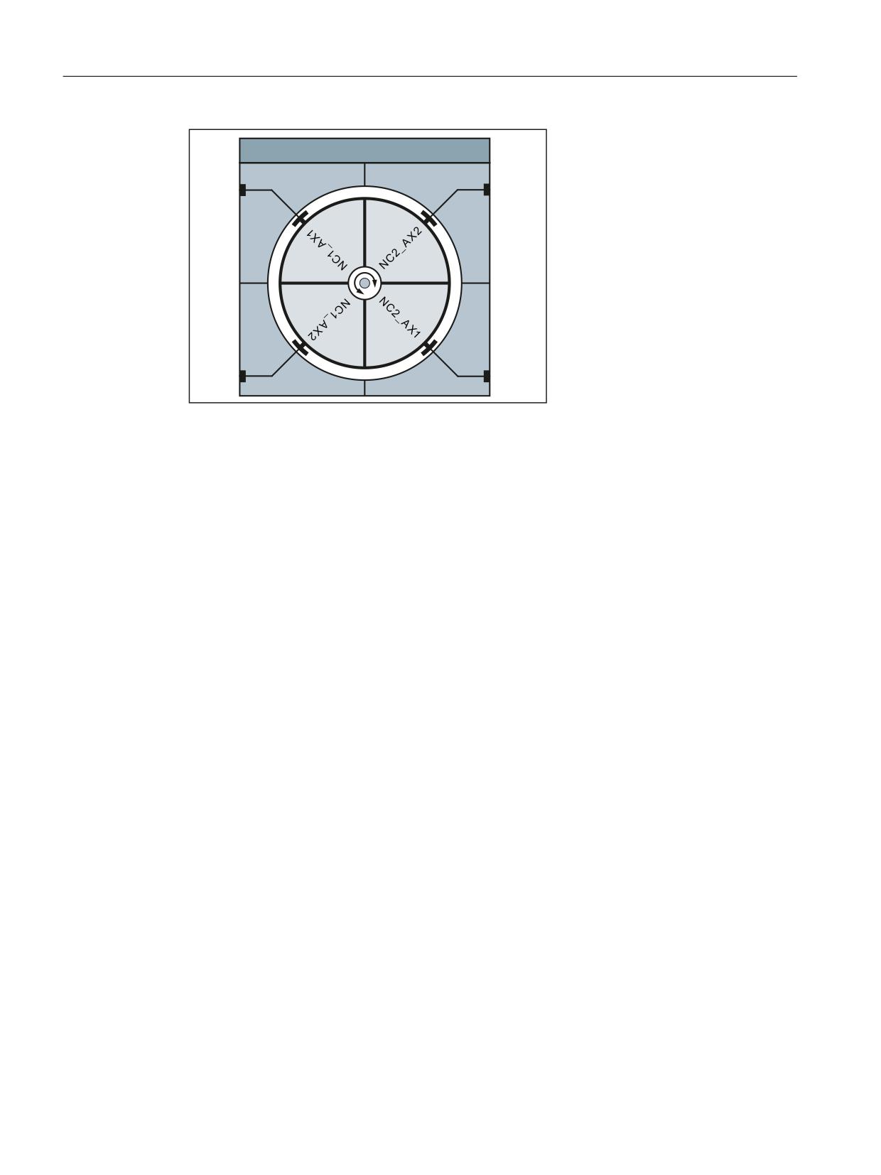
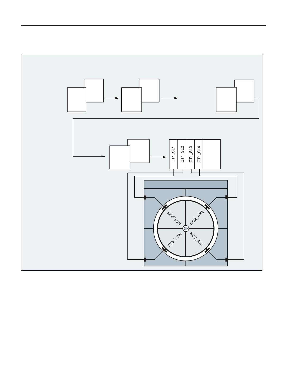
The following figure shows an axis container with four slots. The container axes refer in the
current position of the axis container to the following machine axes:
Container axis
Machine axis
CT1_SL1
NCU 1: AX1
CT1_SL2
NCU 1: AX2
CT1_SL3
NCU 2: AX1
CT1_SL4
NCU 2: AX2
Basic functions
Function Manual, 10/2020, 6FC5397-2GP40-0BA1
843
Distributed systems
15.2 NCU link
$[LV FRQWDLQHU &7
6ORW
6ORW
6ORW
6ORW
Figure 15-11
Example: Axis container CT1 with four slots
Rules
The following rules must be observed with regard to axis containers:
• All machine axes of an axis container may be assigned to just one channel axis at any one
time.
• Multiple slots of an axis container must not reference the same machine axis.
• At any one time, only one channel is authorized to write to a machine axis, directly or via a
container axis.
• Several geometry and/or special axes of a channel can also be assigned to the container axes
of an axis container.
Assignment: Geometry or special axis → container axis
In the logical machine axis image MD10002 $MN_AXCONF_LOGIC_MACHAX_TAB, a container
axis can be assigned as a machine axis via container and slot to a geometry or special axis, e.g.
CONTAINER "CT1", slot "1":
MD10002 $MN_AXCONF_LOGIC_MACHAX_TAB[ n ] = CT1_SL1
During the traversing of the geometry or special axis, the machine axis assigned at this time to
slot 1 then traverses.
Axis container rotation
An axis container rotation is always performed when all channels involved on the axis container
have granted their enable with a program command. After the axis container rotation, other
machine axes are assigned to the geometry or special axes of the channels.
The setting data specifies the increment of an axis container rotation.
See Section "Parameterization (Page 846)".
Basic functions
844
Function Manual, 10/2020, 6FC5397-2GP40-0BA1
Distributed systems
15.2 NCU link
Axis container name
The following program commands can be addressed via the axis container name (<axis
container>):
• Program commands:
- AXCTSWE(<axis container>)
- AXCTSWED(<axis container>)
- AXCTSWEC(<axis container>)
The following names are possible:
CT<container number>: The number of the axis container is attached to the CT letter
combination.
Example: CT3
<container name>:
Individual name of the axis container set using
MD12750 $MN_AXCT_NAME_TAB
Example: A_CONT3
<axis name>:
Axis name of a container axis which is known in the channel
involved.
Implicit wait
There is an implicit wait for the completion of a requested axis container rotation if one of the
following events has occurred:
• Part program language commands which will cause a container axis assigned to this axis
container in this channel to move
• GET(<channel axis name>) on a corresponding container axis
• The next AXCTSWE(<axis container>) for this axis container
Note
Even an IC(0) will result in a wait including synchronization where necessary (block-by-
block change in addressing according to incremental dimension even though an absolute
dimension has been set globally).
Basic functions
Function Manual, 10/2020, 6FC5397-2GP40-0BA1
845

Distributed systems
15.2 NCU link
Synchronization with axis position
If the new container axis assigned to the channel after a container rotation does not have the
same absolute machine position as the previous axis, then the container is synchronized with
the new position (internal REORG).
Note
SD41700 $SN_AXCT_SWWIDTH[<axis container>] is only updated for a new configuration. If,
after incremental rotation of the RTM/MS, the position of a circuit before the initial position is
reached, the container can be rotated normally in the forward direction to reach the initial
position of the container again. The drum or rotary table must however be turned back to the
original position, so that measuring and supply cables are not twisted.
See also
System variable (Page 854)
Programming (Page 852)
15.2.4.2
Parameterization
Machine data
NC-specific machine data
Number
Identifier $MN_
Meaning
MD12750
AXCT_NAME_TAB
Name of the axis container
MD12760
AXCT_FUNCTION_MASK.Bit x
Axis container-specific functions
MD1270x
AXCT_AXCONF_ASSIGN_TABx
Assignment of machine axes to the slots of an axis container
MD18720
MM_SERVO_FIFO_SIZE
Size of the IPO/SERVO data buffer
Note:
The value 3 must be set on all participating NCUs for cross-NCU axis con-
tainers.
Name of the axis container
MD12750 $MN_AXCT_NAME_TAB[ <index> ] = "<name>"
Parameters
Meaning
<index>:
0, 1, … max. axis container index
<name>:
Name of the axis container (e.g. CT1)
Basic functions
846
Function Manual, 10/2020, 6FC5397-2GP40-0BA1
Distributed systems
15.2 NCU link
Axis container-specific functions
MD12760 $MN_AXCT_FUNCTION_MASK.Bit x = <value>
Parameters
<value>
Meaning
Bit 0:
0
For a direct axis container connection (AXCTSWED), all other channels
must be in the RESET state.
1
For a direct axis container connection (AXCTSWED), only other channels
that have the interpolation authorization to axes of the axis container
need to be in the RESET state.
The machine data is used to activate the axis container-specific functions.
Assignment of machine axes to the slots of an axis container
MD1270x $MN_AXCT_AXCONF_ASSIGN_TABx[ <index> ] = <axis>
Parameters
Meaning
x:
1 … max. number of axis containers
<index>:
0, 1, … max. slot index
<axis>:
Name of a local machine axis (e.g. AX1)
Name of a link axis. See Section "General information (Page 837)".
The slots within an axis container must be assigned in ascending order without gaps, starting
with slot index 0.
Setting data
Increment of an axis container rotation
SD41700 $SN_AXCT_SWWIDTH[<index>]=<increment>
Parameters
Meaning
<index>:
0, 1, … max. axis container index
<increment>:
Number of slots through which the axis container rotates
Illustration of the axis container rotation
The axis container rotation is enabled by means of program commands. See Section
"Programming (Page 852)".
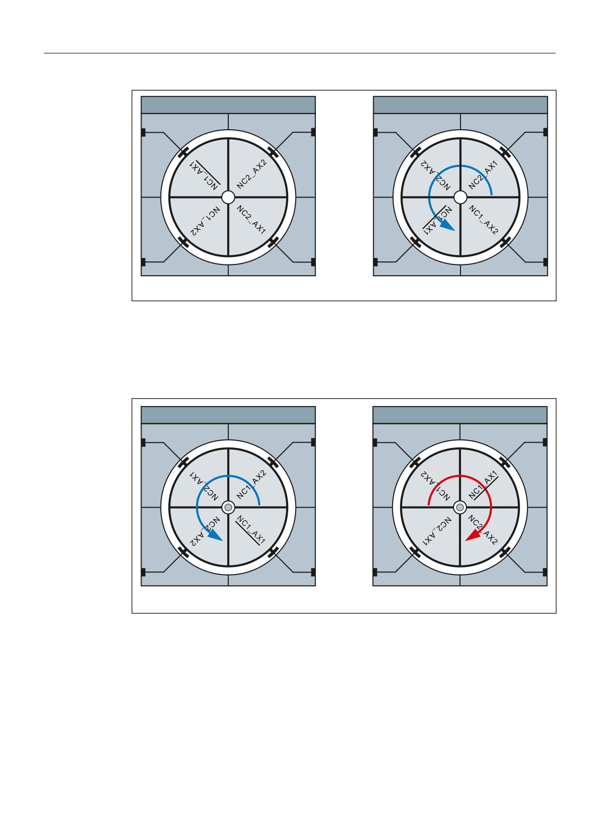
In the left-hand part of the figure "Axis container rotation, Fig. 1," the link axis NCU1_AX1 is
assigned to slot 1 in the initial setting of the axis container.
After the rotation with an increment of 1 (right-hand side), the link axis NCU2_ AX2 is assigned
to slot 1.
Basic functions
Function Manual, 10/2020, 6FC5397-2GP40-0BA1
847
Distributed systems
15.2 NCU link
$[LV FRQWDLQHU &7
$[LV FRQWDLQHU &7
6ORW
6ORW
6ORW
6ORW
6ORW
6ORW
6ORW
6ORW
$VVLJQPHQW SULRU WR URWDWLRQ
$VVLJQPHQW DIWHU URWDWLRQ
6'
61B$;&7B6::,'7+> @
Figure 15-12
Axis container rotation, Fig. 1
Based on the initial setting stated above, the link axis NCU2_ AX1 is assigned to slot 1 after a
rotation with an increment of 2, (figure "Axis container rotation, Fig. 2," left part).
Based on the initial setting stated above, the link axis NCU1_ AX2 is assigned to slot 1 after a
rotation with an increment of -1 (figure "Axis container rotation, Fig. 2," right part).
$[LV FRQWDLQHU &7
$[LV FRQWDLQHU &7
6ORW
6ORW
6ORW
6ORW
6ORW
6ORW
6ORW
6ORW
$VVLJQPHQW DIWHU URWDWLRQ
$VVLJQPHQW DIWHU URWDWLRQ
6'
61B$;&7B6::,'7+> @
6'
61B$;&7B6::,'7+> @
Figure 15-13
Axis container rotation, Fig. 2
Axis container with container-link axes
The parameterization of an axis container that contains container-link axes must be made on the
master NCU of the link group (MD12510 $MN_NCU_LINKNO == 1).
Basic functions
848
Function Manual, 10/2020, 6FC5397-2GP40-0BA1

Distributed systems
15.2 NCU link
Alignment of axial machine data
For container axes, all axial machine data marked with the "CTEQ" (container equal) attribute
must have the same value for all container axes. Any different values will be aligned
automatically.
Control startup
During the control startup, all machine data will be aligned to the values of the container axis
of the first slot. If the value of a machine data item changes, the following message will be
displayed: "The axial machine data of the axes in axis container <n> has been adapted".
Activate machine data
If a machine data item of any container axis is changed, the new value also becomes
immediately available in all other container axes. The following message is displayed: "Caution:
This MD will be set for all container axes".
Slot change
If a slot of an axis container is assigned another machine axis, (MD127xx
AXCT_AXCONF_ASSIGN_TAB<x>), the following message is displayed: "The machine data of the
axes in axis container <n> will be adapted at the next startup".
Note
Container-link axes
For container-link axes, a machine data alignment is performed for all NCUs of the link group
involved on the axis container.
Parameter example
Assumptions
NCU
Components
NCU1:
Channel 1, X/Z geometry axes → 1st/2nd channel axis
Channel 2, X/Z geometry axes → 1st/2nd channel axis
Machine axes: AX1, AX2
CT1 axis container with four slots
NCU2:
Machine axes: AX1, AX2
Basic functions
Function Manual, 10/2020, 6FC5397-2GP40-0BA1
849
Distributed systems
15.2 NCU link
Parameter assignment: NCU1
1&8
*HRPHWU\ D[LV QDPH
*HRPHWU\ D[HV XVHG LQ WKH FKDQQHO
&KDQQHO D[LV QDPH
0'
0'
0'
0&B$;&21)B*(2$;B1$0(B7$%
0&B$;&21)B*(2$;B$66,*1B7$%
0&B$;&21)B&+$1$;B1$0(B7$%
&KDQQHO
&KDQQHO
&KDQQHO
;
;
&KDQQHO
&KDQQHO
&KDQQHO
=
=
VW JHRPHWU\ D[LV > @
;
VW FKDQQHO D[LV > @
;
QG JHRPHWU\ D[LV > @
=
QG FKDQQHO D[LV > @
=
UG FKDQQHO D[LV > @
UG JHRPHWU\ D[LV > @
0DFKLQH D[HV XVHG LQ WKH FKDQQHO
/RJLFDO PDFKLQH D[LV LPDJH
0'
0&B$;&21)B0$&+$;B86('
0'
01B$;&21)B/2*,&B0$&+$;B7$%
&KDQQHO
&KDQQHO
$[LV FRQWDLQHU &7
6ORW
6ORW
6ORW DVVLJQPHQW
0'
01B$;&21)B$66,*1B7$%> @ ಯ1& B$; ರ
01B$;&21)B$66,*1B7$%> @ ಯ1& B$; ರ
01B$;&21)B$66,*1B7$%> @ ಯ1& B$; ರ
01B$;&21)B$66,*1B7$%> @ ಯ1& B$; ರ
6ORW
6ORW
Figure 15-14
Example: Parameter assignment of channel axes and axis containers
Effect
By programming the X and Z geometry axes in the 1st and 2nd channel of the NCU1, the
following axes traverse in the current position of the container:
• The local AX1 and AX2 machine axes of the NCU1.
• As container-link axes, the AX1 and AX2 machine axes of the NCU2.
For the axis container rotation, see Section "Programming (Page 852)".
Basic functions
850
Function Manual, 10/2020, 6FC5397-2GP40-0BA1
Distributed systems
15.2 NCU link
Notes on the parameter assignment
Container axis distribution and communications utilization
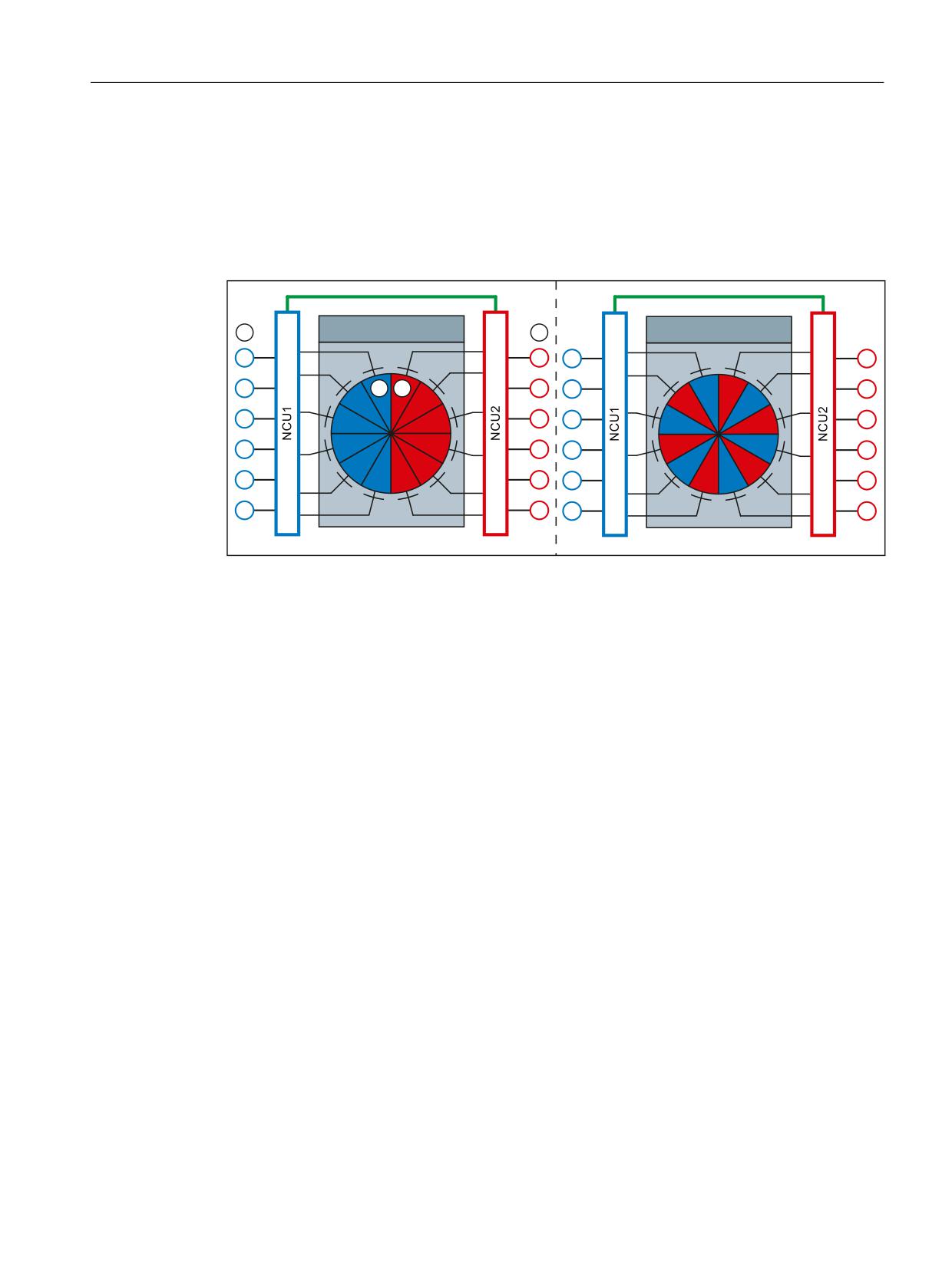
In the case of a plant with several NCUs that traverse alternately axes of other NCUs (link axes)
in conjunction with axis containers, the type and manner how the link axes are distributed
within the axis container decide on the utilization of the link communication.
$[LV FRQWDLQHU &7[
$FKVFRQWDLQHU &7[
6\PPHWULFDO D[LV GLVWULEXWLRQ
$V\PPHWULFDO D[LV GLVWULEXWLRQ
① Blue slot: Refers to a drive connected to the NCU1
② Red slot: Refers to a drive connected to the NCU2
③ Drives connected to NCU1
④ Drives connected to NCU2
Figure 15-15
Axis distribution
• Symmetrical axis distribution
In the case of a symmetrical axis distribution, each NCU first traverses only local axes. This
means no link communication occurs. Provided all NCUs only traverse link axes, each
transition of the axis container increases the utilization of the link communication up to a
maximum.
• Asymmetrical axis distribution
For an asymmetric axis distribution, each NCU traverses local and link axes from the
beginning. Unlike with symmetrical axis distribution, this results in a constant average
utilization of the link communication.
Basic functions
Function Manual, 10/2020, 6FC5397-2GP40-0BA1
851
Distributed systems
15.2 NCU link
Drive distribution and communications utilization
In a system with several NCUs that in conjunction with axis containers alternately traverse axes
of another NCU (link axes), the distribution of the drives connected to the NCU decides the
utilization of the link communication.
•
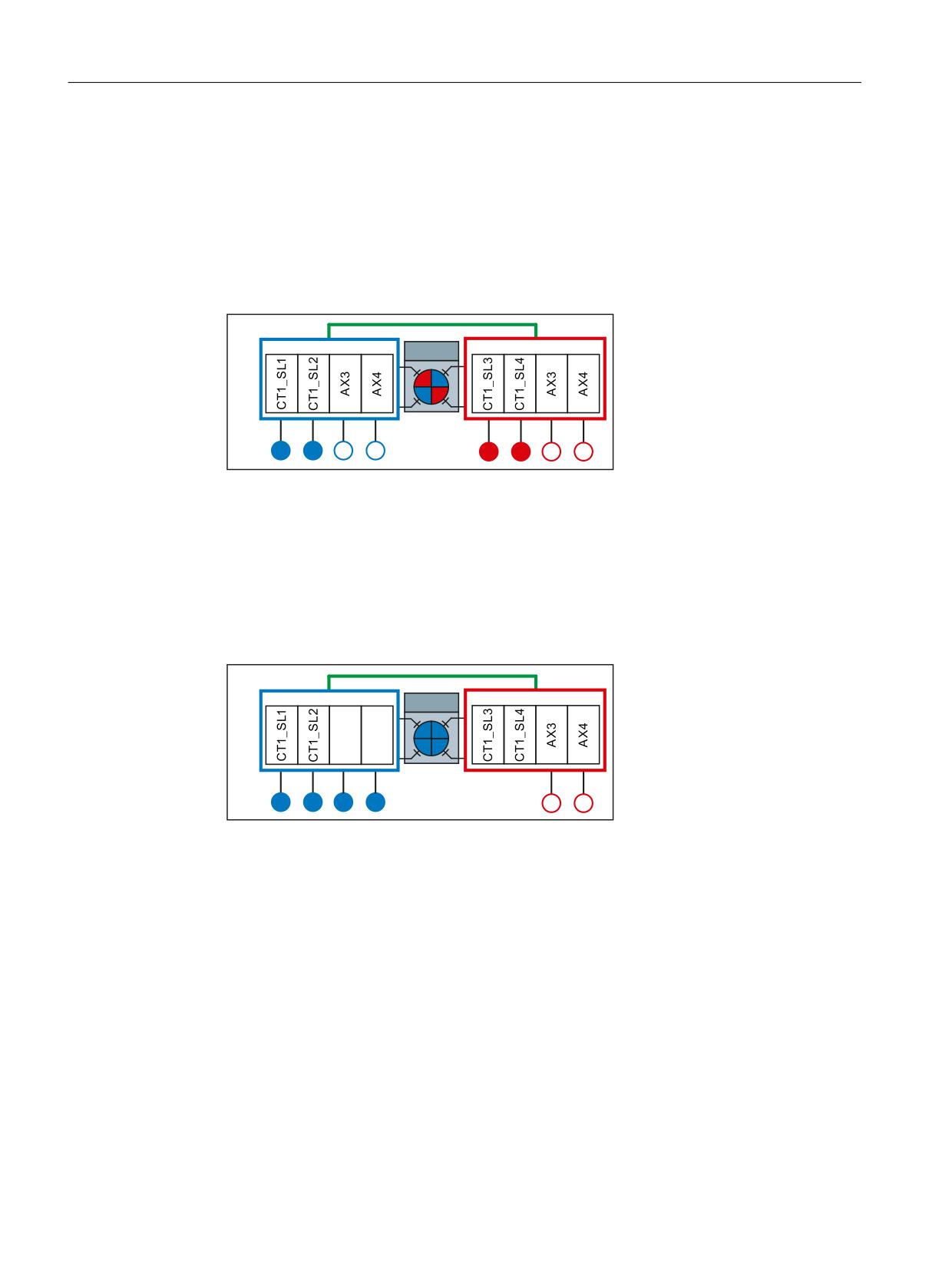
Symmetric drive distribution
In the case of a symmetric drive distribution, the drives addressed via the axis container are
connected to both NCUs. On account of this arrangement, the maximum possible number of
drives can still be addressed via the logical machine axes images (LAI) on both NCUs.
1&8
1&8
&7
/$,
$
$
$
$
$
$
$
$
$
$
$
$
Figure 15-16
Symmetric drive distribution
•
Asymmetric drive distribution
In the case of an asymmetric drive distribution, the drives addressed via the axis container are
only connected to NCU1. On account of this arrangement, the maximum possible number of
drives can only be addressed via the logical machine axes images (LAI) on NCU2. Only the
maximum number minus the drives used by NCU2 can be addressed via the LAI of NCU1. In
order to also be able to use the maximum number of drives on NCU1, they must be connected
to NCU2 and addressed from NCU1 via the NCU link. This results in a higher cyclic link
communication load.
1&8
1&8
&7
/$,
$
$
$
$
$
$
$
$
$
$
Figure 15-17
Asymmetric drive distribution
15.2.4.3
Programming
Function
The AXCTSWE or AXCTSWED commands are used to enable the rotation of the specified axis
container.
Any previously set enable for axis container rotation is cancelled with the AXCTSWEC command.
Syntax
AXCTSWE(<ID>)
AXCTSWED(<ID>)
Basic functions
852
Function Manual, 10/2020, 6FC5397-2GP40-0BA1
Distributed systems
15.2 NCU link
AXCTSWEC(<ID)
Meaning
AXCTSWE:
Enable for rotation of the axis container
The program processing is not stopped by AXCTSWE.
The rotation is performed as soon as all channels involved on the axis container
have been enabled.
The increment of an axis container rotation is set via the SD41700
$SN_AXCT_SWWIDTH setting data (see Section "Parameterization (Page 846)")
AXCTSWED:
Enable to rotate the axis container without consideration of the other channels
involved on the axis container
The increment of an axis container rotation is set via the SD41700
$SN_AXCT_SWWIDTH setting data (see Section "Parameterization (Page 846)")
Note
• Command variant to simplify the commissioning of the part program or
synchronized action.
• The behavior with regard to the other channels involved on the axis con-
tainer can be specified via:
MD12760 $MN_ AXCT_FUNCTION_MASK, bit 0
See Section "Parameterization (Page 846)".
AXCTSWEC:
Canceling the enable to rotate the axis container
Note
The enable for rotating an axis container can only be cancelled when the
rotation has yet not been started:
$AN_AXCTSWA[<axis container>] == 0
See Section "System variable (Page 854)"
<ID>:
Name of the axis container or a container axis:
CT<number>:
Default identifier of an axis container:
MD12750 $MN_AXCT_NAME_TAB
Example: CT1
<Container>:
User-specific name of an axis container:
MD12750 $MN_AXCT_NAME_TAB
Example: CONTAINER_1
<axis>:
Name of a known container axis in the channel
Further information
The use of the AXCTSWEC command in synchronized actions is described in detail in:
Function Manual Synchronized Actions, Detailed description > Actions in synchronized actions
> Cancel release for axis container rotation (AXCTSWEC)
Basic functions
Function Manual, 10/2020, 6FC5397-2GP40-0BA1
853

Distributed systems
15.2 NCU link
15.2.4.4
System variable
Description
Container-specific system variable
System variable
Description
$AC_AXCTSWA[<ID>]
Channel-specific status of the axis container rotation
$AN_AXCTSWA[<ID>]
NCU-specific status of the axis container rotation
$AN_AXCTSWE[<ID>]
Slot-specific status of the axis container rotation
$AN_AXCTAS[<ID>]
Number of slots through which the axis container was just switched
through.
ID: Axis container name or name of a container axis
NC-specific system variable
System variable
Description
$AN_LAI_AX_IS_AXCTAX 1)
Status: LAI axis == container axis
of the machine axes in the logical machine axis image
(MD10002 $MN_AXCONF_LOGIC_MACHAX_TAB) re-
garding axis container.
$AN_LAI_AX_IS_LEADLINKAX 1)
Status: LAI axis == lead-link axis
$AN_LAI_AX_IS_LINKAX 1)
Status: LAI axis == link axis
$AN_LAI_AX_TO_IPO_NC_CHANAX[<ID>]
Channel and channel axis number or NCU-ID and the
global axis number
$AN_LAI_AX_TO_MACHAX[<ID>]
NCU-ID and axis number of the machine axis
1) Bit mask: Bit n ≙ LAI axis (n+1) from MD10002 $MN_AXCONF_LOGIC_MACHAX_TAB
ID: LAI axis number
NCU-ID: Value from MD12510 $MN_NCU_LINKNO
Further information
A detailed description of the system variables can be found in:
List Manual System Variables
See also
Evaluating axis container system variables (Page 866)
Basic functions
854
Function Manual, 10/2020, 6FC5397-2GP40-0BA1
Distributed systems
15.2 NCU link
15.2.4.5
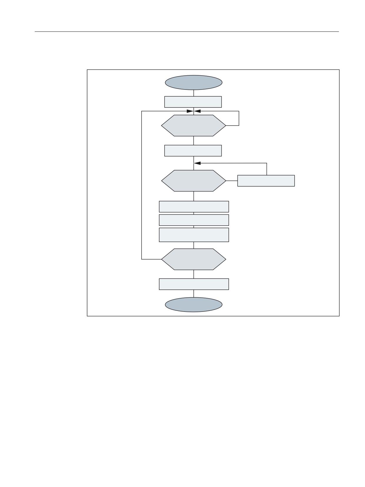
Machining with axis container (schematic)
6WDUW
,QLWLDO VHWXS
,)
+DV D[LV FRQWDLQHU
1R
URWDWLRQ WHUPLQDWHG"
<HV
$1B$;&76:$ &7
6HWXS F\FOLF
,)
+DV URWDWLRQ RQ WKH
0DLQWDLQLQJ
1R
PDFKLQH WHUPLQDWHG"
<HV
0DFKLQH F\FOLF
&OHDQ XS F\FOLF
&RQWDLQHU URWDWLRQ HQDEOH
$;&76:( &7
,)
&RQWLQXH F\FOLF
<HV
PDFKLQLQJ"
1R
)LQDO FOHDQ XS
(QG
Figure 15-18
Example: Schematic machining sequence for a station of a rotary cycle machine
15.2.4.6
Behavior in different operating states
Startup (Power On)
In the startup the controller, with regard to the slot assignment, the initial state defined in the
machine data is always assumed irrespective in which state of the axis container the control was
switched off:
Basic functions
Function Manual, 10/2020, 6FC5397-2GP40-0BA1
855
Distributed systems
15.2 NCU link
MD1270x $MN_AXCT_AXCONF_ASSIGN_TABx
Note
Alignment between setpoint and actual status
After a controller startup, it is the sole responsibility of the user / machine manufacturer to detect
any difference between the status of the axis container and the machine status and to
compensate for this with a suitable axis container rotation.
Mode change
A container axis whose axis container in the Automatic mode was enabled for rotation cannot
be traversed after a change in the JOG mode.
Channel-specific Reset state
As soon as a channel involved on the axis container is in the Reset state, no enable for axis
container rotation is required for this channel. It suffices to enable the remaining active channels.
Block search
An axis container rotation (AXCTSWE) cannot be enabled and activated in one block, but the
enabling and activation commands must be programmed in separate action blocks. In other
words, the axis container status changes in response to each separate rotation command as a
function of the status of other channels.
15.2.4.7
Behavior when withdrawing the release for axis container rotation
TheAXCTSWE command enables the channel-specific axis container rotation for an axis
container. The AXCTSWEC command cancels the enable.
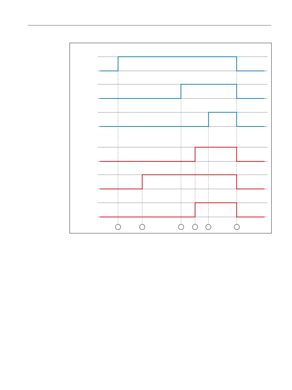
The following figure shows an example the sequence of an axis container rotation as
represented in the axis container-specific system variables. Two channels for two NCUs are
always involved on the axis container.
Basic functions
856
Function Manual, 10/2020, 6FC5397-2GP40-0BA1
Distributed systems
15.2 NCU link
1&8
&KDQQHO
$&B$;&76:$> ,'!@
&KDQQHO
$&B$;&76:$> ,'!@
1&8
$1B$;&76:$> ,'!@
1&8
&KDQQHO
$&B$;&76:$> ,'!@
&KDQQHO
$&B$;&76:$> ,'!@
1&8
$1B$;&76:$> ,'!@
① NCU1, channel1: Enable issued using the AXCTSWE command
② NCU2, channel2: Enable issued using the AXCTSWE command
③ NCU1, channel2: Enable issued via AXCTSWE command → all enables of all channels are now
present in the NCU1 → the overall enable status of NCU1 is transferred to NCU2 via link commu-
nication
④ NCU2, channel1: Enable issued via AXCTSWE command → all enables of all channels are now
present in the NCU2 → the overall enable status of NCU2 is transferred to NCU1 via link commu-
nication
All enable signals for all channels (NCU2 and NCU1) are now present in NCU2 → the axis container
rotation is performed in NCU2
⑤ NCU1: All enable signals for all channels (NCU1 and NCU2) are now present in NCU1 → the axis
container rotation is performed in NCU1
⑥ NCU1/NCU2: axis container rotation has been completed
Figure 15-19
Cross-NCU enable and axis container rotation
To allow a previously granted enable to be canceled, the enable for at least one of the channels
(NCU1 or NCU2) involved on the axis container must still be pending at the time of the
cancellation. This means the cancel must be made before time ④.
Basic functions
Function Manual, 10/2020, 6FC5397-2GP40-0BA1
857
Distributed systems
15.2 NCU link
Withdrawal is no longer possible as soon as all enable signals are available from all channels of
all NCUs (instant in time ④). In this case, the AXCTSWEC command has no effect. No feedback
is sent to the user.
See also
Programming (Page 852)
15.2.4.8
Supplementary conditions
Axis mode
If a container axis in axis mode or as a positioning spindle (POSA, SPOSA) traverses, the axis
container rotates only after reaching the programmed end position.
Spindle
• A container axis active as a spindle continues to rotate during an axis container rotation.
• The control type of a spindle (speed / position control) refers to the associated machine axis.
The set control type "moves" with the machine axis when an axis container rotates.
• For commands that refer to the master spindle of the channel, a machine axis with the
corresponding spindle number must exist in the channel at the time of execution of the
command:
MD35000 $MA_SPIND_ASSIGN_TO_MACHAX[ <axis>] == number of the master spindle
Note
It is the sole responsibility of the user / machine manufacturer to ensure for spindles as
container axes that an appropriate machine axis must still exist in the channel after an axis
container rotation for the master spindle.
Work offsets
Note
It is the sole responsibility of the user / machine manufacturer to ensure that after an axis
container rotation the effective work offsets in the channel are adapted to the changed machine
axis assignments.
Continuous-path mode
If continuous-path mode is active in the channel and an axis container rotation is performed, a
subsequent programming of a container axis interrupts the continuous-path mode. The
interruption also occurs even when the container axis not a path axis.
Basic functions
858
Function Manual, 10/2020, 6FC5397-2GP40-0BA1
Distributed systems
15.2 NCU link
PLC axis
If a container axis whose axis container has been enabled for rotation becomes a PLC axis, the
status change occurs only after completion of the axis container rotation.
Command axis
If a container axis whose axis container has been enabled for rotation traverses as a command
axis, the traversing movement is performed only after completion of the axis container rotation.
Oscillating axis
If a container axis whose axis container has been enabled for rotation becomes an oscillation
axis, the status change occurs only after completion of the axis container rotation.
External work offset
The "external work offset" is based on the machine coordinate system (MCS). Therefore, for an
active "external work offset", one of the container axes rejects the axis container rotation with
alarm 4022.
Axial frames
The axial frame of a channel axis, which is also a container axis, is no longer valid after an axis
container rotation. Since the axis container rotation assigns a new machine axis to the channel
axis, but the axial frame is referred to a machine axis, the rotation also changes the axial frame.
If the two frames do not coincide, a synchronization process (internal REORG) is performed.
Note
The assignment between a channel axis and a machine axis is altered by the axis container
rotation. The current frames remain unchanged after a rotation. The user is responsible for
ensuring that the correct frames are selected after a rotation by programming basic frame
masks, for example.
Transformation
If a container axis is involved as a spindle in a transformation, the transformation must be
deselected before the enable of the axis container rotation.
Axis couplings
If an axis coupling is active for a container axis, the coupling with COUPOF must be deselected
before the enable of the axis container rotation. After completion of the rotation, the coupling
can be immediately selected again with COUPON. A new define of the coupling is not required.
Basic functions
Function Manual, 10/2020, 6FC5397-2GP40-0BA1
859
Distributed systems
15.2 NCU link
Gantry axis
A gantry axis cannot be a container axis.
Travel to fixed limit
If a container axis is at the limit stop, no axis container rotation can be performed.
Drive alarms
If a drive alarm is pending for a container axis, the axis container rotation is not performed.
15.2.5
Lead link axes
15.2.5.1
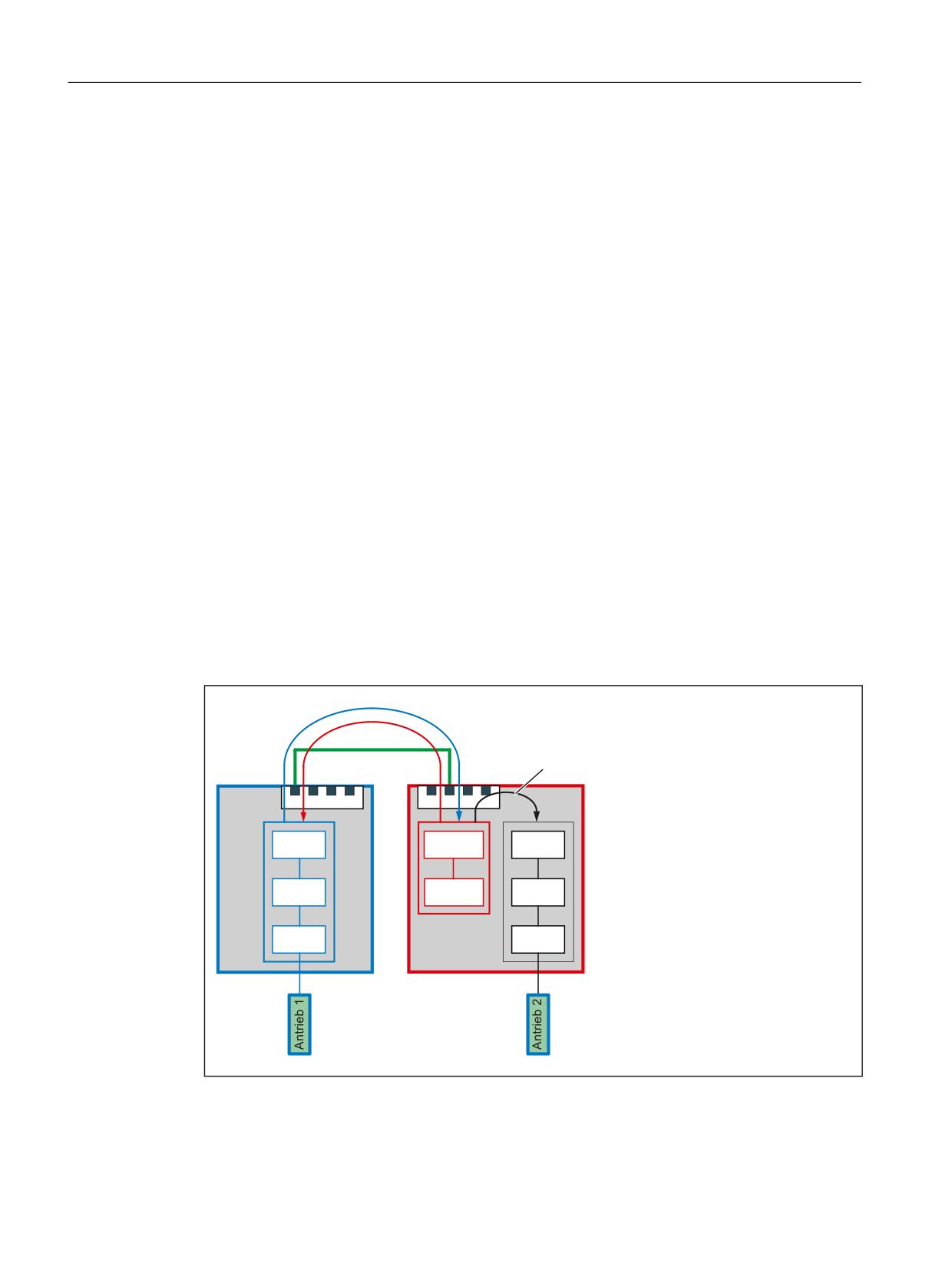
General information
If, for an axis coupling, the the machine axes of the leading and following axes are not connected
to the same NCU, the coupling must be established using a link axis of the NCU of the following
axis. In this case, the link axis is designated as lead-link axis.
The setpoints of the master axis are transferred synchronously in the interpolator cycle via the
NCU link to the lead-link axis. Similarly, in the opposite direction, the actual values and the status
data of the lead-link and the following axis are transferred to the leading axis.
The lead-link axis is parameterized as local leading axis of the following axis.
/HDGLQJ D[LV GDWD
$[LV FRXSOLQJ
)ROORZLQJ D[LV GDWD
/HDG OLQN D[LV
8S
1&8 OLQN
)ROORZLQJ D[LV
1&8
1&8
.DQDODFKVHQ
0'
;
;
<
0&B$;&21)B&+$1$;B1$0(B7$%
/RJ 0DVFKLQHQDFKVDEELOG
$;
1& B$;
$;
0'
01B$;&21)B/2*,&B0$&+$;B7$%
0DVFKLQHQDFKVHQ
/HDG OLQN
0$
0$
0'
$[LV
01B$;&21)B0$&+$;B1$0(B7$%
/HDGLQJ D[LV
)ROORZLQJ D[LV
Figure 15-20
Lead-link axis
Basic functions
860
Function Manual, 10/2020, 6FC5397-2GP40-0BA1

Distributed systems
15.2 NCU link
Coupled axes
Lead link axes can be used in conjunction with following axis couplings:
• Master value coupling
• Coupled motion
• Tangential tracking
• Electronic gear (ELG)
• Synchronous spindle
Requirement
The NCU must communicate via the NCU link. See Section "Link communication (Page 822)"
15.2.5.2
Parameterization
Link communication
NC-specific machine data
Number
Identifier $MN_
Meaning
MD12510
NCU_LINKNO
Unique numerical identification of the NCU within the link group. The
identifiers must be assigned without any gaps in ascending ordering start-
ing from 1.
Value range: 1, 2, ... Maximum NCU number
Note:
The NCU to which the value 1 is assigned as NCU identification is
the master NCU of the link group. The parameterization of link axes and
axis containers may only be made with the machine and setting data of
the master NCU.
MD18780
MM_NCU_LINK_MASK.Bit 0
Activation of the link communication
MD18781
NCU_LINK_CONNECTIONS
Number of internal link connections
Note:
It is recommended to retain the default value 0 (determination of the
number by the NC).
MD18782
MM_LINK_NUM_OF_MODULES
Number of NCUs to be connected with one another via NCU link.
Basic functions
Function Manual, 10/2020, 6FC5397-2GP40-0BA1
861

Distributed systems
15.2 NCU link
Setpoint synchronization
NC-specific machine data
Number
Identifier $MN_
Meaning
MD18720
MM_SERVO_FIFO_SIZE
Size of the IPO/SERVO data buffer
The transfer of the setpoints of the leading axis via the NCU link to the NCU
of the lead-link axis produces a deadtime of two interpolator cycles. The
dead time is compensated by parameterizing the sizes of the IPO/SERVO
data buffer on the NCU of the leading axis and the NCU of the lead-link axis:
• NCU of the leading axis: 4
• NCU of the lead-link axis: 2
Note
With the simultaneous use of lead link axes and cross-NCU axis containers, the axis container
means machine data MD18720 $MN_MM_SERVO_FIFO_SIZE = 3 must be set. This means a
synchronous output of the setpoints for leading and following axis is not possible. The offset
then has the size of one interpolator cycle.
Leading, lead-link and following axis
NC-specific machine data
Number
Identifier $MN_
Meaning
MD10000
AXCONF_MACHAX_NAME_TAB
Machine axis name
MD10002
AXCONF_LOGIC_MACHAX_TAB
Logical machine axis image
Channel-specific machine data
Number
Identifier $MC_
Meaning
MD20070
AXCONF_MACHAX_USED
Used machine axis
Axis-specific machine data
Number
Identifier $MA_
Meaning
MD30554
AXCONF_ASSIGN_MASTER_NCU
Master NCU
If a machine axis can be traversed for several NCUs, one NCU must be
defined as master NCU. The setpoint generation is made after the start-
up of the control for this NCU.
15.2.5.3
System variables to enter a leading value
Leading values can be specified on the NCU of the leading axis using the following system
variable:
• Position leading value: $AA_LEAD_SP[<leading axis>]
• Velocity leading value: $AA_LEAD_SV[<leading axis>]
Basic functions
862
Function Manual, 10/2020, 6FC5397-2GP40-0BA1

Distributed systems
15.2 NCU link
When making a change, the values are also transferred to the NCU of the following axis per NCU
link.
Note
These system variables have a lower transfer priority than those of the link variables.
15.2.5.4
Supplementary conditions
The following supplementary conditions must be observed:
• The leading axis cannot be a link axis
• The leading axis cannot be a container axis
• The leading axis cannot be a gantry axis
• The leading axis may only be replaced within its own NCU (see Section "Cross-channel axis
interchange (Page 539)")
• Couplings with lead link axes must not be cascaded
• A lead link axis must not be traversed independently of the leading axis
Note
"Lead link axes" and "link axes" functions
Because the "lead link axes" and "link axes" functions require different settings in machine
data: MD18720 $MN_MM_SERVO_FIFO_SIZE, they cannot be used simultaneously within a
link group.
15.2.5.5
Example
A detailed example for parameterizing and programming an axis coupling with lead-link axis is
provided in the Section: "Examples" > "Lead link axis (Page 877)".
15.2.6
System of units within a link group
For a cross-NCU interpolation, the same system of units must be active on all NCUs of the link
group.
Common system of units changeover via HMI
The following conditions must be fulfilled for all NCUs of the link group in order that a system of
units changeover can be made from the HMI user interface of an NCU of the link group as well
as on all other NCUs of the link group:
• MD10260 $MN_CONVERT_SCALING_SYSTEM = 1
• For all channels:
MD20110 $MC_RESET_MODE_MASK, Bit 0 = 1
Basic functions
Function Manual, 10/2020, 6FC5397-2GP40-0BA1
863

Distributed systems
15.3 Examples
• All channels are in the reset state
• No axis is traversed in the JOG or DRF mode or via the PLC
• The function "constant grinding wheel peripheral speed (GWPS)" is not active.
If, on one NCU of the link group, one of the specified conditions is not fulfilled, then the system
of units changeover is not made on any of the NCUs of the link group.
Different systems of units
Different systems of units are possible in spite of an active link group, as long as no cross NCU
interpolation takes place. The system of units settings are made for a specific NCU in the part
program or synchronous action using G commands (G70, G71, G700, G710).
Further information
Function Manual Basic Functions; Velocities, setpoint/actual value systems, closed-loop control
15.3
Examples
15.3.1
Link axis
Parameter example for two NCUs each with a link axis
NCU1
Machine data
Note
General link data:
$MN_NCU_LINKNO = 1
Master NCU
$MN_MM_NCU_LINK_MASK = 1
Set NCU-link active
$MN_MM_SERVO_FIFO_SIZE = 3
Size of the data buffer between interpolation and position con-
trol
$MN_MM_LINK_NUM_OF_MODULES = 2
Number of link modules
Logical machine axis image (LAI):
$MN_AXCONF_LOGIC_MACHAX_TAB[0] = "AX1"
Local machine axis
$MN_AXCONF_LOGIC_MACHAX_TAB[1] = "AX2"
Local machine axis
$MN_AXCONF_LOGIC_MACHAX_TAB[2] = "NC2_AX3"
Link axis
Machine axis name, unique system-wide as NCU identifier:
$MN_AXCONF_MACHAX_NAME_TAB[0] = "NC1_A1"
$MN_AXCONF_MACHAX_NAME_TAB[1] = "NC1_A2"
$MN_AXCONF_MACHAX_NAME_TAB[2] = "NC1_A3"
Assignment of channel axis to machine axis:
$MC_AXCONF_MACHAX_USED[0] = 1
1. Channel axis to the machine axis of LAI[0]
Basic functions
864
Function Manual, 10/2020, 6FC5397-2GP40-0BA1

Distributed systems
15.3 Examples
Machine data
Note
$MC_AXCONF_MACHAX_USED[1] = 2
2. Channel axis to the machine axis of LAI[1]
$MC_AXCONF_MACHAX_USED[2]=3
3. Channel axis to the machine axis of LAI[2]
NCU2
Machine data
Note
General link data:
$MN_NCU_LINKNO = 2
Slave NCU
$MN_MM_NCU_LINK_MASK = 1
Set NCU-link active
$MN_MM_SERVO_FIFO_SIZE = 3
Size of the data buffer between interpolation and position con-
trol
$MN_MM_LINK_NUM_OF_MODULES = 2
Number of link modules
Logical machine axis image (LAI):
$MN_AXCONF_LOGIC_MACHAX_TAB[0] = "AX1"
Local machine axis
$MN_AXCONF_LOGIC_MACHAX_TAB[1] = "AX2"
Local machine axis
$MN_AXCONF_LOGIC_MACHAX_TAB[2] = "NC1_AX3"
Link axis
Machine axis name, unique system-wide as NCU identifier:
$MN_AXCONF_MACHAX_NAME_TAB[0] = "NC2_A1"
$MN_AXCONF_MACHAX_NAME_TAB[1] = "NC2_A2"
$MN_AXCONF_MACHAX_NAME_TAB[2] = "NC2_A3"
Assignment of channel axis to machine axis:
$MC_AXCONF_MACHAX_USED[0] = 1
1. Channel axis to the machine axis of LAI[0]
$MC_AXCONF_MACHAX_USED[1] = 2
2. Channel axis to the machine axis of LAI[1]
$MC_AXCONF_MACHAX_USED[2]=3
3. Channel axis to the machine axis of LAI[2]
15.3.2
Axis container coordination
The characteristic as a function of time is displayed from top to bottom in the following tables.
The data are valid on condition that only two channels have axes in the container.
15.3.2.1
Axis container rotation without a part program wait
Channel 1
Channel 2
Comment
AXCTWE(C1)
Part program ...
Channel 1 enables the axis container for
rotation.
Part program without movement of a
Part program ...
container axis
Basic functions
Function Manual, 10/2020, 6FC5397-2GP40-0BA1
865

Distributed systems
15.3 Examples
Channel 1
Channel 2
Comment
AXCTSWE(C1)
Channel 2 enables the axis container for
rotation, container rotates because both
channels have enabled rotation
Part program with movement of a con-
Part program with movement of a con-
Without wait
tainer axis
tainer axis
15.3.2.2
Axis container rotation with an implicit part program wait
Channel 1
Channel 2
Comment
AXCTWE(C1)
Part program ...
Channel 1 enables the axis container for
rotation.
Part program with movement of a con-
Part program ...
Channel 1 waits implicitly for axis con-
tainer axis
tainer rotation
AXCTSWE(C1)
Channel 2 enables the axis container for
rotation, rotation occurs.
Channel 1 is continued.
15.3.2.3
Axis container rotation by one channel only (e.g. during power up)
Channel 1
Channel 2
Comment
AXCTWED(C1)
In the RESET state
Instantaneous rotation
15.3.3
Evaluating axis container system variables
15.3.3.1
Conditional branch
Channel 1
Comment
N100 AXCTWE(CT1)
Channel 1: Enable of the rotation of axis container CT1
MARKER1:
N200 ...
Part program without movement of a container axis
IF $AC_AXCTSWA[CT1] == 1 GOTOB MARKE1
IF rotation of axis container CT1 still active
THEN continue with MARKER1
ELSE (rotation of axis container CT1 completed)
N300 ...
Part program with movement of a container axis
Basic functions
866
Function Manual, 10/2020, 6FC5397-2GP40-0BA1

Distributed systems
15.3 Examples
15.3.3.2
Static synchronized action with $AN_AXCTSWA
Channel 1
Comment
IDS =1 EVERY $AN_AXCTSWA[CT1] == 1 DO M99
Static synchronized action:
Always output auxiliary function M99 at the beginning of an
axis container rotation.
Further information: Synchronized Actions Function Manual
15.3.3.3
Wait for certain completion of axis container rotation
Note
Although programming system variables $AN_AXCTSWA initiates an implicit preprocessing
stop, the subsequent command sequence cannot be used to uniquely identify the completion
of a requested axis container rotation in the channel:
WHILE ($AN_AXCTSWA[<ID>] == TRUE) ; wait: until the enable for axis
container rotation was canceled
ENDWHILE
While the channel in the command sequence waits for the completion of the axis container
rotation, initiated from another channel, a reorganization could be carried out in the
backg16round. For instance, by transferring a requested axis to another channel. As a
consequence, the system variable would then supply the value FALSE. Even if the axis container
rotation had still not been completed.
Recommended command sequence:
RL = $AN_AXCTAS[<ID>] ; read: actual axis container position
AXCTSWE(<ID>)
; enable: axis container rotation
WHILE (RL == $AN_AXCTAS[<ID>]) ; wait: until the read is not equal to
the actual axis container
; position
ENDWHILE
RL is any random user variable.
Example 1: Explicit waiting using system variable $AN_AXCTAS
Program code
Comment
RL = $AN_AXCTAS[<ID>]
; Reading: actual axis container position
AXCTSWE(<ID>)
; Enable: Axis container rotation
WHILE (RL == $AN_AXCTAS[<ID>])
; Wait: Change the axis container
ENDWHILE
; Position
Basic functions
Function Manual, 10/2020, 6FC5397-2GP40-0BA1
867

Distributed systems
15.3 Examples
Example 2: Explicit wait using the WAIT mark
Program code
Comment
CLEARM(9)
; Delete: marker (tag) 9 in the channel
AXCTSWE(<ID>)
; Enable: Axis container rotation
; SynAct: Wait for axis container rotation to have been completed ⇒ set: marker
(tag) 9 in the channel
WHEN $AN_AXCTSWA[<ID>] == TRUE DO SETM(9)
WAITMC(9, 1)
; Wait: Marker (tag) 9 of channel 1
Example 3: Implicit wait using the container spindle
Program code
Comment
; Program (again) the container spindle
; Internally, before starting the container spindle, the system waits for the end
; of the axis container rotation
M3 S100
; Master spindle of the channel
Example 4: Implicit wait using the container axis
Program code
Comment
; Program the container axis incrementally without traversing path
; Internally, before starting the container axis, the system waits for the end
; of the axis container rotation
X=IC(0)
; Channel axis X
15.3.4
Configuration of a multi-spindle turning machine
Introduction
The following example describes the use of:
• Several NCUs in the NCU link group
• Flexible configuration with axis containers
Basic functions
868
Function Manual, 10/2020, 6FC5397-2GP40-0BA1
Distributed systems
15.3 Examples
Machine description
•
Over the circumference of a drum A (front-plane machining), the machine has distributed:
-
4 main spindles, HS1 to HS4
Each main spindle has the possibility of material feed (bars, hydraulic bar feed, axes:
STN1-STN4).
-
4 cross slides
- Each slide has two axes.
- Optionally, a powered tool S1-S4 can operate on each slide.
•
Over the circumference of a drum B (back-plane machining), the machine has distributed:
-
4 counterspindles GS1 to GS4
–
4 cross slides
- Each slide has two axes.
- Optionally, a powered tool S5-S8 can operate on each slide.
- Each counterspindle can be moved through a linear axis, for example, for transferring
parts from the main spindle for the rear-plane machining in drum B. (Transfer axes. Axes:
ZG1-ZG4).
•
Couplings:
- If drum A rotates, all of the main spindles of this drums are subordinated to a different
group of slides.
- If drum B rotates, all of the counterspindles and all of the transfer axes of this drum are
subordinated to a different group of slides.
- The rotations of drums A and B are autonomous.
- The rotations of drums A and B are limited to 270 degrees.
(range and twisting of supply cables)
Term: Position
Main spindle HSi and counterspindle GSi together with their slides characterize a position.
NCU assignment
The axes and spindles of a position (for this example) are each assigned to an NCU. One of the
NCUs, the master NCU, also controls the axes for rotating drums A and B. The result is 4 NCUs
with a maximum of the following axes:
Number of axes
Per NCUi the following axes/spindles must be configured:
Slide 1: Xi1, Zi1
2: Xi2, Zi2
Spindles: HSi, GSi, powered tools: S1, S2
Basic functions
Function Manual, 10/2020, 6FC5397-2GP40-0BA1
869
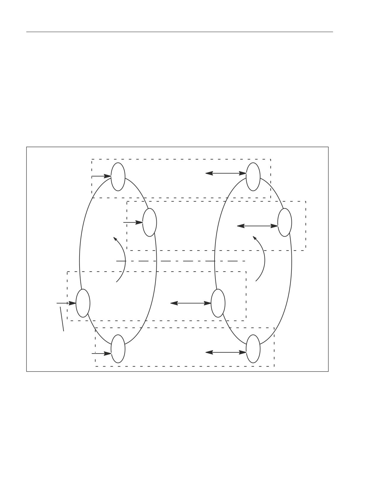
Distributed systems
15.3 Examples
Transfer axis: ZG
i
Bar feed: STNi.
For the master NCU, the two axes for rotating drums A and B are added to the above-mentioned
axes. The list shows that it would not be possible to configure the axis number for a total of 4
positions via an NCU. (Limit 31 axes, 4 + 10 + 2 axes are required).
Axis container
With rotation of drums A/B, HSi, GSi, ZGi and STNi must be assigned to another NCU and must
therefore be configured as link axes in axis containers.
Front-plane machining: Drum V
Back-plane machining: Drum H
NCUd
ZG4
STN4
HS4
Part transfer
GS4
Position d
NCUc
STN3
ZG3
HS3
GS3
Part transfer
Position c
TRV
TRH
NCUa
ZG1
HS1
GS1
Part transfer
Position a
STN1
NCUb
ZG2
Bar feed:
HS2
GS2
STN2
Part transfer
Position b
Figure 15-21
Schematic diagram of main spindles HSi, countersp. GSi, bar feed axis STNi and transfer axes ZGi
Basic functions
870
Function Manual, 10/2020, 6FC5397-2GP40-0BA1
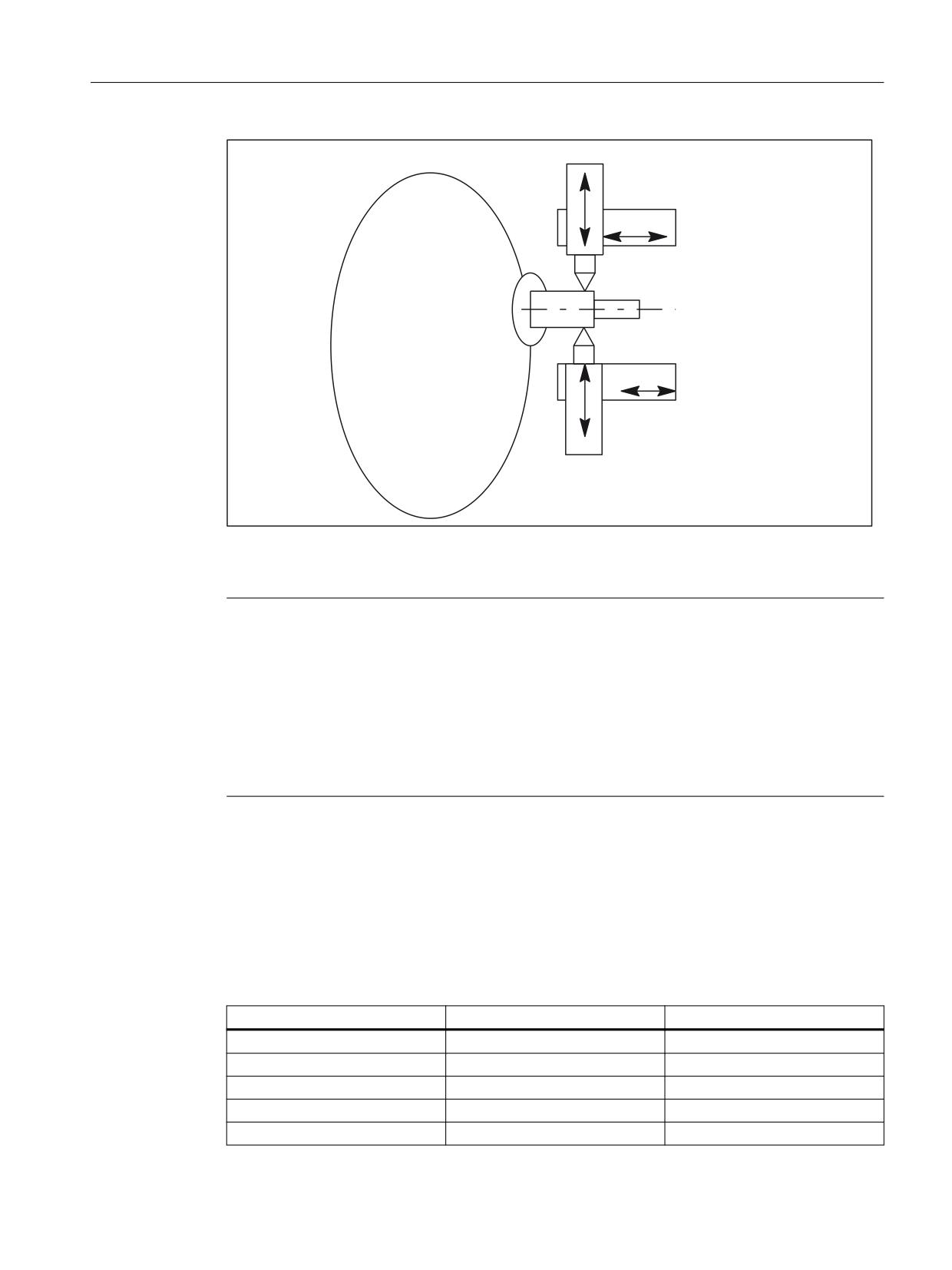
Distributed systems
15.3 Examples
; &
= &
3RVLWLRQ F
+6
= &
; &
Figure 15-22
Two slides per position can also work together on one spindle.
Note
The axes are given the following names in order to clarify the assignments of axes to slides and
positions:
Xij with i slide (1, 2), j position (A-D)
Zij with i slide (1, 2), j position (A-D)
Whereas the positions and their slides remain in one place, main spindles, counterspindles, bar
feed axes STN and transfer axes ZG move to new positions as the result of rotations of drums V
or H.
For example, the axes to be managed per NC when the slide is taken into account are as follows
for the configurations shown in the above diagrams:
Axes of master NCU
Table 15-1
Axes of master NCU: NCUa
Common axes
Local axes
Remark
TRV (drum V)
Only master NCU
TRH (drum H)
Only master NCU
X1A
Slide 1
Z1A
Slide 1
X2A
Slide 2
Basic functions
Function Manual, 10/2020, 6FC5397-2GP40-0BA1
871

Distributed systems
15.3 Examples
Common axes
Local axes
Remark
Z2A
Slide 2
S1
Slide 1
S2
Slide 2
HS1
Axis container required
GS1
Axis container required
ZG1
Axis container required
STN1
Axis container required
4
8
Axes of the NCUb to NCUd
The NCUs that are not master NCUs have the same axes with the exception of the axes for the
drive for drums TRV and TRH. The letter designating the position must be replaced accordingly
for the NCU and axis name (a, A → b, B to d, D).
Configuration rules
The following rules were applied for the configuration described below:
• Main spindle, counterspindles and axes that are assigned to different NCUs through drum
rotation while they are operating as illustrated in the above diagram "Main spindle ..." must
be configured in an axis container.
(HSi, GSi, ZGi, STNi).
• All main spindles of drum A are in the same container (No. 1).
• All bar feed axes of drum A are in the same container (No. 2).
• All counterspindles of drum B are in the same container (No. 3).
• All transfer axes of drum B are in the same container (No. 4).
• The main spindles HSi and their counterspindles GSi as well as the transfer axes of the
counterspindle ZGi and the bar feed axes STNi of the main spindle are assigned as follows for
reasons of NCU equal load distribution:
NCUa HS1-STN1,
NCUb HS2-STN2, ... etc.
• Slide axes Xij, Zij are purely local axes with fixed NCU assignment.
• Slides are assigned to a dedicated channel of an NCU in each case.
Slides can therefore be moved autonomously.
Basic functions
872
Function Manual, 10/2020, 6FC5397-2GP40-0BA1

Distributed systems
15.3 Examples
Configuration options
• Main spindles or counterspindles must be flexibly assigned to the slide.
• The speed of the main spindle and the counterspindle can be defined independently in each
position.
Exceptions:
During the parts change from front-plane machining in drum V to rear-plane machining in
drum H, the speeds of the main spindle and the counterspindle must be synchronized
(synchronous spindle coupling).
In cases where slide 2 also participates in front-plane machining so as to "support" slide 1, the
main spindle speed also applies to slide 2. Similarly if slide 1 participates in rear-plane
machining, the counterspindle speed also applies to slide 1.
Minor changes in speed
Due to the unavoidable time delays incurred in the processing of actual values, abrupt changes
in speed should be avoided during cross-NCU machining operations. See axis data and signals.
Configuration for NCU1
Uniform use of channel axis names in the part programs:
S4: Main spindle
S3: Counterspindle
X1: Infeed axis
Z1: Longitudinal axis
S1: Driven tool
Z3: Transfer axis
TRV: Drum V for main spindle
TRH: Drum H for counterspindle
STN: Hydraulic bar feed
Axes highlighted in bold characterize the current channel as home channel for the axis in
conjunction with axis replacement.
Table 15-2
NCUa, position: a, channel: 1, slide: 1
Channel axis name
..._MA-
$MN_
Container, slot
Machine axis name
CHAX_USED AXCONF_LOGIC_MA-
entry (string)
CHAX_TAB
S4
1
AX1: CT1_SL1
1 1
HS1
NC1_AX1
S3
2
AX2: CT3_SL1
3 1
GS1
NC1_AX2
X1
3
AX3:
X1A
Z1
4
AX4:
Z1A
Basic functions
Function Manual, 10/2020, 6FC5397-2GP40-0BA1
873

Distributed systems
15.3 Examples
Channel axis name
..._MA-
$MN_
Container, slot
Machine axis name
CHAX_USED AXCONF_LOGIC_MA-
entry (string)
CHAX_TAB
Z3
5
AX5: CT4_SL1
4 1
ZG1
NC1_AX5
S1
6
AX6:
WZ1A
STN
7
AX7: CT2_SL1
2 1
STN1
NC1_AX7
TRV
11
AX11:
TRV
TRH
12
AX12:
TRH
x2 *
z2 *
Table 15-3
NCUa, position: a, channel: 2, slide: 2
Channel axis name
..._MA-
$MN_
Container, slot
Machine axis name
CHAX_USED AXCONF_LOGIC_MA-
entry (string)
CHAX_TAB
S4
1
AX1: CT1_SL1
1 1
HS1
NC1_AX1
S3
2
AX2: CT3_SL1
3 1
GS1
NC1_AX2
Z3
5
AX5: CT4_SL1
4 1
ZG1
NC1_AX5
STN
7
AX7: CT2_SL1
2 1
STN1
NC1_AX7
X2
8
AX8:
X2A
Z2
9
AX9:
Z2A
S1
10
AX10:
WZ2A
x1 *
z1 *
Note
* due to program coordination via axis positions and 4-axis machining in one position
For the entry in a location of the axis container, the format: "NC1_AX.." is required, with the
meaning NC1 = NCU 1. In the above tables, NCUa is mapped to NC1_..., NCUb to NC2_..., etc.
Basic functions
874
Function Manual, 10/2020, 6FC5397-2GP40-0BA1

Distributed systems
15.3 Examples
Further NCUs
The above listed configuration data must be specified accordingly for NCUb to NCUd. The
following must be observed:
• The axes TRA and TRB are only available for NCUa, channel 1.
• The container numbers are retained for the additional NCUs, as specified for the individual
axes.
• The slot numbers are as follows:
NCUb → 2
NCUc → 3
NCUd → 4.
• The machine axis names are as follows:
NCUb → HS2, GS2, ZG2, STN2
NCUc → HS3, GS3, ZG3, STN3
NCUd → HS4, GS4, ZG4, STN4.
Axis container
The information relating to containers given in Table 7-17 and the container entries of the
similarly configured NCUs, NCUb to NCUd, are specified in the following tables, sorted according
to containers and slots, as they have to be set in machine data:
MD12701 $MN_AXCT_AXCONF_ASSIGN_TAB1[slot]
MD12716 $MN_AXCT_AXCONF_ASSIGN_TAB16[slot]
whereby slots: 1-4 must be set for the 4 positions of a multi-spindle turning machine:
Note
For the machine data entry
$MN_AXC_AXCONF_ASSIGN_TABi[slot]
the values (without decimal point and machine axis name) that are entered under initial position
in the above tables must be set.
Table 15-4
Axis containers and their position-dependent contents for drum A
Container
Slot
Initial Situation
Switch 1
Switch 2
Switch 3
Switch 4 =
(TRA 0°)
(TRA 90°)
(TRA 180°)
(TRA 270°)
(TRA 0°)
1
1
NC1_AX1, HS1
NC2_AX1, HS2
NC3_AX1, HS3
NC4_AX1, HS4
NC1_AX1, HS1
2
NC2_AX1, HS2
NC3_AX1, HS3
N4C_AX1, HS4
NC1_AX1, HS1
NC2_AX1, HS2
3
NC3_AX1, HS3
NC4_AX1, HS4
NC1_AX1, HS1
NC2_AX1, HS2
NC3_AX1, HS3
4
NC4_AX1, HS4
NC1_AX1, HS1
NC2_AX1, HS2
NC3_AX1, HS3
NC4_AX1, HS4
Basic functions
Function Manual, 10/2020, 6FC5397-2GP40-0BA1
875
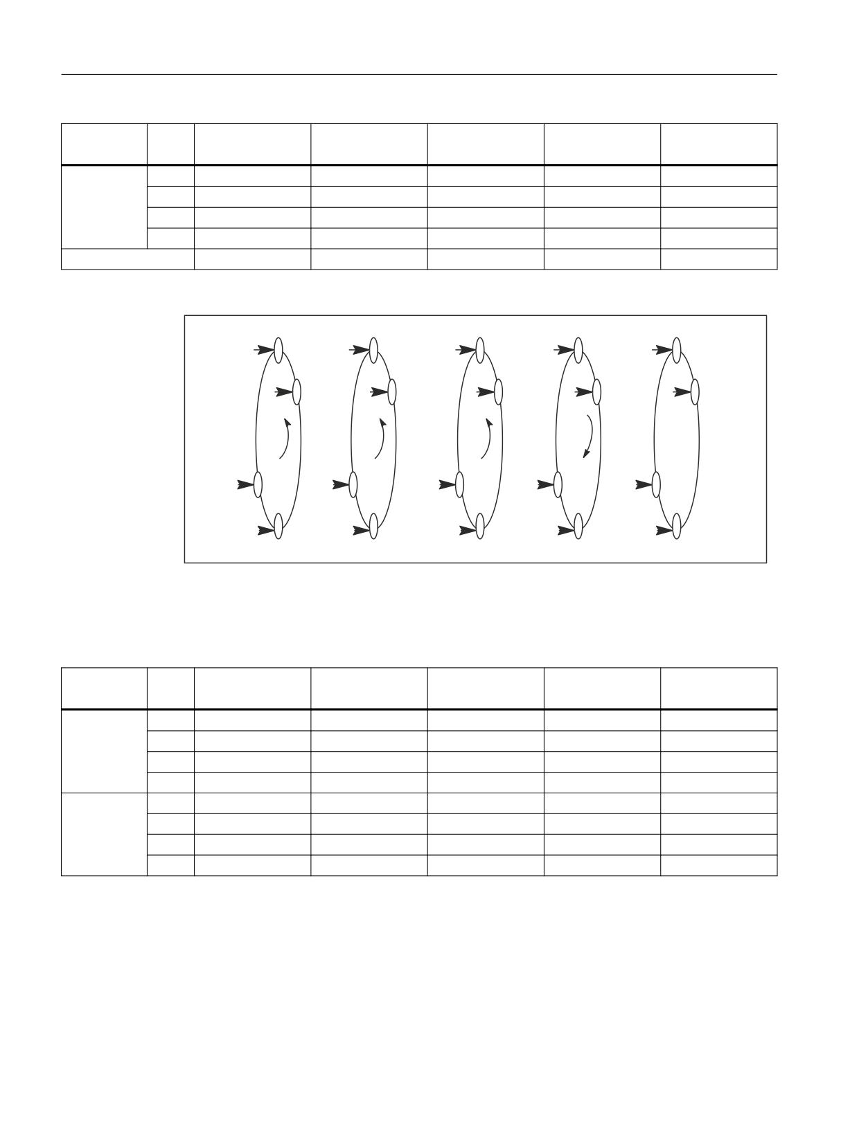
Distributed systems
15.3 Examples
Container
Slot
Initial Situation
Switch 1
Switch 2
Switch 3
Switch 4 =
(TRA 0°)
(TRA 90°)
(TRA 180°)
(TRA 270°)
(TRA 0°)
2
1
NC1_AX7, STN1
NC2_AX7, STN2
NC3_AX7, STN3
NC4_AX7 STN4
NC1_AX7, STN1
2
NC2_AX7, STN2
NC3_AX7, STN3
NC4_AX7, STN4
NC1_AX7, STN1
NC2_AX7, STN2
3
NC3_AX7, STN3
NC4_AX7, STN4
NC1_AX7, STN1
NC2_AX7, STN2
NC3_AX7, STN3
4
NC4_AX7, STN4
NC1_AX7, STN1
NC2_AX7, STN2
NC3_AX7, STN3
NC4_AX7, STN4
Drum movement
0°
+ 90°
+ 90°
+ 90°
- 270°
STN4
STN3
STN2
STN1
STN4
HS4
HS3
HS2
HS1
HS4
HS3
HS2
HS1
HS4
HS3
STN3
STN2
STN1
STN4
STN3
HS1
HS4
HS3
HS2
HS1
STN1
STN4
STN3
STN2
STN1
HS2
HS1
HS4
HS3
HS2
STN2
STN1
STN4
STN3
STN2
Figure 15-23
Positions of drum A
Table 15-5
Axis containers and their position-dependent contents for drum B
Container
Slot
Initial Situation
Switch 1
Switch 2
Switch 3
Switch 4 =
(TRB 0°)
(TRB 90°)
(TRB 180°)
(TRB 270°)
(TRB 0°)
3
1
NC1_AX2, GS1
NC2_AX2, GS2
NC3_AX2, GS3
NC4_AX2, GS4
NC1_AX2, GS1
2
NC2_AX2, GS2
NC3_AX2, GS3
NC4_AX2, GS4
NC1_AX2, GS1
NC2_AX2, GS2
3
NC3_AX2, GS3
NC4_AX2, GS4
NC1_AX2, GS1
NC2_AX2, GS2
NC3_AX2, GS3
4
NC4_AX2, GS4
NC1_AX2, GS1
NC2_AX2, GS2
NC3_AX2, GS3
NC4_AX2, GS4
4
1
NC1_AX5, ZG1
NC2_AX5, ZG2
NC3_AX5, ZG3
NC4_AX5 ZG4
NC1_AX5, ZG1
2
NC2_AX5, ZG2
NC3_AX5, ZG3
NC4_AX5, ZG4
NC1_AX5, ZG1
NC2_AX5, ZG2
3
NC3_AX5, ZG3
NC4_AX5, ZG4
NC1_AX5, ZG1
NC2_AX5, ZG2
NC3_AX5, ZG3
4
NC4_AX5, ZG4
NC1_AX5, ZG1
NC2_AX5, ZG2
NC3_AX5, ZG3
NC4_AX5, ZG4
Basic functions
876
Function Manual, 10/2020, 6FC5397-2GP40-0BA1
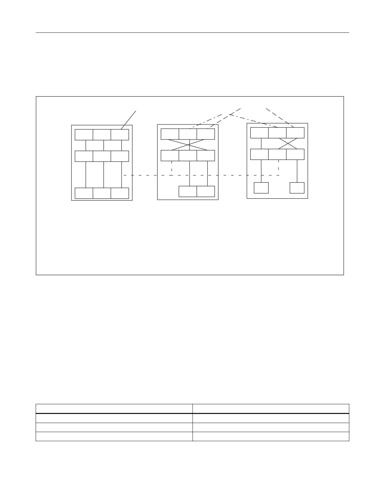
Distributed systems
15.3 Examples
15.3.5
Lead link axis
15.3.5.1
Configuration
Lead link axes
Master
Following
axis
axes
X
Y
Z
X
Y
Z
X
Y
Z
LAX 1
LAX 2
LAX 3
LAX 1
LAX 2
LAX 3
LAX 1
LAX 2
LAX 3
AX 1
AX 3
AX 1
AX 2
AX 3
AX 2
AX 3
NCU 1
NCU 2
NCU n
Coupled axes on leading axis NC1_AX3 with
Z(LAX1) on NCU2 and Z(LAX2) on NCUn as
lead link axes
Figure 15-24
NCU2 to NCUn use a lead link axis to enable coupling to the machine axis on NCU1 (NCU1-AX3).
The following example refers to the axis coupling section between Y(LAX2, AX2) as following
axis on NCU2 and Z(LAX3, NC1_AX3) as lead link axis.
Machine data
• The machine data of a leading value axis may only be loaded on the home NCU. From this
NCU, the relevant machine data are distributed to the other NCUs where a lead link axis has
been defined.
• Each lead link axis reduces the maximum number of axes that can be traversed on this NCU
by one axis.
Machine data for NCU1 (leading axis)
Machine data
Meaning
$MN_NCU_LINKNO = 1
1. or master NCU
$MN_MM_NCU_LINK_MASK = 1
NCU link active
$MN_MM_LINK_NUM_OF_MODULES= 2
Number of link modules
Basic functions
Function Manual, 10/2020, 6FC5397-2GP40-0BA1
877

Distributed systems
15.3 Examples
Machine data
Meaning
$MN_MM_SERVO_FIFO_SIZE = 4
The size of the data buffer is increased to 4 between interpo-
lation and position control
$MN_AXCONF_LOGIC_MACHAX_TAB[0] = "AX1"
$MN_AXCONF_LOGIC_MACHAX_TAB[1] = "AX2"
$MN_AXCONF_LOGIC_MACHAX_TAB[2] = "AX3"
$MN_AXCONF_MACHAX_NAME_TAB[0] = "XM1"
$MN_AXCONF_MACHAX_NAME_TAB[2] = "YM1"
$MA_AXCONF_ASSIGN_MASTER_NCK[ AX3 ] = 1
$MC_AXCONF_MACHAX_USED[0]=1 ; X
$MC_AXCONF_MACHAX_USED[1]=2 ; Y
$MC_AXCONF_MACHAX_USED[2]=3 ; Z
Machine data for NCU2 (following axis)
Machine data
Meaning
$MN_NCU_LINKNO = 2
2. NCU number
$MN_MM_NCU_LINK_MASK = 1
Activate link
$MN_MM_NUM_CURVE_TABS = 5
Number of curve tables
$MN_MM_LINK_NUM_OF_MODULES= 2
Number of link modules
$MN_MM_NUM_CURVE_SEGMENTS= 50
$MN_MM_NUM_CURVE_POLYNOMS = 100
$MN_MM_SERVO_FIFO_SIZE = 2
Size of the data buffer between interpolation and position
control (standard)
$MN_AXCONF_LOGIC_MACHAX_TAB[0] = "NC1_AX3"
Lead link on NCU1/AX3
$MN_AXCONF_LOGIC_MACHAX_TAB[1] = "AX2"
$MN_AXCONF_LOGIC_MACHAX_TAB[2] = "AX3"
$MC_AXCONF_MACHAX_USED[0]=3
AX3 is machine axis of the 1st channel axis
$MC_AXCONF_MACHAX_USED[1]=2
AX2 is machine axis of the 2nd channel axis
$MC_AXCONF_MACHAX_USED[2]=1
AX3 on NCU1 is machine axis of the 3rd channel axis
15.3.5.2
Programming
Program for NCU1 (leading axis)
NCU1 traverses leading axis Z
Identifier for NCU2, that the leading axis of NCU1 is assigned: Link variable $A_DLB[0] = 1
Basic functions
878
Function Manual, 10/2020, 6FC5397-2GP40-0BA1
Distributed systems
15.3 Examples
Identifier for NCU2, that the leading axis of NCU1 has been released: Link variable $A_DLB[0] =
0
Program code
Comment
N1000 R1 = 0
; Initialize loop counter
N1004 G1 Z0 F1000
; Traverse axis Z to the starting position
N1005 $A_DLB[0] = 1
; Identifier for NCU2: Axis Z is assigned
LOOP10:
;
N1005 R1=R1+1
; Increment loop counter
N1006 Z0.01 G91
; Traversing the leading value axis Z
N1008 Z0.02
; Traversing the leading value axis Z
N1010 Z0.03
; Traversing the leading value axis Z
N1012 IF R1 < 10 GOTOB LOOP10
;
N1098 $A_DLB[0] = 0
; Identifier for NCU2: Axis Z is free
Program for NCU2 (following axis)
The program establishes a connection between leading axis movements on NCU1 and following
axis movements on NCU2 via a curve table. If the table has been defined, NCU2 goes into the
wait position (N2006) until NCU1 has assigned axis Z as the leading axis (N1005). The coupling
is activated (N2010) as soon as axis Z has been assigned as leading axis. The coupling is kept until
NCU1 has released axis Z as the leading axis.
Program code
Comment
N2000 CTABDEL(1)
; Initialize table 1
N2001 G04 F.1
;
N2003 G0 Y0 Z0
; Traverse axes Y, Z into the starting position
N2002 CTABDEF(Y, Z, 1, 0)
; Table definition ON
N2003 G1 X0 Y0
;
Intermediate point 1
N2004 G1 X100 Y200
;
Intermediate point 2
N2005 CTABEND
; Table definition OFF
LOOP20:
;
N2006 IF ($A_DLB[0] == 0) GOTOB LOOP20
; Wait for NCU1
N2010 LEADON(Y,Z,1)
;
=> close coupling
LOOP25:
;
N2030 IF ($A_DLB[0] > 0) GOTOB LOOP25
; Keep the coupling until NCU1 no longer traver-
ses the leading value axis
N2090 LEADOF(Y,Z)
;
=> open coupling
Basic functions
Function Manual, 10/2020, 6FC5397-2GP40-0BA1
879

Distributed systems
15.4 Data lists
15.4
Data lists
15.4.1
Machine data
15.4.1.1
General machine data
Number
Identifier: $MN_
Description
10002
AXCONF_LOGIC_MACHAX_TAB
Logical NCU machine axis image
10065
POSCTRL_DESVAL_DELAY
Position setpoint delay
10134
MM_NUM_MMC_UNITS
Number of simultaneous MMC communication partners
12510
NCU_LINKNO
NCU number in an NCU group
12520
LINK_TERMINATION
NCU numbers for which bus terminating resistors are
active
12530
LINK_NUM_OF_MODULES
Number of link modules
12701
AXCT_AXCONF_ASSIGN_TAB1
List of axes in the axis container
12716
AXCT_AXCONF_ASSIGN_TAB16
12750
AXCT_NAME_TAB
List of axis container names
12760
AXCT_FUNCTION_MASK
Functions for the axis container
18700
MM_SIZEOF_LINKVAR_DATA
Size of the link variables memory
18720
MM_SERVO_FIFO_SIZE
Size of the data buffer between interpolation and posi-
tion controller
18780
MM_NCU_LINK_MASK, bit 0
Link communication activation
15.4.1.2
Channelspecific machine data
Number
Identifier: $MC_
Description
20000
CHAN_NAME
Channel name
20070
AXCONF_MACHAX_USED
Machine axis number valid in channel
28160
MM_NUM_LINKVAR_ELEMENTS
Number of write elements for the NCU link variables
15.4.1.3
Axis/spindlespecific machine data
Number
Identifier: $MA_
Description
30550
AXCONF_ASSIGN_MASTER_CHAN
Default assignment between an axis and a channel
30554
AXCONF_ASSIGN_MASTER_NCU
Initial setting defining which NCU generates setpoints
for the axis
30560
IS_LOCAL_LINK_AXIS
Axis is a local link axis
32990
POCTRL_DESVAL_DELAY_INFO
Current position setpoint delay
Basic functions
880
Function Manual, 10/2020, 6FC5397-2GP40-0BA1

Distributed systems
15.4 Data lists
15.4.2
Setting data
15.4.2.1
General setting data
Number
Identifier: $SA
Description
41700
AXCT_SWWIDTH[container number]
Axis container rotation setting
15.4.2.2
Axis/spindle-specific setting data
Number
Identifier: $SA_
Description
43300
ASSIGN_FEED_PER_REV_SOURCE
Rotational feedrate for positioning axes/spindles
15.4.3
Signals
15.4.3.1
Signals from NC
Signal name
SINUMERIK 840D sl
MCP1 ready
DB10.DBX104.0
MCP2 ready
DB10.DBX104.1
HHU ready
DB10.DBX104.2
NCU link active
DB10.DBX107.6
HMI2-CPU ready (HMI connected to OPI or MPI)
DB10.DBX108.1
HMI1-CPU at MPI ready
DB10.DBX108.2
HMI1-CPU at OPI ready (standard connection)
DB10.DBX108.3
15.4.3.2
Signals from HMI/PLC
Signal name
SINUMERIK 840D sl
ONL_REQUEST
DB19.DBB100
Online request from HMI
ONL_CONFIRM
DB19.DBB102
Acknowledgement from PLC for online request
PAR_CLIENT_IDENT
DB19.DBB104
HMI writes its client identification (bus type, HMI bus ad-
dress)
PAR_MMC_TYP
DB19.DBB106
HMI type according to NETNAMES.INI: Main/secondary op-
erator panel/alarm server
Basic functions
Function Manual, 10/2020, 6FC5397-2GP40-0BA1
881

Distributed systems
15.4 Data lists
Signal name
SINUMERIK 840D sl
PAR_MSTT_ADR
DB19.DBB107
HMI writes address to the MCP to be activated
PAR_STATUS
DB19.DBB108
PLC writes the online enable for the HMI (connection state)
PAR_Z_INFO
DB19.DBB109
PLC writes additional information to the connection state
M_TO_N_ALIVE
DB19.DBB110
Sign of life from the PLC to HMI using M to N block
15.4.3.3
General online interface
Signal name
SINUMERIK 840D sl
MMC1_CLIENT_IDENT
DB19.DBB120
PLC writes PAR_CLIENT_IDENT to MMCx_CLIENT_IDENT, if
HMI goes online.
MMC1_TYP
DB19.DBB122
PLC writes PAR_MMC_TYP to MMCx_TYP, if HMI goes online.
MMC1_MSTT_ADR
DB19.DBB123
PLC writes PAR_MSTT_ADR to MMCx_MSTT_ADR, if HMI goes
online
MMC1_STATUS
DB19.DBB124
Connection state, HMI and PLC write alternating, their re-
quests/acknowledgements.
MMC1_Z_INFO
DB19.DBB125
Additional information, connection state (pos./neg. ac-
knowledgement, error messages, ...)
MMC1_SHIFT_LOCK
DB19.DBX126.0
HMI switchover lock
MMC1_MSTT_SHIFT_LOCK
DB19.DBX126.1
MCP switchover lock
MMC1_ACTIVE_REQ
DB19.DBX126.2
HMI requests active operator mode
MMC1_ACTIVE_PERM
DB19.DBX126.3
Enable from PLC to change the operator mode
MMC1_ACTIVE_CHANGED
DB19.DBX126.4
HMI has changed the operator mode
MMC1_CHANGE_DENIED
DB19.DBX126.5
HMI active/passive switchover denied
MMC2_CLIENT_IDENT
DB19.DBB130
PLC writes PAR_CLIENT_IDENT to MMCx_CLIENT_IDENT, if
HMI goes online.
MMC2_TYP
DB19.DBB132
PLC writes PAR_MMC_TYP to MMCx_TYP, if HMI goes online.
Basic functions
882
Function Manual, 10/2020, 6FC5397-2GP40-0BA1

Distributed systems
15.4 Data lists
Signal name
SINUMERIK 840D sl
MMC2_MSTT_ADR
DB19.DBB133
PLC writes PAR_MSTT_ADR to MMCx_MSTT_ADR, if HMI goes
online.
MMC2_STATUS
DB19.DBB134
Connection state, HMI and PLC write alternating, their re-
quests/acknowledgements.
MMC2_Z_INFO
DB19.DBB135
Additional information, connection state (pos./neg. ac-
knowledgement, error messages, ...)
MMC2_SHIFT_LOCK
DB19.DBX136.0
HMI switchover lock
MMC2_MSTT_SHIFT_LOCK
DB19.DBX136.1
MCP switchover lock
MMC2_ACTIVE_REQ
DB19.DBX136.2
HMI requests active operator mode
MMC2_ACTIVE_PERM
DB19.DBX136.3
Enable from PLC to change the operator mode
MMC2_ACTIVE_CHANGED
DB19.DBX136.4
HMI has changed the operator mode
MMC2_CHANGE_DENIED
DB19.DBX136.5
HMI active/passive switchover denied
15.4.3.4
Signals from axis/spindle
Signal name
SINUMERIK 840D sl
SINUMERIK 828D
NCU link: Axis active
DB31, ... DBX60.1
-
Axis-specific alarm
DB31, ... DBX61.1
DB390x, DBX1.1
Axis ready
DB31, ... DBX61.2
DB390x, DBX1.2
Axis container: Rotation active
DB31, ... DBX62.7
-
15.4.4
System variables
System variable
Description
$AN_AXCTSWE[axis]
Supplies the slots of the axis container of the specified axis which are ena-
bled for the next axis container rotation
$AN_LAI_AX_IS_AXCTAX
Contains the container axes of the logical machine axis image as bit field
$AN_LAI_AX_IS_LINKAX
Contains the link axes of the logical machine axis image as bit field
$AN_LAI_AX_IS_LEADLINKAX
Contains the lead-link axes of the logical machine axis image as bit field
$AN_LAI_AX_TO_MACHAX[axis]
For the specified axis of the logical machine axis image, supplies the NCU-ID
and the axis number of the associated machine axis
Basic functions
Function Manual, 10/2020, 6FC5397-2GP40-0BA1
883

Distributed systems
15.4 Data lists
System variable
Description
$AN_LAI_AX_TO_IPO_NC_CHANAX[axis]
For the specified axis of the logical machine axis image, supplies the channel
and channel axis number and/or the NCU and global axis number
$AN_IPO_CHANAX[global axis number]
For the specified global axis number, supplies the channel and channel axis
number
$AA_MACHAX[axis]
For the specified axis, supplies the NCU-ID and the machine axis number
$AA_IPO_NC_CHANAX[axis]
For the specified axis, supplies the channel and channel axis number or NCU-
ID and the global axis number
$VA_IPO_NC_CHANAX[axis]
For the specified machine axis, supplies the channel and channel axis num-
ber or NCU-ID and global axis number
Detailed explanations regarding system variables can be obtained in:
Further information:
List Manual System Variables
Basic functions
884
Function Manual, 10/2020, 6FC5397-2GP40-0BA1
Memory configuration
16
16.1
Introduction
Memory areas
The memory card of the NCU contains two memory areas for storing and managing the data of
the local persistent and non-persistent data of the NC:
• Static NC memory
That static NC memory contains the persistent NC data of the active and passive file system
(Page 885).
• Dynamic NC memory
The dynamic NC memory contains the non-persistent NC data, such as macros, local user
data, buffer memory, etc., generated dynamically by the NC.
Deterministic behavior
To ensure the behavior of the NC is deterministic in all machining situations, all memory areas
of the local static and dynamic NC memory have a settable, but permanent size.
Memory configuration
The memory areas of the local static and dynamic NC memory are set up when the control is
first started based on the standard settings of the machine data that configure the memory.
These settings are adequate in most cases.
Reconfiguration
If necessary, the memory configuration can be adapted to the user-specific requirements. The
necessary reconfiguration of the memory can result in loss of all user data in the static NC
memory. Therefore, after a change to memory-configuring machine data, the Alarm 4400: "MD
change results in reorganization of the buffered memory (loss of data!)" is displayed. Prior to
activating the machine data change or reconfiguration of the memory by an NC reset, a
commissioning archive should be created.
The memory configuration will be changed the next time the NC is started. Then the created
commissioning archive can be read-in for restoring the user data.
16.2
Active and passive file system
The user-specific data of the NC are stored in the local static NC memory. The memory area
contains the data of the active and passive file system.
Basic functions
Function Manual, 10/2020, 6FC5397-2GP40-0BA1
885
Memory configuration
16.2 Active and passive file system
Active file system
The active file system contains system data used to parameterize the NC. Essentially, these are:
• Machine data
• Setting data
• Option data
• Global user data (GUD)
• Tool-offset/magazine data
• Protection areas
• R parameters
• Work offsets/FRAME
• Sag compensations
• Quadrant error compensation
• Leadscrew error compensation
The data of the active file system represent the current work data of the NC.
The view of the active file system is data-oriented.
Passive file system
The passive file system contains all local files loaded in the NC:
• Main programs
• Subprograms
• Workpieces
• Global user data and macro definition files (*.DEF)
• Standard cycles
• User cycles
• Comments
• Binary files (e.g. pictures, PDF documents)
The view of the passive file system is file-oriented.
Basic functions
886
Function Manual, 10/2020, 6FC5397-2GP40-0BA1
Memory configuration
16.3 Commissioning
16.3
Commissioning
16.3.1
Configuration
The configuration of the local static and dynamic NC memory is set and influenced by the
following machine data:
• Machine data that configure the memory:
- $MN_MM_... (NC-specific, memory-configuring machine data)
- $MC_MM_... (channel-specific memory-configuring machine data)
- $MA_MM_... (axis-specific memory-configuring machine data)
• Number of parameterized channels:
- MD10010 $MN_ASSIGN_CHAN_TO_MODE_GROUP (channel valid in mode group)
16.3.2
Reconfiguration
The first time the controller starts up, the sizes of the memory areas of the local NC memory are
set based on the default settings of the memory-configuring machine data. Generally, these
settings are sufficient for the operation of the control. If the memory areas of the local NC
memory are adapted because of special user-specific requirements, this results in
reconfiguration of the local NC memory. If the active and/or passive file system of the static NC
memory is affected, Alarm 4400 is displayed. The user should then back up the relevant data by
creating a commissioning archive on an external storage medium.
Alarm 4400 is displayed in the following cases:
• Memory-configuring machine data of the passive file system was changed
• Memory-configuring machine data of the active file system was changed and the function
"Automatic Memory Reconfiguration" (AMR) is not active
• Memory-configuring machine data of the active file system was changed, the AMR function
is active, but the data of the active file system cannot be buffered locally
NOTICE
Loss of data due to reconfiguration
A reconfiguration of the local static NC memory can result in the loss of the user data on the
active and/or passive file system. We therefore urgently recommend the back up of all relevant
data by creating a commissioning archive if Alarm 4400 is displayed, before activating the
changed memory configuration by an NC reset.
Basic functions
Function Manual, 10/2020, 6FC5397-2GP40-0BA1
887
Memory configuration
16.4 Configuration of the static user memory
"Automatic memory reconfiguration" function (AMR)
Active file system
The AMR function enables the reconfiguration of memory areas of the active file system
(Page 885) without having to create and then read back a commissioning archive to prevent the
loss of user data.
If the function is active, and memory-configuring machine data that affects the active file system
is modified, it is first checked whether all data of the active file system can be buffered locally. If
this is the case, the data of the active file system will be first buffered locally on activation of the
modified memory configuration by triggering a warm restart. The memory of the active file
system is then reconfigured. Finally, the buffered data are read back to the newly configured
active file system.
If the data of the active file system cannot be buffered, Alarm 4400 is displayed. Then, before
activating the machine data change, a commissioning archive containing the relevant user data
should be created. Refer to the paragraph "Further information".
Passive file system
If machine data that requires a reconfiguration of the passive file system is changed, Alarm 4400
will always be displayed, independent of the AMR function. Then, before activating the machine
data change, a commissioning archive containing the relevant user data should be created.
If machine data that only requires a reconfiguration of the active file system is changed, the data
of the passive file system is retained.
Activation
The "Automatic memory reconfiguration" function (AMR) is activated via machine data:
MD17950 $MN_IS_AUTOMATIC_MEM_RECONFIG = TRUE
16.4
Configuration of the static user memory
16.4.1
Division of the static NC memory
The static NC memory is used jointly by the system and by the user. The area available to the user
is defined as the static user memory. It contains the data from the active and passive file system.
The following figure shows principle partitioning of the static NC memory:
Basic functions
888
Function Manual, 10/2020, 6FC5397-2GP40-0BA1
Memory configuration
16.4 Configuration of the static user memory
0HPRU\ XVHG E\ WKH V\VWHP
8VHU F\FOHV SDUW SURJUDPV
ZRUNSLHFHV
8
0'
01B00B8B),/(B0(0B6,=(
3DVVLYH ILOH
V\VWHP
0DFKLQH PDQXIDFWXUHU F\FOHV
0
0'
01B00B0B),/(B0(0B6,=(
7RRO PDQDJHPHQW
*OREDO XVHU GDWD
$FWLYH ILOH
V\VWHP
)UHH FDSDFLW\
0'
01B,1)2B)5((B0(0B67$7,&
0HPRU\ H[SDQVLRQ RSWLRQ
Static-user-memory size
The size of the static user memory is displayed in machine data:
MD18230 $MN_MM_USER_MEM_BUFFERED
Parts of the static user memory
Passive file system
The following partitions of the passive file system are present in the static user memory:
Partition
Storage of:
U (User)
• Files from the _N_CUS_DIR directory (user cycles)
• Part programs
• Workpieces
M (Manufacturer = Machine manufactur-
Files from the _N_CMA_DIR directory (Machine-manufac-
er)
turer cycles)
Basic functions
Function Manual, 10/2020, 6FC5397-2GP40-0BA1
889
Memory configuration
16.4 Configuration of the static user memory
The free memory of the passive file system displayed in MD18060
$MN_INFO_FREE_MEM_STATIC can be divided among the partitions U and M. The setting is
made via the machine data:
• MD18352 $MN_MM_U_FILE_MEM_SIZE = <memory size for user data>
• MD18353 $MN_MM_M_FILE_MEM_SIZE = <memory size for machine manufacturer data>
Note
Partition S
Partition S (Siemens = Control manufacturer) of the passive file systems is in the dynamic NC
memory (Page 891).
Active file system
The memory of the active file system is divided into different areas (tool management, global
user data, ...). The size can be set for each area in the machine data that configures memory
(...MM_...).
Free static user memory
The free static user memory is displayed in the machine data:
MD18060 $MN_INFO_FREE_MEM_STATIC
Note
The memory required to expand the memory areas is displayed in the "Startup" area of the user
interface. This information enables the system startup engineer to estimate the actual memory
requirements for the planned expansion.
Memory expansion (option)
If additional static user memory is required, a memory expansion can be purchased as an option.
You can use the additional memory as required to expand partitions U and/or M or to expand the
memory area of the active file system.
16.4.2
Commissioning
You can adjust the default memory division by increasing/decreasing individual memory areas
for each user.
Basic functions
890
Function Manual, 10/2020, 6FC5397-2GP40-0BA1
Memory configuration
16.5 Configuration of the dynamic user memory
Basic procedure:
1. Load standard machine data.
Further information
Commissioning Manual CNC: NC, PLC, drive; Requirements for commissioning
2. Determining the maximum possible size of the static user memory (including the optional
memory expansion):
MD18230 $MN_MM_USER_MEM_BUFFERED
3. Optional: modifying the size of the static user memory:
- MD19250 $ON_USER_MEM_BUFFERED
- Perform a power-on reset.
4. Optional: setting the size partitions U and M:
- MD18352 $MN_MM_U_FILE_MEM_SIZE
- MD18353 $MN_MM_M_FILE_MEM_SIZE
5. Optional: setting up additional channels of the control:
MD10010 $MC_ASSIGN_CHAN_TO_MODE_GROUP
6. Optional: setting the size of the memory areas of the active file system (tool management,
global user data, ...):
- Determining the free static user memory:
MD18060 $MN_INFO_FREE_MEM_STATIC
- Setting the size of the memory areas of the active file system in the machine data that
configure memory (...MM_...).
7. Perform a power-on reset.
The memory will be reconfigured the next time the control starts up.
Further information
• List Manual Machine Data and Parameters
16.5
Configuration of the dynamic user memory
16.5.1
Division of the dynamic NC memory
The dynamic NC memory is used jointly by the system and by the user. The area available to the
user is defined as the dynamic user memory.
The figure below shows the principle division of the dynamic NC memory:
Basic functions
Function Manual, 10/2020, 6FC5397-2GP40-0BA1
891
Memory configuration
16.5 Configuration of the dynamic user memory
'\QDPLF PHPRU\ XVHG E\ WKH V\VWHP
6
6LHPHQV F\FOHV
0DFURV
0LVFHOODQHRXV IXQFWLRQV DQG SDUDPHWHUV
/RFDO XVHU GDWD
+DVK WDEOHV
7DVNV
5HRUJ IXQFWLRQ
,QWHUSRODWLRQ EXIIHU
&RPSLOH F\FOHV
3URWHFWLRQ DUHDV
)UHH FDSDFLW\
0'
01B,1)2B)5((B0(0B'<1$0,&
Dynamic-user-memory size
The size of the dynamic user memory is displayed in machine data:
MD18210 $MN_MM_USER_MEM_DYNAMIC
Parts of the dynamic user memory
Passive file system
Partition S of the passive file system is in the dynamic user memory:
Partition
Storage of:
S (Siemens = Control manufacturer)
Files from the _N_CST_DIR directory (Siemens cycles)
The size of partition S is preset and cannot be modified.
User data areas
The dynamic user memory contains the user data areas for saving the non-persistent NC data
dynamically generated by the NC, e.g. macros, local user data, buffer, etc.
Basic functions
892
Function Manual, 10/2020, 6FC5397-2GP40-0BA1
Memory configuration
16.6 Boundary conditions
Dynamic user memory still available
The dynamic memory still available is shown in machine data:
MD18050 $MN_INFO_FREE_MEM_DYNAMIC
The value of the machine data specifies how much memory is available per channel for enlarging
the user data areas.
16.5.2
Commissioning
You can adjust the default memory division by increasing/decreasing individual memory areas
for each user.
Basic procedure:
1. Determining the size of the free dynamic user memory:
MD18050 $MN_INFO_FREE_MEM_DYNAMIC
2. Optional: Setting the size of the memory areas of the dynamic user memory in the machine
data that configure memory (...MM_...):
3. Perform a power-on reset.
The memory will be reconfigured the next time the control starts up.
For further information, see Machine Data and Parameters List Manual.
16.6
Boundary conditions
16.6.1
Depending on the number of channels and tool carriers
If the number of channels is increased, then it may also be necessary to increase the number of
tool carriers.
The number of tool carriers available in the control has to be set according to the following rule:
MD18088 $MN_NUM_TOOL_CARRIER =
<Highest number of tool carriers in one channel> *
<Number of parameterized channels>
The tool carriers are distributed in the control equally among the available channels.
Example
3 channels are parameterized in the NC. The number of tool carriers required in the channels is:
1. Channel: 3 ⇒ maximum value
2. Channel: 2
3. Channel: 1
Basic functions
Function Manual, 10/2020, 6FC5397-2GP40-0BA1
893

Memory configuration
16.7 Data lists
MD18088 = <Highest number of tool carriers in one channel> * <Number of
channels> = 3 * 3 = 9
3 tool carriers are thus assigned to each channel
16.6.2
Subsequent reduction of the number of channels and/or axes
Once an increase in the number of channels and/or axes has been made effective in the control
by a warm restart, it cannot then be reversed if a setup archive is to be created for this control.
If such a setup archive is loaded into a control, the process is interrupted by an alarm.
Differences between the dynamic and static memory of the NC
• Dynamic memory: The internal memory requirement increases if the numbers of channels
and axes are increased.
• Static memory: The internal memory requirement increases only if the number of channels
is increased.
16.7
Data lists
16.7.1
Machine data
16.7.1.1
General machine data
Number
Identifier: $MN_
Description
10134
MM_NUM_MMC_UNITS
Number of simultaneous HMI communication partners
10850
MM_EXTERN_MAXNUM_OEM_GCODES
Maximum number of OEM-G commands
10880
MM_EXTERN_CNC_SYSTEM
Definition of the control system to be adapted
10881
MM_EXTERN_GCODE_SYSTEM
ISO_3 Mode: GCodeSystem
18050
INFO_FREE_MEM_DYNAMIC
Free-dynamic-memory display data
18060
INFO_FREE_MEM_STATIC
Free-static-memory display data
18070
INFO_FREE_MEM_DPR
Display data for free memory in
dual-port RAM
18072
INFO_FREE_MEM_CC_MD
Displays memory available in the CC-MD memory
18078
MM_MAX_NUM_OF_HIERARCHIES
Maximum number of definable magazine-location-type
hierarchies
18079
MM_MAX_HIERARCHY_ENTRIES
Maximum permissible number of entries in a magazine-
location-type hierarchy
18080
MM_TOOL_MANAGEMENT_MASK
Mask for reserving memory for tool management
18082
MM_NUM_TOOL
Number of tools managed by NC
18084
MM_NUM_MAGAZINE
Number of magazines managed by NC
Basic functions
894
Function Manual, 10/2020, 6FC5397-2GP40-0BA1