SINUMERIK 840D sl. Service - Functions. Manual (2018-2020) - page 28
Various NC/PLC interface signals and functions
12.2 Functions
Value range
Addressing a motor or drive data set n, with n = 1, 2, 3, ..., is realized based on its index i, with
i = n - 1 = 0, 1, 2, ...
• Motor data sets: MDS[ 0, 1, 2, ... 15 ]
• Drive data sets: DDS[ 0, 1, 2, ... 31 ]
Formatting interfaces
Formatting the request interface, i.e. which bits are used to address the motor data sets (MDS)
- and which are used to address the drive data sets (DDS) is set via the formatting interface
(Page 688).
Motor and drive data sets in the drive
The number of motor data sets (MDS) and drive data sets (DDS) in the drive can be determined
using the following drive parameters:
• p0130 (number of motor data sets)
• p0180 (number drive data sets)
Motor data set (MDS) for main spindle drives
For main spindle drives, the following association applies:
• MDS[ 0 ] → star operation
• MDS[ 1 ] → delta operation
12.2.5.4
Display interface
The active motor data set (MDS) and drive data set (DDS) are displayed via the interface:
DB31, ... DBX93.0 - .4 == <MDS / DDS index>
Value range and formatting are identical to the request interface (Page 688).
12.2.5.5
Example
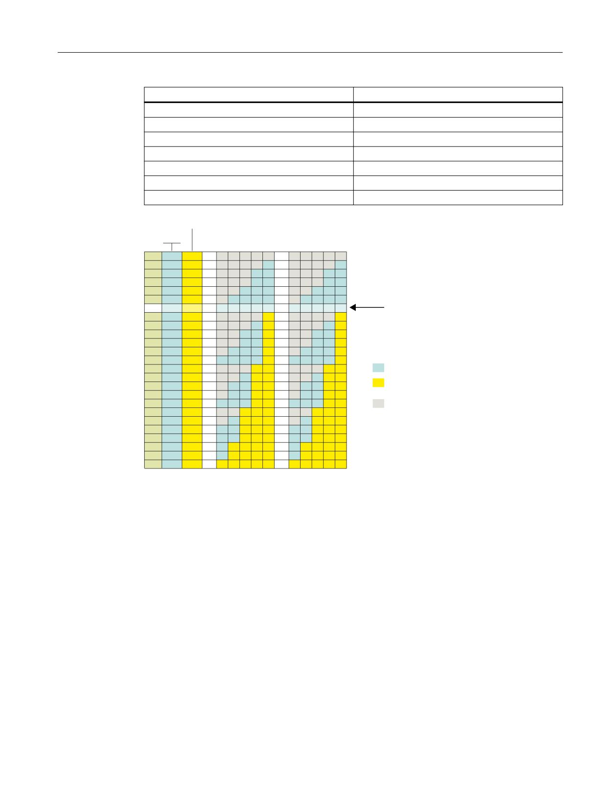
Two motor data sets (MDS) and two drive data sets (DDS) are available in the drive for each motor
data set. This corresponds to "No.": 9 of the possible data set combinations displayed in
the Figure 12-2 Principle of the motor/drive data set switchover (Page 691).
Format
Bit positions for drive data set switchover (DDS):
• DB31, ... DBX130.0 == 1
Bit positions for motor data set switchover (MDS):
• DB31, ... DBX130.1 == 0
Basic functions
Function Manual, 10/2020, 6FC5397-2GP40-0BA1
689

Various NC/PLC interface signals and functions
12.2 Functions
Invalid bit positions:
• DB31, ... DBX130.2 == 0
• DB31, ... DBX130.3 == 0
• DB31, ... DBX130.4 == 0
Interfaces of the drive data sets (DDS)
Relevant bit positions of the request and display interfaces:
• DB31, ... DBX21.0 / DBX93.0
- DB31, ... DBX21.0 / DBX93.0 == 0 ⇒ 1st drive data set DDS[0]
- DB31, ... DBX21.0 / DBX93.0 == 1 ⇒ 2nd drive data set DDS[1])
Interfaces of the motor data sets (MDS)
Relevant bit positions of the request and display interfaces:
• DB31, ... DBX21.1 / DBX93.1
- DB31, ... DBX21.1 / DBX93.1 == 0 ⇒ 1st motor data set MDS[0]
- DB31, ... DBX21.1 / DBX93.1 == 1 ⇒ 2nd motor data set MDS[1])
Invalid bit positions (MDS/DDS)
Invalid bit positions of the request and display interfaces:
• DB31, ... DBX21.1 / DBX93.2 == 0
• DB31, ... DBX21.1 / DBX93.3 == 0
• DB31, ... DBX21.1 / DBX93.4 == 0
See also
Overview of the interfaces (Page 690)
12.2.5.6
Overview of the interfaces
Table 12-1
Configurable MDS / DDS combinations
Number of MDS (motors)
Number of DDS (drives) per MDS
1
1 ... 32
2
1, 2, 4, 8, 16
3
1, 2, 4, 8
4
1, 2, 4, 8
5
1, 2, 4
6
1, 2, 4
7
1, 2, 4
8
1, 2, 4
9
1, 2
Basic functions
690
Function Manual, 10/2020, 6FC5397-2GP40-0BA1
Various NC/PLC interface signals and functions
12.2 Functions
Number of MDS (motors)
Number of DDS (drives) per MDS
10
1, 2
11
1, 2
12
1, 2
13
1, 2
14
1, 2
15
1, 2
16
1, 2
''6 SHU 0'6
'%
'%
'%;
[
[
'%;
[
0'6
1R
8Q VXSSRUWHG FRPELQDWLRQ
5HOHYDQW ELW SRVLWLRQ ZLWK UHJDUG WR
0RWRU GDWD VHW 0'6
'ULYH GDWD VHW ''6
,QYDOLG ELW SRVLWLRQ
MDS
Number of motor data sets
DDS per MDS
Number of drive data sets per motor data set
DB31, ... DBX21.x
Request interface
DB31, ... DBX93.x
Display interface
DB31, ... DBX130.x
Formatting interface
Figure 12-2
Principle of the motor/drive data set switchover
12.2.5.7
Supplementary conditions
Variable number of drive data sets for the "last" motor data set
The "last" motor data set is the motor data set with the highest number or index.
Generally, the same number of drive data sets is created for each motor data set (number of "DDS
per MDS") in the drive. Only the "last" motor data set can differ from this; any number (a) of drive
data sets can be parameterized:
1 ≤ a ≤ (number of "DDS per MDS")
Basic functions
Function Manual, 10/2020, 6FC5397-2GP40-0BA1
691

Various NC/PLC interface signals and functions
12.3 Examples
Example
4 motor data sets (MDS) and 8 drive data sets (DDS) per motor data set (DDS per MDS) are to be
parameterized. This corresponds to "No.": 22 of the possible data set combination displayed in
the Figure 12-2 Principle of the motor/drive data set switchover (Page 691):
• Motor data sets: MDS[ 0 ], MDS[ 1 ], ... MDS[ 3 ] ("last" motor data set)
• Drive data sets per motor data set: DDS[ 0 ] ... DDS[ 7 ]
The number of drive data sets for the individual motor data sets is therefore:
Motor data set (MDS)
Number of drive data sets (DDS) per motor data set (MDS)
MDS[ 0 ] ... MDS[ 2 ]
8
MDS[ 3 ]
1 - 8
Switchover instant: Drive parameter set
In principle it is possible to switch over drive parameter sets at any point in time. While an axis
is traversing, especially when switching over speed controller parameters and the motor speed
scaling, torque jumps/steps can occur. We therefore recommend that a drive parameter set is
only switched over for stationary states, especially when the axis is at a standstill.
See also
Overview of the interfaces (Page 690)
12.3
Examples
12.3.1
Parameter set changeover
Parameter set changeover
A parameter set changeover is performed to change the position control gain (KVfactor) from KV
= 4.0 to KV = 0.5 for machine axis X1.
Preconditions
The parameter set changeover must be enabled by the machine data:
MD35590 $MA_PARAMSET_CHANGE_ENABLE [AX1] = 1 or 2 (parameter set change possible)
The 1st parameter set for machine axis X1 is set, in accordance with machine data with index "0"
NC/PLC interface:
DB31, … DBX9.0 - DBX9.2 = 0 (controller parameter set)
Basic functions
692
Function Manual, 10/2020, 6FC5397-2GP40-0BA1

Various NC/PLC interface signals and functions
12.3 Examples
Parameter-set-dependent machine data
Parameter-set-dependent machine data are set as follows:
Machine data
Comment
MD32200 $MA_POSCTRL_GAIN [0, AX1] = 4.0
KV setting for parameter set 1
MD32200 $MA_POSCTRL_GAIN [1, AX1] = 2.0
KV setting for parameter set 2
MD32200 $MA_POSCTRL_GAIN [2, AX1] = 1.0
KV setting for parameter set 3
MD32200 $MA_POSCTRL_GAIN [3, AX1] = 0.5
KV setting for parameter set 4
MD32200 $MA_POSCTRL_GAIN [4, AX1] = 0.25
KV setting for parameter set 5
MD32200 $MA_POSCTRL_GAIN [5, AX1] = 0.125
KV setting for parameter set 6
MD31050 $MA_DRIVE_AX_RATIO_DENOM [0, AX1] = 3
Denominator load gearbox for parameter set 1
MD31050 $MA_DRIVE_AX_RATIO_DENOM [1, AX1] = 3
Denominator load gearbox for parameter set 2
MD31050 $MA_DRIVE_AX_RATIO_DENOM [2, AX1] = 3
Denominator load gearbox for parameter set 3
MD31050 $MA_DRIVE_AX_RATIO_DENOM [3, AX1] = 3
Denominator load gearbox for parameter set 4
MD31050 $MA_DRIVE_AX_RATIO_DENOM [4, AX1] = 3
Denominator load gearbox for parameter set 5
MD31050 $MA_DRIVE_AX_RATIO_DENOM [5, AX1] = 3
Denominator load gearbox for parameter set 6
MD31060 $MA_DRIVE_AX_RATIO_NUMERA [0, AX1] = 5
Counter load gearbox for parameter set 1
MD31060 $MA_DRIVE_AX_RATIO_NUMERA [1, AX1] = 5
Counter load gearbox for parameter set 2
MD31060 $MA_DRIVE_AX_RATIO_NUMERA [2, AX1] = 5
Counter load gearbox for parameter set 3
MD31060 $MA_DRIVE_AX_RATIO_NUMERA [3, AX1] = 5
Counter load gearbox for parameter set 4
MD31060 $MA_DRIVE_AX_RATIO_NUMERA [4, AX1] = 5
Counter load gearbox for parameter set 5
MD31060 $MA_DRIVE_AX_RATIO_NUMERA [5, AX1] = 5
Counter load gearbox for parameter set 6
MD35130 $MA_AX_VELO_LIMIT [0...5, AX1]
Setting for each parameter set*)
MD32800 $MA_EQUIV_CURRCTRL_TIME [0..5, AX1]
Setting for each parameter set*)
MD32810 $MA_EQUIV_SPEEDCTRL_TIME [0..5, AX1]
Setting for each parameter set*)
MD32910 $MA_DYN_MATCH_TIME [0...5, AX1]
Setting for each parameter set*)
*) The appropriate line must be specified separately for each parameter set according to the applicable syntax rules.
Switchover
In order to switch over the position-control gain, the PLC user program selects the 4th parameter
set for machine axis X1.
• Request by PLC user program:
DB31, … DBX9.0 - DBX9.2 = 3 (parameter set servo)
- A request to change over to the 4th parameter set is sent for machine axis AX1.
- The parameter set is changed over once a delay has elapsed.
- Parameter set 4 is now active, in accordance with machine data with index "3"
• Feedback by NC:
DB31, … DBX69.0 - DBX69.2 = 3 (parameter set servo)
- The NC confirms/acknowledges the parameter-set changeover.
Basic functions
Function Manual, 10/2020, 6FC5397-2GP40-0BA1
693

Various NC/PLC interface signals and functions
12.4 Data lists
12.4
Data lists
12.4.1
Machine data
12.4.1.1
Display machine data
Number
Identifier: $MM_
Description
SINUMERIK Operate
9000
LCD_CONTRAST
Contrast
9001
DISPLAY_TYPE
Monitor type
9004
DISPLAY_RESOLUTION
Display resolution
9006
DISPLAY_SWITCH_OFF_INTERVAL
Time for screen darkening
12.4.1.2
NC-specific machine data
Number
Identifier: $MN_
Description
10350
FASTIO_DIG_NUM_INPUTS
Number of active digital NC input bytes
10360
FASTIO_DIG_NUM_OUTPUTS
Number of active digital NC output bytes
10361
FASTIO_DIG_SHORT_CIRCUIT
Short-circuit digital inputs and outputs
11120
LUD_EXTENDED_SCOPE
Activate global program variables (PUD)
11270
DEFAULT_VALUES_MEM_MSK
Active.
Function: Save DEFAULT values of GUD.
18150
MM_GUD_VALUES_MEM
Reserve memory space for GUD
12.4.1.3
Channelspecific machine data
Number
Identifier: $MC_
Description
21015
INVOLUTE_RADIUS_DELTA
NC start disable without reference point
21016
INVOLUTE_AUTO_ANGLE_LIMIT
Automatic angle limitation for involute interpolation
27800
TECHNOLOGY_MODE
Technology in channel
28150
MM_NUM_VDIVAR_ELEMENTS
Number of write elements for PLC variables
28530
MM_PATH_VELO_SEGMENTS
Number of storage elements for limiting path velocity in
block
Basic functions
694
Function Manual, 10/2020, 6FC5397-2GP40-0BA1

Various NC/PLC interface signals and functions
12.4 Data lists
12.4.1.4
Axis/spindlespecific machine data
Number
Identifier: $MA_
Description
30350
SIMU_AX_VDI_OUTPUT
Output of axis signals for simulation axes
33050
LUBRICATION_DIST
Lubrication pulse distance
35590
PARAMSET_CHANGE_ENABLE
Parameter set definition possible from PLC
36060
STANDSTILL_VELO_TOL
Maximum velocity/speed when axis/spindle stationary
36610
AX_EMERGENCY_STOP_TIME
Length of the braking ramp for error states
36620
SERVO_DISABLE_DELAY_TIME
Cutout delay servo enable
Basic functions
Function Manual, 10/2020, 6FC5397-2GP40-0BA1
695

Various NC/PLC interface signals and functions
12.4 Data lists
12.4.2
System variables
Names
Description
$P_FUMB
Unassigned part program memory (Free User Memory Buffer)
$A_DBB[n]
Data on PLC (data type BYTE)
$A_DBW[n]
Data on PLC (WORD type data)
$A_DBD[n]
Data on PLC (DWORD type data)
$A_DBR[n]
Data on PLC (REAL type data)
Basic functions
696
Function Manual, 10/2020, 6FC5397-2GP40-0BA1

Auxiliary function outputs to PLC
13
13.1
Brief description
13.1.1
Function
Auxiliary functions permit activation of the system functions of the NC and PLC user functions.
Auxiliary functions can be programmed in:
• Part programs
• Synchronized actions
• User cycles
For detailed information on the use of auxiliary function outputs in synchronized actions, see:
Further information
Function Manual Synchronized Actions
Predefined auxiliary functions
Predefined auxiliary functions activate system functions. The auxiliary function is also output to
the NC/PLC interface.
The following auxiliary functions are predefined:
Type
Function
Example
Meaning
M
Additional function
M30
End of program
S
Spindle function
S100
Spindle speed 100 (e.g. rpm)
T
Tool number
T3
Tool number 3
D, DL
Tool offset
D1
Tool cutting edge number 1
F
Feedrate
F1000
Feedrate 1000 (e.g. mm/min)
Userdefined auxiliary functions
User-defined auxiliary functions are either extended predefined auxiliary functions or user-
specific auxiliary functions.
Extension of predefined auxiliary functions
Extension of predefined auxiliary functions refers to the "address extensions" parameter. The
address extension defines the number of the spindle to which the auxiliary function applies. The
spindle function M3 (spindle right) is predefined for the master spindle of a channel. If a
Basic functions
Function Manual, 10/2020, 6FC5397-2GP40-0BA1
697

Auxiliary function outputs to PLC
13.1 Brief description
2nd spindle is assigned to a channel, a corresponding user-defined auxiliary function must be
defined that extends the predefined auxiliary function.
Type
Function
Example
Meaning
M
Additional function
M2=3
2nd spindle: Spindle right
S
Spindle function
S2=100
2nd spindle: Spindle speed = 100 (e.g. rpm)
T
Tool number
T2=3
User-specific auxiliary functions
User-specific auxiliary functions do not activate system functions. User-specific auxiliary
functions are output to the NC/PLC interface only. The functionality of the auxiliary functions
must be implemented by the machine manufacturer / user in the PLC user program.
Type
Function
Example
Meaning
H1)
Auxiliary function
H2=5
User-specific function
1)
Recommendation
13.1.2
Definition of an auxiliary function
An auxiliary function is defined by the following parameters:
• Type, address extension and value
The three parameters are output to the NC/PLC interface.
• Output behavior
The auxiliary function-specific output behavior defines for how long an auxiliary function is
output to the NC/PLC interface and when it is output relative to the traversing motion
programmed in the same part program block.
• Group assignment
An auxiliary function can be assigned to a particular auxiliary function group. The output
behavior can be defined separately for each auxiliary function group. This becomes active if
no auxiliary function-specific output behavior has been defined. Group membership also
affects output of an auxiliary function after block search.
Further information
Function Manual PLC and Basic Program, Basic program
13.1.3
Overview of the auxiliary functions
M functions
M (special function)
Address extension
Value
Range of values
Meaning
Value range 10)
Type
Meaning
Number 8)
0 (implicit)
---
0 ... 99
INT
Function
5
Basic functions
698
Function Manual, 10/2020, 6FC5397-2GP40-0BA1

Auxiliary function outputs to PLC
13.1 Brief description
M (special function)
Range of values
Meaning
Value range 11)
Type
Meaning
Number 8)
1 ... 20
Spindle number
1 ... 99
INT
Function
5
Range of values
Meaning
Value range 12)
Type
Meaning
Number 8)
0 ... 99
Any
100 ... 2147483647
INT
Function
5
8)
See "Meaning of footnotes" at the end of the overview.
10) For the value range 0 ... 99, the address extension is 0. Mandatory without address extension: M0, M1, M2, M17, M30
11) M3, M4, M5, M19, M70: The address extension is the spindle number, e.g. M2=5 ⇒ spindle stop (M5) for spindle 2.
Without address extension, the M function acts on the master spindle.
12) User-specific M functions.
Use
Controlling machine functions in synchronism with the part program.
Further information
• The following M functions have a predefined meaning: M0, M1, M2, M17, M30, M3, M4, M5,
M6, M19, M70, M40, M41, M42, M43, M44, M45.
• A dynamic NC/PLC interface signal for displaying the validity is assigned to the M functions
(M0 - M99). Furthermore, 64 additional signals can be assigned for independent M functions
(see Function Manual PLC and Basic Program, Section Basic program).
• For subprograms, machine data can be used to set whether an output of the M function
should be realized for the end of the part program M17, M2 or M30 to the PLC:
MD20800 $MC_SPF_END_TO_VDI (subprogram end to PLC)
• For the predefined M functions M40 - M45, only limited redefinition of the output
specification is possible.
Basic functions
Function Manual, 10/2020, 6FC5397-2GP40-0BA1
699

Auxiliary function outputs to PLC
13.1 Brief description
• The predefined auxiliary functions M0, M1, M17, M30, M6, M4, M5 cannot be redefined.
• M function-specific machine data:
- MD10800 $MN_EXTERN_CHAN_SYNC_M_NO_MIN
- MD10802 $MN_EXTERN_CHAN_SYNC_M_NO_MAX
- MD10804 $MN_EXTERN_M_NO_SET_INT
- MD10806 $MN_EXTERN_M_NO_DISABLE_INT
- MD10814 $MN_EXTERN_M_NO_MAC_CYCLE
- MD10815 $MN_EXTERN_M_NO_MAC_CYCLE_NAME
- MD20094 $MC_SPIND_RIGID_TAPPING_M_NR
- MD20095 $MC_EXTERN_RIGID_TAPPING_M_NR
- MD20096 $MC_T_M_ADDRESS_EXT_IS_SPINO
- MD22200 $MC_AUXFU_M_SYNC_TYPE
- MD22530 $MC_TOCARR_CHANGE_M_CODE
- MD22532 $MC_GEOAX_CHANGE_M_CODE
- MD22534 $MC_TRAFO_CHANGE_M_CODE
- MD22560 $MC_TOOL_CHANGE_M_CODE
S functions
S (spindle function)
Address extension10)
Value
Range of values
Meaning
Range of values
Type
Meaning
Number 8)
0 ... 20
Spindle number 5)
0 ... ± 3.4028 exp38 3)
REAL
Spindle speed
3
3)
5) 8) See "Meaning of footnotes" at the end of the overview
10) The master spindle of the channel is addressed if no address extension is specified.
Use
Spindle speed.
Further information
• S functions are assigned to auxiliary function group 3 by default.
• Without an address extension, the S functions refer to the master spindle of the channel.
• S function-specific machine data:
MD22210 $MC_AUXFU_S_SYNC_TYPE (output time of the S functions)
Basic functions
700
Function Manual, 10/2020, 6FC5397-2GP40-0BA1
Auxiliary function outputs to PLC
13.1 Brief description
H functions
The functionality of an H function must be implemented in the PLC user program.
H (auxiliary function) 10)
Address extension
Value
Range of values
Meaning
Range of values
Type
Meaning
Number 8)
0 ... 99
Any
- 2147483648 ...
INT
Any
3
+ 2147483647
0 ... ± 3.4028 exp38 2) 3) 4)
REAL
2)
3) 4) 8) See "Meaning of footnotes" at the end of the overview.
Use
User-specific auxiliary functions.
Further information
H function-specific machine data:
• MD22110 $MC_AUXFU_H_TYPE_INT (type of H-auxiliary function is an integer)
• MD22230 $MC_AUXFU_H_SYNC_TYPE (output time of the H functions)
T functions
Tool names are not output at the NC/PLC interface.
T (tool number) 1) 5) 6)
Address extension
Value
Range of values
Meaning
Range of values
Type
Meaning
Number 8)
1 ... 12
Spindle number
0 ... 32000
INT
Selection of the tool
1
(with active tool man-
(also symbolic names for ac-
agement)
tive tool management)
1) 5) 6) 8) See "Meaning of footnotes" at the end of the overview.
Use
Tool selection.
Further information
• Identification of the tools, optionally with tool number or location number (see Function
Manual Tools, Section Tool offset).
Function Manual Tool Management
• When T0 is selected, the current tool is removed from the toolholder but not replaced by a
new tool (default setting).
• T function-specific machine data:
MD22220 $MC_AUXFU_T_SYNC_TYPE (output time of the T functions)
Basic functions
Function Manual, 10/2020, 6FC5397-2GP40-0BA1
701
Auxiliary function outputs to PLC
13.1 Brief description
D functions
The tool offset is deselected using D0. Default setting is D1.
D (tool offset)
Address extension
Value
Range of values
Meaning
Range of values
Type
Meaning
Number 8)
---
---
0 ... 9
INT
Selection of the tool
1
offset
8)
See "Meaning of footnotes" at the end of the overview.
Use
Selection of the tool offset.
Further information
• Initial setting: D1
• After a tool change, the default tool cutting edge can be parameterized via:
MD20270 $MC_CUTTING_EDGE_DEFAULT (basic position of the tool cutting edge without
programming)
• Deselection of the tool offset: D0
• D function-specific machine data:
MD22250 $MC_AUXFU_D_SYNC_TYPE (output time of the D functions)
DL functions
The additive tool offset selected with DL refers to the active D number.
DL (additive tool offset)
Address extension
Value
Range of values
Meaning
Range of values
Type
Meaning
Number 8)
---
---
0 ... 6
INT
Selection of the sum-
1
med tool offset
8)
See "Meaning of footnotes" at the end of the overview.
Use
Selection of the additive tool offset with reference to an active tool offset.
Further information
• Initial setting: DL = 0
• DL values cannot be output to the PLC via synchronized actions.
• Default setting of the additive tool offset without an active DL function:
MD20272 $MC_SUMCORR_DEFAULT (basic setting of the additive offset without a program)
• Deselection of the additive tool offset: DL = 0
• DL function-specific machine data:
MD22252 $MC_AUXFU_DL_SYNC_TYPE (output time DL functions)
Basic functions
702
Function Manual, 10/2020, 6FC5397-2GP40-0BA1

Auxiliary function outputs to PLC
13.1 Brief description
F functions
F (feedrate)
Address extension
Value
Range of values
Meaning
Range of values
Type
Meaning
Number 8)
---
---
0.001 ... 999 999.999
REAL
Path feedrate
6
8)
See "Meaning of footnotes" at the end of the overview.
Use
Path velocity.
Further information
F function-specific machine data:
• MD22240 $MC_AUXFU_F_SYNC_TYPE (output time of F functions)
FA functions
FA (axes-specific feedrate)
Address extension
Value
Range of values
Meaning
Range of values
Type
Meaning
Number 8)
1 - 31
Axis number
0.001 ... 999 999.999
REAL
Axial feedrate
6
8)
See "Meaning of footnotes" at the end of the overview.
Use
Axis-specific velocity.
Further information
F function-specific machine data:
• MD22240 $MC_AUXFU_F_SYNC_TYPE (output time of F functions)
Meaning of footnotes
1)
If tool management is active, neither a T change signal nor a T word is output at the channel-
specific NC/PLC interface.
2)
The type for the values can be selected by the user via MD22110 $MC_AUX-
FU_H_TYPE_INT.
3)
Because of the limited display options on the operator panel screens, the REAL type values
displayed are restricted to:
-999 999 999.9999 to 999 999 999.9999
The NC calculates internally but with complete accuracy.
4)
The REAL values are rounded and output to the PLC when setting the machine data:
MD22110 $MC_AUXFU_H_TYPE_INT = 1 (type of H-auxiliary functions is an integer)
The PLC user program must interpret the value transferred according to the machine data
setting.
Basic functions
Function Manual, 10/2020, 6FC5397-2GP40-0BA1
703
Auxiliary function outputs to PLC
13.2 Predefined auxiliary functions
5)
If the tool management is active, the meaning of the address extension can be parameter-
ized. Address extension = 0 means the value must be replaced by that of the master spindle
number, i.e. it is equivalent to not programming the address extension.
Auxiliary functions M19 "Position spindle" collected during a block search are not output to
the PLC.
6)
M6: Range of values of the address extension:
- without tool management: 0 ... 99
- with tool management: 0 ... maximum spindle number
0: To be replaced by the value of the master spindle number or master tool holder
7)
If tool management is active, the auxiliary function M6 "Tool change" can only be program-
med once in a part program block, irrespective the address extensions that are programmed.
8)
Maximum number of auxiliary functions per part program block.
13.2
Predefined auxiliary functions
Function
Every pre-defined auxiliary function is assigned to a system function and cannot be changed. If a
pre-defined auxiliary function is programmed in a part program/cycle, then this is output to the
PLC via the NC/PLC interface and the corresponding system function is executed in the NC.
Definition of a predefined auxiliary function
The parameters of the predefined auxiliary function are stored in machine data and can be
changed in some cases. All machine data, which are assigned to an auxiliary function, have the
same index <n>.
• MD22040 $MC_AUXFU_PREDEF_GROUP[<n>] (group assignment of predefined auxiliary
functions)
• MD22050 $MC_AUXFU_PREDEF_TYPE[<n>] (type of predefined auxiliary functions)
• MD22060 $MC_AUXFU_PREDEF_EXTENSION[<n>] (address extension for predefined
auxiliary functions)
• MD22070 $MC_AUXFU_PREDEF_VALUE[<n>] (value of predefined auxiliary functions)
• MD22080 $MC_AUXFU_PREDEF_SPEC[<n>] (output behavior of predefined auxiliary
functions)
13.2.1
Overview: Predefined auxiliary functions
Significance of the parameters listed in the following tables:
Parameter
Meaning
Index <n>
Machine data index of the parameters of an auxiliary function
Type
MD22050 $MC_AUXFU_PREDEF_TYPE[<n>]
Basic functions
704
Function Manual, 10/2020, 6FC5397-2GP40-0BA1
Auxiliary function outputs to PLC
13.2 Predefined auxiliary functions
Parameter
Meaning
Address extension
MD22060 $MC_AUXFU_PREDEF_EXTENSION[<n>]
Value
MD22070 $MC_AUXFU_PREDEF_VALUE[<n>]
Group
MD22040 $MC_AUXFU_PREDEF_GROUP[<n>]
Predefined auxiliary functions
General auxiliary functions, Part 1
System function
Index <n>
Type
Address ex-
Value
Group
tension
Stop
0
M
0
0
1
Conditional stop
1
M
0
1
1
End of subprogram
2
M
0
2
1
3
M
0
17
1
4
M
0
30
1
Tool change
5
M
(0)
6 1)
(1)
Spindle-specific auxiliary functions, spindle 1
System function
Index <n>
Type
Address ex-
Value
Group
tension
Spindle right
6
M
1
3
(2)
Spindle left
7
M
1
4
(2)
Spindle stop
8
M
1
5
(2)
Position spindle
9
M
1
19
(2)
Axis mode
10
M
1
70 2)
(2)
Automatic gear stage
11
M
1
40
(4)
Gear stage 1
12
M
1
41
(4)
Gear stage 2
13
M
1
42
(4)
Gear stage 3
14
M
1
43
(4)
Gear stage 4
15
M
1
44
(4)
Gear stage 5
16
M
1
45
(4)
Spindle speed
17
S
1
-1
(3)
General auxiliary functions, Part 2
System function
Index <n>
Type
Address ex-
Value
Group
tension
Feedrate
18
F
0
-1
(1)
Cutting edge selection
19
D
0
-1
(1)
DL
20
L
0
-1
(1)
Tool selection
21
T
(0)
-1
(1)
Stop (associated)
22
M
0
-1 3)
1
Conditional stop (associated)
23
M
0
-1 4)
1
Basic functions
Function Manual, 10/2020, 6FC5397-2GP40-0BA1
705

Auxiliary function outputs to PLC
13.2 Predefined auxiliary functions
General auxiliary functions, Part 2
System function
Index <n>
Type
Address ex-
Value
Group
tension
End of subprogram
24
M
0
-1 5)
1
Nibbling
25
M
0
20 6)
(10)
Nibbling
26
M
0
23 6)
(10)
Nibbling
27
M
0
22 6)
(11)
Nibbling
28
M
0
25 6)
(11)
Nibbling
29
M
0
26 6)
(12)
Nibbling
30
M
0
122 6)
(11)
Nibbling
31
M
0
125 6)
(11)
Nibbling
32
M
0
27 6)
(12)
Spindle-specific auxiliary functions, spindle 2
System function
Index <n>
Type
Address ex-
Value
Group
tension
Spindle right
33
M
2
3
(72)
Spindle left
34
M
2
4
(72)
Spindle stop
35
M
2
5
(72)
Position spindle
36
M
2
19
(72)
Axis mode
37
M
2
70 2)
(72)
Automatic gear stage
38
M
2
40
(74)
Gear stage 1
39
M
2
41
(74)
Gear stage 2
40
M
2
42
(74)
Gear stage 3
41
M
2
43
(74)
Gear stage 4
42
M
2
44
(74)
Gear stage 5
43
M
2
45
(74)
Spindle speed
44
S
2
-1
(73)
Spindle-specific auxiliary functions, spindle 3
System function
Index <n>
Type
Address ex-
Value
Group
tension
Spindle right
45
M
3
3
(75)
Spindle left
46
M
3
4
(75)
Spindle stop
47
M
3
5
(75)
Position spindle
48
M
3
19
(75)
Axis mode
49
M
3
70 2)
(75)
Automatic gear stage
50
M
3
40
(77)
Gear stage 1
51
M
3
41
(77)
Gear stage 2
52
M
3
42
(77)
Gear stage 3
53
M
3
43
(77)
Gear stage 4
54
M
3
44
(77)
Basic functions
706
Function Manual, 10/2020, 6FC5397-2GP40-0BA1

Auxiliary function outputs to PLC
13.2 Predefined auxiliary functions
Spindle-specific auxiliary functions, spindle 3
System function
Index <n>
Type
Address ex-
Value
Group
tension
Gear stage 5
55
M
3
45
(77)
Spindle speed
56
S
3
-1
(76)
Spindle-specific auxiliary functions, spindle 4
System function
Index <n>
Type
Address ex-
Value
Group
tension
Spindle right
57
M
4
3
(78)
Spindle left
58
M
4
4
(78)
Spindle stop
59
M
4
5
(78)
Position spindle
60
M
4
19
(78)
Axis mode
61
M
4
70 2)
(78)
Automatic gear stage
62
M
4
40
(80)
Gear stage 1
63
M
4
41
(80)
Gear stage 2
64
M
4
42
(80)
Gear stage 3
65
M
4
43
(80)
Gear stage 4
66
M
4
44
(80)
Gear stage 5
67
M
4
45
(80)
Spindle speed
68
S
4
-1
(79)
Spindle-specific auxiliary functions, spindle 5
System function
Index <n>
Type
Address ex-
Value
Group
tension
Spindle right
69
M
5
3
(81)
Spindle left
70
M
5
4
(81)
Spindle stop
71
M
5
5
(81)
Position spindle
72
M
5
19
(81)
Axis mode
73
M
5
70 2)
(81)
Automatic gear stage
74
M
5
40
(83)
Gear stage 1
75
M
5
41
(83)
Gear stage 2
76
M
5
42
(83)
Gear stage 3
77
M
5
43
(83)
Gear stage 4
78
M
5
44
(83)
Gear stage 5
79
M
5
45
(83)
Spindle speed
80
S
5
-1
(82)
Basic functions
Function Manual, 10/2020, 6FC5397-2GP40-0BA1
707

Auxiliary function outputs to PLC
13.2 Predefined auxiliary functions
Spindle-specific auxiliary functions, spindle 6
System function
Index <n>
Type
Address ex-
Value
Group
tension
Spindle right
81
M
6
3
(84)
Spindle left
82
M
6
4
(84)
Spindle stop
83
M
6
5
(84)
Position spindle
84
M
6
19
(84)
Axis mode
85
M
6
70 2)
(84)
Automatic gear stage
86
M
6
40
(86)
Gear stage 1
87
M
6
41
(86)
Gear stage 2
88
M
6
42
(86)
Gear stage 3
89
M
6
43
(86)
Gear stage 4
90
M
6
44
(86)
Gear stage 5
91
M
6
45
(86)
Spindle speed
92
S
6
-1
(85)
Spindle-specific auxiliary functions, spindle 7
System function
Index <n>
Type
Address ex-
Value
Group
tension
Spindle right
93
M
7
3
(87)
Spindle left
94
M
7
4
(87)
Spindle stop
95
M
7
5
(87)
Position spindle
96
M
7
19
(87)
Axis mode
97
M
7
70 2)
(87)
Automatic gear stage
98
M
7
40
(89)
Gear stage 1
99
M
7
41
(89)
Gear stage 2
100
M
7
42
(89)
Gear stage 3
101
M
7
43
(89)
Gear stage 4
102
M
7
44
(89)
Gear stage 5
103
M
7
45
(89)
Spindle speed
104
S
7
-1
(88)
Spindle-specific auxiliary functions, spindle 8
System function
Index <n>
Type
Address ex-
Value
Group
tension
Spindle right
105
M
8
3
(90)
Spindle left
106
M
8
4
(90)
Spindle stop
107
M
8
5
(90)
Position spindle
108
M
8
19
(90)
Axis mode
109
M
8
70 2)
(90)
Basic functions
708
Function Manual, 10/2020, 6FC5397-2GP40-0BA1

Auxiliary function outputs to PLC
13.2 Predefined auxiliary functions
Spindle-specific auxiliary functions, spindle 8
System function
Index <n>
Type
Address ex-
Value
Group
tension
Automatic gear stage
110
M
8
40
(92)
Gear stage 1
111
M
8
41
(92)
Gear stage 2
112
M
8
42
(92)
Gear stage 3
113
M
8
43
(92)
Gear stage 4
114
M
8
44
(92)
Gear stage 5
115
M
8
45
(92)
Spindle speed
116
S
8
-1
(91)
Spindle-specific auxiliary functions, spindle 9
System function
Index <n>
Type
Address ex-
Value
Group
tension
Spindle right
117
M
9
3
(93)
Spindle left
118
M
9
4
(93)
Spindle stop
119
M
9
5
(93)
Position spindle
120
M
9
19
(93)
Axis mode
121
M
9
70 2)
(93)
Automatic gear stage
122
M
9
40
(95)
Gear stage 1
123
M
9
41
(95)
Gear stage 2
124
M
9
42
(95)
Gear stage 3
125
M
9
43
(95)
Gear stage 4
126
M
9
44
(95)
Gear stage 5
127
M
9
45
(95)
Spindle speed
128
S
9
-1
(94)
Spindle-specific auxiliary functions, spindle 10
System function
Index <n>
Type
Address ex-
Value
Group
tension
Spindle right
129
M
10
3
(96)
Spindle left
130
M
10
4
(96)
Spindle stop
131
M
10
5
(96)
Position spindle
132
M
10
19
(96)
Axis mode
133
M
10
70 2)
(96)
Automatic gear stage
134
M
10
40
(98)
Gear stage 1
135
M
10
41
(98)
Gear stage 2
136
M
10
42
(98)
Gear stage 3
137
M
10
43
(98)
Gear stage 4
138
M
10
44
(98)
Gear stage 5
139
M
10
45
(98)
Spindle speed
140
S
10
-1
(97)
Basic functions
Function Manual, 10/2020, 6FC5397-2GP40-0BA1
709

Auxiliary function outputs to PLC
13.2 Predefined auxiliary functions
Spindle-specific auxiliary functions, spindle 11
System function
Index <n>
Type
Address ex-
Value
Group
tension
Spindle right
141
M
11
3
(99)
Spindle left
142
M
11
4
(99)
Spindle stop
143
M
11
5
(99)
Position spindle
144
M
11
19
(99)
Axis mode
145
M
11
70 2)
(99)
Automatic gear stage
146
M
11
40
(101)
Gear stage 1
147
M
11
41
(101)
Gear stage 2
148
M
11
42
(101)
Gear stage 3
149
M
11
43
(101)
Gear stage 4
150
M
11
44
(101)
Gear stage 5
151
M
11
45
(101)
Spindle speed
152
S
11
-1
(100)
Spindle-specific auxiliary functions, spindle 12
System function
Index <n>
Type
Address ex-
Value
Group
tension
Spindle right
153
M
11
3
(102)
Spindle left
154
M
12
4
(102)
Spindle stop
155
M
12
5
(102)
Position spindle
156
M
12
19
(102)
Axis mode
157
M
12
70 2)
(102)
Automatic gear stage
158
M
12
40
(104)
Gear stage 1
159
M
12
41
(104)
Gear stage 2
160
M
12
42
(104)
Gear stage 3
161
M
12
43
(104)
Gear stage 4
162
M
12
44
(104)
Gear stage 5
163
M
12
45
(104)
Spindle speed
164
S
12
-1
(103)
Spindle-specific auxiliary functions, spindle 13
System function
Index <n>
Type
Address ex-
Value
Group
tension
Spindle right
165
M
13
3
(105)
Spindle left
166
M
13
4
(105)
Spindle stop
167
M
13
5
(105)
Position spindle
168
M
13
19
(105)
Axis mode
169
M
13
70 2)
(105)
Basic functions
710
Function Manual, 10/2020, 6FC5397-2GP40-0BA1

Auxiliary function outputs to PLC
13.2 Predefined auxiliary functions
Spindle-specific auxiliary functions, spindle 13
System function
Index <n>
Type
Address ex-
Value
Group
tension
Automatic gear stage
170
M
13
40
(107)
Gear stage 1
171
M
13
41
(107)
Gear stage 2
172
M
13
42
(107)
Gear stage 3
173
M
13
43
(107)
Gear stage 4
174
M
13
44
(107)
Gear stage 5
175
M
13
45
(107)
Spindle speed
176
S
13
-1
(106)
Spindle-specific auxiliary functions, spindle 14
System function
Index <n>
Type
Address ex-
Value
Group
tension
Spindle right
177
M
14
3
(108)
Spindle left
178
M
14
4
(108)
Spindle stop
179
M
14
5
(108)
Position spindle
180
M
14
19
(108)
Axis mode
181
M
14
70 2)
(108)
Automatic gear stage
182
M
14
40
(110)
Gear stage 1
183
M
14
41
(110)
Gear stage 2
184
M
14
42
(110)
Gear stage 3
185
M
14
43
(110)
Gear stage 4
186
M
14
44
(110)
Gear stage 5
187
M
14
45
(110)
Spindle speed
188
S
14
-1
(109)
Spindle-specific auxiliary functions, spindle 15
System function
Index <n>
Type
Address ex-
Value
Group
tension
Spindle right
189
M
15
3
(111)
Spindle left
190
M
15
4
(111)
Spindle stop
191
M
15
5
(111)
Position spindle
192
M
15
19
(111)
Axis mode
193
M
15
70 2)
(111)
Automatic gear stage
194
M
15
40
(113)
Gear stage 1
195
M
15
41
(113)
Gear stage 2
196
M
15
42
(113)
Gear stage 3
197
M
15
43
(113)
Gear stage 4
198
M
15
44
(113)
Gear stage 5
199
M
15
45
(113)
Spindle speed
200
S
15
-1
(112)
Basic functions
Function Manual, 10/2020, 6FC5397-2GP40-0BA1
711

Auxiliary function outputs to PLC
13.2 Predefined auxiliary functions
Spindle-specific auxiliary functions, spindle 16
System function
Index <n>
Type
Address ex-
Value
Group
tension
Spindle right
201
M
16
3
(114)
Spindle left
202
M
16
4
(114)
Spindle stop
203
M
16
5
(114)
Position spindle
204
M
16
19
(114)
Axis mode
205
M
16
70 2)
(114)
Automatic gear stage
206
M
16
40
(116)
Gear stage 1
207
M
16
41
(116)
Gear stage 2
208
M
16
42
(116)
Gear stage 3
209
M
16
43
(116)
Gear stage 4
210
M
16
44
(116)
Gear stage 5
211
M
16
45
(116)
Spindle speed
212
S
16
-1
(115)
Spindle-specific auxiliary functions, spindle 17
System function
Index <n>
Type
Address ex-
Value
Group
tension
Spindle right
213
M
17
3
(117)
Spindle left
214
M
17
4
(117)
Spindle stop
215
M
17
5
(117)
Position spindle
216
M
17
19
(117)
Axis mode
217
M
17
70 2)
(117)
Automatic gear stage
218
M
17
40
(119)
Gear stage 1
219
M
17
41
(119)
Gear stage 2
220
M
17
42
(119)
Gear stage 3
221
M
17
43
(119)
Gear stage 4
222
M
17
44
(119)
Gear stage 5
223
M
17
45
(119)
Spindle speed
224
S
17
-1
(118)
Spindle-specific auxiliary functions, spindle 18
System function
Index <n>
Type
Address ex-
Value
Group
tension
Spindle right
225
M
18
3
(120)
Spindle left
226
M
18
4
(120)
Spindle stop
227
M
18
5
(120)
Position spindle
228
M
18
19
(120)
Axis mode
229
M
18
70 2)
(120)
Basic functions
712
Function Manual, 10/2020, 6FC5397-2GP40-0BA1

Auxiliary function outputs to PLC
13.2 Predefined auxiliary functions
Spindle-specific auxiliary functions, spindle 18
System function
Index <n>
Type
Address ex-
Value
Group
tension
Automatic gear stage
230
M
18
40
(122)
Gear stage 1
231
M
18
41
(122)
Gear stage 2
232
M
18
42
(122)
Gear stage 3
233
M
18
43
(122)
Gear stage 4
234
M
18
44
(122)
Gear stage 5
235
M
18
45
(122)
Spindle speed
236
S
18
-1
(121)
Spindle-specific auxiliary functions, spindle 19
System function
Index <n>
Type
Address ex-
Value
Group
tension
Spindle right
237
M
19
3
(123)
Spindle left
238
M
19
4
(123)
Spindle stop
239
M
19
5
(123)
Position spindle
240
M
19
19
(123)
Axis mode
241
M
19
70 2)
(123)
Automatic gear stage
242
M
19
40
(125)
Gear stage 1
243
M
19
41
(125)
Gear stage 2
244
M
19
42
(125)
Gear stage 3
245
M
19
43
(125)
Gear stage 4
246
M
19
44
(125)
Gear stage 5
247
M
19
45
(125)
Spindle speed
248
S
19
-1
(124)
Spindle-specific auxiliary functions, spindle 20
System function
Index <n>
Type
Address ex-
Value
Group
tension
Spindle right
249
M
20
3
(126)
Spindle left
250
M
20
4
(126)
Spindle stop
251
M
20
5
(126)
Position spindle
252
M
20
19
(126)
Axis mode
253
M
20
70 2)
(126)
Automatic gear stage
254
M
20
40
(128)
Gear stage 1
255
M
20
41
(128)
Gear stage 2
256
M
20
42
(128)
Gear stage 3
257
M
20
43
(128)
Gear stage 4
258
M
20
44
(128)
Gear stage 5
259
M
20
45
(128)
Spindle speed
260
S
20
-1
(127)
Basic functions
Function Manual, 10/2020, 6FC5397-2GP40-0BA1
713

Auxiliary function outputs to PLC
13.2 Predefined auxiliary functions
Toolholder-specific auxiliary functions, T auxiliary functions
System function
Index <n>
Type
Address ex-
Value
Group
tension
Tool selection
261
T
1
-1
129
Tool selection
262
T
2
-1
130
Tool selection
263
T
3
-1
131
Tool selection
264
T
4
-1
132
Tool selection
265
T
5
-1
133
Tool selection
266
T
6
-1
134
Tool selection
267
T
7
-1
135
Tool selection
268
T
8
-1
136
Tool selection
269
T
9
-1
137
Tool selection
270
T
10
-1
138
Tool selection
271
T
11
-1
139
Tool selection
272
T
12
-1
140
Tool selection
273
T
13
-1
141
Tool selection
274
T
14
-1
142
Tool selection
275
T
15
-1
143
Tool selection
276
T
16
-1
144
Tool selection
277
T
17
-1
145
Tool selection
278
T
18
-1
146
Tool selection
279
T
19
-1
147
Tool selection
280
T
20
-1
148
Toolholder-specific auxiliary functions, M6 auxiliary functions
System function
Index <n>
Type
Address ex-
Value
Group
tension
Tool change
281
M
1
6 1)
149
Tool change
282
M
2
6 1)
150
Tool change
283
M
3
6 1)
151
Tool change
284
M
4
6 1)
152
Tool change
285
M
5
6 1)
153
Tool change
286
M
6
6 1)
154
Tool change
287
M
7
6 1)
155
Tool change
288
M
8
6 1)
156
Tool change
289
M
9
6 1)
157
Tool change
290
M
10
6 1)
158
Tool change
291
M
11
6 1)
159
Tool change
292
M
12
6 1)
160
Tool change
293
M
13
6 1)
161
Tool change
294
M
14
6 1)
162
Basic functions
714
Function Manual, 10/2020, 6FC5397-2GP40-0BA1

Auxiliary function outputs to PLC
13.2 Predefined auxiliary functions
Toolholder-specific auxiliary functions, M6 auxiliary functions
System function
Index <n>
Type
Address ex-
Value
Group
tension
Tool change
295
M
15
6 1)
163
Tool change
296
M
16
6 1)
164
Tool change
297
M
17
6 1)
165
Tool change
298
M
18
6 1)
166
Tool change
299
M
19
6 1)
167
Tool change
300
M
20
6 1)
168
Legend:
( ) The value can be changed.
1)
The value is depends on the machine data:
MD22560 $MC_TOOL_CHANGE_M_MODE (M function for tool change)
2)
The value can be preset with a different value using the following machine data:
MD20095 $MC_EXTERN_RIGID_TAPPING_M_NR (M function for switching over to control-
led axis mode (ext. mode))
MD20094 $MC_SPIND_RIGID_TAPPING_M_NR (M function for switching over to controlled
axis mode)
Note
The value 70 is always output at the PLC.
3)
The value is set using machine data:
MD22254 $MC_AUXFU_ASSOC_M0_VALUE (additional M function for program stop)
4)
The value is set using machine data:
MD22256 $MC_AUXFU_ASSOC_M1_VALUE (additional M function for conditional stop)
5)
The value is set using machine data:
MD10714 $MN_M_NO_FCT_EOP (M function for spindle active after reset)
6)
The value is set using machine data:
MD26008 $MC_NIBBLE_PUNCH_CODE (definition of M functions)
13.2.2
Overview: Output behavior
Significance of the parameters listed in the following table:
Parameter
Meaning
Index <n>
Machine data index of the parameters of an auxiliary function
Output behavior
MD22080 $MC_AUXFU_PREDEF_SPEC[<n>], Bits 0 ... 18
Bits 19 ... 31: Reserved
Basic functions
Function Manual, 10/2020, 6FC5397-2GP40-0BA1
715

Auxiliary function outputs to PLC
13.2 Predefined auxiliary functions
Output behavior of the predefined auxiliary functions
System function
Index <n>
Output behavior, bit
18
17
16
15
14
13
12
11
10
9
8
7
6
5
4
3
2
1
0
Stop
0
0
0
0
(0)
0
0
0
0
(0)
0
0
1
0
0
0
0
0
(0)
(1)
Conditional stop
1
0
0
0
(0)
0
0
0
0
(0)
0
0
1
0
0
0
0
0
(0)
(1)
End of subroutine
2
0
0
0
(0)
0
0
0
0
(0)
0
0
1
0
0
0
0
0
(0)
(1)
3
0
0
0
(0)
0
0
0
0
(0)
0
0
1
0
0
0
0
0
(0)
(1)
4
0
0
0
(0)
0
0
0
0
(0)
0
0
1
0
0
0
0
0
(0)
(1)
Tool change
5
0
0
0
(0)
0
0
0
(0)
(0)
(0)
(0)
(0)
(0)
(1)
(0)
(0)
(0)
(0)
(1)
Spindle right
6
0
0
0
(0)
0
0
0
(0)
(0)
(0)
(0)
(0)
(0)
(1)
(0)
(0)
(0)
(0)
(1)
Spindle left
7
0
0
0
(0)
0
0
0
(0)
(0)
(0)
(0)
(0)
(0)
(1)
(0)
(0)
(0)
(0)
(1)
Spindle stop
8
0
0
0
(0)
0
0
0
(0)
(0)
(0)
(0)
(0)
(0)
(1)
(0)
(0)
(0)
(0)
(1)
Spindle positioning
9
0
0
0
(0)
0
0
0
(0)
(0)
(0)
(0)
(0)
(0)
(1)
(0)
(0)
(0)
(0)
(1)
Axis mode
10
0
0
0
(0)
0
0
0
(0)
(0)
(0)
(0)
(0)
(0)
(1)
(0)
(0)
(0)
(0)
(1)
Automatic gear stage
11
0
0
0
(0)
0
0
0
(0)
(0)
(0)
(0)
0
0
1
(0)
(0)
(0)
(0)
(1)
Gear stage 1
12
0
0
0
(0)
0
0
0
(0)
(0)
(0)
(0)
0
0
1
(0)
(0)
(0)
(0)
(1)
Gear stage 2
13
0
0
0
(0)
0
0
0
(0)
(0)
(0)
(0)
0
0
1
(0)
(0)
(0)
(0)
(1)
Gear stage 3
14
0
0
0
(0)
0
0
0
(0)
(0)
(0)
(0)
0
0
1
(0)
(0)
(0)
(0)
(1)
Gear stage 4
15
0
0
0
(0)
0
0
0
(0)
(0)
(0)
(0)
0
0
1
(0)
(0)
(0)
(0)
(1)
Gear stage 5
16
0
0
0
(0)
0
0
0
(0)
(0)
(0)
(0)
0
0
1
(0)
(0)
(0)
(0)
(1)
Spindle speed
17
0
0
0
(0)
0
0
0
(0)
(0)
(0)
0
(0)
(1)
(0)
(0)
(0)
0
(0)
(1)
Feed
18
0
0
0
(0)
0
0
0
(0)
(0)
(0)
0
(0)
(1)
(0)
0
(1)
0
(0)
(1)
Cutting edge selection
19
0
0
0
(0)
0
0
0
(0)
(0)
(0)
0
(0)
(0)
(1)
0
(0)
0
(0)
(1)
DL
20
0
0
0
(0)
0
0
0
(0)
(0)
(0)
0
(0)
(0)
(1)
0
(0)
0
(0)
(1)
Tool selection
21
0
0
0
(0)
0
0
0
(0)
(0)
(0)
0
(0)
(0)
(1)
0
(0)
0
(0)
(1)
Stop (associated)
22
0
0
0
(0)
0
0
0
0
(0)
0
0
1
0
0
0
0
0
(0)
(1)
Conditional stop (associ-
23
0
0
0
(0)
0
0
0
0
(0)
0
0
1
0
0
0
0
0
(0)
(1)
ated)
End of subroutine
24
0
0
0
(0)
0
0
0
0
(0)
0
0
1
0
0
0
0
0
(0)
(1)
Nibbling
25
0
0
0
(0)
0
0
0
(0)
(0)
(0)
(0)
(0)
(1)
(0)
0
(0)
(0)
(0)
(1)
Nibbling
26
0
0
0
(0)
0
0
0
(0)
(0)
(0)
(0)
(0)
(1)
(0)
0
(0)
(0)
(0)
(1)
Nibbling
27
0
0
0
(0)
0
0
0
(0)
(0)
(0)
(0)
(0)
(1)
(0)
0
(0)
(0)
(0)
(1)
Nibbling
28
0
0
0
(0)
0
0
0
(0)
(0)
(0)
(0)
(0)
(1)
(0)
0
(0)
(0)
(0)
(1)
Nibbling
29
0
0
0
(0)
0
0
0
(0)
(0)
(0)
(0)
(0)
(1)
(0)
0
(0)
(0)
(0)
(1)
Nibbling
30
0
0
0
(0)
0
0
0
(0)
(0)
(0)
(0)
(0)
(1)
(0)
0
(0)
(0)
(0)
(1)
Nibbling
31
0
0
0
(0)
0
0
0
(0)
(0)
(0)
(0)
(0)
(1)
(0)
0
(0)
(0)
(0)
(1)
Nibbling
32
0
0
0
(0)
0
0
0
(0)
(0)
(0)
(0)
(0)
(1)
(0)
0
(0)
(0)
(0)
(1)
( ) The value can be changed.
Basic functions
716
Function Manual, 10/2020, 6FC5397-2GP40-0BA1

Auxiliary function outputs to PLC
13.2 Predefined auxiliary functions
Significance of the bits
Bit
Meaning
0
Acknowledgement "normal" after an OB1 cycle
An auxiliary function with normal acknowledgment is output to the NC/PLC interface at the beginning of the OB1 cycle.
The auxiliary function-specific change signal indicates to the PLC user program that the auxiliary function is valid.
The auxiliary function is acknowledged as soon as organization block OB1 has run once. This corresponds to a complete
PLC user cycle.
The auxiliary function with normal acknowledgment is output in synchronism with the part program block in which it
is programmed. If execution of the parts program block, e.g. path and/or positioning axis movements, is completed
before acknowledgment of the auxiliary function, the block change is delayed until after acknowledgment by the PLC.
In continuous-path mode, a constant path velocity can be maintained in conjunction with an auxiliary function with
normal acknowledgment, if the auxiliary function is output by the PLC during the traversing motion and before reaching
the end of the block.
1
Acknowledgement "quick" with OB40
An auxiliary function with quick acknowledgment is output to the NC/PLC interface before the next OB1 cycle. The
auxiliary function-specific change signal indicates to the PLC user program that the auxiliary function is valid.
The auxiliary function is acknowledged immediately by the PLC basic program in the next OB40 cycle. Acknowledgment
of the auxiliary function is not confirmation that the corresponding PLC user function has been executed. The auxiliary
function is still executed in the OB1 cycle. Next output of the auxiliary functions to the PLC is therefore not possible until
after this OB1 cycle has run completely. This is noticeable in continuous-path mode (drop in path velocity) especially if
auxiliary functions with quick acknowledgment are output in several consecutive part program blocks.
With auxiliary functions with quick acknowledgment, it cannot be guaranteed that the PLC user program will respond
in synchronism with the block.
Note
Parameterization of the output behavior of auxiliary functions as "quick auxiliary functions" is only possible in conjunc-
tion with user-defined auxiliary functions.
2
No predefined auxiliary function
A predefined auxiliary function is treated like a user-defined auxiliary function with this setting. The auxiliary function
then no longer triggers the corresponding system function but is only output to the PLC.
Example:
Reconfiguration of the "Position spindle" auxiliary function (index 9) to a user-defined auxiliary function with normal
acknowledgment and output prior to the traversing motion.
MD22080 $MC_AUXFU_PREDEF_SPEC [ 9 ] = 'H25' (100101B)
3
No output to the PLC
The auxiliary function is not output to the PLC.
4
Spindle response after acknowledgement by the PLC
The associated system function is only executed after acknowledgment by the PLC.
5
Output prior to motion
The auxiliary function is output to the PLC before the traversing motions programmed in the part program block (path
and/or block-related positioning axis movements).
6
Output during motion
The auxiliary function is output to the PLC during the traversing motions programmed in the part program block (path
and/or block-related positioning axis movements).
7
Output at block end
The auxiliary function is output to the PLC after the traversing motions programmed in the part program block have been
completed (path and/or block-related positioning axis movements).
8
Not output after block search, types 1, 2, 4
Block search, types 1, 2, 4: The auxiliary function collected during the block search is not output.
Basic functions
Function Manual, 10/2020, 6FC5397-2GP40-0BA1
717

Auxiliary function outputs to PLC
13.2 Predefined auxiliary functions
Bit
Meaning
9
Collection during block search with program test (type 5, SERUPRO)
For a block search with program test, the auxiliary function is collected group-specific in the following system variables:
• $AC_AUXFU_M_VALUE[<n>]
• $AC_AUXFU_M_EXT[<n>]
• $AC_AUXFU_M_STATE[<n>]
10
No output during block search with program test (type 5, SERUPRO)
For block search with program test, the auxiliary function is not output to the PLC.
11
Cross-channel auxiliary function (SERUPRO)
For block search with program test (SERUPRO), the help function is collected on a cross-channel basis in the global list
of the auxiliary functions.
Note
For each auxiliary function group, only the last auxiliary function of the group is always collected.
12
Output performed via synchronized action (read only)
The bit is set if the auxiliary function was output to the PLC via a synchronized action.
13
Implicit auxiliary function (read-only)
The bit is set if the auxiliary function was implicitly output to the PLC.
14
Active M01 (read only)
The bit is set if the auxiliary function, for active M01, was output to the PLC.
15
No output during positioning test run
During the run-in test, the auxiliary function is not output to the PLC.
16
Nibbling off
17
Nibbling on
18
Nibbling
Note
In the case of auxiliary functions for which no output behavior has been defined, the following
default output behavior is active:
• Bit 0 = 1: Output duration one OB1 cycle
• Bit 7 = 1: Output at block end
13.2.3
Parameterization
13.2.3.1
Group assignment
The handling of the auxiliary functions for a block search is defined using the group assignment
of an auxiliary function. The 168 auxiliary function groups available are subdivided into
predefined and user-definable groups:
Predefined groups:
1 ... 4
10 ... 12
72 ... 168
User-defined groups:
5 ... 9
13 ... 71
Basic functions
718
Function Manual, 10/2020, 6FC5397-2GP40-0BA1

Auxiliary function outputs to PLC
13.2 Predefined auxiliary functions
Each predefined auxiliary function is assigned, as standard, to an auxiliary function group. For
most pre-defined auxiliary functions, this assignment can be changed using the following
machine data:
MD22040 $MC_AUXFU_PREDEF_GROUP[<n>] (group assignment of predefined auxiliary
functions)
If an auxiliary function is not assigned to any group, then a value of "0" should be entered into
the machine data.
For the pre-defined auxiliary functions with the following indices <n>, the group assignment
cannot be changed: 0, 1, 2, 3, 4, 22, 23, 24
Note
1. Auxiliary function group and block search
Auxiliary functions of the 1st auxiliary function group are, for a block search, only collected, but
not output.
13.2.3.2
Type, address extension and value
An auxiliary function is programmed via the type, address extension and value parameters (see
Section "Programming an auxiliary function (Page 732)").
Type
The identifier of an auxiliary function is defined via the "type," e.g.:
"M"
For additional function
"S"
For spindle function
"F"
For feed
The setting is made via the following machine data:
MD22050 $MC_AUXFU_PREDEF_TYPE[<n>] (type of predefined auxiliary functions)
Note
The "type" cannot be changed for predefined auxiliary functions.
Address extension
The "address extension" of an auxiliary function is for addressing different components of the
same type. In the case of predefined auxiliary functions, the value of the "address extension" is
the spindle number to which the auxiliary function applies.
The setting is made via the following machine data:
MD22060 $MC_AUXFU_PREDEF_EXTENSION[<n>] (address extension for predefined auxiliary
functions)
Grouping together auxiliary functions
Basic functions
Function Manual, 10/2020, 6FC5397-2GP40-0BA1
719
Auxiliary function outputs to PLC
13.2 Predefined auxiliary functions
To assign an auxiliary function for all spindles of a channel to the same auxiliary function group,
the value "-1" is entered for the "address extension" parameter.
Example:
The auxiliary function M3 (machine data index = 6) is assigned to the second auxiliary function
group for all the channel's spindles.
MD22040 $MC_AUXFU_PREDEF_GROUP[ 6 ]
= 2
MD22050 $MC_AUXFU_PREDEF_TYPE[ 6 ]
= "M"
MD22060 $MC_AUXFU_PREDEF_EXTENSION[ 6 ]
= -1
MD22070 $MC_AUXFU_PREDEF_VALUE[ 6 ]
= 3
Value
The parameters "value" and "type" define the meaning of an auxiliary function, i.e. the system
function that is activated on the basis of this auxiliary function.
The "value" of an auxiliary function is defined in the machine data:
MD22070 $MC_AUXFU_PREDEF_VALUE[<n>] (value of predefined auxiliary functions)
Note
The "value" cannot be changed for a predefined auxiliary function. For some predefined auxiliary
functions, the "value" can be reconfigured via additional machine data (see Section "Associated
auxiliary functions (Page 728)").
13.2.3.3
Output behavior
Parameter "Output behavior" defines when the predefined auxiliary function is output to the NC/
PLC interface and when it is acknowledged by the PLC.
The setting is done via the following machine data:
MD22080 $MC_AUXFU_PREDEF_SPEC[<n>] (output behavior of predefined auxiliary functions)
Output behavior relative to motion
Output prior to motion
• The traversing motions (path and/or block-related positioning axis movements) of the
previous part program block end with an exact stop.
• The auxiliary functions are output at the beginning of the current parts program block.
• The traversing motion of the actual part program block (path and/or positioning axis motion)
is only started after acknowledgment of the auxiliary functions by the PLC:
- Output duration one OB1 cycle (normal acknowledgment): after one OB1 cycle
- Output duration one OB40 cycle (quick acknowledgment): after one OB40 cycle
Basic functions
720
Function Manual, 10/2020, 6FC5397-2GP40-0BA1
Auxiliary function outputs to PLC
13.2 Predefined auxiliary functions
Output during motion
• The auxiliary functions are output at the beginning of the traversing motions (path and/or
positioning axis movements).
• The path velocity of the current parts program block is reduced so that the time to the end
of the block is greater than the time to acknowledgment of the auxiliary functions by the PLC.
- Output duration one OB1 cycle (normal acknowledgment): one OB1 cycle
- Output duration one OB40 cycle (quick acknowledgment): one OB40 cycle
Output after motion
• The traversing motions (path and/or block-related positioning axis movements) of the
current part program block end with an exact stop.
• The auxiliary functions are output after completion of the traversing motions.
• The block change is performed after acknowledgment of the auxiliary functions by the PLC:
- Output duration one OB1 cycle (normal acknowledgment): after one OB1 cycle
- Output duration one OB40 cycle (quick acknowledgment): after one OB40 cycle
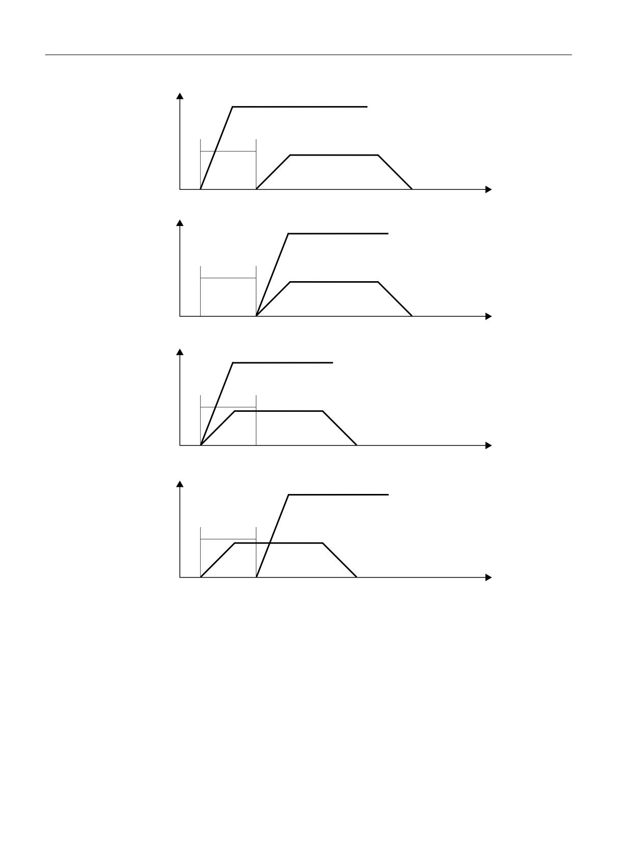
Examples of different output behavior
The following figures illustrate the differing behavior regarding:
• Output and acknowledgment of the auxiliary function
• Spindle response (speed change)
• Traverse movement (velocity change)
The binary values specified in the diagrams under "Output behavior" refer to the parameterized
output behavior (MD22080).
Basic functions
Function Manual, 10/2020, 6FC5397-2GP40-0BA1
721
Auxiliary function outputs to PLC
13.2 Predefined auxiliary functions
0 6
;
Y
2XWSXW EHKDYLRU
6SLQGOH UHVSRQVH
2XWSXW
$FNQ
0
$[LV PRYHPHQW
%ORFN FKDQJH
W
0 6
;
Y
2XWSXW EHKDYLRU
6SLQGOH UHVSRQVH
2XWSXW
$FNQ
0
$[LV PRYHPHQW
%ORFN FKDQJH
W
0 6
;
Y
2XWSXW EHKDYLRU
6SLQGOH UHVSRQVH
2XWSXW
$FNQ
0
$[LV PRYHPHQW
%ORFN FKDQJH
W
0 6
;
Y
2XWSXW EHKDYLRU
6SLQGOH UHVSRQVH
2XWSXW
$FNQ
0
$[LV PRYHPHQW
%ORFN FKDQJH
W
Basic functions
722
Function Manual, 10/2020, 6FC5397-2GP40-0BA1
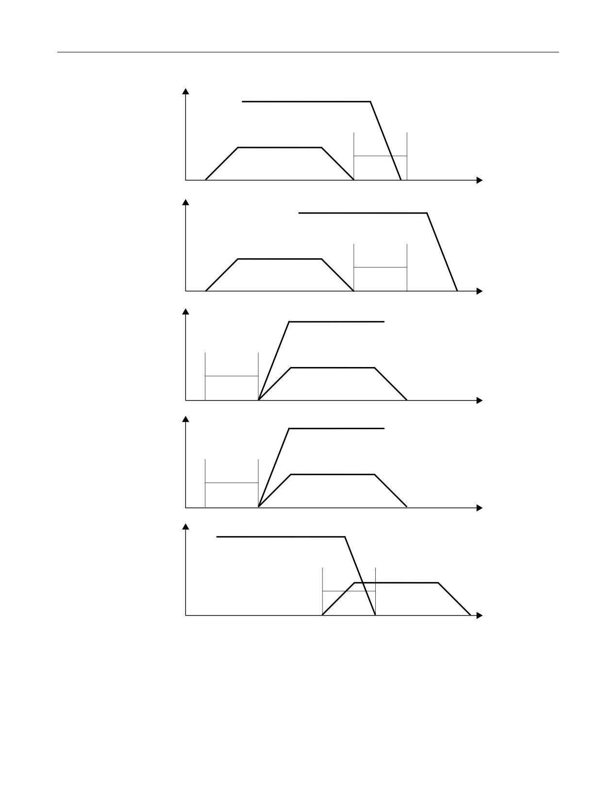
Auxiliary function outputs to PLC
13.2 Predefined auxiliary functions
0 ;
Y
2XWSXW EHKDYLRU
6SLQGOH UHVSRQVH
2XWSXW
$FNQ
$[LV PRYHPHQW
0
%ORFN FKDQJH
W
0 ;
Y
2XWSXW EHKDYLRU
6SLQGOH UHVSRQVH
2XWSXW
$FNQ
$[LV PRYHPHQW
0
%ORFN FKDQJH
W
'HIDXOW VHWWLQJ
Y
6SLQGOH UHVSRQVH
0 6
;
2XWSXW EHKDYLRU
2XWSXW
$FNQ
$[LV PRYHPHQW
0
%ORFN FKDQJH
W
'HIDXOW VHWWLQJ
Y
6SLQGOH UHVSRQVH
0 6
;
2XWSXW EHKDYLRU
2XWSXW
$FNQ
$[LV PRYHPHQW
0
%ORFN FKDQJH
W
'HIDXOW VHWWLQJ
Y
0 ;
6SLQGOH UHVSRQVH
2XWSXW EHKDYLRU
2XWSXW
$FNQ
$[LV PRYHPHQW
0
%ORFN FKDQJH
W
Basic functions
Function Manual, 10/2020, 6FC5397-2GP40-0BA1
723
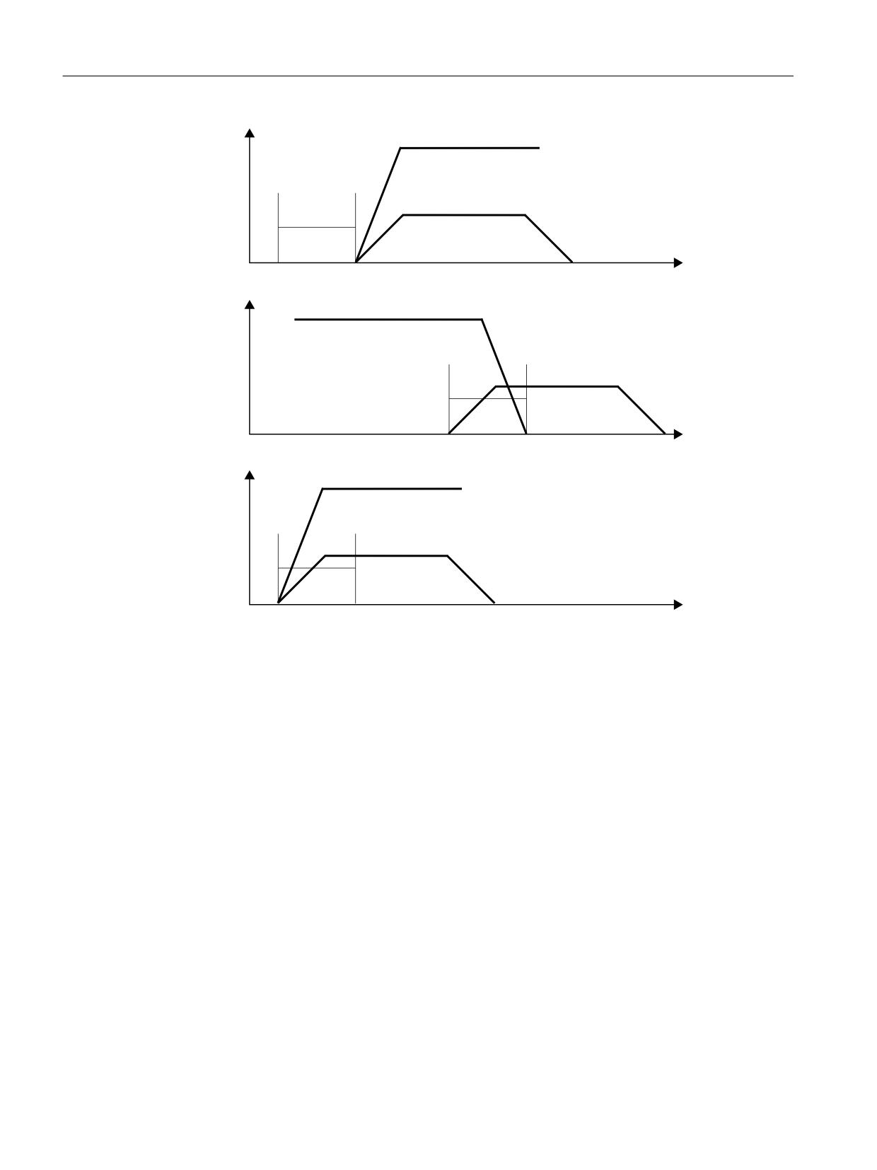
Auxiliary function outputs to PLC
13.3 Userdefined auxiliary functions
'HIDXOW VHWWLQJ
Y
6SLQGOH UHVSRQVH
0
;
2XWSXW EHKDYLRU
2XWSXW
$FNQ
$[LV PRYHPHQW
0
%ORFN FKDQJH
W
'HIDXOW VHWWLQJ
Y
0
;
6SLQGOH UHVSRQVH
2XWSXW EHKDYLRU
2XWSXW
$FNQ
$[LV PRYHPHQW
0
%ORFN FKDQJH
W
'HIDXOW VHWWLQJ
Y
6SLQGOH UHVSRQVH
0 6
;
2XWSXW EHKDYLRU
2XWSXW
$FNQ
6
$[LV PRYHPHQW
%ORFN FKDQJH
W
13.3
Userdefined auxiliary functions
There are two uses for user-defined auxiliary functions:
• Extension of predefined auxiliary functions
• User-specific auxiliary functions
Extension of predefined auxiliary functions
Because there is only one set of machine data for the predefined auxiliary functions, they can
only ever be used to address one spindle of the channel. To address further spindles, user-
defined auxiliary functions must be parameterized to supplement the predefined auxiliary
functions.
Extension of predefined auxiliary functions refers to the "address extensions" parameter. The
number of the spindle that the auxiliary function refers to is entered in the "address extension"
parameter.
Basic functions
724
Function Manual, 10/2020, 6FC5397-2GP40-0BA1

Auxiliary function outputs to PLC
13.3 Userdefined auxiliary functions
The relevant predefined auxiliary functions can be extended for the following system functions:
System function
Type
Address extension 1)
Value
Tool change
M
1
6
Spindle right
M
1
3
Spindle left
M
1
4
Spindle stop
M
1
5
Position spindle
M
1
19
Axis mode
M
1
70
Automatic gear stage
M
1
40
Gear stage 1
M
1
41
Gear stage 2
M
1
42
Gear stage 3
M
1
43
Gear stage 4
M
1
44
Gear stage 5
M
1
45
Spindle speed
S
1
-1
Tool selection
T
1
-1
1)
Address extension = 1 is the default value used in the auxiliary functions predefined in the machine data
Example:
Extension of the predefined auxiliary function for the system function "spindle right" for the
second and third spindle of the channel.
Auxiliary function "spindle right" for the second spindle of the channel:
MD22010 $MC_AUXFU_ASSIGN_TYPE[ n ]
= "M"
MD22020 $MC_AUXFU_ASSIGN_EXTENSION[ n ]
= 2
MD22030 $MC_AUXFU_ ASSIGN_VALUE[ n ]
= 3
Auxiliary function "spindle right" for the third spindle of the channel:
MD22010 $MC_AUXFU_ ASSIGN_TYPE[ m ]
= "M"
MD22020 $MC_AUXFU_ASSIGN_EXTENSION[ m ]
= 3
MD22030 $MC_AUXFU_ ASSIGN_VALUE[ m ]
= 3
User-specific auxiliary functions
User-specific auxiliary functions have the following characteristics:
• User-specific auxiliary functions only activate user functions.
• No system functions can be activated by user-specific auxiliary functions.
• A user-specific auxiliary function is output to the PLC according to the parameterized output
behavior.
• The functionality of a user-specific auxiliary function is implemented by the machine
manufacturer/user in the PLC user program.
Basic functions
Function Manual, 10/2020, 6FC5397-2GP40-0BA1
725
Auxiliary function outputs to PLC
13.3 Userdefined auxiliary functions
13.3.1
Parameterization
13.3.1.1
Maximum number of user-defined auxiliary functions
The maximum number of user-defined auxiliary function per channel can be parameterized via
the machine data:
MD11100 $MN_AUXFU_MAXNUM_GROUP_ASSIGN (maximum number of user-defined
auxiliary functions)
13.3.1.2
Group assignment
The handling of the auxiliary functions for a block search is defined using the group assignment
of an auxiliary function. The 168 auxiliary function groups available are subdivided into
predefined and user-definable groups:
Predefined groups:
1 ... 4
10 ... 12
72 ... 168
User-defined groups:
5 ... 9
13 ... 71
Every user-defined auxiliary function is assigned as standard to the 1st auxiliary function group.
The assignment can be changed using the following machine data:
MD22000 $MC_AUXFU_ASSIGN_GROUP[<n>] (group assignment of user-defined auxiliary
functions)
If an auxiliary function is not assigned to any group, then a value of "0" should be entered into
the machine data.
Note
1. Auxiliary function group and block search
Auxiliary functions of the 1st auxiliary function group are, for a block search, only collected, but
not output.
13.3.1.3
Type, address extension and value
An auxiliary function is programmed via the type, address extension and value parameters (see
Section "Programming an auxiliary function (Page 732)").
Type
The name of an auxiliary function is defined via the "type".
Basic functions
726
Function Manual, 10/2020, 6FC5397-2GP40-0BA1

Auxiliary function outputs to PLC
13.3 Userdefined auxiliary functions
The identifiers for user-defined auxiliary functions are:
Type
Identifier
Meaning
"H"
Auxiliary function
User-specific auxiliary functions
"M"
Special function
Extension of predefined auxiliary func-
tions
"S"
Spindle function
"T"
Tool number
The setting is made via the following machine data:
MD22010 $MC_AUXFU_ASSIGN_TYPE[<n>] (type of user-defined auxiliary functions)
Address extension
MD22020 $MC_AUXFU_ASSIGN_EXTENSION[<n>] (address extension user-defined auxiliary
functions)
The functionality of the address extension is not defined in user-specific auxiliary functions. It is
generally used to distinguish between auxiliary functions with the same "value".
Grouping together auxiliary functions
If all the auxiliary functions of the same type and value are assigned to the same auxiliary
function group, a value of "-1" must be entered for the "address extension" parameter.
Example:
All user-specific auxiliary functions with the value "= 8" are assigned to the tenth auxiliary
function group.
MD22000 $MC_AUXFU_ASSIGN_GROUP [ 1 ]
= 10
MD22010 $MC_AUXFU_ ASSIGN_TYPE [ 1 ]
= "H"
MD22020 $MC_AUXFU_ ASSIGN_EXTENSION [ 1 ]
= -1
MD22030 $MC_AUXFU_ ASSIGN_VALUE [ 1 ]
= 8
Value
MD22030 $MC_AUXFU_ASSIGN_VALUE[<n>] (value of user-defined auxiliary functions)
The functionality of the "value" parameter is not defined in user-specific auxiliary functions. The
value is generally used to activate the corresponding PLC user function.
Grouping together auxiliary functions
If all the auxiliary functions of the same type and address extension are assigned to the same
auxiliary function group, a value of "-1" must be entered for the "value" parameter.
Example:
All user-specific auxiliary functions with the address extension "= 2" are assigned to the eleventh
auxiliary function group.
MD22000 $MC_AUXFU_ASSIGN_GROUP [ 2 ]
= 11
MD22010 $MC_AUXFU_ ASSIGN_TYPE [ 2 ]
= "H"
Basic functions
Function Manual, 10/2020, 6FC5397-2GP40-0BA1
727
Auxiliary function outputs to PLC
13.4 Associated auxiliary functions
MD22020 $MC_AUXFU_ ASSIGN_EXTENSION [ 2 ]
= 2
MD22030 $MC_AUXFU_ ASSIGN_VALUE [ 2 ]
= -1
13.3.1.4
Output behavior
The "output behavior" of user-defined auxiliary functions can be parameterized via the machine
data:
MD22035 $MC_AUXFU_ASSIGN_SPEC[<n>] (output behavior of user-defined auxiliary
functions)
For a description of the individual output parameters, see the "Output behavior (Page 720)"
section of the predefined auxiliary functions. The information given there can be applied
analogously to the output behavior of user-defined auxiliary functions.
13.4
Associated auxiliary functions
Function
Associated help functions are user-defined help functions with the same properties as the
corresponding predefined help functions. User-defined auxiliary functions can be associated for
the following predefined auxiliary functions:
• M0 (programmed stop)
• M1 (optional stop)
G group
An associated help function is assigned to the G group of the corresponding predefined help
function.
Parameterization
Association of a user-defined auxiliary function with one of the predefined auxiliary functions
mentioned is set in the machine data:
• MD22254 $MC_AUXFU_ASSOC_M0_VALUE (associated M function for "Programmed stop")
• MD22256 $MC_AUXFU_ASSOC_M1_VALUE (associated M function for "Optional stop")
Selection
Selection of "Associated help function" (M-1) is made via the SINUMERIK Operate user interface
in the operating area "Automatic" > "Program control" by setting the HMI/PLC interface signal
DB21, ... DBX24.4.
Depending on the value of the FB1 parameter MMCToIf, the interface signal is transmitted from
the basic PLC program to the NC/PLC interface signal DB21, ... DBX30.5:
• "TRUE": Transmission
• "FALSE": No transmission
Basic functions
728
Function Manual, 10/2020, 6FC5397-2GP40-0BA1
Auxiliary function outputs to PLC
13.4 Associated auxiliary functions
By default, the value of the parameter is "TRUE".
Note
Selection option via user interface SINUMERIK Operate
The selection of an associated help function is only displayed in the "Automatic" > "Program
control" operating area if it is parameterized in the machine data.
Application
Associated auxiliary functions can be used in:
• Main program
• Subprogram
• Cycle
Note
Associated auxiliary functions may not be used in synchronized actions.
NC/PLC interface signals
In the case of an associated user-defined auxiliary function, the same signals are output to the
NC/PLC interface as for the corresponding predefined auxiliary function. To distinguish which
auxiliary function has actually been programmed, the value of the user-defined auxiliary
function ("value" parameter) is output as the value of the auxiliary function. This means it is
possible to distinguish between predefined and user-defined auxiliary functions in the PLC user
program.
NC/PLC interface signals for associated help functions:
• DB21, ... DBX24.4 (associated help function selected)
• DB21, ... DBX30.5 (activate associated help function)
• DB21, ... DBX318.5 (associated help function active)
Boundary conditions
Please note the following boundary conditions:
• A user-defined auxiliary function may not be associated a multiple number of times.
• It is not permissible to associate predefined auxiliary functions (e.g. M3, M4, M5 etc.).
Basic functions
Function Manual, 10/2020, 6FC5397-2GP40-0BA1
729

Auxiliary function outputs to PLC
13.5 Type-specific output behavior
Examples
1. Associating the user-defined auxiliary function M111 for M0:
MD22254 $MC_AUXFU_ASSOC_M0_VALUE = 111
The user-defined auxiliary function M111 therefore has the same functionality as M0.
2. Associating the user-defined auxiliary function M222 for M1:
MD22256 $MC_AUXFU_ASSOC_M1_VALUE = 222
The user-defined auxiliary function M222 therefore has the same functionality as M1.
13.5
Type-specific output behavior
Function
The output behavior of auxiliary functions relative to a traversing motions programmed in the
parts program block can be defined type-specifically.
Parameter assignment
Parameters are assigned to type-specific output behavior via the machine data:
MD22200 $MC_AUXFU_M_SYNC_TYPE (output time for M functions)
MD22210 $MC_AUXFU_S_SYNC_TYPE (output time for S functions)
MD22220 $MC_AUXFU_T_SYNC_TYPE (output time for T functions)
MD22230 $MC_AUXFU_H_SYNC_TYPE (output time for H functions)
MD22240 $MC_AUXFU_F_SYNC_TYPE (output time for F functions)
MD22250 $MC_AUXFU_D_SYNC_TYPE (output time for D functions)
MD22252 $MC_AUXFU_DL_SYNC_TYPE (output time for DL functions)
The following output behaviors can be parameterized:
MD $MC_AUXFU_xx_SYNC_TYPE = <value>
Value
Output behavior
0
Output prior to motion
1
Output during motion
2
Output at block end
3
No output to the PLC
4
Output according to the output behavior defined with MD22080
For a description of the various output behaviors, see the section titled "Output behavior
(Page 720)".
Note
For the output behavior that can be set for each type of auxiliary function, please refer to the
"Detailed Description of Machine Data" Parameter Manual.
Basic functions
730
Function Manual, 10/2020, 6FC5397-2GP40-0BA1
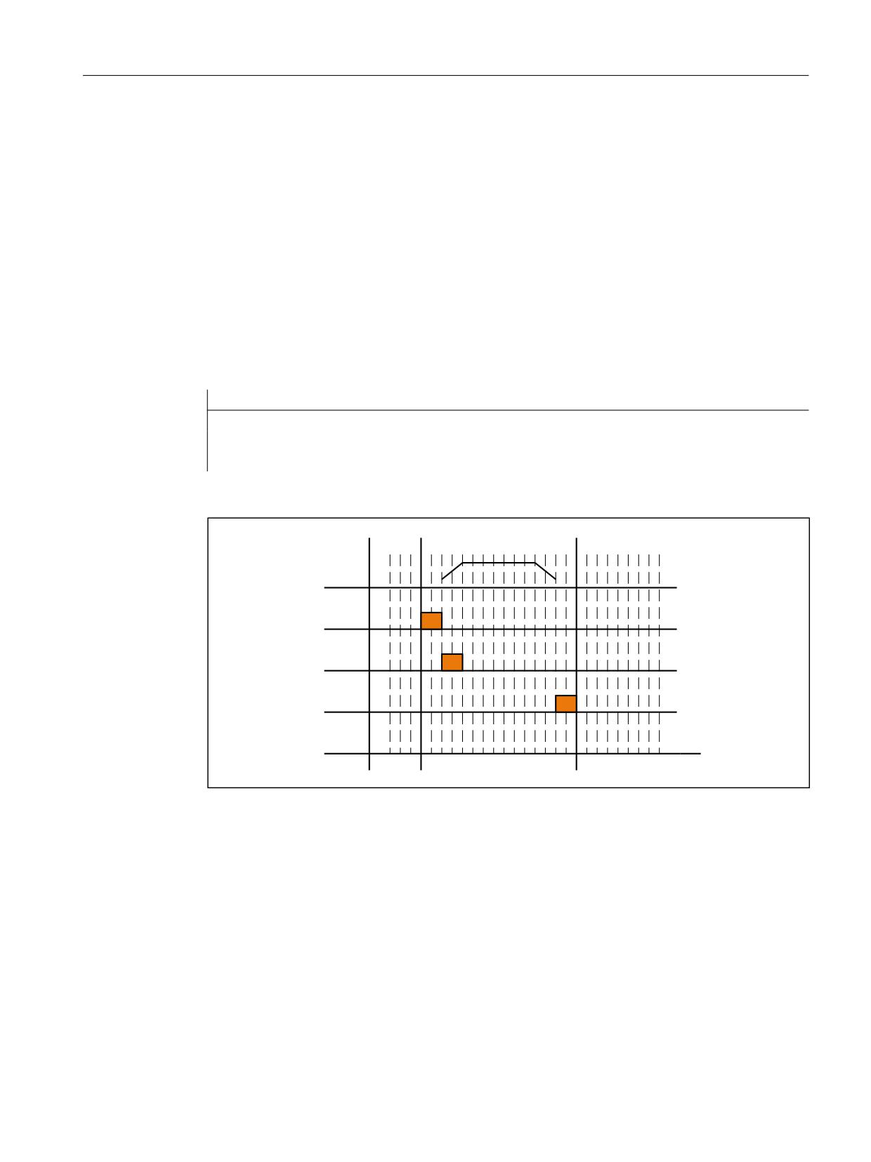
Auxiliary function outputs to PLC
13.6 Priorities of the output behavior for which parameters have been assigned
Example
Output of auxiliary functions with different output behaviors in a part program block with
traverse movement.
Output behavior for which parameters have been assigned:
MD22200 $MC_AUXFU_M_SYNC_TYPE = 1
⇒ M function:
Output during motion
MD22220 $MC_AUXFU_T_SYNC_TYPE = 0
⇒ T function:
Output prior to motion
MD22230 $MC_AUXFU_H_SYNC_TYPE = 2
⇒ H function:
Output at the end of the block
Parts program block:
Program code
N10 G01 X100 M07 H5 T5
Time sequence for auxiliary function output:
;
7
0
+
W
! 6WDUW 1
13.6
Priorities of the output behavior for which parameters have been
assigned
The following priorities must be observed for the following areas in connection with the
parameterized output behavior of an auxiliary function:
• Output duration (normal / quick acknowledgement)
• Output relative to motion (prior to / during / after the motion)
As a general rule, the parameterized output behavior with lower priority becomes active if no
output behavior with higher priority has been parameterized.
Basic functions
Function Manual, 10/2020, 6FC5397-2GP40-0BA1
731

Auxiliary function outputs to PLC
13.7 Programming an auxiliary function
Output duration
The following priorities apply to the output duration:
Priority
Output behavior
Defined via:
Highest
Auxiliary function-specific
Part program instruction: QU(…)
(see Section "Programmable output duration (Page 734)")
↓
Auxiliary function-specific
MD22035 $MC_AUXFU_ASSIGN_SYNC[<n>]
MD22080 $MC_AUXFU_PREDEF_SYNC[<n>]
↓
Group-specific
MD11110 $MC_AUXFU_GROUP_SPEC[<n>]
Lowest
Not defined
Default output behavior: Output duration one OB1 cycle
Output relative to motion
The following rules apply to output relative to motion:
Priority
Output behavior
Defined via:
Highest
Auxiliary function-specific
MD22035 $MC_AUXFU_ASSIGN_SYNC[<n>]
MD22080 $MC_AUXFU_PREDEF_SYNC[<n>]
↓
Group-specific
MD11110 $MC_AUXFU_GROUP_SPEC[<n>]
↓
Type-specific
MD22200 $MC_AUXFU_M_SYNC_TYPE
MD22210 $MC_AUXFU_S_SYNC_TYPE
MD22220 $MC_AUXFU_T_SYNC_TYPE
MD22230 $MC_AUXFU_H_SYNC_TYPE
MD22240 $MC_AUXFU_F_SYNC_TYPE
MD22250 $MC_AUXFU_D_SYNC_TYPE
MD22252 $MC_AUXFU_DL_SYNC_TYPE
Lowest
Not defined
Default output behavior: Output at block end
Note
Part program blocks without path motion
In a part program block without a path motion (even those with positioning axes and spindles),
the auxiliary functions are all output immediately in a block.
13.7
Programming an auxiliary function
Syntax
An auxiliary function is programmed in a part program block with the following syntax:
<Type>[<Address extension>=]<Value>
Basic functions
732
Function Manual, 10/2020, 6FC5397-2GP40-0BA1

Auxiliary function outputs to PLC
13.7 Programming an auxiliary function
Note
If no address extension is programmed, the address extension is implicitly set = 0.
Predefined auxiliary functions with the address extension = 0 always refer to the master spindle
of the channel.
Symbolic addressing
The values for the "address extension" and "value" parameters can also be specified symbolically.
The symbolic name for the address extension must then be stated in brackets.
Example:
Symbolic programming of the auxiliary function M3 (spindle right) for the 1st spindle:
Program code
Comment
DEF SPINDEL_NR=1
; 1st spindle in the channel
DEF DREHRICHTUNG=3
; Clockwise rotation
N100 M[SPINDEL_NR]=DREHRICHTUNG
; in accordance with: M1=3
Note
If you use symbolic names to program an auxiliary function, the symbolic name is not
transferred when the auxiliary function is output to the PLC. The corresponding numerical value
is transferred instead.
Examples
Example 1: Programming of predefined auxiliary functions
Program code
Comment
N10 M3
; "Spindle clockwise" for the master spindle of the channel.
N20 M0=3
; "Spindle clockwise" for the master spindle of the channel.
N30 M1=3
; "Spindle clockwise" for the 1st spindle of the channel.
N40 M2=3
; "Spindle clockwise" for the 2nd spindle of the channel.
Example 2: Programming examples of auxiliary functions with the corresponding values
for output to the PLC
Program code
Comment
DEF Coolant=12
; Output to the PLC: - - -
DEF Lubricant=130
; Output to the PLC: - - -
H[coolant]=lubricant
; Output to the PLC: H12=130
H=coolant
; Output to the PLC: H0=12
H5
; Output to the PLC: H0=5
H=5.379
; Output to the PLC: H0=5.379
Basic functions
Function Manual, 10/2020, 6FC5397-2GP40-0BA1
733
Auxiliary function outputs to PLC
13.8 Programmable output duration
Program code
Comment
H17=3.5
; Output to the PLC: H17=3.5
H[coolant]=13.8
; Output to the PLC: H12=13.8
H='HFF13'
; Output to the PLC: H0=65299
H='B1110'
; Output to the PLC: H0=14
H5.3=21
; Error
13.8
Programmable output duration
Function
User-specific auxiliary functions for which the output behavior "Output duration of an OB1 cycle
(slow acknowledgment)" was parameterized can be defined for individual outputs via the part
program instruction QU (Quick) for auxiliary functions with quick acknowledgment.
Syntax
An auxiliary function with quick acknowledgment is defined in a part program block with the
following syntax:
<Type>[<Address extension>]=QU(<Value>)
Example
Different behavior for the output of the auxiliary functions M100 and M200 in a part program.
The output behavior of the auxiliary functions is parameterized as follows:
• M100
- Output duration one OB1 cycle (slow acknowledgment)
- Output during motion
• M200
- Output duration one OB1 cycle (slow acknowledgment)
- Output prior to motion
Program code
Comment
N10 G94 G01 X50 M100
; Output of M100: During motion
; Acknowledgment: Slow
N20 Y5 M100 M200
; Output of M200: Prior to motion
; Output of M100: During motion
; Acknowledgment: Slow
N30 Y0 M=QU(100) M=QU(200)
; Output of M200: Prior to motion
; Output of M100: During motion
; Acknowledgment: Fast
N40 X0
Basic functions
734
Function Manual, 10/2020, 6FC5397-2GP40-0BA1
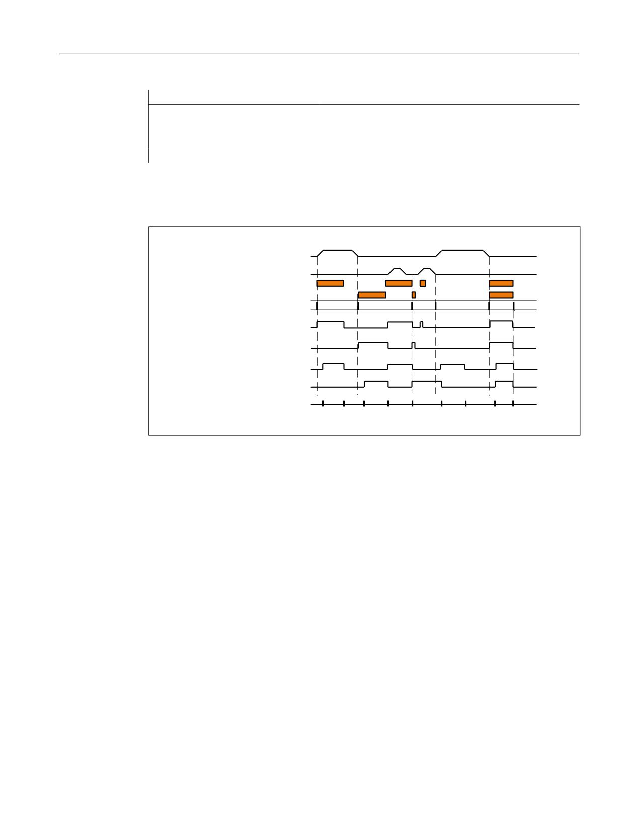
Auxiliary function outputs to PLC
13.9 Auxiliary function output to the PLC
Program code
Comment
N50 M100 M200
; Output of M200: Immediately 1)
; Output of M100: Immediately 1)
; Acknowledgment: Slow
M17
1)
Without a traversing motion, auxiliary functions are always output to the PLC immediately.
The following figure shows the time sequence of the part program. Please note the time
difference during the processing of part program blocks N20 and N30.
; D[LV
< D[LV
0
0
%ORFN QXPEHU
1
1
1
1
1
6WUREH IURP 1&. DQG
0
DFNQRZOHGJHPHQW E\ 3/&
EDVLF SURJUDP
0
0
FKDQJH 167
0
FKDQJH 167
3/& F\FOH WLPH 2%
2%
13.9
Auxiliary function output to the PLC
Function
On output of an auxiliary function to the PLC, the following signals and values are transferred to
the NC/PLC interface:
• Change signals
• "Address extension" parameter
• "Value" parameter
Data areas in the NC/PLC interface
The change signals and values of the auxiliary functions are within the following data areas in
the NC/PLC interface:
• Change signals for auxiliary function transfer from NC channel:
DB21, ... DBB58 - DBB67
• Transferred M and S functions:
DB21, ... DBB68 - DBB112
Basic functions
Function Manual, 10/2020, 6FC5397-2GP40-0BA1
735

Auxiliary function outputs to PLC
13.10 Auxiliary functions without block change delay
• Transferred T, D and DL functions:
DB21, ... DBB116 - DBB136
• Transferred H and F functions:
DB21, ... DBB140 - DBB190
• Decoded M signals (M0 - M99):
DB21, ... DBB194 - DBB206 (dynamic M functions)
Further information
• Function Manual PLC and Basic Program, Basic PLC program
• Function Manual PLC and Basic Program, Reference on the basic PLC program
13.10
Auxiliary functions without block change delay
Function
For auxiliary functions with parameterized and/or programmed output behavior, too:
• "Output duration one OB40 cycle (quick acknowledgment)"
• "Output before the motion" or "Output during the motion"
there may be drops in velocity in continuos-path mode (short traverse paths and high velocities).
This the system has to wait for acknowledgment of the auxiliary function by the PLC toward the
end of the block. To avoid these velocity drops, the block change can be made irrespective of
whether such auxiliary functions have been acknowledged:
Parameter assignment
Suppression of the block change delay with quick auxiliary functions is set via the machine data:
MD22100 $MC_AUXFU_QUICK_BLOCKCHANGE (block change delay with quick auxiliary
functions)
Value
Meaning
0
In the case of quick auxiliary function output to the PLC, the block change is delayed until
acknowledgment by the PLC (OB40).
1
In the case of quick auxiliary function output to the PLC, the block change is not delayed.
Boundary conditions
Synchronism of auxiliary functions that are output without a block change delay is no longer
ensured for the part program block in which they are programmed. In the worst case scenario,
acknowledgment comes one OB40 cycle and execution of the auxiliary function comes one OB1
cycle after the change to the next part program block.
Basic functions
736
Function Manual, 10/2020, 6FC5397-2GP40-0BA1
Auxiliary function outputs to PLC
13.12 Response to overstore
13.11
M function with an implicit preprocessing stop
Function
Triggering a preprocessing stop in conjunction with an auxiliary function can be programmed
explicitly via the STOPRE part program command. Always triggering a preprocessing stop in M
function programming can be parameterized for each M function via the following machine
data:
MD10713 $MN_M_NO_FCT_STOPRE[<n>] (M function with preprocessing stop)
Example
The user-defined M function M88 is intended to trigger a preprocessing stop.
Parameterization:
MD10713 $MN_M_NO_FCT_STOPRE [ 0 ] = 88
Application:
Part program (extract)
Program code
Comment
N100 G0 X10 M88
; Traversing motion and implicit preprocessing stop via M88.
N110 Y=R1
; N110 is only interpreted after the traversing motion has
been completed and the M function has been acknowledged.
Supplementary conditions
If a subprogram is called indirectly via an M function in a part program in one of the following
ways, no preprocessing stop is performed:
• MD10715 $MN_M_NO_FCT_CYCLE (M function to be replaced by subprogram)
• M98 (ISO dialect T / ISO dialect M)
13.12
Response to overstore
Overstore
On the SINUMERIK operator interface, before starting the following functions:
• NC START of a part program
• NC START to resume an interrupted part program
the auxiliary functions that are output at the start can be changed by the "Overstore" function.
Basic functions
Function Manual, 10/2020, 6FC5397-2GP40-0BA1
737
Auxiliary function outputs to PLC
13.13 Behavior during block search
Possible applications include:
• Addition of auxiliary functions after block search
• Restoring the initial state to position a part program
Types of auxiliary functions that can be overstored
The following types of auxiliary functions can be overstored:
• M (special function)
• S (spindle speed)
• T (tool number)
• H (aux. function)
• D (tool offset number)
• DL (additive tool offset)
• F (feed)
Duration of validity
An overstored auxiliary function, e.g. M3 (spindle right), is valid until it is overwritten by another
auxiliary function from the same auxiliary function group, by additional overstoring or by
programming in a part program block.
13.13
Behavior during block search
13.13.1
Auxiliary function output during type 1, 2, and 4 block searches
Output behavior
In the case of type 1, 2, and 4 block searches, the auxiliary functions are collected on the basis of
specific groups. The last auxiliary function in each auxiliary function group is output after NC-
START in a separate part program block before the actual reentry block, and has the following
output behavior:
• Output duration of one OB1 cycle (normal acknowledgement)
• Output prior to motion
Basic functions
738
Function Manual, 10/2020, 6FC5397-2GP40-0BA1

Auxiliary function outputs to PLC
13.13 Behavior during block search
Output control
Whether or not the auxiliary function is output to the PLC after a block search can be configured
via bit 8 of the machine data:
• MD22080 $MC_AUXFU_PREDEF_SPEC[<n>]
(output behavior of predefined auxiliary functions)
where <n> = system function index (0 ... 32)
• MD22035 $MC_AUXFU_ASSIGN_SPEC[<n>]
(output behavior of user-defined auxiliary functions)
where <n> = auxiliary function index (0 ... 254)
• MD11110 $MN_AUXFU_GROUP_SPEC[<n>]
(output behavior of the auxiliary functions in a group)
where <n> = group index (0 ... 63)
Bit
Value
Meaning
10
0
Output during type 1, 2, and 4 block searches
1
No output during type 1, 2, and 4 block searches
This behavior does not affect the display and does not affect variables $AC_AUXFU_STATE[<n>],
$AC_AUXFU_VALUE[<n>], and $AC_AUXFU_EXT[<n>].
The auxiliary functions are always regarded as collected after a block search, even though they
are not output to the PLC.
During collection, an auxiliary function that is not output after a block search also overwrites an
auxiliary function whose bit 8 is not set.
The user can scan the collected auxiliary functions after a block search and, under certain
circumstances, output them again by means of the subprogram or synchronized actions.
Note
The following auxiliary functions are not collected:
• Auxiliary functions which are not assigned to any auxiliary function group.
• Auxiliary functions which are assigned to the first auxiliary function group.
Overstorage of auxiliary functions
After completion of a block search, the collected auxiliary functions are ouput on the next NC-
START. If it is necessary to output additional auxiliary functions, they can be added via the
"Overstore" function (see Section "Response to overstore (Page 737)").
M19 behavior (position spindle)
After a block search, the last spindle positioning command programmed with M19 is always
carried out, even if other spindle-specific auxiliary functions are programmed between the part
program with M19 and the target block. Setting the necessary spindle enables must therefore
be derived from the interface signals of the traverse commands in the PLC user program:
DB31, ... DBX64.6/64.7 (traversing command minus/plus)
Basic functions
Function Manual, 10/2020, 6FC5397-2GP40-0BA1
739
Auxiliary function outputs to PLC
13.13 Behavior during block search
In this case, the spindle-specific auxiliary functions M3, M4, and M5 are not suitable because
they might not be output to the PLC until after the spindle positioning.
For detailed information on the block search, see Section "Mode group, channel, program
operation, reset response (Page 25)".
13.13.2
Assignment of an auxiliary function to a number of groups
Function
User-defined auxiliary functions can also be assigned to multiple groups via the group
assignment (MD22000 $MC_AUXFU_ASSIGN_GROUP). During the block search these auxiliary
functions are collected for all the configured groups.
Note
Predefined auxiliary functions can only be assigned to one group.
Example
The DIN includes the following M-commands for coolant output:
• M7: Coolant 2 ON
• M8: Coolant 1 ON
• M9: Coolants 1 and 2 OFF
Consequently, both coolants can also be active together:
• If M7 and M8 are collected in two separate groups (e.g. groups 5 and 6)
• If M9 has to be assigned to these two groups, e.g.
- Group 5: M7, M9
- Group 6: M8, M9
Parameterization:
MD11100 $MN_AUXFU_MAXNUM_GROUP_ASSIGN = 4
MD22000 $MC_AUXFU_ASSIGN_GROUP [0] = 5
MD22000 $MC_AUXFU_ASSIGN_GROUP [1] = 5
MD22000 $MC_AUXFU_ASSIGN_GROUP [2] = 6
MD22000 $MC_AUXFU_ASSIGN_GROUP [3] = 6
MD22010 $MC_AUXFU_ASSIGN_TYPE [0] = M
MD22010 $MC_AUXFU_ASSIGN_TYPE [1] = M
MD22010 $MC_AUXFU_ASSIGN_TYPE [2] = M
MD22010 $MC_AUXFU_ASSIGN_TYPE [3] = M
Basic functions
740
Function Manual, 10/2020, 6FC5397-2GP40-0BA1
Auxiliary function outputs to PLC
13.13 Behavior during block search
MD22020 $MC_AUXFU_ASSIGN_EXTENSION [0] = 0
MD22020 $MC_AUXFU_ASSIGN_EXTENSION [1] = 0
MD22020 $MC_AUXFU_ASSIGN_EXTENSION [2] = 0
MD22020 $MC_AUXFU_ASSIGN_EXTENSION [3] = 0
MD22030 $MC_AUXFU_ASSIGN_VALUE [0] = 7
MD22030 $MC_AUXFU_ASSIGN_VALUE [1] = 9
MD22030 $MC_AUXFU_ASSIGN_VALUE [2] = 8
MD22030 $MC_AUXFU_ASSIGN_VALUE [3] = 9
MD22035 $MC_AUXFU_ASSIGN_SPEC [0] = 'H121'
MD22035 $MC_AUXFU_ASSIGN_SPEC [1] = 'H121'
MD22035 $MC_AUXFU_ASSIGN_SPEC [2] = 'H121'
MD22035 $MC_AUXFU_ASSIGN_SPEC [3] = 'H121'
Part program (section):
Program code
N10 ... M8
N20 ... M9
N30 ... M7
During the block search, the auxiliary function M9 is collected for groups 5 and 6.
Scan of the collected M auxiliary functions:
M function of the fifth group: $AC_AUXFU_M_VALUE [4] = 7
M function of the sixth group: $AC_AUXFU_M_VALUE [5] = 9
13.13.3
Time stamp of the active M auxiliary function
When outputting collected auxiliary functions following a block search, attention must be paid
to the sequence during collecting. For this reason, each group is assigned a time stamp which
can be queried on a group-specific basis by way of the system variable below:
$AC_AUXFU_M_TICK[<n>] (time stamp of the active M auxiliary function)
13.13.4
Determining the output sequence
Function
The following predefined procedure is provided to simplify the process of determining the
output sequence of M auxiliary functions for the programmer:
Basic functions
Function Manual, 10/2020, 6FC5397-2GP40-0BA1
741
Auxiliary function outputs to PLC
13.13 Behavior during block search
AUXFUMSEQ(VAR INT _NUM_IN, VAR INT _M_IN[], VAR INT _EXT_IN[], VAR
INT _NUM_OUT, VAR INT _M_OUT[], VAR INT _EXT_OUT[])
Input parameters:
VAR INT _NUM_IN:
Number of relevant M commands
VAR INT _M_IN[]:
Field of relevant M codes
VAR INT _EXT_IN[]:
Field of relevant M address extensions
Output parameters:
VAR INT _NUM_OUT:
Number of determined M codes
VAR INT _M_OUT[]:
Field of determined M codes
VAR INT _EXT_OUT[]:
Field of determined M address extensions
The function determines the sequence in which the M auxiliary functions, which have been
collected on a group-specific basis, are output for the predefined M codes. The sequence is
determined from the collection times $AC_AUXFU_M_TICK[<n>] (see Section "Time stamp of
the active M auxiliary function (Page 741)").
A particular M code is only taken into account once, even if it belongs to more than one group.
If the number of relevant M commands is less than or equal to 0, all the collected M codes are
output. The number of relevant M commands is limited to 64.
Example
M commands for coolant output:
• M7: Coolant 2 ON
• M8: Coolant 1 ON
• M9: Coolants 1 and 2 OFF
Group assignment:
• Group 5: M7, M9
• Group 6: M8, M9
Part program (section):
Program code
N10 ... M8
N20 ... M9
N30 ... M7
Basic functions
742
Function Manual, 10/2020, 6FC5397-2GP40-0BA1

Auxiliary function outputs to PLC
13.13 Behavior during block search
During block searches, the auxiliary functions are collected on the basis of specific groups. The
last auxiliary function in an auxiliary function group is output to the PLC following a block search:
• Group 5: M7
• Group 6: M9
If they are output in the sequence M7 → M9, no coolant is then active. However, coolant 2 would
be active during the execution of the program. Therefore, the correct output sequence for the
M auxiliary functions is determined with an ASUP which contains the predefined procedure
AUXFUMSEQ(…):
Program code
DEF INT _I, _M_IN[3], _EXT_IN[3], _NUM_OUT, _M_OUT[2], _EXT_OUT[2]
_M_IN[0]=7 _EXT_IN[0]=0
_M_IN[1]=8 _EXT_IN[1]=0
_M_IN[2]=9 _EXT_IN[2]=0
AUXFUMSEQ(3,_M_IN,_EXT_IN,_NUM_OUT,_M_OUT,_EXT_OUT)
FOR _I = 0 TO _NUM_OUT-1
M[_EXT_OUT[_I]]=_M_OUT[_I]
ENDFOR
13.13.5
Output suppression of spindle-specific auxiliary functions
Function
In certain situations, such as a tool change, it may be necessary not to output the spindle-
specific auxiliary functions collected during the block search in action blocks, but to delay
output, for example, until after a tool change. The automatic output of the spindle-specific
auxiliary functions after a block search may be suppressed for this purpose. Output can then be
performed manually later by overstoring or by an ASUP.
Parameterization
Suppression of the automatic output of the spindle-specific auxiliary functions after a block
search is set via machine data:
MD11450 $MN_SEARCH_RUN_MODE (behavior after a block search)
Bit
Value
Meaning
2
0
The output of the spindle-specific auxiliary functions is performed in the action blocks.
1
Output of the auxiliary functions is suppressed in the action blocks.
Basic functions
Function Manual, 10/2020, 6FC5397-2GP40-0BA1
743

Auxiliary function outputs to PLC
13.13 Behavior during block search
System variables
The spindle-specific auxiliary functions are always stored in the following system variables
during block searches, irrespective of the parameter assignment described above:
System variable
Description
$P_SEARCH_S [<n> ]
Accumulated spindle speed
Value range:
0 ... Smax
$P_SEARCH_SDIR [<n>]
Accumulated spindle direction of rotation
Value range:
3, 4, 5, -5, -19, 70
$P_SEARCH_SGEAR [<n>]
Accumulated spindle gear stage M function
Value range:
40 ... 45
$P_SEARCH_SPOS [<n>]
Accumulated spindle position
Value range:
0 ... MD30330 $MA_MODULO_RANGE
(size of the module range)
or
Accumulated traversing path
Value range:
-100,000,000 ... 100,000,000
$P_SEARCH_SPOSMODE [<n>]
Accumulated position approach mode
Value range:
0 ... 5
For later output of the spindle-specific auxiliary functions, the system variables can be read in an
ASUP, for example, and output after the action blocks are output:
DB21, ... DBX32.6 = 1 (last action block active)
Note
The contents of the system variables $P_S, $P_DIR and $P_SGEAR may be lost after block search
due to synchronization operations.
For more detailed information on ASUP, block search and action blocks, see Section "Mode
group, channel, program operation, reset response (Page 25)".
Example
Block search for contour with suppression of output of the spindle-specific auxiliary functions
and start of an ASUP after output of action blocks.
Parameterization: MD11450 $MN_SEARCH_RUN_MODE, bit 2 = 1
After the block search on N55, the ASUP is started.
Part program:
Program code
Comment
N05 M3 S200
; Spindle 1:
N10 G4 F3
N15 SPOS=111
; Spindle 1 is positioned to 111 degrees in the ASUP
N20 M2=4 S2=300
; Spindle 2:
N25 G4 F3
Basic functions
744
Function Manual, 10/2020, 6FC5397-2GP40-0BA1
Auxiliary function outputs to PLC
13.13 Behavior during block search
Program code
Comment
N30 SPOS[2]=IC(77)
; Spindle 2 traverses incrementally through 77 degrees
N55 X10 G0
; Target block
N60 G4 F10
N99 M30
ASUP:
Program code
Comment
PROC ASUP_SAVE
MSG ("Output of the spindle functions")
DEF INT SNR=1
AUSG_SPI:
M[SNR]=$P_SEARCH_SGEAR[SNR]
; Output gear stage.
S[SNR]=$P_SEARCH_S[SNR]
; Output speed (for M40, a suitable
gear stage is determined).
M[SNR]=$P_SEARCH_SDIR[SNR]
; Output direction of rotation, posi-
tioning or axis mode.
SNR=SNR+1
; Next spindle.
REPEAT AUSG_SPI P=$P_NUM_SPINDLES-1
; For all spindles.
MSG("")
REPOSA
RET
Explanation of example
If the number of spindles is known, outputs of the same type can be written in one part program
block to reduce program runtime.
Output of $P_SEARCH_SDIR should be made in a separate part program block because spindle
positioning or switchover to axis mode in conjunction with the gear change can cause an alarm.
If the ASUP which has been started is ended with REPOSA, spindle 1 remains at position 111
degrees, while spindle 2 is repositioned at position 77 degrees.
If a different response is required, the program sequence for block search (for example) "N05
M3 S..." and "N30 SPOS[2] = IC(...)" requires special treatment.
Whether block search is active can be ascertained in the ASUP via the system variable
$P_SEARCH.
$P_SEARCH==1 ; Block search active
In the case of incremental positioning after speed control operation, the path to be traversed is
defined but, in some cases, the final position reached only becomes known during positioning.
This is the case, for example, during position calibration on crossing the zero mark when
switching on position control. For this reason, the distance programmed after the zero position
is accepted as the REPOS position (REPOSA in the ASUP).
Supplementary conditions
Collected S values
Basic functions
Function Manual, 10/2020, 6FC5397-2GP40-0BA1
745
Auxiliary function outputs to PLC
13.13 Behavior during block search
The meaning of an S value in the part program depends on the feed type that is currently active:
G93, G94, G95, G97, G971:
The S value is interpreted as the speed
G96, G961:
The S value is interpreted as a constant cutting rate
If the feed operation is changed (e.g. for a tool change) before output of the system variable
$P_SEARCH_S, the original setting from the target block in the part program must be restored to
avoid use of the wrong type of feed.
Collected direction of rotation
For output of the direction of rotation, the system variable $P_SEARCH_SDIR is assigned default
value "-5" at the start of the block search. This value has no effect on output.
This ensures that the last spindle operating mode is retained for a block search across program
sections in which spindles are not programmed with a direction of rotation, positioning or axis
mode.
The programming of M19, SPOS, and SPOSA is collected as "M-19" (internal M19) in the system
variables $P_SEARCH_SDIR as an alternative to M3, M4, M5, and M70.
For the output of "M-19", the positioning data is read internally from the system variables
$P_SEARCH_SPOS and $P_SEARCH_SPOSMODE. Both system variables can also be written to, in
order, for example, to make corrections.
Note
Because of the assignments described above (e.g. M[<n>] = $P_SEARCH_SDIR[<n>]), the values
"-5" and "19" generally remain hidden from the user and only have to be observed in the case of
special evaluation of the system variables in the ASUP.
13.13.6
Auxiliary function output with a type 5 block search (SERUPRO)
Output behavior
In the case of type 5 block searches (SERUPRO), an auxiliary function can be output to the PLC
during the block search and/or collected on a group-specific basis in the following system
variables:
• $AC_AUXFU_PREDEF_INDEX[<n>] (index of a predefined auxiliary function)
• $AC_AUXFU_TYPE[<n>] (type of auxiliary function)
• $AC_AUXFU_STATE[<n>] (output state of the auxiliary function)
• $AC_AUXFU_EXT[<n>] (address extension of the auxiliary function)
• $AC_AUXFU_VALUE[<n>] (value of the auxiliary function)
For a description of the system variables, see Section "Querying system variables (Page 760)".
Basic functions
746
Function Manual, 10/2020, 6FC5397-2GP40-0BA1
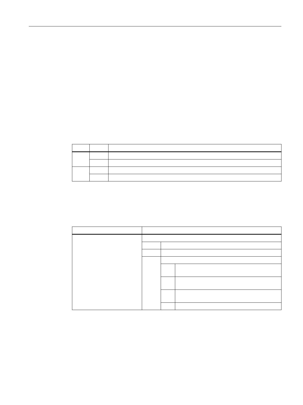
Auxiliary function outputs to PLC
13.13 Behavior during block search
Output control
Whether an auxiliary function is output to the PLC during a type 5 block search (SERUPRO) and/
or collected on a group-specific basis in the following system variables can be configured via bits
9 and 10 of the machine data:
• MD22080 $MC_AUXFU_PREDEF_SPEC[<n>]
(output behavior of predefined auxiliary functions)
where <n> = system function index (0 ... 32)
• MD22035 $MC_AUXFU_ASSIGN_SPEC[<n>]
(output behavior of user-defined auxiliary functions)
where <n> = auxiliary function index (0 ... 254)
• MD11110 $MN_AUXFU_GROUP_SPEC[<n>]
(output behavior of the auxiliary functions in a group)
where <n> = group index (0 ... 63)
Bit
Value
Meaning
9
0
No collection during type 5 block searches (SERUPRO)
1
Collection during type 5 block searches (SERUPRO)
10
0
Output during type 5 block searches (SERUPRO)
1
No output during type 5 block searches (SERUPRO)
Output counter
The user can output the collected auxiliary functions to the PLC on a channel-by-channel basis
in the block search ASUP. For the purposes of serialized output via multiple channels, the three
output counters are changed across all the channels each time an auxiliary function is output:
System variable
Meaning
$AC_AUXFU_TICK[<n>,<m>]
Output counter of the active auxiliary function
Index
Meaning
<n>
Group index (0 … 63)
<m>
Output counter (0 ... 2)
Val-
Meaning
ue
0
Output sequence counter (all outputs within an IPO
cycle)
1
Package counter within an output sequence in the
IPO cycle
2
Auxiliary function counter within a package
Explanation
• An auxiliary function package comprises a maximum of ten auxiliary functions.
• Two packages can be processed per IPO cycle in each channel during SERUPRO because
synchronized actions are processed in this cycle.
• An output sequence of up to a maximum of 20 packages (2 packages per channel * 10
channels) can be processed within an IPO cycle across all channels.
Basic functions
Function Manual, 10/2020, 6FC5397-2GP40-0BA1
747

Auxiliary function outputs to PLC
13.13 Behavior during block search
The encoding indicates how many auxiliary function packages and, within these, how many
auxiliary functions have been processed during the same IPO cycle:
• Auxiliary functions which have been collected in one IPO cycle have the same sequence
counter.
• Auxiliary functions which have been collected in one package (block or synchronized action)
all have the same package counter.
The total on the auxiliary function counter increases every time an auxiliary function is collected.
Global list of auxiliary functions
At the end of SERUPRO, the auxiliary functions collected on a group-specific basis in the
individual channels are entered in a cross-channel list with the channel number and group index
according to their counter state.
System variable 1)
Meaning
$AC_AUXFU_TICK[<n>,<m>]
Counter value
$AN_AUXFU_LIST_CHANNO[<n>] 2)
Channel number
$AN_AUXFU_LIST_GROUPINDEX[<n>] 2)
Group index
1) Value range index <n>: 0 ... MAXNUM_GROUPS * MAXNUM_CHANNELS - 1
2) The system variables can be read and written.
Basic functions
748
Function Manual, 10/2020, 6FC5397-2GP40-0BA1
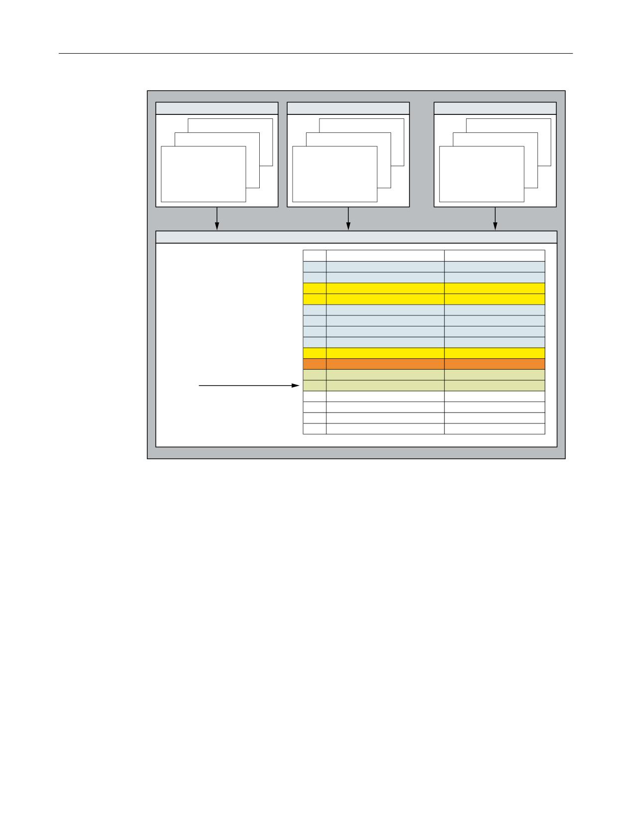
Auxiliary function outputs to PLC
13.13 Behavior during block search
&KDQQHO
&KDQQHO
&KDQQHO
Q
0$;180B*52836
Q
0$;180B*52836
Q
0$;180B*52836
Q
Q
Q
Q
Q
Q
$&B$8;)8B35('()B,1'(;>Q@
$&B$8;)8B35('()B,1'(;>Q@
$&B$8;)8B35('()B,1'(;>Q@
$&B$8;)8B7<3(>Q@
$&B$8;)8B7<3(>Q@
$&B$8;)8B7<3(>Q@
$&B$8;)8B(;7>Q@
$&B$8;)8B(;7>Q@
$&B$8;)8B(;7>Q@
$&B$8;)8B9$/8(>Q@
$&B$8;)8B9$/8(>Q@
$&B$8;)8B9$/8(>Q@
$&B$8;)8B67$7(>Q@
$&B$8;)8B67$7(>Q@
$&B$8;)8B67$7(>Q@
$&B$8;)8B63(&>Q@
$&B$8;)8B63(&>Q@
$&B$8;)8B63(&>Q@
$&B$8;)8B7,&.>Q@
$&B$8;)8B7,&.>Q@
$&B$8;)8B7,&.>Q@
*OREDO OLVW RI DX[LOLDU\ IXQFWLRQV
Q
$1B$8;)8B/,67B*5283,1'(;>Q@
$1B$8;)8B/,67B&+$112>Q@
Q
0$;180B*52836
0$;180B&+$11(/6
$1B$8;)8B/,67B(1',1'(;
The global list is structured on the basis of the sequence in which the search target was found.
It is intended to be used as a system proposal for auxiliary functions to be output in the following
ASUP at the end of SERUPRO. If an auxiliary function is not to be output, the corresponding group
index is to be set to "0".
Behavior regarding spindle auxiliary functions
Following the start of the block search, all the channels collect the auxiliary functions in the
channel variables on a group-specific basis. In order to perform a far-reaching restoration of the
spindle state in the SERUPRO target block using the collected auxiliary functions, the last active
auxiliary function in any group of spindle auxiliary functions must characterize the state of the
spindle in the target block. In the case of transitions in spindle states, obsolete auxiliary
functions are deleted or, if necessary, implicit auxiliary functions are entered.
All the spindle auxiliary functions from the global auxiliary function list must correspond to the
spindle states achieved in the target block to enable the auxiliary functions to be processed
when the list is output and to ensure that no alarms or unintended spindle states are requested
which could prevent the continuation of the part program.
Basic functions
Function Manual, 10/2020, 6FC5397-2GP40-0BA1
749
Auxiliary function outputs to PLC
13.13 Behavior during block search
This affects the groups of auxiliary functions for any spindle configured in the system, whereby
the spindle number corresponds to an auxiliary function's address extension.
Group a:
M3, M4, M5, M19, M70
Group b:
M40, M41, M42, M43, M44, M45
Group c:
S
Deleting obsolete auxiliary functions
In the functions below, the auxiliary functions from group a are deleted for the spindle
concerned:
• For the following spindle when a generic coupling, such as COUPON, TRAILON, EGON, etc. is
switched on
Generating implicit auxiliary functions from group a
In the functions below, the auxiliary functions from group a are generated implicitly for the
spindle concerned:
• For the following spindle when the synchronous spindle coupling is switched off
- COUPOF generates M3, M4 and S or M5 in the main run depending on the coupling
situation.
- COUPOF(S<n>, S<m>, POS) and COUPOFS(S<n>, S<m>, POS, POS) generate M3, M4 and
S.
- COUPOFS generates M5 in the main run.
- COUPOFS(S<n>, S<m>, POS) generates M19 in the main run.
The implicit M19 ("SPOS[<address extension>] = IC(0)" in the ASUP) activates the
positioning mode without a traversing motion.
• M70 is generated during a traversing motion as an axis or during the transition to axis mode
by selecting a transformation during which the spindle enters as an axis.
• M5 is generated during SPCOF.
Note
Within the context of the "axis interchange" and "axis container rotation" functions, the auxiliary
functions for programming the spindle must always be specified in a way which ensures
compatibility with the actual (motor) state during interchange/rotation. A distinction is made
here between the axis interchange and axis container mechanisms.
Example of axis container rotation:
An axis container has four spindles, each assigned to a separate channel (1 - 4). M3 S1000 is
always programmed in channel 1, and an axis container rotation is then executed. The other
channels do not perform any spindle programming. Following the third axis container rotation
and the fourth spindle programming, M3, all four spindles rotate clockwise at a speed of 1000
rpm. If the end of the SERUPRO now lies within this range, every ASUP for a channel is expected
to contain an M3 S1000 for the local spindle.
During interchange however, the collected auxiliary functions may only be assigned to the
channel where the spindle is currently located.
Basic functions
750
Function Manual, 10/2020, 6FC5397-2GP40-0BA1

Auxiliary function outputs to PLC
13.13 Behavior during block search
Cross-channel auxiliary function
An auxiliary function can also be collected on a cross-channel basis in the global auxiliary
function list in the case of type 5 block searches (SERUPRO). Only the last auxiliary function
collected from this group (highest counter state) is entered in the global list.
The appropriate configuring is performed with the following machine data:
• MD22080 $MC_AUXFU_PREDEF_SPEC[<n>], Bit 11
(output behavior of predefined auxiliary functions)
where <n> = system function index
• MD22035 $MC_AUXFU_ASSIGN_SPEC[<n>], Bit 11
(output behavior of user-defined auxiliary functions)
where <n> = auxiliary function index
• MD11110 $MN_AUXFU_GROUP_SPEC[<n>], Bit 11
(output behavior of the auxiliary functions in a group)
where <n> = group index
Bit
Value
Meaning
11
0
Channel-specific collection
1
Cross-channel collection
The spindle auxiliary functions are filtered out beforehand at the end of the block search
depending on the spindle state. The channel data is updated accordingly. The global auxiliary
function list can be processed sequentially in the ASUPs at the end of the SERUPRO, and the
sorted auxiliary functions can be output with channel synchronization.
Querying the last auxiliary function collected
The index of the last auxiliary function collected in the global list can be queried using the system
variable $AN_AUXFU_LIST_ENDINDEX.
13.13.7
ASUB at the end of the SERUPRO
Function
After completing the block search with the program test (SERUPRO), before starting the
subsequent processing, the auxiliary functions collected during the block search must be
output. For this purpose, during the block search, the auxiliary functions are collected in a global
list. The SERUPRO end ASUPs generate the corresponding part program blocks channel-specific
from this list. This ensures that the collected auxiliary functions can be output both channel-
specific as well as cross-channel in the correct sequence. A fully functional SERUPRO end ASUP
is a component of the NC software.
Users/machinery construction OEMs can change the SERUPRO end ASUP. The subsequently
described functions support processing the global list of auxiliary functions and generating the
part program blocks required for synchronized auxiliary function output.
Basic functions
Function Manual, 10/2020, 6FC5397-2GP40-0BA1
751
Auxiliary function outputs to PLC
13.13 Behavior during block search
Function AUXFUSYNC(...)
Function:
The function AUXFUSYNC generates a complete part program block as string from the global list
of auxiliary functions at each call. The part program block either contains auxiliary functions or
commands to synchronize auxiliary function outputs (WAITM, G4, etc.).
The function triggers a preprocessing stop.
Syntax:
PROC AUXFUSYNC(VAR INT <NUM>, VAR INT <GROUPINDEX>[10], VAR
STRING[400] <ASSEMBLED>)
Parameters:
<NUM>:
Contains information about the part program block, supplied in param-
eter <ASSEMBLED> or the auxiliary functions contained in it.
Value range: -1, 0, 1 ... 10
Val- Meaning
ue
≥1
Number of auxiliary functions contained in the part program
block
0
Part program block without auxiliary functions, e.g. WAITM, G4
-1
End identifier. The global list of auxiliary functions has been com-
pletely processed for the actual channel.
<GROUP INDEX>:
Contains the indices of the auxiliary function groups contained in the
part program block. With index = number of the auxiliary function group
- 1
<ASSEMBLED>:
Contains the complete part program block for the channel-specific SER-
UPRO end ASUP as string.
Further information:
If auxiliary functions were collected via a synchronized action, two NC blocks are generated. One
NC block to output the auxiliary functions. An executable NC block via which the NC block is
transported to the main run to output the auxiliary functions:
1. Output of the auxiliary functions via synchronized action, e.g.: WHEN TRUE DO M100 M102
2. Executable NC block, e.g.: G4 F0.001
Function AUXFUDEL(...)
Function:
The function AUXFUDEL deletes the specified auxiliary function from the global list of auxiliary
functions channel-specific for the calling channel. Deletion is realized by setting the
corresponding group index ...GROUPINDEX[n] to 0.
The function must be called before calling AUXFUSYNC.
The function triggers a preprocessing stop.
Syntax:
Basic functions
752
Function Manual, 10/2020, 6FC5397-2GP40-0BA1

Auxiliary function outputs to PLC
13.13 Behavior during block search
PROC AUXFUDEL(CHAR <TYPE>, INT <EXTENSION>, REAL <VALUE>, INT
<GROUP>)
Parameters:
<TYPE>:
Type of auxiliary function to be deleted
<EXTENSION>:
Address extension of the auxiliary function to be deleted
<VALUE>:
Value of auxiliary function to be deleted
<GROUP>:
Number of the auxiliary function group
Function AUXFUDELG(...)
Function:
The function AUXFUDELG deletes all auxiliary functions of the specified auxiliary function group
from the global list of auxiliary functions channel-specific for the calling channel. Deletion is
realized by setting the corresponding group index ...GROUPINDEX[n] to 0.
The function must be called before calling AUXFUSYNC.
The function triggers a preprocessing stop.
Syntax:
PROC AUXFUDELG(INT <GROUP>)
Parameters:
<GROUP>:
Number of the auxiliary function group
Multi-channel block search
NOTICE
Multi-channel block search and AUXFUDEL / AUXFUDELG
If, for a multi-channel block search in the SERUPRO end ASUPs, auxiliary functions with
AUXFUDEL / AUXFUDELG are deleted from the global list of auxiliary functions, before calling
the AUXFUSYNC function, the channels involved must be synchronized. The synchronization
ensures that before calling the AUXFUSYNC, all delete requests are processed and a consistent
list is available.
Examples
Two examples for configuring a user-specific SERUPRO end ASUP.
Example 1: Deleting auxiliary functions and generating the auxiliary function output with
AUXFUSYNC(...)
Program code
Comment
N10 DEF STRING[400] ASSEMBLED=""
N20 DEF STRING[31] FILENAME="/_N_CST_DIR/_N_AUXFU_SPF"
N30 DEF INT GROUPINDEX[10]
Basic functions
Function Manual, 10/2020, 6FC5397-2GP40-0BA1
753
Auxiliary function outputs to PLC
13.13 Behavior during block search
Program code
Comment
N40 DEF INT NUM
N60 DEF INT ERROR
N90
N140 AUXFUDEL("M",2,3,5)
; M2=3 (5th auxiliary function group) delete
N150
N170 AUXFUDELG(6)
; Delete the collected auxiliary function of the
; 6th group.
N180
N190 IF ISFILE(FILENAME)
N210
DELETE(ERROR,FILENAME)
; Delete the FILENAME file
N220
IF (ERROR<>0)
; Error evaluation
N230
SETAL(61000+ERROR)
N240
ENDIF
N250 ENDIF
; CAUTION!
; If, for a multi-channel block search, auxiliary functions with AUXFUDEL/AUXFUDELG
; are deleted from the global list of auxiliary functions, before the loop to
; generate the subprogram FILENAME with AUXFUSYNC, the channels must be synchronized.
The synchronization ensures that all delete requests were processed
; in all channels and a consistent list is available.
; Example: WAITM(99,1,2,3)
N270 LOOP
N300
AUXFUSYNC(NUM,GROUPINDEX,ASSEMBLED)
; Generate a part program block
N310
N320
IF (NUM==-1)
; All auxiliary functions of the channel
; have been executed.
N340
GOTOF LABEL1
N350
ENDIF
N380
WRITE(ERROR,FILENAME,ASSEMBLED)
; Write a part program block to file FILENAME.
N390
IF (ERROR<>0)
; Error evaluation
N400
SETAL(61000+ERROR)
N410
ENDIF
N430 ENDLOOP
N440
N450 LABEL1:
N460
N480 CALL FILENAME
; Execute a generated subprogram.
N490
N510 DELETE(ERROR,FILENAME)
; Delete the file again after execution.
N520 IF (ERROR<>0)
N530
SETAL(61000+ERROR)
N540 ENDIF
N550
N560 M17
Basic functions
754
Function Manual, 10/2020, 6FC5397-2GP40-0BA1
Auxiliary function outputs to PLC
13.13 Behavior during block search
Example 2: Deleting auxiliary functions and generating the auxiliary function output
without AUXFUSYNC(...)
Program code
Comment
N0610 DEF STRING[400] ASSEMBLED=""
N0620 DEF STRING[31] FILENAME="/_N_CST_DIR/_N_AUXFU_SPF"
N0630 DEF INT GROUPINDEX[10]
N0640 DEF INT NUM
N0650 DEF INT LAUF
N0660 DEF INT ERROR
N0670 DEF BOOL ISQUICK
N0680 DEF BOOL ISSYNACT
N0690 DEF BOOL ISIMPL
N0760 AUXFUDEL("M",2,3,5)
; M2=3 (5th auxiliary function group) delete
N0770
N0790 AUXFUDELG(6)
; Delete the collected auxiliary function of the
; 6th group.
N0800
N0810 IF ISFILE(FILENAME)
N0830
DELETE(ERROR,FILENAME)
; File already exists and must be
; deleted.
N0840
IF (ERROR<>0)
N0850
SETAL(61000+ERROR)
N0860
ENDIF
N0870 ENDIF
N0880
; CAUTION!
; If, for a multi-channel block search, auxiliary functions with AUXFUDEL/AUXFUDELG
; are deleted from the global list of auxiliary functions, before the loop to
; generate the subprogram FILENAME with AUXFUSYNC, the channels must be synchronized.
The synchronization ensures that all delete requests were processed
; in all channels and a consistent list is available.
; Example: WAITM(99,1,2,3)
N0890 LOOP
N0920
AUXFUSYNC(NUM,GROUPINDEX,ASSEMBLED)
; Procedure to generate
; auxiliary function blocks from the global
; auxiliary function list.
N0930
N0940
IF (NUM==-1)
; All auxiliary functions of the channel
; have been executed.
N0960
GOTOF LABEL1
N0970
ENDIF
N0980
Basic functions
Function Manual, 10/2020, 6FC5397-2GP40-0BA1
755
Auxiliary function outputs to PLC
13.13 Behavior during block search
Program
code
Comment
N1000
IF (NUM>0)
; If auxiliary functions are output,
; the block is generated.
N1010
N1020
ASSEMBLED=""
N1030
N1050
FOR LAUF=0 TO NUM-1
; Collected auxiliary functions for a
; block.
N1060
N1080
IF GROUPINDEX[LAUF]<>0
; Auxiliary functions deleted from the
; global list have the group index 0.
N1090
N1100
ISQUICK=$AC_AUXFU_SPEC[GROUPINDEX[LAUF]] BAND'H2'
N1110
N1120
ISSYNACT=$AC_AUXFU_SPEC[GROUPINDEX[LAUF]] BAND'H1000'
N1130
N1140
ISIMPL=$AC_AUXFU_SPEC[GROUPINDEX[LAUF]] BAND'H2000'
N1150
N1180
IF ISSYNACT
; Assemble a block for the M auxiliary
; function output
N1190
ASSEMBLED= ASSEMBLED << "WHEN TRUE DO "
N1200
ENDIF
N1210
;
Implicitly generated M19 is mapped to SPOS[SPI(<Spindle no.>)] = IC(0)
N1230
IF (ISIMPL AND ($AC_AUXFU_VALUE[GROUPINDEX[LAUF]==19))
N1240
ASSEMBLED= ASSEMBLED << "SPOS[SPI(" <<
$AC_AUXFU_EXT[GROUPINDEX[LAUF]] << ")=IC(0)"
N1260
ELSE
N1270
ASSEMBLED= ASSEMBLED << "M[" << $AC_AUXFU_EXT[GROUPINDEX[LAUF]] << "]="
N1280
N1290
IF ISQUICK
N1300
ASSEMBLED= ASSEMBLED << "QU("
N1310
ENDIF
N1320
N1330
ASSEMBLED= ASSEMBLED << $AC_AUXFU_VALUE[GROUPINDEX[LAUF]]
N1340
N1350
IF ISQUICK
N1360
ASSEMBLED= ASSEMBLED << ")"
N1370
ENDIF
N1380
ENDIF
N1400
ENDIF
N1420
ENDFOR
N1430
N1450
WRITE(ERROR,FILENAME,ASSEMBLED)
; Write an auxiliary function block to a file.
N1460
N1470
IF ISSYNACT
Basic functions
756
Function Manual, 10/2020, 6FC5397-2GP40-0BA1