SINUMERIK 840D sl. Service - Functions. Manual (2018-2020) - page 27
Measurement
10.5 Workpiece and tool measurement
Program code
Comment
G1 X4
;
2. Approach measuring point.
$AA_MEAS_POINT2[X]=$AA_IW[X]
$AA_MEAS_POINT2[Y]=$AA_IW[Y]
$AA_MEAS_POINT2[Z]=$AA_IW[Z]
$AA_MEAS_SETPOINT[X]=0
;
Set set position of the groove center.
$AA_MEAS_SETPOINT[Y]=0
$AA_MEAS_SETPOINT[Z]=0
$AC_MEAS_DIR_APPROACH=0
;
Set approach direction +X.
$AC_MEAS_ACT_PLANE=0
;
Measuring plane is G17.
$AC_MEAS_FRAME_SELECT=0
;
Select frame - SETFRAME
$AC_MEAS_T_NUMBER=1
;
Select tool.
$AC_MEAS_D_NUMBER=1
$AC_MEAS_TYPE=12
;
Set measurement type on groove.
RETVAL=MEASURE()
;
Start measuring process.
IF RETVAL <> 0 SETAL(61043, << RETVAL)
ENDIF
$P_SETFRAME=$AC_MEAS_FRAME
$P_SETFR=$P_SETFRAME
;
Write system frames to the data management.
G1 X0 Y0
;
Approach the groove center.
M30
Basic functions
Function Manual, 10/2020, 6FC5397-2GP40-0BA1
619
Measurement
10.5 Workpiece and tool measurement
10.5.2.6
Measurement type 13: Measurement of a web
Function
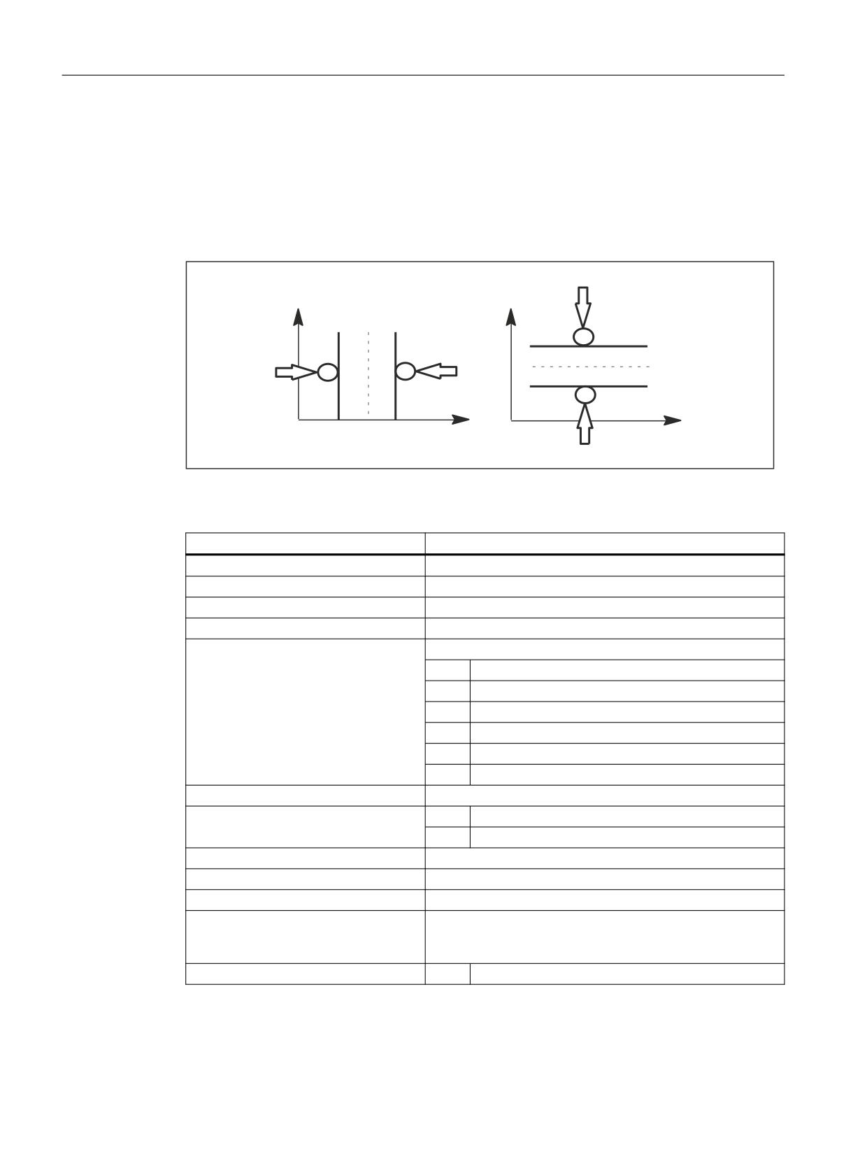
A web is measured by approaching the two outside corners or inner edges. The web center can
be set to a set position. The component of the approach direction determines the web position.
-y
y
y
y0
+x
-x
x0
x
+y
x
Figure 10-8
Measurement of a web
The values of the following system variables are evaluated for measurement type 13:
Input variable
Meaning
$AC_MEAS_VALID
Validity bits for input variables
$AA_MEAS_POINT1[<Axis>]
Measuring point 1
$AA_MEAS_POINT2[<Axis>]
Measuring point 2
$AA_MEAS_SETPOINT[<Axis>] *)
Set position of the web center
$AC_MEAS_DIR_APPROACH
Direction of approach to the workpiece
= 0
+ X
= 1
- X
= 2
+ Y
= 3
- Y
= 4
+ Z
= 5
- Z
$AC_MEAS_ACT_PLANE *)
Calculation with active plane unless otherwise specified.
$AC_MEAS_FINE_TRANS *)
= 0
Coarse offset
= 1
Fine offset
$AC_MEAS_FRAME_SELECT *)
Calculated as additive frame unless otherwise specified.
$AC_MEAS_T_NUMBER *)
Calculated with active T unless otherwise specified (T0).
$AC_MEAS_D_NUMBER *)
Calculated with active D unless otherwise specified (D0).
$AC_MEAS_INPUT[0] *)
Approach direction for 2nd measuring point for a recess meas-
urement. Must have the same coordinate as the approach
direction of the 1st measuring point.
$AC_MEAS_TYPE
= 13
Measurement type 13: Measurement of a web
*) Optional
Basic functions
620
Function Manual, 10/2020, 6FC5397-2GP40-0BA1
Measurement
10.5 Workpiece and tool measurement
The following output variables are written for measurement type 13:
Output variable
Meaning
$AC_MEAS_FRAME
Result frame with translation
$AC_MEAS_RESULTS[0]
Position of the calculated web center (X0, Y0 or Z0)
$AC_MEAS_RESULTS[1]
Web width in approach direction
10.5.2.7
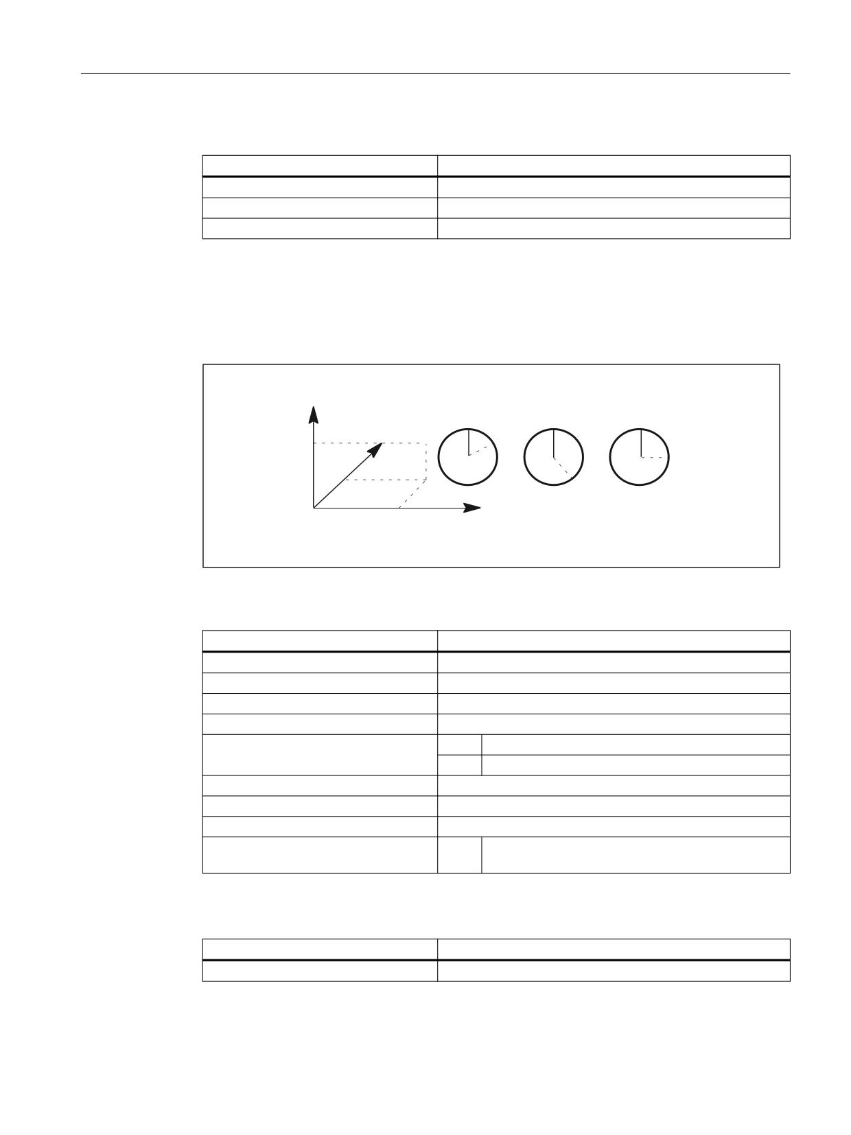
Measurement type 14: Preset actual value for geometry and special axes
Function
6SHFLDO D[HV
]
$ 6HW
$ 6HW
$ 6HW
<
3
$FW
$
]L
$FW
$ $FW
\L
$ $FW
3
6HW
[V \V ]V
[L
[
Figure 10-9
Preset actual value for geometry and special axes
The values of the following system variables are evaluated for measurement type 14:
Input variable
Meaning
$AC_MEAS_VALID
Validity bits for input variables
$AA_MEAS_POINT1[<Axis>]
Actual values of the axes
$AA_MEAS_SETPOINT[<Axis>] *)
Set position of the individual axes
$AC_MEAS_ACT_PLANE *)
Calculation with active plane unless otherwise specified.
$AC_MEAS_FINE_TRANS *)
= 0
Coarse offset
= 1
Fine offset
$AC_MEAS_FRAME_SELECT *)
Calculated as additive frame unless otherwise specified.
$AC_MEAS_T_NUMBER *)
Calculated with active T unless otherwise specified (T0).
$AC_MEAS_D_NUMBER *)
Calculated with active D unless otherwise specified (D0).
$AC_MEAS_TYPE
= 14
Measurement type 14: Preset actual value for geom-
etry and special axes
*) Optional
The following output variables are written for measurement type 14:
Output variable
Meaning
$AC_MEAS_FRAME
Result frame with translations
Basic functions
Function Manual, 10/2020, 6FC5397-2GP40-0BA1
621

Measurement
10.5 Workpiece and tool measurement
Example
Reference point setting in relative coordinate systems.
Program code
Comment
DEF INT RETVAL
T1 D1
; Activate probe.
G54
; Activate all frames and G54.
TRANS X=10
; Offset between WCS and SZS
G0 X0 F10000
; WCS(X)=0; SZS(X)=10
$AC_MEAS_VALID=0
; Set all input variables to invalid.
$AC_MEAS_TYPE=14
; Measurement type for preset actual value
$AC_MEAS_ACT_PLANE=0
; Measuring plane is G17.
$AC_MEAS_P1_COORD=5
; SZS_REL for 1st measuring point
$AC_MEAS_LATCH[0]=1
; Pick up all axis positions.
$AC_MEAS_SET_COORD=5
; Set position is relative to SZS.
$AA_MEAS_SETPOINT[X]=0
; Set position in the relative SZS coordinate
system
$AC_MEAS_FRAME_SELECT=2505
; $P_RELFR
RETVAL=MEASURE()
; Calculation of $P_RELFR, PI SETUDT(6)
IF RETVAL<>0 GOTOF ERROR
ENDIF $P_RELFR=$AC_MEAS_FRAME
; Activation, PI SETUDT(7)
10.5.2.8
Measurement type 15: Preset actual value for special axes only
Function
6SHFLDO D[HV
$ 6HW
$ 6HW
$ 6HW
$ $FW
$ $FW
$ $FW
Figure 10-10
Preset actual value for special axes only
Basic functions
622
Function Manual, 10/2020, 6FC5397-2GP40-0BA1
Measurement
10.5 Workpiece and tool measurement
The values of the following system variables are evaluated for measurement type 15:
Input variable
Meaning
$AC_MEAS_VALID
Validity bits for input variables
$AA_MEAS_POINT1[<Axis>]
Actual values of the axes
$AA_MEAS_SETPOINT[<Axis>] *)
Set position of the individual axes
$AC_MEAS_FINE_TRANS *)
= 0
Coarse offset
= 1
Fine offset
$AC_MEAS_FRAME_SELECT *)
Calculated as additive frame unless otherwise specified.
$AC_MEAS_TYPE
= 15
Measurement type 14: Preset actual value for special
axes only
*) Optional
The following output variables are written for measurement type 15:
Output variable
Meaning
$AC_MEAS_FRAME
Result frame with translations
10.5.2.9
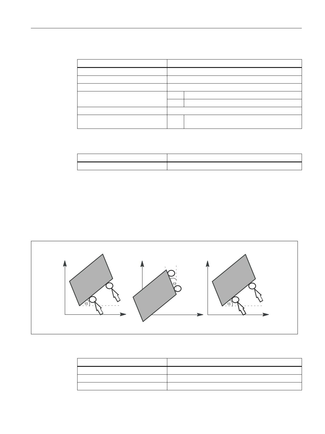
Measurement type 16: Measurement of an inclined edge
Function
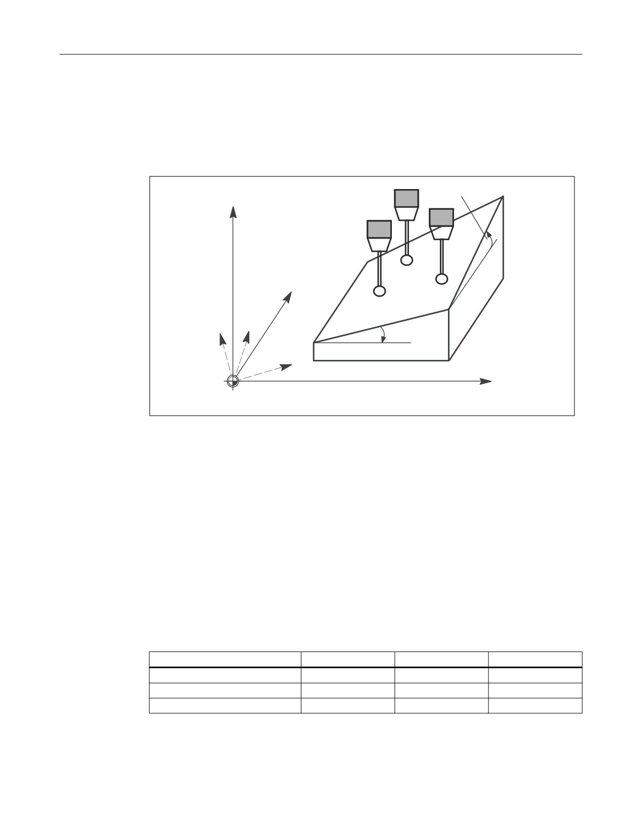
This measurement determines the position angle of the workpiece and enters it in the frame. A
set angle in the ± 90 degrees range can be specified. This can be interpreted as the resulting
rotation of the workpiece after the result frame for the active WCS has been activated.
G17
G18
G19
Y
x
Reference axis
z
P2
P2
P1
P2
P1
P1
x
z
Y
Figure 10-11
Measurement of an inclined edge in planes G17/G18/G19
The values of the following system variables are evaluated for measurement type 16:
Input variable
Meaning
$AC_MEAS_VALID
Validity bits for input variables
$AA_MEAS_POINT1[<Axis>]
Measuring point 1
$AA_MEAS_POINT2[<Axis>]
Measuring point 2
Basic functions
Function Manual, 10/2020, 6FC5397-2GP40-0BA1
623
Measurement
10.5 Workpiece and tool measurement
Input variable
Meaning
$AA_MEAS_SETANGLE *)
Set angle
$AC_MEAS_ACT_PLANE *)
Calculation with active plane unless otherwise specified.
$AC_MEAS_FINE_TRANS *)
= 0
Coarse offset
= 1
Fine offset
$AC_MEAS_FRAME_SELECT *)
Calculated as additive frame unless otherwise specified.
$AC_MEAS_T_NUMBER *)
Calculated with active T unless otherwise specified (T0).
$AC_MEAS_D_NUMBER *)
Calculated with active D unless otherwise specified (D0).
$AC_MEAS_INPUT[0] *)
Unless otherwise specified, the reference coordinate for the
alignment of the workpiece is always the abscissa of the se-
lected plane.
= 0
Reference coordinate is the abscissa
= 1
Reference coordinate is the ordinate
$AC_MEAS_INPUT[1] *)
Unless otherwise specified, the workpiece position angle is
entered in the frame as a rotation. Otherwise, a channel axis
index can be specified for a rotary axis whose translation is set
to the current rotary axis position plus the calculated rotation.
The workpiece is then aligned at rotary axis position = 0. The
current rotary axis value must be set in
$AA_MEAS_POINT[<Axis>].
$AC_MEAS_TYPE
= 16
Measurement type 16: Measurement of an inclined
edge
* optional
The following output variables are written for measurement type 16:
Output variable
Meaning
$AC_MEAS_FRAME
Result frame with rotation
$AC_MEAS_WP_ANGLE
Calculated workpiece position angle
Basic functions
624
Function Manual, 10/2020, 6FC5397-2GP40-0BA1
Measurement
10.5 Workpiece and tool measurement
10.5.2.10
Measurement type 17: Measurement of an angle in an inclined plane
Function
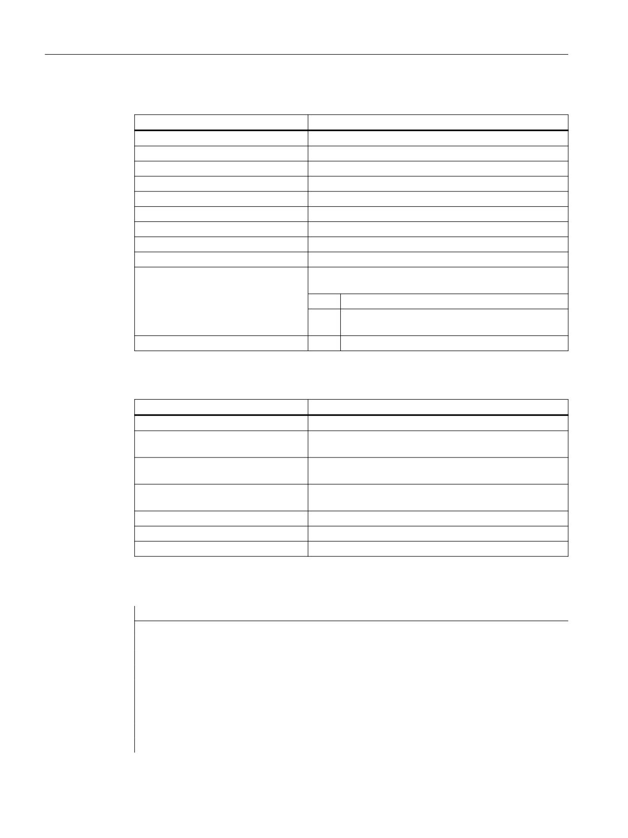
The inclined plane is determined using three measuring points P1, P2 and P3.
$AC_MEAS_RESULTS[0]
z
¥Æ0
P2
P3
y
P1
y¡fl
z¡fl
¥Æ1
$AC_MEAS_RESULTS[1]
x¡fl
x
Figure 10-12
Measurement of an angle in an inclined plane in G17
With measurement type 17, two resulting angles α 0 and α 1 are determined for the skew of the
plane and entered in $AC_MEAS_RESULTS[0 ... 1]:
• $AC_MEAS_RESULTS[0] → Rotation around the abscissa
• $AC_MEAS_RESULTS[1] → Rotation around the ordinate
These angles are calculated with the three measuring points P1, P2 and P3.
With measurement type 17, the angle for the applicate ($AC_MEAS_RESULTS[2]) is always
preset with 0.
A set rotation that is entered in the result frame can be specified for the abscissa and/or the
ordinate. If only one angle is specified with a setpoint, the second angle is calculated so that the
three measuring points are on an inclined plane with the setpoint angle. Only rotations are
entered in the result frame, the WCS reference point is retained. The WCS is rotated so that Z' is
perpendicular to the inclined plane.
The following plane settings are defined for measurement type 17:
Axis identifier
G17
G18
G19
Abscissa
X axis
Z axis
Y axis
Ordinate
Y axis
X axis
Z axis
Applicate (infeed axis)
Z axis
Y axis
X axis
Basic functions
Function Manual, 10/2020, 6FC5397-2GP40-0BA1
625
Measurement
10.5 Workpiece and tool measurement
The values of the following system variables are evaluated for measurement type 17:
Input variable
Meaning
$AC_MEAS_VALID
Validity bits for the input variables
$AA_MEAS_POINT1[<Axis>]
Measuring point 1
$AA_MEAS_POINT2[<Axis>]
Measuring point 2
$AA_MEAS_POINT3[<Axis>]
Measuring point 3
$AA_MEAS_SETANGLE[<Axis>] *)
Set rotations around abscissa and ordinate.
$AC_MEAS_ACT_PLANE *)
Calculation with active plane unless otherwise specified.
$AC_MEAS_FRAME_SELECT *)
Calculated as additive frame unless otherwise specified.
$AC_MEAS_T_NUMBER *)
Calculated with active T unless otherwise specified (T0).
$AC_MEAS_D_NUMBER *)
Calculated with active D unless otherwise specified (D0).
$AC_MEAS_INPUT[0] *)
Unless otherwise specified, the points are not projected in a
plane.
= 0
Points are not projected on a plane.
= 1
Points are projected in the active plane or in the se-
lected plane.
$AC_MEAS_TYPE
= 17
*) Optional
The following output variables are written for measurement type 17:
Output variable
Meaning
$AC_MEAS_FRAME
Result frame
$AC_MEAS_RESULTS[0]
Angles around abscissa from which three measuring points
are calculated
$AC_MEAS_RESULTS[1]
Angles around ordinate from which three measuring points
are calculated
$AC_MEAS_RESULTS[2]
Angles around applicate from which three measuring points
are calculated
$AC_MEAS_RESULTS[3]
Angle around abscissa which is entered in the result frame
$AC_MEAS_RESULTS[4]
Angle around ordinate which is entered in the result frame
$AC_MEAS_RESULTS[5]
Angle around applicate which is entered in the result frame
Example
Program code
Comment
DEF INT RETVAL
DEF AXIS _XX, _YY, _ZZ
T1 D1
; Activate probe.
G54
; Activate all frames and G54.
$AC_MEAS_VALID=0
; Set all input values to invalid.
$AC_MEAS_TYPE=17
; Set measurement type for inclined plane.
Basic functions
626
Function Manual, 10/2020, 6FC5397-2GP40-0BA1
Measurement
10.5 Workpiece and tool measurement
Program code
Comment
$AC_MEAS_ACT_PLANE=0
;
Measuring plane is G17.
_XX=$P_AXN1
;
Specify axes according to the plane.
_YY=$P_AXN2
_ZZ=$P_AXN3
G17 G1 _XX=10 _YY=10 F1000
;
Approach 1st measuring point.
MEAS=1 _ZZ=...
$AA_MEAS_POINT1[_XX]=$AA_MW[_XX]
;
Assign measured value to abscissa.
$AA_MEAS_POINT1[_YY]=$AA_MW[_YY]
;
Assign measured value to ordinate.
$AA_MEAS_POINT1[_ZZ]=$AA_MW[_ZZ]
;
Assign measured value to applicate.
G1 _XX=20 _YY=10 F1000
;
Approach 2nd measuring point.
MEAS=1 _ZZ=...
$AA_MEAS_POINT2[_XX]=$AA_MW[_XX]
;
Assign measured value to abscissa.
$AA_MEAS_POINT2[_YY]=$AA_MW[_YY]
;
Assign measured value to ordinate.
$AA_MEAS_POINT2[_ZZ]=$AA_MW[_ZZ]
;
Assign measured value to applicate.
G1 _XX=20 _YY=20 F1000
;
Approach 3rd measuring point.
MEAS=1 _ZZ=...
$AA_MEAS_POINT3[_XX]=$AA_MW[_XX]
;
Assign measured value to abscissa.
$AA_MEAS_POINT3[_YY]=$AA_MW[_YY]
;
Assign measured value to ordinate.
$AA_MEAS_POINT3[_ZZ]=$AA_MW[_ZZ]
;
Assign measured value to applicate.
;
Specify setpoints for angles.
$AA_MEAS_SETANGLE[_XX]=12
;
Rotation around the abscissa.
$AA_MEAS_SETANGLE[_YY]=4
;
Rotation around the ordinate.
$AC_MEAS_FRAME_SELECT=102
;
Select target frame - G55
$AC_MEAS_T_NUMBER=1
;
Select tool.
$AC_MEAS_D_NUMBER=1
RETVAL=MEASURE()
;
Start measurement calculation.
IF RETVAL <> 0
SETAL(61043, << RETVAL)
ENDIF
IF $AC_MEAS_RESULTS[0] <> 12
SETAL(61043, << $AC_MEAS_RESULTS[0])
ENDIF
IF $AC_MEAS_RESULTS[1] <> 4
Basic functions
Function Manual, 10/2020, 6FC5397-2GP40-0BA1
627
Measurement
10.5 Workpiece and tool measurement
Program code
Comment
SETAL(61043, << $AC_MEAS_RESULTS[1])
ENDIF
$P_UIFR[2]=$AC_MEAS_FRAME
; Write measurement frame to the data manage-
ment (G55).
G55 G0 AX[_XX]=10 AX[_YY]=10
; Activate frame and traverse.
M30
10.5.2.11
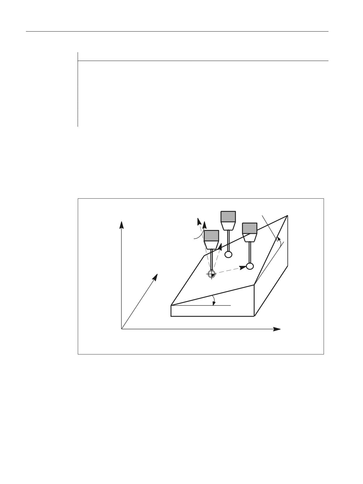
Measurement type 18: Redefining the WCS on the inclined plane
Function
The zero point of the new WCS is determined by measuring point P1 at surface normal on the
inclined plane.
$&B0($6B5(68/76> @
]
]
$&B0($6B5(68/76> @
˞
\
3
[
3
<
:&6
3
˞
$&B0($6B5(68/76> @
:&6
[
Figure 10-13
Redefining the WCS on the inclined plane in G17
Measurement of plane
The plane is measured in one measuring cycle. The cycle records the three measuring points and
passes the necessary values to the variable interface.
The MEASURE() function calculates the solid angles and translational offset of the new WCS' on
the basis of the input values.
Basic functions
628
Function Manual, 10/2020, 6FC5397-2GP40-0BA1
Measurement
10.5 Workpiece and tool measurement
Transformation of measuring frame
The results of the calculation, i.e. the solid angles and translation, are entered in the
$AC_MEAS_FRAME measuring frame. The measuring frame is transformed according to the
selected frame in the frame chain. The solid angles are also stored in the
$AC_MEAS_RESULTS[0 ... 2] output values.
• $AC_MEAS_RESULTS[0]: Angle around the abscissa of the old WCS
• $AC_MEAS_RESULTS[1]: Angle around the ordinate
• $AC_MEAS_RESULTS[2]: Angle around the applicate
Specifying the new WCS' zero point
After performing the calculation, the measuring cycle can write and activate the selected frame
in the frame chain with the measuring frame. After activation, the new WCS' is positioned at
surface normal on the inclined plane, with measuring point P1 as the zero point of the new WCS'.
The programmed positions then refer to the inclined plane.
Application
CAD systems often define inclined planes by specifying three points P1, P2 and P3 on this plane.
Whereby, the 1st measuring point P1 is used as the new WCS' reference point, the 2nd
measuring point P2 specifies the direction of the abscissa X' of the new rotated WCS' coordinate
system and the 3rd measuring point P3 is required to determine the solid angles.
Input/output variables
The values of the following system variables are evaluated for measurement type 18:
Input variable
Meaning
$AC_MEAS_VALID
Validity bits for the input variables
$AA_MEAS_POINT1[<Axis>]
Measuring point 1
$AA_MEAS_POINT2[<Axis>]
Measuring point 2
$AA_MEAS_POINT3[<Axis>]
Measuring point 3
$AA_MEAS_SETPOINT[<Axis>] *)
Set position of P1
$AC_MEAS_ACT_PLANE *)
Calculation with active plane unless otherwise specified.
$AC_MEAS_FRAME_SELECT *)
Calculated as additive frame unless otherwise specified.
$AC_MEAS_T_NUMBER *)
Calculated with active T unless otherwise specified (T0).
$AC_MEAS_D_NUMBER *)
Calculated with active D unless otherwise specified (D0).
$AC_MEAS_INPUT[0] *)
Unless otherwise specified, the points are not projected in a
plane.
= 0
Points are not projected on a plane.
= 1
Points are projected in the active plane or in the se-
lected plane.
$AC_MEAS_TYPE
= 18
Measurement type 18: Redefining the WCS on the in-
clined plane
* optional
Basic functions
Function Manual, 10/2020, 6FC5397-2GP40-0BA1
629

Measurement
10.5 Workpiece and tool measurement
The following output variables are written for measurement type 18:
Output variable
Meaning
$AC_MEAS_FRAME
Result frame with rotations and transformation
$AC_MEAS_RESULTS[0]
Calculated angle around the abscissa
$AC_MEAS_RESULTS[1]
Calculated angle around the ordinate
$AC_MEAS_RESULTS[2]
Calculated angle around the applicate
Example
Program code
Comment
DEF INT RETVAL
DEF AXIS _XX, _YY, _ZZ
T1 D1
;
Activate probe.
G54
;
Activate all frames and G54.
$AC_MEAS_VALID=0
;
Set all input values to invalid.
$AC_MEAS_TYPE=18
;
Set measurement type for inclined plane.
$AC_MEAS_ACT_PLANE=0
;
Measuring plane is G17.
_XX=$P_AXN1
;
Specify axes according to the plane.
_YY=$P_AXN2
_ZZ=$P_AXN3
G17 G1 _XX=10 _YY=10 F1000
;
Approach 1st measuring point.
MEAS=1 _ZZ=...
$AA_MEAS_POINT1[_XX]=$AA_MW[_XX]
;
Assign measured value to abscissa.
$AA_MEAS_POINT1[_YY]=$AA_MW[_YY]
;
Assign measured value to ordinate.
$AA_MEAS_POINT1[_ZZ]=$AA_MW[_ZZ]
;
Assign measured value to applicate.
G1 _XX=20 _YY=10 F1000
;
Approach 2nd measuring point.
MEAS=1 _ZZ=...
$AA_MEAS_POINT2[_XX]=$AA_MW[_XX]
;
Assign measured value to abscissa.
$AA_MEAS_POINT2[_YY]=$AA_MW[_YY]
;
Assign measured value to ordinate.
$AA_MEAS_POINT2[_ZZ]=$AA_MW[_ZZ]
;
Assign measured value to applicate.
G1 _XX=20 _YY=20 F1000
;
Approach 3rd measuring point.
MEAS=1 _ZZ=...
$AA_MEAS_POINT3[_XX]=$AA_MW[_XX]
;
Assign measured value to abscissa.
$AA_MEAS_POINT3[_YY]=$AA_MW[_YY]
;
Assign measured value to ordinate.
$AA_MEAS_POINT3[_ZZ]=$AA_MW[_ZZ]
;
Assign measured value to applicate.
Basic functions
630
Function Manual, 10/2020, 6FC5397-2GP40-0BA1

Measurement
10.5 Workpiece and tool measurement
Program code
Comment
$AA_MEAS_SETPOINT[_XX]=10
; Specify setpoints for P1.
$AA_MEAS_SETPOINT[_YY]=10
$AA_MEAS_SETPOINT[_ZZ]=10
$AC_MEAS_FRAME_SELECT=102
; Select target frame - G55
$AC_MEAS_T_NUMBER=1
; Select tool.
$AC_MEAS_D_NUMBER=1
RETVAL=MEASURE()
; Start measurement calculation.
IF RETVAL <> 0
SETAL(61043, << RETVAL)
ENDIF
; Calculation results for the solid angles.
R0=$AC_MEAS_RESULTS[0]
; Angle around the abscissa of the old WCS
R1=$AC_MEAS_RESULTS[1]
; Angle around the ordinate
R2=$AC_MEAS_RESULTS[2]
; Angle around the applicate
$P_UIFR[2]=$AC_MEAS_FRAME
; Write measurement frame to the data manage-
ment (G55).
G55 G0 AX[_XX]=10 AX[_YY]=10
; Activate frame and traverse.
M30
10.5.2.12
Measurement type 19: 1-dimensional setpoint specification
Function
With this measurement method, it is possible to define exactly one setpoint for the abscissa, the
ordinate and the applicate. If two or three setpoints are defined, only the first is accepted in the
sequence abscissa, ordinate and applicate. The tool is not taken into account.
It is purely a preset actual value for the abscissa, the ordinate or the applicate.
The values of the following system variables are evaluated for measurement type 19:
Input variable
Meaning
$AC_MEAS_VALID
Validity bits for the input variables
$AA_MEAS_POINT1[<Axis>]
Measuring point 1 for the abscissa
$AA_MEAS_POINT1[<Axis>]
Measuring point 1 for the ordinate
$AA_MEAS_POINT1[<Axis>]
Measuring point 1 for the applicate
$AA_MEAS_SETPOINT[<Axis>]
Set position of the abscissa or ordinate or applicate
$AC_MEAS_ACT_PLANE *)
Calculation with active plane unless otherwise specified.
$AC_MEAS_FRAME_SELECT *)
Calculated as additive frame unless otherwise specified.
Basic functions
Function Manual, 10/2020, 6FC5397-2GP40-0BA1
631
Measurement
10.5 Workpiece and tool measurement
Input variable
Meaning
$AC_MEAS_FINE_TRANS *)
Unless otherwise specified, written to the coarse offset.
= 0
Coarse offset
= 1
Fine offset
$AC_MEAS_TYPE
= 19
Measurement type 19: 1-dimensional setpoint speci-
fication
*) Optional
The following output variables are written for measurement type 19:
Output variable
Meaning
$AC_MEAS_FRAME
Result frame with rotations and translation
Example
Program code
Comment
DEF INT RETVAL
DEF REAL _CORMW_XX, CORMW_YY, _CORMW_ZZ
DEF AXIS _XX, _YY, _ZZ
T1 D1
; Activate probe.
G54
; Activate all frames and G54.
$AC_MEAS_VALID=0
; Set all input values to invalid.
$AC_MEAS_TYPE=19
; Set measurement type for 1-dimensional set-
point specification.
$AC_MEAS_ACT_PLANE=0
; Measuring plane is G17.
_XX=$P_AXN1
; Specify axes according to the plane.
_YY=$P_AXN2
_ZZ=$P_AXN3
; Assign measured values.
$AA_MEAS_POINT1[_XX]=$AA_MW[_XX]
; Assign measured value to abscissa.
$AA_MEAS_POINT1[_YY]=$AA_MW[_YY]
; Assign measured value to ordinate.
$AA_MEAS_POINT1[_ZZ]=$AA_MW[_ZZ]
; Assign measured value to applicate.
$AA_MEAS_SETPOINT[_XX]=10
; Specify setpoint for the abscissa.
$AC_MEAS_FRAME_SELECT=102
; Select target frame - G55
RETVAL=MEASURE()
; Start measurement calculation.
IF RETVAL <> 0
SETAL(61043, << RETVAL)
ENDIF
$P_UIFR[2]=$AC_MEAS_FRAME
; Write measurement frame to the data manage-
ment (G55).
G55 G0 AX[_XX]=10 AX[_YY]=10
; Activate frame and traverse.
M30
Basic functions
632
Function Manual, 10/2020, 6FC5397-2GP40-0BA1
Measurement
10.5 Workpiece and tool measurement
10.5.2.13
Measurement type 20: 2-dimensional setpoint specification
Function
Setpoints for two dimensions can be defined using this measuring method. Any combination of
2 out of 3 axes is permissible. If three setpoints are specified, only the values for the abscissa and
the ordinate are accepted. The tool is not taken into account.
This is a purely preset actual value.
The values of the following system variables are evaluated for measurement type 20:
Input variable
Meaning
$AC_MEAS_VALID
Validity bits for the input variables
$AA_MEAS_POINT1[<Axis>]
Measuring point 1 for the abscissa
$AA_MEAS_POINT1[<Axis>]
Measuring point 1 for the ordinate
$AA_MEAS_POINT1[<Axis>]
Measuring point 1 for the applicate
$AA_MEAS_SETPOINT[<Axis>]
Set position for the 1st dimension
$AA_MEAS_SETPOINT[<Axis>]
Set position for the 2nd dimension
$AC_MEAS_ACT_PLANE *)
Calculation with active plane unless otherwise specified.
$AC_MEAS_FRAME_SELECT *)
Calculated as additive frame unless otherwise specified.
$AC_MEAS_FINE_TRANS *)
Unless otherwise specified, written to the coarse offset.
= 0
Coarse offset
= 1
Fine offset
$AC_MEAS_TYPE
= 20
Measurement type 20: 2-dimensional setpoint speci-
fication
*) Optional
The following output variables are written for measurement type 20:
Output variable
Meaning
$AC_MEAS_FRAME
Result frame with rotations and translation
Example
Program code
Comment
DEF INT RETVAL
DEF REAL _CORMW_XX, CORMW_YY, _CORMW_ZZ
DEF AXIS _XX, _YY, _ZZ
T1 D1
; Activate probe.
G54
; Activate all frames and G54.
$AC_MEAS_VALID=0
; Set all input values to invalid.
$AC_MEAS_TYPE=20
; Set measurement type for 2-dimensional set-
point specification.
$AC_MEAS_ACT_PLANE=0
; Measuring plane is G17.
_XX=$P_AXN1
; Specify axes according to the plane.
_YY=$P_AXN2
Basic functions
Function Manual, 10/2020, 6FC5397-2GP40-0BA1
633
Measurement
10.5 Workpiece and tool measurement
Program code
Comment
_ZZ=$P_AXN3
; Assign measured values.
$AA_MEAS_POINT1[_XX]=$AA_MW[_XX]
; Assign measured value to abscissa.
$AA_MEAS_POINT1[_YY]=$AA_MW[_YY]
; Assign measured value to ordinate.
$AA_MEAS_POINT1[_ZZ]=$AA_MW[_ZZ]
; Assign measured value to applicate.
$AA_MEAS_SETPOINT[_XX]=10
; Specify setpoint for the abscissa and ordi-
nate.
$AA_MEAS_SETPOINT[_YY]=10
$AC_MEAS_FRAME_SELECT=102
; Select target frame - G55
RETVAL=MEASURE()
; Start measurement calculation.
IF RETVAL <> 0
SETAL(61043, << RETVAL)
ENDIF
$P_UIFR[2]=$AC_MEAS_FRAME
; Write measurement frame to the data manage-
ment (G55).
G55 G0 AX[_XX]=10 AX[_YY]=10
; Activate frame and traverse.
M30
10.5.2.14
Measurement type 21: 3-dimensional setpoint specification
Function
Using this measurement method, it is possible to define a setpoint for the abscissa, the ordinate
and the applicate. The tool is not taken into account.
It is purely a preset actual value for the abscissa, ordinate and applicate.
The values of the following system variables are evaluated for measurement type 21:
Input variable
Meaning
$AC_MEAS_VALID
Validity bits for the input variables
$AA_MEAS_POINT1[<Axis>]
Measuring point 1 for the abscissa
$AA_MEAS_POINT1[<Axis>]
Measuring point 1 for the ordinate
$AA_MEAS_POINT1[<Axis>]
Measuring point 1 for the applicate
$AA_MEAS_SETPOINT[<Axis>]
Set position for the abscissa
$AA_MEAS_SETPOINT[<Axis>]
Set position for the ordinate
$AA_MEAS_SETPOINT[<Axis>]
Set position for the applicate
$AC_MEAS_ACT_PLANE *)
Calculation with active plane unless otherwise specified.
$AC_MEAS_FRAME_SELECT *)
Calculated as additive frame unless otherwise specified.
$AC_MEAS_FINE_TRANS *)
Unless otherwise specified, written to the coarse offset.
= 0
Coarse offset
= 1
Fine offset
$AC_MEAS_TYPE
= 21
Measurement type 21: 3-dimensional setpoint speci-
fication
*) Optional
Basic functions
634
Function Manual, 10/2020, 6FC5397-2GP40-0BA1

Measurement
10.5 Workpiece and tool measurement
The following output variables are written for measurement type 21:
Output variable
Meaning
$AC_MEAS_FRAME
Result frame with rotations and translation
Example
Program code
Comment
DEF INT RETVAL
DEF REAL _CORMW_XX, CORMW_YY, _CORMW_ZZ
DEF AXIS _XX, _YY, _ZZ
T1 D1
; Activate probe.
G54
; Activate all frames and G54.
$AC_MEAS_VALID=0
; Set all input values to invalid.
$AC_MEAS_TYPE=21
; Set measurement type for 3-dimensional set-
point specification.
$AC_MEAS_ACT_PLANE=0
; Measuring plane is G17.
_XX=$P_AXN1
; Specify axes according to the plane.
_YY=$P_AXN2
_ZZ=$P_AXN3
; Assign measured values.
$AA_MEAS_POINT1[_XX]=$AA_MW[_XX]
; Assign measured value to abscissa.
$AA_MEAS_POINT1[_YY]=$AA_MW[_YY]
; Assign measured value to ordinate.
$AA_MEAS_POINT1[_ZZ]=$AA_MW[_ZZ]
; Assign measured value to applicate.
$AA_MEAS_SETPOINT[_XX]=10
; Specify setpoint for the abscissa, ordinate
and applicate.
$AA_MEAS_SETPOINT[_YY]=10
$AA_MEAS_SETPOINT[_ZZ]=10
$AC_MEAS_FRAME_SELECT=102
; Select target frame - G55
RETVAL=MEASURE()
; Start measurement calculation.
IF RETVAL <> 0
SETAL(61043, << RETVAL)
ENDIF
$P_UIFR[2]=$AC_MEAS_FRAME
; Write measurement frame to the data manage-
ment (G55).
G55 G0 AX[_XX]=10 AX[_YY]=10
; Activate frame and traverse.
M30
10.5.2.15
Measurement type 24: Coordinate transformation of a measuring point
Function
With this method of measurement, a measuring point in any coordinate system (WCS, BCS, MCS)
can be converted to a new coordinate system by coordinate transformation.
The new coordinate system is generated by specifying a desired frame chain.
Basic functions
Function Manual, 10/2020, 6FC5397-2GP40-0BA1
635
Measurement
10.5 Workpiece and tool measurement
]
]
3
0&6
3
0&6
\
<
[
:&6
6SHFLILHG IUDPH
%&6
[
Figure 10-14
Coordinate transformation of a measuring point
The values of the following system variables are evaluated for measurement type 24:
Input variable
Meaning
$AC_MEAS_VALID
Validity bits for the input variables
$AA_MEAS_POINT1[<Axis>]
Position to be transformed
$AC_MEAS_P1:COORD *)
= 0
WCS (default)
= 1
BCS
= 2
MCS
$AC_MEAS_P2_COORD *)
Target coordinate system
$AC_MEAS_TOOL_MASK *)
0x20
Length of the active tool is included in the coordinate
transformation of a position.
$AC_MEAS_CHSFR *)
System frames from the data management
$AC_MEAS_NCBFR *)
Global basic frames from the data management
$AC_MEAS_CHBFR *)
Channel basic frames from the data management
$AC_MEAS_UIFR *)
Settable frame from the data management
$AC_MEAS_PFRAME *)
= 1
Programmable frame is not calaculated.
$AC_MEAS_TYPE
= 24
Measurement type 24:
*) Optional
The following output variables are written for measurement type 24:
Output variable
Meaning
$AC_MEAS_POINT2[axis]
Converted axis positions
Basic functions
636
Function Manual, 10/2020, 6FC5397-2GP40-0BA1
Measurement
10.5 Workpiece and tool measurement
Example
WCS coordinate transformation of a measured position.
Program code
Comment
DEF INT RETVAL
DEF INT LAUF
DEF REAL_CORMW_XX, _CORMW_YY, _CORMW_ZZ
DEF AXIS _XX, _YY, _ZZ
$TC_DP1[1,1]=120
; Tool type, end mill
$TC_DP2[1,1]=20
$TC_DP3[1,1]=0
; (Z) length compensation vector
$TC_DP4[1,1]=0
; (Y) length compensation vector
$TC_DP5[1,1]=0
; (X) length compensation vector
$TC_DP6[1,1]=2
; Radius
T1 D1
; Activate probe.
G17
; Inclined plane G17
_XX=$P_AXN1 _YY=$P_AXN2 _ZZ=$P_AXN3
; Specify axes according to the plane.
; Entire frame results in
; CTRANS(_XX,10,_YY,-1,_ZZ,5,A,6,B,7)
$P_CHBFR[0]=CTRANS(_ZZ,5,A,6):CROT(_ZZ,45)
$P_UIFR[1]=CTRANS( )
$P_UIFR[1,_XX,TR]= -SIN(45)
$P_UIFR[1,_YY,TR]= -SIN(45)
$P_UIFR[2]=CTRANS( )
$P_PFRAME=CROT(_ZZ,-45)
$P_CYCFR=CTRANS(_XX,10,B,7)
G54
; Activate all frames and G54.
G0 X0 Y0 Z0 A0 B0 F1000
$AC_MEAS_VALID=0
; Set all input values to invalid.
$AC_MEAS_TYPE=24
; Set measurement type for coordinate trans-
formation.
$AC_MEAS_ACT_PLANE=0
; Measuring plane is G17.
; Assign measured values.
$AA_MEAS_POINT1[_XX]=$AA_IW[_XX]
; Assign measured value to abscissa.
$AA_MEAS_POINT1[_YY]=$AA_IW[_YY]
; Assign measured value to ordinate.
$AA_MEAS_POINT1[_ZZ]=$AA_IW[_ZZ]
; Assign measured value to applicate.
$AA_MEAS_POINT1[A]=$AA_IW[A]
$AA_MEAS_POINT1[B]=$AA_IW[B]
Basic functions
Function Manual, 10/2020, 6FC5397-2GP40-0BA1
637
Measurement
10.5 Workpiece and tool measurement
Program code
Comment
$AC_MEAS_P1_COORD=0
; Converting a position from WCS to WCS'
$AC_MEAS_P2_COORD=0
; Set WCS.
; Entire frame results from
; CTRANS(_XX,0,_YY,0,_ZZ,5,A,6,B,0)
; Stop cycle frame
$AC_MEAS_CHSER=$MC_MM_SYSTEM_FRAME_MASK B_AND 'B1011111'
$AC_MEAS_NCBFR='B0'
; Stop global basic frame.
$AC_MEAS_CHBFR='B1'
; Channel basic frame 1 from data management
$AC_MEAS_UIFR=2
; Settable frame G55 from data management
$AA_MEAS_PFRAME=1
; Do not include programmable frame in calcu-
lation
RETVAL=MEASURE()
; Start measurement calculation.
IF RETVAL <> 0
SETAL(61043, << RETVAL)
ENDIF
IF $AA_MEAS_PIONT2[_XX] <> 10
SETAL(61043)
M0
STOPRE
ENDIF
IF $AA_MEAS_PIONT2[_YY] <> -1
SETAL(61043)
M0
STOPRE
IF $AA_MEAS_PIONT2[_ZZ] <> 0
SETAL(61043)
M0
STOPRE
IF $AA_MEAS_PIONT2[A] <> 0
SETAL(61043)
M0
STOPRE
IF $AA_MEAS_PIONT2[B] <> 7
SETAL(61043)
M0
STOPRE
M30
Basic functions
638
Function Manual, 10/2020, 6FC5397-2GP40-0BA1
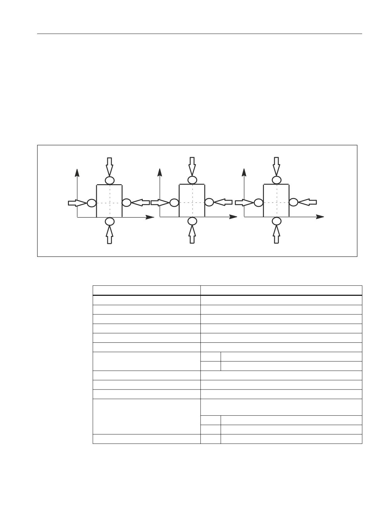
Measurement
10.5 Workpiece and tool measurement
10.5.2.16
Measurement type 25: Measurement of a rectangle
Function
Four measuring points per rectangle are required to determine a rectangle (tool dimensions) in
the working plane G17 (working plane X/Y, infeed direction Z), G18 (working plane Z/X, infeed
direction Y) or G19 (working plane Y/Z, infeed direction X).
Measuring points can be specified in any desired order. The measuring points with the largest
ordinate distance correspond to points P3 and P4.
G17
G18
G19
y
x
z
P4
P4
P4
P2
P2
P2
P1
P1
P1
P3
P3
P3
y
x
z
Figure 10-15
Measurement of a rectangle
The values of the following system variables are evaluated for measurement type 25:
Input variable
Meaning
$AC_MEAS_VALID
Validity bits for input variables
$AA_MEAS_POINT1[<Axis>]
Measuring point 1
$AA_MEAS_POINT2[<Axis>]
Measuring point 2
$AA_MEAS_POINT3[<Axis>]
Measuring point 3
$AA_MEAS_POINT4[<Axis>]
Measuring point 4
$AC_MEAS_ACT_PLANE *)
Calculation with active plane unless otherwise specified.
$AC_MEAS_FINE_TRANS *)
= 0
Coarse offset
= 1
Fine offset
$AC_MEAS_FRAME_SELECT *)
Calculated as additive frame unless otherwise specified.
$AC_MEAS_T_NUMBER *)
Calculated with active T unless otherwise specified (T0).
$AC_MEAS_D_NUMBER *)
Calculated with active D unless otherwise specified (D0).
$AC_MEAS_INPUT[0] *)
Unless otherwise specified, measurement is performed for the
outer corner.
= 0
Measurement for outer corner
= 1
Measurement for inner corner
$AC_MEAS_TYPE
= 25
Measurement type 25: Measurement of a rectangle
*) Optional
Basic functions
Function Manual, 10/2020, 6FC5397-2GP40-0BA1
639
Measurement
10.5 Workpiece and tool measurement
The following output variables are written for measurement type 25:
Output variable
Meaning
$AC_MEAS_FRAME
Result frame with translation
$AC_MEAS_RESULTS[0]
Abscissa of the calculated center point
$AC_MEAS_RESULTS[1]
Ordinate of the calculated center point
$AC_MEAS_RESULTS[2]
Applicate of the calculated center point
$AC_MEAS_RESULTS[3]
Width of the rectangle P1/P2
$AC_MEAS_RESULTS[4]
Length of the rectangle P3/P4
10.5.2.17
Measurement type 26: Backup of data management frames
Function
This measurement type offers the option of saving some or all data management frames with
their current value assignments to a file. The measurement can be initiated by executing a
command or via the part program. The function can also be activated from different channels.
The files are saved in the "_N_SYF_DIR" directory.
A Restore operation deletes the backed-up data and a new Save operation overwrites the
existing back-up.
The data saved last can be deleted from the data management through a new backup with the
following settings:
• $AC_MEAS_CHSFR = 0 ; System frames
• $AC_MEAS_NCBFR = 0 ; Global basic frames
• $AC_MEAS_CHBFR = 0 ; Channel basic frames
• $AC_MEAS_UIFR = 0 ; Number of settable frames
Note
If you decide to create a backup of all data management frames, remember that 1 KB of memory
is needed to save each frame. If insufficient memory is available, the process is aborted with an
error message.
Remedy: Adapt the configuration of the static user memory.
Further information: Function Manual Basic Functions, Memory Configuration
The values of the following system variables are evaluated for measurement type 26:
Input variable
Meaning
$AC_MEAS_VALID
Validity bits for the input variables
$AC_MEAS_CHSFR *)
Bit mask of system frames from the data management
If this variable is not written, all system frames are backed up.
Basic functions
640
Function Manual, 10/2020, 6FC5397-2GP40-0BA1

Measurement
10.5 Workpiece and tool measurement
Input variable
Meaning
$AC_MEAS_NCBFR *)
Bit mask of global basic frames from the data management
If this variable is not written, all global basic frames are backed
up.
$AC_MEAS_CHBFR *)
Bit mask of channel basic frames from the data management
If this variable is not written, all channel basic frames are
backed up.
$AC_MEAS_UIFR *)
Number of settable frames from the data management
If this variable is not written, all settable frames are backed up.
$AC_MEAS_TYPE
= 26
Measurement type 26: Backup of data management
frames
*) Optional
10.5.2.18
Measurement type 27: Restoration of backed up data management data
Function
This measurement type allows data management frames backed up by measurement type 26 to
be restored to the dynamic user memory.
It is possible to restore either the frames backed up last or selected frames. If a frame that has
not been backed up is selected, the selection is ignored. The process is not aborted.
The values of the following system variables are evaluated for measurement type 27:
Input variable
Meaning
$AC_MEAS_VALID
Validity bits for input variables
$AC_MEAS_CHSFR *)
Bit mask of system frames from the data management.
If the variable is not written, all system frames are restored.
$AC_MEAS_NCBFR *)
Bit mask of global basic frames from the data management.
If the variable is not written, all global basic frames are re-
stored.
$AC_MEAS_CHBFR *)
Bit mask of channel basic frames from the data management.
If the variable is not written, all channel basic frames are re-
stored.
$AC_MEAS_UIFR *)
Number of settable frames from the data management.
If the variable is not written, all settable frames are restored.
$AC_MEAS_TYPE
= 27
Measurement type 27: Restoration of backed up data
management data
*) Optional
Basic functions
Function Manual, 10/2020, 6FC5397-2GP40-0BA1
641
Measurement
10.5 Workpiece and tool measurement
10.5.2.19
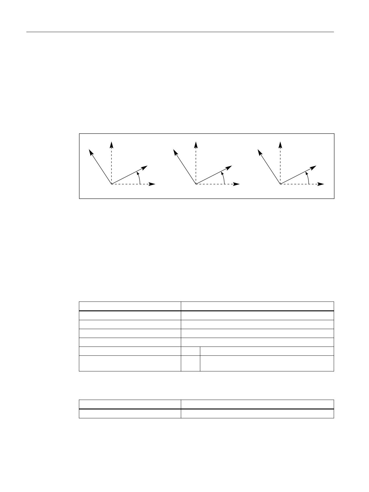
Measurement type 28: Specification of an additive rotation for taper turning
Function
Measuring type 28 can be used to specify an additive rotation through an angle α of the active
or a certain plane.
Value range: - 90 ° ≤ α ≤ + 90 °
The rotation takes place on the coordinate axis at right angles to the plane.
\
[
]
\
[
]
*
*
*
[
]
\
˞
˞
˞
[
]
\
Figure 10-16
Specification of an additive rotation (α = +30°) for taper turning in the G17/G18/G19 plane
Application
With taper turning, the active plane is rotated by the taper angle, whereby the rotation is written
in the active cycle frame. The cycle frame is deleted with reset. Re-activation may be necessary.
The selection of the cycle frame is made depending on the SZS position display. If after activation
of the rotation, e.g. with active plane G18, traversing is performed in the direction of Z', the
actual positions of the corresponding axes change simultaneously for X and Z. Rotations with
active planes G17 and G19 behave similarly and are displayed in the above figure.
Input/output variables
The values of the following system variables are evaluated for measurement type 28:
Input variable
Meaning
$AC_MEAS_VALID
Validity bits for input variables
$AC_MEAS_WP_SETANGLE
Set angle
$AC_MEAS_ACT_PLANE *)
Rotation is around the active plane unless otherwise specified.
$AC_MEAS_FRAME_SELECT *)
Calculated as additive frame unless otherwise specified.
$AC_MEAS_INPUT[0] *)
= 1
Taper turning is active.
$AC_MEAS_TYPE
= 28
Measurement type 28: Specification of an additive ro-
tation for taper turning
*) Optional
The following output variables are written for measurement type 28:
Output variable
Meaning
$AC_MEAS_FRAME
Result with rotation
Basic functions
642
Function Manual, 10/2020, 6FC5397-2GP40-0BA1
Measurement
10.5 Workpiece and tool measurement
10.5.3
Measuring types of the tool measurement
10.5.3.1
Overview
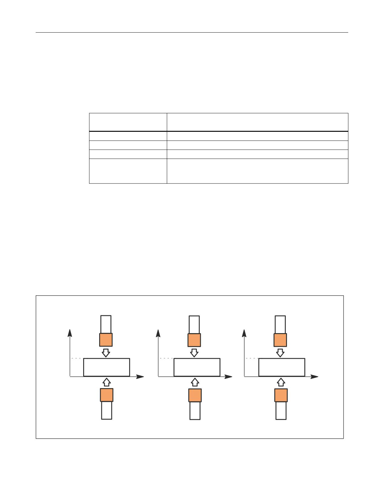
The following measurement types can be used to measure a tool loaded on a turning or milling
machine:
Measurement type
Type of measurement
$AC_MEAS_TYPE =
10
Measurement of the tool length (Page 643)
11
Measurement of the tool diameter (Page 645)
22
Measurement of tool lengths with zoom-in function (Page 647)
23
Measurement of a tool length with a stored or actual position
(Page 648)
Measurement of a tool length of two tools with orientation (Page 649)
10.5.3.2
Measurement type 10: Measurement of the tool length
Function
The tool length can be measured on a previously measured reference part.
The plane selection depends on the position of the tool:
• G17 for tool position in the Z direction
• G18 for tool position in the Y direction
• G19 for tool position in the X direction
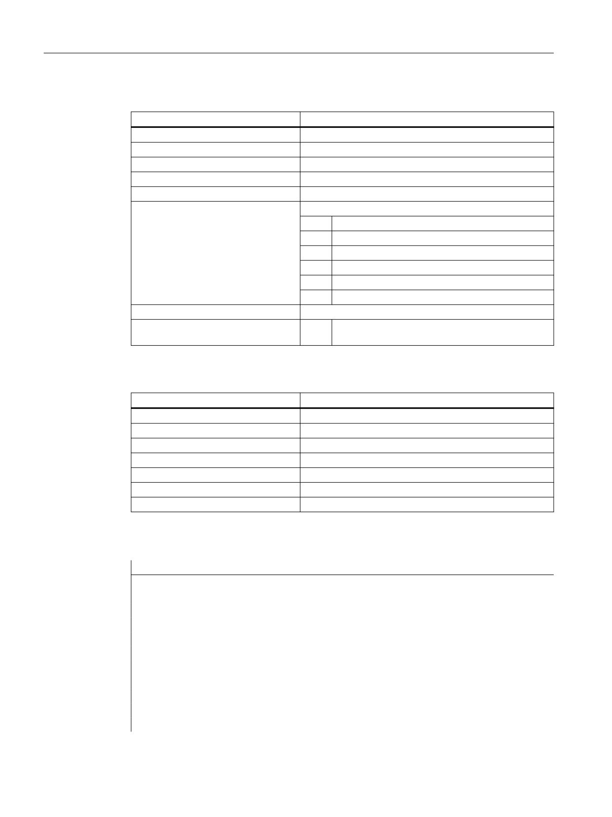
G17
G18
G19
z
y
x
-z
-y
-x
z0
y0
x0
x
z
y
+z
+y
+x
Figure 10-17
Measurement of the tool length in the G17/G18/G19 plane
Basic functions
Function Manual, 10/2020, 6FC5397-2GP40-0BA1
643
Measurement
10.5 Workpiece and tool measurement
The values of the following system variables are evaluated for measurement type 10:
Input variable
Meaning
$AC_MEAS_VALID
Validity bits for the input variables
$AA_MEAS_POINT1[<Axis>]
Measuring point 1
$AC_MEAS_P1_COORD *)
Coordinate system of the measuring point
$AA_MEAS_SETPOINT[<Axis>]
Set position Z0
$AC_MEAS_SET_COORD *)
Coordinate system of the setpoint
$AC_MEAS_DIR_APPROACH
Direction of approach to the workpiece
= 0
+ X
= 1
- X
= 2
+ Y
= 3
- Y
= 4
+ Z
= 5
- Z
$AC_MEAS_ACT_PLANE *)
Calculation with active plane unless otherwise specified.
$AC_MEAS_TYPE
= 10
Measurement type 10: Measurement of the tool
length
*) Optional
The following output variables are written for measurement type 10:
Output variable
Meaning
$AC_MEAS_TOOL_LENGTH
Tool length
$AC_MEAS_RESULTS[0]
Tool length in X
$AC_MEAS_RESULTS[1]
Tool length in Y
$AC_MEAS_RESULTS[2]
Tool length in Z
$AC_MEAS_RESULTS[3]
Tool length L1
$AC_MEAS_RESULTS[4]
Tool length L2
$AC_MEAS_RESULTS[5]
Tool length L3
Example
Program code
Comment
DEF INT RETVAL
T0 D0
G0 X0 Y0 Z0 F10000
; Measure tool length.
$AC_MEAS_VALID=0
; Set all input values to invalid.
G1 Z10
; Traverse tool to reference part.
$AC_MEAS_LATCH[0]=1
; Pick up measuring point 1.
$AC_MEAS_DIR_APPROACH=5
; Set approach direction -Z
$AA_MEAS_SETPOINT[X]=0
; Set reference position.
$AA_MEAS_SETPOINT[Y]=0
Basic functions
644
Function Manual, 10/2020, 6FC5397-2GP40-0BA1
Measurement
10.5 Workpiece and tool measurement
Program code
Comment
$AA_MEAS_SETPOINT[Z]=0
$AC_MEAS_ACT_PLANE=0
; Measuring plane is G17.
$AC_MEAS_T_NUMBER=0
; No tool has been selected.
$AC_MEAS_D_NUMBER=0
$AC_MEAS_TYPE=10
; Set measuring type on tool length.
RETVAL=MEASURE()
; Start measuring process.
IF RETVAL <> 0
SETAL(61043, << RETVAL)
ENDIF
IF $AC_MEAS_TOOL_LENGTH <> 10
; Query known tool length.
SETAL(61043, << $AC_MEAS_TOOL_LENGTH)
ENDIF
M30
10.5.3.3
Measurement type 11: Measurement of the tool diameter
Function
The tool diameter can be measured on a previously measured reference part.
The plane selection depends on the position of the tool:
• G17 for tool position in the Z direction
• G18 for tool position in the Y direction
• G19 for tool position in the X direction
Basic functions
Function Manual, 10/2020, 6FC5397-2GP40-0BA1
645
Measurement
10.5 Workpiece and tool measurement
z
z
G17
G17
+x
-x
+y
-y
x0
x
y0
x
y
y
G18
G18
+x
-x
+z
-z
x0
x
z0
z
x
x
G19
G19
+y
-y
+z
-z
y0
y
z0
z
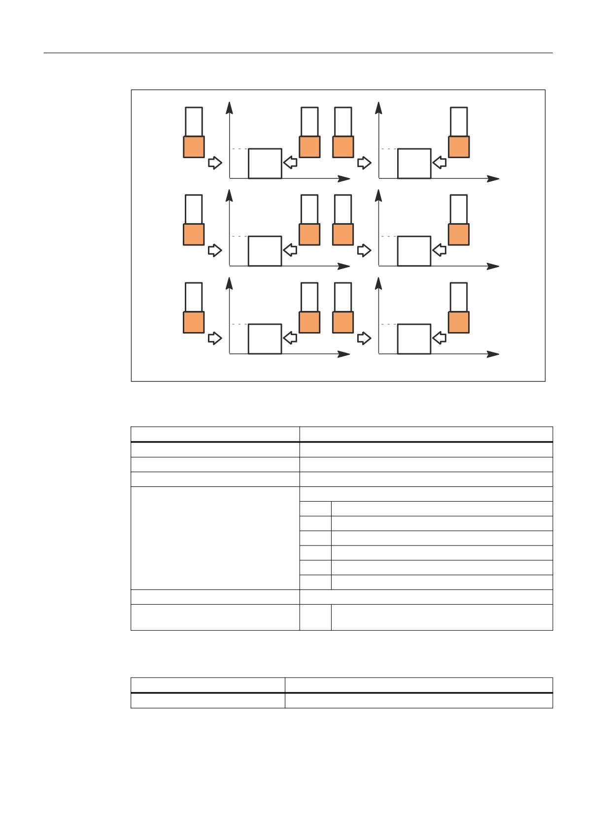
Figure 10-18
Measurement of the tool diameter in the G17/G18/G19 plane
The values of the following system variables are evaluated for measurement type 11:
Input variable
Meaning
$AC_MEAS_VALID
Validity bits for the input variables
$AA_MEAS_POINT1[<Axis>]
Measuring point 1
$AA_MEAS_SETPOINT[<Axis>]
Set position X0
$AC_MEAS_DIR_APPROACH
Direction of approach to the workpiece
= 0
+ X
= 1
- X
= 2
+ Y
= 3
- Y
= 4
+ Z
= 5
- Z
$AC_MEAS_ACT_PLANE *)
Calculation with active plane unless otherwise specified.
$AC_MEAS_TYPE
= 11
Measurement type 11: Measurement of the tool di-
ameter
*) Optional
The following output variables are written for measurement type 11:
Output variable
Meaning
$AC_MEAS_TOOL_DIAMETER
Tool diameter
Basic functions
646
Function Manual, 10/2020, 6FC5397-2GP40-0BA1
Measurement
10.5 Workpiece and tool measurement
10.5.3.4
Measurement type 22: Measurement of tool lengths with zoom-in function
Function
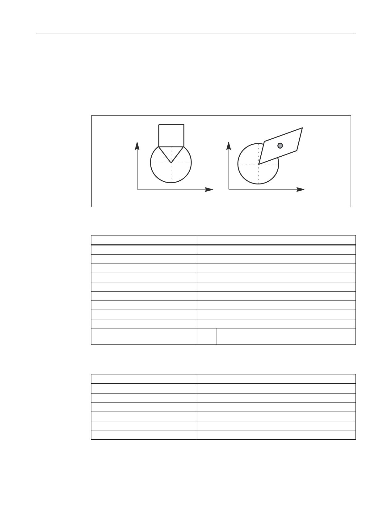
If a zoom-in function is available on the machine, it can also be used to determine the tool
lengths.
x
x
z
z
Figure 10-19
Measurement of tool lengths with zoom-in function
The values of the following system variables are evaluated for measurement type 22:
Input variable
Meaning
$AC_MEAS_VALID
Validity bits for the input variables
$AA_MEAS_POINT1[<Axis>]
Measuring point 1 for all channel axes
$AC_MEAS_P1_COORD *)
Coordinate system of the measuring point
$AA_MEAS_SETPOINT[<Axis>]
Zoom positions X and Z must be specified.
$AC_MEAS_SET_COORD *)
Coordinate system of the setpoint
$AC_MEAS_ACT_PLANE *)
Calculation with active plane unless otherwise specified.
$AC_MEAS_FRAME_SELECT *)
Calculated as additive frame unless otherwise specified.
$AC_MEAS_T_NUMBER *)
Calculated with active T unless otherwise specified (T0).
$AC_MEAS_D_NUMBER *)
Calculated with active D unless otherwise specified (D0).
$AC_MEAS_TYPE
= 22
Measurement type 22: Measurement of tool lengths
with zoom-in function
*) Optional
The following output variables are written for measurement type 22:
Output variable
Meaning
$AC_MEAS_RESULT[0]
Tool length in X
$AC_MEAS_RESULT[1]
Tool length in Y
$AC_MEAS_RESULT[2]
Tool length in Z
$AC_MEAS_RESULT[3]
Tool length L1
$AC_MEAS_RESULT[4]
Tool length L2
$AC_MEAS_RESULT[5]
Tool length L3
Basic functions
Function Manual, 10/2020, 6FC5397-2GP40-0BA1
647
Measurement
10.5 Workpiece and tool measurement
10.5.3.5
Measurement type 23: Measurement of a tool length with a stored or actual position
Function
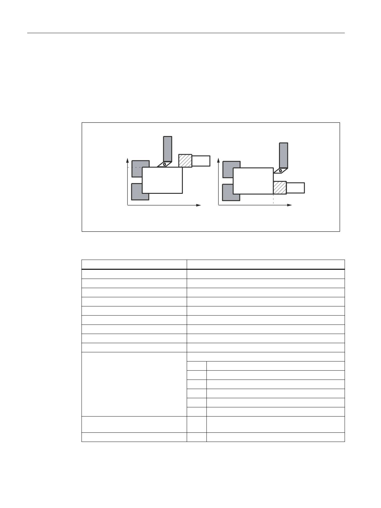
In the case of manual measurement, the tool dimensions can be determined in the X and Z
directions. ShopTurn then calculates the tool offset data from the known position of the tool
carrier reference point and the workpiece dimensions.
[
[
[
]
]
]
Figure 10-20
Measurement of a tool length with a stored or actual position
The values of the following system variables are evaluated for measurement type 23:
Input variable
Meaning
$AC_MEAS_VALID
Validity bits for the input variables
$AA_MEAS_POINT1[<Axis>]
Current or stored position
$AC_MEAS_P1_COORD *)
Coordinate system of the measuring point
$AA_MEAS_SETPOINT[<Axis>]
Set position (at least one geometry axis must be specified)
$AC_MEAS_SET_COORD *)
Coordinate system of the setpoint
$AC_MEAS_ACT_PLANE *)
Calculation with active plane unless otherwise specified.
$AC_MEAS_T_NUMBER *)
Calculated with active T unless otherwise specified (T0).
$AC_MEAS_D_NUMBER *)
Calculated with active D unless otherwise specified (D0).
$AC_MEAS_TOOL_MASK *)
Tool position, radius
$AC_MEAS_DIR_APPROACH *)
Direction of approach to the workpiece
= 0
+ X
= 1
- X
= 2
+ Y
= 3
- Y
= 4
+ Z
= 5
- Z
$AC_MEAS_INPUT[0] *)
= 1
The calculated tool lengths are written to the data
management.
$AC_MEAS_TYPE
= 23
Measurement type 23:
*) Optional
Basic functions
648
Function Manual, 10/2020, 6FC5397-2GP40-0BA1
Measurement
10.5 Workpiece and tool measurement
The following output variables are written for measurement type 23:
Output variable
Meaning
$AC_MEAS_RESULT[0]
Tool length in X
$AC_MEAS_RESULT[1]
Tool length in Y
$AC_MEAS_RESULT[2]
Tool length in Z
$AC_MEAS_RESULT[3]
Tool length L1
$AC_MEAS_RESULT[4]
Tool length L2
$AC_MEAS_RESULT[5]
Tool length L3
10.5.3.6
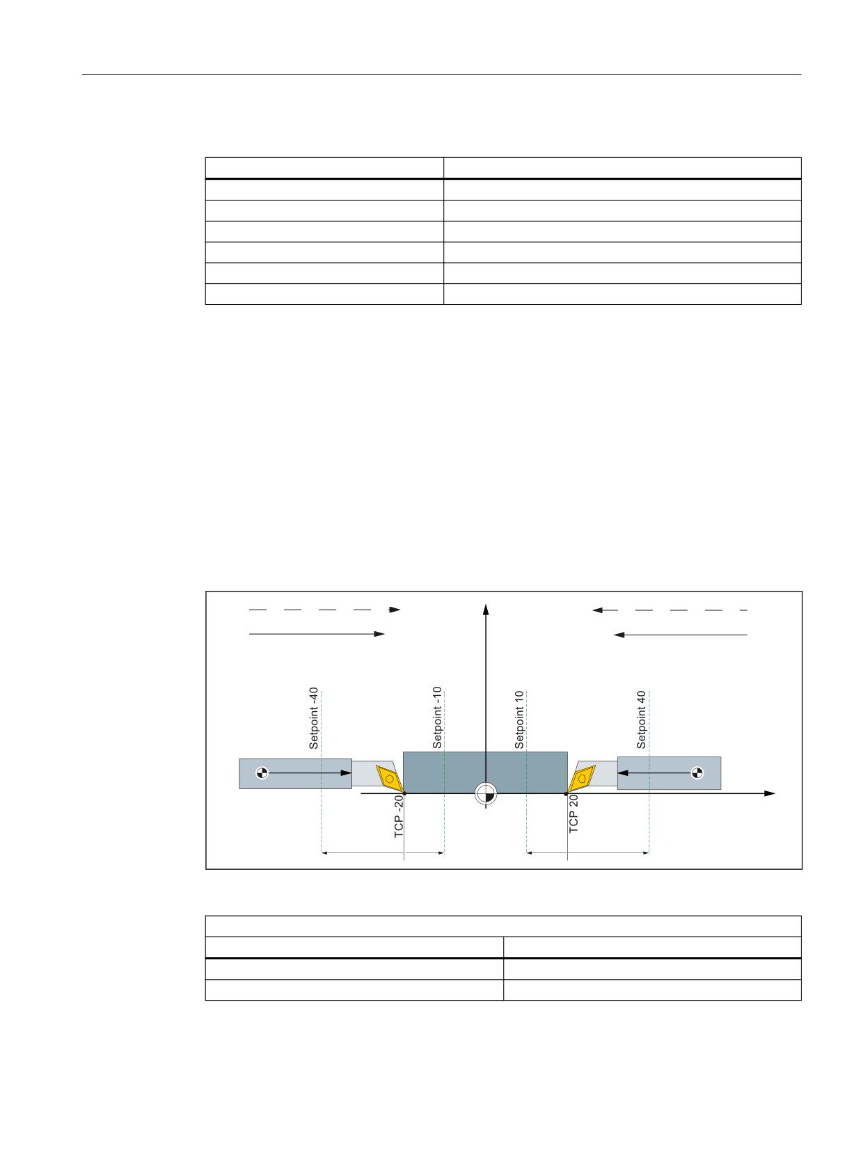
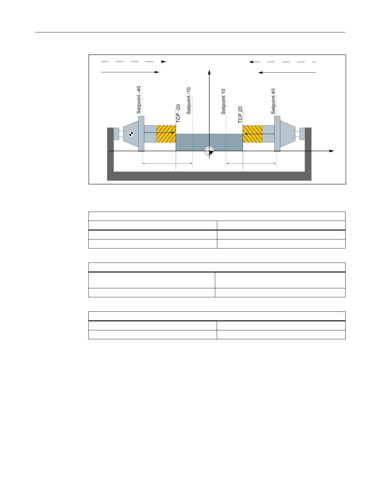
Measurement type 23: Measurement of a tool length of two tools with the following
orientation:
Tool orientation
For tools whose orientation points to the toolholder shows must be set in the system variables
$AC_MEAS_TOOL_MASK, bit 9 = 1 (0x200). The calculated tool lengths are then included
negatively.
Two turning tools each with their own reference point with a tool orientation in the approach
direction
%&6
$SSURDFK GLUHFWLRQ
[
[
$SSURDFK GLUHFWLRQ
7RRO RULHQWDWLRQ
[
[
7RRO RULHQWDWLRQ
[
:=/ ದ
:=/ ದ
Settings in the system data:
Left-hand tool: Approach direction and tool orientation +x
System variable
Meaning
$AC_MEAS_TOOL_MASK = 0x2
Tool position in x direction (G19)
$AC_MEAS_DIR_APPROACH = 0
Approach direction +x
Basic functions
Function Manual, 10/2020, 6FC5397-2GP40-0BA1
649
Measurement
10.5 Workpiece and tool measurement
Right-hand tool: Approach direction and tool orientation -x
$AC_MEAS_TOOL_MASK = 0x40
Tool position in the -x direction
$AC_MEAS_DIR_APPROACH = 1
Approach direction -x
For both tools
$AC_MEAS_Px_COORD = 1
Coordinate system of x-th measuring point = BCS
$AC_MEAS_SET_COORD = 1
Coordinate system of the setpoint = BCS
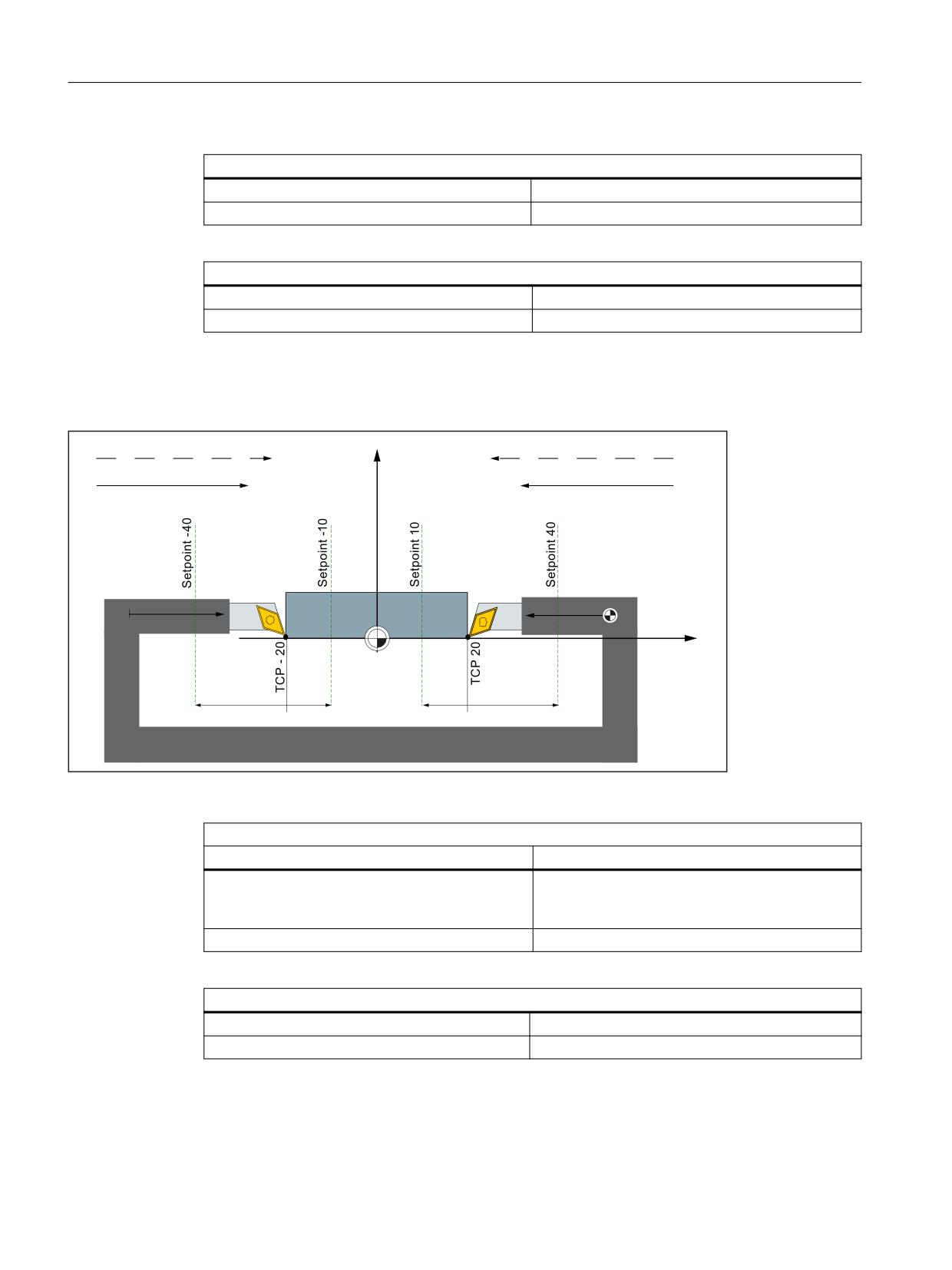
Two turning tools each with their own reference point with a tool counter-orientation in the
approach direction
%&6
$SSURDFK GLUHFWLRQ
[
[
$SSURDFK GLUHFWLRQ
7RRO RULHQWDWLRQ
[
[
7RRO RULHQWDWLRQ
[
:=/
:=/
Settings in the system data:
Left-hand tool: Approach direction and tool orientation +x
System variable
Meaning
$AC_MEAS_TOOL_MASK = 0x2 + 0x200
Tool position in x direction (G19) +
Tool length differential values are included nega-
tively
$AC_MEAS_DIR_APPROACH = 0
Approach direction +x
Right-hand tool: Approach direction and tool orientation -x
$AC_MEAS_TOOL_MASK = 0x40
Tool position in the -x direction
$AC_MEAS_DIR_APPROACH = 1
Approach direction -x
Basic functions
650
Function Manual, 10/2020, 6FC5397-2GP40-0BA1
Measurement
10.5 Workpiece and tool measurement
For both tools
$AC_MEAS_Px_COORD = 1
Coordinate system of x-th measuring point = BCS
$AC_MEAS_SET_COORD = 1
Coordinate system of the setpoint = BCS
%&6
$SSURDFK GLUHFWLRQ
[
[
$SSURDFK GLUHFWLRQ
7RRO RULHQWDWLRQ
[
[
7RRO RULHQWDWLRQ
[
:=/ ದ
ದ
:=/
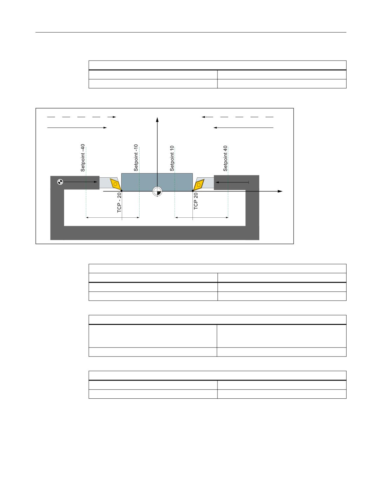
Settings in the system data:
Left-hand tool: Approach direction and tool orientation +x
System variable
Meaning
$AC_MEAS_TOOL_MASK = 0x2
Tool position in x direction (G19)
$AC_MEAS_DIR_APPROACH = 0
Approach direction +x
Right-hand tool: Approach direction and tool orientation -x
$AC_MEAS_TOOL_MASK = 0x40 + 0x200
Tool position in x direction +
Tool length differential values are included nega-
tively
$AC_MEAS_DIR_APPROACH = 1
Approach direction -x
For both tools
$AC_MEAS_Px_COORD = 1
Coordinate system of x-th measuring point = BCS
$AC_MEAS_SET_COORD = 1
Coordinate system of the setpoint = BCS
Basic functions
Function Manual, 10/2020, 6FC5397-2GP40-0BA1
651
Measurement
10.5 Workpiece and tool measurement
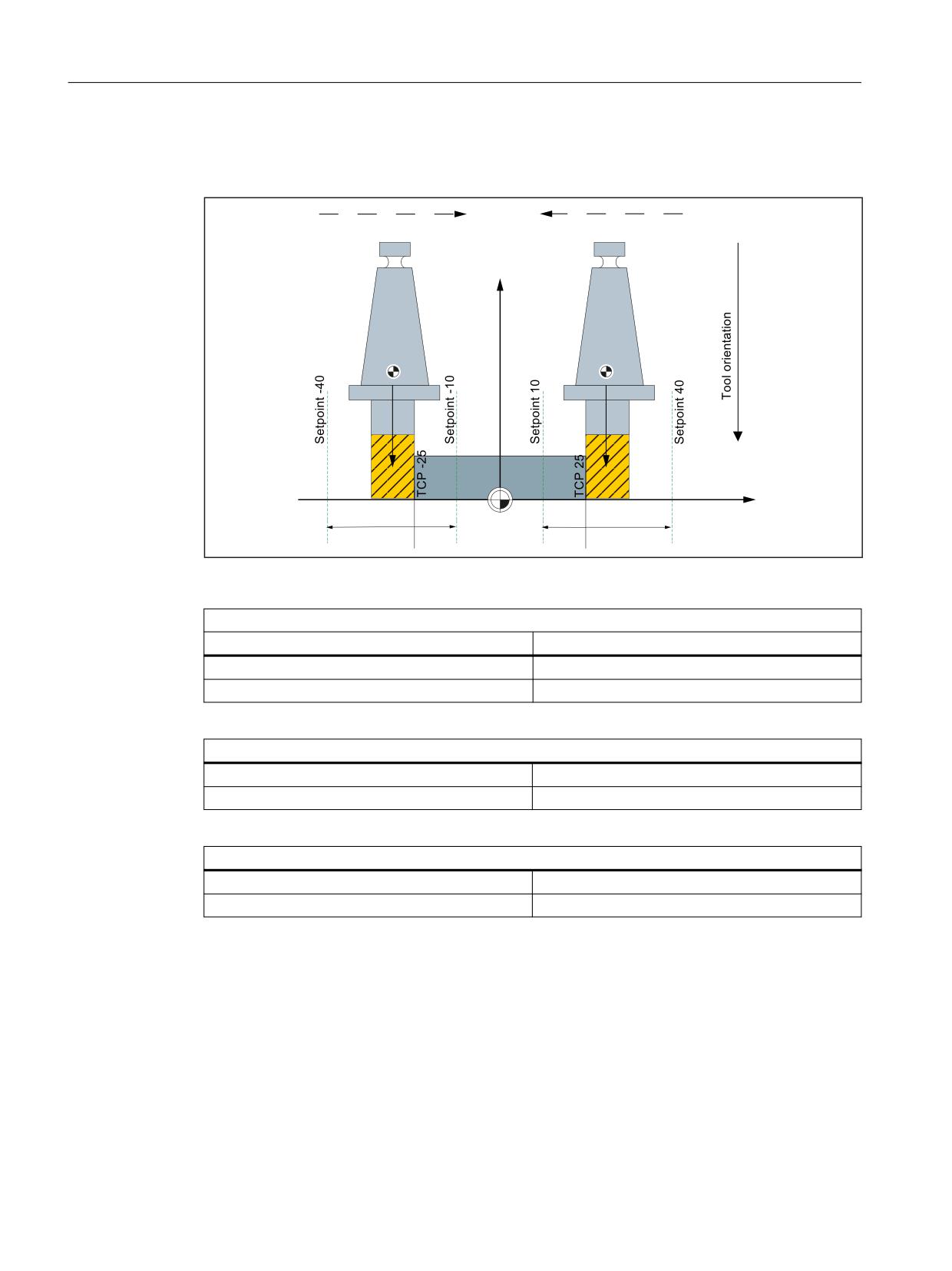
Two milling tools each with their own reference point, tool orientation perpendicular to the
approach direction
$SSURDFK GLUHFWLRQ
[
ದ[
$SSURDFK GLUHFWLRQ
%&6
\
:
[
ದ
ದ
Settings in the system data:
Left-hand tool: Approach direction +x and tool orientation -y
System variable
Meaning
$AC_MEAS_TOOL_MASK = 0x80
Tool position in -y direction
$AC_MEAS_DIR_APPROACH = 0
Approach direction +x
Right-hand tool: Approach direction -x and tool orientation -y
$AC_MEAS_TOOL_MASK = 0x80
Tool position in -y direction
$AC_MEAS_DIR_APPROACH = 1
Approach direction -x
For both tools
$AC_MEAS_Px_COORD = 1
Coordinate system of x-th measuring point = BCS
$AC_MEAS_SET_COORD = 1
Coordinate system of the setpoint = BCS
Basic functions
652
Function Manual, 10/2020, 6FC5397-2GP40-0BA1
Measurement
10.5 Workpiece and tool measurement
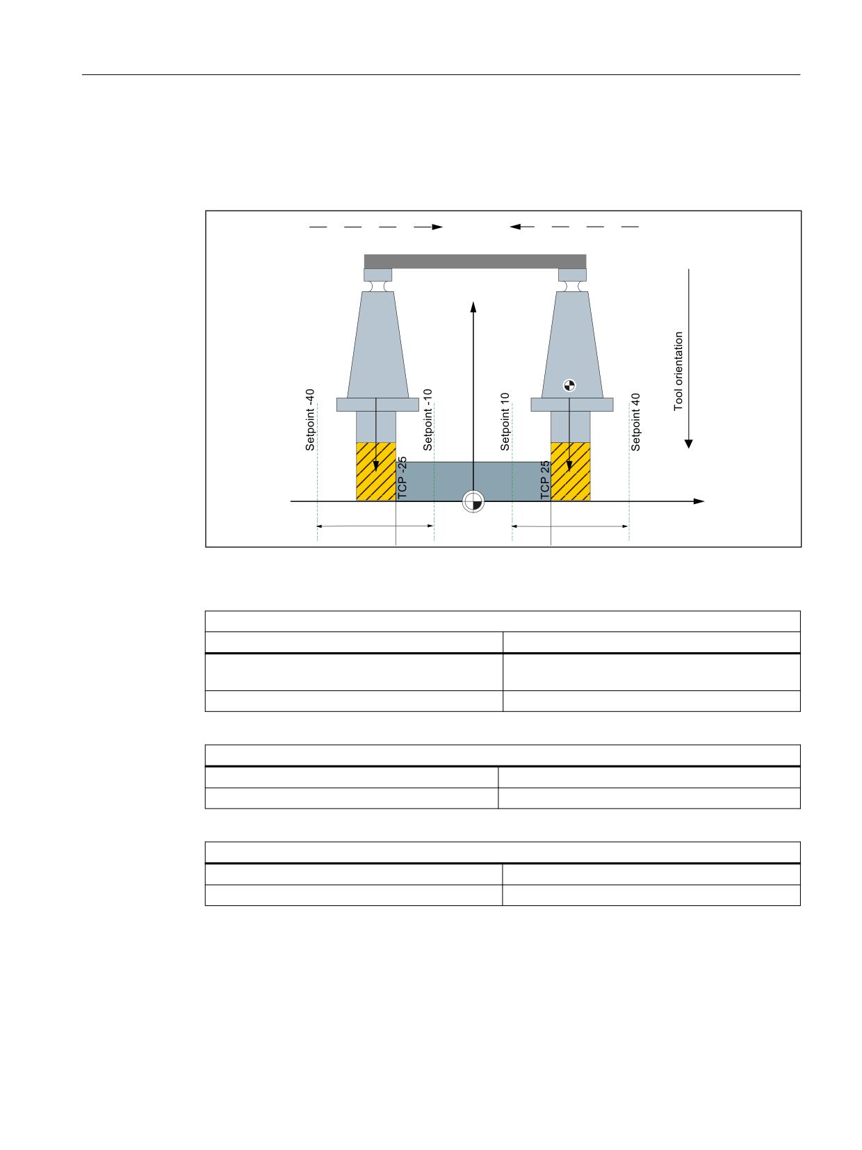
Two milling tools each with a reference point, tool orientation perpendicular to the approach
direction
Two milling tools with one reference point with a tool orientation in -y
$SSURDFK GLUHFWLRQ
[
ದ[
$SSURDFK GLUHFWLRQ
%&6
\
:
[
ದ
In the present layout, the tool position $AC_MEAS_TOOL_MASK and approach direction to the
workpiece $AC_MEAS_DIR_APPROACH must be set as follows:
Left-hand tool: Approach direction +x and tool orientation -y
System variable
Meaning
$AC_MEAS_TOOL_MASK = 0x80 + 0x200
Tool position in -y direction + tool length differen-
tial values are included negatively
$AC_MEAS_DIR_APPROACH = 0
Approach direction +x
Right-hand tool: Approach direction -x and tool orientation -y
$AC_MEAS_TOOL_MASK = 0x80
Tool position in -y direction
$AC_MEAS_DIR_APPROACH = 1
Approach direction -x
For both tools
$AC_MEAS_Px_COORD = 1
Coordinate system of x-th measuring point = BCS
$AC_MEAS_SET_COORD = 1
Coordinate system of the setpoint = BCS
Basic functions
Function Manual, 10/2020, 6FC5397-2GP40-0BA1
653
Measurement
10.5 Workpiece and tool measurement
$SSURDFK GLUHFWLRQ
[
ದ[
$SSURDFK GLUHFWLRQ
%&6
\
:
[
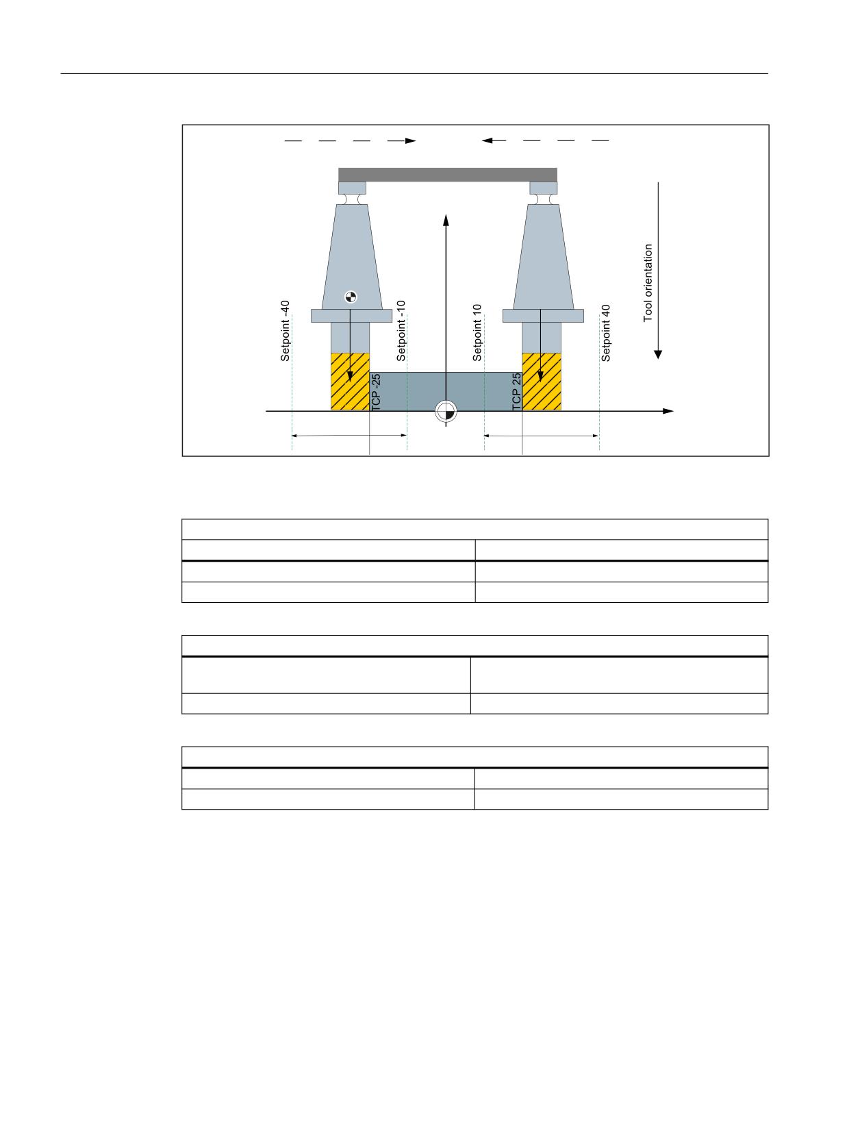
In the present layout, the tool position $AC_MEAS_TOOL_MASK and approach direction to the
workpiece $AC_MEAS_DIR_APPROACH must be set as follows:
Left-hand tool: Approach direction +x and tool orientation -y
System variable
Meaning
$AC_MEAS_TOOL_MASK = 0x80
Tool position in -y direction
$AC_MEAS_DIR_APPROACH = 0
Approach direction +x
Right-hand tool: Approach direction -x and tool orientation -y
$AC_MEAS_TOOL_MASK = 0x80 + 0x200
Tool position in -y direction + tool length differential
values are included negatively
$AC_MEAS_DIR_APPROACH = 1
Approach direction -x
For both tools
$AC_MEAS_Px_COORD = 1
Coordinate system of x-th measuring point = BCS
$AC_MEAS_SET_COORD = 1
Coordinate system of the setpoint = BCS
Basic functions
654
Function Manual, 10/2020, 6FC5397-2GP40-0BA1
Measurement
10.5 Workpiece and tool measurement
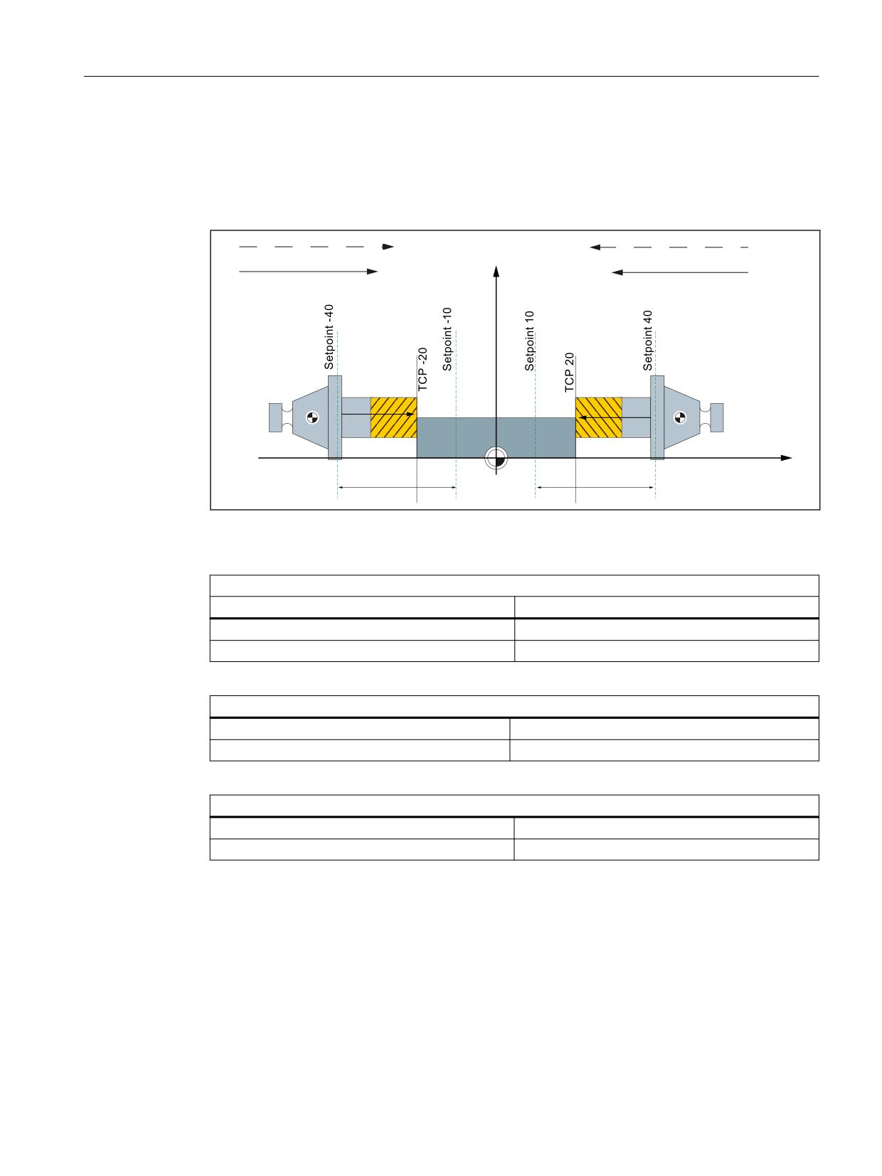
Two milling tools each with their own reference point with tool counter-orientation in the approach
direction
Two milling tools each with their own reference point with a tool orientation in the
approach direction
$SSURDFK GLUHFWLRQ
[
[
$SSURDFK GLUHFWLRQ
7RRO RULHQWDWLRQ
[
[
7RRO RULHQWDWLRQ
%&6
[
ದ
ದ
In the present layout, the tool position $AC_MEAS_TOOL_MASK and approach direction to the
workpiece $AC_MEAS_DIR_APPROACH must be set as follows:
Left-hand tool: Approach direction and tool orientation +x
System variable
Meaning
$AC_MEAS_TOOL_MASK = 0x2
Tool position in x direction (G19)
$AC_MEAS_DIR_APPROACH = 0
Approach direction +x
Right-hand tool: Approach direction and tool orientation -x
$AC_MEAS_TOOL_MASK = 0x40
Tool position in the -x direction
$AC_MEAS_DIR_APPROACH = 1
Approach direction -x
For both tools
$AC_MEAS_Px_COORD = 1
Coordinate system of x-th measuring point = BCS
$AC_MEAS_SET_COORD = 1
Coordinate system of the setpoint = BCS
Basic functions
Function Manual, 10/2020, 6FC5397-2GP40-0BA1
655
Measurement
10.5 Workpiece and tool measurement
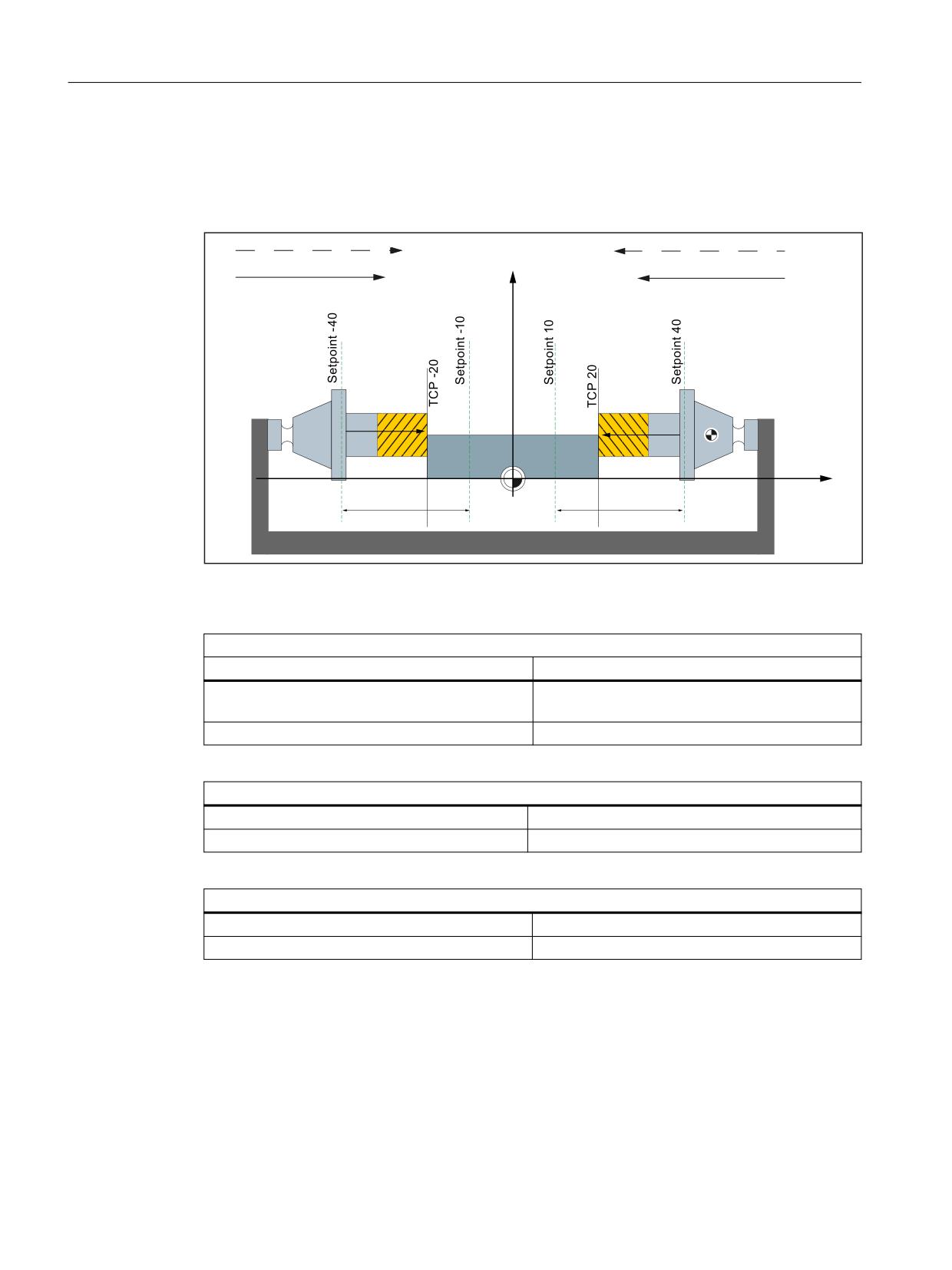
Two milling tools each with a reference point with tool counter-orientation in the approach
direction
Two milling tools with one reference point with a tool position opposite to the orientation
$SSURDFK GLUHFWLRQ
[
[
$SSURDFK GLUHFWLRQ
7RRO RULHQWDWLRQ
[
[
7RRO RULHQWDWLRQ
%&6
[
ದ
In the present layout, the tool position $AC_MEAS_TOOL_MASK and approach direction to the
workpiece $AC_MEAS_DIR_APPROACH must be set as follows:
Left-hand tool: Approach direction and tool orientation +x
System variable
Meaning
$AC_MEAS_TOOL_MASK = 0x2 + 0x200
Tool position in x direction (G19) + tool length dif-
ferential values are included negatively
$AC_MEAS_DIR_APPROACH = 0
Approach direction +x
Right-hand tool: Approach direction and tool orientation -x
$AC_MEAS_TOOL_MASK = 0x40
Tool position in the -x direction
$AC_MEAS_DIR_APPROACH = 1
Approach direction -x
For both tools
$AC_MEAS_Px_COORD = 1
Coordinate system of x-th measuring point = BCS
$AC_MEAS_SET_COORD = 1
Coordinate system of the setpoint = BCS
Basic functions
656
Function Manual, 10/2020, 6FC5397-2GP40-0BA1
Measurement
10.5 Workpiece and tool measurement
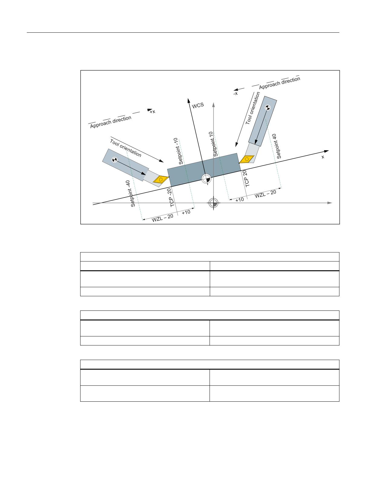
$SSURDFK GLUHFWLRQ
[
[
$SSURDFK GLUHFWLRQ
7RRO RULHQWDWLRQ
[
[
7RRO RULHQWDWLRQ
%&6
[
In the present layout, the tool position $AC_MEAS_TOOL_MASK and approach direction to the
workpiece $AC_MEAS_DIR_APPROACH must be set as follows:
Left-hand tool: Approach direction and tool orientation +x
System variable
Meaning
$AC_MEAS_TOOL_MASK = 0x2
Tool position in x direction (G19)
$AC_MEAS_DIR_APPROACH = 0
Approach direction +x
Right-hand tool: Approach direction and tool orientation -x
$AC_MEAS_TOOL_MASK = 0x40 + 0x200
Tool position in -x direction + tool length differential
values are included negatively
$AC_MEAS_DIR_APPROACH = 1
Approach direction -x
For both tools
$AC_MEAS_Px_COORD = 1
Coordinate system of x-th measuring point = BCS
$AC_MEAS_SET_COORD = 1
Coordinate system of the setpoint = BCS
Basic functions
Function Manual, 10/2020, 6FC5397-2GP40-0BA1
657
Measurement
10.5 Workpiece and tool measurement
Different tools in the WCS
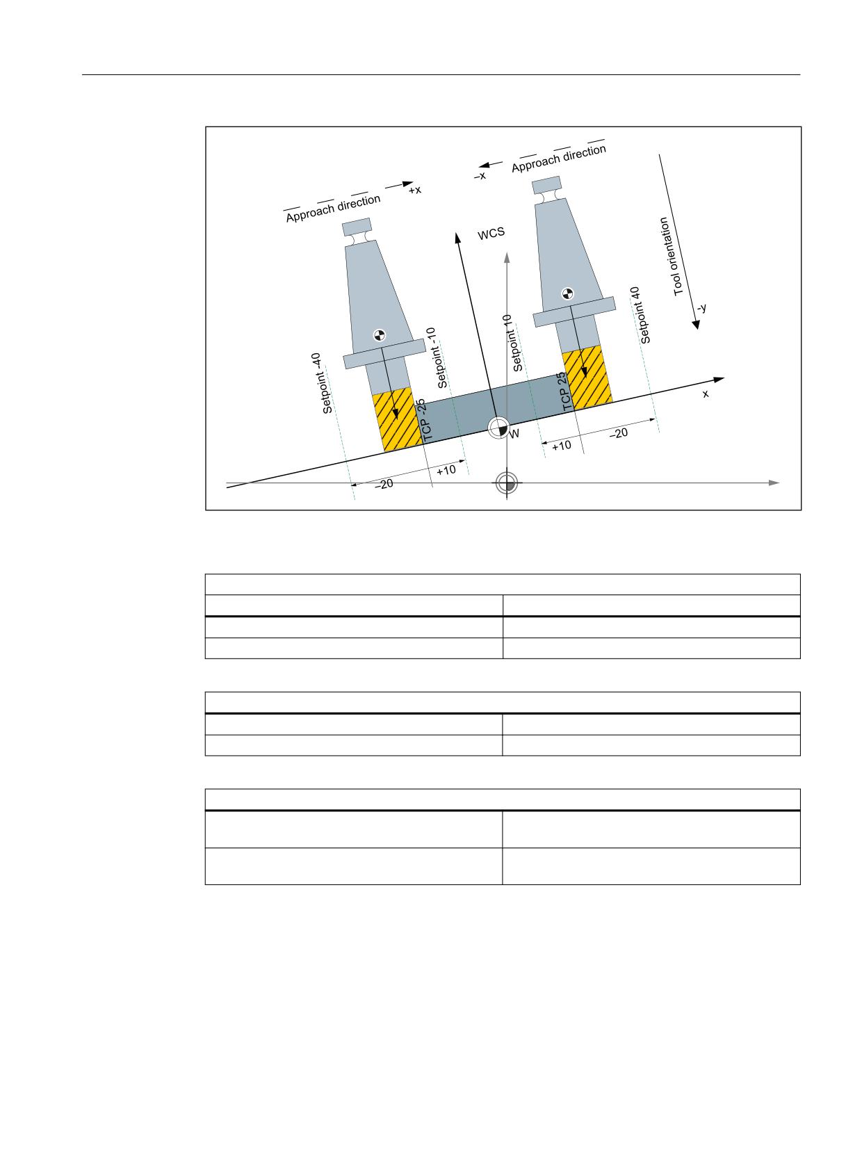
%&6
[
Figure 10-21
Two turning tools each with their own reference point
Settings in the system data:
Left-hand tool: Approach direction +x and tool orientation -y
System variable
Meaning
$AC_MEAS_TOOL_MASK = 0x0
All tool lengths are considered
(default setting)
$AC_MEAS_DIR_APPROACH = 0
Approach direction +x
Right-hand tool: Approach direction -x and tool orientation -y
$AC_MEAS_TOOL_MASK = 0x0
All tool lengths are considered
(default setting)
$AC_MEAS_DIR_APPROACH = 1
Approach direction -x
For both tools
$AC_MEAS_Px_COORD = 0
Coordinate system of x-th measuring point =
WCS (default setting)
$AC_MEAS_SET_COORD = 0
Coordinate system of the setpoint =
WCS (default setting)
Basic functions
658
Function Manual, 10/2020, 6FC5397-2GP40-0BA1
Measurement
10.5 Workpiece and tool measurement
%&6
[
Figure 10-22
Two milling tools each with its own reference point
Settings in the system data:
Left-hand tool: Approach direction +x and tool orientation -y
System variable
Meaning
$AC_MEAS_TOOL_MASK = 0x80
Tool position in -y direction
$AC_MEAS_DIR_APPROACH = 0
Approach direction +x
Right-hand tool: Approach direction -x and tool orientation -y
$AC_MEAS_TOOL_MASK = 0x80
Tool position in -y direction
$AC_MEAS_DIR_APPROACH = 1
Approach direction -x
For both tools
$AC_MEAS_Px_COORD = 0
Coordinate system of x-th measuring point =
WCS (default setting)
$AC_MEAS_SET_COORD = 0
Coordinate system of the setpoint =
WCS (default setting)
Basic functions
Function Manual, 10/2020, 6FC5397-2GP40-0BA1
659
Measurement
10.5 Workpiece and tool measurement
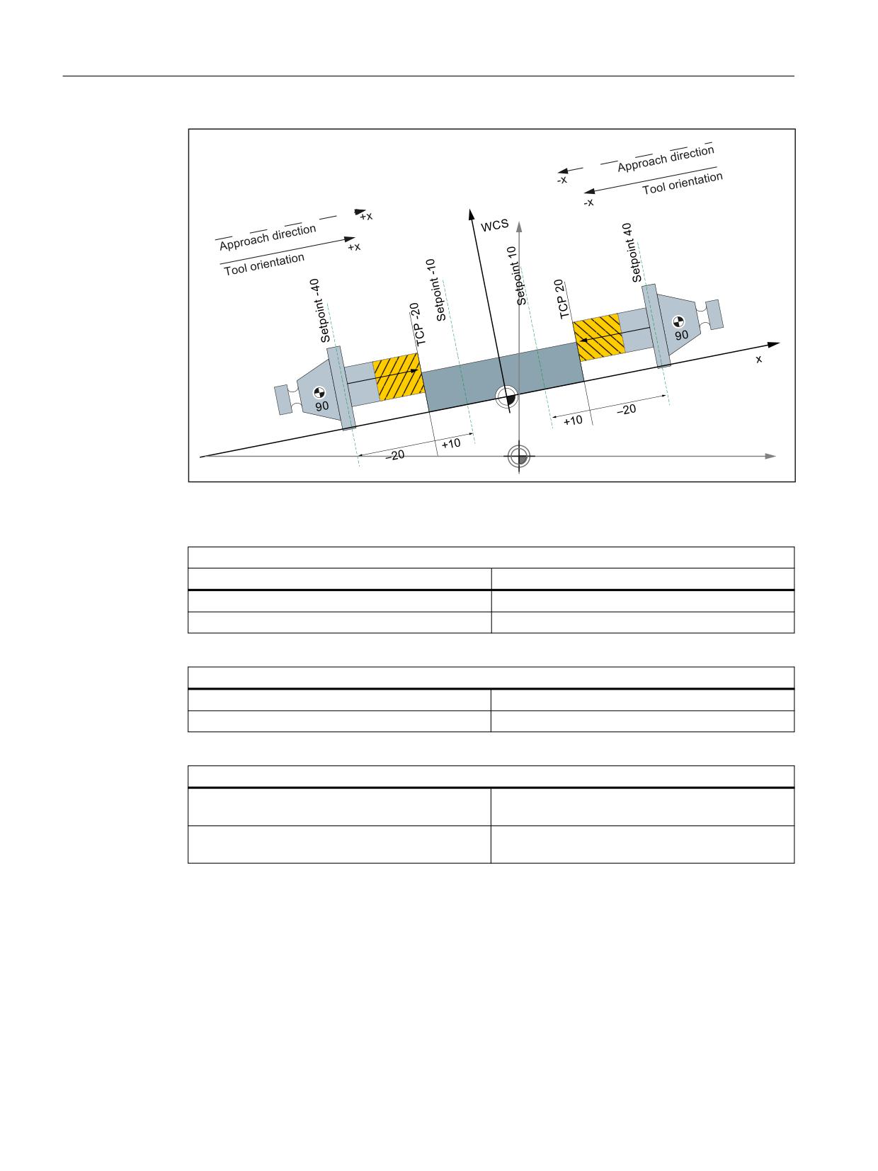
%&6
[
Figure 10-23
Two milling tools rotated at 90 degrees each with their own reference point
Settings in the system data:
Left-hand tool: Approach direction +x and tool orientation -y
System variable
Meaning
$AC_MEAS_TOOL_MASK = 0x2
Tool position in x direction (G19)
$AC_MEAS_DIR_APPROACH = 0
Approach direction +x
Right-hand tool: Approach direction -x and tool orientation -y
$AC_MEAS_TOOL_MASK = 0x40
Tool position in the -x direction
$AC_MEAS_DIR_APPROACH = 1
Approach direction -x
For both tools
$AC_MEAS_Px_COORD = 0
Coordinate system of x-th measuring point =
WCS (default setting)
$AC_MEAS_SET_COORD = 0
Coordinate system of the setpoint =
WCS (default setting)
Basic functions
660
Function Manual, 10/2020, 6FC5397-2GP40-0BA1
Measurement
10.6 Measurement accuracy and functional testing
10.6
Measurement accuracy and functional testing
10.6.1
Measurement accuracy
The measuring accuracy is affected by the following parameters:
• Delay time of the measuring signal (TDelay)
• Traversal speed during the measurement (vM)
Delay time compensation of the measuring signal (TDelay)
The delay time of the measuring signal, i.e. the time from the initiation of the probe until the
saving of the measured value in the control depends on the response time of the probe and the
signal runtime of the control hardware. The control compensates for the delay time during the
measurement. This requires that the delay time is determined and entered in the following
machine data:
MD13220 $MN_MEAS_PROBE_DELAY_TIME = <determined delay time>
Note
Maximum compensated delay time TMaxDelay
TMaxDelay = 31 * position controller or DP cycle
The compensation of a delay time > TMaxDelay is not sensible from the control viewpoint. This
means larger values are limited to TMaxDelay.
Maximum traversal speed during the measurement (vM)
The maximum permitted traversal speed for a measurement depends on the number of
programmed measuring edges and the parameterized position-controller or DP cycle.
To receive correct results, the traversal speed during the measurement must be chosen so that
the following conditions are satisfied every two position-controller or DP cycles:
• Maximum one identical trigger signal, i.e. one positive or one negative edge of one probe
• Maximum four different identical trigger signals, i.e. one positive and one negative edge
of two probes
10.6.2
Probe function test
The function check of the probe is performed via an NC program according to the following
example:
Program code
Comment
%_N_PRUEF_MESSTASTER_MPF
;$PATH=/_N_MPF_DIR
;Testing program probe connection
N05 DEF INT MTSIGNAL
; Bit memory for control state.
Basic functions
Function Manual, 10/2020, 6FC5397-2GP40-0BA1
661
Measurement
10.6 Measurement accuracy and functional testing
Program code
Comment
N10 DEF INT ME_NR=1
; Measuring input number.
N20 DEF REAL MESSWERT_IN_X
N30 G17 T1 D1
; Preselect tool offset for probe.
N40 _ANF: G0 G90 X0 F150
; Starting position and measuring
speed.
N50 MEAS=ME_NR G1 X100
; Measurement at measuring input 1 in
the X axis.
N60 STOPRE
N70 MTSIGNAL=$AC_MEA[1]
; Read software switching signal at
1st measuring input.
N80 IF MTSIGNAL==0 GOTOF _FEHL1
; Evaluation of the signal
N90 MESSWERT_IN_X=$AA_MW[X]
; Read in measured value in workpiece
coordinates.
N95 M0
N100 M02
N110 _FEHL1: MSG ("Probe does not switch!")
N120 M0
N130 M02
The measuring signal can be checked at the end of the program via the diagnostics menu "PLC
status":
• DB10 DBX107.0 (probe 1 deflected)
• DB10 DBX107.1 (probe 2 deflected)
The current measuring status of an axis is shown with the following NC/PLC interface signal:
• DB31, ... DBX62.3 (measurement active)
This signal can be evaluated for all measurement functions and also be read via the
$AA_MEAACT[<Axis>] system variable in synchronized actions.
Further information
Function Manual Synchronized Actions
10.6.3
Repeat accuracy
The measuring scatter (repeat accuracy) of the entire measuring system (machine probe signal
transmission to the NC) can be determined via an NC program according to the following
example.
In this program example, ten measurements are taken in the X axis and the measured value
recorded in the workpiece coordinates.
It is therefore possible to determine the random dimensional deviations which are not subject
to any trend.
Program code
Comment
%_N_PRUEF_GENAU_MPF;
$PATH=/_N_MPF_DIR
Basic functions
662
Function Manual, 10/2020, 6FC5397-2GP40-0BA1
Measurement
10.7 Simulated measuring
Program code
Comment
DEF INT SIGNAL, II
; Variable definition
DEF REAL MESSWERT_IN_X[10]
G17 T1 D1
; Initial conditions,
: Tool compensation
; preselect for probe
_ANF: G0 X0 F150
; Prepositioning in the measured axis
MEAS=+1 G1 X100
; at 1st measurement input when
; switching signal not deflected,
; deflected in the X axis
STOPRE
; Stop decoding for this only after
; subsequent evaluation of the
; result
SIGNAL= $AC_MEA[1]
; Read software switching signal at the
; 1st measuring input
IF SIGNAL == 0 GOTOF_FEHL1
; Check switching signal
MESSWERT_IN_X[II]=$AA_MW[X]
; Read measured value in workpiece coordi-
nates
II=II+1
IF II<10 GOTOB_ANF
; Repeat 10 times
M0
M02
_FEHL1: MSG ("Probe not switching")
M0
M02
After the parameter display (user-defined variables) has been selected, the measurement results
can be read in the MEASVALUE_IN_X[10] field as long as the program execution is still active.
10.7
Simulated measuring
10.7.1
General functionality
Brief description
To make measurements at real machines, probes must be connected which supply switching
signals at certain positions. Probes are not used when making measurements in simulated
environments - the switching positions are specified in a different way.
Simulated measuring supports two ways of entering switching positions:
• Position-related switch request: The switching position is derived from the axial end position
programmed in the measuring block.
• External switching request: The switching position is defined by controlling a digital output.
Basic functions
Function Manual, 10/2020, 6FC5397-2GP40-0BA1
663
Measurement
10.7 Simulated measuring
Preconditions
For simulated measuring, all of the machine axes in the system must be parameterized as
simulated axes:
• MD30130 $MA_CTRLOUT_TYPE[axis] = 0 (simulated setpoint)
• MD30240 $MA_ENC_TYPE[axis] = 0 (simulated encoder)
10.7.2
Position-related switch request
Function
"Position-related switch request" is selected using the following NC-specific machine data:
• MD13230 $MN_MEAS_PROBE_SOURCE = 0
• MD13231 $MN_MEAS_PROBE_OFFSET = <position offset>
The axial switching position is calculated from the axial end position programmed in the
measuring block and the parameterized position offset:
Switching position[axis] = End position[axis] - position offset
During the measuring block, it is cyclically checked as to whether the switching position of the
axis is reached:
Setpoint position[axis] ≥ switching position[axis]
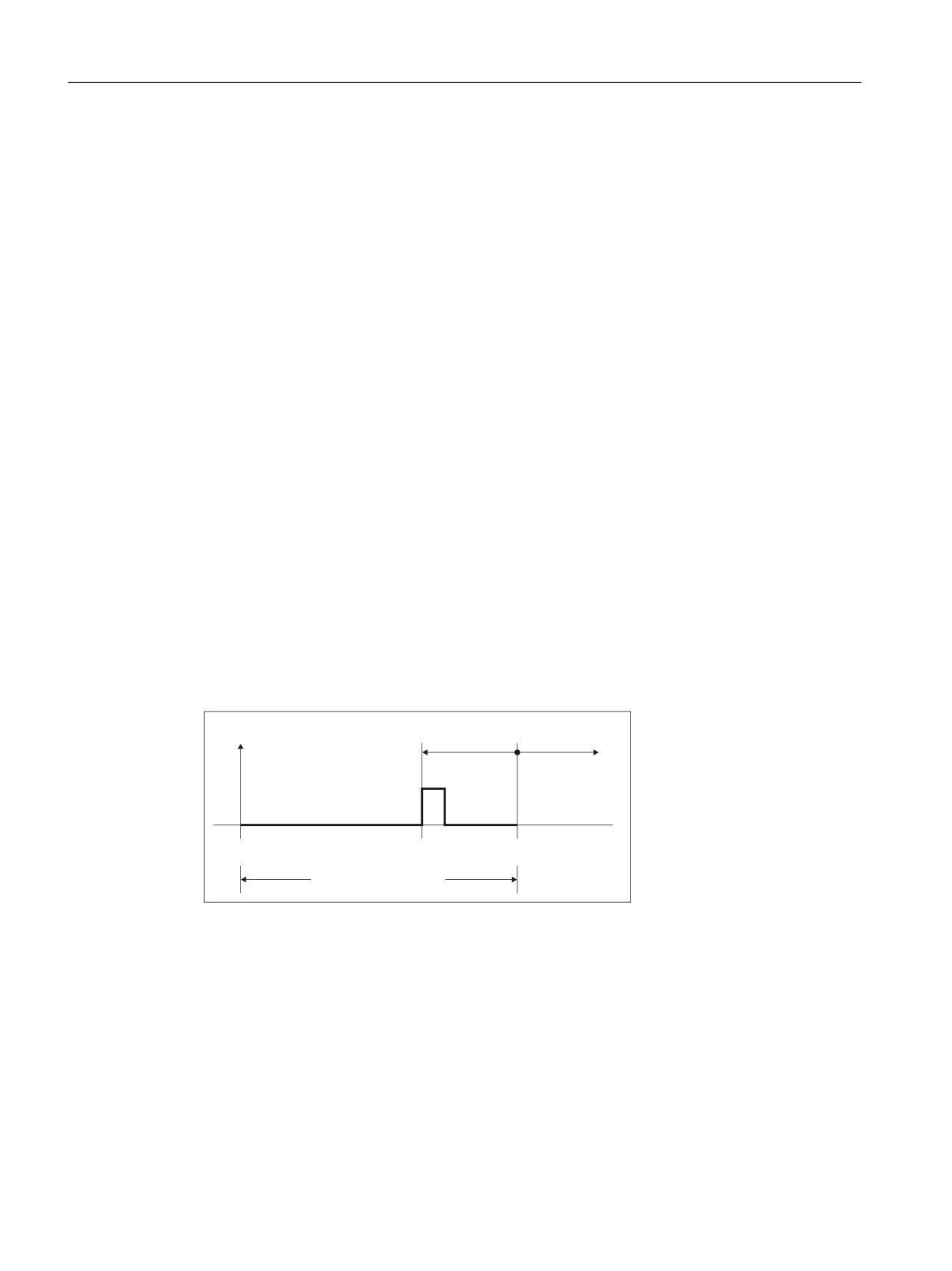
When the switching position is reached, the rising edge of the switching signal is generated for
probes 1 and 2. One position controller cycle later, the following edges.
3RVLWLRQ RIIVHW
6ZLWFKLQJ VLJQDO
3RVLWLYH
1HJDWLYH
6WDUW SRVLWLRQ
6ZLWFKLQJ SRVLWLRQ (QG SRVLWLRQ
0HDVXULQJ EORFN
Figure 10-24
Position-dependent switch request
The measured value is the actual value of the axis at the instant in time that the switching signal
programmed in the measuring block occurs (rising / falling edge).
Basic functions
664
Function Manual, 10/2020, 6FC5397-2GP40-0BA1
Measurement
10.7 Simulated measuring
If several axes are programmed in a measuring block, then a dedicated switching position is
obtained for each axis by the position offset that is axially taken into consideration. The probe
signal is generated at the first axial switching position that is reached.
Note
Probe signals
The probe signals are always simultaneously generated for probes 1 and 2.
Negative offset values
The switching position is shifted behind the end position by entering a negative value for the
position offset. In this case, no probe signals are generated.
Examples
The position offset is set to 0.1 mm: MD13231 $MN_MEAS_PROBE_OFFSET = 0.1
Example 1: Channel-specific measuring in 2 axes
Program code
Comment
N10 G01 G90
N20 MEAS=1 X100 Y10 F100
; rising edge, probe 1
; switching position[X] = 99.9
; switching position[Y] = 9.9
Example 2: Axial measuring using synchronized action
Program code
Comment
N10 G01 G90
N15 WHEN TRUE DO MEASA[X]=(1,1)
; rising edge, probe 1
N20 X10 F100
; switching position[X] = 9.9
10.7.3
External switch request
Function
The "external switching request" is selected using the NC-specific machine data by entering the
number (1...8) of the digital output being used:
• MD13230 $MN_MEAS_PROBE_SOURCE = <number of the digital output>
The probe signal is triggered by controlling the configured digital output. It is not necessary to
hard-wire the digital output to a measuring input.
The rising edge of the switching signal for probes 1 and 2 is generated by setting the digital
output. The falling edges are generated by resetting the digital output.
Basic functions
Function Manual, 10/2020, 6FC5397-2GP40-0BA1
665
Measurement
10.7 Simulated measuring
The measured value is the actual value of the axis at the instant in time that the switching signal
programmed in the measuring block occurs (rising / falling edge).
Digital output: Configuration
The following machine data must be set to be able to use digital outputs for simulated
measuring:
• MD10360 $MN_FASTIO_DIG_NUM_OUTPUTS = 1 (number of active digit. NC output bytes)
• MD13120 $MN_CONTROL_UNIT_LOGIC_ADDRESS = 0 (logical address, SINAMICS-CU)
Digital output: Setting
The configured digital output can be set in a synchronized action:
WHEN <condition> DO $A_OUT[<number of digital output>] = 1
Examples
Digital output used: MD13230 $MN_MEAS_PROBE_SOURCE = 1
Example 1: Channel-specific measuring in 2 axes
Program code
Comment
N10 G01 G90 $A_OUT[1]=0
; preassign digital output 1
N15 WHEN $AC_DETW<=10 DO $A_OUT[1]=1
; path distance-to-go <= 10 => dig. output 1 = 1
N20 MEAS=1 X100 Y10 F100
; rising edge, probe 1
Example 2: Axial measurement
Program code
Comment
N10 G01 G90 $A_OUT[1]=0
; preassign digital output 1
N15 WHEN $AA_IW[X]>=80 DO $A_OUT[1]=1
; axial setpoint >= 80 => dig. output 1 = 1
N20 MEASA[X]=(1,1) X100 F100
; rising edge, probe 1
10.7.4
System variable
For simulated measuring, the following system variables have the same functionality as for real
measuring:
• $AC_MEA (probe has responded)
• $AA_MEAACT (axial measuring active)
• $AA_MM (acquired probe position (MCS))
• $AA_MM1...4 (probe position 1st - 4th trigger (MCS))
• $AA_MW (acquired probe position (WCS))
• $AA_MW1...4 (probe position 1st trigger (WCS))
Basic functions
666
Function Manual, 10/2020, 6FC5397-2GP40-0BA1

Measurement
10.8 Data lists
The following system variable does not supply sensible values:
• $A_PROBE (probe state)
10.8
Data lists
10.8.1
Machine data
10.8.1.1
General machine data
Number
Identifier: $MN_
Meaning
13200
MEAS_PROBE_LOW_ACTIVE
Switching characteristics of probe
13201
MEAS_PROBE_SOURCE
Measuring pulse simulation via digital output
13210
MEAS_TYPE
Type of measurement for PROFIBUS DP drives
13211
MEAS_CENTRAL_SOURCE
Central measuring data source with PROFIBUS DP drives
10.8.1.2
Channel-specific machine data
Number
Identifier: $MC_
Meaning
28264
LEN_AC_FIFO
Length of $AC_FIFO ... FIFO variables
10.8.2
System variables
Table of all the input values
Identifier
Meaning
$AC_FIFO1…10
FIFO variable 1 to 10
$AC_MEAS_SEMA
Interface assignment
$AC_MEAS_VALID
Validity bits for input values
$AA_MEAS_POINT1
1st measuring point for all channel axes
$AA_MEAS_POINT2
2nd measuring point for all channel axes
$AA_MEAS_POINT3
3rd measuring point for all channel axes
$AA_MEAS_POINT4
4th measuring point for all channel axes
$AA_MEAS_SETPOINT
Setpoint position for all channel axes
$AA_MEAS_SETANGLE
Setpoint angle for all channel axes
$AC_MEAS_P1_COORD
Coord. system for the 1st measuring point
$AC_MEAS_P2_COORD
Coord. system for the 2nd measuring point
Basic functions
Function Manual, 10/2020, 6FC5397-2GP40-0BA1
667

Measurement
10.8 Data lists
Identifier
Meaning
$AC_MEAS_P3_COORD
Coord. system for the 3rd measuring point
$AC_MEAS_P4_COORD
Coord. system for the 4th measuring point
$AC_MEAS_SET_COORD
Coordinate system of the setpoint
$AC_MEAS_LATCH[0...3]
Pick up measuring points in the WCS
$AA_MEAS_P1_VALID
Delatching of 1st measuring point in the WCS
$AA_MEAS_P2_VALID
Delatching of 2nd measuring point in the WCS
$AA_MEAS_P3_VALID
Delatching of 3rd measuring point in the WCS
$AA_MEAS_P4_VALID
Delatching of 4th measuring point in the WCS
$AA_MEAS_SP_VALID
Set setpoint position of axis as valid
$AC_MEAS_WP_SETANGLE
Setpoint workpiece position angle
$AC_MEAS_CORNER_SETANGLE
Setpoint cutting angle of corner
$AC_MEAS_DIR_APPROACH
Approach direction
$AC_MEAS_ACT_PLANE
Working plane for the workpiece
$AC_MEAS_SCALEUNIT
Unit of measurement INCH / METRIC
$AC_MEAS_FINE_TRANS
Corrections in fine displacement
$AC_MEAS_FRAME_SELECT
Frame selection for the workpiece measurement
$AC_MEAS_CHSFR
Frame chain setting: System frames
$AC_MEAS_NCBFR
Frame chain setting: Global basic frames
$AC_MEAS_CHBFR
Frame chain setting: Channel basic frames
$AC_MEAS_UIFR
Frame chain setting: Settable frames
$AC_MEAS_PFRAME
Frame chain setting: Program frame
$AC_MEAS_T_NUMBER
Tool selection
$AC_MEAS_D_NUMBER
Cutting edge selection
$AC_MEAS_TOOL_MASK
Tool settings
$AC_MEAS_TYPE
Measuring type
$AC_MEAS_INPUT
Measurement input parameters
Table of all the output values
Identifier
Meaning
$A_PROBE[1,2]
Probe status
$A_PROBE_LIMITED[1,2]
Measuring velocity exceeded
$AC_MEA[1,2]
Probe has responded
$AA_MM
Acquired probe position (MCS)
$AA_MM1...4
Probe position 1st to 4th trigger event (MCS)
$AA_MW
Acquired probe position (WCS)
$AA_MW1...4
Probe position 1st to 4th trigger event (WCS)
$AC_MEAS_FRAME
Result frame
$AC_MEAS_WP_ANGLE
Calculated workpiece position angle
$AC_MEAS_CORNER_ANGLE
Calculated angle of intersection
$AC_MEAS_DIAMETER
Calculated diameter
Basic functions
668
Function Manual, 10/2020, 6FC5397-2GP40-0BA1

Measurement
10.8 Data lists
Identifier
Meaning
$AC_MEAS_TOOL_LENGTH
Calculated tool length
$AC_MEAS_RESULTS
Measurement results (depending on measurement type)
Basic functions
Function Manual, 10/2020, 6FC5397-2GP40-0BA1
669
Measurement
10.8 Data lists
Basic functions
670
Function Manual, 10/2020, 6FC5397-2GP40-0BA1
Emergency stop
11
11.1
Brief Description
Function
The control system supports the machine manufacturer in implementing an emergency stop
function on the basis of the following functions:
• An emergency stop button is installed in a location easily accessible to the machine operator
on all SINUMERIK machine control panels. The functionality of the emergency stop button
includes the positive opening of electrical switching contacts and a mechanical self-
activating latching/locking.
• The emergency stop request to the NC is transmitted via the NC/PLC interface on the PLC.
• The Emergency Stop function must bring the machine to a standstill according to stop
category 0 or 1 (EN 60204).
• In the case of an emergency stop, all machine functions controlled by the PLC can be brought
to a safe state that can be set by the machine manufacturer.
• Unlatching the emergency stop button does not cancel the emergency stop state nor does it
initiate a restart.
• After the emergency stop state has been canceled, it is not necessary to reference the
machine axes or synchronize the spindles. The actual positions of the machine axes are
continuously tracked during the emergency stop sequence.
11.2
Relevant standards
Relevant standards
Compliance with the following standards is essential for the emergency stop function:
• EN ISO 12000-1
• EN ISO 12000-2
• EN 418
• EN 60204
Emergency stop
In accordance with EN 418, an emergency stop is a function that:
• Is intended to prevent or diminish developing or existing risks to operating personnel, and
damage to the machine or machined materials.
• Is triggered by a single action of a person, if the normal stop function is not suitable for it.
Basic functions
Function Manual, 10/2020, 6FC5397-2GP40-0BA1
671
Emergency stop
11.3 Emergency stop control elements
Hazards
In the terms of EN 418, risks may arise from:
• Functional irregularities (machine malfunctions, unacceptable properties of the material to
be machined, human error, etc.).
• Normal operation.
Stadard EN ISO 12000-2
In accordance with the basic safety requirement of the EC Machinery Directive regarding
emergency stop, machines must be equipped with an energency stop device.
Exceptions
No emergency stop device is required on machines:
• Where an emergency stop device would not reduce the risk, either because the shutdown
time would not be reduced or because the measures to be taken would not be suitable for
controlling the risk.
• That are held and operated manually.
Note
The machine manufacturer is expressly directed to comply with the national and
international standards. The SINUMERIK controllers support the machine manufacturer in
the implementation of the emergency stop function according to the specifications in the
following function description. But the responsibility for the emergency stop function (its
triggering, sequence and acknowledgement) rests exclusively with the machine
manufacturer.
11.3
Emergency stop control elements
Emergency stop control elements
In accordance with EN 418, emergency stop control elements must be designed so that they
latch mechanically on their own and are easy for the operator and others to actuate in the event
of an emergency.
The following list includes some possible types of control elements:
• Mushroom pushbutton switches
• Wires/cables, cords, rods
• Puller grips
• In special cases: Foot switches without protective covers
Basic functions
672
Function Manual, 10/2020, 6FC5397-2GP40-0BA1
Emergency stop
11.4 Emergency stop sequence
Emergency stop button and control
Actuation of the emergency stop button or a signal derived directly from the button must be
routed to the controller (PLC) as a PLC input. In the PLC user program, this PLC input must be
forwarded to the NC on the interface signal:
DB10 DBX56.1 (Emergency stop)
Resetting of the emergency stop button or a signal derived directly from the button must be
routed to the controller (PLC) as a PLC input. In the PLC user program, this PLC input must be
forwarded to the NC on the interface signal:
DB10 DBX56.2 (Acknowledge emergency stop)
Connection conditions
For connection of the emergency stop button, see:
Further information:
Equipment Manual Operator Components
11.4
Emergency stop sequence
After actuation of the emergency stop control element, the emergency stop device must
operate in the best possible way to prevent or minimize the danger.
"In the best possible way" means that the most favorable delay rate can be selected and the
correct stop category (defined in EN 60204) can be determined according to a risk assessment.
Emergency stop sequence in the NC
The predefined (in EN 418) sequence of internal functions implemented to obtain the
emergency stop state is as follows in the control system:
1. Part program execution is interrupted.
All machine axes are braked in the relevant axis-specific parameterized time:
MD36610 $MA_AX_EMERGENCY_STOP_TIME (time of braking ramp in event of errors)
The maximum braking ramp that can be achieved thereby, is defned by the maximum brake
current of the respective drive. The maximum brake current is achieved by setting a setpoint
= 0 (fast braking).
2. Reset interface signal:
DB11 DBX6.3 (Mode group ready)
3. Set the interface signal:
DB10 DBX106.1 (emergency stop active)
4. Alarm 3000 "Emergency stop" is displayed.
5. After the expiry of a paramaterized delay time, the servo enables of machine axes are reset.
The setting of the delay time is programmed in machine data:
MD36620 $MA_SERVO_DISABLE_DELAY_TIME (OFF delay of the controller enable)
The following setting rule must be observed: MD36620 ≥ MD36610
6. All machine axes are switched in the follow-up mode within the controller.
The machine axes are no longer in position control.
Basic functions
Function Manual, 10/2020, 6FC5397-2GP40-0BA1
673
Emergency stop
11.5 Emergency stop acknowledgement
Emergency stop sequence at the machine
The emergency stop sequence on the machine is determined solely by the machine
manufacturer.
Attention should be paid to the following points in connection to the sequence on the NC:
• The process in the NC is started using the interface signal:
DB10 DBX56.1 (Emergency stop)
After the machine axes have come to a standstill, the power supply must be interrupted, in
compliance with EN 418.
Note
The responsibility for interrupting the power supply rests with the machine manufacturer.
• The digital and analog outputs of the PLC I/O are not influenced by the emergency stop
sequence in the NC.
If individual outputs are required to attain a particular state or voltage level in the event of an
emergency stop, the machine manufacturer must implement this in the PLC user program.
• The fast digital outputs of the NCK I/O system are not influenced by the emergency stop
sequence in the NC.
If individual outputs must assume a specific state in case of emergency stop, the machine
manufacturer must transmit the desired state to the NC in the PLC user program via interface
signals:
DB10 DBB4-7
Note
If the sequence in the NC is not to be executed as described above, then the interface signal
DB10 DBX56.1 (emergency stop) must not be set until an emergency stop state defined by
the machine manufacturer in the PLC user program is reached.
As long as the interface signal is not set and no other alarm is pending, all interface signals
are operative in the NC. Any emergency stop state defined by the manufacturer (including
axis-, spindle- and channel-specific emergency stop states) can therefore be assumed.
11.5
Emergency stop acknowledgement
The emergency stop control element may only be reset as a result of manual manipulation of the
emergency stop control element according to EN 418.
Resetting of the emergency stop control element alone must not trigger a restart command.
A machine restart must be impossible until all of the actuated emergency stop control elements
have been deliberately reset by hand.
Emergency stop acknowledgment
The EMERGENCY STOP state is only reset if the interface signal:DB10 DBX56.2 (acknowledge
EMERGENCY STOP) is set followed by the interface signal:DB11, ... DBX0.7 (mode group reset).
Basic functions
674
Function Manual, 10/2020, 6FC5397-2GP40-0BA1
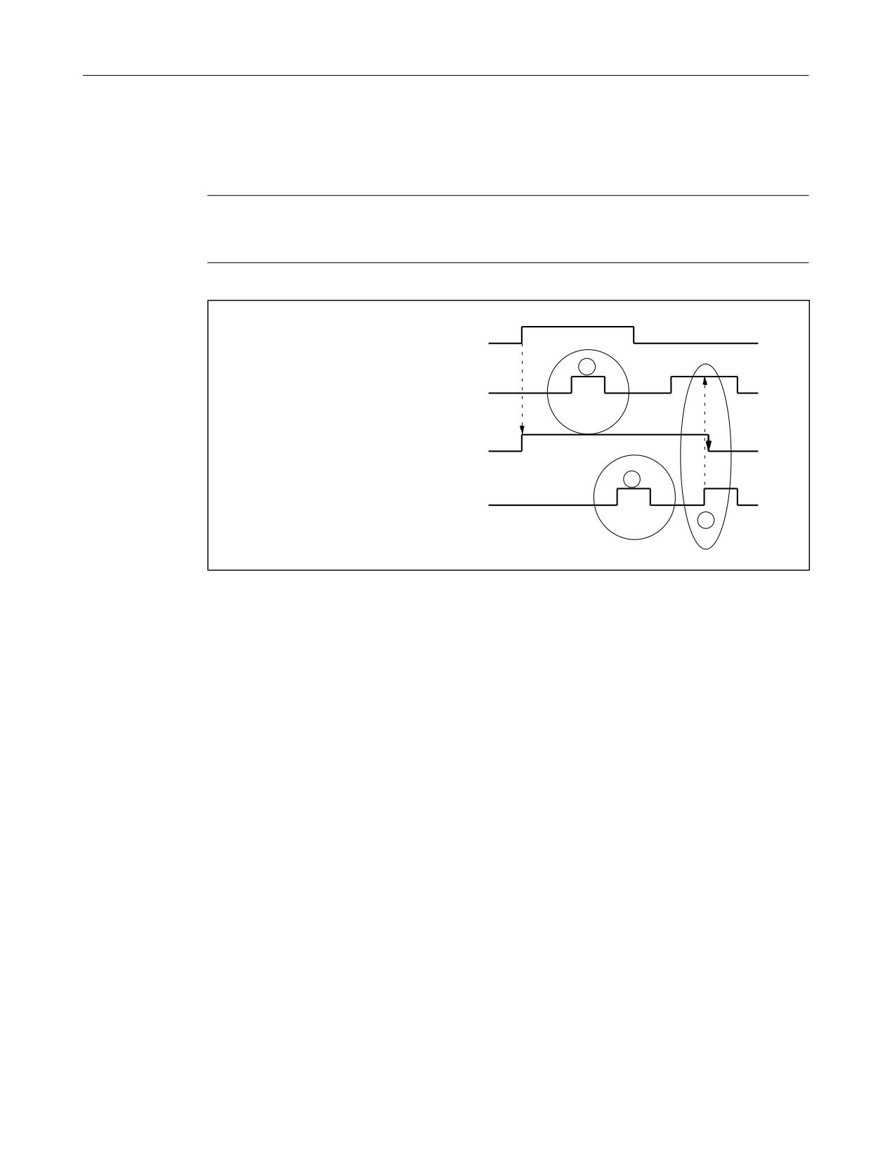
Emergency stop
11.5 Emergency stop acknowledgement
Hence it can be noted that the interface signal DB10 DBX56.2 (acknowledge emergency stop)
and the interface signal DB21, ... DBX7.7 (Reset) together are set at least for so long until the
interface signal DB10 DBX106.1(emergency stop active) is reset.
Note
The emergency stop state cannot be reset with the interface signal DB21, ... DBX7.7 (Reset)
alone.
'% '%;
(PHUJHQF\ 6WRS
'% '%;
DFNQRZOHGJH (PHUJHQF\
6WRS
'% '%;
HPHUJHQF\ VWRS
DFWLYH
'%
'%;
5(6(7
(1)
DB10 DBX56.2 (acknowledge emergency stop) is inoperative
(2)
DB21, ... DBX7.7 (Reset) is inoperative
(3)
DB10 DBX56.2 and DB21, ... DBX7.7 reset DB10 DBX106.1 (emergency stop active)
Figure 11-1
Resetting the emergency stop state
Effects
Resetting the emergency stop state has the following effects:
• Within the controller for all machine axes:
- The servo enables are set.
- The follow-up mode is canceled.
- The position control is activated.
• The following interface signals are set:
DB31, ... DBX60.5 (position control active)
DB11 DBX6.3 (mode group ready)
• The following interface signal is reset:
DB10 DBX106.1 (emergency stop active)
• Alarm 3000 "Emergency stop" is deleted.
• Part program processing is interrupted in all channels of the NC.
Basic functions
Function Manual, 10/2020, 6FC5397-2GP40-0BA1
675
Emergency stop
11.6 Data lists
PLC and NC I/O
The PLC user program must switch the PLC and NC I/O back to the state for operation of the
machine.
POWER OFF / ON (supply off / on)
The emergency stop state can also be reset by switching the controller off and back on (POWER
OFF / ON).
Requirement:
During power-up of the controller the interface signal DB10 DBX56.1 (emergency stop) must
not be set.
11.6
Data lists
11.6.1
Machine data
11.6.1.1
Axis/spindlespecific machine data
Number
Identifier: $MA_
Description
36610
AX_EMERGENCY_STOP_TIME
Length of the braking ramp for error states
36620
SERVO_DISABLE_DELAY_TIME
Cutout delay servo enable
Basic functions
676
Function Manual, 10/2020, 6FC5397-2GP40-0BA1

Various NC/PLC interface signals and functions
12
12.1
Brief description
Contents
The PLC/NC interface comprises a data interface on one side and a function interface on the
other. The data interface contains status and control signals, auxiliary and G commands, while
the function interface is used to transfer jobs from the PLC to the NC.
This Description describes the functionality of interface signals, which are of general relevance
but are not included in the descriptions of functions.
• Asynchronous events
• Status signals
• PLC variable (read and write)
12.2
Functions
12.2.1
Screen refresh behavior for overload
There are part programs, where the main run must wait until the preprocessing run provides
new blocks.
Preprocessing run and display refresh compete for NC processor time.
The following machine data can be used to set how the NC should behave if the preprocessing
run is too slow:
MD10131 $MN_SUPPRESS_SCREEN_REFRESH
Value
Meaning
0
If the preprocessing run of a channel is too slow, the display is not refreshed in all channels.
1
If the preprocessing run of a channel is too slow, the display is only refreshed in the time critical channels in order to
obtain processor time for the preprocessing run.
2
Display refresh is not suppressed.
Basic functions
Function Manual, 10/2020, 6FC5397-2GP40-0BA1
677

Various NC/PLC interface signals and functions
12.2 Functions
12.2.2
Activate DEFAULT memory
GUD start values
The DEF... / REDEF... NC commands can be used to assign default settings to global user data
(GUD). To make these default values available at the parameterized initialization time, e.g. with
the attribute INIPO, after power on, they must be saved permanently in the system. The
required memory space must be enabled using the following machine data:
MD18150 $MM_GUD_VALUES_MEM (non-volatile memory space for GUD values)
Further information
• Memory configuration (Page 885)
• "NC Programming" Programming Manual
12.2.3
Read/write PLC variable
High-speed data channel
For high-speed exchange of information between the PLC and NC, a memory area is reserved in
the communications buffer on these modules (dual-port RAM). Variables of any type (I/O, DB,
DW, flags) may be exchanged within this memory area.
The PLC accesses this memory using 'Function Calls' (FC) while the NC uses system variables.
Organization of memory area
The user's programming engineer (NC and PLC) is responsible for organizing (structuring) this
memory area.
Every storage position in the memory can be addressed provided that the limit is selected
according to the appropriate data format (i.e. a DWORD for a 4-byte limit, a WORD for a 2-byte
limit, etc.).
The memory is accessed via the data type and the position offset within the memory area.
Access from NC
System variables are available in the NC for fast access to PLC variables from a part program or
synchronized action. The data is read/written directly by the NC. The data type results from the
identifier of the system variables. The position within the memory area is specified as index in
bytes.
System variable
Data type
Range of values
$A_DBB[<index>]
Byte (8 bits)
0 <= x <= 255
$A_DBW[<index>]
Word (16 bits)
-32768 <= x <= 32767
$A_DBD[<index>]
Double word (32 bits)
-2147483648 <= x <= 2147483647
$A_DBR[<index>]
Floating point (32 bits)
±(1.5·10-45 <= x <= 3.4·1038)
Basic functions
678
Function Manual, 10/2020, 6FC5397-2GP40-0BA1
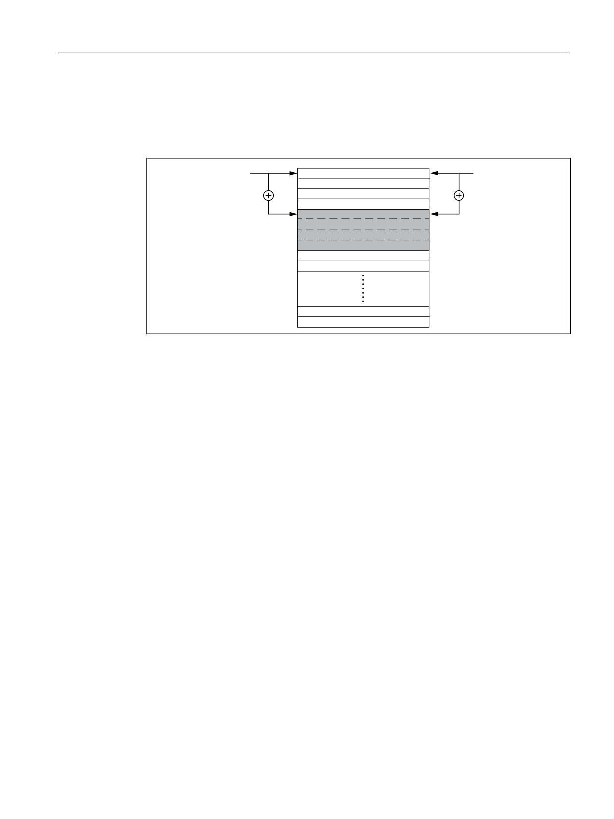
Various NC/PLC interface signals and functions
12.2 Functions
Access from PLC
The PLC uses function calls (FC) to access the memory. The data is read and written immediately
in the DPR with the FC and not just at the beginning of the PLC cycle. Data type and position in
the memory area are transferred as parameters to the FC.
1& $B'%'>
3/& &$// )&
2IIVHW
[
2IIVHW
[
'DWHQW\S '%'
%\WH
Figure 12-1
Communications buffer (DPR) for NC/PLC communication
Boundary conditions
• The structuring of the DPR memory area is the sole responsibility of the user. No checks are
made for matching configuration.
• A total of 4096 bytes are available in the input and output directions.
• Single-bit operations are not supported and must be linked back to byte operations by the
user.
• Since the contents of variables are manipulated directly in the communications buffer, the
user must remember that intermediate changes in values occur as a result of multiple access
operations where a variable is evaluated several times or when variables are linked (i.e. it may
be necessary to store values temporarily in local variables or R parameters or to set up a
semaphore).
• The user's programming engineer is responsible for coordinating access operations to the
communications buffer from different channels.
• Data consistency can be guaranteed only for access operations up to 16 bits (byte and word).
The user is solely responsible for ensuring consistent transmission of 32-bit variables (double
and real). A simple semaphore mechanism is available in the PLC for this purpose.
Basic functions
Function Manual, 10/2020, 6FC5397-2GP40-0BA1
679
Various NC/PLC interface signals and functions
12.2 Functions
• The PLC stores data in 'Little Endian' format in the DPR.
• Values transferred with $A_DBR are subject to data conversion and hence to loss of accuracy.
The data format for floating-point numbers is DOUBLE (64 bits) in the NC, but only FLOAT (32
bits) in the PLC. The format used for storage in the dual-port RAM is FLOAT. Conversion takes
place respectively before/after storage in the dual-port RAM.
If a read/write access is made from the NC to a variable in the dual-port RAM, the conversion
is performed twice. It is impossible to prevent differences between read and written values
because the data is stored in both formats.
Example
Bypassing the problem by means of comparison on "EPSILON" (minor deviation)
Program code
N10
DEF REAL DBR
N12
DEF REAL EPSILON = 0.00001
N20
$A_DBR[0]=145.145
N30
G4 F2
N40
STOPRE
N50
DBR=$A_DBR[0]
N60
IF ( ABS(DBR/145.145-1.0) < EPSILON ) GOTOF ENDE
N70
MSG ( "error" )
N80
M0
N90
END:
N99
M30
Activation
The maximum number of simultaneously writable output variables is adjustable via:
MD28150 $MC_MM_NUM_VDIVAR_ELEMENTS (number of elements for writing PLC variables)
Example
A variable of type WORD is to be transferred from the PLC to the NC.
The position offset within the NC input (PLC output area) should be the fourth byte. The position
offset must be a whole-number multiple of the data width.
Writing from PLC:
Program code
Comment
CALL FC21 (
Enable
:=M10.0,
; if TRUE, then FC21 active
Funct
:=B#16#4,
S7Var :=P#M 104.0 WORD1,
IVAR1
:=04,
IVAR2
:=-1,
Error
:=M10.1,
ErrCode :=MW12);
Basic functions
680
Function Manual, 10/2020, 6FC5397-2GP40-0BA1
Various NC/PLC interface signals and functions
12.2 Functions
Program code
Comment
)
Reading in part program
Program code
Comment
PLCDATA = $A_DBW[4];
; Read a word
Behavior during POWER ON, block search
The DPR communications buffer is initialized during "POWER ON".
During a "block search", the PLC variable outputs are collected and transferred to the DPR
communications buffer with the approach block (analogous to writing of analog and digital
outputs).
Other status transitions have no effect in this respect.
Further information
A detailed description of the data exchange by the PLC with FC 21 can be found in:
Function Manual PLC and Basic Program
12.2.4
Access protection via password and keyswitch
Access rights
Access to functions, programs and data is user-oriented protected via 7 hierarchical protection
levels. These are subdivided into:
• Password levels for machine manufacturers and users
• Key switch positions for users
Basic functions
Function Manual, 10/2020, 6FC5397-2GP40-0BA1
681

Various NC/PLC interface signals and functions
12.2 Functions
Multi-level security concept
A multi-level security concept to regulate access rights is available in the form of password levels
and keyswitch settings.
Protection level
Category
User
Access rights
1
Password
Machine manufacturer:
Access to defined functions, pro-
grams and data.
Development
Example: entering options
2
Password
Machine manufacturer:
Access to defined functions, pro-
grams and data.
Commissioning engineer
Example: Access to many machine
data
3
Password
User:
Access to assigned functions, pro-
grams and data.
Service
4
Keyswitch position 3
User:
Fewer access rights than for protec-
tion levels 0 - 3.
Programmer, machine setter
Defined by machine manufacturer
or users.
5
Keyswitch position 2
User:
Fewer access rights than for protec-
tion levels 0 - 3.
Skilled operator without pro-
gramming knowledge
Defined by users.
6
Keyswitch position 1
User:
Example:
Trained operator without pro-
Program selection only, tool wear
gramming knowledge
entries and work offset entries
7
Keyswitch position 0
User:
Example:
Semi-skilled operator
No inputs and program selection
possible, only the machine control
panel can be operated
Access features
• Protection level 1 provides the greatest number of access rights, protection level 7 the least.
• If certain access rights are granted to a protection level, these protection rights automatically
apply to any higher protection levels.
• Conversely, protection rights for a certain protection level can only be altered from a higher
protection level.
• The access rights for protection levels 1 - 3 are defined by Siemens by default.
• Access rights can be set by querying the current keyswitch positions and comparing the
passwords entered. When a password is entered it overwrites the access rights of the
keyswitch position.
• Options can be protected on each protection level. However, option data can only be entered
in protection level 1.
• Access rights for protection levels 4 - 7 are merely suggested settings and can be altered by
the machine tool manufacturer or user.
Basic functions
682
Function Manual, 10/2020, 6FC5397-2GP40-0BA1

Various NC/PLC interface signals and functions
12.2 Functions
12.2.4.1
Password
Set password
The password for a protection level (1 - 3) is entered via the user interface:
"Setup" operating area > "Password" > "Set password"
Delete password
Access rights assigned by means of setting a password remain effective until they are explicitly
revoked by deleting the password:
"Setup" operating area > "Password" > "Delete password"
Change password
The password for a protection level (1 - 3) is changed via the user interface:
"Setup" operating area > "Password" > "Change password"
Note
Warm restart
Access rights and password status (set/deleted) are not affected by a warm restart!
Defaults
As standard, the following passwords are effective for protection levels 1 - 3:
• Protection level 1: SUNRISE
• Protection level 2: EVENING
• Protection level 3: CUSTOMER
NOTICE
Default passwords must be changed
The default passwords of protection levels 1 - 3 must be changed to user-defined/individual
passwords at the latest before operational use.
Changing a password
The passwords of protection levels 1 - 3 must be changed at the latest after commissioning has
been completed.
Basic functions
Function Manual, 10/2020, 6FC5397-2GP40-0BA1
683

Various NC/PLC interface signals and functions
12.2 Functions
The following rules must be met:
• A password must contain at least eight and can contain up to 32 characters.
• Permissible characters are:
- Uppercase characters
- Lowercase characters
- Numbers
- Special characters (ASCII 0x20 to 0x7E)
• The character combination of a password must contain:
- At least one numeral
- At least one uppercase letter
- At least one lowercase letter
• A password must not be too similar to the following names:
- User names (manufacturer, service, user)
- Computer name
- The additional values that can be stored for a user in the Linux password file (so-called
GECOS data)
We recommend that you confine yourself to the characters available on the operator panel front
when selecting a password.
NOTICE
Default passwords must be changed
The default passwords of protection levels 1 - 3 must be changed to user-defined/individual
passwords at the latest before operational use.
NOTICE
SIEMENS cannot reset the passwords
SIEMENS has no way of resetting a password to the default password on a SINUMERIK.
Therefore, take good care of your modified passwords. The passwords can only be reset by
erasing the memory card and reinstalling a software version (restore -full). An update (restore
-update) does not reset the passwords to the default passwords.
NOTICE
Passwords are not included in the archive
Passwords are not included in the SINUMERIK archive. For this reason, they may have to be
changed again when a memory card is replaced.
Basic functions
684
Function Manual, 10/2020, 6FC5397-2GP40-0BA1

Various NC/PLC interface signals and functions
12.2 Functions
Note
Assigning secure passwords
Observe the following rules when assigning new passwords:
• When assigning new passwords, make sure that you do not assign passwords that can be
easily guessed, e.g. simple words, key combinations that can be easily guessed, etc.
• Passwords must always contain a combination of uppercase and lowercase letters as well as
numbers and special characters. Passwords must comprise at least eight characters. PINS
must comprise an arbitrary sequence of digits.
• Wherever possible and where it is supported by the IT systems, a password must always have
a character sequence as complex as possible.
Further rules for the assignment of secure passwords can be found at Federal Office for
Information Security (Bundesamt für Sicherheit in der Informationstechnik, abbreviated as BSI).
GSK_15_EL_EN_Draft.pdf?__blob=publicationFile&v=2)
You can use a program for password management for assistance when dealing with passwords.
With its help, you can save passwords and PINs in encrypted form, manage them and generate
secure passwords.
Linux passwords
NC and Linux passwords are brought together on the SINUMERIK control system. The passwords
that apply in the NC for the access levels Manufacturer (OEM), Service and User are identical
to the passwords that apply in Linux for the corresponding Linux users manufact, service
and user. This means that if the NC password is changed via the HMI user interface, the
password of the Linux user is also changed. Conversely, a password change in Linux results in
simultaneous changing of the NC passwords.
The following equivalences apply:
Access level in the NC
Linux user
Manufacturer (OEM)
manufact
Service
service
User
user
After a software update, the passwords currently stored in the Linux system apply immediately
to the NC. The Linux passwords are the same as the default passwords that applied in the
delivered condition. If they were subsequently changed, these changed passwords apply to the
NC immediately after the software update.
Basic functions
Function Manual, 10/2020, 6FC5397-2GP40-0BA1
685
Various NC/PLC interface signals and functions
12.2 Functions
12.2.4.2
Keyswitch
Assignment keyswitch position - protection level
The keyswitch has four switch positions (0 to 3):
A certain protection level is assigned to each switch position:
Switch position
Protection level
0
7
1
6
2
5
3
4
The keyswitch has three different-colored keys that can be removed in different switch
positions.
Color
Can be removed in switch position
Black
0 or 1
Green
0, 1 or 2
Red
0, 1, 2 or 3
Depending on the keyswitch position, access to certain elements in the NC can be enabled or
disabled:
• Keyswitch position 0 represents the lowest access rights.
• Keyswitch position 3 represents the highest access rights.
Interface signals
The interface signals of keyswitch positions 1 to 3 can either be directly specified from the
keyswitch on the machine control panel or from the PLC user program.
DB10 DBX56.4 / .5 / .6 / .7 (switch positions 0 / 1 / 2 / 3)
It is only permissible to set one bit. If several bits are set simultaneously, the control internally
activates switch position 3.
12.2.4.3
Parameterizable protection levels
The protection level can be freely parameterized for a variety of functions and data areas.
Basic functions
686
Function Manual, 10/2020, 6FC5397-2GP40-0BA1
Various NC/PLC interface signals and functions
12.2 Functions
The protection level is set via operator-panel machine data, designated as follows:
$MM_USER_CLASS_<Function_DataArea>
Examples
$MM_USER_CLASS_READ_TOA
Read tool offsets
$MM_USER_CLASS_WRITE_TOA
Write tool offsets
$MM_USER_CLASS_READ_PROGRAM
Read part programs
$MM_USER_CLASS_WRITE_PROGRAM
Write/edit part programs
Default values
On delivery or following standard commissioning, with very few exceptions, the default values
for the protection level will be set to 7 (lowest protection level).
12.2.5
Switching over motor/drive data sets
12.2.5.1
General Information
Motor and drive data sets
For optimum adaptation to the particular machining situation or because of different machine
configurations, it may be necessary that several different data sets are available in a drive for
motors, drive parameters and encoders. The creation of the basic data sets of the drive objects
is performed during startup with the aid of the "Drive wizard".
Note
Further information
Commissioning Manual: CNC: NC, PLC, Drive, Commissioning NC-controlled drives
The following duplication and management of the data sets is performed via the user interface:
SINUMERIK Operate: "Setup" operating area > "Drive system" > "Drives" > "Data sets"
The activation of the motor data set (MDS) or drive data set (DDS) required for a machine axis in a
specific machining situation, must be made from the PLC user program via the interfaces
described below.
Axial NC/PLC interface
The interfaces in the axial NC/PLC interface for switching the motor and drive data sets is divided
into three areas:
• Formatting interface (Page 688)
• Request interface (Page 688)
• Display interface (Page 689)
Basic functions
Function Manual, 10/2020, 6FC5397-2GP40-0BA1
687

Various NC/PLC interface signals and functions
12.2 Functions
12.2.5.2
Formatting interfaces
Formatting
The formatting interface is used to set which bits of the request and display interface are used
to address the motor data sets (MDS) and which are used to address the drive data sets (DDS):
DB31, ... DBX130.0 - 4, with bit x = <value>
<value>
Meaning
0
Bit position for motor data set (MDS) - or invalid bit position
1
Bit position for drive data set (DDS)
Motor and drive data sets in the drive
Formatting depends on the number of motor data sets (MDS) and drive data sets (DDS) in the
drive. The number can be determined using the following drive parameters:
• p0130 (number of motor data sets)
• p0180 (number drive data sets)
Validity of the interfaces
After powering up, as soon as the control has received all the required information from the drive
and this has been evaluated by the NC, the request (Page 688) and display interfaces
(Page 689) are shown as valid:
DB31, ... DBX130.7 == 1 (request and display interfaces valid)
If no or incompatible information is transferred from the drive, the request and display interfaces
are shown as invalid.
Note
With invalid request and display interfaces, it however remains the sole responsibility of the
user / machine manufacturer to perform a data set switchover via the invalid request and display
interfaces.
See also
Example (Page 689)
Overview of the interfaces (Page 690)
12.2.5.3
Request interface
The switchover to a new motor (MDS) and/or drive data sets (DDS) is requested via the interface:
DB31, ... DBX21.0 - .4 = <MDS/DDS index>
Basic functions
688
Function Manual, 10/2020, 6FC5397-2GP40-0BA1