SINUMERIK 840D sl. Service - Functions. Manual (2018-2020) - page 25
Continuous-path mode, exact stop, LookAhead
6.4 Dynamic adaptations
6.4.4
Interaction between the "smoothing of the path velocity" and "adaptation of
the path dynamic response" functions
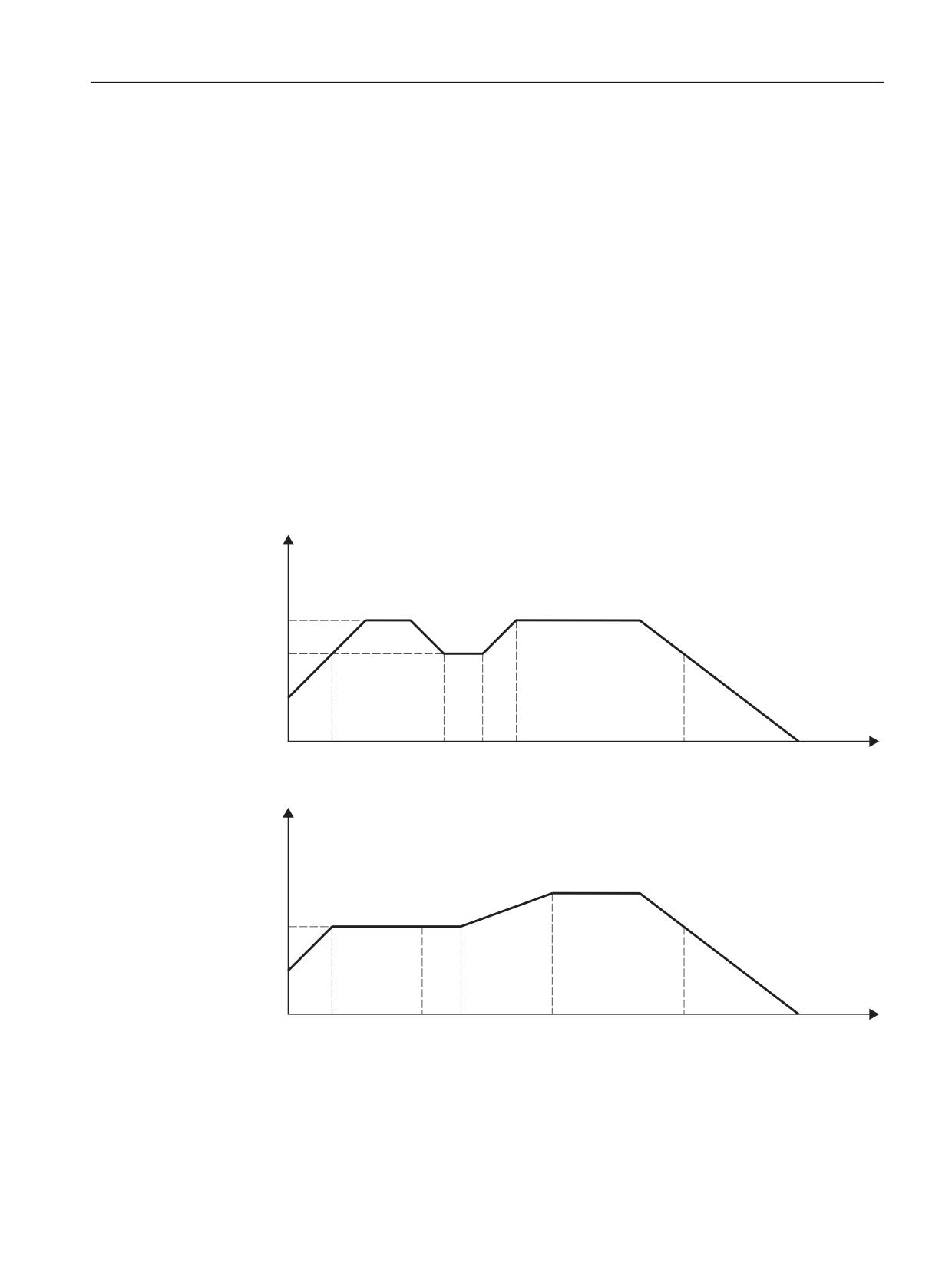
The following examples serve to illustrate the interaction between the "smoothing of the path
velocity" and "adaptation of the path dynamic response" functions in continuous-path mode.
Example 1
Acceleration mode: BRISK
The path involves the three axes X = AX1, Y = AX2, Z = AX3.
The following parameters are assumed:
MD20465 $MC_ADAPT_PATH_DYNAMIC[0] = 3
MD20460 $MC_LOOKAH_SMOOTH_FACTOR = 80.0
MD32440 $MA_LOOKAH_FREQUENCY[AX1] = 20
TAX1 = 1/20 Hz = 50 ms
MD32440 $MA_LOOKAH_FREQUENCY[AX2] = 20
TAX2 = 1/20 Hz = 50 ms
MD32440 $MA_LOOKAH_FREQUENCY[AX3] = 20
TAX3 = 1/20 Hz = 50 ms
Y%
Y
Y
W
W
W
W
W
W
Figure 6-11
Path velocity profile optimized for time without smoothing or dynamic adaptation response
Y%
Y
W
W
W
W
W
W
Figure 6-12
Path velocity profile with smoothing of the path velocity and adaptation of dynamic path
response
Basic functions
Function Manual, 10/2020, 6FC5397-2GP40-0BA1
481
Continuous-path mode, exact stop, LookAhead
6.4 Dynamic adaptations
Effects of smoothing of path velocity:
Interval t1 - t2:
The acceleration and deceleration process between t1 and t2 does not take
place because the lengthening of the machining time without the accel-
eration process to v12 is less than the resulting time if a smoothing factor
of 80% is applied.
Interval t3 - t5:
The acceleration and braking profile between t3 and t5 does not fulfill this
condition or takes longer than the parameterized smoothing time
TAxn = 2/20 Hz = 100 ms.
Effects of the dynamic response adaptation:
Interval t3 - t4:
The acceleration process between t3 and t4 is shorter than
MIN(TAXn) = 1/20 Hz = 50 ms and is, therefore, executed with an acceler-
ation reduced by an adaptation factor of 3.
Interval up to t1:
The acceleration up to t1 left over after path smoothing is stretched to the
time period up to t1' by the dynamic response adaptation.
Note
The example shows that those acceleration or deceleration processes that are not eliminated by
the smoothing of the path velocity can be subsequently optimized by adapting the dynamic path
response. For this reason, both functions should always be activated, if possible.
Example 2
Acceleration mode: SOFT
The path involves the three axes X = AX1, Y = AX2, Z = AX3.
The following parameters are assumed:
MD20465 $MC_ADAPT_PATH_DYNAMIC[1] = 1
MD20460 $MC_LOOKAH_SMOOTH_FACTOR = 0.0
MD32440 $MA_LOOKAH_FREQUENCY[AX1] = 10
TAX1 = 1/20 Hz = 100 ms
MD32440 $MA_LOOKAH_FREQUENCY[AX2] = 10
TAX2 = 1/20 Hz = 100 ms
MD32440 $MA_LOOKAH_FREQUENCY[AX3] = 20
TAX3 = 1/20 Hz = 50 ms
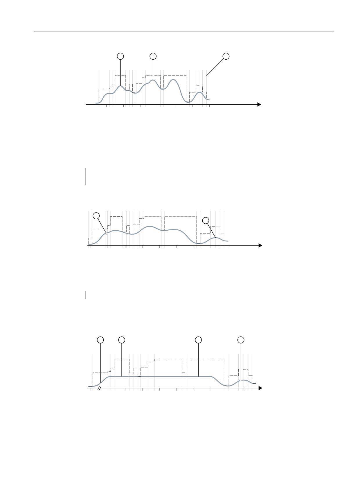
This leads to a path velocity profile which is optimized in terms of time without smoothing the
path velocity or adapting the dynamic path response:
Basic functions
482
Function Manual, 10/2020, 6FC5397-2GP40-0BA1
Continuous-path mode, exact stop, LookAhead
6.4 Dynamic adaptations
7LPH LQ ,32 F\FOHV
① Path velocity characteristic
② Limiting the path velocity due to the axis dynamics or the programmed feedrate
③ Block change markings
The parameter assignment is changed as follows:
MD20465 $MC_ADAPT_PATH_DYNAMIC[1] = 4
MD20460 $MC_LOOKAH_SMOOTH_FACTOR = 1.0
This results in a path velocity profile with adaptation of the dynamic path response and with
minimum, and thus virtually deactivated, smoothing of the path velocity:
7LPH LQ ,32 F\FOHV
① More stable path velocity thanks to reduced jerk on path
The smoothing factor is set to 0% instead of 1% (in accordance with the default!):
MD20460 $MC_LOOKAH_SMOOTH_FACTOR = 0.0
A smoothing factor of 100% comes into effect with this parameter assignment.
This gives rise to a path velocity profile with smoothing of the path velocity and adaptation of
dynamic path response:
7LPH LQ ,32 F\FOHV
① More stable path velocity thanks to reduced jerk on path
② Dispensing with accelerations and braking, effect of path smoothing
Basic functions
Function Manual, 10/2020, 6FC5397-2GP40-0BA1
483

Continuous-path mode, exact stop, LookAhead
6.4 Dynamic adaptations
6.4.5
Dynamic response mode for path interpolation
Function
Technology-specific, dynamic response settings can be saved in machine data and can be
activated in the part program via the commands from G group 59 (dynamic response mode for
path interpolation).
Command
Activates the dynamic response settings for:
DYNNORM
Standard dynamic response settings
DYNPOS
Positioning mode, tapping
DYNROUGH
Roughing
DYNSEMIFIN
Semi-finishing
DYNFINISH
Finishing
DYNPREC
Smooth finishing
Note
The dynamic response of the path axes alone is determined by the commands from G group 59
(dynamic response mode for path interpolation). They have no effect on:
• Positioning axes
• PLC axes
• Command axes
• Motions based on axis coupling
• Overlaid motions with handwheel
• JOG motions
• Reference point approach (G74)
• Fixed-point approach (G75)
• Rapid traverse motion (G0)
The standard dynamic response setting (DYNNORM) always takes effect for these axis motions.
Application
By switching the dynamic response settings, roughing can be optimized in terms of time and
smoothing can be optimized in terms of the surface, for example.
Parameter assignment
Axis-specific dynamic response settings:
• MD32300 $MA_MAX_AX_ACCEL[<n>] (axis acceleration)
• MD32310 $MA_MAX_ACCEL_OVL_FACTOR[<n>] (overload factor for axial jumps in velocity)
• MD32431 $MA_MAX_AX_JERK[<n>] (maximum axial jerk for path motion)
Basic functions
484
Function Manual, 10/2020, 6FC5397-2GP40-0BA1
Continuous-path mode, exact stop, LookAhead
6.4 Dynamic adaptations
• MD32432 $MA_PATH_TRANS_JERK_LIM[<n>] (maximum axial jerk at the block transition in
continuous-path mode)
• MD32433 $MA_SOFT_ACCEL_FACTOR[<n>] (scaling of the acceleration limitation with
SOFT)
Channel-specific dynamic response settings:
• MD22450 $MC_DYN_LIM_MODE[<n>] (axial or geometric velocity limits)
• MD20600 $MC_MAX_PATH_JERK[<n>] (path-related maximum jerk)
• MD20602 $MC_CURV_EFFECT_ON_PATH_ACCEL[<n>] (influence of path curvature on path
acceleration)
• MD20603 $MC_CURV_EFFECT_ON_PATH_JERK[<n>] (influence of path curvature on path
jerk)
where index <n>
0
for DYNNORM
=
1
for DYNPOS
2
for DYNROUGH
3
for DYNSEMIFIN
4
for DYNFINISH
5
for DYNPREC
Note
Writing the machine data without an index places the same value in all field elements of the
relevant machine data.
Reading the machine data without an index always supplies the value of the field with index 0.
Suppressing G commands
It is recommended that G commands from G group 59 (dynamic response mode for path
interpolation) which are not intended for use should be suppressed via the following machine
data:
MD10712 $MN_NC_USER_CODE_CONF_NAME_TAB[<n>] (list of reconfigured NC commands)
If a suppressed G command is used, an alarm is displayed. This prevents machine data that has
not been parameterized taking effect.
Example
The G commands DYNPOS and DYNSEMIFIN can be suppressed with the following settings:
• MD10712 $MN_NC_USER_CODE_CONF_NAME_TAB[0]="DYNPOS"
• MD10712 $MN_NC_USER_CODE_CONF_NAME_TAB[1]=" "
• MD10712 $MN_NC_USER_CODE_CONF_NAME_TAB[2]="DYNSEMIFIN"
• MD10712 $MN_ NC_USER_CODE_CONF_NAME_TAB[3]=" "
Basic functions
Function Manual, 10/2020, 6FC5397-2GP40-0BA1
485
Continuous-path mode, exact stop, LookAhead
6.4 Dynamic adaptations
Further information
Detailed information regarding programming of the G commands for G group 59 (dynamic
response mode for path interpolation) can be obtained in:
"NC Programming" Programming Manual
Use of the "Top Speed" option (position setpoint filter)
If the "Top Speed" option is used in one or more axes, the dynamic response-dependent FIR
filter settings for each dynamic response mode are also switched over.
For further information about the "Top Speed" option, see the Axes and Spindles Function
Manual.
Use of the "Intelligent load adaptation" option
If the "Intelligent load adaptation" option is used, the load-dependent scaling (especially the
limiting of the scaling) of acceleration and jerk for each dynamic response mode can be set
individually.
For further information about the "Intelligent load adaptation" option, see the Axes and
Spindles Function Manual.
6.4.6
Free-form surface mode: Basic functions
Introduction
In tool and mold making applications, it is important that the surfaces on the workpiece are as
uniform as possible. This requirement is generally more important than the precision of the
surface of the workpiece.
Workpiece surfaces that lack uniformity can be attributed to the following causes, for example:
• The part program to machine the workpiece contains a non-uniform geometry. This, most
notably, influences the profile of the curvature and torsion.
Note
The curvature k of a contour is the inverse of radius r of the adapted circle at a contour point
(k = 1/r). The torsion is the change in curvature (1st derivative).
As a result of the lack of uniformity in geometry, the machine's dynamic response limits are
reached when processing the part program - and axes are unnecessarily decelerated and
accelerated. Depending on the extent of the effective over-travel of the axes, this leads to
different deviations in contours.
• When an axis unnecessary brakes or accelerates, this can trigger machine vibration that
result in unwanted marks on the workpiece.
Basic functions
486
Function Manual, 10/2020, 6FC5397-2GP40-0BA1
Continuous-path mode, exact stop, LookAhead
6.4 Dynamic adaptations
There are various options available for eliminating these problems:
• Use a CAD/CAM system
The part programs generated by CAD/CAM systems contain a very uniform curvature and
torsion profile, preventing unnecessary reductions in path velocity.
• Specify the maximum path velocity in such a way that unwanted geometric fluctuations in
the curvature and torsion profile have no effect.
Function
With the "Free-form surface mode: Basic functions" - for the active geometry axes and for
active orientation transformation of the rotary axes involved with the transformation - can
be used to define path velocity limits to make them less sensitive to small geometric
fluctuations in curvature and torsion without exceeding the machine's dynamic limits in terms
of axis acceleration and jerk.
This has the following advantages:
• Greater uniformity in the profile of the path velocity
• Greater uniformity in the surface of the workpiece
• Shorter machining time (if the dynamic response of the machine permits it)
Applications
The function is used to machine workpieces which primarily comprise free-form surfaces.
Requirements
The function can only be activated if the required memory capacity is reserved when
configuring the memory:
MD28610 $MC_MM_PREPDYN_BLOCKS = 10
The value entered specifies the number of blocks that have to be taken into consideration when
determining the path velocity (velocity preparation).
A sensible value is "10".
If MD28610 has a value of "0", only the motion of the axes in a particular block are taken into
consideration when determining the maximum velocity of the path for that particular block. If
the geometry of neighboring blocks is also taken into consideration when determining the
velocity of the path (value > 0), a more uniform path velocity is achieved.
Activation/deactivation
The function can be switched on or off independently for every dynamic response mode (see
Section "Dynamic response mode for path interpolation (Page 484)"):
Basic functions
Function Manual, 10/2020, 6FC5397-2GP40-0BA1
487

Continuous-path mode, exact stop, LookAhead
6.4 Dynamic adaptations
MD20606 $MC_PREPDYN_SMOOTHING_ON[<n>] = <value>
Index <n>
Dynamic response mode
<Value>
Free-form surface mode: Basic func-
tions
0
Standard dynamic response set-
0
Off
tings (DYNNORM)
1
On
1
Positioning mode, tapping (DYN-
0
Off
POS)
1
On
2
Roughing (DYNROUGH)
0
Off
1
On
3
Semi-finishing (DYNSEMIFIN)
0
Off
1
On
4
Finishing (DYNFINISH)
0
Off
1
On
5
Smooth-finishing (DYNPREC)
0
Off
1
On
Note
Due to the additional memory requirement, the function should only be activated in the relevant
processing channels.
Parameterization
Change in the contour sampling factor
The secant error which occurs during the interpolation of curved contours is dependent on the
following factors:
• Curvature
• Interpolator clock cycle (indicated in MD10071 $MN_IPO_CYCLE_TIME)
• Velocity with which the relevant contour is traversed
The maximum possible secant error is defined for each axis in the machine data:
MD33100 $MA_COMPRESS_POS_TOL (max. deviation with compression)
If the set interpolator clock cycle is not sufficiently small, the max. path velocity may be reduced
in the case of contours with higher levels of curvature. This is necessary for ensuring that the
surface of the workpiece is also produced with an adequate degree of precision in cases such as
these.
By changing the contour sampling factor, the time interval with which a curved contour is
sampled in the interpolator (contour sampling time) can be set differently than the interpolator
clock cycle. A contour sampling time which is shorter than the interpolator clock cycle can
prevent a reduction in path velocity in the case of contours with a higher level of curvature.
The contour sampling factor is set with machine data:
MD10682 $MN_CONTOUR_SAMPLING_FACTOR
The effective contour sampling time is calculated as follows:
Basic functions
488
Function Manual, 10/2020, 6FC5397-2GP40-0BA1

Continuous-path mode, exact stop, LookAhead
6.4 Dynamic adaptations
T
s
= f * T1
with: Ts
= effective contour sampling time
T1
= interpolator clock cycle
f
= contour sampling factor (value from MD10682)
The default contour sampling factor is "1", i.e. the contour sampling time equals the interpolator
clock cycle.
The contour sampling factor can be both greater or less than "1".
If a value less than "1" is set, monitoring of contour sampling precision is deactivated.
The set sampling time must not be below the configured minimum contour sampling time:
MD10680 $MN_MIN_CONTOUR_SAMPLING_TIME
Note
MD10680 is specifically set for every control model, and cannot be changed.
Velocity limiting
The mode of velocity limiting due to curvatures can be specified for each dynamic response
mode with the following machine data:
MD22450 $MC_DYN_LIM_MODE [<n>] = <Value>
where index <n>
0
for DYNNORM
=
1
for DYNPOS
2
for DYNROUGH
3
for DYNSEMIFIN
4
for DYNFINISH
5
for DYNPREC
<Val-
Meaning
ue>
= 0
Velocity limitation is based on the axis-specific accelerations of the geometry axes involved in
the path
This setting increases path velocity as faster speeds are possible in a diagonal direction.
= 1
Velocity limit is based on the geometric curvatures of the geometry axes involved in the path
This setting limits the path velocity at positions with diagonal and axis-parallel tangents
equally. The course of path velocity is thus smoother. This setting should therefore be selected
for finishing.
MD22450 affects limiting of the path velocity with:
• "Programmable contour accuracy" function
• Maximum axis acceleration (MD32300 $MA_MAX_AX_ACCEL)
• Contour sampling factor (MD10682 $MN CONTOUR_SAMPLING_FACTOR)
Basic functions
Function Manual, 10/2020, 6FC5397-2GP40-0BA1
489
Continuous-path mode, exact stop, LookAhead
6.5 Compressor functions
Programming
Depending on the setting in machine data MD20606 $MC_PREPDYN_SMOOTHING_ON, "Free-
form surface mode: Basic functions" can be activated and deactivated in the part program by
changing the active dynamic response mode.
Example:
By assigning the parameters MD20606 $MC_PREPDYN_SMOOTHING_ON[2-5] = 1 and
MD20606 $MC_PREPDYN_SMOOTHING_ON[0-1] = 0, the function can be activated using the
commands DYNROUGH, DYNSEMIFIN, DYNFINISH and DYNPREC and deactivated using the
commands DYNNORM and DYNPOS.
See also
Rounding of tangential block transitions (G645) (Page 459)
Free-form surface mode: Extension function (Page 468)
6.5
Compressor functions
6.5.1
Compression of linear, circular and rapid traverse blocks
6.5.1.1
Function
CAD/CAM systems generate a large number of linear and circular blocks, some of which with
very short path lengths, to describe complex contours. The maximum possible path velocity is
frequently limited by the block change time. As of a certain path velocity, not enough new
traversing blocks can be prepared in the preprocessing and switched to the main run.
Compressing linear blocks
Compressor functions replace consecutive linear blocks with polynomial blocks having the
longest possible path lengths while maintaining a parameterizable contour precision. This has
the following advantages:
• Reduction of the number of traversing blocks
• Increasing the path velocity
• Increasing the surface quality
• Continuous block transitions
Basic functions
490
Function Manual, 10/2020, 6FC5397-2GP40-0BA1

Continuous-path mode, exact stop, LookAhead
6.5 Compressor functions
The compressor functions with their most important properties/attributes that are available are
listed in the following table:
Compressor
Function
Continuity at block
Notes about use
transitions
COMPON
COMPON creates from
Continuous velocity
up to 10 consecutive
linear blocks, type "G01
X... Y... Z... F..." a poly-
nomial block.
COMPCURV
the same as COMPON
Continuous velocity
and acceleration
COMPCAD
COMPCAD can create a
Continuous velocity
COMPCAD is very processor and memory-intensive. It is
polynomial block
and acceleration
therefore recommended that COMPCAD only be used
from any number of
where measures to improve surface quality were not
consecutive linear
successful in the CAD/CAM program.
blocks.
COMPSURF
the same as COMPCAD
Continuous velocity
Using COMPSURF, even better results can be obtained
and acceleration
than with COMPCAD. However, just the same as for
COMPCAD, COMPSURF takes up a lot of computation
time and memory space.
By using COMPSURF, for example for inclined line-by-
line finishing programs, poor data quality and/or irreg-
ular point distribution in the CAD/CAM program, signif-
icantly improved workpiece surfaces can be achieved.
In addition, COMPSURF facilitates a direction-independ-
ent identical smoothing of the milling paths that can be
deactivated; this significantly increases the surface qual-
ity for bidirectional milling tools.
If commands which are not traversing instructions are programmed in and between the
traversing blocks to be compressed (e.g. auxiliary function outputs, commands for activating
the absolute or chain dimensional notations, etc.), the compression process is interrupted. To
ensure that blocks can be compressed in the part program, only G0, G1, G2, G3, axis positions,
orientation vectors and feedrate values may be programmed. All other commands or G codes
will interrupt the compression and this can lead to a slowing down of the part program execution
for short paths.
The maximum tolerable deviation of the calculated path to the programmed positions can be
specified in machine data for all compressor functions (see "Parameterization (Page 492)").
Unlike COMPON and COMPCURV, the parameterized tolerances are not used in different
directions in neighboring paths with COMPCAD and COMPSURF.
Compression of circular and rapid traverse blocks
In addition to the compression of linear blocks, all compressor functions also allow rapid traverse
blocks (G0 blocks) to be compressed. On the other hand, circular blocks can only be compressed
using the COMPCAD compressor function.
The compression of circular and/or rapid traverse blocks is set for specific channels using the
hundreds position in machine data:
Basic functions
Function Manual, 10/2020, 6FC5397-2GP40-0BA1
491
Continuous-path mode, exact stop, LookAhead
6.5 Compressor functions
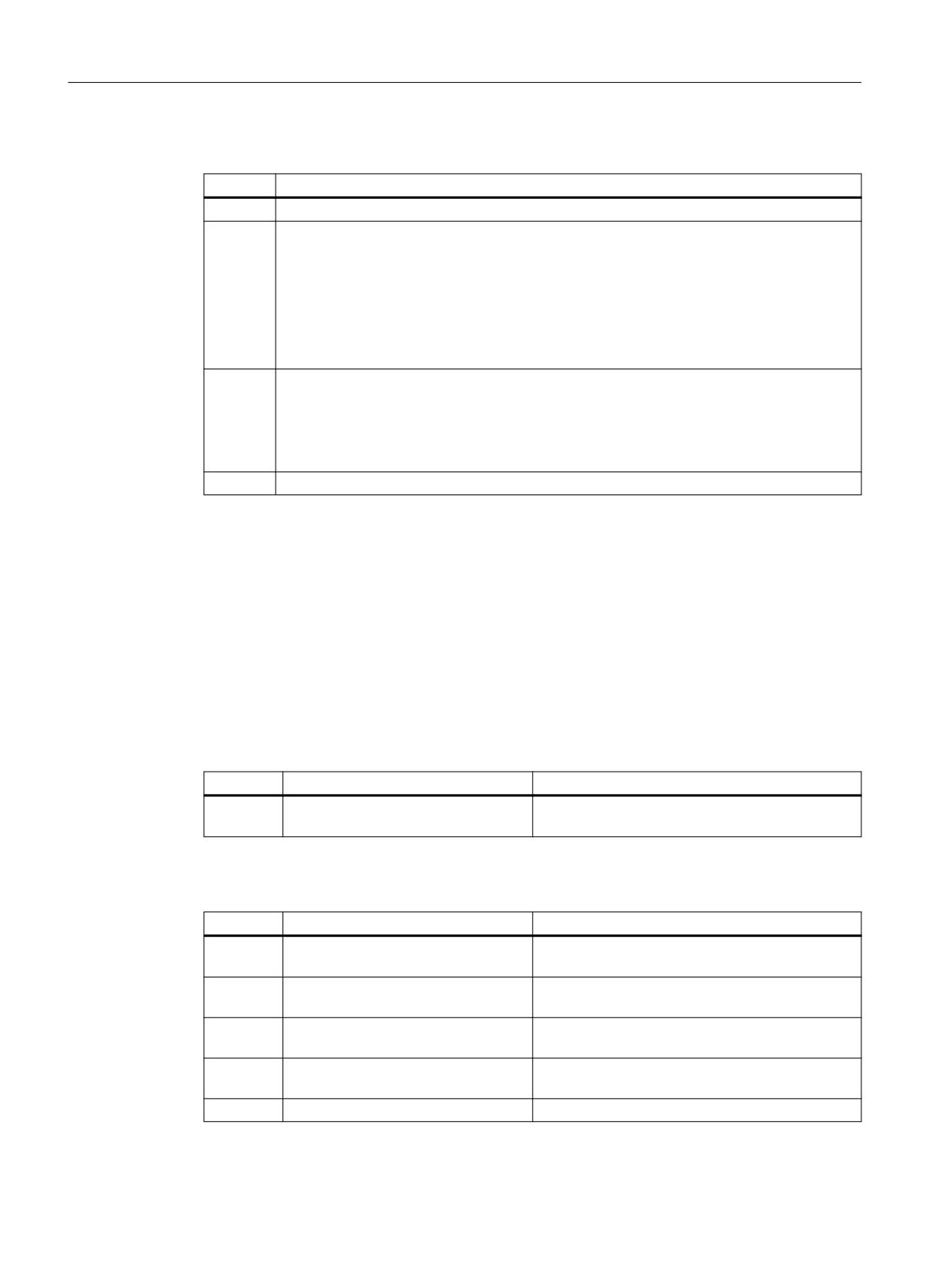
MD20482 $MC_COMPRESSOR_MODE = <value>
Value
Meaning
0xx
Circular blocks and G0 blocks are not compressed. This is compatible with earlier SW versions.
1xx
Circular blocks are linearized and compressed by COMPCAD.
Advantage:
The compressor function operates more precisely and therefore creates generally better
surfaces.
Disadvantage:
The compressor function is more sensitive to defects in the NC programs. For reasons of
compatibility it might therefore be necessary to keep the setting 0xx.
2xx
G0 blocks are compressed - it is possible that a different tolerance becomes effective (see
"Tolerances for rapid traverse movements (Page 505)").
Advantage:
As a result that the tolerance has been set higher and the compression of G0 infeed motion,
these can be more quickly and more fluidly executed.
3xx
Combination of the two previous options: Circular blocks as well as G0 blocks are compressed.
Activation / deactivation
Compressor functions COMPON, COMPCURV, COMPCAD and COMPSURF are activated/
deactivated using the G commands of G group 30 (see "Programming (Page 494)").
6.5.1.2
Commissioning
Parameterization
Axis-specific machine data
Number
Identifier $MA_
Meaning
MD33100
COMPRESS_POS_TOL
Maximum permissible axis-specific path deviation
with compression
Channel-specific machine data
Number
Identifier $MC_
Meaning
MD20170
COMPRESS_BLOCK_PATH_LIMIT
Maximum traversing length of an NC block that can
be compressed
MD20171
SURF_BLOCK_PATH_LIMIT
Maximum traversing length of a compressible NC
block for compression with COMPSURF
MD20172
COMPRESS_VELO_TOL
Maximum permissible deviation from path feed for
compression
MD20173
SURF_VELO_TOL
Maximum permissible deviation from path feed for
compression with COMPSURF
MD20482
COMPRESSOR_MODE
Principle of operation of the compressor
Basic functions
492
Function Manual, 10/2020, 6FC5397-2GP40-0BA1

Continuous-path mode, exact stop, LookAhead
6.5 Compressor functions
Number
Identifier $MC_
Meaning
MD20485
COMPRESS_SMOOTH_FACTOR
Smoothing factor for compression with COMPCAD
for the particular dynamic response mode
MD20486
COMPRESS_SPLINE_DEGREE
Spline degree for compression with COMPCAD for
the particular dynamic response mode
MD20487
COMPRESS_SMOOTH_FACTOR_2
Smoothing factor for rotary axes for compression
with COMPCAD for the particular dynamic re-
sponse mode
MD28071
MM_NUM_SURF_LEVELS
Dimensioning the COMPSURF function (DRAM)
MD28072
MM_MAXNUM_SURF_GROUPS
Dimensioning the COMPSURF function regarding
axis groups (DRAM)
Channel-specific setting data
Number
Identifier $SC_
Meaning
SD42470
CRIT_SPLINE_ANGLE
Corner angle limit for compression with COMPCAD
SD42471
MIN_CURV_RADIUS
Minimum radius of curvature for compression with
COMPCAD
SD42472
MIN_SURF_RADIUS
Minimum radius of curvature for compression with
COMPSURF
SD42473
ACTNUM_SURF_GROUPS
Number of axis groups for COMPSURF
SD42475
COMPRESS_CONTUR_TOL
Maximum permissible contour deviation with com-
pression
SD42476
COMPRESS_ORI_TOL
Maximum deviation of the tool orientation for com-
pression
Note:
Only for active orientation transformation!
SD42477
COMPRESS_ORI_ROT_TOL
Maximum deviation of the tool rotation for com-
pression
Note:
Only for 6-axis machines with rotatable tool!
Note
Corner limit angle and compressor function COMPCAD
The corner limit angle for the compressor function COMPCAD set via the setting data SD42470
$SC_CRIT_SPLINE_ANGLE is only used as an approximate measure for corner detection. By
evaluating the plausibility, the compressor can also identify flatter block transitions as corners
and larger angles as outliers.
Recommended settings for tool and mold making with Advanced Surface / Top Surface
Compressor functions are very important in milling of free-form surfaces in tool and mold
making. If they are used as part of the option "Advanced Surface" or "Top Surface" for which a
license is required, please observe the setting recommendations! A special test program is
provided via the SIOS portal for checking the set machine and setting data.
Basic functions
Function Manual, 10/2020, 6FC5397-2GP40-0BA1
493

Continuous-path mode, exact stop, LookAhead
6.5 Compressor functions
→ Test program for Advanced Surface / Top Surface (https://
support.industry.siemens.com/cs/ww/en/view/109738423)
6.5.1.3
Programming
Activating/deactivating NC block compression (COMPON, COMPCURV, COMPCAD, COMPSURF,
COMPOF)
The functions to compress linear blocks (and dependent on the parameterization, also circular
and/or rapid traverse blocks) are activated/deactivated using G commands of G group 30. The
commands are modal.
Syntax
COMPON / COMPCURV / COMPCAD / COMPSURF
COMPOF
Meaning
COMPON:
Activating the compressor function COMPON
COMPCURV:
Activating the compressor function COMPCURV
COMPCAD:
Activating the compressor function COMPCAD
COMPSURF:
Activating the compressor function COMPSURF
COMPOF:
Deactivating the currently active compressor function
Note
The smoothing function G642 and jerk limitation SOFT further improve the surface quality.
These commands must be written at the beginning of the program.
Example: COMPCAD
Program code
Comment
N10 G00 X30 Y6 Z40
N20 G1 F10000 G642
; Activation: Smoothing function G642
N30 SOFT
; Activation: Jerk limitation SOFT
N40 COMPCAD
; Activation: Compressor function COMPCAD
N50 FIFOCTRL
N24050 Z32.499
; 1. traversing block
N24051 X41.365 Z32.500
; 2. traversing block
N99999 X... Z...
; last traversing block
COMPOF
; compressor function off.
Basic functions
494
Function Manual, 10/2020, 6FC5397-2GP40-0BA1
Continuous-path mode, exact stop, LookAhead
6.5 Compressor functions
Program code
Comment
6.5.1.4
Supplementary conditions
Orientation transformation (TRAORI)
When orientation transformation is active, the compressor functions can also compress motion
blocks for tool orientation and tool rotation.
Further information
Function Manual Transformations; Multi-axis transformations> Orientation > Compression of
the orientation
Block search with calculation
If the target block for block search type 2 or type 4 (block search with calculation to ...) is in a
program section in which a compressor function is active, positions are approached on the path
calculated by the compressor on repositioning. These positions must precisely match the
positions on the path programmed in the part program.
Part program blocks that are replaced by compression cannot be found as the target block in the
block search. Alarm 15370 "Search target for block search not found" is output.
6.5.2
Compression of short spline blocks
Function
When spline blocks are generated to describe complex contours using CAD/CAM systems, spline
blocks with very short path lengths occur between spline blocks with long path lengths. These
force the control to significantly reduce the path velocity. The functions for the compression of
short spline blocks generate new spline blocks with the longest possible path lengths.
Commissioning
Activation
The compression of short spline blocks can be activated for the following spline types:
• BSPLINE
• BSPLINE/ORICURVE
• CSPLINE
It is activated in the channel-specific machine data:
Basic functions
Function Manual, 10/2020, 6FC5397-2GP40-0BA1
495

Continuous-path mode, exact stop, LookAhead
6.5 Compressor functions
MD20488 $MC_SPLINE_MODE, bit <n> = <value>
Bit
<Value>
Spline type
Compressing short spline blocks
0
0
BSPLINE
Not active
1
BSPLINE
Active
1
0
BSPLINE/ORICURVE
Not active
1
BSPLINE/ORICURVE
Active
2
0
CSPLINE
Not active
1
CSPLINE
Active
Boundary conditions
• If commands that are not traverse commands, e.g. auxiliary function outputs, are
programmed in and between the traversing blocks to be compressed, the spline blocks
cannot be combined.
• The maximum number of blocks that can be combined into a program section in succession,
depends on the parameterized size of the block memory available in the block preparation.
MD28070 $MC_MM_NUM_BLOCKS_IN_PREP (number of blocks for block preparation)
Example
To achieve a higher path velocity when executing the traversing blocks, compression for short
spline blocks is activated for BSPLINE interpolation:
MD20488 $MC_SPLINE_MODE, Bit 0 = 1
Program code
Comment
N10 G1 G64 X0 Y0 Z0 F1000
; Initial setting
N20 G91 F10000 BSPLINE
; Activation: B spline
N30 X0.001 Y0.001 Z0.001
; From here: Combine short spline blocks
N40 X0.001 Y0.001 Z0.001
Basic functions
496
Function Manual, 10/2020, 6FC5397-2GP40-0BA1
Continuous-path mode, exact stop, LookAhead
6.6 Contour/Orientation tolerance
6.6
Contour/Orientation tolerance
6.6.1
Commissioning
6.6.1.1
Parameter assignment
Machine data
Contour tolerance / orientation tolerance
MD33100 $MA_COMPRESS_POS_TOL[<axis>] = <value> (maximum tolerance with
compression)
Via the axis-specific machine data, the maximum permitted contour deviation (contour
tolerance) or angle deviation of the tool orientation (orientation tolerance) of each axis is set.
The machine data is effective with the following functions:
• Smoothing: G642, G643, G644, G645
• Compressor: COMP...
• The higher the value, the more short blocks can be compressed into a long block.
The machine data is not effective for smoothing function G641. For G641, the path distance to
the block transition, which can be programmed with ADIS or ADISPOS, is effective.
Smoothing mode
MD20480 $MC_SMOOTHING_MODE (smoothing behavior with G64x)
Compressor mode
MD20482 $MC_COMPRESSOR_MODE (mode of compression)
Smoothing G645
MD33120 $MA_PATH_TRANS_POS_TOL (maximum contour deviation for smoothing G645)
Effective for smoothing tangential, but not continuously curved block transitions (e.g. circle -
straight line)
Setting data
Channel-specific contour tolerance
SD42465 $SC_SMOOTH_CONTUR_TOL (maximum contour deviation)
Channel-specific orientation tolerance
SD42466 $SC_SMOOTH_ORI_TOL (maximum angular deviation of the tool orientation)
Channel-specific orientation tolerance for smoothing with OST
SD42676 $SC_ORI_SMOOTH_TOL (tolerance for smoothing with orientation on smoothing)
Basic functions
Function Manual, 10/2020, 6FC5397-2GP40-0BA1
497
Continuous-path mode, exact stop, LookAhead
6.6 Contour/Orientation tolerance
Channel-specific orientation tolerance for smoothing orientation using ORISON
SD42678 $SC_ORISON_TOL (tolerance for smoothing the orientation)
6.6.2
Programming
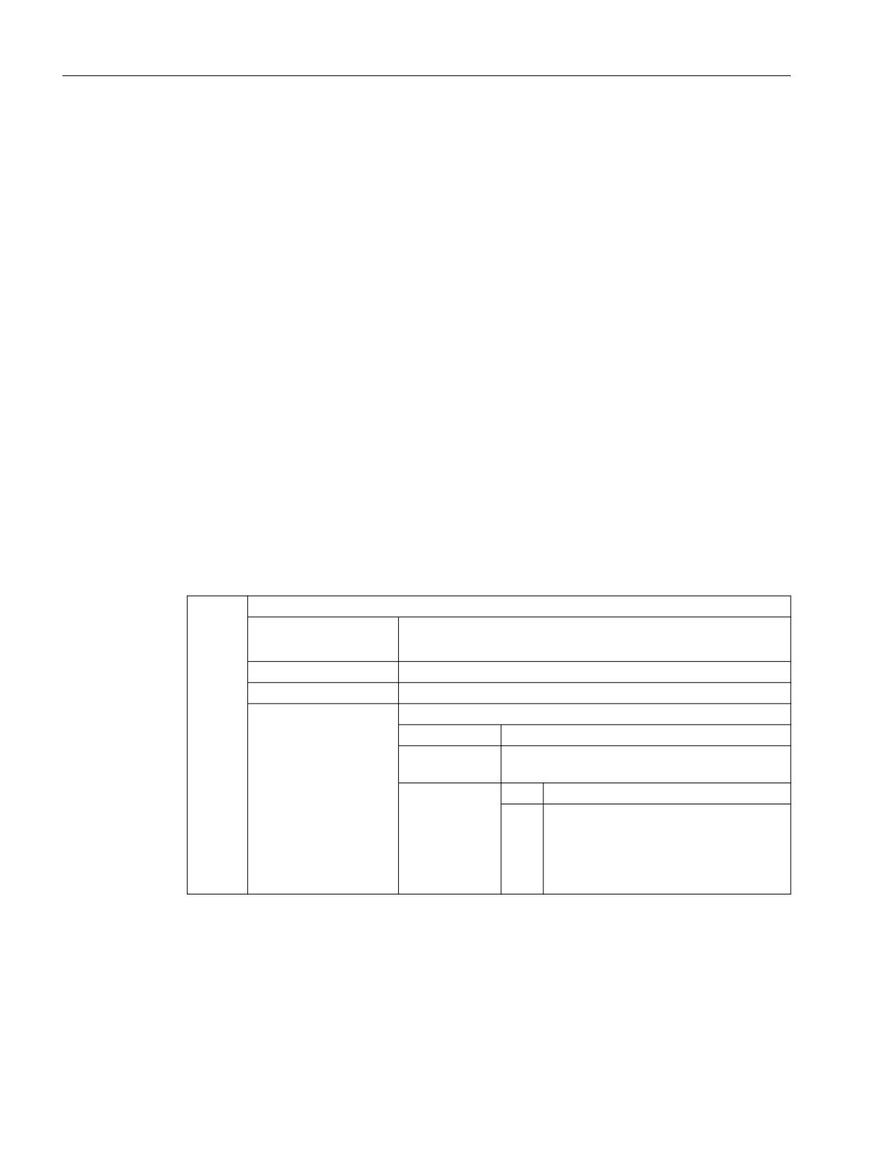
6.6.2.1
Programming contour/orientation tolerance (CTOL, OTOL, ATOL)
Addresses CTOL, OTOL and ATOL can be used to adapt the machining tolerances - parameterized
using machine and setting data - for compressor functions, smoothing and orientation
smoothing in the part program.
The programmed tolerance values are valid until they are reprogrammed or deleted by assigning
a negative value. Further, they are deleted at the end of the program or a reset The
parameterized tolerance values become effective again after deletion.
Syntax
CTOL=<Value>
OTOL=<Value>
ATOL[<Axis>]=<Value>
Meaning
CTOL:
Address to program the contour tolerance
Applications:
• All compressor functions
• All rounding types except G641 and G644
Preprocessing stop:
No
Effective:
Modal
<Value>:
The value for the contour tolerance is specified as a length.
Type:
REAL
Unit:
inch/mm (dependent on the current dimensions
setting)
Value range:
≥ 0:
Tolerance value
< 0:
The programmed tolerance value is de-
leted
⇒ The tolerance value parameterized in
the machine or setting data becomes ef-
fective again.
Basic functions
498
Function Manual, 10/2020, 6FC5397-2GP40-0BA1
Continuous-path mode, exact stop, LookAhead
6.6 Contour/Orientation tolerance
OTOL:
Address to program the orientation tolerance
Applications:
• All compressor functions
• ORISON orientation smoothing
• All smoothing types except G641, G644 and OSD
Preprocessing stop:
No
Effective:
Modal
<Value>:
The value for the orientation tolerance is specified as an angle.
Type:
REAL
Unit:
degrees
Value range:
≥ 0:
Tolerance value
< 0:
The programmed tolerance value is de-
leted
⇒ The tolerance value parameterized in
the machine or setting data becomes ef-
fective again.
ATOL:
Address for programming an axis-specific tolerance
Applications:
• All compressor functions
• ORISON orientation smoothing
• All smoothing types except G641, G644 and OSD
Preprocessing stop:
No
Effective:
Modal
<Axis>:
Name of the channel axis to which the programmed tolerance will
apply
<Value>:
The value for the axis tolerance will be specified as a length or an
angle dependent on the axis type (linear or rotary axis).
Type:
REAL
Unit:
For linear axes:
inch/mm (dependent on
the current dimensions set-
ting)
For rotary axes:
degrees
Value range:
≥ 0:
Tolerance value
< 0:
The programmed tolerance value is de-
leted
⇒ The tolerance value parameterized in
the machine or setting data becomes ef-
fective again.
Note
The channel-specific tolerance values programmed with CTOL and OTOL have higher priority
than the axis-specific tolerance values programmed with ATOL.
Note
Scaling frames
Scaling frames affect programmed tolerances in the same way as axis positions; in other words,
the relative tolerance remains the same.
Basic functions
Function Manual, 10/2020, 6FC5397-2GP40-0BA1
499
Continuous-path mode, exact stop, LookAhead
6.6 Contour/Orientation tolerance
Example
Program code
Comment
COMPCAD G645 G1 F10000
; Activate COMPCAD compressor function.
X... Y... Z...
; The machine and setting data is applied here.
X... Y... Z...
X... Y... Z...
CTOL=0.02
; A contour tolerance of 0.02 mm is applied start-
ing from here.
X... Y... Z...
X... Y... Z...
X... Y... Z...
ASCALE X0.25 Y0.25 Z0.25
; A contour tolerance of 0.005 mm is applied start-
ing from here.
X... Y... Z...
X... Y... Z...
X... Y... Z...
CTOL=-1
; The machine and setting data is applied again
starting from here.
X... Y... Z...
X... Y... Z...
X... Y... Z...
Basic functions
500
Function Manual, 10/2020, 6FC5397-2GP40-0BA1
Continuous-path mode, exact stop, LookAhead
6.6 Contour/Orientation tolerance
6.6.2.2
Programming contour/orientation tolerance (CTOL, OTOL, ATOL) Additional
information
System variables
Reading with preprocessing stop
Using the following system variables, the currently active tolerances can be read in the part
program and synchronized action:
• $AC_CTOL
Channel-specific contour tolerance effective when the actual main run block was
preprocessed.
If no contour tolerance is effective, $AC_CTOL will return the root of the sum of the squares
of the tolerances of the geometry axes.
• $AC_OTOL
Channel-specific orientation tolerance effective when the actual main run block was
preprocessed.
If no orientation tolerance is effective, $AC_OTOL will return the root of the sum of the
squares of the tolerances of the orientation axes during active orientation transformation.
Otherwise, it will return the value "-1."
• $AA_ATOL[<axis>]
Axis-specific contour tolerance effective when the actual main run block was preprocessed.
If no contour tolerance is active, $AA_ATOL[<geometry axis>] returns the contour tolerance
divided by the root of the number of geometry axes.
If an orientation tolerance and an orientation transformation are active
$AA_ATOL[<orientation axis>] will return the orientation tolerance divided by the root of the
number of orientation axes.
Note
If now tolerance values have been programmed, the $A variables are not differentiated enough
to distinguish the tolerance of the individual functions.
Circumstances like this can occur if the machine data and the setting data set different tolerances
for compressor functions, smoothing and orientation smoothing. The system variables then
return the greatest value occurring with the functions that are currently active. For example, if
a compressor function is active with an orientation tolerance of 0.1° and ORISON orientation
smoothing with 1°, the $AC_OTOL variable will return the value "1." If orientation smoothing is
deactivated, $AC_OTOL returns a value value "0.1."
Basic functions
Function Manual, 10/2020, 6FC5397-2GP40-0BA1
501
Continuous-path mode, exact stop, LookAhead
6.7 Rapid traverse movements
Reading without preprocessing stop
Using the following system variables, the currently active tolerances can be read in the part
program:
• $P_CTOL
Currently active channel-specific contour tolerance.
• $P_OTOL
Currently active channel-specific orientation tolerance.
• $PA_ATOL
Currently active axis-specific contour tolerance.
Supplementary conditions
The tolerances programmed with CTOL, OTOL and ATOL also affect functions that indirectly
depend on these tolerances:
• Limiting the chord error in the setpoint value calculation
• The basic functions of the free-form surface mode
The following smoothing functions are not affected by the programming of CTOL, OTOL and
ATOL:
• Smoothing the orientation with OSD
OSD does not use a tolerance, it uses a distance from the block transition.
• Smoothing with G644
G644 is not used for smoothing, it is used for optimizing tool changes and other motion not
involving machining.
• Smoothing with G645
G645 virtually always behaves like G642 and, thus, uses the programmed tolerances. The
tolerance value from machine data MD33120 $MA_PATH_TRANS_POS_TOL is only used in
uniformly tangential block transitions with a jump in curvature, e.g. a tangential circle/
straight line transition. The rounding path at these points may also be located outside the
programmed contour, where many applications are less tolerant. Furthermore, it generally
takes a small, fixed tolerance to compensate for the sort of changes in curvature which need
not concern the NC programmer.
6.7
Rapid traverse movements
6.7.1
Function
6.7.1.1
Rapid traverse
During rapid traversing, programmed tool movements are carried out at the fastest possible
traversing velocity.
Basic functions
502
Function Manual, 10/2020, 6FC5397-2GP40-0BA1
Continuous-path mode, exact stop, LookAhead
6.7 Rapid traverse movements
The velocity of the rapid traversing is defined separately for each axis (see "Parameter
assignment (Page 506)").
Application
Rapid traversing movements are used for the following tasks, for example:
• Quickly positioning of the tool
• Passing around the workpiece
• Approaching tool change points
• Retracting the tool
Note
Rapid traversing movements are not suitable for workpiece machining!
Activation
Rapid traverse is activated by programming of G0 in the part program (see "Programming
(Page 508)").
Basic functions
Function Manual, 10/2020, 6FC5397-2GP40-0BA1
503
Continuous-path mode, exact stop, LookAhead
6.7 Rapid traverse movements
6.7.1.2
Interpolation response of path axes for rapid traversing movements
Liner/non-linear interpolation
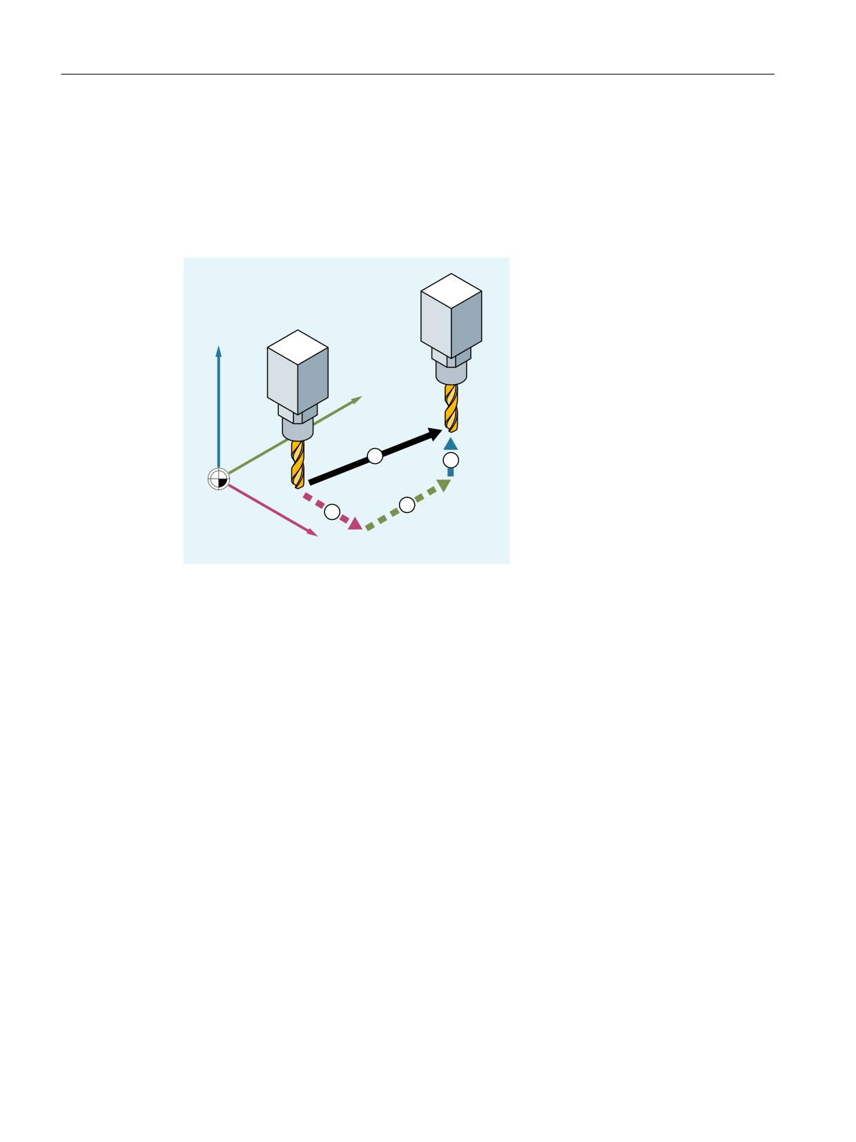
Path axes can be traversed in linear or non-linear interpolation mode in rapid traverse
movement.
=
<
;
① Path for rapid traverse with linear interpolation
② Single axis movements for rapid traverse with non-linear interpolation
Linear interpolation
Properties:
• The path axes are interpolated together.
• The tool movement programmed with G0 is executed at the highest possible velocity (rapid
traverse).
• The rapid traverse velocity is defined separately for each axis.
• If the rapid traverse movement is executed simultaneously on several axes, the rapid traverse
speed is determined by the axis which requires the most time for its section of the path.
Linear interpolation is always performed in the following cases:
• For a G command combination with G0 that does not allow positioning axis motion, e.g.:
G40, G41, G42, G96, G961 and MD20750 $MC_ALLOW_G0_IN_G96 == FALSE
• With a combination of G0 and G64.
• When a compressor or transformation is active.
• In point-to-point (PTP) travel mode.
• When a contour handwheel is selected (FD = 0).
• In case of an active frame with rotation of geometry axes.
• If nibbling is active for geometry axes.
Basic functions
504
Function Manual, 10/2020, 6FC5397-2GP40-0BA1

Continuous-path mode, exact stop, LookAhead
6.7 Rapid traverse movements
Non-linear interpolation
Properties:
• Each path axis interpolates as a single axis (positioning axis) independently of the other axes
at the axis-specific rapid traverse velocity.
• The channel-specific "Delete distance-to-go" command via the PLC and synchronized action
is applied to all positioning axes that were programmed as path axes.
In non-linear interpolation, with reference to the axis-specific jerk, one of the following two
settings applies alternatively:
• Positioning axis commands BRISKA, SOFTA, DRIVEA
• Machine data:
- MD32420 $MA_JOG_AND_POS_JERK_ENABLE
- MD32430 $MA_JOG_AND_POS_MAX_JERK
The existing system variables which refer to the distance-to-go ($AC_PATH, $AC_PLTBB and
$AC_PLTEB) are supported.
CAUTION
Risk of collision
Since the tool movement for non-linear interpolation can differ from the tool movement for
linear interpolation, synchronous actions relative to the coordinates of the path movement
may not become active.
Selection of interpolation type
The type of interpolation which is to be in effect for rapid traverse movements is preset by
machine data (see "Parameter assignment (Page 506)").
Independently of the default setting, the desired interpolation response can also be set in the
part program (see "Switch on/off linear interpolation for rapid traverse movements (RTLION,
RTLIOF) (Page 509)").
6.7.1.3
Tolerances for rapid traverse movements
Tolerances for rapid traverse movements (G0 tolerances) can have different settings for the
workpiece processing tolerances.
Advantage
Greater G0 tolerances allow a faster traversing of G0 blocks.
Basic functions
Function Manual, 10/2020, 6FC5397-2GP40-0BA1
505
Continuous-path mode, exact stop, LookAhead
6.7 Rapid traverse movements
Prerequisites
G0 tolerances are only effective in compliance with the following conditions:
• One of the following functions is active:
- Compressor function COMP...
- Smoothing function G642 or G645
- Orientation smoothing OST
- Orientation smoothing ORISON
- Smoothing for path-relevant orientation ORIPATH
• Several (≥ 2) consecutive G0 blocks in the part program.
For a single G0 block, the G0 tolerances are not effective, as at the transition from a non G0
motion to a G0 motion (and vice versa), the "lower tolerance" always applies (workpiece
processing tolerance)!
Setting the G0 tolerances
G0 tolerances are preset channel-specifically with the machine data (see "Parameter assignment
(Page 506)").
The preset G0 tolerances can be temporarily adapted by programming in the part program (see
"Adapt tolerances for rapid traverse motion (STOLF, CTOLG0, OTOLG0) (Page 511)").
6.7.1.4
Rapid traverse override
With the rapid traverse override switch on the machine control panel, the operator can reduce
the rapid traverse velocity by percentages on-site and with immediate effect.
An active rapid traverse correction has an effect on all path axes that are traversed in rapid
traverse mode with linear or non-linear interpolation and are assigned to the current channel.
Additional information: Function Manual Axes and Spindles
6.7.2
Commissioning
6.7.2.1
Parameter assignment
Rapid traverse velocity
The rapid traverse velocity corresponds to the maximum permitted axis velocity, which is
defined for each axis via the following machine data:
MD32000 $MA_MAX_AX_VELO (maximum axis velocity) will still apply even after the coupling
is activated
Basic functions
506
Function Manual, 10/2020, 6FC5397-2GP40-0BA1
Continuous-path mode, exact stop, LookAhead
6.7 Rapid traverse movements
Interpolation response for rapid traverse movements
The interpolation response for rapid traverse movements is channel-specifically preset for via the
machine data:
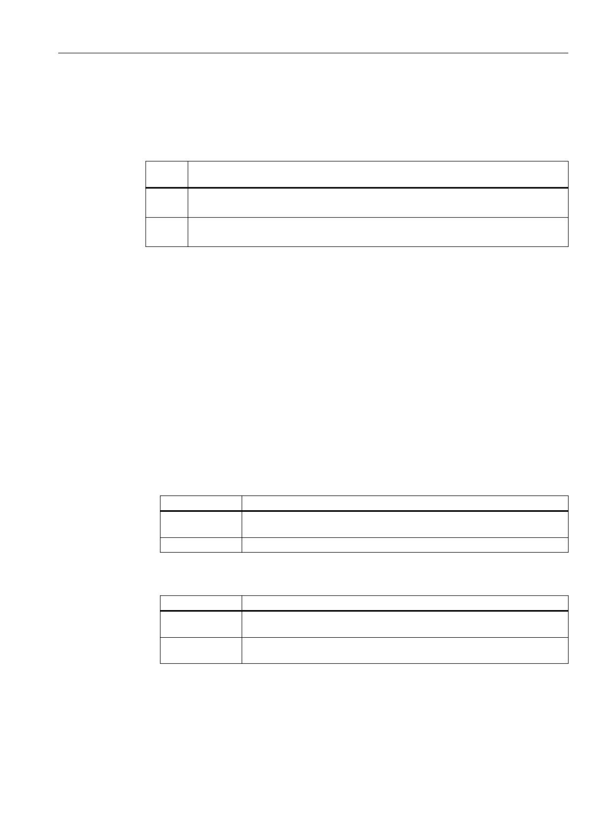
MD20730 $MC_G0_LINEAR_MODE = <Value> (interpolation behavior with G0)
<Val-
Meaning
ue>
0
In the rapid traversing mode (G0) the non-linear interpolation is active.
Path axes are traversed as positioning axes.
1
In the rapid traversing mode (G0) the linear interpolation is active.
The path axes are interpolated together.
G0 tolerances
Relative G0 tolerance
Tolerances for rapid traverse movements can be set relative to the workpiece processing
tolerances via a channel-specific tolerance factor:
MD20560 $MC_G0_TOLERANCE_FACTOR (tolerance factor for G0)
The tolerance factor can be both greater or less than 1.0. If the factor is equal to 1.0 (default
value), then the same tolerances are active for rapid traverse movements as for non-rapid
traverse movements. Normally, the tolerance factor is set to > 1.0.
Absolute G0 tolerances
Alternatively, the channel-specific tolerances for rapid traverse movements can also be set
absolute and separate for contour tolerance and orientation tolerance:
• MD20561 $MC_G0_TOLERANCE_CTOL_ABS (contour tolerance for G0 movements) =
<Value>
<Value>
Meaning
= 0 (default)
The contour tolerance for G0 movements is determined by the relative G0 tol-
erance.
> 0
The contour tolerance for G0 movements is defined with the value of MD20651.
• MD20562 $MC_G0_TOLERANCE_OTOL_ABS (orientation tolerance for G0 movements) =
<Value>
<Value>
Meaning
= 0 (default)
The orientation tolerance for G0 movements is determined by the relative G0
tolerance.
> 0
The orientation tolerance for G0 movements is defined with the value of
MD20652.
Basic functions
Function Manual, 10/2020, 6FC5397-2GP40-0BA1
507
Continuous-path mode, exact stop, LookAhead
6.7 Rapid traverse movements
6.7.3
Programming
6.7.3.1
Activating rapid traverse (G0)
The traversing of the path axes at rapid traversing velocity is activated with the G command G0.
Syntax
G0 X… Y… Z…
G0 RP=… AP=…
Meaning
G0:
Traversing the axis with rapid traverse velocity
Effective:
Modal
X... Y... Z...:
Specifying the end point in Cartesian coordinates
RP=... AP=... :
Specifying the end point in polar coordinates
Examples
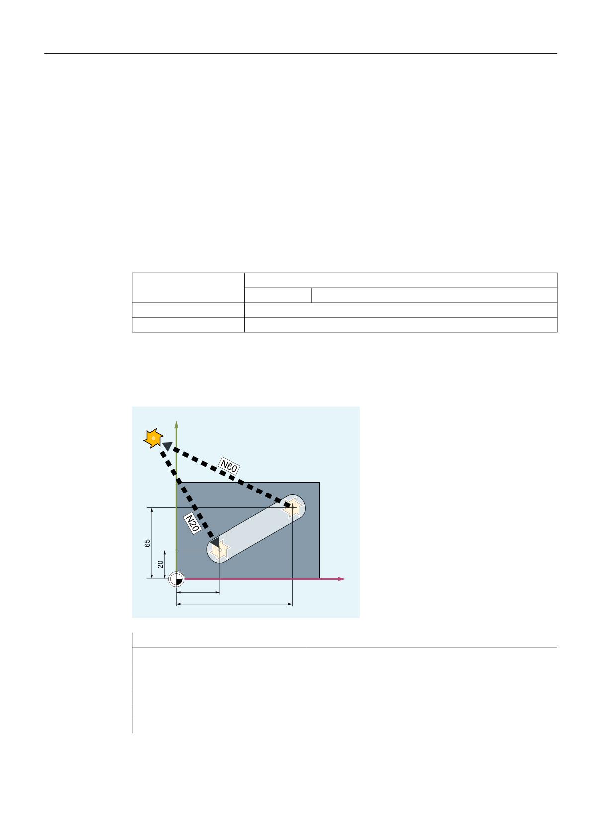
Example 1: Milling
<
;
Program code
Comment
N10 G90 S400 M3
; Absolute dimension input, spindle clockwise
N20 G0 X30 Y20 Z2
; Approach the starting position
N30 G1 Z-5 F1000
; Tool infeed
N40 X80 Y65
; Traversing along a straight line
N50 G0 Z2
N60 G0 X-20 Y100 Z100 M30
; Retract tool, end of program
Basic functions
508
Function Manual, 10/2020, 6FC5397-2GP40-0BA1
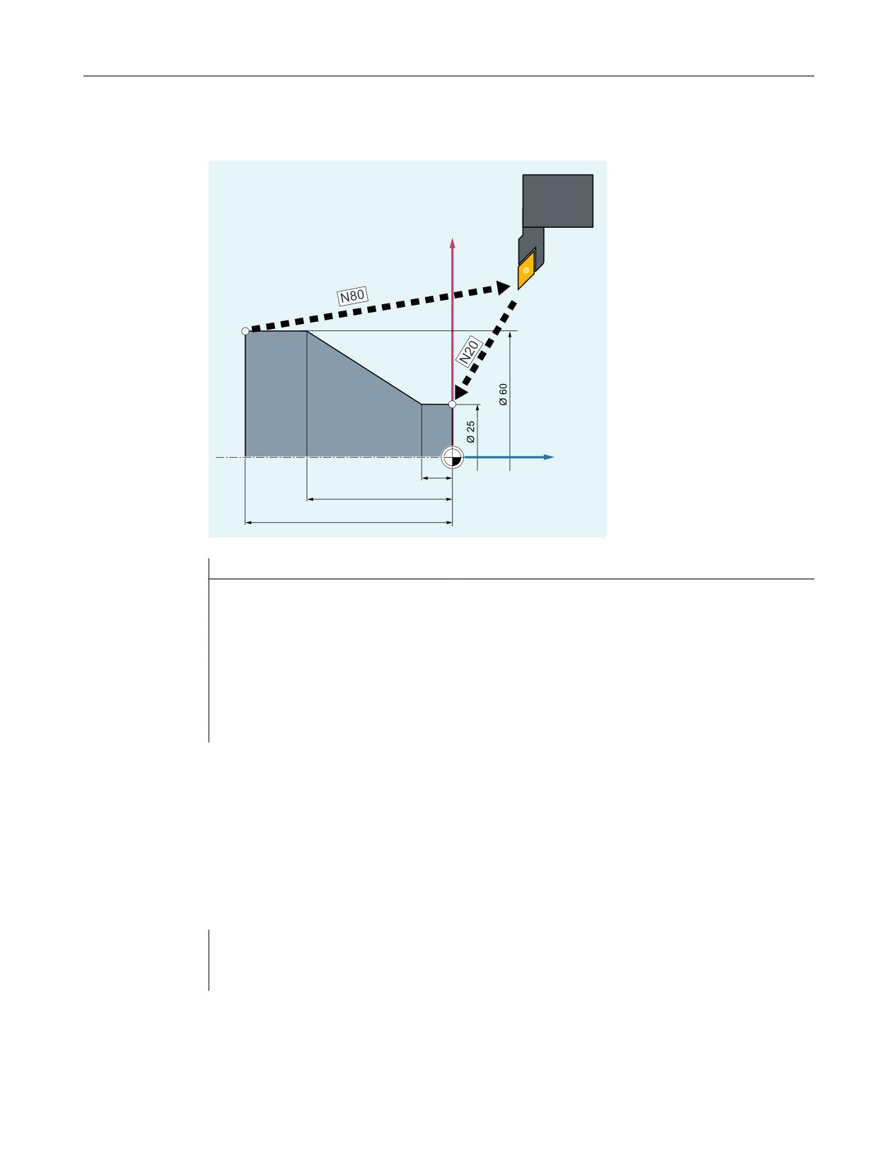
Continuous-path mode, exact stop, LookAhead
6.7 Rapid traverse movements
Example 2: Turning
;
=
Program code
Comment
N10 G90 S400 M3
; Absolute dimension input, spindle clockwise
N20 G0 X25 Z5
; Approach the starting position
N30 G1 G94 Z0 F1000
; Tool infeed
N40 G95 Z-7.5 F0.2
N50 X60 Z-35
; Traversing along a straight line
N60 Z-50
N70 G0 X62
N80 G0 X80 Z20 M30
; Retract tool, end of program
6.7.3.2
Switch on/off linear interpolation for rapid traverse movements (RTLION, RTLIOF)
Independently of the default setting (MD20730 $MC_G0_LINEAR_MODE), the interpolation
response for rapid traverse movements can also be set in the part program using the commands
of the G group 55.
Syntax
RTLIOF
RTLION
Basic functions
Function Manual, 10/2020, 6FC5397-2GP40-0BA1
509

Continuous-path mode, exact stop, LookAhead
6.7 Rapid traverse movements
Meaning
RTLIOF:
G command for switching off the linear interpolation
⇒ In the rapid traversing mode (G0), the non-linear interpolation is active. All of
the path axes reach their end points independently of one another.
Effective:
Modal
RTLION:
G command for switching on the linear interpolation
⇒ In the rapid traversing mode (G0), the linear interpolation is active. All of the
path axes reach their end points simultaneously.
Effective:
Modal
Note
Preconditions for RTLIOF
To ensure, with RTLIOF non-linear interpolation, the following conditions must be fulfilled:
• No transformation (TRAORI, TRANSMIT, etc.) active.
• G60 active (stop at the block end).
• No compressor active (COMPOF).
• No tool radius compensation active (G40).
• No contour handwheel selected.
• No nibbling active.
If one of these conditions is not met, linear interpolation is as with RTLION.
Example
Program code
Comment
; Linear interpolation is the default:
; MD20730 $MC_GO_LINEAR_MODE == TRUE
N30 RTLIOF
; Switch off linear interpolation.
N40 G0 X0 Y10
; G0 blocks are traversed using non-linear inter-
polation.
N50 G41 X20 Y20
; TRC active ⇒ G0 blocks are traversed using lin-
ear interpolation.
N60 G40 X30 Y30
; TRC not active ⇒ G0 blocks are traversed using
non-linear interpolation.
N70 RTLION
; Switch on linear interpolation.
Further information
Reading the current interpolation behavior
The current interpolation behavior can be read via the system variables $AA_G0MODE.
Basic functions
510
Function Manual, 10/2020, 6FC5397-2GP40-0BA1
Continuous-path mode, exact stop, LookAhead
6.7 Rapid traverse movements
6.7.3.3
Adapt tolerances for rapid traverse motion (STOLF, CTOLG0, OTOLG0)
The tolerances for rapid traverse motion (G0 tolerances) configured using machine data can be
temporarily adapted in the part program. In so doing, the settings in the machine data are not
changed. After channel or end of program reset, the configured tolerances become effective
again.
Requirements
G0 tolerances are only effective in compliance with the following conditions:
• One of the following functions is active:
- Compressor function COMP...
- Smoothing function G642 or G645
- Orientation smoothing OST
- Orientation smoothing ORISON
- Smoothing for path-relevant orientation ORIPATH
• Several (≥ 2) consecutive G0 blocks in the part program.
For a single G0 block, the G0 tolerances are not effective, as at the transition from non G0
motion to G0 motion (and vice versa), the "lower tolerance" always applies (workpiece
processing tolerance)!
Syntax
Adaptation of the relative G0 tolerance
STOLF=<Value>
Adaptation of the absolute G0 tolerances
CTOLG0=<Value>
OTOLG0=<Value>
Basic functions
Function Manual, 10/2020, 6FC5397-2GP40-0BA1
511
Continuous-path mode, exact stop, LookAhead
6.7 Rapid traverse movements
Meaning
STOLF:
Address for programming a temporarily effective tolerance factor for rapid traverse motion
<Value>:
G0 tolerance factor
Type:
REAL
Value:
≥ 0:
The G0 tolerance factor can be greater or less than 1.0. If
the factor is equal to 1.0 (default value), then the same
tolerances are active for rapid traverse motion as for non-
rapid traverse motion. Normally, the tolerance factor is set
to > 1.0.
The programmed G0 tolerance factor remains effective un-
til it is overwritten by renewed STOLF programming, re-
placed by CTOLG0/OTOLG0 programming or deleted by
channel or end of program reset.
< 0:
the programmed tolerance factor is deleted
⇒ The tolerance value preset in the machine data becomes
effective again.
CTOLG0:
Address for programming a temporarily effective contour tolerance factor for rapid traverse
motion
<Value>:
Absolute value for the contour tolerance
Type:
REAL
Value:
≥ 0:
The programmed absolute value for the contour tolerance
remains effective until it is overwritten by renewed CTOLG0
programming, replaced by STOLF programming or deleted
by channel or end of program reset.
< 0:
the programmed tolerance value is deleted
⇒ The tolerance value preset in the machine data becomes
effective again.
OTOLG0:
Address for programming a temporarily effective orientation tolerance factor for rapid tra-
verse motion
<Value>:
Absolute value for the orientation tolerance
Type:
REAL
Value:
≥ 0:
The programmed absolute value for the orientation toler-
ance remains effective until it is overwritten by renewed
OTOLG0 programming, replaced by STOLF programming or
deleted by channel or end of program reset.
< 0:
the programmed tolerance value is deleted
⇒ The tolerance value preset in the machine data becomes
effective again.
Note
The last programmed address always has priority, as shown in the following examples:
• When CTOLG0 is programmed with active STOLF, the tolerance value programmed with
CTOLG0 is applied to smooth the contour.
• When OTOLG0 is programmed with active STOLF, the tolerance value programmed with
OTOLG0 is applied to smooth the orientation.
• After programming STO again, the tolerance factor for the contour and orientation tolerance
is applied.
Basic functions
512
Function Manual, 10/2020, 6FC5397-2GP40-0BA1
Continuous-path mode, exact stop, LookAhead
6.7 Rapid traverse movements
Examples
Example 1: Adaptation of the relative G0 tolerance
Program code
Comment
COMPCAD G645 G1 F10000
; Compressor function COMPCAD
X... Y... Z...
; The machine and setting data apply here.
X... Y... Z...
X... Y... Z...
G0 X... Y... Z...
G0 X... Y... Z...
; Machine data $MC_G0_TOLERANCE_FACTOR (e.g. =3) is ef-
fective here, i.e. a smoothing tolerance of:
$MC_G0_TOLERANCE_FACTOR * $MA_COMPRESS_POS_TOL
CTOL=0.02
STOLF=4
G1 X... Y... Z...
; A contour tolerance of 0.02 mm is applied starting
from here.
X... Y... Z...
X... Y... Z...
G0 X... Y... Z...
X... Y... Z...
; From here, a G0 tolerance factor of 4 applies, i.e. a
contour tolerance of 0.08 mm.
Example 2: Adaptation of the absolute G0 tolerances
The following absolute G0 tolerances should be preset in the machine data:
• G0 contour tolerance: 0.1
• G0 orientation tolerance: 1.0
These tolerances should be temporarily adapted in the part program:
Program code
Comment
COMPCAD G645 G1 F10000
; Compressor function COMPCAD
X... Y... Z...
; The configured workpiece machining tolerances apply
from here.
X... Y... Z...
X... Y... Z...
G0 X... Y... Z...
G0 X... Y... Z...
; The configured absolute G0 tolerances apply here.
CTOLG0=0.2 OTOLG0=2.0
; Programming the absolute G0 tolerances.
G1 X... Y... Z...
X... Y... Z...
X... Y... Z...
G0 X... Y... Z...
X... Y... Z...
; The programmed G0 tolerances apply from here.
Basic functions
Function Manual, 10/2020, 6FC5397-2GP40-0BA1
513
Continuous-path mode, exact stop, LookAhead
6.8 RESET behavior
Further information
Reading the G0 tolerance factor
The currently active tolerance factor for rapid traverse motion can be read using system
variables:
• In synchronized actions or with preprocessing stop in the part program via system variable:
$AC_STOLF
Active G0 tolerance factor
G0 tolerance factor, which was effective when processing the
actual main run block.
• Without preprocessing stop in the part program via system variable:
$P_STOLF
Programmed G0 tolerance factor
If no value with STOLF is programmed in the active part program, then these two system
variables return the value configured in the machine data.
If no rapid traverse (G0) is active in a block, then these system variables always supply a value
of 1.
Reading absolute G0 tolerances
The currently active absolute tolerances for rapid traverse motion can be read via system
variables.
• In synchronized actions or with preprocessing stop in the part program via the system
variables:
$AC_CTOL_G0_ABS
Active contour tolerance for G0 motion
G0 contour tolerance that was active when the current main
run block was preprocessed.
$AC_OTOL_ G0_ABS
Active orientation tolerance for G0 motion
G0 orientation tolerance that was active when the current
main run block was preprocessed.
• Without preprocessing stop in the part program via system variables:
$P_CTOL_ G0_ABS
Programmed contour tolerance for G0 motion
$P_OTOL_ G0_ABS
Programmed orientation tolerance for G0 motion
If no absolute G0 tolerances with CTOLG0 and OTOLG0 are programmed in the active part
program, then these system variables supply the values configured in the machine data.
6.8
RESET behavior
MD20150
With the reset (channel or mode group reset), the initial setting parameterized channel-
specifically becomes effective for all G groups:
Basic functions
514
Function Manual, 10/2020, 6FC5397-2GP40-0BA1
Continuous-path mode, exact stop, LookAhead
6.9 Supplementary conditions
MD20150 $MC_GCODE_RESET_VALUES (initial setting of the G groups)
The following G groups are of relevance to "continuous-path mode, exact stop, LookAhead":
• Group 10: Exact stop - continuous-path mode
• Group 12: Block-change criterion for exact stop
• Group 21: Acceleration profile
• Group 30: NC block compression
• Group 59: Dynamic response mode for path interpolation
For detailed information on setting initial states, see Section "Mode group, channel, program
operation, reset response (Page 25)."
6.9
Supplementary conditions
6.9.1
Block change and positioning axes
If path axes are traversed in continuous path mode in a part program, traversing positioning axes
can also simultaneously affect both the response of the path axes and the block change.
A detailed description of the positioning axes can be obtained in:
Further information
Function Manual Axes and Spindles; Positioning axes
6.9.2
Block change delay
Even if all path axes and special axes traversing in the part program block have satisfied their
specific block transition criteria, the block change can still be delayed due to other unsatisfied
conditions and/or active functions:
Examples:
• Missing auxiliary function acknowledgement by the PLC
• Non-existent following blocks
• Active function "Empty buffer"
Effects
If a block change cannot be executed in continuous path mode, all axes programmed in this part
program block (except cross-block traversing special axes) are stopped. In this case, contour
errors do not occur.
The stopping of path axes during machining can cause undercuts on the workpiece surface.
Basic functions
Function Manual, 10/2020, 6FC5397-2GP40-0BA1
515

Continuous-path mode, exact stop, LookAhead
6.10 Data lists
6.10
Data lists
6.10.1
Machine data
6.10.1.1
General machine data
Number
Identifier: $MN_
Description
10110
PLC_CYCLE_TIME_AVERAGE
Average PLC acknowledgment time
10680
MIN_CONTOUR_SAMPLING_TIME
Minimum contour sampling time
10682
CONTOUR_SAMPLING_FACTOR
Contour sampling factor
10712
NC_USER_CODE_CONF_NAME_TAB
List of reconfigured NC commands
12030
OVR_FACTOR_FEEDRATE
Evaluation of the path feedrate override switch
12100
OVR_FACTOR_LIMIT_BIN
Limit for binary-coded override switch
18360
MM_EXT_PROG_BUFFER_SIZE
FIFO buffer size for execution from external source
(DRAM)
6.10.1.2
Channelspecific machine data
Number
Identifier: $MC_
Description
20150
GCODE_RESET_VALUES
Basic setting of the groups
20170
COMPRESS_BLOCK_PATH_LIMIT
Maximum traversing length of an NC block that can be
compressed
20171
SURF_BLOCK_PATH_LIMIT
Maximum traversing length of a compressible NC block
for compression with COMPSURF
20172
COMPRESS_VELO_TOL
Maximum permissible deviation from path feed for com-
pression
20173
SURF_VELO_TOL
Maximum permissible deviation from path feed for com-
pression with COMPSURF
20400
LOOKAH_USE_VELO_NEXT_BLOCK
LookAhead following block velocity
20430
LOOKAH_NUM_OVR_POINTS
Number of override switch points for LookAhead
20440
LOOKAH_OVR_POINTS
Override switch points for LookAhead
20443
LOOKAH_FFORM
Activating the extended LookAhead
20450
LOOKAH_RELIEVE_BLOCK_CYCLE
Relief factor for the block cycle time
20455
LOOKAH_FUNCTION_MASK
Special LookAhead functions
20460
LOOKAH_SMOOTH_FACTOR
Smoothing factor for LookAhead
20462
LOOKAH_SMOOTH_WITH_FEED
Smoothing with programmed feed
20465
ADAPT_PATH_DYNAMIC
Adaptation of path dynamic response
20480
SMOOTHING_MODE
Rounding behavior with G64x
20482
COMPRESSOR_MODE
Principle of operation of the compressor
20484
COMPRESSOR_PERFORMANCE
Compressor performance
Basic functions
516
Function Manual, 10/2020, 6FC5397-2GP40-0BA1

Continuous-path mode, exact stop, LookAhead
6.10 Data lists
Number
Identifier: $MC_
Description
20485
COMPRESS_SMOOTH_FACTOR
Smoothing factor for compression with COMPCAD for
the particular dynamic response mode
20486
COMPRESS_SPLINE_DEGREE
Spline degree for compression with COMPCAD for the
particular dynamic response mode
20487
COMPRESS_SMOOTH_FACTOR_2
Smoothing factor for rotary axes for compression with
COMPCAD for the particular dynamic response mode
20488
SPLINE_MODE
Setting for spline interpolation
20490
IGNORE_OVL_FACTOR_FOR_ADIS
G641/G642 independent of the overload factor
20550
EXACT_POS_MODE
Exact-stop conditions with G0/G1
20552
EXACT_POS_MODE_G0_TO_G1
Exact stop criterion for rapid traverse transitions in the
continuous path mode
20560
G0_TOLERANCE_FACTOR
G0 tolerance factor
20561
G0_TOLERANCE_CTOL_ABS
Contour tolerance for G0 movements
20562
G0_TOLERANCE_OTOL_ABS
Orientation tolerance for G0 movements
20600
MAX_PATH_JERK
Pathrelated maximum jerk
20602
CURV_EFFECT_ON_PATH_ACCEL
Influence of path curvature on path dynamic response
20603
CURV_EFFECT_ON_PATH_JERK
Influence of path curvature on path jerk
20605
PREPDYN_SMOOTHING_FACTOR
Factor for smoothing the curvature
20606
PREPDYN_SMOOTHING_ON
Activation of the curvature smoothing
20730
G0_LINEAR_MODE
Interpolation behavior with G0
28060
MM_IPO_BUFFER_SIZE
Number of NC blocks in IPO buffer (DRAM)
28070
MM_NUM_BLOCKS_IN_PREP
Number of NC blocks for block preparation (DRAM)
28071
MM_NUM_SURF_LEVELS
Dimensioning the COMPSURF function (DRAM)
28072
MM_MAXNUM_SURF_GROUPS
Dimensioning the COMPSURF function regarding axis
groups (DRAM)
28520
MM_MAX_AXISPOLY_PER_BLOCK
Maximum number of axis polynomials per block
28530
MM_PATH_VELO_SEGMENTS
Number of storage elements for limiting path velocity in
block
28533
MM_LOOKAH_FFORM_UNITS
Memory for extended LookAhead
28540
MM_ARCLENGTH_SEGMENTS
Number of storage elements for arc length function
representation per block
28610
MM_PREPDYN_BLOCKS
Number of blocks for velocity preparation
6.10.1.3
Axis/spindlespecific machine data
Number
Identifier: $MA_
Description
32000
MAX_AX_VELO
Maximum axis velocity
32310
MAX_ACCEL_OVL_FACTOR
Overload factor for axial velocity jumps
32431
MAX_AX_JERK
Maximum axial jerk when traversing along the path
32432
PATH_TRANS_JERK_LIM
Maximum axial jerk at the block transition in continu-
ous-path mode
32433
SOFT_ACCEL_FACTOR
Scaling of acceleration limitation for SOFT
Basic functions
Function Manual, 10/2020, 6FC5397-2GP40-0BA1
517

Continuous-path mode, exact stop, LookAhead
6.10 Data lists
Number
Identifier: $MA_
Description
32434
G00_ACCEL_FACTOR
Scaling of acceleration limitation for G00
32435
G00_JERK_FACTOR
Scaling of axial jerk limitation for G00
32440
LOOKAH_FREQUENCY
Smoothing limit frequency for LookAhead
33100
COMPRESS_POS_TOL
Maximum deviation with compensation
33120
PATH_TRANS_POS_TOL
Maximum deviation when rounding with G645
35240
ACCEL_TYPE_DRIVE
DRIVE acceleration characteristic for axes on/off
36000
STOP_LIMIT_COARSE
Exact stop coarse
36010
STOP_LIMIT_FINE
Exact stop fine
36012
STOP_LIMIT_FACTOR
Exact stop coarse/fine factor and zero speed monitoring
36020
POSITIONING_TIME
Delay time exact stop fine
6.10.2
Setting data
6.10.2.1
Channelspecific setting data
Number
Identifier $SC_
Description
42465
SMOOTH_CONTUR_TOL
Max. contour deviation during rounding
42466
SMOOTH_ORI_TOL
Max. deviation of the tool orientation during rounding
42470
CRIT_SPLINE_ANGLE
Corner angle limit for compression with COMPCAD
42471
MIN_CURV_RADIUS
Minimum radius of curvature for compression with
COMPCAD
42472
MIN_SURF_RADIUS
Minimum radius of curvature for compression with
COMPSURF
42473
ACTNUM_SURF_GROUPS
Number of axis groups for COMPSURF
42475
COMPRESS_CONTUR_TOL
Maximum permissible contour deviation with compres-
sion
42476
COMPRESS_ORI_TOL
Maximum deviation of the tool orientation for compres-
sion
Note:
Only for active orientation transformation!
42477
COMPRESS_ORI_ROT_TOL
Maximum deviation of the tool rotation for compression
Note:
Only for 6-axis machines with rotatable tool!
42676
ORI_SMOOTH_TOL
Tolerance for smoothing of the orientation when
smoothing
42678
ORISON_TOL
Smoothing tolerance of the orientation
Basic functions
518
Function Manual, 10/2020, 6FC5397-2GP40-0BA1
Cross-channel program coordination and channel-
by-channel running-in
7
7.1
Cross-channel program coordination
7.1.1
Cross-channel program coordination (INIT, START, WAITM, WAITMC, WAITE,
SETM, CLEARM)
In principle, a channel of the NC can execute the program started in it independently of other
channels in its mode group. If, however, several programs in several channels of the mode group
are involved in machining a workpiece, the program sequences in the various channels must be
coordinated with the following coordination commands.
Requirement
All the channels involved in the program coordination must belong to the same mode group:
MD10010 $MC_ASSIGN_CHAN_TO_MODE_GROUP[<Channel>] = <Mode group number>
Channel name instead of channel number
Instead of the channel numbers, the channel names entered in MD20000
$MC_CHAN_NAME[<Channel index>] can be used as parameters of the predefined procedures
for the program coordination. The use of the channel names in the NC programs first has to be
enabled:
MD10280 $MN_PROG_FUNCTION_MASK, bit 1 = TRUE
Note
Minimum distance between commands
At least two traversing block distances must be maintained between the commands INIT,
START, WAITE, WAITM, SETM, CLEARM and the command WAITMC. WAITMC is an executable
block, but is moved into the previous block for optimization, and then deleted as a block. SETM
for example is not an executable block, and is moved into the next block so that if there were a
distance of one block between two commands, both commands would be in the middle block.
As only one block is possible, optimization is not performed with a one block distance
for WAITMC.
This stops the program, and processing is briefly interrupted.
Syntax
INIT(<ChanNo>, <Prog>, <AckMode>)
START(<ChanNo>, <ChanNo>, ...)
WAITM(<MarkNo>, <ChanNo>, <ChanNo>, ...)
WAITE(<ChanNo>, <ChanNo>, ...)
Basic functions
Function Manual, 10/2020, 6FC5397-2GP40-0BA1
519
Cross-channel program coordination and channel-by-channel running-in
7.1 Cross-channel program coordination
WAITMC(<MarkNo>, <ChanNo>, <ChanNo>, ...)
SETM(<MarkNo>, <MarkNo>, ...)
CLEARM(<MarkNo>, <MarkNo>, ...)
Meaning
INIT():
Predefined procedure for selecting the NC program that is to be executed in the specified
channel
START():
Predefined procedure for starting the selected program in the respective channel
WAITM():
Predefined procedure to wait for a wait marker to be reached in the specified channels
The specified wait marker is set by WAITM in the same channel. The previous block is
terminated with exact stop. The wait marker is deleted after synchronization.
A maximum of 10 markers can be set simultaneously in each channel.
WAITE():
Predefined procedure to wait for the end of program in one or more other channels
WAITMC(): 1)
Predefined procedure to wait for a wait marker to be reached in the specified channels
In contrast to WAITM, the braking of the axes to exact stop is only initiated if the other
channels have not yet reached the wait marker.
SETM(): 1)
Predefined procedure to set one or more wait markers for the channel coordination
The processing in own channel is not affected by this.
SETM remains valid after a channel reset and NC start.
CLEARM(): 1)
Predefined procedure to delete one or more wait markers for the channel coordination
The processing in own channel is not affected by this.
CLEARM() deletes all wait markers in the channel.
CLEARM(0) only deletes wait marker "0".
CLEARM remains valid after a channel reset and NC start.
<ChanNo>:
Channel number
The number of the own channel does not have to be specified.
Type:
INT
<Prog>:
Absolute or relative path specification (optional) + program name
Type:
STRING
Information relating to path data, see the Programming Manual NC Programming, Chap-
ter "Addressing program memory files".
<AckMode>:
Acknowledgment mode (optional)
Type:
CHAR
Val-
"N"
Without acknowledgment
ues:
The program execution is continued after the command has been sent.
The sender is not informed if the command cannot be executed suc-
cessfully.
"S"
Synchronous acknowledgment
The program execution is stopped until the receiving component has
acknowledged the command. If the acknowledgment is positive, the
next command is executed. If the acknowledgment is negative, an error
message is output.
Basic functions
520
Function Manual, 10/2020, 6FC5397-2GP40-0BA1

Cross-channel program coordination and channel-by-channel running-in
7.1 Cross-channel program coordination
<MarkNo>:
Number of the wait marker
Note
In a multi-channel system, a maximum of 100 wait markers are available (wait markers
0 ... 99).
Only wait marker 0 is available in a single-channel system.
1) For user-specific communication and/or coordination of channels, wait markers can be deployed
using SETM / CLEARM - and also without using the conditional wait command WAITMC. The wait markers
retain their values, even after a channel reset and NC start.
Examples
START using channel names from MD20000
• Parameter assignment
MD10280 $MN_PROG_FUNCTION_MASK, bit 1 = TRUE
$MC_CHAN_NAME[ 0 ] = "MACHINING"; Name of channel 1
$MC_CHAN_NAME[ 1 ] = "INFEED"; Name of channel 2
• Programming
Program code
Comment
START(MACHINING)
; Start of channel 1
START(INFEED)
; Start of channel 2
START using local "channel names" and user variables
Program code
Comment
DEF INT MACHINE = 1
; Definition of user variable for channel 1
DEF INT LOADER = 2
; Definition of user variable for channel 2
START(MACHINE)
; Start of channel 1
START(LOADER)
; Start of channel 2
START using local "channel names", user variables and parameterized channel names
Program code
Comment
DEF INT chanNo1
; Definition of user variable for channel 1
DEF INT chanNo2
; Definition of user variable for channel 2
chanNo1 = CHAN_1
; Assignment of parameterized channel name channel 1
chanNo2 = CHAN_2
; Assignment of parameterized channel name channel 2
START(ChanNo1)
; Start of channel 1
START(ChanNo2)
; Start of channel 2
INIT command with absolute path specification
Selection of program /_N_MPF_DIR/_N_ABSPAN1_MPF in channel 2.
Program code
INIT(2,"/_N_WCS_DIR/_N_SHAFT1_WPD/_N_CUT1_MPF")
Basic functions
Function Manual, 10/2020, 6FC5397-2GP40-0BA1
521

Cross-channel program coordination and channel-by-channel running-in
7.1 Cross-channel program coordination
INIT command with program name
Selection of the program with the name "MYPROG". The control searches for the program using
the search path.
Program code
INIT(2,"MYPROG")
Program coordination with WAITM
• Channel 1: The program /_N_MPF_DIR/_N_MPF100_MPF has already been selected and
started.
Program code
Comment
; Program MPF100
N10 INIT(2,"MPF200","N")
; Selection of program MPF200, channel 2
N11 START(2)
; Start of channel 2
N80 WAITM(1,1,2)
; Wait for WAIT marker 1 in channels 1 and
2
N81 ...
; Channel 1, N81 and channel 2, N71 are
; started synchronously
N180 WAITM(2,1,2)
; Wait for WAIT marker 2 in channels 1 and
2
N181 ...
; Channel 1, N181 and channel 2, N271 are
; started synchronously
N200 WAITE(2)
; Wait for end of program in channel 2
N201 ...
; N201 is not started until the end of
program
; MPF200 started in channel 2
N201 M30
; End of program channel 1
• Channel 2: In channel 1, the program MPF200_MPF is selected and started for channel 2
using blocks N10 and N20.
Program code
Comment
;$PATH=/_N_MPF_DIR
; Program MPF200
N70 WAITM(1,1,2)
Wait for WAIT marker 1 in channels 1 and 2
N71 ...
; Channel 1, N81 and channel 2, N71 are
; started synchronously
N270 WAITM(2,1,2)
Wait for WAIT marker 2 in channels 1 and 2
N271 ...
; Channel 1, N181 and channel 2, N271 are
; started synchronously
N400 M30
End of program channel 2
Basic functions
522
Function Manual, 10/2020, 6FC5397-2GP40-0BA1
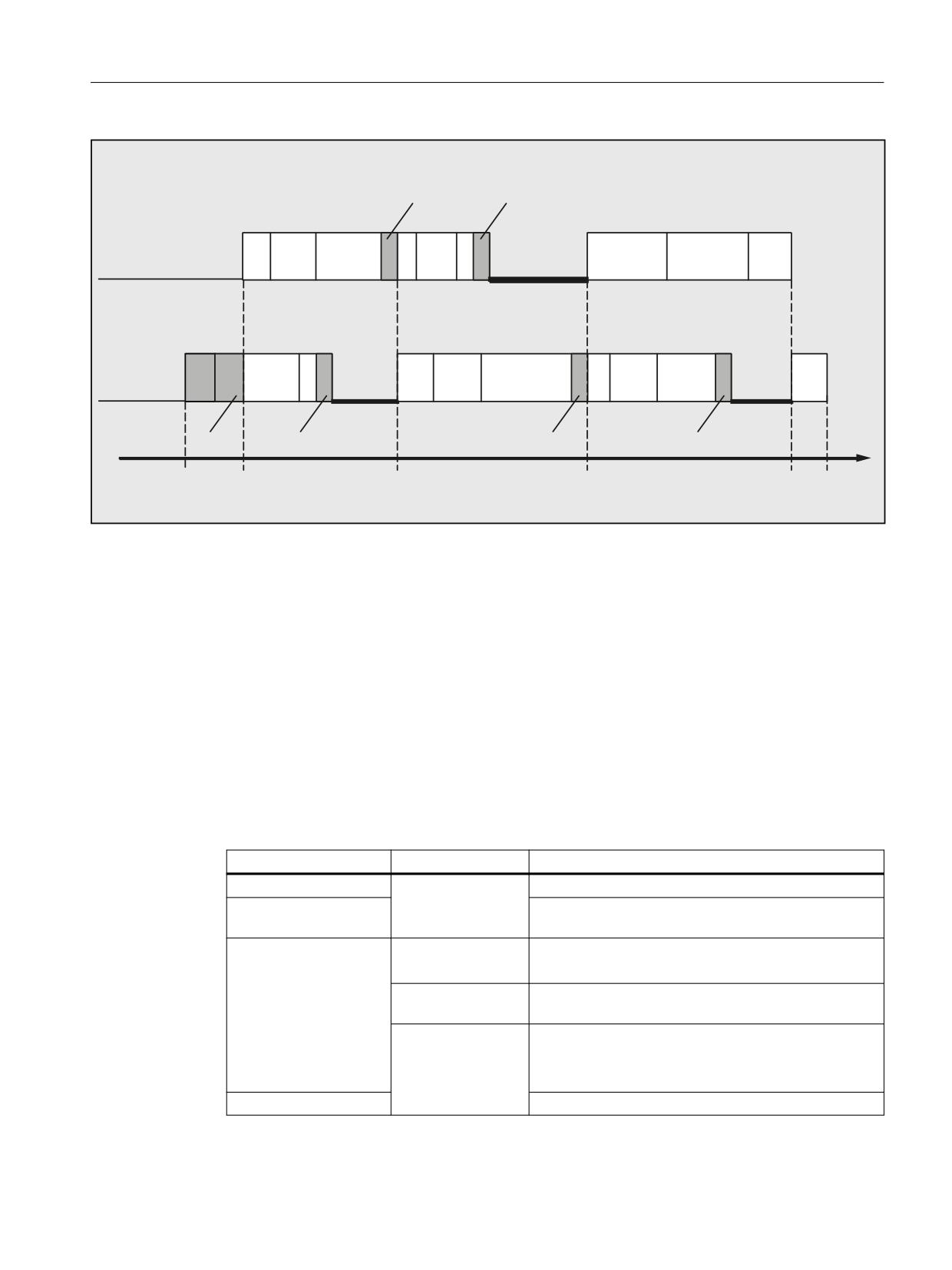
Cross-channel program coordination and channel-by-channel running-in
7.1 Cross-channel program coordination
1
1
:$,70
:$,70
&KDQQHO
1
03)
1
0
:DLWLQJ
&KDQQHO
1
1
1
03)
:DLWLQJ
:DLWLQJ
0
1
1
1
67$57
:$,70
:$,70
:$,7(
6WDUW
67$57
0
0
(QG RI WLPH
Supplementary conditions
Non-synchronous start of execution of following blocks after WAIT markers
In the case of channel coordination using WAIT markers, execution of the following blocks may
start non-synchronously. This behavior occurs if an action is triggered in one of the channels to
be synchronized immediately before reaching the common WAIT marker; the consequence of
which is implicit repositioning (REPOSA) in this delete distance-to-go.
Assumption: Current axis assignment in channels 1 and 2
• Channel 1: Axes X1 and U
• Channel 2: Axis X2
Table 7-1
Time sequence in channels 1 and 2
Channel 1
Channel 2
Description
Arbitrary processing in channels 1 and 2
N100
Channel 1: reaches the WAIT marker and waits for syn-
WAITM(20,1,2)
chronization with channel 2
Start of the GETD(U) pro-
N200 GETD(U)
Channel 2: Requests axis U from channel 1
cessing:
Channel 1: Processing of GET(U) in the backg14round
• Axis interchange
N210
Channel 2: reaches the WAIT marker. ⇒ This completes
• Delete distance-to-
WAITM(20,1,2)
the synchronization of channels 1 and 2
go
N220 G0 X2=100
Channel 2: Start of processing of N220
• REPOSA
End
N110 G0 X1=100
Channel 1: Staggered start of processing of N110
Basic functions
Function Manual, 10/2020, 6FC5397-2GP40-0BA1
523
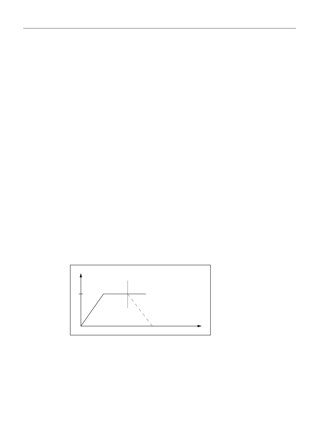
Cross-channel program coordination and channel-by-channel running-in
7.1 Cross-channel program coordination
See also
Conditional wait (WAITMC) in the continuous path mode (Page 524)
Programming: Fetching an axis (GET, GETD) (Page 541)
7.1.2
Conditional wait (WAITMC) in the continuous path mode
If in a channel, at the time that WAITMC is being processed, all of the required wait markers of
the other channels have already been received, then in this channel, traversing motion is not
braked, or the further program execution is not stopped, but continued with the processing of
the following block.
WAITMC is in separate block as function call. For the correct execution of WAITMC without
braking, a traversing block must be immediately before WAITMC. For traversing blocks with
G64x, the block with WAITMC is added to the previous block to avoid a drop in velocity. If there
are no traversing blocks, e.g. "IF loops", immediately before WAITMC, the command cannot be
assigned consistently and braking occurs.
Requirement
The following functions must be active in the channel:
• Continuous-path mode (G64, G641, G642, G643, G644 or G645)
• "LookAhead" function
Braking behavior
No braking
Starting with the motion block before the WAITMC call, the wait markers of the other channels
to be synchronized are checked. If these are already available, no braking is performed:
Y
:$,70&
W
Figure 7-1
Change of the path velocity for the conditional waiting with WAITCM: Wait markers for all
channels already available
Short-time braking
If the wait marker for a channel to be synchronized is missing, braking will be started. During
braking, a check is made in each interpolator cycle as to whether the still missing wait markers
have been received in the meantime. If this is the case, then the axis accelerates back to the
programmed velocity:
Basic functions
524
Function Manual, 10/2020, 6FC5397-2GP40-0BA1
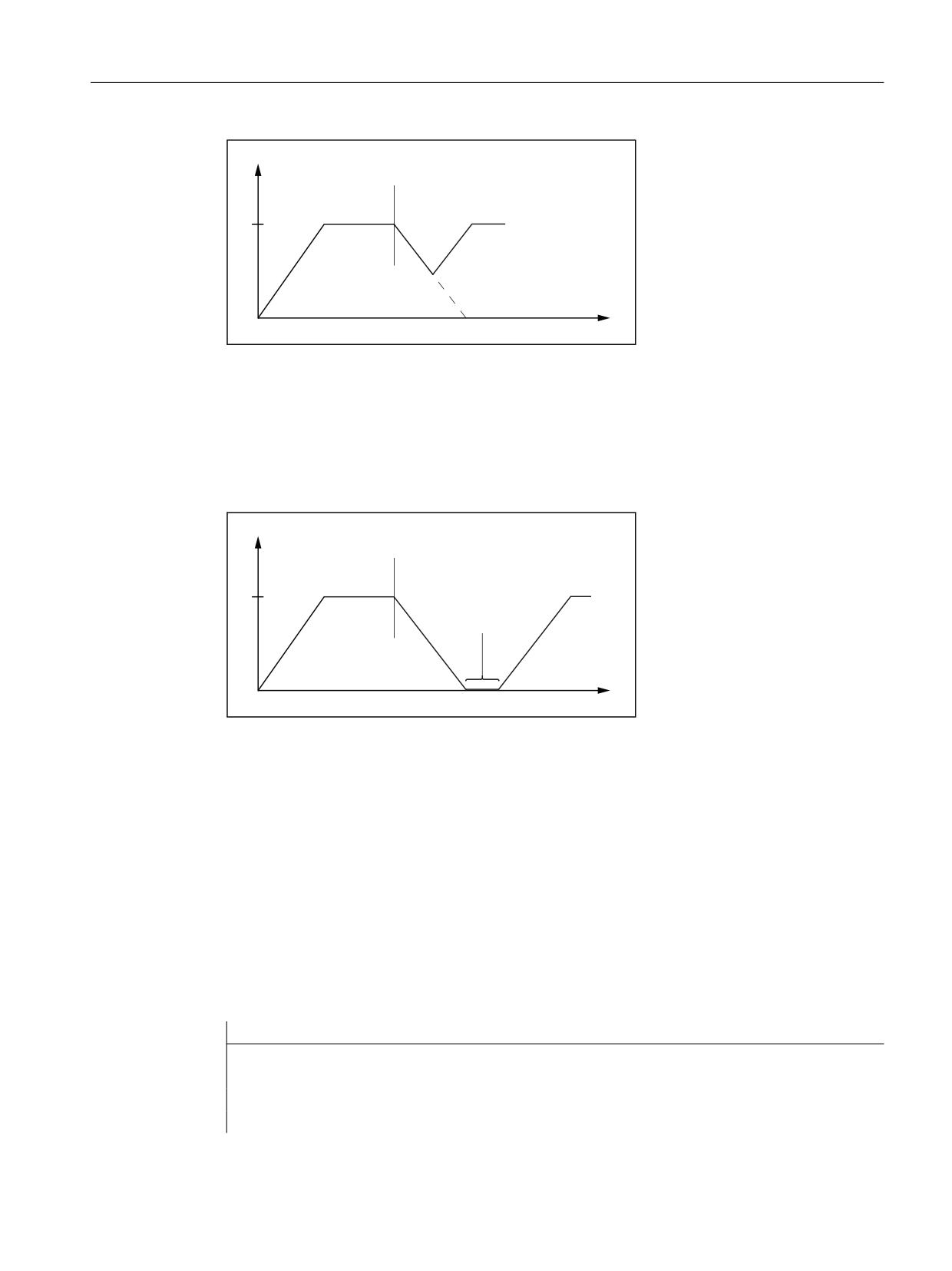
Cross-channel program coordination and channel-by-channel running-in
7.1 Cross-channel program coordination
Y
:$,70&
W
Figure 7-2
Change of the path velocity for the conditional waiting with WAITCM: The last wait marker
arrives during braking
Braking down to standstill
If the wait marker is not received during the braking phase, then the axis is braked down to
standstill and the system waits. When the wait marker is received, the axis accelerates back to
the programmed velocity.
Y
:$,70&
6WDQGVWLOO
W
Figure 7-3
Change of the path velocity for the conditional waiting with WAITCM: The last wait marker
arrives after the braking
Block change while braking (IPOBRKA)
If the IPOBRKA (block change criterion "braking ramp") end of motion criterion is active, the
arrival of the last missing wait marker causes a transition to the next block and the axis is
accelerated.
Example 1: Conditional wait in continuous-path mode
The example is schematic, and shows only those commands that are relevant for the
synchronization.
Channel 1
Program code
Comment
N10 INIT(2, "_N_200_MPF","n")
; Select partner program channel 2.
N11 INIT(3,"_N_300_MPF","n")
; Select partner program channel 3.
N15 START(2,3)
; Start programs in channels 2, 3.
; Machining in channel 1.
Basic functions
Function Manual, 10/2020, 6FC5397-2GP40-0BA1
525

Cross-channel program coordination and channel-by-channel running-in
7.1 Cross-channel program coordination
Program code
Comment
N20 WAITMC(7,2,3)
; Conditional wait for marker 7 from channels 2 and
3.
; Further machining in channel 1.
N40 WAITMC(8,2)
; Conditional wait for marker 8 from channel 2.
; Further machining in channel 1.
N70 M30
; End channel 1.
Channel 2
Program code
Comment
N200 ...
; Machining in channel 2.
N210 SETM(7)
; Channel 2 sets wait marker 7.
; Further machining in channel 2.
N250 SETM(8)
; Channel 2 sets wait marker 8.
N260 M30
; End channel 2.
Channel 3
Program code
Comment
N300 ...
; Machining in channel 3.
N350 WHEN <condition> DO SETM(7)
; Set wait marker in a synchronous action.
; Additional machining in channel 3.
N360 M30
; End channel 3.
Basic functions
526
Function Manual, 10/2020, 6FC5397-2GP40-0BA1
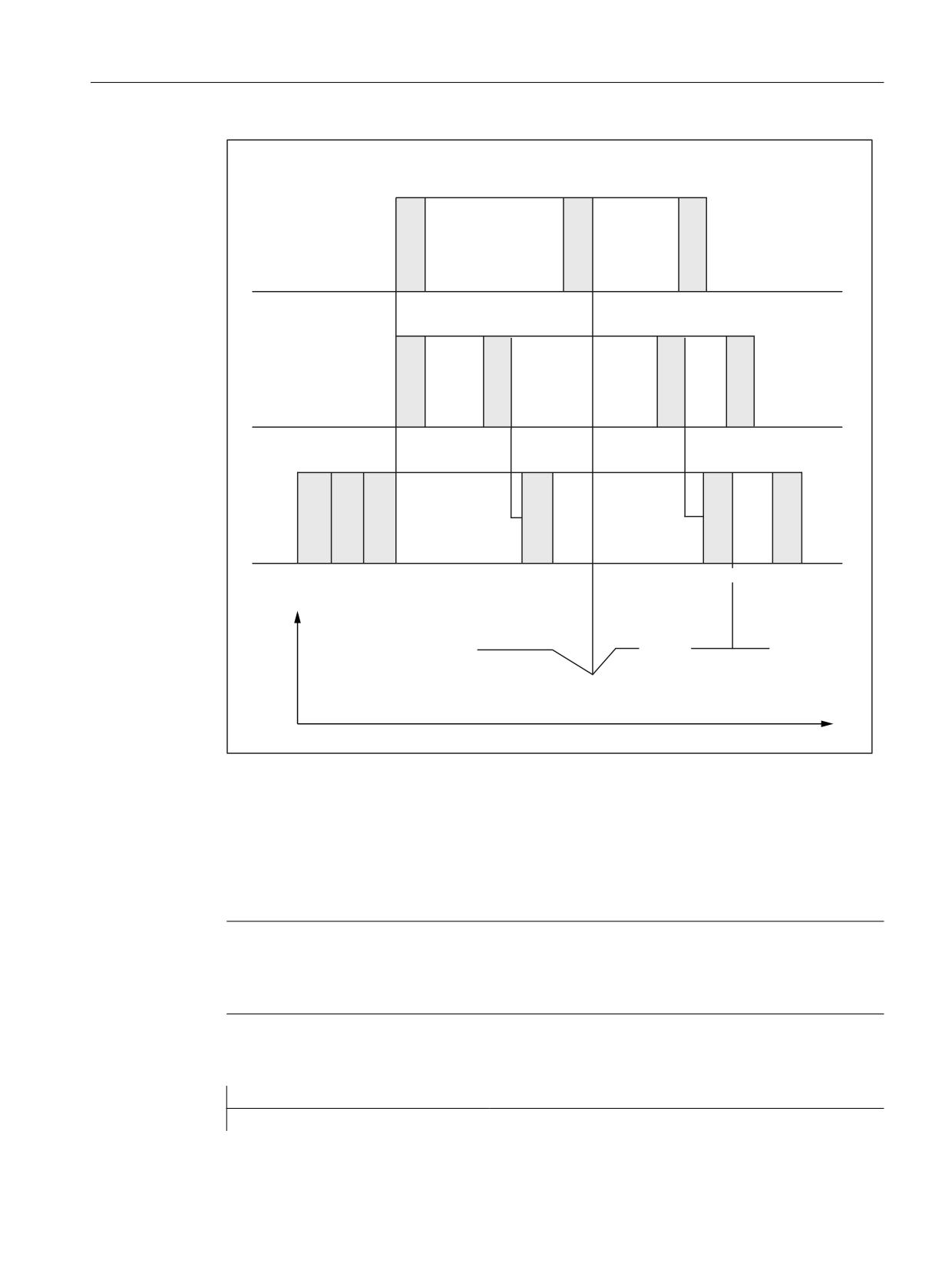
Cross-channel program coordination and channel-by-channel running-in
7.1 Cross-channel program coordination
:+(1 FRQGLWLRQ!
&RQGLWLRQ IXOILOOHG
'2 6(70
&KDQQHO
1
1
1
&KDQQHO
6(70
6(70
1
1
1
1
&KDQQHO
1
1
1
1
1
1
:$,70&
:$,70&
Y
3DWK YHORFLW\
1R EUDNLQJ
&KDQQHO
W
Figure 7-4
Conditional wait in path-controlled operation with three involved channels (schematic)
Example 2: WAITMC and read-in disable
Auxiliary function M555 is output in channel 3 while the axis is traversing and creates a read-in
disable. As WAITMC is assigned block N312, the wait marker is set, and channel 2 progresses. The
read-in disable causes the program execution in channel 3 to stop.
Note
For an active G64, WAITMC does not to create a dedicated block, but instead, is added to the
previous block. A drop in velocity must be prevented when continuous-path mode is active.
A WAITMC is therefore fulfilled if the preceding block is stopped, e.g. by a read-in disable.
Channel 2
Program code
Comment
N112 G18 G64 X200 Z200 F567
; Machining in channel 2
Basic functions
Function Manual, 10/2020, 6FC5397-2GP40-0BA1
527

Cross-channel program coordination and channel-by-channel running-in
7.2 Running-in channel-by-channel
Program code
Comment
N120 WAITMC(1,2,3)
; Conditional wait for wait marker 1
; from channels 2 and 3
; Additional machining in channel 2, as
; WAITMC is added to block N312.
; Additional machining in channel 2
N170 M30
; End of channel 2
Channel 3
Comment
; During traversing read-in disable M555
N300
; Machining in channel 3
N312 G18 G64 D1 X180 Z300 M555
N320 WAITMC(1,2,3)
; Wait because of read-in inhibit
7.2
Running-in channel-by-channel
7.2.1
Function
The "channel-by-channel running-in" function is used to test or run-in the NC programs of one
or more channels that are synchronized with each other. The programmed traversing motion of
the channel axes and/or spindles in the channels, which are in the "Normal operating" state,
results in the machine axes traversing. The following applies to channels that are in the "Program
test" state:
• In the default setting, for axes for normal operation, identical setpoints are generated,
however, these are not output at the machine axes .
• In the default setting, the setpoints for spindles are output at the machine axes.
• The displayed actual values of the inhibited axes/spindles are internally generated from
setpoints.
• The commands for channel synchronization are processed normally.
• The NC/PLC interface signals are processed normally.
• The processing time of the program is the same as in normal operation.
Temporarily when required, the "Program test" state can be exited on an axis-for-axis basis. The
setpoints are then output again on the machine axes so that they are really traversed on the
machine.
Basic functions
528
Function Manual, 10/2020, 6FC5397-2GP40-0BA1
Cross-channel program coordination and channel-by-channel running-in
7.2 Running-in channel-by-channel
7.2.2
Sequence
Normally, a channel moves a tool in the working area. If several channels are each moving a tool
in the same working area, the tool movements must be synchronized. The following
synchronizations are possible:
• Channel synchronization via the program coordination commands WAITM, WAITMC, WAITE,
START.
• Channel synchronization via the PLC user program and NC/PLC interface signals. For
example, via M function output from the channel to the PLC and read-in disable from the PLC
to the channel.
• Axis interchange: The channel waits until the other channel relinquishes the axis.
• Synchronization by means of global variables in the NC program.
• Cross-channel couplings
• Axis container rotation
• Testing the program including the parallel synchronized actions in the main run and
synchronization of the synchronized actions with the channel.
Under these general conditions, it is almost impossible to just start one channel - it would remain
stationary at the first synchronization location.
Using the "Channel-by-channel running-in", function, all of the required channels can be started
so that only those channels receive the traversing enable signals, whose interaction of the
programmed traversing motion are to be tested. The other channels are then in the "program
test" state.
To do this, before starting the channels, the machine operator must define the channels that are
to be traversed under "Program test". This is made from the user interface in the "Program
controls" menu.
7.2.3
Single-channel view
Selection
"Program test" (PRT) for the channel displayed in the "Machine" basic display is selected via the
user interface, e.g. SINUMERIK Operate:
1. Softkey: Operating area "Machine" > "Program control"
2. "Program controls" menu: Select check box "Program test (PRT)".
Basic functions
Function Manual, 10/2020, 6FC5397-2GP40-0BA1
529
Cross-channel program coordination and channel-by-channel running-in
7.2 Running-in channel-by-channel
NC/PLC interface signals
After selecting program test (PRT), the following NC/PLC interface signals are set (see below note
"Automatic transfer of interface signals"):
• Channels
- DB21, ... DBX25.7 == 1 (from HMI: program test selected)
- DB21, ... DBX1.7 == 1 (from PLC: activate program test)
- DB21, ... DBX33.7 == 1 (from NC: program test active)
• Axes
- DB31, ... DBX128.0 == 0 (from HMI: suppress program test)
- DB31, ... DBX128.1 == 0 (activate program test from HMI)
- DB31, ... DBX14.0 == 0 (from PLC: suppress program test)
- DB31, ... DBX14.1 == 0 (from PLC: activate program test)
• Spindles
- DB31, ... DBX128.0 == 1 (from HMI: suppress program test)
- DB31, ... DBX128.1 == 0 (from HMI: activate program test)
- DB31, ... DBX14.0 == 1 (from PLC: suppress program test)
- DB31, ... DBX14.1 == 0 (from PLC: activate program test)
Note
Default state of traversing motion
The default state regarding traversing motion after selecting "Program test" in the channel is:
• Axes: Inhibited
• Spindles: Enabled
Note
Automatic transfer of the interface signals
The HMI request signals DB21, ... DBX128.0 / .1 are only transferred from the basic PLC program
to the PLC request signals DB21, ... DBX14.0 / .1 if FB1 parameter MMCToIF is set to TRUE. If the
parameters are not set, then the PLC request signals must be set by the PLC user program.
Inhibiting spindle traversing motion
If, during "Program test" spindles are not to be traversed, then they must be explicitly inhibited/
locked via the PLC user program:
• DB31, ... DBX128.0 = 0 (suppress program test)
• DB31, ... DBX128.1 = 1 (activate program test)
• DB31, ... DBX14.0 = 0 (from PLC: suppress program test)
• DB31, ... DBX14.1 = 1 (from PLC: activate program test)
Basic functions
530
Function Manual, 10/2020, 6FC5397-2GP40-0BA1
Cross-channel program coordination and channel-by-channel running-in
7.2 Running-in channel-by-channel
NOTICE
Spindle traversing motion
Traversing motion of the spindles of the channel is enabled in the "Program test" as default
setting.
Enabling traversing motion of the axes
If, during "Program test" channel axes are to be traversed, then they must be explicitly enabled
via the PLC user program:
• DB31, ... DBX14.0 = 1 (from PLC: suppress program test)
• DB31, ... DBX14.1 = 0 (from PLC: activate program test)
Permissible switching instants
• Channel
Interface signals to deactivate/activate the channel-specific "Program test" state (DB21, ...
DBX25.7 or DBX1.7), may only be switched in the "Reset" or "Interrupted" channel state.
• Axes/spindles
Interface signals to activate/deactivate the axis-specific "Program test" state (DB31, ...
DBX128.0 / .1 or DBX14.0 / .1) may always be switched.
7.2.4
Multi-channel view
Prerequisites
The following preconditions must be satisfied so that in the multi-channel view in menu
"Program controls", the channels and spindles can be displayed:
• Channels
- More than one channel is parameterized (MD10010
$MN_ASSIGN_CHAN_TO_MODE_GROUP[<channel>] ≠ 0)
- Option "programSYNC" (6FC5800-0AP05-0YB0) is set/licensed
• Spindles
- The significance of the spindle, parameterized in the channel, has been defined
(MD52206 $MC_AXIS_USAGE[<spindle>] ≠ 0)
Selection
"Program test" (PRT) for one or several channels parameterized in the control is selected via the
user interface, e.g. SINUMERIK Operate:
1. Softkey: Operating area "Machine" > "Program control"
2. Softkey: "Running-in"
3. "Program controls" menu: Deselect group "Running-in” > Check box "Channel x".
Basic functions
Function Manual, 10/2020, 6FC5397-2GP40-0BA1
531

Cross-channel program coordination and channel-by-channel running-in
7.2 Running-in channel-by-channel
Check box channel/spindle
In menu "Program controls": The following behavior can be set for the "Running-in" group using
check box "Channel x" or "Spindle x":
Check box
Selected
Deselected
"Channel x"
Normal operation
Program is only calculated
(channel in test run)
"Spindle x"
Normal operation
No machining at spindle x
(spindle in test run)
NC/PLC interface signals
After deselecting the checkbox for "Channel x", the channel is in the "Program test (PRT)" state.
The following NC/PLC interface signals are set (see below note "Automatic transfer of interface
signals"):
• Channels
- DB21, ... DBX25.7 == 1 (from HMI: program test selected)
- DB21, ... DBX1.7 == 1 (from PLC: activate program test)
- DB21, ... DBX33.7 == 1 (from NC: program test active)
• Axes
- DB31, ... DBX128.0 == 0 (from HMI: suppress program test)
- DB31, ... DBX128.1 == 0 (activate program test from HMI)
- DB31, ... DBX14.0 == 0 (from PLC: suppress program test)
- DB31, ... DBX14.1 == 0 (from PLC: activate program test)
In the default setting, the control boxes for the spindles are selected, i.e. spindles are in normal
operation:
• Spindles
- DB31, ... DBX128.0 == 1 (from HMI: suppress program test)
- DB31, ... DBX128.1 == 0 (from HMI: activate program test)
- DB31, ... DBX14.0 == 1 (from PLC: suppress program test)
- DB31, ... DBX14.1 == 0 (from PLC: activate program test)
Note
Default state of traversing motion
The default state regarding traversing motion after selecting "Program test" in the channel is:
• Axes: Inhibited
• Spindles: Enabled
Basic functions
532
Function Manual, 10/2020, 6FC5397-2GP40-0BA1

Cross-channel program coordination and channel-by-channel running-in
7.2 Running-in channel-by-channel
Note
Automatic transfer of the interface signals
The HMI request signals DB21, ... DBX128.0 / .1 are only transferred from the basic PLC program
to the PLC request signals DB21, ... DBX14.0 / .1 if FB1 parameter MMCToIF is set to TRUE. If the
parameters are not set, then the PLC request signals must be set by the PLC user program.
Inhibiting spindle traversing motion
If, during "Program test" spindles of the channel are not to be traversed, then they must be
explicitly inhibited/locked via the PLC user program:
• DB31, ... DBX128.0 = 0 (suppress program test)
• DB31, ... DBX128.1 = 1 (activate program test)
• DB31, ... DBX14.0 = 0 (from PLC: suppress program test)
• DB31, ... DBX14.1 = 1 (from PLC: activate program test)
NOTICE
Spindle traversing motion
Traversing motion of the spindles of the channel is enabled in the "Program test" as default
setting.
Enabling traversing motion of the axes
If, during "Program test" channel axes are to be traversed, then they must be explicitly enabled
via the PLC user program:
• DB31, ... DBX14.0 = 1 (from PLC: suppress program test)
• DB31, ... DBX14.1 = 0 (from PLC: activate program test)
Permissible switching instants
• Channel
Interface signals to deactivate/activate the channel-specific "Program test" state (DB21, ...
DBX25.7 or DBX1.7), may only be switched in the "Reset" or "Interrupted" channel state.
• Axes/spindles
Interface signals to activate/deactivate the axis-specific "Program test" state (DB31, ...
DBX128.0 / .1 or DBX14.0 / .1) may always be switched.
Basic functions
Function Manual, 10/2020, 6FC5397-2GP40-0BA1
533

Cross-channel program coordination and channel-by-channel running-in
7.2 Running-in channel-by-channel
7.2.5
System variables
The "program test" state can be interrogated using system variables:
• For the display in the user interface, in synchronized actions or with a preprocessing stop in
the part program via the system variables:
$AC_ISTEST
"Program test" state for the channel
Supplies TRUE (1), if the "program test" state for the channel is active.
$AA_ISTEST[<n>]
"Program test" state for the axis <n>
Supplies TRUE (1), if the "program test" state for axis <n> is active.
• Without preprocessing stop in the part program via the system variable:
$P_ISTEST
Supplies TRUE (1), if the "program test" state for the channel is active.
Example
The channel runs under "program test" and axis "C" was withdrawn using "suppress program
test". A query using system variables then supplies the following result:
• $AC_ISTEST == TRUE
• $P_ISTEST == TRUE
• $AA_ISTEST[C] == FALSE
7.2.6
Supplementary conditions
Axis interchange
The "axis interchange" function allows that an axis/spindle is known in several channels and can
be programmed by these alternately (see Section "Cross-channel axis interchange (Page 539)").
In conjunction with the functions "program test" and "channel-by-channel running-in", the
following must be observed for an axis interchange:
• If only one of the channels is in the "program test" state, then the interchanged axis is taken
from this channel and is inserted in a channel that is not in the "program test" state. For an
interchanged axis with active axis disable, for a change via the channels with/without
channel state "program test", then the state in the axis itself does not change (see example
3).
• For a program test, for end of part program/reset, for all axes/spindles that do not interpolate,
resynchronization is made at the actual position. As a consequence, for an axis interchange
that is first made after the end of the program, as the axis may only exit the channel at the
end of the program, the simulated position reached is not transferred to the accepting
channel.
Note
The programs should also include a WAIT tag at the end in order that they are simultaneously
exited.
Basic functions
534
Function Manual, 10/2020, 6FC5397-2GP40-0BA1
Cross-channel program coordination and channel-by-channel running-in
7.2 Running-in channel-by-channel
7.2.7
Examples
Example 1: Channel 2 is to be tested in a 3-channel system.
Test option 1: Program test without SERUPRO
1. The user decides which axes/spindles should actually be physically traversed. "Suppress
program test" is set for these axes.
2. The "program test" state is selected for channels 1 and 3.
3. Channels 1, 2 and 3 are started via the PLC.
4. "Program test" can be selected again after the end of the program.
5. If the actual setting of "suppress program test" is also practical for other situations (channel
1 or channel 3 are to be tested), then this signal can remain set. This is certainly practical in
many cases.
Test option 2: Program test with SERUPRO
1. The user decides which axes/spindles should actually be physically traversed. "Suppress
program test" is set for these axes.
2. The "program test" state is selected for channels 1 and 3.
3. Channels 1, 2 and 3 are started via the PLC.
4. A fault or an alarm occurs, the user interrupts with RESET.
5. SERUPRO at the interruption location of all 3 channels.
6. Search destination has been reached in all 3 channels.
7. Start all 3 channels.
8. Channels 1 and 3 are now again in "program test" and "channel-by-channel running-in" is
continued.
Example 2: Activating "suppress program test"
A channel is in program test. In operation, "suppress program test" should be initiated for axis "Y"
(at block N1010).
Program code
Comment
N1000 G0 Y1000
N1010 G4 F10
N1020 G0 G91 Y=10
; Incremental traversing.
N1030 M30
With this sequence, the program moves to position 1010, i.e. the simulated component "1000"
of this axis is moved after activating "suppress program test".
Example 3: Program test and axis interchange
Axis X1 from channel 1 and axis X2 from channel 2 are assigned to the 1st machine axis AX1 of
the NC.
Channel 1 with "Program test"
Channel 2 without "Program test"
N10010 G0 G90 X0
Basic functions
Function Manual, 10/2020, 6FC5397-2GP40-0BA1
535
Cross-channel program coordination and channel-by-channel running-in
7.3 Supplementary conditions
Channel 1 with "Program test"
Channel 2 without "Program test"
N10020 X1=100
N10030 WAITM(91,1,2)
N10040 WAITM(92,1,2)
N10050 M0
N10060 M30
N20010 WAITM(91,1,2)
N20020 G91 G0 X2=10
N20030 WAITM(92,1,2)
N20040 M0
N20050 M30
In block N20040, machine axis AX1 is interchanged to channel 2, the last position of the axis
from channel 1 is taken over and the axis traversed to position 110.
7.3
Supplementary conditions
7.3.1
MDI mode: Path control mode and WAITMC
MDI mode: Continuous path mode and WAITMC
In the MDI mode, when starting to execute the MDI block buffer, it is not permissible that
the WAITMC in conjunction with the path control mode (G64 / G604), is located in the last block
of the MDI block buffer. Otherwise the program will stop with the last but one traversing block,
and can only be canceled with a reset.
Example
Before an NC start, the MDI block buffer contains the following blocks:
Program code
Comment
N10 G64 G1 G94 F5000 X100
; Continuous path mode in the first block of
the
; MDI block buffer
N20 X200
N30 X300
; Last but one traversing block
N40 X400
; Program execution stops here
N50 WAITMC(...)
; due to WAITMC in N50.
; Cancellation with reset required!
Basic functions
536
Function Manual, 10/2020, 6FC5397-2GP40-0BA1
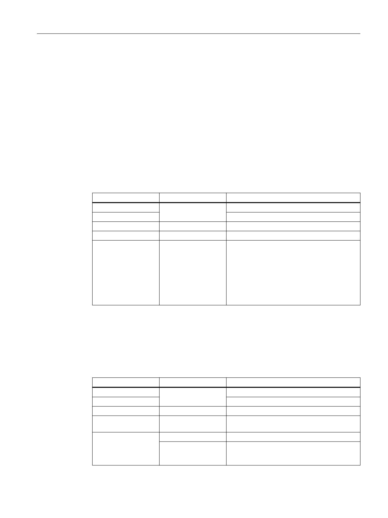
Cross-channel program coordination and channel-by-channel running-in
7.3 Supplementary conditions
7.3.2
Non-synchronous start of traversing motion after WAIT commands
In the case of channel coordination using WAIT commands, a non-synchronous start when
executing the following blocks can occur. This behavior occurs if an action is triggered in one of
the channels immediately before reaching the common synchronization location; the
consequence of which is implicit repositioning (REPOSA) in this delete distance-to-go.
Assumption: Current axis allocation in channels 1 and 2
• Channel 1: Axes Z1 and W
• Channel 2: Axis Z2
Example 1: Start of traversing motion with time offset
The following command sequences in channels 1 and 2 result in a possible problematical start
of traversing motion with time offset after the synchronization location N110 / N210:
Table 7-2
Sequence (time) in channels 1 and 2
Channel 1
Channel 2
Description
Any processing in channels 1 and 2
N100 W100
Channel 1: Traversing axis W
Arbitrary processing in channels 1 and 2
N110 WAITM(2,1,2)
N210 WAITM(2,1,2)
Channels 1 and 2: wait for synchronization
Start "AUTOGET(W)":
"AUTOGET(W)" and wait
for axis W from channel
• Axis replacement
1
Channel 2: Start of traversing motion with time off-
• Delete distance-to-
N220 Z2=100 W100
set
go
• REPOSA
End
Channel 1: Start of traversing motion
N120 Z1=100
Example 2: Simultaneous start of traversing motion
Start of traversing motion with time offset (delay) in example 1 can be avoided by explicitly
enabling and requesting the axis W to be replaced and by inserting an additional
synchronization location. The following command sequences in channels 1 and 2 result in a
simultaneous start of traversing motion after the synchronization location N120 / N220:
Table 7-3
Sequence (time) in channels 1 and 2
Channel 1
Channel 2
Description
Arbitrary processing in channels 1 and 2
N100 W100
Channel 1: Traversing axis W
Arbitrary processing in channels 1 and 2
RELEASE(W)
Channel 1: Enable axis W ⇒ The axis replacement
in channel 2 no longer affects channel 1
N110 WAITM(2,1,2)
N210 WAITM(2,1,2)
Channels 1 and 2: wait for synchronization
N215 GET(W)
Channel 2: Request axis W. Axis replacement is op-
timum from a time perspective, as axis W is already
enabled
Basic functions
Function Manual, 10/2020, 6FC5397-2GP40-0BA1
537

Cross-channel program coordination and channel-by-channel running-in
7.3 Supplementary conditions
Channel 1
Channel 2
Description
N120 WAITM(9,1,2)
N220 WAITM(9,1,2)
Channels 1 and 2: wait for synchronization
N130 Z1=100
N230 Z2=100 W100
Channels 1 and 2: simultaneous start of traversing
motion
Basic functions
538
Function Manual, 10/2020, 6FC5397-2GP40-0BA1
Cross-channel axis interchange
8
8.1
Overview
Note
Spindles
The following statements and functions regarding the "axis interchange" function for axes also
apply to spindles.
Each axis must be assigned to a channel during control commissioning. The axis can only be
traversed, for example, by part programs or synchronized actions from the channel to which the
axis is assigned. With the "axis interchange" function, it is possible to enable an axis and to
allocate it to another channel, that is, to interchange the axis. Only than can the axis be traversed
by another channel.
Axis states
As part of the "axis interchange" function, an axis can have the following states:
• "Channel axis"
A channel axis is an axis that is assigned to a channel. It can be traversed via a part program
or manually.
• "PLC axis"
A PLC axis is an axis that is assigned to the PLC. It can only be traversed by the PLC user
program.
• "Neutral axis"
A neutral axis is an axis that is not currently assigned to a channel or the PLC. Before
traversing, it must first be requested by a channel or the PLC.
• "Axis in another channel"
An axis is in this state if a channel has requested the axis. However, it could not yet be
assigned to it because it is still occupied by another channel.
8.2
Commissioning
Parameter assignment
NC-specific machine data
• General parameterization of the axis replacement form
MD10722 $MN_AXCHANGE_MASK
Basic functions
Function Manual, 10/2020, 6FC5397-2GP40-0BA1
539

Cross-channel axis interchange
8.3 Programming: Releasing an axis (RELEASE)
Channel-specific machine data
• Parameterization of which axes belong to the channel or are channel axes:
MD20070 $MC_AXCONF_MACHAX_USED[<channel axis>] = <machine axis>
Note: Assignment of all axes used in the NC must be performed in any case as channel axes
of one or more channels, irrespective of the "axis replacement" function.
Axis-specific machine data
• If an axis is a channel axis in multiple channels, the machine data defines to which channel
the axis is assigned after control startup (power-on reset):
MD30550 $MA_AXCONF_ASSIGN_MASTER_CHAN[<channel>] = <channel number>
The parameterized channel is the master channel of the axis.
• Parameterization of the response if an axis is programmed in a part program and the axis is
not currently assigned to the channel:
- Display an alarm and do not traverse the axis.
- Automatically requesting the axis according to the command GET (Page 541)
- Automatically requesting the axis according to the command GETD (Page 541)
MD30552 $MA_AUTO_GET_TYPE[<axis>] = <response>
System variable
Axis-specific system variable
• Axis type in relation to axis replacement:
$AA_AXCHANGE_TYP[<axis>]
• Axis replacement status of the axis:
$AA_AXCHANGE_STAT[<axis>]
8.3
Programming: Releasing an axis (RELEASE)
Function
An axis that is assigned to the current channel is released for an axis interchange via the
predefined RELEASE() procedure and put into the "neutral axis" state for this purpose.
Syntax
RELEASE(<axis1>[, axis2 ... axis15])
Meaning
RELEASE:
Release axis for axis interchange
Preprocessing
Yes
stop:
Alone in the
Yes
block:
Basic functions
540
Function Manual, 10/2020, 6FC5397-2GP40-0BA1

Cross-channel axis interchange
8.4 Programming: Fetching an axis (GET, GETD)
<axis>:
Axis: Channel axis name of the releasing axis
Spindle: Channel axis name of the releasing spindle or conversion of the spindle number
in the channel axis names by means of SPI(<spindle number>)
Type:
AXIS
Supplementary conditions
No enable possible
• The axis is involved in a transformation.
• The axis belongs to an axis grouping.
Guide axis of a gantry grouping
If the guide axis of a gantry grouping is released, all synchronous axes are also released.
8.4
Programming: Fetching an axis (GET, GETD)
Requesting axis interchange (GET):
Function
With the predefined GET() procedure, an axis is requested for the same channel.
In the channel, to which the axis is currently assigned, the axis must be released in a part
program or synchronized action for axis interchange with RELEASE().
After axis interchange, the axis has "channel axis" status.
Syntax
GET(<axis1>[, axis2 ... axis15])
Meaning
GET:
Request of an axis for the current channel
Preprocessing
Yes
stop:
Alone in the
Yes
block:
<axis>:
Axis: Channel axis name of the requested axis
Spindle: Channel axis name of the requested spindle or conversion of the spindle number
in the channel axis names by means of SPI(<spindle number>)
Type:
AXIS
Supplementary conditions
Axis interchange is delayed in the following situations:
• The axis has not yet been released with RELEASE by the channel to which it is assigned.
• A change of measuring system has not yet been completed.
Basic functions
Function Manual, 10/2020, 6FC5397-2GP40-0BA1
541

Cross-channel axis interchange
8.4 Programming: Fetching an axis (GET, GETD)
• The change of status of the controller enable has not yet been completed (transition of rules
to follow-up/stop and vice versa).
• The NC/PLC interface signal "axis or spindle disable" is pending (DB31, ... DBX1.3 == 1)
• The current traversing movement (interpolation) of the axis has not yet been completed.
Fetching an axis directly (GETD)
Function
An axis that is not assigned to the current channel is required for the following machining section
of a part program. With the predefined procedure GETD(), the axis is fetched directly from the
channel to which the axis is assigned. For this purpose, the axis does not have to be released by
this channel with RELEASE().
After axis interchange, the axis has "channel axis" status.
Depending on the state of the axis in the relinquishing channel, a preprocessing stop is triggered
in this channel (STOPRE):
• "Channel axis" status ⇒ preprocessing stop
• "Neutral axis" status ⇒ no preprocessing stop
To coordinate transfer of the axis between the channels with GETD(), we recommend using
channel synchronization (Page 519) between the requesting and the relinquishing channel.
NOTICE
Preprocessing stop in the relinquishing channel
If the axis in the relinquishing channel has "channel axis" status, a preprocessing stop will be
triggered in this channel (STOPRE):
Syntax
GETD(<axis>)
Meaning
GETD:
Fetching an axis directly into the current channel
Preprocessing
Yes
stop:
Alone in the
Yes
block:
<axis>:
Axes: Channel axis name of the requested axis
Spindles: Channel axis name of the requested spindle or conversion of the spindle num-
ber in the channel axis names by means of SPI(<spindle number>)
Supplementary condition
If the axis has "PLC axis" status in the relinquishing channel, the axis must be released for axis
interchange by the PLC user program.
Basic functions
542
Function Manual, 10/2020, 6FC5397-2GP40-0BA1
Cross-channel axis interchange
8.5 Automatic axis replacement
Supplementary conditions
Channel reset
• If a channel reset is triggered in the channel that requested the axis, axis interchange is
canceled.
• A replaced axis remains assigned to the channel that last requested it even after a channel
reset.
8.5
Automatic axis replacement
Function
Automatic axis replacement or automatic fetching of an axis into the current channel is
performed if the axis is programmed in the part program or synchronized action, but it is not
assigned to the channel at the moment.
Requirement
Parameterization of automatic axis replacement by GET() or GETD():
MD30552 $MA_AUTO_GET_TYPE (Page 539)
Supplementary conditions
See Description (Page 541) of GETD().
Examples
Example 1
Program code
Comment
N1 M3 S1000
; Traversing the main spindle
N2 RELEASE (SPI(1))
; Release to neutral status
N3 S3000
; Programming the main spindle => automatic fetching
; Behavior depending on MD30552 $MA_AUTO_GET_TYPE:
; 0 => Alarm "Wrong axis type"
; 1 => implicit GET(SPI(1))
; 2 => implicit GETD(SPI(1))
Example 2
Program code
Comment
; Machine axis AX1 ≙ channel axis X
N1 RELEASE (AX1)
; Release to neutral status
N2 G04 F2
; Dwell time
N3 G0 X100 Y100
; Programming axis X as a path axis
; Behavior depending on MD30552 $MA_AUTO_GET_TYPE:
Basic functions
Function Manual, 10/2020, 6FC5397-2GP40-0BA1
543
Cross-channel axis interchange
8.6 Axis replacement via PLC
Program code
Comment
; 0 => Alarm "Wrong axis type"
; 1 => implicit GET(AX1)
; 2 => implicit GETD(AX1)
Example 3
Program code
Comment
; Machine axis AX1 ≙ channel axis X
N1 RELEASE (AX1)
; Release to neutral status
N2 G04 F2
; Dwell time
N3 POS (X) = 100
; Programming axis X as a positioning axis
; Behavior depending on MD30552 $MA_AUTO_GET_TYPE:
; 0 => Alarm "Wrong axis type"
; 1 => implicit GET(AX1) *)
; 2 => implicit GETD(AX1) *)
*) If the axis has not yet been synchronized, a separate block is generated for automatic fetching
of the axis using (GET() or GETD().
8.6
Axis replacement via PLC
Function
Axis replacement can be requested by the PLC user program via the NC/PLC interface:
• From an NC channel to the PLC
• From the PLC to an NC channel
• From an NC channel to another NC channel
'%
'%%
3/& ൺ 1&
%LW
5HTXLUHPHQW &KDQQHO QXPEHU RI WKH
FKDQQHO WR ZKLFK WKH D[LV LV WR EH DVVLJQHG
5HTXLUHPHQW 6ZLWFK RYHU D[LV
5HTXHVW IURP 3/& ൺ
$FNQRZOHGJPHQW E\ 1&
ൺ
5HTXLUHPHQW $[LV W\SH 3/& D[LV
Figure 8-1
Axis replacement request: DB31, ... DBB8 (PLC → NC)
Axis replacement status
The current status of an axis with regard to axis replacement can be read by the PLC user program
via the NC/PLC interface.
Basic functions
544
Function Manual, 10/2020, 6FC5397-2GP40-0BA1
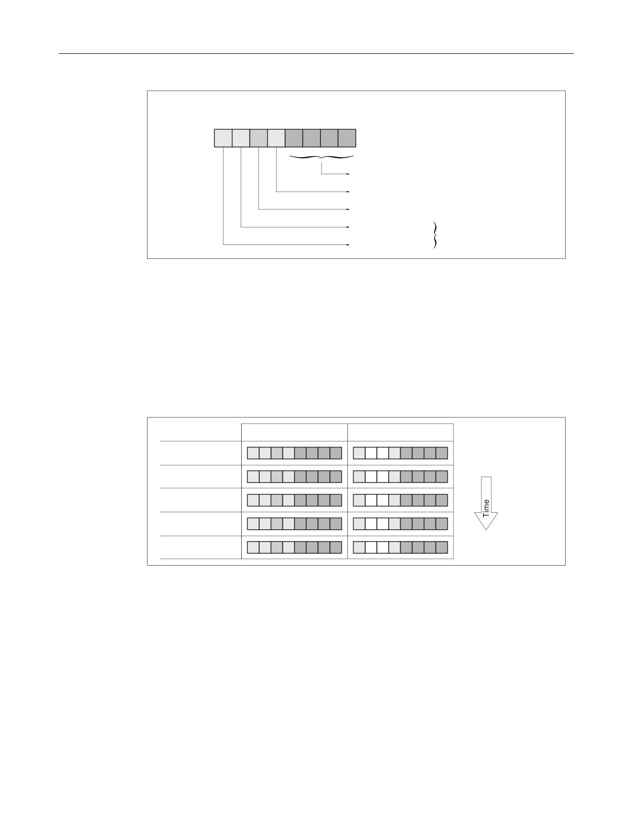
Cross-channel axis interchange
8.6 Axis replacement via PLC
'%
'%%
1& ൺ 3/&
%LW
&KDQQHO QXPEHU RI WKH FKDQQHO WR
ZKLFK WKH D[LV LV DVVLJQHG
1HZ D[LV W\SH UHTXHVWHG E\ WKH 3/&
$[LV UHSODFHPHQW LV SRVVLEOH
1HXWUDO D[LV
$[LV W\SH
3/& D[LV
Figure 8-2
Axis replacement status: DB31, ... DBB68 (NC → PLC)
Examples
Example 1
Axis replacement of an axis from channel 1 to channel 2 by means of RELEASE() and GET() in
part programs that are executed in each channel:
• Channel 1: RELEASE(<axis>)
• Channel 2: GET(<axis>)
'%
'%%
'%
'%%
$IWHU SRZHU RQ
FKDQQHO D[LV LQ .
5(/($6( $;
*(7 $;
Example 2
Status change of an axis assigned to channel 1 from "NC axis" to "PLC axis" by the PLC user
program.
Basic functions
Function Manual, 10/2020, 6FC5397-2GP40-0BA1
545
Cross-channel axis interchange
8.6 Axis replacement via PLC
'%
'%%
'%
'%%
$IWHU SRZHU RQ
FKDQQHO D[LV LQ .
5HTXHVW E\ 3/&
1HZ 7<3 3/& D[LV
5HTXHVW GHWHFWHG
$[LV UHSODFHPHQW SRVVLEOH
5HTXHVW E\ 1& UHVHW
3/& D[LV LQ .
Example 3
Status change of an axis assigned to channel 1 from "NC axis" via "PLC axis" to "neutral axis" by
the PLC user program.
'%
'%%
'%
'%%
$IWHU SRZHU RQ
FKDQQHO D[LV LQ .
5HTXHVW E\ 3/&
1HZ 7<3 3/& D[LV
5HTXHVW GHWHFWHG
$[LV UHSODFHPHQW SRVVLEOH
5HTXHVW E\ 1& UHVHW
3/& D[LV LQ .
5HTXHVW E\ 3/&
1HZ 7<3 1HXWUDO D[LV
5HTXHVW GHWHFWHG
$[LV UHSODFHPHQW SRVVLEOH
1HXWUDO D[LV LQ
5HTXHVW E\ 1& UHVHW
Basic functions
546
Function Manual, 10/2020, 6FC5397-2GP40-0BA1
Cross-channel axis interchange
8.8 Axis replacement with and without preprocessing stop
8.7
Axis interchange via axis container rotation
Enabling axis container rotation
When an axis container rotation is enabled, all container axes that can be allocated to a channel
are allocated to this channel using implicitly generated GET or GETD. An axis can only be
relinquished, e.g. to another channel, after container rotation.
Note
The implicit assignment of an axis to a channel is notpossible if the axis in the state "main run
axis" (e.g. is a PLC axis). In order to be able to participate in the axis container rotation, the axis
must first exit the state.
For further explanations on the axis replacement of container axes (see Section "B3: Distributed
systems").
Example: Axis container rotation with an implicit GET or GETD
Action Channel 1
Action Channel 2
SPOS = 180 positioned
AXCTSWE(CT 1)
; gets spindle in Channel 1
; and allows axis container rotation
Assumption:
The spindle is used in both channels and is also an axis in axis container CT 1.
Activation
Axis interchange using axis container rotation and implicit GET/GETD is activated using machine
data MD10722 $MN_AXCHANGE_MASK, bit 1=1.
8.8
Axis replacement with and without preprocessing stop
Axis replacement extension without preprocessing stop
Instead of a GET block with a preprocessing stop, this GET request only generates an
intermediate block. In the main run, when this block is executed, the system checks whether the
states of the axes in the block match the current axis states. If they do not match, forced
reorganization can be triggered.
The following states of an axis or positioned spindle are checked for:
• The mode, either for the axis or for positioned spindle
• Setpoint position
Basic functions
Function Manual, 10/2020, 6FC5397-2GP40-0BA1
547
Cross-channel axis interchange
8.8 Axis replacement with and without preprocessing stop
The following states of a Spindle in speed mode are checked:
• Spindle mode: Speed mode
• Spindle speed S
• Direction of rotation M3, M4
• Gear stage M40, M41, M42, M43, M44, M45
• Master spindle at constant cutting rate.
In some instances, forced reorganization may be possible. Reorganization of the following axes
is forced in any case.
Activation
Replacement without preprocessing and checking of the current states is activated with
machine data MD10722 $MN_AXCHANGE_MASK, Bit 2=1.
Example
Activating an axis replacement without a preprocessing stop
Table 8-1
N010 M4 S1000
N011 G4 F2
N020 M5
N021 SPOS=0
N022 POS[B]=1
N023 WAITP(B)
; Axis b becomes the neutral axis
N030 X1 F10
N031 X100 F500
N032 X200
N040 M3 S500
N041 G4 F2
N050 M5
N099 M30
If the spindle (axis B) is traversed immediately after block N023 as a PLC axis to 180° and back
to 1°, and then again to the neutral axis, block N040 does not trigger a preprocessing stop nor
a reorganization.
Special case: Axis replacement with preprocessing stop
Without a GET or GETD instruction having previously occurred in the main run, the spindle or the
axis can be made available again by RELEASE (axis) or WAITP (axis), for example. A subsequent
GET leads to a GET with a preprocessing stop.
Basic functions
548
Function Manual, 10/2020, 6FC5397-2GP40-0BA1
Cross-channel axis interchange
8.9 Axis exclusively controlled from the PLC
8.9
Axis exclusively controlled from the PLC
Function
After the control boots, the axis is in the "neutral axis" state. The PLC controls it. To traverse the
axis as competing positioning axis (from the PLC via function block FC18), the axis must first be
explicitly requested from the PLC.
Note
Per machine data, the axis interchange to the PLC can be exclusively restricted to PLC controlled
axes: MD10722 $MN_AXCHANGE_MASK, Bit 3 = 1
The axis cannot be traversed from an NC part program.
Parameter assignment
Parameterizing an axis as axis that is exclusively controlled from the PLC is realized using the axis-
specific machine data:
MD30460 $MA_BASE_FUNCTION_MASK, Bit 4 = 1
Control by PLC
The traversing behavior of an axis exclusively controlled from the PLC is only influenced by the
axial NC/PLC interface signals:
• DB31, ... DBX28.1 (reset)
• DB31, ... DBX28.2 (continue)
• DB31, ... DBX28.6 (stop along braking ramp)
Possible traversing functions
The following traversing functions are possible for axes exclusively controlled from the PLC:
1. Traversing in the JOG mode using the traversing keys and handwheel
2. Referencing the axis
3. Traversing as command axis via static synchronized actions
4. Traversing as asynchronous oscillating axis
5. Traversing as competing positioning axis from the PLC via FC18
After traversing functions 1. to 4. have been completed, the axis automatically goes back into
the "neutral axis" state. After traversing function 5. from the PLC has been completed, the axis
remains in the state "PLC axis". The axis only changes into the "Neutral axis" state after having
been explicitly released by the PLC.
Basic functions
Function Manual, 10/2020, 6FC5397-2GP40-0BA1
549
Cross-channel axis interchange
8.10 Axis permanently assigned to the PLC
8.10
Axis permanently assigned to the PLC
Function
After the control has booted, the axis is in the "neutral axis" state and is controlled from the NC
channel. To traverse the axis as competing positioning axis (from the PLC via function block
FC18), the axis does not have to be explicitly requested from the PLC. Axis interchange to the
PLC is realized automatically using the traversing request via FC18. After the traversing motion
requested via FC18 has been completed, the axis again automatically changes into the "neutral
axis" state.
After the axis has been interchanged, and after the request from the PLC, the axis can also be
controlled from the PLC: "PLC axis" state.
Note
Per machine data, the axis interchange to the PLC can be exclusively restricted to axes that are
permanently assigned to the PLC: MD10722 $MN_AXCHANGE_MASK, Bit 3 = 1
Parameter assignment
Parameterizing an axis as axis that is permanently assigned to the PLC is realized using the axis-
specific machine data:
MD30460 $MA_BASE_FUNCTION_MASK, Bit 5 = 1
Control by the PLC or NC channel
The traversing behavior of an axis permanently assigned to the PLC can either be influenced by
the NC channel or by the PLC:
NC channel: Channel-specific NC/PLC interface signals (selection)
• DB21, ... DBXDBX7.1 (NC start)
• DB21, ... DBXDBX7.3 (NC stop)
• DB21, ... DBXDBX7.7 (reset)
PLC: Axial NC/PLC interface signals
• DB31, ... DBX28.1 (reset)
• DB31, ... DBX28.2 (continue)
• DB31, ... DBX28.6 (stop along braking ramp)
Possible traversing functions
The following traversing functions are possible for an axis permanently assigned to the PLC:
1. Traversing in the JOG mode using the traversing keys and handwheel
2. Referencing the axis
3. Traversing as competing positioning axis from the PLC via FC18
Basic functions
550
Function Manual, 10/2020, 6FC5397-2GP40-0BA1