SINUMERIK 840D sl. Service - Functions. Manual (2018-2020) - page 23
Axes, coordinate systems, frames
4.5 Frames
$MC_FRAME_ADD_COMPONENTS=TRUE
; G58, G59 is possible.
; TRANSMIT is the 1st transformation
$MC_TRAFO_TYPE_1=256
$MC_TRAFO_AXES_IN_1[0]=1
$MC_TRAFO_AXES_IN_1[1]=6
$MC_TRAFO_AXES_IN_1[2]=3
$MC_TRAFO_AXES_IN_1[3]=0
$MC_TRAFO_AXES_IN_1[4]=0
$MA_ROT_IS_MODULO[AX6]=TRUE;
$MC_TRAFO_GEOAX_ASSIGN_TAB_1[0]=1
$MC_TRAFO_GEOAX_ASSIGN_TAB_1[1]=6
$MC_TRAFO_GEOAX_ASSIGN_TAB_1[2]=3
$MC_TRANSMIT_BASE_TOOL_1[0]=0.0
$MC_TRANSMIT_BASE_TOOL_1[1]=0.0
$MC_TRANSMIT_BASE_TOOL_1[2]=0.0
$MC_TRANSMIT_ROT_AX_OFFSET_1=0.0
$MC_TRANSMIT_ROT_SIGN_IS_PLUS_1=TRUE
$MC_TRANSMIT_ROT_AX_FRAME_1=1
; TRANSMIT is the 2nd transformation
$MC_TRAFO_TYPE_2=256
$MC_TRAFO_AXES_IN_2[0]=1
$MC_TRAFO_AXES_IN_2[1]=6
$MC_TRAFO_AXES_IN_2[2]=2
$MC_TRAFO_AXES_IN_2[3]=0
$MC_TRAFO_AXES_IN_2[4]=0
$MC_TRAFO_GEOAX_ASSIGN_TAB_2[0]=1
$MC_TRAFO_GEOAX_ASSIGN_TAB_2[1]=6
$MC_TRAFO_GEOAX_ASSIGN_TAB_2[2]=2
$MC_TRANSMIT_BASE_TOOL_2[0]=4.0
$MC_TRANSMIT_BASE_TOOL_2[1]=0.0
$MC_TRANSMIT_BASE_TOOL_2[2]=0.0
$MC_TRANSMIT_ROT_AX_OFFSET_2=19.0
Basic functions
Function Manual, 10/2020, 6FC5397-2GP40-0BA1
343
Axes, coordinate systems, frames
4.5 Frames
$MC_TRANSMIT_ROT_SIGN_IS_PLUS_2=TRUE
$MC_TRANSMIT_ROT_AX_FRAME_2=1
Example: Part program
; Frame settings
N820 $P_UIFR[1] = ctrans(x,1,y,2,z,3,c,4)
N830 $P_UIFR[1] = $P_UIFR[1] : crot(x,10,y,20,z,30)
N840 $P_UIFR[1] = $P_UIFR[1] : cmirror(x,c)
N850
N860 $P_CHBFR[0] = ctrans(x,10,y,20,z,30,c,15)
N870
; Tool selection, clamping compensation, plane selection
N890 T2 D1 G54 G17 G90 F5000 G64 SOFT
N900
; Approach start position
N920 G0 X20 Z10
N930
N940 if $P_BFRAME <> CTRANS(X,10,Y,20,Z,30,C,15)
N950 setal(61000)
N960 endif
N970 if $P_BFRAME <> $P_CHBFR[0]
N980 setal(61000)
N990 endif
N1000 if $P_IFRAME <>
CTRANS(X,1,Y,2,Z,3,C,4):CROT(X,10,Y,20,Z,30):CMIRROR(X,C)
N1010 setal(61000)
N1020 endif
N1030 if $P_IFRAME <> $P_UIFR[1]
N1040 setal(61000)
N1050 endif
N1060 if $P_ACTFRAME <>
CTRANS(X,11,Y,22,Z,33,C,19):CROT(X,10,Y,20,Z,30):CMIRROR(X,C)
N1070 setal(61000)
N1080 endif
N1090
N1100 TRANSMIT(2)
N1110
N1120 if $P_BFRAME <> CTRANS(X,10,Y,0,Z,20,CAZ,30,C,15)
N1130 setal(61000)
N1140 endif
N1180 if $P_IFRAME <>
Basic functions
344
Function Manual, 10/2020, 6FC5397-2GP40-0BA1
Axes, coordinate systems, frames
4.5 Frames
CTRANS(X,1,Y,0,Z,2,CAZ,3,C,4):CROT(X,10,Y,20,Z,30):CMIRROR(X,C)
N1190 setal(61000)
N1200 endif
N1240 if $P_ACTFRAME <>
CTRANS(X,11,Y,0,Z,22,CAZ,33,C,19):CROT(X,10,Y,20,Z,30):CMIRROR(X,C)
N1250 setal(61001)
N1260 endif
N1270
N1280
N1290 $P_UIFR[1,x,tr] = 11
N1300 $P_UIFR[1,y,tr] = 14
N1310
N1320 g54
N1330
; Set frame
N1350 ROT RPL=-45
N1360 ATRANS X-2 Y10
N1370
; Four-edge roughing
N1390 G1 X10 Y-10 G41 OFFN=1; allowance 1 mm
N1400 X-10
N1410 Y10
N1420 X10
N1430 Y-10
N1440
; Tool change
N1460 G0 Z20 G40 OFFN=0
N1470 T3 D1 X15 Y-15
N1480 Z10 G41
N1490
; Four-edge finishing
N1510 G1 X10 Y-10
N1520 X-10
N1530 Y10
N1540 X10
N1550 Y-10
N1560
Basic functions
Function Manual, 10/2020, 6FC5397-2GP40-0BA1
345
Axes, coordinate systems, frames
4.5 Frames
; Deselect frame
N2950 m30 N1580 Z20 G40
N1590 TRANS
N1600
N1610 if $P_BFRAME <> CTRANS(X,10,Y,0,Z,20,CAZ,30,C,15)
N1620 setal(61000)
N1630 endif
N1640 if $P_BFRAME <> $P_CHBFR[0]
N1650 setal(61000)
N1660 endif
N1670 if $P_IFRAME <>
TRANS(X,11,Y,0,Z,2,CAZ,3,C,4):CROT(X,10,Y,20,Z,30):CMIRROR(X,C)
N1680 setal(61000)
N1690 endif
N1730 if $P_ACTFRAME <>
TRANS(X,21,Y,0,Z,22,CAZ,33,C,19):CROT(X,10,Y,20,Z,30):CMIRROR(X,C)
N1740 setal(61001)
N1750 endif
N1760
N1770 TRAFOOF
N1780
N1790 if $P_BFRAME <> CTRANS(X,10,Y,20,Z,30,C,15)
N1800 setal(61000)
N1810 endif
N1820 if $P_BFRAME <> $P_CHBFR[0]
N1830 setal(61000)
N1840 endif
N1850 if $P_IFRAME <>
TRANS(X,11,Y,2,Z,3,C,4):CROT(X,10,Y,20,Z,30):CMIRROR(X,C)
N1860 setal(61000)
N1870 endif
N1880 if $P_IFRAME <> $P_UIFR[1]
N1890 setal(61000)
N1900 endif
N1910 if $P_ACTFRAME <>
TRANS(X,21,Y,22,Z,33,C,19):CROT(X,10,Y,20,Z,30):CMIRROR(X,C)
N1920 setal(61002)
N1930 endif
N1940
N2010 $P_UIFR[1] = ctrans()
N2011 $P_CHBFR[0] = ctrans()
N2020 $P_UIFR[1] = ctrans(x,1,y,2,z,3,c,0)
N2021 G54
N2021 G0 X20 Y0 Z10 C0
Basic functions
346
Function Manual, 10/2020, 6FC5397-2GP40-0BA1
Axes, coordinate systems, frames
4.5 Frames
N2030 TRANSMIT(1)
N2040 TRANS x10 y20 z30
N2041 ATRANS y200
N2050 G0 X20 Y0 Z10
N2051 if $P_IFRAME <> CTRANS(X,1,Y,0,Z,3,CAY,2)
N2052 setal(61000)
N2053 endif
N2054 if $P_ACTFRAME <> CTRANS(X,11,Y,20,Z,33,CAY,2):CFINE(Y,200)
N2055 setal(61002)
N2056 endif
N2060 TRAFOOF
N2061 if $P_IFRAME <> $P_UIFR[1]
N2062 setal(61000)
N2063 endif
N2064 if $P_ACTFRAME <> CTRANS(X,11,Y,2,Z,33):CFINE(Y,0)
N2065 setal(61002)
N2066 endif
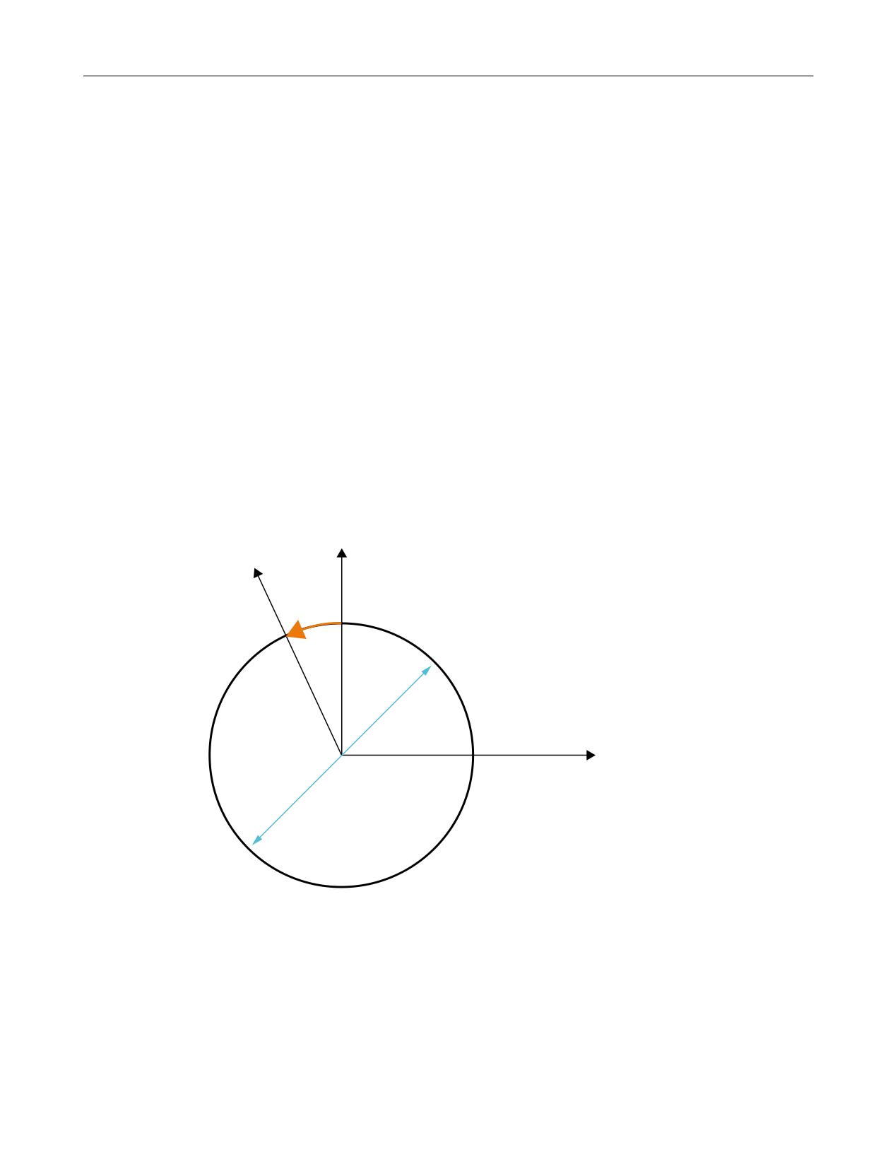
4.5.6.4
Selecting and deselecting transformations: TRACYL
\
F
[
'LDPHWHU G
TRACYL expansions:
The machine data below can be used to take the axis-specific complete frame of the TRACYL
rotary axis, i.e. the translation, fine offset, mirroring and scaling, into account in the
transformation:
• MD24805 $MC_TRACYL_ROT_AX_FRAME_1 = 1
• MD24855 $MC_TRACYL_ROT_AX_FRAME_2 = 1
Basic functions
Function Manual, 10/2020, 6FC5397-2GP40-0BA1
347
Axes, coordinate systems, frames
4.5 Frames
A rotary axis offset can, for example, be entered by compensating the oblique position of a
workpiece in a frame within a frame chain. As a rule, this offset can also be included in the
transformation as an offset in the rotary axis or as a y offset. A C axis offset, as in the figure above,
then leads to corresponding X and Y values.
• MD24805 $MC_TRACYL_ROT_AX_FRAME_1 = 2
• MD24855 $MC_TRACYL_ROT_AX_FRAME_2 = 2
With this setting, the axis-specific offset of the rotary axis is taken account of in the
transformation up to the SZS. The axial offsets of the rotary axis included in the SZS frames are
entered into the transformation frame as offsets on the peripheral surface. This setting is only
effective if the transformation frame has been configured.
Frame expansions:
The expansions described below are only valid for the following machine data settings:
• MD10602 $MN_FRAME_GEOAX_CHANGE_MODE = 1
• MD10602 $MN_FRAME_GEOAX_CHANGE_MODE = 2
The selection of transformation TRACYL produces a virtual geometry axis on the peripheral
surface, coupled via the rotary axis, which is only taken into account in the contour frame but
does not have a reference to an axis-specific frame. All components of the virtual geometry axis
are deleted. All other geometry axes accept their axis-specific components when the
transformation is selected.
Components:
• Translations
When selecting TRACYL, translations of the virtual axis are deleted. Translations of the rotary
axis can be taken into account in the transformation.
• Rotations
Rotations before the transformation are accepted.
• Mirrorings
Mirroring of the virtual axis is deleted. Mirroring of the rotary axis can be taken into account
in the transformation.
• Scalings
Scaling of the virtual axis is deleted. Scaling of the rotary axis can be taken into account in the
transformation.
Example: Machine data
; FRAME configurations
$MC_MM_SYSTEM_FRAME_MASK = 'H41'
; TRAFRAME, SETFRAME
$MC_CHSFRAME_RESET_MASK = 'H41'
; Frames are active after Reset.
$MC_CHSFRAME_POWERON_MASK = 'H41'
; Frames are deleted for Power On.
$MN_FRAME_GEOAX_CHANGE_MODE = 1
; Frames are calculated after switchover
of the geo axis.
Basic functions
348
Function Manual, 10/2020, 6FC5397-2GP40-0BA1
Axes, coordinate systems, frames
4.5 Frames
$MC_RESET_MODE_MASK = 'H4041'
; Basic frame is not deselected after Re-
set.
;$MC_RESET_MODE_MASK = 'H41'
; Basic frame is deselected after Reset.
;$MC_GCODE_RESET_VALUES[7] = 2
; G54 is the default setting.
$MC_GCODE_RESET_VALUES[7] = 1
; G500 is the default setting.
$MN_MM_NUM_GLOBAL_USER_FRAMES = 0
$MN_MM_NUM_GLOBAL_BASE_FRAMES = 3
$MC_MM_NUM_USER_FRAMES = 10
; from 5 to 100
$MC_MM_NUM_BASE_FRAMES = 3
; from 0 to 8
$MN_NCBFRAME_RESET_MASK = 'HFF'
$MC_CHBFRAME_RESET_MASK = 'HFF'
$MN_MIRROR_REF_AX = 0
; No scaling when mirroring.
$MN_MIRROR_TOGGLE = 0
$MN_MM_FRAME_FINE_TRANS = 1
; Fine offset
$MC_FRAME_ADD_COMPONENTS = TRUE
; G58, G59 is possible
; TRACYL with groove wall offset is the 3rd transformation
$MC_TRAFO_TYPE_3 = 513; TRACYL
$MC_TRAFO_AXES_IN_3[0] = 1
$MC_TRAFO_AXES_IN_3[1] = 5
$MC_TRAFO_AXES_IN_3[2] = 3
$MC_TRAFO_AXES_IN_3[3] = 2
$MC_TRAFO_GEOAX_ASSIGN_TAB_3[0] = 1
$MC_TRAFO_GEOAX_ASSIGN_TAB_3[1] = 5
$MC_TRAFO_GEOAX_ASSIGN_TAB_3[2] = 3
$MC_TRACYL_BASE_TOOL_1[0] = 0.0
$MC_TRACYL_BASE_TOOL_1[1] = 0.0
$MC_TRACYL_BASE_TOOL_1[2] = 0.0
$MC_TRACYL_ROT_AX_OFFSET_1 = 0.0
$MC_TRACYL_ROT_SIGN_IS_PLUS_1 = TRUE
$MC_TRACYL_ROT_AX_FRAME_1 = 1
Basic functions
Function Manual, 10/2020, 6FC5397-2GP40-0BA1
349
Axes, coordinate systems, frames
4.5 Frames
Example: Part program
;Simple traversing test with groove side offset
N450 G603
N460
; Frame settings
N500 $P_UIFR[1] = CTRANS(x,1,y,2,z,3,b,4)
N510 $P_UIFR[1] = $P_UIFR[1] : CROT(x,10,y,20,z,30)
N520 $P_UIFR[1] = $P_UIFR[1] : CMIRROR(x,b)
N530
N540 $P_CHBFR[0] = CTRANS(x,10,y,20,z,30,b,15)
N550
N560 G54
N570
; Continuous-path mode with selected smoothing
N590 G0 x0 y0 z-10 b0 G90 F50000 T1 D1 G19 G641 ADIS=1 ADISPOS=5
N600
N610 if $P_BFRAME <> CTRANS(X,10,Y,20,Z,30,B,15)
N620 setal(61000)
N630 endif
N640 if $P_BFRAME <> $P_CHBFR[0]
N650 setal(61000)
N660 endif
N670 if $P_IFRAME <>
TRANS(X,1,Y,2,Z,3,B,4):CROT(X,10,Y,20,Z,30):CMIRROR(X,B)
N680 setal(61000)
N690 endif
N700 if $P_IFRAME <> $P_UIFR[1]
N710 setal(61000)
N720 endif
N730 if $P_ACTFRAME <>
TRANS(X,11,Y,22,Z,33,B,19):CROT(X,10,Y,20,Z,30):CMIRROR(X,B)
N740 setal(61000)
N750 endif
N760
; Transformation ON
N780 TRACYL(40.)
N790
N800 if $P_BFRAME <> CTRANS(X,10,Y,0,Z,30,CAY,20,B,15)
N810 setal(61000)
N820 endif
Basic functions
350
Function Manual, 10/2020, 6FC5397-2GP40-0BA1
Axes, coordinate systems, frames
4.5 Frames
N830 if $P_CHBFR[0] <> CTRANS(X,10,Y,0,Z,30,CAY,20,B,15)
N840 setal(61000)
N850 endif
N860 if $P_IFRAME <>
TRANS(X,1,Y,0,Z,3,CAY,2,B,4):CROT(X,10,Y,20,Z,30):CMIRROR(X,B)
N870 setal(61000)
N880 endif
N890 if $P_UIFR[1] <>
TRANS(X,1,Y,0,Z,3,CAY,2,B,4):CROT(X,10,Y,20,Z,30):CMIRROR(X,B)
N900 setal(61000)
N910 endif
N920 if $P_ACTFRAME <>
TRANS(X,11,Y,0,Z,33,CAY,22,B,19):CROT(X,10,Y,20,Z,30):CMIRROR(X,B)
N930 setal(61001)
N940 endif
N950
N960 $P_UIFR[1,x,tr] = 11
N970 $P_UIFR[1,y,tr] = 14
N980
N990 g54
N1000
N1010 if $P_BFRAME <> CTRANS(X,10,Y,0,Z,30,CAY,20,B,15)
N1020 setal(61000)
N1030 endif
N1040 if $P_BFRAME <> $P_CHBFR[0]
N1050 setal(61000)
N1060 endif
N1070 if $P_IFRAME <>
TRANS(X,11,Y,0,Z,3,CAY,2,B,4):CROT(X,10,Y,20,Z,30):CMIRROR(X,B)
N1080 setal(61000)
N1090 endif
N1100 if $P_IFRAME <> $P_UIFR[1]
N1110 setal(61000)
N1120 endif
N1130 if $P_ACTFRAME <>
TRANS(X,21,Y,0,Z,33,CAY,22,B,19):CROT(X,10,Y,20,Z,30):CMIRROR(X,B)
N1140 setal(61001)
N1150 endif
N1160
; Transformation off
N1180 TRAFOOF
N1190
N1200 if $P_BFRAME <> CTRANS(X,10,Y,20,Z,30,B,15)
N1210 setal(61000)
Basic functions
Function Manual, 10/2020, 6FC5397-2GP40-0BA1
351
Axes, coordinate systems, frames
4.5 Frames
N1220 endif
N1230 if $P_BFRAME <> $P_CHBFR[0]
N1240 setal(61000)
N1250 endif
N1260 if $P_IFRAME <>
TRANS(X,11,Y,2,Z,3,B,4):CROT(X,10,Y,20,Z,30):CMIRROR(X,B)
N1270 setal(61000)
N1280 endif
N1290 if $P_IFRAME <> $P_UIFR[1]
N1300 setal(61000)
N1310 endif
N1320 if $P_ACTFRAME <>
TRANS(X,21,Y,22,Z,33,B,19):CROT(X,10,Y,20,Z,30):CMIRROR(X,B)
N1330 setal(61002)
N1340 endif
N1350
N1360 G00 x0 y0 z0 G90
N1370
N1380 m30
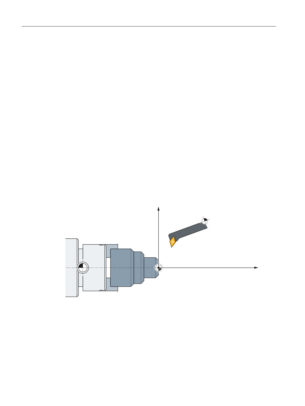
4.5.6.5
Selecting and deselecting transformations: TRAANG
;
=
:
0
Frame expansions:
The expansions described below are only valid for the following machine data settings:
• MD10602 $MN_FRAME_GEOAX_CHANGE_MODE = 1
• MD10602 $MN_FRAME_GEOAX_CHANGE_MODE = 2
Basic functions
352
Function Manual, 10/2020, 6FC5397-2GP40-0BA1
Axes, coordinate systems, frames
4.5 Frames
Components:
• Translations
When selecting TRAANG, translations of the virtual axis are deleted.
• Rotations
Rotations before the transformation are accepted.
• Mirrorings
Mirrorings of the virtual axis are taken over.
• Scalings
Scalings of the virtual axis are taken over.
Example: Machine data
; FRAME configurations
$MC_MM_SYSTEM_FRAME_MASK = 'H1'
; SETFRAME
$MC_CHSFRAME_RESET_MASK = 'H41'
; Frames are active after RESET.
$MC_CHSFRAME_POWERON_MASK = 'H41'
; Frames are deleted for "Power On".
$MN_FRAME_GEOAX_CHANGE_MODE = 1
; Frames are calculated after switchover
of the geo axis.
$MC_RESET_MODE_MASK = 'H4041'
; Basic frame is not deselected after RE-
SET.
;$MC_RESET_MODE_MASK = 'H41'
; Basic frame is deselected after RESET.
;$MC_GCODE_RESET_VALUES[7] = 2
; G54 is the default setting.
$MC_GCODE_RESET_VALUES[7] = 1
; G500 is the default setting.
$MN_MM_NUM_GLOBAL_USER_FRAMES = 0
$MN_MM_NUM_GLOBAL_BASE_FRAMES = 3
$MC_MM_NUM_USER_FRAMES = 10
; from 5 to 100
$MC_MM_NUM_BASE_FRAMES = 3
; from 0 to 8
$MN_NCBFRAME_RESET_MASK = 'HFF'
$MC_CHBFRAME_RESET_MASK = 'HFF'
$MN_MIRROR_REF_AX = 0
; No scaling when mirroring.
$MN_MIRROR_TOGGLE = 0
$MN_MM_FRAME_FINE_TRANS = 1
; Fine offset
$MC_FRAME_ADD_COMPONENTS = TRUE
; G58, G59 is possible.
; TRAANG is the 1st transformation
$MC_TRAFO_TYPE_1 = 1024
Basic functions
Function Manual, 10/2020, 6FC5397-2GP40-0BA1
353
Axes, coordinate systems, frames
4.5 Frames
$MC_TRAFO_AXES_IN_1[0] = 4
; Inclined axis
$MC_TRAFO_AXES_IN_1[1] = 3
; Axis is parallel to z
$MC_TRAFO_AXES_IN_1[2] = 2
$MC_TRAFO_AXES_IN_1[3] = 0
$MC_TRAFO_AXES_IN_1[4] = 0
$MC_TRAFO_GEOAX_ASSIGN_TAB_1[0]=4
$MC_TRAFO_GEOAX_ASSIGN_TAB_1[1]=2
$MC_TRAFO_GEOAX_ASSIGN_TAB_1[2] = 3
$MC_TRAANG_ANGLE_1 = 85.
$MC_TRAANG_PARALLEL_VELO_RES_1 = 0.
$MC_TRAANG_PARALLEL_ACCEL_RES_1 = 0.
$MC_TRAANG_BASE_TOOL_1[0] = 0.0
$MC_TRAANG_BASE_TOOL_1[1] = 0.0
$MC_TRAANG_BASE_TOOL_1[2] = 0.0
; TRAANG is the 2nd transformation
$MC_TRAFO_TYPE_2 = 1024
$MC_TRAFO_AXES_IN_2[0] = 4
$MC_TRAFO_AXES_IN_2[1] = 3
$MC_TRAFO_AXES_IN_2[2] = 0
$MC_TRAFO_AXES_IN_2[3] = 0
$MC_TRAFO_AXES_IN_2[4] = 0
$MC_TRAFO_GEOAX_ASSIGN_TAB_2[0] = 4
$MC_TRAFO_GEOAX_ASSIGN_TAB_2[1] = 0
$MC_TRAFO_GEOAX_ASSIGN_TAB_2[2] = 3
$MC_TRAANG_ANGLE_2 = -85.
$MC_TRAANG_PARALLEL_VELO_RES_2 = 0.2
$MC_TRAANG_PARALLEL_ACCEL_RES_2 = 0.2
$MC_TRAANG_BASE_TOOL_2[0] = 0.0
$MC_TRAANG_BASE_TOOL_2[1] = 0.0
$MC_TRAANG_BASE_TOOL_2[2] = 0.0
Example: Part program
; Frame settings
N820 $P_UIFR[1] = ctrans(x,1,y,2,z,3,b,4,c,5)
Basic functions
354
Function Manual, 10/2020, 6FC5397-2GP40-0BA1
Axes, coordinate systems, frames
4.5 Frames
N830 $P_UIFR[1] = $P_UIFR[1] : crot(x,10,y,20,z,30)
N840 $P_UIFR[1] = $P_UIFR[1] : cmirror(x,c)
N850
N860 $P_CHBFR[0] = ctrans(x,10,y,20,z,30,b,40,c,15)
N870
; Tool selection, clamping compensation, plane selection
N890 T2 D1 G54 G17 G90 F5000 G64 SOFT
N900
; Approach start position
N920 G0 X20 Z10
N930
N940 if $P_BFRAME <> CTRANS(X,10,Y,20,Z,30,B,40,C,15)
N950 setal(61000)
N960 endif
N970 if $P_BFRAME <> $P_CHBFR[0]
N980 setal(61000)
N990 endif
N1000 if $P_IFRAME <>
TRANS(X,1,Y,2,Z,3,B,4,C,5):CROT(X,10,Y,20,Z,30):CMIRROR(X,C)
N1010 setal(61000)
N1020 endif
N1030 if $P_IFRAME <> $P_UIFR[1]
N1040 setal(61000)
N1050 endif
N1060 if $P_ACTFRAME <>
TRANS(X,11,Y,22,Z,33,B,44,C,20):CROT(X,10,Y,20,Z,30):CMIRROR(X,C)
N1070 setal(61000)
N1080 endif
N1090
N1100 TRAANG(,1)
N1110
N1120 if $P_BFRAME <> CTRANS(X,10,Y,20,Z,30,CAX,10,B,40,C,15)
N1130 setal(61000)
N1140 endif
N1150 if $P_BFRAME <> $P_CHBFR[0]
N1160 setal(61000)
N1170 endif
N1180 if $P_IFRAME <>
CTRANS(X,1,Y,2,Z,3,CAX,1,B,4,C,5):CROT(X,10,Y,20,Z,30):CMIRROR(X,CAX,C)
N1190 setal(61000)
N1200 endif
N1210 if $P_IFRAME <> $P_UIFR[1]
Basic functions
Function Manual, 10/2020, 6FC5397-2GP40-0BA1
355
Axes, coordinate systems, frames
4.5 Frames
N1220 setal(61000)
N1230 endif
N1240 if $P_ACTFRAME <>
TRANS(X,11,Y,22,Z,33,CAX,11,B,44,C,20):CROT(X,10,Y,20,Z,30):CMIRROR(X,CAX,
C)
N1250 setal(61001)
N1260 endif
N1270
N1280
N1290 $P_UIFR[1,x,tr] = 11
N1300 $P_UIFR[1,y,tr] = 14
N1310
N1320 g54
N1330
; Set frame
N1350 ROT RPL=-45
N1360 ATRANS X-2 Y10
N1370
; Four-edge roughing
N1390 G1 X10 Y-10 G41 OFFN=1; allowance 1 mm
N1400 X-10
N1410 Y10
N1420 X10
N1430 Y-10
N1440
; Tool change
N1460 G0 Z20 G40 OFFN=0
N1470 T3 D1 X15 Y-15
N1480 Z10 G41
N1490
; Four-edge finishing
N1510 G1 X10 Y-10
N1520 X-10
N1530 Y10
N1540 X10
N1550 Y-10
N1560
Basic functions
356
Function Manual, 10/2020, 6FC5397-2GP40-0BA1
Axes, coordinate systems, frames
4.5 Frames
; Deselect frame
N1580 Z20 G40
N1590 TRANS
N1600
N1610 if $P_BFRAME <> CTRANS(X,10,Y,20,Z,30,CAX,10,B,40,C,15)
N1620 setal(61000)
N1630 endif
N1640 if $P_BFRAME <> $P_CHBFR[0]
N1650 setal(61000)
N1660 endif
N1670 if $P_IFRAME <>
TRANS(X,11,Y,14,Z,3,CAX,1,B,4,C,5):CROT(X,10,Y,20,Z,30):CMIRROR(X,CAX,C)
N1680 setal(61000)
N1690 endif
N1700 if $P_IFRAME <> $P_UIFR[1]
N1710 setal(61000)
N1720 endif
N1730 if $P_ACTFRAME <>
TRANS(X,21,Y,34,Z,33,CAX,11,B,44,C,20):CROT(X,10,Y,20,Z,30):CMIRROR(X,CAX,
C)
N1740 setal(61001)
N1750 endif
N1760
N1770 TRAFOOF
N1780
N1790 if $P_BFRAME <> CTRANS(X,10,Y,20,Z,30,B,40,C,15)
N1800 setal(61000)
N1810 endif
N1820 if $P_BFRAME <> $P_CHBFR[0]
N1830 setal(61000)
N1840 endif
N1850 if $P_IFRAME <>
TRANS(X,1,Y,14,Z,3,B,4,C,5):CROT(X,10,Y,20,Z,30):CMIRROR(X,C)
N1860 setal(61000)
N1870 endif
N1880 if $P_IFRAME <> $P_UIFR[1]
N1890 setal(61000)
N1900 endif
N1910 if $P_ACTFRAME <>
TRANS(X,11,Y,34,Z,33,B,44,C,20):CROT(X,10,Y,20,Z,30):CMIRROR(X,C)
N1920 setal(61002)
N1930 endif
N1940
N1950 m30
Basic functions
Function Manual, 10/2020, 6FC5397-2GP40-0BA1
357

Axes, coordinate systems, frames
4.5 Frames
4.5.6.6
Adapting active frames
The geometry axis constellation can change during the program processing or for RESET. The
number of existent geometry axes varies between zero to three. For non-existent geometry
axes, components in the active frames (e.g. rotations) can cause the active frames for these axis
constellations to become invalid. This is indicated with the "Channel %1 block %2 rotation
programmed for non-existent geometry axis" alarm. The alarm remains pending until the
frames have been changed appropriately.
The automatic adaptation of active frames can be activated with the following machine data:
MD24040 $MC_FRAME_ADAPT_MODE, bit<n> = <value>
Bit
<value>
Meaning
0
1
Rotations in active frames that rotate coordinate axes for which there are no ge-
ometry axes, are deleted from the active frames.
1
1
Shearing angles in active frames are made orthogonal.
2
1
Scaling factors of all geometry axes in the active frames are set to 1.
All rotations in the active frames that could cause coordinate axis motions for non-existent
geometry axes are deleted with the following machine data:
MD24040 $MC_FRAME_ADAPT_MODE = 1
The data management frames are not changed in the process. Only the possible rotations are
accepted for the activation of data management frames.
Example:
No Y axis exists:
• MD20050 $MC_AXCONF_GEOAX_ASSIGN_TAB[0] = 1
• MD20050 $MC_AXCONF_GEOAX_ASSIGN_TAB[1] = 0
• MD20050 $MC_AXCONF_GEOAX_ASSIGN_TAB[2] = 3
• $P_UIFR[1] = CROT(X,45,Y,45,Z,45)
Program code
; Comment
N390 G54 G0 X10 Z10 F10000
IF $P_IFRAME <> CROT(Y,45)
; Only the rotation around Y is transfer-
red
SETAL(61000)
ENDIF
4.5.6.7
Mapped Frames
Overview
The "mapped frames" function supports the cross-channel consistent change of axis-specific
frames inside channel-specific or global data management frames. Using axis-specific machine
data, it is defined between which axes mapping is realized.
Basic functions
358
Function Manual, 10/2020, 6FC5397-2GP40-0BA1
Axes, coordinate systems, frames
4.5 Frames
If frame mapping is, e.g. active for machine axes AX1 and AX4, and the axis-specific frame of axis
AX1 is changed in a channel-specific data management frame (e.g. basic frame $P_CHBFR[x])
(translation, fine translation, scaling, mirroring), then this frame data for AX1 and AX4 is
transferred to all channel-specific data management frames (e.g. basic frame $P_CHBFR[x]) in
all channels in which they are parameterized as channel axes.
Frame mapping is not realized when changing the axis-specific frame data for the rotation.
Requirements
The following requirements must be fulfilled for frame mapping:
• The data management frames used for mapping must be configured:
MD28083 $MC_MM_SYSTEM_DATAFRAME_MASK (system frames)
• Channel-specific data management frames must be explicitly enabled for mapping:
MD10616 $MN_MAPPED_FRAME_MASK (enable frame mapping)
Note
For global data management frames, mapping is always carried out. An enable is not
required.
Parameterization
The parameterization of the mapping relationships is realized in the axis-specific machine data:
MD32075 $MA_MAPPED_FRAME[<AXn>] = "AXm"
AXn, AXm: Machine axis name with n, m = 1, 2, ... max. number of machine axes
Mapping rules
The following rules apply for frame mapping:
• The mapping is bidirectional.
An axis-specific frame can be written for axis AXn or AXm. The frame data is always accepted
and taken for the other axis.
• All parameterized mapping relationships are always evaluated.
When writing an axis-specific frame of axes AXn, all mapping relationships are evaluated and
the frame data accepted for all directly and indirectly involved axes.
• The mapping is global across all channels.
When writing an axis-specific frame of axis AXn or AXm for a channel-specific frame, the
frame data is accepted for all channels in which AXn or AXm are parameterized as channel
axes.
Basic functions
Function Manual, 10/2020, 6FC5397-2GP40-0BA1
359
Axes, coordinate systems, frames
4.5 Frames
• When writing an axis-specific frame using geometry or special axis name, the mapping
relationships are evaluated via the machine axes currently assigned to the geometry or
special axis.
• Mapping is frame-specific.
When writing an axis-specific frame, the frame data is only mapped within the same channel-
specific or global data management frame.
Note
Data consistency
The user / machine manufacturer is solely responsible for ensuring that after a frame is
written, consistent frame data is available in all channels, e.g. by using channel
synchronization.
Basic functions
360
Function Manual, 10/2020, 6FC5397-2GP40-0BA1
Axes, coordinate systems, frames
4.5 Frames
&KDQQHO
&KDQQHO
&KDQQHO
&KDQQHO
&KDQQHO D[HV
*HRPHWU\
DGGLWLRQDO D[HV
0DFKLQH D[LV
;
$;
;
$;
;
$;
;
$;
;
$;
;
$;
;
$;
;
$;
;
$;
;
$;
;
$;
;
$;
;
$;
;
$;
([SOLFLW PDSSLQJ
<
$;
<
$;
,PSOLFLW PDSSLQJ
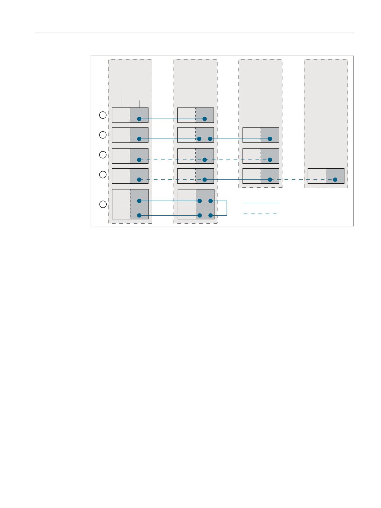
Description
Parameterization: $MA_
① Simple mapping relationship:
MAPPED_FRAME[<AX1>] = "AX4"
AX1(K1) ↔ AX4(K2)
② Chained mapping relationships:
MAPPED_FRAME[<AX1>] = "AX4"
AX1(K1) ↔ AX4(K2) ↔ AX7(K3)
MAPPED_FRAME[<AX4>] = "AX7"
③ Mapping relationship to itself, with AX1 as chan-
MAPPED_FRAME[<AX1>] = "AX1"
nel axis of channels 1, 2 and 3:
AX1(K1+K2+K3)
④ Mapping relationship between two axes, the
MAPPED_FRAME[<AX1>] = "AX4"
channel axes in two channels are:
AX1(K1+K2) ↔ AX4(K3+K4)
⑤ Chained mapping relationships where multiple
MAPPED_FRAME[<AX4>] = "AX7"
channel axes can be written in the same channel:
MAPPED_FRAME[<AX7>] = "AX8"
AX4(K1) ↔ AX7(K2) ↔ AX8(K2) ↔ AX5(K1)
MAPPED_FRAME[<AX8>] = "AX5"
Figure 4-25
Mapping examples
Basic functions
Function Manual, 10/2020, 6FC5397-2GP40-0BA1
361

Axes, coordinate systems, frames
4.5 Frames
Activating the data management frame
Data management frames can be written in the part program and via the user interface of
SINUMERIK Operate. The following should be noted when activating the data management
frames in the channels written directly and via frame mapping:
• Writing in the part program
The data management frames must be explicitly activated in each channel (G500, G54 ...
G599)
• Writing via user interface
Data management frames are written via the user interface, e.g. by entering new work
offsets. A modified data management frame is immediately active in all of the involved
channels if none of these channels is in the "Channel active" state. The data management
frame is not active in any channel if one of the channels involved is in the "Channel active"
state. The activation must then be explicitly programmed in each channel in the part
program (G500, G54 ... G599). Or, the next time that the channel state changes, it becomes
active after "Channel reset".
Example
The following channels and channel axes are parameterized at a control:
• Channel 1
- Z: Geometry axis
- AX1: Machine axis of geometry axis Z
• Channel 2
- Z: Geometry axis
- AX4: Machine axis of geometry axis Z
The zero point of the Z axis should always be the same in both channels:
• Mapping relationship: $MA_MAPPED_FRAME[AX1] = "AX4"
Part programs in channel 1 and 2
Channel 1
Channel 2
N100 WAIT (10,1,2)
N200 WAIT (10,1,2)
N110 $P_UIFR[1] = CTRANS(Z, 10)
N120 WAIT (20,1,2)
N220 WAIT (20,1,2)
N130 G54
N230 G54
N140 IF ($P_IFRAME[0, Z, TR] <> 10)
N230 IF ($P_IFRAME[0, Z, TR] <> 10)
N150
SETAL(61000)
N250
SETAL(61000)
N160 ENDIF
N260 ENDIF
Description:
N100 / N200
Channel synchronization for consistent writing and mapping of frame data
Basic functions
362
Function Manual, 10/2020, 6FC5397-2GP40-0BA1
Axes, coordinate systems, frames
4.5 Frames
N110
Writing of the settable data management frame $P_UIFR[1]:
Moving the zero point of the Z axis to 10 mm
Mapping the axis-specific frame data:
Channel1: Z ≙ AX1 ⇔ channel 2: Z ≙ AX4
N120 / N220
Channel synchronization for consistent activation of new frame data
N130 / N230
Activating the new frame data
N140 / N240
Checking the zero point of the Z axis for: 10 mm
4.5.6.8
Mapped Frames
Overview
The "mapped frames" function supports the cross-channel consistent change of axis-specific
frames inside channel-specific or global data management frames. Using axis-specific machine
data, it is defined between which axes mapping is realized.
If frame mapping is, e.g. active for machine axes AX1 and AX4, and the axis-specific frame of axis
AX1 is changed in a channel-specific data management frame (e.g. basic frame $P_CHBFR[x])
(translation, fine translation, scaling, mirroring), then this frame data for AX1 and AX4 is
transferred to all channel-specific data management frames (e.g. basic frame $P_CHBFR[x]) in
all channels in which they are parameterized as channel axes.
Frame mapping is not realized when changing the axis-specific frame data for the rotation.
Requirements
The following requirements must be fulfilled for frame mapping:
• The data management frames used for mapping must be configured:
MD28083 $MC_MM_SYSTEM_DATAFRAME_MASK (system frames)
• Channel-specific data management frames must be explicitly enabled for mapping:
MD10616 $MN_MAPPED_FRAME_MASK (enable frame mapping)
Note
For global data management frames, mapping is always carried out. An enable is not
required.
Parameterization
The parameterization of the mapping relationships is realized in the axis-specific machine data:
MD32075 $MA_MAPPED_FRAME[<AXn>] = "AXm"
AXn, AXm: Machine axis name with n, m = 1, 2, ... max. number of machine axes
Basic functions
Function Manual, 10/2020, 6FC5397-2GP40-0BA1
363
Axes, coordinate systems, frames
4.5 Frames
Mapping rules
The following rules apply for frame mapping:
• The mapping is bidirectional.
An axis-specific frame can be written for axis AXn or AXm. The frame data is always accepted
and taken for the other axis.
• All parameterized mapping relationships are always evaluated.
When writing an axis-specific frame of axes AXn, all mapping relationships are evaluated and
the frame data accepted for all directly and indirectly involved axes.
• The mapping is global across all channels.
When writing an axis-specific frame of axis AXn or AXm for a channel-specific frame, the
frame data is accepted for all channels in which AXn or AXm are parameterized as channel
axes.
• When writing an axis-specific frame using geometry or special axis name, the mapping
relationships are evaluated via the machine axes currently assigned to the geometry or
special axis.
• Mapping is frame-specific.
When writing an axis-specific frame, the frame data is only mapped within the same channel-
specific or global data management frame.
Note
Data consistency
The user / machine manufacturer is solely responsible for ensuring that after a frame is
written, consistent frame data is available in all channels, e.g. by using channel
synchronization.
Basic functions
364
Function Manual, 10/2020, 6FC5397-2GP40-0BA1
Axes, coordinate systems, frames
4.5 Frames
&KDQQHO
&KDQQHO
&KDQQHO
&KDQQHO
&KDQQHO D[HV
*HRPHWU\
DGGLWLRQDO D[HV
0DFKLQH D[LV
;
$;
;
$;
;
$;
;
$;
;
$;
;
$;
;
$;
;
$;
;
$;
;
$;
;
$;
;
$;
;
$;
;
$;
([SOLFLW PDSSLQJ
<
$;
<
$;
,PSOLFLW PDSSLQJ
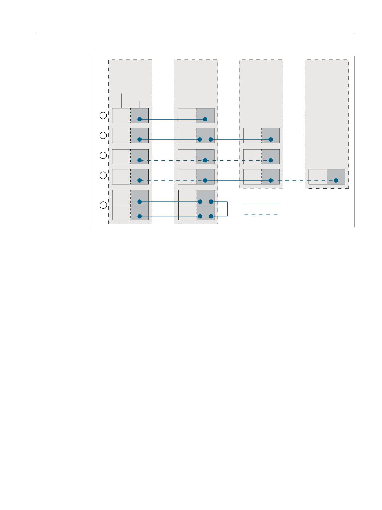
Description
Parameterization: $MA_
① Simple mapping relationship:
MAPPED_FRAME[<AX1>] = "AX4"
AX1(K1) ↔ AX4(K2)
② Chained mapping relationships:
MAPPED_FRAME[<AX1>] = "AX4"
AX1(K1) ↔ AX4(K2) ↔ AX7(K3)
MAPPED_FRAME[<AX4>] = "AX7"
③ Mapping relationship to itself, with AX1 as chan-
MAPPED_FRAME[<AX1>] = "AX1"
nel axis of channels 1, 2 and 3:
AX1(K1+K2+K3)
④ Mapping relationship between two axes, the
MAPPED_FRAME[<AX1>] = "AX4"
channel axes in two channels are:
AX1(K1+K2) ↔ AX4(K3+K4)
⑤ Chained mapping relationships where multiple
MAPPED_FRAME[<AX4>] = "AX7"
channel axes can be written in the same channel:
MAPPED_FRAME[<AX7>] = "AX8"
AX4(K1) ↔ AX7(K2) ↔ AX8(K2) ↔ AX5(K1)
MAPPED_FRAME[<AX8>] = "AX5"
Figure 4-26
Mapping examples
Activating the data management frame
Data management frames can be written in the part program. The following should be noted
when activating the data management frames in the channels written directly and via frame
mapping:
• Writing in the part program
The data management frames must be explicitly activated in each channel (G500, G54 ...
G599)
Basic functions
Function Manual, 10/2020, 6FC5397-2GP40-0BA1
365

Axes, coordinate systems, frames
4.5 Frames
Example
The following channels and channel axes are parameterized at a control:
• Channel 1
- Z: Geometry axis
- AX1: Machine axis of geometry axis Z
• Channel 2
- Z: Geometry axis
- AX4: Machine axis of geometry axis Z
The zero point of the Z axis should always be the same in both channels:
• Mapping relationship: $MA_MAPPED_FRAME[AX1] = "AX4"
Part programs in channel 1 and 2
Channel 1
Channel 2
N100 WAIT (10,1,2)
N200 WAIT (10,1,2)
N110 $P_UIFR[1] = CTRANS(Z, 10)
N120 WAIT (20,1,2)
N220 WAIT (20,1,2)
N130 G54
N230 G54
N140 IF ($P_IFRAME[0, Z, TR] <> 10)
N230 IF ($P_IFRAME[0, Z, TR] <> 10)
N150
SETAL(61000)
N250
SETAL(61000)
N160 ENDIF
N260 ENDIF
Description:
N100 / N200
Channel synchronization for consistent writing and mapping of frame data
N110
Writing of the settable data management frame $P_UIFR[1]:
Moving the zero point of the Z axis to 10 mm
Mapping the axis-specific frame data:
Channel1: Z ≙ AX1 ⇔ channel 2: Z ≙ AX4
N120 / N220
Channel synchronization for consistent activation of new frame data
N130 / N230
Activating the new frame data
N140 / N240
Checking the zero point of the Z axis for: 10 mm
4.5.7
Predefined frame functions
4.5.7.1
Inverse frame
The INVFRAME() function calculates the appropriate inverse frame from a frame.
Basic functions
366
Function Manual, 10/2020, 6FC5397-2GP40-0BA1
Axes, coordinate systems, frames
4.5 Frames
Function description
The chaining between a frame and its inverse frame always produces a zero frame.
FRAME: INVFRAME(FRAME) ⇒ null frame
Frame inversion is an aid for coordinate transformations. Measuring frames are usually
calculated in the WCS. If you wish to transform this calculated frame into another coordinate
system, i.e. the calculated frame should be entered into any arbitrary frame within the frame
chain, then the calculations below should be used.
The new complete frame is a chain of the old complete frame and the calculated frame:
$P_ACTFRAME = $P_ACTFRAME: $AC_MEAS_FRAME
The new frame in the frame chain is therefore:
• Target frame is $P_SETFRAME:
$P_SETFRAME = $P_ACTFRAME: $AC_MEAS_FRAME: INVFRAME($P_ACTFRAME):
$P_SETFRAME
• The target frame is the nth channel basic frame $P_CHBFRAME[<n>]:
k = $MN_MM_NUM_GLOBAL_BASE_FRAMES
- For n = 0, TMP is resolved as:
TMP = $P_PARTFRAME : $P_SETFRAME : $P_EXTFRAME :
$P_NCBFRAME[<0...k>]
- For n ≠ 0, TMP is resolved as:
TMP = $P_PARTFRAME : $P_SETFRAME : $P_EXTFRAME :
$P_NCBFRAME[<0..k>] : $P_CHBFRAME[<0...n> - 1]
$P_CHBFRAME[<n>] = INVFRAME(TMP) : $P_ACTFRAME : $AC_MEAS_FRAME :
INVFRAME($P_ACTFRAME) : TMP : $P_CHBFRAME[<n>]
• The target frame is $P_IFRAME:
TMP = $P_PARTFRAME: $P_SETFRAME: $P_EXTFRAME: $P_BFRAME
$P_IFRAME = INVFRAME(TMP): $P_ACTFRAME: $AC_MEAS_FRAME:
INVFRAME($P_ACTFRAME) : TMP : $P_IFRAME
Example
A frame calculated, for example, using a measuring function, must be entered in the
actual SETFRAME such that the new complete frame is a chain of the old complete frame and
the measurement frame. The SETFRAME is calculated accordingly by means of frame inversions.
Program code
Comment
DEF INT RETVAL
DEF FRAME TMP
$TC_DP1[1,1]=120
; Type
$TC_DP2[1,1]=20.
; 0
$TC_DP3[1,1]= 10.
; (z) length correction vector
$TC_DP4[1,1]= 0.
; (y)
$TC_DP5[1,1]= 0.
; (x)
$TC_DP6[1,1]= 2.
; Radius
T1 D1
g0 x0 y0 z0 f10000
Basic functions
Function Manual, 10/2020, 6FC5397-2GP40-0BA1
367
Axes, coordinate systems, frames
4.5 Frames
Program code
Comment
G54
$P_CHBFRAME[0] = CROT(Z,45)
$P_IFRAME[X,TR] = -SIN(45)
$P_IFRAME[Y,TR] = -SIN(45)
$P_PFRAME[Z,TR] = -45
$AC_MEAS_VALID = 0
; Measure corner with four measuring
points
G1 X-1 Y-3
; 1st Approach measuring point
$AC_MEAS_LATCH[0] = 1
; 1st Store measuring point
G1 X5 Y-3
; 2nd Approach measuring point
$AC_MEAS_LATCH[1] = 1
; 2nd Store measuring point
G1 X-4 Y4
; 3rd Approach measuring point
$AC_MEAS_LATCH[2] = 1
; 3rd Store measuring point
G1 X-4 Y1
; 4th Approach measuring point
$AC_MEAS_LATCH[3] = 1
; 4th Store measuring point
$AA_MEAS_SETPOINT[X] = 0
; Set position setpoint of the corner
$AA_MEAS_SETPOINT[Y] = 0
$AA_MEAS_SETPOINT[Z] = 0
$AC_MEAS_CORNER_SETANGLE = 90
; Define setpoint angle of intersection
$AC_MEAS_WP_SETANGLE = 30
$AC_MEAS_ACT_PLANE = 0
; Measuring plane is G17
$AC_MEAS_T_NUMBER = 1
; Select tool
$AC_MEAS_D_NUMBER = 1
$AC_MEAS_TYPE = 4
; Set measuring type on corner 1
RETVAL = MEASURE()
; Start measuring process
IF RETVAL <> 0
SETAL(61043, << RETVAL)
ENDIF
IF $AC_MEAS_WP_ANGLE <> 30
SETAL(61043, << $AC_MEAS_WP_ANGLE)
ENDIF
IF $AC_MEAS_CORNER_ANGLE <> 90
SETAL(61043, << $AC_MEAS_CORNER_ANGLE)
ENDIF
; Transform measured frame and write to $P_SETFRAME so that a complete frame is cre-
ated,
; which linked from the old total frame results in the measurement frame.
$P_SETFRAME = $P_ACTFRAME: $AC_MEAS_FRAME: INVFRAME($P_ACTFRAME): $P_SETFRAME
$P_SETFR = $P_SETFRAME
; Describe system frames in data manage-
ment
G1 X0 Y0
; Approach the corner
G1 X10
; Retract the rectangle rotated about 30
degrees
Y10
X0
Basic functions
368
Function Manual, 10/2020, 6FC5397-2GP40-0BA1

Axes, coordinate systems, frames
4.5 Frames
Program code
Comment
Y0
M30
4.5.7.2
Additive frame in frame chain
Measurements on the workpiece or calculations in the part program or cycle often produce a
frame that is applied additively to the active complete frame. This causes, for example, the WCS
and thus the programming zero point to be displaced and/or possibly rotated. The measured
frame so exists in a frame variable and has not yet been included in the frame chain calculation.
Function description
The ADDFRAME() function calculates from the temporary frame the specified target frame
specified by the <STRING> parameter so that the new active $P_ACTFRAME complete frame
from the chaining of the old active complete frame with the temporary frame gives:
ERG = ADDFRAME(TMPFRAME,"$P_SETFRAME") ⇒ $P_SETFRAMEnew = $P_SETFRAMEold
ADD TMPFRAME and $P_ACTFRAMEnew = $P_ACTFRAMEold : TMPFRAME
If an active frame has been specified as a target frame, the new complete frame becomes active
at the preprocessing stage.
If the target frame is a data management frame, the frame becomes active only when it is
activated explicitly in the channel, e.g. part program or cycle.
The function returns a return value for which a user-specific response is possible, e.g. in a user
cycle.
Programming
Syntax
INT ADDFRAME(<FRAME>,<STRING>)
Meaning
<FRAME>:
Frame variable with the values to be included additively in the calculation
Type
FRAME
<STRING>:
The name of an active or data management frame:
• Active frames
"$P_CYCFRAME", "$P_ISO4FRAME", "$P_PFRAME", "$P_WPFRAME",
"$P_TOOLFRAME", "$P_IFRAME", "$P_GFRAME", "$P_CHBFRAME[<n>]",
"$P_NCBFRAME[<n>]", "$P_ISO1FRAME", "$P_ISO2FRAME",
"$P_ISO3FRAME", "$P_EXTFRAME", "$P_SETFRAME", "$P_PARTFRAME"
• Data management frames
"$P_CYCFR", "$P_ISO4FR, "$P_TRAFR", "$P_WPFR", "$P_TOOLFR",
"$P_UIFR[<n>]", "$P_GFR", "$P_CHBFR[<n>]", "$P_NCBFR[<n>]",
"$P_ISO1FR, "$P_ISO2FR, "$P_ISO3FR, "$P_EXTFR", "$P_SETFR",
"$P_PARTFR"
Type
STRING
Basic functions
Function Manual, 10/2020, 6FC5397-2GP40-0BA1
369
Axes, coordinate systems, frames
4.5 Frames
Return value:
Possible return values:
•
0: OK
•
1: Specified target (string) is wrong
•
2: Target frame is not configured
•
3: Rotation in frame is not permitted
Type
INT
4.5.8
Functions
4.5.8.1
Setting zeros, workpiece measuring and tool measuring
Set actual value is initiated by means of an HMI operator action or via measuring cycles. The
calculated frame can be written to system frame SETFRAME. The position setpoint of an axis in
the WCS can be altered during set actual value.
The term "scratching" refers to both the workpiece and tool measurement. The position of the
workpiece can be measured in relation to an edge, a corner or a hole. To determine the zero
position of the workpiece or the hole, position setpoints can be added to the measured positions
in the WCS. The resulting offsets can be entered in a selected frame. In the tool measurement,
the length or radius of a tool can be measured using a measured reference part.
The measurements can be initiated by means of an operator action or via measuring cycles.
Communication with the NC takes place via predefined system variables. The calculation is
performed in the NC when a PI service is activated by means of an HMI operator action or via a
part program command from the measuring cycles. A tool and a plane can be selected as a basis
for the calculation. The calculated frame is entered in the result frame.
4.5.8.2
Axis-specific external work offset
Machine data
The external work offset or the $P_EXTFRAME system frame is activated with the following
machine data:
MD28082 $MC_MM_SYSTEM_FRAME_MASK, bit 1 = TRUE
The magnitude for the external work offset can be specified manually via the HMI user interface,
and the PLC user program via OPI or programmed in the part program via the axial system
variable $AA_ETRANS[<axis>].
Activation
The external work offset is activated with the interface signal:
DB31, ... DBX3.0 (accept external work offset)
Behavior
Upon activation of the external work offset, the traversing movements of all axes, except
command and PLC axes, are stopped immediately and the advance is reorganized. The rough
offset of the current system frame and of the system frame in data management is set to the
Basic functions
370
Function Manual, 10/2020, 6FC5397-2GP40-0BA1

Axes, coordinate systems, frames
4.5 Frames
value of the axial system variable $AA_ETRANS[<axis>]. Thereafter, the offset is traversed first
and then the interrupted movement is continued.
Behavior for incremental dimension
In case of active incremental dimension G91 and machine data:
MD42440 $MC_FRAME_OFFSET_INCR_PROG (work offset in frames) = 0
traversing the offset is done in the scope of the external work offset via system frame, despite
opposite configuring of the machine data, with the approach block, although it is specified by a
frame.
Note
The external work offset always acts absolutely.
4.5.8.3
Toolholder
Translations
With kinematics of type "P" and "M", the selection of a toolholder activates an additive frame
(table offset of the orientable toolholder) which takes into account the work offset as a result of
the rotation of the table. The work offset is entered in the system frame $P_PARTFR. In this case
the translatory component of this frame is overwritten. The other frame components are
retained.
The system frame $P_PARTFR must be enabled via the following machine data:
MD28082 $MC_MM_SYSTEM_FRAME_MASK, bit 2 = 1 (system frame for TCARR and PAROT)
Note
Alternatively, the offset can also parameterized via machine data to record the table offset:
MD20184 $MC_TOCARR_BASE_FRAME_NUMBER = <number of the basic frame>
This option is only for compatibility reasons to older software versions. You are strongly
recommended not to use this procedure any longer.
A frame offset as a result of a toolholder change becomes effective immediately on selection of
TCARR=
A change in the tool length, on the other hand, only becomes effective
immediately if a tool is active.
A frame rotation is not executed with the activation, or a rotation which is already active is not
changed. As in case T (only the tool can be rotated), the position of the rotary axes used for the
calculation is dependent on the command TCOFR/TCOABS and determined from the rotation
component of an active frame or from the $TC_CARR entries. Activation of a frame changes the
position in the workpiece coordinate system accordingly, without compensating motion by the
machine itself.
The ratios are shown in the figure below:
Basic functions
Function Manual, 10/2020, 6FC5397-2GP40-0BA1
371
Axes, coordinate systems, frames
4.5 Frames
2ULJLQDO SRVLWLRQ RI WKH FRRUGLQDWH V\VWHP
&RRUGLQDWH V\VWHP SRVLWLRQ DIWHU
7&$55
&RRUGLQDWH V\VWHP SRVLWLRQ DIWHU
2ULJLQDO
3$527
SRVLWLRQ RI
WDEOH
3RVLWLRQ RI WKH WDEOH
DIWHU URWDWLRQ
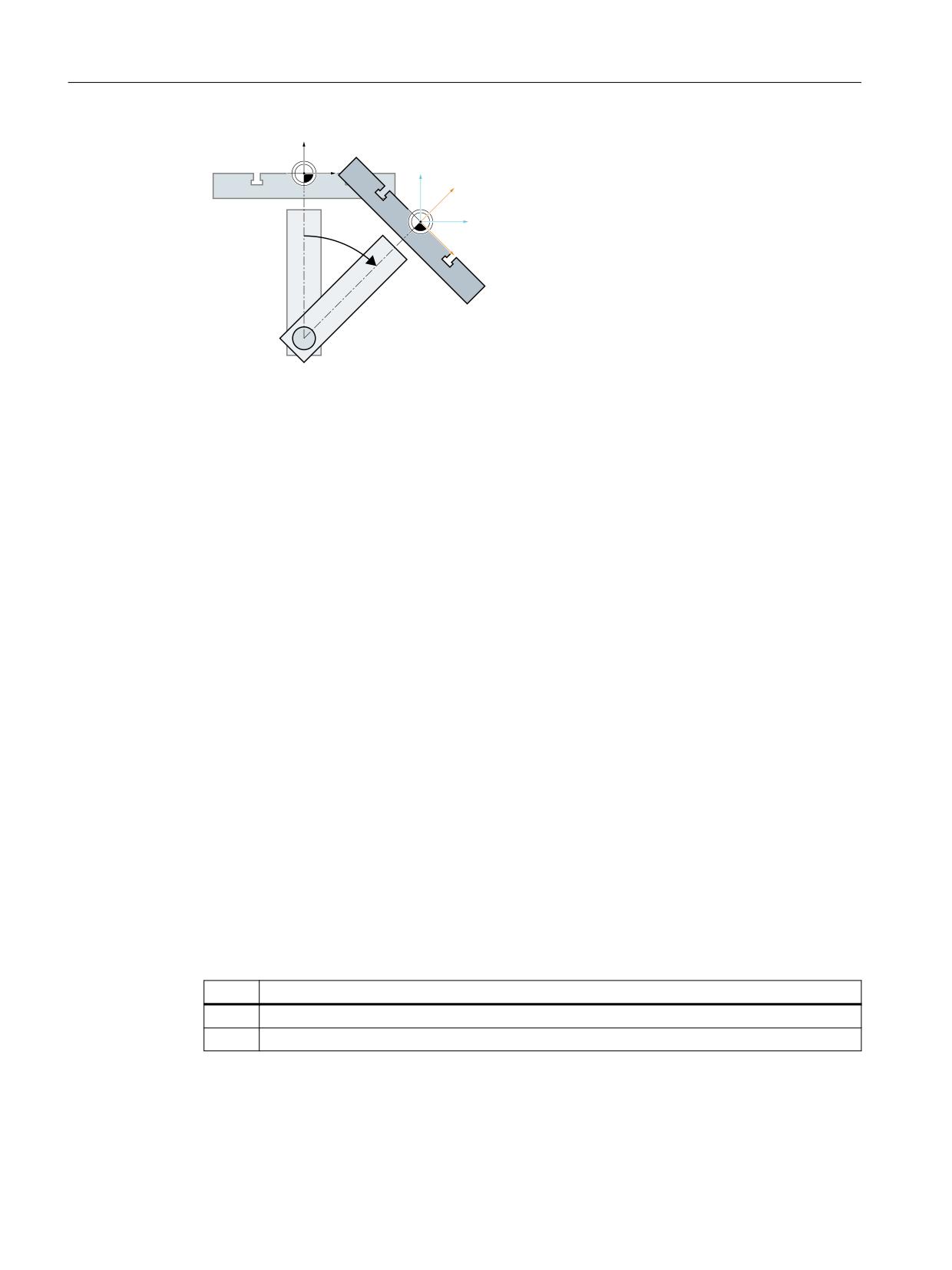
Figure 4-27
Frame on activation of a rotary table with TCARR
With kinematics of type M (tool and table are each rotary around one axis), the activation of a
toolholder with TCARR simultaneously produces a corresponding change in the effective tool
length (if a tool is active) and the work offset.
Rotations
Depending on the machining task, it is necessary to take into account not only a work offset
(whether as frame or as tool length) when using a rotary toolholder or table, but also a rotation.
However, the activation of an orientable toolholder never leads directly to a rotation of the
coordinate system.
If only the tool can be rotated, a frame can be defined for it using TOFRAME or TOROT.
With rotary tables (kinematics types P and M), activation with TCARR similarly does not lead to
an immediate rotation of the coordinate system, i.e. even though the zero point of the
coordinate system is offset relative to the machine, while remaining fixed relative to the zero
point of the workpiece, the orientation remains unchanged in space.
If the coordinate system needs to be fixed relative to the workpiece, i.e. not only offset relative
to the original position but also rotated according to the rotation of the table, then PAROT can
be used to activate such a rotation in a similar manner to the situation with a rotary tool.
With PAROT, the translations, scalings and mirroring in the active frame are retained, but the
rotation component is rotated by the rotation component of an orientable toolholder
corresponding to the table. The entire programmable frame including its rotation component
remains unchanged.
The rotation component that describes the rotation of the table is then either entered in the
system frame $PARTFR or in the basic frame parameterized with MD20184
$MC_TOCARR_BASE_FRAME_NUMBER:
$MC_MM_SYSTEM_FRAME_MASK, bit 2 = <value>
Value
Meaning
1
Rotation component → $PARTFR
0
Rotation component → MD20184 $MC_TOCARR_BASE_FRAME_NUMBER
As with the note made in the description of the table offset, the second alternative here is not
recommended for use with new systems.
The rotation component of the part frame can be deleted with PAROTOF, irrespective of
whether this frame is in a basic or a system frame.
Basic functions
372
Function Manual, 10/2020, 6FC5397-2GP40-0BA1
Axes, coordinate systems, frames
4.5 Frames
The translation component is deleted when a toolholder which does not produce an offset is
activated or a possibly active orientable toolholder is deselected with TCARR=0.
PAROT or TOROT take into account the overall orientation change in cases where the table or the
tool are oriented with two rotary axes. With mixed kinematics, only the corresponding
component caused by a rotary axis is considered. It is thus possible, for example, when using
TOROT, to rotate a workpiece such that an inclined plane lies parallel to the XY plane fixed in
space, whereby rotation of the tool must be taken into account in machining where any holes
to be drilled, for example, are not perpendicular to this plane.
Example
On a machine, the rotary axis of the table points in the positive Y direction. The table is rotated
by +45 degrees. PAROT defines a frame which similarly describes a rotation of 45 degrees
around the Y axis. The coordinate system is not rotated relative to the actual environment
(marked in the figure with "Position of the coordinate system after TCARR"), but is rotated by -45
degrees relative to the defined coordinate system (position after PAROT). If this coordinate
system is defined with ROT Y-45, for example, and if the toolholder is then selected with active
TCOFR, an angle of +45 degrees will be determined for the rotary axis of the toolholder.
Language command PAROT is not rejected if no orientable toolholder is active. However, such
a call then produces no frame changes.
Machining in direction of tool orientation
Particularly on machines with tools that can be oriented, traversing should take place in the tool
direction (typically, when drilling) without activating a frame (e.g. using TOFRAME or TOROT),
on which one of the axes points in the direction of the tool. This is also a problem if, when
carrying out inclined machining operations, a frame defining the inclined plane is active, but the
tool cannot be set exactly perpendicularly because an indexed toolholder (Hirth tooth system)
prevents free setting of the tool orientation. In these cases it is then necessary - contrary to the
motion actually requested perpendicular to the plane - to drill in the tool direction, as the drill
would otherwise not be guided in the direction of its longitudinal axis (tool breaks).
Incremental traversing
The end point for incremental traversing motion in the tool direction is programmed using
MOVT = <Value> or MOVT=IC(<Value>).
The positive traversing direction is defined from the tool tip to the tool adapter. Corresponding
to paraxial machining, e.g. with G91 Z
Absolute traversing
The end point for absolute incremental traversing motion in the tool direction is programmed
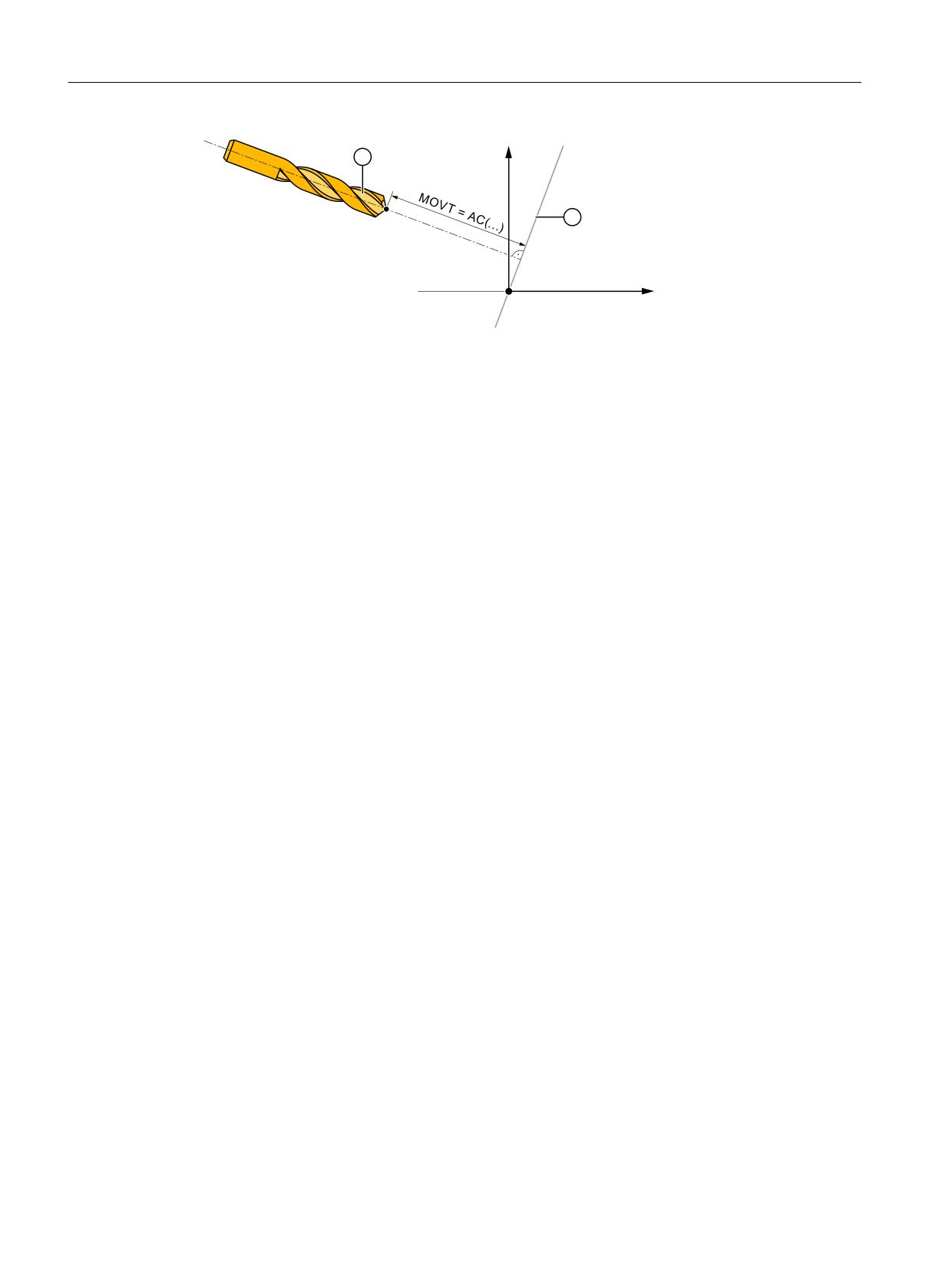
using MOVT=AC(<Value>).
In this case a plane is defined, which runs through the current zero point, and whose surface
normal vector is parallel to the tool orientation. MOVT then gives the position relative to this
plane (see figure). The reference plane is only used to calculate the end position. Active frames
are not affected by this internal calculation.
Basic functions
Function Manual, 10/2020, 6FC5397-2GP40-0BA1
373
Axes, coordinate systems, frames
4.5 Frames
=
;
Programming with MOVT is independent of the existence of a toolholder that can be oriented.
The direction of the motion is dependent on the active plane.
It runs in the directions of the vertical axes, i.e. with G17 in Z direction, with G18 in Y direction
and with G19 in X direction. This applies when no orientable toolholder is active and for the case
of an orientable toolholder without rotary tool or with a rotary tool in its basic setting.
MOVT acts similarly for active orientation transformation (3-, 4-, 5-axis transformation).
If in a block with MOVT the tool orientation is changed simultaneously (e.g. active 5-axis
transformation by means of simultaneous interpolation of the rotary axes), the orientation at
the start of the block is decisive for the direction of motion of MOVT.
With an active 5-axis transformation, the path of the tool center point (TCP) is not affected by the
change of orientation, i.e. the path remains a straight line and its direction is determined by the
tool orientation at the start of the block.
If MOVT is programmed, linear or spline interpolation must be active (G0,G1, ASPLINE,
BSPLINE, CSPLINE). Otherwise, an alarm is produced.
If a spline interpolation is active, the resultant path is generally not a straight line, since the end
point calculated by MOVT is treated as if it had been programmed explicitly with X, Y, Z.
It is not permissible to program geometry axes in a block with MOVT.
Definition of frame rotations with solid angles
Where a frame is to be defined to describe a rotation around more than one axis, this is achieved
through chaining individual rotations. The subsequent rotation is realized in the newly rotated
coordinate system.
This applies both to programing in one block - and when configuring a frame in several
consecutive blocks:
• One block: N10 ROT X... Y... Z...
• Several consecutive blocks:
N10 ROT Y...
N20 AROT X...
N30 AROT Z...
Solid angle
Often, solid angles are specified in workpiece drawings to define inclined surfaces. Solid angles
are angles which the intersection lines of the inclined plane form with the main planes (X-Y, Y-
Z, Z-X planes) of the workpiece coordinate system (see diagram). The orientation of a plane in
space is defined unambiguously by specifying two solid angles. The third solid angle is derived
from the first two.
Basic functions
374
Function Manual, 10/2020, 6FC5397-2GP40-0BA1
Axes, coordinate systems, frames
4.5 Frames
Rotations can be directly defined as solid angle using ROTS, AROTS and CROTS commands.
It is permissible to specify a single solid angle. The rotation which is performed with ROTS or
AROTS in this case is identical to that for ROT and AROT.
The two axes programmed in the command define a plane. The non-programmed axis defines
the associated third axis of a coordinate system. This also means that for the two programmed
axes, it is uniquely defined which is the first axis and which is the second axis. The definition
corresponds to the definition of a plane for G17/G18/G19.
The angle programmed with the axis letter of an axis of the plane then specifies the axis, around
which the other axis of the plane must be rotated in order to move this into the line of
intersection, which the rotated plane forms with the plane surrounded by the other and the third
axis. This definition ensures that, in the case that one of the two programmed angles is towards
zero, the defined plane enters the plane, which is created if only one axis is programmed (e.g.
with ROT or AROT).
Basic functions
Function Manual, 10/2020, 6FC5397-2GP40-0BA1
375
Axes, coordinate systems, frames
4.5 Frames
=
=
<ಿ
=ಿ
3
3
<
<
6
3
˞
3
3
˟
=ಿ
˟
;ಿ
6
˞
3
<ಿ
;
;
;ಿ
=
=
<ಿ
<ಿ
3
3
<
<
=ಿ
˞
3
6
;ಿ
6
=ಿ
˟
˟
˞
3
3
3
;
;
;ಿ
I, ...,
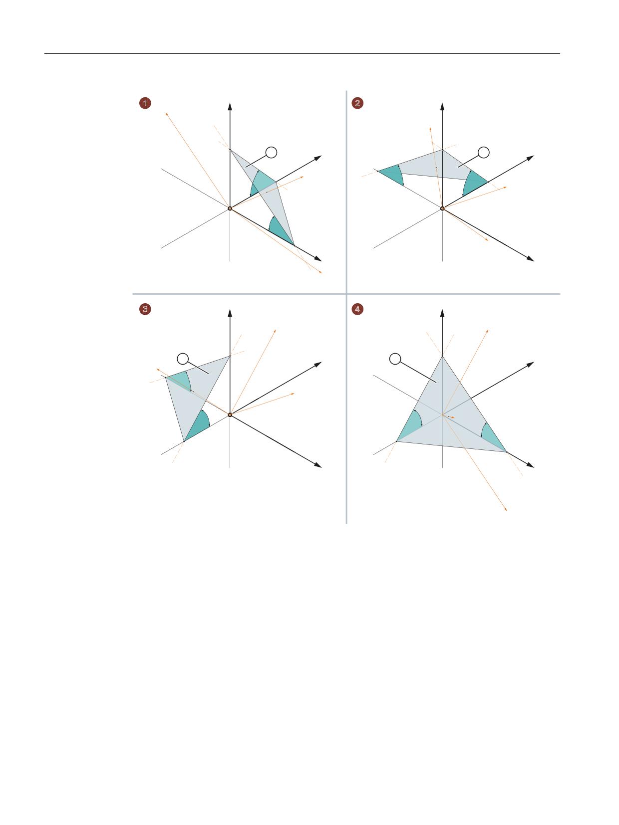
Quadrants 1 to 4
IV
① Inclined plane as specification for the new G17 plane
α, β Solid angle of the inclined plane
Figure 4-28
Rotation around the solid angle
In the diagram, the solid angles are shown for an example of a plane in quadrants I to IV. The
inclined plane defines the alignment of the G17 plane after rotating the workpiece coordinate
Basic functions
376
Function Manual, 10/2020, 6FC5397-2GP40-0BA1
Axes, coordinate systems, frames
4.5 Frames
system WCS. The sign of the solid angle specifies the direction around which the coordinate
system is rotated around the relevant axis.
1. Rotation around y:
Rotation of the workpiece coordinate system WCS around the y axis around the signed angle
α ⇒
The x' axis is aligned parallel (colinear) to the intersection lines of the xz plane with the
inclined plane
2. Rotation around x':
Rotation of the new workpiece coordinate system WCS around the x' axis around the signed
angle β ⇒
- The y' axis is aligned in parallel (colinear) to the intersection lines of the zy plane with the
inclined plane
- The z' axis is perpendicular to the inclined plane
- G17' lies in parallel to the inclined plane
The programming to align the G17 plane of the workpiece coordinate system WCS to the
inclined plane is, for each quadrant:
• Quadrant I: ROTS X<+α> Y<-β>
• Quadrant II: ROTS X<-α> Y<-β>
• Quadrant III: ROTS X<-α> Y<+β>
• Quadrant IV: ROTS X<+α> Y<+β>
Orientation
The specification of the solid angle does not define the orientation of the two-dimensional
coordinate system within the plane (i.e. the angle of rotation around the surface normal vector).
The position of the coordinate system is thus determined so that the rotated first axis lies in the
plane which is formed by the first and third axes of the non-rotated coordinate system.
This means that
• When programming X and Y, the new X axis lies in the original Z-X plane.
• When programming Z and X, the new Z axis lies in the original Y-Z plane.
• When programming Y and Z, the new Y axis lies in the original X-Y plane.
If the required coordinate system does not correspond to this basic setting, then an additional
rotation must be performed with AROT
Parameterization: zy'x'' (RPY angle) or zx'z'' convention
The programmed solid angles are converted to the equivalent Euler angles according to the the
zy'x" convention (RPY angle) or zx'z" convention when entering depending on the following
machine data:
MD10600 $MN_FRAME_ANGLE_INPUT_MODE
Basic functions
Function Manual, 10/2020, 6FC5397-2GP40-0BA1
377
Axes, coordinate systems, frames
4.5 Frames
Frame rotation in tool direction
With the language command TOFRAME, which also existed in older software versions, it is
possible to define a frame whose Z axis points in the tool direction.
An already programmed frame is then overwritten by a frame which describes a pure rotation.
Any work offsets, mirrorings or scalings existing in the previously active frame are deleted.
This response is sometimes interfering. It is often particularly practical to retain a work offset,
with which the reference point in the workpiece is defined.
The language command TOROT is then also used. This command overwrites only the rotation
component in the programmed frame and leaves the remaining components unchanged. The
rotation defined with TOROT is the same as that defined with TOFRAME.
TOROT is, like TOFRAME, independent of the availability of an orientable toolholder. This
language command is also especially useful for 5-axis transformations.
The new language command TOROT ensures consistent programming with active orientable
toolholders for each kinematics type.
TOFRAME or TOROT defines frames whose Z direction points in the tool direction. This definition
is suitable for milling, where G17 is usually active. However, particularly with turning or, more
generally, when G18 or G19 is active, it is desirable that frames which will be aligned on the X
or Y axis, can be defined. For this purpose, the following commands are available in G group 53:
• TOFRAMEX, TOFRAMEY, TOFRAMEZ
• TOROTX, TOROTY, TOROTZ
The appropriate frames can be defined with these commands. The functions of TOFRAME and
TOFRAMEZ or of TOROT and TOROTZ are identical to one another.
The frames resulting from TOROT or TOFRAME can be written in a separate system frame
($P_TOOLFR). The programmable frame is then retained unchanged.
• Requirement: MD28082 $MC_MM_SYSTEM_FRAME_MASK, bit 3 = 1
When programming TOROT or TOFRAME, etc. response is identical, with or without a system
frame. Differences occur when the programmable frame is processed further elsewhere.
Note
In new systems, it is recommended that only the intended system frame is used for frames
produced by the commands of G group 53.
Example
TRANS is programmed after TOROT. TRANS without specified parameters deletes the
programmable frame. In the variant without a system frame, this also deletes the frame
component of the programmable frame produced by TOROT, but if the TOROT component is in
the system frame, it is retained.
TOROT or TOFRAME, etc. are disabled with language command TOROTOF. TOROTOF deletes the
entire system frame $P_TOOLFR. If the programmable frame (old variant) and not the system
frame is described by commands TOFRAME, etc. TOROT only deletes the rotation component
and leaves the remaining frame components unchanged.
If a rotating frame is already active before language command TOFRAME or TOROT is activated,
a request is often made that the newly defined frame should deviate as little as possible from the
old frame. This is the case, for example, if a frame definition needs to be modified slightly
Basic functions
378
Function Manual, 10/2020, 6FC5397-2GP40-0BA1
Axes, coordinate systems, frames
4.5 Frames
because the tool orientation cannot be set freely on account of Hirth-toothed rotary axes. The
language commands uniquely define the Z direction of the new frame.
Parameterization: Frame definition for TOFRAME, TOROT and PAROT (SD42980)
With the following setting data, the direction of the geometry axes of the actual machining
plane (G17: X and Y axis) for the frame definition is defined using TOFRAME, TOROT
(TOROTY, TOROTX) or PAROT.
For a frame calculation, the tool direction is defined, so that the tool direction and applicate
(G17: Z axis) of the frame are parallel and perpendicular to the machining plane.
Initially, rotation around the tool axis is arbitrary. Using the setting data, this free rotation can be
defined so that the newly defined frame deviates as little as possible from a previously active
frame.
In all cases where the setting data is not equal to zero, an active frame remains unchanged if the
tool direction of the old and the new frame match one another.
SD42980 $SC_TOFRAME_MODE
TCARR (request toolholder) and PAROT (align workpiece coordinate system on the workpiece)
TCARR uses the basic frame identified by following machine data:
MD20184 $MC_TOCARR_BASE_FRAME_NUMBER.
A system frame can be created for TCARR and PAROT alone, in order to avoid conflicts with
systems, which already use all the basic frames.
PAROT, TOROT and TOFRAME have previously changed the rotation component of the
programmable frames. In this case, it is not possible to shut down PAROT or TOROT separately.
On RESET, the programmable frame is deleted, which means that after changing the operating
mode to JOG, the rotation component of PAROT and TOROT is no longer available. The user must
also have unrestricted access to the programmable frame. Frames produced by PAROT and
TOROT must be able to be archived and reloaded via data backup.
The system frame for TCARR and PAROT is configured with:
MD28082 $MC_MM_SYSTEM_FRAME_MASK, bit 2 = 1
The following machine data is then no longer evaluated:
MD20184 $MC_TOCARR_BASE_FRAME_NUMBER
If the system frame for TCARR is configured, TCARR and PAROT describe that corresponding
system frame; otherwise the basic frame identified by machine data MD20184 is described.
With kinematics systems of the types P and M, TCARR will enter the table offset of the orientable
toolholder (work offset resulting from the rotation of the table) as a translation into the system
frame. PAROT converts the system frame so that a workpiece-related WCS results.
The system frames are stored retentively and therefore retained after a reset. The system frames
also remain active in the case of a mode change.
For the display, the commands PAROT and TOROT, TOFRAME are each assigned to a separate G
group.
Basic functions
Function Manual, 10/2020, 6FC5397-2GP40-0BA1
379
Axes, coordinate systems, frames
4.5 Frames
PAROTOF
PAROTOF is the switch off command for PAROT. This command deletes the rotations in the
system frame for PAROT. In so doing, the rotations in the current $P_PARTFRAME and in the data
management frame $P_PARTFR are deleted. The position of the coordinate system is then
recreated according to TCARR. PAROTOF is in the same G group as PAROT and appears therefore
in the G command display.
TOROT (align Z axis of the WCS by rotating the frame parallel to the tool orientation) and TOFRAME
(ditto.)
The system frame for TOROT and TOFRAME is activated via the following machine data:
MD28082 $MC_MM_SYSTEM_FRAME_MASK, bit 3 = 1
This system frame is located before the programmable frame in the frame chain.
The SZS coordinate system is located before the programmable frame.
TOROTOF
TOROTOF is the switch off command for TOROT and TOFRAME. This command deletes the
corresponding system frame. The current $P_TOOLFRAME and the data management frame
$P_TOOLFR are also deleted. TOROTOF is in the same G group as TOROT and TOFRAME and
appears therefore in the G command display.
Example
Use of an orientable toolholder with resolved kinematics.
N10 $TC_DP1[1,1]=120
N20 $TC_DP3[1,1]= 13
; Tool length 13 mm
; Definition of toolholder 1:
N30 $TC_CARR1[1] = 0
; X component of the 1st offset vector
N40 $TC_CARR2[1] = 0
; Y component of the 1st offset vector
N50 $TC_CARR3[1] = 0
; Z component of the 1st offset vector
N60 $TC_CARR4[1] = 0
; X component of the 2nd offset vector
N70 $TC_CARR5[1] = 0
; Y component of the 2nd offset vector
N80 $TC_CARR6[1] = -15
; Z component of the 2nd offset vector
N90 $TC_CARR7[1] = 1
; X component of the 1st axis
N100 $TC_CARR8[1] = 0
; Y component of the 1st axis
N110 $TC_CARR9[1] = 0
; Z component of the 1st axis
N120 $TC_CARR10[1] = 0
; X component of the 2nd axis
N130 $TC_CARR11[1] = 1
; Y component of the 2nd axis
N140 $TC_CARR12[1] = 0
; Z component of the 2nd axis
N150 $TC_CARR13[1] = 30
; Angle of rotation of 1st axis
N160 $TC_CARR14[1] = -30
; Angle of rotation of 2nd axis
N170 $TC_CARR15[1] = 0
; X component of the 3rd offset vector
N180 $TC_CARR16[1] = 0
; Y component of the 3rd offset vector
N190 $TC_CARR17[1] = 0
; Z component of the 3rd offset vector
N200 $TC_CARR18[1] = 0
; X component of the 4th offset vector
Basic functions
380
Function Manual, 10/2020, 6FC5397-2GP40-0BA1
Axes, coordinate systems, frames
4.5 Frames
N210 $TC_CARR19[1] = 0
; Y component of the 4th offset vector
N220 $TC_CARR20[1] = 15
; Z component of the 4th offset vector
N230 $TC_CARR21[1] = A
; Reference for 1st axis
N240 $TC_CARR22[1] = B
; Reference for 2nd axis
N250 $TC_CARR23[1] = "M"
; Toolholder type
N260 X0 Y0 Z0 A0 B45 F2000
N270 TCARR=1 X0 Y10 Z0 T1 TCOABS
; Selection of orientable tool holder
N280 PAROT
; Rotation of table
N290 TOROT
; Rotation of z axis in tool orient.
N290 X0 Y0 Z0
N300 G18 MOVT=AC(20)
; Processing in G18 plane
N310 G17 X10 Y0 Z0
; Processing in G17 plane
N320 MOVT=-10
N330 PAROTOF
; Deactivate rotation of table
N340 TOROTOF
; No longer align WCS with tool
N400 M30
4.5.9
Subprograms with SAVE attribute (SAVE)
For various frames, the behavior regarding subprograms can be set using the SAVE attribute.
Settable frames G54 to G599
The behavior of the adjustable frames can be set using MD10617
$MN_FRAME_SAVE_MASK.BIT0 :
• BIT0 = 0
If using the subprogram, only the values of the active adjustable frame are changed using the
system variable $P_IFRAME, but the G command is kept, then the change is also kept after the
end of the subprogram.
• BIT0 = 1
With the end of the subprogram, the adjustable frame, G command and values, active before
the subprogram call, are reactivated.
Basic frames $P_CHBFR[ ] and $P_NCBFR[ ]
The behavior of the basic frame can be set using MD10617 $MN_FRAME_SAVE_MASK.BIT1:
• BIT1 = 0
If the active basic frame is changed by the subprogram, the change remains effective even
after the end of the subprogram.
• BIT1 = 1
With the end of the subprogram the basic frame which is active before the subprogram call
is reactivated.
Basic functions
Function Manual, 10/2020, 6FC5397-2GP40-0BA1
381
Axes, coordinate systems, frames
4.5 Frames
Programmable frame
With the end of the subprogram the programmable frame active before the subprogram call is
reactivated.
System frames
If the system frames are changed by the subprogram, the change remains effective even after
the end of the subprogram.
4.5.10
Data backup
Data blocks
The data backup of the frames is performed in the following data blocks:
• Channel-specific frames ⇒ _N_CHAN<x>_UFR data blocks
• Global frames ⇒ _N_NC_UFR data block
Note
• It is strongly recommended that the following machine data is not changed between the
backup and restoration of the saved system frames. Otherwise, it is possible that the saved
system frames cannot be loaded.
MD28082 $MC_MM_SYSTEM_FRAME_MASK (configuration of channel-specific system
frames that are included in the channel calculation)
• The data backup is always performed in accordance with geometry axis assignments
currently valid in the channel rather than in accordance with the axis constellations originally
set in the machine data.
Data backup of system frames
Only the system frames created in the data management are considered for the data backup of
the system frames. These system frames were selected during the commissioning of the control
with the following machine data:
MD28083 $MC_MM_SYSTEM_DATAFRAME_MASK
Frames not created in the data management are not backed up.
Data backup of NC-global frames
A data backup of NC-global frames is performed only when at least one NC-global frame has
been parameterized in one of the following machine data items:
• MD18601 $MN_MM_NUM_GLOBAL_USER_FRAMES
• MD18602 $MN_MM_NUM_GLOBAL_BASE_FRAMES
• MD18603 $MN_MM_NUM_GLOBAL_G_FRAMES
Basic functions
382
Function Manual, 10/2020, 6FC5397-2GP40-0BA1

Axes, coordinate systems, frames
4.5 Frames
4.5.11
Positions in the coordinate system
The current setpoint positions in the coordinate systems can be read via the following system
variables: The actual values can be displayed in the WCS, SZS, BZS or MCS via the PLC. There is
an Actual value display softkey in the MCS/WCS. The machine manufacturer can specify on the
PLC which coordinate system corresponds to the workpiece coordinate system on a machine.
The HMI requests the corresponding actual values form the NC.
$AA_IM[axis]
The setpoints in the machine coordinate system can be read for each axis with the $AA_IM[axis]
variable.
$AA_IEN[axis]
The setpoints in the settable zero system (SZS) can be read for each axis with the $AA_IEN[axis]
variable.
$AA_IBN[axis]
The setpoints in the basic zero system (BZS) can be read with the $AA_IBN[axis] variable.
$AA_IW[axis]
The setpoints in the workpiece coordinate system (WCS) can be read with the $AA_IW[axis]
variable.
4.5.12
Control system response
4.5.12.1
POWER ON
Frame
Frame conditions after POWER ON
$P_PFRAME programmable frame
Deleted.
$P_IFRAME settable frame
Is retained, depending on:
• MD24080 $MC_USER_FRAME_POWERON_MASK, bit 0
• MD20152 $MC_GCODE_RESET_MODE[7]
$P_GFRAME grinding frame
Is retained, depending on:
• MD24080 $MC_USER_FRAME_POWERON_MASK, bit 0
• MD20152 $MC_GCODE_RESET_MODE[63]
$P_ACTBFRAME complete basic
Is retained, depending on:
frame
• MD20110 $MC_RESET_MODE_MASK bit 0 and bit 14
Basic frames can be deleted via machine data:
• MD10615 $MN_NCBFRAME_POWERON_MASK
• MD24004 $MC_CHBFRAME_POWERON_MASK
Basic functions
Function Manual, 10/2020, 6FC5397-2GP40-0BA1
383

Axes, coordinate systems, frames
4.5 Frames
Frame
Frame conditions after POWER ON
System frames:
Retained
$P_PARTFRAME, $P_SETFRAME,
Individual system frames can be deleted via machine data:
$P_ISO1FRAME, $P_ISO2FRAME,
• MD24008 $MC_CHSFRAME_POWERON_MASK
$P_ISO3FRAME, $P_TOOLFRAME,
Deletion of system frames is executed in the data management on
$P_WPFRAME, $P_TRAFRAME,
first priority.
$P_ISO4FRAME, $P_RELFRAME,
$P_CACFRAME
$P_EXTFRAME external work offset
Is retained, but has to be activated again.
DRF offset
Deleted.
4.5.12.2
Mode change
System frames
The system frames are retained and remain active.
JOG mode
In JOG mode, the frame components of the current frame are only taken into account for the
geometry axes if a rotation is active. No other axis-specific frames are taken into account.
PLC and command axes
The response for PLC and command axes can be set via machine data:
MD32074 $MA_FRAME_OR_CORRPOS_NOTALLOWED (frame or HL correction is not
permissible)
4.5.12.3
Channel reset / part program end
Reset behavior of the basic frames
The reset behavior of the basic frames is set via the machine data:
MD20110 $MC_RESET_MODE_MASK (definition of initial control settings after channel reset /
part program end)
Reset behavior of system frames
The system frames are retained in the data management after a channel reset / part program
end.
The machine data below can be used to configure the activation of individual system frames:
Basic functions
384
Function Manual, 10/2020, 6FC5397-2GP40-0BA1

Axes, coordinate systems, frames
4.5 Frames
MD24006 $MC_CHSFRAME_RESET_MASK, bit<n> = <VALUE> (active system frames after
channel-reset / part program end)
Bit
Value
Meaning
0
1
System frame for actual value setting and scratching is active after channel reset /
part program end.
1
1
System frame for external work offset is active after channel reset / part program
end.
2
---
Is not evaluated.
3
---
Is not evaluated.
4
1
System frame for workpiece reference points is active after channel reset / part
program end.
5
1
System frame for cycles is active after channel reset / part program end.
6
---
Reserved, RESET response depends on MD20110 $MC_RESET_MODE_MASK.
7
1
System frame $P_ISO1FR is active after channel reset / part program end.
8
1
System frame $P_ISO2FR is active after channel reset / part program end.
9
1
System frame $P_ISO3FR is active after channel reset / part program end.
10
1
System frame $P_ISO4FR is active after channel reset / part program end.
11
1
System frame $P_RELFR is active after channel reset / part program end.
For bit<n> = 0, the associated system frame is not active.
Reset behavior of the system frames for TCARR, PAROT, TOROT and TOFRAME
The reset behavior of the system frames for TCARR, PAROT, TOROT and TOFRAME after channel
reset / part program end depends on the reset setting of the G commands.
Basic functions
Function Manual, 10/2020, 6FC5397-2GP40-0BA1
385

Axes, coordinate systems, frames
4.5 Frames
The setting is made with machine data:
•
MD20110 $MC_RESET_MODE_MASK, bit<n> = <value>
Bit
Value
Meaning
0
0
The current system frame for TCARR and PAROT is retained.
0
1
Additional relevant machine data settings
Effect
MD20152 $MC_GCODE_RESET_MODE[51] = 0 and
PAROTOF
MD20150 $MC_GCODE_RESET_VALUES[51] = 1
MD20152 $MC_GCODE_RESET_MODE[51] = 0 and
PAROT
MD20150 $MC_GCODE_RESET_VALUES[51] = 2
MD20152 $MC_GCODE_RESET_MODE[51] = 1
TCARR
and PAROT are re-
tained.
MD20152 $MC_GCODE_RESET_MODE[52] = 0 and
TOROTOF
MD20150 $MC_GCODE_RESET_VALUES[52] = 1
MD20152 $MC_GCODE_RESET_MODE[52] = 0 and
TOROT
MD20150 $MC_GCODE_RESET_VALUES[52] = 2
MD20152 $MC_GCODE_RESET_MODE[52] = 0 and
TOFRAME
MD20150 $MC_GCODE_RESET_VALUES[52] = 3
MD20152 $MC_GCODE_RESET_MODE[52] = 1
TOROT
and TOFRAME are
retained
Description of the further bits for bit 0 == 1
14
0
Chained complete basic frame is deleted.
1
The complete basic frame results from the following additional machine data:
MD24002 $MC_CHBFRAME_RESET_MASK, bit<n> = 1
n: The nth channel-specific basic frame is calculated into the chained complete
basic frame.
MD10613 $MN_NCBFRAME_RESET_MASK, bit<n> = 1
n: The nth NCU-global basic frame is calculated into the chained complete basic
frame.
TCARR and PAROT are two independent functions, which describe the same frame.
With PAROTOF, the component of TCARR is not activated for channel reset / part program
end.
•
MD20152 $MC_GCODE_RESET_MODE[ ] (RESET response of G groups)
•
MD20150 $MC_GCODE_RESET_VALUES (RESET position of G groups)
Frame states after channel reset / part program end
Frame
Status after channel reset / part program end
$P_PFRAME programmable frame
Deleted.
$P_IFRAME settable frame
Is retained, depending on:
• MD20110 $MC_RESET_MODE_MASK
• MD20152 $MC_GCODE_RESET_MODE[7]
Basic functions
386
Function Manual, 10/2020, 6FC5397-2GP40-0BA1

Axes, coordinate systems, frames
4.5 Frames
Frame
Status after channel reset / part program end
$P_GFRAME grinding frame
Is retained, depending on:
• MD20110 $MC_RESET_MODE_MASK
• MD20152 $MC_GCODE_RESET_MODE[63]
$P_ACTBFRAME complete basic frame
Is retained, depending on:
• MD20110 $MC_RESET_MODE_MASK bit 0 and bit 14
• MD10613 $MN_NCBFRAME_RESET_MASK
• MD24002 $MC_CHBFRAME_RESET_MASK
System frames:
Are retained, depending on:
$P_PARTFRAME, $P_SETFRAME,
• MD24006 $MC_CHSFRAME_RESET_MASK
$P_ISO1FRAME, $P_ISO2FRAME,
• MD20150 $MC_GCODE_RESET_VALUES[<n>]
$P_ISO3FRAME, $P_TOOLFRAME,
$P_WPFRAME, $P_TRAFRAME,
$P_ISO4FRAME, $P_RELFRAME,
$P_CACFRAME
$P_EXTFRAME external work offset
Retained
DRF offset
Retained
Deletion of system frames
The system frames in the data management can be deleted for channel reset / part program end
with the following machine data:
MD24007 $MC_CHSFRAME_RESET_CLEAR_MASK, bit<n> = <value>
Bit
Value
Meaning
0
1
System frame for actual value setting and scratching is deleted for channel reset /
part program end.
1
1
System frame for external work offset is deleted for channel reset / part program
end.
2
---
Reserved, for TCARR and PAROT see MD20150 $MC_GCODE_RESET_VALUES[ ].
3
---
Reserved, for TOROT and TOFRAME see MD20150 $MC_GCODE_RESET_VALUES[ ].
4
1
System frame for workpiece reference points is deleted for channel reset / part
program end.
5
1
System frame for cycles is deleted for channel reset / part program end.
6
---
Reserved, RESET response depends on MD20110 $MC_RESET_MODE_MASK.
7
1
System frame $P_ISO1FR is deleted for channel reset / part program end.
8
1
System frame $P_ISO2FR is deleted for channel reset / part program end.
9
1
System frame $P_ISO3FR is deleted for channel reset / part program end.
10
1
System frame $P_ISO4FR is deleted for channel reset / part program end.
11
1
System frame $P_RELFR is deleted for channel reset / part program end.
For bit<n> = 0, the associated system frame is not deleted.
Basic functions
Function Manual, 10/2020, 6FC5397-2GP40-0BA1
387

Axes, coordinate systems, frames
4.5 Frames
4.5.12.4
Part program start
Frame conditions after part program start
Frame
Condition after part program start
$P_PFRAME programmable frame
Deleted.
$P_IFRAME settable frame
Is retained depending on:
MD20112 $MC_START_MODE_MASK
$P_GFRAME grinding frame
Is retained depending on:
MD20112 $MC_START_MODE_MASK
$P_ACTBFRAME complete basic frame
Retained
System frames:
Retained
$P_PARTFRAME, $P_SETFRAME,
$P_ISO1FRAME, $P_ISO2FRAME,
$P_ISO3FRAME, $P_TOOLFRAME,
$P_WPFRAME, $P_TRAFRAME,
$P_ISO4FRAME, $P_RELFRAME, $P_CAC-
FRAME
$P_EXTFRAME external work offset
Retained
DRF offset
Retained
4.5.12.5
Block search
Block search with calculation
Data management frames are also modified when carrying out a block search with calculation.
Cancellation of block search
If a block search is aborted with channel reset, then the following machine data can be used to
set that all data management frames are reset to the value they had before the block search:
MD28560 $MC_MM_SEARCH_RUN_RESTORE_MODE, bit<n>
Bit
Value
Meaning
0
1
All frames in the data management are restored.
In case of cascaded block searches, the frames are set to the status of the previous block search.
SERUPRO
The "SERUPRO" function is not supported.
4.5.12.6
REPOS
There is no special treatment for frames. If a frame is modified in an ASUB, it is retained in the
program. On repositioning with REPOS, a modified frame is included, provided the modification
was activated in the ASUB.
Basic functions
388
Function Manual, 10/2020, 6FC5397-2GP40-0BA1
Axes, coordinate systems, frames
4.6 Workpiece-related actual-value system
4.6
Workpiece-related actual-value system
4.6.1
Overview
Definition
The term "workpiece-related actual-value system" designates a series of functions that permit
the user:
• To use a workpiece coordinate system defined in machine data after powerup.
Features:
- No additional operations are necessary.
- Effective in JOG and AUTOMATIC modes
• To retain the valid settings for the following after end of program for the next part program:
- Active plane
- Settable frame (G54-G57)
- Kinematic transformation
- Active tool offset
• To change between work coordinate system and machine coordinate system via the user
interface.
• To change the work coordinate system by operator action (e.g., changing the settable frame
or the tool offset).
4.6.2
Use of the workpiece-related actual value system
Requirements, basic settings
The settings described in the previous Section have been made for the system.
The predefined setting after power-up of the HMI software is MCS.
Switchover to WCS
The change to the WCS via the user interface causes the axis positions relative to the origin of
the WCS to be displayed.
Switchover to MCS
The change to the MCS via the user interface causes the axis positions relative to the origin of
the MCS to be displayed.
Basic functions
Function Manual, 10/2020, 6FC5397-2GP40-0BA1
389
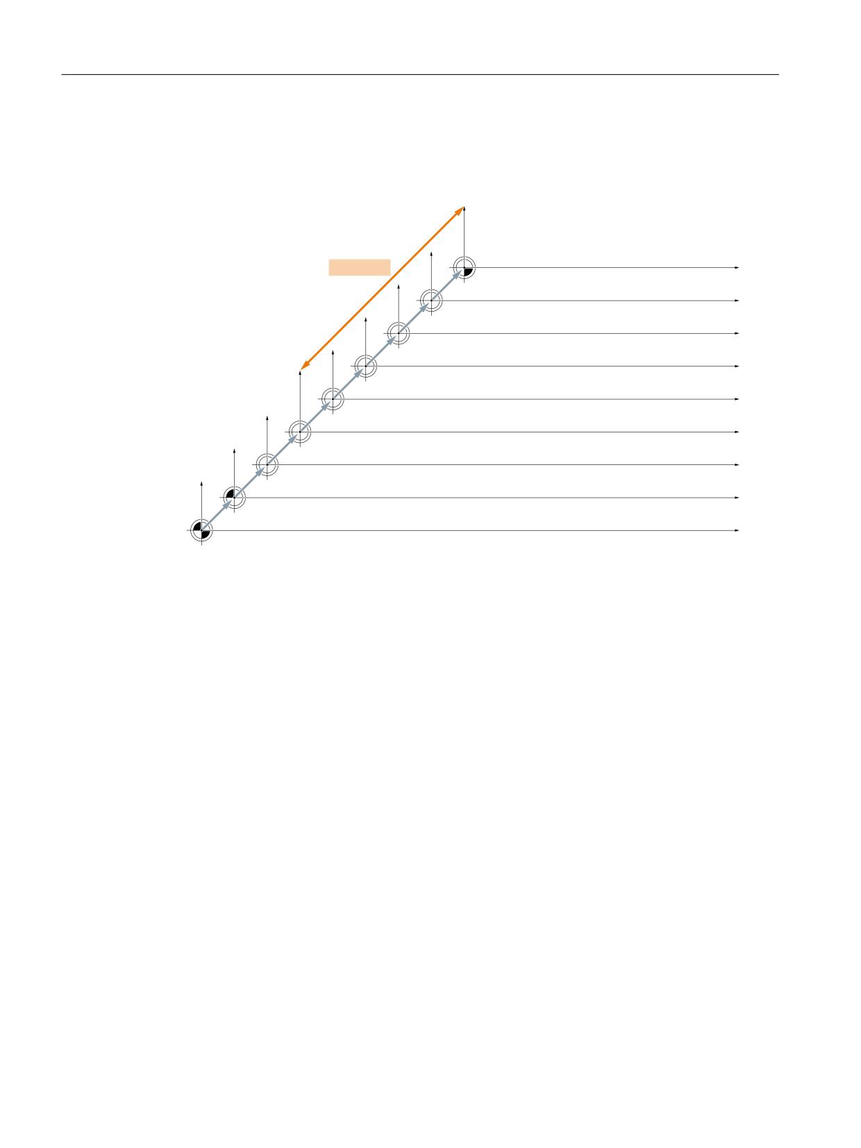
Axes, coordinate systems, frames
4.6 Workpiece-related actual-value system
Interrelationships between coordinate systems
The figure below shows the interrelationships between the machine coordinate system (MCS)
and the workpiece coordinate system (WCS).
Frame chain
)UDPH IRU F\FOHV SURJUDPPHG IUDPH
:.6
WUDQVIRUPDWLRQV
6\VWHP IUDPH IRU 72527 72)5$0(
(16
ZRUNSLHFHV
* ಹ*
VHWWDEOH IUDPH
FKDQQHO VSHFLILF RU 1&8 JOREDO
&KDLQHG ILHOG RI EDVLF IUDPHV
%16
FKDQQHO VSHFLILF DQG RU 1&8 JOREDO
&KDLQHG V\VWHP IUDPHV IRU 3$527 DFWXDO YDOXH VHWWLQJ
VFUDWFKLQJ H[W ZRUN RIIVHW
+DQGZKHHO '5) RIIVHW RYHUODLG PRYHPHQW H[WHUQDO
ZRUN RIIVHW
%.6
.LQHPDWLF WUDQVIRUPDWLRQ
0.6
5HIHUHQFH SRLQW RIIVHW
WCS: Workpiece Coordinate System
SZS:
Settable Zero System
BZS:
Basic Zero System
BCS:
Basic Coordinate System
MCS: Machine Coordinate System
Figure 4-29
Frame chain
For further information, see "Auxiliary function outputs to PLC (Page 697)" and Function Manual
Tools under Tool offset.
Further information
• NC Programming Programming Manual
• Function Manual Transformations, Kinematics transformation
• Function Manual Axes and Spindles; Axis couplings
• Function Manual Technologies; Tangential control
Basic functions
390
Function Manual, 10/2020, 6FC5397-2GP40-0BA1
Axes, coordinate systems, frames
4.6 Workpiece-related actual-value system
4.6.3
Special reactions
Overstore
Overstoring in RESET state of:
• Frames (zero offsets)
• Active plane
• Activated transformation
• Tool offset
immediately affects the actual-value display of all axes in the channel.
Entry via operator panel front
If operations on the operator panel are used to change the values for
"Active frame" (zero offsets, "Parameters" operating area)
and
"Active tool length compensation" ("Parameters" operating area)
, one of the following actions is used to activate these changes in the display:
• Press the RESET key.
• Reselect:
- Zero offset by the part program
- Tool offset by the part program
• Reset:
- Zero offset by overstoring
- Tool offset by overstoring
• Part program start
MD9440
If the HMI machine data
MD9440 ACTIVATE_SEL_USER_DATA
for the operator panel front is set, the entered values become active immediately in RESET
state.
When values are entered in the part-program execution stop state, they become effective when
program execution continues.
Actual-value reading
If the actual value of $AA_IW is read in the WCS after activation of a frame (zero offset) or a tool
offset, the activated changes are already contained in the result read even if the axes have not
yet been traversed with the activated changes.
Basic functions
Function Manual, 10/2020, 6FC5397-2GP40-0BA1
391
Axes, coordinate systems, frames
4.7 Boundary conditions
The actual values in the settable zero system (SZS) can be read from the part program for each
axis using the variable $AA_IEN[axis].
The actual values in the basic zero system (BZS) can be read from the part program for each axis
using the variable $AA_IBN[axis].
Actual-value display
The programmed contour is always displayed in the WCS.
The following offsets are added to the MCS:
• Kinematic transformation
• DRF offset/zero offset external
• Active frame
• Active tool offset of the current tool
Switchover by PLC
The actual values can be displayed in the WCS, SZS, BZS or MCS via the PLC. The PLC can define,
which coordinate system corresponds to the workpiece coordinate system on a machine.
On MMC power-up the MCS is preset.
With the signal DB19 DBB0.7 "MCS/WCS switchover", it is also possible to switch from the PLC to
the WCS.
Transfer to PLC
Depending on machine data
MD20110 / MD20112, bit 1
, the auxiliary functions (D, T, M) are output to the PLC (or not) on selection of the tool length
compensation.
Note
If the WCS is selected from the PLC, an operator action can still be used to switch between the
WCS and MCS for the relevant mode.
However, when the mode and or area is changed, the WCS selected by the PLC is evaluated and
activated (see Section "Mode group, channel, program operation, reset response (Page 25)").
4.7
Boundary conditions
There are no supplementary conditions to note.
Basic functions
392
Function Manual, 10/2020, 6FC5397-2GP40-0BA1
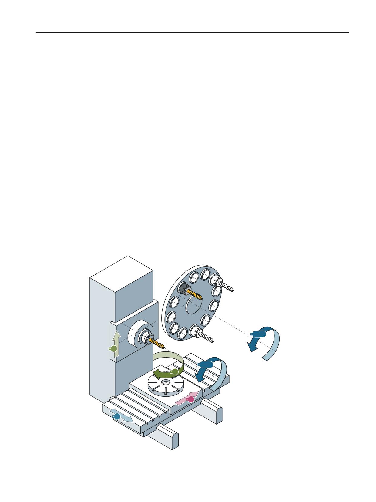
Axes, coordinate systems, frames
4.8 Examples
4.8
Examples
4.8.1
Axes
Axis configuration for a 3axis milling machine with rotary table
1. Machine axis: X1
Linear axis
2. Machine axis: Y1
Linear axis
3. Machine axis: Z1
Linear axis
4. Machine axis: B1
Rotary table (for turning for multiface machining)
5. Machine axis: W1
Rotary axis for tool magazine (tool revolver)
6. Machine axis: C1
(Spindle)
1. Geometry axis: X
(1. channel)
2. Geometry axis: Y
(1. channel)
3. Geometry axis: Z
(1. channel)
1. Special axis: B
(1. channel)
2. Special axis: WZM
(1. channel)
1. spindle: S1/C
(1. channel)
:=0
<
6
&
%
;
=
Basic functions
Function Manual, 10/2020, 6FC5397-2GP40-0BA1
393

Axes, coordinate systems, frames
4.8 Examples
Parameterization of the machine data
Machine data
Value
MD10000 AXCONF_MACHAX_NAME_TAB[0]
= X1
MD10000 AXCONF_MACHAX_NAME_TAB[1]
= Y1
MD10000 AXCONF_MACHAX_NAME_TAB[2]
= Z1
MD10000 AXCONF_MACHAX_NAME_TAB[3]
= B1
MD10000 AXCONF_MACHAX_NAME_TAB[4]
= W1
MD10000 AXCONF_MACHAX_NAME_TAB[5]
= C1
MD20050 AXCONF_GEOAX_ASSIGN_TAB[0]
= 1
MD20050 AXCONF_GEOAX_ASSIGN_TAB[1]
= 2
MD20050 AXCONF_GEOAX_ASSIGN_TAB[2]
= 3
MD20060 AXCONF_GEOAX_NAME_TAB[0]
=X
MD20060 AXCONF_GEOAX_NAME_TAB[1]
=Y
MD20060 AXCONF_GEOAX_NAME_TAB[2]
=Z
MD20070 AXCONF_MACHAX_USED[0]
= 1
MD20070 AXCONF_MACHAX_USED[1]
= 2
MD20070 AXCONF_MACHAX_USED[2]
= 3
MD20070 AXCONF_MACHAX_USED[3]
= 4
MD20070 AXCONF_MACHAX_USED[4]
= 5
MD20070 AXCONF_MACHAX_USED[5]
= 6
MD20080 AXCONF_CHANAX_NAME_TAB[0]
=X
MD20080 AXCONF_CHANAX_NAME_TAB[1]
=Y
MD20080 AXCONF_CHANAX_NAME_TAB[2]
=Z
MD20080 AXCONF_CHANAX_NAME_TAB[3]
= B
MD20080 AXCONF_CHANAX_NAME_TAB[4]
= WZM
MD20080 AXCONF_CHANAX_NAME_TAB[5]
= S1
MD30300 IS_ROT_AX[3]
= 1
MD30300 IS_ROT_AX[4]
= 1
MD30300 IS_ROT_AX[5]
= 1
MD30310 ROT_IS_MODULO[3]
= 1
MD30310 ROT_IS_MODULO[4]
= 1
MD30310 ROT_IS_MODULO[5]
= 1
MD30320 DISPLAY_IS_MODULO[3]
= 1
MD30320 DISPLAY_IS_MODULO[4]
= 1
MD20090 SPIND_DEF_MASTER_SPIND
= 1
Basic functions
394
Function Manual, 10/2020, 6FC5397-2GP40-0BA1
Axes, coordinate systems, frames
4.8 Examples
Machine data
Value
MD35000 SPIND_ASSIGN_TO_MACHAX[AX1]
= 0
MD35000 SPIND_ASSIGN_TO_MACHAX[AX2]
= 0
MD35000 SPIND_ASSIGN_TO_MACHAX[AX3]
= 0
MD35000 SPIND_ASSIGN_TO_MACHAX[AX4]
= 0
MD35000 SPIND_ASSIGN_TO_MACHAX[AX5]
= 0
MD35000 SPIND_ASSIGN_TO_MACHAX[AX6]
= 1
4.8.2
Coordinate systems
Configuration of a global basic frame
An NC with two channels is required. The following applies:
• Both channels can then write the global basic frame.
• The other channel recognizes the change when the global basic frame is activated again.
• Both channels can read the global basic frame.
• Both channels can activate the global basic frame independently.
Machine data
Machine data
Value
MD10000 $MN_AXCONF_MACHAX_NAME_TAB[0]
= X1
MD10000 $MN_AXCONF_MACHAX_NAME_TAB[1]
= X2
MD10000 $MN_AXCONF_MACHAX_NAME_TAB[2]
= X3
MD10000 $MN_AXCONF_MACHAX_NAME_TAB[3]
= X4
MD10000 $MN_AXCONF_MACHAX_NAME_TAB[4]
= X5
MD10000 $MN_AXCONF_MACHAX_NAME_TAB[5]
= X6
MD18602 $MN_MM_NUM_GLOBAL_BASE_FRAMES
= 1
MD28081 $MC_MM_NUM_BASE_FRAMES
= 1
Machine data for channel 1
Value
Machine data for channel 1
Value
$MC_AXCONF_CHANAX_NAME_TAB[0]
= X
$MC_AXCONF_CHANAX_NAME_TAB[0]
= X
$MC_AXCONF_CHANAX_NAME_TAB[1]
= Y
$MC_AXCONF_CHANAX_NAME_TAB[1]
= Y
$MC_AXCONF_CHANAX_NAME_TAB[2]
= Z
$MC_AXCONF_CHANAX_NAME_TAB[2]
= Z
$MC_AXCONF_MACHAX_USED[0]
= 1
$MC_AXCONF_MACHAX_USED[0]
= 4
$MC_AXCONF_MACHAX_USED[1]
= 2
$MC_AXCONF_MACHAX_USED[1]
= 5
$MC_AXCONF_MACHAX_USED[2]
= 3
$MC_AXCONF_MACHAX_USED[2]
= 6
Basic functions
Function Manual, 10/2020, 6FC5397-2GP40-0BA1
395

Axes, coordinate systems, frames
4.8 Examples
Machine data for channel 1
Value
Machine data for channel 1
Value
$MC_AXCONF_GEOAX_NAME_TAB[0]
= X
$MC_AXCONF_GEOAX_NAME_TAB[0]
= X
$MC_AXCONF_GEOAX_NAME_TAB[1]
= Y
$MC_AXCONF_GEOAX_NAME_TAB[1]
= Y
$MC_AXCONF_GEOAX_NAME_TAB[2]
= Z
$MC_AXCONF_GEOAX_NAME_TAB[2]
= Z
$MC_AXCONF_GEOAX_ASSIGN_TAB[0]
= 1
$MC_AXCONF_GEOAX_ASSIGN_TAB[0]
= 4
$MC_AXCONF_GEOAX_ASSIGN_TAB[1]
= 2
$MC_AXCONF_GEOAX_ASSIGN_TAB[1]
= 5
$MC_AXCONF_GEOAX_ASSIGN_TAB[2]
= 3
$MC_AXCONF_GEOAX_ASSIGN_TAB[2]
= 6
Part program in the 1st channel
Code (excerpt)
; Comment
N100 $P_NCBFR[0] = CTRANS( x, 10 )
; Activation of the NC-global basic frame
N130 $P_NCBFRAME[0] = CROT(X, 45)
; Activation of the NC-global basic frame with rotation =>
; Alarm 18310, because rotations are not permitted for
; NC-global frames
Part program in the 2nd channel
Code (excerpt)
; Comment
N100 $P_NCBFR[0] = CTRANS( x, 10 )
; The NC-global basic frame is also effective in the 2nd
channel
N510 G500 X10
; Activate basic frame
N520 $P_CHBFRAME[0] = CTRANS( x, 10 )
; Current frame of the 2nd channel is activated with an off-
set
4.8.3
Frames
Example 1
The channel axis is to be switched to a geometry axis by means of a geometry axis interchange.
The intention of the interchange is to give the programmable frame a translation component of
10 in the X axis.
The current settable frame is to be retained:
FRAME_GEOAX_CHANGE_MODE = 1
Program code
Comment
$P_UIFR[1] = CROT(X,10,Y,20,Z,30)
; Frame is retained after geometry axis interchange.
Basic functions
396
Function Manual, 10/2020, 6FC5397-2GP40-0BA1
Axes, coordinate systems, frames
4.8 Examples
Program code
Comment
G54
; Settable frame becomes active.
TRANS A10
; Axis-specific offset of A is also interchanged.
GEOAX(1,A)
; A becomes the X axis
; $P_ACTFRAME = CROT(X,10,Y,20,Z,30) : CTRANS(X10)
Multiple channel axes can become geometry axes at the same time on a transformation change.
Example 2
Channel axes 4, 5 and 6 become the geometry axes of a 5axis orientation transformation. The
geometry axes are thus all substituted before the transformation.
The current frames are changed when the transformation is activated.
The axis-specific frame components of the channel axes that become geometry axes are used in
the calculation of the new WCS. Rotations programmed before the transformation are retained.
The old WCS is restored when the transformation is deactivated.
The most common application is probably that the geometry axes do not change before and
after the transformation and that the frames are to stay as they were before the transformation.
Machine data:
$MN_FRAME_GEOAX_CHANGE_MODE = 1
$MC_AXCONF_CHANAX_NAME_TAB [0] = "CAX"
$MC_AXCONF_CHANAX_NAME_TAB [1] = "CAY"
$MC_AXCONF_CHANAX_NAME_TAB [2] = "CAZ"
$MC_AXCONF_CHANAX_NAME_TAB [3] = "A"
$MC_AXCONF_CHANAX_NAME_TAB [4] = "B"
$MC_AXCONF_CHANAX_NAME_TAB [5] = "C"
$MC_AXCONF_GEOAX_ASSIGN_TAB [0] = 1
$MC_AXCONF_GEOAX_ASSIGN_TAB [1] = 2
$MC_AXCONF_GEOAX_ASSIGN_TAB [2] = 3
$MC_AXCONF_GEOAX_NAME_TAB [0] = "X"
$MC_AXCONF_GEOAX_NAME_TAB [1] = "Y"
$MC_AXCONF_GEOAX_NAME_TAB [2] = "Z"
$MC_TRAFO_GEOAX_ASSIGN_TAB_1 [0] = 4
$MC_TRAFO_GEOAX_ASSIGN_TAB_1 [1] = 5
$MC_TRAFO_GEOAX_ASSIGN_TAB_1 [2] = 6
$MC_TRAFO_AXES_IN_1 [0] = 4
$MC_TRAFO_AXES_IN_1 [1] = 5
$MC_TRAFO_AXES_IN_1 [2] = 6
Basic functions
Function Manual, 10/2020, 6FC5397-2GP40-0BA1
397

Axes, coordinate systems, frames
4.9 Data lists
$MC_TRAFO_AXES_IN_1 [3] = 1
$MC_TRAFO_AXES_IN_1 [4] = 2
Program:
Program code
Comment
$P_NCBFRAME[0] = CTRANS(X,1,Y,2,Z,3,A,4,B,5,C,6)
$P_CHBFRAME[0] = CTRANS(X,1,Y,2,Z,3,A,4,B,5,C,6)
$P_IFRAME = CTRANS(X,1,Y,2,Z,3,A,4,B,5,C,6) : CROT(Z,45)
$P_PFRAME = CTRANS(X,1,Y,2,Z,3,A,4,B,5,C,6) : CROT(X,10,Y,20,Z,30)
TRAORI
; Transformation sets GEOAX(4,5,6)
; $P_NCBFRAME[0] = CTRANS(X,4,Y,5,Z,6,CAX,1,CAY,2,CAZ,3)
; $P_ACTBFRAME = CTRANS(X,8,Y,10,Z,12,CAX,2,CAY,4,CAZ,6)
; $P_PFRAME = CTRANS(X,4,Y,5,Z,6,CAX,1,CAY,2,CAZ,3) : CROT(X,10,Y,20,Z,30)
; $P_IFRAME = CTRANS(X,4,Y,5,Z,6,CAX,1,CAY,2,CAZ,3) : CROT(Z,45)
TRAFOOF
; Deactivating transformation sets GEOAX (1,2,3)
; $P_NCBFRAME[0] = CTRANS(X,1,Y,2,Z,3,A,4,B,5,C,6)
; $P_CHBFRAME[0] = CTRANS(X,1,Y,2,Z,3,A,4,B,5,C,6)
; $P_IFRAME = CTRANS(X,1,Y,2,Z,3,A,4,B,5,C,6) : CROT(Z,45)
; $P_PFRAME = CTRANS(X,1,Y,2,Z,3,A,4,B,5,C,6) : CROT(X,10,Y,20,Z,30)
4.9
Data lists
4.9.1
Machine data
4.9.1.1
Displaying machine data
Number
Identifier: $MM_
Description
SINUMERIK Operate
9242
MA_STAT_DISPLAY_BASE
Numerical basis for display of moving
joint STAT
9243
MA_TU_DISPLAY_BASE
Numerical basis for display of rotary ax-
is position TU
9244
MA_ORIAXES_EULER_ANGLE_NAME
Display of orientation axes as Euler an-
gle
9245
MA_PRESET_FRAMEIDX
Value storage scratching and PRESET
9247
USER_CLASS_BASE_ZERO_OFF_PA
Availability of basic offset in "Parame-
ters" operating area
9248
USER_CLASS_BASE_ZERO_OFF_MA
Availability of basic offset in Machine
operating area
9424
MA_COORDINATE_SYSTEM
Coordinate system for actualvalue dis-
play
Basic functions
398
Function Manual, 10/2020, 6FC5397-2GP40-0BA1

Axes, coordinate systems, frames
4.9 Data lists
Number
Identifier: $MM_
Description
9440
ACTIVE_SEL_USER_DATA
Active data (frames) are immediately
operative after editing
9449
WRITE_TOA_LIMIT_MASK
Applicability of MD9203 to edge data
and locationdependent offsets
9450
MM_WRITE_TOA_FINE_LIMIT
Limit value for wear fine
9451
MM_WRITE_ZOA_FINE_LIMIT
Limit value for offset fine
4.9.1.2
NC-specific machine data
Number
Identifier: $MN_
Description
10000
AXCONF_MACHAX_NAME_TAB
Machine axis name
10600
FRAME_ANGLE_INPUT_MODE
Sequence of rotation in the frame
10602
FRAME_GEOAX_CHANGE_MODE
Frames and switchover of geometry axes
10610
MIRROR_REF_AX
Reference axis for mirroring
10612
MIRROR_TOGGLE
Change over mirror
10613
NCBFRAME_RESET_MASK
ActiveNCU-global basic frame after reset
10615
NCBFRAME_POWERON_MASK
Reset global basic frames after Power On
10617
FRAME_SAVE_MASK
Behavior of frames for SAVE subprograms
10650
IPO_PARAM_NAME_TAB
Name of interpolation parameters
10660
INTERMEDIATE_POINT_NAME_TAB
Name of intermediate point coordinates for G2/G3
11640
ENABLE_CHAN_AX_GAP
Channel axis gaps are allowed
18600
MM_FRAME_FINE_TRANS
Fine offset for FRAME (SRAM)
18601
MM_NUM_GLOBAL_USER_FRAMES
Number of globally predefined user frames (SRAM)
18602
MM_NUM_GLOBAL_BASE_FRAMES
Number of global basic frames (SRAM)
4.9.1.3
Channel-specific machine data
Number
Identifier: $MC_
Description
20050
AXCONF_GEOAX_ASSIGN_TAB
Assignment geometry axis to channel axis
20060
AXCONF_GEOAX_NAME_TAB
Geometry axis name in channel
20070
AXCONF_MACHAX_USED
Machine axis number valid in channel
20080
AXCONF_CHANAX_NAME_TAB
Channel axis name in the channel
20110
RESET_MODE_MASK
Definition of basic control settings after RESET / TP end
20118
GEOAX_CHANGE_RESET
Allow automatic geometry axis change
20126
TOOL_CARRIER_RESET_VALUE
Active toolholder on RESET
20140
TRAFO_RESET_VALUE
Transformation record on power-up (RESET / TP-End)
20150
GCODE_RESET_VALUES
Initial setting of the G groups
20152
GCODE_RESET_MODE
RESET response of the G groups
20184
TOCARR_BASE_FRAME_NUMBER
Number of the basic frame for pickup of the table offset
21015
INVOLUTE_RADIUS_DELTA
End point monitoring for evolvents (involutes)
Basic functions
Function Manual, 10/2020, 6FC5397-2GP40-0BA1
399

Axes, coordinate systems, frames
4.9 Data lists
Number
Identifier: $MC_
Description
22532
GEOAX_CHANGE_M_CODE
M code for replacement of geometry axes
22534
TRAFO_CHANGE_M_CODE
M code for transformation change
24000
FRAME_ADD_COMPONENTS
Frame components for G58 and G59
24002
CHBFRAME_RESET_MASK
RESET response of channel-specific basic frames
24004
CHBFRAME_POWERON_MASK
Reset channel-specific basic frames after Power On
24006
CHSFRAME_RESET_MASK
Active system frames after reset
24007
CHSFRAME_RESET_CLEAR_MASK
Clear system frames on RESET
24008
CHSFRAME_POWERON_MASK
Reset system frames after POWER ON
24010
PFRAME_RESET_MODE
RESET mode for programmable frame
24020
FRAME_SUPPRESS_MODE
Positions for frame suppression
24030
FRAME_ACT_SET
SZS coordinate system setting
24040
FRAME_ADAPT_MODE
Adapting active frames
24050
FRAME_SAA_MODE
Saving and activating data management frames
24805
TRACYL_ROT_AX_FRAME_1
Rotary axis offset TRACYL 1
24855
TRACYL_ROT_AX_FRAME_2
Rotary axis offset TRACYL 2
24905
TRANSMIT_ROT_AX_FRAME_1
Rotary axis offset TRANSMIT1
24955
TRANSMIT_ROT_AX_FRAME_2
Rotary axis offset TRANSMIT2
28080
MM_NUM_USER_FRAMES
Number of settable Frames (SRAM)
28081
MM_NUM_BASE_FRAMES
Number of basic frames
28082
MM_SYSTEM_FRAME_FRAMES
System frames (SRAM)
28560
MM_SEARCH_RUN_RESTORE_MODE
Restore data after a simulation
4.9.1.4
Axis/spindlespecific machine data
Number
Identifier: $MA_
Description
32074
FRAME_OR_CORRPOS_NOTALLOWED
FRAME or HL offset is not permitted
35000
SPIND_ASSIGN_TO_MACHAX
Assignment spindle to machine axis
4.9.2
Setting data
4.9.2.1
Channelspecific setting data
Number
Identifier: $SC_
Description
42440
FRAME_OFFSET_INCR_PROG
Work offsets in frames
42980
TOFRAME_MODE
Frame definition for TOFRAME, TOROT and PAROT
Basic functions
400
Function Manual, 10/2020, 6FC5397-2GP40-0BA1

Axes, coordinate systems, frames
4.9 Data lists
4.9.3
System variables
Identifier
Description
$AA_ETRANS[axis]
External work offset
$AA_IBN[axis]
Actual value in basic zero coordinate system (BZS)
$AA_IEN[axis]
Actual value in settable zero point coordinate system (SZS)
$AA_OFF[axis]
Overlaid motion for programmed axis
$AC_DRF[axis]
Handwheel override of an axis
$AC_JOG_COORD
Coordinate system for manual traversing
$P_ACSFRAME
Active frame between BCS and SZS
$P_ACTBFRAME
Active complete basic frame
$P_ACTFRAME
Active complete frame
$P_BFRAME
1st active basic frame. Corresponds to $P_CHBFRAME[0]
$P_CHBFR[<n>]
Data management frame: Basic frame can be activated via G500, G54...G599
$P_CHBFRAME[<n>]
Active basic frame
$P_CHBFRMASK
Basic frame mask in the channel
$P_CHSFRMASK
System frame mask
$P_CYCFR
Data management frame: System frame for cycles
$P_CYCFRAME
Active system frame for cycles
$P_EXTFR
Data management frame: System frame for work offset external
$P_EXTFRAME
Active system frame for external work offset
$P_IFRAME
Active settable frame
$P_ISO1FR
Data management frame: System frame for ISO G51.1 mirroring
$P_ISO2FR
Data management frame: System frame for ISO G68 2DROT
$P_ISO3FR
Data management frame: System frame for ISO G68 3DROT
$P_ISO4FR
Data management frame: System frame for ISO G51 Scale
$P_ISO1FRAME
Active system frame for ISO G51.1 Mirroring
$P_ISO2FRAME
Active system frame for ISO G68 2DROT
$P_ISO3FRAME
Active system frame for ISO G68 3DROT
$P_ISO4FRAME
Active system frame for ISO G51 Scale
$P_NCBFR[n]
Data management frame: NCU-global basic frame in the data management,
can be activated via G500, G54...G599
$P_NCBFRAME[n]
Active NCU-global basic frame
$P_NCBFRMASK
Global basic frame mask
$P_PARTFR
Data management frame: System frame for TCARR and PAROT
$P_PARTFRAME
Active system frame for TCARR and PAROT with orientable toolholder
$P_PFRAME
Active programmable frame
$P_SETFR
Data management frame: System frame for actual value setting
$P_SETFRAME
Active system frame for actual value setting
$P_TOOLFR
Data management frame: System frame for TOROT and TOFRAME
$P_TOOLFRAME
Active system frame for TOROT and TOFRAME
$P_TRAFRAME
Data management frame: System frame for transformations
Basic functions
Function Manual, 10/2020, 6FC5397-2GP40-0BA1
401

Axes, coordinate systems, frames
4.9 Data lists
Identifier
Description
$P_TRAFRAME
Active system frame for transformations
$P_UBFR
1st basic frame in the channel in the data management that is activated af-
ter G500, G54...G599. Corresponds to $P_CHBFR[0].
$P_UIFR[n]
Data management frame: Settable frame, can be activated via G500, G54
to G599
$P_UIFRNUM
Number of active settable frame
$P_WPFR
Data management frame: System frame for the workpiece
$P_WPFRAME
Active system frame for the workpiece
Basic functions
402
Function Manual, 10/2020, 6FC5397-2GP40-0BA1
Kinematic chain
5
5.1
Function description
5.1.1
Characteristics
This section describes how the kinematic structure of a machine can be mapped using a
kinematic chain and parameterized in the control using system variables for NC functions such
as "collision avoidance" or "kinematic transformation".
The system variables are retentively saved in the NC and can be archived and/or read as "NC data"
via SINUMERIK Operate using the commissioning archive.
For functions such as "collision avoidance", which also require a description of the machine
geometry, see Function Manual Monitoring and Compensating, Section Geometric machine
modeling.
Note
Graphical editor
As an alternative to writing the system variables in a part program, the machine can be modeled
from the SINUMERIK Operate user interface:
Operating area: "Commissioning" > "NC" > "Machine model"
Changes to the machine model
The direct changes to the machine model at the system variables only become visible at the user
interface after explicitly requesting that the machine model is recalculated by calling the
PROTA() or PROTS() function.
Changes to the machine model made at the user interface are immediately accepted in the
system variables of the NC. The changes only become active after explicitly requesting that the
machine model is recalculated by calling the PROTA() or PROTS() function.
Kinematic structure
The kinematic structure of a machine comprises the following:
• Number and type of the machine axes: Linear or rotary axes
• Arrangement of the machine axes: Position and orientation
• Dependencies of the machine axes to one another: Which machine axis traverses with which
other machine axis.
Basic functions
Function Manual, 10/2020, 6FC5397-2GP40-0BA1
403
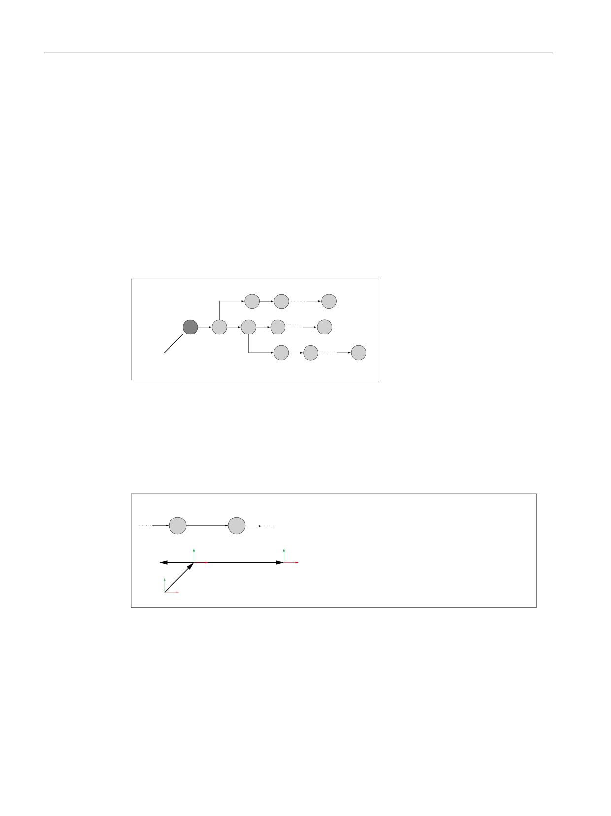
Kinematic chain
5.1 Function description
Kinematic chain
A kinematic structure of a machine is described using a kinematic chain with the following
properties:
• A kinematic chain consists of an arbitrary number of interconnected elements.
• Parallel subchains can branch off from a kinematic chain.
• Only one active kinematic chain is available in the control.
• The active kinematic chain starts with the root element.
• Parameterized elements or subchains that are not connected to the root element or whose
connection points toward the root element, are not part of the currently active kinematic
chain.
• A kinematic chain is defined in the spatially fixed coordinates of the world coordinate system.
3DUDOOHOH 7HLONHWWH
3DUDOOHOH 7HLONHWWH
5RRW (OHPHQW
$QIDQJ GHU ZLUNVDPHQ NLQHPDWLVFKHQ .HWWH
Figure 5-1
Example of a kinematic chain
Element
An element of a kinematic chain basically describes the transformation with which the local
coordinate system of the previous element is mapped in the local coordinate system of the
current element:
Kn-1 ⇒ Tn ⇒ Kn
(OHPHQW
(OHPHQW
HQ
HQ
<Q
<Q
7Q
.[ /RFDO HOHPHQW FRRUGLQDWH V\VWHPV
;Q
.Q
.Q;Q
7UDQVIRUPDWLRQV
7Q
7Q &RQVWDQW RIIVHW LQ WKH ; < GLUHFWLRQ
<
Q
7Q &KDQJHDEOH RIIVHW LQ WKH ; GLUHFWLRQ WKURXJK OLQHDU D[LV
;
Q
.Q
Figure 5-2
Local element coordinate systems
The following constant transformations are possible:
• Offset (type: OFFSET (Page 423))
• Rotation (type: ROT_CONST (Page 421))
Basic functions
404
Function Manual, 10/2020, 6FC5397-2GP40-0BA1
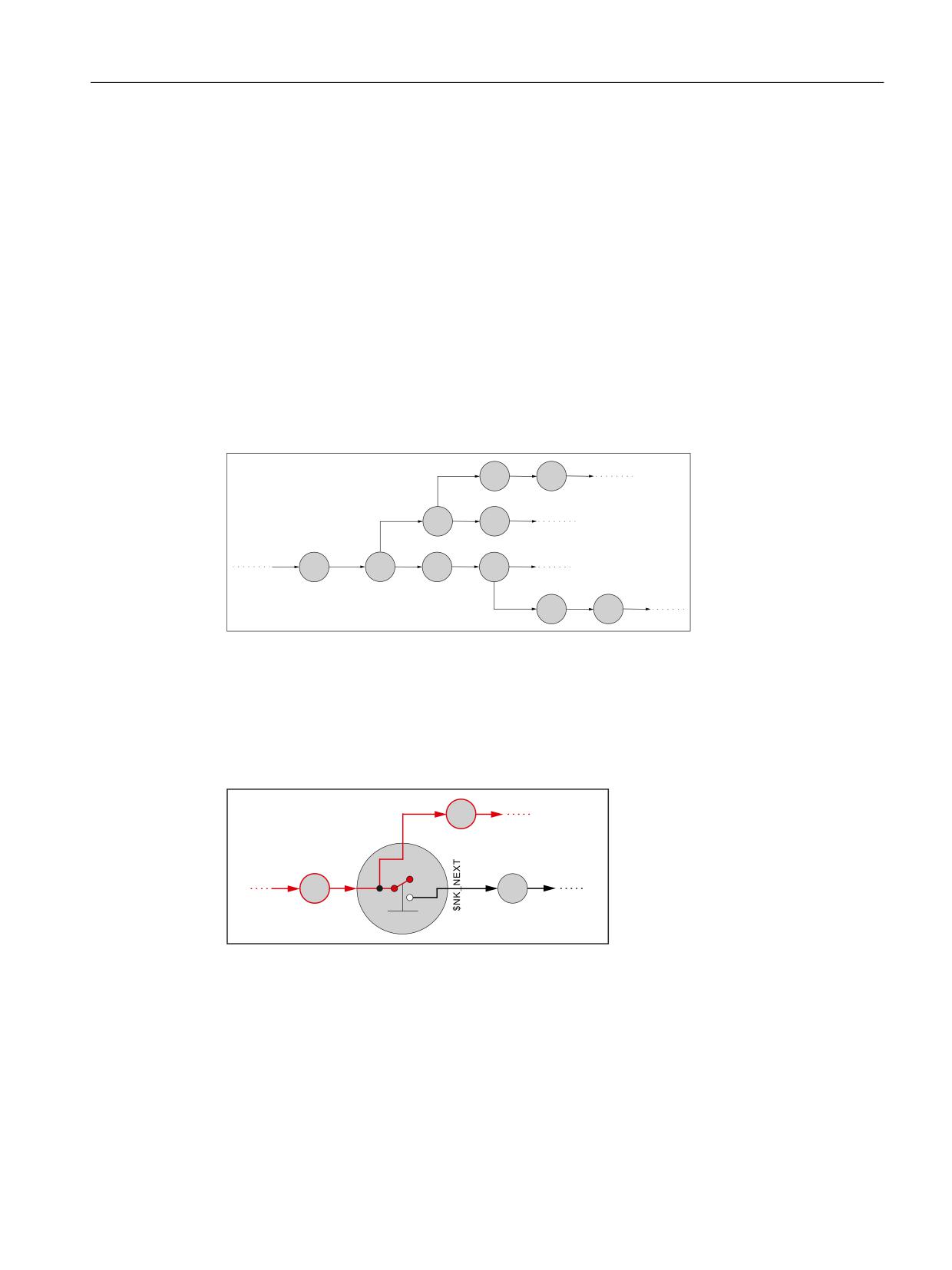
Kinematic chain
5.1 Function description
The following changing transformations, based on the current position values of the machine
axis assigned to the element (linear axis / rotary axis), are possible:
• Offset (type: AXIS_LIN (Page 415))
• Rotation (type: AXIS_ROT (Page 418))
A position or orientation change in an element, e.g. through a position change of the associated
machine axis, affects all the following elements of the chain or parallel subchains.
The maximum number of possible elements can be parameterized using machine data
(Page 409).
Parallel subchains
If a parallel subchain branches off from an element en, then for the kinematics, the branch is
always before the element. For this reason, a change in element en, e.g. a position change of the
associated machine axis, does not affect the subchain branch.
HO
HO
HN
HN
HQ
HQ
HQ
HQ
HP
HP
Figure 5-3
Parallel subchains branching off from elements en and en+2
Switch
A switch is a special element that is not kinematically active (type: SWITCH (Page 425)) in a
kinematic chain, which can assume the CLOSED and OPEN states.
In the OPEN state, the connection from the previous to the following element is interrupted.
HN
1.B
3$5$//(/
V[
HQ
HQ
[
\
Figure 5-4
OPEN state
In the CLOSED state, the previous element is connected to the following element.
Basic functions
Function Manual, 10/2020, 6FC5397-2GP40-0BA1
405
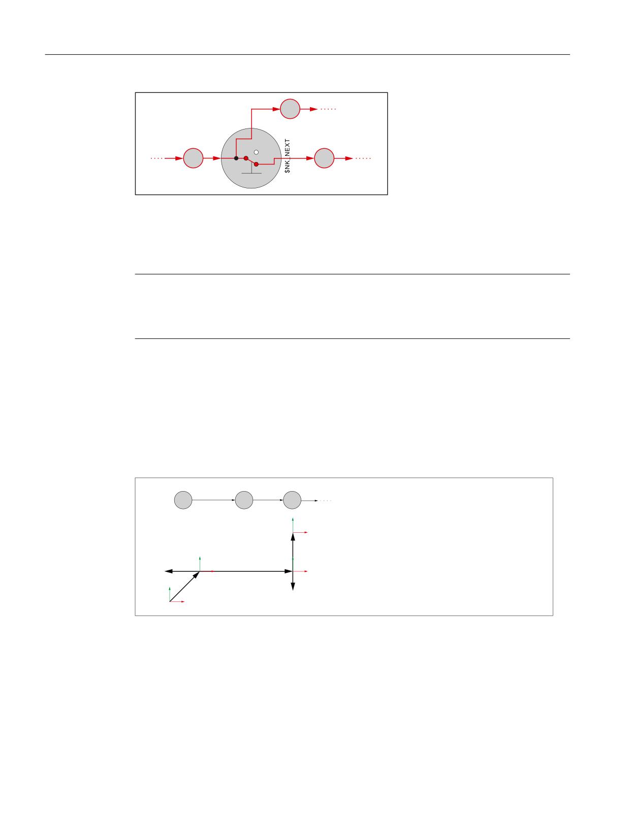
Kinematic chain
5.1 Function description
HN
1.B
3$5$//(/
V[
HQ
HQ
[
\
Figure 5-5
CLOSED state
The switch does not influence the connection to a parallel element.
The maximum number of possible switches can be parameterized usingmachine data
(Page 409).
Note
Local coordinate system
The local coordinate system of a switch is not rotated with respect to the world coordinate
system.
World coordinate system
In order to uniquely describe the kinematic stricture of a machine, all elements of the kinematic
chain - as well as the orientation and offset vectors of the machine axes and the constant
rotation/offsets - are referred to the world coordinate system.
Elements with linear axes do not change the orientation of the following elements. The
orientation and offset vectors of the following elements can therefore refer to the world
coordinate system without further supplementary conditions.
(OHPHQW
(OHPHQW
(OHPHQW
H
H
H
<
;
:RUOG FRRUGLQDWH V\VWHP
7
/RFDO HOHPHQW FRRUGLQDWH V\VWHPV
<
<
7
7UDQVIRUPDWLRQV
;
;
7
&RQVWDQW RIIVHW LQ WKH ; < GLUHFWLRQ
7
&KDQJHDEOH RIIVHW LQ WKH ; GLUHFWLRQ WKURXJK OLQHDU D[LV
<
7
7
&KDQJHDEOH RIIVHW LQ WKH < GLUHFWLRQ WKURXJK OLQHDU D[LV
;
Elements with rotary axes change the orientation of the following elements. This is the reason
that the orientation and offset vectors of the following elements, for a defined initial position of
the previous orientation changing elements, must be referred to the world coordinate system.
Basic functions
406
Function Manual, 10/2020, 6FC5397-2GP40-0BA1
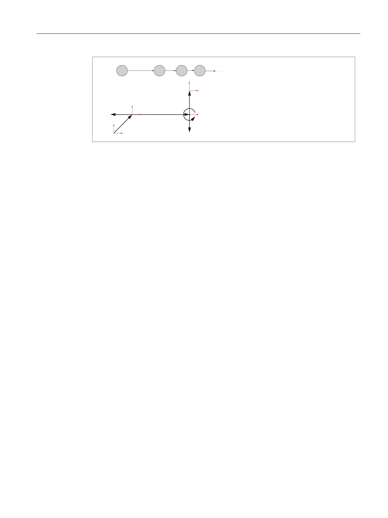
Kinematic chain
5.2 Commissioning
(OHPHQW
(OHPHQW
(OHPHQW (OHPHQW
H
H
H
H
<
;
:RUOG FRRUGLQDWH V\VWHP
ORFDO HOHPHQW FRRUGLQDWH V\VWHPV
7
<
<
7UDQVIRUPDWLRQV
7
7
FRQVWDQW RIIVHW LQ WKH ; < GLUHFWLRQ
;
7
FKDQJLQJ RIIVHW LQ WKH ; GLUHFWLRQ ZLWK D OLQHDU D[LV
;
7
7
FKDQJLQJ URWDWLRQ DURXQG WKH = ZLWK D URWDU\ D[LV
<
7
7
FKDQJLQJ RIIVHW LQ WKH < GLUHFWLRQ ZLWK D OLQHDU D[LV
,QLWLDO SRVLWLRQ 7 URWDU\ D[LV GHJUHH
;
The origin and orientation of the world coordinate system can be freely selected in chain
elements that are defined before the root element. For the active coordinate system after the
root element, the following conditions must be met:
• Origin of the world coordinate system at the machine zero point
• Orientation of the world coordinate system so that the coordinate axes are arranged in the
positive traversing direction of the machine linear main axes
Direction vectors
Within a kinematic chain, the direction vectors, which are used to specify the alignment of the
machine axes, are always specified in absolute terms, i.e. referred to the world coordinate
system.
See also
Machine data (Page 409)
5.2
Commissioning
5.2.1
General
5.2.1.1
Overview
The commissioning of the "Kinematic chain" function is performed using:
• Machine data
- Specification of the quantity structure
- Specification of the first element in the kinematic chain
• System variables
- Specification of the kinematic properties of an element
- Connection of the element to the kinematic chain
Basic functions
Function Manual, 10/2020, 6FC5397-2GP40-0BA1
407
Kinematic chain
5.2 Commissioning
5.2.1.2
Structure of the system variables
The system variables are structured according to the following scheme:
• $NK_<Name>[<Index_1>]
• $NK_<Name>[<Index_1>, <Index_2>]
General
The system variables to describe the elements of kinematic chains have the following properties:
• The prefix for all system variables of the kinematic chain is $NK_, (N for NC, K for kinematic).
• The system variables can be read and written via NC programs.
• The system variables can be stored in archives and loaded to the NC again.
Data type
STRING
All system variables of the STRING data type have the following properties:
• Maximum string length: 31 characters
• No distinction is made between upper and lower case
Example: "Axis1" is identical to "AXIS1"
• Spaces and special characters are permitted
Example: "Axis1" is not identical to "Axis 1"
• Names that start with two underscores "__" are reserved for system purposes and must not
be used for user-defined names.
Note
Leading space
Since spaces are valid and distinct characters, names that start with a space followed by two
underscores "__" can, in principle, be used for user-defined names. However, because they
can be easily mistaken for system names, this procedure is not recommended.
Index_1
The individual elements are addressed via index_1. Index 0 → 1. Element, index 1 → 2.
Element, ... n → (n+1) element, with n = ($MN_MM_MAXNUM_KIN_CHAIN_ELEM - 1)
All system variables of an element have the same index.
Basic functions
408
Function Manual, 10/2020, 6FC5397-2GP40-0BA1
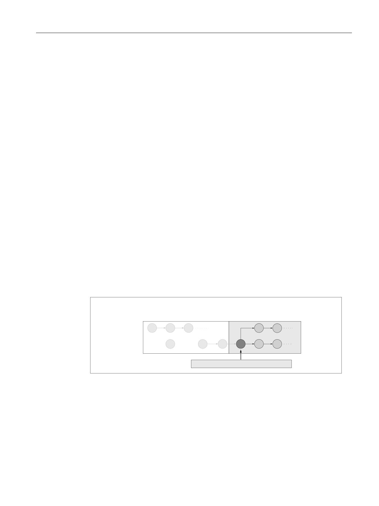
Kinematic chain
5.2 Commissioning
Index_2
For system variables that contain a vector, the coordinates of the vector are addressed via
index_2.
•
0 → X axis
•
1 → Y axis
•
2 → Z axis
5.2.2
Machine data
5.2.2.1
Maximum number of elements
The maximum number of elements for kinematic chains is set using machine data.
MD18880 $MN_MM_MAXNUM_KIN_CHAIN_ELEM = <number>
5.2.2.2
Root element
The following machine data is used to specify the root element, i.e. the first element of the
currently active kinematic chain.
MD16800 $MN_ROOT_KIN_ELEM_NAME = "<element_name>"
All parameterized elements and subchains that are connected to the root element in such a way
that the connection starts at the root element, are part of the currently active kinematic chain.
Parameterized elements or subchains that are not connected to the root element or whose
connection points towards the root element, are not part of the currently active kinematic chain.
3DUDPHWHUL]HG HOHPHQWV DQG VXEFKDLQV WKDW DUH QRW
(OHPHQWV DQG VXEFKDLQV RI WKH DFWLYH NLQHPDWLF
SDUW RI WKH DFWLYH NLQHPDWLF FKDLQ
FKDLQ
0'
01B5227B.,1B(/(0B1$0(
5.2.2.3
Maximum number of switches
The maximum number of switches for kinematic chains is set with the machine data
MD18882 $MN_MM_MAXNUM_KIN_SWITCHES = <number>
Basic functions
Function Manual, 10/2020, 6FC5397-2GP40-0BA1
409
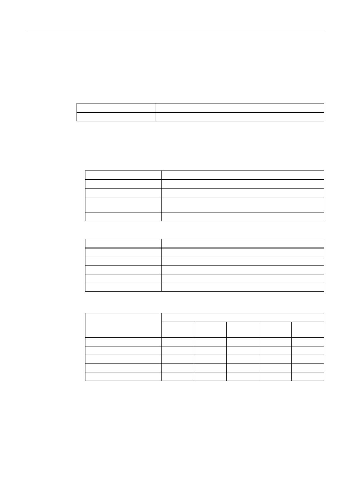
Kinematic chain
5.2 Commissioning
5.2.3
System variables
5.2.3.1
Overview
System variables independent of any element
System variable
Meaning
$NK_SWITCH
Switch variable to open and close the switch
Element-specific system variables
Element-specific system variables are subdivided into variables that are independent of the type
and dependent on the type:
• Variables independent of the type
System variable
Meaning
$NK_NAME
Name of the current element en
$NK_NEXT
Name of the next element en+1
$NK_PARALLEL
Name of a branching parallel element ep before the current element
en
$NK_TYPE
Type of the element
• Variables dependent on the type
System variable
Meaning
$NK_OFF_DIR
Offset or direction vector
$NK_AXIS
Machine axis or object name
$NK_A_OFF
Work offset for linear axis or rotary axis
$NK_SWITCH_INDEX
Switch index
$NK_SWITCH_POS
Switch position "CLOSED"
For the following types, variables dependent on the type are evaluated:
System variable
Type
OFFSET
AXIS_LIN
AXIS_ROT
ROT_CONS
SWITCH
T
$NK_OFF_DIR
x
x
x
x
-
$NK_AXIS
-
x
x
-
-
$NK_A_OFF
-
x
x
x
-
$NK_SWITCH_INDEX
-
-
-
-
x
$NK_SWITCH_POS
-
-
-
-
x
Basic functions
410
Function Manual, 10/2020, 6FC5397-2GP40-0BA1

Kinematic chain
5.2 Commissioning
The system variables are described in detail in the following sections.
Note
Establish a defined initial state
It is recommended that a defined initial state be generated before parameterizing the kinematic
chain. To do this, the system variables of the kinematic chain should be set to their default value
using function DELOBJ().
Change system variable values
If the value of one of the system variables listed above is changed, then the change becomes
immediately visible on the user interface, e.g. SINUMERIK Operate. The machine model of the
NC is only updated after explicitly requesting that the machine model is recalculated by calling
the PROTA() or PROTS() function.
See also
Deletion of components (DELOBJ) (Page 428)
5.2.3.2
$NK_NAME
Function
Enter the NC-wide unique element name in the system variable. The element is referenced via
this name, e.g. within kinematic chains. The name is also displayed in the graphical editor of
SINUMERIK Operate.
Syntax
$NK_NAME[<n>] = "<name>"
Meaning
$NK_NAME:
Name of the element
Data type:
STRING
Default value:
"" (empty string)
<n>:
System variable or element index
Data type:
INT
Range of values:
0, 1, 2, ... ($MN_MM_MAXNUM_KIN_CHAIN_ELEM - 1)
<name>:
Element name, max. string length: 31 characters
Data type:
STRING
Basic functions
Function Manual, 10/2020, 6FC5397-2GP40-0BA1
411

Kinematic chain
5.2 Commissioning
Example
The 9th kinematic element is assigned the name "B axis":
Program code
Comment
N100 $NK_NAME[8] = "B axis"
; 9th kin. element,
; name = "B axis"
5.2.3.3
$NK_NEXT
Function
If the element is part of a kinematic chain, the name of the following element should be entered
in the system variable.
Syntax
$NK_NEXT[<n>] = "<name>"
Meaning
NK_NEXT:
Name of the following element
Data type:
STRING
Range of values:
All names contained in $NK_NAME (Page 411)
Default value:
"" "" (empty string)
<n>:
System variable or element index
Data type:
INT
Range of values:
0, 1, 2, ... ($MN_MM_MAXNUM_KIN_CHAIN_ELEM - 1)
<name>:
Element name, max. string length: 31 characters
Data type:
STRING
Example
The 9th kinematic element does not have a following element:
Program code
Comment
N100 $NK_NEXT[8] = ""
; 9. kin. element,
; following element = ""
Basic functions
412
Function Manual, 10/2020, 6FC5397-2GP40-0BA1