SINUMERIK 840D sl. Service - Functions. Manual (2018-2020) - page 21
Mode group, channel, program operation, reset response
3.15 Process Datashare - output to an external device/file
<ExtDev>:
Parameter 2: Symbolic identifier for the external device/file to be opened
Type:
STRING
The symbolic identifier comprises:
1. the logical device name
2. where relevant, followed by a file path (attached using "/").
The following logical device names have been defined:
"LOCAL_DRIVE":
Local CF card (pre-defined)
"CYC_DRIVE":
Reserved drive name for use in SIEMENS cycles (pre-de-
fined)
"/dev/ext/1", ...
Available network drives
"/dev/ext/9":
Note:
It is necessary to configure in the extdev.ini file!
"/dev/cyc/1",
Reserved drive names for use in SIEMENS cycles
"/dev/cyc/2":
Note:
It is necessary to configure in the extdev.ini file!
File path:
• A file path must be specified for "LOCAL_DRIVE" and "CYC_DRIVE" e.g.
"LOCAL_DRIVE/my_dir/my_file.txt"
• The logical device names "/dev/ext/1...9" and "/dev/cyc/1...2" can be configured:
- To already refer to a file, in which case only the logical device names may be
specified, e.g.:
"/dev/ext/4"
- Or to a directory, in which case a file path must be specified, e.g.:
"/dev/ext/5/my_dir/my_file.txt"
Note:
For the logical device names "/dev/ext/1...9", "/dev/v24" and "/dev/cyc/1...2" up-
percase/lowercase is ignored; uppercase/lowercase is significant for specifying a
path to a file. Only uppercase letters are permissible for "LOCAL_DRIVE" and
"CYC_DRIVE".
<SyncMode>:
Parameter 3: Processing mode for the WRITE commands to this device/file
Type:
STRING
Values:
"SYN":
Synchronous writing
Program execution is stopped until the write operation
has been completed.
Successfully completing the synchronous write opera-
tion can be checked by evaluating the error variables of
the WRITE command.
"ASYN":
Asynchronous writing
Program execution is not interrupted by the WRITE com-
mand.
Note.
In this mode, the result variable of the WRITE command
does not provide any information and always has the
value 0 (no error). In this particular mode, there is no
certainty that the WRITE command was successful.
Basic functions
Function Manual, 10/2020, 6FC5397-2GP40-0BA1
205
Mode group, channel, program operation, reset response
3.15 Process Datashare - output to an external device/file
<AccessMode>:
Parameter 4: Usage mode for this device/file
Type:
STRING
Values:
"SHARED":
Device/file is requested in the "shared" mode. Other
channels can also use the device, i.e. also open in this
mode.
"EXCL":
Device/file is exclusively used in the channel; no other
channel can use the device.
<WriteMode>:
Parameter 5: Write mode for the WRITE commands to this file/device (optional)
Type:
STRING
Values:
"APP":
Attaching
The file is always kept regarding its contents; write calls
are attached at the end.
"OVR":
Overwrite
The contents of the file are deleted and re-generated
using the subsequent write calls.
Note:
Using this parameter, the write mode configured in the extdev.ini file cannot be
overwritten. In the case of a conflict, then the EXTOPEN call is acknowledged with
error.
WRITE:
Pre-defined procedure to write output data
EXTCLOSE:
Pre-defined procedure to close an external device/file that has been opened
<Result>:
Parameter 1: Result variable
Type:
INT
Values:
0
No error
16
Invalid external path has been programmed
21
Error when closing the external device
<ExtDev>:
Parameter 2: Symbolic identifier for the external device/file description to be
closed, see EXTOPEN!
Note:
The identifier must be identical to the identifier specified in the EXTOPEN call!
Example
Program code
N10
DEF INT RESULT
N20
DEF BOOL EXTDEVICE
N30
DEF STRING[80] OUTPUT
N40
DEF INT PHASE
N50
EXTOPEN(RESULT,"LOCAL_DRIVE/my_file.txt","SYN","SHARED")
N60
IF RESULT > 0
N70
MSG("Error for EXTOPEN:" << RESULT)
N80
ELSE
N90
EXTDEVICE=TRUE
Basic functions
206
Function Manual, 10/2020, 6FC5397-2GP40-0BA1
Mode group, channel, program operation, reset response
3.16 System settings for power-up, RESET / part program end and part program start
Program code
N100
ENDIF
…
N200
PHASE=4
N210
IF EXTDEVICE
N220
OUTPUT=SPRINT("End phase: %D",PHASE)
N230
WRITE(RESULT,"LOCAL_DRIVE/my_file.txt",OUTPUT)
N240
ENDIF
…
3.15.4
Supplementary conditions
Effect on continuous path mode
The EXTOPEN, WRITE and EXTCLOSE commands trigger a preprocessing stop and therefore
interrupt the continuous path mode.
Behavior during block search
During "block search with calculation" with WRITE, no output is made. However, the EXTOPEN
and EXTCLOSE commands are collected and set active with NC start after the search target was
reached. The following WRITE commands therefore find the same environment as for the normal
program processing.
For a block search with calculation in the (SERUPRO) "Program test" mode, EXTOPEN, WRITE and
EXTCLOSE are executed just the same as for normal program processing.
3.16
System settings for power-up, RESET / part program end and part
program start
3.16.1
System settings for power-up, RESET / part program end and part program
start
Concept
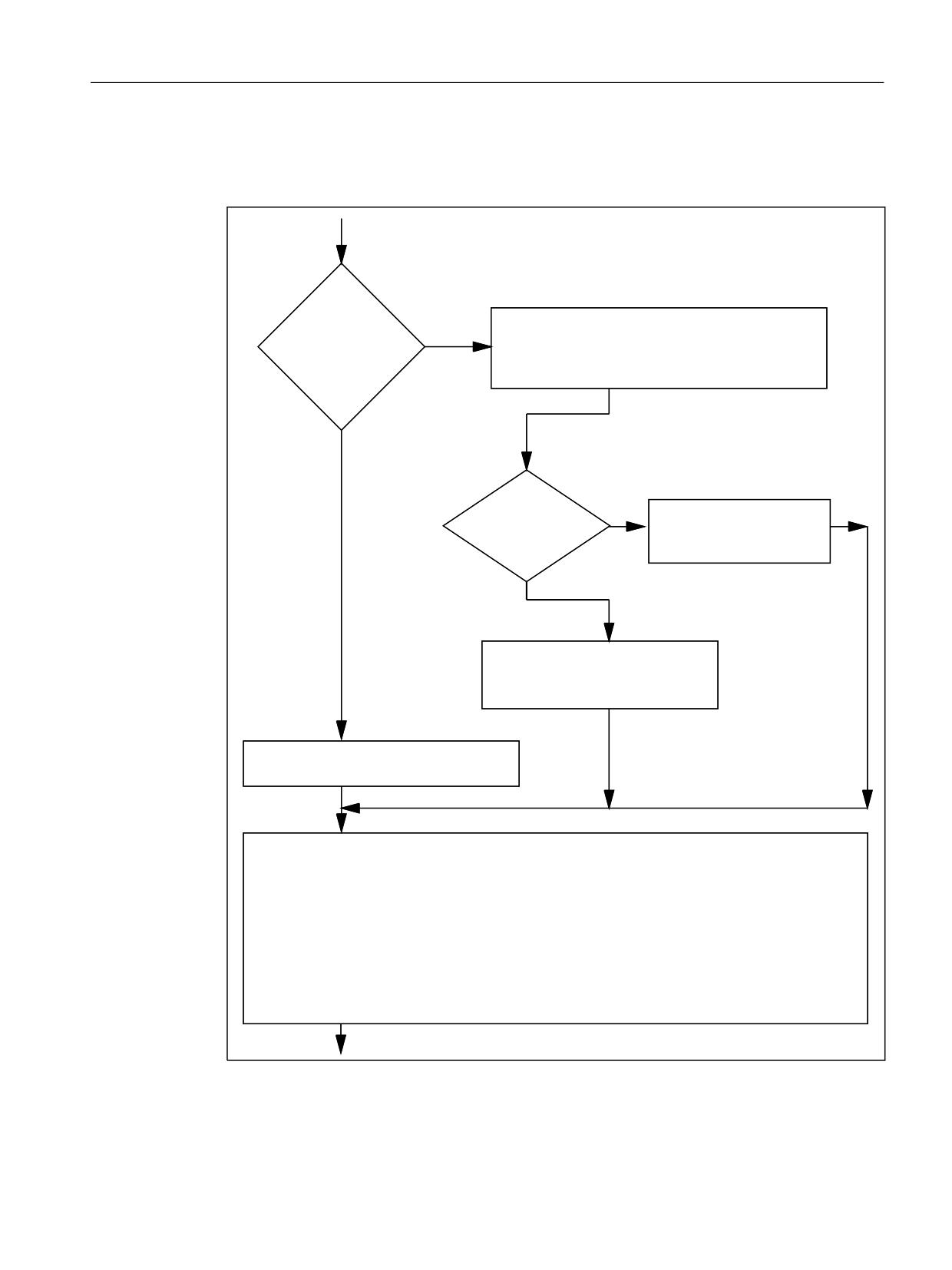
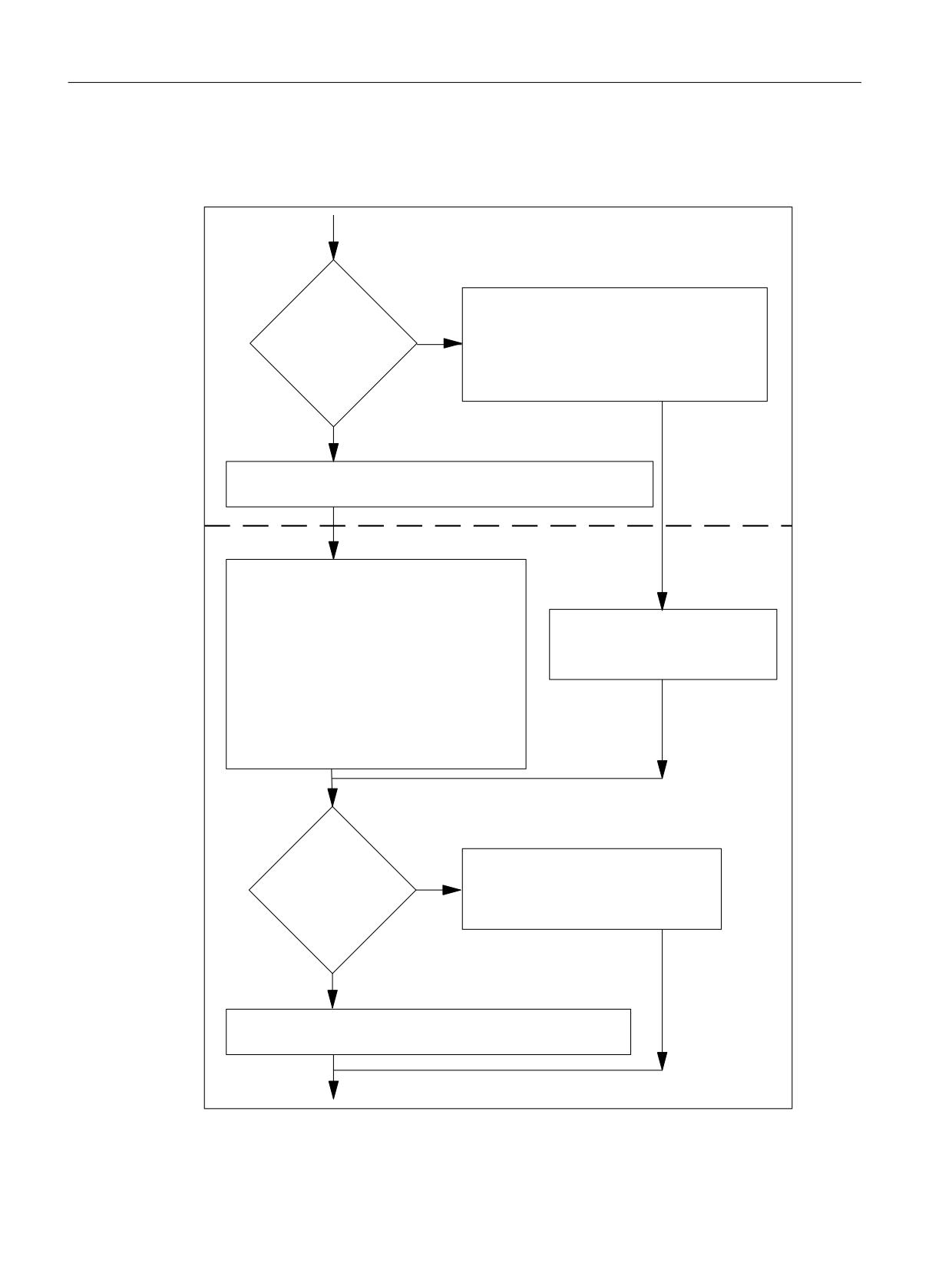
The behavior of the control can be set via the machine data for the following events:
• Run-up (power-on)
• Reset / part program end
• Part program start
Basic functions
Function Manual, 10/2020, 6FC5397-2GP40-0BA1
207

Mode group, channel, program operation, reset response
3.16 System settings for power-up, RESET / part program end and part program start
The control-system response after:
Can be set with:
Run-up (power on) *)
MD20110 $MC_RESET_MODE_MASK
MD20144 $MC_TRAFO_MODE_MASK
MD20150 $MC_GCODE_RESET_VALUES
RESET / part program end
MD20110 $MC_RESET_MODE_MASK
MD20150 $MC_GCODE_RESET_VALUES
MD20152 $MC_GCODE_RESET_MODE
Part program start
MD20112 $MC_START_MODE_MASK
MD20110 $MC_RESET_MODE_MASK
*) see also POWER ON (Page 383)
Basic functions
208
Function Manual, 10/2020, 6FC5397-2GP40-0BA1
Mode group, channel, program operation, reset response
3.16 System settings for power-up, RESET / part program end and part program start
System settings after run-up
MD20110 $MC_RESET_MODE_MASK, bit 0 = 0 or 1
%RRWLQJ
32:(5 21
7UDQVIRUPDWLRQ DFWLYH
0'
%LW
DFF WR 0'
0'
%LW
0'
%LW
5(6(7B02'(B0$6.
*HR D[LV LQWHUFKDQJH DFWLYH
%LW
'HIDXOW
DFF WR 0'
ZLWK 0'
VHWWLQJ
%LW
%LW
%LW
7KH WRRO OHQJWK
0'
%LW DQG ELW
FRPSHQVDWLRQ
VHOHFWHG EHIRUH 32:(5 21
UHPDLQV DFWLYH
%LW
7RRO OHQJWK FRPSHQVDWLRQ DFWLYH
DFF WR 0'
0'
0'
7UDQVIRUPDWLRQ RII
7RRO OHQJWK FRPSHQVDWLRQ DFWLYH
* FRGHV DFF WR 0'
0&B*&2'(B5(6(7B9$/8(6
&RXSOHG PRWLRQ JURXSV LV WULJJHUHG
7DQJHQWLDO IROORZ XS LV QRW DFWLYH
6\QFKURQL]HG VSLQGOH FRXSOLQJ LV QRW DFWLYH
$[LDO UHYROXWLRQDO IHHGUDWH RII SDWK DQG V\QFKURQL]HG D[HV EDFN WR PDVWHU VSLQGOH
*HRPHWU\ D[LV DVVLJQPHQW DFF WR 0'
0&B$;&21)B*(2$;B$66,*1B7$%
0DVWHU YDOXH FRXSOLQJ LV QRW DFWLYH
%DVLF IUDPH LV GHVHOHFWHG
(OHFWURQLF JHDUER[ LV QRW DFWLYH
0DVWHU VSLQGOH EDVLF SRVLWLRQ DFF WR 0'
0&B63,1'B'()B0$67(5B63,1'
0DVWHU WRRO KROGHU EDVLF SRVLWLRQ DFF WR 0'
0&B722/B0$1*(0(17B722/+2/'(5
5HIHUHQFH D[LV DFF WR 0'
0&B',$0(7(5B$;B'()
5(6(7
SDUW SURJUDP HQG
Figure 3-7
System settings after run-up (power-on)
Basic functions
Function Manual, 10/2020, 6FC5397-2GP40-0BA1
209
Mode group, channel, program operation, reset response
3.16 System settings for power-up, RESET / part program end and part program start
System settings after reset / part program end and part program start
MD20110 $MC_RESET_MODE_MASK, bit 0 = 0 or 1
5(6(7
SDUW SURJUDP HQG
%LW
* FRGHV DFF WR 0'
DQG 0'
0'
ELW
DUH HYDOXDWHG L H
0'
WKH IXQFWLRQ DVVLJQHG WR WKH UHOHYDQW ELWV
5(6(7B02'(B0$6.
HLWKHU UHWXUQV WR LWV UHVHW SRVLWLRQ RU
%LW
'HIDXOW
VWD\V LQ LWV FXUUHQW SRVLWLRQ VHH WDEOHV
VHWWLQJ
EHORZ
%LW
7KH FXUUHQW VHWWLQJV DUH UHWDLQHG
3DUW SURJUDP VWDUW
* FRGHV DFF WR 0'
7RRO OHQJWK FRPSHQVDWLRQ DFWLYH
7UDQVIRUPDWLRQ RII
&RXSOHG PRWLRQ RII
7DQJHQWLDO IROORZ XS RII
7KH VHWWLQJV DFWLYDWHG E\ 5(6(7
6\QFKURQL]HG VSLQGOH RII
EHFRPH YDOLG
*HRPHWU\ D[LV DVVLJQPHQW DFF WR 0'
0DVWHU YDOXH RII
$[LDO UHYROXWLRQDO IHHGUDWH RII
5HVHUYHG EDVLF IUDPH RII
0DVWHU VSLQGOH DFF WR 0'
0DVWHU WRRO KROGHU RII
5HIHUHQFH D[LV DFF WR 0'
%LW
%LW
0'
)XQFWLRQ WDNHV DFFRXQW RI 5(6(7 SRVLWLRQ
67$57B02'(B0$6.
%LW
%LW
5HIHUHQFH D[LV LV UHWDLQHG
%LW
GHIDXOW VHWWLQJ
%LW
7KH FXUUHQW VHWWLQJV DUH UHWDLQHG
%LW
)XQFWLRQ WDNHV DFFRXQW RI 5(6(7 SRVLWLRQ
,QWHUSUHWDWLRQ RI VW SDUW SURJUDP EORFN
Figure 3-8
System settings after reset / part program end and part program start
Basic functions
210
Function Manual, 10/2020, 6FC5397-2GP40-0BA1
Mode group, channel, program operation, reset response
3.16 System settings for power-up, RESET / part program end and part program start
G command effective after run-up and reset / part program end
The G code that is effective in every G group after run-up (power-on) and reset / part program
end is set in the following machine data:
MD20150 $MC_GCODE_RESET_VALUES[<G group>] = <default-G code>
MD20152 $MC_GCODE_RESET_MODE[<G group>] = <value>
Value
Description: Per G group
0
The default G command from MD20150 $MC_GCODE_RESET_VALUES takes effect.
1
The last active/current G command takes effect
Control basic setting after run-up, reset / part program end and part program start
The control basic setting after run-up (power-on), reset / part program end and part program
start is defined in the following machine data:
• MD20110 $MC_RESET_MODE_MASK (definition of the control basic setting after run-up
and reset / part program end)
• MD20112 $MC_START_MODE_MASK (definition of the control basic setting after part
program start)
Further information
Detailed machine data description
Relevant machine data
Machine data
Meaning
MD20120 $MC_TOOL_RESET_VALUE
Tool length compensation during run-up, reset / part program
end
MD20121 $MC_TOOL_PRESEL_RESET_VALUE
Preselect tool on Reset
MD20130 $MC_CUTTING_EDGE_RESET_VALUE
Tool cutting-edge length compensation on run-up
MD20140 $MC_TRAFO_RESET_VALUE
Run-up transformation data block
MD20144 $MC_TRAFO_MODE_MASK
Selection of the kinematic transformation function
MD20150 $MC_GCODE_RESET_VALUES
Basic setting of the G groups
MD20152 $MC_GCODE_RESET_MODE
Reset behavior of the G groups
MD21330 $MC_COUPLE_RESET_MODE_1
Coupling cancellation response
MD20050 $MC_AXCONF_GEOAX_ASSIGN_TAB
Assignment of geometry axis to channel axis
MD20118 $MC_GEOAX_CHANGE_RESET
Allow automatic geometry axis change
Example
Activate reset setting on reset:
• MD20110, bit 0 = 1
• MD20112 = 0
Basic functions
Function Manual, 10/2020, 6FC5397-2GP40-0BA1
211
Mode group, channel, program operation, reset response
3.16 System settings for power-up, RESET / part program end and part program start
Transformation remains with reset / part program start:
• MD20110, bit 0 = 1
• MD20110, bit 7 = 1
• MD20112 = 0
Tool length compensation is retained after reset / part program start:
• MD20110, bit 4 = 1
• MD20110, bit 6 = 1
• MD20112 = 0
Active level (bit 4) and settable frame (bit 5) remain active after reset and are reset on part
program start:
• MD20110, bit 4 = 1
• MD20110, bit 5 = 1
• MD20112, bit 4 = 1
• MD20112, bit 5 = 1
Note
MD20110/MD20112, bit 5 and bit 6
If MD20110/MD20112 are parameterized so that tool length compensation or a frame is
active on a part program start in the automatic or MDI mode, the first programming of the
axes must use absolute measurements (because of the traversing of the offset).
Exception: With MD42442/MD42440 the offsetting process for G91 is suppressed.
3.16.2
Tool withdrawal after POWER ON with orientation transformation
Function
If a part program with a machining operation with tool orientation is aborted due to a power
failure or reset, it is possible to select the previously active transformation and generate a frame
in the direction of the tool axis after the control has run up (power on). The tool can then be
retracted in JOG mode by means of a retraction movement towards the tool axis.
Requirement
The active measuring systems must have a machine reference for all the machine axes involved
in the transformation. See Function Manual "Axes and Spindles", Section "Automatic restoration
of the machine reference".
Basic functions
212
Function Manual, 10/2020, 6FC5397-2GP40-0BA1

Mode group, channel, program operation, reset response
3.16 System settings for power-up, RESET / part program end and part program start
Parameterization
The following machine data must be set so that the last active transformation is retained after
POWER ON:
• MD20144 $MC_TRAFO_MODE_MASK, bit 1 = 1
• MD20110 $MC_RESET_MODE_MASK, bit 0 = 1
• MD20110 $MC_RESET_MODE_MASK, bit 7 = 1
See also Section "System settings for power-up, RESET / part program end and part program start
(Page 207)".
Programming
Wait for machine reference WAITENC
With the command WAITENC, the system waits channel-specific in a program until there is a valid
machine reference for all the active measuring systems of the parameterized axes. See the
"Requirement" section above. The parameter assignment of the axes is performed via:
MD34800 $MA_WAIT_ENC_VALID = 1
Application
In the user program (…/_N_CMA_DIR/_N_PROG_EVENT_SPF) to be called event-controlled when
running up (requirement: MD20108 bit 3 = 1), the system must wait using the command
WAITENC until the valid axis positions are available.
A frame that positions the tool axis in the direction of the X, Y or Z axis can then be generated
using the NC language command TOROTX/TOROTY/TOROTZ.
Example
Orientation transformation and orientation axes with incremental encoders.
Configuration:
Meaning:
MD10720 $MN_OPERATING_MODE_DEFAULT [ 0 ] = 6
Run-up in JOG mode.
MD30240 $MA_ENC_TYPE [ 0, <axis>] = 1
Incremental measuring system.
MD34210 $MA_ENC_REFP_STATE [ 0, <axis>] = 3
Enable the restoration of axis positions for incre-
mental encoders.
MD20108 $MC_PROG_EVENT_MASK = ’H9’
Activate event-controlled using program
PROG_EVENT during run-up and at the start of the
part program.
MD20152 $MC_GCODE_RESET_MODE [ 52 ] = 1
Obtain TOFRAME via reset.
MD20110 $MC_RESET_MODE_MASK = ’HC1’
Obtain transformation and tool offset via reset.
MD20144 $MC_TRAFO_MODE_MASK = ’H02’
Obtain transformation via POWER OFF.
Basic functions
Function Manual, 10/2020, 6FC5397-2GP40-0BA1
213
Mode group, channel, program operation, reset response
3.16 System settings for power-up, RESET / part program end and part program start
Event-driven user program (…/_N_CMA_DIR/_N_PROG_EVENT_SPF):
; Example with activation of the frame, which aligns the WCS in the tool direction,
; when running up and resetting with part program start.
IF $P_PROG_EVENT == 4 ; Run-up.
IF $P_TRAFO <> 0 ; Transformation was selected.
WAITENC ; Wait for valid axis positions of the orientation axes.
TOROTZ ; Rotate the Z axis of the WCS towards the tool axis.
ENDIF
M17
ENDIF
IF $P_PROG_EVENT == 1 ; Part program start.
TOROTOF ; Reset tool frame.
RET
ENDIF
The WAITENC command essentially corresponds to the following program sequence (example
for 5-axis machine with AB kinematics):
WHILE TRUE ; Waiting for measuring system.
IF (($AA_ENC_ACTIVE[X]==TRUE) AND ($AA_ENC_ACTIVE[Y]
==TRUE) AND ($AA_ENC_ACTIVE[Z]==TRUE) AND ($AA_ENC_ACTIVE[A]
==TRUE) AND ($AA_ENC_ACTIVE[B]==TRUE)) GOTOF GET_LABEL
ENDIF
G4 F0.5 ; Wait time 0.5 s
ENDWHILE
:Position synchronization
GET_LABEL: GET(X,Y,Z,A,B,)
Continuing machining
AUTOMATIC mode
For automatic execution of programs in the AUTOMATIC mode, all the machine axes, whose
actual position of the active measuring system has been restored, must be referenced.
MDI mode and overstore
In the MDI mode and for the overstore function, machining can also be performed, without
referencing the axes, with restored positions. To do this, NC start with restored positions must
be enabled explicitly for a specific channel:
MD20700 $MC_REFP_NC_START_LOCK = 2
Boundary condition
Axes with incremental encoders and without actual value buffering
It is to be assumed that axes with incremental encoders and without actual value buffering are
clamped with sufficient speed in the event of a power failure to prevent them drifting from their
last position setpoint.
Basic functions
214
Function Manual, 10/2020, 6FC5397-2GP40-0BA1

Mode group, channel, program operation, reset response
3.17 Replacing functions by subprograms
3.17
Replacing functions by subprograms
3.17.1
Overview
Function
User-specific auxiliary functions (e.g. M101) do not trigger any system functions. They are only
output to the NC/PLC interface. The functionality of the auxiliary function must be implemented
by the user / machine manufacturer in the PLC user program. A description will be provided as
to how a user-specific subprogram call can be configured (replacement subprogram) instead of
the output to NC/PLC interface, which is the default setting.
Function M101 is then still programmed in the part program. However, when executing the part
program, the substitute subprogram is called. Therefore, the NC replaces the function by a
subprogram call. This results in the following advantages:
• When adapting to the production process, an existing, tested and proven part program can
still be used, unchanged. The changes required are then shifted into the user-specific
subprograms.
• The functionality can be implemented within the substitute subprogram with the full
functional scope of the NC language.
• The communication overhead between NC and PLC is not required.
Functions that can be replaced
The following functions can be replaced by subprograms:
Auxiliary functions
M
Switching functions
T
Tool selection
TCA
Tool selection independent of the tool status
D
Tool offset
DL
Additive tool offset
Spindle-related functions during active synchronous spindle coupling
M40
Automatic gear stage change
M41 - M45
Gear stage selection 1 ... 5
SPOS
Spindle positioning
SPOSA
Spindle positioning
M19
Spindle positioning
Basic functions
Function Manual, 10/2020, 6FC5397-2GP40-0BA1
215
Mode group, channel, program operation, reset response
3.17 Replacing functions by subprograms
3.17.2
Replacement of M, T/TCA and D/DL functions
3.17.2.1
Replacement of M functions
General Information
The following conditions are applicable for replacing the M functions:
• Per block only one M function is replaced.
• A block in which an M function is to be replaced, must not contain the following elements:
- M98
- Modal subprogram call
- Subprogram return
- Part program end
• M functions that trigger system functions must not be replaced by a subprogram (see Section
"Non-replaceable M functions").
Parameterization
M function and subprogram
M functions and the replacement subprograms are parameterized in the following machine
data:
• MD10715 $MC_M_NO_FCT_CYCLE[<Index>] = <M function number>
• MD10716 $MC_M_NO_FCT_CYCLE_NAME[<Index>] = "<subprogram name>"
The M function and the corresponding replacement subprogram are connected through the
same index.
Example: M function M101 is replaced by subprogram SUB_M101 and M function M102 by
SUB_M102:
MD10715 $MC_M_NO_FCT_CYCLE[ 0 ]
= 101
MD10716 $MC_M_NO_FCT_CYCLE_NAME[ 0 ]
= "SUB_M101"
MD10715 $MC_M_NO_FCT_CYCLE[ 1 ]
= 102
MD10716 $MC_M_NO_FCT_CYCLE_NAME[ 1 ]
= "SUB_M102"
System variable for transferring information
For a freely selectable M function, information regarding the M function that has been replaced
and additional functions (T, TCA, D, DL) for evaluation in the replacement subprogram are made
available via the system variable (see Section "System variable (Page 220)"). The data contained
in the system variables refers to the block in which the M function to be replaced is programmed.
The M function is selected with the index of machine data MD10715
$MC_M_NO_FCT_CYCLE[<Index>] in which the M function to be replaced has been
parameterized:
Basic functions
216
Function Manual, 10/2020, 6FC5397-2GP40-0BA1

Mode group, channel, program operation, reset response
3.17 Replacing functions by subprograms
MD10718 $MC_M_NO_FCT_CYCLE_PAR = <Index>
Note
For an M function replacement with transfer of information via system variable, the address
extension and function value of the M function must be programmed as constant values.
Permissible programming:
• M<function value>
• M=<function value>
• M[<address extension>]=<function value>
Illegal programming:
• M=<variable1>
• M[<variable2>]=<variable1>
Programming
Rules for replacing M functions:
• The replacement subprogram is called at the block end
• Within the replacement subprogram, no M functions are replaced
• In an ASUB, the M function is also replaced if the ASUB was started within the replacement
subprogram.
M functions that cannot be replaced
The following M functions trigger system functions as pre-defined auxiliary functions and
must not be replaced by a subprogram:
• M0 ... M5
• M17, M30,
• M19
• M40 ... M45
• M98, M99 (only for MD18800 $MN_MM_EXTERN_LANGUAGE ≠ 0)
User-specific M functions parameterized via machine data must also not be replaced by a
subprogram as they also trigger system functions.
Machine data
Meaning
MD10714 $MN_M_NO_FCT_EOP
M function for spindle active after RESET
MD10804 $MN_EXTERN_CHAN_M_NO_SET_INT
M function for ASUB activation (exter-
nal mode)
MD10806 $MN_EXTERN_CHAN_M_NO_DISABLE_INT
M function for ASUB deactivation (ex-
ternal mode)
MD10814 $MN_EXTERN_M_NO_MAC_CYCLE
Macro call via M function
MD20094 $MC_SPIND_RIGID_TAPPING_M_NR
M function for switchover to controlled
axis mode
Basic functions
Function Manual, 10/2020, 6FC5397-2GP40-0BA1
217
Mode group, channel, program operation, reset response
3.17 Replacing functions by subprograms
Machine data
Meaning
MD20095 $MC_EXTERN_RIGID_TAPPING_M_NR
M function for switchover to controlled
axis mode (external mode)
MD22254 $MC_AUXFU_ASSOC_M0_VALUE
Additional M function for program stop
MD22256 $MC_AUXFU_ASSOC_M1_VALUE
Additional M function for conditional
stop
MD26008 $MC_NIBBLE_PUNCH_CODE
Definition of M functions (for nibble-
specific)
MD26012 $MC_PUNCHNIB_ACTIVATION
Activation of punching and nibbling
functions
Note
Exception
The M function parameterized with MD22560 $MC_TOOL_CHANGE_M_CODE (tool change with
M function) must not be replaced with a subprogram.
3.17.2.2
Replacing T/TCA and D/DL functions
Supplementary conditions
For replacing functions T, TCA, D and DL, the following supplementary conditions apply:
• A maximum of one function replacement is active per block.
• A block with the function replacement must not contain the following elements:
- M98
- Modal subprogram call
- Subprogram return
- Part program end
• If the multitool slot number is programmed with address MTL for the multitool select with
T = slot number, the T replacement also replaces the MTL address. The programmed values
can be queried in the replacement subprogram using the $C_MTL_PROG and $C_MTL system
variables.
Parameterization: Replacement subprogram
The replacement subprogram is specified function-specific in the machine data:
Function
Machine data
T
MD10717 $MN_T_NO_FCT_CYCLE_NAME
TCA
MD15710 $MN_TCA_CYCLE_NAME
D/DL
MD11717 $MN_D_NO_FCT_CYCLE_NAME
Basic functions
218
Function Manual, 10/2020, 6FC5397-2GP40-0BA1

Mode group, channel, program operation, reset response
3.17 Replacing functions by subprograms
Note
It is recommended that the same subprogram is used to replace T, TCA and D/DL functions.
Parameterization: Behavior regarding D or DL function with simultaneous T function
When D or DL and T functions are simultaneously programmed in a block, the D or DL number
is either transferred as parameter to the replacement subprogram or the D or DL function is
executed before calling the replacement subprogram. The behavior is configurable via:
MD10719 $MN_T_NO_FCT_CYCLE_MODE (parameterization of the T function replacement)
Bit
Value
Meaning
0
0
The D or DL number is available in the subprogram in the form of a system variable (initial
state).
1
The D or DL number is calculated directly in the block.
Note:
This function is only active if the tool change was configured with M function:
MD22550 $MC_TOOL_CHANGE_MODE = 1
otherwise the D or DL values are always transferred.
System variable for transferring information
The replacement subprogram is provided with all of the information relevant to the functions
programmed in the block via system variables (see Section "System variable (Page 220)").
The data contained in the system variables refers to the block in which the function to be
replaced was programmed.
Parameterization: Time that the replacement subprogram is called
The call time of the replacement subprogram is set via:
MD10719 $MN_T_NO_FCT_CYCLE_MODE, bit 1 and bit 2
Bit 2
Bit 1
Time that the replacement subprogram is called
0
0
At the end of the block
After the replacement subprogram has been executed, the interpretation is resumed
with the program line following the line that triggered the replacement operation.
0
1
At block start
After the replacement subprogram has been executed, the program line, which re-
sulted in the replacement subprogram being called, is interpreted. The T address and
the D or DL address and the M function for the tool change are no longer processed.
1
-
At block start and block end
The replacement program is called twice.
Basic functions
Function Manual, 10/2020, 6FC5397-2GP40-0BA1
219

Mode group, channel, program operation, reset response
3.17 Replacing functions by subprograms
System variable for the call time
System variable $P_SUB_STAT can be used to read whether the substitution is active, and if so,
when the replacement subprogram - referred to the block - was called up:
Value
Meaning
0
Replacement not active
1
Replacement active, subprogram call is made at the block start
2
Replacement active, subprogram call is made at the block end
Example: Replacement of the T function
Parameterization
Meaning
MD22550 $MC_TOOL_CHANGE_MODE = 0
Tool change with T function
MD10717 $MN_T_NO_FCT_CYCLE_NAME = "MY_T_CYCLE"
Name of the subprogram to re-
place the T function
MD10719 $MN_T_NO_FCT_CYCLE_MODE = 0
Call time: End of block
Programming
Comment
N110 D1
; D1
N120 G90 G0 X100 Y100 Z50
; D1 is active.
N130 D2 X110 Z0 T5
; D1 remains active. The T function is replaced
at the block end with the MY_T_CYCLE subprogram
call. D2 provides MY_T_CYCLE in a system varia-
ble.
A detailed example for replacement of the T function can be found in Section: "Examples of M/
T function replacement at a tool change (Page 222)".
3.17.2.3
System variable
General Information
The replacement subprogram is provided with all of the information relevant to the functions
programmed in the block (T or TCA, D or DL, M) via system variables.
Exception
D or DL number is not transferred if:
• MD10719 $MN_T_NO_FCT_CYCLE_MODE, bit 0 = 1
• MD22550 $MC_TOOL_CHANGE_MODE = 1
Basic functions
220
Function Manual, 10/2020, 6FC5397-2GP40-0BA1

Mode group, channel, program operation, reset response
3.17 Replacing functions by subprograms
AND
• D or DL are programmed together with the T or M function in a block.
CAUTION
Values do not act
The values provided for the replacement subprogram in the system variables are not yet
effective. It is the sole responsibility of the user / machine manufacturer to resolve this by
using the appropriate programming in the replacement subprogram.
System variable
System variable
Meaning
$C_M_PROG
TRUE, if the M function has been programmed
$C_M
For $C_M_PROG == TRUE, contains the value of address M
We must differentiate between two cases here:
• $C_M supplies the value if, for the tool change with M function,
a subprogram is configured with parameter transfer: MD10715
MN_M_NO_FCT_CYCLE
• If only one subprogram is configured for the addresses T and/or
D/DL and if in the program the M function for the tool change
is programmed together with one of the addresses to be re-
placed, then $C_M supplies the value: MD22560
$MC_TOOL_CHANGE_M_CODE
$C_AUX_VALUE[0]
Value of the replaced M function
$C_ME
For $C_M_PROG == TRUE, contains the value of the address ex-
tension of the M function
$C_AUX_EXT[0]
Address extension of the M function (identical to $C_ME)
$C_AUX_IS_QUICK[0]
TRUE, if the M function was programmed with quick output to the
PLC
$C_T_PROG
TRUE, if the T function was programmed
$C_T
For $C_T_PROG == TRUE, contains the value of the T function
$C_TE
Contains for:
• $C_T_PROG == TRUE
• $C_TS_PROG == TRUE
the value of the address extension of the T function
$C_TS_PROG
TRUE, if for the T or TCA replacement, a tool name has been pro-
grammed.
$C_TS
For $C_TS_PROG == TRUE, contains the tool name programmed for
the T or TCA replacement
$C_TCA
TRUE, if the TCA replacement is active
$C_DUPLO_PROG
TRUE, if the duplo number of the TCA replacement has been pro-
grammed
$C_DUPLO
For $C_DUPLO_PROG == TRUE, contains the value of the program-
med duplo number
Basic functions
Function Manual, 10/2020, 6FC5397-2GP40-0BA1
221

Mode group, channel, program operation, reset response
3.17 Replacing functions by subprograms
System variable
Meaning
$C_THNO_PROG
TRUE, if the toolholder/spindle number of the TCA replacement has
been programmed
$C_THNO
For $C_THNO_PROG == TRUE, contains the value of the program-
med toolholder/spindle number
$C_D_PROG
TRUE, if the D function has been programmed
$C_D
For $C_D_PROG == TRUE, contains the value of the D function
$C_DL_PROG
TRUE, if the DL function was programmed
$C_DL
For $C_DL_PROG == TRUE, contains the value of the DL function
$P_SUB_STAT
Block-related time when the replacement subprogram is called
$C_MTL_PROG
TRUE if address MTL has been programmed
$C_MTL
For $C_MTL_PROG == TRUE, contains the value of address MTL
3.17.2.4
Example: Replacement of an M function
Example 1
The function M6 is replaced by calling the subprogram "SUB_M6".
The information relevant for a tool change should be transferred using system variables.
Parameterization
Machine data
Meaning
MD10715 $MN_M_NO_FCT_CYCLE[2] = 6
Tool change with M6
MD10716 $MN_M_NO_FCT_CYCLE_NAME[2] = "SUB_M6"
Replacement subpro-
gram for M6
MD10718 $MN_M_NO_FCT_CYCLE_PAR = 2
Information transfer
using system variables
Main program
Programming
Comment
PROC MAIN
;
N10 T1 D1 M6
; M6 is replaced by subprogram "SUB_M6"
;
;
N90 M30
Subprogram "SUB_M6"
Programming
Comment
PROC SUB_M6
N110 IF $C_T_PROG==TRUE
; IF address T is programmed
N120
T[$C_TE]=$C_T
; Execute T selection
N130 ENDIF
; ENDIF
Basic functions
222
Function Manual, 10/2020, 6FC5397-2GP40-0BA1

Mode group, channel, program operation, reset response
3.17 Replacing functions by subprograms
Programming
Comment
N140 M[$C_ME]=6
; Execute tool change.
N150 IF $C_D_PROG==TRUE
; IF address D is programmed
N160
D=$C_D
; Execute D selection
N170 ENDIF
; ENDIF
N190 M17
Example 2
The new tool is prepared for changing with the T function. The tool change is only realized with
function M6. The T function is replaced by calling the subprogram "MY_T_CYCLE". The D / DL
number is transferred to the subprogram.
Parameterization
Parameterization
Meaning
MD22550 $MC_TOOL_CHANGE_MODE = 1
Tool change prepared with T
function
MD10717 $MN_T_NO_FCT_CYCLE_NAME = "MY_T_CYCLE"
Replacement subprogram
MD10719 $MN_T_NO_FCT_CYCLE_MODE = 0
Transfer of the D/DL number
Main program
Program code
Comment
N210 D1
;
N220 G90 G0 X100 Y100 Z50
; D1 is active.
N230 D2 X110 Z0 T5
; D1 remains active, programmed D2 is transferred
; to the subprogram as variable
N240 M6
; Execute tool change
Example 3
The new tool is prepared for changing with the T function. The tool change is only realized with
function M6. The T function is replaced by calling the subprogram "MY_T_CYCLE". The D / DL
number is not transferred to the subprogram.
Parameterization
Parameterization
Meaning
MD22550 $MC_TOOL_CHANGE_MODE = 1
Tool change prepared with T
function
MD10717 $MN_T_NO_FCT_CYCLE_NAME = "MY_T_CYCLE"
Replacement subprogram
MD10719 $MN_T_NO_FCT_CYCLE_MODE = 1
No transfer of the D/DL number
Main program
Program code
Comment
N310 D1
Basic functions
Function Manual, 10/2020, 6FC5397-2GP40-0BA1
223

Mode group, channel, program operation, reset response
3.17 Replacing functions by subprograms
Program code
Comment
N320 G90 G0 X100 Y100 Z50
; D1 is active.
N330 D2 X110 Z0 T5
; D2 is active and is not transferred as variable
to
; the replacement subprogram.
N340 M6
; Execute tool change.
Example 4
The functions T and M6 are replaced by the subprogram "MY_T_CYCLE".
The parameters are transferred to the subprogram when replacing M6.
If M6 is programmed together with D or DL in the block, the D or the DL number is also
transferred as parameter to the subprogram if no transfer of the D/DL number has been
parameterized:
MD10719 $MN_T_NO_FCT_CYCLE_MODE = 1
Parameterization
Configuration
Meaning
MD22550 $MC_TOOL_CHANGE_MODE = 1
Tool change with M function
MD22560 $MC_TOOL_CHANGE_M_CODE = 6
M code for tool change
MD10715 $MC_M_NO_FCT_CYCLE[3] = 6
M function to be replaced
MD10716 $MC_M_NO_FCT_CYCLE_NAME[3] = "MY_T_CYCLE"
Replacement subprogram for
the M function
MD10717 $MN_T_NO_FCT_CYCLE_NAME = "MY_T_CYCLE"
Replacement subprogram for
the T function
MD10718 $MN_M_NO_FCT_CYCLE_PAR = 3
Parameter transfer to the
replacement subprogram for M6
MD10719 $MN_T_NO_FCT_CYCLE_MODE = 1
No transfer of the D/DL number
Main program
Program code
Comment
N410 D1
N420 G90 G0 X100 Y100 Z50
; D1 is active.
N330 D2 X110 Z0 T5 M6
; D1 remains active, D2 and T5 are transferred to
the M6 replacement subprogram as variable.
3.17.2.5
Example: Replacement of a T and D function
The functions T and D are replaced by calling the subprogram "D_T_SUB_PROG". The following
should also be true for the example:
• The tool change is realized with address T.
• The subprogram is called at the start of the block.
Basic functions
224
Function Manual, 10/2020, 6FC5397-2GP40-0BA1
Mode group, channel, program operation, reset response
3.17 Replacing functions by subprograms
• The tool management is not active.
• Axis B is an indexing axis with Hirth gearing.
Parameterization
Machine data
Meaning
MD11717 $MN_D_NO_FCT_CYCLE_NAME = "D_T_SUB_PROG"
Replacement subpro-
gram
for D function
MD10717 $MN_T_NO_FCT_CYCLE_NAME = "D_T_SUB_PROG"
Replacement subpro-
gram
for M function
MD10719 $MN_T_NO_FCT_CYCLE_MODE = 'H2'
Call at block start
MD22550 $MC_TOOL_CHANGE_MODE = 0
Tool change with T
function
Main program
Programming
Comment
PROC MAIN
;
N10 G01 F1000 X10 T1=5 D1
; T and D function replaced by calling
; "D_T_SUB_PROG" at start of block
;
N90 M30
Subprogram "D_T_SUB_PROG"
Programming
Comment
N1000 PROC D_T_SUB_PROG DISPLOF SBLOF
N4100 IF $C_T_PROG==TRUE
; IF address T is programmed
N4120
POS[B]=CAC($C_T)
; Approach indexing position
N4130
T[$C_TE]=$C_T
; Select tool (T selection)
N4140 ENDIF
; ENDIF
N4300 IF $C_T_PROG==TRUE
; IF address D is programmed
N4320
D=$C_D
; Select offset (D selection)
N4330 ENDIF
; ENDIF
N4400 IF $C_DL_PROG==TRUE
; IF address DL is programmed
N4420
D=$C_DL
; Select insert offset
N4430 ENDIF
; ENDIF
Basic functions
Function Manual, 10/2020, 6FC5397-2GP40-0BA1
225

Mode group, channel, program operation, reset response
3.17 Replacing functions by subprograms
Programming
Comment
N9999 RET
3.17.2.6
Behavior in the event of a conflict
Conflict case
A conflict is present if several functions are programmed in one block and the functions should
be replaced with different subprograms:
• Addresses D and DL replaced with subprogram:
MD11717 $MN_FCT_CYCLE_NAME = "D_SUB_PROG"
• Address T replaced with subprogram:
MD10717 $MN_FCT_CYCLE_NAME = "T_SUB_PROG"
• M function M6 replaced with subprogram:
MD10715 $MN_M_NO_FCT_CYCLE[0] = 6
MD10716 $MN_M_NO_FCT_CYCLE_NAME[0] = "M6_SUB_PROG"
MD10718 $MN_M_NO_FCT_CYCLE_PAR = 0
MD22550 $MC_TOOL_CHANGE_MODE = 1
MD22560 $MC_TOOL_CHANGE_M_CODE = 6
Resolution
A conflict is resolved corresponding to the following table:
The following are programmed in one program line:
Called subprogram:
D and/or DL
T or TCA
M6
–
-
x
M6_SUB_PROG
–
x
-
T_SUB_PROG
–
x
x
M6_SUB_PROG
x
-
-
D_SUB_PROG
x
-
x
M6_SUB_PROG
x
x
-
T_SUB_PROG
x
x
x
M6_SUB_PROG
Basic functions
226
Function Manual, 10/2020, 6FC5397-2GP40-0BA1

Mode group, channel, program operation, reset response
3.17 Replacing functions by subprograms
3.17.3
Replacement of spindle functions
3.17.3.1
General information
Function
When a coupling is active the following spindle functions can be replaced for leading spindles:
• M40: Automatic gear stage change
• M41 ... M45 Programmed gear stage change
• SPOS, SPOSA and M19: Spindle positioning
Boundary conditions
• To replace a spindle function, the following conditions must be met:
- The programmed spindle must be the leading spindle of an active coupling.
- Leading and following spindle are located in the same channel. This is only detected if the
leading spindle is located in the channel in which the coupling was closed. If the leading
spindle is changed to another channel, a gear stage change or positioning of this spindle
does not call the replacement subprogram.
- A programmed gear stage change must result in a real gear stage change. For this
purpose, the programmed and active gear stage must differ.
• In a block, only one spindle function can be replaced. Multiple replacements lead to the
termination of the program processing. The spindle functions, which are to be replaced,
must then be distributed over several blocks.
Parameterization
Spindle function
The spindle functions to be replaced by the subprogram are selected in the machine data:
MD30465 $MA_AXIS_LANG_SUB_MASK
Bit
Meaning
0
Gear-stage change automatic (M40) and directly (M41-M45)
Val-
Meaning
ue
0
No replacement
1
Replacement through the subprogram set in MD15700 and MD15702
1
Spindle positioning with SPOS / SPOSA / M19
Val-
Meaning
ue
0
No replacement
1
Replacement through the subprogram set in MD15700 and MD15702
Basic functions
Function Manual, 10/2020, 6FC5397-2GP40-0BA1
227

Mode group, channel, program operation, reset response
3.17 Replacing functions by subprograms
Subprogram: Name
The name of the replacement subprogram is entered in the machine data:
MD15700 $MN_LANG_SUB_NAME = "<subprogram name>"
Subprogram: Path
The path of the replacement subprogram is set in the machine data:
MD15702 $MN_LANG_SUB_PATH = <value>
Value
Meaning
0
Manufacturer cycle folder: /_N_CMA_DIR
1
User cycle folder: /_N_CUS_DIR
2
Siemens cycle folder: /_N_CST_DIR
System variable: Time that the replacement subprogram is called
The time that the replacement subprogram is called can be read using the system variable
$P_SUB_STAT:
Value
Meaning
0
Replacement not active
1
Replacement active, subprogram call is made at the block start
2
Replacement active, subprogram call is made at the block end
Block processing
If the replacement subprogram is called at the block start, after processing the replacement
subprogram, the block that initiated the call is processed. The replaced commands are no longer
processed.
If the replacement subprogram is called at the block end, the block that initiated calling the
replacement subprogram is first processed without the commands to be replaced. The
replacement subprogram is then subsequently called.
3.17.3.2
Replacement of M40 - M45 (gear stage change)
Function
When a coupling is active, the commands for gear stage change (M40, M41 ... M45) of the
leading spindle are replaced by calling a user-specific subprogram.
Parameterization
Activation
• MD30465 $MA_AXIS_LANG_SUB_MASK, bit 0 = 1
Basic functions
228
Function Manual, 10/2020, 6FC5397-2GP40-0BA1

Mode group, channel, program operation, reset response
3.17 Replacing functions by subprograms
Time that the subprogram is called
• M40
The time of the call cannot be set. The replacement subprogram is always called at the block
start.
• M41 ... M45
The call time depends on the configured output behavior of the auxiliary function to the PLC
(see below MD22080):
- Output before or during motion: Subprogram call at the start of the block.
- Output after motion: Subprogram call at the end of the block
MD22080 $MC_AUXFU_PREDEF_SPEC[12 ... 16] (output behavior for M41 ... M45)
Bit
Value
Meaning
5
1
Output of the auxiliary function before the motion
6
1
Output of the auxiliary function during the motion
7
1
Output of the auxiliary function after the motion
System variable to transfer information
The replacement subroutine is provided with all of the information relevant to the functions
programmed in the block via system variables (see Chapter "System variable (Page 230)"). The
data refer exclusively to the block, in which the function to be replaced has been programmed.
3.17.3.3
Replacement of SPOS, SPOSA, M19 (spindle positioning)
Function
When a coupling is active, the positioning commands (SPOS, SPOSA or M19) of a leading spindle
are replaced by calling a user-specific subprogram (replacement subprogram).
Application example
When machining workpieces in parallel on a double-spindle machine, the spindles are coupled
through a coupling factor not equal to 1. When changing the tool, they must be brought to the
same position. The replacement subprogram opens the coupling, separately positions the
spindles at the tool change position and then recloses the coupling.
Parameterization
Activation
• MD30465 $MA_AXIS_LANG_SUB_MASK, bit 1 = 1
Basic functions
Function Manual, 10/2020, 6FC5397-2GP40-0BA1
229

Mode group, channel, program operation, reset response
3.17 Replacing functions by subprograms
Time that the replacement subprogram is called
• SPOS, SPOSA
The time of the call cannot be set. The replacement subprogram is always called at the block
start.
• M19
The call time depends on the configured output behavior of the auxiliary function to the PLC
(see below MD22080):
- Output before or during motion: Subprogram call at the start of the block.
- Output after motion: Subprogram call at the end of the block
MD22080 $MC_AUXFU_PREDEF_SPEC[9]
Bit
Value
Meaning
5
1
Output of the auxiliary function before the motion
6
1
Output of the auxiliary function during the motion
7
1
Output of the auxiliary function after the motion
System variable for transferring information
The replacement subroutine is provided with all of the information relevant to the functions
programmed in the block via system variables (see Chapter "System variable (Page 230)"). The
data refer exclusively to the block, in which the function to be replaced has been programmed.
3.17.3.4
System variable
System variable
Meaning
$P_SUB_AXFCT
TRUE, if M40, M41 ... M45 replacement is active
$P_SUB_GEAR
Programmed or calculated gear stage
Outside the replacement subprogram: Gear stage of the master spindle
$P_SUB_AUTOGEAR
TRUE, if M40 was active in the block that had initiated the replacement
operation.
Outside the replacement subprogram: Actual setting in the interpreter
$P_SUB_LA
Contains the axis name of the leading spindle of the active coupling, which
had triggered the replacement operation.
Note
If the variable is used outside the replacement subprogram, program pro-
cessing is cancelled with an alarm.
$P_SUB_CA
Contains the axis name of the following spindle of the active coupling, which
had triggered the replacement operation.
Note
If the variable is called outside the replacement subprogram, program pro-
cessing is cancelled with an alarm.
$P_SUB_AXFCT
Contains the active replacement types corresponding to MD30465 $MA_AX-
IS_LANG_SUB_MASK
$P_SUB_SPOS
TRUE, if the SPOS replacement is active
$P_SUB_SPOSA
TRUE, if the SPOSA replacement is active
Basic functions
230
Function Manual, 10/2020, 6FC5397-2GP40-0BA1

Mode group, channel, program operation, reset response
3.17 Replacing functions by subprograms
System variable
Meaning
$P_SUB_M19
TRUE, if the M19 replacement is active
$P_SUB_SPOSIT
Contains the programmed spindle position
Note
If the variable is called outside the replacement subprogram, program pro-
cessing is cancelled with an alarm.
$P_SUB_SPOSMODE
Contains the position approach mode for the programmed spindle position:
Value
Meaning
0
No change of the position approach mode
1
AC
2
IC
3
DC
4
ACP
5
ACN
6
OC
7
PC
Note:
If the variable is called outside the replacement subprogram, program pro-
cessing is cancelled with an alarm.
$P_SUB_STAT
Block-related time when the replacement subprogram is called
3.17.3.5
Example: Gear stage change
In the subprogram, all commands to change the gear stage M40, M41 ... M45 are replaced.
Parameterization
Machine data
Meaning
MD15700 $MN_LANG_SUB_NAME = "LANG_SUB"
Subprogram
MD15702 $MN_LANG_SUB_PATH = 0
Manufacturer's folder
MD22080 $MC_AUXFU_PREDEF_SPEC[12] = 'H21'
M41: Output prior to motion
MD22080 $MC_AUXFU_PREDEF_SPEC[13] = 'H21'
M42: Output prior to motion
MD22080 $MC_AUXFU_PREDEF_SPEC[13] = 'H21'
M43: Output prior to motion
MD22080 $MC_AUXFU_PREDEF_SPEC[15] = 'H21'
M44: Output prior to motion
MD22080 $MC_AUXFU_PREDEF_SPEC[16] = 'H21'
M45: Output prior to motion
MD30465 $MA_AXIS_LANG_SUB_MASK[AX5] = 'H0001' Replace gear change commands
Main program
Programming
Comment
PROC MAIN
N110 COUPON(S2,S1)
; Close the synchronous spindle coupling
N120 G01 F100 X100 S5000 M3 M43
; Subprogram call due to M43
N130 M40
; Switch on automatic gear stage change
Basic functions
Function Manual, 10/2020, 6FC5397-2GP40-0BA1
231

Mode group, channel, program operation, reset response
3.17 Replacing functions by subprograms
Programming
Comment
N140 M3 S1000
; Subprogram call due to S1000
; and as a result an initiated automatic
; gear stage change
N9999 M30
Replacement subprogram "LANG_SUB", version 1
Optimized for simplicity and velocity by directly addressing the spindles (S1: Leading spindle, S2:
Following spindle).
Programming
Comment
N1000 PROC LANG_SUB DISPLOF SBLOF
N1100 IF($P_SUB_AXFCT ==1)
; Replacement due to gear stage change
N1140
DELAYFSTON
; Start of stop delay area
N1150
COUPOF(S2,S1)
; Open synchronous spindle coupling
N1160
;gear stage change separately for leading and following spindles
N1170
M1=$P_SUB_GEAR M2=$P_SUB_GEAR
N1180
DELAYFSTON
; End of stop delay area
N1190
COUPON(S2,S1)
; Close the synchronous spindle coupling
N1200 ENDIF
N9999 RET
Replacement subprogram "LANG_SUB", version 2
Flexibility through indirect addressing using the system variable (leading spindle: $P_SUB_LA,
Folgespindel: $P_SUB_CA).
Programming
Comment
N1000 PROC LANG_SUB DISPLOF SBLOF
N1010 DEF AXIS _LA
; Bit memory for leading axis / leading spindle
N1020 DEF AXIS _CA
; Bit memory for following axis / following
spindle
N1030 DEF INT _GEAR
; Bit memory for gear stage
N1100 IF($P_SUB_AXFCT==1)
; Replacement due to gear stage change
N1110
_GEAR=$P_SUB_GEAR
; Gear stage to be activated
N1120
_LA=$P_SUB_LA
; Axis name of the leading spindle
N1130
_CA=$P_SUB_CA
; Axis name of the following spindle
N1140
DELAYFSTON
; Start of stop delay area
N1150
COUPOF(_CA,_LA)
; Open synchronous spindle coupling
N1160
;gear stage change for leading and following spindles
N1170
M[AXTOSPI(_LA)]=_GEAR M[AXTOSPI(_CA)]=_GEAR
N1180
DELAYFSTOF
; End of stop delay area
N1190
COUPON(_CA,_LA)
; Close the synchronous spindle coupling
Basic functions
232
Function Manual, 10/2020, 6FC5397-2GP40-0BA1

Mode group, channel, program operation, reset response
3.17 Replacing functions by subprograms
Programming
Comment
N1200 ENDIF
N9999 RET
3.17.3.6
Example: Spindle positioning
In the subprogram, only the replacement of commands SPOS and SPOSA is explicitly executed.
Additional replacements should be supplemented in essentially the same fashion.
Parameterization
Machine data
Meaning
MD30465 $MA_AXIS_LANG_SUB_MASK[AX5] = 'H0002' Replace positioning commands
MD22080 $MC_AUXFU_PREDEF_SPEC[9] = 'H0021'
Output of M19 to the PLC before mo-
tion
Setting data
Meaning
SD43240 $SA_M19_SPOS[AX5] = 260
Spindle position for M19 = 260
SD43250 $SA_M19_SPOSMODE[AX5] = 4
Position approach mode for M19:
"Approach in the positive direction
(ACP)"
Main program
Programming
Comment
PROC MAIN
N210 COUPON(S2,S1)
; Activate synchronous spindle coupling
N220 SPOS[1]=100
; Position leading spindle with SPOS
N310 G01 F1000 X100 M19
; Position leading spindle with M19
Replacement subprogram "LANG_SUB", version 1
Optimized for simplicity and velocity by directly addressing the spindles (S1: Leading spindle, S2:
Following spindle).
Programming
Comment
N1000 PROC LANG_SUB DISPLOF SBLOF
N2100 IF($P_SUB_AXFCT==2)
N2110 ;Replacement of SPOS/SPOSA/M19 for active synchronous spindle coupling
N2185
DELAYFSTON
; Start of stop delay area
N2190
COUPOF(S2,S1)
; Open synchronous spindle coupling
Basic functions
Function Manual, 10/2020, 6FC5397-2GP40-0BA1
233

Mode group, channel, program operation, reset response
3.17 Replacing functions by subprograms
Programming
Comment
N2200
; Position leading and following spindles
N2210
IF($P_SUB_SPOS==TRUE) OR ($P_SUB_SPOSA==TRUE)
N2220
;SPOS and SPOSA are mapped to SPOS
N2230
CASE $P_SUB_SPOSMODE OF \
0 GOTOF LABEL1_DC \
1 GOTOF LABEL1_IC \
2 GOTOF LABEL1_AC \
3 GOTOF LABEL1_DC \
4 GOTOF LABEL1_ACP \
5 GOTOF LABEL1_ACN \
DEFAULT GOTOF LABEL_ERR
LABEL1_DC: SPOS[1]=DC($P_SUB_SPOSIT) SPOS[2]=DC($P_SUB_SPOSIT)
GOTOF LABEL1_CONT
LABEL1_IC: DELAYFSTOF
SPOS[1]=IC($P_SUB_SPOSIT) SPOS[2]=IC($P_SUB_SPOSIT)
DELAYFSTON
GOTOF LABEL1_CONT
LABEL1_AC: SPOS[1]=AC($P_SUB_SPOSIT) SPOS[2]=AC($P_SUB_SPOSIT)
GOTOF LABEL1_CONT
LABEL1_ACP: SPOS[1]=ACP($P_SUB_SPOSIT) SPOS[2]=ACP($P_SUB_SPOSIT)
GOTOF LABEL1_CONT
LABEL1_ACN: SPOS[1]=ACN($P_SUB_SPOSIT) SPOS[2]=ACN($P_SUB_SPOSIT)
LABEL1_CONT:
N2250
ELSE
; Position the spindle with M19
N2270
M1=19 M2=19
; Leading and following spindles
N2280
ENDIF
; End replacement SPOS, SPOSA
N2285
DELAYFSTOF
; End of stop delay area
N2290
COUPON(S2,S1)
; Activate synchronous spindle coupling
N2410 ELSE
N2420
;from here processing further replacements
N3300 ENDIF
; End replacements
N9999 RET
; Normal end of program
LABEL_ERR: SETAL(61000)
; Error has occurred
Replacement subprogram "LANG_SUB", version 2
Flexibility through indirect addressing using the system variable (leading spindle: $P_SUB_LA,
Folgespindel: $P_SUB_CA).
Programming
Comment
N1000 PROC LANG_SUB DISPLOF SBLOF
N1010 DEF AXIS _LA
; Leading axis/spindle
Basic functions
234
Function Manual, 10/2020, 6FC5397-2GP40-0BA1
Mode group, channel, program operation, reset response
3.17 Replacing functions by subprograms
Programming
Comment
N1020 DEF AXIS _CA
; Following axis/spindle
N1030 DEF INT _LSPI
; Leading spindle number (programmed
; spindle)
N1040 DEF INT _CSPI
; Following spindle number
N2100 IF($P_SUB_AXFCT==2)
N2110 ; Replacement of SPOS/SPOSA/M19 for active ; synchronous spindle coupling
N2120
_LA=$P_SUB_LA
; Axis name of the leading spindle
N2130
_CA=$P_SUB_CA
; Axis name of the following spindle
N2140
_LSPI=AXTOSPI(_LA)
; Number of the leading spindle
N2180
_CSPI=AXTOSPI(_LA)
; Number of the following spindle
N2185
DELAYFSTON
; Start of stop delay area
N2190
COUPOF(_CA,_LA)
; Deactivate synchronous spindle coupling
N2200
; Position leading and following spindles:
N2210
IF($P_SUB_SPOS==TRUE) OR ($P_SUB_SPOSA==TRUE)
N2220
;SPOS and SPOSA are mapped to SPOS
N2230
CASE $P_SUB_SPOSMODE OF
0 GOTOF LABEL1_DC \
1 GOTOF LABEL1_IC \
2 GOTOF LABEL1_AC \
3 GOTOF LABEL1_DC \
4 GOTOF LABEL1_ACP \
5 GOTOF LABEL1_ACN \
DEFAULT GOTOF LABEL_ERR
LABEL1_DC: SPOS[_LSPI]=DC($P_SUB_SPOSIT) SPOS[_CSPI]=DC($P_SUB_SPOSIT)
GOTOF LABEL1_CONT
LABEL1_IC: DELAYFSTOF
SPOS[_LSPI]=IC($P_SUB_SPOSIT) SPOS[_CSPI]=IC($P_SUB_SPOSIT)
DELAYFSTON
GOTOF LABEL1_CONT
LABEL1_AC: SPOS[_LSPI]=AC($P_SUB_SPOSIT) SPOS[_CSPI]=AC($P_SUB_SPOSIT)
GOTOF LABEL1_CONT
LABEL1_ACP: SPOS[_LSPI]=ACP($P_SUB_SPOSIT) POS[_CSPI]=ACP($P_SUB_SPOSIT)
GOTOF LABEL1_CONT
LABEL1_ACN: SPOS[_LSPI]=ACN($P_SUB_SPOSIT) POS[_CSPI]=ACN($P_SUB_SPOSIT)
LABEL1_CONT:
N2250
ELSE
; Position spindles with M19
N2270
M[_LSPI]=19 M[_CSPI]=19
N2280
ENDIF
N2285
DELAYFSTOF
; End of stop delay area
N2290
COUPON(_CA,_LA)
; Activate synchronous spindle coupling
N2410 ELSE
N2420
;from here processing further replacements
Basic functions
Function Manual, 10/2020, 6FC5397-2GP40-0BA1
235

Mode group, channel, program operation, reset response
3.17 Replacing functions by subprograms
Programming
Comment
N3300 ENDIF
N9999 RET
; Normal end of program
LABEL_ERR: SETAL(61000)
; Error has occurred
3.17.4
Properties of the subprograms
General rules
• The subprogram called when making the replacement can contain the command PROC and
the attribute SBLOF and DISPLOF.
• The replacement is also made in the ISO language mode. However, the replacement
subprograms are exclusively processed in the standard language mode (Siemens). There is
an implicit switchover into the standard language mode. The original language mode is
reselected with the return jump from the replacement subprogram.
• System variables are exclusively used to transfer information to the replacement
subprogram. Transfer parameters are not possible.
• The behavior for a single block and attribute SBLOF depends on the setting in:
MD10702 IGNORE_SINGLEBLOCK_MASK, bit 14 (prevent single-block stop)
Value
Meaning
0
The replacement subprogram behaves like a "normal" subprogram:
• Return jump with M17: Stop at the end of the subprogram
Note
The output of the M function at the PLC depends on:
MD20800 $MC_SPF_END_TO_VDI, bit 0 (subprogram end to PLC)
- Bit 0 = 0: No output
- Bit 0 = 1: M17 is output to the PLC.
• Return jump with RET: No stop at the end of the replacement subprogram
1
In the block, in which the replacement subprogram is called, only one stop is made. Regardless
of whether:
• The subprogram was called at the block start and/or at the block end
• Other subprograms are called in the subprogram
• The subprogram is exited with M17 or RET
The single-block stop takes place for the replacement of M functions at the end of the replace-
ment subprogram.
For the replacement of T and D/DL functions, the time of the single-block stop depends on when
the subprogram is called:
• Call at block start: Single-block stop at the end of the block
• Call at the block end: Single-block stop at the end of the replacement subprogram
Basic functions
236
Function Manual, 10/2020, 6FC5397-2GP40-0BA1
Mode group, channel, program operation, reset response
3.17 Replacing functions by subprograms
• For replacement subprograms with the attribute DISPLOF in the block display, the program
line is displayed as actual block, which resulted in the subprogram being called.
• In the replacement subprogram, areas or the complete replacement subprogram can be
protected against interruptions, such as NC stop, read-in inhibit etc., using the DELAYFSTON
and DELAYFSTOF commands.
• Replacements do not occur recursively, i.e. the function that has led to the replacement
subprogram call is no longer replaced if it is programmed again in the replacement
subprogram.
Output of auxiliary functions to PLC
When replacing auxiliary functions, calling the replacement subprogram does not initiate that
the auxiliary function is output to the PLC. The auxiliary function is only output if the auxiliary
function is reprogrammed in the replacement subprogram.
Behavior during block search
The replacement subprogram is also called in the block search modes "Block search with
calculation" and "Block search with calculation in the program test mode" (SERUPRO). Any
special features must be implemented in the replacement subprogram using the system
variable: $P_SEARCH, $AC_SERUPRO.
Regarding collecting actions for "block search with calculation", replacement subprograms
behave just like "normal" subprograms.
3.17.5
Restrictions
• Function replacements are not permitted in:
- Synchronized actions
- Technology cycles
• There must be no blockwise synchronized actions in front of a block that contains functions
at the beginning to be replaced. See the paragraph below "Example for: Non-modal
synchronized actions".
• Only the actions required for the respective replacements can be performed in the
replacement subprogram.
• In a block, in which the replacement subprogram is called at the block end, the following
should be observed:
- No modal subprogram call should be active
- No subprogram return jump should be programmed
- No program end should be programmed
Note
The controller does not monitor whether the function to be replaced has been realized in
the replacement subprogram.
Basic functions
Function Manual, 10/2020, 6FC5397-2GP40-0BA1
237
Mode group, channel, program operation, reset response
3.18 Renaming/locking NC commands
Example of: Non-modal synchronized actions
MD30465 $MA_AXIS_LANG_SUB_MASK, bit 0 = 1 (gear stage change)
Program code
N1000 WHENEVER $AA_IM[X2] <= $AA_IM[X1] + 0.5 DO $AA_OVR[X1]=0
N1010 G1 X100 M43
If, in block N1010, the function M43 initiates that a replacement subprogram is called,
machining is interrupted and an alarm is output.
3.18
Renaming/locking NC commands
Function
The machine manufacturer or user can change the names of existing NC commands with the
"Rename/lock NC commands" function.
Application
The function can be used for the following purposes:
• Improve the readability of part programs
• Lock NC commands
• User-specific extension of NC functions
Parameterization
The renaming/locking of NC commands is made via the machine data:
MD10712 $MN_NC_USER_CODE_CONF_NAME_TAB[<n>] (list of reconfigured NC codes)
An even index [<n>] contains the original name of the command. The following uneven index
contains the new name of the command.
An empty string ("") as new name means that there is no new name for the command.
Consequently, the command is locked and can no longer be programmed.
Changes of MD10712 become effective during the control system startup.
Example
Rename command G00 and deactivate G01
MD10712 $MN_NC_USER_CODE_CONF_NAME_TAB[0] = "G00"
MD10712 $MN_NC_USER_CODE_CONF_NAME_TAB[1] = "RAPIDTRAVERSE"
MD10712 $MN_NC_USER_CODE_CONF_NAME_TAB[2] = "G01"
Basic functions
238
Function Manual, 10/2020, 6FC5397-2GP40-0BA1

Mode group, channel, program operation, reset response
3.19 Program runtime / part counter
MD10712 $MN_NC_USER_CODE_CONF_NAME_TAB[3] = ""
After activation with Power On, rapid traverse can no longer be programmed with the G00
command, but only with the RAPIDTRAVERSE command. G01 can no longer be programmed.
3.19
Program runtime / part counter
Information on the program runtime and workpiece counter is provided to support the machine
tool operator.
This information can be processed as system variables in the NC and/or PLC program. This
information is also available to be displayed on the operator interface.
3.19.1
Program runtime
3.19.1.1
Function
The "Program runtime" function provides various timers to monitor technological processes,
which can be read into the part program and into synchronized actions via system variables.
There are two types of timers:
1. Standard timers
Standard timers are always active
2. Timers that can be activated
Timers that can be activated must be activated via machine data.
Standard timers
Time since the last control power-up
System variable
Meaning
$AN_SETUP_TIME
Time since the last control power-up with default values in minutes.
Is automatically reset to "0" in each control power-up with default values.
$AN_POWERON_TIME
Time since the last normal control power-up ("warm restart") in minutes.
Is automatically reset to "0" in each normal control power-up.
Basic functions
Function Manual, 10/2020, 6FC5397-2GP40-0BA1
239

Mode group, channel, program operation, reset response
3.19 Program runtime / part counter
Program runtime
The timers to measure the program runtimes are only available in AUTOMATIC mode.
System variable (channel-specific)
Description
$AC_ACT_PROG_NET_TIME
Actual net runtime of the current program in seconds
Net runtime means that the time, in which the program was stopped, has been
deducted.
If, in the AUTOMATIC operating mode, a part program is restarted from the RESET
channel state, then $AC_ACT_PROG_NET_TIME is automatically reset to "0".
Additional properties:
• The reset button does not reset $AC_ACT_PROG_NET_TIME back to "0", but
rather only stops the timer.
• When starting an ASUB, $AC_ACT_PROG_NET_TIME is set to "0" and also
counts the runtime of the ASUB. At the end of an ASUB, it behaves just the
same as for the RESET button: The timer is only held, but is not set to "0".
• $AC_ACT_PROG_NET_TIME is not reset when starting an event-controlled
program (PROG_EVENT).
The program runtime is only counted further if it involves a start, M30 or a
search PROG_EVENT.
• The behavior of $AC_ACT_PROG_NET_TIME for GOTOS and override = 0% can
be parameterized using MD27850 (refer to Section "Parameterization")
Tip:
With $AC_PROG_NET_TIME_TRIGGER, $AC_ACT_PROG_NET_TIME can be manip-
ulated further.
$AC_OLD_PROG_NET_TIME
Net runtime in seconds of the program that has just been correctly ended
"Correctly ended" means that the program was not interrupted with RESET, but
instead ended properly with M30.
If a new program is started, $AC_OLD_PROG_NET_TIME remains unscanned,
till M30 is reached again.
Additional properties:
• $AC_OLD_PROG_NET_TIME is set to "0" if the currently selected program is
edited.
• $AC_OLD_PROG_NET_TIME is not changed at the end of an ASUB or an event-
controlled program (PROG_EVENT).
Tip:
The implied copying process of $AC_ACT_PROG_NET_TIME after
$AC_OLD_PROG_NET_TIME takes place only when $AC_PROG_NET_TIME_TRIG-
GER is not written.
Basic functions
240
Function Manual, 10/2020, 6FC5397-2GP40-0BA1

Mode group, channel, program operation, reset response
3.19 Program runtime / part counter
System variable (channel-specific)
Description
$AC_OLD_PROG_NET_TIME_COUNT
Changes to $AC_OLD_PROG_NET_TIME
After POWER ON, $AC_OLD_PROG_NET_TIME_COUNT is at "0".
$AC_OLD_PROG_NET_TIME_COUNT is always increased if the control has newly
written to $AC_OLD_PROG_NET_TIME.
If the user terminates the running program with RESET,
$AC_OLD_PROG_NET_TIME and $AC_OLD_PROG_NET_TIME_COUNT remain un-
changed.
With $AC_OLD_PROG_NET_TIME_COUNT it can thus be ascertained, whether
$AC_OLD_PROG_NET_TIME was written.
Example:
If two programs running consecutively have the same runtime and were ended
correctly, then the user can identify this via the changed value in
$AC_OLD_PROG_NET_TIME_COUNT.
$AC_PROG_NET_TIME_TRIGGER
Trigger for the selective measurement of program sections.
The function is triggered by the writing of the value to the variable:
Val-
Function
ue
0
Not active
1
Terminates the measurement
• $AC_OLD_PROG_NET_TIME = $AC_ACT_PROG_NET_TIME
• $AC_ACT_PROG_NET_TIME = 0 and then continues to run
2
Starts the measurement
• $AC_ACT_PROG_NET_TIME = 0
• $AC_OLD_PROG_NET_TIME is not changed
3
Stops the measurement
• $AC_OLD_PROG_NET_TIME is not changed
• $AC_ACT_PROG_NET_TIME is not changed
4
Continues the stopped measurement
• $AC_ACT_PROG_NET_TIME continues to run
• $AC_OLD_PROG_NET_TIME is not changed
All system variables are reset to 0 as a result of POWER ON!
Note
Residual time for a workpiece
If the same workpieces are machined one after the other then using the following timer values
the remaining residual time for a workpiece can be determined.
• Processing time for the last workpiece produced (see $AC_OLD_PROG_NET_TIME)
• Current processing time (see $AC_ACT_PROG_NET_TIME)
The residual time is displayed on the user interface in addition to the current processing time.
Basic functions
Function Manual, 10/2020, 6FC5397-2GP40-0BA1
241

Mode group, channel, program operation, reset response
3.19 Program runtime / part counter
Note
Using STOPRE
The system variables $AC_OLD_PROG_NET_TIME and $AC_OLD_PROG_NET_TIME_COUNT do
not generate any implicit preprocessing stop. This is uncritical when used in the part program if
the value of the system variables comes from the previous program run. However, if the trigger
for the runtime measurement ($AC_PROG_NET_TIME_TRIGGER) is written very frequently and
as a result $AC_OLD_PROG_NET_TIME changes very frequently, then an explicit STOPRE should
be used in the part program.
Timers that can be activated
Program runtime
The timers to measure the program runtimes are only available in AUTOMATIC mode.
System variable (channel-
Description
specific)
$AC_OPERATING_TIME
Total runtime of NC programs in Automatic mode (in s)
In the automatic mode, the runtimes of all programs between NC start and end of pro-
gram / reset are summed up.
The default is not to count in NC stop and override = 0%. Continued counting can be activated
at an override of 0% via MD27860.
The value is automatically reset to "0" every time the control powers up.
$AC_CYCLE_TIME
Runtime of the selected NC program (in seconds)
The runtime between NC Start and end of program / NC reset is measured in the selected NC
program.
The default is not to count in NC stop and override = 0%. Continued counting can be activated
at an override of 0% via MD27860.
The value is automatically reset to "0" every time a new NC program starts up. MD27860 can
be set to ensure that this value will be deleted even if there is a jump to the beginning of the
program with GOTOS or in the event of ASUBs and PROG_EVENTs starting.
$AC_CUTTING_TIME
Processing time in seconds
The runtime of the path axes (at least one is active) is measured in all NC programs between
NC Start and end of program / NC reset without rapid traverse active. MD27860 can be used
to set whether measuring should only be conducted when the tool is active or independent
of the tool state.
The measurement is interrupted when a dwell time is active.
The value is automatically reset to "0" every time the control powers up with default values.
3.19.1.2
Commissioning
Activation/deactivation
The timer that can be activated is switched-in/switched-out using machine data:
Basic functions
242
Function Manual, 10/2020, 6FC5397-2GP40-0BA1

Mode group, channel, program operation, reset response
3.19 Program runtime / part counter
MD27860 $MC_PROCESSTIMER_MODE, bit 0 - 2 = <value>
Bit
Value
Meaning
0
0
Timer for $AC_OPERATING_TIME not active.
1
Timer for $AC_OPERATING_TIME active.
1
0
Timer for $AC_CYCLE_TIME not active.
1
Timer for $AC_CYCLE_TIME active.
2
0
Timer for $AC_CUTTING_TIME not active.
1
Timer for $AC_CUTTING_TIME active.
Parameterization
Behavior of the timer that is always active
The behavior of the timer that is always active for GOTOS and override = 0% is set using machine
data:
MD27850 $MC_PROG_NET_TIMER_MODE
Bit
Value
Meaning
0
0
$AC_ACT_PROG_NET_TIME is not reset to "0" in case of a jump with GOTOS to the pro-
gram start (initial setting).
1
With a jump with GOTOS to the start of the program, $AC_ACT_PROG_NET_TIME is reset
to "0", the value is first saved in $AC_OLD_PROG_NET_TIME and the program counter
$AC_OLD_PROG_NET_TIME_COUNT is incremented.
1
0
$AC_ACT_PROG_NET_TIME is not increased for override = 0%. This means that the pro-
gram runtime is measured without the time for which the override was set to "0" (basic
setting).
1
$AC_ACT_PROG_NET_TIME is also increased for override = 0%. This means that the pro-
gram runtime is measured with the time for which the override was set to "0".
Behavior of the timer that can be activated
The behavior of the timer that can be activated for certain functions (e.g. test run feedrate,
program test) is set using machine data:
MD27860 $MC_PROCESSTIMER_MODE
Bit
Value
Meaning
4
0
No measurement during active dry run feedrate.
1
Measurement during active dry run feedrate.
5
0
No measurement during program test.
1
Measurement during program test.
6
Only for bit 1 = 1 (timer for $AC_CYCLE_TIME is active)
0
$AC_CYCLE_TIME is reset to "0" also in case of Start through ASUB and PROG_EVENTs.
1
$AC_CYCLE_TIME is not reset to "0" in case of Start through ASUB and PROG_EVENTs.
7
Only for bit 2 = 1 (timer for $AC_CUTTING_TIME is active)
0
Timer for $AC_CUTTING_TIME counts only for the active tool.
1
Timer for $AC_CUTTING_TIME counts independent of the tool.
Basic functions
Function Manual, 10/2020, 6FC5397-2GP40-0BA1
243

Mode group, channel, program operation, reset response
3.19 Program runtime / part counter
Bit
Value
Meaning
8
Only for bit 1 = 1 (timer for $AC_CYCLE_TIME is active)
0
$AC_CYCLE_TIME is not reset to "0" in case of a jump with GOTOS to the program start.
1
$AC_CYCLE_TIME is reset to "0" in case of a jump with GOTOS to the program start.
9
Only for bit 0, 1 = 1 (timer for $AC_OPERATING_TIME and $AC_CYCLE_TIME are active)
0
Counting of the program runtime is not continued at an override of 0%.
1
Counting of the program runtime continues at an override of 0%.
3.19.1.3
Supplementary conditions
Block search
No program runtimes are determined through block searches.
REPOS
The duration of a REPOS process is added to the current processing time
($AC_ACT_PROG_NET_TIME).
3.19.1.4
Examples
Example 1: Parameterization of the runtime measurement via MD27860
Activating the runtime measurement for the active NC program and hence no measurement in
case of active dry run feedrate and program test:
MD27860 $MC_PROCESSTIMER_MODE = 'H2'
Activating the measurement for the tool action time and measurement also with active dry run
feedrate and program test.
MD27860 $MC_PROCESSTIMER_MODE = 'H34'
Activating the measurement for the total runtime and the processing time with an active tool,
including measurement with a program test:
MD27860 $MC_PROCESSTIMER_MODE = 'H25'
Activating the measurement for the total runtime and the machining time (independent of the
tool), including measurement with a program test:
MD27860 $MC_PROCESSTIMER_MODE = 'Ha5'
Activating the measurement for the processing time with an active tool, including
measurements at an override = 0%, but not with a trial run feed active:
MD27860 $MC_PROCESSTIMER_MODE = 'H22'
Basic functions
244
Function Manual, 10/2020, 6FC5397-2GP40-0BA1
Mode group, channel, program operation, reset response
3.19 Program runtime / part counter
Example 2: Measuring the duration of "mySubProgrammA"
Program code
N50 DO $AC_PROG_NET_TIME_TRIGGER=2
N60 FOR ii= 0 TO 300
N70 mySubProgrammA
N80 DO $AC_PROG_NET_TIME_TRIGGER=1
N95 ENDFOR
N97 mySubProgrammB
N98 M30
After the program has processed line N80, the net runtime of "mySubProgrammA" is located in
$AC_OLD_PROG_NET_TIME.
The value from $AC_OLD_PROG_NET_TIME:
• Is kept beyond M30.
• Is updated each time the loop is run through.
Example 3: Measuring the duration of "mySubProgrammA" and "mySubProgrammC"
Program code
N10 DO $AC_PROG_NET_TIME_TRIGGER=2
N20 mySubProgrammA
N30 DO $AC_PROG_NET_TIME_TRIGGER=3
N40 mySubProgrammB
N50 DO $AC_PROG_NET_TIME_TRIGGER=4
N60 mySubProgrammC
N70 DO $AC_PROG_NET_TIME_TRIGGER=1
N80 mySubProgrammD
N90 M30
3.19.2
Workpiece counter
3.19.2.1
Function
Various counters with a range of values from 0 to 999,999,999 are available with the "Workpiece
counter" function in the form of channel-specific system variables. Read and write access to the
system variables is possible.
The following channel-specific machine data can be used to control counter activation, counter
reset timing and the counting algorithm.
Basic functions
Function Manual, 10/2020, 6FC5397-2GP40-0BA1
245

Mode group, channel, program operation, reset response
3.19 Program runtime / part counter
System variables for workpiece counting
System variable
Meaning
$AC_REQUIRED_PARTS
Number of workpieces to be produced (setpoint number of workpieces)
In this counter the number of workpieces at which the actual workpiece
count ($AC_ACTUAL_PARTS) will be reset to "0" can be defined.
MD27880 can be used to activate the generation of the display alarm:
"Channel %1 workpiece target = %2 reached"
and of the channel-specific NC/PLC interface signal:
DB21, DBX317.1 (workpiece target reached)
$AC_TOTAL_PARTS
Total number of completed workpieces (actual workpiece total)
This counter specifies the total number of workpieces produced since the
start time. The value is only automatically reset to "0" when the control
runs up with default values.
$AC_ACTUAL_PARTS
Number of completed workpieces (actual workpiece total)
This counter registers the total number of workpieces produced since the
start time. On condition that $AC_REQUIRED_PARTS > 0, the counter is
automatically reset to "0" when the required number of workpieces
($AC_REQUIRED_PARTS) is reached.
$AC_SPECIAL_PARTS
Number of workpieces selected by the user
This counter supports user-specific workpiece counts. An alarm can be
defined to be output when the setpoint number of workpieces is reached
($AC_REQUIRED_PARTS). Users must reset the counter themselves.
Note
All workpiece counters are set to "0" when the control runs up with default values and can be
read and written independent of their activation.
3.19.2.2
Commissioning
Activation
The workpiece counter is activated with the machine data:
MD27880 $MC_PART_COUNTER (activation of workpiece counters)
Bit
Value
Meaning
0
1
$AC_REQUIRED_PARTS is active
1
0
Alarm/signal output for: $AC_ACTUAL_PARTS = $AC_REQUIRED_PARTS
1
Alarm/signal output for: $AC_SPECIAL_PARTS = $AC_REQUIRED_PARTS
4
1
$AC_TOTAL_PARTS is active.
5
0
$AC_TOTAL_PARTS is incremented by the value "1" through M02/M30.
1
$AC_TOTAL_PARTS is incremented by the value "1" through the M command defined with
MD27882[0].
6
0
$AC_TOTAL_PARTS is also active for program test / block search.
7
1
$AC_TOTAL_PARTS is incremented by the value "1" upon a jump back with GOTOS.
Basic functions
246
Function Manual, 10/2020, 6FC5397-2GP40-0BA1
Mode group, channel, program operation, reset response
3.19 Program runtime / part counter
Bit
Value
Meaning
8
1
$AC_ACTUAL_PARTS is active
9
0
$AC_ACTUAL_PARTS is incremented by the value "1" through M02/M30.
1
$AC_ACTUAL_PARTS is incremented by the value "1" through the M command defined
with MD27882[1].
10
0
$AC_ACTUAL_PARTS is also active for program test / block search.
11
1
$AC_ACTUAL_PARTS is incremented by the value "1" upon a jump back with GOTOS.
12
1
$AC_SPECIAL_PARTS is active.
13
0
$AC_SPECIAL_PARTS is incremented by the value "1" through M02/M30.
1
$AC_SPECIAL_PARTS is incremented by the value 1 through the M command defined
with MD27882[2].
14
0
$AC_SPECIAL_PARTS is also active for program test / block search.
15
1
$AC_SPECIAL_PARTS is incremented by the value "1" upon a jump back with GOTOS.
Parameter assignment
Workpiece counting with user-defined M command
If the corresponding bit is set in MD27880, then the count pulse can be triggered via a user-
defined M command parameterized via the following machine data instead of via the end of
program M2/M30.
MD27882 $MC_PART_COUNTER_MCODE[<n>] (workpiece counting with user-defined M
command)
<n>
Meaning
0
MD27882[0] defines the M command in which $AC_TOTAL_PARTS is incremented.
1
MD27882[1] defines the M command in which $AC_ACTUAL_PARTS is incremented.
2
MD27882[2] defines the M command in which $AC_SPECIAL_PARTS is incremented.
The respective workpiece counter is incremented by "1", when a user-defined M command is
called.
Protection level for workpiece counting
Using the following machine data, the protection level for activating/deactivating the workpiece
counting at the user interface is set.
MD51074 $MN_ACCESS_WRITE_WPC_COUNTER = <protection level>
3.19.2.3
Supplementary conditions
Mode change / NC RESET
The counters are not affected by a mode change or NC RESET.
Basic functions
Function Manual, 10/2020, 6FC5397-2GP40-0BA1
247
Mode group, channel, program operation, reset response
3.19 Program runtime / part counter
$AC_REQUIRED_PARTS ≤ 0
Where $AC_REQUIRED_PARTS ≤ 0 and MD27880 $MC_PART_COUNTER, bit 0 = 1, the counting
procedure and the identity comparison set with MD27880 are not conducted for all the active
counters.
3.19.2.4
Examples
Activation of the workpiece counter $AC_REQUIRED_PARTS:
• MD27880 $MC_PART_COUNTER = 'H3'
$AC_REQUIRED_PARTS is active
Display alarm for: $AC_REQUIRED_PARTS == $AC_SPECIAL_PARTS
Activation of the workpiece counter $AC_TOTAL_PARTS:
• MD27880 $MC_PART_COUNTER = 'H10'
• MD27882 $MC_PART_COUNTER_MCODE[0] = 80
$AC_TOTAL_PARTS is active; the counter is incremented by the value 1 with each M02.
$MC_PART_COUNTER_MCODE[0] has no significance.
Activation of the workpiece counter $AC_ACTUAL_PARTS:
• MD27880 $MC_PART_COUNTER = 'H300'
• MD27882 $MC_PART_COUNTER_MCODE[1] = 17
$AC_TOTAL_PARTS is active; the counter is incremented by a value of "1" with each M17.
Activation of the workpiece counter $AC_SPECIAL_PARTS:
• MD27880 $MC_PART_COUNTER = 'H3000'
• MD27882 $MC_PART_COUNTER_MCODE[2] = 77
$AC_SPECIAL_PARTS is active.
With each M77 the following is realized: $AC_SPECIAL_PARTS + 1
Deactivation of the workpiece counter $AC_ACTUAL_PARTS:
• MD27880 $MC_PART_COUNTER = 'H200'
• MD27882 $MC_PART_COUNTER_MCODE[1] = 50
$AC_ACTUAL_PARTS is inactive
Activation of all counters:
• MD27880 $MC_PART_COUNTER = 'H3313'
• MD27882 $MC_PART_COUNTER_MCODE[0] = 80
• MD27882 $MC_PART_COUNTER_MCODE[1] = 17
• MD27882 $MC_PART_COUNTER_MCODE[2] = 77
$AC_REQUIRED_PARTS is active
Basic functions
248
Function Manual, 10/2020, 6FC5397-2GP40-0BA1
Mode group, channel, program operation, reset response
3.20 Program simulation
Display alarm for: $AC_REQUIRED_PARTS == $AC_SPECIAL_PARTS
$AC_TOTAL_PARTS is active; the counter is incremented by the value 1 with each M02.
$MC_PART_COUNTER_MCODE[0] has no significance.
$AC_ACTUAL_PARTS is active; the counter is incremented by a value of "1" with each M17.
$AC_SPECIAL_PARTS is active; the counter is incremented by a value of "1" with each M77.
Workpiece counter $AC_ACTUAL_PARTS is not processed during the program test / block
search:
• MD27880 $MC_PART_COUNTER = 'H700'
• MD27882 $MC_PART_COUNTER_MCODE[1] = 75
$AC_ACTUAL_PARTS is active; the counter is incremented by a value of "1" with each M75, apart
from during the program test and search.
Cancellation of the count modes in the MD27880 $MC_PART_COUNTER with bit 0 = 1:
• MD27882 $MC_PART_COUNTER_MCODE[0] = 41
• MD27882 $MC_PART_COUNTER_MCODE[1] = 42
• MD27882 $MC_PART_COUNTER_MCODE[2] = 43
Program code
Comment
N100 $AC_REQUIRED_PARTS=-10
; value <0: Set counting.
N200 M41 M43
; no counting.
N300 M42
N500 $AC_REQUIRED_PARTS=52
; value > 0: Counting in accordance with MD27880
activated.
N501 M43
; counting.
N502 M42 M41
; counting.
3.20
Program simulation
3.20.1
Function
The current part program is calculated completely in the program simulation and the result is
graphically displayed in the user interface. The result of programming is verified without
traversing the machine axes. Incorrectly programmed machining steps are detected at an early
stage and incorrect machining on the workpiece prevented.
Basic functions
Function Manual, 10/2020, 6FC5397-2GP40-0BA1
249
Mode group, channel, program operation, reset response
3.20 Program simulation
Simulation NC
The simulation uses its own NC instance (simulation NC). Therefore, before a simulation is
started, the real NC must be aligned to the simulation NC. With this alignment, all active machine
data is read out of the NC and read into the simulation NC. The NC and cycle machine data is
included in the active machine data.
3.20.2
Program simulation in conjunction with compile cycles
Some compile cycles (CC) are supported in program simulation. The machine data of the
supported compile cycles is aligned once after the control has powered-up. An alignment with
"simulation start" does not take place!
Note
In part programs, CC-specific language commands and machine data of unsupported
CCs cannot be used (see also paragraph "CC-commands in the part program").
Special motion of supported CCs (OEM transformations) are - under certain circumstances -
incorrectly displayed.
CC-commands in the part program
Language commands in the part program of compile cycles that are not supported
(OMA1 ... OMA5, OEMIPO1/2, G810 ... G829, own procedures and functions) therefore result in
an alarm message and cancellation of the simulation without any individual handling.
Solution:
Individually handle the missing CC-specific language elements in the part program ($P_SIM
query).
Example:
Program code
Comment
N1 G01 X200 F500
IF (1==$P_SIM)
N5 X300
; CC not active for simulation.
ELSE
N5 X300 OMA1=10
ENDIF
Basic functions
250
Function Manual, 10/2020, 6FC5397-2GP40-0BA1

Mode group, channel, program operation, reset response
3.21 Data lists
3.21
Data lists
3.21.1
Machine data
3.21.1.1
General machine data
Displaying machine data
Number
Identifier: $MM_
Description
SINUMERIK Operate
9421
MA_AXES_SHOW_GEO_FIRST
Display geo axes of channel first
9422
MA_PRESET_MODE
PRESET / basic offset in JOG.
9423
MA_MAX_SKP_LEVEL
Maximum number of skip levels
NC-specific machine data
Number
Identifier: $MN_
Description
10010
ASSIGN_CHAN_TO_MODE_GROUP
Channel valid in mode group
10125
EES_NC_NAME
NCU name for the generation of unique NC program
names in the EES mode
10280
PROG_FUNCTION_MASK
Comparison commands ">" and "<"
10700
PREPROCESSING_LEVEL
Program preprocessing level
10702
IGNORE_SINGLEBLOCK_MASK
Prevent single block stop
10707
PROG_TEST_MASK
Program test modes
10708
SERUPRO_MASK
Block change modes
10710
PROG_SD_RESET_SAVE_TAB
Setting data to be updated
10711
NC_LANGUAGE_CONFIGURATION
Manner of handling the languages, whose related op-
tion or function is not activated.
10713
M_NO_FCT_STOPRE
M function with preprocessing stop
10715
M_NO_FCT_CYCLE
M function to be replaced by subprogram
10716
M_NO_FCT_CYCLE_NAME
Subroutine name for M function replacement
10717
T_NO_FCT_CYCLE_NAME
Name of the tool change cycle for T function replace-
ment
10718
M_NO_FCT_CYCLE_PAR
M function replacement with parameters
10719
T_NO_FCT_CYCLE_MODE
Parameter assignment for T function replacement
11450
SEARCH_RUN_MODE
Block search parameter settings
11470
REPOS_MODE_MASK
Repositioning properties
11600
BAG_MASK
Mode group response to ASUB
11602
ASUP_START_MASK
Ignore stop conditions for ASUB
11604
ASUP_START_PRIO_LEVEL
Priorities, starting from which $MN_AS-
UP_START_MASK is effective
Basic functions
Function Manual, 10/2020, 6FC5397-2GP40-0BA1
251

Mode group, channel, program operation, reset response
3.21 Data lists
Number
Identifier: $MN_
Description
11610
ASUP_EDITABLE
Activating a user-specific ASUB program
11612
ASUP_EDIT_PROTECTION_LEVEL
Protection level of user-specific ASUB program
11620
PROG_EVENT_NAME
Program name for PROG_EVENT
11625
FILE_ONLY_WITH_EXTENSION
When calling the program, only search for files with a
file ID
11626
CYCLES_ONLY_IN_CYCDIR
Only search for programs with interface in the cycle di-
rectories
11717
D_NO_FCT_CYCLE_NAME
Subroutine name for D function replacement
15700
LANG_SUB_NAME
Name for replacement subprogram
15702
LANG_SUB_PATH
Call path for replacement subprogram
17200
GMMC_INFO_NO_UNIT
Global HMI info (without physical unit)
17201
GMMC_INFO_NO_UNIT_STATUS
Global HMI status info (without physical unit)
18045
EES_MODE_INFO
Mode in which the EES function operates
18360
MM_EXT_PROG_BUFFER_SIZE
FIFO buffer size for execution from external source
(DRAM)
18362
MM_EXT_PROG_NUM
Number of program levels that can be processed simul-
taneously from external
3.21.1.2
Channel-specific machine data
Basic machine data
Number
Identifier: $MC_
Description
20000
CHAN_NAME
Channel name
20050
AXCONF_GEOAX_ASSIGN_TAB
Assignment of geometry axis to channel axis
20060
AXCONF_GEOAX_NAME_TAB
Channel axis name in the channel
20070
AXCONF_MACHAX_USED
Machine axis number valid in channel
20080
AXCONF_CHANAX_NAME_TAB
Channel axis name in channel [channel axis no.]: 0...7
20090
SPIND_DEF_MASTER_SPIND
Basic setting of master spindle in channel
20100
DIAMETER_AX_DEF
Geometry axis with transverse axis function
20106
PROG_EVENT_IGN_SINGLEBLOCK
Prog events ignore the single block
20107
PROG_EVENT_IGN_INHIBIT
Prog events ignore the read-in disable
20108
PROG_EVENT_MASK
Event-driven program calls
20109
PROG_EVENT_MASK_PROPERTIES
Prog events properties
20114
MODESWITCH_MASK
Setting for REPOS
20116
IGNORE_INHIBIT_ASUP
Execute user ASUPs completely in spite of read-in disable
20117
IGNORE_SINGLEBLOCK_ASUP
Process user ASUPs completely in spite of single-block
processing
20160
CUBIC_SPLINE_BLOCKS
Number of blocks for C spline
20170
COMPRESS_BLOCK_PATH_LIMIT
Maximum traversing length of NC block for compression
20191
IGN_PROG_STATE_ASUP
Do not display the execution of the interrupt routine on
the operator panel
Basic functions
252
Function Manual, 10/2020, 6FC5397-2GP40-0BA1

Mode group, channel, program operation, reset response
3.21 Data lists
Number
Identifier: $MC_
Description
20192
PROG_EVENT_IGN_PROG_STATE
Do not display the execution of the program events on
the operator panel
20193
PROG_EVENT_IGN_STOP
Prog events ignore the Stop key
20194
IGNORE_NONCSTART_ASUP
ASUP start permitted despite pending alarm response
"NC Start disable" for certain user alarms
20210
CUTCOM_CORNER_LIMIT
Max. angle for intersection calculation with tool radius
compensation
20220
CUTCOM_MAX_DISC
Maximum value for DISC
20230
CUTCOM_CURVE_INSERT_LIMIT
Maximum angle for intersection calculation with tool
radius compensation
20240
CUTCOM_MAXNUM_CHECK_BLOCKS
Blocks for predictive contour calculation with tool radius
compensation
20250
CUTCOM_MAXNUM_DUMMY_BLOCKS
Maximum number of blocks without traversing motion
for TRC
20270
CUTTING_EDGE_DEFAULT
Basic setting of tool cutting edge without programming
20400
LOOKAH_USE_VELO_NEXT_BLOCK
Look Ahead to programmed following block velocity
20430
LOOKAH_NUM_OVR_POINTS
Number of override points for Look Ahead
20440
LOOKAH_OVR_POINTS
Override switch points for LookAhead
20500
CONST_VELO_MIN_TIME
Minimum time with constant velocity
20600
MAX_PATH_JERK
Pathrelated maximum jerk
20610
ADD_MOVE_ACCEL_RESERVE
Acceleration reserve for overlaid motions
20700
REFP_NC_START_LOCK
NC start disable without reference point
20750
ALLOW_GO_IN_G96
G0 logic for G96, G961
20800
SPF_END_TO_VDI
Subprogram end to PLC
21000
CIRCLE_ERROR_CONST
Circle end point monitoring constant
21010
CIRCLE_ERROR_FACTOR
Circle end point monitoring factor
21100
ORIENTATION_IS_EULER
Angle definition for orientation programming
21110
X_AXIS_IN_OLD_X_Z_PLANE
Coordinate system for automatic Frame definition
21200
LIFTFAST_DIST
Traversing path for fast retraction from the contour
21210
SETINT_ASSIGN_FASTIN
HW assignment of the ext. NC input byte for NC program
interrupt:
21202
LIFTFAST_WITH_MIRROR
Lift fast with mirror
Block search
Number
Identifier: $MC_
Description
20128
COLLECT_TOOL_CHANGE
Tool change commands to the PLC after block search
22600
SERUPRO_SPEED_MODE
Velocity for block search type 5
22601
SERUPRO_SPEED_FACTOR
Velocity factor for block search type 5
22621
ENABLE_START_MODE_MASK_PRT
Switches MD22620: START_MODE_MASK_ PRT free for
SERUPRO block search run
22622
DISABLE_PLC_START
Allow part program start via PLC
22680
AUTO_IPTR_LOCK
Disable interrupt pointer
Basic functions
Function Manual, 10/2020, 6FC5397-2GP40-0BA1
253

Mode group, channel, program operation, reset response
3.21 Data lists
Reset response
Number
Identifier: $MC_
Description
20110
RESET_MODE_MASK
Initial setting after RESET / parts program end
20112
START_MODE_MASK
Basic setting for NC start after part program start
20118
GEOAX_CHANGE_RESET
Allow automatic geometry axis change
20120
TOOL_RESET_VALUE
Tool length compensation when powering-up (RE-
SET / part program end)
20121
TOOL_PRESEL_RESET_VALUE
Preselected tool on RESET
20130
CUTTING_EDGE_RESET_VALUE
Tool cutting edge length compensation when powering-
up (RESET / part program end)
20140
TRAFO_RESET_VALUE
Transformation data set when powering-up (RE-
SET / part program end)
20150
GCODE_RESET_VALUES
Initial setting of the G groups
20152
GCODE_RESET_MODE
Reset behavior of G groups
20156
MAXNUM_GCODES_EXT
Reset behavior of the external G groups
22620
START_MODE_MASK_PRT
Initial setting at special NC Start after power-up and at
RESET
Auxiliary function settings
Number
Identifier: $MC_
Description
22000
AUXFU_ASSIGN_GROUP
Auxiliary function group
22010
AUXFU_ASSIGN_TYPE
Auxiliary function type
22020
AUXFU_ASSIGN_EXTENSION
Auxiliary function extension
22030
AUXFU_ASSIGN_VALUE
Auxiliary function value
22200
AUXFU_M_SYNC_TYPE
Output timing of M functions
22210
AUXFU_S_SYNC_TYPE
Output timing of S functions
22220
AUXFU_T_SYNC_TYPE
Output timing of T functions
22230
AUXFU_H_SYNC_TYPE
Output timing of H functions
22240
AUXFU_F_SYNC_TYPE
Output timing of F functions
22250
AUXFU_D_SYNC_TYPE
Output timing of D functions
22400
S_VALUES_ACTIVE_AFTER_RESET
S function active after RESET
22410
F_VALUES_ACTIVE_AFTER_RESET
F function active after RESET
22510
GCODE_GROUPS_TO_PLC
G commands that are output to the NC/PLC interface on
block change / RESET
22550
TOOL_CHANGE_MODE
New tool offset for M function
22560
TOOL_CHANGE_M_CODE
M function for tool change
Basic functions
254
Function Manual, 10/2020, 6FC5397-2GP40-0BA1

Mode group, channel, program operation, reset response
3.21 Data lists
Memory settings
Number
Identifier: $MC_
Description
27900
REORG_LOG_LIMIT
Percentage of IPO buffer for log file enable
28000
MM_REORG_LOG_FILE_MEM
Memory size for REORG (DRAM)
28010
MM_NUM_REORG_LUD_MODULES
Number of blocks for local user variables for REORG
28020
MM_NUM_LUD_NAMES_TOTAL
Number of local user variables (DRAM)
28040
MM_LUD_VALUES_MEM
Memory size for local user variables (DRAM)
28050
MM_NUM_R_PARAM
Number of channelspecific R parameters (SRAM)
28060
MM_IPO_BUFFER_SIZE
Number of NC blocks in IPO buffer (DRAM)
28070
MM_NUM_BLOCKS_IN_PREP
Number of blocks for block preparation (DRAM)
28080
MM_NUM_USER_FRAMES
Number of settable Frames (SRAM)
28090
MM_NUM_CC_BLOCK_ELEMENTS
Number of block elements for compile cycles (DRAM)
28100
MM_NUM_CC_BLOCK_USER_MEM
Size of block memory for compile cycles (DRAM)
28400
MM_ABSBLOCK
Activating basis blocks with absolute values
28402
MM_ABSBLOCK_BUFFER_CONF
Dimension size of upload buffer
28500
MM_PREP_TASK_STACK_SIZE
Stack size of preparation task (DRAM)
Program runtime and workpiece counter
Number
Identifier: $MC_
Description
27860
PROCESSTIMER_MODE
Activate the runtime measurement
27880
PART_COUNTER
Activate the workpiece counter
27882
PART_COUNTER_MCODE[ ]
Workpiece counting via M command
3.21.1.3
Axis/spindlespecific machine data
Number
Identifier: $MA_
Description
30465
AXIS_LANG_SUB_MASK
Substitution of NC language commands
30550
AXCONF_ASSIGN_MASTER_CHAN
Reset position of channel for axis change
30600
FIX_POINT_POS
Fixed value positions of axes with G75
33100
COMPRESS_POS_TOL
Maximum deviation with compensation
Basic functions
Function Manual, 10/2020, 6FC5397-2GP40-0BA1
255

Mode group, channel, program operation, reset response
3.21 Data lists
3.21.2
Setting data
3.21.2.1
Channelspecific setting data
Number
Identifier $SC_
Description
42000
THREAD_START_ANGLE
Start angle for thread
42010
THREAD_RAMP_DISP
Acceleration behavior of axis when thread cutting
42100
DRY_RUN_FEED
Dry run feedrate
42200
SINGLEBLOCK2_STOPRE
Activate debug mode for SBL2
42220
CFG_STOP_ARRAY
Configured stop: NC functions and subprograms before
which stops are to be made
42222
CFG_STOP_MASK
Configured stop: G function transitions at which a stop
should be made
42224
CFG_STOP_ARRAY_MASK
Configured stop: Release of SD42220
$SC_CFG_STOP_ARRAY
42444
TARGET_BLOCK_INCR_PROG
Continuation mode after block search with calculation
42700
EXT_PROG_PATH
Program path for external subroutine call EXTCALL
42750
ABSBLOCK_ENABLE
Enable basic block display
42990
MAX_BLOCKS_IN_IPOBUFFER
Maximum number of blocks in the interpolation buffer
Basic functions
256
Function Manual, 10/2020, 6FC5397-2GP40-0BA1
Axes, coordinate systems, frames
4
4.1
Brief description
4.1.1
Axes
Machine axes
Machine axes are the axes that actually exist on a machine tool.
Channel axes
Every geometry axis and every special axis is assigned to a channel and, therefore, a channel
axis. Geometry axes and additional axes are always traversed in "their" channel.
Geometry axes
The three geometry axes always make up a fictitious rectangular coordinate system, the basic
coordinate system (BCS).
By using FRAMES (offset, rotation, scaling, mirroring), it is possible to image geometry axes of
the workpiece coordinate system (WCS) on the BCS.
Special axes
In contrast to geometry axes, no geometrical relationship is defined between the special axes.
Path axes
Path axes are interpolated together (all the path axes of a channel have a common path
interpolator).
All the path axes of one channel have the same acceleration phase, constant travel phase and
delay phase.
Positioning axes
Positioning axes are interpolated separately (each positioning axis has its own axis interpolator).
Each positioning axis has its own feedrate and acceleration characteristic.
Synchronized axes
Synchronous axes are interpolated together with path axes (all path axes and synchronous axes
of one channel have a common path interpolator).
Basic functions
Function Manual, 10/2020, 6FC5397-2GP40-0BA1
257
Axes, coordinate systems, frames
4.1 Brief description
All path axes and all synchronous axes of a channel have the same acceleration phase, constant
travel phase and deceleration phase.
Axis configuration
The machine data below are used to assign the geometry axes, special axes, channel axes and
machine axes as well as the names of the individual axis types:
MD20050 $MC_AXCONF_GEOAX_ASIGN_TAB (assignment of geometry axis to channel axis)
MD20060 $MC_AXCONF_GEOAX_NAME_TAB (name of the geometry axis in the channel)
MD20070 $MC_AXCONF_MACHAX_USED (machine axis number valid in channel)
MD20080 $MC_AXCONF_CHANAX_NAME_TAB (name of the channel axis in the channel)
MD10000 $MN_AXCONF_MACHAX_NAME_TAB (machine axis name)
MD35000 $MA_SPIND_ASSIGN_TO_MACHAX (assignment of spindle to machine axis)
Replaceable geometry axes
The "Replaceable geometry axes" function allows the geometry axes in a grouping to be replaced
by other channel axes.
Axes that are initially configured as synchronous special axes in a channel can replace any
selected geometry axis in response to a program command.
Link axis
Link axes are axes, which are physically connected to another NCU and whose position is
controlled from this NCU. Link axes can be assigned dynamically to channels of another NCU.
Link axes are not local axes from the perspective of a particular NCU.
The axis container concept is used for the dynamic modification of the assignment to an NCU.
Axis replacement with GET and RELEASE from the part program is not available for link axes
across NCU boundaries.
Further information
The link axes are described under Distributed systems (Page 815).
Axis container
An axis container is a circular buffer data structure, in which local axes and/or link axes are
assigned to channels. The entries in the circular buffer can be shifted cyclically.
In addition to the direct reference to local axes or link axes, the link axis configuration in the
logical machine axis image also allows references to axis containers.
This type of reference consists of:
• Axis container number
• A slot (circular buffer location within the corresponding container)
Basic functions
258
Function Manual, 10/2020, 6FC5397-2GP40-0BA1
Axes, coordinate systems, frames
4.1 Brief description
The entry in a circular buffer location contains:
• A local axis
or
• A link axis
Further information
The axis containers are described under Distributed systems (Page 815).
4.1.2
Coordinate systems
MCS
The machine coordinate system (MCS) has the following properties:
• It is defined by the machine axes.
• The machine axes can be perpendicular to each other to form Cartesian system or arranged
in any other way.
• The names of the machine axes can be defined.
• The machine axes can be linear or rotary axes.
BCS
The basic coordinates system (BCS) has the following properties:
• The geometry axes form a perpendicular Cartesian coordinate system.
• The BCS is derived from a kinematic transformation of the MCS.
BZS
The basic zero system (BZS) is the basic coordinate system with a basic offset.
SZS
The settable zero system (SZS) is the workpiece coordinate system with a programmable frame
from the viewpoint of the WCS. The workpiece zero is defined by the settable frames G54
to G599.
WCS
The workpiece coordinate system (WCS) has the following properties:
• In the workpiece coordinate system all the axes coordinates are programmed (parts
program).
• It is made up of geometry axes and special axes.
• Geometry axes always form a perpendicular Cartesian coordinate system
Basic functions
Function Manual, 10/2020, 6FC5397-2GP40-0BA1
259

Axes, coordinate systems, frames
4.1 Brief description
• Special axes form a coordinate system without any geometrical relation between the special
axes.
• The names of the geometry axes and special axes can be defined.
• The workpiece coordinate system can be translated, rotated, scaled or mirrored with FRAMES
(TRANS, ROT, SCALE, MIRROR).
Multiple translations, rotational movements, etc., are also possible.
External work offset
The zero offset external has the following properties:
• At a time defined in the PLC, a predefined additional zero offset between the basic and the
workpiece coordinate systems is activated.
• The magnitudes of the offsets can be set by the following for each of the axes involved:
- PLC
- Operator panel
- Part program
• Activated offsets take effect at the instant the first motion block of the relevant axes is
processed after offset activation. The offsets are superimposed on the programmed path (no
interpolation).
The velocity, at which the zero offset external is applied, is as follows:
Programmed F value + 1/2 JOG velocity
The zero offset external is traversed at the end of G0 blocks.
• The activated offsets are retained after RESET and end of program.
• After POWER ON, the last active offset is still stored in the control but must be reactivated by
the PLC.
4.1.3
Frames
A frame is a closed calculation rule (algorithm) that translates one Cartesian coordinate system
into another.
Frame components
A frame consists of the following components:
Frame components
Programmable with:
Offset
Coarse offset
TRANS
ATRANS (additive translation component)
CTRANS (work offset for multiple axes)
G58 (axial work offset)
Fine offset
CFINE
G59 (axial work offset)
Basic functions
260
Function Manual, 10/2020, 6FC5397-2GP40-0BA1
Axes, coordinate systems, frames
4.1 Brief description
Frame components
Programmable with:
Rotation
ROT / ROTS
AROT / AROTS
CROTS
Scaling
SCALE
ASCALE
Mirroring
MIRROR
AMIRROR
Scaling
Rotation
Mirroring
)LQH RIIVHW
&RDUVH RIIVHW
Figure 4-1
Frame components
Coarse and fine offsets
As the assignment of machine axes to channel axes and, in particular, to geometry axes, can be
different in all channels, there is consequently no unique cross-channel geometric relationship
between the channel axes. Therefore, only offset, scaling and mirroring is possible for NCU-
global frames. Rotations are not possible.
G58: Absolute axis-specific programmable work offset (coarse offset)
The absolute component of the translatory offset (coarse offset) is programmed axis-specifically
with G58. The additive component of the translatory offset (fine offset) is retained.
G59: Additive axis-specific programmable work offset (fine offset)
The additive component of the translatory offset (fine offset) is programmed axis-specifically
with G59. The absolute component of the translatory offset (coarse offset) is retained.
G59 can only be used when the fine offset has been released:
• MD18600 $MN_MM_FRAME_FINE_TRANS = TRUE
• MD24000 $MC_FRAME_ADD_COMPONENTS = TRUE
Basic functions
Function Manual, 10/2020, 6FC5397-2GP40-0BA1
261

Axes, coordinate systems, frames
4.1 Brief description
Rotation
Orientations in space are defined via frame rotations as follows:
• Rotation with ROT defines the individual rotations for all geometry axes.
• Solid angles with ROTS, AROTS, CROTS define the orientation of a plane in space.
• Frame rotation with TOFRAME defines a frame with a Z axis pointing in the tool direction.
Scaling
SCALE is used to program the programmable scale factors for all geometry axes and special axes.
If a new scaling is to be based on a previous scaling, rotation, translation or mirroring, then
ASCALE must be programmed.
Mirroring
The following machine data is used to set how the mirroring is to be performed:
MD10610 $MN_MIRROR_REF_AX
Concatenation
Frames and frame components can be combined using the concatenation operator ":". The
channel-specific active frame $P_ACTFRAME results, for example, from the chaining of all active
frames of the channel:
$P_ACTFRAME =
$P_PARTFRAME : $P_SETFRAME : $P_EXTFRAME :
$P_ISO1FRAME : $P_ISO2FRAME : $P_ISO3FRAME :
$P_ACTBFRAME : $P_IFRAME : $P_GFRAME :
$P_TOOLFRAME : $P_WPFRAME : $P_TRAFRAME :
$P_PFRAME : $P_ISO4FRAME : $P_CYCFRAME
Supplementary conditions
Incremental dimensioning G91
Incremental programming with G91 is defined such that the offset value is traversed additively
to the incrementally programmed value when a work offset is selected.
The behavior depends on the setting in the setting data:
SD42440 $SC_FRAME_OFFSET_INCR_PROG (work offsets in frames)
Value
Meaning
1
Work offset is applied on FRAME and incremental programming of an axis (= default setting).
0
Only the programmed path is traversed.
Basic functions
262
Function Manual, 10/2020, 6FC5397-2GP40-0BA1
Axes, coordinate systems, frames
4.2 Axes
Consistency
When writing, reading and activating frames, e.g. using channel coordination, the user is solely
responsible for achieving consistent behavior within the channels. Cross-channel activation of
frames is not supported.
4.2
Axes
4.2.1
Overview
*HRPHWU\ D[HV
$GGLWLRQDO D[HV
&KDQQ
HO D[HV
3DWK D[HV
3RVLWLRQLQJ D[HV
6SLQGOH D[HV
&RPPDQG D[HV
*DQWU\ D[HV
)HHGUDWH GHWHUPL
6\QFKUR
5HFLSURFDWLQJ D[HV
&RXSOHG D[HV
QLQJ SDWK D[HV
QRXV
3/& D[HV
*XLGH YDOXH FRXSOLQJ
)*5283
D[HV
D[HV
.LQHPDWLFV
WUDQVIRUPDWLRQ
/LQHDU D[HV
5RWDU\ D[HV
2ULHQWDWLRQ D[HV
0DFKLQH D[HV
Figure 4-2
Relationship between geometry axes, special axes and machine axes
0DFKLQH D[HV
/RFDO PDFKLQH D[LV
/LQN D[LV YLD 1&8 OLQN
Basic functions
Function Manual, 10/2020, 6FC5397-2GP40-0BA1
263
Axes, coordinate systems, frames
4.2 Axes
Figure 4-3
Local and external machine axes (link axes)
4.2.2
Machine axes
Meaning
Machine axes are the axes that actually exist on a machine tool.
:=0
<
6
&
%
;
=
Figure 4-4
Machine axes X, Y, Z, B, S on a Cartesian machine
Application
The following can be machine axes:
• Geometry axes X, Y, Z
• Orientation axes A, B, C
• Loader axes
• Tool turrets
• Axes for tool magazine
• Axes for automatic tool changer
Basic functions
264
Function Manual, 10/2020, 6FC5397-2GP40-0BA1
Axes, coordinate systems, frames
4.2 Axes
• Spindle sleeves
• Axes for pallet changers
• Etc.
4.2.3
Channel axes
Meaning
Each geometry axis and each special axis is assigned to a channel. Geometry axes and additional
axes are always traversed in "their" channel.
4.2.4
Geometry axes
Meaning
The three geometry axes always make up a fictitious rectangular coordinate system.
By using FRAMES (offset, rotation, scaling, mirroring), it is possible to image geometry axes of
the workpiece coordinate system (WCS) on the BCS.
Application
Geometry axes are used to program the workpiece geometry (the contour).
Plane selection G17, G18 and G19 (DIN 66217) always refers to the three geometry axes. That
is why it is advantageous to name the three geometry axes X, Y and Z.
4.2.5
Special axes
Significance
In contrast to geometry axes, no geometrical relationship is defined between the special axes.
Note
Geometry axes have an exactly defined relationship in the form of a rightangled coordinate
system.
Special axes are part of the basic coordinate system (BCS). With FRAMES (translation, scaling,
mirroring), special axes of the workpiece coordinate system can be mapped on the basic
coordinate system.
Basic functions
Function Manual, 10/2020, 6FC5397-2GP40-0BA1
265
Axes, coordinate systems, frames
4.2 Axes
Application
Typical special axes are:
• Rotary axes
• Machine tool axes
• Tool revolver axes
• Loader axes
4.2.6
Path axes
Meaning
Path axes are interpolated together (all the path axes of a channel have a common path
interpolator).
All the path axes of one channel have the same acceleration phase, constant travel phase and
delay phase.
The feedrate programmed under address F (path feedrate) applies to all the path axes
programmed in a block, with the following exceptions:
• An axis has been programmed that has been defined as having no control over the path
velocity with instruction FGROUP.
• Axes programmed with instructions POS or POSA have an individual feedrate setting (axis
interpolator).
Application
Path axes are used to machine the workpiece with the programmed contour.
4.2.7
Positioning axes
Meaning
Positioning axes are interpolated separately (each positioning axis has its own axis interpolator).
Each positioning axis has its own feedrate and acceleration characteristic. Positioning axes can
be programmed in addition to path axes (even in the same block). Path axis interpolation (path
interpolator) is not affected by the positioning axes. Path axes and the individual positioning
axes do not necessarily reach their block end points at the same time.
Basic functions
266
Function Manual, 10/2020, 6FC5397-2GP40-0BA1
Axes, coordinate systems, frames
4.2 Axes
Instructions POS and POSA are used to program positioning axes and define block change
criteria:
• POS
Block change takes place when the path axes and positioning axes have reached their block
end points.
• POSA
Block change takes place when the path axes have reached their end of block position.
Positioning axes continue to traverse beyond block limits to their block end point.
Concurrent positioning axes differ from positioning axes in that they:
• Only receive their block end points from the PLC
• Can be started at any time (not at block limits)
• Do not affect the execution of current part programs.
Application
Typical positioning axes are:
• Loaders for moving workpieces away from machine
• Tool magazine/turret
Further information
• Function Manual Axes and Spindles
• Function Manual Synchronized Actions
• Function Manual PLC and Basic Program
4.2.8
Main axes
Meaning
A main axis is an axis that is interpolated by the main run.
This interpolation can be started as follows:
• From synchronized actions
(as command axes due to an event via block-related, modal or static synchronized actions)
• From the PLC via special function blocks in the basic PLC program
(named as a concurrent positioning axis or a PLC axis)
• Via the setting data or from the part program
(as an asynchronous or block-synchronous oscillating axis)
Basic functions
Function Manual, 10/2020, 6FC5397-2GP40-0BA1
267
Axes, coordinate systems, frames
4.2 Axes
Channel control
An axis interpolated by the main axis reacts in terms of:
• NC stop
• Alarm handling
• Program control
• End of program
• RESET
Note
The response at the end of the program varies. The axis movement need not always be
completed and, therefore, may carry on beyond the end of the program.
Application
Certain axes in the main run can be decoupled at the channel response triggered by the NC
program sequence and controlled from the PLC. These axes are also interpolated in the main run
and respond independently for the channel and program sequence.
A PLC-controlled axis can then be controlled independently by the NC. This concerns the
following actions:
• The sequence for canceling the axis (equivalent to delete distancetogo)
• Stopping or interrupting the axis
• Continuing the axis (continue sequence of motion)
• Resetting the axis to its basic status
4.2.9
Synchronized axes
Meaning
Synchronous axes are components of the path axes, which are not referenced in order to
calculate the tool path velocity. They are interpolated together with path axes (all path axes and
synchronous axes of one channel have a common path interpolator).
All path axes and all synchronous axes of a channel have the same acceleration phase, constant
travel phase and deceleration phase.
The feedrate (path feedrate) programmed under address F applies to all the path axes
programmed in a block but not to the synchronous axes.
Synchronous axes take the same time to cover the programmed path as the path axes.
FGROUP command
The command FGROUP specifies whether the axis is a feed-defining path axis (used to calculate
the path velocity) or a synchronous axis (not used to calculate the path velocity).
Basic functions
268
Function Manual, 10/2020, 6FC5397-2GP40-0BA1
Axes, coordinate systems, frames
4.2 Axes
Example
Program code
Comment
N05 G00 G94 G90 M3 S1000 X0 Y0 Z0
;
N10 FGROUP(X,Y)
; Axes X and Y are path axes,
Z is a synchronous axis
N20 G01 X100 Y100 F1000
; Progr. feedrate 1000 mm/min.
Feedrate of axis X = 707 mm/min.
Feedrate of axis Y = 707 mm/min.
N30 FGROUP (X)
; Axis X is a path axis,
axis Y is a synchronous axis
N20 X200 Y150
; Progr. Feedrate 1000 mm/min
Feedrate of Axis X = 1000 mm/min
Feedrate of Axis Y is set to 500 mm/min,
because only half the distance is to be
traversed.
Note
The channel axis name must be used for the FGROUP command.
This is defined by the machine data:
MD20080 $MC_AXCONF_CHANAX_NAME_TAB (name of the channel axis in the channel)
Application
In the case of helical interpolation FGROUP can be programmed to determine whether:
• The programmed feedrate should be valid on the path
(all three programmed axes are path axes)
• The programmed feedrate should be valid on the circle
(two axes are path axes and the infeed axis is a synchronous axis)
Basic functions
Function Manual, 10/2020, 6FC5397-2GP40-0BA1
269
Axes, coordinate systems, frames
4.2 Axes
4.2.10
Axis configuration
Assigning geometry, special, channel and machine axes and drives
1&8
*HRPHWU\ D[LV QDPHV
&KDQQHO D[HV XVHG
0'
0&B$;&21)B*(2$;B1$0(B7$%>N@>Q@
0'
0&B$;&21)B*(2$;B$66,*1B7$%>N@>Q@
&KDQQHO N
&KDQQHO N
&KDQQHO
&KDQQHO
VW JHRPHWU\ D[LV
> @
;
VW JHRPHWU\ D[LV
> @
QG JHRPHWU\ D[LV
> @
<
QG JHRPHWU\ D[LV
> @
UG JHRPHWU\ D[LV
> @
=
UG JHRPHWU\ D[LV
> @
&KDQQHO D[LV QDPHV
0DFKLQH D[HV XVHG
0'
0&B$;&21)B&+$1$;B1$0(B7$%>N@>Q@
0'
0&B$;&21)B0$&+$;B86('>N@>Q@
&KDQQHO N
&KDQQHO N
&KDQQHO
&KDQQHO
VW FKDQQHO D[LV
> @
;
VW FKDQQHO D[LV
> @
QG FKDQQHO D[LV
> @
<
QG FKDQQHO D[LV
> @
UG FKDQQHO D[LV
> @
=
UG FKDQQHO D[LV
> @
WK FKDQQHO D[LV
> @
$
WK FKDQQHO D[LV
> @
WK FKDQQHO D[LV
> @
%
WK FKDQQHO D[LV
> @
WK FKDQQHO D[LV
> @
8
WK FKDQQHO D[LV
> @
WK FKDQQHO D[LV
> @
9
WK FKDQQHO D[LV
> @
WK FKDQQHO D[LV
> @
WK FKDQQHO D[LV
> @
/RJLFDO PDFKLQH D[LV LPDJH
0'
01B$;&21)B/2*,&B0$&+$;B7$%>Q@
> @
> @
> @
> @
> @
> @
> @
>
@
$[LV FRQWDLQHU QDPHV
0'
01B$;&7B1$0(B7$%>Q@
/RFDO PDFKLQH D[HV
0'
$[LV FRQWDLQHU &7
> @
&7
01B$;&21)B0$&+$;B1$0(B7$%>Q@
0'
01B$;&7B$;&21)B$66,*1B7$%
> @
&7
VW PDFKLQH D[LV
> @
$;
6ORW
6ORW
> @
&7
QG PDFKLQH D[LV
> @
$;
> @
&7
UG PDFKLQH D[LV
> @
$;
WK PDFKLQH D[LV
> @
$;
WK PDFKLQH D[LV
> @
$;
&RQWDLQHU OLQN D[LV
WK PDFKLQH D[LV
> @
$;
0DFKLQH D[LV $;P RQ 1&8 Q ZLWK
WK PDFKLQH D[LV
> @
Qำ
WK PDFKLQH D[LV
> @
6ORW
6ORW
/LQN D[LV 0DFKLQH D[LV $; RQ 1&8
Figure 4-5
Axis assignment
Basic functions
270
Function Manual, 10/2020, 6FC5397-2GP40-0BA1
Axes, coordinate systems, frames
4.2 Axes
1&8
6HWSRLQW FKDQQHO RI WKH PDFKLQH D[LV
0'
0$B&75/287B02'8/(B15> $FKVH!@>Q@
VW PDFKLQH D[LV
> @
QG PDFKLQH D[LV
> @
UG PDFKLQH D[LV
> @
/RJLFDO GULYH DGGUHVVHV
WK PDFKLQH D[LV
> @
0'
01B'5,9(B/2*,&B$''5(66
VW GULYH
> @
QG GULYH
> @
UG GULYH
> @
$FWXDO YDOXH FKDQQHO RI WKH PDFKLQH D[LV
WK GULYH
> @
0'
> @
0$B(1&B02'8/(B15> $FKVH!@>Q@
> @
VW PDFKLQH D[LV
> @
QG PDFKLQH D[LV
> @
UG PDFKLQH D[LV
> @
WK PDFKLQH D[LV
> @
Figure 4-6
Drive assignment
Boundary conditions
• Leading zeros for user-defined axis names are ignored:
MD10000 `$MN_AXCONF_MACHAX_NAME_TAB[0] = X01 corresponds to X1
• The geometry axes must be assigned to the channel axes in ascending order without any
gaps.
• All channel axes that are not geometry axes are special axes.
Channel axis gaps
Normally, each channel axis defined in machine data MD20080
$MC_AXCONF_CHANAX_NAME_TAB must be assigned a machine axis via MD20070
$MC_AXCONF_MACHAX_USED.
In order to simplify commissioning series of machines with a different number of machine axes,
channel axes may also be defined, which are not assigned to any machine axis. As a result, gaps
can occur in the numbering sequence of the channel axes.
Any channel axis gaps must be explicitly enabled:
MD11640 $MN_ENABLE_CHAN_AX_GAP = 1
Without being enabled, a value of 0 in machine data MD20070 $MC_AXCONF_MACHAX_USED
stops the assignment of further channel axes to machine axes.
Example
Channel axis B is not assigned to a machine axis.
Basic functions
Function Manual, 10/2020, 6FC5397-2GP40-0BA1
271
Axes, coordinate systems, frames
4.2 Axes
1&8
&KDQQHO D[LV QDPHV
0DFKLQH D[HV XVHG
0'
0&B$;&21)B&+$1$;B1$0(B7$%>Q@>P@
0'
0&B$;&21)B0$&+$;B86('>Q@>P@
&KDQQHO Q
&KDQQHO Q
&KDQQHO
&KDQQHO
VW FKDQQHO D[LV
> @
;
VW FKDQQHO D[LV
> @
QG FKDQQHO D[LV
> @
<
QG FKDQQHO D[LV
> @
UG FKDQQHO D[LV
> @
=
UG FKDQQHO D[LV
> @
WK FKDQQHO D[LV
> @
$
WK FKDQQHO D[LV
> @
WK FKDQQHO D[LV
> @
%
&KDQQHO D[LV JDS
WK FKDQQHO D[LV
> @
WK FKDQQHO D[LV
> @
8
WK FKDQQHO D[LV
> @
WK FKDQQHO D[LV
> @
9
WK FKDQQHO D[LV
> @
WK FKDQQHO D[LV
> @
WK FKDQQHO D[LV
> @
Figure 4-7
Axis configuration with channel axis gap (excerpt)
Boundary conditions
• Channel axes without assigned machine axes (channel axis gaps) are, regarding the number
and indexing of the channel axes, treated just like normal channel axes with associated
machine axes.
• If a channel axis without assigned machine axis (channel axis gap) is defined as geometry
axis, then this is rejected without an alarm.
4.2.11
Link axes
Meaning
A link axis is a machine axis that is not on the NCU from which it is traversed. The name of a local
machine axis is not entered in the machine data for the logical machine axis image of the
traversing NCU, but the NCU and machine axis name of the NCU to which it is physically
connected.
As an example, machine axis AX1 of NCU2 should be traversed from NCU1:
• NCU1: MD10002 $MN_AXCONF_LOGIC_MACHAX_TAB[n] = NC2_AX1
Requirement
The NCUs involved must be connected using link communication as a requirement for using link
axes. The link axes and link communication functions are described in detail in Distributed
systems (Page 815).
Basic functions
272
Function Manual, 10/2020, 6FC5397-2GP40-0BA1
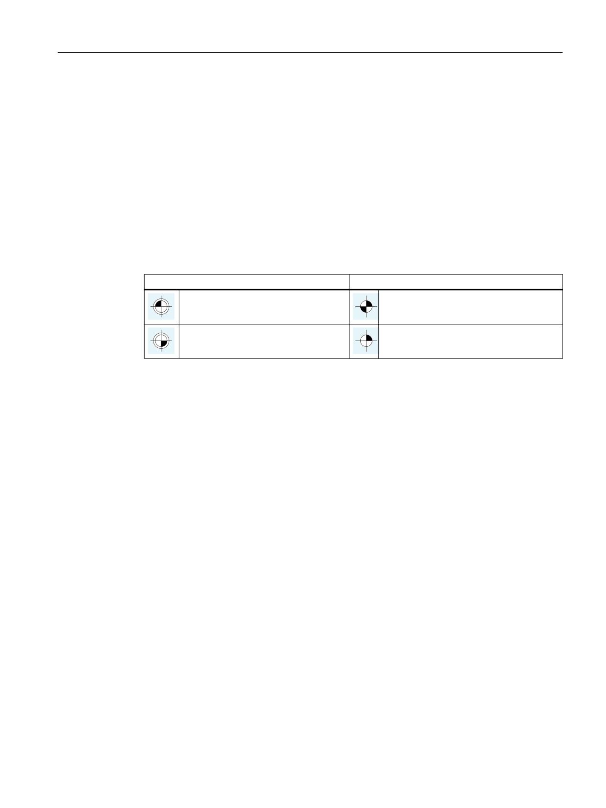
Axes, coordinate systems, frames
4.3 Zero points and reference points
4.3
Zero points and reference points
4.3.1
Reference points in working space
Zeros and reference points
The neutral position of the machine is obtained from the coordinate axes and the constructive
characteristics of the machine. The zero of the coordinate system is obtained by defining a
suitable reference point on the machine in its neutral position.
The position of the coordinate systems (MCS, BCS, BZS, SZS, WCS) is determined by means of
zeros.
Zero points
Reference points
M = Machine zero
R = Reference point
W = Workpiece zero
T = Toolholder reference point
Machine zero M
The machine zero M defines the machine coordinate system MCS. All other reference points refer
to the machine zero.
Workpiece zero W
The workpiece zero W defines the workpiece coordinate system in relation to the machine zero
M. The programmed part-program blocks are executed in the workpiece coordinate system WCS.
Reference point R
The position of the reference point R is defined by cam switches. Reference point R calibrates the
position measuring system.
With incremental encoders, the reference point must be approached every time the control
power is switched on. The control can only then work with the measuring system and transfer
all position values to the coordinate systems.
Toolholder reference point T
The toolholder reference point T is located on the toolholder locator. By entering the tool
lengths, the control calculates the distance between the tool tip (TCP Tool Center Position) and
the toolholder reference point.
Basic functions
Function Manual, 10/2020, 6FC5397-2GP40-0BA1
273
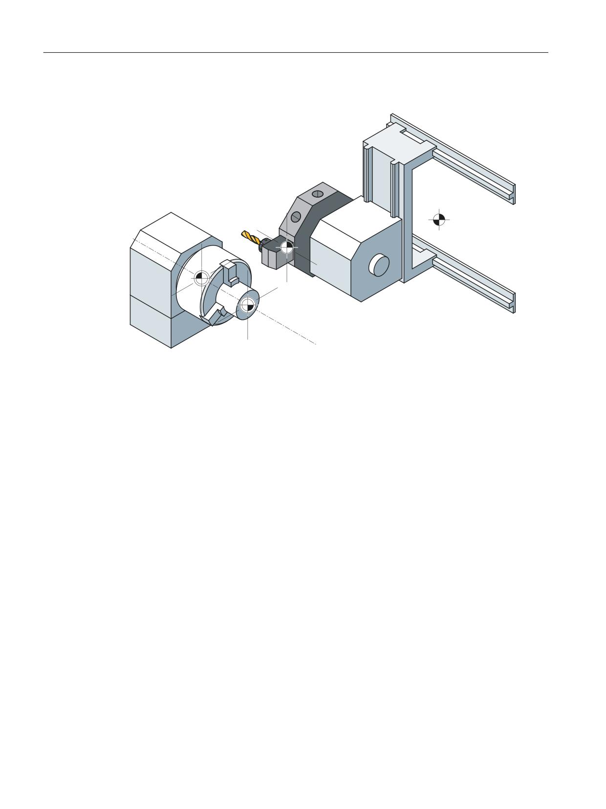
Axes, coordinate systems, frames
4.3 Zero points and reference points
Example: Zeros and reference points on a turning machine
5
7
0
:
Basic functions
274
Function Manual, 10/2020, 6FC5397-2GP40-0BA1