SINUMERIK 840D sl. Service - Functions. Manual (2018-2020) - page 20

Mode group, channel, program operation, reset response
3.8 Block search Type 5 (SERUPRO)
Example: Rotary axis A is programmed incrementally
Rotary axis A is the fourth machine axis.
•
Rotary axis A is positioned at 11° before the REPOS operation.
In the interruption block, i.e. in the target block of SERUPRO, rotary axis A should be moved
to 27°.
Any number of blocks later, rotary axis A is moved incrementally through 5°:
N1010 POS[A]=IC(5) FA[A]=1000
When interface signal DB34 DBX10.0 = 1 is set (REPOS delay), rotary axis A is not moved in
the REPOS operation, and is moved with N1010 to 32°. The user may have to consciously
acknowledge the movement from 11° to 27°.
DANGER
Risk of collision
As, after the interruption, the axis is incrementally programmed, it moves to 16° instead of
32°.
•
Starting axes individually
The REPOS behavior for SERUPRO approach with several axes is selected with:
MD11470 $MN_REPOS_MODE_MASK.BIT 3 = 1
The NC commences SERUPRO approach with a block that moves all positioning axes to the
programmed end and the path axis to the target block.
The user starts the individual axes by selecting the appropriate feedrate enables. The target
block is then executed.
•
Repositioning positioning axes in the repositioning block
Positioning axes are not repositioned in the residual block but rather in the repositioning
block, and their effect is not limited to the block search via program test on SERUPRO
approach.
MD11470 $MN_REPOS_MODE_MASK.bit 3 = 1: for block search via program test (SERUPRO)
MD11470 $MN_REPOS_MODE_MASK.bit 4 = 1: for each REPOS
Note
If neither bit 3 nor bit 4 is set, in that this phase non-path axes are repositioned in the residual
block.
Delayed approach of axis with REPOS offset
If the axis-specific interface signal DB31, ... DBX10.0 (REPOS delay) is set with the positive edge
of DB21, ... DBX31.4 (REPOS mode change), the REPOS offset for this axis is only traversed
through when programmed the next time.
Basic functions
Function Manual, 10/2020, 6FC5397-2GP40-0BA1
137

Mode group, channel, program operation, reset response
3.8 Block search Type 5 (SERUPRO)
Whether this axis is currently subject to a REPOS offset can be read via synchronized actions with
$AA_REPOS_DELAY.
CAUTION
Risk of collision
DB31, ... DBX10.0 (REPOS delay) have no effect on machine axes, which form a path.
Whether an axis is a path axis can be determined using DB31, ... DBX76.4 (path axis).
Acceptance timing of REPOS SIGNALS
With the positive edge of DB21, ... DBX31.4 (REPOS mode change), the following REPOS signals
are transferred into the NC:
• Channel-specific: DB21, ... DBX31.0 - 2 (REPOS mode)
• Axis-specific: DB31, ... DBX10.0 (REPOS delay)
The level of the REPOS signals refers to the actual main run block. There are two different cases:
1. One repositioning block of a currently active REPOS operation is contained in the main run.
The active REPOS operation is canceled, restarted and the REPOS offsets are influenced by the
REPOS signals mentioned above:
2. No repositioning block of a currently active REPOS operation is contained in the main run.
Each future REPOS operation wanting to reapproach the current main program block is
influenced by the REPOS signals mentioned above.
Note
In a running ASUB, DB21, ... DBX31.4 (REPOS mode change) does not act on the final REPOS,
unless the signal is inadvertently set at the instant in time that the REPOS blocks are being
executed.
In case 1, the signal is allowed only in the stopped state.
Response to RESET:
• The NC has already acknowledged the PLC signal:
DB21, ... DBX31.4 == 1 (REPOS mode change) AND
DB21, ... DBX319.0 == 1 (REPOS mode change acknowledgment)
If, in this situation, a channel reset occurs, then the active REPOS mode is cleared:
DB21, ... DBX319.1 - 3 = 0 (active REPOS mode)
• The NC has still not acknowledged the PLC signal:
DB21, ... DBX31.4 == 1 (REPOS mode change) AND
DB21, ... DBX319.0 == 0 (REPOS mode change acknowledgment)
If, in this situation, a channel reset occurs, then acknowledgment of the REPOS mode change
and the active REPOS mode are cleared:
DB21, ... DBX319.0 = 0 (REPOS mode change acknowledgment)
DB21, ... DBX319.1 - 3 = 0 (active REPOS mode)
Basic functions
138
Function Manual, 10/2020, 6FC5397-2GP40-0BA1
Mode group, channel, program operation, reset response
3.8 Block search Type 5 (SERUPRO)
Controlling SERUPRO approach with NC/PLC interface signals
The SERUPRO approach can be used with:DB21, ... DBX31.4 (REPOS mode change) and the
associated signals in the following phases:
• From "Search target found" to "Start SERUPRO ASUB"
• From "SERUPO ASUB stops automatically before REPOS" to "Target block is executed"
While the SERUPRO ASUB is being executed, e.g. in the program section before the REPOS
operation, the interface signal does not affect the SERUPRO positioning
REPOS operations with NC/PLC interface signals
Control REPOS with NC/PLC interface signals
REPOS offsets can be influenced with the following NC/PLC interface signals:
• DB21, ... DBX31.0 - 2 (REPOS mode)
• DB21, ... DBX31.4 (REPOS mode change)
• DB31, ... DBX10.0 (REPOS delay)
• DB31, ... DBX72.0 (REPOS delay)
REPOS acknowledgment signals
The following NC/PLC interface signals can be used to acknowledge from the NC, functions that
control the REPOS response via PLC:
• DB21, ... DBX319.0 (REPOS mode change acknowledgment)
• DB21, ... DBX319.1 - 3 (active REPOS mode)
• DB21, ... DBX319.5 (REPOS acknowledgment delay)
• DB31, ... DBX70.0 (REPOS offset)
• DB31, ... DBX70.1 (REPOS offset valid)
• DB31, ... DBX70.2 (REPOS delay acknowledgment)
• DB31, ... DBX76.4 (path axis)
For further information, see "REPOS offset in the interface"
REPOS acknowledgment operations
If the NC recognizes a REPOS mode change (DB21, ... DBX31.4 == 1), then this is acknowledged
by the PLC with DB21, ... DBX319.0 = 1.
Note
If the NC has not yet acknowledged interface signal DB21, ... DBX31.4 (REPOS MODE CHANGE)
with interface signal DB21, ... DBX319.0 (REPOS mode change acknowledgment)
, then a channel reset in this situation causes the program to be canceled, and the REPOS, which
is to be used to control the REPOS mode, is not executed.
Basic functions
Function Manual, 10/2020, 6FC5397-2GP40-0BA1
139
Mode group, channel, program operation, reset response
3.8 Block search Type 5 (SERUPRO)
A REPOS mode issued from the PLC is acknowledged by the NC using the following interface
signals:
• DB21, ... DBX319.1 - 3 (active REPOS mode)
• DB31, ... DBX10.0 (REPOS delay)
• DB31, ... DBX70.2 (REPOS delay acknowledgment)
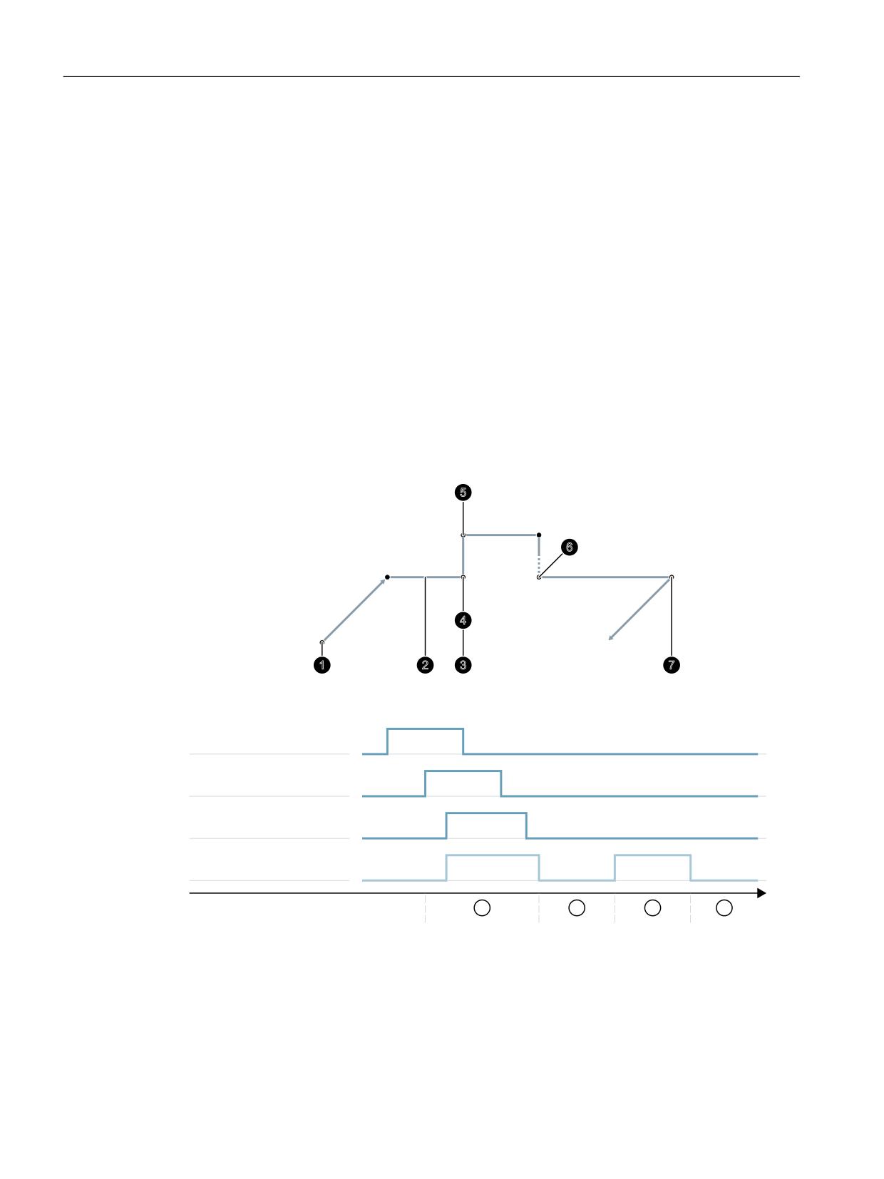
Example
• Instant in time ②: An NC program in block N20 is stopped with an NC stop. All axes are braked
along their parameterized braking ramps to standstill.
• Instant in time ③: After the PLC user program has set "REPOS mode", the NC accepts REPOS
mode with the 0/1 edge of "REPOS mode change".
• Instant in time ④: "REPOS mode change acknowledgment" remains set until the ASUB is
initiated.
• Instant in time ⑤: The REPOS operation begins in the ASUB.
• Instant in time ⑥: The residual block of the ASUB is reloaded.
&RPPDQG ZLWK $68% LV LQLWLDWHG
5H DSSURDFK IURP 5(326 KDV
EHHQ FRPSOHWHG
7KH UHPDLQGHU EORFN EHJLQV
1
1
1
7ULJJHU $68%
3UHVHOHFW 501%/
7KH UHPDLQGHU EORFN
6WDUW RI WKH SDUW
6WRS RI WKH SDUW
LV ILQLVKHG
SURJUDP
SURJUDP
5(3263$7+02'(
5(32602'(('*(
5(32602'(('*($&.1
5HSRV 3DWK 0RGH $FNQ
W
Figure 3-5
REPOS sequence in part program with timed acknowledgment signals from NC
NC sets acknowledgment again
Phase with REPOSPATHMODE still active (residual block of the program stopped at → Time (2)
is not yet completely executed).
Basic functions
140
Function Manual, 10/2020, 6FC5397-2GP40-0BA1
Mode group, channel, program operation, reset response
3.8 Block search Type 5 (SERUPRO)
As soon as the REPOS repositioning motion of the ASUB is executed, the NC sets the "Repos Path
Mode Ackn" again (→ Time (5)). If no REPOSPATHMODE has been preselected via an NC/PLC
interface signal, the programmed REPOS mode is displayed.
"Repos Path Mode Ackn" is canceled when the residual block is activated (→ Time (6)).
The part program block N30 following the block at → Time (2) is resumed.
Interface signal:
DB31, ... DBX70.2 (REPOS delay acknowledgment) is analogously defined.
DB31, ... DBX70.1 (REPOS offset valid) = 1, if:
DB21, ... DBX319.1-319.3 (active REPOS mode) = 4 (RMNBL).
Valid REPOS offset
At the end of the SERUPRO operation, the user can read out the REPOS offset via the axis/spindle
NC/PLC interface signal (NC→PLC):
DB31, ... DBX70.0 (REPOS offset).
The effects of this signal on the relevant axis are as follows:
Value 0:
No REPOS offset is applied.
Value 1:
REPOS offset is applied.
Range of validity
Interface signal:
DB31, ... DBX70.0 (REPOS offset)
is supplied at the end of the SERUPRO operation.
The REPOS offset is invalidated at the start of a SERUPRO ASUB or the automatic ASUB start.
Updating the REPOS offset in the range of validity
Between the SERUPRO end and SERUPRO start, the axis can be moved in JOG mode with a mode
change.
In JOG mode, the user manually moves the axis over the REPOS offset path in order to set
interface signal:
DB31, ... DBX70.0 (REPOS offset) to the value 0.
Within the range of validity, the axis can also be traversed using FC18, whereby the interface
signal
DB31, ... DBX70.0 (REPOS offset) is continuously updated.
Displaying the range of validity
The range of validity of the REPOS offset is indicated with interface signal:
DB31, ... DBX70.1 (REPOS offset valid)
Basic functions
Function Manual, 10/2020, 6FC5397-2GP40-0BA1
141
Mode group, channel, program operation, reset response
3.8 Block search Type 5 (SERUPRO)
It is indicated whether the REPOS offset calculation was valid or invalid:
Value 0:
The REPOS offset of this axis is calculated correctly.
Value 1:
The REPOS offset of this axis cannot be calculated, as the REPOS has not yet oc-
curred, e.g. it is at the end of the ASUB, or no REPOS is active.
REPOS offset after an axis interchange
The group signal:DB21, ... DBX319.5 (REPOS delay) can be used to determine whether a valid
REPOS offset has taken place:
Value 0:
All axes currently controlled by this channel have either no REPOS offset or their
REPOS offsets are invalid.
Value 1:
Miscellaneous.
REPOS offset with synchronized synchronous spindle coupling
When repositioning with SERUPRO, processing continues at the point of interruption. If a
synchronous spindle coupling was already synchronized, there is no REPOS offset of the
following spindle and no synchronization path is present. The synchronization signals remain
set.
Search target found on block change
The axis-specific NC/PLC interface signal DB31, ... DBX76.4 (path axis) is 1 if the axis is part of the
path grouping.
This signal shows the status of the current block to be executed during block change.
Subsequent status changes are ignored.
If the SERUPRO operation is ended with "Search target found", DB31, ... DBX76.4 (path axis)
refers to the target block.
3.8.2.1
Repositioning with controlled REPOS
Once SERUPRO has been used to find the target block, prior to continuing the interrupted
program, a REPOS operation for repositioning the contour is performed. The REPOS mode
"Reposition at the block start point of the target block" (RMBBL) is active by default. The REPOS
mode can be defined user-specific via the NC/PLC interface:
DB21, ... DBX31.0 - .2 (REPOS mode)
Further information
A detailed description of the interface signals can be found in the Function Manual PLC.
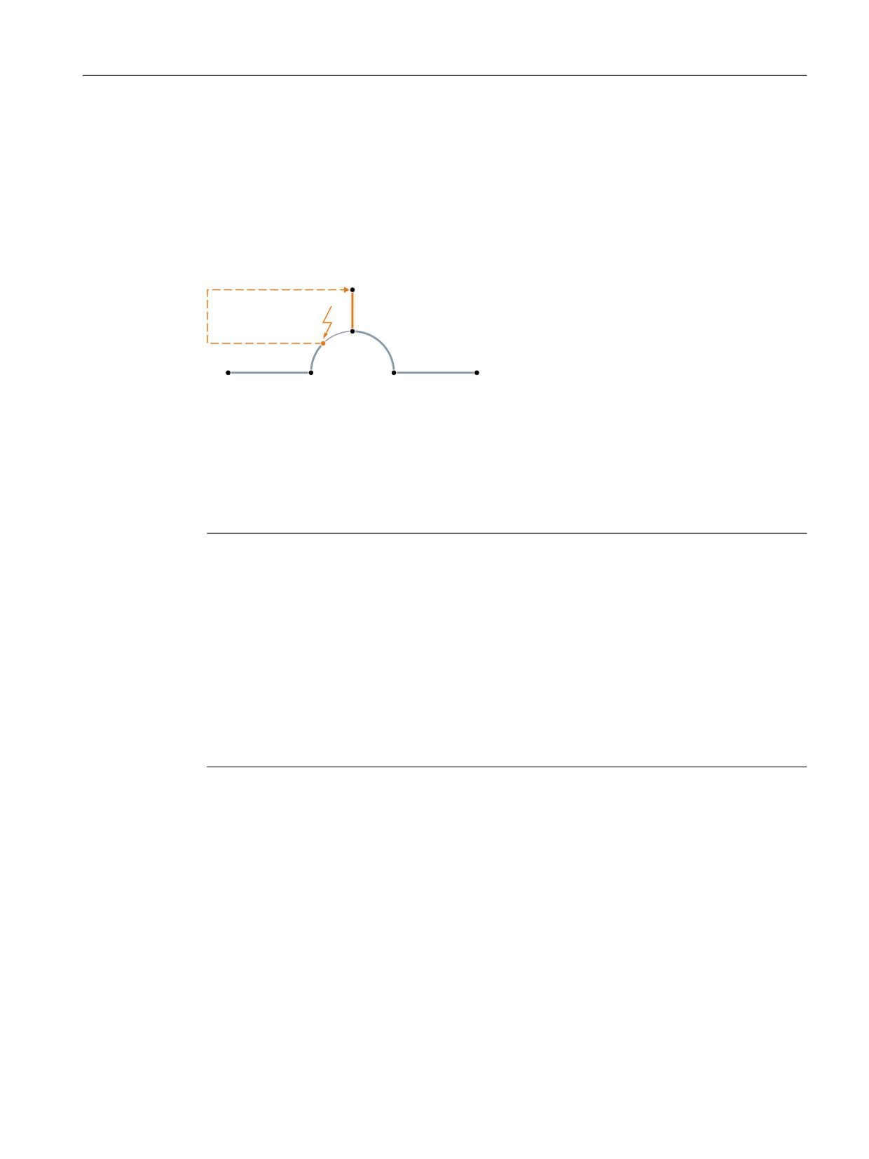
REPOS mode: Repositioning to the next point on the path (RMNBL)
in the RMNBL REPOS mode, positioning is made for the REPOS start position from the next
nearest contour point.
Basic functions
142
Function Manual, 10/2020, 6FC5397-2GP40-0BA1
Mode group, channel, program operation, reset response
3.8 Block search Type 5 (SERUPRO)
Example
The program is interrupted at any point in the block N110. The axes were then traversed to
position (A), e.g. manually. Once SERUPRO has found target block N110, the REPOS operation
with REPOS mode RMNBL is performed. With regard to the REPOS start position (A), point (B) is
the next nearest point of the contour. The REPOS operation is completed when point (B) is
reached. The programmed contour of the interrupted program is traversed again starting at
point (B).
$
,QWHUUXSWLRQ SRLQW 1
%
1
1
Specifying the REPOS mode via the NC/PLC interface
The REPOS mode can be specified via the following NC/PLC interface signal:
DB21, ... DBX31.0 - .2 (REPOS mode)
Note
RMNBL is a general REPOS extension and it is not restricted to SERUPRO.
RMIBL and RMBBL behavior identically for SERUPRO.
DB21, ... DBX31.0 - .2 (REPOS mode) affects only the traversing motion of the path axes.
The behavior of the other axis can be changed individually using interface signal DB31, ...
DBX10.0 (REPOSDELAY). The REPOS offset is not applied immediately, but only when it is next
programmed.
For further information on the programming of the repositioning point, see:
Further information
"NC Programming" Programming Manual
3.8.3
Accelerate block search
Machine data settings
The speed of execution of the SERUPRO operation can be influenced via the following machine
data.
Basic functions
Function Manual, 10/2020, 6FC5397-2GP40-0BA1
143

Mode group, channel, program operation, reset response
3.8 Block search Type 5 (SERUPRO)
MD22600 $MC_SERUPRO_SPEED_MODE = <value>
<Value>
Meaning
0
Program test with block search velocity / dry run feedrate:
• Axes: MD22601 $MC_SERUPRO_SPEED_FACTOR * dry run feedrate
• Spindles: MD22601 $MC_SERUPRO_SPEED_FACTOR * programmed speed
Dynamic limitations of axes / spindles are not considered.
1
Program test with programmed velocity:
• Axes: Dry run feedrate
• Spindles: Programmed speed
Dynamic limitations of axes / spindles are considered.
2
Program test with dry run feedrate
Under program test, traversing is performed with the programmed velocity / speed.
Dynamic limitations of axes / spindles are considered.
3
Program test with block search velocity
Under program test, traversing is performed with the following velocity:
• Axes: MD22601 $MC_SERUPRO_SPEED_FACTOR * programmed feedrate
• Spindles: MD22601 $MC_SERUPRO_SPEED_FACTOR * programmed speed.
Dynamic limitations of axes / spindles are not considered.
Note
When revolutional feedrate is active (e.g. G95), the programmed feedrate is not multiplied by
MD22601 $MC_SERUPRO_SPEED_FACTOR but only the programmed spindle speed. This re-
sults, here too, in an increase in the effective path velocity by MD22601 $MC_SERU-
PRO_SPEED_FACTOR.
Supplementary conditions
Main axes
MD22600 $MC_SERUPRO_SPEED_MODE acts on the following main run axes with SERUPRO:
• PLC axes
• Command axes
• Positioning axes
• Reciprocating axes
Synchronized actions
NOTICE
Actions of synchronized action may not be executed with SERUPRO
Because during SERUPRO other actual values (e.g. axis positions) are generated internally that
are different from those in normal program execution, with SERUPRO, conditions of
synchronized actions that check the actual values (e.g. axis positions) are no longer recognized
as true (TRUE) and that the action part of the synchronized action is therefore not executed.
Basic functions
144
Function Manual, 10/2020, 6FC5397-2GP40-0BA1
Mode group, channel, program operation, reset response
3.8 Block search Type 5 (SERUPRO)
Revolutional feedrate
Effects of MD22601 $MC_SERUPRO_SPEED_FACTOR during DryRun:
• Switchover of G95/G96/G961/G97/G971 to G94
• Tapping and thread cutting: Normal dry run velocity.
Tapping without compensating chuck
• With "tapping without compensating chuck" (G331/G332), the spindle is interpolated under
position control in a path grouping. The drilling depth (linear axis), the thread pitch, and
speed (spindle) are defined.
During dry run, the velocity of the linear axis is specified, the speed remains constant, and the
pitch is adjusted.
After SERUPRO, a position for the spindle results that is deviates from normal mode because
the spindle has revolved fewer times in SERUPRO.
3.8.4
SERUPRO ASUB
SERUPRO ASUP special points
Special points should be noted for SERUPRO ASUP with regard to:
• Reference point approach: Referencing via part program G74
• Tool management: Tool change and magazine data
• Spindle ramp-up: On starting a SERUPRO ASUP
G74 reference point approach
If command G74 (reference point approach) is programmed between the program start and the
search target, this will be ignored by the NC.
SERUPRO approach does not take this G74 command into account!
Tool management
If tool management is active, the following setting is recommended:
MD20310 $MC_TOOL_MANAGEMENT_MASK Bit 20 = 0
The tool management command generated during the SERUPRO operation is thus not output to
the PLC!
Basic functions
Function Manual, 10/2020, 6FC5397-2GP40-0BA1
145
Mode group, channel, program operation, reset response
3.8 Block search Type 5 (SERUPRO)
The tool management command has the following effect:
• The NC acknowledges the commands automatically.
• No magazine data is changed.
• Tool data is not changed.
Exception:
The tool enabled during the test mode can assume 'active' state. In this way, the wrong tool
may be on the spindle after the SERUPRO operation.
Remedy:
The user starts a SERUPRO ASUP that is actually traversed. Prior to the start, the user can start
an ASUP that loads the correct tool.
SERUPRO operation: Functionality: In sequence steps 2. to 6.
SERUPRO ASUP: Functionality: The sequence of step 7.
In addition, machine data setting MD20310 $MC_TOOL_MANAGEMENT_MASK Bit 11 = 1 is
required because the ASUP may have to repeat a T selection.
Systems with tool management and auxiliary spindle are not supported by SERUPRO!
Example
Tool change subprogram
Program code
Comment
PROC L6
; Tool change routine
N500 DEF INT TNR_AKTUELL
; Variable for active T number
N510 DEF INT TNR_VORWAHL
; Variable for preselected T number
; Determine current tool
N520 STOPRE
; In program testing
N530 IF $P_ISTEST
; From the program context
N540 TNR_AKTUELL = $P_TOOLNO
; The "current" tool is read
N550 ELSE
; Otherwise, the tool of the spindle is read out.
N560 TNR_AKTUELL = $TC_MPP6[9998,1]
; Read tool T number on the spindle
N570 ENDIF
N580 GETSELT(TNR_VORWAHL)
; Read T number of the preselected tool of the master spindle
; Execute tool change only if tool is not yet current
N590 IF TNR_AKTUELL <> TNR_VORWAHL
; Approach tool change point
N600 G0 G40 G60 G90 SUPA X450 Y300
Z300 D0
N610 M206
; Execute tool change
N620 ENDIF
N630 M17
Basic functions
146
Function Manual, 10/2020, 6FC5397-2GP40-0BA1
Mode group, channel, program operation, reset response
3.8 Block search Type 5 (SERUPRO)
ASUP for calling the tool change routine after type 5 block search
Program code
Comment
PROC ASUPWZV2
N1000 DEF INT TNR_SPINDEL
; Variable for active T number
N1010 DEF INT TNR_VORWAHL
; Variable for preselected T number
N1020 DEF INT TNR_SUCHLAUF
; Variable for T number determined in block search
N1030 TNR_SPINDEL = $TC_MPP6[9998,1]
; Read tool T number on the spindle
N1040 TNR_SUCHLAUF = $P_TOOLNO
; Read T number determined by block search,
i.e. this tool determines the
current tool offset
N1050 GETSELT(TNR_VORWAHL)
; Read T number of preselected tool
N1060 IF TNR_SPINDEL ==TNR_SUCHLAUF GOTOF AS-
UP_ENDE1
N1070 T = $TC_TP2[TNR_SUCHLAUF]
; T selection by tool name
N1080 L6
; Call tool change routine
N1085 ASUP_ENDE1:
N1090 IF TNR_VORWAHL == TNR_SUCHLAUF GOTOF AS-
UP_ENDE
N1100 T = $TC_TP2[TNR_VORWAHL]
; Restore T preselection by tool name
N1110 ASUP_ENDE:
N1110 M90
; Feedback to PLC
N1120 REPOSA
; ASUP end
In both of the programs PROC L6 and PROC ASUPWZV2, the tool change is programmed with
M206 instead of M6.
ASUP "ASUPWZV2" uses different system variables to detect the progress of the program
($P_TOOLNO) and represent the current status of the machine ($TC_MPP6[9998,1] ).
Spindle ramp-up
When the SERUPRO ASUP is started, the spindle is not accelerated to the speed specified in the
program because the SERUPRO ASUP is intended to move the new tool into the correct position
at the workpiece after the tool change.
A spindle ramp-up is performed with SERUPRO ASUP as follows:
• SERUPRO operation has finished completely.
• The user starts the SERUPRO ASUP via function block FC 9
in order to ramp up the spindle.
• The start after M0 in the ASUP does not change the spindle status.
• SERUPRO ASUP automatically stops before the REPOS part program block.
Basic functions
Function Manual, 10/2020, 6FC5397-2GP40-0BA1
147
Mode group, channel, program operation, reset response
3.8 Block search Type 5 (SERUPRO)
• The user presses START.
• The spindle accelerates to the target block state if the spindle was not programmed
differently in the ASUP.
Note
Modifications for REPOS of spindles:
The transitions of speed control mode and positioning mode must be taken into
consideration in the event of modifications in SERUPRO approach and spindle functionality.
For further information on the operating mode switchover of spindles, see Section "Mode
types and mode type change (Page 31)".
3.8.5
Selfacting SERUPRO
Self-acting SERUPRO
The channel-specific function "Self-acting SERUPRO" allows a SERUPRO sequence without
having to previously define a search target in a program of the associated SERUPRO channels.
A special channel, the "serurpoMasterChan", can also be defined for each "Self-acting SERUPRO".
A search target can be defined in this channel.
The "Self-acting SERUPRO" function supports the SERUPRO cross-channel block search.
Function
The "Self-acting SERUPRO" operation cannot be used to find a search target. If the search target
is not reached, then no channel is stopped. However, in certain situations the channel is
temporarily stopped. Generally, the channel waits for another channel. Examples are: Wait
marks, couplings or axis interchange.
The wait phase occurs:
During this wait phase, the NC checks the "seruproMasterChan" channel whether it has reached
a search target. The wait phase is exited when a search target is not reached.
If the search target is reached,
the SERUPRO operation is also ended in the channel. The "seruproMasterChan" channel must
have been started in normal SERUPRO mode.
No wait phase occurs:
"Self-acting SERUPRO" is ended by M30 of the part program.
The channel is now in the Reset state again.
There is no SERUPRO approach.
Basic functions
148
Function Manual, 10/2020, 6FC5397-2GP40-0BA1
Mode group, channel, program operation, reset response
3.8 Block search Type 5 (SERUPRO)
Starting a group of channels
If a group of channels is only started with "Self-acting SERUPRO", then all channels are ended
with "RESET".
Exception:
A channel waits for a partner channel that has not been started at all.
A cross-channel block search can be carried out as follows:
• Via the HMI, the user selects the channels that must work together (channel group).
• The user selects a particularly important channel from the channel group for which a search
target is to be explicitly selected (target channel).
• The HMI will then start SERUPRO on the target channel and "Self-acting SERUPRO" in the
remaining channels of the channel group.
The operation is complete when every relevant channel has deleted "seruproActive".
"Self-acting SERUPRO" accepts no master channel on another NCU.
Activation
"Self-acting SERUPRO" is activated via the HMI as a block search start for the Type 5 block search
for target channel "seruproMasterChan".
A search target is not specified for the dependent channels started from the target channel.
3.8.6
Locking a program section for "Continue machining at the contour"
Programmed interrupt pointer
If because of manufacturing and/or process-related reasons, "Continue machining at the
contour" may not be possible within a certain program section at a program abort, this program
section can be locked for the target block of a block search.
If after a program abort there is a block search for the interruption point within the locked
program section for "Continue machining at the contour", the last executable block (main run
block) before the start of the locked section is used by the control as target block (hold block).
Programming
Syntax
IPTRLOCK()
Functionality
Marks the beginning of the program section as of which "Continue machining at the contour" is
locked. The next executable block (main run block) in which IPTRLOCK becomes active is now
used as target block for a block search with "Continue machining at the interruption point", until
the release with IPTRUNLOCK. This block is referred to as the hold block in the following.
Effectiveness: Modal
Basic functions
Function Manual, 10/2020, 6FC5397-2GP40-0BA1
149
Mode group, channel, program operation, reset response
3.8 Block search Type 5 (SERUPRO)
Syntax
IPTRUNLOCK()
Marks the end of the program section locked for "Continue machining at the contour". As of the
next executable block (main run block) in which IPTRLOCK becomes active, the current block
is used again as target block for a block search with "Continue machining at the interruption
point". This block is referred to as the release block in the following.
Effectiveness: Modal
Example
Program code
Comment
N010 IPTRLOCK()
; Locked area: Start
N020 R1=R1+1
N030 G4 F1
; Hold block
; Locked area
N200 IPTRUNLOCK()
; Locked area: End
N220 R1=R1+1
N230 G4 F1
; Release block
Supplementary conditions
• IPTRLOCK acts within a program (*.MPF, *.SPF) at the most up to the end of the program
(M30, M17, RET). IPTRUNLOCK implicitly becomes active at the end of the program.
• Multiple programming of IPTRLOCK within a program does not have a cumulative effect.
With the first programming of IPTRUNLOCK within the program or when the end of the
program is reached, all previous IPTRLOCK calls are terminated.
• If there is a subprogram call within a locked area, "Continue machining at the contour" is also
locked for this and all following subprogram levels. The lock also cannot be cancelled within
the called subprogram through explicit programming of IPTRUNLOCK.
Example: Nesting of locked program sections in two program levels
With the activation of the "Continue machining at the contour" lock in PROG_1, "Continue
machining at the contour" is also locked for PROG_2 and all following program levels.
Program code
Comment
PROC PROG_1
; Program 1
N010 IPTRLOCK()
N020 R1=R1+1
N030 G4 F1
; Hold block
; Locked area: Start
N040 PROG_2
; Locked area
; Locked area: End
N050 IPTRUNLOCK()
Basic functions
150
Function Manual, 10/2020, 6FC5397-2GP40-0BA1

Mode group, channel, program operation, reset response
3.8 Block search Type 5 (SERUPRO)
Program code
Comment
N060 R2=R2+2
N070 G4 F1
; Release block
Program code
Comment
PROC PROG_2
; Program 2
N210 IPTRLOCK()
; Ineffective due to program 1
N250 IPTRUNLOCK()
; Ineffective due to program 1
N280 RET
; Ineffective due to program 1
Example 3: Multiple programming of IPTRLOCK
Program code
Comment
PROC PROG_1
; Program 1
N010 IPTRLOCK()
N020 R1=R1+1
N030 G4 F1
; Hold block
; Locked area: Start
N150 IPTRLOCK()
; Locked area
; Locked area
N250 IPTRLOCK()
; Locked area
; Locked area: End
N360 IPTRUNLOCK()
N370 R2=R2+2
N380 G4 F1
; Release block
System variable
The status of the current block can be determined via the system variable $P_IPTRLOCK:
$P_IPTRLOCK
Meaning
FALSE
The current block is not within a program section locked for "Continue machining at
the contour"
TRUE
The current block is within a program section locked for "Continue machining at the
contour"
Automatic function-specific "Continue machining at the contour" lock
For various couplings, the activation/deactivation of the "Continue machining at the contour"
lock can be performed automatically channel-specifically with the activation/deactivation of the
coupling:
Basic functions
Function Manual, 10/2020, 6FC5397-2GP40-0BA1
151

Mode group, channel, program operation, reset response
3.8 Block search Type 5 (SERUPRO)
MD22680 $MC_AUTO_IPTR_LOCK, bit x
Bit
Val-
Meaning
ue
0
Electronic gear ( EGON / EGOF)
1
Automatic "Continue machining at the contour" lock is active
0
Automatic "Continue machining at the contour" lock is not active
1
Axial master value coupling (LEADON / LEADOF)
1
Automatic "Continue machining at the contour" lock is active
0
Automatic "Continue machining at the contour" lock is not active
This program section begins with the last executable block before the activation and ends with
the deactivation.
The automatic interrupt pointer is not active for couplings that were activated or deactivated via
synchronized actions.
Example: Automatically declaring axial master value coupling as search-suppressed:
Program code
Comment
N100 G0 X100
N200 EGON(Y,"NOC",X,1,1)
; Search-suppressed program section starts.
N300 LEADON(A,B,1)
N400 EGOFS(Y)
N500 LEADOF(A,B)
; Search-suppressed program section ends.
N600 G0 X200
A program abort within search-suppressed program section (N200 - N500) always provides the
interrupt pointer with N100.
NOTICE
Unwanted state caused by function overlappings
If there is an overlap of the "Programmable interrupt pointer" and "Automatic interrupt pointer"
functions via machine data, the NC selects the largest possible search-suppressed area.
A program may need a coupling for almost all of the runtime. In this case, the automatic
interrupt pointer would always point to the start of the program and the SERUPRO function
would in fact be useless.
3.8.7
Behavior during POWER ON, mode change and RESET
SERUPRO is inactive at Power On. The operating mode change is permitted during SERUPRO.
RESET aborts SERUPRO, the internally selected program test is deselected again. SERUPRO
cannot be combined with other block search types.
Basic functions
152
Function Manual, 10/2020, 6FC5397-2GP40-0BA1
Mode group, channel, program operation, reset response
3.8 Block search Type 5 (SERUPRO)
3.8.8
Supplementary conditions
3.8.8.1
STOPRE in the target block
The STOPRE block receives all modal settings from the preceding block and can, therefore, apply
conditions in advance in relation to the following actions:
• Synchronize program line currently processing with the main run.
• Derive modal settings for SERUPRO in order, for example, to influence this REPOS motion on
approach of SERUPRO.
Example: Position a Z axis by specifying an X axis setpoint.
When block "G1 F100 Z=$AA_IM[X]" is interpreted, the preceding STOPRE block ensures
synchronization with the main run. The correct setpoint of the X axis is thus read via $AA_IM to
move the Z axis to the same position.
Example: Read and correctly calculate external work offset.
N10 G1 X1000 F100
N20 G1 X1000 F500
N30 G1 X1000 F1000
N40 G1 X1000 F5000
N50 SUPA G1 F100 X200
; move external work offset to 200
N60 G0 X1000
N70 ...
Via an implicit STOPRE before N50, the NC can read and correctly calculate the current work
offset.
For a SERUPRO operation on the N50 search target, repositioning is on the implicit STOPRE in the
SERUPRO approach and the velocity is determined from N40 with F5000.
Basic functions
Function Manual, 10/2020, 6FC5397-2GP40-0BA1
153
Mode group, channel, program operation, reset response
3.8 Block search Type 5 (SERUPRO)
Implicit preprocessing stop
Situations in which an implicit preprocessing stop is issued:
1. In all blocks in which one of the following variable access operations occurs:
- Programming of a system variable beginning with $A...
- Programming of a system variable beginning with attribute SYNR/SYNRW
2. For the following commands:
- Part program MEACALC, MEASURE commands
- Programming of SUPA (suppress frame and online corrections)
- Programming of CTABDEF (start of the curve table definition)
- Part program WRITE/DELETE command (write/delete file)
- Before the first WRITE/DELETE command of a sequence of such commands
- Part program EXTCALL command
- Part program GETSELT, GETEXET commands
- For tool and active FTOCON tool fine correction
3. For the following command processing:
- End processing of a type 1 block search ("block search without calculation")
- End processing of a type 2 block search with calculation ("block search at contour end
point")
3.8.8.2
SPOS in target block
If a spindle is programmed with M3/M4 and a switch made to SPOS in the target block, the
spindle is switched to SPOS at the end of the SERUPRO operation ("Search target found" status).
DB31, ... DBX84.5 = TRUE (active spindle mode: positioning mode)
3.8.8.3
Travel to fixed stop (FXS)
During repositioning (REPOS), the "Travel to fixed stop" function (FXS) is repeated automatically.
Every axis is taken into account. The torque programmed last before the search target is used as
torque.
System variable
The system variables for "Travel to fixed stop" have the following meaning with SERUPRO:
• $AA_FXS: Progress of the program simulation
• $VA_FXS: Real machine state
The two system variables always have the same values outside the SERUPRO function.
ASUP
A user-specific ASUP can be activated for SERUPRO.
Basic functions
154
Function Manual, 10/2020, 6FC5397-2GP40-0BA1
Mode group, channel, program operation, reset response
3.8 Block search Type 5 (SERUPRO)
Further information
Detailed information regarding the SERUPRO block search can be obtained in the Function
Manual Axes and Spindles; Travel to fixed stop.
3.8.8.4
Travel with limited torque/force (FOC)
During repositioning (REPOS), the "Travel with limited torque/force" function (FOC) is repeated
automatically. Every axis is taken into account. The torque programmed last before the search
target is used as torque.
System variable
The system variables for "Travel with limited torque/force" have the following meaning with
SERUPRO:
• $AA_FOC: Progress of the program simulation
• $VA_FOC: Real machine state
Boundary condition
A changing torque characteristic cannot be implemented during repositioning.
Example
A program traverses axis X from 0 to 100 and switches "Travel with limited torque/force" (FOC)
on every 20 increments for 10 increments. This torque characteristic is usually generated with
non-modal FOC and cannot be performed during repositioning (REPOS). Instead, axis X is
traversed from 0 to 100 with or without limited torque/force in accordance with the last
programming.
Further information
Detailed information regarding the SERUPRO block search can be obtained in the Function
Manual Axes and Spindles; Travel to fixed stop.
3.8.8.5
Synchronous spindle
The synchronous spindle can be simulated.
The synchronous spindle operation with main spindle and any number of following spindles can
be simulated in all existing channels with SERUPRO.
Further information
Further information regarding synchronous spindles can be obtained in the Function Manual
Extended Functions; Synchronous spindle
Basic functions
Function Manual, 10/2020, 6FC5397-2GP40-0BA1
155
Mode group, channel, program operation, reset response
3.8 Block search Type 5 (SERUPRO)
3.8.8.6
Couplings and master-slave
Setpoint and actual value couplings
The SERUPRO operation is a program simulation in Program Test mode with which setpoint and
actual value couplings can be simulated.
Specifications for EG simulation
For simulation of EG, the following definitions apply:
1. Simulation always takes place with setpoint coupling.
2. If not all leading axes are under SERUPRO, the simulation is aborted with Alarm 16952 "Reset
Clear/No Start". This can occur with cross-channel couplings.
3. Axes that have only one encoder from the NC point of view and are moved externally, cannot
be simulated correctly. These axes must not be integrated in couplings.
CAUTION
Incorrect simulation
In order to be able to simulate couplings correctly, they must have been switched off
previously.
This can be performed with machine data MD10708 $MA_SERUPRO_MASK.
Specifications for coupled axes
The SERUPRO operation simulates coupled axes always assuming that they are setpoint
couplings. In this way, the end points are calculated for all axes that are used as target points for
SERUPRO approach. The coupling is also active with "Search target found". The path from the
current point to the end point is carried out for SERUPRO approach with the active coupling.
LEADON
The following specifications apply for the simulation of axial master value couplings:
1. Simulation always takes place with setpoint coupling.
2. SERUPRO approach takes place with active coupling and an overlaid motion of the following
axis in order to reach the simulated target point.
The following axis that is moved solely by the coupling cannot always reach the target point. In
SERUPRO approach, an overlaid linear motion is calculated for the following axis to approach the
simulated point!
Basic functions
156
Function Manual, 10/2020, 6FC5397-2GP40-0BA1

Mode group, channel, program operation, reset response
3.8 Block search Type 5 (SERUPRO)
Reaching simulated target point for LEAD with JOG
At the time of "Search target found", the coupling is already active, especially for the JOG
motions. If the target point is not reached, SERUPRO approach can be used to traverse the
following axis with active coupling and an overlaid motion to the target point.
Note
For further information on the repositioning of axis couplings, see Section "Repositioning to the
contour (REPOS) (Page 135)".
Master-slave
A system ASUP can be started automatically after the block search has finished. In this ASUP, the
user can control the coupling state and the associated axis positions subsequently. The required
information is provided via the following system variables:
System variable
Description
$P_SEARCH_MASLD[<slave axis>]
Position offset between slave and master axis when the
link is closed.
$AA_MASL_STAT[<slave axis>]
Current state of a master/slave coupling
$P_SEARCH_MASLC[<slave axis>]
Status: The state of the coupling was changed during the
block search
The system variables are deleted when the coupling is switched on with MASLON.
Note
The coupled axes must be in the same channel when the block search is executed.
Further information
Further information regarding the master-slave coupling can be obtained in the Function
Manual Technologies; Speed/torque coupling, master-slave"
Basic functions
Function Manual, 10/2020, 6FC5397-2GP40-0BA1
157

Mode group, channel, program operation, reset response
3.8 Block search Type 5 (SERUPRO)
Example
•
System ASUP
- Path and name: /_N_CMA_DIR/PROGEVENT.SPF
- Master axis: X
- Slave axis: Y
Program code
PROG PROGEVENT
N10 IF(($S_SEARCH_MASLC[Y]< >0) AND ($AA_MASL_STAT[Y]< >0))
N20
MASLOF(Y)
N30
SUPA Y = $AA_IM[X] - $P_SEARCH_MASLD[Y]
N40
MASLON(Y)
N50 ENDIF
N60 REPOSA
RET
•
Machine data
To ensure that the ASUP starts automatically, the following machine data must be set:
- NC-specific machine data:
- MD11604 $MN_ASUP_START_PRIO_LEVEL = 100
- MD11450 $MN_SEARCH_RUN_MODE = 'H02'
- Channel-specifically for the channel in which the ASUP is started or generally for all
channels:
- MD20105 $MC_PROG_EVENT_IGN_REFP_LOCK, bit<n> = TRUE
n: For all required event-driven program calls (prog events)
- MD20115 $MC_IGNORE_REFP_LOCK_ASUP, bit<n> = TRUE
n: For all required user interrupts
NOTICE
System interrupts
MD20115 $MC_IGNORE_REFP_LOCK_ASUP, bits 8 to 31 enable the system interrupts.
Bit 8 / interrupt 9 starts an ASUP that contains traversing motions.
Basic functions
158
Function Manual, 10/2020, 6FC5397-2GP40-0BA1
Mode group, channel, program operation, reset response
3.8 Block search Type 5 (SERUPRO)
Axis couplings
• Acceleration of the processing speed and leading axis and following axes in different
channels
For a leading axis whose following axes are assigned to a different channel than that of the
leading axis, the setting for acceleration of the execution speed has no effect (MD22601
(Page 143)$MC_SERUPRO_SPEED_FACTOR):
• Coupled motion
The coupled motion function (TRAILON) is supported by SERUPRO.
Further information
For further information on coupled motion with TRAILON and TRAILOF, see:
- Function Manual Axes and Spindles; Axis couplings
- Programming Manual Advanced; Axis couplings
• Gantry axes
The gantry axis function is supported by SERUPRO.
Further information
Further information regarding the functionality of gantry axes can be obtained in the
Function Manual Axes and Spindles; Gantry axes
• Tangential control
The tangential follow-up of individual axes function is supported by SERUPRO.
Further information
Further information on the tangential control can be found in the Function Manual Special
Functions; Tangential control
3.8.8.7
Axis functions
SERUPRO conditions
The special conditions for SERUPRO must be observed with axis enable, autonomous axis
operations, and axis interchange.
Axis enable
The axial interface DB31, ... DBX3.7 ("Program test axis/spindle enable") controls the axis
enables if no closed-loop controller enable is to (or can) be issued at the machine and is active
only during the program test or when SERUPRO is active.
It is possible to issue this enable via interface signal PLC → NC
DB31, ... DBX3.7 (program test axis/spindle enable). If the real servo enable is missing during
program test or SERUPRO, the effect on the axes/spindles is as follows:
• As soon as the simulated program run intends to move an axis/spindle, the message "Waiting
for axis enable" or "Waiting for spindle enable" is displayed and the simulation is stopped.
• If during a simulated motion, NC/PLC interface signal DB31, ... DBX3.7 (program test axis/
spindle enable) is then canceled, alarm 21612: "Channel %1 axis %2 NC/PLC interface signal
'controller enable' reset during motion" is activated.
Basic functions
Function Manual, 10/2020, 6FC5397-2GP40-0BA1
159

Mode group, channel, program operation, reset response
3.8 Block search Type 5 (SERUPRO)
Autonomous axis operations
Autonomous single-axis operations are axes controlled by the PLC that can also be simulated on
SERUPRO. During SERUPRO operation, as in normal operation, the PLC can take over or give up
control of an axis. If required, this axis can also be traversed using FC18. The PLC takes over
control of the axis before the approach block and is responsible for positioning this axis. This is
valid for all block search types.
Further information
Further information regarding autonomous single-axis operations can be obtained in the
Function Manual Axe and Spindles; Positioning axes
Axis interchange
Problem: A program moves an axis and gives up control before the target block with WAITP(X).
X is thus not subject to REPOS and the axis is not taken into account in SERUPRO approach.
Via the machine data MD11470 $MN_REPOS_MODE_MASK, the following behavior can be
achieved for SERUPRO-REPOS:
The neutral axes are moved as "command axes" in the SERUPRO-REPOS. The axis interpolates
without a path context even if it was last programmed as a path axis. In this scenario, the velocity
results from MD32060 $MA_POS_AX_VELO. After SERUPRO approach, this axis is again neutral.
Neutral axes that are however not allowed to be repositioned must receive the axial NC/PLC
interface signal "REPOSDELAY". This deletes the REPOS movement.
Example:
After SERUPRO, one axis is deliberately moved in the synchronized action via technology cycles.
The command axes are always moved in the approach block, never in the target block. The target
block can only be changed if all command axes have been moved to the end.
CAUTION
The PLC-controlled axis is not repositioned
Axes enabled by RELEASE(X) before the target block are not repositioned.
3.8.8.8
Gear stage change
Operational sequences
The gear stage change (GSC) requires physical motions from the NC in order to be able to engage
a new gear.
In the SERUPRO operation, no gear stage change is required and is carried out as follows:
Some gears can only be changed when controlled by the NC, since either the axis must oscillate
or a certain position must be approached beforehand.
The gear stage change can be suppressed selectively for DryRun, program test, and SERUPRO
using bits 0 to 2 in MD35035 $MA_SPIND_FUNCTION_MASK.
The gear stage change must then be performed in REPOS; this will work even if the axis involved
is to be in "speed control mode" at the target block. In other cases, the automatic gear stage
Basic functions
160
Function Manual, 10/2020, 6FC5397-2GP40-0BA1
Mode group, channel, program operation, reset response
3.8 Block search Type 5 (SERUPRO)
change is denied with an alarm if, for example, the axis was involved in a transformation or
coupling between the gear stage change and the target block.
Note
For further information regarding gear stage change with DryRun, program test and SERUPRO,
see Function Manual Axes and Spindles under Spindles.
3.8.8.9
Superimposed motion
Only SERUPRO
If "overlaid movements" are used, only the block search via program test (SERUPRO) can be used,
since the overlaid movements are interpolated accordingly in the main run. This applies in
particular to $AA_OFF.
Velocity profile instead of maximum axis velocity
During Program test, a velocity profile must be used, which allows "superimposed movements"
to be interpolated during the main run. It is thus not possible to interpolate at the maximum axis
velocity.
The axis velocity is set in "Dry run feedrate" mode using
SD42100 $SC_DRY_RUN_FEED.
The velocity of the SERUPRO operation is selected using
MD22600 $MC_SERUPRO_SPEED_MODE.
3.8.8.10
NC/PLC interface signals
REPOS offset available
If a REPOS offset has resulted for an axis during SERUPRO, this is displayed via the axial NC/PLC
interface at the end of the SERUPRO operation:
DB31, ...DBX70.0 == 1 (REPOS offset available)
Validity of the REPOS offset
The REPOS offset becomes invalid at the start of a SERUPRO ASUB or NC start to resume the
machining:
DB31, ... DBX70.1 == 1 (REPOS offset invalid)
The axis can be traversed manually in JOG mode or via the PLC user program using FC 18
between the end of the SERUPRO operation and NC start to resume the machining. If the REPOS
offset is traversed completely, the interface signal is reset.
Basic functions
Function Manual, 10/2020, 6FC5397-2GP40-0BA1
161

Mode group, channel, program operation, reset response
3.8 Block search Type 5 (SERUPRO)
3.8.8.11
Making the initial settings more flexible
Basic setting / basic SERUPRO setting
Machine data MD20112 $MC_START_MODE_MASK defines the basic setting of the control for
part program start with respect to the G codes (especially the current plane and settable zero
offset), tool length compensation, transformation, and axis couplings. The special option exists
for the SERUPRO operation of using MD22620 $MC_ENABLE_START_MODE_MASK_PRT to select
a basic setting that differs from the normal part program start. The new setting must therefore
be stored in the machine data:
MD22620 $MC_START_MODE_MASK_PRT
The meaning of the bits of MD22620 is identical to those of MD20112
$MC_START_MODE_MASK.
Example:
The synchronous spindle coupling at the beginning of the SERUPRO operation is retained for the
part program start.
; Synchronous spindle cou-
pling not configured
$MC_START_MODE_MASK = 'H400'
; will be switched off
$MC_START_MODE_MASK_PRT = 'H00'
; remains active
$MC_ENABLE_START_MODE_MASK_PRT = 'H01'
; $MC_START_MODE_MASK_PRT is
evaluated in SERUPRO instead
of $MC_START_MODE_MASK
3.8.8.12
Compressor functions
If, during a block search type 5 the target block is located in a program section in which a
compressor function (COMP...) is active, positions are approached on the path calculated by
the compressor when repositioning. These positions must precisely match the positions on the
path programmed in the part program.
If programmed blocks are eliminated from the part program during compression, these blocks
will not be found as the target block in the block search. Alarm 15370 "Search target for block
search not found" is output.
3.8.9
System variable
Overview of the system variables relevant for SERUPRO:
System variable
Meaning
$AC_ASUP, bit 20
ASUP activation reason:
$AC_ASUP, Bit 20 == 1 ⇒ system ASUP active, reason: SERUPRO search goal reached
$AC_SERUPRO
SERUPRO status:
$AC_SERUPRO == 1 ⇒ SERUPRO is active
Basic functions
162
Function Manual, 10/2020, 6FC5397-2GP40-0BA1
Mode group, channel, program operation, reset response
3.9 Asynchronous subprograms (ASUPs)
System variable
Meaning
$P_ISTEST
Program test status:
SERUPRO active ⇒ $P_ISTEST == 1
$P_SEARCHL
Most recently active block-search type:
$P_SEARCHL == 5 from the start of SERUPRO to reset or end of program
$AC_REPOS_PATH_MODE
REPOS mode for repositioning the contour after a SERUPRO
3.9
Asynchronous subprograms (ASUPs)
3.9.1
Function
Note
The terms "asynchronous subprogram", "ASUB" and "interrupt routine" used interchangeably in
the description below refer to the same functionality.
General
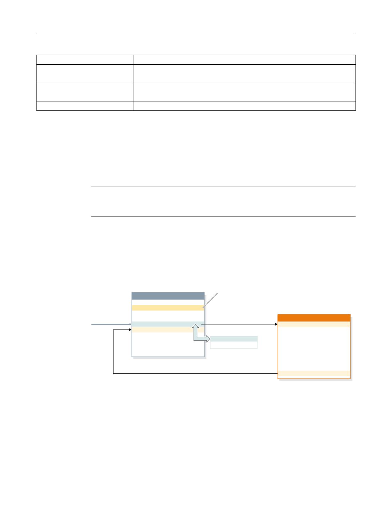
Asynchronous subprograms (ASUB) are NC programs that are started in an NC channel as
response to asynchronous events (interrupt input signals, process and machine states). The
activation of an ASUB interrupts an NC program currently executing. The NC program can be
continued at the interrupt position when the ASUB ends.
$VVLJQ D URXWLQH WR DQ HYHQW
0DLQ SURJUDP VXESURJUDP
DQG DFWLYDWH
1
6(7,17 ಹ
%ORFN LQ
1
ಹ
ແ
,QWHUUXSW URXWLQH
H[HFXWLRQ
1
ಹ
$%+(%B=
1
ಹ
1
5
ಹ
ແ
1
;ಹ<ಹ
ແ
(YHQW
ແ
LQSXW VZLWFKHG
ແ
1
ಹ
1
0
1
ಹ
ແ
ແ
5HWXUQ SRVVLEOH
ແ
0
The NC program being executed in the channel can be protected from being interrupted by an
ASUB either completely or only in sections. See Section "Programming (SETINT, PRIO)
(Page 172)" "Flexible programming".
Definition
To create an ASUB (interrupt routine) from an NC program, an interrupt signal must be assigned
to the NC program via the SETINT command (see Section "Programming (SETINT, PRIO)
(Page 172)") or via the PI service "ASUB" (see "PLC" Function Manual) in the block descriptions.
Basic functions
Function Manual, 10/2020, 6FC5397-2GP40-0BA1
163
Mode group, channel, program operation, reset response
3.9 Asynchronous subprograms (ASUPs)
Interrupt signals
• A total of eight I/O inputs are available as interrupt signals.
• The I/O input signals can be influenced via the PLC user program.
• The first four I/O inputs are the four fast inputs of the NCU module. The signal states can be
read via the NC/PLC interface in the DB10 data block. The input signals can also be locked via
the NC/PLC interface in the DB10 data block.
Further information
• You will find more information under Digital and analog NC I/O (Page 773).
• Further information regarding PLC control of the fast NC inputs (interrupt signals) can be
obtained in the Function Manual PLC.
Call
During program mode
During program mode, i.e. in AUTOMATIC or MDI mode, an ASUB can always be called.
Outside the program mode
Outside the program mode, an ASUB can be called in the following modes, machine functions
and states:
• JOG, JOG REF
• MDI Teach In, MDI Teach In REF, MDI Teach In JOG, MDI REF, MDI JOG
• AUTOMATIC, program statuses "stopped", "ready"
• Axis state "Not referenced"
If an ASUB is started during JOG or JOG REF, the current traversing is aborted.
Activation
An ASUB is activated via:
•
0/1 edge of the interrupt signal, triggered by a 0/1 edge at the associated fast NC input
• Calling of the "Function Call ASUB" (see also Function Manual "PLC and Basic Program",
Section "Basic PLC program").
• Setting an output via synchronized action which is parameterized on an interrupt via short-
circuit (see "Examples (Page 175)")
Further information
Function Manual Synchronized Actions
Display
The activation of an ASUB is shown channel-specifically with the following NC/PLC interface
signal:
DB21, … DBX378.0 == 1 (ASUB active)
Basic functions
164
Function Manual, 10/2020, 6FC5397-2GP40-0BA1
Mode group, channel, program operation, reset response
3.9 Asynchronous subprograms (ASUPs)
3.9.1.1
Execution sequence of an ASUP in program mode
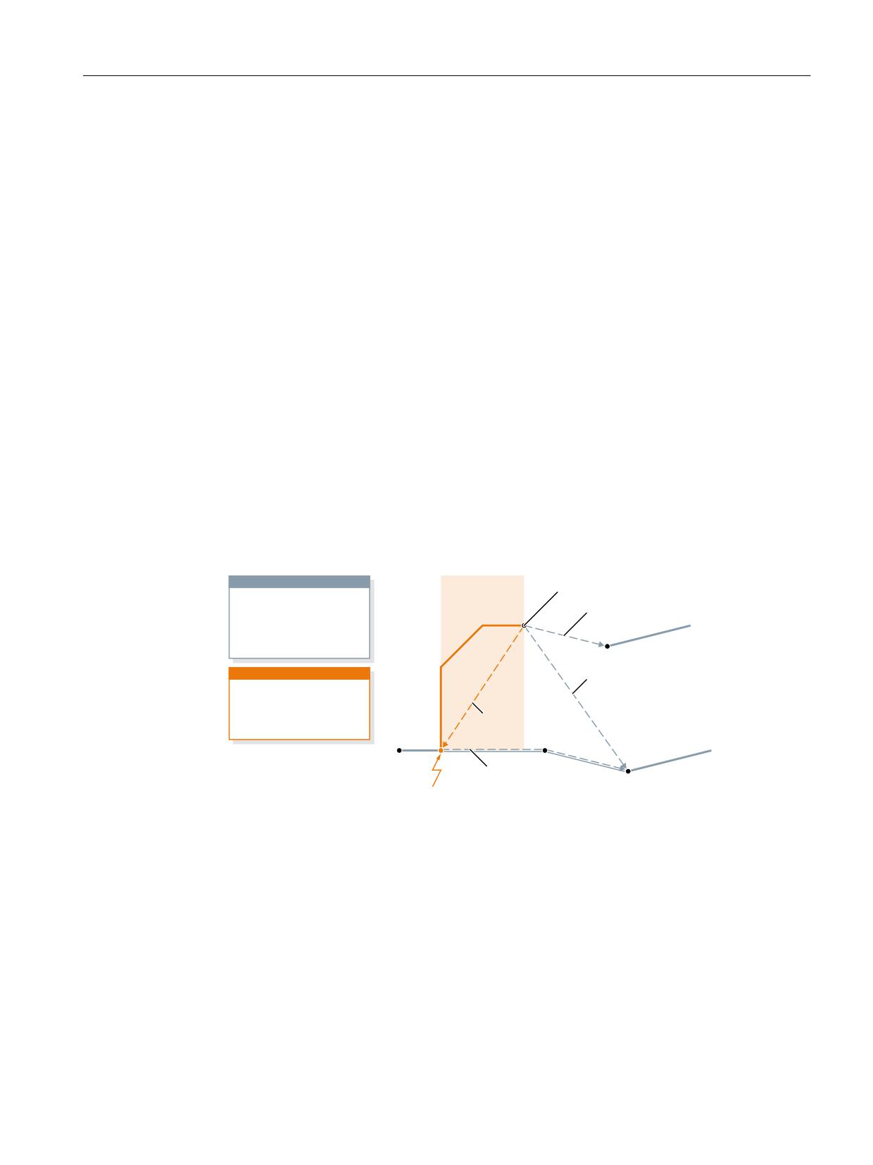
1.
Decelerating the axes
Upon activation of the ASUP, all machine axes are decelerated to a standstill according to the
deceleration ramp (MD32300 $MA_MAX_AX_ACCEL), and the axis positions are saved.
2.
Reorganization
In addition to decelerating the axes, the previously decoded calculation blocks are calculated
back to the interruption block, i.e. all the variables, frames and G commands are assigned the
value that they would have at the point of interruption if the part program had not been
previously decoded. These values are also buffered so they remain available after the end of
the ASUP.
Exceptions where no reorganization is possible:
- In thread cutting blocks
- With complex geometries (e.g. spline or radius compensation)
3.
Processing the ASUP
The ASUP is started automatically on completion of the reorganization.
The ASUP is processed as a normal subprogram (nesting depth, etc.).
4.
End of the ASUP
After the end identifier (M02, M30, M17) of the ASUP has been processed, the axis traverses
by default to the end position programmed in the part program block following the
interruption block.
A REPOS statement must have been programmed at the end of the ASUP if return positioning
to the point of interruption is required, e.g. N104 REPOSL M17
3DUW SURJUDP
$68% WUDYHO SDWK
(QG SRLQW RI WKH $68%
352*B1$0(
1
ಹ
&RQWLQXH *
1
<
1
1
;
ZLWKRXW 5(326
1
ಹ
1
1
1
0
1
$683
&RQWLQXH *
,17(5B1$0(
1
ZLWKRXW 5(326
1
ಹ
1
1
ಹ
5HSRVLWLRQLQJ
1
ಹ
1
ZLWK 5(326
1
5(326/ 0
1
&RQWLQXH DIWHU
1
1
5(326
,QWHUUXSWLRQ SRLQW
3.9.1.2
ASUP with REPOSA
If an NC program is stopped by an NC stop or alarm, and an ASUP with REPOSA is subsequently
initiated from the PLC user program using FC9, then typically, the following sequence is
obtained:
• The ASUP and/or the traversing motion programmed in it are executed:
- Program status: "Stopped"
- DB21, ... DBX318.0 (ASUP is stopped) = 1
• A new stop is executed before repositioning to the contour (REPOS).
Basic functions
Function Manual, 10/2020, 6FC5397-2GP40-0BA1
165

Mode group, channel, program operation, reset response
3.9 Asynchronous subprograms (ASUPs)
• The operator initiates an NC start to reposition to the contour (REPOS):
- DB21, ... DBX318.0 (ASUP is stopped) = 0
- The reapproach movement is executed.
• At the end of the reapproach motion, the FC9 acknowledge signal "ASUP done" is set and the
path of the interrupted NC program is continued.
Note
The NC/PLC interface signal DB21, ... DBX318.0 (ASUP is stopped) is set only in the following
case:
Interrupt in the program mode and in the "interrupted" channel state.
Note
For ASUPs without REPOS, the FC9 acknowledge signal "ASUP done" and the reset of the NC/
PLC interface signal DB21, ... DBX318.0 = 0 (ASUP is stopped) coincide from a timing
perspective.
3DWK PRWLRQ RI DQ
$68% ZLWK 5(326$
&RQWURO LV VWRSSHG
DXWRPDWLFDOO\
$Q HYHQW WKDW SXWV WKH FRQWURO
167
$68% VWRSSHG LV
LQ WKH VWRSSHG VWDWH RFFXUV
VHW
([DPSOH 6WRS EXWWRQ
)& EORFN VLJQDOV $68%
GRQH
3DWK RI WKH SDUW
SURJUDP
&RQWURO KDV VWRSSHG DIWHU
ZKLFK WKH $68% LV VWDUWHG
E\ WKH )&
Figure 3-6
Schematic sequence: ASUP with REPOSA
3.9.1.3
NC response
The different responses in the various states for channel, mode group or NC on an activated ASUP
are listed in the following table:
State
ASUP start
Control system response
Program is active
Interrupt, (PLC)
1. Fast retraction or stop axes
2. Interrupt the program for the duration of the ASUP
3. Approach of the interruption point, if REPOS in ASUP
4. Continuation of the part program
Reset
Interrupt, (PLC)
The ASUP is executed like a main program. Reset (without M30) is executed
at the end of the ASUP. The next control system status depends on the
following machine data:
MD20110 $MC_RESET_MODE_MASK
MD20112 $MC_START_MODE_MASK
Further information
Workpiece-related actual-value system (Page 389)
Basic functions
166
Function Manual, 10/2020, 6FC5397-2GP40-0BA1

Mode group, channel, program operation, reset response
3.9 Asynchronous subprograms (ASUPs)
State
ASUP start
Control system response
Program mode (AUTOMATC
Interrupt, (PLC)
ASUP is executed. At the end of the ASUP the STOP state is reapplied.
or MDI)
If REPOS in the ASUP:
+ channel stopped
• The ASUP processing is stopped before the approach block.
• The approach movement can be initiated with the Start key.
Start key
Once the ASUP has been executed, processing of the interrupted program
is resumed.
Manual mode
Interrupt, (PLC)
Control system assumes the status "internal program execution mode" for
+ channel stopped
the addressed channel (not evident externally) and then activates the AS-
UP. The selected operating mode remains valid. The original status is re-
sumed after execution of the ASUP (M17).
JOG
Interrupt, (PLC)
Stop processing, evaluate:
AUTO Teach-In
MD11602 $MN_ASUP_START_MASK
AUTO Teach reference point.
MD11604 $MN_ASUP_START_PRIO_LEVEL
MDI JOG,
Interrupt, (PLC)
Internal switchover to "internal program execution mode" if appropriate,
MDI Teach-In,
activate ASUP, restore status prior to ASUP start.
MDI Teach reference point.
Any LIFTFAST defined with SETINT is not activated in JOG mode.
Manual mode
Interrupt, (PLC)
The current active motion is stopped. The distance-to-go is deleted. The
+ channel running
remaining sequence of operations is the same as for "Manual mode, chan-
nel stopped".
User alarm 65500 - 65999,
Interrupt, (PLC)
When the following machine data is set, the user ASUP is processed despite
channel in reset
the "NC Start disable" alarm response:
MD20194 $MC_IGNORE_NONCSTART_ASUP
Processing of INITIAL.INI
Not possible
The signal "Interrupt request not possible" is generated.
Block search
Alarm that cannot be re-
moved by NC Start.
Digitalizing active
Channel in fault condition
User alarm other
Not possible
The "request was canceled because of an alarm" signal is generated.
than 65500 - 65999,
channel in reset,
MD20194 not active
3.9.2
Commissioning: Machine data
3.9.2.1
NC-spec.: Mode-group-specific NC/PLC interface signals and operating mode
switchover
The machine data specifies the effectiveness of the mode-group-specific NC/PLC interface
signals of DB11 and the channels in which an operating mode switchover is performed:
Basic functions
Function Manual, 10/2020, 6FC5397-2GP40-0BA1
167

Mode group, channel, program operation, reset response
3.9 Asynchronous subprograms (ASUPs)
MD11600 $MN_BAG_MASK = <Value>
Val-
Meaning
ue
0
The mode-group-specific NC/PLC interface signals of DB11 are effective.
An internal operating mode switchover is performed in all channels of the mode group.
1
The mode-group-specific NC/PLC interface signals of DB11 are not effective.
An internal operating mode switchover is performed only in the channel in which an ASUP is
active.
2
The mode-group-specific NC/PLC interface signals of DB11 are effective.
An internal operating mode switchover is performed only in the channel in which an ASUP is
active.
3
The mode-group-specific NC/PLC interface signals of DB11 are not effective.
An internal operating mode switchover is performed only in the channel in which an ASUP is
active.
Note
Multi-channel systems
If the "Manual traversing during an ASUP interruption in JOG mode" function is to be possible in
multi-channel systems (see below), MD11600 $MN_BAG_MASK must be set to "2" or "3".
See also
Programming (SETINT, PRIO) (Page 172)
3.9.2.2
NC-spec.: ASUP start enable
With the machine data, you can specify which stop reasons are to be ignored for an ASUP start:
MD11602 $MN_ASUP_START_MASK, <Bit> = <Value>
Bit
Val-
Meaning
ue
0
0
The ASUP is not started when a stop is present from the Stop key, M0 or M01.
1
The ASUP is started even when a stop is present from the Stop key, M0 or M01.
Basic functions
168
Function Manual, 10/2020, 6FC5397-2GP40-0BA1

Mode group, channel, program operation, reset response
3.9 Asynchronous subprograms (ASUPs)
Bit
Val-
Meaning
ue
2
0
When an ASUP is started, the channel-specific machine data is effective when there is a
read-in disable in the channel:
• MD20107 $MC_PROG_EVENT_IGN_INHIBIT
• MD20116 $MC_IGNORE_INHIBIT_ASUP
1
The start of a user or system ASUP is enabled in all channels of the NC even when there is
a read-in disable in the relevant channel.
The settings in the channel-specific machine data are not effective:
• MD20107 $MC_PROG_EVENT_IGN_INHIBIT
• MD20116 $MC_IGNORE_INHIBIT_ASUP
Notice
The start enable is active in all channels of the NC despite a read-in disable. Not only for
the user, but also for the system ASUPs. It is therefore strongly recommended that
the channel-specific enables are used instead of the NC-specific enable.
3
0
If an ASUP was started in JOG mode and interrupted by an NC stop, axes cannot be
traversed manually in this state.
1
If an ASUP was started in JOG mode and interrupted by an NC stop, axes can be traversed
manually in this state.
The ASUP can be continued with NC start. A REPOS operation is then performed auto-
matically.
Note
If more than one channel is parameterized in the control, the following machine data must
also be set:
MD11600 $MN_BAG_MASK, bit 1 = 1
Manual start enable
If an ASUP is not started automatically due to the parameterized start enables, the ASUP can still
be started via NC/PLC interface signal (DB21, ... DBX7.1) from the PLC user program or by manual
actuation of NC start.
Note
The ASUP for "fast retraction from the contour" (LIFTFAST) is started in every case.
3.9.2.3
NC-spec.: Effectiveness of the parameterized start enables
With the machine data, you set up to which ASUP priority (Page 172), starting from the highest
priority, the settings in MD11602 $MN_ASUP_START_MASK are effective:
MD11604 $MN_ASUP_START_PRIO_LEVEL = <ASUP priority>
Example
MD11604 $MN_ASUP_START_PRIO_LEVEL = 5
The settings in MD11602 $MN_ASUP_START_MASK are effective for ASUPs of priorities 1 → 5.
Basic functions
Function Manual, 10/2020, 6FC5397-2GP40-0BA1
169

Mode group, channel, program operation, reset response
3.9 Asynchronous subprograms (ASUPs)
3.9.2.4
Channel-spec.: Start enable despite non-referenced axes
With the machine data, you can set for which interrupts the associated ASUP is started despite
the parameterized "NC start disable without reference point" function (MD20700
$MC_REFP_NC_START_LOCK):
MD20115 $MC_IGNORE_REFP_LOCK_ASUP, bit (1 - <Interrupt>) = TRUE
NOTICE
System interrupts
With MD20115 $MC_IGNORE_REFP_LOCK_ASUP, bits 8 - 31, the ASUPs assigned to the system
interrupts are enabled.
Bit 8 / interrupt 9 starts an ASUP that contains traversing motions.
NC-specific ASUP start enable
If MD11602 $MN_ASUP_START_MASK, bit 2 == TRUE, the ASUP start enable is set for all
channels of the NC despite the parameterized channel-specific "NC start disable without
reference point" function (MD20700 $MC_REFP_NC_START_LOCK). It is therefore strongly
recommended that the channel-specific enable is used instead of the NC-specific enable.
3.9.2.5
Channel-spec.: Start enable despite read-in disable
With the machine data, you can set for which interrupts the associated ASUP is started despite
the read-in disable present in the channel (DB21, ... DBX6.1):
MD20116 $MC_IGNORE_INHIBIT_ASUP, bit (1 - <Interrupt>) = TRUE
NOTICE
System interrupts
With MD20116 $MC_IGNORE_INHIBIT_ASUP, bits 8 - 31, the ASUPs assigned to the system
interrupts are enabled.
Bit 8 / interrupt 9 starts an ASUP that contains traversing motions.
NC-specific ASUP start enable
If MD11602 $MN_ASUP_START_MASK, bit 2 == TRUE, the channel-specific settings in
MD20116 $MC_IGNORE_INHIBIT_ASUP are ignored in all channels of the NC. It is
therefore strongly recommended that the channel-specific enable is used instead of the NC-
specific enable.
3.9.2.6
Channel-spec.: Continuous execution despite single block
With the machine data, you can set for which interrupts the associated ASUP is
executed continuously, i.e. without block-by-block interruption, despite active single block
processing in the channel (DB21, ... DBX0.4):
MD20117 $MC_IGNORE_SINGLEBLOCK_ASUP, bit (1 - <Interrupt>) = TRUE
Basic functions
170
Function Manual, 10/2020, 6FC5397-2GP40-0BA1

Mode group, channel, program operation, reset response
3.9 Asynchronous subprograms (ASUPs)
Supplementary conditions
The settings in MD20117 $MC_IGNORE_SINGLEBLOCK_ASUP are only active for a single block
SBL1 (main run single block).
NOTICE
System interrupts
With MD20117 $MC_IGNORE_SINGLEBLOCK_ASUP, bits 8 - 31, the ASUPs assigned to the
system interrupts are enabled.
Bit 8 / interrupt 9 starts an ASUP that contains traversing motions.
NC-specific ASUP start enable
If MD10702 $MN_IGNORE_SINGLEBLOCK_MASK, bit 1 == TRUE, the channel-specific settings
in MD20117 $MC_IGNORE_SINGLEBLOCK_ASUP are ignored in all channels of the NC. It is
therefore strongly recommended that the channel-specific enable is used instead of the NC-
specific enable.
3.9.2.7
Channel-spec.: Refreshing the display
With the machine data, you can set that the display is not refreshed while the ASUP is being
executed to avoid a flickering of the display of the program and the channel states on the user
interface when executing a very short ASUP:
MD20191 $MC_IGN_PROG_STATE_ASUP, bit (1 - <Interrupt>) = TRUE
Note
NC/PLC interface signal
The following NC/PLC interface signal is set when executing an ASUP with suppressed display:
DB21, … DBX378.1 = 1 ("silent" ASUP active)
System variables and NC/PLC interface signals
The system variables and NC/PLC interface signals for the program state and the channel state
are not affected by the suppression of the display during the execution of an ASUP:
• $AC_STAT (channel state)
• $AC_PROG (program state)
• DB21, ... DBX35.5 - 7 (channel state)
• DB21, ... DBX35.0 - 4 (program state)
Basic functions
Function Manual, 10/2020, 6FC5397-2GP40-0BA1
171

Mode group, channel, program operation, reset response
3.9 Asynchronous subprograms (ASUPs)
3.9.3
Programming: System variables
3.9.3.1
REPOS option ($P_REPINF)
In conjunction with ASUPs, program execution sequences can be generated for which there is
no unambiguous return to a repositioning point on the contour (REPOS).
The system variable can be used to read in the ASUP whether a REPOS is possible.
<value> = $P_REPINF
Value
Meaning
0
Repositioning with REPOS not possible because:
• Not called in the ASUP
• ASUP ran from reset state
• ASUP ran from JOG
1
Repositioning with REPOS possible in ASUP
3.9.3.2
Activation event ($AC_ASUP)
The following information with regard to the event that caused the activation of the ASUP can
be read via the $AC_ASUP system variable:
• The reason why the ASUP was activated, e.g. Bit 0: User interrupt "ASUP with Blsync"
• How the ASUP was activated, e.g. Bit 0: NC/PLC interface signal, digital-analog interface
• How is it possible to continue, e.g. Bit 0: Freely selectable REORG or RET
3.9.4
Programming (SETINT, PRIO)
Assignment: Interrupt to the NC program
The SETI command assigns an NC program to an interrupt. This makes the NC program into an
ASUB.
Syntax
SETINT(<n>) <NC program>
Meaning
SETINT:
Assignment of an NC program to an interrupt signal
<n>:
Number of the interrupt signal
Range of values:
0, 1, 2, ... 8
<NC program>:
Program name
Basic functions
172
Function Manual, 10/2020, 6FC5397-2GP40-0BA1

Mode group, channel, program operation, reset response
3.9 Asynchronous subprograms (ASUPs)
Example
Program code
Comment
N20 SETINT(3) LIFT_Z
; IF input 3 == 1
; THEN start ASUB "LIFT_Z"
Together with SETINT additionally the following statements can be programmed:
• LIFTFAST
When the interrupt signal arrives, a "Fast retraction of the tool from the contour" is performed
before the ASUB starts. The motion direction for the fast retraction is specified by the program
instruction ALF.
• BLSYNC
Upon receiving the interrupt signal, the current program block is processed and only then is
the ASUB started.
Note
The assignment interrupt signal ↔ part program is cleared when the following happens:
• Channel in Reset state
• CLRINT statement in the part program
Priorities
If several interrupts are activated by SETINT in an NC program, the assigned NC programs or
ASUBs must be assigned different priorities.
Syntax
PRIO=<value>
Meaning
PRIO:
Keyword for defining the priority of the interrupt
<Value>:
Priority: 1, 2, 3 ... 128. Whereby 1 is the highest priority.
Example
Program code
Comment
N20 SETINT(3) PRIO=2 LIFT_Z
; IF input 3 == 1
; THEN start ASUB "LIFT_Z"
N30 SETINT(2) PRIO=3 LIFT_X
; IF INPUT 2 == 1
; THEN start ASUB "LIFT_X"
The ASUBs are executed in the sequence of the priority values if the inputs 2 and 3 have switched
simultaneously:
1. "LIFT_Z"
2. "LIFT_X"
Basic functions
Function Manual, 10/2020, 6FC5397-2GP40-0BA1
173

Mode group, channel, program operation, reset response
3.9 Asynchronous subprograms (ASUPs)
Additional interrupt-specific commands
Command
Meaning
SAVE
If the SAVE command is used in an ASUB, the G commands, frames and
transformations active in the interrupted NC program before the interrup-
tion take effect again at the end of the ASUB.
DISABLE
The DISABLE ENABLE command pair can be set to protect program sec-
tions from being interrupted by ASUBs.
ENABLE
The assignment of an interrupt signal to an NC program made with SETINT
is retained.
The ASUB is then started with the next 0/1 edge of the interrupt signal
after ENABLE.
CLRINT(<n>)
Delete the assignment of interrupt signals n to the NC program assigned
with SETI.
Further information
"NC Programming" Programming Manual
See also
Programming (Page 177)
3.9.5
Restrictions
Cross-mode ASUP start
Settings to be checked
• MD11600 $MN_BAG_MASK
• MD11604 $MN_ASUP_START_PRIO_LEVEL
• Interrupt assignment priority
Recommended settings
NC-specific machine data:
• MD11600 $MN_BAG_MASK = 'H3'
Note
Note with this setting, that the mode-group-specific NC/PLC interface signals of DB11 no
longer affect the channel in which the ASUP is executed. If this behavior is not desired,
alternatively the setting MD11600 $MN_BAG_MASK = 'H2' can be used (see "Commissioning:
Machine data (Page 167)").
MD11602 $MN_ASUP_START_MASK = 'H5'
• MD11604 $MN_ASUP_START_PRIO_LEVEL = 7
Basic functions
174
Function Manual, 10/2020, 6FC5397-2GP40-0BA1
Mode group, channel, program operation, reset response
3.9 Asynchronous subprograms (ASUPs)
Channel-specific machine data for the channel in which the ASUP is started or generally for all
channels:
• MD20105 $MC_PROG_EVENT_IGN_REFP_LOCK, bit <n> = TRUE
<n>: For all required event-driven program calls (prog events)
• MD20115 $MC_IGNORE_REFP_LOCK_ASUP, bit <n> = TRUE
<n>: For all required user interrupts
NOTICE
System interrupts
With MD20115 $MC_IGNORE_REFP_LOCK_ASUP, bits 8 - 31, the system interrupts are
enabled.
Bit 8 / interrupt 9 starts an ASUP that contains traversing motions.
3.9.6
Examples
Activation of an ASUP by an interrupt from a synchronized action
1. Parameterize two active digital I/O bytes:
- MD10350 $MN_FASTIO_DIG_NUM_INPUTS = 2
- MD10360 $MN_FASTIO_DIG_NUM_OUTPUTS = 2
2. Parameterize a short-circuit with OR operation from output 9 to input 9:
- Input 1, input byte 2 = (output 1, output byte 2) OR (HW input signal 1, input byte 2):
MD10361 $MN_FASTIO_DIG_SHORT_CIRCUIT[0] = 'H0102B102'
3. Assign the HW input byte to the SETINT interrupt programming:
- Input byte 2:
MD21210 $MC_SETINT_ASSIGN_FASTIN = 2
4. Define input as ASUP trigger:
- Input 1 in the second input byte, i.e. absolute input 9, starts the SYNCASUP program
SETINT(1) PRIO=1 SYNCASUP
5. Define a synchronized action to set the output:
- Synchronized action with ID 1 always sets output 9 to 1 when the value of the
standardized path parameter becomes >= 0.5:
IDS=1 EVERY $$AC_PATHN >= 0.5 DO $A_OUT[9]=1
The short-circuit of output 9 to input 9 causes interrupt 1 and the "SYNC" NC program to
be started as ASUP.
Basic functions
Function Manual, 10/2020, 6FC5397-2GP40-0BA1
175
Mode group, channel, program operation, reset response
3.10 User-specific ASUB for RET and REPOS
3.10
User-specific ASUB for RET and REPOS
3.10.1
Function
Function
The control software includes a Siemens-specific ASUP to implement the NC program end (RET)
and repositioning on the contour (REPOS) functions. The machine tool manufacturer can
replace the system ASUP with a user-specific ASUP.
DANGER
Programming fault
The machine manufacturer has sole responsibility for ensuring the correct operation of the
user-specific ASUP that replaces the Siemens-specific ASUP ("ASUP.SYF").
3.10.2
Parameter assignment
Installation
ASUP name
The user-specific ASUP must be given the following name:
• _N_ASUP_SPF
ASUP directories
The user-specific ASUP "_N_ASUP_SPF" must be stored in one of the two directories:
• _N_CMA_DIR (manufacturer directory)
• _N_CUS_DIR (user directory)
Activation and search path
Bits 0 and 1 of the following machine data specify the event for which the user-specific ASUP
"_N_ASUP_SPF" is activated.
Bit 2 specifies the search start for activation of the user-specific ASUP "_N_ASUP_SPF".
Basic functions
176
Function Manual, 10/2020, 6FC5397-2GP40-0BA1

Mode group, channel, program operation, reset response
3.10 User-specific ASUB for RET and REPOS
MD11610 $MN_ASUP_EDITABLE, bit 0, 1, 2 = <value>
Bit
Value
Meaning
0 and 1
0
The user-specific ASUP is activated neither for program end (RET) nor for reposi-
tioning on the contour (REPOS).
1
The user-specific ASUP is activated for RET.
The system-specific ASUP is activated for REPOS.
2
The system-specific ASUP is activated for RET.
The user-specific ASUP is activated for REPOS.
3
The user-specific ASUP is activated for RET and REPOS.
2
0
The user-specific ASUP is searched for first in the user directory _N_CUS_DIR.
1
The user-specific ASUP is searched for first in the manufacturer
directory _N_CMA_DIR.
Defining a level of protection
If a user-specific ASUP is to be used for RET and/or REPOS (MD11610 $MN_ASUP_EDITABLE ≠ 0),
a protection level can be defined for the user-specific routine "_N_ASUP_SPF". The level of
protection can have values in the range 0 - 7. The setting is made via the following machine data:
MD11612 $MN_ASUP_EDIT_PROTECTION_LEVEL <protection level of the user-specific ASUP>
Details regarding the protection levels can be obtained in:
Further information
Commissioning Manual; Protection level concept
Behavior when the single-block processing is set
The following machine data specifies that the system-specific ASUP and the user-specific ASUP
"_N_ASUP_SPF" should be processed without interruption, despite active single-block
processing:
MD10702 $MN_IGNORE_SINGLEBLOCK_MASK, bit 0 = <value>
Bit
Value
Meaning
0
0
For active single-block mode, a stop is made in every ASUP.
1
For active single-block mode, the ASUP is processed without interruption.
3.10.3
Programming
Determining the cause of the ASUB activation
The cause of the activation of the ASUB can be read bit-coded via the system variable $AC_ASUP.
Basic functions
Function Manual, 10/2020, 6FC5397-2GP40-0BA1
177
Mode group, channel, program operation, reset response
3.11 Perform ASUB start for user alarms
Continuation
When using the system ASUB, the behavior for the continuation after execution of the actions
is permanently specified within the ASUB:
• System ASUB 1 → continuation with RET (subprogram return)
• System ASUB 2 → continuation with REPOS (repositioning)
The description of the system variables specifies the behavior with regard to the system ASUB for
each cause at "Continued for".
Note
Continued for user-specific ASUB
It is recommended for user-specific ASUBs that the appropriate continuation of the system ASUB
be retained.
Cause: Change of operating mode ($AC_ASUP, bit 9 == 1)
At a change of operating mode, the continuation depends on the machine data:
MD20114 $MC_MODESWITCH_MASK (interruption of MDA through mode change)
• Bit 0 == 0: System ASUB 1 → continuation with RET
• Bit 0 == 1: System ASUB 2 → continuation with REPOS
Further information
A detailed description regarding the system variable can be obtained in the List Manual System
Variables
3.11
Perform ASUB start for user alarms
3.11.1
Function
Description
An ASUB can be initiated in various situations, either by the user, the system or event-controlled.
A user alarm with the "NC Start disable" alarm response prevents the ASUB start in some
situations. For a pending alarm response, a user ASUB from reset acknowledges with the alarm
16906.
Basic functions
178
Function Manual, 10/2020, 6FC5397-2GP40-0BA1

Mode group, channel, program operation, reset response
3.11 Perform ASUB start for user alarms
With the appropriate setting of a channel-specific machine data it is possible to start and perform
an ASUB although a user alarm with the alarm response "NC Start disable" is active. The alarm
response is overridden for the ASUB start and permits its execution.
Note
NC alarms with the "NC Start disable" alarm response are not affected by the override. A user
ASUB from reset is still not possible and will be rejected with the alarm 16906.
User alarms that can be overridden
The number range for the user alarms that can be overridden is classified as follows:
Number range
Effect
Delete
65000 - 65499
Display, NC Start disable
Reset
65500 - 65999
Display, NC Start disable (not for ASUBs for set MD20194)
Reset
66000 - 66999
Display, NC Start disable, motion standstill after executing the
Reset
pre-decoded blocks
67000 - 67999
Display
Cancel
68000 - 68999
Display, NC Start disable, immediate interpolator stop
Reset
69000 - 69999
Display, NC Start disable, stop at next block end
Reset
Note
Although it is possible to override the "NC Start disable" alarm response for the following alarm
number ranges, the other responses of the associated alarms ensure for the stop conditions. The
stop conditions cannot be overridden with the function described in this section:
•
66000 - 66999
•
68000 - 68999
•
69000 - 69999
3.11.2
Activation
Setting
Each ASUP channel can be set separately with the following channel-specific machine data:
MD20194 $MC_IGNORE_NONCSTART_ASUP (ASUP start permitted despite pending alarm
response "NC Start disable" for certain user alarms)
A change of the MD setting acts only with the NEWCONF part program command or from the user
interface per softkey.
Basic functions
Function Manual, 10/2020, 6FC5397-2GP40-0BA1
179

Mode group, channel, program operation, reset response
3.11 Perform ASUB start for user alarms
Sequence
The normal sequence for the ASUP start has the following form:
• Set machine data appropriate with MD20194 $MC_IGNORE_NONCSTART_ASUP and activate
with NEWCONF.
• Start the part program.
A user alarm from the number ranges that can be overridden appears, e.g. alarm 65500. This
can occur from a synchronized action or with a part program command.
• Despite alarm, the part program is processed to the program end M02, M30 or M17.
The Reset channel state is active.
• A started user ASUP from reset is now performed.
Note
An ASUP start from a running or stopped part program is also permitted for a pending "NC Start
disable" alarm response. It is irrelevant whether a user alarm or an NC alarm with the "NC Start
disable" alarm response is involved.
Note
If the part program is stopped during the processing of the user ASUP, the ASUP can no longer
be continued with the NC Start key, e.g. for M0 in the ASUP or for user stop. The "NC Start disable"
alarm response is rejected with the alarm 16906. The previously generated user alarm can be
acknowledged only with reset.
3.11.3
Examples
3.11.3.1
User ASUB from reset - example 1
MD20194 is not set in the application
Main program
Program code
N10 G90 G0 Z10
N20 SETAL(65500)
N30 X100
N40 Z0
N50 M30
User ASUB
Program code
N110 G91 G0 X-10 Z5
Basic functions
180
Function Manual, 10/2020, 6FC5397-2GP40-0BA1

Mode group, channel, program operation, reset response
3.11 Perform ASUB start for user alarms
Program code
N120 X20
N130 REPOSA
Sequence
1
$ODUP
1
5(326$
1
8VHU $68% IURP
DFWLYH SURJUDP
1
1
$ODUP
8VHU $68% IURP
0
UHVHW
The block N10 is processed. The alarm 65500 appears that contains the "Display" and "NC Start
disable" alarm responses. The part program does not stop as result. The block N30 is loaded and
processed. If the user ASUB is used in the block middle, it is performed despite pending "NC Start
disable" alarm response. The REPOSA resumes at the program interruption and processes the
part program to the program end M30. If the user ASUB is now used, it will be rejected with alarm
16906. The NC state is reset.
3.11.3.2
User ASUB from reset - example 2
The application is the normal case, MD20194 is set.
Main program
Program code
N4 $MC_IGNORE_NONCSTART_ASUP=1
N6 NEWCONF
N10 G90 G0 Z10
N20 SETAL(65500)
N30 X100
N40 Z0
N50 M30
User ASUB
Program code
N110 G91 G0 X-10 Z5
N120 X20
N130 REPOSA
Basic functions
Function Manual, 10/2020, 6FC5397-2GP40-0BA1
181

Mode group, channel, program operation, reset response
3.11 Perform ASUB start for user alarms
Sequence
1
$ODUP
1
5(326$
1
1
8VHU $68% IURP
DFWLYH SURJUDP
1
1
1
5(326$
8VHU $68% IURP
0
UHVHW
The machine data MD20194 $MC_IGNORE_NONCSTART_ASUP is set for ASUB channel 1 and
activated with NEWCONF. The block N10 is processed. The alarm 65500 appears that contains
the "Display" and "NC Start disable" alarm responses. The part program does not stop as result.
The block N30 is loaded and processed. If the user ASUB is used in the block middle, it is
performed despite pending "NC Start disable" alarm response. The REPOSA resumes at the
program interruption and processes the part program to the program end M30. If the user ASUB
is now used, it is repeated because of the set machine data MD20194.
3.11.3.3
User ASUB with M0
MD20194 is set in the application.
Main program
Program code
N4 $MC_IGNORE_NONCSTART_ASUP=1
N6 NEWCONF
N10 G90 G0 Z10
N20 SETAL(65500)
N30 X100
N40 Z0
N50 M30
User ASUB
Program code
N110 G91 G0 X-10 Z5
N120 X10
N122 M0
N124 X10
N130 REPOSA
Basic functions
182
Function Manual, 10/2020, 6FC5397-2GP40-0BA1
Mode group, channel, program operation, reset response
3.11 Perform ASUB start for user alarms
Sequence
1
$ODUP
$ODUP
1
1& VWDUW DIWHU VWDQGVWLOO
1
8VHU $68% IURP
DFWLYH SURJUDP
1
The machine data MD20194 $MC_IGNORE_NONCSTART_ASUP is set for ASUB channel 1 and
activated with NEWCONF. The block N10 is processed. The alarm 65500 appears that contains
the "Display" and "NC Start disable" alarm responses. The part program does not stop as result.
The block N30 is loaded and processed. If the user ASUB is used in the block middle, it is
performed despite pending "NC Start disable" alarm response. The part program stops at block
N122 because of M0. The ASUB can no longer be continued when the NC Start key is pressed. The
"NC Start disable" alarm response is rejected with the alarm 16906. The previously generated
65500 alarm can be acknowledged only with reset.
3.11.3.4
User ASUB with stop
MD20194 is set in the application.
Main program
Program code
N4 $MC_IGNORE_NONCSTART_ASUP=1
N6 NEWCONF
N10 G90 G0 Z10
N20 SETAL(65500)
N30 X100
N40 Z0
N50 M30
User ASUB
Program code
N110 G91 G0 X-10 Z5
N120 X20
N130 REPOSA
Basic functions
Function Manual, 10/2020, 6FC5397-2GP40-0BA1
183
Mode group, channel, program operation, reset response
3.11 Perform ASUB start for user alarms
Sequence
1& VWRS
1
$ODUP
$ODUP
1
1& VWDUW DIWHU VWDQGVWLOO
1
8VHU $68% IURP
1
DFWLYH SURJUDP
The machine data MD20194 $MC_IGNORE_NONCSTART_ASUP is set for ASUB channel 1 and
activated with NEWCONF. The block N10 is processed. The alarm 65500 appears that contains
the "Display" and "NC Start disable" alarm responses. The part program does not stop as result.
The block N30 is loaded and processed. If the user ASUB is used in the block middle, it is
performed despite pending "NC Start disable" alarm response. If the NC Stop key is pressed for
N120 in the block middle, the ASUB stops. The ASUB can no longer be continued when the NC
Start key is pressed. The "NC Start disable" alarm response is rejected with the alarm 16906. The
previously generated 65500 alarm can be acknowledged only with reset.
3.11.3.5
User ASUB from stopped
MD20194 is or not set in the application.
Main program
Program code
N10 G90 G0 Z10
N20 SETAL(65500)
N30 X50
N35 M0
N38 X100
N40 Z0
N50 M30
User ASUB
Program code
N110 G91 G0 X-10 Z5
N120 X20
N130 REPOSA
Basic functions
184
Function Manual, 10/2020, 6FC5397-2GP40-0BA1

Mode group, channel, program operation, reset response
3.12 Execution from external
Sequence
1
$ODUP
$ODUP
1
1& VWDUW DIWHU VWDQGVWLOO
0
1
8VHU $68% IURP
1
VWRSSHG
The block N10 is processed. The alarm 65500 appears that contains the "Display" and "NC Start
disable" alarm responses. The part program does not stop as result. The block N30 is loaded and
processed. The part program stops at block N35 because of M0. The NC state is stopped. If the
user ASUB is now used, it is performed despite the stopped NC state and pending "NC Start
disable" alarm response. It does not matter whether or not the machine data MD20194
$MC_IGNORE_NONCSTART_ASUP is set. After block N120, the ASUB remains stationary before
REPOSA. Repositioning is possible only at the next NC Start. The NC Start, however, is rejected
with the alarm 16906 because of the "NC Start disable" alarm response. The previously
generated 65500 alarm can be acknowledged only with reset.
3.12
Execution from external
Function
The "execution from external source" function can be used to execute programs from an external
program memory that cannot be saved in the NC memory due to their size.
Note
Protected cycles (_CPF files) can not be executed from an external program memory.
Basic functions
Function Manual, 10/2020, 6FC5397-2GP40-0BA1
185

Mode group, channel, program operation, reset response
3.12 Execution from external
External program memory
External program memory can be found on the following data carriers:
• Local drive
• Network drive
• USB drive
Note
Only the USB interfaces on the operator panel front or the TCU can be used as interface for
the processing of an external program on a USB drive.
NOTICE
Tool/workpiece damage caused by the USB flash drive
It is recommended that a USB flash drive is not used for the execution of an external
subprogram. A communication interruption to the USB flash drive during the execution of
the subprogram due to contact problems, failure, abort through trigger or unintentional
unplugging, results in an immediate machining stop. The tool and/or workpiece could be
damaged.
Applications
• Direct execution from external programs
In principle, any program that is accessible via the directory structure of the interface in the
"Execution from external" HMI mode can be selected and executed.
• Execution of external subprograms from the part program
The "external" subprogram is called with the part program command EXTCALL by specifying
a call path (optional) and the name of the part subprogram (→ see "Execution of external
subprograms (EXTCALL) (Page 187)").
Parameterization
A reloading memory (FIFO buffer) must be reserved in the dynamic NC memory for executing a
program in "execution from external source" mode.
Size of FIFO buffer
The size of the FIFO buffer is set in the machine data:
MD18360 $MN_MM_EXT_PROG_BUFFER_SIZE (FIFO buffer size for processing from external)
Note
Programs with jump commands
For external programs that contain jump commands (GOTOF, GOTOB, CASE, FOR, LOOP, WHILE,
REPEAT, IF, ELSE, ENDIF etc.) the jump destinations must lie within the post loading memory.
Basic functions
186
Function Manual, 10/2020, 6FC5397-2GP40-0BA1
Mode group, channel, program operation, reset response
3.13 Executing external subprograms (EXTCALL)
Note
ShopMill/ShopTurn programs
The contour descriptions added at the file end mean the ShopMill and ShopTurn programs must
be stored completely in the read-only memory.
Number of FIFO buffers
One FIFO buffer must be provided for each one of the programs that are executed
simultaneously in "execution from external source" mode.
The number of FIFO buffers is set in the machine data:
MD18362 $MN_MM_EXT_PROG_NUM (number of externally executed program levels
executable simultaneously)
Behavior on reset, power-on
External program calls are aborted using reset and power-on and the particular FIFO buffers are
erased.
A main program selected from an external program memory is selected again automatically
after a power-on if the same program memory is still available and execution of EXTCALL calls
has been activated in MD9106 $MM_SERVER_EXTCALL_PROGRAMS.
3.13
Executing external subprograms (EXTCALL)
Function
Individual machining steps for producing complex workpieces may involve program sequences
that require so much memory that they cannot be stored in the NC memory.
In such cases, the user has the option of executing the program sequences as subprograms from
an external program memory in the "Execution from external source" mode with the help of the
EXTCALL part program command.
Prerequisites
The following preconditions are applicable to the execution from external subprograms:
• The subprograms must be accessible via the directory structure of the operator interface.
• A reloading memory (FIFO buffer) must be reserved for each subprogram in the dynamic NC
memory.
Basic functions
Function Manual, 10/2020, 6FC5397-2GP40-0BA1
187
Mode group, channel, program operation, reset response
3.13 Executing external subprograms (EXTCALL)
Note
Subprograms with jump commands
For external subprograms that contain jump commands (GOTOF, GOTOB, CASE, FOR, LOOP,
WHILE, REPEAT, IF, ELSE, ENDIF etc.) the jump destinations must lie within the post loading
memory.
The size of the post loading memory is set via:
MD18360 MM_EXT_PROG_BUFFER_SIZE
ShopMill/ShopTurn programs
The contour descriptions added at the file end mean the ShopMill and ShopTurn programs must
be stored completely in the read-only memory.
Parameter assignment
The path for the external subprogram directory can be preset using setting data:
SD42700 $SC_EXT_PROG_PATH (program path for the EXTCALL external subprogram call)
The entire path of the program to be called along with the subprogram path or name specified
during programming is derived therefrom.
Note
If the program path is only specified using the appropriate programming, then SD42700 must
be empty!
Programming
An external subprogram is called by means of parts program command EXTCALL.
Syntax:
EXTCALL("<path/><program name>")
Parameter:
<path>:
Absolute or relative path data (optional)
Type:
STRING
<program name>: The program name is specified without prefix "_N_".
The file extension ("MPF", "SPF") can be attached to program names
using the "_" or "." character (optional).
Type:
STRING
Basic functions
188
Function Manual, 10/2020, 6FC5397-2GP40-0BA1
Mode group, channel, program operation, reset response
3.13 Executing external subprograms (EXTCALL)
Note
Path specification: Short designations
The following short designations can be used to specify the path:
• LOCAL_DRIVE: for local drive
• CF_CARD: for memory card
• USB: for USB front connection
CF_CARD: and LOCAL_DRIVE: can be alternatively used.
EXTCALL call with absolute path name
If the subprogram exists at the specified path, it will be executed following the EXTCALL call. If
it does not exist, program execution is canceled.
EXTCALL call with relative path name / without path name
In the event of an EXTCALL call with a relative path name or without a path name, the available
program memories are searched as follows:
• If a path name is preset in SD42700 $SC_EXT_PROG_PATH, the data specified in the EXTCALL
call (program name or with relative path name) is searched for first, starting from this path.
The absolute path is obtained from linking the following characters:
- The path name preset in SD42700
- The "/" character as a separator
- The subprogram path or name programmed in EXTCALL
• If the called subprogram is not found at the preset path, the data specified in the EXTCALL
call is then searched for in the user-memory directories.
• The search ends when the subprogram is found for the first time. If the search does not
produce any hits, the program is canceled.
Example
Execute from local drive
Main program:
Program code
N010 PROC MAIN
N020 ...
N030 EXTCALL ("ROUGHING")
N040 ...
N050 M30
External subprogram:
Program code
N010 PROC ROUGHING
Basic functions
Function Manual, 10/2020, 6FC5397-2GP40-0BA1
189

Mode group, channel, program operation, reset response
3.14 Execution from external storage (EES) (option)
Program code
N020 G1 F1000
N030 X= ... Y= ... Z= ...
N040
N999999 M17
The "MAIN.MPF" main program is stored in NC memory and is selected for execution.
The "SCHRUPPEN.SPF" or "SCHRUPPEN.MPF" subprogram to be subsequently loaded is on the
local drive in the directory "/user/sinumerik/data/prog/WKS.DIR/WST1.WPD".
The subprogram path is preset in SD42700:
SD42700 $SC_EXT_PROG_PATH = "LOCAL_DRIVE:WKS.DIR/WST1.WPD"
Note
Without the path being specified in the SD42700, the EXTCALL operation for this example
would have to be programmed as follows:
EXTCALL("LOCAL_DRIVE:WKS.DIR/WST1.WPD/SCHRUPPEN")
3.14
Execution from external storage (EES) (option)
3.14.1
Function
Note
To use the function, the "Expanded CNC user storage" or "Execute from external storage (EES)"
licensed option is required!
Function
Using the EES (Execution from External Storage) function, users have the option of having the
NCK execute programs directly from an external program storage.
Basic functions
190
Function Manual, 10/2020, 6FC5397-2GP40-0BA1

Mode group, channel, program operation, reset response
3.14 Execution from external storage (EES) (option)
The following drives are available as external memory:
Drive
Symbolic name 1)
SINUMERIK 840D sl
NC Extend
CF_CARD
CF card of NCU
(previously "Lo-
LOCAL_DRIVE
or
cal drive")
SYS_DRIVE
Local hard disk of a PCU
USER CF
CF_CARD
-
LOCAL_DRIVE
Network drive
Statically managed USB drive
1)
For SINUMERIK 840D sl, the symbolic names LOCAL_DRIVE, CF_CARD, and SYS_DRIVE are permanently
assigned to the drive NC Extend (⇒ NC Extend can be addressed via LOCAL_DRIVE, CF_CARD, and
SYS_DRIVE).
NOTICE
Tool/workpiece damage caused by the USB flash drive
A USB flash drive cannot be recommended when executing an external program. A
communication abort to the USB flash drive during the execution of the program due to contact
problems, failure, abort through trigger or unintentional unplugging, results in an
uncontrolled stop of the machining. The tool and/or workpiece could be damaged.
Requirements
The following prerequisites apply when using EES:
• The "Expanded CNC user storage" or "Execute from external storage (EES)" licensed option
must be set.
• The drives, which are used at the control as external memory, must be configured as a logical
drives (see "Commissioning (Page 193)").
• A list of available IPCs is available under Available IPCs (Page 906).
Basic functions
Function Manual, 10/2020, 6FC5397-2GP40-0BA1
191

Mode group, channel, program operation, reset response
3.14 Execution from external storage (EES) (option)
Operating mode
Depending on the option available and the drive configuration, various EES operating modes are
possible. The active operating mode of a control is displayed using machine data MD18045
$MN_EES_MODE_INFO.
MD18045
Operating mode
Option
External memory
SINUMERIK 840D sl
= 0
EES not active
-
-
= 1
Local EES active
6FC5800-0AP77-0YB0
The use of EES on an NCU is limited to the expanded user
memory (100 MB) of the CF card.
CNC user memory expan-
ded
If EES is used on a PCU, the entire free memory can be used
by NC Extend.
EES via network or USB is not possible.
6FC5800-0AP12-0YB0
If EES is used on an NCU, with the additional option, the
local user memory can be expanded up to 6 GB (depending
additional HMI user memo-
on MD9111).
ry on CF card of NCU.
If EES is used on a PCU, the additional option is not required.
= 2
Global EES active
6FC5800-0AP75-0YB0
EES can be used for all available external storage.
Execution from external
storage (EES)
6FC5800-0AP12-0YB0
If EES is used on an NCU, with the additional option, the
local user memory can be expanded up to 6 GB (depending
additional HMI user memo-
on MD9111).
ry on CF card of NCU.
If EES is used on a PCU, the additional option is not required.
= 5
Local EES active
The same as MD18045 = 1, only that on the expanded user memory a global part program
memory (Page 195) is set up.
+
Global part program
memory
= 6
Global EES active
The same as MD18045 = 2, only that on an external user memory a global part program
memory (Page 195) is set up.
+
Global part program
memory
Properties
The EES function can replace the "Execution from external (Page 185)" and "Executing external
subprograms (EXTCALL) (Page 187)" functions.
The EES function has the following advantages:
• Standard program handling throughout the system
• No restrictions regarding the commands that can be used
The restrictions on "execution from external source" and "execution of external subprograms
(EXTCALL)", e.g. no backward jumps, limitation of the jump distance of jump commands by
the size of the reload memory, are eliminated with EES.
• Programs can be moved between different program storages (NC, GDIR, external drive)
significantly easier.
Basic functions
192
Function Manual, 10/2020, 6FC5397-2GP40-0BA1
Mode group, channel, program operation, reset response
3.14 Execution from external storage (EES) (option)
• There are practically no restrictions regarding the part program size and the number of
programs (this is only limited by the capacity of the external data memory).
• Uniform syntax for the subprogram call, independent of the storage location of the
subprogram (an EXTCALL call is not required).
• Network drives can be used jointly by more than one station (PCU/NCU). Prerequisite is a
uniform drive configuration for these stations. This results in a uniform view of the programs
for all stations.
• Because of the uniform view of the external program storage for all stations, changes to the
programs stored there consistently apply to all stations.
3.14.2
Commissioning
3.14.2.1
Configuring the drives
To use the EES function, the drives used with the control system must be declared.
Further information
• Commissioning Manual, base software and operating software
• Operating Manual SINUMERIK Operate
After activating the new drive configuration, the programs can be freely distributed among the
available drives.
Note
All the previous drives may no longer be available in the newly created drive configuration.
Access to the programs on these drive is then no longer possible.
Remedy: First copy the programs stored on these drives to a drive that can still be accessed.
Note
Because protected cycles (_CPF files) are only executed from the NC part program memory for
system reasons, they cannot be stored for execution on an external program memory.
Basic functions
Function Manual, 10/2020, 6FC5397-2GP40-0BA1
193
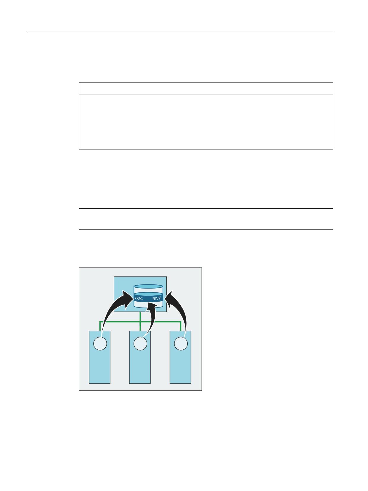
Mode group, channel, program operation, reset response
3.14 Execution from external storage (EES) (option)
The previous NC part program memory with the MPF.DIR, SPF.DIR and WKS.DIR directories is not
absolutely necessary when using EES. A system can also be configured without using the NC part
program memory.
NOTICE
Executing programs that are not visible
Even if the NC part program memory was removed from the drive configuration, it is always still
available in the system itself. This especially means that when executing the program it is
possible that programs that still exist there are inadvertently executed from the SPF.DIR.
Remedy: If the system is configured without NC part program memory in the drive
configuration, any programs still stored there should be deleted manually.
If the NC part program memory is still to be used, then it should not be completely removed from
the system, only assigned an appropriate protection level when required.
Drives can be used jointly by multiple stations (PCU/IPC/NCU). A standard drive configuration for
these stations means that there is a standard program view that is independent of the particular
station.
Note
The memory card of an NCU/PPU cannot be used by several stations.
Example:
Several NCUs jointly use a program memory on the local hard disk of the PCU (LOCAL_DRIVE).
3&8 ,3&
$/B'
1&
1&
1&
1&8
1&8
1&8
Basic functions
194
Function Manual, 10/2020, 6FC5397-2GP40-0BA1
Mode group, channel, program operation, reset response
3.14 Execution from external storage (EES) (option)
Note
If external program memories are used together at different stations in the EES mode, then the
following rules must be observed:
• A program cannot be simultaneously edited from several stations.
• Programs, which are being executed, can no longer be changed.
For operation with an external HMI, the drives must be configured on the external HMI! The drive
configuration (logdrive.ini) must be loaded into the corresponding NCU from the external HMI.
A softkey is available for the transfer on the dialog for the drive configuration.
In systems in which multiple NCs work together, the drive configuration must be identical for all
NCs. This is achieved by distributing the logdrive.ini file to all of the NCUs listed in the mmc.ini
file. The configurations existing there are therefore overwritten.
Further information
A list of PCU-Basesoftware can be obtained at:
• Commissioning Manual SINUMERIK 840D sl PCU-Basesoftware
• A list of available IPCs is available under Available IPCs (Page 906).
3.14.2.2
Global part program memory (GDIR)
When declaring the drives, one of the drives can be designated the global part program memory
(GDIR).
Further information
Operating Manual Universal/Turning/Milling/Grinding; Managing programs > Setting up drives
The system automatically creates the MPF.DIR, SPF.DIR and WKS.DIR directories on the drive that
acts as the GDIR. These three directories form the GDIR.
The GDIR only plays a role for the EES function. Depending on the drive configuration, the GDIR
replaces or extends the NC part program memory. However, it is not mandatory to set up a GDIR
for the EES operation.
The directories and files of the GDIR can be addressed in the part program in the same way as in
the passive file system. Therefore, a compatible relocation of an NC program with path
specification is possible for the passive file system to the GDIR.
The GDIR extends the search path for subprograms, which are called without specifying an
absolute path.
GDIR replaces the NC part program memory
If the NC part program memory is completely empty in the MPF.DIR, SPF.DIR and WKS.DIR
directories, then the GDIR replaces the NC part program memory. The previous NC search path
is emulated 1:1 by the GDIR.
Basic functions
Function Manual, 10/2020, 6FC5397-2GP40-0BA1
195

Mode group, channel, program operation, reset response
3.14 Execution from external storage (EES) (option)
Selecting the main program on an external archive/data storage medium
Search sequence for the subprograms:
1. Actual directory on an external archive/data storage medium
2. SPF.DIR in the GDIR memory
3. The drive referenced using CALLPATH
4. Cycles
GDIR extends the NC part program memory
When the NC part program memory is not empty in the MPF.DIR, SPF.DIR and WKS.DIR
directories, then the search sequence for the subprograms depends on where the main program
is archived (active directory).
Selecting the main program in the NC part program memory (MPF.DIR or xxx.WPD in
WKS.DIR)
Search sequence for the subprograms:
1. Actual directory in the NC part program memory
2. SPF.DIR in the NC part program memory
3. The drive referenced using CALLPATH
4. Cycles
Selecting the main program on an external archive/data storage medium released for EES
Search sequence for the subprograms:
1. Actual directory on an external archive/data storage medium
2. SPF.DIR in the NC part program memory
3. SPF.DIR in GDIR
4. The drive referenced using CALLPATH
5. Cycles
Note
To define the search sequence, also see MD11625 $MN_FILE_ONLY_WITH_EXTENSION and
MD11626 $MN_CYCLES_ONLY_IN_CYCDIR!
Note
An external drive can also be referenced using the CALLPATH statement.
Basic functions
196
Function Manual, 10/2020, 6FC5397-2GP40-0BA1

Mode group, channel, program operation, reset response
3.14 Execution from external storage (EES) (option)
3.14.2.3
Settings for file handling in the part program for EES
Program names unique throughout the system
If external program memories are used together at different stations in EES mode, file operations
performed simultaneously on different stations (WRITE, DELETE, …) result in access conflicts.
To avoid such access conflicts, we recommend setting up a name space for file names on each
station that is unique throughout the system.
Name space unique throughout the system
A name space for file names that is unique throughout the system is achieved, for example, by
associating the file names with the EES-specific name of the NC parameterized in the machine
data and the channel number of the channel in which the program is executed. For example,
when the program is executed, the following code generates the file name (MYFILE
_NC1_1.SPF), which is unique throughout the system, by appending the EES-specific name of
the NC (NC1) and the channel number (channel 1) to the program name.
$MN_EES_NC_NAME="NC1"
N10 DEF STRING[31] FILENAME
N20 FILENAME="MYFILE_" << $MN_EES_NC_NAME << "_" << $P_CHANNO <<
".SPF"
Parameter assignment
The EES-specific name of the NC is set in the NC-specific machine data:
MD10125 $MN_EES_NC_NAME = <NC name>
Note
Name of the NC unique throughout the system
To avoid access conflicts, the EES-specific name of the NC must be unique throughout the
system. The responsibility for this resides exclusively with the user/machine manufacturer.
When calling the program, only search for files with file ID
In order to speed up the program search for subprogram calls during EES operation, we
recommend that you limit the search to files with file ID (e.g. SPF, MPF, etc.):
MD11625 $MN_FILE_ONLY_WITH_EXTENSION = 1
Note
MD11625 has no effect on the program search when processing external subprograms with
EXTCALL.
Further information
For further information describing the search path to call the subprogram, see "NC
Programming" Programming Manual.
Basic functions
Function Manual, 10/2020, 6FC5397-2GP40-0BA1
197

Mode group, channel, program operation, reset response
3.14 Execution from external storage (EES) (option)
Only search for programs with interface in the cycle directories
In order to speed up the program search for subprogram calls during EES operation, we
recommend the search for subprograms which have created an interface description (by means
of PROC statement), and whose interface description was generated from the one of the cycle
directories (CUS, CMA, CST) be limited to the cycle directories:
MD11626 $MN_CYCLES_ONLY_IN_CYCDIR = 1
Note
MD11626 has no effect on subprograms whose interface was created using an EXTERNAL
declaration. A search is made in all program directories.
NOTICE
No search success for cycles outside the cycle directories
Cycles in the current directory and global subprogram directory are no longer found with the
setting MD11626 = 1!
Remedy: Always store cycles in the cycle directories.
3.14.2.4
Memory configuration
Reducing the user program memory in the passive file system
With active EES, the user program memory in the passive file system can be reduced:
MD18352 $MN_MM_U_FILE_MEM_SIZE (user memory for part programs / cycles / files)
The released memory can then be used, for example, for tool data or manufacturer cycles
(MD18353 $MN_MM_M_FILE_MEM_SIZE).
Further information
For detailed information regarding memory configuration, see Memory configuration
(Page 885).
Releasing reload memory
The EES function can replace the "Execution from external source" and "Execution of external
subprograms (EXTCALL)" functions.
In order to execute subprograms from part programs with EXTCALL calls with EES instead of the
"Execution of external subprograms (EXTCALL)" function, the EXTCALL calls must be changed to
CALL calls, and the path specifications adapted if required.
After a complete changeover, the reload memory (FIFO buffer) required for the "Execution from
external source" and "Execution of external subprograms (EXTCALL)" can be released:
MD18362 $MN_MM_EXT_PROG_NUM (number of externally executed program levels
executable simultaneously) = 0
Basic functions
198
Function Manual, 10/2020, 6FC5397-2GP40-0BA1
Mode group, channel, program operation, reset response
3.15 Process Datashare - output to an external device/file
3.14.3
Supplementary conditions
Teach in
In the EES mode, it is not possible to use the "Teach In" function in the AUTOMATIC operating
mode.
3.15
Process Datashare - output to an external device/file
3.15.1
Function
With the "Process Datashare" function, it is possible to write data from a part program to an
external device or to an external file; for instance, to log production data or to control additional
equipment at a control system.
Availability
The function is available:
• Only in the real NC (not in the SNC and VNC simulation software).
• Only in part programs (not in synchronized actions).
• Parallel in all machining channels of the NC for all available (configured) output devices.
External devices/files
External devices/files can be:
• Files on the local memory card
The local memory card represents the memory which is referenced by HMI with the symbolic
identifier LOCAL_DRIVE.
Note
For SINUMERIK 840D sl, the option "Additional xxx MB HMI user memory on memory card of
the NCU" is required for output to the LOCAL_DRIVE device.
• Files on a network drive
• RS-232-C
Note
For SINUMERIK 840D sl, the NCU option module RS 232 interface is required for output at the
RS-232-C.
Basic functions
Function Manual, 10/2020, 6FC5397-2GP40-0BA1
199

Mode group, channel, program operation, reset response
3.15 Process Datashare - output to an external device/file
Maximum number of opened external devices
More than one external device/file can also be assigned in a part program / channel. A maximum
of ten output devices can be simultaneously opened across all NC channels. In addition, there
are two entries reserved for Siemens cycles.
A maximum of five jobs may be active simultaneously to the output devices.
Usage mode
For each output device, when opening the device, it can be specified as to whether the device
is to be exclusively used by just one channel or whether several channels can output to the
device ("shared" mode).
Behavior for part program end / channel reset
With part program end and channel reset, all of the external devices/files that have been opened
in the channel are closed.
Use of the function for data transfer to the control
NOTICE
Data security
If the Process Datashare function is used to send data from an external device via the Ethernet
interface X130 to the control, there is the possibility that the data on the control could be
falsified by a third-party and is no longer consistent. When using the function, ensure that the
network is protected against access by third-parties.
3.15.2
Commissioning
The external devices to be used are configured in the /oem/sinumerik/nck/extdev.ini or /user/
sinumerik/nck/extdev.ini file. If both files are available, then the entries in the user area have
priority. The file can be updated in the operating area COMMISSIONING under SYSTEMDATEN/CF
card.
Note
It is not necessary to configure in the extdev.ini file when using LOCAL_DRIVE and CYC_DRIVE.
The two devices are always available as soon as the corresponding option is set or the user
CompactFlash card is available.
The external devices to be used are defined/listed in the section [ExternalDevices] of the
extdev.ini file. A serial device (/dev/v24) and up to nine files or directories (/dev/ext/1…9) can be
specified as device. The Linux notation is used when specifying devices. Lines, which start with
";", are comments and are overread.
Basic functions
200
Function Manual, 10/2020, 6FC5397-2GP40-0BA1

Mode group, channel, program operation, reset response
3.15 Process Datashare - output to an external device/file
With the exception of /dev/v24, the devices can be declared as directory path - terminated with
an attached "/" - or as file path - i.e. with attached fully qualified path, ending with a file name
(without a terminating "/"). When used in a part program, a file name (path) must also be
specified for a device with directory path.
Except for /dev/v24, a device is defined using the three items separated by a comma for "Server",
"Path" and the optional "Write mode".
For the files or directories (this then applies to all files in the directory), it can be specified as to
whether the file should be overwritten after it has been opened ("O" = Overwrite) or whether the
outputs should be attached to the file ("A" = Append). The default value is "A". A file/directory that
does not exist is newly created when opening.
For the device V.24 interface, only the settings for baud rate, data bits, stop bits, parity, protocol
and possibly end are specified in this sequence.
For files that are generated/saved on the LOCAL_DRIVE, LOCAL_DRIVE_MAX_FILESIZE data can
be used to set a maximum file size in bytes - this is then valid as standard for all files. The file size
is checked when executing an EXTOPEN command in Append mode. Optionally, the write mode
("O" = Overwrite, "A" = Append) can be defined using the LOCAL_DRIVE_FILE_MODE data. The
default value is "A".
Note
A copy template for the extdev.ini configuration file is available in the /siemens/sinumerik/nck
directory.
Note
Changes to the extdev.ini file only become effective after an NC restart/boot.
Note
USB devices
For SINUMERIK 840D sl, only statically connected USB interfaces of a TCU can be configured as
USB devices. The configuration is realized using the SERVER:/PATH type as specification for
"Server" in the sense above, whereby SERVER is the TCU name and /PATH designates the USB
interface. The USB interfaces of a TCU are addressed using "dev0-0", "dev0-1", "dev1-0". The path
data always starts with "/Partition", whereby the partition can be specified using a two-digit
partition number or its partition name - and where required, is extended with a file path up to
the required target, e.g.:
/dev/ext/8 = "TCU4:/dev0-0, /01/, A"
/dev/ext/8 = "TCU4:/dev0-0, /01/mydir.dir/"
/dev/ext/8 = "TCU4:/dev0-0, /myfirstpartition/Mydir.dir/myfile.txt, O"
Example
[ExternalDevices]
; Comment line
; example for V24
Basic functions
Function Manual, 10/2020, 6FC5397-2GP40-0BA1
201

Mode group, channel, program operation, reset response
3.15 Process Datashare - output to an external device/file
; /dev/v24 = "9600, 8, 1, none, rts [, etx]"
; examples for network drives
; /dev/ext/1 = "//[USERNAME[/DOMAIN][%PASSWORD]@]SERVER/SHARE/, /, A"
; /dev/ext/2 = "//[USERNAME[/DOMAIN][%PASSWORD]@]SERVER/SHARE, /myfile.txt, O"
; /dev/ext/3 = "//[USERNAME[/DOMAIN][%PASSWORD]@]SERVER/SHARE, /mydir/, A"
; /dev/ext/4 = "SERVER:/dev0-0, /01/, A"
; …
; SIEMENS only
; /dev/cyc/1= "//[USERNAME[/DOMAIN][%PASSWORD]@]SERVER/SHARE, /mydir/, A"
; /dev/cyc/2= "//[USERNAME[/DOMAIN][%PASSWORD]@]SERVER/SHARE/mydir, /, A"
LOCAL_DRIVE_MAX_FILESIZE = 50000
LOCAL_DRIVE_FILE_MODE = "O"
Effectiveness of the EXTOPEN parameter <WriteMode>
By specifying the write mode, when configuring in the extdev.ini file as well as for an EXTOPEN
call, authorization conflicts can occur, which are then acknowledged with EXTOPEN - possibly
with error:
Value from extdev.ini
Value of the EXTOPEN parameter
"OVR"
"APP"
-
"O"
O
Error
O
"A"
Error
A
A
-
O
A
A
Explanation:
O: "Overwrite" mode is active.
A: "Append" mode is active.
Error: EXTOPEN call is acknowledged with error.
LOCAL_DRIVE: File attribute
The files created with EXTOPEN on LOCAL_DRIVE are allocated the following file attributes:
• Owner:
"user"
Read/write rights set
• Group:
"operator"
Read/write rights set
Basic functions
202
Function Manual, 10/2020, 6FC5397-2GP40-0BA1
Mode group, channel, program operation, reset response
3.15 Process Datashare - output to an external device/file
3.15.3
Programming
The writing of data from a part program to an external device/file is performed in three steps:
1. Open the external device/file
The external device/file is opened for the channel for writing using the EXTOPEN command.
2. Writing data
The output data can be processed using the string functions of the NC language, e.g. SPRINT.
The WRITE command is used for writing.
3. Close the external device/file
The external device/file assigned in the channel is released again using the EXTCLOSE
command, when the end of the program is reached (M30) or for a channel reset.
Syntax
DEF INT <Result>
DEF STRING[<n>] <Output>
…
EXTOPEN(<Result>,<ExtDev>,<SyncMode>,<AccessMode>,<WriteMode>)
…
<Output>="data output"
WRITE(<Result>,<ExtDev>,<Output>)
…
EXTCLOSE(<Result>,<ExtDev>)
Basic functions
Function Manual, 10/2020, 6FC5397-2GP40-0BA1
203

Mode group, channel, program operation, reset response
3.15 Process Datashare - output to an external device/file
Meaning
EXTOPEN:
Pre-defined procedure to open an external device/file
<Result>:
Parameter 1: Result variable
By using the result variable value, it can be evaluated in the program as to whether
the operation was successful and processing is then appropriately continued.
Type:
INT
Values:
0
No error
1
External device cannot be opened
2
External device is not configured
3
External device with invalid path configured
4
No access rights for external device
5
Usage mode: External device already "exclusively" occupied
6
Usage mode: External device already being "shared"
7
File length longer than LOCAL_DRIVE_MAX_FILESIZE
8
Maximum number of external devices has been exceeded
9
Option for LOCAL_DRIVE not set
11
Reserved
12
Write mode: Data contradicts extdev.ini
16
Invalid external path has been programmed
22
External device not mounted
Basic functions
204
Function Manual, 10/2020, 6FC5397-2GP40-0BA1