SINUMERIK 840D sl. Service - Functions. Manual (2018-2020) - page 19
Mode group, channel, program operation, reset response
3.5 Program operation
Search path
The PROG_EVENT program must be located in one of the following cycle directories. The
following search path is passed through when the parameterized event occurs:
1.
/_N_CUS_DIR/ (user cycles)
2.
/_N_CMA_DIR/ (manufacturer cycles)
3.
/_N_CST_DIR/ (standard cycles)
The first program found with the name specified in MD11620 $MN_PROG_EVENT_NAME is
executed.
Note
• The specified program name is checked syntactically as in case of a subprogram name, i.e. the
first two characters must be letters or underscores (no digits). Prefix (_N_) and suffix (_SPF)
of the program names are added automatically, if not specified.
• The same protection mechanisms that can be activated for cycles (protection levels for
writing, reading, etc.) are activated.
Behavior when starting a user ASUB
The behavior of the function "event-driven program call" upon start of a user ASUB from the reset
channel status can be set channel-specific with the machine data:
MD20109 $MC_PROG_EVENT_MASK_PROPERTIES.Bit 0 = <value>
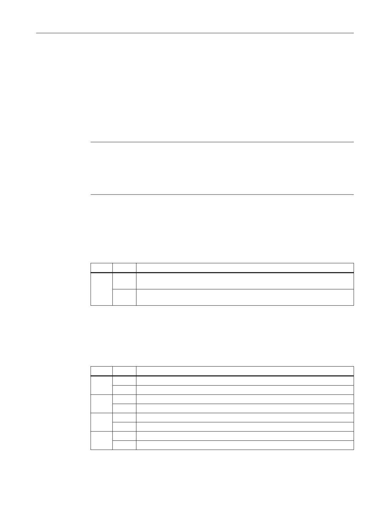
Bit
Value
Meaning
0
0
The PROG_EVENT program is started when one of the events parameterized with
MD20108 occurs.
1
The PROG_EVENT program is not started when one of the events parameterized with
MD20108 occurs.
Behavior when the single-block processing is set
The behavior of the "event-driven program call" function for set single-block processing can be
set channel-specific with the following machine data:
MD20106 $MC_PROG_EVENT_IGN_SINGLEBLOCK.Bit <n> = <value>
Bit
Value
Meaning: In the PROG_EVENT program, the single-block processing for event:
0
0
Part program start: acts
1
Part program start: is suppressed
1
0
Part program end: acts
1
Part program end: is suppressed
2
0
Channel reset: acts
1
Channel reset: is suppressed
3
0
Run-up: acts
1
Run-up: is suppressed
Basic functions
Function Manual, 10/2020, 6FC5397-2GP40-0BA1
67
Mode group, channel, program operation, reset response
3.5 Program operation
If the single-block processing is suppressed, the PROG_EVENT program is processed without
interruption.
Note
• MD20106 $MC_PROG_EVENT_IGN_SINGLEBLOCK affects all single-block processing types.
• The single-block processing in the PROG_EVENT program can be disabled with the following
setting:
MD10702 $MN_IGNORE_SINGLEBLOCK_MASK, bit 0 = 1 (prevent single-block stop)
The settings in MD20106 $MC_PROG_EVENT_IGN_SINGLEBLOCK then do not act.
Behavior when the read-in disable is set
The behavior of the "event-driven program call" function in case of set read-in disable
(DB21, ... DBX6.1 = 1) can be set channel-specific for each initiating event with the following
machine data:
MD20107 $MC_PROG_EVENT_IGN_INHIBIT.Bit <n> = <value>
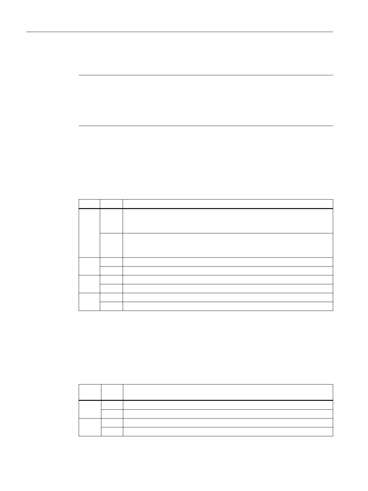
Bit
Value
Meaning: In the PROG_EVENT program, the read-in disable for event:
0
0
Part program start: acts
If the PROG_EVENT program is terminated with the RET command, no executable
block is created
1
Part program start: is suppressed
If the PROG_EVENT program is terminated with the RET command, an executable
block analog to M17 is created.
1
0
Part program end: acts
1
Part program end: is suppressed
2
0
Channel reset: acts
1
Channel reset: is suppressed
3
0
Run-up: acts
1
Run-up: is suppressed
Suppress updating of the display of the program and channel statuses
To prevent flickering when displaying the program and channel statuses on the HMI user
interface, the display refresh can be suppressed for the execution of the normally very brief
PROG_EVENT program. The program and the channel status before activation of the
PROG_EVENT program then remain visible in the display.
MD20192 $MC_PROG_EVENT_IGN_PROG_STATE.Bit <n> = <value>
Bit
Value
Meaning: While processing the PROG_EVENT program, the refresh of the display
of the program and channel statuses for event:
1
0
Part program end: Not suppressed
1
Part program end: Suppressed
2
0
Channel reset: Not suppressed
1
Channel reset: Suppressed
Basic functions
68
Function Manual, 10/2020, 6FC5397-2GP40-0BA1

Mode group, channel, program operation, reset response
3.5 Program operation
Bit
Value
Meaning: While processing the PROG_EVENT program, the refresh of the display
of the program and channel statuses for event:
3
0
Run-up: Not suppressed
1
Run-up: Suppressed
Note
The system variables $AC_STAT and $AC_PROG are not affected by this function, i.e. in the
running event-driven user program, $AC_STAT is set to "active" and $AC_PROG to "running".
NC/PLC interface signals DB21, ... DBX35.0-7 ("Program status ..." and "Channel status ...") also
remain unaffected.
Response for DB21, ... DBX7.2 / 3 / 4 (NC stop ...)
The response of the "event-driven program call" function for "NC stop", "NC stop at block limit"
and "NC stop axes plus spindle" can be set channel-specific for the part program end, channel
reset and ramp up events with the following machine data:
MD20193 $MC_PROG_EVENT_IGN_STOP.Bit <n> = <value>
Bit
Value
Meaning: The PROG_EVENT-program for NC stop and event
1
0
Part program end: is stopped/prevented
1
Part program end: is processed completely
2
0
Channel reset: is stopped/prevented
1
Channel reset: is processed completely
3
0
Run-up: is stopped/prevented
1
Run-up: is processed completely
Application example
An edge change of the interface signal DB21, ... DBX7.3 (NC stop) initiated by the operator by
pressing the NC Stop key during a channel reset or power-up is ignored during the execution of
the PROG_EVENT program and so an undesired stop behavior at the machine is prevented.
Note
Programming DELAYFSTON/DELAYFSTOF in the PROG_EVENT program cannot replace the
behavior set with MD20193. NC stop before executing the DELAYFSTON command can still
cause an interruption.
Basic functions
Function Manual, 10/2020, 6FC5397-2GP40-0BA1
69

Mode group, channel, program operation, reset response
3.5 Program operation
3.5.12.3
Programming
PROG_EVENT program
End of program
The following must be kept in mind, if the user program is to be activated through the part
program start.
• The user program must be ended with M17 or RET.
• A return jump with the REPOS command is not permissible.
Block display
The display can be suppressed in the current block display using the DISPLOF attribute in the
PROC statement.
Communication to the PLC user program
User M functions programmed in the PROG_EVENT program can inform the PLC user program,
e.g. about the processing status of the PROG_EVENT program.
System variable
Query for triggering event
The initiating event can be queried in the PROG_EVENT program with the following system
variables:
<value> = $P_PROG_EVENT (event-driven program call active)
Value
Meaning: Activation by
1
Part program start
2
Part program end
3
Channel reset
4
Power-up
5
After output of the last action block after Block search (see "Automatic Start of an ASUP after
block search (Page 124)")
Query of the current channel
The channel in which the PROG_EVENT program is processed can be determined with the
following system variables:
<value> = $P_CHANNO (query the current channel number)
Note
The PROG_EVENT program is processed in the channel in which the initiating event occurred.
Power-up is an event that takes place concurrently in all channels.
Basic functions
70
Function Manual, 10/2020, 6FC5397-2GP40-0BA1
Mode group, channel, program operation, reset response
3.5 Program operation
3.5.12.4
Boundary conditions
Emergency stop / alarm
If an emergency stop or a mode group / NC-specific alarm is present for a channel reset or after
power-up, the PROG_EVENT program is processed only after the emergency stop or the error has
been acknowledged in all channels.
Note
The "power-up" event occurs in all channels concurrently.
3.5.12.5
Examples
Example 1: Call the PROG_EVENT program for all events
Parameterization
MD20108 $MC_PROG_EVENT_MASK = 'H0F'
Call of _N_PROG_EVENT_SPF for:
• Part program start
• Part program end
• Channel reset
• Power-up
Programming
Program code
Comment
PROC PROG_EVENT DISPLOF
; Processing for part program start
IF ($P_PROG_EVENT==1)
MY_GUD_VAR=0
; Initialize GUD variable
RET
ENDIF
; Processing for part program end and channel reset
IF ($P_PROG_EVENT==2) OR
($P_PROG_EVENT==3)
DRFOF
; Deactivate DRF offsets
IF $MC_CHAN_NAME=="CHAN1"
CANCEL(2)
; Clear modal synchronized action 2
ENDIF
RET
ENDIF
; Sequence for power-up
IF ($P_PROG_EVENT==4)
IF $MC_CHAN_NAME=="CHAN1"
Basic functions
Function Manual, 10/2020, 6FC5397-2GP40-0BA1
71

Mode group, channel, program operation, reset response
3.5 Program operation
Program code
Comment
IDS=1 EVERY $A_INA[1]>5.0 DO
$A_OUT[1]=1
ENDIF
RET
ENDIF
RET
Example 2: ; Call the PROG_EVENT program for channel reset
Parameterization
MD20108 $MC_PROG_EVENT_MASK = 'H04'
Call of _N_PROG_EVENT_SPF for:
• Operator panel reset
Programming
Program code
Comment
PROC PROG_EVENT DISPLOF
N10 DRFOF
; Deactivate DRF offsets
N20 M17
Example 3: Initialization of the function
Parameterization
Machine data assignment, extract from the commissioning file (_N_INITIAL_INI)
Program code
Comment
CHANDATA(3)
; Initialization for channel 3
$MC_PROG_EVENT_IGN_INHIBIT='H01F'
$MC_PROG_EVENT_MASK='H04'
; Event: Channel reset
Meaning
The PROG_EVENT program _N_CMA_DIR/_N_PROG_EVENT_SPF is started for channel reset in
the 3rd channel and processed until program end, irrespective of whether or not the read-in
disable is activated or deactivated.
Basic functions
72
Function Manual, 10/2020, 6FC5397-2GP40-0BA1

Mode group, channel, program operation, reset response
3.5 Program operation
3.5.13
Influencing the stop events by stop delay areas
3.5.13.1
Function
Stop delay area
The response to a stop event can be influenced by the conditioned interruptible area in the NC
program. Such a program area is called a stop delay area.
Within the stop delay areas there should be no stop and the feedrate should not be changed.
Stops do not take effect until the program section has been completed.
This has the following advantages:
• A program section is processed without a drop in velocity.
• If the user aborts the program after a stop with reset, the aborted program block is after the
protected section. This program block is a suitable search target for a subsequent block
search.
• The following main run axes are not stopped as long as a stop delay area is in progress:
- Command axes
- Positioning axes that travel with POSA
Application
Example: Machining a thread.
Definition
The definition of a stop delay area is made in the part program with the predefined DELAYFSTON
and DELAYFSTOF procedures (see "Programming (Page 76)").
Stop events
Overview of the events that cause a stop:
Event
Reaction
DB21, ... DBX7.7 (reset) or DB11 DBX20.7 (mode group reset)
Immediate
NC program: M30
Alarm 16954
User interrupt to start an ASUP:
Delayed
FC 9 or DB10 DBB1 (setting the digital NC inputs for the PLC)
DB21, ... DBX6.2 / DB31, ... DBX2.2 (clear distance-to-go) channel/axis-specific
Immediate
DB21, ... DBX6.3 (clear the number of subprogram repetitions)
Delayed
DB21, ... DBX6.4 (program level abort)
Delayed
Basic functions
Function Manual, 10/2020, 6FC5397-2GP40-0BA1
73

Mode group, channel, program operation, reset response
3.5 Program operation
Event
Reaction
Stop because of single block
Delayed
• In the stop delay area:
The NC stops at the end of the 1st block outside the stop delay area.
• Single block is active before the stop delay area:
NC stops at each block limit, i.e. also in the stop delay area:
DB21, ... DBX7.2 (NC stop at the block limit)
This deselects the stop delay area!
DB11 DBX21.7 (activate single-block type A)
Delayed
DB11 DBX21.6 (activate single-block type B)
Delayed
DB21, ... DBX7.4 (NC stop) and DB11 DBX0.6 (mode group stop, axes plus
Immediate
spindles)
DB21, ... DBX7.3 (NC stop at block limit) and DB11 DBX0.5 (mode group stop)
Delayed
NC program: Stop because of empty overstore buffer
Alarm 16954
NC program: Programmed or implicit STOPRE
Alarm 16954
NC program: M0 or M1
Alarm 16954
DB21, ... DBX7.2 (NC stop at the block limit)
Delayed
Subprogram end should always deselect the stop delay area.
System error
NC program: WAITM
Alarm 16954
NC program: WAITE
Alarm 16954
NC program: INIT with parameter "S"
Alarm 16954
NC program: MMC (STRING, CHAR)
Alarm 16954
DB21, ... DBB26 (activate/deactivate skip block)
Delayed
DB21, ... DBB26 (deactivate skip block)
Delayed
DB21, ... DBX0.6 (activate DryRun)
Delayed
DB21, ... DBX0.6 (deactivate DryRun)
Delayed
DB21, ... DBX6.1 (read-in disable)
Delayed
Alarm: Alarm configuration STOPATENDBYALARM
Immediate
Alarm: Alarm configuration STOPBYALARM
Immediate
Internal: Stop after alarm for empty IPO buffer
Immediate
Internal: Stop after alarm for empty IPO buffer
Immediate
NC program: Alarm 16954 for LFON
Alarm 16954
NC program: WAITMC
Alarm 16954
NC program: NEWCONF
Alarm 16954
NC program: NEWCONF
Alarm 16954
OPI: PI "_N_SETUDT"
Delayed
Extended stop and retract
Delayed
DB31, ... DBX3.0 (accept external work offset)
Delayed
OPI: PI "_N_FINDST" STOPRUN
Alarm 16955
Alarms with NOREADY response
Immediate
DB21, ... DBX7.2 == 1 (NC stop at block limit)
Delayed
DB21, ... DBX7.3 == 1 (NC stop)
DB21, ... DBX7.4 == 1 (NC stop, axes plus spindles)
DB21, ... DBX6.1 == 1 (read-in disable)
Delayed
Basic functions
74
Function Manual, 10/2020, 6FC5397-2GP40-0BA1

Mode group, channel, program operation, reset response
3.5 Program operation
Event
Reaction
DB21, ... DBX2.0 == 1 (single block)
Delayed
Reaction
• Immediate
Stops immediately, even in the stop delay area. Designated as a "hard stop event".
• Delayed
Does not stop (even short-term) until after the stop delay area. Is known as a "soft stop event".
• Alarm 16954
Program is aborted because illegal program commands have been used in the stop delay area.
• Alarm 16955
Program is continued, an illegal action occurred in the stop delay area.
• Alarm 16957
The program area (stop delay area) enclosed by DELAYFSTON and DELAYFSTOF could not be activa-
ted. As a result, every stop will take effect immediately and is not subject to a delay! This will always
occur when the deceleration begins before the stop delay area but ends within the stop delay area.
Likewise, if the stop delay area is entered with an override of 0, the stop delay area also cannot be
activated. (Example: A G4 before the stop delay area allows the user to reduce the override to 0. The
next block in the stop delay area then begins with override 0 and the described alarm situation
occurs.)
Note
MD11411 $MN_ENABLE_ALARM_MASK (activation of warnings) Bit 7 activates this alarm.
Note
Some NC events are stopped for only a short time, in order to perform a switching operation, and
restart immediately. This includes, e.g. an interrupt that stops the NC program briefly in order to
start the associated ASUP. These events are also allowed in the stop delay area, however they are
pushed back to its end and are thus considered "soft stop events".
Note
If a "hard" stop event coincides with the "stop delay area", the entire "stop delay area" is
deselected! Thus, if any other stop occurs in this program section, it will be stopped immediately.
A new program setting (new DELAYFSTON) must be made in order to start a new stop delay area.
3.5.13.2
Parameterization
Machine data
Stop response for G331/G332
For tapping without compensating chuck (G331, G332), the stop response can be set as follows:
Basic functions
Function Manual, 10/2020, 6FC5397-2GP40-0BA1
75
Mode group, channel, program operation, reset response
3.5 Program operation
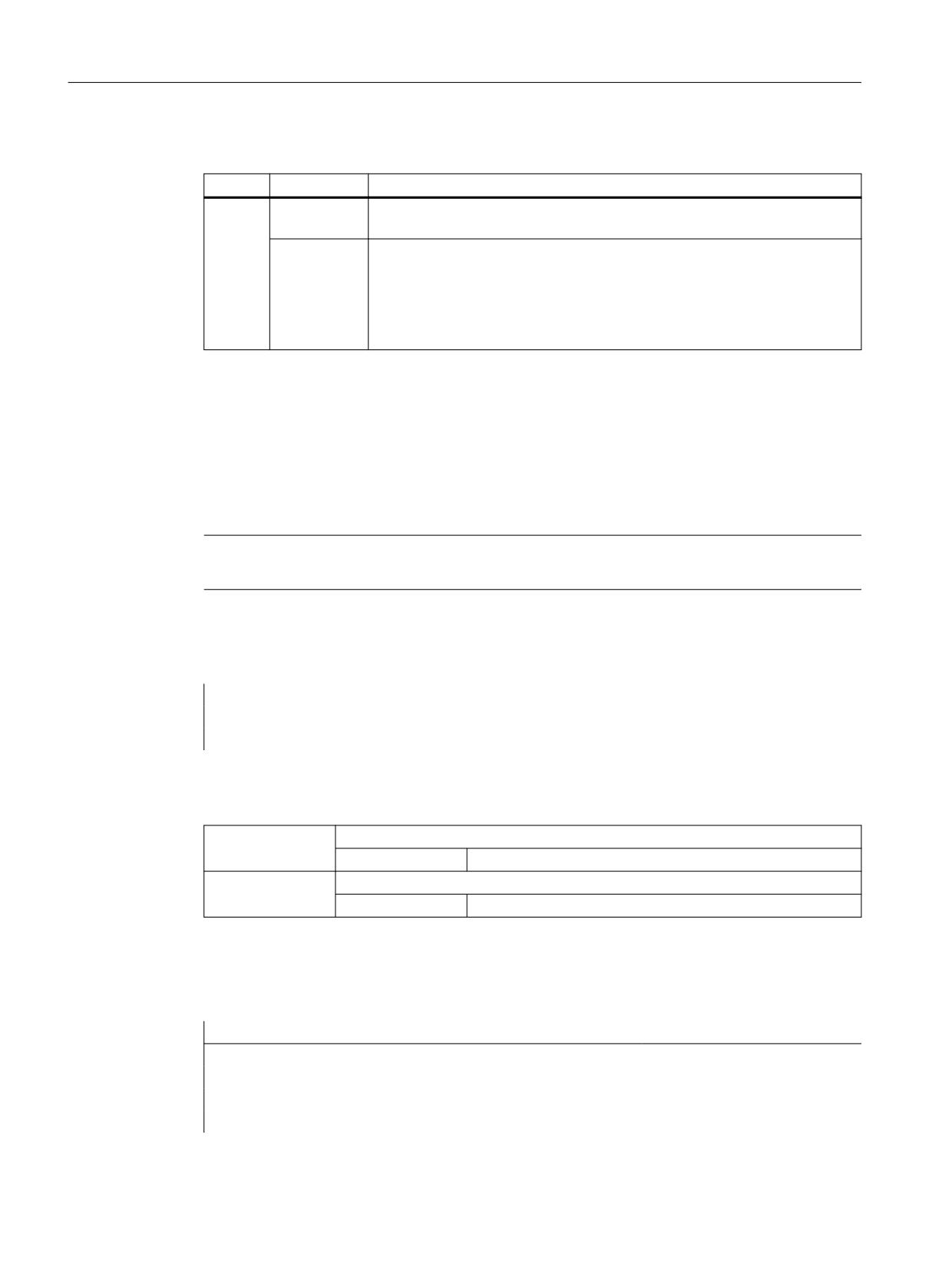
MD11550 $MN_STOP_MODE_MASK
Bit
Value
Meaning
0
0 (default)
Results in an implicit stop delay range if G331/G332 is active - and path motion
or a dwell time (G4) was also programmed.
1
A stop while G331/G332 is active is possible in the following situations:
• The continuous path mode is interrupted (G64).
• A dwell time (G4) is programmed between the G33x blocks.
NC commands DELAYFSTON and DELAYFSTOF must be used to define a stop
delay range.
3.5.13.3
Programming
Defining a stop delay range (DELAYFSTON, DELAYFSTOF)
The predefined DELAYFSTON and DELAYFSTOF procedures are used to define a conditionally
interruptible range in the part program (stop delay range).
Note
DELAYFSTON and DELAYFSTOF are not permitted in synchronized actions!
Syntax
DELAYFSTON
DELAYFSTOF
Meaning
DELAYFSTON:
Defining the start of a stop delay range
Alone in the block:
Yes
DELAYFSTOF:
Define the end of the stop delay area
Alone in the block:
Yes
Programming example
The following program block is repeated in a loop:
Program code
N99 MY_LOOP:
N100 G0 Z200
N200 G0 X0 Z200
Basic functions
76
Function Manual, 10/2020, 6FC5397-2GP40-0BA1
Mode group, channel, program operation, reset response
3.5 Program operation
Program code
N300 DELAYFSTON
N400 G33 Z5 K2 M3 S1000
N500 G33 Z0 X5 K3
N600 G0 X100
N700 DELAYFSTOF
N800 GOTOB MY_LOOP
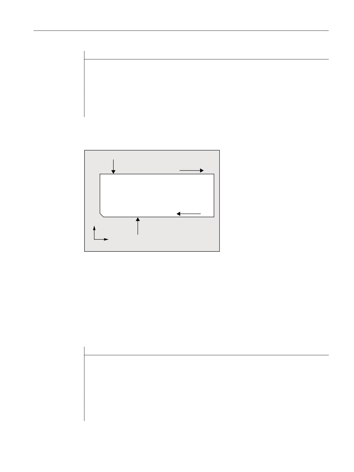
In the following diagram it can be seen that the user pressed "Stop" in the stop delay range, and
the NC started braking outside the stop delay range, i.e. in block N100. That causes the NC to
stop at the beginning of N100.
1& VWRSSW
1
* =
1
* ;
1
* ; =
1
*
=
;
1
*
=
;
6WRS EXWWRQ
6WRS EXWWRQ GXULQJ D *
=
PDFKLQLQJ
Additional information
End of subprogram
DELAYFSTOF is activated implicitly at the end of the subprogram in which DELAYFSTON is called.
Nesting
If subprogram 1 calls subprogram 2 in a stop delay area, the whole of subprogram 2 is a stop
delay area. In particular, DELAYFSTOF in subprogram 2 has no effect.
Example:
Program code
Comment
N10010 DELAYFSTON
; Blocks with N10xxx program level 1.
N10020 R1 = R1 + 1
N10030 G4 F1
; Stop delay area starts.
N10040 subprogram2
; Interpretation of subprogram 2.
N20010 DELAYFSTON
; Ineffective, repeated start, 2nd level.
Basic functions
Function Manual, 10/2020, 6FC5397-2GP40-0BA1
77

Mode group, channel, program operation, reset response
3.5 Program operation
Program code
Comment
N20020 DELAYFSTOF
; Ineffective, end at another level.
N20030 RET
N10050 DELAYFSTOF
; Stop delay end of range at the same level.
N10060 R2 = R2 + 2
N10070 G4 F1
; Stop delay area ends. From now, stops act immediately.
System variables
The following system variables can be queried to determine whether part program processing
is currently in a stop delay area:
• in the part program with $P_DELAYFST
• in synchronized actions with $AC_DELAYFST
Value
Meaning
0
Delay stop range not active
1
Delay stop area active
3.5.13.4
Supplementary conditions
Overlap
If two stop delay areas overlap, one from DELAYFSTON/DELAYFSTOF and the other from
MD11550 $MN_STOP_MODE_MASK, the largest possible stop delay area will be generated.
Dwell time (G4)
G4 is permitted in the stop delay area. Other part program commands that cause a stop in the
meantime (e.g. WAITM) are not permitted and trigger the alarm 16954.
Override
If the override is changed before a stop delay area, the override takes effect in the stop delay
area.
If the override is changed in the stop delay area, the change takes effect after the stop delay area.
Note
Override = 0
If the override is reduced to 0 before a stop delay area, the stop delay area cannot be activated.
Feed disable
DB21, ... DBX6.0 The feed disable has no effect in the stop delay area; the program does not stop
until after the stop delay area.
Basic functions
78
Function Manual, 10/2020, 6FC5397-2GP40-0BA1

Mode group, channel, program operation, reset response
3.5 Program operation
Single block
If the single block is activated in the stop delay area, the NC stops at the end of the first block
outside the stop delay area.
If the single block is already selected before the stop delay area, the NC stops at each block limit,
i.e. also in the stop delay area! This deselects the stop delay area.
3.5.14
Adapting the size of the interpolation buffer
MD28060
The channel-specific interpolator executes prepared blocks from the interpolation buffer during
the part program run. The maximum number of blocks requiring space in the interpolation
buffer at any given point in time is defined by the memory configuring MD28060
$MM_IPO_BUFFER_SIZE (number of NC blocks in the IPO buffer (DRAM)). For some applications
it may be meaningful not to use the full buffer capacity in order to minimize the "interval"
between preparation and interpolation.
SD42990
The number of blocks in the interpolation buffer can be restricted dynamically to a smaller value
than in MD28060 $MC_MM_IPO_BUFFER_SIZE (number of NC blocks in the IPO buffer (DRAM)),
minimum 2 blocks, with the setting data SD42990 $SC_MAX_BLOCKS_IN_IPOBUFFER (max.
number of blocks in the IPO buffer).
Values of setting data SD42990 $SC_MAX_BLOCKS_IN_IPOBUFFER:
Value
Effect
< 0
No interpolation buffer limit active.
The max. possible IPO buffer as set in MD 28060: MM_IPO_BUFFER_SIZE is acti-
vated.
or 1
The minimum permissible IPO buffer with two blocks is activated.
< MM_IPO_BUFFER_SIZE
The IPO buffer is activated with no more than the maximum specified number of
blocks.
>= MM_IPO_BUFFER_SIZE
The IPO buffer is activated with the number of blocks specified in MD 28060:
MM_IPO_BUFFER_SIZE.
Basic functions
Function Manual, 10/2020, 6FC5397-2GP40-0BA1
79
Mode group, channel, program operation, reset response
3.5 Program operation
Note
If SD42990 $SC_MAX_BLOCKS_IN_IPOBUFFER is set in the part program, the interpolation
buffer limitation takes effect immediately if the block with the SD is being preprocessed by the
interpreter.
This means that the limitation of the IPO buffer may take effect a few blocks before the intended
limitation (see also MD 28070 $MC_MM_NUM_BLOCKS_IN_PREP).
To avoid premature activation and to make the limitation of the IPO buffer take effect in
synchronism with the block, a STOPRE (preprocessing stop) must be programmed before the SD
is set in the part program.
Validity
SD42990 $SC_MAX_BLOCK_IN_IPOBUFFER has global, channel-specific validity and can also be
modified in a part program. This modified value is retained at the end of the program. If this
setting data is to be reset again on defined events, a so-called event-driven program must be
created to do this. For example, this setting data could always be set to a predefined value on
RESET.
Application
The IPO buffer limitation can be used whenever the number of blocks between block preparation
and interpolation must be minimized, e.g. when actual positions in the part program must be
read and processed for other purposes.
Example
N10 ...
N20 ...
N100 $SC_MAX_BLOCKS_IN_IPOBUFFER = 5
; Limitation of the IPO buffer to
five NC blocks
N110 ...
N120 ...
N200 $SC_MAX_BLOCKS_IN_IPOBUFFER = -1
; Cancellation of the IPO buffer
limitation
N210 ...
Basic functions
80
Function Manual, 10/2020, 6FC5397-2GP40-0BA1

Mode group, channel, program operation, reset response
3.5 Program operation
3.5.15
Basic block display (only for ShopMill/ShopTurn)
3.5.15.1
Function
In ShopMill/ShopTurn, a so-called basic block display can be used in addition to the existing block
display to show all blocks that produce an action on the machine.
The end positions actually approached are shown as an absolute position. The position values
refer either to the workpiece coordinate system (WCS) or the settable zero system (SZS).
The number of LookAhead display blocks stored in the display buffer depends on the number of
prepared blocks in the relevant processing state in the preprocessing buffer of the control. If a
preprocessing stop is processed, the number of display blocks is reduced to zero and increases
again after the stop is acknowledged. In the case of REORG events (e.g. mode change, ASUB
start), the display blocks stored for LookAhead are deleted and preprocessed again afterwards.
Values processed in the basic block display coincide with the:
• Selected tools
• Feedrate and spindle speed
• Position values actually approached
Exceptions:
With active tool radius compensation, deviations can occur.
For modulo axes, the programmed value is displayed in the basic block display. This value can
also lie outside the modulo range.
Activating/deactivating basic block display
The basic block display can be activated/deactivated in the following setting data:
SD42750 $SC_ABSBLOCK_ENABLE (enabling the basic block display)
3.5.15.2
Parameterization
Configure basic block display
The basic block display can be configured via the following machine data:
NC machine data for basic block display
Meaning:
MD28400 $MC_MM_ABSBLOCK
Activate basic block display
MD28402 $MC_MM_ABSBLOCK_BUFFER_CONF[2]
Size of the display buffer
Machine data display
Position values to be set:
MD9004 $MM_DISPLAY_RESOLUTION
for metric dimensional notation
MD9011 $MM_DISPLAY_RESOLUTION_INCH
for imperial dimensional notation
MD9010 $MM_SPIND_DISPLAY_RESOLUTION
Coordinate system to be set for spindles display
resolution
MD9424 $MM_MA_COORDINATE_SYSTEM
for WCS or SZS actual value display
This display machine data is copied to NC machine data
MD17200 $MN_GMMC_INFO_UNIT[0] (global HMI information) to MD17200
$MN_GMMC_INFO_UNIT[3]. This permits access from the NC to this display machine data.
Basic functions
Function Manual, 10/2020, 6FC5397-2GP40-0BA1
81
Mode group, channel, program operation, reset response
3.5 Program operation
Activation
The basic block display is activated by MD 28400 $MC_MM_ABSBLOCK (activate block display
with absolute values) by means of Power On. If MD28400 $MC_MM_ABSBLOCK is set to 1, a
channel-specific display buffer (FIFO) is created during power-up.
Size of display buffer (FIFO) = (MD28060 $MC_MM_IPO_BUFFER_SIZE (number of NC blocks
in the IPO buffer) + MD28070 $MC_MM_NUM_BLOCKS_IN_PREP (number of blocks for the block
preparation)) multiplied by 128 bytes. For the standard machine data setting, this represents a
size of 6 KB.
Optimize the size of display buffer:
The memory requirement can be optimized by entering a value between 128 and 512. The
display blocks prepared in the display buffer are transferred to the HMI via a configurable upload
buffer.
The maximum size of the upload buffer is obtained by multiplying (MD28402
$MC_MM_ABSBLOCK_BUFFER_CONF[0] +
MD28402 $MC_MM_ABSBLOCK_BUFFER_CONF[1] + 1) by the block length configured in
MD28400 $MC_MM_ABSBLOCK.
The number of blocks before the current block is configured in
MD28402 $MC_MM_ABSBLOCK_BUFFER_CONF[0] and the number of blocks after the current
block is configured in MD28402 $MC_MM_ABSBLOCK_BUFFER_CONF[1].
Supplementary conditions
If the length of a display block configured in MD28400 $MC_MM_ABSBLOCK is exceeded, this
display block is truncated accordingly. To represent this, the "..." string is appended to the block
end.
For preprocessed cycles
(MD10700 $MN_PREPROCESSING_LEVEL > 1 (program preprocessing level)), the display block
contains only axis positions.
Additional supplementary conditions for the basic block display:
• Modal synchronized action blocks with absolute values are
not taken into account.
• The basic block display is deactivated during block search with or without calculation.
• Polar coordinate programming is not shown in Cartesian system.
Basic functions
82
Function Manual, 10/2020, 6FC5397-2GP40-0BA1
Mode group, channel, program operation, reset response
3.5 Program operation
Radius/diameter values
Diameter values shown in the basic block display and position display may be needed as a radius
for internal calculation. These values for measurements in radius/diameter according to G group
29 can be manipulated using the following options:
• G command DIAMCYCOF (extension of channel-specific diameter programming)
This G command deactivates the channel-specific diameter programming during the cycle
execution. In this way, calculations in the cycle can always be made in the radius. The position
display and the basic block display are continued according to the state of the diameter
programming before DIAMCYCOF.
In the basic block display, the last displayed value is retained.
• G command DIACYCOFA[AX] (axis-specific diameter programming)
This G command deactivates the axis-specific diameter programming during the cycle
execution. In this way, calculations in the cycle can always be made in the radius. In the
position display and in the basic block display, this continues according to the state of the
diameter programming before DIACYCOFA[AX] indicator.
In the basic block display, the last displayed value is retained.
• MD27100 $MC_ABSBLOCK_FUNCTION_MASK (parameterize the block display with absolute
values)
Bit0 = 1
Setpoints of the transverse axis are always displayed as diameter values in
the basic block display.
Behavior for active compressor
Two display blocks are generated for active compressor with G group 30 not equal to COM. The
• first contains the G command of the active compressor, the
• second contains the string "..." as character for missing display blocks
Example:
G0 X10 Y10 Z10
; block still prepared for the basic block display
COMPCAD
; compressor for optimized surface quality (CAD program)
; String as sign that the display blocks are missing
To prevent bottlenecks of the NC performance, the basic block display is disabled automatically.
As a sign that the display blocks are missing, a display block with the string "..." is generated.
All display blocks are always generated in the single block.
Basic functions
Function Manual, 10/2020, 6FC5397-2GP40-0BA1
83

Mode group, channel, program operation, reset response
3.5 Program operation
3.5.15.3
Structure for a DIN block
Structure of display block for a DIN block
Basic structure of display block for a DIN block
• Block number/label
• G command of the first G group
(only if changed as compared to the last machine function block).
• Axis position
(sequence corresponding to MD20070 $MC_AXCONF_MACHAX_USED (machine axis
number valid in the channel)).
• Further modal G commands
(only if changed as compared to the last machine function block).
• Other addresses as programmed.
The display block for the basic block display is directly derived from the programmed part
program blocks according to the following rules:
• Macros are expanded.
• Skip identifiers and comments are omitted.
• Block number and labels are transferred from the original block, but omitted if DISPLOF is
active.
• The number of decimal places is defined in display machine data MD 9004, MD 9010 and MD
9011 via the HMI.
HMI display machine data
Access in the NC machine data
MD9004 $MM_DISPLAY_RESOLUTION
MD17200 $MN_GMMC_INFO_NO_UNIT[0]
MD9011 $MM_DISPLAY_RESOLUTION_INCH
MD17200 $MN_GMMC_INFO_NO_UNIT[1]
MD9010 $MM_SPIND_DISPLAY_RESOLUTION
MD17200 $MN_GMMC_INFO_NO_UNIT[2]
MD9424 $MM_MA_COORDINATE_SYSTEM
MD17200 $MN_GMMC_INFO_NO_UNIT[3]
• Programmed axis positions are represented as absolute positions in the coordinate system
(WCS / SZS) specified in MD9424 $MM_MA_COORDINATE_SYSTEM (coordinate system for
actual value display)
Note
The modulo correction is omitted for modulo axes, which means that positions outside the
modulo range can be displayed. It also means that the basic block display differs from the
position display in which values are always modulo-converted.
Basic functions
84
Function Manual, 10/2020, 6FC5397-2GP40-0BA1
Mode group, channel, program operation, reset response
3.5 Program operation
Examples
Comparisons between display block (original block) and basic block display:
• Programmed positions are displayed as absolute.
The addresses AP/RP are displayed with their programmed values.
Original block:
Display block:
N10 G90 X10.123
N10 X10.123
N20 G91 X1
N20 X11.123
• Address assignments (non-DIN addresses) are displayed in the form <address> =
<constant>.
Original block:
Display block:
N110 R1 = -67.5 R2 = 7.5
N130 Z = R1 RND = R2
N130 Z-67.5 RND = 7.5
• Address indices (address extensions) are displayed as constants <address> [ <constant> ]
= <constant>.
Original block:
Display block:
N220 DEF AXIS AXIS_VAR = X
N240 FA[ AXIS_VAR] = R2
N240 FA[X] = 1000
• DIN addresses without address extension are displayed in the form
<din_address> <constant>.
Original block:
Display block:
N410 DEF REAL FEED = 1.5
N420 F = FEED
N420 F1.5
Basic functions
Function Manual, 10/2020, 6FC5397-2GP40-0BA1
85
Mode group, channel, program operation, reset response
3.5 Program operation
The following applies for H functions: Each programmed value is display irrespective of the
output type to the PLC.
(MD22110 $MC_AUXFU_H_TYPE_INT (type of H auxiliary function is integer)).
• For Tool selection by tool command
Display information is generated in the form T<value> or T=<string>. If an address extension
has been programmed, this is displayed as well.
If several spindles have been configured or the "Tool change via master toolholder" function
(MD20124 $MC_TOOL_MANAGEMENT_TOOLHOLDER (toolholder number)) is active, the T
number is always output with address extension.
If no address extension has been programmed, the number of the master spindle or the
master toolholder is used instead (T<spindle_number/tool_holder>= ).
• For the Spindle programming via S, M3, M4, M5, M19, M40 - M45 and M70 (or MD 20094
$MC_SPIND_RIGID_TAPPING_M_NR (M function for switching over in the controlled axis
operation)) the following regulation applies regarding the address extension:
If an address extension has been programmed, then this is also resolved.
If several spindles have been configured, then the address extension is also output.
If no address extension has been programmed, the number of the master spindle is used
(S<spindle_number>=).
• Indirect G command programming in form G[ <group> ] = <expression> is substituted by
the corresponding G command.
Original block:
Display block:
N510 R1=2
N520 G[8]= R1
N520 G54
• Modal G commands that do not generate an executable block are collected and output with
the display block of the next executable block if permitted by the syntax (DIN block). If this
is not the case (e.g. predefined subprogram call TRANSMIT), a separate display block
containing the modified G commands is placed in front of the next executable block.
Original block:
Display block:
N610 G64
G64
N620 TRANSMIT
N620 TRANSMIT
• A display block is always generated for part program lines in which the addresses F and FA
appear (including for MD22240 $MC_AUXFU_F_SYNC_TYPE = 3 (output time of the F
functions)).
Original block:
Display block:
N630 F1000
N630 F1000
N640 X100
N640 X100
• The display blocks generated for the block display are derived directly from the
programmed part program blocks. If intermediate blocks (e.g. tool radius compensation G41/
G42, radius/chamfer RNDM, RND, CHF, CHR) are generated in the course of contour
preprocessing, these are assigned the display information from the part program block on
which the motion is based.
Basic functions
86
Function Manual, 10/2020, 6FC5397-2GP40-0BA1

Mode group, channel, program operation, reset response
3.6 Program control
Original block:
Display block:
N710 Y157.5 G42
N710 Y157.5 G42
N720 Z-67.5 RND=7.5
N720 Z-67.5 RND=7.5
• With the EXECTAB command (processing a table of contour elements), the block generated
by EXECTAB is shown in the display block.
Original block:
Display block:
N810 EXECTAB (KTAB[5])
N810 G01 X46.147 Z-25.38
• With the EXECSTRING command, the block generated via EXECSTRING is displayed in the
display block.
Original block:
N910 DEF STRING[40] PROGSTRING = "N905 M3 S1000 G94 Z100 F1000 G55"
N920 EXECSTRING(PROGSTRING)
Original block:
N905 Z100 G55 G94 M3 S1000 F1000
3.6
Program control
3.6.1
Overview
The control system provides various functions for controlling the execution of an NC program.
These functions are predominantly used for testing and running-in a new part program. Using
these functions significantly reduces the danger to the machine and time required during the
test phase.
Several program control functions can be activated at the same time to achieve a better result.
Functions
The following program control functions are available:
• Program test (Page 89)
• Dry run feedrate (Page 92)
• Reduced rapid traverse (Page 94)
• Programmed stop (Page 94)
• Handwheel offset (Page 95)
• Skipping program blocks (Page 96)
Basic functions
Function Manual, 10/2020, 6FC5397-2GP40-0BA1
87
Mode group, channel, program operation, reset response
3.6 Program control
• Single block (Page 99)
• Configured stop (Page 108)
Selecting and activating
Via the user interface
A program control function is selected for the active channel via the user interface, e.g.
SINUMERIK Operate:
1. Softkey: Operating area "Machine" > "Program control"
2. "Program control" menu: select the function checkbox.
The PLC then transfers the selection signal to the corresponding activation signal of the NC/PLC
interface.
Directly via the PLC user program
The function may also be directly activated via the PLC user program by setting the
corresponding activation signal in the NC/PLC interface.
Note
Selection activation via the user interface
The HMI request signals are only transferred from the basic PLC program to the PLC request
signals if FB1 parameter MMCToIF is set to TRUE:
• MMCTolf == "TRUE" ; ⇒ Transfer (default setting)
• MMCTolf == "FALSE" ; ⇒ No transfer
If the parameters are not set, the PLC request signals must be set by the PLC user program.
Note
Activation via the PLC user program
The FB1 parameter MMCToIf must be set to "FALSE", otherwise the NC/PLC interface would be
overwritten with the values of the HMI/PLC interface.
Basic functions
88
Function Manual, 10/2020, 6FC5397-2GP40-0BA1
Mode group, channel, program operation, reset response
3.6 Program control
3.6.2
Program test
Function
In the "Program test" state, a part program can be executed without actually traversing any of the
machine axes. The user can use this to check the programmed axis positions and auxiliary
function outputs of a part program. This program simulation can also be used as an extended
syntax check.
Note
Spindle traversing motions
Contrary to the machine axes - in the "Program test" state - traversing motion of the spindles of
the channel is enabled as default setting (see Section "Basic setting").
If, in the "Program test" state, spindles are not to be traversed, then they must be explicitly
inhibited/locked via the PLC user program.
Basic settings
The following settings apply as default setting for channels in the "Program test" state:
• Setpoints identical to normal operation are generated for the axes; however they are not
output to the machine axes.
• For the spindles, setpoints are output to the machine axes.
• The displayed actual values of the inhibited axes/spindles are internally generated from
setpoints.
• The commands for channel synchronization are processed normally.
• The NC/PLC interface signals are processed normally.
• The processing time of the program is the same as in normal operation.
Temporarily when required, the "Program test" state can be exited on an axis-for-axis basis. The
setpoints are then output again on the machine axes so that they actually traverse at the
machine.
Selecting and activating
Via the user interface
"Program test" for the channel displayed in the "Machine" basic display is selected via the user
interface, e.g. SINUMERIK Operate:
1. Softkey: Operating area "Machine" > "Program control"
2. "Program control" menu: Select check box "Program test (PRT)".
The PLC then transfers the selection signal to the corresponding activation signal of the NC/PLC
interface.
Basic functions
Function Manual, 10/2020, 6FC5397-2GP40-0BA1
89
Mode group, channel, program operation, reset response
3.6 Program control
Directly via the PLC user program
The function may also be directly activated via the PLC user program by setting the
corresponding activation signal in the NC/PLC interface.
NC/PLC interface signals
After selecting the program test (PRT), the following NC/PLC interface signals are set:
• Channels
- DB21, ... DBX25.7 (from the HMI: program test selected) == 1
- DB21, ... DBX1.7 (from the PLC: activate program test) == 1
- DB21, ... DBX33.7 (from the NC: program test active) == 1
• Axes
- DB31, ... DBX128.0 (from the HMI: suppress program test) == 0
- DB31, ... DBX128.1 (activate program test from the HMI) == 0
- DB31, ... DBX14.0 (from the PLC: suppress program test) == 0
- DB31, ... DBX14.1 (from the PLC: activate program test) == 0
• Spindles
- DB31, ... DBX128.0 (from the HMI: suppress program test) == 1
- DB31, ... DBX128.1 (from the HMI: activate program test) == 0
- DB31, ... DBX14.0 (from the PLC: suppress program test) == 1
- DB31, ... DBX14.1 (from the PLC: activate program test) == 0
Note
Default state of traversing motion
The default state regarding traversing motion after selecting "Program test" in the channel is:
• Axes: Inhibited
• Spindles: Enabled
Inhibiting spindle traversing motions
If, during "Program test", spindles are not to be traversed, then they must be explicitly inhibited/
locked via the PLC user program:
• DB31, ... DBX128.0 (suppress program test) == 0
• DB31, ... DBX128.1 (activate program test) == 1
• DB31, ... DBX14.0 (from the PLC: suppress program test) == 0
• DB31, ... DBX14.1 (from the PLC: activate program test) == 1
Basic functions
90
Function Manual, 10/2020, 6FC5397-2GP40-0BA1
Mode group, channel, program operation, reset response
3.6 Program control
Enable axis traversing motion
If, during "Program test" channel axes are to be traversed, then they must be explicitly enabled
via the PLC user program:
• DB31, ... DBX14.0 (from the PLC: suppress program test) == 1
• DB31, ... DBX14.1 (from the PLC: activate program test) == 0
Permissible switching instants
• Channel
Interface signals to deactivate/activate the channel-specific "Program test" state (DB21, ...
DBX25.7 or DBX1.7), may only be switched in the "Reset" or "Interrupted" channel state.
• Axes/spindles
Interface signals to activate/deactivate the axis-specific "Program test" state (DB31, ...
DBX128.0 / .1 or DBX14.0 / .1) may always be switched.
Program start and program run
When the program test function is active, the part program can be started and executed via the
following NC/PLC interface signals (incl. auxiliary function outputs, wait times, G command
outputs, etc.):
DB21, ... DBX7.1 (NC Start)
The safety functions such as software limit switches, working area limits continue to be valid.
The programmed velocities remain unchanged. This means that the position and velocity
information on the operator interface is exactly the same as that output during normal part
program execution. The position control is not interrupted, so the axes do not have to be
referenced when the function is switched off.
Note
The signals for exact stop DB31, ... DBX60.6/60.7 (exact stop coarse/fine) mirror the actual status
on the machine.
They are only canceled during program testing if the axis is pushed out of its set position (the set
position remains constant during program testing).
With signal DB21, ... DBX33.7 (program test active) both the PLC program and the part program
can use variable $P_ISTEST to decide how to react or branch in response to these signals during
testing.
Note
Dry run feedrate
Program execution in the "program test" state can also be activated using the "Dry run feedrate"
function. With this function, part program sections with a small programmed feedrate can be
processed in a shorter time.
Basic functions
Function Manual, 10/2020, 6FC5397-2GP40-0BA1
91

Mode group, channel, program operation, reset response
3.6 Program control
Note
Tool management
Because of the axis disable, the assignment of a tool magazine is not changed during program
testing. A PLC application must be used to ensure that the consistency between the data in the
tool management system and the magazine is not corrupted.
3.6.3
Dry run feedrate
Function
To reduce the processing time during the program test, traversing motion can be executed faster
by activating the drive run feedrate. For example, for G01, G02, G03, G33, G34, G35, G95, the
test feedrate applies instead of the programmed feedrate.
NOTICE
Destroyed tool or workpiece as a result of excessively high cutting velocities
When a workpiece is machined with the dry run feedrate function active, the resulting cutting
velocities may lie outside the permissible range and lead to destruction of the tool and / or
workpiece.
As a consequence, the dry run feedrate should only be used for the program test.
Activation
The dry run feedrate is selected at the user interface in the AUTOMATIC and MDI modes, and can
be activated when automatic operation is interrupted or at the end of the block.
Selection
The "Dry run feedrate" function is selected for the channel displayed in the "Machine" basic
display via the user interface, e.g. SINUMERIK Operate:
1. Softkey: Operating area "Machine" > "Program control"
2. "Program control" menu: select checkbox "Dry run feedrate (DRY)".
The following signal is set in the HMI/PLC interface to request that the PLC user program activates
the function:
DB21, ... DBX24.6 (dry run feedrate selected) == 1
Basic functions
92
Function Manual, 10/2020, 6FC5397-2GP40-0BA1

Mode group, channel, program operation, reset response
3.6 Program control
The PLC then transfers the selection signal to the corresponding activation signal of the NC/PLC
interface.
Note
The function may also be directly activated via the PLC user program by setting the
corresponding activation signal in the NC/PLC interface.
Activation
To request that the NC activates the function, the PLC user program must set the following NC/
PLC interface signal:
DB21, ... DBX0.6 (activate dry run feedrate) == 1
Feedback signal
The following NC/PLC interface signal is set as feedback signal to the PLC user program that the
function is active in the NC:
DB21, ... DBX318.6 (dry run feedrate active) == 1
Parameterization
Dry run feedrate
The dry run feedrate effective in the channel is set using:
SD42100 $SC_DRY_RUN_FEED = <dry run feedrate>
Note
Revolutional feedrate
The dry run feedrate also replaces the programmed revolutional feedrate in program blocks with
G95.
Dry run feedrate mode
The dry run feedrate mode is set with:
SD42101 $SC_DRY_RUN_FEED_MODE = <value>
<Val-
Meaning
ue>
0
The maximum from SD42100 and the programmed feedrate are effective as dry run feedrate.
1
The minimum from SD42100 and the programmed feedrate are effective as dry run feedrate.
2
SD42100 is effective as dry run feedrate.
10
The same as for a value of 0, except for thread cutting (G33, G34, G35) and tapping (G331,
G332, G63): For these functions, the programmed feedrate applies.
11
The same as for a value of 1, except for thread cutting (G33, G34, G35) and tapping (G331,
G332, G63): For these functions, the programmed feedrate applies.
12
The same as for a value of 2, except for thread cutting (G33, G34, G35) and tapping (G331,
G332, G63): For these functions, the programmed feedrate applies.
Basic functions
Function Manual, 10/2020, 6FC5397-2GP40-0BA1
93
Mode group, channel, program operation, reset response
3.6 Program control
Further information
For additional information on influencing the feedrate, see Function Manual Axes and Spindles.
3.6.4
Reduced rapid traverse
Function
In the reduced rapid traverse mode, the traversing velocity of the axes is reduced to the
percentage value currently set.
Setting
The percentage value for the reduced rapid traverse is specified via the following setting data:
SD42122 $SC_OVR_RAPID_FACTOR (add. rapid traverse override can be specified through
operation)
SD42122 is only effective when the "Reduced rapid traverse" function is active.
Activation
The "Reduced rapid traverse" function is selected and activated for the channel displayed in the
"Machine" root screen via the user interface, e.g. SINUMERIK Operate:
1. Softkey: Operating area "Machine" > "Program control"
2. "Program control" menu: Select checkbox "Reduced rapid traverse (RG0)".
3.6.5
Programmed stop
Function
If function "Programmed stop 1" is active, then program execution stops at all blocks in which
supplementary function M01 is programmed. This means that while machining a workpiece,
users have the option of checking the results of individual machining steps.
Activation
Selection
The "Programmed stop 1" function is selected for the channel displayed in the "Machine" basic
display via the user interface, e.g. SINUMERIK Operate:
1. Softkey: Operating area "Machine" > "Program control"
2. "Program control" menu: select the check box "Programmed stop 1 (M01)".
Basic functions
94
Function Manual, 10/2020, 6FC5397-2GP40-0BA1
Mode group, channel, program operation, reset response
3.6 Program control
The following signal is set in the HMI/PLC interface to request that the PLC user program activates
the function:
DB21, ... DBX24.5 (M01 requested) == 1
Note
The function may also be directly activated via the PLC user program by setting the
corresponding activation signal in the NC/PLC interface.
Activation
To request that the NC activates the function, the PLC user program must set the following NC/
PLC interface signal:
DB21, ... DBX0.5 (activate M01) == 1
Feedback signal
The following NC/PLC interface signal is set as feedback signal to the PLC user program that the
function is active in the NC:
DB21, ... DBX32.5 (M01 active) == 1
If the NC program is stopped at the end of a block due to the function, the following NC/PLC
interface signal is set:
DB21, ... DBX35.2 (program status stopped) == 1
3.6.6
Handwheel offset
Function
The "Handwheel offset (DRF)" function can be used to set an additive incremental zero offset for
geometry and auxiliary axes in the basic coordinate system in the AUTOMATIC mode via an
electronic handwheel.
Typical applications:
• Offsetting tool wear within an NC block
Where NC blocks have very long processing times, it becomes necessary to offset tool wear
manually within the NC block (e.g. for milling machines that machine large surfaces).
• Highly precise offset during grinding
• Simple temperature compensation
Basic functions
Function Manual, 10/2020, 6FC5397-2GP40-0BA1
95
Mode group, channel, program operation, reset response
3.6 Program control
Activation
Selection
The "Handwheel offset" function is selected for the channel displayed in the "Machine" basic
display via the user interface, e.g. SINUMERIK Operate:
1. Softkey: Operating area "Machine" > "Program control"
2. "Program control" menu: select checkbox "Handwheel offset (DRF)".
The following signal is set in the HMI/PLC interface to request that the PLC user program activates
the function:
DB21, ... DBX24.3 (handwheel offset requested) == 1
Note
The function may also be directly activated via the PLC user program by setting the
corresponding activation signal in the NC/PLC interface.
Activation
To request that the NC activates the function, the PLC user program must set the following NC/
PLC interface signal:
DB21, ... DBX0.3 (activate handwheel offset) == 1
Feedback signal
The following NC/PLC interface signal is set as feedback signal to the PLC user program that the
function is active in the NC:
DB21, ... DBX33.3 (handwheel offset active) == 1
Further information
Detailed information about the DRF offset function is provided in Function Manual Axes and
Spindles.
3.6.7
Skipping program blocks
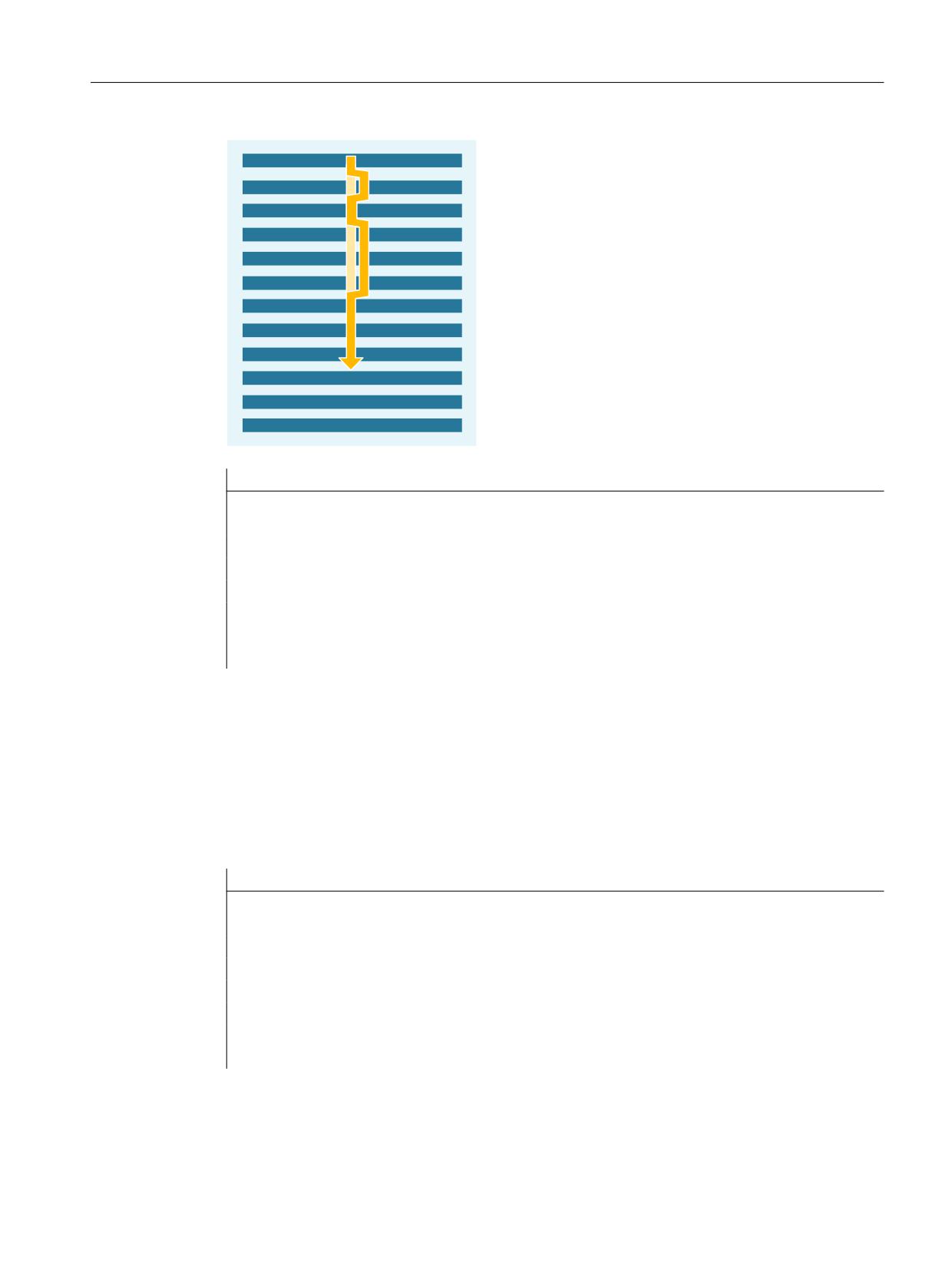
NC blocks, which are not to be executed every time the program runs, can be skipped and not
processed. This function is used when testing and/or running-in new programs, for example.
Skip blocks
Blocks to be skipped are indicated in the part program by the character "/" before the block
number. Several consecutive blocks can also be skipped. The instructions in the skipped blocks
are not executed and the program resumes with the next block that is not skipped.
Example:
Basic functions
96
Function Manual, 10/2020, 6FC5397-2GP40-0BA1
Mode group, channel, program operation, reset response
3.6 Program control
1
1
1
1
1
1
1
1
1
1
1
1
Program code
Comment
N10 …
; Is executed
/N20 …
; Skipped
N30 …
; Is executed
/N40 …
; Skipped
/N50 …
; Skipped
/N60 …
; Skipped
N70 …
; Is executed
Skip levels
Blocks can be assigned to skip levels (max. 10), which can be activated via the user interface or
the PLC user program.
The assignment is made in the NC program using a forward slash, followed by the number of the
skip level. Only one skip level can be specified for each block.
Example:
Program code
Comment
/ ...
; Block is skipped (1st skip level)
/0 ...
; Block is skipped (1st skip level)
/1 N010...
; Block is skipped (2nd skip level)
/2 N020...
; Block is skipped (3rd skip level)
/7 N100...
; Block is skipped (8th skip level)
/8 N080...
; Block is skipped (9th skip level)
/9 N090...
; Block is skipped (10th skip level)
Basic functions
Function Manual, 10/2020, 6FC5397-2GP40-0BA1
97

Mode group, channel, program operation, reset response
3.6 Program control
Note
The levels to be skipped can only be changed when the control system is in the STOP/reset state.
Note
The number of skip levels that can be used depends on a display machine data.
Note
Skipping blocks also remains active during block searches.
Note
System and user variables can also be used in conditional jumps in order to control program
execution.
Selection
Skip levels for the channel displayed in the "Machine" basic display are selected via the user
interface, e.g. SINUMERIK Operate:
1. Softkey: Operating area "Machine" > "Program control"
2. "Program control" menu: Select checkbox "Skip level... (SKP)".
The associated signal is set in the HMI/PLC interface to request that the PLC user program
activates the selected skip level:
DB21, ... DBX26.0 (skip blocks of the 1st skip level) == 1
DB21, ... DBX26.1 (skip blocks of the 2nd skip level) == 1
DB21, ... DBX26.7 (skip blocks of the 8th skip level) == 1
DB21, ... DBX27.0 (skip blocks of the 9th skip level) == 1
DB21, ... DBX27.1 (skip blocks of the 10th skip level) == 1
Note
The function may also be directly activated via the PLC user program by setting the
corresponding activation signal in the NC/PLC interface.
Activation
To request that the NC activates the skip level, the PLC user program must set the appropriate NC/
PLC interface signal:
DB21, ... DBX2.0 (skip blocks of the 1st skip level) == 1
DB21, ... DBX2.1 (skip blocks of the 2nd skip level) == 1
Basic functions
98
Function Manual, 10/2020, 6FC5397-2GP40-0BA1
Mode group, channel, program operation, reset response
3.6 Program control
DB21, ... DBX2.7 (skip blocks of the 8th skip level) == 1
DB21, ... DBX31.6 (skip blocks of the 9th skip level) == 1
DB21, ... DBX31.7 (skip blocks of the 10th skip level) == 1
Parameterization
Number of skip levels
The number of skip levels is defined using machine data:
MD51029 $MM_MAX_SKP_LEVEL (max. number of skip levels in the NC program)
3.6.8
Single block
3.6.8.1
Function
For single block execution, part program execution stops after every program block. If tool radius
compensation is selected, processing stops after every intermediate block inserted by the
control system. The program status switches to "Program status stopped". The channel status
remains active. The next part program block is processed on NC Start.
Application
With this function, users have the option of executing a part program block for block - and
checking the individual machining steps. The next block can be executed once the user decides
that an executed part program block is functioning correctly.
Single block types
The following single block types are available:
• "SB1: Single block coarse" (stop after each block with a machine function = main run block)
After each completely executed block with a machine function, the NC program and/or
processing is stopped.
• "SB2: Calculation block" (stop after each block, including calculation blocks and comment
blocks)
After each block, the NC program or processing is stopped.
• "SB3: Single block fine" (stop after every block with machine function, even in a cycle)
As for SB1, but stops after every block with a machine function in cycles, too.
See also
Constraints (Page 106)
Basic functions
Function Manual, 10/2020, 6FC5397-2GP40-0BA1
99
Mode group, channel, program operation, reset response
3.6 Program control
3.6.8.2
Selecting and activating
Selection
Single block processing can be selected:
• Via the machine control panel (key "Single Block")
• Via the user interface, e.g. SINUMERIK Operate:
1. Operating area "Machine" > "Program control"
2. Menu: "Program control": In the single block type selection list, select "SB1", "SB2" or "SB3".
Further information: Operating Manual
Activation
The basic PLC program activates the function for the selected channel via the NC/PLC interface
signal:
DB21, ... DBX0.4 (activate single block) == 1
Feedback signal
Once the program has executed a part program block in single block mode, the following NC/PLC
interface signals are set:
DB21, ... DBX39.4 (stop at block end due to single block) == 1
DB21, ... DBX35.2 (program status stopped) == 1
3.6.8.3
Parameterization
Machine data
Deactivate single-block execution
In the following machine data, it is possible to select for certain machining situations and
program types that a stop will not be performed although the single block function is active:
MD10702 $MN_IGNORE_SINGLEBLOCK_MASK
Note
By programming (Page 101) SBLON/SBLOF within an ASUB or subprogram, single block
machining can be explicitly activated/deactivated.
Note
For single block type "SB2: Calculation block", the machine data only active for system ASUBs,
user ASUBs and subprograms with attribute DISPLOF.
Basic functions
100
Function Manual, 10/2020, 6FC5397-2GP40-0BA1
Mode group, channel, program operation, reset response
3.6 Program control
Behavior of event-controlled program calls
The behavior of event-driven program calls (program events) with respect to a single block is set
using:
MD20106 $MC_PROG_EVENT_IGN_SINGLEBLOCK
The behavior of interrupt programs (ASUB)
The behavior of interrupt programs (ASUB) with respect to a single block is set using:
MD20117 $MC_IGNORE_SINGLEBLOCK_ASUB
If an ASUB is activated during the single block, execution of the ASUB is completed. The single
block does not act until after the ASUB or in the first main run block in which single-block
suppression is not activated. On the transition from ASUB to the NC program, if the path velocity
is too large so that it is not possible to brake to standstill in the following block, e.g. when
continuous-path mode G64 is active, the deceleration may extend over several following blocks.
Note
By programming (Page 101) SBLON within an ASUB, in this case single block processing cannot
be reactivated.
Setting data
Debug mode for single block "SB2: calculation block" (SD42200)
Because the blocks are decoded in advance, the connection between the current block display
referring to the main run and the displayed variable values at the user interface can be lost. In
that case, the variable values displayed may not be plausible.
With the following channel-specific setting data, it is possible to set that, when single block "SB2:
calculation block" is active, a preprocessing stop will be performed for each block. This
suppresses the advance processing of part program blocks and maintains the connection
between the current block display and the display of variable values.
SD42200 $SC_SINGLEBLOCK2_STOPRE (activate debug mode for SB2)
Note
Contour deviation
When executing traversing blocks with single block type "SB2: Calculation block" in the debug
mode, contour deviations can occur.
3.6.8.4
Programming
Even with active single block machining, the user can completely or partly process an NC
program without interruption. Single block machining is suppressed via the SBLOF command,
and reactivated via the SBLON command.
Basic functions
Function Manual, 10/2020, 6FC5397-2GP40-0BA1
101

Mode group, channel, program operation, reset response
3.6 Program control
Suppressing single block machining for the complete NC program
If the deactivation of single block machining (SBLOF) is programmed in the first line (PROC ...)
of a main program, this remains valid until the end of the NC program or until the NC program
is canceled. The NC program is then executed without stopping when in the single block mode.
If deactivating single block machining (SBLOF) is programmed in the first line (PROC ...) of a
subprogram, this remains valid until the end of the NC program or until the NC program is
canceled. With the programmed return command, the decision is made whether to stop at the
end of the subprogram:
• Return with M17: Stop at the end of the subprogram
• Return with RET: No stop at end of subprogram
Suppressing single block machining within the NC program
If the deactivation of single block machining (SBLOF) is programmed in a block within an NC
program, then single block machining is deactivated from this block onward up to the next
programmed activation of single block machining (SBLON) - or at the end of the active
subprogram level.
Syntax
Suppressing single block machining for the complete NC program:
PROC ... SBLOF
Suppressing single block machining within the NC program:
SBLOF
SBLON
Meaning
PROC:
First operation in a program
SBLOF:
Predefined procedure to deactivate single block machining
Alone in the block:
Yes, possible in the PROC block
Effectiveness:
Modal
SBLON:
Predefined procedure to activate single block machining
Alone in the block:
yes
Effectiveness:
Modal
Basic functions
102
Function Manual, 10/2020, 6FC5397-2GP40-0BA1
Mode group, channel, program operation, reset response
3.6 Program control
Special aspects
•
Block display with suppressed single block machining
The current block display can be suppressed in subprograms using DISPLOF. If DISPLOF is
programmed together with SBLOF, for single block stops within the subprogram, the
subprogram call is displayed.
•
Suppression of single block machining with asynchronous subprograms (ASUB)
In order to execute an ASUB with active single block machining in one step, a PROC statement
must be programmed in the ASUB with SBLOF. This also applies to the function "Editable
system ASUB" (MD11610 $MN_ASUP_EDITABLE).
If the single block stop in the system or user ASUB is suppressed by programming SBLOF in
the PROC line or using the settings in machine data
MD10702 $MN_IGNORE_SINGLEBLOCK_MASK (bit0 = 1 or bit1 = 1), then the single block
stop can be reactivated by programming SBLON in the ASUB.
If the single block stop in the user ASUB is suppressed using the setting in machine data
MD20117 $MC_IGNORE_SINGLEBLOCK_ASUP, the single block stop cannot be reactivated
by programming SBLON in the ASUB.
•
Special features for various single block machining types
- "SB2: Arithmetic block" AND MD10702 $MN_IGNORE_SINGLEBLOCK_MASK, Bit 12 = 1:
→ The program is not stopped in the SBLON block.
- "SB3: single block fine":
→ The SBLOF command is suppressed.
•
Suppression of single block machining in nested programs
If SBLOF was programmed in the PROC statement in a subprogram, then execution is stopped
at the subprogram return with M17. That prevents the next block in the calling program from
already running. If, in a subprogram with SBLOF, without SBLOF in the PROC statement, a
suppression of single block machining is activated, execution is only stopped after the next
machine function block of the calling program. If that is not wanted, SBLON must be
programmed in the subprogram before the return (M17). Execution does not stop for a
return to a higher-level program with RET.
Examples
Example 1: Suppressing single block machining within the NC program
Initial situation: Single block machining is active.
Program code
Comment
N10 G1 X100 F1000
N20 SBLOF
; Switch off single block machining
N30 Y20
N40 M100
N50 R10=90
N60 SBLON
; Reactivate single block machining
N70 M110
N80 ...
The area between N20 and N60 is executed as one step in single block mode.
Basic functions
Function Manual, 10/2020, 6FC5397-2GP40-0BA1
103

Mode group, channel, program operation, reset response
3.6 Program control
Example 2: A cycle is to act like a command for a user
Initial situation: Single block machining is active.
Main program:
Program code
N100 G1 X10 G90 F200
N120 X-4 Y6
N130 CYCLE1
N140 G1 X0
N150 M30
Cycle CYCLE1:
Program code
Comment
N100 PROC CYCLE1 DISPLOF SBLOF
; Suppress single block machining for the com-
plete program.
N110 R10=3*SIN(R20)+5
N120 IF (R11 <= 0)
N130 SETAL(61000)
N140 ENDIF
N150 G1 G91 Z=R10 F=R11
N160 M17
The cycle CYCLE1 is processed with active single block machining. CYCLE1 is processed for active
single block machining, i.e. the Start key must be pressed once to process CYCLE1.
Example 3: An ASUB, which is started by the PLC in order to activate a modified zero offset
and tool offsets, is to be executed invisibly
Program code
Comment
N100 PROC NV SBLOF DISPLOF
; Suppress single block machining and block
display.
N110 CASE $P_UIFRNUM OF
0 GOTOF _G500
1 GOTOF _G54
2 GOTOF _G55
3 GOTOF _G56
4 GOTOF _G57
DEFAULT GOTOF END
N120 _G54: G54 D=$P_TOOL T=$P_TOOLNO
N130 RET
N140 _G54: G55 D=$P_TOOL T=$P_TOOLNO
N150 RET
N160 _G56: G56 D=$P_TOOL T=$P_TOOLNO
N170 RET
N180 _G57: G57 D=$P_TOOL T=$P_TOOLNO
N190 RET
Basic functions
104
Function Manual, 10/2020, 6FC5397-2GP40-0BA1

Mode group, channel, program operation, reset response
3.6 Program control
Program code
Comment
N200 END: D=$P_TOOL T=$P_TOOLNO
N210 RET
Example 4: Specific stopping in the subprogram
Initial situation:
• Single block machining is active.
• MD10702 $MN_IGNORE_SINGLEBLOCK_MASK, Bit12 = 1
Main program:
Program code
Comment
N10 G0 X0
; single block stop
N20 X10
; single block stop
N30 CYCLE
; Traversing block generated by the cycle.
N50 G90 X20
; single block stop
M30
Cycle CYCLE:
Program code
Comment
PROC CYCLE SBLOF
; Suppress single block machining
N100 R0=1
N110 SBLON
; No single block stop due to MD10702 bit12 = 1
N120 X1
; single block stop
N140 SBLOF
N150 R0=2
RET
Example 5: Suppression of single block machining with program nesting
Initial situation:
• Single block machining type 2 is active.
• The program execution shall not be interrupted in the SBLON block
(MD10702 $MN_IGNORE_SINGLEBLOCK_MASK, Bit12 = 1)
Program code
Comment
N10 X0 F1000
; single block stop
N20 UP1(0)
PROC UP1(INT _NR) SBLOF
; Deactivate single block machining for
UP1
N100 X10
N110 UP2(0)
PROC UP2(INT _NR)
N200 X20
N210 SBLON
; Activate single block machining
N220 X22
; single block stop
Basic functions
Function Manual, 10/2020, 6FC5397-2GP40-0BA1
105
Mode group, channel, program operation, reset response
3.6 Program control
Program code
Comment
N230 UP3(0)
PROC UP3(INT _NR)
N300 SBLOF
; Switch off single block machining
N305 X30
N310 SBLON
; Activate single block machining
N320 X32
; single block stop
N330 SBLOF
; Switch off single block machining
N340 X34
N350 M17
; single block stop (M17)
N240 X24
; single block stop (N210)
N250 M17
; single block stop (M17)
N120 X12
N130 M17
; single block stop (M17)
N30 X0
; single block stop
N40 M30
; single block stop
3.6.8.5
Constraints
Behavior when synchronized actions are used
For single block type "SB2: Calculation block" for a block-related synchronized action, the next
stop is only executed after the next main run block (block with a machine function). No stop is
performed during preprocessing blocks between the synchronized action and the next main run
block.
Behavior for G33/G34/G35
For a series of G33/G34/G35 blocks, single block SB1 or SB3 is only active if "Dry run feedrate" is
selected. SB2 has no effect for G33/G34/G35. Calculation blocks are not processed in single-step
mode (only if single decoding block is active).
Alarm 16922
Initial situation: In a channel, an NC program is stopped by an M0 programmed in it, and in the
channel a single block is active (DB21, ... DBX0.4 == 1)
If, in this situation the single block type is toggled between SB1 or SB3 and SB2 at the user
interface several times, then alarm 16922 "Maximum nesting depth exceeded" is displayed.
3.6.9
Mode group-specific single block type A / B
For a mode group-specific single block, in a channel (control channel) the NC program is
executed in single blocks. In the control channel, single block must be activated using the NC/PLC
interface signal DB21 ... DBX0.4.
Basic functions
106
Function Manual, 10/2020, 6FC5397-2GP40-0BA1
Mode group, channel, program operation, reset response
3.6 Program control
In the remaining channels of the mode group ("dependent channels"), the respective NC
program is executed block-by-block in accordance with the single block type A or B, which was
selected mode group-specifically via NC/PLC interface signal DB11 DBX1.6/7. In the dependent
channels, it is not permissible that the NC/PLC interface signal DB21 ... DBX0.4 is set.
Single block type A / B
Single block type A: If the control channel stops, then also the dependent channels immediately
stop, comparable with NC stop.
Single block type B: If the control channel stops, then also the dependent channels stop at the
particular end of block, comparable with NC stop at the block limit.
Interface signals
Control channel
• DB21, ... DBX0.4 (activate single block)
All channels of the mode group
• DB21, ... DBX7.1 (NC Start)
Mode group
• DB11 DBX1.6 (single block, type B)
• DB11 DBX1.7 (single block, type A)
Schematic execution sequence for single block type A
Prerequisite: All mode group channels are in the "Reset" or "Interrupted" state.
1. PLC user program: Select single block in the control channel, DB21 ... DBX0.4 = 1
2. PLC user program: Select single block type A for the mode group, DB11 DBX1.7 = 1
3. PLC user program: All channels of the mode group start, DB21 ... DBX0.4 = 1
4. The control channel stops at the end of the block.
5. All dependent channels receive an internal signal to immediately stop machining.
6. All mode group channels are in the "Interrupted" state once all of the dependent channels
have reached the particular end of the braking phase.
Schematic execution sequence for single block type B
Prerequisite: All mode group channels are in the "Reset" or "Interrupted" state.
1. PLC user program: Select single block in the control channel, DB21 ... DBX0.4 = 1
2. PLC user program: Select single block type B for the mode group, DB11 DBX1.6 = 1
3. PLC user program: All channels of the mode group start, DB21 ... DBX0.4 = 1
4. The control channel stops at the end of the block.
Basic functions
Function Manual, 10/2020, 6FC5397-2GP40-0BA1
107
Mode group, channel, program operation, reset response
3.6 Program control
5. All dependent channels receive an internal signal to stop machining at the end of the block.
6. All mode group channels are in the "Interrupted" state once all of the dependent channels
have reached the particular end of the block.
3.6.10
Configured stop
3.6.10.1
Function
Unlike with the "Single block" function, in which the NC program is stopped after each block, the
"Configured stop" function gives the machine operator the capability of stopping only at critical
program locations. Before the program is started, the operator must select the stop situations
that are relevant for this from a selection defined by the machine manufacturer.
Definition of stop situations
The following NC function calls or NC function transitions can be specified as stop situations:
• M/H/T/D function calls
• Calls of subprograms (and user ASUBs)
• G function transitions:
- G0 → Not-G0
- Not-G0 → G0
- G0 → G0
The stop situations for the configured stop are defined during commissioning by means of
setting data (Page 110). The machine operator selects and activates (Page 109) this via the user
interface or directly through the PLC user program.
Program flow
If the controller during program interpretation detects a function/subprogram call or G function
transition that is defined as a stop situation, the NC program is stopped at the end of the block
before the block with the function/subprogram call or G function transition. The program status
switches to "Program status stopped". The channel status remains active. The program
execution can be continued up to the next stop situation with NC start.
Applications
Tool and mold making
Part programs in tool and mold making can be made up of a large number of short G1 blocks,
which delineate a single path on the workpiece. To ensure that the program is not stopped after
each of these short G1 blocks when single block processing is active, the machine operator can
use the "Configured stop" function instead of single block processing and specify, for example,
that stops are only to take place before the G0 feed motion to the next path of the workpiece
(stop situation "Transition Not G0 → G0"). For the long G0 blocks that are more critical to the
Basic functions
108
Function Manual, 10/2020, 6FC5397-2GP40-0BA1

Mode group, channel, program operation, reset response
3.6 Program control
execution and are traversed at maximum speed, a stop should be made after each G0 block (stop
situation "Transition G0 → G0").
Positioning a workpiece
In machine tools, many machine functions are implemented with auxiliary functions (M/H
functions) or cycles (subprograms) (e.g. tool change, traverse steady rest to the workpiece,
etc.). When positioning a workpiece, the machine operator usually wants to execute such
machine functions somewhat more slowly to ensure that no collisions occur. With the aid of the
"Configured stop" function, the operator can stop the program before the start of the cycle or
before the auxiliary function is started and then set the override switch down to 0%. Then the
operator continues program execution with NC start. The block with the cycle or auxiliary
function is loaded and traversing is started by turning on the override switch.
Note
The override value can also be set to 0% via the PLC user program.
Another critical situation when positioning a workpiece is the start of motions involving large
masses or bodies. The "Configured stop" function can also be used to make stops before such
motions if a suitable stop situation has been defined prior to the program start.
3.6.10.2
Selecting and activating
Selection
It is possible to select the "Configured stop" function for the channel displayed in the root screen
"Machine" in all modes via the operator interface.
E.g. SINUMERIK Operate:
1. Operating area "Machine" > "Program control"
2. "Program control" window: select "CST configured stop"
The relevant stop situations are selected via the corresponding selection box in the "Program
control" window. All of the stop situations that were defined during commissioning are listed
there.
To select the function and the relevant stop situations, the channel must be in the "Reset" or
"Interrupted" state:
DB21, … DBX35.7 == 1 (channel status "reset")
DB21, ... DBX35.6 == 1 (channel state "interrupted")
The following signal is set in the HMI/PLC interface to request that the PLC user program activates
the function:
DB21, ... DBX24.1 (activate configured stop) == 1
Note
The function may also be directly activated via the PLC user program by setting the
corresponding activation signal in the NC/PLC interface.
Basic functions
Function Manual, 10/2020, 6FC5397-2GP40-0BA1
109
Mode group, channel, program operation, reset response
3.6 Program control
Activation
To request that the NC activates the function, the PLC user program must set the following NC/
PLC interface signal:
DB21, ... DBX7.6 (activate configured stop) == 1
Feedback signal
The following NC/PLC interface signal is set as feedback signal to the PLC user program that the
function is active in the NC:
DB21, ... DBX39.6 (configured stop is activated) == 1
If the NC program is stopped at the end of a block due to the function, the following NC/PLC
interface signals are set:
DB21, ... DBX39.7 (stop at block end due to configured stop) == 1
DB21, ... DBX35.2 (program status stopped) == 1
Deselection
It is possible to deselect the "Configured stop" function in all program and channel states.
3.6.10.3
Parameter assignment
Machine data
Preventing a configured stop
You can use the following machine data to prevent stopping in certain machining situations
despite the "Configured stop" function being active:
MD10703 $MN_IGNORE_CFG_STOP_MASK
Basic functions
110
Function Manual, 10/2020, 6FC5397-2GP40-0BA1
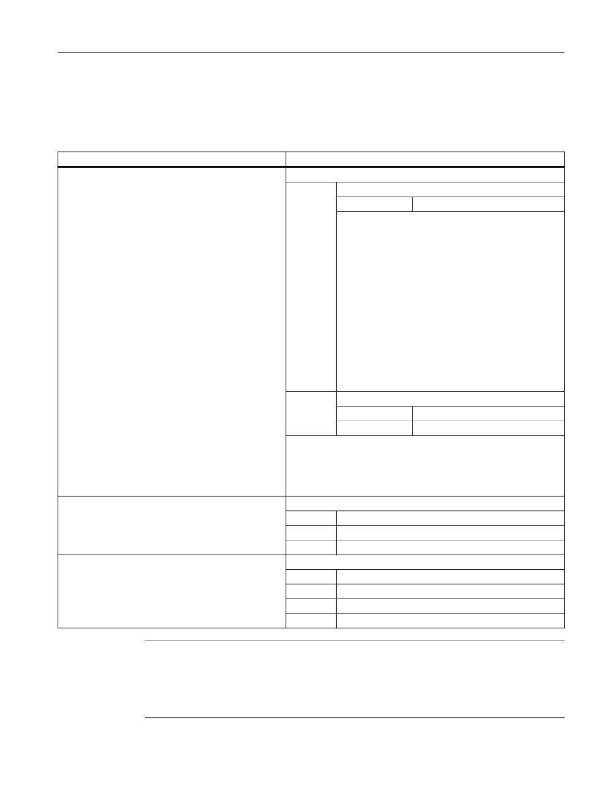
Mode group, channel, program operation, reset response
3.6 Program control
Setting data
Definition of stop situations
The stop situations for the configured stop are defined by the following setting data:
Setting data
Meaning
SD42220 $SC_CFG_STOP_ARRAY[<n>] = "<Name>"
NC functions and subprograms before which stops are to be made
<Name>:
Name of the NC function/subprogram
Data type:
STRING
The following are permitted:
• M/H/T/D function calls
The following syntax rules must be observed:
- No address extensions are supported for D.
- The value of the auxiliary function is always a
positive INTEGER value, including 0.
- Negative INTEGER values for the address exten-
sion are permitted for M functions.
Example: "M[-5]=3"
- An asterisk (*) is permitted as a wildcard.
Example: "M[*]=87" / "M*=87"
• Subprogram names
Valid nomenclature: "_N_..."
<n>:
Array index
Data type:
INT
Range of values:
0 ... 19
Examples:
• $SC_CFG_STOP_ARRAY[0] = "M=87"
• $SC_CFG_STOP_ARRAY[1] = "_N_CS_TOOL"
• $SC_CFG_STOP_ARRAY[3] = "_N_MY_TOOL_CHANGE"
SD42222 $SC_CFG_STOP_MASK
G function transitions at which a stop should be made
Bit 0
G0 → G0
Bit 1
G0 → Not-G0
Bit 2
Not-G0 → G0
SD42224 $SC_CFG_STOP_ARRAY_MASK
Release of SD42220 $SC_CFG_STOP_ARRAY[<n>]
Bit 0
Release of SD42220 $SC_CFG_STOP_ARRAY[0]
Bit 1
Release of SD42220 $SC_CFG_STOP_ARRAY[1]
Bit 19
Release of SD42220 $SC_CFG_STOP_ARRAY[19]
Note
The valid nomenclature and syntax rules must be observed when specifying the NC function or
subprogram name.
In the event of an error, alarm 16968 "Machine data $SC_CFG_STOP_ARRAY contains invalid
syntax" is displayed.
Basic functions
Function Manual, 10/2020, 6FC5397-2GP40-0BA1
111
Mode group, channel, program operation, reset response
3.6 Program control
Example
$SC_CFG_STOP_MASK = 6
Stop before the selection and deselection
of G0
$SC_CFG_STOP_ARRAY[0]="_N_MY_UP_0"
Stop before the call of subprogram
MY_UP_0
SC_CFG_STOP_ARRAY[1]="M=3"
Stop before the execution of M3
$SC_CFG_STOP_ARRAY_MASK='H0FFF'
Release of SD42220 $SC_CFG_STOP_AR-
RAY bit 0 ... 11
3.6.10.4
Programming
Just as with single block processing, the configured stop also permits switching off the function
in the NC program via the pre-defined SBLOF procedure and switching it on again via the
predefined SBLON procedure.
For further information, see Chapter "Single block (Page 99)".
3.6.10.5
Constraints
Configured stop during simultaneous single block execution
If the "Single block" and "Configured stop" functions are active at the same time, the configured
stop is additive. This means that additional stops by means of the configured stop are retained
and become effective, for example, when the single block stop is prevented by MD10702
$MN_IGNORE_SINGLEBLOCK_MASK.
Stop only in executable NC blocks
Stops by means of the "Configured stop" function can only take effect in executable blocks. They
have no effect in NC blocks which are deleted by the internal block execution.
Stop-preventing situations
Stops are ignored by the configured stop in the following situations:
• Tapping G331/G63 without spindle stop being active.
• Thread cutting G33 is active.
• Retraction motion of the tool is active.
• During an ASUB in the startup.
• During a Safety ASUB.
• Upon occurrence in a conditionally interruptible program area (stop-delay area).
Basic functions
112
Function Manual, 10/2020, 6FC5397-2GP40-0BA1
Mode group, channel, program operation, reset response
3.6 Program control
Synchronized actions
The action part of a synchronized action is not evaluated for the configured stop! An auxiliary
function specified as a stop situation therefore does not result in a program stop upon
occurrence in a synchronized action.
3.6.10.6
Examples
Stop situation: Transition G0 → G0
Parameter assignment
$SC_CFG_STOP_MASK = 1
Stop when transitioning from G0 to G0
Programming example
Program code
N10 G0 X10
N20 G0 X20
N30 G1 X30 F1000
N40 G1 X40
N50 G0 X50
N60 G0 X70
N70 M30
Program flow
NC start
→ The program starts, then stops after reaching position X10 in block N10.
NC start
→ The program is continued, then stopped after position X50 in block N50 is
reached.
NC start
→ The program is continued without further stops until the end of the pro-
gram.
Stop situation: M function
Parameter assignment
$SC_CFG_STOP_ARRAY[3]="M=88"
Stop before execution of auxiliary function M88
$SC_CFG_STOP_ARRAY_MASK='H8'
Release of SD42220 $SC_CFG_STOP_ARRAY bit 3
Program example 1
Program code
N10 G0 X10
N20 G0 X20
N30 G1 X30 F1000
N35 M88
Basic functions
Function Manual, 10/2020, 6FC5397-2GP40-0BA1
113

Mode group, channel, program operation, reset response
3.6 Program control
Program code
N40 G1 X40
N50 G0 X50
N60 M30
Program execution 1
NC start
→ The program starts. Stops at the end of block N30 at position X = 30.
NC start
→ Output of the M function, the program is continued without further stops
until the end of the program.
Program example 2
Program code
N10 G0 X10
N20 G0 X20
N30 G1 X30 M88 F1000
N40 G1 X40
N50 G0 X50
N60 M30
Program execution 2
NC start
→ The program starts. Stops at the end of block N20 at position X = 20.
NC start
→ The output of the M function takes place in block N30, the program is con-
tinued without further stops until the end of the program.
Program example 3
Program code
N10 G0 X10
N20 G0 X20
N30 G1 X30 F1000
N35 WHEN TRUE DO M88
N40 G1 X40
N50 G0 X50
N60 M30
Program execution 3
NC start
→ The program starts and is executed until the end of the program. The aux-
iliary function call in the action part of the synchronized action does not
result in a program stop.
Basic functions
114
Function Manual, 10/2020, 6FC5397-2GP40-0BA1
Mode group, channel, program operation, reset response
3.6 Program control
Stop situation: Subprogram
Parameter assignment
$SC_CFG_STOP_AR-
Stop before execution of the CS_TOOL subprogram
RAY[0]="_N_CS_TOOL"
$SC_CFG_STOP_ARRAY_MASK='H1'
Release of SD42220 $SC_CFG_STOP_ARRAY bit 0
Programming example
Program code
N10 G0 X10
N20 G0 X20
N30 G1 X30 F1000
N35 CS_TOOL
N40 G1 X40
N50 G0 X50
N60 G0 X70
N70 M30
Program flow
NC start
→ The program starts, then stops after reaching position X30 in block N30.
NC start
→ The program is continued without further stops until the end of the pro-
gram.
Stop situation: Tool change with T function
In the following example, the "Configured stop" function is to be used to only stop before
specific tool changes on a turning machine with a tool turret and inactive tool management
system.
Parameter assignment
$MN_MM_TOOL_MANAGEMENT_MASK No memory reserving for tool management
= 0
$MC_TOOL_MANAGEMENT_MASK = 0
Tool management inactive
$MC_TOOL_CHANGE_MODE = 0
Tool change with T number
$SC_CFG_STOP_ARRAY[0] = 'T=1'
Stop before switching in tool T=1
$SC_CFG_STOP_ARRAY[1] = 'T=3'
Stop before switching in tool T=3
$SC_CFG_STOP_ARRAY_MASK = 3
Release of SD42220 $SC_CFG_STOP_ARRAY bit
0 and 1
Programming example
Program code
Comment
N50 G0 Z0
N100 G0 Z10 X20
; Stop at Z10 X20
Basic functions
Function Manual, 10/2020, 6FC5397-2GP40-0BA1
115

Mode group, channel, program operation, reset response
3.6 Program control
Program code
Comment
N200 T1
; NC start required to continue the program and for tool
change
N250 G1 X9
N300 G1 Z100
N350 G1 X20
N400 G1 Z10
; No stop because T2 not in $SC_CFG_STOP_ARRAY
N500 T2
N550 G1 X9
N600 G1 Z100
N650 G1 X20
N700 G1 Z10
; Stop at Z10 X20
N800 T3
; NC start required to continue the program and for tool
change
N850 G1 X8
N900 G1 Z100
N950 G1 X20
N1000 G1 Z10
N2000 M30
; Stop due to end of program
Note
Without tool management, the T functions are treated like any other auxiliary functions. This
allows a selective stop before a specific tool change (as shown in the example).
This is not possible with tool management. Here stops can only be made before each tool change
(with the stop situation "T[*]=*").
Basic functions
116
Function Manual, 10/2020, 6FC5397-2GP40-0BA1

Mode group, channel, program operation, reset response
3.7 Block search, types 1, 2, and 4:
3.6.11
Status
The currently selected settings for program control can be read through system variables:
• In the part program via preprocessing variables:
System variable
Type
Meaning
$P_ISTEST
BOOL
Program test active
$P_DRYRUN
BOOL
Dry run feedrate active
$P_ISRG0
BOOL
Reduced rapid traverse active
$P_ISPROGSTOP
BOOL
Programmed stop 1 (M01) active
$P_ISDRF
BOOL
Handwheel offset active
$P_ISSKIP
BOOL
Skip block active
• In the part program and in synchronized actions via the main run variable:
System variable
Type
Meaning
$AC_PROGINF
INT
Active program control
The value is bit-coded. These individual bits have the following mean-
ing:
Bits 0 ... 9
Skip level 0 ... 9 active
Bit 10
Dry run feedrate active
Bit 11
Programmed stop 1 (M01) active
Bit 12
Handwheel offset active
Bit 13
Single block active
Bit 14
Reduced rapid traverse active
Bit 15
Feed stop active
Bit 16
Program test active
Bit 17
Associated help function (M-1) active
Bit 18
Configured stop active
Further information: List Manual System Variables
3.7
Block search, types 1, 2, and 4:
Function
Block search offers the possibility of starting part program execution from almost any part
program block.
This involves the NC rapidly performing an internal run through the part program (without
traversing motions) to the selected target block during block search. Here, every effort is made
to achieve the exact same control status as would result at the target block during normal part
program execution (e.g. with respect to axis positions, spindle speeds, loaded tools, NC/PLC
interface signals, variable values) in order to be able to resume automatic part program
execution from the target block with minimum manual intervention.
Basic functions
Function Manual, 10/2020, 6FC5397-2GP40-0BA1
117
Mode group, channel, program operation, reset response
3.7 Block search, types 1, 2, and 4:
Block search types
• Type 1: Block search without calculation
Block search without calculation is used to find a part program block in the quickest possible
way. No calculation of any type is performed. The control status at the target block remains
unchanged compared to the status before the start of the block search.
• Type 2: Block search with calculation at contour
Block search with calculation at contour is used to enable the programmed contour to be
approached in any situation. On NC Start, the start position of the target block or the end
position of the block before the target block is approached. This is traversed up to the end
position. Processing is true to contour.
• Type 4: Block search with calculation at block end point
Block search with calculation at block end point is used to enable a target position (e.g. tool
change position) to be approached in any situation. The end position of the target block or
the next programmed position is approached using the type of interpolation valid in the
target block. This is not true to contour.
Only the axes programmed in the target block are moved. If necessary, a collision-free initial
situation must be created manually on the machine in "JOG REPOS" mode before the start of
further automatic part program execution.
• Type 5: Block search with calculation in "Program test" (SERUPRO) mode
SERUPRO (search run by programtest) is a cross-channel block search with calculation. Here,
the NC starts the selected part program in "Program test" mode. On reaching the target block,
the program test is automatically deselected. This type of block search also enables
interactions between the channel in which the block search is being performed and
synchronized actions as well as with other NC channels.
See Section "Block search Type 5 (SERUPRO) (Page 131)".
Note
For further explanations regarding the block search, see Section "Behavior during block search
(Page 738)."
Subsequent actions
After completion of a block search, the following subsequent actions may occur:
• Type 1 - Type 5: Automatic Start of an ASUP
When the last action block is activated, a user program can be started as an ASUP.
• Type 1 - Type 4: Cascaded block search
A further block search with a different target specification can be started from "Search target
found".
Basic functions
118
Function Manual, 10/2020, 6FC5397-2GP40-0BA1
Mode group, channel, program operation, reset response
3.7 Block search, types 1, 2, and 4:
3.7.1
Description of the function
Basic sequence for type 2 or type 4
1. User: Activation of the block search type 2 or type 4 (block search with calculation to ...) via
the user interface
2. Search for the target block with collection of auxiliary functions
3. Stop after "Search target found ⇒ display of alarm 10208 "Continue program with NC start"
4. User: NC start to execute the action blocks ⇒ DB21, ... DBX7.1 = 1 (NC start)
5. Execution of the action blocks
6. Last action block is activated ⇒ Automatic start of /_N_CMA_DIR/_N_PROG_EVENT_SPF
(default) as an ASUB
7. Last ASUB block (REPOSA) is activated ⇒ DB21, ... DBX32.6 = 1 (last action block active)
8. Optional: Execution of user-specific requirements via PLC user program
9. Display of the alarm 10208 "Continue program with NC start"
10.User: Continue program with NC start ⇒ DB21, ... DBX7.1 = 1 (NC start)
Search target not found
If the search target is not found, alarm 15370 "Search target not found during block search" is
displayed and the block search is canceled.
Basic functions
Function Manual, 10/2020, 6FC5397-2GP40-0BA1
119
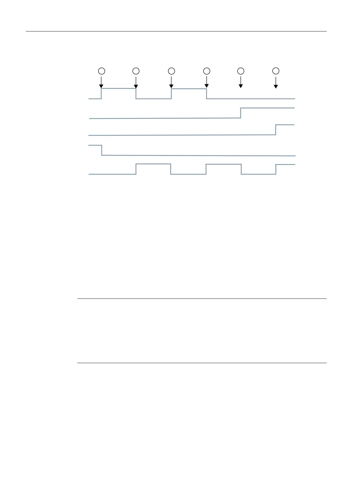
Mode group, channel, program operation, reset response
3.7 Block search, types 1, 2, and 4:
Time sequence
%ORFN VHDUFK DFWLYH
'%
'%;
$FWLRQ EORFN DFWLYH
'%
'%;
/DVW DFWLRQ EORFN DFWLYH
'%
'%;
&KDQQHO VWDWXV UHVHW
'%
'%;
&KDQQHO VWDWXV LQWHUUXSWHG
'%
'%;
①
Start block search
②
Search target 1 found
③
Start block search
④
Search target 2 found
⑤
NC start - output action blocks
⑥
Last action block
Action blocks
During a block search type 2 or type 4 (block search with calculation to ...), actions such as tool
(T, D), spindle (S), feedrate programming or M function outputs are collected. With NC start to
execute the action blocks, the collected actions are output to the PLC.
Note
With NC start for the action blocks, the spindle programming collected during block search type
2 or type 4 (block search with calculation to ...) (S value, M3 / M4 / M5 / M19, SPOS) becomes
active.
The user has to ensure in the PLC user program that the tool can be operated or the spindle
programming is reset or not output:
DB31, ... DBX2.2 = 1 (spindle reset).
Constraints
Continuation mode after block search type 4
If initial programming of an axis is performed incrementally to a block search type 4 (block
search with calculation to block end point), the programmed incremental value can be added to
Basic functions
120
Function Manual, 10/2020, 6FC5397-2GP40-0BA1
Mode group, channel, program operation, reset response
3.7 Block search, types 1, 2, and 4:
the position value collected up to the search target or to the current actual value of the axis. The
setting is realized via:
SD42444 $SC_TARGET_BLOCK_INCR_PROG
The setting data is evaluated with NC start for outputting the action blocks.
Single block
If you do not wish to stop after each action block after the search target during block search type
2 or type 4 (block search with calculation to ...) is found and while function "Single block"
(DB21, ... DBX0.4 == 1 (activate single block)) is active, this behavior can be deactivated in
machine data:
MD10702 $MN_IGNORE_SINGLEBLOCK_MASK, Bit 3 = 1 (ignore signal block for action blocks)
Interface signal "start block active"
The interface signal is only set during block search type 2 (block search with calculation to
contour):
• DB21, ... DBX32.4 = 1 (approach block active)
For block search type 4 (block search with calculation to block end point), the interface signal
is not set because no approach block is generated here (approach block equal to target block).
Type of interpolation of the target block
For a block search type 4 (block search with calculation to block end point), the start
movement is performed in the interpolation type valid in the target block. For interpolation
types other than linear interpolation (G0 or G1), the start movement can be canceled with an
alarm (e.g. circle end point error in circular interpolation G2 or G3).
3.7.2
Block search in connection with other NCK functions
3.7.2.1
ASUB after and during block search
Block search type 2 and type 4: Synchronization of the channel axes
If an ASUP is started after a block search type 2 or type 4 (block search with calculation to ...)",
the actual positions of all channel axes are synchronized.
Effect
If the following system variables are read in the ASUP, they contain the following values:
• $P_EP: Current actual position of the channel axis in the WCS
• $AC_RETPOINT: Collected block search position of the channel axis in the WCS
Basic functions
Function Manual, 10/2020, 6FC5397-2GP40-0BA1
121
Mode group, channel, program operation, reset response
3.7 Block search, types 1, 2, and 4:
Block search type 2: ASUP completion
For block search type 2 (block search with calculation at contour), the following
command REPOSA (reapproach to the contour; linear; all channel axes) must be programmed
by completion of the ASUP.
Effect
• All channel axes are moved to their search position that was collected during the block search.
• $P_EP == "collected block search position of the channel axis (WCS)"
Block search type 4: REPOS behavior
After block search type 4 (block search with calculation to block end point), no automatic
repositioning is triggered during the period described by the beginning and end by the REPOS
command:
• Begin: NC/PLC interface signals DB21, ... DBX32.6 == 1 (last action block active)
• End: Continuing program execution with NC start.
The start point of the approach movement are the current positions of the channel axes at the
time of the NC start command. The end point results from the other transversing movements
programmed in the part program.
For block search type 4, no approach movement is generated by the NC.
Effect:
• After exiting the ASUP, the system variable $P_EP (programmed end position) contains the
actual position, at which the channel axes were positioned by the ASUP or manually (mode:
JOG).
$P_EP == "current actual position of the channel axis in the WCS
3.7.2.2
PLC actions after block search
If all action blocks have been executed by the NC and actions by the PLC, e.g. starting an ASUP
to perform a tool change, or of the operator, e.g. restore, are possible, the following channel-
specific NC/PLC interface signal is set:
• DB21, ... DB32.6 = 1 (last action block active)
Parameterizing the time of alarm output
To inform the operator that NC start is required in the channel to continue program execution,
alarm 10208 "Continue program with NC start" is displayed.
Basic functions
122
Function Manual, 10/2020, 6FC5397-2GP40-0BA1

Mode group, channel, program operation, reset response
3.7 Block search, types 1, 2, and 4:
When the alarm is displayed can be set via machine data:
MD11450 $MN_SEARCH_RUN_MODE, Bit 0 = <value>
<val-
Meaning
ue>
0
With the change of the last action block after a block search, the following takes place:
• Execution of the part program is stopped
• DB21, ... DBB32.6 = 1 (last action block active)
• Display alarm 10208
1
With the change of the last action block after a block search, the following takes place:
• Execution of the part program is stopped
• DB21, ... DBB32.6 = 1 (last action block active)
• Only display alarm 10208 if DB21, ... DBX1.6 == 1 (PLC action ended)
In combination with the alarm, the following interface signals are set:
• DB21, ... DBX36.7 = 1 (NC alarm with machining standstill is pending)
• DB21, ... DBX36.6 = 1 (NC alarm channel-specific is pending)
3.7.2.3
Spindle functions after block search
Control system response and output
Whether the spindle-specific auxiliary functions collected during block search are automatically
output to the PLC in the action block or user-specifically at a later time can be set in
MD11450 $MN_SEARCH_RUN_MODE, Bit 2 = <value>
<val-
Meaning
ue>
0
Output of spindle-specific auxiliary functions collected during block search (M3, M4, M5, M19,
M70) in action blocks.
1
The spindle-specific auxiliary functions collected during block search are not output in the
action block.
They can be output at a later time, for example, in an ASUP. The spindle-specific auxiliary
functions collected are stored in system variables:
System variables
The spindle-specific auxiliary functions collected during block search are stored in the following
system variables:
System variable
Description
$P_SEARCH_S [ <n> ]
The spindle speed or cutting speed last programmed
$P_SEARCH_SDIR [ <n> ]
Spindle direction last programmed
$P_SEARCH_SGEAR [ <n> ]
Gear stages last programmed M function
$P_SEARCH_SMODE [ <n> ]
Spindle mode last programmed
Basic functions
Function Manual, 10/2020, 6FC5397-2GP40-0BA1
123

Mode group, channel, program operation, reset response
3.7 Block search, types 1, 2, and 4:
System variable
Description
$P_SEARCH_SPOS [ <n> ]
Spindle position or traverse path last programmed by means
of M19, SPOS or SPOSA
$P_SEARCH_SPOSMODE [ <n> ]
Position approach mode last programmed by means of M19,
SPOS, or SPOSA
<n>: Spindle number
For later output of the spindle-specific auxiliary functions, the system variables can be read, for
example, in an ASUB, and output after output of the action blocks:
DB21, ... DBX32.6 == 1 (last action block active)
Note
The contents of the system variables $P_S, $P_DIR and $P_SGEAR may be lost after block search
due to synchronization operations.
For more detailed information on ASUB, block search and action blocks, see Sections "Output
suppression of spindle-specific auxiliary functions (Page 743)" and "Program test (Page 89)."
3.7.2.4
Reading system variables for a block search
In part programs, values can be read from the areas processing, main run, or servo/drive via
system variables:
$P_...
Preprocessing-related system variables contain programmed values
$A_...
Main-run-related system variables contain current values
$V_...
Servo/drive-related system variables contain current values
Because no blocks enter the main run during a block search of type 2 and type 4 (block search
with calculation to ...), main run and servo/drive-related system variables are not changed
during the block search. Where necessary, for these system variables, the block search must
specially handled in the NC program by querying whether a block search is active $P_SEARCH
(block search active).
Preprocessing-related system variables provide correct values in all search types.
3.7.3
Automatic start of an ASUB after a block search
Parameter assignment
Making the function effective
The automatic ASUB start after a block search is activated by the following MD setting:
MD11450 $MN_SEARCH_RUN_MODE, bit 1 = 1
Program to be activated
In the default setting, the program _N_PROG_EVENT_SPF is activated from the directory
_N_CMA_DIR as ASUB after the block search by changing the last action block. If another
Basic functions
124
Function Manual, 10/2020, 6FC5397-2GP40-0BA1

Mode group, channel, program operation, reset response
3.7 Block search, types 1, 2, and 4:
program is to be activated, then the name of this user program must be entered in the following
machine data:
MD11620 $MN_PROG_EVENT_NAME
Behavior when the single-block processing is set
The following channel-specific machine data are used to set whether the activated ASUP will be
processed without interruption although single-block processing is set or whether single-block
processing will be activated:
MD20106 $MC_PROG_EVENT_IGN_SINGLEBLOCK, bit 4 = <value>
<val-
Meaning
ue>
0
Single-block processing is active.
1
Single-block processing is suppressed.
Behavior when the read-in disable is set
The channel-specific machine data is used to set whether the ASUP will be processed without
interruption although read-in disable (DB21, ... DBX6.1 = 1) is set, or whether the read-in disable
will be effective:
MD20107 $MC_PROG_EVENT_IGN_INHIBIT, Bit 4 = <value>
<val-
Meaning
ue>
0
Read-in disable is active.
1
Read-in disable is suppressed.
Note
For more information on parameterizing MD11620, MD20108, and MD20107, see Section
"Parameterization (Page 66)."
Programming
The event by which the ASUP has been started is stored in the system variable $P_PROG_EVENT.
On automatic activation after a block search, $P_PROG_EVENT returns the value "5."
Sequence
Sequence of automatic start of an ASUB after a block search
1. User: Activation of the block search type 2 or type 4 (block search with calculation to ...) via
the operator interface
2. Search for the target block with collection of auxiliary functions
3. Stop after "Search target found ⇒ display of alarm 10208 "Continue program with NC start"
4. User: NC start to execute the action block s⇒ DB21, ... DBX7.1 = 1 (NC start)
5. Execution of the action blocks
Basic functions
Function Manual, 10/2020, 6FC5397-2GP40-0BA1
125
Mode group, channel, program operation, reset response
3.7 Block search, types 1, 2, and 4:
6. Last action block is activated ⇒ Automatic start of /_N_CMA_DIR/_N_PROG_EVENT_SPF
(default) as an ASUB.
7. Last ASUP block (REPOSA) is activated ⇒ DB21, ... DBX32.6 = 1 (last action block active)
8. Optional: Execution of user-specific requirements via PLC user program
9. Display of the alarm 10208 "Continue program with NC start"?
Note
With MD11450 $MN_SEARCH_RUN_MODE, Bit 0 == 1, alarm 10208 will only be output after
enabling by the PLC user program (DB21, ... DBX1.6 = 1 (PLC action ended)).
10.User: Continue program with NC start ⇒ DB21, ... DBX7.1 = 1 (NC start)
3.7.4
Cascaded block search
Functionality
The "Cascaded block search" function can be used to start another block search from the status
"Search target found". The cascading can be continued after each located search target as often
as you want and is applicable to the following block search functions:
• Type 1 block search without calculation
• Type 2 block search with calculation at contour
• Type 3 block search with calculation at block end point
Note
Another "cascaded block search" can be started from the stopped program execution only if
the search target has been found.
Activation
The "cascaded block search" is configured in the existing machine data:
MD11450 $MN_SEARCH_RUN_MODE
• The cascaded block search is enabled (i.e. several search targets can be specified)
with Bit 3 = 0 (FALSE).
• For compatibility reasons, the cascaded block search can be disabled with Bit 3 = 1 (TRUE).
By default, the cascaded block search is set with Bit 3 = 0.
Execution behavior
Search target found, restart block search
Basic functions
126
Function Manual, 10/2020, 6FC5397-2GP40-0BA1
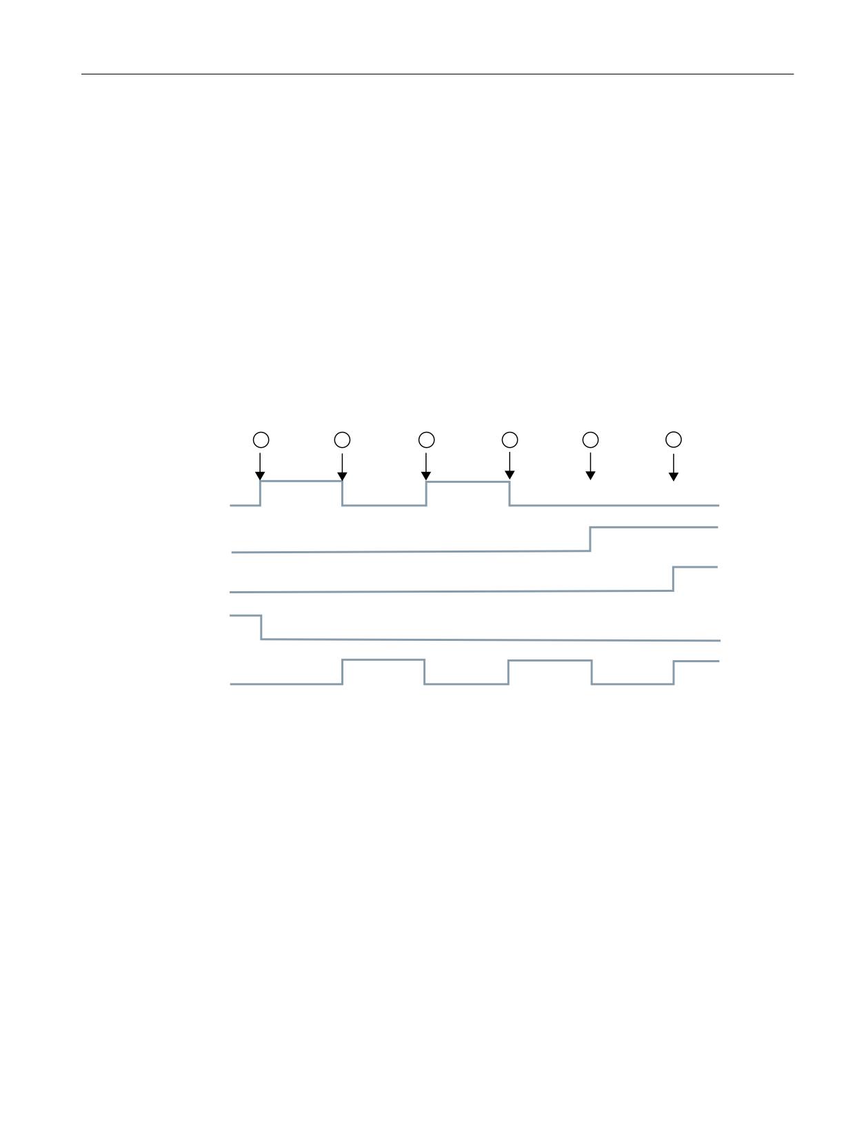
Mode group, channel, program operation, reset response
3.7 Block search, types 1, 2, and 4:
When the search target is reached, the program execution is stopped and the search target
displayed as current block. After each located search target, a new block search can be repeated
as often as you want.
Changing the search target specifications
You can change the search target specifications and block search function before every block
search start.
Example: Execution sequence with cascaded block search
• RESET
• Block search up to search target 1
• Block search up to search target 2 → "Cascaded block search"
• NC Start for output of the action blocks → Alarm 10208
• NC Start → Continue program execution
%ORFN VHDUFK DFWLYH
'%
'%;
$FWLRQ EORFN DFWLYH
'%
'%;
/DVW DFWLRQ EORFN DFWLYH
'%
'%;
&KDQQHO VWDWXV UHVHW
'%
'%;
&KDQQHO VWDWXV LQWHUUXSWHG
'%
'%;
Figure 3-2
Chronological order of interface signals
3.7.5
Examples for block search with calculation
Selection
From the following examples, select the type of block search that corresponds to your task.
Basic functions
Function Manual, 10/2020, 6FC5397-2GP40-0BA1
127
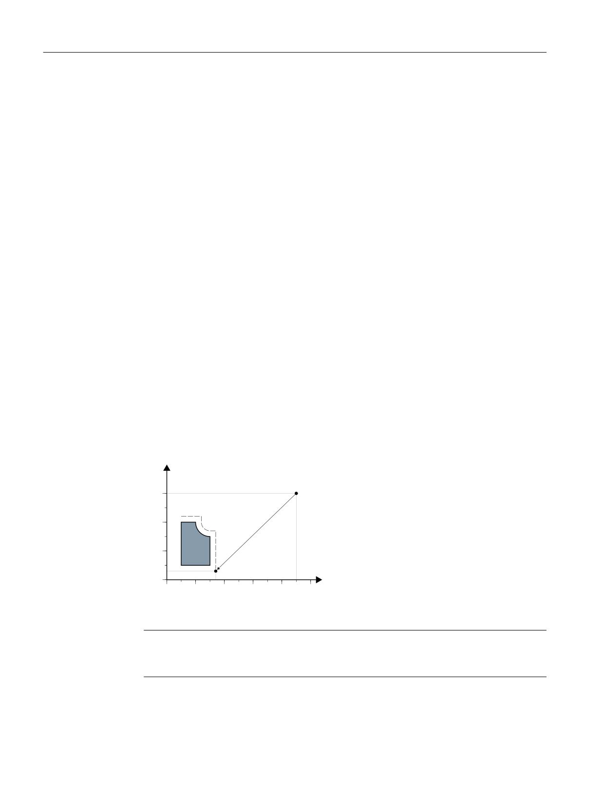
Mode group, channel, program operation, reset response
3.7 Block search, types 1, 2, and 4:
Type 4 block search with calculation at block end point
Example with automatic tool change after block search with active tool management:
1. Set machine data:
MD11450 $MN_ SEARCH_RUN_MODE to 1
MD11602 $MN_ASUP_START_MASK Bit 0 = 1 (ASUP Start from stopped state)
2. Select ASUP "BLOCK_SEARCH_END" from the PLC via FB4 (see also Function Manual "PLC and
Basic Program", Section "Basic PLC program").
3. Load and select part program "WORKPIECE_1".
4. Block search to block end point, block number N220.
5. HMI signals "Search target found".
6. NC Start for output of action blocks.
7. With the PLC signal:
DB21... DB32.6 (last action block active)
the PLC starts ASUB "BLOCK_SEARCH_END" via FC9 (see also Function Manual "PLC and Basic
Program", Section "Basic PLC program").
8. After the end of the ASUP (can be evaluated, e.g. via M function M90 to be defined, see
example for block N1110), the PLC sets signal
DB21, ... DBX1.6 (PLC action complete).
Alternatively, NC/PLC interface signal:
DB21-DB30 DBB318 bit 0 (ASUP is stopped)
can be scanned.
As a result, Alarm 10208 is displayed, i.e. other actions can now be performed by the
operator.
9. Manual operator actions (JOG, JOG-REPOS, overstoring)
10.Continue part program with NC Start.
\
7RRO FKDQJH SRLQW
$SSURDFK PRYHPHQW
7DUJHW EORFN 1
$SSURDFK SRLQW
[
Figure 3-3
Approach motion for block search to block end point (target block N220)
Note
"Block search at contour" with target block N220 would generate an approach motion to the
tool change point (start point of the target block).
Basic functions
128
Function Manual, 10/2020, 6FC5397-2GP40-0BA1
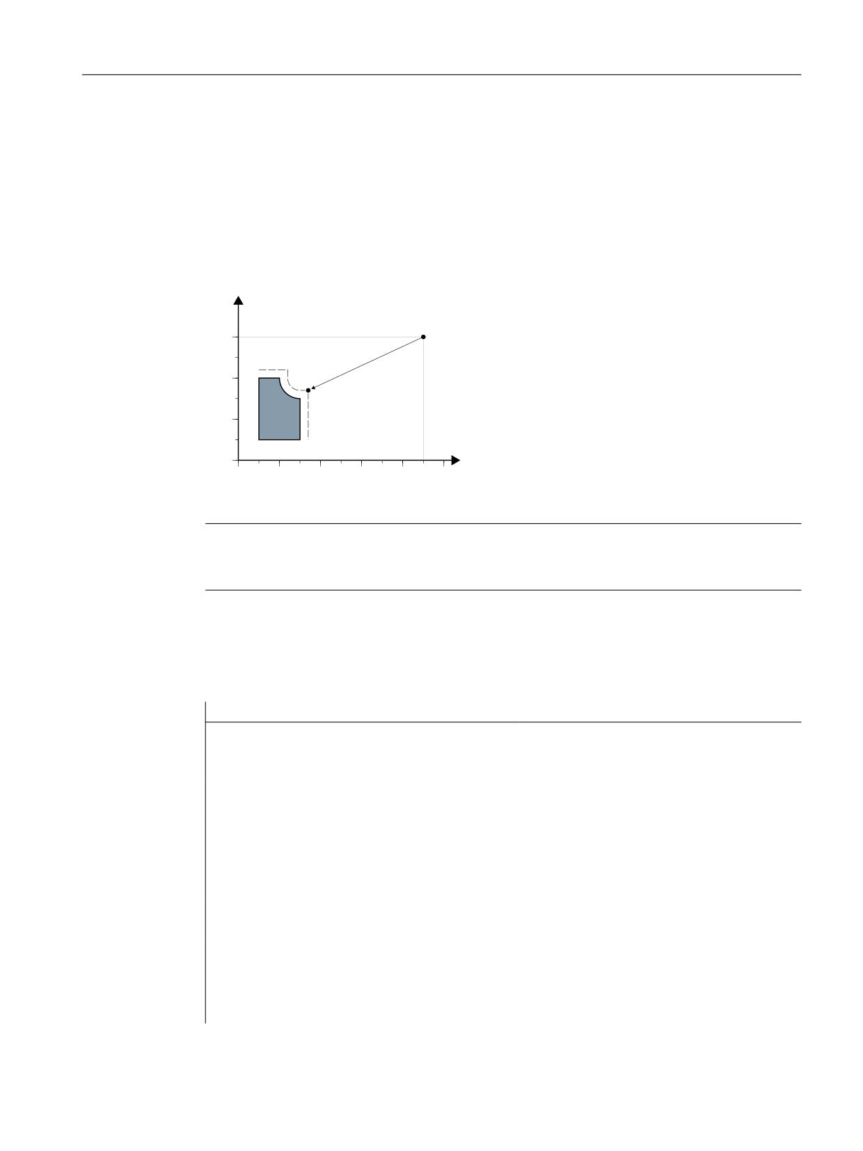
Mode group, channel, program operation, reset response
3.7 Block search, types 1, 2, and 4:
Type 2 block search with calculation at contour
Example with automatic tool change after block search with active tool management:
1. to 3.
Same as example for Type 4 block search
4.
Block search at contour, block number N260
5. to 10.
Same as example for Type 4 block search
\
7RRO FKDQJH SRLQW
$SSURDFK PRYHPHQW
$SSURDFK SRLQW
[
Figure 3-4
Approach motion for block search at contour (target block N260)
Note
"Block search to block end point" with target block N260 would result in Alarm 14040 (circle end
point error).
Part programs for Type 4 and Type 2
PROC WORKPIECE_1
Program code
Comment
; Main program
;Machine contour section 1 with "CUTTER_1"tool
N100 G0 G40 X200 Y200
; Deselect radius compensation
N110 Z100 D0
; Deselect length correction
;End of contour section 1
;
;Machine contour section 2 with "CUTTER_2"tool
N200 T="CUTTER_2"
; Preselect tool
N210 WZW
; Call tool change routine
N220 G0 X170 Y30 Z10 S3000 M3 D1
; Approach block for contour section 2
N230 Z-5
; Infeed
N240 G1 G64 G42 F500 X150 Y50
; Start point of contour
N250 Y150
Basic functions
Function Manual, 10/2020, 6FC5397-2GP40-0BA1
129
Mode group, channel, program operation, reset response
3.7 Block search, types 1, 2, and 4:
Program code
Comment
N260 G2 J50 X100 Y200
N270 G1 X50
N280 Y50
N290 X150
N300 G0 G40 G60 X170 Y30
; Deselect radius compensation
N310 Z100 D0
; Deselect length correction
End of contour section 2
M30
PROC WZW
;Tool change routine
N500 DEF INT TNR_AKTIV
; Variable for active T number
N510 DEF INT TNR_VORWAHL
; Variable for preselected T number
N520 TNR_AKTIV = $TC_MPP6[9998,1]
; Read T number of active tool
N530 GETSELT(TNR_VORWAHL)
; Read T number of preselected tool
;
;Execute tool change only if tool is not yet active
N540 IF TNR_AKTIV == TNR_VORWAHL GOTOF ENDE
N550 G0 G40 G60 G90 SUPA X450 Y300 Z300 D0
; Approach tool change point
N560 M6
; Execute tool change
;
END: M17
PROC BLOCK_SEARCH_END SAVE
;ASUP for calling the tool change routine after block search
N1000 DEF INT TNR_AKTIV
; Variable for active T number
N1010 DEF INT TNR_VORWAHL
; Variable for preselected T number
N1020 DEF INT TNR_SUCHLAUF
; Variable for T number determined in
; block search
N1030 TNR_AKTIV = $TC_MPP6[9998,1]
; Read T number of active tool
N1040 TNR_SUCHLAUF = $P_TOOLNO
; Read T number determined by block
search
N1050 GETSELT(TNR_VORWAHL)
; Read T number of preselected tool
N1060 IF TNR_AKTIV ==TNR_SUCHLAUF GOTOF ASUP_ENDE
N1070 T = $TC_TP2[TNR_SUCHLAUF]
; T selection by tool name
N1080 WZW
; Call tool change routine
N1090 IF TNR_VORWAHL == TNR_SUCHLAUF GOTOF ASUP_ENDE
N1100 T = $TC_TP2[TNR_VORWAHL]
; Restore T preselection by tool name
ASUP_END:
N1110 M90
; Feedback to PLC
N1120 REPOSA
; ASUP end
Basic functions
130
Function Manual, 10/2020, 6FC5397-2GP40-0BA1
Mode group, channel, program operation, reset response
3.8 Block search Type 5 (SERUPRO)
3.7.6
Constraints
Behavior with compressor function active
If the target block for block search type 2 or type 4 (block search with calculation to ...) is in a
program section in which a compressor function (COMP...) is active, positions are approached
on the path calculated by the compressor on repositioning. These positions must precisely
match the positions on the path programmed in the part program.
If programmed blocks are eliminated from the part program during compression, these blocks
will not be found as the target block in the block search. Alarm 15370 "Search target for block
search not found" is output.
3.8
Block search Type 5 (SERUPRO)
3.8.1
Description of the function
Block search type 5, block search with calculation in the "Program test" mode (SERUPRO, "Search-
Run by Program test") enables a cross-channel block search with calculation at a selectable
interruption point. Taking into account existing program coordination commands, all the status
data required to continue the program in the interrupted channels is determined during
SERUPRO and then the NC and PLC set to a state permitting the program continuation.
Before repositioning with subsequent continuation of the program execution, all the output
states that may still be required can be automatically generated via a user-specific ASUP.
Channels
In combination with the HMI, SERUPRO is provided for the following channels:
• For the current SERUPRO channel only (1)
• For all channels with the same workpiece name as the SERUPRO channel (2)
• For all channels with the same mode group as the SERUPRO channel (3)
• For all channels of the NCU (4)
The scope of channels for SERUPRO is selected by means of configuration file maschine.ini, in
Section [BlockSearch]:
Section [BlockSearch]
Enable block search function for HMI and select block search configuration
SeruproEnabled=1
;SERUPRO softkey available for HMI. Default value is (1)
SeruproConfig=1
;Number (1) to (4) of above indicated channel grouping. Default value is (1)
All other channels started with SERUPRO are operated in "Self-Acting SERUPRO" mode. Only the
channel in which a target block has been selected can be started with a block search in SERUPRO
mode.
Basic functions
Function Manual, 10/2020, 6FC5397-2GP40-0BA1
131
Mode group, channel, program operation, reset response
3.8 Block search Type 5 (SERUPRO)
Activation
SERUPRO is activated via the HMI. SERUPRO is operated using the "Prog.Test Contour" softkey.
SERUPRO uses REPOS to approach the target block.
Chronological sequence of SERUPRO
1. Via HMI, softkey "Pog. test contour" and the search target are operated.
2. The NC now automatically starts the selected program in "Program test" mode.
- In this mode, axes are not traversed.
- Auxiliary functions $A_OUT and the direct PLC IO are output.
- The auxiliary functions of the target block are not output.
3. The NC stops at the beginning of the target block, deselects the program test internally, and
displays the stop condition "Wait: Search target found".
4. If the user-specific ASUP "PROG_EVENT.SPF" is available, it is started automatically.
5. Repositioning is performed with the next NC start (REPOS).
The REPOS operation is performed via a system ASUP and can be extended using the "Editable
ASUP" function.
Boundary conditions for block search SERUPRO
The SERUPRO function may only be activated in "AUTOMATIC" mode and may only be aborted in
program state (channel state RESET).
If in normal mode only the PLC starts commonly several channels, then this can be simulated by
SERUPRO in each channel.
With machine data setting:
MD10708 $MN_SERUPRO_MASK, bit 1 = 0,
alarm 16942: "Channel %1 Start program command action %2<ALNX> not possible"
aborts the simulation if part program command START is used.
Machine data:
MD10707 $MN_PROG_TEST_MASK
allows shutdown in the stopped state and has no effect on the SERUPRO operation. The default
setting allows program testing to be deactivated only in the RESET state.
Note
After program testing has been deactivated, a REPOS operation is initiated that is subject to the
same restrictions as a SERUPRO approach operation. Any adverse effects can be inhibited using
an ASUP.
Basic functions
132
Function Manual, 10/2020, 6FC5397-2GP40-0BA1
Mode group, channel, program operation, reset response
3.8 Block search Type 5 (SERUPRO)
Controlling SERUPRO behavior
For the functions listed below as an example, the SERUPRO behavior can be set specifically for
the NC:
• Programmed stop (M0)
• Program coordination command START
• Group SERUPRO
• Cross-channel exiting of SERUPRO
• Override
MD10708 $MN_SERUPRO_MASK = <behavior with SERUPRO>
Channel-specific basic settings for SERUPRO
The channel-specific basic settings are normally specified with the following machine data after
a part program start:
MD20112 $MC_START_MODE_MASK= basic settings>
You can specify your own basic settings for SERUPRO which replace the basic settings from
MD20112:
MD22620 $MN_START_MODE_MASK_PRT = <SERUPRO basic settings>
The SERUPRO basic settings must be explicitly released via:
MD22621 $MC_ENABLE_START_MODE_MASK_PRT = 1
NC/PLC interface signal "Block search via program test is active"
The block search via program test is displayed using the NC/PLC interface signal:
DB21, ... DBX318.1 == 1
The interface signal is set from the start of the block search until the target block is inserted into
the main run.
For user-defined ASUP after the SERUPRO operation
Note
If the machine manufacturer decides to start an ASUP after the SERUPRO operation as described
in point 7, the following must be observed:
Stopped status acc. to point 6:
Machine data:
MD11602 $MN_ASUP_START_MASK
and
MD11604 $MN_ASUP_START_PRIO_LEVEL
allow the NC to start the ASUP from the stopped status automatically via the FC9 block.
Basic functions
Function Manual, 10/2020, 6FC5397-2GP40-0BA1
133
Mode group, channel, program operation, reset response
3.8 Block search Type 5 (SERUPRO)
Acknowledgment of FC9 only after completion of REPOS block:
The ASUP can only be signaled as complete from the FC9 block with "ASUP Done" if the REPOS
block has also been completed.
Deselection of assigned REPOS operation after point 8:
The start of the ASUP deselects the assigned REPOS operation!
Therefore, the ASUP should be ended with REPOSA in order to retain the REPOS operation.
Deleting an unwanted REPOS operation:
The unwanted REPOS operation is deleted by completing the ASUP with M17 or RET.
Special handling of ASUP:
As a basic rule, an ASUP that ends with REPOS and is started from stopped state receives special
treatment.
The ASUP stops automatically before the REPOS block and indicates this via:
DB21, ... DBX318.0 (ASUP is stopped)
Automatic ASUP start
The ASUP in path:
/_N_CMA_DIR/_N_PROG_EVENT_SPF
is started automatically in SERUPRO approach with machine data:
MD11450 $MN_SEARCH_RUN_MODE, bit 1 = 1
according to the following sequence:
1. The SERUPRO operation has been performed completely.
2. The user presses "NC start".
3. The ASUP is started.
4. The NC stops automatically before the REPOS part program command and the
message "Press NC start to continue the program" appears.
5. The user presses "NC start" again.
6. The NC executes the repositioning motion and continues the part program at the target
block.
Note
The automatic ASUP start with MD11450 requires Starts to continue the program.
The procedure is in this respect similar to other block search types.
Basic functions
134
Function Manual, 10/2020, 6FC5397-2GP40-0BA1

Mode group, channel, program operation, reset response
3.8 Block search Type 5 (SERUPRO)
3.8.2
Repositioning to the contour (REPOS)
The "Reposition to the contour" (REPOS) function can be used to continue an interrupted
machining at the interrupted location. Unlike REPOS, SERUPRO permits the "refetching" or
"repetition" of a program section. For this purpose, once SERUPRO has found the target block,
the contour is positioned at the location selected with REPOS mode and the machining
continued.
SERUPRO: Set REPOS response
The REPOS behavior, i.e. the behavior in the repositioning block, is set with the following
machine data:
MD11470 $MN_REPOS_MODE_MASK = <REPOS mode>
<REPOS mode>
Bit
Value
Meaning
0
0
An interrupted delay time is repeated
1
An interrupted delay time is continued
1
-
Reserved
2
0
DB31, ... DBX10.0 (REPOS delay) not considered in the repositioning deceleration
block.
1
DB31, ... DBX10.0 (REPOS delay) considered in the repositioning deceleration block.
3
0
SERUPRO: Only path axes traverse in the repositioning block
1
SERUPRO: Path and positioning axes traverse concurrently in the repositioning
block
4
0
REPOS: Only path axes traverse in the repositioning block
1
REPOS: Path and positioning axes traverse concurrently in the repositioning block
5
0
During the interruption, changed feedrates and spindle speeds act only after the
first part program block following the interruption location
1
Modified feedrates and spindle speeds during the interruption are valid immedi-
ately from the interruption point onward, i.e. they are already valid in the residual
block and are given priority. This behavior relates to every REPOS operation.
6
0
SERUPRO: In the repositioning block, neutral axes and positioning spindles traverse
as path axes.
1
SERUPRO: In the repositioning block, neutral axes and positioning spindles traverse
as command axes.
Neutral axes and positioning spindles are repositioned after SERUPRO.
For neutral axes, where it is not permissible to reposition them, the REPOS delay
must be set: DB31, ... DBX10.0 = 1 (REPOS delay)
7
0
The REPOS delay is not enabled.
1
The REPOS delay is enabled.
Axes with active REPOS delay (DB31, ... DBX10.0 == 1), which are neither geometry
nor orientation axes, are not traversed when repositioning.
Basic functions
Function Manual, 10/2020, 6FC5397-2GP40-0BA1
135

Mode group, channel, program operation, reset response
3.8 Block search Type 5 (SERUPRO)
CAUTION
Risk of collision
MD11470 $MN_REPOS_MODE_MASK, Bit 3 or Bit 4 = 1
The user alone is responsible for ensuring that the concurrent traversal of the axes in the
repositioning block does not cause any collision on the machine.
Repositioning with controlled REPOS
The REPOS mode can be specified for the path axes via the NC/PLC interface:
DB21, ... DBX31.0 - 2 (REPOS mode)
The REPOS mode is programmed in the NC program, and defines the approach behavior (see
Section "Repositioning with controlled REPOS (Page 142)").
The REPOS behavior of individual axes can also be controlled via NC/PLC interface signals, and
must be enabled using machine data:
MD11470 $MN_REPOS_MODE_MASK BIT 2=1.
Path axes cannot be influenced individually. For all other axes that are not geometry axes, REPOS
of individual axes can be prevented temporarily and also delayed. NC/PLC interface signals can
be used to subsequently re-enable or to continue blocking individual channel axes that REPOS
would like to traverse.
DANGER
Risk of collision
Signal DB31, ... DBX2.2 (delete distance-to-go) produces the following dangerous behavior
when function "Prevent repositioning of individual axes" is selected:
MD11470 $MN_REPOS_MODE_MASK.bit 2 == 1
As long as an axis is programmed incrementally after the interruption, the NC approaches
different positions than those approached with no interruption.
See the example below: Axis is programmed incrementally
Basic functions
136
Function Manual, 10/2020, 6FC5397-2GP40-0BA1