SINUMERIK 840D sl. Service - Functions. Manual (2018-2020) - page 17

Extended stop and retract
21.3 ESR executed autonomously in the drive
21.3.5
ESR is enabled via system variable
The ESR response of an axis, configured via drive parameter, must be programmed on a user-
specific basis in a part program/synchronized action using the following axis-specific system
variable:
$AA_ESR_ENABLE[<axis>]
Value
Meaning
1
ESR responses enabled in the drive
0
ESR responses inhibited in the drive
21.3.6
Triggering ESR via system variable
Triggering ESR responses, configured via drive parameter and enabled via
$AA_ESR_ENABLE[<axis>], must be programmed on a user-specific basis in a part program/
synchronized action via the following NC-specific system variable:
$AN_ESR_TRIGGER
Value
Meaning
1
trigger drive-integrated ESR reactions that have been released
0
do not trigger drive-integrated ESR reactions that have been released
Note
The trigger signal must be active in the part program/synchronized action for at least 2 IPO cycles
to ensure that the PROFIdrive telegram is transferred to the drive.
Mapping in the drive unit
System variable $AN_ESR_TRIGGER is mapped to drive parameter p0890.0. Interconnecting
drive parameter p0890.0 with the corresponding information in telegram 390 or 391 to the
Control Unit is realized automatically when the drive unit commissions the ESR reactions.
Further information
For a detailed description of drive parameters, refer to:
SINAMICS S120/S150 List Manual
21.3.7
Feedback of the ESR status
The drive signals back the actual ESR status to the control using the message word (MELDW) of
the cyclic PROFIdrive telegram. In the PLC, the status can be read via system variables and NC/PLC
interface signals.
Axes and spindles
918
Function Manual, 10/2020, 6FC5397-4GP40-0BA1

Extended stop and retract
21.3 ESR executed autonomously in the drive
System variable
The system variables can be evaluated in the part program / synchronized action, for example,
in order to trigger the drive-autonomous ESR (see Section "Triggering ESR via system variable
(Page 918)") or to acknowledge the ESR reactions triggered in the drive (see Section
"Acknowledge ESR reactions (Page 919)").
Interrelationship between signals
MELDW
System variable
NC/PLC interface sig-
Meaning
nal
MELDW.Bit 9
$AA_ESR_STAT.Bit 2
DB31, … DBX95.2
ESR: Reaction triggered or generator operation
active (r0887.12)
(r0887.12)
MELDW.Bit 4
$AA_ESR_STAT.Bit 3
DB31, … DBX95.1
ESR: DC link undervoltage (p1248)
(r0056.15)
MELDW.Bit 2
$AA_ESR_STAT.Bit 4
DB31, … DBX95.3
ESR, generator operation: Speed lower than min-
imum (p2161)
(r2199.0)
21.3.8
Acknowledge ESR reactions
Acknowledging axis-specific drive-independent ESR reactions must be programmed on a user-
specific basis in a part program/synchronized action. After the ESR reaction in the drive has been
completed, an edge change must be generated in the system variables $AA_ESR_ENABLE:
1→0→1. In order that the drive-integrated ESR reactions can be retriggered, the system variable
$AN_ESR_TRIGGER must also be reset to a value of 0.
Axes and spindles
Function Manual, 10/2020, 6FC5397-4GP40-0BA1
919
Extended stop and retract
21.3 ESR executed autonomously in the drive
System variable and drive parameters
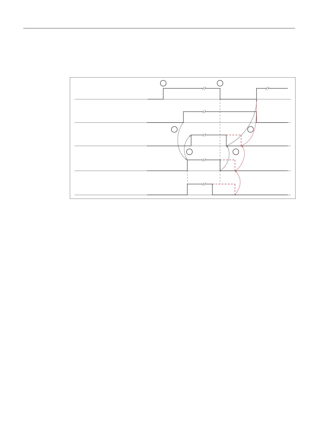
The following diagram shows the relationship between system variables and drive parameters
when triggering and acknowledging ESR reactions.
$$B(65B(1$%/(> D[LV!@
$1B(65B75,**(5
$$B(65B67$7 %,7 > D[LV!@
U
(65 WULJJHUHG
U
(65 UHDFWLRQ EHLQJ H[HFXWHG
① NC: Enabling the ESR reaction via $AA_ESR_ENABLE = 1 (axis-specific)
② NC: Triggering ESR responses via $AN_ESR_TRIGGER = 1
③ Drive: The triggering of the ESR reaction has been detected (CU_STW.2 == 1) ⇒
r0887.12 = 1 AND r0887.13 = 1
Feedback signal to the NC via $AA_ESR_STAT.BIT2 = 1 (axis-specific)
④ NC: Acknowledging the ESR reaction via $AA_ESR_ENABLE = 0 (axis-specific)
Black: At instant in time ④, the ESR reaction no longer runs (r0887.13 == 0) ⇒
⑤ Drive: Reset "ESR triggered": r0887.12 = 0
Feedback signal to the NC via $AA_ESR_STAT.BIT2 = 0 (axis-specific)
⑥ NC: The ESR reaction can be re-enabled ⇒
$AA_ESR_ENABLE = 1 AND $AN_ESR_TRIGGER = 0
Red: At instant in time ④, the ESR reaction still runs (r0887.13 == 1) ⇒
⑤ Drive: "ESR initiated" is only reset (r0887.12 = 0), if the ESR response in the drive has been
completed: r0887.13 == 0
Feedback signal to the NC via $AA_ESR_STAT.BIT2 = 0 (axis-specific)
⑥ See ⑥ above
Figure 21-6
Sequence: Trigger and acknowledge drive-integrated ESR reactions
21.3.9
Configuring ESR in the part program
Configuring drive-autonomous ESR functions "stop" and "retract" can be changed using the
commands from the part program described in the following.
Axes and spindles
920
Function Manual, 10/2020, 6FC5397-4GP40-0BA1

Extended stop and retract
21.3 ESR executed autonomously in the drive
21.3.9.1
Stopping (ESRS)
Syntax
ESRS(<access_1>,<stopping time_1>[,...,<axis_n>,<stopping time_n>])
Meaning
ESRS:
Using the function, drive parameters can be changed regarding the drive-au-
tonomous "stop" ESR function.
Special situations:
• Must be alone in the block
• Triggers a preprocessing stop
• Cannot be used in synchronized actions
• A maximum of five axes can be programmed per function call; n = 5
<axis_n>:
For the specified axis, writes to drive parameter p0888 (configuration): p0888
= 1
Data type:
AXIS
Range of values:
Channel axis name
<stopping
For the axis specified under <Axis_n>, writes to drive parameter p0892 (timer):
time_n>:
P0892 = <stopping time_n>
Unit:
s
Data type:
REAL
Range of values:
0.00 - 20.00
21.3.9.2
Retraction (ESRR)
Syntax
ESRR(<axis_1>,<retraction distance_1>,<retraction
velocity_1>[,...,<axis_n>,<retraction distance_n>,<retraction
velocity_n>])
Axes and spindles
Function Manual, 10/2020, 6FC5397-4GP40-0BA1
921

Extended stop and retract
21.3 ESR executed autonomously in the drive
Meaning
ESRR:
Using the function, drive parameters can be changed regarding the drive-au-
tonomous "retract" ESR function.
Special situations:
• Must be alone in the block
• Triggers a preprocessing stop
• Cannot be used in synchronized actions
• A maximum of five axes can be programmed per function call; n = 5
<axis_n>:
For the specified axis, writes to drive parameter p0888 (configuration): p0888
= 2
Data type:
AXIS
Range of values:
Channel axis name
<retraction
For the axis specified under <Axis_n>, writes to drive parameter p0893 (re-
velocity_n>:
traction speed):
p0893 = (<retraction velocity> based on the currently effective total transmis-
sion ratio converted into the corresponding retraction speed)
Unit:
mm/min, inch/min, degrees/min (depending on the unit of
the axis)
Data type:
REAL
Range of values:
0.00 - MAX
<retraction
For the axis specified under <Axis_n>, writes to drive parameter p0892 (re-
distance_n>:
traction time):
p0892 = <retraction distance_n> / <retraction velocity _n>
Unit:
mm, inches, degrees (depending on the unit of the axis)
Data type:
REAL
Range of values:
MIN - MAX
Note
Retraction speed
It should be ensured that the drive can reach the programmed retraction speed (see parameters
<retraction velocity_n>) within the retraction time (see parameter <retraction distance _n>).
The settings in the following drive parameters should be checked:
• p1082[0...n] (maximum speed)
• p1135[0...n] (OFF3 ramp-down time)
Retraction path
The conversion of the retraction path into a retraction duration for drive parameter p0892 is
performed under the assumption that the retraction motion is triggered at axis standstill (see
"Figure 21-5 Configuring_drive_integrated_generator_operation (Page 917)").
If retraction motion is triggered while the axis is traversing, the actually traversed retraction
distance differs from the programmed retraction distance due to the fact that traversing motion
is superimposed on the retraction motion.
Axes and spindles
922
Function Manual, 10/2020, 6FC5397-4GP40-0BA1
Extended stop and retract
21.3 ESR executed autonomously in the drive
Dependencies
The programmed values for the retraction path and the retraction velocity refer to the load side.
Before writing to the drive parameters these are converted over to the motor side. The
transmission ratio effective in the NC at the execution time is applicable for the conversion. If the
drive-autonomous ESR for an axis is enabled ($AA_ESR_ENABLE[<axis>] == 1), then it is not
permissible to change the axial transmission ratio.
Note
Changing the transmission ratio
If the drive-autonomous ESR is not enabled for an axis ($AA_ESR_ENABLE[<axis>] == 0), then
the axial transmission ratio can be changed. After the change, it is the sole responsibility of the
user/machine manufacturer to appropriately adapt the retraction distance and the retraction
velocity.
See also
Configuring generator operation in the drive (Page 916)
21.3.9.3
Boundary conditions
Description
Consistent parameter change
In order that the drive parameters are consistently effective, in the part program the drive-
autonomous ESR enable signals must be withdrawn before the functions ESRS(...) and
ESRR(...).
Example:
Program code
Comment
N100 $AA_ESR_ENABLE[X1]=0
;Withdraw ESR enable signals
N110 $AA_ESR_ENABLE[Z1]=0
N120 $AA_ESR_ENABLE[Y1]=0
N130 ESRR(X1,20.0,10000.0,Z1,-15.0,20000.0)
;Change ESR parameters
N140 ESRS(Y1,0.5,B1,0.5)
N150 $AA_ESR_ENABLE[X1]=1
;Set ESR enable signals
N160 $AA_ESR_ENABLE[Z1]=1
N170 $AA_ESR_ENABLE[Y1]=1
When executing the functions ESRS(...) and ESRR(...) further execution of the part
program is stopped until writing to the drive parameters has been acknowledged. During this
time, the following message is used as feedback signal for the user: "Wait for drive parameters
from <Function>" is displayed.
Axes and spindles
Function Manual, 10/2020, 6FC5397-4GP40-0BA1
923
Extended stop and retract
21.3 ESR executed autonomously in the drive
Block search with calculation
During the block search with calculation, the functions ESRS(...) and ESRR( ... ) are
collected and executed in the action block.
Block search with calculation in "Program test" (SERUPRO) mode
During SERUPRO, the functions ESRS(...) and ESRR( ... ) are executed immediately.
Reset behavior
The parameter values written using the functions ESRS(...) and ESRR(...) are
overwritten with the parameter values saved in the drive when the drive runs up or for a drive
warm restart.
Drive parameters can be saved from the HMI user interface or in the drive. From the HMI user
interface:
• Operating area "Commissioning" > "Machine data" > "Drive MD" > "Save/Reset" > "Save" >
"Drive object"or "drive unit" or " drive system"
Control power-up (POWER ON)
If the drive-autonomous ESR should already be active after the control has powered up (POWER
ON), then the programming and enable must be realized within one of the ASUBs started from
the PLC - or using the PROGEVENT mechanism.
Further information
For detailed information about event-controlled program calls, refer to:
Function Manual Basic Functions; Mode group, channel, program mode, reset response, event-
driven program calls
21.3.10
ESR and Safety Integrated
Delay times
In order that drive-integrated ESR reactions in conjunction with Safety Integrated are executed
before the safety reactions associated with STOP E, STOP F or communication failure, then the
corresponding delay times regarding safety reactions must be configured in the control and in
the drive.
Delay times are configured in the controller using the following machine data:
• MD36954 $MA_SAFE_STOP_SWITCH_TIME_E (transition time, STOP E to safe standstill)
• MD36955 $MA_SAFE_STOP_SWITCH_TIME_F (transition time, STOP F to STOP B)
• MD36961 $MA_SAFE_VELO_STOP_MODE (stop response, safely-reduced speed)
• MD36963 $MA_SAFE_VELO_STOP_REACTION (stop response, safely-reduced speed)
• MD10089 $MN_SAFE_PULSE_DIS_TIME_BUSFAIL (wait time pulse cancellation when the
bus fails)
Axes and spindles
924
Function Manual, 10/2020, 6FC5397-4GP40-0BA1
Extended stop and retract
21.4 Boundary conditions
Delay times in the drive are configured using the following drive parameters:
• p9554 (transition time from STOP E to "Safe Operating Stop" (SOS))
• p9555 (transition time STOP F to STOP B)
• p9561 (SG stop response)
• p9563 (SG-specific stop response)
• p9580 (wait time after which the pulses are safely cancelled after bus failure)
• p9697 (delay time for the pulse suppression after bus failure)
• p9897 (delay time for the pulse suppression after bus failure)
Note
The drive parameters are automatically aligned with the corresponding NC machine data
using the Safety Integrated commissioning function "Copy SI data".
Trigger drive-integrated ESR reactions
The feedback signal of the safety stop reaction - currently active in the drive - sent to the control
is realized using the following axis-specific system variable:
• $VA_STOPSI[<axis>] (actual stop reaction)
By evaluating the system variable in a part program/synchronized action, a user-specific
response can be realized to the particular stop reaction of the axis, e.g. by triggering the drive-
integrated and/or control-managed ESR reactions using the system variable $AN_ESR_TRIGGER
and/or $AC_ESR_TRIGGER or $AA_ESR_TRIGGER.
Further information
A detailed description for configuring and the interaction of drive-integrated ESR responses and
Safety Integrated functions is given in:
Function Manual SINUMERIK Safety Integrated
21.4
Boundary conditions
Transformation
If NC-controlled extended stopping and retraction is activated for anaxis involved in an active
transformation, then extended stopping and retraction must also be activated for all other axes
involved in the transformation. Otherwise, when activating extended stopping and retraction,
it is possible that the transformation group will ungrouped.
Axes and spindles
Function Manual, 10/2020, 6FC5397-4GP40-0BA1
925
Extended stop and retract
21.5 Examples
Drive components
In order that the configured stopping or retraction responses can be executed, the drive
components involved must be fully functional. Axis-specific servo or drive alarms, which indicate
the failure of one of these components, are also implicitly signaling that the configured stopping
or retraction response of the axis involved is no longer available or only partially.
Motion-synchronous actions
Motion-synchronous actions are executed in the interpolator clock cycle. Increasing the
interpolator clock cycle, e.g. due to a high number of active motion-synchronous actions, results
in a coarser time grid for evaluating trigger conditions and triggering responses for extended
stopping and retraction.
21.5
Examples
21.5.1
NC-controlled reactions
Task
The A axis is to operate as the generator drive, while the X axis should retract 10 mm at
maximum velocity in the event of a fault. The Y and Z axes should stop after a delay of 100 ms
so that the X retraction axis has sufficient time to cancel the mechanical coupling.
The example is performed using NC-controlled reactions.
Only the essential parts of the entire functionality are displayed.
Requirements
The following functions must be available:
• Extended stopping and retraction (ESR)
• Static synchronized actions
• Asynchronous subprograms (ASUBs)
Settings
Machine data
Axis-specific operating mode of the ESR
• MD37500 $MA_ESR_REACTION[X] = 21 (NC-controlled retraction axis)
• MD37500 $MA_ESR_REACTION[Y] = 22 (NC-controlled stop axis)
• MD37500 $MA_ESR_REACTION[Z] = 22 (NC-controlled stop axis)
Axes and spindles
926
Function Manual, 10/2020, 6FC5397-4GP40-0BA1
Extended stop and retract
21.5 Examples
Configuration: NC-controlled extended stop
• MD21380 $MC_ESR_DELAY_TIME1 = 0.1 (duration of the path interpolation in seconds)
• MD21381 $MC_ESR_DELAY_TIME2 = 0.04 (braking duration in seconds)
Programming
Program code
Comment
LFPOS
Axis-specific lift to a position
POLF[X]=IC(10)
Retraction position, incremental
POLFMASK(X)
Enable retraction
; Enable "Extended stop and retract"
$AA_ESR_ENABLE[X]=1
; X axis
$AA_ESR_ENABLE[Y]=1
; Y axis
$AA_ESR_ENABLE[Z]=1
; Z axis
Trigger conditions and static synchronized actions
Example 1
Trigger condition is the occurrence of alarms, which activate the follow-up (tracking) mode:
Program code
IDS=02 WHENEVER ($AC_ALARM_STAT B_AND 'H2000') > 0 DO $AC_ESR_TRIGGER=1
Example 2
Trigger condition is when the ELG synchronous monitoring responds, if, e.g. Y is defined as ELG
following axis and the max. permissible synchronism difference is 100 mm:
Program code
IDS=03 WHENEVER $VA_EG_SYNCDIFF[Y] > 0.1 DO $AC_ESR_TRIGGER=1
21.5.2
Retraction while thread cutting
During thread cutting, for a fault/interruption, axis X should be retracted to the position
specified under POLF as response. Axis Z continues to traverse until it is stopped as normal.
Program code
Comment
N10 G0 G90 X200 Z0 S200 M3
;
N20 G0 G90 X170
;
N30 POLF[X]=210
; Retraction position axis X, absolute
N40 LFPOS
; Retraction via POLF/POLFMASK ON
N50 POLFMASK(X)
; Enable retraction, axis X
N60 LFON
; Fast retraction for thread cutting ON
; Thread cutting
N70 G33 X100 I10
; Retraction response, axial: X (abs.)
N80 X130 Z-45 K10
; dto.
Axes and spindles
Function Manual, 10/2020, 6FC5397-4GP40-0BA1
927

Extended stop and retract
21.5 Examples
Program code
Comment
N90 X155 Z-128 K10
; dto.
N100 X145 Z-168 K10
; dto.
N110 X120 I10
; dto.
N120 G0 Z0 LFOF
; Fast retraction for thread cutting OFF
N130 POLFMASK()
; Disable retraction of all axes
21.5.3
Rapid lift using ASUB and fast input
Activating ASUB using the LIFTFAST program command (rapid lift) via fast input 1:
Program code
Comment
N10 SETINT (1) PRIO=1 ABHEB_Y LIFTFAST
; ASUB activation, fast input 1
N20 LFPOS
; Retraction via POLF/POLFMASK ON
N30 POLF[X]=19.5 POLF[Y]=33.3
; Retraction positions axis X Y, absolute
N40 POLF[Z]=100
; Retraction position axis Z, absolute
N50 X0 Y0 G0
;
N60 POLFMASK(X, Y)
; Enable retraction, axis X Y
N70 Z100 G1 F1000
; Retraction response, axial: X, Y (abs.)
N80 POLFMASK(Z)
; Disable retraction, axis X Y and
; Enable retraction, axis Z
N90 Y10
; Retraction response, axial: Z (abs.)
N100 POLFMASK()
; Disable retraction of all axes
21.5.4
Rapid lift, absolute and incremental
Retraction to absolute positions and through an incremental distance:
Program code
Comment
N10 $AA_ESR_ENABLE[X]=1
; Enable retraction, axis X
N20 $AA_ESR_ENABLE[Z]=1
; Enable retraction, axis Z
N30 $AA_ESR_ENABLE[Y]=1
; Enable retraction, axis Y
N40 LFPOS
; Retraction via POLF/POLFMASK ON
N50 POLF[X]=IC(3.0) POLF[Y]=-4.0
; Retraction position axis X, incremental
; Retraction position axis Y, absolute
N60 POLF[Z]=100
; Retraction position axis Z, absolute
N70 G0 X0 Y0 Z0
;
N80 POLFMASK(X, Y)
; Enable retraction, axis X Y
N90 Z100 G1 F1000
; Retraction response, axial: X (inc.), Y (abs.)
N100 POLF[X]=10
; Retraction position axis X, absolute
N110 Y0 G1 F1000
; Retraction response, axial: X, Y (abs.)
N120 POLFMASK(Z)
; Disable retraction, axis X Y and
; Enable retraction, axis Z
N130 Y10
; Retraction response, axial: Z (abs.)
Axes and spindles
928
Function Manual, 10/2020, 6FC5397-4GP40-0BA1

Extended stop and retract
21.6 Data lists
Program code
Comment
N140 POLFMASK()
; Disable retraction of all axes
21.5.5
Lift fast with linear relation of axes
Retracting in a linear relationship, absolute and incremental
Program code
Comment
N10 $AA_ESR_ENABLE[X]=1
; Enable retraction, axis X
N20 $AA_ESR_ENABLE[Y]=1
; Enable retraction, axis Y
N30 $AA_ESR_ENABLE[Z]=1
; Enable retraction, axis Z
N40 LFPOS
; Retraction via POLF/POLFMASK ON
N50 POLF[X]=IC(3.0) POLF[Z]=-4.0
; Retraction position axis X, incremental
; Retraction position axis Z, absolute
N60 POLF[Y]=100
; Retraction position axis Z, absolute
N70 X0 Y0 Z0 G0
; ---
N80 POLFMLIN(X, Y)
; Enable retraction, axis X Y, linear
; Relationship
N85 POLFMASK(Z)
; Enable retraction, axis Z
N90 Z100 G1 F1000
;
Retraction response:
;
- linear relation: X (inc.), Y (abs.)
;
- axial: Z (abs.)
N95 POLF[X]=10
; Retraction position axis X, absolute
N100 Y0 G1 F1000
;
Retraction response:
;
- linear relation: X (inc.), Y (abs.)
;
- axial: Z (abs.)
N110 POLFMLIN()
; Disable retraction, axis X Y
N120 Y10
; Retraction response, axial: Z (abs.)
N130 POLFMASK()
; Disable retraction of all axes
21.6
Data lists
21.6.1
Machine data
21.6.1.1
Channelspecific machine data
Number Identifier: $MC_
Description
21204
LIFTFAST_STOP_COND
Stop characteristics for rapid lift
21380
ESR_DELAY_TIME1
Delay time (STOPBYALARM, NOREAD) for ESR axes
21381
ESR_DELAY_TIME2
Time for interpolatory braking of ESR axes
Axes and spindles
Function Manual, 10/2020, 6FC5397-4GP40-0BA1
929

Extended stop and retract
21.6 Data lists
21.6.1.2
Axis/spindlespecific machine data
Number
Identifier: $MA_
Description
37500
ESR_REACTION
Reaction definition with extended stop and retract
21.6.2
System variables
Identifier
Meaning
$A_DBB
Read/write data byte from/to PLC
$A_IN
Digital input
$A_OUT
Digital output
$AA_ESR_ENABLE[<axis>]
Enable "Extended stop and retract"
$AA_TYP[<axis>]
Axis type
$AA_ESR_TRIGGER[<axis>]
Initiate ESR for PLC controlled axis (single axis)
$AC_ALARM_STAT
Alarm status in the channel
$AC_ESR_TRIGGER
Trigger ESR, channel-specific
$AC_STAT
Channel status
Axes and spindles
930
Function Manual, 10/2020, 6FC5397-4GP40-0BA1
Path length evaluation
22
22.1
Brief description
Function
With the "Path length evaluation" function, the NC specific machine axis data is made available
as the system and OPI variables, with whose help it is possible to assess the strain on the machine
axes and thereby make an evaluation on the state of the machine's maintenance.
Recorded data
The following data is recorded:
• Total traverse path
• Total travel time
• Total travel count
• Total traverse path at high axis speeds
• Total travel time at high axis speeds
• Travel count at high axis speeds
• Total sum of jerks
• Axis travel time with jerk
• Travel count with jerk
Evaluation
When the function is activated, the selected control data is automatically sent and made
available via the system and OPI variables for evaluation in the part program or synchronized
actions, as with user-specified HMI functions.
Meaning
The data remains saved in the control, so that it may continue to be used after POWER OFF / ON.
Consequently, the actual value of a data item represents the sum of all measured values since
the function was activated.
Axes and spindles
Function Manual, 10/2020, 6FC5397-4GP40-0BA1
931

Path length evaluation
22.3 Parameterization
22.2
Data
The following data is available:
System variable 1)
OPI variable
Meaning
$AA_TRAVEL_DIST
aaTravelDist
Total traverse path:
sum of all set position changes in MCS 2) in [mm] or [deg.].
$AA_TRAVEL_TIME
aaTravelTime
Total travel time:
sum of IPO clock cycles from set position changes in MCS 2) in [s] (sol-
ution: 1 IPO clock cycle)
$AA_TRAVEL_COUNT
aaTravelCount
Total travel count:
a complete machine axis trip is defined by the following succession of
states, as based on set position: standstill > traversing > standstill
$AA_TRAVEL_DIST_HS
aaTravelDistHS
Total traversing distance at high axis velocities 3)
$AA_TRAVEL_TIME_HS
aaTravelTimeHS
Total traversing time at high axis velocities 3)
$AA_TRAVEL_COUNT_HS
aaTravelCountHS
Total number of traversing operations at high axis velocities 3)
$AA_JERK_TOT
aaJerkTotal
Total sum of axis jerks:
Sum of all jerk setpoints in [m/s3] or [deg./ s3].
$AA_JERK_TIME
aaJerkTime
Total travel time with jerk:
sum of IPO clock cycles from jerk setpoint changes in [s] (solution: 1 IPO
clock cycle)
$AA_JERK_COUNT
aaJerkCount
Total number of traversing operations with jerk
1) System variables can be read from part programs and synchronized actions
2) MCS: Machine coordinate system
3) Actual machine axis velocity ≥ 80% of the maximum parameterized axis velocity (MD32000 MAX_AX_VELO)
22.3
Parameterization
22.3.1
General activation
The function is generally activated via the NC-specific machine data:
MD18860 $MN_MM_MAINTENANCE_MON (Activate recording of maintenance data)
22.3.2
Data groups
The data has been collected into data groups.
The data groups are activated via the axis-specific machine data:
Axes and spindles
932
Function Manual, 10/2020, 6FC5397-4GP40-0BA1

Path length evaluation
22.4 Examples
MD33060 $MA_MAINTENANCE_DATA (configuration to record maintenance data)
Bi
Value
Activation of the following data: System variable / OPI variable
t
0
1
• Total traverse path: $AA_TRAVEL_DIST / aaTravelDist
• Total travel time: $AA_TRAVEL_TIME / aaTravelTime
• Total travel count: $AA_TRAVEL_COUNT / aaTravelCount
1
1
• Total traversing distance for high velocities:
$AA_TRAVEL_DIST_HS / aaTravelDistHS
• Total traversing time for high velocities:
$AA_TRAVEL_TIME_HS / aaTravelTimeHS
• Total number of traversing operations at high velocities:
$AA_TRAVEL_COUNT_HS / aaTravelCountHS
2
1
• Total sum of jerks: $AA_JERK_TOT / aaJerkTotal
• Travel time with jerk: $AA_JERK_TIME / aaJerkTime
• Total travel count with jerk:
$AA_JERK_COUNT / aaJerkCount
22.4
Examples
22.4.1
Traversal per part program
Three geometry axes AX1, AX2 and AX3 exist in a machine. For geometry axis AX1, the part
program-driven total traverse path, total travel time and travel count should be calculated.
Parameter assignment
Activation of the overall function:
MD18860 $MN_MM_MAINTENANCE_MON = TRUE
Group activation: "Total travel distance, total travel time and number of travel operations" for
geometry axis AX1:
MD33060 $MA_MAINTENANCE_DATA[AX1] = 1
Programming
To determine the values referred to the part program, the actual value of the system variables
at the beginning of the part program must be saved in a calculation variable. The difference is
acquired at the end of the part program.
Part program (extract):
Program code
Comment
Axes and spindles
Function Manual, 10/2020, 6FC5397-4GP40-0BA1
933

Path length evaluation
22.5 Data lists
Program code
Comment
; Current values:
R10=$AA_TRAVEL_DIST[AX1]
; Total traversing distance AX1
R11=$AA_TRAVEL_TIME[AX1]
; Total traversing time AX1
R12=$AA_TRAVEL_COUNT[AX1]
; Number of traversing operations AX1
; Traversing motion of axes
; Generating the difference:
R10=R10-$AA_TRAVEL_DIST[AX1]
; Traversing distance AX1 in the part pro-
gram
R11=R11-$AA_TRAVEL_TIME[AX1]
; Traversing time AX1 in the part program
R12=R12-$AA_TRAVEL_COUNT[AX1]
; Number of traversing operations AX1 in
the part program
22.5
Data lists
22.5.1
Machine data
22.5.1.1
NC-specific machine data
Number
Identifier: $MN_
Description
18860
MM_MAINTENANCE_MON
Activate recording of maintenance data
22.5.1.2
Axis/spindlespecific machine data
Number
Identifier: $MA_
Description
33060
MAINTENANCE_DATA
Configuration, recording maintenance data
Axes and spindles
934
Function Manual, 10/2020, 6FC5397-4GP40-0BA1
Automatic post optimization with AST (option)
23
23.1
Function
Note
The "Automatic post optimization with AST" function is an option that requires a license.
With the "Automatic post optimization with AST" function, axes with a changed mechanical
system can be post optimized from the part program.
SIEMENS provides predefined cycles for the functions of the Automatic Servo Tuning (AST) (post
optimization) (see "Programming (Page 938)"). They can be used by machine manufacturers
to create their own tuning cycles. The machine operator must only use the machine
manufacturer's cycle.
Note
Storage location for optimization cycles
In order that the machine operator can call the optimization cycles generated by the machine
manufacturer based on AST cycles, these must be saved in the manufacturer cycle directory
(_N_CMA_DIR) of the NC memory.
Application
General problem description: Dependency on the loading
After changing the load - and therefore the moment of inertia, for all directly-driven axes, the
current setpoint filters must be adapted to ensure that the speed control loop remains stable.
Such axes are:
• Tables with torque motors
• Linear axes with linear motors that support different masses
• Directly driven main spindles with different clamping fixtures (lathe chuck)
Axes and spindles
Function Manual, 10/2020, 6FC5397-4GP40-0BA1
935
Automatic post optimization with AST (option)
23.1 Function
All conventionally driven axes (servomotor with ball screw spindle and possibly with gearbox)
do not require that the speed controller is post optimized (retuned).
Note
If, after the load has changed, the actual parameter data set no longer fits, in order to traverse
directly-driven axis reliably without any instability, then parameter values must be
adapted before setting the controller enable (DB31, ... DBX2.1 = 1). Automatic post
optimization with AST is only possible after the controller has been enabled.
The following measures are possible:
• The active parameter data set is set so that it is suitable for all load conditions - and can be
used without adaptation ("moderately" adjusted parameter data set).
• A "moderately" adjusted parameter data set is adapted using automatic post optimization
with AST, and is then subsequently activated.
• The required parameter values are assigned by the PLC (FB3, PI services, …) and/or
manufacturer cycle before setting the controller enable.
Typical applications
For typical applications, see Section "Examples (Page 960)".
Setting up optimization cycles/troubleshooting
We recommend that an optimization cycle that has been newly created or modified is executed
and tested before the machine is shipped.
The reasons for this are as follows:
• For programming errors - or if the appropriate preconditions are not available (e.g. XML file
with optimization strategy is missing), then the program is canceled. Based on the alarm that
is output, the program line with the error can be identified and the error subsequently
resolved. As soon as the optimization cycle can be executed without any errors, program
stops should no longer occur for the end user.
• If the user interface-based automatic servo optimization (AST) had not been previously used
on the machine, and the machine data is not set for the current recommendation for
precontrol (e.g. MD33000 $MA_FIPO_TYPE = 3, MD32620 $MA_FFW_TYPE = 4), then the
first time that the AST cycles are executed results in this machine data being set, and a power
on (NC reset) or a channel reset is necessary.
Further information
For information on user interface-based automatic servo optimization, see:
• CNC Commissioning Manual: NC, PLC, drive
Axes and spindles
936
Function Manual, 10/2020, 6FC5397-4GP40-0BA1
Automatic post optimization with AST (option)
23.2 Commissioning
23.2
Commissioning
System requirements
• SINUMERIK NCU with SINUMERIK Operate
• "Automatic post optimization with AST" option is set.
Machines with several HMI components
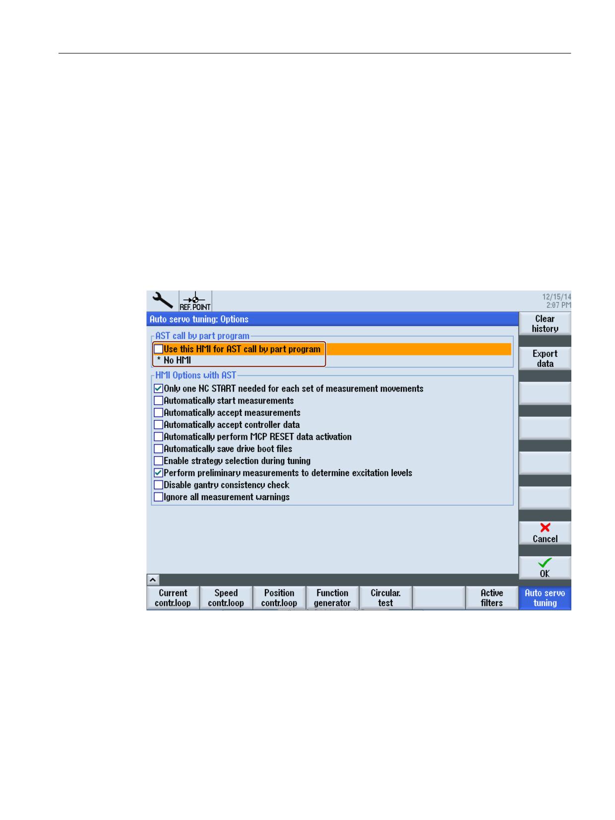
The "Automatic post optimization with AST" function can always be assigned to an HMI.
In order to change the actual assignment, in the HMI intended for the function, window
≫Automat. servo optimization: options≪ must be called, and option ≫Assign this HMI for "Call
AST from the part program" ≪ selected.
Axes and spindles
Function Manual, 10/2020, 6FC5397-4GP40-0BA1
937

Automatic post optimization with AST (option)
23.3 Programming
23.3
Programming
23.3.1
Overview
Predefined cycles for automatic post optimization with AST
SIEMENS provides machinery builders (OEMs) the following cycles so that they can program
their own optimization cycles:
• CYCLE751 - Open/execute/close optimization session (Page 940)
• CYCLE752 - Add axis to an optimization session (Page 940)
• CYCLE753 - Select optimization mode (Page 943)
• CYCLE754 - Add/remove data set (Page 944)
• CYCLE755 - Backup/restore data (Page 945)
• CYCLE756 - Activate optimization results (Page 947)
• CYCLE757 - Save optimization data (Page 948)
• CYCLE758 - Change a parameter value (Page 951)
• CYCLE759 - Read parameter value (Page 953)
Internally, each of these cycles calls CYCLE750, which contains the MMC command with the
actual function call.
Data handling
Archived in standard directories
Automatic servo optimization (AST) uses three standard directories in the file system to save
specific data:
Directory path
To archive the following files
/user/sinumerik/nck/data/optimization
• XML files with axis and/or path-specific optimization data, which
are automatically generated for the user interface-based auto-
matic servo optimization.
• XML files with axis and/or path-specific optimization data, which
are automatically generated for automatic post optimization
with AST using CYCLE757.
/user/sinumerik/nck/data/optimization/restore
• Backup files that are generated by the automatic post optimiza-
tion with AST using CYCLE755.
/user/sinumerik/nck/data/optimization/data
• CSV files that are generated by the automatic post optimization
with AST using CYCLE757.
Axes and spindles
938
Function Manual, 10/2020, 6FC5397-4GP40-0BA1
Automatic post optimization with AST (option)
23.3 Programming
Note
Secure archiving of strategy files
When the optimization strategy is created with the aid of Sinumerik Operate, the optimization
strategies are archived in the following folder: /user/sinumerik/nck/data/optimization/.
To ensure that the right strategy file is always used when CYCLE752 is called, it is recommended
that the strategy file (e.g. "oem_ax1.xml") is moved to another folder that can only be accessed
by the machine manufacturer, e.g.: /oem/sinumerik/nck/data/optimization/.
The option "Optimization data from a user-defined optimization file" (Page 940) is explicitly
recommended.
CYCLE752(myaxiswithnewload,2,...)
When CYCLE752 and CYCLE755 are called, the corresponding OEM path must then be
specified, e.g.:
CYCLE752(myaxiswithnewload,2,false,"/oem/sinumerik/nck/data/
optimization/oem_ax1.xml")
Furthermore, archiving of the results with absolute path data to an OEM folder is recommended
to protect the results of measurements.
Addressing using absolute path data
Optimization files must be addressed using absolute path data. That is to say, path data must
include the complete address.
For Linux, the complete address comprises the following elements:
• Directory path
• File name
Example:
oem/sinumerik/nck/data/optimization/my_ast_ax1.xml
Addressing files in external memories
When addressing optimization files in an external memory, the drive name must be specified at
the beginning of the path.
All symbolic device names configured in card/user/sinumerik/hmi/cfg/logdrive.ini are
permissible.
Examples:
• LOCAL_DRIVE:/… (local drive)
•
//DEV_5:/… (user-defined drive)
Axes and spindles
Function Manual, 10/2020, 6FC5397-4GP40-0BA1
939

Automatic post optimization with AST (option)
23.3 Programming
23.3.2
CYCLE751 - Open/execute/close optimization session
Syntax
CYCLE751(<S_I_SESSIONCOMMAND>)
Parameter
No.
Parameters
1
<S_I_SESSIONCOMMAND>
Data type:
INT
Value:
0
Not defined
1
Open new optimization session
Note:
Multiple sessions cannot be open concurrently. Opening a new session closes the current session
automatically.
2
Close current optimization session
3
Execute optimization functions of the current session with immediate transfer of the optimization
results
The scope of the optimization functions (measurement of the speed control loop, measurement of
the position control loop, optimization of the path interpolation) to be executed depends on the axis-
specific optimization strategies set from the user interface.
The optimization results are transferred immediately (update the axis and drive parameters, update
the optimization files).
4
Execute optimization functions of the current session without immediate transfer of the optimiza-
tion results
Unlike 3, the optimization results are not transferred immediately. Transfer can be realized later in the
optimization session using CYCLE756.
23.3.3
CYCLE752 - Add axis to an optimization session
After opening the optimization session, CYCLE752 specifies which axes should be reoptimized.
If a reoptimization of the path interpolation is provided, CYCLE752 also specifies the axes
required for the comparison of the path interpolation.
Syntax
CYCLE752(<S_I_AXIS>, <S_I_ACTIONREQUEST>, <S_B_ISPATHMEMBER>,
<S_SZ_FILENAME>)
Axes and spindles
940
Function Manual, 10/2020, 6FC5397-4GP40-0BA1

Automatic post optimization with AST (option)
23.3 Programming
Parameter
No.
Parameter
1
<S_I_AXIS>
Meaning:
Machine axis number
Specifies the axis to be added to the optimization session.
Note:
For gantry or master-slave couplings, only the leading or master axis of the coupling group should be
specified.
Data type:
INT
2
<S_I_ACTIONREQUEST>
Meaning:
Specifies whether the stored optimization data (optimization strategy and optimization results) should
be used or the axis with AST default settings reoptimized for the axis to be added.
Note:
If the axis has already been optimized and the optimization data has been saved in an optimization file,
this data is normally accessed first. CYCLE753 can then specify the further procedure.
Data type:
INT
Value:
0
Not defined
1
Reoptimization with AST default settings
The axis should be remeasured and reoptimized with the AST default settings. The selected AST
settings are not considered on the user interface.
2
Optimization data from a user-defined optimization file
The stored optimization data from the specified user-defined optimization file (see <S_SZ_FILE-
NAME> parameter) is used for the axis.
Note:
This setting is only possible if the axis has already been optimized once, and the results have been
saved to a user-defined optimization file.
3
Optimization data from the standard optimization file
The stored optimization data from the axis-specific standard optimization file is used for the axis.
The selected AST settings are considered on the user interface.
Note:
For the user interface-based automatic servo optimization, the standard optimization files are
automatically generated to backup optimization information and data (optimization strategy,
measuring and optimization results) and saved in the file system under /user/sinumerik/nck/data/
optimization. There is a standard optimization file for every axis - and a standard optimization file
for the path interpolation.
For example, the setting <S_I_ACTIONREQUEST> = 2 or 3 is used in the following cases:
• The axis should be post-optimized using the saved strategy and measurement settings. To do this,
the saved optimization data is loaded with CYCLE752 and the deployed optimization mode defined
with CYCLE753.
• On completion of the reoptimization of the individual axes, the path interpolation must be reopti-
mized.
• Saved optimization results (values for NC and drive parameters) should be restored.
Axes and spindles
Function Manual, 10/2020, 6FC5397-4GP40-0BA1
941

Automatic post optimization with AST (option)
23.3 Programming
No.
Parameter
3
<S_B_ISPATHMEMBER>
Meaning:
Consideration of the axis for the last optimization step (optimization of the path interpolation)
Data type:
BOOL
Value:
0 (FALSE)
Do not consider the axis for the optimization of the path interpolation
1 (TRUE)
Consider the axis for the optimization of the path interpolation
All axes, which are added using CYCLE752( , , TRUE, ), are taken into account when
optimizing path interpolation. This is realized within the scope of the optimization, e.g.
started using CYCLE751(3).
4
<S_SZ_FILENAME>
Meaning:
Address of the user-defined, axis-specific optimization file (only relevant for <S_I_ACTIONREQUEST> = 2!)
When the optimization strategy is created with the aid of Sinumerik Operate, the optimization strategies
are archived by default in the following folder: /user/sinumerik/nck/data/optimization/.
To ensure that the right strategy file is always used when CYCLE752 is called, it is recommended that the
strategy file (e.g. "oem_ax1.xml") is moved to another folder that can only be accessed by the machine
manufacturer, e.g.: /oem/sinumerik/nck/data/optimization/.
Using the option "Optimization data from a user-defined optimization file" (<S_I_ACTIONREQUEST> = 2)
is explicitly recommended:
CYCLE752(myaxiswithnewload,2,...)
When CYCLE752 is called, the corresponding OEM path must then be specified, e.g.:
CYCLE752(myaxiswithnewload,2,false,"/oem/sinumerik/nck/data/optimization/
oem_ax1.xml")
Data type:
STRING [100]
Note
Gantry/master-slave coupling
For gantry or master-slave couplings, with CYCLE752, only the leading or master axis of the
coupling group is specified. The AST software automatically adds the coupled following or slave
axes.
AST then automatically measures all axes of a coupling group - and optimizes them with
identical controller settings. The position controller gains are set the same, the integral time in
the speed controller is selected the same and the effective speed controller gain (relative to the
overall moment of inertia) is selected the same. The current setpoint filters can be optimized
differently.
Coupled axes must be referenced (homed) before the automatic optimization!
Axes and spindles
942
Function Manual, 10/2020, 6FC5397-4GP40-0BA1

Automatic post optimization with AST (option)
23.3 Programming
Note
Premeasurement
The decision for performing a premeasurement depends on the available axis optimization data.
• Cases in which the control unit performs a premeasurement for determining the measuring
parameters:
- The optimization strategy envisages a premeasurement; data from an earlier
premeasurement is not available.
- The optimization data does not specify any optimization strategy.
• Cases in which no premeasurement is performed:
- The optimization strategy envisages a premeasurement; data from an earlier
premeasurement is available.
- The optimization strategy does not envisage any premeasurement (the optimization
strategy takes precedence over the "Perform premeasurement for determining the
excitation" option selected from the user interface).
See also
Example 6: Measuring an axis without optimization (Page 975)
23.3.4
CYCLE753 - Select optimization mode
CYCLE753 must be programmed when different strategy settings should act for the axis than
those stored as standard or selected from the user interface. For example, this the case when an
axis with user-defined strategy and measuring settings from a stored optimization file should be
remeasured and reoptimized.
Syntax
CYCLE753(<S_I_AXIS>, <S_I_ACTION>, <S_B_SAVEBOOTFILES>)
Parameters
No.
Parameters
1
<S_I_AXIS>
Meaning:
Machine axis number
Data type:
INT
Axes and spindles
Function Manual, 10/2020, 6FC5397-4GP40-0BA1
943

Automatic post optimization with AST (option)
23.3 Programming
No.
Parameters
2
<S_I_ACTION>
Meaning:
Specifies the optimization mode for the specified axis.
Data type:
INT
Value:
0
Not defined
1
Match the path interpolation
The axis (path axis) should not be remeasured and reoptimized, but rather considered and adap-
ted only for the optimization of the path interpolation.
The stored results from the optimization file are used for the axis. The optimization of the path
interpolation means that the axis-specific machine data and drive parameters can change.
2
Reoptimization with a different optimization strategy based on stored measurements
The axis should be reoptimized based on the results from an earlier measurement and currently
valid optimization strategy changed from the user interface or CYCLE758.
This mode is used, for example, to eliminate known periodic disturbance frequencies (see "Ex-
ample 5: Reoptimize the speed control loop to eliminate known periodic disturbance frequencies.
(Page 973)").
3
Measurement and reoptimization (→ Mode for changed mechanics/loading!)
The mechanics/loading has changed. The axis should be remeasured and reoptimized using the
user-defined strategy and measuring settings from an optimization file. The strategy and meas-
uring settings can be adapted from the user interface or with CYCLE758.
3
<S_B_SAVEBOOTFILES>
Meaning:
Save updated drive parameter values as persistent data
Data type:
BOOL
Value:
0 (FALSE)
No
1 (TRUE)
Yes (default)
23.3.5
CYCLE754 - Add/remove data set
If the optimization results rather than the current data set should overwrite a specific axis or drive
data set, the data set to be overwritten must be added to the data set list with CYCLE754. This
list involves an invisible internal function list used to define data sets to be optimized. As default
setting, only the currently selected data set is included in it. CYCLE754 must also be used to
remove a data set from the list.
Note
Adding or removing an axis or drive data set using CYCLE754 only refers to the data set list, i.e
an axis or drive data set removed from the list still remains in the control or in the drive.
Syntax
CYCLE754(<S_I_AXIS>, <S_I_ACTIONREQUEST>, <S_I_DATASETTYPE>,
<S_I_INDEX>)
Axes and spindles
944
Function Manual, 10/2020, 6FC5397-4GP40-0BA1

Automatic post optimization with AST (option)
23.3 Programming
Parameters
No.
Parameters
1
<S_I_AXIS>
Meaning:
Machine axis number
Data type:
INT
2
<S_I_ACTIONREQUEST>
Meaning:
Specifies whether the specified axis or drive data set should be added to or removed from the data set
list.
Data type:
INT
Value:
0
Not defined
1
Add a data set
2
Remove a data set
3
Remove all data sets from the list
Note:
If the list is empty, the optimization results can be written only to the active data set.
3
<S_I_DATASETTYPE>
Meaning:
Data set type
Data type:
INT
Value:
0
Not defined
1
Axis data set (servo parameter set)
2
Drive data set (DDS)
4
<S_I_INDEX>
Meaning:
Data set index
Specifies the data set to be added and into which the optimization results should be written or should
be removed from the list.
Note:
The following applies to the axisdata set index: <n> = parameter set number - 1
Example: Index 0 ≙ parameter set 1
Data type:
INT
Range of values:
-1, 0, 1, ... <MAX_INDEX>
-1
active data set
23.3.6
CYCLE755 - Backup/restore data
Using CYCLE755, backup files can be created in the file system that permit the backup of the
actual data, and therefore facilitate specific data restoration at any time during the optimization
session. Data restoration is also called using CYCLE755. Further, CYCLE755 is used to query the
existence of a backup file as well as to delete backup files.
Note
The backup files are no longer required after the optimization session has been successfully
completed. This is the reason that these should be deleted again at the end of the optimization
session with CYCLE755.
Axes and spindles
Function Manual, 10/2020, 6FC5397-4GP40-0BA1
945

Automatic post optimization with AST (option)
23.3 Programming
Typical examples for using CYCLE755 include:
• Undoing data changes, which are only to be temporarily valid.
• Restoring data after an interrupted optimization session.
A program that queries the existence of a backup file, and for a positive result, restores the
data from this file, can be used to return to a defined initial state after an optimization session
has been interrupted.
Syntax
CYCLE755(<S_I_ACTIONREQUEST>, <S_SZ_NAME>, <S_SZ_GUD_BOOL_NAME>)
Parameter
No.
Parameter
1
<S_I_ACTIONREQUEST>
Data type:
INT
Value:
0
Not defined
1
Backup data for a later restore
This setting saves the data values at the time of the cycle call in the specified file.
The following parameters define the content of the data backup:
• the currently valid optimization strategy
• the axes currently added to the optimization session
• the current list of parameter sets to be written
2
Restore data
This setting restores the data from the specified file.
Requirements:
• The optimization session is still active.
• The axis and data set selection at the time of the backup is still available.
3
Delete backup file
4
Querying the existence of a backup file
The result of the query is saved to a channel-global user variable (GUD), type BOOL (see parameter
<S_SZ_GUD_BOOL_NAME>).
2
<S_SZ_NAME>
Meaning:
Address of the backup file
The file name can be freely selected with the following restriction: it is not permissible that the sequence
of letters "AST" is located at the beginning of the file name.
It is recommended that the backup files be saved in a protected manufacturer directory and always
addressed with absolute path data.
Example: "oem/sinumerik/nck/data/restore/x1_original.xml"
Data type:
STRING [100]
Axes and spindles
946
Function Manual, 10/2020, 6FC5397-4GP40-0BA1

Automatic post optimization with AST (option)
23.3 Programming
No.
Parameter
3
<S_SZ_GUD_BOOL_NAME>
Meaning:
Name of the GUD, in which the result of the file query should be saved
(only relevant, if <S_I_ACTIONREQUEST> = 4!)
Note:
The specified GUD must be defined in a definition file as a channel-global variable, type BOOL:
DEF CHAN BOOL
Data type:
STRING [50]
23.3.7
CYCLE756 - Activate optimization results
CYCLE756 can be used to activate the optimization results at a specific time / under specific
conditions. The conditions must be queried in the manufacturer cycle. CYCLE756 can also
specify which control parameters should be active: original data, axis-optimum data or path-
optimum data.
Syntax
CYCLE756(<S_I_AXIS>, <S_I_REGULATOR_ROLE>, <S_B_SAVEBOOTFILES>)
Parameters
No.
Parameters
1
<S_I_AXIS>
Meaning:
Machine axis number
Data type:
INT
2
<S_I_REGULATOR_ROLE>
Meaning:
Specifies which optimization results should act for the specified axis in the control unit and in the drive.
Note:
If the axis is part of a gantry group or a master-slave coupling, then optimization factors are included in
the optimization results, which would be necessary to adapt the dynamic response of all axes of the
coupling group.
Data type:
INT
Value:
0
Not defined
1
The original data should act for the specified axis.
2
The current optimization results without optimization of the path interpolation should become
active for the specified axis (axis-optimum data)
3
The current optimization results with optimization of the path interpolation should become active
for the specified axis (path-optimum data).
3
<S_B_SAVEBOOTFILES>
Meaning:
Save updated drive parameter values as persistent data
Data type:
BOOL
Value:
0 (FALSE)
No
1 (TRUE)
Yes (default)
Axes and spindles
Function Manual, 10/2020, 6FC5397-4GP40-0BA1
947
Automatic post optimization with AST (option)
23.3 Programming
Application
Some situations for which CYCLE756 is useful:
• CYCLE751(4) executes the optimization functions of the current session without transferring
the optimization results immediately. The optimization results can be activated later during
the optimization session with CYCLE756. Prior to the activation, the data can be read and
tested with CYCLE758/759.
• CYCLE752 loads the saved optimization data from an optimization file. CYCLE756 activates
the loaded data.
23.3.8
CYCLE757 - Save optimization data
Contrary to the user interface-based automatic servo optimization, where optimization data are
automatically saved (standard optimization files), saving optimization data for program-based
automatic post optimization with AST must be explicitly called by programming CYCLE757.
The following user-defined optimization files can be created in CYCLE757:
• Optimization files in the XML format:
- for the axis-specific optimization data
- for the data to optimize path interpolation
• Optimization files in the CSV format with frequency, amplitude and phase of the following
frequency responses:
- measured speed-controlled system
- measured mechanical frequency response
- calculated closed speed controller
- calculated closed position controller
- measured closed speed controller
- measured closed position controller
NOTICE
Data loss
If CYCLE757 is not programmed, measurement data as well as parameters for assessment and
offline optimization are no longer available after the optimization session has been closed.
However, the optimization (depending on the strategy) is written to the axis and drive
parameters.
Remedy: Save optimization data to be backed up before closing the optimization session with
CYCLE757.
Syntax
CYCLE757(<S_I_AXIS>, <S_SZ_FILENAME>, <S_I_CONTENT_TYPE>,
<S_I_FORMATFILTER>, <S_I_SUPPINFO>)
Axes and spindles
948
Function Manual, 10/2020, 6FC5397-4GP40-0BA1

Automatic post optimization with AST (option)
23.3 Programming
Parameter
No.
Parameter
1
<S_I_AXIS>
Meaning:
Machine axis number
Data type:
INT
2
<S_SZ_FILENAME>
Meaning:
Address of the optimization file to be created (file name with extension ".xml" or ".csv")
The file name can be freely selected with the following restriction: it is not permissible that the sequence
of letters "AST" is located at the beginning of the file name.
It is recommended that the optimization files be saved in a protected manufacturer directory and always
addressed with absolute path data.
Example: "oem/sinumerik/nck/data/optimization/my_ast_ax1.xml"
If a path is not specified (not recommended), the files are saved in the file system in the following default
directories:
• XML files: /user/sinumerik/nck/data/optimization
• CSV files: /user/sinumerik/nck/data/optimization/data
Special case:
• Empty string (""); only valid, if <S_I_CONTENT_TYPE> = 1 or 2
Entering an empty string means that the data of the program-based automatic post optimization are
written to the standard optimization file for the axis (<S_I_CONTENT_TYPE> = 1) or for the path
interpolation (<S_I_CONTENT_TYPE> = 2).
Notice:
The standard optimization files contain the data of the user interface-based automatic servo opti-
mization. By programming <S_SZ_FILENAME> = "", these are overwritten by the data of the program-
based automatic post optimization.
Data type:
STRING [100]
Axes and spindles
Function Manual, 10/2020, 6FC5397-4GP40-0BA1
949

Automatic post optimization with AST (option)
23.3 Programming
No.
Parameter
3
<S_I_CONTENT_TYPE>
Meaning:
Specifies which optimization data should be saved in the created optimization file.
Data type:
INT
Value:
0
Not defined
1
Creates an XML file in which the axis-specific optimization data for the specified axis is saved.
The following data is included:
• Measuring conditions
• Measurement results
• Optimization strategy
• Optimization results
Note:
If the axis is part of a gantry group or a master-slave coupling, then the optimization information
for the axis, includes the optimization information for all other axes of the coupling group.
2
Creates an XML file in which the data for optimization of the path interpolation is saved.
The following data is included:
• List of all involved axes
• Strategy for optimization of the path interpolation
3
Creates a CSV file, in which the data for the frequency characteristic of the measured speed
controlled system is to be saved.
The data is stored as a 3-column table:
• Column 1: Frequency [Hz]
• Column 2: Linear amplitude
• Column 3: Phase [rad]
4
Creates a CSV file in which the data for the measured mechanical frequency response is saved.
The data is stored as a 3-column table:
• Column 1: Frequency [Hz]
• Column 2: Linear amplitude
• Column 3: Phase [rad]
5
Creates a CSV file, in which the data for the frequency response of the calculated closed speed
controller is saved.
The data is stored as a 3-column table:
Column 1: Frequency [Hz]
Column 2: Linear amplitude
Column 3: Phase [rad]
6
Creates a CSV file, in which the data for the frequency response of the calculated closed position
controller is saved.
The data is stored as a 3-column table:
Column 1: Frequency [Hz]
Column 2: Linear amplitude
Column 3: Phase [rad]
7
Creates a CSV file, in which the data for the frequency response of the measured closed speed
controller is saved.
The data is stored as a 3-column table:
Column 1: Frequency [Hz]
Axes and spindles
950
Function Manual, 10/2020, 6FC5397-4GP40-0BA1

Automatic post optimization with AST (option)
23.3 Programming
No.
Parameter
Column 2: Linear amplitude
Column 3: Phase [rad]
8
Creates a CSV file, in which the data for the frequency response of the measured closed position
controller is saved.
The data is stored as a 3-column table:
Column 1: Frequency [Hz]
Column 2: Linear amplitude
Column 3: Phase [rad]
4
<S_I_FORMATFILTER>
Meaning:
Reserved
Data type:
INT
5
<S_I_SUPPINFO>
Meaning:
Reserved
Data type:
INT
23.3.9
CYCLE758 - Change a parameter value
CYCLE758 changes individual strategy and measuring settings prior to the optimization or the
optimization results after the optimization.
Syntax
CYCLE758(<S_I_AXIS>, <S_I_PARAMID>, <S_I_MEASTYPE>, <S_I_MEASINDEX>,
<S_SZ_NEWVALUE>)
Parameters
No.
Parameters
1
<S_I_AXIS>
Meaning:
Machine axis number (not relevant for parameters that affect the optimization of the path interpolation!)
Data type:
INT
2
<S_I_PARAM
ID>
Meaning:
ID number of the parameter whose value should be changed
Parameter IDs, see "List of the parameters for the automatic servo optimization (Page 954)".
Data type:
INT
Axes and spindles
Function Manual, 10/2020, 6FC5397-4GP40-0BA1
951

Automatic post optimization with AST (option)
23.3 Programming
No.
Parameters
3
<S_I_MEASTYPE>
Meaning:
Measuring type to which the parameter refers (relevant only for measuring parameters!)
Uniquely identifies measuring parameters with the same ID number.
Data type:
INT
Value:
1
Mechanical frequency response
2
Closed position control loop
3
Closed speed control loop
4
Speed-controlled system
5
Speed setpoint step change
4
<S_I_MEASINDEX>
Meaning:
Measurement index to which the parameter refers (relevant only for measuring parameters!)
Uniquely identifies measuring parameters with the same ID number that refer to the same measuring
type. It must be specified only when multiple measurements of a measuring type exist.
Data type:
INT
5
<S_SZ_NEWVALUE>
Meaning:
New parameter value
Data type:
STRING [20]
Value:
The value should be specified as a character string in inverted commas. The character string can comprise
a maximum of 20 characters.
Values are only permissible that correspond to the data type of the parameter to be changed - and that
lie within the valid range.
Examples:
1. The parameter to be changed is of data type BOOL (e.g. <S_I_PARAMID> = 157).
Value range: 0 (= FALSE), 1 (= TRUE)
For <S_SZ_NEWVALUE>, the following permissible character string is obtained: "true", "false", "TRUE",
"FALSE", "0" or "1"
Inadmissible character strings would be, for example: 0, 1, true, false, "2", "my_bool"
2. The parameter to be changed is of data type REAL (e.g. <S_I_PARAMID> = 34).
In this particular case, with <S_SZ_NEWVALUE> theoretically, every real number within the value
range ± (∼ 2.2*10-308 … ∼ 1.8*10+308) can be specified.
Permissible character strings are, for example: "14.1", ".0023"
Inadmissible character strings would be, for example "true", 14.1, "my_real", "R1"
Note
Gantry/master-slave coupling
If the measurement parameters of a specific following or slave axis must be changed, then in
CYCLE758 the corresponding number of this axis must be specified (not the number of the
leading or master axis, as when adding coupled axes with CYCLE752 (Page 940)).
Axes and spindles
952
Function Manual, 10/2020, 6FC5397-4GP40-0BA1

Automatic post optimization with AST (option)
23.3 Programming
23.3.10
CYCLE759 - Read parameter value
CYCLE759 reads the strategy and measuring parameters and the optimized controller
parameters. This is useful for checking the file loaded with CYCLE752 prior to the optimization
or reading the results after the optimization (e.g. determined total inertia, determined gain).
Syntax
CYCLE759(<S_I_AXIS>, <S_I_PARAMID>, <S_I_MEASTYPE>, <S_I_MEASINDEX>,
<S_SZ_GUDRESULT>)
Parameters
No.
Parameters
1
<S_I_AXIS>
Meaning:
Machine axis number (not relevant for parameters that affect the optimization of the path interpolation!)
Data type:
INT
2
<S_I_PARAMID>
Meaning:
ID number of the parameter whose value should be read
Parameter IDs, see "List of the parameters for the automatic servo optimization (Page 954)".
Data type:
INT
3
<S_I_MEASTYPE>
Meaning:
Measuring type to which the parameter refers (relevant only for measuring parameters!)
Uniquely identifies measuring parameters with the same ID number.
Data type:
INT
Value:
1
Mechanical frequency response
2
Closed position control loop
3
Closed speed control loop
4
Speed-controlled system
5
Speed setpoint step change
4
<S_I_MEASINDEX>
Meaning:
Measurement index to which the parameter refers (relevant only for measuring parameters!)
Uniquely identifies measuring parameters with the same ID number that refer to the same measuring
type. It must be specified only when multiple measurements of a measuring type exist.
Data type:
INT
Axes and spindles
Function Manual, 10/2020, 6FC5397-4GP40-0BA1
953

Automatic post optimization with AST (option)
23.3 Programming
No.
Parameters
5
<S_SZ_GUDRESULT>
Meaning:
Name of the global user variable (GUD) into which the parameter value should be copied.
Note:
The variable must be a global channel variable which has been defined by the manufacturer in the data
block MGUD.
For detailed information on the GUD definition, see the Programming Manual NC Programming.
Note:
The data type of the GUD must match the data type of the parameter. If the data type is not correct, the
program execution is stopped and an alarm displayed.
Parameter data types, see "List of the parameters for the automatic servo optimization (Page 954)".
Example: GUD for recording the measured total inertia
Procedure for the creation of GUD:
1. Display data tree ("Commissioning" operating area → "System data" softkey).
2. Navigate to the "NC data/definitions" directory.
3. Open the "MGUD.DEF" file for editing.
Note:
If the file does not exist, a new file must be created (→ “New” softkey).
4. Add the following entry:
DEF CHAN REAL AST_TOTAL_INERTIA
5. Save file.
Data type:
STRING [20]
This means that the variable name may comprise a maximum of 19 characters.
23.3.11
List of the parameters for the automatic servo optimization
The ID of a parameter for the automatic servo optimization whose value should be changed with
CYCLE758 or read with CYCLE759 can be taken from the following table:
ID
Meaning
Unit
Data
Value range
Write
Read
type
with
with
CYCLE758
CYCLE759
Measuring conditions
001
Start position of the axis during a measurement
mm or de-
REAL
-
+
grees
002
Direction sequence during a measurement
INT
1, 2, 3, 4
+
+
•
1 = plus
•
2 = minus
•
3 = plus, then minus
•
4 = minus, then plus
003
Number of measurement repetitions for deter-
INT
0 to
+
+
mining the frequency range averaging
004
Number of time range windows in each time
INT
1 to
+
+
range averaging
Axes and spindles
954
Function Manual, 10/2020, 6FC5397-4GP40-0BA1

Automatic post optimization with AST (option)
23.3 Programming
ID
Meaning
Unit
Data
Value range
Write
Read
type
with
with
CYCLE758
CYCLE759
005
Settling time: The wait time after the PRBS exci-
s
REAL
0 to
+
+
tation before the first measuring window is ac-
quired
006
Measurement bandwidth
Hz
REAL
Float: 0 ... fs/2
+
+
This value only determines the measurement
bandwidth (i.e. excitation and sampling frequen-
cy). This allows the frequency resolution to be
influenced.
007
Time for performing an individual measurement
s
REAL
-
+
(without repetition, ramp-up and settling time)
008
Time required to bring the speed offset to the set-
s
REAL
-
+
point
009
Estimated travelled distance during the maxi-
m or rad
REAL
-
+
mum traversing motion in the repetition se-
quence
010
Estimated total time of the axis motion during the
s
REAL
-
+
measurement
011
Specifies the measurement type:
INT
1 ... 5
-
+
•
1 = frequency response of the mechanical
parts
•
2 = closed position control loop
•
3 = closed speed control loop
•
4 = speed-controlled system
•
5 = speed setpoint increment
012
Specifies whether the axis motion lies within the
BOOL
0 (= FALSE)
-
+
traverse range limits
1 (= TRUE)
013
Specifies whether a measurement is performed
BOOL
0 (= FALSE)
-
+
with the maximum bandwidth
1 (= TRUE)
021
Amplitude of the excitation
Nm, N,
REAL
Dynamic
+
+
m/s, rad/s,
m, rad (de-
pendent
on the
measure-
ment
type1) )
022
Velocity offset
m/s or
REAL
Dynamic
+
+
rad/s (de-
pending
on meas-
urement
type1) )
Speed control (controller)
031
Proportional gain for the speed control loop
Nms/rad
REAL
+
+
or Ns/m
032
Integral time for the speed control loop
s
REAL
+
+
Axes and spindles
Function Manual, 10/2020, 6FC5397-4GP40-0BA1
955

Automatic post optimization with AST (option)
23.3 Programming
ID
Meaning
Unit
Data
Value range
Write
Read
type
with
with
CYCLE758
CYCLE759
033
Motor moment of inertia
kgm2
REAL
-
+
or kg
034
Total moment of inertia of the axis expressed in
kgm2
REAL
+
+
the units of the motor
or kg
035
Specifies whether the reference model is activa-
BOOL
0 (= FALSE)
+
+
ted for the speed control
1 (= TRUE)
036
Frequency of the PT2 reference model
Hz
REAL
+
+
037
Damping of the PT2 reference model
REAL
+
+
038
Ratio of the Kp proportional gain to the moment
1/s
REAL
-
+
of inertia that represents the 1/s bandwidth of
the idealized PT1-equivalent (proportional-con-
trolled) systems
Position control (controller)
101
Position control loop gain
1000/min
REAL
+
+
102
Specifies whether DSC (dynamic stiffness control)
BOOL
0 (= FALSE)
+
+
is active
1 (= TRUE)
103
Specifies the precontrol type:
INT
0, 1, 2
+
+
•
0 = none
•
1 = speed precontrol
•
2 = speed and torque precontrol
104
Total moment of inertia of the axis as parameter
kg m2
REAL
+
+
for the torque precontrol
or kg
105
Delay of the speed precontrol in the drive (e.g.
s
REAL
+
+
p1429)
106
Equivalent time constant of the speed control
s
REAL
+
+
loop as parameter for the speed precontrol
107
Adapted parameter value 106 for considering the
s
REAL
+
+
following effects:
• Inconsistent delays
• Changes carried out by the NC
108
Equivalent time constant of the current control
s
REAL
+
+
loop as parameter for the torque precontrol
109
Adapted parameter value 108 for considering the
s
REAL
+
+
following effects:
• Inconsistent delays
• Changes carried out by the NC
110
PT1 time constant of the axis to adapt the dy-
s
REAL
+
+
namic response
(MD32910 $MA_DYN_MATCH_TIME)
111
Time constant used for the dynamic response
s
REAL
+
+
adaptation for the axis-specific setpoint phase fil-
ter (MD32895 $MA_DESVAL_DELAY_TIME)
Axes and spindles
956
Function Manual, 10/2020, 6FC5397-4GP40-0BA1

Automatic post optimization with AST (option)
23.3 Programming
ID
Meaning
Unit
Data
Value range
Write
Read
type
with
with
CYCLE758
CYCLE759
112
Calculated total time constant for the positioning
s
REAL
-
+
response, including precontrol and all prefilters.
This time constant is only intended to provide
users with information. You can use it as a target
time constant for the position controller strategy
for another axis. By forcing the same total time
constant, interpolation fits already after axis op-
timization.
Position control (strategy)
151
Adaptation factor (reduction) for the optimized
REAL
0.1 ... 1.0
+
+
maximum Kv value
152
Not defined
153
Specifies the additional method for maximizing
INT
0 ... 3
+
+
the Kv value:
•
0 = none (standard)
•
1 = PT1 speed filter 2
•
2 = damping of the optimum speed controller
•
3 = PT1 speed filter 1
154
DSC (Dynamic Servo Control):
BOOL
0 (= FALSE)
+
+
• TRUE = active
1 (= TRUE)
• FALSE = inactive
155
Select precontrol type:
INT
0, 1, 2
+
+
•
0 = none
•
1 = speed precontrol
•
2 = speed and torque precontrol
156
Maximum permissible Kv value
1000/min
REAL
0.1 ... 99.0
+
+
157
Specifies whether the precontrol should always
BOOL
0 (= FALSE)
+
+
be active for the axis
1 (= TRUE)
158
Setpoint for the equivalent time of the position
s
REAL
+
+
controller overall response (including precontrol
and setpoint filter)
159
Indicates whether an attempt should be made to
BOOL
0 (= FALSE)
+
+
attain the nominal equivalent time
1 (= TRUE)
160
Specifies the jerk filter technology to be selected:
INT
0 ... 2
+
+
•
0 = keep the existing jerk filter settings in the
machine data
•
1 = deactivates the jerk filter
•
2 = use jerk filter, type 2 (= sliding average
value generation)
161
Time constant (MD32410 $MA_AX_JERK_TIME)
s
REAL
0 … 0.5
+
+
for type 2 jerk filter (parameter 160 = 2)
Speed control (strategy)
Axes and spindles
Function Manual, 10/2020, 6FC5397-4GP40-0BA1
957

Automatic post optimization with AST (option)
23.3 Programming
ID
Meaning
Unit
Data
Value range
Write
Read
type
with
with
CYCLE758
CYCLE759
201
Setpoint for the amplitude reserve for the opti-
dB
REAL
+
+
mization
202
Setpoint for the phase reserve for the optimiza-
deg
REAL
+
+
tion
203
Indicates whether the reference model should be
BOOL
0 (= FALSE)
+
+
activated
1 (= TRUE)
204
Specifies the permissible minimum value for the
s
REAL
0.001 ... 1.000
+
+
integral time of the speed control loop
205
Specifies whether the design of band-stop filters
BOOL
0 (= FALSE)
+
+
should deploy a constant reduction (for the case
1 (= TRUE)
that significantly more poles are available as filter)
206
Optimization aggressiveness of the speed con-
REAL
0 ... 1
+
+
troller
A higher value produces a better optimization re-
sult coupled with a reduction of the robustness
207
Kp upper limit based on the bandwidth of a PT1-
Hz
REAL
+
+
equivalent proportionally-controlled system
Specifying a maximum speed controller band-
width is an additional rule to limit the Kp. In so
doing, the dynamic response of the speed control
is limited in the form of a "Control bandwidth"
(speed controller response in the frequency do-
main). Just as before, amplitude and phase re-
serves must be maintained. As long as the ampli-
tude and phase reserve permit a higher Kp, Kp is
calculated under the following assumptions:
• The total moment of inertia is a rigid mass.
• The speed control loop can be approximated
as a first order (PT1) lowpass filter.
208
Indicates whether a gain filter for eliminating fre-
BOOL
0 (= FALSE)
+
+
quency-specific periodic disturbances should be
1 (= TRUE)
designed and deployed
209
Frequency of the optional gain filter for eliminat-
Hz
REAL
+
+
ing frequency-specific periodic disturbances
Optimization of path interpolation (strategy)
251
Indicates whether an attempt should be made to
BOOL
0 (= FALSE)
+
+
achieve an agreement with the effective Kp value
1 (= TRUE)
252
Indicates whether an attempt should be made to
BOOL
0 (= FALSE)
+
+
achieve an agreement with the Tn integral time
1 (= TRUE)
253
The maximum proportion with which the Kp val-
REAL
0.1 ... 1.0
+
+
ue may be reduced to order to achieve an agree-
ment with the effective Kp value
254
Specifies whether non-agreements of the Kv val-
BOOL
0 (= FALSE)
+
+
ue between axes are permitted
1 (= TRUE)
Axes and spindles
958
Function Manual, 10/2020, 6FC5397-4GP40-0BA1

Automatic post optimization with AST (option)
23.4 Diagnostics
ID
Meaning
Unit
Data
Value range
Write
Read
type
with
with
CYCLE758
CYCLE759
255
Indicates whether the axes without precontrol or
BOOL
0 (= FALSE)
+
+
with speed precontrol must have matched refer-
1 (= TRUE)
ence models
256
Specifies the strategy for the path compensation:
INT
0, 1
+
+
•
0 = adapt the equivalent time of the control
loop with controller parameters and/or
MD32800/MD32810
•
1 = use MD32895 (time constant for the axial
setpoint phase filter) for adaptation
257
Specifies whether the precontrol should always
BOOL
0 (= FALSE)
+
+
be active for all axes in the group
1 (= TRUE)
258
Specifies whether the equivalent times should be
BOOL
0 (= FALSE)
+
+
identical for all axes
1 (= TRUE)
1) The parameter value unit depends on the measurement type:
• The following measurements were carried out in the drive. This is the reason that the units
refer to the motor side. The resulting axis velocity is obtained, taking into account the
gearbox ratios or spindle pitch. The velocity specified here is only equal to the axis velocity for
linear motors and torque motors (without gearbox). Here, it should be noted that the axis
velocity is specified in the AST screen forms, e.g. mm/min. Here, the numerical values cannot
be taken from the screen forms.
Unit
Parameter 021:
Parameter 022:
Amplitude of the excitation
Velocity offset
Measurement type
Rotary motor
Linear motor
Rotary motor
Linear motor
Speed-controlled system
Nm
N
rad/s
m/s
Closed speed control loop
rad/s
m/s
rad/s
m/s
• The following measurement were carried out via the control. Here, the units refer to the axis,
i.e. to the load side. It may be necessary to convert to SI units.
Unit
Parameter 021:
Parameter 022:
Amplitude of the excitation
Velocity offset
Measurement type
Rotary axis
Linear axis
Rotary axis
Linear axis
Mechanical frequency response
rad/s
m/s
rad/s
m/s
Closed position control loop
rad
m
rad/s
m/s
23.4
Diagnostics
If an error occurs when executing cycles, then an appropriate HMI alarm is output (number
range 150001 to 150004) as well as NC alarm 61840. Based on the block number specified in
alarm 61840, the user can define which NC block with a CYCLE75x call caused the error.
Axes and spindles
Function Manual, 10/2020, 6FC5397-4GP40-0BA1
959

Automatic post optimization with AST (option)
23.6 Examples
Further information
Alarm descriptions, see Diagnostics Manual Alarms.
23.5
Supplementary conditions
"Automatic post optimization with AST" for active coupling
The following table lists which coupling function support the "Automatic post optimization with
AST":
Coupling function
"Automatic post optimization with AST" can be used?
Gantry axes
+
Master-slave coupling
+
Coupled motion
-
Leading value coupling
-
Electronic gear
-
Synchronous spindle
-
23.6
Examples
23.6.1
Example 1: Measuring an axis with AST default settings
The rotary axis (here: 4th axis) driven with a torque motor depends greatly on the inertia of the
clamped mass. If the load inertia changes, the axis must be measured again. No controller values
for AST should be overwritten; the optimization, however, is determined with new
measurements. The results, such as the complete inertia, can be read with CYCLE759. The newly
calculated values also indicate whether the controlled system has changed. In specific cases,
switching can be made to predefined controller data sets or the acceleration changed. The AST
default setting includes the speed and position controller optimization with "normal"
optimization objective. The determined controller data is, however, not activated in this
example.
Programming
Definition of global user variables (GUD)
To read out the complete moment of inertia, a new type CHAN REAL variable must be defined in
file MGUD.DEF (it is possible that this file must be newly created):
; Definition of GUD to read out the total moment of inertia.
DEF CHAN REAL _AST_R_ESTINERTIA
Axes and spindles
960
Function Manual, 10/2020, 6FC5397-4GP40-0BA1
Automatic post optimization with AST (option)
23.6 Examples
Optimization cycle
Note
In the following program example, those cycle calls required for the measurement are
highlighted bold.
Any cycle calls not highlighted are optional.
DEF INT myaxiswithnewload=4
; Switch to a safe data set.
; Traverse axis to the safe position / home position.
; Is the optimization strategy set from the user interface?
; Is a destination data set (DDS) available that may be overwritten?
; Open the optimization session.
CYCLE751(1)
; Optimize axis 4: Optimization with a selected strategy based on a new
measurement.
; Optimization with default values (the selection from the AST user
interface is not used).
; No path interpolation, no values are written by AST.
CYCLE752(myaxiswithnewload,1,false)
; Save the original state in a file.
CYCLE755(1,"/oem/sinumerik/nck/data/restore/restorepoint1")
; Start the optimization without activating the results.
CYCLE751(4)
; Save the optimization data in an XML file.
CYCLE757(myaxiswithnewload,"/oem/sinumerik/nck/data/optimization/
axis_retuned.xml",1,,)
; Export the speed-controlled system.
CYCLE757(myaxiswithnewload,"/oem/sinumerik/nck/data/optimization/
speedctrlplant.csv",3,,)
; Fetch the inertia.
CYCLE759(myaxiswithnewload,34,,,"_AST_R_ESTINERTIA")
; If required check the optimization results, and then activate.
; Do not activate the results.
; Use predefined parameter sets.
Axes and spindles
Function Manual, 10/2020, 6FC5397-4GP40-0BA1
961
Automatic post optimization with AST (option)
23.6 Examples
; Close the optimization session.
CYCLE751(2)
; Switch to the newly optimized DDS or select the predefined DDS depending
on the load inertia.
; Limit the acceleration depending on the new inertia.
M17
23.6.2
Example 2: Reoptimize the speed controller of an axis
The controller setting of the rotary axis (here: 4th axis), which is driven by a torque motor,
depends on the clamping equipment and the load moment of inertia. If the clamping equipment
or the load inertia changes, the axis must be measured again. A new controller parameter set
must be determined (a DDS will be overwritten), otherwise the axis would be unstable because
of the new resonances. New current setpoint filters must probably by set. Only the speed
controller is reoptimized. Because the position control remains identical and the precontrol
should not be changed, a similar bandwidth of the speed controller should be attained again.
For this purpose, a target bandwidth can be selected in the speed controller optimization
strategy. This is set to 100 Hz for the "normal compensation" optimization objective. If the new
load inertia and the clamping make many filters necessary and the ratio from the load inertia /
motor inertia is large, this objective may possibly not be achieved. In this case, a message is
issued. And the axis machine data is still set correctly from the first optimization (initial
commissioning). This means that the precontrol mode (MD32620 $MA_FFW_MODE), DSC
(MD32640 $MA_STIFFNESS_CONTROL_ENABLE), position controller gain (MD32200
$MA_POSCTRL_GAIN) and equivalent time precontrol (MD32800 $MA_EQUIV_CURRCTRL_TIME
or MD32810 $MA_EQUIV_SPEEDCTRL_TIME) are set correctly so that the loop interpolation is
correct.
The results of the reoptimization, such as the complete inertia, can be read with CYCLE759. The
newly optimized speed controller is written to another data set. The path interpolation is not
considered here, because it is assumed that the precontrol data does not change significantly or
another axis has a larger time constant in MD32800 $MA_EQUIV_CURRCTRL_TIME. The
optimization strategy for axis and speed controllers is deployed that was stored in the XML file
for this axis (/oem/sinumerik/nck/data/optimization/oem_ax4.xml).
Axes and spindles
962
Function Manual, 10/2020, 6FC5397-4GP40-0BA1
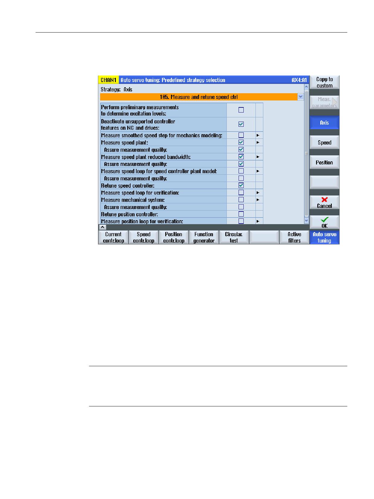
Automatic post optimization with AST (option)
23.6 Examples
Preparation
• Select optimization strategy 105 from the user interface:
• If necessary, change the optimization objective (fast, moderate, robust) with the "Speed"
softkey.
Programming
Definition of global user variables (GUD)
To read out the complete moment of inertia, a new type CHAN REAL variable must be defined in
file MGUD.DEF (it is possible that this file must be newly created):
; Definition of GUD to read out the total moment of inertia.
DEF CHAN REAL _AST_R_ESTINERTIA
Optimization cycle
Note
In the following program example, those cycle calls required for the reoptimization are
highlighted bold.
Any cycle calls not highlighted are optional.
DEF INT myaxiswithnewload=4
; Switch to a safe data set.
Axes and spindles
Function Manual, 10/2020, 6FC5397-4GP40-0BA1
963
Automatic post optimization with AST (option)
23.6 Examples
; Traverse axis to the safe position / home position.
; Is the optimization strategy set from the user interface?
; Is a destination data set (DDS) available that may be overwritten?
; Open the optimization session.
CYCLE751(1)
; Optimize axis 4: Optimization with a selected strategy based on a new
measurement.
; Add axis 4.
; Transfer the optimization strategy from the user-defined optimization
file (XML file).
; The axis is not considered for an optimization of the path interpolation.
CYCLE752(myaxiswithnewload,2,false,"/oem/sinumerik/nck/data/optimization/
oem_ax4.xml")
; Remove the current DDS from the data set list.
CYCLE754(myaxiswithnewload,2,2,-1)
; Add DDS3 to the data set list and overwrite after optimization.
CYCLE754(myaxiswithnewload,1,2,3)
; Save the original state in a file.
CYCLE755(1,"/oem/sinumerik/nck/data/restore/restorepoint1")
; Start the optimization by activating the results.
; CYCLE751(3)
; Start optimization without activation of the results, if necessary, check
the results first.
CYCLE751(4)
; Save the optimization data in an XML file.
CYCLE757(myaxiswithnewload,"/oem/sinumerik/nck/data/optimization/
axis_retuned.xml",1,,)
; Export the speed-controlled system.
CYCLE757(myaxiswithnewload,"/oem/sinumerik/nck/data/optimization/
speedctrlplant.csv",3,,)
; The inertia can be used to limit the acceleration:
; Fetch the inertia.
CYCLE759(myaxiswithnewload,34,,,"_AST_R_ESTINERTIA")
; If required check the optimization results, and then activate.
Axes and spindles
964
Function Manual, 10/2020, 6FC5397-4GP40-0BA1
Automatic post optimization with AST (option)
23.6 Examples
; Activate result:
; Activate axis-optimum results.
; Save boot files.
CYCLE756(myaxiswithnewload,2,1)
; Close the optimization session.
CYCLE751(2)
; Switch to the newly optimized DDS or limit the acceleration depending on
the new inertia.
M17
23.6.3
Example 3: Reoptimize the speed controller and the position controller of an
axis
The controller setting of the rotary axis (here: 4th axis), which is driven by a torque motor,
depends on the clamping equipment and the load moment of inertia. If the clamping equipment
or the load inertia changes, the axis must be measured again. New current setpoint filters must
probably by set. The speed controller must be reoptimized. Because it is not known whether the
low-frequency behavior has changed, the position controller must also be reoptimized and the
associated mechanical frequency response measured.
The results, such as the complete inertia, can be read with CYCLE759. The newly optimized
speed controller is written to another data set. The newly optimized position controller can be
written to any desired axis parameter set. The correct path interpolation is guaranteed by a
target value for the (precontrolled) positioning behavior being specified in accordance with the
previously optimized axes. The optimization strategy for axis and speed controllers is deployed
that was stored in the XML file for this axis (/oem/sinumerik/nck/data/optimization/
oem_ax4.xml).
Axes and spindles
Function Manual, 10/2020, 6FC5397-4GP40-0BA1
965
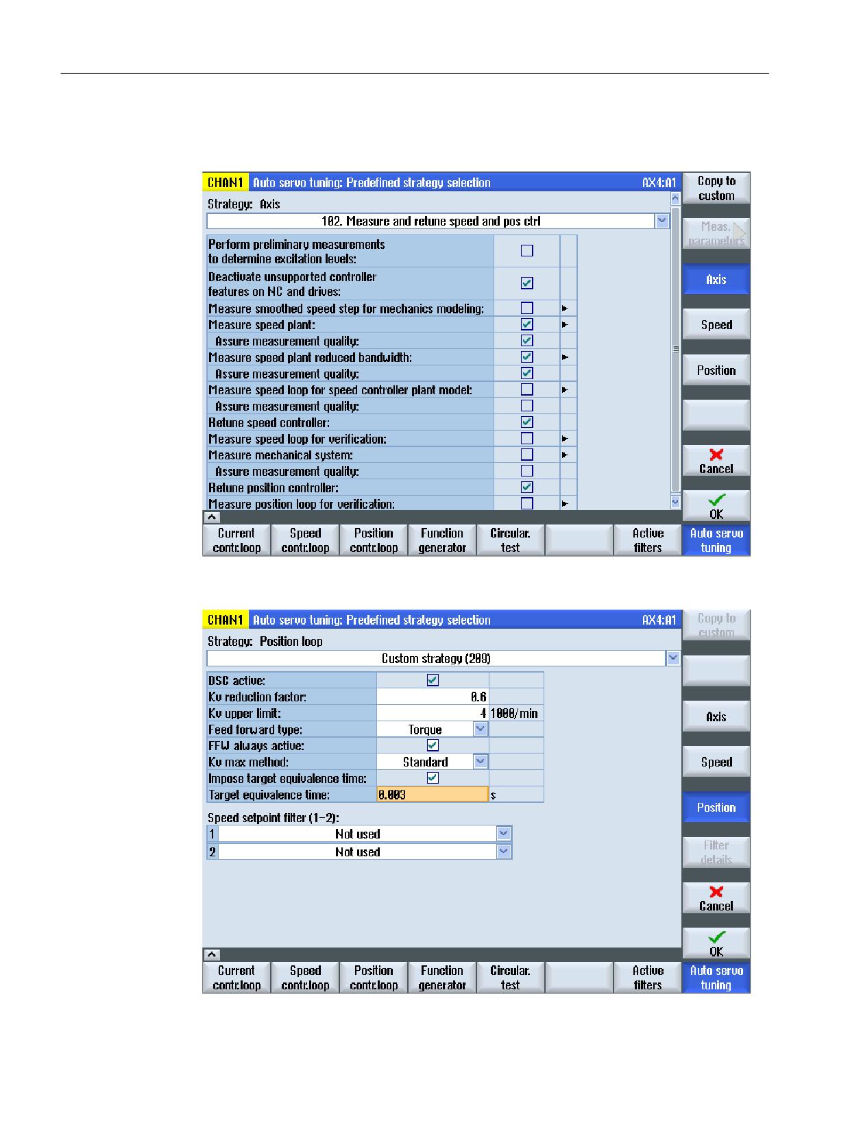
Automatic post optimization with AST (option)
23.6 Examples
Preparation
• Select optimization strategy 102 from the user interface:
• Press the "Position" softkey to display the window for adaptation of the position controller
strategy and select "User-defined strategy 209":
Axes and spindles
966
Function Manual, 10/2020, 6FC5397-4GP40-0BA1

Automatic post optimization with AST (option)
23.6 Examples
• Select the "Force equivalent time target value" option.
Note
The "Force equivalent time target value" option is set, when in addition to the speed
controller, the position controller is also reoptimized, and despite an equivalent time of the
precontrol specified, the path interpolation should not be reoptimized.
To ensure the correct path interpolation, an equivalent time can be specified. This should
correspond to the equivalent time of the axes previously optimized on the path.
• Take the equivalent time (MD32800 $MA_EQUIV_CURRCTRL_TIME or MD32810
$MA_EQUIV_SPEEDCTRL_TIME depending on MD32620 $MA_FFW_MODE) from the other
axes (here, 3 ms).
• The following parameters must be set in the servo parameter set:
- Precontrol equivalent time (MD32800 $MA_EQUIV_CURRCTRL_TIME) = 3 ms
- Position controller gain (MD32200 $MA_POSCTRL_GAIN)
Note
For the automatic operation, the servo parameter set with the appropriate path-optimum
values must then be selected in the other axes (here: with equivalent time = 3 ms).
Programming
Definition of global user variables (GUD)
To read out the complete moment of inertia, a new type CHAN REAL variable must be defined in
file MGUD.DEF (it is possible that this file must be newly created):
; Definition of GUD to read out the total moment of inertia.
DEF CHAN REAL _AST_R_ESTINERTIA
Optimization cycle
Note
In the following program example, those cycle calls required for the reoptimization are
highlighted bold.
Any cycle calls not highlighted are optional.
DEF INT myaxiswithnewload=4
; Switch to a safe data set.
; Traverse axis to the safe position / home position.
; Strategy settings: target value for the equivalent time!
; Is a destination data set (DDS) available that may be overwritten?
; Open the optimization session.
Axes and spindles
Function Manual, 10/2020, 6FC5397-4GP40-0BA1
967
Automatic post optimization with AST (option)
23.6 Examples
CYCLE751(1)
; Optimize axis 4: Optimization with a selected strategy based on a new
measurement.
; Add axis 4.
; Transfer the optimization strategy from the user-defined optimization
file (XML file).
; The axis is not considered for an optimization of the path interpolation.
CYCLE752(myaxiswithnewload,2,false,"/oem/sinumerik/nck/data/optimization/
oem_ax4.xml")
; Remove the current DDS from the data set list.
CYCLE754(myaxiswithnewload,2,2,-1)
; Add DDS3 to the data set list and overwrite after optimization.
CYCLE754(myaxiswithnewload,1,2,3)
; Axis: Add parameter set 4 to the data set list and overwrite after
optimization.
CYCLE754(myaxiswithnewload,1,1,3)
; Save the original state in a file.
CCYCLE755(1,"/oem/sinumerik/nck/data/restore/restorepoint1")
; Start the optimization by activating the results.
; CYCLE751(3)
; Start optimization without activation of the results, if necessary, check
the results first.
CYCLE751(4)
; Save the optimization data in an XML file.
CYCLE757(myaxiswithnewload,"/oem/sinumerik/nck/data/optimization/
axis_retuned.xml",1,,)
; Export the speed-controlled system.
CYCLE757(myaxiswithnewload,"/oem/sinumerik/nck/data/optimization/
speedctrlplant.csv",3,,)
; The inertia can be used to limit the acceleration:
; Fetch the inertia.
CYCLE759(myaxiswithnewload,34,,,"_AST_R_ESTINERTIA")
; If required check the optimization results, and then activate.
; Activate result:
Axes and spindles
968
Function Manual, 10/2020, 6FC5397-4GP40-0BA1
Automatic post optimization with AST (option)
23.6 Examples
; Activate axis-optimum results.
; Save boot files.
CYCLE756(myaxiswithnewload,2,1)
; Close the optimization session.
CYCLE751(2)
; Switch to the newly optimized DDS.
; Has Kv been optimized in the current parameter set?
; The equivalent time of the precontrol was forced by the strategy.
; For path interpolation, all axes must select the correct servo parameter
set.
; Limit the acceleration depending on the new inertia.
M17
23.6.4
Example 4: Reoptimization of the path interpolation
For a 5-axis machine, the rotary axis with torque motor (here: 4th axis) must position very
accurate and participate in the path interpolation. The changes of the clamping situation and
the inertia are completely unknown or so large that even large changes of the equivalent time
(also power controller) are expected. The unknown equivalent time means that the path
interpolation must be tested and compensated again after the axis optimization.
Only the rotary axis (workpiece-dependent) should be reoptimized. The other axes need to be
adapted in the precontrol only when the dynamic response of the rotary axis has changed
significantly. The rotary axis has several DDS. A safe data set that has a stable setting for clamping
the workpieces is selected. It must be considered that the mass inertia to be clamped is not
known. Consequently, the maximum inertia must be used for the calculation.
New current setpoint filters must probably be set for the rotary axis. The speed controller must
be reoptimized. Because it is not known whether the low-frequency behavior has changed, the
position controller must also be reoptimized and the associated mechanical frequency response
measured.
The results, such as the complete inertia, can be read with CYCLE759. The newly optimized
speed controller is written to another data set. The newly optimized position controller can be
written to any desired axis parameter set. The correct path interpolation is guaranteed by all axes
involved by being optimized by AST and now, after the reoptimization of the axis, the path
interpolation optimization is performed again by AST. The optimization strategy for axis and
speed controller is deployed that is stored in the XML file for this axis (/oem/sinumerik/nck/data/
optimization/oem_ax4.xml). The path optimization strategy set from the user interface is
deployed and stored in the XML file for the optimization of the path interpolation.
Axes and spindles
Function Manual, 10/2020, 6FC5397-4GP40-0BA1
969
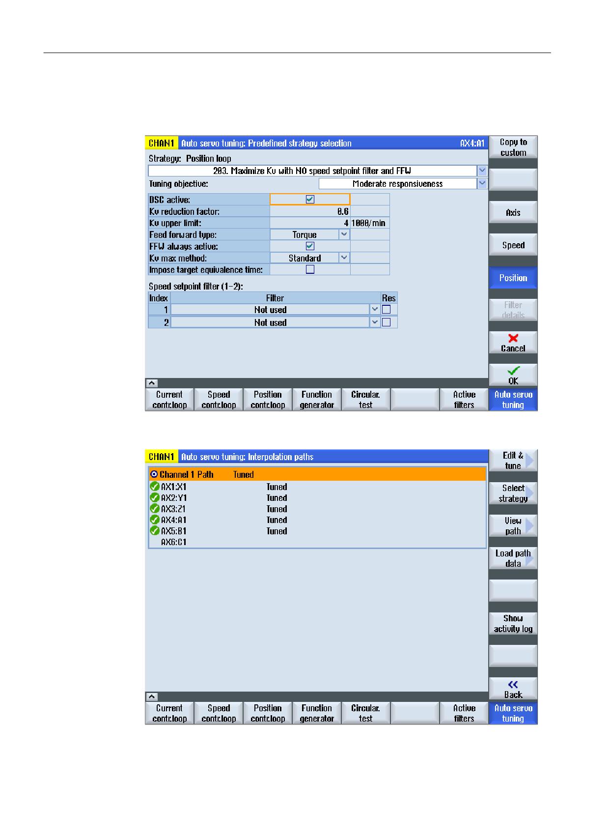
Automatic post optimization with AST (option)
23.6 Examples
Preparation
• No equivalent time is forced, namely, the predefined strategies for the position controller
optimization are deployed:
• For the path interpolation, the strategy (all equivalent times identical or use MD32895
$MA_DESVAL_DELAY_TIME) was already chosen for the first optimization.
Axes and spindles
970
Function Manual, 10/2020, 6FC5397-4GP40-0BA1
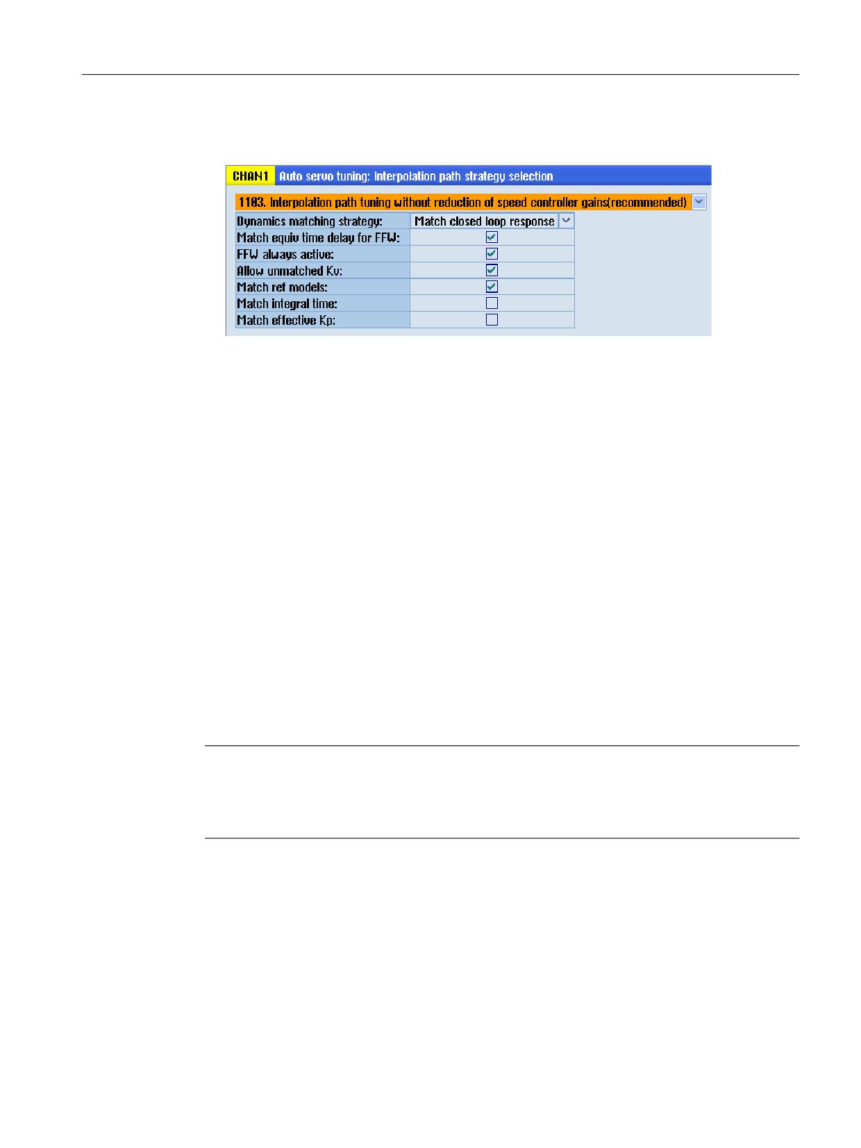
Automatic post optimization with AST (option)
23.6 Examples
The following selection sets the balancing times (in MD32800 $MA_EQUIV_CURRCTRL_TIME
or MD32810 $MA_EQUIV_SPEEDCTRL_TIME) of all involved axes to the largest time constant:
• The following questions must be answered:
- Which axis parameter set may be reparameterized (for the path interpolation)?
- May the first axis parameter set be overwritten?
- Does the spindle need to be part of the path interpolation?
- If the thread cutting should also run with this axis configuration, parameter set 2 for the
axes and the gear stages in the spindle (parameter set 2 ... 6) may need to be optimized.
• Save the original path data!
Programming
Definition of global user variables (GUD)
To read out the complete moment of inertia, a new type CHAN REAL variable must be defined in
file MGUD.DEF (it is possible that this file must be newly created):
; Definition of GUD to read out the total moment of inertia.
DEF CHAN REAL _AST_R_ESTINERTIA
Optimization cycle
Note
In the following program example, those cycle calls required for the reoptimization are
highlighted bold.
Any cycle calls not highlighted are optional.
DEF INT myaxiswithnewload=4
; Switch to a safe data set.
; Traverse axis to the safe position / home position.
; Strategy settings: target value for the equivalent time!
; Is a destination data set (DDS) available that may be overwritten?
; Each axis was already optimized once with AST.
Axes and spindles
Function Manual, 10/2020, 6FC5397-4GP40-0BA1
971
Automatic post optimization with AST (option)
23.6 Examples
; As a consequence, a user-defined optimization file for CYCLE752 exists
for each axis.
; Open the optimization session.
CYCLE751(1)
; Optimize axis 4, with path interpolation.
; Select strategy:
; Add axis 4.
; Transfer the optimization strategy from the user-defined optimization
file (XML file).
; The axis is considered for an optimization of the path interpolation.
CYCLE752(myaxiswithnewload,2,true,"/oem/sinumerik/nck/data/optimization/
oem_ax4.xml")
; Measure axis 4 again and reoptimize, save the boot files.
CYCLE753(myaxiswithnewload,3,1)
; Add axis 1 because of the path interpolation.
CYCLE752(1,2,true,"/oem/sinumerik/nck/data/optimization/oem_ax1.xml")
; Axis 1, only post-optimize path interpolation.
CYCLE753(1,1,true)
; Add axis 2 because of the path interpolation.
CYCLE752(2,2,true,"oem/sinumerik/nck/data/optimization/oem_ax2.xml")
; Axis 2, only post-optimize path interpolation.
CYCLE753(2,1,true)
; Add axis 3 because of the path interpolation.
CYCLE752(3,2,true,"/oem/sinumerik/nck/data/optimization/oem_ax3.xml")
; Axis 3, only post-optimize path interpolation.
CYCLE753(3,1,true)
; Add axis 6 because of the path interpolation.
CYCLE752(6,3,true)
; Axis 6, only post-optimize path interpolation.
CYCLE753(6,1,true)
; Remove the current DDS from the data set list.
CYCLE754(myaxiswithnewload,2,2,-1)
; Add DDS3 to the data set list and overwrite after optimization.
CYCLE754(myaxiswithnewload,1,2,3)
; Axis: Add parameter set 4 to the data set list and overwrite after
optimization.
CYCLE754(myaxiswithnewload,1,1,3)
Axes and spindles
972
Function Manual, 10/2020, 6FC5397-4GP40-0BA1
Automatic post optimization with AST (option)
23.6 Examples
; Save the original state in a file.
CYCLE755(1,"/oem/sinumerik/nck/data/restore/restorepoint1")
; Start the optimization by activating the results.
CYCLE751(3)
; Save the optimization data in an XML file.
CYCLE757(myaxiswithnewload,"/oem/sinumerik/nck/data/optimization/
axis_retuned.xml",1,,)
; Save the measurement data of the speed controlled system to file.
CYCLE757(myaxiswithnewload,"/oem/sinumerik/nck/data/optimization/
speedctrlplant.csv",3,,)
; Save the result of the path optimization to file.
CYCLE757(1,"path_retuned.xml",2,0,0)
; Fetch the inertia.
CYCLE759(myaxiswithnewload,34,,,"_AST_R_ESTINERTIA")
; Close the optimization session.
CYCLE751(2)
; Switch to the newly optimized DDS.
; Kv has been optimized; switch to the appropriate parameter set.
; The path interpolation has been reoptimized.
; Limit the acceleration in axis 4 depending on the new inertia.
M17
23.6.5
Example 5: Reoptimize the speed control loop to eliminate known periodic
disturbance frequencies.
This example shows how the speed controller from the part program is reoptimized without new
measurement. The objective of the reoptimization is to minimize vulnerability to known process-
related periodic disturbance frequencies. The path interpolation is not reoptimized in this
example because the optimization strategy for the position controller provides a dynamic
customization by setting an equivalent time.
Axes and spindles
Function Manual, 10/2020, 6FC5397-4GP40-0BA1
973
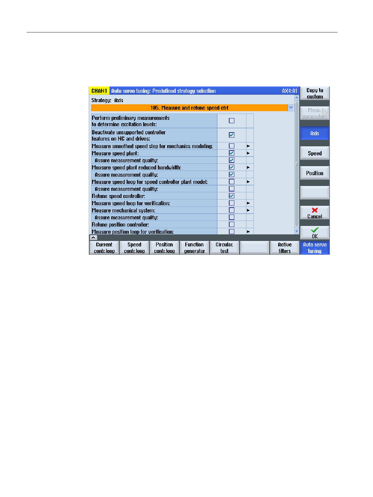
Automatic post optimization with AST (option)
23.6 Examples
Preparation
In the simplest case, only a speed controller optimization is necessary:
• Select optimization strategy 105 from the user interface:
Programming
DEF INT myAxis=4
; Open the optimization session.
CYCLE751(1)
; Add axis.
; The optimization data are loaded from the user-defined optimization file.
; The axis is not considered for an optimization of the path interpolation.
CYCLE752(myAxis,2,false,"/oem/sinumerik/nck/data/optimization/
oem_ax4.xml")
; The axis dynamic response is not measured again.
; The axis is reoptimized on the basis of the loaded measurement results and
the currently valid optimization strategy.
CYCLE753(myAxis,2,)
; Activate the use of the gain filter.
CYCLE758(myAxis,208,,,"true" )
Axes and spindles
974
Function Manual, 10/2020, 6FC5397-4GP40-0BA1
Automatic post optimization with AST (option)
23.6 Examples
; Gain filter: set the optimum frequency to 40 Hz.
CYCLE758(myAxis,209,,,"40.0" )
; Perform the optimization.
CYCLE751(3)
; Save the axis-specific optimization data for the offline analysis.
CYCLE757(myAxis,"/oem/sinumerik/nck/data/optimization/
AX1_TEMP_40HZ.XML",1,,)
; For known periodic disturbance frequencies (40 Hz):
; Deactivate the use of the gain filter.
CYCLE758(myAxis,208,,,"false" )
; Perform the optimization.
CYCLE751(3)
; Close the optimization session.
CYCLE751(2)
; For normal broadband disturbances:
M17
23.6.6
Example 6: Measuring an axis without optimization
By selecting a strategy, which does not carry out any optimization, then the axis can be
automatically measured. This can be used to diagnose mechanical changes. These can involve:
• Load weight
• Component stiffness
Using the automatic measurement, it can also be checked as to whether the control loop has the
same response as when the system was originally delivered, for example. This AST strategy then
supplies the actual measurement of the closed loop in the CSV format.
The following data can be automatically measured and exported:
• Speed controlled system
• Closed speed control loop (calculated and/or check measurement)
• Mechanical frequency response (if there are 2 encoders)
• Closed position control loop (calculated and/or check measurement of the position control
loop)
Axes and spindles
Function Manual, 10/2020, 6FC5397-4GP40-0BA1
975
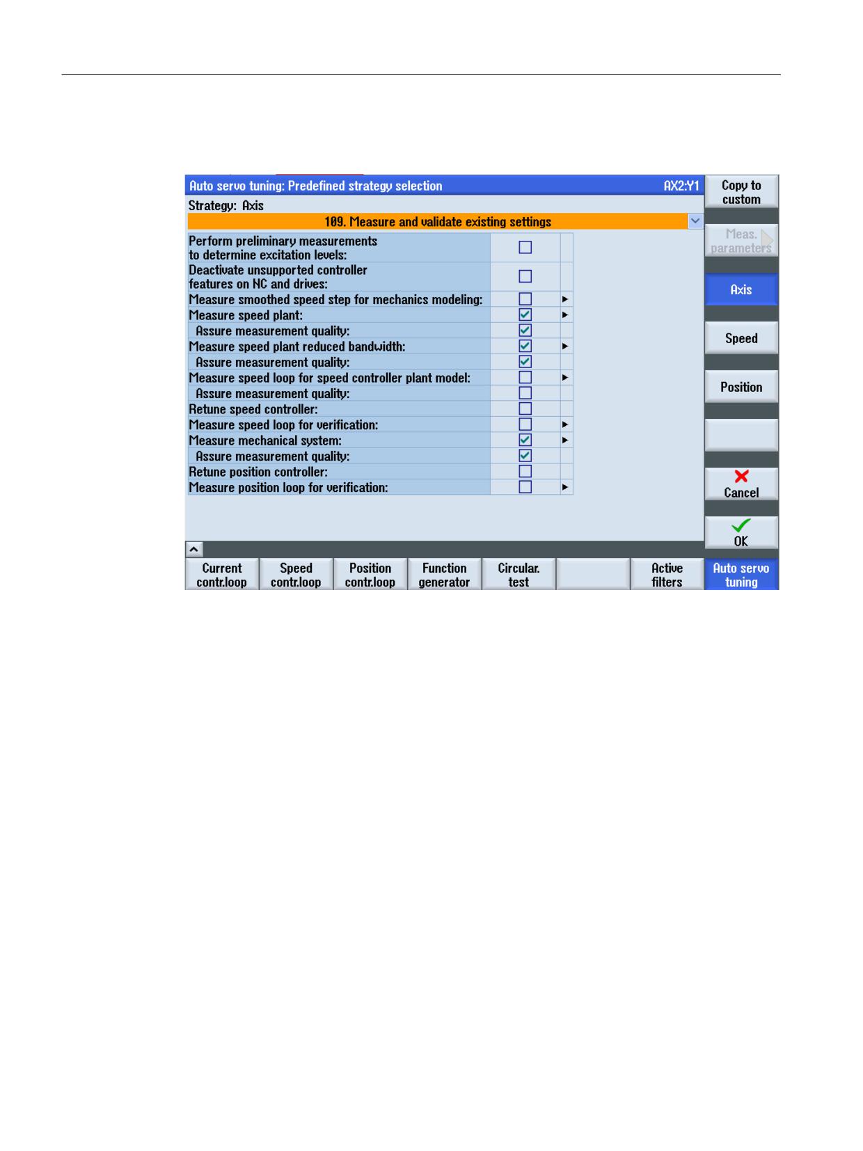
Automatic post optimization with AST (option)
23.6 Examples
Preparation
1. Select optimization strategy 109 from the user interface:
2. Measure and check controller settings.
3. Accept measurement results.
4. Save data under a new name (e.g. RESULT_STRATEGY109_AX1.xml) as a user-defined file in
a protected manufacturer directory.
Programming
Example of a cycle to measure an axis without optimization:
; Release brake
DEF INT AxNr=1
; Open the optimization session.
CYCLE751(1)
; For axis 1, the saved data are used from the user-defined file
RESULT_STRATEGY109_AX1.xml.
CYCLE752(AxNr,2,0,"/oem/sinumerik/nck/data/optimization/
RESULT_STRATEGY109_AX1.xml")
; Start automatic measurement.
CYCLE751(4)
Axes and spindles
976
Function Manual, 10/2020, 6FC5397-4GP40-0BA1
Automatic post optimization with AST (option)
23.6 Examples
; Export the speed-controlled system in the CSV format.
CYCLE757(AxNr,"/oem/sinumerik/nck/data/optimization/speedctrlplant.csv",3)
; Export the mechanical frequency response in the CSV format.
CYCLE757(AxNr,"/oem/sinumerik/nck/data/optimization/mechresponse.csv",4)
; Export the speed control loop (calculated) in the CSV format.
CYCLE757(AxNr,"/oem/sinumerik/nck/data/optimization/speedloopcalc.csv",5)
; Export the position control loop (calculated) in the CSV format.
CYCLE757(AxNr,"/oem/sinumerik/nck/data/optimization/posloopcalc.csv",6)
; Export the speed control loop (measured) in the CSV format.
CYCLE757(AxNr,"/oem/sinumerik/nck/data/optimization/speedloopmeas.csv",7)
; Export the position control loop (measured) in the CSV format.
CYCLE757(AxNr,"/oem/sinumerik/nck/data/optimization/posloopmeas.csv",8)
; Close the optimization session.
CYCLE751(2)
M17
Axes and spindles
Function Manual, 10/2020, 6FC5397-4GP40-0BA1
977
Automatic post optimization with AST (option)
23.6 Examples
Axes and spindles
978
Function Manual, 10/2020, 6FC5397-4GP40-0BA1
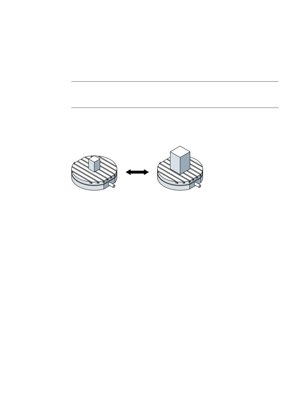
Intelligent load adjustment (option)
24
Note
The function "Intelligent Load Control" is an option for SINUMERIK 840D sl that requires a license.
Article no.: 6FC5800-0AS11-0YB0
24.1
Function
,/&
The "Intelligent Load Control" (ILC) function adapts dynamic and control parameters to the
actual load of an axis using predefined adaptation characteristic curves.
This results in the following advantages:
• Shorter machining times
• Increased dynamic response
• Greater accuracy
• Enhanced precision
Input variable and input value
The moment of inertia of the axis that depends on the load is used as the input variable for the
adaptation. The actual value to be determined for the input variable is used as the input value
for calculating the adaptation.
Output variable and adaptation factor
The control calculates a scaling factor (adaptation factor) for the output variable of the
adaptation (dynamic or closed loop control parameter) based on the input value and the
predefined adaptation characteristic.
Commissioning
When setting up the function, the machine OEM defines the adaptations available on the
machine tool. Dialog boxes on the user interface support the machine OEM in this task:
Operating area "Commissioning" → "NC" → Menu forward key → softkey: "Adaptations"
Axes and spindles
Function Manual, 10/2020, 6FC5397-4GP40-0BA1
979

Intelligent load adjustment (option)
24.2 Parameterization
More information: CNC Commissioning Manual: NC, PLC, drive
The settings made in the user interface are entered in the relevant machine data (Page 980).
Activation/deactivation
The activation behavior of an adaptation is determined by the activation mode which is
specified during the commissioning of the function (Page 980) for each adaptation. Without an
activation mode selected, an adaptation remains inactive. The activation mode can be set to
"permanently active" or "temporarily activatable":
Activation mode
Meaning
Adaptation permanently active
For permanently active load adaptations, the following applies:
• They are inactive at first after the controller ramps up.
• The adaptation is activated by calling CYCLE782. The input val-
ue is also calculated or specified with this cycle.
• They remain active beyond the end of the program reset and
channel reset. A previously programmed input value also re-
mains active.
Adaptation can be activated tem-
The following applies to temporarily activatable load adaptations:
porarily
• They are inactive at first after the controller ramps up.
• The adaptation is activated/deactivated by calling CYCLE782.
• On program end or channel reset, all adaptations not deactiva-
ted with CYCLE782 are deactivated implicitly.
Further information on CYCLE782, see:
• Operating Manual for SINUMERIK Operate
• NC Programming Programming Manual
24.2
Parameterization
Activation mode
The activation mode of an adaptation is set with machine data:
MD16501 $MN_CADAPT_MODE[<n>]
where <n> = number of the adaptation (0 ... 99)
Value
Meaning
0
Adaptation is not active (default setting)
1
Adaptation is permanently active
2
Adaptation can be activated temporarily
Input variable
The input variable of an adaptation is specified in machine data:
Axes and spindles
980
Function Manual, 10/2020, 6FC5397-4GP40-0BA1

Intelligent load adjustment (option)
24.2 Parameterization
MD16502 $MN_CADAPT_INPUT[<n>]
where <n> = number of the adaptation (0 ... 99)
Value
Meaning
1
The input variable for the adaptation is the moment of inertia of the axis
Output variable
The selection of the output value of an adaptation is done via the machine data:
MD16503 $MN_CADAPT_OUTPUT[<n>]
where <n> = number of the adaptation (0 ... 99)
Value
Meaning
0
No output variable, no adaptation active (default setting)
1
Axis acceleration with dynamic mode DYNNORM
2
Axis acceleration with dynamic mode DYNPOS
3
Axis acceleration with dynamic mode DYNROUGH
4
Axis acceleration with dynamic mode DYNSEMIFIN
5
Axis acceleration with dynamic mode DYNFINISH
6
Axis acceleration with dynamic mode DYNPREC
11
Position controller gain (servo gain factor)
12
Moment of inertia for torque feedforward control
21
Drive adaptation factor 1
22
Drive adaptation factor 2
23
Drive adaptation factor 3
24
Drive adaptation factor 4
31
Axial jerk with dynamic mode DYNNORM
32
Axial jerk with dynamic mode DYNPOS
33
Axial jerk with dynamic mode DYNROUGH
34
Axial jerk with dynamic mode DYNSEMIFIN
35
Axis jerk with DYNFINISH dynamic mode
36
Axial jerk with dynamic mode DYNPREC
Drive adaptation factor 1 ... 4
A maximum of 4 drive variables from parameter p2782[0...3] "Mode adaptation" can be
adapted:
• Kp speed controller P gain adaptation speed
• Tn speed controller integral time adaptation speed
• Current setpoint filter 1 denominator and numerator
• Current setpoint filter 2 denominator and numerator
• Speed setpoint filter 1 denominator and numerator
• Speed controller reference model natural frequency and damping
Axes and spindles
Function Manual, 10/2020, 6FC5397-4GP40-0BA1
981

Intelligent load adjustment (option)
24.2 Parameterization
• APC / APC ECO Tv (p3769)
• APC / APC ECO filter (p3766)
Note
The adaptation of drive variables requires use of telegram 146, 148, or 149.
More information:
• For information about adapting drive variables, see "SINAMICS S120 Drive Functions
Function Manual".
• For information about telegram 146/148/149, see "SINAMICS S120 Function Manual,
Communication".
Machine axis number of the input variable
The input variable of an adaptation is assigned to a machine axis using machine data:
MD16504 $MN_CADAPT_INPUT_AX[<n>]
where <n> = number of the adaptation (0 ... 99)
Value
Meaning
0
No machine axis assigned, adaptation is not active (default setting)
1 ... 31
Number of the assigned machine axis
Machine axis number of the output variable
The output variable of an adaptation is assigned to a machine axis using machine data:
MD16505 $MN_CADAPT_OUTPUT_AX[<n>]
where <n> = number of the adaptation (0 ... 99)
Value
Meaning
0
No machine axis assigned, adaptation is not active (default setting)
1 ... 31
Number of the assigned machine axis
Adaptation characteristic
The characteristic curve of a load adaptation is defined by interpolation points that are derived
from fixed moment of inertia values and the associated scaling factors (0% ... 3000%) for the
output variable. The values between the interpolation points are interpolated linearly.
Two interpolation points are sufficient for a simple adaptation:
• MD16506 $MN_CADAPT_INPUT_VALUE_1[<n>] (input value 1 of the adaptation)
• MD16507 $MN_CADAPT_INPUT_VALUE_2[<n>] (input value 2 of adaptation)
• MD16508 $MN_CADAPT_OUTPUT_VALUE_1[<n>] (output value 1 of the adaptation)
• MD16509 $MN_CADAPT_OUTPUT_VALUE_2[<n>] (output value 2 of adaptation)
Axes and spindles
982
Function Manual, 10/2020, 6FC5397-4GP40-0BA1
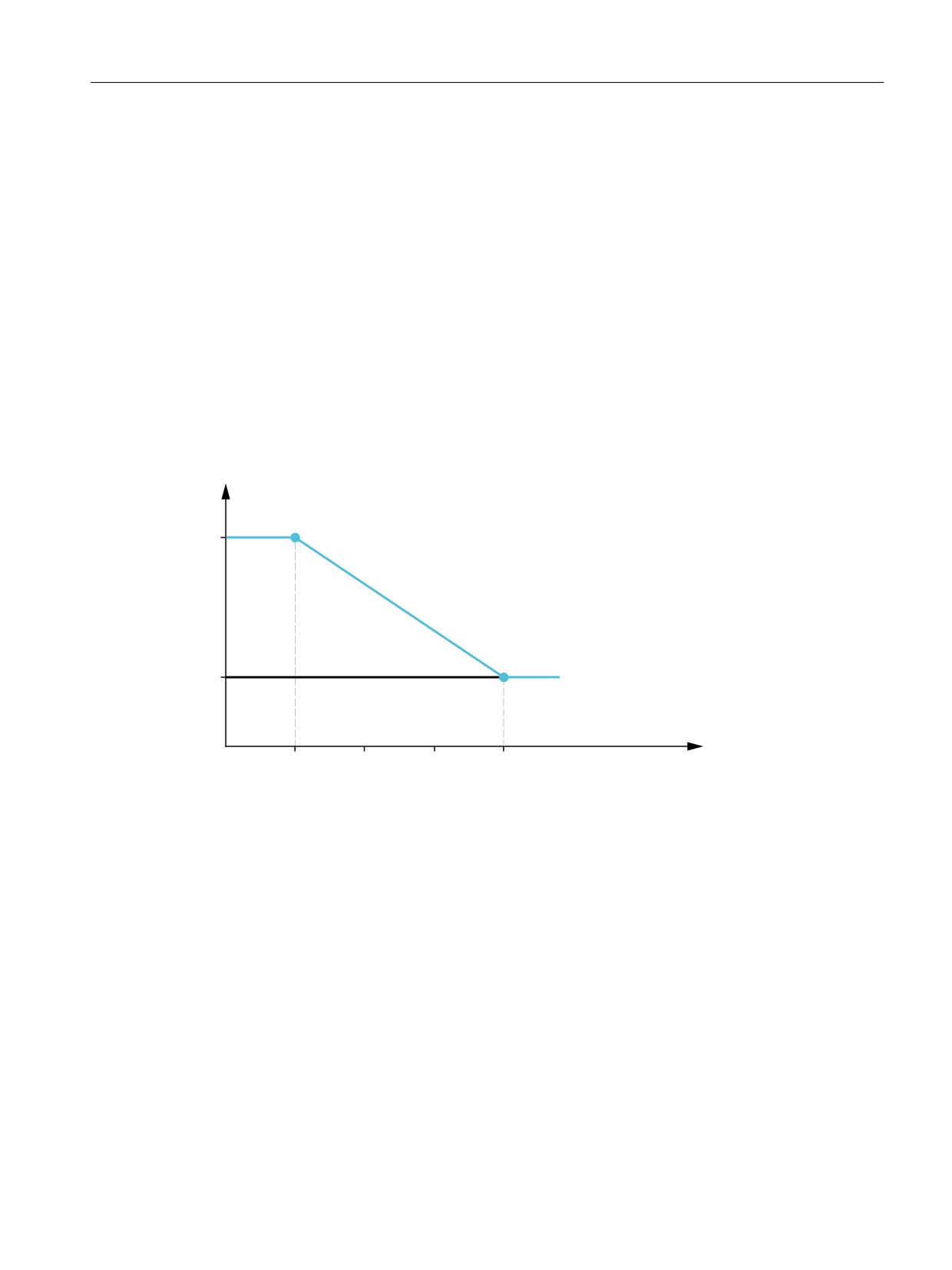
Intelligent load adjustment (option)
24.4 Example
24.3
Boundary conditions
Simulation behavior
With the "Determine total load" setting, CYCLE782 does not provide an inertia value in the
simulation. The adaptation is activated with an input value of zero.
Alternatively, CYCLE782 can be called up with the setting "Specify total load". The adaptation is
then activated with a specified input value.
24.4
Example
For a rotary table with highly variable loading, the effective acceleration should be adapted to
the current moment of inertia. The function "Intelligent Load control" is used to increase
acceleration at minimal loading to 150 %.
$FFHOHUDWLRQ
>
@
ZLWK DGDSWDWLRQ
ZLWKRXW DGDSWDWLRQ
-PLQ
-PD[
0RPHQW RI LQHUWLD >NJP @
Jmin
⇒ MD16506[0] $MN_CADAPT_INPUT_VALUE_1
Jmax
⇒ MD16507[0] $MN_CADAPT_INPUT_VALUE_2
150%
⇒ MD16508[0] $MN_CADAPT_OUTPUT_VALUE_1
100 %
⇒ MD16509[0] $MN_CADAPT_OUTPUT_VALUE_2
Axes and spindles
Function Manual, 10/2020, 6FC5397-4GP40-0BA1
983
Intelligent load adjustment (option)
24.4 Example
Axes and spindles
984
Function Manual, 10/2020, 6FC5397-4GP40-0BA1
Intelligent dynamic control (option)
25
Note
The "Intelligent Dynamic Control" function is an option for SINUMERIK 840D sl that requires a
license.
Article no.: 6FC5800-0AS23-0YB0
25.1
Function
With the function "Intelligent Dynamic Control" (IDC), it is possible to adapt control parameters
to the current position/speed of an axis with the aid of pre-defined adaptation characteristic
curves.
This results in the following advantages:
• Shorter machining times
• Increased dynamic response
• Greater accuracy
• Enhanced precision
Input variable and input value
The axis position or the axis speed is used as in input value for the Intelligent Dynamic Control:
• Axis position
Determined by the kinematics of the machine, a different position of the center of gravity of
the axis results depending on the position of the axes. From this, a variable dynamic behavior
of the machine results, which can negatively influence the stability of the control depending
on the axis position.
• Axis speed
A speed dependent adaptation of the position controller gain can be achieved, for example,
by means of the movement-dependent adjustment of the parameters in drives whose
stability changes due to the different traversing speeds.
The current input value is used as the initial value for adaption calculations.
Output variable and adaptation factor
The control calculates a scaling factor (adaptation factor) for the output variable of the
adaptation (closed loop control parameter) based on the input value and the predefined
adaptation characteristic.
Axes and spindles
Function Manual, 10/2020, 6FC5397-4GP40-0BA1
985

Intelligent dynamic control (option)
25.2 Parameterization
Commissioning
When setting up the function, the machine OEM defines the adaptations available on the
machine tool. Dialog boxes on the user interface support the machine OEM in this task:
Operating area "Commissioning" → "NC" → Menu forward key → softkey: "Adaptations"
More information: CNC Commissioning Manual: NC, PLC, drive
The settings made in the user interface are entered in the relevant machine data (Page 986).
Activation/deactivation
The activation behavior of an adaptation is determined by the activation mode which is
specified during the commissioning of the function (Page 986) for each adaptation. Without an
activation mode selected, an adaptation remains inactive. The activation mode can be set to
"permanently active" or "temporarily activatable":
Activation mode
Meaning
Adaptation permanently active
For permanently active adaptations, the following applies:
• They are active immediately after the controller ramps up.
• They remain active beyond the end of the program reset and
channel reset.
Adaptation can be activated tem-
The following applies to temporarily activatable adaptations:
porarily
• They are inactive at first after the controller ramps up.
• The activation/deactivation is done via the call-up of CADAP-
TON/CADAPTOF (Page 989).
• At the end of the program or with a channel reset, all of the
adaptations that are not yet deactivated by CADAPTOF are im-
plicitly deactivated.
Note
If the axis position is used as the input value, the input axis must be referenced to ensure that
the adaptation takes effect.
25.2
Parameterization
Activation mode
The activation mode of an adaptation is set with machine data:
MD16501 $MN_CADAPT_MODE[<n>]
Axes and spindles
986
Function Manual, 10/2020, 6FC5397-4GP40-0BA1