SINUMERIK 840D sl. Service - Functions. Manual (2018-2020) - page 16

Oscillation
19.3 Oscillation controlled by synchronized actions
• Conditions for motion-synchronized actions (frequency WHEN / WHENEVER)
• Activation through motion block
- Assign oscillation axis and infeed axes to one another OSCILL
- Specify infeed response POSP
Note
By setting the axial override in the action component of the motion-synchronized action to zero
(DO $AA_OVR[<axis>]=0), then the oscillating/infeed axis can be stopped if the associated
condition (frequency WHEN / WHENEVER) is fulfilled.
An override of 100% automatically becomes active if the condition is no longer fulfilled.
Main run evaluation
It is possible to compare the synchronization conditions in the Interpolator clock cycle in the
main run with the current actual values ($$ variable on the right of comparison conditions). With
normal system variable comparison, the expressions are evaluated in the first run.
You can find a complete description of the synchronized actions in:
Further information
Function Manual Synchronized Actions
Examples
Example 1: unchanged reversal positions
For motion-synchronized actions, the reversal positions $SA_OSCILL_REVERSE_POS are used at
the preprocessing level. If the corresponding setting data change, then the modified values are
not active in the program.
Program code
Comment
$SA_OSCILL_REVERSE_POS1[Z]=-10
; Preprocessing var.: reversal position 1
$SA_OSCILL_REVERSE_POS2[Z]=10
; Preprocessing var.: reversal position 2
G0 X0 Z0
WAITP(Z)
; Synchronized action 1: Reversal point 1 fallen below ⇒
; Stop infeed axis with override 0%
; Preprocessing var. Reversal position 1 is used
ID=1 WHENEVER $AA_IM[Z] < $SA_OSCILL_REVERSE_POS1[Z] DO $AA_OVR[X]=0
; Synchronized action 2: Reversal point 2 exceeded ⇒
; Stop infeed axis with override 0%
; Preprocessing var. reversal position 2 is used
ID=2 WHENEVER $AA_IM[Z] > $SA_OSCILL_REVERSE_POS2[Z] DO $AA_OVR[X]=0
OS[Z]=1 FA[X]=1000 POS[X]=40
; Activate oscillation
Axes and spindles
850
Function Manual, 10/2020, 6FC5397-4GP40-0BA1
Oscillation
19.3 Oscillation controlled by synchronized actions
Program code
Comment
OS[Z]=0
; Deactivate oscillation
M30
Example 2: changing reversal positions
For the motion-synchronized actions, as reversal position, main run variable $
$AA_OSCILL_REVERSE_POSx is used. If the corresponding setting data change, then the
modified values are active in the program.
Program code
Comment
$SA_OSCILL_REVERSE_POS1[Z]=-10
; Preprocessing var.: reversal position 1
$SA_OSCILL_REVERSE_POS2[Z]=10
; Preprocessing var.: reversal position 2
G0 X0 Z0
WAITP(Z)
; Synchronized action 1: Reversal point 1 fallen below ⇒
; Stop infeed axis with override 0%
; Main run var. Reversal position 1 is used
ID=1 WHENEVER $AA_IM[Z] < $$SA_OSCILL_REVERSE_POS1[Z] DO $AA_OVR[X]=0
; Synchronized action 2: Reversal point 2 exceeded ⇒
; Stop infeed axis with override 0%
; Main run var. reversal position 2 is used
ID=2 WHENEVER $AA_IM[Z] > $$SA_OSCILL_REVERSE_POS2[Z] DO $AA_OVR[X]=0
OS[Z]=1 FA[X]=1000 POS[X]=40
; Activate oscillation
OS[Z]=0
; Deactivate oscillation
M30
19.3.1
Infeed at reversal point 1 or 2
Function
As long as the oscillation axis has not reached the reversal point, the infeed axis does not move.
Application
Direct infeed in reversal point
Programming
Reversal point 1
WHENEVER $AA_IM[Z] <> $SA_OSCILL_REVERSE_POS1[Z]
DO $AA_OVR[X] = 0 $AA_OVR[Z] = 100
Reversal point 2
WHENEVER $AA_IM[Z] <> $SA_OSCILL_REVERSE_POS2[Z]
Axes and spindles
Function Manual, 10/2020, 6FC5397-4GP40-0BA1
851
Oscillation
19.3 Oscillation controlled by synchronized actions
DO $AA_OVR[X] = 0 $AA_OVR[Z] = 100
Explanation of system variables
• $AA_IM[ Z ]: Current position of oscillating axis Z in the MCS
• $SA_OSCILL_REVERSE_POS1[ Z ]: Position of the reversal point1 of the oscillation axis
• $AA_OVR[ X ]: Axial override of the infeed axis
• $AA_OVR[ Z ]: Axial override of the oscillation axis
Infeed
The absolute infeed value is defined by the POSP instruction (see Section "Definition of infeeds
POSP (Page 857)").
Assignment
The assignment between the oscillation axis and the infeed axis is defined by the OSCILL
instruction (see Section "Assignment of oscillation and infeed axes OSCILL (Page 857)").
19.3.2
Infeed in reversal point range
Reversal range 1
Function
No infeed takes place provided the oscillation axis has not reached the reversal range (position
at reversal point 1 plus contents of variables ii1). This applies on the condition that reversal point
1 is set to a lower value than reversal point 2. If this is not the case, then the condition must be
changed accordingly.
Application
The purpose of this synchronized action is to prevent the infeed movement from starting until
the oscillation movement has reached reversal range 1 (see "Figure 19-1 Arrangement
oscillating axis, infeed axis (Page 849)").
Programming
WHENEVER $AA_IM[Z] > $SA_OSCILL_REVERSE_POS1[Z] + ii1
DO $AA_OVR[X] = 0
Explanation of system variables:
• $AA_IM[ Z ]: Current position of oscillating axis Z
• $SA_OSCILL_REVERSE_POS1[ Z ]: Position of reversal point 1 of the oscillation axis
• $AA_OVR[ X ]: Axial override of the infeed axis
• ii1: Magnitude of reversal range (user variable)
Axes and spindles
852
Function Manual, 10/2020, 6FC5397-4GP40-0BA1
Oscillation
19.3 Oscillation controlled by synchronized actions
Reversal range 2
Function
The infeed axis stops until the current position (value) of the oscillation axis is lower than the
position at reversal point2 minus the contents of variable ii2. This applies on condition that the
setting for reversal point position 2 is higher than that for reversal point position 1. If this is not
the case, then the condition must be changed accordingly.
Application
The purpose of this synchronized action is to prevent the infeed movement from starting until
the oscillation movement has reached reversal range 2 (see "Figure 19-1 Arrangement
oscillating axis, infeed axis (Page 849)").
Programming
WHENEVER $AA_IM[Z] < $SA_OSCILL_REVERSE_POS2[Z] - ii2
DO $AA_OVR[X] = 0
Explanation:
• $AA_IM[ Z ]: Current position of oscillating axis Z
• $SA_OSCILL_REVERSE_POS2[ Z ]: Position of reversal point 2 of the oscillation axis
• $AA_OVR[ X ]: Axial override of the infeed axis
• ii2: Magnitude of reversal range 2 (user variable)
Infeed
The absolute infeed value is defined by the POSP instruction (see Section "Definition of infeeds
POSP (Page 857)").
Assignment
The assignment between the oscillation axis and the infeed axis is defined by the OSCILL
instruction (see Section "Assignment of oscillation and infeed axes OSCILL (Page 857)").
See also
Oscillation controlled by synchronized actions (Page 848)
19.3.3
Infeed at both reversal points
General procedure
The functions described above for infeed at the reversal point and in the reversal range can be
freely combined.
Axes and spindles
Function Manual, 10/2020, 6FC5397-4GP40-0BA1
853
Oscillation
19.3 Oscillation controlled by synchronized actions
Combinations
Infeed at two sides
• Reversal point 1 - reversal point 2
• Reversal point 1 - reversal range 2
• Reversal range 1 - reversal point 2
• Reversal range 1 - reversal range 2
One-sided infeed
• Reversal point 1
• Reversal point 2
• Reversal range 1
• Reversal range 2
(See Section "Infeed at reversal point 1 or 2 (Page 851)" and "Infeed in reversal point range
(Page 852)")
19.3.4
Stop oscillation movement at the reversal point
Function
Reversal point 1:
Every time the oscillation axis reaches reversal position 1, it must be stopped by means of the
override and the infeed movement started.
Application
The synchronized action is used to hold the oscillation axis stationary until partial infeed has
been executed. This synchronized action can be omitted if the oscillation axis need not wait at
reversal point 1 until partial infeed has been executed. At the same time, this synchronized
action can be used to start the infeed movement if this has been stopped by a previous
synchronized action which is still active.
Programming
WHENEVER $AA_IM[oscillation axis] ==
$SA_OSCILL_REVERSE_POS1[oscillation axis]
DO $AA_OVR[oscillation axis] = 0
$AA_OVR[infeed axis] = 100
Explanation of system variables
$AA_IM[ oscillation axis ]: Current position of oscillation axis
$SA_OSCILL_REVERSE_POS1[ oscillation axis ]: Reversal point 1 of the oscillation
axis
$AA_OVR[ oscillation axis]: Axial override of the oscillation axis
Axes and spindles
854
Function Manual, 10/2020, 6FC5397-4GP40-0BA1
Oscillation
19.3 Oscillation controlled by synchronized actions
$AA_OVR[infeed axis ]: Axial override of the infeed axis
Function
Reversal point 2:
Every time the oscillation axis reaches reversal position 2, it must be stopped by means of the
override 0 and the infeed movement started.
Application
The synchronized action is used to hold the oscillation axis stationary until partial infeed has
been executed. This synchronized action can be omitted if the oscillation axis need not wait at
reversal point 2 until partial infeed has been executed. At the same time, this synchronized
action can be used to start the infeed movement if this has been stopped by a previous
synchronized action which is still active.
Programming
WHENEVER $AA_IM[oscillation axis] ==
$SA_OSCILL_REVERSE_POS2[oscillation axis]
DO $AA_OVR[oscillation axis] = 0
$AA_OVR[infeed axis] = 100
Explanation of system variables
• $AA_IM[ oscillation axis ]: Current position of oscillation axis
• $SA_OSCILL_REVERSE_POS2[ oscillation axis ]: Reversal point 2 of the
oscillation axis
• $AA_OVR[ oscillation axis ]: Axial override of the oscillation axis
• $AA_OVR[ infeed axis ]: Axial override of the infeed axis
19.3.5
Oscillation movement restarting
Function
The oscillation axis is started via the override whenever the distance-to-go for the currently
traversed path section of the infeed axis = 0, i.e. partial infeed has been executed.
Application
The purpose of this synchronized action is to continue the movement of the oscillation axis on
completion of the part infeed movement. If the oscillation axis need not wait for completion of
partial infeed, then the motion-synchronous action with which the oscillation axis is stopped at
the reversal point must be omitted.
Programming
WHENEVER $AA_DTEPW[infeed axis] == 0
Axes and spindles
Function Manual, 10/2020, 6FC5397-4GP40-0BA1
855
Oscillation
19.3 Oscillation controlled by synchronized actions
DO $AA_OVR[oscillation axis]=100
Explanation of system variables
• $AA_DTEPW[ infeed axis ]: axial remaining travel distance for the infeed axis in the
workpiece coordinate system (WCS): Path distance of the infeed axis
• $AA_OVR[ oscillation axis ]: Axial override for oscillation axis
19.3.6
Do not start partial infeed too early
Function
The functions described above prevent any infeed movement outside the reversal point or the
reversal range. On completion of an infeed movement, however, restart of the next partial
infeed must be prevented.
Application
A channel-specific flag is used for this purpose. This flag is set at the end of the partial infeed
(partial distance-to-go == 0) and is deleted when the axis leaves the reversal range. The next
infeed movement is then prevented by a synchronized action.
Programming
WHENEVER $AA_DTEPW[infeed axis]==0 DO $AC_MARKER[index]=1
Reversal point 1
WHENEVER $AA_IM[Z] <> $SA_OSCILL_REVERSE_POS1[Z] DO
$AC_MARKER[index]=0
WHENEVER $AC_MARKER[index]==1 DO $AA_OVR[infeed axis]=0
Explanation of system variables
• $AA_DTEPW[ infeed axis ]: axial remaining travel distance for the infeed axis in the
workpiece coordinate system (WCS): Path distance of the infeed axis
• $AC_MARKER[ index ]: Channel-specific marker with index
• $AA_IM[ oscillation axis ]: Current position of oscillation axis
• $SA_OSCILL_REVERSE_POS1[ oscillation axis ]: Reversal point 1 of the
oscillation axis
• $AA_OVR[ infeed axis ]: Axial override for infeed axis
Axes and spindles
856
Function Manual, 10/2020, 6FC5397-4GP40-0BA1
Oscillation
19.3 Oscillation controlled by synchronized actions
19.3.7
Assignment of oscillation and infeed axes OSCILL
Function
One or several infeed axes are assigned to the oscillation axis with command OSCILL. Oscillation
motion starts.
The PLC is informed of which axes have been assigned via the NC/PLC interface. If the PLC is
controlling the oscillation axis, it must now also monitor the infeed axes and use the signals for
the infeed axes to generate the reactions on the oscillation axis via 2 stop bits of the interface.
Application
The axes whose response has already been defined by synchronous conditions are assigned to
one another for activation of oscillation mode. The oscillation movement is started.
Programming
OSCILL[oscillation axis] = (infeed axis1, infeed axis2, infeed axis3)
Infeed axis2 and infeed axis3 in brackets plus their delimiters can be omitted if they are not
required.
19.3.8
Definition of infeeds POSP
Function
The control receives the following data for the infeed axis:
• Total infeed
• Part infeed at reversal point/reversal point range
• Part infeed response at end
Application
This instruction must be given after activation of oscillation with OSCILL to inform the
controller of the required infeed values at the reversal points/reversal point ranges.
Programming
POSP[infeed axis] = (end position, part section, mode)
End position: End position for the infeed axis after all partial infeeds have been traversed.
Part section: Part infeed at reversal point/reversal point range
Mode 0: For the last two part steps, the remaining path up to the target point is divided into two
equally large residual steps (default setting).
Axes and spindles
Function Manual, 10/2020, 6FC5397-4GP40-0BA1
857
Oscillation
19.3 Oscillation controlled by synchronized actions
Mode 1: The part length is adjusted such that the total of all calculated part lengths corresponds
exactly to the path up to the target point.
19.3.9
External oscillation reversal
For example, keys on the PLC can be used to change the oscillation area or instantaneously
reverse the direction of oscillation.
The edge-triggered PLC input signal DB31, ... DBX28.0 (oscillation reversal) is used to brake the
current oscillation motion and then traverse in the opposite direction. The braking phase is
signaled via the PLC output signal DB31, ... DBX100.2 (oscillation reversal active).
The braking position of the axis can be accepted as the new reversal position by means of the
PLC signal DB31, ... DBX28.4 (change reversal position).
The PLC input signal DB31, ... DBX28.3 (select reversal point) is ignored, but rather the change
affects the last initiated external oscillation reversal command.
No change in the reversal points applied via handwheel or JOG keys may be active for the
relevant axis. If handwheel or JOG key changes are currently active, display alarm 20081
(Braking position cannot be accepted as reversal position - handwheel active) will be generated.
The alarm is automatically reset when the conflict has been eliminated.
Hold time
No stop time is applied for a change of direction due to an external oscillation reversal. The axis
waits for the exact stop fine signal. Any configured exact stop condition is fulfilled.
Infeed motion
With non-modal oscillation, no infeed movement is performed for a change of direction due to
an external oscillation reversal as the reversal position has not been reached and consequently
the appropriate synchronized action is not fulfilled.
System variables
The braking position can be scanned via system variable $AA_OSCILL_BREAK_POS1, when
approach to reversal position 1 is aborted or via
$AA_OSCILL_BREAK_POS2 when approach to reversal position 2 is aborted.
If the relevant reversal point is approached again, the position of the reversal point can be
scanned in $AA_OSCILL_BREAK_POS1 or $AA_OSCILL_BREAK_POS2.
In other words, only after an External oscillation reversal command is there a difference
between the values in $AA_OSCILL_BREAK_POS1 and $AA_OSCILL_REVERSE_POS1 or the
values in $AA_OSCILL_BREAK_POS2 and $AA_OSCILL_REVERSE_POS2.
External oscillation reversal can therefore be detected by a synchronized action (see Section
"Examples (Page 859)").
Axes and spindles
858
Function Manual, 10/2020, 6FC5397-4GP40-0BA1
Oscillation
19.5 Examples
Special cases
If the PLC input signal "oscillation reversal" is activated as the axis is approaching the start
position, the approach movement is aborted and the axis continues by approach interruption
position 1.
If the PLC input signal "oscillation reversal" is set during a stop period, the stop timer is
deactivated; if exact stop fine has not yet been reached, the axis waits for the exact stop fine
reached signal before continuing its motion.
If the PLC input signal "oscillation reversal" is activated as the axis is approaching the end
position, the approach movement is aborted and oscillation is terminated.
For an example of the external oscillation reversal command (see Section "Change reversal
position via synchronized action with "external oscillation reversal" (Page 869)").
19.4
Marginal conditions
Availability of the "Oscillation" function
The function is an option ("oscillation functions"), which must be assigned to the hardware
through the license management.
19.5
Examples
Requirements
The examples given below require components of the NC language specified in the sections
entitled:
• Asynchronous oscillation
and
• Oscillation controlled by synchronized actions.
19.5.1
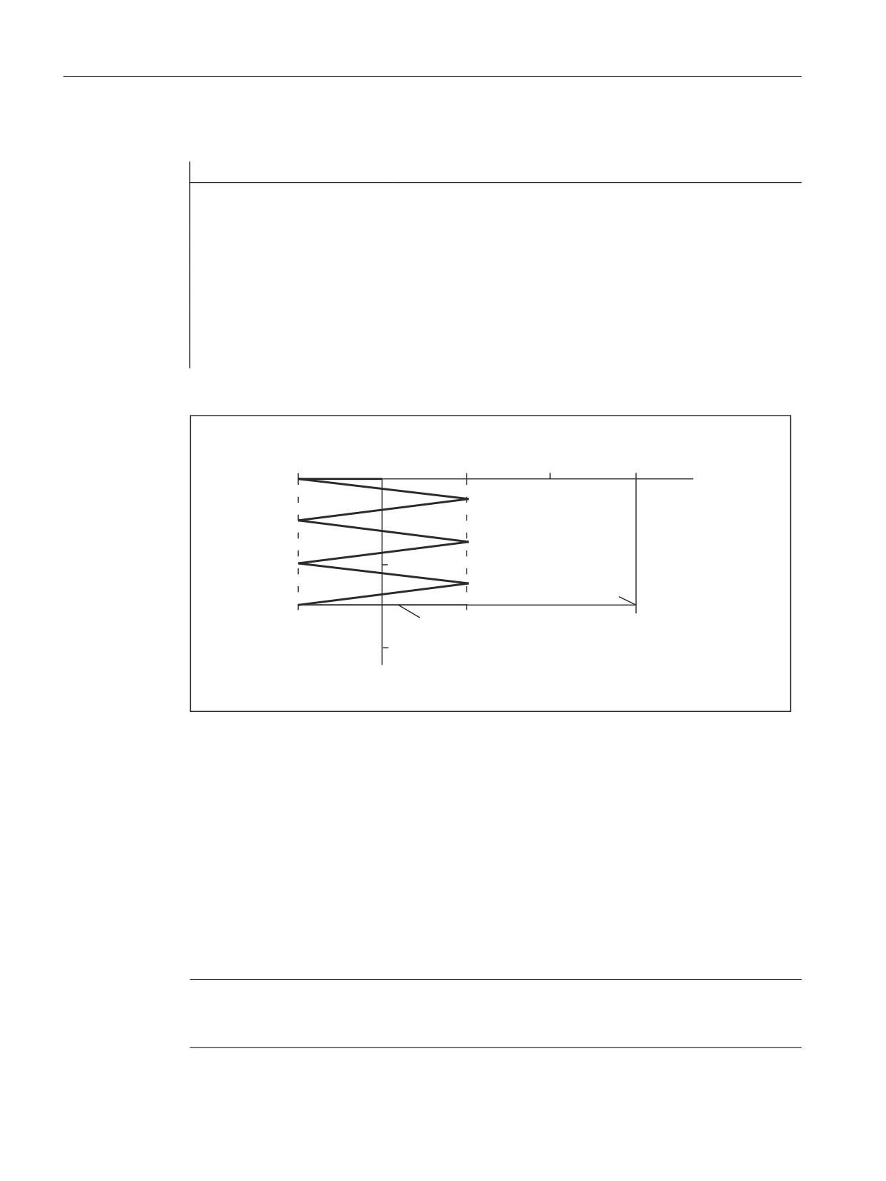
Example of asynchronous oscillation
Task
The oscillation axis Z must oscillate between -10 and 10. Approach reversal point 1 with exact
stop coarse and reversal point 2 without exact stop. The oscillation axis feedrate must be 5000.
3 sparking-out strokes must be executed at the end of the machining operation followed by
approach by oscillation axis to end position 30. The feedrate for the infeed axis is 1000, end of
the infeed in X direction is at 15.
Axes and spindles
Function Manual, 10/2020, 6FC5397-4GP40-0BA1
859
Oscillation
19.5 Examples
Program section
Program code
Comment
OSP1[Z]=-10
; Reversal point 1
OSP2[Z]=10
; Reversal point 2
OST1[Z]=-1
; Stop time at reversal point 1: Exact stop coarse
OST2[Z]=-2
; Stop time at reversal point 2: without exact stop
FA[Z]=5000
; Infeed for oscillating axis
OSNSC[Z]=3
; three spark-out strokes
OSE[Z]=-3
; End position
OS1 F500 X15
; start oscillation, infeed X axis
; with infeed 500, feed target 15
Z axis
-10
0
10
20
30
10
End position
U2
U1
3 sparking-out strokes
20
X axis
Figure 19-2
Sequences of oscillation movements and infeed, example 1
19.5.2
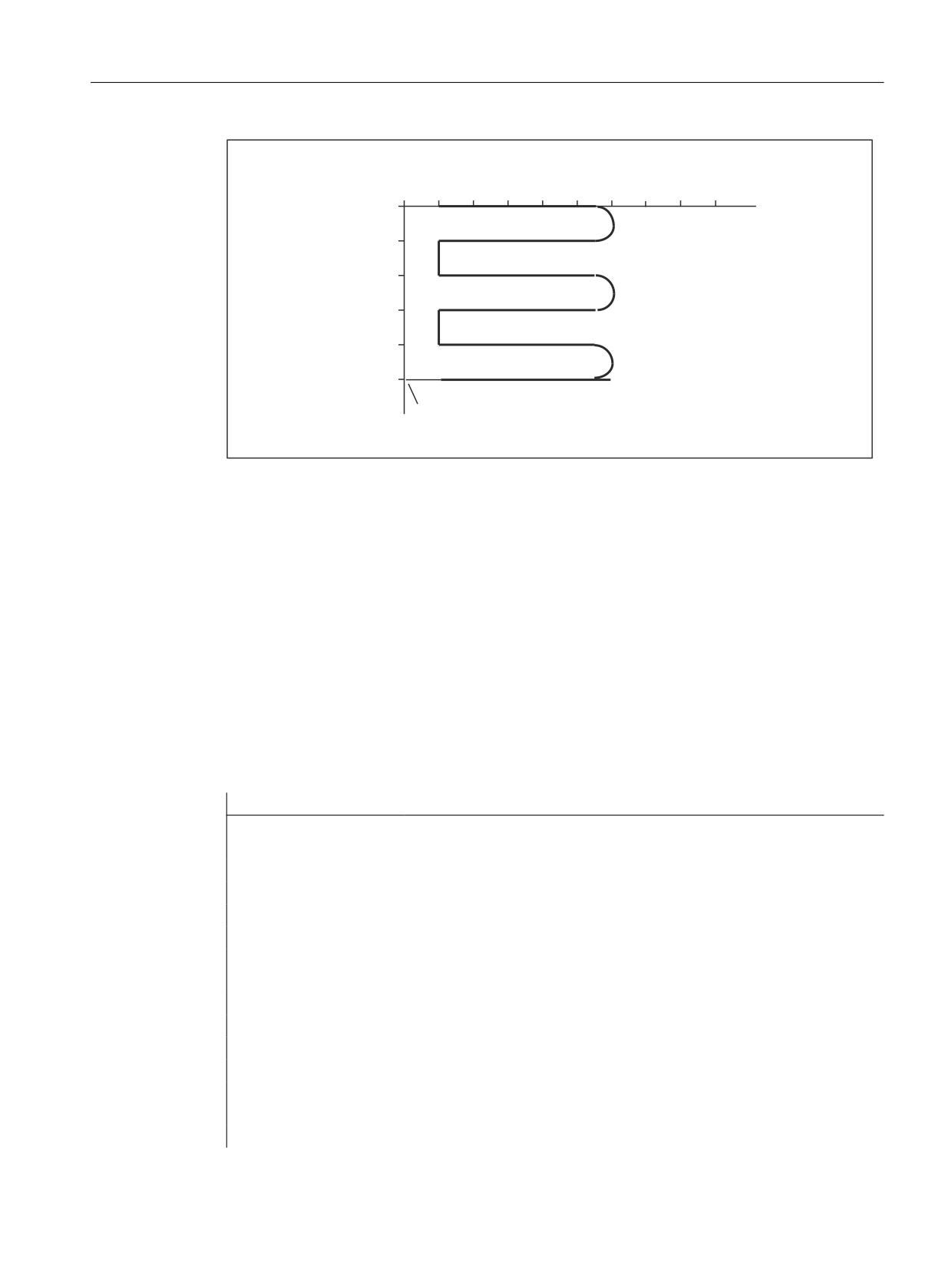
Example 1 of oscillation with synchronized actions
Task
Direct infeed must take place at reversal point 1; the oscillation axis must wait until the partial
infeed has been executed before it can continue traversal. At reversal point 2, the infeed must
take place at a distance of -6 from reversal point 2; the oscillation axis must not wait at this
reversal point until partial infeed has been executed. Axis Z is the oscillation axis and axis X is the
infeed axis (see Section "Oscillation controlled by synchronized actions (Page 848)).
Note
The setting data OSCILL_REVERSE_POS_1/2 are values in the machine coordinate system;
therefore comparison is only suitable with $AA_IM[n].
Axes and spindles
860
Function Manual, 10/2020, 6FC5397-4GP40-0BA1
Oscillation
19.5 Examples
Program section
Program code
Comment
; Example 1: Oscillation with synchronized actions
OSP1[Z]=10 OSP2[Z]=60
; explain reversal points 1 and 2
OST1[Z]=-2 OST2[Z]=0
; Reversal point 1: without exact stop
; Reversal point 2: Exact stop fine
FA[Z]=5000 FA[X]=250
; Feed for oscillating axis, feedrate, infeed axis
OSCTRL[Z]=(1+8+16,0)
; Switch off oscillation motion at reversal point 1
; After delete DTG spark-out and approach end position
; After DTG, approach relevant reversal position
;
OSNSC[Z]=3
; 3 sparking-out strokes
OSE[Z]=0
; End position = 0
WAITP(Z)
; enable oscillation for the Z axis
;
; motion-synchronous actions:
;
; always, when
the current position of the oscillating axis in the
;
Machine Coordinate System
; not equal to
reversal position 1
; then
set the marker with index 1 to value 0
;
(Reset marker 1)
WHENEVER $AA_IM[Z]<>$SA_OSCILL_REVERSE_POS1[Z] DO $AC_MARKER[1]=0
;
; always, when
the current position of the oscillating axis in the
;
Machine Coordinate System
; less than
the beginning of reversal range 2
;
(here: reversal point 2 -6),
; then
set the axial override of the infeed axis to 0%.
; and
set the marker with index 2 to value 0
;
(Reset marker 2)
WHENEVER $AA_IM[Z]<$SA_OSCILL_REVERSE_POS2[Z]-6 DO $AA_OVR[X]=0 $AC_MARKER[2]=0
;
; always, when
the current position of the oscillating axis in the
;
Machine Coordinate System
; equal to
reversal position 1,
; then
set the axial override of the oscillation axis to 0%
;
; and
Set the axial override of the infeed axis to
;
100% (so that the previous synchronized action
;
is cancelled!)
WHENEVER $AA_IM[Z]==$SA_OSCILL_REVERSE_POS1[Z] DO $AA_OVR[Z]=0 $AA_OVR[X]=100
;
; always, when
the distance-to-go of the partial infeed is
; equal to
0,
Axes and spindles
Function Manual, 10/2020, 6FC5397-4GP40-0BA1
861
Oscillation
19.5 Examples
Program code
Comment
; then
set the marker with index 2 to value 1
; and
set the marker with index 1 to value 1
WHENEVER $AA_DTEPW[X]==0 DO $AC_MARKER[2]=1 $AC_MARKER[1]=1
;
; always, when
the flag with index 2 is
; equal to
1,
; then
Set the axial override of the infeed axis to
;
0%, this prevents a premature infeed
;
(oscillation axis has not exited the
;
reversal point 1).
;
WHENEVER $AC_MARKER[2]==1 DO $AA_OVR[X]=0
;
; always, when
the flag with index 1 is
; equal to
1,
; then
Set the axial override of the infeed axis to
;
0%, this prevents a premature infeed
;
(oscillation axis has not exited the
;
reversal point range 2).
; and
Set the axial override of the infeed axis to
;
100% ('Start' oscillation)
WHENEVER $AC_MARKER[1]==1 DO $AA_OVR[X]=0 $AA_OVR[Z]=100
;
; if the current position of the oscillating axis in the MCS is
; equal to
reversal position 1,
; then
Set the axial override of the infeed axis to
;
100%
; and
Set the axial override of the infeed axis to
;
0% (so that the second synchronized action
;
is cancelled once!)
WHEN $AA_IM[Z]==$SA_OSCILL_REVERSE_POS1[Z] DO $AA_OVR[Z]=100 $AA_OVR[X]=0
;
;------------------------------------------
OSCILL[Z]=(X)
; Assign axis X to the oscillation axis Z as
POSP[X]=(5,1,1)
; infeed axis, this should
; infeed to end position 5 in steps
; from 1 and the sum of all part lengths should
; give exactly the end position
M30
; End of program
Axes and spindles
862
Function Manual, 10/2020, 6FC5397-4GP40-0BA1
Oscillation
19.5 Examples
Z axis
0
10
20
30
40
50
60
70
0
1.0
2.0
3.0
4.0
X axis
5.0
Approach reversal position 1 and 3 sparking-out strokes
Approach end position
Figure 19-3
Sequences of oscillation movements and infeed, example 1
19.5.3
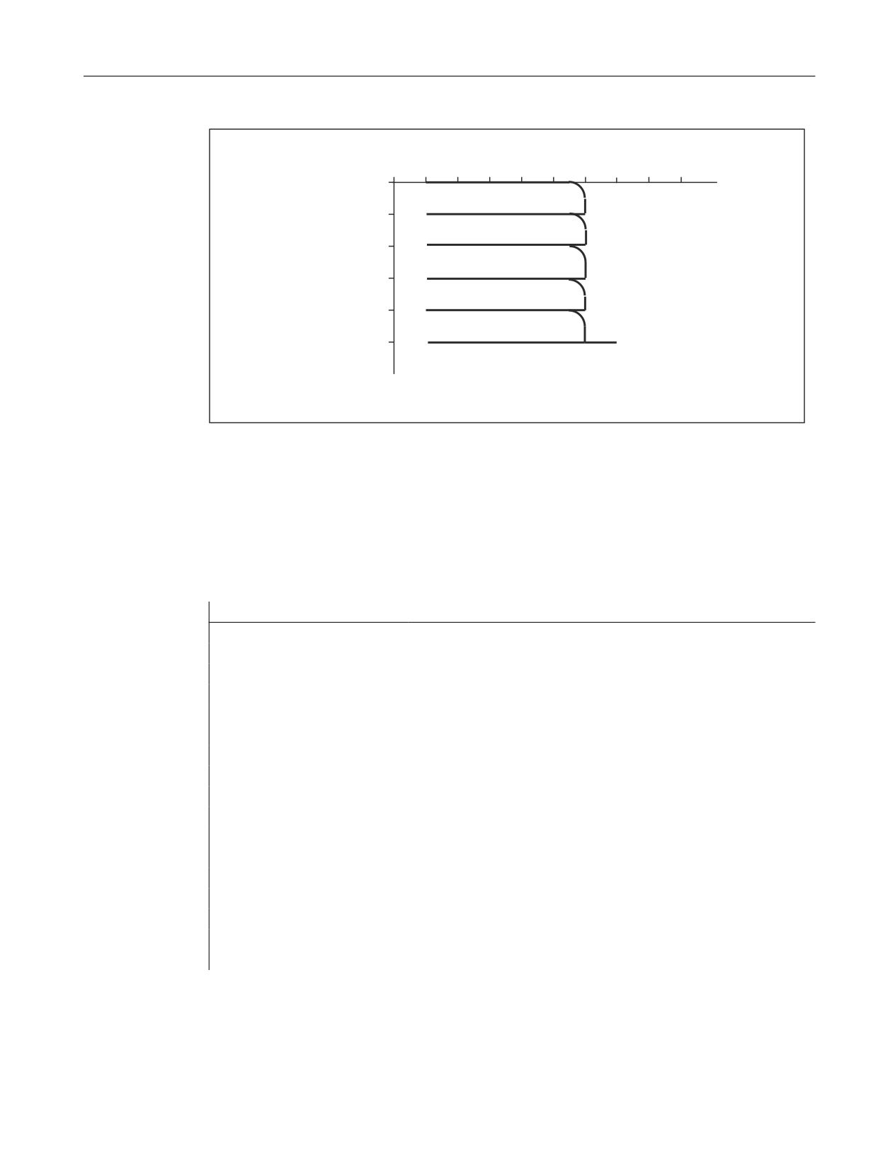
Example 2 of oscillation with synchronized actions
Task
No infeed must take place at reversal point 1. At reversal point 2, the infeed must take place at
distance ii2 from reversal point 2; the oscillation axis must wait at this reversal point until partial
infeed has been executed. Axis Z is the oscillation axis and axis X the infeed axis.
Program section
Example 2: Oscillation with synchronized actions
Program code
Comment
DEF INT ii2
; Define variable for reversal area 2
;
OSP1[Z]=10 OSP2[Z]=60 ; explain reversal points 1 and 2
OST1[Z]=0 OST2[Z]=0
; Reversal point 1: Exact stop fine
;
Reversal point 2: Exact stop fine
FA[Z]=5000 FA[X]=100
; Feed for oscillating axis, feed for infeed axis
OSCTRL[Z]=(2+8+16,1)
; Switch off oscillation motion at reversal point 2
;
After delete distance-to-go, spark-out and end position
;
Approach appropriately after delete distance-to-go
;
Approach reversal position
OSNSC[Z]=3
; 3 sparking-out strokes
OSE[Z]=70
; End position = 70
ii2=2
; Set reversal point range
WAITP(Z)
; permit oscillation for Z axis
;
Axes and spindles
Function Manual, 10/2020, 6FC5397-4GP40-0BA1
863
Oscillation
19.5 Examples
Program code
Comment
; motion-synchronous actions:
; always, when
the current position of the oscillating axis in the
;
Machine Coordinate System
; less than
the start of reversal area 2
; then
set the axial override of the feed axis
;
to 0%
; and
set the marker with index 0 to value 0
WHENEVER $AA_IM[Z]<$SA_OSCILL_REVERSE_POS2[Z]-ii2 DO $AA_OVR[X]=0 $AC_MARKER[0]=0
;
; always, when
the current position of the oscillating axis in the
;
Machine Coordinate System
; greater or equal to
reversal position 2
; then
set the axial override of the oscillating axis
;
to 0%
WHENEVER $AA_IM[Z]>=$SA_OSCILL_REVERSE_POS2[Z] DO $AA_OVR[Z]=0
;
; always, when
the distance-to-go of the partial infeed is
; equal to
0,
; then
set the marker with index 0 to value 1
WHENEVER $AA_DTEPW[X] == 0 DO $AC_MARKER[0]=1
;
; always, when
the flag with index 0 is
; equal to
1,
; then
set the axial override of the infeed axis to 0%
;
to prevent a new premature infeed
;
(oscillation axis has not yet exited the reversal point
range 2,
;
but the infeed axis is ready for a
;
new infeed)
; and
set the axial override of the oscillation axis to 100%
;
(this cancels the 2nd synchronized action)
;
WHENEVER $AC_MARKER[0]==1 DO $AA_OVR[X]=0 $AA_OVR[Z]=100
;
OSCILL[Z]=(X)
; Start the axes
POSP[X]=(5,1,1)
;
The oscillating axis Z is assigned axis X as
;
an infeed axis
;
Axis X should travel to end position 5 in
;
increments of 1
;
M30
Axes and spindles
864
Function Manual, 10/2020, 6FC5397-4GP40-0BA1
Oscillation
19.5 Examples
Z axis
0
10
20
30
40
50
60
70
0
1.0
2.0
3.0
4.0
Approach end position
5.0
Approach reversal position 2 and 3 sparking-out strokes
X axis
Figure 19-4
Sequences of oscillation movements and infeed, example 2
19.5.4
Examples for starting position
19.5.4.1
Define starting position via language command
Program code
Comment
WAITP(Z)
; enable oscillation for the Z axis
OSP1[Z]=10 OSP2[Z]=60
; explain reversal points 1 and 2
OST1[Z]=-2 OST2[Z]=0
; Reversal point 1: without exact stop
; Reversal point 2: Exact stop fine
FA[Z]=5000 FA[X]=2000
; Infeed for oscillating axis,
; feedrate for infeed axis
OSCTRL[Z]=(1+8+16,0)
; Switch off oscillation motion at reversal point 1
; after delete DTG spark-out and approach end position,
; After DTG, approach relevant reversal position
;
OSNSC[Z]=3
; 3 sparking-out strokes
OSE[Z]=0
; End position = 0
OSB[Z]=0
; Start position = 0
OS[Z]=1 X15 F500
; Start oscillation, continuous infeed
OS[Z]=0
; Deactivate oscillation
WAITP(Z)
; wait for completion of the oscillation motion
M30
Axes and spindles
Function Manual, 10/2020, 6FC5397-4GP40-0BA1
865
Oscillation
19.5 Examples
Explanation
When the Z axis starts oscillation, it first approaches the starting position (position = 0 in the
example) and then begins the oscillation motion between the reversal points 10 and 60. When
the X axis has reached its end position 15, the oscillation finishes with 3 sparking out strokes and
approach of end position 0.
19.5.4.2
Start oscillation via setting data
Program code
Comment
WAITP(Z)
STOPRE
$SA_OSCILL_REVERSE_POS1[Z]=-10
;
reversal position 1 = -10
$SA_OSCILL_REVERSE_POS2[Z]=30
;
reversal position 2 = 30
$SA_OSCILL_START_POS[Z] = -50
;
Start position = -50
$SA_OSCILL_CTRL_MASK[Z] = 512
;
Approach start position,
;
on switch-off, stop at the next
;
reversal point
;
do not approach any end position
;
no sparking-out strokes for DTG
$SA_OSCILL_VELO[ Z ] = 5000
;
Infeed for oscillating axis
$SA_OSCILL_IS_ACTIVE[ Z ] = 1
;
starting
$SA_OSCILL_DWELL_TIME1[ Z ] = -2
;
without wait for exact stop
$SA_OSCILL_DWELL_TIME2[ Z ] = 0
;
wait for fine exact stop
STOPRE
X30 F100
$SA_OSCILL_IS_ACTIVE[ Z ] = 0
;
Stop
WAITP(Z)
M30
Description
When the Z axis starts oscillation, it first approaches the starting position (position = -50 in the
example) and then begins the oscillation motion between the reversal points -10 and 30. When
the X axis has reached its end position 30, the oscillation finishes at the next approached reversal
point.
19.5.4.3
Non-modal oscillation (starting position = reversal point 1)
Oscillation with synchronized actions
Program code
Comment
N701
; Oscillation with synchronized actions,
; start position == reversal point 1
;
Axes and spindles
866
Function Manual, 10/2020, 6FC5397-4GP40-0BA1
Oscillation
19.5 Examples
Program code
Comment
N702 OSP1[Z]=10 OSP2[Z]=60
; explain reversal points 1 and 2
N703 OST1[Z]=0 OST2[Z]=0
; Reversal point 1: Exact stop coarse
; Reversal point 2: Exact stop fine
N704 FA[Z]=5000 FA[X]=2000
; Infeed for oscillating axis,
; feedrate for infeed axis
N705 OSCTRL[Z]=(1+8+16.0)
; switch off oscillation motion at
; reversal point 1 after DTG spark-out
; and approach end position
; After DTG, approach relevant
; reversal position
;
N706 OSNSC[Z]=3
; 3 sparking-out strokes
N707 OSE[Z]=0
; End position = 0
N708 OSB[Z]=10
; Start position = 10
N709 WAITP(Z)
; enable oscillation for the Z axis
;
; motion-synchronous actions:
; set marker with index 2 on 1 (initialization)
WHEN TRUE DO $AC_MARKER[2]=1
;
; always, when
the marker with index 2 equals 0
;
and the current position of the oscillating axis
;
does not equal the reversal position 1
; then
set the marker with index 1 to 0.
;
WHENEVER ($AC_MARKER[2] == 0) AND $AA_IW[Z]>$SA_OSCILL_REVERSE_POS1[Z])
DO $AC_MARKER[1]=0
; always, when
the current position of the oscillating axis
;
is less than the start of reversal range 2
;
; then
set the axial override of the feed axis
;
to 0 and set the marker with index 0 to
;
0
WHENEVER $AA_IW[Z]<$SA_OSCILL_REVERSE_POS2[Z]-6 DO $AA_OVR[X]=0 $AC_MARKER[0]=0
;
; always, when
the current position of the oscillating axis
;
is equal to the reversal position 1,
; then
set the axial override of the oscillating axis
;
to 0 and set the axial override of the
;
infeed axis to 100% (so that the
;
previous synchronized action is cancelled!)
WHENEVER $AA_IW[Z]==$SA_OSCILL_REVERSE_POS1[Z] DO $AA_OVR[Z]=0 $AA_OVR[X]=100
;
; always, when
the distance-to-go of the partial infeed equals
0
Axes and spindles
Function Manual, 10/2020, 6FC5397-4GP40-0BA1
867
Oscillation
19.5 Examples
Program code
Comment
;
; then
Set the marker with index 0 to 1 and
;
set the marker with index 1 to 1 and
WHENEVER $AA_DTEPW[X]==0 DO $AC_MARKER[0]=1 $AC_MARKER[1]=1
;
; always, when
the marker with index 0 equals 1,
; then
set the axial override of the feed axis
;
to 0 to prevent a new premature
;
infeed!
WHENEVER $AC_MARKER[0]==1 DO $AA_OVR[X]=0
;
; always, when
the marker with index 1 equals 1,
; then
set the axial override of the feed axis
;
to 0 (to prevent a new premature
;
infeed!) and set the
;
axial override of the oscillation axis to 100%
;
(so that the previous
;
synchronized action is canceled!)
WHENEVER $AC_MARKER[1]==1 DO $AA_OVR[X]=0 $AA_OVR[Z]=100
;
; When
the current position of the oscillating axis
;
is equal to the reversal position 1,
; then
reset the marker with index 2,
;
release the first synchronized action (no
;
infeed when reaching the start position
;
==
reversal position 1)
WHEN $AA_IW[Z]==$SA_OSCILL_REVERSE_POS1[Z] DO $AC_MARKER[2]=0
;
;----------------------------------
N750 OSCILL[Z]=(X) POSP[X]=(5,1,1)
; Assign axis X to the oscillation axis Z as infeed axis,
; this should infeed to end position 5
; in substeps of 1 and the sum of all sublengths
; should be exactly the same as the end position.
;
N780 WAITP(Z)
; release the Z axis
;
N790 X0 Z0
N799 M30
; End of program
Description
The starting position matches reversal point 1. The WHEN
synchronized actions (see above)
prevent an infeed when the starting position is reached.
Axes and spindles
868
Function Manual, 10/2020, 6FC5397-4GP40-0BA1

Oscillation
19.6 Data lists
19.5.5
Example of external oscillation reversal
19.5.5.1
Change reversal position via synchronized action with "external oscillation reversal"
Program code
Comment
DEFINE BREAKPZ AS $AA_OSCILL_BREAK_POS1[Z]
DEFINE REVPZ AS $SA_OSCILL_REVERSE_POS1[Z]
WAITP(Z)
; enable oscillation for the Z axis
OSP1[Z]=10 OSP2[Z]=60
; explain reversal points 1 and 2
OSE[Z]=0
; End position = 0
OSB[Z]=0
; Start position = 0
; At external reversal of oscillation for
; oscillation reversal point 1, adapt this
WHENEVER BREAKPZ <> REVPZ DO $$SA_OSCILL_REVERSE_POS1 = BREAKPZ
OS[Z]=1 X150 F500
; Start oscillation, continuous infeed
OS[Z]=0
; Deactivate oscillation
WAITP(Z)
; wait for completion of the oscillation motion
M30
19.6
Data lists
19.6.1
Machine data
19.6.1.1
General machine data
Number
Identifier: $MN_
Description
10710
PROG_SD_RESET_SAVE_TAB
Oscillations to be saved from SD
11460
OSCILL_MODE_MASK
Control screen form for asynchronous oscillation
Axes and spindles
Function Manual, 10/2020, 6FC5397-4GP40-0BA1
869

Oscillation
19.6 Data lists
19.6.2
Setting data
19.6.2.1
Axis/spindle-specific setting data
Number Identifier: $SA_
Description
43700
OSCILL_REVERSE_POS1
Position at reversal point 1
43710
OSCILL_REVERSE_POS2
Position at reversal point 2
43720
OSCILL_DWELL_TIME1
Stop time at reversal point 1
43730
OSCILL_DWELL_TIME2
Stop time at reversal point 2
43740
OSCILL_VELO
Feed velocity of oscillation axis
43750
OSCILL_NUM_SPARK_CYCLES
Number of sparking-out strokes
43760
OSCILL_END_POS
Position after sparking-out strokes/at end of oscillation move-
ment
43770
OSCILL_CTRL_MASK
Control screen form for oscillation
43780
OSCILL_IS_ACTIVE
Oscillation movement ON/OFF
43790
OSCILL_START_POS
Position that is approached after oscillation before reversal
point 1, if activated in SD43770:
19.6.3
System variables
19.6.3.1
Main run variables for motion-synchronous actions
Main run variable_read
The following variables are provided for main run variable_read:
$A_IN[<arith. expression>]
digital input (Boolean)
$A_OUT[<arith. expression>]
digital output (Boolean)
$A_INA[<arith. expression>]
analog input (Boolean)
$A_OUTA[<arith. expression>]
analog output (Boolean)
$A_INCO[<arith. expression>]
comparator inputs (Boolean)
$AA_IW[<axial expression>]
actual position PCS axis (real)
$AA_IB[<axial expression>]
actual position BCS axis (real)
$AA_IM[<axial expression>]
Actual position MCS axis (IPO setpoints) (real)
With $AA_IM[S1] setpoints for spindles can be eval-
uated. Modulo calculation is used for spindles and
rotary axes, depending on machine data
$MA_ROT_IS_MODULO and $MA_DISPLAY_IS_MOD-
ULO.
$AA_OSCILL_BREAK_POS1
Breaking position after external oscillation reversal
when approaching reversal point 1
$AA_OSCILL_BREAK_POS2
Breaking position after external oscillation reversal
when approaching reversal point 2
Axes and spindles
870
Function Manual, 10/2020, 6FC5397-4GP40-0BA1

Oscillation
19.6 Data lists
$AC_TIME
Time from the start of the block (real) in seconds
(including the times for the internally generated in-
termediate blocks)
$AC_TIMES
Time from the start of the block (real) in seconds
(without times for the internally generated inter-
mediate blocks)
$AC_TIMEC
Time from the start of the block (real) in IPO steps
(including steps for the internally generated inter-
mediate blocks)
$AC_TIMESC
Time from the start of the block (real) in IPO steps
(without steps for the internally generated inter-
mediate blocks)
$AC_DTBB
Distance from beginning of block in BCS
(Distance to begin, baseCoor) (real)
$AC_DTBW
Distance from beginning of block in PCS
(Distance to begin, workpieceCoor) (real)
$AA_DTBB[<axial expression>]
axial distance from beginning of block in BCS
(Distance to begin, baseCoor) (real)
$AA_DTBW[<axial expression>]
axial distance from beginning of block in PCS
(Distance to begin, workpieceCoor) (real)
$AC_DTEB
Distance to end of block in BCS (Distance to end)
(Distance to end, baseCoor) (real)
$AC_DTEW
Distance to end of block in PCS
(Distance to end, workpieceCoor) (real)
$AA_DTEB[<axial expression>]
axial distance to end of movement in BCS
(Distance to end, baseCoor) (real)
$AA_DTEW[<axial expression>]
axial distance to end of movement in PCS
(Distance to end, workpieceCoor) (real)
$AC_PLTBB
Distance from beginning of block in BCS
(Path Length from begin, baseCoor) (real)
$AC_PLTEB
Distance to end of block in BCS (Distance to end)
(Path Length to end, baseCoor) (real)
$AC_VACTB
Path speed in BCS
(Velocity actual, baseCoor) (real)
$AC_VACTW
Path speed in PCS
(Velocity actual, workPieceCoor) (real)
$AA_VACTB[<axial expression>]
Axis velocity in BCS
(Velocity actual, baseCoor) (real)
$AA_VACTW[<axial expression>]
Axis velocity in PCS
(Velocity actual, workPieceCoor) (real)
$AA_DTEPB[<axial expression>]
axial distance-to-go for oscillation infeed in BCS
(Distance to end, pendulum, baseCoor) (real)
$AA_DTEPW[<axial expression>]
axial distance-to-go for oscillation infeed in PCS
(Distance to end, pendulum, workpieceCoor) (real)
$AC_DTEPB
Path distance-to-go for oscillation infeed in BCS
(not P2) (Distance to end, pendulum, baseCoor) (re-
al)
$AC_DTEPW
Path distance-to-go for oscillation infeed in PCS
(not P2) (Distance to end, pendulum, workpiece-
Coor) (real)
Axes and spindles
Function Manual, 10/2020, 6FC5397-4GP40-0BA1
871

Oscillation
19.6 Data lists
$AC_PATHN
(Path parameter normalized) (real)
Normalized path parameter: 0 for beginning of block
to 1 for end of block
$AA_LOAD[<axial expression>]
Drive utilization
$AA_POWER[<axial expression>]
Drive efficiency in W
$AA_TORQUE[<axial expression>]
Drive torque setpoint in Nm
$AA_CURR[<axial expression>]
Actual current value of axis
$AC_MARKER[<arithmetic_expression>] (int)
Flag variables: Can be used to set up complex condi-
tions in synchronized actions:
8 bit memories (Index 0 - 7) are available.
Reset sets the bit memories to 0.
Example:
WHEN
DO $AC_MARKER[0]=2
WHEN
DO $AC_MARKER[0]=3
WHEN $AC_MARKER[0]==3 DO $AC_OVR=50
Can be read and written independently of synchro-
nous actions in the parts program:
IF $AC_MARKER == 4 GOTOF SPRUNG
$AC_PARAM[<arithmetic_expression>] (real)
Floating-decimal parameter for synchronous ac-
tions. Serves as intermediate saving and evaluation
in synchronous actions.
50 Parameters (Index 0 - 49) are available.
$AA_OSCILL_REVERSE_POS1
[<axial expression>] (real)
$AA_OSCILL_REVERSE_POS2
current oscillation reversal points 1 and 2:
[<axial expression>] (real)
The current setting data from
$SA_OSCILL_REVERSE_POS1 or
$SA_OSCILL_REVERSE_POS2 is read.
This enables setting data changes at the reversal po-
sitions during active oscillation, i.e. during an active
synchronous action.
Conditions
Conditions for motion-synchronous actions are formulated:
Main run variable comparison operator expression
For details, see:
Further information
Function Manual Synchronized Actions
Axes and spindles
872
Function Manual, 10/2020, 6FC5397-4GP40-0BA1
Software cams, position switching signals
20
20.1
Brief description
Function
The "Software cams" function generates position-dependent switching signals for axes that
supply an actual position value (machine axes) and for simulated axes.
These cam signals can be output to the PLC and also to the NC I/O.
The cam positions at which signal outputs are set can be defined and altered via setting data. The
setting data can be read and written via HMI, PLC and part program.
Activation
The "Software cams" function can be activated and used in all operating modes. The function
remains active in the event of reset or Emergency Stop.
Field of application
Output cam signals can be used, for example:
• To activate protection zones
• To initiate additional movements as a function of position
• As reversing signals for hydraulically controlled oscillation axes
Axis types
Software cams can be used on linear and modulo rotary axes that are defined as machine axes.
Cam range/cam pair
Cams are always assigned in pairs to axes. A pair consists of a plus and a minus cam. 32 cam pairs
are available.
The plus and minus cams each simulate a mechanical cam which is actuated at a defined point
(cam position) in a specific approach direction when the axis reaches the cam position.
Cam ranges are assigned to the plus and minus cams as follows:
• Cam range plus:
All positions ≥ plus cam
• Cam range minus:
All positions ≤ minus cam
Axes and spindles
Function Manual, 10/2020, 6FC5397-4GP40-0BA1
873
Software cams, position switching signals
20.2 Cam signals and cam positions
20.2
Cam signals and cam positions
20.2.1
Generation of cam signals for separate output
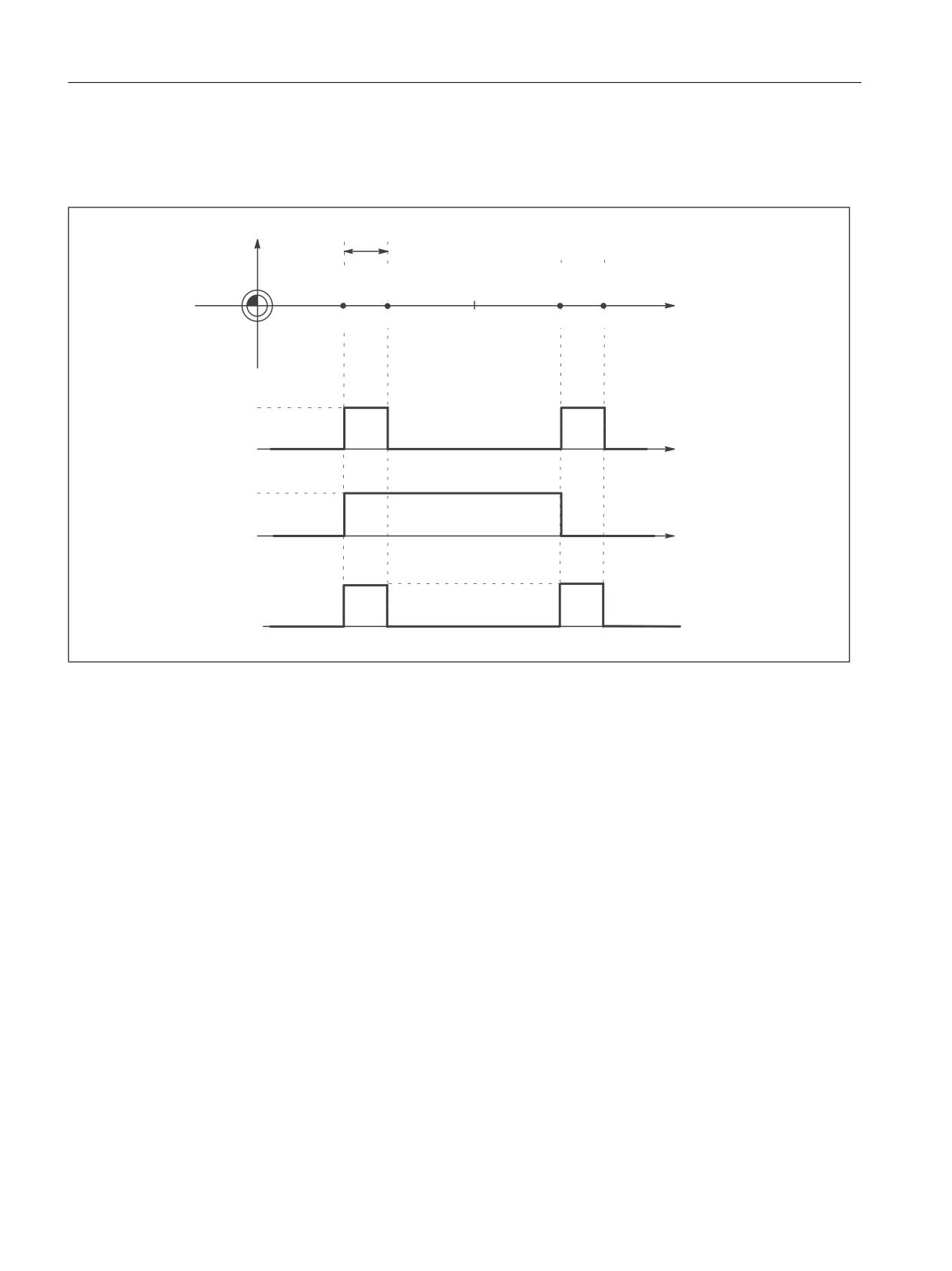
Separate output of the plus and minus cam signals makes it easy to detect whether the axis is
within or outside the plus or minus cam range.
Axes and spindles
874
Function Manual, 10/2020, 6FC5397-4GP40-0BA1
Software cams, position switching signals
20.2 Cam signals and cam positions
Linear axes
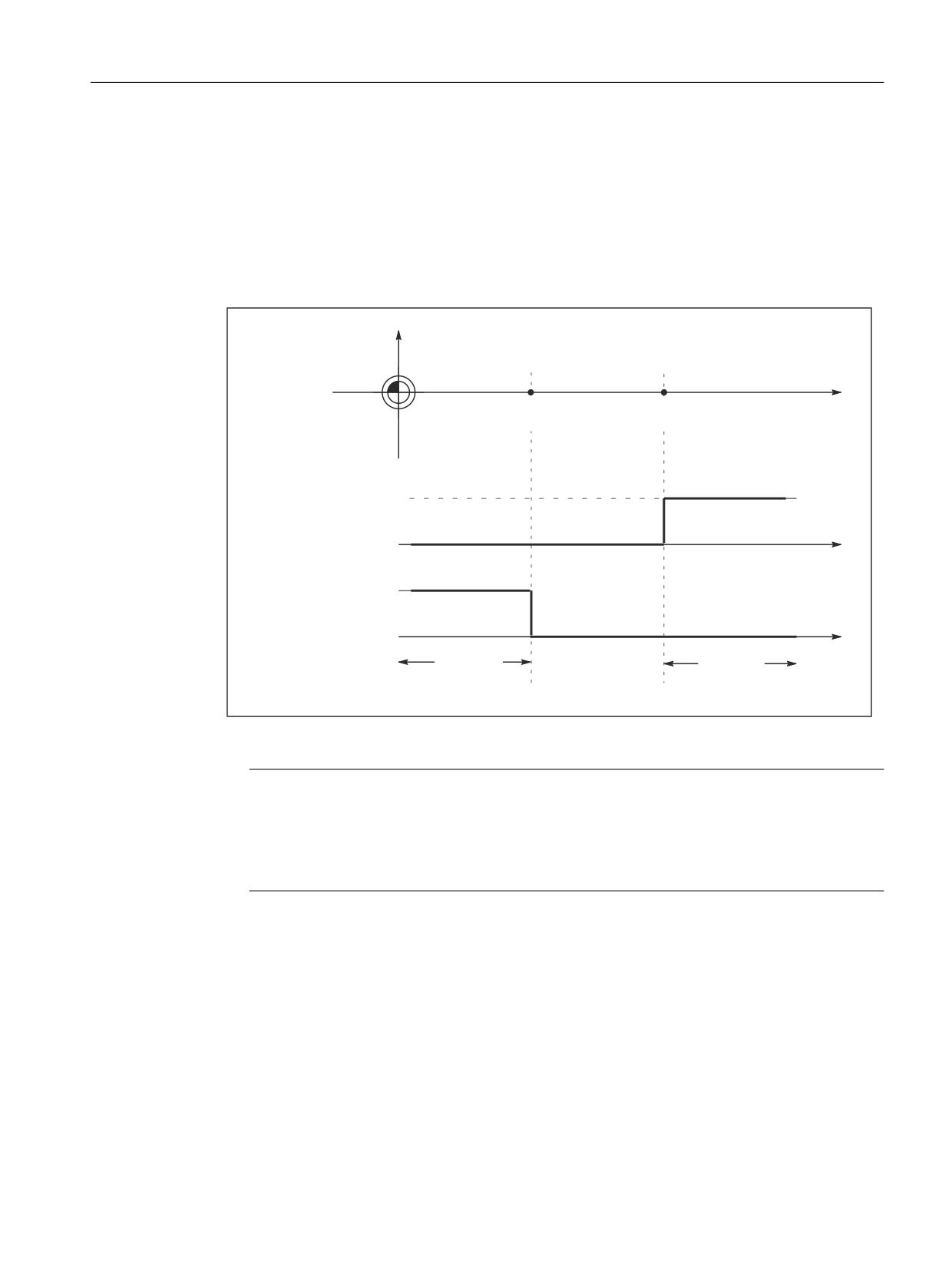
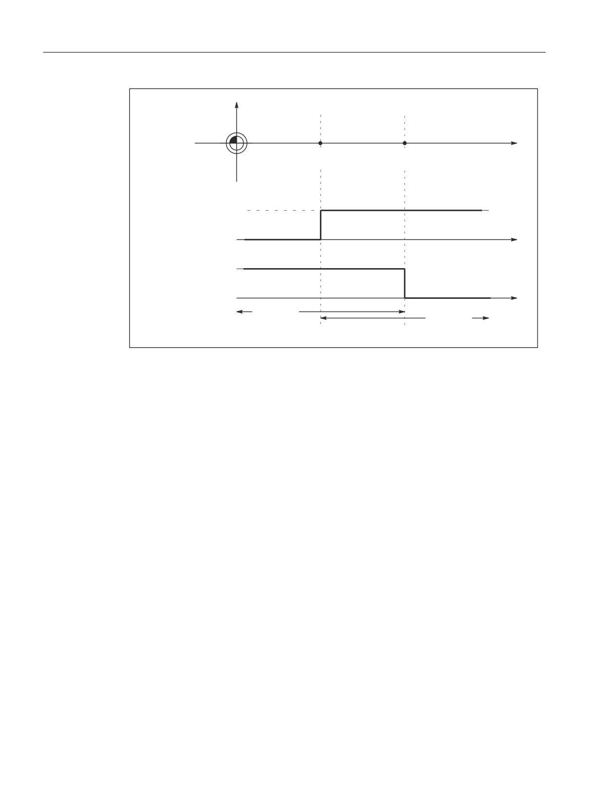
The switching edges of the cam signals are generated as a function of the axis traversing
direction:
• The minus cam signal switches from 1 to 0 when the axis traverses the minus cam in the
positive axis direction.
• The plus cam signal switches from 0 to 1 when the axis traverses the plus cam in the positive
direction.
Machine axis[m]
Machine
cam position
cam position
Machine axis[n]
zero
(minus cam)
(plus cam)
[mm, inch]
1
Plus cam signal
0
1
Minus cam signal
0
Cam range
Cam range
minus
plus
Figure 20-1
Software cams for linear axis (minus cam < plus cam)
Note
If the axis is positioned exactly at the output cam position (plus or minus), the defined output
flickers. If the axis moves one increment further, the output becomes a definite zero or one.
Flickering of the actual position causes the signals to flicker in this manner.
The actual position is evaluated.
Axes and spindles
Function Manual, 10/2020, 6FC5397-4GP40-0BA1
875
Software cams, position switching signals
20.2 Cam signals and cam positions
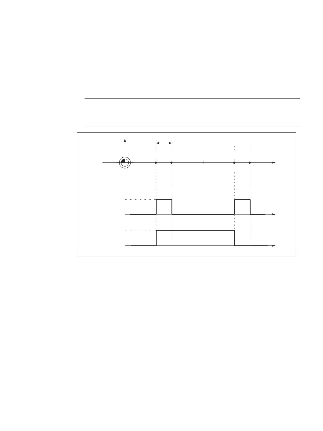
Machine axis[m]
Machine
cam position
cam position
Machine axis[n]
zero
(plus cam)
(minus cam)
[mm, inch]
1
Plus cam signal
0
1
Minus cam signal
0
Cam range
Cam range
minus
plus
Figure 20-2
Software cams for linear axis (plus cam < minus cam)
Axes and spindles
876
Function Manual, 10/2020, 6FC5397-4GP40-0BA1
Software cams, position switching signals
20.2 Cam signals and cam positions
Modulo rotary axes
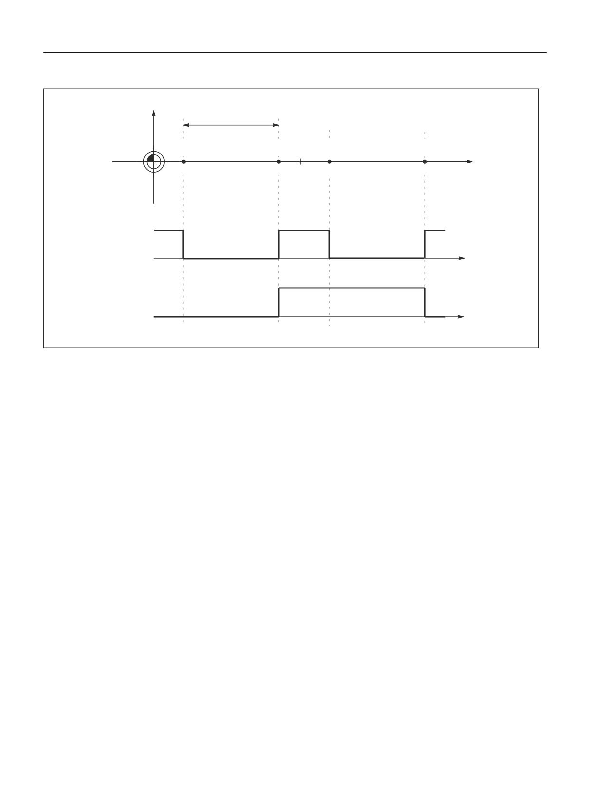
The switching edges of the cam signals are generated as a function of the rotary axis traversing
direction:
• The plus cam signal switches from 0 to 1 when the axis traverses the minus cam in a positive
axis direction and from 1 back to 0 when it traverses the plus cam.
• The minus cam signal changes level in response to every positive edge of the plus cam signal.
Note
The described response of the plus cam applies on conditionthat:
plus cam - minus cam < 180 degrees
< 180¡˘
Machine axis[m]
Minus
Plus
Minus
Plus
cam
cam
cam
cam
Machine
0¡˘
120¡˘
180¡˘
0¡˘
120¡˘
180¡˘
Machine axis[n]
zero
(modulo rotary
axis) [degrees]
1
Plus cam
signal
0
1
Minus cam
signal
0
Figure 20-3
Software cams for modulo rotary axis (plus cam - minus cam < 180 degrees)
The signal change of the minus cam makes it possible to detect traversal of the cam even if the
cam range is set so small that the PLC cannot detect it reliably.
Both cam signals can be output to the PLC and to the NC I/O. Separate output of the plus and
minus cam signals makes it easy to detect whether the axis is within or outside the plus or minus
cam range.
If this condition (plus cam - minus cam < 180 degrees) is not fulfilled or if the minus cam is set
to a greater value than the plus cam, then the response of the plus cam signal is inverted. The
response of the minus cam signal remains unchanged.
Axes and spindles
Function Manual, 10/2020, 6FC5397-4GP40-0BA1
877
Software cams, position switching signals
20.2 Cam signals and cam positions
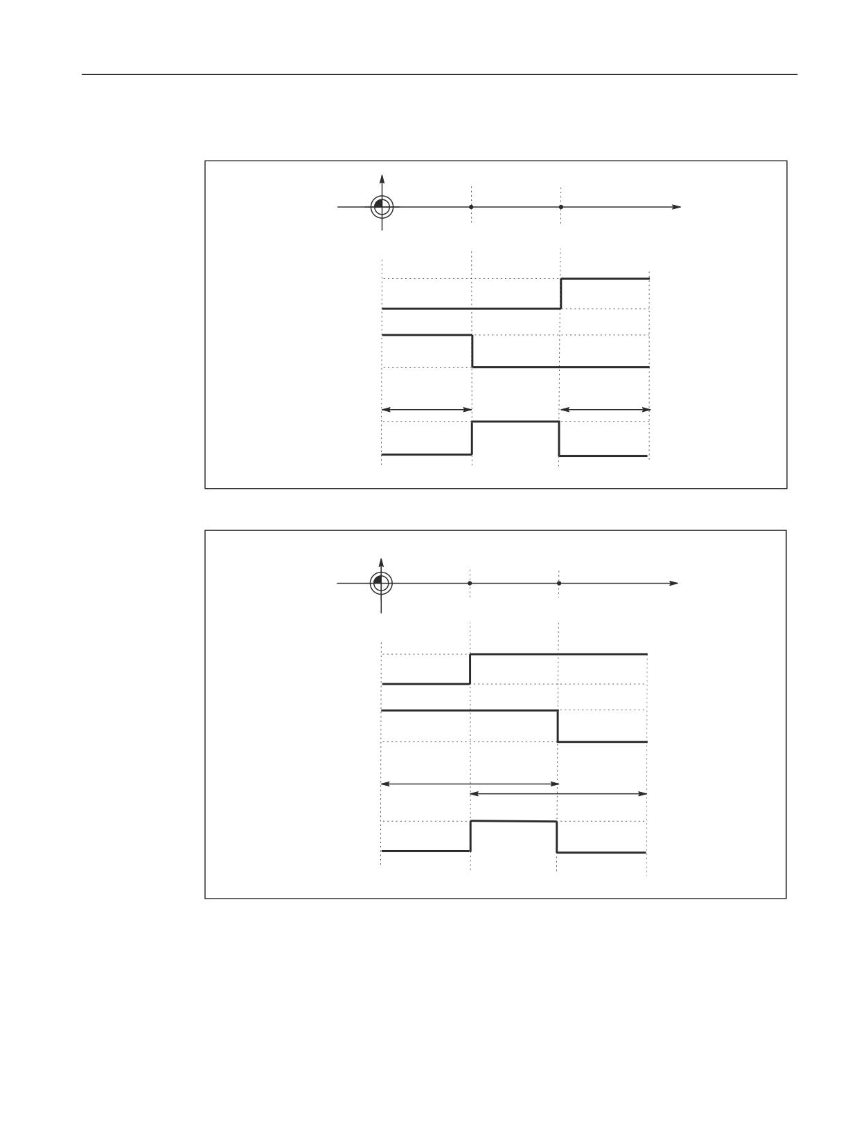
Machine axis[m]
> 180¡˘
Minus
Plus
Minus
Plus
cam
cam
cam
cam
0¡˘
90¡˘
290¡˘
0¡˘
90¡˘
290¡˘
Machine axis[n]
Machine
zero
(modulo rotary
axis) [degrees]
1
Plus
cam signal
0
1
Minus
cam signal
0
Figure 20-4
Software cams for modulo rotary axis (plus cam - minus cam > 180 degrees)
20.2.2
Generation of cam signals with gated output
The plus and minus cam output signals are gated in the case of:
• timer-controlled cam signal output to the four onboard outputs on the NCU
• Output to the NCK I/O, if the 2nd byte in the following machine data was not specified (= "0"):
MD10470 SW_CAM_ASSIGN_FASTOUT_2
MD10473 SW_CAM_ASSIGN_FASTOUT_4
Axes and spindles
878
Function Manual, 10/2020, 6FC5397-4GP40-0BA1
Software cams, position switching signals
20.2 Cam signals and cam positions
Linear axes
Machine axis
Machine zero
cam position
Cam position
Machine axis
(minus cam)
(plus cam)
[mm, inch]
Plus cam signal:
1
0
Minus cam signal:
1
0
Cam range
Cam range
minus
plus
1
Digital output
0
Figure 20-5
Position switching signals for linear axis (minus cam < plus cam)
Machine axis
Machine zero
Cam position
Cam position
Machine axis
(plus cam)
(minus cam)
[mm, inch]
Plus cam signal:
1
0
Minus cam signal:
1
0
Cam range
Cam range
minus
plus
1
Digital output
0
Figure 20-6
Position switching signals for linear axis (plus cam < minus cam)
Axes and spindles
Function Manual, 10/2020, 6FC5397-4GP40-0BA1
879
Software cams, position switching signals
20.2 Cam signals and cam positions
Modulo rotary axis
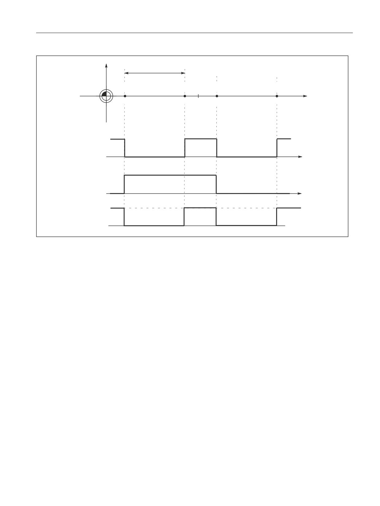
The default signal response for modulo rotary axes is dependent on the cam width:
<180¡˘
Machine axis[m]
Minus
Plus
Minus
Plus
cam
cam
cam
cam
Machine
0¡˘
120¡˘
180¡˘
0¡˘
120¡˘
180¡˘
Machine axis[n]
zero
(modulo rotary
axis) [degrees]
1
Plus
cam signal
0
1
Minus
cam signal
0
1
Digital
output
0
Figure 20-7
Software cams for modulo rotary axis (plus cam - minus cam < 180 degrees)
Axes and spindles
880
Function Manual, 10/2020, 6FC5397-4GP40-0BA1
Software cams, position switching signals
20.2 Cam signals and cam positions
Machine axis[m]
> 180¡˘
Minus
Plus
Minus
Plus
cam
cam
cam
cam
0¡˘
90¡˘
290¡˘
0¡˘
90¡˘
290¡˘
Machine axis[n]
Machine
(modulo rotary
zero
axis) [degrees]
1
Plus
cam signal
0
1
Minus
cam signal
0
1
Digital
output
0
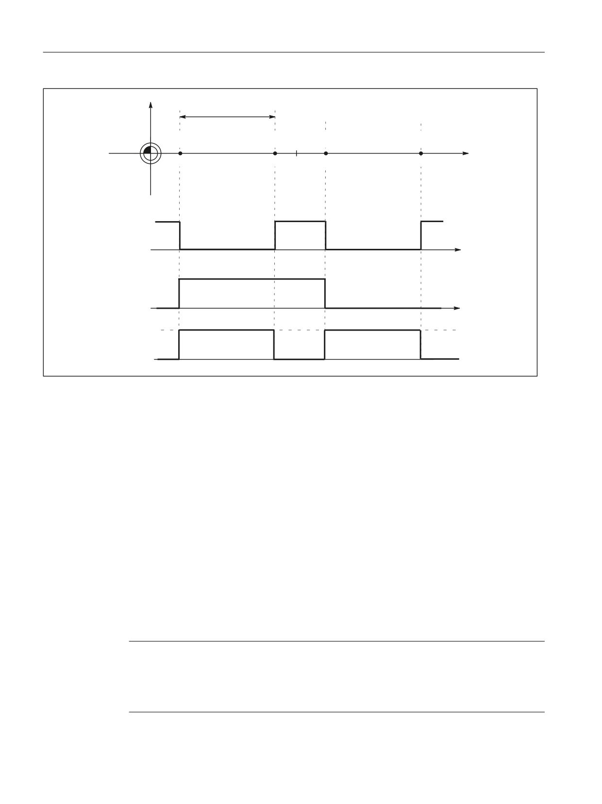
Figure 20-8
Software cams for modulo rotary axis (plus cam - minus cam > 180 degrees)
Suppression of signal inversion
With the following setting, selection of signal inversion for
"plus cam - minus cam > 180 degrees" can be suppressed.
MD10485 SW_CAM_MODE bit 1=1
Axes and spindles
Function Manual, 10/2020, 6FC5397-4GP40-0BA1
881
Software cams, position switching signals
20.2 Cam signals and cam positions
0DFKLQH D[LV >P@
!
r
0LQXV
3OXV
0LQXV
3OXV
FDP
FDP
FDP
FDP
r
r
r
r
r
r
0DFKLQH D[LV
0DFKLQH
>Q@
]HUR SRLQW
PRGXOR URWDU\
D[LV >GHJUHHV@
3OXV
FDP VLJQDO
0LQXV
FDP VLJQDO
'LJLWDO
RXWSXW
Figure 20-9
Software cams for modulo rotary axis (plus cam - minus cam > 180 degrees) and suppression of signal inversion
20.2.3
Cam positions
Setting cam positions
The positions of the plus and minus cams are defined using general setting data:
• SD41500 SW_CAM_MINUS_POS_TAB_1[n]
Position of minus cams 1 - 8
• SD41501 SW_CAM_PLUS_POS_TAB_1[n]
Position of plus cams 1 - 8
• SD41502 SW_CAM_MINUS_POS_TAB_2[n]
Position of minus cams 9 - 16
• SD41503 SW_CAM_PLUS_POS_TAB_2[n]
Position of plus cams 9 - 16
• SD41504 SW_CAM_MINUS_POS_TAB_3[n]
Position of minus cams 17 - 24
• SD41505 SW_CAM_PLUS_POS_TAB_3[n]
Position of plus cams 17 - 24
• SD41506 SW_CAM_MINUS_POS_TAB_4[n]
Position of minus cams 25 - 32
• SD41507 SW_CAM_PLUS_POS_TAB_4[n]
Position of plus cams 25 - 32
Note
Owing to the grouping of cam pairs (eight in each group), it is possible to assign different access
authorization levels (e.g. for machine-related and workpiece-related cam positions). The
positions are entered in the machine coordinate system. No check is made with respect to the
maximum traversing range.
Axes and spindles
882
Function Manual, 10/2020, 6FC5397-4GP40-0BA1

Software cams, position switching signals
20.2 Cam signals and cam positions
Dimension system metric/inch
With the setting:
MD10260 CONVERT_SCALING_SYSTEM = 1
, the cam positions no longer refer to the configured basic dimension system, but to the
dimension system set in the following machine data:
MD10270 POS_TAB_SCALING_SYSTEM (measuring system of position tables)
Value
Meaning
0
Metric
1
inch
MD10270 therefore defines the dimension system for position data from setting data SD41500
… SD41507.
A switchover with G70/G71 or G700/G710 has no effect.
Sensing of cam positions
To set the cam signals, the actual position of the axes is compared to the cam position.
Writing/reading of cam positions
The setting data can be read and written via HMI, PLC and part program.
Accesses from the part program are not synchronous to machining.
Synchronization can only be achieved by means of a programmed block preprocessing stop
(STOPRE command).
It is possible to read and write the cam positions with FB2 and FB3 in the PLC user program.
Axis/cam assignment
A cam pair is assigned to a machine axis using the general machine data:
MD10450 SW_CAM_ASSIGN_TAB[n] (assignment of software cams to machine axes)
Note
Changes to an axis assignment take effect after the next NC power-up.
Cam pairs to which no axis is assigned are not active.
A cam pair can only be assigned to one machine axis at a time.
Several cam pairs can be defined for one machine axis.
Axes and spindles
Function Manual, 10/2020, 6FC5397-4GP40-0BA1
883
Software cams, position switching signals
20.2 Cam signals and cam positions
20.2.4
Lead/delay times (dynamic cam)
Function
To compensate for any delays, it is possible to assign two lead or delay times with additive action
to each minus and plus cam for the cam signal output.
The two lead or delay times are entered in a machine data and a setting data.
Note
The input of negative time values causes a delay in the output of cam signals.
Lead or delay time in machine data
The first lead or delay time is entered in the following general machine data:
• MD10460 SW_CAM_MINUS_LEAD_TIME[n]
(lead or delay time at the minus
cams)
• MD10461 SW_CAM_PLUS_LEAD_TIME[n]
(lead or delay time at the plus
cams)
For example, the following can be entered into the machine data:
• Constant internal delay times between actual value sensing and cam signal output (e.g. as
determined by an oscilloscope)
• Constant external delay times
Lead or delay time in setting data
The second lead or delay time is entered into the following general setting data:
• SD41520 SW_CAM_MINUS_TIME_TAB_1[n]
(lead or delay time at the minus
cams 1 - 8)
• SD41521 SW_CAM_PLUS_TIME_TAB_1[n]
(lead or delay time at the plus
cams 1 - 8)
• SD41522 SW_CAM_MINUS_TIME_TAB_2[n]
(lead or delay time at the minus
cams 9 - 16)
• SD41523 SW_CAM_PLUS_TIME_TAB_2[n]
(lead or delay time at the plus
cams 9 - 16)
• SD41524 SW_CAM_MINUS_TIME_TAB_3[n]
(lead or delay time at the minus
cams 17 - 24)
• SD41525 SW_CAM_PLUS_TIME_TAB_3[n]
Lead or delay time on plus cams 17
- 24
Axes and spindles
884
Function Manual, 10/2020, 6FC5397-4GP40-0BA1
Software cams, position switching signals
20.3 Output of cam signals
• SD41526 SW_CAM_MINUS_TIME_TAB_4[n]
(lead or delay time at the minus
cams 25 - 32)
• SD41527 SW_CAM_PLUS_TIME_TAB_4[n]
(lead or delay time at the plus
cams 25 - 32)
Delay times which may change during machining must, for example, be entered in the setting
data.
20.3
Output of cam signals
20.3.1
Activating
The status of the cam (cam signals) can be output to the PLC as well as to the NC I/O.
Activation of cam signal output
The output of cam signals of an axis is activated via the NC/PLC interface signal:
DB31, ... DBX2.0 (cam activation)
Check-back signal to PLC
The successful activation of all cams of an axis is signaled back to the PLC using the following NC/
PLC interface signal:
DB31, ... DBX62.0 (cams active)
Note
The activation can be linked with other conditions by the PLC user (e.g. axis referenced, reset
active).
20.3.2
Output of cam signals to PLC
Output to PLC
The status of the cam signals for all machine axes with activated software cams is output to the
PLC.
The status is output in the IPO cycle and is transferred to the PLC asynchronously.
Axes and spindles
Function Manual, 10/2020, 6FC5397-4GP40-0BA1
885
Software cams, position switching signals
20.3 Output of cam signals
Minus cam signals
The status of the minus cam signals is entered into the following NC/PLC interface signals:
DB10 DBX110.0 to 113.7 (minus cam signal 1 to 32)
Plus cam signals
The status of the plus cam signals is entered into the following NC/PLC interface signals:
DB10 DBX114.0 to 117.7 (plus cam signals 1 to 32)
Note
If no measuring system has been selected or NC/PLC interface signal DB31, ... DBX2.0 (cam
activation) is set to 0, then the following NC/PLC interface signals are also set to 0:
• DB10 DBX110.0-113.7 (minus cam signals 1-32)
• DB10 DBX114.0-117.7 (plus cam signals 1-32)
• DB31, ... DBX62.0 (cams active)
20.3.3
Output of cam signals to NCK I/Os in position control cycle
Signal output in position control cycle
For cams assigned to an HW byte via machine data MD10470 to MD10473 (see Section
"Hardware assignment"), the signal is output in the position control cycle.
The 4 onboard outputs on the NCU and a total of 32 optional external NC outputs are available
as the digital outputs of the NC I/Os.
Further information
See Function Manual Basic Functions; Digital and analog NC I/O.
Hardware assignment
The assignment to the hardware bytes used is made for each eight cam pairs in the following
general machine data:
• MD10470 SW_CAM_ASSIGN_FASTOUT_1
Hardware assignment for the output of
cams1 - 8 to NC I/O
• MD10471 SW_CAM_ASSIGN_FASTOUT_2
Hardware assignment for the output of
cams 9 - 16 to NC I/O
• MD10472 SW_CAM_ASSIGN_FASTOUT_3
Hardware assignment for the output of
cams 17 - 24 to NC I/O
• MD10473 SW_CAM_ASSIGN_FASTOUT_4
Hardware assignment for the output of
cams 25 - 32 to NC I/O
Axes and spindles
886
Function Manual, 10/2020, 6FC5397-4GP40-0BA1
Software cams, position switching signals
20.3 Output of cam signals
Note
It is possible to define one HW byte for the output of eight minus cam signals and one HW byte
for the output of eight plus cam signals in each machine data.
In addition, the output of the cam signals can be inverted with the two machine data.
If the 2nd byte is not specified (= "0"), then the 8 cams are output as a logic operation of the
minus and plus cam signals via the 1st HW byte using the 1st inversion screen form.
Status query in the part program
The status of the HW outputs can be read in the part program with main run variable $A_OUT[n]
(n = no. of output bit).
Switching accuracy
Signals are output to the NC I/O or onboard outputs in the position control cycle.
As a result of the time scale of the position control cycle, the switching accuracy of the cam
signals is limited as a function of the velocity.
The following applies:
Delta pos = Vact * position control cycle
With: Delta pos =
switching accuracy (depending on position control cycle)
Vact =
Current axis velocity
Example:
Vact = 20 m/min, PC cycle = 4 ms
Delta pos = 1.33 mm
Vact = 2000 rpm, PC cycle = 2 ms
Delta pos = 24 degrees
20.3.4
Timer-controlled cam signal output
Timer-controlled output
A significantly higher degree of accuracy can be achieved by outputting the cam signals
independently of the position control cycle using a timer interrupt.
The following machine data can be used to select the timer-controlled output to the 4 NCU
onboard outputs for 4 cam pairs:
MD10480 SW_CAM_TIMER_FASTOUT_MASK (screen form for the output of cam signals via
timer interrupts on the NCU)
Axes and spindles
Function Manual, 10/2020, 6FC5397-4GP40-0BA1
887

Software cams, position switching signals
20.3 Output of cam signals
In this case, the minus and plus signals of a cam pair are logically combined for output as one
signal.
Signal generation
Previously, it had to be specified in which way the signals to be logically combined should be
generated. This is realized using bit 1 in machine data:
MD10485 SW_CAM_MODE (behavior of the software cams)
Bit
Value
Signal generation
1
0
Inversion of the signal behavior of the plus cam when:
plus cam - minus cam ≥ 180 degrees
1
No inversion of the signal behavior of the plus cam when:
plus cam - minus cam ≥ 180 degrees
Note
This function operates independently of the HW assignment selected in MD10470 ... MD10473.
The onboard byte may not be used a multiple number of times.
Restrictions
The following applies to the mutual position of the cam positions:
Only one timer-controlled output takes place per interpolation cycle.
If signal changes for more than one cam pair are active in the same interpolation cycle, the
output is prioritized:
The cam pair with the lowest number (1...32) determines the output time for all active signals,
i.e. the signal change of the other cam pairs takes place at the same time.
PLC interface
The NC image of the onboard outputs and the status of the plus and minus cams is displayed at
the PLC interface.
However, these signals are irrelevant or correspondingly inaccurate for the timer-controlled
cam output version, as described in the following paragraphs. The signals for the plus and minus
cams are generated (once) in synchronism with the interpolator clock cycle and transmitted
together to the PLC.
Pulses shorter than an interpolator clock cycle are therefore not visible in the PLC.
The onboard outputs are set and reset asynchronously to the interpolator clock cycle for each
interrupt. The status of the onboard outputs is detected and transmitted to the PLC in
synchronism with the update time of the PLC interface.
Depending on the current status at the moment the PLC interface is updated, pulses shorter than
one interpolator clock cycle are not visible or are displayed stretched by one or several IPO cycles.
Axes and spindles
888
Function Manual, 10/2020, 6FC5397-4GP40-0BA1

Software cams, position switching signals
20.3 Output of cam signals
Further settings
The following bit must be set to "0" if the behavior described here is to be activated:
MD10485 SW_CAM_MODE bit 0 = 0
20.3.5
Independent, timer-controlled output of cam signals
Independent, timer-controlled cam output
Each switching edge is output separately per interrupt due to the timer-controlled, independent
(of interpolator clock cycle) cam output.
The mutual influence of the cam signals is no longer applicable as a result of:
• single output per interpolator clock cycle
• output time determined by highest priority cam pair (lowest cam pair number)
A total of 8 timer-controlled cam outputs per interpolator clock cycle can be configured for
setting/resetting the 4 onboard outputs. The signal states of the plus and minus cams are also
made available as standard on the PLC interface for the timer-controlled variant. However, these
signals are not relevant or are correspondingly inaccurate with a timer-controlled output.
Signal generation
Previously, it had to be specified in which way the signals to be logically combined should be
generated. This is realized using bit 1 in machine data:
MD10485 SW_CAM_MODE (behavior of the software cams)
Bit
Value
Signal generation
1
0
Inversion of the signal behavior of the plus cam when:
plus cam - minus cam ≥ 180 degrees
1
No inversion of the signal behavior of the plus cam when:
plus cam - minus cam ≥ 180 degrees
Settings
Cam pairs are assigned to onboard outputs using machine data:
MD10480 SW_CAM_TIMER_FASTOUT_MASK (screen form for the output of cam signals via
timer interrupts on the NCU)
In addition, this type of processing must be explicitly selected:
MD10485 SW_CAM_MODE bit 0 = 1
Note
This function operates independently of the HW assignment selected in MD10470 … MD10473.
The onboard byte may not be used a multiple number of times.
Axes and spindles
Function Manual, 10/2020, 6FC5397-4GP40-0BA1
889
Software cams, position switching signals
20.4 Position-time cams
20.4
Position-time cams
Position-time cams
The term "position-time cam" refers to a pair of software cams that can supply a pulse of a certain
duration at a defined axis position.
Solution
The position is defined by a pair of software cams.
The pulse duration is defined by the lead/delay time of the plus cam.
Machine data can be used to specify that cam pairs with "minus cam position = plus cam
position" should be processed as position-time cams.
Properties of position-time cams
• The pulse duration is independent of the axis velocity and travel direction reversal.
• The pulse duration is independent of changes in the axis position (Preset).
• Activation (rising signal edge) takes place only when the cam position is crossed.
Moving the axis position (e.g. preset) does not trigger activation.
• A lead/delay time is operative for the minus cam and causes a time displacement of the pulse.
• Activation (ON edge) and pulse duration are independent of the travel direction.
• The cam is not deactivated if the cam position is crossed again when the cam is active
(direction reversal).
• The cam time (pulse width) is not interrupted and the cam time not restarted when the cam
position is crossed again.
This behavior is particularly relevant with respect to modulo axes, i.e. if the cam time is
greater than the modulo range crossing time, the cam is not switched in every revolution.
Settings
The following settings must be made to program a position-time cam:
• Position
The position must be defined by a cam pair with which the minus cam position is equal to the
plus cam position.
This is defined using setting data:
SD41500 SW_CAM_MINUS_POS_TAB_1
SD41507 SW_CAM_PLUS_POS_TAB_4.
• Pulse duration
The pulse duration is calculated by adding together the associated entries for the cam pair in:
MD10461 SW_CAM_PLUS_LEAD_TIME[n]
SD41521 SW_CAM_PLUS_TIME_TAB_1[n]...
SD41527 SW_CAM_PLUS_TIME_TAB_4[n]
Axes and spindles
890
Function Manual, 10/2020, 6FC5397-4GP40-0BA1

Software cams, position switching signals
20.6 Data lists
• Offset
The time displacement of the position-time cam is calculated by adding together the
associated entries for the cam pair in:
MD10460 SW_CAM_MINUS_LEAD_TIME[n]
SD41520 SW_CAM_MINUS_TIME_TAB_1[n]...
SD41526 SW_CAM_MINUS_TIME_TAB_4[n]
• Mode
MD10485 SW_CAM_MODE
Bit 2 = 1 must be set in the machine data to ensure that all cam pairs with the same values
for minus cam and plus cam positions are treated as position-time cams.
20.5
Boundary conditions
Availability of function "Software cams, position switching signals"
The function is an option ("position-switching signals/cam controller"), which must be assigned
to the hardware through the license management.
20.6
Data lists
20.6.1
Machine data
20.6.1.1
General machine data
Number
Identifier: $MN_
Description
10260
CONVERT_SCALING_SYSTEM
Basic system switchover active
10270
POS_TAB_SCALING_SYSTEM
System of units for positioning tables
10450
SW_CAM_ASSIGN_TAB[n]
Assignment of software cams to machine axes
10460
SW_CAM_MINUS_LEAD_TIME[n]
Lead or delay time at the minus cams 1-16
10461
SW_CAM_PLUS_LEAD_TIME[n]
Lead or delay time at the plus cams 1-16
10470
SW_CAM_ASSIGN_FASTOUT_1
Hardware assignment for the output of cams
1-8 to NC I/O
10471
SW_CAM_ASSIGN_FASTOUT_2
Hardware assignment for the output of cams
9-16 to NC I/O
10472
SW_CAM_ASSIGN_FASTOUT_3
Hardware assignment for the output of cams
17-24 to NC I/O
10473
SW_CAM_ASSIGN_FASTOUT_4
Hardware assignment for the output of cams
25-32 to NC I/O
Axes and spindles
Function Manual, 10/2020, 6FC5397-4GP40-0BA1
891

Software cams, position switching signals
20.6 Data lists
Number
Identifier: $MN_
Description
10480
SW_CAM_TIMER_FASTOUT_MASK
Screen form for the output of the cam signals via timer
interrupts on the NCU
10485
SW_CAM_MODE
Behavior of the software cams
20.6.2
Setting data
20.6.2.1
General setting data
Number
Identifier: $SN_
Description
41500
SW_CAM_MINUS_POS_TAB_1[n]
Position of minus cams 1 -8
41501
SW_CAM_PLUS_POS_TAB_1[n]
Position of plus cams 1 -8
41502
SW_CAM_MINUS_POS_TAB_2[n]
Position of minus cams 9 -16
41503
SW_CAM_PLUS_POS_TAB_2[n]
Position of plus cams 9 -16
41504
SW_CAM_MINUS_POS_TAB_3[n]
Position of minus cams 17 -24
41505
SW_CAM_PLUS_POS_TAB_3[n]
Position of plus cams 17 -24
41506
SW_CAM_MINUS_POS_TAB_4[n]
Position of minus cams 25 -32
41507
SW_CAM_PLUS_POS_TAB_4[n]
Position of plus cams 25 -32
41520
SW_CAM_MINUS_TIME_TAB_1[n]
Lead or delay time on minus cams 1 -8
41521
SW_CAM_PLUS_TIME_TAB_1[n]
Lead or delay time on plus cams 1 -8
41522
SW_CAM_MINUS_TIME_TAB_2[n]
Lead or delay time on minus cams 9 -16
41523
SW_CAM_PLUS_TIME_TAB_2[n]
Lead or delay time on plus cams 9 -16
41524
SW_CAM_MINUS_TIME_TAB_3[n]
Lead or delay time on minus cams 17 -24
41525
SW_CAM_PLUS_TIME_TAB_3[n]
Lead or delay time on plus cams 17 -24
41526
SW_CAM_MINUS_TIME_TAB_4[n]
Lead or delay time on minus cams 25 -32
41527
SW_CAM_PLUS_TIME_TAB_4[n]
Lead or delay time on plus cams 25 -32
Axes and spindles
892
Function Manual, 10/2020, 6FC5397-4GP40-0BA1
Extended stop and retract
21
21.1
Brief description
The extended stop and retract function - subsequently called ESR - offers the possibility of
flexibly responding when a fault situation occurs as a function of the process:
• Extended stop
Assuming that the specific fault situation permits it, all of the axes, enabled for extended
stopping, are stopped in an orderly fashion.
• Retract
The tool currently in use is retracted from the workpiece as quickly as possible.
• Generator operation (SINAMICS drive function "Vdc control")
If a parameterizable value of the DC link voltage is fallen below, e.g. because the line voltage
fails, the electrical energy required for retraction is generated by recovering the braking
energy of the drive intended for this purpose (generator operation).
ESR and active couplings
While stopping and retracting, active couplings are kept for a parameterizable time.
Retracting along a path
A straight line can be programmed as retraction path, as an alternative to purely axial retraction.
21.2
Control-managed ESR
21.2.1
Extended stop and retract (ESR)
Using the "Extended stop/retract (ESR)" function, axes that have been enabled for the function
are stopped and retracted in a defined, delayed fashion. This is done to quickly separate the tool
and workpiece in certain programmable system states.
In order that the energy required for the retraction motion is available in the drives involved -
even when the power fails - then one or several drives can be parameterized as "generators"
Axes and spindles
Function Manual, 10/2020, 6FC5397-4GP40-0BA1
893
Extended stop and retract
21.2 Control-managed ESR
using the SINAMICS S120 "Vdc control" drive function. Even when the power fails, their kinetic
energy is used to maintain the DC link voltage in order to permit NC controlled retraction motion.
Note
Detailed information on the SINAMICS S120 drive function "Vdc control" can be found in:
Further information
Function Manual SINAMICS S120 Drive Functions
NC-controlled responses
The function provides the following NC-controlled responses:
• "Extended stop":
Programmable, defined, delayed path-related stopping of traversing motion
• "Retraction":
Fastest possible retraction away from the machining plane to a safe retraction position to
separate the tool and workpiece
The responses are independent of each other. Retraction operations and temporary
continuation of axis couplings before stopping can be configured so that they are executed in
parallel from a time perspective. In this case, an axis in generator mode (Vdc control) can
maintain the DC link voltage.
Interaction of NC-controlled responses
The NC controlled responses are initiated via the channel-specific system variable
$AC_ESR_TRIGGER.
Using $AC_ESR_TRIGGER, interpolatory stopping along the path or contour is possible. The NC-
controlled retraction is performed in synchronism by the retraction axes in the channel.
For ESR-enabled axes, only precisely one channel may be assigned and it is not possible to switch
between channels.
For NC-controlled stopping, an existing traversing motion as well as an active electronic
coupling is maintained over an adjustable time (MD21380 $MC_ESR_DELAY_TIME1) even if
there is an alarm with motion stop. After the parameterized time has expired, the axis is braked
down to standstill along the programmed path.
In order to perform retraction outside the AUTOMATIC mode as well, triggering of this function
is linked to the system variable $AC_ESR_TRIGGER. Retraction initiated via $AC_ESR_TRIGGER is
locked, in order to prevent multiple retractions.
Axes and spindles
894
Function Manual, 10/2020, 6FC5397-4GP40-0BA1
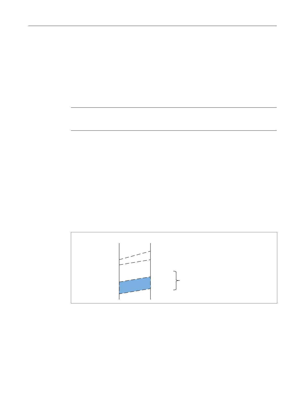
Extended stop and retract
21.2 Control-managed ESR
21.2.2
Drive-independent reactions
Generator operation
Generator operation is a drive function. Using the "Vdc control" function, the SINAMICS S120
drive unit can monitor the DC link group for undervoltage. When an adjustable voltage value is
fallen below, then the drive intended for the purpose is switched into generator operation. The
kinetic energy of the drive is used to buffer the DC link voltage. This allows the axes that are still
moving to be stopped and retracted in an ordering fashion on the NC side.
Note
At the instant that it is switched into generator operation, if an axis is in closed-loop position
control, then additional alarms can occur.
Further information
For detailed information on the SINAMICS S120 drive function "Vdc control", see:
Function Manual SINAMICS S120 Drive Functions
21.2.3
Power failure detection and bridging
DC link voltage limit values
The DC link is monitored against the limit values shown in the following diagram:
'& OLQN YROWDJH
9
3XOVH FDQFHOODWLRQ '& OLQN
3XOVH FDQFHOODWLRQ GULYHV
9
9
9
9
:RUN DUHD
9
3XOVH UHVLVWRU PRGXOH
9
9
Figure 21-1
DC link voltage limit values
The drive and DC link pulses are cancelled at specific voltage levels, which means that the drives
coast-down. If this behavior is not desired, the excess energy can be discharged using a resistor
Axes and spindles
Function Manual, 10/2020, 6FC5397-4GP40-0BA1
895
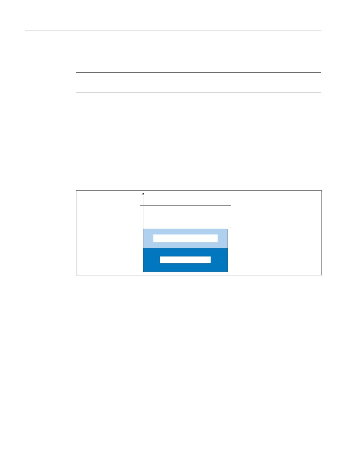
Extended stop and retract
21.2 Control-managed ESR
module. The operating range of the resistor module (shown highlighted in the diagram) lies
below the critical voltage level.
Note
The pulse power of the resistor module is greater than the infeed power.
Monitoring the intermediate circuit minimum voltage limit
The DC link voltage can be monitored against a limit value that can be parameterized in the drive:
• p1248 (DC link voltage - lower voltage threshold)
When the limit value is fallen below, the following signal is set in the message word (MELDW)
of the PROFIdrive telegram:
• MELDW.Bit4 = 1 (VDC_min controller is active (Vdc link < p1248))
The signal can be used in the NC to initiate ESR responses.
9
9'& OLQN UDWHG
9
9
9'& OLQN YROWDJH
8=. S
WKUHVKROGBORZHU
'& OLQN XQGHUYROWDJH
9'& OLQN RII
9
6,1$0,&6 $/0 2))
9
Figure 21-2
Monitoring the DC link voltage
21.2.4
NC-controlled extended stop
Axis-specific parameterization
The NC-controlled extended stopping for a machine axis is activated using machine data:
Axes and spindles
896
Function Manual, 10/2020, 6FC5397-4GP40-0BA1
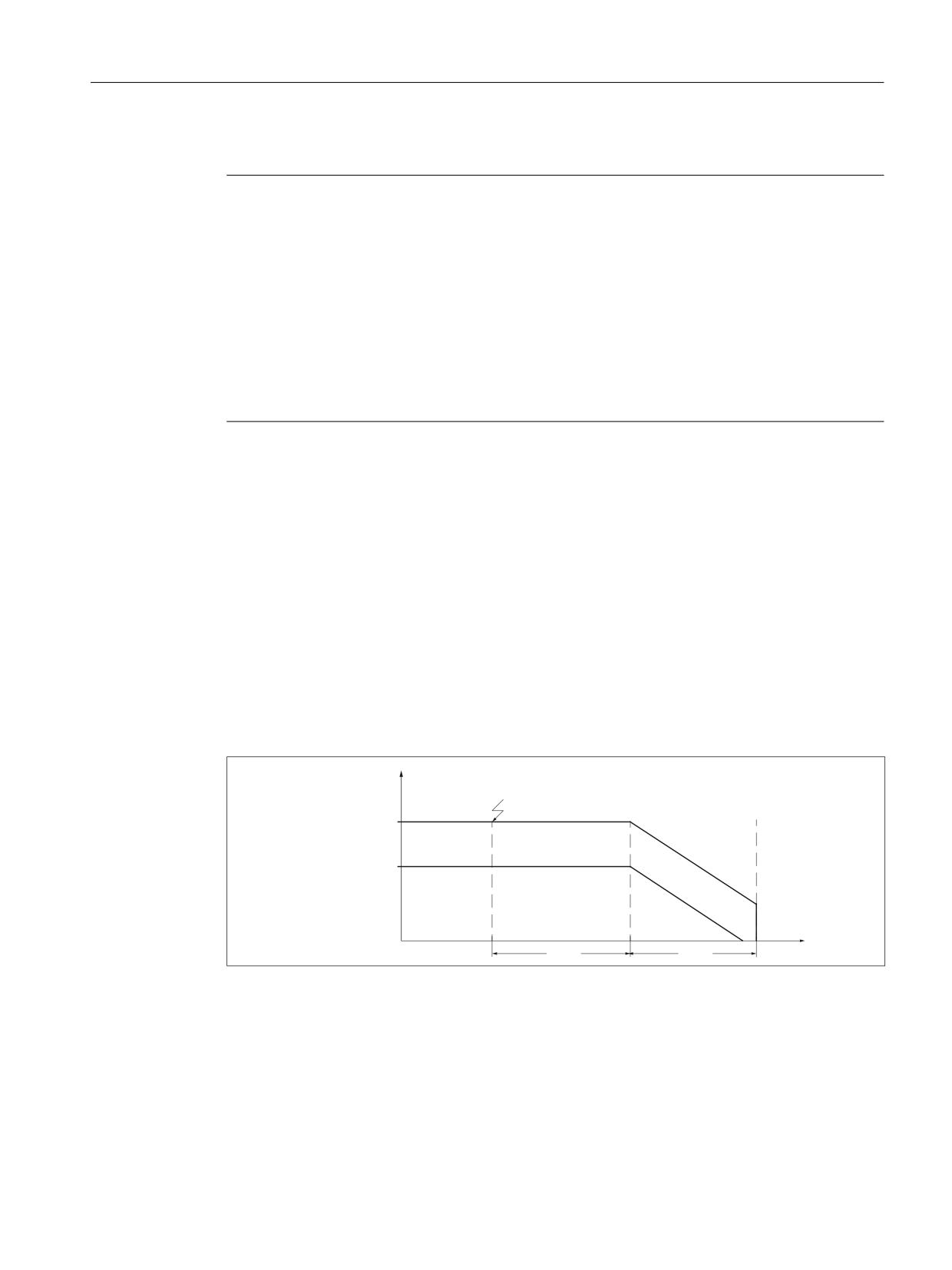
Extended stop and retract
21.2 Control-managed ESR
MD37500 $MA_ESR_REACTION[<axis>] = 22
Note
Path axes
If NC-controlled extended stopping is parameterized for a path axis, then the corresponding
behavior is also transferred to all other path axes of the channel.
Leading and following axis
During the extended stopping, a following axis of an electronic gearbox follows the leading axes
according to the parameterized/programmed motion principle. That is why independent
braking is not possible for the following axis during the times specified in MD21380
$MC_DELAY_TIME1 and MD21381 $MC_ESR_DELAY_TIME2. MD21380
$MC_DELAY_TIME1MD21381 $MC_ESR_DELAY_TIME2 A prerequisite for correct functioning of
ESR is that all necessary enable signals must be set and remain set.
Channel-specific parameterization
The timing within a channel is parameterized using the following machine data:
• MD21380 $MC_ESR_DELAY_TIME1[<axis>] (delay time ESR axes)
• MD21381 $MC_ESR_DELAY_TIME2[<axis>] (ESR time for interpolatory braking)
Time sequence
After initiating ESR, the axis continues to traverse with the actual speed. After a delay time has
expired (..._TIME1), the axis is braked, interpolating.
The set time (..._TIME 2) is the maximum time available for interpolatory braking. After this time
has expired, a setpoint of 0 is output for the axis, and the follow-up mode is activated.
6SHHG Q
(65 WULJJHUHG
2XWSXW RI VHWSRLQW
Q
Q
7
7
=HLW W
T1
MD21380 $MC_ESR_DELAY_TIME1 (delay time, ESR axes)
T2
MD21381 $MC_ESR_DELAY_TIME2 (ESR time for interpolatory braking)
n1
Actual speed, which could be braked to a standstill within T2
n2
Actual speed, which could not be braked to a standstill within T2 ⇒ fast braking
Axes and spindles
Function Manual, 10/2020, 6FC5397-4GP40-0BA1
897
Extended stop and retract
21.2 Control-managed ESR
Note
For safety reasons, the sum of T1 and T2 should not exceed a maximum value of approx. 1
second.
Requirement
To ensure that ESR is carried out, at least one of the axes involved in the movement must be
parameterized as an NC-controlled retraction or stopping axis: MD37500 $MA_ESR_REACTION
> 20
For axes that are not parameterized as NC controlled retraction or stopping axis, fast braking
with subsequent tracking is realized immediately so that extended stopping starts
($AC_ESR_TRIGGER = 1).
Processing of all commands, especially those that result in an axis stop (e.g. Reset, Stop, Stopall),
as well as the standard alarm responses STOPBYALARM and NOREADY, is delayed by the sum of
the parameterized times:
Delay time = MD21380 $MC_ESR_DELAY_TIME1 + MD21381 $MC_ESR_DELAY_TIME2
An NC controlled stop is also active in conjunction with the "Electronic gearbox" function. It
contains the (selective) switchover of the electronic gearbox to actual value coupling if there is
a fault on the leading axes, and also maintains traversing motion and the enable signals during
the delay time for ESR axes: MD21380 $MC_ESR_DELAY_TIME1
For further information see Function Manual Axis and Spindles.
See also
Electronic gear (EG) (Page 581)
21.2.5
Retract
21.2.5.1
Function
Rapid lift to the position defined with POLF is programmed using modal command LFPOS.
Retraction motion parameterized with LFPOS or POLF for the axes programmed with
POLFMASK or POLFMLIN replaces the traversing motion programmed for these axes in the NC
program.
Regarding retraction motion, the following applies:
• The axes specified with POLFMASK independently traverse to the positions specified
with POLF.
• The axes specified with POLFMLIN traverse to the positions specified with POLF in a linear
relationship.
The extended retraction (i.e. LIFTFAST/LFPOS initiated through $AC_ESR_TRIGGER) cannot
be interrupted and can only be terminated prematurely using Emergency Off.
Axes and spindles
898
Function Manual, 10/2020, 6FC5397-4GP40-0BA1
Extended stop and retract
21.2 Control-managed ESR
Velocity and acceleration limits for the axes involved in the retraction are monitored during the
retraction motion. The retracting movement takes place with BRISK, i.e. without jerk limitation.
Initiating the retraction
Retraction motion LIFTFAST is initiated in a channel, if, in this channel there is an axis for which
retraction motion is enabled ($AA_ESR_ENABLE == 1) - and the trigger for fast retraction
($AC_ESR_TRIGGER = 1) is set.
Requirement
• The retraction position must be programmed in the NC program.
• The enable signals must be set and remain set for retraction motion.
21.2.5.2
Parameterization: Machine data
Activation
NC-controlled retraction for an axis is activated using machine data:
MD37500 $MA_ESR_REACTION = 21
Delay times
Two different retraction times can be parameterized for the retraction:
• MD21380 $MC_ESR_DELAY_TIME1 = <delay time: Traversing motion>
• MD21381 $MC_ESR_DELAY_TIME2 = <delay time: Interpolatory braking>
To perform retraction motion, the sum of the two delay times are available. After the total delay
time has expired, fast braking is initiated for the retraction axes with a setpoint of 0 - with
subsequent switchover into follow-up (tracking) operation.
Mirroring
The machine data is used to set, whether, for active "Mirroring" function (DB31, … DBX97.2), the
retraction direction should be mirrored for "Fast retraction from the contour" (LIFTFAST):
MD21202 $MC_LIFTFAST_WITH_MIRROR = TRUE
The mirroring of the retraction direction only refers to the direction components perpendicular
to the tool direction.
Stop behavior
The stop response for lift motion is set on a channel-for-general basis using the following
machine data:
Axes and spindles
Function Manual, 10/2020, 6FC5397-4GP40-0BA1
899

Extended stop and retract
21.2 Control-managed ESR
MD21204 $MC_LIFTFAST_STOP_COND, <bit> = <value>
Bit
Val-
Description
ue
0
Response to the axis-specific NC/PLC interface signal DB31 DBB4.3 (feed stop) or context-sensitive
interpolator stop.
0
Retraction motion is stopped for axis-specific feed stop or context-sensitive interpolator
stop
1
Retraction motion is not stopped for axis-specific feed stop or context-sensitive interpo-
lator stop
1
Response to the channel-specific NC/PLC interface signal DB21, ... DBB6.0 (feed inhibit)
0
Retraction motion stop for feed disable in the channel
1
No retraction motion stop for feed disable in the channel
Note
Influence of the interface signals
• The axis-specific NC/PLC interface signal DB31 DBB4.3 (feed stop) influences the complete
retraction motion. All axis motion defined using POLFMASK and POLFMLIN are stopped.
• The channel-specific NC/PLC interface signal, DB21, ... DBB7.3 (NC stop) has no effect on the
retraction movement.
See also
Lift fast with linear relation of axes (Page 929)
21.2.5.3
Parameterization: System variable
Axis-specific function enable
An axis is enabled for retraction on an axis-for-axis basis using system variable:
$AA_ESR_ENABLE[<axis>] = 1
Channel-specific initiation
Retraction motion is initiated on a channel-for-channel basis using system variable:
$AC_ESR_TRIGGER = 1
Retraction is then realized in all channel axes for which the following applies:
$AA_ESR_ENABLE[<axis>] == 1 AND MD37500 $MA_ESR_REACTION[axis] == 21 OR 22
21.2.5.4
Programming (POLF, POLFA, POLFMASK, POLFMLIN)
Syntax
POLF(<axis>)=<position>
POLFA(<axis>,<type>,<position>)
POLFA(<axis>,<type>)
Axes and spindles
900
Function Manual, 10/2020, 6FC5397-4GP40-0BA1
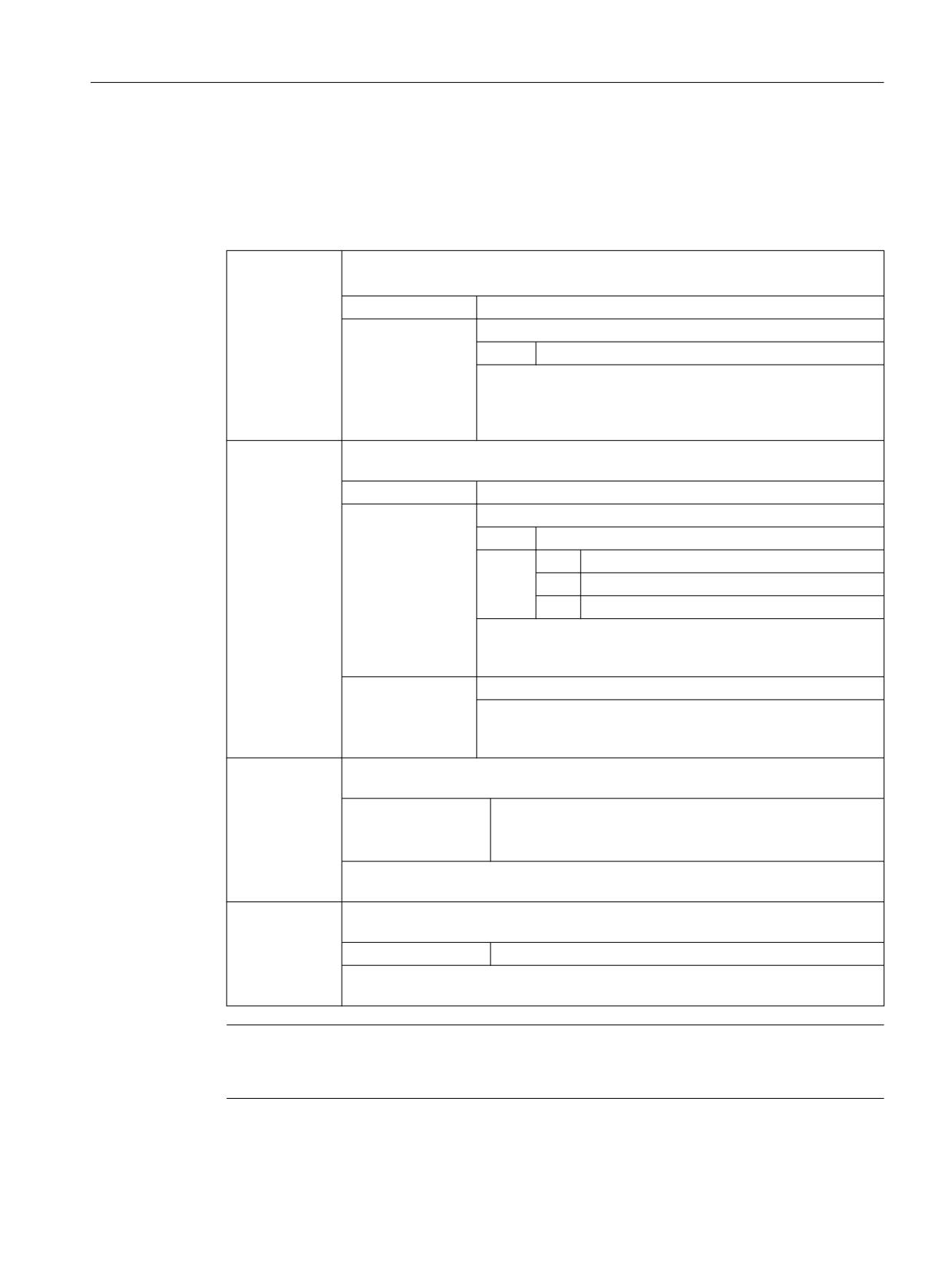
Extended stop and retract
21.2 Control-managed ESR
POLFMASK(<axis_1>,<axis_2>,...)
POLFMLIN(<axis_1>,<axis_2>,...)
Meaning
POLF:
Address for specifying the target position of the retraction axis
POLF is modal.
<axis>:
Channel axis name of the retraction axis
<position>:
Retraction position
Type:
REAL
The geometry axis is retracted in the WCS. For all other channel
axes in the MCS.
With the same identifiers for geometry and channel/machine
axis, retraction is in the WCS.
POLFA:
Predefined subprogram call for the specification of the retraction position of single
axes
<axis>:
Channel axis name of the retraction axis
<type>:
Position specification mode
Type:
INT
Value:
0
Mark position value as invalid
1
Position value is absolute
2
Position value is incremental (distance)
Note:
If an axis is not a single axis or if the type is missing or type=0,
then a corresponding alarm is output.
<position>:
Retraction position (see above) (optional)
Note:
The position value is also accepted with type=0. Only this value
is marked as invalid and has to be reprogrammed for retraction.
POLFMASK:
Predefined subprogram call for selection of the axes that are to be retracted after
tripping of rapid lift independently of one another.
<axis_1>,…:
Names of the axes that are to be traversed to their positions
defined with POLF during rapid lift.
All the axes specified must be in the same coordinate system.
POLFMASK() without specification of an axis deactivates the rapid lift for all axes that
have been retracted independently of one another.
POLFMLIN:
Predefined subprogram call for selection of the axes that are to be retracted after
tripping of rapid lift in linear relation.
<axis_1>,…:
See above.
POLFMLIN() without specification of an axis deactivates the rapid lift for all axes that
have been retracted in linear relation.
Note
Before rapid retraction to a fixed position can be enabled via POLFMASK or POLFMLIN, a position
must have been programmed with POLF for the selected axes.
Axes and spindles
Function Manual, 10/2020, 6FC5397-4GP40-0BA1
901

Extended stop and retract
21.2 Control-managed ESR
Note
If axes are enabled one after the other with POLFMASK, POLFMLIN or POLFMLIN, POLFMASK,
then the last definition always applies for the particular axis.
Note
The positions programmed with POLF and the activation by POLFMASK or POLFMLIN are
deleted when the part program is started. This means that the user must reprogram the values
for POLF and the selected axes in POLFMASK or POLFMLIN in each part program.
Note
If, when using the abbreviated form POLFA only the type is changed, then the user must ensure
that either the retraction position or the retraction path contains a practical and sensible value.
In particular, the retraction position and the retraction path have to be set again after a warm
restart.
Example: Retracting an individual axis
Program code
Comment
MD37500 $MA_ESR_REACTION[AX1]=21
; NC-controlled retraction.
$AA_ESR_ENABLE[AX1]=1
POLFA(AX1,1,20.0)
; AX1 is assigned the axial retraction
position 20.0 (absolute).
$AA_ESR_TRIGGER[AX1]=1
; Retraction starts from here.
21.2.5.5
Boundary conditions
General supplementary conditions
Exceptions
Retraction and/or rapid lift is not executed for the following axes:
• Axes, which are not permanently assigned a channel
• Axes, which are in the open-loop speed-controlled mode (spindles)
• Axes, which are interpolated as positioning spindles (SPOS/SPOSA)
Modulo rotary axes
Modulo rotary axes respond to rapid lift as follows:
• For incremental programming of the target position, the latter is approached without
modulo offset.
• With absolute programming, the target position is approached time-optimized with the use
of modulo offsets. This is almost identical to positioning via the shortest path.
Axes and spindles
902
Function Manual, 10/2020, 6FC5397-4GP40-0BA1
Extended stop and retract
21.2 Control-managed ESR
Utilizing the axis dynamics
The retraction movement is interpolated linearly, using the maximum acceleration and speed of
the axes involved in POLFLIN.
Parallel retraction
Only one linear retraction is permitted in each channel. This means that multiple axis groups,
which approach their retraction positions linearly, cannot be created in the channel.
In parallel with linear retraction, additional axes can also use POLFMASK for independent axis-
specific retraction movement to their programmed retraction positions.
Concurrent retraction
If axes are used in both POLFMASK and in POLFMIN, it should be noted that the last state
programmed is always active for retracting movement. This means that an axis previously
activated with POLFMIN is removed from the linear relationship following programming in
POLFMASK and the retracting movement would then take place as an independent movement
(see the examples in Chapter "Lift fast with linear relation of axes (Page 929)").
Effectiveness of retraction parameters
The parameters valid at the triggering time are decisive for the retraction movement. If one of
these parameters (POLF, POLFMASK, POLFMLIN, Frame, etc.) changes during the retracting
movement (e.g. due to a block change), this change does not affect the retraction movement
that has already started.
Supplementary conditions: Path axes
Alternative extended stopping
If, for a path axis ESR_REACTION=21 (NC-controlled retraction) is configured and enabled with
$AC_ESR_ENABLE=1, then ESR_REACTION=22 (extended stopping) is active for all path axes for
which no ESR_REACTION=21 is configured or enabled.
Rapid retraction/lift without retraction motion enabled
If, for an axis, ESR_REACTION=21 is configured and enabled with $AC_ESR_ENABLE=1, but e.g.
no retraction motion is enabled with POLFMASK, then, for this axis, ESR_REACTION=22 is active
(extended stopping).
Behavior for different enable signals
"NC-controlled retraction" is configured for path axes X and Y:
• MD37500 $MA_ESR_REACTION[X] = 21
• MD37500, $MA_ESR_REACTION[Y] = 21
Axes and spindles
Function Manual, 10/2020, 6FC5397-4GP40-0BA1
903
Extended stop and retract
21.2 Control-managed ESR
1. "Extended stop and retract" and retraction motion is enabled for both path axes:
- $AA_ESR_ENABLE(X) = 1
- $AA_ESR_ENABLE(Y) = 1
- POLFMASK(X,Y)
For rapid lift, X and Y execute the programmed retraction motion.
2. "Extended stop and retract" is only enabled for one path axis, but retraction motion is enabled
for both path axes:
- $AA_ESR_ENABLE(X) = 0
- $AA_ESR_ENABLE(Y) = 1
- POLFMASK(X,Y)
For rapid lift, for axis X, due to the path interrelationship, in spite of the fact that it is not
enabled, "extended stopping" corresponding to ESR_REACTION = 22 is executed.
Axis Y executes the programmed retraction motion.
3. However, for both path axes, "Extended stop and retract" is enabled - but retraction motion
only for one path axis:
- $AA_ESR_ENABLE(X) = 1
- $AA_ESR_ENABLE(Y) = 1
- POLFMASK(Y)
For rapid lift, for axis X, due to the path interrelationship, in spite of the missing enable signal,
retraction motion "extended stopping" corresponding to ESR_REACTION = 22 is executed.
Axis Y executes the programmed retraction motion.
21.2.6
Trigger sources
A distinction must be made between the ESR trigger sources on a user-for-user basis by
evaluating system variables. This is the reason that all system variables are available, which can
be read in synchronized actions.
General trigger sources
• Digital inputs of the NCU module or the internal control image of digital outputs that can be
read back: $A_IN, $A_OUT
• Channel status: $AC_STAT
• NC/PLC interface signals
• System variables written from the PLC: $A_DBB, $A_DBW, $A_DBD
It is not recommended to use these system variables, written by the PLC for time-critical
signals, as in this case, the PLC cycle time is included in the total response time. Nevertheless,
it is an appropriate way for the PLC to influence the sequence or release of the extended stop
and retract function. However, linking-in PLC states in such a fashion does make sense if
these are exclusively input from the PLC (e.g. Emergency-Stop, reset button, stop button)
• Group signals from alarms: $AC_ALARM_STAT
Axes and spindles
904
Function Manual, 10/2020, 6FC5397-4GP40-0BA1
Extended stop and retract
21.2 Control-managed ESR
Axial trigger sources
• $VA_SYNCDIFF[<following axis>] (synchronism difference, on the actual value side)
• $AA_ESR_STAT (axial return signal word: ESR status)
Alarm responses
When ESR is active, the alarm responses NOREADY and STOPBYALARM are delayed by one IPO
cycle. The self-clearing alarm is displayed to indicate this delay:
Alarm 21600 "Monitoring for ESR active".
Note
The display of this alarm can be suppressed by:
MD11410 $MN_SUPPRESS_ALARM_MASK, bit16 = 1
21.2.7
Logic gating functions: Source and reaction linking
The flexible logic operation possibilities of the static synchronized actions can be used to
trigger specific reactions based on sources. Linking all relevant sources using static synchronized
actions is the responsibility of the user/machine manufacturer. They can selectively evaluate the
source system variables as a whole or by means of bit masks, and then make a logic operation
with their desired reactions. The static synchronized actions are effective in all operating modes.
A detailed description of how to use synchronized actions can be found in:
Further information:
• Function Manual Synchronized Actions
• NC Programming Programming Manual
Linking of axial sources with global or channel specific sources can be configured variably with
the aid of $AA_TYP (axis type).
21.2.8
Activation
Option
The function "Extended stop and retract" is an option.
Axis-specific function enable ($AA_ESR_ENABLE)
The axis-specific function enable is realized using the system variable:
$AA_ESR_ENABLE[<axis>] = 1
Axes and spindles
Function Manual, 10/2020, 6FC5397-4GP40-0BA1
905
Extended stop and retract
21.2 Control-managed ESR
Axis-specific enable for extended stopping
An axis is enabled for extended stopping with:
MD37500 $MA_ESR_REACTION[axis] = 22
Axis-specific enable for retraction
An axis is enabled for retraction using:
MD37500 $MA_ESR_REACTION[axis] = 21
Channel-specific trigger ($AC_ESR_TRIGGER)
ESR is triggered on a channel-for-channel basis by setting the following system variable:
$AC_ESR_TRIGGER = 1
ESR is then realized in all channel axes for which the following applies:
$AA_ESR_ENABLE[<axis>] == 1 AND MD37500 $MA_ESR_REACTION[axis] == 21 OR 22
21.2.9
Configuring aids for ESR
Voltage failure
For the following modules, when the line voltage fails, the power supply must be maintained
using suitable measures at least until it is ensured that the axes have come to a stop:
• SINUMERIK 840D sl NCU 7x0
• SINUMERIK NCU I/O modules
• SIMATIC PLC I/O modules
• SINAMICS drive system S120 (booksize)
DC link energy
The energy available in the DC link of the drive units when the line supply fails is calculated as
follows:
E = 1/2 * C * (VDC linkalarm2 - VDC linkmin2)
E:
Energy in wattseconds [Ws]
C:
Total capacity of intermediate circuit in Farad [F]
VDClinkalarm: DC link voltage below which an undervoltage is identified.
SINAMICS Parameter: r0296 + p0279
VDClinkmin: Lower limit of the DC link voltage for safe and reliable operation,
taking into account the motor-specific EMF.
Note VDC linkmin > VDC linkoff
Axes and spindles
906
Function Manual, 10/2020, 6FC5397-4GP40-0BA1
Extended stop and retract
21.2 Control-managed ESR
This energy is available for a minimum time of t
min
:
tP = E / Pn * η
E:
Energy in wattseconds [Ws]
tP:
Buffer time in milliseconds [ms]
Pn:
Power in kilowatt [kW]
η:
Efficiency of the drive unit
Example
Assumptions:
• Pn = 16 kW, infeed (ALM) with 3-ph. 380 VAC
• C = Cis - 20% = 20,000 µF - 20% = 16,000 µF = 16 * 10-3 F, for safety, a 20% lower effectively
available capacity is assumed.
• VDC linkalarm = 550 V
• VDC linkmin = 350 V
E = 1/2 * 16*10-3 F * ( (550 V)2 - (350 V)2 ) = 1440 Ws
This energy is available for a time tmin, e.g. for a retraction:
• E = 1440 Ws
• Pn = 16 kW
• η = 0.9 (assumption)
tPmin = 1440 Ws / 16 kW * 0.9 = 81 ms
The following table shows a summary of the values for various SINAMICS infeeds (ALMs).
Whereby, the nominal (Cmax) and minimum (Cmin) capacitance are taken into account.
The total capacitance of the DC link available is made up, taking into account the respective
maximum capacitance Cmax (charge limit), from the capacitances of the infeed (ALM), the motor
modules as well as any capacitor modules.
The capacitance specified in the table for the minimum energy content (Emin for Cmin) takes into
account a component tolerance of -20% (worst case).
Note
It is recommended that the SIZER configuration tool be used to determine the total capacitance
of the DC link available.
Axes and spindles
Function Manual, 10/2020, 6FC5397-4GP40-0BA1
907

Extended stop and retract
21.2 Control-managed ESR
Table 21-1
SINAMICS infeeds (ALMs): Nominal and minimum buffer times
ALM
Max. capacitance
Energy content
Energy content
Backup time tPmax
Buffer time tPmin for
Cmax [μF]
Emax for Cmax [Ws]
Emin for Cmin [Ws]
for Pmax [ms]
Pmax [ms]
Pmax[kW]
16
20000
1800
1440
101.25
81.00
36
20000
1800
1440
45.00
36.00
55
20000
1800
1440
29.46
23.56
80
20000
1800
1440
20.25
16.20
120
20000
1800
1440
13.50
10.80
Energy balance
When configuring retraction motion, it is always necessary to consider the energy flow (balance)
to find out whether an additional capacitor module or a generator axis (with correspondingly
dimensioned flywheel effect) is required - or not.
Stopping as energy supply
From approx. the third interpolator clock cycle, the speed setpoints of the configured stopping
or retraction axes change. After this time the braking phase starts (if no drive independent
shutdown is projected for this axis).
As soon as the braking process is initiated, the energy released in this manner is available for
retraction motion. An energy balance must be used to ensure that the kinetic energy of the
braking axes is sufficient for retraction.
The energy balance shows the maximum setting for the interpolator clock cycle time, which will
allow a safe emergency retraction to be executed.
Example
With a 16 kW unit under maximum load and minimum intermediate circuit capacity it should be
possible to execute an emergency retraction without generator operation. Interpolator clock
cycle time may theoretically not be more than 4.86 ms, i.e. in this case a maximum of 4 ms could
be set.
If necessary, a more powerful NCU must be chosen in order to achieve optimal conditions.
Generator operation
For cases in which the DC link energy is not sufficient for safe and reliable retraction (minimum
3 IPO cycles), generator operation can be configured for a drive using the SINAMICS "Vdc control"
function. In this case, the mechanical energy of an axis is fed back into the DC link.
The energy stored in an axis can be calculated as follows:
E = 1/2 * Jtot * ω2
Jtot
Total moment of inertia [kg*m2]
ω
Angular velocity at the time of switchover to generator operation [s-1]
This energy is fed back into the DC link with an efficiency of approx. 90%:
Axes and spindles
908
Function Manual, 10/2020, 6FC5397-4GP40-0BA1

Extended stop and retract
21.2 Control-managed ESR
When using infeeds with a high power rating (55, 80, 120 kW) for generator operation, it is
recommended to use a dedicated axis with additional flywheel effect. For this axis, after the
drive has accelerated to the rated speed, energy is only required to compensate for friction
losses.
However, in principle, any axis can be used for generator operation, if this is not directly involved
in extended stopping and retraction or in couplings that must be specifically maintained.
In order to prevent that the DC link voltage does not become too high when using generator
operation (limit value: pulse cancelation, drive) and as a consequence that the pulses are
canceled for the axes, adequately dimensioned pulsed resistor modules must be used or the
SINAMICS function "Vdc control, overvoltage monitoring".
21.2.10
Control system response
21.2.10.1
Axis behavior depending on the enable signals
Systematic
If an axis is configured as NC-controlled retraction axis:
MD37500, $MA_ESR_REACTION[<axis>] = 21
The following enable signals must be available to execute retraction motion in the case of ESR:
• Axial ESR enable using system variable: $AA_ESR_ ENABLE[<axis>] = 1
• Axial retraction enable using a part program command: POLFMASK(<axis>)
If one of the two enable signals is not available, then in the case of ESR, the axis responds
corresponding to the following table:
Enable signals
Response in the case of ESR
• $AA_ESR_ ENABLE[<axis>] = 1
For the axis, implicit NC-controlled stopping becomes active, corresponding to
MD37500, $MA_ESR_REACTION[<axis>] = 22.
• No enable via POLFMASK
• $AA_ESR_ ENABLE[<axis>] = 0
Axis is a path axis:
For the axis, the ESR response is implicitly changed to NC-controlled stopping.
• Enable via POLFMASK(<axis>)
The response corresponds then to a configuration of MD37500, $MA_ESR_RE-
ACTION[<axis>] = 22
Axis is a special axis:
The axis is stopped with rapid stop.
Examples for axes with path relationship
For the subsequent examples, two path axes X and Y are assumed, which are configured as NC-
controlled retraction axes and are programmed for the retraction positions:
• MD37500, $MA_ESR_REACTION[X] = 21
• MD37500, $MA_ESR_REACTION[Y] = 21
Axes and spindles
Function Manual, 10/2020, 6FC5397-4GP40-0BA1
909

Extended stop and retract
21.2 Control-managed ESR
• POLF[X]=<retraction position> LFPOS
• POLF[Y]=<retraction position> LFPOS
Initial situation
Response in the case of ESR
• $AA_ESR_ ENABLE[X] = 1
Retraction motion in X and Y.
• $AA_ESR_ ENABLE[Y] = 1
• POLFMASK(X,Y)
• Program traversing motion: Y
• $AA_ESR_ ENABLE[X] = 0
X does not have ESR enable. As X is a path axis, for X, the ESR response is
implicitly changed to 22 (stopping). This is the reason that X continues to
• $AA_ESR_ ENABLE[Y] = 1
traverse corresponding to the programmed traversing motion.
• POLFMASK(X,Y)
Y executes retraction motion.
• Program traversing motion: X and Y
After the delay time for ESR axes expires, MD21380, $MC_ESR_DELAY_TIME1,
X is stopped with the path acceleration.
• $AA_ESR_ ENABLE[X] = 1
X has no retraction enable (POLFMASK). X does not execute any retraction
motion. As X is a path axis, for X, the ESR response is implicitly changed to 22
• $AA_ESR_ ENABLE[Y] = 1
(stopping). This is the reason that X continues to traverse corresponding to the
• POLFMASK(Y)
programmed traversing motion.
• Program traversing motion: X
Y executes retraction motion.
After the delay time for ESR axes expires, MD21380, $MC_ESR_DELAY_TIME1,
X is stopped with the path acceleration.
• $AA_ESR_ ENABLE[X] = 1
Y has not been enabled for retraction (POLFMASK). see lines above, syntax Y
does not execute retraction motion. As Y is a path axis, for Y, the ESR response
• $AA_ESR_ ENABLE[Y] = 1
is implicitly changed to 22 (stopping). This is the reason that Y continues to
• POLFMASK(X)
traverse corresponding to the programmed traversing motion.
• Program traversing motion: X and Y
X executes retraction motion.
After the delay time for ESR axes expires, MD21380, $MC_ESR_DELAY_TIME1,
Y is stopped with the path acceleration.
Examples for axes without path relationship
For the subsequent examples, path axes X and a command axis B are assumed, which are
configured as NC-controlled retraction axis:
• MD37500, $MA_ESR_REACTION[X] = 21
• MD37500, $MA_ESR_REACTION[B] = 21
Axes and spindles
910
Function Manual, 10/2020, 6FC5397-4GP40-0BA1

Extended stop and retract
21.2 Control-managed ESR
Initial situation
Response in the case of ESR
• $AA_ESR_ ENABLE[X] = 1
B is not enabled for ESR. As B is not a path axis, B is immediately stopped with
a rapid stop.
• $AA_ESR_ ENABLE[B] = 0
X executes retraction motion.
• POLFMASK(X)
• Program traversing motion: X and B
• $AA_ESR_ ENABLE[X] = 1
B is not enabled for retraction (POLFMASK). However, as B is enabled for ESR,
for B, the ESR response is implicitly changed to 22 (stopping). This is the reason
• $AA_ESR_ ENABLE[B] = 1
that B continues to traverse corresponding to the programmed traversing mo-
• POLFMASK(X)
tion.
• Program traversing motion: X and B
Y executes retraction motion.
After the delay time for ESR axes expires, MD21380, $MC_ESR_DELAY_TIME1,
B is stopped with axial acceleration.
21.2.10.2
POWER OFF/POWER ON
If the user-specific retraction logic is programmed within motion synchronized actions, then it
must be observed that this is still not active when the control boots (POWER ON). A retraction
logic, which should be active after POWER ON, must therefore lie in an ASUB started from the PLC
or must be called event-controlled.
Further information
For detailed information about event-driven program calls see:
Function Manual Basic Functions; Mode group, channel, program mode, reset response, event-
driven program calls
21.2.10.3
Operating mode change, NC Stop, reset
Static synchronized actions (IDS keyword) can be used for user-specific retraction logic as the
following system states or state change have no influence on this:
• Operating mode change, e.g. DB11 DBX0.0 (AUTOMATIC)
• NC stop, e.g. DB21, ... DBX7.3 (NC stop)
• Reset, e.g. DB21, ... DBX7.7 (reset)
Note
NC stop and command axes
Traversing command axes is interrupted for an NC stop.
Note
POLF/POLFMASK reset and program commands
For reset, the programmed absolute retraction positions (POLF) and the enable signals for the
retraction axes (POLFMASK) are not deleted.
Axes and spindles
Function Manual, 10/2020, 6FC5397-4GP40-0BA1
911
Extended stop and retract
21.2 Control-managed ESR
21.2.10.4
Part program start, NC start
In order that a defined initial state is available when a part program starts, the programmed
absolute retraction positions and the enable signals of the retraction axes are deleted when the
part program starts.
Note
Retraction positions and enable signals
When a part program starts, the absolute retraction positions (POLF) and the enable signals of
the retraction axes (POLFMASK) must be reprogrammed corresponding to the actual
requirements.
21.2.10.5
Alarm behavior
The alarm response depends on the axis in which a fault occurs:
• Fault in an axis outside the axis grouping of an electronic gear:
This axis switches off "normally". Extended stopping and retraction continue to operate as
before - or are initiated by such a fault.
• Error in a leading axis (LA):
selective switchover to actual value linkage already during stop, otherwise as previously.
• Error in a following axis (FA):
- Carry out retract: Retraction axis may not be a following axis, that is, no conflict.
- Carry out stop: The following axis may react with uncontrollable behavior. Saving the
workpiece/tool must be left to the retraction; however, the stop should not disrupt the
process any further.
• Error in the retraction axis: There is no retraction.
• Emergency Stop
An Emergency Stop is not a fault from a control system point of view, rather the response is
the same as for any other control signal. For safety reasons, Emergency Stop interrupts the
interpolation and all traversing motion, and also cancels the electronic coupling by
withdrawing the controller enable signals.
In applications where the coupling and traversing movements must remain valid after
Emergency Stop, the PLC must delay the Emergency Stop long enough for the required NC
or drive-end reactions to terminate.
The following interface signal is available as feedback signal to the PLC:
IS "ESR reaction not initiated" DB31, ... DBX98.7
If an alarm with cross-channel NOREADY reaction is issued during the active phase of the ESR (i.e.
NOREADY | NCKREACTIONVIEW | BAGREACTIONVIEW), then ESR is triggered in all channels.
21.2.10.6
Block search, REPOS
Extended stop and retract does not affect block search or REPOS motions.
Axes and spindles
912
Function Manual, 10/2020, 6FC5397-4GP40-0BA1
Extended stop and retract
21.3 ESR executed autonomously in the drive
21.3
ESR executed autonomously in the drive
21.3.1
Fundamentals
Function
Drive-autonomous Extended Stop and Retract (ESR) enables the fast separation of workpiece
and tool independent of the higher-level control (NC).
For this purpose, the following axis-specific functions can be configured in the drive:
• Generator operation
• Extended stop
• Retract
The drive-autonomous responses are automatically initiated in error situations. The triggering
of the drive-autonomous responses can also be realized user-specific via the part programs or
synchronized actions from the higher-level control system.
As the stopping and retraction motion of the drive-autonomous ESR are purely axis-specific, in
contrast to control-managed ESR, couplings are not taken into account.
ESR executed autonomously in the drive can also be used in combination with control-managed
ESR. This also allows stopping and retraction motion in the drives if they are no longer specified
from the control, e.g. as a result of a communication failure.
Note
DRIVE-CLiQ
For possibly occurring DRIVE-CLiQ errors, in order to keep the reaction to the functions of the
drive-autonomous ESR as low as possible, within the scope of ESR, we recommend that the
motor modules involved are not connected through a line-type topology, but instead are directly
connected to the Control Unit (CU).
Link axes
The "Drive-autonomous extended stop and retract (ESR)" function cannot be used in conjunction
with link axes.
Requirements
The following conditions must be fulfilled:
• SINAMICS and SINUMERIK software version: ≥ V4.4
• Servo drive object, PROFIdrive telegram: 102 - 199
• Servo drive object, function module "ESR" active
The function module "Extended stop and retract (ESR)" must be activated via the drive wizard
of SINUMERIK Operate. For a description of the drive wizard, see: SINUMERIK Operate online
help.
• Servo drive object, generator operation (Vdc control) active in a drive
Axes and spindles
Function Manual, 10/2020, 6FC5397-4GP40-0BA1
913
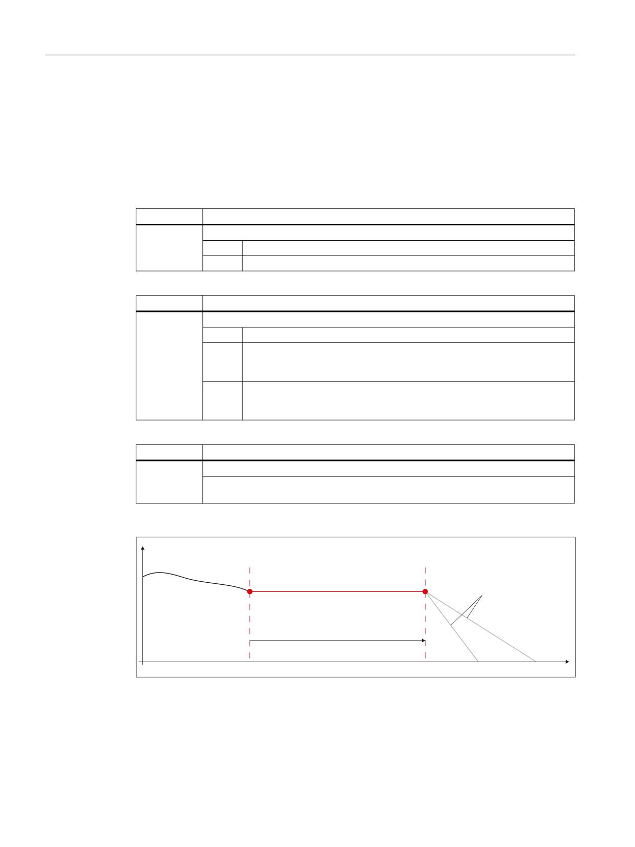
Extended stop and retract
21.3 ESR executed autonomously in the drive
• Control unit drive object, PROFIdrive telegram: 390, 391
• The 24 V power supply for the modules is buffered via CSM or UPS
21.3.2
Configuring stopping in the drive
Drive integrated shutdown is configured via the following drive parameters:
Parameter
Description
p0888
ESR: Configuration
Value
Meaning
1
Extended stopping (function integrated in the drive)
Parameter
Description
p0891
ESR: Off ramp
Value
Meaning
0
OFF3 (default)
The drive is braked along the OFF3 down ramp by immediately entering n_set
= 0 (p1135: OFF3 ramp-down time).
1
OFF1
By immediately entering n_set = 0, the drive is braked along the ramp gener-
ator down ramp (p1121: ramp-function generator ramp-down time).
Parameter
Description
p0892
ESR: Timer
The drive travels at a constant velocity for the configured time with the speed setpoint
that was present when the fault occurred.
6SHHG Q
S
S
$86
$86
7
7
7LPH W
T1
Time at which stopping was triggered
T2
Instant in time after the time that was configured in p0892 has expired
OFF3/OFF1
Braking ramp as a function of p0891
Figure 21-3
Response to drive-integrated stopping
Axes and spindles
914
Function Manual, 10/2020, 6FC5397-4GP40-0BA1

Extended stop and retract
21.3 ESR executed autonomously in the drive
Feedback signal
The stop status is returned to the control (see Section "Feedback of the ESR status (Page 918)").
Further information
For a detailed description of drive parameters, refer to:
SINAMICS S120/S150 List Manual
21.3.3
Configuring retraction in the drive
Drive integrated retraction is configured using the following drive parameters:
Parameter
Description
p0888
ESR: Configuration
Value
Meaning
2
Extended retraction (function integrated in the drive)
Parameter
Description
p0891
ESR: Off ramp
Value
Meaning
0
OFF3 (default)
The drive is braked along the OFF3 down ramp by immediately entering n_set
= 0 (p1135: OFF3 ramp-down time).
1
OFF1
By immediately entering n_set = 0, the drive is braked along the ramp gener-
ator down ramp (p1121: ramp-function generator ramp-down time).
Parameter
Description
p0892
ESR: Timer
The parameter specifies the total time that elapses to reach the speed specified in p0893
followed by constant velocity travel.
This is followed by an OFF1 or OFF3 ramp depending on the parameterization in p0891.
Parameter
Description
p0893
ESR: Speed
The parameter specifies the speed (retraction speed) that is reached when initiating
retraction via an OFF3 ramp.
Axes and spindles
Function Manual, 10/2020, 6FC5397-4GP40-0BA1
915
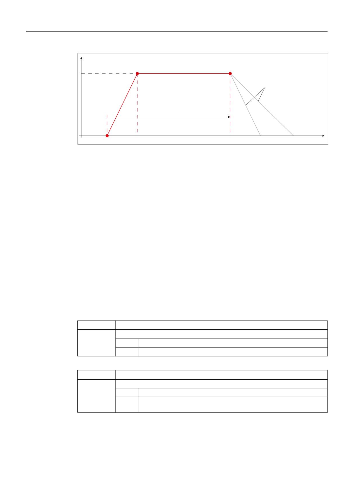
Extended stop and retract
21.3 ESR executed autonomously in the drive
6SHHG Q
S
S
$86
S
$86
$86
7
7
7
7LPH W
T1
Instant in time that retraction was initiated
T2
Instant in time when the retraction speed specified in p0893 is reached
T3
Instant in time after the time that was configured in p0892 has expired
Figure 21-4
Behavior for drive-integrated retraction
Feedback signal
The retract status is returned to the control (see Section "Feedback of the ESR status
(Page 918)").
Further information
For a detailed description of drive parameters, refer to:
SINAMICS S120/S150 List Manual
21.3.4
Configuring generator operation in the drive
The generator mode for the drive-autonomous ESR is configured using the following drive
parameters:
Parameter
Description
p0888
ESR: Configuration
Value
Meaning
3
Generator operation (Vdc controller)
Parameter
Description
p1240
Vdc controller or Vdc monitoring configuration
Value
Meaning
2
When reaching the lower DC link voltage threshold (p1248) - for ESR - the
motor is braked in order to utilize its kinetic energy to buffer the DC link.
Axes and spindles
916
Function Manual, 10/2020, 6FC5397-4GP40-0BA1
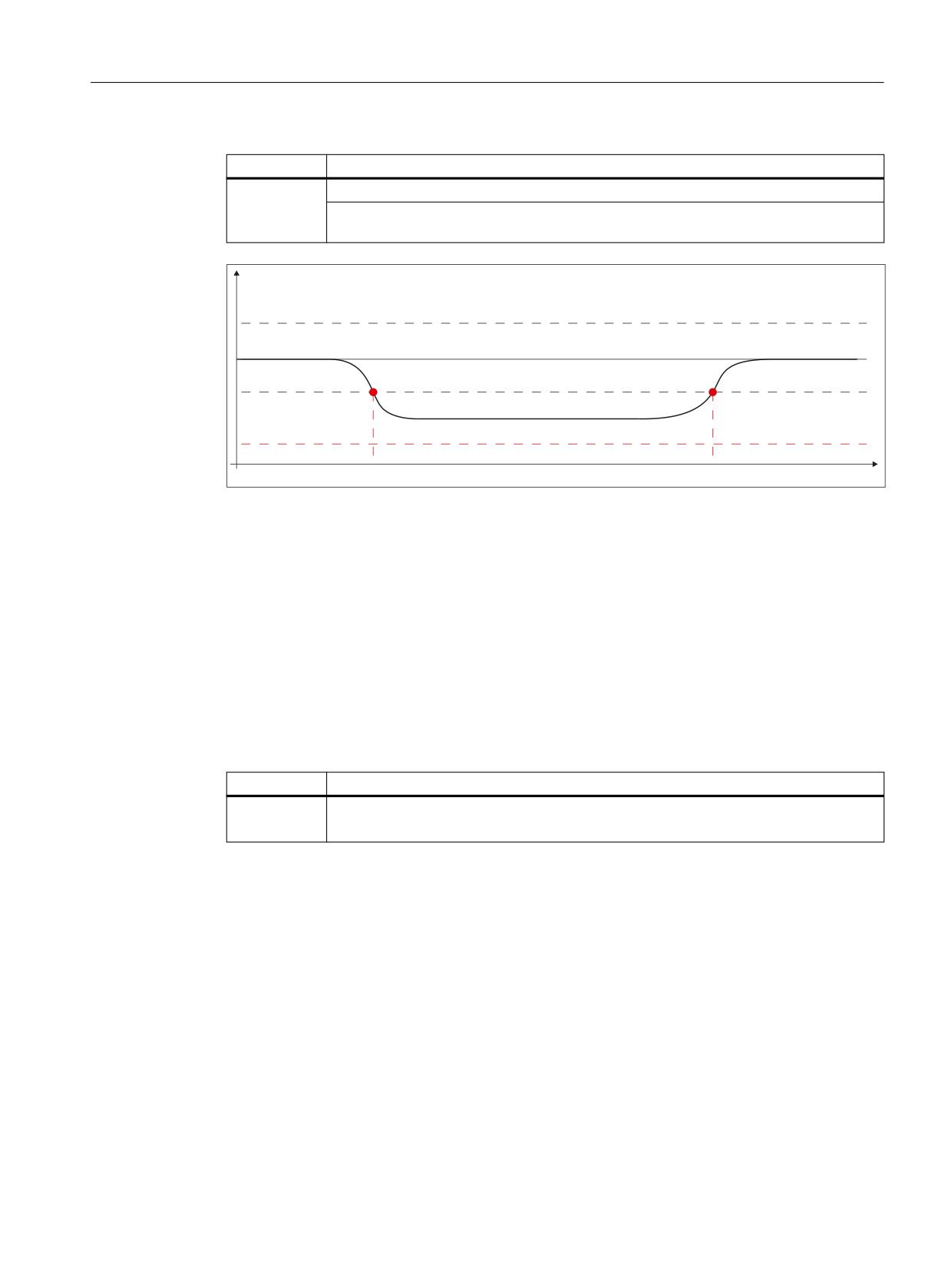
Extended stop and retract
21.3 ESR executed autonomously in the drive
Parameter
Description
p1248
Lower DC link voltage threshold
Setting the lower threshold for the DC link voltage. For p1240 = 2, this threshold is used
as setpoint limit for the Vdc_min controller.
'& OLQN YROWDJH 9
S
S
U
7
7
7LPH W
p1244
Upper DC link voltage threshold
p1248
Lower DC link voltage threshold
r0208
Rated power unit line supply voltage.
The pulses are canceled if the DC link voltage drops below 0.9*r0208
T1
Instant in time at which generator operation was triggered
T2
Instant in time at which generator operation was exited
Figure 21-5
Configuring_drive_integrated_generator_operation
Generator minimum speed
The lower limit of the motor speed of the generator axis is configured using drive parameter
p2161:
Parameter
Description
p2161
Speed threshold value 3
Speed threshold for the message: |n_act| < speed threshold 3
Feedback signal
The generator operation status is returned to the control (see Section "Feedback of the ESR
status (Page 918)").
Further information
A detailed description of drive parameters and the Vdc control can be found in:
• SINAMICS S120/S150 List Manual
• Function Manual SINAMICS S120 Drive Functions; Servo control > Vdc control
Axes and spindles
Function Manual, 10/2020, 6FC5397-4GP40-0BA1
917