SINUMERIK 840D sl. Service - Functions. Manual (2018-2020) - page 15

Manual traversing
15.15 Start-up: Handwheels
Handwheel slot
The PROFIBUS module must be configured in addition to the parameterization of handwheels in
the NC machine data in STEP 7. Among others the logical address of the handwheel slot is
specified.
The handwheel slot is situated at the following slot of the PROFIBUSmodule:
PROFIBUS module
Slot
Machine control panel MCP 483
2
Machine control panel MCP 310
2
Handwheel connection module
1
Example
Parameterization of 5 handwheels, connected via 4 machine control panels "MCP 483". Two
handwheels can be connected to a machine control panel"MCP 483".
Handwheel num-
Machine data set
Connection
ber
(Index)
in NC
1
0
1st MCP, 1. Handwheel in handwheel slot
2
1
1st MCP, 2. Handwheel in handwheel slot
3
2
2nd MCP, 1. Handwheel in handwheel slot
5
4
3rd MCP, 1. Handwheel in handwheel slot
6
5
4th MCP, 2. Handwheel in handwheel slot
The 4th handwheel in the NC is not used (machine data gap).
Note
Machine data gaps are allowed when parameterizing handwheels in NC machine data.
Machine control panels have been configured in SIMATIC STEP 7, HW Config as follows:
Slot
DP ID
Article No./designation
I address
O address
1st MCP
1
55
Standard+Handwheel
0 ... 7
0 ... 7
2
2AE
→ Standard+Hand-
288 ... 291
wheel
3
1
→ Standard+Hand-
wheel
2nd MCP
1
55
Standard+Handwheel
8 ... 15
8 ... 15
2
2AE
→ Standard+Hand-
304 ... 307
wheel
3
1
→ Standard+Hand-
wheel
Axes and spindles
780
Function Manual, 10/2020, 6FC5397-4GP40-0BA1

Manual traversing
15.15 Start-up: Handwheels
Slot
DP ID
Article No./designation
I address
O address
3rd MCP
1
55
Standard+Handwheel
16 ... 23
16 ... 23
2
2AE
→ Standard+Hand-
320 ... 323
wheel
3
1
→ Standard+Hand-
wheel
4th MCP
1
55
Standard+Handwheel
24 ... 29
24 ... 29
2
2AE
→ Standard+Hand-
330 ... 333
wheel
3
1
→ Standard+Hand-
wheel
Parameterizing in the NC machine data:
Machine data
Val-
Meaning
ue
1st handwheel in the NC
MD11350 $MN_HANDWHEEL_SEGMENT[ 0]
5
Hardware segment: PROFIBUS
MD11351 $MN_HANDWHEEL_MODULE[ 0]
1
Reference to logical base address of the handwheel slot of the 1st
MCP
MD11352 $MN_HANDWHEEL_INPUT[ 0]
1
1st handwheel in the handwheel slot
2nd handwheel in the NC
MD11350 $MN_HANDWHEEL_SEGMENT[ 1]
5
Hardware segment: PROFIBUS
MD11351 $MN_HANDWHEEL_MODULE[ 1]
1
Reference to logical base address of the handwheel slot of the 1st
MCP
MD11352 $MN_HANDWHEEL_INPUT[ 1]
2
2nd handwheel in the handwheel slot
3rd handwheel in the NC
MD11350 $MN_HANDWHEEL_SEGMENT[ 2]
5
Hardware segment: PROFIBUS
MD11351 $MN_HANDWHEEL_MODULE[ 2 ]
2
Reference to logical base address of the handwheel slot of the 2nd
MCP
MD11352 $MN_HANDWHEEL_INPUT[ 2 ]
1
1st handwheel in the handwheel slot
4th handwheel in the NC
MD11350 $MN_HANDWHEEL_SEGMENT[ 3 ]
0
No handwheel parameterized
MD11351 $MN_HANDWHEEL_MODULE[ 3 ]
0
No handwheel parameterized
MD11352 $MN_HANDWHEEL_INPUT[ 3 ]
0
No handwheel parameterized
5th handwheel in the NC
MD11350 $MN_HANDWHEEL_SEGMENT[ 4 ]
5
Hardware segment: PROFIBUS
MD11351 $MN_HANDWHEEL_MODULE[ 4 ]
6
Reference to logical base address of the handwheel slot of the 3rd
MCP
MD11352 $MN_HANDWHEEL_INPUT[ 4 ]
1
1st handwheel in the handwheel slot
6th handwheel in the NC
Axes and spindles
Function Manual, 10/2020, 6FC5397-4GP40-0BA1
781

Manual traversing
15.15 Start-up: Handwheels
Machine data
Val-
Meaning
ue
MD11350 $MN_HANDWHEEL_SEGMENT[ 5 ]
5
Hardware segment: PROFIBUS
MD11351 $MN_HANDWHEEL_MODULE[ 5 ]
5
Reference to logical base address of the handwheel slot of the 4th
MCP
MD11352 $MN_HANDWHEEL_INPUT[ 5 ]
2
2nd handwheel in the handwheel slot
Logical base addresses:
Machine data
Value
Meaning
MD11353 $MN_HANDWHEEL_LOGIC_ADDRESS [ 0 ]
288
Logical base address handwheel slot 1st MCP
MD11353 $MN_HANDWHEEL_LOGIC_ADDRESS [ 1 ]
304
Logical base address handwheel slot 2nd MCP
MD11353 $MN_HANDWHEEL_LOGIC_ADDRESS [ 4 ]
330
Logical base address handwheel slot 4th MCP
MD11353 $MN_HANDWHEEL_LOGIC_ADDRESS [ 5 ]
320
Logical base address handwheel slot 3rd MCP
15.15.3
Connection via Ethernet
Parameterization
The parameters for handwheels connected via Ethernet modules, e.g. machine control panel
"MCP 483C IE", "HT 8", or "HT 2", are assigned in the following NC machine data:
• MD11350 $MN_HANDWHEEL_SEGMENT[< x - 1 >] = 7
When connected via Ethernet modules, the segment always has to be entered as 7
(Ethernet).
• MD11351 $MN_HANDWHEEL_MODULE[< x - 1 >] = 1
When connected via Ethernet modules, the module always has to be entered as 1.
• MD11352 $MN_HANDWHEEL_INPUT[< x - 1 >] = y
with y = 1, 2, 3, ... (handwheel interface at the Ethernet bus)
with x = 1, 2, 3, ... (handwheel number in the NC)
Handwheel interfaces at the Ethernet Bus
The handwheel interfaces at the Ethernet bus are numbered on the basis of the following
definitions:
• The sequence of the operator component interfaces is: MCP1, MCP2, BHG
• Each operator component interface has two handwheel interfaces
• Operator components: MCP 483C IE
A maximum of two handwheels can be connected to an MCP 483C IE via connections X60
and X61 . The assignment of the connections in the operator component interface is:
- Connection X60: 1st handwheel in the operator component interface MCP1 /MCP2
- Connection X61: 2nd handwheel in the operator component interface MCP1 /MCP2
Axes and spindles
782
Function Manual, 10/2020, 6FC5397-4GP40-0BA1

Manual traversing
15.15 Start-up: Handwheels
• Operator components: HT 8
The handwheel of the HT 8 is always assigned to the 1st handwheel of operator component
interface MCP1 /MCP2 .
• Operator components: HT 2
The handwheel of the HT 2 is always assigned to the 1st handwheel of operator component
interface BHG .
Operator component interface ->
MCP1
MCP2
BHG
Handwheel interface 1)
1
2
1
2
1
2
FB1 parameters 2)
MCP1BusAdr
MCP2BusAdr
BHGRecGDNo
Assignment of the handwheels 3)
MCP 483C IE
X60
X61
X60
X61
-
-
HT 8
x
-
x
-
-
-
HT 2
-
-
-
-
x
-
Handwheel interface at the Ethernet bus (y) 4) ->
1
2
3
4
5
6
1) Numbering of the handwheel interfaces within an operator component interface
2) Assignment of the operator component to the interface via the corresponding FB1 parameter
3) Assignment of the handwheels of the respective operator components to the handwheel interfaces
4) Numbering of the handwheel interfaces at the Ethernet bus -> MD11352 $MN_HANDWHEEL_INPUT[< x - 1 >] = y
Example
Parameterization of 3 handwheels, connected via the following operator components:
Operator component interface ->
MCP1
MCP2
BHG
Operator component
HT 8
MCP 483C
HT 2
FB1 parameters
MCP1BusAdr := 39
MCP2BusAdr := 192
BHGRecGDNo := 40
Handwheel interface
x
-
-
X61
x
-
Handwheel interface at Ethernet bus ->
1
2
3
4
5
6
Table 15-1
NC machine data for the handwheel assignment
Machine data
Value
Description
HT 8: Handwheel number in the NC = 1
MD11350 $MN_HANDWHEEL_SEGMENT[ 0 ]
7
Segment: Ethernet
MD11350 $MN_HANDWHEEL_MODULE[ 0 ]
1
Module: Ethernet
MD11350 $MN_HANDWHEEL_INPUT[ 0 ]
1
Handwheel interface at Ethernet bus
MCP 483C IE: Handwheel number in the NC = 2
MD11350 $MN_HANDWHEEL_SEGMENT[ 1 ]
7
Segment: Ethernet
MD11350 $MN_HANDWHEEL_ MODULE [ 1 ]
1
Module: Ethernet
MD11350 $MN_HANDWHEEL_ INPUT [ 1 ]
4
Handwheel interface at Ethernet bus
HT 2: Handwheel number in the NC = 3
MD11350 $MN_HANDWHEEL_SEGMENT[ 2 ]
7
Segment: Ethernet
Axes and spindles
Function Manual, 10/2020, 6FC5397-4GP40-0BA1
783

Manual traversing
15.15 Start-up: Handwheels
Machine data
Value
Description
MD11350 $MN_HANDWHEEL_ MODULE [ 2 ]
1
Module: Ethernet
MD11350 $MN_HANDWHEEL_ INPUT [ 2 ]
5
Handwheel interface at Ethernet bus
Table 15-2
FB1 parameters (excerpt)
Parameter
Value
Remark
MCPNum
:= 2
// Number of connected MCPs
// MCP1 = HT 8
MCP1In
// MCP1 parameters
MCP1BusAdr
:= 39
// Via switches S1 and S2 on the connecting
device
// Set "IP address"
// MCP2 = MCP 483C IE
MCP2In
// MCP2 parameters
MCP2BusAdr
:= 192
// Via switch S2 on the MCP 483C
// Set "IP address"
MCPBusType
:= b#16#55
// Bus type: Ethernet
// HHU = HT 2
HHU
:= 5
// Bus type: Ethernet
BHGIn
// HHU Parameter ...
BHGRecGDNo
:= 40
// Via switches S1 and S2 on the connecting
device
// Set "IP address"
Filter time
Since the handwheel pulses on the Ethernet bus are not transferred deterministically, filtering
(smoothing) of the handwheel pulse transfer process may be necessary for highly dynamic
drives. The filter time is parameterized using the following machine data:
• MD11354 $MN_HANDWHEEL_FILTER_TIME[< x - 1 >] = <filter time>
with x = 1, 2, 3, ... (handwheel number in the NC) and filter time = 0.0 ... 2.0 s
The filter time specifies the time it takes for the handwheel pulses transferred to the control to
be sent on to the interpolator for traversing purposes. With a filter time of 0.0 s, the handwheel
pulses are sent on to the interpolator within a single interpolation cycle. This can result in jerky
axis traversing.
The recommended filter time is: 0.2 - 0.5 s
Axes and spindles
784
Function Manual, 10/2020, 6FC5397-4GP40-0BA1

Manual traversing
15.16 Data lists
Zero speed detection
A stationary state is detected by the Ethernet modules to which the handwheel is connected. If
a handwheel does not transfer any handwheel pulses for a defined period of time, the module
detects this to be a stationary state and transfers it to the NC/PLC interface:
NC/PLC interface signal
Value
Meaning
DB10, DBX245.0
0
Handwheel 1 is operated.
1
Handwheel 1 is stationary
DB10 DBX245.1
0
Handwheel 2 is operated.
1
Handwheel 2 is stationary.
DB10 DBX245.2
0
Handwheel 3 is operated.
1
Handwheel 3 is stationary.
DB10 DBX245.3
0
Handwheel 4 is operated.
1
Handwheel 4 is stationary.
DB10 DBX245.4
0
Handwheel 5 is operated.
1
Handwheel 5 is stationary.
DB10 DBX245.5
0
Handwheel 6 is operated.
1
Handwheel 6 is stationary.
By evaluating the signal, it is possible to reduce the overtravel of an axis traversed via the
handwheel, due to the handwheel pulses that have been collected in the control but not yet
transferred to the interpolator for traversing purposes. To do this, deletion of the distance-to-go
must be triggered for the relevant axis or in the channel when a stationary state is detected:
• DB31,... DBX2.2 = 1 (axial delete distance-to-go)
• DB21,... DBX6.2 = 1 (channel-specific deletion of distance-to-go)
15.16
Data lists
15.16.1
Machine data
15.16.1.1
General machine data
Number
Identifier: $MN_
Description
10000
AXCONF_MACHAX_NAME_TAB[n]
Machine axis name
10720
OPERATING_MODE_DEFAULT
Setting of the operating mode after Power On
10721
OPERATING_MODE_EXTENDED
Extended setting of the operating mode after Power On
10735
JOG_MODE_MASK
Settings for JOG mode
11300
JOG_INC_MODE_LEVELTRIGGRD
INC and REF in inching mode
11310
HANDWH_REVERSE
Defines movement in the opposite direction
11320
HANDWH_IMP_PER_LATCH[n]
Handwheel pulses per locking position
11324
HANDWH_VDI_REPRESENTATION
Coding of the handwheel number (NCK/PLC interface)
Axes and spindles
Function Manual, 10/2020, 6FC5397-4GP40-0BA1
785

Manual traversing
15.16 Data lists
Number
Identifier: $MN_
Description
11330
JOG_INCR_SIZE_TAB[n]
Increment size for INC/handwheel
11340
ENC_HANDWHEEL_SEGMENT_NR
Third handwheel: Bus segment
11342
ENC_HANDWHEEL_MODULE_NR
Third handwheel: Logical drive number
11344
ENC_HANDWHEEL_INPUT_NR
Third handwheel: Encoder interface
11346
HANDWH_TRUE_DISTANCE
Handwheel path or velocity specification
11350
HANDWHEEL_SEGMENT[n]
Handwheel segment
11351
HANDWHEEL_MODULE[n]
Handwheel module
11352
HANDWHEEL_INPUT[n]
Handwheel connection
11353
HANDWHEEL_LOGIC_ADDRESS[n]
Logical handwheel slot address (STEP 7)
17900
VDI_FUNCTION_MASK
Function mask for VDI signals
15.16.1.2
Channel-specific machine data
Number
Identifier: $MC_
Description
20060
AXCONF_GEOAX_NAME_TAB
Geometry axis in channel
20100
DIAMETER_AX_DEF
Geometry axes with transverse axis functions
20110
RESET_MODE_MASK
Initial setting after reset / program end
20150
GCODE_RESET_VALUES
Reset position of the G groups
20151
GCODE_RESET_MODE
Reset behavior of the G groups
20360
TOOL_PARAMETER_DEF_MASK
Definition of the tool parameters
20620
HANDWH_GEOAX_MAX_INCR_SIZE
Limitation of the geometry axes
20622
HANDWH_GEOAX_MAX_INCR_VSIZE
Path-velocity override
20624
HANDWH_CHAN_STOP_COND
Definition of the manual traversing behavior using a
handwheel, channel-specific
20700
REFP_NC_START_LOCK
NC start disable without reference point
21150
JOG_VELO_RAPID_ORI
Conventional rapid traverse for orientation axes
21155
JOG_VELO_ORI
Conventional velocity for orientation axes
21158
JOG_JERK_ORI
Maximum jerk when manually traversing orientation
axes
21159
JOG_JERK_ORI_ENABLE
Jerk limitation for manual traversing of orientation axes
activated
21160
JOG_VELO_RAPID_GEO
Conventional rapid traverse for geometry axes
21165
JOG_VELO_GEO
Conventional speed for geometry axes
21166
JOG_ACCEL_GEO
Maximum acceleration when manually traversing ge-
ometry axes
21168
JOG_JERK_GEO
Maximum jerk when manually traversing geometry axes
Axes and spindles
786
Function Manual, 10/2020, 6FC5397-4GP40-0BA1

Manual traversing
15.16 Data lists
15.16.1.3
Axis/spindlespecific machine data
Number
Identifier: $MA_
Description
30450
IS_CONCURRENT_POS_AX
Default setting at reset: Neutral axis or channel axis
30600
FIX_POINT_POS[n]
Fixed point positions of the axis
30610
NUM_FIX_POINT_POS
Number of fixed point positions of an axis
31090
JOG_INCR_WEIGHT
Weighting of an increment for INC/handwheel
32000
MAX_AX_VELO
Maximum axis velocity
32010
JOG_VELO_RAPID
Rapid traverse in jog mode
32020
JOG_VELO
Axis velocity in job mode
32040
JOG_REV_VELO_RAPID
Revolutional feedrate in JOG mode with rapid traverse override
32050
JOG_REV_VELO
Revolutional feedrate for JOG
32060
POS_AX_VELO
Reset position for positioning-axis velocity
32080
HANDWH_MAX_INCR_SIZE
Limitation of the selected increment size
32082
HANDWH_MAX_INCR_VELO_SIZE
Limitation of the selected increment for velocity override
32084
HANDWH_STOP_COND
Behavior, handwheel travel
32090
HANDWH_VELO_OVERLAY_FACTOR
Ratio of JOG velocity to handwheel velocity (with DRF)
32300
MAX_AX_ACCEL
Maximum axis acceleration
32420
JOG_AND_POS_JERK_ENABLE
Basic setting of axis-specific jerk limitation
32430
JOG_AND_POS_MAX_JERK
Maximum axis-specific jerk for single-axis movements
32431
MAX_AX_JERK
Maximum axis-specific jerk during path movements
34210
ENC_REFP_STATE
Measuring system status
35130
GEAR_STEP_MAX_VELO_LIMIT[n]
Maximum velocity for gear stage
15.16.2
Setting data
15.16.2.1
General setting data
Number
Identifier: $SN_
Description
41010
JOG_VAR_INCR_SIZE
Size of the variable increment for incremental manual
traversing or manual traversing using a handwheel
41050
JOG_CONT_MODE_LEVELTRIGGRD
Jog/continuous mode for continuous manual traversing
41100
JOG_REV_IS_ACTIVE
JOG: Revolutional/linear feedrate
41110
JOG_SET_VELO
Axis velocity in JOG mode
41120
JOG_REV_SET_VELO
Revolutional feedrate of axes in JOG mode
41130
JOG_ROT_AX_SET_VELO
Axis velocity of the rotary axes in JOG mode
41200
JOG_SPIND_SET_VELO
Velocity for spindle in JOG mode
Axes and spindles
Function Manual, 10/2020, 6FC5397-4GP40-0BA1
787

Manual traversing
15.16 Data lists
15.16.2.2
Channel-specific setting data
Number
Identifier: $SC_
Description
42690
JOG_CIRCLE_CENTRE
Center of circle
42691
JOG_CIRCLE_RADIUS
Circle radius
42692
JOG_CIRCLE_MODE
Jog circle mode
42693
JOG_CIRCLE_START_ANGLE
Start angle for circular travel in JOG
42694
JOG_CIRCLE_END_ANGLE
End angle for circular travel in JOG
15.16.2.3
Axis/spindle-specific setting data
Number
Identifier: $SA_
Description
43320
JOG_POSITION
JOG position
15.16.3
System variable
15.16.3.1
System variable
Identifier
Description
$AA_POSRES
Axis state "Position restored"
15.16.4
OPI variable
15.16.4.1
OPI variable
Identifier
Description
retractState, bit 0
Retraction data available
retractState, bit 1
JOG retract active
retractState, bits 2 - 3
Retraction axis
aaPosRes
Axis state "Position restored".
Axes and spindles
788
Function Manual, 10/2020, 6FC5397-4GP40-0BA1
Travel to fixed stop
16
16.1
Brief description
Function
With the "Travel to fixed stop" function, moving machine parts, e.g. tailstock or sleeve, can be
traversed so that they can apply a defined torque or force with respect to other machine parts
over any time period.
Characteristics
•
Programmability using commands in the part program or synchronized action:
- Activating and deactivating the "Travel to fixed stop" function
- Setting the clamping torque
- Setting the monitoring window
•
Manual intervention option using setting data:
- Activating and deactivating the "Travel to fixed stop" function
- Setting the clamping torque
- Setting the monitoring window
•
Presettings using machine data
- Clamping torque
- Monitoring window
•
Identifying the function status via NC/PLC interface signals
•
Enable or acknowledgment options via NC/PLC interface signals
•
Reading the reference and actual status of the function via system variable
•
"Travel to fixed stop" is possible for axes and spindles.
•
"Travel to fixed stop" is possible simultaneously for several axes and parallel to the traversing
of other axes.
•
Multi-channel block search can be performed with calculation of all the required additional
data (SERUPRO).
•
Simulated axis traversal in conjunction with "travel to fixed stop" and "torque reduction"
possible.
•
"Vertical" axes can also be moved with FXS to a fixed stop.
Axes and spindles
Function Manual, 10/2020, 6FC5397-4GP40-0BA1
789

Travel to fixed stop
16.2 Detailed description
16.2
Detailed description
16.2.1
Programming
Function
Travel to fixed stop
The "Travel to fixed stop" function is controlled via the FXS, FXST and FXSW commands.
The activation can also be performed without traversing motion of the relevant axis. The torque
is immediately limited. The fixed stop is monitored as soon as the axis is traversed.
Note
Synchronized actions
The "Travel to fixed stop" function can also be controlled via synchronized actions.
Further information
Function Manual Synchronized Actions
Travel with limited torque/force
Travel with limited torque/force can be controlled via the FOCON, FOCOF and FOC commands
(see Section "Traveling with limited torque/force FOC (Page 808)").
Syntax
FXS[<Axis>]=<Request>
FXST[<Axis>]=<Clamping torque>
FXSW[<Axis>]=<Window width>
Meaning
Parameter
Meaning
FXS:
"Travel to fixed stop" function, effectiveness: modal
<Request>:
0 = switch off
1 = switch on
FXST:
Set clamping torque
<Clamping torque>:
Clamping torque in % of the maximum drive torque.
SINAMICS S120: p2003
FXSW:
Set monitoring window
<Window width>:
Width of the tolerance window around the fixed stop
Unit: mm, inch or degrees
<Axis>:
Name of the channel axis, type: AXIS
Axes and spindles
790
Function Manual, 10/2020, 6FC5397-4GP40-0BA1

Travel to fixed stop
16.2 Detailed description
Changes to the torque limiting (FXST)
The torque limit value can be changed in each block. The change becomes effective before
executing the traversing motion programmed in the block. The torque limitation acts in addition
to the acceleration limitation (ACC).
Ramp-shaped change
A time can be set using the machine data, within which the torque limit value is linearly changed:
MD37012 $MA_FIXED_STOP_TORQUE_RAMP_TIME (time until the new torque limit is reached)
Changes to the monitoring window (FXSW)
The monitoring window can be changed in each block. The change becomes effective before
executing the traversing motion programmed in the block.
When the monitoring window is changed, not only does the window width change, but also the
reference point of the window to the actual axis position.
"Travel to fixed stop" when the continuous-path mode is active (G64)
The following machine data can be used to set that with the selection of the (FXS) function
during active continuous-path mode (G64), no exact stop is triggered at the block change (G60):
MD37060 $MA_FIXED_STOP_ACKN_MASK (monitoring PLC acknowledgements for travel to
fixed stop)
Bit
Value
Meaning
0
0
Start of the traversing motion without acknowledgement by the PLC
1
Start of the traversing motion after acknowledgement by the PLC
Boundary conditions
• The traversing motion to the fixed stop can be programmed as a path- or block-related or
modal positioning axis motion.
• Travel to fixed stop can be selected for several machine axes simultaneously.
• For a machine axis, which is traversed to a fixed stop, it is not permissible that transformation,
coupling and frame functions are active:
• The travel path and the activation of the function must be programmed in one block in the
part program.
• If "Travel to fixed stop" is activated via synchronized actions, the travel path and the activation
of the function can be programmed in separate blocks.
Axes and spindles
Function Manual, 10/2020, 6FC5397-4GP40-0BA1
791
Travel to fixed stop
16.2 Detailed description
16.2.2
Functional sequence
16.2.2.1
Selection
$FWXDO SRVLWLRQ DIWHU
7UDYHO WR IL[HG VWRS
)L[HG VWRS PRQLWRULQJ
6WDUWLQJ SRVLWLRQ
3URJU
ZLQGRZ
(QG SRVLWLRQ
Figure 16-1
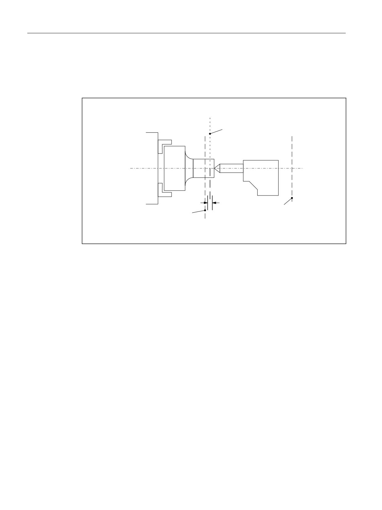
Example of travel to fixed stop
Procedure
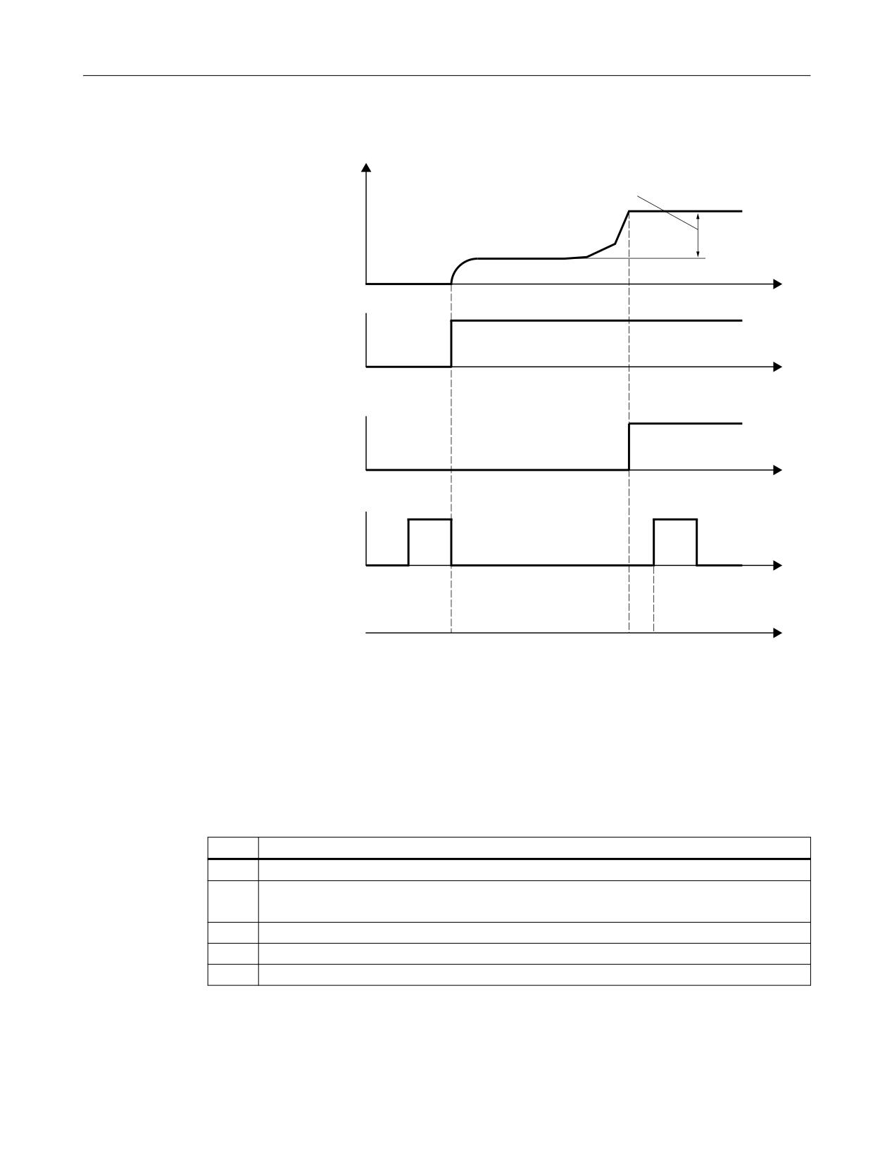
The NC detects that the function "Travel to fixed stop" is selected via the command FXS[x]=1
and signals the PLC using the IS DB31, ... DBX62.4 ("Activate travel to fixed stop") that the
function has been selected.
If the machine data:
MD37060 $MA_FIXED_STOP_ACKN_MASK (monitoring PLC acknowledgements for travel to
fixed stop)
is set correspondingly, the system waits for the acknowledgement of the PLC using the IS
DB31, ... DBX3.1 ("Enable travel to fixed stop").
The programmed target position is then approached from the start position at the programmed
velocity. The fixed stop must be located between the start and target positions of the axis/
spindle. A programmed torque limit (clamping torque specified via FXST[<axis>]) is effective
from the start of the block, i.e. the fixed stop is also approached with reduced torque. Allowance
for this limitation is made in the NC through an automatic reduction in the acceleration rate.
If no torque has been programmed in the block or since the start of the program, then the value
is valid in the axis-specific machine data:
MD37010 $MA_FIXED_STOP_TORQUE_DEF (default for fixed stop clamping torque)
is entered.
Axes and spindles
792
Function Manual, 10/2020, 6FC5397-4GP40-0BA1

Travel to fixed stop
16.2 Detailed description
16.2.2.2
Fixed stop is reached
Detecting the fixed stop
Detecting the fixed stop or identifying that the machine axis has reached the fixed stop can be
set using the following machine data:
MD37040 $MA_FIXED_STOP_BY_SENSOR = <value> (fixed stop detection via sensor)
<value>
Meaning
0
The fixed stop has been reached when the contour deviation of the machine axis has excee-
ded the value set in the machine data:
MD37030 $MA_FIXED_STOP_THRESHOLD (threshold for fixed stop detection)
1
An external sensor detects when the fixed stop has been reached and informs the control via
the following axial NC/PLC interface signal:
DB31, ... DBX1.2 == 1 (sensor for fixed stop)
2
The fixed stop has been reached, if one of the conditions, specified under <value> == 0 OR
<value> == 1 applies.
Ineffective NC/PLC interface signals
When the axis is in the "Fixed stop reached" state, the following NC/PLC interface signals have no
effect:
• DB31, ... DBX1.3 (axis/spindle disable)
• DB31, ... DBX2.1 (controller enable)
Actions when the fixed stop is reached
The following actions are executed when the fixed stop is reached:
• The torque in the drive is increased up to the programmed clamping torque (FXST)
• The remaining distance to go is deleted
• The position setpoint is tracked
• The NC/PLC interface signal is set: DB31, ... DBX62.5 = 1 ("fixed stop reached")
• Executing a block change:
- Executing a block change when the fixed stop is reached: MD37060
$MA_FIXED_STOP_ACKN_MASK, Bit 1 = 0
The block change is immediately executed after reaching the fixed stop.
- Block change is only executed after the acknowledgment by the PLC user program:
MD37060 $MA_FIXED_STOP_ACKN_MASK, Bit 1 = 1
After reaching the fixed stop, the block is not changed until acknowledgment by the PLC
user program:
DB31, ... DBX1.1 == 1 (acknowledge fixed stop reached)
In order to also maintain the clamping torque after the block change, the NC still outputs a
setpoint for the machine axis.
• Activating the fixed stop monitoring or the monitoring window
Axes and spindles
Function Manual, 10/2020, 6FC5397-4GP40-0BA1
793
Travel to fixed stop
16.2 Detailed description
Monitoring window
If, in the traversing block to the fixed stop or since the beginning of the program, no specific value
for the monitoring window is programmed with FXSW then the value set in the machine data is
active:
MD37020 $MA_FIXED_STOP_WINDOW_DEF (default for fixed stop monitoring window)
If the axis leaves the position it was in when the fixed stop was detected by more than the
specified window, then alarm 20093 "Fixed stop monitoring has responded" is displayed and the
"Travel to fixed stop" function is deselected.
The monitoring window must be selected by the user such that the alarm is activated only when
the axis leaves the fixed stop position.
NOTICE
"Fixed stop reached" and when the fixed stop breaks
As soon as the "fixed stop reached" state is identified, then a speed setpoint derived from the
axis-specific machine data servo gain factor (KV) (MD32200) and the threshold for the fixed
stop detection (MD37030) is entered for the drive. If the fixed stop breaks in this state, then the
axis accelerates until it reaches the monitoring window limit. The velocity that is then reached
is proportional to the values set in the specified machine data. For appropriately high values,
it is possible that the drive accelerates up to the maximum motor speed.
Axes and spindles
794
Function Manual, 10/2020, 6FC5397-4GP40-0BA1
Travel to fixed stop
16.2 Detailed description
Overview
)ROORZLQJ HUURU
0'
0$B),;('B6723B7+5(6+2/'
W
'%
'%;
DFWLYDWH 7UDYHO WR IL[HG
VWRS
'%
'%;
)L[HG VWRS UHDFKHG
%ORFN FKDQJH
9$B);6
Figure 16-2
Fixed stop is reached
16.2.2.3
Fixed stop is not reached
Alarm suppression
Alarms for various causes of breakage can be suppressed using the machine data:
MD37050 $MA_FIXED_STOP_ALARM_MASK = <value>
Value
Description: Suppressed alarms
0
Alarm 20091 "Fixed stop not reached"
2
Alarm 20091 "Fixed stop not reached"
Alarm 20094 "Fixed stop aborted"
3
Alarm 20094 "Fixed stop aborted"
8
Alarm 25042 "FOC: Standstill monitoring"
16
Only initiate alarm 20095 if the brake test torque is less than the holding torque.
Axes and spindles
Function Manual, 10/2020, 6FC5397-4GP40-0BA1
795
Travel to fixed stop
16.2 Detailed description
Actions in the case of a fault or breakage
The following actions are executed when a fault occurs or for a breakage:
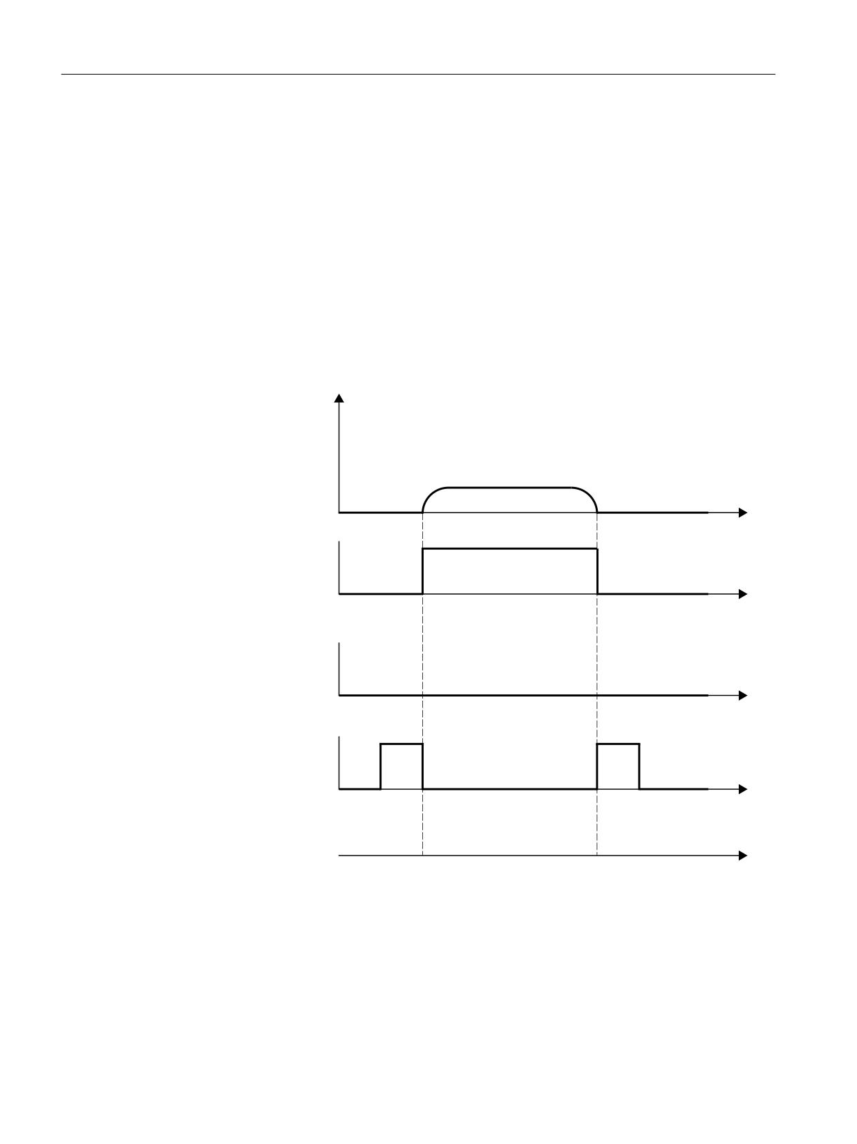
• The NC/PLC interface signal is reset: DB31, ... DBX62.4 = 0 (activate travel to fixed stop)
• Depending on the setting in the machine data, the system waits for acknowledgment:
- MD37060 $MA_FIXED_STOP_ACKN_MASK
- DB31, ... DBX3.1 == 0 (enable travel to fixed stop)
• Withdrawing torque limits
• Executing a block change
Overview
)ROORZLQJ HUURU
W
'%
'%;
DFWLYDWH 7UDYHO WR IL[HG
VWRS
'%
'%;
)L[HG VWRS UHDFKHG
%ORFN FKDQJH
9$B);6
Figure 16-3
Fixed stop is not reached
16.2.2.4
Deselection
The "travel to fixed stop" function is deselected using the command FXS[<axis>] = 0 in a
block of an NC program.
Axes and spindles
796
Function Manual, 10/2020, 6FC5397-4GP40-0BA1

Travel to fixed stop
16.2 Detailed description
Actions when deselecting the function
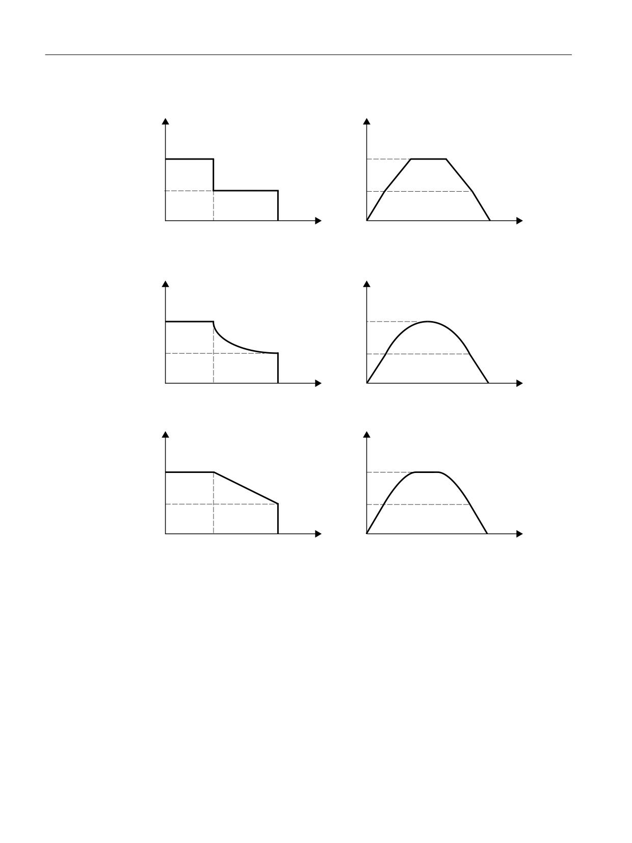
When deselecting the function, the following actions are executed:
• A preprocessing stop is initiated (STOPRE)
• The NC/PLC interface signals are reset
- DB31, ... DBX62.4 = 0 (activate travel to fixed stop)
- DB31, ... DBX62.5 = 0 (fixed stop reached)
• Depending on the machine data, the system waits for acknowledgment from the PLC user
program:
- MD37060 $MA_FIXED_STOP_ACKN_MASK
- DB31, ... DBX3.1 == 0 (enable travel to fixed stop)
- DB31, ... DBX1.1 == 0 (acknowledge fixed stop reached)
• Exiting the follow-up mode
• Axis resumes closed-loop position control
Pulse enable
The pulse enable or pulse inhibit can be canceled via:
• Drive: Via terminal EP (enable pulses)
• NC/PLC interface signal: DB31, ... DBX21.7 ("pulse enable")
The behavior at the fixed stop can be set via the following machine data:
MD37002 $MA_FIXED_STOP_CONTROL, bit 0 and bit 1 (sequence control for traversing to fix
stop)
Bit
Val-
Meaning
ue
0
Behavior for pulseinhibit at the fixed stop
0
"Travel to fixed stop" is aborted
1
"Travel to fixed stop" is interrupted, i.e. the drive is without power.
1
Behavior for pulseenable at the fixed stop
0
The torque is injected suddenly.
1
The torque is linearly ramped-up over the time specified in the machine data:
MD37012 $MA_FIXED_STOP_TORQUE_RAMP_TIME
Special case: Deleting the pulse enable during deselection
If, during deselection, the function in state: "Waiting for PLC acknowledgements" the pulse
enable is deleted, the torque limit is reduced to 0. In this phase, if pulse enable is set again torque
is no longer established in the drive. Once the deselection has been completed the axis can be
traversed normally again.
Axes and spindles
Function Manual, 10/2020, 6FC5397-4GP40-0BA1
797
Travel to fixed stop
16.2 Detailed description
Overview
D
Y
DPD[
YPD[
DUHG
YUHG
YUHG
YPD[
Y
W
D
Y
DPD[
YPD[
DUHG
YUHG
YUHG
YPD[
Y
W
D
Y
DPD[
YPD[
DUHG
YUHG
YUHG
YPD[
Y
W
① Traversing block with deselection FXS[<axis>]=0
Figure 16-4
Fixed stop deselection
Axes and spindles
798
Function Manual, 10/2020, 6FC5397-4GP40-0BA1
Travel to fixed stop
16.2 Detailed description
16.2.3
Behavior during block search
Function
Block search with calculation
• If the target block is located in a program section in which the axis must stop at a fixed limit,
then the fixed stop is approached if it has not yet been reached.
• If the target block is located in the program section in which the axis must not stop at a fixed
limit, then the axis leaves the fixed stop if it is still positioned there.
• If the axis is in the "Fixed stop reached" state, message 10208 "Press NC start to continue the
program" is displayed. The program can be continued with NC start.
• Clamping torque FXST and monitoring window FXSW have the value that they have for
normal program processing at the start of the target block.
Block search without calculation
The FXS, FXST and FXSW commands are ignored during the block search.
Effectiveness of FOCON/FOCOF
The state of the modal-acting torque/force reduction FOCON/FOCOF is maintained during the
block search and is effective in the approach block.
Block search with FXS or FOC
The user selects FXS or FOC in a program area of the target block in order to acquire all states and
functions of the machining last valid. The NC starts the selected program in Program test mode
automatically. After the target block has been found, the NC stops at the beginning of the target
block, deselects Program test internally again and displays the Stop condition "Search target
found" in its block display.
CAUTION
SERUPRO approach does not really take the FXS command into account
The approach to the programmed end position of the FXS block is only simulated without
torque limitation.
If FXS is located between the beginning of the program and the search target, the command is
not executed by the NC. The motion is only simulated up to the programmed end point.
The user can log the turning on and turning off of FXS in the part program. If necessary, the user
can start an ASUP in order to activate or deactivate FXS in this SERUPRO-ASUP.
System variable
The reference and actual state of the "travel to fixed stop" function can be read using the
following system variable:
• $AA_FXS (desired state)
• $VA_FXS (actual state)
Axes and spindles
Function Manual, 10/2020, 6FC5397-4GP40-0BA1
799

Travel to fixed stop
16.2 Detailed description
SERUPRO: $AA_FXS (desired state)
During SERUPRO, $AA_FXS supplies the following values depending on the activation status of
the "Travel to fixed stop" function:
Activation status of the "travel to fixed stop"
System variable $AA_FXS ==
function
"Deactivated"
0 (axis not at fixed stop)
"Activated"
3 ("Travel to fixed stop" selection is active)
Note
During SERUPRO, the system variable $AA_FXS only supplies the values 0 and 3. As a result,
based on $AA_FXS, the program sequence can be changed with SERUPRO compared to the
normal program execution for program branches.
SERUPRO: $VA_FXS (actual state)
During SERUPRO, the variable $VA_FXS always supplies the real state of axis on the machine.
Example
The current state of the "Travel to fixed stop" function can be determined in the SERUPRO ASUP
via the system variables $AA_FXS and $VA_FXS, and the appropriate response initiated:
Program code: FXS_SERUPRO_ASUP.MPF
Comment
N100 WHEN ($AA_FXS[X]==3) AND ($VA_FXS[X]==0) DO
; Reference=="Selection not active" AND
FXS[X]=1
; Actual=="Axis not at fixed stop"
; => "Switch on"
N200 WHEN ($AA_FXS[X]==0) AND ($VA_FXS[X]==1) DO
; Reference=="Axis not at fixed stop" AND
FXS[X]=0
; Actual=="Fixed stop successfully approached"
; => "Switch on"
N1020 REPOSA
; Repositioning linearly with all axes
Displaying the REPOS offset
Once the search target has been found, for each axis, the actual state regarding the "Travel to
fixed stop" is displayed using the following NC/PLC interface signals:
• DB31, ... DBX62.4 (activate travel to fixed stop)
• DB31, ... DBX62.5 (fixed stop reached)
Example:
If the axis is at the fixed stop and the target block is available after deselection of FXS, the new
target position is displayed via DB31, ... DBX62.5 (fixed stop reached) as the REPOS offset.
Axes and spindles
800
Function Manual, 10/2020, 6FC5397-4GP40-0BA1

Travel to fixed stop
16.2 Detailed description
REPOS and FXS
With REPOS, the functionality of FXS is repeated automatically and called FXS-REPOS in the
following. This sequence is comparable to the FXS_SERUPRO_ASUP.MPF program. Every axis is
taken into account and the torque last programmed before the search target is applied.
The user can treat FXS separately in a SERUPRO ASUP.
The following then applies:
Every FXS action executed in the SERUPRO ASUP automatically takes care of
$AA_FXS[ <axis> ] = $VA_FXS[ <axis> ].
This deactivates FXS-REPOS for axis X.
Deactivating FXS-REPOS
FXS-REPOS is deactivated by:
• An FXS synchronized action which refers to REPOSA
• $AA_FXS[X] = $VA_FXS[X] in the SERUPRO_ASUP
Note
A SERUPRO ASUP without FXS treatment or no SERUPRO ASUP results automatically in FXS-
REPOS.
CAUTION
Speed too high for FXS-REPOS
FXS-REPOS traverse all path axes together to the target position. Axes with and without FXS
treatment thus traverse together with the G command and feedrate valid in the target block.
As a result, the fixed stop may be approached in rapid traverse(G0) or higher velocity.
FOC-REPOS
FOC-REPOS behaves in the same way as FXS-REPOS.
A changing torque characteristic during the program preprocessing cannot be implemented
with FOC-REPOS.
Example
Axis X is traversed from position 0 to 100. FOC is switched on every 20 millimeters for 10
millimeters. The resulting torque characteristic is generated with non-modal FOC and cannot be
traced by FOC-REPOS. Axis X is traversed by FOC-REPOS with or without FOC in accordance with
the last programming before the target block.
For FXS "Travel to fixed stop" programming examples, see the Basic Functions Function Manual.
Axes and spindles
Function Manual, 10/2020, 6FC5397-4GP40-0BA1
801

Travel to fixed stop
16.2 Detailed description
16.2.4
Behavior for reset and function abort
NC reset
As long as the function is still not in the "Successful travel to fixed stop" state, the travel to fixed
stop can be aborted with NC reset.
Even when the fixed stop has already has been approached, but the specified stop torque not yet
fully reached, then the function can still be aborted with NC reset. The position setpoint of the
axis is synchronized with the current actual position.
As soon as the function is in the "Successful travel to fixed stop" state, the function also remains
active after the NC reset.
Function abort
A function abort can be triggered by the following events:
• Emergency stop
CAUTION
Dangerous machine situations possible for travel to limit stop
It must be ensured that no dangerous machine situations occur while travel to fixed stop is
active when an "Emergency stop" is triggered or reset.
For example, behavior when setting and canceling the pulse enable:
MD37002 $MA_FIXED_STOP_CONTROL, bit 0 (behavior for pulse disable at the stop)
• Bit 0 = 0: Travel to fixed stop is aborted
• Bit 0 = 1: Travel to fixed stop is interrupted, i.e. the drive is without power
Once the pulse disable is canceled again, the drive presses with the stop torque again.
Note
NC and drive have no power during "Emergency stop", i.e. the PLC must react.
• Functional state: "Fixed stop not reached"
• Functional state: "Fixed stop aborted"
• Aborted by the PLC user program:
DB31, ... DBX62.4 = 0 ("Activate travel to fixed stop")
• Cancellation of the pulse enable and machine data parameterization:
MD37002 $MA_FIXED_STOP_CONTROL, bit 0 = 0 (see above)
16.2.5
Behavior with regard to other functions
Measurement with delete distance-to-go
"Travel to fixed stop" (FXS) cannot be programmed in a block with "Measurement with delete
distance-to-go" (MEAS). Except when on function acts on a path axis while the other acts on a
positioning axis or both functions act on positioning axes.
Axes and spindles
802
Function Manual, 10/2020, 6FC5397-4GP40-0BA1
Travel to fixed stop
16.2 Detailed description
Contour monitoring
The axis contour monitoring function is inoperative while "Travel to fixed stop" is active.
Positioning axes
For "Travel to fixed stop" with positioning axes POSA, the block change is executed even when
the positioning axis has not yet reached the fixed stop by this time.
Vertical axes
The "Travel to fixed stop" function can be used for vertical axes even when alarms are active.
If a function-specific alarm occurs for a vertical axis when traveling to fixed stop, the NC/PLC
interface signal DB11, DBX6.3 (mode group ready) is not reset. This means that the
corresponding drive is not de-energized.
This corresponds to an electronic weight compensation for the vertical axis and can be
configured via the following machine data:
MD37052 $MA_FIXED_STOP_ALARM_REACTION
Further information
Further information on vertical axes can be found in:
• Function Manual Drive Functions SINAMICS S120
• Function Manual Monitoring and Compensating; Compensation, electronic weight
counterbalance
16.2.6
Setting data
The values programmed via the function-specific FXS, FXST and FXSW commands are written
block-synchronously to the following, immediately effective, axis-specific setting data:
Switching the function on/off
SD43500 $SA_FIXED_STOP_SWITCH (selection/deselection of travel to fixed stop)
Axes and spindles
Function Manual, 10/2020, 6FC5397-4GP40-0BA1
803
Travel to fixed stop
16.2 Detailed description
Clamping torque
SD43510 $SA_FIXED_STOP_TORQUE (clamping torque)
Note
Clamping torque greater than 100%
A value for the clamping torque in SD43510 greater than 100% of the maximum motor torque
is only advisable for a short time. In addition, the maximum motor torque is limited by the drive.
For example, the following drive parameters have a limiting effect:
• p1520/p1521 upper torque limit/force limit / lower torque limit/force limit
• p1522/p1523 upper torque limit/force limit / lower torque limit/force limit
• p1530/p1531 power limit motorized / power limit regenerative
• p0640 current limit
• p0326 motor stall force correction factor
Detailed information on the drive parameters and the functions can be found in:
Further information
• SINAMICS S120/S150 List Manual
• Function Manual Drive Functions SINAMICS S120
Monitoring window
SD43520 $SA_FIXED_STOP_WINDOW (monitoring window)
Default setting
The defaults for the setting data are set via the following machine data:
• Clamping torque:
MD37010 $MA_FIXED_STOP_TORQUE_DEF (default clamping torque)
• Monitoring window:
MD37020 $MA_FIXED_STOP_WINDOW_DEF (default monitoring window)
Effectiveness
The setting data for the clamping torque and monitoring window takes effect immediately. In
this way, the clamping state can be adapted to the machining situation at any time by the
operator or via the PLC user program.
Further information
Further detailed information on the machine and setting data can be found in:
List Manual, Detailed Machine Data Description
Axes and spindles
804
Function Manual, 10/2020, 6FC5397-4GP40-0BA1

Travel to fixed stop
16.2 Detailed description
16.2.7
System variables
Reference/actual state
The reference and actual state of the "travel to fixed stop" function can be read using the
following system variables:
• $AA_FXS = <value> (status, "Travel to fixed stop" reference state)
• $VA_FXS = <value> (status, "Travel to fixed stop" actual state)
<val-
Description
ue>
0
Axis is not at fixed stop
1
Fixed stop was successfully approached
2
Approach to fixed stop failed
3
Selection "Travel to fixed stop" is active.
4
Fixed stop was detected.
5
Travel to fixed stop deselection active
Additional information
If errors occurred when traversing to the fixed stop ($VA_FXS == 2), then additional information
is displayed in the following system variables:
• $VA_FXS_INFO = <value> (additional information when "traveling to fixed stop")
<val-
Description
ue>
0
No additional information available
1
No approach motion programmed
2
Programmed end position reached, motion stopped
3
Cancellation using a reset, DB21, ... DBX7.7 == 1
4
Monitoring window was exited
5
Torque reduction rejected by drive
6
PLC has withdrawn the enable, DB31, ... DBX3.1 == 0 (travel to fixed stop enabled)
Application example for $AA_FXS
In order that a block change is executed, no alarm should be triggered when a fault occurs. The
cause is then determined using the system variable $VA_FXS_INFO and a specific response
initiated.
Requirement: MD37050 $MA_FIXED_STOP_ALARM_MASK = 0 (when traveling to fixed stop, no
alarm initiated)
Program code
Comment
X300 Y500 F200 FXS[X1]=1 FXST[X1]=25 FXSW[X1]=5
; Travel to fixed stop
IF $AA_FXS[X1] == 2 GOTOF FXS_ERROR
; IF fixed stop == reached
Axes and spindles
Function Manual, 10/2020, 6FC5397-4GP40-0BA1
805
Travel to fixed stop
16.2 Detailed description
Program code
Comment
R100=$AA_IM[X1]
; THEN (normal case)
IF R100 ...
; Evaluation of the
; actual position
GOTOF PROG_END
FXS_ERROR:
; ELSE (error case)
CASE($VA_FXS_INFO[X1]) OF 0 GOTOF LABEL_0 OF 1 GOTOF LABEL_1 ...
; Error handling
LABEL_0: ...
GOTOF CASE_END
LABEL_1: ...
GOTOF CASE_END
CASE_END:
PROG_END: M30
; ENDIF end of program
16.2.8
Alarms
Alarm 20091 "Fixed stop not reached"
If the fixed stop position is not reached during travel to fixed stop, alarm 20091 "Fixed stop not
reached" is displayed and a block change executed.
Alarm 20092 "Travel to fixed stop is still active"
If there is a travel request or renewed function selection for the axis after the fixed stop has been
reached, alarm 20092 "Travel to fixed stop is still active" is displayed.
Alarm 20093 "Standstill monitoring at fixed stop has triggered"
If an axis has reached the fixed stop and is then moved out of this position by more than the value
specified in the setting data
SD43520 FIXED_STOP_WINDOW (fixed stop monitoring window)
alarm 20093 "Standstill monitoring at fixed stop has triggered" is displayed, travel to fixed stop
for this axis is deselected and the following system variable set:
$AA_FXS[x] = 2
Alarm 20094 "Function has been aborted"
The travel to fixed stop is aborted if the clamping torque can no longer be applied due to the
cancellation of the pulse enable, or the requested acknowledgement signal at the NC/PLC
interface has been reset:
• Acknowledgement signal required: MD37060 $MA_FIXED _STOP_ACKN_MASK, bit 0 = 1
• Acknowledgement signal: DB31, ... DBX3.1 == 0 (enable travel to fixed stop)
Axes and spindles
806
Function Manual, 10/2020, 6FC5397-4GP40-0BA1
Travel to fixed stop
16.2 Detailed description
Enabling the fixed stop alarms
The following machine data can be use to set whether the fixed stop alarms
• Alarm 20091 "Fixed stop not reached",
• Alarm 20094 "Fixed stop aborted"
are displayed:
MD37050 $MA_FIXED_STOP_ALARM_MASK (enable of the fixed stop alarms)
Settable functional behavior for fixed stop alarms
The following machine data can be used to set that the function is not aborted when function-
specific alarms occur:
• Alarm 20090 Travel to fixed stop not possible
• Alarm 20091 Fixed stop not reached
• Alarm 20092 Travel to fixed stop is still active
• Alarm 20093 Standstill monitoring at fixed stop has triggered
• Alarm 20094 Travel to fixed stop aborted
MD37052 $MA_FIXED_STOP_ALARM_REACTION (reaction to fixed stop alarms)
Alarm suppression after new programming
Travel to fixed stop can be used for simple measuring processes.
For example, it is possible to carry out a check for tool breakage by measuring the tool length by
traversing onto a defined obstacle. To do so, the fixed stop alarm must be suppressed. When the
function for clamping workpieces is then used "normally," the alarm can be activated using part
program commands.
Axes and spindles
Function Manual, 10/2020, 6FC5397-4GP40-0BA1
807

Travel to fixed stop
16.2 Detailed description
16.2.9
Travel with limited torque/force FOC
Function
Using the "Force Control" function to traverse with limited torque/force, when traversing, the
maximum permissible torque/force can be limited to a percentage of the maximum possible axis
torque. The limit value can be changed at any time, also while the axis is traversing. The changes
can be realized in the interpolator clock cycle, dependent on distance, time or on any other
variable. The "Force Control" function can also be programmed in synchronized actions. The
function can be permanently activated, or block related.
Note
The current torque/force actual value from SINAMICS (VA_TORQUE) is required for optimum
utilization of the "Force Control" function to detect when the torque limit is reached. This actual
value is only included in the transfer of telegrams upwards of telegram number 116.
For drives which do not provide these values, but do allow a torque reduction (MOM_RED),
detection of the stop is limited to evaluation of the contour violation. There is no guarantee that
the desired torque limit will be reached.
Optimum use of travel to fixed stop and Force Control is therefore assured for all drives based on
SINAMICS S120. For all other drives (e.g. SINAMICS S210), check whether the applications can
be executed in a practical manner with the desired quality.
Programming
Syntax
FOCON[<axis>]
FOCOF[<axis>]
FOC[<axis>]
Meaning
Parameter
Meaning
FOCON:
Activate torque/force limiting
FOCOF:
Deactivate torque/force limiting
FOC:
Activate non-modal torque/force limiting
<Axis>:
Channel axis name, type: AXIS
Example
Program code
Comment
N10 FOCON[X]
; Modal activation of the torque limit
N20 X100 Y200 FXST[X]=15
; X travels with reduced torque (15%)
N30 FXST[X]=75 X20
; Changing the torque to 75%,
N40 FOCOF[X]
; Disable torque limit
Axes and spindles
808
Function Manual, 10/2020, 6FC5397-4GP40-0BA1

Travel to fixed stop
16.2 Detailed description
Parameterization
Machine data
• MD37010 $MA_FIXED_STOP_TORQUE_DEF (default for fixed stop clamping torque)
The value specified in the machine data is effective after activating the function, as long as
no explicit value is programmed using FXST.
• MD36042 $MA_FOC_STANDSTILL_DELAY_TIME (delay time standstill monitoring for active
torque/force limiting)
Permanent activation (FOCON/FOCOF)
Permanent activation of the "Force Control" function after POWER ON or RESET can be set using
the machine data:
MD37080 $MA_FOC_ACTIVATION_MODE, bit 0 and bit 1 (basic setting of the modal force/
torque limiting)
Bit
Value
Meaning
0
0
The "Force Control" function is not active after POWER ON.
1
The "Force Control" function is active after POWER ON.
1
0
The "Force Control" function is not active after RESET.
1
The "Force Control" function is active after RESET.
If a limiting torque or force is programmed using FXST = <value> before activation, then this
is effective from activation onwards.
If a limiting torque or force was not programmed using FXST = <value> before activation,
then the value specified in the machine data is effective as standard.
MD37010 $MA_FIXED_STOP_TORQUE_DEF (default for fixed stop clamping torque)
Block-related activation (FOC)
The function for the actual block is activated using the FOC command.
Activating the function using a synchronized action takes effect up to the end of the current part
program block.
Priority of FXS before FOC
Activating the "Travel to fixed stop" function FXS has a higher priority than the "Force Control"
function. If "Travel to fixed stop" is active at the same time as "Force Control", then the first is
executed.
Deselecting the "Travel to fixed stop" function FXS cancels the clamping. A "Force Control"
function that is at same time permanently active, remains active.
System variable
Status of the "Force Control" function
The status of the "Force Control" function can be read using system variable $AA_FOC.
Axes and spindles
Function Manual, 10/2020, 6FC5397-4GP40-0BA1
809

Travel to fixed stop
16.2 Detailed description
Changing the status of the "Travel to fixed stop" function FXS does not change the status of the
"Force Control" function.
$AA_FOC
Value
Meaning
0
FOC not active
1
FOC modal active
2
FOC non-modal active
Status of torque limiting
The actual status of the torque limiting can be read using system variable
$VA_TORQUE_AT_LIMIT.
$VA_TORQUE_AT_LIMIT
Value
Meaning
0
actually effective torque < torque limit value
1
actually effective torque == torque limit value
Restrictions
the "Force Control" function has the following restrictions:
• The change of the torque/force limitation representing itself as an acceleration limitation
is only taken into account in the traversing movement at block limits (see
command ACC).
• Only FOC: No monitoring is possible from the NC/PLC interface to check that the active
torque limit has been reached.
• If the acceleration limitation is not adapted accordingly, an increase in the following error
occurs during the traversing motion.
• If the acceleration limitation is not adapted accordingly, the end-of-block position is possibly
reached later than specified in the machine data:
MD36040 $MA_STANDSTILL_DELAY_TIME
The machine data:
MD36042 $MA_FOC_STANDSTILL_DELAY_TIME
is introduced for this and monitored in this status.
Possible application for link and container axes
All axes that can be traversed in a channel, i.e. also link axes and container axes, can be traversed
to fixed stop.
Further information:
Function Manual Basic Functions; Distributed systems; Multiple control panels on multiple NCUs
The status of the machine axis is kept in the case of a container rotation, i.e. a clamped machine
axis remains at the stop.
If a modal torque limitation has been activated with FOCON, this is kept for the machine axis
even after a container rotation.
Axes and spindles
810
Function Manual, 10/2020, 6FC5397-4GP40-0BA1

Travel to fixed stop
16.3 Examples
16.3
Examples
Example 1: Travel to fixed stop with static synchronized actions
Travel to fixed stop (FXS) is initiated when requested via R parameter ($R1) in a static
synchronized action.
Program code
Comment
N10 IDS=1 WHENEVER
; Static synchronized action 1:
(($R1==1) AND
; R1==1 (FXS for Y requested) AND
($AA_FXS[Y]==0)) DO
; Avoidance of multiple selection
; $AA_FXS[Y]==0 (axis not at limit): =>
$R1=0 FXS[Y]=1
; reset $R1, activate FXS for Y
FXST[Y]=10
; Limit torque: 10%
FA[Y]=200
; Axial feedrate Y: 200
POS[Y]=150
; Positioning movement Y
N11 IDS=2 WHENEVER
; Static synchronized action 2:
($AA_FXS[Y]==4) DO
; $AA_FXS[Y]==4 (limit detected): =>
FXST[Y]=30
; Limit torque:
30%
N12 IDS=3 WHENEVER
; Static synchronized action 3:
($AA_FXS[Y]==1) DO
; $AA_FXS[Y]==1 (limit reached successfully): =>
FXST[Y]=$R0
; Limit torque: Value from R parameter $R0
N13 IDS=4 WHENEVER
; Static synchronized action 4:
(($R3==1) AND
; R3==1: Deselection of FXS for Y requested
($AA_FXS[Y]==1)) DO
; $AA_FXS[Y]==1 (limit reached successfully): =>
FXS[Y]=0
; Deselect FXS
FA[Y]=1000 POS[Y]=0
; Positioning movement Y
N20 FXS[Y]=0 G0 G90 X0 Y0
; Set initial settings: FXS deselected,
X and Y at initial position
N30 RELEASE(Y)
; Release Y for movements in synchronized actions
N60 GET(Y)
Include axis Y back into the path group
Note
Avoidance of multiple selection for FXS
To avoid a multiple selection, we recommend that prior to activating FXS, query either the
$AA_FXS==0 system variable or a user-specific flag. See above, program example N10
Axes and spindles
Function Manual, 10/2020, 6FC5397-4GP40-0BA1
811

Travel to fixed stop
16.4 Data lists
Example 2: Traveling to fixed stop with block-related synchronized actions
"Travel to fixed stop" is activated from a specific position of the traversing motion of the following
block
Program code
Comment
N10 G0 G90 X0
; Starting position
N20 WHEN $AA_IW[X]>17 DO FXS[X]=1
; Synchronized action: Actual position of
X axis > 17
; => activate FXS for axis X
N30 G1 F200 X100
; Traversing motion for axis X
Note
A block-related synchronized action is processed in the following main program block.
16.4
Data lists
16.4.1
Machine data
16.4.1.1
Axis/spindlespecific machine data
Number
Identifier: $MA_
Description
36042
FOC_STANDSTILL_DELAY_TIME
Delay time, standstill monitoring for active torque/
force limiting
37000
FIXED_STOP_MODE
Travel to fixed stop mode
37002
FIXED_STOP_CONTROL
Sequence monitoring for travel to fixed stop
37010
FIXED_STOP_TORQUE_DEF
Fixed stop clamping torque default setting
37012
FIXED_STOP_TORQUE_RAMP_TIME
Time until the modified torque limit is reached
37020
FIXED_STOP_WINDOW_DEF
Default for fixed stop monitoring window
37030
FIXED_STOP_THRESHOLD
Threshold for fixed stop detection
37040
FIXED_STOP_BY_SENSOR
Fixed stop detection via sensor
37050
FIXED_STOP_ALARM_MASK
Enabling the fixed stop alarms
37052
FIXED_STOP_ALARM_REACTION
Reaction to fixed stop alarms
37060
FIXED_STOP_ACKN_MASK
Monitoring of PLC acknowledgments for travel to fixed
stop
37070
FIXED_STOP_ANA_TORQUE
Torque limit on fixed stop approach for analog drives
37080
FOC_ACTIVATION_MODE.
Initial setting of the modal torque/force limiting
Axes and spindles
812
Function Manual, 10/2020, 6FC5397-4GP40-0BA1

Travel to fixed stop
16.4 Data lists
16.4.2
Setting data
16.4.2.1
Axis/spindle-specific setting data
Number
Identifier: $SA_
Description
43500
FIXED_STOP_SWITCH
Selection of travel to fixed stop
43510
FIXED_STOP_WINDOW
Fixed stop clamping torque
43520
FIXED_STOP_TORQUE
Fixed stop monitoring window
Axes and spindles
Function Manual, 10/2020, 6FC5397-4GP40-0BA1
813
Travel to fixed stop
16.4 Data lists
Axes and spindles
814
Function Manual, 10/2020, 6FC5397-4GP40-0BA1
Setpoint switchover
17
17.1
Brief description
Function
The "Setpoint switchover" function is required if only one motor is to be used to drive several
axes/spindles. For example, for milling heads, where the spindle motor is to be used to drive the
tool as well as to orientate the milling head.
Requirements
The following conditions must be fulfilled so that the setpoint can be switched over:
• All of the axes involved in the setpoint switchover are at a standstill
• No sign-of-life error and no errors are active on PROFIBUS
• None of the following functions in the axis with drive control are active:
- Reference point approach
- Measuring
- Travel to fixed stop
- Function generator
- Star/delta switchover
- Parameter set switchover
Position control loop
The drive train, and therefore also the position control loop, are disconnected while the setpoint
is being switched over. In order to avoid instability, the setpoint is only switched over at standstill
- and once all controller enable signals have been cleared (deleted).
When using a single drive, only one control loop can be closed at the same instant in time. Axes
without drive control are operated with open position controller and tracked positions.
Note
Vertical axes
The controller enable signals for all of the axes involved are automatically withdrawn by the
control for the duration of the switchover. Axes without drive control are not in closed-loop
control. Therefore, a brake control must be implemented for vertical axes.
Axes and spindles
Function Manual, 10/2020, 6FC5397-4GP40-0BA1
815
Setpoint switchover
17.1 Brief description
Example
;
;
60&
;
;
;
;
'5,9( &/L4
60&
60&
1&8
$FWLYH /LQH
6LQJOH 0RWRU
'RXEOH 0RWRU
0RGXOH
0RGXOH
0RGXOH
1
a 0
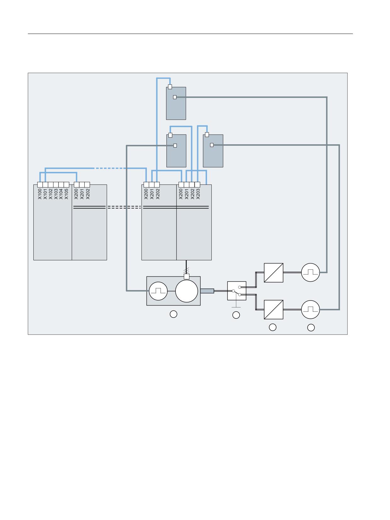
0
①
Motor with encoder
②
Mechanical switchover device
③
Gearbox 1
④
Encoder 1 (e.g. for the milling head)
⑤
Gearbox 2
⑥
Encoder 2 (e.g. for the spindle)
Figure 17-1
Setpoint switchover with 2 axes
Axes and spindles
816
Function Manual, 10/2020, 6FC5397-4GP40-0BA1
Setpoint switchover
17.2 Startup
17.2
Startup
Machine data
Setpoint assignment
The same setpoint channel of a drive is assigned a number of times to define the axes
participating in the setpoint switchover. For this, the following machine data must be pre-
assigned with the same logical drive number for each axis:
MD30110 $MA_CTRLOUT_MODULE_NR (setpoint assignment: module number)
Note
Alarm 26018 is output if the option is missing.
Encoder assignment
The encoder is assigned in the machine data on an axis-for-axis basis:
MD30230 $MA_ENC_INPUT_NR(actual value assignment: Input on drive module/measuring
circuit module)
NC/PLC interface signals
Note
Access rights
Despite assignment of a drive to several machine axes, the use of NC/PLC interface signals
remains unchanged. In the PLC user program this requires an explicit coordination of the access
operations to the NC/PLC interface signal of the individual machine axes involved in the setpoint
switchover.
Request for drive control
The request to assume drive control is realized via:
DB31, ... DBX24.5 (setpoint switchover: request drive control)
Status of the drive control
The current status of drive control is displayed via:
DB31, ... DBX96.5 (setpoint switchover: drive control active)
Status signals
After drive control is assumed for the first time for one of the machine axes involved in the
setpoint switchover (DB31, ... DBX24.5 = 1 (setpoint switchover: switchover)) the following
status signals are always displayed the same for all of the machine axes involved:
DB31, ... DBB92 - DBB95
Axes and spindles
Function Manual, 10/2020, 6FC5397-4GP40-0BA1
817
Setpoint switchover
17.2 Startup
Control signals
The control signals are only active in the machine axis that currently has the drive control
(DB31, ... DBX96.5 == 1 (setpoint switchover active)):
DB31, ... DBB20 to DBB21
Controller enable
The controller enable (DB31, ... DBX2.1) is only active in the machine axis that currently has drive
control (DB31, ... DBX96.5 == 1 (status setpoint switchover))
Follow-up mode
Machine axes without drive control, involved in the setpoint switchover, are always switched
into the follow-up mode in the control itself (DB31, ... DBX61.3 == 0).
Note
Only one axis with drive control
At any one point in time, only one axis must have drive control DB31, ... DBX24.5 == 1 and
DB31, ... DBX96.5 == 1.
Special cases
Several simultaneous requests to take over
No switchover takes place for several simultaneous takeover requests. The last axis used keeps
drive control. The same effect applies if there are no takeover requests.
No takeover request when powering up
If there is no takeover request when the control powers up, then the control assigns the drive
control to the first machine axis with the same logical drive number.
MD30110 $MA_CTRLOUT_MODULE_NR[0,AX1] = 1
MD30110 $MA_CTRLOUT_MODULE_NR[0,AX2] = 2
MD30110 $MA_CTRLOUT_MODULE_NR[0,AX3] = 3
MD30110 $MA_CTRLOUT_MODULE_NR[0,AX4] = 4 ; setpoint switchover: 1st
axis
MD30110 $MA_CTRLOUT_MODULE_NR[0,AX5] = 4 ; setpoint switchover: 2nd
axis
In order to be able to traverse the axis using the drive, the NC/PLC interface signal to request drive
control (DB31, ... DBX24.5) must be set.
Axes and spindles
818
Function Manual, 10/2020, 6FC5397-4GP40-0BA1
Setpoint switchover
17.3 Flow diagram
17.3
Flow diagram
$;
7UDYHO FRPPDQG WUDYHO UHTXHVW
LV DFWLYH
'% '%;
25
25
25
$;
<HV
'ULYH FRQWURO
DFWLYH"
'% '%;
1R
$;
&ORVH EUDNH
5HOLQTXLVK GULYH FRQWURO
'% '%;
6ZLWFKRYHU PHFKDQLFDO V\VWHP
$;
5HTXHVW GULYH FRQWURO
'% '%;
$;
'ULYH FRQWURO
DFWLYH"
1R
'% '%;
<HV
$;
$;
7UDFNLQJ IROORZ XS PRGH
7UDFNLQJ IROORZ XS PRGH
LV VZLWFKHG RYHU
LV VZLWFKHG RYHU
'% '%;
'% '%;
$;
6HW FRQWUROOHU HQDEOH
'% '%;
2SHQ EUDNH
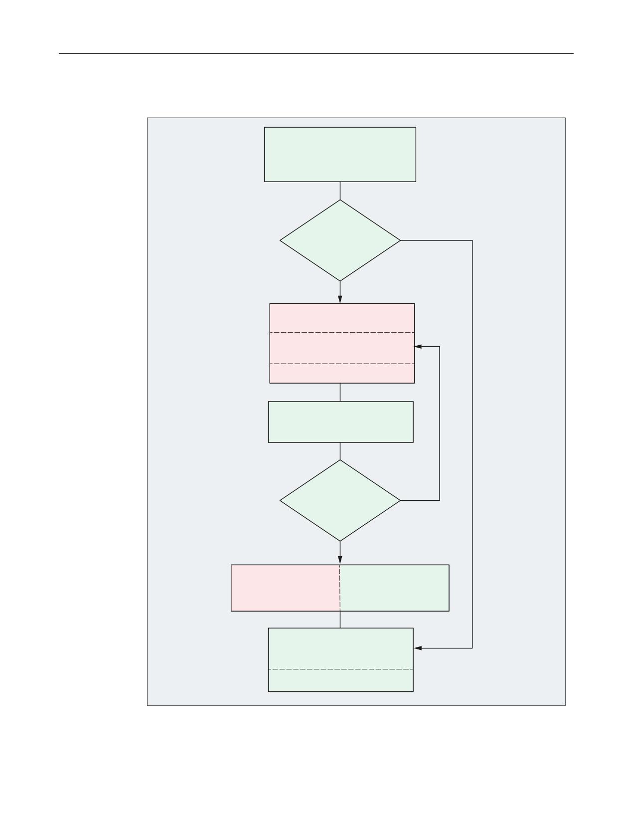
Figure 17-2
Sequence when switching over the setpoint from machine axes AX1 to AX2
Axes and spindles
Function Manual, 10/2020, 6FC5397-4GP40-0BA1
819
Setpoint switchover
17.4 Boundary conditions
17.4
Boundary conditions
Alarms
Only axes with active drive control display drive alarms.
Position control loop
The drive train, and therefore also the position control loop, are disconnected while the setpoint
is being switched over. In order to avoid instability, the setpoint is only switched over at standstill
- and once all controller enable signals have been cleared (deleted).
When using a single drive, only one control loop can be closed at the same instant in time. Axes
without drive control are operated with open position controller and tracked positions.
Reference points
The use of load-side encoders does not affect the axis-specific reference points of a setpoint
switchover.
However, the mechanical reference to the load can be lost following setpoint switchover for a
load-side position derived solely from the motor encoder. These types of axis must be referenced
again after every setpoint switchover.
Parameter set switchover
A setpoint exchange is not performed if one of the following states is present:
• A parameter set changeover in one of the two machine axes has not completed.
• The parameter sets of the two machine axes are not the same.
Note
If, due to secondary conditions, a setpoint switchover is not performed, then a message is not
displayed.
"Parking" state
If an axis is in the "Parking" state, this state can only be canceled if this axis assumes drive control.
Service display drive
The "Drive service display" HMI diagnostics screen does not take into account the changes in
assignments between machine axes and the drive.
Commissioning via SinuCom NC
The "SinuCom NC" commissioning tool can only be used to commission the setpoint switchover
via the expert list.
Axes and spindles
820
Function Manual, 10/2020, 6FC5397-4GP40-0BA1

Setpoint switchover
17.5 Data lists
17.5
Data lists
17.5.1
Machine data
17.5.1.1
Axis/spindlespecific machine data
Number
Identifier: $MA_
Description
30130
CTRLOUT_TYPE
Output type of setpoint
30200
NUM_ENCS
Number of encoders
30220
ENC_MODULE_NR
Actual-value assignment:
Drive number / measurement circuit number
30230
ENC_INPUT_NR
Actual-value assignment:
Input on drive module/measuring circuit module
Axes and spindles
Function Manual, 10/2020, 6FC5397-4GP40-0BA1
821
Setpoint switchover
17.5 Data lists
Axes and spindles
822
Function Manual, 10/2020, 6FC5397-4GP40-0BA1
Tangential control
18
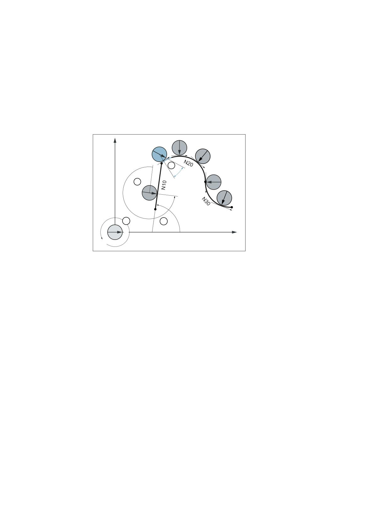
Using the "Tangential control" function, a rotary axis is coupled as following axis to two
geometry axes as leading axes, so that the alignment of the following axis is a function of the
path tangent of the leading axes.
<
;
&
|
① Initial position and positive direction of rotation of the following/rotary axes C
② Angle of the path tangent in machining plane X/Y
③ Offset angle = 270° or -90°
④ Rounding clearance and present angular deviation
The path-defining leading axes, geometry axes X and Y and rotary axis C the following axis of the
tangential coupling can be seen in the diagram. The rotary axis is tracked with a programmable
offset angle of 270° with respect to the path tangent. At the block transition from N10 to N20,
the contour has a discontinuous transition or corner. As a result of a dynamic response that is too
low, the following axis cannot follow the path tangent over part of the path (blue). However, the
dynamic response of the following axis is sufficient so that it can precisely follow circular blocks
N20 and N30 further along the contour.
Properties
The tangential coupling sets itself apart as a result of the following features:
• The leading axes of the tangential coupling must be two geometry axes.
• The following axis of the tangential coupling must be a rotary axis.
• The tangential coupling can be defined, activated, deactivated and deleted in the NC
program.
• Tangential control is defined for the basic and the workpiece coordinate system.
• The positive direction of the path tangent is the same as the traversing direction of the path.
• For an offset angle of 0° between the rotary axis and the path tangent, shows the 0° direction.
• The axes of the tangential coupling must be the channel axes of the same channel.
Axes and spindles
Function Manual, 10/2020, 6FC5397-4GP40-0BA1
823
Tangential control
18.1 Commissioning
• The position of the following axis can act as the input value for an additional transformation.
• The tangential coupling is only active in the AUTOMATIC and MDI modes.
Application examples
• Tangential positioning a rotatable tool during nibbling
• Tracking the workpiece alignment for a belt saw.
• Positioning a dressing tool on a grinding wheel
• Positioning a cutting wheel for cutting glass or paper
• Tangentially feeding a wire for 5-axis welding.
Corner behavior:
If the contour described by the leading axes has a discontinuous block transition or corner, then
one of the following corner behaviors can be selected.
• The dynamic response of the rotary axis has no effect on the leading axes
• The dynamic response of the rotary axis is considered in the path planning of the leading axes
together with programmable parameters "rounding clearance" and "angular tolerance".
• The leading axes are stopped before the corner, and in an automatically generated
intermediate block, the following axis is realigned.
The corner angle is detected depending on the value of machine data MD37400
$MA_EPS_TLIFT_TANG_STEP (tangential angle for corner detection).
18.1
Commissioning
Machine data
Corner detection TLIFT()
In conjunction with the corner detection function TLIFT() (Page 827), a discontinuity in the
programmed path of the leading axes is identified as a corner if the change in the tangential
angle for the following axis is greater at this location than the value specified in the machine
data:
MD37400 $MA_EPS_TLIFT_TANG_STEP[<following axis>] = <tangent change angle>
Parameterizable offset angle
A parameterizable offset angle is specified for the following axis using the machine data:
Maschinendatum MD37402 $MA_TANG_OFFSET[<following axis>] = <parameterizable offset
angle>
The offset angle of the following axis is the angle between the zero position of the following axis
and the path tangent of the programmed path of the leading axes when tangential coupling is
active.
Axes and spindles
824
Function Manual, 10/2020, 6FC5397-4GP40-0BA1
Tangential control
18.2 Programming
The active offset angle is the sum of the offset angle parameterized in the machine data and the
offset angle programmed with TANGON() (Page 828) when tangential coupling is activated:
Block search settings
Using the machine data, the velocity is selected with which the tangential axis traverses to its
position when tangential coupling is activated during or after a block search:
• Rapid traverse velocity (G0)
• Programmed velocity (G1 F
)
• Setting data SD42121 $SC_AX_ADJUST_FEED ≠ 0
MD11450 $MN_SEARCH_RUN_MODE, bit 7
See also: General conditions (Page 832)
System variables
$AC_BLOCKTYPE block type
System variable $AC_BLOCKTYPE can be used to determine as to whether the actual block is an
intermediate block generated by TLIFT(). The actual block is an intermediate block generated by
TLIFT() if the following applies:
$AC_BLOCKTYPE == 6
18.2
Programming
18.2.1
Defining coupling (TANG)
Via the predefined procedure TANG(...), a tangential coupling between a rotary axis is defined as
the following axis and two geometry axes as the leading axes. The following axis is continuously
aligned with the path tangent of the leading axes.
Note
Coupling factor
A coupling factor of 1 does not have to be programmed explicitly.
The direction of the tangential axis is rotated using the coupling factor of -1.
Syntax
TANG(<following axis>, <leading axis_1>, <leading axis_2>, <coupling
factor>, <coordinate system>, <optimization>)
Axes and spindles
Function Manual, 10/2020, 6FC5397-4GP40-0BA1
825

Tangential control
18.2 Programming
Meaning
TANG(...):
Define tangential coupling
<following axis>:
Axis name of the following axis (rotary axis)
Data type:
AXIS
Range of values:
Channel axis names
<leading axis_1>
Axis names of the leading axes (geometry axes) 1)
<leading axis_2>:
Data type:
AXIS
Range of values:
Geometry axis names of the channel
<coupling factor>:
Factor n of the angle change of the following axis for changing the path
tangent of the leading axes:
Angle changefollowing axis = angle changepath tangent * n
Data type:
REAL
Default value:
1.0
<coordinate system>:
Active coordinate system 2)
Data type:
CHAR
Value:
"B":
Basic coordinate system (default value)
"W":
Workpiece coordinate system (not availa-
ble)
<optimization>:
Optimization type
Data type:
CHAR
Value:
"S":
Standard (default value)
The dynamic response of the rotary axis has
no effect on the leading axes If the dynamic
response of the rotary axis is greater than
required for tracking, this method is suffi-
ciently precise. If the dynamic response of
the rotary axis is not great enough to follow
the change in the path tangent, the orien-
tation of the rotary axis will deviate from
the target orientation along an undefined
rounding clearance.
"P":
The dynamic response of the rotary axis is
considered in the path planning of the lead-
ing axes.
For this purpose, on activation of the tan-
gential coupling with TANGON(), two addi-
tional parameters must be specified:
• Rounding clearance
• Angular tolerance
See Section "Activating the coupling (TAN-
GON) (Page 828)"
Note
With kinematic transformations, we recom-
mend using optimization method "P."
Note
Default values do not have to be programmed explicitly.
Axes and spindles
826
Function Manual, 10/2020, 6FC5397-4GP40-0BA1

Tangential control
18.2 Programming
1)
Note
As the leading axes for tangential coupling, the geometry axes must be used that travel along the
programmed path in the machine coordinate system (MCS) with reference to the initial position of the
machine. For example, if swivel cycle CYCLE800 is used on a milling machine with a swivel head, de-
pending on how the cycle is configured, interpolation will be performed in the WCS, e.g. with the ge-
ometry axes X and Y. The tangential coupling, however, must be defined with the geometry axes as the
leading axes, which travel along the programmed path in the MCS. For this purpose, the geometry axes
in the non-swiveled condition of the machine must be used as the leading axes.
2) Note
The basic coordinate system (BCS) must not be rotated with respect to the MCS. For example, if the BCS
is rotated with the ROT command or with the swivel cycle CYCLE800, the tangential control is no longer
correct.
18.2.2
Activating intermediate block generation (TLIFT)
If the tangent change of the following axis at any position along the programmed path of the
leading axes exceeds the limit parameterized in machine data MD37400
$MA_EPS_TLIFT_TANG_STEP, further path planning will depend on the set behavior at corners.
Without use of the predefined procedure TLIFT(...), the path is traversed in accordance with the
rounding behavior programmed in connection with TANG(...) (Page 825) and TANGON(...)
(Page 828).
Activating intermediate block generation
If TLIFT(...) is programmed after TANG(...), an intermediate block automatically generated by the
control is inserted at this point when a corner is detected during preprocessing.
When the program is executed, the leading axes are stopped when the intermediate block is
reached. In the intermediate block, the following axis is rotated with maximum axis dynamics
toward the path tangent of the following block. The leading axes are then traversed further on
the programmed path.
Deactivating intermediate block generation
To deactivate intermediate block generation, the tangential coupling must be defined again
using TANG(...), but without subsequent activation of intermediate block generation by means
of TLIFT(...).
Syntax
TLIFT(<following axis>)
Meaning
TLIFT(...):
Activate corner detection with intermediate block calculation
<following axis>:
Axis name of the following axis (rotary axis)
Data type:
AXIS
Range of values:
Channel axis names
Axes and spindles
Function Manual, 10/2020, 6FC5397-4GP40-0BA1
827
Tangential control
18.2 Programming
Speed of rotation of the following axis
Path axis
If the following axis had already been traversed as a path axis before tangential coupling was
activated, the rotational movement is performed in the intermediate block as a path axis.
If you specify the reference radius with FGREF[<axis>]=0.001, the rotational movement will
be performed with the parameterized maximum axis velocity:
MD32000 $MA_MAX_AX_VELO[<following axis>]
Positioning axis
If the following axis had not yet been traversed as a path axis before tangential coupling was
activated, the rotation is performed in the intermediate block as a positioning axis.
The rotational movement is performed with the parameterized positioning axis velocity:
MD32060 $MA_POS_AX_VELO[<following axis>]
18.2.3
Activating the coupling (TANGON)
Via the predefined procedure TANGON(...), a tangential coupling previously defined
with TANG(...) (Page 825) is activated. The following axis is then continuously aligned with the
path tangent during subsequent travel.
Angle of the following axis
The angle of the following axis with respect to the path tangent depends on the transformation
ratio specified in TANG(...), the offset angle parameterized in the machine data MD37402
$MA_TANG_OFFSET, and the offset angle specified for TANGON(...), which is applied additively.
Optimization "P"
If the value "P" was specified as the optimization parameter in the definition of the tangential
coupling (TANG(...)), the parameter "rounding clearance" and optionally the parameter "angular
tolerance" must be set when coupling is activated.
If the value 0 is specified as the angular tolerance, only the parameter "rounding clearance" will
be active.
If a value greater than 0 is specified as the angular tolerance, the active rounding clearance
results from the minimum of the parameterized rounding clearance and the rounding clearance
based on the parameterized angular tolerance.
If the dynamic response of the following axis is not sufficient to follow the parameterized
conditions, the path velocity of the leading axes will be reduced accordingly.
Syntax
TANGON(<following axis>, <offset angle>, <rounding clearance>,
<angular tolerance>)
Axes and spindles
828
Function Manual, 10/2020, 6FC5397-4GP40-0BA1

Tangential control
18.2 Programming
Meaning
TANGON(...):
Activate tangential coupling
<following axis>:
Axis name of the following axis (rotary axis)
Data type:
AXIS
Range of values:
Channel axis names
<offset angle>:
Offset angle of following axis with respect to the path tangent
The reference point is the zero point of the rotary axis.
Data type:
REAL
<rounding clearance>:
Maximum permissible rounding clearance
If the rounding clearance is increased due to the dynamic conditions, the
path velocity of the leading axes is reduced.
Data type:
REAL
<angular tolerance>:
Maximum permissible tolerance with respect to the specified angle be-
tween the following axis zero setting and the path tangent
Data type:
REAL
18.2.4
Deactivating the coupling (TANGOF)
Via the predefined procedure TANGOF(...), a tangential coupling defined with TANG(...)
(Page 825) and activated with TANGON(...) (Page 828) is deactivated. The following axis is then
no longer aligned with the path tangent of the leading axis. However, the coupling of the
following axis to the leading axes is retained even after deactivation, which prevents the
following functions, for example:
• Plane change
• Geometry axis switchover
• Definition of a new tangential coupling for the following axis
Final cancellation of the connection of the coupling of the following axis to the leading axes is
not completed until the coupling has been deleted with TANGDEL(...) (Page 830).
Programming
TANGOF(<following axis>)
Meaning
TANGOF(...):
Deactivate a tangential coupling
<following axis>:
Axis name of the following axis (rotary axis)
Data type:
AXIS
Range of values:
Channel axis names
Axes and spindles
Function Manual, 10/2020, 6FC5397-4GP40-0BA1
829

Tangential control
18.2 Programming
18.2.5
Deleting a coupling (TANGDEL)
A tangential coupling defined with TANG(...) (Page 825) will be retained even after deactivation
of the tangential coupling with TANGOF(...) (Page 829). The existing tangential coupling then
continues to prevent, for example, the following functions:
• Plane change
• Geometry axis switchover
• Definition of a new tangential coupling for the following axis
With the predefined procedure TANGDEL(...), the existing tangential coupling is deleted after
the tangential coupling has been deactivated with TANGOF(...).
Syntax
TANGDEL(<following axis>)
Meaning
TANGDEL(...):
Delete a tangential coupling defined with TANG()
Effective:
Non-modal
<following axis>:
Axis name of the following axis whose tangential coupling is to be de-
leted
Data type:
AXIS
Range of values:
Channel axis names
Examples
Leading axis change
Before a new tangential coupling can be defined with another leading axis for the following axis,
the existing tangential coupling must first be deleted.
Program code
Comment
N10 TANG(A, X, Y, 1)
; Define tangential couping for following axis A: A to
X and Y
N20 TANGON(A)
; Activate tangential coupling for following axis A
N30 X10 Y20
N80 TANGOF(A)
; Deactivate tangential coupling for following axis A
N90 TANGDEL(A)
; Delete tangential coupling for following axis A
N120 TANG(A, X, Z)
; Define new tangential coupling for following axis A
N130 TANGON(A)
; Activate new tangential coupling for following axis A
Axes and spindles
830
Function Manual, 10/2020, 6FC5397-4GP40-0BA1
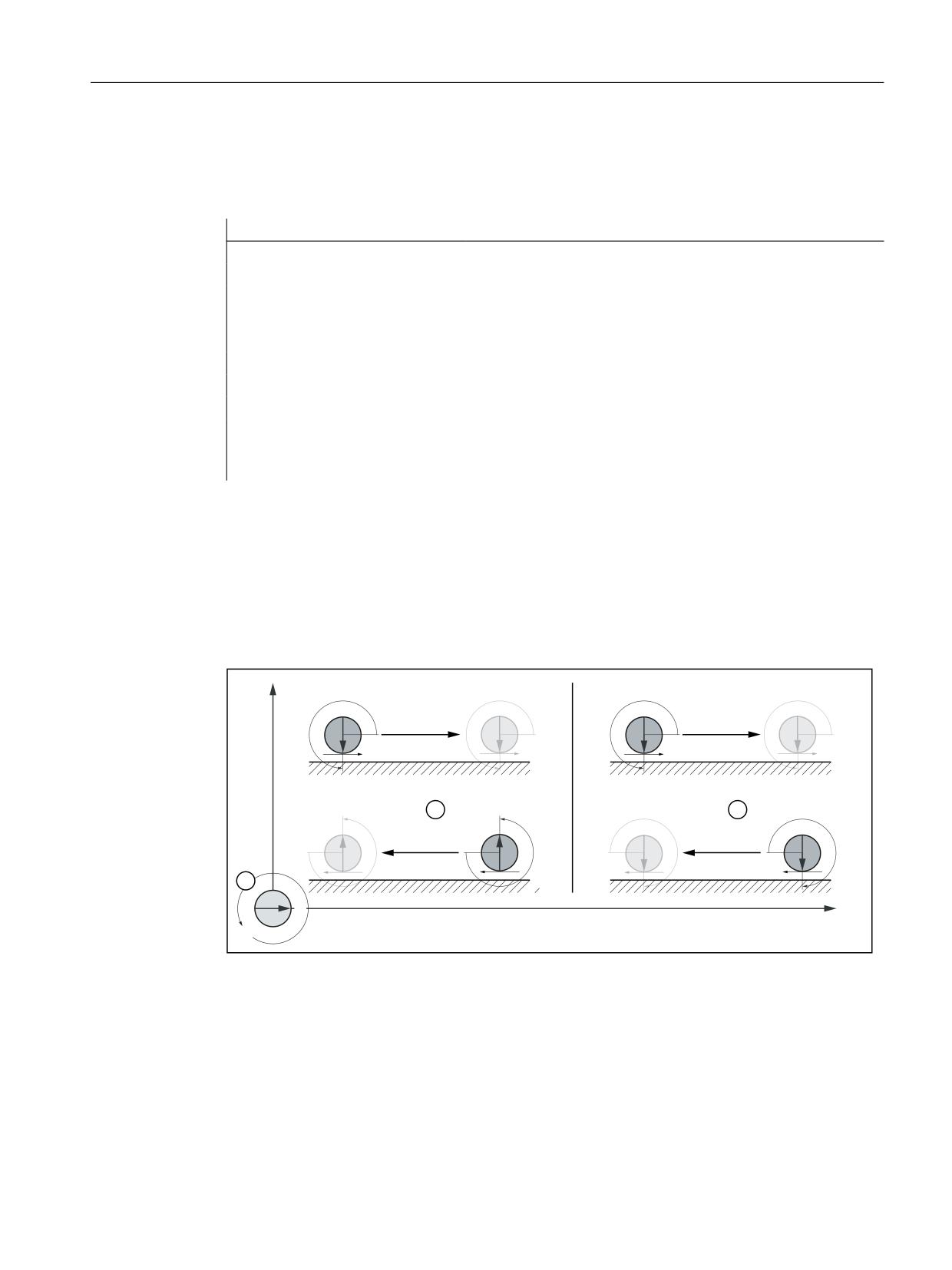
Tangential control
18.3 Limit angle
Geometry axis switchover
Before geometry axis switchover can be performed for an existing coupling, the coupling must
first be deleted.
Program code
Comment
N10 GEOAX(2,Y1)
; 2nd geometry axis = machine axis Y1
N20 TANG(A, X, Y)
; Define tangential coupling for following axis A
N30 TANGON(A, 90)
; Activate tangential coupling for following axis A
N40 G2 F8000 X0 Y0 I0 J50
; Motion block
N50 TANGOF(A)
; Deactivate tangential coupling for following axis A
N60 TANGDEL(A)
; Delete tangential coupling for following axis A
N70 GEOAX(2, Y2)
; 2nd geometry axis = machine axis Y2
N80 TANG(A, X, Y)
; Define new tangential coupling for following axis A
N90 TANGON(A, 90)
; Activate new tangential coupling for following axis
A
18.3
Limit angle
For alternating traversing motion, the direction of the path tangent jumps through 180° at the
reversal point. The alignment of the following axis also jumps through 180 °. This behavior is
generally not practical (see Fig., ②). Instead, for return motion, the following axis should be
traversed with the same alignment as for the forward motion (see Fig., ③).
r
r
<
r
r
&
|
;
① Initial position and positive direction of rotation of the following/rotary axis C
② Forward and reverse motion with the same offset angle 270°
③ Forward and reverse motion with alternating offset angles, 270° and -270°
Axes and spindles
Function Manual, 10/2020, 6FC5397-4GP40-0BA1
831
Tangential control
18.5 Examples
Avoiding reversal jump
Using the working area limitation G25 (lower limit) and G26 (upper limit), for the following axis,
a minimum and a maximum value must be entered for the position values referred to the basic
coordinate system. After this, the working area limitation for the following axis should be
activated/deactivated depending on the machining situation using the WALIMON / WALIMOF
commands. At the path reversal instant , the working area limitation must beactive.
Effect
If the following axis traverses with the actual offset angle with the axis position outside the active
working area limitation, then the control system checks whether the following axis, when using
the negative offset angle, would move in a permissible working area. If this is the case, then the
following axis is traversed with the negative offset angle.
Further information
Programming Manual Fundamentals; Supplementary commands > Working area limitation >
Working area limitation in the BCS (G25/G26, WALIMON, WALIMOF)
18.4
General conditions
Block search with active tangential coupling
If tangential control is active, it is recommended that for a block search only optimization type
"P" and block search type 2 ("Block search with calculation at the contour"), programmable under
TANG() (Page 825), or 5 ("Block search with calculation in the program test mode (SERUPRO)")
are used.
Explicit positioning of the following axis
If the following axis explicitly traverses an active tangential coupling, then the traversed
distance is additive to the programmed offset angle.
18.5
Examples
Example 1: Define and activate tangential coupling
Program code
Comment
; Define tangential coupling:
;
- Following axis C, leading axes X and Y
;
- Coupling factor: 1.0
;
- Coordinate system: BCS
;
- Optimization type: "P"
N10 TANG(C,X,Y,1,"B","P")
; Simplified: TANG(C,X,Y,,,"P")
; Activate tangential coupling:
;
- Offset angle: 90°
Axes and spindles
832
Function Manual, 10/2020, 6FC5397-4GP40-0BA1

Tangential control
18.5 Examples
Program code
Comment
N20 TANGON(C,90)
Example 2: Plane change
Program code
Comment
; Define tangential coupling:
;
- Following axis A, leading axes X and Y
;
- Coupling factor: 1.0
;
- Coordinate system: BCS
;
- Optimization type: "S"
N10 TANG(A,X,Y)
; Activate tangential coupling:
;
- Offset angle: 0°
N20 TANGON(A)
N30 X10 Y20
; Traverse leading axes
N80 TANGOF(A)
; Deactivate tangential coupling
N90 TANGDEL(A)
; Delete tangential coupling
; Define NEW tangential coupling:
;
- Following axis A, leading axes X and Z
;
- Coupling factor: 1.0
;
- Coordinate system: BCS
;
- Optimization type: "S"
TANG(A,X,Z)
TANGON(A)
Example 3: Geometry axis switchover
Program code
Comment
N10 GEOAX(2,Y1)
; 2nd geometry axis: Y1
; Define tangential coupling:
;
- Following axis A, leading axes X and Y
;
- Coupling factor: 1.0
;
- Coordinate system: BCS
;
- Optimization type: "S"
N20 TANG(A,X,Y)
; Activate tangential coupling:
;
- Offset angle: 90°
N30 TANGON(A,90)
N40 G2 F8000 X0 Y0 I0 J50
; Traverse circle
Axes and spindles
Function Manual, 10/2020, 6FC5397-4GP40-0BA1
833

Tangential control
18.5 Examples
Program code
Comment
N50 TANGOF(A)
; Deactivate tangential coupling
N60 TANGDEL(A)
; Delete tangential coupling
N70 GEOAX(2,Y2)
; 2nd geometry axis: Y2
; Define NEW tangential coupling:
;
- Following axis A, leading axes X and Y
;
- Coupling factor: 1.0
;
- Coordinate system: BCS
;
- Optimization type: "S"
N80 TANG(A,X,Y)
; Activate tangential coupling:
;
- Offset angle: 90°
N90 TANGON(A,90)
Example 4: Optimization type "P"
Program code
Comment
N100 G0 C0
N110 G1 X1000 Y500 F50000
N120 TRAORI
; Activate transformation
N130 G642
; Activate smoothing
N171 TRANS X50 Y50
; Work offset WCS
; Define tangential coupling:
;
- Following axis C, leading axes X and Y
;
- Coupling factor: 1.0
;
- Coordinate system: BCS
;
- Optimization type: "P"
N180 TANG(C,X,Y,1,,"P")
; Activate tangential coupling:
;
- Offset angle: 0°
;
- Rounding clearance 5.0 mm
;
- Angular tolerance 2.0°
N190 TANGON(C,0,5.0,2.0)
N210 G1 X1310 Y500
N215 G1 X1420 Y500
N220 G3 X1500 Y580 I=AC(1420) J=AC(580)
N230 G1 X1500 Y760
N240 G3 X1360 Y900 I=AC(1360) J=AC(760)
N250 G1 X1000 Y900
N280 TANGOF(C)
; Deactivate tangential coupling
N290 TRAFOOF
; Deactivate transformation
Axes and spindles
834
Function Manual, 10/2020, 6FC5397-4GP40-0BA1

Tangential control
18.6 Data lists
Example 5: Corner in space
Program code
; Comment
; Define tangential coupling:
;
- Following axis A, leading axes X and Y
;
- Coupling factor: 1.0
;
- Coordinate system: BCS
;
- Optimization type: "S" (standard)
TANG(A,X,Y,1.0,"B")
TLIFT(A)
; Activate intermediate block generation
G1 G641 X0 Y0 Z0 A0
; Go to initial position
; Activate tangential coupling:
;
- Offset angle: 0°
TANGON(A,0)
N4 X10
; Traverse leading axis X
N5 Z10
; Traverse geometry axis Z
N6 Y10
; Traverse leading axis Y
M30
By traversing the geometry axes in blocks N4 and N6, a discontinuous characteristic is obtained,
i.e. a corner in the contour of the leading axes of the tangential coupling. By programming
TLIFT(), an intermediate block is inserted in front of N6, in which following axis A is rotated
through 90° in the tangential direction of the Y axis. Only then is the Y axis traversed in N6.
18.6
Data lists
18.6.1
Machine data
18.6.1.1
NC-specific machine data
Number
Identifier: $MN_
Description
11450
SEARCH_RUN_MODE
Block search parameterization
18.6.1.2
Axis/spindlespecific machine data
Number
Identifier: $MA_
Description
37400
EPS_TLIFT_TANG_STEP
Tangential angle for corner recognition
37402
TANG_OFFSET
Default angle for tangential follow-up control
Axes and spindles
Function Manual, 10/2020, 6FC5397-4GP40-0BA1
835

Tangential control
18.6 Data lists
18.6.2
Setting data
18.6.2.1
Channel-specific setting data
Number
Identifier $SC_
Description
42121
AX_ADJUST_FEED
Path feed in adjustment motion of the tangential axes
18.6.3
System variables
Identifier
Description
$AC_BLOCKTYPE
Current block is an intermediate block generated by TLIFT
Axes and spindles
836
Function Manual, 10/2020, 6FC5397-4GP40-0BA1
Oscillation
19
19.1
Brief description
Definition
When the "Oscillation" function is selected, an oscillation axis oscillates backwards and forwards
at the programmed feedrate or a derived feedrate (revolutional feedrate) between two reversal
points. Several oscillation axes can be active at the same time.
Oscillation variants
Oscillation functions can be classified according to the axis response at reversal points and with
respect to infeed:
• Asynchronous oscillation across block boundaries
During reciprocating movement, other axes can interpolate at will. The oscillation axis can
act as the input axis for dynamic transformation or as the master axis for gantry or coupled-
motion axes. Oscillation is not automatically linked to the AUTOMATIC mode.
• Oscillation with continuous infeed.
Simultaneous infeed in multiple axes is possible. However, there is no interpolative
connection between the infeed and oscillation movements.
• Oscillation with infeed in both reversal points or only in the left-hand or right-hand reversal
point. The infeed can be initiated at a programmable distance from the reversal point.
• Sparking-out strokes after oscillation.
• Beginning and end of oscillation at defined positions.
Response at reversal points
The change in direction is initiated:
• without the exact stop limit being reached (exact stop fine or coarse)
• After reaching the programmed position or
• after the programmed position is reached and expiry of a dwell.
• by an external signal (from the PLC).
Control methods
Oscillation movements can be controlled by various methods:
• The oscillation movement and/or infeed can be interrupted by delete distance-to-go.
• The reversal points can be altered via NC program, PLC, HMI, handwheel or directional keys.
Axes and spindles
Function Manual, 10/2020, 6FC5397-4GP40-0BA1
837
Oscillation
19.2 Asynchronous oscillation
• The feedrate velocity of the oscillation axis can be altered through a value input in the NC
program, PLC, HMI or via an override. The feedrate can be programmed to be dependent on
a master spindle, rotary axis or spindle (revolutional feedrate).
Further information
Feedrates (Page 195)
• The oscillation movement can be controlled entirely by the PLC.
Methods of oscillation control
There are two modes of oscillation:
1. Asynchronous oscillation:
Is active across block boundaries and can also be started from the PLC/HMI.
2. Oscillation by synchronized movement actions:
In this case the asynchronous oscillation and an infeed movement are coupled via
synchronized actions. In this way, it is possible to program oscillation with infeed at the
reversal points which is active on a non-modal basis.
19.2
Asynchronous oscillation
19.2.1
Asynchronous oscillation
Characteristics
The characteristics of asynchronous oscillation are as follows:
• The oscillation axis oscillates backwards and forwards between reversal points 1 and 2 at the
specified feedrate until the oscillation movement is deactivated or until there is an
appropriate response to a supplementary condition. If the oscillation axis is not positioned at
reversal point 1 when the movement is started, then it traverses to this point first.
• Linear interpolation G01 is active for the oscillating axis regardless of the G command
currently valid in the program. Alternately, revolutional feedrate G95 can be activated.
• Asynchronous oscillation is active on an axis-specific basis beyond block limits.
• Several oscillation axes (i.e. maximum number of positioning axes) can be active at the same
time.
• During the oscillation movement, axes other than the oscillation axis can be freely
interpolated. A continuous infeed can be achieved via a path movement or with a positioning
axis. In this case, however, there is no interpolative connection between the oscillation and
infeed movements.
• If the PLC does not have control over the axis, then the axis is treated like a normal positioning
axis during asynchronous oscillation. In the case of PLC control, the PLC program must ensure
via the appropriate stop bits of the NC/PLC interface that the axis reacts in the desired way to
NC/PLC interface signals. These NC/PLC interface signals also include end of program,
operating mode change and single block.
Axes and spindles
838
Function Manual, 10/2020, 6FC5397-4GP40-0BA1
Oscillation
19.2 Asynchronous oscillation
• The oscillating axis can be an input axis for transformations (e.g. inclined axis, see Function
Manual "Transformations", Section "Kinematics transformation").
• The oscillation axis can act as the master axis for gantry and coupled motion axes.
Further information
Gantry axes (Page 345)
• It is possible to traverse the axis with jerk limitation (SOFT) and/or with knee-shaped
acceleration characteristic (as for positioning axes).
• In addition to this, the oscillation movement can be activated in synchronism with the block
via the part program.
• The oscillation movement can likewise be started, influenced and stopped from the PLC/HMI.
• Interpolatory oscillation is not possible (e.g. oblique oscillation).
19.2.2
Influences on asynchronous oscillation
Setting data
The setting data required for oscillation can be set with special language commands in the NC
part program, via the HMI and/or the PLC.
Feedrate
The feed velocity for the oscillation axis is selected or programmed as follows:
• The velocity defined for the axis as a positioning axis is used as the feed velocity. This value
can be programmed via FA[axis] and has a modal action. If no velocity is programmed, then
the value stored in machine data POS_AX_VELO is used (see also Section "Positioning axes
(Page 271)").
• When an oscillation movement is in progress, the feed velocity of the oscillation axis can be
altered via setting data. It can be specified via the part program and setting data whether the
changed velocity must take effect immediately or whether it should be activated at the next
reversal point.
• The feedrate can be influenced by the override (axial NC/PLC interface signal and
programmable).
• If Dry Run is active, the dry run velocity setting is applied if it is higher than the currently
programmed velocity.
Activation of the dry run feed entered in SD42100 $SC_DRY_RUN_FEED can be controlled
with SD42101 $SC_DRY_RUN_FEED_MODE.
Further information
Feedrates (Page 195)
• The velocity overlay / path overlay can be influenced by the handwheel (see following table
and Section "Manual traversing (Page 695)").
• The oscillation axis can be moved with reversal feed.
Axes and spindles
Function Manual, 10/2020, 6FC5397-4GP40-0BA1
839

Oscillation
19.2 Asynchronous oscillation
Revolutional feedrate
The reversal feed can also be used for oscillation axes.
Reversal points
The positions of the reversal points can be entered via setting data before an oscillation
movement is started or while one is in progress.
• The reversal point positions can be entered by means of manual travel (handwheel, JOG
keys) before or in the course of an oscillation movement, regardless of whether the
oscillation movement has been interrupted or not.
The following applies to alteration of a reversal point position: When an oscillation movement
is already in progress, the altered position of a reversal point does not become effective until this
point is approached again. If the axis is already approaching the position, the correction will take
effect in the next oscillation stroke.
Note
If a reversal point must be altered at the same time as NC/PLC interface signal DB21, … DBX0.3
("Activate DRF") is set, the handwheel signals are applied both to the DRF offset and to the offset
of the reversal point, i.e. the reversal point is shifted absolutely by an amount corresponding to
twice the distance.
Stop times
A stop time can be programmed via setting data for every reversal point.
The setting can be changed in the following blocks of the NC program. It is then effectively block
synchronous from the next reversal point.
Stop time can be changed asynchronously via setting data. It is then effective from the instant
that the appropriate reversal point is next traversed.
The following table explains the motional behavior in the exact stop range or at the reversal
point, depending on the stop time input.
Table 19-1
Effect of stop time
Stop time set-
Response
ting
-2
Interpolation continues without wait for exact stop
-1
Wait for coarse exact stop at reversal point
0
Wait for fine exact stop at reversal point
>0
Wait for fine exact stop at reversal point, followed by wait for stop time.
Axes and spindles
840
Function Manual, 10/2020, 6FC5397-4GP40-0BA1

Oscillation
19.2 Asynchronous oscillation
Deactivate oscillation
One of the following options can be set for termination of the oscillation movement when
oscillation mode is deactivated:
• Termination of oscillation movement at the next reversal point
• Termination of oscillation movement at reversal point 1
• Termination of oscillation movement at reversal point 2
Following this termination process, sparking-out strokes are processed and an end position
approached if programmed.
On switchover from asynchronous oscillation to spark-out and during spark-out, the response at
the reversal point regarding exact stop corresponds to the response determined by the stop time
programmed for the appropriate reversal point. A sparking-out stroke is the motion to the other
reversal point and back (see the table below):
Note
Oscillation with motion-synchronous actions and stop times "OST1/OST2"
Once the set stop times have expired, the internal block change is executed during oscillation
(indicated by the new distances-to-go of the axes). The deactivation function is checked when
the block changes. The deactivation function is defined according to the control setting for the
motional sequence "OSCTRL".
This dynamic response can be influenced by the feed override.
An oscillation stroke may then be executed before the sparking-out strokes are started or the end
position approached.
Although it appears as if the deactivation response has changed, this is not in fact the case.
Table 19-2
Operational sequence for deactivation of oscillation
Function
Inputs
Explanation
Deactivation at defined reversal
Number of sparking-out strokes
The oscillation movement is stop-
point
equals 0,
ped at the appropriate reversal
no end position active
point
Deactivation with specific num-
Number of sparking-out strokes
After the appropriate reversal
ber of sparking-out strokes
is not equal to 0,
point is reached, the number of
no end position is active
sparking-out strokes specified in
the command are processed.
Deactivation with sparking-out
Number of sparking-out strokes
After the appropriate reversal
strokes and defined end position
is not equal 0
point is reached, the number of
(optional)
end position active
sparking-out strokes specified in
the command are processed, fol-
lowed by approach to specified
end position.
Deactivation without sparking-
Number of sparking-out strokes
After the appropriate reversal
out strokes, but with defined end
is equal 0
point is reached, the axis is trav-
position (optional)
end position active
ersed to the specified end posi-
tion.
Axes and spindles
Function Manual, 10/2020, 6FC5397-4GP40-0BA1
841

Oscillation
19.2 Asynchronous oscillation
NC language
The NC programming language allows asynchronous oscillation to be controlled from the part
program. The following functions allow asynchronous oscillation to be activated and controlled
as a function of NC program execution.
Note
If the setting data is directly written in the part program, then the data change takes effect
prematurely with respect to processing of the part program (at the preprocessing time). It is
possible to re-synchronize the part program and the oscillation function commands by means
of a preprocessing stop (STOPRE).
Further information
Programming Manuals
1) Activate, deactivate oscillation:
• OS[oscillation axis] = 1; Activate oscillation for oscillation axis
• OS[oscillation axis] = 0; Deactivate oscillation for oscillation axis
Note
Every axis may be used as an oscillation axis.
2) End of oscillation:
• WAITP(oscillation axis)
Positioning axis command - stops block until oscillation axis is at fine stop and synchronizes
preprocessing and main run. The oscillation axis is entered as positioning axis again and can
then be used normally.
If an axis is to be used for oscillation, it must be released with a WAITP(axis) command
beforehand.
This also applies if oscillation is initiated from the PLC/HMI. In this case, the WAITP(axis) call
is also needed if the axis was programmed beforehand via the NC program. As of SW version
3.2 it is possible to select via machine data $MA_AUTO_GET_TYPE, whether WAITP() shall be
performed with programming or automatically.
Note
WAITP effectively implements a time delay until the oscillation movement has been
executed. Termination of the movement can be initiated, for example, through a
programmed deactivation command in the NC program or via the PLC or HMI by means of
deletion of distance-to-go.
3) Setting reversal points:
• OSP1[oscillation axis] = position of reversal point 1
• OSP2[oscillation axis] = position of reversal point 2
A position is entered into the appropriate setting data in synchronism with the block in the main
run and thus remains effective until the setting data is next changed.
If incremental traversal is active, then the position is calculated incrementally to the last
appropriate reversal point programmed in the NC program.
Axes and spindles
842
Function Manual, 10/2020, 6FC5397-4GP40-0BA1

Oscillation
19.2 Asynchronous oscillation
4) Stopping times at reversal points:
• OST1[oscillation axis] = stop time at reversal point 1 in [s]
• OST2[oscillation axis] = stop time at reversal point 2 in [s]
A stop time is entered into the appropriate setting data in synchronism with the block in the main
run and thus remains effective until the setting data is next changed.
The unit for the stop time is identical to the unit selected for the stop time programmed with G04.
5) Setting feedrate:
• FA[axis] = FValue
Positioning axis infeed.
The feedrate is transferred to the appropriate setting data in synchronism with the block in the
main run. If the oscillation axis is moved with reversal feed, the corresponding dependencies
must be indicated as described in Description of Functions V1.
6) Setting control settings for sequence of movements:
• OSCTRL[oscillating axis] = (set options, reset options)
The set options are defined as follows (the reset options deselect the settings):
Table 19-3
Set/reset options
Option value
Meaning
0
Stop at next reversal point on deactivation of the oscillation movement (default). Can
only be achieved by resetting option values 1 and 2.
1
Stop at reversal point 1 on deactivation of the oscillation movement
2
Stop at reversal point 2 on deactivation of the oscillation movement
3
On deactivation of oscillation movement, do not approach reversal point unless spark-
ing-out strokes are programmed
4
Approach an end position after spark-out process
8
If the oscillation movement is aborted by delete distance-to-go, the sparking-out
strokes must then be executed and the end position approached (if programmed)
16
If the oscillation movement is terminated by deletion of distance-to-go, the program-
med reversal point must be approached on deactivation of the oscillation movement.
32
Altered feedrate will only take effect from the next reversal point.
64
If feedrate setting is 0, path overlay is active, or otherwise velocity overlay
128
For rotary axis DC (shortest path)
256
Sparking-out stroke as single stroke
512
First approach start position
Note
The option values 0-3 encode the behavior at reversal points at Power OFF. You can choose one
of the alternatives 0-3. The other settings can be combined with the selected alternative
according to individual requirements. A + character can be inserted to create a string of options.
Axes and spindles
Function Manual, 10/2020, 6FC5397-4GP40-0BA1
843
Oscillation
19.2 Asynchronous oscillation
Example: The oscillation movement for axis Z must stop at reversal point 1 on deactivation; an
end position must then be approached and a newly programmed feedrate take immediate
effect; the axis must stop immediately after deletion of distance-to-go.
OSCTRL[Z] = (1+4, 16+32+64)
The set/reset options are entered into the appropriate setting data in synchronism with the block
in the main run and thus remain effective until the setting data is next changed.
Note
The control evaluates the reset options, then the set options.
7) Sparking-out strokes:
• OSNSC[oscillation axis] = number of sparking-out strokes
The number of sparking-out strokes is entered into the appropriate setting data in synchronism
with the block in the main run and thus remains effective until the setting data is next changed.
8) End position to be approached after deactivation of oscillation:
• OSE[oscillation axis] = end position of oscillation axis
The end position is entered into the appropriate setting data in synchronism with the block in the
main run and thus remains effective until the setting data is next changed. Option value 4 is
implicitly set so that the set end position is approached.
9) Start position to be approached prior to activation of oscillation:
• OSB [oscillation axis] = start position of oscillation axis
The start position is entered into the appropriate setting data SD43790 $SA_OSCILL_START_POS
in synchronism with the block in the main run and thus remains effective until the setting data
is next changed. Bit 9 in setting data SD43770 $SA_OSCILL_CTRL_MASK must be set to initiate
an approach to the start position. The start position is approached before reversal point 1. If the
start position coincides with reversal position 1, reversal position 2 is approached next.
As an alternative to programming command OSB, it is also possible to enter the start position
directly in setting data SD43790 $SA_OSCILL_START_POS.
All positional information in the setting data and system variables refer to the basic coordinate
system (BCS). The positional data for OSB, OSE refer to the workpiece coordinate system (WCS).
No halt time applies when the start position is reached, even if this position coincides with
reversal position 1; instead, the axis waits for the exact stop fine signal. Any configured exact
stop condition is fulfilled.
If a non-modal oscillation process does not require an infeed motion if the start position
coincides with reversal position 1, this option can be configured with another synchronized
action (see Section "Non-modal oscillation (starting position = reversal point 1) (Page 866)").
Programming example
An example that contains all the important elements for asynchronous oscillation can be found
in Section "Example of asynchronous oscillation (Page 859)".
Axes and spindles
844
Function Manual, 10/2020, 6FC5397-4GP40-0BA1
Oscillation
19.2 Asynchronous oscillation
19.2.3
Asynchronous oscillation under PLC control
Activation
The function can be selected from the PLC using the following setting data in all operating
modes except for MDA Ref and JOG Ref.:
SD43780 OSCILL_IS_ACTIVE (switch-on oscillation motion)
Settings
The following criteria can be controlled from the PLC via setting data: Activation and
deactivation of oscillation movement, positions of reversal points, stop times at reversal points,
feedrate velocity, the options in the reversal points, the number of sparking-out strokes and the
end position after deactivation. However, these values can also be set beforehand as a setting
data via the HMI user interface directly or via an NC program. These settings remain valid after
power ON and the PLC can also start an oscillation movement set in this way directly via setting
data OSCILL_IS_ACTIVE (via variable service).
Supplementary conditions
A spindle which must act as an axis to execute an oscillation movement started via the PLC must
fulfill the conditions required to allow traversal as a positioning axis, i.e. the spindle must, for
example, have been switched to the position control (SPOS) beforehand.
The axes always respond to the following two stop bits - regardless of whether the axis is
controlled from the PLC or not:
• DB31, ... DBX28.5 (stop at the next reversal point)
• DB31, ... DBX28.6 (stop along braking ramp)
19.2.4
Special reactions during asynchronous oscillation
With PLC control
The PLC program can assume the control of an oscillation axis via NC/PLC signals. The NC/PLC
interface signals also include end of program, operating mode change and single block.
Using the NCU system software, an asynchronous reciprocating axis interpolated by the main
run reacts to NC STOP, alarm handling, end of program, program control and RESET.
The axis/spindle is controlled via the axial NC/PLC interface (PLC→NC) by means of IS DB31, ...
DBX28.7 (PLC controlled axis) = 1
For further information about axes with PLC control, see Section "Positioning axes (Page 271)".
Without PLC control
If the PLC does not have control over the axis, then the axis is treated like a normal positioning
axis (POSA) during asynchronous oscillation.
Axes and spindles
Function Manual, 10/2020, 6FC5397-4GP40-0BA1
845

Oscillation
19.2 Asynchronous oscillation
Delete distance-to-go
Channel-specific delete distance-to-go is ignored.
Axial delete distance-to-go
• Without PLC control: Stop via braking ramp
• With PLC control: No stop (must be initiated from the PLC)
The following applies to both cases: After the axis is stopped, if necessary, the appropriate
reversal point is approached and the distance-to-go deleted. The sparking-out strokes are then
executed and the end position approached. Provided this has been set in OSCILL_CTRL_MASK.
The oscillation movement is then completed.
Note
During grinding, the calipers can be put into action via axial delete distance-to-go.
Emergency stop
The emergency stop completes the oscillation movement that must be restarted.
Reset
The oscillation movement is interrupted and deselected with a braking ramp. The options
selected subsequently are not processed (sparking-out strokes, end point approach).
Working area limitation, limit switches
If it is detected during preprocessing that the oscillation movement would violate an active
limitation, then an alarm is output and the oscillation movement not started.
If during an active oscillation movement the oscillation axis overtravels a limitation that has
been activated in the meantime (e.g. 2nd software limit switch), then the axis is decelerated
along a ramp and an alarm output.
CAUTION
Protection areas
No protection areas act for a oscillation movement.
Follow-up mode
There is no difference to positioning axes.
End of program
If the axis is not controlled by the PLC, then the program end is not reached until the oscillation
movement is terminated (reaction as for POSA:
Axes and spindles
846
Function Manual, 10/2020, 6FC5397-4GP40-0BA1

Oscillation
19.2 Asynchronous oscillation
Positioning across block boundaries).
If the axis is controlled by the PLC, then it continues to oscillate after program end.
Mode change
The following table shows the operating modes in which oscillation can be implemented.
Changeover to an operating mode which allows oscillation does not affect the oscillation
movement. Changeover to inadmissible operating modes is rejected with an alarm. It is not
possible to traverse an axis in oscillation mode while applying control commands from the NC
program or via operator inputs (JOG) simultaneously; an alarm is output if this is attempted. The
following applies: The type of movement first started has priority.
Table 19-4
Operating modes which allow oscillation
Operating mode
Allows oscillation
AUTO
Yes
MDA
Yes
MDA Repos
Yes
MDA Teachin
Yes
MDA Ref
No
JOG
Yes
JOG Ref
No
JOG Repos
Yes
Single-block processing
If the axis is not controlled by the PLC, then it responds to a single block in the same way as a
positioning axis (POSA), i.e. it continues the movement.
Override
The override is specified by the:
NC/PLC interface
Axial override acts on the oscillation axis.
Programming
The override acts on oscillation axes in the same way as on positioning axes.
Block search
In Block Search the last valid oscillation function is registered and the machine data
OSCILL_MODE_MASK is activated (default) accordingly, either directly after NC start (when
approaching the start position after block search) or after reaching the start position after block
search.
OSCILL_MODE_MASK Bit 0:
0: Oscillation starts after reaching the start position.
Axes and spindles
Function Manual, 10/2020, 6FC5397-4GP40-0BA1
847
Oscillation
19.3 Oscillation controlled by synchronized actions
1: Oscillation starts immediately after NC start.
REORG
Reversal point 1 is always approached first before oscillation continues.
ASUB
The oscillation movement continues while an ASUB (asynchronous subprogram) is in progress.
19.3
Oscillation controlled by synchronized actions
General procedure
An asynchronous oscillation movement is coupled via synchronized actions with an infeed
motion and controlled accordingly.
The following description concentrates solely on the motion-synchronous actions associated
with the oscillation function.
Further information
Function Manual Synchronized Actions
Functions
You can implement the following functions with the commands described in the following:
1. Infeed at the reversal point (see Section "Infeed at reversal point 1 or 2 (Page 851)").
2. Infeed at the reversal range (see Section "Infeed in reversal point range (Page 852)").
3. Infeed in both reversal points (see Section "Infeed at both reversal points (Page 853)").
4. Stop the oscillation movement at the reversal point until infeed is terminated (see Section
"Stop oscillation movement at the reversal point (Page 854)").
Axes and spindles
848
Function Manual, 10/2020, 6FC5397-4GP40-0BA1
Oscillation
19.3 Oscillation controlled by synchronized actions
5. Enable oscillation movement (see Section "Oscillation movement restarting (Page 855)").
6. Do not start partial infeed too early (see Section "Do not start partial infeed too early
(Page 856)").
x
Oscillation path
Infeed
Grinding disc
Workpiece
z
ii1
ii2
U1
U2
U1
Reversal point 1
U2
Reversal point 2
ii1
Reversal range 1
ii2
Reversal range 2
Figure 19-1
Arrangement oscillating axis, infeed axis
Programming
Before the motion block that contains the assignment between the infeed and the oscillating
axis (see Section "Assignment of oscillation and infeed axes OSCILL (Page 857)"), the infeed
definition (POSP) and the motion-synchronous actions, the parameters for the oscillation must
first be defined (see Section "Influences on asynchronous oscillation (Page 839)"):
Using a WAITP [oscillating axis] (see MD30552 $MA_AUTO_GET_TYPE), the axis for oscillation
is enabled. This means that the oscillating parameters are simultaneously transferred into the
setting data. The symbolic names, e.g. $SA_REVERSE_POS1 can then be used to program the
motion-synchronous actions.
Note
For motion-synchronous actions with $SA_REVERSE_POS values, the comparison values at the
time of interpretation are valid. If setting data is changed afterwards, this has no effect.
For motion-synchronous actions with $AA_REVERSE_POS values, the comparison values within
the interpolation are valid. This ensures a reaction to the modified reversal positions.
Axes and spindles
Function Manual, 10/2020, 6FC5397-4GP40-0BA1
849