SINUMERIK 840D sl. Service - Functions. Manual (2018-2020) - page 13
Axis couplings
14.5 Generic coupling
Programming
Offset of the input value
Syntax:
CPLINTR[FAx,LAx]= <value>
Designation:
Coupling Lead In Translation Displacement
Functionality:
Defines the offset value for the input value of the LAx leading axis.
Value:
Type: REAL
Default value:
0
Example:
Programming
Comment
CPLINTR[X2,X1]=-50
; The input value of the leading axis X1 is moved in the
negative direction by the value 50.
Scaling the input value
Syntax:
CPLINSC[FAx,LAx]= <value>
Designation:
Coupling Lead In Scale Factor
Functionality:
Defines the scaling factor for the input value of the LAx leading axis.
Value:
Type: REAL
Default value:
1
Example:
Programming
Comment
CPLINSC[X2,X1]=0.5
; The input value of the leading axis X1 is multiplied
with the factor 0.5.
Offset of the output value
Syntax:
CPLOUTTR[FAx,LAx]= <value>
Designation:
Coupling Lead Out Translation Displacement
Functionality:
Defines the offset value for the output value of coupling the following axis
FAx to leading axis LAx.
Value:
Type: REAL
Axes and spindles
642
Function Manual, 10/2020, 6FC5397-4GP40-0BA1

Axis couplings
14.5 Generic coupling
Default value:
0
Example:
Programming
Comment
CPLOUTTR[X2,X1]=100
; The output value of the coupling of the following axis
X2 with leading axis X1 is displaced by the value 100 in
the positive direction.
Scaling of the output value
Syntax:
CPLOUTSC[FAx,LAx]= <value>
Designation:
Coupling Lead Out Scale Factor
Functionality:
Defines the scaling factor for the output value of coupling the following
axis FAx with leading axis LAx.
Value:
Type: REAL
Default value:
1
Example:
Programming
Comment
CPLOUTSC[X2,X1]=3
The output value of the coupling of the following axis X2
with leading axis X1 is multiplied with factor 3.
Note
The following setting data used in the existing coupling type "Master value coupling" is
considered in generic coupling independently of the set coupling type (CPSETTYPE):
SD43102 $SA_LEAD_OFFSET_IN_POS[FAx] (offset of master value)
SD43104 $SA_LEAD_SCALE_IN_POS[FAx] (scaling of master value)
SD43106 $SA_LEAD_OFFSET_OUT_POS[FAx] (offset of function value of the curve table)
SD43108 $SA_LEAD_SCALE_OUT_POS[FAx] (scaling of function value of the curve table)
These setting data have the following effect:
• on all leading axes that are coupled with the following axis via a curve table. This must be
taken into account for couplings with more than one leading axis!
• in addition to the CP key words CPLINTR, CPLINSC, CPLOUTTR and CPLOUTSC.
Axes and spindles
Function Manual, 10/2020, 6FC5397-4GP40-0BA1
643

Axis couplings
14.5 Generic coupling
14.5.5.15
Synchronism monitoring stage 1 (CPSYNCOP, CPSYNFIP, CPSYNCOV, CPSYNFIV)
Synchronism monitoring stage 1
In each interpolator clock cycle, the synchronous operation of the coupling group is monitored
- both on the setpoint and actual value sides. The synchronous operation monitoring responds
as soon as the synchronous operation difference (the difference between the setpoint or
actual value of the following axis and the value calculated from the setpoints or actual values of
the leading axes according to the coupling rule) reaches one of the following programmed
threshold values:
• At setpoint / actual value coupling (see "Coupling relationship (CPLSETVAL) (Page 627)"):
- "Coarse" position synchronous operation threshold value
- "Fine" position synchronous operation threshold value
• For velocity coupling (see "Coupling relationship (CPLSETVAL) (Page 627)"):
- Threshold value of "Coarse" speed synchronous operation
- Threshold value of "Fine" speed synchronous operation
The actual synchronous operation difference can be read out with the following CP system
variables:
System variable
Meaning
$AA_SYNCDIFF [FAx]
Synchronous operation difference of the setpoint
$VA_SYNCDIFF [FAx]
Synchronous operation difference of the actual value
Note
Synchronous operation differences are signed and enable the advance or delay of the following
axis to be determined.
Axes and spindles
644
Function Manual, 10/2020, 6FC5397-4GP40-0BA1
Axis couplings
14.5 Generic coupling
Status of the coupling during synchronous operation
State
Description
Not synchronized
Provided the synchronous operation difference is greater than the
threshold value for position "coarse" synchronous operation or
"coarse" speed synchronous operation, the coupled group is desig-
nated as non-synchronous.
"Coarse" synchronous operation
The synchronous operation difference has reached the threshold
reached
value for "coarse" position synchronous operation or "coarse" speed
synchronous operation.
In case the actual value-based synchronous operation difference, the
following NC/PLC-interface signal is set:
DB31, ... DBX98.1 (coarse synchronous operation)
"Fine" synchronous operation
The synchronous operation difference has reached the threshold
reached
value for "fine" position synchronous operation or "fine" speed syn-
chronous operation.
In case the actual value-based synchronous operation difference, the
following NC/PLC-interface signal is set:
DB31, ... DBX98.0 (fine synchronous operation)
The status of the coupling for the synchronous operation can be read with the following system
variables:
System variable
Meaning
$AA_SYNC [FAx]
State of the coupling
Value
State
0
Not synchronized
1
"Coarse" synchronous operation reached
2
"Fine" synchronous operation reached
Signal reaction
Synchronous operation signals themselves do not stop the involved axes, but can release them
via synchronized action or NC/PLC interface signals (see Section "Extended stop and retract
(Page 893)").
Configuration
The threshold values for the first stage of the synchronous operation monitoring will be adjusted:
• For setpoint / actual value coupling in the machine data:
- MD37200 $MA_COUPLE_POS_TOL_COARSE (threshold value for "coarse synchronism")
- MD37210 $MA_COUPLE_POS_TOL_FINE (threshold value for "fine synchronism")
• For speed coupling in the machine data:
- MD37220 $MA_COUPLE_VELO_TOL_COARSE ("coarse" speed tolerance)
- MD37230 $MA_COUPLE_VELO_TOL_FINE ("fine" speed tolerance)
Axes and spindles
Function Manual, 10/2020, 6FC5397-4GP40-0BA1
645
Axis couplings
14.5 Generic coupling
Programming
CP keywords can also be used to program the threshold values for the first stage of the
synchronous operation monitoring:
"Coarse" position synchronous operation threshold value
Syntax:
CPSYNCOP[FAx]= <value>
Designation:
Coupling Synchronous Difference Coarse Position
Functionality:
Defines the threshold value for the "Coarse' position synchronous oper-
ation.
Value:
Type: REAL
The default value corresponds to the setting in the machine data:
MD37200 $MA_COUPLE_POS_TOL_COARSE [FAx]
"Fine" position synchronous operation threshold value
Syntax:
CPSYNFIP[FAx]= <value>
Designation:
Coupling Synchronous Difference Fine Position
Functionality:
Defines the threshold value for the "Fine" position synchronous opera-
tion.
Value:
Type: REAL
The default value corresponds to the setting in the machine data:
MD37210 $MA_COUPLE_POS_TOL_FINE [FAx]
Threshold value of "Coarse" speed synchronous operation
Syntax:
CPSYNCOV[FAx]= <value>
Designation:
Coupling Synchronous Difference Coarse Velocity
Functionality:
Defines the threshold value for the "Coarse'' speed synchronous opera-
tion.
Value:
Type: REAL
The default value corresponds to the setting in the machine data:
MD37220 $MA_COUPLE_VELO_TOL_COARSE [FAx]
Axes and spindles
646
Function Manual, 10/2020, 6FC5397-4GP40-0BA1
Axis couplings
14.5 Generic coupling
Threshold value of "Fine" speed synchronous operation
Syntax:
CPSYNFIV[FAx]= <value>
Designation:
Coupling Synchronous Difference Fine Velocity
Functionality:
Defines the threshold value for the "Fine" velocity synchronous opera-
tion.
Value:
Type: REAL
The default value corresponds to the setting in the machine data:
MD37230 $MA_COUPLE_VELO_TOL_FINE [FAx]
Example
Program code
Comment
CPDEF=(S2) CPLA[S2]=(S1)
; Definition of a spindle coupling:
Leading spindle S1 to following spindle S2
CPON=(S2) CPSYNCOP[S2]=0.5
; Activation of the coupling with following spin-
CPSYNFIP[S2]=0.25
dle S2. The threshold values for the position syn-
chronous operation are set to 0.5 ("coarse") and
0.25 ("fine").
Supplementary conditions
• When considering the synchronous operation difference, an active coupling cascade is not
taken into account. This means: if in the considered coupling module, the leading axis is a
following axis in another coupling module, the current actual or setpoint position is still used
as input variable for the calculation of the synchronous operation difference. This
synchronous operation difference therefore does not show the total synchronous operation
error of the cascade.
• If the leading axis is not a real axis, but a simulated axis, then the actual value is not available
for the synchronous operation monitoring of the actual value. In this case, the modeled
actual values (according to the machine data setting) are used.
14.5.5.16
Synchronous operation monitoring stage 2 (CPSYNCOP2, CPSYNFIP2)
Synchronism monitoring stage 2
For active CP position coupling (setpoint or actual value coupling, see "Coupling relationship
(CPLSETVAL) (Page 627)"), after reaching the "COARSE"/"FINE" block change criterion (see "Block
change behavior (CPBC) (Page 629)"), the second stage of the synchronous operation
monitoring can be used to monitor that one of the threshold values of the first stage is
maintained on the actual value side, independent of the synchronism tolerance.
Axes and spindles
Function Manual, 10/2020, 6FC5397-4GP40-0BA1
647
Axis couplings
14.5 Generic coupling
The following two threshold values must configured or programmed for the second stage of
synchronous operation monitoring:
• "Coarse" 2 position synchronous operation threshold value
• "Fine" 2 position synchronous operation threshold value
Technical backg7round
As part of the "synchronous operation reached" and "exit synchronous window" monitoring
functions, for a correct assessment of any problems that arise during the multi-edge turning
(surface, waste, etc. ) and sometimes also for oscillating synchronous spindle it is often very
useful to define a tolerance range independent of the coarse/fine synchronous operation
tolerances of the first stage of the synchronous operation monitoring (similar to exact stop and
standstill monitoring for axes) in order to obtain a configurable error message or warning.
Configuration
The threshold values for the second stage of the synchronous operation monitoring are set in
the machine data:
MD37202 $MA_COUPLE_POS_TOL_COARSE_2 (second threshold value for "coarse synchronous
operation")
MD37212 $MA_COUPLE_POS_TOL_FINE_2 (second threshold value for "fine synchronous
operation")
Note
If the appropriate threshold value = 0, the associated monitoring is inactive. This is also the
default value so that the compatibility with older software versions is retained.
Programming
CP keywords can also be used to program the threshold values for the second stage of the
synchronous operation monitoring:
"Coarse" 2 position synchronous operation threshold value
Syntax:
CPSYNCOP2[FAx]= <value>
Designation:
Coupling Synchronous Difference Coarse Position 2
Functionality:
Defines the second threshold value for the "Coarse' position synchro-
nous operation.
Value:
Type: REAL
The default value corresponds to the setting in the machine data:
MD37202 $MA_COUPLE_POS_TOL_COARSE_2 [FAx]
Axes and spindles
648
Function Manual, 10/2020, 6FC5397-4GP40-0BA1
Axis couplings
14.5 Generic coupling
"Fine" 2 position synchronous operation threshold value
Syntax:
CPSYNFIP2[FAx]= <value>
Designation:
Coupling Synchronous Difference Fine Position 2
Functionality:
Defines the second threshold value for the "Fine" position synchronous
operation.
Value:
Type: REAL
The default value corresponds to the setting in the machine data:
MD37212 $MA_COUPLE_POS_TOL_FINE_2 [FAx]
The programming applies similarly to the general CP behavior in the part program only with the
next switching command; for synchronized actions, immediately.
Sequence
Starting
The second stage of the synchronous operation monitoring function starts with active coupling
as soon as the following conditions are fulfilled:
• The setpoint synchronous operation is reached:
DB31, ... DBX99.4 (synchronization running) = 0
• The actual value related "coarse"/"fine" synchronous operation of the tolerance of the first
stage of the synchronous operation monitoring (see "Synchronism monitoring stage 1
(CPSYNCOP, CPSYNFIP, CPSYNCOV, CPSYNFIV) (Page 644)") is reached:
DB31, ... DBX98.1 (coarse synchronous operation) = 1 / DB31, ... DBX98.0 (fine synchronous
operation) = 1
Monitor
As long as the synchronism difference of the actual the threshold values for "fine" 2 position
synchronous operation and "coarse" 2 position synchronous operation are not exceeded, the
following NC/PLC interface signals are set:
DB31, ... DBX103.4 (synchronous operation 2 fine)
DB31, ... DBX103.5 (synchronous operation 2 coarse)
If, due to temporary overload in machining process (e.g. infeed feedrate for multi-edge
machining too high), the following axis/spindle can no longer follow the specifications of the
leading axis(n)/spindle(s) and the deviation is greater than the set tolerance, the violation of the
"fine"/"coarse" tolerance displays a display alarm that can be deleted:
Alarm 22026 "Channel %1 Block %2 Following axis/spindle %3 Synchronism (2): Coarse
tolerance exceeded"
Axes and spindles
Function Manual, 10/2020, 6FC5397-4GP40-0BA1
649
Axis couplings
14.5 Generic coupling
Alarm 22025 "Channel %1 Block %2 Following axis/spindle %3 Synchronism (2): Fine tolerance
exceeded"
This does not interrupt the machining.
Note
Both alarms can also occur simultaneously.
Exit
The second stage of the synchronous operation monitoring ends in the following cases:
• Deactivation of the coupling (for the power-down command: CPOF, CPDEL, CPLOF, CPLDEL)
• New synchronization request by:
- CPON / CPLON / CPDO / CPLOF
- DB31, ... DBX31.4 (synchronize following spindle) = 1
- Internal synchronization requests
If, in these cases, the start conditions are satisfied again, the monitoring will be restarted.
• For coupled block changes (CPLNUM, CPLDEN, CPLCTID) in synchronized actions
• Resetting the setpoint synchronous operation because of missing enable signals for the
following spindle (emergency stop, alarm responses)
The DB31, ... DBX103.4/5 signals are reset when the monitoring is ended.
Boundary conditions
Exclusion conditions
No monitoring is performed in the following cases:
• MD37202 or MD37212 = 0.
• Speed coupling is active (CPLSETVAL="CMDVEL").
• DB31, ... DBX31.5 (inhibit synchronization of the FS) = 1
• Rapid stop of the following axis/spindle or one of the active leading axes/spindles.
• SERUPRO or block search is active.
• For channel-related run-in when the following axis/spindle or an active leading axis/spindle
does not really move.
• DB31, ... DBX63.3 (axis/spindle disable active) = 1 for the following axis/spindle or for one of
the active leading axes/spindles.
"Track the synchronous operation deviation" is active
Monitoring is suspended while the "track the synchronous operation deviation" function is
active (DB31, ... DBX31.6 = 1; see "Tracking the deviation from synchronism (Page 674)").
Axes and spindles
650
Function Manual, 10/2020, 6FC5397-4GP40-0BA1
Axis couplings
14.5 Generic coupling
Synchronous operation monitoring level 2 for the traditional coupling types
For the traditional coupled motion, master value coupling, electronic gearbox and synchronous
spindle coupling types, the "stage 2 synchronous operation monitoring" is available only with
the CP adaptive cycles (see "Adaptive cycles (Page 659) ").
Example
Program code
Comment
G0 Z-300 X50
CPDEF=(S2) CPLA=(S1) CPLNUM=2 CPLDEN=1
; Gear ratio in accordance with tool.
CPBC="FINE"
M3 S2000
CPON=(S2) CPLA=(S1) CPSYNCOP2[X]=1.6
; Block change is performed on reaching "fine synchronous
CPSYNFIP2[X]=0.8
operation".
; Synchronous operation monitoring stage 2 is also activa-
ted
; (tolerances: coarse 1.6, fine 0.8).
X20
G1 Z-200
; Machining block, material removal.
; Synchronous operation determines the quality.
CPOF=(S2)
; Deselect coupling, deactivate the monitoring function.
14.5.5.17
Reaction to stop signals and commands (CPMBRAKE)
The response of the following axis to certain stop signals and commands can be defined with the
CP keyword CPMBRAKE.
Programming
Syntax:
CPMBRAKE[FAx]= <value>
Designation:
Coupling Mode Brake
Axes and spindles
Function Manual, 10/2020, 6FC5397-4GP40-0BA1
651
Axis couplings
14.5 Generic coupling
Functionality:
CPMBRAKE is a bit-coded CP keyword that defines the braking behavior of
the following axis FAx for the following events:
Bit
Event
0
• NST DB31, ... DBX4.3 (feed stop / spindle stop) present
or
• CP SW limit stop is set (see "CP SW limit monitoring
(Page 668)")
Note:
Bit 0 is significant only for a "Freely programmable" coupling type
(CPSETTYPE=CP).
Value Meaning
0
The brake is not transferred to the leading axes.
1
The brake is transferred to the leading axes depending
on the context.
1 - 31
Reserved
The following rules apply for the programming:
• CPMBRAKE must be programmed in one block with CPDEF or CPON (⇒
can only be programmed for an inactive coupling).
• While defining a coupling, the following values are captured without the
explicit programming of CPMBRAKE:
Bit 0 = 1 for pre-processing couplings with CPSETTYPE=CP (otherwise
bit 0 = 0)
Examples
Example 1:
Programming
Comment
CPDEF=(AX5) CPLA[AX5]=(AX4) CPMBRAKE[AX5]=0
;
Defining a coupling (lead-
ing axis Ax4 with following
axis Ax5). NST "feed stop /
spindle stop" or "CP SW lim-
it stop" should not brake
the coupling group.
Example 2:
Programming
Comment
CPDEF=(S2) CPLA[S2]=(S1)
;
Definition of a spindle coupling:
Leading spindle S1 with following spindle S2
CPON=(S2) CPMBRAKE[S2]=1
;
Activation of the coupling with following
spindle S2. NST "feed stop / spindle stop"
or "CP SW limit stop" should brake the cou-
pling group.
Axes and spindles
652
Function Manual, 10/2020, 6FC5397-4GP40-0BA1
Axis couplings
14.5 Generic coupling
14.5.5.18
Response to certain NC/PLC interface signals (CPMVDI)
The CP keyword CPMVDI can be used to define the coupling module's response to certain NC/PLC
interface signals.
Programming
Syntax:
CPMVDI[FAx]= <value>
Designation:
Coupling Mode VDI Signal
Functionality:
CPMVDI is a bit-coded CP keyword, which defines the response of the cou-
pling module of following axis FAx to certain NC/PLC interface signals.
The bit combination operators B_OR, B_AND, B_NOT, and B_XOR can be
used to set individual bits.
Axes and spindles
Function Manual, 10/2020, 6FC5397-4GP40-0BA1
653
Axis couplings
14.5 Generic coupling
Bit
Meaning
0
Reserved.
1
Reserved.
2
Reserved.
3
The effect of NC/PLC interface signal
DB31, ... DBX1.3 (axis/spindle disable)
on the following axis/spindle can be set via bit 3:
Bit 3 = 0
DB31, ... DBX1.3 has no effect on the following axis/
spindle. The state of the following axis/spindle with ref-
erence to the axis/spindle disable is derived solely from
the state of the leading axes/spindles.
Bit 3 = 1
DB31, ... DBX1.3 has an effect on the following axis/spin-
dle. The state of the leading axes/spindles with reference
to the axis/spindle disable is not imposed on the follow-
ing axis/spindle.
Note:
If bit 3 = 1, the axis/spindle disable state of the following axis/spindle
only has an effect if the program test or SERUPRO states are not active
(see also bit 5).
4
Bit 4 is used to define the enable for the dependent motion compo-
nents when the NC/PLC interface signal DB31, … DBX1.3 (axis/spindle
disable) has an effect on the following axis/spindle:
Bit 4 = 0
Dependent motion components of the leading axes/
spindles become effective irrespective of the state of the
axis/spindle disable of the relevant leading axis/spindle.
Bit 4 = 1
Dependent motion components of the leading axes/
spindles only become effective if the state of the axis/
spindle disable of the leading axis/spindle matches that
of the axis/spindle disable of the following axis/spindle.
Otherwise, the components are suppressed.
Note:
Bit 4 is only of significance if bit 3 is set, i.e. if the NC/PLC interface
signal DB31, … DBX1.3 (axis/spindle disable) has an effect on the
following axis/spindle (see bits 3 and 5).
5
The effect of NC/PLC interface signal
DB21, ... DBX25.7 (program test selected) or
DB21, ... DBX1.7 (activate program test)
on the following axis/spindle can be set via bit 5:
Bit 5 = 0
DB21, ... DBX25.7 or DB21, ... DBX1.7 has no effect on
the following axis/spindle. The state of the following ax-
is/spindle with reference to the axis/spindle disable is
derived solely from the state of the leading axes/spin-
dles.
Bit 5 = 1
If the "program test" state is active for an axis of the
coupling module, then for the following axis/spindle, its
own state is active regarding the axis/spindle disable.
The state of the leading axes/spindles with reference to
the axis/spindle disable is not imposed on the following
axis/spindle.
Axes and spindles
654
Function Manual, 10/2020, 6FC5397-4GP40-0BA1

Axis couplings
14.5 Generic coupling
Note:
When bit 5 is set, the program test state still has an effect on the
following axis/spindle, even if the leading axes/spindles have a differ-
ent state.
6
Bit 6 is used to define the enable for the dependent motion compo-
nents when the NC/PLC interface signal DB21, … DBX25.7 (program
test selected) or DB21, ... DBX1.7 (activate program test) has an ef-
fect on the following axis/spindle:
Bit 6 = 0
Dependent motion components of the leading axes/
spindles become effective irrespective of the state of the
axis/spindle disable of the relevant leading axis/spindle.
Bit 6 = 1
Dependent motion components of the leading axes/
spindles only become effective if the state of the axis/
spindle disable of the leading axis/spindle matches that
of the axis/spindle disable of the following axis/spindle.
Otherwise, the components are suppressed.
Note:
Bit 6 is only of significance if bit 5 is set, i.e. if the program test state
has an effect on the following axis/spindle (see bits 3 and 5).
7
Reserved.
8
Reserved.
Note
The axis/spindle disable, which is set for the following axis/spindle via the NC/PLC interface signal
DB31, ... DBX1.3, can be overwritten by the program test (DB21, ... DBX25.7 or DB21, ... DBX1.7)
and SERUPRO states; this is also the case for every other axis/spindle.
Effect of bits 3/5 and 4/6
The effects of the different motion components on the following axis/spindle as a function of the
associated axis/spindle disable are illustrated in the table below:
A/S disable
A/S disable
A/S disable
CPMVDI
CPMVDI
FATotal
Meaning
FA
LA1
LA2
Bit 3/5
Bit 4/6
for FA
0
0
0
0
0
FACmd +
Real movement.
FADEP1 +
FADEP2
0
0
0
1
0
FACmd +
Real movement.
FADEP1 +
FADEP2
0
1
1
0
0
FACmd +
Simulated
FADEP1 +
movement
FADEP2
0
0
1
0
0
-
Alarm 16773,
different lead-
ing axis states
with ref. to the
A/S disable
Axes and spindles
Function Manual, 10/2020, 6FC5397-4GP40-0BA1
655

Axis couplings
14.5 Generic coupling
A/S disable
A/S disable
A/S disable
CPMVDI
CPMVDI
FATotal
Meaning
FA
LA1
LA2
Bit 3/5
Bit 4/6
for FA
1
0
0
0
0
FACmd +
Real move-
FADEP1 +
ment, FA spin-
FADEP2
dle disable has
no effect.
1
0
1
1
0
FACmd +
Simulated
FADEP1 +
movement, FA
FADEP2
spindle disable
has an effect.
1
0
1
1
1
FACmd +
Simulated
FADEP2
movement, as
bit 4 is set,
FADEP1 is sup-
pressed.
0
1
1
0
1
Alarm 16694
bit 4/6 = 1 is on-
ly supported if
bit 3/5 = 1.
1
0
0
0
1
Alarm 16694
bit 4/6 = 1 is on-
ly supported if
bit 3/5 = 1.
A/S disable:
Axis/spindle disable
This refers to the resulting internal state of the axis/spindle disa-
ble. The spindle disable, which is set via the NC/PLC interface
signal DB31, … DBX1.3 (axis/spindle disable), can be overwritten
by states such as program test (DB21, … DBX25.7 or
DB21, … DBX1.7) and SERUPRO, thus generating an axis/spindle
state which differs from the NC/PLC interface signal.
FA:
Following axis
LA1:
Leading axis 1
LA2:
Leading axis 2
FATotal:
Total setpoint value of the following axis
FACmd:
Independent motion component of the following axis
FADEP1:
Dependent motion component of leading axis 1
FADEP2:
Dependent motion component of leading axis 2
Real movement:
Real movement means that positioning movements are transfer-
red to the position control.
Simulated movement:
Simulated movement means that no positioning movements are
transferred to the position control. The real machine axis remains
stationary. This corresponds to the state of an activated axis/spin-
dle disable or program test.
Axes and spindles
656
Function Manual, 10/2020, 6FC5397-4GP40-0BA1
Axis couplings
14.5 Generic coupling
Note
The states in the columns for leading axes 1 and 2 also apply if there are several leading axes/
spindles, which have the same state with reference to the axis/spindle disable.
14.5.5.19
Alarm suppression (CPMALARM)
The CP keyword CPMALARM can be used to suppress coupling-related alarms.
Programming
Syntax:
CPMALARM[FAx]= <value>
Designation:
Coupling Mode Alarm
Functionality:
CPMALARM is a bit-coded CP keyword for suppressing special coupling-rela-
ted alarm outputs.
The bit combination operators B_OR, B_AND, B_NOT, and B_XOR can be
used to set individual bits.
Bit
Value
Meaning
0
= 1
Alarm 16772 is suppressed.
1
= 1
Alarm 16773 is suppressed.
2
= 1
Alarm 16774 is suppressed.
3
= 1
Alarm 22012 is suppressed.
4
= 1
Alarm 22013 is suppressed.
5
= 1
Alarm 22014 is suppressed.
6
= 1
Alarm 22015 is suppressed.
7
= 1
Alarm 22016 is suppressed.
8
= 1
Alarm 22025 is suppressed.
9
= 1
Alarm 22026 is suppressed.
10
= 1
Alarm 22040 is suppressed for the cyclic check in
case of previously activated position control for fol-
lowing and leading spindles.
11
= 1
Alarm 16771 is suppressed.
12 - 31
Reserved.
The default values correspond to the settings in the machine data:
• MD11410 $MN_SUPPRESS_ALARM_MASK (mask for suppressing special
alarm outputs)
• MD11415 $MN_SUPPRESS_ALARM_MASK_2 (suppress alarm outputs)
Axes and spindles
Function Manual, 10/2020, 6FC5397-4GP40-0BA1
657
Axis couplings
14.5 Generic coupling
Example
Program code
Comment
CPMALARM[X2]='H300'
; The 22025 and 22026 alarms are suppressed for the cou-
pling of the X2 following axis.
14.5.6
Coupling cascading
Coupling cascades
The coupling modules can be connected in series. The following axis/spindle of a coupling
module then becomes the leading axis/spindle of another coupling module. This results in a
coupling cascade.
Multiple coupling cascades in series is also possible. The internal computation sequence of the
individual coupling modules is performed so that there is no position offset in the coupling
relationship. This also applies for a cross-channel cascading.
Example:
Two new coupling modules are created. For the coupling module with following axis X2, the
leading axis X1 is defined. For the coupling module with following axis X2, the leading axis X2
and A1 are defined.
Programming
CPDEF=(X2) CPLA[X2]=(X1) CPDEF=(A2) CPLA[A2]=(X2) CPLA[A2]=(A1)
Supplementary conditions
• The availability of cascading is option-based (see Section "Requirements (Page 609)").
• Cascades between couplings of existing coupling functions and couplings of generic
couplings are not possible.
• A ring coupling is not permitted. It is rejected with alarm 16778:
"Ring coupling with following axis FAx and leading axis LAx not allowed"
(A ring coupling occurs when a following axis is also a leading axis of its own coupling
module or a leading axis in a series-connected coupling module).
Axes and spindles
658
Function Manual, 10/2020, 6FC5397-4GP40-0BA1

Axis couplings
14.5 Generic coupling
14.5.7
Compatibility
14.5.7.1
Adaptive cycles
Adaptive cycles
The provision of adaptive cycles as fixed component of the NC software ensures a syntactic and
functional compatibility to coupling calls of existing coupling types (coupled motion, master
value coupling, electronic gearbox and synchronous spindle). This means that as long as the
manufacturer/user does not need new coupling characteristics, it is not necessary to modify
present coupling calls and any dependent application components (e.g. PLC evaluation of
coupling signals).
Assignment to existing coupling commands
The number of adaptive cycles corresponds to the number of existing coupling commands. The
assignment is as follows:
Coupling commands
Adaptive cycle
TRAILON
cycle700
TRAILOF
cycle701
LEADON
cycle702
LEADOF
cycle703
COUPDEF
cycle704
COUPON
cycle705
COUPONC
cycle706
COUPOF
cycle707
COUPOFS
cycle708
COUPDEL
cycle709
COUPRES
cycle710
EGDEF
cycle711
EGON
cycle712
EGONSYN
cycle713
EGONSYNE
cycle714
EGOFC
cycle715
EGOFS
cycle716
EGDEL
cycle717
Storage location
Adaptive cycles are stored in the directory "CST".
Axes and spindles
Function Manual, 10/2020, 6FC5397-4GP40-0BA1
659
Axis couplings
14.5 Generic coupling
User-specific adaptive cycles
If necessary (functional completion) the user can copy an adaptive cycle to the directory "CMA"
or "CUS" and apply changes there. When reading adaptive cycles, the sequence CUS → CMA →
CST is observed and cycle variants are taken over on a first found basis, i.e. the adaptive cycles
copied into the directory CMA / CUS by the user are selected on a priority basis.
Note
When upgrading the NC software, a log file is saved in the "CST" directory (Changelog),
indicating necessary changes of the adaptive cycles.
14.5.7.2
Coupling types (CPSETTYPE)
Coupling types
If presetting of coupling types (coupled motion, master value coupling, electronic gearbox and
synchronized spindle) is required, when creating the coupling module (CPON/CPLON or CPDEF/
CPLDEF), the keyword CPSETTYPE needs to be used also.
Programming
Syntax:
CPSETTYPE[FAx]= <value>
Designation:
Coupling Set Type
Functionality:
Defines the presettings of coupling characteristics (coupling type).
Value:
Type: STRING
Range of values:
"CP"
Freely programmable
"TRAIL"
Coupling type "Coupled motion"
"LEAD"
Coupling type "Master Value Coupling"
"EG"
Coupling type "Electronic gearbox"
"COUP"
Coupling type "Synchronized spindle"
Default value:
"CP"
Axes and spindles
660
Function Manual, 10/2020, 6FC5397-4GP40-0BA1

Axis couplings
14.5 Generic coupling
Example:
Program code
Comment
CPLON[X2]=(X1) CPSETTYPE[X2]="LEAD"
; Creates a coupling module for following
axis X2 with leading axis X1 and acti-
vates the coupling module. Coupling prop-
erties are set such that they correspond
to the existing master value coupling
type.
Default settings
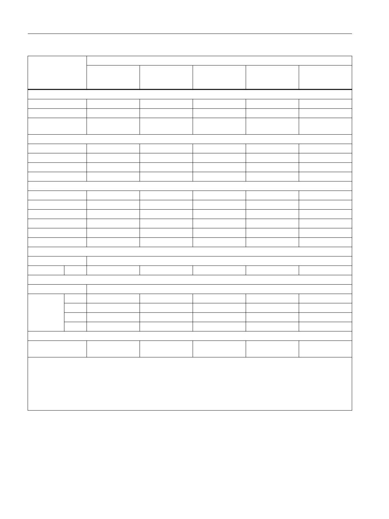
Presettings of programmable coupling characteristics for various coupling types can be found in
the following table:
Keyword
Coupling type
Default
Coupled motion
Master value cou-
Electronic gear
Synchronous
(CP)
(TRAIL)
pling
(EG)
spindle
(LEAD)
(COUP)
CPDEF
-
-
CPDEL
-
-
CPLDEF
-
-
CPLDEL
-
-
CPON
CPOF
CPLON
CPLOF
CPLNUM
1.0
1.0
-
1.0
1.0
CPLDEN
1.0
1.0
-
1.0
1.0
CPLCTID
Not set
-
0
Not set
-
CPLSETVAL
CMDPOS
CMDPOS
CMDPOS
CMDPOS
CMDPOS
CPFRS
BCS
BCS
BCS
BCS
MCS
CPBC
NOC
NOC
NOC
FINE
IPOSTOP
CPFPOS + CPON
Not set
-
-
Not set
Not set
CPFPOS + CPOF
Not set
-
-
-
Not set
CPFMSON
CFAST
CFAST
CCOARSE
NRGT
CFAST
CPFMON
STOP
VL1): STOP
VL1): CONT
STOP
CONT
HL2): CONT
HL2): CONT
CPFMOF
STOP
VL1): STOP
VL1): STOP
STOP
CONT
HL2): STOP
HL2): STOP
CPLPOS + CPON
Not set
-
-
Not set
-
Axes and spindles
Function Manual, 10/2020, 6FC5397-4GP40-0BA1
661
Axis couplings
14.5 Generic coupling
Keyword
Coupling type
Default
Coupled motion
Master value cou-
Electronic gear
Synchronous
(CP)
(TRAIL)
pling
(EG)
spindle
(LEAD)
(COUP)
CPMRESET
NONE
MD20110
MD20110
MD20110
MD20110
CPMSTART
NONE
MD20112
MD20112
MD20112
MD20112
CPMPRT
NONE
MD20112 /
MD20112 /
MD20112 /
MD20112 /
MD226203)
MD226203)
MD226203)
MD226203)
CPLINTR
0.0
0.0
0.0
0.0
0.0
CPLINSC
1.0
1.0
1.0
1.0
1.0
CPLOUTTR
0.0
0.0
0.0
0.0
0.0
CPLOUTSC
1.0
1.0
1.0
1.0
1.0
CPSYNCOP
MD37200
MD37200
MD37200
MD37200
MD37200
CPSYNFIP
MD37210
MD37210
MD37210
MD37210
MD37210
CPSYNCOP2
MD37202
MD37202
MD37202
MD37202
MD37202
CPSYNFIP2
MD37212
MD37212
MD37212
MD37212
MD37212
CPSYNCOV
MD37220
MD37220
MD37220
MD37220
MD37220
CPSYNFIV
MD37230
MD37230
MD37230
MD37230
MD37230
CPMBRAKE
Bit 0
1
-
-
-
-
CPMVDI
Bit 3
0
0
0
0
0
Bit 4
1
1
1
1
1
Bit 5
0
0
0
0
0
Bit 6
1
1
1
1
1
CPMALARM
MD11410
MD11410
MD11410
MD11410
MD11410
MD11415
MD11415
MD11415
MD11415
MD11415
Legend:
1) Pre-processing
2) Main run
3) depends additionally on MD22621
- not relevant or not allowed
Axes and spindles
662
Function Manual, 10/2020, 6FC5397-4GP40-0BA1

Axis couplings
14.5 Generic coupling
Additional properties
Value ranges or availability of additional properties of a set coupling type (CPSETTYPE) can be
found in the following table:
Default
Coupled motion
Master value
Electronic gear
Synchronous spin-
(CP)
(TRAIL)
coupling (
(EG)
dle
LEAD)
(COUP)
Number of
≦ 5
≦ 2
1
≦ 5
1
leading axes
Following axis
Axis/spindle
Axis/spindle
Axis/spindle
Axis/spindle
Spindle
type
Defining/delet-
CPDEF/CPDEL
CPON/CPOF
CPON/CPOF
CPDEF/CPDEL
CPDEF/CPDEL
ing coupling
or
module
CPON/CPOF
Defining/delet-
CPLDEF/CPLDEL
CPLON/CPLOF
CPLON/CPLOF
CPLDEF/CPLDEL
CPLDEF/CPLDEL
ing leading axis
or
CPLON/CPLOF
Cascading
+/-
+/-
+/-
+/-
-
Dynamic obser-
-
-
-
-
+/-
vation
of the leading
spindle
Implicit selec-
-
-
-
-
+/-
tion/deselec-
tion of state
control1)
Legend:
1) See also Chapter "Synchronous spindle (Page 489)"
- not relevant or not allowed
Availability of the specified characteristics depends on the available version (see Section
"Requirements (Page 609)").
Example:
The coupled motion coupling type (CPSETTYPE="TRAIL") allows a maximum of two leading
axes and cascading. However, this is not available in the basic version, but requires the CP-
EXPERT option.
Constraints
• CPSETTYPE can be programmed in synchronized actions.
• If the coupling type (CPSETTYPE) is set, certain coupling characteristics are preset and
cannot be changed. Subsequent change attempts with keywords cause an error and are
rejected with an alarm:
Axes and spindles
Function Manual, 10/2020, 6FC5397-4GP40-0BA1
663

Axis couplings
14.5 Generic coupling
CPSETTYPE=
TRAIL
LEAD
EG
COUP
CPDEF
Alarm 16686
Alarm 16686
CPDEL
Alarm 16686
Alarm 16686
CPLDEF
CPLDEL
CPON
Alarm 16686
Alarm 16686
CPLON
CPOF
Alarm 16686
Alarm 16686
CPLOF
CPRES
Alarm 16686
Alarm 16686
Alarm 16686
CPLNUM
Alarm 16686
Alarm 16686
CPLDEN
Alarm 16686
Alarm 16686
CPLCTID
Alarm 16686
Alarm 16686
CPLSETVAL
Alarm 16686
Alarm 16686
Alarm 16686
with CMDVEL
with CMDVEL
with CMDVEL
CPFRS
Alarm 16686
with BCS
CPBC
Alarm 16686
Alarm 16686
CPFPOS + CPON
Alarm 16686
Alarm 16686
CPFPOS + CPOF
Alarm 16686
Alarm 16686
Alarm 16686
CPFMSON
Alarm 16686
Alarm 16686
Alarm 16686
CPFMON
Alarm 16686
Alarm 16686
Alarm 16686
Alarm 16686
with ADD/STOP
with STOP
CPFMOF
Alarm 16686
Alarm 16686
Alarm 16686
Alarm 16686
with ADD/STOP
with ADD
with ADD
CPLPOS + CPON
Alarm 16686
Alarm 16686
Alarm 16686
CPMRESET
Alarm 16686
Alarm 16686
Alarm 16686
Alarm 16686
CPMSTART
Alarm 16686
Alarm 16686
Alarm 16686
Alarm 16686
CPMPRT
Alarm 16686
Alarm 16686
Alarm 16686
Alarm 16686
CPMBRAKE
Alarm 16686
Alarm 16686
Alarm 16686
Alarm 16686
Number of leading
Alarm 16672
Alarm 16672
Alarm 16672
Alarm 16672
axes (∑ LA)
with ∑ LA > 2
with ∑ LA > 1
with ∑ LA > 5
with ∑ LA > 1
Following axis type
Alarm 14092
with axis
Axes and spindles
664
Function Manual, 10/2020, 6FC5397-4GP40-0BA1
Axis couplings
14.5 Generic coupling
14.5.7.3
Projected coupling (CPRES)
If the coupling type "Synchronous spindle" is set, (see CPSETTYPE), the coupling properties
contained in machine data can be activated instead of the programmed coupling properties.
Further information
Synchronous spindle (Page 489)
Programming
Syntax:
CPRES= (<following spindle>)
Designation:
Coupling Restore
Functionality:
Activates projected data of the synchronous spindle coupling to following
spindle FAx.
Following spindle: Type: AXIS
Value range:
All defined spindle names in the channel
Example:
Programming
Comment
CPLON[S2]=(S1) CPSETTYPE[S2]="COUP"
; Creates a coupling module for follow-
ing spindle S2 with leading spindle S1
and activates the coupling module. Cou-
pling properties are set such that they
correspond to the existing synchronous
spindle coupling type.
CPRES=(S2)
; Activates projected data of the syn-
chronous spindle coupling to following
spindle S2.
Boundary conditions
• CPRES is only allowed when the coupling type "Synchronous spindle"
(CPSETTYPE="COUP") is set.
• Application of CPRES to an already active coupling results in a new synchronization.
• Applying CPRES to an undefined coupling module does not result in any action.
14.5.8
Cross-channel coupling, axis replacement
The following and leading axes must be known to the calling channel.
Axes and spindles
Function Manual, 10/2020, 6FC5397-4GP40-0BA1
665
Axis couplings
14.5 Generic coupling
Following axis
The following axis is requested for replacement in the channel when programming a CP keyword
in the part program, depending on the axis replacement projection (MD30552) with the
language command GETD.
Axis change of the following axis after activating the coupling module is only permitted in the
channel. Changing from channel to main run and vice versa is still possible, however a change
across channel boundaries is not. Supplementary conditions and properties still apply to axis
change. The axis replacement via channel axes is released again after deactivating the coupling
module.
Further information
Function Manual Basic Functions; Mode groups, channels, axis replacement
Leading axes
Axis change of leading axes can be performed independently of the state of the coupling.
14.5.9
Behavior with rotary axes
Rotary axes as leading or following axes
It is possible to couple rotary axes to a linear axis and vice versa. Note that a direct assignment
of degrees to mm must be performed using the coupling rule.
Example:
A = Rotary axis, X = Linear axis
Programming
Comment
N10 G0 A0 X0
; Traverse motion:
X = 0 mm, A = 0 degrees
N20 CPON=(A) CPLA[A]=(X) CPLNUM[A,X]=2
; A coupling module for rotary ax-
is A with linear axis X as lead-
ing axis is created and activa-
ted. The coupling value is 2.
N30 X100
; Traverse motion:
X = 100 mm, A = 200 degrees (=
100*2)
Modulo reduced rotary axes as leading axes
With modulo reduced rotary axes as leading axes, the input variable is not reduced during the
reduction of the leading axis. The non-reduced position is still taken as the input variable, i.e. the
traversed distance is considered.
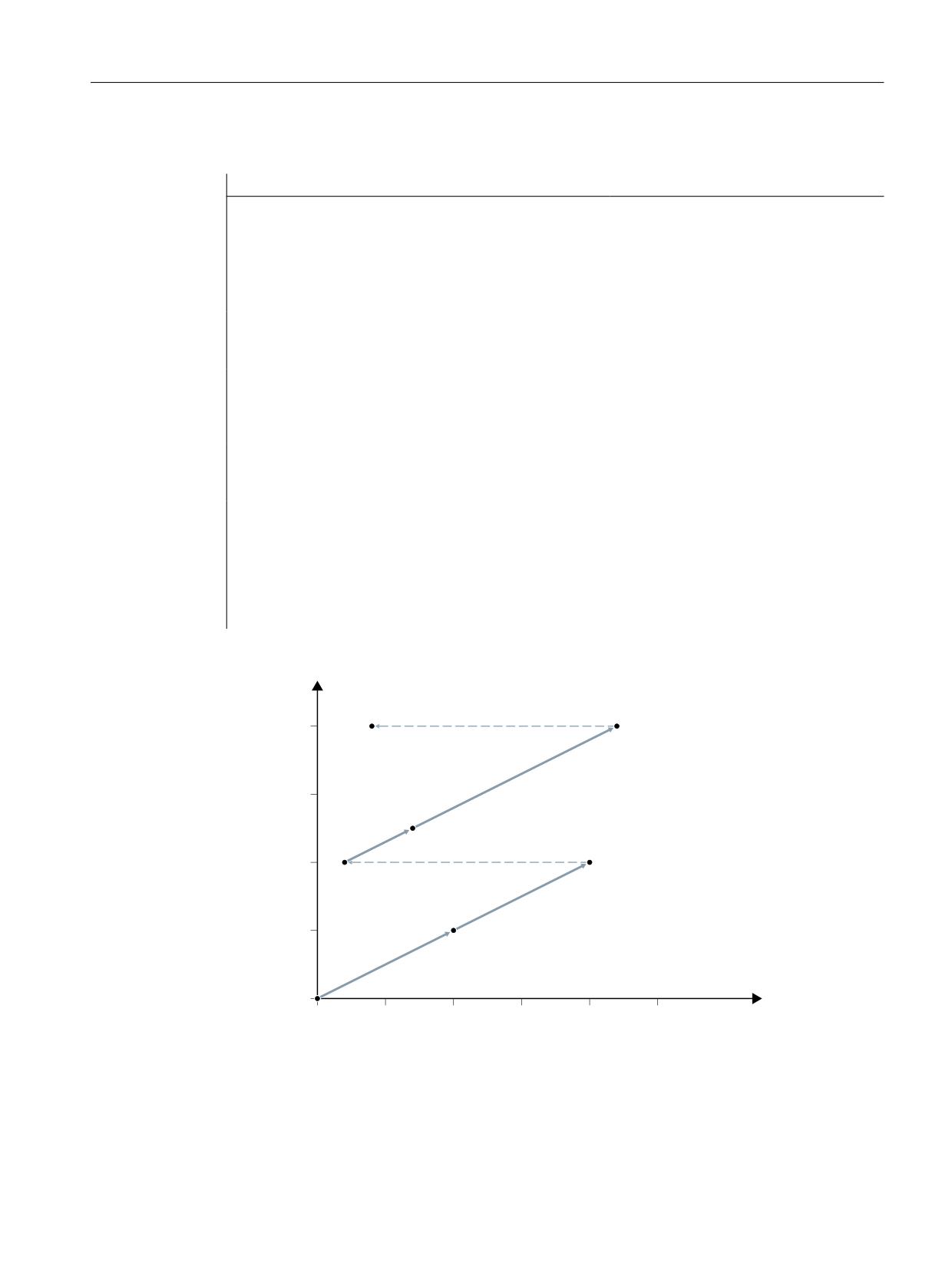
Example:
Axes and spindles
666
Function Manual, 10/2020, 6FC5397-4GP40-0BA1
Axis couplings
14.5 Generic coupling
A = Modulo reduced rotary axis, X = Linear axis
Programming
Comment
N10 G0 A0 X0
; Traverse motion:
X = 0 degrees, X = 0 mm
N20 CPON=(X) CPLA[X]=(A) CPLNUM[X,A]=0.5
; A coupling module for linear ax-
is X with rotary axis A as lead-
ing axis is created and activa-
ted. The coupling value is 0.5.
N30 A200
; Traverse motion:
A = 200 degrees, X = 100 mm
(= 200*0.5)
N40 A=IC(200)
; A traverses through 200 degrees
in a positive direction to 400
degrees, Display A = 40. X tra-
verses through 100 mm to 200.
N50 A=IC(100)
; A traverses from 40 degrees to
140 degrees, X traverses through
additional 50mm to 250.
N60 A=ACP(80)
; A traverses in the positive di-
rection to 50 degrees, the tra-
versing path is 300 degrees in
the positive direction. X traver-
ses correspondingly by 150 mm in
the positive direction. The end
position is therefore X = 400.
'PMMPXJOH BYJT
9
3FEVDUJPO PG MFBEJOH BYJT CZ
p
NN
/
NN
/
3FEVDUJPO PG MFBEJOH BYJT CZ
p
NN
/
NN
/
p
p
p
p
p
-FBEJOH BYJT "
Figure 14-12
Example: Modulo reduced rotary axis to linear axis
(...)
Position indication for X, A
Axes and spindles
Function Manual, 10/2020, 6FC5397-4GP40-0BA1
667
Axis couplings
14.5 Generic coupling
14.5.10
Behavior during POWER ON, ...
Power on
No coupling is active at power ON. Coupling modules are not available.
RESET
The behavior on RESET can be set separately for each coupling module (see CPMRESET). The
coupling can be activated, deactivated or the current state can be retained.
Mode change
The coupling remains active during a mode change. The coupling is suppressed (not
deselected!) only in JOG-REF mode when referencing a following axis.
Reference point approach
G74 of the following axis is not possible with an active coupling. An alarm is output.
If the JOG-REF mode is selected and the following axis is traversed, the coupling is suppressed.
The coupling is only performed after JOG-REF mode is cancelled.
SERUPRO
The SERUPRO procedure will simulate the generic coupling and provide values for a restart.
With axial couplings, the simulation always assumes a setpoint coupling, which means, when
there is an actual value coupling, this is switched to setpoint coupling during the SERUPRO
procedure. This can mean that the simulation is not performed correctly.
Further deviations from the real procedure can occur due to increased simulation speed and
canceled axis dynamics limitations.
14.5.11
CP SW limit monitoring
14.5.11.1
Function
What is the purpose of the function?
The "CP-SW limit monitoring" function improves the braking response of a following axis or a
following spindle in axis operation when approaching a software limit switch.
Advantages:
• This avoids that the software limit switch is passed.
• If possible, synchronous operation of the coupling is kept.
Axes and spindles
668
Function Manual, 10/2020, 6FC5397-4GP40-0BA1
Axis couplings
14.5 Generic coupling
Availability
The "CP SW limit monitoring" function can only be activated for following axes from:
• Generic couplings, type "Freely programmable" (CPSETTYPE[FAx] = "CP")
• Couplings (generic coupling with CPSETTYPE[FAx] not equal to "CP", coupled motion,
electronic gearbox, master value coupling or synchronous spindle) with a maximum of one
active leading axis/spindle
In all other cases (and in the event of non-activation of the "CP SW limit monitoring") the previous
function of the software limit switch monitoring is in effect.
Monitoring and setting the brake
The "CP-SW limit monitoring" function checks, in every IPO cycle, as to whether the movement
of the following axis/spindle can be enabled for the following IPO cycle, so that the axis can
always stop in plenty of time before the software limit switch. If this is not the case, for the
following axis, a "CP-SW limit stop" is set; this signifies unconditional direction-specific braking
along the contour.
Transferring the brake to the axes
Setting the brake means that the coupling-independent motion component (CMD and CORR
component) of the following axis is stopped. On the other hand, the coupling-dependent
motion component (DEP component) of the following axis can only be braked by braking the
leading axes.
For couplings (generic coupling with CPSETTYPE[FAx] not equal to "CP", coupled motion,
electronic gearbox, master value coupling or synchronous spindle) with a maximum of one
active leading axis/spindle, the brake is also set for the (only) active leading axis in the collision
direction (depending on the coupling factor).
For generic couplings, type "freely programmable" (CPSETTYPE[FAx] = "CP"), the brake is only
transferred to all of the active leading axes, if the coupling property CPMBRAKE[FAx] Bit 0 = 1 has
been programmed (see "Reaction to stop signals and commands (CPMBRAKE) (Page 651)").
The collision direction depends on the coupling factor for the specific leading axis: With a
negative coupling factor, the collision direction reverses, there is no transfer for a coupling factor
of "zero". For non-linear couplings (e.g. curve table), the coupling factor is derived from the
gradient, determined as linear approximation.
Note
A brake set for a following axis can only influence its leading axes as long as the coupling is active.
Braking behavior
The normal acceleration ramp is used when braking the axes towards the software limit switch
along the contour, maintaining the coupling definition.
When braking, the stop state 75 "brake request" and situation-dependent, the higher priority
stop states 22 "wait: spindle enable missing", 12 "wait for axis/spindle release" or 71 "wait for
enable, transformation axis" are displayed.
Axes and spindles
Function Manual, 10/2020, 6FC5397-4GP40-0BA1
669

Axis couplings
14.5 Generic coupling
If the following axis is stationary as result of the "CP-SW limit stop", and cannot approach the
software limit switch any closer, then the following alarm is displayed:
10625 "%?C{channel %1: %}block %3 following axis/spindle %2 with CP-SW limit stop %4"
This means that up to the "final" stopping position, the situation can be somewhat relieved by
moving the following axis in the opposite direction.
Note
For the "CP-SW limit monitoring", coupling involves maintaining synchronous operation. As a
consequence, it cannot be guaranteed that the axis stops at precisely the correct position, if the
coupling rule is to be maintained. If the brake is to be transferred to the leading axes, and the
interpolators brake as required, then the leading axis comes to a standstill in front of the
software limit switch. The maximum distance to the software limit switch is then obtained from
the actual maximum acceleration rate of the following axes multiplied by the square of the
interpolation cycle time.
Retraction
The user is responsible for retraction.
For diagnostic purposes, there are:
• the stop state 75 "brake request"
(if an axis has a travel command, but stops or may not traverse as a result of a braking request)
• and the system variables:
$AA_BRAKE_STATE (actual brake status)
$AA_BRAKE_CONDB (context-sensitive conditions for the interpolator stop in the BCS)
$AA_BRAKE_CONDM (context-sensitive conditions for the interpolator stop in the MCS)
including the OPI variables aaBrakeState, aaBrakeCondB and aaBrakeCondM derived from
these.
Example for retraction:
1. acknowledge alarm 10625.
2. Switch to the JOG mode.
3. Traverse the leading axis using the traversing keys so that the following axis moves away from
the software limit switch.
14.5.11.2
Parameterization
Activation
The "CP SW limit monitoring" function is activated on an axis-for-axis basis using machine data:
MD30455 $MA_MISC_FUNCTION_MASK (axis functions)
Bit
Value
Meaning
11
0
CP SW limit monitoring is not active.
1
CP SW limit monitoring is active.
Axes and spindles
670
Function Manual, 10/2020, 6FC5397-4GP40-0BA1
Axis couplings
14.5 Generic coupling
14.5.11.3
Programming
Transferring the brake to the leading axes
For generic couplings, type "freely programmable" (CPSETTYPE[FAx] = "CP"), by programming
the coupling property CPMBRAKE (see "Reaction to stop signals and commands (CPMBRAKE)
(Page 651)") it can be set as to whether the brake of the following axis, initiated using the "CP-
SW limit monitoring" function, should also be transferred to the leading axes.
14.5.11.4
Boundary conditions
Possible fault sources
If the axes do not brake as required, this could be due to the following reason:
At least one leading axis does not react to the brake, because it is also a leading axis in its own
right (cascade), and the brake is not transferred to its leading axes. A brake is only transferred to
the leading axes (recursive), if the following applies for the following axes involved:
CPSETTYPE[FAx] = "CP" and CPMBRAKE[Fax] bit 0 = 1
Even if all of the axes brake as required, the contour can be violated as a result of different
acceleration rates and/or coupling factors if these values have not been appropriately
configured and/or programmed.
Even if all of the previous preconditions are fulfilled, there are still some reasons why it cannot
be avoided that a following axis passes a software limit switch:
• The actual maximum acceleration of a leading axis changes.
• The actual maximum acceleration of the following axis becomes smaller.
• The velocity of the following axis when switching in the coupling or when the CP-SW limit
monitoring responds is already so high that with the actual
maximum acceleration it is no longer possible to stop the axis in the appropriate time.
If the axis cannot be stopped in the appropriate time, then as before, the previous software limit
switch monitoring responds, and stops the following axis at the software limit switch.
Braking response for transformations
If the axis to be braked is the output of a transformation, and it has a (MCS) travel command in
the collision direction, then the brake is transferred to all input axes of the transformation in both
directions, and a path stop is executed for this transformation. However, the following
exceptions apply: It does not apply to the independent axes of the transformation. For
TRANSMIT and TRAANG, these are the axes specified in machine data
$MC_TRAFO_AXES_IN_*[2]. For the transformations, braking is only transferred to their
dependent input axes.
DRF offset
Setting a CP-SW limit stop can cause a DRF movement to be canceled, as shown in the following
example:
Axes and spindles
Function Manual, 10/2020, 6FC5397-4GP40-0BA1
671
Axis couplings
14.5 Generic coupling
The basic motion is path motion with extremely low velocity in the positive direction. A larger
DRF correction motion applies to this in the opposite direction. This results in a travel command
in the negative direction. If these movements are now stopped using a CP-SW limit stop, then for
standard machine data, this means that DRF motion is canceled, and only path motion is
continued after the stop is withdrawn.
NCU link
The following restriction must be taken into account for cross-NCU couplings based on lead-link
axis and axis container:
As the leading axis can be interpolated on another NCU, it can take between one and two IPO
cycles for the brake to be transferred to the NCU of the leading axis.
14.5.11.5
Examples
Example 1: Generic coupling type "freely programmable" (CPSETTYPE[FAx] = "CP")
Configuration:
MD26110 $MA_POS_LIMIT_PLUS[AX2]=15 ;
Position of the 1st software limit
switch of the following axis for the
traversing range limit in the positive
direction
MD30455 $MA_MISC_FUNCTION_MASK[AX2] = 'H800' ; Bit 11 = 1 (CP-SW limit monitoring is
activated)
Programming:
; start position of X and Y
N100 G0 X0 Y0
; coupling activation FA=Y LA=X
; set with CPMBRAKE bit 0 (transfer of the brake to the leading axis)
N120 CPON=Y CPSETTYPE="CP" CPLA=X CPLDEN=2 CPMBRAKE B_OR='H1'
N140 G4 F2
; traverse leading axis X
N200 G1 X=1000 F1000
Example 2: Couplings with a maximum of one active leading axis/spindle
With the following calls, the CP-SW limit monitoring is executed - including the transfer of the
brake to the leading axis - if MD30455 MA_MISC_FUNCTION_MASK[AX2] bit 11 is set:
TRAILON(Y,X,0.5) ;
Definition and switching in the coupling of the coupled motion
axis Y two leading axis X.
Axes and spindles
672
Function Manual, 10/2020, 6FC5397-4GP40-0BA1
Axis couplings
14.5 Generic coupling
EGDEF(Y,X,1) ;
Definition of an EG axis group with setpoint coupling
from X to Y (following axis).
EGON( Y,"FINE",X,1,2) ;
Activating coupling.
14.5.12
Disturbance characteristic
14.5.12.1
Rapid stop
Function
The rapid stop stops the axis / spindle without ramp, i.e. the velocity setpoint value is specified
as zero. This default applies the brakes at the current limit. The servo enable is retained.
The rapid stop is set at:
• Stop A and Stop C (Safety Integrated)
• Alarms with rapid stop as configured braking behavior
• Reaching the hardware limit switch and rapid stop as configured braking behavior:
MD36600 $MA_BRAKE_MODE_CHOICE = 1
Switchover to actual-value coupling.
The actual values of the leading spindle are used to calculate the setpoint values as soon as the
rapid stop of the leading spindle is reported to a generic coupling.
The changeover to actual value coupling takes place smoothly and remains active till the servo
enable as well as the pulse enable is available again to the leading spindle and no more position
offset takes place. The setpoint value calculation is programmed as with CPLSETVAL only if
these conditions are fulfilled.
Note
A rapid stop that was initiated on reaching the hardware limit switch does not changeover the
actual value coupling.
Response of the following spindle
If a rapid stop is detected for a leading spindle and the following spindle does not execute any
rapid stop by itself, then the following spindle tries to follow the dynamics of the movement of
the leading spindle defined within its framework. As position synchronization is generated,
there may be oscillations in the following axis in relation to the position to be approached.
Axes and spindles
Function Manual, 10/2020, 6FC5397-4GP40-0BA1
673
Axis couplings
14.5 Generic coupling
The start of a rapid stop for a leading axis/spindle is detected across NCUs.
Note
A simultaneous rapid stop of the leading and following spindle is executed in the synchronized
spindle coupling type (CPSETTYPE="COUP") during a servo alarm.
14.5.13
Tracking the deviation from synchronism
14.5.13.1
Fundamentals
Deviation from synchronism
Workpiece machining operations which are to be carried out both on the face front and the face
rear require a workpiece transfer to another workpiece receptacle (e.g. a counterspindle chuck).
When workpieces are transferred from front to rear machining, a position offset may result from
the closing of the workpiece receptacle. This could be down to square-edged workpieces or due
to the generation of an angular momentum when the workpiece receptacle (chuck) is closed
quickly during a movement. Depending on the resistance of the workpiece, the tension can be
detected by means of an increase in the current consumption of both the motors involved in the
coupling and/or by means of the workpiece being subjected to torsion.
This could lead to the following NC/PLC interface signals being reset, according to the
synchronism tolerance which has been set, and the magnitude of the offset:
DB31, ... DBX98.1 (coarse synchronous operation) and/or
DB31, ... DBX98.0 (fine synchronous operation)
For the setpoint coupling, the position and velocity setpoints are calculated precisely in
accordance with the programmed coupling rule and output to the Control Units. If identical
drives and a rigid workpiece are used, this will lead to a regulative deviation at the leading and
following spindle, half due to a setpoint difference and half due to an actual value difference.
Function
The "track the deviation from synchronism" function serves to detect the position offset which
has been imposed on the actual value and to correct the following spindle when calculating the
setpoint.
Requirement
A coupling closed via the part/chuck must be in place in order to use this function.
Axes and spindles
674
Function Manual, 10/2020, 6FC5397-4GP40-0BA1
Axis couplings
14.5 Generic coupling
Versions
There are two different options for determining the deviation from synchronism:
1. The deviation from synchronous operation is determined by the NC (see "Measuring the
deviation from synchronism (Page 675)").
2. The deviation value is already known and entered by the user directly (see "Entering the
deviation from synchronism directly (Page 678)").
In both cases, the deviation value is then incorporated into the setpoint value calculation for the
following spindle, as a correction value.
Availability
The "track the deviation from synchronism" function was developed for machine couplings
(CPFRS="machine"). This means that it is also available for the "synchronous spindle"
coupling type (CPSETTYPE="COUP").
Like the other higher-level movements, the availability of the function (e.g. speed difference)
depends on the option (see "Requirements (Page 609)").
14.5.13.2
Measuring the deviation from synchronism
The controller measures the difference between the setpoint positions and actual positions
when the following spindle is operating in synchronism. This results in a correction value, which
is saved in a system variable.
Axes and spindles
Function Manual, 10/2020, 6FC5397-4GP40-0BA1
675
Axis couplings
14.5 Generic coupling
Requirements
The following requirements must be met to enable the controller to calculate the correction
value:
•
Requirements if the set coupling type is "synchronous spindle" (CPSETTYPE="COUP"):
- The coupling has precisely one leading spindle (requirement is met
if CPSETTYPE="COUP").
- The coupling factor (quotient from CPLNUM and CPLDEN) is 1 or -1.
- The following value is derived from the setpoint position ("DV") or the actual position
("AV") of the leading spindle.
- Setpoint synchronism must be achieved:
DB31, ... DBX99.4 (synchronization running) = 0
- Setpoint synchronism must not decline again.
- No overlaid movement (DB31, ... DBX98.4 = 0) must be present.
- A dynamics limit is required for the leading spindle, in order to exclude the possibility of
the following spindle being subjected to excessive demands.
•
Requirements for a free generic coupling with CPFRS="machine":
- The configured spindles are coupled.
- The coupling has precisely one leading spindle.
- The coupling factor (quotient from CPLNUM and CPLDEN) is 1 or -1.
- The following value is derived from the setpoint position (CPLSETVAL="CMDPOS") or
the actual position (CPLSETVAL="ACTPOS") of the leading spindle.
- Setpoint synchronism must be achieved:
DB31, ... DBX99.4 (synchronization running) = 0
- Setpoint synchronism must not decline again.
- No overlaid movement (DB31, ... DBX98.4 = 0) must be present.
- A dynamics limit is required for the leading spindle, in order to exclude the possibility of
the following spindle being subjected to excessive demands.
Note
Dynamics limit for the leading spindle
The "dynamics limit for the leading spindle" property is specified automatically when the
"synchronous spindle" coupling type (CPSETTYPE="COUP") is set. In the case of other coupling
types, it is the particular responsibility of the user/machine manufacturer to provide suitable
measures to ensure that the following spindle cannot become dynamically overloaded.
Activation
Measuring and tracking of the deviation from synchronism are activated by setting the following
NC/PLC interface signal to "1":
DB31, ... DBX31.6 (track synchronism)
Axes and spindles
676
Function Manual, 10/2020, 6FC5397-4GP40-0BA1

Axis couplings
14.5 Generic coupling
The signal only has an effect on the following spindle.
Note
In the following cases, signal DB31, ... DBX31.6 (track synchronism) is ignored:
• Axis/spindle disable is active (DB31, ... DBX1.3 = 1).
• Program test is selected.
• SERUPRO is active.
If one of these situations arises when the "track the deviation from synchronism" function is
already active, the function will be deactivated.
Time when measurement is performed
The time when the measurement is performed and the correction value is calculated depends
on the bit 7 setting made in the following item of machine data:
MD30455 $MA_MISC_FUNCTION_MASK (axis functions)
Bit
Value
Meaning
7
0
The correction value is calculated continuously, as long as the NC/PLC interface signal
DB31, ... DBX31.6 (track synchronism) is set and setpoint synchronism is active (cyclic
calculation).
1
The correction value is only calculated at the time when the NC/PLC interface signal
DB31, ... DBX31.6 (track synchronism) changes from 0 to 1 (edge evaluation).
Note
If a temporal extension is taken into account when relieving the tension between the leading
and the following spindle, bit 7 should be set to 0. The interface signal is then state-controlled.
The time required to relieve the tension can depend on various factors (e.g. KV factor of position
control, accelerating power of the motors) and must be determined by way of experiment.
Measuring sequence
The NC/PLC interface signal DB31, ... DBX31.6 (track synchronism) can only become effective
once setpoint synchronism has been achieved:
DB31, ... DBX99.4 (synchronization running) = 0
The actual values of the following spindle are read within the interpolation cycle and the
difference between them and the setpoint position is calculated, either for as long as signal
DB31, ... DBX31.6 is activated, or just once on that signal's rising edge (the frequency will
depend on the setting of bit 7 in MD30455; see the section titled "Time when measurement is
performed").
The correction value is the difference between the setpoint and actual-value synchronism
positions. This value is saved for the corresponding following spindle in the following system
variable:
Axes and spindles
Function Manual, 10/2020, 6FC5397-4GP40-0BA1
677
Axis couplings
14.5 Generic coupling
$AA_COUP_CORR[S<n>] (following spindle: correction value for synchronous spindle coupling)
Note
You must ensure that the velocity of the leading and following axes is kept as constant as
possible and that no acceleration jump occurs for the duration of the measurement.
Example
When the coupling of the synchronous spindle [S2] is activated, a position offset of 77 degrees
is also programmed:
CPON=S2 ... CPFPOS[S2]=AC(77)
When the workpiece receptacle is closed, this results in a mechanical position offset, which leads
to an actual-value position offset of 81 degrees.
When the "track the deviation from synchronism" function is activated (DB31, ... DBX31.6 = 1)
and setpoint synchronism has been achieved (DB31, ... DBX99.4 = 0), the actual-value position
offset ($VA_COUP_OFFS[S2] = 81) is compared with the setpoint position offset
($AA_COUP_OFFS[S2] = 77). This results in a correction value of 4 degrees, which is saved in
system variable $AA_COUP_CORR[S2].
14.5.13.3
Entering the deviation from synchronism directly
If the deviation value is known, it can be written directly to the system variable $AA_COUP_CORR
for the corresponding following spindle. This is executed via a part program or synchronized
action.
Note
Please note that the system variable can only be written once the mechanical coupling has been
created. Otherwise a new offset may arise when closing the chuck.
Requirements
To enable the system variable $AA_COUP_CORR to be written from the part program or
synchronized actions, a generic machine coupling must have been activated at least once for the
corresponding following spindle since the most recent controller power-up was performed.
14.5.13.4
Synchronism correction
If correction value $AA_COUP_CORR[S<n>] is a value other than zero and a generic machine
coupling has been active for following spindle S<n> (by means of CPFRS="machine"
or CPSETTYPE="COUP"), the following NC/PLC interface signal is set:
DB31, ... DBX103.0 (synchronism correction is taken into account)
The correction value is incorporated into the setpoint value calculation for the following spindle,
in the coupling module. Resetting the setpoint by the coupling offset relieves the tension
between the leading and following spindles.
Axes and spindles
678
Function Manual, 10/2020, 6FC5397-4GP40-0BA1
Axis couplings
14.5 Generic coupling
The synchronism signals are produced by comparing the actual values with the corrected
setpoints. Once a correction process has been undertaken, the synchronism signals should be
present again:
DB31, ... DBX98.1 (coarse synchronism) and/or
DB31, ... DBX98.0 (fine synchronism)
The correction value can be implemented and the synchronism signals produced as well, since
the whole point of the "tracking the deviation from synchronism" function is to improve
synchronism when tension is present. When implementing this value, the accelerating power is
restricted to no more than 10% of the maximum acceleration and velocity.
When $AA_COUP_CORR[S<n>] has been implemented in full, the following NC/PLC interface
signal is set:
DB31, ... DBX99.2 (synchronism correction implemented)
This still applies even if $AA_COUP_CORR[S<n>] is zero and no correction needs to be
implemented.
When synchronism correction is complete, the NC/PLC interface signal DB31, ... DBX31.6 (track
synchronism) must be reset to "0" in order to restore the rigidity of the coupling.
The correction value is not changed again once signal DB31, ... DBX31.6 has been reset or once
the coupling has been deactivated (with CPOF). The system variable $AA_COUP_CORR[S<n>]
then returns a constant value.
The correction value is taken into account until it is reset by setting system variable
$AA_COUP_CORR[S<n>] to "0", which must be done, at the very latest, once the workpiece is
removed from the spindle.
Note
The setpoint correction by means of the system variable $AA_COUP_CORR[S<n>] impacts on all
subsequent following spindle programming in the same way as a position offset, similar to a DRF
offset in the machine.
14.5.13.5
Diagnostics for synchronism correction
The current value of $AA_COUP_CORR (correction value for tracking the deviation in
synchronism) is displayed in the "Axis/Spindle Service" window, under the "Position offset for the
leading axis/spindle setpoint" line, for the purposes of diagnostics.
System variable $AA_COUP_CORR_DIST ($AA_COUP_CORR distance-to-go) can be used to
determine how much of the correction value is still be implemented.
Axes and spindles
Function Manual, 10/2020, 6FC5397-4GP40-0BA1
679
Axis couplings
14.5 Generic coupling
14.5.13.6
Resetting synchronism correction
Versions
Synchronism correction can be reset in the following ways:
• Writing value "0" to variable $AA_COUP_CORR[S<n>].
Synchronism correction is suppressed via a ramp with reduced accelerating power (just as
when a correction value is implemented).
• Resetting synchronism correction via the PLC.
On the rising edge of the NC/PLC interface signal:
DB31, ... DBX31.7 (reset synchronism correction)
, the variable $AA_COUP_CORR[S<n>] is set to zero and synchronism correction is reset as
follows:
- If the spindle is in speed control mode, the correction movement is stopped. The existing
synchronism correction is then transferred to the setpoint position.
- In all other cases, the synchronism correction that has already been implemented is reset
in exactly the same way as when variable $AA_COUP_CORR[S<n>] is set to zero.
Requirements
A requirement for resetting synchronism correction is that the correction value is not currently
being calculated (see Section "Measuring the deviation from synchronism (Page 675)").
End of the reset procedure
When the reset procedure is complete, the following NC/PLC interface signal is set:
DB31, ... DBX99.2 (synchronism correction implemented)
If the NC/PLC interface signal DB31, ... DBX103.0 (synchronism correction is taken into account)
is also reset, so too can the NC/PLC interface signal DB31, ... DBX31.7 (reset synchronism
correction) be reset.
Axes and spindles
680
Function Manual, 10/2020, 6FC5397-4GP40-0BA1
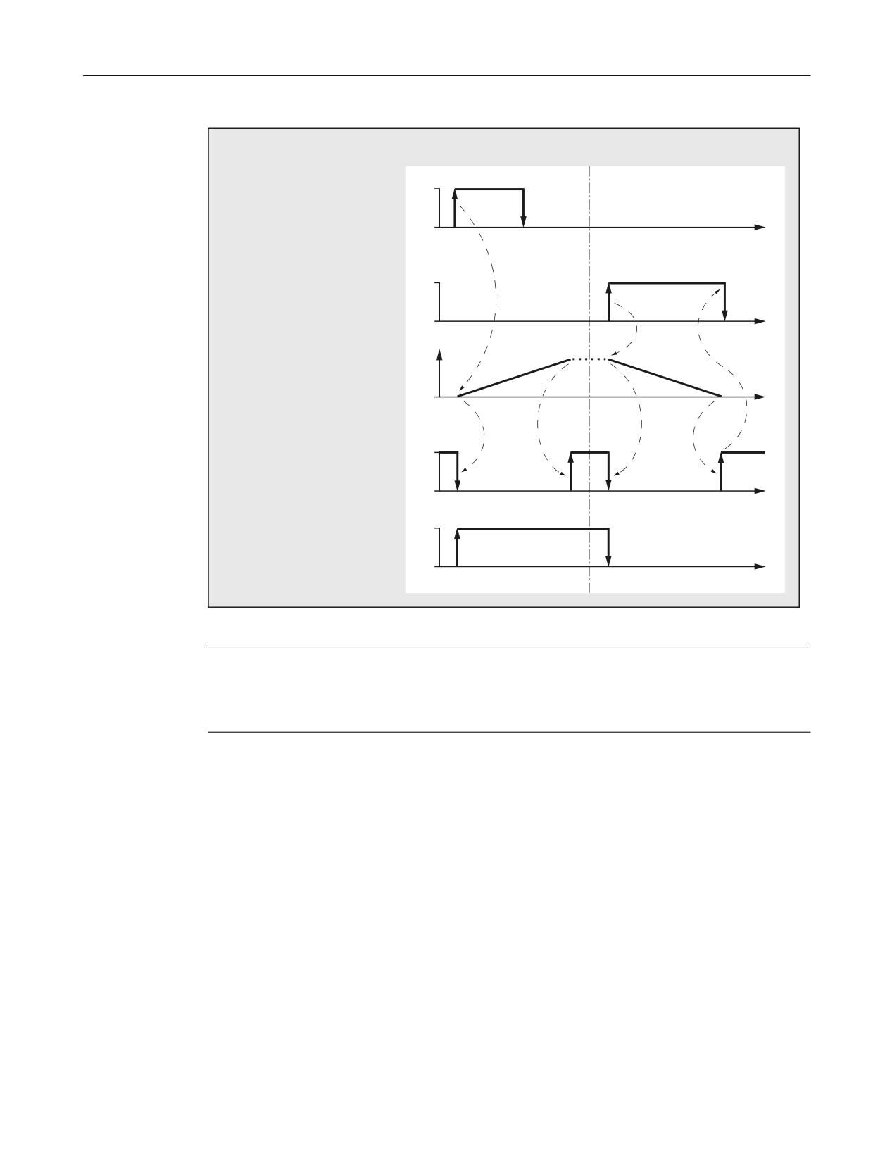
Axis couplings
14.5 Generic coupling
6\QFKURQL]LQJ
5HVHWWLQJ
'%
'%;
WUDFN V\QFKURQLVP
W
'%
'%;
UHVHW V\QFKURQLVP FRUUHFWLRQ
W
&RUUHFWLRQ SDWK
WULJJHUHG E\
$$B&283B&255
W
'%
'%;
V\QFKURQLVP FRUUHFWLRQ
LPSOHPHQWHG
W
'%
'%;
V\QFKURQLVP FRUUHFWLRQ
LV WDNHQ LQWR DFFRXQW
W
Figure 14-13
Time diagram for synchronizing and resetting synchronism correction
Note
If the correction path has not been traversed in full and the NC/PLC interface signal
DB31, ... DBX31.7 (reset synchronism correction) has not been reset, writing to variable
$AA_COUP_CORR[S<n>] will not have any effect.
14.5.13.7
Limitations and constraints
Several following spindles
If a leading spindle has several following spindles, each of these following spindles can be
processed with the axial NC/PLC interface signal DB31, ... DBX31.6 (track synchronism)
separately from one another.
Writing variable $AA_COUP_CORR
System variable $AA_COUP_CORR is only written from the part program or synchronized actions
when a generic machine coupling has been activated for the corresponding axis/spindle at least
once.
Axes and spindles
Function Manual, 10/2020, 6FC5397-4GP40-0BA1
681
Axis couplings
14.5 Generic coupling
Correction value
If the correction value $AA_COUP_CORR is being written via a part program/synchronized action,
as well as being determined due to the "track the deviation from synchronism" function being
activated (DB31, ... DBX31.6 = 1), the most recent event to occur is always the one that takes
effect.
Resetting synchronism correction
Writing correction value $AA_COUP_CORR (via a part program or synchronized action or when
performing a calculation) has no effect when synchronism correction is being reset.
Response to channel/mode group reset
Synchronism correction is not reset in the event of a channel/mode group reset, it is retained
instead.
Response to search for reference and zero mark synchronization
If a search for reference or zero mark synchronization procedure is performed for spindles,
synchronism correction is reset automatically.
The system variable $AA_COUP_CORR must not be set during the search for reference/zero mark
synchronization and, as a result, no measurement may be taken for the deviation from
synchronism either.
Furthermore, the synchronism correction must have been implemented in full before the search
for reference/zero mark synchronization is started.
Response to an interruption
If an interruption occurs (e.g. emergency stop), synchronism correction is reset automatically,
the existing synchronism correction is transferred to the setpoint position, and the NC/PLC
interface signal DB31, ... DBX99.2 (synchronism correction implemented) is set.
If, once the interruption has been dealt with, the generic machine coupling remains active and
the NC/PLC interface signal DB31, ... DBX31.6 (track synchronism) is set, the following applies:
• If the signal is level-triggered (MD30455 $MA_MISC_FUNCTION_MASK, bit 7 = 0), the
deviation from synchronism is measured and written to $AA_COUP_CORR; the setpoints are
corrected accordingly.
• If the signal is edge-triggered (MD30455 $MA_MISC_FUNCTION_MASK, bit 7 = 1) and the
deviation from synchronism is to be measured, a new rising edge of the NC/PLC interface
signal DB31, ... DBX31.6 (track synchronism) needs to be executed.
Axes and spindles
682
Function Manual, 10/2020, 6FC5397-4GP40-0BA1
Axis couplings
14.5 Generic coupling
14.5.14
Examples
14.5.14.1
Programming examples
Direct switch on/off with one leading axis
A coupling module is created and activated with following axis X2 and leading axis X1. The
coupling factor is 2.
CPON=(X2) CPLA[X2]=(X1) CPLNUM[X2,X1]=2
CPOF=(X2)
; The coupling is deactivated and the created
coupling module is deleted with CPOF.
Direct switch on/off with two leading axes
A coupling module is created and activated with following axis X2 and leading axes X1 and Z.
The coupling factor regarding leading axis X1 is 2, the coupling factor regarding leading axis Z
is 3.
CPON=(X2) CPLA=(X1) CPLNUM[X2,X1]=2 CPLA=(Z) CPLNUM[X2,Z]=3
CPOF=(X2)
; The coupling is deactivated and the created
coupling module is deleted with CPOF.
Selective switch-off with two leading axes
A coupling module is created and activated with following axis Y and leading axes X and Z. The
coupling factor regarding leading axis X is 2, the coupling factor regarding leading axis Z is 1.2.
CPON=(X2) CPLA[X2]=(X1) CPLNUM[X2,X1]=2 CPLA[X2]=(Z) CPLNUM[X2,Z]=1.2
CPOF=(X2) CPLA[X1]=(Z)
; The coupling with leading axis Z is deactiva-
ted with CPOF, the coupling with leading axis
X1 is retained. The created coupling module
remains created.
Selective switch-on/off with three leading axes
A coupling module is created and activated with following axis X2 and leading axes X1, Z and A.
N10 CPDEF=(X2) CPLA[X2]=(X1) CPLA[X2]=(Z) CPLA[X2]=(A)
N20 CPON=(X2)
; All leading axes become active, i.e. all
contribute a position component accord-
ing to the coupling rule (coupling com-
ponent) to axis X2.
N30 CPOF=(X2)
; All leading axes are deactivated.
Axes and spindles
Function Manual, 10/2020, 6FC5397-4GP40-0BA1
683
Axis couplings
14.5 Generic coupling
N40 CPLON[X2]=(X1)
; Leading axis X1 is activated, only this
axis supplies a coupling component.
Leading axes Z and A remain deactivated.
N50 CPLON[X2]=(A)
; Leading axis X1 remains active, leading
axis A is deactivated, X1 and A contrib-
ute coupling components (→ selective
switch-on is additive, the condition of
the other leading axes is retained).
N60 CPLON[X2]=(Z) CPLOF[X2]=(A)
; Leading axis Z is activated, leading ax-
is A deactivated. Leading axes X 1and Z
are now active.
N70 CPLOF[X2]=(X1)
; Leading axis X1 is deactivated. Leading
axis Z remains active.
Definition/deletion of a coupling module
With CPDEF a coupling module is created and activated with following axis X2 and leading axes
X1 and Z. The coupling is not activated. Following axis X2 does not follow the coupling rule!
CPDEF=(X2) CPLA[X2]=(X1) CPLNUM[X2,X1]=2 CPLA[X2]=(Z) CPLNUM[X2,Z]=3
Activation can be done with CPON, deactivation with CPOF.
After the deactivation of the coupling relationship to all leading axes, the coupling object can be
deleted. Reserved memory is released:
CPDEL=(X2)
14.5.14.2
Adapt adaptive cycle
Target
Coupled motion in the machine co-ordinate system must be possible with the existing coupling
command TRAILON. The adaptive cycle for TRAILON is supplemented with the coupling
characteristic "Co-ordinate reference" (CPFRS).
Procedure
1. Copy adaptive cycle 700 from directory "CST" to directory "CMA".
2. Supplement cycle 700 with the following entry:
CPFRS[_FA]="MCS"
3. Comment to cycle changes (e.g. user version number and change date).
4. Save cycle.
Axes and spindles
684
Function Manual, 10/2020, 6FC5397-4GP40-0BA1

Axis couplings
14.6 Dynamic response of following axis
;*CHANGE : 07.01.02.00 Mar 08, 2006
;$PATH=/_N_CST_DIR/_N_CYCLE700_SPF
;USER V1.1 Mar 22, 2006
;classic TRAILON(FA,LA,Factor)
PROC CYCLE700(AXIS _CPF=NO_AXIS, AXIS _CPL=NO_AXIS,REAL _CPLF=1) IPTRLOCK SBLOF DISPLOF ICYCOF
;*IF _CPLF==0 GOTOF _CPOF
CPLON[_CPF]=(_CPL) CPSETTYPE[_CPF]="TRAIL" CPLNUM[_CPF,_CPL]=(_CPLF) CPFRS[_CPF]="MCS"
RET
_CPOF:
IF ($P_TECCYCLE==TRUE)
IF ($AA_CPSETTYPE[_CPF]<>"TRAIL") GOTOF _EXIT
ELSE
IF ($PA_CPSETTYPE[_CPF]<>"TRAIL") GOTOF _EXIT
ENDIF
IF _CPL==NO_AXIS
CPSETTYPE[_CPF]="TRAIL" CPOF=(_CPF)
ELSE
CPSETTYPE[_CPF]="TRAIL" CPLOF[_CPF]=(_CPL)
ENDIF
_EXIT: RET
;* SysError 500918 therefore IF command commented
Figure 14-14
Cycle 700 after adaption. Changes are indicated by a colored bar.
14.6
Dynamic response of following axis
14.6.1
Parameterized dynamic limits
The dynamics of the following axis is limited with the following machine data values:
MD32000 $MA_MAX_AX_VELO (maximum axis velocity)
MD32300 $MA_MAX_AX_ACCEL (Maximum axis acceleration)
Axes and spindles
Function Manual, 10/2020, 6FC5397-4GP40-0BA1
685

Axis couplings
14.6 Dynamic response of following axis
14.6.2
Programmed dynamic limits
14.6.2.1
Programming (VELOLIMA, ACCLIMA)
Reducing or increasing dynamics limits
The dynamic limits of the following axis (FA) specified through MD32000 and MD32300 can be
reduced or increased from the part program:
Command
Meaning
VELOLIMA[FA]
Reducing or increasing the maximum Axis velocity
ACCLIMA[FA]
Reducing or increasing the maximum Axis acceleration
The values specified during the programming of VELOLIMA[FA] and ACCLIMA[FA] are
process values. They define the proportion with which the parameterized dynamic limits
(MD32000 and MD32300) are to be considered:
Range of values
Meaning
1 ≤ value < 100
effects a Reduction in the dynamic limit
100 ≤ value < 200
effects an increase in the dynamic limit
The dynamic limits for the velocity and acceleration of the following axis are then calculated as
follows:
Maximum axis velocity = MD32000 $MA_MAX_AX_VELO * VELOLIMA[FA]
Maximum axis acceleration = MD32300 $MA_MAX_AX_ACCEL * ACCLIMA[FA]
Note
The reduction / increase is effected on the overall dynamics of the axis, i.e., on the sum of the axis
component from overlay and coupling.
Programming in synchronized actions
The possibility of programming VELOLIMA[FA] and ACCLIMA[FA] in synchronized actions
depends on the coupling type:.
Coupling type
Part program
Synchronized actions
Tangential correction
x
Coupled motion
x
x
Master value coupling
x
x
Electronic gearbox
x
Synchronous spindle
x
Generic coupling
x
x
Axes and spindles
686
Function Manual, 10/2020, 6FC5397-4GP40-0BA1

Axis couplings
14.6 Dynamic response of following axis
Synchronization between following and leading axes
The acceleration characteristics set and the dynamics offsets set change the duration for
synchronization between following and leading axes during acceleration operations as follows:
Dynamic offset
Effect
Dynamic reduction
Prolongs the synchronism difference.
The monitoring from leading to following value may exceed the al-
lowed range for extended periods.
Dynamic increase
Shortens the synchronism difference.
The monitoring of leading and following values may exceed the al-
lowed range for short periods.
Note
The user must restore the technological synchronization between machining and the
synchronism difference.
Acceleration mode
Only BRISKA is available for the following axis, i.e., abrupt axis acceleration. Acceleration
modes SOFTA and DRIVEA are not available for the following axes described.
Furthermore, it is also possible to configure the positions controller as a PI controller.
CAUTION
Application faults
This option can only be used in conjunction with servo trace and with the appropriate technical
knowledge of the control.
Further information
• CNC Commissioning Manual: NC, PLC, drive
• Velocities, setpoint/actual value systems, closed-loop control (Page 135)
POWER ON
During POWER ON the values of VELOLIMA and ACCLIMA are initialized to 100%.
Mode change
The dynamic offsets remain valid only on transition from AUTO → JOG mode.
RESET
The validities of the (VELOLIMA and ACCLIMA) dynamic offsets after RESET depend on the
setting in the channel-specific machine data:
Axes and spindles
Function Manual, 10/2020, 6FC5397-4GP40-0BA1
687

Axis couplings
14.6 Dynamic response of following axis
MD22410 $MC_F_VALUES_ACTIVE_AFTER_RESET (F Function is active even after RESET)
Value
Meaning
0
The values of VELOLIMA[FA] and ACCLIMA[FA] are set to 100% after RESET.
1
The last programmed values of VELOLIMA[FA] and ACCLIMA[FA] are also active after RESET.
This response also applies for dynamics offsets set using static synchronized actions. If this is not
the case even when MD22410 = 0, then the IDS synchronized action should trigger a repeat or
continuous writing of the dynamic offset.
Further information
Function Manual Synchronized Actions
14.6.2.2
Examples
Electronic gearbox
Axis 4 is coupled to X via an electronic gearbox coupling. The acceleration capability of the
following axis is limited to 70% of maximum acceleration. The maximum permissible velocity is
limited to 50% of maximum velocity. After POWER ON, the maximum permissible velocity is set
to 100% again.
N120 ACCLIMA[AX4]=70
N130 VELOLIMA[AX4]=50
; reduced speed
N150 EGON(AX4,"FINE",X,1,2)
N200 VELOLIMA[AX4]=100
; full speed
Master value coupling
Axis 4 is coupled to X via a master value coupling. The acceleration capability of the following
axis is limited to 80% of maximum acceleration.
N120 ACCLIMA[AX4]=80
; 80%
N130 LEADON(AX4,X,2)
; Activate coupling
Master value coupling with synchronized action
Axis 4 is coupled to X via a master value coupling. The acceleration response is limited to position
80% by static synchronized action 2 from position 100.
Axes and spindles
688
Function Manual, 10/2020, 6FC5397-4GP40-0BA1
Axis couplings
14.7 General supplementary conditions
N120 IDS=2 WHENEVER $AA_IM[AX4] > 100 DO ACCLIMA[AX4]=80
N130 LEADON(AX4,X,2)
14.6.2.3
System variables
For geometry axis, channel axis, machine axis and spindle axis, the following readable system
variables are available in the part program and synchronous actions:
Identifier
Data type
Description
Unit
Preprocessing
$PA_ACCLIMA[n]
REAL
Acceleration offset set with ACCLIMA[Ax]
%
$PA_VELOLIMA[n]
REAL
Velocity offset set with VELOLIMA[Ax]
%
Main run
$AA_ACCLIMA[n]
REAL
Acceleration offset set with ACCLIMA[Ax]
%
$AA_VELOLIMA[n]
REAL
Velocity offset set with VELOLIMA[Ax]
%
Note
Reading the main run variables, implicitly triggers a preprocessing stop.
14.7
General supplementary conditions
Note
Drive optimization
At a SINAMICS S120 drive unit, a maximum of 3 drives can be optimized or measured at the same
time (speed controller optimization/function generator). Therefore, for a coupling with more
than 3 coupled drives at the same time, we recommend that these are distributed over several
drive units.
Note
Block search with active coupling
For an active coupling, it is recommended to only use block search type 5, "Block search via
program test" (SERUPRO) for a block search.
Axes and spindles
Function Manual, 10/2020, 6FC5397-4GP40-0BA1
689

Axis couplings
14.8 Data lists
14.8
Data lists
14.8.1
Machine data
14.8.1.1
NC-specific machine data
Number Identifier: $MN_
Description
11410
SUPPRESS_ALARM_MASK
Screen form for suppressing special alarm outputs
11415
SUPPRESS_ALARM_MASK_2
Suppress alarm outputs
11660
NUM_EG
Number of possible electronic gears
11750
NCK_LEAD_FUNCTION_MASK
Functions for master value coupling
11752
NCK_TRAIL_FUNCTION_MASK
couple motion functions
18400
MM_NUM_CURVE_TABS
Number of curve tables (SRAM)
18402
MM_NUM_CURVE_SEGMENTS
Number of curve segments (SRAM)
18403
MM_NUM_CURVE_SEG_LIN
Number of linear curve segments (SRAM)
18404
MM_NUM_CURVE_POLYNOMS
Number of curve table polynomials (SRAM)
18406
MM_NUM_CURVE_TABS_DRAM
Number of curve tables in DRAM
18408
MM_NUM_CURVE_SEGMENTS_DRAM
Number of curve segments in DRAM
18409
MM_NUM_CURVE_SEG_LIN_DRAM
Number of linear curve segments (DRAM)
18410
MM_NUM_CURVE_POLYNOMS_DRAM
Number of curve polynomials in DRAM
18450
MM_NUM_CP_MODULES
Maximum number of allowed CP coupling modules
18452
MM_NUM_CP_MODUL_LEAD
Maximum number of allowed CP master values
14.8.1.2
Channelspecific machine data
Number Identifier: $MC_
Description
20110
RESET_MODE_MASK
Definition of control basic setting after run-up and RESET/
part program end
20112
START_MODE_MASK
Definition of control basic setting after run-up and RESET
22620
START_MODE_MASK_PRT
Definition of the control basic settings for special start
22621
ENABLE_START_MODE_MASK_PRT
Activation of MD22620
20900
CTAB_ENABLE_NO_LEADMOTION
Curve tables with jump of following axis
20905
CTAB_DEFAULT_MEMORY_TYPE
Default memory type for curve tables
21300
COUPLE_AXIS_1
Projection synchronous spindle pair
Axes and spindles
690
Function Manual, 10/2020, 6FC5397-4GP40-0BA1

Axis couplings
14.8 Data lists
14.8.1.3
Axis/spindlespecific machine data
Number
Identifier: $MA_
Description
30130
CTRLOUT_TYPE
Setpoint output type
30132
IS_VIRTUAL_AX
Axis is virtual axis
30455
MISC_FUNCTION_MASK
Axis functions
35040
SPIND_ACTIVE_AFTER_RESET
Own spindle RESET
37160
LEAD_FUNCTION_MASK
Functions for master value coupling
37200
COUPLE_POS_TOL_COARSE
Threshold value for "Coarse synchronous operation"
37202
COUPLE_POS_TOL_COARSE_2
Second synchronous operation monitoring: Threshold
value for "Coarse synchronous operation"
37210
COUPLE_POS_TOL_FINE
Threshold value for "Fine synchronous operation"
37212
COUPLE_POS_TOL_FINE_2
Second synchronous operation monitoring: Threshold
value for "Fine synchronous operation"
37220
COUPLE_VELO_TOL_COARSE
Velocity tolerance "coarse"
37230
COUPLE_VELO_TOL_FINE
Velocity tolerance "fine"
37500
ESR_REACTION
Reaction definition with extended stop and retract
37550
EG_VEL_WARNING,
Threshold value for speed warning threshold
37560
EG_ACC_TOL
Threshold value for the signal "Axis is accelerating"
14.8.2
Setting data
14.8.2.1
Axis/spindle-specific setting data
Number
Identifier: $SC_
Description
43100
LEAD_TYPE
Definition of master value type
43102
LEAD_OFFSET_IN_POS
Offset of master value with coupling to this axis
43104
LEAD_SCALE_IN_POS
Scaling of master value with coupling to this axis
43106
LEAD_OFFSET_OUT_POS
Offset of the function value of the curve table
43108
LEAD_SCALE_OUT_POS
Scaling of the function value of the curve table
14.8.3
System variables
Electronic gear (EG) and master value coupling
Identifier
Meaning
$AA_EG_ACTIVE
Coupling for leading axis b is active, i.e. switched on
$AA_EG_AX
Name for nth leading axis
Axes and spindles
Function Manual, 10/2020, 6FC5397-4GP40-0BA1
691

Axis couplings
14.8 Data lists
Identifier
Meaning
$AA_EG_DENOM
Numerator of the coupling factor for leading axis b
$AA_EG_NUMERA
Numerator of the coupling factor for leading axis b
$AA_EG_NUMLA
Number of leading axes defined with EGDEF
$AA_EG_SYN
Synchronized position of leading axis b
$AA_EG_SYNFA
Synchronous position of following axis a
$AA_EG_TYPE
Type of coupling for leading axis b
$AA_IN_SYNC[FA]
Synchronization status of the following axis
$AA_LEAD_P
Current leading position value (modulo reduced).
$AA_LEAD_P_TURN
current leading value - position component lost as a result of modulo reduction.
$AA_LEAD_SP
simulated master value - position MCS
$AA_LEAD_SV
Simulated master value - velocity
$AA_LEAD_V
Current leading velocity value
$AA_SYNC
Coupling status of the following axis for leading value coupling.
$P_EG_BC
Block change criterion for EG activation calls: EGON, EGONSYN. WAITC = immediate
synchronism fine or coarse and setpoint synchronous operation.
$VA_EG_SYNCDIFF
Synchronism difference
Generic coupling
Identifier
Meaning
$AA_ACCLIMA
Acceleration correction (main run) set with ACCLIMA
$AA_COUP_ACT
Coupling type of a following axis/spindle
$AA_COUP_CORR
Following spindle - correction value for tracking the deviation in synchronism
$AA_COUP_CORR_DIST
$AA_COUP_CORR distance-to-go
$AA_COUP_OFFS
Setpoint position offset
$AA_CPACTFA
Name of active following axis
$AA_CPACTLA
Name of active leading axis
$AA_CPBC
Block change criterion
$AA_CPDEFLA
Name of defined leading axis
$AA_CPFACT
Coupling type of the following axis/spindle.
$AA_CPFCMDPT
Axis setpoint position for all coupling components
$AA_CPFCMDVT
Axis setpoint speed for all coupling components
$AA_CPFMOF
Behavior of the following axis at switch-off
$AA_CPFMON
Behavior of the following axis at switching on
$AA_CPFMSON
Synchronization mode
$AA_CPFRS
Coupling reference system
$AA_CPLCMDP
Axis setpoint component of the leading axis
$AA_CPLCMDV
Axis setpoint speed component of the leading axis
$AA_CPLCTID
Table number of the active curve table
$AA_CPLDEN
Denominator of the coupling factor
$AA_CPLNUM
Numerator of the coupling factor
Axes and spindles
692
Function Manual, 10/2020, 6FC5397-4GP40-0BA1

Axis couplings
14.8 Data lists
Identifier
Meaning
$AA_CPLSETVAL
Coupling reference of the leading axis
$AA_CPLSTATE
State of the coupling
$AA_CPSYNCOP
Threshold value of position synchronism "Coarse" (main run)
$AA_CPSYNCOV
Threshold value of velocity synchronism "Coarse" (main run)
$AA_CPSYNFIP
Threshold value of position synchronism "Fine" (main run)
$AA_CPSYNFIV
Threshold value of velocity synchronism "Fine" (main run)
$AA_CPLINSC
Scaling factor of the input value of a leading axis (main run)
$AA_CPLINTR
Offset value of the input value of a leading axis (main run)
$AA_CPLOUTSC
Scaling factor of the output value of the coupling (main run)
$AA_CPLOUTTR
Offset value of the output value of the coupling (main run)
$AA_CPLTYPE
Type of coupling
$AA_CPMRESET
State of the coupling after RESET
$AA_CPMSTART
State of the coupling after program start
$AA_CPNACTFA
Number of active following axes
$AA_CPNACTLA
Number of active leading axes
$AA_CPNDEFLA
Number of defined leading axes
$AA_CPSETTYPE
Preset coupling type
$AA_EG_ACTIVE
Coupling for leading axis b is active
$AA_EG_AX
Name for nth leading axis
$AA_EG_BC
Block change criterion
$AA_EG_DENOM
Denominator of the coupling factor
$AA_EG_NUMERA
Numerator of the coupling factor
$AA_EG_NUM_LA
Number of leading axes defined with EGDEF
$AA_EG_SYN
Synchronized position of the leading axis
$AA_EG_SYNFA
Synchronized position of the following axis
$AA_EG_TYPE
Type of coupling
$AA_IN_SYNC[FA]
Synchronization status of the following axis
$AA_JERKLIMA
Jerk correction set with JERKLIMA (main run)
$AA_LEAD_SP
Simulated master value - position with LEAD
$AA_LEAD_SV
Simulated master value - speed with LEAD
$AA_LEAD_P_TURN
Current leading value - position component lost as a result of modulo reduction.
$AA_LEAD_P
Current leading value - position (modulo reduced)
$AA_LEAD_V
Current leading velocity value
$AA_SYNC
Coupling status of following axis
$AA_SYNCDIFF[FA]
Synchronism difference of the setpoint
$AA_SYNCDIFF_STAT[FA]
Status of the synchronism difference of the setpoint
$AA_TYP/TYPE
Axis type
$AA_VELOLIMA
Velocity correction set with VELOLIMA (main run)
$PA_ACCLIMA
Acceleration correction set with ACCLIMA (pre-processing)
$PA_CPFACT
Coupling type of the following axis/spindle.
$PA_CPFPOSSTAT
Validity of synchronous and stop position
Axes and spindles
Function Manual, 10/2020, 6FC5397-4GP40-0BA1
693

Axis couplings
14.8 Data lists
Identifier
Meaning
$PA_CPSYNCOP
Threshold value of position synchronism "Coarse" (pre-processing)
$PA_CPSYNCOV
Threshold value of velocity synchronism "Coarse" (pre-processing)
$PA_CPSYNFIP
Threshold value of position synchronism "Fine" (pre-processing)
$PA_CPSYNFIV
Threshold value of velocity synchronism "Fine" (pre-processing)
$PA_CPLINSC
Scaling factor of the input value of a leading axis (pre-processing)
$PA_CPLINTR
Offset value of the input value of a leading axis (pre-processing)
$PA_CPLOUTSC
Scaling factor of the output value of the coupling (pre-processing)
$PA_CPLOUTTR
Offset value of the output value of the coupling (pre-processing)
$PA_CPSETTYPE
Preset coupling type
$PA_JERKLIMA
Jerk correction set with JERKLIMA (pre-processing)
$PA_VELOLIMA
Velocity correction set with VELOLIMA (pre-processing)
$VA_COUP_OFFS[S2]
Actual-value position offset of the synchronous spindle
$VA_EG_SYNCDIFF
Synchronism difference
$VA_EG_SYNCDIFF_S
Synchronism difference with sign
$VA_SYNCDIFF[FA]
Synchronism difference of the actual value
$VA_SYNCDIFF_STAT[FA]
Status of the synchronism difference
$P_COUP_OFFS[S2]
Programmed position offset of the synchronous spindle
$P_EG_BC
Block change criterion
Dynamics of following axis
Identifier
Meaning
$AA_ACCLIMA
Main run acceleration correction set with ACCLIMA
$AA_VELOLIMA
Main run speed correction set with VELOLIMA
$PA_ACCLIMA
Preprocessing acceleration correction set with ACCLIMA
$PA_VELOLIMA
Preprocessing speed correction set with VELOLIMA
Axes and spindles
694
Function Manual, 10/2020, 6FC5397-4GP40-0BA1
Manual traversing
15
15.1
Overview
Application
Even on modern, numerically controlled machine tools, a facility must be provided that allows
the user to traverse the axes manually.
Examples:
• Setting up the machine
Especially when setting up a new machining program, a manual traversing of the machine
axes is required. Where coordinate offset or rotation is selected, manual travel can even be
performed in the transformed workpiece coordinate system.
• Retraction of the tool after a program abort
After a program abort due to a power failure or RESET, the operator must manually retract the
tool from its current machining position. The transformations and coordinate systems used
for machining must remain active while this is done.
JOG mode
Manual traversing of axes is performed in JOG mode.
If JOG mode is active for the current mode group, this is reported to the PLC via the
corresponding interface signal:
DB11 DBX6.2 (BAG1: operating mode JOG)
DB11 DBX26.2 (BAG2: operating mode JOG)
DB11 DBX186.2 (BAG10: operating mode JOG)
Further information:
Function Manual Basic Functions; Mode group, channel, program operation, reset response
Display
If JOG mode is active, the basic JOG screen is displayed on the operator interface. This main
screen contains values relating to position, feedrate, spindle, and tool.
Axes and spindles
Function Manual, 10/2020, 6FC5397-4GP40-0BA1
695
Manual traversing
15.1 Overview
Manual traversing in the BCS and WCS
The user has the option of traversing axes in the basic coordinate system (BCS) or workpiece
coordinate system (WCS).
• Manual traversing in the BCS
Each axis can be traversed manually.
• Manual traversing in the WCS
Only the axes declared as geometry axes can be manually traversed in the WCS (channel-
specific). Any coordinate offsets or rotations that have been selected remain active.
Manual traversing of several axes
Several axes can be manually traversed at the same time in JOG mode. However, there is no
interpolatory relationship.
Control via the PLC interface
Manual traversing is controlled via the PLC interface.
See Section "Control via the PLC interface (Page 698)".
A separate PLC interface exists in each case for machine axes (axis-specific), geometry axes
(channel-specific), and orientation axes (channel-specific).
Parameter assignment (general)
For the manual traversing of axes, there are parameterizable properties, which are valid for all
JOG movements regardless of the traversing variant and the selected JOG function. These are
described under "Parameter assignment (general) (Page 699)".
Traversing variants
The following manual traversing variants are possible in JOG mode:
• Continuous traversing with the traversing keys of the machine control panel in jog or
continuous mode
See Section "Continuous manual traversing (Page 704)".
• Incremental traversing with the traversing keys of the machine control panel in jog or
continuous mode
See Section "Incremental manual traversing (Page 707)".
• Traversing of axes via electronic handwheels
See Section "Manual traversing using a handwheel (Page 712)".
Manual traversing of the spindle
Spindles can also be traversed manually in JOG mode. Essentially, the same conditions apply as
for manual traversing of axes. Spindles can be traversed in JOG mode using the traversing keys
continuously or incrementally, in jog or continuous mode, or using the handwheel. The function
is selected and activated via the axis-/spindle-specific PLC interface in the same way as for the
machine axes. The axis-specific machine data also applies to the spindles.
Axes and spindles
696
Function Manual, 10/2020, 6FC5397-4GP40-0BA1
Manual traversing
15.1 Overview
Special features to be observed during manual traversing of spindles can be found in Section
"Manual traversing of the spindle (Page 726)".
Manual traversing of geometry axes
Manual traversing of geometry axes is used for traversing for which transformations and frames
have to be active. The geometry axes are traversed in the most recently valid coordinate system.
Special features to be observed during manual traversing of geometry axes (and orientation
axes) can be found in Section "Manual traversing of geometry axes/orientation axes
(Page 727)".
Additional functions
In addition to various traversing variants, further functions can be selected in JOG mode:
• REF (reference point approach)
• REPOS (repositioning)
• Approach of configured fixed points
See Section "Approaching a fixed point in JOG (Page 730)".
• Approach of a definable position
See Section "Position travel in JOG (Page 737)".
• Traverse geometry axes along a circular arc
See Section "Circular travel in JOG (Page 742)".
• JOG retract (retraction movement in the tool direction after a program abort due to a power
failure or RESET)
See Section "Retraction in the tool direction (JOG retract) (Page 751)".
Use of handwheels in automatic mode
Handwheels can also be used in automatic mode:
• Handwheel override in AUTOMATIC mode with path specification and/or velocity override
(Page 761)
• Contour handwheel/path input using handwheel (option) (Page 768)
• Correction of the tool wear for machining in AUTOMATIC mode by means of additional
incremental work offset using the handwheel (DRF) (Page 761)
Monitoring
For manual traversing, limitations apply, which are monitored in the controller.
See Section "Monitoring functions (Page 777)".
Switching from JOG mode to AUTOMATIC/MDI mode
It is only possible to switch operating modes from JOG to AUTOMATIC or MDI if all axes in the
channel have reached "coarse exact stop".
Axes and spindles
Function Manual, 10/2020, 6FC5397-4GP40-0BA1
697
Manual traversing
15.2 Control via the PLC interface
Further information:
Function Manual Basic Functions; Mode group, channel, program operation, reset response
Commissioning
For information on the commissioning of electronic handwheels, see Section "Start-up:
Handwheels (Page 778)".
15.2
Control via the PLC interface
The JOG functions in the NC are activated via the PLC interface from the machine control panel
(MCP). To do this, the input signals of the machine control panel from the PLC must be
transferred to the input interface of the NC in the NC/PLC interface. In this way, the machine
manufacturer can simply adapt the functionality of manual traversing to the machine tool
through the PLC user program. You can use this, for example, to change the assignment between
the direction keys of the machine control panel and the traversing requests to the NC with regard
to the machine and geometry axes.
Basic procedure
The following figure shows the basic procedure for the selection of a JOG function from the
machine control panel (MCP) to the NC.
1&8
1&
3/&
2
%DVLF
3/&
1
3/&
XVHU
0&3
SURJUDP
SURJUDP
3
① The operator selects, for example, the "Continuous traversing" machine function on the machine control panel for a
machine axis.
The input signals of the MCP are transferred cyclically from the basic PLC program in the data blocks of the MCP input
interface.
② The PLC user program reads the input signals of the MCP. The input signals can be linked with any other signals in
accordance with the current machine or machining situation. Finally, the PLC user program writes the corresponding
request signals to the NC in the respective axis-specific NC/PLC interface.
The basic PLC program transfers the request signals in the internal input interface to the NC.
③ After activation of the requested function, the NC writes the feedback in the internal output interface to the PLC. The
basic PLC program cyclically transfers the output signals in the respective axis-specific NC/PLC interface
Axes and spindles
698
Function Manual, 10/2020, 6FC5397-4GP40-0BA1

Manual traversing
15.3 Parameter assignment (general)
Further information
Detailed information on the configuration and integration of machine control panels in the PLC
user program can be found in the Function Manual PLC.
See also
Feedrates (Page 195)
15.3
Parameter assignment (general)
Feedrate behavior
In JOG mode, it is possible to traverse an axis/spindle manually also at a revolutional feedrate (as
for G95) specific to the current speed of the master spindle.
The setting is made via the setting data:
SD41100 $SN_JOG_REV_IS_ACTIVE (JOG: revolutional/linear feedrate)
Bit
Value
Meaning
0
0
The behavior of the axis/spindle depends on the setting data:
SD43300 $SA_ASSIGN_FEED_PER_REV_SOURCE (revolutional feedrate for position-
ing axes/spindles)
The behavior of a geometry axis on which a frame with rotation acts, or of an
orientation axis, depends on the channel-specific setting data:
SD42600 $SC_JOG_FEED_PER_REV_SOURCE (control of the revolutional feedrate
in JOG)
1
For a JOG movement, it is always traversed with revolutional feedrate as a function
of the master spindle.
1
0
For rapid traverse as well, the axis/spindle, geometry axis or orientation axis is
traversed with revolutional feedrate (selection see Bit 0).
1
For rapid traverse, the axis/spindle, geometry axis or orientation axis is always
traversed without revolutional feedrate.
2
0
For manual traversing using the handwheel in the JOG mode, the axis/spindle,
geometry axis or orientation axis is traversed with the revolutional feedrate (selec-
tion see bit 0).
1
For manual traversing using the handwheel in the JOG mode, the axis/spindle,
geometry axis or orientation axis is always traversed with the revolutional feedrate.
3
0
For manual traversing using the handwheel in the DRF mode, the axis/spindle is
traversed with the revolutional feedrate (selection see bit 0).
1
For manual traversing using the handwheel in the DRF mode, the axis/spindle is
always traversed without the revolutional feedrate.
Note
If a master spindle has not been defined and the axis is to be manually traversed at a revolutional
feedrate, alarm 20055 is output or alarm 20065 for geometry axes.
Axes and spindles
Function Manual, 10/2020, 6FC5397-4GP40-0BA1
699
Manual traversing
15.3 Parameter assignment (general)
Velocity
The system data that determines the velocity of the manual traversing depends on the active
feedrate behavior.
Linear feedrate (G94) active
• Machine axes
The velocity is determined by the following setting data:
- For linear axes:
SD41110 $SN_JOG_SET_VELO (axis velocity for JOG)
- For rotary axes:
SD41130 $SN_JOG_ROT_AX_SET_VELO (JOG velocity for rotary axes)
If "0" is entered in SD41110/SD41130, the axis-specific machine data takes effect:
MD32020 $MA_JOG_VELO (conventional axis velocity)
The default setting for feedrate velocity unit is mm/min or rpm for rotary axes.
• Spindles
The velocity applied for the manual traversing of the spindles is defined by the setting data:
SD41200 $SN_JOG_SPIND_SET_VELO (speed of spindle in JOG mode)
If "0" is entered in SD41200, the axis-specific machine data takes effect:
MD32020 $_MA_JOG_VELO (conventional axis velocity)
The maximum speeds of the active gear stage are considered when manually traversing a
spindle.
Further information
Spindles (Page 377)
• Geometry axes
The velocity applied for the manual traversing of geometry axes is defined by the channel-
specific machine data:
MD21165 $MC_JOG_VELO_GEO (conventional velocity for geometry axes)
• Orientation axes
The velocity applied for the manual traversing of orientation axes is defined by the channel-
specific machine data:
MD21155 $MC_JOG_VELO_ORI (conventional velocity for orientation axes)
Revolutional feedrate (G95) active
The feedrate value (in mm/rev.) is defined by the following setting data:
SD41120 $SN_JOG_REV_SET_VELO (revolutional feedrate of axes in JOG)
If "0" is entered in SD41120, the axis-specific machine data takes effect:
MD32050 $MD_JOG_REV_VELO (revolutional feedrate for JOG)
Axes and spindles
700
Function Manual, 10/2020, 6FC5397-4GP40-0BA1
Manual traversing
15.3 Parameter assignment (general)
Rapid traverse override
If the traversing keys/handwheel are also actuated together with the rapid traverse override key,
the movement will be made with the configured rapid traverse velocity:
• Machine axes
- MD32010 $MA_JOG_VELO_RAPID (rapid traverse in jog mode)
- MD32040 $MA_JOG_REV_VELO_RAPID (revolutional feedrate for JOG with rapid traverse
override)
• Geometry axes
- MD21160 $MC_JOG_VELO_RAPID_GEO (conventional rapid traverse for geometry axes)
• Orientation axes
- MD21150 $MC_JOG_VELO_RAPID_ORI (conventional rapid traverse for orientation axes)
Feedrate override
The velocity applied for manual traversing can also be influenced using the axis-specific feedrate
override switch provided that the following NC/PLC interface signal is set:
DB31, ... DBX1.7 (axis-specific feedrate override active)
Percentages are assigned to the individual feedrate override switch positions via machine data.
For a switch position of 0 % the axis is not traversed, provided that 0 is entered in the associated
machine data.
The interface signal DB31, ... DBX1.7 (axis-specific feedrate override active) has no meaning for
switch position 0 %.
Instead of being set by the feedrate override switch position (gray code), the percentage value
(0 % to 200 %) can optionally be set directly by the PLC. Again, the selection is made via machine
data.
Further information
Feedrates (Page 195)
Spindle override
The velocity during manual traversing of the spindle can be influenced by the spindle override
switch.
Further information
Spindles (Page 377)
Acceleration and jerk
The axis-specific acceleration and jerk limitation values also take effect in JOG mode.
It is also possible to limit acceleration and jerk channel-specifically for manual traversing of
geometry and orientation axes. This enables better handling of the kinematics that generate
Cartesian motions entirely via rotary axes (robots).
Axes and spindles
Function Manual, 10/2020, 6FC5397-4GP40-0BA1
701

Manual traversing
15.3 Parameter assignment (general)
Maximum axis-specific acceleration for JOG motion
The maximum acceleration for manual traversing of an axis is defined in machine data:
MD32300 $MA_MAX_AX_ACCEL [0] (maximum axis-specific acceleration for path motions in
the dynamic response mode DYNNORM)
Note
Only the dynamic response mode DYNNORM is always effective for JOG mode.
Basic setting of axis-specific jerk limitation
Acceleration with jerk limitation can be specified as the axis-specific basic setting for JOG mode:
MD32420 $MA_JOG_AND_POS_JERK_ENABLE== TRUE
Maximum axis-specific jerk
For JOG motions with active jerk limitation, the value from the following machine data takes
effect as maximum axis-specific jerk:
MD32430 $MA_JOG_AND_POS_MAX_JERK (maximum axis-specific jerk)
Note
MD32430 $MA_JOG_AND_POS_MAX_JERK acts only when the axis-specific jerk limitation in
JOG mode has been enabled for the machine axes to be traversed:
MD32420 $MA_JOG_AND_POS_JERK_ENABLE [<axis>] == TRUE
This is also possible by programming SOFTA(<Axis1>,<Axis2>, ...) in the part program.
Maximum acceleration when manually traversing spindles
As a spindle often uses many gear stages in speed-control mode and position-control mode, the
acceleration associated with the current gear stage is always applied to the spindle in JOG mode.
Further information
Spindles (Page 377)
Maximum acceleration when manually traversing geometry axes
The maximum acceleration when manually traversing geometry axes can be specified for each
channel via the machine data:
MD21166 $MC_JOG_ACCEL_GEO [<geometry axis>]
With <geometry axis> = 0, 1, 2
Note
With MD21166 $MC_JOG_ACCEL_GEO [<geometry axis>], there is no direct limitation to
MD32300 $MA_MAX_AX_ACCEL.
Axes and spindles
702
Function Manual, 10/2020, 6FC5397-4GP40-0BA1

Manual traversing
15.3 Parameter assignment (general)
Note
When a transformation is active, MD32300 $MA_MAX_AX_ACCEL determines the maximum
possible axis-specific acceleration.
Maximum jerk when manually traversing geometry axes
The maximum jerk when manually traversing geometry axes in the SOFT acceleration mode
(acceleration with jerk limitation) can be specified for each channel via the machine data:
MD21168 $MC_JOG_JERK_GEO [<geometry axis>]
With <geometry axis> = 0, 1, 2
Note
MD21168 $MC_JOG_JERK_GEO acts only when the axis-specific jerk limitation in JOG mode has
been enabled for the base machine axes:
MD32420 $MA_JOG_AND_POS_JERK_ENABLE [<axis>] == TRUE
With MD21168 = 0, instead of the channel-specific jerk limitation, the axis-specific limit value
from MD32430 $MA_JOG_AND_POS_MAX_JERK is effective.
Maximum jerk when manually traversing orientation axes
The maximum jerk when manually traversing orientation axes can be specified for each channel
via the machine data:
MD21158 $MC_JOG_JERK_ORI [<orientation axis>]
For MD21158 to take effect, the channel-specific jerk limitation for the manual traversing of
orientation axes must be enabled via the following machine data:
MD21159 $MC_JOG_JERK_ORI_ENABLE == TRUE
See also
Manual traversing of geometry axes/orientation axes (Page 727)
Manual traversing of the spindle (Page 726)
Axes and spindles
Function Manual, 10/2020, 6FC5397-4GP40-0BA1
703

Manual traversing
15.4 Continuous manual traversing
15.4
Continuous manual traversing
15.4.1
Function
For continuous manual traversing, the plus and minus traversing keys are selected to move the
relevant axis in the appropriate direction. If both traversing keys are pressed simultaneously,
there is no traversing movement, or, if an axis is in motion, it is stopped.
Note
When the control is switched on, axes can be traversed to the limits of the machine because they
have not yet been referenced. Hardware limit switches might be triggered as a result. The
software limit switches and the working-area limitation are not operative.
Continuous traversing in jog mode
In jog mode, the axis traverses as long as the traversing key is pressed. With the release of the
traversing key, the axis is decelerated to standstill. The movement is completed when the
parameterized exact stop criterion of the axis is reached.
If the axis reaches a traversing range limit before the traversing key is released (working area
limitation, software limit switch, etc.), the axis is stopped at the limit.
Continuous traversing in continuous mode
In continuous mode, traversing of the axis is started by pressing the traversing key. The
traversing movement is continued even after the traversing key is released.
WARNING
Risk of collision
In continuous mode, several axes can be started by pressing the respective traversing key. Any
interlocks must be implemented by the user / machine manufacturer via the PLC user program.
The traversing movement can be interrupted and continued by the operator at any time or
aborted. If the axis reaches a traversing range limit before canceling the traversing movement
(working area limitation, software limit switch, etc.), the axis is stopped at the limit.
Interrupt traversing movement
The operator can interrupt traversing via the operator controls of the machine control panel
(MCP) in the following ways:
• Feedrate override = 0%
• Feedrate stop
• NC stop or NC stop axis/spindle
If the cause of the interruption is removed, the axis continues to traverse.
Axes and spindles
704
Function Manual, 10/2020, 6FC5397-4GP40-0BA1
Manual traversing
15.4 Continuous manual traversing
Abort traversing movement
The operator can cancel traversing via the operator controls of the machine control panel (MCP)
in the following ways:
• Pressing the same traversing key again
• Pressing the traversing key for the opposite direction
• RESET
• Deselection of the JOG mode by changing the operating mode to AUTOMATIC or MDI
The traversing movement is canceled by the controller:
• If an active traversing range limit is reached (working area limitation, software limit switch,
etc.)
CAUTION
Traversing range limit inactive
Software limit switches and working-area limitations are only active after referencing of the
axis.
• If an alarm occurs with cancellation of the traversing movements
Interface signals
Selection
Continuous traversing in JOG mode must be activated via the PLC interface:
• Machine axes:
- DB31, ... DBX5.6 (request machine function "Continuous manual traversing")
• Geometry axes:
- DB21, ... DBX13.6 (geometry axis 1: Request machine function "Continuous manual
traversing")
- DB21, … DBX17.6 (geometry axis 2: Request machine function "Continuous manual
traversing")
- DB21, … DBX21.6 (geometry axis 3: Request machine function "Continuous manual
traversing")
• Orientation axes:
- DB21, ... DBX321.6 (orientation axis 1: Request machine function "Continuous manual
traversing")
- DB21, … DBX325.6 (orientation axis 2: Request machine function "Continuous manual
traversing")
- DB21, … DBX329.6 (orientation axis 3: Request machine function "Continuous manual
traversing")
Axes and spindles
Function Manual, 10/2020, 6FC5397-4GP40-0BA1
705
Manual traversing
15.4 Continuous manual traversing
Feedback
Once the continuous procedure takes effect, a feedback is sent to the PLC:
• Machine axes:
- DB31, ... DBX65.6 (active machine function "Continuous manual traversing")
• Geometry axes:
- DB21, ... DBX41.6 (geometry axis 1: Active machine function "Continuous manual
traversing")
- DB21, … DBX47.6 (geometry axis 2: Active machine function "Continuous manual
traversing")
- DB21, … DBX53.6 (geometry axis 3: Active machine function "Continuous manual
traversing")
• Orientation axes:
- DB21, ... DBX333.6 (orientation axis 1: Active machine function "Continuous manual
traversing")
- DB21, … DBX337.6 (orientation axis 2: Active machine function "Continuous manual
traversing")
- DB21, … DBX341.6 (orientation axis 3: Active machine function "Continuous manual
traversing")
Travel command plus/minus
Once a traversing request for an axis is pending, the interface signal "Travel command minus" or
"Travel command plus" is output to the PLC depending on the direction of movement:
• Machine axes:
- DB31, ... DBX64.6 (travel command "minus") or
- DB31, ... DBX64.7 (travel command "plus")
• Geometry axis 1:
- DB21, … DBX40.6 (geometry axis 1: Travel command "minus") or
- DB21, … DBX40.7 (geometry axis 1: Travel command "plus")
• Geometry axis 2:
- DB21, … DBX46.6 (geometry axis 2: Travel command "minus") or
- DB21, … DBX46.7 (geometry axis 2: Travel command "plus")
• Geometry axis 3:
- DB21, … DBX52.6 (geometry axis 3: Travel command "minus") or
- DB21, … DBX52.7 (geometry axis 3: Travel command "plus")
• Orientation axis 1:
- DB21, … DBX332.6 (orientation axis 1: Travel command "minus") or
- DB21, … DBX332.7 (orientation axis 1: Travel command "plus")
Axes and spindles
706
Function Manual, 10/2020, 6FC5397-4GP40-0BA1
Manual traversing
15.5 Incremental manual traversing
• Orientation axis 2:
- DB21, … DBX336.6 (orientation axis 2: Travel command "minus") or
- DB21, … DBX336.7 (orientation axis 2: Travel command "plus")
• Orientation axis 3:
- DB21, … DBX340.6 (orientation axis 3: Travel command "minus") or
- DB21, … DBX340.7 (orientation axis 3: Travel command "plus")
Note
A travel command set in JOG mode is canceled if the controller enable or pulse enable for the axis
to be traversed is missing. The travel command must therefore be set again after release of the
axis.
15.4.2
Parameter assignment
Jog or continuous mode
The selection of jog or continuous mode for the continuous procedure is performed NC-
specifically for all axes via the setting data:
SD41050 $SN_JOG_CONT_MODE_LEVELTRIGGRD (jog/continuous mode for JOG continuous)
Jogging mode is the default setting.
15.4.3
Supplementary conditions
Indexing axis
An indexing axis always stops at an indexing position both in jog mode and in continuous mode.
In jog mode, the indexing axis traverses to the next indexing position in the direction of travel,
for example, when the traversing key is released
15.5
Incremental manual traversing
15.5.1
Function
With incremental traversing, the operator specifies the number of increments to be traversed by
the axis via the machine control panel.
In addition to five fixed increment sizes (default setting: INC1, INC10, INC100, INC1000 and
INC10000), a variable increment size (INCvar) that can be set via the setting data is also available.
Axes and spindles
Function Manual, 10/2020, 6FC5397-4GP40-0BA1
707
Manual traversing
15.5 Incremental manual traversing
Incremental travel in jogging mode
If the traversing key for the required direction (e.g. +) is pressed, the axis begins to traverse the
increment that has been set. If the traversing key is released before the increment has been fully
traversed, the movement is interrupted and the axis stops. If the same traversing key is pressed
again, the axis traverses the remaining distance until it is zero. Up to this point, the movement
can still be interrupted by releasing the traversing key.
Pressing the traversing key for the opposite direction does not have any effect, unless the
increment has been fully traversed or the movement has been aborted.
Cancel traversing movement
If the increment should not travel to the end, the traversing movement can be interrupted as
follows:
• RESET
• DB31, ... DBX2.2 (delete distance-to-go)
Incremental travel in continuous mode
The axis traverses the entire set increment when the traversing key is pressed (first rising edge).
If the same traversing key is pressed again (second rising edge) before the axis has finished
traversing the increment, the traversing movement is aborted, i.e. not completed.
Interrupt traversing movement
Behavior as for continuous traversing (see "Continuous manual traversing (Page 704)").
Cancel traversing movement
The traversing movement can be stopped and aborted by means of the following operations or
monitoring functions:
• Pressing the same traversing key again
• Pressing the traversing key for the opposite direction
• RESET
• DB31, ... DBX2.2 (delete distance-to-go)
• When the first valid limit is reached
CAUTION
Traversing range limit inactive
Software limit switches and working-area limitations are only activated after reference
point approach.
• Deselection or change of the current increment (e.g. change from INC100 to INC10)
• When faults occur (e.g. on cancellation of the servo enable)
Axes and spindles
708
Function Manual, 10/2020, 6FC5397-4GP40-0BA1

Manual traversing
15.5 Incremental manual traversing
WARNING
Risk of collision
If "continuous" mode is selected, several axes can by started by pressing and releasing the
relevant direction key. Any interlocks must be implemented via the PLC!
Note
While an axis is moving, a change of mode from JOG to AUTOMATIC or MDI is not permitted
within the control.
Interface signals
Selection
Incremental traversing in JOG mode must be activated via the PLC interface:
• Machine axes:
- DB31, ... DBX5.0 - 5 (request machine function "INC1" to "INCvar")
• Geometry axes:
- DB21, ... DBX13.0 - 5 (geometry axis 1: Request machine function "INC1" to "INCvar")
- DB21, ... DBX17.0 - 5 (geometry axis 2: Request machine function "INC1" to "INCvar")
- DB21, ... DBX21.0 - 5 (geometry axis 3: Request machine function "INC1" to "INCvar")
• Orientation axes:
- DB21, ... DBX321.0 - 5 (orientation axis 1: Request machine function "INC1" to "INCvar")
- DB21, ... DBX325.0 - 5 (orientation axis 2: Request machine function "INC1" to "INCvar")
- DB21, ... DBX329.0 - 5 (orientation axis 3: Request machine function "INC1" to "INCvar")
Feedback
Once the incremental procedure takes effect, a feedback is sent to the PLC:
• Machine axes:
- DB31, ... DBX65.0 - 5 (active machine function "INC1" to "INCvar")
• Geometry axes:
- DB21, ... DBX41.0 - 5 (geometry axis 1: Active machine function "INC1" to "INCvar")
- DB21, ... DBX47.0 - 5 (geometry axis 2: Active machine function "INC1" to "INCvar")
- DB21, … DBX53.0 - 5 (geometry axis 3: Active machine function "INC1" to "INCvar")
• Orientation axes:
- DB21, ... DBX333.0 - 5 (orientation axis 1: Active machine function "INC1" to "INCvar")
- DB21, ... DBX337.0 - 5 (orientation axis 2: Active machine function "INC1" to "INCvar")
- DB21, ... DBX341.0 - 5 (orientation axis 3: Active machine function "INC1" to "INCvar")
Axes and spindles
Function Manual, 10/2020, 6FC5397-4GP40-0BA1
709
Manual traversing
15.5 Incremental manual traversing
Travel command plus/minus
Once a traversing request for an axis is pending, the interface signal "Travel command minus" or
"Travel command plus" is output to the PLC depending on the direction of movement:
• Machine axes:
- DB31, ... DBX64.6 (travel command "minus") or
- DB31, ... DBX64.7 (travel command "plus")
• Geometry axis 1:
- DB21, … DBX40.6 (geometry axis 1: Travel command "minus") or
- DB21, … DBX40.7 (geometry axis 1: Travel command "plus")
• Geometry axis 2:
- DB21, … DBX46.6 (geometry axis 2: Travel command "minus") or
- DB21, … DBX46.7 (geometry axis 2: Travel command "plus")
• Geometry axis 3:
- DB21, … DBX52.6 (geometry axis 3: Travel command "minus") or
- DB21, … DBX52.7 (geometry axis 3: Travel command "plus")
• Orientation axis 1:
- DB21, … DBX332.6 (orientation axis 1: Travel command "minus") or
- DB21, … DBX332.7 (orientation axis 1: Travel command "plus")
• Orientation axis 2:
- DB21, … DBX336.6 (orientation axis 2: Travel command "minus") or
- DB21, … DBX336.7 (orientation axis 2: Travel command "plus")
• Orientation axis 3:
- DB21, … DBX340.6 (orientation axis 3: Travel command "minus") or
- DB21, … DBX340.7 (orientation axis 3: Travel command "plus")
Note
A travel command set in JOG mode is canceled if the controller enable or pulse enable for the axis
to be traversed is missing. The travel command must therefore be set again after release of the
axis.
15.5.2
Parameter assignment
Fixed increments
The parameter assignment of the fixed increment sizes is performed via NC-specific machine
data:
Axes and spindles
710
Function Manual, 10/2020, 6FC5397-4GP40-0BA1
Manual traversing
15.5 Incremental manual traversing
MD11330 $MN_JOG_INCR_SIZE_TAB[1 ... 5] = <number of increments 1 ... 5>
Variable increment
The parameter assignment of the variable increment size is performed via NC-specific setting
data:
SD41010 $SN_JOG_VAR_INCR_SIZE = <number of increments>
Distance evaluation of one increment
The distance evaluation of one increment for fixed and variable increment sizes is performed via
the axis-specific machine data:
MD31090 $MA_JOG_INCR_WEIGHT = <distance>
Note
Reversal of the direction evaluation
The input of a negative value causes a reversal of the direction evaluation of the traversing keys
or the handwheel direction of rotation.
Jog or continuous mode
The selection of jog or continuous mode is performed for the incremental procedure NC-
specifically for all axes via the machine data:
MD11300 $MN_JOG_INC_MODE_LEVELTRIGGRD (INC and REF in jog mode)
Jogging mode is the default setting.
15.5.3
Supplementary conditions
Indexing axis
Irrespective of the set increment value, an indexing axis traverses to the next indexing position
in the direction of travel after pressing the traversing key.
Axes and spindles
Function Manual, 10/2020, 6FC5397-4GP40-0BA1
711