SINUMERIK 840D sl. Service - Functions. Manual (2018-2020) - page 12
Axis couplings
14.3 Master value coupling
MD37160 $MA_LEAD_FUNCTION_MASK Bit 0 = 0
Interface to axis exchange
A master value coupled following axis receives its setpoint values from curve tables. Overlaid
programming of this axis is not possible in the part program. Therefore, the master value-
coupled following axis is removed from the channel in the same way as for axis exchange. This
is carried out automatically when the coupling is activated in the part program.
If the coupling is to be activated with synchronized action, then it must be prepared for it in
advance with RELEASE.
After a master value coupling has been deactivated, the former following axis can be
programmed again in the part program.
Spindles in master value coupling
A spindle can only be used as the master value coupled following axis if it has been switched to
axis mode beforehand. The machine data parameter block of the axis drive then applies.
Example: Activation from synchronized action
Program code
Comment
SPOS=0
B=IC(0)
; switch spindle to axis operation.
RELEASE(Y)
; Enable for synchronized action.
ID=1 WHEN ($AA_IM[X]<-50) DO LEADON(B,X,2)
; Y is coupled to X via curve table No.
2.
14.3.3
Programming
Definition and activation
An axis master value coupling is defined and activated simultaneously with the modal effective
language command LEADON.
Syntax:
LEADON(<FA>,<LA>,<CTABn>)
Meaning:
<FA>
Following axis as geometry-, channel- or machine axis name (X, Y, Z,...)
<LA>
Leading axis as geometry-, channel- or machine axis name (X, Y, Z,...)
Software axis is also possible:
MD30130 $MA_CTRLOUT_TYPE=0 (setpoint output type)
<CTABn>
Number of curve table
Value range:
1 to 999
Axes and spindles
574
Function Manual, 10/2020, 6FC5397-4GP40-0BA1
Axis couplings
14.3 Master value coupling
Example:
Program code
Comment
LEADON(Y,X,1)
;Definition and activation of a master value coupling between
the leading axis X and the following axis Y. Curve Table No. 1
should be used to calculate the following value.
Boundary conditions:
• No reference point is required to activate the coupling.
• A defined following axis cannot be traversed in the JOG mode (not even if the "Synchronized
run fine" or. "synchronized run coarse" interface signal is not there).
• An activated coupling must first be deactivated with LEADOF before it can be activated again
with LEADON. The settings in the following machine data are to be considered in this
connection:
MD20112 MC_START_MODE_MASK (definition of initial control system settings with NC-
START)
MD20110 $MC_RESET_MODE_MASK (definition of initial control settings after RESET/TP-
End)
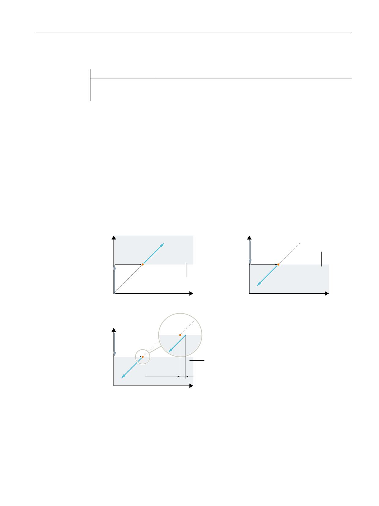
-"% 0/ BOE TZODISPOPVT XJUI '" QPTJUJPO
-"% JT POMZ TXJUDIFE PO XIFO UIF -" JT XJUIJO UIF UBCMF SBOHF PG UIF '"
-"
-"
5BCMF SBOHF
5SBWFSTJOH
EJSFDUJPO
-"% 0/
-"% 0/
5SBWFSTJOH EJSFDUJPO
5BCMF SBOHF
'"
'"
0WFSSJEF GPMMPXJOH -"% 0/ XJUI IBOEXIFFM %3'
-"
-"% 0/
*O UIF DPVQMFE TUBUF UIF GPMMPXJOH BYJT DBO CF
PWFSMBJE XJUI "650 %3' NPEF
5BCMF SBOHF
0WFSSJEF
'"
Figure 14-6
Activating master value coupling
Switch off
An axis master value coupling is deactivated with the model language command LEADOF.
Axes and spindles
Function Manual, 10/2020, 6FC5397-4GP40-0BA1
575

Axis couplings
14.3 Master value coupling
When the axis master value coupling is deactivated, the following axis becomes the command
axis and a stop command is generated implicitly for the following axis. The stop command can
be overwritten by another command with a synchronous action.
Syntax:
LEADON(<FA>,<LA>)
Meaning:
<FA>
Following axis as geometry-, channel- or machine axis name (X, Y, Z,...)
<LA>
Leading axis as geometry-, channel- or machine axis name (X, Y, Z,...)
Software axis is also possible:
MD30130 $MA_CTRLOUT_TYPE=0 (setpoint output type)
Example:
Program code
Comment
LEADOF(Y,X,1)
;Switching off of master value coupling between the leading ax-
is X and the following axis Y.
Note
Activating / deactivating the axis master value coupling with LEADON / LEADOF is permissible
both in the part program and in synchronous actions.
Further information
Function Manual Synchronized Actions
Coupling type
The coupling type is defined by the following axis-specific setting data:
SD43100 $SA_LEAD_TYPE[<LA>] (type of master value)
<LA>: Leading axis as geometry axis name, channel axis name or machine axis name (X, Y, Z,...)
Value
Meaning
0
Actual value coupling (this type of coupling must be used for external leading axes)
1
Setpoint coupling (default setting)
2
Simulated master value (note virtual axis, not evaluated for FA)
Switch-over between actual and setpoint value coupling is possible at any time (preferably in the
idle phase).
Axes and spindles
576
Function Manual, 10/2020, 6FC5397-4GP40-0BA1
Axis couplings
14.3 Master value coupling
System variables of the master value
The following master value system variables can only be read from part program and from
synchronous actions:
System variable
Meaning
$AA_LEAD_V[ax]
Velocity of the leading axis
$AA_LEAD_P[ax]
Position of the leading axis
$AA_LEAD_P_TURN
Master value position
Portion that is deducted during modulo reaction.
The actual (not modulo-reduced) position of the leading axis is:
$AA_LEAD_P_TURN + $AA_LEAD_P
The speeds and positions of simulated master values (when $SA_LEAD_TYPE[ax]=2) can be
written in and read from the part program and synchronous actions.
System variable
Meaning
$AA_LEAD_SV[ax]
Simulated master value velocity per IPO cycle
$AA_LEAD_SP[ax]
Simulated position in MCS
System variables of the following axis
For the following axis, the following system variables can be read in the part program and
synchronized action:
System variable
Meaning
$AA_SYNC[ax]
Condition of the coupling between following and leading axes
Value
Meaning
0
not synchronized
1
"Coarse synchronous operation" 1)
2
"Fine synchronous operation" 2)
3
"Coarse synchronous operation" 1) AND "Fine synchronous opera-
tion" 2)
Corresponds to:
1)
• MD37200 $MA_COUPLE_POS_TOL_COARSE
• DB31, ... DBX98.1 (coarse synchronous operation)
2)
• MD37210 $MA_COUPLE_POS_TOL_FINE
• DB31, ... DBX98.0 (fine synchronous operation)
$AA_IN_SYNC[ax]
Condition of the synchronization between following and leading axes
Value
Meaning
0
Synchronization not started or ended.
1
Synchronization is running, i. e., the following axis is synchronized.
$AA_IN_SYNC[ax] corresponds to the NC/PLC interface signal:
DB31, ... DBX99.4 (synchronization running)
Axes and spindles
Function Manual, 10/2020, 6FC5397-4GP40-0BA1
577
Axis couplings
14.3 Master value coupling
Note
If the following axis is not enabled for travel, it is stopped and is no longer synchronous.
14.3.4
Behavior in AUTOMATIC, MDA and JOG modes
Effectiveness
A master value coupling is active depending on the settings in the part program and in the
following machine data:
MD20110 $MC_RESET_MODE_MASK (definition of initial control settings after RESET / TP End)
MD20112 $MC_START_MODE_MASK (definition of initial control system settings with NC-
START)
Manual mode
Once a master axis coupling has been activated, traversal of the master axis (e.g. with rapid
traverse or incremental dimension INC1 ... INC10000) results in a movement of the slave axis,
allowing for the curve table definition.
Referencing
A master value coupled-following axis should be referenced prior to activation of the coupling.
A following axis cannot be referenced when the coupling is activated.
Deletion of distance-to-go
When deletion of distance-to-go is performed for a leading axis, all axes in the associated,
activated master value coupling are shut down.
Basic setting after POWER ON
No master value couplings are active after POWER ON. (Options with ASUB).
Behavior after NC start/RESET
The following behavior results, depending on the settings of the machine data:
MD20110 $MC_RESET_MODE_MASK (bit 13) (definition of initial control settings after RESET /
TP End)
Axes and spindles
578
Function Manual, 10/2020, 6FC5397-4GP40-0BA1
Axis couplings
14.3 Master value coupling
MD20112 $MC_START_MODE_MASK (bit 13) (definition of initial control system settings with
NC-START)
• MD20110 $MC_RESET_MODE_MASK=2001H
&&
MD20112 $MC_START_MODE_MASK=0H
→ Master value coupling remains valid after RESET and START
• MD20110 $MC_RESET_MODE_MASK=2001H
&&
MD20112 $MC_START_MODE_MASK=2000H
→ Master value coupling remains valid after RESET and is canceled with START. However,
master value coupling activated via IDS=... remains valid.
• MD20110 $MC_RESET_MODE_MASK=1H
→ Master value coupling is canceled with RESET irrespective of machine data:
MD20112 $MC_START_MODE_MASK
Master value coupling activated via IDS=... can only be deactivated via an operator front
panel reset and remains valid after program end/reset (M30, M02).
• MD20110 $MC_RESET_MODE_MASK=0H
→ Master value coupling remains valid after RESET and is canceled with START, irrespective
of machine data:
MD20112 $MC_START_MODE_MASK
However, master value coupling activated via IDS=... remains valid.
Further information
Function Manual Basic Functions; Coordinate systems, axis types, axis configurations, ...
Activating, deactivating
Master value couplings activated via a static synchronous action (IDS=...) are:
• not deactivated during program start, regardless of the value of machine data:
MD20110 $MC_RESET_MODE_MASK (definition of initial control settings after RESET / TP
End)
and
MD20112 $MC_START_MODE_MASK (definition of initial control system settings with NC-
START)
• not deactivated during program end reset (M30, M02), regardless of the value of machine
data:
MD20110 $MC_RESET_MODE_MASK
Axes and spindles
Function Manual, 10/2020, 6FC5397-4GP40-0BA1
579
Axis couplings
14.3 Master value coupling
14.3.5
Effectiveness of PLC interface signals
Leading axis
When a coupled axis group is active, the interface signals (IS) of the leading axis are applied to
the appropriate following axis via axis coupling. i.e.:
• a feed control action of the leading axis is applied via the master value coupling to effect an
appropriate feed control action in the following axis.
• shutdown of the leading axis as the result of an IS (e.g. axis-specific feed stop, axis inhibit,
servo enable, etc.) causes the corresponding coupled motion axis to shut down.
Position measuring system 1/2 (DB31, ... DBX1.5/1.6))
Switch-over of the position measuring system for the leading and following axes is not inhibited
for an active coupled axis group. The coupling is not canceled.
Recommendation: Switch the measuring system over when the coupling is deactivated.
14.3.6
Special characteristics of the axis master value coupling function
Control dynamics
Depending on the application in question, it may be advisable to match the position controller
parameter settings (e.g. servo gain factor (KVfactor)) of the leading axis and following axis in an
axis grouping. It may be necessary to activate other parameter sets for the following axis. The
dynamics of the following axis should be the same or better than those of the leading axis.
Status of coupling
See Chapter "Status of coupling (Page 544)"
Actual value display
The display of the actual value is updated for all axes of in a master value coupled axis grouping
(only real axes) coupled via a master value.
Interpolation
When the movement defined in the curve table is interpolated, axis position and axis speed are
calculated for a master value and its speed.
Logging
The curve tables generated by the definition of motion sequences are stored in the battery-
backed memory.
Axes and spindles
580
Function Manual, 10/2020, 6FC5397-4GP40-0BA1
Axis couplings
14.4 Electronic gear (EG)
The curve tables are not lost when the control system is switched off.
These functions have no effect on cyclic machines because they are performed without operator
actions. Nor does it make sense to perform automatic (re-)positioning via the NC with external
master values.
14.3.7
Supplementary conditions
External master value axes
When using the REPOS or REPOSA parts program instructions in conjunction with external
master value axes, it should be ensured that these are released by the channel or switched to a
"neutral state" using the RELEASE instruction.
When attempting to reposition without release of the axis, the message "Wait: Feed stop active"
is displayed and the processing of the part program is not continued.
14.4
Electronic gear (EG)
14.4.1
Product brief
14.4.1.1
Function
General
The "electronic gear" function makes it possible to control the movement of a following axis,
depending on up to five master axes. The relationship between each leading axis and the
following axis is defined by the coupling factor. Following axis motion components derived from
the individual leading axis motion components have an additive effect.
The coupling can be based on:
• Actual value of the leading axis
• Setpoint of the leading axis
The following functions of a gear grouping can be programmed using part program instructions:
• Defining
• Switch on
• Switch off
• Delete
Axes and spindles
Function Manual, 10/2020, 6FC5397-4GP40-0BA1
581
Axis couplings
14.4 Electronic gear (EG)
Curve tables
Non-linear relationships between lead and following axes can also be implemented using curve
tables.
Cascading
Electronic gearboxes can be cascaded, i.e. the following axis of an electronic gearbox can be the
leading axis for a subsequent electronic gearbox.
Synchronous position
An additional function for synchronizing the following axis allows a synchronous position to be
selected:
• Approach next division (tooth gap) time-optimized
• Approach next division (tooth gap) path-optimized
• Approach in positive direction of axis rotation, absolute
• Approach in negative direction of axis rotation, absolute
• Traverse time-optimized with respect to programmed synchronized position
• Traverse path-optimized with respect to programmed synchronized position
Application Examples:
• Machine tools for gear cutting
• Gear trains for production machines
14.4.1.2
Preconditions
The "Electronic Gearbox" option or the relevant option of generic coupling (refer to
" Preconditions (Page 609) " in the "Brief description" of Generic Coupling) is required for the
usage of function.
14.4.2
Electronic gear (EG)
Function
With the aid of the "Electronic gearbox" the movement of a following axis FA can be
interpolated dependent of up to five leading axes LA. The relationship between each leading
axis and the following axis is defined by a coupling factor. The following axis motion components
derived in this manner from the individual leading axis motion components have an additive
effect.
FAset = SynPosFA + (LA1-SynPosLA1)*CF1 +... +(LA5-SynPosLA5)*CF5
With:
SynPosFA, SynPosLAi: from call EGONSYN (see below)
Axes and spindles
582
Function Manual, 10/2020, 6FC5397-4GP40-0BA1
Axis couplings
14.4 Electronic gear (EG)
FA
setpoint
: Partial setpoint of the following axis
LAi: Setpoint or actual value of the ith leading axis (depending on the type of coupling - see
below)
KFi: Coupling factor of the ith leading axis (see below)
All paths are referred to the basic co-ordinate system BCS.
When an EG axis group is activated, it is possible to synchronize the leading axes and following
axis in relation to a defined starting position.
From the part program a gearbox group can be:
• defined,
• activated,
• deactivated,
• deleted.
Extensions
The influence of each of the 5 leading axes can be specified using a curve table as an alternative
to a transmission ratio (KF=numerator/denominator).
It is thus possible for each curve (except for the special case of a straight line) for the leading axis
to influence the following axis in a non-linear manner. The function can only be used with
EGONSYN.
The function EG can be activated with curve tables with EGON.
The function EGONSYNE is available for approaching the synchronized position of the following
axis with a specified approach mode.
For special applications, it may be advisable configure the position controller as a PI controller.
CAUTION
Application faults
Knowledge of the control technology and measurements with servo trace are an absolute
prerequisite for using this function.
Further information
• CNC Commissioning Manual: NC, PLC, drive
• Velocities, setpoint/actual value systems, closed-loop control (Page 135)
Coupling type
The following axis motion can be derived from either of the following:
• Setpoints of leading axes
• Actual values of leading axes
The reference is set in the definition call for the EG axis group:
Axes and spindles
Function Manual, 10/2020, 6FC5397-4GP40-0BA1
583
Axis couplings
14.4 Electronic gear (EG)
EGDEF
(see Section "Definition of an EG axis group (Page 590)")
Coupling factor
The coupling factor must be programmed for each leading axis in the group. It is defined by
numerator/denominator.
Coupling factor values numerator and denominator are entered per leading axis with the
following activation calls:
EGON
EGONSYN
EGONSYNE
(see Section "Activating an EG axis group (Page 591)")
Number of EG axis groups
Several EG axis groups can be defined at the same time. The maximum possible number of EG
axis groupings is set in the following machine data:
MD11660 $MN_NUM_EG
The maximum permissible number of EG axis groups is 31.
Note
The option must be enabled.
Axes and spindles
584
Function Manual, 10/2020, 6FC5397-4GP40-0BA1
Axis couplings
14.4 Electronic gear (EG)
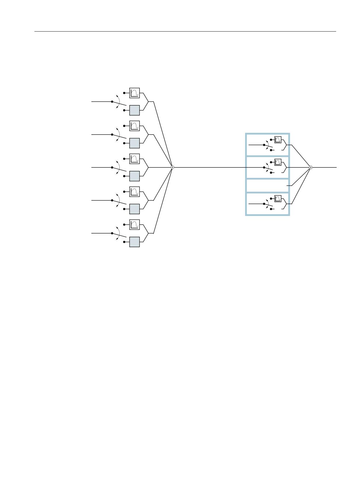
EG cascading
The following axis of an EG can be the leading axis of another EG. For a sample configuration
file, see Section "Examples".
-"
;
/
$BTDBEJOH BMTP QPTTJCMF
-"
;
-",
/
;/
-"
4PGUXBSF BYJT
-",
;
;/
/
ॱ
-"
-",
;
;/
/
-"
;
/
Figure 14-7
Block diagram of an electronic gearbox
Synchronous positions
To start up the EG axis group, an approach to defined positions for the following axis can first be
requested.
Synchronous positions are specified with:
EGONSYN (see below for details)
EGONSYNE (extended EGONSYN call)
Synchronization
If a gear is started with EGON(), EGONSYN() or EGONSYNE() see below, the actual position of the
following axis is only identical to the setpoint position defined by the rule of motion of the gear
specified by the positions of the leading axes at this time if the part program developer makes
sure that it is. The control then uses the motion of the following axis to ensure that the setpoint
and actual positions of the following axes correspond as quickly as possible if the leading axes
are moved further. This procedure is called synchronization. After synchronization of the
following axis, the term synchronous gearing is used.
Axes and spindles
Function Manual, 10/2020, 6FC5397-4GP40-0BA1
585
Axis couplings
14.4 Electronic gear (EG)
Activation response
An electronic gearbox can be activated in two different ways:
1. On the basis of the axis positions that have been reached up to now in the course of
processing the command to activate the EG axis group is issued without specifying the
synchronizing positions for each individual axis.
EGON (see Section "Activating an EG axis group (Page 591)")
2. The command to activate the EG axis group specifies the synchronized positions for each axis.
From the point in time when these positions are reached, the EG should be synchronized.
EGONSYN (see Section "Activating an EG axis group (Page 591)")
3. The command to activate the EG axis group specifies the synchronized positions and
approach mode for each axis. From the point in time when these positions are reached, the
EG should be synchronized.
EGONSYNE (see Section "Activating an EG axis group (Page 591)")
Synchronization with EGON
With EGON(), no specifications are made for the positions at which the following axis is to be
synchronized. The control system activates the EG and issues the signal "Synchronized position
reached".
Synchronization for EGONSYN
1. With EGONSYN(), the positions of the leading axes and the synchronization position for the
following axis are specified by the command.
• The control then traverses the following axis with just the right acceleration and velocity to
the specified synchronization position so that the following axis is in position with the leading
axes at its synchronization position.
• If the following axis is stationary: If the "Feed stop/spindle stop" DB 31, ... DBX 4.3 is set for
the following axis, the following axis is not set in motion by EGON or EGONSYN. A traverse
command is issued and block changing is blocked until the axis-specific feed is enabled.
EGOSYN is topped by RESET transformed into EGON. The programmed synchronized
positions are deleted.
• If the following axis is not stationary: The NST "Feed Stop/Spindle Stop" DB31, ... DBX4.3 has
no direct influence on the electronic gearbox. As before, it does have an indirect effect on the
leading axes, if these are located in the same channel.
• For channel specific feed enabling and for override nothing is implemented. Override still
has no direct influence on the electronic gearbox. The axis-specific feed enable is set,
depending on the current override setting.
Synchronization for EGONSYNE
With EGONSYN(), the positions of the leading axes and the synchronization position for the
following axis are specified by the command.
The control system moves the following axis to the synchronized position according to the
program approach mode.
Axes and spindles
586
Function Manual, 10/2020, 6FC5397-4GP40-0BA1
Axis couplings
14.4 Electronic gear (EG)
Synchronization abort with EGONSYN and EGONSYNE
1. The EGONSYN/EGONSYNE command is aborted under the following conditions and changed
to an EGON command:
• RESET
• Axis switches to tracking
The defined synchronization positions are ignored. Synchronous traverse monitoring still takes
synchronized positions into account.
Aborting position synchronization generates alarm 16774.
The alarm may be suppressed with the following machine data:
MD11410 $MN_SUPPRESS_ALARM_MASK Bit31 = 1
Synchronous monitoring
The synchronism of the gearbox is monitored in each interpolator clock cycle on the basis of the
actual values of the following and leading axes. For this purpose, the actual values of the axes
are computed according to the rule of motion of the coupling. The synchronism difference is
the difference between the actual value of the following axis and the value calculated from the
leading axis actual values according to the rule of motion. The synchronism difference can be
queried from the part program (see below).
Changes in the synchronism difference
The mass inertia of the axis systems during acceleration can cause dynamic fluctuations in the
synchronism difference. The synchronism difference is checked continuously and the tolerance
values in the machine data used to produce interface signals.
The synchronism difference is compared with the following machine data:
MD37200 $MA_COUPLE_POS_TOL_COARSE
MD37210 $MA_COUPLE_POS_TOL_FINE
Depending on the result of this comparison, the following signals are set:
NST "Synchronous travel fine" DB31, ... DBX98.0
NST "synchronous traverse coarse" DB31, ... DBX98.1
Difference > .. TOL_COARSE
As long as the synchronism difference is greater than the following machine data, the gearbox
is not synchronized and neither IS "Coarse synchronism" DB 31, ... DBX 98.1 nor IS "Fine
synchronism" DB 31, ... DBX 98.0 is active:
MD37200 $MN_COUPLE_POS_TOL_COARSE
Instead, the following interface signal is displayed:
NST "synchronization running" DB31, ... DBX99.4
Axes and spindles
Function Manual, 10/2020, 6FC5397-4GP40-0BA1
587
Axis couplings
14.4 Electronic gear (EG)
Difference < .. TOL_COARSE
As long as the synchronism difference is smaller than the following machine data, IS "Coarse
synchronism" DB 31, ... DBX 98.1 is at the interface and IS "Synchronism running" DB31, ...
DBX99.4 is deleted:
MD37200 $MN_COUPLE_POS_TOL_COARSE
Difference > .. TOL_FINE
If the synchronism difference is smaller than the following machine data, then NST
"synchronous traverse fine" DB31, ... DBX98.0 is at the interface:
MD37210 $MA COUPLE_POS_TOL_FINE
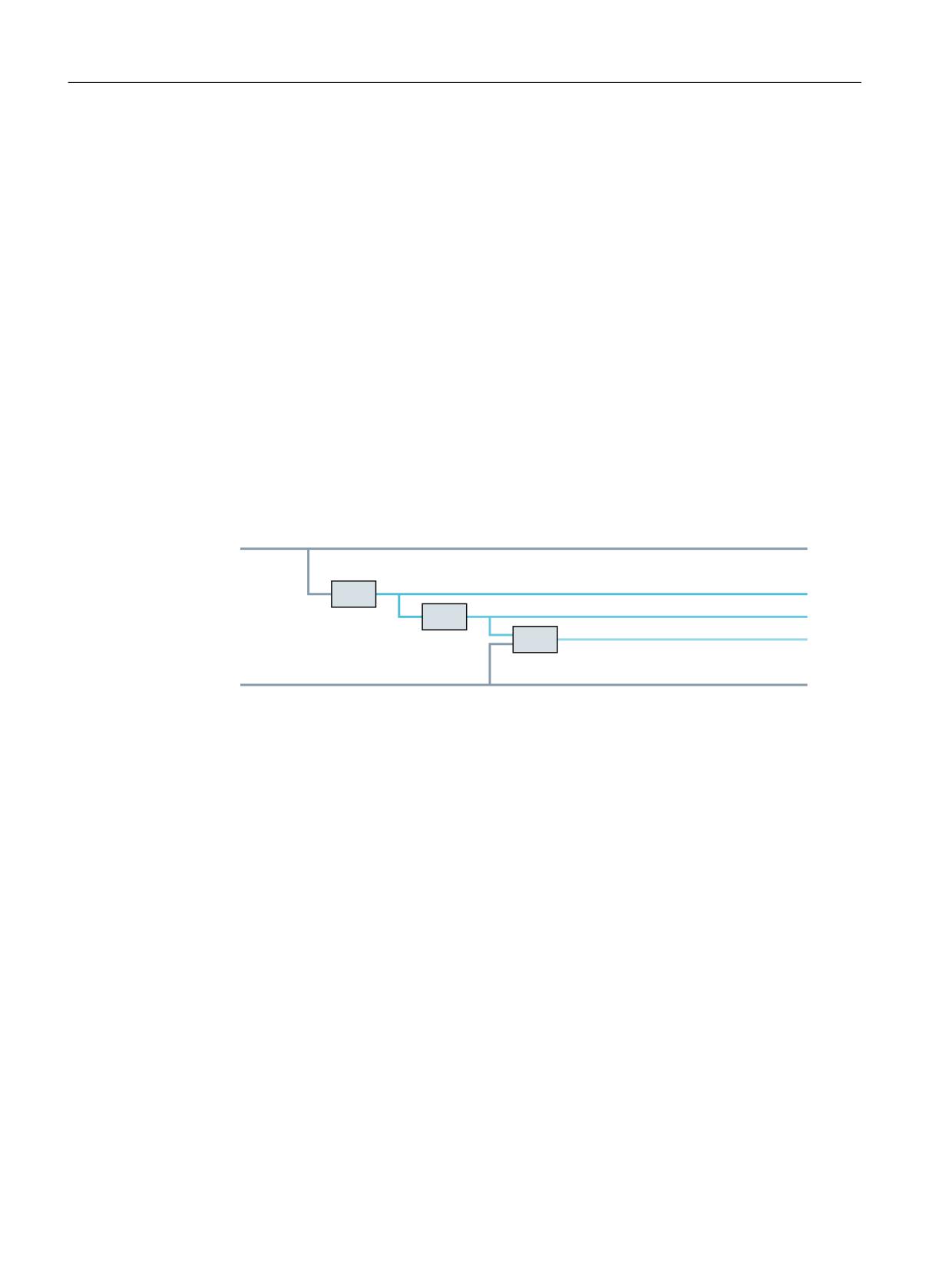
Synchronism difference for EG cascades
Synchronism difference for EG cascades is the deviation of the actual position of the following
axis from setpoint position that results for the rule of motion for the real axes involved.
Example:
-"
-"
&(
'"
&(
'"
&(
'"
-"
-"
-"J ࠞ SFBM MFBEJOH BYJT
'"J ࠞ GPMMPXJOH BYJT GSPN &(J
Figure 14-8
Three-level EG cascade
According to the definition given, the synchronism difference of following axis FA3 in the
example below is determined by the value of following axis FA3Act and the value of leading axis
FA2Act and LA2Act, but not by LA1Act and FA1Act.
If FA2 is not a real axis, the actual value FA2Act is not available. In this case, the setpoint of the
axis derived solely from the leading axis value FA1Act must be used instead of the actual value of
the setpoint of the axis.
Other signals
If an EGON(), EGONSYN() or EGONSYNE() block is encountered in the main run, the signal
"Coupling active" is set for the following axis. If the following axis is only overlaid, the signals
"Coupling active" and "Axis override" are set. If EGON(), EGONSYN() or EGONSYNE() is active and
the following axis is also overlaid, the signals "Coupling active" and "Axis override" are also set.
IS "following spindle active" DB31, ... DBX 99.1: Coupling active,
IS "overlaid movement" DB31, ... DBX98.4: axis is overlaid,
IS "Enable following axis override" DB31, ... DBX26.4
Axes and spindles
588
Function Manual, 10/2020, 6FC5397-4GP40-0BA1
Axis couplings
14.4 Electronic gear (EG)
In the case of the commands EGON() and EGONSYNE(), the "Enable following axis override"
signal must be present for the gear to synchronize to the specified synchronization position for
the following axis. If it is not present, alarm 16771 "Override movement not enabled" is issued.
If the signal is present, the following axis travels to the synchronized position with the calculated
acceleration and at the velocity set for the approach mode.
Further monitoring signals
Machine data MD37550 $MA_EG_VEL_WARNING allows a percentage of the speeds and
accelerations to be specified in the following machine data MD32000 $MA_MAX_AX_VELO and
MD32300 $MA_MAX_AX_ACCEL, with reference to the following axis, which results in the
generation of the following interface signals:
IS "Speed warning threshold" DB31, ... DBX98.5
IS "Acceleration warning threshold" DB31, ... DBX98.6
The monitoring signals can be used as trigger criteria for emergency retraction (see Section
"Trigger sources (Page 904)").
Machine data MD37560 $MA_EG_ACC_TOL allows a percentage with reference to machine data
MD32300 $MA_MAX_AX_ACCEL of the following axis to be defined, and the IS signal "axis
accelerates" DB31, ... DBX99.3 to be generated.
Request synchronism difference
1. The result of the synchronism difference calculation can be read as an amount in the part
program with system variable $VA_EG_SYNCDIFF. The relevant value with sign is available in
the system variables $VA_EG_SYNCDIFF_S. The following meanings apply:
• Negative value (in positive traverse direction for lead and following axis): The following axis
lags behind its calculated setpoint position.
• Positive value (in positive traverse direction for lead and following axis): The following axis
leads before its calculated setpoint position (overswing).
The amount of the synchronism difference with sign corresponds to the system variables
without sign from $VA_EG_SYNCDIFF.
$VA_EG_SYNCDIFF[ax] = ABS($VA_EG_SYNCDIFF_S[ax])
Block change mode
1. When an EG axis group is activated, it is possible to specify the conditions under which a part
program block change is to be executed:
2. The specification is made with a string parameter with the following meaning:
3. "NOC": Immediate block change
4. "FINE": Block change if "Fine synchronism" is present
5. "COARSE": Block change if "Coarse synchronism" is present
6. "IPOSTOP": Block change if "Setpoint synchronism" is present
Axes and spindles
Function Manual, 10/2020, 6FC5397-4GP40-0BA1
589
Axis couplings
14.4 Electronic gear (EG)
Note
When programmed in activation calls EGON, EGONSYN, EGONSYNE, each of the above strings
can be abbreviated to the first two characters.
If no block change has been defined for the EG axis group and none is currently specified, "FINE"
applies.
14.4.3
Definition of an EG axis group
Note
The following definition commands and switch instructions of the electronic gearbox must all be
contained in only one block of a parts program.
All commands of the electronic gearbox result in a preprocessing stop, except for the activation
commands:
• EGON
• EGONSYN
• EGONSYNE
Definition and activation
The definition described below and activation are separate processes. An activation is not
possible unless it has been defined previously.
Definition of an EG axis group
An EG axis group is defined through the input of the following axis and at least one, but not more
than five, leading axis, each with the relevant coupling type:
EGDEF(following axis, leading axis1, coupling type1, leading axis2, coupling type 2,...)
The coupling type does not need to be the same for all leading axes and must be programmed
separately for each individual leading axis.
Coupling type:
Evaluate actual value of leading axis: 0
Evaluate setpoint of leading axis: 1
The coupling factors are preset to zero when the EG axis group is defined. As such, the group has
no effect on the following axis until it is activated. (See EGON, EGONSYN, EGONSYNE).
Preconditions for defining an EG axis group:
No existing axis coupling may already be defined for the following axis. (If necessary, an existing
axis must be deleted with EGDEL.)
EGDEF triggers preprocessing stop with alarm.
Axes and spindles
590
Function Manual, 10/2020, 6FC5397-4GP40-0BA1
Axis couplings
14.4 Electronic gear (EG)
For an example of how to use the EG gearbox for gear hobbing, please see Chapter "Examples",
"Electronic Gearbox for Gear Hobbing".
EGDEF
The gearbox definition with EGDEF should also be used unaltered when one or more leading
axes affect the following axis via a curve table.
The variant extended with the addition of non-linear coupling via curve tables is illustrated in an
extended example in Chapter "Extended Example with non-linear Components".
14.4.4
Activating an EG axis group
Without synchronization
The EG axis group is activated without synchronization selection with:
EGON(FA, block change mode, LA1, Z1, N1, LA2 , Z2, N2,..LA5, Z5, N5.)
The coupling is activated immediately.
With:
FA: Following axis
Depending on block change mode, the next block will be activated:
"NOC": Block change takes place immediately
"FINE": Block change is performed in "Fine synchronism"
"COARSE": Block change is performed in "Coarse synchronism"
"IPOSTOP": Block change is performed for setpoint-based synchronism
LAi: Axis name of the leading axis i
Zi: Counter for coupling factor of leading axis i
Ni: Denominator for coupling factor of leading axis i
Only the leading axes previously specified with the EGDEF command may be programmed in the
activation line. At least one leading axis must be programmed.
The positions of the leading axes and following axis at the instant the grouping is switched on
are stored as "Synchronized positions". The "Synchronized positions" can be read with the system
variable $AA_EG_SYN.
With synchronization
The EG axis group is activated with synchronization selective:
1. EGONSYN
EGONSYN(FA, block change mode, SynPosFA, LAi, SynPosLAi, Z_LAi, N_LAi)
Axes and spindles
Function Manual, 10/2020, 6FC5397-4GP40-0BA1
591
Axis couplings
14.4 Electronic gear (EG)
With:
FA: Following axis
Block change mode:
"NOC": Block change takes place immediately
"FINE": Block change is performed in "Fine synchronism"
"COARSE": Block change is performed in "Coarse synchronism"
"IPOSTOP": Block change is performed for setpoint-based synchronism
SynPosFA: Synchronized position of the following axis
LAi: Axis name of the leading axis i
SynPosLAi: Synchronized position of leading axis i
Zi: Counter for coupling factor of leading axis i
Ni: Denominator for coupling factor of leading axis i
Note
The parameters indexed with i must be programmed for at least one leading axis, but for no
more than five.
Only leading axes previously specified with the EGDEF command may be programmed in the
activation line.
Through the programmed "Synchronized positions" for the following axis (SynPosFA) and for the
leading axes (SynPosLA), positions are defined for which the axis grouping is interpreted as
synchronous. If the electronic gear is not in the synchronized state when the grouping is
switched on, the following axis traverses to its defined synchronized position.
The position specification of the synchronized positions is specified in the configured basic
system independently of the programmable dimensions (G70/G71).
If the axis grouping includes modulo axes, their position values are reduced in the modulo, This
way the fastest possible synchronized position is approached reliably, e. g., the next tooth from
the tooth spacing (360 degree* Zn/Ni) and the associated synchronized positions.
(So-called relative synchronization.)
thereby ensuring that they approach the fastest possible synchronized position. (So-called
relative synchronization, e.g. the next tooth gap after "centering".)
If the following interface signal has not been set for the following axis, the axis will not travel to
the synchronization position.
DB31, ... DBX26.4 (Enable following axis override)
Instead the program is stopped at the EGONSYN block and the self-clearing alarm 16771 is
issued until the above mentioned signal is set.
2. EGONSYNE
EGONSYNE(FA, block change mode, SynPosFA, Approach mode, LAi,SynPosLAi, Z_LAi, N_LAi)
with:
Axes and spindles
592
Function Manual, 10/2020, 6FC5397-4GP40-0BA1
Axis couplings
14.4 Electronic gear (EG)
"FA": Following axis
Block change mode:
"NOC": Block change takes place immediately
"FINE": Block change is performed in "Fine synchronism"
"COARSE": Block change is performed in "Coarse synchronism"
"IPOSTOP": Block change is performed for setpoint-based synchronism
SynPosFA: Synchronized position of the following axis
Approach mode:
"NTGT": NextToothGapTime-optimized, the next tooth gap is approached time-optimized
(preset is used if no setting is applied).
"NTGP": The next tooth gap is approached time-optimized.
"ACN": AbsoluteCoordinateNegative, Absolute measurement specification, rotary axis traverses
in negative rotation direction
"ACP": AbsoluteCoordinatePositive, Absolute measurement specification, rotary axis traverses in
positive rotation direction
"DCT": DirectCoordinateTime-optimized, Absolute measurement specification, rotary axis
traverses time-optimized to programmed synchronized position
"DCP": DirectCoordinatePath-optimized, Absolute measurement specification, rotary axis
traverses path-optimized to programmed synchronized position
LAi: Axis name of the leading axis i
SynPosLAi: Synchronized position of leading axis i
Zi: Counter for coupling factor of leading axis i
Ni: Denominator for coupling factor of leading axis i
Note
The parameters indexed with i must be programmed for at least one leading axis, but for no
more than five.
The function is active only for modulo following axes that are coupled to modulo leading axes.
Tooth gap
The tooth gap is defined as 360 degrees * Zi / Ni
Example:
EGONSYNE(A, "FINE", FASysPos, "Traversing mode", B, LASynPos, 2, 10)
Tooth gap: 360*2/10 = 72 (degrees)
Approach response with FA at standstill
In this case, the time-optimized and path-optimized traversing modes are identical.
Axes and spindles
Function Manual, 10/2020, 6FC5397-4GP40-0BA1
593
Axis couplings
14.4 Electronic gear (EG)
The table below shows the target positions and traversed paths with direction marker (in
brackets) for the particular approach modes:
Programmed
Position of the fol-
Traversing
Traversing mode
Traversing mode
Traversing mode
synchronized posi-
lowing axis be-
mode NTGT/
DCT/DCP
ACP
ACN
tion FaSysPos
fore EGONSYNE
NTGP
110
150
182 (+32)
110 (-40)
110 (+320)
110 (-40)
110
350
326 (-24)
110 (+120)
110 (+120)
110 (-240)
130
0
346 (-14)
130 (+130)
130 (+130)
130 (-230)
130
30
58 (+28)
130 (+100)
130 (+100)
130 (-260)
130
190
202 (+12)
130 (-60)
130 (+300)
130 (-60)
190
0
334 (-26)
190 (-170)
190 (+190)
190 (-170)
230
0
14 (+14)
230 (-130)
230 (+230)
230 (-130)
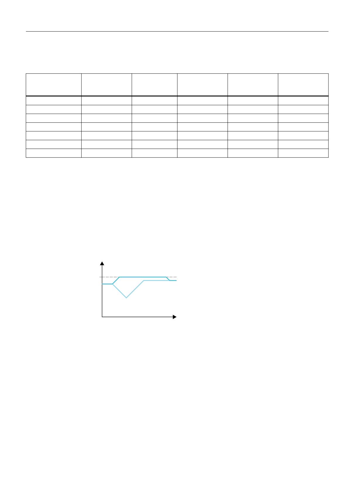
Approach response for moving FA
The following axis moves at almost maximum velocity in the positive direction when the
coupling is activated by EGONSYNE. The programmed synchronized position of the following
axis is 110, the current position 150. This produces the two alternative synchronized positions
110 and 182 (see table above).
In the case of traversing mode NTGP (path-optimized), synchronized position 182 is selected
independent of the current velocity. This has the shortest distance from the current position of
the following axis. Traversing mode NTGT (time-optimized) considers the current speed of the
following axis and produces a deceleration on account of the limit for the maximum axis speed
to reach synchronism in the shortest possible time (see Figure).
W
/5(1
WNBY
/5(5
U
Figure 14-9
Reaching the next tooth gap, FA path-optimized (top) vs. time-optimized (bottom)
Sample notations
EGONSYNE(A, "FINE", 110, "NTGT", B, 0, 2, 10)
couple A to B, synchronized position A = 110, B = 0, coupling factor 2/10, approach mode = NTGT
EGONSYNE(A, "FINE", 110, "DCT", B, 0, 2, 10)
couple A to B, synchronized position A = 110, B = 0, coupling factor 2/10, approach mode = DCT
EGONSYNE(A, "FINE", 110, "NTGT", B, 0, 2, 10, Y, 15, 1, 3)
couple A to B, synchronized position A = 110, B = 0, Y = 15,
Coupling factor to B = 2/10, Coupling factor to Y = 1/3,
Axes and spindles
594
Function Manual, 10/2020, 6FC5397-4GP40-0BA1
Axis couplings
14.4 Electronic gear (EG)
approach mode = NTGT
With synchronization
The syntax specified above applies with the following different meanings:
If a curve table is used for a leading axis, then the denominator of the linear coupling of the
coupling factor (Ni) must be set to 0 (denominator 0 would be impermissible for linear
couplings).
For control, denominator zero is the indicator that the counter of the coupling factor (Zi) is to be
interpreted as the number of the curve table to be used. The curve table with the specified
number must already be defined at power on (in accordance with Chapter "Curve Tables").
The leading axis specified (LAi) corresponds to the one specified for coupling via coupling factor
(linear coupling).
14.4.5
Deactivating an EG axis group
Variant 1
There are different ways to deactivate an active EG axis grouping.
EGOFS(following axis)
The electronic gear is deactivated. The following axis is braked to a standstill. This call triggers
a preprocessing stop.
Variant 2
The following parameterization of the command makes it possible to selectively control the
influence of individual leading axes on the motion of the following axis.
EGOFS(following axis, leading axis 1, ... leading axis 5)
Note
At least one leading axis must be specified.
The influence of the specified leading axes on the slave is selectively inhibited. This call triggers
a preprocessing stop.
If the call still includes active leading axes, then the slave continues to operate under their
influence. If the influence of all leading axes is excluded by this method, then the following axis
is braked to a standstill.
If the command EGONSYN is deactivated selectively, no axis movement is performed.
Variant 3
EGOFC(following spindle)
Axes and spindles
Function Manual, 10/2020, 6FC5397-4GP40-0BA1
595

Axis couplings
14.4 Electronic gear (EG)
The electronic gear is deactivated. The following spindle continues to traverse at the speed/
velocity that applied at the instant of deactivation. This call triggers a preprocessing stop.
Note
Call for following spindles available. For EGOFC a spindle name must be programmed.
14.4.6
Deleting an EG axis group
An EG axis grouping must be switched off, as described in Chapter "Switching off a EG Axis
Group", before its definition can be deleted.
EGDEL(following axis)
The defined coupling of the axis grouping is deleted. Additional axis groups can be defined by
means of EGDEF until the maximum number of simultaneously activated axis groups is reached.
This call triggers a preprocessing stop.
14.4.7
Interaction between rotation feedrate (G95) and electronic gearbox
The FPR( ) part program command can be used to specify the following axis of an electronic gear
as the axis, which determines the rotational feedrate. Please note the following with respect to
this command:
• The feedrate is determined by the setpoint velocity of the following axis of the electronic gear.
• The setpoint velocity is calculated from the speeds of the leading spindles and modulo axes
(which are not path axes) and from their associated coupling factors.
• Velocity components from other leading axes and overlaid motion of the following axis are
not taken into account.
Further information
Feedrates (Page 195)
14.4.8
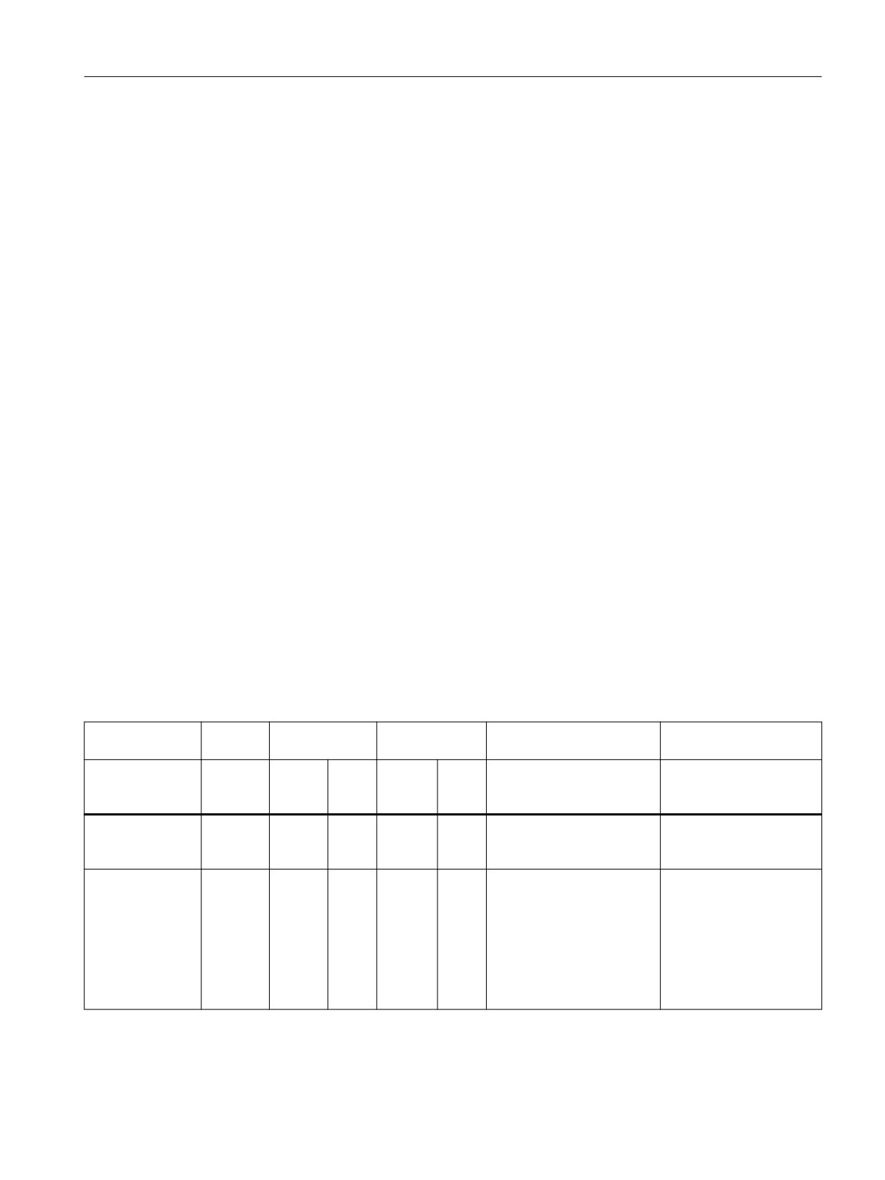
Response to POWER ON, RESET, operating mode change, block search
Function
Behavior regarding electronic gearbox
Coupling state
Configuration
Mode change
Is retained
Is retained
End of part program
Is retained
Is retained
Reset
Is retained
Is retained
Power On 1)
Is not retained
Is not retained
1) No coupling is active after Power On.
Axes and spindles
596
Function Manual, 10/2020, 6FC5397-4GP40-0BA1
Axis couplings
14.4 Electronic gear (EG)
Block search
A search while a coupling is active (EG) is possible under the following supplementary
conditions:
• Simulation is exclusively with setpoint coupling.
• No cross-channel leading axes may be disabled.
• Axis movements for which all real positions are known to the NC.
If it is technically not sensible or not possible to permit the target block for a block search with
calculation or SERUPRO within a part program section with active coupling, this section can be
locked for "continue machining at the contour".
Programming
• IPTRLOCK()
• IPTRUNLOCK()
Further information
Function Manual Basic Functions; Mode group, channel, program operation, reset response,
block search type 5 SERUPRO > Lock program section for continue machining at the contour
14.4.9
System variables for electronic gearbox
Application
The following system variables can be used in the part program to scan the current states of an
EG axis group and to initiate appropriate reactions if necessary:
Table 14-1
System variables, R means: Read access possible
Name
Type
Access
Preprocessing
Meaning, value
Cond. Index
stop
part
Sync
part
Sync
pro-
act.
pro-
act.
gram
gram
$AA_EG_
INT
R
R
Type of coupling:
Axis name
TYPE[a,b]
0: actual value
a: Following axis
1: Setpoint value coupling
b: Leading axis
$AA_EG_
REAL
R
R
Numerator of coupl. factor
Axis name
NUMERA[a,b]
KF
a: Following axis
KF = numerator/denomina-
b: Leading axis
tor
preset: 0
Number of curve table
when $AA_EG_DE-
NOM[a,b] is 0.
Axes and spindles
Function Manual, 10/2020, 6FC5397-4GP40-0BA1
597

Axis couplings
14.4 Electronic gear (EG)
Name
Type
Access
Preprocessing
Meaning, value
Cond. Index
stop
part
Sync
part
Sync
pro-
act.
pro-
act.
gram
gram
$AA_EG_
REAL
R
R
Denominator of coupl. fact.
Axis name
DENOM[a,b]
KF
a: Following axis
KF = numerator/denomina-
b: Leading axis
tor
preset: 1
Denominator must be posi-
tive.
Denominator is 0, if instead
of the numerator
$AA_EG_NUMERA[a,b] the
number of a curve table is
specified.
$AA_EG_
REAL
R
R
Synchronized position for
Axis name
SYN[a,b]
specified leading axis
a: Following axis
Default: 0
b: Leading axis
$AA_EG_
REAL
R
R
Synchronized position for
Axis name
SYNFA[a]
specified following axis
a: Following axis
Default: 0
$P_EG_BC[a]
STRING
R
R
Block change criterion for
Axis name
EG activation calls: EGON,
a: Following axis
EGONSYN:
"NOC": immediately
"FINE": Synchronoous tra-
verse fine
"COARSE": Synchronous tra-
verse coarse
"IPOSTOP": Setpoint-based
synchronism
$AA_EG_
INT
R
R
Number of leading axes de-
Axis name
NUM_LA[a]
fined with EGDEF. 0 if no ax-
a: Following axis
is has been defined as a fol-
lowing axis with EGDEF.
$AA_EG_
AXIS
R
R
Axis name of leading axis
Axis name
AX[n,a]
whose index n has been
n: Index of leading axis in
specified.
the EG coupling 0 ... 4
a: Following axis
$AA_EG_
BOOL
R
R
Determine power-on state
Axis name
ACTIVE[a,b]
of a leading axis:
a: Following axis
0: Switched off
b: Leading axis
1: activated
$VA_EG_
REAL
R
R
R
Actual value of synchronism
Axis name
SYNCDIFF[a]
difference. A comparison of
a: Following axis
machine data MD37200
$MA_COU-
PLE_POS_TOL_COARSE and
MD37210 $MA_COU-
PLE_POS_TOL_FINE produ-
ces interface signals.
Axes and spindles
598
Function Manual, 10/2020, 6FC5397-4GP40-0BA1
Axis couplings
14.4 Electronic gear (EG)
14.4.10
Examples
14.4.10.1
Example using linear couplings
Use of axes
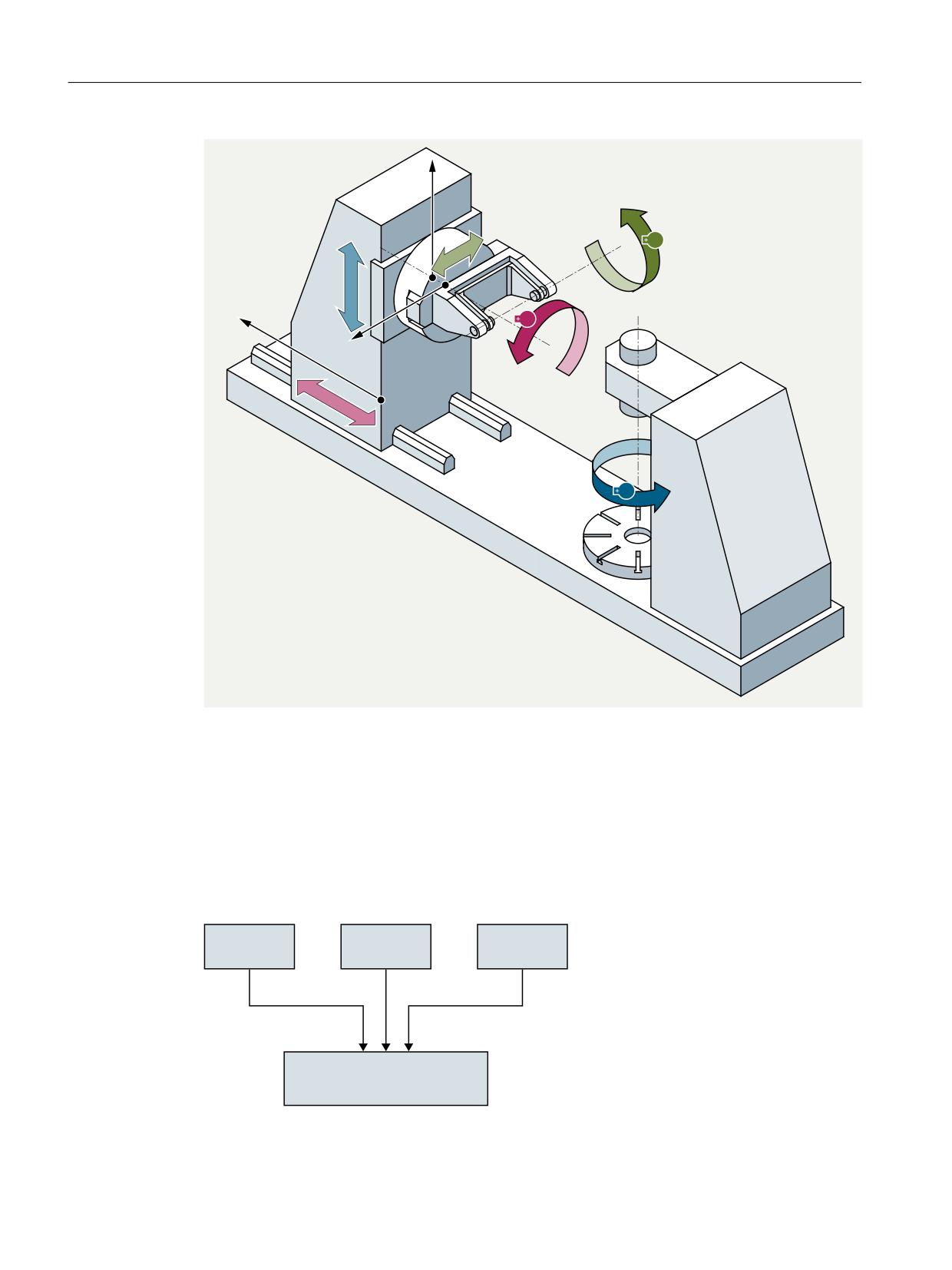
The following diagram shows the configuration of a typical gear hobbing machine. The machine
comprises five numerically closed loop controlled axes and an open loop controlled main
spindle. These are:
• The rotary motion of the workpiece table (C) and hobbing cutter (B)
• The axial axis (Z) for producing the feed motion over the entire workpiece width
• The tangential axis (Y) for moving the hobbing cutter along its axis
• The radial axis (X) for infeeding the cutter to depth of tooth
• The cutter swivel axis (A) for setting the hobbing cutter in relation to the workpiece as a
function of cutter lead angle and angle of inclination of tooth
Axes and spindles
Function Manual, 10/2020, 6FC5397-4GP40-0BA1
599
Axis couplings
14.4 Electronic gear (EG)
X
Radial axis
Y
Tangential axis (master drive 3)
Z
Axial axis (master drive 2)
A
Milling swivel axis
C
Workpiece rotational axis (slave drive)
B
Milling rotational axis, main spindle (master drive 1)
Figure 14-10
Definition of axes on a gear hobbing machine (example)
The functional interrelationships on the gear hobbing machine are as follows:
#
;
:
-"
-"
-"
3FWPMVUJPO PG
8JEUI PG
-POHJUVEJOBM BYJT
NJMMJOH UPPM
XPSLQJFDF
PG NJMMJOH UPPM
;
'"
8PSLQJFDF SPUBUJPOBM BYJT HFBS XIFFM
Axes and spindles
600
Function Manual, 10/2020, 6FC5397-4GP40-0BA1
Axis couplings
14.4 Electronic gear (EG)
In this case, the workpiece table axis (C) is the following axis which is influenced by three master
drives.
The setpoint of the following axis is calculated cyclically with the following logic equation:
nc = nb * (z0 / z2) + vz * (udz / z2) + vy * (udy / z2)
With: nc
= Rotational speed of workpiece axis (C)
nb
= Rotational speed of milling spindle (B)
z0
= Number of gears of the hobbing machine
z2
= Number of teeth of the workpiece
vz
= Feed velocity of axial axis (Z)
vy
= Feed velocity of tangential axis (Y)
udz
= Axial differential constant
udy
= Tangential differential constant
Quantities which influence the setpoint of workpiece axis C
The first addend of the above equation determines the speed ratio between workpiece table and
cutter, and thus the number of teeth of the workpiece.
The second addend effects the necessary additional rotation of the C axis as a function of the
axial feed motion of the cutter to produce the tooth inclination on helical teeth.
The third component also makes allowance for additional rotation of the C axis to compensate
for the tangential movement of the cutter in relation to the workpiece, thus ensuring that the
tool is equally stressed over its entire length.
Workpiece/tool parameter
The values z0, z2, udz, and udy are workpiece- or tool-dependent and are specified by the NC
operator or in the part program.
Differential constants
Differential constants udz and udy make allowance for the angle of workpiece teeth and for cutter
geometry. These differential constants can be determined in user-specific cycles.
udz = (sin β° / (mn * π) ) * 360
[degrees/mm]
udy = (cos γ° / (mn * π) ) * 360
[degrees/mm]
With: mn
= Normal module (in mm)
β°
= Incline angle of gear wheel
γ°
= Pitch angle of hobbing machine
Axes and spindles
Function Manual, 10/2020, 6FC5397-4GP40-0BA1
601
Axis couplings
14.4 Electronic gear (EG)
Extract from part program
Program code
Comment
EGDEF(C,B,1,Z,1,Y,1)
; Definition of EG axis grouping
with setpoint coupling (1) from
B, Z, Y to C (following axis).
EGON(C,"FINE",B,z0,z2,Z,udz,z2,Y,udy,z2)
; Activate coupling.
…
Axes and spindles
602
Function Manual, 10/2020, 6FC5397-4GP40-0BA1
Axis couplings
14.4 Electronic gear (EG)
14.4.10.2
Extended example with non-linear components
Introduction
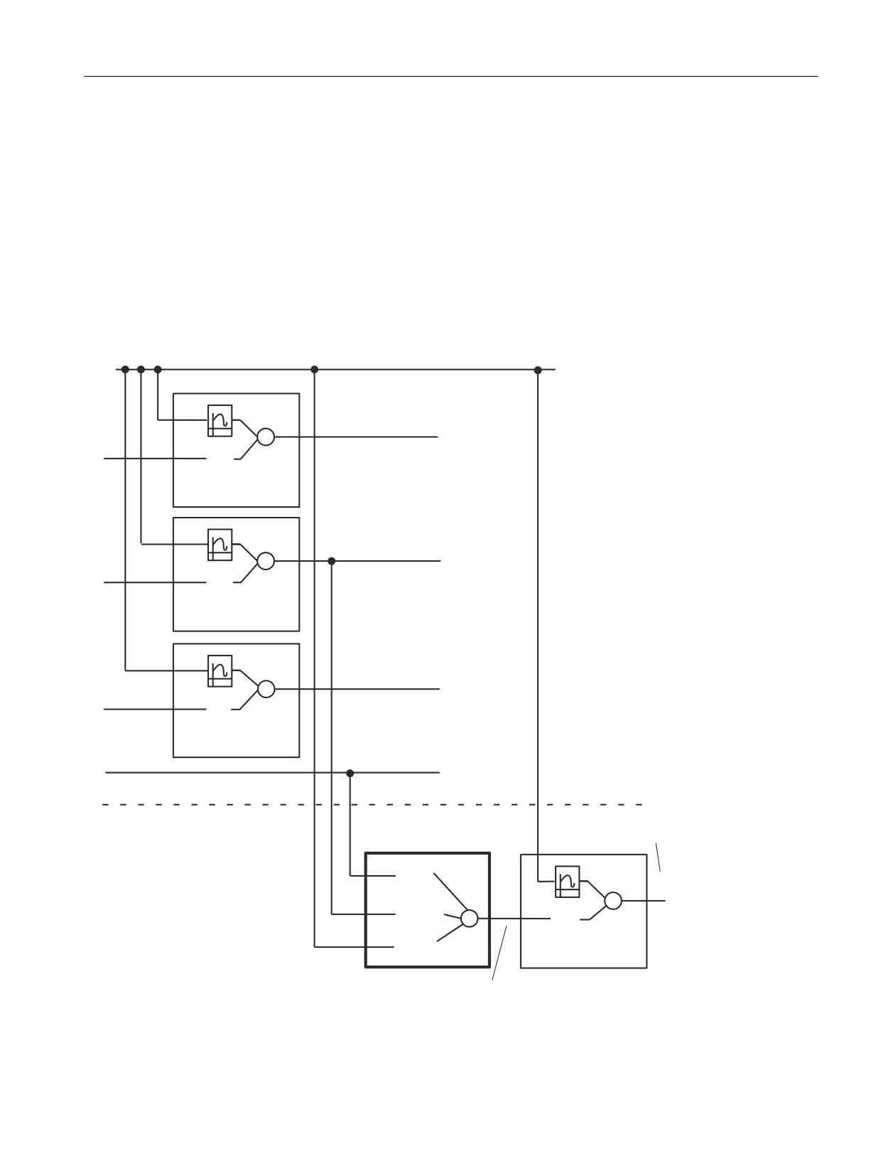
The following example extends the example (see "Figure 14-10 Definition of axes on a gear
hobbing machine (example) (Page 600)") with the following:
• Machine error compensations which are not linearly dependent on the Z axis, and
• a Z-axis dependent component with tooth geometry.
This can be used to create a slightly convex tooth surface, so that the center of the tooth is
stressed more than the edges during operation.
/HDGLQJ D[HV
/$
=
=
&
;
=
;
1
*
&
<
<
&RPSHQVDWLRQ I =
=
1
*
&
$
$
=
1
*
%
%
$FFRUGLQJ WR %DVH ([DPSOH
)ROORZLQJ D[LV
=
&
1
&
*HDU JHRPHWU\
=
&
=
2&
1
=
1
*
*
6RIWZDUH D[LV
Figure 14-11
Extended example with non-linear machine fault compensation and non-linear components on the tooth
geometry
Axes and spindles
Function Manual, 10/2020, 6FC5397-4GP40-0BA1
603
Axis couplings
14.4 Electronic gear (EG)
The following section of a part program is intended to illustrate the general concept;
supplementary curve tables and gear wheel/machine parameters are still to be added.
Components to be added are marked with <...> . Stated parameters may also have to be
modified, e.g. coupling factors.
N100 CTABDEF(X, Z, 1, 0)
;
declaration and specification of non-periodic curve table C1
N110 < ...
;
Preset of curve table: Curve points or polynomial blocks
>
N190 CTABEND
N200 CTABDEF(Y, Z, 2,
;
declaration and specification of non-periodic curve table C2
0)
N210 < ...
;
Preset of curve table: Curve points or polynomial blocks
>
N290 CTABEND
N300 CTABDEF(A, Z, 3, 0)
;
declaration and specification of non-periodic curve table C3
N310 < ...
;
Preset of curve table: Curve points or polynomial blocks
>
N390 TABEND
N400 CTABDEF(C, Z, 4, 0)
;
declaration and specification of non-periodic curve table C4
N410 < ...
;
Preset of curve table: Curve points or polynomial blocks
>
N490 CTABEND
N500 EGDEF(X, Z, 1)
;
Declaration of path via C1, setpoint coupling
N510 G1 F1000 X10
;
declaration of command component of X
N520 EGONSYN(X, "NOC",
;
Path switch-on via C1
<SynPosX>, Z,
<SynPosX_Z>, 1, 0)
N600 EGDEF(Y, Z, 1)
;
Declaration of path via C2, setpoint coupling
N610 G1 F1000 Y10
;
declaration of command component of Y
N620 EGONSYN(Y,
;
Path switch-on via C2
"COARSE",
<SynPosY>, Z,
<SynPosY_Z>, 2, 0)
N700 EGDEF(A, Z, 1)
;
Declaration of path via C3, setpoint coupling
N710 G1 F1000 A10
;
declaration of command component of A
N720 EGONSYN(A, "FINE",
;
Path switch-on via C3
<SynPosA>, Z,
<SynPosA_Z>, 3, 0)
; 1st Gear stage, C99 is the software axis between the two electronic gears
N800 EGDEF(C99, Y, 1, Z,
1, B, 1 )
N810 EGONSYN(C99, "NOC",
; Switch-on of leading axis B
<SynPosC99>, B,
<SynPosC99_B>,
18.2, &
Y, <Syn-
; Switch-on of leading axis Y
PosC99_Y>,R1 * π, 1, &
Axes and spindles
604
Function Manual, 10/2020, 6FC5397-4GP40-0BA1

Axis couplings
14.4 Electronic gear (EG)
Z, <Syn-
; Switch-on of leading axis Z
PosC99_Z>,10, 1)
; "&" character means: command continued in next line, no LF nor comment per-
missible in program
; 2nd Gear stage
N900 EGDEF(C, C99, 1,
; declaration of following C99 of step 1 as leading axis of step 2,
Z, 1)
; Setpoint value coupling
N910
; Declaration of path via C4, setpoint coupling
N900
; Switch-on of software axis C99
N910
; and of leading axis Z via C4
N920 EGONSYN(C, "NOC",
<SynPosC>, C99,
<SynPosC_C99>, 1,
1, &
Z, <SynPosC_Z>, 4,
0)
N999 M30
Machine data
Only one section is specified, which extends beyond the necessary geometry/channel
configuration and machine axis parameters.
$MN_NUM_EG = 5
; Maximum number of gearboxes
$MN_MM_NUM_CURVE_TABS = 5
; Maximum number of curve tables
$MN_MM_NUM_CURVE_SEGMENTS = 50
;Max. Number of curve segments
$MN_MM_NUM_CURVE_POLYNOMS = 100
;Max. Number of curve polynomials
Setting data
If the scaling described in Section "Electronic gear (EG) (Page 581)" is used, the function value
from the following machine data changes according to the displacement:
MD43108 $SD_LEAD_SCALE_OUT_POS[4] = 1.2 ; scaling for table C4
System variables
In accordance with the above definitions, the following values are entered in the associated
system variables by the control.
Further information
List Manual System Variables
The system variables listed below are only used for explanatory purposes!
; ************** Gear X (G1)
$AA_EG_TYPE[X, Z] = 1
; Setpoint value coupling
$AA_EG_NUMERA[X, Z] = 1
; curve table No. = 1
Axes and spindles
Function Manual, 10/2020, 6FC5397-4GP40-0BA1
605
Axis couplings
14.4 Electronic gear (EG)
$AA_EG_DENOM[X, Z] = 0
; nominator = 0 → curve table applies
$P_EG_BC[X] = "NOC"
; Block change criterion
$AA_EG_NUM_LA[X] = 1
; Number of leading axes
$AA_EG_AX[0, X] = Z
; name of leading axis
$AA_EG_SYN[X,Z] = <SynPosX_Z>
; Synchronized position of leading axis Z
$AA_EG_SYNFA[X] = <SynPosX>
; Synchronized position of the following axis
; ************** Gear Y (G2)
$AA_EG_TYPE[Y, Z] = 1
; Setpoint value coupling
$AA_EG_NUMERA[Y, Z] = 2
; curve table No. = 2
$AA_EG_DENOM[Y, Z] = 0
; nominator = 0 → curve table applies
$P_EG_BC[Y10] = "COARSE"
; Block change criterion
$AA_EG_NUM_LA[Y] = 1
; Number of leading axes
$AA_EG_AX[0, Y] = Z
; name of leading axis
$AA_EG_SYN[Y, Z] = <SynPosY_Z>
; Synchronized position of leading axis Z
$AA_EG_SYNFA[Y] = <SynPosY>
; Synchronized position of the following axis
; ************** Gear A (G3)
$AA_EG_TYPE[A, Z] = 1
; Setpoint value coupling
$AA_EG_NUMERA[A, Z] = 3
; curve table No. = 3
$AA_EG_DENOM[A, Z] = 0
; nominator = 0 → curve table applies
$P_EG_BC[A10] = "FINE"
; Block change criterion
$AA_EG_NUM_LA[A] = 1
; Number of leading axes
$AA_EG_AX[0, A] = Z
; name of leading axis
$AA_EG_SYN[A, Z] = <SynPosA_Z>
; Synchronized position of leading axis Z
$AA_EG_SYNFA[A] = <SynPosA>
; Synchronized position of the following axis
; ************** Gear C99 (G4)
$AA_EG_TYPE[C99, Y] = 1
; Setpoint value coupling
$AA_EG_NUMERA[C99, Y] = 18
; numerator for coupling factory
$AA_EG_DENOM[C99, Y] = 2
; denominator for coupling factory
$AA_EG_TYPE[C99, Z] = 1
; Setpoint value coupling
$AA_EG_NUMERA[C99, Z] = R1 * π
; numerator for coupling factorz
$AA_EG_DENOM[C99, Z] = 1
; denominator for coupling factorz
$AA_EG_TYPE[C99, B] = 1
; Setpoint value coupling
$AA_EG_NUMERA[C99, B] = 10
; numerator for coupling factorb
$AA_EG_DENOM[C99, B] = 1
; denominator for coupling factorb
$P_EG_BC[C99] = "NOC"
; Block change criterion
$AA_EG_NUM_LA[C99] = 3
; Number of leading axes
$AA_EG_AX[0, C99] = Y
; name of leading axis Y
$AA_EG_AX[1, C99] = Z
; name of leading axis Z
$AA_EG_AX[2, C99] = B
; name of leading axis B
$AA_EG_SYN[C99, Y] = <SynPosC99_Y>
; Synchronized position of leading axis Y
$AA_EG_SYN[C99, Z] = <SynPosC99_Z>
; Synchronized position of leading axis Z
$AA_EG_SYN[C99, B] = <SynPosC99_B>
; Synchronized position of leading axis B
Axes and spindles
606
Function Manual, 10/2020, 6FC5397-4GP40-0BA1
Axis couplings
14.4 Electronic gear (EG)
$AA_EG_SYNFA[C99] = <SynPosC99>
; Synchronized position of the following axis
; *************** Gear C (G5)
$AA_EG_TYPE[C, Z] = 1
; Setpoint value coupling
$AA_EG_NUMERA[C, Z] = 4
; curve table No. = 4
$AA_EG_DENOM[C, Z] = 0
; nominator = 0 → curve table applies
$AA_EG_TYPE[C, C99] = 1
; Setpoint value coupling
$AA_EG_NUMERA[C, C99] = 1
; numerator for coupling factorC99
$AA_EG_DENOM[C, C99] = 1
; denominator for coupling factorC99
$P_EG_BC[C] = "NOC"
; Block change criterion
$AA_EG_NUM_LA[C] = 2
; Number of leading axes
$AA_EG_AX[0, C] = Z
; name of leading axis Z
$AA_EG_AX[1, C] = C99
; name of leading axis C99
$AA_EG_SYN[C, Z] = <SynPosC_Z>
; Synchronized position of leading axis Z
$AA_EG_SYN[C, C99] = <SynPosC_C99>
; Synchronized position of leading axis C99
$AA_EG_SYNFA[C] = <SynPosC>
; Synchronized position of leading axis C
Machine data
Extract from MD:
; ************** Channel 1
CHANDATA(1)
; ************** Axis 1, "X"
$MC_AXCONF_GEOAX_NAME_TAB[0] = "X"
$MC_AXCONF_CHANAX_NAME_TAB[0] = "X"
$MC_AXCONF_MACHAX_USED[0]=1
$MN_AXCONF_MACHAX_NAME_TAB[0] = "X1"
$MA_SPIND_ASSIGN_TO_MACHAX[AX1] = 0
$MA_IS_ROT_AX[AX1] = FALSE
; *************** Axis 2, "Y"
$MC_AXCONF_GEOAX_NAME_TAB[1]="Y"
$MC_AXCONF_CHANAX_NAME_TAB[1] = "Y"
$MC_AXCONF_MACHAX_USED[1] = 2
$MN_AXCONF_MACHAX_NAME_TAB[1] = "Y1"
$MA_SPIND_ASSIGN_TO_MACHAX[AX2] = 0
$MA_IS_ROT_AX[AX2] = FALSE
; *************** Axis 3, "Z"
$MC_AXCONF_GEOAX_NAME_TAB[2] = "Z"
$MC_AXCONF_CHANAX_NAME_TAB[2] = "Z"
Axes and spindles
Function Manual, 10/2020, 6FC5397-4GP40-0BA1
607
Axis couplings
14.4 Electronic gear (EG)
$MC_AXCONF_MACHAX_USED[2]=3
$MN_AXCONF_MACHAX_NAME_TAB[2] = "Z1"
$MA_SPIND_ASSIGN_TO_MACHAX[AX3] = 0
$MA_IS_ROT_AX[AX3] = FALSE
; *************** Axis 4, "A"
$MC_AXCONF_CHANAX_NAME_TAB[3] = "A"
$MC_AXCONF_MACHAX_USED[3]=4
$MN_AXCONF_MACHAX_NAME_TAB[3] = "A1"
$MA_SPIND_ASSIGN_TO_MACHAX[AX4]=0
$MA_IS_ROT_AX[AX4] = TRUE
$MA_ROT_IS_MODULO[AX4] = TRUE
; *************** Axis 5, "B"
$MC_AXCONF_CHANAX_NAME_TAB[4] = "B"
$MC_AXCONF_MACHAX_USED[4]=5
$MC_SPIND_DEF_MASTER_SPIND = 1
$MN_AXCONF_MACHAX_NAME_TAB[4] = "B1"
$MA_SPIND_ASSIGN_TO_MACHAX[AX5] = 1
$MA_IS_ROT_AX[AX5] = TRUE
$MA_ROT_IS_MODULO[AX5] = TRUE
; ************** Axis 6, "C"
$MC_AXCONF_CHANAX_NAME_TAB[5] = "C"
$MC_AXCONF_MACHAX_USED[5]=6
$MN_AXCONF_MACHAX_NAME_TAB[5] = "C1"
$MA_SPIND_ASSIGN_TO_MACHAX[AX6] = 0
$MA_IS_ROT_AX[AX6] = TRUE
$MA_ROT_IS_MODULO[AX6] = TRUE
; ************** Axis 10, "C99"
$MC_AXCONF_CHANAX_NAME_TAB[9] = "C99"
$MC_AXCONF_MACHAX_USED[9]=10
$MA_SPIND_ASSIGN_TO_MACHAX[AX10] = 0
$MA_IS_ROT_AX[AX10] = TRUE
$MA_ROT_IS_MODULO[AX10] = TRUE
Axes and spindles
608
Function Manual, 10/2020, 6FC5397-4GP40-0BA1
Axis couplings
14.5 Generic coupling
14.5
Generic coupling
14.5.1
Brief description
14.5.1.1
Function
Function
"Generic Coupling" is a general coupling function, combining all coupling characteristics of
existing coupling types (coupled motion, master value coupling, electronic gearbox and
synchronous spindle).
The function allows flexible programming:
• Users can select the coupling properties required for their applications (building block
principle).
• Each coupling property can be programmed individually.
• The coupling properties of a defined coupling (e.g. coupling factor) can be changed.
• Later use of additional coupling properties is possible.
• The coordinate reference system of the following axis (Base co-ordinate system or Machine
co-ordinate system) is programmable.
• Certain coupling properties can also be programmed with synchronous actions.
Further information
Function Manual Synchronized Actions
Adaptive cycles
Previous coupling calls for coupled motion (TRAIL*), Master value coupling (LEAD*), Electronic
Gearbox (EG*) and Synchronous spindle (COUP*) are still supported via adaptive cycles (see
Section "Adaptive cycles (Page 659)").
14.5.1.2
Requirements
CP version
The generic coupling is available in a basic version and four optional versions:
• CP-STATIC
• CP-BASIC
• CP-COMFORT
• CP-EXPERT
Axes and spindles
Function Manual, 10/2020, 6FC5397-4GP40-0BA1
609
Axis couplings
14.5 Generic coupling
This structure is based on the following considerations:
• Functional scope and required application knowledge increase from the basic version to the
optional CP_EXPERT version.
• The number of required couplings (following axes, following spindles) and their properties
are decisive in the selection of versions.
- Example of simultaneous operation:
If sequential operation of 1 x synchronous spindle pair for part transfer from the main to
the supplementary spindle and the 1 x multi-edge turning is required, then the CP-BASIC
option is suitable and sufficient. However, if it cannot be excluded that both operations
can overlap (multi-edge turning running when part transfer is started), the CP-COMFORT
option would be required.
- Example of property:
If a coupled axis grouping with a leading axis is required, the base version is sufficient. For
coupled motion groups with two leading axes, one of the optional versions is required.
• Individual versions are independent of each other. They can be combined and can be
activated simultaneously.
Table 14-2
Quantity structure, which is dependent on the execution of coupling modules that can be simultaneously activated
Typ
CP versions allow one or more different CPSETTYPE
Base ver-
CP-
CP-BA-
CP-COM-
CP-EX-
e
coupling objects simultaneously:
sion
STATIC
SIC
FORT
PERT
A
Coupled motion
4
-
4
4
8
B
Synchronous spindle with |1|:1 coupling
-
1
-
-
-
C
o./u. Synchronous spindles, multi-edge turning
-
-
1
4
8
o./u. Master value coupling / curve tables interpolation
o./u. MCS coupling
D
o./u. Electronic gearbox "plain"
-
-
-
1
8
o./u. Free generic coupling "basic"
E
o./u. Electronic gearbox
-
-
-
-
5
o./u. Free generic coupling
o./u. stands for over/under
Table 14-3
Scaling of availability of coupling properties
Type A
Type B
Type C
Type D
Type E
20
1
13
9
5
Maximum number of CPSETTYPE-related functionalities (per
type)
TRAIL - coupled motion
20
-
13
9
5
Maximum number of coupled motion groups with the following
properties:
→ refer to CPSETTYPE="TRAIL"1)
1
2
2
2
Maximum number of master values
-
-
+
+
Coupling between a spindle and an axis
+
+
+
+
Coupling between a rotary axis and a linear axis
Axes and spindles
610
Function Manual, 10/2020, 6FC5397-4GP40-0BA1

Axis couplings
14.5 Generic coupling
Type A
Type B
Type C
Type D
Type E
-
+
+
+
From part program and synchronous actions
+
+
+
+
Superimposition / speed difference permitted
-
-
-
+
Cascading permitted
BCS
BCS / MCS
BCS / MCS
BCS / MCS
Coordinate reference (default: CPFRS="BCS")
Synchronous spindle with |1|:1 coupling
-
1
-
-
-
Maximum number of synchronous spindles / multi-edge turning
with the following properties:
→ refer to CPSETTYPE="COUP"1)
1
Maximum number of master values
-
From part program and synchronous actions
-
Superimposition / speed difference permitted
-
Cascading permitted
MCS
Coordinate reference fix (CPFRS="MCS")
COUP - synchronous spindle/multi-edge turning
-
-
13
9
5
Maximum number of synchronous spindles / multi-edge turning
with the following properties:
→ refer to CPSETTYPE="COUP"1)
1
1
1
Maximum number of master values
-
-
-
From part program and synchronous actions
+
+
+
Superimposition / speed difference permitted
-
-
-
Cascading permitted
MCS
MCS
MCS
Coordinate reference fix (CPFRS="MCS")
LEAD - master value coupling / curve tables interpolation
-
-
13
9
5
Maximum number of master value couplings / curve tables inter-
polation with the following properties:
→ refer to CPSETTYPE="LEAD"1)
1
1
1
Maximum number of master values
+
+
+
From part program and synchronous actions
+
+
+
Superimposition / speed difference permitted
-
-
+
Cascading permitted
BCS / MCS
BCS / MCS
BCS / MCS
Coordinate reference (default: CPFRS="BCS")
EG - electronic gearbox
-
-
-
9
5
Maximum number of electronic gearboxes
with the following properties:
→ refer to CPSETTYPE="EG"1)
3
5
Maximum number of master values
-
-
From part program and synchronous actions
+
+
Superimposition / speed difference permitted
-
+
Cascading permitted
BCS / MCS
BCS / MCS
Coordinate reference (default: CPFRS="BCS")
-
+
Non-linear coupling law (CPLCTID) permitted
CP - free generic coupling
Axes and spindles
Function Manual, 10/2020, 6FC5397-4GP40-0BA1
611
Axis couplings
14.5 Generic coupling
Type A
Type B
Type C
Type D
Type E
-
-
-
9
5
Maximum number of free generic couplings
with the following properties:
Default (corresponds to CPSETTYPE="CP"1))
3
5
Maximum number of master values
+
+
From part program and synchronous actions
+
+
Superimposition / speed difference permitted
-
+
Cascading permitted
BCS / MCS
BCS / MCS
Coordinate reference (default: CPFRS="BCS")
-
+
Non-linear coupling law (CPLCTID) permitted
1) Refer to " Coupling types (CPSETTYPE) (Page 660) ".
Note
Existing coupling options (Master value coupling, Electronic gearbox and Synchronous spindle)
are not taken into consideration by generic coupling. Simultaneous operation of existing
coupling options and generic coupling is only possible if the couplings refer to different axes/
spindles.
Memory configuration
Memory space reserved in dynamic NC memory for generic coupling is defined in machine data:
MD18450 $MN_MM_NUM_CP_MODULES (maximum allowed number of CP coupling
modules)
MD18452 $MN_MM_NUM_CP_MODUL_LEAD (maximum allowed number of CP master
values)
Note
Recommendation: Expected maximum values, which can be expected simultaneously for this
machine in its maximum configuration, should already be set during commissioning.
Hardware requirements
Systems with more than 6 axes are required when using the "CP-EXPERT" option.
14.5.2
Fundamentals
14.5.2.1
Coupling module
With the help of a coupling module, the motion of one axis (→ following axis) can be
interpolated depending on other axes (→ leading axes).
Axes and spindles
612
Function Manual, 10/2020, 6FC5397-4GP40-0BA1
Axis couplings
14.5 Generic coupling
Coupling rule
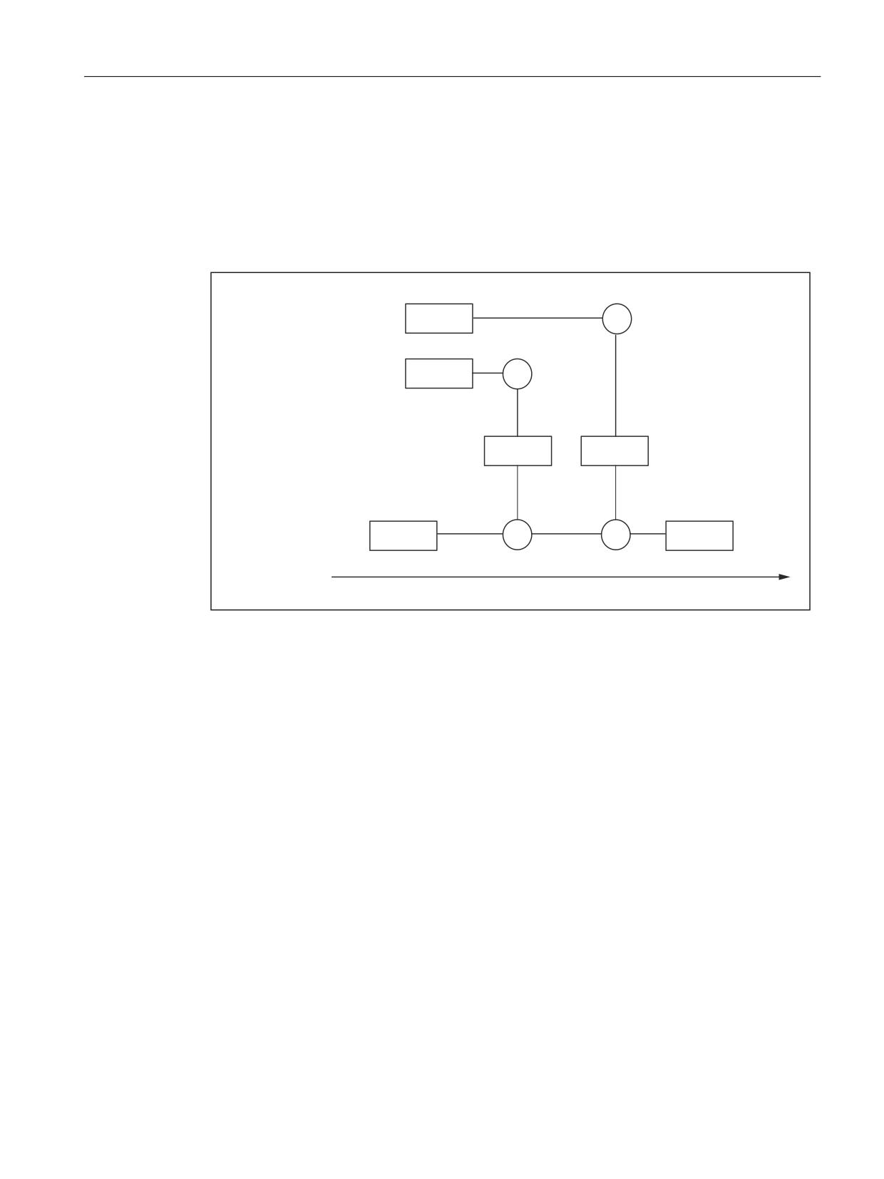
The relationships between leading axis/values and a following axis are defined by a coupling rule
(coupling factor or curve table). The individual motion components from the individual leading
axes/values have an additive effect.
The relationship is demonstrated by the following example (following axis with two leading
axes):
&RXSOLQJ UXOH
/HDGLQJ D[LV
/$
.)
&RXSOLQJ UXOH
/HDGLQJ D[LV
/$
.)
)$'HS
)$'HS
)ROORZLQJ D[LV
)$&PG
)$7RWDO
FATotal
Total setpoint value of the following axis
FACmd
Setpoint value set in part program
= independent motion component of the following axis
FADEP1
Dependent motion component of leading axis 1
FADEP2
Dependent motion component of leading axis 2
LA1
Setpoint or actual value of the 1st leading axis
LA2
Setpoint or actual value of the 2nd leading axis
SynPosLA1
Synchronized position of the 1st leading axis
SynPosLA2
Synchronized position of the 2nd leading axis
KF1
Coupling factor of the 1st leading axis
KF2
Coupling factor of the 2nd leading axis
The following axis position results from the overlay (summation) of the dependent motion
components (FADEP1 and FADEP2), which result from the individual coupling relationships to the
leading axes, and of the independent motion component (FACmd) of the following axis:
FATotal = FACmd + FADEP1 + FADEP2
Axes and spindles
Function Manual, 10/2020, 6FC5397-4GP40-0BA1
613

Axis couplings
14.5 Generic coupling
The motion components of the following axis are calculated as follows:
Dependent motion component of leading axis 1:
FADEP1 = (LA1 - SynPosLA1) * KF1
Dependent motion component of leading axis 2:
FADEP2 = (LA2 -SynPosLA2) * KF2
Independent motion component of the following axis:
FACmd
Following axis overlay
The overlay of dependent and independent motion components of the following axis is called
following axis overlay.
The independent motion component of the following axis can be programmed with the full
range of available motion commands.
14.5.2.2
Keywords and coupling characteristics
Keywords
Programming is done via language commands, e.g. coupled motion with TRAILON(X,Y,2).
Keywords replace the language commands in generic coupling.
This has the following advantages:
• Coupling characteristics can be programmed individually (see following example).
• Programming of multiple couplings can be done in one block (since keywords do not require
their own block).
Advantage: Reduction of work off time
Example:
The properties set with the existing coupling call TRAILON(X,Y,2)(following axis, leading axis
and coupling factor) are defined in the generic coupling with the following keywords:
CPON=(X1) CPLA[X1]=(X2) CPLNUM[X1,X2]=2
CPON=(X1)
Switch on coupling to following axis X1.
CPLA[X1]=(X2)
Define axis X2 as leading axis.
CPLNUM[X1,X2]=2
Set numerator of the coupling factor to 2.
Notation
In order to be uniquely assigned, keywords are furnished with the prefix "CP", for Coupling).
Depending on meaning and application position, a third letter is used:
Keyword prefix
Meaning
Example
CP*
Describes the characteristics of the entire coupling.
CPON1)
CPF*
Describes the characteristics of the following axis (Follow-
CPFPOS1)
ing axis).
Axes and spindles
614
Function Manual, 10/2020, 6FC5397-4GP40-0BA1
Axis couplings
14.5 Generic coupling
Keyword prefix
Meaning
Example
CPL*
Describes a property referring to the leading axis (Leading
CPLON1),
axis) or the coupling rule.
CPLNUM1)
CPM*
Describes a property of the entire coupling for special
CPMRESET1)
states.
1) For keyword meaning, please refer to the following table "Overview of all keywords and coupling
characteristics".
Overview of all keywords and coupling characteristics
The following table gives an overview of all keywords of the generic coupling and the
programmable coupling characteristics:
Keyword
Coupling characteristics / meaning
Default setting (CPSET-
TYPE="CP")
CPDEF
Creating a coupling module
CPDEL
Deletion of a coupling module
CPLDEF
Definition of a leading axis and creation of a coupling
module
CPLDEL
Deleting a leading axis of a coupling module
CPON
Switching on a coupling module
CPOF
Switching off a coupling module
CPLON
Switching on a leading axis of a coupling module
CPLOF
Switching off a leading axis of a coupling module
CPLNUM
Numerator of the coupling factor
1.0
CPLDEN
Denominator of the coupling factor
1.0
CPLCTID
Number of curve table
Not set
CPLSETVAL
Coupling reference
CMDPOS
CPFRS
Co-ordinate reference system
BCS
CPBC
Block change criterion
NOC
CPFPOS + CPON
Synchronized position of the following axis when
Not set
switching on
CPLPOS + CPON
Synchronized position of the leading axis when
Not set
switching on
CPFMSON
Synchronization mode
CFAST
CPFMON
Behavior of the following axis at switching on
STOP
CPFMOF
Behavior of the following axis at complete switch-off
STOP
CPFPOS + CPOF
Switch-off position of the following axis when switch-
Not set
ing off
CPMRESET
Coupling response to RESET
NONE
Axes and spindles
Function Manual, 10/2020, 6FC5397-4GP40-0BA1
615
Axis couplings
14.5 Generic coupling
Keyword
Coupling characteristics / meaning
Default setting (CPSET-
TYPE="CP")
CPMSTART
Coupling behavior at part program start
NONE
CPMPRT
Coupling response when the part program starts un-
NONE
der block search run via program test
CPLINTR
Offset value of the input value of a leading axis
0.0
CPLINSC
Scaling factor of the input value of a leading axis
1.0
CPLOUTTR
Offset value for the output value of a coupling
0.0
CPLOUTSC
Scaling factor for the output value of a coupling
1.0
CPSYNCOP
Threshold value of position synchronism "Coarse"
MD37200
CPSYNFIP
Threshold value of position synchronism "Fine"
MD37210
CPSYNCOP2
Second threshold value for the "Coarse" position syn-
MD37202
chronism
CPSYNFIP2
Second threshold value for the "Fine" position syn-
MD37212
chronism
CPSYNCOV
Threshold value of velocity synchronism "Coarse"
MD37220
CPSYNFIV
Threshold value of velocity synchronism "Fine"
MD37230
CPMBRAKE
Response of the following axis to certain stop signals
1
and stop commands
CPMVDI
Response of the following axis to certain NC/PLC in-
0 (for bits 0 to 3, 5)
terface signals
1 (for bits 4, 6)
CPMALARM
Suppression of special coupling-related alarm out-
MD11410
puts
MD11415
CPSETTYPE
Coupling type
CP
Note
Coupling characteristics, which are not explicitly programmed (in part program of synchronous
actions), become effective with their default settings (see right hand column of the table).
Depending on the settings of the keyword CPSETTYPE instead of the default settings
(CPSETTYPE="CP") preset coupling characteristics can become effective (see Section
"Coupling types (Page 660)").
Axes and spindles
616
Function Manual, 10/2020, 6FC5397-4GP40-0BA1

Axis couplings
14.5 Generic coupling
14.5.2.3
System variables
The current state of a coupling characteristic set with a keyword, can be read and written to with
the relevant system variable.
Note
When writing in the part program, PREPROCESSING STOP is generated.
Notation
The names of system variables are normally derived from the relevant keywords and a
corresponding prefix.
The first letter of the prefix defines the access location when reading:
System variable prefix
Access location during read
Features
$PA_CP
Reading of channel referenced axis
Use in synchronous actions is not
specific coupling characteristics in
possible.
block preparation (Preparation)
Does not generate an implicit pre-
processing stop.
$AA_CP
Reading of the current state of the
Use in the part program and in syn-
coupling module (across channels).
chronous actions is possible.
Generates an implicit preprocessing
stop when used in the part program.
Note
The preprocessing value of a $PA_CP.. CP system variable only differs from the values of the
corresponding $AA_CP.. CP system variable during active part program processing.
At the end of the program or with abort, there is an appropriate synchronization of the
preprocessing with the main run states.
System variable list
A list of all system variables which can be used in a generic coupling is contained in the data lists
(see Section "System variables (Page 691)").
The exhaustive description of the system variables can be found in:
Further information
List Manual System Variables
14.5.3
Creating/deleting coupling modules
14.5.3.1
Creating a coupling module (CPDEF)
An axial coupling module is created through the definition of the following axis.
Axes and spindles
Function Manual, 10/2020, 6FC5397-4GP40-0BA1
617
Axis couplings
14.5 Generic coupling
Programming
Syntax:
CPDEF= (<following axis/spindle>)
Designation:
Coupling Definition
Functionality:
Definition of a coupling module The coupling is not activated.
Following axis/
Type: AXIS
spindle:
Range of values: All defined axis and spindle names in the channel
Example:
Programming
Comment
CPDEF=(X2)
; A coupling module is created with axis X2 as following
axis.
Boundary conditions
• The maximum number of coupling modules is limited (see Section "Requirements
(Page 609)").
• The application of CPDEF to an already created coupling module is possible and will not result
in an alarm being generated.
14.5.3.2
Delete coupling module (CPDEL)
A coupling module created with CPDEF can be deleted with CPDEL.
Programming
Syntax:
CPDEL= (<following axis/spindle>)
Designation:
Coupling Delete
Functionality:
Deletion of a coupling module. All leading axis modules are deleted with
the coupling module and reserved memory is released.
Following axis/
Type: AXIS
spindle:
Range of values: All defined axis and spindle names in the channel
Axes and spindles
618
Function Manual, 10/2020, 6FC5397-4GP40-0BA1
Axis couplings
14.5 Generic coupling
Example:
Programming
Comment
CPDEL=(X2)
; Deletion of the coupling module with following axis X2.
Boundary conditions
• The switch command CPDEL results in a preprocessing stop with active coupling.
Exception: CPSETTYPE="COUP" does not result in a preprocessing stop.
• Applying CPDEL to a coupling module active in the block preparation results in implicit
deactivation of this coupling.
• Applying CPDEL to an undefined coupling module does not result in any action.
14.5.3.3
Defining leading axes (CPLDEF or CPDEF+CPLA)
The leading axes/spindles defined for a coupling can be programmed/created with the
keyword CPLDEF or with the keyword CPLA in conjunction with CPDEF.
Programming with CPLDEF
Syntax:
CPLDEF[FAx]= (<leading axis/spindle>)
Designation:
Coupling Lead Axis Definition
Functionality:
Definition of leading axis/spindle for following axis/spindle FAx. A leading
axis/spindle module is created in the coupling module. If the coupling
module of the following axis/spindle has not yet been created, the cou-
pling module will be created implicitly.
Leading axis/
Type: AXIS
spindle:
Range of values: All defined axis and spindle names in the channel
Example:
Programming
Comment
CPLDEF[X2]=(X1)
; Definition of leading axis X1 for following axis X2.
Programming with CPLA and CPDEF
Syntax:
CPLA[FAx]= (<leading axis/spindle>)
Designation:
Coupling Lead Axis
Axes and spindles
Function Manual, 10/2020, 6FC5397-4GP40-0BA1
619
Axis couplings
14.5 Generic coupling
Functionality:
Definition of leading axis/spindle for following axis/spindle FAx.
Leading axis/spin- Type: AXIS
dle:
Range of values: All defined axis and spindle names in the channel
Example:
Programming
Comment
CPDEF=(X2) CPLA[X2]=(X1)
; Definition of leading axis X1 for following axis
X2.
Boundary conditions
• CPLDEF is only allowed in blocks without CPDEF/CPON/CPOF/CPDEL.
(This limitation applies to the case where the keywords refer to the same coupling module.)
• The maximum number of leading axis modules per coupling module is limited (see Section
"Requirements (Page 609)").
• Definition of leading axes on an already defined or active coupling module is possible. Any
newly defined leading axes and their properties (e.g. coupling factor) are not active
immediately. A corresponding switch-on command like (CPON or CPLON) is required.
14.5.3.4
Delete leading axes (CPLDEL or CPDEL+CPLA)
Defined leading axes can be deleted with CPLDEL or with CPLA in conjunction with CPDEL, i.e.
removed from the coupling module.
Programming with CPLDEL
Syntax:
CPLDEL[FAx]= (<leading axis/spindle>)
Designation:
Coupling Lead Axis Delete
Functionality:
Deletion of leading axis/spindle of following axis/spindle FAx. The leading
axis/spindle module will be deleted and the corresponding memory will be
released. If the coupling module does not have a leading axis/spindle any
more, the coupling module will be deleted and the memory will be re-
leased.
Leading axis/
Type: AXIS
spindle:
Axes and spindles
620
Function Manual, 10/2020, 6FC5397-4GP40-0BA1
Axis couplings
14.5 Generic coupling
Range of values: All defined axis and spindle names in the channel
Example:
Programming
Comment
CPLDEL[X2]=(X1)
; Deletion of leading axis X1 of the coupling to following
axis X2.
Programming with CPLA and CPDEL
Syntax:
CPLA[FAx]= (<leading axis/spindle>)
Designation:
Coupling Lead Axis
Functionality:
Deleting a leading axis/spindle: The leading axis/spindle module will be
deleted and the corresponding memory will be released. If the coupling
module does not have a leading axis/spindle any more, the coupling mod-
ule will be deleted and the memory will be released.
Leading axis/spin- Type: AXIS
dle:
Range of values: All defined axis and spindle names in the channel
Example:
Programming
Comment
CPDEL=(X2) CPLA[X2]=(X1)
; Deletion of leading axis X1 of the coupling to fol-
lowing axis X2.
Boundary conditions
• CPLDEF is only allowed in blocks without CPDEF/CPON/CPOF/CPDEL.
(This limitation applies to the case where the keywords refer to the same coupling module.)
• If an active leading axis is deleted, the coupling to this leading axis is implicitly deactivated.
• Deletion of the last leading axis results in the entire coupling module to be deleted.
Axes and spindles
Function Manual, 10/2020, 6FC5397-4GP40-0BA1
621
Axis couplings
14.5 Generic coupling
14.5.4
Switching coupling on/off
14.5.4.1
Switching on a coupling module (CPON)
A defined coupling module is switched on with the switch command CPON.
Coupling characteristics like coupling reference can be programmed together with the switch on
command (see Section "Programming coupling characteristics (Page 625)").
Without programming, a coupled motion group or a synchronous spindle pair becomes
effective based on a setpoint coupling (default setting for CPLSETVAL) with the coupling rule
1:1 (default setting for CPLNUM/CPLDEN).
Programming
Syntax:
CPON= (<following axis/spindle>)
Designation:
Coupling On
Functionality:
Activate the coupling of the following axis to all defined leading axes.
Following axis/
Type: AXIS
spindle:
Range of values: All defined axis and spindle names in the channel
Example:
Programming
Comment
CPON=(X2)
; Activation of coupling of the following axis X2.
Boundary conditions
Application of CPON to an already active coupling results in a resynchronization. If applicable,
changed coupling properties become effective as a result. Any lost synchronization (for
example, following axis was in tracking mode) is restored.
14.5.4.2
Switch off coupling module (CPOF)
An activated coupling can be deactivated with the CPOF switching command. The deactivation,
i.e. the switching off of the coupling to the leading axis, is performed in accordance with the set
switch-off properties (see CPFMOF)
Axes and spindles
622
Function Manual, 10/2020, 6FC5397-4GP40-0BA1
Axis couplings
14.5 Generic coupling
Programming
Syntax:
CPOF= (<Following axis / spindle>)
Designation:
Coupling Off
Functionality:
Deactivate the coupling of the following axis to all defined leading axes.
Following axis/
Type: AXIS
spindle:
Range of values: All defined axis and spindle names in the channel
Example:
Programming
Comment
CPOF=(X2)
; Deactivation of coupling of following axis X2.
Boundary conditions
• The switch command CPOF results in a preprocessing stop with active coupling.
Exception: CPSETTYPE="COUP" does not result in a preprocessing stop
• A CPOF switching command on an already deactivated or deleted coupling module has no
effect and is not executed.
• CPOF can be programmed in synchronous actions.
14.5.4.3
Switching on leading axes of a coupling module (CPLON)
CPLON activates the coupling of a leading axis to a following axis. If several leading axes are
defined for a coupling module, they can be activated and deactivated separately with CPLON.
Programming
Syntax:
CPLON[FAx]= (<leading axis/spindle>)
Designation:
Coupling Lead Axis On
Functionality:
Activates the coupling of a leading axis/spindle to following axis/spindle
FAx.
Leading axis/
Type: AXIS
spindle:
Range of values: All defined axis and spindle names in the channel
Axes and spindles
Function Manual, 10/2020, 6FC5397-4GP40-0BA1
623
Axis couplings
14.5 Generic coupling
Example:
Programming
Comment
CPLON[X2]=(X1)
; The coupling of leading axis X1 to following axis X2 is ac-
tivated.
Boundary conditions
CPON can be programmed in synchronous actions.
14.5.4.4
Switching off leading axes of a coupling module (CPLOF)
CPLOF deactivates the coupling of a leading axis to a following axis. If several leading axes are
defined for a coupling module, they can be deactivated separately with CPLOF.
Programming
Syntax:
CPLOF[FAx]= (<leading axis/spindle>)
Identifiers:
Coupling Lead Axis Off
Functionality:
Deactivates the coupling of a leading axis/spindle to the following axis/
spindle FAx.
Leading axis/
Type: AXIS
spindle:
Range of values: Axes of the channel
Example:
Programming
Comment
CPLOF[X2]=(X1)
; The coupling of leading axis X1 to following axis X2 is de-
activated.
Constraints
CPLOF can be programmed in synchronous actions.
14.5.4.5
Implicit creation and deletion of coupling modules
Switch-on commands may also be used to create coupling modules (without prior definition
with CPDEF).
Axes and spindles
624
Function Manual, 10/2020, 6FC5397-4GP40-0BA1
Axis couplings
14.5 Generic coupling
Example
Programming
Comment
CPON=(X2) CPLA[X2]=(X1)
; Creates a coupling module for following axis X2 with
leading axis X1 and activates the coupling module.
or
CPLON[X2]=(X1)
CPOF=(X2)
; After its deactivation, the implicitly created cou-
pling module is deleted.
Constraints
• Implicitly created coupling modules (via switch-on commands) are deleted once they are
completely deactivated (CPOF).
Advantage: Deleting them with CPDEL/CPLDEL is not necessary.
Disadvantage (possibly): All coupling properties which were set with CPOF are lost.
• Implicitly created coupling modules can be transformed into explicit coupling modules with
the following instruction CPDEF/CPLDEF. In this case CPOF does not delete the coupling
module and the data is retained.
14.5.5
Programming coupling characteristics
14.5.5.1
Coupling rule (CPLNUM, CPLDEN, CPLCTID)
The functional relationship between the leading value and the following value is specified by a
coupling rule for each leading axis. This functional relationship can be defined linear via a
coupling factor or non-linear via a curve table. The following axis components calculated in this
way from the individual leading values have an additive effect.
Programming: Coupling factor
When programming a coupling factor, a previously activated non-linear coupling relationship
(curve table) is deactivated.
The coupling factor is programmed with numerator and denominator.
In the default state, i.e. without explicit programming after creation of a new coupling module,
the numerator and denominator are each preset with 1.
If only the numerator is programmed, this is applied as the factor as the denominator is 1.
More exact linear relationships can be defined by programming numerators and denominators.
Numerator of the coupling factor
Syntax:
CPLNUM[FAx,LAx]= <value>
Axes and spindles
Function Manual, 10/2020, 6FC5397-4GP40-0BA1
625
Axis couplings
14.5 Generic coupling
Designation:
Coupling Lead Numerator
Functionality:
Defines the numerator of the coupling factor for the coupling rule of the
following axis/spindle FAx to the leading axis/spindle LAx.
Value:
Type: REAL
Range of values:
-231 to +231
Default value:
+1.0
Example:
Programming
Comment
CPLNUM[X2,X1]=1.3
; The numerator of the coupling factor of the coupling of
the following axis X2 to the leading axis X1 must be 1.3.
Denominator of the coupling factor
Syntax:
CPLDEN[FAx,LAx]= <value>
Designation:
Coupling Lead Denominator
Functionality:
Defines the denominator of the coupling factor for the coupling rule of the
following axis/spindle FAx to the leading axis/spindle LAx.
Value:
Type: REAL
Range of values:
-231 to +231
Default value:
+1.0
Example:
Programming
Comment
CPLDEN[X2,X1]=2
; The denominator of the coupling factor of the coupling of
the following axis X2 to the leading axis X1 must be 2.
Programming: Curve table
When programming a table number, a previously activated non-linear coupling relationship
(coupling factor) is deactivated.
Axes and spindles
626
Function Manual, 10/2020, 6FC5397-4GP40-0BA1
Axis couplings
14.5 Generic coupling
The leading axis specific coupling component for the leading value of the leading axis is
calculated using the specified curve table.
Syntax:
CPLCTID[FAx,LAx]= <value>
Designation:
Coupling Lead Curve Table Id
Functionality:
Specifies the number of the curve table to be used to calculate how the
leading axis/spindle must act on the following axis/spindle.
Value:
Type: INT
Range of values:
-215 to +215
Example:
Programming
Comment
CPLCTID[X2,X1]=5
; The leading axis specific coupling component of the cou-
pling of the following axis X2 to the leading axis X1 is
calculated with curve table No. 5.
Supplementary conditions
• A coupling factor of zero (CPLNUM=0) is a permissible value. In this case, the leading axis/
spindle does not provide a path component for the following axis/spindle, however, it
remains a part of the coupling. Contrary to the switched-off state, the leading axis/spindle
still has an influence on the following axis/spindle. This affects, for example, reactions to
errors, limit switches and NC/PLC interface signals.
• CPLDEN=0 is not a valid value and is rejected with alarm.
• CPLNUM, CPLDEN and CPLCTID can be programmed in synchronous actions.
• Availability of non-linear coupling relationships (CPLCTID) depends on selected options
(see Section "Requirements (Page 609)").
14.5.5.2
Coupling relationship (CPLSETVAL)
The following value can be derived from either of the following:
• position setpoint of the leading axis
• speed setpoint of the leading axis
• position actual value of the leading axis
The following couplings can be programmed accordingly:
• Setpoint value coupling
• Speed coupling
• Actual value coupling
Axes and spindles
Function Manual, 10/2020, 6FC5397-4GP40-0BA1
627
Axis couplings
14.5 Generic coupling
Programming
Syntax:
CPLSETVAL[FAx,LAx]= <value>
Identifiers:
Coupling Lead Set Value
Functionality:
Defines tapping of the leading axis/spindle LAx and the reaction point
on the following axis/spindle FAx.
Coupling reference:
Type: STRING
Range of values:
"CMDPOS"
Commanded Position
Setpoint value coupling
"CMDVEL"
Commanded Velocity
Speed coupling
"ACTPOS"
Actual Value
Actual value coupling
Default value:
"CMDPOS"
Example:
Programming
Comment
CPLSETVAL[X2,X1]="CMDPOS"
; The coupling of following axis X2 to leading ax-
is X1 is deducted from the setpoint.
Constraints
For a coupling module speed coupling cannot be activated simultaneously with setpoint or
actual value coupling of another leading axis.
14.5.5.3
Co-ordinate reference (CPFRS):
The co-ordinate reference of the following axis/spindle specifies in which co-ordinate reference
system the coupling component resulting from the coupling is applied. in the base co-ordinate
system or in the machine co-ordinate system.
It is further specified which co-ordinate reference the leading values of the leading axis spindle
must have. When a transformation is active and when the machine co-ordinate system is
specified as co-ordinate reference (CPFRS="MCS"), the initial transformation values are taken
as leading values.
Programming
Syntax:
CPFRS[FAx]= (<co-ordinate reference>)
Identifiers:
Coupling Following Relation System
Axes and spindles
628
Function Manual, 10/2020, 6FC5397-4GP40-0BA1
Axis couplings
14.5 Generic coupling
Functionality:
Defines the co-ordinate reference system for the coupling module of the
following axis/spindle FAx.
Co-ordinate refer- Type: STRING
ence:
Range of values:
”BCS”
Basis Co-ordinate System
Basic Coordinate System
”MCS”
Machine Coordinate System
Machine coordinate system
Default value:
”BCS”
Example:
Programming
Comment
CPFRS[X2]="BCS"
; The base co-ordinate system is the co-ordinate reference for
the coupling module with following axis X2.
Constraints
• Co-ordinate reference has to be specified when creating a coupling module, else the default
value is used. It is not possible to effect subsequent changes.
• Simultaneous active transformation and coupling via RESET is not supported.
Solution: Switching off the coupling with CPMRESET="OF" with RESET switching it on again
with CPMSTART="ON" in the part program.
• Simultaneous operation of the previous function "Axial Coupling in the Machine Co-ordinate
System (MCS Coupling)" and the generic coupling is not supported.
• CPFRS is not available in the main run.
14.5.5.4
Block change behavior (CPBC)
The block change criterion can be used to specify under which conditions the block change with
activated coupling is to be permitted in the processing of the part program. The status of the
coupling influences the block change behavior. If the specified condition is not fulfilled, the block
change is disabled. The block change criterion is only evaluated with an active coupling.
The block change criterion can be defined with the keyword CPBC or with the programming
command WAITC. The instruction programmed last is valid.
Programming with PCBC
Syntax:
CPBC[FAx]= "<block change criterion>"
Identifiers:
Coupling Block Change Criterium
Axes and spindles
Function Manual, 10/2020, 6FC5397-4GP40-0BA1
629
Axis couplings
14.5 Generic coupling
Functionality:
Defines block change criterion with active coupling.
Block change criteri- Type: STRING
on:
Range of values:
"NOC"
Block change is performed irrespective of the coupling
status.
"IPOSTOP"
Block change is performed with setpoint synchronism.
"COARSE"
Block change is performed with actual value synchron-
ism “coarse”.
"FINE"
Block change is performed with actual value synchron-
ism “fine”.
Default value:
"NOC"
Example:
Programming
Comment
CPBC[X2]="IPOSTOP"
; Block change during processing of the part program is
done with setpoint synchronism (with active coupling to
following axis X2).
Programming with WATC
Syntax:
WAITC(FAx1,BC)
Identifiers:
Wait for Coupling Condition
Functionality:
Defines block change criterion with active coupling.
Parameter:
Fax:
Designates the following axis and therefore the coupling module.
BC:
Defines the desired block change criterion.
FAx:
Type: STRING
Range of values: Axes of the channel
BC:
Type: STRING
Range of values:
Axes and spindles
630
Function Manual, 10/2020, 6FC5397-4GP40-0BA1
Axis couplings
14.5 Generic coupling
"NOC"
Block change is performed irrespective of the coupling
status.
"IPOSTOP"
Block change is performed with setpoint synchronism.
"COARSE"
Block change is performed with actual value synchron-
ism “coarse”.
"FINE"
Block change is performed with actual value synchron-
ism “fine”.
Default value:
"NOC"
Example:
Programming
Comment
WAITC(X2,"IPOSTOP")
; Block change during processing of the part program is
done with setpoint synchronism (with active coupling to
following axis X2).
Constraints
WAITC can only occur singularly in a block, contrary to the keyword CPBC.
14.5.5.5
Synchronized position of the following axis when switching on (CPFPOS+CPON)
When switching on the coupling (CPON) approach of the following axis can be programmed for a
specified synchronized position.
The synchronized position takes immediate effect at switch on. The total position, resulting from
the synchronized position and the coupling rule, is approached according to the specified
synchronization mode (CPFMSON), taking into account the dynamic response limits.
Programming
Syntax:
CPON=FAx CPFPOS[FAx]= <value>
Designation:
Coupling Following Position
Functionality:
Defines the synchronized position of the following axis when switching
on. AC, IC and GP are possible in position specification.
Value:
Type: REAL
Range of values: All positions within the traverse range boundaries
Axes and spindles
Function Manual, 10/2020, 6FC5397-4GP40-0BA1
631
Axis couplings
14.5 Generic coupling
Example:
Programming
Comment
CPON=X2 CPFPOS[X2]=100
; Activation of coupling to following axis X2. 100 is
taken as synchronized position of following axis X2.
Supplementary conditions
• CPFPOS is only effective as synchronized position with the switch-on command CPON/
CPLON.
The switch-off command CPOF evaluates CPFPOS as switch off position (see Section
"Following Axis Position on Switch off (Page 637)").
• CPFPOS without switch-on command results in an alarm.
• If the synchronized position of the following axis is not set during switch on, then the current
position of the following axis takes effect as synchronized position.
The program instruction IC can be used to move the current position.
• The position specification is specified in the configured basic system independently of the
programmable dimensions(G70/G71).
Part program section (Example)
Programming
Comment
CPON=(X2) CPFPOS[X2]=100
; Activation of coupling to following axis X2. 100
is taken as synchronized position of the following
axis.
G00 X2=123
; Following axis X2 is traversed to position 123.
CPON=(X2)
; The current position (=123) is taken as synchron-
ized position of the following axis. The previous-
ly active synchronized position 100 becomes effec-
tive.
14.5.5.6
Synchronized position of the leading axis when switching on (CPLPOS)
The current leading axis position, taken as leading value, can be offset. The synchronized
position of the leading axis therefore defines the zero point of the input variable.
Programming
Syntax:
CPLPOS[FAx,LAx]= <value>
Identifiers:
Coupling Lead Position
Functionality:
Defines the synchronized position of the following axis at switch on. On-
ly AC is possible in the position specification.
Axes and spindles
632
Function Manual, 10/2020, 6FC5397-4GP40-0BA1
Axis couplings
14.5 Generic coupling
Value:
Type: REAL
Range of values: All position within the traverse range boundaries
Example:
Programming
Comment
CPLPOS[X2,X1]=200
; 200 is taken as synchronized position of the leading ax-
is X1 of the coupling to following axis X2.
Constraints
• CPFPOS can only set with the switch-on command CPON / CPLON. CPFPOS without switch-
on command results in an alarm.
• If the synchronized position of the leading axis is not set with the switch on command
(CPON), then the current position of the leading axis takes effect as synchronized position
and therefore as zero point of the input variable.
• The position specification is specified in the configured basic system independently of the
programmable dimensions(G70 / G71).
Part program section (Example)
Programming
Comment
CPON=(X2) CPFPOS[X2]=100 CPLPOS[X2,X1]=200
; Activation of coupling to following axis X2.
100 is taken as synchronized position of fol-
lowing axis and 200 for leading axis X1.
N20 X1=280 F1000
; Leading axis X1 is traversed to position 280.
CPON=(X2)
; The current position X1=280 is taken as
synchronized position of the leading axis. The
previously active synchronized position of the
leading axis (200) becomes ineffective.
14.5.5.7
Synchronization mode (CPFMSON)
Synchronization mode determines synchronization behavior during switch-on of the coupling.
Programming
Syntax:
CPFMSON[FAx]= "<synchronization mode>"
Identifiers:
Coupling Following Mode Strategy On
Functionality:
Determines the synchronization mode during coupling.
Axes and spindles
Function Manual, 10/2020, 6FC5397-4GP40-0BA1
633
Axis couplings
14.5 Generic coupling
Synchronization
Type: STRING
mode:
Range of values:
"CFAST"
Closed Coupling Fast
The coupling is closed time-
optimized.
"CCOARSE"
Closed If Gab Coarse
The coupling is only closed
when the following axis posi-
tion, required according to the
coupling rule, is in the range
of the current following axis
position.
"NTGT"
Next Tooth Gap Time
The next tooth gap is ap-
Optimized
proached time-optimized.
"NTGP"
Next Tooth Gap Path
The next tooth gap is ap-
Optimized
proached path-optimized.
"NRGT"
Next Ratio Gap Time
The next segment is approach-
Optimized
ed in a time-optimized man-
ner, in accordance with the ra-
tio of the number of gears to
the number of teeth.
"NRGP"
Next Ratio Gap Path
The next segment is approach-
Optimized
ed in a path-optimized man-
ner, in accordance with the ra-
tio of the number of gears to
the number of teeth.
"ACN"
Absolute Co-
For rotary axes only!
ordinate Negative
The rotary axis traverses to-
wards the synchronized posi-
tion in the negative axis direc-
tion. Synchronization is effec-
ted immediately.
"ACP"
Absolute Coordinate
For rotary axes only!
Positive
The rotary axis traverses to the
synchronized position in
the positive axis direction.
Synchronization is effected im-
mediately.
"DCT"
Direct Co-
For rotary axes only!
ordinate Time Opti-
The rotary axis traverses to the
mized
programmed synchronized
position in time-optimized
fashion. Synchronization is ef-
fected immediately.
Axes and spindles
634
Function Manual, 10/2020, 6FC5397-4GP40-0BA1
Axis couplings
14.5 Generic coupling
"DCP"
Direct Co-
For rotary axes only!
ordinate Path Opti-
The rotary axis traverses to the
mized
programmed synchronized
position in path-optimized
fashion. Synchronization is ef-
fected immediately.
Default value: "CFAST"
Example:
Programming
Comment
CPFMSON[X2]="CFAST"
; CFAST is taken as synchronization mode of the coupling
to following axis X2.
14.5.5.8
Behavior of the following axis at switch-on (CPFMON)
The behavior of the following axis/spindle during switch-on of the coupling can be programmed
with the keyword CPFMON.
Programming
Syntax:
CPFMON[FAx]= "<block change criterion>"
Identifiers:
Coupling Following Mode On
Functionality:
Defines the behavior of the following axis/spindle during switch-on of
the coupling.
Poweron response:
Type: STRING
Range of values:
"STOP"
Stop
For spindles only!
An active motion of the following
spindle is stopped before switch-on.
"CONT"
Continue
For spindles and main traverse axes
only!
The current motion of the following
axis/spindle is taken over into the
coupling as start motion.
Axes and spindles
Function Manual, 10/2020, 6FC5397-4GP40-0BA1
635
Axis couplings
14.5 Generic coupling
"ADD"
Additional
For spindles only!
The motion components of the cou-
pling operate in addition to the cur-
rently overlaid motion, i.e. the cur-
rent motion of the following axis/
spindle is retained as overlaid mo-
tion.
Default value:
"STOP"
Example:
Programming
Comment
CPFMON[X2]="CONT"
; The current motion of following axis X2 is taken over as
start motion.
14.5.5.9
Behavior of the following axis at switch-off (CPFMOF)
The behavior of the following axis/spindle during complete switch-off of an active coupling can
be programmed with the keyword CPFMOF.
Programming
Syntax:
CPFMOF[FAx]= "<switch-off behavior>"
Identifiers:
Coupling Following Mode Off
Functionality:
Defines the behavior of the following axis/spindle during complete
switch-off of the coupling.
Switch-off response:
Type: STRING
Range of values:
"STOP"
Stop
Stop of a following axis/spindle.
An active overlaid motion is also
braked to standstill. Then the coupling
is opened, (deactivated).
"CONT"
Continue
For spindles and main traverse axes on-
ly!
The following spindle continues to tra-
verse at the speed/velocity that applied
at the instant of deactivation.
Default value:
"STOP"
Axes and spindles
636
Function Manual, 10/2020, 6FC5397-4GP40-0BA1
Axis couplings
14.5 Generic coupling
Example:
Programming
Comment
CPFMOF[S2]="CONT"
; The following spindle S2 continues to traverse at the speed
that was applied at the instant of deactivation.
14.5.5.10
Position of the following axis when switching off (CPFPOS+CPOF)
When switching off a coupling (CPOF) traversing to a certain position can be requested for the
following axis.
Programming
Syntax:
CPOF=(FAx) CPFPOS[FAx]= <value>
Functionality:
Defines the switch-off position of the following axis FAx.
Value:
Type: REAL
Range of values: All positions within the traverse range boundaries
Example:
Programming
Comment
CPOF=(X2) CPFPOS[X2]=100
; Deactivation of coupling to following axis X2. 100
is approached as switch-off position of the fol-
lowing axis.
Supplementary conditions
• CPFPOS is only effective as switch-off position with the switch-off command CPOF.
The switch command CPON evaluates CPFPOS as switch-on position (see Section
"Synchronized Position of the Following Axis on Switch-on (Page 631)").
• The setting of a switch-off position is only permitted with the switch-off mode:
CPFMOF=STOP
• Switch-off position is approached with maximum dynamics.
• Block change behavior depends on parameterization of the keyword CPBC.
14.5.5.11
Condition at RESET (CPMRESET)
With RESET, the coupling can be activated, deactivated or the current status can be retained. The
behavior can be set separately for each coupling module.
Axes and spindles
Function Manual, 10/2020, 6FC5397-4GP40-0BA1
637
Axis couplings
14.5 Generic coupling
Programming
Syntax:
CPMRESET[FAx]= "<Reset behavior>"
Identifiers:
Coupling Mode RESET
Functionality:
Defines the behavior of a coupling at RESET.
Reset response:
Type: STRING
Range of values:
"NONE"
The current state of the coupling is retained.
"ON"
When the appropriate coupling module is created, the
coupling is switched on. All defined leading axis relation-
ships are activated. This is also performed when all or
parts of these leading axis relationships are active, i.e.
resynchronization is performed even with a completely
activated coupling.
"OF"
An active overlaid motion is also braked to standstill. The
coupling is then deactivated. When the relevant cou-
pling module was created without an explicit definition
(CPDEF), the coupling module is deleted. Otherwise it is
retained, i.e. it can still be used.
"OFC"
Possible only in spindles!
The following spindle continues to traverse at the speed/
velocity that applied at the instant of deactivation. The
coupling is switched off. When the relevant coupling
module was created without an explicit definition
(CPDEF), the coupling module is deleted. Otherwise it is
retained, i.e. it can still be used.
"DEL"
An active overlaid motion is also braked to standstill. The
coupling is then deactivated and then deleted.
"DELC"
Possible only in spindles!
The following spindle continues to traverse at the speed/
velocity that applied at the instant of deactivation. The
coupling is deactivated and then deleted.
Default value:
"NONE"
Example:
Programming
Comment
CPMRESET[X2]="DEL"
; On RESET the coupling to following axis X2 is deactiva-
ted and then deleted.
Axes and spindles
638
Function Manual, 10/2020, 6FC5397-4GP40-0BA1
Axis couplings
14.5 Generic coupling
Constraints
• The coupling characteristics set with CPMRESET is retained until the coupling module is
deleted with (CPDEL).
• For the coupling type (CPSETTYPE="TRAIL", "LEAD", "EG" or "COUP") the response is
defined by the following machine data during RESET:
MD20110 $MC_RESET_MODE_MASK (definition of initial control system settings after RESET/
TP-End)
→ See Section "Defaults" in " Coupling Types (CPSETTYPE) (Page 660) ".
14.5.5.12
Condition at parts program start (CPMSTART)
At part program start the coupling can be activated, deactivated or the current status can be
retained. The behavior can be set separately for each coupling module.
Programming
Syntax:
CPMSTART[FAx]= <value>
Identifiers:
Coupling Mode Start
Functionality:
Defines the behavior of a coupling at part program start.
Value:
Type: STRING
Range of values:
"NONE"
The current state of the coupling is retained.
"ON"
When the appropriate coupling module is created, the cou-
pling is switched on. All defined leading axis relationships
are activated. This is also performed when all or parts of
these leading axis relationships are active, i.e. resynchro-
nization is performed even with a completely activated
coupling.
"OF"
The coupling is switched off. When the relevant coupling
module was created without an explicit definition
(CPDEF), the coupling module is deleted. Otherwise it is
retained, i.e. it can still be used.
"DEL"
The coupling is deactivated and then deleted.
Default value:
"NONE"
Example:
Programming
Comment
CPMSTART[X2]="ON"
; At part program start, coupling to following axis X2 is
switched on.
Axes and spindles
Function Manual, 10/2020, 6FC5397-4GP40-0BA1
639
Axis couplings
14.5 Generic coupling
Constraints
• The coupling characteristics set with CPMSTART are retained until the coupling module is
deleted with (CPDEL).
• For the set coupling type (CPSETTYPE="TRAIL", "LEAD", "EG" or "COUP"), the response
is defined by the following machine data during part program start:
MD20112 $MC_START_MODE_MASK (Definition of the control default settings in case of NC
START)
→ See Section "Defaults" in " Coupling Types (CPSETTYPE) (Page 660) ".
14.5.5.13
Status during part program start in search run via program test (CPMPRT)
When starting the part program under block search run via program test (SERUPRO), the
coupling can be activated, deactivated or the current status can be retained. The behavior can
be set separately for each coupling module.
Programming
Syntax:
CPMPRT[FAx]= <value>
Designation:
Coupling Mode Program Test
Functionality:
Defines the behavior of a coupling when the part program starts under
block search run via program test.
Value:
Type: STRING
Value range:
"NONE"
The current state of the coupling is retained.
"ON"
When the appropriate coupling module is created, the cou-
pling is switched on. All defined leading axis relationships
are activated. This is also performed when all or parts of
these leading axis relationships are active, i.e. resynchro-
nization is performed even with a completely activated
coupling.
"OFF"
The coupling is switched off. When the relevant coupling
module was created without an explicit definition
(CPDEF), the coupling module is deleted. Otherwise it is
retained, i.e. it can still be used.
"DEL"
The coupling is deactivated and then deleted.
Default value:
"NONE"
Axes and spindles
640
Function Manual, 10/2020, 6FC5397-4GP40-0BA1

Axis couplings
14.5 Generic coupling
Example:
Programming
Comment
CPMPRT[X2]="ON"
; When the part program starts under block search run via
program test, the coupling to following axis X2 is switch-
ed on.
Supplementary conditions
• The coupling characteristics set with CPMPRT is retained until the coupling module is deleted
with (CPDEL).
• If CPMPRT="NONE" is set, then the response when the part program starts under block
search run via program test (SERUPRO) is defined by CPMSTART.
• For the set coupling type (CPSETTYPE="TRAIL", "LEAD", "EG" or "COUP"), the response
is defined by the following machine data when the part program starts during block search
run via program test:
MD22620 $MN_START_MODE_MASK_PRT(definition of initial control system settings with
special start)
MD22621 $MC_ENABLE_START_MODE_MASK_PRT (activation of MD22620)
MD20112 $MC_START_MODE_MASK (definition of initial control settings for NC-START)
→ See Section "Defaults" in " Coupling types (CPSETTYPE) (Page 660) ".
14.5.5.14
Offset / scaling (CPLINTR, CPLINSC, CPLOUTTR, CPLOUTSC)
An existing coupling relationship between a following axis and a leading axis can be scaled and
offset.
The effect of these functions on the total setpoint value of the following axes can be viewed from
the following formula:
)$7RWDO
)$FPG
^ WUDQV2XW VFDOH2XW
>
/$
6\Q3RV/$
VFDOH,Q WUDQV,Q @
.) ` ^ WUDQV2XW VFDOH2XW
>
/$
6\Q3RV/$
VFDOH,Q WUDQV,Q @
.) `
FATotal
Total setpoint value of the following axis
FACmd
Setpoint set in the part program
LA1 / 2
Setpoint or actual value of the 1st or 2nd leading axis/value
SynPosLA1 / 2
Synchronized position of the 1st or 2nd leading axis/value
scaleIn1 / 2
Scaling factor of the 1st or 2nd lead value
transIn1 / 2
Offset of the 1st or 2nd lead value
KF1 / 2
Coupling factor of the 1st or 2nd leading axis/value
scaleOut1 / 2
Scaling factor of the 1st or 2nd output value
transOut1 / 2
Offset of the 1st or 2nd output value
Note
The scaling and offset values can be defined for each leading axis.
Axes and spindles
Function Manual, 10/2020, 6FC5397-4GP40-0BA1
641