SINUMERIK 840D sl. Service - Functions. Manual (2018-2020) - page 10
Spindles
12.4 Configurable gear adaptations
• Switch over skip block, switch over Dry Run
• Editing in the modes
• Compensation block alarms
• Overstore
• Rapid retraction with G33, G34, G35
• Subprogram level abort, subprogram abort
Response after POWER ON
The active gear stage on the machine can be specified by the PLC after POWER ON and in the
RESET state of the NC.
The NC will then select the appropriate parameter set
and check back the NC/PLC interface signals:
DB31, ... DBX82.0-82.2 (set gear stage A to C)
to the PLC.
12.4.7
Gear step change with oscillation mode
The spindle is in the oscillation mode if a new gear stage was defined using M40 (automatic gear
stage selection) - or M41 to M45.
When oscillating, the direction of rotation of the spindle motor is continually reversed in short
intervals. The oscillating motion of the motor helps to engage a new gear stage, for example. In
principle, a new gear stage can also be engaged without oscillation.
The following oscillation types are possible:
• Oscillation controlled by the NC
• Oscillation controlled by the PLC
• Oscillation with FC 18
Further information
Function Manual PLC
Commissioning: Machine data
• MD35010 $MA_GEAR_STEP_CHANGE_ENABLE (assign parameters to the gear step change).
• MD35410 $MA_SPIND_OSCILL_ACCEL (acceleration when oscillating)
• MD35430 $MA_SPIND_OSCILL_START_DIR (start direction when oscillating)
• MD35400 $MA_SPIND_OSCILL_DES_VELO (oscillation speed)
• MD35450 $MA_SPIND_OSCILL_TIME_CCW (oscillation time for the M4 direction)
• MD35440 $MA_SPIND_OSCILL_TIME_CW (oscillation time for the M3 direction)
Axes and spindles
436
Function Manual, 10/2020, 6FC5397-4GP40-0BA1
Spindles
12.4 Configurable gear adaptations
Commissioning: NC/PLC interface signals
• DB31, ... DBX16.0 - 2 (actual gear stage)
• DB31, ... DBX16.3 (gear is changed)
• DB31, ... DBX18.4 (oscillation controlled by the PLC)
• DB31, ... DBX18.5 (oscillation enable)
• DB31, ... DBX18.6 (setpoint direction of rotation, clockwise)
• DB31, ... DBX18.7 (setpoint direction of rotation, counterclockwise)
• DB31, ... DBX61.4 (spindle stationary)
• DB31, ... DBX82.0 - 2 (set gear stage)
• DB31, ... DBX82.3 (change over gear stage)
• DB31, ... DBX83.5 (spindle in setpoint range)
• DB31, ... DBX84.6 (active spindle mode: oscillating mode)
Description of the sequence: Gear stage change
Parameterization: MD35010 $MA_GEAR_STEP_CHANGE_ENABLE, bit 0 = 1
Sequence:
• Deceleration of the spindle.
The braking action corresponds to an M5 movement.
• NC/PLC interface signals NC → PLC:
- DB31, ... DBX84.6 == 1 (oscillation mode)
- DB31, ... DBX82.3 == 1 (changeover gear stage)
- DB31, ... DBX82.0 - 2 == <set gear stage>
- DB31, ... DBX61.5 == 0 (position controller active)
• The load gear can now "disengage".
• Oscillation can now be executed from the NC or the PLC (refer below).
• Program execution continues after the feedback signal from the PLC to the NC that the gear
stage has been switched over and the new gear stage is active:
• DB31, ... DBX16.3 = 1 (gear stage is changed)
• DB31, ... DBX16.0 - 2 (actual gear stage)
• For measuring systems with indirect encoder (motor encoder) the referencing status is
deleted:
DB31, ... DBX60.4 / 5 = 0
Oscillation controlled by the NC
Requirement
• DB31, ... DBX18.5 = 1 (oscillation enable)
Axes and spindles
Function Manual, 10/2020, 6FC5397-4GP40-0BA1
437
Spindles
12.4 Configurable gear adaptations
Status feedback signals
• DB31, ... DBX84.6 == 1 (oscillation mode)
• DB31, ... DBX82.3 == 1 (changeover gear stage)
• DB31, ... DBX82.0 - 2 == <set gear stage>
• DB31, ... DBX61.5 == 0 (position controller active)
The load gear can now "disengage".
Start oscillation
The PLC user program can now set the oscillation enable signal.
• DB31, ... DBX18.5 = 1 (oscillation enable)
The motor accelerates with the oscillation acceleration to the oscillation speed in the start
direction for the direction of rotation dependent oscillation time:
• MD35410 $MA_SPIND_OSCILL_ACCEL (acceleration when oscillating)
• MD35430 $MA_SPIND_OSCILL_START_DIR (start direction when oscillating)
• MD35400 $MA_SPIND_OSCILL_DES_VELO (oscillation speed)
• MD35450 $MA_SPIND_OSCILL_TIME_CCW (oscillation time for the M4 direction)
• MD35440 $MA_SPIND_OSCILL_TIME_CW (oscillation time for the M3 direction)
Reversing the direction of rotation
After the direction-dependent oscillation time has expired, the motor is braked with the
oscillation deceleration and is accelerated in the opposite direction of rotation to the oscillation
speed for the other oscillation time.
Oscillation controlled by the PLC
Requirement
• DB31, ... DBX18.4 = 1 (oscillation controlled by the PLC)
• DB31, ... DBX18.5 = 1 (oscillation enable)
Status feedback signals
• DB31, ... DBX84.6 == 1 (oscillation mode)
• DB31, ... DBX82.3 == 1 (changeover gear stage)
• DB31, ... DBX82.0 - 2 == <set gear stage>
• DB31, ... DBX61.5 == 0 (position controller active)
The load gear can now "disengage".
Start oscillation
The PLC user program can now set the oscillation enable signal:
• DB31, ... DBX18.7 = 1 (setpoint direction of rotation, counterclockwise) or DB31, ... DBX18.6
= 1 (setpoint direction of rotation, clockwise)
Axes and spindles
438
Function Manual, 10/2020, 6FC5397-4GP40-0BA1
Spindles
12.4 Configurable gear adaptations
The motor accelerates with the oscillation acceleration to the oscillation speed in the specified
setpoint direction of rotation:
• MD35410 $MA_SPIND_OSCILL_ACCEL (acceleration when oscillating)
• MD35400 $MA_SPIND_OSCILL_DES_VELO (oscillation speed)
Reversing the direction of rotation
The oscillation times and switching over the direction of rotation must be realized in the PLC user
program.
End of oscillation mode
On termination of oscillation mode, the spindle returns to the open-loop control mode and
automatically changes to the mode defined by SPCON or SPCOF.
All gear-specific limit values (min./max. speed, etc.) correspond to the parameterized values of
the actual gear stage.
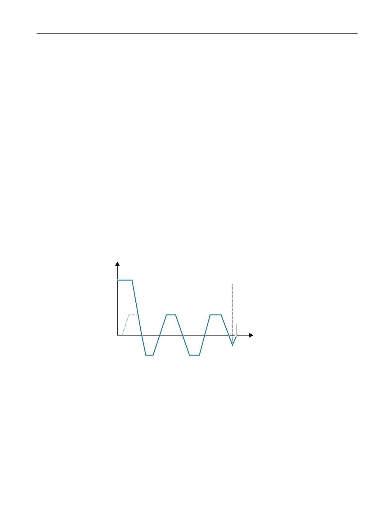
Block change
Processing of the active NC program is stopped if the spindle was switched into the oscillation
mode (DB31, ... DBX82.3 = 1 (switchover gear stage)).
Processing of the NC program is continued if the gear stage has been switched over (DB31, ...
DBX16.3 == 1 (gear stage has been switched over).
4QFFE
SQN
%#
ܵ %#9
HFBS JT TXJUDIFE PWFS
#MPDL
DIBOHF
5JNF
T
Figure 12-5
Block change following oscillation mode
Axes and spindles
Function Manual, 10/2020, 6FC5397-4GP40-0BA1
439
Spindles
12.4 Configurable gear adaptations
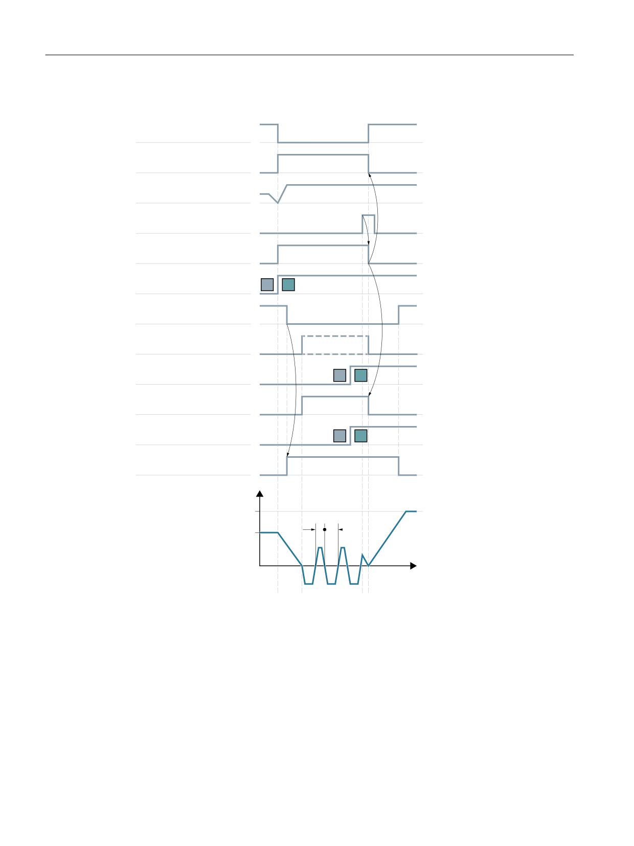
Example of the signal flow
%#
ܵ %#9
DPOUSPM NPEF
%#
ܵ %#9
PTDJMMBUJPO NPEF
1SPHSBNNFE 4 WBMVF
%#
ܵ %#9
HFBS JT TXJUDIFE PWFS
%#
ܵ %#9
TXJUDI PWFS HFBS
%#
ܵ %#9
TFU HFBS TUBHF
%#
ܵ %#9
TQJOEMF JO TFUQPJOU SBOHF
%#
ܵ %#9
TQJOEMF TUBUJPOBSZ
%#
ܵ %#9
BDUVBM HFBS TUBHF
%#
ܵ %#9
PTDJMMBUJPO FOBCMF
(FBS TUBHF FOHBHFE
NFDIBOJDBM
*OUFSOBM GFFE EJTBCMF
4QJOEMF TQFFE
5
5
U
U
U
U
U
t1:
As a result of the newly programmed S value S1300 in the NC program, the NC identifies the
necessity to switch over the gear stage (1st → 2nd gear stage), and requests the enable from the
PLC:
• NC → PLC: DB31, ... DBX82.3 = 1 (switchover gear stage)
The NC locks program processing (internal feed rate disable *)
Axes and spindles
440
Function Manual, 10/2020, 6FC5397-4GP40-0BA1
Spindles
12.4 Configurable gear adaptations
t2:
The NC signals spindle speed == 0 to the PLC:
• DB31, ... DBX61.4 = 1 (spindle stationary)
The PLC user program enables the oscillation mode.
• PLC → NC: DB31, ... DBX18.5 = 1 (oscillation enable)
Note
The oscillation enable must be set at the latest at time t2.
The NC starts to oscillate.
t3 :
The gear stage at the machine was switched over.
The PLC user program signals the switchover to the NC and deletes the oscillation mode enable:
• PLC → NC: DB31, ... DBX16.0 - 2 = 2 (actual gear stage)
• PLC → NC: DB31, ... DBX16.3 = 1 (gear stage has been switched over)
• PLC → NC: DB31, ... DBX18.5 = 0 (oscillation enable)
t4:
The NC exits the gear stage switchover by resetting the request to the PLC and the oscillation by
switching over the spindle mode from oscillation mode to control mode:
• NC → PLC: DB31, ... DBX82.3 = 0 (switchover gear stage)
• DB31, ... DBX84.6 = 0 (active spindle mode: oscillating mode)
• DB31, ... DBX84.7 = 1 (active spindle mode: control mode)
The NC enables the next block for machining, and accelerates the spindle to the new S value S1300.
*:
The internal feed disable is set if:
• Gear stage switchover as a result of programming the S value in the NC program AND
• A machiningblock is active (not rapid traverse G0)
Note
The internal feed disable is not set during a gear stage change from synchronized actions or in the
case of specifications via the PLC with FC 18.
Figure 12-6
Gear stage change with stationary spindle
Boundary conditions
• The NC/PLC interface signal does not have to be set in order to brake the spindle:
DB31, ... DBX4.3 (spindle stop)
The spindle is brought to a standstill in the control system when a gear stage switchover is
requested.
• The gear stage switchover must always be exited by setting the NC/PLC interface signal:
DB31, ... DBX16.3 = 1 (gear stage is changed)
• Oscillation motion in the NC is stopped when the NC/PLC interface signal is reset.
DB31, ... DBX18.5 (oscillation enable)
However, the spindle remains in the "Oscillation mode" mode.
• Spindle synchronization is lost for gear stage switchover and indirect measuring system
(MD31050 $MA_ENC_IS_DIRECT = 0 motor encoder).
Gear stage switchover ⇒ DB31, ... DBX60.4 / 5 = 0 (referenced/synchronized)
The spindle is again automatically synchronized when the zero mark is passed the next time
after a gear stage switchover.
Axes and spindles
Function Manual, 10/2020, 6FC5397-4GP40-0BA1
441
Spindles
12.4 Configurable gear adaptations
12.4.8
Gear stage change at fixed position
Application and advantages
Machine tools increasingly use standardized spindle drives, firstly to save technological dead
time on a gear stage change and secondly to gain the cost benefits of using standardized
components.
The "Gear stage change at fixed position" function supports the "directed gear stage change" of
load gearboxes that need to be activated in a different way than the NC. The gear stage change
can in this case only be performed at a defined spindle position. An oscillation movement as
required by conventional load gearboxes is thus no longer necessary.
Sequence for gear stage change at fixed position
The gear stage change at fixed position
Machine data configuration:
MD35010 $MA_GEAR_STEP_CHANGE_ENABLE = 2
runs the following sequence:
• Positioning of the spindle from standstill or movement to the position configured in machine
data:
MD35012 $MA_GEAR_STEP_CHANGE_POSITION.
If the gear stage change is performed out of a movement, then the current direction of
rotation is maintained. The spindle is in positioning mode during the positioning action.
NC/PLC IS:
DB31, ... DBX84.5 (positioning mode)
is output.
If no reference is available:
DB31, ... DBX60.4/5 = 0
or NC/PLC IS:
DB31, ... DBX17.4/5 (resynchronize on positioning MS 1/2)
is set, the positioning action is extended by the time it takes to find the zero mark.
• After reaching the gear stage change position configured in machine data:
MD35012$MA_GEAR_STEP_CHANGE_POSITION
the machine waits for the time in machine data:
MD35310 $MA_SPIND_POSIT_DELAY_TIME
before switching to oscillation mode,
and the known gear stage change dialog starts.
• Output of NC/PLC interface signals:
DB31, ... DBX84.6 (oscillation mode)
DB31, ... DBX82.3 (change gear)
DB31, ... DBX82.0-82.2 (set gear stage A to C).
Axes and spindles
442
Function Manual, 10/2020, 6FC5397-4GP40-0BA1
Spindles
12.4 Configurable gear adaptations
•
Position control is not disabled when an active measuring system with indirect encoder
(motor encoder) is used:
MD31040 $MA_ENC_IS_DIRECT = 0
If a measuring system with a direct encoder (load encoder) is active, position control is
deactivated:
DB31, ... DBX61.5 = 0,
because the induction flux to the load is interrupted and closed-loop position control is no
longer possible.
•
If position-controlled operation is not possible, it can be disabled by
resetting "Controller enable":
DB31, ... DBX2.1 = 0
•
Mechanical switchover of the gear stage on the machine.
No oscillation movement is required from the drive.
NC/PLC IS:
DB31, ... DBX18.5 (oscillation enable)
and
DB31, ... DBX18.4 (oscillation via PLC)
should not be set.
In principle, oscillation movement is still possible at this point.
•
Writing of NC/PLC IS:
DB31, ... DBX16.0-16.2 (actual gear stage A to C)
by the PLC.
•
After signal:
DB31, ... DBX16.3 (gear stage changed),
the last movement to be active is continued, if available.
For indirect encoders (motor encoders), the referencing status is cleared:
DB31, ... DBX60.4/5 = 0.
The spindle is in speed control mode and NC/PLC IS:
DB31, ... DBX84.7 (open-loop control mode)
is output.
Axes and spindles
Function Manual, 10/2020, 6FC5397-4GP40-0BA1
443
Spindles
12.4 Configurable gear adaptations
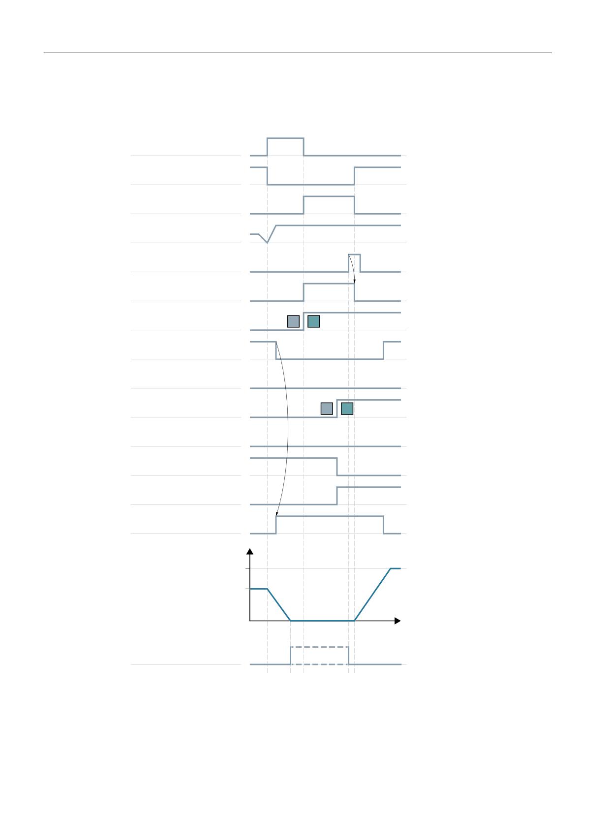
GSC at fixed position
Typical time sequence for the gear stage change at fixed position:
%#
ܵ %#9
QPTJUJPOJOH NPEF
%#
ܵ %#9
DPOUSPM NPEF
%#
ܵ %#9
PTDJMMBUJPO NPEF
1SPHSBNNFE 4 WBMVF
%#
ܵ %#9
HFBS JT TXJUDIFE PWFS
%#
ܵ %#9
TXJUDI PWFS HFBS
%#
ܵ %#9
TFU HFBS TUBHF " $
%#
ܵ %#9
TQJOEMF JO TFUQPJOU SBOHF
%#
ܵ %#9
TQJOEMF TUBUJPOBSZ
%#
ܵ %#9
BDUVBM HFBS TUBHF " $
%#
ܵ %#9
PTDJMMBUJPO TQFFE
TU HFBS TUBHF FOHBHFE
NFDIBOJDBM
OE HFBS TUBHF FOHBHFE
NFDIBOJDBM
*OUFSOBM GFFE EJTBCMF
4QJOEMF TQFFE
U
%#
ܵ %#9
FYBDU TUPQ OF
U
U
U
U
U
t1:
With the programming of S1300, NC detects a new gear stage (second gear stage), sets IS
DB31, ... DBX84.5 (positioning mode) and blocks processing for the next part program block (=
internal feed disable*).
Axes and spindles
444
Function Manual, 10/2020, 6FC5397-4GP40-0BA1
Spindles
12.4 Configurable gear adaptations
t2:
The spindle is stationary, and exact stop is signaled.
t3:
Gear stage change - wait time
t4:
The new gear stage is engaged. The PLC user transfers the new (actual) gear stage to the NC and
sets IS DB31, ... DBX16.3 (gear is changed).
t5:
The NC then retracts IS DB31, ... DBX82.3 (change gear), releases the next part program block for
processing, and accelerates the spindle to the new S value (S1300).
* :
The internal feed disable is set if:
• The spindle gear stage change has been programmed via the part program and
• A processing block is activated (i.e. G0 is not active)
The internal feed disable is not set during a gear stage change from synchronized actions or in the
case of specifications via the PLC with FC 18.
Figure 12-7
Gear stage change with stationary spindle
gear stage change position MD35012
The gear stage change position is defined in machine data:
MD35012 $MA_GEAR_STEP_CHANGE_POSITION
for each gear stage.
Gear stage change wait time MD35310
After the positioning action the machine waits for the time configured in machine data:
MD35310 $MA_SPIND_POSIT_DELAY_TIME
until gear change request:
DB31, ... DBX84.6 (oscillation mode)
DB31, ... DBX82.3 (change gear)
and
DB31, ... DBX82.0-82.2 (set gear stage A to C)
are output.
Position identifiers / position
The position is always approached via the shortest path (corresponds to DC).
If no reference is available and the spindle is in standstill
(e.g. after Power On), then the direction of travel is determined by the following machine data:
MD35350 $MA_SPIND_POSITIONING_DIR
If an adjustable gear stage change position is required, then this can be achieved by writing the
machine data and by a subsequent "Activate machine data".
The change of the MD value can be achieved by the part program or HMI.
If the system is unable to reach the preset position, then alarm 22020 is signaled and the gear
stage change dialog between NC and PLC does not take place in order not to destroy the gears.
As this alarm is serious, the part program cannot continue and the cause must be eliminated
under all circumstances. Experience has shown that the abortion of positioning is usually due to
incorrect MD settings or incompatible PLC signals.
Axes and spindles
Function Manual, 10/2020, 6FC5397-4GP40-0BA1
445
Spindles
12.4 Configurable gear adaptations
Velocity
The positioning velocity is taken from the machine data which is configured depending on the
gear stage:
MD35300 $MA_SPIND_POSCTRL_VELO
The NC/PLC interface signals "Spindle override"/"Feedrate override" at
DB31, ... DBX17.0=0: DB31, ... DBB19)
as well as:
DB31, ... DBX17.0=1: DB31, ... DBB0
are effective as normal for positioning.
The positioning speed can be changed proportionally through the program statement
OVRA[Sn].
Note
OVRA[Sn] is valid modally. After the gear stage change, a value appropriate for the machining
should be reset.
The part program statement FA[Sn] does not change the positioning speed during gear stage
change.
Acceleration
The acceleration values are determined by the machine data which is configured depending on
the gear stage:
MD35200 $MA_GEAR_STEP_SPEEDCTRL_ACCEL
and
MD35210 $MA_GEAR_STEP_POSCTRL_ACCEL
The acceleration can be changed proportionally by programming ACC[Sn].
Note
ACC[Sn] is valid modally. After the gear stage change, a value appropriate for the machining
should be reset.
Speed-dependent acceleration
The "knee-shaped acceleration characteristic" is effective as in positioning with SPOS or FC18.
Jerk
It is currently not possible to limit the change in acceleration.
Axes and spindles
446
Function Manual, 10/2020, 6FC5397-4GP40-0BA1
Spindles
12.4 Configurable gear adaptations
End of positioning
The transition between the end of the positioning action (DB31, ... DBX84.5)
and the start of oscillation mode (DB31, ... DBX84.6) is defined on
reaching "Exact stop fine" (DB31, ... DB60.7) and the time value entered in machine data:
MD3510 $MA_SPIND_POSIT_DELAY_TIME
The determination of the transition condition has an effect firstly on the gear stage change time
and secondly on the accuracy of the approach to the preset gear stage change position.
Block change
The block change is stopped and the machining blocks are not started until the gear stage has
been changed by the PLC (DB31, ... DBX16.3).
End of gear stage change
Once the gear stage change has been completed, the spindle returns to open-loop control mode
and will automatically change to the closed-loop control mode defined by SPCON or SPCOF.
All gear-specific limit values (min./max. speed of gear stage, etc.) correspond to the check-back
values of the actual gear stage.
Supplementary conditions
• The spindle must have at least one measuring system.
• Position-controlled operation must be possible and must have been activated.
• Generally, it must be possible to execute SPOS from the part program, from a synchronized
action or via FC18: "Start spindle positioning" without errors.
Unless all requirements can be met, the function described cannot be used successfully.
Activation
The function of gear stage change at fixed position
is activated by the configuration:
MD35010 $MA_GEAR_STEP_CHANGE_ENABLE = 2
12.4.9
Configurable gear step in M70
Technical backg5round
In some machines the spindle needs to be in a particular gear stage during axis mode.
Axes and spindles
Function Manual, 10/2020, 6FC5397-4GP40-0BA1
447

Spindles
12.4 Configurable gear adaptations
Possible reasons:
• Only one optimization (KV, feedforward control, filter) to suit a gear stage can be found in the
servo parameter set for axis mode (index 0). The machine data for this parameter set should
not be rewritten.
• There is only one mechanical transmission ratio which, unlike the others, possesses little or
no backlash compensation. The spindle can only follow a path motion or transformations
(e.g. TRANSMIT) together with other axes in this gear stage.
Function
If the function is activated, a predefined gear stage is loaded automatically during transition to
axis mode.
The gear stage change is integrated into the M70 process and occurs after spindle deceleration
and before the loading of the servo parameter set with index 0 (note
MD35590 $MA_PARAMSET_CHANGE_ENABLE!).
The typical dialog between NC and PLC which occurs during gear stage changes is executed in
a similar way to programmed gear stage changes (M41 ... M45) performed.
Requirements
Gear stage changes during transition to axis mode require general enabling of the gear stage
change via the machine data:
MD35010 $MA_GEAR_STEP_CHANGE_ENABLE (assign parameters to the gear stage change).
MD35090 $MA_NUM_GEAR_STEPS (number of gear stages set up)
Activation/deactivation
The function is activated/deactivated via the machine data:
MD35014 $MA_GEAR_STEP_USED_IN_AXISMODE (gear stage for axis mode in M70)
Value
Meaning
0
No implicit gear stage change occurs in M70. The current gear stage is retained (default
setting!).
1 ... 5
A gear stage change to gear stage 1 ... 5 occurs during the processing of M70.
Supplementary conditions
Gear stage change at fixed position (MD35010 $MA_GEAR_STEP_CHANGE_ENABLE = 2)
The "gear stage change at fixed position" function is supported. The sequence in M70 is then
extended by the time it takes to position the spindle. The position is approached at the current
gear stage.
Transition to axis mode without programming M70
The control system detects the transition to axis mode automatically from the program
sequence (see "Implicit transition to axis mode (Page 401)") and generates the requisite M70
sequence, including the gear stage change, within the control system.
Axes and spindles
448
Function Manual, 10/2020, 6FC5397-4GP40-0BA1

Spindles
12.4 Configurable gear adaptations
Transition to axis mode with FC 18
Implicit gear stage change is not supported in transition to axis mode with the FC 18 ("Start
axis"). This requires the right gear stage to be engaged by the PLC application before switching
to axis mode. The gear stage change is also possible with the FC 18 ("Start gear stage change").
Change from axis mode to spindle mode
When changing from axis mode to spindle mode, the gear stage loaded with M70 remains
activated. The gear stage which is activated in spindle mode prior to M70 is not automatically
loaded again. The servo parameter set is changed from parameter set 1 (index 0) to parameter
sets 2 ... 6 (index 1 ... 5) to suit the gear stage (with
MD35590 $MA_PARAMSET_CHANGE_ENABLE < 2).
Example
Gear stage 4 should be loaded in the case of spindle transition to axis mode.
Configuration: MD35014 $MA_GEAR_STEP_USED_IN_AXISMODE[<spindle name>] = 4
Program code
Comment
N05 M3 S1000
N10 G1 X100 F1000
N15 M70
; Gear stage 4 is loaded.
N20 POS[C]=77
N25 ...
Note
MD35014 can be changed by the "Activate machine data" function. Thus, the gear stage being
loaded can still be changed in the part program before transition to axis mode, if necessary.
12.4.10
Suppression of the gear stage change for DryRun, program test and SERUPRO
Function
For test feed rate (DryRun), program test and SERUPRO, normally, a gear stage change is not
required. This is the reason that it can be suppressed for these functions. The corresponding
configuration is realized with bits 0 ... 2 in machine data:
MD35035 $MA_SPIND_FUNCTION_MASK
Dry run feedrate (DryRun)
Bit 0 = 0
When the DryRun function is active - for part program blocks - gear stages are changed
with M40, M41 to M45, or programming via FC18 and synchronized actions.
Axes and spindles
Function Manual, 10/2020, 6FC5397-4GP40-0BA1
449

Spindles
12.4 Configurable gear adaptations
Bit 0 = 1
When the DryRun function is active - for part program blocks - a gear stage change is
suppressed with M40, M41 to M45, programming via FC18 and synchronized actions.
Program test and SERUPRO
Bit 1 = 0
For active program test / SERUPRO function - for part program blocks - gear stages are
selected with M40, M41 to M45, programming via FC18 and synchronized actions.
Bit 1 = 1
For active program test / SERUPRO function - for part program blocks - a gear stage change
is suppressed with M40, M41 to M45, programming via FC18 and synchronized actions.
DryRun, program testing and SERUPRO
Bit 2 = 0
Gear stage change for programmed gear stage is not performed subsequently on REPOS
after deselection of functions DryRun, Program Test and SERUPRO.
Bit 2 = 1
Gear stage change for programmed gear stage is performed after deselection of functions
DryRun and SERUPRO if possible.
Sequence
If a gear stage change is suppressed, if necessary, the interpolator will limit the programmed
spindle speed to the permissible speed range of the active gear stage.
NC/PLC interface signals DB31, ... DBX83.2 (setpoint speed increased) and DB31, ... DBX83.1
(setpoint speed limited) generated as a result of this limit are suppressed.
Monitoring by the PLC program is not necessary during DryRun and in dry run feedrate.
When the gear stage change is suppressed, no new gear stage setpoint (DB31,... DBX82.0-82.2)
is output to the PLC.
The gear stage change request DB31, ... DBX82.3 (change gear) is also suppressed.
This ensures that no gear stage change information has to be processed by the PLC program.
Determining the last active gear stage
System variable $P_GEAR returns the gear stage programmed in the part program (which may
not have been output to the PLC).
System variable $AC_SGEAR can be used to read the last active gear stage from the part
program, synchronized actions and at the user interface.
Behavior after deselection
The DryRun function can be deselected within a running part program. Once it has been
deselected, the correct gear stage requested by the part program must be identified and
selected.
It cannot be assured that the remainder of the part program will run without errors until the
correct gear stage has been activated. Any necessary gear stage change is performed in the
system REPOS started on deselection if the spindle is in speed control mode. A complete gear
stage change dialog takes place with the PLC and the last programmed gear stage is activated.
If, for REPOS, there is a mismatch between the gear stage programmed in the part program and
the actual gear stage supplied via the NC/PLC interface, then no gear stage change takes place.
Axes and spindles
450
Function Manual, 10/2020, 6FC5397-4GP40-0BA1
Spindles
12.5 Additional adaptations to the spindle functionality that can be configured
The same applies to the SERUPRO function.
For further explanations regarding the block search SERUPRO, see:
Further information
Velocities, setpoint/actual value systems, closed-loop control (Page 135)
Boundary conditions
If the gear stage change is suppressed, the output spindle speed moves within the speed range
specified by the current gear stage.
The following restrictions apply to the subsequent activation of a gear stage change with REPOS:
• The gear stage change is not activated subsequently if the spindle in the deselection or target
block is a command spindle (synchronized action) or PLC spindle (FC18).
• If the gear stage cannot be activated because the spindle is in position or axis mode or a link
is active, alarm 22011"Channel%1 block%3 spindle2% Change to programmed gear stage
not possible" is signaled.
Example
Gear stage change in DryRun
; 1st gear stage for output state activation
N00 M3 S1000 M41
; 1st gear stage is selected
M0
; Part program stop
; PI service: Activate dry run feedrate (DryRun)
; (Configuration)
N10 M42
; 2nd gear stage requested, no gear stage change
takes place
N11 G0 X0 Y0 Z0
; Position axes
N12 M0
; Part program stop
; PI service: Deactivate dry run feedrate (DryRun)
; REORG and REPOS are performed
; now the gear stage change to the 2nd gear
stage takes place
N20 G1 Z100 F1000
N99 M30
; Part program end
12.5
Additional adaptations to the spindle functionality that can be
configured
The following spindle functions can be activated using the machine data:
Axes and spindles
Function Manual, 10/2020, 6FC5397-4GP40-0BA1
451

Spindles
12.5 Additional adaptations to the spindle functionality that can be configured
MD35035 $MA_SPIND_FUNCTION_MASK, <bit> = <value>
<Bit>
<Val-
Meaning
ue>
0 ... 2
1
Activation: Gear stage change behavior for test feedrate (DryRun), program test and
SERUPRO
See "Suppression of the gear stage change for DryRun, program test and SERUPRO
(Page 449)".
4
1
Spindle speed S..., programmed in the NC program, is taken after
SD43200 $SA_SPIND_S. This also applies to speed setpoint signals via the PLC user
program with FC18 and synchronized actions.
See "Function (Page 462)".
5
0
When traversing the spindle in the JOG mode, the currently valid speed setpoint
applies.
See SD41200 $SN_JOGSPIND_SET_VELO
1
When traversing the spindle in the JOG mode, the speed parameterized in
SD43200 $SA_SPIND_S is effective.
8
1
Cutting velocity S..., programmed in the NC program is taken after
SD43202 $SA_SPIND_CONSTCUT_S.
This also applies to cutting velocity setpoint signals via the PLC user program with
FC18.
See "Function (Page 462)".
10
0
SD 43206 $SA_SPIND_SPEED_TYPE is not changed by the NC program or channel
settings.
1
If the spindle is a master spindle, then the feedrate type (active value of the 15th G
group) is taken after SD43206 $SA_SPIND_SPEED_TYPE.
If the spindle is not a master spindle, then SD43206 $SA_SPIND_SPEED_TYPE remains
unchanged.
See "Function (Page 462)".
12
Effectiveness of the spindle override for a zero mark search, M19, SPOS, SPOSA = 0:
0
The spindle override is not active.
1
The spindle override is active.
19
Response regarding an implicit auxiliary function output M19:
0
AND MD20850 $MC_SPOS_TO_VDI == 0:
For SPOS and SPOSA, auxiliary function M19 is not output to the PLC.
1
For SPOS and SPOSA, auxiliary function M19 is output to the PLC.
The address extension corresponds to the spindle number.
See "Positioning mode (Page 383)"
20
Response regarding an implicit auxiliary function output M70:
0
An implicit auxiliary function M70 is not output to the PLC.
Note: A programmed auxiliary function M70 is always output to the PLC.
1
When transitioning from spindle to axis operation, auxiliary function M70 is output to
the PLC.
The address extension corresponds to the spindle number.
See "Implicit transition to axis mode (Page 401)".
Axes and spindles
452
Function Manual, 10/2020, 6FC5397-4GP40-0BA1

Spindles
12.6 Selectable spindles
<Bit>
<Val-
Meaning
ue>
22
Deactivating the axis-specific NC/PLC interface signal DB31, ... DBX17.6 (invert M3/M4) to
reverse the direction of rotation of the spindle for tapping without compensating check
(G331, G332).
0
Interface signal DB31, ... DBX17.6 active.
Note
• Standard case: The value of the interface signal is determined when the NC
program starts. When the interface signal subsequently changes, this has no ef-
fect within the NC program.
• Special case: If a change to the interface signal must be taken into account while
the NC program is being executed, then this must be implemented as part of the
application engineering. See Chapter "Special case: Direction of rotation reversal
via NC/PLC interface signal in the NC program (Page 409)".
1
Interface signal DB31, ... DBX17.6 not active.
12.6
Selectable spindles
Function
Regarding channel spindles, the "Switchable spindles" function allows general NC programs to
be written, which can be used in different channels. The logical spindle number used in the NC
program is converted to the physical spindle number using a spindle number converter. This
means for the same spindle number programmed in the NC program, different physical spindles
(machine axes) can be traversed in different channels.
The physical spindles loaded or unloaded by "axis replacement" no longer have to be specified
explicitly in the part program.
Machine data
Physical spindle number
Each spindle must be assigned to a machine axes using a unique configurable number, the
physical spindle number:
MD35000 $MA_SPIND_ASSIGN_TO_MACHAX[<machine axis>] = <physical spindle number>
Activation of the spindle number converter
The spindle number converter is activated on a channel-for-channel basis using machine data:
MD20092 $MC_SPIND_ASSIGN_TAB_ENABLE = TRUE
Axes and spindles
Function Manual, 10/2020, 6FC5397-4GP40-0BA1
453
Spindles
12.6 Selectable spindles
Setting data
Spindle number converter
To parameterize the channel-specific spindle number converter, each logical spindle number or
programmed address extension - with which a spindle (channel spindle) is addressed in the NC
program - is assigned a physical spindle number (machine axis):
SD42800 $SC_SPIND_ASSIGN_TAB[<logical spindle number>] = <physical spindle number>
Further information:
• The logical spindle number of the current master spindle can be read from SD42800
$SC_SPIND_ASSIGN_TAB[ 0 ]. It is not permissible to write to this data. The data is updated
when programming SETMS.
Unused spindles are assigned the value 0 in SD42800.
• When an auxiliary function is output, the physical spindle number is output as address
extension.
• The spindle number converter is active when programming spindles in NC programs and
synchronized actions.
• The spindle number converter is not active when spindles are entered at the NC/PLC interface
using function block FC18, as in this case the physical spindles are directly addressed.
• System variables affected by the spindle conversion are: $P_S, $P_SDIR, $P_SMODE,
$P_GWPS, $AC_SDIR, §AC_SMODE, $AC_MSNUM, $AA_S
General conditions
• Switchable channel spindles are not a substitute for the "Axis replacement" function.
• Spindle conversion can be modified by writing to setting data (SD42800
$SC_SPIND_ASSIGN_TAB) via the NC program, PLC user program or PI service. The change
takes effect immediately.
• In the spindle number converter, only physical spindles can be used that are assigned to the
channel (MD20070 $MC_AXCONF_MACHAX_USED).
If physical spindles are specified in the spindle number converter, which are presently active
in another channel, then depending on the setting in MD30552 $MA_AUTO_GET_TYPE,
either the physical spindle is requested for the channel, or alarm 16105 "Assigned spindle
does not exist" is displayed.
• If SD42800 $SC_SPIND_ASSIGN_TAB[<n>] is written by the PLC, then the channel for which
the table is being changed should be in Reset status or the spindle to be changed should not
be used in the active part program.
A synchronized response can be achieved by means of a STOPRE preprocessing stop.
• Converting a logical to several physical spindles is not locked. However, with the display of
the logical spindle in the user interface, there are ambiguities corresponding to the
conversion table.
Axes and spindles
454
Function Manual, 10/2020, 6FC5397-4GP40-0BA1
Spindles
12.6 Selectable spindles
Example
Assignment, spindle number and machine axis:
MD35000 $MA_SPIND_ASSIGN_TO_MACHAX [AX4] = 1
MD35000 $MA_SPIND_ASSIGN_TO_MACHAX [AX5] = 2
MD35000 $MA_SPIND_ASSIGN_TO_MACHAX [AX6] = 3
MD35000 $MA_SPIND_ASSIGN_TO_MACHAX [AX7] = 5
Accepting a machine axis in a channel:
MD20070 $MC_AXCONF_MACHAX_USED[0] = 4
MD20070 $MC_AXCONF_MACHAX_USED[1] = 5
MD20070 $MC_AXCONF_MACHAX_USED[2] = 6
MD20070 $MC_AXCONF_MACHAX_USED[3] = 7
Specifying the master spindle:
MD20090 $MC_SPIND_DEF_MASTER_SPIND = 1
Spindle number converter
MD20092 $MC_SPIND_ASSIGN_TAB_EN-
; Activate spindle number converter
ABLE=1
SD42800 $SC_SPIND_AS-
; Master spindle as configured
SIGN_TAB[0]=1
SD42800 $SC_SPIND_AS-
; Basic setting of the table
SIGN_TAB[1]=1
SD42800 $SC_SPIND_AS-
SIGN_TAB[2]=2
SD42800 $SC_SPIND_AS-
SIGN_TAB[3]=3
SD42800 $SC_SPIND_AS-
; Logical spindle not assigned
SIGN_TAB[4]=0
; Address extension is 1 output: M1=3 S1=1000
; Spindle 1 (physical master spindle) rotates
M3 S1000
; Assignment of logical spindle 1 to physical spindle 5
SD42800 $SC_SPIND_AS-
SIGN_TAB[1]=5
; Assignment of logical spindle 2 to physical spindle 3
SD42800 $SC_SPIND_AS-
SIGN_TAB[2]=3
Axes and spindles
Function Manual, 10/2020, 6FC5397-4GP40-0BA1
455
Spindles
12.6 Selectable spindles
; Caution: physical spindle 3 has now been assigned twice.
; When programming logical spindles 2 and 3,
; physical spindle 3 is always addressed.
; In the basic machine displays, both spindles rotate.
SETMS(2)
; SD42800 $SC_SPIND_ASSIGN_TAB[0] = 2
; Master spindle = address extension = 2, converted spindle number M3 = 5 is output
; The physical spindle configured with number "3" stops.
M5
GET(S4)
; Alarm 16105: logical spindle 4
; cannot be converted
RELEASE(S1)
; Channel spindle 1 = physical spindle 5
; is released.
Axes and spindles
456
Function Manual, 10/2020, 6FC5397-4GP40-0BA1
Spindles
12.7 Programming
12.7
Programming
12.7.1
Programming from the part program
Programming statements
Statement
Description
SETMS:
Master spindle is the spindle specified in the following machine data:
MD20090 $MC_SPIND_DEF_MASTER_SPIND (position of deletion of the master spindle in
the channel)
SETMS(<n>):
The spindle with the number <n> is the master spindle
(may differ from the initial setting:
MD20090 $MC_SPIND_DEF_MASTER_SPIND).
The master spindle must be defined for the following functions:
• G95:
Revolutional feedrate
• G96 S.../G961
Constant cutting rate in m/min or feet/min
S...:
• G97/G971:
Cancel G96/G961 and freeze last spindle speed
• G63:
Tapping with compensating chuck
• G33/G34/G35:
Thread cutting
• G331/G332:
Tapping without compensating chuck
• G4 S...:
Dwell time in spindle revolutions
• Programming M3, M4, M5, S, SVC, SPOS, M19, SPOSA, M40, M41 to M45, and WAITS
without entering the spindle number
The current master spindle setting can be retained via RESET / part program end and part
program start. The setting is done via the machine data:
• MD20110 $MC_RESET_MODE_MASK
• MD20112 $MC_START_MODE_MASK
M3:
Clockwise spindle rotation for the master spindle
M<n>=3:
Clockwise spindle rotation for spindle number <n>
M4:
Counter-clockwise spindle rotation for the master spindle
M<n>=4:
Counter-clockwise spindle rotation for spindle number <n>
M5:
Spindle stop without orientation for the master spindle
M<n>=5:
Spindle stop without orientation for spindle number <n>
S...:
Spindle speed in rpm for the master spindle
S<n>=...:
Spindle speed in rpm for spindle number <n>
SVC=...:
Cutting rate in m/min or feet/min for the master spindle
SVC[<n>]=...:
Cutting rate in m/min or feet/min for the spindle <n>
SPOS=...:
Spindle positioning for the master spindle
SPOS[<n>]=...:
Spindle positioning for spindle number <n>
The block change is only performed when the spindle is in position.
Axes and spindles
Function Manual, 10/2020, 6FC5397-4GP40-0BA1
457

Spindles
12.7 Programming
Statement
Description
SPOSA=...:
Spindle positioning for the master spindle
SPOSA[<n>]=...:
Spindle positioning for spindle number <n>
The block change is executed immediately. Spindle positioning continues, regardless of
further part program processing, until the spindle has reached its position.
SPOS=DC(...):
The direction of motion is retained for positioning while in motion and the position ap-
proached. When positioning from standstill, the position is approached via the shortest
SPOS[<n>]=DC(...):
path.
SPOSA=DC(...):
SPOSA[<n>]=DC(...):
SPOS=ACN(...):
The position is always approached with negative direction of motion. If necessary, the
direction of motion is inverted prior to positioning.
SPOS[<n>]=ACN(...):
SPOSA=ACN(...):
SPOSA[<n>]=ACN(...):
SPOS=ACP(...):
The position is always approached with positive direction of motion.
If necessary, the direction of motion is inverted prior to positioning.
SPOS[<n>]=ACP(...):
SPOSA=ACP(...):
SPOSA[<n>]=ACP(...):
SPOS=IC(...):
The travel path is specified. The direction of travel is determined from the sign in front of
the travel path. If the spindle is in motion, the direction of travel is inverted as necessary to
SPOS[<n>]=IC(...):
allow traversing in the programmed direction.
SPOSA=IC(...):
If the zero mark is crossed during traversing, the spindle is automatically synchronized with
SPOSA[<n>]=IC(...):
the zero mark if no reference is available or if a new one has been requested via an interface
signal.
M19:
Positioning the master spindle to the position in SD43240
M[<n>]=19:
Positioning spindle number <n> to the position in SD43240
The block change is only performed when the spindle is in position.
Bring spindle to standstill and activate position control, select zero parameter set, activate
axis mode
M70:
for the master spindle
M<n>=70:
for spindle number <n>
Spindle position control ON
SPCON:
for the master spindle
SPCON(<n>):
for spindle number <n>
SPCON(<n>,<m>):
for spindle numbers <n> and <m>
Spindle position control OFF, activate speed control mode
PCOF:
for the master spindle
SPCOF(<n>):
for spindle number <n>
SPCOF(<n>,<m>):
for spindle numbers <n> and <m>
FPRAON(S<n>):
Revolutional feedrate for spindle <n> ON, derived from the master spindle
FPRAON(S<n>,S<m>):
Revolutional feedrate for spindle <n> ON, derived from spindle <m>
The revolutional feedrate value must be specified with FA[S<m>].
FPRAOF(S<n>):
Revolutional feedrate for spindle <n> OFF
C30 G90 G1 F3600
Rotary axis C (spindle in axis mode) travels to the position 30 degrees at a speed of 3600
degrees/min = 10 rpm
Axes and spindles
458
Function Manual, 10/2020, 6FC5397-4GP40-0BA1

Spindles
12.7 Programming
Statement
Description
Programmable minimum spindle speed limitation
G25 S...:
for the master spindle
G25 S<n>:
for spindle number <n>
Programmable maximum spindle speed limitation
G26 S...:
for the master spindle
G26 S<n>:
for spindle number <n>
Programmable maximum spindle speed limitation with G96, G961, G97
LIMS=...:
for the master spindle
LIMS[<n>]=...:
for spindle number <n>
VELOLIM[<spindle>]=...:
Programmable limiting of the configured gear stage dependent maximum speed
Using machine data (MD30455 $MA_MISC_FUNCTION_MASK, bit 6), when programming
in the part program, it can be set as to whether VELOLIM is effective independent of
whether used as spindle or axis (bit 6 = 1) - or is able to be programmed separately for each
operating mode (bit 6 = 0). If they are to be separately effective, then the selection is made
using the name when programming:
• Spindle name S<n> for spindle operating modes
• Axis name, e.g. "C", for axis operation
The correction value refers to:
• Spindles in axis operation (if MD30455 Bit 6 = 0):
To the configured maximum axis velocity (MD32000 $MA_MAX_AX_VELO).
• Spindles in spindle or axis operation (if MD30455 bit 6 = 1):
To the maximum speed of the active gear unit stage
(MD35130 $MA_GEAR_STEP_MAX_VELO_LIMIT[<n>])
WAITS:
Synchronization command for master spindle
The subsequent blocks are not processed until the spindle programmed in a previous NC
block with SPOSA has reached its position (with exact stop fine).
WAITS after M5: Wait until the spindle is stationary.
WAITS after M3/M4: Wait until the spindle reaches its setpoint speed.
WAITS(<n>):
Synchronization command for spindle number <n>
WAITS(<n>,<m>):
Synchronization command for spindle numbers <n> and <m>
FA[S<n>]:
Programming of positioning speed (axial feed) for spindle <n> in [deg/min]
With FA[S<n>]=0, the configured value takes effect once more:
MD35300 $MA_SPIND_POSCTRL_VELO
OVRA[S<n>]:
Programming of the axial override value for spindle <n> in [%]
ACC[S<n>]:
Programming of the axial acceleration capacity for spindle <n> in [%]
Axes and spindles
Function Manual, 10/2020, 6FC5397-4GP40-0BA1
459

Spindles
12.7 Programming
Statement
Description
SPI(<n>):
With SPI(<n>) a spindle number is converted into the data type AXIS according to ma-
chine data
MD35000 $MA_SPIND_ASSIGN_TO_MACHAX[ ]
SPI is used if axis functions are to be programmed with the spindle.
The following commands are possible with SPI:
• Frame commands:
- CTRANS()
- CFINE()
- CMIRROR()
- CSCALE()
• Velocity and acceleration values for following spindles:
- FA[SPI(<n>)]
- ACC[SPI(<n>)]
- OVRA[SPI(<n>)]
• System variables:
- $P_PFRAME[SPI(<n>),TR]=<value>
- $P_PFRAME=
CTRANS(X,<axis value>,Y,<axis value>,SPI(<n>),<axis value>)
- $P_PFRAME=
CSCALE(X,<scale>,Y,<scale>,SPI(<n>),<scale>)
- $P_PFRAME=CMIRROR(S<n>,Y,Z)
- $P_UBFR=CTRANS(A,10) : CFINE (19,0.1)
M40:
Automatic gear stage selection for the master spindle
M<n>=40:
Automatic gear stage selection for spindle number <n>
M41 to M45:
Select gear stage 1 to 5 for the master spindle
M<n>=41 to M<n>=45:
Select gear stage 1 to 5 for spindle number <n>.
Note
M functions M3, M4, M5, and M70 are not output in DB21, ... DBB194 and DBB202 if a spindle is
configured in a channel. These M functions are offered as extended M functions in DB21, ...
DBB68 ff. and in the relevant axis DBs, DB31, ... DBB86 ff.
Further information
For exhaustive information about programming the spindle, see the NC Programming
Programming Manual.
Axes and spindles
460
Function Manual, 10/2020, 6FC5397-4GP40-0BA1
Spindles
12.7 Programming
12.7.2
Programming via synchronized actions
Description
M functions M40 to M45 can also be programmed in synchronized actions.
The following must be observed:
• Programming of M40 ... M45 in the part program has no effect on the current status of the
automatic gear step change of synchronized actions, and vice versa.
• When programming S values with M40, automatic gear step change is effective separately
for synchronized actions and the part program.
• M40 is deactivated after POWER ON.
The gear step is not adjusted if an S value is specified from a synchronized action.
• An M40 command programmed using synchronized actions always remains active for
synchronized actions (modal) and is not reset on reset.
• M41 ... M45 selects first to fifth gear steps in accordance with the programming in the part
program.
An axis replacement is necessary in order to run the function.
Once the gear step change has been performed, the spindle status is neutral (same response
to M3, M4, M5 programming).
Further information
For further explanations regarding the programming of the spindle as well as spindle
movements from synchronized actions, refer to:
• NC Programming Programming Manual
• Function Manual Synchronized Actions
12.7.3
Programming spindle controls via PLC with FC18
When the PLC specifies the direction of rotation and speed using FC18, the NC can determine and
select a gear stage to match the speed. This is equivalent to the M40 functionality when
programming via the part program.
The correct start code must be set when FC18 is called in a PLC user program, in order to activate
gear stage selection.
Further information
More detailed explanations regarding the programming of spindle controls by PLC with FC18 can
be found in:
• Function Manual PLC
Axes and spindles
Function Manual, 10/2020, 6FC5397-4GP40-0BA1
461
Spindles
12.7 Programming
12.7.4
Programming using NC/PLC interface signals
12.7.4.1
Function
Note
The function is only available when using SINUMERIK Operate!
The following jobs/tasks can be issued to a spindle from the PLC user program using the job
interface DB31, … DBX30.0 - 4:
• Spindle stop
• Spindle start, clockwise rotation
• Spindle start, counter-clockwise rotation
• Select gear stage
• Spindle-start positioning
Job ID
At the NC side, a spindle job is identified as a result of a positive edge change of the appropriate
interface signal (0 → 1).
Requirements
At the instant of the spindle job, the following preconditions must be satisfied regarding the
channel, program and spindle states.
• Channel state:
- DB21, ... DBX35.6 == 1 (channel state "interrupted") OR
- DB21, … DBX35.7 == 1 (channel state "reset")
• Program state:
- DB21, ... DBX35.3 = 1 (program state "interrupted") OR
- DB21, ... DBX35.4 = 1 (program state "interrupted")
• Spindle state
-
("Channel axis" OR "Neutral axis") AND NO
– (positioning motion using FC18 OR synchronized action)
Note
Response in the event of an error
In the event of an error, i.e. if a job signal is set during an invalid state, then the corresponding
job is ignored without any feedback signal.
Axes and spindles
462
Function Manual, 10/2020, 6FC5397-4GP40-0BA1

Spindles
12.7 Programming
Channel assignment
A spindle job is processed in that particular channel, which is assigned to the spindle at the
instant of the job.
The channel, which is assigned to the spindle, can be determined using the following NC/PLC
interface signal:
DB31, ... DBX68.0 - 3 (channel assignment of the NC axis/spindle)
Mode change
The definitions made within the context of the spindle jobs are kept beyond any mode change.
Program start
When an NC program starts in the channel, which is assigned to the spindle, then the actual
spindle definitions are kept. Spindle definitions can be changed using NC program commands or
using synchronized actions.
See also
M40: Automatic gear stage selection for speeds outside the configured switching thresholds
(Page 477)
Velocities, setpoint/actual value systems, closed-loop control (Page 135)
12.7.4.2
Commissioning: Machine data
Automatically accepting spindle definitions in setting data
Using the following machine data settings, spindle definitions are transferred from NC
programs, synchronized actions and the spindle control by the PLC (FC18) into the
corresponding setting data:
MD35035 $MA_SPIND_FUNCTION_MASK, bit x = <value>
Bit
Value
Meaning
4
1
A speed setpoint is entered via NC program, synchronized actions or FC18 is trans-
ferred into the following spindle-specific setting data:
SD43200 $SA_SPIND_S[<spindle>]
Note
S values that are not programmed speed values are not transferred. e.g.:
• S value at constant cutting speed (G96, G961)
• S value for rotation-related dwell time (G4)
0
No speed setpoints are transferred into the setting data.
Axes and spindles
Function Manual, 10/2020, 6FC5397-4GP40-0BA1
463

Spindles
12.7 Programming
Bit
Value
Meaning
8
1
A cutting rate is entered as setpoint in the following spindle-specific setting data
via the NC program, synchronized actions or FC18 if the "Constant cutting rate"
function is active (G96, G961, G962):
SD43202 $SA_SPIND_CONSTCUT_S[<spindle>]
Note
S values that are not programmed cutting rate values are not transferred. e.g.:
• S value for rotation-related dwell time (G4)
0
No cutting rate setpoints are transferred into the setting data.
10
1
For the master spindle the feedrate type is transferred into the following setting
data:
SD43206 $SA_SPIND_SPEED_TYPE[<spindle>]
0
No feedrate type definitions for the master spindle are transferred into the setting
data.
With the spindle definitions transferred into the setting data, the spindle is traversed to execute
the spindle jobs.
12.7.4.3
Commissioning: NC/PLC interface signals
Job interface
• DB31, … DBX30.0 (spindle stop)
• DB31, … DBX30.1 (spindle start, clockwise)
• DB31, … DBX30.2 (spindle start, counter-clockwise)
• DB31, ... DBX30.3 (select gear stage)
• DB31, … DBX30.4 (spindle positioning start)
Relevant state signals
• DB21, ... DBX35.3 (program state "interrupted")
• DB21, ... DBX35.4 (program state "canceled")
• DB21, ... DBX35.7 (channel state "reset")
• DB21, ... DBX35.6 (channel state "interrupted")
• DB31, ... DBX68.0 - 3 (channel assignment of the NC axis/spindle)
• DB31, ... DBX 84.0 (constant cutting rate)
Further information
A detailed description of the NC/PLC interface signals can be found in the NC Variables and
Interface Signals List Manual.
12.7.4.4
Speed setpoint (SD43200)
When starting a spindle using a spindle job, then the spindle-specific value entered in the setting
data becomes active as spindle speed:
Axes and spindles
464
Function Manual, 10/2020, 6FC5397-4GP40-0BA1
Spindles
12.7 Programming
SD43200 $SA_SPIND_S[<spindle>] (speed when the spindle is started via the PLC job interface)
Writing a new speed value
In the following situations, a new speed value is written to the setting data:
• A speed setpoint is entered via NC program, synchronized action or FC18
Supplementary conditions:
- MD35035 $MA_SPIND_FUNCTION_MASK (Page 463), bit 4 == 1
- DB31, ... DBX84.0 == 0 (constant cutting rate)
• Writing the setting data to the NC program or synchronized action
• Writing the setting data via HMI (OPI) @@@
Supplementary conditions
Gear stage change
A gear stage change is not initiated if the setpoint speed is out of the speed range of the actual
gear stage.
Exceptions, see Chapter "M40: Automatic gear stage selection for speeds outside the
configured switching thresholds (Page 477)".
12.7.4.5
Entering a constant cutting rate (SD43202)
When starting a master spindle using a spindle job - and the "Constant cutting rate" spindle
speed type is active, then the spindle-specific value entered in the setting data becomes active
as constant cutting rate:
SD43202 $SA_SPIND_CONSTCUT_S[<spindle>] (cutting rate when the spindle starts via the PLC
job interface)
Writing a new cutting rate of value
In the following situations, a new constant cutting rate of the master spindle is written to the
spindle-specific setting data:
• A constant cutting rate is entered via NC program, synchronized action or FC18
Supplementary conditions:
- MD35035 $MA_SPIND_FUNCTION_MASK (Page 463), bit 8 == 1
- DB31, ... DBX84.0 == 1 (constant cutting rate active)
• Writing the setting data to the NC program or synchronized action
• Writing the setting data via HMI (OPI) @@@
Axes and spindles
Function Manual, 10/2020, 6FC5397-4GP40-0BA1
465

Spindles
12.7 Programming
System of units
When writing the setting data, the value is interpreted corresponding to the following secondary
conditions:
• Writing via NC program or synchronized action:
- G700 active: feet/min
- G710 active: m/min
- G70, G71 active: Depending on the setting in MD10240
$MN_SCALING_SYSTEM_IS_METRIC
• Writing via SINUMERIK Operate:
- Depending on the setting in MD10240 $MN_SCALING_SYSTEM_IS_METRIC
• Writing via FC18:
- Function number 10: "constant cutting rate (m/min)"
- Function number 11: "constant cutting rate (feet/min)"
Reading via system or OPI variable
In the NC program, synchronized action or HMI, the currently entered setpoint for the constant
cutting rate can be read using the following system data:
System variable
OPI variable
Meaning
$P_CONSTCUT_S
---
Last programmed cutting rate
$AC_CONSTCUT_S
acConstCutS
Actual constant cutting rate
12.7.4.6
Entering the spindle speed type for the master spindle (SD43206)
Definition of the spindle speed type for the master spindle from part program, FC18 or
synchronized actions are written to the following setting data from all the usual sources:
SD43206 $SA_SPIND_SPEED_TYPE (spindle speed type for spindle start via PLC interface)
The value range and functionality correspond to the 15th G group (feedrate type).
Permissible values are G values: 93, 94, 95, 96, 961, 97 and 971.
Depending on the setting, for DB31, … DBX30.1/2 (spindle start, clockwise/counter-clockwise)
either the speed from SD43200 $SA_SPIND_S or the cutting speed from
SD43202 $SA_SPIND_CONSTCUT_S is active:
93, 94, 95, 97 and 971:
The master spindle is started with the speed from SD43200.
96 and 961:
The speed of the master spindle is obtained from the specified
cutting rate (SD43202) and the radius of the transverse axis.
Axes and spindles
466
Function Manual, 10/2020, 6FC5397-4GP40-0BA1

Spindles
12.7 Programming
12.7.5
External programming (PLC, HMI)
SD43300 and SD42600
The revolutional feedrate behaviour can be selected externally via the axial setting data:
SD43300 $SA_ASSIGN_FEED_PER_REV_SOURCE (Rotational feedrate for spindles)
in JOG operating mode using the channel-specific setting data
SD42600 $SC_JOG_FEED_PER_REV_SOURCE (Revolutional fedrate control in JOG mode)
The following settings can be made via the setting data:
>0:
The machine axis number of the rotary axis/spindle from which the revolutional feedrate shall
be derived.
-1:
The revolutional feedrate is derived from the master spindle of the channel in which the axis/
spindle is active in each case.
0:
Function is deselected.
FPRAON (S2)
Revolutional feedrate for spindle S2 ON, derived from the master spindle
FPRAON (S2, A)
Revolutional feedrate for spindle S2 ON, derived from axis A.
The revolutional feedrate value must be specified with FA[Sn].
FPRAOF (S2)
Revolutional feedrate for spindle S2 OFF.
SPI(n)
It is also possible to program SPI(n) instead of SPI(Sn).
Axes and spindles
Function Manual, 10/2020, 6FC5397-4GP40-0BA1
467
Spindles
12.8 Spindle monitoring
12.8
Spindle monitoring
12.8.1
Permissible speed ranges
The permissible speed range of a spindle results from the parameterized or programmed speed
limit values and the active spindle function (G94, G95, G96, G961, G97, G971, G33, G34, G35,
G331, G332, etc.).
6SHHG
0D[ HQFRGHU OLPLW IUHTXHQF\
0'
0$B(1&B)5(4B/,0,7
0DFKLQH GHSHQGHQW PD[ VSLQGOH VSHHG
0'
0$B63,1'B9(/2B/,0,7
3URFHVV GHSHQGHQW PD[ VSLQGOH VSHHG
6'
6$B63,1'B86(5B9(/2B/,0,7
0D[ VSLQGOH VSHHG RI DFWLYH JHDU VWDJH Q
0'
0$B*($5B67(3B0$;B9(/2B/,0,7>Q@
0'
0$B*($5B67(3B3&B0$;B9(/2B/,0,7>Q@
3URJUDPPDEOH VSLQGOH VSHHG OLPLW *
6'
6$B63,1'B0$;B9(/2B*
3URJUDPPDEOH VSLQGOH VSHHG OLPLWDWLRQ /,06 *
6'
6$B63,1'B0$;B9(/2B/,06
3URJUDPPDEOH PLQLPXP VSLQGOH VSHHG *
6'
6$B63,1'B0,1B9(/2B*
0LQ VSLQGOH VSHHG RI DFWLYH JHDU VWDJH Q
0'
0$B*($5B67(3B0,1B9(/2B/,0,7>Q@
0D[ YHORFLW\ VSHHG $[LV VSLQGOH VWRSSHG
0'
0$B67$1'67,//B9(/2B72/
,) $[LV VSLQGOH VWDWLRQDU\ Q QPLQ
6SHHG UDQJH RI VSLQGOH RU VSLQGOH FKXFN
6SHHG UDQJH RI DFWLYH JHDU VWDJH
6SHHG UDQJH RI DFWLYH JHDU VWDJH
OLPLWHG E\ * DQG *
6SHHG UDQJH RI DFWLYH JHDU VWDJH
ZLWK FRQVWDQW FXWWLQJ UDWH * DQG *
,) 5HIHUHQFHG V\QFKURQL]HG
Figure 12-8
Ranges of spindle monitoring functions / speeds
Axes and spindles
468
Function Manual, 10/2020, 6FC5397-4GP40-0BA1
Spindles
12.8 Spindle monitoring
12.8.2
Axis/spindle stationary
Functions such as tool change, open machine doors, path feedrate enable, etc. are only possible
at the machine when the spindle is stationary.
Function
The "axis/spindle stationary" state is reached if a setpoint is no longer generated and the spindle
actual speed falls below the configured threshold value for "axis/spindle stationary":
MD36060 $MA_STANDSTILL_VELO_TOL (max. velocity/speed for "axis/spindle stationary")
If the spindle has come to a standstill, the following NC/PLC interface signal is set:
DB31, ... DBX61.4 (axis/spindle stationary)
Effectiveness
Monitoring for spindle stop is effective in all spindle modes and in axis mode.
Deactivate path feed
If a spindle is stopped in the open-loop control mode (M5), then path feed is deactivated if the
following machine data is set:
MD35510 $MA_SPIND_STOPPED_AT_IPO_START (feedrate enable for spindle stopped)
The path feed is re-enabled if the spindle comes to a standstill.
12.8.3
Spindle in setpoint range
Function
"Spindle in setpoint range" spindle monitoring checks whether:
• The programmed spindle speed is reached.
• The spindle is at a standstill:
DB31, ... DBX61.4 (axis/spindle stationary) = 1
• The spindle is still in the acceleration or deceleration phase.
In the spindle mode, open-loop control mode, the setpoint speed is compared with the actual
speed. If the actual speed deviates by more than the spindle tolerance that can be entered via
MD (refer below) then:
• The following axial NC/PLC interface signal is set to "0":
DB31, ... DBX83.5 (spindle in setpoint range) = 0
• The next machining block is not enabled (depending on the setting in
MD35500 $MA_SPIND_ON_SPEED_AT_IPO_START, see "Axis/spindle stationary (Page 469)").
Axes and spindles
Function Manual, 10/2020, 6FC5397-4GP40-0BA1
469
Spindles
12.8 Spindle monitoring
Spindle setpoint speed
The spindle speed setpoint is derived from the programmed speed taking into account the
spindle override and the active limits.
If the programmed speed is limited or increased, this is displayed using DB31, ... DBX83.1 (speed
setpoint limited) or DB31, ... DBX83.2 (speed setpoint increased) (see also "Minimum /
maximum speed of the gear stage (Page 470)"). The means that reaching the tolerance range
of the setpoint speed is not prevented.
Tolerance range for setpoint speed
The tolerance range of the setpoint speed is defined by the spindle speed tolerance factor:
MD35150 $MA_SPIND_DES_VELO_TOL
Example:
MD35150 $MA_SPIND_DES_VELO_TOL = 0.1
⇒ The spindle actual speed may deviate ±10% from the setpoint speed.
The following NC/PLC interface signal is set to "1" if the spindle actual speed lies within the
tolerance range:
DB31, ... DBX83.5 (spindle in setpoint range) = 1
Special case:
If the spindle speed tolerance is set to "0", then DB31, ... DBX83.5 (spindle in the setpoint range)
is permanently set to "1" and no path control is performed.
Speed change
Path control only takes place at the start of the traverse block and only if a speed change has
been programmed. If the speed tolerance range is exited, e.g. due to an overload, the path
movement is not automatically brought to a standstill.
12.8.4
Minimum / maximum speed of the gear stage
Minimum speed
The minimum speed of the gear stage of a spindle is configured in the machine data:
MD35140 $MA_GEAR_STEP_MIN_VELO_LIMIT[<n>]
The speed setpoints, generated taking into account the override, do not fall below the minimum
speed.
If an S value is programmed, which is less than the minimum speed, the setpoint speed is
increased to the minimum speed and the following NC/PLC interface signal is set:
DB31, ... DBX83.2 (speed setpoint increased)
Axes and spindles
470
Function Manual, 10/2020, 6FC5397-4GP40-0BA1

Spindles
12.8 Spindle monitoring
The minimum gear stage speed is effective only in speed mode and can only be undershot by:
• Spindle override 0%
• M5
• S0
• DB31, ... DBX4.3 (spindle stop)
• DB31, ... DBX2.1 (withdraw controller enable)
• DB21, ... DBX7.7 (reset)
• DB31, ... DBX2.2 (delete distance-to-go / spindle reset)
• DB31, ... DBX18.5 (oscillation speed)
• DB21, ... DBX7.4 (NC stop axes plus spindles)
• DB31, ... DBX1.3 (axis/spindle disable)
• DB31, ... DBX16.7 (delete S value)
Maximum speed
The maximum speed of the gear stage of a spindle is configured in machine data:
MD35130 $MA_GEAR_STEP_MAX_VELO_LIMIT[<n>]
The speed setpoints, generated taking into account the override, are limited to this speed.
The following NC/PLC interface signal is set in the case that the speed is limited:
DB31, ... DBX83.1 (speed setpoint limited)
12.8.5
Diagnosis of spindle speed limitation
System variables
The effective/limiting spindle parameters can be read via the following system variables: The
system variables must be indexed with the spindle number and they return values only relevant
in the speed control and spindle position modes.
System variable
Meaning
$AC_SMAXVELO[<n>]
Maximum possible spindle speed [RPM].
$AC_SMAXVELO_INFO[<n>]
Identifier for the speed-limiting data element.
$AC_SMINVELO[<n>]
Minimum possible spindle speed [RPM].
$AC_SMINVELO_INFO[<n>]
Identifier for the speed-increasing data element.
$AC_SMAXACC[<n>]
Maximum possible spindle acceleration [rev/s2].
$AC_SMAXACC_INFO[<n>]
Identifier for the acceleration-limiting data element.
$AC_SPIND_STATE[<n>]
Spindle status in speed-control mode.
<n>: 0, 1, 2, ... maximum spindle number (0: current master spindle of the channel)
Axes and spindles
Function Manual, 10/2020, 6FC5397-4GP40-0BA1
471
Spindles
12.8 Spindle monitoring
Further information
The detailed description of the system variables can be found in:
List Manual, System Variables
NC/PLC interface signals
The limit or increase of the spindle speed is signaled with the following NC/PLC interface signals:
• DB31, ... DBX83.1 (speed setpoint limited)
• DB31, ... DBX83.2 (speed setpoint increased)
Boundary conditions
Spindle mode
The values delivered by the system variables depend on the spindle mode:
• Speed control mode:
All system variables deliver current values.
• Positioning mode:
The system variables $AC_SMAXVELO, $AC_SMAXACC and $AC_SPIND_STATE deliver valid
values. The system variables $AC_SMINVELO and $AC_SMINVELO_INFO deliver the data that
becomes effective on changing to the speed control mode.
• Axis mode (e.g. if the spindle is used by a transformation TRANSMIT, TRACYL,... or follows a
path motion as a special axis):
The system variable $AC_SPIND_STATE can also be used in the axis mode. Separate system
variables are available in the axis mode for dynamic data:
$AA_VMAXM, $AA_VMAXB and $AA_VLFCT.
SERUPRO block search
The following control response is obtained for a SERUPRO block search:
• The system variable $AC_SMAXVELO / $AC_SMAXACC delivers the maximum representable
speed / acceleration.
• $AC_SMAXVELO_INFO and $AC_SMAXACC_INFO deliver the VALUE "0" (no limitation active).
• $AC_SMINVELO and $AC_SMINVELO_INFO deliver data as for normal part program
processing.
• $AC_SPIND_STATE returns the states as set for SERUPRO.
Example
The effective/limiting spindle parameters for spindle 1 are written cyclically in the R parameter
and displayed as R parameter in the "Parameters" > "User variable" operating area on the HMI.
Program code
N05 IDS=1 WHENEVER TRUE DO $R10=$AC_SMAXVELO[1]
N10 IDS=2 WHENEVER TRUE DO $R11=$AC_SMAXVELO_INFO[1]
N15 IDS=3 WHENEVER TRUE DO $R12=$AC_SMINVELO[1]
Axes and spindles
472
Function Manual, 10/2020, 6FC5397-4GP40-0BA1
Spindles
12.8 Spindle monitoring
Program code
N20 IDS=4 WHENEVER TRUE DO $R13=$AC_SMINVELO_INFO[1]
N25 IDS=5 WHENEVER TRUE DO $R14=$AC_SPIND_STATE[1]
See also
Spindle in setpoint range (Page 469)
12.8.6
Maximum spindle speed
Maximum spindle speed: parameterizable machine-related limit value
The maximum machine-dependent spindle speed - for protecting the spindle chuck or the tool,
for example - is parameterized using the following machine data:
MD35100 $MA_SPIND_VELO_LIMIT (maximum spindle speed)
The spindle speed is monitored by the NC in the actual values, i.e. taking into account the current
gear stage.
Note
Machine manufacturer
It is recommended that changes to the maximum spindle speed in machine data MD35100 only
be made when the spindle is stationary. This is particularly important for spindles that are active
after NC reset (see also MD35040 SPIND_ACTIVE_AFTER_RESET). Otherwise alarm 22100 may
be output.
Further information
• Manufacturer documentation: List Manual, "Detailed Machine Data Description"
• User documentation: Diagnostics Manual
Responses to violation
If the actual speed of a spindle exceeds the parameterized maximum spindle speed by more than
the tolerance value,
"Actual spindle speed" > MD35100 $MA_SPIND_VELO_LIMIT (maximum
spindle speed) +
MD35150 $MA_SPIND_DES_VELO_TOL (spindle speed tolerance value)
the following effects can be seen on the NC side.
• DB31, ... DBX83.0 = 1 (speed limit exceeded)
• Alarm 22100 "Chuck speed exceeded" is displayed
• All axes and spindles of the channel are stopped
Axes and spindles
Function Manual, 10/2020, 6FC5397-4GP40-0BA1
473

Spindles
12.8 Spindle monitoring
Note
Rotary axis / spindle
If a spindle is also temporarily operated as a rotary axis, alarm 22100 "Chuck speed exceeded"
is displayed if:
"Actual speed of the rotary axis" > MD35100 $MA_SPIND_VELO_LIMIT
(maximum spindle speed) +
MD35150 $MA_SPIND_DES_VELO_TOL (spindle speed tolerance value)
Remedy: Adjust the maximum spindle speed to the maximum rotary axis speed during rotary
operation:
MD35100 $MA_SPIND_VELO_LIMIT = MD32000 $MA_MAX_AX_VELO (maximum
speed of the rotary axis)
For the change to take effect a reset must be triggered.
Maximum spindle speed: Configurable process-dependent limit value
The maximum process-related spindle speed is configured through the following setting data:
SD43235 $SA_SPIND_USER_VELO_LIMIT (maximum spindle speed)
Changes can be made by writing the setting data through:
• Programming in an NC program
• Manually through the user interface by the machine operator
Changes become effective immediately.
Limitation of the speed setpoint
Where appropriate, the controller limits programmed spindle speed setpoints to the values
specified in the setting data. The limitation is then displayed through the following system
variables:
$AC_SMAXVELO_INFO[<Spindle number>] == 21
12.8.7
Maximum encoder limit frequency
CAUTION
Limit violation
The maximum encoder frequency limit of the actual spindle position encoder is monitored by
the control (the limit can be exceeded). It is the responsibility of the machine tool manufacturer
to ensure that the configuration of the spindle motor, gearbox, measuring gearbox, encoder
and machine data prevents the maximum speed of the actual spindle position encoder being
exceeded.
Axes and spindles
474
Function Manual, 10/2020, 6FC5397-4GP40-0BA1
Spindles
12.8 Spindle monitoring
Maximum encoder frequency exceeded.
If the spindle speed reaches a speed (large S value programmed), which exceeds the maximum
encoder limit frequency (the maximum mechanical speed limit of the encoder must not be
exceeded), the synchronization is lost. The spindle continues to rotate, but with reduced
functionality.
With the following functions, the spindle speed is reduced until the active measurement system
is operating below the encoder limit frequency again:
• Thread cutting (G33, G34, G35)
• Tapping without compensating chuck (G331, G332)
• Revolutional feedrate (G95)
• Constant cutting rate (G96, G961, G97, G971)
• SPCON (position-controlled spindle operation)
When the encoder limit frequency is exceeded
NC/PLC IS:
DB31, ... DBX60.4 (referenced/synchronized 1)
or
DB31, ... DBX60.5 (referenced/synchronized 2)
are reset for the measurement system in question and NC/PLC IS:
DB31, ... DBX60.2 (encoder limit frequency 1 exceeded)
or
DB31, ... DBX60.3 (encoder limit frequency 2 exceeded)
are set.
If the spindle is in axis mode, the maximum encoder limit frequency must not be exceeded.
The maximum velocity (MD32000 $MA_MAX_AX_VELO) must lie below the maximum encoder
limit frequency; otherwise, alarm 21610 is output and the axis is brought to a standstill.
Maximum encoder limit frequency undershot
If the maximum encoder frequency limit has been exceeded and the speed subsequently falls
below the maximum encoder limit frequency (smaller S value programmed, spindle override
switch changed, etc.), the spindle is automatically synchronized with the next zero mark or the
next proximity switch signal. The new synchronization will always be carried out for the active
position measuring system that has lost its synchronization and whose maximum encoder limit
frequency is currently undershot.
Special features
If the following functions are active, the maximum encoder frequency cannot be exceeded:
• Spindle positioning mode, axis mode
• Thread cutting (G33, G34, G35)
• Tapping without compensating chuck G331, G332 (does not apply to G63)
• Revolutional feedrate (G95)
• Constant cutting rate (G96, G961, G97, G971)
• SPCON
Axes and spindles
Function Manual, 10/2020, 6FC5397-4GP40-0BA1
475
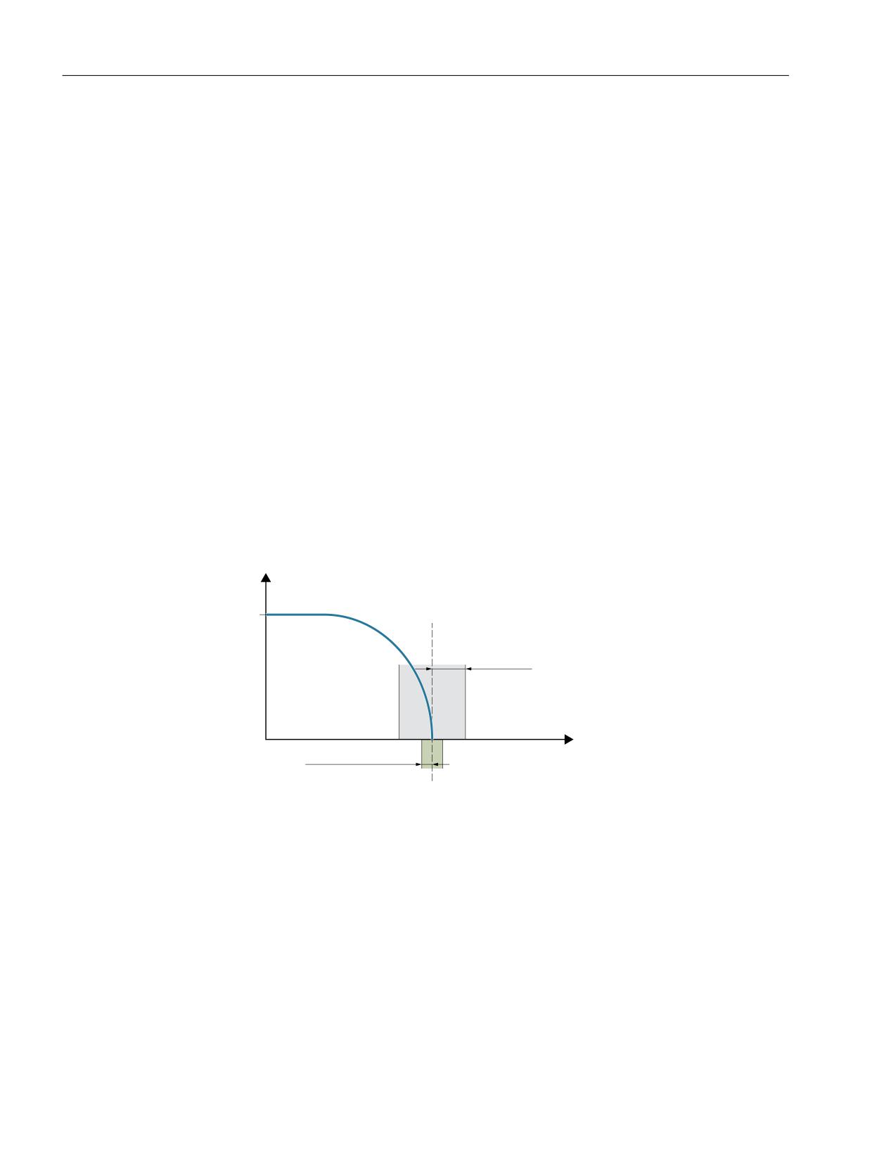
Spindles
12.8 Spindle monitoring
12.8.8
End point monitoring
End point monitoring
During positioning (the spindle is in positioning mode), the system monitors the distance from
the spindle (with reference to the actual position) to the programmed spindle position setpoint
(end point).
For this to work, in machine data:
MD36000 $MA_STOP_LIMIT_COARSE (Exact stop limit coarse)
and
MD36010 $MA_STOP_LIMIT_FINE (Exact stop limit fine)
two limit values can be defined as an incremental path starting from the spindle position
setpoint.
Regardless of the two limit values, the positioning of the spindle is always as accurate as defined
by the connected spindle measurement encoder, the backlash, the transmission ratio, etc.
Exact stop window dependent on parameter set
Various parameter-set-dependent exact stop windows can be configured.
This makes it possible to work to different levels of accuracy in axis mode and spindle
positioning. The exact stop window can be configured separately for each gear step for spindle
positioning.
4QFFE
4FUQPJOU QPTJUJPO
.BY NPUPS
TQFFE
&YBDU TUPQ MJNJU
DPBSTF
1PTJUJPO
&YBDU TUPQ MJNJU OF
Figure 12-9
Exact stop zones of a spindle
DB31, ... DBX60.7 and DB31, ... DBX60.6 (position reached with exact stop coarse / fine)
The two limit values defined by machine data:
MD36000 $MA_STOP_LIMIT_COARSE (Exact stop limit coarse)
and
MD36010 $MA_STOP_LIMIT_FINE (Exact stop limit fine)
are output to the PLC using NC/PLC IS:
DB31, ... DBX60.7 (Position reached with exact stop coarse)
and
DB31, ... DBX60.6 (Position reached with exact stop fine).
Axes and spindles
476
Function Manual, 10/2020, 6FC5397-4GP40-0BA1
Spindles
12.8 Spindle monitoring
Block change for SPOS and M19
When positioning the spindle with SPOS or M19 the block is changed
dependent on end point monitoring with NC/PLC IS:
DB31, ... DBX60.6 (Position reached with exact stop fine).
All other functions programmed in the block must have achieved their end criterion (e.g., all
auxiliary functions acknowledged by the PLC).
With SPOSA, the block change does not depend on the monitoring of the end point.
12.8.9
M40: Automatic gear stage selection for speeds outside the configured
switching thresholds
Function
When M40 is active, an automatic gear stage selection is also made if the programmed spindle
speed S… lies outside the configured switching thresholds.
In this case, a distinction is made between the following cases:
• Programmed speed too high
The programmed speed is higher than the configured maximum speed of the numerically
largest gear stage:
S... > MD35110 $MA_GEAR_STEP_MAX_VELO[<n>]
In this case, the highest gear stage is selected (according to MD35090
$MA_NUM_GEAR_STEPS).
• Programmed speed too low
The programmed spindle speed is less than the configured minimum speed of the first gear
stage:
S... < MD35120 $MA_GEAR_STEP_MIN_VELO[1]
In this case, the first gear stage is selected.
• Programmed speed = 0
When programming speed 0 (S0) the behavior depends on the configuration of the
minimum speed of the first gear stage MD35120 $MA_GEAR_STEP_MIN_VELO[1]:
- If MD35120 $MA_GEAR_STEP_MIN_VELO[1] = 0 is configured, then when
programming S0, the first gear stage is selected.
- If MD35120 $MA_GEAR_STEP_MIN_VELO[1] > 0 is configured, when programming S0
no gear stage change is performed and the last gear stage remains active. This means
that it remains possible to stop the spindle with S0 (instead of M5) without initiating a
gear stage change.
Effectiveness
Selecting the highest gear stage or the first gear stage for automatic gear stage selection (M40)
is active when programming spindle speeds S… using the part program, in synchronized actions
or when entering via PLC FC18.
Axes and spindles
Function Manual, 10/2020, 6FC5397-4GP40-0BA1
477
Spindles
12.8 Spindle monitoring
For speed programming from the part program for tapping with G331, the behavior is also
supported for the second data set to select the gear stage (precondition:
MD35010 $MA_GEAR_STEP_CHANGE_ENABLE, bit 5 = 1).
Supplementary conditions
Enabling the gear stage change
The precondition for the function is that the gear stage change is generally enabled via machine
data:
MD35010 $MA_GEAR_STEP_CHANGE_ENABLE (assign parameters to the gear stage change).
MD35090 $MA_NUM_GEAR_STEPS (number of gear stages set up)
Example
Automatic gear stage selection M40 is the basic setting after NC reset.
Part program:
Program code
Comment
N15 S3500 M3
; S3500 is greater than MD35110 of the 2nd gear stage. The
2nd gear stage is selected.
N50 S0 M3
; Spindle is stopped, S0 does not request a gear stage
change (special handling, S0).
N95 S5 M3
; S5 is less than MD35120 of the 1st gear stage. The 1st
gear stage is selected.
Configuring data for spindle 1 (AX5):
MD35010 $MA_GEAR_STEP_CHANGE_ENABLE[AX5] = 1
; Enable gear stage change
MD35090 $MA_NUM_GEAR_STEPS[AX5] = 2
; Number of existing gear
stages
MD35110 $MA_GEAR_STEP_MAX_VELO[1,AX5] = 500
; Upper switching thresh-
old for gear stage 1
MD35120 $MA_GEAR_STEP_MIN_VELO[1,AX5] = 10
; Lower switching thresh-
old for gear stage 1
MD35110 $MA_GEAR_STEP_MAX_VELO[2,AX5] = 2000
; Upper switching thresh-
old for gear stage 2
MD35120 $MA_GEAR_STEP_MIN_VELO[2,AX5] = 500
; Lower switching thresh-
old for gear stage 2
Axes and spindles
478
Function Manual, 10/2020, 6FC5397-4GP40-0BA1
Spindles
12.9 Spindle with SMI 24 (Weiss spindle)
12.9
Spindle with SMI 24 (Weiss spindle)
12.9.1
General Information
In order to be able to process the sensor data of the spindle in the control, the sensors must first
be connected to I/O modules and transferred to the PLC via fieldbus (PROFIBUS DP or PROFINET
I/O).
For a spindle with SMI 24 (Weiss spindle), the sensor data are transferred to the drive using
DRIVE-CLiQ and are available there in drive parameters. When using cyclic drive telegram 139,
sensor data from the drive are transferred to the control. They are then available there in the
following system data:
• System variable
• OPI variables
• NC/PLC interface signals
Requirement
• The spindle is connected to the drive via Sensor Module SMI 24 using DRIVE-CLiQ.
• Drive telegram 139 is configured for the spindle.
Note
Drive telegram 139
In principle, a spindle with Sensor Module SMI 24 can also be operated with another drive
telegram. However, sensor data is only transferred to the control using drive telegram 139.
12.9.2
Sensor data
Sensors in the spindle motor
The spindle sensors provide information about the clamping device and the angular position of
the motor shaft:
• Analog sensor S1: Clamped state
Voltage value in the range from 0 - 10 V depending on the position of the draw bar.
• Digital sensor S4: Piston end position
-
0 = piston not in position
–
1 = piston is in position, i.e. piston is free to move
• Digital sensor S5: Angular position of the motor shaft
-
0 = motor shaft not aligned
–
1 = motor shaft is in position (requirement: The spindle is stationary)
Axes and spindles
Function Manual, 10/2020, 6FC5397-4GP40-0BA1
479

Spindles
12.9 Spindle with SMI 24 (Weiss spindle)
Note
Spindle with sensor module SMI 24 and axis container
A spindle with sensor module SMI 24 and drive telegram 139 for the transmission of sensor data
to the control must not be part of an axis container whose axes are distributed over several NCUs
via an NCU link.
Transmission of sensor data
Sensor data is transferred to the control from sensor module SMI 24 in cyclic drive telegram 139
as process data 11 - 14. Drive telegram 139 is based on drive telegram 136, where sensor data
is transferred instead of the data of the 2nd encoder. A detailed description of drive telegram
139 can be found in:
Further information: SINAMICS S120/S150 List Manual; Function Diagrams, Chapter:
PROFIdrive
System data: Sensor data
Sensor data can be read into the control via the following system data:
Meaning
System variable
NC/PLC inter-
OPI variables
Drive param-
$VA_
face
eters
DB31, ...
Sensor configuration
MOT_SENSOR_CONF[<axis>]
DBB132,
vaMotSensorConf
r5000
DBB133
Clamped state 1)
MOT_CLAMPING_STATE[<axis>]
DBW134
vaMotClampingState
r5001
Measured value analog
MOT_SENSOR_ANA[<axis>]
DBW136
vaMotSensorAna
r5002
sensor S1 1) 2)
Status digital sensors
MOT_SENSOR_DIGI[<axis>]
DBB138,
vaMotSensorDigi
r5003
DBB139
<axis>: Machine axis name: AX1 ... AXn or spindle name: S1 ... Sm
1)
See Chapter "Clamped state (Page 481)"
2)
Sensor S1: 0 - 10 V
Analog actual value: 10000 increments, resolution 1 mV
Example:
SIMATIC S7 input module: 27648 increments, resolution 0.36 mV
Adaptation factor if you change to a spindle with SMI 24: (10000 incr. * 1 mV) / (27648 incr.
* 0.36 mV) = 1.00469393
Detailed system data description
NC/PLC interface signals
NC Variables and Interface Signals List Manual
System variable:
List Manual, System Variables
Axes and spindles
480
Function Manual, 10/2020, 6FC5397-4GP40-0BA1
Spindles
12.9 Spindle with SMI 24 (Weiss spindle)
OPI variables:
List Manual 2; Variables
Drive parameter:
SINAMICS S120/S150 List Manual
12.9.3
Clamped state
Sensor S1 supplies an analog voltage value 0 V - 10 V depending on the position of the clamping
device. The voltage value is available in the system data for evaluation of the clamped state on
the user side.
Note
The subsequently described evaluation of sensor S1 to generate the state value for the clamped
state and limiting the spindle speed are only realized if the following state values are displayed
in drive parameter r5000:
• r5000.0 == 1: Sensors available
• r5000.1 == 1: Sensor S1 (clamped state) available
• r5000.10 == 1: State values are generated, speed limits p5043 active
See also Section "Sensor data (Page 479)", paragraph: "System data: sensor data"
State value
To simplify the evaluation, the clamped state in the system data is also available as state value
0 - 11.
A voltage range corresponds to a certain clamped state. The voltage ranges can be set using
drive parameter p5041[0...5].
A voltage tolerance can also be set for the voltage ranges using drive parameter p5040.
Note
The voltage range ± voltage tolerance must not overlap.
Speed limits
For the clamped states with state values 3 - 10, speed limit values can be specified using drive
parameter p5043[0...6]. In the other clamped states (state values 1, 2 and 11), a limit value of
0 [rpm] permanently applies.
Axes and spindles
Function Manual, 10/2020, 6FC5397-4GP40-0BA1
481
Spindles
12.9 Spindle with SMI 24 (Weiss spindle)
In the various clamped states, the controller limits the spindle speed to the applicable limit.
Note
Changing the speed limits
A change of the speed limits in drive parameter p5043[0...6] is only effective in the controller
(limitation of the spindle speed to the new speed limit) after:
• Power-on reset or when the controller is switched-off/switched-on
• Deselecting the "Park" status for the spindle (see Function Manual "Monitoring and
Compensating", Section "Parking a machine axis")
Context: State value, voltage range and speed limit
State value 1)
Clamped state
Voltage range 2)
Speed limit
Upper limit
Lower limit
0
Sensor S1 not available or state values inactive
---
---
---
3)
1
State initialization running
---
---
3)
2
Released with signal (error state)
---
p5041[0] + p5040
3
Released
p5041[0]
p5041[1]
p5043[0]
4
Clamping with tool
---
---
p5043[1]
5
Releasing with tool
---
---
p5043[2]
6
Releasing without tool
---
---
p5043[3]
7
Clamped with tool AND S4 == 0
p5041[2]
p5041[3]
p5043[4]
8
Clamped with tool AND S4 == 1
p5043[4]
9
Clamping without tool
---
---
p5043[5]
10
Clamped without tool
p5041[4]
p5041[5]
p5043[6]
3)
11
Clamped with signal (error state)
p5041[5] - p5040
---
1)
The state value can be read into the controller using the following system data:
• System variable:
$VA_MOT_CLAMPING_STATE[<axis>]
• NC/PLC interface:
DB31, ... DBW134
• OPI variables:
vaMotClampingState
• Drive parameters:
r5001
2)
p5041[0...5]: Voltage threshold values, p5040: Voltage threshold values tolerance
3)
Speed limit permanently set: 0 [rpm]
Axes and spindles
482
Function Manual, 10/2020, 6FC5397-4GP40-0BA1
Spindles
12.10 Boundary conditions
12.9.4
Additional drive parameters
P5042:Transition time
The following times can be set in drive parameter p5042 for the clamped state identification:
• p5042[0]: Stabilization time for "clamped with tool"
The clamped state "clamped with tool" must be present in the spindle motor for at least the
set stabilization time before the state is signaled to the controller.
• p5042[1]: Maximum time for clamping
The transition from the "released" state to the "clamped with tool" or "clamped without tool"
state may take - as a maximum - the set time.
r5044: Speed limitation from the clamping cycle
The speed limit from p5043[6] which is active in the clamped state "clamped without tool" is
displayed in drive parameter r5044.
A value of 65535 means that the speed limit is not active.
12.10
Boundary conditions
12.10.1
Changing control parameters
For spindles that are not in position-controlled mode, machine data changes also take effect
when the spindle is not stationary with the NEWCONF command.
In the case of changes to control parameters, speed setpoint jumps may occur when the new
values take effect. Control parameters are, for example:
• MD32200 $MA_POSCTRL_GAIN (servo gain factor)
• MD32210 $MA_POSCTRL_INTEGR_TIME (position controller integral time)
• MD32410 $MA_AX_JERK_TIME (time constant for the axial jerk filter)
Axes and spindles
Function Manual, 10/2020, 6FC5397-4GP40-0BA1
483
Spindles
12.11 Examples
12.11
Examples
12.11.1
Automatic gear step selection (M40)
Example
To illustrate the contents of the new block search variables:
Assumptions about automatic gear step selection (M40):
S0...500
1. Gear step
S501..1000
2. Gear step
S1001..2000
3. Gear step
Content of system variables:
$P_SEARCH_S
; Collected S value
$P_SEARCH_DIR
; Collected direction of rotation
$P_SEARCH_GEAR
; Collected gear step
Collected
S value:
Direction of ro- Gear step:
tation:
; 0/last speed
-5
40/last GS
N05 G94 M40 M3 S1000
; 1000
3
40
N10 G96 S222
: 222
3
40
N20 G97
; f (PlanAxPosPCS)*
3
40
N30 S1500
; 1500
3
40
N40 SPOS=0**
; 1500
-19
40
N50 M19**
; 1500
-19
40
N60 G94 G331 Z10 S300
; 300
-19
40
N70 M42
; 300
-19
42
N80 M4
; 300
4
42
N90 M70
; 300
70
42
N100 M3 M40
; 300
3
40
N999 M30
*
f (PlanAxPosPCS): The speed depends on the current position of the transverse axis in the work-
piece coordinate system.
**
($P_SEARCH_SPOS and $P_SEARCH_SPOSMODE are programmed)
Axes and spindles
484
Function Manual, 10/2020, 6FC5397-4GP40-0BA1

Spindles
12.12 Data lists
12.12
Data lists
12.12.1
Machine data
12.12.1.1
NC-specific machine data
Number
Identifier: $MN_
Description
10192
GEAR_CHANGE_WAIT_TIME
Wait time for acknowledgment of a gear stage change
during reorganization
10714
M_NO_FCT_EOP
M function for spindle active after RESET
12060
OVR_SPIND_IS_GRAY_CODE
Spindle override Gray-coded
12070
OVR_FACTOR_SPIND_SPEED
Evaluation of the spindle override switch
12080
OVR_REFERENCE_IS_PROG_FEED
Override reference velocity
12082
OVR_REFERENCE_IS_MIN_FEED
Defines the reference of the path override
12090
OVR_FUNCTION_MASK
Selection of override specifications
12.12.1.2
Channelspecific machine data
Number
Identifier: $MC_
Description
20090
SPIND_DEF_MASTER_SPIND
Initial setting for master spindle on channel
20092
SPIND_ASSIGN_TAB_ENABLE
Enabling/disabling of spindle converter
20850
SPOS_TO_VDI
Output of M19 to the PLC with SPOS/SPOSA
22400
S_VALUES_ACTIVE_AFTER_RESET
S function active after RESET
12.12.1.3
Axis/spindlespecific machine data
Number
Identifier: $MA_
Description
30300
IS_ROT_AX
Rotary axis
30310
ROT_IS_MODULO
Modulo conversion
31044
ENC_IS_DIRECT2
Encoder on intermediate gear
31050
DRIVE_AX_RATIO_DENOM
Load gear denominator
31060
DRIVE_AX_RATIO_NUMERA
Load gear numerator
31064
DRIVE_AX_RATIO2_DENOM
Intermediate gear denominator
31066
DRIVE_AX_RATIO2_NUMERA
Intermediate gear numerator
31070
DRIVE_ENC_RATIO_DENOM
Measuring gear denominator
31080
DRIVE_ENC_RATIO_NUMERA
Measuring gear numerator
31122
BERO_DELAY_TIME_PLUS
BERO delay time in plus direction
31123
BERO_DELAY_TIME_MINUS
BERO delay time in minus direction
32200
POSCTRL_GAIN
KV factor
Axes and spindles
Function Manual, 10/2020, 6FC5397-4GP40-0BA1
485

Spindles
12.12 Data lists
Number
Identifier: $MA_
Description
32800
EQUIV_CURRCTRL_TIME
Equivalent time constant of the current control loop for
feedforward control
32810
EQUIV_SPEEDCTRL_TIME
Equivalent time constant of the speed control loop for
feedforward control
32910
DYN_MATCH_TIME
Time constant for dynamic response adaptation
34040
REFP_VELO_SEARCH_MARKER
Reference point creep velocity
34060
REFP_MAX_MARKER_DIST
Monitoring of zero mark distance
34080
REFP_MOVE_DIST
Reference point distance / destination point for distance-
coded system
34090
REFP_MOVE_DIST_CORR
Reference point offset / absolute offset, distance-coded
34100
REFP_SET_POS
Reference point value
34200
ENC_REFP_MODE
Referencing mode
35000
SPIND_ASSIGN_TO_MACHAX
Assignment of spindle to machine axis
35010
GEAR_STEP_CHANGE_ENABLE
Type of gear stage change
35012
GEAR_STEP_CHANGE_POSITION
Gear stage change position
35014
GEAR_STEP_USED_IN_AXISMODE
Gear stage for axis mode with M70
35020
SPIND_DEFAULT_MODE
Basic spindle setting
35030
SPIND_DEFAULT_ACT_MASK
Activate basic spindle setting
35035
SPIND_FUNCTION_MASK
Setting of spindle-specific functions
35040
SPIND_ACTIVE_AFTER_RESET
Spindle active after reset
35090
NUM_GEAR_STEPS
Number of set gear stages
35092
NUM_GEAR_STEPS2
2nd gear stage data set: Number of set gear stages
35100
SPIND_VELO_LIMIT
Maximum spindle speed
35110
GEAR_STEP_MAX_VELO[n]
Maximum speed for automatic gear stage change
35112
GEAR_STEP_MAX_VELO2[n]
2nd gear stage data set: Maximum speed for automatic
gear stage change
35120
GEAR_STEP_MIN_VELO[n]
Minimum speed for automatic gear stage change
35122
GEAR_STEP_MIN_VELO2[n]
2nd gear stage data set: Minimum speed for automatic
gear stage change
35130
GEAR_STEP_MAX_VELO_LIMIT[n]
Maximum speed of gear stage
35135
GEAR_STEP_PC_MAX_VELO_LIMIT[n]
Maximum speed of gear stage in position control
35140
GEAR_STEP_MIN_VELO_LIMIT[n]
Minimum speed of gear stage
35150
SPIND_DES_VELO_TOL
Spindle speed tolerance
35160
SPIND_EXTERN_VELO_LIMIT
Spindle speed limitation from PLC
35200
GEAR_STEP_SPEEDCTRL_ACCEL[n]
Acceleration in speed control mode
35210
GEAR_STEP_POSCTRL_ACCEL[n]
Acceleration in position control mode
35212
GEAR_STEP_POSCTRL_ACCEL2[n]
2nd gear stage data set: Acceleration in position control
mode
35220
ACCEL_REDUCTION_SPEED_POINT
Speed limit for reduced acceleration
35230
ACCEL_REDUCTION_FACTOR
Reduced acceleration
35300
SPIND_POSCTRL_VELO
Position control activation speed
35350
SPIND_POSITIONING_DIR
Positioning direction of rotation for a non-synchronized
spindle
Axes and spindles
486
Function Manual, 10/2020, 6FC5397-4GP40-0BA1

Spindles
12.12 Data lists
Number
Identifier: $MA_
Description
35400
SPIND_OSCILL_DES_VELO
Oscillation speed
35410
SPIND_OSCILL_ACCEL
Oscillation acceleration
35430
SPIND_OSCILL_START_DIR
Oscillation start direction
35440
SPIND_OSCILL_TIME_CW
Oscillation time for M3 direction
35450
SPIND_OSCILL_TIME_CCW
Oscillation time for M4 direction
35500
SPIND_ON_SPEED_AT_IPO_START
Feed enable with spindle in setpoint range
35510
SPIND_STOPPED_AT_IPO_START
Feed enable with stationary spindle
35550
DRILL_VELO_LIMIT[n]
Maximum speeds for tapping
35590
PARAMSET_CHANGE_ENABLE
Parameter set specification possible from PLC
36060
STANDSTILL_VELO_TOL
Threshold velocity "Axis/spindle stationary"
36200
AX_VELO_LIMIT
Threshold value for velocity monitoring.
12.12.2
Setting data
12.12.2.1
Channelspecific setting data
Number
Identifier: $SC_
Description
42600
JOG_FEED_PER_REF_SOURCE
Revolutional feedrate control in JOG mode
42800
SPIND_ASSIGN_TAB
Spindle number converter
42900
MIRROR_TOOL_LENGTH
Mirror tool length offset
42910
MIRROR_TOOL_WEAR
Mirror wear values of tool length compensation
42920
WEAR_SIGN_CUTPOS
Mirror wear values of machining plane
42930
WEAR_SIGN
Invert sign of all wear values
42940
TOOL_LENGTH_CONST
Retain the assignment of tool length components when
changing the machining plane (G17 to G19)
12.12.2.2
Axis/spindle-specific setting data
Number
Identifier: $SA_
Description
43200
SPIND_S
Speed for spindle start via PLC interface
43202
SPIND_CONSTCUT_S
Cutting rate for spindle start via PLC interface
43206
SPIND_SPEED_TYPE
For spindle start via PLC interface
43210
SPIND_MIN_VELO_G25
Progr. Spindle speed limiting G25
43220
SPIND_MAX_VELO_G26
Progr. Spindle speed limiting G26
43230
SPIND_MAX_VELO_LIMS
Progr. spindle speed limiting G96/G961
43235
SPIND_USER_VELO_LIMIT
Maximum spindle speed
43240
M19_SPOS
Spindle position for spindle positioning with M19
Axes and spindles
Function Manual, 10/2020, 6FC5397-4GP40-0BA1
487

Spindles
12.12 Data lists
Number
Identifier: $SA_
Description
43250
M19_SPOSMODE
Spindle positioning approach mode for spindle position-
ing with M19
43300
ASSIGN_FEED_PER_REF_SOURCE
Rotational feedrate for positioning axes/spindles
Axes and spindles
488
Function Manual, 10/2020, 6FC5397-4GP40-0BA1
Synchronous spindle
13
13.1
Brief description
13.1.1
Function
The "Synchronous spindle" function can be used to couple two spindles with synchronous
position or speed. One spindle is defined as leading spindle (LS), the second spindle is then the
following spindle (FS).
Speed synchronism:
nFS = kÜ * nLS
with kÜ = 1, 2, 3, ...
Position synchronism:
φFS = φLS + Δφ
with 0° ≤ Δφ < 360°
Possible applications
Rear side machining
One application option is, for example, the reverse side machining in a double-spindle lathe with
on-the-fly transfer of the workpiece from the position-synchronous LS to the FS (or vice versa),
without having to decelerate down to standstill.
Multi-edge machining (polygonal turning)
The "Synchronous spindle" function provides the basis for multi-edge machining (polygonal
turning) through specification of an integer gear ratio kÜ between LS and FS.
Number of FS
The number of FS's that can be operated synchronously to an LS is only restricted by the
performance capability of the NC used. In principle, any number of FS can be coupled
simultaneously to an LS in arbitrary channels of the NC.
2 pairs of synchronous spindles can be active simultaneously in each NC channel.
Definition
The assignment of FS to LS pair of synchronous spindles can be parameterized channel-
specifically via machine data or flexibly defined via part program commands.
Axes and spindles
Function Manual, 10/2020, 6FC5397-4GP40-0BA1
489
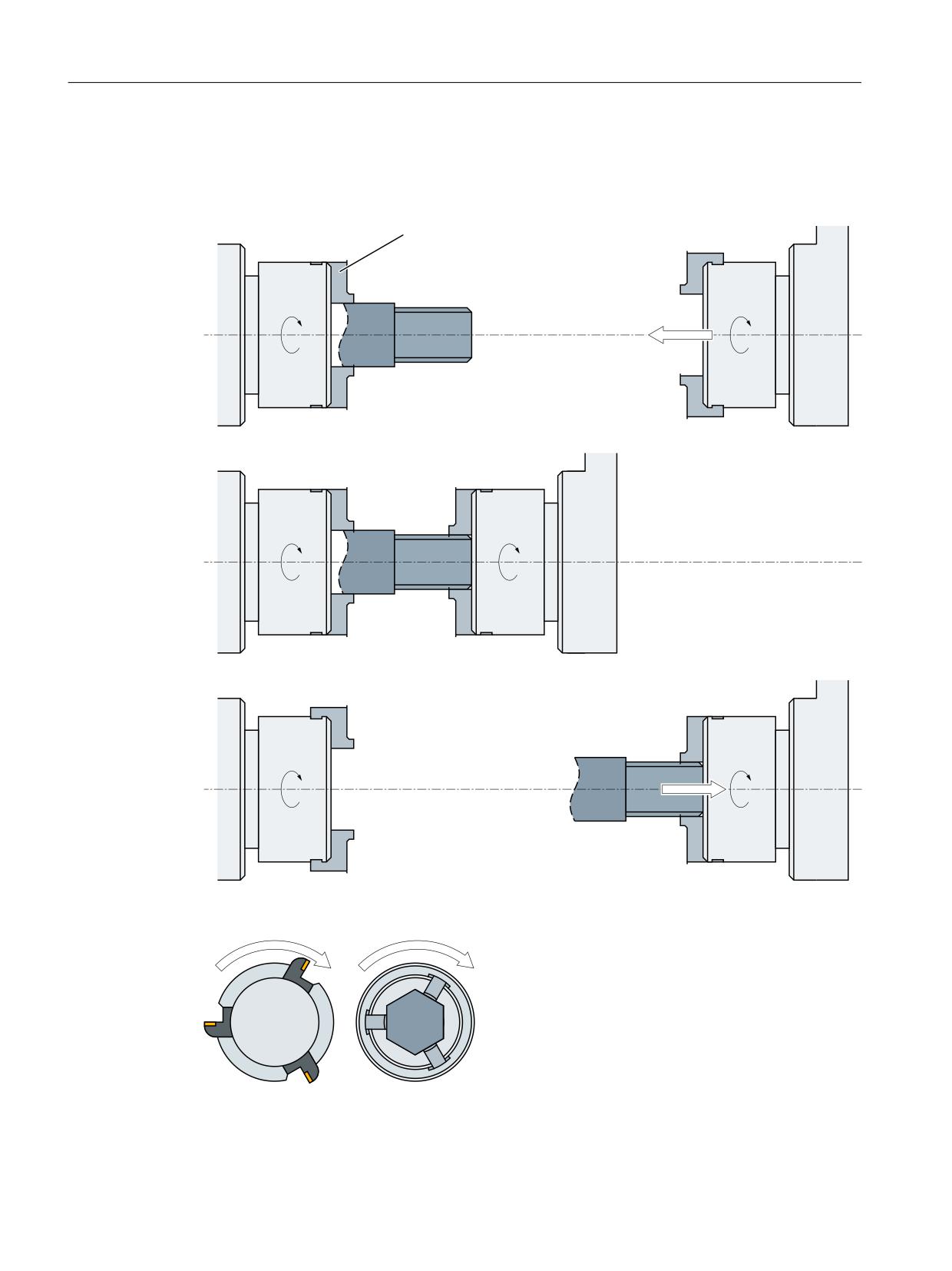
Synchronous spindle
13.1 Brief description
Selecting/de-selecting
Part program commands are used to select/deselect the synchronous operation of a pair of
synchronous spindles.
8PSLIPMEFS
O
O
4QJOEMF
4QJOEMF
O
O
4QJOEMF
4QJOEMF
O
O
4QJOEMF
4QJOEMF
Figure 13-1
Synchronous operation: On-the-fly workpiece transfer from spindle 1 to spindle 2
O
O
4QJOEMF
4QJOEMF
Figure 13-2
Synchronous operation: Polygonal turning
Axes and spindles
490
Function Manual, 10/2020, 6FC5397-4GP40-0BA1

Synchronous spindle
13.1 Brief description
13.1.2
Synchronous mode
Description
<axial expression>:
can be:
- Axis name
- Spindle name
<axis name>:
C (if spindle has the name "C" in axis operation.)
<spindle name>:
Sn, SPI(n) where n = spindle number
<Spindle number>:
1, 2, ... according to the spindle number defined in
MD35000 $MA_SPIND_ASSIGN_TO_MACHAX
(FS, LS, offset):
LS = Leading Spindle, FS = Following Spindle, Off-
set = read programmable offset of following spin-
dle using system variables
$P_COUP_OFFS[Sn]
Programmed position offset of the synchronous
spindle
Synchronous spindle pair
Synchronous operation involves a following spindle (FS) and a leading spindle (LS), referred to
as the synchronous spindle pair. The following spindle imitates the movements of the leading
spindle when a coupling is active (synchronous operation) in accordance with the defined
functional interrelationship.
Synchronous mode
Synchronous mode (also referred to as “Synchronous spindle operation”) is another spindle
operating mode. Before synchronous mode is activated, the following (slave) spindle must have
been switched to position control. Synchronous operation is activated for the following spindle
when the coupling is activated. As soon as the coupling is deactivated, the following spindle
switches back to open-loop control mode.
As soon as synchronous operation is active for the following spindle, the following interface
signal is reported to the PLC:
IS "Synchronous mode" (DB31, ... DBX84.4) = 1.
Number of synchronous spindles
It is possible to couple several following spindles to one leading spindle. The number of
following spindles on this leading spindle depends on the respective version of the appropriate
software versions.
Any number of following spindles in any channels of one NCU or a different NCU can be coupled
to this leading spindle.
Note that one spindle is always the master and the number of couplings results from the number
of axes less the master.
Axes and spindles
Function Manual, 10/2020, 6FC5397-4GP40-0BA1
491
Synchronous spindle
13.1 Brief description
Options in synchronous mode
The following functions are available for synchronous mode:
• FS and LS turn at the same speed
(nFS = nLS; transformation ratio kÜ = 1)
• Rotation in the same or opposite direction between LS and FS
(can be defined positively or negatively using transformation ratio kÜ)
• Following and leading spindles rotate at different speeds
(nFS = kÜ · nLS; transformation ratio kÜ ≠ 1)
Application: Polygonal turning
• Settable angular position between FS and LS (φFS = φLS + Δφ)
The spindles run at synchronous speed with a defined angular offset between FS and LS
(position synchronous coupling).
Application: Shaped workpieces
• Activation of synchronous operation between LS and FS can take place when the spindles are
in motion or at standstill.
• The full functionality of the open-loop and position control modes is available for the leading
spindle.
• When synchronous mode is not active, the FS and LS can be operated in all other spindle
modes.
• The transformation ratio can also be altered when the spindles are in motion in active
synchronous mode.
• With synchronous spindle coupling switched on, the offset of the FS to the LS (overlaid
movement) can be altered.
Coupling options
Synchronous spindle couplings can be defined as
• Permanently configured via channel-specific machine data
(hereinafter referred to as "permanently configured coupling") as well as
• Freely defined using language commands (COUP...) in the part program
(hereafter referred to as "user defined coupling")
. The following variants are possible:
1. A fixed configuration for a coupling can be programmed via machine data. In addition, a
second coupling can be freely defined via the part program.
2. No coupling is configured via machine data. In this case, the couplings can be user-defined
and parameterized via the part program.
Axes and spindles
492
Function Manual, 10/2020, 6FC5397-4GP40-0BA1
Synchronous spindle
13.1 Brief description
Separate following spindle interpolator
The separate following spindle interpolator allows a number of following spindles from
different channels or from another NCU to be coupled as defined by the user to a single leading
spindle. The following spindle interpolator is
• COUPON or COUPONC activated and
• COUPOF or COUPOFS deactivated
and is always located in the channel in which the COUPON, COUPONC command has been
programmed for the following spindle. If the following spindle to be activated was previously
programmed in another channel, COUPON/COUPONC initiates an axis replacement and fetches
the spindle into its own channel.
Certain synchronous spindle functions can be controlled from the PLC by means of coupling-
specific axial VDI interface signals. These signals act exclusively on the slave spindles and do not
affect the leading spindle (see Section "Controlling synchronous spindle coupling via PLC
(Page 501)").
Definition of synchronous spindles
Before synchronous operation is activated, the spindles to be coupled (FS, LS) must be defined.
This can be done in two ways depending on the application in question:
1. Permanently configured coupling:
Machine axes that are to function as the following spindle (FS) and leading spindle (LS) are
defined in channel-specific MD21300 $MC_COUPLE_AXIS_1[n].
The machine axes programmed as the LS and FS for this coupling configuration cannot be
altered by the NC part program.
If necessary, the coupling parameters can be modified with the NC part program.
2. User-defined coupling:
Couplings can be created and altered in the NC part program with language command
"COUPDEF(FS, LS, ...)". If a new coupling relationship is to be defined, it may be necessary to
delete an existing user-defined coupling beforehand (with language
command COUPDEL(FS, LS)).
The axis names (Sn, SPI(n)) for the following and leading spindles must be programmed with
FS and LS for every language command COUP..., thus ensuring that the synchronous spindle
coupling is unambiguously defined.
The valid spindle number must then be assigned axis-specific machine data of a machine axis:
MD35000 $MA_SPIND_ASSIGN_TO_MACHAX.
IS "Following spindle active" (DB31, ... DBX99.1) and IS "Leading spindle active" (DB31, ...
DBX99.0) indicate to the PLC for each machine axis whether the axis is active as a leading or
following spindle.
The LS can be programmed either via a part program, PLC or also using synchronized actions.
Transformation ratio
The transformation ratio is programmed with separate numerical values for numerator and
denominator (transformation ratio parameters). It is therefore possible to specify the
transformation ratio very exactly, even with rational numbers.
In general:
Axes and spindles
Function Manual, 10/2020, 6FC5397-4GP40-0BA1
493
Synchronous spindle
13.1 Brief description
k
Ü
= transformation ratio parameter for numerator Transformation ratio parameters for
denominator = Ünumerator : Üdenominator
The value range of the transformation ratio parameter (Ünumerator, Üdenominator) is virtually unlimited
in the control.
The transformation ratio parameters for the coupling configured via machine data can be
defined in channel-specific SD42300: COUPLE_RATIO_1[n]. In addition, the transformation ratio
can be altered with language command COUPDEF(FS, LS, Ünumerator, Üdenominator ,...). The values
entered in the setting data is not overwritten in this case (default settings).
The transformation ratio for the coupling defined via the NC part program can only be input with
language command COUPDEF (...).
The new transformation ratio parameters take effect as soon as the COUPDEF command has
been processed.
For further programming instructions for synchronous spindle coupling, see Chapter
"Programming (Page 505)".
Coupling characteristics
The following characteristics can be defined for every synchronous spindle coupling:
• Block change behavior
The condition to be fulfilled for a block change can be defined on activation of synchronous
operation or on alteration of the transformation ratio or the defined angular offset when the
coupling is active:
- Block change takes place immediately
- Block change in response to "Fine synchronism"
- Block change in response to "Coarse synchronism"
- Block change for IPOSTOP (i.e. after setpoint-end synchronism)
- Check of the synchronism conditions at an arbitrary moment with WAITC.
• Type of coupling between FS and LS
The position setpoint or the actual position value of the leading spindle can be used as the
reference value for the following spindle. The following coupling types can therefore be
selected:
- Setpoint coupling (DV)
Use in position controlled operation. The control dynamic response of both spindles
should coincide as far as possible. Preferably, the setpoint coupling should be used.
- Actual value coupling (AV)
Application if no position control of the LS is possible or with great deviation of the control
characteristics between FS and LS. The setpoints for the FS are derived from the actual
values of the LS. The quality of synchronism is worse with a varying spindle speed than
with the setpoint coupling.
- Speed coupling (VV)
Internally, the velocity coupling is a setpoint coupling. The requirements for FS and LS are
lower. Position control and measuring systems are not required for FS and LS.
The position offset between FS and LS is undefined.
Axes and spindles
494
Function Manual, 10/2020, 6FC5397-4GP40-0BA1
Synchronous spindle
13.1 Brief description
The selection of the relevant coupling characteristics for the configured coupling is made using
machine data (see Section "Configuration (Page 512)") and for the user defined coupling using
the COUPDEF language command (see Section "Definition (COUPDEF) (Page 506)").
In addition, coupling characteristics Type of coupling and Block change response can be altered
for the permanently configured coupling by means of language command COUPDEF.
Further information: NC Programming Programming Manual
Change protection for coupling characteristics
The channel-specific MD21340 $MC_COUPLE_IS_WRITE_PROT_1 is used to define whether or
not the configured coupling parameters Transformation ratio, Type of coupling and Block
change response can be altered by the NC part program:
0: Coupling parameters can be altered by the NC part program via command COUPDEF
1: Coupling parameters cannot be altered by the NC part program. Attempts to make changes
will be rejected with an alarm message.
Superimposed motion
In synchronous operation, the synchronous spindle copies the movement of the leading spindle
in accordance with the programmed transformation ratio.
At the same time, the synchronous spindle can also be traversed with overlay so that the LS and
FS can operate at a specific angular position in relation to one another.
The overlaid traversing movement of the FS can be initiated in various ways:
• Programmable position offset of FS for AUTOMATIC and MDA:
- The COUPON and SPOS language commands can be used for active synchronous
operation to change the position reference between FS and LS (see Section "Selecting
synchronous mode for a part program (Page 497)").
• Manual position offset of FS:
- In JOG (JOG continuous or JOG incremental) mode
Superimposition of FS using the handwheel or with plus or minus traversing keys when
synchronous operation is active.
- In AUTOMATIC and MDA modes
Superimposition of FS with handwheel using DRF offset
As soon as the FS executes the overlaid traversing movement, IS "Overlaid movement" (DB31, ...
DBX98.4) is set to the 1 signal.
The overlaid movement is executed optimally in terms of time at the maximum possible FS speed
with COUPON. With an offset change by means of SPOS, the positioning velocity can be specified
Axes and spindles
Function Manual, 10/2020, 6FC5397-4GP40-0BA1
495
Synchronous spindle
13.1 Brief description
with FA[Sn] and manipulated by an override (can be selected through IS "Feedrate override valid
for spindle" DB31, ... DBX17.0).
Note
For more information about specifying the position speed with FA[Sn]:
Further information
Positioning mode (Page 383)
Setpoint correction
The setpoint correction of the system variable $AA_COUP_CORR[Sn] impacts on all subsequent
following spindle programming in the same way as a position offset and corresponds to a DRF
offset in the MCS.
Example: establish correction value
If a coupling offset of 7° has been programmed using COUPON(
,77) and if a mechanical
offset of 81° has come about as a result of closing the workpiece support fixture, a correction
value of 4° is calculated:
The system variables return the following values for the following spindle:
$P_COUP_OFFS[S2] ; programmed position offset = 77°
$AA_COUP_OFFS[S2] ; setpoint position offset = 77°
$VA_COUP_OFFS[S2] ; actual value position offset approx. 77°
$AA_COUP_CORR[S2] ; correction value = 4°
13.1.3
Prerequisites for synchronous mode
Conditions on selection of synchronous mode
The following conditions must be fulfilled before the synchronous spindle coupling is activated
or else alarm messages will be generated.
• The synchronous spindle coupling must have been defined beforehand (either permanently
configured via machine data or according to user definition via part program
using COUPDEF).
• The spindles to be coupled must be defined in the NC channel in which the coupling is
activated.
Channel-spec. MD20070 $MC_AXCONF_MACHAX_USED
Axis-spec. MD35000 $MA_SPIND_ASSIGN_TO_MACHAX
Axes and spindles
496
Function Manual, 10/2020, 6FC5397-4GP40-0BA1
Synchronous spindle
13.1 Brief description
• The following spindle must be assigned to the NC channel in which the coupling is activated.
Default setting with axis-specific MD30550 AXCONF_ASSIGN_MASTER_CHAN
• The following applies to setpoint and actual value couplings (DV, AV):
FS and LS must at least have a position measuring system for recording positions and position
controls must be started up.
Note
When position control is activated, the maximum setpoint speed of the LS is automatically
limited to 90% (control reserve) of the maximum speed. The limitation is signaled via IS
"Setpoint speed limited" (DB31, ... DBX83.1).
Further information
Spindles (Page 377)
• The following applies to setpoint couplings (DV):
To ensure more accurate synchronization characteristics, the LS should be in position control
mode (language instruction SPCON) before the coupling is activated.
• Before selecting the synchronous mode, the gear stage necessary for FS and LS must be
selected. In synchronous mode, gear stage changeover and therefore oscillation mode are
not possible for FS and LS. Upon request, an alarm message is generated.
Cross-channel coupling
The LS can be located in any channel.
• The LS can be exchanged between channels by means of "Axis exchange".
• When several following spindles are coupled to one leading spindle, the dynamic response
of the coupling is determined by the weakest response as a function of the coupling factor.
The acceleration rate and maximum speed are reduced for the leading spindle to such a
degree that none of the coupled following spindles can be overloaded.
• The following spindle is always located in the channel in which the coupling has been
activated using COUPON or COUPONC.
See also
Homing (Page 31)
13.1.4
Selecting synchronous mode for a part program
Activate coupling COUPON, COUPONC
Language command COUPON activates the coupling in the part program between the
programmed spindles with the last valid parameters and thus also activates synchronous mode.
This coupling may be a fixed configuration or user-defined. The leading spindle and/or following
spindle may be at standstill or in motion at the instant of activation.
Axes and spindles
Function Manual, 10/2020, 6FC5397-4GP40-0BA1
497
Synchronous spindle
13.1 Brief description
Certain preconditions must be fulfilled before synchronous operation can be activated (see
Section "Prerequisites for synchronous mode (Page 496)").
The COUPONC command adopts the previous programmed direction of spindle rotation and
spindle speed for the following and leading spindle in the part program. It is not possible to
specify an angular offset.
COUPON activation variants
Two different methods can be selected to activate synchronous mode:
1. Fastest possible activation of coupling with any angular reference between leading and
following spindles.
COUPON(FS, LS)
2. Activation of coupling with a defined angular offset POSFS between leading and following
spindle. With this method, the angular offset must be programmed on selection.
COUPON(FS, LS, POSFS)
Block change behavior
Before synchronous operation is selected, it must be determined under what conditions the
block change must occur when the synchronous mode is activated (see Section "Definition
(COUPDEF) (Page 506)").
Determine current coupling status
The $AA_COUP_ACT[<axial expression>] axial system variable can be used in the NC part
program to specify the current coupling status for the specified axis/spindle (see Section "Axial
system variables for synchronous spindle (Page 510)"). As soon as the synchronous spindle
coupling is active for the following spindle, bit 2 must be "1" when read.
Change defined angular offset
Language commands COUPON and SPOS allow the defined angular offset to be changed while
synchronous mode is active. The following spindle is positioned as an overlaid movement at the
angular offset programmed with POSFS. During this time, the IS "overlaid movement" (DB31, ...
DBX98.4) is set.
Angular offset POSFS
The defined angular offset POSFS must be specified as an absolute position referred to the zero
degrees position of the leading spindle in a positive direction of rotation.
Axes and spindles
498
Function Manual, 10/2020, 6FC5397-4GP40-0BA1
Synchronous spindle
13.1 Brief description
The "0° position" of a position-controlled spindle is calculated as follows:
• From the zero mark or proximity sensor signal of the measurement system and
• From the reference values saved using axis-specific machine data:
MD34100 $MA_REFP_SET_POS, reference point value,
of no significance with interval-coded systems.
MD34080 $MA_REFP_MOVE_DIST reference point distance/target point
with interval-coded systems,
MD34090 $MA_REFP_MOVE_DIST_CORR reference point offset / absolute offset with interval
coding.
Range of POSFS: 0 ... 359.999°.
Further information
Homing (Page 31)
Read current angular offset
Using axial system variables, it is possible to read the current position offset between the FS and
LS in the NC part program. A distinction is made between:
• Current position offset of setpoint between FS and LS
$AA_COUP_OFFS [<axis name for FS>]
• Current position offset of actual value between FS and LS
$VA_COUP_OFFS [<axis name for FS>]
(Explanation of <axis name>, see Section "Synchronous mode (Page 491)")
Activation after power ON
Synchronous mode can also be activated with non-referenced/synchronized FS or LS (IS
"Referenced/synchronized 1 or 2" DB31, ... DBX60.4 or DBX60.5 = 0). In this case, a warning
message is displayed.
Example:
LS and FS are already coupled in a friction lock via a workpiece after power ON.
13.1.5
Deselecting the synchronous mode for the part program
Open coupling (COUPOF, COUPOFS)
Synchronous mode between the specified spindles is canceled by the parts program
instruction COUPOF. Three variants are possible.
If synchronous mode is canceled between the specified spindles using COUPOF, then it is
irrelevant whether this coupling is permanently configured or user defined. The leading and
following spindles can be at standstill or in motion when synchronous operation is deactivated.
Axes and spindles
Function Manual, 10/2020, 6FC5397-4GP40-0BA1
499
Synchronous spindle
13.1 Brief description
On switching off the synchronous mode with COUPOF, the following spindle is put into control
mode. The originally programmed S-word is no longer valid for the FS, the following spindle can
be operated like any other normal spindle.
When the coupling is opened with COUPOF, a block preprocessing stop STOPRE is generally
initiated internally in the control.
The COUPOFS instruction can be used to open a coupling either as quickly as possible with a
stop and no position data or with a stop at the programmed position.
COUPOF variants
Three different methods can be used to deselect synchronous mode with COUPOF:
1. Deactivation of coupling as quickly as possible
The block change is enabled immediately.
COUPOF(FS, LS)
2. A coupling is not deselected until the following spindle has crossed the programmed
deactivation position POSFS.
The block change is then enabled.
COUPOF(FS, LS, POSFS)
3. A coupling is not deselected until the following spindle and leading spindle has crossed the
programmed deactivation positions POSFS and POSLS.
The block change is then enabled.
COUPOF(FS, LS, POSFS , POSLS)
POSFS, POSLS
Deactivation positions POSFS and POSLS match the actual positions of FS and LS respectively
referred to the defined reference point value.
Range of POSFS, POSLS: 0 ... 359.999°.
Further information
Homing (Page 31)
COUPOF during the motion
If synchronous mode is deselected while the spindles are in motion with COUPOF, the following
spindle continues to rotate at the current speed (nFS). The current speed can be read with system
variable $AA_S in the NC parts program.
The following spindle can then be stopped from the parts program with M05, SPOS, SPOSA or
from the PLC with the appropriate interface signal.
Axes and spindles
500
Function Manual, 10/2020, 6FC5397-4GP40-0BA1
Synchronous spindle
13.1 Brief description
COUPOFS with stop of following spindle
Opening a synchronous spindle coupling is extended by a stop of the following spindle:
• Deactivating a coupling as quickly as possible and opening a coupling as quickly as possible.
The block change is then enabled.
COUPOFS(FS, LS)
• Opening the coupling with stop of following spindle at the programmed position. The block
change is then enabled.
Boundary condition:
COUPOFS(FS, LS) and COUPOFS(FS, LS, POSFS) have no meaning if a coupling was active.
13.1.6
Controlling synchronous spindle coupling via PLC
Controlling following spindle via PLC
Using the coupling-specific, axial VDI interface signals, it is possible to control synchronization
motions for the following spindle from the PLC program. This offers the option of utilizing the
PLC to disable, suppress or restore a synchronization motion for the following spindle specified
by offset programming.
These signals have no effect on the leading spindle. The following coupling-specific VDI signal
(PLC → NC) is available:
IS "Disable synchronization" (DB31, ... DBX31.5)
"Disable synchronization"
The synchronization motion for the following spindle is suppressed using the axial signal IS
"Disable synchronization" (DB31, ... DBX31.5).
When the main run advances to a block containing part program instruction COUPON (FS, LS,
offset), the following interface signal is evaluated for the following spindle:
IS "Disable synchronization" (DB31, ... DBX31.5).
• For IS "Disable synchronization" (DB31, ... DBX31.5) = 0, the position offset is traversed
through as before.
• For IS "Disable synchronization" (DB31, ... DBX31.5) = 1, only the continuous velocity
synchronism is established. The following spindle does not execute any additional
movement.
The coupling then responds analogously to a programmed COUPON(<FS>,<LS>).
Special features
For the IS "Disable synchronization" (DB31, ... DBX31.5) offset motion of the following spindle
cannot be controlled that was generated as follows:
• SPOS, POS
• Synchronized actions
Axes and spindles
Function Manual, 10/2020, 6FC5397-4GP40-0BA1
501
Synchronous spindle
13.1 Brief description
• FC18 (for 840D sl)
• JOG
These functions are controlled by VDI signal IS "Feedrate stop/Spindle stop" (DB31, ... DBX4.3).
Synchronized state reached
Whenever a state of synchronism has been reached, the following two VDI signals are set
regardless of whether synchronization has been disabled or not:
IS "Synchronism coarse" (DB31, ... DBX98.1) and
IS "Synchronism fine" (DB31, ... DBX98.0)
Further block changes after COUPON are not prevented by suppression of synchronization.
Example
Block change behavior after COUPON
Program code
Comment
; IS "Disable synchronization"
; set (DB31, ... DBX31.5) = 1 for S2
N51 SPOS=10 SPOS[2]=10
; positions correspond to an offset
; of 0°
N52 COUPDEF(S2,S1,1,1,"FINE","DV")
N53 COUPON(S2,S1,77)
; actual offset of 0 degrees is retained
; no following spindle movement,
; VDI signals
; IS "Synchronism coarse"
; (DB31, ... DBX98.1) and
; IS "Synchronism fine"
; (DB31, ... DBX98.0)
; are set and the block change
; is enabled.
N54 M0
N57 COUPOF(S2,S1)
N99 M30
Reset and recovery
Resetting the IS "Disable synchronization" (DB31, ... DBX31.5) has no effect on the following
spindle offset. If the offset motion of the following spindle has been suppressed by the VDI
interface signal, then the offset is not automatically applied when the VDI signal is reset.
Axes and spindles
502
Function Manual, 10/2020, 6FC5397-4GP40-0BA1

Synchronous spindle
13.1 Brief description
Synchronization is recovered as follows:
• By repeating the part program operation COUPON (FS, LS, offset) with IS "Disable
synchronization" (DB31, ... DBX31.5) = 0.
COUPON (FS, LS, offset) can be written e.g. in an ASUB.
• By setting the IS "Resynchronize" (DB31, ... DBX31.4) = 1
Read offset
The following system variables can be used to read three different position offset values of the
following spindle from the part program and synchronized actions. The variable
$P_COUP_OFFS[Sn] is only available in the part program.
Description
NC variable
Programmed position offset of the synchronous spindle
$P_COUP_OFFS[Sn]
Position offset of synchronous spindle, setpoint end
$AA_COUP_OFFS[Sn]
Position offset of synchronous spindle, actual value end
$VA_COUP_OFFS[Sn]
"Feedrate stop/spindle stop"
By configuring bit 4 in MD30455 MISC_FUNCTION_MASK, the behavior of the axial IS "Feedrate
stop/Spindle stop" (DB31, ... DBX4.3) is defined for the following spindle.
Bit 4 = 0 compatibility method:
Canceling feed enable for the following spindle decelerates the coupling assembly.
Bit 4 = 1:
Feedrate enable refers only to the interpolation component (SPOS,..) and does not affect the
coupling.
Note
Other configuration options for axis functions using MD30455 $MA_MISC_FUNCTION_MASK:
Further information
Rotary axes (Page 307)
13.1.7
Monitoring of synchronous operation
Fine/coarse synchronism
In addition to conventional spindle monitoring operations, synchronous operation between the
FS and LS is also monitored in synchronous mode.
IS "Fine synchronism" (DB31, ... DBX98.0) or IS "Coarse synchronism" (DB31, ... DBX98.1) is
transmitted to the PLC to indicate whether the current position (AV, DV) or actual speed (VV) of
the following spindle lies within the specified tolerance window.
Axes and spindles
Function Manual, 10/2020, 6FC5397-4GP40-0BA1
503