SINUMERIK 840D sl. Service - Functions. Manual (2018-2020) - page 9

Gantry axes
11.6 PLC interface signals for gantry axes
For example, all axes in the gantry groupings will be simultaneously shut down when the
following interface signal is set to "0" from the leading axis:
DB31, ... DBX2.1 (servo enable)
The following table shows the effect of individual interface signals (from PLC to axis) on gantry
axes:
NC/PLC interface signal
DB31, ... DBX ...
Effect on
Leading axis
Synchronous axis
Axis/spindle disable
1.3
On all axes in gantry
No effect
grouping
Position measuring system 1/2
1.5 and 1.6
Axial 1)
Axial 1)
Controller enable
2.1
On all axes in gantry grouping 2)
Delete distance to go (axial)
2.2
Axial
No effect
Clamping in progress
2.3
Axial
Axial
Reference point value 1-4
2.4 - 2.7
Axial
Axial
Feed stop
4.3
On all axes in gantry grouping
Hardware limit switch plus/minus
12.0 and 12.1
Axial alarm: Brake request on all axes in gantry
grouping
2nd software limit switch plus/minus
12.2 and 12.3
Axial
Axial
Ramp-function generator fast stop (RFGFS)
20.1
On all axes in gantry grouping
Select drive parameter set
21.0 - 21.2
Axial
Axial
Enable Pulses
21.7
Axial
Axial
1) DB31, ... DBX1.5 and 1.6 (position measuring system 1/2)
The switchover between position measuring systems 1 and 2 applies individually for each gantry axis. However, deactivation
of both position measuring systems (known as the parking position) applies as a common signal for all gantry axes.
2) DB31, ... DBX2.1 (controller enable)
If the servo enable signal on one gantry axis is canceled, all axes in the gantry grouping are shut down simultaneously. The
method by which shutdown is implemented (e.g. with fast stop) is identical for all gantry axes.
Either the "Follow-up" state (IS of one gantry axis = 1) or the "Stop" state (IS of all gantry axes =
0) is activated for all gantry axes, depending on interface signal:
DB31, ... DBX1.4 (follow-up mode)
b) Axial interface signals from the axis to the PLC (NC → PLC)
Each of the axial, axis-to-PLC interface signals for the synchronized axis and the leading axis is
always set on an axis-specific basis and output to the PLC.
Example:
DB31, ... DBX60.4 resp. 60.5 (referenced/synchronized 1/2).
Exception:
When the leading axis is traversed, the interface signal will also be set for the synchronizing axis:
DB31, ... DBX64.6 and 64.7 (traverse command plus resp. minus)
Axes and spindles
366
Function Manual, 10/2020, 6FC5397-4GP40-0BA1
Gantry axes
11.7 Miscellaneous points regarding gantry axes
11.7
Miscellaneous points regarding gantry axes
Manual traversing
It is not possible to traverse a synchronous axis directly by hand in JOG mode. Traverse
commands entered via the traversing keys of the synchronous axis are ignored internally in the
control. Rotation of the handwheel for the synchronous axis has no effect either.
Handwheel override
An overriding motion by means of the handwheel can only be applied to the guide axis in
coupled axis mode. In this case, the synchronous axes traverse in synchronism with the guide
axis.
DRF offset
A DRF offset can only be applied to the guide axis. In this case, the synchronous axes traverse in
synchronism with the guide axis.
Programming in the part program
Only the guide axis of a gantry axis grouping may be programmed in the part program. An alarm
is generated while programming a synchronous axis, even when a gantry axis grouping is
released (MD37140 $MA_GANTRY_BREAK_UP = 1).
PLC or command axes
Only the guide axis of the gantry grouping can be traversed by the PLC using FC 18 or as a
command axis by means of synchronized actions.
Further information
• Function Manual PLC
• Function Manual Synchronized Actions
PRESET
The PRESET function can only be applied to the guide axis. All axes in the gantry grouping are
reevaluated internally in the control when PRESET is activated. The gantry axes then lose their
reference and synchronization:
DB31, ... DBX101.5 (gantry grouping is synchronized) = 0
Channel assignment of the gantry axes
Please ensure that for a gantry grouping whose guide axis is known in several channels, its
synchronous axes in these channels are also known. If this is not the case, Alarm 10651 is output
with reason 60XX (XX is the objectionable gantry grouping).
Axes and spindles
Function Manual, 10/2020, 6FC5397-4GP40-0BA1
367
Gantry axes
11.7 Miscellaneous points regarding gantry axes
Axis interchange
All axes in the gantry grouping are released automatically in response to a RELEASE command
(guide axis).
An axis interchange of the guide axis of a closed gantry grouping is only possible, if all axes of
the grouping are known in the channel in which they are to be transferred, otherwise alarm
10658 is signaled.
No automatic axis interchange and no automatic adjustment of the gantry axis conditions are
undertaken while trying to reconnect a gantry grouping is released with
MD37140 $MA_GANTRY_BREAK_UP = 1. The user is responsible for this. A check of the axis
conditions is conducted after the break up and if necessary, a corresponding alarm 10658 is
output.
Note
If a gantry grouping is to be closed again, the user must ensure that all axes of the grouping are
in a channel with a corresponding axis condition.
Default for RESET
In an active gantry grouping, the following machine data parameterization is ignored for the
synchronous axes:
MD30450 $MA_IS_CONCURRENT_POS_AX = 1 (Reset default: neutral axis/channel axis)
The state of the guide axis is assumed. The user is informed about the inappropriate
configuration with display alarm 4300.
Display data
The position actual value display shows the actual values of both the guide axis and the
synchronous axes. The same applies to the service display values in the "Diagnosis" operating
area.
Software limit switch
The software limit switch monitor is processed for the guide axis only. If the guide axis crosses
the limit switch, all axes in the gantry grouping are braked to a standstill.
Axes and spindles
368
Function Manual, 10/2020, 6FC5397-4GP40-0BA1
Gantry axes
11.8 Examples
Differences in comparison with the "Coupled motion" function
The main differences between the "gantry axes" and "coupled motion" functions are listed
below:
• The axis coupling between the gantry axes must always be active. Separation of the axis
coupling via part program is therefore not possible for gantry axes. In contrast, the coupled
axis grouping can be separated by means of the part program and the axes then traversed
individually.
• In the "Gantry Axes" function, the difference of the actual position values from the guide axis
and synchronous axis is monitored continuously and the traversing motion is shut down if
there are impermissible deviations. There is no monitoring for the "Coupled motion" function.
• Gantry axes must remain coupled even during referencing. For this reason, special
procedures are applied for the reference point approach of gantry axes. In contrast, coupled-
motion axes are referenced as individual axes.
• For the gantry axes to traverse without mechanical offset, the synchronous axes must be set
like the guide axes from the control dynamics perspective. In contrast, the "coupled motion"
function permits axes with different dynamic control response characteristics to be coupled.
Further information:
Coupled motion (Page 537)
Block search with active coupling
Note
For an active coupling, it is recommended to only use block search type 5, "Block search via
program test" (SERUPRO) for a block search.
11.8
Examples
11.8.1
Creating a gantry grouping
Introduction
Setting up gantry grouping, referencing its axes, aligning possible offsets - and finally,
synchronizing the axes involved, are complicated procedures. The individual steps involved in
the process are explained below by an example constellation.
Constellation
Machine axis 1 = gantry leading axis, incremental measuring system
Machine axis 3 = gantry synchronized axis, incremental measuring system
Axes and spindles
Function Manual, 10/2020, 6FC5397-4GP40-0BA1
369
Gantry axes
11.8 Examples
Machine data
The following machine data describes the original values at the beginning of the procedure.
Individual settings must be corrected or added later according to the information below.
Gantry machine data
Axis 1
MD37100 $MA_GANTRY_AXIS_TYPE = 1 (gantry axis definition)
MD37110 $MA_GANTRY_POS_TOL_WARNING =0 (gantry warning limit)
MD37120 $MA_GANTRY_POS_TOL_ERROR = e.g. 1 (gantry trip limit)
MD37130 $MA_GANTRY_POS_TOL_REF = e.g. 100 mm (max. misalignment) (gantry shutdown
limit when referencing)
MD37140 $MA_GANTRY_BREAK_UP = 0 (invalidate gantry axis grouping)
Axis 3
MD37100 $MA_GANTRY_AXIS_TYPE= 11
MD37110 $MA_GANTRY_POS_TOL_WARNING = 0
MD37120 $MA_GANTRY_POS_TOL_ERROR = e.g. 1 mm
MD37130 $MA_GANTRY_POS_TOL_REF = e.g. 100 mm (max. misalignment)
MD37140 $MA_GANTRY_BREAK_UP = 0
Reference point machine data (for first encoder each)
Axis 1
MD34000 $MA_REFP_CAM_IS_ACTIVE = TRUE
MD34010 $MA_REFP_CAM_DIR_IS_MINUS = e.g. FALSE
MD34020 $MA_REFP_VELO_SEARCH_CAM =
MD34030 $MA_REFP_MAX_CAM_DIST = corresponds to max. distance traversed
MD34040 $MA_REFP_VELO_SEARCH_MARKER =
MD34050 $MA_REFP_SEARCH_MARKER_REVERSE = e.g. FALSE
MD34060 $MA_REFP_MAX_MARKER_DIST = Difference betw. cam edge and 0 mark
MD34070 $MA_REFP_VELO_POS =
MD34080 $MA_REFP_MOVE_DIST = 0
MD34090 $MA_REFP_MOVE_DIST_CORR = 0
MD34092 $MA_REFP_CAM_SHIFT = 0
MD34100 $MA_REFP_SET_POS = 0
MD34200 $MA_ENC_REFP_MODE = 1
The reference point machine data (for the first encoder) of axis 3 must be specified analogously.
Axes and spindles
370
Function Manual, 10/2020, 6FC5397-4GP40-0BA1
Gantry axes
11.8 Examples
11.8.2
Setting the NC-PLC interface
Introduction
An automatic synchronization process when referencing axes must be disabled initially to
prevent damaging/destroying grouping axes that are misaligned.
Disabling of automatic synchronization
The PLC user program sets the following for the axis data block of axis 1:
DB31, ... DBX29.4 = 0 (do not start gantry synchronization)
DB31, ... DBX29.5 = 1 (no automatic synchronization process)
The NC sets the following as a confirmation in the axis block of axis 1:
DB31, ... DBB101.4 = 0 (synchronization process not ready to start)
DB31, ... DBB101.6 = 1 (leading axis LA)
DB31, ... DBB101.7 = 1 (gantry axis)
The PLC user program sets for the axis data block of axis 3:
DB31, ... DBX29.4 = 0 (do not start gantry synchronization)
The NC sets the following as a confirmation in the axis block of axis 3:
DB31, ... DBB101.4 = 0 (synchronization process not ready to start)
DB31, ... DBB101.6 = 0 (synchronized axis GA)
DB31, ... DBB101.7 = 1 (gantry axis)
11.8.3
Commencing start-up
Referencing
The following steps must be taken:
• Select "REF" operating mode
• Start referencing for axis 1 (master axis)
• Wait until message "10654 Channel 1 Waiting for synchronization start" appears.
At this point in time, the NC has prepared axis 1 for synchronization and registers this at the
interface signal:
DB31 DB31, ... DBB101.4 = 1 (synchronization process ready to start)
DB31, ... DBB101.6 = 1 (leading axis LA)
Axes and spindles
Function Manual, 10/2020, 6FC5397-4GP40-0BA1
371

Gantry axes
11.8 Examples
DB31, ... DBB101.7 = 1 (gantry axis)
In addition, the following steps must be taken:
•
RESET
•
Read off values in machine coordinate system:
e. g.
X = 0.941
Y = 0.000
XF = 0.000
•
Enter the X value of master axis 1 with inverted sign in the machine data of slave axis 3:
MD34090 $MA_REFP_MOVE_DIST_CORR = - 0.941 (reference point offset/absolute offset)
Note
This machine data is effective after power ON. To avoid having to perform a power ON now,
the value can also be entered in the following machine data:
MD34080 $MA_REFP_MOVE_DIST (reference point distance)
This machine data is then valid after a RESET.
•
Start referencing again for axis 1 (master axis) with the modified machine data
•
Wait until message "10654 Channel 1 Waiting for synchronization start" appears
•
At this point in time, the NC has prepared axis 1 for synchronization and registers this at the
interface signal:
DB31 DB31, ... DBB101.4 = 1 (synchronization process ready to start)
DB31, ... DBB101.6 = 1 (leading axis LA)
DB31, ... DBB101.7 = 1 (gantry axis)
•
Examine actual positions of machine. Case A or B might apply:
$
$
$
$
!
!
GLII
5 !
!5
&DVH $
&DVH %
Figure 11-3
Possible results after referencing axis 1 (master axis)
Axes and spindles
372
Function Manual, 10/2020, 6FC5397-4GP40-0BA1
Gantry axes
11.8 Examples
If Case A applies, the synchronization process can be started immediately (see "start
synchronization process" step). If Case B applies, the offset "diff" must be calculated and taken
into account:
• Measuring of diff
• By using two appropriate, right-angled reference points R' and R" in the machine bed (right
in picture), the difference in position in JOG can be traversed. The diff offset can then be read
as the difference in the position display. The diff offset must be entered in the machine data
of axis 3 (synchronized axis):
MD34100 $MA_REFP_SET_POS
Continue with 1st step (see above).
• Start gantry synchronization. PLC sets:
DB31, ... DBX29.4 = 1 (start synchronization of gantry)
11.8.4
Setting warning and trip limits
If the gantry grouping is set and synchronized, the following machine data must then be set:
MD37110 $MA_GANTRY_POS_TOL_WARNING (gantry warning limit)
MD37120 $MA_GANTRY_POS_TOL_ERROR (gantry trip limit)
Proceed as follows
• Set the machine data for all axes with a large value to begin with:
MD37120 $MA_GANTRY_POS_TOL_ERROR (gantry trip limit)
• Set a very small value in the machine data:
MD37110 $MA_GANTRY_POS_TOL_WARNING (gantry warning limit)
When you put a heavy, dynamic strain on the axes, the self-canceling alarm "10652 channel
%1 axis %2 gantry warning limit exceeded" will be output repeatedly.
• Now increase the following machine data:
MD37110 $MA_GANTRY_POS_TOL_WARNING (gantry warning limit)
Repeat this until the alarm no longer appears. The interface indicates the status:
DB31, ... DBX101.2 = 0 (gantry trip limit not exceeded)
DB31, ... DBX101.3 = 0 (gantry warning limit not exceeded)
DB31, ... DBX101.4 = 0 (gantry synchronization run not ready to start)
DB31, ... DBX101.5 = 1 (gantry grouping is synchronized)
DB31, ... DBX101.6 = 1 (gantry guide axis)
DB31, ... DBX101.7 = 1 (gantry axis)
If the monitoring still only triggers very sporadically, it is possible to program a edge memory bit
in the PLC user program.
• Enter the value calculated for the warning limit + a small safety provision in the following
machine data:
MD37120 $MA_GANTRY_POS_TOL_ERROR (gantry trip limit)
Error limit values
Values are entered in the following machine data:
Axes and spindles
Function Manual, 10/2020, 6FC5397-4GP40-0BA1
373

Gantry axes
11.9 Data lists
MD37110 $MA_GANTRY_POS_TOL_WARNING (gantry warning limit)
MD37120 $MA_GANTRY_POS_TOL_ERROR (gantry trip limit)
MD37130 $MA_GANTRY_POS_TOL_REF (gantry shutdown limit when referencing)
These should have the following scales of magnitude at the end of the customizing process:
MD37110 $MA_GANTRY_POS_TOL_WARNING
MD37120 $MA_GANTRY_POS_TOL_ERROR
MD37130 $MA_GANTRY_POS_TOL_REF
Note
The same procedure must be followed when starting up a gantry grouping in which the coupled
axes are driven by linear motors and associated measuring systems.
The error limits entered into machine data MD37110 and MD37120 are considered as additional
tolerance values of the actual-value difference of the master and following axis if the interface
bit "Gantry is synchronous" is not present (e.g. to be resynchronized after canceling alarms
without gantry).
11.9
Data lists
11.9.1
Machine data
11.9.1.1
Axis/spindlespecific machine data
Number
Identifier: $MA_
Description
30300
IS_ROT_AX
Rotary axis
32200
POSCTRL_GAIN
KV factor (servo gain)
32400
AX_JERK_ENABLE
Axial jerk limitation
32402
AX_JERK_MODE
Filter type for axial jerk limitation
32410
AX_JERK_TIME
Time constant for axial jerk filter
32420
JOG_AND_POS_JERK_ENABLE
Initial setting for axial jerk limitation
32430
JOG_AND_POS_MAX_JERK
Axial jerk
32610
VELO_FFW_WEIGHT
Feedforward control factor for speed feedforward control
32620
FFW_MODE
Feedforward control type
Axes and spindles
374
Function Manual, 10/2020, 6FC5397-4GP40-0BA1

Gantry axes
11.9 Data lists
Number
Identifier: $MA_
Description
32650
AX_INERTIA
Moment of inertia for torque feedforward control
32800
EQUIV_CURRCTRL_TIME
Equivalent time constant, current control loop for feed-
forward control
32810
EQUIV_SPEEDCTRL_TIME
Equivalent time constant, speed control loop for feed
forward control
32900
DYN_MATCH_ENABLE
Dynamic response adaptation
32910
DYN_MATCH_TIME
Time constant for dynamic response adaptation
33000
FIPO_TYPE
Fine interpolator type
34040
REFP_VELO_SEARCH_MARKER
Shutdown velocity
34070
REFP_VELO_POS
Velocity when approaching the reference point
34080
REFP_MOVE_DIST
Reference point approach distance
34090
REFP_MOVE_DIST_CORR
Reference point offset
34100
REFP_SET_POS
Reference point value
34110
REFP_CYCLE_NR
Axis sequence for channel-specific referencing
34330
REFP_STOP_AT_ABS_MARKER
Distance-coded linear measuring system without desti-
nation point
36012
STOP_LIMIT_FACTOR
Factor, exact stop coarse/fine - and zero speed
36030
STANDSTILL_POS_TOL
Standstill tolerance
36500
ENC_CHANGE_TOL
Maximum tolerance for position actual value switchover
37100
GANTRY_AXIS_TYPE
Gantry axis definition
37110
GANTRY_POS_TOL_WARNING
Gantry warning limit
37120
GANTRY_POS_TOL_ERROR
Gantry shutdown limit
37130
GANTRY_POS_TOL_REF
Gantry shutdown limit when referencing
37140
GANTRY_BREAK_UP
Break up gantry axis grouping
Axes and spindles
Function Manual, 10/2020, 6FC5397-4GP40-0BA1
375
Gantry axes
11.9 Data lists
Axes and spindles
376
Function Manual, 10/2020, 6FC5397-4GP40-0BA1
Spindles
12
12.1
Brief Description
The primary function of a spindle is to set a tool or workpiece in rotary motion in order to
facilitate machining.
Depending on the type of machine, the spindle must support the following functions in order to
achieve this:
• Input of a direction of rotation for the spindle (M3, M4)
• Input of a spindle speed (S, SVC)
• Spindle stop, without orientation (M5)
• Spindle stop with orientation / Spindle positioning
(SPOS, M19 and SPOSA)
• Gear change (M40 to M45)
• Spindleaxis functionality (spindle becomes rotary axis and vice versa)
• Thread cutting (G33, G34, G35)
• Tapping without compensating chuck (G331, G332)
• Tapping with compensating chuck (G63)
• Revolutional feedrate (G95)
• Constant cutting rate (G96, G961, G97, G971)
• Programmable spindle speed limits (G25, G26, LIMS=)
• Position encoder assembly on the spindle or on the spindle motor
• Spindle monitoring for min. and max. speed as well as
max. encoder limit frequency and end point monitoring of spindle
• Switching the position control (SPCON, SPCOF, M70) on/off
• Programming of spindle functions:
- From the part program
- Via synchronized actions
- Via PLC with FC18 or via special spindle interfaces for simple spindle activation
Axes and spindles
Function Manual, 10/2020, 6FC5397-4GP40-0BA1
377
Spindles
12.2 Operating modes
12.2
Operating modes
12.2.1
Overview
A spindle is an endlessly rotating axis, which can be operated in either the closed-loop position
control or closed-loop speed control modes.
Operating modes
• Control operation (closed-loop speed control)
• Oscillating operation (closed-loop speed control)
• Positioning operation (closed-loop position control)
• Synchronous mode
Further information:Synchronous spindle (Page 489)
• Tapping without compensating chuck (G331, G332)
Further information: NC Programming Programming Manual
• Axis mode (closed-loop position control)
Note
Switchover, axis/spindle mode
A spindle can be switched over between the axis and spindle mode if the same motor is used for
axis and spindle operation.
12.2.2
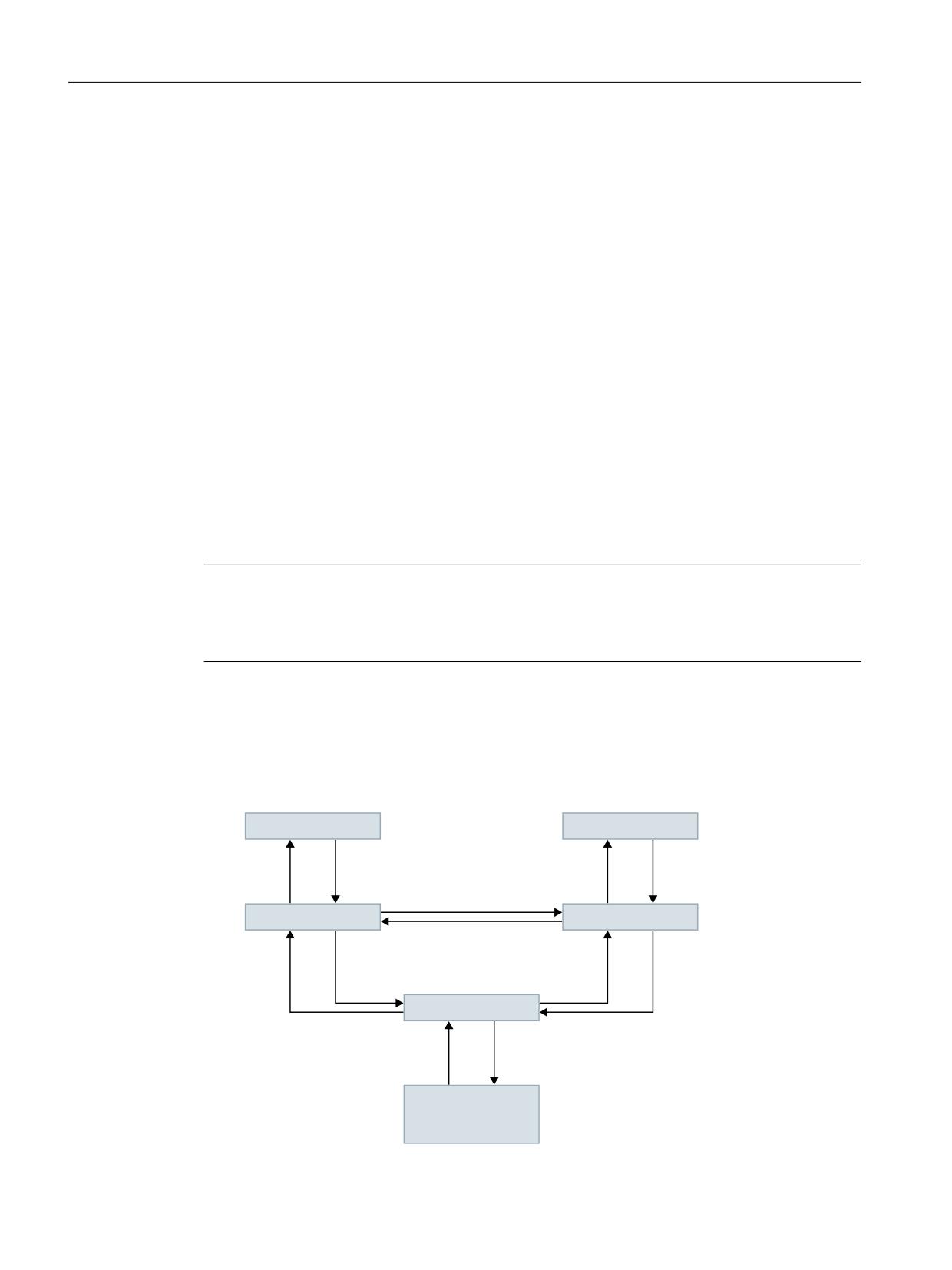
Mode change
Switching between spindle and axis operation can be done as follows:
0TDJMMBUJPO NPEF
4ZODISPOPVT NPEF
$IBOHF HFBS
(FBS DIBOHFE
$0610/
$0610'
4104 .
4104"
$POUSPM NPEF
1PTJUJPOJOH NPEF
41$0'
4104 .
4104"
"YJT NPEF
41$0'
"YJT OBNF
(
(
5BQQJOH
XJUIPVU
DPNQFOTBUJOH DIVDL
Axes and spindles
378
Function Manual, 10/2020, 6FC5397-4GP40-0BA1
Spindles
12.2 Operating modes
•
Control mode → Oscillation mode
The spindle changes to oscillation mode if a new gear stage has been specified using
automatic gear step selection (M40) in conjunction with a new S value or by M41 to M45. The
spindle only changes to oscillation mode if the new gear step is not equal to the current actual
gear step.
•
Oscillation mode → Control mode
When the new gear is engaged, the interface signal:
DB31, ... DBX84.6 (Oscillation mode)
is reset and the interface signal:
DB31, ... DBX16.3 (Gear changed)
is used to go to control mode.
The last programmed spindle speed (S value) is reactivated.
•
Control mode → Positioning mode
To stop the spindle from rotation (M3 or M4) with orientation or to reorient it from standstill
(M5), SPOS, M19 or SPOSA are used to switch to positioning mode.
•
Positioning mode → Control mode
M3, M4 or M5 are used to change to control mode if the orientation of the spindle is to be
terminated. The last programmed spindle speed (S value) is reactivated.
•
Positioning mode → Oscillation mode
If the orientation of the spindle is to be terminated, M41 to M45 can be used to change to
oscillation mode. When the gear change is complete, the last programmed spindle speed (S
value) and M5 (control mode) are reactivated.
•
Positioning mode → Axis mode
If a spindle was stopped with orientation, the assigned axis name is used to program a
change to axis mode. The gear step is retained.
•
Control mode → Axis mode
Switching from control mode to axis mode can be also achieved by the programming of M70.
In this case, a rotating spindle is decelerated in the same way as for M5, position control
activated and the zero parameter set selected.
•
Axis mode → Control mode
To terminate axis mode, M3, M4 or M5 can be used to change to control mode. The last
programmed spindle speed (S value) is reactivated.
•
Axis mode → Oscillation mode
To terminate axis mode, M41 to M45 can be used to change to oscillation mode (only if the
programmed gear step is not the same as the actual gear step). When the gear change is
complete, the last programmed spindle speed (S value) and M5 (control mode) are
reactivated.
Axes and spindles
Function Manual, 10/2020, 6FC5397-4GP40-0BA1
379
Spindles
12.2 Operating modes
12.2.3
Control mode
When open-loop control mode?
The spindle is in open-loop control mode with the following functions:
• Constant spindle speed:
- S... M3/M4/M5 and G93, G94, G95, G97, G971
- S... M3/M4/M5 and G33, G34, G35
- S... M3/M4/M5 and G63
• Constant cutting speed:
- G96/G961 S... M3/M4/M5
The spindle need not be synchronized.
Requirements
A spindle position actual value encoder is absolutely essential for M3/M4/M5 in connection with:
• Revolutional feedrate (G95)
• Constant cutting speed (G96, G961, G97, G971)
• Thread cutting (G33, G34, G35)
• Tapping without compensating chuck (G331, G332)
• Activate position control (SPCON, M70)
A spindle position actual value encoder is not required for M3/M4/M5 in connection with:
• Inverse-time feedrate coding (G93)
• Feedrate in mm/min or inch/min (G94)
• Tapping with compensating chuck (G63)
Speed control mode
Speed control mode is particularly suitable if a constant spindle speed is required, but the
position of the spindle is not important (e.g. constant milling speed for even appearance of the
workpiece surface).
• Speed control mode is activated in the part program with M3, M4, M5 or with SPCOF.
• The following NC/PLC interface signal is set:
DB31, ... DBX84.7 (control mode)
Axes and spindles
380
Function Manual, 10/2020, 6FC5397-4GP40-0BA1

Spindles
12.2 Operating modes
• NC/PLC IS:
DB31, ... DBX61.5 (position controller active)
is reset if position control is not used.
• Acceleration in speed control mode is defined independently of the gear stage in the
machine data:
MD35200 $MA_GEAR_STEP_SPEEDCTRL_ACCEL
The value should reflect the physical circumstances, if possible.
Position control mode
Position control is particularly suitable if the position of the spindle needs to be tracked over a
longer period or if synchronous spindle setpoint value linkage is to be activated.
• Position control mode is switched on in the part program with: SPCON(<spindle
number>)
• The following NC/PLC interface signal is set:
DB31, ... DBX61.5 (position controller active)
• Acceleration in position control mode is defined independent of the gear stage in the
machine data:
MD35210 $MA_GEAR_STEP_POSCTRL_ACCEL
Independent spindle reset
The spindle response after a reset or the end of the program (M2, M30) is set with the machine
data:
MD35040 $MA_SPIND_ACTIVE_AFTER_RESET (individual spindle reset)
Value
Meaning
0
When the spindle is reset or at the end of the program, the spindle immediately decelerates to
a stop at the active acceleration rate. The last programmed spindle speed and direction of
rotation are deleted.
1
Upon reset or at the end of the program, the last programmed spindle speed (S-value) and the
last programmed direction of spindle rotation (M3, M4, M5) are retained. The spindle is not
braked.
If prior to reset or end of program the constant cutting speed (G96, G961) is active, the current
spindle speed (in relation to 100% spindle override) is internally accepted as the spindle speed
last programmed.
The spindle can only be stopped with the NC/PLC interface signal:
DB31, ... DBX2.2 (delete distance-to-go / spindle reset)
The direction of rotation is deleted in the event of all alarms generating a spindle quick stop. The
last programmed spindle speed (S value) is retained. Once the source of the alarm has been
eliminated, the spindle must be restarted.
Spindle actual speed display and spindle behavior with G96, G961
DB31, ... DBX61.4 (axis/spindle stationary)
Axes and spindles
Function Manual, 10/2020, 6FC5397-4GP40-0BA1
381
Spindles
12.2 Operating modes
The speed at which the spindle is deemed to be "stationary" is set with the machine data:
MD36060 $MA_STANDSTILL_VELO_TOL
The value should be measured in such a way that the following NC/PLC interface signal is reliably
present at a standstill:
DB31,... DBX61.4 (axis/spindle stationary)
If DB31,... DBX61.4 (axis/spindle stationary) is signaled and there is no closed-loop position
control active for the spindle, an actual speed of zero is displayed at the operator interface, and
zero is read with the system variable $AA_S[<n>].
Spindle response at constant cutting speed G96, G961
• At the start of machining (transition from G0 to Gx) and after NC stop, G60 (exact stop,
modal) and G9 (exact stop, non-modal) the system waits until the actual speed has reached
the speed setpoint tolerance range before starting the path.
DB31, ... DBX83.5 (nact = nset)
• The NC/PLC IS:
DB31, ... DBX83.5 (nact = nset)
and
DB31, ... DBX83.1 (setpoint speed limited) are also set to defined values
even if significant speed changes are specified (transverse axis travels towards position 0).
• If the speed drops below the minimum speed
or when NC/PLC IS:
DB31, ... DBX61.4 (axis/spindle stationary)
is detected, NC/PLC IS:
DB31, ... DBX83.5 (nact = nset)
is reset (e.g. for an emergency machine strategy).
• A path operation which has started (G64, rounding), is not interrupted.
In addition, the spindle response is influenced by the following machine data:
MD35500 $MA_SPIND_ON_SPEED_AT_IPO_START (feed enable with spindle in setpoint range).
Spindle behavior at the end of gear stage change
• NC/PLC IS:
DB31, ... DBX16.3 (gear changed)
informs the NC that the new gear stage
(NC/PLC IS DB31, ... DBX16.0-16.2 (actual gear stage A to C))
applies and oscillation mode is terminated.
In this case, it does not matter whether NC/PLC IS:
DB31, ... DBX18.5 (oscillation mode)
is still set.
The actual gear stage should correspond to the set gear stage.
The actual gear stage signaled is relevant for selection of the parameter set.
• Once the gear stage change (GSW) has been acknowledged via the PLC (DB31, ... DBX16.3),
the spindle is in speed control mode (DB31, ... DBX84.7 = 1).
If a direction of rotation (M3, M4, M5 or FC18: "Start spindle rotation") or a spindle speed (S
value) was programmed before the gear stage change, then the last speed and direction of
rotation will be reactivated after the gear stage change.
Axes and spindles
382
Function Manual, 10/2020, 6FC5397-4GP40-0BA1
Spindles
12.2 Operating modes
12.2.4
Oscillation mode
Oscillation mode is activated for the spindle during the gear step change.
The mode of operation is described in detail in the topic "Gear step change with oscillation mode
(Page 436)".
12.2.5
Positioning mode
12.2.5.1
General functionality
When is positioning mode used?
The spindle positioning mode stops the spindle at the defined position and activates the position
control, which remains active until it is de-activated.
For the following functions the spindle is in positioning mode:
• SPOS[<n>]=...
• SPOS[<n>]=ACP(...)
• SPOS[<n>]=ACN(...)
• SPOS[<n>]=AC(...)
• SPOS[<n>]=IC(...)
• SPOS[<n>]=DC(...)
• SPOSA[<n>]=ACP(...)
• SPOSA[<n>]=ACN(...)
• SPOSA[<n>]=AC(...)
• SPOSA[<n>]=IC(...)
• SPOSA[<n>]=DC(...) equal to SPOSA[<n>]=...
• M19 or M[<n>]=19
The address extension [<n>] with <n> = spindle number may not apply for the main spindle.
SPOS[<n>]=AC(...)
Spindle positioning to an absolute position (0 to 359.999 degrees). The positioning direction is
determined either by the current direction of spindle rotation (spindle rotating) or the distance-
to-go.
SPOS[<n>]=IC(...)
Spindle positioning to an incremental position (+/- 999999.99 degrees) in relation to the last
programmed position. The positioning direction is defined by the sign of the path to be
traversed.
Axes and spindles
Function Manual, 10/2020, 6FC5397-4GP40-0BA1
383
Spindles
12.2 Operating modes
SPOS[<n>]=DC(...)
Spindle positioning across the shortest path to an absolute position (0 to 359.999 degrees).
The positioning direction is determined either by the current direction of spindle rotation
(spindle rotating) or automatically by the control (spindle stationary).
SPOS[<n>]=...
Same functional sequence as SPOS [<n>]=DC(...).
SPOS[<n>]=ACP(...)
Approaches the position from the positive direction.
When positioning from a negative direction of rotation, the speed is decelerated to zero and
accelerated in the opposite direction to execute the positive approach.
SPOS[<n>]=ACN(...)
Approaches the position from the negative direction.
When positioning from a positive direction of rotation, the speed is decelerated to zero and
accelerated in the opposite direction to execute the negative approach.
M19 (DIN 66025)
M19 can be used to position the spindle. The position and the position approach mode are read
here from the following setting data:
SD43240 $SA_M19_SPOS[<n>] (spindle position for spindle positioning with M19)
SD43250 $SA_M19_SPOSMODE[<n>] (spindle position for spindle positioning with M19)
The positioning options of M19 are identical to those of:
SPOS = <approach mode> <position/path>
M19 is output as an auxiliary function to the NC/PLC interface as an alternative to M3, M4, M5,
and M70. The M19 block remains active in the interpolator for the duration of positioning (like
SPOS).
Part programs using M19 as a macro (e.g. DEFINE M19 AS SPOS = 0) or as a subprogram,
continue to remain executable. For the sake of compatibility with previous controls, the internal
processing of M19 (NC positions the spindle) can be disabled as shown in the following example:
MD22000 $MC_AUXFU_ASSIGN_GROUP[0] = 4
; Auxiliary function group: 4
MD22010 $MC_AUXFU_ASSIGN_TYPE[0] = "M"
; Auxiliary function type: "M"
MD22020 $MC_AUXFU_ASSIGN_EXTENSION[0] = 0
; Auxiliary functions Extension: 0
MD22030 $MC_AUXFU_ASSIGN_VALUE[0] = 19
; Auxiliary function value: 19
Axes and spindles
384
Function Manual, 10/2020, 6FC5397-4GP40-0BA1
Spindles
12.2 Operating modes
Implicitly generated auxiliary function M19
To achieve uniformity in terms of how M19 and SPOS or SPOSA behave at the NC/PLC interface,
auxiliary function M19 can be output to the NC/PLC interface in the event of SPOS and SPOSA.
The two following options are available for activating this function:
• Channel-specific activation for all the spindles in the channel via the machine data:
MD20850 $MC_SPOS_TO_VDI (Output of M19 to the PLC with SPOS/SPOSA)
Bit
Value Meaning
0
0
If bit 19 is also set to "0" in the MD35035 $MA_SPIND_FUNC-
TION_MASK, no auxiliary function M19 is generated in SPOS and
SPOSA. This therefore eliminates the acknowledgment time for the
auxiliary function.
1
The auxiliary function M19 is generated and output to the PLC dur-
ing the programming of SPOS and SPOSA in the part program. The
address extension corresponds to the spindle number.
• Spindle-specific and cross-channel activation via the machine data:
MD35035 $MA_SPIND_FUNCTION_MASK (spindle functions)
Bit
Value Meaning
19
0
If bit 0 is also set to "0" in the MD20850 $MC_SPOS_TO_VDI, no
auxiliary function M19 is generated in SPOS and SPOSA. This there-
fore eliminates the acknowledgment time for the auxiliary function.
1
The implicit auxiliary function M19 is generated and output to the
PLC during the programming of SPOS and SPOSA. The address ex-
tension corresponds to the spindle number.
Note
Activation via MD35035 should be preferred when using a spindle in multiple channels (axis/
spindle exchange).
The auxiliary function M19 is implicitly generated if either of the MD configurations = 1.
After activation, the minimum duration of an SPOS/SPOSA block is increased to the time for
output and acknowledgment of the auxiliary functions by the PLC.
The properties of the implicitly generated auxiliary function output M19 are "Quick" and "Output
during motion". These properties are fixed settings and are independent of the M19
configuration in the auxiliary function-specific machine data (MD..._$M..._AUXFU_...).
There is no auxiliary function M19 implicitly generated in the case of spindle positioning
commands via FC 18.
Axes and spindles
Function Manual, 10/2020, 6FC5397-4GP40-0BA1
385
Spindles
12.2 Operating modes
End of positioning
The positioning can be programmed with:
FINEA[S<n>]:
End of motion on reaching "Exact stop fine" (DB31, ... DBX60.7)
COARSEA[S<n>]:
End of motion on reaching "Exact stop coarse" (DB31, ...
DBX60.6)
IPOENDA[S<n>]:
End of motion on reaching "IPO stop"
In addition, an end-of-motion criterion for block changes can be set in the braking ramp
(100-0%) with IPOBRKA for single-axis interpolation.
Further information
Positioning axes (Page 271)
Block change
The program advances to the next block if the end-of-motion criteria for all spindles or axes
programmed in the current block, plus the block change criterion for path interpolation, are
fulfilled. This applies to both part-program and technology-cycle blocks.
SPOS, M19 and SPOSA have the same functionality but differ in their block change behavior:
• SPOS and M19
The block change is carried out if all functions programmed in the block have reached their
end-of-block criterion (e.g. all auxiliary functions acknowledged by the PLC, all axes have
reached their end points) and the spindle has completed its positioning motion.
• SPOSA
The program moves to the next block if all the functions (except for spindle) programmed in
the current block have reached their end-of-block criterion. If SPOSA is the only entry in the
block, block change is performed immediately. The spindle positioning operation may be
programmed over several blocks (see WAITS).
Coordination
A coordination of the sequence of motions can be achieved with:
• PLC
• MD configuration
• Programming in the part program
PLC
If the NC/PLC interface signal:
DB31, ... DBX83.5 (spindle in the setpoint range)
is not available, then the channel-specific NC/PLC interface signal:
DB21, ... DBX 6.1 (read-in inhibit)
can be set in order to wait for a spindle to reach a certain position.
MD configuration
Axes and spindles
386
Function Manual, 10/2020, 6FC5397-4GP40-0BA1
Spindles
12.2 Operating modes
Setting:
MD35500 $MA_SPIND_ON_SPEED_AT_IPO_START = 1
is used to perform path interpolation taking the tolerance:
MD35150 $MA_SPIND_DES_VELO_TOL
into account only if the spindle has rotated up to the preselected speed.
The setting
MD35500 $MA_SPIND_ON_SPEED_AT_IPO_START = 2
is used to stop traveling path axes before the start of machining at the last G0.
Machining continues:
• With the next traversing command.
• If the spindle speed is reached.
• When MD35510 $MA_SPIND_STOPPED_AT_IPO_START = 1
(path feed enable, if spindle stationary).
Programming in the part program
Coordination actions in the part program have the following advantages:
• The part program author can decide at what point in the program the spindle needs to be up
to speed, e.g. in order to start machining a workpiece.
• This avoids unnecessary delays.
Coordination in the part program involves programming the WAITS command:
WAITS:
for main spindle (master spindle)
WAITS[<n>]:
for spindles with number <n>
WAITS[<n>,<m>,...]:
for several spindles up to the maximum number of spindles
CAUTION
Coordination error
The part program author must ensure that one of the following maintenance conditions occurs
for WAITS.
• Position reached
• Spindle stationary
• Spindle up to programmed speed
In cases where one spindle is used in several channels, the part program author must ensure
that WAITS starts at the earliest in the phase in which the spindle from another channel has
already started to accelerate or decelerate towards the required new speed or direction of
rotation.
Axes and spindles
Function Manual, 10/2020, 6FC5397-4GP40-0BA1
387
Spindles
12.2 Operating modes
The control waits before executing subsequent blocks until:
•
Position(s) programmed with SPOSA are reached.
•
Spindle standstill is reached with M5:
DB31, ..., DBX 61.4 (spindle stationary)
taking into account the tolerance:
MD36060 $MA_STANDSTILL_VELO_TOL
WAITS is terminated and the next block loaded when the first occurrence of the signal is
detected.
•
In M3/M4 (speed control mode), the speed in the setpoint range is:
DB31, ..., DBX83.5 (spindle in setpoint range)
taking into account the tolerance:
MD35150 $MA_SPIND_DES_VELO_TOL
WAITS is terminated and the next block loaded when the first occurrence of the signal is
detected.
This WAITS function applies in the programmed channel.
WAITS can be used to wait for all spindles known to this channel, although spindles may also
have been started in other channels.
Special cases
•
Tolerance for spindle speed:
If the machine data setting is:
MD35150 $MA_SPIND_DES_VELO_TOL = 0
the NC/PLC interface signal:
DB31, ... DBX83.5 (spindle in setpoint range)
is always set to 1.
WAITS is terminated as soon as the spindle has reached the setpoint-side target after a
change in speed or direction (M3/M4).
•
Missing enable signals:
If the WAITS function waits for the "Spindle in setpoint range" signal in speed control mode
and the spindle stops or fails to rotate because an enable signal (axial feed enable, controller,
pulse enable, etc.) is missing, the block is not terminated until the "Spindle in setpoint range"
signal is active, once enable signals are being received again.
•
Response to NC and mode-group stop:
If an NC or mode-group stop is triggered during WAITS, the wait operation is resumed after
the NC start with all the above conditions.
Note
In particular when using spindles across different channels, care should be taken when
programming not to start WAITS too early in one channel, i.e. at a time when the spindle in
the other channel is still rotating at its "old" speed.
In such cases, the "Spindle in setpoint range" signal is activated and WAITS is stopped too
soon.
To prevent this happening, it is strongly recommended to set a WAITM before WAITS.
Feedrate
The positioning speed is configured in the machine data:
Axes and spindles
388
Function Manual, 10/2020, 6FC5397-4GP40-0BA1
Spindles
12.2 Operating modes
MD35300 $MA_SPIND_POSCTRL_VELO (position control switching speed)
The configured positioning speed can be modified by programming or by synchronized actions:
FA[S<n>]=<value>
With: <n>:
Spindle number
<value> Positioning speed in degrees/min
:
With FA[S<n>]=0, the configured speed takes effect.
Acceleration
The accelerations are configured in the machine data:
MD35210 $MA_GEAR_STEP_POSCTRL_ACCEL (acceleration in position control mode)
MD35200 $MA_GEAR_STEP_SPEEDCTRL_ACCEL (acceleration in the speed control mode)
The configured dynamic response during positioning can be modified by programming or by
synchronized actions:
ACC[S<n>]=<value>
With: <n>:
Spindle number
<value> Acceleration as a percentage of the configured acceleration
:
With ACC[S<n>]=0, the configured acceleration takes effect.
Aborting the positioning process
The positioning action is aborted:
• By the NC/PLC interface signal:
DB31, ... DBX2.2 (delete distance-to-go / spindle reset).
• With every reset (e.g. operator panel front reset).
• Through NC stop.
The abort response in independent of the machine data:
MD35040 $MA_SPIND_ACTIVE_AFTER_RESET (individual spindle reset)
Special features
The spindle override switch is valid.
12.2.5.2
Positioning from rotation
Initial situation
The spindle can be in speed control mode or in position control mode when positioning starts
(SPOS, M19 or SPOSA command in the program).
Axes and spindles
Function Manual, 10/2020, 6FC5397-4GP40-0BA1
389
Spindles
12.2 Operating modes
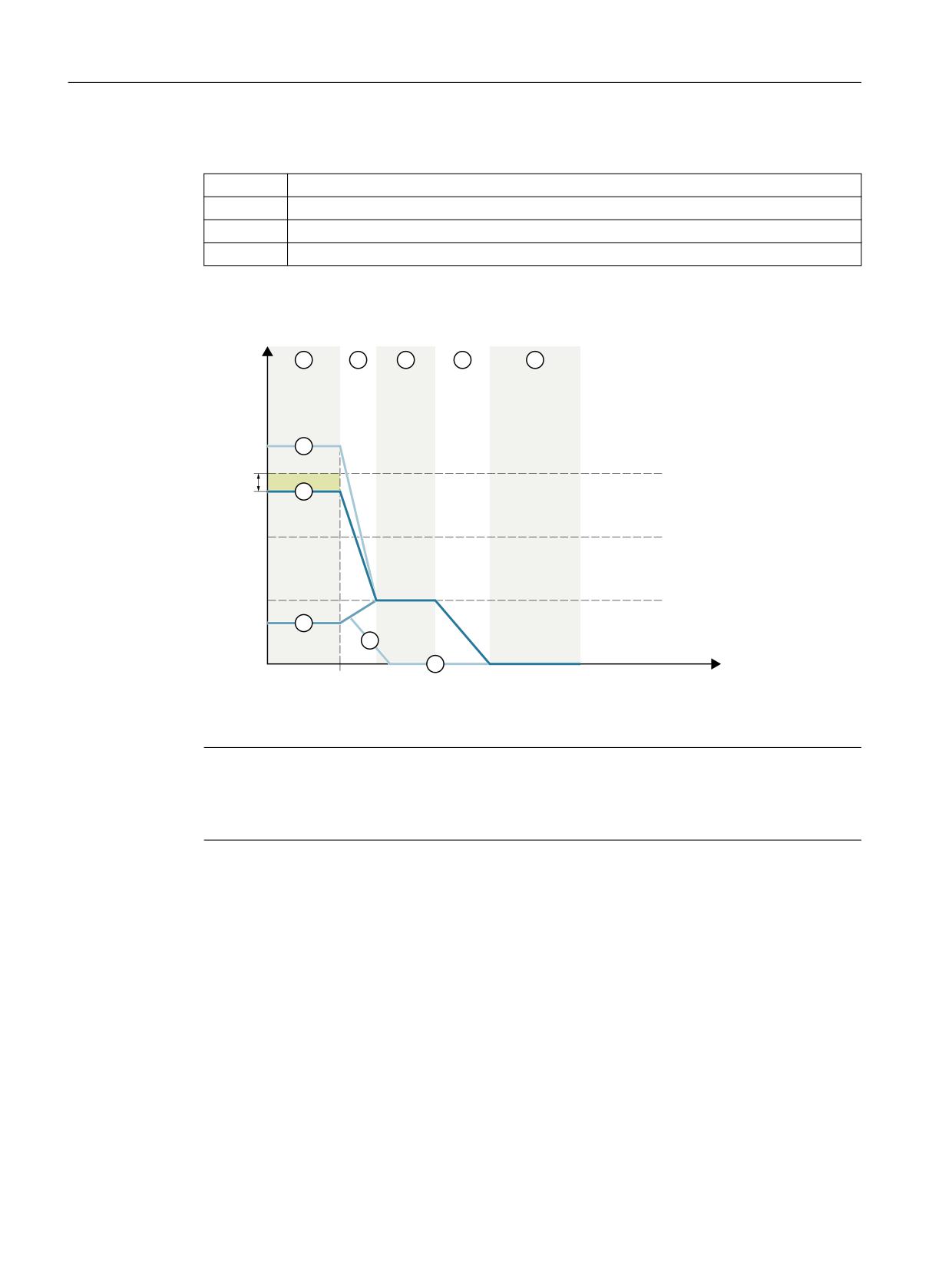
One must distinguish between the following cases:
Case 1:
Spindle in speed control mode, encoder limit frequency exceeded
Case 2:
Spindle in speed control mode, encoder limit frequency not exceeded
Case 3:
Spindle in position control mode
Case 4:
Spindle speed ‹ Position-control activation speed
Sequence
4QFFE
1IBTF
SQN
B
.%
&/$@'3&2@-*.*5
&ODPEFS MJNJU GSFRVFODZ
C
FRQWURO
PDUJLQ
.%
&/$@'3&2@-*.*5@-08
&ODPEFS MJNJU GSFRVFODZ
3FTZODISPOJ[BUJPO
.%
41*/%@104$53-@7&-0
1PTJUJPO DPOUSPM BDUJWBUJPO TQFFE
D
B
B
5JNF
6326
T
Figure 12-1
Positioning from rotation
Note
The speed arising from the configuration of the encoder limit frequency for the
resynchronization of the encoder (MD36302 $MA_ENC_FREQ_LOW) must be greater than the
position control activation speed (MD35300 $MA_SPIND_POSCTRL_VELO).
Phase ①
Positioning from phase 1a:
The spindle is rotating at a higher speed than the encoder limit frequency. The spindle is not
synchronized.
Positioning from phase 1b:
Axes and spindles
390
Function Manual, 10/2020, 6FC5397-4GP40-0BA1
Spindles
12.2 Operating modes
The spindle is rotating at a lower speed than the encoder limit frequency. The spindle is
synchronized.
Note
If the position control is active, the speed can only amount to 90% of the maximum speed of the
spindle or the encoder limit frequency (10% control reserve required).
Positioning from phase 1c:
The spindle rotates at the programmed spindle speed, where the speed is lower than the
configured position control activation speed:
MD35300 $MA_SPIND_POSCTRL_VELO
The spindle is synchronized.
Phase ②
Spindle speed > Position control activation speed
When the SPOS, M19 or SPOSA command is activated, the spindle begins to slow down to the
position-control activation speed with the configured acceleration:
MD35200 $MA_GEAR_STEP_SPEEDCTL_ACCEL
The spindle is synchronized once the encoder limit frequency threshold is crossed.
Spindle speed < Position control activation speed
SPOS, M19 or SPOSA are programmed to switch the spindle to position control mode (if it is not
already in that mode).
The configured acceleration in position control mode is activated:
MD35210 $MA_GEAR_STEP_POSCTRL_ACCEL
The travel path to the target point is calculated.
The spindle travels to the programmed end point optimally in terms of time. This means that the
end point is approached at the highest possible speed (maximum
MD35300 $MA_SPIND_POSCTRL_VELO). Depending on the appropriate constraints, phases 2 -
3 - 4 - 5 or 2 - 4a - 5a are executed.
Phase ③
Spindle speed > Position control activation speed
When the configured position-control activation speed
(MD35300 $MA_SPIND_POSCTRL_VELO) is reached:
• Position control is activated (if not already active)
• The distance-to-go (to the target point) is calculated
• There is a changeover to the configured acceleration in position control mode (or this level
of acceleration is maintained):
MD35210 $MA_GEAR_STEP_POSCTRL_ACCEL
Axes and spindles
Function Manual, 10/2020, 6FC5397-4GP40-0BA1
391
Spindles
12.2 Operating modes
Spindle speed < Position control activation speed
The spindle was accelerated up to the configured position-control activation speed (MD35300
$MA_SPIND_POSCTRL_VELO) to reach the end point. This is not exceeded.
The braking start point calculation detects when the programmed spindle position can be
approached accurately at the acceleration configured in position control mode (MD35210
$MA_GEAR_STEP_POSCTRL_ACCEL).
Phase ④
Spindle speed > Position control activation speed
The spindle brakes from the calculated "braking point" with machine data:
MD35210 $MA_GEAR_STEP_POSCTRL_ACCEL
to the target position.
Spindle speed < Position control activation speed
At the time identified by the braking start point calculation in phase 3, the spindle brakes to a
standstill with the acceleration configured in position control mode
(MD35210 $MA_GEAR_STEP_POSCTRL_ACCEL).
Phase 4a:
When the SPOS command is activated the proximity of the end point is such that the spindle can
no longer be accelerated to the configured position-control activation speed
(MD35300 $MA_SPIND_POSCTRL_VELO).
The spindle brakes to a standstill with the acceleration configured in position control mode
(MD35210 $MA_GEAR_STEP_POSCTRL_ACCEL).
Phase ⑤
Spindle speed > Position control activation speed
Position control remains active and holds the spindle in the programmed position.
Note
The maximum encoder limit frequency of the spindle position encoder is monitored by the
control (it may be exceeded); in position control mode, the setpoint speed is reduced to 90% of
the measuring system limit speed.
The following NC/PLC interface signal is set:
DB31, ... DBX83.1 (programmed speed too high)
If "MS limit frequency exceeded" is still pending following a reduction in the setpoint speed, an
alarm is output.
Spindle speed < Position control activation speed (Phase 5, 5a)
The spindle is stationary and it has reached the position. The position control is active and stops
the spindle in the programmed position.
Axes and spindles
392
Function Manual, 10/2020, 6FC5397-4GP40-0BA1
Spindles
12.2 Operating modes
If the distance between the spindle actual position and the programmed position (spindle
setpoint position) is less than the configured exact stop fine and coarse limits, the following NC/
PLC interface signals are set:
DB31, ... DBX60.6 (position with exact stop coarse reached)
DB31, ... DBX60.7 (position with exact stop fine reached)
The exact stop limits are defined with the machine data:
MD36010 $MA_STOP_LIMIT_FINE (exact stop fine)
MD36000 $MA_STOP_LIMIT_COARSE (exact stop coarse)
Note
The positioning procedure is considered complete when the end-of-positioning criterion is
reached and signaled.
The precondition is "Exact stop fine". This applies to SPOS, M19 or SPOSA from the part program,
synchronized actions and spindle positioning by the PLC using FC 18.
Axes and spindles
Function Manual, 10/2020, 6FC5397-4GP40-0BA1
393
Spindles
12.2 Operating modes
12.2.5.3
Positioning from standstill
Sequence
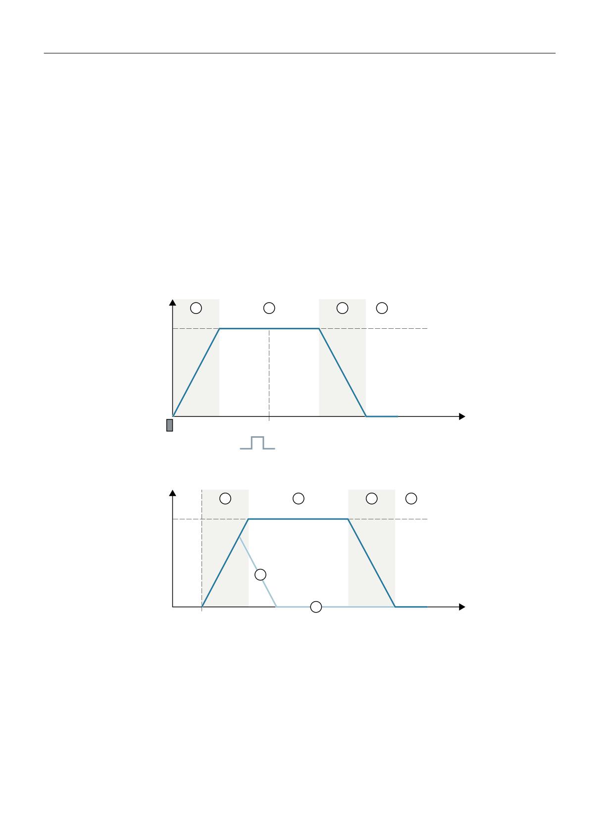
A distinction is made between two cases with regard to positioning from standstill:
• Case 1: The spindle is not synchronized
This is the case if the spindle is to be positioned after switching on the control and drive or
after a gear step change (e.g. for a tool change).
MD31040 $MA_ENC_IS_DIRECT = 0
• Case 2: The spindle is synchronized
This is the case if, after switching on the control and drive, the spindle is to be rotated through
a minimum of one revolution with M3 or M4 and then stopped with M5 (synchronization
with the zero mark) before the first positioning action.
$BTF TQJOEMF OPU TZODISPOJ[FE
4QFFE
1IBTF
SQN
.%
41*/%@104$53-@7&-0
1PTJUJPO DPOUSPM BDUJWBUJPO TQFFE
5JNF
;FSP NBSL
6326
T
$BTF TQJOEMF TZODISPOJ[FE
4QFFE
1IBTF
SQN
.%
41*/%@104$53-@7&-0
1PTJUJPO DPOUSPM BDUJWBUJPO TQFFE
B
B
5JNF
6326
T
Figure 12-2
Positioning with stationary spindle
Phase ①
Case 1: Spindle not synchronized
With the programming of SPOS, M19 or SPOSA the spindle accelerates with the acceleration
from the machine data:
Axes and spindles
394
Function Manual, 10/2020, 6FC5397-4GP40-0BA1
Spindles
12.2 Operating modes
MD35200 $MA_GEAR_STEP_SPEEDCTRL_ACCEL (acceleration in speed control mode)
This direction of rotation is defined by the machine data:
MD35350 $MA_SPIND_POSITIONING_DIR (direction of rotation when positioning to standstill)
Exception:
If ACN, ACP, IC is used for positioning, the programmed direction of travel is activated.
The spindle is synchronized at the next zero mark of the spindle position actual-value encoder
and switches to the position control mode.
Whether the zero mark is found in the traversed path (except for IC), is monitored:
MD34060 $MA_REFP_MAX_MARKER_DIST (maximum distance to reference mark)
If the speed defined in machine data:
MD35300 $MA_SPIND_POSCTRL_VELO (Positioning speed)
is reached before the spindle is synchronized, the spindle will continue to rotate at the
positioning activation speed (it is not accelerated further).
Case 2: Spindle synchronized
SPOS, M19 or SPOSA will switch the spindle to position control mode.
The acceleration from the following machine data is active:
MD35210 $MA_GEAR_STEP_POSCTRL_ACCEL (acceleration in position control mode)
The direction of rotation is defined by the programmed motion (ACP, ACN, IC, DC) or via the
pending distance-to-go.
The speed entered in the machine data:
MD35300 $MA_SPIND_POSCTRL_VELO (position control activation speed)
is not exceeded.
The travel path to the target position is calculated.
The spindle travels to the programmed end point optimally in terms of time. This means that the
end point is approached at the highest possible speed (maximum
MD35300 $MA_SPIND_POSCTRL_VELO). Depending on the appropriate constraints, the phases
1 - 2 - 3 - 4 or 1- 3a - 4a are executed.
Phase ②
Case 1: Spindle not synchronized
When the spindle is synchronized, position control is activated.
The spindle rotates at the maximum speed stored in machine data:
MD35300 $MA_SPIND_POSCTRL_VELO
until the braking start point calculation identifies the point at which the programmed spindle
position can be approached accurately with the defined acceleration.
Case 2: Spindle synchronized
To reach the end point, the spindle is accelerated up to the speed defined in machine data:
MD35300 $MA_SPIND_POSCTRL_VELO.
This is not exceeded.
Axes and spindles
Function Manual, 10/2020, 6FC5397-4GP40-0BA1
395
Spindles
12.2 Operating modes
The braking start point calculation identifies when the programmed spindle position can be
approached accurately at the acceleration defined in machine data:
MD35210 $MA_GEAR_STEP_POSCTRL_ACCEL.
At the point, which is determined by the braking start point in Phase 1, the spindle decelerates
to a standstill with the acceleration from the following machine data:
MD35210 $MA_GEAR_STEP_POSCTRL_ACCEL
Phase ③
At the point, which is determined by the braking start point in Phase 2, the spindle decelerates
to a standstill with the acceleration from the following machine data:
MD35210 $MA_GEAR_STEP_POSCTRL_ACCEL
Phase 3a:
When the SPOS command is activated the proximity of the end point is such that the spindle can
no longer be accelerated up to machine data:
MD35300 $MA_SPIND_POSCTRL_VELO.
The spindle is braked to a standstill with the acceleration given in the following machine data:
MD35210 $MA_GEAR_STEP_POSCTRL_ACCEL
Phase ④, ④a
The spindle is stationary and it has reached the position. The position control is active and stops
the spindle in the programmed position.
The NC/PLC interface signals:
DB31, ... DBX60.6 (position reached with exact stop coarse)
and
DB31, ... DBX60.7 (position reached with exact stop fine)
are set if the distance between the spindle actual position and the programmed position (spindle
setpoint position) is less than the settings for the exact stop fine and coarse limits.
This is defined in the machine data:
MD36010 $MA_STOP_LIMIT_FINE
MD36000 $MA_STOP_LIMIT_COARSE
Phase 3:
At the point, which is determined by the braking start point in Phase 2, the spindle decelerates
to a standstill with the acceleration from the following machine data:
MD35210 $MA_GEAR_STEP_POSCTRL_ACCEL
Phase 4:
The spindle is stationary and it has reached the position. The position control is active and stops
the spindle in the programmed position.
The NC/PLC interface signals:
DB31, ... DBX60.6 (position reached with exact stop coarse)
Axes and spindles
396
Function Manual, 10/2020, 6FC5397-4GP40-0BA1
Spindles
12.2 Operating modes
and
DB31, ... DBX60.7 (position reached with exact stop fine)
are set if the distance between the spindle actual position and the programmed position (spindle
setpoint position) is less than the settings for the exact stop fine and coarse limits.
This is defined in the machine data:
MD36010 $MA_STOP_LIMIT_FINE
MD36000 $MA_STOP_LIMIT_COARSE
12.2.5.4
"Spindle in position" signal for tool change
Function
The motion sequence for a tool change, especially for milling machines, mainly comprises
positioning the spindle and then the subsequent (for optimization runs, also at the same time)
approach to the tool change position with the path axes. In this case, the mandatory
requirement is that the spindle is reached before approaching the tool change position.
If the tool change cycle is interrupted by the machine operator (e.g. with an NC stop, NC stop
axes plus spindles, mode group stop, etc.), then it must be completely ruled out that the spindle
moves into the tool changer at an incorrect position.
This is the reason that for spindle positioning, when the last programmed spindle position is
reached with "Exact stop fine" the following NC/PLC interface signal is output to check the
position:
DB31, ... DBX85.5 (spindle in position)
Note
The signal is only output for the "Spindle positioning" function.
This includes:
• SPOS, SPOSA and M19 in the part program
• SPOS and M19 in synchronized actions
• Spindle positioning, using FC18
• Spindle positioning via PLC interface (DB31, ... DBX30.4)
Axes and spindles
Function Manual, 10/2020, 6FC5397-4GP40-0BA1
397
Spindles
12.2 Operating modes
Setting the signal
Requirements for output of signal DB31, ... DBX85.5 (spindle in position) are as follows:
• The referenced state of the spindle:
DB31, ... DBX60.4/5 (referenced/synchronized 1/2) = 1
Note
When positioning the spindle, the zero mark is automatically searched for. This is the reason
that for an error-free sequence, the referenced signal is always available at the end of
positioning movement.
• "Exact stop fine" must have been reached:
DB31, ... DBX60.7 (exact stop fine) = 1
Additionally, the last programmed spindle position must have been reached on the setpoint
side.
Deleting the signal
When signal DB31, ... DBX60.7 is withdrawn (exact stop fine), then signal DB31, ... DBX85.5
(spindle in position) is also always reset.
Additional properties
• If the spindle is already at the programmed position after a positioning, then the NC/PLC
interface signal DB31, ... DBX85.5 (spindle in position) remains set.
• If, after a positioning ("Spindle in position" signal was output) the spindle is traversed, e.g. in
the JOG mode, then the NC/PLC interface signal DB31, ... DBX85.5 (spindle in position) is
deleted.
If the spindle is returned to its original position in this mode, then the NC/PLC interface signal
DB31, ... DBX85.5 (spindle in position) is set again. The last position selection is kept.
12.2.6
Axis mode
12.2.6.1
General functionality
Functionality
If for certain machining tasks, e.g. on lathes with end-face machining, it is not sufficient to
traverse the spindle exclusively under speed control via M3, M4, M5 or to position with SPOS, M19
or SPOSA, the spindle can be switched to position-controlled axis mode and traversed as a rotary
axis.
Examples of rotary axis functions:
• Programming with axis name
• Zero offsets (G54, G55, TRANS, etc.)
• G90, G91, IC, AC, DC, ACP, ACN
Axes and spindles
398
Function Manual, 10/2020, 6FC5397-4GP40-0BA1
Spindles
12.2 Operating modes
• Kinematic transformations (e.g. TRANSMIT)
• Path interpolation
• Traversing as positioning axis
Further information
Rotary axes (Page 307)
Requirements
• The same spindle motor is used for spindle mode and axis mode.
• The same position measurement system or separate position measurement systems can be
used for spindle mode and axis mode.
• An actual position value encoder is a mandatory requirement for axis mode.
• The spindle must be referenced for use of the axis mode, e.g. referenced with G74.
Example:
Program code
Comment
M70
; Switch spindle over to axis mode
G74 C1=0 Z100
; Reference axis
G0 C180 X50
; Traverse axis position-controlled
Configurable M function
The M function used to switch the spindle to axis mode can be configured channel-specifically
via the following machine data:
MD20094 $MC_SPIND_RIGID_TAPPING_M_NR
Note
The control detects the transition to axis mode automatically from the program sequence (see
"Implicit transition to axis mode (Page 401)"). The explicit programming of the configured M
function for switching the spindle to axis mode in the part program is therefore not necessary.
However, the M function can continue to be programmed, e.g. to increase the readability of the
part program.
Special features
• The feedrate override switch is valid.
• The NC/PLC interface signal does not terminate the axis mode per default:
DB21, ... DBX7.7 (reset).
• The NC/PLC interface signals:
DB31, ... DBB16 to DBB19 and DBB82 to DBB91
are not important if:
DB31, ... DBX60.0 == 0 (spindle / rotary axis)
Axes and spindles
Function Manual, 10/2020, 6FC5397-4GP40-0BA1
399
Spindles
12.2 Operating modes
• Axis mode can be activated in all gear stages.
If the actual position value encoder is installed on the motor (indirect measuring system), the
positioning and contouring accuracy can vary for the different gear stages.
• The gear stage cannot be changed when the axis mode is active. For this purpose, the spindle
must first be switched to control mode with M41 ... M45 or M5, SPCOF.
• In axis mode, the first parameter set is effective (machine data index = zero).
Further information
Velocities, setpoint/actual value systems, closed-loop control (Page 135)
Dynamic response
The dynamic limits of the axis apply in axis mode. For example:
• MD32000 $MA_MAX_AX_VELO[<axis>] (maximum axis velocity)
• MD32300 $MA_MAX_AX_ACCEL[<axis>] (maximum axis acceleration)
• MD32431 $MA_MAX_AX_JERK[<axis>] (maximum axial jerk for path motion)
Feedforward control
The feedforward control mode active for the axis is retained.
A detailed description of the "Dynamic feedforward control" function can be found in:
Further information
Function Manual Monitoring and Compensating; Compensations > Dynamic feedforward
control (following error compensation)
Example: Resolution switchover for analog actuator
Switching to axis mode
Programming
Comment
SPOS=...
M5
; Control enable off (from PLC)
→ is output on PLC
M70
; Switch actuator (from PLC on account of M70)
Control enable on (from PLC)
C=...
; NC traverses with axis parameter set
Switching to spindle mode
Programming
Comment
C=...
M71
; → is output to PLC
Closed-loop controller enable off (from PLC)
Switch actuator (from PLC)
Switched to spindle parameter set (1-5) internally in the
NC, controller enable on (from PLC)
M3/4/5 or SPOS=...
; NC traverses with spindle parameter set
Axes and spindles
400
Function Manual, 10/2020, 6FC5397-4GP40-0BA1

Spindles
12.2 Operating modes
Change to spindle mode
The parameter set 1 ... 5 is selected for the active gear stage.
The feedforward control is activated, except for tapping with compensating chuck, if the
following applies:
MD32620 $MA_FFW_MODE (feedforward control mode) ≠ 0
Parameter set
Axis mode
Spindle mode
1
Valid
-
2
-
Valid
3
-
Valid
4
-
Valid
5
-
Valid
6
-
Valid
Spindle mode: Parameter set according to the gear stage
12.2.6.2
Implicit transition to axis mode
Function
The control detects the transition to axis mode automatically from the program sequence and
generates the requisite M70 sequence in the control. The situation will dictate which steps are
performed. At most, these will include:
1. Stopping the spindle
2. Switching on of the position control, treatment of feedforward control and parameter block
changeover
3. Position synchronization of the block preparation (internal preprocessing stop, if necessary)
This function is always active. Explicit programming of M70 in the part program is therefore
basically not necessary.
Sequence
Sequence of the implicit transition to axis mode (M70 is not programmed in the part program):
• Transition from speed control mode (M3, M4, M5, SPCOF, ...) to axis mode:
The transition is detected internally by the control, and an intermediate block is inserted in
front of the block which requests the axis mode. The block created contains the M70
functionality. The execution duration for this block is more or less the same as the time
required to execute a programmed M70 block. Differences may arise in the event of short
switchovers when the spindle is stationary (no braking time) if the implicit generation and
output of the auxiliary function M70 to the PLC is dispensed with (see MD35035).
• Transition from positioning mode (M19, SPOS, SPOSA) to axis mode:
The transition is executed immediately and without the generation of an intermediate block.
Configured accordingly (see MD35035), the auxiliary function M70, which is generated
implicitly, is output to the PLC when the block in which the spindle has its axis mode is loaded.
Axes and spindles
Function Manual, 10/2020, 6FC5397-4GP40-0BA1
401

Spindles
12.2 Operating modes
Output of auxiliary functions to PLC
The implicit transition to axis mode can be notified to the PLC in the form of an auxiliary function
output.
Activation/deactivation
The activation/deactivation of this functionality is performed via the machine data:
MD35035 $MA_SPIND_FUNCTION_MASK (spindle functions)
Bit
Value
Meaning
20
0
No auxiliary function output to the PLC in the case of M70 functionality which is
generated in the control.
1
In the case of M70 functionality which is generated inside the control, the auxiliary
function M70 is generated and output to the PLC. The address extension corresponds
to the spindle number.
Note
An auxiliary function M70 which is programmed in the part program is always output to the PLC.
Properties
The properties of the implicitly generated auxiliary function output M70 are "Quick" and "Output
during motion". These properties are fixed settings and are independent of the M70
configuration in the auxiliary-function-specific machine data (MD..._$M..._AUXFU_...).
M70 is only generated once during transition to axis mode. No further M70 auxiliary functions
are generated and output in adjacent blocks in which the spindle is operated as an axis. M70 is
not implicitly generated and output again until axis mode is exited via, for example, SPOS, M3,
M4, M5, SPCOF, etc. and following a renewed transition to axis mode.
Supplementary conditions
Synchronized actions
When the spindle is programmed as an axis in synchronized actions, it is essential to continue
making provisions in the application to ensure there are criteria for the transition to axis mode.
If the spindle is in speed control mode, the instruction M70 or SPOS must be programmed prior
to programming as an axis. Otherwise alarm signals occur during axis programming.
FC 18
As with synchronized actions, transition to axis mode must also be performed on the application
side in FC 18, e.g. through a preparatory positioning instruction. Otherwise, the FC 18 call is
acknowledged with an error bit in the FC 18 status word.
No auxiliary function M70 is implicitly generated in the event of transition to axis mode through
programming via FC 18.
Examples
Example 1:
Part program: Transition from rotating spindle to axis mode
Axes and spindles
402
Function Manual, 10/2020, 6FC5397-4GP40-0BA1

Spindles
12.2 Operating modes
Configuration: MD35035 $MA_SPIND_FUNCTION_MASK, bit 20 = 1
Program code
Comment
N05 M3 S1000
N10 ...
N15 POS[C]=77
: Before loading N15, an M70 intermediate block is generated
in which the spindle is stopped, and M70 is output to the PLC.
…
Example 2:
Part program: Transition from positioning mode to axis mode
Configuration: MD35035 $MA_SPIND_FUNCTION_MASK, bit 20 = 1
Program code
Comment
N05 SPOS=0
N10 ...
N15 C77
; Output of the implicit M70 to the PLC, no intermediate
block.
…
Example 3:
Synchronized actions: Transition from spindle positioning mode to axis mode
Configuration: MD35035 $MA_SPIND_FUNCTION_MASK, bit 20 = 1
Program code
Comment
WHEN COND1==TRUE DO SPOS=180
WHEN COND2==TRUE DO POS[C]=270
; Output of the implicit M70 to the PLC.
Example 4:
Synchronized actions: Transition from speed control mode to axis mode with M70
Configuration: MD35035 $MA_SPIND_FUNCTION_MASK, bit 20 = 1
Program code
Comment
WHEN COND11==TRUE DO M3 S1000
WHEN COND12==TRUE DO M70
; Output of M70 to the PLC.
WHEN COND13==TRUE DO POS[C]=270
; No generation of an implicit M70 because
axis mode already exists.
Example 5:
Synchronized actions: Invalid transition from speed control mode to axis mode
Axes and spindles
Function Manual, 10/2020, 6FC5397-4GP40-0BA1
403

Spindles
12.2 Operating modes
Configuration: MD35035 $MA_SPIND_FUNCTION_MASK, bit 20 = 1
Program code
Comment
WHEN COND21==TRUE DO M3 S1000
WHEN COND22==TRUE DO POS[C]=270
; Alarm 20141!
12.2.7
Initial spindle state
Spindle basic setting
The following machine data is used to specify a spindle mode as basic setting:
MD35020 $MA_SPIND_DEFAULT_MODE
Value
Spindle basic setting
0
Speed control mode, position control deselected
1
Speed control mode, position control activated
2
Positioning mode
3
Axis mode
Time when the spindle basic setting takes effect
The time when the spindle basic setting takes effect is set in the machine data:
MD35030 $MA_SPIND_DEFAULT_ACT_MASK
Value
Effective time
0
POWER ON
1
POWER ON and program start
2
POWER ON and RESET (M2 / M30)
Axes and spindles
404
Function Manual, 10/2020, 6FC5397-4GP40-0BA1
Spindles
12.2 Operating modes
12.2.8
Tapping without compensating chuck
12.2.8.1
Function
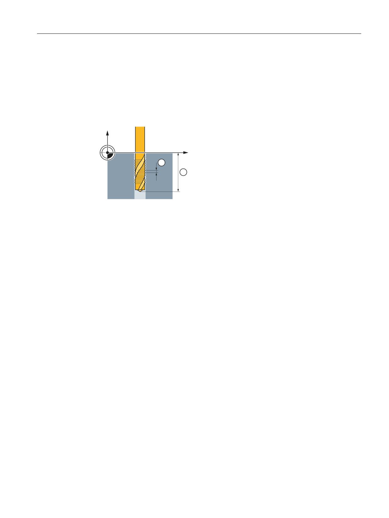
For tapping without compensating chuck, the traversing motion of the linear axis and the
spindle are interpolated, closed-loop position controlled. This requires a position-
controlled spindle with position measuring system.
;
9
① Thread pitch
② Thread depth
Thread direction of rotation
The thread direction of rotation (right or left-handed thread) is defined by the sign of the pitch:
• Positive pitch → right-handed thread (direction of rotation corresponding to M3)
• Negative pitch → left-handed thread (direction of rotation corresponding to M4)
Defined spindle start position
When tapping without compensating chuck, a defined spindle start position (SPOS) must be
programmed in the following cases:
• Threads produced using multiple machining operations
• Threads, for which a defined thread start position is specified
SPOS = <start position>
G331 ...
12.2.8.2
Programming
For tapping without compensating chuck, using the G331 and G332commands, the following
traversing motion is executed:
• G331: Tapping in the tapping direction up to the end of thread point
• G332: Retraction motion up to the tapping block G331 with automatic spindle direction of
rotation reversal
Syntax
G331 <axis> <thread pitch>
G331 <axis> <thread pitch> S...
Axes and spindles
Function Manual, 10/2020, 6FC5397-4GP40-0BA1
405

Spindles
12.2 Operating modes
G332 <axis> <thread pitch>
Meaning
G331:
Tapping
The tapped hole is defined by the traversing motion of the axis (drilling depth)
and the thread pitch.
Effectiveness:
Modal
G332:
Retraction motion when tapping
Retraction motion must have the same pitch as when tapping (G331). The
direction of rotation of the spindle is reversed automatically.
Effectiveness:
Modal
<axis>:
Traversing distance/position of the geometry axis (X, Y or Z) at the end of the
thread, e.g. Z50
<Thread pitch>:
Thread pitch I (X), J (Y) or K (Z):
• Positive pitch: Right-handed thread, e.g. K1.25
• Negative pitch: Left-handed thread, e.g. K-1.25
Range of values:
±0.001 to ±2000.00 mm/revolution
S...:
Spindle speed
The last active spindle speed is used if a spindle speed is not specified.
Note
Second gear-stage data block
To achieve effective adaptation of spindle speed and motor torque and be able to accelerate
faster, a second gear-stage data block for two further configurable switching thresholds
(maximum speed and minimum speed) can be preset in axis-specific machine data deviating
from the first gear step data block and also independent of these speed switching thresholds.
The specifications of the machine manufacturer must be observed.
For further information see the "Axes and Spindles" Function Manual.
Examples
• Example: Tapping with G331 / G332 (Page 407)
• Example: Output the programmed drilling speed in the current gear stage (Page 407)
• Example: Application of the second gear-stage data block (Page 408)
• Example: Speed is not programmed, the gearbox stage is monitored (Page 408)
• Example: Gearbox stage cannot be changed, gearbox stage monitoring (Page 408)
• Example: Programming without SPOS (Page 409)
See also
Configurable gear adaptations (Page 417)
Axes and spindles
406
Function Manual, 10/2020, 6FC5397-4GP40-0BA1

Spindles
12.2 Operating modes
12.2.8.3
Example: Tapping with G331 / G332
Program code
Comment
N10 SPOS[n]=0
; Spindle: Position control mode
; Start position 0 degrees
N20 G0 X0 Y0 Z2
; Axes: Approach starting position
N30 G331 Z-50 K-4 S200
; Tapping in Z,
; Pitch K-4 negative =>
; Direction of spindle rotation: CCW
rotation,
; Spindle speed 200 rpm
N40 G332 Z3 K-4
; Retraction motion in Z,
; Pitch K-4 negative (counterclock-
wise),
; autom. direction of rotation reversal
=>
; Clockwise spindle direction of rota-
tion
N50 G1 F1000 X100 Y100 Z100 S300 M3
; Spindle in spindle operation
12.2.8.4
Example: Output the programmed drilling speed in the current gear stage
Program code
Comment
N05 M40 S500
; Programmed spindle speed: 500 rpm =>
; Gearbox stage 1 (20 to 1028 rpm)
N55 SPOS=0
; Position the spindle
N60 G331 Z-10 K5 S800
; Tapping
; Spindle speed 800 rpm => gearbox stage 1
The appropriate gear stage for the programmed spindle speed S500 with M40 is determined on
the basis of the first gear-stage data block. The programmed drilling speed S800 is output in the
current gear stage and, if necessary, is limited to the maximum speed of the gear stage. No
automatic gear-stage change is possible following an SPOS operation. In order for an automatic
change in gear stage to be performed, the spindle must be in speed-control mode.
Note
If gearbox stage 2 is selected at a spindle speed of 800 rpm, then the switching thresholds for
the maximum and minimum speed must be configured in the relevant machine data of the
second gear-stage data block (see the examples below).
Axes and spindles
Function Manual, 10/2020, 6FC5397-4GP40-0BA1
407

Spindles
12.2 Operating modes
12.2.8.5
Example: Application of the second gear-stage data block
The switching thresholds of the second gear-stage data block for the maximum and minimum
speed are evaluated for G331/G332 and when programming an S value for the active master
spindle. Automatic M40 gear-stage change must be active. The gear stage as determined in the
manner described above is compared with the active gear stage. If they are found to be
different, then the gearbox stage is changed.
Program code
Comment
N05 M40 S500
; Programmed spindle speed: 500 rpm
N50 G331 S800
; Master spindle: Gearbox stage 2 is selected
N55 SPOS=0
; Position the spindle
N60 G331 Z-10 K5
; Tapping
; Spindle acceleration from second gearbox stage data block 2
12.2.8.6
Example: Speed is not programmed, the gearbox stage is monitored
If no speed is programmed when using the second gearbox stage data block with G331, then the
last speed programmed will be used to produce the thread. The gear stage does not change.
However, monitoring is performed in this case to check that the last speed programmed is within
the preset speed range (defined by the maximum and minimum speed thresholds) for the active
gear stage. Otherwise, alarm 16748 is output.
Program code
Comment
N05 M40 S800
; Programmed spindle speed: 800 rpm
N55 SPOS=0
; Position the spindle
N60 G331 Z-10 K5
; Tapping
; Monitoring the spindle speed, 800 rpm
; Gearbox stage 1 is active
; Gearbox stage 2 should be active => Alarm 16748
12.2.8.7
Example: Gearbox stage cannot be changed, gearbox stage monitoring
If the spindle speed is programmed in addition to the geometry in the G331 block when using
the second gear-stage data block, if the speed is not within the preset speed range (defined by
the maximum and minimum speed thresholds) of the active gear stage, it will not be possible
to change gear stages, because the path motion of the spindle and the infeed axis (axes) would
not be retained.
As in the example above, the speed and gearbox stage are monitored in the G331 block and
alarm 16748 is signaled if necessary.
Program code
Comment
N05 M40 S500
; Programmed spindle speed: 500 rpm =>
; Gearbox stage 1
N55 SPOS=0
; Position the spindle
Axes and spindles
408
Function Manual, 10/2020, 6FC5397-4GP40-0BA1

Spindles
12.2 Operating modes
Program code
Comment
N60 G331 Z-10 K5 S800
; Tapping
; Gearbox stage cannot be changed,
; Monitoring the spindle speed, 800 rpm
; with gearbox stage data set 1: Gearbox stage 2
; should be active => Alarm 16748
12.2.8.8
Example: Programming without SPOS
Program code
Comment
N05 M40 S500
; Programmed spindle speed: 500 rpm =>
; Gearbox stage 1 (20 to 1028 rpm)
N50 G331 S800
; Master spindle: Gearbox stage 2 is selected
N60 G331 Z-10 K5
; Tapping
; Spindle acceleration from second gearbox stage data block 2
Thread interpolation for the spindle starts from the current position, which is determined by the
previously processed section of the part program, e.g. if the gear stage was changed. Therefore,
it might not be possible to remachine the thread.
Note
Please note that when machining with multiple spindles, the drill spindle also has to be the
master spindle. SETMS(<spindle number>) can be programmed to set the drill spindle as
the master spindle.
12.2.8.9
Special case: Direction of rotation reversal via NC/PLC interface signal in the NC
program
Normally, a request to invert the direction of rotation of the spindle via the NC/PLC interface
signal "Invert M3 / M4" (DB31, ... DBX17.6) is realized by the PLC user program before the NC
program is started. Only when starting does the NC automatically evaluate the status of the
interface signal, and if necessary, change the spindle direction of rotation.
If, while the program is being executed, the spindle direction of rotation must again be changed
as a result of the NC/PLC interface signal "Invert M3 / M4" (DB31, ... DBX17.6), then within an NC
program, this can only be achieved using the subsequently described principle sequence:
N110 SPCOF or M5
Stop the spindle and switch into the closed-loop speed controlled
mode
N111 Mxx or Hxx
Output a user-specific help function to initiate the following ac-
tions in the PLC user program:
• Set the read-in inhibit in the channel: DB21, ... DBX6.1 = 1
• Invert the interface signal "Invert M3/M4" of the spindle:
DB31, ... DBX17.6
• Reset the read-in inhibit in the channel: DB21, ... DBX6.1 = 0
Axes and spindles
Function Manual, 10/2020, 6FC5397-4GP40-0BA1
409
Spindles
12.2 Operating modes
N112 STOPRE
Preprocessing stop
N113 SPOS=IC(0.001)
Incrementally traverse the spindle in the closed-loop position con-
trolled mode.
By incrementally traversing the spindle in the closed-loop position
controlled mode, the NC again evaluates interface signal DB31, ...
DBX17.6 (invert M3/M4).
From this block onward, when traversing the spindle, the direction
of reversal based on the interface signal is active.
N114 SPOS=0
Optional: Position the spindle if, technologically, a defined output
position is required, e.g. 0°
Example
Program code
Comment
N010
G0 X0 Z0
; Initial position of the axes
N020
G1 G94 F1000 Z10
; Traverse the Z axis to the initial position
N030
M3 S100
; Traverse the spindle in the closed-loop speed controlled
mode
; 100 rpm with the spindle direction of rotation that was
determined
; at the start of the program
; Any arbitrary machining
N040
M5
; Stop the spindle and switch into the closed-loop speed
controlled mode
N050
H10
; Auxiliary function output: H0=10
; In the PLC user program:
;
- set the read-in inhibit: DB21, ... DBX6.1=1
;
- invert the direction of rotation: DB31, ... DBX17.6
;
- reset the read-in inhibit: DB21, ... DBX6.1=0
N060
STOPRE
; Preprocessing stop
N070
SPOS=IC(0.001)
; Incrementally traverse the spindle in the closed-loop po-
sition controlled mode.
N080
SPOS=0
; Position the spindle
N090
G331 Z-10 K1 S500
; Tapping without compensating chuck
N100
G332 Z2 K1
; Tapping without compensating chuck Retraction movement
N110
G1 G94 F1000 Z10
; Retract to the initial position of the Z axis
N120
SPCOF
; Switch the spindle into the closed-loop speed controlled
mode
N130
H10
; See above
N140
STOPRE
; Preprocessing stop
N150
SPOS=IC(.001)
; Incrementally traverse the spindle in the closed-loop po-
sition controlled mode.
N160
SPOS=0
; Position the spindle
N170
G331 Z-10 K1 S500
; Tapping without compensating chuck
N180
G332 Z2 K1
; Tapping without compensating chuck Retraction movement
N190
G1 G94 F1000 Z10
; Traverse the Z axis to the initial position
Axes and spindles
410
Function Manual, 10/2020, 6FC5397-4GP40-0BA1
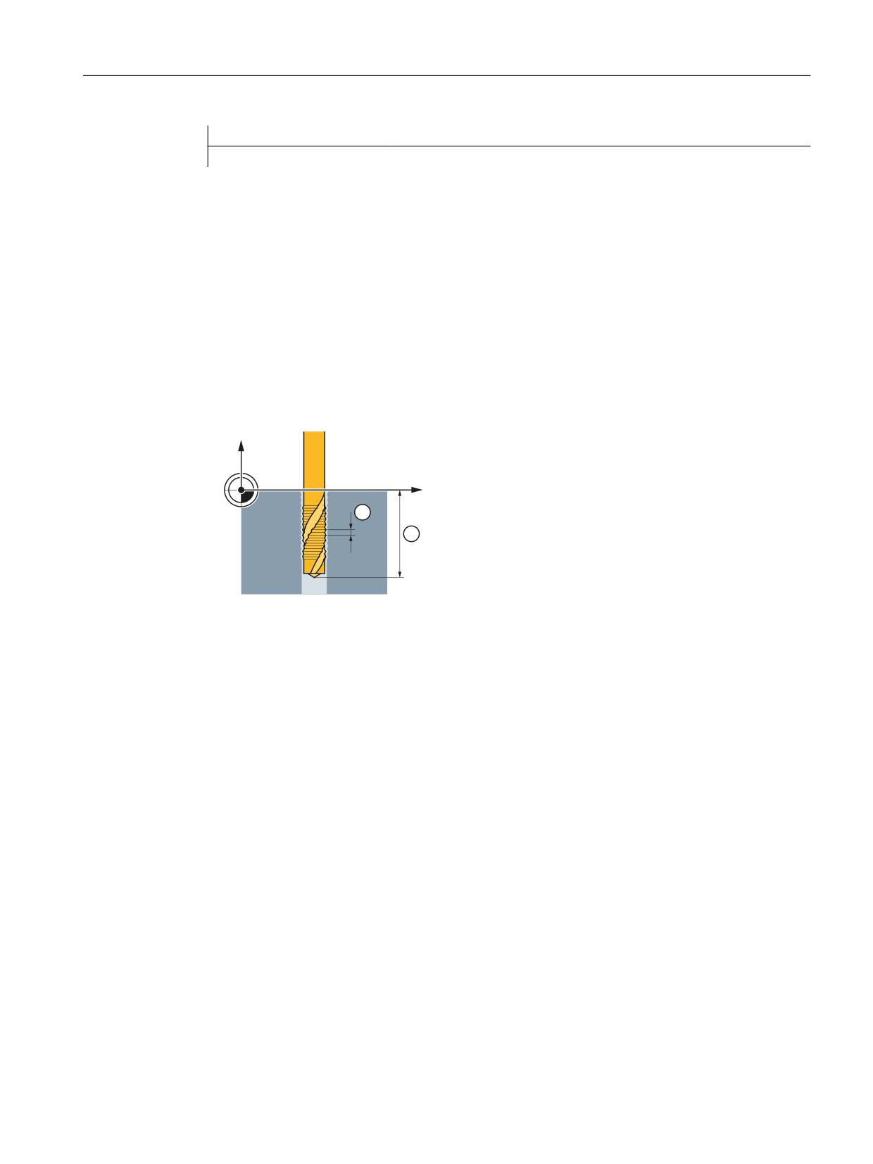
Spindles
12.2 Operating modes
Program code
Comment
12.2.9
Tapping with compensating chuck
12.2.9.1
Function
When tapping with compensating chuck (G63) the spindle is not interpolated with the linear
axis, but is operated in the closed-loop speed controlled mode. The feedrate of the linear axis
dependent on the spindle speed and the thread pitch must be calculated and explicitly
programmed. As the spindle and linear axis are not interpolated together, to compensate
spindle speed fluctuations for example, a tapping drill in a length-compensating chuck is
required.
;
9
① Thread pitch
② Thread depth
Retraction movement
The retraction motion is also programmed with G63 - but with the opposite spindle direction of
rotation.
Axis and spindle override value
While the "Tapping with compensating chuck" function is selected, 100% is active as axis and
spindle override value.
Feedrate
Feedrate F of the linear axis to be programmed is obtained from the product of the spindle speed
and the thread pitch of the tapping drill:
F [mm/min] = spindle speed S [rpm] *thread pitch [mm/U]
12.2.9.2
Programming
For tapping with compensating chuck, using the G63 command, the following traversing
motion is executed:
• G63: Tapping in the tapping direction up to the end of thread point
• G63: Retraction motion with programmed spindle direction of rotation reversal
Axes and spindles
Function Manual, 10/2020, 6FC5397-4GP40-0BA1
411

Spindles
12.2 Operating modes
Note
After a G63block, the last effective interpolation type G0, G1, G2 is active.
Syntax
G63 <axis> <direction of rotation> <speed <feedrate>
Meaning
G63:
Tapping with compensating chuck
Effective:
Non-modal
<Axis>:
Traversing distance/position of the geometry axis (X, Y or Z) at the end of the
thread, e.g. Z50
<Direction of
Direction of spindle rotation:
rotation>:
• M3: Clockwise rotation, right-hand thread
• M4: Counterclockwise rotation, left-hand thread
<Speed>:
Maximum permissible spindle speed while tapping, e.g. S100
<Feedrate>:
Feedrate of the tapping axis F, with F = spindle speed * thread pitch
Example
Tapping an M5 thread:
• Spindle pitch according to the standard: 0.8 mm/rev
• Spindle speed S: 200 rpm
• Feedrate F = 200 rpm * 0.8 mm/rev = 160 mm/min.
Program code
Comment
N10 G1 X0 Y0 Z2 F1000 S200 M3
; Approach starting point
; Spindle clockwise direction of rotation, 200
rpm
N20 G63 Z-50 F160
; Tapping with compensating chuck
; Drilling depth: absolute Z=50mm
; Feedrate: 160 mm/min
N30 G63 Z3 M4
; Retraction movement: absolute Z=3mm
; Direction of rotation reversal
; Spindle with counterclockwise direction of
rotation, 200 rpm
Axes and spindles
412
Function Manual, 10/2020, 6FC5397-4GP40-0BA1
Spindles
12.3 Reference / synchronize
12.3
Reference / synchronize
Why synchronize?
In order to ensure that the controller detects the exact position of the spindle when it is switched
on, the controller must be synchronized with the position measuring system of the spindle.
The following functions are possible only with a synchronized spindle:
• Thread cutting
• Tapping without compensating chuck
• Axis programming
For further information about synchronizing the spindle, see Section "Homing (Page 31)".
Why reference?
In order to ensure that the controller detects the exact machine zero when it is switched on, the
controller must be synchronized with the position measurement system of the rotary axis. This
process is known as referencing. The sequence of operations required to reference an axis is
known as search for reference.
Only a referenced axis can approach a programmed position accurately on the machine.
For further information about referencing the rotary axis, see Section "Homing (Page 31)".
Installation position of the position measurement system
The position measurement systems can be installed as follows:
• directly at the motor in combination with a contactless proximity switch on the spindle as a
zero mark encoder
• at the motor using a measuring gearbox in combination with a contactless proximity switch
on the spindle as a zero mark encoder
• Directly on the spindle
• on the spindle via a measuring gearbox in combination with a contactless proximity switch
on the spindle as a zero mark encoder (only with ratios not equal to 1:1)
Where two position measuring systems are provided, they can be installed either in the same
location or separately.
Synchronization procedure
When the spindle is switched on, it can be synchronized as follows:
• The spindle is started with a spindle speed (S value) and a spindle rotation (M3 or M4) and
synchronized with the next zero mark of the position measurement system or with the next
signal from the contactless proximity switch.
• The spindle is to be positioned from standstill using SPOS, M19 or SPOSA. The spindle
synchronizes with the next zero mark of the position measurement system or with the next
proximity switch signal. It is then positioned to the programmed position.
Axes and spindles
Function Manual, 10/2020, 6FC5397-4GP40-0BA1
413
Spindles
12.3 Reference / synchronize
•
The spindle can be synchronized from the motion (after M3 or M4) using SPOS, M19
or SPOSA.
The responses are as follows:
- With SPOS=<Pos>, SPOS=DC(<Pos>) and SPOS=AC(<Pos>), the direction of motion
is retained and the position is approached.
- With SPOS = ACN(<Pos>) or SPOS = ACP(<Pos>), the position is always
approached with a negative or positive direction of motion. If necessary, the direction of
motion is inverted prior to positioning.
•
Crossing the zero mark in JOG mode by means of direction keys in speed control mode.
Note
It does not make any difference whether the synchronization procedure is initiated from the
part program, FC 18 or synchronized actions.
Note
During synchronization of the spindle, all four possible reference point values are effective
depending on the measuring system selected. The measurement system offset has the same
effect.
The following machine data must be observed:
• MD34080 $MA_REFP_MOVE_DIST
(Reference point distance / destination point for a distance-coded system)
• MD34090 $MA_REFP_MOVE_DIST_CORR
(Reference point offset / absolute offset, distance-coded)
• MD34100 $MA_REFP_SET_POS
(Reference point value, with distance-coded system without any significance)
If a non-referenced spindle with SPOS=IC(...) and a path < 360 degrees is positioned, it
may be the case that the zero mark is not crossed and the spindle position is still not
synchronized with the zero mark. This can happen:
• After POWER ON
• By setting the axial NC/PLC interface signals:
DB31, ... DBX17.5 (resynchronize spindle when positioning 2)
DB31, ... DBX17.4 (resynchronize spindle when positioning 1)
Special features when synchronizing using a contactless proximity switch
The position error caused by the signal delay when using a contactless proximity switch can be
corrected internally in the NC by entering a signal runtime compensation.
The signal runtime compensation is set by means of the machine data:
• MD31122 $MA_BERO_DELAY_TIME_PLUS
(delay time of the contactless proximity switch, positive motion direction)
• MD31123 $MA_BERO_DELAY_TIME_MINUS
(delay time of the contactless proximity switch, negative motion direction)
The effect depends on the selected referencing mode:
Axes and spindles
414
Function Manual, 10/2020, 6FC5397-4GP40-0BA1

Spindles
12.3 Reference / synchronize
MD34200 $MA_ENC_REFP_MODE = <value>
<Val-
Meaning
ue>
2
The position is synchronized without entering a specific starting velocity/speed.
7
As starting velocity to synchronize the position, the velocity from the following machine data
is used:
MD34040 $MA_REFP_VELO_SEARCH_MARKER (creep velocity)
The zero mark is not automatically looked for, it has to be requested explicitly with the 0/1 edge
of the NC/PLC interface signal:
DB31, ... DBX16.4 / 5 (resynchronize spindle, measuring system 1 / 2)
Note
Generally, no change is required as signal runtimes and signal runtime compensation are preset
when the system is delivered.
Referencing sequence
If the spindle is to be programmed in axis mode directly after controller power-up, it must be
ensured that the axis is referenced.
When the controller is switched on, the spindle can be referenced (condition is one zero mark
per revolution).
For information about the referencing sequence, see Section "Homing (Page 31)".
The rotary axis is referenced at the same time as the spindle is synchronized (see section
"Synchronization procedure") if the position measuring system used for the spindle is also used
for the rotary axis.
Position measurement systems, spindle
The spindle can be switched from spindle mode to axis mode (rotary axis) if a single motor is
used for spindle mode and axis mode.
The spindle (spindle mode and axis mode) can be equipped with one or two position
measurement systems. With two position measurement systems, it is possible to assign one
position measurement system to the spindle and the other to the rotary axis, or to assign two
position measurement systems to the spindle. Where two position measurement systems are
provided, both are updated by the controller, but only one can be active.
The active position measuring system is selected with the NC/PLC interface signal:
DB31, ... DBX1.5 / 6 (position measuring system 1 / 2)
The active position measurement system is required for the following functions:
• Position control of the spindle (SPCON)
• Spindle positioning (SPOS, M19 and SPOSA)
• Thread cutting (G33, G34, G35)
• Tapping without compensating chuck (G331, G332)
Axes and spindles
Function Manual, 10/2020, 6FC5397-4GP40-0BA1
415
Spindles
12.3 Reference / synchronize
• Revolutional feedrate (G95)
• Constant cutting rate (G96, G961, G97, G971)
• Spindle actual speed display
• Axis mode
• Synchronous spindle setpoint coupling
Resynchronizing the position measuring system for the spindle
In the following cases, the spindle position measurement system must be resynchronized:
• The position encoder is on the motor, a contactless proximity switch is mounted on the
spindle and the gear stage is changed. Synchronization is triggered internally once the
spindle is rotating in the new gear stage (see Synchronization procedure).
• The machine has a selector switch for a vertical and horizontal spindle. Two different position
encoders are used (one for the vertical spindle and one for the horizontal spindle), but only
one actual value input is used on the controller. When the system switches from the vertical
to the horizontal spindle, the spindle must be resynchronized.
This synchronization is initiated with the NC/PLC interface signal:
DB31, ... DBX16.4 (resynchronize spindle 1)
or
DB31, ... DBX16.5 (resynchronize spindle 2)
The spindle must be in open-loop control mode.
Restoring the position after a warm restart
For spindles with incremental position measuring systems, it is possible to buffer the actual
values after a POWER OFF and after POWER ON, to restore the position last buffered before
switching-off, in order that position-dependent functions, e.g. transformations can be restored
(see Section "Automatic restoration of the machine reference (Page 72)"). One application, for
example, is the tool retraction after a warm restart during processing with tool orientation (see
Function Manual Basic Function, Section "Tool retraction after POWER ON with orientation
transformation").
The following NC/PLC interface signals display the state of the position measuring system after
the position has been restored:
DB31, ... DBX71.4 ("Restored 1") for position measuring system 1
DB31, ... DBX71.5 ("Restored 2") for position measuring system 2
Once the tool has been retracted in JOG mode, axes whose positions have been restored are
referenced. As a consequence, signals DB31, ... DBX71.4/5 ("Restored 1/2") are deleted and
signals DB31, ... DBX60.4/5 ("Referenced/synchronized 1/2") are set.
Note
If machine data MD20700 $MC_REFP_NC_START_LOCK is set to a value of "2", then an NC start
is also possible with "restored" axis positions (in the MDI mode or when overstoring).
Axes and spindles
416
Function Manual, 10/2020, 6FC5397-4GP40-0BA1

Spindles
12.4 Configurable gear adaptations
12.4
Configurable gear adaptations
12.4.1
Gear stages for spindles and gear change change
Why do we need gear stages?
Gear stages are used on spindles to step down the speed of the motor in order to generate a high
torque at low spindle speeds or to step up in order to maintain a high speed.
No. of gear stages
Five gear stages can be configured for each spindle.
The number of used gear stages is defined in machine data:
MD35090 $MA_NUM_GEAR_STEPS
Parameterization of the gear stages
The gear stages 1 to 5 can be parameterized via the following machine data:
Machine data
Meaning
MD35012 $MA_GEAR_STEP_CHANGE_POSITION[<n>]
Gear stage change position
MD35110 $MA_GEAR_STEP_MAX_VELO[<n>]
Maximum speed for automatic
gear stage change
MD35120 $MA_GEAR_STEP_MIN_VELO[<n>]
Minimum speed for automatic
gear stage change
MD35130 $MA_GEAR_STEP_MAX_VELO_LIMIT[<n>]
Maximum speed of gear stage
MD35135 $MA_GEAR_STEP_PC_MAX_VELO_LIMIT[<n>]
Maximum speed of gear stage in
position control
MD35140 $MA_GEAR_STEP_MIN_VELO_LIMIT[<n>]
Minimum speed of gear stage
MD35200 $MA_GEAR_STEP_SPEEDCTRL_ACCEL[<n>]
Acceleration in speed control mode
MD35210 $MA_GEAR_STEP_POSCTRL_ACCEL[<n>]
Acceleration in position control
mode
MD35300 $MA_SPIND_POSCTRL_VELO[<n>]
Position control activation speed
MD35310 $MA_SPIND_POSIT_DELAY_TIME[<n>]
Positioning delay time
MD35550 $MA_DRILL_VELO_LIMIT[<n>]
Maximum speed for tapping with-
out compensating chuck
Type of gear stage change
The type of gear stage change is set in machine data:
Axes and spindles
Function Manual, 10/2020, 6FC5397-4GP40-0BA1
417

Spindles
12.4 Configurable gear adaptations
MD35010 $MA_GEAR_STEP_CHANGE_ENABLE
Bit
Value
Meaning
0
0
The spindle motor is attached to the spindle directly (1:1) or with a non-variable trans-
mission ratio (basic setting).
The machine data of the first gear stage is effective.
1
Spindle motor with up to five gear stages.
The gear stage change takes place:
• In oscillation mode
• At indefinite change position
1
0
Meaning as in Bit 0 = 0.
1
Meaning as in Bit 0 = 1, however, the gear stage change takes place at the configured
spindle position.
The change position is set in machine data:
MD35012 $MA_GEAR_STEP_CHANGE_POSITION
The position is approached in the current gear stage before the gear stage change.
If Bit 1 is set, then Bit 0 is ignored!
3
1
The gear stage change dialog between NC and PLC is simulated.
5
1
The second gear stage data set is used while tapping with G331/G332 (see the following
paragraph "Second gear stage data set"). The bit must be set for the master spindle used
during the tapping.
Requirement for a gear stage change
In principle, the gear stage change is only performed if the requested gear stage is not the same
as the active gear stage.
Parameter set selection during gear stage change
The servo parameter set is also changed over with the gear stage if:
MD35590 $MA_PARAMSET_CHANGE_ENABLE = 0 or 1
For further information, see Section "Parameter set selection during gear step change
(Page 431)".
Axes and spindles
418
Function Manual, 10/2020, 6FC5397-4GP40-0BA1
Spindles
12.4 Configurable gear adaptations
Request gear stage change
A gear stage change can be requested:
•
In the part program using:
- M40 S...
Automatic gear stage selection to the programmed speed S...
- M41 ... M45
Direct selection of gear stages 1 ... 5
- M70
For MD35014 $MA_GEAR_STEP_USED_IN_AXISMODE = 1 ... 5
(see "Configurable gear step in M70 (Page 447)")
- G331 S...
For MD35010 $MA_GEAR_STEP_CHANGE_ENABLE, Bit 5 = 1
•
In synchronized actions using:
- DO M40 S...
Automatic gear stage selection to the programmed speed S...
- DO M41... M45
Direct selection of gear stages 1 ... 5
- DO M70
For MD35014 $MA_GEAR_STEP_USED_IN_AXISMODE = 1 ... 5
•
Through the PLC using the FC18 function block
•
In the reset state through description of NC/PLC interface:
DB31, ... DBX16.0-16.2 (actual gear stage A to C)
The mechanically active gear stage can be communicated to the NC especially after a POWER
ON.
Note
If the spindle motor is attached to the spindle directly (1:1) or with a non-variable
transmission ratio (MD35010 = 0), then the M40 and M41 ... M45 auxiliary functions are not
relevant to this spindle.
Axes and spindles
Function Manual, 10/2020, 6FC5397-4GP40-0BA1
419
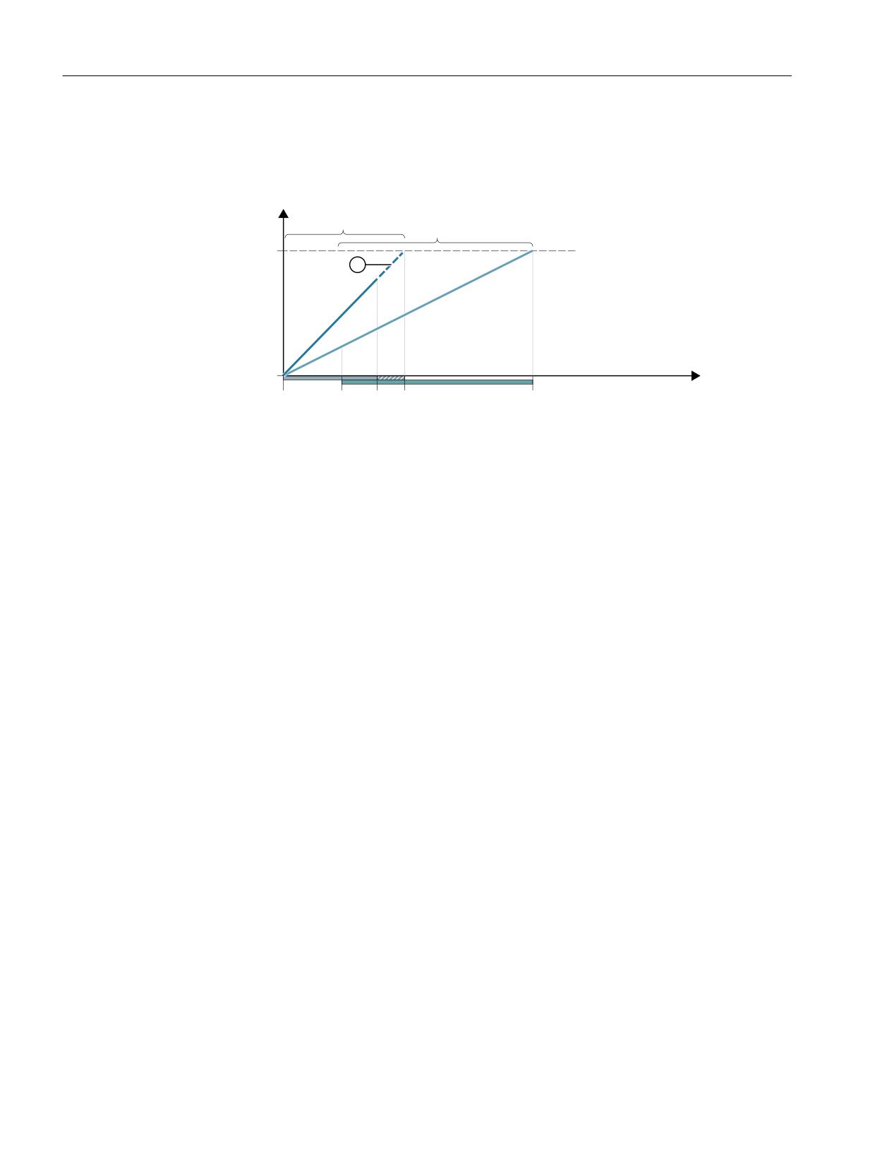
Spindles
12.4 Configurable gear adaptations
gear stage selection
Gear stage selection between two gear stages with specification of a maximum spindle speed is
shown in the example below:
.PUPS TQFFE
(FBS TUBHF
SQN
(FBS TUBHF
.BY NPUPS
TQFFE
4QJOEMF TQFFE
H NJO
H NJO
H NBYO NBY
O NBYH NBY
SQN
Can be specified by MD35110 GEAR_STEP_MAX_VELO:
n1max
... max. spindle speed of the 1st gear stage
g1min
... min. spindle speed of the 1st gear stage for automatic gear stage selection
g1max
... max. spindle speed of the 1st gear stage for automatic gear stage selection
n2gmax
... max. spindle speed of the 2nd gear stage
g2min
... min. spindle speed of the 2nd gear stage for automatic gear stage selection
g2max
... max. spindle speed of the 2nd gear stage for automatic gear stage selection
Figure 12-3
Gear stage change with selection between two gear stages
Axes and spindles
420
Function Manual, 10/2020, 6FC5397-4GP40-0BA1
Spindles
12.4 Configurable gear adaptations
Process sequence of the gear stage change
If the new gear stage is preselected, the following sequence is implemented:
1.
Changeover sequence
The two following NC/PLC interface signals are set:
DB31, ... DBX82.0-82.2 (setpoint gear stage A to C)
DB31, ... DBX82.3 (change over gear stage)
In accordance with the point at which NC/PLC IS:
DB31, ... DBX18.5 (oscillation speed)
is set, the spindle decelerates to a standstill at the acceleration for oscillation or at the
acceleration for speed control / position control.
Oscillation can be activated at the latest when the spindle reaches a standstill:
DB31, ... DBX61.4 (axis/spindle stationary)
with NC/PLC IS:
DB31, ... DBX18.5 (oscillation speed).
In principle, the new gear stage can also be engaged without oscillation.
When the new gear stage is engaged, the following NC/PLC interface signals are set by the
PLC program:
DB31, ... DBX16.0-16.2 (actual gear stage A to C)
DB31, ... DBX16.3 (gear is changed)
2.
End of gear stage change
The gear stage change is treated as completed (spindle operation type "oscillation mode" is
deselected), if the following NC/PLC interface signal is set:
DB31, ... DBX16.3 (gear is changed)
The new actual gear stage is changed to the servo and interpolation parameter set when the
motor is stationary.
With NC/PLC interface signal:
DB31, ... DBX16.3 (gear is changed)
is used to communicate to the NC that the new gear stage is valid and the oscillation mode
can be completed.
The NC/PLC interface signal:
DB31, ... DBX82.3 (change gear)
is reset by the NC,
which causes the PLC program to reset NC/PLC IS:
DB31, ... DBX16.3 (gear changed).
In this case, it does not matter whether NC/PLC IS:
DB31, ... DBX18.5 (oscillation mode)
is still set.
The actual gear stage, which should correspond to the set gear stage, is relevant
for selecting the parameter set.
If this is not the case, then Alarm 22010 :
MD11410 $MN_SUPPRESS_ALARM_MASK, Bit 3 = 0
is output.
Following acknowledgment of gear stage change via the PLC
with NC/PLC IS:
DB31, ... DBX16.3 (gear changed)
the spindle is in speed control mode (DB31, ... DBX84.7).
For further information on the signal exchange between PLC and NC, see Basic Functions
Function Manual.
Axes and spindles
Function Manual, 10/2020, 6FC5397-4GP40-0BA1
421

Spindles
12.4 Configurable gear adaptations
Second gear stage data set
The automatic gear stage change M40 can be extended by a second configurable gear stage data
set.
The second gear stage data set is used exclusively in connection with tapping without
compensation chuck (G331, G332) so that an effective adjustment of spindle speed and motor
torque can be achieved.
The activation is undertaken by setting the following bit for the master spindle:
MD35010 $MA_GEAR_STEP_CHANGE_ENABLE, Bit 5 = 1
The number of used gear stages of the second gear stage data set is defined with the machine
data:
MD35092 $MA_NUM_GEAR_STEPS2
The second gear stage block data set is deactivated if:
MD35092 $MA_NUM_GEAR_STEPS2 = 0 (basic setting)
The first gear stage data set then selects the gear stage when M40 is active.
Note
The number of gear stages in the second data set can vary from the first. If no appropriate gear
stage is found for a programmed speed for M40, then no gear stage change is carried out
(exceptions, see "M40: Automatic gear stage selection for speeds outside the configured
switching thresholds (Page 477)").
For further information on a typical program execution for thread cutting without
compensating chuck G331/G332, see NC Programming Programming Manual.
The gear stages 1 to 5 of the second gear stage data set can be parameterized via the following
machine data:
Machine data
Meaning
MD35112 $MA_GEAR_STEP_MAX_VELO2[n]
Maximum speed for automatic gear stage
change
MD35122 $MA_GEAR_STEP_MIN_VELO2[n]
Minimum speed for automatic gear stage
change
MD35212 $MA_GEAR_STEP_POSCTRL_ACCEL2[n]
Acceleration in position control mode
Note
The number of servo parameter sets concerning the mechanical factors remain unchanged.
Furthermore, five mechanical gear stages for the spindle and one for the axis operation can be
configured.
Axes and spindles
422
Function Manual, 10/2020, 6FC5397-4GP40-0BA1
Spindles
12.4 Configurable gear adaptations
The speed limitations are configured only once for each gear stage with the following machine
data, independently of the different switching thresholds:
Machine data
Meaning
MD35130 $MA_GEAR_STEP_MAX_VELO_LIMIT[n]
Maximum speed of gear stage
MD35140 $MA_GEAR_STEP_MIN_VELO_LIMIT[n]
Minimum speed of gear stage
For tapping without compensating chuck (G331, G332) the speed can be limited to the linear
acceleration range of the motor additionally. For this, the maximum speed of the linear motor
characteristics range is specified in the following machine data as a function of the gear stage:
MD35550 $MA_DRILL_VELO_LIMIT[n]
Specify gear stage in the part program
Automatic selection with active M40
The gear stage is automatically selected by the control. The gear stage in which the programmed
spindle speed (S...) is possible is checked in this context. If a gear stage results from this that
is not equal to the current (actual) gear stage, then the following NC/PLC interface signals are set:
DB31, ... DBX82.3 (change over gear stage)
DB31, ... DBX82.0-82.2 (setpoint gear stage A to C)
While the appropriate gear stage is being determined, a gear stage change is only requested if
the new speed is not within the permissible speed range of the active gear stage.
The speed is limited to the maximum speed of the current gear stage or raised to the minimum
speed of the current gear stage and the appropriate NC/PLC interface signal is set:
DB31, ... DBX83.1 (speed setpoint limited)
DB31, ... DBX83.2 (speed setpoint increased)
Axes and spindles
Function Manual, 10/2020, 6FC5397-4GP40-0BA1
423
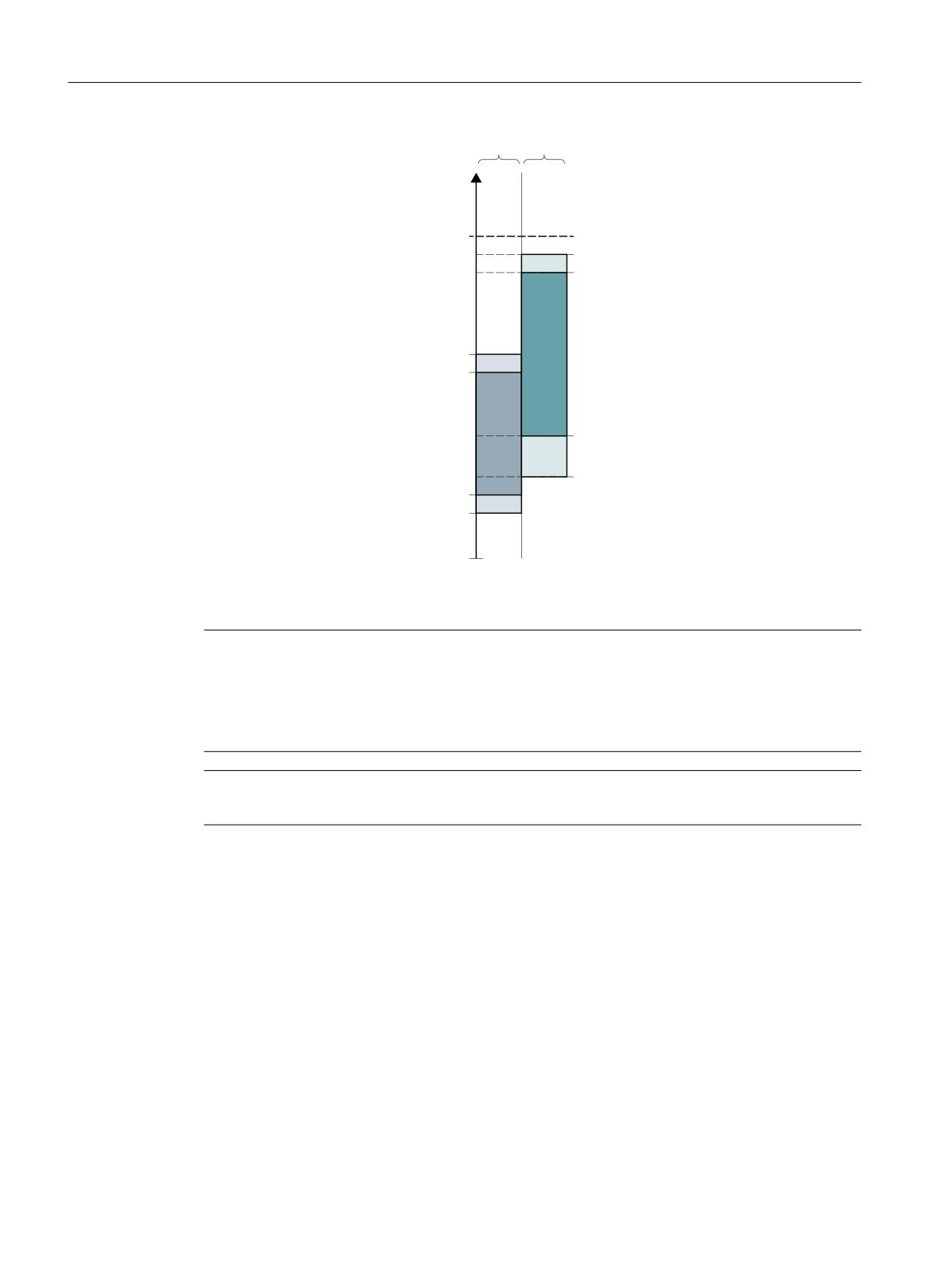
Spindles
12.4 Configurable gear adaptations
(FBS TUBHF
(FBS TUBHF
4QFFE
SQN
.BYJNVN TQJOEMF TQFFE
.BYJNVN TQFFE PG HFBS TUBHF
.BYJNVN TQFFE GPS BVUPN (4$
PG HFBS TUBHF
.BYJNVN TQFFE PG HFBS TUBHF
.BYJNVN TQFFE GPS BVUPN (4$
PG HFBS TUBHF
.JOJNVN TQFFE GPS BVUPN (4$
PG HFBS TUBHF
.JOJNVN TQFFE GPS BVUPN (4$
.JOJNVN TQFFE PG HFBS TUBHF
PG HFBS TUBHF
.JOJNVN TQFFE PG HFBS TUBHF
Figure 12-4
Example for two gear stages with overlapping speed ranges for automatic gear stage
change (M40)
Note
In the case of M40, the spindle must be in open-loop control mode for automatic gear stage
selection with an S word. Otherwise the gear stage change is rejected and the following alarm
is set:
Alarm 22000 "gear stage change is not possible"
Note
An active reduction gear is not considered in the selection for the automatic gear stage change.
Permanently defining the gear stage with M41 to M45
The gear stage can be permanently defined in the part program with M41 to M45.
If a gear stage is specified via M41 to M45 that is not equal to the current (actual) gear stage, then
the following NC/PLC interface signals are set:
DB31, ... DBX82.3 (change over gear stage)
DB31, ... DBX82.0-82.2 (setpoint gear stage A to C)
Axes and spindles
424
Function Manual, 10/2020, 6FC5397-4GP40-0BA1
Spindles
12.4 Configurable gear adaptations
The programmed spindle speed (S...) then refers to this permanently defined gear stage:
• If a spindle speed is programmed and it is higher than the maximum speed of the
permanently defined gear stage (MD35130 $MA_GEAR_STEP_MAX_VELO_LIMIT), then the
speed is decreased to this limit and the following NC/PLC interface signal is set:
DB31, ... DBX83.1 (speed setpoint limited)
• If a spindle speed is programmed and it is lower than the minimum speed of the permanently
defined gear stage (MD35140 $MA_GEAR_STEP_MIN_VELO_LIMIT), then the speed is
increased to this minimum and the following NC/PLC interface signal is set:
DB31, ... DBX83.2 (speed setpoint increased)
Block change
When programming the gear stage change in the part program, the gear stage change set
remains active until it is aborted by PLC.
This corresponds to the effect as if the following NC/PLC interface signal were set:
DB21, ... DBX6.1 (read-in disable)
Specification of gear stage via PLC with FC18
The gear stage change can also be performed by function block FC18 during a part program, in
the reset state or in all operating modes.
If the speed and direction of rotation is specified with FC18, the NC can be requested to select
the gear stage as appropriate for the speed. This corresponds to an automatic gear stage change
with M40.
The gear stage is not changed if:
• The spindle is positioned via FC18.
• The spindle is traversed in the axis mode.
Further information
For further information on the FC18 function block, see Function Manual PLC.
Specification of a gear stage in synchronized actions
The gear stage change can be requested by synchronized actions using:
• DO M40 S...
Automatic gear stage selection to the programmed speed S...
• DO M41... M45
Direct selection of gear stages 1 ... 5
• DO M70
For MD35014 $MA_GEAR_STEP_USED_IN_AXISMODE = 1 ... 5
(see "Configurable gear step in M70 (Page 447)")
Axes and spindles
Function Manual, 10/2020, 6FC5397-4GP40-0BA1
425
Spindles
12.4 Configurable gear adaptations
The gear stage is not changed if:
• The spindle is positioned via synchronized actions.
• The spindle is traversed in the axis mode.
Note
For further details, please refer to the section "Specification of a gear stage in part program".
Exception:
The block change is not affected by the specification of a gear stage in synchronized actions.
Manual specification of a gear stage
Outside a part program that is running, the gear stage can also be changed without a request
from the NC or the machine. This is the case, for example, when a gear stage is changed
manually.
To select the appropriate parameter set, the NC must be informed of the current gear stage. To
enable this, the control or the part program must be in the reset state.
Constraints
Transfer of the gear stage to the NC is initiated when
NC/PLC IS:
DB31, ... DBX16.0-16.2 (actual gear stage A to C) changes
These three bits must be set continuously during operation.
Successful transfer is acknowledged with NC/PLC IS:
DB31, ... DBX82.0-82.2 (set gear stage A to C)
to the PLC.
NC/PLC IS:
DB31, ... DBX16.3 (gear changed)
must not be set.
If position control is active when a new gear stage is specified by the PLC with
DB31, ... DBX16.0-16.2, then it is switched off for the duration of this changeover sequence.
Axes and spindles
426
Function Manual, 10/2020, 6FC5397-4GP40-0BA1
Spindles
12.4 Configurable gear adaptations
NC stop during gear stage change
The spindle cannot be stopped with NC/PLC IS:
DB21, ... DBX7.4 (NC stop)
if:
• The spindle is not yet in oscillation mode for the gear stage change.
• NC/PLC IS:
DB31, ... DBX16.3 (gear changed)
is not set.
Note
Options for aborting:
DB31, ... DBX2.2 (delete distance-to-go / spindle reset)
or
DB31, ... DBX16.3 (gear changed)
with corresponding acknowledgment from actual gear stage:
DB31, ... DBX16.0-16.2 (actual gear stage)
Spindle response after a gear stage change
How the spindle behaves once the gear stage has been changed depends on the following initial
conditions:
• If the spindle was in the stop state before the gear stage change (M5, FC18: "Stop rotate
spindle"), in positioning or axis mode, M5 (spindle stop) is active after completion of the gear
stage change.
• If a direction of rotation
(M3, M4, FC18: "Start spindle rotation"), then the last speed and direction of rotation will
become active again after the gear stage change. In the new gear stage, the spindle
accelerates to the last spindle speed programmed (S...).
• If position control was active before the gear stage change (SPCON), then it is reactivated
after the gear stage change.
The next block in the part program can be executed.
Axes and spindles
Function Manual, 10/2020, 6FC5397-4GP40-0BA1
427
Spindles
12.4 Configurable gear adaptations
Special features
The following points must be observed on gear stage change:
• The gear stage change is not terminated by selecting
NC/PLC IS:
DB31, ... DBX20.1 (run-up switchover to V/f mode).
Setpoint 0 is output.
The gear stage change is acknowledged as usual
via the NC/PLC interface signal:
DB31, ... DBX16.3 (gear is changed)
• The "Ramp-function generator rapid stop" signal must be reset by the PLC before the gear
stage change is completed by the PLC.
• The process sequence of the gear stage change is ended during NC reset without any alarm
output.
The gear stage output with NC/PLC IS:
DB31, ... DBX16.0-16.2 (actual gear stage A to C)
is applied by the NC.
Star/delta switchover with FC17
Digital main spindle drives can be switched in both directions between star and delta using
FC17, even when the spindle is running. This automatic switchover is controlled by a defined
logic circuit in FC17 which provides the user with a configurable switchover time for the relevant
spindle.
Further information
For further information on the FC17 function block, see Function Manual PLC.
12.4.2
Spindle gear stage 0
Technical backg5round
For machine's where the spindle load gear can be changed over, situations can occur where the
gear train between the motor and load (workpiece/tool) is interrupted. This state can occur, e.g.
when pressing Reset or Emergency Stop while performing a gear stage change or when the
machine is commissioned for the first time while it is being installed. The control must identify
this state where the gear train is open and the next gear stage change request must be
unconditionally executed.
Function
When the gear is disengaged, the binary-coded value "0" (≙ gear stage 0) is transferred to the NC
from the PLC using the interface signal bits DB31, ... DBX16.0-2 (actual gear stage A to C):
DB31, ... DBX16.0-2 = 0
The value is used by the control to identify the state where the gear train is open.
Axes and spindles
428
Function Manual, 10/2020, 6FC5397-4GP40-0BA1
Spindles
12.4 Configurable gear adaptations
Effects on the gear stage change
Gear stage change in the part program
The actual gear stage signaled from the PLC is read by the NC when starting a part program. If,
at this instant in time, a value of "0" is read for the actual gear stage, then the next gear stage
change is executed and the gear stage change dialog is performed by the PLC. If a value greater
than "0" is read, then already in the program a comparison is made between the requested and
active gear stage. If both gear stages are the same, the gear stage is not changed and a possibly
programmed path motion is not interrupted.
Gear stage change in synchronized actions, FC18 and DBB30
The actual gear stage signaled from the PLC is always evaluated by the NC when the gear stage
is changed. The gear stage is always changed if a value of "0" is read from the NC. When reading
a value greater than "0", a comparison is made between the requested and active gear stage. The
gear stage is only changed with the PLC if the two values are not equal and the NC/PLC interface
signal DB31, ... DBX82.3 (change over gear) is then output.
Boundary conditions
• Output of DB31, ... DBX16.0-2 = 0
When the gear is disengaged, the PLC must enter gear stage 0 in the NC/PLC interface
DB31, ... DBX16.0-2 (actual gear stage A to C).
• Enabling the gear stage change
The precondition for a gear stage change after reaching gear stage 0 is the general enable of
the gear stage change via via machine data:
MD35010 $MA_GEAR_STEP_CHANGE_ENABLE (assign parameters to the gear stage change)
MD35090 $MA_NUM_GEAR_STEPS (number of gear stages set up)
MD35092 $MA_NUM_GEAR_STEPS2 (2nd gear stage data set: Number of gear stages that
have been created) if MD35010 $MA_GEAR_STEP_CHANGE_ENABLE, bit 5 = 1 (tapping
without compensating chuck)
• PLC user program/ POWER ON ASUB
The PLC user program or POWER ON ASUB should ensure that when the gear is disengaged
(gear stage 0) before spindle motion, a gear stage change request is programmed. For
instance, this can be realized with M41 in the ASUB. Spindle motion such as e.g. in JOG or in
axis operation does not generate any gear stage change itself.
Example
Example for the sequence to select the first gear stage after POWER ON
1. POWER ON.
2. The PLC user program determines, in the mechanical environment, the "Gear is disengaged"
state.
3. The PLC transfers the "Gear is disengaged" state to the NC by setting:
DB31, ... DBX16.0-2 = 0
4. Part program start or POWER ON ASUB.
Axes and spindles
Function Manual, 10/2020, 6FC5397-4GP40-0BA1
429
Spindles
12.4 Configurable gear adaptations
5. N05 (part program, refer below) is executed:
The gear stage is changed to gear stage 1.
From the NC:
- the following NC/PLC-interface signal is set:
DB31, ... DBX82.3 (change over gear stage)
- the setpoint gear stage 1 is signaled to the PLC:
DB31, ... DBX82.0 = 1
DB31, ... DBX82.1 = 0
DB31, ... DBX82.2 = 0
6. Mechanical gear stage change, acknowledgement
If the gear stage is selected, then from the PLC:
- the following NC/PLC-interface signal is set:
DB31, ... DBX16.3 (gear is changed)
- Actual gear stage 1 signaled to the NC:
DB31, ... DBX16.0 = 1
DB31, ... DBX16.1 = 0
DB31, ... DBX16.2 = 0
7. N80 is executed:
Due to the optimization of the gear stage change frequency in the part program, the gear
stage is not changed.
Part program:
Program code
Comment
N05 M41
; Select 1st gear stage
N80 M41
; No gear stage change, if the 1st gear stage is selected.
Configuring data for spindle 1 (AX5):
MD35010 $MA_GEAR_STEP_CHANGE_ENABLE[AX5] = 1 (enable gear stage change)
12.4.3
Determining the spindle gear stage
The actual stage of a spindle can be read using system variables:
• For the display in the user interface, in synchronized actions or with a preprocessing stop in
the part program via the system variables:
$VC_SGEAR[<n>]
Currently selected spindle gear stage
$VC_SGEAR reads the actual gear stage signaled from the PLC.
Value range:
0 ... 5
Axes and spindles
430
Function Manual, 10/2020, 6FC5397-4GP40-0BA1
Spindles
12.4 Configurable gear adaptations
$AC_SGEAR[<n>]
Active spindle gear stage
$AC_SGEAR reads the setpoint gear stage in the main run.
Value range:
1 ... 5
The data set for the spindle is activated corresponding to this
gear stage.
Note
For a block search, the actual gear stage ($VC_SGEAR[<n>]) can differ from the setpoint gear
stage ($AC_SGEAR[<n>]) as, during the block search, no gear stage change takes place.
Therefore, using $VC_SGEAR[<n>] and $AC_SGEAR[<n>], it can be interrogated whether a gear
stage change should be made after a block search.
• Without preprocessing stop in the part program via system variables:
$P_SGEAR[<n>]
Setpoint gear stage
$P_SGEAR reads the gear stage programmed in the part pro-
gram (M41 ... M45), for M40 selected, or for M70, the config-
ured gear stage.
$P_SEARCH_SGEAR[<n>]
Block search: Gear-specific M function
$P_SEARCH_SGEAR contains the last programmed gear stage
M function collected with the block search.
12.4.4
Parameter set selection during gear step change
Servo parameter sets
The servo parameter sets 1 to 6 adapt the position controller to the changed properties of the
machine during a gear change of the spindle.
Parameter set selection during gear stage change
The gear stage parameter set (interpolation parameters) and, depending on the setting in the
following machine data, the servo parameter set are also modified during gear stage change.
Axes and spindles
Function Manual, 10/2020, 6FC5397-4GP40-0BA1
431

Spindles
12.4 Configurable gear adaptations
MD35590 $MA_PARAMSET_CHANGE_ENABLE (parameter set change possible)
Value
Meaning
0
In-system parameter set selection
The parameter sets of the servo are assigned permanently.
The following applies:
• For axes and spindles in the axis mode, the first parameter set is active in principle.
Exception:
For G33, G34, G35, G331 and G332, for the axes involved, the parameter set with the
following number is activated:
Master spindle gear stage + 1 (corresponds to parameter set No. 2 ... 6)
• For spindles in the spindle mode, the parameter set is set matching the gear stage.
1
Besides the in-system parameter set selection, there is also the option of an "external" parameter
set selection.
• By the PLC (DB31, ... DBX 9.0 - 9.2)
• Via programming of SCPARA in the part program or in synchronized actions
However, the in-system parameter set selection has priority.
Note: Value 1 is relevant only to axes.
2
The servo parameter set is specified exclusively by the PLC (DB31, ... DBX 9.0 - 9.2) or through
the programming of SCPARA in the part program or in synchronized actions (for axes and
spindles).
The 1st parameter set is selected after POWER ON.
Spindle mode
MD35590 $MA_PARAMSET_CHANGE_ENABLE = 0 or 1
The parameter set is selected according to the gear stage + 1.
The active gear stage is located in:
DB31, ... DBX16.0-16.2 (actual gear stage A to C)
The active parameter set is output in:
DB31, ... DBX69.0-69.2 (controller parameter set A to C)
One set of parameters, with the following assignment, is provided by the NC for each of the five
gear stages:
Data set for ...
NC/PLC interface
Parameter set
Parameter set
DBX 69.2 / 69.1 / 69.0
Number
Index [n]
Axis mode
Last active gear stage
1
0
Gear stage 1
001
2
1
Gear stage 2
010
3
2
Gear stage 3
011
4
3
Gear stage 4
100
5
4
Gear stage 5
101
6
5
110
111
Axes and spindles
432
Function Manual, 10/2020, 6FC5397-4GP40-0BA1
Spindles
12.4 Configurable gear adaptations
Spindle in axis mode
If the spindle is in axis mode, the parameter set index "0" is selected in the servo (note
MD35590 $MA_PARAMSET_CHANGE_ENABLE!).
The gear stage change behavior depends on the setting in the machine data:
MD35014 $MA_GEAR_STEP_USED_IN_AXISMODE (gear stage for axis mode in M70)
If there is no gear stage configured for axis mode (MD35014 = 0), no implicit gear stage change
takes place in M70 (default setting!). The last gear stage is saved internally and is reactivated
with the associated parameter set during the next spindle programming.
If, however, a gear stage is configured for axis mode (MD35014 = 1 ... 5), a gear stage change
to gears 1 ... 5 takes place during the execution of M70. When changing from axis mode to
spindle mode, the gear stage loaded with M70 remains activated. The gear stage which is
activated in spindle mode prior to M70 is not automatically loaded again.
See also "Configurable gear step in M70 (Page 447)".
Load gearbox transmission ratio
It is possible to configure positive or negative load gearbox factors for each gear stage and in
axis mode.
The setting is undertaken separately for numerator and denominator via the machine data:
MD31050 $MA_DRIVE_AX_RATIO_DENOM[n] (load gearbox denominator)
MD31060 $MA_DRIVE_AX_RATIO_DENOM[n] (load gearbox numerator)
The setting range is the same size for positive and negative load gearbox factors.
It is not possible to enter the value "0".
Note
If an indirect encoder is configured, and the load gearbox transmission ratio changes, then the
reference is lost and the NC/PLC interface signal:
DB31, ... DBX60.4/60.5 (referenced/synchronized 1 or 2)
is reset for the relevant measuring system.
Further information
For further information about control and servo parameter set, please refer to:
• Velocities, setpoint/actual value systems, closed-loop control (Page 135)
• NC Programming Programming Manual
Axes and spindles
Function Manual, 10/2020, 6FC5397-4GP40-0BA1
433

Spindles
12.4 Configurable gear adaptations
12.4.5
Intermediate gear
Application and functions
A configured intermediate gear can be used to adapt a variety of rotating tools. The intermediate
gear on the tool side has a multiplicative effect on the motor/load gearbox.
It is set via machine data:
MD31066 $MA_DRIVE_AX_RATIO2_NUMERA (intermediate gear numerator)
MD31064 $MA_DRIVE_AX_RATIO2_DENOM (intermediate gear denominator)
An encoder on the tool for the intermediate gear
is configured with machine data:
MD31044 $MA_ENC_IS_DIRECT2 (encoder on intermediate gear)
A changed parameterization of this machine data can be activated with the "Activate machine
data" function either with the aid of the SinuCOM-NC commissioning software or via a softkey
on the operator panel (HMI). The existing motor/load gearboxes, on the other hand, are active
after POWER ON.
Tool change
If the intermediate gear is changed at the same time as the tool, the user must also reconfigure
the transmission ratio of the numerator and denominator via the machine data of the
intermediate gear.
Example:
CAUTION
Engineering error
It remains the task of the user to stop within the appropriate period in order to make changes
to the machine data when required and then activate the "Activate machine data" function.
In the case of an installed tool with a transmission ratio of 2:1, a suitable intermediate gear is
configured and is activated immediately in the part program with the command NEWCONF.
Program code
N05 $MA_DRIVE_AX_RATIO2-NUMERA[AX5] = 2
M10 $MA_DRIVE_AX_RATIO2-DENOM[AX5] = 1
N15 NEWCONF
Axes and spindles
434
Function Manual, 10/2020, 6FC5397-4GP40-0BA1
Spindles
12.4 Configurable gear adaptations
Changeover
Changeover to a new transmission ratio is performed immediately with the aid of the "Activate
machine data" function. From a technological viewpoint, the associated mechanical changeover
process takes some time, since, in mechanical terms, a different intermediate gear with rotating
tool is being installed.
Note
At zero speed, changeover is jerk-free. The user is therefore responsible for taking appropriate
precautions.
Applications in which changeover takes place during motion and which require smoothed or
soft speed transition can be handled using existing setpoint speed filters.
For further explanations regarding control engineering dependencies, see Section "Velocities,
setpoint/actual value systems, closed-loop control (Page 135)".
12.4.6
Nonacknowledged gear step change
Mode change
A gear stage change that has not been acknowledged cannot be interrupted by a change in
operating mode (e.g. switchover to JOG).
The switchover is delayed by the maximum period entered in machine data:
MD10192 $MN_GEAR_CHANGE_WAIT_TIME
If the gear stage change is not acknowledged within this time, the NC will output an alarm:
Further events
Events that initiate reorganization will also wait until a gear stage change is completed.
The time entered in machine data:
MD10192 $MN_GEAR_CHANGE_WAIT_TIME
determines how long the control waits before executing the gear stage change.
If this time elapses without the gear stage change being completed, the NC responds with an
alarm.
The following events have an analog response:
• User ASUP
• Mode change
• Delete distance-to-go
• Axis replacement
• Activate PI user data
• Enable PI service machine data
Axes and spindles
Function Manual, 10/2020, 6FC5397-4GP40-0BA1
435