SINUMERIK 840D sl. Service - Functions. Manual (2018-2020) - page 7

Feedrates
6.2 Path feedrate F
This corresponds to a reference radius of:
FGREF = 360 mm / (2π) = 57.296 mm
This default is independent of the active basic system
(MD10240 $MN_SCALING_SYSTEM_IS_METRIC) and the currently active G70/G71/G700/G710
setting.
Special features of the feedrate weighting for rotary axes in FGROUP:
Program code
N100 FGROUP(X,Y,Z,A)
N110 G1 G91 A10 F100
N120 G1 G91 A10 X0.0001 F100
The programmed F value in block N110 is evaluated as a rotary axis feedrate in degrees/min,
while the feedrate weighting in block N120 is either 100 inch/min or 100 mm/min, depending
on the current inch/metric setting.
NOTICE
Different systems of units
The FGREF factor also works if only rotary axes are programmed in the block. The normal F
value interpretation as degree/min applies in this case only if the radius reference corresponds
to the FGREF default:
• For G71/G710: FGREF[A]=57.296
• For G70/G700: FGREF[A]=57.296/25.4
Example
The following example is intended to demonstrate the effect of FGROUP on the path and path
feedrate. The variable $AC_TIME contains the time of the block start in seconds. It can only be
used in synchronized actions.
Program code
Comment
N100 G0 X0 A0
N110 FGROUP(X,A)
N120 G91 G1 G710 F100
; Feedrate = 100 mm/min or 100 degrees/min
N130 DO $R1=$AC_TIME
N140 X10
; Feedrate = 100 mm/min, path = 10 mm, R1 = approx. 6 s
N150 DO $R2=$AC_TIME
N160 X10 A10
; Feedrate = 100 mm/min, path = 14.14 mm, R2 = approx.
8 s
N170 DO $R3=$AC_TIME
N180 A10
; Feedrate = 100 degrees/min, path = 10 degrees, R3
= approx. 6 s
N190 DO $R4=$AC_TIME
N200 X0.001 A10
; Feedrate = 100 mm/min, path = 10 mm, R4 = approx. 6 s
N210 G700 F100
; Feedrate = 2540 mm/min or 100 degrees/min
N220 DO $R5=$AC_TIME
Axes and spindles
228
Function Manual, 10/2020, 6FC5397-4GP40-0BA1
Feedrates
6.2 Path feedrate F
Program code
Comment
N230 X10
; Feedrate = 2540 mm/min, path = 254 mm, R5 = approx. 6
s
N240 DO $R6=$AC_TIME
N250 X10 A10
; Feedrate = 2540 mm/min, path = 254.2 mm, R6 = approx.
6 s
N260 DO $R7=$AC_TIME
N270 A10
; Feedrate = 100 degrees/min, path = 10 degrees, R7
= approx. 6 s
N280 DO $R8=$AC_TIME
N290 X0.001 A10
; Feedrate = 2540 mm/min, path = 10 mm, R8 = approx.
0.288 s
N300 FGREF[A]=360/(2*$PI)
; Set 1 degree = 1 inch via the effective radius
N310 DO $R9=$AC_TIME
N320 X0.001 A10
; Feedrate = 2540 mm/min, path = 254 mm, R9 = approx. 6
s
N330 M30
Diagnostics
Read reference radius
The value of the reference radius of a rotary axis can be read using system variables:
• For the display in the user interface, in synchronized actions or with a preprocessing stop in
the part program via the system variable:
$AA_FGREF[<axis>]
Current main run value
• Without preprocessing stop in the part program via the system variable:
$PA_FGREF[<axis>]
Programmed value
If no values are programmed, the default 360 mm / (2π) = 57.296 mm (corresponding to 1 mm
per degree) will be read in both variables.
For linear axes, the value in both variables is always 1 mm.
Read path axes affecting velocity
The axes involved in path interpolation can be read using system variables:
• For the display in the user interface, in synchronized actions or with a preprocessing stop in
the part program via the system variables:
$AA_FGROUP[<axis>]
Returns the value "1" if the specified axis affects the path
velocity in the current main run record by means of the
basic setting or through FGROUP programming. Other-
wise, the variable returns the value "0".
$AC_FGROUP_MASK
Returns a bit key of the channel axes programmed
with FGROUP which are to affect the path velocity.
• Without preprocessing stop in the part program via system variables:
Axes and spindles
Function Manual, 10/2020, 6FC5397-4GP40-0BA1
229
Feedrates
6.3 Feedrate for positioning axes (FA)
$PA_FGROUP[<axis>]
Returns the value "1" if the specified axis affects the path
velocity by means of the basic setting or through FGROUP
programming. Otherwise, the variable returns the value
"0".
$P_FGROUP_MASK
Returns a bit key of the channel axes programmed
with FGROUP which are to affect the path velocity.
6.3
Feedrate for positioning axes (FA)
Function
The velocity of a positioning axis is programmed with axis-specific feedrate FA.
FA is modal.
The feedrate type is always G94.
Note
The maximum axis velocity (MD32000 $MA_MAX_AX_VELO) is not exceeded.
Programming
No more than five axis-specific feedrates can be programmed in each part program block.
Syntax:
FA[<positioning axis>]=<feedrate value>
<positioning axis>:
Name of the channel axis
(MD20080 $MC_AXCONF_CHANAX_NAME_TAB)
<feedrate value>:
Feedrate
Range of values:
0.001…999 999.999 mm/min, deg./min
or
0.001…39 999.9999 inch/min
Default setting
If no axial feedrate FA is programmed, the axial default setting is applied:
MD32060 $MA_POS_AX_VELO (initial setting for positioning axis velocity)
Axes and spindles
230
Function Manual, 10/2020, 6FC5397-4GP40-0BA1
Feedrates
6.4 Feedrate control
Output to PLC
The feedrate value can be output to the PLC:
• To the channel-specific NC/PLC interface via:
DB21, ... DBB158 - DBB193
• To the axis-specific NC/PLC interface via:
DB31, ... DBB78 - DBB81
The output time is specified using machine data:
MD22240 $MC_AUXFU_F_SYNC_TYPE (output time for F functions)
The output is suppressed in the default setting (MD22240 = 3), because drops in velocity can
occur through the output of F functions to the NC/PLC interface in continuous-path mode.
Further information: Basic Functions Function Manual; function description "Auxiliary function
outputs to PLC"
Reset behavior
The behavior after the end of program or NC reset is specified by the machine data:
MD22410 $MC_F_VALUES_ACTIVE_AFTER_RESET (F function is active even after reset)
Value
Meaning
0
The default values are effective after NC reset.
1
The last programmed FA values are effective after NC reset.
6.4
Feedrate control
6.4.1
Feedrate disable and feedrate/spindle stop
Function
The "Feed disable" or "Feed/spindle stop" brings the axes to a standstill with adherence to the
braking characteristics With the exception for thread cutting G33, the programmed contour is
maintained.
Channel-specific feedrate disable
All axes (geometry and special axes) of a channel are stopped in all modes using the channel-
specific NC/PLC interface signal:
DB21, ... DBX6.0 (feedrate disable)
Axes and spindles
Function Manual, 10/2020, 6FC5397-4GP40-0BA1
231

Feedrates
6.4 Feedrate control
Channel-specific "Feed stop" for geometry axes in the JOG mode
The traversing motion of a specific geometry axis of the channel is stopped using the channel-
specific NC/PLC interface signals:
• DB21, ... DBX12.3 (feedrate stop, geometry axis 1)
• DB21, ... DBX16.3 (feedrate stop, geometry axis 2)
• DB21, ... DBX20.3 (feedrate stop, geometry axis 3)
The interface signals are only active in the JOG mode.
Axis-specific "Feedrate stop/spindle stop" for machine axes
Traversing motion of the machine axis is stopped using the axis-specific NC/PLC interface signal:
DB31, ... DBX4.3 (feedrate stop / spindle stop)
AUTOMATIC and MDI modes
The following applies in the AUTOMATIC and MDI modes:
• If the "Feed stop" is performed for a path axis, all the axes traversed in the current block and
all axes participating in the axis group are stopped.
• If the "Feed stop" is performed for a positioning axis, only this axis is stopped.
Thread cutting
Thread cutting
Effectiveness
G33, G34, G35
Effective
Notice
Contour deviation
G331, G332
Effective
G63
Axis: Effective
Spindle: Not effective
Axis-specific axis/spindle disable for machine axes
Traversing motion of the machine axis is stopped using the axis-specific NC/PLC interface signal:
DB31, ... DBX1.3 (axis/spindle disable)
6.4.2
Feedrate override via machine control panel
Function
With the "Feedrate override via machine control panel", the operator can locally increase or
decrease the path feedrate at the machine as a percentage with immediate effect. To achieve
this, the programmed feedrates are multiplied with the override values available at the NC/PLC
interface.
Axes and spindles
232
Function Manual, 10/2020, 6FC5397-4GP40-0BA1

Feedrates
6.4 Feedrate control
The feedrate can be changed axis-specifically for positioning axes.
The "Spindle override" can be used to change the spindle speed and the cutting rate (G96,
G961).
With a feedrate change, the axial acceleration and velocity limits are maintained. There are no
contour errors along the path.
The feedrate override can be changed separately for path and position axes.
The overrides influence the programmed values or the limits (e.g. G26, LIMS for spindle speed).
Channel-specific feedrate and rapid traverse override
For feedrate and rapid traverse override, dedicated enable signals and correction/offset factors
are available in the NC/PLC interface:
DB21, ... DBX6.7 (feedrate override active)
DB21, ... DBB4 (feedrate override)
DB21, ... DBX6.6 (rapid traverse override active)
DB21, ... DBB5 (rapid traverse override)
The override factors can be specified from the PLC either in the binary or Gray-coded format. The
format is communicated to the NC via the following machine data:
MD12020 $MN_OVR_FEED_IS_GRAY_CODE (path feedrate override switch Gray-coded)
MD12040 $MN_OVR_RAPID_IS_GRAY_CODE (rapid traverse override switch Gray-coded)
The following permanent assignment applies to binary code:
Binary code
Decimal
Override factor
00000000
0
0.00 ≙ 0%
00000001
1
0.01 ≙ 1%
00000010
2
0.02 ≙ 2%
00000011
3
0.03 ≙ 3%
00000100
4
0.04 ≙ 4%
01100100
100
1.00 ≙ 100%
11001000
200
2.00 ≙ 200%
With Gray coding, the override factors corresponding to the switch position must be entered in
the following machine data:
MD12030 $MN_OVR_FACTOR_FEEDRATE [<n>] (evaluation of the path feedrate override
switch)
MD12050 $MN_OVR_FACTOR_RAPID_TRA [<n>] (evaluation of the rapid traverse override
switch)
An active feedrate override acts on all path axes that are assigned to the current channel. An
active rapid traverse override has an effect on all the axes that are traversed with rapid traverse
and that are assigned to the current channel.
Axes and spindles
Function Manual, 10/2020, 6FC5397-4GP40-0BA1
233

Feedrates
6.4 Feedrate control
No rapid traverse override switch available
If there is no dedicated rapid traverse override switch, you can switch between rapid traverse
override and feedrate override. The override to be active can be selected via the PLC or operator
panel front. When rapid traverse override is active, the feedrate override values are limited to
100%.
• When the rapid traverse override is activated via the operator panel front, the basic PLC
program:
- Transfers the selection of the feedrate override for rapid traverse on the activation signal
for the rapid traverse override:
DB21, ... DBX6.6 = DB21, ... DBX25.3
- Transfers the feedrate override value in the rapid traverse value
DB21, ... DBB5 = DB21, ... DBB4
• When the rapid traverse override is selected via the PLC, the PLC user program:
- Must set the activation signal for the rapid traverse override:
DB21, ... DBX6.6 = 1
- Must transfer the feedrate override value in the rapid traverse override value:
DB21, ... DBB5 = DB21, ... DBB4
Effectiveness of the channel-specific feedrate and rapid traverse override:
• With active G33, G34, G35:
Not effective
• With active G63:
Not effective
• With active G331, G332:
Not effective
Reference velocity for path feedrate override
The reference velocity for the "Path feedrate override via machine control panel" can be set
differently to the standard feedrate (= programmed feedrate).
MD12082 $MN_OVR_REFERENCE_IS_MIN_FEED
Axis-specific feedrate override
An enable signal and a byte for the feedrate override factor are available in the NC/PLC interface
for each positioning axis:
DB31, ... DBX1.7 (override effective)
DB31, ... DBB0 (feedrate override)
The override factor can be specified from the PLC either in the binary or Gray-coded format. The
format is communicated to the NC via the following machine data:
MD12000 $MN_OVR_AX_IS_GRAY_CODE (axis feedrate override switch Gray-coded)
The following permanent assignment applies to binary code:
Binary code
Decimal
Override factor
00000000
0
0.00 ≙ 0%
00000001
1
0.01 ≙ 1%
Axes and spindles
234
Function Manual, 10/2020, 6FC5397-4GP40-0BA1
Feedrates
6.4 Feedrate control
Binary code
Decimal
Override factor
00000010
2
0.02 ≙ 2%
00000011
3
0.03 ≙ 3%
00000100
4
0.04 ≙ 4%
01100100
100
1.00 ≙ 100%
11001000
200
2.00 ≙ 200%
With Gray coding, the override factors corresponding to the switch position must be entered in
the following machine data:
MD12010 $MN_OVR_ FACTOR_AX_ SPEED [<n>] (evaluation of the axis feedrate override
switch)
Effectiveness of the axis-specific feedrate override:
• With active G33, G34, G35:
Not effective
• With active G63:
Not effective
(the override is set in the NC permanently to 100%)
• With active G331, G332:
Not effective
(the override is set in the NC permanently to 100%)
Spindle override
An enable signal and a byte for the spindle override factor are available in the NC/PLC interface
for each spindle:
DB31, ... DBX1.7 (override effective)
DB31, ... DBB19 (spindle override)
The override factor can be specified from the PLC either in the binary or Gray-coded format. The
format is communicated to the NC via the following machine data:
MD12060 $MN_OVR_SPIND_IS_GRAY_CODE (spindle override switch Gray-coded)
The following permanent assignment applies to binary code:
Binary code
Decimal
Override factor
00000000
0
0.00 ≙ 0%
00000001
1
0.01 ≙ 1%
00000010
2
0.02 ≙ 2%
00000011
3
0.03 ≙ 3%
00000100
4
0.04 ≙ 4%
01100100
100
1.00 ≙ 100%
11001000
200
2.00 ≙ 200%
With Gray coding, the override factors corresponding to the switch position must be entered in
the following machine data:
Axes and spindles
Function Manual, 10/2020, 6FC5397-4GP40-0BA1
235

Feedrates
6.4 Feedrate control
MD12070 $MN_OVR_FACTOR_SPIND_SPEED [<n>] (evaluation of the spindle override switch)
Effectiveness of the "spindle override":
• With active G33, G34, G35:
Effective
• With active G63:
Not effective
• With active G331, G332:
Effective
Reference of the spindle override
The spindle override can refer to the speed or the programmed speed limited by the machine or
setting data. The setting is realized via:
MD12080 $MN_OVR_REFERENCE_IS_PROG_FEED (override reference velocity)
Limiting the override factor
For binary-coded override factors, the maximum possible overrides for path feedrate, axis
feedrate and spindle speed can be limited:
MD12100 $MN_OVR_FACTOR_LIMIT_BIN (limit for binary coded override switch)
Override active
For overrides that have been enabled, the specified override values entered via the machine
control panel become immediately active in all operating modes and machine functions.
Override inactive
An override factor of 100% is internally effective if an override is not activated. The override
factor at the NC/PLC interface is not evaluated.
An exception is the zero setting for a binary interface and the 1st switch setting for a Gray-coded
interface. In these cases, the override factors entered at the NC/PLC interface are evaluated. For
a binary interface, the override factor is always 0%. For a Gray-coded interface, the value entered
in machine data for the 1st switch position value is output as override value. It should be
assigned the value "0".
6.4.3
Programmable feedrate override
Function
The "Programmable feedrate override" function can be used to change the velocity level of path
and positioning axes via the part program.
Axes and spindles
236
Function Manual, 10/2020, 6FC5397-4GP40-0BA1

Feedrates
6.4 Feedrate control
Programming
Syntax
Meaning
OVR=<value>
Feedrate change for path feedrate F
OVRA[<axis>=<value>
Feedrate change for positioning feedrate FA
The programmable range is between 0 and 200%.
Default setting: 100%
Effectiveness
The NC/PLC interface signals DB21, ... DBB6 (rapid traverse or feedrate override active) and
DB31, ... DBX1.7 (axis-specific override active) do not refer to the programmable feedrate
override. The programmable feedrate override remains active when these signals are
deactivated.
The effective override is calculated from the product of the "Programmable feedrate override"
and the "Feedrate override via machine control panel (Page 232)".
The default setting for the "Programmable feedrate override" is 100%.
The default setting is effective:
• If no feedrate override is programmed or
• After reset if the machine data:
MD22410 $MC_F_VALUES_ACTIVE_AFTER_RESET (F function is active even after reset)
is not set.
Note
OVR is not effective with G33, G34, G35.
6.4.4
Maximum programmable path velocity
With the function "Adapt maximum path velocity", the velocity of the path motion resulting from
the axial limitation values can be limited or reduced in critical program sections in the part
program. The velocity value to which the maximum path velocity is to be limited is programmed
via the address FLIM. The programmed value is always effective only until the next NC reset or
the end of the part program.
The override also affects the feedrate limited by FLIM. FLIM can therefore be moderately
exceeded using the override switch.
Effectiveness
The function is effective:
• In the AUTOMATIC operating modes
• Only on path axes
Axes and spindles
Function Manual, 10/2020, 6FC5397-4GP40-0BA1
237
Feedrates
6.4 Feedrate control
• Only for G94
• Not with rapid traverse
Note
The function "Adjust maximum path velocity" is only effective in combination with linear
feedrate G94. The function cannot be used in combination with other feed types (G93, G931,
G95, G96, G97, G971, G972).
Syntax
FLIM=<Value>
FLIM=-1
Meaning
FLIM
Address for adjusting the maximum path velocity
<Value>
Speed value to which the maximum path velocity should be limited
Data type:
REAL
Value range:
1.0 * 10-6 ... 1.0 * 1038
Unit:
mm/min or inch/min (depending on the active system of
units)
FLIM=-1
Cancels the limit programmed by FLIM=<Value>.
Example
Program code
Comment
N1000 G0 X0 Y0 F10000 G64 G710
N1100 G1 X20 RNDM=5
N1200 G1 Y20 FLIM=5000
; The axis slide in Y direction is moved at
max. 5 m/min.
N1300 G1 X0 Y40
; The path movement of the axis slides in X
direction and Y direction are moved at max.
5 m/min.
N1400 G1 Y0 FLIM=-1
; The axis slide in Y direction is moved at
10 m/min.
M30
Axes and spindles
238
Function Manual, 10/2020, 6FC5397-4GP40-0BA1

Feedrates
6.4 Feedrate control
6.4.5
Dry run feedrate
Function
The dry run feedrate is used when testing part programs without machining the workpiece in
order to allow the program or program sections to execute with an increased path feedrate, for
example.
Activation
The dry run feedrate can be selected in the automatic modes and activated from the PLC or the
operator panel front.
When activated from the operator panel front, the interface signal:
DB21, ... DBX24.6 (dry run feedrate selected)
is set and transferred from the basic PLC program to the interface signal:
DB21, ... DBX0.6 (activate dry run feedrate).
When selected on the PLC, the interface signal DB21, ... DBX0.6 (activate dry run feedrate) must
be set from the PLC user program.
Effectiveness
As long as the "Activate dry run feedrate" interface signal is set, instead of the programmed
feedrate, the feedrate value set via SD42100 DRY_RUN_FEED is effective in the way specified via
SD42101 $SC_DRY_RUN_FEED_MODE (see parameterization):
The dry run feedrate is always interpreted as linear feedrate (G94).
Parameterization
Activation of dry run feedrate
The time of activation depends on the setting in the machine data:
MD10704 $MN_DRYRUN_MASK (activation of dry run feedrate)
Value
Meaning
0
The dry run feedrate may only be switched on and off at the end of the block (default setting).
1
The dry run feedrate can also be activated during the program processing (in the part program
block).
Notice:
Activation during processing triggers an internal reorganization operation on the controller
which causes the axes to be stopped for a short time. This can affect the surface finish of the
workpiece being machined.
2
The dry run feedrate can be activated/deactivated at any time without the axes being stopped.
The function only takes effect with a block "later" in the program run.
Axes and spindles
Function Manual, 10/2020, 6FC5397-4GP40-0BA1
239

Feedrates
6.4 Feedrate control
Changing the dry run feedrate
The feedrate for the dry run is entered in the setting data:
SD42100 $SC_DRY_RUN_FEED (dry run feedrate)
The setting data can be changed via the operator panel front in the "Parameters" operating area.
If the selection has been accepted by the NC, the following NC/PLC interface signal is set:
DB21, ... DBX318.6 (dry run feedrate active)
"DRY" is displayed in the operator panel front status bar to indicate an active dry run feedrate if:
• Selection took place during the program stop at the end of a block or
• The machine data MD10704 $MN_DRYRUN_MASK was set to "1" during the program
execution
Mode of operation of the dry run feedrate
The mode of operation of the dry run feedrate entered in SD42100 can be set via the setting data:
SD42101 $SC_DRY_RUN_FEED_MODE
Value
Meaning
0
The programmed feedrate is compared to the dry run feedrate in SD42100 and then travers-
ing is performed with the higher of the two feedrates (default setting).
1
The programmed feedrate is compared to the dry run feedrate in SD42100 and then travers-
ing is performed with the lower of the two feedrates.
2
The dry run feedrate entered in SD42100 takes effect directly, irrespective of the programmed
velocity.
3 - 9
Reserved
10
As for configuration 0, except for thread cutting (G33, G34, G35) and tapping (G331, G332,
G63). These functions are executed as programmed.
11
As for configuration 1, except for thread cutting (G33, G34, G35) and tapping (G331, G332,
G63). These functions are executed as programmed.
12
As for configuration 2, except for thread cutting (G33, G34, G35) and tapping (G331, G332,
G63). These functions are executed as programmed.
6.4.6
Multiple feedrate values in one block
Function
The function "Multiple feedrate values in one block" can be used to activate six different feedrate
values of an NC block, a dwell time or a retraction motion-synchronously, depending on the
external digital and/or analog inputs.
When the input for the sparking out time or retraction path is activated, the distance-to-go for
the path axes or the particular single axis is deleted and the dwell time or retraction is started.
The retraction is started within an IPO cycle.
Axes and spindles
240
Function Manual, 10/2020, 6FC5397-4GP40-0BA1

Feedrates
6.4 Feedrate control
Signals
The input signals are combined in one input byte for the function. A fixed functional assignment
applies within the byte.
Table 6-1
Input byte for the "Multiple feedrates in one block" function
Bit
7
6
5
4
3
2
1
0
Input no.
I7
I6
I5
I4
I3
I2
I1
I0
Feedrate address
F7
F6
F5
F4
F3
F2
ST
SR
I7 to I2: Activation of feedrates F7 to F2
E1: Activation of the dwell time ST/STA (in seconds)
I0: Activation of the retraction motion SR/SRA
Priority of the signals
The signals are scanned in ascending order starting at I0. Therefore, the retraction motion (SR)
has the highest priority and the feedrate F7 the lowest priority.
SR and ST end the feedrate motions that were activated with F2 to F7.
SR also ends ST, i.e. the complete function.
The signal with the highest priority determines the current feedrate.
The response to loss of the respective highest-priority input (F2 - F7) can be defined with the
machine data:
MD21230 $MC_MULTFEED_STORE_MASK (storage behavior for the "Multiple feedrate values in
one block" function)
Bit
Value
Meaning
2 ... 7
0
With the loss of the respective highest-priority input, the associated feedrate is not
retained (default setting).
1
Set bit 2 to 7 ensures that the associated feedrate (F2 to F7) that was selected by the
respective highest-priority input signal is also retained when there is a loss of the
input signal and a lower-priority input is active.
The end-of-block criterion is satisfied when:
• The programmed end position is reached
• The retraction motion ends (SR)
• The dwell time elapses (ST)
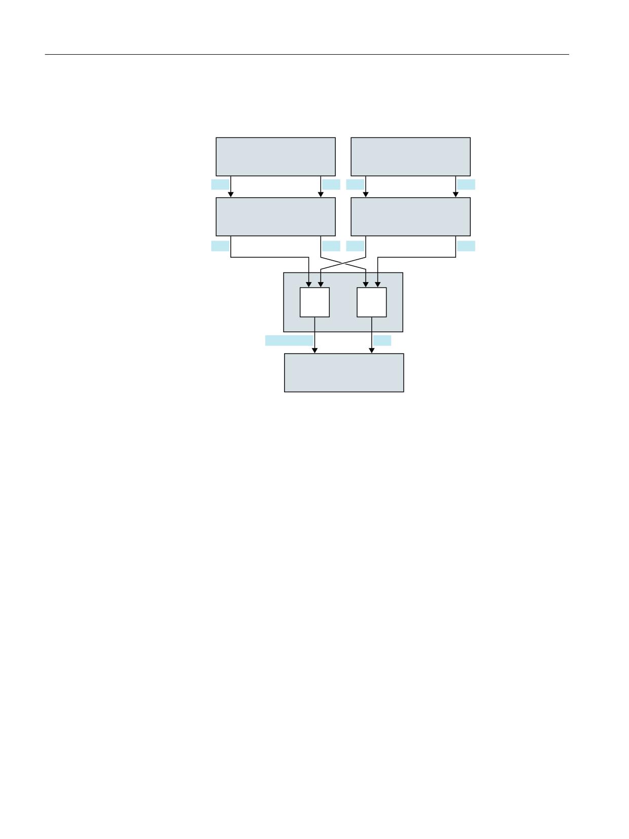
Hardware assignment
The input byte for the "Multiple feedrate values in one block" function can be assigned a
maximum of two digital input bytes or comparator input bytes of the NC I/O:
MD21220 $MC_MULTFEED_ASSIGN_FASTIN (assignment of the input bytes of the NC I/O for
"Multiple feedrate values in one block"), bits 0 ... 15
The input bits can also be inverted:
Axes and spindles
Function Manual, 10/2020, 6FC5397-4GP40-0BA1
241
Feedrates
6.4 Feedrate control
MD21220 $MC_MULTFEED_ASSIGN_FASTIN, bit 16 ... 31
%\WH
%\WH
0'
0'
'LJLWDO LQSXW E\WH
'LJLWDO LQSXW E\WH
0&B08/7)(('B
0&B08/7)(('B
RU
RU
$66,*1B)$67,1
$66,*1B)$67,1
FRPSDUDWRU LQSXW E\WH
FRPSDUDWRU LQSXW E\WH
%LW ಹ
%LW ಹ
%LW
ಹ
%LW
%LW
ಹ
%LW
0'
0&B
0'
0&B08/7
08/7)(('B
)(('B
,QYHUWHU PDVN
,QYHUWHU PDVN
$66,*1B)$67,1
$66,*1B)$67,1
%LW
ಹ
%LW
ಹ
%LW
ಹ
%LW
%LW
ಹ
%LW
ุ
ಹ
ุ
,QSXW ELW
ಹ
%LW
,QSXW E\WH IRU
PXOWLSOH IHHGUDWH YDOXHV LQ D
VLQJOH EORFN
Figure 6-10
Signal assignment for the "Multiple feedrate values in one block" function
The assignment of the digital input bytes and parameterization of the comparators are described
in:
Further information:
Function Manual Basic Functions; Digital and analog NC I/O
Programming
Path motion
The path feedrate is programmed under the address F and remains valid until an input signal is
present. This value acts modally.
F2=... to F7=... can be used in addition to the path feedrate to program up to six further
feedrates in the block. The numerical expansion indicates the bit number of the input that
activates the feedrate when changed:
Example:
F7=1000
;7 corresponds to input bit 7
The programmed values act non-modally. The path feedrate programmed under F applies in the
next block.
Axes and spindles
242
Function Manual, 10/2020, 6FC5397-4GP40-0BA1
Feedrates
6.4 Feedrate control
Dwell (sparking out time) and retraction path are programmed under separate addresses in the
block:
ST=...
Dwell time (for grinding sparking out time)
SR=...
Retraction path
These addresses apply non-modally.
Axial motion
The axial feedrates are programmed under address FA and remain valid until an input signal is
present. They act modally.
FMA[2,<axis>]=... to FMA[7,<axis>]=... can be used to program up to six further
feedrates per axis in the block.
The first expression in square brackets indicates the bit number of the input that activates the
feedrate when changed. The second expression indicates the axis to which the feedrate applies.
Example:
FMA[3,Y]=1000
; Axial feedrate for Y axis, corresponds to input bit 3
The values programmed under FMA act non-modally. The feedrate programmed under FA
applies to the next block.
Dwell (sparking out time) and retraction path can also be defined for a single axis:
STA[<axis>]=...
Axial dwell time (sparking out time)
SRA[<axis>]=...
Axial retraction path
The expression in square brackets indicates the axis for which the sparking out time and
retraction path apply.
Examples:
STA[X]=2.5
; The sparking out time for the X axis is 2.5 seconds.
SRA[X]=3.5
; The retraction path for the X axis is 3.5 (unit e.g. mm).
These addresses apply non-modally.
Note
Retraction path
The unit for the retraction path refers to the current valid unit of measurement (mm or inch).
The reverse stroke is always made in the opposite direction to the current motion. SR/SRA always
programs the value for the reverse stroke. No sign is programmed.
Axes and spindles
Function Manual, 10/2020, 6FC5397-4GP40-0BA1
243

Feedrates
6.4 Feedrate control
Note
POS instead of POSA
If feedrates, sparking out time (dwell time) or return path are programmed for an axis on
account of an external input, this axis must not be programmed as POSA axis (positioning axis
over multiple blocks) in this block.
Note
Status query
It is also possible to poll the status of an input for synchronous commands of various axes.
Note
LookAhead
Look Ahead is also active for multiple feedrates in one block. In this way, the current feedrate can
be restricted by the Look Ahead value.
Application
The "Multiple feedrate values in one block" function is used primarily for grinding, but is not
restricted to it.
Typical applications are, for example:
• Analog or digital calipers
Depending on whether the external inputs are analog or digital, various feedrate values, a
dwell time and a retraction path can be activated. The limit values are defined via the setting
data.
• Switching from infeed to working feedrate via proximity switch
Axes and spindles
244
Function Manual, 10/2020, 6FC5397-4GP40-0BA1
Feedrates
6.4 Feedrate control
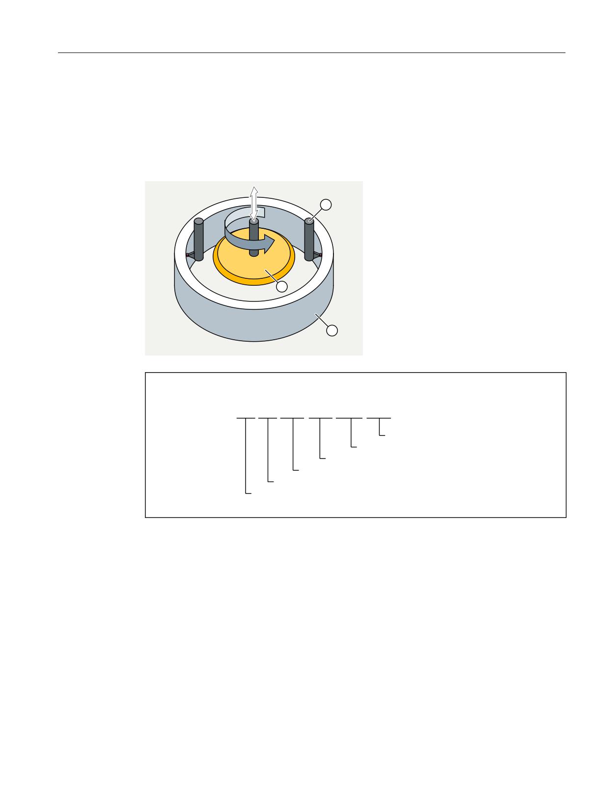
Example
Internal grinding of a conical ring, where the actual diameter is determined using calipers and,
depending on the limits, the feedrate value required for roughing, finishing or fine finishing is
activated. The position of the calipers also provides the end position. Thus, the block end
criterion is determined not only by the programmed axis position of the infeed axis but also by
the calipers.
*
;
)
,QLWLDO VHWWLQJ
*
;
)
)
)
)
67
65
5HWUDFWLRQ
6SDUNLQJ RXW WLPH
)HHGUDWH IRU ILQH ILQLVKLQJ
)HHGUDWH IRU ILQLVKLQJ
)HHGUDWH IRU URXJKLQJ
)HHGUDWH IRU JULQGLQJ LQ DLU
6.4.7
Fixed feedrate values
Function
The "Fixed feedrate values" function can be used to activate fixed feedrates (max. four) defined
via the machine data instead of the programmed feedrate or the configured JOG velocities.
The function is available in AUTOMATIC and JOG mode.
Behavior in AUTOMATIC mode
The contour travels at the activated fixed feedrate, instead of using the programmed feedrate.
Axes and spindles
Function Manual, 10/2020, 6FC5397-4GP40-0BA1
245
Feedrates
6.4 Feedrate control
Behavior in JOG mode
The axis is traversed with the activated fixed feedrate instead of the configured JOG velocity /
JOG rapid traverse velocity. The travel direction is specified via the interface signal.
Parameterization
The setting of the fixed feedrates is performed:
• For linear axes with the machine data:
MD12202 $MN_PERMANENT_FEED[<n>]
• For rotary axes with the machine data:
MD12204 $MN_PERMANENT_ROT_AX_FEED[<n>]
where <n> = 0, 1, 2, 3 (for fixed feedrate 1, 2, 3, 4)
Note
The fixed feedrates are always linear feedrate values. Switchover to linear feedrate is conducted
internally even in case of revolutional feedrate.
Activation
The fixed feedrates are activated via NC/PLC interface signals:
• In AUTOMATIC mode for path/geometry axes using the channel-specific interface signals:
DB21, ... DBX29.0 (activate fixed feedrate 1)
DB21, ... DBX29.1 (activate fixed feedrate 2)
DB21, ... DBX29.2 (activate fixed feedrate 3)
DB21, ... DBX29.3 (activate fixed feedrate 4)
• In JOG mode for machine axes using the axis-specific interface signals:
DB31, ... DBX3.2 (activate fixed feedrate 1)
DB31, ... DBX3.3 (activate fixed feedrate 2)
DB31, ... DBX3.4 (activate fixed feedrate 3)
DB31, ... DBX3.5 (activate fixed feedrate 4)
Supplementary conditions
Effectiveness
The function "Fixed feedrate values" is not active:
• For spindles
• For positioning axes
• When tapping
Override = 0
The traversing behavior for override = 0 depends on the setting in machine data:
MD12200 $MN_RUN_OVERRIDE_0
Axes and spindles
246
Function Manual, 10/2020, 6FC5397-4GP40-0BA1
Feedrates
6.4 Feedrate control
DRF offset
The DRF offset cannot be activated for a selected fixed feedrate.
6.4.8
Programmable feedrate characteristics
Function
To permit flexible definition of the feedrate characteristic, the feedrate programming according
to DIN 66025 has been extended by linear and cubic characteristics.
The cubic profiles can be programmed directly or as an interpolating spline.
Programming
You can program the following feedrate profiles:
• FNORM
Behavior in accordance with DIN 66025 (default setting).
An F-value programmed in the block is applied over the entire path of the block, and is
subsequently regarded as a fixed modal value.
• FLIN
An F value programmed in the block is traversed linearly over the path from the current value
at the beginning of the block to the end of the block, and is subsequently regarded as modal
value.
• FCUB
The F values programmed block-by-block are - relative to the end of the block - connected by
a spline. The spline starts and ends tangentially to the previous or following feedrate setting.
If the F address is missing in one block, then the last programmed F value is used.
• FPO
The F address [syntax: F=FPO(...,...,...)] designates the characteristic of the
feedrate via a polynomial from the current value to the end of the block in which it was
programmed. The end value is treated as modal from there onwards.
Constraints
FLIN/FCUB
The path velocity profile programmed with FLIN or FCUB is not active together with revolutional
feedrate for G95 as well as with constant cutting rate with G96/G961 and G97/G971.
Further information
For further information on the programmable feedrate characteristics, see Programming
Manual NC Programming.
Axes and spindles
Function Manual, 10/2020, 6FC5397-4GP40-0BA1
247

Feedrates
6.4 Feedrate control
6.4.9
Feedrate for chamfer/rounding FRC, FRCM
The machining conditions can change significantly during surface transitions to chamfer/
rounding. Hence, the chamfer/rounding contour elements require dedicated, optimized
feedrate values to achieve the desired surface quality.
Function
The feedrate for chamfer/rounding can be programmed via NC addresses.
Programming
Syntax:
... FRC/FRCM=<value>
Meaning:
FRC:
Non-modal feedrate for chamfer/rounding
FRCM:
Modal feedrate for chamfer/rounding
<value>:
The feedrate is interpreted according to the active feedrate type:
• G94, G961, G971:
Feedrate in mm/min or inch/min or o/min
• G95, G96, G97:
Revolutional feedrate in mm/rev or inch/rev
Note
FRC is only effective if a chamfer/rounding is programmed in the block or if RNDM has been
activated.
FRC overwrites the F or FRCM value in the current block.
The feedrate programmed under FRC must be greater than zero.
FRCM=0 activates the feedrate programmed under F for chamfering/rounding.
Parameterization
Assignment of the chamfer/rounding to the previous or following block
The feedrate type (G94, G95, G96, G961 ... ) and therefore the conversion to the internal format
must be consistent within the block for F and FRC/FRCM. In this context, the following machine
data must be taken into account:
MD20201 $MC_CHFRND_MODE_MASK (chamfer/rounding behavior)
Bit
Value
Meaning
0
0
The technology of the chamfer/rounding (feedrate, feedrate type, M commands, etc.) is
determined by the following block (default setting).
1
The technology of the chamfer/rounding is determined by the previous block (recom-
mended setting).
Axes and spindles
248
Function Manual, 10/2020, 6FC5397-4GP40-0BA1
Feedrates
6.4 Feedrate control
Maximum number of empty blocks
The number of blocks without traversing information in the compensation plane (empty blocks)
permitted between two blocks with traversing information during active chamfer/rounding, is
limited. The maximum number is specified in the machine data:
MD20200 $MC_CHFRND_MAXNUM_DUMMY_BLOCKS (empty blocks for chamfer/radii)
Supplementary conditions
FLIN/FCUB
Feedrate interpolation FLIN and FCUB is not possible for chamfer/rounding.
G0
FRC/FRCM is not active when a chamfer is traversed with G0. The programming is possible in
accordance with the F value without error message.
Change G94 ↔ G95
If FRCM is programmed, the FRCM value will need to be reprogrammed like F on change
G94 ↔ G95, etc. If only F is reprogrammed and if the feedrate type FRCM > 0 before the change,
an error message will be output.
Example
Example 1: MD20201 bit 0 = 0; take feedrate from following block (default setting!)
Program code
Comment
N10 G0 X0 Y0 G17 F100 G94
N20 G1 X10 CHF=2
; Chamfer N20-N30 with F=100 mm/min
N30 Y10 CHF=4
; Chamfer N30-N40 with FRC=200 mm/min
N40 X20 CHF=3 FRC=200
; Chamfer N40-N60 with FRCM=50 mm/min
N50 RNDM=2 FRCM=50
N60 Y20
; Modal rounding N60-N70 with FRCM=50 mm/min
N70 X30
; Modal rounding N70-N80 with FRCM=50 mm/min
N80 Y30 CHF=3 FRC=100
; Chamfer N80-N90 with FRC=100 mm/min
N90 X40
; Modal rounding N90-N100 with F=100 mm/min (dese-
lection of FRCM)
N100 Y40 FRCM=0
; Modal rounding N100-N120 with G95 FRC=1 mm/rev
N110 S1000 M3
N120 X50 G95 F3 FRC=1
M02
Axes and spindles
Function Manual, 10/2020, 6FC5397-4GP40-0BA1
249
Feedrates
6.4 Feedrate control
Example 2: MD20201 bit 0 = 1; take feedrate from previous block (recommended setting!)
Program code
Comment
N10 G0 X0 Y0 G17 F100 G94
N20 G1 X10 CHF=2
; Chamfer N20-N30 with F=100 mm/min
N30 Y10 CHF=4 FRC=120
; Chamfer N30-N40 with FRC=120 mm/min
N40 X20 CHF=3 FRC=200
; Chamfer N40-N60 with FRC=200 mm/min
N50 RNDM=2 FRCM=50
N60 Y20
; Modal rounding N60-N70 with FRCM=50 mm/min
N70 X30
; Modal rounding N70-N80 with FRCM=50 mm/min
N80 Y30 CHF=3 FRC=100
; Chamfer N80-N90 with FRC=100 mm/min
N90 X40
; Modal rounding N90-N100 with FRCM=50 mm/min
N100 Y40 FRCM=0
; Modal rounding N100-N120 with F=100 mm/min
N110 S1000 M3
N120 X50 CHF=4 G95 F3 FRC=1
; Chamfer N120-N130 with G95 FRC=1 mm/rev
N130 Y50
; Modal rounding N130-N140 with F=3 mm/rev
N140 X60
M02
6.4.10
Non-modal feedrate FB
Function
The "Non-modal feedrate" function can be used to define a separate feedrate for a single part
program block. After this block, the previous modal path feedrate is active again.
Programming
Syntax:
... FB=<value>
Meaning:
FB:
Separate feedrate for the current block
<value>:
The feedrate is interpreted according to the active feedrate type:
• G94, G961, G971:
Feedrate in mm/min or inch/min or o/min
• G95, G96, G97:
Revolutional feedrate in mm/rev or inch/rev
Axes and spindles
250
Function Manual, 10/2020, 6FC5397-4GP40-0BA1
Feedrates
6.4 Feedrate control
Note
The feedrate programmed under FB must be greater than zero.
If no traversing motion is programmed in the block (e.g. computation block), the FB has no
effect.
If no explicit feed for chamfering/rounding is programmed, then the value of FB also applies for
any contour element chamfering/rounding in this block.
Simultaneous programming of FB and FD (manual handwheel traversing with feedrate
override) or F (modal path feedrate) is not possible.
6.4.11
Influencing the single axis dynamic response
Single axes
Single axes can be programmed in the part program, in synchronized actions and via the PLC:
• Part program:
POS[<axis>]=...
POSA[<axis>]=...
SPOS[<axis>]=...
SPOSA[<axis>]=...
OS[<axis>]=...
OSCILL[<axis>]=...
• Synchronized actions:
EVERY ... DO
POS[<axis>]=...
SPOS[<spindle>]=...
MOV[<axis>]=...
• PLC:
FC18
Axes and spindles
Function Manual, 10/2020, 6FC5397-4GP40-0BA1
251
Feedrates
6.4 Feedrate control
Dynamic response
The dynamic response of an axis is influenced by:
• MD32060 $MA_POS_AX_VELO (positioning axis velocity)
The effective positioning axis velocity can be changed:
- Part program / synchronized action: Axial feedrate FA or percentage feedrate override
OVRA
- PLC: Specification of FRate or overwriting the axial override
• MD32300 $MA_MAX_AX_ACCEL (maximum axis acceleration)
The effective maximum axis acceleration can be changed:
- Part program indirectly: Writes the machine data with subsequent "Activate machine
data"
- Part program directly: Percentage acceleration override ACC
- Synchronized actions indirectly: Writes the machine data and triggers an ASUP for the
activation of "Activate machine data" function
- Synchronized actions directly: Percentage acceleration override ACC (cannot be preset by
the PLC).
Via the PLC, the same options apply as in synchronized actions.
• Part program commands: BRISKA, SOFTA, DRIVEA, JERKA
Cannot be programmed in synchronized actions (only indirectly via ASUP).
Cannot be specified by the PLC (only indirectly via ASUP).
• Active servo parameter set
The active parameter set can be changed:
- Part program / synchronized action: SCPARA
- PLC: DB31, … DBX9.0-2 (controller parameter set)
For detailed information on the servo parameter sets, see "Parameter sets of the position
controller (Page 180)".
Note
Dynamic response changes
Dynamic response changes made in the part program do not affect command or PLC axis
motion. Dynamic response changes made in synchronized actions have no effect on traversing
motion programmed in the part program.
Feedforward control
The type of feedforward control and the path axes that should be traversed with feedforward
control can be directly programmed in the part program using FFWON/FFWOF. In synchronized
actions and from the PLC, programming is only possible indirectly via an ASUP.
Axes and spindles
252
Function Manual, 10/2020, 6FC5397-4GP40-0BA1
Feedrates
6.4 Feedrate control
Percentage acceleration override (ACC)
In a part program or synchronized action, the acceleration specified in machine data:
MD32300 $MA_MAX_AX_ACCEL (maximum axis acceleration)
can be changed in a range from 0% - 200% using the ACC command.
Syntax:
ACC[<axis>]=<value>
Meaning:
ACC:
Keyword for the programming of the percentage acceleration override
<Axis>:
Name of the channel axis or spindle
<value>:
Acceleration change in percent relative to MD32300
Value range:
0 ... 200
The actual axial acceleration value can be read via the system variable $AA_ACC. It is determined
by:
$AA_ACC[<axis>] = (MD32300 $MA_MAX_AX_ACCEL[<axis>]) * ACC[<axis>] / 100
MD32320 $MA_DYN_LIMIT_RESET_MASK can be used to specify the basic setting of the value
programmed with ACC for a channel reset or end of part program M30.
Note
The acceleration override programmed with ACC can be read using the system variable
$AA_ACC. However, $AA_ACC is read in the part program at a different time than when reading
in a synchronized action.
The system variables $AA_ACC only contain the value programmed in the part program with
ACC if, in the meantime, the acceleration override was not changed by programming ACC in a
synchronized action. The same applies for the reverse situation.
Percentage acceleration override and main run axes
Depending on whether the system variable $AA_ACC is read in the part program or synchronized
action, the value for the acceleration override programmed with ACC is output for the NC axes
or main run axes (command axes, PLC axes, asynchronous oscillating axes, etc.).
For correct results, system variable $AA_ACC must therefore always be read at the same location
(part program or synchronized action) from where the acceleration override was programmed
with ACC.
Examples:
Writing ACC in a part program:
N80 G01 POS[X]=100 FA[X]=1000 ACC[X]=90 IPOENDA[X]
Writing ACC in a synchronized action:
N100 EVERY $A_IN[1] DO POS[X]=50 FA[X]=2000 ACC[X]=140 IPOENDA[X]
Axes and spindles
Function Manual, 10/2020, 6FC5397-4GP40-0BA1
253
Feedrates
6.4 Feedrate control
Writing ACC and reading $AA_ACC in a part program:
ACC[X]=50
; writing
RO=$AA_ACC[X]
; reading
IF (RO <> $MA_MAX_AX_ACCEL[X] * 0.5)
; checking
SETAL(61000)
ENDIF
Writing ACC and reading $AA_ACC in a synchronized action:
WHEN TRUE DO ACC[X]=25 R0=$AA_ACC[X]
; writing and reading
G4 F1
IF (RO <> $MA_ MAX_AX_ACCEL[X] * 0.25)
; checking
SETAL(61001)
ENDIF
end-of-motion criterion for single axes
Similar to the block change criterion for path interpolation (G601, G602, G603) the end-of-
motion criterion for traversing motion of individual axes can be programmed in part programs /
synchronized actions:
Program command
End-of-motion criterion
FINEA[<axis>]
"Exact stop fine"
COARSEA[<axis>]
"Exact stop coarse"
IPOENDA[<axis>]
"Interpolator stop" (IPO stop)
The most recently programmed value is kept after the end of program or NC reset.
The effective end-of-motion criterion can be read using the axis-specific system variable
$AA_MOTEND.
Note
Depending on whether the system variable $AA_MOTEND is read in the part program or
synchronized action, it contains the value for the NC axes or the main run axes.
Example:
Part program:
N80 G01 POS[X]=100 FA[X]=1000 ACC[X]=90 COARSEA[X]
Synchronized action:
N100 EVERY $A_IN[1] DO POS[X]=50 FA[X]=2000 ACC[X]=140 IPOEN-
DA[X]
Axes and spindles
254
Function Manual, 10/2020, 6FC5397-4GP40-0BA1
Feedrates
6.4 Feedrate control
Further information
For further information on the block change and movement end criteria for FINEA, COARSEA and
IPOENDA, see:
Block change (Page 290)
Programmable servo parameter set (SCPARA)
In the part program / synchronized action, the servo parameter set can be specified using
SCPARA.
Syntax
SCPARA[<axis>] = <parameter set number>
Meaning
SCPARA:
Keyword for the activation of the specified servo parameter
set
<Axis>:
Name of the channel axis
<parameter set number>:
Number of the servo parameter set to be activated
Note
The activation of the parameter set specified using SCPARA can be suppressed from the PLC user
program:
DB31,… DBX9.3 = 1 (parameter set specification disabled by SCPARA)
In this case, no message is displayed.
The number of the active parameter set can be read using the system variable $AA_SCPAR.
Boundary conditions
Different end-of-motion criteria
Different end-of-motion criteria will affect how quickly or slowly part program blocks are
completed. This can have side effects for technology cycles and PLC user parts.
Parameter set change
The PLC user program must be expanded if the servo parameter set is to be changed both inside
a part program or synchronized action and the PLC.
Power On
After POWER ON, the following basic settings are made:
• Percentage acceleration override for all single-axis interpolations: 100%
• End-of-motion criterion for all single-axis interpolations: FINEA
• Servo parameter set: 1
Axes and spindles
Function Manual, 10/2020, 6FC5397-4GP40-0BA1
255
Feedrates
6.5 Boundary conditions
Mode change
When the operating mode is changed from AUTOMATIC to JOG, the programmed dynamic
response changes remain valid.
Reset
With reset, the last programmed value remains for the part program specifications. The settings
for main-run interpolations do not change.
Block search
The last end-of-motion criterion programmed for an axis is collected and output in an action
block. The last block with a programmed end-of-motion criterion that was processed in the block
search run serves as a container for all programmed end-of-motion criteria for all axes.
6.5
Boundary conditions
Unit of measurement
The valid unit of measurement of the feedrates depends on the set measuring system and the
entered axis type:
MD10240 $MN_SCALING_SYSTEM_IS_METRIC (basic system of the control metric/inch)
MD30300 $MA_IS_ROT_AX (rotary or linear axis)
Initial setting for the feedrate type
The initial setting for the feedrate type is specified in the machine data:
MD20150 $MC_GCODE_RESET_VALUES (initial setting of the G groups)
The default setting is G94.
The initial setting of the feedrate type is only displayed when a part program is started.
Effectiveness after reset
Whether the last programmed F, FA, OVR, OVRA values are also active after reset depends on the
setting in the machine data:
MD22410 $MC_F_VALUES_ACTIVE_AFTER_RESET (F function is active even after reset)
Spindle positioning
With active G95, G96, G961, G97, G971, G33, G34, G35 spindle positioning should not be
performed, because the derived path feedrate following spindle positioning = 0. If the
programmed axis position has not then been reached, the block cannot be completed.
Axes and spindles
256
Function Manual, 10/2020, 6FC5397-4GP40-0BA1

Feedrates
6.6 Data lists
6.6
Data lists
6.6.1
Machine data
6.6.1.1
NC-specific machine data
Number
Identifier: $MN_
Description
10651
IPO_PARAM_THREAD_NAME_TAB
Name of the interpolation parameters for convex
threads
10704
DRYRUN_MASK
Activation of dry run feedrate
10710
PROG_SD_RESET_SAVE_TAB
Setting data to be updated
11410
SUPPRESS_ALARM_MASK
Mask for suppressing special alarms
11550
STOP_MODE_MASK
Defines the stop behavior
12000
OVR_AX_IS_GRAY_CODE
Axis feedrate override switch, Gray-coded
12010
OVR_FACTOR_AX_SPEED
Evaluation of the axis feedrate override switch
12020
OVR_FEED_IS_GRAY_CODE
Path feedrate override switch, Gray-coded
12030
OVR_FACTOR_FEEDRATE
Evaluation of the path feedrate override switch
12040
OVR_RAPID_IS_GRAY_CODE
Rapid traverse override switch, Gray-coded
12050
OVR_FACTOR_RAPID_TRA
Evaluation of the rapid traverse override switch
12060
OVR_SPIND_IS_GRAY_CODE
Spindle override switch, Gray-coded
12070
OVR_FACTOR_SPIND_SPEED
Evaluation of the spindle override switch
12080
OVR_REFERENCE_IS_PROG_FEED
Override reference velocity
12082
OVR_REFERENCE_IS_MIN_FEED
Defines the reference of the path override
12090
OVR_FUNCTION_MASK
Selection of override specifications
12100
OVR_FACTOR_LIMIT_BIN
Limit for binary-coded override switch
12200
RUN_OVERRIDE_0
Traversing with override 0
12202
PERMANENT_FEED
Fixed feedrates for linear axes
12204
PERMANENT_ROT_AX_FEED
Fixed feedrates for rotary axes
6.6.1.2
Channel-specific machine data
Number
Identifier: $MC_
Description
20100
DIAMETER_AX_DEF
Geometry axes with transverse axis functions
20150
GCODE_RESET_VALUES
Basic setting of the G groups
20172
COMPRESS_VELO_TOL
Maximum permissible deviation from path feed for com-
pression
20200
CHFRND_MAXNUM_DUMMY_BLOCKS
Empty blocks with phase/radii
20201
CHFRND_MODE_MASK
Behavior for chamfer/rounding
20750
ALLOW_GO_IN_G96
G0 logic for G96, G961
21200
LIFTFAST_DIST
Traversing path for fast retraction from the contour
Axes and spindles
Function Manual, 10/2020, 6FC5397-4GP40-0BA1
257

Feedrates
6.6 Data lists
Number
Identifier: $MC_
Description
21220
MULTFEED_ASSIGN_FASTIN
Assignment of input bytes of NC I/O for "Multiple fee-
drate values in one block"
21230
MULTFEED_STORE_MASK
Storage behavior for the "Multiple feedrate values in one
block" function
22240
AUXFU_F_SYNC_TYPE
Output timing of F functions
22410
F_VALUES_ACTIVE_AFTER_RESET
F function active after reset
6.6.1.3
Axis/Spindle-specific machine data
Number
Identifier: $MA_
Description
30300
IS_ROT_AX
Rotary axis/spindle
32000
MAX_AX_VELO
Maximum axis velocity
32060
POS_AX_VELO
Initial setting for positioning axis velocity
32300
MAX_AX_ACCEL
Axis acceleration
32320
DYN_LIMIT_RESET_MASK
Reset behavior of dynamic limits
34990
ENC_ACTIVAL_SMOOTH_TIME
Smoothing time constant for actual values
35100
SPIND_VELO_LIMIT
Maximum spindle speed
35130
GEAR_STEP_MAX_VELO_LIMIT
Maximum speed of gear stage
35140
GEAR_STEP_MIN_VELO_LIMIT
Minimum speed of gear stage
35160
SPIND_EXTERN_VELO_LIMIT
Spindle-speed limitation via PLC
6.6.2
Setting data
6.6.2.1
Channel-specific setting data
Number
Identifier: $SC_
Description
42000
THREAD_START_ANGLE
Start angle for thread
42010
THREAD_RAMP_DISP
Acceleration behavior of axis when thread cutting
42100
DRY_RUN_FEED
Dry run feedrate
42101
DRY_RUN_FEED_MODE
Dry run feed mode
42110
DEFAULT_FEED
Default value for path feed
42600
JOG_FEED_PER_REV_SOURCE
Revolutional feedrate control in the JOG mode
43300
ASSIGN_FEED_PER_RES_SOURCE
Revolutional feedrate for positioning axes/spindles
Axes and spindles
258
Function Manual, 10/2020, 6FC5397-4GP40-0BA1

Feedrates
6.6 Data lists
6.6.2.2
Axis/spindle-specific setting data
Number
Identifier: $SA_
Description
43210
SPIND_MIN_VELO_G25
Programmed spindle speed limiting G25
43220
SPIND_MAX_VELO_G26
Programmed spindle speed limiting G26
43230
SPIND_MAX_VELO_LIMS
Spindle speed limiting with G96
Axes and spindles
Function Manual, 10/2020, 6FC5397-4GP40-0BA1
259
Feedrates
6.6 Data lists
Axes and spindles
260
Function Manual, 10/2020, 6FC5397-4GP40-0BA1
Transverse axes
7
7.1
Function
Transverse axis
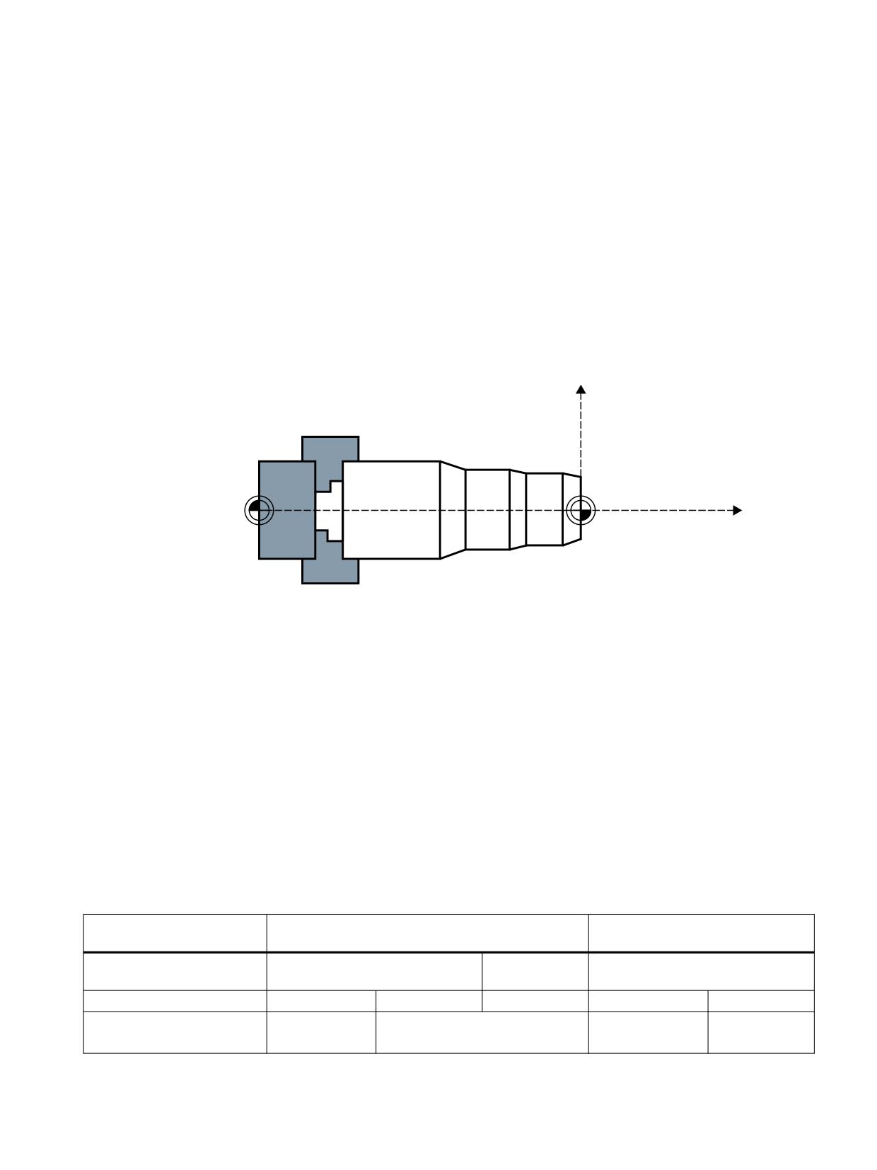
Within the framework of "turning" technology, the transverse axis refers to the machine axis that
travels perpendicular to the axis of symmetry of the spindle, in other words, to longitudinal axis
Z.
[
7UDQVYHUVH D[LV
0
:
]
/RQJLWXGLQDO D[LV
Figure 7-1
Position of the transverse axis in the machine coordinate system
Geometry axis as transverse axis
Every geometry axis of a channel can be defined as a transverse axis.
For the geometry axis as a transverse axis, the following functions can be simultaneously or
separately permitted and activated:
• Programming and display in the diameter
• Reference axis for constant cutting speed G96/G961/G962
Several transverse axes in the channel
The introduction several transverse axes in the channel involves a functional decoupling of
diameter programming and reference axis for G96/G961/G962. Diameter programming and
reference axis for G96/G961/G962 can be active for different transverse axes (see table below).
Programming and display
Reference axis for
in the diameter
G96 / G961 / G962
Permissible axis type:
Geometry axis
Linear channel
Geometry axis
axes
Selection in the channel:
one
m of 3
m of n
one
one of 3
Specific effect:
Channel
Axis
Channel
Machine data:
MD20100
MD30460
MD20100
Axes and spindles
Function Manual, 10/2020, 6FC5397-4GP40-0BA1
261

Transverse axes
7.1 Function
Programming and display
Reference axis for
in the diameter
G96 / G961 / G962
Programming:
DIAM*
SCC[<Axis>]
channel-specific modal
channel-specific modal
G group 29
Reference axis for G96/G961/G962
Acceptance during axis re-
DIAM*A[<Axis>]
placement:
axis-specific modal
Axis-specific non-modal dia-
DAC, DIC; RAC, RIC
metral/radius program-
blockwise axis-specific only programming
ming:
DIAM*: DIAMOF, DIAMON, DIAM90, DIAMCYCOF
DIAM*A[<Axis>]: DIAMOFA[<Axis>], DIAMONA[<Axis>], DIAM90A[<Axis>], DIACYCOFA[<Axis>], DIAMCHANA[<Axis>]
<Axis>: Axis name for geometry, channel or machine axis name
Note
Rotary axes are not permitted to serve as transverse axes.
Diameter-related data
DIAMON/DIAMONA[<Axis>]
After activation of the diameter programming with DIAMON/DIAMONA[<Axis>] (see
"Programming (Page 267)"), the following data refer to diameter dimensions:
• Display data of transverse axis in the workpiece coordinate system:
- Setpoint and actual position
- Distance-to-go
- REPOS offset
• "JOG" mode:
- Increment (INC) through incremental manual handwheel traversing (depending on the
active MD)
• Part program programming:
- End positions, independent of reference mode (G90 / G91)
- Interpolation parameters of circular-path programming (G2 / G3) if these are
programmed with part program instruction AC absolute.
• Actual values read with reference to the workpiece coordinate system (WCS):
- $AA_MW[<transverse axis>]
System variable of the measuring functions MEAS (measuring with delete distance-to-go)
and MEAW (measuring without delete distance-to-go)
- $P_EP[<transverse axis>]
- $AA_IW[<transverse axis>]
Axes and spindles
262
Function Manual, 10/2020, 6FC5397-4GP40-0BA1
Transverse axes
7.1 Function
DIAM90/DIAM90A[<Axis>]
After activation of the reference-mode-dependent diameter programming with DIAM90/
DIAM90A[<Axis>], the following data is always displayed in relation to diameter regardless of
the operating mode (G90/G91):
• Actual value
• Actual values read with reference to the workpiece coordinate system (WCS):
- $AA_MW[<transverse axis>]
System variable of the measuring functions MEAS (measuring with delete distance-to-go)
and MEAW (measuring without delete distance-to-go)
- $P_EP[<transverse axis>]
- $AA_IW[<transverse axis>]
DIAMCYCOF/DIACYCOFA[<Axis>]
With DIAMCYCOF / DIACYCOFA[<Axis>], a changeover to radius programming takes place
within the controller. The diameter programming status that was active before DIAMCYCOF
or DIACYCOFA[AX] continues to be displayed to the HMI.
Permanently radius-related data
For transverse axes, the following data is always entered, programmed and displayed in relation
to radius:
• Part program programming
- Interpolation parameters of circular-path programming with CIP
• Offsets:
- Tool offsets
- Programmable and configurable frames
- External work offset
- DRF and preset offset
- etc.
• Working area limitation
• Software limit switch
• Feedrate
• Display data with reference to the machine coordinate system
• Display data of the service images for axis, FSD and MSD
Axes and spindles
Function Manual, 10/2020, 6FC5397-4GP40-0BA1
263

Transverse axes
7.2 Parameterization
Extended functions for data that is always radius-related:
The following applies for PLC axes, via FC18 or axes controlled exclusively from the PLC:
• The dimension for PLC axes in the radius also applies to several transverse axes with diameter
function and is independent of channel-specific or axis-specific diameter programming.
• In the JOG mode (Inc) a PLC axis is subordinate to the channel status. If diameter
programming is active and MD20624 $MC_HANDWH_CHAN_STOP_COND bit 15 = 0, only
half the path of the specified increment is traversed.
7.2
Parameterization
Defining a geometry axis as a transverse axis
Defining a geometry axis as a transverse axis in the channel is realized using machine data:
MD20100 $MC_DIAMETER_AX_DEF (geometry axis with transverse axis function)
Example
MD20100 $MC_DIAMETER_AX_DEF="X" ; geometry axis X is the transverse axis in the channel.
For this axis, diameter programming and assigning a constant cutting speed with G96 / G961 /
G962 are both permitted.
Several transverse axes in the channel
Defining additional transverse axes in the channel, for which the functionality of the axis-
specific diameter programming is permitted, is performed using the machine data:
MD30460 BASE_FUNCTION_MASK.Bit 2 = <value>
Bit
Value
Meaning
2
0
Axis-specific diameter programming is not permitted.
1
Axis-specific diameter programming is permitted.
Note
The setting MD30460 bit 2 = 1 is only possible for linear axes.
Constraints
In a channel, a transverse axis can be defined as channel-specific (MD20100) and axis-specific
(MD30460, bit 2) axis at the same time. The channel-specific machine data has the higher
priority.
With MD20100, the following channel-specific functions are assigned to the transverse axis
during the run-up
The following axis-specific basic position is assigned to the transverse axis during the power-up
of the NC: "Transfer of the diameter programming channel status" DIAMCHANA[<axis>]
Axes and spindles
264
Function Manual, 10/2020, 6FC5397-4GP40-0BA1

Transverse axes
7.2 Parameterization
With the release of the axis-specific diameter programming (MD30460, bit 2 = 1), the following
axis-specific operations can be used at the user's end:
• DIAMONA (axis-specific modal diameter programming: ON)
• DIAMOFA (axis-specific modal diameter programming: OFF)
• DIAM90A (axis-specific modal diameter programming for G90 and AC, radius programming
for G91 and IC)
• DIACYCOFA (axis-specific modal diameter programming: OFF in cycles)
• DIAMCHANA (transfer of the diameter programming channel status)
Dimensions for tool parameters
With the following channel-specific machine data, the following tool parameters can be
activated as diameter values for all of the transverse axes defined in the channel:
MD20360 $MC_TOOL_PARAMETER_DEF_MASK.<Bit> = <value>
MD20360 $MC_TOOL_PARAMETER_DEF_MASK
Bit
Value
Meaning
1
1
Transverse axis tool length as a diameter
2
1
Alarm for wear or tool length as a diameter and plane change
3 1)
0
Work offset $P_EXTFRAME and frames
For transverse axes, work offsets in frames are always calculated as radius values.
1
The work offset (WO) in frames in the transverse axis as a diameter
The frame stores the work offsets internally as a radius value. There is no conversion
during a change of diameter to radius programming or vice versa.
4
1
Preset value as a diameter
5 1)
0
External work office (axis overlay)
For transverse axes, the external work offset is always calculated as a radius value.
1
External WO of the transverse axis as a diameter
There is no conversion during a change of diameter to radius programming or vice
versa.
6
1
Actual values of the transverse axis as a diameter
7
1
Display of actual values of the transverse axis as a diameter value
8 1)
1
Display of remaining path in WCS always as a radius
9 1)
For all of the transverse axes for which it is set that the specifications of the handwheel are path
specifications (MD11346 $MN_HANDWH_TRUE_DISTANCE == 1), the following applies:
0
Half of the path of the specified handwheel increment is traveled if channel-specific or
axis-specific diameter programming is active for this axis.
1
Half of the path of the specified handwheel increment is always traveled.
10
1
Tool portion of an active tool carrier that can be oriented if no tool is active
11
1
Evaluation of $TC_DP6 as a diameter
12
1
Evaluation of $TC_DP15 as wear of the tool diameter
13 1)
1
When jogging around circles, the circle center point coordinate is always a radius
value, see SD42690 $SC_JOG_CIRCLE_CENTRE
14 1)
1
For cycle masks, the absolute values of the transverse axis are always meant as the
radius.
Axes and spindles
Function Manual, 10/2020, 6FC5397-4GP40-0BA1
265

Transverse axes
7.2 Parameterization
MD20360 $MC_TOOL_PARAMETER_DEF_MASK
Bit
Value
Meaning
15
1
Incremental values of the transverse axis for cycle masks as diameters
1) The function is dependent upon the settings in MD20100 $MC_DIAMETER_AX_DEF and MD30460
$MA_BASE_FUNCTION_MASK, bit 2
Behavior during manual handwheel traversing
The behavior during manual handwheel traversing (MD11346
$MN_HANDWH_TRUE_DISTANCE == 1 or 3) of a transverse axis while diameter programming is
active can be adjusted with the following machine data:
MD20624 $MC_HANDWH_CHAN_STOP_COND.Bit 15 = <value>
Bit
Value
Meaning
15
0
Only the half path of the specified increment is traveled.
1
The specified increment is traveled completely.
Displaying position values in the diameter
Position values of transverse axes are always displayed as diameter values, if:
MD27100 $MC_ABSBLOCK_FUNCTION_MASK, bit 0 = 1
Channel-specific basic position after power up, reset
The channel-specific basic position after power up or channel reset or the part program end of
G group 29 (DIAMON, DIAM90, DIAMOF, DIAMCYCOF) is defined by the machine data MD20110
$MC_RESET_MODE_MASK.
MD20110 $MC_RESET_MODE_MASK, bit 0 = 0:
• Power-up: Basic position according to MD20150 $MC_GCODE_RESET_VALUE
• Channel reset or part program end: Basic position according to MD20150
$MC_GCODE_RESET_VALUES
MD20110 $MC_RESET_MODE_MASK, bit 0 = 1:
• After power-up: Basic position according to MD20150 $MC_GCODE_RESET_VALUE
• After channel reset or part program end: Basic position according to MD20152
$MC_GCODE_RESET_MODE
The user can set the respective desired status via an event-driven program call (ProgEvent).
If the basic position after the power-up is G96 / G961 / G962, a transverse axis must be defined
with MD20100 $MC_DIAMETER_AX_DEF, otherwise the alarm 10870 is displayed.
To ensure that the reference axis for G96 / G961 / G962 is retained during a reset, end of part
program or start of part program, the following setting must be made:
• Channel reset or part program end: MD20110 $MC_RESET_MODE_MASK, bit 18 = 1
• Part program start: MD20112 $MC_START_MODE_MASK, bit 18 = 1
Axes and spindles
266
Function Manual, 10/2020, 6FC5397-4GP40-0BA1
Transverse axes
7.3 Programming
A reference axis for G96 / G961 / G962 can also be assigned without the parameterization of a
transverse axis in MD20100 via SCC[AX]. For this scenario, the constant cutting speed must not
already be activated with G96. For additional information, see the following:
Further information: Programming Manual NC Programming
7.3
Programming
Transverse axes can be programmed with respect to both diameter and radius. Generally, they
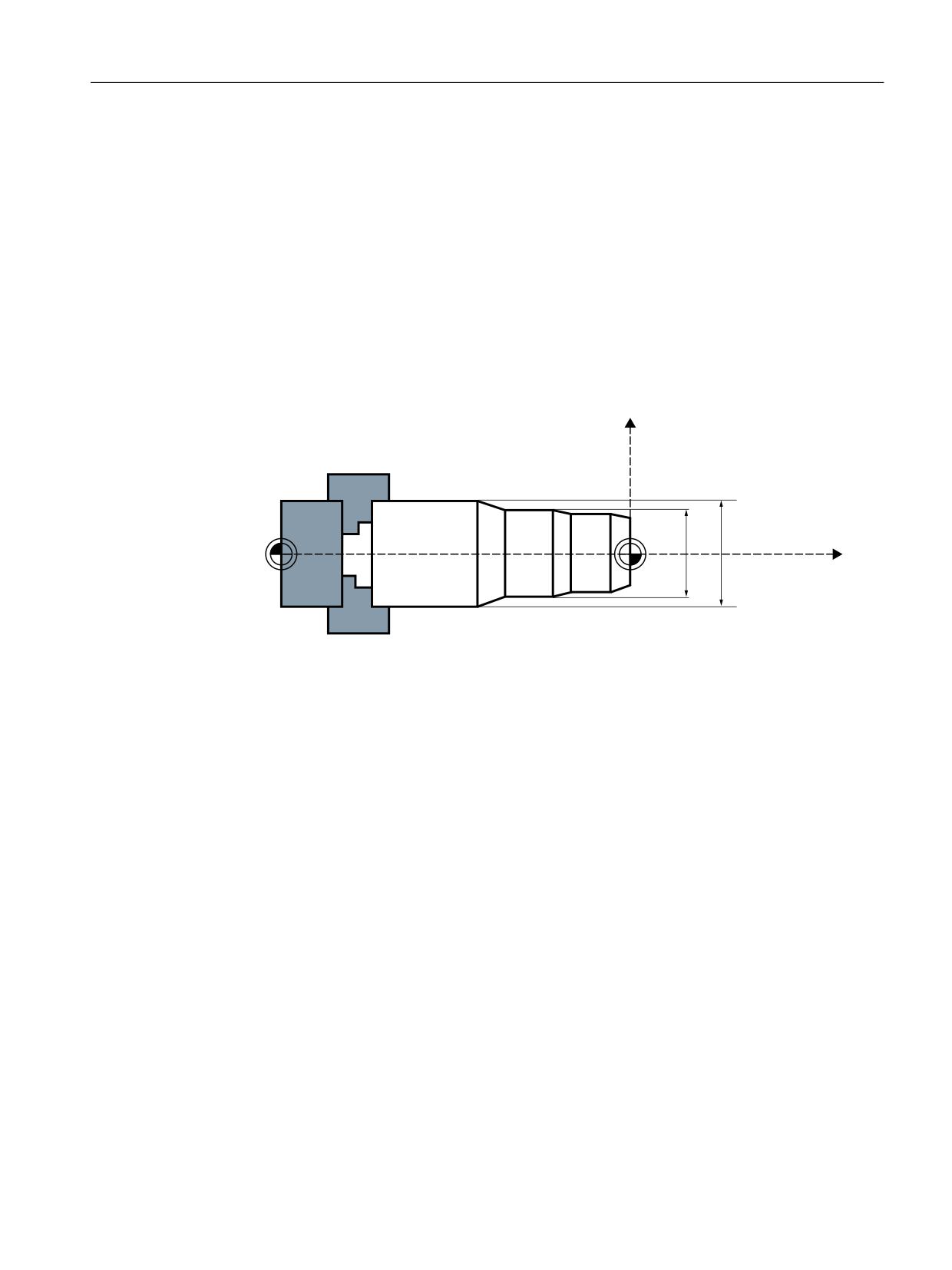
are diameter-related, i.e. programmed with doubled path dimension so that the corresponding
dimensional information can be transferred to the part program directly from the technical
drawings.
[
7UDQVYHUVH D[LV
0
:
'
'
]
/RQJLWXGLQDO D[LV
Figure 7-2
Transverse axis with diameter information (D1, D2)
Switching the diameter programming on/off
Channel-specific diameter programming
The activating or deactivating of the diameter programming is done via the modally active part
program statements of the G group 29:
• DIAMON: Diameter programming ON
• DIAMOF: Diameter programming OFF, in other words, radius programming ON
• DIAM90: Diameter or radius programming depending on the reference mode:
- Diameter programming ON in connection with absolute dimensioning G90
- Radius programming ON in connection with incremental dimensioning G91
• DIAMCYCOF: Radius programming for G90 and G91 ON, for the HMI, the last active G
command of this group remains active
Reference is made exclusively to the transverse axis of the channel.
Axes and spindles
Function Manual, 10/2020, 6FC5397-4GP40-0BA1
267
Transverse axes
7.4 Supplementary conditions
Axis-specific diameter programming for several transverse axes in one channel
Note
The additionally specified axis must be activated via MD30460 $MA_BASE_FUNCTION_MASK
with bit 2 = 1.
The axis specified must be a known axis in the channel. Geometry, channel or machine axes are
permitted.
Programming is not permitted in synchronized actions.
The following axis-specific modal statements can be programmed several times in a part
program block:
• DIAMONA[<Axis>]: Diameter programming for G90, G91, AC and IC ON
• DIAMOFA[<Axis>]: Diameter programming OFF, in other words, radius programming ON
• DIAM90A[<Axis>]: Diameter or radius programming depending on the reference mode:
- Diameter programming ON in connection with absolute dimensioning G90 and AC
- Radius programming ON in connection with incremental dimensioning G91 and IC
• DIACYCOFA[Axis]: Radius programming for G90 and G91 ON, for the HMI, the last active
G command of this group remains active
• DIAMCHANA[Axis]: Acceptance of diameter programming channel status
• DIAMCHAN: All axes with MD30460, bit 2 = 1 accept the diameter programming channel
status
Axis-specific modal statements have priority over the channel setting.
7.4
Supplementary conditions
Axis interchange
Due to a GET request from the parts program, the diameter programming status for an
additional transverse axis is accepted in the new channel during axis replacement
using RELEASE[<Axis>].
Axis interchange in synchronized actions
For axis replacement in synchronized actions, a transverse axis takes the status of the axis-
specific diameter programming with it into the new channel if:
• with MD30460, bit 2 = 1 axis-specific diameter programming is permitted for the transverse
axis.
• the transverse axis is not subordinated to the channel-specific diameter programming in the
releasing channel.
The active dimension can be queried via the system variable $AA_DIAM_STAT[<Axis>].
Axes and spindles
268
Function Manual, 10/2020, 6FC5397-4GP40-0BA1
Transverse axes
7.5 Examples
Axis interchange via axis container rotation
By rotating the axis container, the assignment of a channel axis can change to assignment of a
machine axis. The current diameter programming status is retained however for the channel
axis after the rotation. This also applies to the current channel and axis status, because the status
is the same for all axes of the axis container at the time of the machine data "putting into effect"
the status from MD30460 $MA_BASE_FUNCTION_MASK.
7.5
Examples
Example 1
X is a transverse axis defined via MD20100 $MC_DIAMETER_AX_DEF.
Y is a geometry axis and U is an additional axis. These two axes are additional transverse axes
with diameter specifications defined in MD30460 $MA_BASE_FUNCTION_MASK with bit 2 = 1.
DIAMON is not active after power up.
Program code
Comment
N10 G0 G90 X100 Y50
;no diameter programming is active
N20 DIAMON
;Channel-specific diameter programming, in effect for X
N30 Y200 X200
;Dimensions: X in the diameter, Y in the radius
N40 DIAMONA[Y]
;axis-specific modal diameter programming,
;in effect for Y
N50 Y250 X300
;Dimensions: X and Y in diameter
N60 DIAM90
;Dimensions: X G90/AC in the diameter, G91/IC in the ra-
dius
N70 Y200
;Y: continuing, axis-specific modal diameter programming
N75 G91 Y20 U=DIC(40)
;Dimensions: Y in the diameter, U non-modally IC in the
diameter
N80 X50 Y100
;Dimensions: X in the radius (G91), Y in the diameter
N85 G90 X100 U200
;Dimensions: X in the diameter, U in the radius
N90 DIAMCHANA[Y]
;Y accepts the channel status DIAM90
N95 G91 X100 Y100
;Dimensions: X and Y in the radius(G91)
N100 G90 X200 Y200
;Dimensions: X and Y in diameter
Example 2
Transverse axes with diameter specification applied as in the previous example.
X and Y are located in channel 1 and are also known in channel 2; i.e. permitted for axis
replacement.
Program code
Comment
Channel 1
N10 G0 G90 X100 Y50
;no diameter programming is active
N20 DIAMON
;Channel-specific diameter programming for X
N30 Y200 X200
;Dimensions: X in the diameter, Y in the radius
Axes and spindles
Function Manual, 10/2020, 6FC5397-4GP40-0BA1
269

Transverse axes
7.6 Data lists
Program code
Comment
N40 DIAMONA[Y]
;Y axis-specific modal diameter programming
N50 Y250 X300
;Dimensions: X and Y in diameter
N60 SETM(1)
;Synchronous marker 1
N70 WAIT(1,2)
;wait for synchronous marker 1 in channel 2
Channel 2
N50 DIAMOF
;channel 2 no diameter programming active
N100 WAIT(1,1)
;wait for synchronous marker 1 in channel 1
N110 GETD(Y)
;Axis replacement direct Y
N120 Y100
;Y is the channel-specific diameter programming
;subordinated in channel 2; i.e. dimension in the radius
7.6
Data lists
7.6.1
Machine data
7.6.1.1
Channelspecific machine data
Number
Identifier: $MC_
Description
20050
AXCONF_GEOAX_ASSIGN_TAB[n]
Assignment of geometry axis to channel axis
20060
AXCONF_GEOAX_NAME_TAB[n]
Channel axis name in the channel
20100
DIAMETER_AX_DEF
Geometry axis with transverse axis function
20110
RESET_MODE_MASK
Definition of the control basic setting after power-up and RESET /
part program end
20112
START_MODE_MASK
Definition of the control basic setting for NC start
20150
GCODE_RESET_VALUES[n]
Basic setting of the G groups
20152
GCODE_RESET_MODE[n]
G command basic setting at RESET / part program end
20360
TOOL_PARAMETER_DEF_MASK
Definition of tool parameters
20624
HANDWH_CHAN_STOP_COND
Definition of the behavior of the manual handwheel traversing
27100
ABSBLOCK_FUNCTION_MASK
Parameterize block display with absolute values
7.6.1.2
Axis/spindlespecific machine data
Number
Identifier: $MA_
Description
30460
BASE_FUNCTION_MASK
Axis functions
Axes and spindles
270
Function Manual, 10/2020, 6FC5397-4GP40-0BA1
Positioning axes
8
8.1
Brief description
Axes for auxiliary movements
In addition to axes for machining a workpiece, modern machine tools can also be equipped with
axes for auxiliary movements, e.g.:
• Axis for tool magazine
• Axis for tool turret
• Axis for workpiece transport
• Axis for pallet transport
• Axis for loader (also multi-axis)
• Axis for tool changer
• Axis for sleeve assembly / end support
The axes for the workpiece machining are called path axes. Within the channel they are guided
by the interpolator such that they start simultaneously, accelerate, reach the end point and stop
together.
Axes for auxiliary movements are traversed independently of the path axes at a separate, axis-
specific feedrate. In the past, many of these axes were moved hydraulically and started by an
auxiliary function in the part program. With the closed-loop axis control implemented in the NC,
Axes and spindles
Function Manual, 10/2020, 6FC5397-4GP40-0BA1
271
Positioning axes
8.1 Brief description
the axis can be addressed by name in the part program and its actual position displayed on the
screen.
Note
"Positioning axis/Auxiliary spindle" option
Axes for auxiliary movements must not be interpolating ("full-value") NC axes. Auxiliary
movements may also be carried out using special axes, which can be obtained using the
"Positioning axis/Auxiliary spindle" option.
Functional restrictions
Optional positioning axes/auxiliary spindles have fewer functions. The following functions
are not possible:
• Using the axis as a path axis, geometry axis, or special path axis
• Incorporating the axis into the geometry axis grouping (GEOAX)
• Rigid thread cutting and tapping
Commissioning
As standard, axes are defined as interpolating axes:
MD30460 $MA_BASE_FUNCTION_MASK bit 8 = 0
If an axis is to be operated as a positioning axis/auxiliary spindle with reduced functionality, the
value for bit 8 must be set to "1":
MD30460 $MA_BASE_FUNCTION_MASK bit 8 = 1
Function
The "positioning axes" function makes it easier to integrate axes for auxiliary movement into the
control system:
• during programming:
The axes are programmed together with the axes for workpiece machining in the same part
program, without having to sacrifice valuable machining time.
There are special (POS, POSA) traversing instructions.
• during program testing/start-up:
Program testing and start-up are performed simultaneously for all axes.
• during operation:
Operation and monitoring of the machining process commence simultaneously for all axes.
• during PLC configuring/commissioning:
No allowance has to be made on PLC or external computers (PCs) for synchronization
between axes for machining and axes for auxiliary movements.
• during system configuring:
A second channel is not required.
Axes and spindles
272
Function Manual, 10/2020, 6FC5397-4GP40-0BA1
Positioning axes
8.2 Own channel, positioning axis or concurrent positioning axis
Motions and interpolations
Each channel has one path interpolator and at least one axis interpolator with the following
interpolation functions:
• for path interpolator:
Linear interpolation (G1), circular interpolation (G2 / G3), spline interpolation, etc.
• for axis interpolator:
If a positioning axis is programmed, an axis interpolator starts in the control (with linear
interpolation G1).
• End-of-motion criterion:
The programmed end position of a positioning axis has been reached when the end-of-
motion criterion FINEA, COARSA or IPOENDA is fulfilled.
• Path axes with rapid traverse movement:
Path axes can be traversed in linear or non-linear interpolation mode with rapid traverse
movement (G0).
Further information
Function Manual Basic Functions; Continuous-path mode, exact stop, LookAhead
• Autonomous singleaxis operations:
Single PLC axes, command axes started via static synchronized actions or asynchronous
reciprocating axes can be interpolated independently of the NC.
An axis/spindle interpolated by the main run then reacts independently of the NC program.
The channel response triggered by the program run is decoupled to transfer the control of a
certain axis / spindle to the PLC.
• Control by PLC:
All channel-specific signals normally act to the same extent on path and positioning axes.
Positioning axes can be controlled via additional, axis-specific signals.
PLC axes are traversed by the PLC via special function blocks in the basic program; their
movements can be asynchronous to all other axes. The travel motions are executed separate
from the path and synchronized actions.
8.2
Own channel, positioning axis or concurrent positioning axis
When axes are provided for auxiliary movements on a machine tool, the required properties will
decide whether the axis is to be:
• programmed in a separate part program (see Section "Own channel (Page 274)").
• programmed in the same part program as the processing (see Section "Positioning axis
(Page 274)").
• started exclusively by the PLC during machining (see Section "Concurrent positioning axis
(Page 277)").
Axes and spindles
Function Manual, 10/2020, 6FC5397-4GP40-0BA1
273
Positioning axes
8.2 Own channel, positioning axis or concurrent positioning axis
8.2.1
Own channel
A channel represents a self-contained NC which, with the aid of a part program, can be used to
control the movement of axes, spindles and machine functions independently of other
channels.
Non-dependence between channels
Independence between channels is assured by means of the following provisions:
• An active part program per channel
• Channel-specific interface signals such as
- DB21, ... DBX7.1 (NC start)
- DB21, ... DBX7.3 (NC stop)
- DB21, ... DBX7.7 (reset)
• one feedrate override per channel
• One rapid traverse override per channel
• Channel-specific evaluation and display of alarms
• Channel-specific display, e.g. for
- Actual axis positions
- Active G commands
- Active auxiliary functions
- Current program block
• Channel-specific testing and channel-specific control of programs:
- Single block
- Dry run (DRY RUN)
- Block search
- Program test
Further information
For more information on the channel functionality, please refer to:
Function Manual Basic Functions; Mode group, channel, program mode, reset response
8.2.2
Positioning axis
Positioning axes are programmed together with path axes, i.e. with the axes that are responsible
for workpiece machining.
Commands for positioning axes and path axes can be included in the same NC block. Although
they are programmed in the same NC block, the path and positioning axes are not interpolated
Axes and spindles
274
Function Manual, 10/2020, 6FC5397-4GP40-0BA1

Positioning axes
8.2 Own channel, positioning axis or concurrent positioning axis
together and do not reach their end point simultaneously (no direct time relationship, see also
Section "Motion behavior and interpolation functions (Page 278)").
Positioning axis types and block change
The block change time depends on the programmed positioning axis type (refer also to Section
"Block change (Page 290)"):
Type
Description
1
The block change occurs when all path and positioning axes have reached their programmed
end point.
2
The block change occurs when all path axes have reached their programmed end point.
With positioning axis type 2, it is possible to approach the programmed end point across several
block limits.
3
It is possible to set the block change within the braking ramp of the single axis interpolation if
the criteria for the motion end and the block change are fulfilled for the path interpolation.
Motion synchronization
Positioning axes permit movements to be activated from the same machining program and such
movements to be synchronized at block limits (type 1) or at explicit points by means of a WAITP
command (type 2).
Motion end criterion for block change in the brake ramp
For single-axis interpolation, it is also possible to set another end-of-motion criterion for the
block change in the braking ramp.
Traverse path axes in G0 as positioning axis
Each path axis can be traversed as positioning axis in rapid traverse movement (G0). Thus all
axes travel to their end point independently.
In this way, two sequentially programmed X and Z axes are treated like positioning axes in
conjunction with G0. The block change to axis Z can be initiated by axis X as a function of the
braking ramp time setting (100-0%). Axis Z starts to move while axis X is still in motion. Both axes
approach their end point independently of one another.
Axis types
Positioning axes can be linear axes and rotary axes.
Positioning axes can also be configured as indexing axes.
Independence of positioning axes and path axes
The mutual independence of positioning and path axes is ensured by the following measures:
• No shared interpolation
• Each positioning axis has a dedicated axis interpolator
Axes and spindles
Function Manual, 10/2020, 6FC5397-4GP40-0BA1
275
Positioning axes
8.2 Own channel, positioning axis or concurrent positioning axis
• Dedicated feedrate override for each positioning axis
• Dedicated programmable feedrate
• Dedicated "axis-specific delete distance-to-go" interface signal
Dependencies
Positioning axes are dependent in the following respects:
• A shared part program
• Starting of positioning axes only at block boundaries in the part program
• With rapid traverse movement G0 path axes traverse as positioning axes in one of two
different modes
• No rapid traverse override
• The following interface signals act on the entire channel and therefore on positioning axes:
- DB21, ... DBX7.1 (NC start)
- DB21, ... DBX7.3 (NC stop)
- DB21, ... DBX7.7 (reset)
- DB21, ... DBX6.1 (read-in disable)
• Alarms specific to program and channel also deactivate positioning axes.
• Program control (dry run feed, program test, DRF, ... etc.) also act on positioning axes
• Block search and single block also act on positioning axes.
• The last block with a programmed end-of-motion criterion that was processed in the search
run serves as a container for setting all axes.
• Group 1 (modal movement commands) of the G commands (i.e. G0, G1, G2, ...) does not
apply to positioning axes.
Further information
Programming Manual NC Programming
Applications
The following are typical applications for positioning axes:
• Single-axis loaders
• Multi-axis loaders without interpolation (PTP → point-to-point traversing)
• Workpiece feed and transport
Axes and spindles
276
Function Manual, 10/2020, 6FC5397-4GP40-0BA1
Positioning axes
8.2 Own channel, positioning axis or concurrent positioning axis
Other applications are also possible:
• With G0 workpiece delivery and workpiece transport can travel to their end points
independently of one another.
• On machines with several machining processes in sequence: Significant reduction in
individual machining steps due to block change in the braking ramp of the single-axis
interpolation.
Note
Positioning axes are not suitable for multi-axis loaders that require interpolation between the
axes (path interpolator).
8.2.3
Concurrent positioning axis
Concurrent positioning axes are positioning axes with the following properties:
• Activation from the PLC need not take place at block limits, but can be implemented at any
time in any operating mode (even when a part program is already being processed in the
channel).
• Program command WAITP is required to move a concurrent positioning axis from the part
program immediately after power ON.
• The part program continues to run uninhibited, even if the concurrent positioning axis has
not reached the position defined by the PLC.
• An automatic axis change is possible, depending on the setting in the machine data
MD30552 $MA_AUTO_GET_TYPE.
• With programming commands:
- GET(<axis>) or WAITP(<axis>) becomes a concurrent positioning axis of the
channel axis again.
- "RELEASE (axis)" or WAITP(<axis>) is a channel axis that becomes a concurrent
axis under PLC control.
Activation from PLC
For SINUMERIK 840D sl, the concurrent positioning axis is activated via FC 18 from the PLC.
• Feedrate
For feedrate = 0, the feedrate is determined from the following machine data:
MD32060 $MA_POS_AX_VELO (initial setting for positioning axis velocity)
• Absolute dimensions (G90), incremental dimensions (G91)
Absolute dimensions along shortest path for rotary axes (<rotary axis
name>=DC(<value>))
The following functions are defined:
• Linear interpolation (G1)
• Feedrate in mm/min or degrees/min (G94)
Axes and spindles
Function Manual, 10/2020, 6FC5397-4GP40-0BA1
277
Positioning axes
8.3 Motion behavior and interpolation functions
• Exact stop (G9)
• Settable zero offsets currently selected are valid
Applications
Typical applications for concurrent positioning axes include:
• Tool magazines with manual loading and unloading during machining
• Tool magazines with tool preparation during machining
8.3
Motion behavior and interpolation functions
8.3.1
Path interpolator and axis interpolator
Path interpolator
Every channel has a path interpolator for a wide range of interpolation modes such as linear
interpolation (G1), circular interpolation (G2/G3), spline interpolation etc.
Axis interpolator
Each channel has axis interpolators in addition to path interpolators. The maximum number
corresponds to the maximum number of existing channel axes.
If a positioning axis is programmed, an axis interpolator starts in the control with straight line
interpolation G1. This axis interpolator runs independently of the path interpolator until the
programmed end position of the positioning axis has been reached.
There is no time relationship between the path interpolator and the axis interpolator, nor
between the axis interpolators.
Path control mode (G64) is not possible with positioning axes.
The programmed end position of a positioning axis has been reached when the end-of-motion
criterion FINEA, COARSA or IPOENDA is fulfilled.
Axes and spindles
278
Function Manual, 10/2020, 6FC5397-4GP40-0BA1
Positioning axes
8.3 Motion behavior and interpolation functions
8.3.2
Autonomous singleaxis operations
Functionality
Single PLC axes, command axes started via static synchronized actions or asynchronous
reciprocating axes can be interpolated independently of the NC. An axis/spindle interpolated by
the main run then reacts independently of the NC program with respect to:
• NC stop
• Alarm handling
• Program control
• End of program
• RESET
Boundary conditions
Axes/spindles currently operating according to the NC program are not controlled by the PLC.
Command axis movements cannot be started via non-modal or modal synchronized actions for
PLC-controlled axes/spindles. Alarm 20143 is signaled.
Transfer axis control to the PLC
Description of the sequence
1. PLC → NC: Request to control the axis
DB31, ... DBX28.7 = 1 (PLC controls axis)
2. NC: Checks whether the axis is a main run axis or a neutral axis.
3. NC: Checks whether an additional axis may be controlled from the PLC.
4. NC confirms the transfer:
- DB31, ... DBX63.1 = 1 (PLC controls the axis)
- System variable $AA_SNGLAX_STAT = 1
Result: The PLC controls the axis/spindle.
Axes and spindles
Function Manual, 10/2020, 6FC5397-4GP40-0BA1
279
Positioning axes
8.3 Motion behavior and interpolation functions
Alternatives
Initial state: The axis is controlled by the PLC. As a result of a channel stop, the channel is in the
"interrupted" state.
• Axis state "inactive" ⇒
- The stop state is canceled.
- If the axis is started, this directly results in axis motion.
• Axis state "active" ⇒
- The stop state is not canceled.
- Generate the axis state according to Use case 2 "Stop axis".
- Resume axis motion according to Use case 3 "Continue axis motion".
• A reset is performed in the channel ⇒
This process is asynchronous to control acceptance by the PLC. The two previously
mentioned alternatives can occur or the axis is assigned to the channel and is reset.
Boundary conditions
Axes/spindles, traversed by an NC program, cannot be transferred to the PLC. Axes/spindles,
which are traversed by static synchronized actions or as oscillating axis, as neutral axis,
concurrent positioning axis or command axis, can be transferred.
Relinquish axis control by the PLC
Description of the sequence:
1. PLC → NC: The PLC returns axis control to the NC
DB31, ... DBX28.7 = 0 (PLC controls axis)
2. NC: Checks whether an axial alarm is present.
3. NC: Checks whether a movement has been activated that has still not been completed? If yes,
then the movement is stopped with an axial stop according to Use case 2 "Stop axis/
spindle".
4. NC: Carries out an axial reset corresponding to Use case 4 "Reset axis/spindle".
5. NC confirms the acceptance:
DB31, ... DBX63.0 = 0 (reset executed)
DB31, ... DBX63.1 = 0 (PLC controls the axis)
DB31, ... DBX63.2 = 0 (axis stop active)
System variable $AA_SNGLAX_STAT = 0
Result: The NC has now taken over control of the axis/spindle.
Alternatives
In the following cases the NC confirms the transfer - but internally sets the "stopped" channel
state for the axis/spindle:
• The channel is in the "interrupted" state
• A stop alarm is active for the channel
• A stop alarm is active for the mode group
Axes and spindles
280
Function Manual, 10/2020, 6FC5397-4GP40-0BA1
Positioning axes
8.3 Motion behavior and interpolation functions
Boundary conditions
The axis/spindle must be operating under PLC control.
The NC confirms acceptance of an axis/spindle only if an axial alarm is not active.
Description of the sequence based on use cases
Requirement
The axis/spindle is controlled by the PLC
Relevant NC/PLC interface signals
One of the axes/spindles controlled by the PLC can be influenced by the following NC/PLC
interface signals independent of the NC program:
• DB21, ... DBX6.2 (delete distance-to-go)
• DB31, ... DBX28.1 (reset)
• DB31, ... DBX28.2 (continue)
• DB31, ... DBX28.6 (stop along braking ramp)
For signal flow between the NC and PLC at the NC/PLC interface during autonomous single
operations, see Section "Control by the PLC (Page 298)".
Use case 1: Cancel axis/spindle
The behavior when canceling the axis/spindle function is the same as for "delete distance-to-go":
DB21, ... DBX6.2 = 1 (delete distance-to-go)
Use case 2: Stop axis/spindle
The following traversing motion of the axis/spindle controlled from the main run is stopped:
• PLC axis
• Asynchronous oscillating axis
• Command axis by static synchronized action
• Superimposed motion $AA_OFF,DRF handwheel traversal, online tool offset and external
work offset.
Following axis movements of the axis/spindle are not stopped.
Axes and spindles
Function Manual, 10/2020, 6FC5397-4GP40-0BA1
281
Positioning axes
8.3 Motion behavior and interpolation functions
Description of the sequence:
• PLC → NC: Request to stop the axis/spindle
DB31, ... DBX28.6 = 1 (stop along braking ramp)
• NC: Brakes the axis along a ramp.
• NC confirms the execution:
- DB31, ... DBX60.6 = 1 (exact stop coarse)
- DB31, ... DBX60.7 = 1 (exact stop fine)
- DB31, ... DBX63.2 = 0 (axis stop active)
- DB31, ... DBX64.6 / 7 = 0 (traversing command minus/plus)
- Axis status interrupted with system variable $AA_SNGLAX_STAT == 3.
Result: The axis/spindle is stopped.
Note
Following axis movements
Following axis movements can only be suppressed when the leading axis stops.
Retraction motion
Retraction motion triggered by the "Extended stop and retract" function cannot be stopped.
Further information
Extended stop and retract (Page 893)
Use case 3: Continue axis/spindle
Traversing motion interrupted after Use case 2 "Stop axis" should be continued.
Description of the sequence:
• PLC → NC: Continue axis
DB31, ... DBX28.2 = 1 (continue)
• NC: Checks whether for the axis/spindle an axial alarm with delete criterion "CANCELCLEAR"
or "NCSTARTCLEAR" is present? If yes, then this is deleted.
• NC: Checks whether axis motion can be resumed? If yes, then the axis/spindle makes the
transition into the "active" state.
• NC confirms the execution:
- DB31, ... DBX60.6 = 0 (exact stop coarse)
- DB31, ... DBX60.7 = 0 (exact stop fine)
- DB31, ... DBX63.2 = 0 (axis stop active)
- DB31, ... DBX64.6 / 7 = 1 (traversing command minus/plus)
- Axis state active with system variable $AA_SNGLAX_STAT == 4.
Result: Traversing motion of the axis/spindle is continued.
Axes and spindles
282
Function Manual, 10/2020, 6FC5397-4GP40-0BA1
Positioning axes
8.3 Motion behavior and interpolation functions
Boundary conditions
In the following cases, the request to continue is ignored:
• The axis/spindle is not controlled by the PLC.
• The axis/spindle is not in the stopped state.
• An alarm is pending for the axis/spindle.
Use case 4: Reset axis/spindle (reset)
Description of the sequence:
• PLC → NC: Reset request for this axis/spindle
DB31, ... DBX28.1 = 1 (reset)
• NC: Transitions the axis/spindle into the "stopped" state.
• NC: Interrupts the stopped sequences and signals to the PLC the interruption - essentially the
same as for "Delete distance-to-go".
• NC: The internal states for the axis/spindle are reset.
• NC: The axis-specific machine data, which become effective at reset, become active.
Note
In conjunction with a channel reset, no axis-specific machine data is active for axes controlled
from the PLC.
• NC confirms the execution:
- DB31, ... DBX63.0 = 1 (reset executed)
- DB31, ... DBX63.2 = 0 (axis stop active)
- System variable $AA_SNGLAX_STAT = 1
• NC exits this operation.
8.3.3
Autonomous single-axis functions with NC-controlled ESR
Extended stop numerically controlled
The numerically controlled extended stop and retract function is also available for single axes
and is configurable with axial machine data:
Delay time for ESR single axis with
MD37510 $MA_AX_ESR_DELAY_TIME1
ESR time for interpolatory braking of the single axis with
MD37511 $MA_AX_ESR_DELAY_TIME2
The values of these axial machine data are however effective only if the axis/spindle is a single
axis.
Axes and spindles
Function Manual, 10/2020, 6FC5397-4GP40-0BA1
283
Positioning axes
8.3 Motion behavior and interpolation functions
The NC-controlled extended stop and retract is activated by the axial trigger
$AA_ESR_TRIGGER[axis]. It works analogously to $AC_ESR_TRIGGER and applies exclusively to
single axes.
Further information
Axis couplings (Page 537)
Extended retract numerically controlled
For retracting single axes, the value must have been programmed via POLFA(axis, type, value)
and the following conditions must be met:
• The axis must be a single axis at the time of triggering
• $AA_ESR_ENABLE[axis]=1
• POLFA(axis, type, value) with type=1 or type=2 only
POLFA(axis, value, axis, type, axis type).
Note
NC-controlled extended stop for single axes:
The trigger is only effective if the axis is a single axis at the time of triggering, otherwise the
trigger is ignored and the axial stop for this axis is not executed.
NC-controlled extended retract for single axes:
The channel-specific NC-controlled extended retract function is not effective for single axes.
All axes that are single axes at the time of triggering $AC_ESR_TRIGGER will be ignored for
channel-specific retraction.
This also applies when all the parameters for retraction are set, such as:
MD37500 $MA_ESR_REACTION
$AA_ESR_ENABLE for the axis, etc.
Examples
Extended stopping of a single axis:
MD37500 $MA_ESR_REACTION[AX1]=22
MD37510 $MA_AX_ESR_DELAY_TIME1[AX1]=0.3
MD37511 $MA_AX_ESR_DELAY_TIME2[AX1]=0.06
$AA_ESR_ENABLE[AX1] = 1
$AA_ESR_TRIGGER[AX1]=1 ; axis begins to stop the process here
Extended retraction of a single axis:
MD37500 $MA_ESR_REACTION[AX1]=21
$AA_ESR_ENABLE[AX1] = 1
Axes and spindles
284
Function Manual, 10/2020, 6FC5397-4GP40-0BA1
Positioning axes
8.4 Positioning axis dynamic response
POLFA(AX1, 1, 20.0); AX1 is assigned the axial retraction position 20.0 ; (absolute)
$AA_ESR_TRIGGER[AX1]=1 ; AX1 begins to retract here
POLFA(axis, type): permissible programming abbreviation
POLFA(axis, 0/1/2) ; quick deactivation/activation
WARNING
No preprocessing limitation
If abbreviated notation is used and only the type is changed, make sure that the value for the
retraction position or retraction path in the application is meaningful!
The abbreviated notation should only be used in exceptional circumstances.
This particularly applies after:
A power on, the retraction path or the retraction position must be reset.
POLFA(axis, 1, $AA_POLFA[axis]) ; causes a preprocessing stop
POLFA(axis, 1); does not cause a preprocessing stop
8.4
Positioning axis dynamic response
Velocity
The positioning axes traverse at the axis-specific feedrate programmed for them. As described
under "Motion behavior and interpolation functions (Page 278)", this feedrate is not influenced
by the path axes.
The feedrate is programmed as an axis-specific velocity in units of min/mm, inch/min or degrees/
min.
The axis-specific feedrate is always permanently assigned to a positioning axis by the axis name.
If a positioning axis has no programmed feedrate, the control system automatically applies the
rate set in axis-specific machine data:
MD32060 $MA_POS_AX_VELO (initial setting for positioning axis velocity)
The programmed axis-specific feedrate is active until the end of the program.
Feedrate override
The path and positioning axes have separate feedrate overrides. Each positioning axis can be
influenced by its own axis-specific feedrate override.
Rapid traverse override
Rapid traverse override applies only to path axes. Positioning axes have no rapid traverse
interpolation (only axial linear interpolation G01) and therefore no rapid traverse override.
Axes and spindles
Function Manual, 10/2020, 6FC5397-4GP40-0BA1
285

Positioning axes
8.4 Positioning axis dynamic response
Revolutional feedrate
In JOG mode the behavior of the axis/spindle also depends on the setting of SD41100
JOG_REV_IS_ACTIVE (revolutional feedrate when JOG active).
• If this setting data is active, an axis/spindle is always moved with revolutional feedrate
MD32050 $MA_JOG_REV_VELO (revolutional feedrate with JOG) or MD32040
$MA_JOG_REV_VELO_RAPID (revolutional feedrate with JOG with rapid traverse overlay) as
a function of the master spindle.
• If the setting data is not active, the behavior of the axis/spindle depends on SD43300
$SA_ASSIG_FEED_PER_REV_SOURCE (revolutional feedrate for positioning axes/spindles)
• If the setting data is not active, the behavior of a geometry axis on which a frame with
rotation is effective depends on the channel-specific setting data SD42600
$SC_JOG_FEED_PER_REV_SOURCE. (In the operating mode JOG, revolutional feedrate for
geometry axes on which a frame with rotation is effective.)
Maximum axial acceleration
With positioning axis motions, one of the two following maximum values is effective depending
on the set positioning axis dynamic response mode:
• MD32300 $MA_MAX_AX_ACCEL [0] (maximum axial acceleration for path motions in the
dynamic response mode DYNNORM)
• MD32300 $MA_MAX_AX_ACCEL [1] (maximum axial acceleration for path motions in the
dynamic response mode DYNPOS)
The positioning axis dynamic response mode is set in the NC-specific machine data:
MD18960 $MN_POS_DYN_MODE = <mode>
<mode>
Meaning
0
Effective maximum axial acceleration: MD32300 $MA_MAX_AX_ACCEL[ 0 ]
1
Effective maximum axial acceleration: MD32300 $MA_MAX_AX_ACCEL[ 1 ]
Maximum axial jerk
When traversing positioning axes with active jerk limitation, the value from one of the following
machine data takes effect as maximum axial jerk:
• MD32430 $MA_JOG_AND_POS_MAX_JERK (maximum axial jerk for positioning axis
motions)
• MD32431 $MA_MAX_AX_JERK [0] (maximum axial jerk for path motions in the dynamic
response mode DYNNORM)
• MD32431 $MA_MAX_AX_JERK [1] (maximum axial jerk for path motions in the dynamic
response mode DYNPOS)
The machine data to be used is determined by the set positioning axis dynamic response mode:
Axes and spindles
286
Function Manual, 10/2020, 6FC5397-4GP40-0BA1

Positioning axes
8.5 Programming
MD18960 $MN_POS_DYN_MODE = <mode>
<mode>
Meaning
The following is effective as maximum axial jerk for positioning axis motions:
0
MD32430 $MA_JOG_AND_POS_MAX_JERK
With active G75 (fixed-point approach): MD32431 $MA_MAX_AX_JERK[0]
1
MD32431 $MA_MAX_AX_JERK[1]
8.5
Programming
8.5.1
General
Note
For programming positioning axes, please observe the following documentation:
Further information
See Feedrates (Page 195) and Spindles (Page 377)
Note
The maximum number of positioning axes that can be programmed in a block is limited to the
maximum number of available channel axes.
Definition
Positioning axes are defined using the following parameters:
• Axis type: Positioning axis type 1, type 2 or type 3
• End point coordinates (in absolute dimensions or in incremental dimensions)
• Feedrate for linear axes in [mm/min], for rotary axes in [degrees/min]
Example: Positioning axis type 1
Program code
Comment
POS[Q1]=200 FA[Q1]=1000
;Axis Q1 with feedrate 1000 mm/min at Position 200.
Example: Positioning axis type 2
Program code
Comment
POSA[Q2]=300 FA[Q2]=1500
;Axis Q2 with feedrate 1500 mm/min at Position 300.
Axes and spindles
Function Manual, 10/2020, 6FC5397-4GP40-0BA1
287
Positioning axes
8.5 Programming
Note
Within a part program, an axis can be a path axis or a positioning axis. Within a movement block,
however, each axis must be assigned a unique axis type.
Programming in synchronized action
Axes can be positioned completely asynchronous to the part program from synchronized
actions.
Example:
Program code
Comment
ID=1 WHENEVER $R==1 DO
;The axial feedrate is specified permanently.
POS[Q4]=10 FA[Q3]=990
Further information
Function Manual Synchronized Actions
Block change
The block change can be adjusted for positioning axis types 1 and 2 with:
FINEA=<axis name> or
FINEA[<axis name>]
COARSEA=<axis name> or
COARSEA[<axis name>]
IPOENDA=<axis name> or
IPOENDA[<axis name>]
In Type 3 positioning axis, the block change within the brake ramp of the single interpolation can
be set with:
IPOBRKA=<axis name> or
IPOBRKA(<axis name>[,<instant in time*>])
* Instant in time of the block change, referred to the braking ramp as a %
Absolute dimension / incremental dimension
The programming of the end point coordinates takes place in absolute dimension (G90) or in
incremental dimension (G91).
Example
Meaning
Programming the end point coordinates:
G90 POS[Q1]=200
In absolute dimension
G91 POS[Q1]=AC(200)
In absolute dimension
G91 POS[Q1]=200
In incremental dimension
G90 POS[Q1]=IC(200)
In incremental dimension
Axes and spindles
288
Function Manual, 10/2020, 6FC5397-4GP40-0BA1
Positioning axes
8.5 Programming
Reprogram type 2 positioning axes
With type 2 positioning axes (motion across block limits), you need to be able to detect in the
part program whether the positioning axis has reached its end position. Only then is it possible
to reprogram this positioning axis (otherwise an alarm is issued).
If POSA and then POSA again with IPOBRKA (block change in the braking ramp) is programmed,
an alarm is not issued. For more information, please refer to NC command IPOBKA in Section
"Settable block change time".
Coordination (WAITP)
The coordination command WAITP enables you to designate a position in the NC program
where the program is to wait until an axis programmed with POSA in a previous NC block has
reached its end position.
WAITP exists in an internal block.
An explicit reference must be made to any axis for which the program is to wait.
Example:
Program code
Comment
N10 G01 G90 X200 F1000 POSA[Q1]=200
FA[Q1]=500
N15 X400
N20 WAITP(Q1)
;The program processing is stopped automatically until Q1 is at
position.
N25 X600 POS[Q1]=300
;Q1 is a positioning axis type 1 (feedrate FA[Q1] from block N10).
N30 X800 Q1=500
;Q1 is the path axis (path feedrate F1000 from set N10).
Tool offset
A tool length compensation for positioning axes can be implemented by means of an axial zero
offset, allowing, for example, the positioning path of a loader to be altered. An example where
the axial zero offset might be used in place of the tool length compensation is where a loader
containing tools of various dimensions has to bypass an obstacle.
End of program
The program end (program status selected) is delayed until all axes (path axes + positioning
axes) have reached their programmed end points.
8.5.2
Revolutional feed rate in external programming
The two following setting data can be used to specify that the revolutional feed rate of a
positioning axis should be derived from another rotary axis/spindle:
SD43300 $SA_ASSIGN_FEED_PER_REV_SOURCE(revolutional feed rate for position axes/
spindles)
SD42600 JOG_FEED_PER_REV_SOURCE (control of revolutional feed rate in JOG)
Axes and spindles
Function Manual, 10/2020, 6FC5397-4GP40-0BA1
289

Positioning axes
8.6 Block change
The following settings are possible:
Value
Description
0
No revolutional feed rate selected
>0
The revolutional feed rate is derived from the round axis/spindle with the machine axis index
specified here.
-1
The revolutional feed rate is derived from the master spindle of the channel in which the axis/
spindle is active.
-2
The revolutional feed rate is derived from the rotary axis/spindle with the machine axis index
0.
-3
The revolutional feed rate is derived from the master spindle of the channel in which the axis/
spindle is active. No revolutional feed rate is selected if the master spindle is at a standstill.
8.6
Block change
Since path and positioning axes are interpolated separately, they reach their programmed end
positions at different instants in time. If path and positioning axes are programmed in a block
together, then the block change behavior depends on the programmable type of positioning
axes.
Type 1: Block-related positioning axis
Properties:
• The block change is performed as soon as all path and positioning axes have reached their
respective programmed end-of-motion criterion:
- Path axes: G601, G602, G603
- Positioning axes: FINEA, COARSA, IPOENDA
• Programming the positioning axis: POS[<axis>]
Axes and spindles
290
Function Manual, 10/2020, 6FC5397-4GP40-0BA1
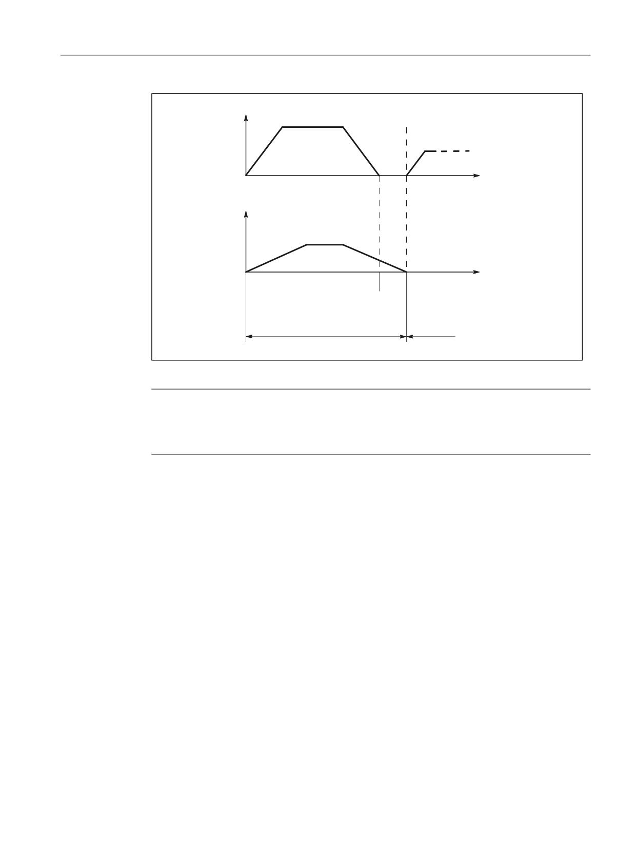
Positioning axes
8.6 Block change
9HORFLW\ SDWK D[HV
7LPH
9HORFLW\ SRVLWLRQLQJ D[LV
7LPH
3DWK D[HV KDYH UHDFKHG WKH
3RVLWLRQLQJ D[LV KDV UHDFKHG
SURJUDPPHG HQG SRVLWLRQ
SURJUDPPHG HQG SRVLWLRQ
1
1
%ORFN FKDQJH
Figure 8-1
Block change for path axis and positioning axis type 1
Note
Continuous path mode
Continuous path mode across block limits (G64) is only possible if the positioning axes reach
their end-of-motion criterion before the path axes (in the diagram above, this is not the case).
Type 2: Modal positioning axis (across blocks)
Properties:
• The block change is performed as soon as all path axes have reached their programmed end-
of-motion criterion (G601, G602, G603)
• Programming the positioning axis: POSA[<axis>]
• The positioning axis traverses beyond the block limits to its programmed end position. It is
not permissible that the positioning axis is programmed again before reaching its end-of-
motion criterion.
Axes and spindles
Function Manual, 10/2020, 6FC5397-4GP40-0BA1
291
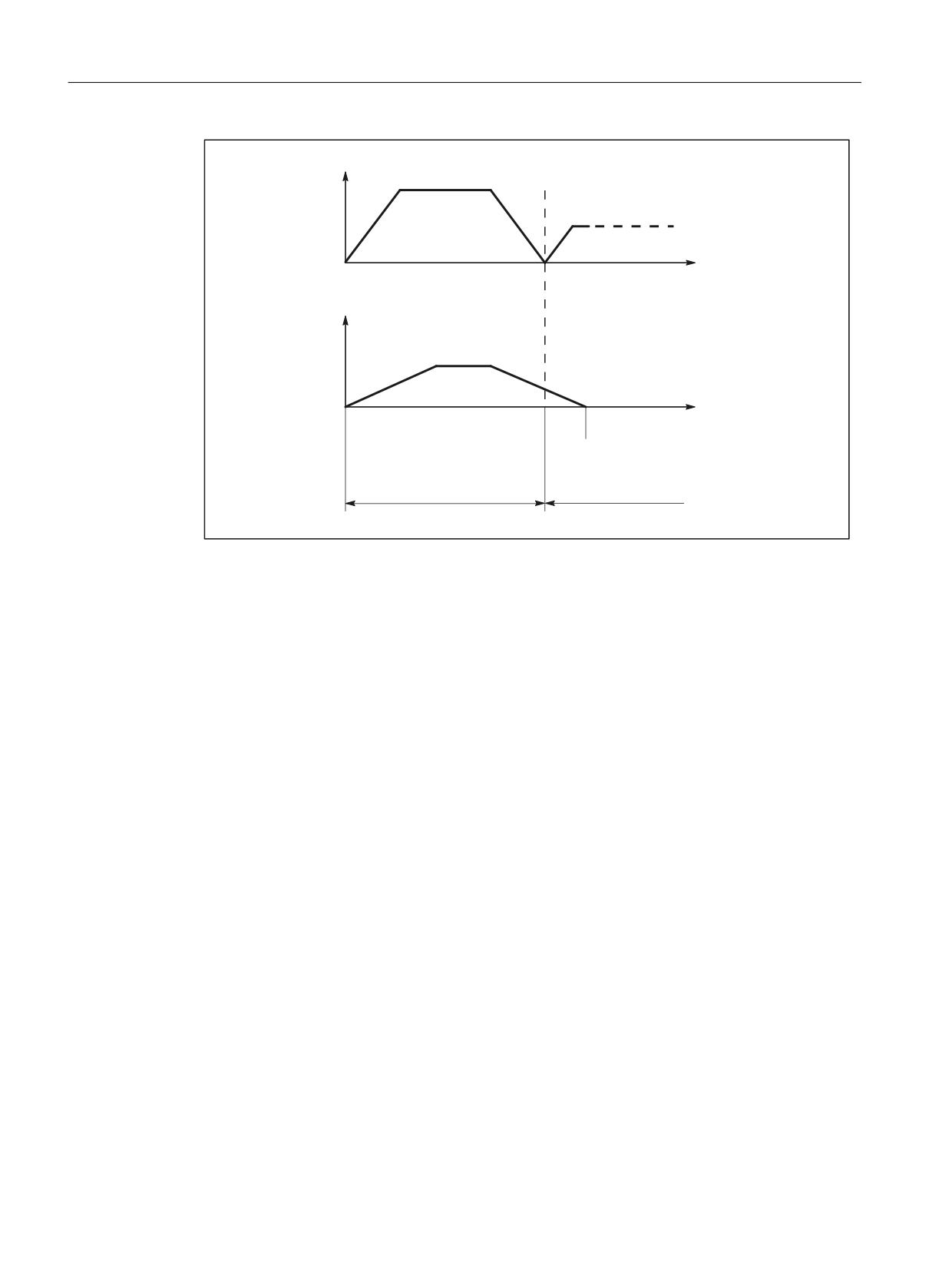
Positioning axes
8.6 Block change
9HORFLW\ SDWK D[HV
7LPH
9HORFLW\ SRVLWLRQLQJ D[LV
7LPH
3DWK D[HV KDYH UHDFKHG WKH
3RVLWLRQLQJ D[LV KDV UHDFKHG
SURJUDPPHG HQG SRVLWLRQ
SURJUDPPHG HQG SRVLWLRQ
1
1
%ORFN FKDQJH
Figure 8-2
Block change for path axis and positioning axis type 2
8.6.1
Settable block change time
Type 3: Conditional block-related positioning axis
Properties:
• The block change is performed as soon as all path and positioning axes have reached their
respective programmed end-of-motion criterion:
- Path axes: G601, G602, G603
- Positioning axes: IPOBRKA
• Programming the positioning axis:
- N(x) IPOBRK(<axis>[,<time>]) ;own block
- N(x+1) POS[<axis>]
Axes and spindles
292
Function Manual, 10/2020, 6FC5397-4GP40-0BA1
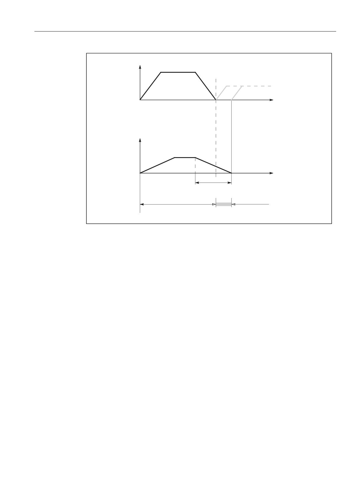
Positioning axes
8.6 Block change
9HORFLW\ SDWK D[HV
7LPH
3DWK D[HV KDYH UHDFKHG WKH
SURJUDPPHG HQG SRVLWLRQ
9HORFLW\ SRVLWLRQLQJ D[LV
7LPH
%ORFN HQG FULWHULRQ
; RI WKH EUDNLQJ UDPS
1
1
%ORFN FKDQJH DUHD
GHSHQGHQW RQ [
Figure 8-3
Block change for path axis and positioning axis type 3
Block change criterion: "Braking ramp" (IPOBRKA)
If, when activating the block change criterion "brake ramp", a value is programmed for the
optional parameter <time>, then this becomes effective for the next positioning motion and is
written into the setting data synchronized to the main run. If no value is specified for the block
change instant in time, then the actual value of the setting data is effective.
SD43600 $SA_IPOBRAKE_BLOCK_EXCHANGE
The time at which the block change can be realized is specified as a percentage of the braking
ramp:
•
100% = start of the braking ramp
•
0% = end of the braking ramp, the same significance as block change criterion IPOENDA
Programming
IPOBRKA(<axis>[,<time>])
IPOBRKA:
Block change criterion: Deceleration ramp
Effectiveness:
Modal
<axis>:
Channel axis name (X, Y,
)
Axes and spindles
Function Manual, 10/2020, 6FC5397-4GP40-0BA1
293
Positioning axes
8.6 Block change
<time>:
Time of the block change, referred to the braking ramp as a %:
•
100% = start of the braking ramp
•
0% = end of the braking ramp, the same significance
as IPOENDA
Type:
REAL
IPOBRKA is deactivated for the corresponding axis when an axis end-of-motion criterion (FINEA,
COARSEA, IPOENDA) is next programmed for the corresponding axis.
Additional block change criterion: "Tolerance window" (ADISPOSA)
A tolerance window around the end of block (either as actual or setpoint position) can be
defined as additional block change criterion. Then, two conditions must be fulfilled for the block
change:
• Block change criterion: "Braking ramp"
• Block change criterion: "Tolerance window"
Programming
ADISPOSA(<axis>[,<mode>,<window size>])
ADISPOSA:
Tolerance window for end-of-motion criterion
Effectiveness:
Modal
<axis>:
Channel axis name (X, Y,
)
<mode>:
Reference of the tolerance window
Type: INT
Range of values: 0 Tolerance window not active
1
Tolerance window with respect to set posi-
tion
2
Tolerance window with respect to actual
position
<window size>:
Size of the tolerance window
Type: REAL
System variable for end-of-motion criterion
The effective end-of-motion criterion can be read using the system variable $AA_MOTEND.
Further information: List Manual 2
Note
Information about other programmable end-of-motion criteria FINEA, COARESA, IPOENDA can
be found in Chapter:
• Operating modes (Page 378)
• Influencing the single axis dynamic response (Page 251)
Axes and spindles
294
Function Manual, 10/2020, 6FC5397-4GP40-0BA1
Positioning axes
8.6 Block change
Constraints
Premature block change
A premature block change is not possible in the following cases:
• Oscillating axis
During oscillation with partial infeed, the block-specific oscillation motion must remain
active until the axis with partial infeed has reached its final position.
• Handwheel
For handwheel input, the last set end-of-motion criterion applies.
Changing the axis state
The axis for which a block change occurred within the braking ramp can only be programmed
in the following block in the same axis state.
When the axis state changes, e.g. POS is followed by SPOS, the last programmed end-of-motion
criterion FINEA, COARSEA, IPOENDA is active. This also applies in the following cases:
• A positioning axis becomes a path axis
• If the program waits for the end of the positioning movement: WAITP, M30, end of the
technology cycle, preprocessing stop
• Velocity override is deactivated or activated
Note
For further information on programming positioning axes, see NC Programming Programming
Manual.
Examples
Block change criteria "braking ramp" in the part program
Program code
Comment
;Default setting effective.
N10 POS[X]=100
;Positioning motion from X to position 100.
;Block change criterion: "Exact stop fine"
N20 IPOBRKA(X,100)
;Block change criterion: "Braking ramp", 100% = start of the
braking ramp.
N30 POS[X]=200
;The block is changed as soon as axis X starts to brake.
N40 POS[X]=250
;Axis X no longer brakes at position 200, but rather contin-
ues to traverse to position 250. As soon as the axis starts
to brake, the block changes.
N50 POS[X]=0
;Axis X brakes and returns to position 0,
the block change is realized at position 0 and "exact stop
fine".
N60 X10 F100
;Axis X traverses as path axis to position 10.
N70 M30
Axes and spindles
Function Manual, 10/2020, 6FC5397-4GP40-0BA1
295

Positioning axes
8.6 Block change
Block change criterion "braking ramp" in synchronized action
In the technology cycle:
Program code
Comment
FINEA
;End-of-motion criterion: "Exact stop fine"
N10 POS[X]=100
;The technology cycle block change is realized if the X axis
has reached position 100 and "exact stop fine" is reached.
N20 IPOBRKA(X,100)
;Activate block change criterion "braking ramp",
100% = start of the braking ramp.
N30 POS[X]=200
;Technology cycle block is changed as soon as axis X starts
to brake.
N40 POS[X]=250
;X axis does not brake at position 200, but rather continues
to traverse to position 250. As soon as the X axis starts to
brake, the block change takes place in the technology cycle.
N50 POS[X]=0
;X axis brakes and returns to position 0,
the block change is realized at position 0 and "exact stop
fine".
N60 M17
Block change criterion "braking ramp" and "tolerance window" in the part program
Program code
Comment
;Default setting effective.
N10 POS[X]=100
;Positioning motion from X to position 100.
;Block change criterion: "Exact stop fine"
N20 IPOBRKA(X,100)
;Block change criterion: "Braking ramp", 100% = start of the
braking ramp.
N21 ADISPOSA(X,1,0.5)
;Tolerance window: 1 = set position, tolerance = 0.5
N30 POS[X]=200
;The block is changed as soon as axis X starts to brake.
N40 POS[X]=250
;Axis X no longer brakes at position 200, but rather contin-
ues to traverse to position 250. As soon as the axis starts
to brake, the block changes.
N50 POS[X]=0
;Axis X brakes and returns to position 0,
the block change is realized at position 0 and "exact stop
fine".
N60 X10 F100
N70 M30
Block change criterion "braking ramp" and "tolerance window" in synchronized action
In the technology cycle:
Program code
Comment
FINEA
;End-of-motion criterion: "Exact stop fine"
N10 POS[X]=100
;The technology cycle block change is realized if the X axis
has reached position 100 and "exact stop fine" is reached.
N20 IPOBRKA(X,100)
;Activate block change criterion "braking ramp", 100% =
start of the braking ramp.
Axes and spindles
296
Function Manual, 10/2020, 6FC5397-4GP40-0BA1
Positioning axes
8.6 Block change
Program code
Comment
N21 ADISPOSA(X,2,0.3)
;Tolerance window: 2 = actual position, tolerance = 0.3
N30 POS[X]=200
;Technology cycle block change is realized as soon as the X
axis starts to brake and the actual position of the X axis
>= 199.7.
N40 POS[X]=250
;X axis does not brake at position 200, but rather continues
to traverse to position 250. As soon as the X axis starts to
brake and the position of the X axis >= 249.7, the block
change takes place in the technology cycle.
N50 POS[X]=0
;X axis brakes and returns to position 0,
the block change is realized at position 0 and "exact stop
fine".
N60 M17
IPOBRKA(X) could also be written into the N20 blocks without specifying the instant in time, if
the corresponding value has already been entered into the setting data:
SD43600 $SA_IPOBRAKE_BLOCK_EXCHANGE[X] == 100
See also
Control by the PLC (Page 298)
8.6.2
End of motion criterion with block search
Last block serves as container
The last end-of-motion criterion programmed for an axis is collected and output in an action
block. The last block with a programmed motion end condition that was processed in the search
run serves as a container for setting all axes.
Example
For two action blocks with end-of-motion criteria for three axes:
Program code
Comment
N01 G01 POS[X]=20 POS[Y]=30
IPOENDA[X]
;Last programmed IPOENDA end-of-mo-
tion criterion
N02 IPOBRKA(Y, 50)
;Second action block for Y axis IPOENDA
N03 POS[Z]=55 FINEA[Z]
;Second action block for the Z axis FI-
NEA
N04 $A_OUT[1]=1
;First action block for output as dig-
ital output
N05 POS[X]=100
N06 IPOBRKA(X, 100)
;Second action block for X axis IPOBR-
KA container
Axes and spindles
Function Manual, 10/2020, 6FC5397-4GP40-0BA1
297