SINUMERIK 840D sl. Service - Functions. Manual (2018-2020) - page 8
Positioning axes
8.7 Control by the PLC
Program code
Comment
;For all programmed end-of-motion cri-
teria
TARGET:
;Block search target
The first action block contains the digital output:
$A_OUT[1] = 1.
The second action block contains the settings for the end-of-motion criteria:
for the X axis IPOBRKA / $SA_IPOBRAKE_BLOCK_EXCHANGE[AX1]=100
for the Y axis IPOBRKA / $SA_IPOBRAKE_BLOCK_EXCHANGE[AX2]=50
for the Z axis FINEA. The motion end condition IPOENDA last programmed is also stored for the
X axis.
8.7
Control by the PLC
PLC axes
PLC axes are traversed from the PLC and can move asynchronously to all other axes. The travel
motions are executed separate from the path and synchronized actions.
Further information
Function Manual PLC
Concurrent positioning axes
Concurrent positioning axes can be started from the PLC using the FC18 function block.
Channel-specific signals
All channel-specific signals act to the same extent on path and positioning axes.
Only the following signals are an exception:
• NST DB21, ... DBB4 ("feedrate override")
• IS DB21, ... DBX6.2 ("Delete distance to go")
Axisspecific signals
Positioning axes have the following additional signals:
• IS DB31, ... DBX76.5 ("Positioning axis")
• Feedrate for positioning axes/spindles (FA)
• NST DB31, ... DBB0 ("feedrate override") - axis-specific
• IS DB31, ... DBX2.2 ("Distance to go/Spindle reset") Axis-specific deletion of distance to go
Axes and spindles
298
Function Manual, 10/2020, 6FC5397-4GP40-0BA1
Positioning axes
8.7 Control by the PLC
Single-axis functions of PLC-controlled axes
The behavior of individual PLC axes can be manipulated in
the following way with machine data:
MD30460 $MA_BASE_FUNCTION_MASK:
• Bit 4 = 1
The axis is exclusively controlled by the PLC.
• Bit 5 = 1
The axis is a permanently assigned PLC axis.
• Bit 6 = 1
The channel-specific NC/PLC interface signal:
DB21, ... DBX6.0 ("feed disable")
is not active for the axis if this is a PLC-controlled axis.
• Bit 7= 1
The channel-specific NC/PLC interface signal:
DB21, ... DBX36.3 ("all axes stationary")
is setindependently of an axis if this is a PLC-controlled axis.
For a PLC-controlled axis:
• The channel-specific NC/PLC interface signal DB21, ... DBX6.0 ("feed disable"), is active if
bit 6 = 0 in machine data MD30460 $MA_BASE_FUNCTION_MASK.
• The channel-specific NC/PLC interface signal DB21, ... DBX36.3 ("all axes stationary") is only
set if bit 7 = 0 in machine data MD30460 $MA_BASE_FUNCTION_MASK.
If an attempt is made to assign an exclusively PLC-controlled axis to the NC program or to
request the axis for the NC program, then this is rejected with Alarm 26075. Alarm 26076 is
generated in the same way for a PLC axis with fixed assignment.
A PLC axis with fixed assignment is a "neutral axis" on power up. For a travel request via the NC/
PLC interface, a concurrent positioning axis automatically changes to a PLC axis without being
interchanged beforehand.
Axis interchange via PLC
The type of an axis for axis interchange is transferred to the PLC with axial interface byte NC→PLC
NST DB31, ... DBB68 (see also Function Manual "Basic Functions" Section "K5: Cross-channel
program coordination and channel-by-channel running-in"):
• IS DB31, ... DBX68.0-68.3 ("NC axis/spindle in channel") channels 1 to 10
• IS DB31, ... DBX68.4 ("new type requested by PLC")
• IS DB31, ... DBX68.5 ("axis can be replaced")
• IS DB31, ... DBX68.6 ("neutral axis/spindle")
• IS DB31, ... DBX68.7 ("PLC axis/spindle")
If IS DB31, ... DBX68.5 ("axis can be replaced") = 1, an axis replacement request can be issued
from the PLC.
Axes and spindles
Function Manual, 10/2020, 6FC5397-4GP40-0BA1
299

Positioning axes
8.7 Control by the PLC
8.7.1
Starting concurrent positioning axes from the PLC
Traversing an axis in the NC as competing positioning axes from the PLC user program is realized
using block FC18:
The following functions are defined:
• Linear interpolation (G01)
• Feedrate in mm/min or degrees/min (G94)
• Exact stop (G09)
• The active adjustable work offsets are taken into account
Since each axis is assigned to exactly one channel, the control can select the correct channel
from the axis name/axis number and start the concurrent positioning axis on this channel.
Further information
Function Manual PLC; Block descriptions > FC18: SpinCtrl, spindle control
8.7.2
PLC-controlled axes
PLC actions
The table below compares the following PLC actions as response of the NC for a machine axis:
• Start machine axis as PLC axis using FC18
• Initiate NC start or NC stop
• Axis-specific STOP, RESUME or RESET
• Trigger NC-RESET
• Cancel or set controller enable for the machine axis
• Relinquish control of machine axis to NC
Examples of NC responses
PLC actions as response of the NC are listed in the table below.
PLC actions
NC response
Machine axis AX1 is the channel axis in channel
1, start as PLC axis using FC18
Initiate NC stop axes and spindles
AX1 is stopped.
DB21, ... DBX7.4 = 1 (NC stop axes plus spindle)
DB21, ... DBX7.1 = 1 initiate (NC start)
AX1 continues to traverse.
The PLC wants to control AX1,
Checking AX1 is relinquished to the PLC. DB31, ...
DBX63.1 = 1 (PLC controls the axis)
DB31, ... DBX28.7 = 1 (PLC controls axis)
Initiate NC stop for axes and spindles
AX1 is not stopped.
DB21, ... DBX7.4 = 1 ("NC stop axes plus spindle")
Axes and spindles
300
Function Manual, 10/2020, 6FC5397-4GP40-0BA1

Positioning axes
8.7 Control by the PLC
PLC actions
NC response
Initiate axial stop
AX1 is stopped
DB31, ... DBX63.2 ==1 (axis stop active)
DB31, ... DBX28.6 = 1 (stop along braking ramp)
Initiate axial continuation
AX1 traverses further
DB31, ... DBX63.2 == 0 (axis stop active)
DB31, ... DBX28.2 = 1 (continue)
Initiate NC RESET
No effect on AX1
DB21, ... DBX7.7 = 1 initiate (reset)
Initiate axial reset
AX1 is stopped and the traversing motion is inter-
rupted:
DB31, ... DBX28.1 = 1 (reset)
• DB31, ... DBX63.2 = 0 (axis stop active)
• Read-in axial machine data
• DB31, ... DBX63.0 = 1 (reset executed)
• DB31, ... DBX63.2 = 0 (axis stop active)
Start machine axis AX1 as PLC axis via FC 18
DB31, ... DBX63.0 = 0 (reset executed)
Withdraw controller enable for AX1:
Alarm 21612 "Axis %1 measuring system change"
is displayed
DB31, ... DBX2.1 = 0 (controller enable)
Initiate axial continuation
• Alarm 21612 "Axis %1 measuring system
DB31, ... DBX28.2 = 1 (continue)
change" is deleted
• DB21, ... DBX40.7 = 1(traversing command
plus)
• AX1 does not traverse due to a missing control-
ler enable signal.
Set controller enable for AX1
AX1 moves to the programmed end point.
DB31, ... DBX2.1 = 1 (controller enable)
Initiate axial reset
• Stop AX1
DB31, ... DBX28.1 = 1 (reset)
• Read-in axial machine data
• DB31, ... DBX63.0 = 0 (reset)
PLC relinquishes control of AX1 to the NC from
• NC accepts control of machine axis
DB31, ... DBX28.7 = 0 (PLC controls axis)
• DB31, ... DBX63.1 = 0 (PLC controls the axis)
• DB31, ... DBX63.0 = 0 (reset)
8.7.3
Control response of PLC-controlled axes
Response for a channel reset, activate machine data, block search and MD30460
Table 8-1
Control response to
PLC-controlled axis
Mode change and NC program control
Work independently of axis.
Channel RESET
No axial machine data are effective and a traversing
movement is not aborted.
NEWCONF
No axial machine data are effective.
Axes and spindles
Function Manual, 10/2020, 6FC5397-4GP40-0BA1
301

Positioning axes
8.7 Control by the PLC
Control response to
PLC-controlled axis
Block search Type 5 SERUPRO
Are processed during SERUPRO to simulate the nor-
mal procedure, e.g. PLC takes over or relinquishes
control of this axis which is also traversing via the
PLC.
All block search variants
The PLC takes over control of the axis before the
of types 1, 2, 4 and 5
approach block and is responsible for positioning
this axis.
NC-controlled retraction activated with
Has no effect and acts only on the specified PLC-
$AC_ESR_TRIGGER.
controlled axis.
Machine data:
Which is not controlled
MD30460 $MA_BASE_FUNKTION_MASK
exclusively by the PLC
Bit 4 = 0
Cannot be changed directly with axis replacement
command GET (axis) or AXTOCHAN (axis, channel)
to an axis controlled by the NC program.
Bit 4 = 1
Cannot be requested for the NC program. GET or
AXTOCHAN from the NC program or a synchronized
action, or programming the axis in the NC program,
are rejected with alarm 26075.
MD30460 $MA_BASE_FUNKTION_MASK
For the PLC-controlled axis
Bit 6 = 1
Channel-specific
IS DB 21, ... DBX6.0 ("feed disable") is not effective.
This axis is not stopped when feed disable is acti-
vated, but continues to move.
Bit 7 = 1
The axis is not taken into account when
IS DB 21, ... DBX36.3 ("all axes stationary") is gen-
erated. This signal is output with 1 even if all other
axes in the channel are stationary and only the PLC-
controlled axis is active.
* Note on axis replacement
This replacement of a "neutral axis" by an "NC program axis" does not take place until the PLC has
really relinquished control of the axis in accordance with use case "Relinquish control of axis".
8.7.4
Control response of PLC-controlled axes
Response for a channel reset, activate machine data, block search and MD30460
Table 8-2
Control response to
PLC-controlled axis
Mode change and NC program control
work independently of axis.
Channel RESET
No axial machine data are effective and a traversing
movement is not aborted.
NEWCONF
No axial machine data are effective.
Axes and spindles
302
Function Manual, 10/2020, 6FC5397-4GP40-0BA1

Positioning axes
8.8 Response with special functions
Control response to
PLC-controlled axis
Block search Type 5 SERUPRO
are processed during SERUPRO to simulate the nor-
mal procedure, e.g. PLC takes over or relinquishes
control of this axis which is also traversing via the
PLC.
All block search variants
The PLC takes over control of the axis before the
of types 1, 2, 4 and 5
approach block and is responsible for positioning
this axis.
NC-controlled retraction activated with
has no effect and acts only on the specified PLC-
$AC_ESR_TRIGGER.
controlled axis.
machine data:
which is not controlled
MD30460 $MA_BASE_FUNKTION_MASK
exclusively by the PLC
Bit 4 = 0
cannot be changed directly with axis replacement
command GET (axis) or AXTOCHAN(axis, channel)
to an axis controlled by the NC program, see * Note
on axis replacement.
Bit 4 = 1
cannot be requested for the NC program. GET or
AXTOCHAN from the NC program or a synchronized
action, or programming the axis in the NC program,
are rejected with alarm 26075.
MD30460 $MA_BASE_FUNKTION_MASK
For the PLC-controlled axis
Bit 6 = 1
channel-specific
IS DB 21, ... DBX6.0 ("feed disable") is not effective.
This axis is not stopped when feed disable is acti-
vated, but continues to move.
Bit 7 = 1
the axis is not taken into account when
IS DB 21, ... DBX36.3 ("all axes stationary") is gen-
erated. This signal is output with 1 even if all other
axes in the channel are stationary and only the PLC-
controlled axis is active.
* Note on axis replacement
This replacement of a "neutral axis" by an "NC program axis" does not take place until the PLC has
really relinquished control of the axis in accordance with use case "Relinquish control of axis".
Waiting for this axis interchange is displayed on the HMI operator panel front.
8.8
Response with special functions
8.8.1
Dry run (DRY RUN)
The dry run feedrate is also effective for positioning axes unless the programmed feedrate is
larger than the dry run feedrate.
Activation of the dry run feed entered in SD42100 $SA_DRY_RUN_FEED can be controlled with
SD42101 $SA_DRY_RUN_FEED_MODE. See
Further information
Feedrates (Page 195)
Axes and spindles
Function Manual, 10/2020, 6FC5397-4GP40-0BA1
303
Positioning axes
8.9 Examples
8.8.2
Single block
Positioning axis type 1
Single-block mode is effective with positioning axes of type 1.
Positioning axis type 2
Positioning axes of type 2 also continue across block limits in single block mode.
Positioning axis type 3
Positioning axes of type 3 also continue across block limits in single block mode.
8.9
Examples
8.9.1
Motion behavior and interpolation functions
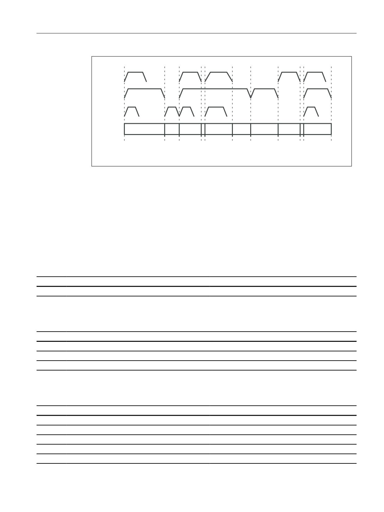
In the following example, the two positioning axes Q1 and Q2 represent two separate units of
movement. There is no interpolation relationship between the two axes. In the example, the
positioning axes are programmed as type 1 (e.g. in N20) and type 2 (e.g. in N40).
Program example
Program code
N10 G90 G01 G40 T0 D0 M3 S1000
N20 X100 F1000 POS[Q1]=200 POS[Q2]=50 FA[Q1]=500
FA[Q2]=2000
N30 POS[Q2]=80
N40 X200 POSA[Q1]=300 POSA[Q2]=200 FA[Q1]=1500
N45 WAITP(Q2)
N50 X300 POSA[Q2]=300
N55 WAITP(Q1)
N60 POS[Q1]=350
N70 X400
N75 WAITP(Q1,Q2)
N80 G91 X100 POS[Q1]=150 POS[Q2]=80
N90 M30
Axes and spindles
304
Function Manual, 10/2020, 6FC5397-4GP40-0BA1
Positioning axes
8.10 Data lists
X
Q1
Q2
N20
N30
N
45 N50
N55
N60
N70 N
7
5 N80
X
path axes
Q1, Q2
positioning axes
Figure 8-4
Timing of path axes and positioning axes
8.10
Data lists
8.10.1
Machine data
8.10.1.1
NC-specific machine data
Number Identifier: $MN_
Description
18960
POS_DYN_MODE
Type of positioning axis dynamic response
8.10.1.2
Channelspecific machine data
Number Identifier: $MC_
Description
20730
G0_LINEAR_MODE
Interpolation behavior with G0
20732
EXTERN_G0_LINEAR_MODE
Interpolation behavior with G00
22240
AUXFU_F_SYNC_TYPE
Output timing of F functions
8.10.1.3
Axis/spindlespecific machine data
Number Identifier: $MA_
Description
30450
IS_CONCURRENT_POS_AX
Concurrent positioning axis
30460
BASE_FUNCTION_MASK
Axis functions
32060
POS_AX_VELO
Feedrate for positioning axis
32300
MAX_AX_ACCEL
Maximum axis acceleration
32430
JOG_AND_POS_MAX_JERK
Maximum axial jerk for positioning axis movements
Axes and spindles
Function Manual, 10/2020, 6FC5397-4GP40-0BA1
305

Positioning axes
8.10 Data lists
Number Identifier: $MA_
Description
32431
MAX_AX_JERK
Maximum axial jerk for path movements
37510
AX_ESR_DELAY_TIME1
Delay time for ESR single axis
37511
AX_ESR_DELAY_TIME2
ESR time for interpolatory braking of single axis
8.10.2
Setting data
8.10.2.1
Axis/spindle-specific setting data
Number Identifier: $SA_
Description
43600
IPOBRAKE_BLOCK_EXCHANGE
Braking ramp block change condition
43610
ADISPOSA_VALUE
Braking ramp tolerance window
Axes and spindles
306
Function Manual, 10/2020, 6FC5397-4GP40-0BA1
Rotary axes
9
9.1
Brief description
The following are typical applications for positioning axes:
•
5-axis machining (operating range limited or unlimited)
• Rotary axis for eccentric machining (unlimited operating range)
• Rotary axis for cylindrical or form grinding (unlimited operating range)
• C axis with TRANSMIT (unlimited operating range)
• Rotary axis on winding machines (unlimited operating range)
• Rotary workpiece axis (C) on hobbing machines (unlimited operating range)
• Round tool magazines and tool turrets (unlimited operating range)
• Rotary axis for peripheral surface transformation (limited operating range)
• Swivel axes for gripping (operating range 360°)
• Rotary axes for swiveling (operating range < 360°; e.g., 60°)
• Milling swivel axis (A) on hobbing machines (operating range, e.g., 90°)
Axis addresses
Linear axes, rotary axes and directions of movement of numerically-controlled machine tools are
designated according to DIN 66025 as follows:
• Linear axes: X, Y, Z
• Rotary axes: A, B, C
Axes and spindles
Function Manual, 10/2020, 6FC5397-4GP40-0BA1
307
Rotary axes
9.1 Brief description
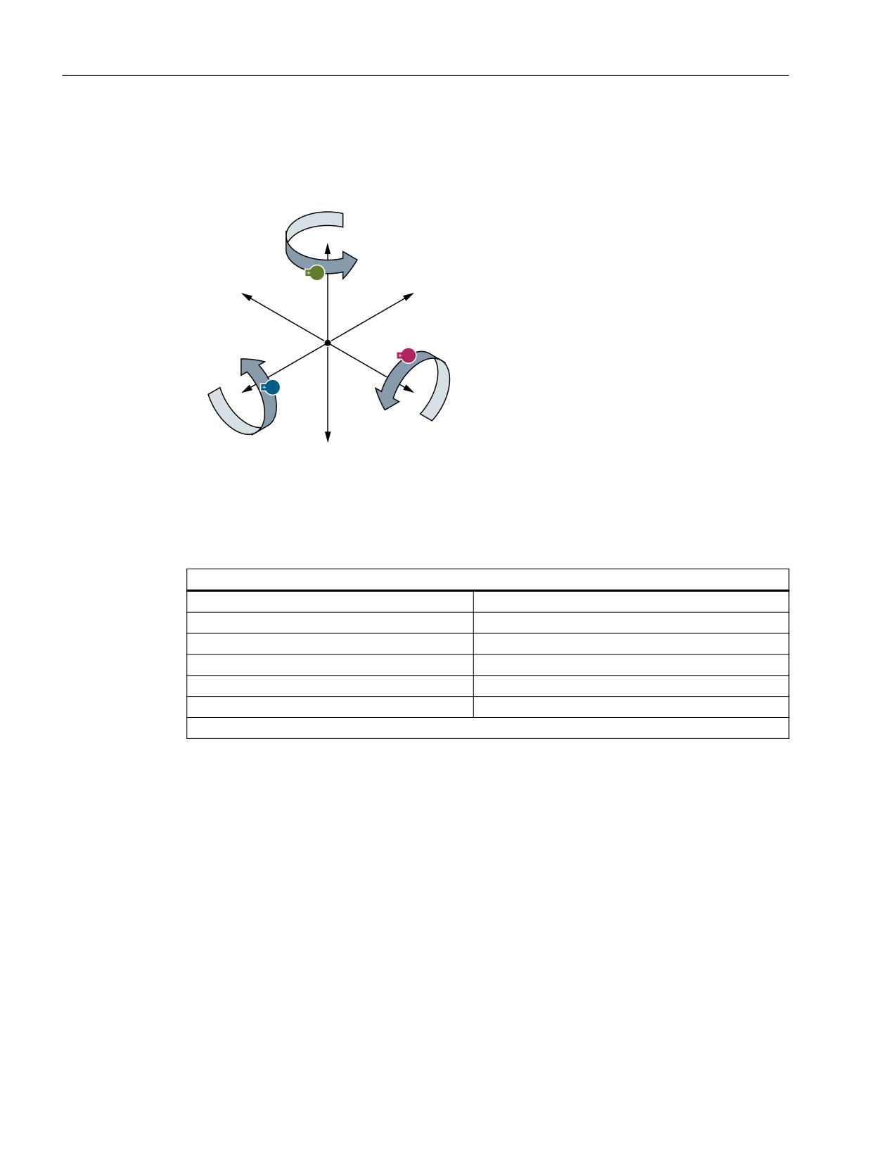
• Assignment: A rotates about X, B rotates about Y and C rotates about Z
• Direction of rotation: The positive rotary-axis direction of a rotation corresponds to a
clockwise rotation when looking in the positive axis direction of the corresponding linear
axis.
:
#
9
;
"
$
;
9
:
Figure 9-1
Axis identifiers and directions of movement for rotary axes
Units of measurement
The following units of measurement apply as standard to inputs and outputs for rotary axes:
Units of measurement for rotary axes
Physical quantity
Unit
Angular position
Degrees
Programmed angular velocity
Degrees/min
Angular velocity
1) rev/min
Angular acceleration
1) rev/sec2
Angular jerk limit
1)rev/sec3
1) Unit of the axis-specific machine data for rotary axes.
Further information
Velocities, setpoint/actual value systems, closed-loop control (Page 135)
Feedrate
The programmed feedrate F corresponds to an angular velocity (degrees/min) in the case of
rotary axes.
If rotary axes and linear axes traverse a common path with G94 or G95, the feedrate should be
interpreted in the linear-axis unit of measurement (e. g. mm/min, inch/min].
The tangential velocity of the rotary axis refers to diameter Dunit (unit diameter Dunit=360/π). In
the case of unit diameter D=Dunit, the programmed angular velocity in degrees/min and the
tangential velocity in mm/min (or inch/min) are numerically identical.
Axes and spindles
308
Function Manual, 10/2020, 6FC5397-4GP40-0BA1

Rotary axes
9.2 Modulo 360 degrees
In general, the following applies for tangential velocity:
F = Fangle * D/Dunit
F
= Tangential velocity [mm/min]
Fangle
= Angular velocity [degrees/min]
D
= Diameter acted on by F [mm]
With Dunit = 360/π
DE
= Unit diameter [mm]
π
= Circle constant Pi
JOG mode: Revolutional feedrate
In the JOG mode, the response of the rotary axis spindle also depends on the setting data:
SD41100 $SN_JOG_REV_IS_ACTIVE (revolutional feed rate for JOG active)
9.2
Modulo 360 degrees
A 360° modulo rotary axis is a rotary axis whose position is mapped to the range from 0° to
359.999°. As a consequence, in principle, the traversing range of a 360° modulo rotary axis is
infinity. The traversing range limits (software limit switch and working area limits) of 360°
modulo rotary axes are not effective.
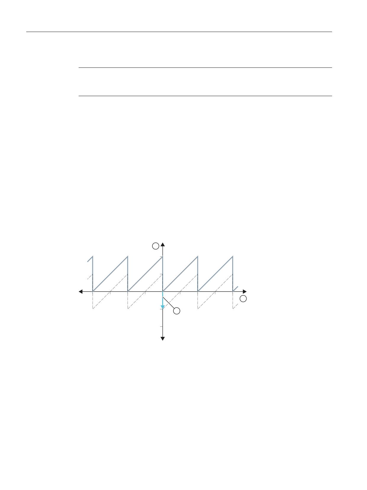
In the diagram below, the absolute position of a rotary axis in the positive direction of rotation
is represented as a spiral. The pointer to the spiral indicates the absolute position of the rotary
axis (420°). The point where the pointer intersects with the modulo circle marks the
corresponding 360° modulo position (60°).
p
p
p
p
p
p
p
p
p
p
p
p
p
p
p
Figure 9-2
Modulo_mapping
Parameter assignment
Modulo function
The modulo function for a rotary axis is activated using the axis-specific machine data:
Axes and spindles
Function Manual, 10/2020, 6FC5397-4GP40-0BA1
309
Rotary axes
9.2 Modulo 360 degrees
MD30310 $MA_ROT_IS_MODULO = 1
Note
For a 360° modulo rotary axis, it is recommended that the position display is also set to 360° at
the user interface.
Modulo range
For a 360° modulo rotary axis, the modulo range must be set to 360° using the axis-specific
machine data:
MD30330 $MA_MODULO_RANGE = 360.0
Starting position of the 360° modulo range
The starting position of the 360° modulo range can be set using the axis-specific machine data:
MD30340 $MA_MODULO_RANGE_START = <Starting position>
As a consequence, the parameterized starting position represents an offset of the modulo
function in the vertical axis. The modulo range still remains 360°.
Examples
• Standard starting position: 0° ⇒ modulo range: 0° - 360°
• Shifted starting position: -180° ⇒ modulo range: -180° to +180°
p
p
p
p
p
p
p
p
p
p
p
p
p
① Absolute position
② Modulo position
③ Shifted starting position (-180°)
Figure 9-3
Standard and shifted starting position (red)
Axes and spindles
310
Function Manual, 10/2020, 6FC5397-4GP40-0BA1

Rotary axes
9.2 Modulo 360 degrees
Note
Modulo partition axes
By aligning the two following machine data, indexing positions of 360° modulo indexing axes
can be implemented in the same way as for the 360° modulo range:
• MD30503 $MA_INDEX_AX_OFFSET
• MD30340 $MA_MODULO_RANGE_START
See the examples in Chapter "Indexing axes, "Example 3: Rotary modulo axis as equidistant
indexing axis (Page 340)" and the following chapters.
360° modulo rotary axis: Positioning behavior for G90 (modal absolute programming)
The standard behavior for G90 is set via the machine data:
MD30455 $MA_MISC_FUNCTION_MASK, bit 2 = <value>
<value>
Meaning
0
The 360° modulo rotary axis positions corresponding to AC as standard for G90 program-
ming:
• Target position > Current position: Move in positive traversing direction
• Target position < Current position: Move in negative traversing direction
1
For G90 programming, the 360° modulo rotary axis positions as standard corresponding
to DC, i.e. the shortest path.
Position display in the 360° modulo representation
Activating the position display at the user interface in the 360° modulo representation is realized
using the axis-specific machine data:
MD30320 $MA_DISPLAY_IS_MODULO = 1
NC/PLC interface signals
Activating the traversing range limits
In principle, the traversing range of a 360° modulo rotary axis is infinity. This is the reason that
axis-specific traversing range limits to not apply as standard, such as software limit switches and
working error limits. The traversing range limits of a 360° modulo rotary axis can be activated
using the subsequent absolute axis-specific NC/PLC interface signal, possibly initiated via an M/
H function in the NC program:
DB31, ... DBX12.4 = 1 (360° modulo rotary axes: Activate traversing range limits)
Axes and spindles
Function Manual, 10/2020, 6FC5397-4GP40-0BA1
311
Rotary axes
9.2 Modulo 360 degrees
Preconditions:
• The 360° modulo rotary axis must be referenced.
• Software limit switch
Software limit switch 1 or 2 to be monitored must be active:
- DB31,
DBX12.2 / 3 (activation)
– MD36100 $MA_POS_LIMIT_MINUS / MD36110 $MA_POS_LIMIT_PLUS (software limit
switch 1)
- MD36120 $MA_POS_LIMIT_MINUS2 / MD36130 $MA_POS_LIMIT_PLUS2 (software limit
switch 2)
• Working area limitation
Both limits must be active, either via G26/G25 or setting data:
- SD43400 $SA_ WORKAREA_PLUS_ENABLE / SD43410 $SA_WORKAREA_MINUS_ENABLE
(activation)
- SD43420 $SA_WORKAREA_LIMIT_PLUS / SD43430 $SA_WORKAREA_LIMIT_MINUS
(limiting)
• Synchronization with STOPRE
If the traversing range limits are activated using the NC/PLC interface signal in an NC program
being executed, e.g. as a result of an M/H command at the PLC, then a preprocessing strop
must be programmed in the following block (STOPRE). Only then can it be ensured that the
activation of the traversing range limits are taken into account in the subsequent traversing
blocks.
NOTICE
User: Activation and effectiveness
If the traversing range limits of a 360° modulo rotary axis are activated by the NC/PLC interface
signal (DB31, ... DBX12.4) in a block in the main run, (e.g. using the M/H function), under
certain circumstances, as a result of the preprocessing of already subsequent traversing blocks,
the traversing range limits were not taken into account. As a consequence, it is solely the
responsibility of the user to apply suitable measures, e.g. by programming STOPRE in the
following block after activating the traversing range limits. This means that from the activation
time in the NC program, the traversing range limits are also effective in all of the subsequent
blocks.
Axes and spindles
312
Function Manual, 10/2020, 6FC5397-4GP40-0BA1

Rotary axes
9.2 Modulo 360 degrees
p
p
p
p
p
p
① Direction of rotation +/-
② Software limit switch +/-
Figure 9-4
360° modulo rotary axis with software limit switch
Feedback signal, activation of the traversing range limits
The feedback signal that the traversing range limits of a 360° modulo rotary axis are active in the
NC, is realized using the axis-specific NC/PLC interface signal:
DB31, ... DBX74.4 == 1 (modulo rotary axes: traversing range limits active)
Example: Changing the traversing range limits
Pallet 1 with several clamped workpieces is machined on a 360° modulo rotary axis. The pallet
1 is then swapped for a pallet 2 with a built-on axis. The traverse range now has to be monitored.
Parameterization:
• MD30300 $MA_IS_ROT_AX[ AX5 ] = 1
• MD30310 $MA_ROT_IS_MODULO[ AX5 ] = 1
• MD36110 $MA_POS_LIMIT_PLUS[ AX5 ] = 340
• MD36100 $MA_POS_LIMIT_MINUS[ AX5 ] = 350
Extract from part program:
Program code
Comment
M123
; Insert pallet 1 with quadruple clamping
; PLC: deactivate traversing range limits of the
; B axis => DB35, DBX12.4=0
STOPRE
; Trigger a preprocessing stop
S1000 M3
G4 F2
G1 X0 Y300 Z500 B0 F5000
CYCLE84(500,400,0,350,0,1,4,10,,0,500,1000) ; drilling cycle
G0 Z540 B0
Axes and spindles
Function Manual, 10/2020, 6FC5397-4GP40-0BA1
313

Rotary axes
9.3 Programming of rotary axes
Program code
Comment
M124
; Insert pallet 2 with built-on axis
; PLC: activate traversing range limits of the
; B axis => DB35, DBX12.4=1
STOPRE
; Trigger a preprocessing stop
B270
9.3
Programming of rotary axes
9.3.1
General information
Note
For information about programming, see the NC Programming Programming Manual.
MD30310
Axis-specific machine data is used to define whether a rotary axis behaves as a linear axis during
programming and positioning, or whether rotary-axis special features should be taken into
account:
MD30310 $MA_ROT_IS_MODULO (modulo conversion for rotary axis)
These features and any differences (mainly with respect to absolute programming) are
explained on the following pages.
Modulo display for rotary axes and spindles
MD30320 $MA_DISPLAY_IS_MODULO (modulo display for rotary axis or spindle)
If MD30310 and MD30320 are set to "1", the change to a modulo display takes place as soon as
the actual value display changes between 0° and 359.999° - or exceeds 359.999° in the positive
direction of rotation, or falls below 0° in the negative direction of rotation.
For internal setpoint and actual values, the behavior of rotary axes and spindles differ:
• For spindles, the modulo conversion takes place for each spindle programming (M3, M4 and
M5).
• For rotary axes, the modulo conversion only takes place with a new traversing command.
If the setpoint and actual values are read out, these are the same as the display values in the
"Service overview" - "Service axis" under the selected axis. For rotating spindles or rotary axes,
these values can also lie below the modulo range of 0° to 359.999°.
Axes and spindles
314
Function Manual, 10/2020, 6FC5397-4GP40-0BA1
Rotary axes
9.3 Programming of rotary axes
9.3.2
Rotary axis with modulo conversion (continuously-turning rotary axis).
Absolute programming (AC, ACP, ACN, G90)
Example of the absolute programming for a modulo rotary axis as positioning axis:
POS[<axis name>] = ACP(<value>)
• <value>: Target position of the modulo rotary axis in the range between 0° and 359.999°
Negative values are also possible if a range offset has been realized with the following
machine data:
- MD30340 $MA_ MODULO_RANGE_START
- MD30330 $MA_MODULO_RANGE
• ACP: Absolute programming of the target position in positive rotation direction (counter
clockwise).
• ACN: Absolute programming of the target position in negative rotation direction (clockwise).
• AC / G90: by block / modally valid absolute programming of the target position.
The direction of rotation depends on the current position of the modulo rotary axis.
- Target position > Current position: Travel in positive direction.
- Target position < Current position: Travel in negative direction.
Note
The G90 positioning behavior can be projected via MD30455 $MA_MISC_FUNCTION_MASK,
Bit 2. See Section "Modulo 360 degrees (Page 309)".
Application example
ACP / ACN: Defined direction of rotation for asymmetric workpieces in order to exclude collisions
during rotation.
Programming examples
Starting position of modulo rotary axis C = 0° (see figure below).
Axes and spindles
Function Manual, 10/2020, 6FC5397-4GP40-0BA1
315

Rotary axes
9.3 Programming of rotary axes
p
p
p
p
p
p
p
① POS[C] = ACP(100); Traverse in positive direction of rotation to
position 100°
② POS[C] = ACN(300); Traverse in negative direction of rotation to
position 300°
③ POS[C] = ACP(240); Traverse in positive direction of rotation to
position 240°
④ POS[C] = AC(0); Traverse in negative direction of rotation to position
0°
Figure 9-5
Absolute programming for modulo rotary axes
Absolute programming along the shortest path (DC)
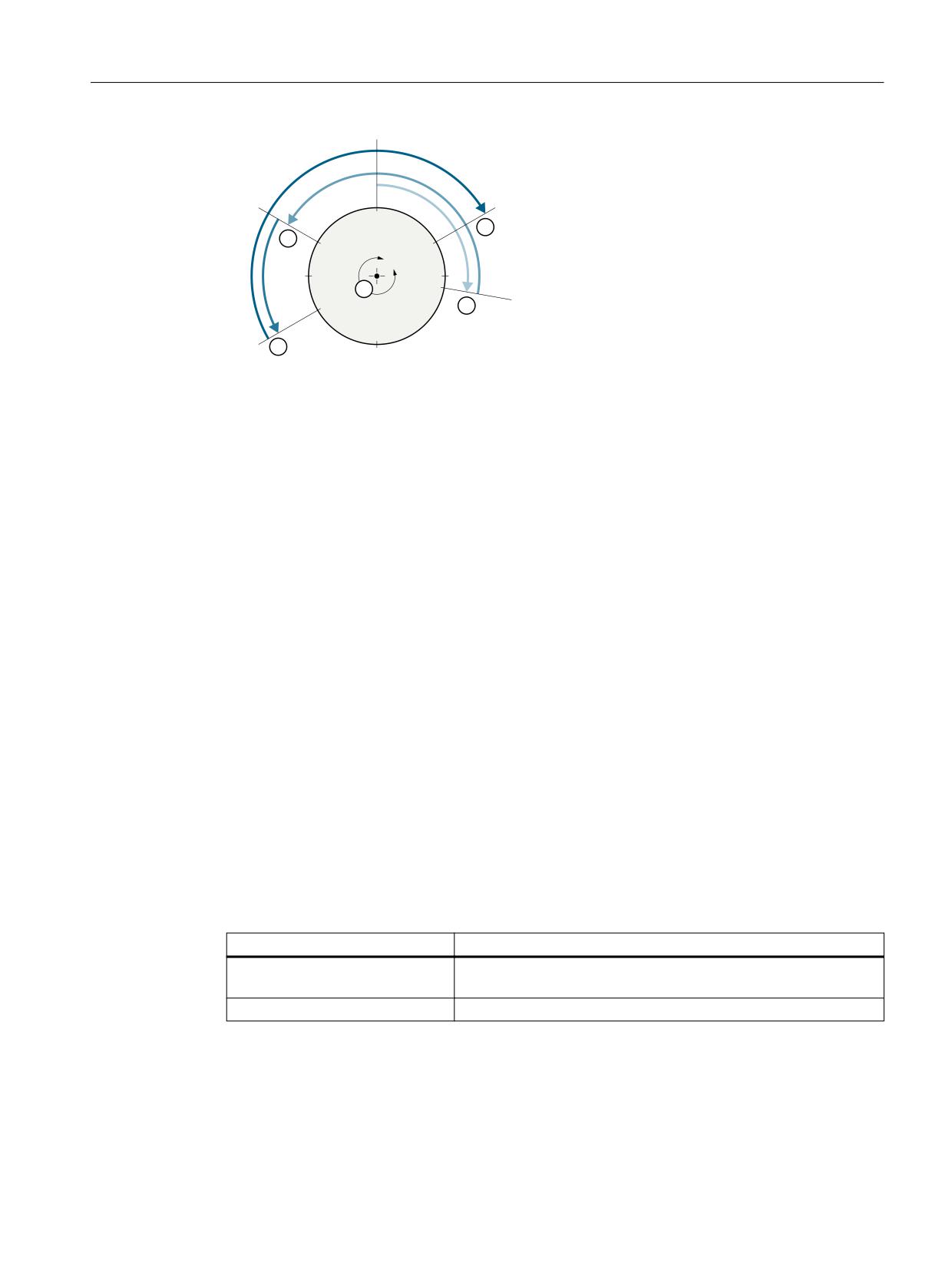
Example of absolute programming on the shortest path for a modulo rotary axis as positioning
axis:
POS[<axis name>] = ACP(<value>)
• <value>: Target position of the modulo rotary axis in the range between 0° and 359.999°
Negative values are also possible if a range offset has been realized with the following
machine data:
- MD30340 $MA_ MODULO_RANGE_START
- MD30330 $MA_MODULO_RANGE
• DC: Absolute programming of the target position for moving by the shortest direction of
rotation.
Note
If the route is the same in both directions (180°), movement in in the positive direction of
rotation.
Programming examples
Starting position of modulo rotary axis C = 0° (see figure below).
Axes and spindles
316
Function Manual, 10/2020, 6FC5397-4GP40-0BA1
Rotary axes
9.3 Programming of rotary axes
p
p
p
p
p
p
p
p
① POS[C] = DC(100); Traverse by shortest path to position 100°
② POS[C] = DC(300); Traverse by shortest path to position 300°
③ POS[C] = DC(240); Traverse by shortest path to position 240°
④ POS[C] = DC(60); Traverse by shortest path to position 60°
; in positive direction of rotation
Figure 9-6
Absolute programming with shortest path for modulo rotary axes
Block-search response
After block search with calculation, the collected search run positions can be read by modulo,
converted using the system variable $AC_RETPOINT[<axis>].
Supplementary conditions for ASUB after block search with calculation
In this instance, as well as with the cross-channel block-search tool SERUPRO, the modulo
conversion simulated in the block search must be performed in the part program.
Incremental programming (IC, G91)
Example for positioning axis: POS[axis name] = IC(+/-value)
• The value identifies the rotary-axis traversing distance. The value can be negative and ≥
+/-360°.
• The value's sign unequivocally defines the rotary-axis traversing direction.
• Application example: milling a spiral groove across several revolutions
Example
Programming
Effect
POS[C]=IC(720)
C axis traverses to 720° incrementally in the positive direction
(two revolutions)
POS[C]=IC(-180)
C axis traverses to 180° incrementally in the negative direction
Program example: Modulo rotary axes as endlessly rotating rotary axis
Program code
LOOP:
Axes and spindles
Function Manual, 10/2020, 6FC5397-4GP40-0BA1
317

Rotary axes
9.3 Programming of rotary axes
Program code
POS[C] = IC(720) ; Traverse as positioning axis by 270°
GOTOB LOOP
; Return to Label LOOP
9.3.3
Rotary axis without modulo conversion
Deactivating modulo conversion
→ set MD30310 $MA_ROT_IS_MODULO = 0.
Absolute programming (AC, G90)
Example for positioning axis: POS[axis name] = AC (+/- value)
• The value and its sign uniquely identify the rotary-axis target position. The value can be ≥
+/-360°. The position value is limited by the software limit switch positions.
• The traversing direction is defined by the control according to the signed rotary axis actual
position.
• If ACP or ACN is programmed, alarm 16810, "ACP traverse instruction cannot be used", or
alarm 16820 "ACN traverse instruction cannot be used", is output.
• Application example:
Linear motion (cam gear) are coupled to the rotary axis, thus certain end positions may not
be passed.
Example:
Programming
Effect
POS[C] = AC (-100)
Rotary axis C traverses to position -100°;
traversing direction depends on the starting position
POS[C] = AC (1500)
Rotary axis C traverses to position 1500°
Absolute programming along the shortest path (DC)
POS[axis name] = DC(value)
Even if the rotary axis is not defined as a modulo axis, the axis can still be positioned with DC
(Direct Control). The behavior is the same as that of a modulo axis.
• The value identifies the rotary axis target position in a range from 0° to 359.999° (modulo
360°). Alarm 16830, "Incorrect modulo position programmed", is output for values with a
negative sign or ≥ 360º.
• With DC (Direct Control), the rotary axis approaches the programmed absolute position
within one revolution along the shortest path (traversing movement max. ±180°).
Axes and spindles
318
Function Manual, 10/2020, 6FC5397-4GP40-0BA1

Rotary axes
9.3 Programming of rotary axes
• The control calculates the direction of rotation and the traverse path according to the current
actual position (in relation to modulo 360°). If the path to be traversed is the same in both
directions (180°), the positive direction of rotation has priority.
• DC application example: the rotary table is required to approach the changeover position in
the shortest time (and, therefore, via the shortest path) possible.
• If DC is programmed for a linear axis, alarm 16800, "DC traverse instruction cannot be used",
is output.
Example:
Programming
Effect
POS[C] = AC (7200)
Rotary axis C traverses to position 7200°;
traversing direction depends on the starting position
POS[C] = DC (300)
Rotary axis C approaches "modulo" position 300°
along the shortest path
Thus, C traverses through 60° with a negative direction of rotation
and stops at absolute position 7140°.
POS[C] = AC (7000)
Rotary axis C traverses to position 7000° absolute,
C traverses through 140° with a negative direction of rotation
Note
In this example, it would be advisable to activate the modulo 360º display (MD30320
$MA_DISPLAY_IS_MODULO = 1).
Incremental programming (IC, G91)
Example for positioning axis: POS[axis name] = IC(+/- value)
When programming with incremental dimensions, the rotary axis traverses along the same path
as for the modulo axis. In this case, however, the traversing range is limited by the software limit
switches.
• The value identifies the rotary axis traversing distance.
The value can be negative and ≥ +/-360°.
• The sign of the value defines the rotary axis traversing direction.
Limited traversing range
The traversing range is limited just the same as for linear axes. The range limits are defined by
the "plus" and "minus" software limit switches.
Axes and spindles
Function Manual, 10/2020, 6FC5397-4GP40-0BA1
319

Rotary axes
9.4 Activating rotary axes
9.3.4
Other programming features relating to rotary axes
Offsets
TRANS (absolute) and ATRANS (additive) can be applied to rotary axes.
Scalings
SCALE or ASCALE are not suitable for rotary axes, since the control always bases its modulo
calculation on a 360º full circle.
Preset actual value memory
PRESETON is possible.
Indexing axes
See Section "Indexing axes (Page 325)".
9.4
Activating rotary axes
Procedure
The procedure for activating rotary axes is the same as that for linear axes with a small number
of exceptions. It should be noted that, as soon as the axis is defined as a rotary axis (MD30300
$MA_IS_ROT_AX = 1), the axis-specific-machine-/setting-data units are interpreted by the
control as follows:
Positions
In "degrees"
Velocities
In "rev/min"
Accelerations
In "rev/sec2"
Jerk limitation
In "rev/sec3"
Special machine data
Special rotary-axis machine data may also have to be entered, depending on the application:
MD30310 $MA_ROT_IS_MODULO
Modulo conversion for positioning and program-
ming
MD30320 $MA_DISPLAY_IS_MODULO
Modulo conversion for position display
MD10210 $MN_INT_INCR_PER_DEG
Computational resolution for angular positions
Axes and spindles
320
Function Manual, 10/2020, 6FC5397-4GP40-0BA1

Rotary axes
9.4 Activating rotary axes
The following overview lists the possible combinations of these machine data for a rotary axis:
Possible combinations of rotary-axis machine data
MD30300
MD30310
MD30320
Application
Comment
permitted
0
0
0
Yes
The axis is a linear axis (default).
1
0
0
Yes
The axis is a rotary axis; modulo conversion
is not used for positioning, i.e. the software
limit switches are active; the position dis-
play is absolute.
1
0
1
Yes
The axis is a rotary axis; modulo conversion
is not used for positioning, i.e. the software
limit switches are active; the position dis-
play is modulo;
application: for axes with an operating
range of +/-1000°, for example
1
1
1
Yes
The axis is a rotary axis; positioning is per-
formed with modulo conversion, i.e. the
software limit switches are inactive, the
operating range is unlimited; the position
display is modulo (setting most frequently
used for rotary axes); axis with/without
working-area limitation can be used.
1
1
0
Yes
The axis is a rotary axis; positioning is per-
formed with modulo conversion, i.e. the
software limit switches are inactive, the
operating range is unlimited; the position
display is absolute; axis with/without work-
ing-area limitation can be used.
0
0 or 1
0 or 1
Not recom-
Axis is not a rotary axis;
mended
therefore, the other MD are not evaluated.
JOG velocity for rotary axes
SD41130 $SN_JOG_ROT_AX_SET_VELO (JOG speed for rotary axes)
The above setting data can be used to define a valid JOG velocity for all rotary axes (see also
Section "Manual traversing (Page 695)").
If a value of 0 is entered in the setting data, the following axial machine data acts as JOG velocity
for the rotary axis:
MD21150 $MC_JOG_VELO (conventional axis velocity)
Axes and spindles
Function Manual, 10/2020, 6FC5397-4GP40-0BA1
321
Rotary axes
9.5 Special features of rotary axes
9.5
Special features of rotary axes
Software limit switch
The software limit switches and working-area limitations are active and are required for swivel
axes with a limited operating range. However, in the case of continuously rotating rotary axes
(MD30310 $MA_ROT_IS_MODULO = 1), the software limit switches and working area
limitations can be deactivated for individual axes.
A modulo rotary axis with/without working-area limitation can be used.
Further information
Function Manual Monitoring and Compensating; Reference point approach (R1)
Function Manual Monitoring and Compensating; Reference point approach (R1)Mirroring of rotary
axes
Mirroring can be implemented for rotary axes by programming MIRROR(C) or AMIRROR(C).
Reference point approach
Further information
Function Manual Monitoring and Compensating; Reference point approach (R1)
Spindles as rotary axes
For notes concerning the use of spindles as rotary axes (C axis operation), please refer to:
Further information
Spindles (Page 377)
Axes and spindles
322
Function Manual, 10/2020, 6FC5397-4GP40-0BA1
Rotary axes
9.7 Data lists
9.6
Examples
Fork head, inclined-axis head
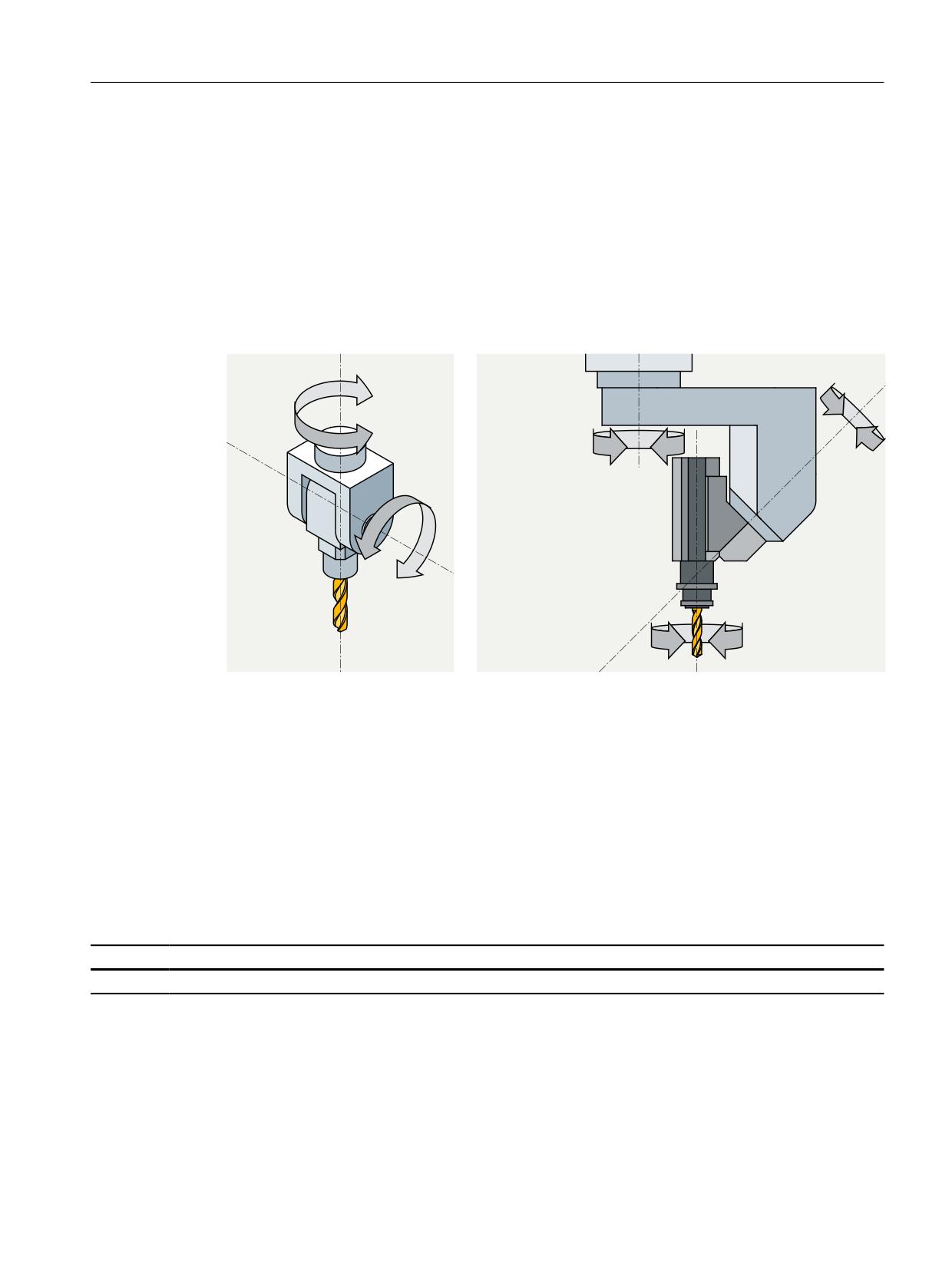
Rotary axes are frequently used on 5-axis milling machines to swivel the tool axis or rotate the
workpiece. These machines can position the tip of a tool on any point on the workpiece and take
up any position on the tool axis. Various milling heads are required, depending on the
application. The figure shows a fork head and an inclined-axis head as example rotary-axis
arrangements.
'PSL IFBE
*ODMJOFE BYJT IFBE
Figure 9-7
Fork head, inclined-axis head
9.7
Data lists
9.7.1
Machine data
9.7.1.1
General machine data
Number
Identifier: $MN_
Description
10210
INT_INCR_PER_DEG
Computational resolution for angular positions
Axes and spindles
Function Manual, 10/2020, 6FC5397-4GP40-0BA1
323

Rotary axes
9.7 Data lists
9.7.1.2
Axis/spindlespecific machine data
Number
Identifier: $MA_
Description
30300
IS_ROT_AX
Axis is rotary axis
30310
ROT_IS_MODULO
Modulo conversion for rotary axis
30320
DISPLAY_IS_MODULO
Actual value display modulo
30330
MODULO_RANGE
Modulo-range size
30340
MODULO_RANGE_START
Modulo-range starting position
30455
MISC_FUNCTION_MASK
Axis functions
36100
POS_LIMIT_MINUS
Minus software limit switch
36110
POS_LIMIT_PLUS
Plus software limit switch
9.7.2
Setting data
9.7.2.1
General setting data
Number
Identifier: $SN_
Description
41130
JOG_ROT_AX_SET_VELO
JOG velocity for rotary axes
9.7.2.2
Axis/spindle-specific setting data
Number
Identifier: $SA_
Description
43420
WORKAREA_LIMIT_PLUS
Plus working-area limitation
43430
WORKAREA_LIMIT_MINUS
Minus working-area limitation
Axes and spindles
324
Function Manual, 10/2020, 6FC5397-4GP40-0BA1
Indexing axes
10
10.1
Brief description
When machine axes only traverse between a certain number of fixed positions, these positions
can be parameterized as indexing positions. In NC programs, these machine axes, then known
as indexing axes, can be traversed with reference to indexing positions using special commands.
Typical applications for indexing axes include tool magazines, for example (tool revolver, tool
chain magazines or tool cartridge magazines). The magazine locations of the tools are
parameterized as indexing positions.
It is possible to traverse an indexing axis in the following operating modes:
• AUTOMATIC
• MDI
• JOG
• JOG / INC1, INC10, ... INCvar
10.2
Detailed description
10.2.1
Traversing of indexing axes in the AUTOMATIC mode
Traversal to selected positions
Using the general traversing commands ( G90, G91, AC, IC, ...) an indexing axis can be traversed
to any position within the traversing range of the machine axis.
Traversing to indexing positions
Using the specific traversing commands for indexing axes, it is ensured that only the
parameterized indexing positions are approached. See Chapter "Programming (Page 334)".
10.2.2
Traversing of indexing axes in the JOG mode
In the JOG mode, the indexing positions are only taken into account after referencing/
synchronizing the active measuring system of the indexing axis.
Further information
Homing (Page 31)
Axes and spindles
Function Manual, 10/2020, 6FC5397-4GP40-0BA1
325
Indexing axes
10.2 Detailed description
Continuous traversing (JOG CONT)
Jog mode
In the jog mode (SD41050 $SN_JOG_CONT_MODE_LEVELTRIGGRD = 1) the indexing axis
traverses in the selected direction after the traversing key has been actuated. The indexing axis
is stopped at the next possible indexing position after releasing the traversing key. The indexing
position where the axis stops is dependent on:
• Distance to the indexing position
• Traversing velocity
• Axis dynamic response
Continuous operation
In continuous operation (SD41050 $SN_JOG_CONT_MODE_LEVELTRIGGRD = 0), after actuating
the traversing key (first rising edge), the indexing axis is traversed as usual. The indexing axis is
stopped at the next possible indexing position when the traversing key is actuated again (second
rising edge). The indexing position where the axis stops is dependent on:
• Distance to the indexing position
• Traversing velocity
• Axis dynamic response
Generally, indexing axes are traversed in the jog mode.
Direction change
If, before reaching the indexing position, the operator changes the direction by actuating the
traversing key for the opposite direction, the indexing axis continues to traverse to the next
possible indexing position where it can then be stopped. The traversing motion must then be
started in the opposite direction by again actuating the traversing key.
Further information
You can find detailed information on the traversing axes in the JOG mode in:
Manual traversing (Page 695)
Incremental traversing (INC)
Independent of the active technology function (INC1, INC10, ... , INCvar), the indexing axis
always moves in the selected direction to the next indexing position after the traversing key has
been pressed.
Jog mode
In the jog mode (SD41050 $SN_JOG_CONT_MODE_LEVELTRIGGRD = 1), the indexing axis is
immediately stopped after releasing the traversing key. Under certain circumstances, the
indexing axis is then not located at an indexing position. Traversing motion is continued at the
indexing position by again actuating the traversing key.
Continuous operation
In continuous operation (SD41050 $SN_JOG_CONT_MODE_LEVELTRIGGRD = 0), after actuating
the traversing key (first rising edge), the indexing axis is traversed as usual. The indexing axis is
Axes and spindles
326
Function Manual, 10/2020, 6FC5397-4GP40-0BA1

Indexing axes
10.2 Detailed description
immediately stopped when the traversing key is actuated again (second rising edge). Under
certain circumstances, the indexing axis is then not located at an indexing position. Traversing
motion is continued at the indexing position by again actuating the traversing key.
Revolutional feedrate
The revolution feedrate with which the indexing axis is traversed in the JOG mode is dependent
on:
SD41100 $SN_JOG_REV_IS_ACTIVE, bit 0 = <value>
<value>
Meaning
0
Depending on the traversing mode, the revolutional feed rate is defined by the following
setting data:
• The indexing axis traverses as positioning axis:
SD43300 $SA_ASSIGN_FEED_PER_REV_SOURCE (revolutional feedrate for positioning ax-
es)
• The indexing axis traverses as geometry axis, on which a frame with rotation acts:
SD42600 $SC_JOG_FEED_PER_REV_SOURCE (revolutional feedrate in JOG)
1
The indexing axis is traversed with a rotational feedrate derived from the master spindle:
Corresponding machine data:
• MD32050 $MA_JOG_REV_VELO (revolutional feed rate for JOG mode)
• MD32040 $MA_JOG_REV_VELO_RAPID (revolutional feed rate for JOG with rapid traverse
override)
Further information
• Feedrates (Page 195)
• Manual traversing (Page 695)
• NC Programming Programming Manual
10.2.3
Traversing of indexing axes by PLC
Indexing axes can be traversed from the PLC user program.
• Competing positioning axes, see Section "Positioning axes (Page 271)"
• Asynchronous subprograms (ASUBs)
Further information:
Function Manual Basic Functions; Mode group, channel, program operation, reset response
See also
Homing (Page 31)
Axes and spindles
Function Manual, 10/2020, 6FC5397-4GP40-0BA1
327

Indexing axes
10.3 Commissioning
10.3
Commissioning
10.3.1
Machine data for indexing axes
Indexing axis
An axis is defined as indexing axis by assigning an indexing position table to this axis, using the
following axis-specific machine data:
MD30500 $MA_INDEX_AX_ASSIGN_POS_TAB = <value>
<Val-
Meaning
ue>
1
The axis is assigned indexing position table 1.
2
The axis is assigned indexing position table 2.
3
Equidistant indexing intervals (Page 331)
First indexing position for indexing axes with equidistant positions
For an indexing axis with equidistant positions, the absolute position of the first indexing
position is set using the following axes-specific machine data:
MD30503 $MA_INDEX_AX_OFFSET
Indexing position tables
In the indexing position tables, the indexing positions are saved in mm, inches or degrees.
Presently, two indexing position tables are available.
MD10910 $MN_INDEX_AX_POS_TAB_1 [ <n> ] (indexing position table 1)
MD10930 $MN_INDEX_AX_POS_TAB_2 [ <n> ] (indexing position table 2)
with <n> = 0 ... (maximum number - 1)
Multiple table assignment
Several axes can be assigned to an indexing position table.
Requirement: the axes are of the same type (linear axis, rotary axis, modulo 360° function)
General supplementary conditions
• The indexing positions must be listed in the indexing position table without gaps in an
ascending order.
• Indexing positions that follow one another must not be identical.
• The indexing positions must be specified in the basic coordinate system.
Axes and spindles
328
Function Manual, 10/2020, 6FC5397-4GP40-0BA1

Indexing axes
10.3 Commissioning
Additional secondary conditions for modulo rotary axes
• Permissible range: 0° ≤ indexing position < 360°
• If the indexing axis is at the last indexing position in the indexing position table, when
traversing to the next indexing position in the positive direction of rotation, the first indexing
position is approached.
• If the indexing axis is at the first indexing position in the indexing position table, when
traversing to the next indexing position in the negative direction of rotation, the last indexing
position is approached.
No. of indexing positions
A maximum of 60 indexing positions can be entered in an indexing position table. The actual
number of indexing positions that is used or the programmable number is defined using
machine data:
MD10900 $MN_INDEX_AX_LENGTH_POS_TAB_1 (number of indexing positions of indexing
position table 1)
MD10920 $MN_INDEX_AX_LENGTH_POS_TAB_2 (number of indexing positions of indexing
position table 2)
Note
Entries in the indexing positions table that exceed the parameterized number of indexing
positions are not considered.
System of units for indexing positions
The system of units of indexing positions is defined on an NC-specific basis:
MD10270 $MN_POS_TAB_SCALING_SYSTEM = <value>
<Val-
System of units
ue>
0
Metric
1
inch
Note
The machine data is only evaluated if the following applies: MD10260
$MN_CONVERT_SCALING_SYSTEM == 1
Displaying the actual indexing position
When traversing indexing axes, the machine data is used to define at which actual position the
display of the actual indexing position changes in the system variable
$AA_ACT_INDEX_AX_POS_NO:
Axes and spindles
Function Manual, 10/2020, 6FC5397-4GP40-0BA1
329
Indexing axes
10.3 Commissioning
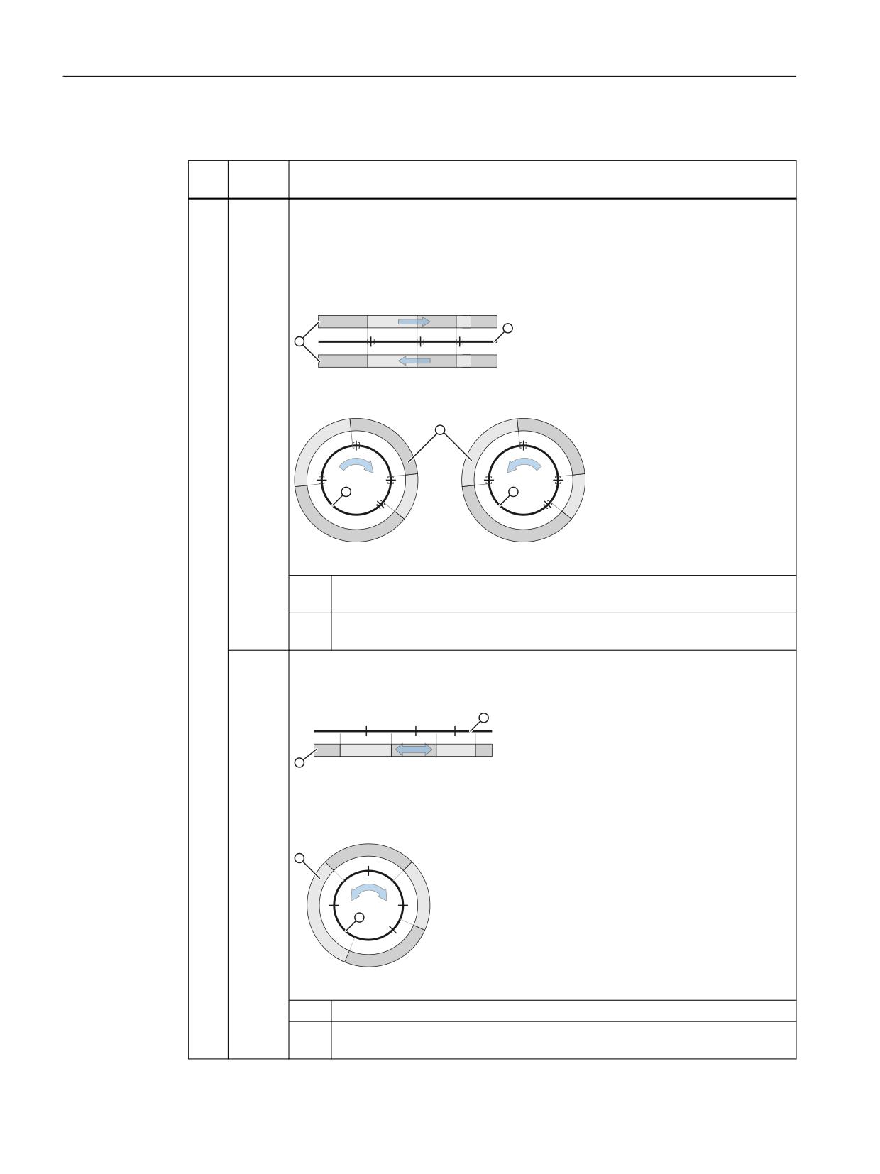
MD10940 $MN_INDEX_AX_MODE, bit 0 = <value>
Bit
<Val-
Meaning
ue>
0
0
When traversing in the direction of ascending indexing positions, the displayed current
indexing position changes in the system variable $AA_ACT_INDEX_AX_POS_NO upon
reaching/overtraveling the "Exact stop fine" window (MD36010 $MA_STOP_LIM-
IT_FINE) of the next indexing position.
When traversing in the direction of descending indexing positions, the indexing posi-
tion display changes as soon as you exit the "Exact stop fine" window.
Linear axis
Modulo rotary axis
①
The traversing range of the indexing axis with indexing positions and "Exact
stop fine" window
②
Indexing position indicated in the system variable $AA_ACT_IN-
DEX_AX_POS_NO
1
The actual indexing position indicated in system variable $AA_ACT_IN-
DEX_AX_POS_NO changes when reaching/passing half the traversing distance to the
next indexing position in the traversing direction.
Linear axis
Modulo rotary axis
①
Traversing range of the indexing axis with indexing positions
②
Indexing position indicated in the system variable $AA_ACT_IN-
DEX_AX_POS_NO
Axes and spindles
330
Function Manual, 10/2020, 6FC5397-4GP40-0BA1

Indexing axes
10.3 Commissioning
Note
With the system variables $AA_ACT_INDEX_AX_POS_NO it is not possible to determine whether
an indexing position has been reached. To this end, one of the two following NC/PLC interface
signals must also be evaluated:
DB31, ... DBX76.6 (indexing position reached)
DB31, ... DBX60.7 (exact stop fine reached)
Example
Assumptions:
• MD10940 $MN_INDEX_AX_MODE, bit 0 == 1
• The axis is located in front of an indexing position outside the tolerance window "exact stop
fine" (DB31,
DBX60.7 == 0)
Although system variable $AA_ACT_INDEX_AX_POS_NO indicates indexing position 2, with the
"Traverse to next position" command, indexing position 3 is not approached, but first precisely
to indexing position 2. Only when the axis is precisely at (DB31,
DBX60.7 == 1) - or is located
after the displayed indexing position, using the "Traverse to next position" command, the next
indexing position is approached, in the example, indexing position 3. This means that the
indexing position is approached that is the closest in the traversing direction ! Under certain
circumstances, it is therefore necessary to issue the "traverse to next position" command twice
to move from the currently displayed indexing position to the next indexing position.
10.3.2
Machine data for equidistant indexing intervals
10.3.2.1
Features
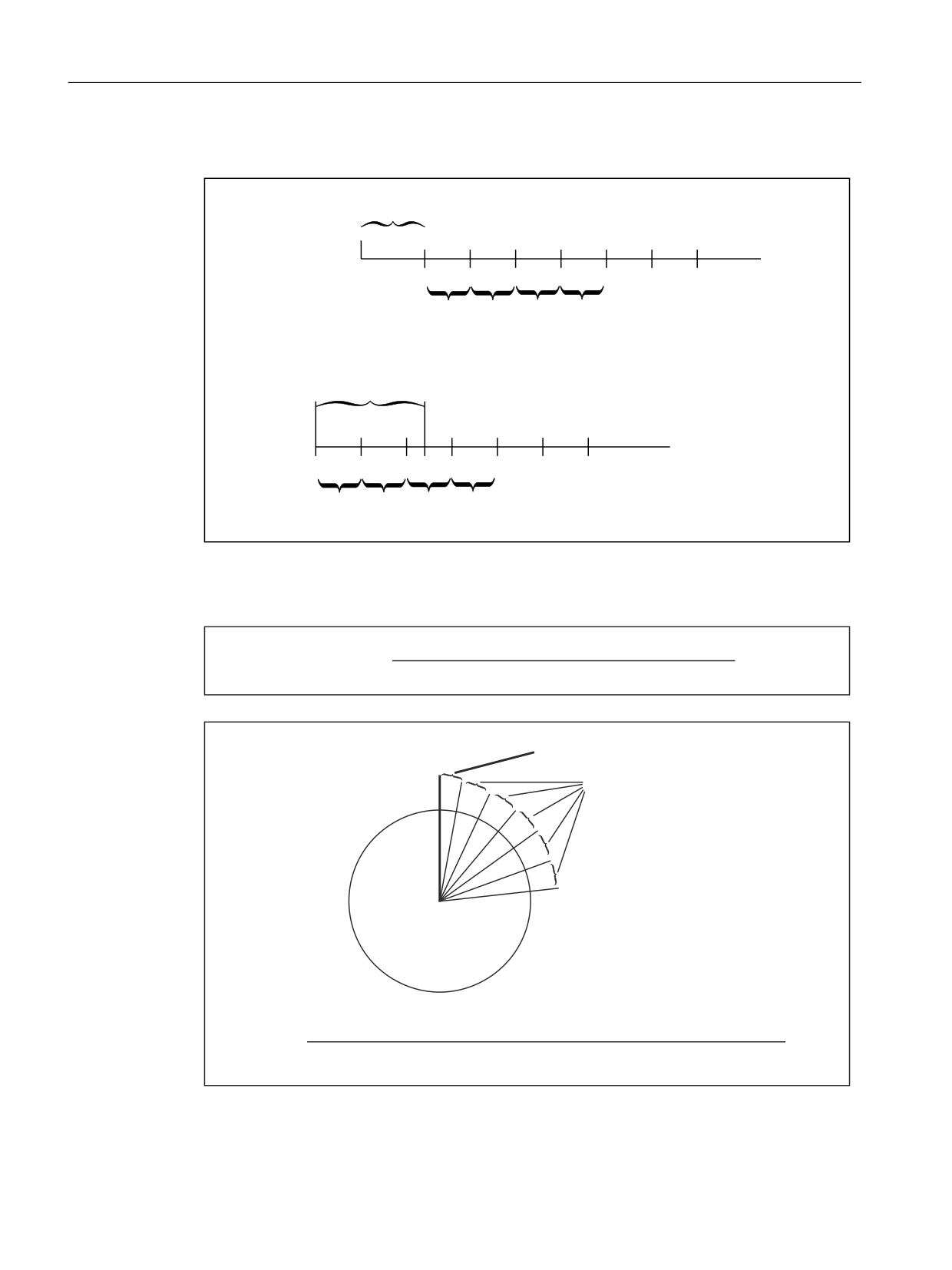
Distance between indexes
The index distance is determined for equidistant index intervals according to the following
formula:
Numerator (MD30501 $MA_INDEX_AX_NUMERATOR)
Distance =
Denominator (MD30502 $MA_INDEX_AX_DENOMINATOR)
Axes and spindles
Function Manual, 10/2020, 6FC5397-4GP40-0BA1
331
Indexing axes
10.3 Commissioning
Linear axes
0'
0$B,1'(;B$;B2))6(7 VW GLVWDQFH IURP ]HUR SRLQW SRVLWLYH
'LVWDQFH VWDQGDUG IRU DOO LQGH[LQJ SRVLWLRQV VHH DERYH
0'
0$B,1'(;B$;B2))6(7 VW GLVWDQFH IURP ]HUR SRLQW QHJDWLYH
'LVWDQFH VWDQGDUG IRU DOO LQGH[LQJ SRVLWLRQV VHH DERYH
Modulo rotary axes
Numerator (MD30330 $MA_MODULO_RANGE)
Index =
Denominator (MD30502 $MA_INDEX_AX_DENOMINATOR)
MD30503 $MA_INDEX_AX_OFFSET
0¡˘
Spacing
Size of modulo range (MD30330 $MA_MODULO_RANGE)
Index =
Number of indexes in modulo range (MD30502 $MA_INDEX_AX_DENOMINATOR)
Axes and spindles
332
Function Manual, 10/2020, 6FC5397-4GP40-0BA1

Indexing axes
10.3 Commissioning
10.3.2.2
Hirth axis
Function
For a "Hirth axis", using a special gearing (Hirth gearing) the rotary axis is interlocked when
reaching an indexing position. In this case, a locking bolt or a gearwheel is engaged using a
linear axis. In order that the mechanical system of the machine is not damaged, the interlock can
only be engaged at an indexing position. For a Hirth axis, all of the indexing positions must have
the same the distance between one another (equidistant indexing positions).
Requirements
• The "Hirth axis" must be a rotary axis.
• The "Hirth axis" must be an indexing axis. See Section "Commissioning (Page 328)"
• The active measuring system of the indexing axis must be synchronized or referenced:
DB31, ... DBX60.4/.5 == 1 (referenced/synchronized, encoder 1/2)
Further information
Homing (Page 31)
Commissioning
Machine data
• MD30300 $MA_IS_ROT_AX = 1 (rotary axis)
• MD30505 $MA_HIRTH_IS_ACTIVE[ <axis> ] = 1 (indexing axis with Hirth gearing)
• MD30500 $MA_INDEX_AX_ASSIGN_POS_TAB[ <axis> ] = 3 (indexing axis with equidistant
indexing positions)
10.3.3
Axis-specific system variables
$AA_PROG_INDEX_AX_POS_NO
Function
The system variable includes the number of the indexing position programmed for the indexing
axis.
Syntax
$AA_PROG_INDEX_AX_POS_NO[<axis>]
Meaning
$AA_PROG_INDEX_AX_POS_NO
0
The axis is not an indexing axis, or presently the indexing axis is not traversing to an indexing
position
> 0
Number of programmed indexing position
Axes and spindles
Function Manual, 10/2020, 6FC5397-4GP40-0BA1
333

Indexing axes
10.4 Programming
$AA_ACT_INDEX_AX_POS_NO
Function
The system variable includes the number of the indexing position last reached by the indexing
axis, or indexing position that was passed by the indexing axis.
Syntax
$AA_ACT_INDEX_AX_POS_NO[<axis>]
Meaning
$AA_ACT_INDEX_AX_POS_NO
0
The axis is not an indexing axis.
> 0
Number of the last indexing position reached or passed
10.3.4
NC/PLC interface signals
Axis-specific interface signals
When stopping the indexing axis at an indexing position ± exact stop window fine (MD36010
$MA_STOP_LIMIT_FINE), then the axis-specific interface signal is set:
DB31, ... DBX76.6 = 1 (indexing axis in position)
10.4
Programming
Coded position
To allow indexing axes to be positioned from the NC part program, special instructions are
provided with which the indexing numbers (e.g. location numbers) are programmed instead of
axis positions in mm or degrees. The availability of a special instruction depends on the axis type
(linear or rotary axis):
Statement
Effect
Availability
CAC(i)
Traverse coded position in absolute terms
Linear axis, rotary axis
CACP(i)
Traverse coded position ain absolute terms in
Rotary axis
the positive direction
CACN(i)
Traverse coded position ain absolute terms in
Rotary axis
the negative direction
CDC(i)
Traverse coded position along the direct (short-
Rotary axis
est) path
CIC(i)
Traverse coded position incrementally
Linear axis, rotary axis
i:
Coded position (indexing position)
Value range of i:
0 ... 59; whole number (positive and negative values are possible
in CIC)
Axes and spindles
334
Function Manual, 10/2020, 6FC5397-4GP40-0BA1
Indexing axes
10.4 Programming
Examples
Program code
Comment
POS[B]=CAC(20)
Indexing axis B approaches the coded position (indexing) 20
in absolute mode. The direction of traversing depends on
the current actual position.
POS[B]=CACP(10)
Indexing axis B approaches the coded position (index posi-
tion ) 10 in absolute mode with positive direction of rota-
tion (possible only for rotary axes).
POS[B]=CACN(10)
Indexing axis B approaches the coded position (index posi-
tion ) 10 in absolute mode with negative direction of rota-
tion (possible only for rotary axes).
POS[B]=CDC(50)
Indexing axis B approaches indexing position 50 directly
along the shortest path (possible only for rotary axes).
POS[B]=CIC(-4)
Indexing axis B traverses four indexing positions incremen-
tally from its current position. in a negative direction.
POS[B]=CIC(35)
Indexing axis B traverses 35 indexing positions incremen-
tally from its present position in a positive direction.
Special features
• Modulo rotary axis as indexing axis
On modulo rotary axes, the indexing positions are divided in factors of 360° and approached
directly.
• Indexing axis is between two indexing positions
The specified position instructions have the following effect in the AUTOMATIC mode.
POS[B]=CIC(1)
The next higher indexing position is approached.
POS[B]=CIC(-1)
The next lower indexing position is approached.
POS[B]=CIC(0)
The indexing axis is not traversed.
Axes and spindles
Function Manual, 10/2020, 6FC5397-4GP40-0BA1
335
Indexing axes
10.5 Supplementary conditions
System variables
Information on the indexing positions can be read via the following system variables:
• $AA_PROG_INDEX_AX_POS_NO
Number of the last programmed indexing position
• $AA_ACT_INDEX_AX_POS_NO
Number of the last overtraveled indexing position
The display depends on the setting in machine data MD10940 $MN_INDEX_AX_MODE.
• $AA_ACT_INDEX_AX_POS_NO
Number of the last indexing position reached or passed
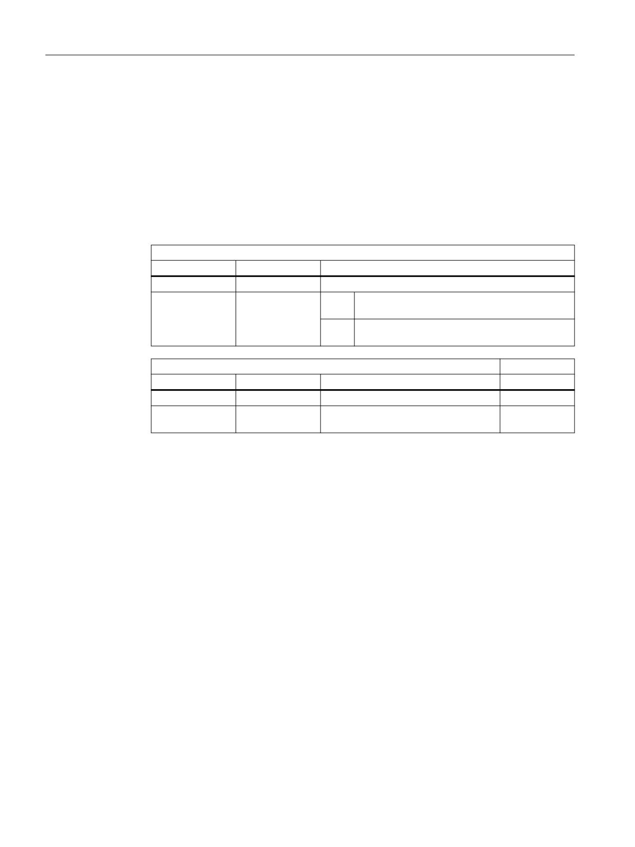
Indexing positions
For axis type
Values
Description
Modulo rotary axis
1, ... n
n = number of indexing positions (Page 328)
Linear axis
0, 1, 2, 3, ... 59,
0
The actual position lies below the lowest indexing
60, 61
position
61
The actual position lies above the highest indexing
position
Equidistant indexing positions
For axis type
Values
Description
Modulo rotary axis
1 ... m
m = denominator (counter)
Linear axis
... -3, -2, -1, 0, 1,
2, 3, ...
10.5
Supplementary conditions
Indexing axes
Various channel and axis-specific NC/PLC interface signals
If, while an indexing axis is traversed, at least one of the following signals occurs, then the axis
stops immediately. The indexing positions are not taken into account.
• Channel-specific signals
- DB21, ... DBB4 == 0 (feedrate override)
- DB21, ... DBX6.2 == 1 (delete distance-to-go)
- DB21, ... DBX7.3 == 1 (NC Stop)
- DB21, ... DBX7.4 == 1 (NC Stop axes plus spindles)
- DB21, ... DBX7.7 == 1 (reset)
• Axis-specific signals
- DB31, ... DBX4.3 == 1 (feedrate stop)
Axes and spindles
336
Function Manual, 10/2020, 6FC5397-4GP40-0BA1
Indexing axes
10.5 Supplementary conditions
Synchronized actions
• Stop (MOV=0)
If an indexing axis is stopped with a synchronized action using MOV=0, then the axis stops in
the traversing direction at the next possible indexing position
• Delete distance to go (DELDTG)
If, for an indexing axis, the distance to go is deleted with a synchronized action
using DELDTG, then the axis is immediately stopped without stopping at an indexing position
Further information: Function Manual Synchronized Actions
Frames and work offsets
In conjunction with indexing axes, generally frames are not necessary. As a consequence, we
recommend that frames and work offsets for indexing axes are suppressed in NC programs.
Software limit switch
When manually traversing an indexing axis in the JOG or JOG/INC operating mode, the indexing
axis traverses - as a maximum up - to the last indexing position before the software limit switch.
Manual traversing using a handwheel (DRF)
When traversing an indexing axis using the handwheel, the indexing positions are not taken into
account. This means that the indexing axis stops immediately, also between two indexing
positions, with the end of the handwheel pulse.
"Hirth axes"
In addition to the secondary conditions mentioned above, for "Hirth axes" the following
additional secondary conditions must be observed.
Various channel and axis-specific NC/PLC interface signals
If, while a "Hirth axis" is being traversed, at least one of the following signals occurs, then the axis
stops immediately at the next possible indexing position in the traversing direction.
• Channel-specific signals
- DB21, ... DBB4 == 0 (feedrate override)
- DB21, ... DBX6.2 == 1 (delete distance-to-go)
- DB21, ... DBX7.3 == 1 (NC Stop)
- DB21, ... DBX7.4 == 1 (NC Stop axes plus spindles)
- DB21, ... DBX7.7 == 1 (reset)
• Axis-specific signals
- DB31, ... DBX4.3 == 1 (feedrate stop)
Emergency Stop
If, while a "Hirth axis" is being traversed, an Emergency Stop is initiated then the axis is
immediately stopped:
DB10 DBX56.1 == 1 (Emergency Stop)
Axes and spindles
Function Manual, 10/2020, 6FC5397-4GP40-0BA1
337
Indexing axes
10.5 Supplementary conditions
Further information: Function Manual Basic Functions, emergency stop
NOTICE
Approaching the indexing position
After an Emergency Stop, before the interlocking of the Hirth gearing at the machine is
reactivated, either the PLC user program or the operator (manually) must first move the "Hirth
axis" to an indexing position in the JOG mode.
Synchronized actions
• Delete distance to go (DELDTG)
If, for a "Hirth axis", the distance to go is deleted with a synchronized action using DELDTG,
then the axis is stopped at the next possible indexing position in the traversing direction
Further information: Function Manual Synchronized Actions, "Detailed description" >
"Actions in synchronized actions" > "Delete distance to go (DELDTG)"
Various axis-specific functions
"Hirth axes" may not be used in conjunction with the following functions:
• Kinematic transformation
Further information: Function Manual Transformations, kinematic transformation
• Work offset by setting the actual value: PRESETON
Further information: "NC Programming" Programming Manual, Chapter "Coordinate
transformations (frames)"
• Revolutional feedrate (G95, FPRAON)
• Manual traversing using a handwheel as well as distance or velocity overlay using the
handwheel (DFR)
Further information: Manual traversing (Page 695)
• Frames
Further information: Function Manual Basic Functions; Axes, coordinate systems, frames >
Frames
• Interpolatory corrections, for example external work offset, DRF offset
• Couplings
It is not permissible that a "Hirth axis" is a following axis of one of the following couplings:
- following axis with master value coupling
Further information: Master value coupling (Page 570)
- Coupled motion axis
Further information: Coupled motion (Page 537)
- gantry following axis
Further information: Gantry axes (Page 345)
Axes and spindles
338
Function Manual, 10/2020, 6FC5397-4GP40-0BA1
Indexing axes
10.6 Examples
10.6
Examples
10.6.1
Example 1: Rotary axis as indexing axis
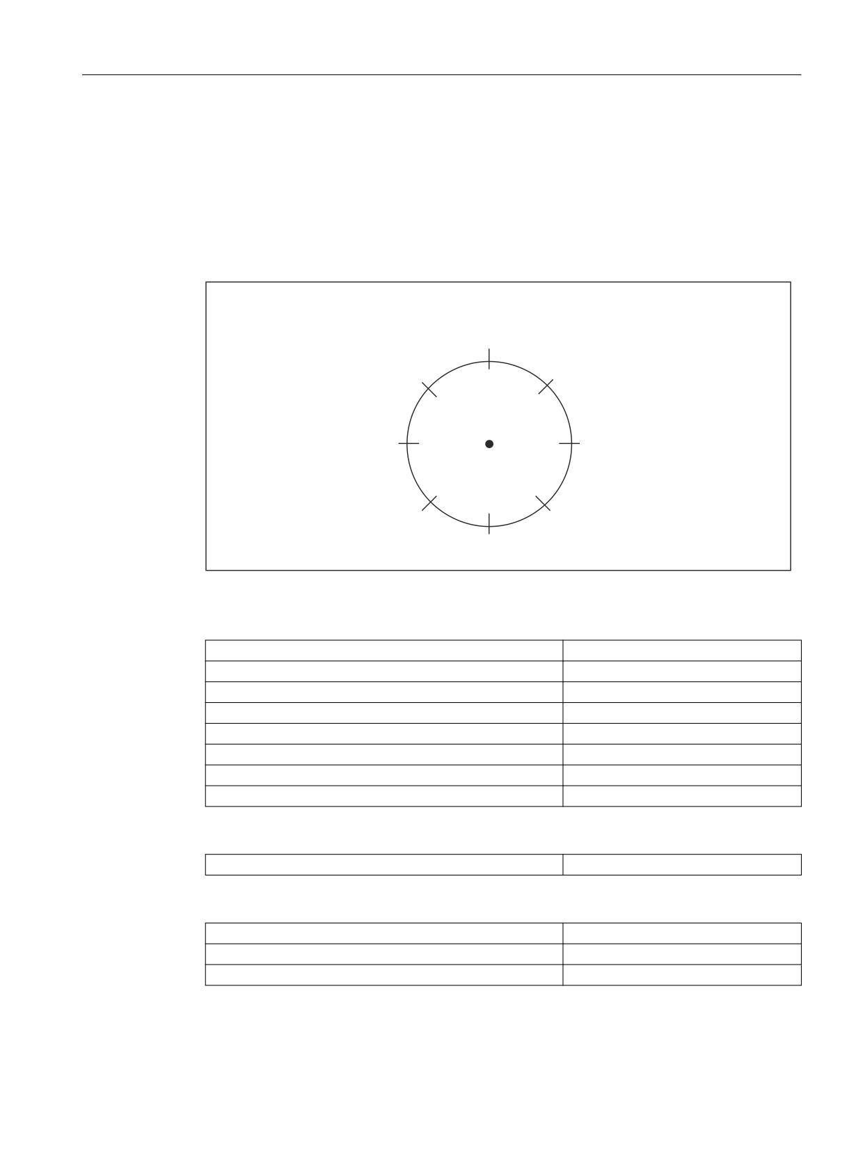
Machine axes AX5 is a tool revolver, with 8 revolver locations (endlessly rotating rotary axis). The
distances between the revolver locations are constant (equidistant indexing positions).
Indexing
position
1
8
0¡˘
2
315¡˘
45¡˘
Axis position
7
270¡˘
90¡˘
3
225¡˘
135¡˘
180¡˘
6
4
5
Figure 10-1
Tool turret with 8 locations
Indexing position table 1
MD10910 $MN_INDEX_AX_POS_TAB_1[ 0 ] = 0
1st indexing position = 0°
MD10910 $MN_INDEX_AX_POS_TAB_1[ 1 ] = 45
2nd indexing position = 45°
MD10910 $MN_INDEX_AX_POS_TAB_1[ 2 ] = 90
3rd indexing position = 90°
MD10910 $MN_INDEX_AX_POS_TAB_1[ 3 ] = 135
4th indexing position = 135°
MD10910 $MN_INDEX_AX_POS_TAB_1[ 4 ] = 180
5th indexing position = 180°
MD10910 $MN_INDEX_AX_POS_TAB_1[ 5 ] = 225
6th indexing position = 225°
MD10910 $MN_INDEX_AX_POS_TAB_1[ 6 ] = 270
7th indexing position = 270°
MD10910 $MN_INDEX_AX_POS_TAB_1[ 7 ] = 315
8th indexing position = 315°
Length of the indexing position table (1)
MD10900 $MN_INDEX_AX_LENGTH_POS_TAB_1= 8
8 indexing positions in table 1
Defining machine axis AX5 as rotary modulo axis and indexing axis
MD30300 $MA_IS_ROT_AX[ AX5 ] = 1
Rotary axis
MD30310 $MA_ ROT_IS_MODULO [AX5] = 1
Modulo rotary axis
MD30500 $MA_INDEX_AX_ASSIGN_POS_TAB [AX5] = 1
Indexing axis, indexing position table 1
Axes and spindles
Function Manual, 10/2020, 6FC5397-4GP40-0BA1
339
Indexing axes
10.6 Examples
10.6.2
Example 2: Indexing axis as linear axis
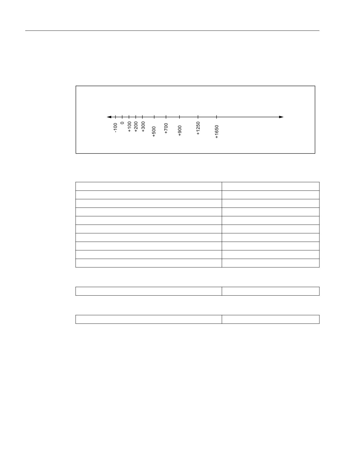
Machine axis AX6 is a workholder with 10 locations. The distances between the 10 locations are
different. The first location is at position -100 mm. Machine axis is AX6.
,QGH[LQJ SRVLWLRQ
$[LV SRVLWLRQ >PP@
Figure 10-2
Indexing positions for a workholder
Indexing position table 2
MD10930 $MN_INDEX_AX_POS_TAB_2[ 0 ] = -100
1st indexing position = -100 mm
MD10930 $MN_INDEX_AX_POS_TAB_2[ 1 ] = 0
2nd indexing position = 0 mm
MD10930 $MN_INDEX_AX_POS_TAB_2[ 2 ] = 100
3rd indexing position = 100 mm
MD10930 $MN_INDEX_AX_POS_TAB_2[ 3 ] = 200
4th indexing position = 200 mm
MD10930 $MN_INDEX_AX_POS_TAB_2[ 4 ] = 300
5th indexing position = 300 mm
MD10930 $MN_INDEX_AX_POS_TAB_2[ 5 ] = 500
6th indexing position = 500 mm
MD10930 $MN_INDEX_AX_POS_TAB_2[ 6 ] = 700
7th indexing position = 700 mm
MD10930 $MN_INDEX_AX_POS_TAB_2[ 7 ] = 900
8th indexing position = 900 mm
MD10930 $MN_INDEX_AX_POS_TAB_2[ 8 ] = 1250
9th indexing position = 1250 mm
MD10930 $MN_INDEX_AX_POS_TAB_2[ 9 ] = 1650
10. Indexing position = 1650 mm
Length of the indexing position table (1)
MD10920 $MN_INDEX_AX_LENGTH_POS_TAB_2 = 10
10 indexing positions in table 2
Defining machine axis AX5 as indexing axis
MD30500 $MA_INDEX_AX_ASSIGN_POS_TAB [AX6] = 2
Indexing axis, indexing position table 2
10.6.3
Example 3: Rotary modulo axis as equidistant indexing axis
Machine axis AX4 is rotary modulo axis with equidistant indexing. Indexing starts at 5°. The
difference between the indexing positions is 20°.
The following indexing positions are obtained:
5, 25, 45, 65, 85, 105, 125, 145, 165, 185, 205, 225, 245, 265, 285, 305, 325, 245 [Degrees]
Axes and spindles
340
Function Manual, 10/2020, 6FC5397-4GP40-0BA1

Indexing axes
10.6 Examples
Indexing data
MD30501 $MA_INDEX_AX_NUMERATOR[ AX4 ] ⇒
This value is ignored for rotary modulo
axes, and MD30330 $MA_MODU-
MD30330 $MA_MODULO_RANGE[ AX4 ] = 360.0
LO_RANGE (default value: 360°) is used
instead.
MD30502 $MA_INDEX_AX_DENOMINATOR[ AX4 ] = 18
Number of indexing positions = 360° /
20° = 18
MD30503 $MA_INDEX_AX_OFFSET[ AX4 ] = 5.0
First indexing position = 5.0°
MD30505 $MA_HIRTH_IS_ACTIVE[ AX4 ] = 0
No Hirth gearing
Defining machine axis AX4 as rotary modulo axis and equidistant indexing axis
MD30300 $MA_IS_ROT_AX[ AX4 ] = 1
Rotary axis
MD30310 $MA_ ROT_IS_MODULO[ AX4 ] = 1
Modulo function active
MD30500 $MA_INDEX_AX_ASSIGN_POS_TAB[ AX4 ] = 3
Equidistant indexing axis
10.6.4
Example 4: Rotary axes as equidistant indexing axis with restricted traversing
range
Machine axis AX4 is a rotary axis with equidistant indexing. The equidistant indexing positions
are every 20°, starting at 100°. Positions less than 100° and greater than 260° should not be
approached.
The following indexing positions are obtained:
100, 120, 140, 160, 180, 200, 220, 240, 260 [degrees]
Indexing data
MD30501 $MA_INDEX_AX_NUMERATOR[ AX4 ] = 360.0
Numerator = 360°
MD30502 $MA_INDEX_AX_DENOMINATOR[ AX4 ] = 18
Number of indexing positions = 360° /
20° = 18
MD30503 $MA_INDEX_AX_OFFSET[ AX4 ] = 100.0
First indexing position = 100.0°
MD30505 $MA_HIRTH_IS_ACTIVE[ AX4 ] = 0
No Hirth gearing
Defining machine axis AX4 as rotary modulo axis and equidistant indexing axis
MD30300 $MA_IS_ROT_AX[ AX4 ] = 1
Rotary axis
MD30310 $MA_ ROT_IS_MODULO[ AX4 ] = 1
Modulo function active
MD30500 $MA_INDEX_AX_ASSIGN_POS_TAB[ AX4 ] = 3
Equidistant indexing axis
MD36100 $MA_POS_LIMIT_MINUS[ AX4 ] = 100.0
1st software limit switch minus = 100.0°
MD36110 $MA_POS_LIMIT_PLUS[ AX4 ] = 260.0
1st software limit switch plus = 260.0°
10.6.5
Example 5: Linear axis as equidistant indexing axis
Machine axis AX4 is a linear axis with equidistant indexing. The equidistant indexing positions
are every 10 mm, starting at -200 mm.
Axes and spindles
Function Manual, 10/2020, 6FC5397-4GP40-0BA1
341
Indexing axes
10.6 Examples
The following indexing positions are obtained:
-200, -190, -180, ... 180, 190, 200 [mm]
Indexing data
MD30501 $MA_INDEX_AX_NUMERATOR[ AX4 ] = 10.0
Numerator = 10
MD30502 $MA_INDEX_AX_DENOMINATOR[ AX4 ] = 1
Denominator = 1
MD30503 $MA_INDEX_AX_OFFSET[ AX4 ] = -200.0
First indexing position = -200.0°
MD30505 $MA_HIRTH_IS_ACTIVE[ AX4 ] = 0
No Hirth gearing
Defining machine axis AX4 as linear axis and equidistant indexing axis
MD30300 $MA_IS_ROT_AX[ AX4 ] = 0
Linear axis
MD30310 $MA_ ROT_IS_MODULO[ AX4 ] = 0
Modulo function is not active
MD30500 $MA_INDEX_AX_ASSIGN_POS_TAB[ AX4 ] = 3
Equidistant indexing axis
MD36100 $MA_POS_LIMIT_MINUS[ AX4 ] = -200.0
1st software limit switch minus = -200.0
mm
MD36110 $MA_POS_LIMIT_PLUS[ AX4 ] = 200.0
1st software limit switch plus = 200.0
mm
10.6.6
Example 6: "Hirth axis"
Machine axis AX4 is a "Hirth axis" (rotary modulo axis with equidistant indexing and Hirth
gearing). The equidistant indexing positions are every 1°, starting at 0°.
Indexing data
MD30501 $MA_INDEX_AX_NUMERATOR[ AX4 ] ⇒
This value is ignored for rotary modulo
axes, and MD30330 $MA_MODU-
MD30330 $MA_MODULO_RANGE[ AX4 ] = 360.0
LO_RANGE (default value: 360°) is used
instead.
MD30502 $MA_INDEX_AX_DENOMINATOR[ AX4 ] = 360
Number of indexing positions = 360° / 1°
= 360
MD30503 $MA_INDEX_AX_OFFSET[ AX4 ] = 0.0
First indexing position = 0.0°
MD30505 $MA_HIRTH_IS_ACTIVE[ AX4 ] = 1
Hirth gearing
Defining machine axis AX4 as linear axis and equidistant indexing axis
MD30300 $MA_IS_ROT_AX[ AX4 ] = 1
Rotary axis
MD30310 $MA_ ROT_IS_MODULO[ AX4 ] = 1
Modulo function active
MD30500 $MA_INDEX_AX_ASSIGN_POS_TAB[ AX4 ] = 3
Equidistant indexing axis
MD36100 $MA_POS_LIMIT_MINUS[ AX4 ] = -200.0
1st software limit switch minus = -200.0
mm
MD36110 $MA_POS_LIMIT_PLUS[ AX4 ] = 200.0
1st software limit switch plus = 200.0
mm
Axes and spindles
342
Function Manual, 10/2020, 6FC5397-4GP40-0BA1

Indexing axes
10.7 Data lists
10.7
Data lists
10.7.1
Machine data
10.7.1.1
General machine data
Number
Identifier: $MN_
Description
10260
CONVERT_SCALING_SYSTEM
Basic system switchover active
10270
POS_TAB_SCALING_SYSTEM
System of measurement of position tables
10900
INDEX_AX_LENGTH_POS_TAB_1
Number of positions for indexing axis table 1
10910
INDEX_AX_POS_TAB_1[n]
Indexing position table 1
10920
INDEX_AX_LENGTH_POS_TAB_2
Number of positions for indexing axis table 2
10930
INDEX_AX_POS_TAB_2[n]
Indexing position table 2
10940
INDEX_AX_MODE
Options for indexing positions
10.7.1.2
Axis/spindlespecific machine data
Number
Identifier: $MA_
Description
30300
IS_ROT_AX
Rotary axis
30310
ROT_IS_MODULO
Modulo conversion for rotary axis
30320
DISPLAY_IS_MODULO
Position display is modulo 360°
30500
INDEX_AX_ASSIGN_POS_TAB
Axis is indexing axis
30501
INDEX_AX_NUMERATOR
Numerator for indexing axes with equidistant positions
30502
INDEX_AX_DENOMINATOR
Denominator for indexing axes with equidistant posi-
tions
30503
INDEX_AX_OFFSET
Indexing position for indexing axes with equidistant po-
sitions
30505
HIRTH_IS_ACTIVE
Hirth tooth system is active
10.7.2
Setting data
10.7.2.1
General setting data
Number
Identifier: $SN_
Description
41050
JOG_CONT_MODE_LEVELTRIGGRD
JOG continuous in inching mode
Axes and spindles
Function Manual, 10/2020, 6FC5397-4GP40-0BA1
343

Indexing axes
10.7 Data lists
10.7.3
System variables
Identifier
Description
$AA_ACT_INDEX_AX_POS_NO[axis]
Number of last indexing position reached or overtraveled
$AA_PROG_INDEX_AX_POS_NO[axis]
Number of programmed indexing position
Axes and spindles
344
Function Manual, 10/2020, 6FC5397-4GP40-0BA1
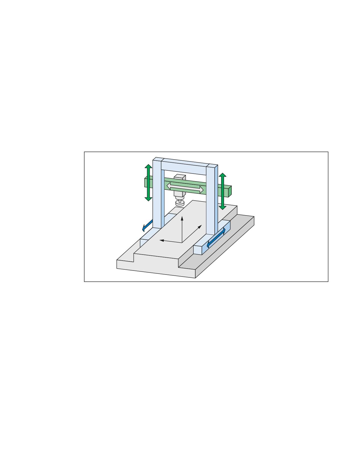
Gantry axes
11
11.1
Brief description
For gantry machines, each of various machine elements, such as the gantry and the transverse
beams, are moved by several axes that operate in parallel. The axes that together move a
machine part, are designated as gantry axes or gantry grouping. Because of the mechanical
structure, the gantry axes are rigidly connected with each other and so must always be traversed
synchronously by the control.
=
=
=
<
=
JDQWU\ JURXSLQJ &URVVEHDPV
=
;
;
<
;
;
JDQWU\ JURXSLQJ *DQWU\
;
Figure 11-1
Example: Gantry-type milling machine with gantry and transverse beams
Guide axis
The guide axis of the gantry grouping is the axis that represents the gantry grouping. Only this
axis is programmed to perform the traversing movements of the gantry grouping.
Synchronous axes
The synchronous axes of the gantry grouping are the axes that because of their coupling with
the guide axis are also automatically traversed by the control. A guide axis can be assigned any
number of synchronous axes.
Synchronization difference
The synchronous operation difference is the deviation of the axial actual value of a synchronous
axis from its ideal position referred to the actual value of the guide axis. The control continually
monitors the synchronous operation difference. A message is displayed if the alarm limit is
exceeded. The complete gantry grouping is stopped when the alarm limit is exceeded. The limit
values can be parameterized as machine data.
Axes and spindles
Function Manual, 10/2020, 6FC5397-4GP40-0BA1
345

Gantry axes
11.2 "Gantry axes" function
11.2
"Gantry axes" function
11.2.1
Definition of a gantry grouping
Definition
The axes of a gantry grouping are specified via the following axial machine data:
MD37100 $MA_GANTRY_AXIS_TYPE[AX1] = xy
x
Tens decimal place: Type of gantry axis (guide or synchronous axis)
y
Ones decimal place: ID of the gantry grouping
A maximum of eight gantry groupings (gantry grouping ID: 1 - 8) can be defined. The gantry
grouping ID must be unique in all channels or in all NCUs in accordance with the assigned axis.
In principle, a gantry grouping can be assigned any number of synchronous axes.
Example
Definition of a gantry grouping with ID=1, guide axis AX1 and synchronous axis AX2
• MD37100 $MA_GANTRY_AXIS_TYPE[AX1] = 01 (guide axis)
• MD37100 $MA_GANTRY_AXIS_TYPE[AX2] = 11 (synchronous axis)
Supplementary conditions
The following supplementary conditions apply to a gantry grouping:
• A gantry grouping must not contain a spindle.
• A synchronous axis must not be a concurrent POS axis.
• A synchronous axis must not belong to a transformation.
• A synchronous axis must not be a following axis of another axis coupling.
• A synchronous axis must not be a guide axis of another axis coupling.
• All axes of a gantry grouping must be of the same axis type, linear or rotary: MD30300
$MA_IS_ROT_AX (rotary axis/spindle)
Note
Drive optimization
At a SINAMICS S120 drive unit, a maximum of three drives can be optimized or measured at
the same time (speed controller optimization / function generator). Therefore, for a coupling
with more than three coupled drives at the same time, we recommend that these are
distributed over several drive units.
Axes and spindles
346
Function Manual, 10/2020, 6FC5397-4GP40-0BA1
Gantry axes
11.2 "Gantry axes" function
11.2.2
Monitoring the synchronism difference
Limit values for monitoring
2 limit values can be specified for the synchronism difference.
Gantry warning limit
The gantry warning limit is set using the following machine data:
MD37110 $MA_GANTRY_POS_TOL_WARNING (gantry warning limit)
The "Alarm limit exceeded" message is displayed if the synchronism difference exceeds the
gantry warning limit. In addition, the NC/PLC-interface signal is set:
DB31, ... DBX101.3 = 1 (gantry warning limit exceeded)
After the alarm limit has been fallen below, the message and interface signal are automatically
reset.
Note
Gantry warning limit
If the "Alarm limit exceeded" message is not to be displayed, then a value of 0 should be entered
into MD37110.
Gantry trip limit
The gantry trip limit is set using the following machine data:
• for the synchronized gantry grouping:
MD37120 $MA_GANTRY_POS_TOL_ERROR
• for the non-synchronized gantry grouping:
MD37130 $MA_GANTRY_POS_TOL_REF
Alarm 10653 "Error limit exceeded" is displayed if the synchronism difference exceeds the gantry
trip limit. In addition, the NC/PLC-interface signal is set:
DB31, ... DBX101.2 = 1 (gantry trip limit exceeded)
Gantry trip limit:
Synchronous grouping: MD37120 $MA_GANTRY_POS_TOL_ERROR
Non-synchronous grouping: MD37130 $MA_GANTRY_POS_TOL_REF
Gantry warning limit:
MD37110 $MA_GANTRY_POS_TOL_WARNING
The alarm is also displayed if the gantry grouping is jammed (no controller enable, gantry
grouping in the "Hold" state).
Axes and spindles
Function Manual, 10/2020, 6FC5397-4GP40-0BA1
347
Gantry axes
11.2 "Gantry axes" function
11.2.3
Extended monitoring of the synchronism difference
Activation of the extended monitoring
An extended monitoring of the synchronism difference can be activated using the following
machine data:
MD37150 $MA_GANTRY_FUNCTION_MASK, Bit 0 = 1
For the extended monitoring, a synchronism difference between the leading and synchronous
axis, obtained when tracking or when the gantry grouping is opened, is taken into account.
The extended monitoring becomes active after the NC boots after the first referencing
(incremental encoder) or synchronization (absolute encoder).
Exceeding the gantry trip limit
If, when the extended monitoring is active, the trip limit of the synchronism difference is
exceeded, Alarm 10653 "Error limit exceeded" is displayed.
In order to be able to reset the alarm, proceed as follows:
1. Deactivating extended monitoring:
MD37150 $MA_GANTRY_FUNCTION_MASK, Bit 0 = 0
2. Deleting the synchronism difference displayed in the machine data:
MD37135 $GANTRY_ACT_POS_TOL_ERROR = 0
3. Cancel alarm
4. Re-reference or re-synchronize the axes of the gantry grouping
5. Reactivating extended monitoring:
MD37150 $MA_GANTRY_FUNCTION_MASK, Bit 0 = 1
11.2.4
Referencing and synchronization of gantry axes
Application
In cases where an incremental measuring system is being used for the guide axis or the
synchronous axis, the measuring systems must be referenced during NC run-up, while
maintaining the axis coupling.
After every axis in the gantry grouping has approached its reference point, any misalignment
that may exist between the axes must be eliminated (gantry synchronization process). Once this
has been done, the NC/PLC interface signal is set:
DB31, ... DBX101.5 = 1 (gantry grouping is synchronized)
For the sequence when referencing or synchronizing gantry axes, see Chapter "Referencing and
synchronization of gantry axes (Page 350)".
Axes and spindles
348
Function Manual, 10/2020, 6FC5397-4GP40-0BA1

Gantry axes
11.2 "Gantry axes" function
11.2.5
Control dynamics
Use case
From the user perspective, a gantry grouping is exclusively traversed via the leading axis. The NC
generates the setpoints of the synchronous axes directly from the setpoints of the leading axis
in time synchronism and outputs these to them. To minimize the synchronous operation
differences, the control system dynamics of all axes of a gantry grouping must be set identical
(see Section "Start-up of gantry axes (Page 360)").
Note
Identical control dynamics must be set for all axes of a gantry grouping.
Disturbance characteristic
If faults occur, which cause an axis of the gantry to be stopped, then the complete gantry
grouping is always stopped.
11.2.6
Opening the gantry grouping
Description
The axis coupling within a gantry grouping can be opened (dissolved) using the following
machine data:
MD37140 $MA_GANTRY_BREAK_UP = 1 (invalidate gantry grouping)
CAUTION
No synchronous operation
If the gantry axes remain mechanically coupled, there is a risk of damage to the machine when
the leading or synchronous axes are traversed in this operating state!
When the setting becomes active, the axes of the gantry grouping can be individually traversed
in the JOG, AUTOMATIC and MDA modes.
The monitoring functions of the synchronism difference and/or the alarm and trip limits are not
active.
The NC/PLC interface signal "Gantry grouping is synchronized" is reset:
DB31, ... DBX101.5 = 0
Axes and spindles
Function Manual, 10/2020, 6FC5397-4GP40-0BA1
349
Gantry axes
11.3 Referencing and synchronization of gantry axes
11.3
Referencing and synchronization of gantry axes
11.3.1
Introduction
Misalignment after starting
Immediately after the machine is switched on, the leading and synchronous axes may not be
ideally positioned in relation to one another (e.g. misalignment of a gantry). Generally speaking,
this misalignment is relatively small so that the gantry axes can still be referenced.
In special cases (e.g. gantry axes were stopped owing to a disturbance, power failure or
EMERGENCY STOP), the dimensional offset must be checked for permissible tolerance values
and a compensatory motion executed if necessary before the axes are traversed.
To execute this compensatory motion, the gantry grouping must be invalidated by means of the
following machine data:
MD37140 $MA_GANTRY_BREAK_UP (invalidate gantry grouping)
Gantry synchronization process
All gantry axes must first be referenced and then synchronized after the control system is
switched on. During gantry synchronization, all gantry axes approach the reference position
of the gantry grouping in the decoupled state. The reference position of the gantry grouping
for referencing the gantry axes corresponds to the reference position of the leading axis:
MD34100 $MA_REFP_SET_POS (reference point value/destination point for distancecoded
system)
Otherwise, the reference position is the current actual position of the leading axis.
These operations for referencing and synchronizing the gantry axes are executed automatically
in accordance with a special flowchart.
Referencing process
The flowchart for referencing gantry axes using an incremental measuring system is as follows:
Section 1:
Referencing of the leading axis
The axis-specific referencing of the gantry axis will be started by the active machine function REF
upon the leading axis' interface signal from the PLC user program:
DB31, ... DBX4.7/4.6 (traversing key plus/minus)
The leading axis approaches the reference point (operational sequence as for reference point
approach).
Further information:
Homing (Page 31)
Axes and spindles
350
Function Manual, 10/2020, 6FC5397-4GP40-0BA1
Gantry axes
11.3 Referencing and synchronization of gantry axes
The appropriate synchronous axes traverse in synchronism with the leading axis. Interface
signal "Referenced/synchronized" of the leading axis is output to indicate that the reference
point has been reached.
Section 2:
Referencing of the synchronous axes
As soon as the leading axis has approached its reference point, the synchronous axis is
automatically referenced (as for reference point approach).
Further information:
Homing (Page 31)
The dependency between the leading axis and synchronous axis is inverted in the control for this
phase so that the leading axis now traverses in synchronism with the synchronous axis. IS
"Referenced/synchronized" of the synchronous axis is output to indicate that the reference point
has been reached. The gantry axis dependency then reverts to its previous status. If a further
synchronous axis is defined in the grouping, then this is also referenced in the way described
above.
Section 3:
Gantry synchronization process
Once all axes in the gantry grouping have been referenced, they must be synchronized with the
defined reference position. The actual position of each gantry axis is first compared to the
defined reference position of the leading axis.
Axes and spindles
Function Manual, 10/2020, 6FC5397-4GP40-0BA1
351
Gantry axes
11.3 Referencing and synchronization of gantry axes
The next step in the operating sequence depends on the difference calculated between the
actual values of the leading and synchronous axes:
• difference is smaller than the gantry warning limit:
MD37110 $MA_GANTRY_POS_TOL_WARNING (gantry warning limit)
The gantry synchronization process is started automatically. The message "Synchronization
in progress gantry grouping x" is output during this process.
The message "Synchronization running gantry grouping x" can be suppressed with:
MD37150 $MA_GANTRY_FUNCTION_MASK Bit 2 = 1
All gantry axes traverse at a specific position value in the decoupled state at the velocity set
in the machine data:
MD34040 $MA_REFP_VELO_SEARCH_MARKER (creep velocity)
The position value is defined by the leading axis:
MD34100 $MA_REFP_SET_POS (reference point/destination point for distancecoordinated
system)
The absolute encoders and distanced-coded encoders of the leading axis will be set to the
current actual position of the leading axis or to the reference point by the following machine
data:
MD34330 $MA_REFP_STOP_AT_ABS_MARKER (Distancecoded linear measuring system
without destination point)
For this operation, the axes traverse at the same velocity as set for reference point approach:
MD34070 $MA_REFP_VELO_POS (reference point positioning velocity)
As soon as all gantry axes have reached their target position (ideal position), IS "Gantry
grouping is synchronized" is set to "1" followed by re-activation of the gantry axis coupling.
The position actual value of all axes in the gantry grouping must now be identical. The gantry
synchronization process is now complete.
• Difference is higher than the gantry warning limit for at least one synchronous axis:
IS "Gantry synchronization read to start" is set to "1" and the message "Wait for
synchronization start of gantry grouping x" is output. The gantry synchronization process is
not started automatically in this case, but must be started explicitly by the operator or from
the PLC user program. The process is initiated by IS "Start gantry synchronization" on the
leading axis. The signal is set on the leading axis. The operational sequence is then the same
as that described above.
The following flowchart illustrates the referencing and synchronization processes.
Axes and spindles
352
Function Manual, 10/2020, 6FC5397-4GP40-0BA1
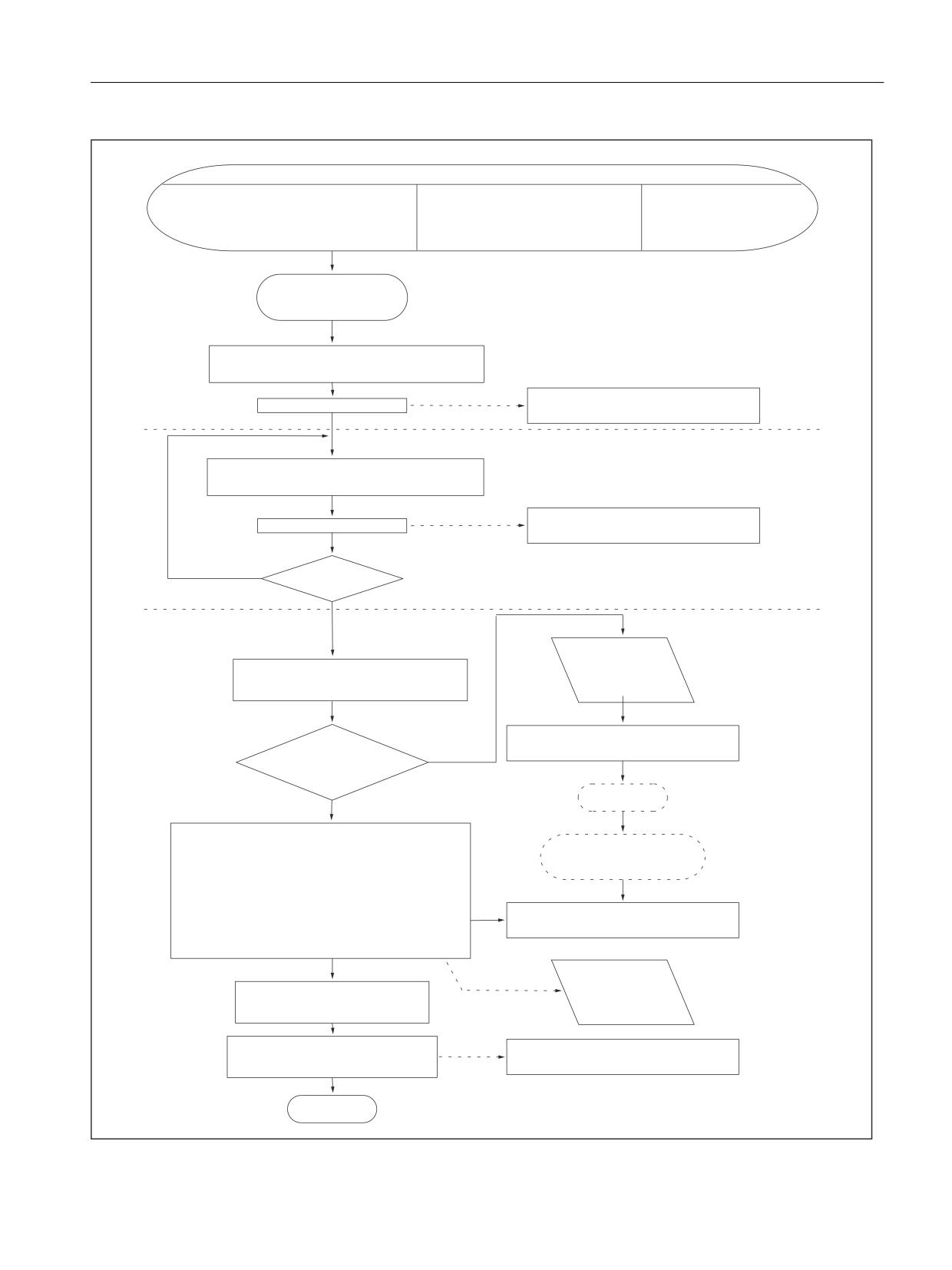
Gantry axes
11.3 Referencing and synchronization of gantry axes
Start referencing operation
Channel-specific
Axis-specific
from part program (with
(with IS "Activate referencing" = 1 and
(with IS "Traversing key +/-" = 1 of
G74 and axis address of
"Active machine function REF" = 1)
leading axis and "Active machine
leading axis)
function REF" = 1)
Section 1 Referencing of leading
Start "Referencing of
axis
gantry axes
Leading axis approaches ref. point; synchro-
nized axis traverses in synchronism
to PLC
IS "Referenced/synchronized" = 1 for
Reference point reached
leading axis
(Internal
Section 2
start)
Referencing of synchronized axis (axes)
Synchronized axis approaches reference
point; leading axis traverses in synchronism
to PLC
IS "Referenced/synchronized" = 1 for
Reference point reached
synchronized axis
j
Next synchro-
nized axis
n
Section 3
Synchronization
Message: "Wait
process
for synchronization
Comparison of actual positions of
start"
leading and synchronized axes
IS "Gantry synchronization ready
Deviation
j
to start¡- = 1
>
MD37110
$MA_GANTRY_POS_TOL_WARNING?
Servicing
n
(Internal start)
All gantry axes traverse in the decoupled state in
gantry synchronized position (MD34100
Operator starts gantry
$MA_REFP_SET_POS of the leading axis). With
synchronization process
absolute encoders and distance-coded encoders,
(External start)
the leading axis will traverse (set via MD34330
$MA_REFP_STOP_AT_ABS_MARKER)
IS "Start gantry synchronization" = 1
the current actual position of the leading axis or the
reference point.
Message:
to PLC
All gantry axes have reached
"Synchronization
synchronized position
in progress"
to PLC
Forced coupling between gantry
IS "Gantry grouping is
axes is reactivated
synchronized" = 1
End
Axes and spindles
Function Manual, 10/2020, 6FC5397-4GP40-0BA1
353
Gantry axes
11.3 Referencing and synchronization of gantry axes
Figure 11-2
Flowchart for referencing and synchronization of gantry axes
Synchronization process
A synchronization process is always required in the following cases:
• after the reference point approach of all axes included in a grouping,
• if the axes become de-synchronized (s below).
Operational sequence failure
If the referencing process described above is interrupted as a result of disturbances or a RESET,
proceed as follows:
• Abort within section 1 or 2:
Restart reference point with leading axis (see section 1)
• Abort in section 3:
In cases where the gantry axes have not yet been referenced (IS "Referenced/Synchronized"
= 1), the gantry synchronization process can be started again with IS "Synchronize gantry
grouping".
Restart gantry synchronization
Synchronization of the gantry axes can be started with IS "Start gantry synchronization" under
the following conditions only:
• JOG/REF mode must be active. The following interface signal must be set:
DB11, ... DBX5.2 = 1 (active machine function REF)
• DB31, ... DBX 101.5 = 0 (gantry grouping is synchronized)
• All grouping axes operate within the tolerance windows:
DB31, ... DBX 101.4 = 1(gantry synchronization process ready to start)
• Axes are not referenced in the relevant NC channel
DB21, ... DBX33.0 = 0 (referencing active)
If the gantry synchronization process is not started from the referencing process by means of
IS "Start gantry synchronization process", then the reference position is not specified as target
position for the synchronous axes:
MD34100 $MA_REFP_SET_POS (reference point value/destination point for distancecoded
system)
Axes and spindles
354
Function Manual, 10/2020, 6FC5397-4GP40-0BA1
Gantry axes
11.3 Referencing and synchronization of gantry axes
Instead, the actual position of the leading axis is specified as the target position and is
approached in the uncoupled state.
Note
For the leading axis, automatic synchronization can be locked using the following NC/PLC
interface signal:
DB31, ... DBX29.5 = 1 (no automatic synchronization process)
This always makes sense if no axis enabling signal has yet been issued for the axes. In this case,
the synchronization process should also be started explicitly with the NC/PLC interface signal:
DB31, ... DBX29.4 = 1 (start gantry synchronization process)
Loss of synchronization
The gantry grouping becomes desynchronized as a result of:
• "Tracking" the gantry axes
• Loss of the reference position of a gantry axis, e.g. by "Parking" (no measuring system active)
• Re-referencing of gantry axis
• The gantry grouping is opened (dissolved) by:
MD37140 $MA_GANTRY_BREAK_UP = 0 (invalidate gantry axis grouping)
The corresponding NC/PLC interface signal is reset:
• DB31, ... DBX60.4 or DBX60.5 == 0 (referenced/synchronized 1 or 2 respectively)
• DB31, ... DBX 101.5 == 0 (gantry grouping is synchronized)
If, in operation, gantry grouping synchronization is lost due to a fault, then synchronization can
be restarted using the NC/PLC interface signal:
DB31, ... DBX29.4 == 1 (start gantry synchronization process)
Requirement is that the following applies to all axes of the gantry grouping:
DB31, ... DBX60.4 or DBX60.5 = 1 (referenced/synchronized 1 or 2 respectively)
In this case, the synchronizing axes traverse the current actual position of the leading axis in the
decoupled state.
If, when the gantry grouping is traversing, the signal "Emergency Stop" (DB10, DBX56.2) is set
and again reset, and the gantry axes have drifted apart less than the standstill tolerance of the
synchronous axes, then these are automatically resynchronized. Automatic synchronization can
be suppressed using the NC/PLC interface signal for the leading axis:
DB31, ... DBX29.5 = 1 (no automatic synchronization process)
Axes and spindles
Function Manual, 10/2020, 6FC5397-4GP40-0BA1
355

Gantry axes
11.3 Referencing and synchronization of gantry axes
Selecting the reference point
To ensure that the shortest possible paths are traversed when the gantry axes are referenced, the
reference point values from leading and synchronous axes should be the same in the machine
data:
MD34100 $MA_REFP_SET_POS (reference point value/destination point for distancecoded
system)
Allowance for deviations in distance between the zero mark and the reference point must be
made for specific axes via the machine data:
MD34080 $MA_REFP_MOVE_DIST (reference point distance)
MD34090 $MA_REFP_MOVE_DIST_CORR (reference point offset/absolute offset)
Referencing direction selection
The zero mark search direction of the synchronous axis can be defined via the machine data:
MD37150 $MA_GANTRY_FUNCTION_MASK, Bit 1
Bit
Value
Meaning
1
0
Zero mark search direction of the synchronous axis analog to machine data:
MD34010 $MA_REFP_CAM_DIR_IS_MINUS
1
Zero mark search direction of the synchronous axis the same as the leading axis
During referencing, the reference point value of the leading axis is specified as the target
position for all axes in the grouping for the synchronization compensatory motion. This position
is then approached without axis coupling. The absolute encoders and distanced-coded encoders
of the leading axis will be set to the current actual position of the leading axis or to the reference
point by the following machine data:
MD34330 $MA_REFP_STOP_AT_ABS_MARKER (Distancecoded linear measuring system
without destination point)
If only one reference cam is used for the leading and synchronous axes, then this must be taken
into account in the PLC user program.
11.3.2
Automatic synchronization
Automatic synchronization can take place:
• in the referencing mode (see Section "Introduction (Page 350)")
• in other modes, as described below:
If a gantry grouping is switched to follow-up mode, monitoring of the actual values between the
leading and synchronized axes is disabled. The grouping is no longer synchronized as a result.
Independent of axes positions, the following interface signal will be set to 0 (from leading axis)
DB31, ... DBX101.5 (gantry grouping is synchronous)
If the gantry grouping is switched from follow-up mode to position control mode, axis
synchronism is automatically restored provided the actual-value monitor does not detect a
Axes and spindles
356
Function Manual, 10/2020, 6FC5397-4GP40-0BA1
Gantry axes
11.3 Referencing and synchronization of gantry axes
difference between the positions of the leading and synchronized axes greater than the setting
in the machine data:
MD36030 $MA_STANDSTILL_POS_TOL (standstill tolerance)
In this case, a new setpoint is specified for the synchronized axis (axes) without interpolation.
The positional difference detected earlier is then corrected by the position controller. The
correction causes only the synchronized axis (axes) to move.
The motional sequence of the synchronized axis (axes) is analogous to the situation in which the
grouping switches from the "Hold" state to position control mode. In this case, the position
specified by the position controller before the grouping is halted is set again on condition that
the zero speed monitor has not activated alarm 25040 (with follow-up as alarm reaction) in the
meantime.
The same tolerance window is used for this mode of automatic synchronization as for the zero
speed monitoring function:
MD36030 $MA_STANDSTILL_POS_TOL (standstill tolerance)
Parameter rate dependence loads with machine data:
MD36012 $MA_STOP_LIMIT_FACTOR (exact stop coarse/fine and standstill factor)
Note
The following interface signal blocks automatic synchronization in all modes except the
referencing mode:
DB31, ... DBX29.5 (no automatic synchronization)
Should the automatic synchronization be activated at this point, then the following interface
signal must be reset:
DB31, ... DBX29.5 = 0 (no automatic synchronization)
Then switch one of the axes in the gantry grouping from follow-up mode to position-controlled
mode. This is achieved with the interface signals:
DB31, ... DBX1.4 = 1 (follow-up mode)
DB31, ... DBX2.1 = 1 (servo enable)
11.3.3
Points to note
2nd position measuring system per gantry axis
Different types of position measuring systems can be mounted on the gantry axes of a grouping.
Furthermore, each gantry axis is capable of processing two position measuring systems, it being
possible to switch over from one system to the other at any time:
DB31, ... DBX1.5 (position measuring system 1)
DB31, ... DBX1.6 (position measuring system 2)
The maximum tolerance for position actual value switchover should be set to a lower value than
the gantry warning limit:
Axes and spindles
Function Manual, 10/2020, 6FC5397-4GP40-0BA1
357
Gantry axes
11.3 Referencing and synchronization of gantry axes
MD36500 $MA_ENC_CHANGE_TOL (Max. tolerance for position actual value switchover)
The two position measuring systems must, however, have been referenced beforehand. The
relevant measuring system must be selected before referencing is initiated. The operational
sequence is then the same as that described above.
Channelspecific referencing
Gantry axes can also be referenced by channel with the following interface signal:
DB21, ... DBX1.0 (activate referencing)
The value of the leading axis' machine data is used for the axis sequence for channel-specific
referencing:
MD34110 $MA_REFP_CYCLE_NR (Axis sequence for channel-specific referencing)
After the reference point of the leading axis has been reached, the synchronized axes are
referenced first as described above.
Referencing from part program with G74
The referencing and synchronization process for gantry axes can also be initiated from the part
program by means of command G74. In this case, only the axis name of the leading axis may be
programmed. The operational sequence is analogous to that described for axis-specific
referencing.
Position measuring system with distancecoded reference marks
In order that reference point approach operations do not have to travel through large distances,
it is possible to use just one position measuring system - or a position measuring system as 2nd
measuring system with distance-coded reference marks for gantry axes. In this way the
measuring system is referenced after traversal of a short path (e.g. 20 mm). The procedure for
referencing the gantry axes is the same as that described for the normal incremental measuring
system.
Further information:
Homing (Page 31)
Absolute encoder
During the course of the synchronization compensatory motion, all axes in the gantry axis
grouping traverse to the reference point value of the leading axis defined in the machine data:
MD34100 $MA_REFP_SET_POS (reference point value/destination point for distancecoded
system)
The absolute encoders and distanced-coded encoders of the leading axis will be set to the
current actual position of the leading axis or to the reference point by the following machine
data:
MD34330 $MA_REFP_STOP_AT_ABS_MARKER (Distancecoded linear measuring system
without destination point)
Axes and spindles
358
Function Manual, 10/2020, 6FC5397-4GP40-0BA1

Gantry axes
11.3 Referencing and synchronization of gantry axes
Activation of axis compensations
Compensation functions can be activated for both the leading axis and the synchronized axes.
Compensation values are applied separately for each individual gantry axis. These values must
therefore be defined and entered for the leading axis and the synchronized axes during start-up.
The compensations do not become operative internally in the control until the axis is referenced
or the gantry grouping synchronized. The following applies:
Compensation type
Takes effect when
PLC interface signal
Backlash compensation
Axis is referenced
"Referenced/Synchronized"
LEC
Axis is referenced
"Referenced/Synchronized"
Sag compensation
Gantry grouping is synchron-
"Gantry grouping is synchronized"
ized
Temperature compensation
Gantry grouping is synchron-
"Gantry grouping is synchronized"
ized
If a movement by the synchronized axis (axes) is caused by an active compensation, a travel
command is displayed for the synchronized axis (axes) independently of the leading axis.
Monitoring functions effective
Analogous to normal NC axes, the following monitoring functions do not take effect for gantry
axes until the reference point is reached (IS "Referenced/Synchronized"):
• Working area limits
• Software limit switch
• Protection zones
The axial machine data values are used as monitoring limit values for the synchronized axes as
well.
Multi-channel block search
The cross-channel block search in Program Test mode (SERUPRO "Search Run by Program test")
can be used to simulate the traversal of gantry axis groupings.
Note
For further information on the multichannel block search SERUPRO, please see:
Further information
Function Manual Basic Functions; Mode group, channel, program operation, program test
Axes and spindles
Function Manual, 10/2020, 6FC5397-4GP40-0BA1
359
Gantry axes
11.4 Start-up of gantry axes
11.4
Start-up of gantry axes
General
Owing to the forced coupling which is normally present between guide and synchronous gantry
axes, the gantry grouping must be started up as if it were an axis unit. For this reason, the axial
machine data for the guide and synchronous axes must always be defined and entered jointly.
If the synchronous axis is overloaded due to a weaker dynamic response than the guide axis,
alarm 10656 is displayed.
Special points to be noted with regard to starting up gantry axes are described below.
Traversing direction
As part of the start-up procedure, a check must be made to ensure that the direction of rotation
of the motor corresponds to the desired traversing direction of the axis. Correct with the
following axial machine data:
MD32100 $MA_AX_MOTION_DIR (traversing direction)
Entering gantry trip limits
For the monitoring of the actual position values of the synchronous axis in relation to the actual
position of the guide axis, the limit values for termination, as well as for the guide and
synchronous axes, should be entered corresponding to the specifications of the machine
manufacturer:
• MD37120 $MA_GANTRY_POS_TOL_ERROR (gantry trip limit)
• MD37130 $MA_GANTRY_POS_TOL_REF (gantry shutdown limit when referencing)
Note
The control must then be switched off and then on again because the gantry axis definition
and the trip limit values only take effect after power ON.
Response to setpoint changes and disturbances
Since digital drives respond well to disturbances and setpoint changes, there is no need for a
compensatory control between the gantry axes. However, the gantry axes can only operate in
exact synchronism if the parameters for the control circuits of the guide and synchronous axes
are set to the same dynamic response value.
To ensure the best possible synchronism, the guide axis and synchronous axis must be capable
of the same dynamic response to setpoint changes. The axial control loops (position, speed
and current controllers) should each be set to the optimum value so that disturbances can be
eliminated as quickly and efficiently as possible. The dynamic response adaptation function in
the setpoint branch is provided to allow differing dynamic responses of axes to be matched
without loss of control quality.
Axes and spindles
360
Function Manual, 10/2020, 6FC5397-4GP40-0BA1
Gantry axes
11.4 Start-up of gantry axes
Axial optimization
For symmetrically set up gantry axes, it is recommended that you set the Kv factors and
precontrol settings for all of the axes of a group identically.
The following control parameters must be set to the optimum axial value for both the guide axis
and the synchronous axis:
• MD32200 $MA_POSCTRL_GAIN (servo gain factor)
• MD32620 $MA_FFW_MODE (feedforward control parameter)
• MD32610 $MA_VELO_FFW_WEIGHT (feedforward control factor for acceleration/speed)
• MD32650 $MA_AX_INERTIA (inertia for torque feedforward control)
• MD32800 $MA_EQUIV_CURRCTRL_TIME (equivalent time constant current control loop for
feedforward control)
• MD32810 $MA_EQUIV_SPEEDCTRL_TIME (equivalent time constant speed control loop for
feedforward control)
Further information
Function Manual Monitoring and Compensating; Compensations
Same settings
The following control parameters must be set to the same value for the guide axis and
synchronous axis:
• MD33000 $MA_FIPO_TYPE (fine interpolator type)
• MD32400 $MA_AX_JERK_ENABLE (axial jerk limitation)
• MD32402 $MA_AX_JERK_MODE (filter type for axial jerk limitation)
• MD32410 $MA_AX_JERK_TIME (time constant for the axial jerk filter)
• MD32420 $MA_JOG_AND_POS_JERK_ENABLE (basic position of axial jerk limitation)
• MD32430 $MA_JOG_AND_POS_MAX_JERK (axial jerk)
Further information
Function Manual Basic Functions; Speeds/setpoint/actual value systems, closed-loop control
Dynamics matching
The guide axis and the coupled synchronous axis must be capable of the same dynamic response
to setpoint changes. The same dynamic response means: The following errors are equal in
magnitude when the axes are operating at the same speed.
The dynamic response adaptation function in the setpoint branch makes it possible to obtain an
excellent match in the response to setpoint changes between axes which have different dynamic
characteristics (control loops). The difference in equivalent time constants between the
dynamically "weakest" axis and the other axis in each case must be specified as the dynamic
response adaptation time constant.
Axes and spindles
Function Manual, 10/2020, 6FC5397-4GP40-0BA1
361
Gantry axes
11.4 Start-up of gantry axes
Example
When the speed feedforward control is active, the dynamic response is primarily determined by
the equivalent time constant of the "slowest" speed control loop.
Guide axis
MD32810 $MA_EQUIV_SPEEDCTRL_TIME [n] = 5 ms (equivalent time constant speed control
loop for feedforward control)
Synchronous axis
MD32810 $MA_EQUIV_SPEEDCTRL_TIME [n] = 3 ms
• Time constant of dynamic response adaptation for synchronous axis:
MD32910 $MA_DYN_MATCH_TIME [n] = 5 ms - 3 ms = 2 ms (time constant of dynamic
response adaptation)
The dynamic response adaptation must be activated axially with the machine data:
MD32900 $MA_DYN_MATCH_ENABLE (dynamic response adaptation)
Check of dynamic response adaptation:
The following errors of the guide and synchronous axes must be equal in magnitude when the
axes are operating at the same speed!
For the purpose of fine tuning, it may be necessary to adjust servo gain factors or feedforward
control parameters slightly to achieve an optimum result.
Referencing gantry axes
The positions of the guide and synchronous axes reference points must first be set to almost
identical values.
To ensure that the synchronization compensatory motion of the gantry axes is not started
automatically, the gantry warning limit must be set to 0 at the first start-up before referencing:
MD37100 $MA_GANTRY_POS_TOL (gantry axis definition)
This will prevent a warning message being output during traversing motion.
In cases where an excessively high additional torque is acting on the drives due to misalignment
between the guide and synchronous axes, the gantry grouping must be aligned before the axes
are traversed. After this, the gantry axes must be referenced. For further details, see:
• Section "Referencing and synchronization of gantry axes (Page 350)"
• Further information: Homing (Page 31)
After the guide and synchronous axes have been referenced, the difference between them must
be determined by comparing the actual position value (HMI: operating area "Diagnostics" >
"Service axes") and taken into account as the reference point offset:
• MD34080 $MA_REFP_MOVE_DIST (reference point distance)
• MD34090 $MA_REFP_MOVE_DIST_CORR (reference point offset/absolute offset)
The differences in distance between the zero mark and reference point must also be calculated
for each gantry axis and adjusted. They are to be customized, via the following machine data, in
Axes and spindles
362
Function Manual, 10/2020, 6FC5397-4GP40-0BA1
Gantry axes
11.4 Start-up of gantry axes
such a way that the actual position values of the guide and synchronous axes are identical after
execution of the compensatory motion:
• MD34080 $MA_REFP_MOVE_DIST (reference point distance)
• MD34090 $MA_REFP_MOVE_DIST_CORR (reference point offset /absolute offset)
Synchronizing gantry axes
The gantry synchronization is activated via the NC/PLC interface signal (see Section "Referencing
and synchronization of gantry axes (Page 348)"):
DB31, ... DBX29.4 = 1 (start synchronization of gantry)
The completion of the synchronization is displayed via the NC/PLC interface signal:
DB31, ... DBX101.5 == 1 (gantry grouping is synchronous)
Once the axes have been synchronized, check that the dimensional offset between the guide
and the synchronous axes is 0. If required, make corrections in the machine data mentioned
above.
Input of gantry warning limit
Once the reference point values for the guide and synchronous axes have been optimized so that
the gantry axes are perfectly aligned with one another after synchronization, the warning limit
values for all axes must be entered in the following machine data:
MD37110 $MA_GANTRY_POS_TOL_WARNING (gantry warning limit)
To do this, the value must be increased incrementally until it is just below the alarm (limit
exceeded) response limit. It is particularly important to check the acceleration phases.
This limit value also determines the position deviation value at which gantry synchronization is
automatically started in the control.
Calculating and activating compensations
In cases where the gantry axes require compensation (backlash, sag, temperature or leadscrew
error), the compensation values for the guide axis and the synchronous axis must be calculated
and entered in the appropriate parameters or tables.
Further information
Function Manual Monitoring and Compensating
Function generator / measuring function
The activation of the function generator and measuring function for a synchronous axis is
aborted with an error message. If an activation of the synchronous axis is absolutely necessary,
e.g. to measure the machine, the guide and the synchronous axes must be temporarily
interchanged.
Axes and spindles
Function Manual, 10/2020, 6FC5397-4GP40-0BA1
363
Gantry axes
11.5 Parameter assignment: Response to faults
Special cases
If individual axes have to be activated, the gantry groups must be temporarily canceled. As the
second axis no longer travels in synchronism with the first axis, the activated axis must not be
allowed to traverse beyond the positional tolerance.
If the gantry grouping is canceled, the following points must be noted:
• Always activate the traversing range limits and set them to the lowest possible values
(position tolerance).
• Synchronize the gantry grouping first if possible and then execute a POWER-ON-
RESET without referencing the axes again. This ensures that the traversing range limits
always refer to the same position (i.e. that which was valid on power ON).
• Avoid using the step-change function. Position step changes are only permissible if they stay
within the permitted tolerance.
• Always use an offset of 0 for the function generator and measuring function in contrast to the
recommendations for normal axes.
• Set the amplitudes for function generator and measuring function to such low values that the
activated axis traverses a shorter distance than the position tolerance allows. Always activate
the traversing range limits as a check (see above).
Further information
Function Manual Drive Functions SINAMICS S120; Speed control loop (DD2)
Start-up support for gantry groupings
The start-up functions of the function generator and measuring are parameterized via the PI
service. The traversing movement starts for all parameterized axes with NC start in JOG mode.
A window is displayed in the "Measuring function and function generator in gantry grouping"
user interface. Two amplitude values, each with an offset and bandwidth, must be entered in this
window. The first amplitude value applies to the measuring axis and the second to the other
coupled axes.
See also
Velocities, setpoint/actual value systems, closed-loop control (Page 135)
11.5
Parameter assignment: Response to faults
Pulse suppression
The behavior of the gantry grouping with regard to faults that trigger pulse suppression can be
set with the following axis-specific machine data:
Axes and spindles
364
Function Manual, 10/2020, 6FC5397-4GP40-0BA1
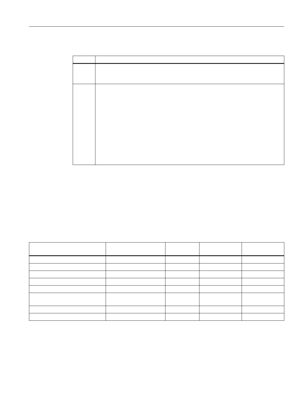
Gantry axes
11.6 PLC interface signals for gantry axes
MD30455 $MA_MISC_FUNCTION_MASK, bit 9 = <value>
<Value>
Meaning
0
When a fault occurs that triggers the pulse suppression (e.g. measuring-circuit fault), the
pulses in all other axes of the gantry grouping will also be suppressed.
Result: Coast down of all axes of the gantry grouping.
1
When a fault occurs that triggers the pulse suppression (e.g. measuring-circuit fault), the
pulses for only this axis will be suppressed. The other axes of the gantry grouping will be
stopped. The pulses for these axes are also then suppressed. To ensure that the pulses these
axes are not suppressed in advance, especially for axes to be held at the standstill position
(vertical axes), the following drive parameters must be taken into account:
• p1135[0...n] OFF3 ramp-down time
• p1217 holding brake application time
• p1227 zero speed detection monitoring time
• p1228 pulse suppression, delay time
For a detailed description of drive parameters, refer to:
Further information
SINAMICS S120/S150 List Manual
11.6
PLC interface signals for gantry axes
Special IS for gantry axes
The special NC/PLC interface signals of the coupled gantry axes are taken via the axial NC/PLC
interface of the leading or synchronized axes. The table below shows all special gantry NC/PLC
interface signals along with their codes and indicates whether the IS is evaluated on the leading
axis or the synchronized axis.
NC/PLC interface signal
Direction of transfer
DB31, ...
Leading axis
Synchronous axis
DBX...
Start gantry synchronization
PLC → NC
29.4
X
No automatic synchronization
PLC → NC
29.5
X
Gantry axis
NC → PLC
101.7
1
1
Gantry leading axis
NC → PLC
101.6
1
0
Gantry grouping is synchronized
NC → PLC
101.5
X
Gantry synchronization ready to
NC → PLC
101.4
X
start
Gantry warning limit exceeded
NC → PLC
101.3
X
Gantry trip limit exceeded
NC → PLC
101.2
X
Effect of axial interface signals on gantry axes
a) Axial interface signals from the PLC to the axis (PLC → NC)
The axial interface signals from the PLC to the axis are always referred to all gantry axes in the
grouping. In this case, all gantry axes (leading and synchronized axis) have equal priority.
Axes and spindles
Function Manual, 10/2020, 6FC5397-4GP40-0BA1
365