SINUMERIK 840D sl. Service - Functions. Manual (2018-2020) - page 6
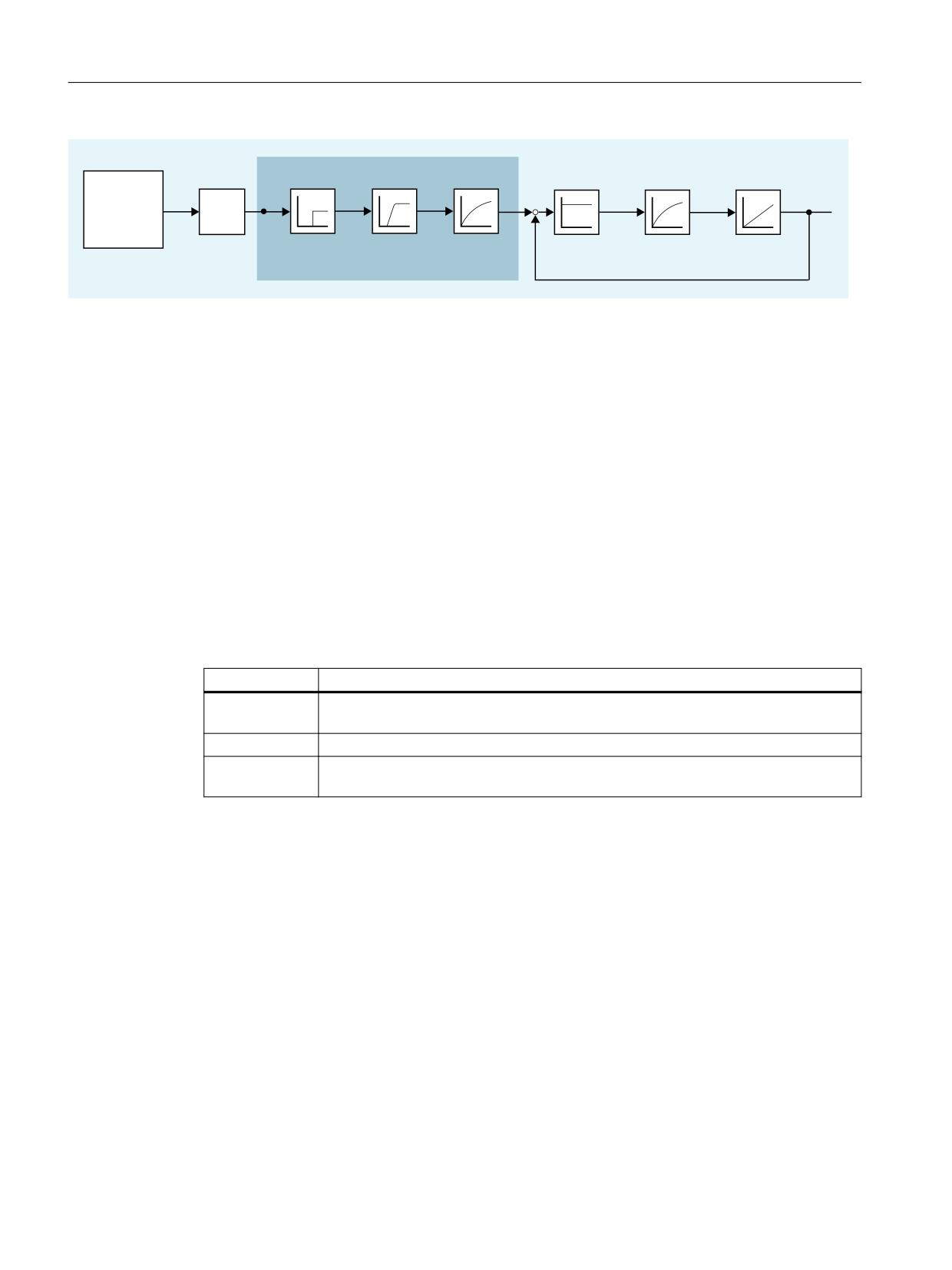
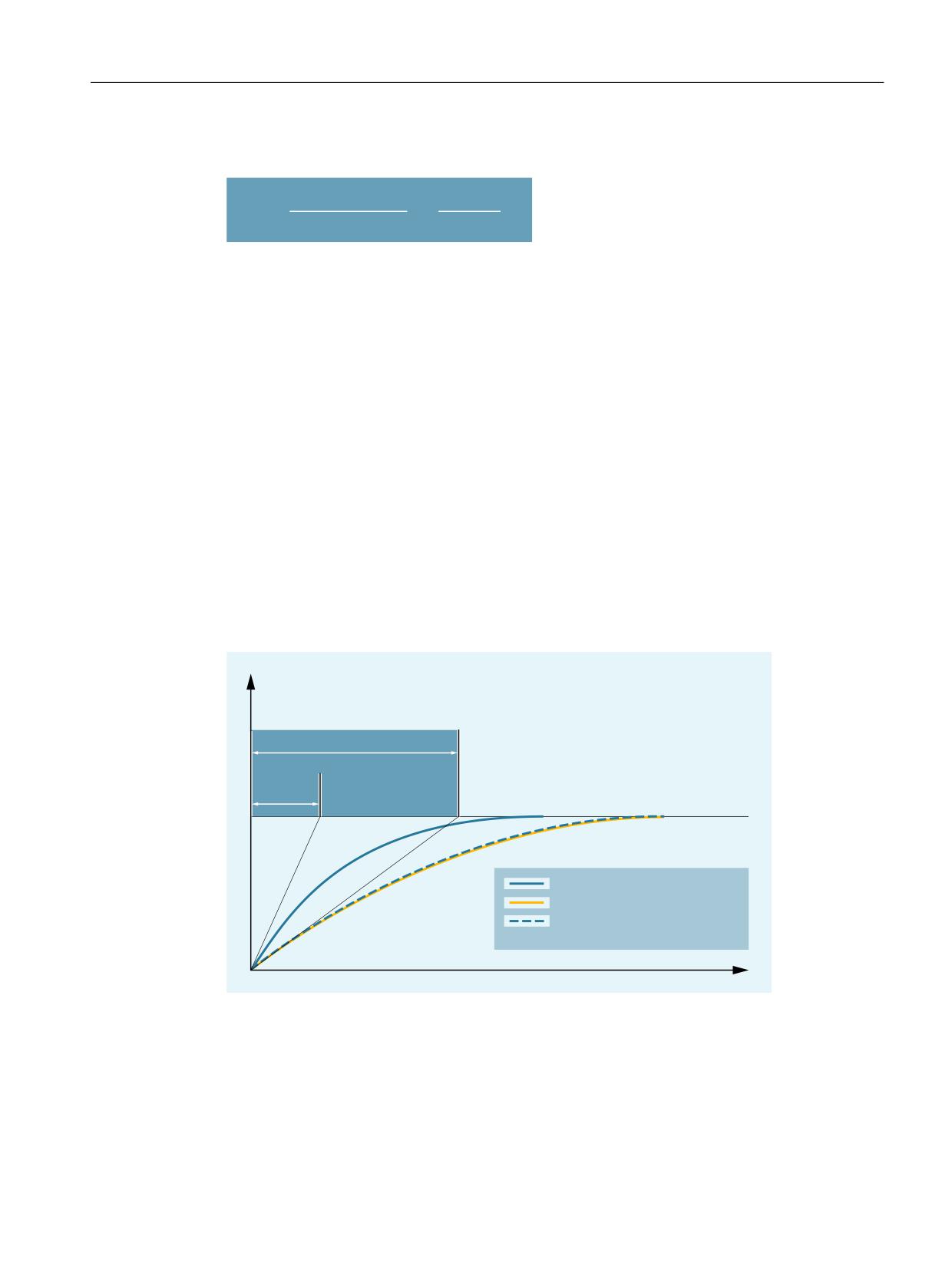
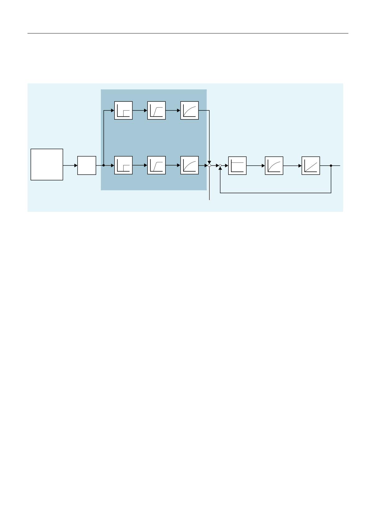
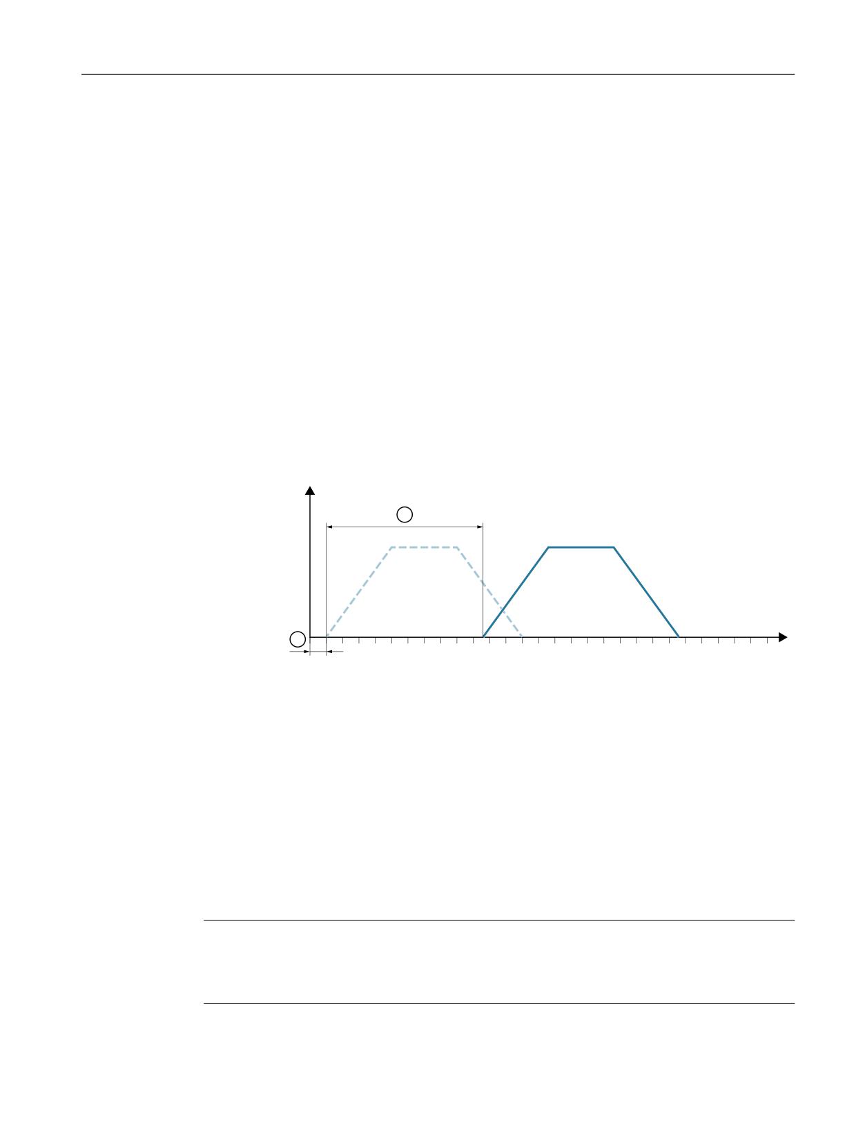
Velocities, setpoint/actual value systems, closed-loop control
5.4 Setpoint/actual-value system
Note
Machine data index [ n ]
The machine data index [ n ] for encoder assignment has the following meaning:
• n = 0: First encoder assigned to the machine axis
• n = 1: Second encoder assigned to the machine axis
The assignment is made using machine data:
• MD30220 $MA_ENC_MODULE_NR[ n ]
• MD30230 $MA_ENC_INPUT_NR[ n ]
Further information
Commissioning Manual, CNC Commissioning: NC, PLC, drive; communication between NC and
drive > Drives: Assign axis
5.4.3
Adapting the motor/load ratios
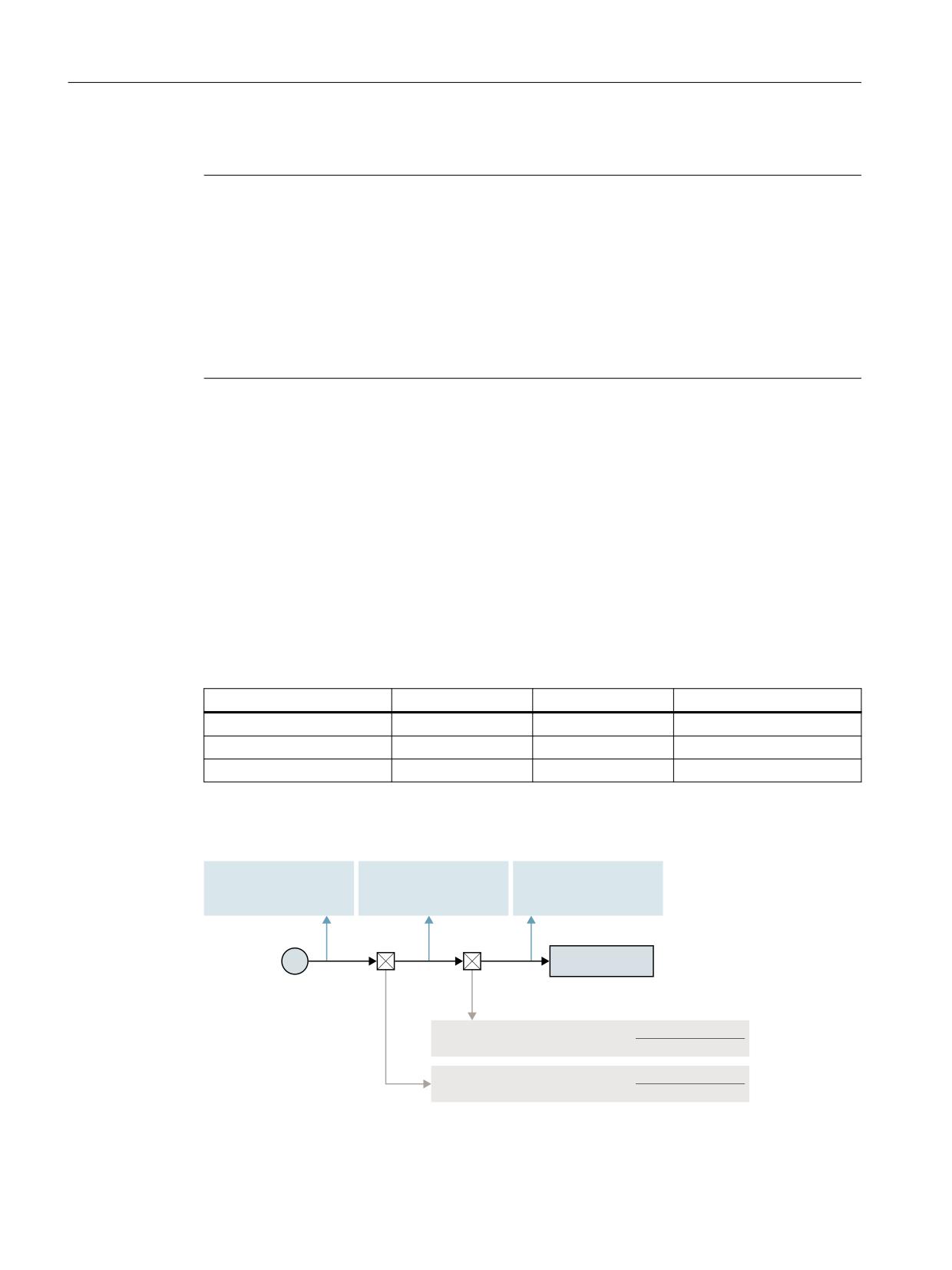
Gear types
The following gear types are available for adapting the mechanical ratios:
Gear type
Activation
Adaptation
Installation location
Motor/load gear
Parameter set
Fixed configuration
Gear unit
Measuring gear encoder
Power On
Sensor-dependent
Sensor-side
Load intermediate gear unit
Warm restart
Load-dependent
Tool-side
Local position of gear unit / encoder
0RWRU VLGH HQFRGHU
/RDG VLGH HQFRGHU
7RRO VLGH HQFRGHU
(1&B,6B',5(&7
(1&B,6B',5(&7
(1&B,6B',5(&7
(1&B,6B',5(&7
(1&B,6B',5(&7
(1&B,6B',5(&7
0RWRU ORDG JHDU
0
7RRO
'5,9(B$;B5$7,2 B180(5$
1R RI ORDG UHY
'5,9(B$;B5$7,2 B'(120
1R RI WRRO UHY
'5,9(B$;B5$7,2B180(5$
1R RI PRWRU UHY
'5,9(B$;B5$7,2B'(120
1R RI ORDG UHY
Figure 5-2
Gear unit types and encoder locations
Axes and spindles
160
Function Manual, 10/2020, 6FC5397-4GP40-0BA1

Velocities, setpoint/actual value systems, closed-loop control
5.4 Setpoint/actual-value system
Motor/load gear
The motor/load gear supported by SINUMERIK is configured via the following machine data:
• MD31060 $MA_DRIVE_AX_RATIO_NUMERA (numerator load gear)
• MD31050 $MA_DRIVE_AX_RATIO_DENOM (denominator load gear)
The transmission ratio is obtained from the numerator/denominator ratio of both machine data.
The associated parameter sets are used automatically as default by the control system to
synchronize the position controller with the relevant transmission ratios.
Since a gear stage change is not always carried out automatically, and there are also several ways
to request a gear stage change, the position controller is not always incorporated via parameter
sets.
Note
For further information about the parameter sets for gear stage change, see Section "Spindles
(Page 377)".
Intermediate gear
Additional, configurable load intermediate gears are also supported by the control system:
• MD31066 $MA_DRIVE_AX_RATIO2_NUMERA (intermediate gear numerator)
• MD31064 $MA_DRIVE_AX_RATIO2_DENOM (intermediate gear denominator)
Power tools generally have their "own" intermediate gear. Such variable mechanics can be
configured by multiplying the active intermediate gear and the motor/load gear.
CAUTION
Different gear transmission ratios for switching
Unlike the motor/load gear, there is no parameter set for the intermediate gear and, therefore,
no way of controlling the time-synchronized switchover to the part program or PLC (NC/PLC
interface). Part machining during gear change is, therefore, ruled out. It remains the task of the
user to match the synchronization of the relevant changed machine data to the corresponding
mechanical switchover and activate it. On switchover during a motion, compensations cannot
be ruled out due to jumps in the scaling factors. These are not monitored for violation of the
maximum acceleration.
Encoder directly at the tool
Another connection option is possible for a "tool-side encoder" on the intermediate gear by
configuring the following machine data:
MD31044 $MA_ENC_IS_DIRECT2
Encoder not directly at the tool
The following supplementary conditions apply to a gear change of the intermediate gear in
position-control mode: The gear ratio to be changed is incorporated in a re-scaling of the
encoder information in this case.
Axes and spindles
Function Manual, 10/2020, 6FC5397-4GP40-0BA1
161

Velocities, setpoint/actual value systems, closed-loop control
5.4 Setpoint/actual-value system
In this case, the following applies to axes/spindles in positioning mode:
• A non-abrupt gear change is only possible at zero speed.
To do this, the tool-side position before and after a gear change are set equal for a change in
the ratio, since the mechanical position does not (or hardly) change during a gear stage
change.
Recommendation:
To avoid 21612 "Controller enable reset during motion", changeover should be carried out
"only at zero speed". It is still permissible and expedient to switch the axis or spindle to speed-
control or follow-up mode before or during a gear change.
Boundary conditions
If the encoder to be used for position control is connected directly at the tool, the gear stage
change only affects the physical quantities at the speed interface between the NC and the drive
of the motor/load gear. The internal parameter sets are not changed.
Reference point and machine reference
CAUTION
Loss of machine reference
The control cannot detect all situations that can lead to loss of the machine reference.
Therefore, it is the general responsibility of the commissioning engineer or user to initiate
explicit referencing of zero marker synchronization in such cases.
In the case of gear changes, it is not possible to make a statement about the effect of the
reference point or machine position reference on the encoder scaling. In such cases, the control
partially cancels the status "Axis referenced/synchronized".
If the machine reference has been lost, it must first be restored through an adjustment or
referencing of the lost machine reference.
See also
Homing (Page 31)
5.4.4
Speed setpoint output
Control direction and travel direction of the feed axes
You must determine the travel direction of the feed axis before starting work.
Control direction
Before the position control is started up, the speed controller and current controller of the drive
must be started up and optimized.
Traversing direction
Axes and spindles
162
Function Manual, 10/2020, 6FC5397-4GP40-0BA1
Velocities, setpoint/actual value systems, closed-loop control
5.4 Setpoint/actual-value system
With the machine data:
MD32100 $MA_AX_MOTION_DIR (traversing direction)
the direction of motion of the axis can be reversed
without affecting the control direction of the position control.
Speed setpoint adjustment
In the case of speed setpoint comparison, the NC is informed which speed setpoint corresponds
to which motor speed in the drive, for parameterizing the axial control and monitoring. This
comparison is carried out automatically.
For PROFIBUS DP drives, alternatively, the manual speed setpoint comparison is also possible.
• Manual adjustment
In the machine data:
MD32250 $MA_RATED_OUTVAL
a value not equal to zero is entered.
Note
Velocity adjustment and maximum speed setpoint
No speed compensation is required due to the automatic speed setpoint adjustment!
Maximum speed setpoint
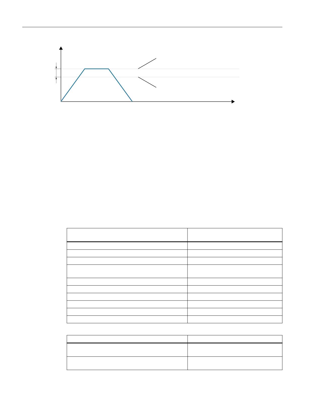
The maximum speed setpoint is defined in percent. 100% means maximum speed setpoint or
maximum speed for PROFIdrive drives (manufacturer-specific setting parameters in the drive,
e.g. p1082 for SINAMICS).
The output of the spindle speed is implemented in the NC.
Data for five gear stages are realized in the controller.
These stages are defined by a minimum and maximum speed for the stage itself and by a
minimum and maximum speed for the automatic gear stage changeover. A new set gear stage
is output only if the new programmed speed cannot be traversed in the current gear stage.
With the machine data:
MD36210 $MA_CTRLOUT_LIMIT[n] (maximum speed setpoint)
the speed setpoint is restricted percentage-wise.
Values up to 200% are possible.
When the speed is exceeded, an alarm is generated.
Axes and spindles
Function Manual, 10/2020, 6FC5397-4GP40-0BA1
163
Velocities, setpoint/actual value systems, closed-loop control
5.4 Setpoint/actual-value system
6SHHG VHWSRLQW
QVHW
0'
&75/287B/,0,7
0D[ VSHHG VHWSRLQW
0'
0$;B$;B9(/2
0D[ D[LV YHORFLW\
W
Figure 5-3
Maximum speed setpoint
However, due to control processes, the axes should not reach their maximum velocity
(MD32000 $MA_MAX_AX_VELO) at 100% of the speed setpoint, but at 80% to 95%.
In case of axes, whose maximum speed is attained at around 80% of the speed setpoint range,
the default value (80%) of the machine data:
MD32000 $MA_MAX_AX_VELO (maximum axis velocity)
can be adopted.
5.4.5
Machine data of the actual value system
Axis-specific machine data
To parameterize the actual value system, the following axis-specific machine data should be set:
Encoder and parameter set-independent machine da-
Meaning
ta: $MA_
MD30200 NUM_ENCS
Number of encoders
MD30300 IS_ROT_AX
Rotary axis / spindle
MD30310 ROT_IS_MODULO
Modulo conversion for rotary axis / spindle
MD30320 DISPLAY_IS_MODULO
360-degree modulo display for rotary axis or
spindle
MD30330 MODULO_RANGE
Size of the modulo range
MD30340 MODULO_RANGE_START
Start position of the modulo range
MD31030 $MA_LEADSCREW_PITCH
Leadscrew pitch
MD31064 $MA_DRIVE_AX_RATIO2_DENOM
Intermediate gear denominator
MD31066 $MA_DRIVE_AX_RATIO2_NUMERA
Intermediate gear numerator
MD32000 $MA_MAX_AX_VELO
Maximum axis velocity
Encoder-dependent machine data: $MA_
Meaning
MD30210 ENC_SEGMENT_NR[ n ]
Actual value assignment: Number of bus
segments
MD30220 ENC_MODULE_NR[ n ]
Actual value assignment: Drive number/
measuring circuit number
Axes and spindles
164
Function Manual, 10/2020, 6FC5397-4GP40-0BA1

Velocities, setpoint/actual value systems, closed-loop control
5.4 Setpoint/actual-value system
Encoder-dependent machine data: $MA_
Meaning
MD30230 ENC_INPUT_NR[ n ]
Actual value assignment: Input on drive
module/measuring circuit module
MD30240 ENC_TYPE[ n ]
Encoder type of the actual value acquisition
(actual position value)
MD30242 ENC_IS_INDEPENDENT[ n ]
Encoder is independent
MD30244 ENC_MEAS_TYPE[ n ]
Encoder measuring type
MD30250 ACT_POS_ABS[ n ]
Internal encoder position
MD30260 ABS_INC_RATIO[ n ]
Absolute encoder: Ratio between the abso-
lute resolution and the incremental resolu-
tion
MD30270 ENC_ABS_BUFFERING[ n ]
Absolute encoder: Traversing range exten-
sion
MD34090 $MA_REFP_MOVE_DIST_CORR[ n ]
Reference point offset
MD34320 $MA_ENC_INVERS[ n ]
Length measuring system is in the opposite
sense
n: Encoder index, with n = 0, 1, ... (1st encoder, 2nd encoder, ...)
Note
The "Activate machine data" can be activated either in the part program with the
command NEWCONF or via the user interface by pressing a softkey.
5.4.6
Actual-value resolution
5.4.6.1
Machine data of the actual value resolution
Depending where the measuring system (encoder) is mounted, the following measuring system
types should be taken into account:
• Load-side encoder: Direct measuring system (DM)
• Motor-side encoder: Indirect measuring system (IM)
Axes and spindles
Function Manual, 10/2020, 6FC5397-4GP40-0BA1
165

Velocities, setpoint/actual value systems, closed-loop control
5.4 Setpoint/actual-value system
Parameterizing the actual value resolution depending on the axis type (linear/rotary axis)
The control system calculates the actual value resolution based on the following machine data.
Machine data for calculating the actual value reso-
Linear axis
Linear axis
Rotary axis
lution
Linear scale /
Indirect
Direct
Indirect
Direct
direct measur-
measur-
measur-
measur-
measur-
ing system
ing sys-
ing sys-
ing sys-
ing sys-
tem
tem: Ma-
tem
tem: Ma-
chine/tool
chine/tool
MD30300 $MA_IS_ROT_AX
0
0
0
1
1
MD31000 $MA_ENC_IS_LINEAR[ n ]
1
0
0
0
0
MD31010 $MA_ENC_GRID_POINT_DIST[ n ]
Spacing
-
-
-
-
1)
MD34320 $MA_ENC_INVERS[ n ]
-
-
-
-
MD31020 $MA_ENC_RESOL[ n ]
-
Pulses/
Pulses/
Pulses/
Pulses/
rev
rev
rev
rev
MD31025 $MA_ENC_PULSE_MULT[ n ]
Encoder multipli-
cation
MD31030 $MA_LEADSCREW_PITCH
-
mm/rev.
mm/rev.
-
-
MD31040 $MA_ENC_IS_DIRECT[ n ]
- / 1
0
1
0
1
MD31044 $MA_ENC_IS_DIRECT2[ n ]
- / 1
0
1
0
1
2)
MD31050 $MA_DRIVE_AX_RATIO_DENOM[ n ]
-
Load
- / 1
Load
rev.
rev.
2)
MD31060 $MA_DRIVE_AX_RATIO_NUMERA[ n ]
-
Motor
- / 1
Motor
rev. if in-
rev.
feed
gear avail-
able
MD31070 $MA_DRIVE_ENC_RATIO_DENOM[ n ]
-
Encoder
Encoder
Encoder
Encoder
rev.
rev.
rev.
rev.
MD31080 $MA_DRIVE_ENC_RATIO_NUMERA[ n ]
-
Motor-
Motor
Motor
Load
side en-
rev.
rev.
rev.
coder 3)
-
Not relevant
1) For distance-coded measuring systems
2) These machine data are not required for encoder matching (path evaluation). However,
they must be entered correctly for the setpoint calculation! Otherwise the required servo
gain factor (KV) will not be set. The load revolutions are entered into machine data
MD31050 $MA_DRIVE_AX_RATIO_DENOM and the motor revolutions in machine data
MD31060 $MA_DRIVE_AX_RATIO_NUMERA.
3) The encoder on the motor side is a built-in encoder and, therefore, does not have a
measuring gear unit.
The transmission ratio is always 1:1.
Axes and spindles
166
Function Manual, 10/2020, 6FC5397-4GP40-0BA1

Velocities, setpoint/actual value systems, closed-loop control
5.4 Setpoint/actual-value system
Machine data of the actual value resolution
The actual-value resolution results from the design of the machine, whether gearboxes are
available and their gear ratio, the leadscrew pitch for linear axes and the resolution of the
encoder being used. The following machine data must be set for this on the control system:
Encoder and parameter set-independent machine da-
Meaning
ta: $MA_
MD30300 IS_ROT_AX
Axis is a rotary axis / spindle
MD31010 ENC_GRID_POINT_DIST
Distance between reference marks of the lin-
ear scale
MD31030 LEADSCREW_PITCH
Leadscrew pitch
MD31064 DRIVE_AX_RATIO2_DENOM
Denominator of attached gearbox
MD31066 DRIVE_AX_RATIO2_NUMERA
Numerator of attached gearbox
Encoder-dependent machine data: $MA_
Meaning
MD31000 ENC_IS_LINEAR[ n ]
Measuring system is a linear scale
MD31020 ENC_RESOL[ n ]
Encoder pulses per revolution
MD31025 ENC_PULSE_MULT[ n ]
Encoder multiplication (high resolution)
MD31040 ENC_IS_DIRECT[ n ]
Direct or indirect measuring system
MD31044 ENC_IS_DIRECT2[ n ]
Encoders installed at the attached gearbox
MD31070 DRIVE_ENC_RATIO_DENOM[ n ]
Measuring gearbox denominator
MD31080 DRIVE_ENC_RATIO_NUMERA[ n ]
Measuring gearbox numerator
n: Encoder index, with n = 0, 1, ... (1st encoder, 2nd encoder, etc.)
Parameter-set-dependent machine data: $MA_
Meaning
MD31050 $MA_DRIVE_AX_RATIO_DENOM[ m ]
Denominator load gearbox
MD31060 $MA_DRIVE_AX_RATIO_NUMERA[ m ]
Numerator load gearbox
m: Parameter set index, with m = 0, 1, ... (1st parameter set, 2nd parameter set, etc.)
Parameterizing the computational resolution
The ratio of control-internal computational resolution to the actual-value resolution is an
indication of how exactly the values calculated by the control system can be implemented on the
machine.
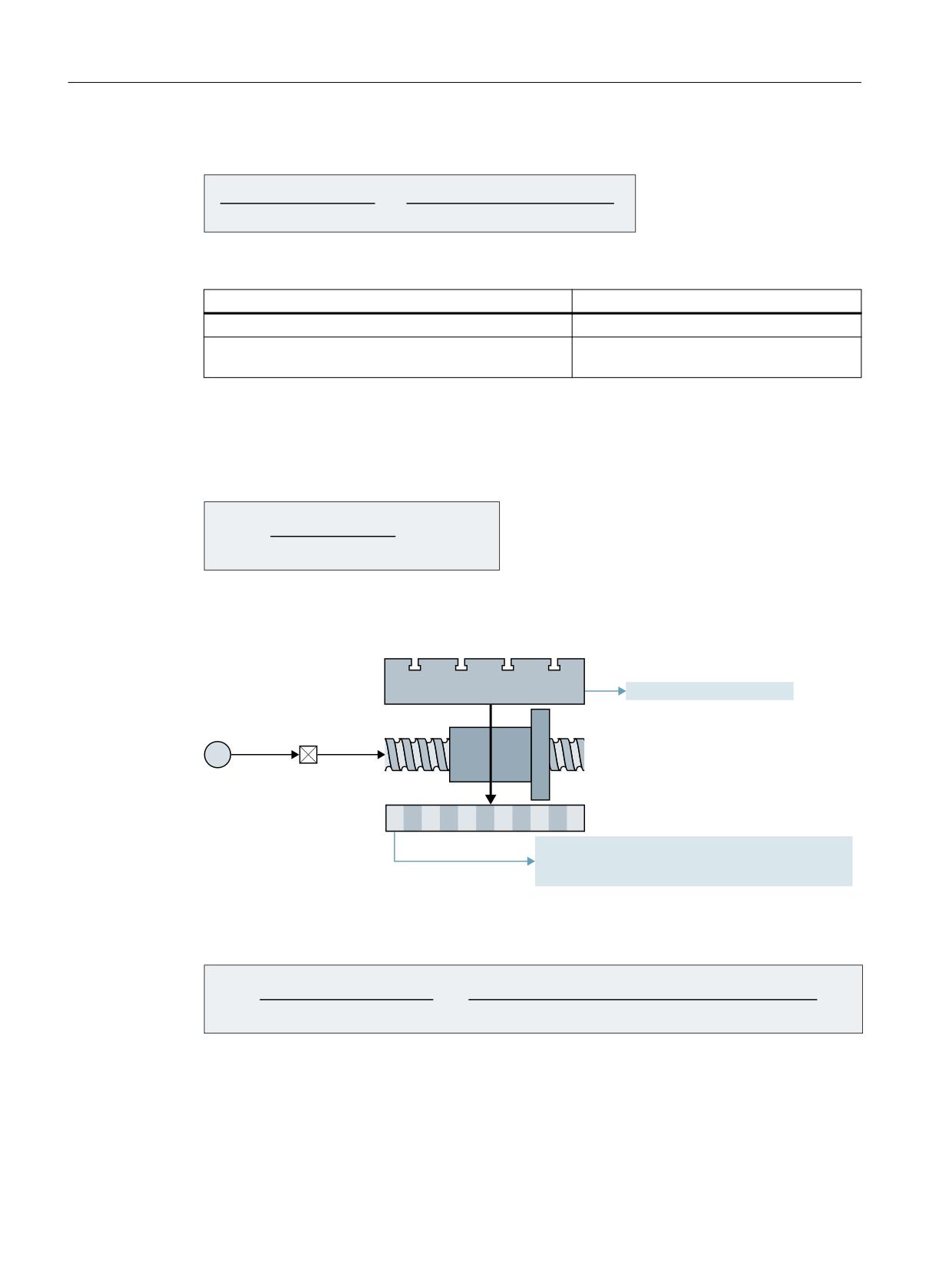
Computational resolution: Linear axes
&RPSXWDWLRQDO UHVROXWLRQ
,QWHUQDO LQFUHPHQWV PP
$FWXDO YDOXH UHVROXWLRQ
(QFRGHU LQFUHPHQWV PP
Axes and spindles
Function Manual, 10/2020, 6FC5397-4GP40-0BA1
167
Velocities, setpoint/actual value systems, closed-loop control
5.4 Setpoint/actual-value system
Computational resolution: Rotary axes
&RPSXWDWLRQDO UHVROXWLRQ
,QWHUQDO LQFUHPHQWV GHJUHH
$FWXDO YDOXH UHVROXWLRQ
(QFRGHU LQFUHPHQWV GHJUHH
Machine data
General machine data: $MN_
Meaning
MD10200 INT_INCR_PER_MM
Computational resolution for linear positions
MD10210 INT_INCR_PER_DEG
Computational resolution for angular posi-
tions
Recommended setting
The above components and settings that are responsible for the actual-value resolution, should
be selected so that the actual-value resolution is higher than the parameterized computational
resolution.
&RPSXWDWLRQDO UHVROXWLRQ
ื
$FWXDO YDOXH UHVROXWLRQ
5.4.6.2
Example: Linear axis with linear scale
7DEOH
0'
,6B527B$;
/RDG
JHDUER[
%DOO VFUHZ
0
/LQHDU VFDOH
0'
(1&B,6B/,1($5
0'
(1&B*5,'B32,17B',67
OLQHDU HQFRGHU
0'
(1&B,19(56
RSSRVLWH GLUHFWLRQ
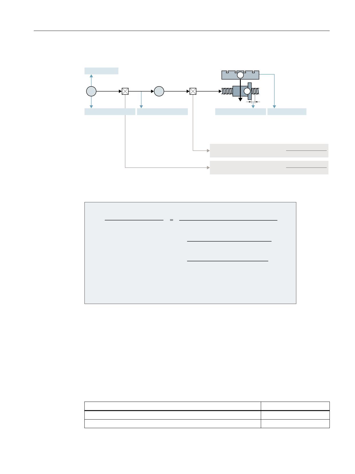
Figure 5-4
Linear axis with linear scale
The ratio of the internal increments to the encoder increments per mm is calculated as follows:
,QWHUQDO LQFUHPHQWV PP
(1&B*5,'B32,17B',67 >Q@
,17B,1&5B3(5B00
(QFRGHU LQFUHPHQWV PP
(1&B38/6(B08/7>Q@
Axes and spindles
168
Function Manual, 10/2020, 6FC5397-4GP40-0BA1
Velocities, setpoint/actual value systems, closed-loop control
5.4 Setpoint/actual-value system
5.4.6.3
Example: Linear axis with rotary encoder on motor
(1&B5(62/
0HDVXULQJ
/RDG
JHDUER[
JHDUER[Q
Q(QFRGHU
6SLQGOH
(
0
(1&B,6B/,1($5
(1&B,6B',5(&7
/($'6&5(:B3,7&+
,6B527B$;
'5,9(B$;B5$7,2B180(5$
1R RI PRWRU UHY
'5,9(B$;B5$7,2B'(120
1R RI ORDG UHY
'5,9(B(1&B5$7,2B180(5$
1R RI PRWRU UHY
'5,9(B(1&B5$7,2B'(120
1R RI HQFRGHU UHY
Figure 5-5
Linear axis with rotary encoder on motor
The ratio of the internal increments to the encoder increments per mm is calculated as follows:
,QWHUQDO LQFUHPHQWV PP
(QFRGHU LQFUHPHQWV PP
(1&B5(62/ >Q@
(1&B38/6(B08/7>Q@
'5,9(B(1&B5$7,2B180(5$ >Q@
'5,9(B(1&B5$7,2B'(120 >Q@
'5,9(B$;B5$7,2B'(120 >Q@
'5,9(B$;B5$7,2B180(5$ >Q@
/($'6&5(:B3,7&+
,17B,1&5B3(5B00
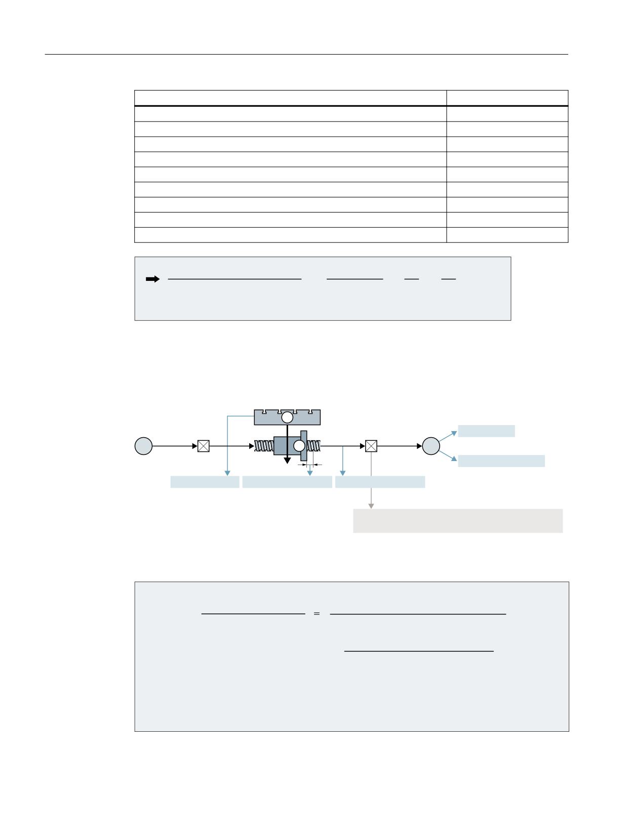
Example
Assumptions:
• Rotary encoder on the motor: 2048 pulses/revolution
• Internal pulse multiplication: 2048
• Gearbox, motor / ball screw: 5:1
• Leadscrew pitch: 10 mm/revolution
• Computational resolution: 10000 increments per mm
Machine data
Value
MD30300 $MA_IS_ROT_AX
0
MD31000 $MA_ENC_IS_LINEAR[0]
0
Axes and spindles
Function Manual, 10/2020, 6FC5397-4GP40-0BA1
169
Velocities, setpoint/actual value systems, closed-loop control
5.4 Setpoint/actual-value system
Machine data
Value
MD31040 $MA_ENC_IS_DIRECT[0]
0
MD31020 $MA_ENC_RESOL[0]
2048
MD31025 $MA_ENC_PULSE_MULT
2048
MD31030 $MA_LEADSCREW_PITCH
10
MD31080 $MA_DRIVE_ENC_RATIO_NUMERA[0]
1
MD31070 $MA_DRIVE_ENC_RATIO_DENOM[0]
1
MD31060 $MA_DRIVE_AX_RATIO_NUMERA[0]
5
MD31050 $MA_DRIVE_AX_RATIO_DENOM[0]
1
MD10210 $MN_INT_INCR_PER_DEG
10000
,QWHUQDO LQFUHPHQWV PP
PP
(QFRGHU LQFUHPHQWV PP
LQFU PP
An encoder increment corresponds to 0.004768 internal increments or 209.731543 encoder
increments correspond to an internal increment.
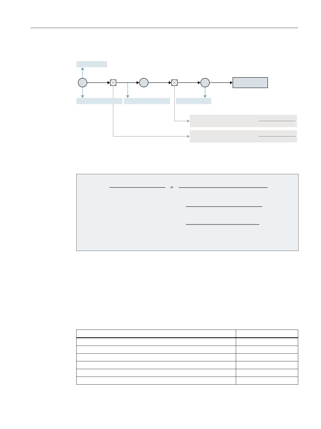
5.4.6.4
Example: Linear axis with rotary encoder on the machine
/RDG
0HDVXULQJ
(1&B5(62/
JHDUER[
JHDUER[Q
Q6SLQGOH
(QFRGHU
0
(
(1&B,6B/,1($5
,6B527B$;
/($'6&5(:B3,7&+
(1&B,6B',5(&7
'5,9(B$;B5$7,2B180(5$
1R RI VSLQGOH UHY
'5,9(B$;B5$7,2B'(120
1R RI HQFRGHU UHY
Figure 5-6
Linear axis with rotary encoder on the machine
The ratio of the internal increments to the encoder increments per mm is calculated as follows:
,QWHUQDO LQFUHPHQWV PP
(QFRGHU LQFUHPHQWV PP
(1&B5(62/ >Q@
(1&B38/6(B08/7>Q@
'5,9(B(1&B5$7,2B180(5$ >Q@
'5,9(B(1&B5$7,2B'(120 >Q@
/($'6&5(:B3,7&+
,17B,1&5B3(5B00
Axes and spindles
170
Function Manual, 10/2020, 6FC5397-4GP40-0BA1
Velocities, setpoint/actual value systems, closed-loop control
5.4 Setpoint/actual-value system
5.4.6.5
Example: Rotary axis with rotary encoder on motor
(1&B5(62/
0HDVXULQJ
/RDG
JHDUER[
JHDUER[
Q(QFRGHU
Q0RWRU
Q0RWRU
Q/RDG
(
0
/
5RWDU\ WDEOH
(1&B,6B/,1($5
(1&B,6B',5(&7
,6B527B$;
'5,9(B$;B5$7,2B180(5$
1R RI PRWRU UHY
'5,9(B$;B5$7,2B'(120
1R RI ORDG UHY
'5,9(B(1&B5$7,2B180(5$
1R RI PRWRU UHY
'5,9(B(1&B5$7,2B'(120
1R RI HQFRGHU UHY
Figure 5-7
Rotary axis with rotary encoder on motor
The ratio of the internal increments to the encoder increments per degree is calculated as
follows:
,QWHUQDO LQFUHPHQWV GHJUHH
GHJUHHV
(QFRGHU LQFUHPHQWV GHJUHH
(1&B5(62/ >Q@
(1&B38/6(B08/7>Q@
'5,9(B(1&B5$7,2B180(5$ >Q@
'5,9(B(1&B5$7,2B'(120 >Q@
'5,9(B$;B5$7,2B'(120 >Q@
'5,9(B$;B5$7,2B180(5$ >Q@
,17B,1&5B3(5B'(*
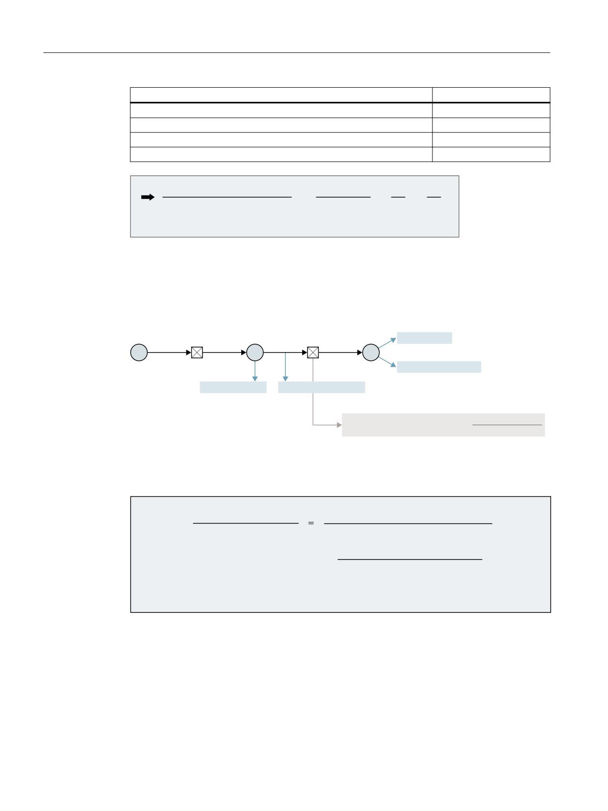
Example
Assumptions:
• Rotary encoder on the motor: 2048 pulses/revolution
• Internal pulse multiplication: 2048
• Gearbox, motor / rotary axis: 5:1
• Computational resolution: 1000 increments per degree
Machine data
Value
MD30300 $MA_IS_ROT_AX
1
MD31000 $MA_ENC_IS_LINEAR[0]
0
MD31040 $MA_ENC_IS_DIRECT[0]
0
MD31020 $MA_ENC_RESOL[0]
2048
MD31025 $MA_ENC_PULSE_MULT
2048
MD31080 $MA_DRIVE_ENC_RATIO_NUMERA[0]
1
Axes and spindles
Function Manual, 10/2020, 6FC5397-4GP40-0BA1
171
Velocities, setpoint/actual value systems, closed-loop control
5.4 Setpoint/actual-value system
Machine data
Value
MD31070 $MA_DRIVE_ENC_RATIO_DENOM[0]
1
MD31060 $MA_DRIVE_AX_RATIO_NUMERA[0]
5
MD31050 $MA_DRIVE_AX_RATIO_DENOM[0]
1
MD10210 $MN_INT_INCR_PER_DEG
1000
,QWHUQDO LQFUHPHQWV GHJUHH
GHJUHHV
(QFRGHU LQFUHPHQWV GHJUHH
LQF GHJUHH
An encoder increment corresponds to 0.017166 internal increments or 58.254689 encoder
increments correspond to an internal increment.
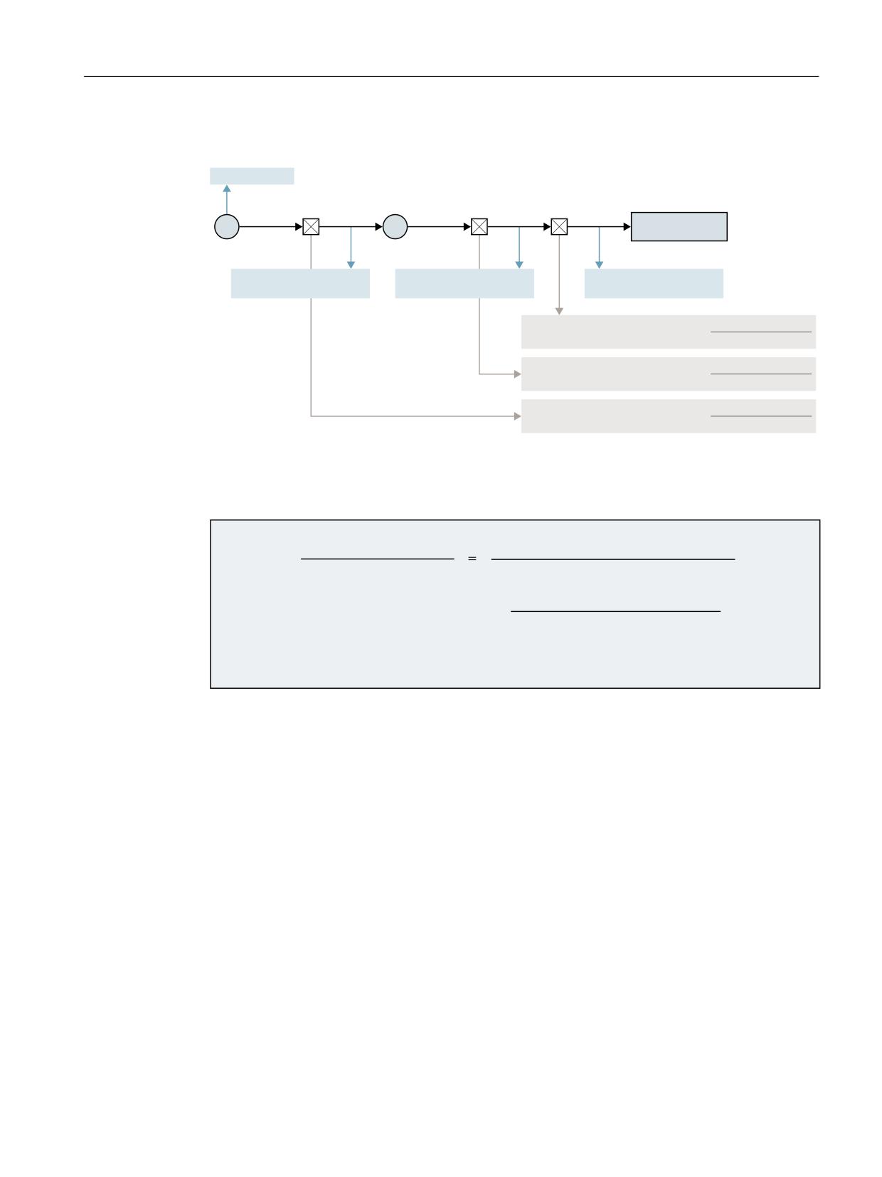
5.4.6.6
Example: Rotary axis with rotary encoder on the machine
/RDG
5RWDU\
0HDVXULQJ
WDEOH
(1&B5(62/
JHDUER[
JHDUER[Q
Q/RDG
(QFRGHU
0
/
(
(1&B,6B/,1($5
,6B527B$;
(1&B,6B',5(&7
'5,9(B(1&B5$7,2B180(5$
1R RI PRWRU UHY
'5,9(B(1&B5$7,2B'(120
1R RI HQFRGHU UHY
Figure 5-8
Rotary axis with rotary encoder on the machine
The ratio of the internal increments to the encoder increments per degree is calculated as
follows:
,QWHUQDO LQFUHPHQWV GHJUHH
GHJUHHV
(QFRGHU LQFUHPHQWV GHJUHH
(1&B5(62/ >Q@
(1&B38/6(B08/7>Q@
'5,9(B(1&B5$7,2B180(5$ >Q@
'5,9(B(1&B5$7,2B'(120 >Q@
,17B,1&5B3(5B'(*
Axes and spindles
172
Function Manual, 10/2020, 6FC5397-4GP40-0BA1
Velocities, setpoint/actual value systems, closed-loop control
5.5 Closed-loop control
5.4.6.7
Example: Intermediate gear with encoder on the tool
(1&B5(62/
0HDVXULQJ
/RDG
,QWHUPHGLDWH
JHDUER[
JHDUER[
JHDUER[
Q(QFRGHU
Q0RWRU
Q0RWRU
Q7RRO
(
0
7RRO
(1&B,6B',5(&7
(1&B,6B',5(&7
(1&B,6B',5(&7
(1&B,6B',5(&7
(1&B,6B',5(&7
(1&B,6B',5(&7
'5,9(B$;B5$7,2 B180(5$
1R RI ORDG UHY
'5,9(B$;B5$7,2 B'(120
1R RI VSLQGOH UHY
'5,9(B$;B5$7,2B180(5$
1R RI PRWRU UHY
'5,9(B$;B5$7,2B'(120
1R RI VSLQGOH UHY
'5,9(B(1&B5$7,2B180(5$
1R RI PRWRU UHY
'5,9(B(1&B5$7,2B'(120
1R RI HQFRGHU UHY
Figure 5-9
Intermediate gear with encoder directly on the rotating tool
The ratio of the internal increments to the encoder increments per degree is calculated as
follows:
,QWHUQDO LQFUHPHQWV GHJUHH
GHJUHHV
(QFRGHU LQFUHPHQWV GHJUHH
(1&B5(62/ >Q@
(1&B38/6(B08/7>Q@
'5,9(B(1&B5$7,2B180(5$ >Q@
'5,9(B(1&B5$7,2B'(120 >Q@
,17B,1&5B3(5B'(*
5.5
Closed-loop control
5.5.1
Position control of axes/spindles
The closed-loop control of an axis consists of the current and speed control loop of the drive plus
a higher-level position control loop in the NC.
The basic structure of an axis/spindle position control is illustrated below:
Axes and spindles
Function Manual, 10/2020, 6FC5397-4GP40-0BA1
173
Velocities, setpoint/actual value systems, closed-loop control
5.5 Closed-loop control
0'
> @
0'
> @
0'
0'
3DWK FRQWURO
[ Y
[
[
[
[
[VHW
QDFW
[DFW
LQWHUSRODWRU
),32
3KDVH ILOWHU
-HUN ILOWHU
'\QDPLF
3RVLWLRQ
'ULYH DQG
UHVSRQVH
FRQWUROOHU
PHFKDQLFDO
PDWFKLQJ
[
V\VWHP
DFW
MD32410
$MA_AX_JERK_TIME
MD32910
$MA_DYN_MATCH_TIME
MD32895
$MA_DESVAL_DELAY_TIME
MD32200
$MA_POSCTRL_GAIN
x
Position setpoint
v
Velocity setpoint
xact
Position actual value
nact
Speed actual value
nset
Speed setpoint
Fine interpolation
Using the fine interpolator (FIPO), the contour precision can be further increased by reducing the
staircase effect in the speed setpoint. You can set three different types of fine interpolation:
MD33000 $MA_FIPO_TYPE = <FIPO mode>
<FIPO mode>
Meaning
1
Differential fine interpolation with mean value generation (smoothing) over an IPO
cycle
2
Cubic fine interpolation
3
Cubic fine interpolation optimized for use with the pre-control for the highest contour
precision
Servo gain factor (KV)
In order that few contour deviations occur in the continuous-path mode, a high servo gain factor
(KV) is necessary:
MD32200 $MA_POSCTRL_GAIN[n]
However, if the servo gain factor (KV) is too high, instability, overshoot and possibly
impermissible high loads on the machine will result.
The maximum permissible servo gain factor (KV) depends on the following:
• Design and dynamics of the drive
(rise time, acceleration and braking capacity)
• Machine quality
(elasticity, oscillation damping)
• Position control cycle or speed control cycle for active DSC
Axes and spindles
174
Function Manual, 10/2020, 6FC5397-4GP40-0BA1
Velocities, setpoint/actual value systems, closed-loop control
5.5 Closed-loop control
The servo gain factor (K
V
) is defined as:
9HORFLW\
>P PLQ@
.Y
)ROORZLQJ HUURU
>PP@
Jerk limiting
For information on the jerk limitation, see Section "Acceleration and jerk (Page 79)".
Dynamic response adaptation
Axes that interpolate with one another, but with different servo gain factors (KV) can be set to the
same following error using the dynamic adaptation function. This allows an optimum contour
accuracy to be achieved without loss of control quality by reducing the servo gain factors (KV) to
the dynamically weakest axis.
The function is activated via:
MD32900 $MA_DYN_MATCH_ENABLE = 1 (dynamic response adaptation)
The dynamic response adaptation is realized by entering a new equivalent time constant. It is
calculated from the difference in the equivalent time constant of the dynamically weakest axis
and the axis to be adapted:
MD32910 $MA_DYN_MATCH_TIME [n] = <difference in the equivalent time constant>
6WHS UHVSRQVH
RI WKH SRVLWLRQ
FRQWURO ORRS
(TXLYDOHQW WLPH D[LV
(TXLYDOHQW WLPH
0'
$[LV
0$B'<1B0$7&+B7,0(
$[LV ZLWK KLJK .9
$[LV ZLWK ORZ .9
$[LV ZLWK KLJK .9 DQG G\QDPLF
UHVSRQVH DGDSWDWLRQ
W
Axes and spindles
Function Manual, 10/2020, 6FC5397-4GP40-0BA1
175

Velocities, setpoint/actual value systems, closed-loop control
5.5 Closed-loop control
Example of a dynamic response adaptation of three axes without speed feedforward
control
The equivalent time constant of the position control loop is:
Axis 1:
30 ms
Axis 2:
20 ms
Axis 3:
24 ms
With an equivalent time constant of 30 ms, axis 1 is the dynamically weakest axis.
This results in the following new equivalent time constants for the axes:
Axis 1:
MD32910 $MA_DYN_MATCH_TIME = 0 ms
Axis 2:
MD32910 $MA_DYN_MATCH_TIME = 30 ms - 20 ms = 10 ms
Axis 3:
MD32910 $MA_DYN_MATCH_TIME = 30 ms - 24 ms = 6 ms
Approximation formulas for the equivalent time constant of the position control loop of an axis
The equivalent time constant Tequiv of the position control loop of an axis is approximately
calculated depending on the type of feedforward control:
• Without feedforward control:
75HSODFHPHQW
ป
0'
326&75/B*$,1 > V@
• With speed feedforward control:
75HSODFHPHQW ป 0'
(48,9B63(('&75/B7,0(
• For combined torque/speed feedforward control
75HSODFHPHQW ป 0'
(48,9B&855&75/B7,0(
Note
If dynamic response adaptation is realized for a geometry axis, then all other geometry axes
must be set to the same dynamic response.
Axes and spindles
176
Function Manual, 10/2020, 6FC5397-4GP40-0BA1
Velocities, setpoint/actual value systems, closed-loop control
5.5 Closed-loop control
5.5.2
Switchable position setpoint filter circuits
Benefits
Two switchable position setpoint filter circuits allow the damping effect of the filters to be
adapted to the specific machining type, and these can also be selected during machining. For
example, filters that provide very high damping (Blackman filters) and very high axial jerk factors
($MA_MAX_AX_JERK, $MA_PATH_TRANS_JERK_LIM) can be used, e.g. for motion outside the
workpiece or when roughing so that processing times can be significantly reduced. The
relatively high contour deviation in conjunction with the powerful filters do not have an
excessively high negative impacts for these machining types.
It is advantageous to couple the filter switchover to the dynamic G code groups DYNNORM,
DYNROUGH, DYNFINISH and DYNPREC and initiate it via a cycle (e.g. CUST_832). The status and
values of the filter changeover can be queried using the following system variables.
• $VA_DESVAL_FILTERS_ACTIVE; status of the setpoint filter circuits
• $VA_DESVAL_FILTERS_DELAY_1/2; effective delay time of the 1st/2nd setpoint filter circuit
• $VA_DESVAL_FILTERS_DELTA_POS; position difference between the setpoint filter circuits.
Option
To be able to use the function for axis movement, a license is required for the following option:
"Jerk adaptation" (6FC5800-0AS22-0Yx0)
The switchover of the position setpoint filter circuits when the axis is at a standstill is also
possible without the option.
Axes and spindles
Function Manual, 10/2020, 6FC5397-4GP40-0BA1
177
Velocities, setpoint/actual value systems, closed-loop control
5.5 Closed-loop control
Function
Position control of an axis/spindle with switchable position setpoint filter circuit:
0'
> @
0'
> @
0'
[
[
[
'\QDPLF
3KDVH ILOWHU
-HUN ILOWHU
UHVSRQVH
PDWFKLQJ
0'
> @
0'
> @
0'
0'
3DWK FRQWURO
[ Y
[
[
[
[
[VHW
QDFW
[DFW
LQWHUSRODWRU
),32
'\QDPLF
3RVLWLRQ
'ULYH DQG
3KDVH ILOWHU
-HUN ILOWHU
UHVSRQVH
FRQWUROOHU
PHFKDQLFDO
PDWFKLQJ
[
V\VWHP
DFW
$$B'(69$/B),/7(56B6(/(&7> D[LV!@
MD32410
$MA_AX_JERK_TIME
MD32910
$MA_DYN_MATCH_TIME
MD32895
$MA_DESVAL_DELAY_TIME
MD32200
$MA_POSCTRL_GAIN
x
Position setpoint
v
Velocity setpoint
xact
Position actual value
nact
Speed actual value
nset
Speed setpoint
Selection and/or preassignment of filter types for every filter circuit
The switchable position setpoint filter circuits are activated by entering a two-digit value in
machine data MD32402 $MA_AX_JERK_MODE (filter type for axial jerk limiting). This allows two
alternative jerk filters to be selected.
Axes and spindles
178
Function Manual, 10/2020, 6FC5397-4GP40-0BA1

Velocities, setpoint/actual value systems, closed-loop control
5.5 Closed-loop control
Parameter assignment
Two filter types must be selected to be able to switch between the two filter circuits from the part
program:
• The jerk filter type of the first filter circuit is selected in the "Ones position" of machine data
MD32402 AX_JERK_MODE, and the associated filter settings are set in index 0 of the machine
data to parameterize the filter.
• The jerk filter type of the second filter circuit is selected in the "Tens position" of machine data
MD32402 AX_JERK_MODE, and the associated filter settings are set in index 1 of the machine
data to parameterize the filter.
• The following machine data has two indices:
- MD32402 AX_JERK_FIR_FREQ
- MD32408 AX_JERK_FIR_ORDER
- MD32409 AX_JERK_FIR_WINDOW
- MD32410 AX_JERK_TIME
- MD32411 AX_JERK_TIME_ADD
- MD32412 AX_JERK_FREQ
- MD32414 AX_JERK_DAMP
Constraints
Filter circuits can only be parameterized if the following conditions are satisfied:
• MD33000 $MA_FIPO_TYPE = 1 or 3
• MD32220 $MA_POSCTRL_INTEGR_ENABLE = 0
• MD32930 $MA_POSCTRL_OUT_FILTER_ENABLE = 0
• MD32610 $MA_VELO_FFW_WEIGHT = 1.0
• MD32620 $MA_FFW_MODE = 0, 3 or 4
Commissioning
Two filter types are selected to preset the filter types for the filter circuits. To switch over the
parameterized filter circuits, you use the system variable $AA_DESVAL_FILTERS_SELECT[<axis>].
The following system variables are available for querying the status of the filter circuits:
System variable
Meaning
$VA_DESVAL_FILTERS_ACTIVE
Currently active filter circuit
$VA_DESVAL_FILTERS_DELTA_POS
Current difference in position between the filter circuits
This is needed in order to be able to determine a suitable switchover point. Suit-
able switchover points are motions with a constant velocity (acceleration = 0) or
when an axis is at a standstill in which the position difference is small. If a switch-
over is made while an axis is accelerating, then an acceleration step (jump) can
occur, which under certain circumstances can trigger the contour monitoring
function. The switchover is made immediately when requested.
Axes and spindles
Function Manual, 10/2020, 6FC5397-4GP40-0BA1
179

Velocities, setpoint/actual value systems, closed-loop control
5.5 Closed-loop control
System variable
Meaning
$VA_DESVAL_FILTERS_DELAY_1
Effective delay time of the first circuit
$VA_DESVAL_FILTERS_DELAY_2
Effective delay time of the second circuit
Example
Two switchover position setpoint filter circuits are parameterized with the following attributes
using MD32402 $MA_AX_JERK_MODE = 25:
• With a value of 5, a position setpoint filter, filter type 5 = FIR lowpass is parameterized in the
first position setpoint filter circuit.
• With a value of 20, a position setpoint filter, filter type 2 = moving average calculation
parameterized in the second position setpoint filter circuit.
• MD32895 $MA_DESVAL_DELAY_TIME is used to synchronize the total delay times of the two
filter circuits to one another.
See also
Jerk filter (position setpoint filter, axis-specific) (Page 106)
5.5.3
Parameter sets of the position controller
Six parameter sets per machine axis are available to quickly adapt the position control to the
changed machine properties during operation, e.g. a gear change of the spindle, or to adjust the
dynamic response to another axis, e.g. during tapping.
Machine data
A parameter set comprises the following machine data:
Number
Identifier $MA_
Meaning
31050
DRIVE_AX_RATIO_DENOM
Denominator load gearbox
31060
DRIVE_AX_RATIO_NUMERA
Numerator load gearbox
32200
POSCTRL_GAIN
Servo gain factor (KV)
32452
BACKLASH_FACTOR
Backlash compensation
32610
VELO_FFW_WEIGHT
Feedforward control factor
36012
STOP_LIMIT_FACTOR
Exact stop coarse/fine factor and zero speed
32800
EQUIV_CURRCTRL_TIME
Equivalent time constant, current control loop for feed-
forward control
32810
EQUIV_SPEEDCTRL_TIME
Equivalent time constant, speed control loop for feed
forward control
32910
DYN_MATCH_TIME
Time constant for dynamic response adaptation
36200
AX_VELO_LIMIT
Threshold value for velocity monitoring
Axes and spindles
180
Function Manual, 10/2020, 6FC5397-4GP40-0BA1

Velocities, setpoint/actual value systems, closed-loop control
5.6 Optimization of the control
Tapping, thread cutting
For tapping or thread cutting, the following applies with regard to the parameter sets of axes:
• For machine axes that are not involved in tapping or thread cutting, parameter set 1 (index
= 0) is active. The other parameter sets do not have to be taken into account.
• For machine axes that are involved in tapping or thread cutting, the same parameter set
number as that of the current gear stage of the spindle is active.
All parameter sets correspond to the gear stages and must therefore be parameterized.
The current parameter set is displayed on the user interface at:
Operating Area "Diagnostics" > "Service axis"
Parameter sets during gear stage change
Each gear stage of a spindle is assigned a separate parameter set. The gear stage is selected via
the following NC/PLC interface signal:
DB31, ... DBX16.0 - 2 = <actual gear stage>
Actual gear stage
DB31, ... DBX16.0 - 2
Parameter set
1st gear stage
000
2
(Index=1)
1st gear stage
001
2
(Index=1)
2nd gear stage
010
3
(Index=2)
3rd gear stage
011
4
(Index=3)
4th gear stage
100
5
(Index=4)
5th gear stage
101
6
(Index=5)
110
111
For further information on gear stages for spindles, see Section "Spindles (Page 377)".
5.6
Optimization of the control
5.6.1
Position controller, position setpoint filter: Balancing filter
Function
With feedforward control active, the position setpoint is sent through a so-called balancing
filter before it reaches the controller itself. It is thus possible to control the speed setpoint to
100% in advance, without resulting in overshoots when positioning.
Activation
The feedforward control variant is selected and so also the filter activated using the axis-specific
machine data:
Axes and spindles
Function Manual, 10/2020, 6FC5397-4GP40-0BA1
181

Velocities, setpoint/actual value systems, closed-loop control
5.6 Optimization of the control
MD32620 $MA_FFW_MODE (feedforward control mode)
Value
Meaning
3
Speed precontrol
4
Combined torque/speed precontrol
Activating and deactivating via the part program
Part programs can be used to activate and deactivate the feedforward control for all axes, using
commands FFWON and FFWOF.
If the feedforward control of the individual axes should not be influenced by FFWON/FFWOF, the
setting in the following machine data must be changed for these axes:
MD32630 $MA_FFW_ACTIVATION_MODE (activate feedforward control from program)
Parameterization
Recommended setting for recommissioning
If recommissioning, or if default values have been loaded (switch position 1 on commissioning
switch and POWER ON), the following machine data default values apply:
• MD32620 $MA_FFW_MODE = 3
• MD32610 $MA_VELO_FFW_WEIGHT (feedforward control factor for the velocity
feedforward control) = 1
The balancing time for the speed feedforward control then just has to be adjusted in the
following machine data:
MD32810 $MA_EQUIV_SPEEDCTRL_TIME (equivalent time constant speed control loop for
feedforward control)
Setting the equivalent time constant of the speed control loop (MD32810)
We recommend that the axis be allowed to move in and out in "AUTOMATIC" mode with a part
program and that travel-in to the target position, i.e. the actual position value of the active
measuring system, be monitored with the servo trace.
The initial value for setting is the time constant of the speed control loop. This can be read from
the reference frequency characteristic of the speed control loop. In the frequent case of a PI
controller with speed setpoint smoothing, an approximate equivalent time can be read from
drive machine data p1414, p1415, p1416 and p1421.
This start value (e.g. 1.5 ms) is now entered:
MD32810 $MA_EQUIV_SPEEDCTRL_TIME = 0.0015
The axis then travels forward and backward and the operator monitors a greatly-magnified
characteristic of the actual position value at the target position.
Axes and spindles
182
Function Manual, 10/2020, 6FC5397-4GP40-0BA1

Velocities, setpoint/actual value systems, closed-loop control
5.6 Optimization of the control
The following rules apply to making manual fine adjustments:
Monitoring
Measure
Effect
Overshoot
Increase MD32810
The position controller responds more slowly.
⇒ The tendency to overshoot decreases.
Problem: The contour error (deviation from the program-
med contour) increases at curves.
Excessively slow
Reduce MD32810
The position controller responds faster.
approach
⇒ The contour error at curves decreases.
Problem: The tendency to overshoot increases.
Note
The effects are similar to modification of the position controller gain (MD32200
$MA_POSCTRL_GAIN). They can be observed on the user interface in the operating section
"Diagnostics" > "Axis service" using the computed KV value.
MD32810 fine adjustment
Therefore, MD32810 should be assigned as small a value as possible, with the overshoot setting
the limit during positioning. Furthermore, the initial value is only modified slightly during fine
adjustment, typically by adding or deducting 0.25 ms.
For example, if the initial value is 1.5 ms, the optimum value calculated manually is usually
within the range 1.25 ms to 1.75 ms.
In the case of axes equipped with direct measuring systems (load encoders) and strong
elasticity, you may possibly accept small overshoots of some micrometers. These can be reduced
with the help of the position setpoint filter for dynamic response adaptation (MD32910
$MA_DYN_MATCH_TIME) and for jerk (MD32410 $MA_AX_JERK_TIME), which also reduces the
axis speed.
Identical axis data within an interpolation group
All the axes within an interpolation group should have identical settings in the following data:
• MD32200 $MA_POSCTRL_GAIN (adapted using MD32910)
• MD32620 $MA_FFW_MODE
• MD32610 $MA_VELO_FFW_WEIGHT
• MD32810 $MA_EQUIV_SPEEDCTRL_TIME (or MD32800 $MA_EQUIV_CURRCTRL_TIME)
(dependent on the mechanical system and drive)
• MD32400 $MA_AX_JERK_ENABLE
• MD32402 $MA_AX_JERK_MODE
• MD32410 $MA_AX_JERK_TIME
The servo gain display (KV) of the user interface in operating section "Diagnostics" > "Axis service"
is used for checking.
Non-identical axis data within an interpolation group
If identical values are not possible for the above data, the following machine data can be used
to make an adjustment:
Axes and spindles
Function Manual, 10/2020, 6FC5397-4GP40-0BA1
183

Velocities, setpoint/actual value systems, closed-loop control
5.6 Optimization of the control
MD32910 $MA_DYN_MATCH_TIME (time constant of dynamic response adaptation)
This allows the same servo gain value (KV) to be displayed.
Different servo gain display values (KV) usually point to the following:
• The gear ratios do not match in one or several axes.
• The feedforward control setting data does not match.
Setting the equivalent time constant of the current control loop (MD32800)
The activation of the torque feedforward control filter is performed with:
MD32620 $MA_FFW_MODE = 4
The same rules and recommendations apply to setting the time constant of the current control
loop MD32800 $MA_EQUIV_CURRCTRL_TIME as to the speed feedforward control.
Limitation to stiff machines
Experience has shown that this expenditure is only worthwhile in the case of very stiff machines,
and requires appropriate experience. The elasticities of the machine are often excited due to the
injection of the torque so strongly that the existing vibrations neutralize the gain in contour
accuracy.
In this case, it would be worth trying the function "Dynamic Stiffness Control" (DSC) as an
alternative:
MD32640 $MA_STIFFNESS_CONTROL_ENABLE = 1
Note
The following conditions apply to use of DSC:
• In the NC, no actual value inversion (MD32110 $MA_ENC_FEEDBACK_POL = -1) must be
parameterized. Actual-value inversion in the drive (SINAMICS parameter p0410) is
permissible.
• The function must be activated for all axes that are in an interpolation relationship (path
motion or coupling) (MD32640 = 1).
• If one of the axes is parameterized as a simulated axis (MD30130 $MA_CTRLOUT_TYPE = 0,
MD30240 $MA_ENC_TYPE = 0), DSC cannot be applied. In this case, the function must be
deactivated for all axes that are in an interpolation relationship (MD32640 = 0).
CAUTION
Exception error condition
An exception error condition may occur if p1192 is set for a non-existing measuring system and
DSC is activated!
For service situations in which an additional measuring system has to be disabled and DSC is
active, it must be assured that p1192 is also adapted.
Axes and spindles
184
Function Manual, 10/2020, 6FC5397-4GP40-0BA1
Velocities, setpoint/actual value systems, closed-loop control
5.6 Optimization of the control
Control response with POWER ON, RESET, REPOS, etc.
In the case of POWER ON and RESET, as well as with "Enable machine data", the setting data of
the feedforward control is read in again (see the appropriate values of the relevant machine
data).
Mode change, block search and REPOS have no influence on the feedforward control.
5.6.2
Position controller, position setpoint filter: Phase filter
Function
The axis-specific phase filter setpoint (dead time / delay) implements a pure phase shifter with
which the setpoint phase response can be influenced. Together with the axis-specific jerk filter
setpoint (MD32402_$MA_AX_JERK_MODE[<axis>] = 2; see Function Manual "Axes and
Spindles", Section "Jerk filter") it is possible to adapt the amplitude response and the phase
response independently of one another to the dynamically weakest of several axes, which
should proceed along a programmed path together.
6SHHG VHWSRLQW
QVHW
W
① Position controller cycle clock: 2 ms
② Time constant of the axis-specific phase filter setpoint: 19.2 ms
Figure 5-10
Effect of the axis-specific phase filter setpoint
Parameterization: Time constant
The time constant for the axis-specific phase filter setpoint can be set in the range:
(0 to 64) * position controller cycle clock (MD10061 $MN_POSCTRL_CYCLE_TIME)
The value of the time constants must be entered in seconds [s] in the machine data:
MD32895 $MA_DESVAL_DELAY_TIME[<axis>]
Example: Position controller cycle clock: 2 ms ⇒ adjustable time constant: 0.0 to 0.128 s
Note
The time constant of the phase filter setpoint delays the axis response characteristics for tapping,
retractions, and exact stops / block changes, etc. It is therefore recommended to set the time
constant as low as possible.
Axes and spindles
Function Manual, 10/2020, 6FC5397-4GP40-0BA1
185
Velocities, setpoint/actual value systems, closed-loop control
5.6 Optimization of the control
Limiting to a maximum value
A greater time constant than the permitted maximum value (64 * position controller cycle clock)
is limited internally to the maximum value. No message / alarm is displayed.
Parameterization: Activation
The function of the axis-specific phase filter setpoint must be activated with the following
machine data:
MD32890 $MA_DESVAL_DELAY_ENABLE[<axis>] = "TRUE"
Examples
Assumption: Position controller cycle clock = 2 ms
1. MD32890 $MA_DESVAL_DELAY_ENABLE[<axis>] = "FALSE"
MD32895 $MA_DESVAL_DELAY_TIME[<axis>] = <Time constant>
- Phase filter setpoint: Not active
- Time constant: Irrelevant
2. MD32890 $MA_DESVAL_DELAY_ENABLE[<axis>] = TRUE
MD32895 $MA_DESVAL_DELAY_TIME[<axis>] = 0.002
- Phase filter setpoint: Active
- Time constant: 2 ms ⇒ the setpoint output is delayed by a position controller cycle clock.
3. MD32890 $MA_DESVAL_DELAY_ENABLE[<axis>] = TRUE
MD32895 $MA_DESVAL_DELAY_TIME[<axis>] = 0.256
- Phase filter setpoint: Active
- Set time constant: 256 ms;
maximum possible time constant: 64 * 2 ms = 128 ms
⇒ internally effective time constant: 128 ms
Constraints
SINUMERIK Safety Integrated
The phase filter setpoint delays the output of axis-specific setpoints; e.g. for retractions (ESR for
STOP E/SS2ESR). However, the phase filter setpoint has no influence over shutdown processes;
e.g. the SOS activation time.
Axes and spindles
186
Function Manual, 10/2020, 6FC5397-4GP40-0BA1
Velocities, setpoint/actual value systems, closed-loop control
5.6 Optimization of the control
5.6.3
Position controller: injection of positional deviation
Preconditions
• The function can only be used on axes with two encoders:
MD30200 $MA_NUM_ENCS = 2
One of the encoders must be parameterized as an indirect measuring system and the other
as a direct measuring system:
- Direct measuring system:
MD31040 $MA_ENC_IS_DIRECT[1]=1
The encoder for position actual-value acquisition is connected directly to the machine
(load encoder).
- Indirect measuring system:
MD31040 $MA_ENC_IS_DIRECT[0]=0
The encoder for position actual-value acquisition is located on the motor (motor encoder).
• Telegram type 136 or 138 must be configured as standard telegram type for PROFIdrive both
in the drive and also in the NC (MD13060 $MN_DRIVE_TELEGRAM_TYPE).
Function
For active injected positional deviation, the difference position between the direct and the
indirect measuring system of an axis is determined and in accordance with the weighting-factor
setting is applied as additional current setpoint for the feedforward control in the position
control cycle. The resulting oscillation damping improves the stability and positioning behavior
of the axis.
Application
The function is used for axes with strong tendency to vibrate.
Effectiveness
The function acts only for axes with small natural frequency (to approximately 20 Hz).
Activation/parameterization
The function is activated by specifying the weighting factor:
MD32950 $MA_POSCTRL_DAMPING (damping of the speed control loop) = <value>
Value range: -100% ... +100%
An input value "100%" means: A supplementary torque in accordance with SINAMICS parameter
p2003 is applied when the determined position difference between the two measuring systems
reaches the following value:
• With linear motors: 1 mm
• With linear axis with rotary motor: MD31030 $MA_LEADSCREW_PITCH (leadscrew pitch)
• For rotary axis/spindle: 360 degrees
Axes and spindles
Function Manual, 10/2020, 6FC5397-4GP40-0BA1
187

Velocities, setpoint/actual value systems, closed-loop control
5.6 Optimization of the control
Standard setting is 0. In this case, the injection of positional deviation is inactive.
Note
The weighting factor MD32950 $MA_POSCTRL_DAMPING can be set on the basis of step
responses, for example.
If the control approaches the stability limit (vibration inclination increases), the parameter is too
large or the value has the incorrect sign.
5.6.4
Position control with proportional-plus-integral-action controller
Function
As standard, the core of the position controller is a P controller. It is possible to switch-in an
integral component for special applications (such as an electronic gear). The resulting
proportional-plus-integral-action controller then corrects the error between setpoint and actual
positions down to zero in a finite, settable time period when the appropriate machine data is set
accordingly.
CAUTION
Overshootings of the actual position for activated PI controller
In this instance, you must decide whether this effect is admissible for the application in
question. Knowledge of the control technology and measurements with servo trace are an
absolute prerequisite for using the function. If the appropriate machine data is incorrectly set,
then machines could be damaged due to instability.
Procedure
1. First optimize the position control loop as a proportional-action controller using the tools
described in the previous subsections.
2. Increase the tolerances of the following machine data while measurements are being taken
to determine the quality of the position control with proportional-plus-integral-action
controller:
- MD36020 $MA_POSITIONING_TIME
- MD36030 $MA_STANDSTILL_POS_TOL
- MD36040 $MA_STANDSTILL_DELAY_TIME
- MD36400 $MA_CONTOUR_TOL
Axes and spindles
188
Function Manual, 10/2020, 6FC5397-4GP40-0BA1
Velocities, setpoint/actual value systems, closed-loop control
5.6 Optimization of the control
3.
Activate the position control loop as a proportional-plus-integral-action controller by setting
the following machine data:
MD32220 $MA_POSCTRL_INTEGR_ENABLE ; set value 1
MD32210 $MA_POSCTRL_INTEGR_TIME ; integral time [sec.]
Effect of integral time:
- Tn → 0:
The control error is corrected quickly; however, the control loop can become instable.
- Tn → ∞:
Effectiveness of the integral component is almost 0. Behavior of the controller like a pure
proportional controller.
4.
Find the right compromise for Tn between these two extreme cases for the application.
Note
Tn must not be chosen too near the stability limit because the occurrence of an instability can
cause machine damage.
It is therefore recommended to set Tn to no less than 1 s.
Use servo trace to trace the travel-in of an automatic program traveling to and from a target
position.
5.
Set the servo trace to display the following:
- Following error
- Actual velocity
- Actual position
- Reference position
6.
Reset the tolerance values in the following machine data to the required values, once the
optimum value for Tn has been identified:
- MD36020 $MA_POSITIONING_TIME
- MD36030 $MA_STANDSTILL_POS_TOL
- MD36040 $MA_STANDSTILL_DELAY_TIME
- MD36400 $MA_CONTOUR_TOL
Supplementary conditions
DSC
If the integrator function is used, DSC (Dynamic Stiffness Control) must be switched off.
Axes and spindles
Function Manual, 10/2020, 6FC5397-4GP40-0BA1
189
Velocities, setpoint/actual value systems, closed-loop control
5.7 Data lists
Example
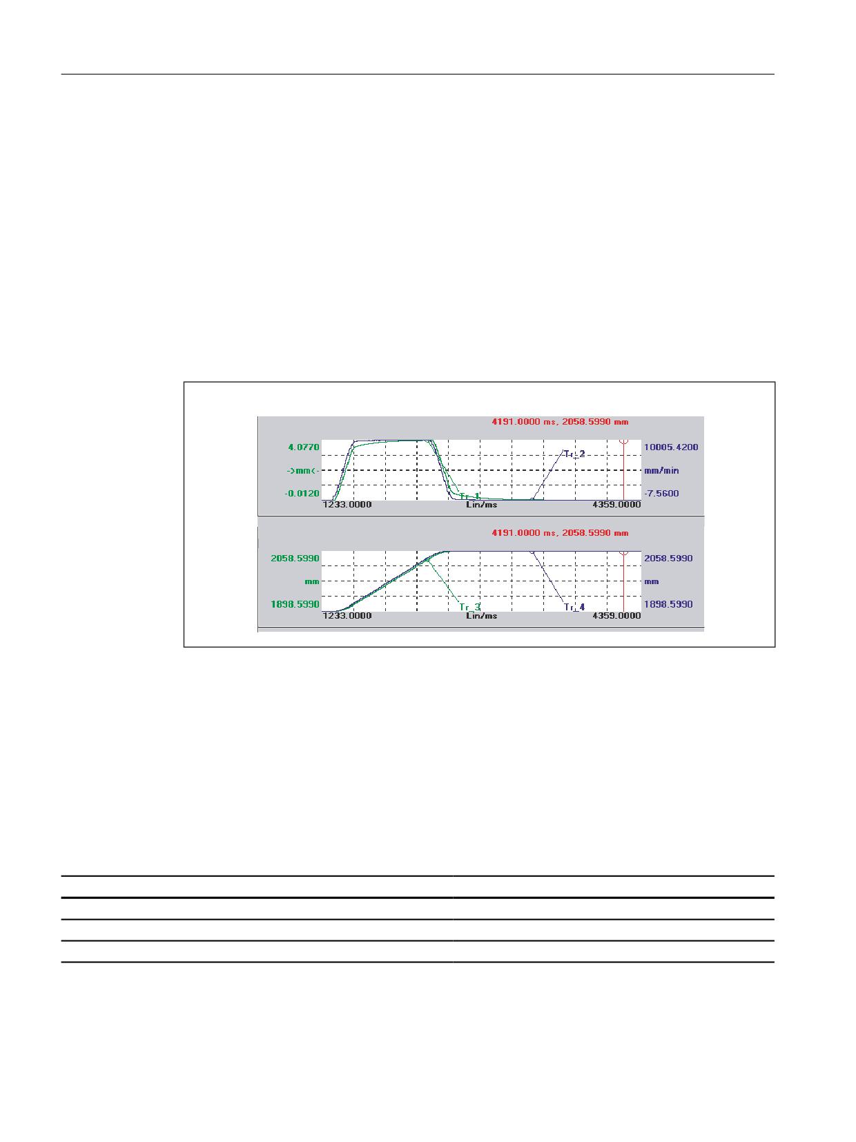
Setting result after several iterative processes for KR and Tn.
Machine data settings:
• MD32220 $MA_POSCTRL_INTEGR_ENABLE = 1
• MD32210 $MA_POSCTRL_INTEGR_TIME = 0.003
• MD32200 $MA_POSCTRL_GAIN[1] = 5.0
Parameter set selection 0
Each of the following quantities - following error, actual velocity, actual position, and position
setpoint - has been recorded by servo trace. When traversing in JOG mode, the characteristic of
the individual data shown in the following figure was then drawn.
Graphic1 <Tr.1: Axis X1, Tr.2: Axis X1>
Tr.1: Following error
Marker X:
Tr.2: Actual velocity
Graphic2 <Tr.3: Axis X1, Tr.4: Axis X1>
Tr.3: Actual position measuring syst. 1
Marker X:
Tr.4: Position setpoint
5.7
Data lists
5.7.1
Machine data
5.7.1.1
Displaying machine data
Number
Identifier: $MM_
Description
9004
DISPLAY_RESOLUTION
Display resolution
9010
SPIND_DISPLAY_RESOLUTION
Display resolution for spindles
9011
DISPLAY_RESOLUTION_INCH
Display resolution for INCH system of measurement
Axes and spindles
190
Function Manual, 10/2020, 6FC5397-4GP40-0BA1

Velocities, setpoint/actual value systems, closed-loop control
5.7 Data lists
5.7.1.2
NC-specific machine data
Number
Identifier: $MN_
Description
10000
AXCONF_MACHAX_NAME_TAB
Machine axis name
10050
SYSCLOCK_CYCLE_TIME
System basic cycle
10070
IPO_SYSCLOCK_TIME_RATIO
Factor for interpolator cycle
10060
POSCTRL_SYSCLOCK_TIME_RATIO
Factor for position-control cycle
10200
INT_INCR_PER_MM
Computational resolution for linear positions
10210
INT_INCR_PER_DEG
Computational resolution for angular positions
10220
SCALING_USER_DEF_MASK
Activation of scaling factors
10230
SCALING_FACTORS_USER_DEF
Scaling factors of physical quantities
10240
SCALING_SYSTEM_IS_METRIC
Basic system metric
10250
SCALING_VALUE_INCH
Conversion factor for switchover to
inch system
10260
CONVERT_SCALING_SYSTEM
Basic system switchover active
10270
POS_TAB_SCALING_SYSTEM
Measuring system of position tables
10290
CC_TDA_PARAM_UNIT
Physical units of the tool data for CC
10292
CC_TOA_PARAM_UNIT
Physical units of the tool edge data for CC
13050
DRIVE_LOGIC_ADDRESS
Logical drive addresses
13060
DRIVE_TELEGRAM_TYPE
Standard message frame type for PROFIBUS DP
13070
DRIVE_FUNCTION_MASK
DP function used
13080
DRIVE_TYPE_DP
Drive type PROFIBUS DP
5.7.1.3
Channelspecific machine data
Number
Identifier: $MC_
Description
20150
GCODE_RESET_VALUES
Initial setting of the G groups
5.7.1.4
Axis/spindlespecific machine data
Number
Identifier: $MA_
Description
30110
CTRLOUT_MODULE_NR
Setpoint assignment: Drive number
30120
CTRLOUT_NR
Setpoint assignment: Setpoint output on drive module
30130
CTRLOUT_TYPE
Output type of setpoint
30200
NUM_ENCS
Number of encoders
30220
ENC_MODULE_NR
Actual value assignment: Drive module number
30230
ENC_INPUT_NR
Actual value assignment: Input on the drive module
30240
ENC_TYPE
Type of actual value acquisition (actual position value)
30242
ENC_IS_INDEPENDENT
Encoder is independent
30300
IS_ROT_AX
Rotary axis
31000
ENC_IS_LINEAR
Direct measuring system (linear scale)
Axes and spindles
Function Manual, 10/2020, 6FC5397-4GP40-0BA1
191

Velocities, setpoint/actual value systems, closed-loop control
5.7 Data lists
Number
Identifier: $MA_
Description
31010
ENC_GRID_POINT_DIST
Distance between reference marks on linear scales
31020
ENC_RESOL
Encoder pulses per revolution
31030
LEADSCREW_PITCH
Leadscrew pitch
31040
ENC_IS_DIRECT
Encoder is connected directly to the machine
31044
ENC_IS_DIRECT2
Encoder on intermediate gear
31050
DRIVE_AX_RATIO_DENOM
Denominator load gearbox
31060
DRIVE_AX_RATIO_NUMERA
Load gear numerator
31064
DRIVE_AX_RATIO2_DENOM
Intermediate gear denominator
31066
DRIVE_AX_RATIO2_NUMERA
Intermediate gear numerator
31070
DRIVE_ENC_RATIO_DENOM
Measuring gear denominator
31080
DRIVE_ENC_RATIO_NUMERA
Measuring gear numerator
31090
JOG_INCR_WEIGHT
Weighting of increment for INC/handwheel
31200
SCALING_FACTOR_G70_G71
Factor for converting values when G70/G71 is active
32000
MAX_AX_VELO
Maximum axis velocity
32100
AX_MOTION_DIR
Travel direction
32110
ENC_FEEDBACK_POL
Sign actual value (feedback polarity)
32200
POSCTRL_GAIN
Servo gain factor (KV)
32210
POSCTRL_INTEGR_TIME
Integrator time position controller
32220
POSCTRL_INTEGR_ENABLE
Activation of integral component of position controller
32250
RATED_OUTVAL
Rated output voltage
32260
RATED_VELO
Rated motor speed
32400
AX_JERK_ENABLE
Axial jerk limitation
32402
AX_JERK_MODE
Filter type for axial jerk limitation
32407
AX_JERK_FIR_FREQ
Corner frequency axial jerk filter, type 5
32408
AX_JERK_FIR_ORDER
Filter order, axial jerk filter, type 5
32409
AX_JERK_FIR_WINDOW
Window type, axial jerk filter, type 5
32410
AX_JERK_TIME
Time constant for the axial jerk filter
32411
AX_JERK_TIME_ADD
Time constant for the second axial jerk filter, type 4
32412
AX_JERK_FREQ
Blocking frequency of the axial jerk filter
32414
AX_JERK_DAMP
Damping, axial jerk filter
32450
BACKLASH
Backlash
32500
FRICT_COMP_ENABLE
Friction compensation active
32610
VELO_FFW_WEIGHT
Feedforward control factor for speed feedforward con-
trol
32620
FFW_MODE
Feedforward control mode
32630
FFW_ACTIVATION_MODE
Activate feedforward control from program
32650
AX_INERTIA
Moment of inertia for torque feedforward control
32652
AX_MASS
Axis mass for torque precontrol
32711
CEC_SCALING_SYSTEM_METRIC
System of units for sag compensation
32800
EQUIV_CURRCTRL_TIME
Equivalent time constant current control loop for feed-
forward control
Axes and spindles
192
Function Manual, 10/2020, 6FC5397-4GP40-0BA1

Velocities, setpoint/actual value systems, closed-loop control
5.7 Data lists
Number
Identifier: $MA_
Description
32810
EQUIV_SPEEDCTRL_TIME
Equivalent time constant speed control loop for feed-
forward control
32890
DESVAL_DELAY_ENABLE
Axial position setpoint phase filter
32895
DESVAL_DELAY_TIME
Time constant for the axial phase position setpoint
phase filter
32900
DYN_MATCH_ENABLE
Dynamics matching
32910
DYN_MATCH_TIME [n]
Time constant for dynamic response adaptation
32930
POSCTRL_OUT_FILTER_ENABLE
Activation of low-pass filter at position controller output
32950
POSCTRL_DAMPING
Damping of the speed control loop
33000
FIPO_TYPE
Fine interpolator type
34320
ENC_INVERS[n]
Length measuring system is inverse
35100
SPIND_VELO_LIMIT
Maximum spindle speed
36200
AX_VELO_LIMIT [n]
Threshold value for velocity monitoring
36210
CTRLOUT_LIMIT[n]
Maximum speed setpoint
36400
AX_JERK_ENABLE
Axis-specific jerk limitation
36410
AX_JERK_TIME
Time constant for the axis-specific jerk filter
36500
ENC_CHANGE_TOL
Max. tolerance for position actual-value switchover
36510
ENC_DIFF_TOL
Measuring system synchronism tolerance
36700
ENC_COMP_ENABLE[n]
Interpolatory compensation
5.7.2
System variables
Identifier
Meaning
Access
$AA_DESVAL_FILTERS_SELECT
System variable that controls the switchover between the filter cir-
r/w
cuits.
$VA_DESVAL_FILTERS_ACTIVE
System variable in which the currently active filter circuit is located.
r
$VA_DESVAL_FILTERS_DELTA_POS
System variable that provides the position difference between the
r
two filter circuits.
$VA_DESVAL_FILTERS_DELAY_1
System variable that provides the effective delay time between the
r
1st or 2nd filter circuit.
$VA_DESVAL_FILTERS_DELAY_2
r
Axes and spindles
Function Manual, 10/2020, 6FC5397-4GP40-0BA1
193
Velocities, setpoint/actual value systems, closed-loop control
5.7 Data lists
Axes and spindles
194
Function Manual, 10/2020, 6FC5397-4GP40-0BA1
Feedrates
6
6.1
Brief description
Types of feedrate
The feedrate determines the machining speed (axis or path velocity) and is observed in every
type of interpolation, even where allowance is made for tool offsets on the contour or on the tool
center point path (depending on G commands).
The following types of feedrate allow optimum adaptation to the various technological
applications (turning, milling, drilling, etc.):
• Rapid traverse feedrate (G0)
• Inverse-time feedrate (G93)
• Linear feedrate (G94)
• Revolutional feedrate (G95)
• Constant cutting speed (G96, G961)
• Constant speed (G97, G971)
• Feedrate for thread cutting (G33, G34, G35)
• Feedrate for tapping without compensating chuck (G331, G332)
• Feedrate for tapping with compensating chuck (G63)
• Feedrate for chamfer/rounding FRC, FRCM
• Non-modal feedrate FB
Axis assignment of the feedrates
Feedrates can be assigned to the axes variably to adjust to the different technological
requirements.
The following variants are possible:
• Separate feedrates for the working plane and the infeed axis
• Variable axis assignment for path feedrate
• Feedrate for positioning axes
Feedrate control
The programmed feedrate can be changed during the machining or for test purposes to enable
adjustment to the changed technological conditions.
• Via the machine control panel
• Via the operator panel front
Axes and spindles
Function Manual, 10/2020, 6FC5397-4GP40-0BA1
195
Feedrates
6.2 Path feedrate F
• Via the PLC
• Per program command
6.2
Path feedrate F
Path feedrate F
The path feedrate represents the geometrical total of the speed components in the participating
axes. It is therefore generated from the individual motions of the interpolating axes.
The default uses the axial speeds of the geometry axes which have been programmed. The
FGROUP command can be used to include other geometry and/or synchronized axes in the
calculation of the path feedrate.
The path feedrate F determines the machining speed and is observed in every type of
interpolation even where allowance is made for tool offsets. The value programmed under the
address F remains in a program until a new F value or a new type of feedrate is programmed.
Range of values for path feedrate F
See function description "Speeds, Setpoint / Actual Value Systems, Closed-Loop Control",
Section: "Velocities (Page 135)".
F value at PLC interface
The F value of the current path feedrate is always entered in the channel-specific PLC interface
for auxiliary functions (DB21, ... DBB158 to 193).
For explanations of the associated interface signals (change signal, F value), see Basic Functions
Function Manual, function description "Auxiliary function outputs to PLC".
Feedrate with transition circle
See NC Programming Programming Manual.
Feedrate for internal radius and external radius path sections
For circular blocks or spline blocks with curvature in the same direction and tool radius offset
activated (G41/G42), the programmed feedrate can act on the center point path or on the
contour (depending on the internal radius or external radius path sections).
Axes and spindles
196
Function Manual, 10/2020, 6FC5397-4GP40-0BA1
Feedrates
6.2 Path feedrate F
A group of G commands is provided for this purpose:
• CFTCP
Programmed feedrate acting on the center point path.
• CFC
Programmed feedrate acting on the contour.
• CFCIN
Programmed feedrate acting only on the contour with a concave spline.
Further information: NC Programming Programming Manual
Maximum path velocity
The maximum path velocity results from the maximum velocities of the linear or rotary axes
involved (MD32000 $MA_MAX_AX_VELO), i.e. the axis with the lowest maximum velocity
determines the maximum path velocity. This cannot be exceeded.
If G0 is programmed, traversing is at the path velocity resulting from the MD32000
$MA_MAX_AX_VELO limitation.
Limit velocity for path axes
In addition, the FL[<axis>] statement can be used to program a limit velocity for path axes
(geometry and synchronized axes).
This enables separate feedrates to be programmed for the working plane and infeed axis. This
means that a feedrate is specified for the path-related interpolation and for the infeed axis. The
axis perpendicular to the selected machining plane is designated as the infeed axis. The infeed
axis-specific feedrate can be programmed to limit the axis velocity and therefore the path
velocity. No coordinate rotations through frames should be included, i.e. the infeed axis must be
an axis of the standard coordinate system. This function can be used to compensate for the fact
that a cutter has a lower cutting performance on the face side than across the cutter
circumference.
Programming example:
Program code
Comment
... G94...
; Selection of feedrate type (mm/min)
X30 Y20 F200
; Path feedrate = 200 mm/s
FL[Z]=50 Z-30
; Max. feedrate for Z axis: 50 mm/s
Low-resolution encoders
When using low-resolution encoders, more continuous path or axis motions can be achieved
with smoothed actual values. The larger the time constant, the better the smoothing of the
actual values, and the longer the overtravel.
MD34990 $MA_ENC_ACTVAL_SMOOTH_TIME[<axis>] (smoothing time constant for actual
values)
Axes and spindles
Function Manual, 10/2020, 6FC5397-4GP40-0BA1
197
Feedrates
6.2 Path feedrate F
Smoothed actual values are used for:
• Thread cutting (G33, G34, G35)
• Feedrate per revolution (G95, G96, G97, FPRAON)
• Display of speed, actual position and velocity
6.2.1
Feedrate type G93, G94, G95
Effectiveness
The feedrate types G93, G94, G95 are active for the G commands of group 1 (except G0) in the
automatic modes.
G94 or G95 can be used for traversing in JOG mode.
Further information
Manual traversing and manual traversing using a handwheel (Page 695)
Inverse-time feedrate (G93)
The inverse-time feedrate is used when it is easier to program the duration, rather than the
feedrate, for retraction of a block.
The inverse-time feedrate is calculated from the following formula:
F = v / s
with F:
Inverse-time feedrate in rpm
v:
Required path velocity in mm/min or inch/min
s:
Path length in mm/inch
Programming example
Program code
Comment
N10 G1 G93 X100 Y200 F2
; The programmed path is traversed in 0.5 min.
Note
G93 may not be used when G41 / G42 is active. If the block length varies greatly from block to
block, a new F value should be programmed in each block for G93.
Linear feedrate (G94)
The linear feedrate is programmed in the following units relative to a linear or rotary axis:
• [mm/min, degrees/min] on standard metric systems
• [inch/min, degrees/min] on standard imperial systems
Axes and spindles
198
Function Manual, 10/2020, 6FC5397-4GP40-0BA1
Feedrates
6.2 Path feedrate F
Revolutional feedrate (G95)
The revolutional feedrate is programmed in the following units relative to a master spindle:
• [mm/rev] on standard metric systems
• [inch/rev] on standard imperial systems
• [degrees/rev] on a rotary axis
The path velocity is calculated from the actual speed of the spindle according to the following
formula:
V = n * F
with V:
Path velocity in mm/min or inch/min
n:
Speed of the master spindle in rpm
F:
Programmed revolutional feedrate in mm/rev or inch/rev
Note
The programmed F value is deleted when the system switches between the feedrate types G93,
G94 and G95.
Tooth feedrate
Primarily for milling operations, the tooth feedrate FZ... (feed distance per tooth), which is
more commonly used in practice, can be programmed instead of the revolutional feedrate
F...:
The control system uses the $TC_DPNT (number of teeth per revolution) tool parameter
associated with the active tool offset data record to calculate the effective revolutional feedrate
for each traversing block from the programmed tooth feedrate.
F = FZ * $TC_DPNT
with F:
Revolutional feedrate in mm/rev or inch/rev
FZ:
Tooth feedrate in mm/tooth or inch/tooth
$TC_DP Tool parameter: Number of teeth/rev
NT:
Example: Milling cutter with 5 teeth ($TC_DPNT = 5)
Program code
Comment
N10 G0 X100 Y50
N20 G1 G95 FZ=0.02
; Tooth feedrate 0.02 mm/tooth
N30 T3 D1
; Load tool and activate tool offset data block.
M40 M3 S200
; Spindle speed 200 rpm
N50 X20
; Milling with FZ = 0.02 mm/tooth
; effective revolutional feedrate:
; F = 0.02 mm/tooth * 5 teeth/rev = 0.1 mm/rev
; or:
; F = 0.1 mm/rev * 200 rpm = 20 mm/min
Axes and spindles
Function Manual, 10/2020, 6FC5397-4GP40-0BA1
199

Feedrates
6.2 Path feedrate F
Program code
Comment
Setting data
Revolutional feedrate in JOG mode
The behavior of an axis in terms of its revolutional feedrate relative to the master spindle of the
channel to which the axis is currently assigned in JOG mode depends on the settings in the NC-
specific setting data:
SD41100 $SN_JOG_REV_IS_ACTIVE, Bit <x>
Bit
Value
Meaning
0
0
The behavior depends on further setting data, depending on the function of the axis:
• Axis / spindle: SD43300 $SA_ASSIGN_FEED_PER_REV_SOURCE
• Geometry axis on which a frame with rotation acts: SD42600
$SC_JOG_FEED_PER_REV_SOURCE
• Orientation axis: SD42600 $SC_JOG_FEED_PER_REV_SOURCE
1
The axis is traversed with the revolutional feedrate.
Boundary condition
Traversing is performed without the revolutional feedrate if the following applies:
• Axis / spindle: The master spindle is stationary AND SD43300 $SA_AS-
SIGN_FEED_PER_REV_SOURCE == -3
• Geometry axis on which a frame with rotation acts: The master spindle is
stationary AND SD42600 $SC_JOG_FEED_PER_REV_SOURCE == -3
• Orientation axis: The master spindle is stationary AND SD42600
$SC_JOG_FEED_PER_REV_SOURCE == -3
1
0
In rapid traverse, traversing is performed with the revolutional feedrate.
1
In rapid traverse, traversing is performed without the revolutional feedrate.
2 1)
0
In handwheel jogging, traversing is performed with the revolutional feedrate.
1
In handwheel jogging, traversing is performed without the revolutional feedrate.
3 1)
0
In DRF handwheel traversing, traversing is performed with the revolutional fee-
drate.
1
In DRF handwheel traversing, traversing is performed without the revolutional
feedrate.
1) The function is active in addition to the setting in bit 1.
NC/PLC interface signals
• Revolutional feedrate active (channel-specific)
The interface signal indicates that axes are traversed with revolutional feedrate in the
channel:
- AUTOMATIC mode: Path or synchronized axes
- JOG mode: Geometry axes
DB31, ... DBX62.2 == 1 (revolutional feedrate active)
• Revolutional feedrate active (axis-specific)
The interface signal indicates that the axis is traversed with revolutional feedrate:
DB31, ... DBX33.2 == 1 (revolutional feedrate active)
Axes and spindles
200
Function Manual, 10/2020, 6FC5397-4GP40-0BA1
Feedrates
6.2 Path feedrate F
6.2.2
Type of feedrate G96, G961, G962, G97, G971
Constant cutting rate (G96, G961)
The constant cutting rate is used on turning machines to keep the cutting conditions constant,
independently of the work diameter of the workpiece. This allows the tool to be operated in the
optimum cutting performance range and therefore increases its service life.
Selection of G96, G961
When programming G96, G961, the corresponding S value is interpreted as the cutting rate in
m/min or ft/min along the transverse axis. If the workpiece diameter decreases during
machining, the speed is increased until the constant cutting speed is reached.
When G96, G961 is first selected in the part program, a constant cutting rate must be entered
in mm/min or ft/min.
With G96, the control system will automatically switch to revolutional feedrate (as with G95),
i.e. the programmed feedrate F is interpreted in mm/rev or inch/rev.
When programming G961, linear feedrate is selected automatically (as with G94). A
programmed feedrate F is interpreted in mm/min or inch/min.
Determining the spindle speed
Based on the programmed cutting rate (either SG96 or SG961) and the actual cartesian position of
the transverse axis (radius), the control system calculates the spindle speed at the TCP using the
following formula:
6 6SHHG
Q
U
n:
Spindle speed
SSpeed:
Programmed cutting rate
π
Circle constant
r:
Radius (distance, center of rotation to TCP)
The following is assumed when determining the radius:
• The transverse axis position 0 in the WCS represents the center of rotation.
• Position offsets (such as online tool offset, external work offset, $AA_OFF, DRF offset) and
position components through couplings (e.g. following axis for TRAIL) are not taken into
account when determining the radius.
Frames (e.g. programmable frames such as SCALE, TRANS or ROT) are taken into account in the
calculation of the spindle speed and can bring about a change in speed, if the effective diameter
at the TCP changes.
Axes and spindles
Function Manual, 10/2020, 6FC5397-4GP40-0BA1
201
Feedrates
6.2 Path feedrate F
Diameter programming and reference axis for several transverse axes in one channel:
One or more transverse axes are permitted and can be activated simultaneously or separately:
• Programming and displaying in the user interface in the diameter
• Assignment of the specified reference axis with SCC[<axis>] for a constant cutting rate
G96, G961, G962
For more information, see Description of Functions "Transverse axes (Page 261)".
Example
SG96 = 230 m/min
• Where r = 0.2 m → n = 183.12 rpm
• Where r = 0.1 m → n = 366.24 rpm
⇒ The smaller the workpiece diameter, the higher the speed.
For G96, G961 or G962, a geometry axis must be defined as the transverse axis.
The transverse axis, whose position affects the speed of the mater spindle, is defined using
channel-specific machine data:
MD20100 $MC_DIAMETER_AX_DEF (geometry axis with transverse axis function)
The function G96, G961 or G962 requires that the machine zero and the workpiece zero of the
transverse axis are in the turning center of the spindle.
Constant speed (G97, G971)
G97, G971 deactivates the "Constant cutting rate function" (G96, G961) and saves the last
calculated spindle speed. With G97, the feedrate is interpreted as a revolutional feedrate (as with
G95). When programming G971, linear feedrate is selected (as with G94). The feedrate F is
interpreted in mm/min or inch/min.
When G97, G971 is active, an S value can be reprogrammed to define a new spindle speed. This
will not modify the cutting rate programmed in G96, G961.
Axes and spindles
202
Function Manual, 10/2020, 6FC5397-4GP40-0BA1
Feedrates
6.2 Path feedrate F
G97, G971 can be used to avoid speed variations in motions along the transverse axis without
machining (e.g. cutting tool).
Note
G96, G961 is only active during workpiece machining (G1, G2, G3, spline interpolation, etc.,
where feedrate F is active).
The response of the spindle speed for active G96, G961 and G0 blocks can be defined in the
channel-specific machine data:
MD20750 ALLOW_G0_IN_G96 (G0 logic for G96, G961)
When constant cutting rate G96, G961 is selected, no gear stage change can take place.
The spindle override switch acts on the calculated spindle speed.
A DRF offset in the transverse axis does not affect the spindle speed setpoint calculation.
At the start of machining (after G0) and after NC stop, G60, G09, ... the path start waits for
"nAct= nSet".
The interface signals "nAct = nSet" and "Set speed limited" are not modified by internal speed
settings.
When the speed falls below the minimum speed or if the signal "Axis/spindle stationary" is
recognized, "nAct =nSet" is reset.
A path operation which has started (G64, rounding), is not interrupted.
Spindle speed limitation with G96, G961
A maximum spindle speed can be specified for the "Constant cutting rate" function:
• In the setting data:
SD43230 $SA_SPIND_MAX_VELO_LIMS (spindle speed limitation for G96/G961)
• In the part program (for the master spindle) with the programming command LIMS
The most recently changed value (LIMS or SD) is active.
LIMS is effective with G96, G961, G97 and can be specified on up to four speed limitations in the
part program in one block. Spindle number <Sn> = 1, 2, 3, or 4 of the master spindle that is
possible in the particular instance can be programmed in part program command LM[<Sn>].
When the block is loaded in the main run, all programmed values are transferred to the setting
data SD43230 $SA_SPIND_MAX_VELO_LIMS.
Depending on the machine data:
MD10710 $MN_PROG_SD_RESET_SAVE_TAB[n] (setting data to be updated),
the speed limit set with LIMS remains stored after the control is switched off.
When G96, G961, G97 are reactivated, this speed limitation is also activated.
The maximum permissible spindle speed defined via G26 or via the setting data:
SD43220 $SA_SPIND_MAX_VELO_G26 (maximum spindle speed)
cannot be exceeded.
In the event of incorrect programming that would cause one of the speed limits (G26 or
SD43220 $SA_SPIND_MAX_VELO_G26) to be exceeded, the following interface signal is set:
Axes and spindles
Function Manual, 10/2020, 6FC5397-4GP40-0BA1
203
Feedrates
6.2 Path feedrate F
DB31, ... DBX83.1 (programmed speed too high)
In order to ensure smooth rotation with large part diameters, the spindle speed is not permitted
to fall below a minimum level.
This speed can be set via the setting data:
SD43210 $SA_SPIND_MIN_VELO_G25 (minimum spindle speed)
and, depending on the gear stage, with the machine data:
MD35140 $MA_GEAR_STEP_MIN_VELO_LIMIT (minimum speed of the gear stage)
The minimum spindle speed can be changed in the part program with G25. In the event of
incorrect programming that would cause one of the speed limits (G25 or SD43210
$SA_SPIND_MIN_VELO_G25) to be undershot, the following interface signal is set:
DB31, ... DBX83.2 (speed setpoint too low)
For more information on the spindle-speed limitations, see function description S1: "Spindles",
Section: "Spindles (Page 377)".
Note
The speed limits changed with G25/G26/LIMS in the part program are taken into the setting data
and therefore remain saved after the end of program.
However, if the speed limits changed with G25/G26/LIMS are no longer to apply after the end of
program, the following definitions must be inserted in the GUD block of the machine
manufacturer:
REDEF $SA_SPIND_MIN_VELO_G25 PRLOC
REDEF $SA_SPIND_MAX_VELO_G26 PRLOC
REDEF $SA_SPIND_MAX_VELO_LIMS PRLOC
Master spindle changeover with G96, G961
If the master spindle is switched over when G96, G961 are active, the speed of the former master
spindle is retained. This corresponds to a transition from G96 to G97. The master spindle newly
defined with SETMS executes the "Constant cutting rate" function generated in this way.
Alarms
Constant cutting rate G96, G961, G962
• If no F value is programmed, alarm 10860 "No feedrate programmed" is output. The alarm
is not generated with G0 blocks.
• Alarm 14800 "Programmed path velocity smaller than or equal to zero" is output while
programming a negative path velocity.
• If, with an active G96, G961 or G962, no transverse axis is defined in the machine data:
MD20100 $MC_DIAMETER_AX_DEF (geometry axis with transverse axis function),
alarm 10870 "No transverse axis defined" is output.
Axes and spindles
204
Function Manual, 10/2020, 6FC5397-4GP40-0BA1
Feedrates
6.2 Path feedrate F
• If a negative maximum spindle speed is programmed with the LIMS program command
when G96, G961 are active, alarm 14820 "Negative maximum spindle speed programmed
for G96, G961" is output.
• If no constant cutting rate is programmed when G96, G961 is selected for the first time, alarm
10900 "No S value programmed for constant cutting rate" is output.
6.2.3
Type of feedrate G96, G961, G962, G97, G971
Constant cutting rate (G96, G961)
The constant cutting rate is used on turning machines to keep the cutting conditions constant,
independently of the work diameter of the workpiece. This allows the tool to be operated in the
optimum cutting performance range and therefore increases its service life.
Selection of G96, G961:
When programming G96, G961, the corresponding S value is interpreted as the cutting rate in
m/min or ft/min along the transverse axis. If the workpiece diameter decreases during
machining, the speed is increased until the constant cutting speed is reached.
When G96, G961 is first selected in the part program, a constant cutting rate must be entered
in mm/min or ft/min.
With G96, the control system will automatically switch to revolutional feedrate (as with G95),
i.e. the programmed feedrate F is interpreted in mm/rev or inch/rev.
When programming G961, linear feedrate is selected automatically (as with G94). A
programmed feedrate F is interpreted in mm/min or inch/min.
Determining the spindle speed
Based on the programmed cutting rate (either SG96 or SG961) and the actual cartesian position of
the transverse axis (radius), the control system calculates the spindle speed at the TCP using the
following formula:
6 6SHHG
Q
U
n:
Spindle speed
SSpeed:
Programmed cutting rate
π
Circle constant
r:
Radius (distance, center of rotation to TCP)
The following is assumed when determining the radius:
• The transverse axis position 0 in the WCS represents the center of rotation.
• Position offsets (such as online tool offset, external zero offset, $AA_OFF, DRF offset and
compile cycles) and position components through couplings (e.g. following axis for TRAIL)
are not taken into account when determining the radius.
Axes and spindles
Function Manual, 10/2020, 6FC5397-4GP40-0BA1
205
Feedrates
6.2 Path feedrate F
Frames (e.g. programmable frames such as SCALE, TRANS or ROT) are taken into account in the
calculation of the spindle speed and can bring about a change in speed, if the effective diameter
at the TCP changes.
Diameter programming and reference axis for several transverse axes in one channel:
One or more transverse axes are permitted and can be activated simultaneously or separately:
• Programming and displaying in the user interface in the diameter
• Assignment of the specified reference axis with SCC[<axis>] for a constant cutting rate
G96, G961, G962
For more information, see Description of Functions "Transverse axes (Page 261)".
Example
SG96 = 230 m/min
• Where r = 0.2 m → n = 183.12 rpm
• Where r = 0.1 m → n = 366.24 rpm
⇒ The smaller the workpiece diameter, the higher the speed.
For G96, G961 or G962, a geometry axis must be defined as the transverse axis.
The transverse axis, whose position affects the speed of the mater spindle, is defined using
channel-specific machine data:
MD20100 $MC_DIAMETER_AX_DEF (geometry axis with transverse axis function)
The function G96, G961 or G962 requires that the machine zero and the workpiece zero of the
transverse axis are in the turning center of the spindle.
Constant speed (G97, G971)
G97, G971 deactivates the "Constant cutting rate function" (G96, G961) and saves the last
calculated spindle speed. With G97, the feedrate is interpreted as a revolutional feedrate (as with
G95). When programming G971, linear feedrate is selected (as with G94). The feedrate F is
interpreted in mm/min or inch/min.
When G97, G971 is active, an S value can be reprogrammed to define a new spindle speed. This
will not modify the cutting rate programmed in G96, G961.
Axes and spindles
206
Function Manual, 10/2020, 6FC5397-4GP40-0BA1
Feedrates
6.2 Path feedrate F
G97, G971 can be used to avoid speed variations in motions along the transverse axis without
machining (e.g. cutting tool).
Note
G96, G961 is only active during workpiece machining (G1, G2, G3, spline interpolation, etc.,
where feedrate F is active).
The response of the spindle speed for active G96, G961 and G0 blocks can be defined in the
channel-specific machine data:
MD20750 ALLOW_G0_IN_G96 (G0 logic for G96, G961)
When constant cutting rate G96, G961 is selected, no gear stage change can take place.
The spindle override switch acts on the calculated spindle speed.
A DRF offset in the transverse axis does not affect the spindle speed setpoint calculation.
At the start of machining (after G0) and after NC stop, G60, G09, ... the path start waits for
"nAct= nSet".
The interface signals "nAct = nSet" and "Set speed limited" are not modified by internal speed
settings.
When the speed falls below the minimum speed or if the signal "Axis/spindle stationary" is
recognized, "nAct =nSet" is reset.
A path operation which has started (G64, rounding), is not interrupted.
Spindle speed limitation with G96, G961
A maximum spindle speed can be specified for the "Constant cutting rate" function:
• In the setting data:
SD43230 $SA_SPIND_MAX_VELO_LIMS (spindle speed limitation for G96/G961)
• In the part program (for the master spindle) with the programming command LIMS
The most recently changed value (LIMS or SD) is active.
LIMS is effective with G96, G961, G97 and can be specified on up to four speed limitations in the
part program in one block. Spindle number <Sn> = 1, 2, 3, or 4 of the master spindle that is
possible in the particular instance can be programmed in part program command LM[<Sn>].
When the block is loaded in the main run, all programmed values are transferred to the setting
data SD43230 $SA_SPIND_MAX_VELO_LIMS.
Depending on the machine data:
MD10710 PROG_SD_RESET_SAVE_TAB[n] (setting data to be updated),
the speed limit set with LIMS remains stored after the control is switched off.
When G96, G961, G97 are reactivated, this speed limitation is also activated.
The maximum permissible spindle speed defined via G26 or via the setting data:
SD43220 $SA_SPIND_MAX_VELO_G26 (maximum spindle speed)
cannot be exceeded.
In the event of incorrect programming that would cause one of the speed limits (G26 or
SD43220 $SA_SPIND_MAX_VELO_G26) to be exceeded, the following interface signal is set.
Axes and spindles
Function Manual, 10/2020, 6FC5397-4GP40-0BA1
207
Feedrates
6.2 Path feedrate F
DB31, ... DBX83.1 (programmed speed too high)
In order to ensure smooth rotation with large part diameters, the spindle speed is not permitted
to fall below a minimum level.
This speed can be set via the setting data:
SD43210 $SA_SPIND_MIN_VELO_G25 (minimum spindle speed)
and, depending on the gear stage, with the machine data:
MD35140 $MA_GEAR_STEP_MIN_VELO_LIMIT (minimum speed of the gear stage)
The minimum spindle speed can be changed in the part program with G25. In the event of
incorrect programming that would cause one of the speed limits (G25 or SD43210
$SA_SPIND_MIN_VELO_G25) to be undershot, the following interface signal is set.
DB31, ... DBX83.2 (speed setpoint too low)
For more information on the spindle-speed limitations, see function description S1: "Spindles",
Section: "Spindles (Page 377)".
Note
The speed limits changed with G25/G26/LIMS in the part program are taken into the setting data
and therefore remain saved after the end of program.
However, if the speed limits changed with G25/G26/LIMS are no longer to apply after the end of
program, the following definitions must be inserted in the GUD block of the machine
manufacturer:
REDEF $SA_SPIND_MIN_VELO_G25 PRLOC
REDEF $SA_SPIND_MAX_VELO_G26 PRLOC
REDEF $SA_SPIND_MAX_VELO_LIMS PRLOC
Master spindle changeover with G96, G961
If the master spindle is switched over when G96, G961 are active, the speed of the former master
spindle is retained. This corresponds to a transition from G96 to G97. The master spindle newly
defined with SETMS executes the "Constant cutting rate" function generated in this way.
Alarms
Constant cutting rate G96, G961, G962
• If no F value is programmed, alarm 10860 "No feedrate programmed" is output. The alarm
is not generated with G0 blocks.
• Alarm 14800 "Programmed path velocity smaller than or equal to zero" is output while
programming a negative path velocity.
• If, with an active G96, G961 or G962, no transverse axis is defined in the machine data:
MD20100 $MC_DIAMETER_AX_DEF (geometry axis with transverse axis function),
alarm 10870 "No transverse axis defined" is output.
Axes and spindles
208
Function Manual, 10/2020, 6FC5397-4GP40-0BA1
Feedrates
6.2 Path feedrate F
• If a negative maximum spindle speed is programmed with the LIMS program command
when G96, G961 are active, alarm 14820 "Negative maximum spindle speed programmed
for G96, G961" is output.
• If no constant cutting rate is programmed when G96, G961 is selected for the first time, alarm
10900 "No S value programmed for constant cutting rate" is output.
6.2.4
Feedrate for thread cutting (G33, G34, G35, G335, G336)
6.2.4.1
Feedrate with G33
G33
The function G33 can be used to machine threads with constant pitch of the following type:
Speed S, feedrate F, thread pitch
A revolutional feedrate [mm/revolution] is used for G33 threads. The revolutional feedrate is
defined by programming the thread pitch [mm/revolution].
The speed of the axes for the thread length is calculated from the programmed spindle speed S
and the thread pitch.
Feedrate F [mm/min] = speed S [rev/min] * pitch [mm/rev]
At the end of the acceleration ramp, the position coupling between the spindle actual value
(spindle setpoint with SPCON on master spindle) and the axis setpoint is established. At this
moment, the position of the axis in relation to the zero mark of the spindle (including zero mark
offsets) is as if the axis had accelerated abruptly at the start of the block when the thread start
position (zero mark plus SF) was crossed. Compensation is made for the following error of the
axis.
Minimum spindle speed
In order to ensure smooth rotation at low speeds, the spindle speed is not permitted to fall below
a minimum level.
This speed can be set:
• With the setting data:
SD43210 $SA_SPIND_MIN_VELO_G25 (minimum spindle speed)
• For each gear stage with the machine data:
MD35140 $MA_GEAR _STEP_MIN_VELO_LIMIT (minimum speed for gear stage change)
The minimum spindle speed can be changed in the part program with G25.
NC stop, single block
NC stop and single block (even at the block boundary) are only active after completion of thread
chaining. All successive G33 blocks and the first following non-G33 block are traversed as a block.
Axes and spindles
Function Manual, 10/2020, 6FC5397-4GP40-0BA1
209
Feedrates
6.2 Path feedrate F
Premature abortion without destruction
Thread cutting can be aborted without destruction before the end point is reached. This can be
done by activating a retraction motion.
Thread cutting with ROT frame
With ROT frame and G33, G34, G35, alarm 10607 "Thread with frame not executable" is
activated if the rotation causes a change in the thread length and thus the pitch. Rotation around
the thread axis is permissible.
Alarm 10607 "Thread with frame not executable" can be suppressed by setting bit 12 in machine
data MD11410 $MN_SUPPRESS_ALARM_MASK, if the ROT instruction is used intentionally in the
application.
All other frames are accepted by the NC without alarm. Attention is drawn to the pitch-changing
effect of SCALE.
6.2.4.2
Linear increasing/decreasing thread pitch change with G34 and G35
Function
The thread pitch increase (G34) defines the numerical increase in the pitch value. A larger pitch
results in a larger distance between the threads on the workpieces. The velocity of the thread
axis therefore increases with assumed constant spindle speed.
The opposite therefore applies for the decrease in thread pitch (G35).
The following definitions are made for the thread pitch change:
• G34: Increase in thread pitch corresponds to progressive change
• G35: Decrease in thread pitch corresponds to degressive change
Both G34 and G35 functions imply the functionality of G33 and also provide the option of
programming an absolute pitch change value for the thread under F. If the start and end pitch
of a thread is known, the thread pitch change can be determined using the following equation:
_
_N H
ದN D
)
O
*
The meaning is as follows:
F:
The thread pitch change to be programmed [mm/rev2]
ke:
Thread pitch of axis target point coordinate, thread axis [mm/rev]
ka:
Initial thread pitch (programmed under I, J or K) [mm/rev]
lG:
Thread length [mm]
The absolute value of F must be applied to G34 or G35 depending on the required pitch increase
of decrease.
Axes and spindles
210
Function Manual, 10/2020, 6FC5397-4GP40-0BA1

Feedrates
6.2 Path feedrate F
When the thread length l
G
, pitch change F and initial pitch ka are known, the pitch increase at the
end of block ke can be determined as follows by modifying the formula:
• For G34 (increasing pitch):
N
)
NH
D
O*
• For G35 (decreasing pitch):
)
NH
N D
O*
Note
If the formula results in a negative root expression, the thread cannot be machined!
In this case, the NC signals alarm 10605 or alarm 22275.
Application
The G34 and G35 functions can be used to produce self-shearing threads.
Example
Thread cutting G33 with decreasing thread pitch G35
Program code
Comment
N1608 M3 S10
; Spindle speed
N1609 G0 G64 Z40 X216
; Approach starting point
N1610 G33 Z0 K100 SF=R14
; Thread with constant pitch 100 mm/rev
N1611 G35 Z-220 K100 F17.045455
; Thread pitch decrease 17.045455 mm/rev2
; Thread pitch at end of block 50 mm/rev
N1612 G33 Z-240 K50
; Traverse thread block without jerk
N1613 G0 X218
N1614 G0 Z40
N1616 M17
Monitoring during the block preparation
Any pitch changes that would overload the thread axis when G34 is active or would result in an
axis standstill when G35 is active, are detected in advance during block preparation. Alarm
10604 "Thread pitch increase too high" or 10605 "Thread pitch decrease too high" is signaled.
During thread cutting, certain practical applications require a correction of the spindle speed. In
this case, the operator will base his correction on the permissible velocity of the thread axis.
To do this, it is possible to suppress the output of alarms 10604 and 10605 as follows:
Axes and spindles
Function Manual, 10/2020, 6FC5397-4GP40-0BA1
211

Feedrates
6.2 Path feedrate F
MD11410 $MN_SUPPRESS_ALARM_MASK bit 10 = 1
Block preparation is then continued normally.
Monitoring during the execution
The following situations are monitored cyclically when the thread is machined (interpolation):
• Exceeding of maximum velocity of thread axis
• Reaching of axis standstill with G35
The following alarm is signaled when the monitoring function responds:
• Alarm 22269 "Maximum velocity of thread axis reached" or
• Alarm 22275 "Zero velocity of thread axis reached"
6.2.4.3
Acceleration behavior of the axis for G33, G34 and G35
The acceleration behavior of the feed axis when thread cutting/tapping with G33, G34 or G35
can be set via the channel-specific setting data:
SD42010 $SC_THREAD_RAMP_DISP[<n>] = <Value>
<n>
Meaning
<Value>
Meaning
0
Acceleration behavior at the
< 0
The acceleration of the thread axis when run-
thread run-in:
ning-in the thread is as programmed
(Default: -1)
in BRISK/SOFT
= 0
The acceleration of the thread axis when run-
ning-in the thread is sudden (step function)
(≙ BRISK).
> 0
The maximum thread run-in distance is speci-
fied.
Specifying the maximum run-in thread path
can also be specified via address DITS also in
the part program (see "Programmed run-in
and run-out path for G33, G34 and G35 (DITS,
DITE) (Page 213)"). When a block is inserted in
the main run, the programmed run-in path is
transferred into the setting data.
Note
Too short a distance can result in the axis be-
ing overloaded when accelerating.
Axes and spindles
212
Function Manual, 10/2020, 6FC5397-4GP40-0BA1
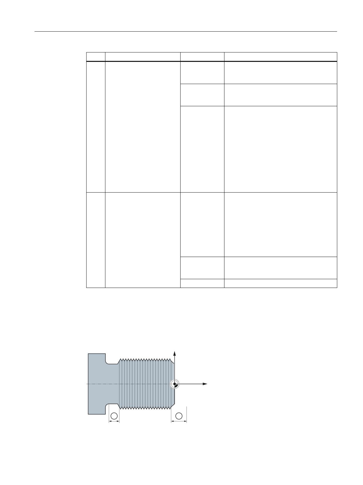
Feedrates
6.2 Path feedrate F
<n>
Meaning
<Value>
Meaning
1
Acceleration behavior at
< 0
The braking of the thread axis when running-
thread run-out:
ou the thread is as programmed in BRISK/
(Default: -1)
SOFT
= 0
The braking of the thread axis when running-
out the thread is sudden (step function)
(≙ BRISK).
> 0
The maximum thread run-out distance is
specified.
Specifying the maximum run-out thread path
can also be specified via address DITE also in
the part program (see "Programmed run-in
and run-out path for G33, G34 and G35 (DITS,
DITE) (Page 213)"). When a block is inserted in
the main run, the programmed run-out path
is transferred into the setting data.
Note
Too short a distance can result in an acceler-
ation overload of the axis.
2
Acceleration behavior for
= -1 (default)
Permits smoothing corners between two
thread transitions within a
thread blocks in order to maintain dynamic
thread chain
response limits.
Rounding using smoothing is not carried out
if the dynamic performance of the machine
allows a hard transition, e.g. as a result of the
effectiveness of the overload factor for axial
velocity step/jumps (MD32310
$MA_MAX_ACCEL_OVL_FACTOR).
= 0
Corners between two thread blocks are exe-
cuted precisely without rounding - the axes
follow the control loop commands.
> 0
Reserved
6.2.4.4
Programmed run-in and run-out path for G33, G34 and G35 (DITS, DITE)
The run-in and run-out path of the thread can be specified in the part program with the DITS
and DITE addresses.
The thread axis is accelerated or braked along the specified path.
=
;
① Run-in/run-out path, depending on the machining direction
Axes and spindles
Function Manual, 10/2020, 6FC5397-4GP40-0BA1
213

Feedrates
6.2 Path feedrate F
Short run-in path
Due to the collar on the thread runin, little room is left for the tool start ramp.
This must therefore be specified shorter via DITS.
Short run-out path
Because of the shoulder at the thread run-out, there is not much room for the tool braking ramp,
introducing a risk of collision between the workpiece and the tool cutting edge. The deceleration
ramp can be specified shorter using DITE. Due to the inertia of the mechanical system, however,
a collision can still occur.
Remedy: Program a shorter thread, reduce the spindle speed.
Note
DITE acts at the end of the thread as a rounding clearance. This achieves a smooth change in
the axis motion.
Effects
The programmed run-in and run-out path only increases the rate of acceleration on the path. If
one of the two paths is set larger than the thread axis needs with active acceleration, the thread
axis is accelerated or decelerated with maximum acceleration.
Syntax
DITS=<Value> DITE=<Value>
Meaning
DITS:
Define thread run-in path
DITE:
Define thread run-out path
<value>:
Only paths, and not positions, are programmed with DITS and DITE.
The programmed run-in/run-out path is handled according to the current dimension
setting (inches, metric).
Example
Program code
Comment
N40 G90 G0 Z100 X10 SOFT M3 S500
N50 G33 Z50 K5 SF=180 DITS=1 DITE=3
; Start of smoothing with Z=53.
N60 G0 X20
Axes and spindles
214
Function Manual, 10/2020, 6FC5397-4GP40-0BA1
Feedrates
6.2 Path feedrate F
Further information
SD42010 $SC_THREAD_RAMP_DISP
When a block containing DITS and/or DITE is inserted in the main run, the programmed run-in/
run-out path is transferred into the setting data SD42010 $SC_THREAD_RAMP_DISP:
• SD42010 $SC_THREAD_RAMP_DISP[ 0 ] = programmed value of DITS
• SD42010 $SC_THREAD_RAMP_DISP[ 1 ] = programmed value of DITE
If no run-in/run-out path is programmed before or in the first thread block, the current value of
the setting data is used.
Behavior following channel / mode group / program end reset
SD 42010 values which have been overwritten by DITS and/or DITE remain active even
following a channel / mode group / program end reset.
Behavior following warm start
In case of a warm start, the setting data is reset to the values which were active before
overwriting by DITS and/or DITE (standard behavior).
If, however, the values programmed with DITS and DITE shall also be active following a warm
restart, the setting data SD42010 $SC_THREAD_RAMP_DISP must be listed in the machine data
MD10710 $MN_PROG_SD_RESET_SAVE_TAB:
MD10710 $MN_PROG_SD_RESET_SAVE_TAB[<n>] = 42010
Behavior if the run-in and/or run-out path is very short
If the run-in and/or run-out path is very short, the acceleration of the thread axis is higher than
the configured value. This causes an acceleration overload on the axis.
Alarm 22280 "Programmed run-in path too short" is then issued for the thread run-in (with the
appropriate configuration in MD11411 $MN_ENABLE_ALARM_MASK). The alarm is purely for
information and has no effect on part program execution.
See also
Acceleration behavior of the axis for G33, G34 and G35 (Page 212)
6.2.4.5
Fast retraction during thread cutting
Function
The "Rapid retraction during thread cutting" function can be used to interrupt thread cutting
without causing irreparable damage in the following circumstances:
• NC stop (NC/PLC interface signal)
• Alarms that implicitly trigger NC stop
• Switching a fast input
For further information, see NC Programming Programming Manual.
Axes and spindles
Function Manual, 10/2020, 6FC5397-4GP40-0BA1
215
Feedrates
6.2 Path feedrate F
The retraction motion can be programmed via:
• Retraction path and retraction direction (relative)
• Retraction position (absolute)
Note
Tapping
The "Fast retraction" function cannot be used with tapping (G331 / G332).
Programming
Syntax
Enable rapid retraction, retraction motion via retraction path and retraction direction:
G33 ... LFON DILF=<value> LFTXT/LFWP ALF=<value>
Enable fast retraction, retraction motion via retraction position:
POLF[<axis name>]=<value> LFPOS
POLFMASK/POLFMLIN(<Axis 1 name>,<Axis 2 name>, etc.)
G33 ... LFON
Disable fast retraction for thread cutting:
LFOF
Meaning
LFON:
Enable fast retraction for thread cutting (G33)
LFOF:
Disable fast retraction for thread cutting (G33)
DILF= :
Define length of retraction path
The value preset during MD configuration (MD21200 $MC_LIFTFAST_DIST)
can be modified in the part program by programming DILF.
Note:
The configured MD value is always active following NC-RESET.
LFTXT
The retraction direction is controlled in conjunction with ALF with G com-
LFWP:
mands LFTXT and LFWP.
LFTXT: The plane in which the retraction motion is executed is calculated
from the path tangent and the tool direction (default setting).
LFWP:
The plane in which the retraction motion is executed is the active
working plane.
Axes and spindles
216
Function Manual, 10/2020, 6FC5397-4GP40-0BA1
Feedrates
6.2 Path feedrate F
ALF= :
The direction is programmed in discrete degree increments with ALF in the
plane of the retraction motion.
With LFTXT, retraction in the tool direction is defined for ALF=1.
For LFWP, the direction in the machining plane is derived from following as-
signment:
• G17 (X/Y plane)
ALF=1 ; Retraction in the X direction
ALF=3 ; Retraction in the Y direction
• G18 (Z/X plane)
ALF=1 ; Retraction in the Z direction
ALF=3 ; Retraction in the X direction
• G19 (Y/Z plane)
ALF=1 ; Retraction in the Y direction
ALF=3 ; Retraction in the Z direction
For further information about the programming capabilities with ALF, see the
NC Programming Programming Manual.
LFPOS:
Retraction of the axis declared with POLFMASK or POLFMLIN to the absolute
axis position programmed with POLF
POLFMASK:
Release of axes (<axis 1 name>,<axis 1 name>, etc.) for independ-
ent retraction to absolute position
POLFMLIN:
Release of axes for retraction to absolute position in linear relation
Note:
Depending on the dynamic response of all the axes involved, the linear relation
cannot always be established before the lift position is reached.
POLF[]:
Define absolute retraction position for the geometry axis or machine axis in the
index
Effectiveness:
Modal
=<value>:
In the case of geometry axes, the assigned value is interpre-
ted as a position in the workpiece coordinate system (WCS).
In the case of machine axes, it is interpreted as a position in
the machine coordinate system (MCS).
The values assigned can also be programmed as incremental
dimensions:
=IC<value>
<axis name>: Name of a geometry axis or machine axis
Note
LFON or LFOF can always be programmed, but the evaluation is performed exclusively during
thread cutting (G33).
Note
POLF with POLFMASK/POLFMLIN are not restricted to thread cutting applications.
Axes and spindles
Function Manual, 10/2020, 6FC5397-4GP40-0BA1
217
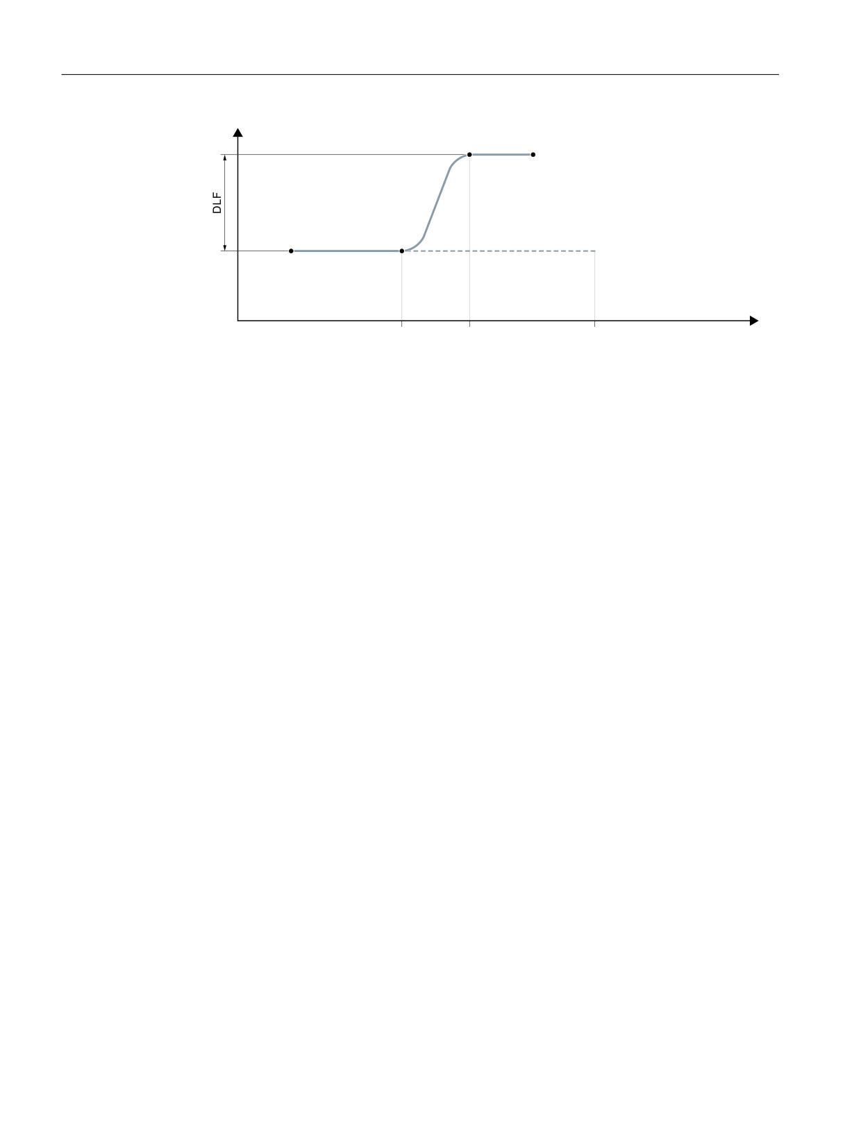
Feedrates
6.2 Path feedrate F
[
$[LV ]HUR VSHHG
6WDUW SRVLWLRQ
7KUHDG FXWWLQJ
1& VWRS
5HWUDFWLRQ PRYHPHQW KDV
1& VWRS
]
6WDUW RI
HQGHG WKUHDG FXWWLQJ LV VWRSSHG
6WDUW RI
UHWUDFWLRQ PRYHPHQW
UHWUDFWLRQ PRYHPHQW
Figure 6-1
Interruption of G33 through retraction motion
Dynamic response of the retraction motion
The retraction motion is executed with maximum axis dynamic response:
• MD32000 $MA_MAX_AX_VELO[<axis>] (velocity)
• MD32300 $MA_MAX_AX_ACCEL[<axis>] (acceleration)
• MD32431 $MA_MAX_AX_JERK[<axis>] (jerk)
Example
Program code
Comment
N55 M3 S500 G90 G18
; Set active machining plane.
N65 MSG ("thread cutting")
MM_THREAD:
N67 $AC_LIFTFAST=0
; Reset before starting the thread.
N68 G0 Z5
N69 X10
N70 G33 Z30 K5 LFON DILF=10 LFWP
; Enable fast retraction for thread
ALF=7
cutting.
; Retraction path = 10 mm
; Retraction plane Z/X (because of G18)
; Retraction direction -X (with ALF=3;
retraction direction +X)
N71 G33 Z55 X15
N72 G1
; Deselect thread cutting.
N69 IF $AC_LIFTFAST GOTOB MM_THREAD ; If thread cutting has been
interrupted.
N90 MSG ("")
N70 M30
Axes and spindles
218
Function Manual, 10/2020, 6FC5397-4GP40-0BA1
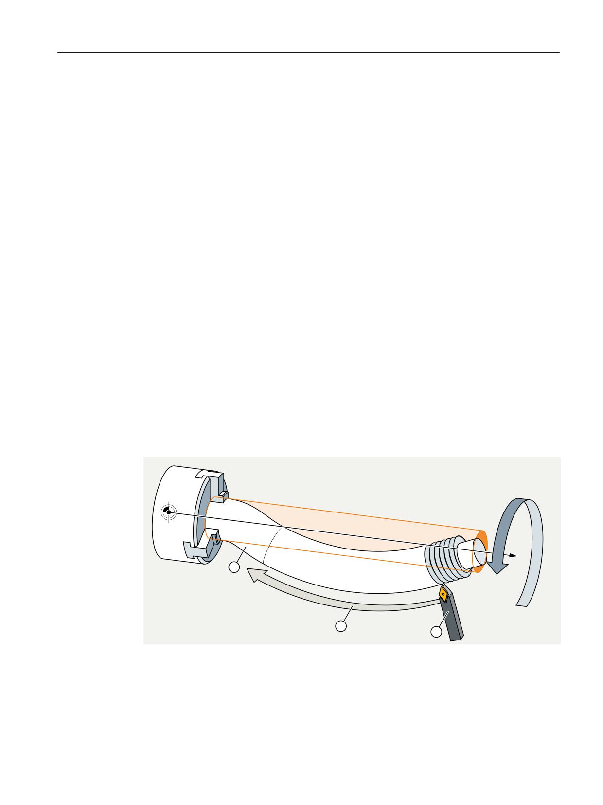
Feedrates
6.2 Path feedrate F
N55 M3 S500 G90 G0 X0 Z0
N87 MSG ("tapping")
N88 LFOF
; Deactivate fast retraction before
tapping.
N89 CYCLE...
; Tapping cycle with G33.
N90 MSG ("")
N99 M30
Behavior at power on and reset
After power on and reset, the following settings are activated:
• Initial settings for the retraction motion (LFON / LFOF) and retraction direction
(LFTXT / LFWP): MD20150 $MC_GCODE_RESET_VALUES
• Retraction path: MD21200 $MC_LIFTFAST_DIST
6.2.4.6
Convex thread (G335, G336)
Function
The G commands G335 and G336 can be used to turn convex threads (= differing to the
cylindrical form). Application is the machining of extremely large components that sag in the
machine because of their self-weight. Paraxial thread would result in the thread being too small
in the middle of the component. This can be compensated with convex threads.
=
① Long, sagging workpiece
② Circular tool path
③ Threaded turning tool
Figure 6-2
Turning a convex thread
Axes and spindles
Function Manual, 10/2020, 6FC5397-4GP40-0BA1
219
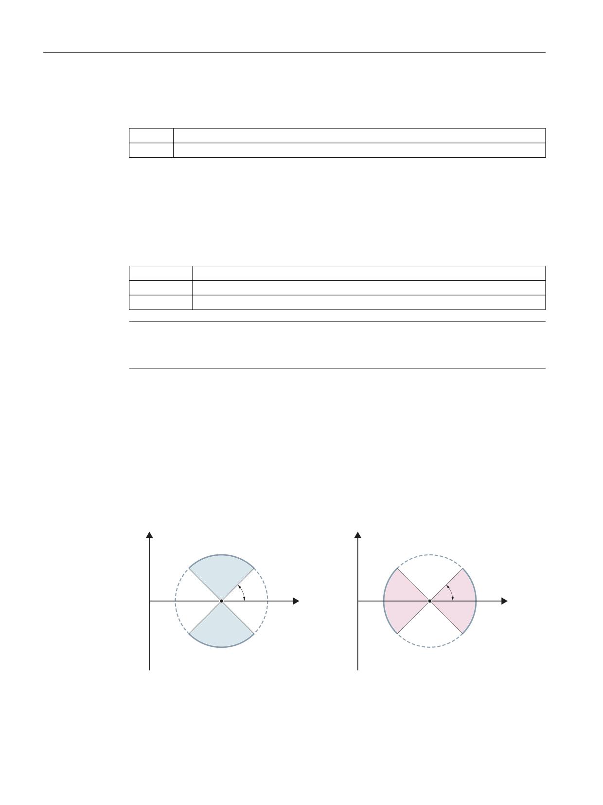
Feedrates
6.2 Path feedrate F
Programming
The turning of a convex thread is programmed with G335 or G336:
G335:
Turning of a convex thread on a circular tool path in a clockwise direction
G336:
Turning of a convex thread on a circular tool path in a counter-clockwise direction
The programming is performed first as for a linear thread by specifying the axial block end points
and the pitch via parameters I, J and K.
An arc is also specified. As for G2/G3, this can be programmed via the center point, radius,
opening angle or intermediate point specification. When programming the convex thread with
center point programming, the following must be taken into account: Since I, J and K are used
for the pitch in thread cutting, the circle parameters in the center point programming must be
programmed with IR=..., JR=... and KR=
IR=...:
Cartesian coordinate for the circle center point in the X direction
JR=...:
Cartesian coordinate for the circle center point in the Y direction
KR=...:
Cartesian coordinate for the circle center point in the Z direction
Note
IR, JR and KR are the default values of the interpolation parameter names for a convex thread
that can be set via machine data MD10651 $MN_IPO_PARAM_THREAD_NAME_TAB.
Optionally, a starting point offset SF can also be specified.
Syntax
The syntax for the programming of a convex thread therefore has the following general form:
G335/G336 <axis target point coordinate(s)> <pitch> <arc> [<starting
point offset>]
Permissible arc areas
The arc programmed at G335/G336 must be in an area in which the specified thread main axis
(I, J or K) has the main axis share on the arc over the entire arc:
[
[
r
r
]
]
Permissible areas for the Z axis (pitch programmed
Permissible areas for the X axis (pitch programmed
with K)
with I)
A change of the thread main axis as shown in the following figure is not permitted:
Axes and spindles
220
Function Manual, 10/2020, 6FC5397-4GP40-0BA1

Feedrates
6.2 Path feedrate F
[
6WDUWLQJ SRLQW
(QG SRLQW
r
]
Figure 6-3
Convex thread: Area that is not permissible
Constraints
Frames
G335 and G336 are also possible with active frames. However, you must ensure that the
permissible arc areas are maintained in the basic coordinate system (BCS).
Response for …
The G335/G336 response for:
• Power On / Power Off
• Mode change
• NCK / mode group / channel / part program end reset
• Block search / REPOS / ASUP
• Alarms / emergency stop / malfuncations
corresponds to the behavior for G33/G34/G35.
There are no specific restrictions.
Examples
Example 1: Convex thread in the clockwise direction with end and center point
programming
Program code
Comment
N5 G0 G18 X50 Z50
; Approach starting point.
N10 G335 Z100 K=3.5 KR=25 IR=-20 SF=90
; Turn convex thread in the clock-
wise direction.
Axes and spindles
Function Manual, 10/2020, 6FC5397-4GP40-0BA1
221
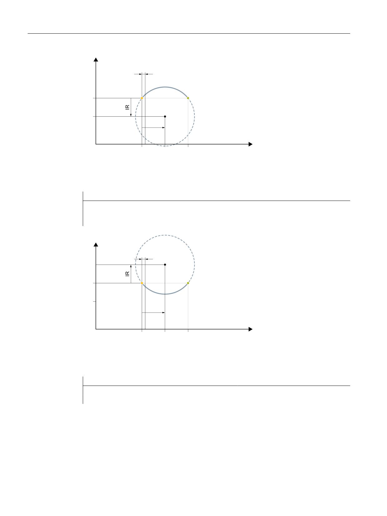
Feedrates
6.2 Path feedrate F
[
6WDUWLQJ SRLQW
(QG SRLQW
&HQWHU SRLQW
.5
]
Figure 6-4
Convex thread in the clockwise direction with end and center point programming
Example 2: Convex thread in the counter-clockwise direction with end and center point
programming
Program code
Comment
N5 G0 G18 X50 Z50
; Approach starting point.
N10 G336 Z100 K=3.5 KR=25 IR=20 SF=90
; Turn convex thread in the coun-
ter-clockwise direction.
[
&HQWHU SRLQW
6WDUWLQJ SRLQW
(QG SRLQW
.5
]
Figure 6-5
Convex thread in the counter-clockwise direction with end and center point programming
Example 3: Convex thread in the clockwise direction with end point and radius
programming
Program code
N5 G0 G18 X50 Z50
N10 G335 Z100 K=3.5 CR=32 SF=90
Axes and spindles
222
Function Manual, 10/2020, 6FC5397-4GP40-0BA1
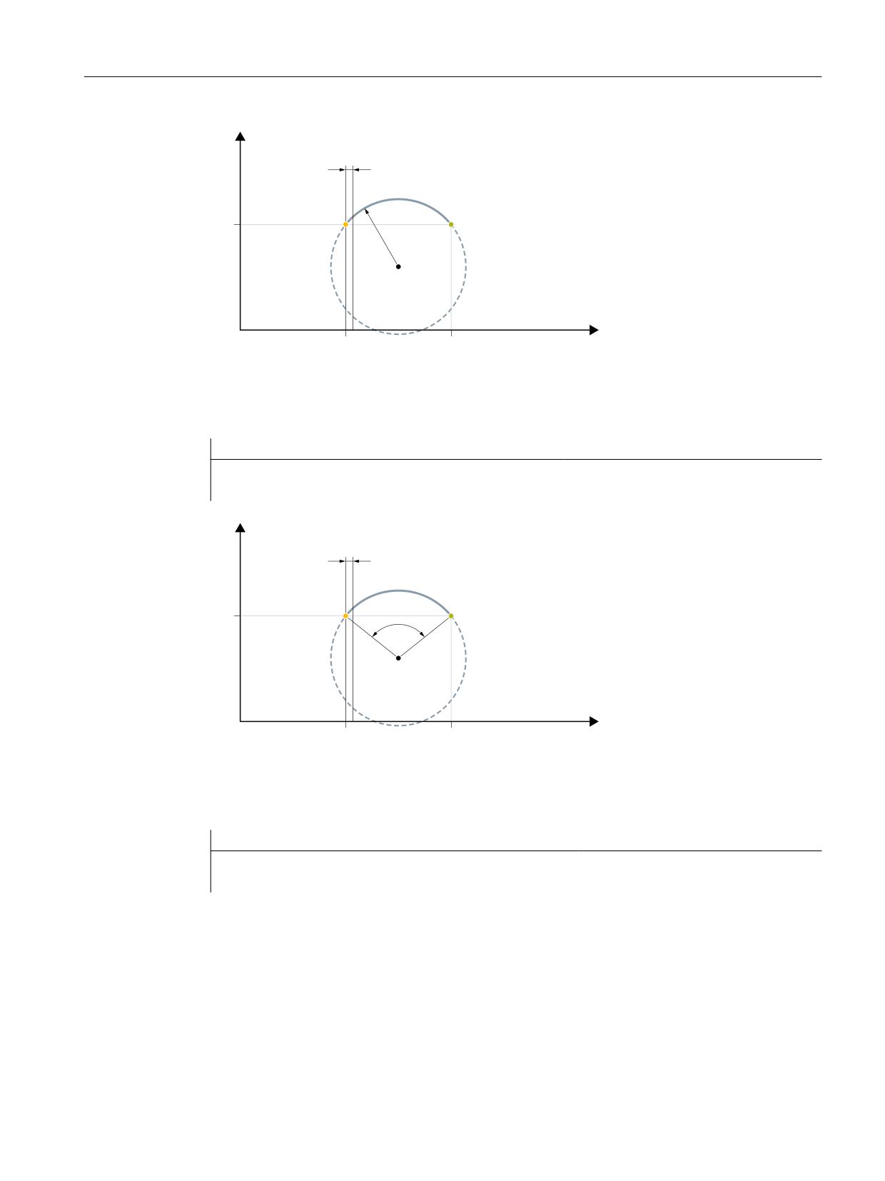
Feedrates
6.2 Path feedrate F
[
6WDUWLQJ SRLQW
(QG SRLQW
&5
&HQWHU SRL
QW
]
Figure 6-6
Convex thread in the clockwise direction with end point and radius programming
Example 4: Convex thread in the clockwise direction with end point and opening angle
programming
Program code
N5 G0 G18 X50 Z50
N10 G335 Z100 K=3.5 AR=102.75 SF=90
[
6WDUWLQJ SRLQW
(QG SRLQW
$5
&HQWHU SR
LQW
]
Figure 6-7
Convex thread in the clockwise direction with end point and opening angle programming
Example 5: Convex thread in the clockwise direction with center point and opening angle
programming
Program code
N5 G0 G18 X50 Z50
N10 G335 K=3.5 KR=25 IR=-20 AR=102.75 SF=90
Axes and spindles
Function Manual, 10/2020, 6FC5397-4GP40-0BA1
223
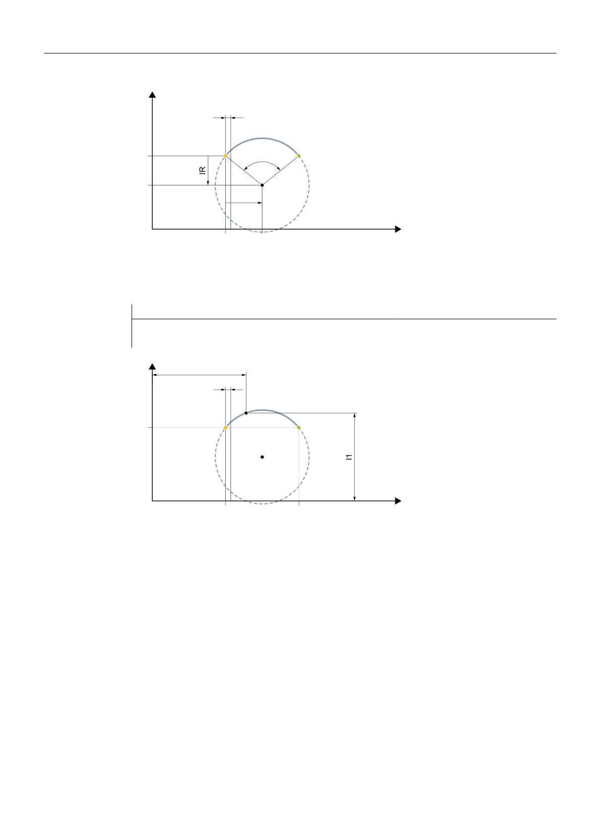
Feedrates
6.2 Path feedrate F
[
6WDUWLQJ SRLQW
(QG SRLQW
$5
&HQWHU SRLQW
.5
]
Figure 6-8
Convex thread in the clockwise direction with center point and opening angle programming
Example 6: Convex thread in the clockwise direction with end and intermediate point
programming
Program code
N5 G0 G18 X50 Z50
N10 G335 Z100 K=3.5 I1=60 K1=64
[
,QWHUPHGLDWH SRLQW
6WDUWLQJ SRLQW
(QG SRLQW
&HQWHU SRL
QW
]
Figure 6-9
Convex thread in the clockwise direction with end and intermediate point programming
6.2.5
Feedrate for tapping without compensating chuck (G331, G332)
Function
A thread can be tapped by rigid tapping with the functions G331 (tapping) and G332 (tapping
retraction).
Path feedrate
With G331 / G332, the path feedrate F for the axes involved in tapping is derived from the
effective spindle speed S and the programmed pitch:
F [mm/min] = S [rpm] * thread pitch [mm/U]
Axes and spindles
224
Function Manual, 10/2020, 6FC5397-4GP40-0BA1
Feedrates
6.2 Path feedrate F
Requirement
The requirement for rigid tapping is a position-controlled spindle with position measuring
system.
Axes and spindles
Function Manual, 10/2020, 6FC5397-4GP40-0BA1
225

Feedrates
6.2 Path feedrate F
Machine data
•
Preventing stop events
In the machine data, the stopping response when G331 / G332 is active is defined:
MD11550 $MN_STOP_MODE_MASK, Bit <x> = <value>
Bit
Value
Meaning
0
0
When G331 / G332 is active, stopping is not performed during a path motion or
dwell time (G4).
1
When G331 / G332 is active, stopping is performed during interruption of path
control mode, for example, by G60 or G4.
If you always want to prevent stopping the traverse movement when G331 / G332 is active,
this area must be declared a stop delay area with the commands DELAYFSTON
and DELAYFSTOF.
Further information
Function Manual Basic Functions; Program operation, Influencing the stop events by stop
delay areas
Note
Single block
If the single block is activated in the stop delay area, the NC stops at the end of the first block
outside the stop delay area. If the single block is already selected before the stop delay area,
the NC stops at each block limit, i.e. also in the stop delay area! This deselects the stop delay
area.
Override changes
If the override is changed before a stop delay area, the override takes effect in the stop delay
area.
If the override is changed in the stop delay area, the change takes effect after the stop delay
area.
•
Override
Which override is active during rigid tapping is set in:
MD12090 $MN_OVR_FUNCTION_MASK, Bit <x> = <value>
Bit
Value
Meaning
0
0
The spindle override is active for G331/G332
Depending on the setting in the following machine data, the override is related
either to the programmed spindle speed or to the configured spindle speed limita-
tion:
MD12080 $MN_OVR_REFERENCE_IS_PROG_FEED
1
The path override is active for G331/G332
Depending on the setting in the following machine data, the override is related
either to the programmed path feedrate or to the configured path feedrate limita-
tion:
MD12082 $MN_OVR_REFERENCE_IS_MIN_FEED
Note
This only applies if the limitation value is lower than the programmed path feedrate.
Axes and spindles
226
Function Manual, 10/2020, 6FC5397-4GP40-0BA1
Feedrates
6.2 Path feedrate F
Boundary conditions
Further overrides
The following overrides are inactive during rigid tapping
• Programmable path feedrate override OVR
• Rapid traverse override
6.2.6
Feedrate for tapping with compensating chuck (G63)
Function
G63 is a subfunction for tapping threads using a tap with compensating chuck. An encoder
(position encoder) is not required.
Speed S, feedrate F, thread pitch
With G63, a speed S must be programmed for the spindle and a feedrate F for the infeed axis (axis
for thread length).
The feedrate F must be calculated by the programmer on the basis of the speed S and the thread
pitch.
Feedrate F [mm/min] = speed S [rev/min] * pitch [mm/rev]
Further information
For more information on G63, see Programming Manual NC Programming.
6.2.7
FGROUP and FGREF
Programming
It should be possible to program the effective machining feedrate in the usual way as a path
feedrate via the F value in processing procedures where the tool, the workpiece or both are
moved by a rotary axis (e.g. laser machining of rotating tubes).
In order to achieve this, it is necessary to specify an effective radius (reference radius) for each
of the rotary axes involved. You can do this by programming the modal NC address:
FGREF[<rotary axis>]=<reference radius>
The unit of the reference radius depends on the G70/G71/G700/G710 setting.
In order to include the axes in the calculation of the path feedrate, they must all be specified in
the FGROUP command.
In order to ensure compatibility with the behavior with no FGREF programming, the evaluation
1 degree = 1 mm is activated on system powerup and RESET.
Axes and spindles
Function Manual, 10/2020, 6FC5397-4GP40-0BA1
227