SINUMERIK 840D sl. Service - Functions. Manual (2018-2020) - page 4
Table of contents
19.6
Data lists
869
19.6.1
Machine data
869
19.6.1.1
General machine data
869
19.6.2
Setting data
870
19.6.2.1
Axis/spindle-specific setting data
870
19.6.3
System variables
870
19.6.3.1
Main run variables for motion-synchronous actions
870
20
Software cams, position switching signals
873
20.1
Brief description
873
20.2
Cam signals and cam positions
874
20.2.1
Generation of cam signals for separate output
874
20.2.2
Generation of cam signals with gated output
878
20.2.3
Cam positions
882
20.2.4
Lead/delay times (dynamic cam)
884
20.3
Output of cam signals
885
20.3.1
Activating
885
20.3.2
Output of cam signals to PLC
885
20.3.3
Output of cam signals to NCK I/Os in position control cycle
886
20.3.4
Timer-controlled cam signal output
887
20.3.5
Independent, timer-controlled output of cam signals
889
20.4
Position-time cams
890
20.5
Boundary conditions
891
20.6
Data lists
891
20.6.1
Machine data
891
20.6.1.1
General machine data
891
20.6.2
Setting data
892
20.6.2.1
General setting data
892
21
Extended stop and retract
893
21.1
Brief description
893
21.2
Control-managed ESR
893
21.2.1
Extended stop and retract (ESR)
893
21.2.2
Drive-independent reactions
895
21.2.3
Power failure detection and bridging
895
21.2.4
NC-controlled extended stop
896
21.2.5
Retract
898
21.2.5.1
Function
898
21.2.5.2
Parameterization: Machine data
899
21.2.5.3
Parameterization: System variable
900
21.2.5.4
Programming (POLF, POLFA, POLFMASK, POLFMLIN)
900
21.2.5.5
Boundary conditions
902
21.2.6
Trigger sources
904
21.2.7
Logic gating functions: Source and reaction linking
905
21.2.8
Activation
905
21.2.9
Configuring aids for ESR
906
21.2.10
Control system response
909
21.2.10.1
Axis behavior depending on the enable signals
909
21.2.10.2
POWER OFF/POWER ON
911
Axes and spindles
Function Manual, 10/2020, 6FC5397-4GP40-0BA1
23
Table of contents
21.2.10.3 Operating mode change, NC Stop, reset
911
21.2.10.4 Part program start, NC start
912
21.2.10.5 Alarm behavior
912
21.2.10.6 Block search, REPOS
912
21.3
ESR executed autonomously in the drive
913
21.3.1
Fundamentals
913
21.3.2
Configuring stopping in the drive
914
21.3.3
Configuring retraction in the drive
915
21.3.4
Configuring generator operation in the drive
916
21.3.5
ESR is enabled via system variable
918
21.3.6
Triggering ESR via system variable
918
21.3.7
Feedback of the ESR status
918
21.3.8
Acknowledge ESR reactions
919
21.3.9
Configuring ESR in the part program
920
21.3.9.1
Stopping (ESRS)
921
21.3.9.2
Retraction (ESRR)
921
21.3.9.3
Boundary conditions
923
21.3.10
ESR and Safety Integrated
924
21.4
Boundary conditions
925
21.5
Examples
926
21.5.1
NC-controlled reactions
926
21.5.2
Retraction while thread cutting
927
21.5.3
Rapid lift using ASUB and fast input
928
21.5.4
Rapid lift, absolute and incremental
928
21.5.5
Lift fast with linear relation of axes
929
21.6
Data lists
929
21.6.1
Machine data
929
21.6.1.1
Channelspecific machine data
929
21.6.1.2
Axis/spindlespecific machine data
930
21.6.2
System variables
930
22
Path length evaluation
931
22.1
Brief description
931
22.2
Data
932
22.3
Parameterization
932
22.3.1
General activation
932
22.3.2
Data groups
932
22.4
Examples
933
22.4.1
Traversal per part program
933
22.5
Data lists
934
22.5.1
Machine data
934
22.5.1.1
NC-specific machine data
934
22.5.1.2
Axis/spindlespecific machine data
934
23
Automatic post optimization with AST (option)
935
23.1
Function
935
23.2
Commissioning
937
Axes and spindles
24
Function Manual, 10/2020, 6FC5397-4GP40-0BA1
Table of contents
23.3
Programming
938
23.3.1
Overview
938
23.3.2
CYCLE751 - Open/execute/close optimization session
940
23.3.3
CYCLE752 - Add axis to an optimization session
940
23.3.4
CYCLE753 - Select optimization mode
943
23.3.5
CYCLE754 - Add/remove data set
944
23.3.6
CYCLE755 - Backup/restore data
945
23.3.7
CYCLE756 - Activate optimization results
947
23.3.8
CYCLE757 - Save optimization data
948
23.3.9
CYCLE758 - Change a parameter value
951
23.3.10
CYCLE759 - Read parameter value
953
23.3.11
List of the parameters for the automatic servo optimization
954
23.4
Diagnostics
959
23.5
Supplementary conditions
960
23.6
Examples
960
23.6.1
Example 1: Measuring an axis with AST default settings
960
23.6.2
Example 2: Reoptimize the speed controller of an axis
962
23.6.3
Example 3: Reoptimize the speed controller and the position controller of an axis
965
23.6.4
Example 4: Reoptimization of the path interpolation
969
23.6.5
Example 5: Reoptimize the speed control loop to eliminate known periodic disturbance
frequencies
973
23.6.6
Example 6: Measuring an axis without optimization
975
24
Intelligent load adjustment (option)
979
24.1
Function
979
24.2
Parameterization
980
24.3
Boundary conditions
983
24.4
Example
983
25
Intelligent dynamic control (option)
985
25.1
Function
985
25.2
Parameterization
986
25.3
Programming
989
25.3.1
Activate/deactivate adaptation (CADAPTON, CADAPTOF)
989
25.4
Example
991
A
Appendix
993
A.1
List of abbreviations
993
A.2
Documentation overview
998
Index
999
Axes and spindles
Function Manual, 10/2020, 6FC5397-4GP40-0BA1
25
Table of contents
Axes and spindles
26
Function Manual, 10/2020, 6FC5397-4GP40-0BA1

Introduction
1
1.1
About this documentation
This documentation is part of the documentation category of SINUMERIK Function Manuals.
SINUMERIK Function Manuals
The SINUMERIK Function Manuals describe the NC functions of a SINUMERIK control.
The target group are configuring engineers, technologists, commissioning engineers and
programmers.
Each Function Manual covers a specific topic and contains all the function descriptions for this
topic.
The following table shows which Function Manuals are available for your SINUMERIK control and
which topics a Function Manual covers:
Function Manual
Topic
Basic functions
Basic functions of a CNC control
Axes and spindles
Axis and spindle functions, axis couplings
Transformations
Transformation functions
Monitoring and compensating
Axis monitoring and compensation functions, collision avoid-
ance
Tools
Functions for selection, correction and monitoring of tools
Synchronized actions
Functionality of synchronized actions
PLC
Structure and functions of the PLC
Tool management
Function, commissioning and programming of tool manage-
ment
Technologies (for SINUMERIK ONE
Extended technological functionalities
and SINUMERIK 840D sl only)
Overview of contents
You will find an overview of the main chapters of the descriptions of functions that are contained
in a Function Manual on the title page.
Validity
The title page also contains all data about the validity of a document, i.e. for which SINUMERIK
control and for which software version this edition of the Function Manual is valid.
Axes and spindles
Function Manual, 10/2020, 6FC5397-4GP40-0BA1
27

Introduction
1.1 About this documentation
System data
In the descriptions of functions, the system data relevant for a function (machine data, setting
data, system variables, interface signals and alarms) are only described with the level of detail
that is strictly necessary to understand the function. You will find detailed information on this
data in the relevant List Manuals and for alarms in the Diagnostics Manual.
PLC blocks
The descriptions of functions often refer to the PLC function blocks (FB) and functions (FC). The
descriptions of these blocks apply to the SINUMERIK 840D sl and can only be applied in part to
other SINUMERIK controls.
Interface signals
In this document, only the absolute address valid for the SINUMERIK 840D sl is used to address
interface signals.
General graphical conventions
Examples
<signal address> (<signal name>)
DB31, ... DBX16.0-2 (actual gear stage A to C)
DB31, ... DBX16.3 (gear is changed)
Note
Quantity structure
Explanations concerning the NC/PLC interface are based on the absolute maximum number of
the following components:
• Mode groups (DB11)
• Channels (DB21, etc.)
• Axes/spindles (DB31, etc.)
Axes and spindles
28
Function Manual, 10/2020, 6FC5397-4GP40-0BA1

Fundamental safety instructions
2
2.1
General safety instructions
WARNING
Danger to life if the safety instructions and residual risks are not observed
If the safety instructions and residual risks in the associated hardware documentation are not
observed, accidents involving severe injuries or death can occur.
• Observe the safety instructions given in the hardware documentation.
• Consider the residual risks for the risk evaluation.
WARNING
Malfunctions of the machine as a result of incorrect or changed parameter settings
As a result of incorrect or changed parameterization, machines can malfunction, which in turn
can lead to injuries or death.
• Protect the parameterization against unauthorized access.
• Handle possible malfunctions by taking suitable measures, e.g. emergency stop or
emergency off.
2.2
Warranty and liability for application examples
Application examples are not binding and do not claim to be complete regarding configuration,
equipment or any eventuality which may arise. Application examples do not represent specific
customer solutions, but are only intended to provide support for typical tasks.
As the user you yourself are responsible for ensuring that the products described are operated
correctly. Application examples do not relieve you of your responsibility for safe handling when
using, installing, operating and maintaining the equipment.
2.3
Security information
Siemens provides products and solutions with industrial security functions that support the
secure operation of plants, systems, machines and networks.
In order to protect plants, systems, machines and networks against cyber threats, it is necessary
to implement - and continuously maintain - a holistic, state-of-the-art industrial security
concept. Siemens’ products and solutions constitute one element of such a concept.
Customers are responsible for preventing unauthorized access to their plants, systems,
machines and networks. Such systems, machines and components should only be connected to
Axes and spindles
Function Manual, 10/2020, 6FC5397-4GP40-0BA1
29
Fundamental safety instructions
2.3 Security information
an enterprise network or the internet if and to the extent such a connection is necessary and only
when appropriate security measures (e.g. firewalls and/or network segmentation) are in place.
For additional information on industrial security measures that may be implemented, please
visit
Siemens’ products and solutions undergo continuous development to make them more secure.
Siemens strongly recommends that product updates are applied as soon as they are available
and that the latest product versions are used. Use of product versions that are no longer
supported, and failure to apply the latest updates may increase customer’s exposure to cyber
threats.
To stay informed about product updates, subscribe to the Siemens Industrial Security RSS Feed
under
services/cert.html#Subscriptions).
Further information is provided on the Internet:
Industrial Security Configuration Manual (https://support.industry.siemens.com/cs/ww/en/
view/108862708)
WARNING
Unsafe operating states resulting from software manipulation
Software manipulations, e.g. viruses, Trojans, or worms, can cause unsafe operating states in
your system that may lead to death, serious injury, and property damage.
• Keep the software up to date.
• Incorporate the automation and drive components into a holistic, state-of-the-art industrial
security concept for the installation or machine.
• Make sure that you include all installed products into the holistic industrial security concept.
• Protect files stored on exchangeable storage media from malicious software by with suitable
protection measures, e.g. virus scanners.
• On completion of commissioning, check all security-related settings.
Axes and spindles
30
Function Manual, 10/2020, 6FC5397-4GP40-0BA1
Homing
3
3.1
Brief Description
Function
When referencing a machine axis, the coordinate system of the machine axis is synchronized
with the coordinate system of the machine. The machine axis is traversed to the machine zero
and then the actual position of the machine axis is set to zero.
If the machine zero cannot be directly approached as a result of the machine design, then a
reference point is defined in the traversing range of the machine axis, which then used to
synchronize the machine axis. Its position with reference to the machine zero must be known.
When referencing, the actual machine axis position is set to this value
Measuring systems and referencing methods
When referencing, machine axes can be synchronized with the following measuring systems
and referencing types:
• Measuring systems
- Incremental rotary measuring system with at least one zero mark
- Incremental linear measuring system
- Rotary measuring system with distancecoded reference marks (supplied by Heidenhain)
- Linear measuring system with distancecoded reference marks (supplied by Heidenhain)
- Absolute rotary measuring system
- Absolute linear measuring system
• Referencing methods
- Referencing with incremental measuring systems with proximity switch and one-edge
and two-edge detection
- Referencing with incremental measuring systems with replacement of homing cam with
proximity switch
- Referencing with incremental measuring systems with proximity switch with configured
approach velocity for spindle applications
- Referencing with measuring systems with distancecoded reference marks by
overtravelling 2 or 4 zero marks
- Referencing of passive measuring systems using measuring system adjustment
- Referencing in follow-up mode
- Referencing with cam switch at the drive
Axes and spindles
Function Manual, 10/2020, 6FC5397-4GP40-0BA1
31

Homing
3.2 Axisspecific referencing
Start
Referencing the machine axis can be manually started, or from the part program:
• Manual: Operation mode JOG and MDI, machine function REF
• Part program: Command G74
3.2
Axisspecific referencing
For axis-specific referencing using the reference point approach, the operation must be
individually started for each machine axis to be referenced.
Selecting mode and machine function
Before starting reference point approach of the machine axes, you must first place the relevant
mode group in JOG or MDI mode:
DB11, ... DBX0.2 (active JOG mode)
DB11, ... DBX0.1 (active MDI mode)
Then machine function REF (reference point approach) must be selected:
DB11, ... DBX1.2 (REF machine function)
Start of reference point approach
In axis-specific reference point approach, each machine axis must be started individually.
Reference point approach is started with the axis-specific traversing keys:
DB31, ... DBX4.6 (Traversing key minus)
DB31, ... DBX4.7 (Traversing key minus)
Direction enable
To avoid operator errors, the direction release must be parameterized. The direction enable
specifies which traversing key starts the reference point approach:
MD34010 $MA_REFP_CAM_DIR_IS_MINUS = <value>
<Value>
Meaning
0
Reference point approach in plus direction
1
Reference point approach in minus direction
Jog mode
The following machine data element can be used to specify whether reference point approach
is completed when the direction key is pressed once or whether the operator is required to keep
the direction key pressed (jogging) for safety reasons:
MD11300 $MN_JOG_INC_MODE_LEVELTRIGGRD (INC and REF in jog mode)
Axes and spindles
32
Function Manual, 10/2020, 6FC5397-4GP40-0BA1
Homing
3.2 Axisspecific referencing
If the machine operator releases the direction key, the machine axis is decelerated to zero speed.
Reference point approach is not aborted. Reference point approach is continued the next time
the direction key is pressed.
Referencing status
The referencing status of the machine axis is reset with the start of the reference point approach:
DB31, ... DBX60.4 (referenced/synchronized 1)
DB31, ... DBX60.5 (referenced/synchronized 2)
DB21, ... DBX36.2 (all axes with obligatory reference point are referenced)
Distance-coded measuring systems
In distance-coded measuring systems, reference point approach can be started with any
traversing key.
Sequence
The machine operator or machine manufacturer (via the PLC user program) is responsible for
ensuring that the machine axes are referenced in the proper order.
• Machine operator
The machine axes must be started by the machine operator in the specified order.
• Machine manufacturer
The PLC user program of the machine manufacturer allows machine axes to be started only
in the proper order.
Simultaneous reference point approach of several machine axes
Several machine axes can be referenced simultaneously, depending on the control:
Completion of reference point approach
Acknowledgment that reference point approach of a machine axis has been successfully
completed is given by setting the referencing status:
DB31, ... DBX60.4 (referenced/synchronized 1)
DB31, ... DBX60.5 (referenced/synchronized 2)
Cancellation of reference point approach
In axis-specific reference point approach, the machine axis is traversed in the channel that was
assigned as the master channel of the machine axis.
MD30550 $MA_ AXCONF_ASSIGN_MASTER_CHAN
For aborting the reference point approach, either mode group reset or channel reset for the
master channel of the machine axis must be activated:
Axes and spindles
Function Manual, 10/2020, 6FC5397-4GP40-0BA1
33

Homing
3.3 Channelspecific referencing
DB11, ... DBX0.7 (mode group reset)
DB21, ... DBX7.7 (channel reset)
All machine axes that have not yet successfully completed reference point approach when the
action is cancelled remain in status "Not referenced":
DB31, ... DBX60.4 (referenced/synchronized 1)
DB31, ... DBX60.5 (referenced/synchronized 2)
3.3
Channelspecific referencing
For channel-specific referencing, all machine axes of the channel are referenced in the
parameterized sequence when reference point approach is initiated.
Selecting mode and machine function
Before starting the reference point approach of the machine axes, the associated mode group
must be switched into the JOG or MDI operating mode:
DB11, ... DBX0.2 (active JOG mode)
DB11, ... DBX0.1 (active MDI mode)
Then machine function REF (reference point approach) must be selected:
DB11, ... DBX1.2 (REF machine function)
Parameterizing the axis sequence
The following machine data element is used to specify the sequence in which the machine axes
of the channel are referenced:
MD34110 $MA_REFP_CYCLE_NR = <number>
<number>
Meaning
-1
The machine axis does not have to be referenced for NC START in the channel.
0
The machine axis does not participate in channel-specific reference point approach.
1 - 15
Sequence number in channel-specific reference point approach.
The machine axes are referenced in ascending order of numbers.
Machine axes with the same number will be referenced simultaneously.
Simultaneous reference point approach of several machine axes
Several machine axes can be referenced simultaneously, depending on the control:
Start of reference point approach
Channel-specific reference point approach is started with:
DB21, ... DBX1.0 (activate referencing)
Axes and spindles
34
Function Manual, 10/2020, 6FC5397-4GP40-0BA1
Homing
3.4 Reference point appraoch from part program (G74)
The status of channel-specific reference point approach is indicated by the channel with:
DB21, ... DBX33.0 (referencing active)
Referencing status
The referencing status of the machine axis is reset with the start of the reference point approach:
DB31, ... DBX60.4 (referenced/synchronized 1)
DB31, ... DBX60.5 (referenced/synchronized 2)
Completion of reference point approach
As soon as channel-specific reference approach has been successfully completed for all machine
axes involved, this is acknowleged with:
DB21, ... DBX36.2 (all axes with obligatory reference point are referenced)
Cancellation of reference point approach
In channel-specific reference point approach the machine axis is traversed in the channel to
which that axis is currently assigned as channel axis.
For aborting the reference point approach either mode group reset or channel reset for the
corresponding channel must be activated:
DB11, ... DBX0.7 (mode group reset)
DB21, ... DBX7.7 (channel reset)
All machine axes for which the reference point approach is not yet successfully completed when
the action is cancelled remain in status "Not referenced":
DB31, ... DBX60.4 (referenced/synchronized 1)
DB31, ... DBX60.5 (referenced/synchronized 2)
3.4
Reference point appraoch from part program (G74)
Function
With command G74, machine axes can be referenced from a part program or synchronized
action either for the first time or again.
Referencing must be repeated, for example, after:
• Actual value offset PRESETON
• Exceeding the encoder limit frequency of the position measuring system
Axes and spindles
Function Manual, 10/2020, 6FC5397-4GP40-0BA1
35

Homing
3.5 Referencing with incremental measurement systems
Programming
Syntax
G74 <machine axis> {<machine axis>}
Meaning
G74:
Command for referencing machine axes
Alone in the
Yes
block:
Effectiveness:
Non-modal
<machine axis>:
The name of a machine axis must be specified (MD10000 $MN_AXCONF_MA-
CHAX_NAME_TAB).
The machine axis must be a channel axis of the channel in which the part
program or the synchronized action is executed.
Reset behavior
Mode group reset or channel reset aborts the reference point approach for all programmed
machine axes:
• DB11, ... DBX0.7 (mode group reset)
• DB21, ... DBX7.7 (channel reset)
All machine axes for which the reference point approach is not yet successfully completed when
the action is canceled remain in status "Not referenced":
• DB31, ... DBX60.4 (referenced/synchronized 1) == 0
• DB31, ... DBX60.5 (referenced/synchronized 2) == 0
3.5
Referencing with incremental measurement systems
3.5.1
Hardware signals
Depending on the machine design and the properties of the incremental measuring system
used, different hardware signals must be connected.
Reference cam
• Connection
The reference cam signal can be connected to a digital input of an external PLC I/O module
or to a fast input on the NCU X142 interface.
• NC/PLC interface signal
The reference cam signal must be transferred from the PLC user program to the axial NC/PLC
interface:
DB31, ... DBX12.7 (deceleration of reference point approach)
Axes and spindles
36
Function Manual, 10/2020, 6FC5397-4GP40-0BA1

Homing
3.5 Referencing with incremental measurement systems
Zero mark selection
If during the reference point approach of the axis or spindle several zero marks of the measuring
system are detected (e.g. measuring gearbox between the motor and encoder), then the
specific zero mark must be selected with an additional contact-free proximity switch signal.
• Connection
The contact-free proximity switch must be connected to a fast digital input on the NCU
interface X122 or X132.
• Activation
In order that the proximity switch signal is evaluated, the digital input to which the proximity
switch is connected must be selected in drive parameter p0493 for the axis/spindle.
Equivalent zero mark
If the used measuring system does not provide a zero mark signal, an equivalent zero mark can
be created via a proximity switch signal.
• Connection
The contact-free proximity switch must be connected to a fast digital input on the NCU
interface X122 or X132.
• Activation
In order that the proximity switch signal is evaluated, the digital input to which the proximity
switch is connected must be selected in the p0494 or p0495 drive parameter for the axis/
spindle.
Overview
Signal
Connection: digital input via
Set
Reference cam
external PLC I/O module
PLC user program:
DB31, ... DBX12.7
or
NCU: X142
Zero mark selection
NCU: X122 or X132
Drive parameter: p0493
External zero mark or equivalent
NCU: X122 or X132
Drive parameter: p0494 or p0495
zero mark
Additional information
• NCU interfaces: Equipment Manual
Connect > Digital inputs/outputs
• Drive parameter: SINAMICS S120/S150 List Manual
Axes and spindles
Function Manual, 10/2020, 6FC5397-4GP40-0BA1
37
Homing
3.5 Referencing with incremental measurement systems
3.5.2
Zero mark selection
Function
Referencing of incremental measuring systems is based on the unique position of the encoder
zero mark relative to the overall traversing range of the machine axis. If because of machine-
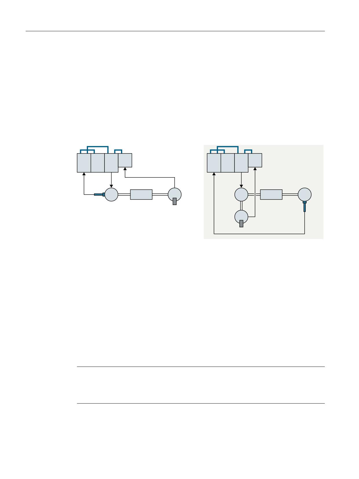
specific conditions, several encoder zero marks are detected in the traversing range of the
machine axis (for examples, see figure below), a proximity switch must be mounted on the
machine for clear determination of the reference point. The position of the reference point is
then derived from the combination of contact-less proximity switch signal and encoder zero
mark.
1&8
$/0
00
60&
1&8
$/0
00
60&
0
(
0
6
%(52
0HDVXULQJ JHDUER[
=HUR PDUN
0HDVXULQJ JHDUER[
%(52
(
=HUR PDUN
BERO Contact-less proximity switch
Figure 3-1
Measuring gear between the motor and encoder or reduction gear between the motor and
spindle
Parameterization
NC: Referencing mode
"Referencing of incremental, rotary or linear measuring systems: Zero pulse on the encoder
track" should be parameterized as referencing mode:
MD34200 $MA_ENC_REFP_MODE[<axis>] = 1
Drive: Zero mark selection
The digital input on the NCU interface to which the proximity switch is connected must be set
in parameter p0493.
Note
Zero mark selection
The processing of the contact-less proximity switch signal is performed exclusively in the drive.
Connection and parameterization, see Section "Hardware signals (Page 36)".
Axes and spindles
38
Function Manual, 10/2020, 6FC5397-4GP40-0BA1
Homing
3.5 Referencing with incremental measurement systems
3.5.3
Time sequence
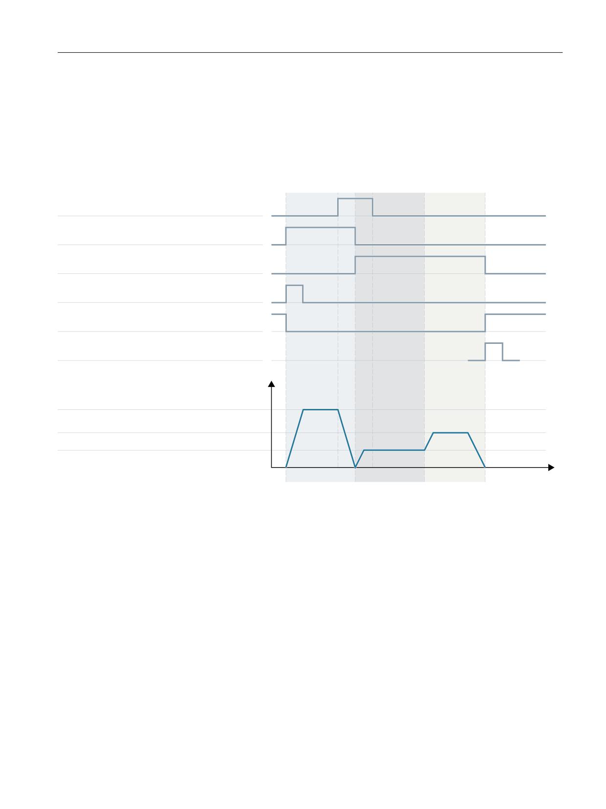
Reference point approach with incremental measuring systems can be divided into three
phases:
• Phase 1: "Phase 1: Traversing to the reference cam (Page 40)"
• Phase 2: "Phase 2: Synchronization with the zero mark (Page 42)"
• Phase 3: "Phase 3: Traversing to the reference point (Page 47)"
'%
ಹ '%;
GHFHOHUDWLRQ UHI SRLQW DSSURDFK
'%
ಹ '%;
PRWLRQ FRPPDQG SOXV
'%
ಹ '%;
PRWLRQ FRPPDQG PLQXV
'%
ಹ '%;
DQG
WUDYHUVLQJ NH\ SOXV PLQXV
'%
ಹ '%;
DQG
UHIHUHQFHG V\QFKURQL]HG
=HUR PDUN
3RVLWLRQ PHDVXULQJ V\VWHP
9HORFLW\
0'
0$B5()3B9(/2B6($5&+B&$0
UHIHUHQFH SRLQW DSSURDFK YHORFLW\
0'
0$B5()3B9(/2B326
UHIHUHQFH SRLQW SRVLWLRQLQJ YHORFLW\
0'
0$B5()3B9(/2B6($5&+B0$5.(5
UHIHUHQFH SRLQW FUHHS YHORFLW\
3KDVH
3KDVH
3KDVH
W
Figure 3-2
Time sequence when referencing with incremental measuring systems (example)
Axes and spindles
Function Manual, 10/2020, 6FC5397-4GP40-0BA1
39
Homing
3.5 Referencing with incremental measurement systems
3.5.4
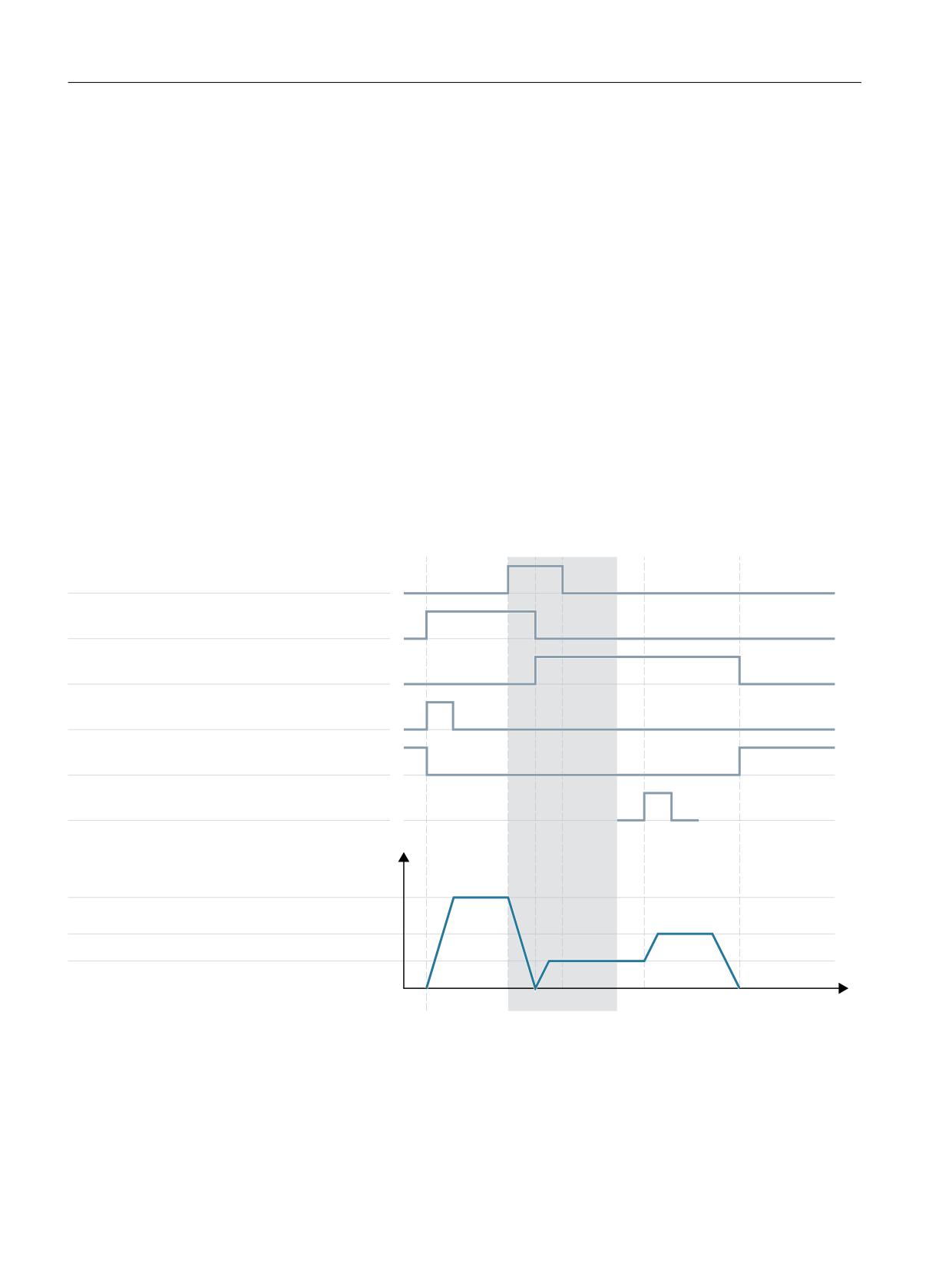
Phase 1: Traversing to the reference cam
Phase 1: Graphic representation
'%
ಹ '%;
GHFHOHUDWLRQ UHI SRLQW DSSURDFK
'%
ಹ '%;
PRWLRQ FRPPDQG SOXV
'%
ಹ '%;
PRWLRQ FRPPDQG PLQXV
'%
ಹ '%;
DQG
WUDYHUVLQJ NH\ SOXV PLQXV
'%
ಹ '%;
DQG
UHIHUHQFHG V\QFKURQL]HG
=HUR PDUN
3RVLWLRQ PHDVXULQJ V\VWHP
9HORFLW\
0'
0$B5()3B9(/2B6($5&+B&$0
UHIHUHQFH SRLQW DSSURDFK YHORFLW\
0'
0$B5()3B9(/2B6($5&+B0$5.(5
UHIHUHQFH SRLQW FUHHS YHORFLW\
0'
0$B5()3B9(/2B326
UHIHUHQFH SRLQW SRVLWLRQLQJ YHORFLW\
3KDVH
W
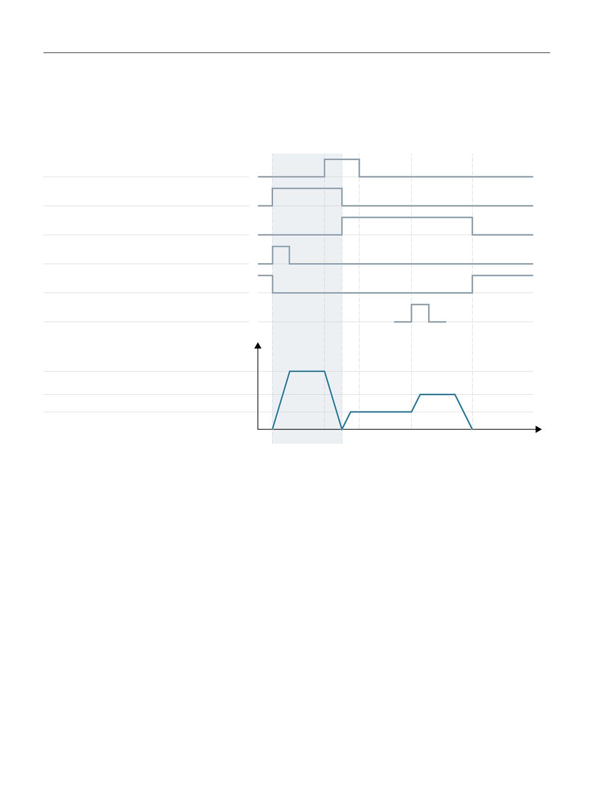
Figure 3-3
Phase 1: Traversing to the reference cam
Phase 1: Start
To start the reference point approach, see Sections "Axisspecific referencing (Page 32)" and "Axis-
specific referencing (Page 32)".
Phase 1: Sequence
In Phase 1, depending on the position of the machine axis with reference to the reference cam,
we distinguish between three cases:
1. The machine axis is positioned before the reference cam
2. The machine axis is positioned on the reference cam
3. The machine axis has no reference cam
Axes and spindles
40
Function Manual, 10/2020, 6FC5397-4GP40-0BA1
Homing
3.5 Referencing with incremental measurement systems
Case 1: The machine axis is positioned before the reference cam
After the start of reference point approach, the machine axis is accelerated in the parameterized
direction and to the parameterized reference point approach velocity :
• MD34010 $MA_REFP_CAM_DIR_IS_MINUS (reference point approach in minus direction)
• MD34020 $MA_REFP_VELO_SEARCH_CAM (reference point approach velocity)
The reaching of the reference cam must detected by querying a digital input in the PLC user
program and communicated to the NC via the following interface signal:
DB31, ... DBX12.7 = 1 (reference point approach deceleration)
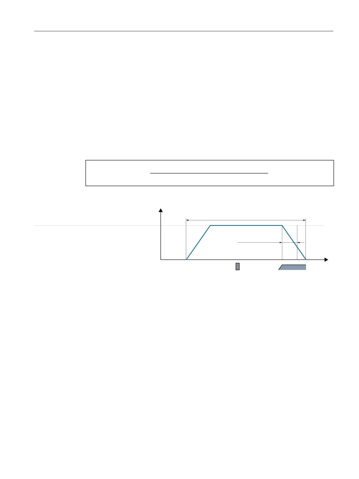
With detection of the NC/PLC interface signal, the machine axis is decelerated to zero speed.
Whereby at least the distance smin is traversed. This ensures that the machine axis leaves the
reference cam in Phase 2 with the parameterized reference point creep velocity.
0'
0$B5()3B9(/2B6($5&+B0$5.(5
VPLQ
0'
0$B0$;B$;B$&&(/
Phase 1 is now complete. Reference point approach is continued with Phase 2.
9HORFLW\
0'
0$B5()3B0$;B&$0B',67
PD[LPXP GLVWDQFH WR UHIHUHQFH FDP
0'
0$B5()3B9(/2B6($5&+B&$0
UHIHUHQFH SRLQW DSSURDFK YHORFLW\
0LQ GLVWDQFH WR JR
'LVWDQFH
=HUR PDUN
5HIHUHQFH FDP
Figure 3-4
Minimum distance for deceleration
Case 2: The machine axis is positioned on the reference cam
The machine axis remains at its starting position.
Phase 1 is now complete. Reference point approach is continued with Phase 2.
Case 3: The machine axis has no reference cam
Machine axes without reference cams remain at their starting position.
These include, for example:
• Machine axes that only have one zero mark along their entire traversing range
• Rotary axes that only have one zero mark per revolution
Zero must be entered in the following machine data for machine axes without a reference cam:
MD34000 $MA_REFP_CAM_IS_ACTIVE = 0 (axis with reference cam)
Phase 1 is now complete. Reference point approach is continued with Phase 2.
Axes and spindles
Function Manual, 10/2020, 6FC5397-4GP40-0BA1
41
Homing
3.5 Referencing with incremental measurement systems
Phase 1: Properties
• Feedrate override is active.
• Feed stop (channel-specific and axis-specific) is active.
• NC stop and NC start are active.
• The machine axis is stopped if the reference cam is not reached within the parameterized
maximum distance:
MD34030 $MA_REFP_MAX_CAM_DIST (max. distance to the reference cam)
See also
Channelspecific referencing (Page 34)
3.5.5
Phase 2: Synchronization with the zero mark
Phase 2: Graphic representation
'%
ಹ '%;
GHFHOHUDWLRQ UHI SRLQW DSSURDFK
'%
ಹ '%;
PRWLRQ FRPPDQG SOXV
'%
ಹ '%;
PRWLRQ FRPPDQG PLQXV
'%
ಹ '%;
DQG
WUDYHUVLQJ NH\ SOXV PLQXV
'%
ಹ '%;
DQG
UHIHUHQFHG V\QFKURQL]HG
=HUR PDUN
3RVLWLRQ PHDVXULQJ V\VWHP
9HORFLW\
0'
0$B5()3B9(/2B6($5&+B&$0
UHIHUHQFH SRLQW DSSURDFK YHORFLW\
0'
0$B5()3B9(/2B326
UHIHUHQFH SRLQW SRVLWLRQLQJ YHORFLW\
0'
0$B5()3B9(/2B6($5&+B0$5.(5
UHIHUHQFH SRLQW FUHHS YHORFLW\
3KDVH
W
Figure 3-5
Phase 2: Synchronization with the zero mark
Phase 2: Start
Phase 2 is automatically started when Phase 1 has been completed without an alarm.
Axes and spindles
42
Function Manual, 10/2020, 6FC5397-4GP40-0BA1

Homing
3.5 Referencing with incremental measurement systems
Initial situation:
The machine axis is positioned on the reference cam.
Zero mark search direction:
The direction of the zero mark search results from the settings in the machine data:
• MD34010 $MA_REFP_CAM_DIR_IS_MINUS (reference point approach in minus direction)
• MD34050 $MA_REFP_SEARCH_MARKER_REVERSE (direction reversal on reference cam)
Phase 2: Sequence
The synchronization in Phase 2 can be performed via the falling or rising edge of the reference
cam. The parameterization is performed via:
MD34050 $MA_REFP_SEARCH_MARKER_REVERSE[<axis>] = <value>
Value
Meaning
0
Synchronization with falling reference cam edge
1
Synchronization with rising reference cam edge
Note
If the actual velocity of the machine axis at approach of the reference cam has not yet reached
the target velocity of Phase 2 within the parameterized tolerance limits, Phase 1 will be
restarted. This will be the case, for example, if the machine axis is positioned on the reference
cam when reference point approach is started.
MD35150 $MA_SPIND_DES_VELO_TOL (spindle speed tolerance)
Case 1: Synchronization with falling reference cam edge
During synchronization with falling reference cam edge, the machine axis accelerates to the
parameterized reference point creep velocity opposite to the parameterized reference point
approach direction (traversing direction of Phase 1)
After leaving the reference cam, the machine axis waits for the next encoder zero mark:
DB31, ... DBX12.7 == 0
As soon as the encoder zero mark is detected, Phase 2 comes to an end. The machine axis
continues at constant velocity and reference point approach is continued with Phase 3.
• MD34040 $MA_REFP_VELO_SEARCH_MARKER (reference point creep velocity)
Axes and spindles
Function Manual, 10/2020, 6FC5397-4GP40-0BA1
43
Homing
3.5 Referencing with incremental measurement systems
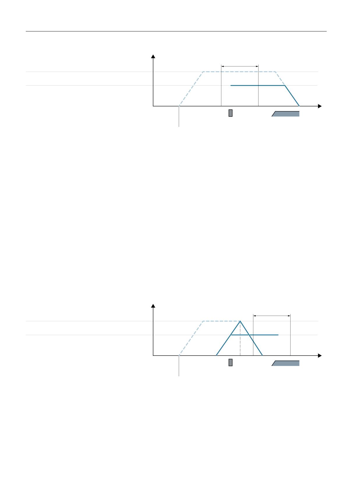
9HORFLW\
0'
0$B5()3B0$;B0$5.(5B',67
PD[ GLVWDQFH WR UHIHUHQFH PDUN
0'
0$B5()3B9(/2B6($5&+B&$0
UHIHUHQFH SRLQW DSSURDFK YHORFLW\
0'
0$B5()3B9(/2B6($5&+B0$5.(5
UHIHUHQFH SRLQW FUHHS YHORFLW\
'LVWDQFH
=HUR PDUN
5HIHUHQFH FDP
6WDUW SRVLWLRQ RI WKH PDFKLQH D[LV
Figure 3-6
Synchronization with falling reference cam edge
Case 2: Synchronization with rising reference cam edge
During synchronization with rising reference cam signal edge, the machine axis accelerates to
the parameterized reference point approach velocity against the parameterized reference point
approach direction (traversing direction of the Phase 1):
• MD34020 $MA_REFP_VELO_SEARCH_CAM (reference point approach velocity)
• MD34010 $MA_REFP_CAM_DIR_IS_MINUS (reference point approach in minus direction)
After leaving the reference cam, the machine axis decelerated to standstill:
DB31, ... DBX12.7 == 0
The machine axis then travels back to the reference cam at the parameterized reference point
creep velocity:
MD34040 $MA_REFP_VELO_SEARCH_MARKER (reference point creep velocity)
After reaching the reference cam (DB31, ... DBX12.7 = 1), the machine axis waits for the next
encoder zero mark.
As soon as the encoder zero mark is detected, Phase 2 comes to an end. The machine axis
continues at constant velocity and reference point approach is continued with Phase 3.
9HORFLW\
0'
0$B5()3B0$;B0$5.(5B',67
PD[ GLVWDQFH WR UHIHUHQFH PDUN
0'
0$B5()3B9(/2B6($5&+B&$0
UHIHUHQFH SRLQW DSSURDFK YHORFLW\
0'
0$B5()3B9(/2B6($5&+B0$5.(5
UHIHUHQFH SRLQW FUHHS YHORFLW\
'LVWDQFH
=HUR PDUN
5HIHUHQFH FDP
6WDUW SRVLWLRQ RI WKH PDFKLQH D[LV
Figure 3-7
Synchronization with rising reference cam edge
Axes and spindles
44
Function Manual, 10/2020, 6FC5397-4GP40-0BA1
Homing
3.5 Referencing with incremental measurement systems
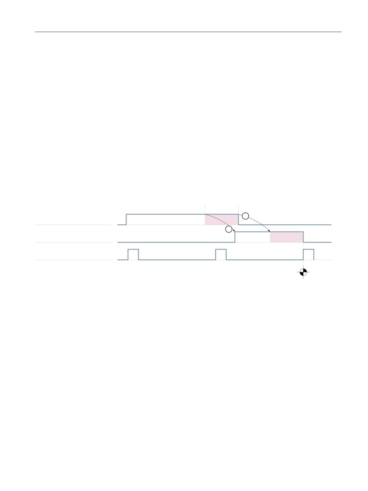
Electronic reference cam shift
The electronic reference cam shift is used to compensate for expansions of the reference cam
caused by temperature so that synchronization is always to the same encoder zero mark:
MD34092 $MA_ REFP_CAM_SHIFT (electronic reference cam shift for incremental measuring
systems with equidistant zero marks)
With the electronic reference cam shift, synchronization is not performed immediately to the
next encoder zero mark after detection of the reference cam edge, but only after the
parameterized offset distance has been traversed.
Due to the determination of the distance traversed in the interpolator clock cycle since the
detection of the reference cam edge, the effective shift distance is sshift:
sshift_min =
MD34092 $MA_ REFP_CAM_SHIFT
sshift_max =
MD34092 $MA_ REFP_CAM_SHIFT +
MD34040 $MA_REFP_VELO_SEARCH_MARKER * interpolator clock cycle
The electronic reference cam shift acts in the direction of zero mark search.
7KHUPDO H[SDQVLRQ
PLQ
PD[
&DP VLJQDO
=HUR PDUN VHDUFK DFWLYH
(TXLGLVWDQW
HQFRGHU ]HUR PDUNV
① Reference cam shift
Figure 3-8
Electronic reference cam shift
Requirement
The electronic reference cam shift is only active for machine axes with reference cam:
MD34000 $MA_REFP_CAM_IS_ACTIVE == 1
Reference cam adjustment
Encoder with equidistant zero marks
Always ensure that the reference cam of encoders that supply zero marks at equidistances is
accurately adjusted so that the correct zero mark is always detected during reference point
approach.
Axes and spindles
Function Manual, 10/2020, 6FC5397-4GP40-0BA1
45
Homing
3.5 Referencing with incremental measurement systems
Dynamic response
The following factors influence the dynamic response from the arrival of the reference cam to
the machine up to the detection of reference cam signals transferred from the PLC user program
to the NC:
• Switching accuracy of the reference cam switch
• Delay of the reference cam switch (NC contact)
• Delay at the PLC input
• PLC cycle time
• Cycle time for updating the NC/PLC interface
• Interpolator clock cycle
• Position control cycle
Notes on setting
• Reference cam
Aligning the signal edge of the reference cam directly between two zero marks has proven
to be the most practical method.
• Electronic reference cam shift
WARNING
Risk of collision
If the reference cam adjustment is faulty or inaccurate, an incorrect zero mark can be
evaluated. The controller then calculates an incorrect machine zero. As a result, the
machine axis will approach the wrong positions. Software limit switches, protected areas
and working area limitations act on incorrect positions and are therefore incapable of
protecting the machine. The path difference is +/- of the path covered by the machine axis
between two zero marks.
Information needed for parameterizing the electronic reference cam shift is to be found in
the read-only machine data:
MD34093 $MA_REFP_CAM_MARKER_DIST (distance between reference cam/reference
mark)
The indicated value is equivalent to the distance between departure from the reference cam
and detection of the reference mark. If the values are too small, there is a risk that the
determination of the reference point will be non-deterministic, due to temperature effects or
fluctuations in the operating time of the cam signal.
Phase 2: Properties
• Feedrate override is not active.
Traversing is performed internally with feedrate override = 100%.
If a feedrate override of 0% is specified, an abort occurs.
• Feed stop (channel-specific and axis-specific) is active.
Axes and spindles
46
Function Manual, 10/2020, 6FC5397-4GP40-0BA1
Homing
3.5 Referencing with incremental measurement systems
• NC stop and NC start are not active.
• If the machine axis does not arrive at Phase 2 within the parameterized distance of the
reference mark (encoder zero mark), the machine axis will be stopped:
MD34060 $MA_REFP_MAX_ MARKER_DIST (max. distance to the reference mark)
3.5.6
Phase 3: Traversing to the reference point
Phase 3: Graphic representation
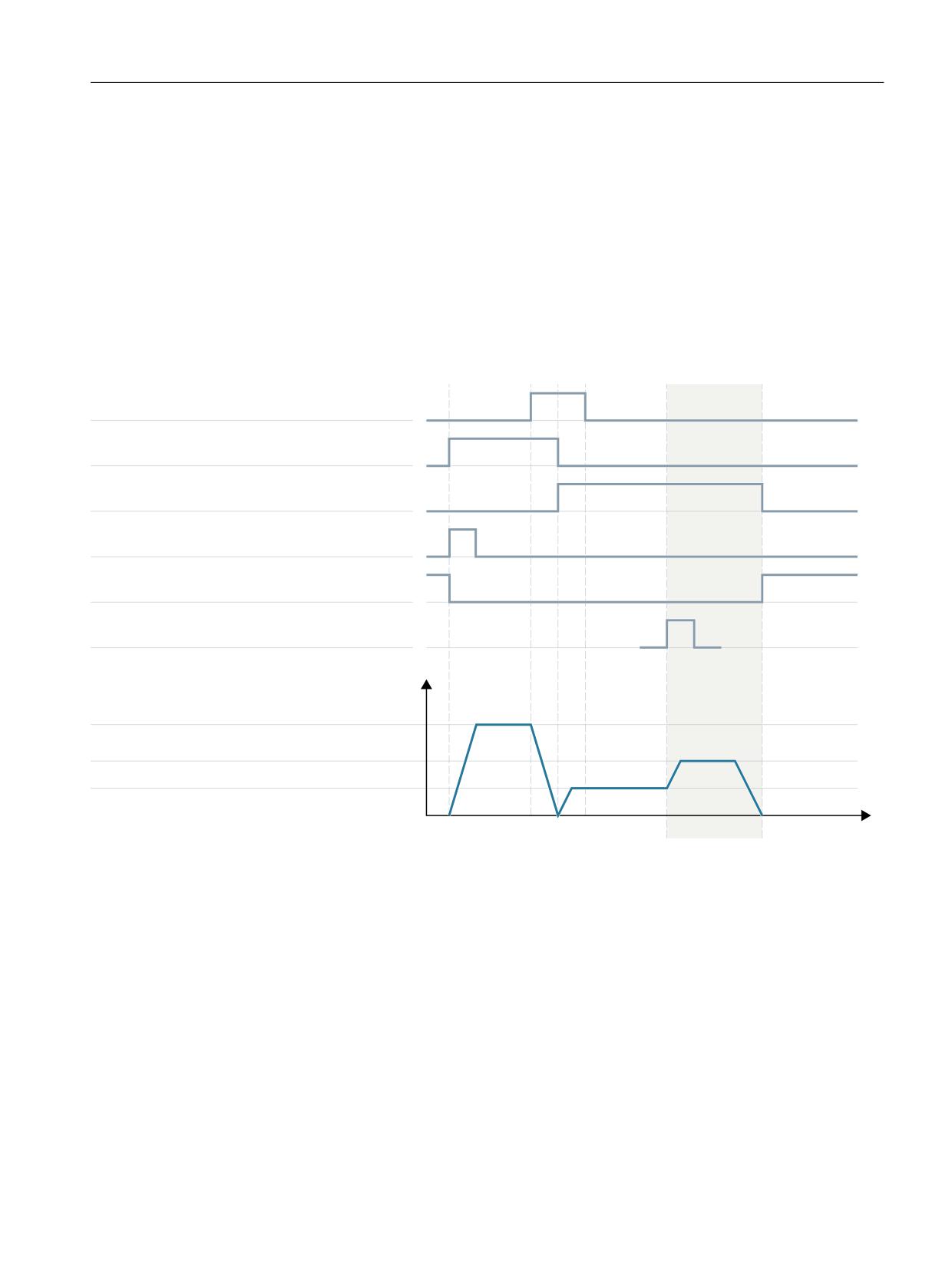
'%
ಹ '%;
GHFHOHUDWLRQ UHI SRLQW DSSURDFK
'%
ಹ '%;
PRWLRQ FRPPDQG SOXV
'%
ಹ '%;
PRWLRQ FRPPDQG PLQXV
'%
ಹ '%;
DQG
WUDYHUVLQJ NH\ SOXV PLQXV
'%
ಹ '%;
DQG
UHIHUHQFHG V\QFKURQL]HG
=HUR PDUN
3RVLWLRQ PHDVXULQJ V\VWHP
9HORFLW\
0'
0$B5()3B9(/2B6($5&+B&$0
UHIHUHQFH SRLQW DSSURDFK YHORFLW\
0'
0$B5()3B9(/2B326
UHIHUHQFH SRLQW SRVLWLRQLQJ YHORFLW\
0'
0$B5()3B9(/2B6($5&+B0$5.(5
UHIHUHQFH SRLQW FUHHS YHORFLW\
3KDVH
W
Figure 3-9
Phase 3: Traversing to the reference point
Phase 3: Start
At the end of Phase 2 the machine axis travels at reference point creep velocity. Therefore, as
soon as Phase 2 is completed successfully without an alarm, Phase 3 is started without
interruption.
Initial situation
The encoder zero mark has been detected.
Axes and spindles
Function Manual, 10/2020, 6FC5397-4GP40-0BA1
47
Homing
3.5 Referencing with incremental measurement systems
Phase 3: Sequence
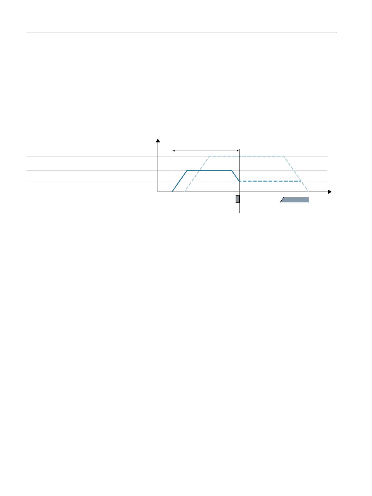
The machine axis moves at the assigned reference point positioning velocity:
MD34070 $MA_REFP_VELO_POS (reference point positioning velocity)
from the encoder zero mark detected in Phase 2 to the reference point.
The path sref to be covered is calculated from the sum of the reference point distance plus
reference point offset:
MD34080 $MA_REFP_MOVE_DIST (reference point distance)
MD34090 $MA_REFP_MOVE_DIST_CORR (reference point offset)
9HORFLW\
0'
0$B5()3B029B',67
0'
0$B5()3B029(B',67B&255
0'
0$B5()3B9(/2B6($5&+B&$0
UHIHUHQFH SRLQW DSSURDFK YHORFLW\
0'
0$B5()3B9(/2B326
UHIHUHQFH SRLQW SRVLWLRQLQJ YHORFLW\
0'
0$B5()3B9(/2B6($5&+B0$5.(5
UHIHUHQFH SRLQW FUHHS YHORFLW\
'LVWDQFH
=HUR PDUN
5HIHUHQFH FDP
0'
0$B5()3B6(7B326 > ಹ
@
0'
0$B5()3B0$;B0$5.(5B',67
UHIHUHQFH SRLQW YDOXH
PD[ GLVWDQFH WR UHIHUHQFH PDUN
Figure 3-10
Reference point position
When the reference point is reached, the machine axis is stopped and the actual-value system
is synchronized with the reference point value n specified by the NC/PLC interface.
MD34100 $MA_ REFP_SET_POS[<n>] (reference point value)
The selection of the reference point value is performed via the NC/PLC interface:
DB31, ... DBX2.4 ... 7 (reference point value 1 ... 4)
The actual-value system is synchronized to the reference point value that was selected at the
time the reference cam was reached in Phase 1 (DB31, ... DBX12.7 == 1).
The machine axis is now referenced. The interface signal is set as feedback to the PLC user
program, depending on the active measuring system:
DB31, ... DBX60.4/5 (referenced/synchronized 1/2) = 1
Features of Phase 3
• Feedrate override is active.
• Feed stop (channel-specific and axis-specific) is active.
• NC stop and NC start are active.
Axes and spindles
48
Function Manual, 10/2020, 6FC5397-4GP40-0BA1
Homing
3.6 Referencing with distance-coded reference marks
Special feature of Phase 3
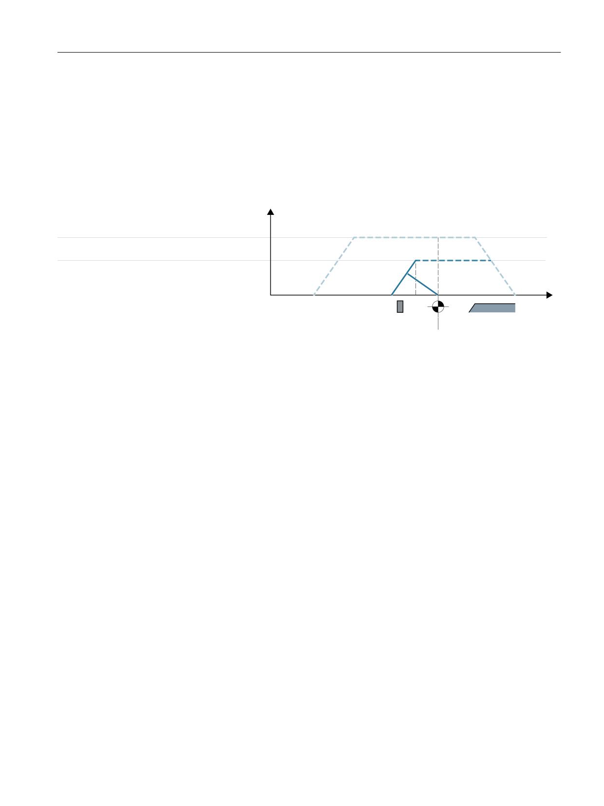
In the following cases, the machine axis stops first after detection of the zero mark and then
traverses back to the reference point:
• Because of the reference point positioning velocity, the sum of reference point distance and
reference point offset is less than the required braking distance:
MD34080 + MD34090 < "required braking distance due to MD34070"
• The reference point is located, opposite to the current travel direction, "behind" the reference
cam.
9HORFLW\
0'
0$B5()3B9(/2B6($5&+B&$0
UHIHUHQFH SRLQW DSSURDFK YHORFLW\
0'
0$B5()3B9(/2B6($5&+B0$5.(5
UHIHUHQFH SRLQW FUHHS YHORFLW\
'LVWDQFH
=HUR PDUN
5HIHUHQFH FDP
0'
0$B5()3B6(7B326 > ಹ
@
UHIHUHQFH SRLQW YDOXH
Figure 3-11
Reference point distance plus reference point offset less than braking distance
3.6
Referencing with distance-coded reference marks
3.6.1
General overview
Distancecoded reference marks
Measuring systems with distance-coded reference marks consist of two parallel scale tracks:
• Incremental grating
• Reference mark track
The distance between any two consecutive reference marks is defined. This makes it possible to
determine the absolute position of the machine axis when two consecutive reference marks are
crossed. For example, if the distance between the reference marks is approx. 10 mm, a traverse
path of approx. 20 mm is all that is required to reference the machine axis.
Referencing can be performed from any axis position in the positive or negative direction
(exception: end of travel range).
Axes and spindles
Function Manual, 10/2020, 6FC5397-4GP40-0BA1
49
Homing
3.6 Referencing with distance-coded reference marks
3.6.2
Basic parameter assignment
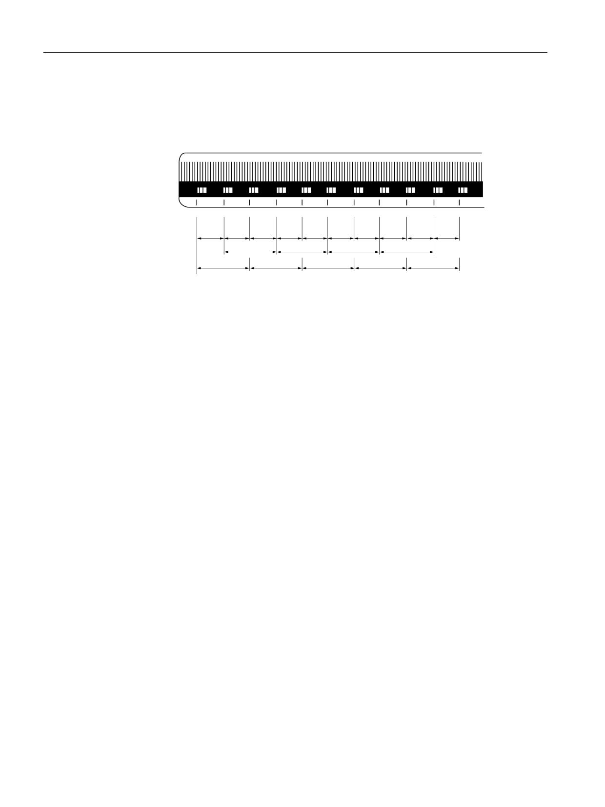
Linear measuring systems.
5HIHUHQFH PDUN
Figure 3-12
Glass measuring scale with distance-coded reference marks, grid spacing: 20 mm
The following data must be set to parameterize linear measuring systems:
• The absolute offset between the machine zero point and the position of the first reference
mark of the linear measuring system:
MD34090 $MA_REFP_MOVE_DIST_CORR (reference point/absolute offset)
See also below: Determining the absolute offset
• Orientation of the length measuring system (equidirectional or inverse) relative to the
machine system coordinate system:
MD34320 $MA_ENC_INVERS (length measuring system inverse to the machine system)
Rotary measuring system
For rotary measuring systems, the same applies as for linear measuring systems (see above).
Determining the absolute offset
The following procedure is recommended for the determination of the absolute offset between
the machine zero point and the position of the first reference mark of a machine axis:
1. Enter the value zero for the absolute offset:
MD34090 $MA_REFP_MOVE_DIST_CORR = 0
2. Perform reference point approach.
Note: The reference point should be approached at a point in the machine where the exact
position of the machine axis relative to machine zero can be determined easily (using a laser
interferometer, for example).
3. Read the displayed actual position of the machine axis in the machine coordinate system MCS
from the user interface, e.g. SINUMERIK Integrate.
Axes and spindles
50
Function Manual, 10/2020, 6FC5397-4GP40-0BA1

Homing
3.6 Referencing with distance-coded reference marks
4. Measure the actual position of the machine axes referred to the machine zero point.
5. Calculate the absolute offset and enter in MD34090.
The absolute offset is calculated with respect to the machine coordinate system and
depending on the orientation of the measuring system as:
Orientation of the measuring system
Absolute offset
Equidirectional
(Measured position) + (displayed actual position)
Opposite direction
(Measured position) - (displayed actual position)
WARNING
Reference point deviation
After determining the absolute offset and the entry in MD34090, the reference point traversing
for the machine axis must be carried out once more.
Referencing methods
Referencing with distance-coded reference marks can be performed in one of two ways:
• Evaluation of two consecutive reference marks:
MD34200 $MA_ENC_REFP_MODE = 3
Advantage:
- Short travel path
• Evaluation of four consecutive reference marks:
MD34200 $MA_ENC_REFP_MODE = 8
Advantage:
- Plausibility check by NC is possible
- Increase in reliability of referencing result
Axes and spindles
Function Manual, 10/2020, 6FC5397-4GP40-0BA1
51
Homing
3.6 Referencing with distance-coded reference marks
3.6.3
Time sequence
Time sequence
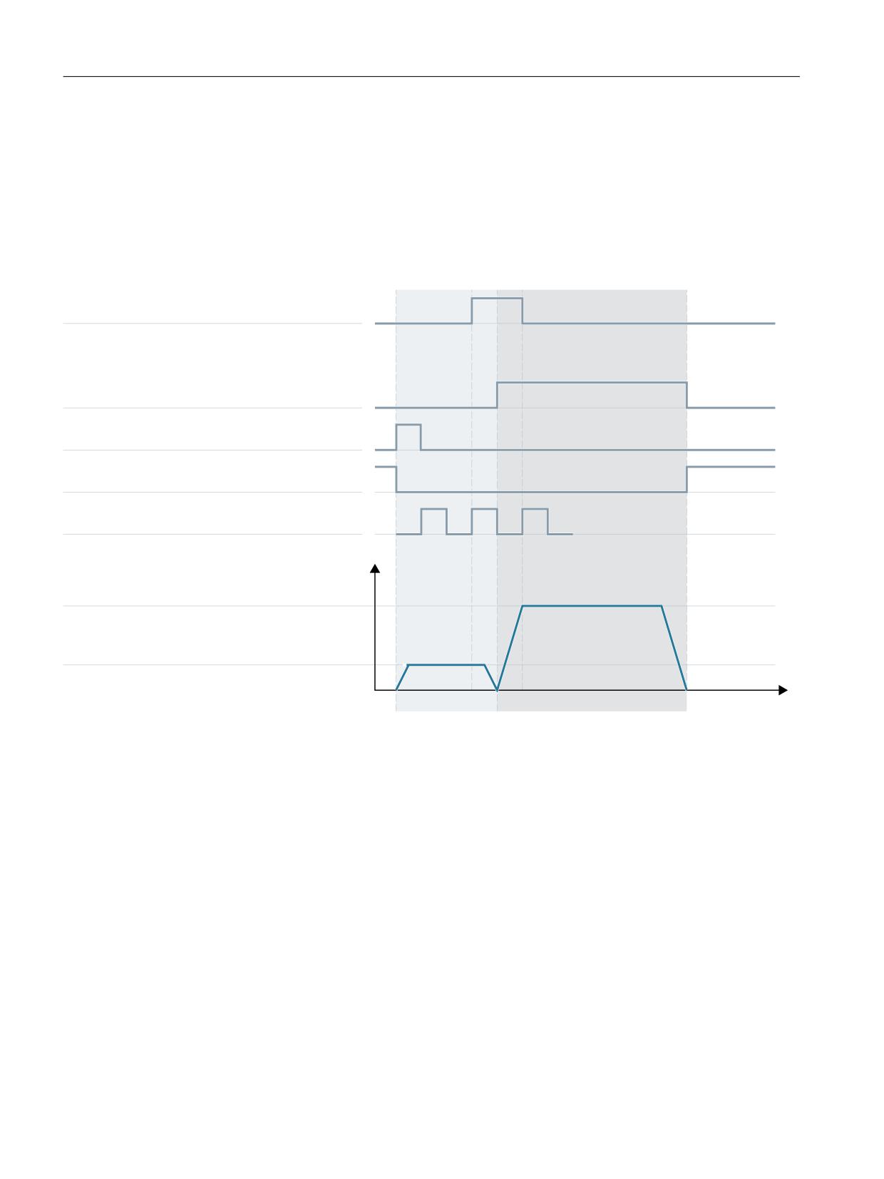
Referencing with distance-coded reference marks can be divided into two phases:
• Phase 1: Travel across the reference marks with synchronization
• Phase 2: Travel to a fixed destination point
'%
ಹ '%;
GHFHOHUDWLRQ UHI SRLQW DSSURDFK
'%
ಹ '%;
PRWLRQ FRPPDQG PLQXV
'%
ಹ '%;
DQG
WUDYHUVLQJ NH\ SOXV PLQXV
'%
ಹ '%;
DQG
UHIHUHQFHG V\QFKURQL]HG
=HUR PDUN
3RVLWLRQ PHDVXULQJ V\VWHP
9HORFLW\
0'
0$B5()3B9(/2B6($5&+B&$0
UHIHUHQFH SRLQW DSSURDFK YHORFLW\
0'
0$B5()3B9(/2B6($5&+B0$5.(5
UHIHUHQFH SRLQW FUHHS YHORFLW\
3KDVH
3KDVH
W
Figure 3-13
Distance-coded reference marks
3.6.4
Phase 1: Travel across the reference marks with synchronization
Phase 1: Start
To start the reference point approach, see Sections "Axisspecific referencing (Page 32)" and
"Channelspecific referencing (Page 34)".
Reference cam
In measuring systems with distance-coded reference marks, reference cams are not required for
the actual referencing action. For functional reasons, however, a reference cam is required for
channel-specific reference point approach and reference point approach from the part program
(G74) before the traversing range end of the machine axis.
Axes and spindles
52
Function Manual, 10/2020, 6FC5397-4GP40-0BA1
Homing
3.6 Referencing with distance-coded reference marks
Phase 1: Sequence
Sequence without contact witha reference cam
Once the reference point approaching process is started, the machine axis accelerates to the
reference point shutdown speed set by means of parameter assignment:
MD34040 $MA_REFP_VELO_SEARCH_MARKER (reference point creep velocity)
Once the number of reference marks set by means of parameter assignment has been crossed,
the machine axis is stopped again and the actual value system of the machine axis is
synchronized to the absolute position calculated by the NC.
Sequence when starting from the reference cam
If the machine axis is at the reference cam at the start of the reference point traversing, it
accelerates to the parameterized reference point creep velocity against the parameterized
reference point approach direction:
MD34040 $MA_REFP_VELO_SEARCH_MARKER (reference point creep velocity)
MD34010 $MA_CAM_DIR_IS_MINUS (reference point approach in minus direction)
That ensures that the machine axis does not reach the travel range limit before it has crossed the
parameterized number of reference marks.
Once the number of reference marks set by means of parameter assignment has been crossed,
the machine axis is stopped again and the actual value system of the machine axis is
synchronized to the absolute position calculated by the NC.
Sequence when contact is made with reference cam during referencing
Once the reference point approaching process is started, the machine axis accelerates to the
reference point shutdown speed set by means of parameter assignment:
MD34040 $MA_REFP_VELO_SEARCH_MARKER (reference point creep velocity)
Before the machine axis travels over the parameterized number of reference marks, it makes
contact with the reference cam. It is then reversed and reference mark search is restarted in the
opposite direction.
Once the number of reference marks set by means of parameter assignment has been crossed,
the machine axis is stopped again and the actual value system of the machine axis is
synchronized to the absolute position calculated by the NC.
Plausiblity check of the reference mark distance
An error occurs if, during reference point traversing for two subsequent reference marks, the NC
determines a distance greater than twice the parameterized reference mark distance.
MD34300 $MA_ENC_REFP_MARKER_DIST (reference mark distance)
The machine axis will then traverse in opposite direction at half the parameterized reference
point creep velocity (MD34040) and the search for reference mark is restarted.
If a faulty reference mark distance is detected again, the machine axis is stopped and the
reference point traversing is aborted (alarm 20003 "fault in the measuring system").
Axes and spindles
Function Manual, 10/2020, 6FC5397-4GP40-0BA1
53

Homing
3.6 Referencing with distance-coded reference marks
Abort criterion
If the parameterized number of reference marks is not detected within the parameterized
distance, the machine axis is stopped and reference point traversing is aborted.
MD34060 $MA_REFP_MAX_ MARKER_DIST (max. distance to the reference mark)
Features of Phase 1
After Phase 1 is successfully completed, the actual value system of the machine axis is
synchronized.
3.6.5
Phase 2: Traversing to the target point
Phase 2: Start
Phase 2 is automatically started when Phase 1 has been completed without an alarm.
Initial situation:
• The machine axis is positioned directly behind the last of the parameterized number of
reference marks.
• The actual value system of the machine axis is synchronized.
Phase 2: Sequence
In Phase 2, the machine axis completes reference point approach by traversing to a defined
target position (reference point). This action can be suppressed in order to shorten the reference
point approach:
MD34330 $MA_STOP_AT_ABS_MARKER = <value>
Value
Meaning
0
Travel to target position
1
No travel to target position
Travel to target position (normal case)
The machine axis accelerates to the parameterized reference point position velocity and travels
to the parameterized target point (reference point):
MD34070 $MA_REFP_VELO_POS (reference point positioning velocity)
MD34100 $MA_REFP_SET_POS (reference point value)
The machine axis is referenced. To identify this, the NC sets an interface signal for the measuring
system that is currently active:
DB31, ... DBX60.4/60.5 (referenced/synchronized 1/2) = 1
Axes and spindles
54
Function Manual, 10/2020, 6FC5397-4GP40-0BA1
Homing
3.6 Referencing with distance-coded reference marks
No travel to target position
The machine axis is now referenced. To identify this, the NC sets an interface signal for the
measuring system that is currently active:
DB31, ... DBX60.4/60.5 (referenced/synchronized 1/2) = 1
Features of Phase 2
Phase 2 will display different characteristics, depending on whether a reference cam is
parameterized for the machine axis.
Machine axis without reference cam
MD34000 $MA_REFP_CAM_IS_ACTIVE (axis with reference cam) = 0
Properties:
• Feedrate override is active.
• The feed stop (channel-specific and axis-specific) is active.
• NC stop and NC start are active.
Machine axis with reference cam
MD34000 $MA_REFP_CAM_IS_ACTIVE (axis with reference cam) = 1
Properties:
• Feedrate override is not active.
Traversing is performed internally with feedrate override = 100%.
If a feedrate override of 0% is specified, an abort occurs.
• The feed stop (channel-specific and axis-specific) is active.
• NC stop and NC start are not active.
• If the parameterized number of reference marks is not detected within the parameterized
distance after the exit of the reference cam, the machine axis will be stopped.
MD34060 $MA_REFP_MAX_ MARKER_DIST (max. distance to the reference mark)
Special features of rotary measuring systems
On rotary distance-coded measuring systems, the absolute position can only be determined
uniquely within one revolution. Depending on the mechanical mounting of the encoder, the
overtravel of the absolute position in the hardware does not always coincide with the traversing
range of the rotary axis.
Special features of modulo rotary axes
With module rotary axes, the reference point position is mapped on the parameterized modulo
range:
MD30330 $MA_MODULO_RANGE (size of the modulo range)
Axes and spindles
Function Manual, 10/2020, 6FC5397-4GP40-0BA1
55
Homing
3.7 Referencing by means of actual value adjustment
MD30340 $MA_MODULO_RANGE_START (start position of the modulo range)
Note
The reference point position is mapped on the parameterized (fictive) modulo range even with
axis function "Determination of reference point position rotary, distance-coded encoder within
the configured modulo range":
MD30455 $MA_MISC_FUNCTION_MASK (axis functions), BIT1 = 1
3.7
Referencing by means of actual value adjustment
3.7.1
Actual value adjustment to the referencing measurement system
Function
When actual value adjustment to the referencing measuring system is performed, the resulting
absolute actual position after successful referencing of the measuring system of a machine axis
is transferred directly to all other measuring systems of the machine axis, and the machine axis
is designated as referenced:
DB31, ... DBB60.4 / 60.5 (referenced/synchronized 1/2) = 1
Advantage
When the machine axis switches from an explicitly referenced measuring system to the
measuring system referenced by actual value adjustment, continuous servo control is assured
(servo enable active) because the matched actual position prevents a sudden change in actual
value.
Note
In order to improve positioning precision by determining the measuring-system-specific
encoder fine information, we recommend explicitly re-referencing the measuring system
previously referenced by actual value adjustment after switching over.
Activation
The activation of the actual value adjustment to the referencing measuring system is machine-
specifically carried out via:
MD34102 $MA_REFP_SYNC_ENCS = 1
Axes and spindles
56
Function Manual, 10/2020, 6FC5397-4GP40-0BA1
Homing
3.7 Referencing by means of actual value adjustment
3.7.2
Actual value adjustment for measuring systems with distance-coded
reference marks
Function
In order to improve positioning precision by determining the measuring-system-specific
encoder fine information, we recommend explicitly re-referencing the measuring system
previously referenced by actual value adjustment after switching over the measuring system.
If an encoder with distance-coded reference marks is used for the passive measuring system,
referencing can be avoided under the following conditions:
1. Active measuring system: Indirect measuring system (motor measuring system) with
absolute encoder, for example
2. Passive measuring system: Direct measuring system with distance-coded reference marks
3. Traversing motion of the machine axis with the referenced indirect measuring system before
measuring system switchover in which the number of reference marks required for
referencing are crossed. Whereby, the passive direct measuring system is referenced
automatically.
Parameterization
In addition to the specific machine data required to reference the individual measuring systems,
the following machine data must be set:
• Enable the actual value adjustment:
MD34102 $MA_REFP_SYNC_ENCS = 1
• Direct measuring system with distance-coded reference marks:
- MD34200 $MA_ENC_REFP_MODE[measuring system] = 3
Distance-coded reference marks
- MD30242 $MA_ENC_IS_INDEPENDENT[measuring system] = 2
In the actual value adjustment, the passive direct measuring system is aligned to the
actual position of the active indirect measuring system, but not marked as referenced.
After the parameterized number of reference marks is crossed, the passive direct
measuring system is referenced automatically. Referencing is performed in every
operating mode.
Axes and spindles
Function Manual, 10/2020, 6FC5397-4GP40-0BA1
57
Homing
3.8 Referencing in follow-up mode
Sequence
1. Initial situation: Both measuring systems are not referenced:
DB31, ... DBX60.4 = 0 (referenced/synchronized 1)
DB31, ... DBX60.5 = 0 (referenced/synchronized 2)
2. Referencing of the indirect measuring system according to the measuring system type:
DB31, ... DBX60.4 = 1 (referenced/synchronized 1)
DB31, ... DBX60.5 = 0 (referenced/synchronized 2)
3. Traversing of the machine axis across the parameterized number of reference marks.
This automatically references the direct measuring system:
DB31, ... DBX60.4 = 1 (referenced/synchronized 1)
DB31, ... DBX60.5 = 1 (referenced/synchronized 2)
3.8
Referencing in follow-up mode
Function
Incremental measuring systems and measuring systems with distance-coded reference marks
can be referenced even when the machine axis is in follow-up mode. Prerequisite for this is the
correct parameterization of the reference point approach according to the used measuring
system (see Section "Referencing with incremental measurement systems (Page 36)" and
"Referencing with distance-coded reference marks (Page 49)").
When referencing in follow-up mode the machine axis is moved not by the NC but by means of
an external travel motion over the encoder zero mark and the parameterized number of
distance-coded reference marks. The measuring system is referenced when the encoder zero
mark or parameterized number of distance-coded reference marks are detected.
Note
Reproducibility of the referencing result
In NC-guided reference point approach, reproducibility of the referencing result is ensured
through adherence to the assigned traverse velocities during the referencing operation. During
referencing in follow-up mode, responsibility for achieving reproducibility of the referencing
results lies with the machine manufacturer / user.
Unique zero mark
Referencing of an incremental measuring system is based on the explicit position of the encoder
zero mark relative to the overall traversing range of the machine axis.
Because the reference cam signal is not evaluated by the NC during referencing in follow-up
mode, unique identification of the reference point when referencing in follow-up mode will only
result with:
• Only one encoder zero mark in the traversing range of the machine axis.
• Linear measuring systems with distance-coded reference marks.
• Modulo rotary axes (absolute position within one revolution).
Axes and spindles
58
Function Manual, 10/2020, 6FC5397-4GP40-0BA1
Homing
3.8 Referencing in follow-up mode
Zero mark selection when several zero mark signals occur
If several encoder zero marks are detected in the traversing range of the machine axis due to
machine-specific factors, e.g. reduction gear between encoder and load, a proximity switch
must be mounted on the machine and connected via a digital input of the NCU interface in order
to clearly determine the reference point.
Note
Contact-less proximity switch signal: Zero mark selection
The processing of the proximity switch signal is performed exclusively in the drive. Connection
and parameterization, see Section "Hardware signals (Page 36)".
Enable
The "Referencing in follow-up mode" function is enabled with:
MD34104 $MA_REFP_PERMITTED_IN_FOLLOWUP = TRUE
Starting the referencing operation
If the machine axis is in follow-up mode (DB31, ... DBX61.3 == TRUE) at the start of reference
point approach, the measuring system is referenced in follow-up mode.
If the machine axis is not operating in the follow-up mode at the start of reference point
traversing, the "normal" from the NC-controlled reference point travels is carried out.
Referencing in follow-up mode can be started in the following modes:
• JOG-REF: Traversing keys
• AUTOMATIC: Part program command G74
Sequence of the referencing operation (JOG-REF mode)
1. Activate follow-up mode of machine axis:
DB31, ... DBX1.4 (follow-up mode) = 1
DB31, ... DBX2.1 (controller enable) = 0
2. Wait for activation of follow-up mode:
DB31, ... DBX61.3 (follow-up active) == 1
3. Switch to JOG mode, REF machine function
4. External motion of machine axis across encoder zero mark or parameterized number of
distance-coded reference marks. The referencing operation is started internally in the NC as
soon as the machine axis is moved: The following NC/PLC interface signal is reset as feedback:
DB31, ... DBX61.4 (axis/spindle stationary) == 0
5. The measuring system is referenced after the encoder zero mark or the assigned number of
distance-coded reference marks have been successfully detected: The following NC/PLC
interface signal is set as feedback:
DB31, ... DBX60.4/60.5 (referenced/synchronized 1/2) == 1
Aborting the reference operation
Axes and spindles
Function Manual, 10/2020, 6FC5397-4GP40-0BA1
59
Homing
3.8 Referencing in follow-up mode
An active referencing operation can be aborted by:
• Deselecting follow-up mode
• NC reset
Response when measuring systems are already referenced
A measuring system that has already been referenced can only be re-referenced in AUTOMATIC
mode using part program command G74.
Sequence of referencing operation (AUTOMATIC mode)
1. Switch to AUTOMATIC mode.
2. Start the part program.
3. Activate follow-up mode of machine axis:
DB31, ... DBX1.4 (follow-up mode) = 1
DB31, ... DBX2.1 (controller enable) = 0
4. Wait for activation of follow-up mode:
DB31, ... DBX61.3 (follow-up active) == 1
5. The referencing operation is started internally in the NC as soon as G74 command has been
processed.
6. External motion of machine axis across encoder zero mark or parameterized number of
distance-coded reference marks.
7. The measuring system is referenced after the encoder zero mark or the assigned number of
distance-coded reference marks have been successfully detected: The following NC/PLC
interface signal is set as feedback:
DB31, ... DBX60.4 / 60.5 (referenced/synchronized 1/2) == 1
8. The block change occurs after the referencing operation has been successfully completed.
Aborting the reference operation
An active referencing operation can be aborted by:
• Deselecting follow-up mode
• NC reset
Response when measuring systems are already referenced
A measuring system that you have already referenced can be re-referenced.
Axes and spindles
60
Function Manual, 10/2020, 6FC5397-4GP40-0BA1

Homing
3.9 Referencing with absolute encoders
3.9
Referencing with absolute encoders
3.9.1
Information about the adjustment
Machine axes with absolute encoder
The advantage of machine axes with absolute encoder is that after a one time adjustment
procedure, the necessary reference point traversing with incremental measuring systems (e.g.
build-up of control, de-selection of "Parking" of machine axes etc.) can be skipped and the actual
value system of the machine axis can be immediately synchronized to the determined absolute
position.
Adjustment
Adjustment of an absolute encoder involves matching the actual value of the encoder with the
machine zero once and then setting it to valid.
The current adjustment status of an absolute encoder is displayed in the following axis-specific
machine data of the machine axis, to which it is connected:
MD34210 $MA_ENC_REFP_STATE (status of absolute encoder)
Value
Meaning
0
Encoder not calibrated
1
Encoder adjustment enabled
2
Encoder is calibrated
Adjustment methods
The following adjustment methods are supported:
• Adjustment by entering a reference point offset
• Adjustment by entering a reference point value
• Automatic adjustment with probe
• Adjustment by means of the proximity switch
Readjustment
Readjustment of the absolute encoder is required after:
• Gear change between load and absolute encoder
• Removal/installation of the absolute encoder
• Removal/installation of the motor with the absolute encoder
• Data loss in the static NC memory
Axes and spindles
Function Manual, 10/2020, 6FC5397-4GP40-0BA1
61

Homing
3.9 Referencing with absolute encoders
•
Battery failure
•
Set actual value (PRESETON)
WARNING
Data backup
During the back-up of machine data of a machine A, the encoder status of the machine axis
(MD34210) is also backed up.
During loading of this data record into a machine B of the same type, e.g. in the context of
a serial start-up or after a case of maintenance, the referenced machine axes will be
automatically regarded as adjusted / referenced by the NC. It is the special responsibility of
the machine manufacturer / user to undertake a readjustment in such cases.
See also explanations regarding machine data:
MD30250 $MA_ACT_POS_ABS (absolute encoder position at the time of switch-off)
Note
The controller can detect a required readjustment of the absolute encoder only during the
following events:
• Gear change with change of gear ratio
• Addressing the zero-mark monitoring
• New encoder serial number after change of the absolute encoder
The controller then sets the status of the absolute encoder to "0":
MD34210 $MA_ENC_REFP_STATE = 0 (encoder not adjusted)
The following alarm is displayed:
Alarm 25022 "Axis <axis name> encoder <number> warning 0"
If the zero-mark monitoring responds, the following alarm is also displayed:
Alarm 25020 "Axis <axis name> zero-mark monitoring of active encoder"
In all other cases (e.g. PRESETON) it is the sole responsibility of the user to display the
misalignment of the absolute encoder by manually setting the status to "0" and to carry out
a readjustment.
3.9.2
Calibration by entering a reference point offset
Function
During adjustment by entering the reference point offset, the difference between the position
displayed on the operator interface and the true actual position in the machine is determined
and made known to the NC as reference point offset.
Axes and spindles
62
Function Manual, 10/2020, 6FC5397-4GP40-0BA1

Homing
3.9 Referencing with absolute encoders
Procedure
1.
Determining the position of the machine axis with reference to the machine zero point via
e.g.:
- position measurement (e.g. laser interferometer)
- Moving the machine axis to a known position (e.g., fixed stop)
2.
Reading the displayed actual position of the machine axis on the operator interface.
3.
Calculating the reference point offset (difference between the actual positions determined
under point 1 and 2) and entering in machine data:
MD34090 $MA_REFP_MOVE_DIST_CORR (reference point offset)
4.
Marking the absolute value encoder as adjusted:
MD34210 $MA_ENC_REFP_STATE = 2
Note
The encoder adjustment does not become active until the next time the encoder is activated
(e.g., when the controller is powered up).
5.
Initiate POWER ON reset.
6.
Controlling the position of the machine axis displayed on the operator interface.
Note
Backlash compensation
If backlash compensation is parameterized for a measuring system with absolute value
encoder, the following must be observed:
No backlash is permitted during machine axis travel to the adjusted machine position.
Activate reference point offset permanently
The entered reference point offset (MD34090) will be permanently active only after initial
POWER ON - Reset. If the machine axis is moved after the absolute encoder adjustment
without an interim POWER ON - Reset, the reference point offset entered in the machine data
can be overwritten, for example, as part of internal overrun offset.
Checking the actual position
Following adjustment of the absolute encoder, we recommend that you verify the actual
position of the machine axis the next time you power up the controller (POWER ON).
3.9.3
Adjustment by entering a reference point value
Function
During adjustment by entering the reference point value, the absolute position of the machine
axis with reference to the machine zero point is determined by e.g.:
• Position measurement (e.g. laser interferometer)
• Moving the machine axis to a known position (e.g. fixed stop)
Axes and spindles
Function Manual, 10/2020, 6FC5397-4GP40-0BA1
63
Homing
3.9 Referencing with absolute encoders
This determined position value will be made known to the NC as the reference point value. The
NC then calculates the reference point offset from the difference between the encoder absolute
value and the reference point value.
Procedure
1. Check whether the referencing mode is set to "Assume the reference point value":
MD34200 $MA_ENC_REFP_MODE == 0
If not, enter the value 0 in the machine and trigger a Power On reset.
2. Traverse the machine axis in JOG mode to the position to be measured (e.g. with a laser
interferometer) or to a known position (e.g. fixed stop).
Note
The machine axis can only be traversed in the direction enabled for referencing with the
travel keys:
MD34010 $MA_REFP_CAM_DIR_IS_MINUS (approach reference point in minus direction)
To avoid an invalid position because of backlash in the drive train, the known position must
be approached at low velocity.
3. Enter the position of the machine axis relative to machine zero as the reference point value
in the machine data:
MD34100 $MA_REFP_SET_POS = Position
4. Enable encoder adjustment:
MD34210 $MA_ENC_REFP_STATE = 1
5. Trigger a Power On reset for acceptance of the entered machine data values.
6. Switch to JOG-REF mode.
Axes and spindles
64
Function Manual, 10/2020, 6FC5397-4GP40-0BA1

Homing
3.9 Referencing with absolute encoders
7. Operate the travel key used for referencing in step 2.
The machine axis does not move when the traversing key is actuated!
The NC calculates the reference point offset from the entered reference point value and that
given by the absolute encoder. The result is entered into the machine data:
MD34090 $MA_REFP_MOVE_DIST_CORR (reference point offset)
The status of the absolute encoder is set to "Encoder is adjusted":
MD34210 $MA_ ENC_REFP_STATE = 2
The actual value system of the machine axis is synchronized.
The machine axis is now referenced. As identification, the NC sets the appropriate interface
signal based on which measuring system is currently active:
DB31, ... DBB60.4 / 60.5 (referenced/synchronized 1 / 2) = 1
8. Initiate Power On reset.
Note
Activate reference point offset permanently
The entered reference point offset (MD34090) will only be permanently active after Power
On reset.
If the machine axis is moved after the absolute encoder adjustment without an interim Power
On reset, the reference point offset entered in the machine data can be overwritten, for
example, within internal overrun corrections.
Checking the actual position
Following adjustment of the absolute encoder, we recommend that you verify the actual
position of the machine axis the next time you power up the controller (Power On).
3.9.4
Automatic calibration with probe
Function
In automatic adjustment with a probe, a known position in the machine is approached with the
machine axis from a part program. The position value is stored in the NC as a reference point
value. The position is reached when the probe switches, and the NC then calculates the
reference point offset from the difference between the encoder value and reference point value.
Note
Part program for automatic adjustment
The part program for automatic adjustment using a probe must be created by the machine
manufacturer / user for the specific requirements of the machine.
Freedom from collision
Because actual-value-related monitoring is not active for the machine axes being referenced,
the machine operator must take special care to ensure that collisions do not occur in the
machine while the machine axes are being moved!
Axes and spindles
Function Manual, 10/2020, 6FC5397-4GP40-0BA1
65

Homing
3.9 Referencing with absolute encoders
Part program
The part program for automatic adjustment of absolute encoders with probe must perform the
points listed below for each axis in the order indicated:
1. Approach the adjustment position of machine axis, which is detected from the probe
response.
The position must be approached several times from the same direction, but at a velocity
which is gradually reduced on each approach, to ensure that the measured value obtained
is as accurate as possible. The measured value is stored in system variable $AA_IM.
2. Calculating and writing the reference point offset:
0'
0$B5()3B029(B',67B&255
0'
0$B5()3B6(7B326 ದ $$B,0
3. Set the absolute encoder status to "Encoder is adjusted":
MD34210 $MA_ ENC_REFP_STATE = 2
Sequence
Proceed as follows for automatic adjustment with probe:
1. Enable part program start even for non-referenced machine axes:
MD20700 $MC_REFP_NC_START_LOCK = 0
2. Enter the machine axis position relative to machine zero when probe is switched as the
reference point value for all relevant machine axes:
MD34100 $MA_REFP_SET_POS = reference point value
3. Activate NCK-Reset for the acceptance of the entered machine data values.
4. Start part program.
5. After completion of the part program, re-secure the partial program start for machine axes
which are not referenced:
MD20700 $MC_REFP_NC_START_LOCK = 1
6. Initiate POWER ON - Reset so that the reference point offset written by the part program is
permanently active:
MD34090 $MA_REFP_MOVE_DIST_CORR (reference point offset)
Note
Activate reference point offset permanently
The entered reference point offset (MD34090) will only be permanently active after
POWER ON - Reset.
If the machine axis is moved after the absolute encoder adjustment without an interim
POWER ON - Reset, the reference point offset entered in the machine data can be overwritten,
for example, as part of internal overrun offset.
Checking the actual position
Following adjustment of the absolute encoder, we recommend that you verify the actual
position of the machine axis the next time you power up the controller (POWER ON).
Axes and spindles
66
Function Manual, 10/2020, 6FC5397-4GP40-0BA1
Homing
3.9 Referencing with absolute encoders
3.9.5
Adjustment with BERO
Function
For adjustment using proximity switch, a reference point approach to a defined machine
position is performed the same as for incremental measuring systems. In this case, the proximity
switch replaces the encoder zero mark that the absolute encoder does not have. After successful
completion of reference point approach, the NC automatically calculates the reference point
offset from the difference between the encoder absolute value and the parameterized reference
point value.
Parameterization
NC: Referencing mode
The referencing mode should be set to "Referencing of incremental, rotary or linear measuring
systems: Zero pulse on the encoder track":
MD34200 $MA_ENC_REFP_MODE[<axis>] = 1
NC: Reference point value
The reference point value is parameterized via:
MD34100 $MA_REFP_SET_POS[<axis>] = <reference point value>
Drive: Equivalent zero mark
The digital input on the NCU interface to which the proximity switch is connected must be set
in parameter p0494 or p0495.
Execution
Reference point approach can be started manually in JOG-REF mode or in AUTOMATIC or MDI
mode via a part program (G74).
After successful completion of the reference point approach, the absolute encoder is adjusted
and the actual-value system of the machine axis is synchronized.
As feedback for the PLC user program, the NC sets the NC/PLC interface signal for the machine
axis, depending on the active measuring system:
DB31, ... DBB60.4/60.5 (referenced/synchronized 1/2) = 1
Note
If the proximity switch is removed after adjustment of the absolute encoder, the referencing
mode must be re-parameterized to "Referencing with absolute encoder".
MD34200 $MA_ENC_REFP_MODE[<axis>] = 0
Axes and spindles
Function Manual, 10/2020, 6FC5397-4GP40-0BA1
67

Homing
3.9 Referencing with absolute encoders
3.9.6
Reference point approach with absolute encoders
Parameter assignment
Traversing movement release
If for a machine axis with adjusted absolute value encoder as active measuring system, reference
point traversing is activated (manually in the JOG-REF mode or automatically via the part
program instruction G74), the machine axis travels depending on the parameterized traversing
movement release.
MD34330 $MA_REFP_STOP_AT_ABS_MARKER = <value>
Value
Meaning
0
Traversing is enabled.
When reference point approach is initiated, the machine axis moves to the reference point
position. When reaching the reference point position, the reference point approach is comple-
ted.
1
Traversing is not enabled.
After the activation of the reference point travel, the machine axis does not travel and the
reference point travel is immediately completed.
3.9.7
Reference point approach for rotary absolute encoders with equivalent zero
mark
Function
To ensure that the reference point approach via zero mark (see Section "Referencing with
incremental measurement systems (Page 36)") can also be used with absolute encoders, the
zero mark, which is not provided in the hardware of absolute encoders, is simulated. For this, the
controller generates the signal for the equivalent zero mark once per encoder revolution, always
at the same position within the revolution.
Difference compared to referencing with incremental encoders
An absolute encoder with replacement zero mark should not be considerd as a complete
equivalent of an incremental encoder. All the properties of the absolute encoder are retained.
The following table lists the different properties of incremental and absolute encoders:
Table 3-1
Properties of incremental and absolute encoders
Property
Incremental encoder
Absolute encoder
Encoder type
MD30240 $MA_ENC_TYPE =
1
4
Internal encoder position
MD30250 $MA_ACT_POS_ABS =
Value is updated only in MD34210 ≥ 1
Value is updated only in MD30270 = 0
Axes and spindles
68
Function Manual, 10/2020, 6FC5397-4GP40-0BA1

Homing
3.9 Referencing with absolute encoders
Property
Incremental encoder
Absolute encoder
Traversing range extension
MD30270 $MA_ENC_ABS_BUFFERING =
No effect
= 0 (default): Active
Reference point offset
MD34090 $MA_REFP_MOVE_DIST_CORR =
Value input allowed
Value is updated exclusively via control
Supported referencing types
MD34200 $MA_ENC_REFP_MODE =
1, 3, 4, 8
0, 1
Adjustment status
MD34210 $MA_ENC_REFP_STATE = 0, 1, 2
Automatic encoder misalignment dur-
Automatic encoder misalignment during pa-
ing shut down while in motion.
rameter set change with position jump or
during serial number change.
Absolute position modulo range
MD34220 $MA_ENC_ABS_TURNS_MODULO =
0
1 - 4096
Encoder serial no.
MD34230 $MA_ENC_SERIAL_NUMBER =
0
The value must be updated from the PLC dur-
ing each encoder change, otherwise loss of
adjustment plus alarm.
Transfer of series startup files
Without any restrictions.
Due to encoder characteristics (MD30250,
MD30270, MD34090, MD34210, MD34220,
MD34230) only possible with certain restric-
tions.
Activation time
0 seconds
several seconds
Zero mark
1 per encoder revolution
None
Zero mark monitoring
Hardware
Software
Position after POWER ON without
0.0
Last position within MD34220.
actual value buffering
MD34210 = 0
MD30270 = 1
Position after POWER ON with ac-
Last standstill position before deactiva-
Last position including small movements dur-
tual value buffering
tion.
ing POWER OFF.
MD34210 = 1
MD30270 = 0
Referenced after POWER ON
depends on adjustment status
Requirement
The function can be used only with rotary absolute encoders:
• MD31000 $MA_ENC_IS_LINEAR == 0
• MD30240 $MA_ENC_TYPE == 4
Parameterization
Reference point approach with equivalent zero mark:
MD34200 $MA_ENC_REFP_MODE = 1
Axes and spindles
Function Manual, 10/2020, 6FC5397-4GP40-0BA1
69
Homing
3.9 Referencing with absolute encoders
Supplementary conditions
• A reference point offset (MD34090 $MA_REFP_MOVE_DIST_CORR) may not be
parameterized.
This MD describes, in connection with absolute encoders, the offset between machine and
absolute encoder zero, and it therefore has a different meaning.
• The load-side zero mark search rate (MD34040 $MA_REFP_VELO_SEARCH_MARKER) should
not exceed the limiting frequency of the absolute trace of the encoder
(MD36302 $MA_ENC_FREQ_LIMIT_LOW)
. If the speed is too high, absolute information cannot be read any more, and thus, no
equivalent zero marks are generated.
• If no zero mark is found within the parameterized path (MD34060
$MA_REFP_MAX_MARKER_DIST), an alarm is output:
• The following MD must be set if the absolute encoder retains even the referenced status
through POWER OFF, besides the last position:
MD34210 $MA_ENC_REFP_STATE = 2
Data backup and standard commissioning
Some properties of an absolute encoder restrict the transfer of a commissioning archive to other
machines. The following machine data must be checked and possibly corrected after loading a
commissioning archive to the controller:
• MD30250 $MA_ACT_POS_ABS (internal encoder position)
• MD30270 $MA_ENC_ABS_BUFFERING (traversing range extension)
• MD34090 $MA_REFP_MOVE_DIST_CORR (absolute offset)
• MD34210 $MA_ENC_REFP_STATE (adjustment status)
• MD34220 $MA_ENC_ABS_TURNS_MODULO (modulo range)
• MD34230 $MA_ENC_SERIAL_NUMBER (encoder serial number)
3.9.8
Enabling the measurement system
The measuring system of a machine axis is activated in the following cases:
• Power up of the control (POWER ON)
• Activation of the measuring system via interface signal (deselection of "parking"):
DB31, ... DBB1.5 / 1.6 (position measuring system 1/2)
DB31, ... DBB2.1 (servo enable)
• Violation of the assigned encoder limit frequency (spindles):
MD36300 $MA_ENC_FREQ_LIMIT
When the measuring system is activated, the NC synchronizes the actual value system of the
machine axis with the current absolute value. Traversing is disabled during synchronization for
axes but not for spindles.
Axes and spindles
70
Function Manual, 10/2020, 6FC5397-4GP40-0BA1

Homing
3.9 Referencing with absolute encoders
Parameterizing the encoder limit frequency (spindles)
The EQN 1325 absolute encoder made by Heidenhain has an incremental track and an absolute
track.
If a spindle is driven at a speed above the encoder limit frequency of the incremental track, the
substantially lower limit frequency of absolute track must be parameterized as the encoder limit
frequency.
MD36300 $MA_ENC_FREQ_LIMIT
Otherwise an incorrect absolute position would be read because the parameterized encoder
limit frequency is not reached when the measuring system is activated. This would cause a
position offset in the actual value system of the machine axis.
Determining the encoder limit frequency
The encoder limit frequency to be parameterized is derived from the smaller of the two following
limit speeds:
• Encoder
The limit speed or encoder limit frequency is listed in the data sheet of the encoder (e.g., limit
speed = 2000 [rpm])
• NC
Due to the NC-internal evaluation process, the maximum limit speed for which error-free
calculation of the absolute value by the NC is possible is 4 encoder revolutions per
interpolator clock cycle.
For an interpolator clock cycle of, for example, 12 ms: Limit speed = 4 / 12 ms = 20,000 rpm
The limiting frequency corresponding to the limiting speed is calculated to be:
0'
0'
0'
0'
MD31020 $MA_ENC_RESOL (encoder pulses per revolution)
MD10050 $MN_SYSCLOCK_CYCLE_TIME (basic system clock cycle)
MD10070 $MN_IPO_SYSCLOCK_TIME_RATIO (factor for the interpolation cycle)
Note
The position control switching speed relevant for spindles is set according to the encoder
limiting frequency of the absolute value encoder of the spindle:
MD35300 $MA_SPIND_POSCTRL_VELO (position control switching speed)
MD36300 $MA_ENC_FREQ_LIMIT (Encoder limit frequency)
Axes and spindles
Function Manual, 10/2020, 6FC5397-4GP40-0BA1
71

Homing
3.10 Automatic restoration of the machine reference
3.9.9
Referencing variants not supported
The following referencing variants are not supported when used with absolute encoders:
• Referencing/calibrating with encoder zero mark
• Distance-coded reference marks
• Proximity switch with two-edge evaluation
3.10
Automatic restoration of the machine reference
3.10.1
Overview
Without a defined machine reference when traversing machine axes, no position-dependent
functions such as transformations or tool frames can be executed. In different machine
situations, these functions must immediately be available for traversing axes when the encoder
is activated, e.g. after the controller is switched on or after the parking of a machine axis has
ended (see Function Manual "Monitoring and Compensating"). However, the machine axes
should not or cannot be traversed again for referencing.
Absolute encoders
For measuring systems with adjusted absolute encoders, the machine reference is restored
immediately without any additional measures when the encoder value is read.
Incremental encoders
With incremental measuring systems, the machine reference can be restored without traversing
the axes through "Automatic referencing" or "Restoration of the actual position".
Boundary conditions
WARNING
Incorrect synchronization of the position measuring system caused by offset of the actual
machine axis position
During the time in which the measuring system of the machine axis is switched off, it is not
permissible that the axis is mechanically moved. Otherwise this results in an offset between the
last buffered actual position and the real actual position of the machine axis. This would lead
to an incorrect synchronization of the measuring system resulting in danger to personnel and
machine.
The machine manufacturer must provide such measures as holding brakes, etc. on the machine
so that the actual position is not changed, and this must be ensured by the user. The
responsibility for this rests exclusively with the machine manufacturer / user.
If axis motion cannot be prevented mechanically in the shutdown state, either an absolute
encoder must be used or the axis must be referenced again with reference point approach after
switching on.
Axes and spindles
72
Function Manual, 10/2020, 6FC5397-4GP40-0BA1

Homing
3.10 Automatic restoration of the machine reference
Note
SMExx Sensor Modules
Automatic referencing or restoration of the actual position to the last buffered position after
restarting the control is only possible in conjunction with SMExx (externally mounted) Sensor
Modules. When using SMCxx (cabinet) or SMIxx (integrated) Sensor Modules, the actual
position cannot be restored after restarting the control (power on). The measuring system of
the machine axis must be referenced again.
3.10.2
Automatic referencing
Function
During automatic referencing, the actual position of the active measuring system of the
machine axis is set to the last buffered position and "referenced" set as encoder state after
switching on the control. This makes it possible to start programs in the AUTOMATIC and MDI
modes directly after run-up of the control.
Requirements
• The active measuring systems when the control is switched on must already have been
referenced once before switching off.
• At the time the control is switched off, the machine axis must be at standstill with "Exact stop
fine" (DB31, ... DBX60.7 == 1) are located.
Note
If the machine axis is not at standstill with "Exact stop fine" when switching off, the actual
position will be initialized with " 0" when switching on. "Not referenced" is displayed as the
encoder state.
Parameterization
The automatic referencing is enabled by setting the encoder state to "Automatic referencing is
enabled, but the encoder has not been referenced":
MD34210 $MA_ENC_REFP_STATE[<encoder>] = 1
After the measuring system has been referenced, the encoder state displays that automatic
referencing will be executed the next time the encoder is activated:
MD34210 $MA_ENC_REFP_STATE[<encoder>] == 2
NC/PLC interface signals
After automatic referencing, the encoder state "Referenced" is displayed for the active
measuring system:
DB31, ... DBX60.4/.5 == 1 (referenced/synchronized 1/2)
Axes and spindles
Function Manual, 10/2020, 6FC5397-4GP40-0BA1
73
Homing
3.10 Automatic restoration of the machine reference
Boundary conditions
Encoder activation with MD34210 $MA_ENC_REFP_STATE[<encoder>] == 1
An encoder state equal to "1" at the time of the encoder activation means that "Automatic
referencing" has been enabled. However, the measuring system has either not been referenced
yet or the machine axis was not switched off at standstill in the "Exact stop fine" state. The
following is set for the machine axis or the active measuring system:
• Actual position = 0
• Active measuring system, encoder state = "Not referenced":
DB31, ... DBX60.4 / .5 = 0 (referenced/synchronized 1/2)
Further information
Referencing with incremental measurement systems (Page 36)
3.10.3
Restoration of the actual position
Function
When restoring the actual position to the last buffered position, the encoder state of the active
measuring system is set to "Restored". The axis can only be traversed manually.
AUTOMATIC mode
To enable NC start for the automatic execution of programs in the AUTOMATIC mode, the
measuring system of the machine axis must be re-referenced.
MDI mode and overstore
In the MDI mode and for the overstore function, machining can also be performed, without
referencing the axes, with restored positions. To do this, NC start with restored positions must
be enabled explicitly for a specific channel:
MD20700 $MC_REFP_NC_START_LOCK = 2
Requirement
The measuring system that is active when the control is switched on must already have been
referenced once before switching off.
Parameterization
Release: Restoration of the actual position
The enable to restore the actual position is performed by setting the encoder state to "The last
buffered axis position before switching off will be restored, no automatic referencing":
MD34210 $MA_ENC_REFP_STATE[<encoder>] = 3
Axes and spindles
74
Function Manual, 10/2020, 6FC5397-4GP40-0BA1
Homing
3.10 Automatic restoration of the machine reference
Release: NC START for "MDI" and "Overstore" modes
The enable of NC START for execution of part programs or part program blocks in the "MDI" and
"Overstore" modes with the state "Position restored" is performed via:
MD34110 $MA_REFP_CYCLE_NR ≠ -1 (axis sequence for channel-specific referencing)
MD20700 $MC_REFP_NC_START_LOCK = 2 (NC START lock without reference point)
NC/PLC interface signals
The restored actual position is not considered to be equivalent to an actual position after
reference point approach. Therefore, the state "Position restored" and not "Referenced/
synchronized" is displayed for the measuring system of the machine axis.
Actual position restored:
• DB31, ... DBX60.4/.5 = 0 (referenced/synchronized 1/2)
• DB31, ... DBX71.4/.5 = 1 (position restored, encoder 1/2)
Measuring system referenced:
• DB31, ... DBX60.4/.5 = 0 → 1 (referenced/synchronized 1/2)
• DB31, ... DBX71.4/.5 = 1 → 0 (position restored, encoder 1/2)
Note
The monitoring of the traversing range limits (software limit switches, working area
limitation, etc.) is already active in the "Position restored" state.
Boundary conditions
Spindles
If the encoder limit frequency is exceeded, a spindle is reset to the "Not referenced/
synchronized" state:
• DB31, ... DBX60.4/.5 = 1 → 0 (referenced/synchronized 1/2)
• DB31, ... DBX71.4/.5 = 1 → 0 (position restored, encoder 1/2)
Further information
Referencing with incremental measurement systems (Page 36)
Axes and spindles
Function Manual, 10/2020, 6FC5397-4GP40-0BA1
75
Homing
3.11 Supplementary conditions
3.11
Supplementary conditions
3.11.1
Large traverse range
Linear axes with a traversing range > 4096 encoder revolutions, rotatory absolute encoder
EQN 1325 and a parameterized absolute encoder range of
MD34220 $MA_ENC_ABS_TURNS_MODULO = 4096:
The maximum possible travel range corresponds to that of incremental encoders.
Endlessly turning rotary axes with absolute encoders:
• Any number of integer transmission ratios are permitted.
• We recommend that you parameterize endlessly turning rotary axes with absolute encoders
as modulo rotary axes (traversing range 0...360 degrees):
MD30310 $MA_ROT_IS_MODULO = 1
Otherwise, the rotary axis may require a very large traversing path to reach absolute zero
when the measuring system is activated.
Machine axes with absolute encoders:
In order that the controller correctly determines the current actual position after the restart of
the measuring system, the machine axis may only be moved less than half the absolute encoder
range when the measuring system is switched off:
MD34220 $MA_ENC_ABS_TURNS_MODULO
Notes on uniqueness of encoder positions
Note
Linear absolute encoders
The absolute value of linear position encoders, e.g. Heidenhain LC181, is always unique for the
scale lengths available.
Rotary absolute encoders
The absolute value of rotary absolute encoders is only unique within the range of the specific
maximum encoder revolutions.
For example, the EQN 1325 rotary absolute encoder by Heidenhain supplies a unique absolute
value in the range of 0 to 4,096 encoder revolutions.
Depending on how the encoder is connected that will result in:
• Rotary axis with encoder on load: 4096 load revolutions
• Rotary axis with encoder on motor: 4096 motor revolutions
• Linear axis with encoder on motor: 4096 motor revolutions
Example:
An EQN 1325 rotary absolute encoder is mounted on the motor of a linear axis. For an effective
leadscrew pitch of 10 mm this will result in a unique absolute value within the travel range
-20.48 to +20.48 m.
Axes and spindles
76
Function Manual, 10/2020, 6FC5397-4GP40-0BA1

Homing
3.12 Data lists
3.12
Data lists
3.12.1
Machine data
3.12.1.1
NC-specific machine data
Number
Identifier: $MN_
Description
11300
JOG_INC_MODE_LEVELTRIGGRD
INC/REF in jog/continuous mode
3.12.1.2
Channelspecific machine data
Number
Identifier: $MC_
Description
20700
REFP_NC_START_LOCK
NC start disable without reference point
3.12.1.3
Axis/spindlespecific machine data
Number
Identifier: $MA_
Description
30200
NUM_ENCS
Number of encoders
30240
ENC_TYP
Actual value encoder type
30242
ENC_IS_INDEPENDENT
Encoder is independent
30250
ACT_POS_ABS
Absolute encoder position at time of deactivation
30270
ENC_ABS_BUFFERING
Absolute encoder: Traversing range extension
30300
IS_ROT_AX
Rotary axis / spindle
30310
ROT_IS_MODULO
Modulo conversion for rotary axis / spindle
30330
MODULO_RANGE
Size of the modulo range
30340
MODULO_RANGE_START
Starting position of modulo range
30355
MISC_FUNCTION_MASK
Axis functions
31122
BERO_DELAY_TIME_PLUS
BERO delay time in plus direction
31123
BERO_DELAY_TIME_MINUS
BERO delay time in minus direction
34000
REFP_CAM_IS_ACTIVE
Axis with reference cam
34010
REFP_CAM_DIR_IS_MINUS
Reference point approach in minus direction
34020
REFP_VELO_SEARCH_CAM
Reference point approach velocity
34030
REFP_MAX_CAM_DIST
Maximum distance to reference cam
34040
REFP_VELO_SEARCH_MARKER
Reference point creep velocity
34050
REFP_SEARCH_MARKER_REVERSE
Direction reversal on reference cam
34060
REFP_MAX_MARKER_DIST
Maximum distance to reference mark;
maximum distance to two reference marks with dis-
tance-coded scales
34070
REFP_VELO_POS
Reference point positioning velocity
Axes and spindles
Function Manual, 10/2020, 6FC5397-4GP40-0BA1
77

Homing
3.12 Data lists
Number
Identifier: $MA_
Description
34080
REFP_MOVE_DIST
Reference point distance / destination point for distance-
coded system
34090
REFP_MOVE_DIST_CORR
Reference point offset / absolute offset, distance-coded
34092
REFP_CAM_SHIFT
Electronic reference cam shift for incremental measur-
ing systems with equidistant zero marks
34093
REFP_CAM_MARKER_DIST
Reference cam / reference mark distance
34100
REFP_SET_POS
Reference point value
34102
REFP_SYNC_ENCS
Actual value adjustment to the referencing measure-
ment system
34104
REFP_PERMITTED_IN_FOLLOWUP
Enable referencing in follow-up mode
34110
REFP_CYCLE_NR
Axis sequence for channel-specific referencing
34120
REFP_BERO_LOW_ACTIVE
Polarity change of the BERO cam
34200
ENC_REFP_MODE
Referencing mode
34210
ENC_REFP_STATE
Status of absolute encoder
34220
ENC_ABS_TURNS_MODULO
Absolute encoder range for rotary encoders
34230
ENC_SERIAL_NUMBER
Encoder serial number
34232
EVERY_ENC_SERIAL_NUMBER
Range of the encoder serial number
34300
ENC_REFP_MARKER_DIST
Basic reference mark distance for distance-coded en-
coders
34310
ENC_MARKER_INC
Interval between two reference marks with distance-co-
ded scales
34320
ENC_INVERS
Linear measuring system inverse to machine system
34330
REFP_STOP_AT_ABS_MARKER
Distance-coded linear measuring system without desti-
nation point
35150
SPIND_DES_VELO_TOL
Spindle speed tolerance
36302
ENC_FREQ_LIMIT_LOW
Encoder limit frequency resynchronization
36310
ENC_ZERO_MONITORING
Zero mark monitoring
Axes and spindles
78
Function Manual, 10/2020, 6FC5397-4GP40-0BA1
Acceleration and jerk
4
4.1
Brief description
Acceleration
The active acceleration can be optimally adapted to the machine and the respective processing
situation by means of axis and channel-specific parameterizable maximum values and
acceleration profiles, dynamic adaptations and limitations that can be programmed in part
programs and synchronized actions.
Axis-specific functions:
• Parameterizable maximum acceleration value
• Acceleration profile selectable via part program instruction:
Acceleration without jerk limitation (BRISKA)
• Specification of the maximum value via a part program instruction (ACC)
• Own maximum value for traversing with programmed rapid traverse (G00).
• Own maximum value for traversing with active jerk limiting
• Exceeding the acceleration with non-tangential block transitions
Channel-specific functions:
• Acceleration profile selectable via part program instruction:
Acceleration without jerk limitation (BRISK)
• Parameterizable constant traversing time for preventing extreme acceleration jumps
• Parameterizable acceleration reserve for overlaid traversing motions
• Settable acceleration limitation
• Settable acceleration for specific real-time events
• Parameterizable acceleration reserve for the radial acceleration
Jerk
In the same way as the acceleration, the active jerk can also be optimally adapted to the machine
and the respective processing situation.
Axis-specific functions:
• Acceleration profile selectable via part program instruction:
Acceleration with jerk limitation (SOFTA)
• Parameterizable maximum value of the jerk for single axis interpolation
• Parameterizable maximum value of the jerk for path interpolation
Axes and spindles
Function Manual, 10/2020, 6FC5397-4GP40-0BA1
79
Acceleration and jerk
4.1 Brief description
Channel-specific functions:
• Acceleration profile selectable via part program instruction:
acceleration with jerk limit (SOFT)
• Settable limitation of the jerk
• Settable path jerk for specific real-time events
• Own maximum value for traversing with programmed rapid traverse (G00)
• Excessive jerk for block transitions without constant curvature
Knee-shaped acceleration characteristic
For machine axes with a motor, particularly stepper motors with a heavily speed-dependent
torque trend, the acceleration can be set via the knee-shaped acceleration characteristic such
that an optimal utilization of the motor is achieved while providing overload protection at the
same time.
A knee-shaped acceleration characteristic is parameterized via the following characteristics:
• Maximum velocity vmax
• Maximum acceleration amax
• Creep velocity vred
• Creep acceleration ared
• Acceleration reduction trend (constant, hyperbolic, linear)
Load-dependent scaling of acceleration and/or jerk
An increase in machine performance can be achieved, particularly regarding the acceleration
limit via load-dependent scaling. In addition, the jerk limitation can also be scaled depending on
the load.
The licensed option "Intelligent load adjustment" is required for the load-dependent scaling of
acceleration and/or jerk.
Further information: Intelligent load adjustment (option) (Page 979)
Axes and spindles
80
Function Manual, 10/2020, 6FC5397-4GP40-0BA1
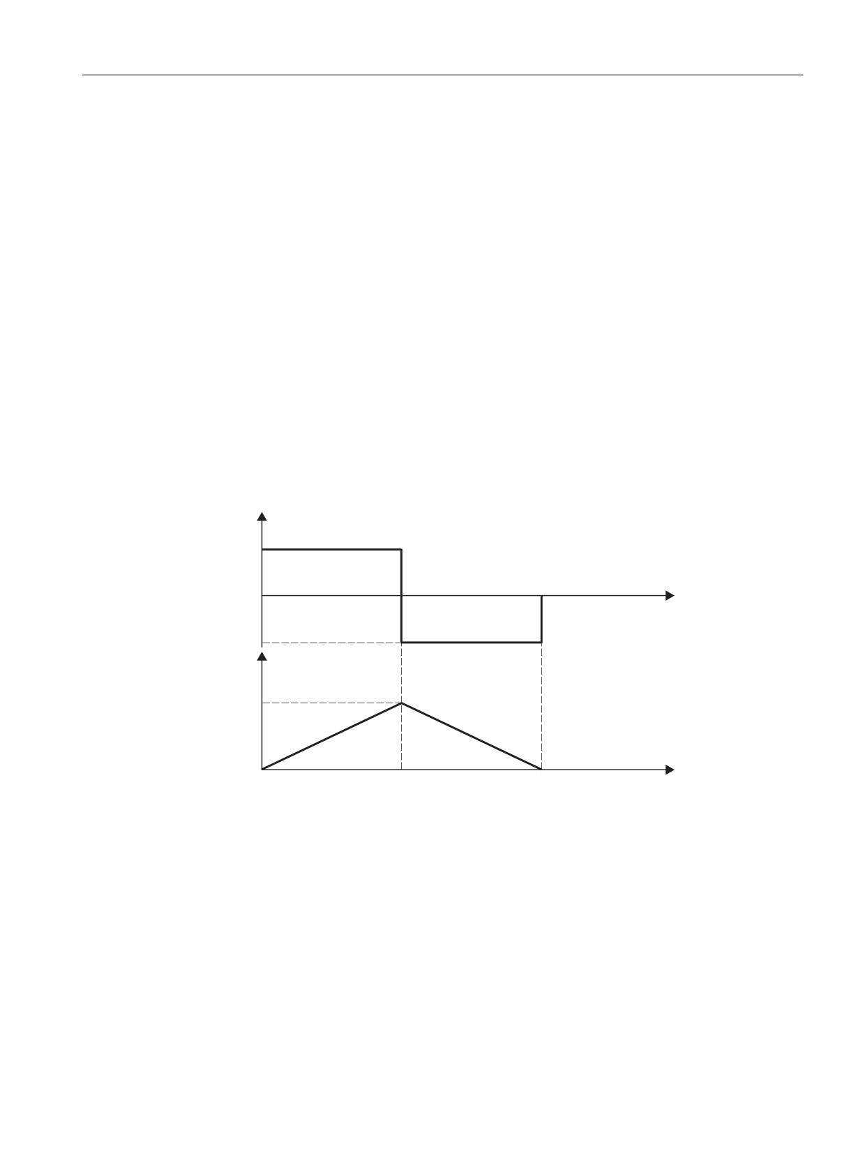
Acceleration and jerk
4.2 Detailed description
4.2
Detailed description
4.2.1
Acceleration without jerk limitation (BRISK/BRISKA) (channel/axis-specific)
4.2.1.1
Function
In the case of acceleration without jerk limitation (jerk = infinite) the maximum value is applied
for acceleration immediately. As regard to acceleration with jerk limitation, it differs in the
following respects:
• Advantages
Shorter processing times with the same maximum values for velocity and acceleration.
• Disadvantages
Increased load on the machine's mechanical components and risk of inducing high-
frequency and difficult-to-control mechanical vibrations.
Acceleration profile
D
DPD[
W
DPD[
Y
YPD[
W
W
W
W
amax:
Maximum acceleration value
vmax:
Maximum velocity value
t:
Time
Figure 4-1
Velocity and acceleration schematic for stepped acceleration profile
The following features of the acceleration profile can be identified from the figure above:
• Time: t0
Sudden acceleration from 0 to +amax
• Interval: t0 - t1
Constant acceleration with +amax; linear increase in velocity
Axes and spindles
Function Manual, 10/2020, 6FC5397-4GP40-0BA1
81

Acceleration and jerk
4.2 Detailed description
• Time: t
1
Sudden acceleration from 2 * amax with immediate switchover from acceleration to braking
Note
The sudden acceleration can normally be avoided by specifying a constant velocity time (see
Section "Constant traversing time (channel-specific) (Page 84)").
• Interval: t1 - t2
Constant acceleration with -amax; linear decrease in velocity
4.2.1.2
Parameterization
Maximum axial acceleration for path motions
The maximum axial acceleration for path motions can be set for the specific technology for each
machine axis via the following machine data:
MD32300 $MA_MAX_AX_ACCEL[<parameter set index>]
With <parameter set index> = 0, 1, 2 ... (max. parameter set number - 1)
For further information about the technology-specific parameter sets, see the Basic Functions
Function Manual.
The path parameters are calculated by the path planning of the preprocessing so that the
parameterized maximum values of the machine axes involved in the path are not exceeded.
Note
It is possible for the maximum value to be exceeded in connection with specific machining
situations (see Sections "Acceleration adaptation (ACC) (axis-specific) (Page 86)" and "Path
acceleration for real-time events (channel-specific) (Page 90)").
Maximum axial acceleration for positioning axis motions
With positioning axis motions, one of the two following maximum values is effective depending
on the set positioning axis dynamic response mode:
• MD32300 $MA_MAX_AX_ACCEL [0] (maximum axial acceleration for path motions in the
dynamic response mode DYNNORM)
• MD32300 $MA_MAX_AX_ACCEL [1] (maximum axial acceleration for path motions in the
dynamic response mode DYNPOS)
The positioning axis dynamic response mode is set in the NC-specific machine data:
MD18960 $MN_POS_DYN_MODE = <mode>
<mode>
Meaning
0
Effective maximum axial acceleration: MD32300 $MA_MAX_AX_ACCEL[ 0 ]
1
Effective maximum axial acceleration: MD32300 $MA_MAX_AX_ACCEL[ 1]
Axes and spindles
82
Function Manual, 10/2020, 6FC5397-4GP40-0BA1
Acceleration and jerk
4.2 Detailed description
Maximum axial acceleration for JOG motions
See Chapter "Acceleration and jerk for JOG motions (Page 123)".
4.2.1.3
Programming
Path acceleration without jerk limitation (BRISK)
Syntax
BRISK
Functionality
The BRISK part-program instruction is used to select the "without jerk limitation" acceleration
profile for the purpose of path acceleration.
G group: 21
Effective: Modal
Reset response
The channel-specific initial setting is activated via a reset:
MD20150 $MC_GCODE_RESET_VALUES[20]
Supplementary conditions
If the acceleration profile is changed in a part program during machining (BRISK/SOFT) an exact
stop is performed at the end of the block.
Single-axis acceleration without jerk limitation (BRISKA)
Syntax
BRISKA (axis{,axis})
Function
The BRISKA part-program command is used to select the "without jerk limitation" acceleration
profile for single-axis movements (JOG, JOG/INC, positioning axis, reciprocating axis, etc.).
G group: -
Effectiveness: Modal
Axis:
• Value range: Axis name of the channel axes
Axes and spindles
Function Manual, 10/2020, 6FC5397-4GP40-0BA1
83
Acceleration and jerk
4.2 Detailed description
Axis-specific initial setting
Acceleration without jerk limitation can be set as the axis-specific initial setting for single-axis
movements:
MD32420 $MA_JOG_AND_POS_JERK_ENABLE = FALSE
Reset behavior
The axis-specific initial setting is activated via a reset:
MD32420 $MA_JOG_AND_POS_ENABLE
4.2.2
Constant traversing time (channel-specific)
4.2.2.1
Function
For acceleration without jerk limitation, an acceleration jump of 2 * amax occurs when changing
from acceleration and braking. To prevent this acceleration jump, a channel-specific constant
traversing time can be parameterized. The constant traversing time specifies the time for
constant velocity traversing between the acceleration and the braking phase:
MD20500 $MC_CONST_VELO_MIN_TIME (minimum time with constant velocity)
Note
Constant traversing time does not act for:
• Active function: LookAhead
• In traversal blocks with a traversal time less than or equal to the interpolation cycle.
Axes and spindles
84
Function Manual, 10/2020, 6FC5397-4GP40-0BA1
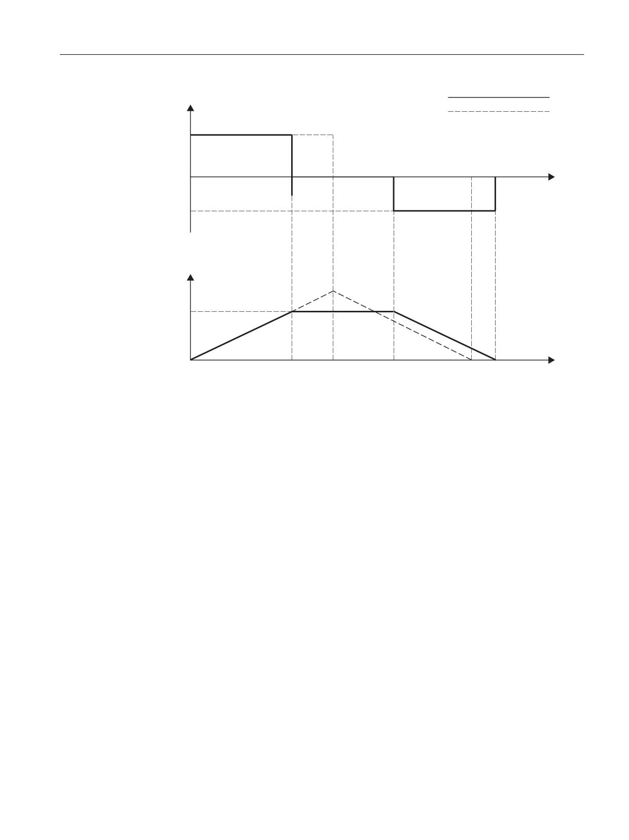
Acceleration and jerk
4.2 Detailed description
D
D
PD[
W
DPD[
Y
YPD[
W
W
W
W
W
W
W
1:
Curve with constant traversing time
2:
Curve without constant traversing time
amax: Maximum acceleration value
vmax: Maximum velocity value
t:
Time
Figure 4-2
Principle characteristic for an abrupt acceleration
The above figure shows the effect of the constant traversing time:
• Time: t1
End of the acceleration phase with acceleration jump 1 * amax
• Interval: t1 - t2
Acceleration 0; constant velocity over the parameterized constant traversing time
• Time: t2
Start of the braking phase with acceleration jump 1 * amax
The instants t0, t1' and t2' indicate the associated curve that would have resulted without
constant traversing time.
4.2.2.2
Parameterization
The constant travel time is parameterized for specific channels using machine data:
MD20500 $MC_CONST_VELO_MIN_TIME
(minimum time with constant velocity)
Axes and spindles
Function Manual, 10/2020, 6FC5397-4GP40-0BA1
85

Acceleration and jerk
4.2 Detailed description
4.2.3
Acceleration adaptation (ACC) (axis-specific)
4.2.3.1
Function
Using the ACC command, the currently effective maximum axis acceleration parameterized in
the acceleration-specific machine data can be reduced for a specific axis. The reduction is in the
form of a percentage factor, which is specified when programming the command.
For instance, reducing the maximum possible axis acceleration in a machining segment can be
used to prevent mechanical vibration as a result of high machining forces.
Effectiveness
Reducing the acceleration with ACC is effective for all interpolation types in the AUTOMATIC and
MDI operating modes - and for the dry run feedrate.
Acceleration reduction is not effective:
• in the JOG mode
• During the machine function REF (reference point approach).
• If, as a result of a fault that has been detected, the axis is stopped with a fast stop (setpoint
= 0).
4.2.3.2
Programming
Syntax
ACC[<axis>]=<reduction factor>
ACC[SPI(<spindle number>)]=<reduction factor>
ACC(S<spindle number>)=<reduction factor>
Meaning
<ACC>:
Command for the axis-specific reduction of the currently maximum possible
acceleration, derived from the machine data
Effectiveness:
Modal
<axis>:
Channel axis name of path axis
Data type:
AXIS
Value range:
Channel axis names
SPI(<spindle
The SPI(...) function converts the spindle number into the corresponding
number>):
channel axis name.
S<spindle
Spindle name in the channel
number>:
Further information
System variable
The acceleration reduction (set using ACC), currently active in the channel, can be read on an
axis-for-axis basis using:
Axes and spindles
86
Function Manual, 10/2020, 6FC5397-4GP40-0BA1
Acceleration and jerk
4.2 Detailed description
$AA_ACC[<axis>]
Reset response
The acceleration reduction set using ACC can be kept after a channel reset or after the end of the
program. The parameterization is performed via:
MD32320 $MA_DYN_LIMIT_RESET_MASK
4.2.4
Acceleration reserve (channel-specific)
4.2.4.1
Function
In a normal scenario, the preprocessing fully utilizes the parameterized maximum values of the
machine axes for the path acceleration. To obtain an acceleration margin for overlaid
movements, e.g. within the scope of the "High-speed retraction from the contour" function, the
path acceleration can be reduced by a parameterizable factor. For a factor of 0.2, for example,
only 80% of the maximum possible acceleration is utilized by preprocessing. 20% remains as an
acceleration margin for overlaid movements.
4.2.4.2
Parameterization
Parameters for the acceleration margin are assigned for each channel by means of machine
datum:
MD20610 $MC_ADD_MOVE_ACCEL_RESERVE
(acceleration margin for overlaid motions)
4.2.5
Limiting the path acceleration (channel-specific)
4.2.5.1
Function
To be able to flexibly respond to the respective processing situation, the path acceleration
calculated by preprocessing can be channel-specifically limited via setting data:
SD42500 $SC_SD_MAX_PATH_ACCEL (maximum path acceleration)
The value specified in the setting data is only taken into consideration if it is smaller than the path
acceleration calculated by preprocessing.
The limitation must be enabled channel-specifically via setting data:
SD42502 $SC_IS_SD_MAX_PATH_ACCEL = TRUE
4.2.5.2
Parameterization
Parameterization is carried out for specific channels using setting data:
SD42500 $SC_SD_MAX_PATH_ACCEL (maximum path acceleration)
Axes and spindles
Function Manual, 10/2020, 6FC5397-4GP40-0BA1
87
Acceleration and jerk
4.2 Detailed description
SD42502 $SC_IS_SD_MAX_PATH_ACCEL (activation of path-acceleration limitation)
4.2.5.3
Programming
Limit value
Syntax
$SC_SD_MAX_PATH_ACCEL = limit value
Functionality
The path-acceleration limitation can be adjusted for the situation by programming the setting
data.
Limit value:
• Value range: ≥ 0
• Unit: m/s2
Application:
• Part program
• Static synchronized action
Switch ON/OFF
Syntax
$SC_IS_SD_MAX_PATH_ACCEL = value
Functionality
The path-acceleration limitation can be activated/deactivated by programming the setting data.
Parameter: Value
• Value range: TRUE, FALSE
Application:
• Part program
• Static synchronized action
Axes and spindles
88
Function Manual, 10/2020, 6FC5397-4GP40-0BA1

Acceleration and jerk
4.2 Detailed description
4.2.6
Limiting the path acceleration (PACCLIM)
With the function "Adapt maximum path acceleration", the acceleration of the path motion
resulting from the axial limitation values can be reduced in critical program sections in the part
program. The acceleration value to which the maximum path acceleration is to be reduced is
programmed via the address PACCLIM. The programmed value is always effective only until the
next NC reset or the end of the part program.
Requirements
Licensing
A license is required for this optional function ("Path acceleration limitation", article number:
6FC5800-0xP26-0YB0) and must be assigned to the hardware via the license management.
Effectiveness
The function is effective:
• In the AUTOMATIC operating modes
• Only on path axes
Syntax
PACCLIM=<Value>
PACCLIM=-1
Meaning
PACCLIM
Address for adjusting the maximum path acceleration
<Value>
Acceleration value to which the maximum path acceleration is to be reduced
Data type:
REAL
Value range:
1.0 * 10-6 ... 1.0 * 1038
Unit:
m/s2 or inch/s2 (depending on the active system of units)
PACCLIM=-1
Cancels the limit programmed by PACCLIM=<Value>.
Note
The effect of PACCLIM is similar to the effect of the setting data SD42500
$SC_SD_MAX_PATH_ACCEL (maximum path acceleration). In contrast to SD42500, however,
PACCLIM works block-synchronously.
Axes and spindles
Function Manual, 10/2020, 6FC5397-4GP40-0BA1
89