SINUMERIK 840D sl. Service - Functions. Manual (2018-2020) - page 5
Acceleration and jerk
4.2 Detailed description
Note
When calculating the limitation value, the value of SD42500 $SC_SD_MAX_PATH_ACCEL is only
taken into account if SD42502 $SC_IS_SD_MAX_PATH_ACCEL is set to "TRUE".
If both PACCLIM and SD42500 $SC_SD_MAX_PATH_ACCEL are active, the smaller of the two
limitation values becomes effective.
Example
Program code
Comment
N1000 G0 X0 Y0 F10000 G64 G710
N1100 G1 X20 RNDM=5
N1200 G1 Y20 PACCLIM=0.5
; The axis slide in Y direction is accel-
erated/decelerated at max. 0.5 m/ss.
N1300 G1 X0 Y40
; The path movement of the axis slides in
X direction and Y direction is acceler-
ated/decelerated at max. 0.5 m/ss.
N1400 G1 Y0
M30
4.2.7
Path acceleration for real-time events (channel-specific)
4.2.7.1
Function
So that no compromise has to be made between machining-optimized acceleration on the one
hand and time-optimized acceleration in connection with the following real-time events on the
other:
• NC Stop / NC Start
• Changing the feedrate override
• Changing the velocity default for "safely reduced velocity" within the context of the "Safety
Integrated" function
For the real-time events mentioned above, the path acceleration can be specified using a
channel-specific system variable:
$AC_PATHACC = path acceleration
Real-time event acceleration will only be active for the duration of the change in velocity in
respect of one of the real-time events specified above.
Axes and spindles
90
Function Manual, 10/2020, 6FC5397-4GP40-0BA1

Acceleration and jerk
4.2 Detailed description
Limitation
If the specified path acceleration exceeds the capabilities of the machine axes that are of
relevance for the path, a limit will be imposed on the path acceleration within the controller so
that the resulting axial acceleration (ares) is restricted to less than 2x the parameterized
maximum axial value (amax).
ares = 2 * amax, with amax = MD32300 $MA_MAX_AX_ACCEL
Note
Path acceleration for real-time events is enabled, irrespective of the radial acceleration.
Effectiveness
Effective
Real-time event acceleration is only enabled in AUTOMATIC and MDA operating modes in
conjunction with the following real-time events:
• NC Stop / NC Start
• Override changes
• Changing the velocity default for "safely reduced velocity" within the context of the
"Safety Integrated" function
Not effective
Path acceleration for real-time events is ineffective for changes in path velocity that are
attributable to path planning during preprocessing for the channel, such as contour
curvatures, corners, kinematic transformation limitations, etc.
Real-time-event path acceleration is ineffective if the programmed value is smaller than
the path acceleration calculated during preprocessing for the path section concerned.
Programming
For information about programming system variables in the part program or synchronized
actions, see Section "Programming (Page 91)".
4.2.7.2
Programming
Syntax
$AC_PATHACC = path acceleration
Functionality
Real-time-event path acceleration is set via the channel-specific system variables.
Parameter: Path acceleration
• Value range: Path acceleration ≥ 0
• Unit: m/s2
Deactivation: $AC_PATHACC = 0
Axes and spindles
Function Manual, 10/2020, 6FC5397-4GP40-0BA1
91
Acceleration and jerk
4.2 Detailed description
Application:
• Part program
• Static synchronized action
Reset response
Real-time-event path acceleration is deactivated on reset.
Supplementary conditions
Programming $AC_PATHACC in the part program automatically triggers a preprocessing stop
with REORG (STOPRE).
4.2.8
Acceleration with programmed rapid traverse (G00) (axis-specific)
4.2.8.1
Function
Frequently the acceleration for the machine axes participating in processing must be set lower
than that which corresponds to the performance capability of the machine, due to the
processing-specific constraints.
For time-optimized traversing of the machine axes for programmed rapid traverse (part program
instruction G00), a separate maximum value of the axis-specific acceleration can be
parameterized.
JOG setup mode
The acceleration during rapid traverse override (ROV) in JOG setup mode is not affected by this
functionality.
4.2.8.2
Parameterization
The maximum value for axis-specific acceleration with programmed rapid traverse is
parameterized (G00) using the axis-specific machine data:
MD32434 $MA_G00_ACCEL_FACTOR
(scaling of the acceleration limitation with G00)
This is used to generate the maximum value for axis-specific acceleration with programmed
rapid traverse (G00) that is taken into account by the path planning component during
preprocessing:
Acceleration[axis] =
MD32300 $MA_MAX_AX_ACCEL * MD32434 $MA_G00_ACCEL_FACTOR
Axes and spindles
92
Function Manual, 10/2020, 6FC5397-4GP40-0BA1
Acceleration and jerk
4.2 Detailed description
4.2.9
Acceleration with active jerk limitation (SOFT/SOFTA) (axis-specific)
4.2.9.1
Function
When accelerating with jerk limitation, with the same maximum acceleration value a certain
time loss arises compared with acceleration without jerk limitation. To compensate for this loss
of time, a separate maximum value of the axis-specific acceleration can be parameterized for the
traversing of the machine axes when jerk limiting is active (SOFT/SOFTA).
The maximum value for acceleration with active jerk limitation is parameterized via a factor
relating to the axis-specific maximum value. This results in the maximum value of the axis-
specific acceleration with active jerk limiting that is taken into account by the path planning
component during preprocessing:
Acceleration[<axis>] =
MD32300 $MA_MAX_AX_ACCEL * MD32433 $MA_SOFT_ACCEL_FACTOR
4.2.9.2
Parameterization
The maximum value for acceleration with active jerk limitation (SOFT/SOFTA) is parameterized
using the axis-specific machine data:
MD32434 $MA_SOFT_ACCEL_FACTOR
(scaling of the acceleration limitation with SOFT)
4.2.10
Exceeding the acceleration with non-tangential block transitions (axis-
specific)
4.2.10.1
Function
In the case of non-tangential block transitions (corners), the controller may have to decelerate
the traversing motion of the geometry axes significantly to ensure compliance with the
parameterized axis dynamics. To reduce or prevent the deceleration at non-tangential block
transitions, a higher axis-specific acceleration can be allowed.
The exceeded acceleration is parameterized via a factor relating to the axis-specific maximum
value. This results in the maximum value of the axis-specific acceleration for non-tangential
block transitions that is taken into account by the path planning during preprocessing:
Acceleration[axis] =
MD32300 $MA_MAX_AX_ACCEL * MD32310 $MA_MAX_ACCEL_OVL_FACTOR
4.2.10.2
Parameterization
Excessive acceleration for non-tangential block transitions is parameterized using the axis-
specific machine data:
MD32310 $MA_MAX_ACCEL_OVL_FACTOR
(overload factor for velocity jumps)
Axes and spindles
Function Manual, 10/2020, 6FC5397-4GP40-0BA1
93
Acceleration and jerk
4.2 Detailed description
4.2.11
Acceleration reserve for the radial acceleration (channel-specific)
4.2.11.1
Function
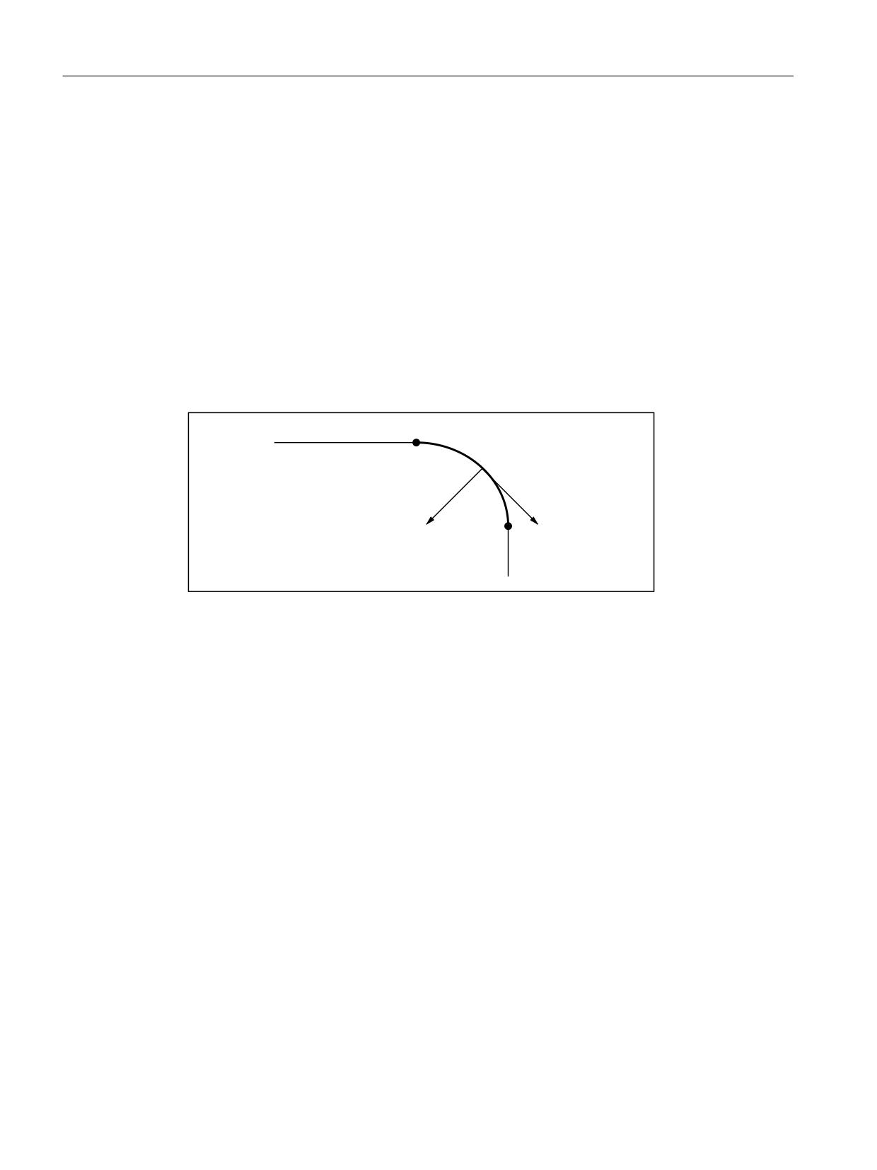
In addition to the path acceleration (tangential acceleration), the radial acceleration also affects
curved contours. If this is not taken into consideration during the parameterization, the active
axial acceleration during acceleration or deceleration on the curved contour can be up to 2 times
the maximum value for a short time.
Active axial acceleration =
portion of the path acceleration + portion of the radial acceleration =
2 * ( MD32300 $MA_MAX_AX_ACCEL )
1
1
D3DWK
D5DGLDO
1
Figure 4-3
Radial and path acceleration on curved contours
The portion of the axis-specific acceleration that is to be
taken into consideration as the acceleration reserve for the radial acceleration can be set via the
channel-specific machine data:
MD20602 $MC_CURV_EFFECT_ON_PATH_ACCEL
(influence of the path curvature on the path dynamics).
For a value of 0.75, for example, 75% of the axis-specific acceleration is provided for the radial
acceleration and 25% for the path acceleration.
In general, the corresponding maximum values for the following are calculated:
Radial acceleration =
MD20602 $MC_CURV_EFFECT_ON_PATH_ACCEL * MD32300 $MA_MAX_AX_ACCEL
Path acceleration =
(1 - MD20602 $MC_CURV_EFFECT_ON_PATH_ACCEL) * MD32300 $MA_MAX_AX_ACCEL
Axes and spindles
94
Function Manual, 10/2020, 6FC5397-4GP40-0BA1

Acceleration and jerk
4.2 Detailed description
Example
The following machine parameters are given:
• MD32300 $MA_MAX_AX_ACCEL for all geometry axes: 3 m/s
• Maximum path velocity for a path radius of 10 mm, based on the mechanical realities of the
machine: 5 m/min
The radial acceleration is calculated from this for:
>P PLQ@
Y
3DWK
PV
D5DGLDO
U >PP@
>P V @
This results in the setting for the acceleration reserve for:
0'
0&B&859B())(&7B21B3$7+B$&&(/
>P V @
D5DGLDO
ป
0'
0$B0$;B$;B$&&(/>P V @
Linear blocks
For linear blocks (linear interpolation) without active kinematics transformation, the cited
acceleration reserve has no effect.
4.2.11.2
Parameterization
The proportion of maximum available axis acceleration to be taken into account as an
acceleration margin for radial acceleration on curved contours is parameterized using the
channel-specific machine data:
MD20602 $MC_CURV_EFFECT_ON_PATH_ACCEL
(influence of path curvature on dynamic path response)
4.2.12
Jerk limitation with path interpolation (SOFT) (channel-specific)
4.2.12.1
Function
As far as the functionality described in the rest of this document is concerned, constant
acceleration, i.e., acceleration with jerk limitation (jerk = infinite value), is the assumed
acceleration profile. In the case of acceleration with jerk limitation, linear interpolation is applied
in respect of acceleration from 0 to the maximum value.
Advantages
Minimal load on the machine's mechanical components and low risk of high-frequency and
difficult-to-control mechanical vibrations thanks to constant excessive acceleration.
Axes and spindles
Function Manual, 10/2020, 6FC5397-4GP40-0BA1
95
Acceleration and jerk
4.2 Detailed description
Disadvantages
Longer machining times compared with stepped acceleration profile when the same maximum
velocity and acceleration values are used.
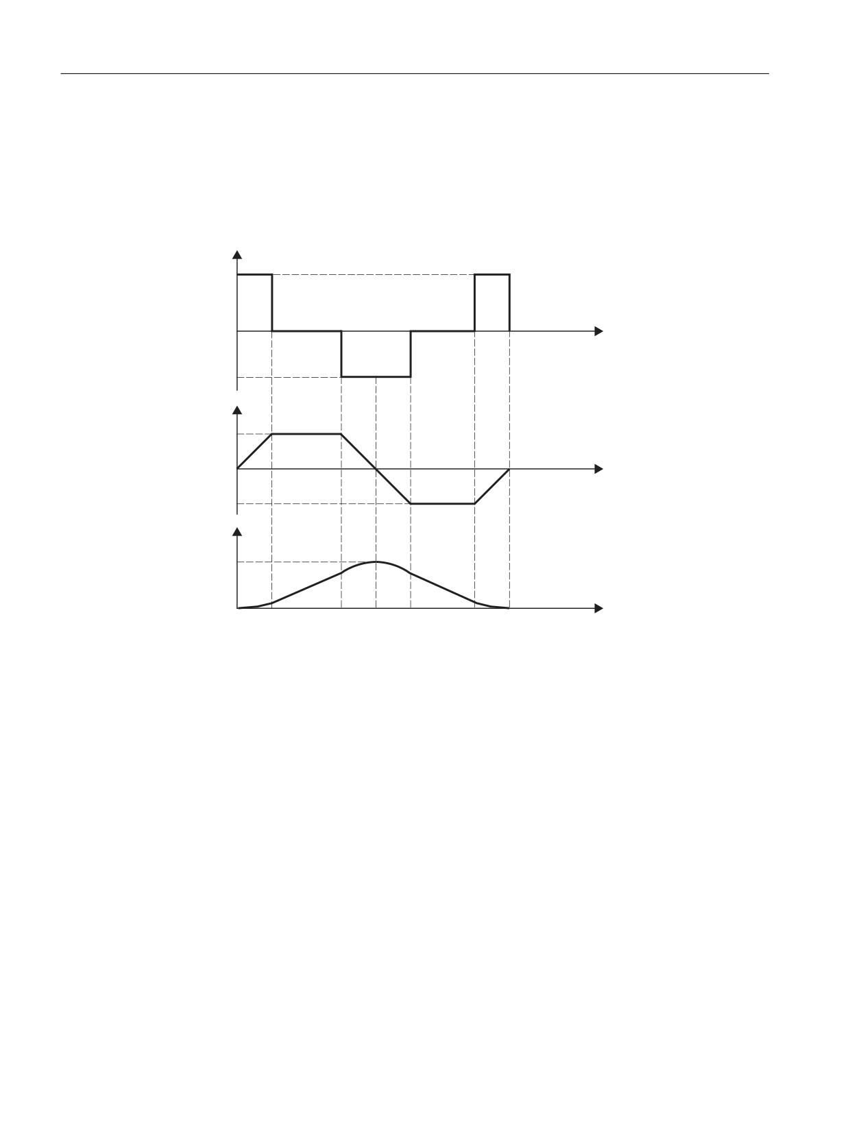
Acceleration profile
U
UPD[
W
UPD[
D
DPD[
W
DPD[
Y
YPD[
W
W
W
W
W
W
W
W
rmax:
Maximum jerk value
amax:
Maximum acceleration value
vmax:
Maximum velocity value
t:
Time
Figure 4-4
Jerk, acceleration and velocity schematic with jerk limitation acceleration profile
The following features of the acceleration profile can be identified from the figure above:
• Interval: t0 - t1
Constant jerk with +rmax; linear increase in acceleration; quadratic increase in velocity
• Interval: t1 - t2
Constant acceleration with +amax; linear increase in velocity
• Interval: t2 - t3
Constant jerk with -rmax; linear decrease in acceleration; quadratic decrease in excessive
velocity until maximum value +vmax is reached
• Interval: t3 - t4
Constant jerk with +rmax; linear increase in braking acceleration; quadratic decrease in
velocity
Axes and spindles
96
Function Manual, 10/2020, 6FC5397-4GP40-0BA1
Acceleration and jerk
4.2 Detailed description
• Interval: t
4
- t5
Constant braking acceleration with -amax; linear decrease in velocity
• Interval: t5 - t6
Constant jerk with -rmax; linear decrease in braking acceleration; quadratic decrease in
velocity reduction until zero velocity is reached v = 0
4.2.12.2
Parameterization
Maximum jerk value for path motions (axis-specific)
The maximum axial jerk for path motions can be set for the specific technology for each machine
axis via the following machine data:
MD32431 $MA_MAX_AX_JERK[<parameter set index>]
With <parameter set index> = 0, 1, 2 ... (max. parameter set number - 1)
For further information about the technology-specific parameter sets, see the Basic Functions
Function Manual.
The path parameters are calculated by the path planning of the preprocessing so that the
parameterized maximum values of the machine axes involved in the path are not exceeded.
Note
It is possible for the maximum value to be exceeded in connection with specific processing
situations (see Section "Path jerk for real-time events (channel-specific) (Page 101)").
Maximum jerk value for path motions (channel-specific)
In addition to the axis-specific setting, the maximum jerk value can also be specified as channel-
specific path parameter via the following machine data:
MD20600 $MC_MAX_PATH_JERK (path-related maximum jerk)
In order to exclude the mutual influencing of axis and channel-specific maximum jerk values, the
channel-specific maximum value must be set to a value greater than the axial maximum values.
4.2.12.3
Programming
Syntax
SOFT
Functionality
The SOFT part-program instruction is used to select the acceleration profile with jerk limitation
for the traversing operations of geometry axes in the channel.
G group: 21
Axes and spindles
Function Manual, 10/2020, 6FC5397-4GP40-0BA1
97

Acceleration and jerk
4.2 Detailed description
Effective: Modal
Reset response
The channel-specific initial setting is activated via a reset:
MD20150 $MC_GCODE_RESET_VALUES[20]
Boundary conditions
If the acceleration mode is changed in a part program during machining (BRISK ↔ SOFT), a
block change is performed at the point of transition with an exact stop at the end of the block,
even in continuous-path mode.
4.2.13
Jerk limitation with single-axis interpolation (SOFTA) (axis-specific)
4.2.13.1
Parameterization
Basic setting of axis-specific jerk limitation
Acceleration with jerk limitation can be set as the axis-specific initial setting:
MD32420 $MA_JOG_AND_POS_JERK_ENABLE== TRUE
Maximum axis-specific jerk for positioning axis movements
When traversing positioning axes with active jerk limitation, the value from one of the following
machine data takes effect as the maximum axis-specific jerk:
• MD32430 $MA_JOG_AND_POS_MAX_JERK (maximum axis-specific jerk)
• MD32431 $MA_MAX_AX_JERK [0] (maximum axis-specific jerk for path motions in the
dynamic response mode DYNNORM)
• MD32431 $MA_MAX_AX_JERK [1] (maximum axis-specific jerk for path motions in dynamic
response mode DYNPOS)
The machine data to be used is determined by the set positioning axis dynamic response mode:
MD18960 $MN_POS_DYN_MODE = <mode>
<mode>
Meaning
The following applies as the maximum axis-specific jerk for positioning axis motions:
0
MD32430 $MA_JOG_AND_POS_MAX_JERK
With active G75 (fixed-point approach): MD32431 $MA_MAX_AX_JERK[ 0 ]
1
MD32431 $MA_MAX_AX_JERK[ 1 ]
Axes and spindles
98
Function Manual, 10/2020, 6FC5397-4GP40-0BA1
Acceleration and jerk
4.2 Detailed description
Maximum axial jerk for JOG motions
See Chapter "Acceleration and jerk for JOG motions (Page 123)".
4.2.13.2
Programming
Syntax
SOFTA (Axis {Axis})
Functionality
The SOFTA part-program command is used to select acceleration with jerk limitation for single-
axis movements (positioning axis, reciprocating axis, etc.)
G group: -
Effectiveness: Modal
Axis:
• Value range: Axis name of the channel axes
Axis-specific initial setting
Acceleration with jerk limitation can be set as the axis-specific initial setting for single-axis
movements:
MD32420 $MA_JOG_AND_POS_JERK_ENABLE = TRUE
Reset behavior
The axis-specific initial setting is activated via a reset:
MD32420 $MA_JOG_AND_POS_ENABLE
4.2.14
Limiting the path jerking (channel-specific)
4.2.14.1
Function
To be able to flexibly respond to the respective preprocessing situation, the path jerk calculated
by preprocessing can be channel-specifically limited via setting data:
SD42510 $SC_SD_MAX_PATH_JERK (maximum path jerk)
The value specified in the setting data is only taken into consideration if it is smaller than the path
jerk calculated by preprocessing.
The limitation must be enabled channel-specifically via setting data:
SD42512 $SC_IS_SD_MAX_PATH_JERK = TRUE
Axes and spindles
Function Manual, 10/2020, 6FC5397-4GP40-0BA1
99
Acceleration and jerk
4.2 Detailed description
4.2.14.2
Parameterization
Parameterization is carried out for specific channels using setting data:
SD42510 $SC_SD_MAX_PATH_JERK (maximum path jerk)
SD42512 $SC_IS_SD_MAX_PATH_JERK
(activation of path-jerk limitation)
4.2.14.3
Programming
Maximum path jerk
Syntax
$SC_SD_MAX_PATH_JERK = jerk value
Functionality
The path-jerk limitation can be adjusted for the situation by programming the setting data.
Jerk value:
• Value range: ≥ 0
• Unit: m/s3
Application:
• Part program
• Static synchronized action
Switch ON/OFF
Syntax
$SC_IS_SD_MAX_PATH_JERK = value
Functionality
The path-jerk limitation can be activated/deactivated by programming the setting data.
Parameter: Value
• Value range: TRUE, FALSE
Axes and spindles
100
Function Manual, 10/2020, 6FC5397-4GP40-0BA1
Acceleration and jerk
4.2 Detailed description
Application:
• Part program
• Static synchronized action
4.2.15
Path jerk for real-time events (channel-specific)
4.2.15.1
Function
So that no compromise has to be made between machining-optimized jerk on the one hand and
time-optimized jerk in connection with the following real-time events on the other:
• NC Stop / NC Start
• Changing the feedrate override
• Changing the velocity default for "safely reduced velocity" within the context of the "Safety
Integrated" function
for the real-time events mentioned, the path jerk can be specified using a channel-specific
system variable:
$AC_PATHJERK = path jerk
Path jerk for real-time events will only be active for the duration of the change in velocity in
respect of one of the real-time events specified above.
Limitation
As the jerk is not a physical variable of any relevance to the drive, no limit is imposed on the jerk
set.
Effectiveness
Effective
Path jerk for real-time events is only enabled in AUTOMATIC and MDA operating modes
in conjunction with the following real-time events:
• NC Stop / NC Start
• Override changes
• Changing the velocity default for "safely reduced velocity" within the context of the
"Safety Integrated" function
Not effective
Path jerk for real-time events is ineffective for changes in the path velocity that are
attributable to path planning during preprocessing for the channel, such as contour
curvatures, corners, kinematic transformation limitations, etc.
Path jerk for real-time events is ineffective if the programmed value is smaller than the
path jerk calculated during preprocessing for the path section concerned.
Axes and spindles
Function Manual, 10/2020, 6FC5397-4GP40-0BA1
101
Acceleration and jerk
4.2 Detailed description
Programming
For the purpose of setting the jerk for real-time events in accordance with the acceleration, the
system variables can be set as follows:
$AC_PATHJERK = $AC_PATHACC/smoothing time
• $AC_PATHACC: Path acceleration [m/s2]
Smoothing time: Freely selectable, e.g. 0.02 s
For information about programming system variables in the part program or synchronized
actions, see Section "Programming (Page 102)".
4.2.15.2
Programming
Syntax
$AC_PATHJERK = path jerk
Functionality
The path jerk for real-time events is set via the channel-specific system variables.
Jerk value:
• Value range: Path jerk ≥ 0
• Unit: m/s3
Application:
• Part program
• Static synchronized action
Reset behavior
The function is deactivated on reset.
Boundary conditions
Programming $AC_PATHJERK in the part program automatically triggers a preprocessing stop
with REORG (STOPRE).
4.2.16
Jerk during programmed rapid traverse (G00) (axis-specific)
4.2.16.1
Function
Frequently the maximum jerk for the machine axes participating in processing must be set lower
than that which corresponds to the performance capability of the machine, due to the
processing-specific constraints.
Axes and spindles
102
Function Manual, 10/2020, 6FC5397-4GP40-0BA1
Acceleration and jerk
4.2 Detailed description
For time-optimized traversing of the machine axes for programmed rapid traverse (part program
instruction G00), a separate maximum value of the axis-specific jerk can be parameterized.
JOG setup mode
The jerk during rapid traverse override (ROV) in JOG setup mode is not affected by this
functionality.
4.2.16.2
Parameterization
The maximum value for axis-specific jerk with programmed rapid traverse is parameterized
(G00) using the axis-specific machine data:
MD32434 $MA_G00_ACCEL_FACTOR
(scaling of the acceleration limitation with G00)
This is used to generate the maximum value for axis-specific jerk with programmed rapid
traverse (G00) that is taken into account by the path planning component during preprocessing:
Jerk[axis] =
MD32431 $MA_MAX_AX_JERK * MD32435 $MA_G00_JERK_FACTOR
4.2.17
Excessive jerk for block transitions without constant curvature (axis-specific)
4.2.17.1
Function
In the case of block transitions without constant curvature (e.g. straight line > circle), the
programmable controller has to decelerate movement of the geometry axes significantly in
order to ensure compliance with the parameterized axis dynamics. To reduce or prevent the
deceleration at block transitions without constant curvature, a higher axis-specific jerk can be
allowed.
The increase in jerk is parameterized via a separate axis-specific maximum value.
4.2.17.2
Parameterization
The excessive jerk for block transitions without constant curvature is parameterized using the
axis-specific machine data:
MD32432 $MA_PATH_TRANS_JERK_LIM
(excessive jerk for block transitions without constant curvature)
Axes and spindles
Function Manual, 10/2020, 6FC5397-4GP40-0BA1
103
Acceleration and jerk
4.2 Detailed description
4.2.18
Velocity-dependent jerk adaptation (axis-specific)
Function
The dynamic path response results from the parameterized, constant axial maximum values for
velocity, acceleration and jerk of the axes involved in the path:
• MD32000 $MA_MAX_AX_VELO (maximum axis velocity)
• MD32300 $MA_MAX_AX_ACCEL (maximum axis acceleration)
• MD32431 $MA_MAX_AX_JERK (max. axial jerk for path motion)
For contours with non-constant curvature (torsion), as for example in connection with free-
form surfaces, fluctuations in the path velocity, particularly in the upper velocity range, can
result mainly due to the axial jerk. The fluctuations of the path velocity lead to adverse affects in
the surface quality.
The influence of the axial jerk on the path velocity is decreased for contours with non-constant
curvature through a velocity-dependent increase of the permissible axial jerk. Fluctuations in
the path velocity can be avoided with the appropriate parameterization.
The velocity-dependent increase of the permissible axial jerk has no effect on the maximum
possible path acceleration and path jerk. These result from the constant axial maximum values
parameterized in the in the machine data even when jerk adaptation is active.
As both curvature and torsion are zero in the case of linear motion, the velocity-dependent jerk
adaptation has no effect with linear motions.
Availability
The "velocity-dependent jerk adaptation" function is available independent of the function
"Freeform surface mode: Basic functions".
For further information about the function "Freeform surface mode: Basic functions" refer to
the Basic Functions Function Manual.
Axes and spindles
104
Function Manual, 10/2020, 6FC5397-4GP40-0BA1
Acceleration and jerk
4.2 Detailed description
Parameter assignment
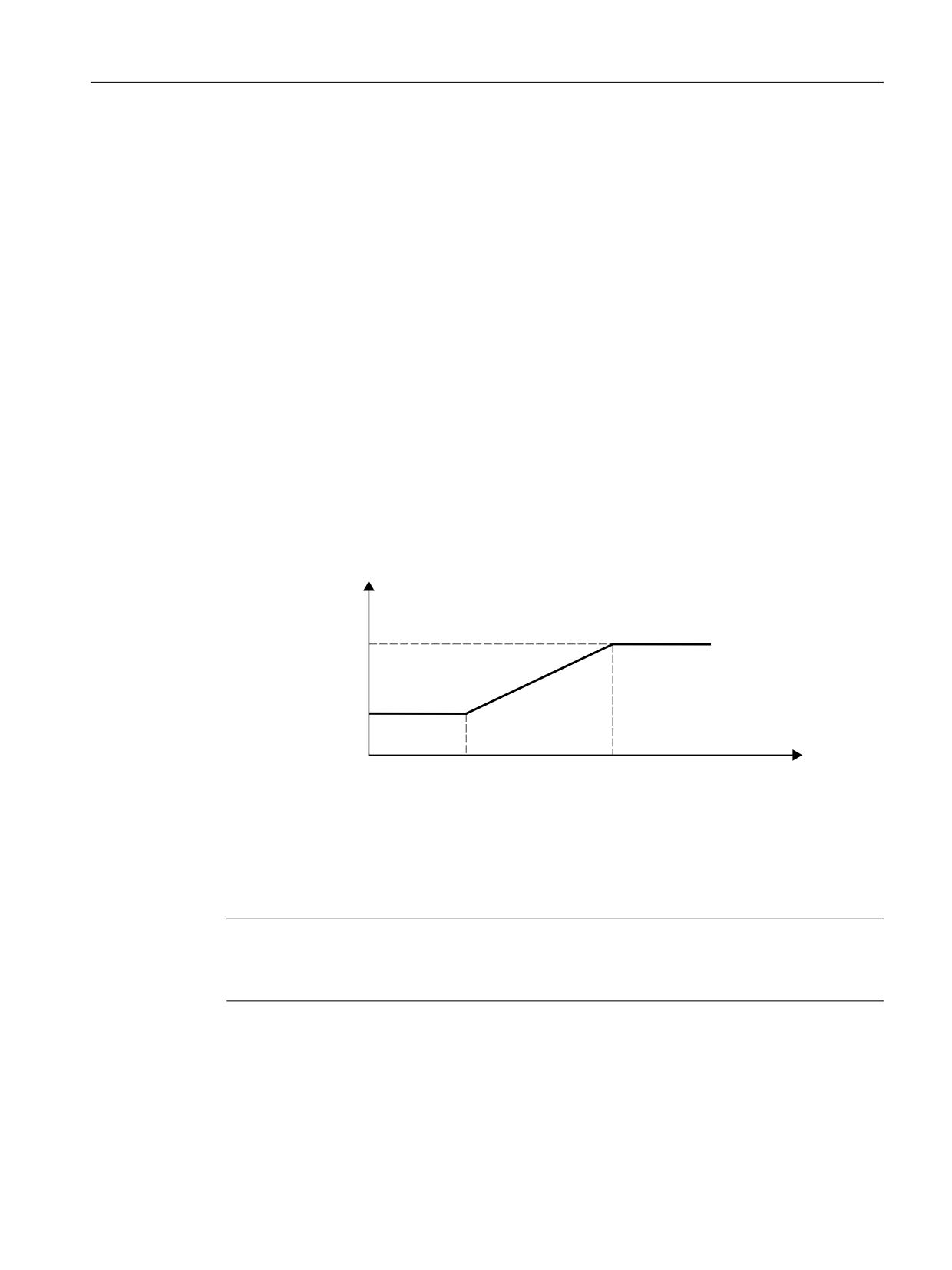
The "Velocity-dependent jerk adaptation" function is parameterized with the following machine
data:
• MD32437 $MA_AX_JERK_VEL0[<n>] = <threshold valuelower>
Lower velocity threshold of the jerk adaptation. Velocity-dependent jerk adaptation takes
effective as of this velocity.
The lower velocity threshold can be set separately via index n for each dynamic response
mode.
• MD32438 $MA_AX_JERK_VEL1[<n>] = <threshold valueupper>
Upper velocity threshold of the jerk adaptation. The velocity-dependent jerk reaches its
maximum value jmax parameterized with MD32439 $MA_MAX_AX_JERK_FACTOR at this
velocity.
The upper velocity threshold can be set separately via index n for each dynamic response
mode.
• MD32439 $MA_MAX_AX_JERK_FACTOR = <factor>
Factor for the parameterization of the maximum velocity-dependent jerk jmax on reaching the
upper velocity threshold MD32438 $MA_AX_JERK_VEL1[<n>]:
jmax = (MD32431 $MA_MAX_AX_JERK) * (MD32439 $MA_MAX_AX_JERK_FACTOR)
The velocity-dependent jerk adaptation is active at a value > 1.0.
The velocity-dependent jerk adaptation is inactive at a value = 1.0.
PD[LPXP SHUPLWWHG
D[LDO MHUN
M
M
Y
Y
$[LV VSHHG
v0:
MD32437 $MA_AX_JERK_VEL0
v1:
MD32438 $MA_AX_JERK_VEL1
j0:
MD32431 $MA_MAX_AX_JERK
j1:
MD32439 $MA_MAX_AX_JERK_FACTOR * MD32431 $MA_MAX_AX_JERK
Figure 4-5
Axial jerk as a function of the axis velocity
Note
The velocity-dependent jerk adaptation is only active, if:
MD32439 $MA_MAX_AX_JERK_FACTOR > 1.0
Axes and spindles
Function Manual, 10/2020, 6FC5397-4GP40-0BA1
105
Acceleration and jerk
4.2 Detailed description
Example
Example of parameter assignment:
• MD32437 $MA_AX_JERK_VEL0 = 3000 mm/min
• MD32438 $MA_AX_JERK_VEL1 = 6000 mm/min
• MD32439 $MA_MAX_AX_JERK_FACTOR[AX1] = 2.0
• MD32439 $MA_MAX_AX_JERK_FACTOR[AX2] = 3.0
• MD32439 $MA_MAX_AX_JERK_FACTOR[AX3] = 1.0
Effect
• The speed-dependent jerk adaptation is active for the 1st and 2nd axis, whereas the function
for the 3rd axis is not active.
• The parameterized jerk is effective at axis velocities in the range of 0 to 3000 mm/min.
• The maximum jerk is linearly increased for axis velocities in the range 3000 mm/min to
6000 mm/min.
• The maximum permitted jerk of the 1st axis is, for axis velocities greater than 6000 mm/min,
increased by a factor of 2 - for the 2nd axis, by factor of 3.
• The parameterized values apply in each dynamic response mode.
4.2.19
Jerk filter (position setpoint filter, axis-specific)
4.2.19.1
Function
In certain application scenarios, e.g. when milling free-form surfaces, it may be beneficial to
smooth the position setpoint characteristics of the machine axes. This enables the surface
quality to be improved by reducing the mechanical vibration generated in the machine.
To smooth the position setpoint characteristic of a machine axis, a jerk filter can be activated at
the position controller level, independent of channel- and axis-specific jerk limitations that are
taken into account at interpolator level. Jerk limitation can be set using the following machine
data, for example:
• MD20600 $MA_MAX_PATH_JERK (pathrelated maximum jerk)
• MD32431 $MA_MAX_AX_JERK (maximum axial jerk for path motion)
All position setpoint filter types have a lowpass characteristic, and always round a contour at the
center of the curvature (towards the inside). Larger time constants or lower filter frequencies
round the contour more significantly; however, that also means that machine resonance points
(machine oscillation) are excited less. A compromise must always be found between an
adequate damping effect and contour accuracy.
The damping effect can be monitored via the positioning response, the contour accuracy using
a circularity test, for example.
Axes and spindles
106
Function Manual, 10/2020, 6FC5397-4GP40-0BA1

Acceleration and jerk
4.2 Detailed description
Various filter types are available to enable the jerk filter to be optimally matched to the specific
machine characteristics:
• 2nd order filter (PT2)
• Moving average calculation
• Bandstop
• Double sliding averaging
• FIR lowpass (FIR: Finite Impulse Response)
Filter type: 2nd order filter
Because it is a simple lowpass filter, a filter type "2nd order filter" can only meet the requirements
specified above where relatively small filter time constants (around 10 ms) are involved. When
used in conjunction with larger time constants, inadmissible contour deviations soon become
apparent. The filter effect is relatively low.
This filter type is the default for historical reasons.
Filter type: Moving average calculation
Where low contour deviations are required, filter time constants within the range of 20 - 40 ms
can be set using the "moving averaging" filter type. The smoothing effect is largely symmetrical.
The display of the calculated servo gain factor (KV) in the user interface, indicates smaller values
than would normally be appropriate for the filter. The contour accuracy is higher than the
displayed servo gain factor (KV) appears to suggest.
When changing from "2nd order filter" to "sliding averaging" filter type, the displayed servo gain
factor (KV) may therefore decrease (with identical filter time constant), even though there is an
improvement in contour accuracy.
Filter type: Bandstop
The use is not recommended and is (still) only available for compatibility reasons.
The band-stop filter is a 2nd order filter in terms of numerator and denominator:
V
V '=
˭ I
˭ I
=
=
+V
V
V '1
˭ I1
˭ I1
With:
fN:
Numerator natural frequency
fD:
Denominator natural frequency
DN:
Numerator damping
DD:
Denominator damping
Axes and spindles
Function Manual, 10/2020, 6FC5397-4GP40-0BA1
107
Acceleration and jerk
4.2 Detailed description
Since a vibration-capable filter setting is not expected to yield useful results in any case, as with
the "2nd-order filter" (PT2) low-pass filter (PT2) type of the jerk filter there is no setting option for
the denominator damping DD. The denominator damping DD is permanently set to 1.
The band-stop filter can be parameterized in two different ways:
• Real band-stop filter
• Band-stop filter with additional amplitude response increase/decrease at high frequencies
Real band-stop filter
A real band-stop filter is obtained when identical numerator and denominator natural
frequencies are selected:
fN = fD = fblock (blocking frequency)
If the numerator damping setting = 0 is selected, the blocking frequency is equivalent to
complete attenuation. In this case the 3 dB bandwidth is calculated as follows:
f3 dB bandwidth = 2 * fblock
If instead of complete attenuation, a reduction by a factor of k is all that is required, then
numerator damping should be selected in accordance with k. In this case the above formula for
calculating the 3 dB bandwidth no longer applies.
Band-stop filter with additional amplitude response increase/decrease at high frequencies
In this case, the numerator and denominator natural frequencies are set to different values. The
numerator natural frequency determines the blocking frequency.
By selecting a lower/higher denominator natural frequency than the numerator natural
frequency, you can increase/decrease the amplitude response at high frequencies. An amplitude
response increase at high frequencies can be justified in most cases, as the controlled system
generally has a lowpass characteristic itself, i.e. the amplitude response decreases at high
frequencies anyway.
Constraints
If the numerator natural frequency is selected to be too high, then the filter is deactivated. In this
case, the frequency limit fZmax depends on the position controller clock cycle:
6KDQQRQ 7KHRUHP
I=PD[
˭
7
˭
7
3RVLWLRQ FRQWURO F\FOH FORFN
=PLQ
Filter type: Double sliding averaging
Double moving average calculation has a stronger smoothing effect than basic moving average
calculation. By additionally parameterizing a second moving average calculation, differences in
the dynamic response between axes that are interpolating with one another can be
compensated.
Axes and spindles
108
Function Manual, 10/2020, 6FC5397-4GP40-0BA1

Acceleration and jerk
4.2 Detailed description
Filter type: FIR lowpass
Note
To use the jerk filter type "FIR lowpass", a license is required for the following option:
"Top Speed" (article number: 6FC5800-0AS13-0Yx0)
Note
The use of the "FIR lowpass" type of jerk filter is only permitted with active jerk limitation (SOFT/
SOFTA).
Using a FIR lowpass as jerk filter allows the required smoothing effect to be specified in the
frequency range. Normally, a FIR lowpass filter has a more significant damping effect with
improved contour accuracy than all of the previously described jerk filter types.
FIR lowpass dynamic response-dependent
The filter settings can be made separately for each dynamic mode (DYNNORM, DYNPOS,
DYNROUGH, DYNSEMIFIN, DYNFINISH, DYNPREC) for the dynamic-dependent FIR lowpass jerk
filter variant, independently of the use in filter circuit 1 or 2 (Page 177). Thus, it is possible to set
the effective damping and the resulting overshot behavior to the processing type or the
expected workpiece quality.
When the CALCFIR (Page 112) NC language command is executed in the "CUST_832"
manufacturer cycle, the dynamic response-dependent FIR jerk filter settings for the active
dynamic response mode in all axes of a channel with active FIR filters are matched to the dynamic
response-limiting linear axis and made effective, thus ensuring path interpolation for all channel
axes involved.
When the control system powers up, for a channel reset and end of program reset, the FIR jerk
filter settings are automatically activated to match the initial setting of G group 59.
Example:
If it is important to have a minimal processing time for DYNROUGH and the highest processing
accuracy and surface quality for DYNFINISH or DYNPREC, these requirements can be fulfilled
using two different FIR jerk filter settings. The NC language command CALCFIR adapts the FIR jerk
filter to the programmed dynamic mode for all of the axes of a channel with active FIR filters and
ensures an identical damping effect and contour accuracy.
4.2.19.2
Parameterization
Activation
The jerk filter is activated using the machine data:
MD32400 $MA_AX_JERK_ENABLE (axial jerk limitation)
The jerk filter is active in all operating modes and with all types of interpolation.
Axes and spindles
Function Manual, 10/2020, 6FC5397-4GP40-0BA1
109

Acceleration and jerk
4.2 Detailed description
Filter type
The filter type is selected via the machine data:
MD32402 $MA_AX_JERK_MODE (filter type for axial jerk limitation)
Value
Filter type
1
2nd order filter
2
Moving average calculation
3
Bandstop
4
Double sliding averaging
5
FIR lowpass
Axial jerk filters (filter types 1, 2 and 3)
The axial jerk filters are set using the following machine data:
• For filter types 1 and 2 with MD32410 $MA_AX_JERK_TIME.
• For filter type 3 using machine data MD32412 AX_JERK_FREQ and MD 32414
AX_JERK_DAMP.
The jerk filter is only effective when the time constant is greater than a position control clock
cycle.
Double sliding averaging (filter type 4)
A double moving average calculation requires that the following machine data are set:
• MD32410 $MA_AX_JERK_TIME
• MD32411 $MA_AX_JERK_TIME_ADD
If both machine data are parameterized the same, a delta filter is implemented, which produces
extremely strong damping, but also significant contour distortion.
FIR lowpass (filter type 5)
A FIR lowpass filter requires that the following machine data are set:
• MD32407 $MA_AX_JERK_FIR_FREQ = (corner frequency (-6dB) of the axial FIR jerk filter
smoothing)
• MD32408 $MA_AX_JERK_FIR_ORDER (order of the filter for the axial FIR jerk filter smoothing)
• MD32409 $MA_AX_JERK_FIR_ORDER (window type of the axial FIR jerk filter smoothing):
- Window type 0 does not use a window.
- Window type 1 uses a Hamming window.
- Window type 2 uses a Blackman-Harris window.
- Window type 3 uses a Gauss window.
Axes and spindles
110
Function Manual, 10/2020, 6FC5397-4GP40-0BA1

Acceleration and jerk
4.2 Detailed description
FIR lowpass dynamic response-dependent (filter type 5)
A dynamic response-dependent FIR lowpass requires that the following machine data be set:
• MD32404 $MA_CALCFIR_SELECT (FIR lowpass - activation of the dynamic response-
dependent filter circuit)
Value
Meaning
0
CALCFIR calculation is inactive for this axis
1
CALCFIR calculation effects the 1st filter circuit
2
CALCFIR calculation effects the 2nd filter circuit
• MD32405 $MA_CALCFIR_FREQ[<n>] (FIR lowpass - frequency [Hz])
• MD32406 $MA_CALCFIR_TOL[<n>] (FIR lowpass - tolerance [mm])
• MD32431 $MA_MAX_AX_JERK[<n>] (maximum axial jerk for path movement)
<n>: Dynamic response mode (0 = DYNNORM, 1 = DYNPOS, 2 = DYNROUGH, 3 = DYNSEMIFIN,
4 = DYNFINISH, 5 = DYNPREC)
The FIR lowpass frequency must usually be selected somewhat above or on the mechanical
natural frequency of the axis. With the FIR lowpass tolerance, the maximum permissible
overshot of the filter is defined during a positioning action (does not correspond to the contour
accuracy). The higher the selected permissible FIR lowpass tolerance, the more accurately the
filter for curvature changes becomes; the contour accuracy of the workpiece is increased. The
maximum permissible overshot of the filter in MD32406 $MA_CALCFIR_TOL is only adhered to
up to a jerk of MD32431 $MA_MAX_AX_JERK. If the jerk is adapted above this value with the aid
of the "Intelligent Load Control" (Page 979) function, higher overshoot may occur.
Example:
• Tolerance = 0.003 [mm]
• Frequency = 25 [Hz]
The CALCFIR (Page 112) NC language command adapts the dynamic-dependent FIR jerk filters
in all axes of a channel with active FIR filters to the dynamic response-limiting linear axis.
The following FIR lowpass machine data are written:
• MD32407 $MA_AX_JERK_FIR_FREQ (corner frequency of the axial FIR jerk filter smoothing)
• MD32408 $MA_AX_JERK_FIR_ORDER (order of the filter for the axial FIR jerk filter smoothing)
Programmable contour accuracy
With heavily damping filters with low filter frequency, the contour accuracy in curvatures can be
adhered to through the use of the "Programmable contour accuracy" function.
If the function is used in combination with the jerk filter type "FIR lowpass", the setting of the
following machine data is required:
MD38020 $MA_MM_CPREC_FIR_POINTS (number of points for characteristic approximation of
FIR filters for CPRECON)
Recommended setting = 100
For further information on the topic "Programmable contour accuracy", see Monitoring and
Compensating Function Manual.
Axes and spindles
Function Manual, 10/2020, 6FC5397-4GP40-0BA1
111
Acceleration and jerk
4.2 Detailed description
4.2.19.3
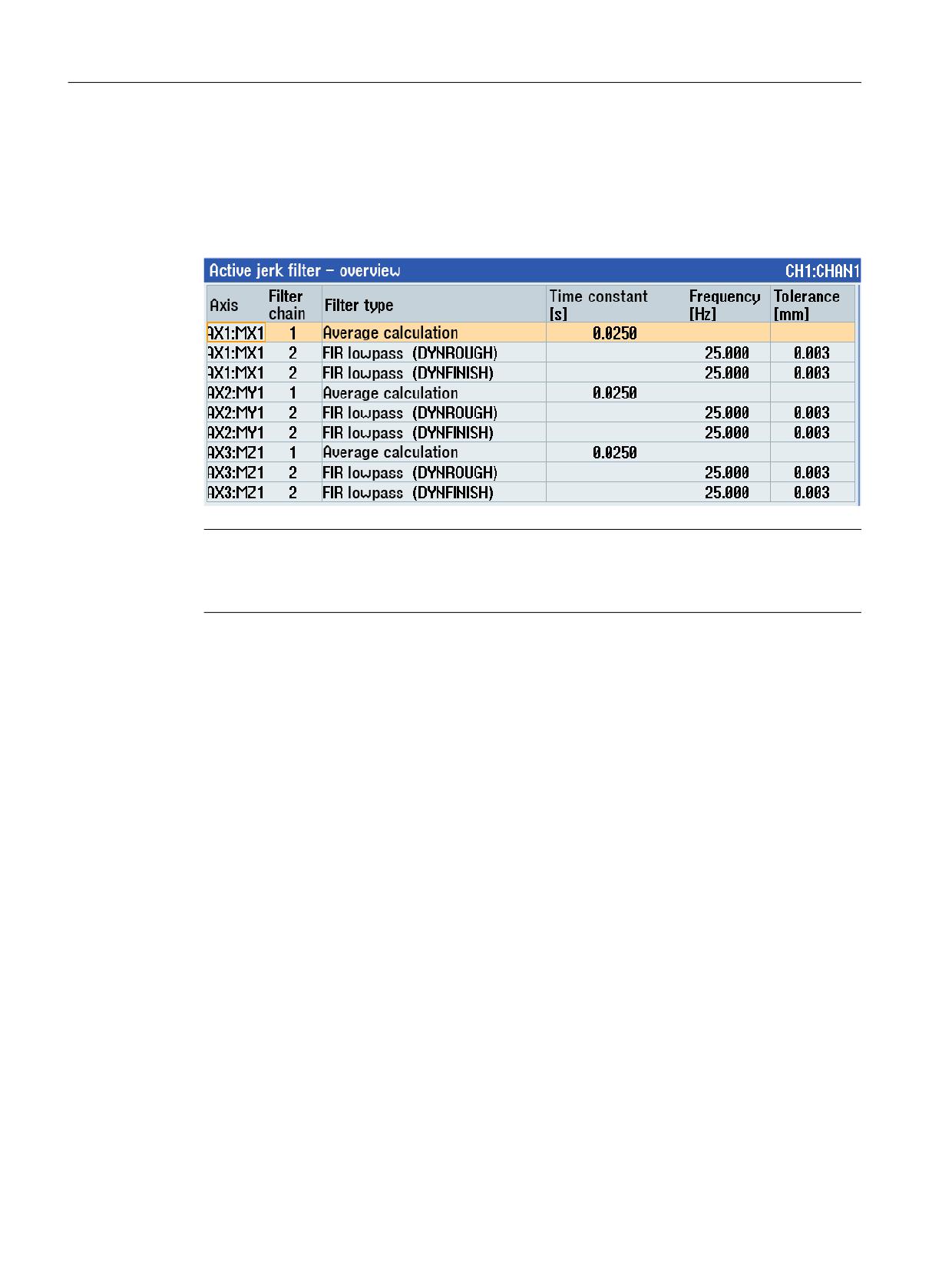
Active jerk filters - overview
All of the active jerk filters in the channel are displayed in tabular format in the operator interface
(SINUMERIK Operate, "Setup" operating area > "NC" > "Jerk filter").
Example:
Note
A jerk filter is active and displayed if the following is true:
MD32400 $MA_AX_JERK_ENABLE = 1
4.2.19.4
Programming
In order to achieve an identical damping effect and contour accuracy for all axes in the channel
for which an FIR low-pass jerk filter is active after changing the dynamic mode, the dynamic
response-dependent FIR filter settings can be calculated and made effective with the NC voice
command CALCFIR.
Application
CALCFIR is used in the CUST_832 manufacturer cycle.
Standard workflow
CYCLE832 is programmed at the start of an NC program for free-form surface machining. When
the program is being executed, CYCLE832 calls the manufacturer cycle CUST_832 and the NC
language command CALCFIR inserted by the machine manufacturer in CUST_832 is executed.
Effectiveness
The filter settings overwritten by CALCFIR remain active until they are again overwritten by the
next CALCFIR call. This is always required, if, using a command of G group 59 (dynamic response
mode for path interpolation), a change to the actual dynamic response mode is programmed.
Response when the control system powers up / channel reset / end of program reset
When the control system powers up, and for a channel/end of program reset, the FIR filter
settings are activated to match the initial setting of G group 59.
Axes and spindles
112
Function Manual, 10/2020, 6FC5397-4GP40-0BA1

Acceleration and jerk
4.2 Detailed description
Requirements
• Option "Top Speed" is set.
Note
To achieve optimum results with "Top Speed", it is recommended that option "Top Surface"
is also used.
• The following conditions must be satisfied for axes in the interpolation group:
- FIR low-pass jerk filter is active.
- FIR filter settings dependent on the dynamic response are configured.
- Overwriting filter settings by CALCFIR is enabled.
• Jerk limiting SOFT/SOFTA is active.
Syntax
CALCFIR is programmed in a separate block. The call in the manufacturer cycle CUST_832 is
realized directly after programming the dynamic response mode:
DYN...
CALCFIR
Meaning
DYN...:
Command from G group 59 to select the dynamic response mode
DYNNORM:
Activate normal dynamic response
DYNPOS:
Activate dynamic response for positioning mode, tapping
DYNROUGH:
Activate dynamic response for roughing
DYNSEMIFIN:
Activate dynamic response for semi-finishing
DYNFINISH:
Activate dynamic response for finishing
DYNPREC:
Activate dynamic response for smooth-finishing
CALCFIR:
Predefined procedure to dynamically adapt the FIR low-pass jerk filters
Note
CALCFIR performs an implicit NEWCONFIG to activate the result of the FIR filter calculation - both
in the axis-specific machine data to parameterize the FIR low-pass jerk filter as well as for
CPRECON. The implicit NEWCONFIG means that additional NEWCONFIG-relevant machine data
become active.
Axes and spindles
Function Manual, 10/2020, 6FC5397-4GP40-0BA1
113
Acceleration and jerk
4.2 Detailed description
Boundary conditions
Use in synchronized actions
CALCFIR cannot be programmed in synchronized actions.
4.2.20
Knee-shaped acceleration characteristic
4.2.20.1
Function: Adaptation to the motor characteristic curve
Various motor types, particularly stepper motors, have a torque characteristic that is highly
dependent on the speed with a steep decline in the torque in the upper speed range. For optimal
utilization of the motor characteristic, the acceleration of the associated NC axis must be
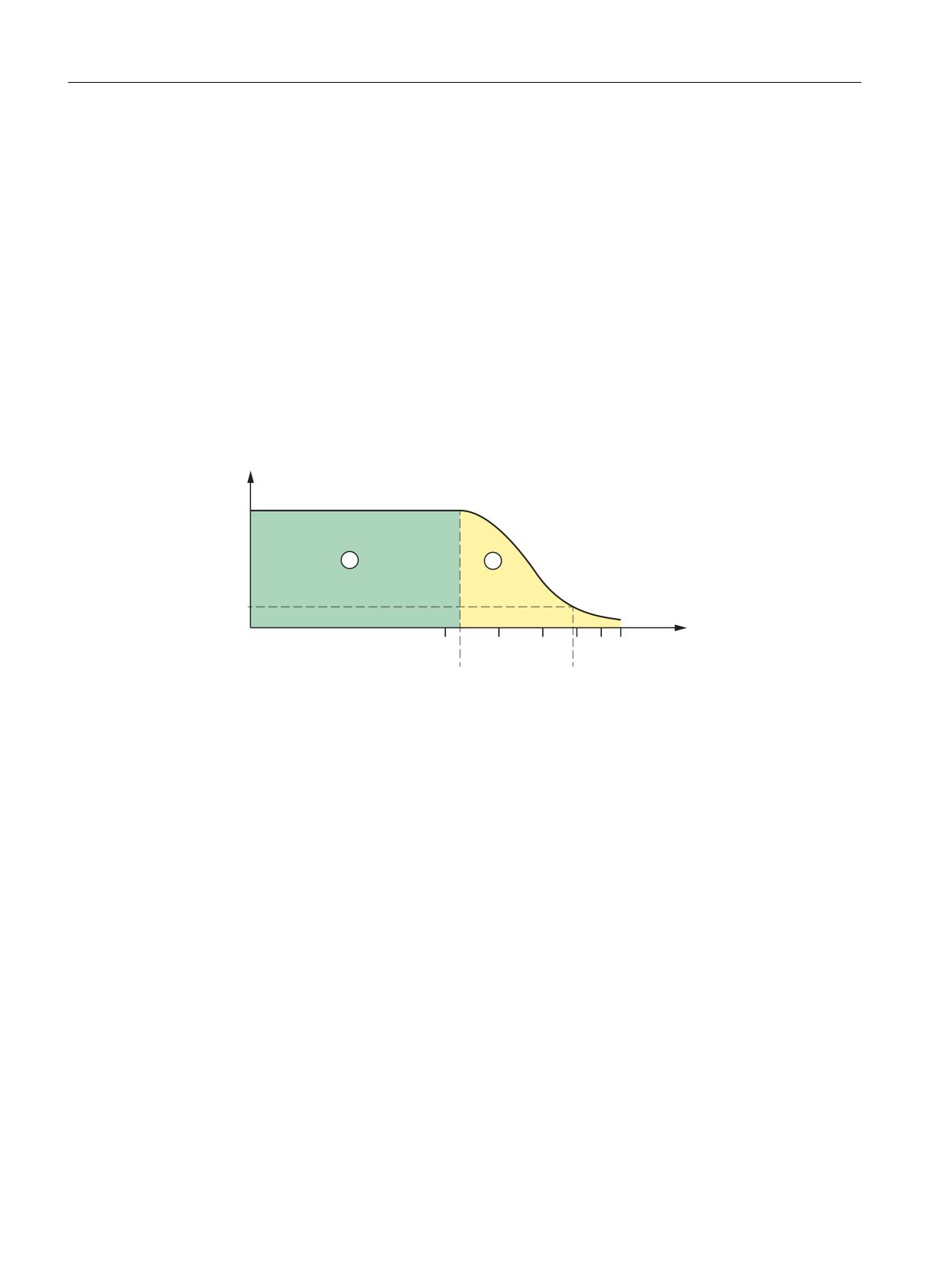
reduced as of a specific speed.
0 >1P@
0PD[
0UHG
Q>
@
QUHG
QPD[
① Normal range
② Reducing range
nred
Speed as of which traversing is done with reduced torque
nmax
Maximum speed
Mmax
Maximum torque
Mred
Torque at nmax (corresponds to acceleration reduction)
Characteristic curve types
As a controller-internal emulation of the torque characteristic curve of the motor, the following
characteristic curve types can be selected for the reducing range (see chapter "Parameterization
(Page 118)"):
• Constant torque characteristic
• Hyperbolic torque characteristic
• Linear torque characteristic
Axes and spindles
114
Function Manual, 10/2020, 6FC5397-4GP40-0BA1
Acceleration and jerk
4.2 Detailed description
4.2.20.2
Function: Effects on the path acceleration
The path acceleration characteristic curve results from the types of characteristic curve for the
axes that are of relevance for the path. If axes with different types of characteristic curve are
interpolated together, the acceleration profile for the path acceleration will be determined on
the basis of the reduction type that is most restrictive.
The following order of priorities applies, whereby 1 = top priority:
1. Acceleration reduction: 0 = constant characteristic
2. Acceleration reduction: 1 = hyperbolic characteristic
3. Acceleration reduction: 2 = linear characteristic
4. No acceleration reduction effective
A situation where no acceleration reduction is active arises for example when:
MD35220 $MA_ACCEL_REDUCTION_SPEED_POINT = 1
and / or
MD35230 $MA_ACCEL_REDUCTION_FACTOR = 0
Note
Machine axes featuring stepper motor and DC drive can be interpolated together.
4.2.20.3
Function: Substitute curve
If the programmed path cannot be traversed with the acceleration curve parameterized in the
machine data of the participating axes, e.g. if kinematic transformation and acceleration
types BRISK or SOFT are active, a substitute curve is generated by reducing the dynamic limit
values. The reduced dynamic limit values are calculated to ensure that the substitute
characteristic curve provides the best possible compromise between maximum velocity and
constant acceleration.
Axes and spindles
Function Manual, 10/2020, 6FC5397-4GP40-0BA1
115
Acceleration and jerk
4.2 Detailed description
Substitute characteristic curve with linear path sections
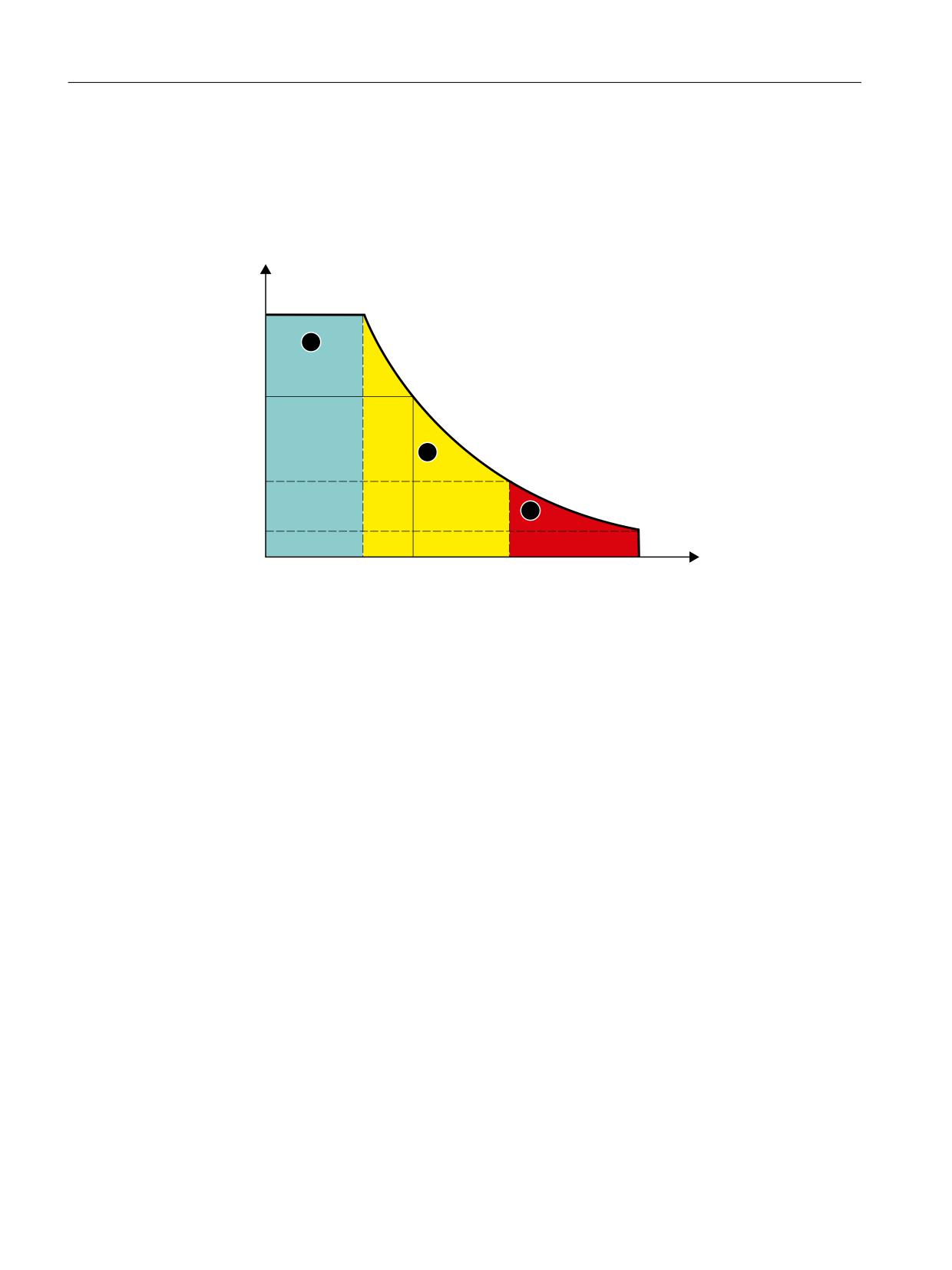
Limitation to this value is applied if the programmed path velocity is greater than that at which
15 % of the maximum acceleration capacity is still available (v15%a). Consequently, 15 % of the
maximum acceleration capacity/motor torque always remains available, whatever the
machining situation.
D
DPD[
DHUV
D
DUHG
YUHG
YSURJ
Y
YPD[
Y
D
① Normal range
② Reducing range
③ Locked area
aers:
Substitute characteristic curve constant acceleration
a15%
Minimal constant acceleration
a15% = 0.15 * (amax - ared) + ared
vers
Substitute characteristic curve velocity
vprog
Programmed velocity
v15%a
Velocity at a15%
Figure 4-6
Substitute path characteristic curve: Linear path
Axes and spindles
116
Function Manual, 10/2020, 6FC5397-4GP40-0BA1
Acceleration and jerk
4.2 Detailed description
Substitute characteristic curve with curved path sections
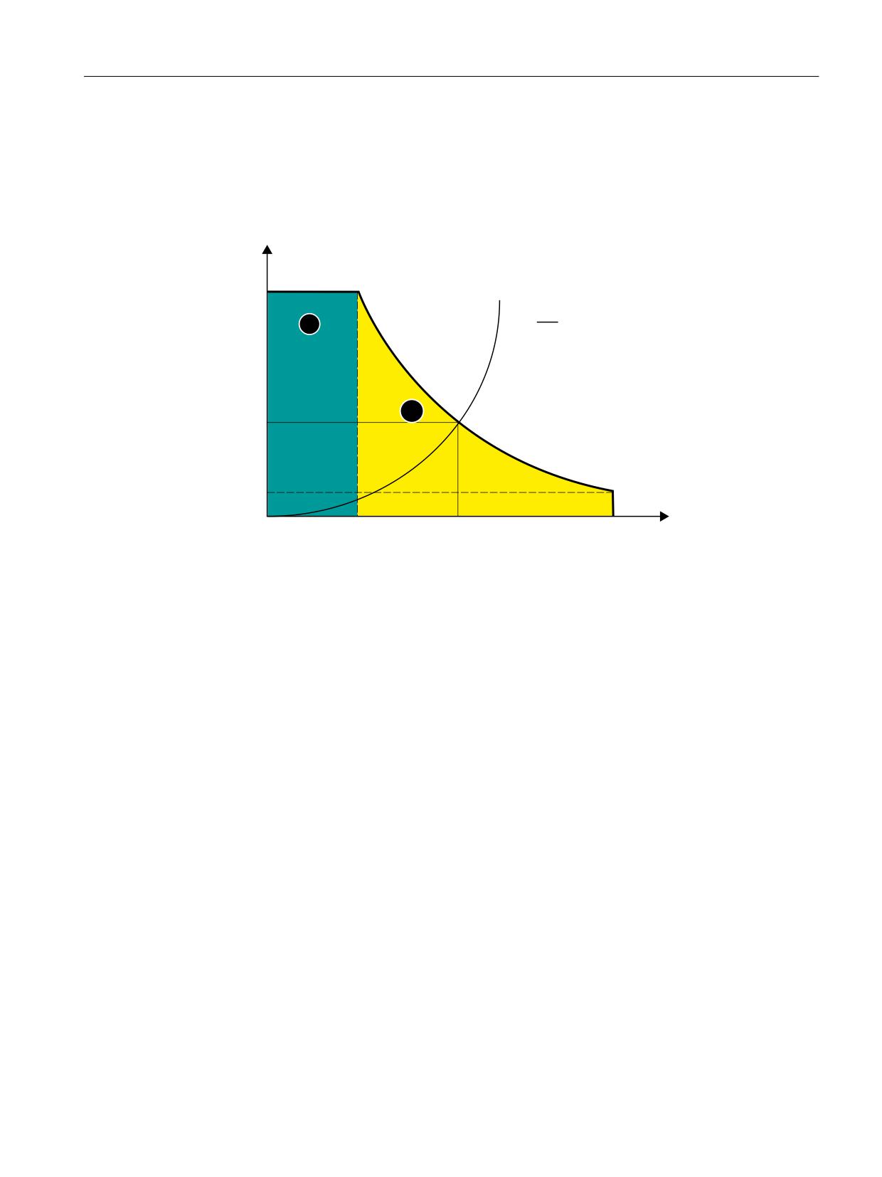
In the case of curved path sections, normal and tangential acceleration are considered together.
The path velocity is reduced so that only up to 25 % of the speed-dependent acceleration
capacity of the axes is required for normal acceleration. The remaining 75 % of the acceleration
capacity is set aside for the tangential acceleration, i.e., deceleration/acceleration on the path.
D
DPD[
Yt
D1
U
DHUV
DUHG
YUHG
YHUV
YPD[
Y
① Normal range
② Reducing range
aN
Normal acceleration
aers:
Substitute characteristic curve constant acceleration
vers
Substitute characteristic curve velocity
r
Path radius
Figure 4-7
Substitute path characteristic curve: Curved path
Block transitions with continuous-path mode
If continuous-path mode is active, non-tangential block transitions result in axial velocity jumps
when the programmed path velocity is used for traversing.
As a result, the path velocity is controlled in such a way that prevents any axial velocity
proportion from exceeding the creep velocity vred at the time of the block transition.
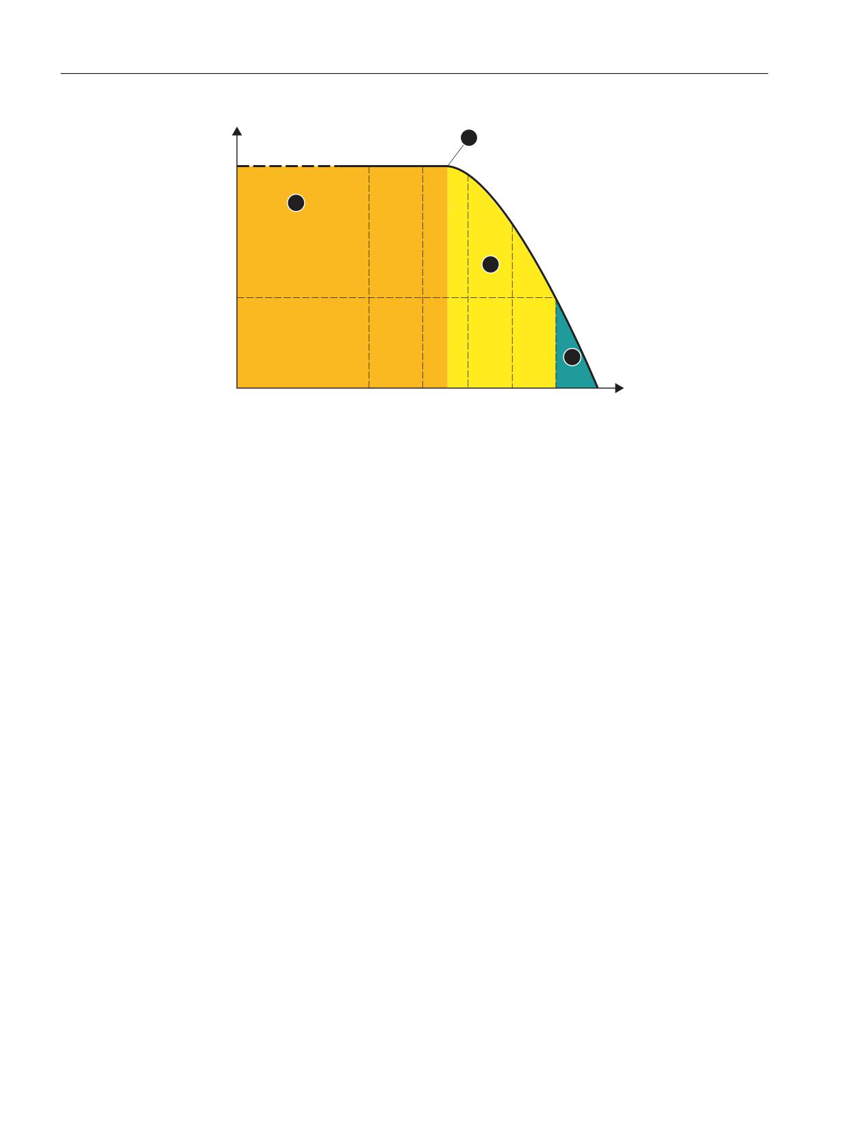
Deceleration ramp with continuous-path mode and LookAhead
In the case of consecutive traversing blocks with short paths, an acceleration or deceleration
operation may be spread over several part program blocks.
In such a situation the "LookAhead" function also takes into account the parameterized speed-
dependent acceleration characteristic.
Axes and spindles
Function Manual, 10/2020, 6FC5397-4GP40-0BA1
117
Acceleration and jerk
4.2 Detailed description
D
DPD[
DHUV
DUHG
1
1
1
1
1
1
W
① Normal range ⇒ a = amax
② Reducing range ⇒ a < amax
③ Constant travel range ⇒ a = 0 m/s2
④ Brake application point
vred:
Creep velocity
vmax
Maximum velocity
Nx
Traversing block with block number Nx
Figure 4-8
Deceleration with LookAhead
4.2.20.4
Parameterization
Path axis
Parameter assignment
The parameterization of the axis-specific velocity limit, above which the reduced acceleration
acts as an axis for traversing movements, is done via the machine data:
MD35220 $MA_ACCEL_REDUCTION_SPEED_POINT = <speed limit>
Single axis
Activation
The activation of the axis-specific velocity limit, above which the reduced acceleration acts as a
single axis for traversing movements, is done via machine data:
MD35240 $MA_ACCEL_TYPE_DRIVE = TRUE
Axes and spindles
118
Function Manual, 10/2020, 6FC5397-4GP40-0BA1

Acceleration and jerk
4.2 Detailed description
Parameter assignment
The following machine data is relevant for parameterizing the axis-specific acceleration
characteristic curve above the configured velocity limit:
• MD32000 $MA_MAX_AX_VELO (maximum axis velocity)
• MD35220 $MA_ACCEL_REDUCTION_SPEED_POINT = <speed limit>
From the parameterized velocity, the reduced acceleration is in effect>
• MD35230 $MA_ACCEL_REDUCTION_FACTOR = <reduction factor>
Beyond the reduction speed, interpolation between the maximum and minimum
acceleration occurs up to the maximum speed. The minimum acceleration is calculated as:
minimum acceleration = maximum acceleration * (1 - reduction factor)
• MD35242 $MA_ACCEL_REDUCTION_TYPE (see paragraph below: "Selection of the torque
characteristic curve")
• MD32300 $MA_MAX_AX_ACCEL (Maximum axis acceleration)
Selection of the torque characteristic curve
The following characteristic curve types can be selected for the reducing range via the machine
data as a controller-internal emulation of the torque characteristic curve of the motor:
MD35242 $MA_ACCEL_REDUCTION_TYPE = <value>
Value
Meaning
0
Constant torque characteristic
1
Hyperbolic torque characteristic
2
Linear torque characteristic
Axes and spindles
Function Manual, 10/2020, 6FC5397-4GP40-0BA1
119
Acceleration and jerk
4.2 Detailed description
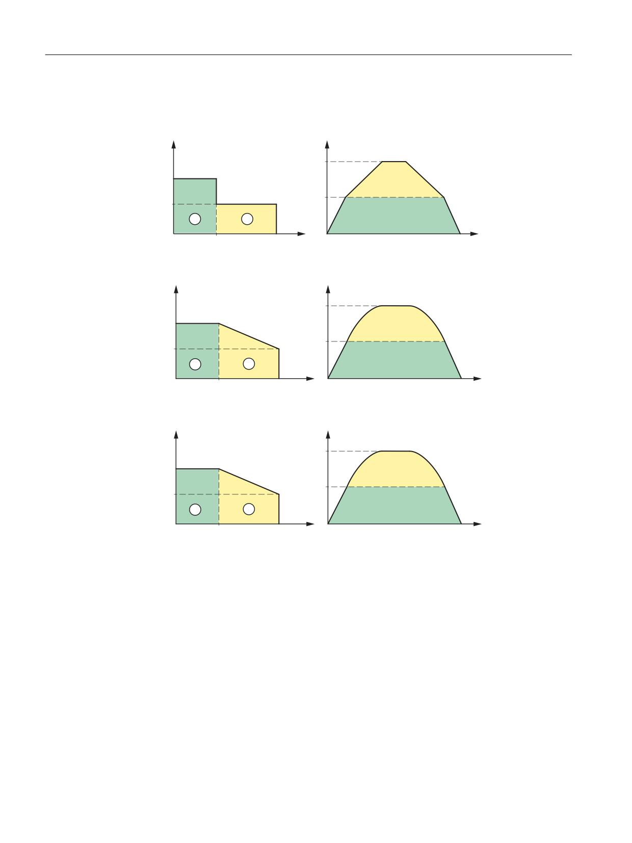
The following figures show the principal velocity and acceleration characteristic curves for the
respective types of characteristic curve:
• Constant torque characteristic (value = 0)
D
Y
YPD[
DPD[
YUHG
DUHG
YUHG
YPD[
Y
W
• Hyperbolic torque characteristic (value = 1)
D
Y
YPD[
DPD[
YUHG
DUHG
YUHG
YPD[
Y
W
• Linear torque characteristic (value = 2)
D
Y
YPD[
DPD[
YUHG
DUHG
YUHG
YPD[
Y
W
Characteristic parameters
The characteristic curve parameters result from the following machine data:
① Normal range
② Reducing range
vmax
$MA_MAX_AX_VELO
vred
$MA_ACCEL_REDUCTION_SPEED_POINT * $MA_MAX_AX_VELO
amax
$MA_MAX_AX_ACCEL
ared
(1 - $MA_ACCEL_REDUCTION_FACTOR) * $MA_MAX_AX_ACCEL
Axes and spindles
120
Function Manual, 10/2020, 6FC5397-4GP40-0BA1

Acceleration and jerk
4.2 Detailed description
4.2.20.5
Programming: Channel-specific activation (DRIVE)
Functionality
The axis-specific velocity limit, above which the reduced acceleration acts as an axis for
traversing movements, is activated with the command DRIVE.
Syntax
DRIVE
Meaning
DRIVE:
Channel-specific switch-on of the reduced acceleration above the parameter-
ized velocity limit
G group:
21
Basic position:
MD20150 $MC_GCODE_RESET_VALUES[ 20 ]
Effectiveness:
Modal
Supplementary conditions
Characteristic changeover
If the acceleration reduction is active due to the programming of DRIVE and the acceleration
profile is changed over by SOFT or BRISK, traversing is then done with a substitute characteristic
with reduced dynamic limit values.
With the re-programming of DRIVE, the reduction in acceleration can be re-activated beyond
the parameterized velocity limit.
See also
Parameterization (Page 118)
4.2.20.6
Programming: Axis-specific activation (DRIVEA)
Functionality
The axis-specific velocity limit, above which the reduced acceleration acts as a single axis for
traversing movements, is activated for the programmed axes with the pre-defined
procedure DRIVEA().
Syntax
DRIVEA(<Axis_1>, <Axis_2>, ...)
Axes and spindles
Function Manual, 10/2020, 6FC5397-4GP40-0BA1
121

Acceleration and jerk
4.2 Detailed description
Meaning
DRIVEA:
Axis-specific activation of the parameterized knee-shaped acceleration char-
acteristic curve.
Effectiveness:
Modal
<axis_x>:
Axis for which the parameterized knee-shaped acceleration characteristic
curve is to be activated.
Data type:
AXIS
Value range:
Channel axis names
Supplementary conditions
If the knee-shaped acceleration characteristic curve is parameterized for an axis, then this
becomes the default acceleration profile for traversing operations.
If the effective acceleration profile is changed for a specific axis using the SOFTA or BRISKA part-
program commands, then an appropriate substitute characteristic curve is used in place of the
knee-shaped acceleration characteristic curve.
It is possible to switch back to the knee-shaped acceleration characteristic curve for a specific axis
by programming DRIVEA.
4.2.20.7
Boundary conditions
Single axis interpolation
After activating the knee-shaped acceleration characteristic curve in case of single-axis
interpolations (positioning axis, oscillating axis, manual traversing, etc.), the machine axis is
traversed exclusively in the mode DRIVEA .
It is not possible to switch over the acceleration profile via the following part program
instructions:
• Abrupt acceleration changes (BRISKA)
• Acceleration with jerk limitation (SOFTA)
Path interpolation
If for a machine axis involved in a programmed path, the knee-shaped acceleration characteristic
curve parameterized without the part program instruction DRIVE is active, then a substitute
characteristic curve with reduced dynamic limit values is determined for the path.
Kinematic transformation
The knee-shaped acceleration characteristic curve is not considered in an active kinematic
transformation. With internal control, a switchover is done to acceleration without jerk
limitation (BRISK) and a substitute characteristic curve becomes active for the path acceleration.
Axes and spindles
122
Function Manual, 10/2020, 6FC5397-4GP40-0BA1
Acceleration and jerk
4.2 Detailed description
4.2.21
Acceleration and jerk for JOG motions
The axis-specific acceleration and jerk limitation values also take effect in JOG mode.
It is also possible to limit acceleration and jerk channel-specifically for manual traversing of
geometry and orientation axes. This enables better handling of the kinematics that generate
Cartesian motions entirely via rotary axes (robots).
4.2.21.1
Parameterization
Axis-specific limitation of acceleration and jerk
Maximum axis-specific acceleration
The maximum acceleration for manual traversing of an axis is defined in machine data:
MD32300 $MA_MAX_AX_ACCEL [0] (maximum axis-specific acceleration for path motions in
dynamic response mode DYNNORM)
Note
Only the dynamic response mode DYNNORM is always effective for JOG mode.
See also Chapter "Acceleration without jerk limitation (BRISK/BRISKA) (channel/axis-specific)
(Page 81)".
Basic setting of axis-specific jerk limitation
Acceleration with jerk limitation can be specified as the axis-specific basic setting for JOG mode:
MD32420 $MA_JOG_AND_POS_JERK_ENABLE== TRUE
Maximum axis-specific jerk
For JOG motions with active jerk limitation, the value from the following machine data takes
effect as the maximum axis-specific jerk:
MD32430 $MA_JOG_AND_POS_MAX_JERK (maximum axis-specific jerk)
See also Chapter "Jerk limitation with single-axis interpolation (SOFTA) (axis-specific) (Page 98)".
Channel-specific limitation of acceleration and jerk
Maximum acceleration when manually traversing geometry axes
The maximum acceleration when manually traversing geometry axes can be specified for each
channel via the machine data:
MD21166 $MC_JOG_ACCEL_GEO [<geometry axis>]
Axes and spindles
Function Manual, 10/2020, 6FC5397-4GP40-0BA1
123

Acceleration and jerk
4.2 Detailed description
With <geometry axis> = 0, 1, 2
Note
With MD21166 $MC_JOG_ACCEL_GEO [<geometry axis>], there is no direct limitation to
MD32300 $MA_MAX_AX_ACCEL.
Note
When a transformation is active, MD32300 $MA_MAX_AX_ACCEL determines the maximum
possible axis-specific acceleration.
Maximum jerk when manually traversing geometry axes
The maximum jerk when manually traversing geometry axes in the SOFT acceleration mode
(acceleration with jerk limitation) can be specified for each channel via the machine data:
MD21168 $MC_JOG_JERK_GEO [<geometry axis>]
With <geometry axis> = 0, 1, 2
Note
MD21168 $MC_JOG_JERK_GEO acts only when the axis-specific jerk limitation in JOG mode has
been enabled for the base machine axes:
MD32420 $MA_JOG_AND_POS_JERK_ENABLE [<axis>] == TRUE
With MD21168 = 0, instead of the channel-specific jerk limitation, the axis-specific limit value
from MD32430 $MA_JOG_AND_POS_MAX_JERK is effective.
Maximum jerk when manually traversing orientation axes
The maximum jerk when manually traversing orientation axes can be specified for each channel
via the machine data:
MD21158 $MC_JOG_JERK_ORI [<orientation axis>]
For MD21158 to take effect, the channel-specific jerk limitation for the manual traversing of
orientation axes must be enabled via the following machine data:
MD21159 $MC_JOG_JERK_ORI_ENABLE == TRUE
4.2.21.2
Supplementary conditions
Behavior for the manual traversing of geometry axes with active rotation
When manually traversing geometry axes in the SOFT acceleration mode (acceleration with jerk
limitation), the value from MD32430 $MA_JOG_AND_POS_MAX_JERK is also used with active
rotation or active orientable tool carrier.
Axes and spindles
124
Function Manual, 10/2020, 6FC5397-4GP40-0BA1
Acceleration and jerk
4.3 Examples
Part program instruction SOFTA / BRISKA / DRIVEA
The part program instruction SOFTA(<axis1>,<axis2>, ...) is also effective in JOG
mode, i.e. the maximum axis-specific jerk from MD32430 $MA_JOG_AND_POS_MAX_JERK is
effective for the specified axes when traversing in JOG mode (exactly as when setting MD32420
$MA_JOG_AND_POS_JERK_ENABLE [<axis>] == TRUE).
Note
On the other hand, the SOFT part program instruction has no effect on JOG mode.
As with SOFTA, the part program instructions BRISKA and DRIVEA are also effective in JOG mode,
i.e. the acceleration is without jerk limitation, even when MD32420
$MA_JOG_AND_POS_JERK_ENABLE is set to "TRUE" for the relevant machine axes.
Note
Manual traversing of orientation axes is not affected by BRISKA/SOFTA/DRIVEA.
Behavior when software limit is reached when axes are in transformations/interpolations
When the software limit is reached, one axis brakes very quickly. All other axes in the
transformation/interpolation group are braked with the set braking ramp. This results in
different braking behavior for the axes.
If there are several successive moves away from and back toward the software limit, the
different braking behavior of the axes causes a jerk to build up.
Example: With TRAANG (inclined axis), the Y axis moves to the software limit resulting in a jerk
in the WCS for the X axis.
See also
Acceleration without jerk limitation (BRISK/BRISKA) (channel/axis-specific) (Page 81)
Jerk limitation with single-axis interpolation (SOFTA) (axis-specific) (Page 98)
4.3
Examples
4.3.1
Acceleration
4.3.1.1
Path velocity characteristic
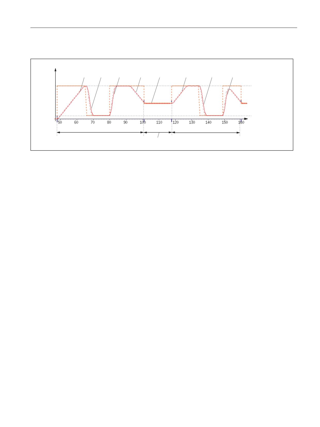
The following example shows the path velocity characteristic, based on programmed traversing
motion and the actions initiated in a part program segment.
Axes and spindles
Function Manual, 10/2020, 6FC5397-4GP40-0BA1
125
Acceleration and jerk
4.3 Examples
Part program extract
Program code
; Synchronized action: Acceleration switchover depending on fast input 1
($A_IN[1]):
N53 ID=1 WHEN $A_IN[1] == 1 DO $AC_PATHACC = 2.*$MA_MAX_AX_ACCEL[X]
; Synchronized action: Test override profile (simulation of external
interventions):
N54 ID=2 WHENEVER ($AC_TIMEC > 16) DO $AC_OVR=10
N55 ID=3 WHENEVER ($AC_TIMEC > 30) DO $AC_OVR=100
;Approach
N1000 G0 X0 Y0 BRISK
N1100 TRANS Y=-50
N1200 AROT Z=30 G642
; Contour
N2100 X0 Y0
N2200 X = 70 G1 F10000 RNDM=10 ACC[X]=30 ACC[Y]=30
N2300 Y = 70
N2400 X0
N2500 Y0
Axes and spindles
126
Function Manual, 10/2020, 6FC5397-4GP40-0BA1
Acceleration and jerk
4.3 Examples
Path velocity characteristic
Y >P V@
$&B295
$&B295
W >
PV@
1
1
Acceleration profile: BRISK
1:
Accelerate to 100% of path velocity (F10000) in accordance with acceleration default: ACC (N2200...)
2:
Brake to 10% of path velocity as a result of override modification ($AC_OVR) in accordance with real-time acceleration
$AC_PATHACC (N53/N54...)
3:
Accelerate to 100% of path velocity as a result of override modification ($AC_OVR) in accordance with real-time
acceleration $AC_PATHACC (N53/N55...)
4:
Brake to block end velocity for intermediate smoothing block in accordance with acceleration default: ACC (N2200...)
5:
Speed limitation as a result of smoothing (see 9)
6:
Accelerate to 100% of path velocity ($AC_OVR) in accordance with acceleration default: ACC (N2300...)
7:
Decelerate as a result of override modification at a rate of acceleration that is in accordance with real-time acceler-
ation $AC_PATHACC (N53/N54...)
8:
Accelerate to 100% of path velocity as a result of override modification ($AC_OVR) in accordance with real-time
acceleration $AC_PATHACC (N53/N55...)
9:
Intermediate block inserted within the control as a result of the programmed smoothing (RNDM) (N2200...)
Figure 4-9
Switching between path acceleration specified during preprocessing and real-time acceleration
4.3.2
Jerk
4.3.2.1
Path velocity characteristic
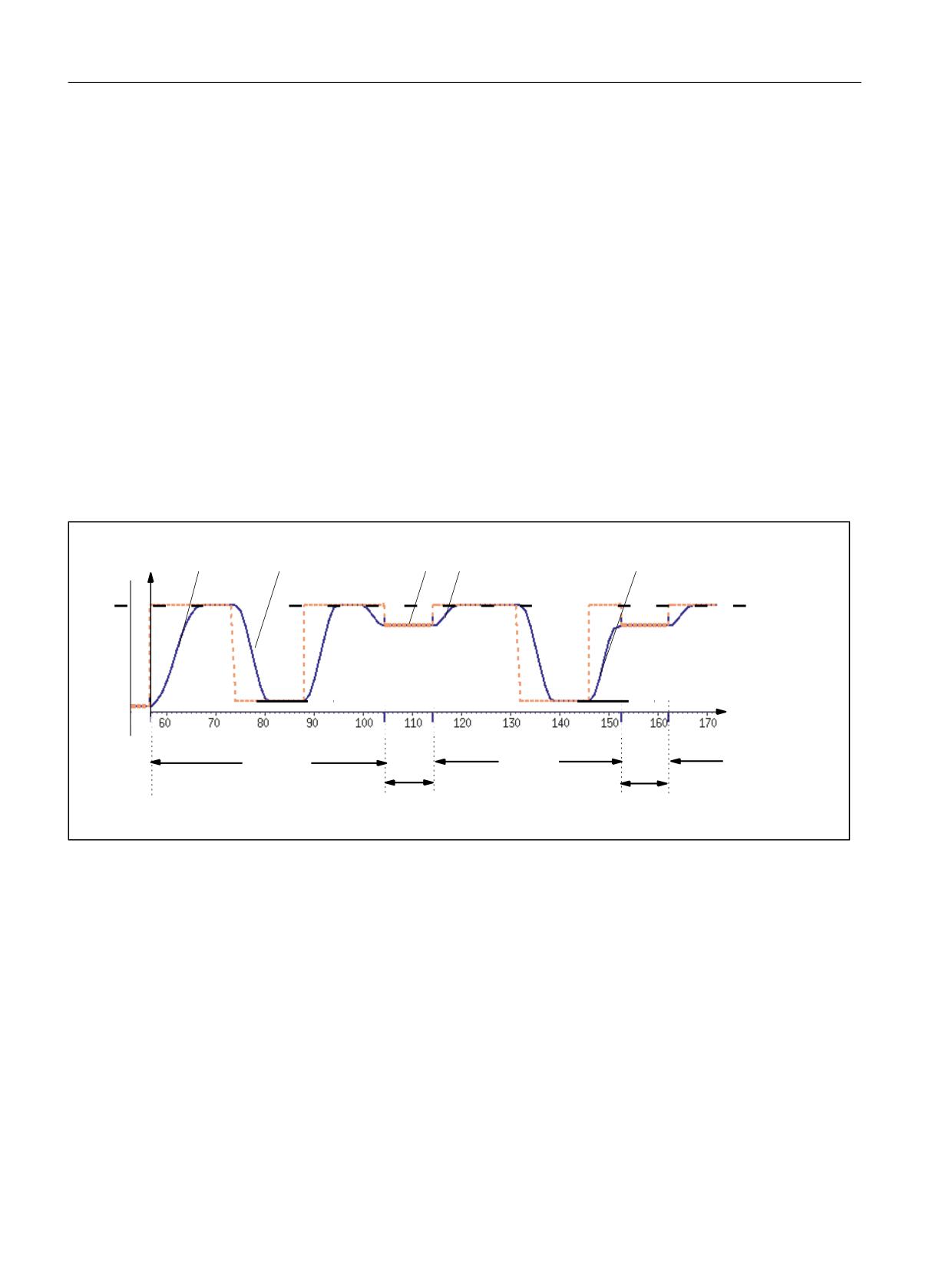
The following example shows the characteristic of path velocity and jerk based on programmed
traversing motion and the actions initiated in a part program segment.
Part program extract
Program code
; Setting of path acceleration and path jerk in the event of external
intervention:
N0100 $AC_PATHACC = 0.0
N0200 $AC_PATHJERK = 4.0 * ($MA_MAX_AX_JERK[X] + $MA_MAX_AX_JERK[Y]) / 2.0
Axes and spindles
Function Manual, 10/2020, 6FC5397-4GP40-0BA1
127
Acceleration and jerk
4.3 Examples
Program code
; Synchronized action: varying the override (simulation of external
interventions)
N0530 ID=1 WHENEVER ($AC_TIMEC > 16) DO $AC_OVR=10
N0540 ID=2 WHENEVER ($AC_TIMEC > 30) DO $AC_OVR=100
;Approach
N1000 G0 X0 Y0 SOFT
N1100 TRANS Y=-50
N1200 AROT Z=30 G642
; Contour
N2100 X0 Y0
N2200 X = 70 G1 F10000 RNDM=10
N2300 Y = 70
N2400 X0
N2500 Y0
Characteristic of path velocity and jerk
Y >P V@
295
295
295
W >
PV@
1
1
51'0
51'0
Acceleration profile: SOFT
1:
Jerk according to $MA_MAX_AX_JERK[..]
2:
Jerk according to $AC_PATHJERK
3:
Jerk according to $MA_MAX_AX_JERK[..] (approach block end velocity)
4:
Velocity limiting using arcs
5:
Jerk according to $AC_PATHJERK
Figure 4-10
Switching between path jerk specified during preprocessing and $AC_PATHJERK
Axes and spindles
128
Function Manual, 10/2020, 6FC5397-4GP40-0BA1
Acceleration and jerk
4.3 Examples
4.3.3
Acceleration and jerk
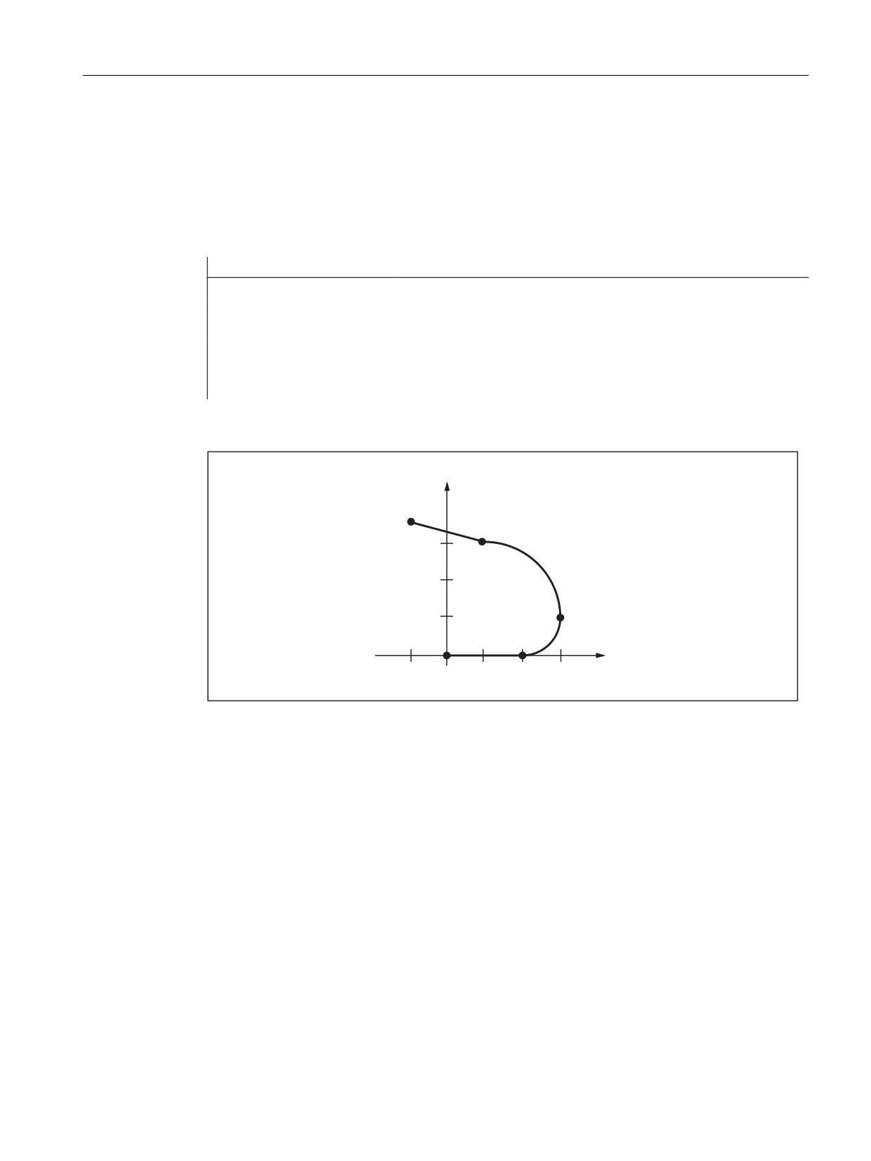
The following example shows the characteristic of velocity and acceleration of the X axis based
on the programmed traversing motion of the part program extract. Further, which of the
velocity and acceleration-relevant machine data are decisive for which section of the contour.
Part program extract
Program code
Comment
N90 F5000 SOFT G64
; Continuous-path mode, jerk-limited acceleration
N100 G0 X0 Y0 Z0
; Rapid traverse
N110 G1 X10
; Straight line
N120 G3 CR=5 X15 Y5
; Circular arc, radius 5 mm, block transition: Tangential
N130 G3 CR=10 X5 Y15
; Circular arc, radius 10 mm, block transition: Tangential
N140 G1 X-5 Y17.679
; Straight line, 15° kink
Contour
\
1
1
1
1
[
Figure 4-11
Contour of the part program extract
Axes and spindles
Function Manual, 10/2020, 6FC5397-4GP40-0BA1
129
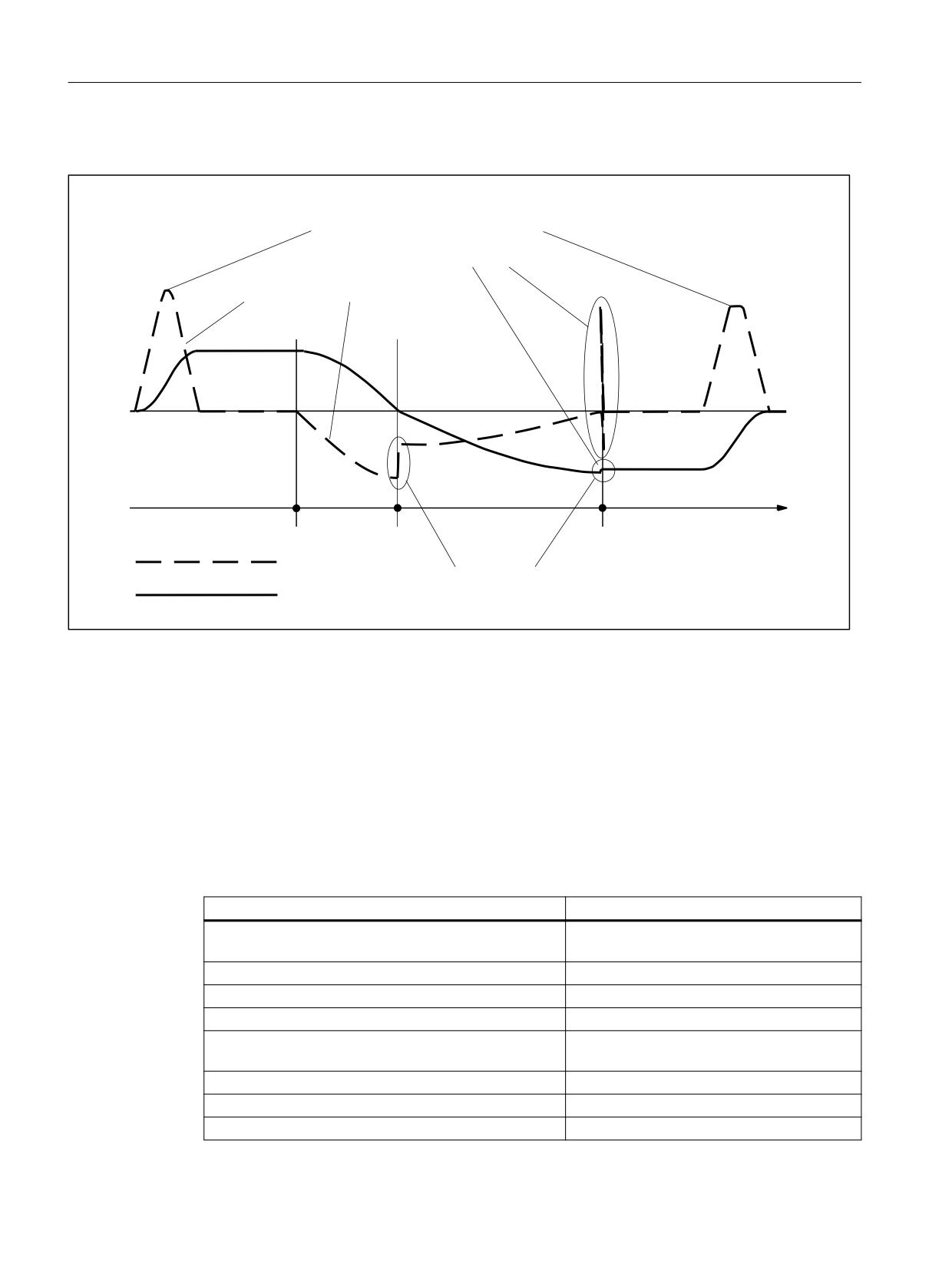
Acceleration and jerk
4.3 Examples
Velocity and acceleration characteristic
0'
0$;B$;B$&&(/>;@
0'
62)7B$&&(/B)$&725>;@
0'
0$;B$&&(/B29/B)$&725>;@
0'
0$;B$;B-(5.>;@
1
1
1
1
$[OH DFFHOHUDWLRQ
$[LV YHORFLW\
0'
3$7+B75$16B-(5.B/,0>;@
Figure 4-12
Velocity and acceleration characteristic curves X axis
4.3.4
Knee-shaped acceleration characteristic
4.3.4.1
Activation
The example illustrates how the knee-shaped acceleration characteristic curve is activated on
the basis of the machine data and a part program extract.
Machine data
Machine data
Value
MD35220 $MA_ACCEL_REDUCTION_SPEED_POINT[
= 0.4
X]
MD35230 $MA_ACCEL_REDUCTION_FACTOR[X]
= 0.85
MD35242 $MA_ACCEL_REDUCTION_TYPE[X]
= 2
MD35240 $MA_ACCEL_TYPE_DRIVE[X]
= TRUE
MD35220
= 0.0
$MA_ACCEL_REDUCTION_SPEED_POINT[Y]
MD35230 $MA_ACCEL_REDUCTION_FACTOR[Y]
= 0.6
MD35242 $MA_ACCEL_REDUCTION_TYPE[Y]
= 1
MD35240 $MA_ACCEL_TYPE_DRIVE[Y]
= TRUE
Axes and spindles
130
Function Manual, 10/2020, 6FC5397-4GP40-0BA1

Acceleration and jerk
4.4 Data lists
Machine data
Value
MD35220
= 0.6
$MA_ACCEL_REDUCTION_SPEED_POINT[Z]
MD35230 $MA_ACCEL_REDUCTION_FACTOR[Z]
= 0.4
MD35242 $MA_ACCEL_REDUCTION_TYPE[Z]
= 0
MD35240 $MA_ACCEL_TYPE_DRIVE[Z]
= FALSE
Activation by entering as channel-specific initial setting:
MC_GCODE_RESET_VALUE[20] = 3 (DRIVE)
Part program extract
Program code
Comment
N10 G1 X100 Y50 Z50 F700
; Path motion (X,Y, Z) with DRIVE
N15 Z20
; Path motion (Z) with DRIVE
N20 BRISK
; Switchover to BRISK
N25 G1 X120 Y70
; Path motion (Y, Z) with substitute
characteristic curve
N30 Z100
; Path motion (Z) with BRISK
N35 POS[X] = 200 FA[X] = 500
; Positioning motion (X) with DRIVEA
N40 BRISKA(Z)
; Activate BRISKA for Z
N40 POS[Z] = 50 FA[Z] = 200
; Positioning motion (Z) with BRISKA
N45 DRIVEA(Z)
; Activate DRIVEA for Z
N50 POS[Z] = 100
; Positioning motion (Z) with DRIVE
N55 BRISKA(X)
; results in error message
4.4
Data lists
4.4.1
Machine data
4.4.1.1
NC-specific machine data
Number Identifier: $MN_
Description
18960
POS_DYN_MODE
Type of positioning axis dynamic response
4.4.1.2
Channel-specific machine data
Number
Identifier: $MC_
Description
20150
GCODE_RESET_VALUES
Initial setting of the G groups
20500
CONST_VELO_MIN_TIME
Minimum time with constant velocity
Axes and spindles
Function Manual, 10/2020, 6FC5397-4GP40-0BA1
131

Acceleration and jerk
4.4 Data lists
Number
Identifier: $MC_
Description
20600
MAX_PATH_JERK
Path-related maximum jerk
20602
CURV_EFFECT_ON_PATH_ACCEL
Influence of path curvature on path dynamic response
20610
ADD_MOVE_ACCEL_RESERVE
Acceleration reserve for overlaid motions
21158
JOG_JERK_ORI
Maximum jerk of the orientation axes when traversing in JOG
21159
JOG_JERK_ORI_ENABLE
Initial setting of the channel-specific jerk limitation of orien-
tation axes for traversing in JOG mode
21166
JOG_ACCEL_GEO
Maximum acceleration rate of the geometry axes when tra-
versing in JOG
21168
JOG_JERK_GEO
Maximum jerk of the geometry axes when traversing in JOG
4.4.1.3
Axis/spindlespecific machine data
Number
Identifier: $MA_
Description
32000
MAX_AX_VELO
Maximum axis velocity
32300
MAX_AX_ACCEL
Maximum axis acceleration
32310
MAX_ACCEL_OVL_FACTOR
Overload factor for velocity jump
32320
DYN_LIMIT_RESET_MASK
Reset behavior of dynamic limits
32400
AX_JERK_ENABLE
Axial jerk limitation
32402
AX_JERK_MODE
Filter type for axial jerk limitation
32407
AX_JERK_FIR_FREQ
Corner frequency axial jerk filter, type 5
32408
AX_JERK_FIR_ORDER
Filter order, axial jerk filter, type 5
32409
AX_JERK_FIR_WINDOW
Window type, axial jerk filter, type 5
32410
AX_JERK_TIME
Time constant for axial jerk filter
32411
AX_JERK_TIME_ADD
Time constant for the second axial jerk filter, type 4
32412
AX_JERK_FREQ
Blocking frequency of the axial jerk filter
32414
AX_JERK_DAMP
Damping, axial jerk filter
32420
JOG_AND_POS_JERK_ENABLE
Basic setting for axial jerk limitation
32430
JOG_AND_POS_MAX_JERK
Axial jerk for single axis motion
32431
MAX_AX_JERK
Maximum axial jerk at the block change in continuous-
path mode
32432
PATH_TRANS_JERK_LIM
Max. axial jerk of a geometry axis at block boundary
32433
SOFT_ACCEL_FACTOR
Scaling of acceleration limitation for SOFT
32434
G00_ACCEL_FACTOR
Scaling of acceleration limitation for G0
32435
G00_JERK_FACTOR
Scaling of axial jerk limitation for G0
32437
AX_JERK_VEL0
First velocity threshold for velocity-dependent jerk adap-
tation
32438
AX_JERK_VEL1
Second velocity threshold for the velocity-dependent
jerk adaptation
32439
MAX_AX_JERK_FACTOR
Factor to set the maximum jerk for higher velocities (ve-
locity-dependent jerk adaptation)
35220
ACCEL_REDUCTION_SPEED_POINT
Speed for reduced acceleration
35230
ACCEL_REDUCTION_FACTOR
Reduced acceleration
Axes and spindles
132
Function Manual, 10/2020, 6FC5397-4GP40-0BA1

Acceleration and jerk
4.4 Data lists
Number
Identifier: $MA_
Description
35240
ACCEL_TYPE_DRIVE
DRIVE acceleration characteristic for axes on/off
35242
ACCEL_REDUCTION_TYPE
Type of acceleration reduction
4.4.2
Setting data
4.4.2.1
Channelspecific setting data
Number
Identifier: $SC_
Description
42500
SD_MAX_PATH_ACCEL
Max. path acceleration
42502
IS_SD_MAX_PATH_ACCEL
Analysis of SD 42500: ON/OFF
42510
SD_MAX_PATH_JERK
Max. path-related jerk
42512
IS_SD_MAX_PATH_JERK
Analysis of SD 42510: ON/OFF
4.4.3
System variables
Identifier
Description
$AC_PATHACC
Path acceleration for real-time events
$AC_PATHJERK
Path jerk for real-time events
Axes and spindles
Function Manual, 10/2020, 6FC5397-4GP40-0BA1
133
Acceleration and jerk
4.4 Data lists
Axes and spindles
134
Function Manual, 10/2020, 6FC5397-4GP40-0BA1
Velocities, setpoint/actual value systems, closed-
loop control
5
5.1
Brief description
The description of functions explains how to parameterize a machine axis in relation to:
• Actual-value/measuring systems
• Setpoint system
• Operating accuracy
• Travel ranges
• Axis velocities
• Control parameters
5.2
Velocities, traversing ranges, accuracies
5.2.1
Velocities
Maximum path and axis velocities and spindle speed
The maximum path and axis velocities and spindle speed are influenced by the machine design,
the dynamic response of the drive and the limit frequency of the actual-value acquisition
(encoder limit frequency).
The maximum axis velocity is defined in machine data:
MD32000 $MA_MAX_AX_VELO (maximum axis velocity)
The maximum permissible spindle speed is specified using machine data:
MD35100 $MA_SPIND_VELO_LIMIT (maximum spindle speed)
For explanations, see Section "Spindles (Page 377)".
With a higher feedrate (resulting from programmed feedrates and feedrate override), the
velocity is limited to Vmax.
This automatic feedrate limiting can lead to a drop in velocity over several blocks with programs
generated by CAD systems with extremely short blocks.
Axes and spindles
Function Manual, 10/2020, 6FC5397-4GP40-0BA1
135

Velocities, setpoint/actual value systems, closed-loop control
5.2 Velocities, traversing ranges, accuracies
Example:
Interpolation cycle = 12 ms
N10 G0 X0 Y0; [mm]
N20 G0 X100 Y100; [mm]
⇒ Path length programmed in block = 141.42 mm
⇒ Vmax = (141.42 mm/12 ms) * 0.9 = 10606.6 mm/s = 636.39 m/min
Minimum path, axis velocity
The following restriction applies to the minimum path or axis velocity:
9PLQ
ุ
,QFU
&RPSXWDWLRQDO >
PP RU GHJUHHV
@
,32 F\FOH >V@
UHVROXWLRQ
The computational resolution is defined using machine data:
MD10200 $MN_INT_INCR_PER_MM (computational resolution for linear positions)
or
MD10210 $MN_INT_INCR_PER_DEG (computational resolution for angular positions)
If Vmin is not reached, no traversing is carried out.
Example:
MD10200 $MN_INT_INCR_PER_MM = 1000 [incr/mm] ;
Interpolation cycle = 12 ms;
⇒ Vmin = 10 -3/(1000 incr/mm x 12 ms) = 0.005 mm/min;
The value range of the feedrates depends on the computational resolution selected.
For the standard assignment of machine data:
MD10200 $MN_INT_INCR_PER_MM
(computational resolution for linear positions) (1000 incr./mm)
or
MD10210 $MN_INT_INCR_PER_DEG
(computational resolution for angular positions) (1000 incr./deg.)
The following value range can be programmed with the specified resolution:
Range of values for path feed F and geometry axes:
Metric system:
Inch system:
0.001 ≤ F ≤ 999,999.999
0.001 ≤ F ≤ 399,999.999 [inch/min, inch/rev]
[mm/min, mm/rev, degrees/min, degrees/rev]
Axes and spindles
136
Function Manual, 10/2020, 6FC5397-4GP40-0BA1
Velocities, setpoint/actual value systems, closed-loop control
5.2 Velocities, traversing ranges, accuracies
Range of values for feedrate for positioning axes:
Metric system:
Inch system:
0.001 ≤ FA ≤ 999,999.999
0.001 ≤ FA ≤ 399,999.999
[mm/min, mm/rev, degrees/min, degrees/rev]
[inch/min, inch/rev]
Range of values for spindle speed S:
0.001 ≤ S ≤ 999,999.999 [rpm]
If the computational resolution is increased/decreased by a factor, then the value ranges change
accordingly.
5.2.2
Traversing ranges
Range of values of the traversing ranges
The range of values of the traversing range depends on the computational resolution selected.
For the standard assignment of machine data:
MD10200 $MN_INT_INCR_PER_MM
(computational resolution for linear positions) (1000 incr./mm)
or
MD10210 $MN_INT_INCR_PER_DEG
(computational resolution for angular positions) (1000 incr./deg.)
The following value range can be programmed with the specified resolution:
Table 5-1
Traversing ranges of axes
G71 [mm, degrees]
G70 [inch, degrees]
Range
Range
Linear axes X, Y, Z, etc.
∓ 999,999.999
∓ 399,999.999
Rotary axes A, B, C, etc.
∓ 999,999.999
∓ 999,999.999
Interpolation parameters I, J, K
∓ 999,999.999
∓ 399,999.999
The unit of measurement of rotary axes is always degrees.
If the computational resolution is increased/decreased by a factor of 10, the ranges of values
change accordingly.
The traversing range can be limited by software limit switches and work areas (see Function
Manual Monitoring and Compensations, Section Axis monitoring).
For special features for a large traversing range for linear and rotary axes, see Section "Homing
(Page 31)".
The traversing range for rotary axes can be limited via machine data.
Further information:
Axes and spindles
Function Manual, 10/2020, 6FC5397-4GP40-0BA1
137

Velocities, setpoint/actual value systems, closed-loop control
5.2 Velocities, traversing ranges, accuracies
Rotary axes (Page 307)
5.2.3
Positioning accuracy of the control system
Actual-value resolution and computational resolution
The positioning accuracy of the control depends on the actual-value resolution (=encoder
increments/(mm or degrees)) and the computational resolution (=internal increments/(mm or
degrees)).
The coarse resolution of these two values determines the positioning accuracy of the control.
The input resolution, interpolator and position-control cycle selections have no effect on this
accuracy.
As well as limiting using MD32000, the control limits the maximum path velocity in relation to
the situation and according to the following formula:
,QWHUQDO LQFUHPHQWV PP
(QFRGHU LQFUHPHQWV PP
(1&B5(62/ >Q@
(1&B38/6(B08/7>Q@
'5,9(B(1&B5$7,2B180(5$ >Q@
'5,9(B(1&B5$7,2B'(120 >Q@
'5,9(B$;B5$7,2B'(120 >Q@
'5,9(B$;B5$7,2B180(5$ >Q@
/($'6&5(:B3,7&+
,17B,1&5B3(5B00
5.2.4
Input/display resolution, computational resolution
Resolutions: Differences
Resolutions, e.g. resolutions of linear and angular positions, velocities, accelerations and jerk,
must be differentiated as follows:
• Input resolution
Data is input via the control panel or part programs.
• Display resolution
Data is displayed via the operator panel front.
• Computational resolution
Data input via the control panel or part program is displayed internally.
Axes and spindles
138
Function Manual, 10/2020, 6FC5397-4GP40-0BA1
Velocities, setpoint/actual value systems, closed-loop control
5.2 Velocities, traversing ranges, accuracies
The input and display resolution is determined by the specified operator panel front used,
whereby the display resolution for position values with the machine data:
MD9004 $MM_DISPLAY_RESOLUTION (display resolution)
can be changed.
The machine data:
MD9011 $MM_DISPLAY_RESOLUTION_INCH (display resolution in inch)
can be used to configure the display resolution for position values with inch setting.
This allows you to display up to six decimal places with the inch setting.
For the programming in part programs, the input resolutions listed in the NC Programming
Programming Manual apply.
The desired computational resolution is defined using the machine data:
MD10200 $MN_INT_INCR_PER_MM (calculation resolution for linear positions)
and
MD10210 $MN_INT_INCR_PER_ DEG (calculation resolution for angular positions)
It is independent of the input/display resolution but should have at least the same resolution.
The maximum number of places after the decimal point for position values, velocities, etc., in
the part program and the number of places after the decimal point for tool offsets, work offsets,
etc. (and therefore also for the maximum possible accuracy) is defined by the computational
resolution.
The accuracy of angle and linear positions is limited to the computational resolution by rounding
the product of the programmed value with the computational resolution to an integer number.
To make the rounding clear, powers of 10 should be used for the calculation resolution.
Example of rounding:
Computational resolution: 1000 increments / mm
Programmed path: 97.3786 mm
Effective value = 97.379 mm
Example of programming in the 1 /10 μm range:
All the linear axes of a machine are to be programmed and traversed within the range of values
0.1 to 1000 μm.
⇒ In order to position accurately to 0.1 μm, the computational resolution must be set to ≥ 104
incr./mm.
⇒ MD10200 $MN_INT_INCR_PER_MM = 10000 [incr./mm]:
Axes and spindles
Function Manual, 10/2020, 6FC5397-4GP40-0BA1
139

Velocities, setpoint/actual value systems, closed-loop control
5.2 Velocities, traversing ranges, accuracies
⇒ Example of associated part program:
Program code
Comment
N20 G0 X1.0000 Y1.0000
; Axes move to position X=1.0000 mm, Y=1.0000 mm
N25 G0 X5.0002 Y2.0003
; Axes move to position X=5.0002 mm, Y=2.0003 mm
5.2.5
Scaling of physical quantities of machine and setting data
Input/output units
Machine and setting data with a physical unit are interpreted in the input/output units stated
below depending on whether the metric or inch system is selected:
Physical unit
Input/output units for standard basic system
Metric
Inch
Linear position
1 mm
1 inch
Angular position
1 degree
1 degree
Linear velocity
1 mm/min
1 inch/min
Angular velocity
1 rpm
1 rpm
Linear acceleration
1 m/s2
1 inch/s2
Angular acceleration
1 rev./s2
1 rev./s2
Linear jerk
1 m/s3
1 inch/s3
Angular jerk
1 rev./s3
1 rev./s3
Time
1 s
1 s
Position controller servo gain
1/s
1/s
Revolutional feedrate
1 mm/rev
inch/rev
Compensation value linear position
1 mm
1 inch
Compensation value angular position
1 degree
1 degree
Internally in the control, the following units are used, whatever basic system is selected:
Physical unit
Unit
Linear position
1 mm
Angular position
1 degree
Linear velocity
1 mm/s
Angular velocity
1 deg./s
Linear acceleration
1 mm/s2
Angular acceleration
1 degree/s2
Linear jerk
1 mm/s3
Angular jerk
1 degree/s3
Time
1 s
Position controller servo gain
1/s
Revolutional feedrate
1 mm/degree
Axes and spindles
140
Function Manual, 10/2020, 6FC5397-4GP40-0BA1
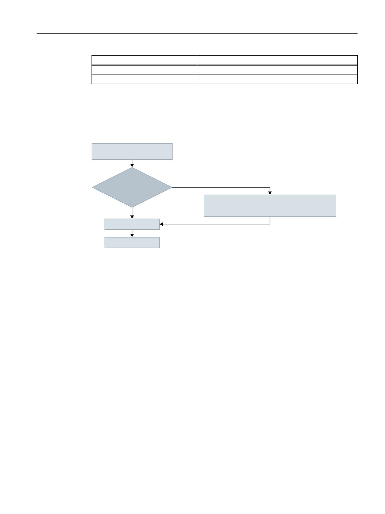
Velocities, setpoint/actual value systems, closed-loop control
5.2 Velocities, traversing ranges, accuracies
Physical unit
Unit
Compensation value linear position
1 mm
Compensation value angular position
1 degree
The user can define different input/output units for machine and setting data. This also requires
an adjustment between the newly selected input/output units and the internal units via the
following machine data:
• MD10220 $MN_SCALING_USER_DEF_MASK
• MD10230 $MN_SCALING_FACTORS_USER_DEF[n]
,QSXW RXWSXW XQLWV IRU PDFKLQH DQG
VHWWLQJ GDWD
'R WKH LQSXW RXWSXW
1R
XQLWV FRUUHVSRQG WR WKH VWDQGDUG
EDVLF V\VWHP"
8VHU GHILQHG
0'
6&$/,1*B)$&7256B86(5B'()>Q@
<HV
0'
6&$/,1*B)$&7256B86(5B'()B0$6.
)RUPDW FRQYHUVLRQ
,QWHUQDO XQLWV
The following applies:
Selected I/O unit = (MD10230 $MN_SCALING_FACTORS_USER_DEF[n]) * internal unit
The selected I/O unit, expressed in the internal units 1 mm, 1 degree, and 1 s must therefore be
entered in machine data MD10230 $MN_SCALING_FACTORS_USER_DEF[n].
Example 1:
Machine data input/output of the linear velocities is to be in m/min instead of mm/min (initial
state).
(The internal unit is mm/s)
⇒ The scaling factor for the linear velocities is to differ from the standard setting. For this,
in machine data:
MD10220 $MN_SCALING_USER_DEF_MASK
bit number 2 must be set.
⇒ MD10220 $MN_SCALING_USER_DEF_MASK = 'H4'; (bit no. 2 as hex value)
⇒ The scaling factor for the linear velocities is to differ from the standard setting. For this,
in machine data:
MD10220 $MN_SCALING_USER_DEF_MASK
bit number 2 must be set.
⇒ MD10220 $MN_SCALING_USER_DEF_MASK = 'H4'; (bit no. 2 as hex value)
Axes and spindles
Function Manual, 10/2020, 6FC5397-4GP40-0BA1
141

Velocities, setpoint/actual value systems, closed-loop control
5.3 System of units, metric/inch
⇒ The scaling factor is calculated using the following formula:
6HOHFWHG LQSXW RXWSXW XQLW
0'
6&$/,1*B)$&7256B86(5B'()>Q@
,QWHUQDO XQLW
P
PP
PLQ
V
0'
6&$/,1*B)$&7256B86(5B'()>Q@
PP
PP
V
V
ය
0'
6&$/,1*B)$&7256B86(5B'()>Q@
Index n defines the "linear velocity" in the "Scaling factors of physical quantities" list.
Example 2:
In addition to the change in Example 1, the machine data input/output of linear accelerations
must be in ft/s2 instead of m/s2 (initial state).
(The internal unit is mm/s2.)
ය 0'
6&$/,1*B86(5B'()B0$6.
+
%LW 1R DQG %LW 1R RI H[DPSOH DV D +H[ YDOXH
IW
PP
V
V
ය
0'
6&$/,1*B)$&7256B86(5B'()> @
PP
PP
V
V
ය
0'
6&$/,1*B)$&7256B86(5B'()> @
Index 4 defines the "linear acceleration" in the "Scaling factors of physical quantities" list.
5.3
System of units, metric/inch
5.3.1
Function
5.3.1.1
Parameterized and programmed system of units
SINUMERIK control systems can operate with a metric system of units as well as an inch system
of units.
Axes and spindles
142
Function Manual, 10/2020, 6FC5397-4GP40-0BA1
Velocities, setpoint/actual value systems, closed-loop control
5.3 System of units, metric/inch
Parameterized system of units (basic system)
The basic setting of the system of units (basic system) is set in machine data MD10240
$MN_SCALING_SYSTEM_IS_METRIC (see "Commissioning (Page 147)").
Depending on the basic system, all length-related data is interpreted either as metric or inch
system of units.
Metric system of units:
mm, mm/min, m/s2, m/s3, mm/rev.
Inch system of units:
inch, inch/min, inch/s2, inch/s3, inch/rev.
The basic system also defines the interpretation of the programmed F value for linear axes:
Feed type
Metric system of units
Inch system of units
G94
mm/min
inch/min
G95
mm/rev.
inch/rev.
Programmed system of units
Using the commands of G group 13 (system of units, inch/metric) within the part program, you
can toggle between the metric and inch system of units (see "Programming (Page 151)").
The programmed system of units and the basic system may be identical or different at any time.
Switchover of the system of units within a particular section of the part program could, for
example, be used to machine an inch thread on a workpiece within a metric basic system.
The reset setting of the G group is defined in machine data MD20150
$MC_GCODE_RESET_VALUES (see "Commissioning (Page 147)").
HMI display
Data relating to length is displayed as follows on the user interface:
Display
in the basic system
in the programmed system of
units
Machine data
x
Data in the machine coordinate
x
system
Tool data
x
Work offsets
x
Data in the workpiece coordinate
x
system
NC/PLC interface
In the case of NC/PLC interface signals containing dimension information, e.g. feedrate for path
and positioning axes, data exchange is carried out with the PLC in the configured basic system.
Axes and spindles
Function Manual, 10/2020, 6FC5397-4GP40-0BA1
143
Velocities, setpoint/actual value systems, closed-loop control
5.3 System of units, metric/inch
Reading in external part programs
If part programs, including data sets (work offsets, tool offsets, etc.), programmed in a system
of units other than the basic system are read in from an external source, then the basic system
must first be changed.
5.3.1.2
Extended system of units functionality
From SW 5 and higher, the system of units functionality has been extended, which significantly
simplifies toggling between systems of units.
The functions include:
• New G commands G700/G710 (see "Programming (Page 151)")
• Data backup with system of units identifier INCH/METRIC (see "Commissioning (Page 147)")
• Automatic data conversions when the system of units is changed, e.g. for:
- Work offsets
- Compensation data (EEC, QEC)
- Tool offsets
- ...
For compatibility reasons, the extended system of units functionality must be activated using a
machine data (see "Commissioning (Page 147)").
5.3.1.3
Extended system of units functionality
From SW 5 and higher, the system of units functionality has been extended, which significantly
simplifies toggling between systems of units.
The functions include:
• System of units switchover at the user interface (Page 145)
• New G commands G700/G710 (see "Programming (Page 151)")
• Data backup with system of units identifier INCH/METRIC (see "Commissioning (Page 147)")
• Automatic data conversions when the system of units is changed, e.g. for:
- Work offsets
- Compensation data (EEC, QEC)
- Tool offsets
- ...
For compatibility reasons, the extended system of units functionality must be activated using a
machine data (see "Commissioning (Page 147)").
Axes and spindles
144
Function Manual, 10/2020, 6FC5397-4GP40-0BA1
Velocities, setpoint/actual value systems, closed-loop control
5.3 System of units, metric/inch
5.3.1.4
System of units switchover at the user interface
Requirement
Extended system of units functionality is active (MD10260 $MN_CONVERT_SCALING_SYSTEM
= 1; see "Commissioning (Page 147)")
Function
The relevant softkey on the HMI in the "Machine" operating area is used to change the system
of units of the control system.
The system of units is only switched over under the following conditions:
• MD20110 $MC_RESET_MODE_MASK, bit 0 is set in every channel.
• All channels are in the Reset state.
• Axes do not currently traverse with JOG, DRF, or PLC.
• Constant grinding wheel peripheral speed (GWPS) is not active.
Actions such as part program start or mode change are disabled while the system of units is
being switched over.
The actual change in the system of units is made by writing all the necessary machine data and
subsequently activating them.
The following machine data are automatically switched over consistently for all configured
channels:
• MD10240 $MN_SCALING_SYSTEM_IS_METRIC
• MD20150 $MN_GCODE_RESET_VALUES
Reset position
When the system of units is switched over from the user interface, the reset position of the G
group 13 is automatically adapted to the actual system of units:
MD20150 $MC_GCODE_RESET_VALUES[12] = <actual system of units>
NCU link
Note
If several NCUs are linked by NCU link, the switchover has the same effect on all linked NCUs. If
the requirements for a switchover are not fulfilled on one of the connected NCUs, no switchover
will take place on any of the NCUs. It is assumed that when there is a NCU link, interpolations
between several NCUs will take place on the existing NCUs, whereby the interpolations can
provide correct results only if the same systems of units are used.
Further information:
Function Manual Basic Functions; Distributed systems
Axes and spindles
Function Manual, 10/2020, 6FC5397-4GP40-0BA1
145
Velocities, setpoint/actual value systems, closed-loop control
5.3 System of units, metric/inch
System data
When the system of units is switched over, from the user's viewpoint, all length-related
specifications are converted to the new system of units automatically.
This includes:
• Positions
• Feedrates
• Accelerations
• Jerk
• Tool offsets
• Programmable, adjustable and external work offsets and DRF offsets
• Compensation values
• Protection zones
• Machine data
• JOG and handwheel factors
After the switchover, all of the above mentioned data is available in physical quantities.
Data, for which no unique physical units are defined, is not converted automatically.
This includes:
• R parameters
• GUDs (Global User Data)
• LUDs (Local User Data)
• PUDs (Program global User Data)
• Analog inputs/outputs
• Data exchange via FC21
The user is prompted to take the currently valid system of units MD10240
$MN_SCALING_SYSTEM_IS_METRIC into consideration.
NC/PLC interface
The current system of units setting can be read at the NC/PLC interface using the following signal:
DB10 DBX107.7 (inch system of units)
The number of times that the system of units has been switched over since the last time the
control powered up can be read out using the following signal byte:
DB10 DBB71 (change counter, system of units inch/metric)
Starting value after the control powered up: 1
Axes and spindles
146
Function Manual, 10/2020, 6FC5397-4GP40-0BA1

Velocities, setpoint/actual value systems, closed-loop control
5.3 System of units, metric/inch
5.3.2
Commissioning
NC-specific machine data
Basic system
The basic system to be used by the controller for the scaling of length-dependent physical
variables for data input/output is specified via the machine data:
MD10240 $MN_SCALING_SYSTEM_IS_METRIC
Value
Meaning
0 (= FALSE)
Data relating to length is interpreted as inch data.
1 (= TRUE)
Data relating to length is interpreted as metric data.
The system must be powered up again after changing this machine data as otherwise associated
machine data, which have physical units, will be incorrectly scaled.
The following procedure must be complied with:
• Changing the MD using manual entry:
-
1. Power up the system.
–
2. Machine data with physical units: Enter a value.
• The MD is changed using machine data:
-
1. Power up the system.
–
2. Load the machine data file once again so that the new physical units are taken into
account.
When changing MD10240, Alarm 4070 "Normalizing machine data has been changed" is
output.
Note
When changing over the system of units at a control system, all length-related data must be
converted consistently and completely into the other measuring system.
Conversion factor (NC-specific)
The factor for converting from metric into the inch system of units is set in machine data:
MD10250 $MN_SCALING_VALUE_INCH (conversion factor for inch)
Default value: 25.4
The conversion factor becomes active when selecting the non-metric basic system (MD10240
$MN_SCALING_SYSTEM_IS_METRIC = 0).
Axes and spindles
Function Manual, 10/2020, 6FC5397-4GP40-0BA1
147

Velocities, setpoint/actual value systems, closed-loop control
5.3 System of units, metric/inch
The following data are multiplied by the conversion factor:
• Length-related data for input/output (e.g. when uploading machine data, work offsets)
• Programmed F values for linear axes
• Programmed geometry of an axis (position, polynomial coefficients, radius for circle
programming, ...), if the system of units programmed with G70/G71 differs from the basic
system (MD10240 $MN_SCALING_SYSTEM_IS_METRIC).
Note
By changing the conversion factor, the control system can be adapted to customer-specific
systems of units.
Extended system of units functionality
The extended system of units functionality can be activated using the following compatibility
machine data:
MD10260 $MN_CONVERT_SCALING_SYSTEM
Value
Meaning
0 (= FALSE)
Extended system of units functionality not active (default setting; compati-
bility to previous software releases)
1 (= TRUE)
Extended system of units functionality active
When changing MD10240, Alarm 4070 "Normalizing machine data has been changed" is
output.
Data backup
Individual data sets that are read from the control system and contain data affected by the
system of units, are assigned an identifier during reading that indicates the current setting for
the system of units:
• MD10260 $MN_CONVERT_SCALING_SYSTEM
• MD10240 $MN_SCALING_SYSTEM_IS_METRIC
The identifier records in which system of units the data have been read out. This ensures that no
data sets are read into the control with a system of units other than that which is currently set.
Since the identifier is also evaluated in part programs, these can also be "protected" against
operator errors as described above. You can therefore prevent part programs containing, e.g.
only metric data, from running on an inch system of units.
Archive and machine data sets are downward-compatible with the following setting:
MD11220 $MN_INI_FILE_MODE = 2
Note
The INCH/METRIC identifier is only generated if the compatibility machine data:
MD10260 $MN_CONVERT_SCALING_SYSTEM = TRUE
Axes and spindles
148
Function Manual, 10/2020, 6FC5397-4GP40-0BA1
Velocities, setpoint/actual value systems, closed-loop control
5.3 System of units, metric/inch
Note
Rounding machine data
All length-related machine data is rounded to the nearest 1 pm when writing in the inch system
of units (MD10240 $MN_SCALING_SYSTEM_IS_METRIC=0 and MD10260
$MN_CONVERT_SCALING_SYSTEM=1), to avoid rounding problems.
This corrects the loss of accuracy resulting from conversion to ASCII when reading out a data
backup in the inch system of units when the data is read back into the system.
Input resolution and computational resolution
The input and calculation resolution is defined as an internal number of increments per
millimeter.
MD10200 $MN_INT_INCR_PER_MM
The precision of entry of linear positions is limited to the calculation resolution. The product of
the programmed position value and the calculation resolution is rounded up to the next integer.
To make the rounding clear and understandable, powers of 10 should be used for the calculation
resolution.
Example:
1 inch = 25.4 mm ⇒ 0.0001 inch = 0.00254 mm = 2.54 μm = 2540 nm
To be able to program and display the last 40 nm, a value of 100000 must be parameterized for
the input and calculation resolution.
Only with this identical setting for both systems of units is it possible to change the system of
units without a significant loss of accuracy. Once MD10200 has been set to this value, it will not
need to be changed each time the measuring system is switched over.
System of units for positioning tables
The system of units for positional data of the indexing axis tables and switching points for
software cams is configured in machine data:
MD10270 $MN_POS_TAB_SCALING_SYSTEM
Further information:
Function Manual Axis and Spindles; Software cams, position switching signals and indexing axes
User tool data
The physical units for user-defined tool and tool cutting edge data can be set in the following
machine data:
• MD10290 $MN_CC_TDA_PARAM_UNIT
• MD10292 $MN_CC_TOA_PARAM_UNIT
Note
When the system of units is switched over, all length-related tool data is converted to the new
system of units.
Axes and spindles
Function Manual, 10/2020, 6FC5397-4GP40-0BA1
149
Velocities, setpoint/actual value systems, closed-loop control
5.3 System of units, metric/inch
Channel-specific machine data
Reset position
For each channel, the reset position of G group 13 (system of units, inch/metric) is set in the
machine data:
MD20150 $MC_GCODE_RESET_VALUES[12] (reset position of G group 13)
Axis/spindle-specific machine data
Conversion factor (axis-specific)
To make pure positioning axes independent of G70/G71, a factor for converting from metric into
the inch system of units can be set in machine data:
MD31200 $MA_SCALING_FACTOR_G70_G71 (conversion factor when G70/G71 is active)
Default value: 25.4
Note
The conversion factor should be identical for all three geometry axes.
JOG and handwheel factor
The following machine data comprises two values containing axis-specific increment weighting
factors for each of the two system of units:
MD31090 $MA_JOG_INCR_WEIGHT
Depending on the actual setting in MD10240 SCALING_SYSTEM_IS_METRIC, the control system
automatically selects the appropriate value.
The user defines the two increment factors when the system is commissioned.
Example: Increment evaluations for the 1st axis
• Metric:
MD31090 $MA_JOG_INCR_WEIGHT[ 0 ; AX1 ] = 0.001 mm
• Inch:
MD31090 $MA_JOG_INCR_WEIGHT[ 1 ; AX1 ] = 0.00254 mm ≙ 0.0001 inch
In this way, MD31090 does not have to be written at every inch/metric switchover.
Remaining distances are not accumulated during incremental traversing with JOG when the
system of units is changed, since all internal positions always refer to mm.
System of units for sag compensation
The system of units for sag compensation is configured using machine data:
MD32711 $MA_CEC_SCALING_SYSTEM_METRIC
Further information:
Function Manual Monitoring and Compensating; Compensations
Axes and spindles
150
Function Manual, 10/2020, 6FC5397-4GP40-0BA1
Velocities, setpoint/actual value systems, closed-loop control
5.3 System of units, metric/inch
5.3.3
Programming
5.3.3.1
Switching over the system of units (G70/G71/G700/G710)
Using the commands of G group 13 (inch/metric system of units) within a part program, you can
switch over between the metric and inch system of units.
Activation
In order that commands G700 and G710 are available, the extended system of units
functionality must be switched on (MD10260 $MN_CONVERT_SCALING_SYSTEM = 1).
Syntax
G70
G71
G700
G710
Meaning
G70:
Activating the inch system of units
The inch system of units is used to read and write geometrical data in units of length.
Technological data in units of length (e.g. feedrates, tool offsets, adjustable work offsets,
machine data and system variables) is read and written using the parameterized basic sys-
tem.
G group:
13
Initial setting:
Settable via MD20150 $MC_GCODE_RESET_VALUES
Effectiveness:
Modal
G71:
Activating the metric system of units
The metric system of units is used to read and write geometrical data in units of length.
Technological data in units of length (e.g. feedrates, tool offsets, adjustable work offsets,
machine data and system variables) is read and written using the parameterized basic sys-
tem.
G group:
13
Initial setting:
Settable via MD20150 $MC_GCODE_RESET_VALUES
Effectiveness:
Modal
G700:
Activating the inch system of units
All geometrical and technological data in units of length is read and written using the inch
system of units.
G group:
13
Initial setting:
Settable via MD20150 $MC_GCODE_RESET_VALUES
Effectiveness:
Modal
Axes and spindles
Function Manual, 10/2020, 6FC5397-4GP40-0BA1
151
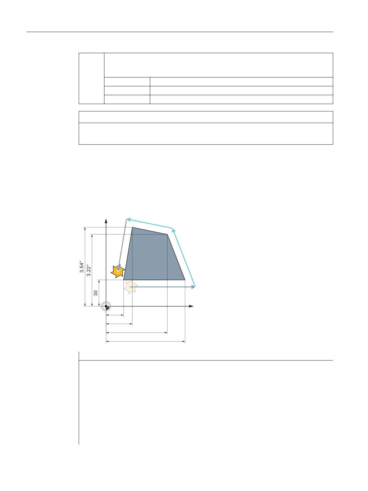
Velocities, setpoint/actual value systems, closed-loop control
5.3 System of units, metric/inch
G710:
Activating the metric system of units
All geometrical and technological data in units of length is read and written using the metric
system of units.
G group:
13
Initial setting:
Settable via MD20150 $MC_GCODE_RESET_VALUES
Effectiveness:
Modal
NOTICE
Axis-specific data of rotary axes
Axis-specific data of rotary axes is read and written using the parameterized basic system.
Example
The basic system is metric (MD10240 $MN_SCALING_SYSTEM_IS_METRIC = 1). However, the
workpiece drawing has dimensions shown in inches. This is the reason why within the part
program, the inch system of units is selected. After the inch dimensions have been processed,
the metric system of units is again selected.
<
*
*
*
*
;
ೀ
ೀ
Program code
Comment
N10 G0 G90 X20 Y30 Z2 S2000 M3 T1
; X=20 mm, Y=30 mm, Z=2 mm, F=rapid traverse
mm/min
N20 G1 Z-5 F500
; Z=-5 mm, F=500 mm/min
N30 X90
; X=90 mm
N40 G70 X2.75 Y3.22
; programmed system of units: inch
; X=2.75 inch, Y=3.22 inch, F=500 mm/min
N50 X1.18 Y3.54
; X=1.18 inch, Y=3.54 inch, F=500 mm/min
N60 G71 X20 Y30
; programmed system of units: Metric
; X=20 mm, Y=30 mm, F=500 mm/min
N70 G0 Z2
; Z=2 mm, F=rapid traverse mm/min
Axes and spindles
152
Function Manual, 10/2020, 6FC5397-4GP40-0BA1

Velocities, setpoint/actual value systems, closed-loop control
5.3 System of units, metric/inch
Program code
Comment
N80 M30
; end of program
Further information
Reading and writing data in the case of G70/G71 and G700/G710
Data area
G70 / G71
G700 / G710
Read
Write
Read
Write
Display, decimal places (WCS)
P
P
P
P
Display, decimal places (MCS)
G
G
G
G
Feedrates
G
G
P
P
Position data X, Y, Z
P
P
P
P
Interpolation parameters I, J, K
P
P
P
P
Circle radius (CR)
P
P
P
P
Polar radius (RP)
P
P
P
P
Thread pitch
P
P
P
P
Programmable FRAME
P
P
P
P
Settable FRAMES
G
G
P
P
Basic frames
G
G
P
P
External work offsets
G
G
P
P
Axial preset offset
G
G
P
P
Working area limits (G25/G26)
G
G
P
P
Protection areas
P
P
P
P
Tool offsets
G
G
P
P
Length-related machine data
G
G
P
P
Length-related setting data
G
G
P
P
Length-related system variables
G
G
P
P
GUDs
G
G
G
G
LUDs
G
G
G
G
PUDs
G
G
G
G
R parameters
G
G
G
G
Siemens cycles
P
P
P
P
Jog/handwheel increment factor
G
G
G
G
P: Writing/reading is performed in the programmed system of units.
G: Writing/reading is performed in the configured basic system
Synchronized actions
Note
Reading position data in synchronized actions
If a system of units has not been explicitly programmed in the synchronized action (condition
component and/or action component) length-related position data in the synchronized action
will always be read in the parameterized basic system.
Axes and spindles
Function Manual, 10/2020, 6FC5397-4GP40-0BA1
153
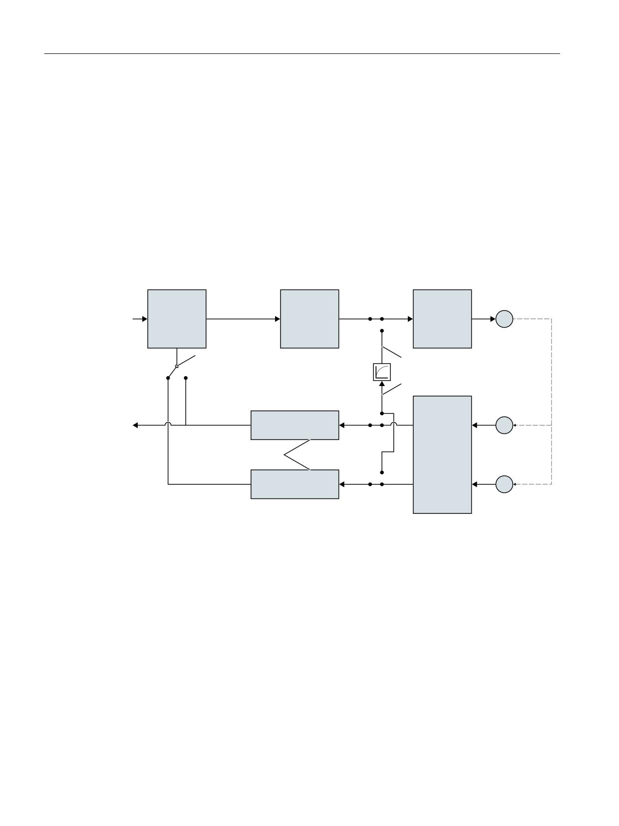
Velocities, setpoint/actual value systems, closed-loop control
5.4 Setpoint/actual-value system
Further information: Function Manual, Synchronized Actions
5.4
Setpoint/actual-value system
5.4.1
General information
Control loop
A control loop with the following structure can be configured for every closed-loop controlled
axis/spindle:
6SHHG
6SHHG
&ORVHG ORRS
0
VHWSRLQW
VHWSRLQW
FRQWURO
RXWSXW
PDUVKDOOLQJ
3RVLWLRQ PHDVXULQJ V\VWHP
LQWHUIDFH
&75/287B7<3(
VLPXODWLRQ
VLJQDO
(1&B7<3(
VLPXODWLRQ
$FWXDO YDOXH
(
SURFHVVLQJ
$FWXDO YDOXH
180B(1&6
PDUVKDOOLQJ
$FWXDO YDOXH
(
SURFHVVLQJ
Figure 5-1
Block diagram of a control loop
Setpoint output
A setpoint telegram can be output for each axis/spindle. The setpoint output to the regulator is
done on the controller.
Actual-value acquisition
A maximum of two measuring systems can be connected for each axis/spindle, e.g. a direct
measuring system for machining processes with high accuracy requirements and an indirect
measuring system for high-speed positioning tasks.
The number of encoders used is recorded in the machine data:
MD30200 $MA_NUM_ENCS (number of encoders)
In the case of two actual-value branches, the actual value is acquired for both branches.
Axes and spindles
154
Function Manual, 10/2020, 6FC5397-4GP40-0BA1
Velocities, setpoint/actual value systems, closed-loop control
5.4 Setpoint/actual-value system
The active measuring system is always used for position control, absolute value calculation and
display. If both measuring systems are activated at the same time by the PLC interface,
positioning measuring system 1 is chosen internally by the controller.
Reference point approach is executed by the selected measuring system.
Every position measuring system must be referenced separately.
For explanations of encoder monitoring, see Function Manual Monitoring and Compensations,
Section Axis monitoring.
For explanations of compensation functions for actual value acquisition, see:
Further information:
Function Manual Monitoring and Compensating; Compensations
Switching between measuring systems
One can switch between the two measuring systems through the following NC/PLC interface
signals:
DB31, ... DBX1.5 (position measuring system 1)
DB31, ... DBX1.6 (position measuring system 2)
Further information
See Function Manual Basic Functions; Various NC/PLC interface signals and functions.
It is possible to switch over measuring systems at any time, the axes do not have to be stationary
to do this. Switchover only takes place if a permissible deviation between the actual values and
the two measuring systems has not been violated.
The associated tolerance is entered in the machine data:
MD36500 $MA_ENC_CHANGE_TOL (max. tolerance on position actual value switchover)
On switchover, the current difference between position measuring system 1 and 2 is traversed
immediately.
Monitoring
The permissible deviation between the actual values of the two measuring systems is to be
entered in the machine data:
MD36510 $MA_ENC_DIFF_TOL
For the cyclic comparison of the two measuring systems used, this difference must not be
exceeded, as otherwise Alarm 25105 "Measuring systems deviate" is generated.
If the axis is not referenced (at least in the current control measuring system), then the related
monitoring is not active if MD36510 = 0 or if neither of the two measuring systems in the axis
is active/available.
Types of actual-value acquisition
The used encoder type must be defined through the following machine data:
MD30240 $MA_ENC_TYPE (type of actual-value acquisition (actual position value))
Axes and spindles
Function Manual, 10/2020, 6FC5397-4GP40-0BA1
155

Velocities, setpoint/actual value systems, closed-loop control
5.4 Setpoint/actual-value system
Simulation axes
The speed control loop of an axis can be simulated for test purposes.
The axis "traverses" with a following error, similar to a real axis.
A simulation axis is defined by setting the two following machine data to "0":
MD30130 $MA_CTRLOUT_TYPE[n] (output value of setpoint)
MD30240 $MA_ENC_TYPE[n] (type of actual-value acquisition)
As soon as the standard machine data has been loaded, the axes become simulation axes.
The setpoint and actual value can be set to the reference point value with reference point
approach.
The machine data:
MD30350 $MA_SIMU_AX_VDI_OUTPUT (output of axis signals with simulation axes)
can be used to define whether the axis-specific interface signals are to be output on the PLC
during the simulation.
Actual-value correction
If actual-value corrections performed by the NC on the encoder selected for position control do
not influence the actual value of another encoder defined in the same axis, then this encoder is
to be declared as "independent" via the following machine data:
MD30242 $MA_ENC_IS_INDEPENDENT
Actual-value corrections include the following:
• Modulo treatment
• Reference point approach
• Measuring system comparison
• PRESET
5.4.2
Setpoint and encoder assignment
Setpoint marshalling
The following machine data is relevant for the setpoint assignment of a machine axis.
MD30100
$MA_CTRLOUT_SEGMENT_NR
Setpoint assignment: Bus segment
System
Value
Meaning
5
PROFIBUS DP / PROFINET (default)
Axes and spindles
156
Function Manual, 10/2020, 6FC5397-4GP40-0BA1
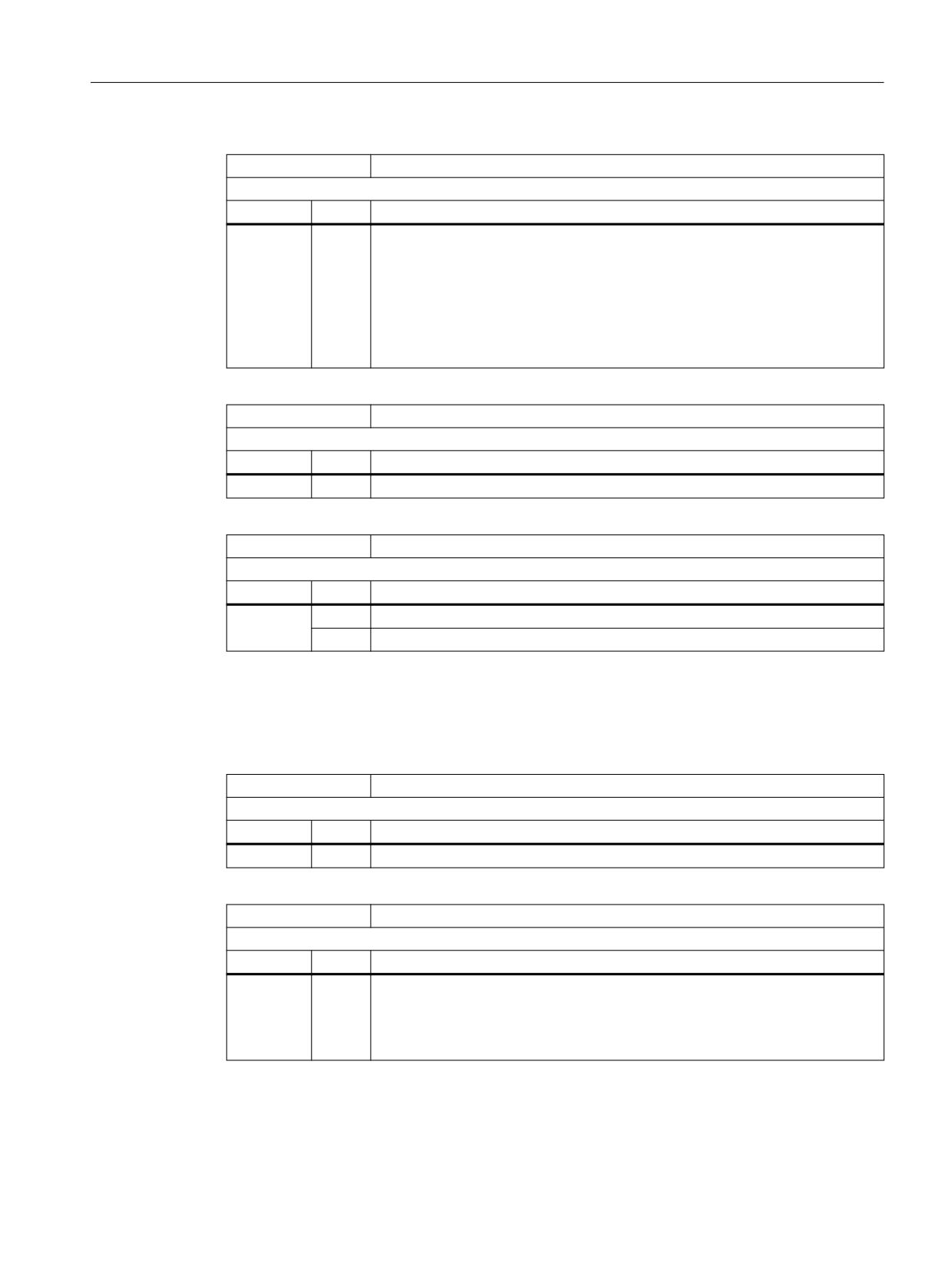
Velocities, setpoint/actual value systems, closed-loop control
5.4 Setpoint/actual-value system
MD30110
$MA_CTRLOUT_MODULE_NR
Setpoint assignment: Drive number / module number
System
Value
Meaning
x
The logical I/O address of the drive is assigned from MD13050 $MN_DRIVE_LOG-
IC_ADDRESS[ n ] via the drive number.
The drive number (x) results from the index (n) of MD13050:
x = n + 1
Note
The machine data is of no significance if the drive is simulated (MD30130
$MA_CTRLOUT_TYPE = 0).
MD30120
$MA_CTRLOUT_NR
Setpoint assignment: Setpoint output on drive module/module
System
Value
Meaning
1
Modular drive at PROFIBUS / PROFINET with PROFIdrive profile (default)
MD30130
$MA_CTRLOUT_TYPE
Setpoint output type
System
Value
Meaning
0
Simulation (operation without drive)
1
Setpoint output active
Encoder assignment
The following machine data is relevant for assigning the encoder information of the drive -
transferred in the PROFIdrive telegram - to the encoder inputs of the machine axis:
MD30210
$MA_ENC_SEGMENT_NR[ n ]
Actual value assignment, bus segment
System
Value
Meaning
5
PROFIBUS DP / PROFINET
MD30220
$MA_ENC_MODULE_NR[ n ]
Actual value assignment: Drive number/measuring circuit number
System
Value
Meaning
x
The logical I/O address of the drive is assigned from MD13050 $MN_DRIVE_LOG-
IC_ADDRESS[ n ] via the drive number.
The drive number (x) results from the index (n) of MD13050:
x = n + 1
Axes and spindles
Function Manual, 10/2020, 6FC5397-4GP40-0BA1
157
Velocities, setpoint/actual value systems, closed-loop control
5.4 Setpoint/actual-value system
MD30230
$MA_ENC_INPUT_NR[ n ]
Actual value assignment: Input on drive module/measuring circuit module
System
Value
Meaning
x
Number of the encoder interface within the PROFIdrive telegram
Examples
PROFIdrive telegram 103
x = 1 → 1st encoder interface (G1_ZSW, G1_XIST1, G1_XIST2)
x = 2 → 2nd encoder interface (G2_ZSW, G2_XIST1, G2_XIST2)
PROFIdrive telegram 118
x = 1 → 1st encoder interface (G2_ZSW, G2_XIST1, G2_XIST2)
x = 2 → 2nd encoder interface (G3_ZSW, G3_XIST1, G3_XIST2)
Note:
For SINAMICS S120:
- Encoder 1 (G1_...): Motor encoder
- Encoder 2 (G2_...): Direct measuring system
- Encoder 3 (G3_...): Additional measuring system
MD30240
$MA_ENC_TYPE[ n ]
Encoder type of actual value acquisition (actual position value)
System
Value
Meaning
0
Simulation (operation without encoder)
1
Incremental encoder
4
Absolute encoder
Note:
Corresponds to PROFIdrive parameter p979
Axes and spindles
158
Function Manual, 10/2020, 6FC5397-4GP40-0BA1

Velocities, setpoint/actual value systems, closed-loop control
5.4 Setpoint/actual-value system
MD30242
$MA_ENC_IS_INDEPENDENT[ n, axis ]
Encoder is independent
System
Value
Meaning
0
The encoder is not independent.
1
The encoder is independent.
If the actual-value corrections, which are made for the encoder selected for the
position control, are not to influence the actual value of the second encoder
defined in the same axis, then this should be declared as independent.
Actual value corrections are:
•
- Modulo treatment
•
- Reference point approach
•
- Measuring system alignment
•
- PRESET
Example: One axis, two encoders, the 2nd encoder is independent
MD30200 $MA_NUM_ENCS[ AX1 ] = 2
MD30242 $MA_ENC_IS_INDEPENDENT[ 0, AX1 ] = 0
MD30242 $MA_ENC_IS_INDEPENDENT[ 1, AX1 ] = 1
Selection, position measuring system 1 / 2: DB31.DBX1.5 / 1.6
If encoder 1 is selected for closed-loop position control, then the actual value
corrections are only performed on this encoder, as encoder 2 is independent.
If encoder 2 is selected for position control, then the actual value corrections are
performed on both encoders, as encoder 1 is not independent.
This means that the machine data only has an effect on the passive encoder of a
machine axis.
2
The passive encoder is dependent.
The actual encoder value is changed by the active encoder. In combination with
MD35102 $MA_REFP_SYNC_ENCS = 1, for reference point approach, the passive
encoder is aligned to the active encoder - but is NOT referenced.
In the referencing mode MD34200 $MA_ENC_REFP_MODE = 3 (distance-coded
reference marks) the passive encoder is automatically referenced with the next
traversing motion after passing the zero mark distance. This is done independent
of the actual operating mode setting.
3
The encoder is independent.
For modulo rotary axes, modulo actual value corrections are also performed in
the passive encoder.
Axes and spindles
Function Manual, 10/2020, 6FC5397-4GP40-0BA1
159