SINUMERIK 840D sl. Service - Functions. Manual (2018-2020) - page 2
Programming
3.4 Subprogram and macro technology
Note
The part program command STOPRE vacates the preprocessing memory. If the skip level is
changed before STOPRE, then all the blocks after STOPRE are changed over securely. The
same is valid for an implicit STOPRE.
Changing the DryRun mode has the same constraints.
No drop in velocity is required when changing the DryRun mode with the machine data
assignment 10704 $MN_DRYRUN_MASK==2. Here too, only the premachining that leads to
the above-mentioned restrictions, is changed.
3.4.10
Eight-digit program number
MD20734 $MC_EXTERN_FUNCTION_MASK, bit 6=1 activates an eight-digit program
number selection. This function impacts on M98 (see "Subprogram technique M98" chapter),
G65/66 (see "Mode changeover during macro calls with G65/G66" chapter) and M96 (see
"Interrupt program with M96/M97 (ASUB)" chapter).
y: Number of program passes
x: Program number
Subprogram call
$MC_EXTERN_FUNCTION_MASK, bit 6 = 0
M98 Pyyyyxxxx or
M98 Pxxxx Lyyyy
Program number max. 4 digits
Addition of program number always to 4 digits with 0
Example:
M98 P20012: calls 0012.mpf 2 passes
M98 P123 L2: calls 0123.mpf 2 passes
$MC_EXTERN_FUNCTION_MASK, bit 6 = 1
M98 Pxxxxxxxx Lyyyy
There is no extension with 0, even if the program number has less than 4 digits.
The number of passes and program number in P(Pyyyyxxxxx) cannot be programmed,
the number of passes must always be programmed with L!
Example:
M98 P123: calls 123.mpf 1 pass
M98 P20012: calls 20012.mpf 1 pass,
Caution: This is no longer compatible with ISO dialect original!
M98 P12345 L2: calls 12345.mpf 2 passes
ISO dialects
74
Function Manual, 12/2019, 6FC5397-7BP40-3BA1
Programming
3.4 Subprogram and macro technology
Modal and blockwise macro G65/G66
$MC_EXTERN_FUNCTION_MASK, bit 6 = 0
G65 Pxxxx Lyyyy
Program number is always expanded to 4 digits using 0s. Program numbers with more than 4
digits result in an alarm.
$MC_EXTERN_FUNCTION_MASK, bit 6 = 1
G65 Pxxxx Lyyyy
0s are not added, even if the program number is less than 4 digits long. A program number with
more than 8 digits leads to an alarm.
Interrupt M96
Does not function in SINUMERIK 802D sl.
$MC_EXTERN_FUNCTION_MASK, bit 6 = 0
M96 Pxxxx
Program number is always expanded to 4 digits with 0s
$MC_EXTERN_FUNCTION_MASK, bit 6 = 1
M96 Pxxxx
0s are not added, even if the program number is less than 4 digits long. A program number with
more than 8 digits leads to an alarm.
3.4.11
System variable for level stack in ISO mode
In standard mode, the current program level is displayed in the $P_STACK system variable.
This variable is affected by all subprogram calls and returns. There are however subprogram
calls in ISO mode for which the current user variable level is not changed. You must know the
current program level in ISO mode in order to realize level-specific variables using GUDs.
System variable $P_IPO_STACK provides the current program level in ISO dialect mode.
The table below shows all the possible subprogram and macro calls in ISO mode and how they
impact on the current program level.
The calls in ISO mode are mapped on calls in standard mode such that the $P_STACK variable
contains the same information as before even in ISO mode.
The number of maximum possible subprogram calls remains unchanged.
System variable $P_IPO_STACK is incremented whenever a subprogram is started which is
programmed as a macro call with G65, G66, G code or M macro in ISO mode. $P_IPO_STACK
is decremented again when returning from such an ISO macro. If there are no ISO macros
active, $P_IPO_STACK = 0. $P_IPO_STACK therefore provides the number of currently active
ISO macros.
When calling an interrupt program defined with M96 Pxx, variable $P_IPO_STACK is also
incremented depending on MD $MC_EXTERN_FUNCTION_MASK, bit 11.
$MC_EXTERN_FUNCTION_MASK
Bit 12 = 0, $P_IPO_STACK is not changed by the interrupt program.
Bit 12 = 1, $P_IPO_STACK is incremented by the interrupt program.
ISO dialects
Function Manual, 12/2019, 6FC5397-7BP40-3BA1
75

Programming
3.4 Subprogram and macro technology
Cycle calls with e.g. G81, G77 etc. or functions realized internally with cycles, e.g. G05, G72.1
etc. and subprogram calls with M98 Pxx do not affect $P_IPO_STACK.
Example:
Subprogram calls in ISO and standard mode.
M98 stands for subprogram calls without an increase in level
G65 P stands for a macro calls with an increase in level
Table 3-4
Subprogram and macro calls
$P_STACK
$P_IPO_STACK
Level 1
Level 2
Level 3
1
1
O111.mpf
1
1
N5 M98 P2222
2
1
O2222.mpf
2
1
G65 P3333
3
2
O3333.mpf
3
2
M99
2
1
M99
M98 does not forward the levels. O1111.mpf and O2222.mpf work with the same $P_ISO_STACK content, G65 forwards the
levels such that O3333.mpf sees different content. $P_STACK continues to display the levels in standard mode.
$P_STACK
$P_IPO_STACK
Level 1
Level 2
Level 3
1
1
O1111.mpf
1
1
N5 G65 P2222
2
2
O2222.mpf
2
2
M98 P3333
3
2
O3333.mpf
3
2
M99
2
1
M99
Switching from ISO to standard mode
$P_STACK
$P_IPO_STACK
Level 1
Level 2
Level 3
1
1
O1111.mpf
1
1
G291
1
1
N5 M98 P2222
2
1
O2222.mpf
2
1
G290
2
1
3333( )
3
2
3333.mpf
3
2
M30
2
1
G291
2
1
M99
1
1
N10 M30
Switching from standard to ISO mode
1
1
1111.mpf
1
1
N5 G290
1
1
N10 2222( )
2
2
2222.mpf
ISO dialects
76
Function Manual, 12/2019, 6FC5397-7BP40-3BA1

Programming
3.4 Subprogram and macro technology
$P_STACK
$P_IPO_STACK
Level 1
Level 2
Level 3
2
2
G291
2
2
M98 P3333
3
2
O3333.mpf
3
2
M99
2
2
G290
2
2
M17
1
1
N15 M30
List of possible subprogram and macro calls in ISO mode
M98 Pxxxx
Subprogram call
Level is not changed
M98 Pxxxx Lyyyy
Up call with iteration
Level is not changed
G65 P
Non-modal macro
Level is increased
G66 P
Modal macro
Level is increased
G05
UP call CYCLE305
Level is not changed
M macro subst
10814: EXTERN_M_NO_MAC_CYCLE
Level is increased
M up subst.
10715: M_NO_FCT_CYCLE
Level is not changed
T subst
10717: T_NO_FCT_CYCLE_NAME
Level is not changed
G subst
10816: EXTERN_G_NO_MAC_CYCLE
Level is increased
M96
Interrupt ASUB
Level is changed depending on
$MC_EXTERN_FUNC-
TION_MASK, bit 12
Shell cycles:
Level is not increased
G code cycles:
G22 G23 G27 G28 G30 G30.1 G72.1 G50
Level is not increased
G code cycles, shell cycles:
$P_ISO_STACK has no meaning for the user because these cycles do not offer access for
writing.
Depending on machine datum $MC_EXTERN_FUNCTION_MASK, bit 12, variable
$P_ISO_STACK is incremented when calling an interrupt program (ASUB).
● Bit 12 = 0
Variable $P_ISO_STACK is not changed when calling an interrupt program defined with
M96 Pxx
● Bit 12 = 1
Variable $P_ISO_STACK is incremented when calling an interrupt program defined with
M96 Pxx
ISO dialects
Function Manual, 12/2019, 6FC5397-7BP40-3BA1
77
Programming
3.4 Subprogram and macro technology
ISO dialects
78
Function Manual, 12/2019, 6FC5397-7BP40-3BA1

Tool changes and tool offsets
4
4.1
Shared tool offset memory
4.1.1
Tool offsets: T, D (ISO dialect M)
Tool data, T/D number H number
As the Siemens and ISO dialect programs are intended to run alternately in the control, they
must be implemented using the Siemens tool data memory.
Each offset data set is assigned to a tool. This offset data set contains the length, geometry and
wear.
In Siemens mode the offset memory is addressed with T (tool number) and D (cutting edge
number), or T/D number for short.
In ISO dialect M programs the offset memory is addressed with D (radius) or H (length), referred
to below as the H number.
In order to be able to assign this H number unambiguously to a T/D number, an element
$TC_DPH[t,d] has been added to the offset data set. The H number of the ISO dialect is entered
in this element.
Table 4-1
Example: Tool offset data set
T
D/cutting edge
H number
Radius
Length
$TC_DPH
1
1
10
1
2
11
1
3
12
100,00
250,00
2
1
13
2
2
14
2
3
15
Example:
Siemens program
ISO dialect program
N5
T1
N5
T1
N10
G41 D3
N10
G41 H12 or G41 D12
When programming the H value in the ISO dialect M program, the corresponding $TC_DPH is
used to search for the offset data set in the active T and the tool is selected.
If an offset data set does not include an H number, this offset cannot be activated in ISO dialect
mode.
ISO dialects
Function Manual, 12/2019, 6FC5397-7BP40-3BA1
79
Tool changes and tool offsets
4.1 Shared tool offset memory
If an H is programmed but no offset data set with the corresponding H number is found or the
associated tool T is not selected, an alarm is output.
4.1.2
Possible H numbers
H = 0
H0 is an offset with the offset value 0. If H0 is programmed during G43/G44, G43/G44 remains
active but with the tool length 0. H0 cannot be programmed while G41/G42 is active,
however.
H = unique
Each H number can only occur once in any TO unit, otherwise unambiguous addressing of the
offset data set is not possible. If you try to assign an H number for a second time, an alarm
"17183 Channel %1 Set %2 H number already exists in T= %3 with D=%4" is sent from the
program on attempting to write the values. This alarm is offset data set-capable and NC start
clear.
Example:
N5 $TC_DPH[1,1] = 5
N10 $TC_DPH[2,1] = 5
If you try to assign an H number twice via BTSS (HMI, PLC), a negative acknowledgement is
output for this write attempt.
Changing the offset memory
Existing tool offsets can be overwritten with G10. New tool offsets are not created with G10.
Tool length geometry offset: G10 L10 Pxx Ryy
Tool length wear offset: G10 L11 Pxx Ryy
Radius geometry offset: G10 L12 Pxx Ryy
Radius wear offset: G10 L13 Pxx Ryy
P indicates the H number of the offset memory and R the value.
L1 can be programmed in place of L11.
Active plane
To ensure that the assignment of tool length offsets to the geometry axes is independent of the
plane selection, the setting data 42940 $SC_TOOL_LENGTH_CONST must contain the value
17. In this way length 1 is always assigned to the Z-axis.
Tool length selection
The tool length and tool radius are always programmed with D or H.
ISO dialects
80
Function Manual, 12/2019, 6FC5397-7BP40-3BA1

Tool changes and tool offsets
4.1 Shared tool offset memory
Example:
T
D/cutting edge
H number
Radius
Length
$TC_DPH
2
3
4
10
15
ISO dialect M:
T2
G43 H4 or D4 ;Length selection
G42 D4 or H4 ;Radius selection
In ISO dialect M programs which are programmed with different D and H numbers, the offset
value must be entered twice.
Example:
T
D/cutting edge
H number
Radius
Length
$TC_DPH
2
3
4
10
15
2
4
5
10
15
ISO dialect M:
T2
G43 H4 ;Length offset from T2 D3
G42 D5 ;Radius and length offset from T2 D4
Flat D number
If flat D numbers are active, the T is programmed independently of the H number. The system
no longer checks whether the H number matches the selected tool.
Even with flat D numbers an H number must be assigned to each offset memory.
Tool management
If tool management is active, sister tools have the same H number. They are differentiated by
means of duplo numbers.
With H99 the offset D1 for the currently selected tool is activated if tool management is active.
In ISO dialect M only numerical expressions are permissible as tool identifiers. Strings are not
permissible as identifiers.
Example: T = "2", selection with T2.
Tool length offset in multiple axes
Tool length offsets can be activated in multiple axes. The resulting tool length offset cannot be
displayed, however.
If T and D numbers are active, the Siemens T and D numbers are displayed.
ISO dialects
Function Manual, 12/2019, 6FC5397-7BP40-3BA1
81
Tool changes and tool offsets
4.1 Shared tool offset memory
For the active ISO dialect H and D numbers there are new BTSS variables that can be
displayed.
The machine data 22220 $MC_AUXFU_T_SYNC_TYPE defines whether output to the PLC
takes place during or after the movement.
The machine data 20110 $MC_RESET_MODE_MASK, bit6 can be used to specify that the tool
length offset remains active after a reset.
MD 20156 $MC_EXTERN_RESET_GCODE_MODE[7] is used to define whether the G code of
group 8 (G43, G44, G49) is retained after a reset or whether the setting from MD 20254
$MC_EXTERN_RESET_GCODE[7] takes effect after a reset.
The default settings for both machine data should be set such that after a reset G49 is active
and the tool length offset is deselected.
Example: Tool selection in ISO dialect M:
;(Fanuc 0 M tool offset with T, cutting edge number
;(the offsets are)
;(with G10)
G290
;Tool offset memory T2 cutting edge1:
N5000 $TC_DP1[2,1]=10
;Type
N5000 $ TC_DP1[2,1]=7
;ISO H number
;Tool offset memory T3 cutting edge2:
N5000 $TC_DP1[3,2]=10
;Type
N5000 $TC_DP1[3,2]=3
;ISO H number
;Tool offset memory T4 cutting edge3:
N5000 $TC_DP1[4,3]=10
;Type
N5000 $TC_DP1[4,3]=8
;ISO H number
G291
;Write tool offsets
;------------------------
;T2 cutting edge1
G10 L12 P7 R5
;T3 cutting edge2
G10 L10 P3 R15
G10 L12 P3 R10
N8 G01 G40 F5000 X0 Y0 Z0
N10 X50.
N15 Y50
N17 Z10.
N20 X0
N25 Y0
N30 X-10 Y-10
N30 T2
;Tool 2
N33 G43 H7 Z0
;H number 7
N35 G41 X0 Y0 Z0 D7
N40 X50.
ISO dialects
82
Function Manual, 12/2019, 6FC5397-7BP40-3BA1
Tool changes and tool offsets
4.1 Shared tool offset memory
N45 Y50.
N48 Z10.
N50 X0
N55 Y0
N60 G40 X-10 Y-10
N65 T3
N68 G43 H3 Z0
N70 G42 X0 Y0 Z0 D3
N75 X50.
N77 Y50.
N78 Z10.
N80 X0
N85 Y0
N90 G40 X-10 Y-10
N95 T4
N98 G43 H8 Z0
N100 G41 X0 Y0 Z0 D8
N105 X50.
N110 Y50.
N112 Z10.
N115 X0
N120 Y0
N125 G40 X-10 Y-10
M30
Whether the offset takes effect in the selection set or the next time the axis is programmed is
defined by machine data 20382 $MC_TOOL_CORR_MOVE_MODE.
4.1.3
Tool offset T (ISO dialect T)
The tool data is located in the Siemens tool data memory and corresponds to the offset data for
a Siemens cutting edge.
The meaning corresponds to the cutting edge position for Siemens turning tools.
In ISO dialect T, the tool number and correction number are both programmed in the T word.
During interpretation, the T word is split according to the tool number and correction number.
The following possibilities now exist:
10889 $MN_EXTERN_DIGITS_OFFSET_NO, number of digits for correction number.
Range of values 0-8, default value 0
The function is deactivated with 0.
The number of digits is counted from the T word from the right, the rest is the tool number.
Example: $MN_EXTERN_DIGITS_OFFSET_NO = 3
T1234 is split into T1 H234
10888 $MN_EXTERN_DIGITS_TOOL_NO, number of digits for tool number.
Range of values 0-8, default value 2
The function is deactivated with 0.
ISO dialects
Function Manual, 12/2019, 6FC5397-7BP40-3BA1
83
Tool changes and tool offsets
4.1 Shared tool offset memory
The number of digits is counted from the T word from the left, the rest is the correction number.
Example: $MN_EXTERN_DIGITS_TOOL_NO = 3
T1234 is split into T123 H4
Only one of the two functions may be active to split the T word. If both machine data have a
value of 0, splitting is not possible. Programming T results in NC alarm 12550.
If both machine data have a value of < > 0, splitting is not possible. Programming T results in
NC alarm 12550.
The function is compatible with the standard values of previous statuses.
Examples
$MN_EXTERN_DIGITS_OFFSET_NO = 0
$MN_EXTERN_DIGITS_TOOL_NO = 2
Splitting according to tool numbers, 2 digits
T123 becomes T12 H3
T0123 becomes T1 H23
$MN_EXTERN_DIGITS_OFFSET_NO = 3
$MN_EXTERN_DIGITS_TOOL_NO = 0
Splitting according to tool numbers, 3 digits
T1234 becomes T12 H234
T01234 becomes T1 H234
$MN_EXTERN_DIGITS_OFFSET_NO = 3
$MN_EXTERN_DIGITS_TOOL_NO = 2
Splitting not possible because both functions are activated. T programming results in alarm
12550.
$MN_EXTERN_DIGITS_OFFSET_NO = 0
$MN_EXTERN_DIGITS_TOOL_NO = 0
Splitting not possible because both functions are deactivated. T programming results in alarm
12550.
Changing the offset memory
Existing tool offsets can be overwritten with G10. New tool offsets are not created with G10.
G10 P<100 / 10000 X Y R Q Geometry
G10 P>100 / 10000 X Y R Q Wear
P100/10000
;With MD 20734: EXTERN_FUNCTION_MASK, bit 1 is selected,
;when P<100 or 10000, whether differentiation is by geometry
;or wear.
X Y Z
;Offset values absolute or incremental, depending on G90/91
U V W
;Offset values incremental
R
;Radius
Q
;Cutting edge position
ISO dialects
84
Function Manual, 12/2019, 6FC5397-7BP40-3BA1
Tool changes and tool offsets
4.1 Shared tool offset memory
Tool offset selection with $TC_DPH
In ISO dialect T the "flat D numbers" function has previously always been active. The D
numbers are unique; with the command Txxyy or G10 Pyy the Siemens cutting edge number
is addressed with yy. In order to use tool management in ISO dialect T, structured D numbers
must be addressed. Just as in ISO dialect M, each cutting edge is therefore given a parameter
$TC_DPH[°], which allows a cutting edge to be addressed unambiguously within a TO unit.
The function is switched on with MD 10890 $MN_EXTERN_TOOLPROG_MODE bit 2=1.
If the function is active, the tool offset must always be addressed with the H number in ISO
dialect T. Programs which address the cutting edge number no longer run. The parameter
$TC_DPH[ ] is only created if $MN_EXTERN_TOOLPROG_MODE bit 2=1. The H numbers
must be allocated unambiguously within a TO unit, otherwise alarm 17183 is output.
There are three options:
$MN_MM_TYPE_OF_CUTTING_EDGE=1 flat D number
1. Flat D number + $MN_EXTERN_TOOLPROG_MODE bit 2=0
The offset is always addressed with cutting edge D.
G290
N605 $TC_DP1[1]= 500
N615 $TC_DP1[2]= 500
N625 $TC_DP1[3]= 500
N635 $TC_DP1[4]= 500
G291
N650 G10 P2 X10
;Write cutting edge 2 geometry
N655 G10 P102 X1
;Write cutting edge 2 wear
N670 T0102
;Select cutting edge 2
N675 T0105
;Alarm because cutting edge 5 does not ex-
ist
2. Flat D number + $MN_EXTERN_TOOLPROG_MODE bit 2=1
The offset is always addressed with the H number.
G290
N705 $TC_DP1[1]= 500
N708 $TC_DPH[1]=11
N710 $TC_DP1[2]= 500
N715 $TC_DPH[2]=22
N720 $TC_DP1[3]= 500
N725 $TC_DPH[3]=33
N730 $TC_DP1[4]= 500
N735 $TC_DPH[4]=44
G291
N740 G10 P22 X10.
;Write cutting edge 2 geometry
N745 G10 P122 X1.
;Write cutting edge 2 wear
N747 G10 P55 X10.
;Alarm 12550 because cutting edge does
;not exist with H55
ISO dialects
Function Manual, 12/2019, 6FC5397-7BP40-3BA1
85
Tool changes and tool offsets
4.1 Shared tool offset memory
N750 T0122
;Cutting edge 2 is selected
N752 T0155
;Alarm 12550 because cutting edge does
;not exist with H55
$MN_MM_TYPE_OF_CUTTING_EDGE=0
Structured D number
3. Structured D number + $MN_EXTERN_TOOLPROG_MODE bit 2=1
The offset is always addressed with the H number.
G290
N805 $TC_DP1[1,1]= 500
N808 $TC_DPH[1,1]=11
N810 $TC_DP1[1,2]= 500
N815 $TC_DPH[1.2]=22
N820 $TC_DP1[2,1]= 500
N825 $TC_DPH[2,1]=33
N830 $TC_DP1[2,2]= 500
N835 $TC_DPH[2,2]=44
G291
N840 G10 P22 X10
;Write T1 cutting edge 2 geometry
N845 G10 P122 X1
;Write T1 cutting edge 2 wear
N847 G10 P55 X1
;Alarm 12550 because cutting edge does
;not exist with H55
N850 T0122
;Select T1 cutting edge 2.
N855 T0244
;Select T2 cutting edge 2
;Alarm because cutting edge
;does not exist in T2 with H22.
4.1.4
Tool change cycle
ISO dialect mode
A subprogram is assigned to the T command using MD 10717 T_NO_FCT_CYCLE_NAME.
Each set containing a T command is executed and then the subprogram is called. The T value
is not output; the T word has to be programmed again in the cycle.
In the subprogram the system variable $C_T_PROG or $C_D_PROG can be used to query
whether T or D has been programmed. The values can be read with the system variables $C_T
and $C_D respectively. If another T command is programmed in the subprogram, no
replacement is made but the T word is output to the PLC.
A subprogram can be assigned to an M function (e.g., M06) using MD 10715
M_NO_FCT_CYCLE and 10716 M_NO_FCT_CYCLE_NAME.
The mapping of M, T programming to cycle calls is the same in ISO dialect mode as in Siemens
mode.
If T and M6 are programmed in a set, the programmed T number can be queried in the cycle
called with M6 using GETSELT(). GETSELT() gets the T number of the preselected tool. In the
ISO dialects
86
Function Manual, 12/2019, 6FC5397-7BP40-3BA1
Tool changes and tool offsets
4.1 Shared tool offset memory
block search the M/T call is likewise mapped to the cycle call. At the end of the search the
change cycle must be started from the PLC side.
Sequence:
N20 T1234
N30 M6
;Change tool
N40 H3 G43
;Activate tool length offset in T1234
N50 T333
;Tool preselection
N60 G1 X10
;T1234 offset is active
N70 M6
;Load tool 333, D0 H0 active
N80 H4
;Activate new tool length offset
N90
ISO dialects
Function Manual, 12/2019, 6FC5397-7BP40-3BA1
87
Tool changes and tool offsets
4.1 Shared tool offset memory
ISO dialects
88
Function Manual, 12/2019, 6FC5397-7BP40-3BA1
Cycles and contour definition
5
5.1
Sequence of cycle calls in the external CNC system using G
commands
General description
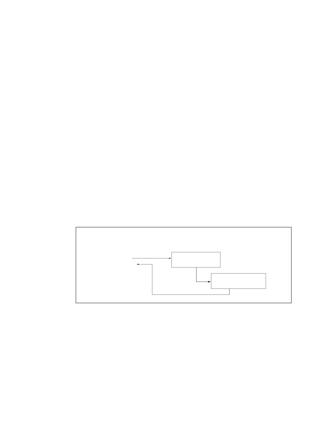
The functionality of the ISO dialect cycles is realized in the Siemens standard cycles:
A shell cycle is called from the ISO dialect program. All addresses programmed in the block are
transferred to this shell cycle in the form of system variables. The shell cycle customizes this
data to the standard Siemens cycle and calls its name.
The machine manufacturer can replace the shell cycles with its own ones.
Cycle parameters
During machining cycles, various cycle parameters should be preset in channel-specific GUDs
(Global User Data). The names and meanings of the GUDs are listed in the "Global user data
(GUD)" chapter.
Sequence for calling cycles using G command
3DUW SURJUDP
H[WHUQDO &1& V\VWHP
H J ,62 GLDOHFW
1
*
6KHOO F\FOH
1
;
<
1
1
6LHPHQV VWDQGDUG F\FOH
Figure 5-1
General cycle sequence in ISO dialect mode
Shell cycle
The customizations, required due to the ISO dialect programming syntax, are undertaken in the
shell cycle. The existing SINUMERIK cycles do not need to be changed for this. The shell cycle
name is permanently assigned.
ISO dialects
Function Manual, 12/2019, 6FC5397-7BP40-3BA1
89
Cycles and contour definition
5.1 Sequence of cycle calls in the external CNC system using G commands
Sequence:
1. The cycle (e.g. G81) is programmed in ISO dialect mode
2. A switch is made automatically to Siemens mode and the associated shell cycle called (see
previous figure)
3. The shell cycle calls the associated standard Siemens cycle
Programming with G290 is not needed. A switch is automatically made to the external CNC
system when returning.
Note
The cycles may only be called with the G commands.
This ensures that the shell cycle is provided with the appropriate cycle parameters.
The shell cycle must not be called directly with CALL CYCLE3xx!
Modally effective cycles
If a modal cycle is active, the shell cycle is called in each NC block. If there are no axis positions
(X, Y or Z) programmed in the NC block, the standard Siemens cycle is not called.
Addresses programmed in the block (F etc.) are activated by the shell cycle. For example, if a
feedrate has not been programmed, the current feedrate is used as the path feedrate.
Cycle parameters can be programmed in the following blocks while a modal cycle is active.
These parameters are written to the system variables so that the shell cycle works with the
modified parameters.
Unlike modal macros, modal cycles are executed in the call block (e.g. block with G81 etc.).
Cycle deselection:
G80 or a G function of the 1st G group is used for deselection.
Example:
N10 G81 X10. Y20. Z-15. R5 F1000
Drilling position X10 mm, Y20 mm
Drilling depth Z-15 mm
Reference plane 5 mm
Drilling feedrate F.. (mm/min or mm/rev.)
N20 X50. Y30. R10
Drilling position X50 mm, Y30 mm,
New reference plane 10 mm
N30 G80
Delete cycle G81
Writing cycle variable, depending on programmed addresses in block
During active modal cycles, to date all programmed addresses in the block have always been
written into the cycle variables. The variables are evaluated in the cycle where a decision is
made on the basis of the cycle logic as to how the variables have to be used.
ISO dialects
90
Function Manual, 12/2019, 6FC5397-7BP40-3BA1
Cycles and contour definition
5.2 Global user data (GUD)
In many cases this results in the cycle parameters being described even if they cannot be
interpreted as cycle parameters because of their programming syntax.
None, or no longer all of the programmed addresses are therefore written in the cycle
parameters for the following functions:
M98 P3 L2 X10 Y20
Addresses Pxx and Lxx are not written in the cycle parameters.
G05 P5 L2 X10 Y20
Addresses Pxx and Lxx are not written in the cycle parameters.
G05 P1 L2 X10 Y20
During an active modal cycle, alarm 12722 is output because
CYCLE305, for which the programmed values are actually in-
tended, is called here after the modal cycle.
G54 P10 X10 Y20 M44
Address Pxx is not written in the cycle parameters.
G31 P98 X30 F100
Addresses Pxx, Fxx and axis values are not written in the cycle
parameters.
G31 P1 X30 Y20 F100
None of the programmed addresses are written in the cycle
parameters.
G51 P1000 I2 J3 K2 X30 Y40
None of the programmed addresses are written in the cycle
parameters.
G50 P10000 X10 Y30
All parameters are written in the cycle parameters.
5.2
Global user data (GUD)
Table 5-1
SGUD for programmed cycle values (ISO dialect program data)
GUD
Description/use
CYCLE
Real values
_ZFPR[0]
Basis (current position for 1st call with G..), retraction position for G98
381M, 383M,
active
384M, 387M
_ZFPR[1]
Reference plane, retraction position for G99 active (only retraction to
381M, 383M,
starting position possible for G87)
384M, 387M
_ZFPR[2]
Final drilling depth, absolute
381M, 383M,
384M, 387M
_ZFPR[3]
Retraction position, depending on G98/G99 (basis/R plane)
381M, 383M,
384M, 387M
_ZFPR[4]
Drilling feedrate
381M, 383M,
384M, 387M
_ZFPR[5]
Dwell time (s) at final depth (G82/G89/G76/G87) [ms]
381M, 384M,
387M
_ZFPR[6]
1st drilling depth (individual drilling depth) incr. (G73/G83)
383M
_ZFPR[7]
1st absolute drilling depth (G73/G83)
383M
_ZFPR[8]
Lifting/feed in distance (G76)
387M
_ZFPR[9]
Speed for tapping (G74/G84)
384M
_ZFPR[10]
Programmable holding distance when dipping back into hole G83
383M
Values:
> > 0 programmable value applies
= 0 automatic calculation
ISO dialects
Function Manual, 12/2019, 6FC5397-7BP40-3BA1
91

Cycles and contour definition
5.2 Global user data (GUD)
GUD
Description/use
CYCLE
_ZFPR[20]
Basis (current position for 1st call)
383T, 384T,
385T
_ZFPR[21]
R plane
383T, 384T,
385T
_ZFPR[22]
Final drilling depth, absolute
383T, 384T,
385T
_ZFPR[23]
Retraction position (1=G98, 2=G99)
383T, 384T,
385T
_ZFPR[24]
Thread lead/drilling feedrate
376T, 383T,
384T, 385T
_ZFPR[25]
Dwell time at final depth
383T, 384T,
385T
_ZFPR[26]
Speed for tapping
384T
_ZFPR[27]
End point X
371T, 372T,
373T, 376T
_ZFPR[28]
End point Z
371T, 372T,
373T, 376T
_ZFPR[29]
Start point offset X (taper thread)
371T, 372T,
376T
_ZFPR[30]
Thread start point X
376T
_ZFPR[31]
Thread start point Z
376T
_ZFPR[32]
First drilling depth
383T
Integer values
_ZFPI[0]
Current G code of ISO dialect drilling cycle
381M, 383M,
384M
_ZFPI[1]
M function for spindle start (M3, M4) after spindle stop
381M, 384M
_ZFPI[20]
Current G code of thread cycle/drilling cycle
383T, 384T,
385T
_ZFPI[21]
Spindle direction (3=M3, 4=M4)
383T, 384T,
385T
_ZFPI[22]
Roughing stock removal type
370T, 371T,
372T, 373T
_ZFPI[23]
Deep-hole / drilling machining type
383T
Assignment list of GUD parameters to the machine data for ISO cycles
GUD up to SW Version 1.5
MD/SD name
_ZSFI[0]
$SCS_ISO_M_DRILLING:AXIS_IS_Z
_ZSFI[1]
$SCS_ISO_M_DRILLING_TYPE
_ZSFI[2]
$SCS_ISO_M_RETRACTION_FACTOR
_ZSFI[3]
$SCS_ISO_M_ENABLE_POLAR_COORD
_ZSFI[4]
$SCS_ISO_ENABLE_INTERRUPTS
_ZSFI[5]
$SCS_ISO_M_RETRACTION_DIR
_ZSFI[6]
$SCS_ISO_ENABLE_DRYRUN
_ZSFI[7]
ISO dialects
92
Function Manual, 12/2019, 6FC5397-7BP40-3BA1

Cycles and contour definition
5.3 Drilling cycles (ISO dialect M)
GUD up to SW Version 1.5
MD/SD name
_ZSFI[8]
$SCS_ISO_SIMULTAN_AXES_START
_ZSFI[9] ... _ZSFI[19]
_ZSFI[20]
$SCS_ISO_T_DEEPHOLE_DRILL_MODE
_ZSFI[21]
_ZSFI[22]
$SCS_ISO_T_RETRACTION_FACTOR
_ZSFI[23]
$SCS_ISO_T_DWELL_TIME_UNIT
_ZSFI[24] ... _ZSFI[38]
_ZSFI[39]
5.3
Drilling cycles (ISO dialect M)
5.3.1
Overview and parameter description
The drilling cycles are modal. When a drilling mode is active, only the new parameters have to
be programmed if a parameter is changed.
No traversing is executed if:
● no value is programmed for X, Y and Z in the NC block
● the number of repeats K=0 has been programmed
The retraction position applies to all drilling cycles
● G98 retraction at basis
● G98 retraction at datum plane
Overview
Table 5-2
Overview of drilling cycles
External cycle call
Description
G73 X.. Y.. Z.. R.. F.. Q..
Deep hole drilling cycle with chip breakage
G74 X.. Y.. Z.. R.. F.. P..
Left tapping cycle
G76 X.. Y.. Z.. R.. F.. Q.. P..
Fine drill cycle
G80
Cycle off; cycle is also deselected by programming a G function
from the 1st G group.
G81 X.. Y.. Z.. R.. F..
Drilling cycle; drilling, retraction with G00
G82 X.. Y.. Z.. R.. F.. P..
Drilling cycle; drilling, dwell time, retraction with G00
G83 X.. Y.. Z.. R.. F.. Q..
Deep hole drilling cycle with chip removal
G84 X.. Y.. Z.. R.. F.. P..
Right tapping cycle
G85 X.. Y.. Z.. R.. F..
Drilling cycle; drilling, retraction with drilling feedrate
G86 X.. Y.. Z.. F.. R.. K..
Drilling cycle, retraction with G00
ISO dialects
Function Manual, 12/2019, 6FC5397-7BP40-3BA1
93
Cycles and contour definition
5.3 Drilling cycles (ISO dialect M)
External cycle call
Description
G87 X.. Y.. Z.. F.. R.. P.. Q.. K..
Reverse countersinking
G89 X.. Y.. Z.. F.. R.. P.. K..
Drilling cycle, retraction with machining feedrate
&\FOH FDOO IURP ,62
6LHPHQV
6KHOO F\FOH
GLDOHFW 0 PRGH
VWDQGDUG F\FOH
*
*
&<&/(
*
&<&/(
&<&/(
0
*
&<&/(
*
*
&<&/(
0
&<&/(
*
*
&<&/(
0
&<&/(
*
*
&<&/(
&<&/(
0
*
&<&/(
6ZLWFK LQWR
6LHPHQV PRGH
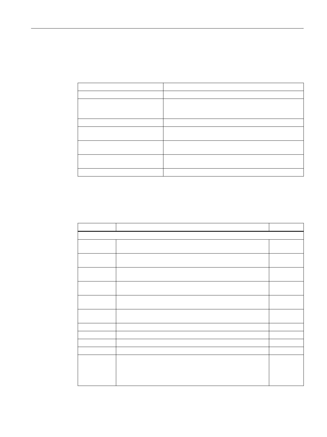
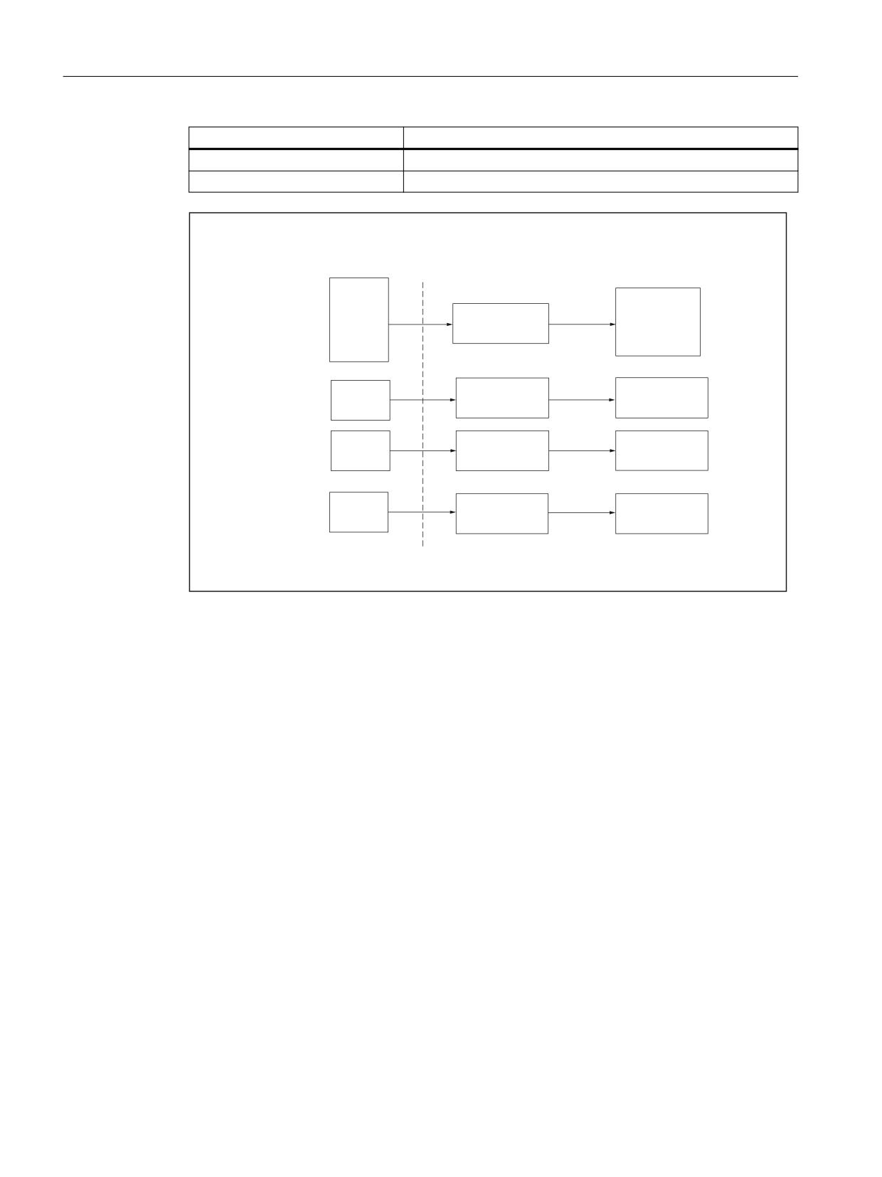
Figure 5-2
Assignment of cycle call to standard Siemens cycle in ISO dialect M mode using shell cycle
Example: ISO dialect M
N10 G81 X100. Z-50. R20 F100
G81 is used to automatically call the CYCLE381M shell cycle.
The calculations are carried out in the shell cycle and the standard drilling cycle CYCLE81 then
called.
ISO dialects
94
Function Manual, 12/2019, 6FC5397-7BP40-3BA1
Cycles and contour definition
5.3 Drilling cycles (ISO dialect M)
Parameter description
* 9 RU
* 9 ;
<
=
5
3
<
)
1XPEHU RI UHSHWLWLRQV
LI QR . LV SURJUDPPHG
WKH F\FOH LV SHUIRUPHG RQFH
0DFKLQLQJ IHHGUDWH
'ULOOHG KROH
SRVLWLRQ
&RQWLQXRXV LQGLYLGXDO GULOOLQJ GHSWK ZLWK *
* OLIWLQJ SDWK ZLWK *
'ZHOO WLPH DW GULOOLQJ KROH GHSWK
IRU *
*
*
*
5HIHUHQFH SODQH
'ULOOLQJ KROH GHSWK
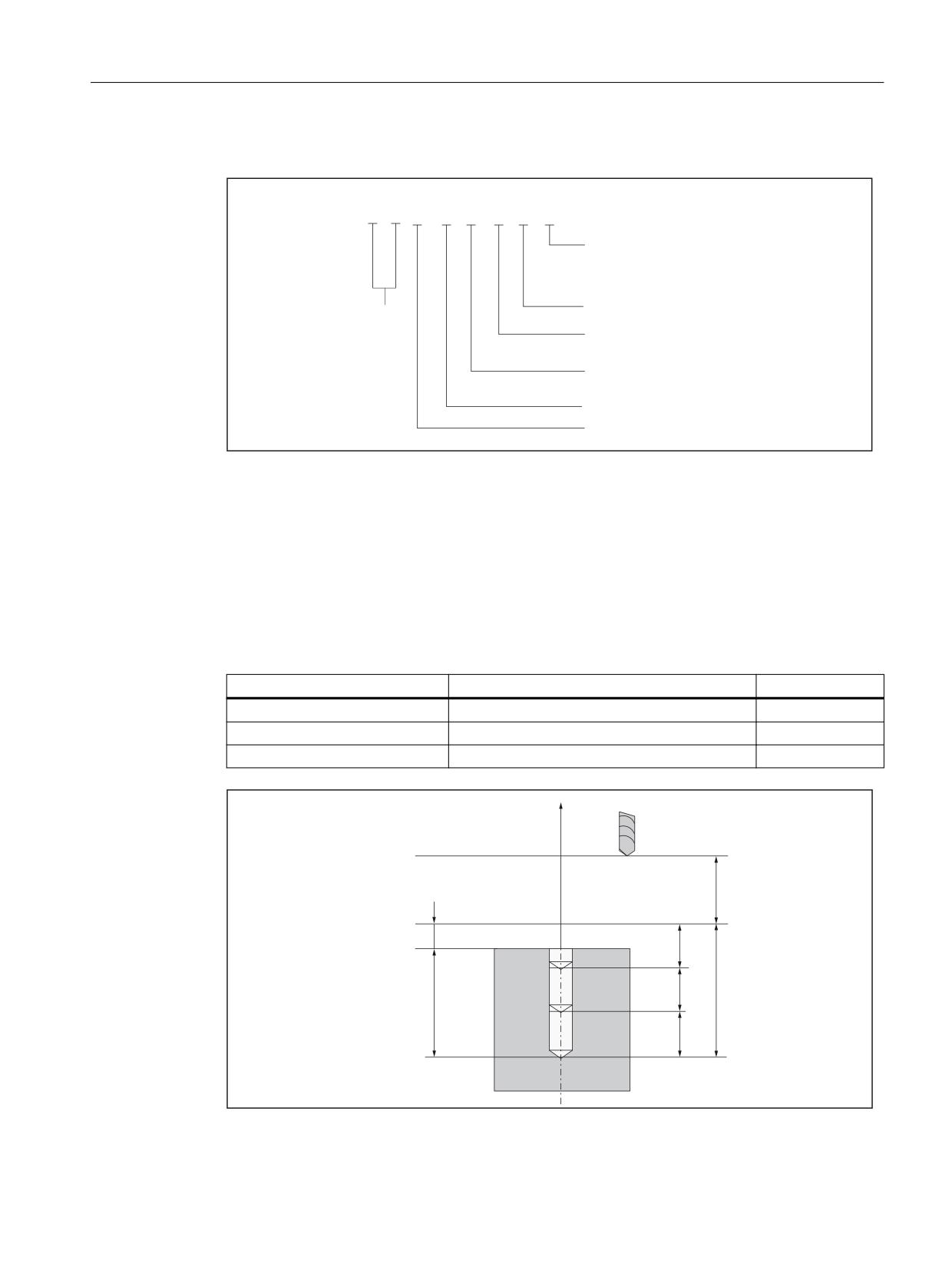
Figure 5-3
Description of permissible parameters for G17 (X/Y plane)
Plane
In drilling cycles, one generally assumes that the current coordinate system in which the
operation is to be executed, is defined through the selection of plane G17, G18 or G19 and
activation of a programmed work offset.
The drilling axis is then always the application of this coordinate system.
Table 5-3
Plane definition
Defined plane
Position of hole
Depth
G17
X, Y
Z
G18
Z, X
Y
G19
Y, Z
X
=
'ULOOLQJ WRRO
2XWSXW SODQH *
5 LQFU
5 DEV
'DWXP SODQH *
4
:RUNSLHFH VXUIDFH
= LQFU
4
= DEV
4
ISO dialects
Function Manual, 12/2019, 6FC5397-7BP40-3BA1
95
Cycles and contour definition
5.3 Drilling cycles (ISO dialect M)
Figure 5-4
Example of deep hole drilling cycle G83 with defined plane G17. Representation of output
and datum plane and parameters
5.3.2
Description of shell cycle CYCLE381M
NOTE
It is called in ISO dialect M mode using the G commands G81, G82, G85, G86, G89.
The drilling axis should be defined via GUD _ZSFI[0] (see "Global user data (GUD)" chapter).
The direction of the basis in relation to the datum plane must be identical to the direction of the
datum plane in relation to the final depth.
GUD _ZSFR[0] can be used to enter a safety clearance. If the safety clearance has already
been taken into account when programming the datum plane, 0 must be entered for _ZSFR[0].
If no datum plane has been programmed, drilling is undertaken from the basis (current position).
The final drilling depth must be programmed. Otherwise, an alarm is displayed.
If a feedrate is not programmed, the current feedrate is used as the drilling feedrate.
Note
Alarms are listed in the "Alarms" chap. along with alarm number and description.
5.3.3
Description of shell cycle CYCLE383M
Call
It is called in ISO dialect M mode using the G commands G73, G83.
NOTE
The drilling axis should be defined via GUD _ZSFI[0] (see "Global user data (GUD)" chapter).
The direction of the basis in relation to the datum plane must be identical to the direction of the
datum plane in relation to the final depth.
GUD _ZSFR[0] can be used to enter a safety clearance. If the safety clearance has already
been taken into account when programming the datum plane, 0 must be entered for _ZSFR[0].
If no datum plane has been programmed, drilling is undertaken in stages from the basis (current
position).
The final drilling depth and the individual drilling depth Q must be programmed. Otherwise, an
alarm is displayed.
ISO dialects
96
Function Manual, 12/2019, 6FC5397-7BP40-3BA1
Cycles and contour definition
5.3 Drilling cycles (ISO dialect M)
If a feedrate is not programmed, the current feedrate is used as the drilling feedrate.
Note
Alarms are listed in the "Alarms" chap. along with alarm number and description.
Deep hole drilling with chip removal (G83)
In the standard Siemens cycle, a formula is used to determine the holding distance, i.e. it cannot
be freely selected.
The system moves back to the datum plane for chip removal.
Individual drilling depth "Q":
● If there is no "Q" or if Q ≤ 0, an alarm is displayed.
● If Q > total depth, drilling is performed to the final depth.
● If Q > total depth/2, the first drilling process uses the Q value. The rest is then drilled in one
drilling process.
● If Q < total depth/2, the individual drilling depth is drilled until the residual depth is < Q/2. The
rest is then split into 2 infeeds of the same size.
Deep hole drilling with chip breakage
The retraction amount from chip breaking is defined with GUD _ZSFR[1].
● _ZSFR[1] > 0 Retraction amount as input
● _ZSFR[1] ≤ 0 Retraction amount is always 1 mm
Individual drilling depth "Q":
● If there is no "Q" or if Q ≤ 0, an alarm is displayed.
● If Q > total depth, drilling is performed to the final depth.
● If Q < total depth, the individual drilling depth is drilled until the residual depth is ≤ Q. The rest
is then drilled in one drilling process.
5.3.4
Description of shell cycle CYCLE384M
NOTE
It is called in ISO dialect M mode using the G commands G74, G84.
The drilling axis should be defined via GUD _ZSFI[0] (see "Global user data (GUD)" chapter).
The direction of the basis in relation to the datum plane must be identical to the direction of the
datum plane in relation to the final depth.
GUD _ZSFR[0] can be used to enter a safety clearance. If the safety clearance has already
been taken into account when programming the datum plane, 0 must be entered for _ZSFR[0].
ISO dialects
Function Manual, 12/2019, 6FC5397-7BP40-3BA1
97
Cycles and contour definition
5.3 Drilling cycles (ISO dialect M)
GUD _ZSFI[2] can be used to influence the speed when retracting.
Example: _ZSFI[2]=80, the retraction takes place at 80% of the drilling speed.
If no datum plane has been programmed, drilling is undertaken from the basis (current position).
The final drilling depth must be programmed. Otherwise, an alarm is displayed.
If a feedrate is not programmed, the current feedrate is used as the drilling feedrate.
If the drilling feedrate has been stated in mm/min (inch/min), the programmed feedrate value is
converted into the appropriate revolution feedrate depending on the last speed programmed
and transferred to the standard tapping cycle CYCLE84 as an incline value.
Note
Alarms are listed in the "Alarms" chap. along with alarm number and description.
5.3.5
Description of shell cycle CYCLE387M
NOTE
It is called in ISO dialect M mode using the G commands G76 and G87.
The drilling axis should be defined via GUD _ZSFI[0] (see "Global user data (GUD)" chapter)
The direction of the basis in relation to the datum plane must be identical to the direction of the
datum plane in relation to the final depth.
GUD _ZSFR[0] can be used to enter a safety clearance. If the safety clearance has already
been taken into account when programming the datum plane, 0 must be entered for _ZSFR[0].
The lifting path always relates to the negative direction of the first geometry axis:
For plane G17: Lifting path in -X
For plane G18: Lifting path in -Z
For plane G19: Lifting path in -Y
The angle must therefore be entered such that the tool tip points to the spindle stop in the
positive direction (+) at the defined plane.
Example: Plane G17 active, then tool tip must be facing +X.
If no datum plane has been programmed, drilling is undertaken from the basis (current position).
The final drilling depth must be programmed. Otherwise, an alarm is displayed.
If a feedrate is not programmed, the current feedrate is used as the drilling feedrate.
In the absence of a programmed lifting amount, Q = 0 is set. The cycle is executed without lifting.
ISO dialects
98
Function Manual, 12/2019, 6FC5397-7BP40-3BA1

Cycles and contour definition
5.4 Turning and drilling cycles (ISO dialect T)
After retraction to the retraction plane, the tool is again moved to the center of the hole and the
spindle started in the direction of rotation for processing.
Note
Alarms are listed in the "Alarms" chap. along with alarm number and description.
5.4
Turning and drilling cycles (ISO dialect T)
5.4.1
Turning cycles G70 to G76
Overview
Table 5-4
Overview of turning cycles
G command
Description
G70
Finishing cycle
G71
Stock removal cycle, longitudinal axis
G72
Stock removal cycle transverse axis
G73
Contour repetition
G74
Deep-hole drilling and grooving in the longitudinal axis (Z)
G75
Deep-hole drilling and grooving in the transverse axis (X)
G76
Multiple thread cutting cycle
The cycle supply for G71 to G76 can consist of two G commands. Depending on the addresses
programmed in the block, only the values of the addresses programmed in the NC block are
saved so they can be used for a later cycle call or additionally to start cycle processing.
Evaluation is undertaken in the shell cycle in both cases.
ISO dialects
Function Manual, 12/2019, 6FC5397-7BP40-3BA1
99
Cycles and contour definition
5.4 Turning and drilling cycles (ISO dialect T)
&\FOH FDOO RII
6LHPHQV
,62 GLDOHFW 7 PRGH
6KHOO F\FOH
VWDQGDUG F\FOH
5XQV ZLWKRXW
*
&<&/(
7
VWDQGDUG F\FOH
*
&<&/(
7
&<&/(
*
&<&/(
7
&<&/(
*
&<&/(
7
&<&/(
*
&<&/(
7
&<&/(
7
*
*
&<&/(
7
&<&/(
*
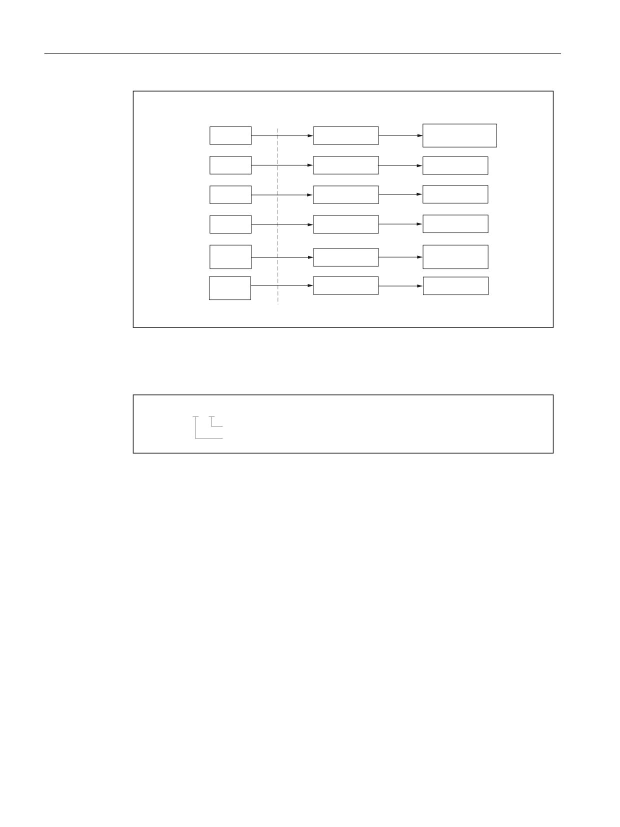
&KDQJHRYHU WR WKH 6LHPHQV PRGH
Figure 5-5
Assignment of cycle call to standard Siemens cycle in ISO dialect T mode using shell cycle
Finishing cycle G70
*
3
4
%ORFN QXPEHU LQ PDLQ SURJUDP DW ZKLFK WKH FRQWRXU GHILQLWLRQ HQGV
%ORFN QXPEHU LQ PDLQ SURJUDP DW ZKLFK WKH FRQWRXU GHILQLWLRQ VWDUWV
Figure 5-6
Description of permissible parameters
In ISO dialect mode, the contour is not skipped in the main program with G70. The program is
always processed in the next part program block after the cycle call.
Example:
When the cycle is called, the contour N20-N50 is traversed. After the end of the cycle, the part
program is processed from N20. Logically, G70 is always called after the contour description.
N10 G70 P20 Q50
N20 X100. Z50.
N30 X200.
N40 Z100.
N50 X250. Z111.
N60 M30
The blocks N20-N50 are processed once by the finishing cycle and then once again by the
normal program sequence.
ISO dialects
100
Function Manual, 12/2019, 6FC5397-7BP40-3BA1

Cycles and contour definition
5.4 Turning and drilling cycles (ISO dialect T)
Stock removal cycle, longitudinal axis G71
*
8 5
5HWUDFWLRQ SDWK
,QIHHG GHSWK IRU VFUXEELQJ
Figure 5-7
Description of permissible parameters; save values in GUDs
*
3
4 8 :
)
6
7
7RRO VHOHFWLRQ
6SLQGOH VSHHG
0DFKLQLQJ IHHGUDWH
)LQLVKLQJ DOORZDQFH LQ WKH = D[LV
)LQLVKLQJ DOORZDQFH LQ WKH ; D[LV
%ORFN QXPEHU DW ZKLFK WKH FRQWRXU GHILQLWLRQ HQGV
%ORFN QXPEHU DW ZKLFK WKH FRQWRXU GHILQLWLRQ VWDUWV
Figure 5-8
Description of permissible parameters; start cycle processing
In ISO dialect T mode with G71 the contour is traversed to the finishing allowance in the main
program after scrubbing (residual corner stock removal). The program is always processed
with the part program block after the last block of the contour description. Part program blocks
which can be found between the cycle call and the first contour description block are not
executed.
N10 G71 P50 Q80 U4 W3 F1000 ...
N20 G1 F0.5 G95 S1000
N30 X30. Z10.
N40 M30
N50 X100. Z50.
N60 X200.
N70 Z100.
N80 X250. Z111.
N90 M30
The blocks N20-N40 are skipped and not executed. If G71 is called in the part program after
the contour description, the program runs in an infinite loop. The different ways in which the part
program is further processed must be taken into account in the shell cycles.
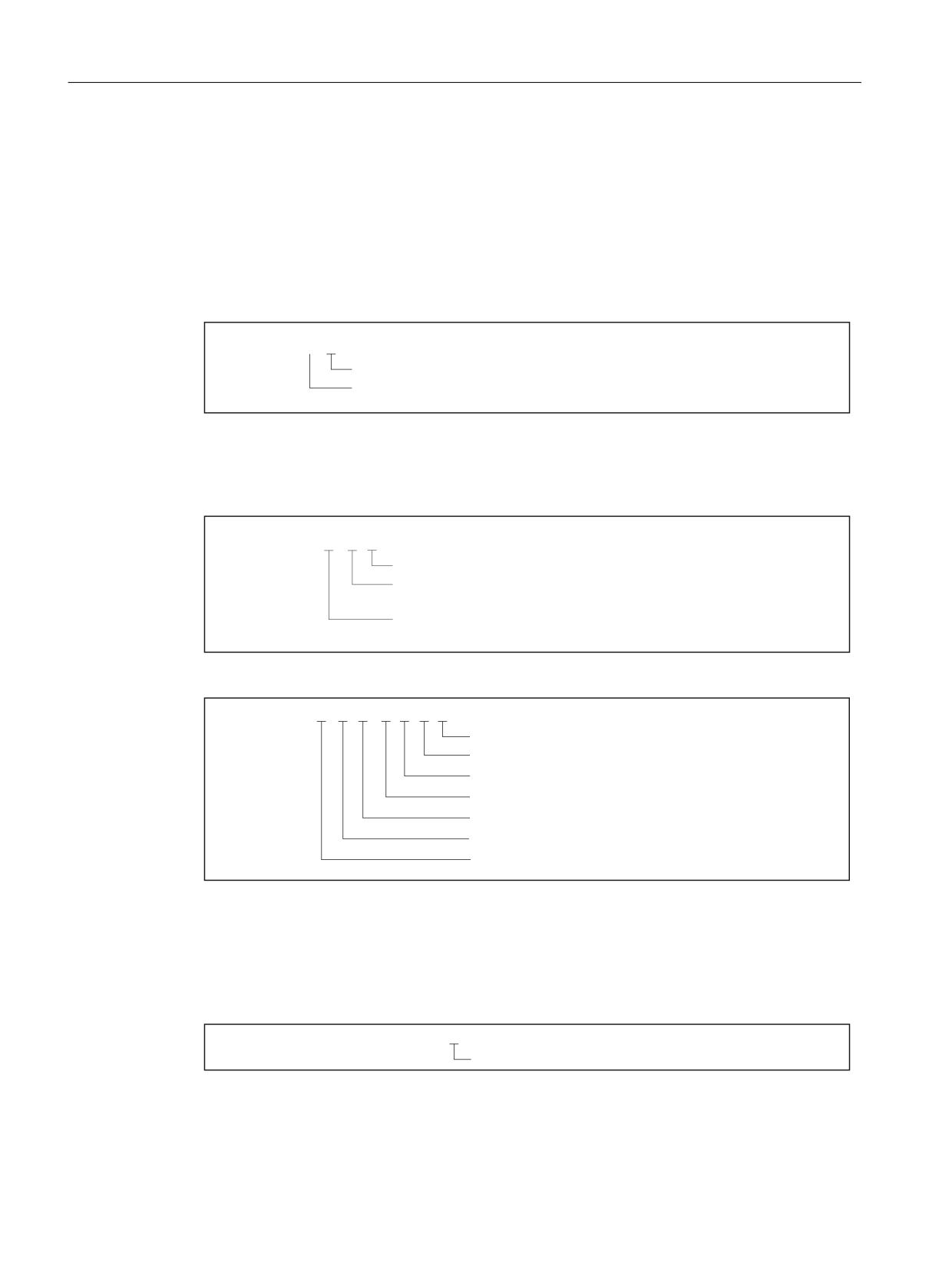
Example: G71 U6 R5 Save values in GUDs
In the example, the programmed values in the shell cycle are read from the system variables
($C_xx) and saved in channel-specific GUDs. There are separate GUDs for each cycle (G71-
G76), which ensures that the programmed values remain valid until they are programmed the
next time (in an NC block with G71-G76). Scenario 1 does not have to be programmed, so it
makes sense to precompile the assigned GUDs.
Example: G71 P30 Q50 U3 Start cycle processing
In the example, the programmed values are only saved in system variables ($C_xx). The
system variables are overwritten in each NC block in which a G function is programmed for the
cycle call. For G71-G73 the processing of cycles always starts with the G command after which
the "P" and "Q" addresses are programmed. Cycle processing G74-G76 is started with the G
command after which addresses X/U or Z/W are programmed. F, S and T commands in the
ISO dialects
Function Manual, 12/2019, 6FC5397-7BP40-3BA1
101
Cycles and contour definition
5.4 Turning and drilling cycles (ISO dialect T)
cycle's call line are also stored in system variables. The addresses do not therefore have to
differ for specific cycles. The shell cycle assigns meaning to the parameters (e.g. for G76
address F = thread lead and not feedrate). For G70, feedrate, speed and tool selection
commands (F, S, T) from the program part of the contour description are relevant.
The same shell cycle is always called in both scenarios.
Stock removal cycle, transverse axis G72
*
: 5
5HWUDFWLRQ SDWK
,QIHHG GHSWK IRU VFUXEELQJ
Figure 5-9
Description of permissible parameters; save values in GUDs
Contour repetition G73
*
8 : 5
1XPEHU RI FXWV SDUDOOHO WR FRQWRXU
0RYHPHQW RI VWDUW SRLQW IURP FXUUHQW
WRRO SRVLWLRQ LQ WKH = D[LV
0RYHPHQW RI VWDUW SRLQW IURP FXUUHQW
WRRO SRVLWLRQ LQ WKH ; D[LV
Figure 5-10
Description of permissible parameters; save values in GUDs
*
3
4 8 : ) 6 7
7RRO VHOHFWLRQ
6SLQGOH VSHHG
0DFKLQLQJ IHHGUDWH
)LQLVKLQJ DOORZDQFH LQ WKH = D[LV
)LQLVKLQJ DOORZDQFH LQ WKH ; D[LV
%ORFN QXPEHU DW ZKLFK WKH FRQWRXU GHILQLWLRQ HQGV
%ORFN QXPEHU DW ZKLFK WKH FRQWRXU GHILQLWLRQ VWDUWV
Figure 5-11
Description of permissible parameters; start cycle processing
Deep-hole drilling and grooving in the longitudinal axis G74
*
5
5HWUDFWLRQ SDWK WR FKLS EUHDNLQJ
Figure 5-12
Description of permissible parameters; save values in GUDs
ISO dialects
102
Function Manual, 12/2019, 6FC5397-7BP40-3BA1
Cycles and contour definition
5.4 Turning and drilling cycles (ISO dialect T)
*
;8 =: 3 4 5 )
0DFKLQLQJ IHHGUDWH
5HWUDFWLRQ SDWK DW HQWU\ EDVH
)HHG LQ LQ WKH ORQJLWXGLQDO D[LV = D[LV WR
FKLS EUHDNLQJ
)HHG LQ LQ WUDQVYHUVH D[LV ; D[LV IRU WKH QH[W FXW
ZKHQ LQVHUWLQJ
6WDUW SRVLWLRQ LQ WKH = D[LV
= 3RVLWLRQ DEVROXWH
: 3RVLWLRQ LQFUHPHQWDO
6WDUW SRVLWLRQ LQ ; D[LV
; 3RVLWLRQ DEVROXWH RU
8 3RVLWLRQ LQFUHPHQWDO
Figure 5-13
Description of permissible parameters; start cycle processing
Note
The cycle can be used as a drilling or cut-in cycle. If the cycle is used for drilling, the addresses
X/U and P cannot be used.
Deep-hole drilling and grooving in the transverse axis G75
*
5
5HWUDFWLRQ SDWK WR FKLS EUHDNLQJ
Figure 5-14
Description of permissible parameters; save values in GUDs
*
;8 =: 3 4 5 )
0DFKLQLQJ IHHGUDWH
5HWUDFWLRQ SDWK DW UHFHVV EDVH
)HHG LQ LQ WKH ORQJLWXGLQDO D[LV = D[LV WR FKLS EUHDNLQJ
)HHG LQ DPRXQW LQ WKH WUDQVYHUVH D[LV ; D[LV WR FKLS
EUHDNLQJ
6WDUW SRVLWLRQ LQ WKH = D[LV
= 3RVLWLRQ DEVROXWH
: 3RVLWLRQ LQFUHPHQWDO
6WDUW SRVLWLRQ LQ ; D[LV
; 3RVLWLRQ DEVROXWH RU
8 3RVLWLRQ LQFUHPHQWDO
Figure 5-15
Description of permissible parameters; start cycle processing
Note
The cycle can be used as a drilling or cut-in cycle. If the cycle is used for drilling, the addresses
Z/W and Q cannot be used.
ISO dialects
Function Manual, 12/2019, 6FC5397-7BP40-3BA1
103

Cycles and contour definition
5.4 Turning and drilling cycles (ISO dialect T)
Multiple thread cutting cycle G76
*
3[[[[[[[ 4
5
)LQLVKLQJ DOORZDQFH
0LQLPXP LQIHHG GHSWK WKLV YDOXH PXVW QRW EH H[FHHGHG ZKHQ
IHHGLQJ LQ
$QJOH RI WRRO EODGH
6L]H RI FKDPIHU RQ WKUHDG HQG LQ
[ WKUHDG OHDG
1XPEHU RI ILQLVKLQJ FXWV
Figure 5-16
Description of permissible parameters; save values in GUDs
*
;8 =: 5 3 4 )
7KUHDG OHDG
6L]H RI ILUVW IHHG LQ
7KUHDG GHSWK WRWDO IHHG LQ LQ WKH ; D[LV
5DGLXV GLIIHUHQFH IRU WDSHU WKUHDG
7KUHDG HQG SRLQW LQ WKH = D[LV
= 3RVLWLRQ DEVROXWH
: 3RVLWLRQ LQFUHPHQWDO
7KUHDG HQG SRLQW LQ WKH ; D[LV
; 3RVLWLRQ DEVROXWH RU
8 3RVLWLRQ LQFUHPHQWDO
Figure 5-17
Description of permissible parameters; start cycle processing
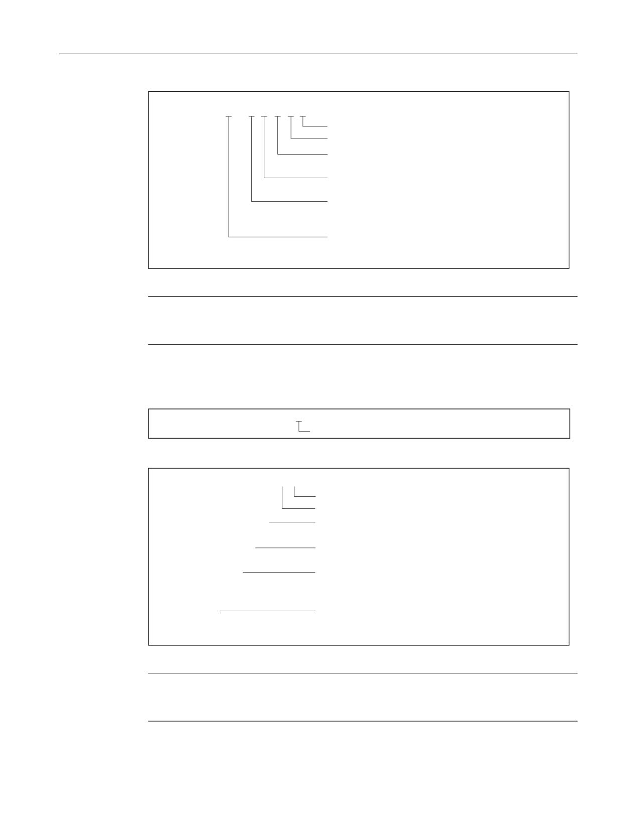
Example for address P:
G76 P012055 Q4 R0.5
3
$QJOH RI ZRUNSLHFH EODGH
GHJUHHV
&KDPIHU RQ WKUHDG HQG
[ WKUHDG OHDG
ILQLVKLQJ FXW
ISO dialects
104
Function Manual, 12/2019, 6FC5397-7BP40-3BA1
Cycles and contour definition
5.4 Turning and drilling cycles (ISO dialect T)
5.4.2
Turning cycles G77 to G79
Overview
Table 5-5
Overview of turning cycles G77 to G79
G command
Description
G77
Lengthwise stock removal
G78
Thread cutting
G79
Transverse stock removal
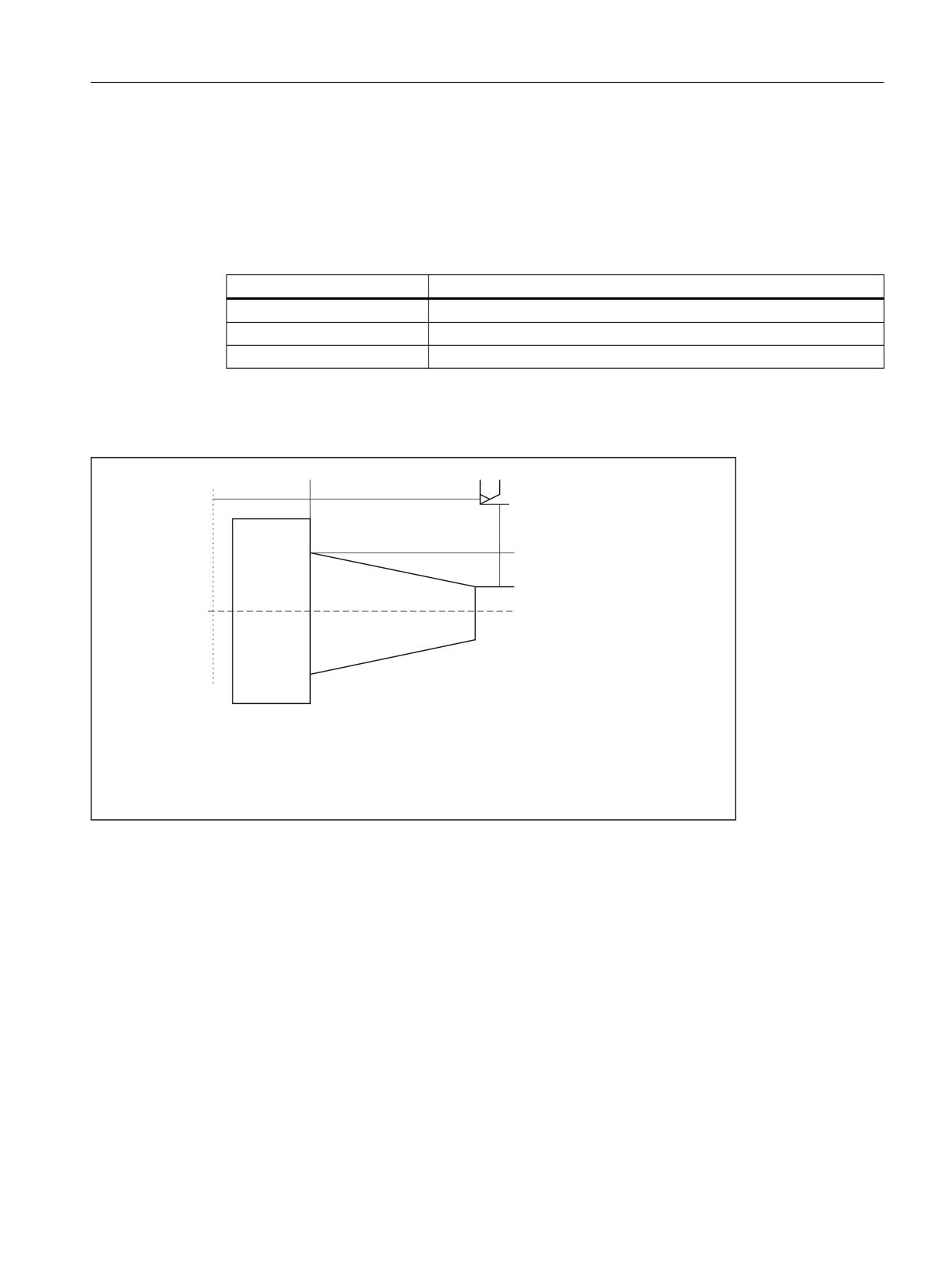
These cycle calls are modally effective and are called in each NC block with axial motion. The
processing movements are defined in the call parameters after the G function. The following
parameters are permitted in NC blocks with cycle calls using G77 to G79:
;
=
:
8
5
=
8 (QG SRVLWLRQ RI FRQWRXU LQ ; LQFU
= (QG SRVLWLRQ RI FRQWRXU LQ = DEV RU
: (QG SRVLWLRQ RI FRQWRXU LQ = LQFU
5 ,QFUHPHQWDO UDGLXV GLIIHUHQFH IRU
HQG SRVLWLRQ LQ ; IRU WDSHU WXUQLQJ
5 )RU *
* PDFKLQLQJ IHHGUDWH
)RU * WKUHDG OHDG
Figure 5-18
Parameters for cycle calls using G77 to G79
ISO dialects
Function Manual, 12/2019, 6FC5397-7BP40-3BA1
105

Cycles and contour definition
5.4 Turning and drilling cycles (ISO dialect T)
Lengthwise stock removal G77
*
;8
=:
5 )
0DFKLQLQJ IHHGUDWH
LQFUHPHQWDO PRYHPHQW RI HQG SRVLWLRQ LQ ; D[LV IRU WDSHU
WXUQLQJ
&\OLQGHU WXUQLQJ 5 QRW SURJUDPPHG RU 5
3RVLWLRQ LQ WKH = D[LV
= 3RVLWLRQ DEVROXWH
: 3RVLWLRQ LQFUHPHQWDO
3RVLWLRQ LQ WKH ; D[LV
; 3RVLWLRQ DEVROXWH
8 3RVLWLRQ LQFUHPHQWDO
Figure 5-19
Description of permissible parameters; start cycle processing
Thread cutting G78
*
;8
=:
5 )
4
6WDUW SRLQW IRU DQJOH RIIVHW
7KUHDG OHDG
LQFUHPHQWDO PRYHPHQW RI HQG SRVLWLRQ
LQ WKH ; D[LV IRU WDSHU WXUQLQJ
&\OLQGHU WXUQLQJ 5 QRW SURJUDPPHG RU 5
3RVLWLRQ LQ WKH = D[LV
= 3RVLWLRQ DEVROXWH
: 3RVLWLRQ LQFUHPHQWDO
3RVLWLRQ LQ WKH ; D[LV
; 3RVLWLRQ DEVROXWH
8 3RVLWLRQ LQFUHPHQWDO
Figure 5-20
Description of permissible parameters; start cycle processing
ISO dialects
106
Function Manual, 12/2019, 6FC5397-7BP40-3BA1
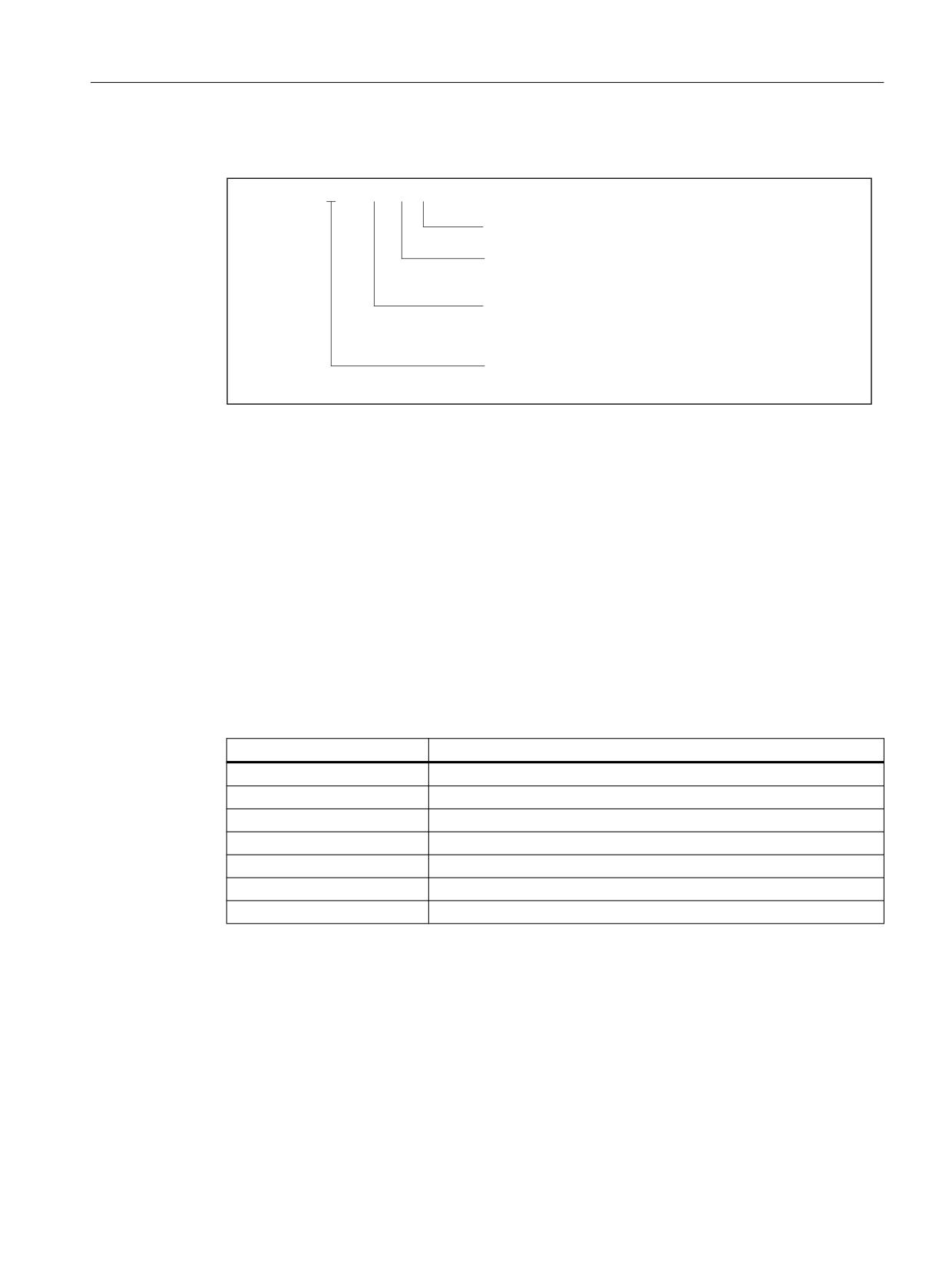
Cycles and contour definition
5.4 Turning and drilling cycles (ISO dialect T)
Transverse stock removal G79
*
;8
=:
5 )
0DFKLQLQJ IHHGUDWH
LQFUHPHQWDO PRYHPHQW RI HQG SRVLWLRQ
LQ WKH = D[LV IRU WDSHU WXUQLQJ
&\OLQGHU WXUQLQJ 5 QRW SURJUDPPHG RU 5
3RVLWLRQ LQ WKH = D[LV
= 3RVLWLRQ DEVROXWH
: 3RVLWLRQ LQFUHPHQWDO
3RVLWLRQ LQ WKH ; D[LV
; 3RVLWLRQ DEVROXWH
8 3RVLWLRQ LQFUHPHQWDO
Figure 5-21
Description of permissible parameters; start cycle processing
5.4.3
Drilling cycles G80 to G89
Overview
With fixed cycles for hole-machining specific movements can be programmed for machining
the drill holes, which normally require several command frames made of several single-block
commands. The program called with the fixed cycle can be deselected again with G80.
The G functions used for calling the fixed cycles G80 to G89 are the same for all G code
systems.
Table 5-6
Overview of drilling cycles
G command
Description
G80
Drilling cycle off
G83
Front face deep hole drilling
G84
Front face tapping
G85
Front face drilling
G87
Side surface deep hole drilling
G88
Side surface tapping
G89
Side surface drilling
ISO dialects
Function Manual, 12/2019, 6FC5397-7BP40-3BA1
107
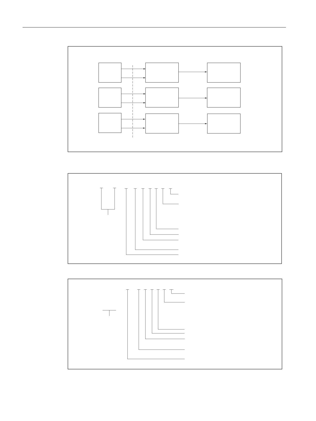
Cycles and contour definition
5.4 Turning and drilling cycles (ISO dialect T)
&\FOH FDOO IURP ,62
6LHPHQV
6KHOO F\FOH
GLDOHFW 7 PRGH
VWDQGDUG F\FOH
*
&<&/(
7
&<&/(
*
*
&<&/(
7
&<&/(
7
*
*
&<&/(
7
&<&/(
7
*
&KDQJHRYHU WR WKH
6LHPHQV PRGH
Figure 5-22
Assignment of drilling cycles to standard Siemens cycle in ISO dialect T mode using shell
cycle
*
;8
&+
=:
5 3 4 ) . 0
*
*
$VFHUWDLQ 0 FRGH IRU & D[LV
1XPEHU RI UHSHWLWLRQV
LI QR . LV SURJUDPPHG
WKH F\FOH LV SHUIRUPHG RQFH
'ULOOHG KROH SRVLWLRQ
. F\FOH LV QRW SHUIRUPHG
0DFKLQLQJ IHHGUDWH
,QIHHG
'ZHOO WLPH DW GULOOLQJ KROH GHSWK
'LVWDQFH EHWZHHQ UHWUDFWLRQ SODQH DQG GULOOLQJ SODQH
'ULOOLQJ KROH GHSWK
Figure 5-23
Description of permissible parameters; start cycle processing
*
=: &+
;8
5 3 4 ) . 0
*
$VFHUWDLQ 0 FRGH IRU & D[LV
*
1XPEHU RI UHSHWLWLRQV
LI QR . LV SURJUDPPHG
WKH F\FOH LV SHUIRUPHG RQFH
'ULOOHG KROH SRVLWLRQ
. F\FOH LV QRW SHUIRUPHG
0DFKLQLQJ IHHGUDWH
,QIHHG
'ZHOO WLPH DW GULOOLQJ KROH GHSWK
'LVWDQFH EHWZHHQ UHWUDFWLRQ SODQH DQG GULOOLQJ
SODQH
'ULOOLQJ KROH GHSWK
Figure 5-24
Description of permissible parameters; start cycle processing
ISO dialects
108
Function Manual, 12/2019, 6FC5397-7BP40-3BA1
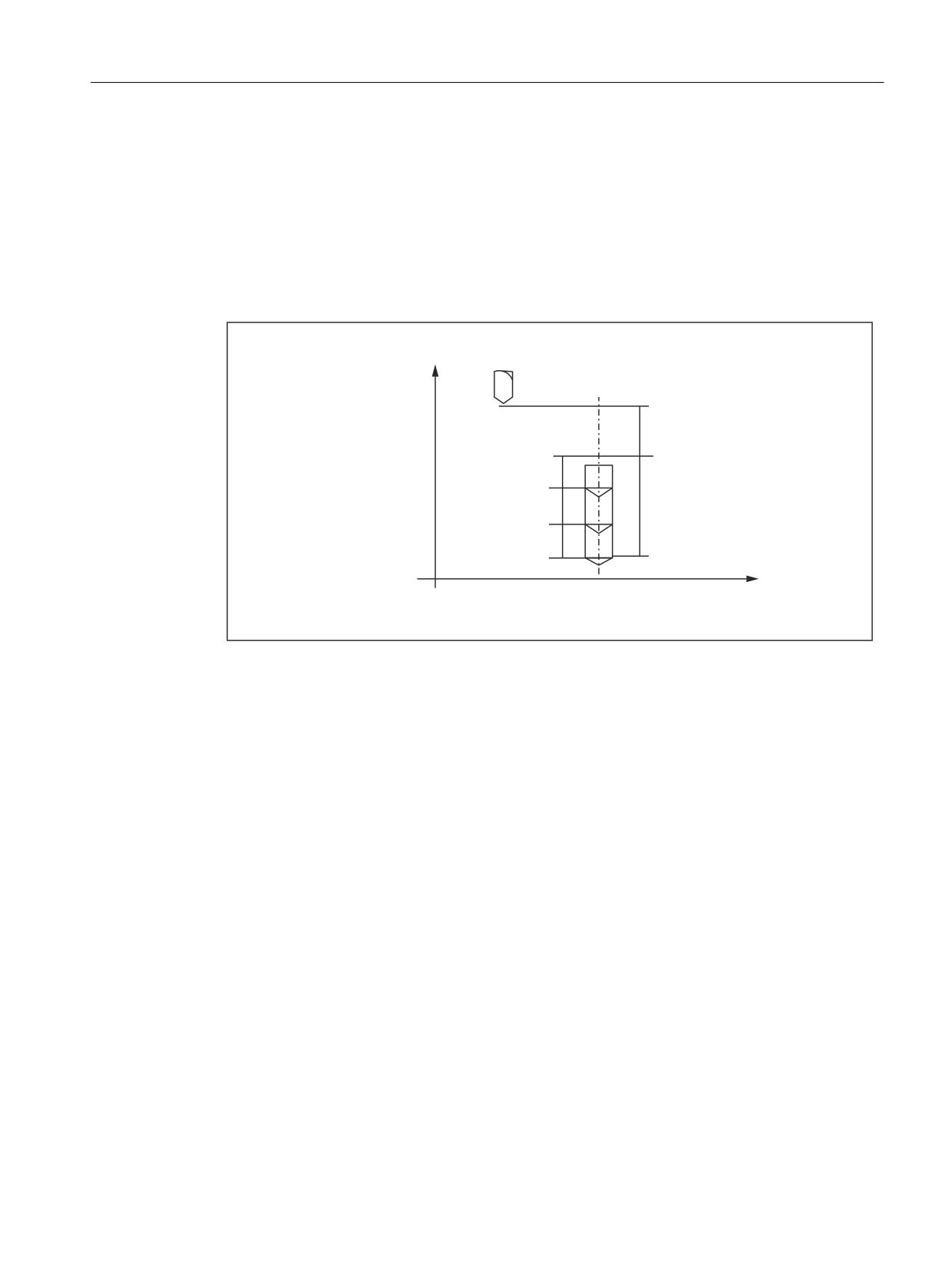
Cycles and contour definition
5.4 Turning and drilling cycles (ISO dialect T)
The drilling cycles are modally effective and are executed in every NC block in which axial
movements of axes X, C, Z are programmed. When a drilling mode is active, only the new
parameters have to be programmed if a parameter is changed. The parameters are stored in
the system variables $C_xx (xx = NC address) which are read by the cycles.
If there is a G function of the 1st G group in the same NC block after the cycle G function, the
cycle is not executed. Only the axes programmed in the NC block are traversed. Addresses R,
Q, P, K are not written to the system variables. The feedrate programmed in this block is
activated.
;
5
4
4
= ;
4
=
Figure 5-25
Drilling cycle
Modal cycles
All modal cycles are deselected in ISO dialect mode with G80 or with a G function of the 1st
group (G00-G03, G33, G34, apart from G77-G79).
Cycle parameters can be programmed in the following blocks while a modal cycle is active.
These parameters are written to the system variables so that the shell cycle works with the
modified parameters.
Example:
N10 G81 X10. Z15. R5 Q4 P10 F1000
N20 X50. ;drilling cycle at position X50
ISO dialects
Function Manual, 12/2019, 6FC5397-7BP40-3BA1
109

Cycles and contour definition
5.4 Turning and drilling cycles (ISO dialect T)
5.4.4
Description of shell cycle CYCLE383T
It is called in ISO dialect T mode using the G commands G83 and G87.
Note
The direction of the basis in relation to the reference plane must be identical to the direction of
the reference plane in relation to the final depth. Otherwise the Siemens drilling cycle results in
an error message.
In ISO dialect T, the programmer must take into account the safety clearance when defining the
reference plane. For Siemens the safety clearance from the R plane can be stated separately.
This option has also been realized in ISO cycles. GUD_ZSFR[20] can be used to enter a safety
clearance if necessary. If the safety clearance has already been taken into account when
programming the R plane, "ZERO" must be entered for GUD_ZSFR[20].
GUD_ZSFR[23] is used to determine whether the dwell time (for deep-hole drilling only) is to be
undertaken in seconds or revolutions for G95.
A shell cycle may only be called by an external G code (G83/G87). Calling in Siemens mode
(after switching over with G290 and CYCLE383T call) is not permitted.
If the G83/G87 block contains axis names other than X/Z (U/W), alarm (61811) "ISO axis name
not permitted" occurs.
GUD_ZSFR[2] is used to determine whether the cycle is to be executed with chip breaking or
chip removal.
With ISO dialect, the constant individual depth is retained until the remainder at the base of the
hole is removed with an infeed. With Siemens the remainder (less than 2*individual depth) at
the base of the hole is split into two infeeds of the same size if necessary.
Note
Alarms are listed in the "Alarms" section along with alarm number and description.
ISO dialects
110
Function Manual, 12/2019, 6FC5397-7BP40-3BA1

Cycles and contour definition
5.4 Turning and drilling cycles (ISO dialect T)
5.4.5
Description of shell cycle CYCLE384T
It is called in ISO dialect T mode using the G commands G84 and G88.
Note
The direction of the basis in relation to the datum plane must be identical to the direction of the
datum plane in relation to the final depth. Otherwise the Siemens drilling cycle results in an error
message. ISO dialect has no monitoring here.
In ISO dialect T, the programmer must take into account the safety clearance when defining the
datum plane. For Siemens the safety clearance from the R plane can be stated separately.
This option has also been realized in ISO cycles. GUD_ZSFR[20] can be used to enter a safety
clearance if necessary. If the safety clearance has already been taken into account when
programming the R plane, "ZERO" must be entered for GUD_ZSFR[20].
A shell cycle may only be called by an external G code (G84/G88). Calling in Siemens mode
(after switching over with G290 and CYCLE384T call) is not permitted.
If the G84/G88 block contains axis names other than X/Z (U/W), alarm (61811) "ISO axis name
not permitted" occurs.
GUD_ZSFI[22] (value as %) can be used to influence the speed of drilling when retracting.
Example: ZSFI[22]=95 Retraction takes place at 95% of the hole depth.
Note
Alarms are listed in the "Alarms" chap. along with alarm number and description.
ISO dialects
Function Manual, 12/2019, 6FC5397-7BP40-3BA1
111

Cycles and contour definition
5.5 System variables
5.4.6
Description of shell cycle CYCLE385T
It is called in ISO dialect T mode using the G commands G85 and G89.
Note
The direction of the basis in relation to the datum plane must be identical to the direction of the
datum plane in relation to the final depth. Otherwise the Siemens drilling cycle results in an error
message. ISO dialect has no monitoring here.
In ISO dialect T, the programmer must take into account the safety clearance when defining the
datum plane. For Siemens the safety clearance from the R plane can be stated separately.
This option has also been realized in ISO cycles. GUD_ZSFR[20] can be used to enter a safety
clearance if necessary. If the safety clearance has already been taken into account when
programming the R plane, "ZERO" must be entered for GUD_ZSFR[20].
A shell cycle may only be called by an external G code (G85/G89). Calling in Siemens mode
(after switching over with G290 and CYCLE385T call) is not permitted.
If the G85/89 block contains axis names other than X/Z (U/W), alarm (61811) "ISO axis name
not permitted" occurs.
If the G84 block contains axis names other than X/Z (U/W), alarm (61811) "ISO axis name not
permitted" occurs.
Note
Alarms are listed in the "Alarms" chap. along with alarm number and description.
5.5
System variables
The names of the system variables all start with $C_ xx. The NC address, the value of which is
stored in the system variables, can be found in the name extension xx. Variable $C_G always
contains the G number with which a cycle has been called.
Bit 0 is set in the $C_x_PROG system variables for all programmed addresses if the address
is programmed.
Bit 1 is also set in the $C_x_PROG variables for axis addresses programmed incrementally.
For end of subprogram with RET, $C_x_PROG is set to FALSE, for end of subprogram with
M17, the values in $C_x_PROG are retained.
Example 1:
N10 G01 G81 X100. Z-50. R20 F100
Shell cycle CYCLE381M for G81 is called automatically. The calculations are carried out in the
shell cycle and the standard Siemens cycle CYCLE82 then called. The G01 command is not
needed.
The values of the programmed addresses are written to the system variables:
ISO dialects
112
Function Manual, 12/2019, 6FC5397-7BP40-3BA1

Cycles and contour definition
5.5 System variables
Address X is written to system variable $C_X;
Address Z is written to system variable $C_Z;
Address R is written to system variable $C_R;
Address F is written to system variable $C_F;
Example 2:
Axis Z is programmed in an incremental manner (G91) → $C_Z_PROG =3
Axis Z is programmed in an absolute manner (G90) → $C_Z_PROG =1
Example 3: Siemens shell cycle for Gxy
N10 PROC CYCLE377 DISPLOF
;Block display remains G77 block,
;Freeze G code display
N20 DEF REAL DELTA_X, pos_X, pos_Z, FEEDRATE
N30 DEF BOOL R_prog, X_prog, Z_prog
N50 DELTA_X = 0
N60 IF $C_R_PROG
;Only load DELTA_X if
N70 DELTA_X = $C_R
;address R has been programmed
N75 ENDIF
N110 CYCLE...(DELTA_X, $C_X, $C_Z,
;Call Siemens cycle
$C_R_PROG, $C_X_PROG, $C_Z_PROG, $C_F)
N230 RET
;Shell cycle end
Table 5-7
List and description of system variables
Identifier
Type
Description
$C_A
REAL
Value of programmed address A in ISO dialect mode for cycle pro-
gramming
$C_B
REAL
Value of programmed address B in ISO-dialect-mode for cycle pro-
gramming
$C_G
INT
G number for cycle calls in external mode
$C_H
REAL
Value of programmed address H in ISO dialect mode for cycle pro-
gramming
$C_I[ ]
REAL
Value of the programmed Address I in ISO dialect mode for cycle pro-
gramming and macro technology with G65/G66. A max. of 10 entries is
possible in the block for the macro programming. The values remain in
the programmed sequence in the array.
$C_I_ORDER[ ]
REAL
For description, refer to $C_I[ ], defines the programming sequence
$C_J[ ]
REAL
For description refer to $C_I[ ]
$C_J_ORDER[ ]
REAL
For description, refer to $C_I[ ], defines the programming sequence
$C_K[ ]
REAL
For description refer to $C_I[ ]
$C_K_ORDER[ ]
REAL
For description, refer to $C_I[ ], defines the programming sequence
$C_L
REAL
Value of programmed address L in ISO dialect mode for cycle pro-
gramming
$C_Z
REAL
Value of programmed address Z in ISO dialect mode for cycle pro-
gramming
ISO dialects
Function Manual, 12/2019, 6FC5397-7BP40-3BA1
113
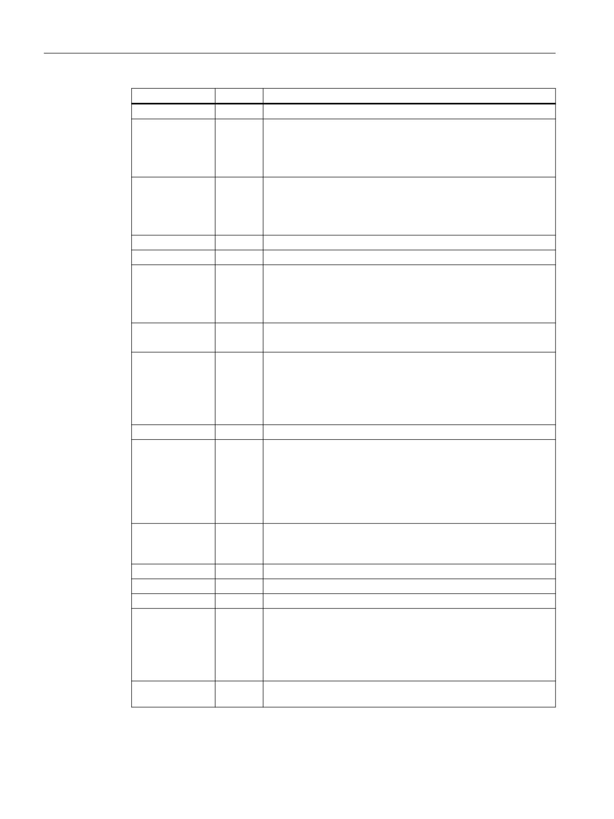
Cycles and contour definition
5.5 System variables
Identifier
Type
Description
$C_TS
STRING
String of tool identifier programmed under the address T
$C_A_PROG
INT
Address A is programmed in a block with cycle call.
0 = Not programmed
1 = Programmed (absolute)
3 = Programmed (incremental)
$C_B_PROG
INT
Address B is programmed in a block with cycle call.
0 = Not programmed
1 = Programmed (absolute)
3 = Programmed (incremental)
$C_G_PROG
INT
The shell cycle is programmed over a G function
$C_Z_PROG
INT
Address Z is programmed in a block with cycle call.
0 = Not programmed
1 = Programmed (absolute)
3 = Programmed (incremental)
$C_TS_PROG
INT
A tool identifier was programmed under address T
TRUE = programmed; FALSE = not programmed
$C_ALL_PROG
INT
Bit pattern of all programmed addresses in a block with cycle call
Bit 0 = Address A
Bit 25 = Address Z
Bit = 1 address is programmed
Bit = 0 address is not programmed
$P_EXTGG[n]
INT
Active G code of the external language
$C_INC_PROG
INT
Bit pattern of all incrementally programmed addresses in a block with
cycle call
Bit 0 = Address A
Bit 25 = Address Z
Bit = 1 address is programmed incrementally
Bit = 0 address is not programmed as absolute
$C_I_NUM
INT
Cycle programming: Value is always 1 if bit 0 is set in $C_I_PROG.
Macro programming: Number of address I programmed in the block
(max. 10).
$C_J_NUM
INT
For description refer to $C_I_NUM
$C_K_NUM
INT
For description refer to $C_I_NUM
$P_AP
INT
Polar coordinates 0=OFF 1=ON
$C_TYP_PROG
INT
Bit pattern of all programmed addresses in a block with cycle call
Bit 0 = A
Bit 25 = Z
Bit = 0 Axis is programmed as INT
Bit = 1 Axis is programmed as REAL
$C_PI
INT
Program number of the interrupt routine that was programmed with
M96
ISO dialects
114
Function Manual, 12/2019, 6FC5397-7BP40-3BA1
Cycles and contour definition
5.6 Programming contour definitions
5.6
Programming contour definitions
Overview
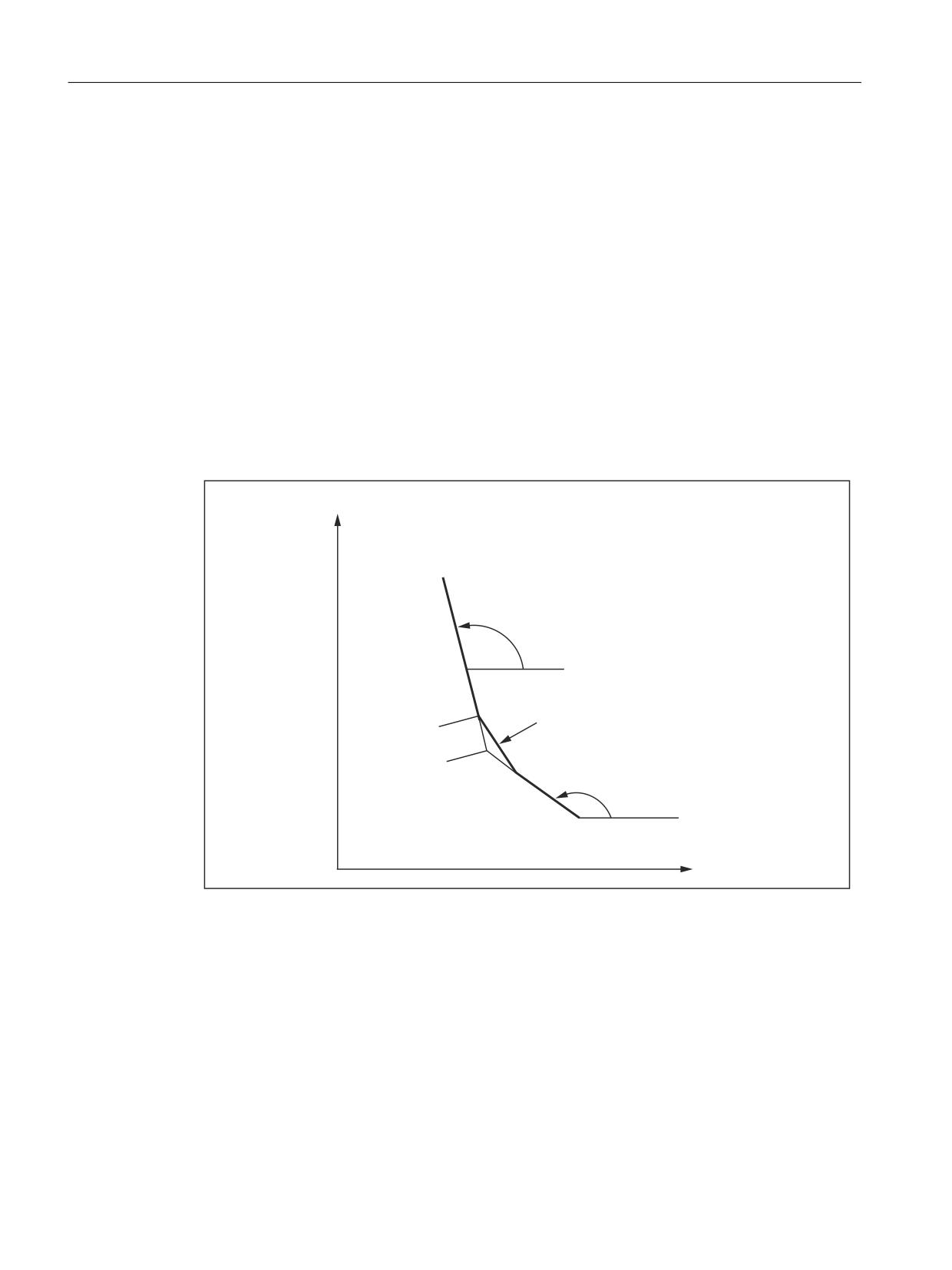
Contour definitions can be programmed in both ISO dialect mode and Siemens mode.
There are three basic forms of contour definitions:
● One straight line
End point is programmed with a Cartesian coordinate and an angle
● Two straight lines
Transition with a curve or chamfer
● Three straight lines
Transitions with a curve or chamfer
In the descriptions that follow, the address letters X, Z, A, R and C sometimes have indices to
allow for clear assignment between NC block and the associated drawing. These indices do not
appear in the NC program. The assignment always clearly results from the block containing an
address letter. Address letter Q is a filler at places where either R or C may occur. Q may also
not be used. In such cases, no chamfer or curve is inserted at the transition of the two straight
lines.
Any other NC addresses can be used, e.g. address letters for other axes (single axes or axis
perpendicular to the machining plane), auxiliary function specifications, G codes, velocities,
etc. in the blocks that describe contour definitions.
It is assumed that G18 is active in the following examples. However, the programming of
contour definitions is also possible without restrictions with G17 or G19.
ISO dialect mode
Address A is used in ISO dialect mode as both an axis identifier and as an identifier for an angle
in the contour definition. To distinguish between the possibilities, a "," must be set before the
address when programming the contour definition.
Address C is used in ISO dialect mode as both an axis identifier and as an identifier for a
chamfer in the contour definition.
Address R can either be a cycle parameter or an identifier for the radius in a contour definition.
To distinguish between the two possibilities, a "," must be set before address C or R when
programming the contour definition. If an angle is programmed before C or R, a comma does
not have to be programmed before it. If radius and chamfer are programmed together in a block,
e.g. N333 X100 A10 C20 R15, regardless of the programming sequence a radius is always
inserted in the contour. The chamfer is ignored.
ISO dialects
Function Manual, 12/2019, 6FC5397-7BP40-3BA1
115
Cycles and contour definition
5.6 Programming contour definitions
Siemens mode
In Siemens mode, the identifiers for angle, radius and chamfer are defined via machine data.
This avoids name conflicts. A comma must not be programmed before the identifier for radius
or chamfer.
Note
MD10652 for angle: $MN_CONTOUR_DEF_ANGLE_NAME
MD10654 for radius: $MN_RADIUS_NAME
MD10656 for chamfer: $MN_CHAMFER_NAME
5.6.1
End point programming with angles
If the address letter A appears in an NC block, either none, one or both of the axes in the active
plane may also be programmed.
If no axis of the active plane has been programmed, then this is either the first or second block
of a contour definition consisting of two blocks. If this is the second block of such a contour
definition, the start and end point in the active plane are identical. The contour definition then
consists only of a motion perpendicular to the active plane.
If exactly one axis of the active plane has been programmed, then this is either a single straight
line whose end point can be clearly defined via the angle and programmed Cartesian
coordinate or the second block of a contour definition consisting of two blocks. In the second
case, the missing coordinate is set to the same as the last (modal) position reached.
If two axes of the active plane have been programmed, then this is the second block of a
contour definition consisting of two blocks. If the current block has not been preceded by a block
with angle programming without programmed axes of the active plane, then this block is not
permitted.
Angle A may only be programmed for linear or spline interpolation. (Spline interpolation in
Siemens mode only.)
Alarms are generated in the following cases:
● With a contour definition consisting of two blocks, at the transition to the second block, the
active plane is changed.
● With the angles programmed, a valid intermediate point cannot be formed for a contour
definition consisting of two straight lines.
● In a block with address A, neither linear nor spline interpolation is active.
● A block with address A without a programmed axis in the active plane is not followed by a
block which can be used to determine the end point of the contour definition. This is the case
if this block is the last in a program or if the following block contains a preprocessing stop.
● No angle has been programmed in the second block of a contour definition consisting of two
straight lines.
● Both axes of the active plane are programmed in a block with address A, which is not the
second block of a contour definition consisting of two straight lines.
● Programmed Cartesian coordinates and programmed angles are incompatible.
ISO dialects
116
Function Manual, 12/2019, 6FC5397-7BP40-3BA1
Cycles and contour definition
5.6 Programming contour definitions
5.6.2
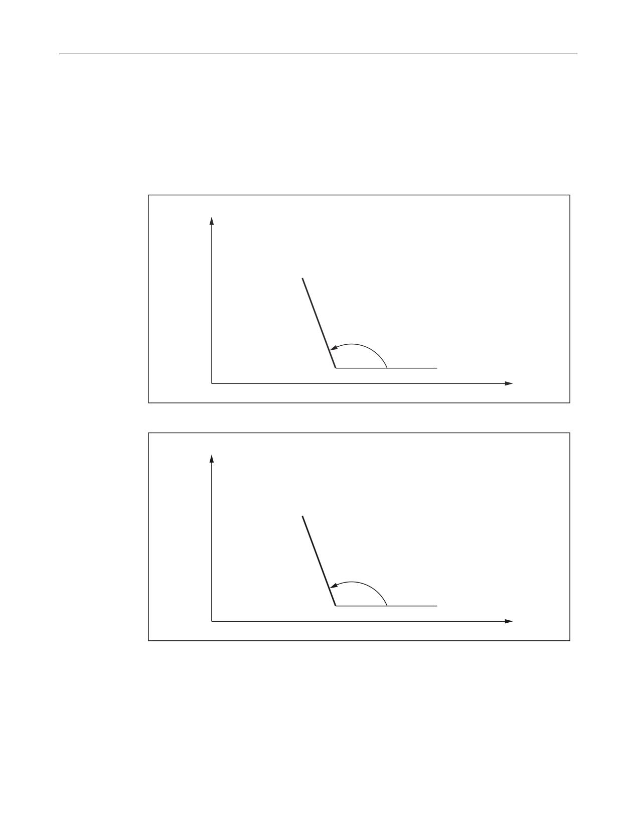
Straight line with angle
The end point is defined by stating angle A and one of the two coordinates X2 or Z2.
Programming syntax:
X2.. ,A.. or
Z2.. ,A..
;
;
=
$
;
=
=
Figure 5-26
Straight line with angle
;
;
=
GHJUHHV
;
=
Figure 5-27
Straight line with angle
Example (previous figure):
Programming in ISO dialect T mode:
N10 G1 X5. Z70. F1000 G18
N20 X88.8 ,A110 or (Z39.5 ,A110)
Programming in Siemens mode:
ISO dialects
Function Manual, 12/2019, 6FC5397-7BP40-3BA1
117
Cycles and contour definition
5.6 Programming contour definitions
N10 X5. Z70. F1000 G18
N20 X88.8 ANG=110 or (Z39.5 ANG=110)
5.6.3
Two straight lines
The end point of the first straight line can be programmed by specifying the Cartesian
coordinates or by specifying the angle of the two straight lines relative to the x coordinate.
Programming syntax:
N10 ,A1.. (Q..)
N20 X3.. Z3.. ,A2..
or
N10 X1.. Z1.. (Q..)
N20 X3.. Z3..
;
;
=
$
5
&
;
=
$
;
=
=
Figure 5-28
Two straight lines
ISO dialects
118
Function Manual, 12/2019, 6FC5397-7BP40-3BA1
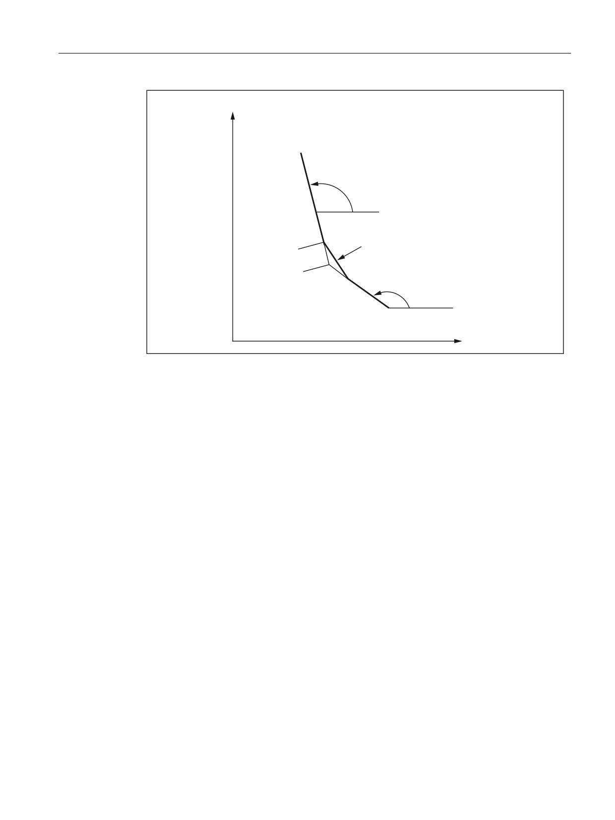
Cycles and contour definition
5.6 Programming contour definitions
;
;
=
GHJUHHV
5
&KDPIHU
;
=
GHJUHHV
;
=
=
Figure 5-29
Two straight lines
Example (previous figure):
Programming in the ISO dialect mode:
N10 G1 X10. Z80. F1000 G18
N20 ,A148.64 C55
N30 X85. Z40. ,A100
Programming in Siemens mode:
N10 X10. Z80. F1000 G18
N20 ANG=148.65 CHR=5.5
N30 X85. Z40. ANG=100
5.6.4
Three straight lines
The end point of the third straight line must always be programmed with Cartesian coordinates.
The transition from the second to the third coordinate can either take the form of a chamfer or
radius.
This type of programming can be continued for any number of blocks, i.e. a distinction does not
have to be made between contour definitions with two or more blocks.
Programming syntax:
N10 X2.. Z2.. (Q1..)
N20 X3.. Z3.. (Q2..)
N30 X4.. Z4..
or
ISO dialects
Function Manual, 12/2019, 6FC5397-7BP40-3BA1
119
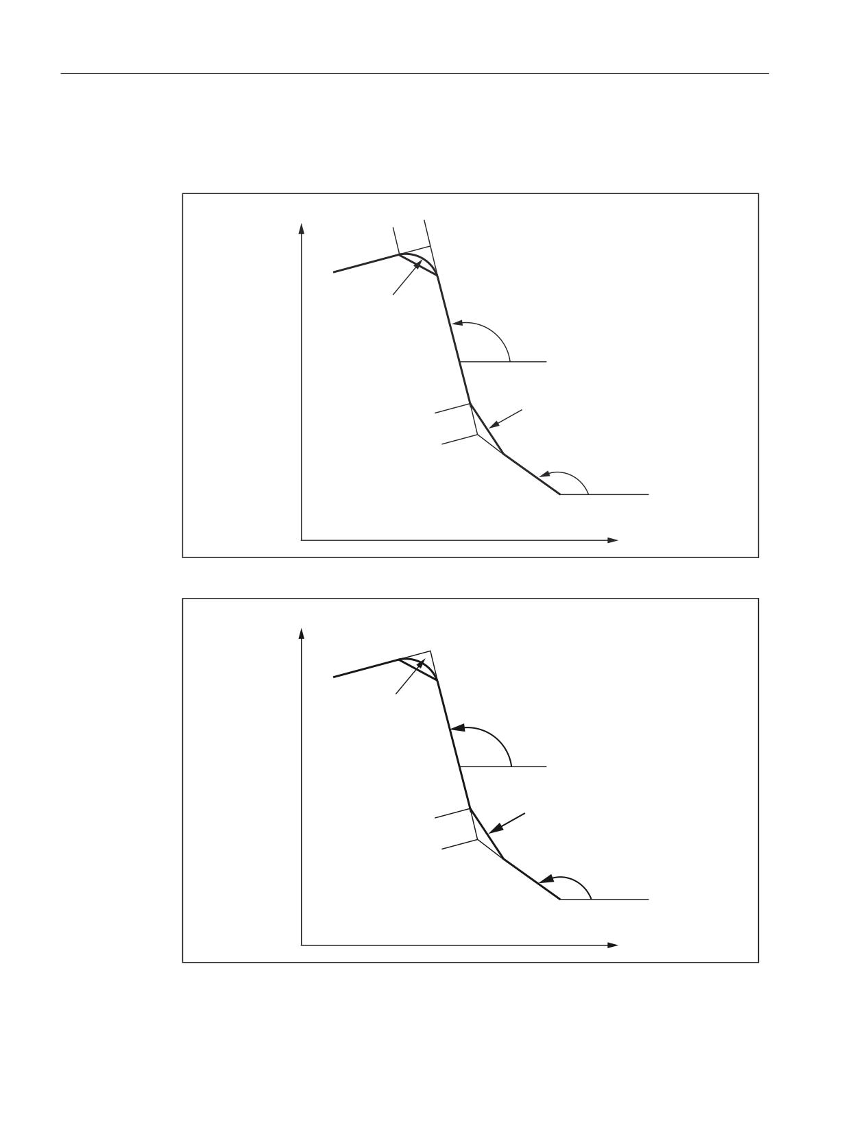
Cycles and contour definition
5.6 Programming contour definitions
N10 ,A1.. (Q1..)
N20 X3.. Z3.. ,A2.. (Q2..)
N30 X4.. Z4..
;
&
;
=
;
=
5
$
5
&
;
=
$
;
=
=
Figure 5-30
Three straight lines
;
;
=
;
=
5DGLXV
GHJUHHV
5
&KDPIHU
;
=
GHJUHHV
;
=
=
Figure 5-31
Three straight lines
Example (previous figure):
ISO dialects
120
Function Manual, 12/2019, 6FC5397-7BP40-3BA1
Cycles and contour definition
5.6 Programming contour definitions
Programming in the ISO dialect mode:
N10 G1 X10. Z100. F1000 G18
N20 ,A140 C7.5
N30 X80. Z70. ,A95.824, R10
Programming in Siemens mode:
N10 X10. Z100. F1000 G18
N20 ANG=140 CHR=7,5
N30 X80. Z70. ANG=95.824 RND=10
N40 X70 Z50
5.6.5
Multi-edge turning with G51.2
Function
Does not function in SINUMERIK 802D sl.
With the G51.2 function, workpieces with multiple edges can be produced by coupling two
spindles. This corresponds to the synchronous spindle function in Siemens mode with a
transformation ratio other than 1 : 1.
With the programming syntax G51.2 Q.. P.. R.. the synchronous spindle coupling is activated.
The transformation ratio from leading spindle to the following spindle is defined with the
parameters "Q" and "P". If the coupling is to be activated with an angular offset from following
spindle and leading axis, the angular difference is programmed with the address "R".
When mapping the function to Siemens language, in order to activate the synchronous spindle
function, two part program commands must always be issued - these must not occur in the
same block.
The assignment of leading and following spindle and the transformation ratio (and type of
coupling) are defined with a part program command (COUPDEF(..)). The second part program
command activates the coupling with the angle offset programmed (COUPON(..)). To execute
the two program commands, a cycle is called with G51.2 (CYCLE3512). The programmed
values are transferred to cycle parameters $C_P, $C_Q and $C_R. G50.2 is used to deactivate
the coupling again (also with CYCLE3512).
With the programming of G51.2, the 1st spindle in the channel is always defined as the leading
spindle and the 2nd spindle as the following spindle. Setpoint linkage is selected as the type of
coupling.
Example
N10 T1234
N20 G0 X10 Z100 M3 S1000
N30 G51.2 P1 Q3
;start synchronous spindle with transforma-
tion ratio 1 : 3
;and angle offset of 0 degrees
Nxx
ISO dialects
Function Manual, 12/2019, 6FC5397-7BP40-3BA1
121

Cycles and contour definition
5.6 Programming contour definitions
N1000 G51.2 R180
;angle offset between leading and
;following spindle of 180 degrees
N1200 G50.2
;switch off synchronous spindle operation
N2000 M30
For a detailed description of the synchronous spindle function, see
Function Manual for extended functions, chapter M1 and
Programming Manual for preparing for work, chapter "Synchronous spindle".
5.6.6
Contour repetition G72.1/G72.2
Function
G72.x is used to call a subprogram programmed under address P... The number of subprogram
repetitions is defined with address L. If address L is not programmed, the subprogram is
executed once. Depending on the G code, a coordinate rotation is executed (G72.1) or an
incremental distance traversed, relative to the contour's start point, before every subprogram
call (G72.2).
G72.1
G72.1 is used to call a subprogram (in which the contour to be repeated is programmed) several
times. The coordinate system is rotated by a certain angle before each subprogram call.
This function is realized by calling a cycle (CYCLE3721). The programmed values in cycle
parameters $C_.. are transferred to the cycle. The G function number can be found in $C_G,
a value of 721 is entered for G72.1 and 722 for G72.2 in $C_G. The cycle carries out the
coordinate rotation n times and calls the subprogram n times. The coordinate rotation is
executed around a vertical axis on the selected plane.
X.. Y.. (Z..)
Reference point for coordinate rotation
P..
Subprogram number
L..
Number of subprogram repeats
R..
Angle of rotation
Example:
ISO dialects
122
Function Manual, 12/2019, 6FC5397-7BP40-3BA1
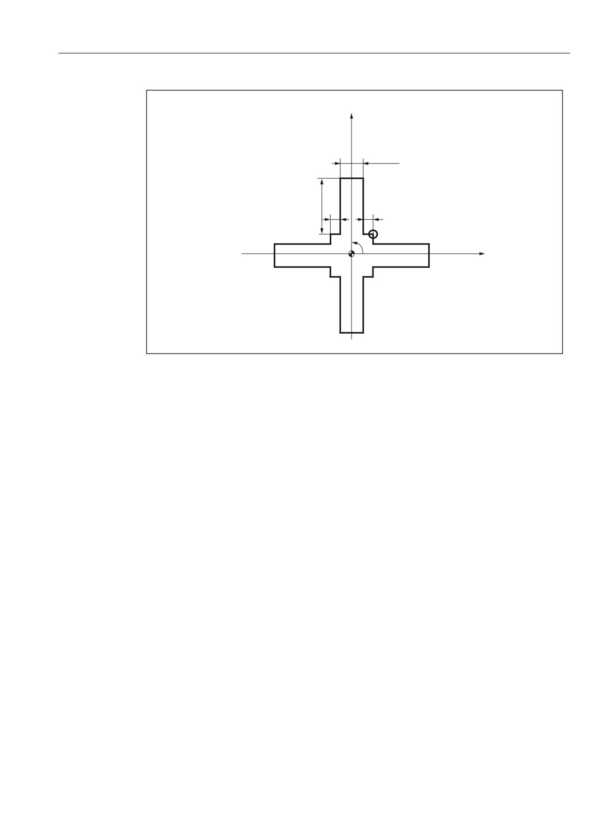
Cycles and contour definition
5.6 Programming contour definitions
<
6WDUW SRLQW
;
Figure 5-32
Contour repetition with G72.1
Main program
N10 G92 X40.0 Y50.0 ;
N20 G01 G90 G17 G41 20 Y20 D01 F1000
N30 G72.1 P1234 L4 X0 Y0 R90.0
N40 G40 G01 X100 Y50 Z0
N50 G00 X40.0 Y50.0 ;
N60 M30 ;
Subprogram 1234.spf
N100 G01 X10
N200 Y50
N300 X-10
N400 Y10
N500 X-20
N600 M99
G72.2
G72.2 is used to call a subprogram (in which the contour to be repeated is programmed) several
times. The axes programmed with I, J and K are traversed incrementally before each
subprogram call. In CYCLE3721 the programmed G function recognizes whether the contour
subprogram is repeated after a rotation or a linear movement.
This function is realized by calling a cycle. The programmed values in cycle parameters $C_..
are transferred to the cycle. The cycle calls the subprogram n times. A distance programmed
ISO dialects
Function Manual, 12/2019, 6FC5397-7BP40-3BA1
123
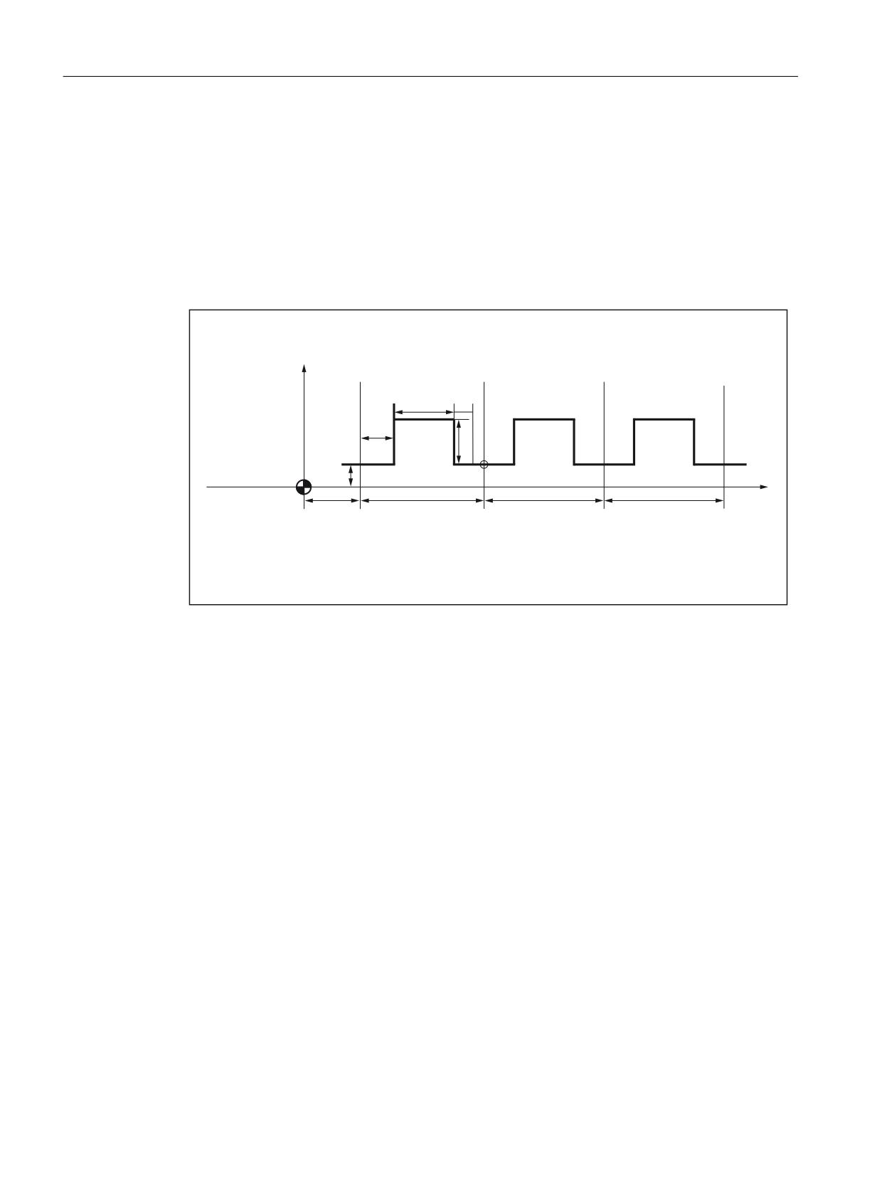
Cycles and contour definition
5.6 Programming contour definitions
under I, J, K is traversed incrementally (calculated from the start point) before each subprogram
call.
I.. J.. K..
Position to which the X, Y Z axes are traversed before calling the
subprogram. The position relates to the start point of the subprogram.
P..
Subprogram number
L..
Number of subprogram repeats
Example:
<
6WDUW SRLQW
6WDUW SRLQW
;
Figure 5-33
Contour repetition with G72.2
N10 G00 G90 X0 Y0
N20 G01 G17 G41 X30. Y0 D01 F1000
N30 Y10.
N40 X30.
N50 G72.2 P2000 L3 I80. J0
O2000 G90 G01 X40.
N100 Y30.
N200 G01 X80.
N300 G01 Y10.
N400 X90.
N500 M99
5.6.7
Output on an external device / an external file
Function
With the "Process DataShare" function, it is possible to write data from a part program to an
external device or an external file; for instance, e.g. to log production data or to control
additional equipment on a control system.
ISO dialects
124
Function Manual, 12/2019, 6FC5397-7BP40-3BA1
Cycles and contour definition
5.6 Programming contour definitions
The part program commands ISOOPEN, ISOPRINT and ISOCLOSE are provided for output on
an external device in the ISO language mode. These commands are parameterized via the
NCK machine data 10830 $MN_EXTERN_PRINT_DEVICE and 10831
$MN_EXTERN_PRINT_MODE.
The ISOOPEN, ISOPRINT and ISOCLOSE commands listed here may only be on their own in
a program block - apart from the block number, skip identifier and comment.
In ISO mode, precisely one device can be used for the output across all channels.
ISOPEN (open output device)
The output device referenced with MD $MN_EXTERN_PRINT_DEVICE is opened. MD
$MN_EXTERN_PRINT_MODE bit 0 can be used to set whether the output is to be synchronous
(FALSE) or asynchronous (TRUE), and $MN_EXTERN_PRINT_MODE bit 1 (FALSE) used to
set whether the output device is to be assigned exclusively.
If MD $MN_EXTERN_PRINT_MODE bit 2 is set, the control character DC2 (H12) is output with
ISOOPEN.
MD $MN_EXTERN_PRINT_MODE bits 4 and 5 can be used to determine whether the output
is to be terminated with LF or CR+LF.
Alarm 14066 "Error during output on an external device" is issued when an error occurs and the
part program execution is aborted. The error cause is specified in the alarm parameter "error
code".
ISOPRINT (output on an external device)
Syntax:
ISOPRINT[<Format string>, <Value list>]
<Format string> Character string that contains fixed and variable parts. The variable parts
are specified by the format statement %P.
Each %P is assigned a value from the <Value list>
●
%.nP: Output of a binary value with n decimal places
Example: ISOPRINT("X%.3P", 123.456)
● %m.nP: Output of a decimal number with m places before the decimal
point and n decimal places.
Example: ISOPRINT("X%5.3P", 123.456)
The <Format string> must only include format operations of one type (%.nP
or %m.nP). The "*" character is converted to a blank.
The start and end of the format string is identified by a ".
Example: "Measured value part 1: %3.2P"
<Value list>
List of the values to be output in the form of REAL constants. The individual
values are separated by commas. The value list can contain a maximum of
ten values.
The prepared string is output on the output device previously opened with ISOOPEN. The
output is terminated with LF or CR+LF depending on the setting of MD
$MN_EXTERN_PRINT_MODE, bits 4 and 5.
ISO dialects
Function Manual, 12/2019, 6FC5397-7BP40-3BA1
125
Cycles and contour definition
5.6 Programming contour definitions
Alarm 14066 "Error during output on an external device" is issued when an error occurs during
the output and the part program execution is aborted. The error cause is specified in the alarm
parameter "error code".
ISOCLOSE (close output device)
The output device opened with ISOOPEN is closed. If MD $MN_EXTERN_PRINT_MODE bit
3 is set, the control character DC4 (H14) is output with ISOCLOSE.
5.6.8
Convex thread with G35 and G36
In ISO dialect T, convex threads are programmed with G codes G35 in the clockwise direction
and G36 in the counter-clockwise direction.
These G codes are available for the G code systems A, B and C. The arc can be programmed
with specification of the circle center point via the circle parameters I, J, K or via specification
of the radius R. Optionally, a thread starting point offset can be specified with Q. If R is
programmed together with I, J, K, only R is effective.
Programming:
X.. Y.. Z.. I.. J.. K.. R.. F.. Q..
X Y Z
End point of the arc
I J K
Coordinates for circle center point programming
R
Radius for radius programming
F
Lead in the direction of the main axis
Q
Thread starting point offset (optional)
Convex threads are described in detail in SINUMERIK 840D sl / 828D Fundamentals
Programming Manual, Section 9 "Motion commands".
ISO dialects
126
Function Manual, 12/2019, 6FC5397-7BP40-3BA1
Commissioning
6
6.1
Machine data
Activating ISO dialect mode
MD18800 $MN_MM_EXTERN_LANGUAGE
Selection of ISO dialect M or T
MD 10880 $MN_MM_EXTERN_CNC_SYSTEM=1: ISO dialect M
MD 10880 $MN_MM_EXTERN_CNC_SYSTEM=2: ISO dialect T
ISO dialect T axis names
The maximum number of axes is eight. The axis identifiers of the first two axes are fixed X, Z.
Possible axis identifiers for the other axes are Y, A, B, C, U, V, W.
If G code system A is active (there is then no G91), incremental values are programmed for X,
Z, Y with U, V, W. U, V, W cannot then be used as axis identifiers, a maximum of six axes are
possible. H is used to incrementally traverse the C axis.
If B is not used as an axis identifier, B can be used as an extended auxiliary function. B is then
output as auxiliary function H with address extension 1 (H1=).
Contour definition:
MD20734 $MC_EXTERN_FUNCTION_MASK, bit 0 is used to define the programming for the
contour definition.
0: Contour definition is programmed with ,C ,R ,A (with commas). C and A can be axis
identifiers.
1: Contour definition is programmed with C R A (without commas). C and A cannot be axis
identifiers.
ISO dialect M axis names
The maximum number of axes is eight. The axis identifiers of the first three axes are fixed X, Y,
Z. Possible axis names for the other axes are A, B, C, U, V, W.
If B is not an auxiliary function, B can be used as an axis identifier.
Axis interpolation
All programmable axes interpolate with one another as standard with ISO dialect.
This corresponds to FGROUP with ISO dialect M: X, Y, Z (A, B, C, U, V, W).
This corresponds to FGROUP with ISO dialect T: X, Z, Y (C).
ISO dialects
Function Manual, 12/2019, 6FC5397-7BP40-3BA1
127
Commissioning
6.1 Machine data
MD22420 $MC_FGROUP_DEFAULT_AXES[0] is used to achieve this behavior if the machine
has four axes:
$MC_FGROUP_DEFAULT_AXES[0] = 1
$MC_FGROUP_DEFAULT_AXES[1] = 2
$MC_FGROUP_DEFAULT_AXES[2] = 3
$MC_FGROUP_DEFAULT_AXES[3] = 4
Work offset (ISO dialect M only)
If only NVs G54 to G59 are used, MD28080 $MC_MM_NUM_USER_FRAMES or with global
frames MD18601 $MC_MM_NUM_GLOBAL_USER_FRAMES >= 7 must be set.
If G54 is to be active after a reset, the following MD must be set to 1:
MD20154 $MC_EXTERN_GCODE_RESET_VALUES[13]
MD20150 $MC_GCODE_RESET_VALUES[7]
If the extended work offsets G54 P1 to P48 are used, MD28080
$MC_MM_NUM_USER_FRAMES or with global frames MD18601
$MC_MM_NUM_GLOBAL_USER_FRAMES >= 55 must be set.
If the following MD is set to 7, after a reset, G54 P1 is active:
MD 20154 $MC_EXTERN_GCODE_RESET_VALUES[13]
MD 20150 $MC_GCODE_RESET_VALUES[7]
G54 P1 is mapped to Siemens G507.
If an activated work offset is not to be retracted with G91, the following setting data should be
set to 0:
SD 42440 $SC_FRAME_OFFSET_INCR_PROG
Suppress tool lengths and radius compensation with G53:
MD 10760 $MN_G53_TOOLCORR = 1
Metric/Inch switchover
The handwheel evaluation and increment evaluation are not switched over with G20 and G21.
This switchover must be performed from the PLC: See MD31090 $MA_JOG_INCR_WEIGHT.
In ISO dialect mode, the work offsets are converted during the switchover. With ISO dialect
original, the comma is simply moved.
Programming diameter or radius
When MD20150 $MC_GCODE_RESET_VALUES[28] = 2, diameter programming is activated
for the transverse axis.
Decimal point programming
MD10884 $MN_EXTERN_FLOATINGPOINT_PROG is used to chose between Standard
Notation and PocketcalculatorNotation.
Input resolution IS-B and IS-C is selected with MD10886
$MN_EXTERN_INCREMENT_SYSTEM.
ISO dialects
128
Function Manual, 12/2019, 6FC5397-7BP40-3BA1
Commissioning
6.1 Machine data
Note that MD10200 $MN_INT_INCR_PER_MM and 10210 $MN_INT_INCR_PER_DEG are at
least set such that input resolution IS-B or IS-C can be allocated.
If this is not the case, the programmed values are rounded.
Example: IS-C mm $MN_INT_INCR_PER_MM = 10000.
Scaling
MD22910 $MC_WEIGHTING_FACTOR_FOR_SCALE=0: 0,001
MD22910 $MC_WEIGHTING_FACTOR_FOR_SCALE=1: 0,00001
Axial scaling factor: MD43120 $MA_DEFAULT_SCALE_FACTOR_AXIS
Scaling factor P: MD42140 $MC_DEFAULT_SCALE_FACTOR_P
Enable axial scaling: MD22914 $MC_AXES_SCALE_ENABLE = 1 (when = 0, axial scaling is
not possible)
Position in machine coordinate system G53
The axial speed for positioning with G53 and with G00 without interpolation is defined in
MD32060 $MA_POS_AX_VELO.
With G53 X.. Y... , a position in the machine coordinate system is approached. The axes don't
interpolate with one another, instead each axis moves to the programmed position separately
at maximum speed.
Incremental positions are skipped in the G53 block. While tool radius compensation or tool
length compensation is active (G41/G42, G43/G44), the axes are not traversed independently
of one another, the axes are interpolated with one another.
Setting actual value G92
Delete the G92 movement at PowerOn:
MD24004 $MC_CHBFRAME_POWERON_MASK=1
G92 is retained during a reset (M30, channel reset):
MD20110 $MC_RESET_MODE_MASK bit 0 and bit 14=1
Resetting the tool coordinate system G92.1
With G92.1 X.. (G code system A: G50.3 P0), a moved coordinate system can be reset before
being moved. The tool coordinate system is reset to the coordinate system that is defined by
the active adjustable work offsets (G54-G59). The tool coordinate system is set to the reference
position if no adjustable work offset is active. G92.1 resets shifts carried out through G92 or
G52. However, only the axes that are programmed, are reset.
Example 1:
N10 G0 X100 Y100
;Display: WCS: X100 Y100 MCS: X100 Y100
N20 G92 X10 Y10
;Display: WCS: X10 Y10
MCS: X100 Y100
ISO dialects
Function Manual, 12/2019, 6FC5397-7BP40-3BA1
129
Commissioning
6.1 Machine data
N30 G0 X50 Y50
;Display: WCS: X50 Y50
MCS: X140 Y140
N40 G92.1 X0 Y0
;Display: WCS: X140 Y140
MCS: X140 Y140
Example 2:
N10 G10 L2 P1 X10 Y10
N20 G0 X100 Y100
;Display: WCS: X100 Y100 MCS: X100 Y100
N30 G54 X100 Y100
;Display: WCS: X100 Y100 MCS: X110 Y110
N40 G92 X50 Y50
;Display: WCS: X50 Y50
MCS: X110 Y110
N50 G0 X100 Y100
;Display: WCS: X100 Y100
MCS: X160 Y160
N60 G92.1 X0 Y0
;Display: WCS: X150 Y150
MCS: X160 Y160
Delete distance-to-go
With ISO dialect original, G31 can be used to delete the distance-to-go. The distance-to-go is
only deleted in this block if the PLC signal is in place for the channel. Without G31, the signal
is not evaluated.
In ISO dialect mode, the PLC signals are evaluated in each block regardless of G31. G31 is
used to activate probe 1.
With ISO dialect, the deleted distance-to-go can be calculated using PLC Varselector.
The function G31 P1 (.. P4) is different from G31 in that different inputs for the measuring signal
can be selected with P1-P4. Several inputs can also be monitored on a rising edge of a
measuring signal simultaneously. The assignment of the inputs to the addresses P1 to P4 is
defined by the following machine data.
MD10810 $MN_EXTERN_MEAS_G31_P_SIGNAL[0 .. 3].
Note
Only two measuring inputs are available for the 840D sl.
Spindle position
The spindle position for M19 is set using setting data 43240 $SC_M19_SPOS.
Protection zone
If G commands G22 and G23 are used, there must be a protection zone:
MD18190 $MM_NUM_PROTECT_AREA_NCK = 1
MD28210 $MC_NUM_PROTECT_AREA_ACTIVE = 1
Auxiliary function output
If value H is to be output to the PLC as an integer value, MD22110 $MC_AUXFU_H_TYPE_INT
must be set to 1.
ISO dialects
130
Function Manual, 12/2019, 6FC5397-7BP40-3BA1
Commissioning
6.1 Machine data
The time at which the auxiliary function is output (M, S, T, H) to the PLC can be set using
machine data:
0 = Auxiliary function output before motion
1 = Auxiliary function output during motion
2 = Auxiliary function output after motion
3 = Motion is not output to PLC
MD22200 $MC_AUXFU_M_SYNC_TYPE for M functions
MD22210 $MC_AUXFU_S_SYNC_TYPE for S functions
MD22220 $MC_AUXFU_T_SYNC_TYPE for T functions
MD22230 $MC_AUXFU_H_SYNC_TYPE for H functions
Approach 1st reference point G28
The following machine data must be set:
●
20050 $MC_AXCONF_GEOAX_ASSIGN_TAB[0-2]
Axis 1 to 3
●
20060 $MC_AXCONF_GEOAX_NAME_TAB[0-2]
Axis names for milling: X, Y, Z
Axis names for turning: X, Z, Y
●
200070 $MC_AXCONF_MACHAX_USED[0-3]
Axis 1 to 4
●
20080 $MC_AXCONF_CHANAX_NAME_TAB[0-3]
4th axis name for milling: X, Y, Z are permanently assigned; A, B, C, U, V or W can also be
selected.
4th axis name for turning: X, Z, Y are permanently assigned; C can also be selected
●
20100 $MC_DIAMETER_AX_DEF
Only when turning: X axis
●
20150 $MC_GCODE_RESET_VALUES[28]
Radius or diameter programming
1 = DIAMOF (radius for G90/G91)
2 = DIAMON (diameter for G90/G91)
3 = DIAM90 (diameter for G90, radius for G91)
Note: DIAM90 is treated like DIAMON within the cycle.
●
34100 $MA_REFP_SET_POS[0]
0 = 1st reference point
Enter a value for each axis
●
35000 $MA_SPIND_ASSIGN_TO_MACHAX
0 = Axis is not spindle
1 = Axis is a spindle
ISO dialects
Function Manual, 12/2019, 6FC5397-7BP40-3BA1
131
Commissioning
6.1 Machine data
Approach 2nd/3rd/4th reference point G30
The following machine data must be set:
●
20050 $MC_AXCONF_GEOAX_ASSIGN_TAB[0-2]
Axis 1 to 3
●
20060 $MC_AXCONF_GEOAX_NAME_TAB[0-2]
Axis names for milling: X, Y, Z
Axis names for turning: X, Z, Y
●
20070 $MC_AXCONF_MACHAX_USED[0-3]
Axis 1 to 4
●
20080 $MC_AXCONF_CHANAX_NAME_TAB[0-3]
4th axis name for milling: X, Y, Z are permanently assigned; A, B, C, U, V or W can also be
selected.
4th axis name for turning: X, Z, Y are permanently assigned; C can also be selected
●
20100 $MC_DIAMETER_AX_DEF
Only when turning: X axis
●
20150 $MC_GCODE_RESET_VALUES[28]
Radius or diameter programming
1 = DIAMOF (radius for G90/G91)
2 = DIAMON (diameter for G90/G91)
3 = DIAM90 (diameter for G90, radius for G91)
Note: DIAM90 is treated like DIAMON within the cycle.
●
34100 $MA_REFP_SET_POS[1,2,3]
1,2,3 = 2nd, 3rd, 4th reference point
Enter a value for each axis
●
35000 $MA_SPIND_ASSIGN_TO_MACHAX
0 = Axis is not spindle
1 = Axis is a spindle
G30.1 reference point position
Reference point approach is realized in the CYCLE328 cycle. The reference point position is
written in setting data 43340 $SC_EXTERN_REF_POSITION_G30_1.
6.1.1
Active G command for PLC
The user can use MD22512 $MC_EXTERN_GCODE_GROUPS_TO_PLC to select the G
groups of an external language whose active G command is to be reported to the PLC.
$MC_EXTERN_GCODE_GROUPS_TO_PLC[0..7]=0
6.1.2
Tool change, tool data
No cutting edge is selected during a tool change.
MD20270 $MC_CUTTING_EDGE_DEFAULT = 0
ISO dialects
132
Function Manual, 12/2019, 6FC5397-7BP40-3BA1
Commissioning
6.1 Machine data
Setting datum: During a tool change, with G91 the compensation is not retracted
SD42442 $SC_TOOL_OFFSET_INCR_PROG = 0
The assignment of tool length compensation to geometry axes is fixed:
Length 1: Z
Length 2: Y
Length 3: X
SD42940 $SC_TOOL_LENGTH_CONST =17
Effectiveness of tool length compensation beyond reset:
MD20110 $MC_RESET_MODE_MASK = 'B1000000'
Effectiveness of tool compensation with programming of T/H/D, not with M6
MD22550 $MC_TOOL_CHANGE_MODE = 0
6.1.3
G00 always with exact stop
At high speeds, collisions may occur during active continuous-path mode in G00 mode when
smoothing. MD20734 $MC_EXTERN_FUNCTION_MASK, bit 4 is used to determine the exact
stop behavior with G00.
MD20734 $MC_EXTERN_FUNCTION_MASK, bit 4=0, G00 is traversed with the exact stop
function currently active. If G64 is active, the G00 blocks are also traversed with G64.
MD20734 $MC_EXTERN_FUNCTION_MASK, bit 4=1, each G00 block with traversing is
traversed with G09 (non-modal exact stop). Even if G64 is active, the non-modal exact stop
takes effect in every G00 block.
6.1.4
Response to syntax faults
Response to faults occurring
MD20734 $MC_EXTERN_FUNCTION_MASK, bit 3 is used to determine the response to faults
occurring in the first part of the ISO Translator. Here the entire ASCII block is examined.
If bit 3==0, an NC alarm is output and processing is stopped if unknown addresses are found.
If bit 3==1, no alarm is output, the ASCII block is forwarded to the Siemens Translator. The NC
block following this is first given back to the ISO Translator and an attempt is made in the
Siemens Translator to translate the ASCII block.
This allows unique Siemens blocks to be programmed without using G290 to switch to Siemens
mode while ISO mode is active.
The current ISO G code is displayed in the G code window, a switch is not made to Siemens
mode.
If a G function, which can be translated directly to an ISO G code, is activated in such a block
in the Siemens Translator, the G codes are updated here.
ISO dialects
Function Manual, 12/2019, 6FC5397-7BP40-3BA1
133
Commissioning
6.1 Machine data
Example
20734 $MC_EXTERN_FUNCTION_MASK, bit 3==0
N5 G291
;ISO mode
N10 WAIT
;Alarm 12080 "WAIT unknown"
N15 G91 G500
;Alarm 12080 "G500 unknown"
20734 $MC_EXTERN_FUNCTION_MASK, bit 3==1
N5 G291
;ISO mode
N10 WAIT
;block is processed by the Siemens Translator
N15 G91 G500
;block is processed by the Siemens Translator
N20 X Y
;because of G291, block is processed by ISO Transla-
tor,
;G91 from N15 is active
Note
Unwanted responses may result from incorrect programming in ISO mode.
Example for ISO M:
To be programmed: G90 G76 ;modal cycle call
but the following is entered: G90 G75
G75 is not available in ISO M mode, the block goes to the Siemens Translator and results in
"Move to fixed point" without any query or alarm G75.
6.1.5
Selection of code system A, B, C (ISO dialect T)
Function
In ISO dialect-T, a differentiation is made between G code system A, B and C. By default, the
G code system B is active.
Code system A, B or C is selected in MD10881 $MN_MM_EXTERN_GCODE_SYSTEM. The
"Rename G codes" function is not used by this function, the user can use this function without
any limitations.
As previously, switching over with a cycle is still possible.
$MN_MM_EXTERN_CNC_SYSTEM = 1: ISO dialect M
$MN_MM_EXTERN_CNC_SYSTEM = 2: ISO dialect T
$MN_MM_EXTERN_GCODE_SYSTEM = 0: G code system B
$MN_MM_EXTERN_GCODE_SYSTEM = 1: G code system A
$MN_MM_EXTERN_GCODE_SYSTEM = 2: G code system C
ISO dialects
134
Function Manual, 12/2019, 6FC5397-7BP40-3BA1
Commissioning
6.1 Machine data
In order for the shell cycle to work in the correct G code system, the corresponding system must
be entered in the GUD variable _ZSFI[39]:
_ZSFI[39]: Setting datum for G code system with ISO T
0 = G code system B
1 = G code system A
2 = G code system B
3 = G code system C
Inch/metric changeover
With ISO dialect original there is a MD which is used to determine how the inch/metric
changeover is programmed, either with G20/21 or G70/71. This MD does not exist for ISO
dialect mode, it can also not be selected using $MN_MM_EXTERN_GCODE_SYSTEM.
G20/G21 is active by default. A switchover to G70/71 is realized using MD10712
$MN_USER_CODE_CONF_NAME_TAB.
$MN_USER_CODE_CONF_NAME_TAB[0]= G20
$MN_USER_CODE_CONF_NAME_TAB[1]= G70
$MN_USER_CODE_CONF_NAME_TAB[2]= G21
$MN_USER_CODE_CONF_NAME_TAB[3]= G71
Regardless of G20/21 G70/71, a 1 is read in system variable $P_GG[6] with G20/G70 and a 2
with G21/G71.
6.1.6
Fixed feedrates F0 - F9
Function
Ten different feedrate values pre-set via setting data can be activated with F0-F9.
To activate the rapid traverse rate with F0, the corresponding speed must be entered in the
setting datum 42160 $SC_EXTERN_FIXED_FEEDRATE_F1_9[0].
The feedrate values for F0-F9 are entered in the setting data as real values. An evaluation of
the input values is not undertaken.
The function is activated via MD22920 $MC_EXTERN_FIXED_FEEDRATE_F1_ON. If the
machine data is set to FALSE, F1-F9 is interpreted as normal feedrate programming, e.g. F2=2
mm/min, F0=0 mm/min.
If the machine data = TRUE, the feedrate values for F0-F9 are fetched from the setting data
42160 $SC_EXTERN_FIXED_FEEDRATE_F1_F9[ ]. If the value 0 exists in one of the setting
data, then the corresponding address extension of feedrate 0 is activated during the
programming.
ISO dialects
Function Manual, 12/2019, 6FC5397-7BP40-3BA1
135
Commissioning
6.1 Machine data
Example
$SC_FIXED_FEEDRATE_F1_F9[0] = 5000
$SC_FIXED_FEEDRATE_F1_F9[1] = 1000
$SC_FIXED_FEEDRATE_F1_F9[2] = 500
N10 X10 Y10 Z10 F0 G94
;Approach position at 5000 mm/min
N20 G01 X150 Y30 F1
;Feedrate 1000 mm/min active
N30 Z0 F2
;Position approached at 500 mm/min
N40 Z10 F0
;Approach position at 5000 mm/min
If the function is activated with MD22920 $MC_FIXED_FEEDRATE_F1_F9_ON and if the
feedrate value from the setting datum is not to be active with F1-F9, then the feedrate value is
programmed as a real value. If, for instance, a feedrate value should be programmed at 1 mm/
min, the feedrate must be programmed with F1.0 instead of F1.
Note
While macroprogramming with G65/66, the programmed value for the address F is always
entered in the $C_F system variable. The address signifies a transfer variable here and has no
direct reference to the feedrate.
The same is true of the thread lead programming in G33-G34 with address F. No feedrate is
programmed with F here, instead the distance between 2 threads during a spindle revolution.
In cycle programming (e.g., G81 X.. Y.. Z.. R.. P.. Q.. F..), the feedrate is always programmed
under address F. In a part program block with a cycle call via a G function (G81-G87 etc.), the
corresponding feedrate value during the programming of F1-F9 is written from the
corresponding setting datum in the variable $C_F.
Restriction
In ISO dialect mode, the feedrate values are changed in the setting data with a handwheel. In
Siemens mode, the feedrates can be influenced only like a directly programmed feedrate, e.g.
using the override switch.
6.1.7
Parallel axes G17 (G18/G19)<Axis name>..
Function G17 (G18, G19)<Axis name>.. can be used to activate an axis parallel to the basic
axis in the coordinate system.
The basic axes are, e.g. X, Y and Z. The following programming is used to activate axis U in the
G17 plane in place of basic axis X:
G17 U0 Y0 ;Activation of parallel axis U
This function can be reproduced with the 840D sl function GEOAX (..,..). GEOAX() can be used
to replace a geometry axis with any channel axis. But all frames (apart from handwheel and
external movement), the working area limitation and the protection zones are then deleted. The
user can prevent the frames from being deleted with MD10602
$MN_FRAME_GEOAX_CHANGE_MODE, the protection zones from being deleted with
ISO dialects
136
Function Manual, 12/2019, 6FC5397-7BP40-3BA1
Commissioning
6.1 Machine data
MD10618 $MC_PROTAREA_GEOAX_CHANGE_MODE and working area limitation from
being deactivated with MD10604 $MN_WALIM_GEOAX_CHANGE_MODE.
One parallel axis can be defined for each of the three geometry axes using MD22930
$MC_EXTERN_PARALLEL_GEOAX[ ]. By programming the G function for plane selection
(G17-G19) and the axis name of the parallel axis, a geometry axis interchange is then carried
out as with the GEOAX() function.
During the selection of planes (geometry axis interchange with parallel axis), the axes are
moved to their programmed position.
If a basic axis of the coordinate system is programmed along with its parallel axis in a plane
selection block, alarm 12726 "Impermissible plane selection with parallel axes" is output.
6.1.8
Inserting chamfers and radii
Chamfers and radii
The process of inserting chamfers and radii is mapped to the corresponding Siemens
functionality. The two blocks between which a radius or chamfer is to be inserted must always
be programmed. If there are several addresses programmed in a block, the last radius
programmed always takes effect.
In ISO dialect M mode, the name for the radius is always "R" and for the chamfer "C". As soon
as a comma is programmed in the block, addresses R and C to the right after the comma are
interpreted as radius and chamfer. If a circle is to be programmed with radius R or axis C, the
two addresses must be positioned to the left before the comma. A radius or chamfer can be
inserted between linear blocks, circle blocks or a mix of the two.
In ISO dialect T mode, the name for the radius is always "R", while addresses "C", "I" and "K"
can be used for the chamfer. Address C may only be used if it is not defined as an axis name.
Radii and chamfers can only be inserted between linear blocks. The linear blocks do not have
to be above one another vertically. Programming a sign before the chamfer and/or radius is of
no significance here because the direction of the chamfer and/or radius is defined with the 2nd
straight line block.
ISO dialect M programming
Chamfers and radii are always marked in the block with a comma. The address for a chamfer
is "C" and for a radius is "R". Chamfers and radii can be inserted between linear blocks and
circle blocks.
N10 X100. ,R10
;insert radius of 10 mm
N20 Y30. ,C5
;insert chamfer of 5 mm
N30 X150. Y40.
N40 G03 X180. Y65. R30, R8
N50 G01 X150. ,R8
ISO dialects
Function Manual, 12/2019, 6FC5397-7BP40-3BA1
137
Commissioning
6.1 Machine data
ISO dialect T programming
Chamfers and radii are not marked in the block with a comma. The address for a radius is
always "R", address "I", "K" or "C" can be used for a chamfer. C may only be used if the address
is not defined as an axis name.
In ISO dialect T mode, chamfers and radii can only be inserted between 2 linear blocks.
N10 X100. R10
;insert radius of 10 mm
N20 Z30. C5
;insert chamfer of 5 mm
N30 X150. Z40.
N40 X180. Z65. I8
N50 G01 X150. K8
6.1.9
Rotary axis function
If an axis is defined as a rotary axis, this axis can be traversed as follows:
● Axis is traversed as linear axis
No modulo conversion is active.
Positive and negative values can be programmed
MD30300 $MA_IS_ROT_AX = TRUE
MD30310 $MA_ROT_IS_MODULO = FALSE
● Example:
N5 G90 B0
N10 B370
;axis moves to 370 degrees
N15 B-10
;axis moves to -10 degrees
N20 G91 B-20
;axis moves to -20 degrees
● Axis traverses at shortest distance
Modulo conversion is active
Values < 0 and > modulo value can be programmed
MD30300 $MA_IS_ROT_AX = TRUE
MD30310 $MA_ROT_IS_MODULO = TRUE
MD20734 $MC_EXTERN_FUNCTION_MASK, bit 5 = 0
MD30455 $MA_MISC_FUNCTION_MASK, bit 0 = 1
Example:
N5 B0
;axis moves to 0 degrees
N10 B10
;axis moves to 10 degrees, positive
;Direction of rotation
N15 B350
;axis moves to 350 degrees, negative
;Direction of rotation
N20 B-5
;axis moves to 355 degrees, positive
;Direction of rotation
N25 G91 B-10
;axis moves to 345 degrees, negative
;Direction of rotation
ISO dialects
138
Function Manual, 12/2019, 6FC5397-7BP40-3BA1
Commissioning
6.1 Machine data
● Axis traverses in positive or negative direction depending on sign programmed
Modulo conversion is active
Values < 0 and > modulo value can be programmed
MD30300 $MA_IS_ROT_AX = TRUE
MD30310 $MA_ROT_IS_MODULO = TRUE
MD20734 $MC_EXTERN_FUNCTION_MASK, bit 5 = 1
MD30455 $MA_MISC_FUNCTION_MASK, bit 0 = 1
Example:
N5 B0
;axis moves to 0 degrees
N10 B10
;axis moves to 10 degrees,
;positive direction of rotation
N15 B350
;axis moves to 350 degrees,
;positive direction of rotation
N20 B-5
;axis moves to 355 degrees,
;negative direction of rotation
N25 G91 B-10
;axis moves to 345 degrees,
;negative direction of rotation
In this case, the sign has two meanings, it is taken into account in the modulo conversion and
determines the direction of rotation.
The response is the same for all types of interpolation.
Incremental motion is always executed depending on the sign.
6.1.10
Program coordination between 2 channels and M commands
Overview
M functions which serve as WAIT marks can be programmed to synchronize the program
sequence between two channels. If one such M function is reached in the part program of one
channel, the program sequence is stopped until the other channel has also reached the same
M function. The part programs in the two channels are then processed further.
The M function numbers for the Wait marks are defined with two pieces of machine data. A
range of M numbers is defined and reserved for this function.
Machine data 10800 $MN_EXTERN_CHAN_SYNC_M_NO_MIN marks the smallest M number
and 10802 $MN_EXTERN_CHAN_SYNC_M_NO_MAX the largest M number in the range
reserved for program coordination. Machine data $MN_EXTERN_CHAN_SYNC_M_NO_MAX
must not exceed ($MN_EXTERN_CHAN_SYNC_M_NO_MIN + 10 * number of channels).
To avoid conflicts with standard M functions, the smallest M number (MD
$MN_EXTERN_CHAN_SYNC_M_NO_MIN) must not be less than 100. If the machine data is
predefined with -1, this means that program coordination in ISO dialect T/M mode is not
possible.
If a value <100 is entered in $MN_EXTERN_CHAN_SYNC_M_NO_MIN or a value <
$MN_ETERN_CHAN_SYNC_M_NO_MIN is entered in
$MN_EXTERN_CHAN_SYNC_M_NO_MAX, alarm 4170 "Impermissible number for channel
synchronization" is output.
ISO dialects
Function Manual, 12/2019, 6FC5397-7BP40-3BA1
139
Commissioning
6.2 Standard machine data assignment for ISO dialect
The function is mapped to the WAITM command of the Siemens language (WAITM(<mark>,
<channel number>, <channel number>)). Channel synchronization in ISO dialect T/M mode is
always carried out for channels 1 and 2. All other channels can only be synchronized in
Siemens mode.
The M numbers are not output to the PLC.
The M functions for channel synchronization must be the only items in their block. The system
issues alarm 12080 "Channel %1 block %2 syntax error for text" if addresses other than "M" are
programmed in the block.
For a more detailed description, see
Job Planning; Section "Program coordination"
Constraint
Only 10 M functions (WAIT marks) can be set per channel. The difference between
$MN_EXTERN_CHAN_SYNC_M_NO_MAX and $MN_EXTERN_CHAN_SYNC_M_NO_MIN
must therefore not exceed 20 in a 2-channel system. With ISO dialect original 99999899 M
numbers can be defined as wait marks.
6.2
Standard machine data assignment for ISO dialect
ISO dialect M
Standard assignment of MD20154 $MC_EXTERN_GCODE_RESET_VALUES[ ]:
$MC_EXTERN_GCODE_RESET_VALUES[0] = 1
G00
$MC_EXTERN_GCODE_RESET_VALUES[1]=1
G17
$MC_EXTERN_GCODE_RESET_VALUES[2]=1
G90
$MC_EXTERN_GCODE_RESET_VALUES[3]=2
G23
$MC_EXTERN_GCODE_RESET_VALUES[4]=1
G94
$MC_EXTERN_GCODE_RESET_VALUES[5]=1
G20
$MC_EXTERN_GCODE_RESET_VALUES[6]=1
G40
$MC_EXTERN_GCODE_RESET_VALUES[7]=3
G49
$MC_EXTERN_GCODE_RESET_VALUES[8]=4
G80
$MC_EXTERN_GCODE_RESET_VALUES[9]=1
G98
$MC_EXTERN_GCODE_RESET_VALUES[10]=1
G50
$MC_EXTERN_GCODE_RESET_VALUES[11]=2
G67
$MC_EXTERN_GCODE_RESET_VALUES[12]=2
G97
$MC_EXTERN_GCODE_RESET_VALUES[13]=1
G54
$MC_EXTERN_GCODE_RESET_VALUES[14]=3
G64
$MC_EXTERN_GCODE_RESET_VALUES[15]=2
G69
$MC_EXTERN_GCODE_RESET_VALUES[16]=1
G15
$MC_EXTERN_GCODE_RESET_VALUES[17]=0
non-modal
$MC_EXTERN_GCODE_RESET_VALUES[21]=1
G50.1
ISO dialects
140
Function Manual, 12/2019, 6FC5397-7BP40-3BA1
Commissioning
6.2 Standard machine data assignment for ISO dialect
$MC_EXTERN_GCODE_RESET_VALUES[24]=1
G12.1
$MC_EXTERN_GCODE_RESET_VALUES[30]=1
G290
ISO dialect T
Standard assignment of MD20154 $MC_EXTERN_GCODE_RESET_VALUES[ ]:
Several G code systems are available as options for ISO dialect T. The same function is called
using different G commands. G code system B is realized as standard. Machine datum 10881
$MN_ EXTERN_GCODE_SYSTEM is used to use another G code system.
$MC_EXTERN_GCODE_RESET_VALUES[0]=1
G00
$MC_EXTERN_GCODE_RESET_VALUES[1]=2
G97
$MC_EXTERN_GCODE_RESET_VALUES[2]=1
G90
$MC_EXTERN_GCODE_RESET_VALUES[3]=2
G69
$MC_EXTERN_GCODE_RESET_VALUES[4]=2
G95
$MC_EXTERN_GCODE_RESET_VALUES[5]=1
G21
$MC_EXTERN_GCODE_RESET_VALUES[6]=1
G40
$MC_EXTERN_GCODE_RESET_VALUES[8]=2
G23
$MC_EXTERN_GCODE_RESET_VALUES[9]=1
G80
$MC_EXTERN_GCODE_RESET_VALUES[10]=1
G98
$MC_EXTERN_GCODE_RESET_VALUES[11]=2
G67
$MC_EXTERN_GCODE_RESET_VALUES[15]=2
G18
$MC_EXTERN_GCODE_RESET_VALUES[17]=0
non-modal
$MC_EXTERN_GCODE_RESET_VALUES[19]=1
G50.2
$MC_EXTERN_GCODE_RESET_VALUES[20]=1
G12.1
$MC_EXTERN_GCODE_RESET_VALUES[30]=1
G290
ISO dialects
Function Manual, 12/2019, 6FC5397-7BP40-3BA1
141