SINUMERIK 840D sl. Service - Functions. Manual (2018-2020) - page 1
Preface
Fundamental safety
1
instructions
2
Short description
SINUMERIK
Programming
3
SINUMERIK 840D sl / 828D
ISO dialects
4
Tool changes and tool offsets
Cycles and contour definition
5
Function Manual
6
Commissioning
Supplementary conditions
7
8
Data descriptions (MD, SD)
Data fields, lists
9
10
Alarms
11
Appendix
Valid for
Control system
SINUMERIK 840D sl / 840DE sl
SINUMERIK 828D
12/2019
6FC5397-7BP40-3BA1
Table of contents
Preface
3
1
Fundamental safety instructions
9
1.1
General safety instructions
9
1.2
Warranty and liability for application examples
9
1.3
Industrial security
10
2
Short description
13
3
Programming
15
3.1
Function activation
15
3.1.1
Switching between the operating modes
16
3.2
G commands
17
3.2.1
Display of the G code
22
3.2.2
Display of non-modal G codes
23
3.2.3
G code output to PLC
23
3.2.4
Decoupling the frames between Siemens and ISO mode
25
3.2.5
Writing work offset with G10
28
3.2.6
Programming the decimal point
29
3.2.7
Rapid lifting with G10.6
31
3.2.8
Multiple-start threads with G33
33
3.2.9
Thread with variable lead G34 (ISO dialect T)
33
3.2.10
Dwell time in spindle revolutions G04
33
3.2.11
Scaling (G50, G51) and mirroring G50.1, G51.1 (ISO dialect M)
34
3.2.12
G60 directed positioning
36
3.2.13
2D/3D rotation G68/G69 (ISO dialect M)
37
3.2.14
Double slide or double turret processing G68/G69
38
3.2.15
Polar coordinates G15/G16 (ISO dialect M)
42
3.2.16
Interpolation of polar coordinates G12.1/G13.1 (G112/G113)
43
3.2.17
Cylindrical interpolation G07.1 (G107)
44
3.2.18
Interrupt program with M96/M97 (ASUB)
46
3.2.19
Comments
49
3.2.20
Skip block
49
3.2.21
Auxiliary function output
50
3.2.22
Approach 1st home position with intermediate point (G28)
51
3.2.23
Switching precontrol on/off with G08 P
51
3.2.24
Compressor in ISO dialect mode
52
3.2.25
Automatic corner override G62
52
3.3
Substitution by a substitution cycle with a tool selection block
55
3.3.1
Milling
55
3.3.2
Turning
57
3.3.3
Indirect programming in ISO mode using $ variables
59
3.4
Subprogram and macro technology
59
3.4.1
Subprogram technique: M98
59
ISO dialects
Function Manual, 12/2019, 6FC5397-7BP40-3BA1
5
Table of contents
3.4.2
Siemens language commands in ISO dialect mode
62
3.4.3
Expansion of subprogram call for contour preparation with CONTPRON
63
3.4.4
Macro commands with G65, G66 and G67
65
3.4.5
Changing mode during macro calls with G65/G66
68
3.4.6
Macro call via M function
69
3.4.7
Macro call via G function
70
3.4.8
High-speed cycle cutting G05 P
72
3.4.9
Switchover modes for DryRun and skip planes
73
3.4.10
Eight-digit program number
74
3.4.11
System variable for level stack in ISO mode
75
4
Tool changes and tool offsets
79
4.1
Shared tool offset memory
79
4.1.1
Tool offsets: T, D (ISO dialect M)
79
4.1.2
Possible H numbers
80
4.1.3
Tool offset T (ISO dialect T)
83
4.1.4
Tool change cycle
86
5
Cycles and contour definition
89
5.1
Sequence of cycle calls in the external CNC system using G commands
89
5.2
Global user data (GUD)
91
5.3
Drilling cycles (ISO dialect M)
93
5.3.1
Overview and parameter description
93
5.3.2
Description of shell cycle CYCLE381M
96
5.3.3
Description of shell cycle CYCLE383M
96
5.3.4
Description of shell cycle CYCLE384M
97
5.3.5
Description of shell cycle CYCLE387M
98
5.4
Turning and drilling cycles (ISO dialect T)
99
5.4.1
Turning cycles G70 to G76
99
5.4.2
Turning cycles G77 to G79
105
5.4.3
Drilling cycles G80 to G89
107
5.4.4
Description of shell cycle CYCLE383T
110
5.4.5
Description of shell cycle CYCLE384T
111
5.4.6
Description of shell cycle CYCLE385T
112
5.5
System variables
112
5.6
Programming contour definitions
115
5.6.1
End point programming with angles
116
5.6.2
Straight line with angle
117
5.6.3
Two straight lines
118
5.6.4
Three straight lines
119
5.6.5
Multi-edge turning with G51.2
121
5.6.6
Contour repetition G72.1/G72.2
122
5.6.7
Output on an external device / an external file
124
5.6.8
Convex thread with G35 and G36
126
6
Commissioning
127
6.1
Machine data
127
6.1.1
Active G command for PLC
132
6.1.2
Tool change, tool data
132
6.1.3
G00 always with exact stop
133
ISO dialects
6
Function Manual, 12/2019, 6FC5397-7BP40-3BA1
Table of contents
6.1.4
Response to syntax faults
133
6.1.5
Selection of code system A, B, C (ISO dialect T)
134
6.1.6
Fixed feedrates F0 - F9
135
6.1.7
Parallel axes G17 (G18/G19)<Axis name>
136
6.1.8
Inserting chamfers and radii
137
6.1.9
Rotary axis function
138
6.1.10
Program coordination between 2 channels and M commands
139
6.2
Standard machine data assignment for ISO dialect
140
7
Supplementary conditions
143
7.1
Supplementary conditions
143
7.2
Constraints
143
7.2.1
Program commands
143
7.2.2
Tool management
145
7.2.3
Control response with power on, reset and block search
146
8
Data descriptions (MD, SD)
149
8.1
General NC machine data
149
8.2
Channel-specific machine data
164
8.3
Axis-specific machine data
179
8.4
Channel-specific setting data
181
8.5
Axis-specific setting data
184
8.6
Channel-specific cycle machine data
185
8.7
Channel-specific cycle setting data
187
9
Data fields, lists
189
9.1
Machine data
189
9.2
Setting data
191
10
Alarms
193
11
Appendix
197
11.1
Documentation overview SINUMERIK 840D sl
197
11.2
Documentation overview SINUMERIK 828D
198
Index
199
ISO dialects
Function Manual, 12/2019, 6FC5397-7BP40-3BA1
7
Table of contents
ISO dialects
8
Function Manual, 12/2019, 6FC5397-7BP40-3BA1
Fundamental safety instructions
1
1.1
General safety instructions
WARNING
Danger to life if the safety instructions and residual risks are not observed
If the safety instructions and residual risks in the associated hardware documentation are not
observed, accidents involving severe injuries or death can occur.
● Observe the safety instructions given in the hardware documentation.
● Consider the residual risks for the risk evaluation.
WARNING
Malfunctions of the machine as a result of incorrect or changed parameter settings
As a result of incorrect or changed parameterization, machines can malfunction, which in turn
can lead to injuries or death.
● Protect the parameterization against unauthorized access.
● Handle possible malfunctions by taking suitable measures, e.g. emergency stop or
emergency off.
1.2
Warranty and liability for application examples
Application examples are not binding and do not claim to be complete regarding configuration,
equipment or any eventuality which may arise. Application examples do not represent specific
customer solutions, but are only intended to provide support for typical tasks.
As the user you yourself are responsible for ensuring that the products described are operated
correctly. Application examples do not relieve you of your responsibility for safe handling when
using, installing, operating and maintaining the equipment.
ISO dialects
Function Manual, 12/2019, 6FC5397-7BP40-3BA1
9
Fundamental safety instructions
1.3 Industrial security
1.3
Industrial security
Note
Industrial security
Siemens provides products and solutions with industrial security functions that support the
secure operation of plants, systems, machines and networks.
In order to protect plants, systems, machines and networks against cyber threats, it is
necessary to implement - and continuously maintain - a holistic, state-of-the-art industrial
security concept. Products and solutions from Siemens constitute one element of such a
concept.
Customers are responsible for preventing unauthorized access to their plants, systems,
machines and networks. Such systems, machines and components should only be connected
to an enterprise network or the Internet if and to the extent such a connection is necessary and
only when appropriate security measures (e.g. using firewalls and/or network segmentation)
are in place.
For additional information on industrial security measures that can be implemented, please
visit:
Siemens’ products and solutions undergo continuous development to make them more secure.
Siemens strongly recommends that product updates are applied as soon as they become
available, and that only the latest product versions are used. Use of product versions that are
no longer supported, and failure to apply the latest updates may increase customer’s exposure
to cyber threats.
To stay informed about product updates, subscribe to the Siemens Industrial Security RSS
Feed at:
Further information is provided on the Internet:
Industrial Security Configuration Manual (https://support.industry.siemens.com/cs/ww/en/
view/108862708)
ISO dialects
10
Function Manual, 12/2019, 6FC5397-7BP40-3BA1
Fundamental safety instructions
1.3 Industrial security
WARNING
Unsafe operating states resulting from software manipulation
Software manipulations, e.g. viruses, Trojans, or worms, can cause unsafe operating states
in your system that may lead to death, serious injury, and property damage.
● Keep the software up to date.
● Incorporate the automation and drive components into a holistic, state-of-the-art industrial
security concept for the installation or machine.
● Make sure that you include all installed products into the holistic industrial security concept.
● Protect files stored on exchangeable storage media from malicious software by with
suitable protection measures, e.g. virus scanners.
● On completion of commissioning, check all security-related settings.
● Protect the drive against unauthorized changes by activating the "Know-how protection"
converter function.
ISO dialects
Function Manual, 12/2019, 6FC5397-7BP40-3BA1
11
Fundamental safety instructions
1.3 Industrial security
ISO dialects
12
Function Manual, 12/2019, 6FC5397-7BP40-3BA1
Short description
2
Introduction
Part programs from external CNC systems can be read in and executed.
This brochure describes the commissioning required for this and how NC programs from an
external CNC system are processed. Functional differences are also explained.
Note
You will find a detailed description of the external program functions in the original
documentation provided for the external CNC system.
Terms used
The following terms are defined for this brochure:
● ISO dialect M is similar to the G code of the "Fanuc16-Milling" control system
● ISO dialect T is similar to the G code of the "Fanuc16-Turning" system B control system
● ISO dialect original corresponds to the original Fanuc16 control system
ISO dialects
Function Manual, 12/2019, 6FC5397-7BP40-3BA1
13
Short description
ISO dialects
14
Function Manual, 12/2019, 6FC5397-7BP40-3BA1
Programming
3
3.1
Function activation
Switchover
The 18800 $MN_EXTERN_LANGUAGE machine data is used to activate the external
language. The ISO dialect M or T language types can be selected via 10880
$MN_EXTERN_CNC_SYSTEM machine data.
The external language can be activated separately for each channel. For example, channel 1
can run in ISO mode while channel 2 is active in Siemens mode.
The two G commands from group 47 are used to switch from Siemens mode to ISO dialect
mode:
● G290: Siemens NC programming language active
● G291: ISO dialect NC programming language active
The active tool, tool offsets and work offsets are retained.
G290 and G291 must be the only components of an NC program block.
Siemens mode
The following conditions are valid in the Siemens mode:
● The default of the G commands can be defined for each channel via the 20150
$MC_GCODE_RESET_VALUE machine data.
● No language commands from the ISO dialects can be programmed in Siemens mode.
ISO dialect mode
The following conditions apply when ISO dialect mode is active:
● The ISO dialect mode can be set with machine data as the default setting for the control
system. In ISO dialect mode, the control system then reboots by default.
● Only G commands from the ISO dialect can be programmed; the programming of Siemens
G functions is not possible in ISO mode.
● ISO dialect and Siemens language cannot be mixed in the same NC block.
● G commands cannot be used to switch between ISO dialect M and ISO dialect T
● Subprograms that are programmed in Siemens mode can be called.
● If Siemens functions are to be used, a switchover to Siemens mode must first be made.
ISO dialects
Function Manual, 12/2019, 6FC5397-7BP40-3BA1
15
Programming
3.1 Function activation
PowerOn/Reset
The table below shows the possible combinations of MD10880
$MN_MM_EXTERN_CNC_SYSTEM and MD20150 $MC_GCODE_RESET_VALUE[46]. This
defines the Power On/Reset behavior.
Table 3-1
Function activation
After PowerOn/Reset
$MC_GCODE_RESET_VALUES[46]=
$MN_EXTERN_CNC_SYSTEM =
Siemens mode active, switching to ISO
1 G290 Siemens mode
1 ISO dialect M
dialect M possible
Siemens mode active, switching to ISO
1 G290 Siemens mode
2 ISO dialect T
dialect T possible
ISO dialect M active, switching to Sie-
2 G291 ISO dialect mode
1 ISO dialect M
mens mode possible
ISO dialect T active, switching to Sie-
2 G291 ISO dialect mode
2 ISO dialect T
mens mode possible
Data storage
Imported ISO programs are stored as main programs in the NC data storage under the default
address:
_N_WKS_DIR/_N_SHOPMILL_WPD.
The input can be changed by editing the DINO.INI file in the USER folder. More information can
be found in the following brochure:
3.1.1
Switching between the operating modes
G290/291
The following G functions can be used to switch between the Siemens mode and the ISO
dialect mode:
● G290 - Siemens NC programming language active
● G291 - ISO Dialect NC Programming language active
The active tool, tool compensation and work offsets are not influenced by the switchover.
G290 and G291 must be programmed alone in an NC block.
G65/66
Macro, non-modal and modal:
The programmed subprogram is called. A switch will only be made to Siemens mode if the
PROC instruction is used in the first line of the subprogram.
If such a program ends with M17 or RET, a mode switch is made back to ISO mode during the
return.
ISO dialects
16
Function Manual, 12/2019, 6FC5397-7BP40-3BA1
Programming
3.2 G commands
Siemens up call in ISO mode
Modal and non-modal subprogram calls, e.g.
N100 CALL "SHAFT"
or
N100 MCALL SHAFT
or
N100 SHAFT
Modal and non-modal subprogram calls with parameter transfer
N100 MCALL SHAFT ("ABC", 33.5)
or
N100 SHAFT ("ABC", 33.5)
Subprogram calls with path details
N100 CALL "/_N_SPF_DIR/SHAFT
or
N100 MCALL /_N_SPF_DIR/SHAFT
or
N100 PCALL /_N_SPF_DIR/SHAFT
During subprogram calls, Siemens mode is selected implicitly and a switch is made back to ISO
dialect mode at the end of the subprogram.
Modal, non-modal cycles
If a modal or non-modal cycle is programmed in ISO mode, a shell cycle is called.
A switch is made to Siemens mode during this call.
3.2
G commands
The G codes of ISO dialect T and M relate to the G code system B.
The active G codes of ISO mode can be read using system variable $P_EXTGG[...]. The
numbers next to the G code specify the respective value in $P_EXTGG[...]. The 20154
EXTERN_GCODE_RESET_VALUES[n] 0, ..., 30 MD is used to define the G codes which are
effective in the power up if the NC channel isn't in Siemens mode.
Table 3-2
The default setting is marked as 1)
ISO dialect T
ISO dialect M
Description
System A
System C
Group 1
G00 1)
1
G00 1)
1
Rapid traverse
G0
G0
G01
2
G01
2
Linear motion
G01
G01
ISO dialects
Function Manual, 12/2019, 6FC5397-7BP40-3BA1
17
Programming
3.2 G commands
ISO dialect T
ISO dialect M
Description
System A
System C
G02
3
G02
3
Circle/helix in clockwise direction
G02
G02
G02.2
6
Involute in clockwise direction
G03
4
G03
4
Circle/helix in counter-clockwise direction
G03
G03
G03.2
7
Involute in counter-clockwise direction
G33
5
G33
5
Thread cutting with constant lead
G32
G33
G34
9
Thread cutting with variable lead
G34
G34
G35
Convex thread in the clockwise direction
G35
G35
G36
Convex thread in the counter-clockwise direction
G36
G36
G77
6
Longitudinal turning cycle
G90
G20
G78
7
Thread cutting cycle
G92
G21
G79
8
Face turning cycle
G94
G24
Group 2
G17 1)
1
XY plane
G18
2
ZX plane
G19
3
YZ plane
G96
1
Constant cutting rate on
G96
G96
G97 1)
2
Constant cutting rate off
G97
G97
Group 3
G90 1)
1
Absolute programming
not
G90
G91
2
Incremental programming
not
G91
Group 4
G22
1
Working area limitation, protection zone 3 on
G23 1)
2
Working area limitation, protection zone 3 off
G68
1
Double slide/turret on
G68
G68
G69 1)
2
Double slide/turret off
G69
G69
Group 5
G23 1)
2
Inverse-time feedrate (rpm)
G94
1
G94 1)
1
Feedrate in [mm/min, inch/min]
G98
G94
G95 1)
2
G95
2
Revolutional feedrate in [mm/rev, inch/rev]
G99
G95
Group 6
G20 1)
1
G20 1) (G70)
1
Inch input system
G20
G70
G21
2
G21 (G71)
2
Metric input system
G21
G71
Group 7
G40 1)
1
G40 1)
1
Deselection of cutter radius compensation
G40
G40
G41
2
G41
2
Compensation left of contour
G41
G41
G42
3
G42
3
Offset to right of contour
G42
G42
Group 8
G43
1
Positive tool length compensation on
--
G43
G44
2
Negative tool length compensation on
--
G44
G49 1)
3
Tool length compensation off
--
G49
Group 9
G22
1
Working area limitation, protection zone 3 on
G22
G22
G23 1)
2
Working area limitation, protection zone 3 off
G23
G23
ISO dialects
18
Function Manual, 12/2019, 6FC5397-7BP40-3BA1
Programming
3.2 G commands
ISO dialect T
ISO dialect M
Description
System A
System C
G73
1
Deep-hole drilling cycle with chip breakage
G73
G73
G74
2
Left tapping cycle
G74
G74
G76
3
Precision drilling cycle
G76
G76
G80 1)
4
Cycle off
G80
G80
G81
5
Drilling cycle counterboring
G81
G81
G82
6
Countersink drilling cycle
G82
G82
G83
7
Deep-hole drilling cycle with chip removal
G83
G83
G84
8
Right tapping cycle
G84
G84
G85
9
Drilling cycle
G85
G85
G86
10
Drilling cycle, retraction with G00
G86
G86
G87
11
Reverse countersinking
G87
G87
G89
13
Drilling cycle, retraction with machining feedrate
G89
G89
Group 10
G80 1)
1
Drilling cycle off
G80
G80
G83
2
Front face deep-hole drilling
G83
G83
G84
3
Front face tapping
G84
G84
G85
4
Front face drilling cycle
G85
G85
G87
5
Side surface deep-hole drilling
G87
G87
G88
6
Side surface tapping
G88
G88
G89
7
Side surface drilling
G89
G89
G98 1)
1
Return to starting point in fixed cycles
--
G98
G99
2
Return to point R in fixed cycles
--
G99
Group 11
G98 1)
1
Return to starting point in drilling cycles
--
G98
G99
2
Return to point R in drilling cycles
--
G99
G50 1)
1
Scaling off
G50
G50
G51
2
Scaling on
G51
G51
Group 12
G66
1
G66
1
Macro module call
G66
G66
G67 1)
2
G67 1)
2
Delete macro module call
G67
G67
Group 13
G96
1
Constant cutting rate on
G96
G96
G97 1)
2
Constant cutting rate off
G97
G97
Group 14
G54 1)
1
G54 1)
1
Select work offset
G54
G54
G55
2
G55
2
Select work offset
G55
G55
G56
3
G56
3
Select work offset
G56
G56
G57
4
G57
4
Select work offset
G57
G57
G58
5
G58
5
Select work offset
G58
G58
G59
6
G59
6
Select work offset
G59
G59
G54 P{1...48} 1
G54 P{1...48} 1
Extended work offsets
G54.1
7
G54.1
7
Extended work offsets
G54.1
G54.1
G54 P0
1
G54 P0
1
"External work offset"
ISO dialects
Function Manual, 12/2019, 6FC5397-7BP40-3BA1
19
Programming
3.2 G commands
ISO dialect T
ISO dialect M
Description
System A
System C
Group 15
G61
1
Exact stop modal
G61
G61
G62
4
Automatic corner override
G62
G62
G63
2
Tapping mode
G63
G63
G64 1)
3
Continuous-path mode
G64
G64
Group 16
G17
1
XY plane
G17
G17
G18 1)
2
ZX plane
G18
G18
G19
3
YZ plane
G19
G19
G68
1
Rotation ON 2D 3D
G68
G68
G69 1)
2
Rotation OFF
G69
G69
Group 17
G15 1)
1
Polar coordinates off
G15
G15
G16
2
Polar coordinates on
G16
G16
Group 18 (non-modal effective)
G04
1
G04
1
Dwell time in [s] or spindle revolutions
G04
G04
G05
20
G05
18
High-speed cycle cutting
G05
G05
G05.1
22
G05.1
20
High-speed cycle -> Call CYCLE305
G05.1
G05.1
G07.1
18
G07.1
16
Cylindrical interpolation
G07.1
G07.1
G08
12
Feedforward control ON/OFF
G08
G08
G09
2
Exact stop
G09
G09
G10
2
G10
3
Write work offset / tool offset
G10
G10
G10.6
19
G10.6
17
Rapid lifting ON/OFF (T)
G10.6
G10.6
Retraction from contour (POLF) (M)
G11
4
End parameter entry
G11
G11
G27
16
G27
13
Referencing check (under development)
G27
G27
G28
3
G28
5
Approach 1st reference point
G28
G28
G30
4
G30
6
Apporach 2nd/3rd/4th reference point
G30
G30
G30.1
21
G30.1
19
Reference point position
G30.1
G30.1
G31
5
G31
7
Measuring with touch-trigger probe
G31
G31
G52
6
G52
8
Programmable work offset
G52
G52
G53
17
G53
9
Approach position in machine coordinate system
G53
G53
G60
24
G60
22
Directed positioning
G60
G60
G65
7
G65
10
Macro call
G65
G65
G70
8
Finishing cycle
G70
G72
G71
9
Stock removal cycle, longitudinal axis
G71
G73
G72
10
Stock removal cycle, transverse axis
G72
G74
G72.1
14
Contour repetition with rotation
G72.1
G72.1
G72.2
15
Linear contour repetition
G72.2
G72.2
G73
11
Contour repetition
G73
G75
G74
12
Deep-hole boring and grooving in the longitudinal axis (Z)
G74
G76
G75
13
Deep-hole boring and grooving in the transverse axis (X)
G75
G77
G76
14
Multiple thread cutting cycle
G76
G78
ISO dialects
20
Function Manual, 12/2019, 6FC5397-7BP40-3BA1
Programming
3.2 G commands
ISO dialect T
ISO dialect M
Description
System A
System C
G92
15
G92
11
Set actual value, spindle speed limitation
G50
G92
G92.1
23
G92.1
21
Delete actual value, reset the WCS
G92.1
G92.1
Group 20
G50.2 1)
1
Multi-edge turning OFF
G50.2
G50.2-
G51.2
2
Multi-edge turning ON
G51.2
-G51.2
Group 21
G13.1 1)
1
TRANSMIT OFF
G13.1
G13.1
G12.1
2
TRANSMIT ON
G12.1
G12.1
Group 22
G50.1
1
Mirroring on programmed axis OFF
G50.1
G50.1
G51.1
2
Mirroring on programmed axis ON
G51.1
G51.1
Group 25
G13.1
1
Polar coordinates interpolation OFF
G13.1
G13.1
G12.1
2
Polar coordinates interpolation ON
G12.1
G12.1
Group 31
G290 1)
1
G290 1)
1
Select Siemens mode
G290
G290
G291
1
G291
1
Select ISO dialect mode
G291
G291
Modally effective G commands
Modally effective G commands which have an identical function in both systems (Siemens and
ISO dialect) are treated as follows:
When programming these G codes in one language, the corresponding G code for the other
language is determined and activated. The following G codes are affected by this:
Table 3-3
G codes have an identical function in Siemens mode and ISO dialect mode
G commands in Siemens mode
Corresponding G commands
Corresponding G commands
ISO dialect T
ISO dialect M
Group 1: G00, G01, G02, G03, G33
Group 1: G00, G01, G02, G03, G33
Group 1: G00, G01, G02, G03, G33
Group 6: G17, G18, G19
Group 16: G17, G18, G19
Group 2: G17, G18, G19
Group 7: G40, G41, G42
Group 7: G40, G41, G42
Group 7: G40, G41, G42
Group 8: G54 to G554
Group 14: G54 to G59, G54 P1 to P48
Group 10: G60, G64
Group 18: G60, G64
Group 18: G60, G64
Group 13: G700, G710
Group 6: G20, G21
Group 6: G20, G21
Group 14: G90, G91
Group 3: G90, G91
Group 3: G90, G91
Group 15: G94
Group 5: G94 Group 2: G97
Group 5: G94 Group 13: G97
G95
Group 5: G95 Group 2: G97
Group 5: G95 Group 13: G97
G96
Group 5: G95 Group 2: G96
Group 5: G95 Group 13: G96
G961
Group 5: G94 Group 2: G96
Group 5: G94 Group 13: G96
G97
Group 5: G95 Group 2: G97
Group 5: G95 Group 13: G97
G971
Group 5: G94 Group 2: G97
Group 5: G94 Group 13: G97
ISO dialects
Function Manual, 12/2019, 6FC5397-7BP40-3BA1
21
Programming
3.2 G commands
Note
If individual G commands from the groups stated in the table cannot be depicted, the basic
setting saved in MD20154 $MC_EXTERN_GCODE_RESET_VALUES and/or MD20152
$MC_GCODE_RESET_VALUES is activated.
Example: ISO mode
N5 G00 X100. Y100.
N10 G90
;activates G90 in ISO mode group 3
;in Siemens mode group 14
N15 G290
;switches over to Siemens, G90 is active
N20 G91
;activates G91 in ISO mode group 3
;in Siemens mode group 14
N25 G291
;switches over to ISO mode
N30 G291
;G91 is active
3.2.1
Display of the G code
The G code must always be displayed in the same language (Siemens or ISO Dialect) as the
relevant current block. If the display of the blocks is suppressed with DISPLOF, the current G
codes continue to be displayed in the same language as the active block.
Example
The G functions of the ISO dialect mode are used to call the Siemens standard cycles. To do
this, DISPLOF is programmed at the start of the relevant cycle; this way the G functions that are
programmed in the ISO dialect language continue to be displayed.
PROC CYCLE328 SAVE DISPLOF
N10
N99 RET
Procedure
The Siemens shell cycles are called via main programs. The Siemens mode is selected
automatically by calling the shell cycle.
With DISPLOF, the block display is frozen on calling the cycle; the G code continues to be
displayed in ISO mode.
The G codes that were changed in the shell cycle, are reset to their original status at the end
of the cycle with the "SAVE" attribute.
ISO dialects
22
Function Manual, 12/2019, 6FC5397-7BP40-3BA1
Programming
3.2 G commands
3.2.2
Display of non-modal G codes
The external non-modal G codes (group 18) are no longer reset when changing block if these
G codes call subprograms. The G codes remain visible in the display until this subprogram is
exited.
However if a switch is made in the subprogram to the external language mode and if another
G code from group 18 is programmed, the previous value is overwritten and the new value
retained until the return.
Example:
Main program
Display group 18
N05 G00 X0 Y0 empty
N08 G27 X10 -> calls Cycle328
Empty
N09 M0
Empty
N40 M30
Empty
Cycle328 subprogram
Display group 18
N100 G290
G27
N102 X=$C_X
G27
N103 M0
G27
N104 G291
G27
N105 G30 X10 Y12 Z13
G30
N120 M99
G30
3.2.3
G code output to PLC
The response of G group transfer to PLC is described in MD22515
$MC_GCODE_GROUPS_TO_PLC_MODE.
With the previous response, the G group is the array index of a 64-byte field (DBB 208 - DBB
271). At the most, the 64th G group can therefore be reached. Only the G groups of the
standard or external language can be displayed.
With the new response, data storage in the PLC is 8 bytes at most (DBB 208 - DBB 215) , i.e.
a total of 8 G groups can be output at most.
With this response, the array index of the following machine data is the same as the array index
of data storage in the PLC (DBB 208 - DBB215):
MD22515 $MC_GCODE_GROUPS_TO_PLC[ ] and/or
MD22512 $MC_EXTERN_GCODE_GROUPS_TO_PLC[ ]
The G code group from MD22515 $MC_GCODE_GROUPS_TO_PLC[ ] is output in DBB 208.
The benefit of this is that G codes of the Siemens and ISO mode can be output at the same time.
Since only the G code of one language can be output in a DBB2xx, each index (0 -7) may only
be set for one of the two machine data and 0 must be entered for the other MD. Faults are
reported with alarm 4045 " Channel %1 conflict between machine datum %2 and machine
datum %3".
ISO dialects
Function Manual, 12/2019, 6FC5397-7BP40-3BA1
23
Programming
3.2 G commands
Example
$MC_GCODE_GROUPS_TO_PLC[0]=3
$MC_GCODE_GROUPS_TO_PLC[1]=0
$MC_GCODE_GROUPS_TO_PLC[2]=0
$MC_GCODE_GROUPS_TO_PLC[3]=0
$MC_GCODE_GROUPS_TO_PLC[4]=1
$MC_GCODE_GROUPS_TO_PLC[5]=2
$MC_GCODE_GROUPS_TO_PLC[6]=0
$MC_GCODE_GROUPS_TO_PLC[7]=0
$MC_EXTERN_GCODE_GROUPS_TO_PLC[0]=0
$MC_EXTERN_GCODE_GROUPS_TO_PLC[1]=3
$MC_EXTERN_GCODE_GROUPS_TO_PLC[2]=18
$MC_EXTERN_GCODE_GROUPS_TO_PLC[3]=1
$MC_EXTERN_GCODE_GROUPS_TO_PLC[4]=0
$MC_EXTERN_GCODE_GROUPS_TO_PLC[5]=0
$MC_EXTERN_GCODE_GROUPS_TO_PLC[6]=6
$MC_EXTERN_GCODE_GROUPS_TO_PLC[7]=31
The following G codes are available on the PLC:
DBB 208 = Group 03 Siemens
DBB 209 = Group 03 ISO dialect
DBB 210 = Group 18 ISO dialect
DBB 211 = Group 01 ISO dialect
DBB 212 = Group 01 Siemens
DBB 213 = Group 02 Siemens
DBB 214 = Group 06 ISO dialect
DBB 215 = Group 31 ISO dialect
Example of incorrect configuration:
$MC_GCODE_GROUPS_TO_PLC[0]=3
$MC_GCODE_GROUPS_TO_PLC[1]=0
$MC_GCODE_GROUPS_TO_PLC[2]=0
$MC_EXTERN_GCODE_GROUPS_TO_PLC[0]=3 ->
Alarm 4045, channel K1 conflict between machine datum {S
$MC_GCODE_GROUPS_TO_PLC} and machine datum {S
$MC_EXTERN_GCODE_GROUPS_TO_PLC}
$MC_EXTERN_GCODE_GROUPS_TO_PLC[1]=0
$MC_EXTERN_GCODE_GROUPS_TO_PLC[2]=18
This process can now be used to display G codes of standard mode and ISO dialect mode at
the same time.
ISO dialects
24
Function Manual, 12/2019, 6FC5397-7BP40-3BA1
Programming
3.2 G commands
3.2.4
Decoupling the frames between Siemens and ISO mode
Frames
In ISO mode, some G codes can be found in the programmable frame $P_FRAME, the
adjustable frame $P_UIFR and three basic frames $P_CHBFRAME[ ]. If a switch is made from
ISO mode to Siemens mode, these frames are not available to the Siemens language user. The
following are affected:
G52 programmable work offset -> progr. frame $P_PFRAME
G51 scaling -> progr. frame $P_BFRAME SCALE
G54-G59 work offset -> adjustable frame $P_UIFR
G54 P1..100 work offset -> adjustable frame $P_UIFR
G68 3D Rot -> basic frame $P_CHBFRAME[3]
G68 2D Rot -> basic frame $P_CHBFRAME[2]
G51.1 mirroring -> basic frame $P_CHBFRAME[1]
G92 set actual value -> basic frame $P_CHBFRAME[0]
G10 L2 P0 ext. work offset -> basic frame $P_CHBFRAME[0]
There are four new system frames, $P_ISO1FRAME to $P_ISO4FRAME for decoupling the
frames in question between Siemens and ISO mode. The frames are created with the 28082
$MC_MM_SYSTEM_FRAME_MASK machine data, bits 7 to 10. The reset behavior is set
using the 24006 $MC_CHSFRAME_RESET_MASK machine data, bits 7 to 10.
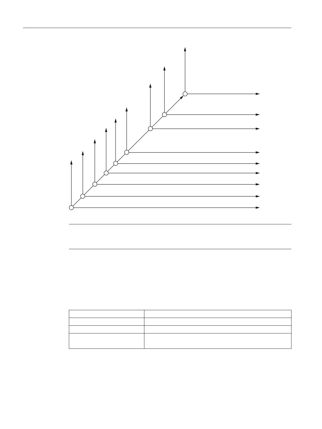
The following figure shows the G codes in ISO mode and the assignment of frames, when
system frames $P_ISO1FRAME to $P_ISO4FRAME, $P_SETFRAME and $P_EXTFRAME
are created.
ISO dialects
Function Manual, 12/2019, 6FC5397-7BP40-3BA1
25
Programming
3.2 G commands
3B,62 )5$0( * VFDOH
3B3)5$0( *
:2
6HWWDEOH IUDPH *
*
:2
3B8,)5 *
3
:2
3B,62 )5$0( *
'5RW
3B,62 )5$0( *
'5RW '5RW
3B,62 )5$0( *
PLUURU DW SURJU D[LV
3B(;7)5$0( *
/ 3
H[W2IIVHW :2
3B6(7)5$0( * VHW DFWXDO YDOXH
Figure 3-1
Mapping of ISO functions on the ISO and Siemens frames
Note
If new frames are created, the ISO G codes write in these frames. If they are not created, the
frames are created as described in the previous section.
The section below shows which G codes describe which frames, how they are created and how
the frames' reset behavior must be set to ensure a compatible response to the ISO mode
original. The reset behavior may be set to deviate from the ISO mode original with the MD
described. This may be necessary when switching from ISO mode to Siemens mode.
G51 scaling
G51 X10 writes in
$P_ISO4FRAME
Component
TRANS, SCALE
Create
$MC_MM_SYSTEM_FRAME_MASK bit 10 = 1
Reset behavior
Delete frame
$MC_CHSFRAME_RESET_MASKBit 10 = 0
ISO dialects
26
Function Manual, 12/2019, 6FC5397-7BP40-3BA1
Programming
3.2 G commands
G52 programmable work offset
G52 X10 writes in
$P_PFRAME
Component
TRANS
Create
Is always present
Reset behavior
Is deleted at Reset
G54 - G59 P1...100 adjustable work offset
G52 - G59
$P_UIFER
Component
TRANS
Create
Is always present
Reset behavior
G54 is active after Reset
$MC_EXTERN_GCODE_RESET_VALUES[13] = 1
G68 3DRot
G68 X Y I J K R
$P_ISO3FRAME
Component
TRANS, SCALE
Create
$MC_MM_SYSTEM_FRAME_MASK bit 9 = 1
Reset behavior
Delete frame
$MC_CHSFRAME_RESET_MASKBit 9 = 0
G68 2DRot
G68 X Y R
$P_ISO2FRAME
Component
TRANS, SCALE
Create
$MC_MM_SYSTEM_FRAME_MASK bit 8 = 1
Reset behavior
Delete frame
$MC_CHSFRAME_RESET_MASKBit 8 = 0
G51.1 mirroring
G51.1 X Y
$P_ISO1FRAME
Component
TRANS, MIRROR
Create
$MC_MM_SYSTEM_FRAME_MASK bit 7 = 1
Reset behavior
Delete frame
$MC_CHSFRAME_RESET_MASKBit 7 = 0
G92 set actual value
G92 X Y R
$P_SETFRAME
Component
TRANS
ISO dialects
Function Manual, 12/2019, 6FC5397-7BP40-3BA1
27
Programming
3.2 G commands
Create
$MC_MM_SYSTEM_FRAME_MASK bit 0 = 1
Reset behavior
Frame is retained after Reset
$MC_CHSFRAME_RESET_MASKBit 0 = 1
G10 L2 P0
G10 L2 P0
$P_EXTFRAME
Component
TRANS
Create
$MC_MM_SYSTEM_FRAME_MASK bit 1 = 1
Reset behavior
Delete frame
$MC_CHSFRAME_RESET_MASKBit 1 = 0
If all frames are created, the frames with FINE components no longer have to be configured for
ISO mode. The MD18600 $MN_MM_FRAME_FINE_TRANS does not have to be set to 1. If a
switch is made from ISO mode to Siemens mode and a function used there which requires a
fine offset (e.g. G58, G59), $MN_MM_FRAME_FINE_TRANS = 1 must always be true.
G54.1
G54.1 Pxx is an alternative way of writing G54 Pxx. The functionality is identical. The P address
must always be programmed in the block for G54.1. If P is not programmed, alarm 12080
(syntax fault) is output.
Display of extended work offset G54 Pxx
In the past when working in ISO dialect T, G54.1 P.. could not be programmed. G code group
14 in ISO dialect T has now had G code G54.1 added to it and G54.1 is now displayed for the
programmed P by default.
When programming G54 Pxx or G54.1 Pxx, to date when working in ISO dialect M, G code
display G54.1 was used.
MD20734 $MC_EXTERN_FUNCTION_MASK bit 11 can now be used to activate the system
such that the programmed P is also displayed after the dot in the G code display.
Programmed
Bit 11 = 1
Bit 11 = 0
G54 P1
Display G54P1
G54.1
G54 P28
Display G54P28
G54.1
G54.1 P28
Display G54P28
G54.1
G54 P48
Display G54P48
G54.1
G54.1 P48
Display G54P48
G54.1
3.2.5
Writing work offset with G10
G10 can be used to write out the work offsets from the part program.
G10 L2 P1...P6 X.. Y..
;G54.. G59
ISO dialects
28
Function Manual, 12/2019, 6FC5397-7BP40-3BA1
Programming
3.2 G commands
G10 L20 P1...P100
;additional adjustable NV
G10 L2 P0
;external extOffset NV
These work offsets are mapped on the same frames as the work offsets which already exist for
ISO dialect M.
The G10 command is extended for ISO dialect T:
Writing system data
G10 Pxx X Y Z ;writing tool compensation data
Depending on the MD20734 $MC_EXTERN_FUNCTION_MASK, bit 1, G10 Pxx is used to
write tool geometry or tool wear.
$MC_EXTERN_FUNCTION_MASK, bit 1 = 0:
P > 100 writing geometry values
P < 100 writing wear values
$MC_EXTERN_FUNCTION_MASK, bit 1 = 1:
P > 10000 writing geometry values
P < 10000 writing wear values
See also
Decoupling the frames between Siemens and ISO mode (Page 25)
3.2.6
Programming the decimal point
Overview
In the ISO dialect mode, there are two notations for weighting programmed values without a
decimal point:
● Pocket calculator notation
Values without decimal points are interpreted as mm, inch or degree.
● Standard notation
Values without decimal point are multiplied by a conversion factor.
The setting is done over MD10884 $MN_EXTERN_FLOATINGPOINT_PROG.
There are two different conversion factors, IS-B and IS-C. This evaluation relates to the
addresses X Y Z U V W A B C I J K Q R and F.
Example:
ISO dialects
Function Manual, 12/2019, 6FC5397-7BP40-3BA1
29
Programming
3.2 G commands
Linear axis in mm:
● X100.5
corresponds to a value with decimal point: 100.5 mm
● X 1000
- Calculator notation: 1,000 mm
- Standard notation:
IS-B: 1,000* 0.001= 1 mm
IS-C: 1,000* 0.0001= 0.1 mm
ISO dialect M
Different conversion factors for IS-B and IS-C
Address
Unit
IS-B
IS-C
Linear axis
mm
0.001
0.0001
inch
0.0001
0.00001
Rotary axis
deg
0.001
0.0001
F feed G94 (mm/inch per min.)
mm
1
1
inch
0.01
0.01
F feed G95 (mm/inch per min.)
mm
0.01
0.01
inch
0.0001
0.0001
F thread lead
mm
0.01
0.01
inch
0.0001
0.0001
C chamfer
mm
0.001
0.0001
inch
0.0001
0.00001
R radius, G10 toolcorr
mm
0.001
0.0001
inch
0.0001
0.00001
Q
mm
0.001
0.0001
inch
0.0001
0.00001
I, J, K IpoParameter
mm
0.001
0.0001
inch
0.0001
0.00001
G04 X or U
s
0.001
0.001
A angle contour definition
deg
0.001
0.0001
G74, G84 tapping cycles
$MC_EXTERN_FUNCTION_MASK
Bit 8 = 0 F as feed such as G94, G95
Bit 8 = 1 F as thread lead
ISO dialects
30
Function Manual, 12/2019, 6FC5397-7BP40-3BA1
Programming
3.2 G commands
ISO dialect T
Different conversion factors for IS-B and IS-C
Address
Unit
IS-B
IS-C
Linear axis
mm
0.001
0.0001
inch
0.0001
0.00001
Rotary axis
deg
0.001
0.0001
F feed G94 (mm/inch per min.)
mm
1
1
inch
0.01
0.01
F feed G95 (mm/inch per rotation)
$MC_EXTERN_FUNCTION_MASK
Bit 8 = 0
mm
0.01
0.01
inch
0.0001
0.0001
Bit 8 = 1
mm
0.0001
0.0001
inch
0.000001
0.000001
F thread lead
mm
0.0001
0.0001
inch
0.000001
0.000001
C chamfer
mm
0.001
0.0001
inch
0.0001
0.00001
R radius, G10 toolcorr
mm
0.001
0.0001
inch
0.0001
0.00001
I, J, K Ipo parameters
mm
0.001
0.0001
inch
0.0001
0.00001
G04 X or U
0.001
0.001
A angle contour definition
0.001
0.0001
G76, G78 tapping cycles
$MC_EXTERN_FUNCTION_MASK
Bit 8 = 0 F as feed such as G94, G95
Bit 8 = 1 F as thread lead
G84, G88 tapping cycles
$MC_EXTERN_FUNCTION_MASK
Bit 9 = 0 G95 F
mm
0.01
0.01
inch
0.0001
0.0001
Bit 8 = 1 G95 F
mm
0.0001
0.0001
inch
0.000001
0.000001
3.2.7
Rapid lifting with G10.6
Function
A retraction position for the rapid lifting of a tool can be activated with G10.6 <Axis position>
(e.g. in case of tool breakage). The retraction motion itself is started with a digital signal. The
NC's 2nd rapid input is used as the start signal.
ISO dialects
Function Manual, 12/2019, 6FC5397-7BP40-3BA1
31
Programming
3.2 G commands
Another rapid input (1-8) can also be selected with the 10820
$MN_EXTERN_INTERRUPT_NUM_RETRAC machine datum.
In Siemens mode, activation of the retraction motion comprises several part program
commands.
N10 G10.6 X19.5 Y33.3 give rise to NCK internal:
N10 SETINT (2) PRIO=1 CYCLE3106 LIFTFAST
;activate interrupt input
N30 LFPOS
; select lifting mode
N40 POLF[X]=19.5 POLF[Y]=33.3
;program lifting positions for x19.5
;and y33.3
N70 POLFMASK(X, Y)
;activate retraction of x and y axis
;
These part program commands are combined internally to one block with G10.6.
An interrupt program (ASUB) must also be defined to activate an interrupt input (SETINT(2)).
If no such program is defined, the part program cannot be continued because it is aborted after
the retraction motion with a reset alarm. The interrupt program (ASUB) CYCLE3106.spf is
always used for the rapid retraction with G10.6. If the CYCLE3106.spf is not available in the part
program memory, the alarm 14011 "Program CYCLE3106 not available or not released for
processing" is output with G10.6 in a part program block.
The response of the control system after the rapid retraction is defined in ASUB
CYCLE3106.spf. If the axes and the spindle are stopped after the rapid retraction, M0 and M5
must be programmed in CYCLE3106.spf. If CYCLE3106.spf is a dummy program that contains
only M17, the part program is continued without any interruption after the rapid retraction.
If rapid retraction is activated with the programming G10.6 <Axis position>, then the change in
input signal of the 2nd NC rapid input from 0 to 1 aborts the current movement and the position
programmed in the G10.6 block is moved at rapid traverse. Here, the positions are approached
as absolute or incremental, as programmed in the G10.6 block.
The function is deactivated with G10.6 (without position specification). Rapid retraction via the
input signal of the 2nd rapid NC input is blocked.
Siemens
The rapid lifting function with G10.6 can be partly covered with the function POLF[<axis name>]
= <retraction position>. The function also retracts to the programmed position. ISO dialect
original's functionality is not however retained. If the interrupt point cannot be approached
directly, the obstruction must be bypassed manually.
Additional information on the fast retraction function is provided in the NC Programming
Programming Manual.
Constraints
Only one axis can be programmed for rapid retraction.
ISO dialects
32
Function Manual, 12/2019, 6FC5397-7BP40-3BA1
Programming
3.2 G commands
3.2.8
Multiple-start threads with G33
The syntax G33 X.. Z.. F.. Q.. is used in ISO dialect T and M mode to program multiple-start
threads. The following applies:
X.. Z.. = End point of the thread
F.. = Thread lead
Q.. = Starting angle
Threads with offset slides are programmed by specifying the mutually offset start points in the
G33 block. The starting point offset is specified as the absolute angle position under the
address "Q". The related setting data 42000 ($SD_THREAD_START_ANGLE) is modified
accordingly.
Example:
Q45000 means: Start offset 45.000 degrees
Range of values: 0.0000 to 359.999 degrees
The start angle must always be programmed as an integer. The input resolution of the angular
data is 0.001 degree.
Example:
N200 X50 Z80 G01 F.8 G95 S500 M3
N300 G33 Z40 F2 Q180000
A thread with a lead of 2 mm and a starting point offset of 180 degree is produced.
3.2.9
Thread with variable lead G34 (ISO dialect T)
The syntax G34 X.. Z.. F.. K.. is used in ISO dialect T mode to program threads with variable
lead. The following applies:
X.. Z..= End point of the thread
F..= Thread lead
K..= Increase in thread lead (positive value) or decrease in thread lead (negative value)
G34 is used to increment or decrement the lead during each spindle revolution by the value
programmed under address K.
Example:
N200 X50 Z80 G01 F.8 G95 S50 M3
N300 G91 G34 Z25.5 F2 K0.1
The programmed distance of 25.5 mm corresponds to 10 spindle revolutions.
3.2.10
Dwell time in spindle revolutions G04
MD20734 $MC_EXTERN_FUNCTION_MASK, bit 2 is used to determine how the programmed
dwell time is interpreted in a G04 block. The dwell time can be programmed with G04 X U or P.
ISO dialects
Function Manual, 12/2019, 6FC5397-7BP40-3BA1
33
Programming
3.2 G commands
Bit 2 = 0: Dwell time is always interpreted in [s].
Bit 2 = 1: If G95 is active, dwell time is interpreted in spindle revolutions
In the instance of standard notation, X and U values without a decimal point are converted into
internal units depending on IS-B or IS-C. P is always interpreted in internal units.
Example:
N5 G95 G04 X1000
Standard notation1000 * 0.001 = 1 spindle revolution
pocket calculator notation: 1000 spindle revolutions
3.2.11
Scaling (G50, G51) and mirroring G50.1, G51.1 (ISO dialect M)
The selection for scaling and mirroring takes place with G51, G51.1.
A distinction is made between two options in scaling:
● Axial scaling with the parameters I, J, K
If I, J, K is not programmed in the G51 block, the relevant default value from the setting data
43120 DEFAULT_SCALE_FACTOR_AXIS is effective.
Negative axial scaling factors lead additionally to mirroring.
● Scaling in all axes with the scaling factor P
If P is not written in the block G51, the default value from the setting data is effective.
Negative P values are not possible.
The scaling factors are multiplied either with 0.001 or 0.00001.
Note
If a factor other than "1" is programmed for the I, J, K parameters, or if there is no address
(default value for I, J, K is effective), the contour is also scaled.
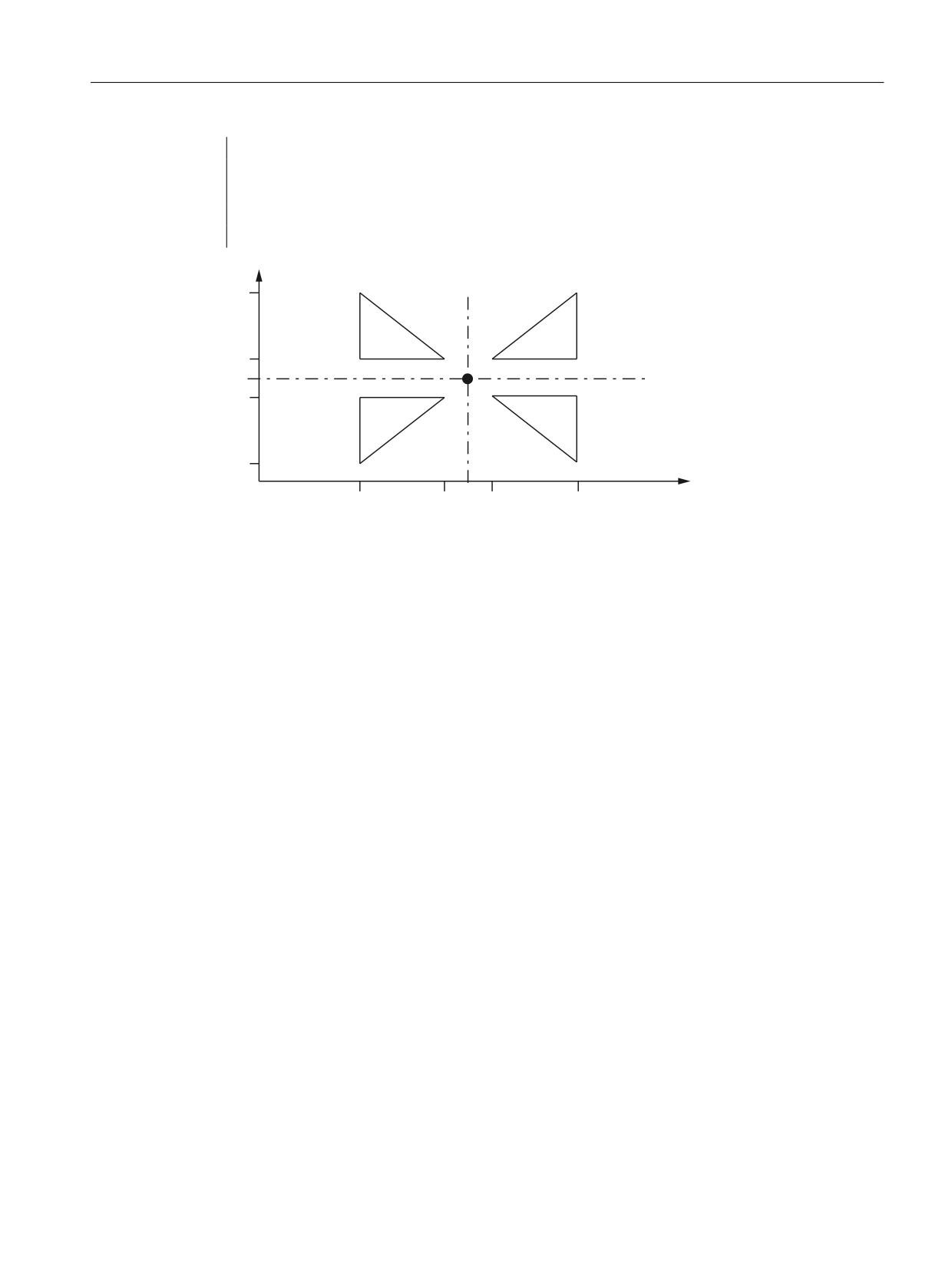
Example
00512 (part program)
N10 G17 G90 G00 X0 Y0
; Approach start position
N30 G01 G94 F6000
N32 M98 P0513
; 1) Contour programmed as in the subprogram
N34 G51 X0. Y0. I-1000 J1000
; 2) Mirror contour by X
N36 M98 P0513
N38 G51 X0. Y0. I-1000 J-1000
; 3) Mirror contour by X and Y
N40 M98 P0513
N42 G51 X0. Y0. I1000 J-1000
; 4) Mirror contour by Y
N44 M98 P0513
N46 G50
; Scaling and mirroring deselection
N50 G00 X0 Y0
N60 M30
00513 (subprogram)
ISO dialects
34
Function Manual, 12/2019, 6FC5397-7BP40-3BA1
Programming
3.2 G commands
N10 G90 X10. Y10.
N20 X50
N30 Y50
N40 X10. Y10.
N50 M99
6WDUW SRLQW
Figure 3-2
Scaling and mirroring
System parameter setup for the scaling and mirroring example:
MD22910 $MC_WEIGHTING_FACTOR_FOR_SCALE = 0
MD22914 $MC_AXES_SCALE_ENABLE = 1
MD10884 $MN_EXTERN_FLOATINGPOINT_PROG = 0
MD10886 $MN_EXTERN_INCREMENT_SYSTEM = 0
When MD22914 $MC_AXES_SCALE_ENABLE = 0, axial scaling is not possible.
When scaling, the reference point is always the workpiece zero, the reference point cannot be
programmed.
Mirroring
G51.1 can be used to mirror workpiece shapes on coordinate axes.
Mirroring takes place on a mirroring axis which is parallel to X, Y or Z and whose position is
programmed with X, Y or Z. G51.1 X0 is used to mirror on the X axis, G51.1 X10 is used to mirror
on a mirroring axis that runs 10 mm parallel to the X axis.
All axes in the channel and not just the geometry axes can be mirrored.
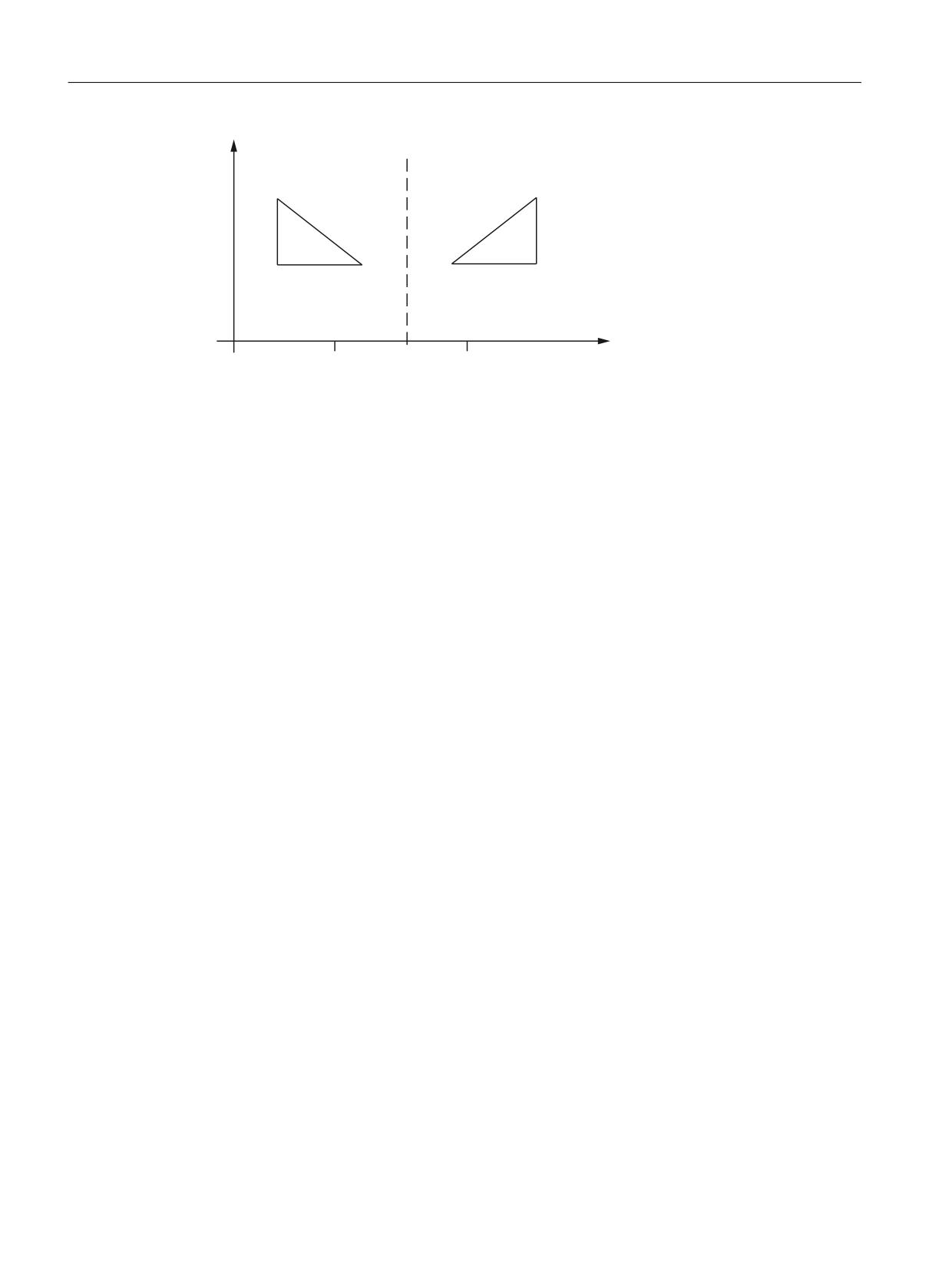
G51.1 has an additive effect, i.e. following N5 G51.1 X10 and N10 G51.1 Y10, mirroring in X
and V is active.
Example: G51.1 X80.
Mirroring is undertaken on a mirroring axis which is parallel to Y and which the X axis bisects
at position 80.
ISO dialects
Function Manual, 12/2019, 6FC5397-7BP40-3BA1
35
Programming
3.2 G commands
<
0LUURUHG
2ULJLQDO
*
;
;
Figure 3-3
Mirroring on a mirroring axis parallel to Y
If standard notation is active (see Section "Decimal point programming"), the axis positions
without a decimal point are interpreted in internal units.
Mirroring with G50.1 X0 Y0 is deselected. Deselection by axis is also possible. Following G50.1
X0, only mirroring in the X axis is deselected, all mirroring in other axes remains active.
G51.1 and G50.1 make up a block.
G51.1 is mapped in the channel-specific basic frame [1]. MD28081
$MC_MM_NUM_BASE_FRAMES >=2 must be set for this.
If the basic frame [1] is changed in Siemens mode, this impacts directly on function in ISO mode.
If the frame is deleted in all frame components, this corresponds to G50.1 X0 Y0.. in all axes.
G51.1 is deselected with Reset.
See also
Decoupling the frames between Siemens and ISO mode (Page 25)
3.2.12
G60 directed positioning
G60 is used in ISO dialect original to compensate for backlash. In Sinumerik, this is achieved
using internal backlash compensation, which is why Siemens mode does not have a G function
to match the G60 used in ISO dialect original.
A G macro call cannot take the place of G60 because two subprogram calls cannot be
undertaken in an NC block. Because directed positioning (backlash) must be executed before
the NC block is processed, calling a G macro at the end of the block would be too late.
Since G60 is used to compensate for backlash and this function can be activated using the axial
machine data $MA_BACKLASH[ ], G60 is skipped in ISO mode without triggering a response.
If the G60 programming is to be taken into account when processing shell cycles, this
information is made available in cycle variable $C_G60_PROG. If G60 is programmed,
$C_G60_PROG = 1 is set and $C_G60_PROG is deleted again when returning to the
subprogram. If a block also needs to contain information as to whether the cycle call is
programmed, this is obtained from cycle variable $C_G_PROG. A G60 functionality can be
added in the shell cycles using the information from these two system variables. The
ISO dialects
36
Function Manual, 12/2019, 6FC5397-7BP40-3BA1

Programming
3.2 G commands
information regarding whether a modal cycle is active can also be found in system variable
$P_MC ($P_MC = 1 -> a modal subprogram is active).
$C_G60_PROG is only set to 1 if G60 is programmed in an NC block as if G60 were a non-
modal effective G function.
Example:
N32 G00 X0. Y0. Z0. R0.
N33 G60 X11.8407 Y2.4418
;$C_G60_PROG = 1, $C_G_PROG = 0, $P_MC = 0
N34 G60 G83 X11.8407 Y2.4418 Z-6.9051 R-5.9 Q0.25F8
;$C_G60_PROG = 1,
;$C_G_PROG = 1, $P_MC = 1
N35 G60 X9.3969 Y2.6099
;$C_G60_PROG = 1, $C_G_PROG = 0, $P_MC = 1
N36 X6.4128 Y2.4511
;$C_G60_PROG = 0, $C_G_PROG = 0, $P_MC = 1
N37 G60 X4.0368 Y2.3131
;$C_G60_PROG = 1, $C_G_PROG = 0, $P_MC = 1
N38 G60 X1.3995 Y2.5461
:$C_G60_PROG = 1, $C_G_PROG = 0, $P_MC = 1
N39 G80
;$C_G60_PROG = 0, $C_G_PROG = 0, $P_MC = 0
cycle383m.spf
PROG CYCLE383M
IF $C_G60_PROG == 1
;G60 functionality
ENDIF
;Continue with shell cycle functionality
3.2.13
2D/3D rotation G68/G69 (ISO dialect M)
2D rotation
The coordinate system is rotated around the vertical axis of the activated plane.
Programming
G68 X.. Y.. R..
X.. Y..:
Coordinates of the pivot point, in relation to the current workpiece zero. If no
coordinate is programmed, the pivot point lies in the actual value. The value is
always interpreted as absolute.
R:
The angle of rotation, depending on G90/G91, has an absolute or incremental
effect. If no angle is programmed, the angle from the setting data 42150 $SA_DE-
FAULT_ROT_FACTOR_R is active. G68 must be alone in the block.
G69
Rotation OFF; other commands can be programmed in this block.
G68 is mapped on the channel-specific basic frame 2. MD 28081
$MC_MM_NUM_BASE_FRAMES >= 3 must be set for this.
ISO dialects
Function Manual, 12/2019, 6FC5397-7BP40-3BA1
37

Programming
3.2 G commands
A programmed angle R is not entered in setting data 42150
$SA_DEFAULT_ROT_FACTOR_R. This setting data can only be written by hand and then only
takes effect if there is no R programmed in the G68 block.
3D rotation
The G code G68 is extended for 3D rotation.
Programming
G68 X.. Y.. Z.. I.. J.. K.. R..
X.. Y.. Z..:
Coordinates of the pivot point, in relation to the current workpiece zero. If
no coordinate is programmed, the pivot point lies in the workpiece zero.
The value is always interpreted as absolute. The coordinates of the pivot
point act as a work offset. G90/91 in the block does not affect the G68
command.
I.. J.. K..:
Vector in pivot point. The coordinate system is rotated around this vector
at angle R.
R:
Angle of rotation. The angle of rotation always has an absolute effect. If
no angle is programmed, the angle from the setting data 42150 $SA_DE-
FAULT_ROT_FACTOR_R is active. G68 must be alone in the block.
The 2D or 3D rotation differentiation takes place only through the programming of the vector I,
J, K. If there is no vector in the block, G68 2DRot is selected. If there is a vector in the block, G68
3DRot is selected.
If a vector is programmed with the length 0 (I0, Y0, K0), alarm 12560 "Programmed value
outside the permissible limits" is triggered.
Two rotations can be switched one after the other with G68. If so far no G68 has been active
in a block containing G68, then the rotation is written to the channel-specific basic frame 2. If
G68 is already active, the rotation is written to the channel-specific basic frame 3. Thus, both
rotations follow one another.
3D rotation is ended with G69. If two rotations are active, both are deselected with G69. G69
must not be alone in the block.
See also
Decoupling the frames between Siemens and ISO mode (Page 25)
3.2.14
Double slide or double turret processing G68/G69
Function
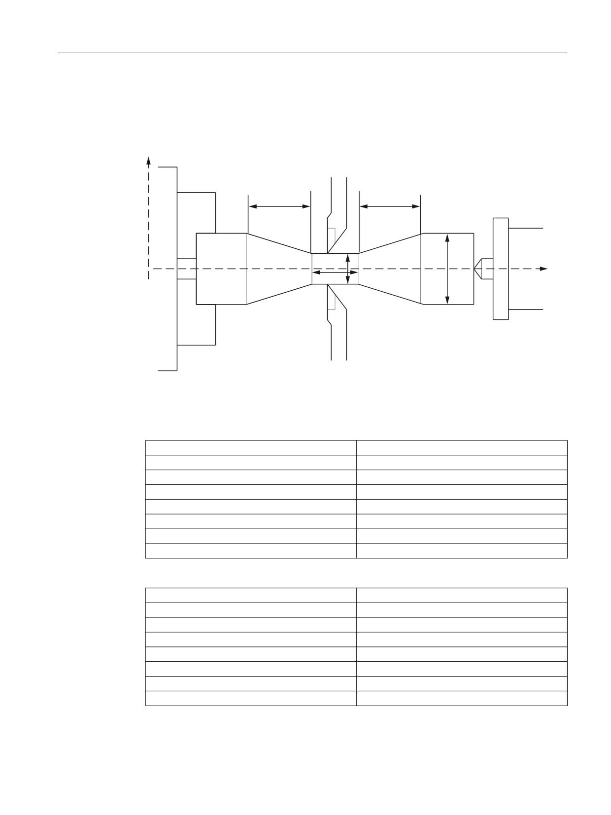
The G68/G69 function can be used to control the processing of rotating parts on both sides.
Both processing with a double slide in two channels and processing in one channel with two
tools which are permanently linked to one another at a distance x.
ISO dialects
38
Function Manual, 12/2019, 6FC5397-7BP40-3BA1
Programming
3.2 G commands
MD10812 $MN_EXTERN_DOUBLE_TURRET_ON is used to define whether processing in the
two channels is synchronized (= FALSE) or whether the two permanently linked tools are used
in turn for processing (= TRUE).
When using permanently linked tools, G68 is used to activate distance x entered in setting data
42162 $SC_EXTERN_DOUBLE_TURRET_DIST as an additive work offset in the X axis.
Because the second tool processes the opposite side of the rotating part, G68 is also used to
activate mirroring around the Z axis (X axis direction change). The work offset and mirroring for
the 2nd tool are activated with the next block with axial motion.
G69 is used to reverse the work offset and processing continues with the 1st tool.
G68 and G69 must be programmed in a block on their own.
During tool length compensation in the X axis for the second tool, the correction sign must be
taken into account. The sign must be entered as if the X axis were not mirrored. Alternatively
the setting data 42900 $SC_MIRROR_TOOL_LENGTH (mirror tool length compensation) and
42190 $SC_MIRROR_TOOL_WEAR (mirror wear values of tool length compensation) must be
set.
MD10610 $MN_MIRROR_REF_AX must either be 0 or 1. The X or 1st axis is then always
mirrored.
If G68 is programmed and G68 is already active, the G function is skipped. The same applies
to G69.
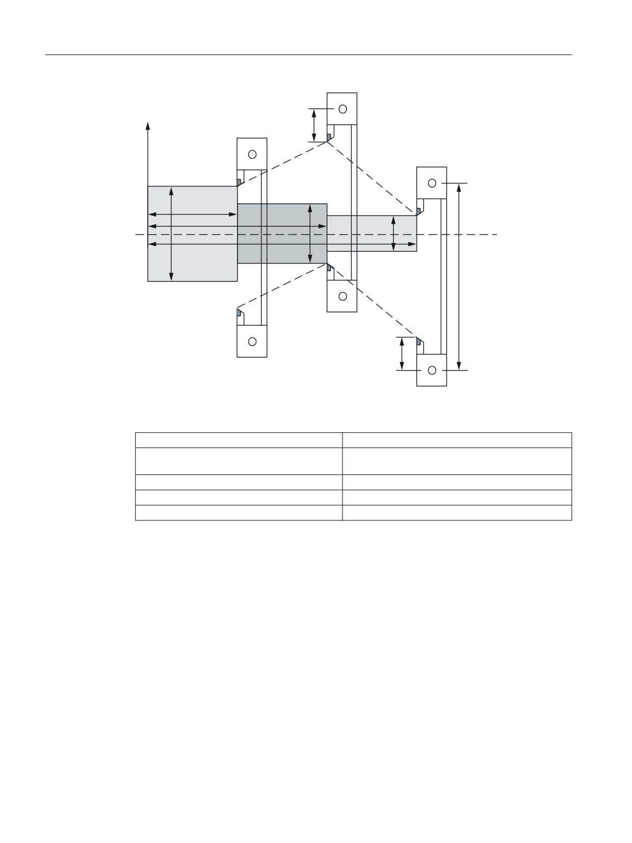
Double turret head: $MN_EXTERN_DOUBLE_TURRET_ON = TRUE
The example below shows processing with two permanently linked tools. Machine data
$MN_EXTERN_DOUBLE_TURRET_ON = TRUE must be set for the function to be effective.
If the setting data 42162 $SC_EXTERN_DOUBLE_TURRET_DIST = 0, alarm 12728 "Distance
for double turret not set" is output.
ISO dialects
Function Manual, 12/2019, 6FC5397-7BP40-3BA1
39
Programming
3.2 G commands
;
7RRO RIIVHW
7RRO 7
=
7RRO RIIVHW
7RRO 7
Figure 3-4
Processing with two permanently linked tools
Example:
N100 X40. Z180. G1 F1 G95 S1000 M3 T1
N110 G68
;Activate mirroring around Z and additive work offset
(220 mm)
N120 X80. Z120. T2
N130 G69
;Deactivate mirroring and additive work offset
N140 X120. Z60 T1
Double slide processing: $MN_EXTERN_DOUBLE_TURRET_ON = FALSE
If MD10812 $MN_EXTERN_DOUBLE_TURRET_ON = FALSE, G68 undertakes channel
synchronization. If G68 is programmed in a channel, processing is stopped until G68 is
detected in the second channel. This function can be used to synchronize the 1st and 2nd
channel. No more synchronization is undertaken. For the two tools to act in a synchronous
manner in subsequent processing, the programmed movements and feeds must be the same
in the two channels.
Wait mark 1 is used for G68 and wait mark 2 is used for G69 to synchronize the first two
channels. The first two M functions must not therefore be used at the same time for channel
synchronization in the same part program (see chap. "Program coordination between two
channels and M commands").
G68 only takes effect in the first two channels. If G68 is programmed in another channel and if
MD10812 $MN_EXTERN_DOUBLE_TURRET_ON = FALSE, G68 is skipped.
The function is used for producing thin rotating parts. The two tools should therefore perform
the same movement on the respective opposite side of the rotating part, mirrored around the
ISO dialects
40
Function Manual, 12/2019, 6FC5397-7BP40-3BA1
Programming
3.2 G commands
Z axis. The same traversing and feeds must be programmed in the two channels for this to take
place.
Example of synchronous processing with two channels:
;
7RRO FKDQQHO
=
7RRO FKDQQHO
Figure 3-5
Synchronous processing with two channels
Example:
Channel 1:
N10 ...
- " -
N1000 G68
;Start synchronization
N1010 G01 X30 Z120 G95 F1.2 S1000 M3
N1020 X15 Z80
N1030 Z65
N1040 Z25 X40
N1050 G69
;Synchronization off
Channel 2:
N10 ...
- " -
N2000 G68
;Start synchronization
N2010 X30 Z120 G01 G95 F1.2 S1000 M3
N2020 X15 Z80
N2030 Z65
N2040 X40 Z25
N2050 G69
;Synchronization off
In ISO dialect original, channel synchronization is also undertaken when G68 is active.
ISO dialects
Function Manual, 12/2019, 6FC5397-7BP40-3BA1
41
Programming
3.2 G commands
3.2.15
Polar coordinates G15/G16 (ISO dialect M)
Programming
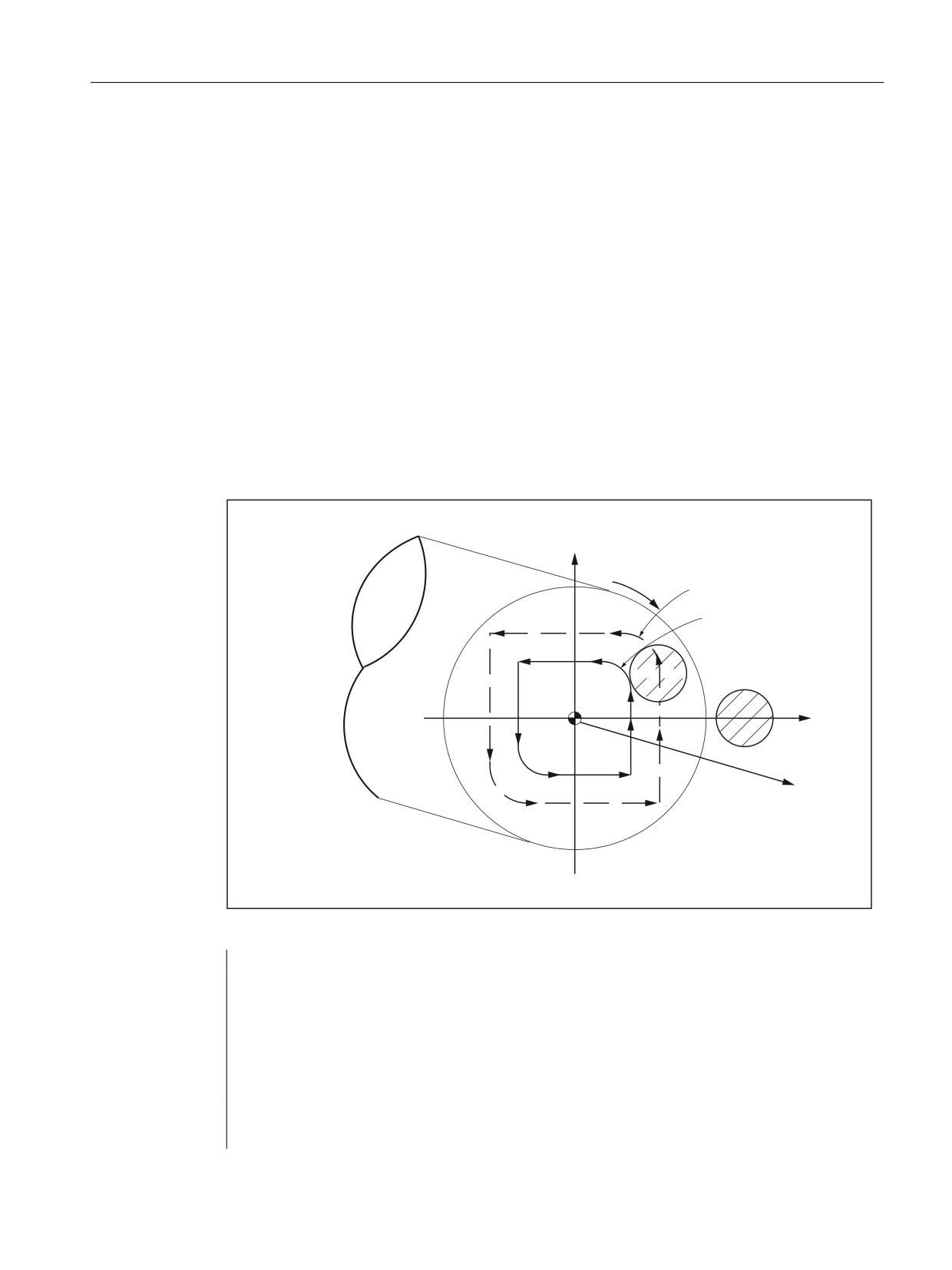
When in ISO dialect mode, NC program parts in which polar programming is undertaken are
started using start command G16. Until the end command G15 is issued, the coordinates of the
end points are interpreted as radius and angle polar coordinate values in the current plane.
The first of the plane's axes is interpreted as a pole radius and the second axis as a pole angle,
i.e. for G17, X is the radius and Y the angle.
After G16, in each block up to G15 the pole is reset and the pole is reset at G17:
● G90 X: The pole lies at the workpiece zero
● G91 X: The pole lies at the current position
● No X in block: The pole lies at the workpiece zero
Example:
N5 G17 G90 X0 Y0 F5000
N10 G16 X50 Y90
;Polar coordinates ON
;the pole is the workpiece zero
;Position X=0 and Y=50 in the Cartesian coordinate system
N20 G90 Y0
;No X in the block
;Pole angle =0, radius= of the last programmed PolarRa-
dius=50
;Position X=50 and Y=0
N30 Y36.87
;The pole is at the workpiece zero
;Pole angle =36.87, radius=50
;Position X=40 and Y=30
G15
The pole radius is always taken as absolute value, while the pole angle can be interpreted as
absolute value as well as incremental value.
Programmed angle
When polar coordinates programming is active, the programmed angle can be read via system
variable $P_AP.
This variable is used in the shell cycle. Before the pole is reset, the angle must be saved during
incremental programming because the angle is deleted.
Pole programing is ended with G15. The pole radius is set to 0.
ISO dialects
42
Function Manual, 12/2019, 6FC5397-7BP40-3BA1
Programming
3.2 G commands
3.2.16
Interpolation of polar coordinates G12.1/G13.1 (G112/G113)
Function
With G12.1 and G13.1 an interpolation is activated and deactivated in the machining plane
between a rotary axis and a linear axis. A further linear axis may be present perpendicular to
this plane. This function corresponds to the TRANSMIT function in the Siemens mode. In
Siemens mode, two TRANSMIT transformations may be parameterized. The 1st TRANSMIT
data block which must correspond to the 2nd transformation data block is always used for
G12.1.
Additional information on the TRANSMIT function is provided in the Transformations Function
Manual.
Example
5RWDU\ D[LV &
1
1
1
1
; D[LV
1
1
1
1
1
= D[LV
Figure 3-6
Example of the interpolation of polar coordinates
N010 T0101
N20 G94
N30 G90
N40 G291
N100 G00 X60. C0. Z50.
N200 G12.1
N201 G42 G01 X20. F1000.
N202 Y10.
N203 G03 X10. Y20. R14.
ISO dialects
Function Manual, 12/2019, 6FC5397-7BP40-3BA1
43
Programming
3.2 G commands
N204 G01 X-20.
N205 Y-10.
N206 G03 X-10.0 Y-20.0 R14.
N207 G01 X20.
N208 Y0
N209 G40 X60.
N210 G13.1
N300 G00 Z50
N180 M30
Note
No geo axis interchange (parallel axes with G17 (G18, G19)) should be active.
3.2.17
Cylindrical interpolation G07.1 (G107)
Function
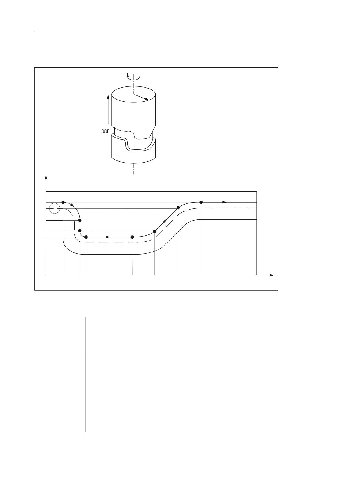
Randomly running grooves can be cut on cylindrical workpieces with function G07.1 (cylindrical
interpolation). The path of the grooves is programmed with reference to the unwrapped, level
surface of the cylinder. The cylindrical interpolation is started with G07.1 with the specification
of the cylinder radius (G07.1 C<cylinder radius>) and ended with G07.1 C0 (radius = 0).
Note
The function is mapped internally on the TRACYL Siemens functionality. In ISO dialect mode,
the 1st TRACYL transformation and the 1st transformation data block are always activated with
G07.1. The 2nd TRACYL function cannot be activated in ISO dialect mode. A detailed
description and parameterization of the 1st TRACYL function can be found in the following
documentation:
Description of functions for extended functions, chapter M1 and
Programming Manual for preparing for work, chapter 7 "Transformations".
Constraints
For Siemens the rotary axis must be defined for cylindrical interpolation in machine data.
With ISO dialect, the rotary axis is defined for cylindrical interpolation with G07.1 programming
<Rotary axis name>
ISO dialects
44
Function Manual, 12/2019, 6FC5397-7BP40-3BA1
Programming
3.2 G commands
Example
&
5DGLXV
=
=
PP
1
1
120
1
1
1
1
1
1
1
'HJU
Figure 3-7
Example of cylindrical interpolation G07.1
Example of programming in ISO dialect mode:
%0001
N05 G00 G90 Z100.0 C0
N10 G01 G91 G18 Z0 C0
N20 G07.1 C57299
;select cylindrical interpolation with radius
57.299 mm
N30 G90 G01 G42 Z120.0 D01 F250
N40 C30.0
N50 G02 Z90.0 C60.0 R30.0
N60 G01 Z70.0
N70 G03 Z60.0 C70.0 R10.0
N80 G01 C150.0
N90 G03 Z70.0 C190.0 R75.0
N100 G01 Z110.0 C230.0
N110 G02 Z120.0 C270.0 R75.0
ISO dialects
Function Manual, 12/2019, 6FC5397-7BP40-3BA1
45
Programming
3.2 G commands
N120 G01 C360.0
N130 G40 Z100.0
N140 G07.1 C0
;deselect cylindrical interpolation
N150 M30 ;
Example of programming in Siemens mode: The Y axis is assigned to the rotary axis as a linear
axis.
%0001
N05 G00 G90 Z100 C0
N10 G01 G91 G18 Z0 C0;
N20 TRACYL(114.598)
;select cylindrical interpolation with radius
57.299 mm
N30 G90 G01 G42 Z120 D01 F250
N40 Y30
N50 G02 Z90 Y60 RND=30
N60 G01 Z70
N70 G03 Z60.0 Y70 RND=10
N80 G01 Y150
N90 G03 Z70 Y190 RND=75
N100 G01 Z110 Y230
N110 G02 Z120 Y270 RND=75
N120 G01 Y360
N130 G40 Z100
N140 TRAFOOF
;deselect cylindrical interpolation
N150 M30 ;
3.2.18
Interrupt program with M96/M97 (ASUB)
M96
A subprogram can be defined as an interrupt routine with the M96 P<Program No.>.
The start of this program is triggered by an external signal. To start the interrupt routine, the 1st
rapid NC input is used from among the eight inputs available in the Siemens mode. Another
rapid input (1 to 8) can also be selected with MD10818
$MN_EXTERN_INTERRUPT_NUM_ASUP.
The function is mapped on the Siemens syntax SETINT(x) <CYCLE396> [PRIO=1].
The interrupt program programmed with Pxxxx is called in shell cycle CYCLE396 in ISO mode.
The program number can be found in $C_PI. At the end of the shell cycle, MD10808
$MN_EXTERN_INTERRUPT_BITS_M96, bit 1 is evaluated and either positioned on the
interruption point with REPOS or continued with the next block. The value programmed with "P"
can be found in the new cycle variable $C_PI without a leading zero. This must be increased
to four digits in the shell cycle before the subprogram is called.
Example:
ISO dialects
46
Function Manual, 12/2019, 6FC5397-7BP40-3BA1
Programming
3.2 G commands
N0020 M96 P5
Call in shell cycle
progName = "000" << $C_PI
ISOCALLprogName
See also how to handle 8-digit program numbers if MD20734
$MC_EXTERN_FUNCTION_MASK, bit 6 is set.
End of interruption (M97)
The interrupt program is deactivated with M97. Only after the next activation with M96 can the
interrupt routine be started with the external signal.
This corresponds to the Siemens syntax ENABLE(x).
x = Content of MD10818 $MN_EXTERN_INTERRUPT_NUM_ASUP
If the interrupt program programmed with M96 Pxx is to be called directly with the interrupt
signal (without intermediate step with CYCLE396), then machine data 20734
$MC_EXTERN_FUNCTION_MASK, bit 10 must be set. The subprogram programmed with
Pxx is then called in Siemens mode during a signal change from 0 -> 1.
The M function numbers for the interrupt function are set through machine data. MD10804
$MN_EXTERN_M_NO_SET_INT is used to determine the M number for activating an interrupt
routine, MD10806 $MN_EXTERN_M_NO_DISABLE_INT is used to determine the M number
for suppressing an interrupt routine.
Only M functions which are not standard M functions may be set. The default of the M functions
is M96 and M97. To activate the function, bit 0 must be set in MD10808
$MN_EXTERN_INTERRUPT_BITS_M96. The M functions are not output to the PLC. The M
functions are interpreted as normal auxiliary functions if bit 0 is not set.
At the end of the "interrupt" program, one normally traverses to the end position of the part
program block following the interruption block. If the part program is to be processed further
from the interruption point, there must be a REPOS instruction at the end of the "interrupt"
program, e.g. REPOSA. For this, the interrupt program must be written in the Siemens mode.
The M functions for activating and deactivating an interrupt program must be present alone in
the block. The system issues alarm 12080 "Channel %1 block %2 syntax error for text %3" if
addresses other than "M" and "P" are programmed in the block.
Information about machining cycles
In ISO dialect original you can set whether a machining cycle is to be interrupted immediately
or only at the end using an interrupt routine. To do this, the shell cycles must evaluate MD10808
$MN_INTERRUPT_BITS_M96 bit 3. If bit=1, the interrupt must be locked at the start of the
cycle with DISABLE(1) and activated again at the end of the cycle with ENABLE(1) so that the
machining cycle is not interrupted.
Because the interrupt program is only started during edge change 0/1, the interrupt input must
be monitored in the event of a locked interrupt during the cycle runtime with a synchronized
action in the shell cycle. If the interrupt signal in the cycle is changed from 0 to 1, the interrupt
signal must be set again following ENABLE(1) at the end of the shell cycle so that the interrupt
program is then started. To be able to write the interrupt input in the shell cycle, MD10361
$MN_FASTIO_DIG_SHORT_CIRCUIT[1] must be parameterized.
ISO dialects
Function Manual, 12/2019, 6FC5397-7BP40-3BA1
47
Programming
3.2 G commands
Machine data
The response of the interrupt program function can be determined from the following machine
data:
MD10808 $MN_EXTERN_INTERRUPT_BITS_M96:
Bit 0 = 0
Interrupt program is not possible as M96/M97 are normal M functions.
Bit 0 = 1
Activation of an interrupt program with M96/M97 is allowed.
Bit 1= 0
The part program is further processed with the end position of the next block following the
interrupt block (REPOSL RMEBL).
Bit 1= 1
Continue processing part program from interrupt position.
(Evaluation in interrupt program (ASUB), return with/without REPOSL)
Bit 2 = 0
The interrupt signal interrupts the current block immediately and starts the interrupt routine.
Bit 2 = 1: The interrupt routine is started only at the end of the block.
Bit 3 = 0
The machining cycle is interrupted immediately after an interrupt signal arrives.
Bit 3 = 1
The interrupt program is started only at the end of the machining cycle
(evaluation in the shell cycles)
Bit 3 must be evaluated in the shell cycles and the cycle process must be adapted accordingly.
Bit 1 must be evaluated in the interrupt program.
If Bit 1 = TRUE, REPOSL RMIBL must be used for positioning on the interruption point at the
end of the program, otherwise REPOSL RMEBL must be used for positioning on the block end
position.
Example:
N1000 M96 P1234
;Activate ASUB 1234.spf. In the case of a rising edge of
;the first high-speed input,
;the 1234.spf program is started.
N3000 M97
;Deactivation of ASUB
Before the call of the interrupt program no rapid lift (LIFTFAST) is performed. With the
increasing edge of the interrupt signal, depending on MD10808
$MN_EXTERN_INTERRUPT_BITS_M96, the interrupt program is started immediately.
Siemens constraints
The interrupt routine is treated as a normal subprogram. In other words, to be able to execute
interrupt routines, at least one subprogram level must be free. (For Siemens there are 12
program levels, for ISO dialect there are 5.)
The interrupt routine is started only during an edge change of the interrupt signal from 0 to 1.
If the interrupt signal remains permanently on 1, then the interrupt program is not restarted any
more
ISO dialects
48
Function Manual, 12/2019, 6FC5397-7BP40-3BA1
Programming
3.2 G commands
ISO dialect constraints
A program level is reserved for the interrupt routine such that all permissible program levels
may be filled before the interrupt program is called.
Depending on the machine data, the interrupt program is also started when there is a static
signal.
3.2.19
Comments
In ISO dialect mode, round brackets are interpreted as comment signs. In Siemens mode, ";"
is interpreted as a comment. To simplify matters, a ";" is also understood as a comment in ISO
dialect mode.
If the comment start sign '(' is used inside a comment again, the comment is ended only if all the
open brackets are closed again.
Example:
N5 (comment) X100 Y100
N10 (comment(comment)) X100 Y100
N15 (comment(comment) X100) Y100
In blocks N5 and N10, X100 Y100 is executed, in block N15 only Y100 because the first
bracket is closed only after X100. Everything up to that point is interpreted as a comment.
3.2.20
Skip block
The sign for skipping or suppression of blocks "/" can be used at any convenient position in a
block, i.e. even in the middle of the block. If the programmed block skip plane is active on the
date of the compilation, the block is not compiled from this point up to the end of the block. An
active block skip plane has the same effect as a block end.
Example:
N5 G00 X100. /3 YY100 --> Alarm 12080,
N5 G00 X100. /3 YY100 --> no alarm, if block skip plane 3 is active
Block skip signs within a comment are not interpreted as block skip signs
Example:
N5 G00 X100. ( /3 Part1 ) Y100
;the Y axis is traversed even when the
block skip plane 3 is active
The block skip planes /1 to /9 can be active. Block skip values <1 >9 lead to alarm 14060
"Channel %1 block %2 Impermissible skip plane for differential block skip".
The function is mapped to the existing Siemens skip planes. Unlike ISO Dialect original, / and /
1 are separate skip planes that must also be activated separately.
ISO dialects
Function Manual, 12/2019, 6FC5397-7BP40-3BA1
49
Programming
3.2 G commands
3.2.21
Auxiliary function output
M functions
ISO dialect mode
M functions are output to the PLC as auxiliary functions. The only exceptions are M98 and M99.
Predefined M functions are:
M17, M40, M41, M42, M43, M44, M45, M70, M96, M97, M98, M99.
Spindle axis switchover with M29
In ISO dialect mode, the spindle is switched to axis mode with M29. The M function number may
however also be set differently using machine datum.
MD20095 $MC_EXTERN_RIGID_TAPPING_M_NR is used to pre-set the M function number.
The machine datum is only effective in external language mode and is preset with M29. Only
the M function numbers that are not used as standard M functions can be assigned. For
example, the M function numbers M0-M5, M30, M98, M99 are not allowed.
The same function is executed in Siemens mode with M70.
MD20094 $MC_SPIND_RIGID_TAPPING_M_NR) is used to pre-set the M function number.
The machine datum is only effective in Siemens mode and is preset with M70. An M function
other than M70 can therefore also be set in Siemens mode for the spindle changeover. The
machine datum may only be assigned M function numbers that are not used as standard M
functions. M0 to M5, M17, M19, M30, M40 to M45 are not permitted.
H functions
All H functions are output to the PLC in ISO dialect M as auxiliary functions. With ISO dialect T
G Code System A, H is the incremental path of the 4th axis - only if a 4th axis is present.
T functions
T functions are output to the PLC as auxiliary functions. T also means tool selection.
D functions
The D function is output to the PLC as an auxiliary function. With ISO dialect M, the tool length
compensation is activated under address D.
B functions
If B is not an axis, the B function is output to the PLC as auxiliary function H with address
extension H1=.
Example: B1234 is output as H1 = 1234.
ISO dialects
50
Function Manual, 12/2019, 6FC5397-7BP40-3BA1
Programming
3.2 G commands
3.2.22
Approach 1st home position with intermediate point (G28)
The CYCLE328 cycle is called automatically when reading the ISO dialect command "G28
<axis>". The intermediate position (incremental or absolute) via which the home position is to
be approached is stated under <Axis>. The intermediate position and reference position are
approached in positioning mode.
The cycle only applies for the axes available with ISO dialect:
● ISO dialect M: X, Y, Z (A, B, C, U, V, W)
● ISO dialect T: X, Z, Y (C)
The cycle is always run with radius programming (DIAMOF). Active G commands become
effective again once the cycle is complete and before the cycle is called.
Various machine data must be set before the 1st home position is approached, see
"Commissioning" chap.
3.2.23
Switching precontrol on/off with G08 P..
Function
The feedforward control reduces the velocity-dependent overtravel when contouring towards
zero. Traversing with feedforward control permits higher path accuracy and thus improved
machining results.
Note
The type of feedforward control and which path axes are to be traversed with feedforward
control is specified via machine data.
Default: Velocity-dependent feedforward control
Option: Acceleration-dependent feedforward control
Example
N0010 G08 P1
; Switch on feedforward control
N0020 G1 X10 Y50 F900
N0030 G1 X20 Y70
N1000 G08 P0
; Switch off feedforward control
If G08 is programmed without "P", alarm 12470 "Channel %1 block %2 G function %3 is
unknown" is output.
In order to use G08 P1 to flexibly activate other functions such as SOFT, BRISK etc., G08 P..
is used to call cycle CYCLE308.spf.
G08 P1 alone must remain in the block.
ISO dialects
Function Manual, 12/2019, 6FC5397-7BP40-3BA1
51
Programming
3.2 G commands
3.2.24
Compressor in ISO dialect mode
The commands COMPON, COMPCURV, COMPCAD are commands of the Siemens
language and they activate a compressor function that combines several linear blocks into one
machining section. If this function is activated in Siemens mode, even linear blocks can then be
compressed in ISO mode with this function.
The blocks can at the most consist of the following commands:
● Block number
● G01, modal or in block
● Axis assignments
● Feedrate
● Comments
If a block contains other commands (e.g., auxiliary functions, other G codes, etc.), then
compression does not take place.
Value assignments with $x for G, axes and feedrate are possible, as is the skip function.
Example: These blocks are compressed:
N5 G290
N10 COMPON
N15 G291
N20 G01 X100. Y100. F1000
N25 X100 Y100 F$3
N30 X$3 /1 Y100
N35 X100 (Axis 1)
These blocks are not compressed:
N5 G290
N10 COMPON
N20 G291
N25 G01 X100 G17
;G17
N30 X100 M22
; Auxiliary function in block
N35 X100 S200
;Spindle speed in block
3.2.25
Automatic corner override G62
An inner corner with active tool radius compensation is often meaningful to reduce the feedrate.
G62 operates only on inner corners with active tool radius compensation and active continuous-
path mode. Only the corners whose inner angle is smaller than SD42526
$SC_CORNER_SLOWDOWN_CRIT are taken into account. The inner angle is defined from
the bend in the contour.
The feedrate is reduced by the factor SD42524 $SC_CORNER_SLOWDOWN_OVR:
ISO dialects
52
Function Manual, 12/2019, 6FC5397-7BP40-3BA1
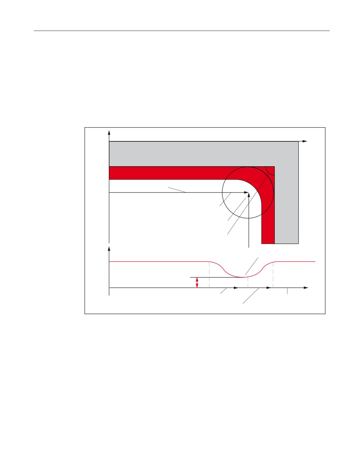
Programming
3.2 G commands
Traversed feedrate =
F * $SC_CORNER_SLOWDOWN_OVR * feedrate override.
The feedrate override is made up of the feedrate override of the Machine Control Panel
multiplied by the override from synchronized actions.
The reduction in feedrate is begun at a distance of SD42520
$SC_CORNER_SLOWDOWN_START before the corner. It ends at distance SD42522
$SC_CORNER_SLOWDOWN_END after the corner (see following figure). An appropriate
path is used for curved contours.
<
;
:RUNSLHFH
&RDWLQJ WR EH PLOOHG RII
7RRO FHQWHU SRLQW SDWK
6&B&251(5B6/2:'2:1B67$57
6&B&251(5B6/2:'2:1B(1'
,QWHUQDO DQJOH ื
6&B&251(5B6/2:'2:1B&5,7
)HHGUDWH VORZGRZQ DW FRUQHU
3DWK YHORFLW\ Y
)
)
6&B&251(5B6/2:'2:1B295
6&B&251(5B6/2:'2:1B67$57
3DWK V
6&B&251(5B6/2:'2:1B(1'
Figure 3-8
Parameter assignment of feedrate reduction G62 with the example of a 90 degree corner
Parameter assignment
The override value is set using the following setting data:
SD42520 $SC_CORNER_SLOWDOWN_START
SD42522 $SC_CORNER_SLOWDOWN_END
SD42524 $SC_CORNER_SLOWDOWN_OVR
SD42526 $SC_CORNER_SLOWDOWN_CRIT
ISO dialects
Function Manual, 12/2019, 6FC5397-7BP40-3BA1
53
Programming
3.2 G commands
The setting data is preassigned with the value 0.
● If $SC_CORNER_SLOWDOWN_CRIT = 0, the corner deceleration is effective only at the
reversal points.
● If $SC_CORNER_SLOWDOWN_START and $SC_CORNER_SLOWDOWN_END are
equal to 0, then the feedrate reduction is approached with the permissible dynamic
response.
● If $SC_CORNER_SLOWDOWN_OVR = 0, then a transient stop is inserted.
● $SC_CORNER_SLOWDOWN_CRIT is related to the geometry axes in G62. It defines the
maximum inner angle in the current machining plane up to which the corner deceleration is
used. G62 is not effective in rapid traverse.
Activating
The function is activated via G62 and/or G621. The G code is active either via the
corresponding part program command or through MD 20150
$MC_GCODE_RESET_VALUES[56].
Examples
$TC_DP1[1,1]=120
$TC_DP3[1,1]=0.
;Tool length compensation
$TC_DP4[1,1]=0.
$TC_DP5[1,1]=0.
N1000 G0 X0 Y0 Z0 F5000 G64 SOFT
N1010 STOPRE
N1020 $SC_CORNER_SLOWDOWN_START = 5.
N1030 $SC_CORNER_SLOWDOWN_END = 8.
N1040 $SC_CORNER_SLOWDOWN_OVR = 20.
N1050 $SC_CORNER_SLOWDOWN_CRIT = 100.
N2010 X00 Y30 G90 T1 D1 G64
N2020 X40 Y0 G62 G41
;Inner corner of N2030,
;but TRC still selected
N2030 X80 Y30
;Inner corner of N2040 127 degrees
N2040 Y70
;Inner corner of N2050 53 degrees
N2050 X40 Y40
;Outer corner of N2060
N2060 X20 Y70
; Inner corner of N2070 97 degrees
N2070 Y60
; Inner corner of N2080 90 degrees
N2080 X20 Y20
; Outer corner of N2090,
;irrelevant due to TRC deselection
N2090 X00 Y00 G40 FENDNORM
M30
ISO dialects
54
Function Manual, 12/2019, 6FC5397-7BP40-3BA1
Programming
3.3 Substitution by a substitution cycle with a tool selection block
3.3
Substitution by a substitution cycle with a tool selection block
3.3.1
Milling
Note
The following generally applies to all substitution cycles in which the programmed values are
transferred in $C_ variables:
The $C_ system variables must be copied at the start of the cycle into R parameters, local and
global user data. The cycle then only works with the copies.
Substitution by an M macro
MD10814: $MN_EXTERN_M_NO_MAC_CYCLE[0] = 6
MD10815: $MN_EXTERN_M_NO_MAC_CYCLE_NAME[0] = "L6"
Nothing from this block is executed, all programmed parameters are copied into $C_ system
variables.
In the cycle, T, H, D and M must be programmed and all other addresses programmed in the
block written indirectly.
Example:
MD22550: $MC_TOOL_CHANGE_MODE = 1
MD22560: $MC_TOOL_CHANGE_M_CODE = 206
N5 T10 H22 M6 or N5 T10 D33 M6 ; M6 calls L6
N100 PROC L6( )
N105
N110 $C_MACPAR[1]=$C_T
N115 $C_MACPAR[2]=$C_H
N120 $C_MACPAR[3]=$C_D
N125 G291
N130 T$1 H$2 M206 or N130 T$1 D$2 M206
N135 G290
N140 RET
T can also be programmed in Siemens mode with T=$C_T.
Substitution by an M function
MD10715: $MN_M_FCT_CYCLE[0] = 6
MD10716: $MN_M_FCT_CYCLE_NAME[0] = "L6"
MD10718: $MN_M_NO_FCT_CYCLE_PAR = 0
MD10719: $MN_T_NO_FCT_CYCLE_MODE
MD10718 is used to parameterize whether the cycle call takes place when the parameters are
transferred. MD10719 is used to set the call time at the start or end of the block.
ISO dialects
Function Manual, 12/2019, 6FC5397-7BP40-3BA1
55
Programming
3.3 Substitution by a substitution cycle with a tool selection block
If just N5 T M6 and not H D is programmed in the part program block, the cycle can be called
without the transfer of parameters. The block is executed and the cycle called without the
transfer of parameters at the end of the block.
Only the M function has to be programmed in the cycle to activate the tool.
Example:
MD22550: $MC_TOOL_CHANGE_MODE = 1
MD22560: $MC_TOOL_CHANGE_M_CODE = 206
MD10715: $MN_M_FCT_CYCLE[0] = 6
MD10716: $MN_M_FCT_CYCLE_NAME[0] = "L6"
MD10718: $MN_M_NO_FCT_CYCLE_PAR = -1
N5 T10 M6 ; M6 calls L6
N100 PROC L6( )
…
…
N110 m206
N115 RET
If N5 T H M6 or N5 T D M6 is programmed in the part program block, the cycle must be called
with the transfer of parameters. T H D and the M function then have to be programmed in the
cycle to activate the tool. H and D must be programmed after the T and M function to activate
the tool.
Example:
MD22550: $MC_TOOL_CHANGE_MODE = 1
MD22560: $MC_TOOL_CHANGE_M_CODE = 206
MD10715: $MN_M_FCT_CYCLE[0] = 6
MD10716: $MN_M_FCT_CYCLE_NAME[0] = "L6"
MD10718: $MN_M_NO_FCT_CYCLE_PAR = 0
N5 T10 H22 D23 M6 ; M6 calls L6
N100 PROC L6( )
N105 IF $C_T_PROG == 1
N110 $C_MACPAR[1]=$C_T
N115 G291
N120 T$1 M206
N125 G290
or
N110; programming of H and D
; indirectly via $C_MACPAR as in blocks N110 and N120
M115 M17
Substitution by T programming
MD10717: $MN_T_FCT_CYCLE_NAME="L6"
$MN_T_NO_FCT_MODE
MD10719: $MN_T_NO_FCT_CYCLE_MODE
Nothing from this block is executed, all programmed values are written into $C_ system
variables. The call time is determined with $MN_T_NO_FCT_MODE. T and M must be
ISO dialects
56
Function Manual, 12/2019, 6FC5397-7BP40-3BA1
Programming
3.3 Substitution by a substitution cycle with a tool selection block
programmed in the cycle. If H or D are programmed in addition to T in the call block, H and D
must be programmed in the cycle after the T and M function to activate the tool.
Example:
MD22550: $MC_TOOL_CHANGE_MODE = 1
MD22560: $MC_TOOL_CHANGE_M_CODE = 206
N5 T10; T calls L6.spf
N100 PROC L6( )
N105 T=$C_T M206
or in ISO mode indirectly via T$1
N110 $C_MACPAR[1]=$C_T
N120 G291
N125 T$1 M206
N125 G290
3.3.2
Turning
Substitution by an M macro
MD10814: $MN_EXTERN_M_NO_MAC_CYCLE[0] = 6
MD10815: $MN_EXTERN_M_NO_MAC_CYCLE_NAME[0] = "L6"
Nothing from this block is executed, all programmed parameters are written into $C_ system
variables.
T must be programmed in the cycle. The programmed T contains the tool number and the
correction number. The programmed value is transferred in $C_T. T1234 results in $C_T =
1234; $C_T_PROG = 1.
Example:
MD22550: $MC_TOOL_CHANGE_MODE = 1
MD22560: $MC_TOOL_CHANGE_M_CODE = 206
N5 T1022 M6 ; M6 calls L6
N100 PROC L6( )
N101 IF $C_T == TRUE
N110 $C_MACPAR[1]=$C_T
N120 G291
N125 T$1 M206
N130 G290
N135 ENDIF
N140 M17
Substitution by an M function
MD10715: $MN_M_FCT_CYCLE[0] = 6
MD10716: $MN_M_FCT_CYCLE_NAME[0] = "L6"
ISO dialects
Function Manual, 12/2019, 6FC5397-7BP40-3BA1
57
Programming
3.3 Substitution by a substitution cycle with a tool selection block
The block is executed and the cycle called without the transfer of parameters at the end of the
block.
The M function is programmed in the cycle at the end to activate the tool (if present).
Example:
MD22550: $MC_TOOL_CHANGE_MODE = 1
MD22560: $MC_TOOL_CHANGE_M_CODE = 206
N5 T1234 M6 ;M6 calls L6
PROC L6( )
…
M206
M17
Substitution by T programming
MD10717: $MN_T_FCT_CYCLE_NAME="L6"
Nothing from the block is executed, all programmed values are written into $C_ system
variables.
The call time is determined with $MN_T_NO_FCT_CYCLE_MODE. T and M must be
programmed in the cycle. The programmed T value contains the tool number and tool
compensation number.
The split T value and the tool number in $C_T and the programmed tool number in $C_H are
transferred to the cycle according to MN_EXTERN_DIGITS_TOOL_NO or
MN_EXTER_DIGITS_OFFSET_NO.
The unsplit programmed T value is also transferred in $C_T_VALUE.
Example:
Tool
Cutting edge
H number
T10
D1
H1
D2
H2
T31
D1
H3
D2
H4
MN_EXTER_DIGITS_OFFSET_NO = 2
N5 T3104 ; tool 31 $C_T == 31
; H number 4$C_H == 4
; $C_T_VALUE == 3104
T is programmed indirectly in the cycle with $C_T_WORD.
Example:
N5 T3104 ; T calls L6.spf
PROC L6( ) ; T indirectly in ISO mode
N100
N102 $C_MACPAR[1] = $C_T_VALUE
N105 G291
N110 T$1
ISO dialects
58
Function Manual, 12/2019, 6FC5397-7BP40-3BA1
Programming
3.4 Subprogram and macro technology
N115 G290
N120 M17
3.3.3
Indirect programming in ISO mode using $ variables
What are known as $ variables exist in order to perform indirect programming in ISO mode.
Values are assigned in ISO mode via these $ variables, for example T$1. In total there are 30
$ variables, $1 to $30.
The $ variables are written in Siemens mode using $C_MACPAR[0] - [30]. When programming
in ISO mode, the value is read from the corresponding $C_MACPAR[ ] variable and assigned
to the address. The integer value following $ corresponds to the index for $C_MACPAR[ ].
Example:
N5 G290
N10 $C_MACPAR[5] = 12
N15 G291
N20 T$5
The value from $C_MACPAR[5] is assigned to address T. This corresponds to T12 in ISO
mode.
Several $ assignments can be located in the same block.
N5 G290
N10 $C_MACPAR[1] = 1000 $C_MACPAR[2] = 85 $C_MACPAR[3] = 93.2
N15 G29
N20 F$1 X$2 Y$3
This corresponds to F1000 X85 Y93.2
Numerous calculations can therefore be undertaken in Siemens mode and the results then
assigned to addresses in ISO mode.
Note
Pure calculations in ISO mode e.g.: N5 $1=$2+1200 are not possible.
3.4
Subprogram and macro technology
3.4.1
Subprogram technique: M98
Subprogram call
In ISO dialect, subprogram calls with M98 are programmed.
For the program syntax, see the figure below:
ISO dialects
Function Manual, 12/2019, 6FC5397-7BP40-3BA1
59
Programming
3.4 Subprogram and macro technology
0
3 [[[[\\\\
3URJUDP QR PD[ GLJLWV
1R RI UHSHWLWLRQV PD[ GLJLWV
Figure 3-9
Description of permissible parameters
Program syntax M98 Pxxxxyyyy is used to call a subprogram with the number yyyy and repeat
it xxxx times. If xxxx is not programmed, the subprogram is only executed once. The
subprogram name always comprises four digits or is extended by adding 0s until there are four
digits.
For example, if M98 P21 is programmed, a search is undertaken for the 0021.spf program
name in the part program memory and the subprogram is run once. If the subprogram is to be
run three times, M98 P30021 should be programmed.
To date the number of program passes (number of repeats) in ISO dialect M/T has been
programmed with the subprogram number under address "P".
As an alternative to this programming syntax, the number of subprogram passes can now also
be programmed under address "L". The subprogram number is still programmed with Pxxxx. If
the number of passes is programmed with both addresses, the number of passes programmed
with address "L" applies. The number of subprogram passes may be between 1 and 9999.
Example:
N20 M98 P20123
;The 123.spf subprogram is executed twice
N40 M98 P55 L4
;The 55.spf subprogram has been executed four times
N60 M98 P30077 L2
;The 77.spf subprogram is executed twice
;The number of passes =3 programmed at address "P" is ignored.
End subprogram
The subprogram is ended with M99.
If M99 Pxxxx is programmed, a move is made to block number Nxxxx when returning to the
main program. The block number must always start with "N". The block number is first looked
for in a forward direction (from subprogram call working towards program end). If no suitable
block number is found, the part program is eventually searched in the reverse direction (in the
direction of the start of the part program).
If M99 has no block number (Pxxxx) in a subprogram, the subprogram is ended and a jump
made to the block after the subprogram call in the main program.
If M99 is without a block number (Pxxxx) in a main program, the control goes to the start of the
main program and the main program is processed afresh.
These M commands are not output to the PLC.
M99 does not reset the program runtime. An activated tool counter is not incremented.
Subprogram return with "RET"
Applies to ISO dialect T only.
ISO dialects
60
Function Manual, 12/2019, 6FC5397-7BP40-3BA1
Programming
3.4 Subprogram and macro technology
After scrubbing, in the Siemens shell cycles for stock removal (as in ISO dialect) the program
should continue in the main program following the contour description. To do this, the shell
cycle must return to the block after the end of the contour description in the subprogram. In
order to jump the blocks with the contour description during stock removal cycles after the
subprogram call (with G71-G73), two optional parameters are added to the RET command.
Program processing in the program being called (main program) with the block <block number/
label> is continued with the RET command (STRING <block number/label>).
If program processing is to be continued with the next block after <block number/label>, the 2nd
parameter in the RET command must be programmed > 0 RET (<block number/label>, 1). If a
value > 1 is programmed for the 2nd value, the subprogram also returns to the block after the
block with <block number/label>.
The contour to be processed is saved in the main program for cycles G70-G73. The extended
RET command is needed to start at the end of G70 (finishing cut above contour with stock
removal cycle) in the main program after the contour description. To jump to the next NC block
after the contour description at the end of the shell cycle for G70, this must end with the
following return syntax:
RET ("N" << $C_Q, 1)
Search direction:
The search direction for <block number/label> is always firstly forward direction (heading
towards program end) and then reverse direction (heading towards program start).
Example
N10 X10. Y20.
N20 G71 P30 Q60 U1 W1 F1000 S1500
N10 ...
;Shell cycle for stock removal cycle
N20 DEF STRING[6]BACK
N30 ...
N90
N100 RET ("N"<<$C_Q, 1)
;Jump back to block after
;contour definition -> N70
N30 X50. Z20.
N40 X60.
N50 Z55.
N60 X100. Z70.
N70 G70 P30 Q60
N80 G0 X150. Z200.
N90 M30
ISO dialects
Function Manual, 12/2019, 6FC5397-7BP40-3BA1
61
Programming
3.4 Subprogram and macro technology
Note
In Siemens mode, M30 is interpreted in the subprogram as a program return jump.
In ISO dialect mode, M30 is also interpreted in the subprogram as part program / end of
program.
3.4.2
Siemens language commands in ISO dialect mode
Programming
Certain Siemens language commands are also needed in ISO dialect mode for ShopMill.
These are then run in ISO dialect mode. These language commands include subprogram calls
with and without the transfer of parameters (not calls with Lxx because address L already has
a different meaning with ISO dialect), program part repeat and control structures. All other
Siemens language commands are rejected with an alarm in ISO dialect mode.
When ISO dialect mode is active, the following Siemens language commands may be
programmed:
REPEAT:
REPEAT
Block number > [<block number>] [P..]
REPEAT
UNTIL
REPEATB
<block number> [P..]
Only block numbers and not labels are permitted as start and end delimiters.
IF - ELSE - ENDIF
FOR - ENDFOR
WHILE - ENDWHILE
IF<condition> - GOTO F<condition>
CASE
Modal and non-modal subprogram calls
N100 CALL "SHAFT" or
N100 MCALL SHAFT" or
N100 SHAFT
ISO dialects
62
Function Manual, 12/2019, 6FC5397-7BP40-3BA1
Programming
3.4 Subprogram and macro technology
Modal and non-modal subprogram calls with transfer of parameters
N100 MCALL SHAFT ("ABC"; 33.5 ) or
N100 SHAFT ("ABC"; 33.5 ) subroutine calls with path name
N100 CALL"/_N_SPF_DIR/SHAFT or
N100 MCALL/_N_SPF_DIR/SHAFT or
N100 PCALL/_N_SPF_DIR/SHAFT
3.4.3
Expansion of subprogram call for contour preparation with CONTPRON
Expansion
With ISO dialect the contour description for the stock removal cycles G70-G73 is not saved
separately in a subprogram (as with SINUMERIK), but in the part program (main program).
When calling the cycles, the range of the contour description is defined with a start and end
block number. The cycles contain these block numbers as transfer parameters. The indirect
subprogram call is expanded for the Siemens adjustment cycles.
Until now a subprogram call has been called indirectly with CALL <program name>.
The indirect subprogram call is expanded as follows for accessing the contour description in the
main program:
CALL [<program name>] BLOCK <start label> TO <end label>
If there is no program name stated or if an empty string is stated as the program name, i.e. CALL
BLOCK <Start label> TO <End label>, the program part (start/end label) is sought in the
program currently selected. The labels are also sought in the selected program for MDA, ASUB
etc. (e.g. in the case of MDA, labels are not sought in the MDA buffer but in the program with
the selected program name). If this syntax is written directly in a main program, it acts like a
program part repeat with REPEAT <Start label> <End label> with a loop pass, i.e. start and end
label are sought in the same program, in which the CALL BLOCK ... command is also
programmed.
If a program name is stated, i.e. CALL <progName> BLOCK <Start label> TO <End label>, the
program part (start/end label) is sought in the "progName" subprogram.
Example
Nxx G71 Pxx Q1110 U.. W..
;ISO dialect G function calls shell cycle
;CYCLE395.spf
;_N_CYCLE395_SPF
N10
Nxxx CYCLE95(
, "N"<<$C_P, "N"<<$C_Q)
;Stock removal cycle with additional parame-
ters
;for start and end label
PROC CYCLE95(
, STRING[20] start lab, STRING[20]
end lab)
ISO dialects
Function Manual, 12/2019, 6FC5397-7BP40-3BA1
63
Programming
3.4 Subprogram and macro technology
N10
Nxxx CONTPRON(...)
N
CALL "" BLOCK start lab TO end lab
;Read contour definition or
N
CALL BLOCK start lab TO end lab
;Call contour program
EXECUTE(...)
Nxx M17
Nxxx
Nxxx RET ("N"<<$C_Q, 1)
;Return to next block after
;contour definition
N1120
Nxxx M30
Note
CONTPRON and EXECUTE calls themselves must not be changed.
Searching for start block number
The search for the start block number (start label) of the contour description always takes place
first working towards the program end (forwards) and then working towards the program start
(backwards).
If the same block number is programmed several times, the next block number (label) after the
current block in the program containing the contour description is recognized as the start of the
contour description (see example). The current block is usually the block in which the stock
removal cycle (shell cycle) was called in the main program.
Example:
In stock removal cycle CYCLE395, the contour description found in the main program between
blocks N10-N30 is to be used (with CALL BLOCK N10 TO N30 in CYCLE395). N40 is the
current program line in the main program.
The contour description block in our example is shown in bold.
N5 G1 F500
N10 X10. Y20.
N20 X30.
N30 Y10.
N40 G71 P10 Q30...
;Call shell cycle for stock removal cycle
;(In the stock removal cycle,
;"CALL BLOCK N10 TO N30" is programmed)
;The bold lines are found as the
;contour definition
N50 G90 G54
ISO dialects
64
Function Manual, 12/2019, 6FC5397-7BP40-3BA1
Programming
3.4 Subprogram and macro technology
N60 F1000 G94
N10 X50. Y10.
N20 X33. Y11.
N30 X10.
N50
N
N800 G71 P10 Q30
;Call shell cycle for stock removal cycle
;(In the stock removal cycle, "CALL BLOCK N10 TO
N30"
; is programmed)
;The lines printed in
;italics are found as the contour definition
N999
N10 X15.
N20 Y25.
N30 X33.
N1010 ...
N1020
3.4.4
Macro commands with G65, G66 and G67
ISO dialect
In ISO dialect mode, G65 Pxx and G66 Pxx are used to call macros in the part program. The
combination of several part program blocks which are terminated with M17 is known as a
macro.
When calling the subprogram, a switch is made from ISO mode to Siemens mode.
The following commands are used for selection and deselection:
● G65 macro call, non-modal effective
● G66 macro call, modal effective
● Deselect G67 modal macro call
Siemens
G commands G65 Pxx and G66 Pxx start macro xx. G65 calls the Pxx subprogram once, G66
makes subprogram call Pxx modal and it is executed in each block with axial motion (as MCALL
xx). G67 deselects the modal subprogram call again (corresponds to G80 for cycle calls).
In a part program block containing G65 or G66, the address Pxx is interpreted as the program
number of the subprogram in which the macro functionality is programmed. The number of
passes of the macro can be defined with the address Lxx. If the number of passes is not
programmed in the call block, the macro is run once. All other addresses in this part program
block are interpreted as transfer parameters and their programmed values are stored in the
system variables $C_A to $C_Z. These system variables can be read in the subprograms and
ISO dialects
Function Manual, 12/2019, 6FC5397-7BP40-3BA1
65
Programming
3.4 Subprogram and macro technology
evaluated for the macro functionality. If other macros with parameter transfer are called in a
macro (subprogram), then the transfer parameters in the subprogram must be saved in internal
variables before the new macro call.
To enable internal variable definitions, one must switch automatically to the Siemens mode for
a macro call. If another macro call is programmed in the subprogram, then the ISO dialect mode
must be reselected in advance.
System variables for the addresses I, J, K
As the addresses I, J, and K can be programmed up to ten times in a block containing macro
call, the system variables of these addresses must be accessed with an array index. The syntax
of these three system variables thus is $C_I[..], $C_J[..], $C_K[..]. The values remain in the
programmed sequence in the array. The number of I, J, K addresses programmed in the block
is given in the variables $C_I_NUM, $C_J_NUM, $C_K_NUM.
The transfer parameters I, J, K for macro calls are treated in each case as one block even if the
individual addresses are not programmed. If a parameter is reprogrammed, or a following
parameter based on the I, J, K sequence has been programmed, it belongs to the next block.
The system variables $C_I_ORDER, $C_J_ORDER, $C_K_ORDER are set to detect the
programming sequence in ISO mode. These are identical arrays to $C_I, $C_K and they
contain the associated numbers of the parameters.
Note
The transfer parameters can only be read in the subprogram.
Example:
N5 I10 J10 K30 J22 K55 I44 K33
;
[ Block1 ] [Block2] [Block3]
$C_I[0]=10
$C_I[1]=44
$C_I_ORDER[0]=1 ; Block 1
$C_I_ORDER[1]=3 ; Block 3
$C_J[0]=10
$C_J[1]=22
$C_J_ORDER[0]=1 ; Block 1
$C_J_ORDER[1]=2 ; Block 2
$C_K[0]=30
$C_K[1]=55
$C_K[2]=33
$C_K_ORDER[0]=1 ; Block 1
$C_K_ORDER[1]=2 ; Block 2
$C_K_ORDER[2]=3 ; Block 3
ISO dialects
66
Function Manual, 12/2019, 6FC5397-7BP40-3BA1
Programming
3.4 Subprogram and macro technology
Cycle parameter $C_x_PROG
In the ISO dialect 0 mode, the programmed values can be evaluated in different ways,
depending on the programming method (integer or actual value). The different evaluation is
activated using machine data.
If the MD is set, the control system responds as in the following example:
X100. ; X axis is traversed through 100 mm (100. with point => actual
value)
Y200 ; Y-axis is traversed through 200 mm (200 without point =>
integer value)
If the addresses programmed in the block are used as transfer parameters for cycles, then the
programmed values always exist as real values in the $C_x variables. For integer values, one
cannot take recourse to the programming method (real/integer) in the cycles any more, and
therefore there is no evaluation of the programmed values with the correct conversion factor.
To identify whether REAL or INTEGER has been programmed, refer to system variable
$C_TYP_PROG, which is structured just like $C_ALL_PROG and $C_INC_PROG. There is
one bit for each address (A-Z). If the value is programmed as INTEGER, bit 0 is set, for REAL
to 1. If the value is programmed using a variable $<Number>, then bit 2 is set = 1.
Examples
● P1234 A100. X100 ⇒ $C_TYP_PROG == 1
Only bit 0 == 1, as only A was programmed as REAL.
● P1234 A100. C20. X100 ⇒ $C_TYP_PROG == 5
Bit 1 == 1 and bit 3 == 1 (A and C).
Restrictions
A maximum of ten I, J, K parameters can be programmed in each block. Only one bit each is
provided for I, J, K in the variable $C_TYP_PROG. Hence in $C_TYP_PROG bits is always set
to 0 for I, J and K. Therefore it cannot be derived whether I, J or K is programmed as REAL or
as INTEGER.
Parameters P, L, O, N can only be programmed as integers. A real value results in an alarm.
The bit in $C_TYP_PROG is therefore always 0.
Modal macro calls
For modal macro calls, the programmed addresses are only written to the system variables in
the call block (block with G66). The macro is then executed in each block with axial motion until
deselected with G67 or until a new macro call is programmed with G66. Only macro parameters
are provided for modal macros in the call block (= block with G66). The macro is first run in the
next block with axial motion. (Process as with MCALL xx in Siemens mode.)
Example of macro call:
_N_M10_MPF:
N10 M3 S1000 F1000
N20 X100. Y50. Z33.
N30 G65 P10 F55 X150. Y100. S2000
N40 X50.
ISO dialects
Function Manual, 12/2019, 6FC5397-7BP40-3BA1
67
Programming
3.4 Subprogram and macro technology
N50
N200 M30
Example of a subprogram as a macro in Siemens mode:
_N_10_SPF:
N10 DEF REAL X_AXIS Y_AXIS, SPEED, FEEDRATE
N15 X_AXIS = $C_X Y_AXIS = $C_Y SPEED = $C_S FEEDRATE = $C_F
N20 G01 F=FEEDRATE G95 S=SPEED
M17
3.4.5
Changing mode during macro calls with G65/G66
In the past during macro calls with G65/G66, a switch has been automatically made into
Siemens mode.
The user can now decide whether a switch is to be made to Siemens mode at the start of the
macro. If the first program line of the macro program contains the operation PROC<Program
name>, a switch is made into Siemens mode. If this operation isn't there, ISO mode is retained
in the macro program.
The user can then decide whether to create local variables (with DEF...) to save transfer
variables. To do this, the user must switch into Siemens mode with the PROC operation. But
he or she can also decide whether his or her macro program (e.g. an existing ISO dialect M/T
macro) can be processed in ISO mode.
Example of the macro call:
_N_M10_MPF:
N10 M3 S1000 F1000
N20 X100. Y50. Z33.
N30 G65 P10 F55 X150. Y100. S2000
N40 X50.
N50
N200 M30
Example of a subprogram as a macro in Siemens mode:
_N_0010_SPF:
PROC 0010
; Changeover to Siemens mode
N10 DEF REAL X_AXIS, Y_AXIS, SPEED, FEEDRATE
N15 X_AXIS= $C_X Y_AXIS= $C_Y SPEED= $C_S FEEDRATE= $C_F
N20 G01 F=FEEDRATE G95 S=SPEED
N80 M17
Example of a subprogram as a macro in ISO mode:
_N_0010_SPF:
G290
; Changeover to Siemens mode
;if transfer variables have to be read
N15 X_AXIS= $C_X Y_AXIS= $C_Y SPEED= $C_S
N20 G01 F= $C_F G95 S= $C_S
N10 G1 X= $C_X Y= $C_Y
ISO dialects
68
Function Manual, 12/2019, 6FC5397-7BP40-3BA1
Programming
3.4 Subprogram and macro technology
G291; Changeover to ISO mode
N15 M3 G54 T1
N20
N80 M99
3.4.6
Macro call via M function
Function
A macro can be called using M numbers in the same way as G65 (see "Mode changeover
during macro calls with G65/G66" chap.).
10 M function replacements are configured using the following machine data:
● MD10814 $MN_EXTERN_M_NO_MAC_CYCLE and
● MD10815 $MN_EXTERN_M_NO_MAC_CYCLE_NAME.
Parameter transfer is identical to G65. Repetitions can be programmed with the L address.
Constraints
Only one M function replacement (or only one subprogram call) can be executed per part
program line. Conflicts with other subprogram calls are reported using alarm 12722 "Channel
%1 block %2 Several ISO_2/3 macro or cycle calls in the block". There is no further M function
replacement in the replaced subprogram.
Otherwise, the same constraints are valid as in G65.
Conflicts with pre-defined and other defined M numbers are rejected with an alarm.
Configuration examples
Call of subprogram M101_MACRO via the M101 M function
MD10814 $MN_EXTERN_M_NO_MAC_CYCLE[0] = 101
MD10815 $MN_EXTERN_M_NO_MAC_CYCLE_NAME[0] = "M101_MACRO"
Call of subprogram M6_MAKRO via the M6 M function.
MD10814 $MN_EXTERN_M_NO_MAC_CYCLE[1] = 6
MD10815 $MN_EXTERN_M_NO_MAC_CYCLE_NAME[1] = "M6_MACRO"
Programming example for tool change with M function:
PROC MAIN
N10
M6 X10 V20
N90
M30
PROC M6_MACRO
ISO dialects
Function Manual, 12/2019, 6FC5397-7BP40-3BA1
69
Programming
3.4 Subprogram and macro technology
N0010
R10 = R10 + 11.11
N0020
IF $C_X_PROG == 1 GOTOF N40
;($C_X_PROG)
N0030
SETAL(61000)
;programmed variable not
;transferred correctly
N0040
IF $C_V == 20 GTOF N60
;($C_V)
N0050
SETAL(61001)
N0060
M17
3.4.7
Macro call via G function
Function
A macro can be called using a G number in the same way as G65 (see "Mode changeover
during macro calls with G65/G66" chap.).
50 G function replacements can be configured using the following machine data:
MD10816 $MN_EXTERN_G_NO_MAC_CYCLE and
MD10817 $MN_EXTERN_G_NO_MAC_CYCLE_NAME
The parameters programmed in the block are stored in the $C_variables. The number of macro
repetitions is programmed with address L. The number of the programmed G_macros is stored
in the variable $C_G. All the other G functions programmed in the block are treated as normal
G functions. The programming sequence of the addresses and G functions in the block is
random, and it does not have any effect on the functionality.
All ISO G codes, including G codes with a decimal point (= real value), can be replaced by a
macro call.
G functions which are not replaced by a macro are still present in the control and can be
redefined using MD10882 $MN_NC_USER_EXTERN_GCODES_TAB[ ].
Constraints
Only one G/M function replacement (or only one subprogram call) can be executed per part
program line. Conflicts with other subprogram calls, e.g. if a modal subprogram call is active,
are reported using alarm 12722 "Channel %1 block %2 Several ISO_2/3 macro or cycle calls
in the block".
If a G macro is active, no other G/M macro or M subprogram is called. M macros/subprograms
are then executed as M functions and G macros as G functions, if there is an appropriate G
function. Otherwise, alarm 12470 is triggered.
Otherwise, the same constraints are valid as for G65
Configuration examples
Calling the subprogram G21_MACRO via G function G21
$MN_EXTERN_G_NO_MAC_CYCLE[0] = 21
$MN_EXTERN_G_NO_MAC_CYCLE_NAME[0] = "G21_MACRO"
ISO dialects
70
Function Manual, 12/2019, 6FC5397-7BP40-3BA1
Programming
3.4 Subprogram and macro technology
$MN_EXTERN_G_NO_MAC_CYCLE[1] = 123
$MN_EXTERN_G_NO_MAC_CYCLE_NAME[1] = "G123_MACRO"
$MN_EXTERN_G_NO_MAC_CYCLE[2] = 421
$MN_EXTERN_G_NO_MAC_CYCLE_NAME[2] = "G123_MACRO"
Programming example
PROC MAIN
N0090 G291
;ISO mode
N0100 G1 G21 X10 Y20 F1000 G90
;Call of G21_MACRO.spf,
;G1 and G90 are activated
;before the call of
;G21_MACRO.spf
N0500 G90 X20 Y30 G123 G1 G54
;Call of G123_MACRO.spf,
;G1, G54 and G90 are activated
;before the call of
;G123_MACRO.spf
N0800 G90 X20 Y30 G421 G1 G54
;Call of G421_MACRO.spf,
;G1, G54 and G90 are activated
;before the call of
;G123_MACRO.spf
N0900 M30
PROC G21_MACRO
N0010 R10 = R10 + 11.11
N0020 IF $C_X_PROG == 0
N0030 SETAL(61000)
;programmed variable not
;transferred correctly
N0040 ENDIF
N0050 IF $C_V_PROG == 0
N0060 SETAL(61001)
N0070 ENDIF
N0080 IF $C_F_PROG == 0
N0090 SETAL(61002)
N0100 ENDIF
N0110 G90 X=$C_X V=$C_V
N0120 G291
N0130 G21 M6 X100
;G21->activate metric measuring system
; (no macro call)
N0140 G290
ISO dialects
Function Manual, 12/2019, 6FC5397-7BP40-3BA1
71
Programming
3.4 Subprogram and macro technology
N0150 M17
PROC G123_MACRO
N0010 R10 = R10 + 11.11
N0020 IF $C_G == 421 GOTOF label_G421
;Macro functionality for G123
N0040 G91 X=$C_X Y=$C_Y F500
N1990 GOTOF label_end
N2000 label_G421:
;Macro functionality for G421
N2010 G90 X=$C_X
Y=$C_Y F100
N202
N3000 G291
N2010 G123
; Alarm 12470, because G123 is not a
;G function and a
;macro call is not possible for
; active macro.
;exception: The macro was called
;as subprogram with CALL
G123_MACRO.
N4000 label_end: G290
N4010 M17
3.4.8
High-speed cycle cutting G05 P..
G05 P.. high-speed cycle cutting is realized as a subprogram call.
Programming: G05 P.. L..
● Pxxxxx
Subprogram number, max. 10 characters
When calling, 0s are not filled as they are for M98.
● Lxxxx
Number of passes, L1 applies if L is not programmed.
Example:
G05 P10123 L3
10123.mpf is passed 3 times.
This call calls any subprogram. This subprogram may be a precompiled program, but doesn't
have to be. Only Siemens part programs can however be precompiled.
ISO dialects
72
Function Manual, 12/2019, 6FC5397-7BP40-3BA1
Programming
3.4 Subprogram and macro technology
Siemens mode has no equivalent for the G05 ISO dialect function. CYCLE305 gives the user
the opportunity to program their own functionality within the framework of the Siemens
functionality.
The CYCLE305.spf cycle is called when programming G05 in the following scenarios:
● G05 without P in block is skipped without alarm.
● G05.1 with and without P is skipped without alarm.
● G05 P0 or P01 are reserved for high-speed remote buffer B. This function is not supported.
All addresses programmed in the block are written into the cycle parameters $C_xx in the
scenarios stated. When calling CYCLE305, the mode does not automatically switch from ISO
to Siemens. If CYCLE305.spf is to be processed in Siemens mode, there must be a PROC
operation in the first program line as for macro calls with G65/G66.
As when programming G05, all functions programmed in the block are executed, i.e.
programmed axes are traversed, auxiliary functions output etc. The programmed addresses
are only written into the cycle parameters as additional information.
If G05 is programmed with a subprogram call (M98 P..) in the same block, alarm 12722
"Channel %1 block %2 Several ISO_2/3 macro or cycle calls in a block" is output.
3.4.9
Switchover modes for DryRun and skip planes
Changeover of the skip levels (DB21.DBB2) always represents an intervention in the program
run which has led to a short-term drop in velocity on the path. The same is true for the
changeover of the DryRun mode (DryRun = dry run feedrate DB21.DBB0.BIT6) from
DryRunOff to DryRunOn or vice-versa.
Drops in velocity can now be avoided by a new changeover mode that is limited in its function.
A drop in velocity is no longer required with a machine data assignment of 10706
$MN_SLASH_MASK==2 while changing the skip levels (i.e. a new value in the PLC->NCK-
Chan interface DB21.DBB2).
Note
The NCK processes blocks in two steps, the premachining and main runs (also pre-travel and
main run). The result of the premachining migrates to the preprocessing memory. Main
machining takes the oldest block in each case out of the preprocessing memory and traverses
its geometry.
Note
Changing the skip levels
Premachining is changed over with the machine data assignment $MN_SLASH_MASK==2
during a change in skip level! All blocks located in the preprocessing memory are traversed with
the old skip level. The user normally does not have any control over the fill level of the
preprocessing memory. The following effect is seen:
This will also be active "sometime" after the changeover of the DryRun mode!
ISO dialects
Function Manual, 12/2019, 6FC5397-7BP40-3BA1
73
//////////////////////////////////////////