SINUMERIK 840D sl. Service - Functions. Manual (2018-2020) - page 11
Synchronous spindle
13.1 Brief description
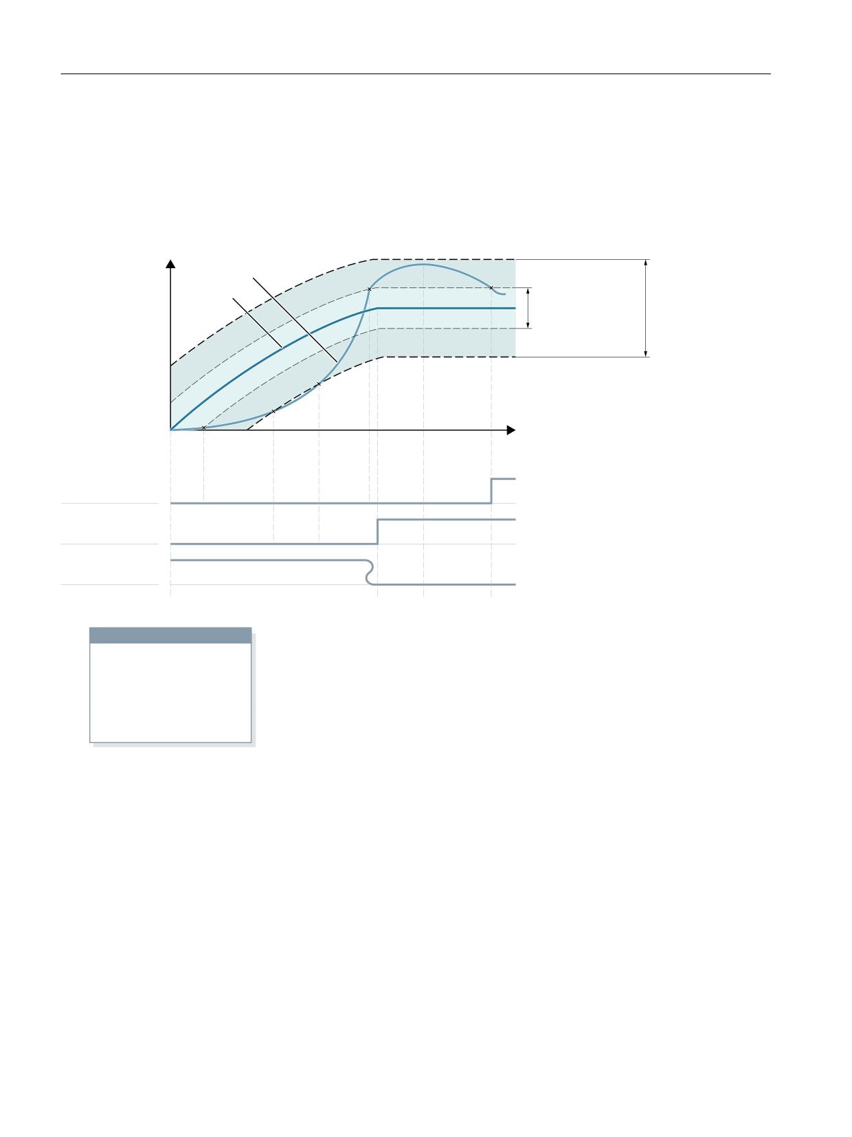
When the coupling is switched on, the signals "Coarse synchronism" and "Fine synchronism" are
updated when setpoint synchronism is reached.
The size of the tolerance windows is set with machine data of the FS. Reaching of the
synchronism is influenced by the following factors:
• AV, DV: Position variance between FS and LS
• VV: Difference in speed between FS and LS
O'4
O"DUVBM'4
O4FU'4
5PMFSBODF CBOE
5PMFSBODF CBOE
'JOF TZODISPOJTN
$PBSTF TZODISPOJTN
U
4JHOBM
'JOF TZODISPOJTN
4JHOBM
$PBSTF TZODISPOJTN
4JHOBM
4ZODISPOJTN SVOOJOH
$0610/
4FUQPJOU CBTFE
8"*5$
-PBEJOH PG OFYU CMPDL
TZODISPOJTN
([DPSOH RI SDUW SURJUDP
ແ
0 6
0
* 3
&28321 6
6
=
:$,7& 6
)LQH
0
ແ
Figure 13-3
Synchronism monitoring with COUPON and synchronism test mark WAITC with synchronization on a turning
leading spindle
Threshold values
The relevant position or velocity tolerance range for the following spindle in relation to the
leading spindle must be specified in degrees or 1 rev/min.
• Threshold value for "Coarse synchronism"
axis spec. MD37200: AV, DV: COUPLE_POS_TOL_COARSE
MD37220: VV: COUPLE_VELO_TOL_COARSE
• Threshold value for "Fine synchronism"
axis spec. MD37210: AV,DV: COUPLE_POS_TOL_FINE
MD37230: VV: COUPLE_VELO_TOL_FINE
Axes and spindles
504
Function Manual, 10/2020, 6FC5397-4GP40-0BA1

Synchronous spindle
13.2 Programming
Speed/acceleration limits
In synchronous mode, the speed and acceleration limit values of the leading spindle are
adjusted internally in the control in such a way that the following spindle can imitate its
movement, allowing for the currently selected gear stage and effective speed ratio, without
violating its own limit values.
For example, the LS is automatically decelerated to prevent the FS from exceeding the maximum
speed in order to maintain synchronism between the spindles.
13.1.8
Dynamic offsets for synchronous spindles
ACCLIMA / ACC acceleration compensation
ACCLIMA acts with following spindles (1% to 200%).
ACCLIMA acts on the total motion of the spindle during spindle operation, i.e. also in the
uncoupled case.
VELOLIMA velocity correction
VELOLIMA (1% to 200%) acts with following spindles, limited to 100% for synchronous spindles.
VELOLIMA is cut off at 100% during spindle operation and acts on the total motion of the spindle,
i.e. also in the uncoupled case.
There is no programming of VELOLIMA for basic motion. This can be programmed using the
VELOLIM command.
Validity (part program, synchronized actions, etc.)
The dynamic offset values ACCLIMA, VELOLIMA, JERKLIMA can be programmed in the part
program or synchronized
actions. The last programming takes effect, regardless of whether it was carried out in the part
program or synchronized actions.
13.2
Programming
Coupling commands with leading-spindle programming
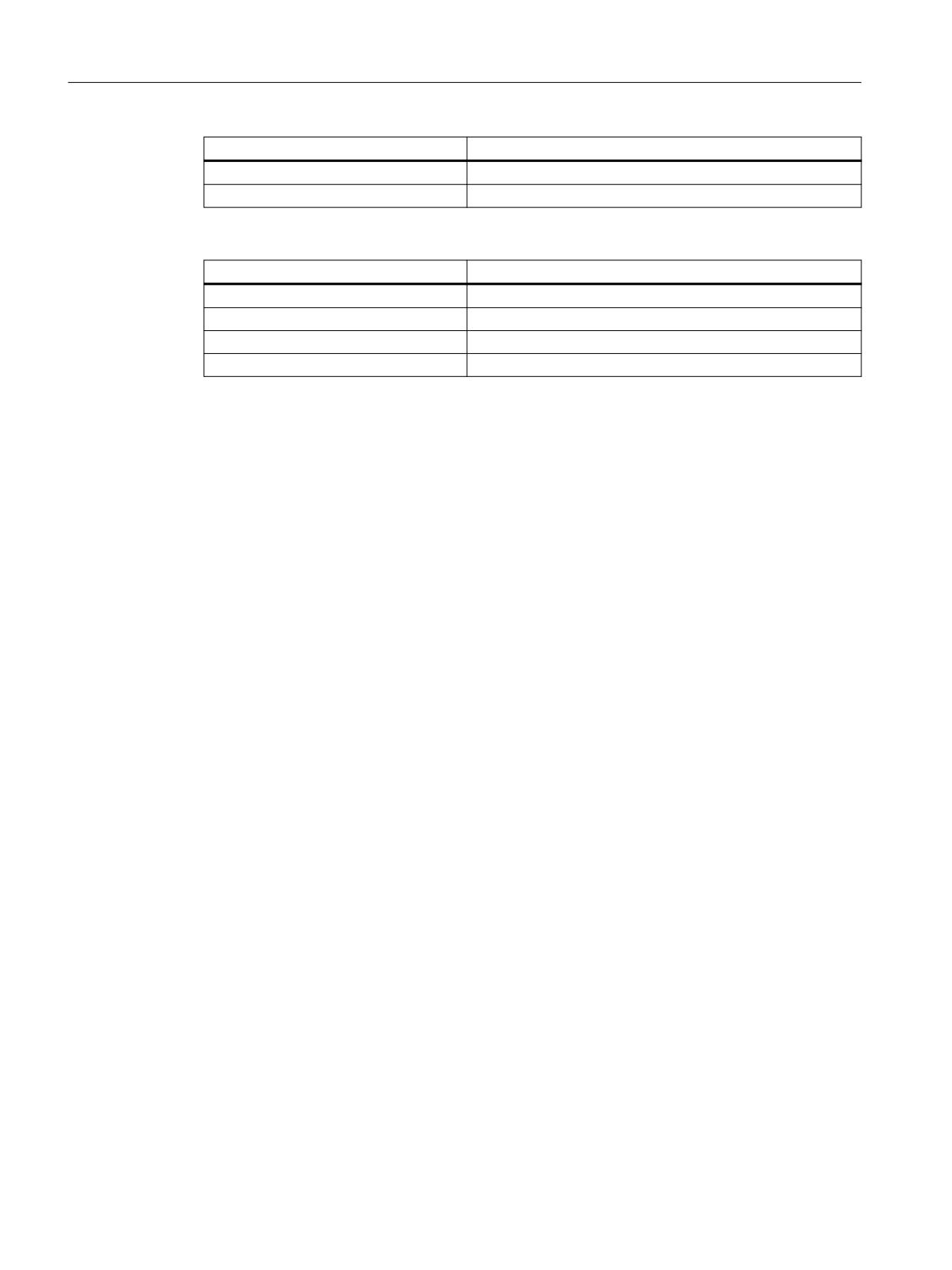
Command
Function
COUPDEF(FS, LS, ...)
Define coupling or change for configured coupling
COUPON(FS, LS, POSFS)
Switch the coupling on
COUPONC(FS, LS)
Activate coupling with transfer of the currently effective
speed of the following spindle
COUPOF(FS, LS, POSFS, POSLS)
Switch the coupling off
COUPOFS(FS, LS, POSFS)
Deactivate coupling with stop of the following spindle
Axes and spindles
Function Manual, 10/2020, 6FC5397-4GP40-0BA1
505
Synchronous spindle
13.2 Programming
Command
Function
COUPDEL (FS, LS)
Delete coupling
COUPRES (FS, LS)
Reactivate configured coupling data
Coupling commands without leading-spindle programming
Command
Function
COUPOF(FS, POSFS, POSLS)
Switch the coupling off
COUPOFS(FS, POSFS)
Deactivate coupling with stop of the following spindle
COUPDEL(FS)
Delete coupling
COUPRES(FS)
Reactivate configured coupling data
See also
Definition (COUPDEF) (Page 506)
Switch the coupling (COUPON, COUPONC, COUPOF) on and off (Page 509)
13.2.1
Definition (COUPDEF)
Programmable couplings
The number of couplings can be programmed as often as desired depending on the axes
available. This number results from the number of axes/spindles less one for the master.
Furthermore, one coupling can also be configured via machine data as in earlier SW versions.
Permanently configured coupling
The coupling characteristics and transformation ratio for a permanently configured
synchronous spindle coupling can be altered by the NC part program provided that they are not
write-protected. The machine axes for LS and FS cannot be changed.
Define new couplings
Language command "COUPDEF" can be used to create new synchronous spindle couplings (user-
defined) and to modify the parameters for existing couplings.
When the coupling parameters are fully specified, the following applies:
COUPDEF(FS, LS, Tnumerator, Tdenominator, block change behavior, coupling type)
The synchronous spindle coupling is unambiguously defined with FS and LS
The other coupling parameters must only be programmed when they need to be changed. The
last valid status remains applicable for non-specified parameters.
Axes and spindles
506
Function Manual, 10/2020, 6FC5397-4GP40-0BA1
Synchronous spindle
13.2 Programming
The individual coupling parameters are explained below:
• FS, LS: Spindle name for following and leading spindles
e.g.: S1, SPI(1), S2, SPI(2)
The valid spindle number must be assigned in the axis-specific MD35000
$MA_SPIND_ASSIGN_TO_MACHAX of a machine axis.
• Tnumerator, Tdenominator: Transformation ratio parameters for numerator and denominator
The transformation ratio is specified in the form of numeric values for numerator and
denominator (see Section "Synchronous mode (Page 491)").
The numerator must always be programmed. If no denominator is specified, then its value is
always assumed to be "1.0".
• Block change behavior
This parameter allows you to select when the block change should take place when
synchronous operation is selected:
NOC: Block change is enabled immediately
FINE: Block change in response to "Fine synchronism"
COARSE: Block change in response to "Coarse synchronism"
IPOSTOP: Block change for IPOSTOP (i.e. after setpoint-end synchronism)
The block change response is specified as a character string (i.e. with quotation marks).
The block change response can be specified simply by writing the letters in bold print. The
remaining letters can be entered to improve legibility of the part program but they are not
otherwise significant.
If no block change response is specified, then the currently selected response continues to apply.
With the programmable synchronism test markers WAITC, the replacement with new blocks is
delayed until the parameterized synchronism is reached.
• Coupling type
DV (Desired Values): Setpoint coupling between FS and LS
AV (Actual Values): Actual value coupling between FS and LS
VV (Velocity Values): Speed coupling between FS and LS
If no coupling type is specified, then the currently selected type continues to apply.
Note
The coupling type may only be changed when synchronous operation is deactivated!
Examples
COUPDEF (SPI(2), SPI(1), 1.0, 1.0, "FINE", "DV")
COUPDEF (S2, S1, 1.0, 4.0)
COUPDEF (S2, SPI(1), 1.0)
Axes and spindles
Function Manual, 10/2020, 6FC5397-4GP40-0BA1
507
Synchronous spindle
13.2 Programming
Default settings
The following default settings apply to user-defined couplings:
• ÜNumerator=1.0
• ÜDenominator =1.0
• Block change response = IPOSTOP (block change enabled with setpoint synchronism)
• Type of coupling = DV (setpoint coupling)
Delete couplings
Language command "COUPDEL" is used to delete user-defined couplings.
COUPDEL (FS, LS)
Note
COUPDEL impacts on an active coupling, deactivates it and deletes the coupling data. Alarm
16797 is therefore meaningless.
The following spindle adopts the last speed. This corresponds to the behavior associated
with COUPOF(FS, LS).
Activate original coupling parameters
Language command "COUPRES" can be used to re-activate the configured coupling parameters.
COUPRES (FS, LS)
The parameters modified using COUPDEF (including the transformation ratio) are subsequently
deleted.
Language command "COUPRES" activates the parameters stored in the machine and setting
data (configured coupling) and activates the default settings (user-defined coupling).
Programmable block change
It is possible to mark a point in the NC program using the "WAITC" language command. The
system waits at this point for fulfillment of the synchronism conditions for the specified FS and
delays changes to new blocks until the specified state of synchronism is reached (see "Figure
13-3 Synchronism monitoring with COUPON and synchronism test mark WAITC with
synchronization on a turning leading spindle (Page 504)").
WAITC (FS)
Advantage: The time between activating the synchronous coupling and reaching synchronism
can be used in a meaningful way, technologically speaking.
Note
Basically, it is always possible to write WAITC. If the spindle indicated is not active as FS, the
command for this spindle is without effect.
Axes and spindles
508
Function Manual, 10/2020, 6FC5397-4GP40-0BA1
Synchronous spindle
13.2 Programming
If no synchronism condition is indicated, the check is always performed for the synchronism
condition programmed/configured on the respective coupling, at least for the setpoint
synchronism.
Examples:
WAITC(S2),
:
WAITC(S2, "Fine"),
:
WAITC(S2, ,S4, "Fine")
Stop and block change
If "Stop" has been activated for the cancellation period of the axis enables for the leading or
following spindle, then the last setpoint positions with the setting of the axis enables from the
servo drive are approached again.
Commands COUPON and WAITC can influence the block change behavior. The block change
criterion is defined using COUPDEF or via the MD21320
$MC_COUPLE_BLOCK_CHANGE_CTRL_1.
13.2.2
Switch the coupling (COUPON, COUPONC, COUPOF) on and off
Activate synchronous mode
Language command COUPON is used to activate couplings and synchronous mode.
Two methods by which synchronous operation can be activated are available:
1. COUPON(FS, LS)
Fastest possible activation of synchronous operation with any angular reference between
the leading and following spindles.
2. COUPON(FS, LS, POSFS)
Activation of synchronous operation with a defined angular offset POSFS between the leading
and following spindles. This offset is referred to the zero degrees position of the leading
spindle in a positive direction of rotation. The block change is enabled according to the
defined setting. Range of POSFS: 0 ... 359.999 degrees.
3. COUPONC(FS, LS)
When activating with COUPONC, the previous programming of M3 S... or M4 S... is adopted. A
difference in speed is transferred immediately. An offset position cannot be programmed.
By programming COUPON(FS, LS, POSFS) or SPOS when synchronous operation is already active,
the angular offset between LS and FS can be changed.
Axes and spindles
Function Manual, 10/2020, 6FC5397-4GP40-0BA1
509
Synchronous spindle
13.2 Programming
Deactivate synchronous mode
Three different methods can be selected to deactivate synchronous mode:
1. COUPOF(FS, LS)
Fastest possible deactivation of synchronous operation. The block change is enabled
immediately.
2. COUPOF(FS, LS, POSFS)
Deselection of synchronous operation after deactivation position POSFS has been crossed.
Block change is not enabled until this position has been crossed.
3. COUPOF(FS, LS, POSFS, POSLS)
Deselection of synchronous operation after the two deactivation positions POSFS and POSLS
have been crossed. Block change is not enabled until both programmed positions have been
crossed.
Range of POSFS, POSLS: 0 ... 359,999°.
If continuous path control (G64) is programmed, a non-modal stop is generated internally in the
control.
Examples:
COUPDEF (S2, S1, 1.0, 1.0, "FINE, "DV")
:
COUPON (S2, S1, 150)
:
COUPOF (S2, S1, 0)
:
COUPDEL (S2, S1)
1. COUPOFS(FS, LS)
Deactivating a coupling with stop of the following spindle. Block change is performed as
quickly as possible with immediate block change.
2. COUPOFS(FS, LS, POSFS)
After the programmed deactivation position that refers to the machine coordinate system
has been crossed, the block change is not enabled until the deactivation positions POSFS
have been crossed.
Value range 0 ... 359.999°.
13.2.3
Axial system variables for synchronous spindle
Determining current coupling status
The current coupling status of the following spindle can be read in the NC part program with the
following axial system variable:
$AA_COUP_ACT[<axial expression>]
For explanation of <axial expression>, see Section "Synchronous mode (Page 491)".
Example:
$AA_COUP_ACT[S2]
Axes and spindles
510
Function Manual, 10/2020, 6FC5397-4GP40-0BA1
Synchronous spindle
13.2 Programming
The value read has the following significance for the following spindle:
Byte = 0:
No coupling active
Bit 2 = 1:
Synchronous spindle coupling active
Bit 2 = 0:
Synchronized spindle coupling is not active
Read current angular offset
The current position offset between the FS and LS can be read in the NC part program by means
of the following axial system variables:
• Setpoint-based position offset between FS and LS:
$AA_COUP_OFFS[<axial expression>]
• Actual-value-based position offset between FS and LS:
$VA_COUP_OFFS[<axial expression>]
Example:
$AA_COUP_OFFS[S2]
If an angular offset is programmed with COUPON, this coincides with the value read after reading
the setpoint synchronization.
Reading the programmed angular offset
The position offset last programmed between the FS and LS can be read in the NC part program
by means of the following axial system variables:
$P_COUP_OFFS[<axial expression>]
Note
After cancellation of the servo enable signal when synchronous operation and follow-up mode
are active, the position offset applied when the controller is enabled again is different to the
originally programmed value.
$P_COUP_OFFS only returns the value originally programmed. $AA_COUP_OFFS and
$VA_COUP_OFFS return the current value. The programmed offset can be recreated with NST
DB31, ... DBX31.4 (resynchronization).
13.2.4
Automatic selection and deselection of position control
Behavior in speed control mode
In DV coupling mode, program instructions COUPON, COUPONC and COUPOF, COUPOFS are
used to activate and/or deactivate position control for the leading spindle as required. If there are
several following spindles on the leading spindle, then in speed-controlled mode, the first
DV activates coupling position control for the leading spindle and the last DV
coupling deactivates coupling position control for the leading spindle if SPCON is not
programmed.
Axes and spindles
Function Manual, 10/2020, 6FC5397-4GP40-0BA1
511

Synchronous spindle
13.3 Configuration
The leading spindle does not need to be located in the same channel as the following spindle.
Automatic selection with COUPON and COUPONC
Depending on the coupling type, the effect of COUPON and COUPONC on the position control
for synchronous operation is as follows:
Coupling type
DV
AV
VV
Following spindle FS
Position control ON
Position control ON
No action
Leading spindle LS
Position control On 1
No action
No action
1 The position control is activated by a COUPON and COUPONC instruction if at least one
following spindle has been coupled to it with coupling type DV.
Automatic deselection with COUPOF and COUPOFS
Depending on the coupling type, the effect of COUPOF and COUPOFS on the position control is
as follows:
Coupling type
DV
AV
VV
Following spindle FS
Position control OFF 2
Position control OFF 2
No action 2
Leading spindle LS
Position control OFF 3
No action
No action
2COUPOF and COUPOFS without position specification
Speed control mode is activated for the following spindle. Positioning mode is activated with
COUPFS with a stop position. Position control is not deactivated if the following spindle was
located in position-controlled spindle mode using SPCON or COUPFS was programmed with
position.
3 With COUPOF position control is deactivated if there are no more couplings of the DV coupling
type for this leading spindle. Position control is retained if the leading spindle is in positioning
mode or axial mode or was in position-controlled spindle mode using SPCON.
13.3
Configuration
Note
One synchronous-spindle coupling can be configured for each channel.
Axes and spindles
512
Function Manual, 10/2020, 6FC5397-4GP40-0BA1

Synchronous spindle
13.3 Configuration
Table 13-1
Machine data
Number
Name: $MC_
Function
MD21300
COUPLE_AXIS_1[<n>]
Machine axes of the synchronous-spindle coupling:
• <n> = 0: Machine axis number of the following spindle
• <n> = 1: Machine axis number of the leading spindle
Machine axis numbers in accordance with: MD20070 $MC_AXCONF_MA-
CHAX_USED (machine axes in the channel)
Machine axis numbers == 0: No coupling configured. The following system data is
then not relevant.
Note: The machine axes configured for the synchronous-spindle coupling cannot
be changed using program commands.
MD21320
COUPLE_BLOCK_
Block change release after activating the synchronous operation 1):
CHANGE_CTRL_1
• Immediately
• On reaching "Synchronism fine"
• On reaching "Synchronism coarse"
• On reaching "Synchronism setpoint"
Note: No change protection1), the block change release can be changed with
the COUPDEF command.
MD21310
COUPLING_MODE_1
Coupling type 1):
• Actual value coupling
• Setpoint value coupling
• Speed coupling
Note: No change protection1), the coupling type can be changed for deactivated
coupling with the COUPDEF command.
MD21330
COUPLE_RESET_
Behavior of the synchronous-spindle coupling with regard to NC Start, NC Stop and
MODE_1
Reset.
MD21340
COUPLE_IS_WRITE_
Change protection for coupling
PROT_1
1) See MD21340 $MC_COUPLE_IS_WRITE_PROT_1
Table 13-2
Setting data
Number
Name: $SC_
Function
SD42300
COUPLE_RATIO_1[<n>]
Speed transmission ratio: FS / LS = numerator / denominator 1):
• <n> = 0: Numerator (FS)
• <n> = 1: Denominator (LS)
Note: No change protection1), the transmission ratio can be changed with
the COUPDEF command.
1) See MD21340 $MC_COUPLE_IS_WRITE_PROT_1
13.3.1
Response of the synchronous-spindle coupling for NC Start
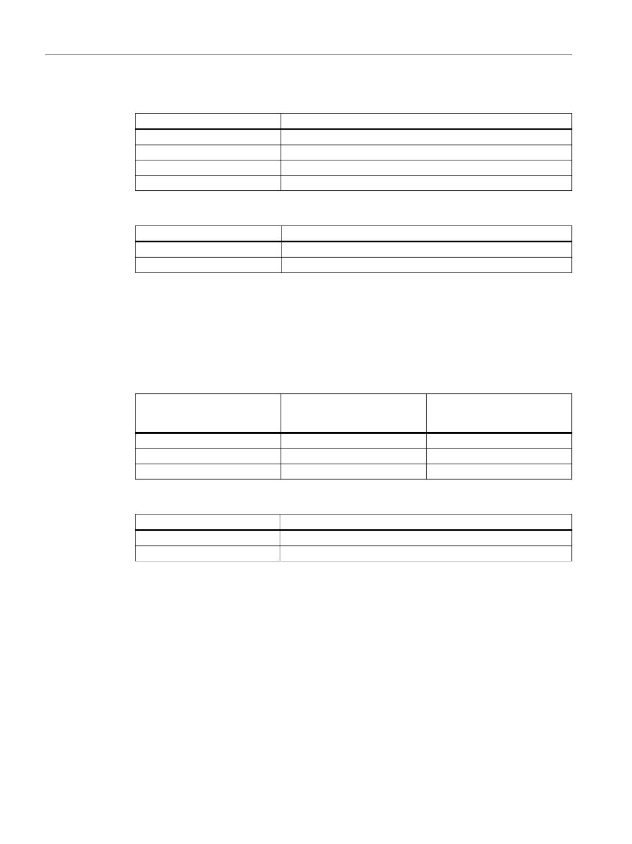
The behavior of the synchronous-spindle coupling during NC Start depends on the setting in the
following machine data:
Axes and spindles
Function Manual, 10/2020, 6FC5397-4GP40-0BA1
513
Synchronous spindle
13.3 Configuration
Configured synchronous-spindle coupling
Response
MD21330 $MC_COUPLE_RESET_MODE_1
Maintain coupling
Bit 0 = 0
Deselect coupling
Bit 0 = 1
Activate configured data
Bit 5 = 1
Switch the coupling on
Bit 9 = 1
Programmed synchronous-spindle coupling
Response
MD20112 $MC_START_MODE_MASK
Maintain coupling
Bit 10 = 0
Deselect coupling
Bit 10 = 1
13.3.2
Behavior of the synchronous-spindle coupling for reset
The behavior of the synchronous operation for reset and at program end depends on the setting
in the following machine data:
Configured synchronous-spindle coupling
Response
MD21330 $MC_COUPLE_RE-
MD20110 $MC_RE-
SET_
SET_MODE_MASK
MODE_1
Maintain coupling
Bit 1 = 0
Bit 0 = 1
Deselect coupling
Bit 1 = 1
Bit 0 = 1
Activate configured data
Bit 6 = 1
Bit 0 = 1
Programmed synchronous-spindle coupling
MD20110 $MC_RESET_MODE_MASK
Maintain coupling
Bit 0 = 1, Bit 10 = 1
Deselect coupling
Bit 0 = 1, Bit 10 = 0
Axes and spindles
514
Function Manual, 10/2020, 6FC5397-4GP40-0BA1
Synchronous spindle
13.4 Special features
13.4
Special features
13.4.1
Special features of synchronous mode in general
Control dynamics
When using the setpoint coupling, the position control parameters of FS and LS (e.g. KV factor)
should be matched with one another. If necessary, different parameter blocks should be
activated for speed control and synchronized mode. The control parameters of the following
spindle may differ from position control, feedforward control and parameter block, as also in the
uncoupled case, set using MD30455 $MA_MISC_FUNCTION_MASK (see Section "Special points
regarding start-up of a synchronous spindle coupling (Page 528)").
Feedforward control
Due to the improved control system dynamic response it provides, feedforward control for the
following and leading spindles in synchronous mode is always active.
It can, however, be deselected for FS and LS with axis-specific MD32620 $MA_FFW_MODE. If
MD32620 $MA_FFW_MODE is set to zero, there are function limitations. Position control can no
longer be activated in motion with SPCON. SPOS, M19 or SPOSA are therefore not possible. The
NC part program cannot deactivate the feedforward control for LS and FS with FFWOF.
The feedforward control mode (speed or torque feedforward control) is defined in axis-specific
MD32620 $MA_FFW_MODE defined (see Function Manual "Monitoring and Compensating",
Section "K3: Compensations").
Speed and acceleration limits
The speed and acceleration limits of the spindles operating in synchronous mode are
determined by the "weakest" spindle in the synchronous spindle pair. The current gear stages,
the programmed acceleration and, for the leading spindle, the effective position control status
(On/Off) are taken into account for this purpose.
The maximum speed of the leading spindle is calculated internally in the control taking into
account the speed ratio and the spindle limitations of the following spindle.
Multiple couplings
If the system detects that a coupling is already active for an FS and LS when the synchronous
mode is activated, then the activation process is ignored and an alarm message is generated.
Examples of multiple couplings:
• A spindle is acting as the FS for several LS
• Coupling cascade (an FS is an LS of an additional coupling)
Axes and spindles
Function Manual, 10/2020, 6FC5397-4GP40-0BA1
515
Synchronous spindle
13.4 Special features
Number of configurable spindles per channel
Every axis in the channel can be configured as a spindle. The number of axes per channel
depends on the control version.
Cross-channel setpoint coupling
• Cross-channel synchronous spindle couplings can be implemented with no additional
restrictions for DV, AV, and VV.
• Any number of following spindles, corresponding to the number of all spindles minus one
spindle for the master, in any channels on an NCU can be coupled to one leading spindle.
Start synchronous mode using ASUB
When the PLC starts an ASUB, in the AUTOMATIC or MDI modes, synchronous operation can be
switched on and off - or terminated.
Further information
Function Manual Basic Functions; Mode group, channel, program mode, reset response
Response to alarms
In the case of an alarm, which occurs during synchronous operation, and acts as alarm response
"withdraw control enable" and "activate follow-up mode" in the control, the ongoing control
behavior is the same as the behavior due to NC/PLC interface signals:
• DB31, ... DBX2.1 = 0 (controller enable)
• DB31, ... DBX1.4 = 1 (follow-up mode)
(See Section "Synchronous mode and NC/PLC interface signals (Page 519)")
By resynchronizing via the NC/PLC interface signal:
DB31, ... DBX31.4 = 0 → 1 (resynchronization)
If the programmed offset is restored (see Section "Restore synchronism of following spindle
(Page 517)").
Block search when synchronous operation is active
Note
When synchronous operation is active for a block search, then it is recommended that only block
search type 5, "Block search via program test" (SERUPRO), is used.
See also
Spindles (Page 377)
Axes and spindles
516
Function Manual, 10/2020, 6FC5397-4GP40-0BA1
Synchronous spindle
13.4 Special features
13.4.2
Restore synchronism of following spindle
Causes for a positional offset
When the coupling is reactivated after the drive enable signals have been canceled, a positional
offset can occur between the leading and following spindles if follow-up mode is activated. A
positional offset can be caused by:
• A part has been clamped or both spindles have been turned manually (machine area is open,
drives are disconnected from supply).
• After the spindle enable signals are canceled, the two spindles coast to standstill at different
speeds if they are not mechanically coupled.
• A drive alarm occurs (internal follow-up mode):
DB31, ... DBX61.3 (follow-up mode active) = 1
When the alarm is cleared, the NC must not trigger any synchronization motion.
• A synchronization was not executed due to a synchronization lock of the following spindle:
DB31, ... DBX29.5 (Disable synchronization)
Basic procedure
If the following and leading spindles have fallen out of synchronism, or failed to synchronize at
all, synchronism can be restored between them by the following measures:
1. Set the axis enable signals and cancel synchronization disable signal if this has been set.
2. Start following spindle resynchronization with the NC/PLC interface signal:
DB31, ... DBX31.4 (resynchronization)
Only after the resynchronization process is complete can the setpoint-end synchronism be
fully restored.
3. Wait until the coupled spindles have synchronized.
Enable resynchronization
Setting the enabling signals closes the coupling at the current actual positions. The two
following NC/PLC interface signals are set:
DB31, ... DBX98.1 (coarse synchronism)
DB31, ... DBX98.0 (fine synchronism)
The following requirements must be fulfilled for resynchronization to work:
• The axis enabling signal must be set for the following spindle.
• The PLC must not set any synchronization disables for the following spindle:
DB31, ... DBX31.5 (Disable synchronization)
Resynchronize following spindle
Resynchronization is started for the relevant following spindle and commences as soon as the
low-high edge of following interface signal is detected:
Axes and spindles
Function Manual, 10/2020, 6FC5397-4GP40-0BA1
517

Synchronous spindle
13.4 Special features
DB31, ... DBX31.4 (resynchronization)
The NC acknowledges the detection of the edge by outputting the NC/PLC interface signal:
DB31, ... DBX99.4 (synchronization running)
The interface signal "Synchronization running" is reset if:
• synchronization of the following spindle has been completed up to the stage at which there
is synchronism at the setpoint end.
• the NST DB31, ... DBX31.4 (resynchronization) was reset.
Response of synchronous signals during additional movements for the following spindle
The superimposed component is calculated to establish the synchronism signals.
Example
Program code
Comment
N51 SPOS=0 SPOS[2]=90
N52 OUPDEF(S2,S1,1,1,"FINE","DV")
N53 COUPON(S2,S1,77)
N54 M0
; Offset=77°, "coarse", "fine" synchro-
nous run signals exist.
N55 SPOS[2]=0 FA[S2]=3600
; Difference in speed, synchronism sig-
nals "coarse", "fine" are reported
N56 M0
; (note tolerances, see above)
; Offset=0°, "coarse", "fine" synchro-
nous run signals exist.
N60 M2=3 S2=500
; difference in speed, synchronism sig-
nals "coarse", "fine" are reported.
; offset undefined, synchronism signals
"coarse", "fine" are reported.
N65 M0
; (Note tolerances, see above)
Note
The axis enable signals can be canceled to interrupt a movement overlaid on the following
spindle (e.g. SPOS). This component of the movement is not affected by IS "NC/PLC interface
signal" DB31, ... DBX31.4 (resynchronization), but is restored by the REPOS operation.
Supplementary condition
IS DB31, ... DBX31.4 (resynchronization) has any effect only if there is a defined offset position
between the following spindle and leading spindle.
This is the case following COUPON with offset positions such as COUPON(...,77) or SPOS,
SPOSA, M19 for the following spindle with a closed coupling..
Axes and spindles
518
Function Manual, 10/2020, 6FC5397-4GP40-0BA1
Synchronous spindle
13.4 Special features
13.4.3
Synchronous mode and NC/PLC interface signals
Note
During synchronous operation, the effect of the associated interface signal for the leading (LS)
or following spindle (FS) on the coupling must always be considered.
Spindle override (DB31, ... DBB19)
Only the spindle override value of the LS is active in synchronous operation.
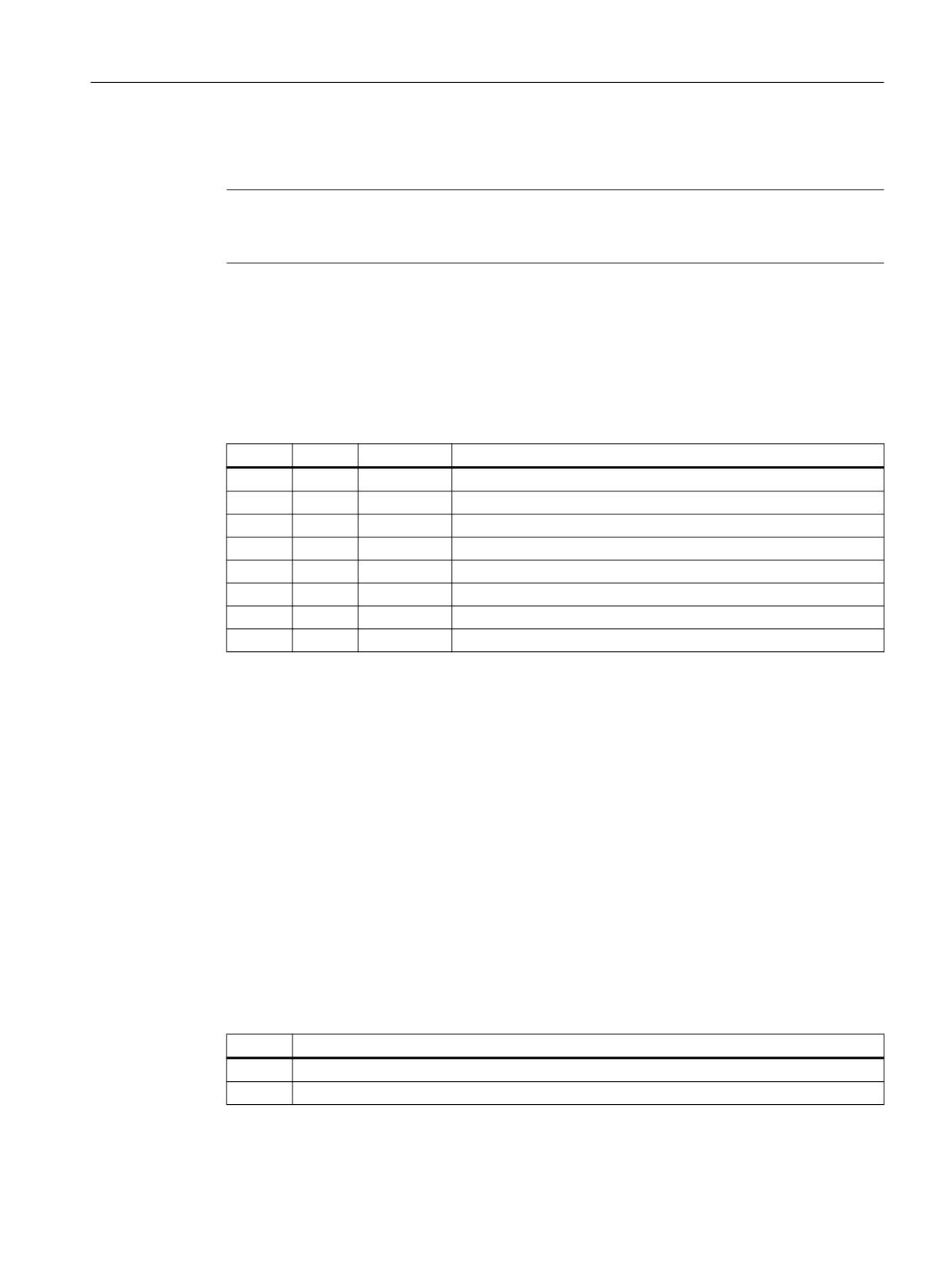
Spindle disable (DB31, ... DBX1.3)
LS
FS
coupling
Response
0
0
off
Setpoints are output
0
1
off
No setpoint output for FS
1
0
off
No setpoint output for LS
1
1
off
No setpoint output for LS and FS
0
0
ON
Setpoints are output
0
1
ON
Spindle disable not effective for FS
1
0
ON
Spindle disable also effective for FS, no setpoint output
1
1
ON
No setpoint output for LS and FS
Controller enable (DB31, ... DBX2.1)
LS: Resetting the "controller enable" during synchronous operation
If the controller enable of the LS is reset during synchronous operation for active setpoint
coupling, a control-internal switching is made to the actual value coupling. If the controller
enable is reset while the LS is traversing, the LS is stopped and an alarm issued. Synchronous
operation remains active.
LS and FS: Selection of synchronous operation without controller enable
If the "controller enable" for LS and FS is not set for selected synchronous operation, it will be
activated. LS and FS, however, are not traversed until controller enable for LS and FS has been
granted.
LS and FS: Setting the "Controller enable"
The position assumed by a spindle with setting the "controller enable" depends on DB31, ...
DBX1.4 == <value> (follow-up operation):
<value>
Assumed spindle position
0
Position when controller enable is canceled
1
Current position
Axes and spindles
Function Manual, 10/2020, 6FC5397-4GP40-0BA1
519

Synchronous spindle
13.4 Special features
Note
It is recommended for synchronous spindles during a block search, to write the DB31, ... DBX2.1
interface signal (controller enable) always together for FS and LS. If this is not done, the block
search, for example, stops after a FS machining because the controller enable of the LS is not
pending.
Note
Synchronism error
If the DB31, ... DBX2.1 interface signal (controller enable) is canceled for the FS after Spindle
Stop without the coupling being deactivated beforehand, then any synchronism error resulting
from external intervention will not be compensated when the "controller enable" is activated
again. This causes any programmed angular relationship between FS and LS to be lost.
The angular relationship can be restored by resynchronizing: DB31, ... DBX31.4 = 1
(resynchronization)
Follow-up mode (DB31, ... DBX1.4)
For follow-up operation, the set position is regularly set to the current actual position:
DB31, ... DBX1.4 == 1 (follow-up operation) AND DB31, ... DBX2.1 == 0 (controller enable)
⇒ Cyclic: Set position = actual position
Note
DB31, ... DBX1.4 (follow-up operation) is relevant only for DB31, ... DBX2.1 == 0 (controller
enable)
Position measuring system 1/2 (DB31, ... DBX1.5 and 1.6)
Switchover of the position measuring system for the FS and LS is possible during synchronous
operation. The coupling is retained.
Note
It is recommended to switchover the position measuring system for FS and LS only for
deselected synchronous operation.
Delete distance-to-go / spindle reset (DB31, ... DBX2.2)
LS: Setting spindle reset during synchronous operation
The setting of spindle reset causes the LS to be braked to standstill with the parameterized
acceleration. Synchronous operation remains active.
Axes and spindles
520
Function Manual, 10/2020, 6FC5397-4GP40-0BA1
Synchronous spindle
13.4 Special features
Any superimposed movement, other than together with COUPON / COUPONC, will be completed
as fast as possible.
Spindle stop (feed stop) (DB31, ... DBX4.3)
LS and FS: Setting spindle stop during synchronous operation
The setting of "spindle stop" for FS or LS causes both spindles to be braked synchronous to
standstill. Synchronous operation remains active.
Resetting spindle stop
Once "spindle stop" has been reset for both spindles, reacceleration is made to the last valid
speed setpoint.
Application example
Bring FS and LS to a standstill when a protection door is opened during synchronous operation.
Signal characteristic for LS and FS:
1. Stop: DB31, ... DBX4.3 = 1 (spindle stop)
2. Waiting for standstill: DB31, ... DBX61.4 == 1
3. Stopping: DB31, ... DBX2.1 = 0 (controller enable)
Delete S value (DB31, ... DBX16.7)
LS: Delete S value during synchronous operation
If "delete S value" is set, the LS is braked to a standstill using a ramp. Synchronous operation
remains active.
FS: Delete S value during synchronous operation
The control interface signal does not have any function for the FS in synchronous operation.
Resynchronize spindle 1/2 (DB31, ... DBX16.4 and 16.5)
LS: Resynchronizing the position measuring system during synchronous operation
Note
It is recommended to resynchronize the position measuring system of the LS only for deselected
synchronous operation.
Axes and spindles
Function Manual, 10/2020, 6FC5397-4GP40-0BA1
521
Synchronous spindle
13.4 Special features
Resynchronize (DB31, ... DBX31.4)
FS: Restoring the programmed angular offset
If synchronism between FS and LS is lost or not performed, the programmed angular offset can
be restored.
• Requirement: DB31, ... DBX31.4 = 1 (resynchronization)
• Acknowledgment: DB31, ... DBX99.4 == 1 (synchronization running)
Traverse keys for JOG (DB31, ... DBX4.6 and 4.7)
The "plus and minus traversing keys" for JOG are not disabled in the control for the FS in
synchronous operation, i.e. the FS executes a superimposed motion if one of these keys is
pressed.
Note
If superimposed traversing movements are to be precluded, they must be locked out by
measures in the PLC user program.
NC Stop axes plus spindles (DB21, ... DBX7.4)
"NC Stop axes plus spindles" in synchronous operation decelerates the coupled spindles in
accordance with the selected dynamic response. They continue to operate in synchronous
mode.
NC Start (DB21, ... DBX7.1)
(See Section "Response of the synchronous-spindle coupling for NC Start (Page 513)")
Note
NC Start after NC Stop does not deselect synchronous operation.
13.4.4
Differential speed between leading and following spindles
When does a differential speed occur?
A differential speed develops, e.g. with turning machine applications, when two spindles
oppose one other. Through the signed addition of two speed sources, a speed component is
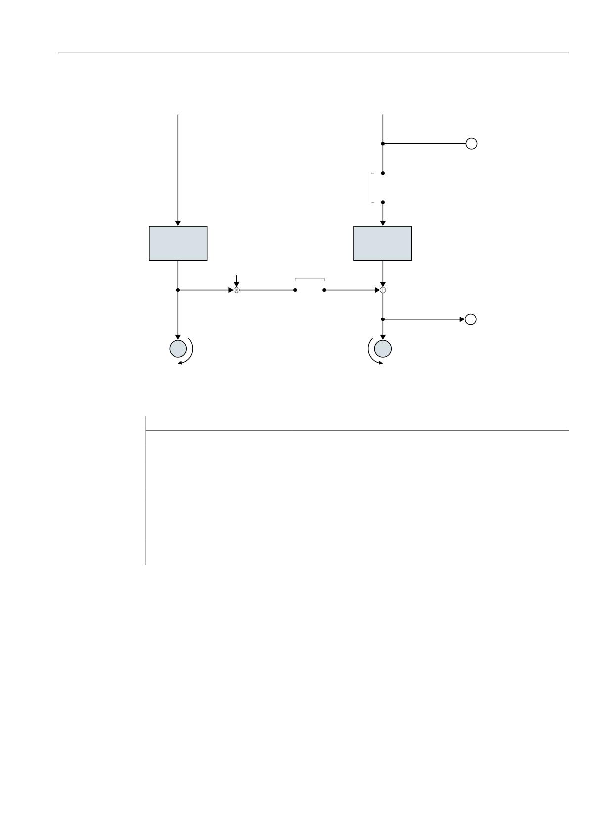
derived from the leading spindle via the coupling factor. In addition to this, for the following
spindle a speed (S...) and a direction of rotation (M3/M4) can be programmed.
Generally, to achieve synchronous operation, a coupling factor is used with a value of '-1'. This
sign reversal then results in a differential speed for the following spindle as compared to an
additional programmed speed.
Axes and spindles
522
Function Manual, 10/2020, 6FC5397-4GP40-0BA1
Synchronous spindle
13.4 Special features
This typical behavior in relation to the NC is illustrated in the following diagram.
4
-FBEJOH TQJOEMF
4
'PMMPXJOH TQJOEMF
. 4
4
4FUQPJOU TQFFE
&OBCMF WJB 1-$
4QFFE
4QFFE
JOUFSQPMBUPS
JOUFSQPMBUPS
$PVQMJOH GBDUPS
$0610/
SQN
SQN
SQN
SQN
"DUVBM TQFFE
Example
Program code
Comment
N01 M3 S500
; S1 rotates in the positive direction with 500 rpm
; the master spindle is spindle 1
N02 M2=3 S2=300
; S2 rotates in the positive direction with 300 rpm
N05 G4 F1
N10 COUPDEF(S2,S1,-1)
; Coupling factor -1:1
N11 COUPON(S2,S1)
; Activate coupling. The speed of the following spindle
S2 results from the speed of the leading spindle S1 and
the coupling factor.
N26 M2=3 S2=100
; Programming the differential speed, S2 is the follow-
ing spindle.
Application
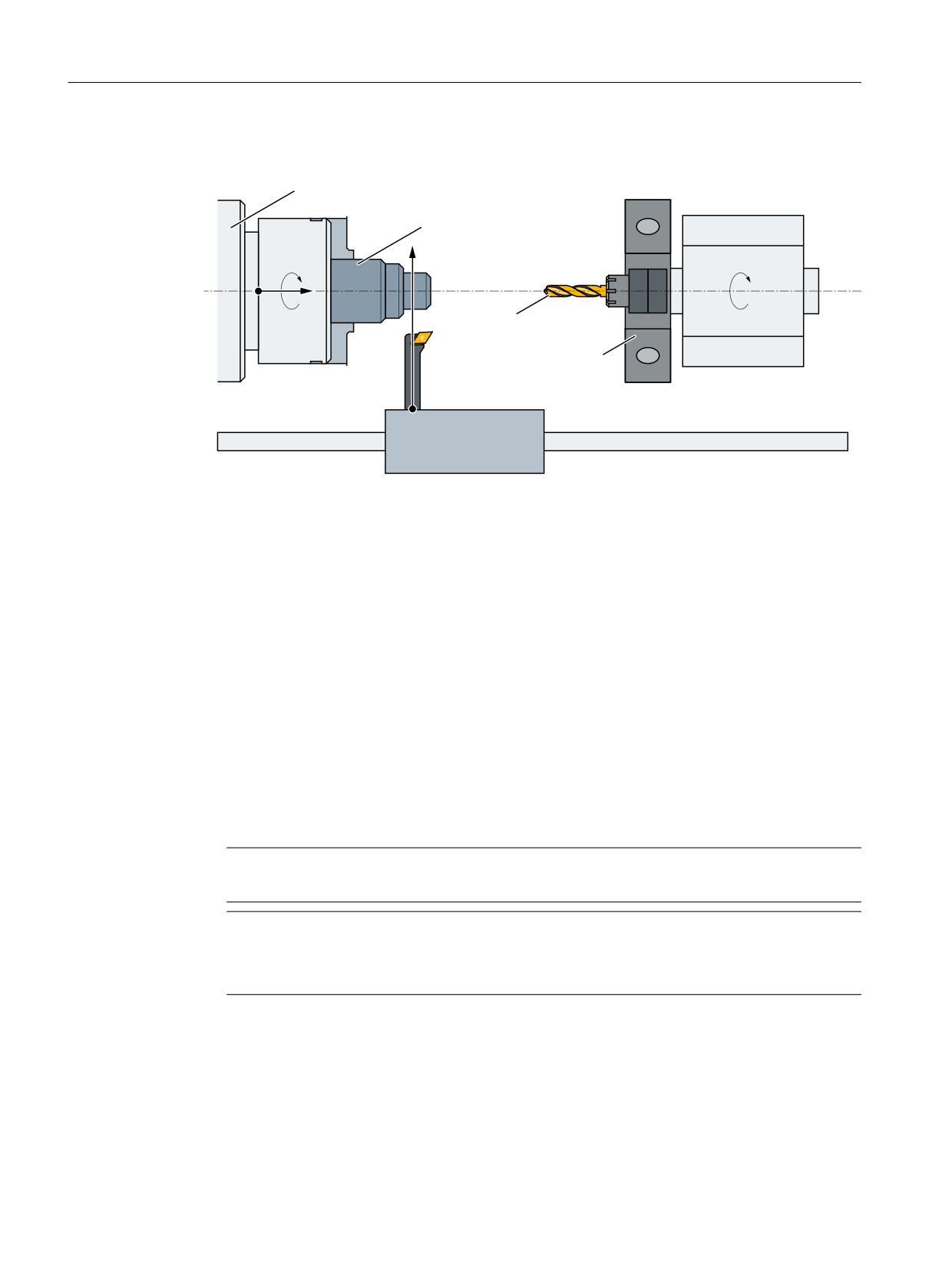
Manufacturing operations with positioned leading spindle and rotating tools require exact
synchronism with the counter spindle which then functions like a following spindle. A turret
rotating about the following spindle allows parts to be machined with different tool types.
The following diagram shows an application in which the tool is positioned parallel to the main
spindle.
Axes and spindles
Function Manual, 10/2020, 6FC5397-4GP40-0BA1
523
Synchronous spindle
13.4 Special features
.BJO TQJOEMF XJUI XPSLQJFDF
$PVOUFSTQJOEMF XJUI ESJWFO UPPM JO
UVSSFU
$IVDL
8PSLQJFDF
9
O
O
;
5PPM
5VSSFU
-FBEJOH TQJOEMF
5VSOJOH UPPM
'PMMPXJOH TQJOEMF
4MJEF
Figure 13-4
Single-slide lathe with revolver around the Z axis
Preconditions
Basic requirements for differential speed programming:
• Synchronous spindle functionality is required.
• The dynamic response of the following spindle must be at least as high as that of the leading
spindle. Otherwise, the system may suffer from reduced quality, for example, rigid tapping
without a compensating chuck G331/G332.
• The differential speed must be programmed in the channel in which the following spindle is
also configured. The leading spindle can be programmed in a different channel.
• The differential speed must be enabled for the following spindle by the PLC via IS "Enable
overlaid movement" (DB31, ... DBX26.4). If the enable signal has not been set, alarm 16771
"Channel% Following axis% Overlaid movement not enabled" is output. This alarm is cleared
when IS "Enable overlaid movement" (DB31, ... DBX26.4) is set or the coupling is opened.
Note
Positioning motion such as SPOS, SPOSA, M19 and axis motion do not have to be enabled.
Note
The differential speed does not therefore affect the coupling process.
The following or leading spindle cannot change gear stages while a coupling is active.
Activate coupling with COUPONC
When the coupling is activated, the following spindle is accelerated, as before, to the leading
spindle speed through application of the coupling factor. If the following spindle is already
rotating (M3, M4) when the coupling is activated, it continues with this motion after coupling.
Axes and spindles
524
Function Manual, 10/2020, 6FC5397-4GP40-0BA1
Synchronous spindle
13.4 Special features
Deactivate coupling
If the coupling is deactivated, the following spindle continues to rotate at the speed
corresponding to the sum of both speed components. The spindle behaves as if it had been
programmed with the speed and direction transferred from the other spindle. When
deactivating, there are no differences to the previous behavior.
Differential speed
A differential speed results from the renewed programming of the following spindle (in the
example, S2=...) or M2=3, M2=4 in speed control mode during an active synchronous spindle
coupling or by adopting the speed of the following spindle for COUPONC.
Condition:
Speed S... must also be re-programmed with direction of rotation M3 or M4. Otherwise alarm
16111 "Channel% Block% Spindle% No speed programmed" is displayed.
Read offsets of following spindle
The current offset always changes when a differential speed is programmed. The current offset
can be read at the setpoint end with $AA_COUP_OFFS[Sn] and at the actual value end with
$VA_COUP_OFFS[Sn].
The last offset programmed returns the variable $P_COUP_OFFS[Sn].
Display differential speed
The programmed difference component is displayed as the speed setpoint for the programmed
differential speed (in our example, corresponds to 100 rpm).
The actual speed refers to the motor speed. In the example, the actual speed is 500 rev/min * (-1)
+ 100 rpm = -400 rev/min.
IS, NC to the PLC
Following spindle in speed-controlled operation
The IS "Spindle in setpoint range" (DB31, ... DBX83.5) is set for the following spindle by the NC
if the programmed speed difference (see previous example, N26 with M2=3 S2=100) is reached.
If a differential speed is programmed and not enabled by the PLC, this VDI interface signal is not
set.
Even if a differential speed has been programmed, the following spindle remains under position
control if this is required by the coupling.
Note
The axial VDI interface signal NC → PLC IS "Superimposed motion" (DB31, ... DBX98.4) is set
when the differential speed programming creates setpoints in addition to the coupling
setpoints.
Axes and spindles
Function Manual, 10/2020, 6FC5397-4GP40-0BA1
525
Synchronous spindle
13.4 Special features
Actual direction of rotation clockwise (DB31, ... DBX83.7)
IS "Actual direction of rotation clockwise" (DB31, ... DBX83.7) refers to the resulting motor
direction.
IS PLC to the NC
Influence on following spindle via PLC interface
The effect of the axial VDI interface signals on the following spindle with differential speed in
speed control mode is described below:
Delete distance to go / Spindle Reset (DB31, ... DBX2.2)
The programmed differential speed and direction can be terminated by IS "Delete distance-to-
go / Spindle Reset" (DB31, ... DBX2.2). To delete the programmed speed only, it is possible to set
IS "Delete S value" (DB31, ... DBX16.7).
Resynchronize spindle 1/2 (DB31, ... DBX16.4 and 16.5)
The IS "Resynchronize spindle 1/2" (DB31, ... DBX16.4/16.5) are not locked. Any positional
offset is not compensated automatically by the coupling.
Invert M3/M4 (DB31, ... DBX17.6)
IS "Invert M3/M4" (DB31, ... DBX17.6) only inverts the additional programmed speed
component for the following spindle.
The motion component generated by the synchronous spindle coupling remains unaffected.
Spindle override (DB31, ... DBB19)
The "Spindle override" VDI interface (DB31, ... DBB19) only affects the additional programmed
speed component for the following spindle. If the spindle override switch is transferred to all
axial inputs, then any change in the spindle override value is applied twice to the following
spindle:
• once indirectly by a change in speed for the leading spindle and
• once in the programmed component of the following spindle.
The offset value can be adjusted accordingly in the PLC program.
Deselecting the coupling
If the coupling is deactivated, the following spindle continues to rotate at the speed
corresponding to the sum of both speed components. The motion transition upon coupling
deselection is at continuous speed.
With COUPOF , the spindle behaves as if it had been programmed with the speed and direction
transferred from the other spindle. In the example, this would be M4 S400.
Axes and spindles
526
Function Manual, 10/2020, 6FC5397-4GP40-0BA1
Synchronous spindle
13.4 Special features
When COUPOFS is programmed, the following spindle is decelerated to standstill from the
current speed.
Activate additional functions
The following spindle can also be a master spindle. In this case, it is capable of additional
functions.
• Rotational feedrate with G95, G96 and G97. With G96 S2=... the "constant cutting speed" can
be activated for the following spindle.
The speed dependent on the position of the transverse axis is the setpoint speed for the
speed interpolator of spindle 2 and is therefore included in the total speed of S2.
• Rigid tapping without compensating chuck with G331, G332.
13.4.5
Behavior of synchronism signals during synchronism correction
Effect of synchronism correction
New synchronism signals are produced by comparing the actual values with the corrected
setpoints. Once a correction process has been undertaken, the synchronism signals should be
present again.
13.4.6
Delete synchronism correction and NC reset
Variable $AA_COUP_CORR[Sn] returns the value zero for different situations in which the
synchronism correct is deleted:
• Once a synchronized spindle coupling has been activated for the following in question
with COUPON(..)/COUPONC(..), an existing synchronism correction is adopted in the setpoint
position.
• A synchronism correction active during NC reset but not at the parts program end is adopted
in the setpoint position. This does not affect the synchronism signals.
• At M30, an existing synchronism correction is retained
• At the user end, the correction value can also be deleted at any early point by describing the
variable $AA_COUP_CORR with the value zero. The synchronism correction is removed
immediately and using a ramp with reduced acceleration rate if larger values are involved.
Axes and spindles
Function Manual, 10/2020, 6FC5397-4GP40-0BA1
527
Synchronous spindle
13.4 Special features
13.4.7
Special points regarding start-up of a synchronous spindle coupling
Spindle start-up
The leading and following spindles must be started up initially like a normal spindle. The
corresponding procedure is described in:
Further information
Commissioning Manual CNC: NC, PLC, drive
Spindles (Page 377)
Requirements
The following parameters must then be set for the synchronous spindle pair:
• The machine numbers for the leading and following spindles
(for permanently configured coupling with channel-specific machine data MD21300
$MC_COUPLE_AXIS_1[n])
• The required coupling mode (setpoint, actual value or speed coupling)
(for permanently configured coupling with channel-specific machine data
MD21310 $MC_COUPLING_MODE_1[n])
• The gear stage(s) of FS and LS for synchronous operation
• The following coupling properties are still applicable for permanently configured
synchronous spindle coupling:
- Block change response in synchronous spindle operation:
MD21320 $MC_COUPLE_BLOCK_CHANGE_CTRL_1
- Coupling cancellation response:
MD21330 $MC_COUPLE_RESET_MODE_1
- Write-protection for coupling parameters:
MD21340 $MC_COUPLE_IS_WRITE_PROT_1
- Transformation parameters for synchronous spindle coupling:
SD42300 $SC_COUPLE_RATIO_1[n]
Command behavior of FS and LS for setpoint coupling
In order to obtain the best possible synchronism in setpoint couplings, the FS and LS must have
the same dynamic response as the response to setpoint changes. The axial control loops
(position, speed and current controllers) should each be set to the optimum value so that
variances can be eliminated as quickly and efficiently as possible.
The dynamic response adaptation function in the setpoint branch is provided to adapt
different axis dynamic responses without loss of control quality (see also Function Manual
Axes and spindles
528
Function Manual, 10/2020, 6FC5397-4GP40-0BA1

Synchronous spindle
13.4 Special features
"Monitoring and Compensating", Section "K3: Compensations"). The following control
parameters must each be set optimally for the FS and LS:
• KV factor (MD32200 $MA_POSCTRL_GAIN)
• Feedforward control parameters
MD32620 $MA_FFW_MODE
MD32610 $MA_VELO_FFW_WEIGHT
MD32650 $MA_AX_INERTIA
MD32800 $MA_EQUIV_CURRCTRL_TIME
MD32810 $MA_EQUIV_SPEEDCTRL_TIME
Behavior during loss of synchronism:
• Axis-specific MD32620 $MA_FFW_MODE
We recommend setting the feedforward control mode of the following axis to speed
feedforward control with Tt balancing MD32620 = 3.
This feedforward control mode can be further optimized for a more secure balancing process by
changing the axis-specific machine data:
Machine data
Meaning
MD32810 EQUIV_SPEEDCTRL_TIME
Equivalent time constant speed control loop for
feedforward control
MD37200 COUPLE_POS_TOL_COURSE
Threshold value for "Coarse synchronism"
MD37210 COUPLE_POS_TOL_FINE
Threshold value for "Fine synchronism"
MD37220 COUPLE_VELO_TOL_COURSE
Velocity tolerance 'coarse'
MD37220 COUPLE_VELO_TOL_FINE
Velocity tolerance 'fine'
In such cases, higher threshold values for the synchronism signals and larger position and/or
speed tolerances result in more stable results.
Dynamic response adaptation
To obtain a good control behavior, FS and LS must have the same dynamic response. The
following error for FS and LS must be equal at any given speed. For dynamically different
spindles, a matching via the dynamic response adaptation can be achieved in the setpoint
branch. The difference of the equivalent time constants between the dynamic "weakest" spindle
to the associated other spindle must be entered as time constant of the dynamic response
adaptation.
Example
When the speed feedforward control is active, the dynamic response is primarily determined by
the equivalent time constant of the "slowest" speed control loop.
• Equivalent time constant LS: MD32810 $MA_EQUIV_SPEEDCTRL_TIME[<LS>] = 5 ms
• Equivalent time constant FS: MD32810 $MA_EQUIV_SPEEDCTRL_TIME[<FS>] = 3 ms
• Time constant of dynamic response adaptation for FS: MD32910
$MA_DYN_MATCH_TIME[<FS>] = 5 ms - 3 ms = 2 ms
• Activation of the dynamic response adaptation for FS: MD32900
$MA_DYN_MATCH_ENABLE[<FS>] = 1
Axes and spindles
Function Manual, 10/2020, 6FC5397-4GP40-0BA1
529
Synchronous spindle
13.4 Special features
The following error for FS and LS is identical for correctly set dynamic response adaptation:
Operating area "Diagnostics" > "Service axes"
For the optimization, it may be necessary to adjust servo gain factors or feedforward control
parameters slightly.
Position control parameter sets
In the case of spindles, each gear stage is assigned a position-control parameter set. These
parameter sets can be used to adapt the dynamic response for LS and FS in synchronous
operation. This requires that a different gear stage is used for speed and positioning operation
and synchronous operation. The associated gear stage must be switched before activating the
associated operating mode.
Control parameters
The following control parameters must be set identically for the FS and LS:
• MD33000 $MA_FIPO_TYPE (fine interpolator type)
• MD32400 $MA_AX_JERK_ENABLE (axial jerk limitation)
• MD32402 $MA_AX_JERK_MODE (filter type for axial jerk limitation)
• MD32410 $MA_AX_JERK_TIME (time constant for the axial jerk filter)
• MD32412 $MA_AX_JERK_FREQ (blocking frequency of the axial jerk filter)
• MD32414 $MA_AX_JERK_DAMP (damping of the axial jerk filter)
• MD32420 $MA_JOG_AND_POS_JERK_ENABLE (release jerk limitation)
• MD32430 $MA_JOG_AND_POS_MAX_JERK (axial jerk)
FS: Automatic parameterization of the control parameters
The control parameters of the following spindle can be set as follows using this machine data:
MD30455 $MA_MISC_FUNCTION_MASK
Bit 5=0: Synchronous spindle coupling, following spindle:
Position control, feedforward control and parameter block are set for the following spindle.
Bit 5=1: Synchronous spindle coupling:
The control parameters of the following spindle are set as in an uncoupled scenario.
Further information
Velocities, setpoint/actual value systems, closed-loop control (Page 135)
Automatic transfer of the LS parameters for synchronous operation
For the automatic dynamic response adaptation for FS and LS, for synchronous operation, the
parameter values for the position control, feedforward control and parameter records of the FS
can be transferred from the LS:
MD30455 $MA_MISC_FUNCTION_MASK, Bit 5
Axes and spindles
530
Function Manual, 10/2020, 6FC5397-4GP40-0BA1
Synchronous spindle
13.4 Special features
Separate dynamic response for spindle and axis operations
In spindle and axis operations, dynamic programming FA, OVRA, ACC and VELOLIMA can be set
separately from one another with the following MD:
MD30455 $MA_MISK_FUNCTION_MASK Bit 6=0
Assignment is undertaken by the programmed axis or spindle name. For example, in spindle
operation, VELOLIMA[S1]=50 therefore only reduces the maximum speed to 50% and in axis
operation, VELOLIMA[C]=50 only reduces the maximum speed to 50%.
If, for example, VELOLIMA[S1]=50 and VELOLIMA[C]=50 are to have the same effect as before
with this machine data, the programming of FA, OVRA, ACC and VELOLIM have an effect
regardless of the programmed names:
MD30455 $MA_MISK_FUNCTION_MASK Bit 6=1
Knee-shaped acceleration characteristic
For the leading spindle, the effect of a knee-shaped acceleration characteristic on the following
spindle is identified by the following axis-specific machine data:
• MD35220 $MA_ACCEL_REDUCTION_SPEED_POINT (speed for reduced acceleration) and
• MD35230 $MA_ACCEL_REDUCTION_FACTOR (reduced acceleration).
If MD35242 $MA_ACCEL_REDUCTION_TYPE is present, it is also used to configure the type of
acceleration reduction. Otherwise a hyperbolic drop in acceleration is assumed.
If the dynamic response of a following spindle is lower than that of the leading spindle when the
coupling factor is taken into account, the leading spindle dynamic response is reduced to the
required level while the coupling is active.
The acceleration should be constant over the entire speed range for the following spindle.
However, if a knee-shaped acceleration characteristic is also stored in the above-mentioned
machine data for the following spindle, this is only taken into account when the spindles are
coupled in. The setpoints of the following spindle are applied for the specified knee-shaped
acceleration characteristic.
Further information
Acceleration and jerk (Page 79), knee-shaped acceleration characteristic
Actual value coupling
In an actual value coupling (AV), the drive for the FS must be considerably more dynamic than
the leading spindle drive. The individual drives in an actual value coupling are also set optimally
according to their dynamic response.
An actual value coupling should only be used in exceptional cases.
Speed coupling
The velocity coupling (VV) corresponds internally to a setpoint coupling (DV), but with lower
dynamic requirements of the FS and LS. A position control servo loop is not required for the FS
and/or LS. Measuring systems are not required.
Axes and spindles
Function Manual, 10/2020, 6FC5397-4GP40-0BA1
531
Synchronous spindle
13.4 Special features
Threshold values for coarse/fine synchronism
After controller optimization and feedforward control setting, the threshold values for coarse
and fine synchronism must be entered for the FS.
• Threshold value for "Coarse synchronism"
Axis-spec. MD7200: AV, DV: COUPLE_POS_TOL_COARSE
MD37220: VV: COUPLE_VELO_TOL_COARSE
• Threshold value for "Fine synchronism"
Axis-spec. MD37210: AV, DV: COUPLE_POS_TOL_FINE
MD37230: VV: COUPLE_VELO_TOL_FINE
The values of the FS must be calculated according to the accuracy requirements of the machine
manufacturer, and the PLC interface must be checked via the service display.
Angular offset LS/FS
If there must be a defined angular offset between the FS and LS, e.g. when synchronous
operation is activated, the "zero degree positions" of the FS and LS must be mutually adapted.
This can be done with the following machine data:
• MD34100 $MA_REFP_SET_POS
• MD34080 $MA_REFP_MOVE_DIST
• MD34090 $MA_REFP_ MOVE_DIST_CORR
Further information
Homing (Page 31)
Service display for FS
In the "Diagnostics" operating area, when commissioning in the synchronous mode, the
following values are displayed for the following spindle:
• Actual deviation between setpoints of FS and LS
Value displayed: Position offset in relation to leading spindle (setpoint)
(value corresponds to angular offset between FS and LS that can be read with axis variable
$AA_COUP_OFFS in the part program)
• Actual deviation between actual values of FS and LS
Value displayed: Position offset in relation to leading spindle (actual value)
Further information
Operating Manual
Axes and spindles
532
Function Manual, 10/2020, 6FC5397-4GP40-0BA1

Synchronous spindle
13.6 Examples
13.5
Boundary conditions
Availability of the "synchronous spindle" function
The function is an option ("synchronous spindle/multi-edge turning" or the corresponding
optional version of the generic coupling), which must be assigned to the hardware via the
license management.
Note
For information on the different versions of generic coupling, see:
Further information
Axis couplings (Page 537)
13.6
Examples
Programming example
Program code
Comment
; Leading spindle = master spindle = spindle 1
; Following spindle = spindle 2
N05 M3 S3000 M2=4 S2=500
; Master spindle rotates at 3000 rpm
; FS: 500 rpm
N10 COUPDEF (S2, S1, 1, 1, "No",
; Def. of coupling, can also
"Dv")
; be configured
N70 SPCON
; Include leading spindle in the position con-
trol
; (setpoint value coupling).
N75 SPCON(2)
; Bring following spindle into closed-loop po-
sition control
N80 COUPON (S2, S1, 45)
; On-the-fly coupling to offset position = 45
degrees
N200 FA [S2] = 100
; Positioning speed = 100 degrees/min
N205 SPOS[2] = IC(-90)
; Traverse with 90° overlay in negative direc-
tion
N210 WAITC(S2, "Fine")
; Wait for "fine" synchronism
N212 G1 X.., Y.. F...
; Machining
N215 SPOS[2] = IC(180)
; Traverse with 180° overlay in positive direc-
tion
N220 G4 S50
; Dwell time = 50 revolutions
; of master spindle
N225 FA [S2] = 0
; Activate configured velocity (MD)
N230 SPOS[2] = IC (-7200)
; 20 rev. with configured velocity
Axes and spindles
Function Manual, 10/2020, 6FC5397-4GP40-0BA1
533

Synchronous spindle
13.7 Data lists
Program code
Comment
; in neg. direction
N350 COUPOF (S2, S1)
; On-the-fly decoupling, S = S2 = 3000
N355 SPOSA[2] = 0
; Stop FS at zero degrees
N360 G0 X0 Y0
N365 WAITS(2)
; Wait for spindle 2
N370 M5
; Stop FS
N375 M30
13.7
Data lists
13.7.1
Machine data
13.7.1.1
NC-specific machine data
Number
Identifier: $MN_
Description
10000
AXCONF_MACHAX_NAME_TAB
Machine axis name
13.7.1.2
Channelspecific machine data
Number
Identifier: $MC_
Description
20070
AXCONF_MACHAX_USED
Machine axis number valid in channel
21300
COUPLE_AXIS_1
Definition of synchronous spindle pair
21310
COUPLING_MODE_1
Type of coupling in synchronous spindle mode
21320
COUPLE_BLOCK_CHANGE_CTRL_1
Block change behavior in synchronous spindle operation
21330
COUPLE_RESET_MODE_1
Coupling abort behavior
21340
COUPLE_IS_WRITE_PROT_1
Coupling parameters are write-protected
13.7.1.3
Axis/spindlespecific machine data
Number
Identifier: $MA_
Description
30455
MISK_FUNCTION_MASK
Axis functions
30550
AXCONF_ASSIGN_MASTER_CHAN
Reset position of channel for axis change
32200
POSCTRL_GAIN
Servo gain factor (KV factor)
32400
AX_JERK_ENABLE
Axial jerk limitation
32410
AX_JERK_TIME
Time constant for axial jerk filter
32420
JOG_AND_POS_JERK_ENABLE
Initial setting for axial jerk limitation
32430
JOG_AND_POS_MAX_JERK
Axial jerk
Axes and spindles
534
Function Manual, 10/2020, 6FC5397-4GP40-0BA1

Synchronous spindle
13.7 Data lists
Number
Identifier: $MA_
Description
32610
VELO_FFW_WEIGHT
Feedforward control factor for speed feedforward control
32620
FFW_MODE
Feedforward control mode
32650
AX_INERTIA
Moment of inertia for torque feedforward control
32800
EQUIV_CURRCTRL_TIME
Equivalent time constant current control loop for feed-
forward control
32810
EQUIV_SPEEDCTRL_TIME
Equivalent time constant speed control loop for feedfor-
ward control
34080
REFP_MOVE_DIST
Reference point approach distance
34090
REFP_MOVE_DIST_CORR
Reference point offset
34100
REFP_SET_POS
Reference point value
35000
SPIND_ASSIGN_TO_MACHAX
Assignment of spindle to machine axis
37200
COUPLE_POS_TOL_COARSE
Threshold value for "Coarse synchronism"
37210
COUPLE_POS_TOL_FINE
Threshold value for "Fine synchronism"
37220
COUPLE_VELO_TOL_COARSE
Speed tolerance "coarse" between leading and following
spindles
37230
COUPLE_VELO_TOL_FINE
Speed tolerance "fine" between leading and following
spindles
13.7.2
Setting data
13.7.2.1
Channelspecific setting data
Number
Identifier: $SC_
Description
42300
COUPLE_RATIO_1
Transmission parameters for synchronous spindle operation
13.7.3
System variables
System variable
Description
$P_COUP_OFFS[following spindle]
Programmed offset of the synchronous spindle
$AA_COUP_OFFS[following spindle]
Position offset for synchronous spindle (setpoint)
$VA_COUP_OFFS[following spindle]
Position offset for synchronous spindle (actual value)
For exhaustive explanations of the system variables, see:
Further information
List Manual System Variables
Axes and spindles
Function Manual, 10/2020, 6FC5397-4GP40-0BA1
535
Synchronous spindle
13.7 Data lists
Axes and spindles
536
Function Manual, 10/2020, 6FC5397-4GP40-0BA1
Axis couplings
14
14.1
Coupled motion
14.1.1
Brief description
14.1.1.1
Function
The "coupled motion" function enables the definition of simple axis links between a master axis
and a slave axis, taking into consideration a coupling factor.
Coupled motion has the following features:
• Any axis of the NC can be defined as a master axis.
• Any axis of the NC can be defined as a coupled axis with a specific coupling factor.
• The master axis and coupled motion axis or axes together form a coupled axis grouping.
• Any number of coupled motion axes can be assigned to a master axis.
• A total of 2 leading axes may be assigned to each coupled motion axis.
• A coupled motion axis can be the master axis of a further coupled axis grouping.
• Traversing movements of the master axis are executed in synchronism on all slave axes based
on the coupling factor.
• Coupled motion axes can be moved independently of the master axis while the coupling is
active (overlaid movements).
• The master and coupled motion axes of a coupled axis grouping are defined, and the coupling
switch on/switch off, by programming instructions in the part program or by synchronized
action.
• Coupled motion is also possible in the following manual modes: JOG, JOG REF, JOG INC, etc.
14.1.1.2
Preconditions
"Coupled motion" function
The "Coupled motion" function is a fixed component of the NC software.
Generic coupling
The coupled motion functionality is also available in the generic coupling.
Axes and spindles
Function Manual, 10/2020, 6FC5397-4GP40-0BA1
537
Axis couplings
14.1 Coupled motion
However, for basic operation of generic coupling, the following restrictions apply:
• The maximum number of coupled motion groupings is limited to 4.
• Only 1 leading axes may be assigned to each coupled motion axis.
• Cascading is not possible.
Note
These restrictions do not apply when NC software is supplied with the relevant options of
generic coupling (refer to " Preconditions (Page 609) " in the "Brief description" of generic
coupling).
14.1.2
General functionality
The "Coupled motion" function allows the definition of simple axis couplings. Coupling is
performed from one leading axis to one or more following axes, the so-called coupled motion
axes. A separate coupling factor can be specified for each coupled motion axis.
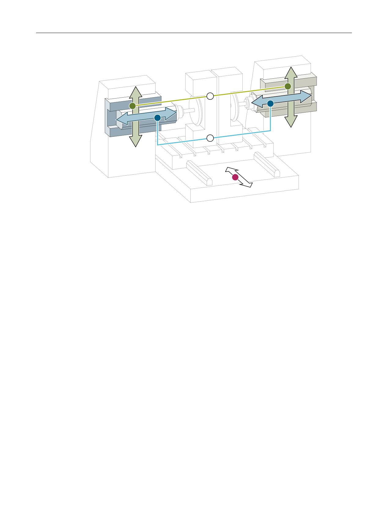
Coupled axis grouping
The leading axis and all the coupled motion axes assigned to it together form a coupled axis
grouping. If the leading axis is traversed, all coupled motion axes traverse in accordance with
their coupling factors.
A coupled axis grouping can consist of any combination of linear and rotary axes.
Leading axes
Any axis of the NC, including simulated axes, can be used as leading axis.
Coupled axes
Any axis of the NC can be used as coupled motion axis.
Coupling factor
The ratio in which the coupled motion axis moves in relation to the leading axis is specified via
the coupling factor:
Coupling factor K = motion of the coupled motion axis / motion of the leading axis
Negative coupling factors (motion of the coupled motion axis in the opposite direction) are also
permitted.
Axes and spindles
538
Function Manual, 10/2020, 6FC5397-4GP40-0BA1
Axis couplings
14.1 Coupled motion
7
8
:
;
9
Leading axis
Coupled-motion axis
Coupling factor
Coupled-motion Y axis
V axis
1
grouping ①
Coupled-motion Z axis
W axis
-1
grouping ②
Figure 14-1
Application example: Two-sided machining
Multiple couplings
Up to 2 leading axes can be assigned to one coupled motion axis. The traversing movement of
the coupled motion axis then results from the sum of the traversing movements of the leading
axes.
Dependent coupled motion axis
A coupled motion axis is a "dependent coupled motion axis" when it traverses as a result of a
leading axis movement.
Independent coupled motion axis
A coupled motion axis is an "independent coupled motion axis" when it traverses as a result of
a direct traverse instruction. The traversing movement resulting from the coupled motion axis
is then the sum total of the traversing movements as a "dependent" and an "independent"
coupled motion axis.
Coupled motion axis as leading axis
A coupled motion axis can at the same time be the leading axis of a further coupled axis
grouping.
Axes and spindles
Function Manual, 10/2020, 6FC5397-4GP40-0BA1
539
Axis couplings
14.1 Coupled motion
Coordinate system
Coupled axis motion is always executed in the base coordinate system (BCS).
Activating/deactivating
Coupled motion can be activated/deactivated via the part programs and synchronous actions. In
this context please ensure activating/deactivating is undertaken with the same programming:
• Activate: Part program → Deactivate: Part program
• Activate: Synchronous action → Deactivate: Synchronized action
Synchronization on-the-fly
If switch on is performed while the leading axis is in motion, the coupled motion axis is first
accelerated to the velocity corresponding to the coupling. The position of the leading axis at the
time the velocities of the leading and coupled motion axes are synchronized then serves as the
start position for further coupled motion.
Operating modes
Coupled motion is effective in the AUTOMATIC, MDA and JOG modes.
Reference point approach
The following applies for referencing of axes of a coupled axis grouping:
• Leading axes
When referencing the leading axis of a coupled axis grouping, the coupling to all coupled
motion axes is retained. The coupled motion axes move in synchronism with the leading axis,
as a function of their coupling factors.
• Coupled motion axis: JOG/REF mode
When referencing a coupled motion axis of a coupled axis grouping, the coupling to the
leading axis is cancelled. If the coupling is canceled, the following alarm is displayed:
Alarm 16772 "Channel Channel No. Block Block No. Axis Axis No. is following axis, coupling
is opened."
The coupling is not activated again until JOG/REF mode is cancelled.
The display of this alarm can be suppressed using the following machine data:
MD11410 $MN_SUPPRESS_ALARM_MASK, Bit 29 = 1 (mask supporting special alarm
generation)
CAUTION
No coupling
When the coupled motion axis is referenced, the coupling to the leading axis is cancelled.
If referencing is executed immediately with the leading axis, i.e. without changing JOG/REF
mode, the coupled motion axis does not traverse with the leading axis.
• Coupled motion axis: Part program command G74
It is not possible to reference a coupled motion axis of a coupled axis grouping using the G74
programming instruction.
Axes and spindles
540
Function Manual, 10/2020, 6FC5397-4GP40-0BA1

Axis couplings
14.1 Coupled motion
Distance-to-go: Coupled-motion axis
The distance-to-go of a coupled motion axis refers to the total residual distance to be traversed
from dependent and independent traversing.
Delete distance-to-go: Coupled-motion axis
Delete distance-to-go for a coupled motion axis only results in aborting of the independent
traversing movement of the leading axis.
Response to NC Start
The behavior of the coupled-axis groupings during NC Start depends on the setting in the
machine data:
MD20112 $MC_START_MODE_MASK (definition of initial control settings for NC-START)
Bit
Value
Meaning
8
0
Coupled-axis groupings are maintained in NC Start.
1
Coupled-axis groupings are phased out in NC Start.
Response to RESET/part program end
The behavior of the coupled-axis groupings during RESET/ part program end depends on the
setting in the machine data:
MD20110 $MC_RESET_MODE_MASK (definition of initial control settings after RESET / TP end)
Bit
Value
Meaning
8
0
Coupled-axis groupings are invalidated on RESET / part program end.
1
Coupled-axis groupings remain active even beyond RESET/part program end.
Note
If with NC RESET or end of part program in a channel, the leading axis is not stopped as well
(cross-channel coupling, command axis, PLC axis, etc.), the requested RESET cannot be
completed.
Because of traversing of the leading axis, the coupled-motion axis is still active for the channel
in which the RESET is requested. With suitable actions (NC RESET in the channel of the leading
axis, stopping of the command or PLC axis), the leading axis must also be stopped in parallel to
the coupled-motion axis.
Axes and spindles
Function Manual, 10/2020, 6FC5397-4GP40-0BA1
541
Axis couplings
14.1 Coupled motion
14.1.3
Programming
14.1.3.1
Definition and switch on of a coupled axis grouping (TRAILON)
Definition and switch on of a coupled axis grouping take place simultaneously with
the TRAILON part program command.
Programming
Syntax:
TRAILON(<coupled motion axis>, <leading axis>,
[<coupling factor>])
Effectiveness:
modal
Parameters:
Coupled motion Type: AXIS
axis:
Range of values: All defined axis and spindle names in the channel
Leading axis:
Type: AXIS
Range of values: All defined axis and spindle names in the channel
Coupling factor: The ratio of the traversing movement of the coupled motion axis to the
leading axis is specified via the optional coupling factor:
Coupling factor = Path of the coupled-motion axis/path of the leading
axis
A negative coupling factor results in motion in opposite directions for
the leading and coupled motion axis.
Type: REAL
Range of values: ± (2,2 * 10-308 … 1,8 * 10+308)
Default value:
+1.0
Example:
Program code
Comment
TRAILON(V,Y,2)
; Definition and switch on of the coupling of the
coupled-motion axis V with leading axis Y. The
coupling factor is 2.
14.1.3.2
Switch off (TRAILOF)
Switch off of the coupling of a coupled-motion axis with a leading axis takes place through
the TRAILOF part program command.
Programming
Syntax:
TRAILON(<coupled motion axis>, <leading axis>)
TRAILOF(<coupled-motion axis>)
Effectiveness:
modal
Axes and spindles
542
Function Manual, 10/2020, 6FC5397-4GP40-0BA1
Axis couplings
14.1 Coupled motion
Parameters:
Coupled motion Type: AXIS
axis:
Range of val- All defined axis and spindle names in the channel
ues:
Leading axis:
Type: AXIS
Range of val- All defined axis and spindle names in the channel
ues:
Example:
Program code
Comment
TRAILOF(V,Y)
;
Deactivation of the coupling of the coupled-motion
;
axis
V to leading axis Y.
14.1.4
Effectiveness of PLC interface signals
Independent coupled motion axis
All the associated channel and axis specific interface signals of the coupled-motion axis are
effective for the independent motion of a coupled-motion axis, e.g.:
• DB21, ... DBX0.3 (Activate DRF)
• DB31, ... DBX0.0 - 0.7 (feedrate override)
• DB31, ... DBX1.3 (axis blocking)
• DB31, ... DBX2.1 (control system enable)
• DB31, ... DBX4.0 - 4.2 (activate handwheel)
• DB31, ... DBX4.3 (feed stop)
•
…
This allows the speed to be changed for the independent motion of a coupled motion axis using
a feedrate override or a DRF offset to be defined using the handwheel in AUTOMATIC and MDA
modes.
Dependent coupled motion axis
With respect to the motion of a coupled motion axis, which is dependent on the leading axis,
only the coupled-motion axis interface signals that effect termination of the motion (e.g. axis-
specific feed stop, axis inhibit, control system enable, etc.) are effective.
Axes and spindles
Function Manual, 10/2020, 6FC5397-4GP40-0BA1
543

Axis couplings
14.1 Coupled motion
Leading axis
When a coupled axis grouping is active, the interface signals (IS) of the leading axis are applied
to the appropriate coupled motion axis via the axis coupling, i.e.
• A position offset or feed control action of the leading axis is applied via the coupling factor to
effect an appropriate position offset or feed control action in the coupled motion axis.
• Shutdown of the leading axis as the result of an interface signal (e.g. axis-specific feed stop,
axis inhibit, servo enable, etc.) causes the corresponding coupled motion axis to shut down.
Position measuring system 1/2 (DB31, ... DBX1.5/1.6))
Switch-over of the position measuring system for the leading and coupled motion axes is not
inhibited for an active coupled axis grouping. The coupling is not canceled.
Recommendation: Switch-over when the coupling is deactivated.
Tracking (DB31, ... DBX1.4)
Activation of tracking for an axis is done via the PLC program by setting the following NC/PLC
interface signals:
DB31, ... DBX2.1 = 0 (control system enable)
DB31, ... DBX1.4 == 1 (tracking mode)
When activating tracking mode for a coupled axis grouping, the specified NC/PLC interface
signals must be set simultaneously for all axes (master and slave axes) of the coupled axis group.
If tracking mode is activated for the master axis only, a permanent offset results within the
coupling.
Whether and which axis is a leading or a following axis can be seen from the following NC/PLC
interface signals and system variables:
DB31, ... DBX99.0 (leading axis/spindel active)
DB31, ... DBX99.1 (following axis/spindel active)
$AA_COUP_ACT[axis name] (see: Status of coupling)
14.1.5
Status of coupling
The coupling status of an axis can be determined using the following system variables:
$AA_COUP_ACT [axis name]
Value
Meaning
0
No coupling active
1, 2, 3
Tangential tracking
4
Synchronous spindle coupling
8
Coupled motion active
16
Master value coupling
32
Following axis of electronic gearbox
Axes and spindles
544
Function Manual, 10/2020, 6FC5397-4GP40-0BA1

Axis couplings
14.1 Coupled motion
Note
Only one coupling mode may be active at any given time.
14.1.6
Dynamics limit
The dynamics limit is dependent on the type of activation of the coupled axis grouping:
• Activation in part program
If activation is performed in the part program and all leading axes are active as program axes
in the activating channel, the dynamic response of all coupled-motion axes is taken into
account during traversing of the leading axes to avoid overloading the coupled-motion axes.
If activation in part program takes place with leading axes that are not active as program axes
in the activating channel ($AA_TYP ≠ 1), then the dynamics of the coupled motion axes is not
considered while traversing the leading axes. This can result in an overload for coupled
motion axes with a dynamic response which is less than that required for the coupling.
• Activation in synchronized action
If activation is performed in a synchronous action, dynamics of the coupled motion axes is
not taken into account during traversing of the leading axis. This can result in an overload for
coupled motion axes with a dynamic response which is less than that required for the
coupling.
CAUTION
Axis overload
If a coupled motion grouping
• in synchronized actions
• is activated in the part program with leading axes, that are not program axes in the
channel of the coupled motion axes,
it is the special responsibility of the user/machine manufacturer to provide suitable
measures to ensure that an overload of the coupled motion axes does not occur through
traversing of the leading axis.
Axes and spindles
Function Manual, 10/2020, 6FC5397-4GP40-0BA1
545
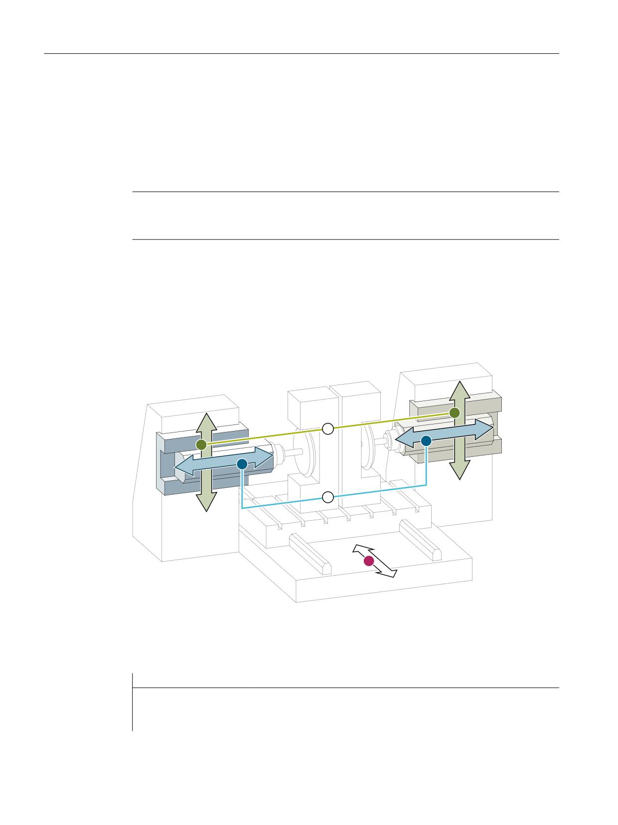
Axis couplings
14.1 Coupled motion
14.1.7
Supplementary conditions
Control system dynamics
It is recommended to align the position control parameters of the leading axis and the coupled
motion axis within a coupled axis group.
Note
Alignment of the position control parameters of the leading axis and the coupled motion axis
can be performed via a parameter set changeover.
14.1.8
Examples
Application Example: Two-sided machining
7
8
:
;
9
Example 1
Example of an NC part program for the axis constellation shown in Fig.:
Program code
Comment
TRAILON(V,Y,1)
; Activation of 1st coupled axis group
TRAILON(W,Z,-1)
; Activation of 2nd coupled axis group
G0 Z10
; Infeed Z and W axes in opposite axial directions
Axes and spindles
546
Function Manual, 10/2020, 6FC5397-4GP40-0BA1
Axis couplings
14.2 Curve tables
Program code
Comment
G0 Y20
; Infeed of Y and V axes in same axis
direction
G1 Y22 V25
; Superimpose dependent and independent movement of coupled
motion axis "V"
TRAILOF(V,Y)
; Deactivate 1st coupled axis group
TRAILOF(W,Z)
; Deactivate 2nd coupled axis group
Example 2
The dependent and independent movement components of a coupled motion axis are added
together for the coupled motion. The dependent component can be regarded as a co-ordinate
offset with reference to the coupled motion axis.
Program code
Comment
N01 G90 G0 X100 U100
;
N02 TRAILON(U,X,1)
; Activation of coupled axis group
N03 G1 F2000 X200
; Dependent movement of U, Upos=200, UTrail=100
N04 U201
; Independent movement, Upos=U201+UTrail=301
N05 X250
; Dependent movement of U, UTrail=UTrail(100)+50=150,
Upos=351
N06 G91 U100
; Independent movement of Upos(351)+U100=451
N07 G90 X0
; Dependent movement of U, Upos=Upos(451)-UTrail(250)=201
N10 TRAILOF(U,X)
14.2
Curve tables
14.2.1
Product brief
14.2.1.1
Function
The "curve tables" function can be used to define the complex sequence of motions of an axis in
a curve table.
Any axis can be defined as a leading axis and a following axis can be traversed by taking a curve
table into account.
The command variable in these motion sequences is an abstract master value, which is
generated by the control or derived from an external variable (e.g. simulated position of an axis).
Creating curve tables is performed via part program sequences.
The curve tables in the static NC memory remain valid after the part program has been been
closed or after POWER DOWN.
Curve tables can be saved in dynamic NC memory for faster access. Please note that tables need
to be reloaded after run-up.
Axes and spindles
Function Manual, 10/2020, 6FC5397-4GP40-0BA1
547
Axis couplings
14.2 Curve tables
Axis groupings with curve tables must be reactivated independently of the storage location of
the curve table after POWER ON.
Linear curve table segments are stored in separate areas to save memory space.
14.2.1.2
Preconditions
Memory configuration
Static NC memory
Memory space for curve tables in static NC memory is defined by machine data:
MD18400 $MN_MM_NUM_CURVE_TABS (number of curve tables)
MD18402 $MN_MM_NUM_CURVE_SEGMENTS (number of curve segments)
MD18403 $MN_MM_NUM_CURVE_SEG_LIN (number of linear curve segments)
MD18404 $MN_MM_NUM_CURVE_POLYNOMS (number of curve table polynomials)
Dynamic NC memory
Memory space for curve tables in dynamic NC memory is defined by machine data:
MD18406 $MN_MM_NUM_CURVE_TABS_DRAM (number of curve tables)
MD18408 $MN_MM_NUM_CURVE_SEGMENTS_DRAM (number of curve segments)
MD18409 $MN_MM_NUM_CURVE_SEG_LIN_DRAM (number of linear curve segments)
MD18410 $MN_MM_NUM_CURVE_POLYNOMS_DRAM (number of curve table polynomials)
14.2.2
General functionality
Curve table
A functional relation between a command variable "master value" and an abstract following
value is described in the curve table.
A following variable can be assigned uniquely to each master value within a defined master
value range.
Curve segment
The functional relation can be subdivided into separate sections of the master value axes, called
curve segments.
Within a curve segment, the relation between the master value and following value is generally
described by a polynomial up to the third order. Polynomials up to the 5th degree are also
permissible.
Further information: NC Programming Programming Manual
Axes and spindles
548
Function Manual, 10/2020, 6FC5397-4GP40-0BA1
Axis couplings
14.2 Curve tables
Curve segments are used if:
• Polynomials or circles are programmed
• Spline is active
• Compressor is active
• Polynomials or circles are generated internally (chamfer/rounding, approximate positioning
with G643, TRC, etc.)
Tool radius compensation
Curve tables are available in which it is possible to specify the tool radius compensation in the
table definition even if polynomial blocks or blocks with no motion for an axis, or jumps for the
following axis, occur in the curve table (G41/G42/G40 in the table definition).
The equidistant curve (tool center point path of tool radius compensation) of a curve consisting
of polynomials can no longer be displayed exactly using polynomials. The associated curve
tables must be approximated stepwise, using polynomials in this case. This means that the
number of segments in the curve table no longer matches the number of programmed
segments. The number of segments required for the curve table is defined by the bend of the
curve. The larger the curvature for the programmed curve, the more segments are required for
the curve table.
On account of tool radius compensation for curve tables, more memory may be required.
Selection option of the memory type should not produce shortage of static NC memory.
Selection of memory type
While defining a curve table, it can be defined whether the curve table is created in the static or
dynamic NC memory.
Note
Table definitions in the static NC memory are available even after control system run-up. Curve
tables of the dynamic NC memory must be redefined after every control system run-up.
14.2.3
Memory organization
Memory configuration
The storage place available for the curve table in the static and dynamic NC memory is defined
during memory configuration (see Section "Memory configuration (Page 551)").
Memory optimization
In a curve table with linear segments, the linear segments can be stored efficiently in the
memory only if the two following machine data items are > 0:
Axes and spindles
Function Manual, 10/2020, 6FC5397-4GP40-0BA1
549
Axis couplings
14.2 Curve tables
MD18403 $MC_MM_NUM_CURVE_SEG_LIN (number of linear curve segments in the static NC
memory)
MD18409 $MC_MM_NUM_CURVE_SEG_LIN_DRAM (number of linear curve segments in the
dynamic NC memory)
If no memory areas are created with this machine data, then the linear segments are stored as
polynomial segments.
Alarm in case of insufficient memory
If memory has been configured for tables with linear and polynomial segments via machine data
and memory for linear segments runs out when generating a linear table, the the memory for
polynomial segments is used for the linear segments (if available). In this case, memory is
"wasted", as a polynomial segment requires an unnecessary amount of memory to store a linear
segment. This circumstance is conveyed through an alarm, which also discloses the number of
unnecessarily used polynomial segments. The alarm only displays awarning and does not result
in the interruption of the program or the generation of the curve table.
If a curve table consists of linear segments and polynomials of a high degree, a memory area for
linear segments and a memory area for polynomial segments is required for the storage of the
curve table. An alarm is output if insufficient memory is available in the relevant areas. The alarm
parameters can be used to detect the resources that are insufficient.
Insufficient memory
If a curve table cannot be created, because sufficient memory is not available, then the newly
created table is deleted immediately after the alarm.
If insufficient is available, then one or more table(s) that is/are no longer required can be deleted
with CTABDEL or, alternatively, memory can be reconfigured via machine data.
Temporary curve table
When a curve table is created, a temporary curve table is set up first in memory, which is then
extended block by block. Finally (CTABEND), the table is checked for consistency. The temporary
table is converted to a table that can be used in a coupling only if it is found to be consistent.
Same table number
A new curve table may have the same number as an existing table. The new curve table then
overwrites the existing table with the same number. This is done only if the new curve table does
not contain any errors. If an error is detected in the new table, the old table is not overwritten.
If the user wishes to have the option of overwriting an existing curve table without deleting it
first, then he will need to dimension the table memory so that there is always enough extra
memory to accommodate the table to be overwritten.
Overwriting curve tables
Curve tables that are not active in a master value coupling and are locked with CTABLOCK() may
be overwritten.
Axes and spindles
550
Function Manual, 10/2020, 6FC5397-4GP40-0BA1

Axis couplings
14.2 Curve tables
Deleting curve tables
Curve tables that are not active in a master value coupling and are locked with CTABLOCK() may
be overwritten.
14.2.4
Commissioning
14.2.4.1
Memory configuration
A defined storage space is available for the curve tables in the static and dynamic NC memory,
which is defined through the following machine data:
Static NC memory
MD18400 $MN_MM_NUM_CURVE_TABS
Defines the number of curve tables that can be stored in the
static NC memory.
MD18402 $MN_MM_NUM_CURVE_SEGMENTS
Defines the number of curve table segments that can be stored
in the static NC memory.
MD18403 $MN_MM_NUM_CURVE_SEG_LIN
Defines the maximum number of linear segments in the static
NC memory.
MD18404 $MN_MM_NUM_CURVE_POLYNOMS
Defines the number of curve table polynomes that can be
stored in the static NC memory.
Dynamic NC memory
MD18406 $MN_MM_NUM_CURVE_TABS_DRAM
Defines the number of curve tables that can be stored in the
dynamic NC memory.
MD18408 $MN_MM_NUM_CURVE_SEGNENTS_DRAM
Defines the number of curve table segments that can be stored
in the dynamic NC memory.
MD18409 $MN_MM_NUM_CURVE_SEG_LIN_DRAM
Defines the maximum number of linear segments in the dy-
namic NC memory.
MD18410 $MN_MM_NUM_CURVE_POLYNOMS_DRAM
Defines the number of curve table polynomes that can be
stored in the dynamic NC memory.
Note
A curve table with linear segments can be stored efficiently in the memory only if:
MD18403 > 0 or MD18409 > 0
If no memory areas are created with this machine data, then the linear segments are stored as
polynomial segments.
Axes and spindles
Function Manual, 10/2020, 6FC5397-4GP40-0BA1
551
Axis couplings
14.2 Curve tables
14.2.4.2
Tool radius compensation
MD20900
Tool radius compensation can produce segments for which the following axis or leading axis
have no movement. A missing movement of the following axis does not normally represent any
problem. As against this, a missing movement of the leading axis requests a specification as to
how such discontinuities are to be handled, i.e., whether or not a curve table should be
generated in these cases. This specification is done in the machine data settings:
MD20900 $MC_CTAB_ENABLE_NO_LEADMOTION (curve tables with discontinuity of the
following axis)
Value
Description
0
No curve tables that contain a discontinuity in the following axis are produced. Alarm 10949 is
output and program processing is aborted.
1
Curve tables with a discontinuity in the following axis can be generated. If a segment contains
a discontinuity in the following axis, Alarm 10955 is output but program processing is contin-
ued.
2
Curve tables with a discontinuity in the following axis can be created without an alarm being
output.
Note
In the case of a curve table that contains segments without leading axis movement (this means
that the following axis jumps at this point), the following axis can only make a jump within its
dynamic limits (max. velocity and max. acceleration). This means that there is always a deviation
from the programmed curve.
14.2.4.3
Specification of memory type
MD20905
If there is no memory specification while defining or deleting a curve table, the memory type can
be determined through the following machine data:
MD20905 $MC_CTAB_DEFAULT_MEMORY_TYPE (default memory type for curve tables)
Value
Description
0
Curve tabels are normally created in the static NC memory.
1
Curve tabels are normally created in the dynamic NC memory.
Axes and spindles
552
Function Manual, 10/2020, 6FC5397-4GP40-0BA1
Axis couplings
14.2 Curve tables
14.2.5
Programming
Definition
The following modal language commands work with curve tables: (The parameters are
explained at the end of the list of functions.)
• Beginning of definition of a curve table:
CTABDEF(following axis, leading axis, n, applim, memType)
• End of definition of a curve table:
CTABEND()
• Deleting curve table(s):
CTABDEL(n)
; curve table n
CTABDEL(n, m)
; [n < m], more than one in the range of numbers
; it is deleted in static "SRAM" and in dynamic "DRAM" of NC memory.
• CTABDEL(n, m, memType)
; Delete with memory specification:
Those curve tables with the numbers in the range, which are in the specified memory type,
will be deleted. All other curve tables are retained.
Delete all tables in a particular memory type:
CTABDEL(, , "DRAM")
CTABDEL(, , "SRAM")
CTABDEL()
; all in DRAM or
; all in SRAM:
; all, irrespective of memory type
• Read the following value for a master value
CTAB(master value, n, degrees, [following axis, lead axis])
• Read the master value for a following value
CTABINV(following value, approx. master value, n, degrees, [following axis, leading axis])
Axes and spindles
Function Manual, 10/2020, 6FC5397-4GP40-0BA1
553
Axis couplings
14.2 Curve tables
Access to curve table segments
• Read start value (following axis value) of a table segment
CTABSSV(leading value, n, degrees, [following axis, leading axis])
• Read end value (following axis value) of a table segment
CTABSEV(master value, n, degrees, [following axis, master axis])
Note
If curve table functions such as CTAB(), CTABINV(), CTABSSV() etc., in synchronized
actions are used, only main traverse variable, e.g. $AC_PARAM[ ... ] or $R[ ... ] is permissible
for the return value and the argument "degrees" of the function.
Example:
ID=1 WHEN TRUE DO $R1 = CTABSSV(10, 1, $R2)
or
ID=1 WHEN TRUE DO $AC_PARAM[1] = CTABSSV(10, 1, $AC_PARAM[2])
Enable/cancel blocking
The following functions can be used to enable or cancel deletion and overwrite blocks for parts.
programs.
• Enable deletion and overwrite block.
General form: CTABLOCK(n, m, memType)
• Cancel deletion and overwrite block.
CTABUNLOCK releases the tables locked with CTABLOCK. Tables involved in an active
coupling remain locked, i.e. they cannot be deleted. However, the CTABLOCK command is
cancelled, i.e. the table can be deleted as soon as the coupling is deactivated. It is not
necessary to call CTABUNLOCK again.
General form: CTABUNLOCK(n, m, memType)
Applications of the forms:
Curve table with number n
CTABLOCK(n)
Curve tables in the number range n to m.
CTABLOCK(n, m)
All curve tables, irrespective of memory type
CTABLOCK()
All curve tables in the specified memory type
CTABLOCK(, , memType)
Curve table with number n
CTABUNLOCK(n)
Curve tables in the number range n to m.
CTABUNLOCK(n, m)
Axes and spindles
554
Function Manual, 10/2020, 6FC5397-4GP40-0BA1
Axis couplings
14.2 Curve tables
All curve tables, irrespective of memory type
CTABUNLOCK()
All curve tables in the specified memory type
CTABUNLOCK(, , memType)
Other commands for calculating and differentiating between curve tables for applications for
diagnosing and optimizing the use of resources:
•
Number of defined tables irrespective of memory type
CTABNO()
•
Number of defined tables in SRAM or DRAM of NC memory
CTABNOMEM(memType)
•
Number of possible curve tables in memory memType.
CTABFNO(memType)
•
Table number of nth curve table.
General form: CTABID(n, memType)
Generates the table number of the nth curve table with memory type memType. CTABID(1,
memType) is used to read out the highest curve number (105) of the memory type specified.
CTABID(n)
Generates the table number of the nth curve table in the memory specified using the
following machine data:
MD20905 $MC_CTAB_DEFAULT_MEMORY_TYPE (default memory type for curve tables)
CTABID(p)
Generates the ID (table number) of the curve table entered in the memory as the pth curve
table.
Note
If for example, the sequence is changed between consecutive calls of CTABID(),
then CTABID(n, ...) can be used to provide a different curve table than the one provided
before the change.
•
Indicates the block state of curve table number n.
CTABISLOCK(n)
•
Checks curve table number n.
CTABEXISTS(n)
•
Returns the memory in which curve table number n is stored.
CTABMEMTYP(n)
•
Returns the table periodicity.
CTABPERIOD(n)
•
Number of curve segments already used in memory memType.
CTABSEG(memType, segType)
•
Number of curve segments used in curve table number n
CTABSEGID(n, segType)
•
Number of still possible curve segments in memory memType.
CTABFSEG(memType, segType)
Axes and spindles
Function Manual, 10/2020, 6FC5397-4GP40-0BA1
555
Axis couplings
14.2 Curve tables
• Maximum number of possible curve segments in memory memType.
CTABMSEG(memType, segType)
• Number of polynomials already used in memory memType.
CTABPOL(memType)
• Number of curve polynomials used by curve table number n.
CTABPOLID(n)
• Number of still possible polynomials in memory memType.
CTABFPOL(n)
• Maximum number of possible polynomials in memory memType.
CTABMPOL(n)
Boundary values of curve tables
Behavior of the leading axis/following axes on the edges of the curve table:
• The value at the beginning of the curve table is read by a following axis.
CTABTSV(n, degrees, F axis), following value at the beginning of the curve table
• The value at the end of the curve table is read by a following axis.
CTABTEV(n, degrees, F axis), following value at the end of the curve table
• The value at the beginning of the curve table is read by the leading axis.
CTABTSP(n, degrees, F axis), master value at the beginning of the curve table
• The value at the end of the curve table is read by the leading axis.
CTABTEP(n, degrees, F axis), master value at the end of the curve table
• Determine the value range of the following value.
CTABTMIN(n, F axis), minimum following value of curve table
CTABTMAX(n, F axis), maximum following value of the curve table
Parameter
• Following axis:
Name of axis via which the following axis is programmed in the definition.
• Leading axis:
Name of axis via which the leading axis is programmed.
• n, m
Numbers for curve tables.
Curve table numbers can be freely assigned. They are used exclusively to uniquely identify a
curve table.
In order to delete a curve table area using the command CTABDEL(n, m) must be greater
than n.
• p
Entry location (in memType memory area)
Axes and spindles
556
Function Manual, 10/2020, 6FC5397-4GP40-0BA1
Axis couplings
14.2 Curve tables
•
applim:
Behavior at the curve table edges.
-
0 non-periodic (table is processed only once, even for rotary axes).
–
1 periodic, modulo (the modulo value corresponds to the LA table values).
–
2 periodic, modulo (LA and FA are periodic).
•
Master value
Position value for which a following value is to be determined.
•
Slave value
Position value for which a master value is to be calculated.
•
aproxmastervalue
Position value that can be used to determine a unique master value in the case of an
ambiguous reversing function of the curve table.
•
degrees
Parameter in which the pitch of the table function is returned.
•
memType
Optional parameter for specifying memory type to be used n curve tables.
Possible values:
"SRAM" curve table is created in static NC memory.
"DSRAM" curve table is created in dynamic NC memory.
If an invalid type is entered, the value -2 is returned.
If the parameter is omitted, then the memory type set via the following machine data takes
effect:
MD20905 $MC_CTAB_DEFAULT_MEMORY_TYPE (default memory type for curve tables)
•
segType
Optional parameter for entry of segment type
Possible values:
segType "L" linear segments
segType "P" Polynomial segments
Further information: NC Programming Programming Manual
Restrictions
The following restrictions apply when programming:
• It is not permissible that the NC block generates a preprocessing stop.
• No discontinuities may occur in leading axis motion.
• Any block that contains a traverse instruction for the following axis must also include a
traverse for the leading axis.
• The direction of motion of the leading axis must not reverse at any point in the rule of motion,
i.e. the position of the leading axis must always be unique within the sequence of motions.
The programmed contour may not move perpendicular to the leading axis.
Axes and spindles
Function Manual, 10/2020, 6FC5397-4GP40-0BA1
557
Axis couplings
14.2 Curve tables
• Axis names from gantry axis groups cannot be used to define a table (only leading axis are
possible).
• Depending on the following machine data, jumps in the following axis may be tolerated if a
movement is missing in the leading axis:
MD20900 $MC_CTAB_ENABLE_NO_LEADMOTION (curve tables with discontinuity of the
following axis)
The other restrictions listed above still apply.
Axis assignment
Does not take effect until coupling is activated with curve table.
Note
The dynamic limit values of the motion commands for a curve table are not checked until
activation or interpolation.
Starting value
The first motion command in the definition of a curve table defines the starting value for the
leading and following value.
All instructions that cause a preprocessing stop must be hidden.
Example 1
Without tool radius compensation, without memory type
Program code
Comment
N100 CTABDEF(AX2, AX1, 3.0)
; Start of the definition for the non-
; periodic curve table no. 3
N110 AX1=0 AX2=0
; 1st motion instruction specifies the start value
; leading value: 0, Following value: 0
N110 AX1=20 AX2=0
; 1st curve segment: Master value: 0...20,
; following value: Starting value …0
N120 AX1=100 AX2=6
; 2nd curve segment: Master value: 20...100,
; following value: 0...6
N130 AX1=150 AX2=6
; 3rd curve segment: Master value: 100...150,
; following value 6
N130 AX1=180 AX2=0
; 4th curve segment: Master value: 150...180,
; following value: 6...0
N200 CTABEND
; end of the definition, the curve table
; is generated in its internal representation.
; the advance is reorganized to the status
; at the start of N100
Axes and spindles
558
Function Manual, 10/2020, 6FC5397-4GP40-0BA1
Axis couplings
14.2 Curve tables
Example 2
Example of a curve table with active tool radius compensation:
Prior to definition of a curve table with CTABDEF(), tool radius compensation must not be active;
otherwise alarm 10942 is generated. This means that tool radius compensation must be
activated within the definition of the curve table. Similarly, it must be deactivated again before
the end of the curve table definition, using CTABEND.
Program code
Comment
N10 CTABDEF(Y, X, 1, 0)
; Start of the definition for the non-
; periodic curve table no. 1
N20 X0 Y0
N30 G41 X10 Y0
; Tool radius compensation on
N40 X20 Y20
N50 X40 Y0
N60 X60 Y20
N70 X80 Y0
N80 G40 X90 Y0
; Tool radius compensation off
N90 CTABEND
Tool radius compensation is activated in block N30; this causes the approach movement for
radius compensation to be made in this block. Similarly, the approach movement for
deactivation of the radius compensation is made in block N80.
Note
The value pairs between CTABDEF and CTABEND must be specified for precisely the axis names
that have been programmed in CTABDEF as the leading axis name and following axis name. In
the case of programming errors, alarms or incorrect contours may be generated.
14.2.6
Access to table positions and table segments
Reading table positions
With the program commands CTAB and CTABINV the following value for a master value (CTAB)
can be read from the part program and from synchronized actions, or alternatively the master
value can be read off for a following value. The pitch value can be used to calculate the speed of
the following axis or leading axis at any position in the table.
Reading segment positions
Segment positions of a curve table for the value for the following axis can be read using the
CTABSSV and CTABSEV calls.
The language commands CTABSSV and CTABSEV generally provide the start and end values of
the internal segments of the curve tables for the following axis. These values only agree with the
programmed values of the curve tables if the programmed segments can be converted 1:1 to the
Axes and spindles
Function Manual, 10/2020, 6FC5397-4GP40-0BA1
559
Axis couplings
14.2 Curve tables
internal segments of the curve table. This is always the case if only G1 blocks or axis polynomials
are used to define the curve tables and no other functions are active.
Under the following conditions, the programmed segments may not be converted unchanged
into the internal segments of the curve table:
• Circles or involutes are programmed
• Chamfering or rounding (CHF, RND) is active
• Smoothing with G643 is active
• Compressor function (COMP...) is active
• Tool radius compensation is active for polynomial interpolation
In these cases, the language commands CTABSSV and CTABSEV may not be used to query the
start and end points of the programmed segments.
CTABINV
When using the inversion function for the curve tables CTABINV, it must be noted that the
following value mapped to the leading value may not be unique.
Within a curve table, the following value can assume the same value for any number of master
value positions. In order to resolve this ambiguity, the program command CTABINV requires a
further parameter, in addition to the following value, which it uses to select the 'correct' master
value. CTABINV always returns the master value that is closest to this auxiliary parameter. This
auxiliary value can, for example, be the master value from the previous interpolator clock cycle.
Note
Although the auxiliary parameter permits calculation of a unique result for the reversal function
of the curve table, it should be noted that numerical inaccuracies may give rise to contours,
which can cause the reversal function to produce results that deviate from those that would be
obtained in a calculation where the accuracy is unrestricted.
Optional parameters
The functions CTAB, CTABINV, CTABSSV and CTABSEV have optional parameters for the leading
and following axes. If one of these parameters is programmed, the master value and following
value are modified using the scaling factors of the relevant axes.
This is particularly important if axes have been configured with different length units (inch/
metric). If no optional parameters are programmed, the master value and following value are
treated as path positions in the conversion from external to internal representation. This means
that the values are multiplied according to the configured resolution (decimal places) and the
remaining decimal places are truncated.
Axes and spindles
560
Function Manual, 10/2020, 6FC5397-4GP40-0BA1
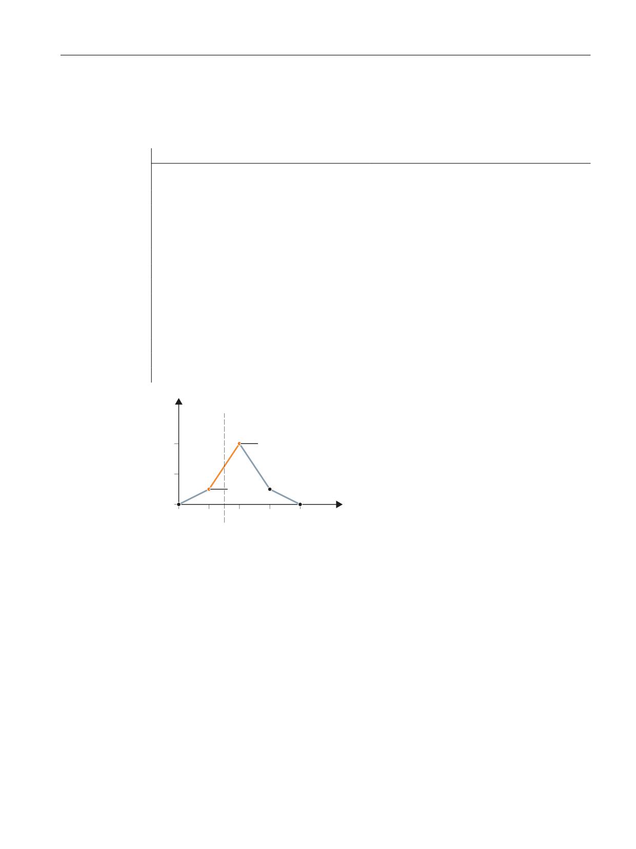
Axis couplings
14.2 Curve tables
Identifying the segment associated with master value X
Example of reading the segment starting and end values for determining the curve segment
associated with master value X = 30 using CTABSSV and CTABSEV:
Program code
Comment
N10 DEF REAL STARTPOS
; Beginning of the definition for the
start position of the curve table
N20 DEF REAL ENDPOS
N30 DEF REAL GRADIENT
N100 CTABDEF(Y,X,1,0)
; Start of table definition
N110 X0 Y0
; Start position, 1st table segment
N120 X20 Y10
; End position, 1st table segment =
; Start position 2nd table segment
N130 X40 Y40
N140 X60 Y10
; 3rd curve segment
N150 X80 Y0
; 4th curve segment
N160 CTABEND
; End of table definition
N200 STARTPOS=CTABSSV(30.0,1,GRADIENT)
; Start position Y in segment 2 = 10.
N210 ENDPOS=
; End position Y in segment 2 = 40
CTABSEV(30.0,1,GRADIENT)
; Segment 2 belongs to LW X = 30.0
:
9
/
&OE
/
/
4UBSU
/
9
Figure 14-2
Determining the curve segment associated with master value X = 30
Reading values at start and end
The values of the following axes and of the master axis at the start and end of a curve table can
be read with the following calls:
R10 =CTABTSV(n, degrees, F axis, following value at the beginning of the table)
R10 =CTABTEV(n, degrees, F axis, following value at the end of the table)
R10 =CTABTSP(n, degrees, L axis, master value at the beginning of the table)
R10 =CTABTEP(n, degrees, L axis, master value at the end of the table)
Axes and spindles
Function Manual, 10/2020, 6FC5397-4GP40-0BA1
561
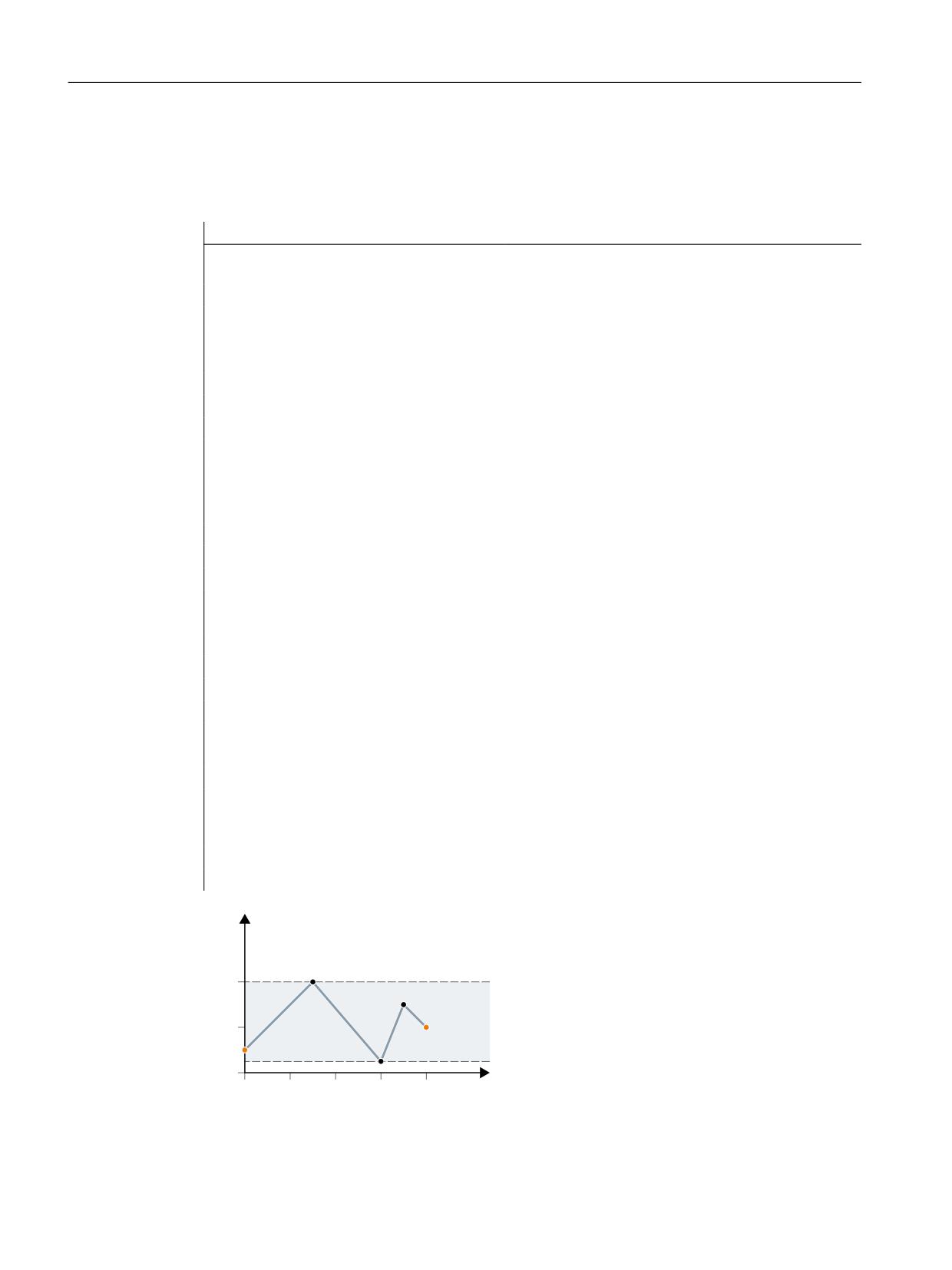
Axis couplings
14.2 Curve tables
Value range of the following value
The following example illustrates how the minimum and maximum values of the table are
determined using CTABTMIN and CTABTMAX:
Program code
Comment
N10 DEF REAL STARTVAL
; Beginning of the definition for the start
and initial values of the curve table
N20 DEF REAL ENDVAL
N30 DEF REAL STARTPARA
N40 DEF REAL ENDPARA
N50 DEF REAL U_MINVAL
N60 DEF REAL U_MAXVAL
N70 DEF REAL GRADIENT
…
N100
CTABDEF(Y,X,1,0)
; Start of table definition
N110
X0 Y10
; Start value, 1st table segment
N120
X30 Y40
; End position, 1st table segment =
; Start position 2nd table segment
N130
X60 Y5
; End position, 2nd table segment …
N140
X70 Y30
; End position, 3rd curve segment …
N150
X80 Y20
; End position, 4th curve segment …
N160
CTABEND
; End of table definition
N200
STARTPOS=CTABTSV(1,GRADIENT)
; STARTPOS = 10
; Start position of table as well as
N210
ENDPOS=CTABTEV(1,GRADIENT)
; ENDPOS = 20
; End position of table
N220
STARTPARA=CTABTSP(1,GRADIENT)
; STARTPARA = 0
; Master value at beginning of curve table
N230
ENDPARA=CTABTEP(1,GRADIENT)
; ENDPARA = 80
; Read master value at the end of the curve
table from the value range of the following
axis
N240
U_MINVAL=CTABTMIN(1)
; Minimum value when Y = 5 and
N250
U_MAXVAL=CTABTMAX(1)
; Maximum value when Y = 40
:
/
.BYJNVN
/
WBMVF
/
'JOBM WBMVF
4UBSU WBMVF
/
.JOJNVN
WBMVF
9
Figure 14-3
Determining the minimum and maximum values of the table
Axes and spindles
562
Function Manual, 10/2020, 6FC5397-4GP40-0BA1
Axis couplings
14.2 Curve tables
14.2.7
Activation/deactivation
Activation
The coupling of real axes to a curve table is activated through this command:
LEADON (<Following axis>, <Leading axis>, <n>)
with <n> =Number of the curve table
Activation is possible:
• In the part program
• in the definition of a synchronous action
Example:
N1000 LEADON(A,X,3)
; Axis A follows the master value X according to the rule
of motions defined in Curve Table No. 3
Deactivation
The switch off of the coupling to a curve table takes place through the following command:
LEADON (<Following axis>, <Leading axis>)
Deactivation is possible:
• In the part program
• in synchronized actions
Note
While programming LEADOF, the abbreviated form is also possible without specification of
the leading axis.
Example:
N1010 LEADOF(A,X)
; The coupling of Axis A with its leading axis is canceled
Multiple use
A curve table can be used several times in a single part program to couple different channel axes.
Axes and spindles
Function Manual, 10/2020, 6FC5397-4GP40-0BA1
563
Axis couplings
14.2 Curve tables
14.2.8
Modulo-leading axis special case
Position is absolute
When an axial master value coupling is active, the position of the following axis via a curve table
is unique, i.e. an absolute assignment to the master axis exists.
This means that, when a modulo rotary axis is used as the master axis, the position of the master
axis is absolute. In other words, the position of the modulo rotary axis entered in the curve table
is absolute, and not modulo-reduced.
Example
Let the position of a modulo rotary axis with LEADON be 210°. The position 210° degrees is used
as the starting value in the curve table. After one rotation of the modulo axis, the axis position
is again displayed as 210°. The absolute position 570° is however taken as the input value in the
curve table:
210° + 1 round (360°) = 570°
14.2.9
Behavior in AUTOMATIC, MDA and JOG modes
Activation
An activated curve table is functional in the AUTOMATIC, MDA and JOG modes.
Basic setting after run-up
No curve tables are active after run-up.
14.2.10
Effectiveness of PLC interface signals
Dependent following axis
With respect to the motion of a following axis that is dependent on the leading axis, only the
following axis interface signals that effect termination of the motion (e.g. axis-specific feed stop,
axis inhibit, servo enable, etc.) are effective.
Axes and spindles
564
Function Manual, 10/2020, 6FC5397-4GP40-0BA1
Axis couplings
14.2 Curve tables
Leading axis
In an activated axis group, the interface signals move the leading axis through the axis coupling
to the associated following axis, i.e.:
• feed control of the leading axis causes a corresponding feed control of the following axis.
• A shutdown of the leading axis through interface signals (e.g., axis-specific feed stop, axis
inhibit, servo enable etc.) causes the corresponding following axis to shut down.
The effect of the axis inhibit of the leading axis on the following axis can be prevented through
the following MD setting:
MD37160 $MA_LEAD_FUNCTION_MASK, Bit 1 = 1
Position measuring system 1/2 (DB31, ... DBX1.5/1.6))
Switch-over of the position measuring system for the leading and following axes is not inhibited
for an active coupled axis group. The coupling is not canceled.
Recommendation: Switch the measuring system over when the coupling is deactivated.
14.2.11
Diagnosing and optimizing utilization of resources
The following functions allow parts programs to get information on the current utilization of
curve tables, table segments and polynomials.
One result of the diagnostic functions is that resources still available can be used dynamically
with the functions, without necessarily having to increase memory usage. The description of the
parameters in Chapter "Programming Curve Tables" also applies to the following functions.
a) Curve tables
• Determine total number of defined tables.
The definition applies to all memory types (see also CTABNOMEM)
CTABNO()
• Number of defined tables in SRAM or DRAM of NC memory.
CTABNOMEM (memType)
If memType is not specified, the memory type specified in the following machine data:
MD20905 $MC_CTAB_DEFAULT_MEMORY_TYPE (default memory type for curve tables)
Result:
>= 0: Number of defined curve tables
-2: Invalid memory type
Axes and spindles
Function Manual, 10/2020, 6FC5397-4GP40-0BA1
565
Axis couplings
14.2 Curve tables
• Determine number of curve tables still possible in memory.
CTABFNO(memType)
If memType is not specified, the memory type specified in the following machine data:
MD220905 $MC_CTAB_DEFAULT_MEMORY_TYPE
Result:
>= 0: Number of possible tables
-2: Invalid memory type
• Determine the table number of the pth table in the memory type specified optionally
CTABID(p, memType)
If memType is not specified, the memory type specified in the following machine data:
MD20905 $MC_CTAB_DEFAULT_MEMORY_TYPE
Result:
Table number or
Alarm for invalid p or memType
When using the CTABID(p, memType) function, no assumptions should be made regarding
the sequence of the curve tables in the memory. The CTABID(p, ...) function supplies the
ID (table number) of the curve table entered in memory as the pth curve table.
If the sequence of curve tables in memory changes between consecutive calls of
CTABID()CTABID(), e.g. due to the deletion of curve tables with CTABDEL(), the
CTABID(p, ...) function can supply a different curve table with the same number.
To prevent this from happening, the curve tables concerned can be locked, using the
CTABLOCK(...) language command. In this case, it should be noted that the curve tables
concerned are then unlocked with CTABUNLOCK().
•
Determine block condition
Table n
CTABISLOCK(n)
Result:
> 0: Table is blocked
Reason for block:
1: by CTABLOCK()
2: by an active coupling
3: by CTABLOCK()and by an active coupling
= 0: Table is not blocked
- 1: Table does not exist
• Check whether the curve table exists
CTABEXISTS(n)
Result:
1: Table exists
0: Table does not exist
Axes and spindles
566
Function Manual, 10/2020, 6FC5397-4GP40-0BA1
Axis couplings
14.2 Curve tables
•
Determine memory type of a curve table
CTABMEMTYP(n)
Result:
0: Table in static SRAM NC memory
1: Table in dynamic "DRAM" NC memory
-1: Table does not exist
• by an active coupling periodic
CTABPERIOD(n)
Result:
0: Table is not periodic
1: Table is periodic in the leading axis
2: Table is periodic in the leading and following axes
-1: Table does not exist
b) Curve table segments
•
Determine number of used curve segments of the type memType in the memory range.
•
CTABSEG(memType, segType)
•
If memType is not specified, the memory type specified in the following machine data:
MD20905 $MC_CTAB_DEFAULT_MEMORY_TYPE
Result:
>= 0: Number of curve segments
-2: Invalid memory type
If segType is not specified, the sum is produced via linear and polynomisl segments in the
memory type.
-2: segType not equal "L" or "P"
•
Determine number of used curve segments of the type memType in the memory range
CTABSEGID(n, segType)
Result:
>= 0: Number of curve segments
-1: Curve table with number n does not exist
-2: segType not equal "L" or "P"
•
Determine number of free curve segments of the type memType in the memory range
CTABFSEG(memType, segType)
If memType is not specified, the memory type specified in the following machine data:
MD20905 $MC_CTAB_DEFAULT_MEMORY_TYPE
Result:
>= 0: Number of free curve segments
-2: Invalid memory type, segType not equal "L" or "P"
•
Determine maximum number of possible curve segments of the type segType in the memory
CTABMSEG(memType, segType)
If memType is not specified, the memory type specified in the following machine data:
MD20905 $MC_CTAB_DEFAULT_MEMORY_TYPE
Result:
>= 0: Maximum number of possible curve segments
-2: Invalid memory type, segType not equal "L" or "P"
Axes and spindles
Function Manual, 10/2020, 6FC5397-4GP40-0BA1
567
Axis couplings
14.2 Curve tables
c) Polynomials
• Determine the number of used polynomials of the memory type
CTABPOL(memType)
If memType is not specified, the memory type specified in the following machine data:
MD20905 $MC_CTAB_DEFAULT_MEMORY_TYPE
Result:
>= 0: Number of polynomials already used in the memory type
-2: Invalid memory type
• Determine the number of curve polynomials used by a curve table
CTABPOLID(n)
Result:
>=0: Number of used curve polynomials
-1: Curve table with number n does not exist
• Determine the number of free polynomials of the memory type
CTABFPOL(memType)
If memType is not specified, the memory type specified in the following machine data:
MD20905 $MC_CTAB_DEFAULT_MEMORY_TYPE
Result:
>= 0: Number of free curve polynomials
-2: Invalid memory type
• Determine the maximum number of polynomials of the memory type
CTABMPOL(memType)
If memType is not specified, the memory type specified in the following machine data:
MD20905 $MC_CTAB_DEFAULT_MEMORY_TYPE
Result:
>= 0: Maximum number of possible curve polynomials
-2: Invalid memory type
14.2.12
Supplementary conditions
Transformations
Transformations are not permissible in curve tables. TRAANG is an exception.
TRAANG
If TRAANG is programmed, the rule of motion programmed in the basic co-ordinate system is
transformed to the associated machine co-ordinate system. In this way it is possible to program
a curve table as Cartesian co-ordinates for a machine with inclined linear axes.
The condition that stipulates that "the direction of motion of the leading axis must not reverse
at any point of the rule of motion" must then be met in the machine co-ordinate system. Please
note that this condition in the basic co-ordinate system does not have the same meaning as in
the machine co-ordinate system, since the contour tangents are changed by the transformation.
Axes and spindles
568
Function Manual, 10/2020, 6FC5397-4GP40-0BA1
Axis couplings
14.2 Curve tables
14.2.13
Examples
Definition of a curve table with linear sets
%_N_TAB_1_NOTPERI_MPF
;$PATH=/_N_WKS_DIR/_N_KURVENTABELLEN_WPD
; Def.TAB1 0-100mm Kue1/1 notperio.
N10 CTABDEF(YGEO,XGEO,1,0)
; FA=Y LA=X Curve No..=1 Not
period.
N1000 XGEO=0 YGEO=0
; Start values
N1010 XGEO=100 YGEO=100
CTABEND
M30
Definition of a curve table with polynomial sets
%_N_TAB_1_NOTPERI_MPF
;$PATH=/_N_WKS_DIR/_N_KURVENTABELLEN_WPD
; Def.TAB1 0-100mm Kue1/1 notperio.
N10 CTABDEF(Y,X,1,0)
; FA=Y LA=X Curve
No..=1 Not period.
N16 G1 X0.000 Y0.000
N17 POLY PO[X]=(31.734,0.352,-0.412) PO[Y]=(3.200,2.383,0.401)
N18 PO[X]=(49.711,-0.297,0.169) PO[Y]=(7.457,1.202,-0.643)
N19 PO[X]=(105.941,1.961,-0.938) PO[Y]=(11.708,-6.820,-1.718)
N20 PO[X]=(132.644,-0.196,-0.053) PO[Y]=(6.815,-2.743,0.724)
N21 PO[X]=(147.754,-0.116,0.103) PO[Y]=(3.359,-0.188,0.277)
N22 PO[X]=(174.441,0.578,-0.206) PO[Y]=(0.123,1.925,0.188)
N23 PO[X]=(185.598,-0.007,0.005) PO[Y]=(-0.123,0.430,-0.287)
N24 PO[X]=(212.285,0.040,-0.206) PO[Y]=(-3.362,-2.491,0.190)
N25 PO[X]=(227.395,-0.193,0.103) PO[Y]=(-6.818,-0.641,0.276)
N26 PO[X]=(254.098,0.355,-0.053) PO[Y]=(-11.710,0.573,0.723)
N26 PO[X]=(254.098,0.355,-0.053) PO[Y]=(-11.710,0.573,0.723)
N27 PO[X]=(310.324,0.852,-0.937) PO[Y]=(-7.454,11.975,-1.720)
N28 PO[X]=(328.299,-0.209,0.169) PO[Y]=(-3.197,0.726,-0.643)
N29 PO[X]=(360.031,0.885,-0.413) PO[Y]=(0.000,-3.588,0.403)
CTABEND
N30 M30
Definition of a periodic curve table
Table No: 2
Master value range: 0 - 360
Axes and spindles
Function Manual, 10/2020, 6FC5397-4GP40-0BA1
569
Axis couplings
14.3 Master value coupling
The following axis traverses from N70 to N90, a movement from 0 to 45 and back to 0.
N10 DEF REAL DEPPOS
N20 DEF REAL GRADIENT
N30 CTABDEF(Y,X,2,1)
N40 G1 X=0 Y=0
N50 POLY
N60 PO[X]=(45.0)
N70 PO[X]=(90.0) PO[Y]=(45.0,135.0,-90)
N80 PO[X]=(270.0)
N90 PO[X]=(315.0) PO[Y]=(0.0,-135.0,90)
N100 PO[X]=(360.0)
N110 CTABEND
N130 G1 F1000 X0
; Testing the curve by coupling Y to X
N140 LEADON(Y,X,2)
N150 X360
N160 X0
N170 LEADOF(Y,X)
N180 DEPPOS = CTAB(75.0,2,GRADIENT)
; Reading the table position at master
value 75.0 from the curve table with
Table No. 2
N190 G0 X75 Y=DEPPOS
; Positions of leading and following
axis
N200 LEADON(Y,X,2)
; No synchronization of the following
axis is required after the coupling
is activated
N210 G1 X110 F1000
N220 LEADOF(Y,X)
N230 M30
14.3
Master value coupling
14.3.1
Product brief
14.3.1.1
Function
The "axial master value coupling" function can be used to process short programs cyclically with
close coupling of the axes to one another and a master value that is either generated internally
or input from an external source.
The master value can, for example, be derived from a conveyor belt or a vertical shaft.
The axial master value coupling can be switched on and off in the NC part program or via
synchronized action.
Axes and spindles
570
Function Manual, 10/2020, 6FC5397-4GP40-0BA1
Axis couplings
14.3 Master value coupling
14.3.1.2
Preconditions
The option "Master Value Coupling and Curve Tables Interpolation" or the relevant option of
generic coupling (refer to " Preconditions (Page 609) " in the "Brief description" for generic
coupling) is a prerequisite for utilization of the function.
14.3.2
General functionality
Curve table
With the axial master value coupling, a leading and a following axis are moved in synchronism.
It is possible to assign the position of the following axis via a curve table or the resulting
polynomial uniquely to a position of the leading axis - simulated if necessary.
Master value object
The master value object is the input variable for the curve table.
The following can be defined as the position of the master value object:
• The axis actual position (actual value measured by transmitter)
or
• The setpoint position (calculated from interpolator) (default)
If the leading axis is interpolated by the same NCU, the setpoint coupling delivers a better follow-
up response than is possible for actual value coupling (in the same IPO cycle).
Virtual leading axis / simulated master value
If the leading axis is not interpolated by the same NCU, the interpolator that is implemented in
the NCU for this particular leading axis can be used for master value simulation. The following
machine data settings must be defined for this:
MD30132 $MA_IS_VIRTUAL_AX[n] = 1 (axis is virtual axis)
MD30130 $MA_CTRLOUT_TYPE[n] = 0 (simulation as output type of setpoint)
Properties of master value simulation:
• Separation of IPO and servo.
• Actual values of the axis are recorded.
• Setpoint values are produced by IPO but not passed on to the servo motor.
• When switching over to master value coupling, the simulation can be programmed with the
last actual value read, whereas the path of the actual value is generally outside the control
of the NCU.
• If, for purposes of master value simulation, the master value object is switched from actual
value coupling to setpoint value coupling and a traversing command is issued for the leading
axis in the same interpolator clock cycle, the interpolator for the axis is initialized by the NC
so that the master value produces a constant path in the first derivation.
Axes and spindles
Function Manual, 10/2020, 6FC5397-4GP40-0BA1
571
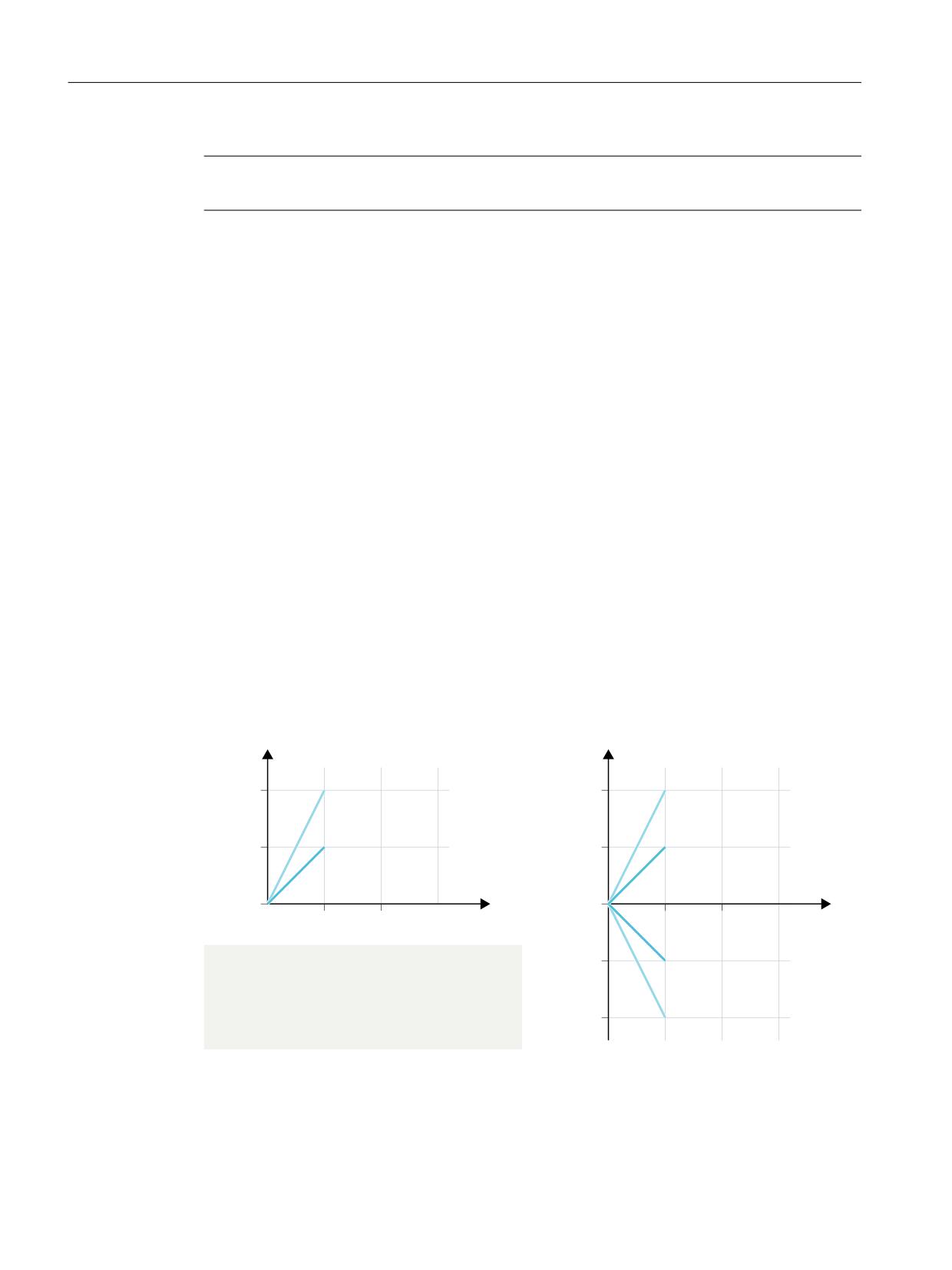
Axis couplings
14.3 Master value coupling
Note
Virtual axes assigned to a real drive must remain unblocked.
Offset and scaling
The setpoint value for the following axis can be offset and scaled. The following setting data is
used for this:
SD43102 $SA_LEAD_OFFSET_IN_POS (offset of master value with coupling to this axis)
SD43104 $SA_LEAD_SCALE_IN_POS (scaling of master value with coupling to this axis)
SD43106 $SA_LEAD_OFFSET_OUT_POS (offset of function value of the curve table)
SD43108 $SA_LEAD_SCALE_OUT_POS (scaling of function value of the curve table)
If (x) is a periodic curve table and this is interpreted as oscillation, the offset and scaling can also
be interpreted as follows:
SD43102 $SA_LEAD_OFFSET_IN_POS[Y] offsets the phase of the oscillation.
SD43106 $SA_LEAD_SCALE_OUT_POS[Y] affects the amplitude.
SD43108 $SA_LEAD_OFFSET_OUT_POS[Y] offsets the center of the oscillation
If the coupling is activated and synchronous, the new set position is approached as soon as
values are written to this setting data.
4%
4"@-&"%@4$"-&@*/@104<'">
4%
4"@-&"%@4$"-&@065@104<'">
5IF JOQVU WBMVF JT NVMUJQMJFE
5IF PVUQVU WBMVF JT NVMUJQMJFE
4FUUJOH EBUB JT FFDUJWF PVUTJEF PG UIF UBCMF EFOJUJPO BMTP JO
UIF OFHBUJWF EJSFDUJPO
'"
'"
JO NN
JO NN
8JUI */ 4$
"-& IBT OP
8JUI 065
4$"-& IBT
FFDU PVUTJEF PG UIF 5"#
FFDU PVUTJEF PG UIF 5"#
-"
-"
JO NN
JO NN
5BCMF EFOJUJPO GPS FYBNQMF
$5"#%&' '" -" $5"#/3
-" '"
-"
'"
$5"#&/%
Figure 14-4
Master value coupling offset and scaling (multiplied)
Axes and spindles
572
Function Manual, 10/2020, 6FC5397-4GP40-0BA1
Axis couplings
14.3 Master value coupling
4%
4"@-&"%@0''4&5@*/@104<'">
4%
4"@-&"%@0''4&5@065@104<'">
5IF DBMDVMBUFE QPTJUJPO PG UIF MFBEJOH BYJT JT PTFU XJUI UIF
5IF DBMDVMBUFE QPTJUJPO PG UIF GPMMPXJOH BYJT JT PTFU XJUI UIF
TQFDJFE JODSFNFOUT
TQFDJFE JODSFNFOUT
*G UIF 5"# JT NPWFE PVUTJEF PG UIF '" -&"%0/ QPTJUJPO -"%
DBOOPU CF TXJUDIFE PO 4FUUJOH EBUB JT FFDUJWF PVUTJEF PG UIF
UBCMF EFOJUJPO BMTP JO UIF OFHBUJWF EJSFDUJPO
/FX -" XJUI
'"
'"
JO NN
JO NN
8JUI */ 0''
4&5 IBT
OP
8JUI 065 0''4&5 IBT
FFDU PVUTJEF PG UIF 5"#
FFDU PVUTJEF PG UIF 5"#
-"
-"
JO NN
JO NN
Figure 14-5
Master value coupling offset and scaling (with increment offset)
Reaction to Stop
All leading value coupled following axes react to channel stop and MODE GROUP stop.
Master value coupled following axes react to a stop due to end of program (M30, M02) if they
have not been activated by static synchronized actions (IDS=...). The following machine data
is to be observed in this connection:
MD20110 $MC_RESET_MODE_MASK (definition of initial control settings after RESET / TP End)
MD20112 $MC_START_MODE_MASK (definition of initial control settings for NC-START)
Leading axis and following axis must always interpolate in the same channel. A following axis
located in a different channel cannot be coupled (axis replacement).
START and mode change enable a following axis in the master value coupling that has been
stopped.
RESET also enables a stopped following axis in master value coupling. If enabling by RESET is not
desired, or if it is dangerous (e.g. because the following axis is coupled to an external master
value not controlled by the NC), then MD20110 must be programmed such that master value
couplings are switched off with RESET (=2001H, i.e. bit 13 set to 1).
Axial functions
Actual value coupling causes a position offset between the leading and following axis. The cause
of this is the IPO cycle-based dead time in the position controller, which lies between the actual
value of the leading axis and the following axis.
Normally, the position offset and the following error is compensated by a linear extrapolation of
the master value to the extent of this dead time, i.e. dead time compensation is active in master
value coupling. The following MD setting is defined to deactivate the dead time compensation:
Axes and spindles
Function Manual, 10/2020, 6FC5397-4GP40-0BA1
573