SINUMERIK 840D sl. Service - Functions. Manual (2018-2020) - page 14
Manual traversing
15.6 Manual traversing using a handwheel
15.6
Manual traversing using a handwheel
15.6.1
Function
The electronic handwheels (accessories) can be used to simultaneously traverse selected axes
manually. The weighting of the handwheel graduations is dependent on the increment-size
weighting. Where coordinate offset or rotation is selected, manual travel can even be performed
in the transformed workpiece coordinate system.
Commissioning
For information on the commissioning of electronic handwheels, see Chapter "Start-up:
Handwheels (Page 778)".
Selection
JOG mode must be active. The user must also set the increment INC1, INC10, etc., which applies
to manual traversing using a handwheel. As with incremental travel, the required machine
function must be set at the PLC interface accordingly.
Traversing
When the electronic handwheel is turned, the associated axis is traversed either in the positive
or negative direction depending on the direction of rotation.
Note
If the axis is already being moved using the traversing keys, then manual traversing using the
handwheel is not possible.
Traversing distance
The traversing distance produced by rotating the handwheel is dependent on the following
factors:
• Number of handwheel pulses received at the interface
• Active increment (machine function INC1, INC10, INC100, ... INCvar)
• Pulse evaluation of the handwheel:
MD11320 $MN_HANDWH_IMP_PER_LATCH (handwheel pulses per detent position)
See Chapter "Parameter assignment (Page 719)".
• Distance of an increment:
MD31090 $MA_JOG_INCR_WEIGHT (evaluation of an increment for INC/handwheel)
See Chapter "Parameter assignment (Page 719)".
Axes and spindles
712
Function Manual, 10/2020, 6FC5397-4GP40-0BA1
Manual traversing
15.6 Manual traversing using a handwheel
Handwheel connection
Up to six handwheels can be connected simultaneously. This means that up to six axes can be
traversed by handwheel simultaneously.
Representation of the handwheel number in the NC/PLC interface signals
Depending on the parameter assignment of MD11324, the representation of the handwheel
number in the NC/PLC interface signals is bit-coded (three handwheels can be represented)
or binary-coded (six handwheels can be represented). From the HMI, the handwheel number
is always transferred bit-coded, independent of the setting in MD11324.
See Chapter "Parameter assignment (Page 719)".
Handwheel assignment
The axis that is moved by turning the handwheel can be set via the via the PLC user interface or
via the user interface (HMI). The assignment is linked to the NC/PLC interface through the PLC
user program. In this way, several axes can be assigned to one handwheel simultaneously.
Setting via the PLC user interface
The assignment is made using one of the following interface signals:
• Machine axes:
- DB31, ... DBX4.0 - 2 (activate handwheel)
• Geometry axes:
- DB21, ... DBX12.0 - 2 (geometry axis 1: Activate handwheel)
- DB21, ... DBX16.0 - 2 (geometry axis 2: Activate handwheel)
- DB21, ... DBX20.0 - 2 (geometry axis 3: Activate handwheel)
• Orientation axes:
- DB21, ... DBX320.0 - 2 (orientation axis 1: Activate handwheel)
- DB21, ... DBX324.0 - 2 (orientation axis 2: Activate handwheel)
- DB21, ... DBX328.0 - 2 (orientation axis 3: Activate handwheel)
Setting via the user interface (HMI)
Pressing the "Handwheel" softkey in the JOG-mode basic menu displays the "Handwheel"
window. Here, every handwheel can be assigned an axis and the handwheel can be enabled or
disabled.
Note
The handwheel assignment is not possible via the user interface (HMI) for more than three
connected handwheels and a binary-coded representation of the handwheel number in the NC/
PLC interface signals.
Axes and spindles
Function Manual, 10/2020, 6FC5397-4GP40-0BA1
713

Manual traversing
15.6 Manual traversing using a handwheel
Handwheel selection by HMI
A separate user interface is provided between the HMI and PLC to allow activation of the
handwheel from the user interface. This interface supplied by the basic PLC program for
handwheels 1, 2 and 3 contains the following information:
• Axis number assigned to the handwheel (if, during the handwheel selection, a machine axis
was selected):
DB10 DBX100.0 - 4 (axis number handwheel 1)
DB10 DBX101.0 - 4 (axis number handwheel 2)
DB10 DBX102.0 - 4 (axis number handwheel 3)
• Channel number assigned to the handwheel (if during the handwheel selection a geometry
axis was selected):
DB10 DBX97.0 - 3 (channel number geometry axis handwheel 1)
DB10 DBX98.0 - 3 (channel number geometry axis handwheel 2)
DB10 DBX99.0 - 3 (channel number geometry axis handwheel 3)
• Additional information on the machine or geometry axis:
DB10 DBX100.7 (machine axis handwheel 1)
DB10 DBX101.7 (machine axis handwheel 2)
DB10 DBX102.7 (machine axis handwheel 3)
• The information that the handwheel is enabled or disabled:
DB10 DBX100.6 (handwheel 1 selected)
DB10 DBX101.6 (handwheel 2 selected)
DB10 DBX102.6 (handwheel 3 selected)
Selection of JOG axis via HMI
When a handwheel is used on a touch control unit, such as the HT 10 for example, the user has
the option of selecting machine or geometry axes for manual traversing directly via the operator
interface.
Further information: PLC Function Manual
The basic PLC program is notified via the following interface signal of whether and which
handwheel is selected for use of the HT 10 via the operator interface:
DB10 DBX246.0 - 5 (handwheel active)
Bit
Value
Meaning
0
= 1
Handwheel 1 active
1
= 1
Handwheel 2 active
2
= 1
Handwheel 3 active
3
= 1
Handwheel 4 active
4
= 1
Handwheel 5 active
5
= 1
Handwheel 6 active
Axes and spindles
714
Function Manual, 10/2020, 6FC5397-4GP40-0BA1
Manual traversing
15.6 Manual traversing using a handwheel
Enable
For the specified axis, the basic PLC program sets the associated interface signal either to "0"
(disable) or to "1" (enable):
• Machine axes:
- DB31, ... DBX4.0 - 2 (activate handwheel)
• Geometry axes:
- DB21, ... DBX12.0 - 2 (geometry axis 1: Activate handwheel)
- DB21, ... DBX16.0 - 2 (geometry axis 2: Activate handwheel)
- DB21, ... DBX20.0 - 2 (geometry axis 3: Activate handwheel)
Note
Orientation axes can only be activated via the associated PLC user interface signals:
• DB21, ... DBX320.0 - 2 (orientation axis 1: Activate handwheel)
• DB21, ... DBX324.0 - 2 (orientation axis 2: Activate handwheel)
• DB21, ... DBX328.0 - 2 (orientation axis 3: Activate handwheel)
Travel request
The following NC/PLC interface signal informs the PLC that an axis wants to travel or is travelling:
• Machine axes:
- DB31, ... DBX64.4 (travel request "minus") or
- DB31, ... DBX64.5 (travel request "plus")
• Geometry axis 1:
- DB21, … DBX40.4 (geometry axis 1: Travel request "minus") or
- DB21, … DBX40.5 (geometry axis 1: Travel request "plus")
• Geometry axis 2:
- DB21, … DBX46.4 (geometry axis 2: Travel request "minus") or
- DB21, … DBX46.5 (geometry axis 2: Travel request "plus")
• Geometry axis 3:
- DB21, … DBX52.4 (geometry axis 3: Travel request "minus") or
- DB21, … DBX52.5 (geometry axis 3: Travel request "plus")
• Orientation axis 1:
- DB21, … DBX332.4 (orientation axis 1: Travel request "minus") or
- DB21, … DBX332.5 (orientation axis 1: Travel request "plus")
Axes and spindles
Function Manual, 10/2020, 6FC5397-4GP40-0BA1
715
Manual traversing
15.6 Manual traversing using a handwheel
• Orientation axis 2:
- DB21, … DBX336.4 (orientation axis 2: Travel request "minus") or
- DB21, … DBX336.5 (orientation axis 2: Travel request "plus")
• Orientation axis 3:
- DB21, … DBX340.4 (orientation axis 3: Travel request "minus") or
- DB21, … DBX340.5 (orientation axis 3: Travel request "plus")
Note
A travel request is the sum of all sub-movements, i.e. the component from couplings and
correction values is also taken into account.
For the method of operation of the "Travel request" function, see Section "Travel request
(Page 724)".
Travel command
Depending on the setting in machine data MD17900 $MN_VDI_FUNCTION_MASK (see Section
"Parameter assignment (Page 719)"), the following interface signal is output to the PC already
when a travel request is present or not until the axis moves:
• Machine axes:
- DB31, ... DBX64.6 (travel command "minus") or
- DB31, ... DBX64.7 (travel command "plus")
• Geometry axis 1:
- DB21, … DBX40.6 (geometry axis 1: Travel command "minus") or
- DB21, … DBX40.7 (geometry axis 1: Travel command "plus")
• Geometry axis 2:
- DB21, … DBX46.6 (geometry axis 2: Travel command "minus") or
- DB21, … DBX46.7 (geometry axis 2: Travel command "plus")
• Geometry axis 3:
- DB21, … DBX52.6 (geometry axis 3: Travel command "minus") or
- DB21, … DBX52.7 (geometry axis 3: Travel command "plus")
• Orientation axis 1:
- DB21, … DBX332.6 (orientation axis 1: Travel command "minus") or
- DB21, … DBX332.7 (orientation axis 1: Travel command "plus")
Axes and spindles
716
Function Manual, 10/2020, 6FC5397-4GP40-0BA1
Manual traversing
15.6 Manual traversing using a handwheel
• Orientation axis 2:
- DB21, … DBX336.6 (orientation axis 2: Travel command "minus") or
- DB21, … DBX336.7 (orientation axis 2: Travel command "plus")
• Orientation axis 3:
- DB21, … DBX340.6 (orientation axis 3: Travel command "minus") or
- DB21, … DBX340.7 (orientation axis 3: Travel command "plus")
Note
A travel command set in JOG mode is canceled if the controller enable or pulse enable for the axis
to be traversed is missing. The travel command must therefore be set again after release of the
axis.
Invert handwheel direction of rotation
The handwheel direction of rotation can be inverted, if the direction of movement of the
handwheel does not match the expected direction of motion of the axis. Adaptation may be
necessary in particular wherever a handwheel can be assigned to various axes.
In addition to configuring the particular MD, handwheel direction of rotation inversion can be
activated by setting the IS "Invert the handwheel direction of rotation" belonging to the
particular axis:
• Machine axes:
- DB31, ... DBX7.0 (invert handwheel direction of rotation)
• Geometry axes:
- DB21, ... DBX15.0 (geometry axis 1: Invert handwheel direction of rotation)
- DB21, ... DBX19.0 (geometry axis 2: Invert handwheel direction of rotation)
- DB21, ... DBX23.0 (geometry axis 3: Invert handwheel direction of rotation)
• Orientation axes:
- DB21, … DBX323.0 (orientation axis 1: Invert handwheel direction of rotation)
- DB21, … DBX327.0 (orientation axis 2: Invert handwheel direction of rotation)
- DB21, … DBX331.0 (orientation axis 3: Invert handwheel direction of rotation)
• Contour handwheel:
- DB21, ... DBX31.5 (contour handwheel: Invert handwheel direction of rotation)
Note
The inversion signal should be set in the PLC user program at the same time as the handwheel
selection (IS "Activate handwheel").
Axes and spindles
Function Manual, 10/2020, 6FC5397-4GP40-0BA1
717

Manual traversing
15.6 Manual traversing using a handwheel
The acknowledgement that the handwheel direction of rotation has been inverted by the NC is
realized for each axis using the IS "Handwheel direction of rotation inversion active":
• Machine axes:
- DB31, ... DBX67.0 (handwheel direction of rotation inversion active)
• Geometry axes:
- DB21, ... DBX43.0 (geometry axis 1: Handwheel direction of rotation inversion active)
- DB21, ... DBX49.0 (geometry axis 2: Handwheel direction of rotation inversion active)
- DB21, ... DBX55.0 (geometry axis 3: Handwheel direction of rotation inversion active)
• Orientation axes:
- DB21, ... DBX335.0 (orientation axis 1: Handwheel direction of rotation inversion active)
- DB21, ... DBX339.0 (orientation axis 2: Handwheel direction of rotation inversion active)
- DB21, ... DBX343.0 (orientation axis 3: Handwheel direction of rotation inversion active)
• Contour handwheel:
- DB21, ... DBX39.5 (contour handwheel: Handwheel direction of rotation inversion
active)
Note
It is only permissible to change the inversion signal at standstill. If the change is made while
motion setpoints are being output by the interpolator, then the signal change is rejected and an
alarm is output; further, motion is stopped taking into account the actual acceleration value.
Abort/interruption of the traversing motion
The following NC/PLC interface signals abort the traversing motion. The setpoint/actual-value
difference is deleted.
NC/PLC interface signal
Scope
Effect
DB21, ... DBX7.7 (NC reset)
Geometry axis / machine axis
Abort
DB21, ... DBX12.0 - 2 (geometry axis 1: Activate hand-
Geometry axis
1 → 0
Abort
wheel)
DB21, ... DBX16.0 - 2 (geometry axis 2: Activate hand-
wheel)
DB21, ... DBX20.0 - 2 (geometry axis 3: Activate hand-
wheel)
DB21, ... DBX6.2 (delete distance-to-go)
Geometry axis / machine axis
0 → 1
Abort
DB31, ... DBX2.2 (delete distance-to-go / spindle reset)
Geometry axis / machine axis
0 → 1
Abort
DB31, ... DBX4.2 (activate handwheel)
Machine axis
1 → 0
Abort
DB31, ... DBX1.3 (axis/spindle disable)
Geometry axis / machine axis
0 → 1
Abort
DB31, ... DBX1.5 (position measuring system 1)
Geometry axis / machine axis
0 → 1
Abort
DB31, ... DBX1.6 (position measuring system 2)
Geometry axis / machine axis
0 → 1
Abort
Axes and spindles
718
Function Manual, 10/2020, 6FC5397-4GP40-0BA1
Manual traversing
15.6 Manual traversing using a handwheel
For other NC/PLC interface signals (hold signals), the influence of manually traversing using the
handwheel (cancellation or interruption of traversing motion) can be set (see Chapter
"Parameter assignment (Page 719)").
NC STOP only interrupts the traversing movement. Any setpoint/actual-value difference is
retained. The distance-to-go is then traversed using NC START.
See also
Monitoring functions (Page 777)
Spindles (Page 377)
15.6.2
Parameter assignment
Distance or velocity specification
Either the distance or the velocity can be entered via the handwheel:
• Distance specification (default setting)
The distance specified by the handwheel is traversed and No pulses are lost.
Limiting the velocity to the maximum permissible value causes the axes to overtravel.
• Velocity specification
The handwheel only defines the traverse velocity. As soon as the handwheel stops, the axes
stop too. Motion is braked immediately if no pulses are supplied from the handwheel in one
IPO cycle, thus preventing overtravel by the axes. The handwheel pulses do not supply a path
default.
The input mode is set with machine data:
MD11346 $MN_HANDWH_TRUE_DISTANCE (handwheel distance or velocity specification)
Pulse evaluation of the handwheel
The number of pulses that are to be generated per handwheel detent position must be specified
for each handwheel:
MD11320 $MN_HANDWH_IMP_PER_LATCH [<n>] (handwheel pulses per detent position)
Note
Input of a negative value results in a reversal of the handwheel direction of rotation.
Increment size
The number of increments to be traversed by the axis per handwheel pulse is determined by the
selected increment size.
In addition to five fixed increment sizes (default setting: INC1, INC10, INC100, INC1000 and
INC10000), a variable increment size (INCvar) that can be set via the setting data is also available.
Axes and spindles
Function Manual, 10/2020, 6FC5397-4GP40-0BA1
719

Manual traversing
15.6 Manual traversing using a handwheel
Fixed increments
The parameter assignment of the fixed increment sizes is performed via NC-specific machine
data:
MD11330 $MN_JOG_INCR_SIZE_TAB[1 ... 5] = <number of increments 1 ... 5>
Variable increment
The parameter assignment of the variable increment size is performed via NC-specific setting
data:
SD41010 $SN_JOG_VAR_INCR_SIZE = <number of increments>
Distance evaluation of one increment
The distance evaluation of one increment for fixed and variable increment sizes is performed via
the axis-specific machine data:
MD31090 $MA_JOG_INCR_WEIGHT = <distance>
Note
Input of a negative value results in a reversal of the handwheel direction of rotation.
Limitation of the increment size
The machine operator can limit the size of the selected increment:
• For machine axes, using the axis-specific machine data:
MD32080 $MA_HANDWH_MAX_INCR_SIZE (limiting the selected increment)
• For geometry axes, using the channel-specific machine data:
MD20620 $MC_HANDWH_GEOAX_MAX_INCR_SIZE (limitation of handwheel increment for
geometry axes)
• For orientation axes, using the channel-specific machine data:
MD20621 $MC_HANDWH_ORIAX_MAX_INCR_SIZE (limitation of handwheel increment for
orientation axes)
Representation of the handwheel number in the NC/PLC interface signals
The representation of the handwheel number in the NC/PLC interface signals is defined using
machine data:
MD11324 $MN_HANDWH_VDI_REPRESENTATION
Value
Meaning
0
Bit-coded representation (basic setting)
→ Three handwheels can be represented.
1
Binary-coded representation
→ Six handwheels can be represented.
Axes and spindles
720
Function Manual, 10/2020, 6FC5397-4GP40-0BA1

Manual traversing
15.6 Manual traversing using a handwheel
Output of the NC/PLC interface signals "travel command plus" / "travel command minus"
The output behavior of the NC/PLC interface signals "travel command plus" / "travel command
minus" is specified with the machine data:
MD17900 $MN_VDI_FUNCTION_MASK
Value
Meaning
0
The NC/PLC interface signals "Travel command plus" / "Travel command minus" are already
output when a travel request is active (default setting).
1
The NC/PLC interface signals "Travel command plus" / "Travel command minus" are only output
when the axis actually moves (i.e. if setpoints are output to the servo).
Velocity
The following axis velocities, effective during JOG, are also used for manually traversing using
the handwheel:
• SD41110 $SN_JOG_SET_VELO (axis velocity for JOG)
• SD41130 $SN_JOG_ROT_AX_SET_VELO (axis velocity for rotary axes for JOG mode)
• MD32020 $MA_JOG_VELO (conventional axis velocity)
Note
Because of the limited feedrate, the axis is not able to follow the handwheel rotation
synchronously, especially in the case of a large pulse weighting, and therefore overtravels.
Acceleration
As for manual travel (see "Parameter assignment (general) (Page 699)").
Movement in the opposite direction
The behavior at a reversal of the traversing direction (by turning the handwheel in the opposite
direction) can be set in the machine data:
MD11310 $MN_HANDWH_REVERSE (threshold for direction change handwheel)
Value
Meaning
= 0
If the handwheel is moved in the opposite direction, the resulting distance is computed and the
calculated end point is approached as fast as possible.
If this end point is located before the point where the moving axis can decelerate in the current
direction of travel, the unit is decelerated and the end point is approached by moving in the
opposite direction. If this is not the case, the newly calculated end point is approached imme-
diately.
> 0
If the handwheel is moved in the opposite direction by at least the number of pulses indicated
in the machine data, the axis is decelerated as fast as possible and all pulses received until the
end of the interpolation are ignored.
This means that another movement takes place only after the axis reaches standstill (setpoint
side).
Axes and spindles
Function Manual, 10/2020, 6FC5397-4GP40-0BA1
721

Manual traversing
15.6 Manual traversing using a handwheel
Response at software limit switches, working area limitation
When axes are traversed in JOG mode, they can traverse only up to the first active limitation
before the corresponding alarm is output.
Depending on the setting in the machine data:
MD11310 $MN_HANDWH_REVERSE (threshold for direction change, handwheel)
the behavior is then as follows (as long as the axis has still not arrived at the end point from the
setpoint side):
• The distance resulting from the handwheel pulses forms a fictitious end point which is used
for subsequent calculations.
If this fictitious end point is, for example, 10 mm behind the limit, these 10 mm must be
traversed in the opposite direction before the axis traverses again. If a movement in the
opposite direction is to be performed immediately after a limitation is reached, the fictitious
distance-to-go can be deleted via delete distance-to-go or deselection of the handwheel
assignment.
• All handwheel pulses leading to an end point behind the limitation are ignored. Any
movement of the handwheel in the opposite direction leads to an immediate movement in
the opposite direction, i.e. away from the limit.
Feedrate behavior
In JOG mode, the feedrate behavior of the axis/spindle also depends on the setting data:
SD41100 $SN_JOG_REV_IS_ACTIVE (JOG: Revolutional/linear feedrate)
SD41100 $SN_JOG_REV_IS_ACTIVE
Active
An axis/spindle is always traversed with revolutional feedrate
MD32050 $MA_JOG_REV_VELO (revolutional feedrate for JOG)
or
MD32040 $MA_JOG_REV_VELO_RAPID
(revolutional feedrate for JOG with rapid traverse override)
depending on the master spindle.
Not active
The behavior of the axis/spindle depends on the setting data:
SD43300 $SA_ASSIGN_FEED_PER_REV_SOURCE
(revolutional feedrate for positioning axes/spindles)
The behavior of a geometry axis on which a frame with rotation acts,
depends on the channel-specific setting data:
SD42600 $SC_JOG_FEED_PER_REV_SOURCE
(control of the revolutional feedrate in JOG)
Effect of the NC/PLC interface stop signals
The effect of the NC/PLC interface stop signals on manual traversing using a handwheel (abort
or interruption of the traversing motion) can be set using machine data:
MD20624 $MC_HANDWH_CHAN_STOP_COND (definition of the handwheel traversing
behavior, channel-specific)
Axes and spindles
722
Function Manual, 10/2020, 6FC5397-4GP40-0BA1

Manual traversing
15.6 Manual traversing using a handwheel
MD32084 $MA_HANDWH_STOP_COND (behavior when manually traversing using a
handwheel)
NC/PLC interface signal
Scope
MD20624 $MC_HANDWH_CHAN_STOP_COND
Bit == 0
Bit == 1
DB11 DBX0.5 (mode group
Geometry axis / machine axis
Interruption until NC start
Abort
stop)
DB11 DBX0.6 (mode group
Geometry axis / machine axis
Interruption until NC start
Abort
stop, axes plus spindle)
DB21, ... DBX7.3 (NC Stop)
Geometry axis / machine axis
Interruption until NC start
Abort
DB21, ... DBX7.4 (NC stop, ax-
Geometry axis / machine axis
Interruption until NC start
Abort
es plus spindle)
DB21, ... DBX6.0 (feedrate dis-
Geometry axis / machine axis
Interruption
Abort
able)
DB21, ... DBB4 (feed rate over-
Geometry axes
Override == 0: Interruption if
Override == 0: Abort if rapid
ride)
rapid traverse override is not
traverse override is not active
active
DB31, ... DBX4.5 (rapid tra-
verse override)
DB21, ... DBB5 (rapid traverse
Geometry axes
Rapid traverse override == 0:
Rapid traverse override == 0:
override)
Interruption if rapid traverse
Abort if rapid traverse over-
override is active
ride is active
DB31, ... DBX4.5 (rapid tra-
verse override)
DB21, ... DBX12/16/20.3 (ge-
Geometry axis
Interruption
Abort
ometry axis 1/2/3: Feedrate
stop)
NC/PLC interface signal
Scope
MD32084 $MC_HANDWH_CHAN_STOP_COND
Bit == 0
Bit == 1
DB31, ... DBB0 (feed rate over-
Machine axis, not spindle
Override == 0: Interruption
Override == 0: Abort
ride, axial)
DB31, ... DBB19 (spindle over-
Spindle
Override == 0: Interruption
Override == 0: Abort
ride)
DB31, ... DBX4.3 (feedrate
Geometry axis / machine axis
Interruption
Abort
stop / spindle stop)
DB31, ... DBX2.3 (clamping in
Geometry axis / machine axis
No effect
Abort
progress)
DB31, ... DBX2.1 (control sys-
Geometry axis / machine axis
Interruption
Abort
tem enable)
DB31, ... DBX21.7 (pulse ena-
Geometry axis / machine axis
Interruption
Abort
ble)
Note
Removal of the "Controller enable" and "Pulse enable" during traversing results in a rapid stop of
the axis and a reset alarm.
Axes and spindles
Function Manual, 10/2020, 6FC5397-4GP40-0BA1
723

Manual traversing
15.6 Manual traversing using a handwheel
Interruption of a traversing motion
When a stop command is issued, the distance-to-go is saved and the handwheel pulses are
collected. When the stop condition no longer applies, the resulting distance is traversed.
Abort of a traversing motion
When a stop command is issued, the distance-to-go is deleted and the handwheel pulses are
ignored (i.e. not collected) until the stop condition no longer applies.
Response in the event of a Safe Operating Stop (SOS)
Analog to the NC/PLC interface stop signals, the behavior in the event of a stop can also be
adjusted by activating the Safe Operating Stop (SOS):
Stop condition
Scope
MD20624 $MC_HANDWH_CHAN_STOP_COND
Bit 12 == 0
Bit 12 == 1
(Default setting)
Safe operating stop in
Machine axis
Interruption
Abort
the event of active tar-
get velocity limit
In the default setting, Bit 12 is set to "1", i.e. in the event of a stop resulting from activation of
the safe stop, current movements are aborted and new handwheel pulses ignored.
Prerequisite for an interpolatory stop is an active target velocity limit (i.e., MD36933
$MA_SAFE_DES_VELO_LIMIT > 0).
15.6.3
Travel request
The following examples are intended to illustrate the method of operation of the "Travel request"
NC/PLC interface signal.
Example 1: Manual traversing using handwheel with distance input, the stop condition is no
criterion for cancellation
If, for manual traversing using a handwheel with distance input
(MD11346 $MN_HANDWH_TRUE_DISTANCE == 1 or == 3), an active stop condition is not a
criterion for cancellation (see MD32084 $MA_HANDWH_STOP_COND or
MD20624 $MC_HANDWH_CHAN_STOP_COND); then, the output of NC/PLC interface signals
"Travel request" and "Travel command" corresponds to the behavior shown in the following
diagrams.
"YJT TIPVME USBWFSTF XJUI
3FWPLF TUPQ DPOEJUJPO
"YJT SFBDIFT FOE QPJOU
QFOEJOH TUPQ DPOEJUJPO
4JHOBM
5SBWFM SFRVFTU
4JHOBM
.PUJPO DPNNBOE
Axes and spindles
724
Function Manual, 10/2020, 6FC5397-4GP40-0BA1

Manual traversing
15.6 Manual traversing using a handwheel
Figure 15-1
Signal-time diagram:Manual traversing using the handwheel with distance input, stop condition is not a
cancellation criterionMD17900 $MN_VDI_FUNCTION_MASK bit 0 = 0
"YJT TIPVME USBWFSTF XJUI
3FWPLF TUPQ DPOEJUJPO
"YJT SFBDIFT FOE QPJOU
QFOEJOH TUPQ DPOEJUJPO
4JHOBM
5SBWFM SFRVFTU
4JHOBM
.PUJPO DPNNBOE
Figure 15-2
Signal-time diagram:Manual traversing using the handwheel with distance input, stop condition is not a
cancellation criterionMD17900 $MN_VDI_FUNCTION_MASK bit 0 = 1
Example 2: Manual traversing using a handwheel, stop condition is a cancellation criterion
If a stop condition is selected as cancellation criterion via machine data
MD32084 $MA_HANDWH_STOP_COND or MD20624 $MC_HANDWH_CHAN_STOP_COND
during manual traversing using a handwheel, no travel command is output, but the
corresponding travel request is output.
When the stop condition is removed, the corresponding "Travel request" NC/PLC interface signal
is reset, as an abort is present. The stop condition is no longer active, but the axis cannot be
traversed as the stop condition has caused an abort.
In addition, either the distance specification (MD11346 $MN_HANDWH_TRUE_DISTANCE == 1
or == 3) is active or the handwheel is moved continuously, i.e. it provides pulses.
"YJT TIPVME USBWFSTF XJUI
3FWPLF TUPQ DPOEJUJPO
"YJT SFBDIFT FOE QPJOU
QFOEJOH TUPQ DPOEJUJPO
4JHOBM
5SBWFM SFRVFTU
4JHOBM
.PUJPO DPNNBOE
Figure 15-3
Signal-time diagram:Manual traversing using a handwheel, stop condition is a cancellation criterion
If a stop condition is activated during the handwheel travel, the motion is aborted and the "Travel
request" and "Travel command" NC/PLC interface signals are reset.
Example 3: Manual traversing using a handwheel with velocity setpoint, stop condition is a
cancellation criterion
If the handwheel is no longer moved for velocity specification
(MD11346 $MN_HANDWH_TRUE_DISTANCE == 0 or == 2), the "Travel request" NC/PLC interface
signal is reset.
The "Travel request" PLC signal is also reset when the handwheel is deselected.
Axes and spindles
Function Manual, 10/2020, 6FC5397-4GP40-0BA1
725
Manual traversing
15.7 Manual traversing of the spindle
"YJT TIPVME USBWFSTF XJUI
3FWPLF TUPQ DPOEJUJPO
"YJT SFBDIFT FOE QPJOU
QFOEJOH TUPQ DPOEJUJPO
4JHOBM
)BOEXIFFM TUPQQFE
5SBWFM SFRVFTU
4JHOBM
.PUJPO DPNNBOE
Figure 15-4
Signal-time diagram:Manual traversing using a handwheel with velocity setpoint, stop condition is a cancellation
criterion
Supplementary conditions
NC stop
With NC stop present, no travel command and, therefore, no travel request is output. There is an
exception with DRF travel: If DRF travel is permitted in the NC stop state via machine data
MD20624 $MC_HANDWH_CHAN_STOP_COND (bit 13 == 1), the behavior corresponds to that of
manual traversing using a handwheel.
15.7
Manual traversing of the spindle
Spindle mode
Manual traversing of the spindle is possible both in positioning mode (spindle is in position
control) and in open-loop control mode.
Velocity
The velocity applied for the manual traversing of the spindles is defined by the general setting
data:
SD41200 $SN_JOG_SPIND_SET_VELO (speed of spindle in JOG mode)
If "0" is entered in SD41200, the axis-specific machine data takes effect:
MD32020 $_MA_JOG_VELO (conventional axis velocity)
The maximum speeds of the active gear stage are also considered when manually traversing a
spindle.
Further information
Spindles (Page 377)
Spindle override
The velocity during manual traversing of the spindle can be influenced by the spindle override
switch.
Axes and spindles
726
Function Manual, 10/2020, 6FC5397-4GP40-0BA1
Manual traversing
15.8 Manual traversing of geometry axes/orientation axes
Acceleration
As a spindle often uses many gear stages in speed-control mode and position-control mode, the
acceleration associated with the current gear stage is always applied to the spindle in JOG mode.
Further information
Spindles (Page 377)
Interface signals
When manually traversing the spindles, the interface signals between NC and PLC have the same
effect as for the machine axes.
The interface signals DB31, ... DBX60.7 or DBX60.6 (position reached with fine or coarse exact
stop) are only set if the spindle is in position control.
Spindle-specific interface signals
In JOG mode, the following interface signals to the spindle have no effect:
• DB31, ... DBX17.6 (invert M3/M4)
• DB31, ... DBX18.6 - 7 (oscillation rotation direction, right/left)
• DB31, ... DBX18.5 (oscillation enable)
• DB31, ... DBX16.7 (delete S value)
In JOG mode, the following interface signals from the spindle are not set:
• DB31, ... DBX83.7 (clockwise actual direction of rotation)
• DB31, ... DBX83.5 (spindle in setpoint range)
15.8
Manual traversing of geometry axes/orientation axes
Note
Transformation package, handling
In the JOG mode, using the "Handling transformation package", the translation of geometry
axes in several valid references systems can be set separately from one another.
Further information
Function Manual Technologies; Transformation package Handling
Also see Function Manual Transformations, Cartesian manual traversing.
See also
Transverse axes (Page 261)
Axes and spindles
Function Manual, 10/2020, 6FC5397-4GP40-0BA1
727
Manual traversing
15.8 Manual traversing of geometry axes/orientation axes
Simultaneous travel
Only one geometry axis can be traversed continuously or incrementally at one time using the
traversing keys. Where an attempt is made to traverse more than one geometry axis, alarm
20062 "Axis already active" is output. However, three geometry axes can be traversed
simultaneously using handwheels 1 to 3.
Transverse axis
If a geometry axis is defined as transverse axis (see MD20100 $MC_DIAMETER_AX_DEF) and
radius programming has been selected, the following applies:
• Continuous travel:
There are no differences when a transverse axis is traversed continuously.
• Incremental travel:
Only half the distance of the selected increment size is traversed. For example, with INC10
the axis only traverses 5 increments when the traversing key is pressed.
• Traversing with the handwheel:
As for incremental travel, with the handwheel only half the distance is traversed per
handwheel pulse.
Additional information
Transverse axes (Page 261)
PLC interface
For geometry axes/orientation axes, there is a separate PLC interface that contains the same
signals as the axis-specific PLC interface:
• Geometry axes:
DB21, ... DBB12 - 23 and
DB21, ... DBB40 - 56
• Orientation axes:
DB21, ... DBB320 - 331 and
DB21, ... DBB332 - 343
Velocity
• Geometry axes
The velocity applied for the manual traversing of geometry axes is defined by the channel-
specific machine data:
MD21165 $MC_JOG_VELO_GEO (conventional velocity for geometry axes)
• Orientation axes
The velocity applied for the manual traversing of orientation axes is defined by the channel-
specific machine data:
MD21155 $MC_JOG_VELO_ORI (conventional velocity for orientation axes)
Axes and spindles
728
Function Manual, 10/2020, 6FC5397-4GP40-0BA1
Manual traversing
15.8 Manual traversing of geometry axes/orientation axes
Rapid traverse override
If the traversing keys/handwheel are also actuated together with the rapid traverse override key,
the movement will be made with the configured rapid traverse velocity:
• Geometry axes
- MD21160 $MC_JOG_VELO_RAPID_GEO (conventional rapid traverse for geometry axes)
• Orientation axes
- MD21150 $MC_JOG_VELO_RAPID_ORI (conventional rapid traverse for orientation axes)
Feedrate override
The channel-specific feedrate override switch is active when manually traversing geometry axes.
Acceleration and jerk
For the manual traversing of geometry axes/orientation axes, the acceleration and jerk can be
limited for specific channels. This enables better handling of the kinematics that generate
Cartesian motions entirely via rotary axes (robots).
Geometry axes
The maximum acceleration when manually traversing geometry axes can be specified for each
channel via the machine data:
MD21166 $MC_JOG_ACCEL_GEO [<geometry axis>]
with <geometry axis> = 0, 1, 2
The maximum jerk when manually traversing geometry axes in the SOFT acceleration mode
(acceleration with jerk limitation) can be specified for each channel via the machine data:
MD21168 $MC_JOG_JERK_GEO [<geometry axis>]
with <geometry axis> = 0, 1, 2
Orientation axes
The maximum jerk when manually traversing orientation axes can be specified for each channel
via the machine data:
MD21158 $MC_JOG_JERK_ORI [<orientation axis>]
For MD21158 to take effect, the channel-specific jerk limitation for the manual traversing of
orientation axes must be enabled via the following machine data:
MD21159 $MC_JOG_JERK_ORI_ENABLE == TRUE
Alarms
Alarm 20060
If the axis is not defined as a geometry axis, alarm 20060, "Axis cannot be traversed as a
geometry axis", is output if you attempt to manually traverse it as a geometry axis in JOG mode.
Axes and spindles
Function Manual, 10/2020, 6FC5397-4GP40-0BA1
729
Manual traversing
15.9 Approaching a fixed point in JOG
Alarm 20062
Alarm 20062, "Axis already active", is triggered in the case that a geometry axis/orientation axis
is manually traversed under the following conditions:
• The axis is already being traversed in JOG mode via the axial PLC interface.
• A frame for a rotated coordinate system is already active and another geometry axis in this
coordinate system is traversed in JOG mode with the traversing keys.
15.9
Approaching a fixed point in JOG
15.9.1
Function
The machine user can use the "Approaching fixed point in JOG" function to approach axis
positions defined through machine data by actuating the traverse keys of the machine control
panel. The traveling axis comes to a standstill automatically on reaching the defined fixed point.
Note
Approaching a fixed point with G75
The process for approaching defined fixed points can also be activated from the part program
using the G75 command.
For further information on fixed point traversing with G75 see:
Further information
Programming Manual NC Programming; Supplementary commands > Approach fixed point
(G75)
Applications
Typical applications are, for example:
• Approaching a basic position before starting an NC program.
• Travel towards tool change points, loading points and pallet change points.
Requirements
• The "Approaching fixed point in JOG" can be activated only in the JOG mode.
The function cannot be activated if the machine function JOG-REPOS or JOG-REF is active and
in JOG in AUTOMATIC.
• The axis to be traversed must be referenced.
• A kinematic transformation may not be active.
• The axis to be traversed may not be a following axis of an active coupling.
Axes and spindles
730
Function Manual, 10/2020, 6FC5397-4GP40-0BA1
Manual traversing
15.9 Approaching a fixed point in JOG
Procedure
Procedure in "Approaching fixed point in JOG"
1. Selection of JOG mode
2. Enabling the "Approach fixed point in JOG" function
3. Traversing of the machine axis with traverse keys or handwheel
Activation
After selecting the "Approach fixed point in JOG" function, the PLC outputs the number of the
fixed point to be approached binary coded to the NC using the following bits:
DB31, ... DBX13.0 - 2 (JOG approach fixed point)
The NC confirms the activation with the interface signal as soon as the function is effective:
DB31, ... DBX75.0 - 2 (JOG approach fixed point active)
Note
Activation is not possible:
• during an NC reset
• In case of impending emergency stop
• During processing of an ASUP
No alarm message occurs. Delayed activation takes place after closure or after
acknowledgement of the active function.
Sequence
The actual traversing is started with the traverse keys or the handwheel in the direction of the
approaching fixed point.
The selected machine axis traverses till it comes to an automatic standstill at the fixed point.
The corresponding NC/PLC interface signal is reported on reaching the fixed point with "Exact
stop fine":
DB31, ... DBX75.3 - 5 (JOG approach fixed point reached)
This display signal is also signaled if the axis reaches the fixed point position in the machine
coordinates system via other methods e.g. NC program, FC18 (for 840D sl) or synchronized
action on the setpoint side and comes to a standstill on the actual value side within the "Exact
stop fine" tolerance window (MD36010 $MA_STOP_LIMIT_FINE).
Movement in the opposite direction
The response while traversing in the opposite direction, i.e. against the direction of the
approaching fixed point, depends on the setting of Bit 2 in the machine data:
MD10735 $MN_JOG_MODE_MASK (settings for the JOG mode)
Traverse in the opposite direction is possible only if the bit is set.
Axes and spindles
Function Manual, 10/2020, 6FC5397-4GP40-0BA1
731
Manual traversing
15.9 Approaching a fixed point in JOG
Traverse in the opposite direction is blocked if the bit is not set and the following channel status
message is output if an attempt is made with the traverse keys or with the handwheel to traverse
in the direction opposite the approaching fixed point:
"JOG: Direction blocked <axis>"
Approaching other fixed point
The axis motion is cancelled and the following alarm is output if a different fixed point is selected
while traversing to the fixed point:
Alarm 17812 "Channel %1 Axis %2 fixed point approach in JOG: Fixed point changed"
The message signal DB31, ... DBX75.0 - 2 (JOG - Approaching fixed point active) displays the
number of the newly selected fixed point. The JOG traverse must be triggered again to continue
traversing.
Note
To avoid the alarm message, the machine user should proceed as follows:
1. Cancel the current traverse movement with residual distance deletion.
2. Activate fixed point approach for another fixed point and start the operation after the axis
comes to a standstill.
Withdrawal from fixed point / deactivation
To withdraw from a fixed position, you must deactivate the "Approaching fixed point in JOG"
function. This is done by resetting the activation signal to "0".
DB31, ... DBX13.0 - 2 = 0
The message signals DB31, ... DBX75.0 - 2 (JOG - Approaching fixed point active) and
DB31, ... DBX75.3 - 5 (JOG - Approaching fixed point reached) are deleted on leaving the fixed
point position.
Special case: Axis is already on fixed point
The axis cannot be moved if, while starting the fixed point traverse, the axis is already at the
position of the fixed point to be approached. This is displayed through the following channel
status message:
"JOG: position reached <axis>"
To withdraw from the fixed position, you must deactivate the "Approaching fixed point in JOG"
function.
Special features of incremental travel
If, during incremental travel, the fixed point is reached before the increment is completed, then
the increment is considered to have been completed fully. This is the case even when only whole
increments are traveled:
MD11346 $MN_HANDWH_TRUE_DISTANCE = 2 or 3
Axes and spindles
732
Function Manual, 10/2020, 6FC5397-4GP40-0BA1

Manual traversing
15.9 Approaching a fixed point in JOG
Special features of modulo rotary axes
Modulo rotary axes can approach the fixed point in both directions. The shortest path (DC) is not
observed during the travel.
Features of spindles
A spindle changes to the positioning mode on actuating the "Approaching fixed point in JOG"
function. The closed loop position control is active and the axis can traverse to the fixed point.
If no zero mark is detected the alarm message in the axis operation is output:
Alarm 17810 "Channel %1 Axis %2 not referenced"
As a spindle must also be a modulo rotary axis at all times, the same conditions apply for
direction observation as for modulo rotary axes (refer to the paragraph "Features of modulo
rotary axes")
15.9.2
Parameterization
Movement in the opposite direction
The behavior while traversing in the opposite direction - i.e. in the direction opposite to
approaching the fixed point - depends on the following setting:
MD10735 $MN_JOG_MODE_MASK, bit 2 (settings for the JOG mode)
Bit
Value
Meaning
2
0
Travel in the opposite direction is not possible (basic setting).
1
Movement in the opposite direction is possible.
Fixed point positions
Up to four fixed point positions can be defined for an axis:
MD30600 $MA_FIX_POINT_POS[0...3] = <fixed point position 1...4>
Number of valid fixed point positions
The number of fixed point positions entered in MD30600 $MA_FIX_POINT_POS that are actually
valid, can be defined using:
Axes and spindles
Function Manual, 10/2020, 6FC5397-4GP40-0BA1
733

Manual traversing
15.9 Approaching a fixed point in JOG
MD30610 $MA_NUM_FIX_POINT_POS = <number of valid fixed point positions>
Note
Exception: G75
For compatibility reasons, the following parameter assignment is also possible for G75:
MD30610 $MA_NUM_FIX_POINT_POS = 0 (no valid fixed point positions)
It is assumed that there are two valid fixed point positions in MD30600 $MA_FIX_POINT_POS[0]
and [1].
Fixed point positions 1 and 2 can be activated via the NC/PLC interface, however they can only
be approached via G75.
Axis dynamics
The axis-specific acceleration and the axis-specific jerk for "Approaching fixed point in JOG" are
determined by the following machine data:
• When traversing with traverse keys or handwheel:
- MD32300 $MA_MAX_AX_ACCEL [0] (maximum axis-specific acceleration for path
motions in the dynamic response mode DYNNORM)
- MD32430 $MA_JOG_AND_POS_MAX_JERK (maximum axis-specific jerk)
Note
MD32430 $MA_JOG_AND_POS_MAX_JERK is only effective when the axis-specific jerk
limitation for single-axis movements has been enabled for the machine axes to be
traversed:
MD32420 $MA_JOG_AND_POS_JERK_ENABLE [<axis>] == TRUE
• During traversing via the G75 part program command:
- MD32300 $MA_MAX_AX_ACCEL [0/1] (maximum axis-specific acceleration for path
motions in the dynamic response mode DYNNORM/DYNPOS)
Note
The type of positioning axis dynamics (DYNNORM or DYNPOS) is defined by the machine
data:
MD18960 $MN_POS_DYN_MODE = <mode>
- MD32431 $MA_MAX_AX_JERK [0] (maximum axis-specific jerk for path motions in the
dynamic response mode DYNNORM)
Note
MD32431 $MA_MAX_AX_JERK is only effective when the axis-specific jerk limitation for
single-axis movements has been enabled for the machine axes to be traversed:
MD32420 $MA_JOG_AND_POS_JERK_ENABLE [<axis>] == TRUE
Axes and spindles
734
Function Manual, 10/2020, 6FC5397-4GP40-0BA1
Manual traversing
15.9 Approaching a fixed point in JOG
Additional information
Acceleration and jerk (Page 79)
15.9.3
Programming
System variables
The following system variables that can be read in the part program and in the synchronous
actions for the "Approach fixed point" function.
System variable
Description
$AA_FIX_POINT_SELECTED [<Axis>]
Number of fixed point to be approached
$AA_FIX_POINT_ACT [<Axis>]
Number of the fixed point on which the axis is cur-
rently located
15.9.4
Supplementary Conditions
Axis is indexing axis
The axis is not traversed and an alarm is output if the axis to be traversed is an indexing axis and
the fixed point position to be approached does not match an indexing position.
Frames active
All active frames are ignored. Traversing is performed in the machine coordinate system.
Offset values active
Active offset values (DRF, external zero offset, synchronized action offset $AA_OFF, online tool
offset) are also traversed. The fixed point is a position in the machine coordinates system.
An alarm is issued if an offset movement (DRF, external zero offset, synchronized action offset
$AA_OFF, online tool offset) is made during a fixed point approach in JOG. The position of the
fixed point to be approached in the machine coordinates system is not reached; instead a
position that would have been reached without active offset movement is reached. The NC/PLC
interface signal DB31, ... DBX75.3-5 corresponding to the fixed point is not output.
Working-area limitations
Working-area limitations (in BCS and WCS) are considered and the axis motion is stopped on
reaching the limits.
Axes and spindles
Function Manual, 10/2020, 6FC5397-4GP40-0BA1
735
Manual traversing
15.9 Approaching a fixed point in JOG
15.9.5
Application example
Target
A rotary axis (machine axis 4 [AX4]) is to be moved to fixed point 2 (90 degrees) with the
"Approaching fixed point in JOG" function.
Parameter assignment
The machine data for the "Approaching fixed point" function of machine axis 4 are
parameterized as follows:
MD30610 $MA_NUM_FIX_POINT_POS[AX4] = 4
4 fixed points are defined for machine
axis 4.
MD30600 $MA_FIX_POINT_POS[0,AX4] = 0
1. Fixed point of AX4 = 0 degrees
MD30600 $MA_FIX_POINT_POS[1,AX4] = 90
2. Fixed point of AX4 = 90 degrees
MD30600 $MA_FIX_POINT_POS[2,AX4] = 180
3. Fixed point of AX4 = 180 degrees
MD30600 $MA_FIX_POINT_POS[3,AX4] = 270
4. Fixed point of AX4 = 270 degrees
Initial situation
Machine axis 4 is referenced and is at position of 0 degrees. This corresponds to the 1st fixed
position and is output through the NC/PLC interface signal:
DB31 DBX75.0 = 1 (bit 0 - 2 = 1)
Approaching fixed point 2
The control is switched into the JOG mode.
The "Approaching fixed point" function is activated at fixed point 2 via the NC/PLC interface
signal:
DB31 DBX13.1 = 1 (bit 0 - 2 = 2)
The actuation is confirmed via the NC/PLC interface signal:
DB31 DB75.1 = 1 (bit 0 - 2 = 2)
The plus travel key on the machine control panel is used to travel continuously to approach fixed
point 2.
The machine axis 4 stops at the 90 degree position. This is signaled via the NC/PLC interface
signal:
DB31 DBX75.4 = 1 (bit 3 - 5 = 2)
Axes and spindles
736
Function Manual, 10/2020, 6FC5397-4GP40-0BA1
Manual traversing
15.10 Position travel in JOG
15.10
Position travel in JOG
15.10.1
Function
The "Position travel in JOG" function allows the machine operator to specify, via the setting data,
a position in the machine coordinate system, to which the selected machine axis can be
traversed using the traverse keys or the handwheel.
Applications
The function is used for machine tools that are exclusively operated manually, e.g. to approach
drill-holes in precise increments.
Preconditions
• The "Position travel in JOG" function can be activated only in the JOG mode.
The function cannot be activated if the machine function JOG-REPOS or JOG-REF is active and
in JOG in AUTOMATIC.
• The axis to be traversed must be referenced.
• A kinematic transformation may not be active.
• The axis to be traversed may not be a following axis of an active coupling.
Procedure
Procedure for position travel in JOG:
1. Selection of JOG mode
2. Specification of the position to be approached
3. Enabling the "Position travel in JOG" function
4. Traversing of the machine axis with traverse keys or handwheel
Specification of the position to be approached
The position to be approached is entered in the setting data:
SD43320 $SA_JOG_POSITION (JOG position)
Activating the function
The PLC sets the interface signal after the "Position travel in JOG" function has been selected:
DB31, ... DBX13.3 (JOG travel to position)
The NC confirms the activation with the interface signal as soon as the function is effective:
Axes and spindles
Function Manual, 10/2020, 6FC5397-4GP40-0BA1
737
Manual traversing
15.10 Position travel in JOG
DB31, ... DBX75.6 (JOG JOG travel to position active)
Note
Activation is not possible:
• during an NC reset
• In case of impending emergency stop
• During processing of an ASUP
• if the "approaching fixed point JOG" function is already activated
No alarm message occurs. Delayed activation takes place after closure or after
acknowledgement of the active function.
Sequence
Approaching the position is started with the traverse keys or the handwheel.
The axis traverses until it comes to an automatic standstill at the position to be approached.
When the position is reached with "Exact stop fine", the following NC/PLC interface signal is
output:
DB31, ... DBX75.7 (JOG position reached)
Approach a different position
If the content of the setting data SD43320 is changed while approaching a position, then the
axis movement is canceled and the following alarm is output:
Alarm 17822 "Channel %1 Axis %2 jogging to position: position changed"
The JOG traverse must be triggered again to approach the new position.
Note
To avoid the alarm message, the machine user should proceed as follows:
1. Cancel the current traverse movement with residual distance deletion.
2. Enter a new position in SD43320 after axis has come to a standstill.
3. Restart the JOG motion.
Retraction from the position/deactivation
To retract from the position, the function "Position travel in JOG" must be deactivated. This is
done by resetting the activation signal to "0".
DB31, ... DBX13.3 = 0
The deactivation also resets the message signals DB31, ... DBX75.6 and DB31, ... DBX75.7.
Axes and spindles
738
Function Manual, 10/2020, 6FC5397-4GP40-0BA1
Manual traversing
15.10 Position travel in JOG
Retraction in the opposite direction
The behavior when retracting from the position in the opposite direction depends on the setting
of bit 2 in the machine data:
MD10735 $MN_JOG_MODE_MASK (settings for the JOG mode)
Retraction in the opposite direction is possible only if the bit is set.
If the bit is not set, retraction in the opposite direction is blocked, and the following channel
status message is output if an attempt is made with the traverse keys or with the handwheel to
exit the approached position in the opposite direction:
"JOG: Direction blocked <axis>"
Special case: axis is already at position
The axis cannot be traversed if the axis is already at the position to be approached when starting
the JOG motion. This is displayed through the following channel status message:
"JOG: position reached <axis>"
To retract, the function "Position travel in JOG" must be deactivated.
Special features of incremental travel
If, during incremental travel, the position is reached before the increment is completed, then the
increment is considered to have been completed fully. This is the case even when only whole
increments are traveled.
MD11346 $MN_HANDWH_TRUE_DISTANCE = 2 or 3
Special features of modulo rotary axes
Modulo rotary axes can approach the position in both directions. The shortest path (DC) is not
observed during the travel.
Features of spindles
A spindle changes to the positioning mode on actuating the "Position travel in JOG" function. The
closed loop position control is active and the axis can be traversed to the position.
If no zero mark is detected the alarm message in the axis operation is output:
Alarm 17810 "Channel %1 Axis %2 not referenced"
As a spindle must also be a modulo rotary axis at all times, the same conditions apply for
direction observation as for modulo rotary axes (refer to the paragraph "Features of modulo
rotary axes")
See also
Parameter setting (Page 740)
Axes and spindles
Function Manual, 10/2020, 6FC5397-4GP40-0BA1
739

Manual traversing
15.10 Position travel in JOG
15.10.2
Parameter setting
Consideration of axial frames and tool length compensation
The consideration of axial frames and, if an axis is configured as geometry axis, the tool length
compensation, depends on the setting of bit 1 in the machine data:
MD10735 $MN_JOG_MODE_MASK (settings for the JOG mode)
Bit
Value
Meaning
1
0
Axial frames and tool length compensation are not considered.
1
Axial frames and tool length compensation are considered.
Retraction in the opposite direction
The behavior when retracting from a position in the opposite direction depends on the setting
of bit 2 in the machine data:
MD10735 $MN_JOG_MODE_MASK (settings for the JOG mode)
Bit
Value
Meaning
2
0
Retraction in the opposite direction is not possible (default setting).
1
Retraction in the opposite direction is possible.
Position to be approached
The position to be approached is entered in the setting data:
SD43320 $SA_JOG_POSITION (JOG position)
15.10.3
Supplementary Conditions
Axis is indexing axis
The axis is not traversed and an alarm is output if the axis to be traversed is an indexing axis and
the position to be approached does not match an indexing position.
Frames active
All active frames are ignored. Traversing is performed in the machine coordinate system.
Correction values active
Active correction values (DRF, external zero offset, synchronized action offset $AA_OFF, online
tool offset) are also traversed.
An alarm is issued if an offset movement (DRF, external zero offset, synchronized action offset
$AA_OFF, online tool offset) is made during the approach of a variable position in JOG. The
Axes and spindles
740
Function Manual, 10/2020, 6FC5397-4GP40-0BA1
Manual traversing
15.10 Position travel in JOG
position to be approached in the machine coordinate system is not reached; instead a position
that would have been reached without active offset movement is reached. The NC/PLC interface
signal DB31, ... DBX75.7 is not reported.
Working area limits
Working-area limitations (in BCS and WCS) are considered and the axis motion is stopped on
reaching the limits.
15.10.4
Application example
Objective
A rotary axis (machine axis 4 [AX4]) is to be moved to Position 100 degrees with the "Position
travel in JOG" function.
Parameter assignment
The position to be approached is specified via the user interface as follows:
SD43320 $SA_JOG_POSITION[AX4] = 100
; position to be approached for machine axis 4 =
100
Initial situation
Axis 4 [AX4] is referred and is at Position 0 degree.
Approaching the position
The control is switched to JOG mode and machine axis 4 is selected.
The function "Position travel in JOG" is activated:
DB34 DBX13.3 = 1
The NC confirms the activation as soon as the function is effective:
DB34 DBX75.6 = 1
Approaching the position is started via continuous traversing and the JOG traverse key Plus of
the machine control panel.
The axis traverses until it comes to an automatic standstill at the position 100 degrees.
When the position is reached with "Exact stop fine", the following NC/PLC interface signal is set:
DB34 DB75.7 = 1
Axes and spindles
Function Manual, 10/2020, 6FC5397-4GP40-0BA1
741

Manual traversing
15.11 Circular travel in JOG
15.11
Circular travel in JOG
15.11.1
Function
With the "Circular travel in JOG" function, the machine operator can simultaneously traverse the
two geometry axes of the active plane along an arc using the traverse keys or handwheel.
Applications
This function is used for machine tools that are exclusively operated manually.
Preconditions
• The "Circular travel in JOG" function can be activated only in the JOG mode.
The function cannot be activated if the machine functions JOG-REPOS and JOG-REF are
active.
• The axes that participate in traversing must be homed.
• The active plane must not be inclined.
Procedure
Procedure for circular travel in JOG:
1. Plane selection
2. Selection of JOG mode
3. Specification of circle parameters
4. Activation of the function "Circular travel in JOG"
5. Traversing of the geometry axes with traverse keys or handwheel
Plane selection
The geometry axes of the active plane are selected by programming one of the following G
commands:
G command
1st geometry axis of the plane
2nd geometry axis of the plane
G17
X
Y
G18
Z
X
G19
Y
Z
Axes and spindles
742
Function Manual, 10/2020, 6FC5397-4GP40-0BA1
Manual traversing
15.11 Circular travel in JOG
Specification of circle parameters
At least the following data is required for circular travel in JOG:
• Coordinates of the circle center point
• The maximum circle radius for internal machining or minimum circle radius for external
machining
• Machining mode (internal or external machining)
The specifications are made via the user interface in the channel-specific setting data:
SD42690 $SC_JOG_CIRCLE_CENTRE (circle center point)
SD42691 $SC_JOG_CIRCLE_RADIUS (circle radius)
SD42692 $SC_JOG_CIRCLE_MODE (jog circle mode)
For details, see Chapter "Parameter setting (Page 747)".
Activating the function
The PLC sets the interface signal after the "Circular travel in JOG" function has been selected:
DB21, ... DBX30.6 (JOG circular travel)
The NC confirms the activation with the interface signal as soon as the function is effective:
DB21, ... DBX377.6 (JOG circular travel active)
Note
Activation is not possible:
• during an NC reset
• In case of impending emergency stop
• During processing of an ASUP
• If at least one of the participating axes is already being traversed
• If PTP travel is active
• During active Cartesian manual traversing with generic transformation
No alarm message occurs. Delayed activation takes place after closure or after
acknowledgement of the active function.
Sequence
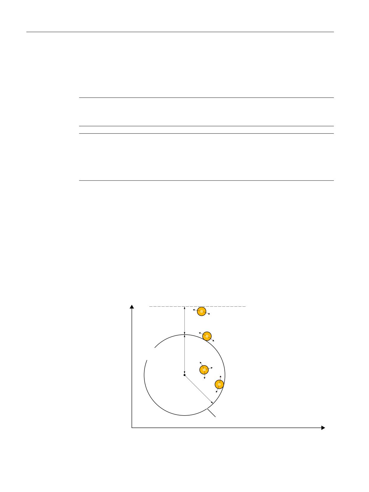
After activating the function, the tool can be traversed by means of a continuous or incremental
JOG motion using traverse keys or a handwheel:
• For a JOG movement request for the 1st geometry axis of the active plane, traversing is done
from the current position via a concentric arc with the same center point as for the defined
arc.
• For a JOG movement request for the 2nd geometry axis of the active plane, traversing is done
perpendicular to the defined arc. As a result, the circle radius changes.
Axes and spindles
Function Manual, 10/2020, 6FC5397-4GP40-0BA1
743
Manual traversing
15.11 Circular travel in JOG
• Only one movement at a time can be carried out in the active plane: either on the arc or
perpendicular to it.
• Regardless of the movements in the active plane, the 3rd geometry axis can be traversed
perpendicular to the active plane.
Note
The radius can only be reduced to zero, i.e. to the center point of the circle. If the radius is then
enlarged again, traversing occurs back in the direction from where the reducing started.
Note
If the current position is the center point of the circle when the function is activated or after a
change to the center point of the circle, then the following applies:
• For a full circle, traversing takes place in the direction of the 2nd geometry axes.
• For a segment of a circle, travel is in the direction of the angle bisector.
Internal or external machining
Depending on the specification in the setting data SD42692 $SC_JOG_CIRCLE_MODE, internal
or external machining takes place:
• Internal machining
- Traversing is only possible within the defined circle.
- The circle radius in SD42691 $SA_CIRCLE_RADIUS is the maximum radius.
• External machining
- Traversing is only possible outside of the defined circle.
- The circle radius in SD42691 $SA_CIRCLE_RADIUS is the minimum radius.
(FPNFUSZ BYJT
PG BDUJWF QMBOF
&YUFSOBM NBDIJOJOH
4%
CJU
*OUFSOBM NBDIJOJOH
4%
CJU
$JSDMF DFOUFS
4%
$JSDMF SBEJVT
4%
%FOFE DJSDVMBS BSD
(FPNFUSZ BYJT PG BDUJWF QMBOF
Axes and spindles
744
Function Manual, 10/2020, 6FC5397-4GP40-0BA1
Manual traversing
15.11 Circular travel in JOG
Figure 15-5
Circular travel in JOG: Internal/external machining
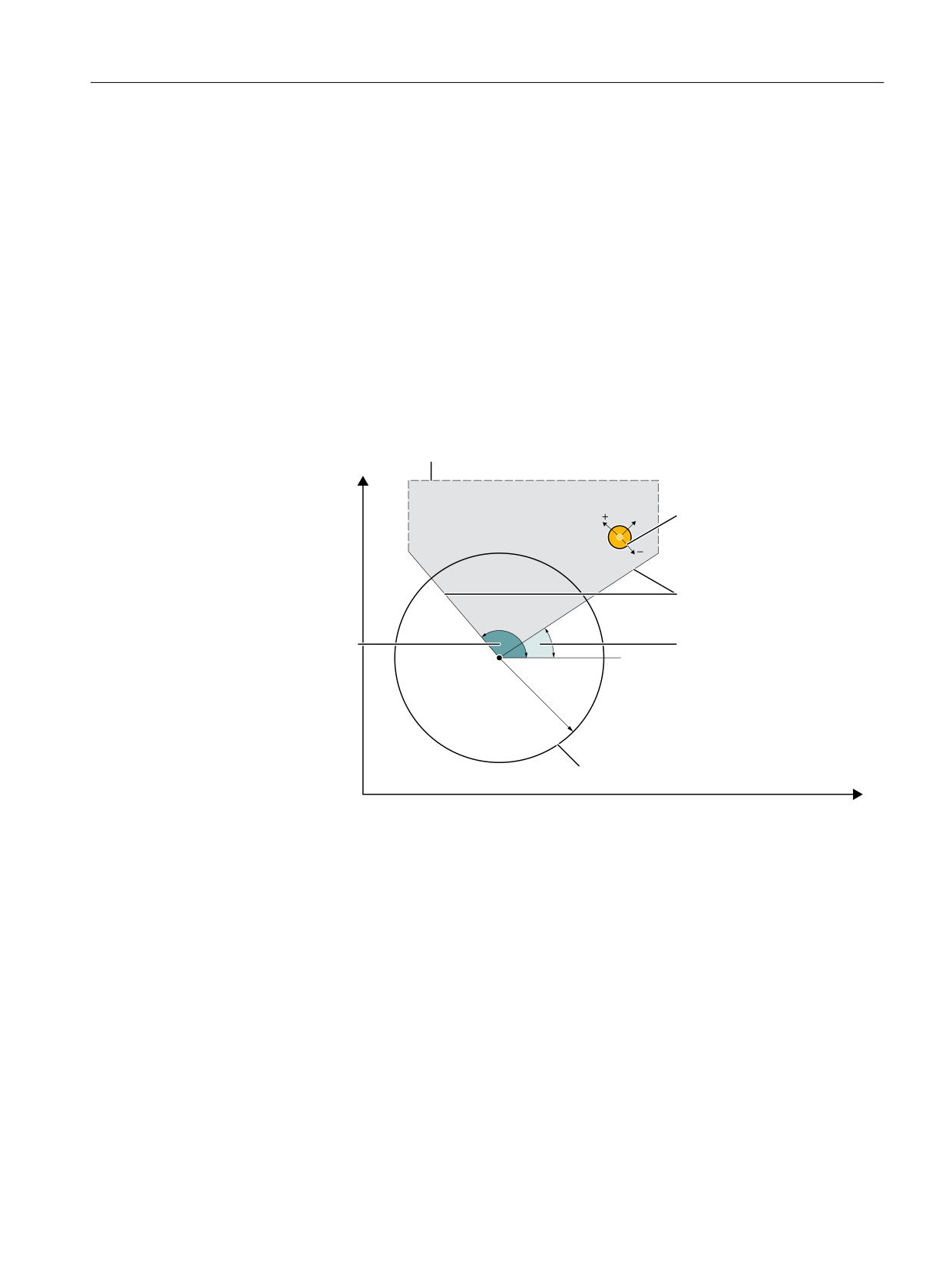
Circle segment machining
By specifying a start and end angle, the working area for the 1st and 2nd geometry axis can be
limited to a circle segment:
SD42693 $SC_JOG_CIRCLE_START_ANGLE (circle start angle)
SD42694 $SC_JOG_CIRCLE_END_ANGLE (circle end angle)
Furthermore, the direction from the start to the end angle must be specified to permit the unique
definition of the circle segment:
SD42692 $SC_JOG_CIRCLE_MODE, bit 0
This bit also specifies the traversing direction along the circular path.
.$4 XPSLJOH BSFB MJNJUBUJPO
(FPNFUSZ BYJT
PG BDUJWF QMBOF
8PSLJOH BSFB
5SBWFSTJOH EJSFDUJPO 4%
CJU
DPVOUFSDMPDLXJTF
ܢ DMPDLXJTF
"OHMF MJNJUBUJPOT
&OE BOHMF 4%
4UBSU BOHMF
4%
IFSF GPS FYBNQMF
p
p
IFSF GPS FYBNQMF
p
$JSDMF DFOUFS
$JSDMF SBEJVT
%FOFE DJSDVMBS BSD
(FPNFUSZ BYJT PG BDUJWF QMBOF
Figure 15-6
Circular travel in JOG: Circle segment machining
Axes and spindles
Function Manual, 10/2020, 6FC5397-4GP40-0BA1
745
Manual traversing
15.11 Circular travel in JOG
Allowance for tool radius
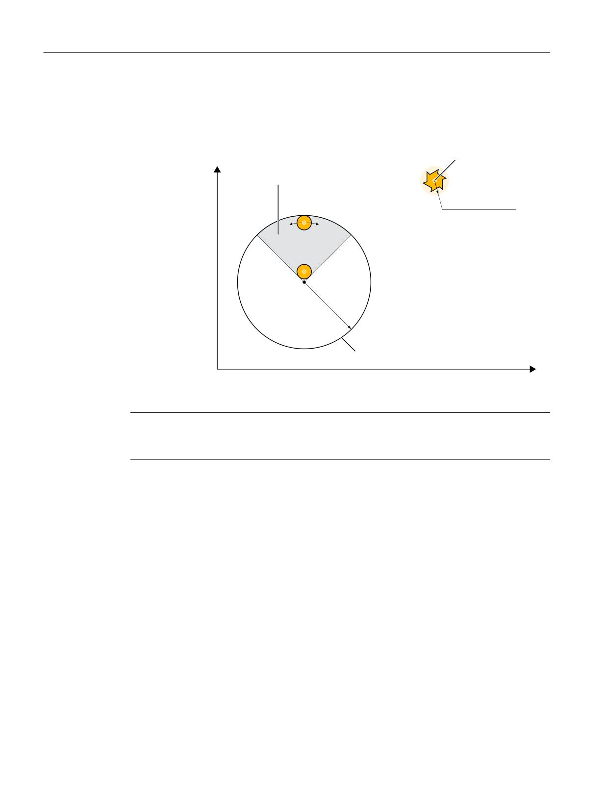
If bit 1 is set in the setting data SD42692 $SC_JOG_CIRCLE_MODE, then the tool radius is
considered when monitoring the operating range limits (define circular arc; for circle segment
machining also the limits that arise due to the start and end angle):
$VUUJOH FEHF DFOUFS
(FPNFUSZ BYJT
QPJOU
PG BDUJWF QMBOF
8PSLJOH BSFB
5PPM SBEJVT
$JSDMF DFOUFS
$JSDMF SBEJVT
%FOFE DJSDVMBS BSD
(FPNFUSZ BYJT PG BDUJWF QMBOF
Figure 15-7
Circular travel in JOG: Circle segment internal machining with tool radius compensation
Note
By taking the tool radius into consideration, the smallest possible radius for the internal
machining in the vicinity of the center point of the circle is also limited.
Axis monitoring
If the current axis positions of the engaged axes are outside of the workspace limits when the
function is activated, then the axes are not traversed and an alarm is output.
Axis positions that are outside of the operating range limits are:
• For internal machining: positions outside of the defined circle
• For external machining: positions within the define circle
• For circle segment machining: Positions outside of the limits that result from the start and
end angles (segment borders)
• For active tool radius compensation: Positions too close to limiting circle
• For active tool radius compensation and internal machining: Positions too close to center of
circle
• For active tool radius compensation and circle segment machining: Positions too close to
segment borders
Axes and spindles
746
Function Manual, 10/2020, 6FC5397-4GP40-0BA1

Manual traversing
15.11 Circular travel in JOG
Changes to the setting data
Changes in the function-relevant setting data SD42690 to SD42694 that are made during an
active JOG motion only take effect after ending the active JOG motion by triggering a new JOG
motion.
Note
To ensure that changes in the setting data take effect more quickly, the machine operator can
proceed as follows:
1. Cancel the current traverse movement with residual distance deletion.
2. Change setting data.
3. Restart the JOG motion.
Abort/deactivation
If during a JOG motion the function "Circular travel in JOG" is deactivated (DB21, ... DBX30.6 =
0), then the JOG motion is canceled and an alarm is output.
Note
To avoid the alarm message, the machine user should proceed as follows:
1. Cancel the current traverse movement with residual distance deletion.
2. Deactivating the function after axis standstill.
15.11.2
Parameter setting
Traversing direction of the second geometry axis
The traversing direction of the second geometry axis can be set via the following machine data:
MD10735 $MN_JOG_MODE_MASK (settings for the JOG mode)
Bit
Value
Meaning
6
0
Traversing of the 2nd geometry axis of the active plane to plus increases the radius,
traversing to minus decreases the radius. The traversing movement is independent of
7
0
whether internal or external machining is active.
Bit
Value
Meaning
6
0
Traversing of the 2nd geometry axis of the active plane to plus always takes place in the
direction of the limiting circle. I.e. the radius is increased for internal machining and
7
1
decreased for external machining.
Axes and spindles
Function Manual, 10/2020, 6FC5397-4GP40-0BA1
747
Manual traversing
15.11 Circular travel in JOG
Bit
Value
Meaning
6
1
Traversing of the 2nd geometry axis of the active plane to minus always takes place in
the direction of the limiting circle. I.e. the radius is increased for internal machining and
7
1
decreased for external machining.
Coordinates of center of circle as radius value
In basic setting, the specified coordinate of an axis is always a diameter value when diameter
programming is active. This can be changed for specifying the center of circle coordinates for
circular traversing in JOG via the following machine data:
MD20360 $MC_TOOL_PARAMETER_DEF_MASK (definition of the tool parameters)
Bit
Value
Meaning
13
0
For circular travel in JOG, the center of circle coordinate is a diameter value (basic set-
ting).
1
For circular travel in JOG, the center of circle coordinate is always a radius value.
Center of circle
The center of the circle to be traversed is set in the setting data:
SD42690 $SC_JOG_CIRCLE_CENTRE (circle center point)
The coordinate data refers to the WCS. It can be a diameter or radius value (depending on the
setting in the MD20360 Bit 13).
Only the center point coordinates of the geometry axes of the active plane are evaluated, not the
coordinates of the geometry axis that is perpendicular to the plane.
Circle radius
The radius of the maximum circle for internal machining or of the minimum circle for external
machining is set in the setting data:
SD42691 $SC_JOG_CIRCLE_RADIUS (circle radius)
The radius that is specified refers to the WCS.
Internal or external machining
The machining mode (internal or external machining) is defined in the setting data:
SD42692 $SC_JOG_CIRCLE_MODE (jog circle mode)
Bit
Value
Meaning
2
0
Internal machining takes place.
The circle radius in SD42691 is the maximum possible radius.
1
External machining takes place.
The circle radius in SD42691 is the minimum possible radius.
Axes and spindles
748
Function Manual, 10/2020, 6FC5397-4GP40-0BA1

Manual traversing
15.11 Circular travel in JOG
Circle segment machining
The start and end angles for defining a circle segment that limits the operating range are set in
the setting data:
SD42693 $SC_JOG_CIRCLE_START_ANGLE (circle start angle)
SD42694 $SC_JOG_CIRCLE_END_ANGLE (circle end angle)
The angle data refers to the abscissa of the active plane.
The direction from the start to the end angle is specified in the setting data:
SD42692 $SC_JOG_CIRCLE_MODE (jog circle mode)
Bit
Value
Meaning
0
0
The direction from the start to the end angle is counterclockwise.
1
The direction from the start to the end angle is clockwise.
Note
If the start and end angle are equal to zero, full circles can be traversed without limitation.
Allowance for tool radius
The consideration of the tool radius can be selected via the following setting data:
SD42692 $SC_JOG_CIRCLE_MODE (jog circle mode)
Bit
Value
Meaning
1
0
When monitoring the operating range limits (define circular arc; for circle segment
machining also the limits that result from the start and end angle), the tool radius is not
considered (basic setting).
1
When monitoring the operating range limits, the tool radius is considered.
15.11.3
Supplementary Conditions
Diameter programming active
During incremental traversing and handwheel traversing of the geometry axes of the active
plane, traversing always takes place in the radius programming, even if diameter programming
is active for one of the two involved geometry axes.
Axis is not a geometry axis
Both axes of the active plane must be defined as geometry axes:
• Either by configuration of MD20050 $MC_AXCONF_GEOAX_ASSIGN_TAB
• or by programming GEOAX in the part program
Axes and spindles
Function Manual, 10/2020, 6FC5397-4GP40-0BA1
749
Manual traversing
15.11 Circular travel in JOG
If the axes of the active plane are not defined as geometry axes, then the axes are not traversed
and an alarm is output.
Axis is hirth axis
If an axis involved in the circular path is a hirth axis, then the axis is not traversed and an alarm
is output.
Protection zones
Protection zones are not monitored.
15.11.4
Application example
Initial situation
• The geometry axes are configured as follows:
MD20050 $MC_AXCONF_GEOAX_ASSIGN_TAB[0] = 1
1st geo. axis = 1st channel axis
MD20050 $MC_AXCONF_GEOAX_ASSIGN_TAB[1] = 2
2nd geo. axis = 2nd channel axis
MD20050 $MC_AXCONF_GEOAX_ASSIGN_TAB[2] = 3
3rd geo. axis = 3rd channel axis
• G17 is active (basic setting):
- X axis = 1st geometry axis of active plane
- Y axis = 2nd geometry axis of active plane
• The selected tool has a radius correction value of 0.02 mm.
• The current axis positions are:
- X axis: 10
- Y axis: 10
• The axes are homed.
Parameter assignment
SD42690 $SC_JOG_CIRCLE_CENTRE[AX1] = 10
Center of circle X axis to position 10 mm
SD42690 $SC_JOG_CIRCLE_CENTRE[AX2] = 20
Center of circle Y axis to position 20 mm
SD42691 $SC_JOG_CIRCLE_RADIUS = 20
Circle radius 20 mm
SD42692 $SC_JOG_CIRCLE_MODE = 2
Traversing with the plus key:
traversing the circle counter-clockwise
Consideration of the tool radius compen-
sation
Internal machining
Axes and spindles
750
Function Manual, 10/2020, 6FC5397-4GP40-0BA1
Manual traversing
15.12 Retraction in the tool direction (JOG retract)
SD42693 $SC_JOG_CIRCLE_START_ANGLE = 0
No start angle active
SD42694 $SC_JOG_CIRCLE_END_ANGLE = 0
No end angle active
Result
Circle inside machining takes place.
With continuous traversing of the X axis using the plus traversing key, a counter-clockwise (G2)
circular movement can be initiated with a radius of 10 mm about the center point of the circle
(10, 20).
With the traversing of the Y axis, the circle radius can be changed between 0.02 and 19.98.
15.12
Retraction in the tool direction (JOG retract)
15.12.1
Overview
Function
The function "Retraction in the tool direction with the machine function JOG retract", called "JOG
retract" in the following, supports the manual tool retraction in the workpiece coordinate system
(WCS) after a program abort through a power off of the control or a channel reset in the
AUTOMATIC or MDI mode.
In particular, the specific features of the following functions are taken into account:
• Tapping with compensating chuck and speed-controlled spindle with encoder (G33)
• Tapping without compensating chuck and position-controlled spindle (G331, G332)
• Machining with tool orientation with swivel cycle CYCLE800 or orientation transformation
Availability
JOG retract can only be selected if one of the following functions was interrupted as a result of
a channel reset or power off:
• Tapping using G33/G331/G332
• Machining using tool type 2xx (drilling tools)
Data to be restored
In order to be able to execute the retraction in the tool direction after a program abort, the
following data which was active in the channel before the program abort, is restored:
• Active tool offset
• Active machining plane
• Active tool carrier
Axes and spindles
Function Manual, 10/2020, 6FC5397-4GP40-0BA1
751

Manual traversing
15.12 Retraction in the tool direction (JOG retract)
• Active transformation data block with transformation parameters
• Data of the thread group with G33 or G331/G332
• Positions of the axes that are involved in the transformation
If this data is completely available after a program abort, it is restored in the channel when the
JOG retract machine function is selected. In this case, the workpiece coordinate system (WCS)
is aligned by the control in such a way that one of the geometry axes is in the direction of the tool
axis. The tool retraction can then be performed manually by traversing this geometry axis.
Note
Data backup
The specified data itself is not backed up, only the references to this data. If the data is changed
prior to the selection of JOG retract, the function is performed on the basis of the changed data.
Restrictions
Programs that can be started by interrupt signals are not executed in JOG retract.
15.12.2
Parameterization
15.12.2.1
Automatic selection of JOG retract after Power On
After the control has run up (Power On), the channels of a BAG are as standard in the
parameterized default mode:
MD10720 $MN_OPERATING_MODE_DEFAULT[<mode group>] = <default mode>
The following NC-specific machine data can be used to set which operating mode is selected
after the control run up, if there is retraction data in a BAG channel.
MD10721 $MN_OPERATING_MODE_EXTENDED[<mode group>] = <value>
Value
Meaning
0
Selection of the operating mode corresponding to MD10720 $MN_OPERATING_MODE_DE-
FAULT
1
Selection of JOG mode, if: DB21, ... DBX377.5 == 1 (retraction data available)
15.12.2.2
Enable of the traversing direction
The retraction movement can be limited to the positive direction of travel or enabled for both
travel directions using the following NC-specific machine data:
MD10735 $MN_JOG_MODE_MASK, Bit 8 = <Value>
Value
Meaning
0
Release: Positive traverse direction
1
Release: Positive and negative traverse direction
Axes and spindles
752
Function Manual, 10/2020, 6FC5397-4GP40-0BA1

Manual traversing
15.12 Retraction in the tool direction (JOG retract)
15.12.2.3
Measuring system status
The current status of the measuring system is displayed via the following axis-specific machine
data or must be set to the desired behavior for selection:
MD34210 $MA_ENC_REFP_STATE[<Axis>] = <Value>
Value 1)
Meaning
Absolute encoder
2
Encoder is calibrated
Incremental encoder
1
Automatic referencing: Enabled, but encoder still not referenced
2
Automatic referencing: Encoder is referenced and in exact stop, automatic referencing takes
effect at next time encoder activation
3
Restoration of the actual position: The last axis position buffered before switching off is
restored, no automatic referencing
1) Only the values relevant for JOG-Retract are stated
15.12.3
Selection
Function
Requirement
The selection of JOG retract is only possible, if valid retraction data is available for the relevant
channel, the channel is in JOG mode and in the "Reset" state:
• DB21, … DBX377.5 == 1 (retraction data available)
• DB11 DBX(n*20+6).2 == 1 (active mode: JOG, with n=0, 1, 2 ... for mode group 1, 2, ...)
• DB21, … DBX35.7 == 1 (channel state: Reset)
Axes and spindles
All active measuring systems of the machine axes involved in the retraction in the tool direction
must be in the "referenced" or "restored" state when the control is switched on again (Power On).
Further information: For automatic restoration of actual positions after the next start of the
control (Power On), see Chapter "Homing (Page 31)".
Axis interchange
If all the axes and spindles involved in the retraction are not assigned to the channel at the time
of selection, an implicit axis interchange is performed for the missing axes.
Coordinate system
With the selection of JOG retract, the workpiece coordinate system (WCS) is set for the traversing
of the channel axes. Axes involved in the retraction can only be traversed in the WCS. All axes that
are not involved in the retraction can also be traversed in the machine coordinate system (MCS).
Axes and spindles
Function Manual, 10/2020, 6FC5397-4GP40-0BA1
753
Manual traversing
15.12 Retraction in the tool direction (JOG retract)
Selection options
The selection of JOG Retract can be supported through automatic selection of the JOG mode
after Power On. The actual selection of JOG retract is performed through manual selection via
the user interface or via the PLC user program.
Automatic selection of JOG mode
If the automatic selection of JOG Retract is parameterized (see Chapter: "Automatic selection of
JOG retract after Power On (Page 752)") and there is retraction data for a channel after control
run-up (Power On), JOG mode is selected for the mode group.
Selection via the user interface
The selection of JOG retract is performed on the user interface via:
"Machine operating area" > "ETC key (">")" > "Retract"
Note
The softkey "Retract" is only displayed if there is retraction data and an active tool.
Selection by PLC user program
The following actions must be performed to select JOG retract by the PLC user program:
• Channel-specific query whether retraction data is available
DB21, … DBX377.5 == 1 (retraction data available)
• Mode group-specific selection of JOG mode:
DB11, ... DBX(n*20+6).2 == 1 (active mode: JOG, with n=0, 1, 2 ... for mode group 1, 2, ...)
• Channel-specific selection of JOG Retract via the PI service "RETRAC".
Further information: For activation of the PI service "RETRAC" via function block FB 4, see
PLC Function Manual.
• After confirmation of the selection of JOG retract (see below), select the workpiece
coordinate system:
- DB19.DBX0.7 (current coordinate system: 1 ⇒ WCS, 0 ⇒ MCS)
- DB19.DBX20.7 (Requirement: Switch over MCS/WCS)
Selection confirmation
After selecting JOG retract, the NC/PLC interface signal is set:
DB21, ... DBX377.4 = 1 (JOG retract active)
Thread cutting (G33 or G331/G332)
If the program execution was aborted during a thread cutting operation (G33 or G331/G332),
the axis grouping of tool axis and spindle is restored when JOG retract is selected. The controller
parameters and parameter sets for the axes involved are also set in accordance with a
programmed thread cutting in the part program.
Axes and spindles
754
Function Manual, 10/2020, 6FC5397-4GP40-0BA1
Manual traversing
15.12 Retraction in the tool direction (JOG retract)
15.12.4
Tool retraction
General retraction behavior
The tool is retracted by manually traversing the retraction axis (geometry axis) specified when
selecting JOG retract in the workpiece coordinate system (WCS). The retraction movement can
be performed via the traversing keys of the machine control panel (MCP) or via the handwheel.
Retraction is possible within the traversing range limits (working area limitation, software limit
switch, etc.).
The retraction movement can be stopped and started again with NC stop / NC start.
The axes and spindles not involved in the tool retraction can be manually traversed as required.
Switching the coordinates systems is possible (MCS ⇔ WCS).
Traversing direction
The retraction movement is only enabled for the positive traversing direction by default. If
traversing in the negative direction is also to be possible, this must be explicitly enabled:
MD10735 $MN_JOG_MODE_MASK, bit 8 = 1
Retraction behavior dependent on processing type and tool type
The following retraction motion is possible depending on the machining type and the active tool
type:
• Thread cutting (G33) or tapping (G331,G332):
Irrespective of the tool type, traverse movements are only possible in the retraction axis (tool
axis)
• Tool type 2xx (drilling tools): traverse movements are only possible in the retraction axis (tool
axis)
• Tool type 4xx (grinding tools): No retraction motion possible
• Tool type 5xx (turning tools): No retraction motion possible
Retraction movement for thread processing
For thread cutting (G33) or tapping (G331,G332) the retraction movement is performed if
either the retraction axis or the spindle is moved.
Retraction using the handwheel
If one of the axes involved in the retraction movement is traversed by means of traversing key,
the handwheel pulses for other axes involved in the retraction movement are ignored.
If handwheels have been selected for several axes and these are moved, the handwheel pulses
are evaluated in the following order:
1. Retraction axis
2. Spindle
3. Axes/spindles not involved in the retraction movement
Axes and spindles
Function Manual, 10/2020, 6FC5397-4GP40-0BA1
755
Manual traversing
15.12 Retraction in the tool direction (JOG retract)
The pulses of the other handwheels are ignored and only evaluated at standstill of the preceding
handwheels.
Locked functions
During JOG retract, the following functions are blocked or are not performed:
• Spindle start via DB31, ... DBX30
• Traversing of a spindle or axis involved in the retraction via function block FC18
• Switchover of a spindle or an axis involved in the retraction to the PLC-controlled axis
• Changing a spindle or axis involved in the retraction to another channel
• Using a spindle or axis involved in the retraction as main run axis (command axis, oscillating
axis, FC18 / concurrent axis)
15.12.5
Deselection
JOG retract is deselected channel-specifically via:
• Channel reset: DB21, … DBX7.7 = 1 (reset)
• User interface: "Back" ("<<") softkey
The following basic settings are active:
• MD20110 $MC_RESET_MODE_MASK[<channel>]
• MD20150 $MC_GCODE_RESET_VALUES[<channel>]
• MD20151 $MC_GCODE_RESET_MODE[<channel>]
After the deselection, the channel is in the JOG mode, channel state "Reset".
All channel axes can be moved manually again. The retraction data is retained. It is therefore
possible to select JOG retract again.
NC/PLC interface signal
With the deselection of JOG retract, the NC/PLC interface signal is reset:
DB21, ... DBX377.4 = 0 (JOG retract active)
15.12.6
Repeated selection
As long as there is retraction data, JOG retract can always be reselected:
DB21, ... DBX377.5 == 1 (retraction data available)
If selected again, the original retraction data is restored.
Changed axis positions
The channel axes can be traversed in JOG mode while JOG retract is deselected. If JOG retract is
selected again, the retraction movement is executed on the basis of the new axis positions.
Axes and spindles
756
Function Manual, 10/2020, 6FC5397-4GP40-0BA1
Manual traversing
15.12 Retraction in the tool direction (JOG retract)
15.12.7
Continuing machining
AUTOMATIC mode
Before the aborted part program is continued with NC start in AUTOMATIC mode, all machine
axes with active measuring systems in the state "restored" or "not homed" must be homed.
NOTICE
Possible axis position displacement
After the control runs up after a power failure, the axis positions for incremental measuring
systems are synchronized or restored corresponding to the setting in machine data. Once the
tool has been retracted in the JOG retract machine function, axes whose positions have been
restored are homed.
MDI mode and overstore
In the MDI mode and for the overstore function, machining can also be performed, without
homing the axes, with restored positions. To do this, NC start with restored positions must be
enabled explicitly for a specific channel:
MD20700 $MC_REFP_NC_START_LOCK = 2
Block search at interruption point
The processing of the part program can be continued from the interruption point via a block
search at the interruption point. The last block of the main program level before the interruption
is available as interruption point.
A detailed description of the function and for the operation of the block search can be found in:
Further information
• Function Manual Basic Functions
• Operating Manual Turning or Operating Manual Milling
Continue with NC start
With NC start in the AUTOMATIC or MDI mode, the processing of the part program is continued
from the selected position. The following actions are performed with regard to JOG retract:
• The retraction data is deleted.
• The NC/PLC interface signal is reset:
DB21, … DBX377.5 = 0 (retraction data available)
• The current data environment is saved.
Axes and spindles
Function Manual, 10/2020, 6FC5397-4GP40-0BA1
757
Manual traversing
15.12 Retraction in the tool direction (JOG retract)
15.12.8
Continuing machining
AUTOMATIC mode
Before the aborted part program is continued with NC start in AUTOMATIC mode, all machine
axes with active measuring systems in the state "restored" or "not homed" must be homed.
NOTICE
Possible axis position displacement
After the control runs up after a power failure, the axis positions for incremental measuring
systems are synchronized or restored corresponding to the setting in machine data. Once the
tool has been retracted in the JOG retract machine function, axes whose positions have been
restored are homed.
MDI mode and overstore
In the MDI mode and for the overstore function, machining can also be performed, without
homing the axes, with restored positions. To do this, NC start with restored positions must be
enabled explicitly for a specific channel:
MD20700 $MC_REFP_NC_START_LOCK = 2
Continue with NC start
With NC start in the AUTOMATIC or MDI mode, the processing of the part program is continued
from the selected position. The following actions are performed with regard to JOG retract:
• The retraction data is deleted.
• The NC/PLC interface signal is reset:
DB21, … DBX377.5 = 0 (retraction data available)
• The current data environment is saved.
Axes and spindles
758
Function Manual, 10/2020, 6FC5397-4GP40-0BA1
Manual traversing
15.12 Retraction in the tool direction (JOG retract)
15.12.9
State diagram
1PXFS 0O
.PEF "650."5*$ PS .%*
DIBOOFM TUBUVT 3FTFU
#"8 +0(
NPEF DIBOHF "650."5*$ PS .%*
.PEF +0(
.PEF "650."5*$ PS .%*
DIBOOFM TUBUVT 3FTFU
DIBOOFM TUBUVT 3FTFU
#"8 +0(
BDUJWBUJPO
+0(
DIBOOFM SFTFU
/$ 4UBSU
DIBOOFM SFTFU
SFUSBDU
.PEF +0(
.PEF "650."5*$ PS .%*
+0( SFUSBDU BDUJWF
DIBOOFM TUBUVT BDUJWF
SFUSBDUJPO EBUB BSF SFDPSEFE
OM
Operating mode
OMC Operating mode change
Figure 15-8
State diagram: JOG retract
15.12.10
System data
The following system data is available for JOG retract:
Meaning
System variable $VA_
NC/PLC interface
OPI variable
Retraction data available
-
DB21, ... DBX377.5
retractState, bit 0
JOG retract active
-
DB21, ... DBX377.4
retractState, bit 1
Retraction axis
-
-
retractState, bits 2 - 3
Position restored, 1st Measuring system
$AA_POSRES
DB31, ... DBX71.4
aaPosRes
Position restored, 2nd Measuring system
$AA_POSRES
DB31, ... DBX71.5
aaPosRes
Additional information
OPI and system variables
• List Manual System Variables
• PLC Function Manual
15.12.11
Supplementary conditions
Incremental measuring systems
The user must ensure that machine axes with incremental measuring systems are clamped with
sufficient speed in the event of a power failure to prevent a change to the last position, known
and saved by the control. Otherwise the assumed position when the control is restarted differs
Axes and spindles
Function Manual, 10/2020, 6FC5397-4GP40-0BA1
759
Manual traversing
15.12 Retraction in the tool direction (JOG retract)
greatly to the actual position of the machine axis. Drive-autonomous retraction must also not
be activated for these axes.
A detailed description of the automatic restoration of actual positions after the next start of the
control (Power On) can be found in:
Additional information
Function Manual Basic Functions
Drive-autonomous retraction
The "Drive-autonomous retraction" function must not be activated for machine axes involved in
the retraction movement.
Axis couplings
Axis couplings are not restored with the selection of JOG retract.
Tapping using G63
JOG retract is not possible for tapping with compensating chuck and speed-controlled spindle
without encoder (G63).
Transformations
If a transformation is selected through JOG retract, the active measuring systems of all machine
axes involved in the transformation must be in the "homed" or "restored" state.
OEM transformations such as parallel kinematics for hexapods, can only be traversed with
homed measuring systems. Traversing with restored axis positions is not possible.
Tool orientation via directly programmed orientation axes
JOG retract cannot generate a retraction movement in the tool direction if the tool orientation
is not performed via NC functions, but through direct programming of the orientation axes.
NCU link
JOG retract is also possible in connection with cross-NCU traversing of axes. The state of axis
containers is not changed through JOG retract. Any adjustments required for a retraction in the
tool direction must be made by the user, e.g. in mode MDA, before the JOG retract movement.
Axes and spindles
760
Function Manual, 10/2020, 6FC5397-4GP40-0BA1

Manual traversing
15.13 Use of handwheels in automatic mode
15.13
Use of handwheels in automatic mode
15.13.1
Handwheel override in automatic mode
15.13.1.1
General functionality
Function
With this function it is possible to traverse axes or to change their velocities directly with the
handwheel in automatic mode (Automatic, MDA).
The handwheel override is activated in the NC part program using the NC language elements FD
(for path axes) and FDA (for positioning axes) and is non-modal.
With positioning axes, it is possible to activate the handwheel override modally using traverse
command POSA. When the programmed target position is reached, the handwheel override
becomes inactive again.
Additional axes can be traversed simultaneously or using interpolation in the same NC block.
The concurrent-positioning-axes function can also be activated by the PLC user program.
Distinction
Depending on the programmed feedrate, a distinction is made between the following for
handwheel override:
• Path definition
Axis feedrate = 0 (FDA = 0)
• Velocity override
Axis feedrate > 0 (FD or FDA > 0)
The table below shows which axis types can be influenced by the "handwheel override in
automatic mode" function.
Axes that can be influenced by the "handwheel override in automatic mode" function
Axis type
Velocity override
Path definition
Positioning axis
FDA[AXi] > 0 ;
FDA[AXi] = 0
acts axially
Concurrent posi-
Parameter "Handwheel override active" = 1 and
Parameter "Handwheel over-
tioning axis
axis feedrate > 0 from FC18
ride active" = 1 and axis fee-
drate = 0 from FC18
Path axis
FD > 0 ;
Not possible
acts on path velocity
Axes and spindles
Function Manual, 10/2020, 6FC5397-4GP40-0BA1
761
Manual traversing
15.13 Use of handwheels in automatic mode
Path definition
With axis feedrate = 0 (e.g. FDA[AXi] = 0), the traversing movement of the positioning axis
towards the programmed target position is controlled entirely by the user rotating the assigned
handwheel.
The direction in which the handwheel is turned determines the traversing direction of the axis.
The programmed target position cannot be exceeded during handwheel override. The axis can
also be moved toward the programmed target position from the opposite direction, whereby the
movement is only restricted by the axial position limitations.
A block change occurs when:
• The axis has reached the programmed target position
or
• The distance-to-go is deleted by axial interface signal
DB31, ... DBX2.2 (delete distance-to-go).
From this moment on, the path default is deactivated and any further handwheel pulses have no
effect.
After this, incrementally programmed positions refer to the point of interruption and not to the
last programmed position.
Velocity override
With regard to the velocity override, a distinction is made between axis feedrate and path
feedrate.
• Axis-velocity override (FDA[AXi] > 0):
The positioning axis is moved to the target position at the programmed axial feedrate. Using
the assigned handwheel, it is possible to increase the axis velocity or to reduce it to a
minimum of zero depending on the direction of rotation. The resulting axis feedrate is limited
by the maximum velocity. However, the axis cannot be traversed in the opposite direction to
that programmed.
The block change is performed as soon as the axis reaches the programmed target position.
This causes the velocity override to be deactivated automatically and any further handwheel
pulses have no effect.
Similarly, this also applies to concurrent positioning axes, where the target position and the
velocity are defined by the PLC.
• Path-velocity override (FD > 0):
The path axes programmed in the NC block traverse to the target position at the programmed
feedrate. If the velocity override is active, the programmed path velocity is overridden by the
velocity generated with the handwheel of the 1st geometry axis. The block change is
performed as soon as the programmed target position is reached.
The path velocity is increased or reduced to a minimum of zero depending on the direction
of rotation of the handwheel. However, it is not possible to reverse the direction of
movement with handwheel override.
Axes and spindles
762
Function Manual, 10/2020, 6FC5397-4GP40-0BA1
Manual traversing
15.13 Use of handwheels in automatic mode
Application example
The "Handwheel override in automatic mode" function is frequently used on grinding machines.
For example, the user can position the reciprocating grinding wheel on the workpiece using the
handwheel (path default). After scratching, the traversing movement is terminated and the
block change is initiated (by activating DB31, ... DBX2.2 (delete distance-to-go)).
Preconditions
In order to activate "Handwheel override in automatic mode", the following requirements must
have been met:
• A handwheel must be assigned to the axis in question.
• Pulse weighting exists for the assigned handwheel.
Handwheel assignment
The assignment of the connected handwheels to the axes is analogous to the "Manual traversing
using a handwheel (Page 712)" via the user interface or via the PLC user interface with one of
the following interface signals:
• Machine axes:
- DB31, ... DBX4.0 - 2 (activate handwheel)
• Geometry axes:
- DB21, ... DBX12.0 - 2 (geometry axis 1: Activate handwheel)
- DB21, ... DBX16.0 - 2 (geometry axis 2: Activate handwheel)
- DB21, ... DBX20.0 - 2 (geometry axis 3: Activate handwheel)
If handwheel override is programmed for an axis to which no handwheel is assigned, a
distinction is made between the following cases:
• For velocity override:
The axes traverse at the programmed velocity.
A self-acknowledging alarm is output (without response).
• For path definition:
No traversing movement is performed because the velocity is zero.
A self-acknowledging alarm is output (without response).
Note
For the velocity override for path axes, only the handwheel of the 1st geometry axis is
applied to the path velocity.
Axes and spindles
Function Manual, 10/2020, 6FC5397-4GP40-0BA1
763
Manual traversing
15.13 Use of handwheels in automatic mode
Handwheel weighting
The travel path of the axis that is generated by rotating the handwheel by one detent position
is dependent on several factors (see Section "Manual traversing using a handwheel (Page 712)"):
• Selected increment size:
MD11330 $MN_JOG_INCR_SIZE_TAB[5] (increment size for INC/handwheel)
or
SD41010 $SN_JOG_VAR_INCR_SIZE (size of the variable increment for JOG)
• Weighting of an increment:
MD31090 $MA_JOG_INCR_WEIGHT
• Number of handwheel pulses per detent position:
MD11320 $MN_HANDWH_IMP_PER_LATCH
For example, the axis traverses by 0.001 mm per handwheel detent position if machine function
INC1 and the default setting of the above machine data are selected.
In the case of velocity override, the velocity results from the traverse path covered using the
handwheel within a certain period of time.
Example
Assumptions:
The operator turns the handwheel with 100 pulses/second.
The selected machine function is INC100.
The default setting is made for the above machine data for handwheel weighting.
⇒ Handwheel traverse path per second:
10 mm
⇒ Velocity override:
0.6 m/min
PLC interface signals
As soon as the handwheel override takes effect, the following interface signals to the PLC are set
to signal 1:
• For positioning axes / concurrent positioning axes / command axes / reciprocating axes:
DB31, ... DBX62.1 (handwheel override active)
• For path axes:
DB21, ... DBX33.3 (handwheel override active)
For the path input, depending on the traversing direction, the appropriate interface signals are
output to the PLC:
• Machine axes:
- DB31, ... DBX64.6 / 7 (travel command "minus"/"plus")
• Geometry axes:
- DB21, ... DBX40.6 - 7 (geometry axis 1: Travel command "minus"/"plus")
- DB21, ... DBX46.6 - 7 (geometry axis 2: Travel command "minus"/"plus")
- DB21, ... DBX52.6 - 7 (geometry axis 3: Travel command "minus"/"plus")
Axes and spindles
764
Function Manual, 10/2020, 6FC5397-4GP40-0BA1
Manual traversing
15.13 Use of handwheels in automatic mode
Limitations
The axial limitations (software limit switch, hardware limit switch, working area limitation) are
effective in conjunction with handwheel override. With path default, the axis can be traversed
with the handwheel in the programmed traversing direction only as far as the programmed
target position.
The resulting velocity is limited by the axial machine data:
MD32000 $MA_MAX_AX_VELO(maximum axis velocity)
NC Stop/override = 0
If the feedrate override is set to 0% or an NC Stop is initiated while the handwheel override is
active, the following applies:
• For path definition:
The handwheel pulses arriving in the meantime are summated and stored. If NC Start or the
feedrate override > 0%, the saved handwheel pulses become effective (i.e. are traversed).
However, if the handwheel is first deactivated [via IS DB21, ... DBX12/16/20.0-2 (geometry
axes 1/2/3: Activate handwheel)] then the stored handwheel pulses are deleted.
• For velocity specification:
The handwheel pulses arriving in the meantime are not summated and are not active.
15.13.1.2
Programming and activating handwheel override
General
When the handwheel override is programmed with NC language elements FD (for path axes)
and FDA (for positioning axes), the following points must be observed:
• FDA and FD function non-modally.
Exception for positioning axes: If traverse instruction POSA is programmed, the handwheel
override can also act modally because this positioning axis does not affect the block
transition.
• When the handwheel override is activated with FDA or FD, a target position must be
programmed in the NC block for the positioning axis or for a path axis. When the
programmed target position is reached, the handwheel override becomes inactive again.
• It is not possible to program FDA and FD or FA and F in the same NC block.
• The positioning axis must not be an indexing axis.
Positioning axis
Syntax for handwheel override:
FDA[AXi] = [feedrate value]
Example 1:
Activate velocity override
Axes and spindles
Function Manual, 10/2020, 6FC5397-4GP40-0BA1
765
Manual traversing
15.13 Use of handwheels in automatic mode
N10 POS[U]=10 FDA[U]=100 POSA[V]=20 FDA[V]=150 . . .
POS[U]=10
Target position of positioning axis U
FDA[U]=100
Activate velocity override for positioning axis U; axis velocity of U = 100 mm/
min
POSA[V]=20
Target position of positioning axis V (modally)
FDA[V]=150
Activate velocity override for positioning axis V; axis velocity of V = 150 mm/
min
Example 2:
Activate path default and velocity override in the same NC block
N20 POS[U]=100 FDA[U]= 0 POS[V]=200 FDA[V]=150 . . .
POS[U]=100
Target position of positioning axis U
FDA[U]= 0
Activate path default for positioning axis U;
POS [V]=200
Target position of positioning axis V
FDA[V]=150
Activate velocity override for positioning axis V; axis velocity of V =
150 mm/min
Path axis
Syntax for handwheel override:
FD = [feedrate value]
In order to activate "Handwheel override in automatic mode", the following requirements must
have been met:
• Active movement commands from group 1: G01, G02, G03, CIP
• Exact stop active (G60)
• Linear feedrate in mm/min or inch/min active (G94)
These requirements are checked by the control and an alarm is output if any of them is not met.
Example 3:
Activate velocity override
N10 G01 X10 Y100 Z200 FD=1500 . . .
X10 Y100 Z200
Target position of path axes X, Y and Z
FD=1500
Activate velocity override for path axes; path velocity = 1500 mm/
min
Concurrent positioning axis
The handwheel override for concurrent positioning axes is activated from the PLC via FC18 by
setting the appropriate interface signal:
DB31, ... DBX62.1 (handwheel override active)
Axes and spindles
766
Function Manual, 10/2020, 6FC5397-4GP40-0BA1
Manual traversing
15.13 Use of handwheels in automatic mode
If the velocity parameter (F_Value) is transferred with the value 0, then the activated handwheel
override acts as distance input, i.e. in this case, the feed is not derived from the axial machine
data (see also Section "Positioning axes (Page 271)"):
MD32060 $MA_POS_AX_VELO (initial setting for positioning axis velocity)
Further information
Function Manual PLC
15.13.1.3
Special features of handwheel override in automatic mode
Velocity display
The following values are shown with display of the speed for handwheel override:
• Setpoint velocity
= programmed velocity
• Actual velocity
= resultant velocity including handwheel override
Effect on transverse axes
If the axis is defined as a transverse axis and DIAMON is active, the handwheel pulses are
interpreted and traversed as diameter values while handwheel override is active.
Dry run feedrate
With active dry run
DB21, ... DBX0.6 (activate dry run feedrate) = 1,
the dry run feedrate is always effective
SD42100 $SC_DRY_RUN_FEED.
In this way, the axis is traversed to the programmed target position at dry run feedrate without
any influence from the handwheel despite the active handwheel override with path default
(FDA[AXi] = 0), i.e., the path default is ineffective.
DRF active
When "Handwheel override in automatic mode" is activated, it is important to check whether the
"DRF" function is active (DB21, ... DBX0.3 = 1).
If this were the case, the handwheel pulses would also cause a DRF offset of the axis. DRF must
therefore be deselected first.
Feedrate override
The feedrate override does not affect the velocity of the movements produced by the handwheel
(exception: 0%). It only affects the programmed feedrate.
Axes and spindles
Function Manual, 10/2020, 6FC5397-4GP40-0BA1
767
Manual traversing
15.13 Use of handwheels in automatic mode
With path default and fast handwheel movements, the axis may not be able to follow the
handwheel rotation synchronously (especially in the case of a large handwheel-pulse
weighting), causing the axis to overtravel.
15.13.2
Contour handwheel/path input using handwheel (option)
"Contour handwheel" function
When the function is activated, the path and synchronized axes can be controlled via a
handwheel in AUTOMATIC and MDI modes.
Requirements
It is not permissible that fixed feedrate, dry run feedrate, thread cutting, or tapping are selected.
Availability
The "Contour handwheel" function is available as an option requiring a license.
Input mode (path or velocity input)
Either the distance or the velocity can be entered via the handwheel:
• Path definition
The traversing velocity obtained as a result of the path defined by the handwheel pulses each
IPO clock cycle, is limited by the control system to the maximum permissible velocity. The
handwheel pulses that are not immediately executed are collected, and traversed through at
a later point in time. As a consequence, it is possible that the axes continue to run. No pulses
are lost.
• Velocity specification
Based on the handwheel pulses for each IPO clock cycle, the velocity is specified at which the
axes will be traversed. Traversing motion is immediately stopped as soon as no pulses are
received from the handwheel in an IPO clock cycle. The axes do not continue to run .
The input mode is set with machine data:
MD11346 $MN_HANDWH_TRUE_DISTANCE
Path velocity
The path velocity in mm/min depends on:
• Handwheel pulses in each IPO clock cycle
• Pulse evaluation of the handwheel using machine data:
MD11322 $MN_CONTOURHANDWH_IMP_PER_LATCH
• Active increment (INC1, 10, 100, ...)
• Distance weighting of an increment of the first available geometry axis:
MD31090 $MA_JOG_INCR_WEIGHT
Axes and spindles
768
Function Manual, 10/2020, 6FC5397-4GP40-0BA1
Manual traversing
15.13 Use of handwheels in automatic mode
The path velocity is independent of:
• Programmed feedrate mode (mm/min, mm/rev.)
• Programmed path velocity
• Rapid traverse velocity for G0 blocks
• Override (with the exception of 0% override)
Traversing direction
The traversing direction depends on the direction of rotation of the handwheel:
• Clockwise rotation: Traversing the axes in the programmed direction.
If the block change criterion (IPO end) is reached, the program advances to the next block
(response identical to G60).
• Counterclockwise: Traversing the axes opposite to the programmed direction.
In this case, traversing is only possible up to the start of the actual block. Pulses are not
collected if the handwheel continues to rotate.
Activation of the function
The function can be activated via interface signals or in the NC program:
• Activation via interface signal
DB21, ... DBX30.0 - 2
• Activation via the NC program
Command FD=0 . The contour handwheel is switched on non-modally. This means in the
following block, the programmed velocity F... from the block before the contour
handwheel again applies when the contour handwheel is activated.
Note
An alarm is displayed if no feedrate was programmed in the previous NC blocks.
"Simulated contour handwheel" function
When the "Contour handwheel" function is active, using the "Simulated contour handwheel"
function, the handwheel or the handwheel pulses are simulated.
Activation
The function is activated via interface signal:
DB21, ... DBX30.3 = 1
The feedrate is then no longer specified by the handwheel pulses, but by feedrate F...
programmed in the NC program.
Specifying the direction of rotation
The direction of rotation of the simulated handwheel is specified using the interface signal:
DB21, ... DBX30.4
Axes and spindles
Function Manual, 10/2020, 6FC5397-4GP40-0BA1
769
Manual traversing
15.13 Use of handwheels in automatic mode
Override
When the "Simulated contour handwheel" function is active, the override is effective as for NC
program execution.
Stopping traversing motion
If the "Simulated contour handwheel" function is deselected, or the direction of rotation
switched over, then the actual traversing motion is stopped along a braking ramp.
Boundary conditions
• Velocity limiting
- When the "Contour handwheel" function is activated via interface signal (DB21, ...
DBX30.0 - 2), the path velocity that can be entered via the handwheel is limited to:
Max. path velocity = (programmed path velocity F...) * (MD12030
$MN_OVR_FACTOR_FEEDRATE[ 30 ] + reserve for dynamic operations)
- When the "Contour handwheel" function is activated using command FD=0 in the NC
program, the path velocity that can be entered via the handwheel is limited to the
maximum axis velocities defined in machine data (MD32000 $MA_MAX_AX_VELO).
• Acceleration and velocity limit values
When traversing the axes using the "Contour handwheel" function, the axis-specific limit
values for acceleration, defined in machine data (e.g. MD32300 $MA_MAX_AX_ACCEL), and
velocity (MD32000 $MA_MAX_AX_VELO) are maintained.
• Interruption of traversing movement
If, while traversing using the "Contour handwheel" function, an NC stop is initiated (DB21, ...
DBX7.3 or 4), then the function remains selected. The handwheel pulses received during an
NC stop are not evaluated. Requirement: MD32084 $MA_HANDWH_CHAN_STOP_COND, bit
2 == 1
• DRF
An active DRF function (DB21, ... DBX0.3) additionally has a path override action.
• Channel-specific delete distance-to-go
Channel-specific delete distance-to-go (DB21, ... DBX6.2) causes the motion, initiated by the
contour handwheel, to be canceled. The axes are braked and the program is restarted with
the next NC block.
• Mold making
Executing mold making programs using the contour handwheel does not produce a suitable
surface quality or constant cutting speed.
15.13.3
DRF offset
15.13.3.1
Function
The "DRF offset" function (differential resolver function) can be used to set an additive
incremental work offset in respect of geometry and auxiliary axes in the basic coordinate system
in AUTOMATIC mode via an electronic handwheel.
Axes and spindles
770
Function Manual, 10/2020, 6FC5397-4GP40-0BA1
Manual traversing
15.13 Use of handwheels in automatic mode
The handwheel assignment, i.e. assignment of the handwheel from which the increments for
the DRF offset are derived, to the geometry or auxiliary axes which is to be shifted as a result,
must be performed via the appropriate machine axis. The appropriate machine axis is that
machine axis on which the geometry or auxiliary axis is mapped.
The DRF offset is not displayed in the axis actual-value display.
Effectiveness
Effectiveness
The work offset introduced via the DRF offset is always effective in all modes by way of an end
of program/channel reset.
It can, however, be suppressed block-by-block in the part program.
The DRF offset is deleted with execution of a warm restart.
Applications
The DRF offset can be used, for example, in the following application cases:
• Offsetting tool wear within an NC block
Where NC blocks have very long processing times, it becomes necessary to offset tool wear
manually within the NC block (e.g. large surface-milling machines).
• Highly precise offset during grinding
• Simple temperature compensation
Activation
DRF must be active to allow the DRF offset to be modified by means of traversal with the
handwheel in AUTOMATIC mode.
Selection
The "Handwheel offset" function is selected for the channel displayed in the "Machine" basic
display via the user interface, e.g. SINUMERIK Operate:
1. Softkey: Operating area "Machine" > "Program control"
2. "Program control" menu: select checkbox "Handwheel offset (DRF)".
The following signal is set in the HMI/PLC interface to request that the PLC user program activates
the function:
DB21, ... DBX24.3 (handwheel offset requested) == 1
Note
The function may also be directly activated via the PLC user program by setting the
corresponding activation signal in the NC/PLC interface.
Axes and spindles
Function Manual, 10/2020, 6FC5397-4GP40-0BA1
771
Manual traversing
15.13 Use of handwheels in automatic mode
Activation
To request that the NC activates the function, the PLC program must set the following NC/PLC
interface signal:
DB21, ... DBX0.3 (activate handwheel offset) == 1
Feedback signal
The following NC/PLC interface signal is set as feedback signal to the PLC user program that the
function is active in the NC:
DB21, ... DBX33.3 (handwheel offset active) == 1
Influencing and control of the DRF offset
The DRF offset can be modified, deleted or read:
1-$ VTFS QSPHSBN
).* PQFSBUPS
/$ QBSU QSPHSBN IJHI MFWFM
MBOHVBHF
3FBE
3FBE
%FMFUF
3FBE
"YJT O
%3' PTFU
"YJT
DIBOHF JO JODSFNFOUT
)BOEXIFFM QVMTFT
.%
./@)"/%8)@*.1@1&3@-"5$)
QFS MPDLJOH QPTJUJPO
4FMFDUFE JODSFNFOU
*/$ ܵ
.%
./@+0(@*/$3@4*;&@5"#
"DUJWF NBDIJOF GVODUJPOT JOUFSGBDF TJHOBM
TJ[F
*/$WBS
4%
./@+0(@7"3@*/$3@4*;&
"DUJWBUF %3'
).* JOUFSGBDF TJHOBM
%3' TFMFDUFE
JOUFSGBDF TJHOBM
%3' BDUJWF
"VUPNBUJD BDUJWF NPEF
)BOEXIFFM
Components
Action
Operator
• Traversing with the handwheel
Part program
• Reading via axis-specific system variable $AC_DRF[<axis>]
• Deleting via parts-program command (DRFOF) for all axes in a chan-
nel
• Non-modal suppression via parts-program command (SUPA)
Further information: NC Programming Programming Manual
Axes and spindles
772
Function Manual, 10/2020, 6FC5397-4GP40-0BA1

Manual traversing
15.13 Use of handwheels in automatic mode
Components
Action
PLC user program
• Reading the DRF offset (axis-specific)
Further information: PLC Function Manual
User interface
• Display of the DRF offset (axis-specific)
Note
Display
The axis actual-position display (ACTUAL POSITION) does not change while an axis is being
traversed with the handwheel via DRF. The current DRF offset of the axis can be displayed in the
"DRF" window.
Note
Deleting the DRF offset
If DRF offset is deleted, the axis is not traversed!
Reference point approach
In phase 1 of the machine-axis reference point approach, the DRF offset for the corresponding
geometry or auxiliary axis is deleted.
During the machine-axis reference point approach, a DRF offset for the corresponding geometry
or auxiliary axis cannot be performed simultaneously.
15.13.3.2
Parameterization
Velocity reduction
The velocity generated using the handwheel for DRF can be reduced with respect to the JOG
velocity:
MD32090 $MA_HANDWH_VELO_OVERLAY_FACTOR (ratio of JOG velocity to handwheel
velocity (DRF))
15.13.3.3
Programming: Deselecting overlays axis-specifically (CORROF)
The following axis-specific overlays (overrides) are deleted with the CORROF procedure:
• Additive work offsets (DRF offsets) set via handwheel traversal
• Position offsets programmed via the $AA_OFF system variable
A preprocessing stop is initiated through the deletion of an overlay (override) value and the
position component of the deselected overlaid movement is transferred to the position in the
basic coordinate system. Whereby, no axis is traversed.
The position value that can be read via the $AA_IM system variable (current MCS setpoint of the
axis) does not change in the machine coordinate system.
Axes and spindles
Function Manual, 10/2020, 6FC5397-4GP40-0BA1
773
Manual traversing
15.13 Use of handwheels in automatic mode
The position value that can be read via the $AA_IW system variable (current WCS setpoint of the
axis) changes in the workpiece coordinate system because it now contains the deselected
component of the overlaid movement.
Note
CORROF can be programmed in an NC program.
CORROF must not be programmed in a synchronized action.
Syntax
CORROF(<Axis>,"<String>"[,<Axis>,"<String>"])
Meaning
CORROF:
Procedure for the deselection of the following offsets and overlays of an axis:
• DRF offset
• Position offsets ($AA_OFF)
Effectiveness:
Modal
<Axis>:
Axis identifier (channel, geometry or machine axis identifier)
Data type:
AXIS
<String>:
Character string for the definition of the overlay type
Data type:
BOOL
Value
Meaning
DRF
DRF offset
AA_OFF
Position offset ($AA_OFF)
Examples
Example 1: Axis-specific deselection of a DRF offset (1)
A DRF offset is generated in the X axis by DRF handwheel traversal. No DRF offsets are operative
for any other axes in the channel.
Program code
Comment
N10 CORROF(X,"DRF")
; CORROF has the same effect as DRFOF here.
Example 2: Axis-specific deselection of a DRF offset (2)
A DRF offset is generated in the X and Y axes by DRF handwheel traversal. No DRF offsets are
operative for any other axes in the channel.
Program code
Comment
; Only the DRF offset of the X axis is deselected; the DRF offset of the Y axis is
retained.
; With DRFOF, both offsets would have been deselected.
Axes and spindles
774
Function Manual, 10/2020, 6FC5397-4GP40-0BA1

Manual traversing
15.13 Use of handwheels in automatic mode
Program code
Comment
N10 CORROF(X,"DRF")
Example 3: Axis-specific deselection of a $AA_OFF position offset
Program code
Comment
; A position offset == 10 is interpolated for the X axis.
N10 WHEN TRUE DO $AA_OFF[X]=10 G4 F5
; The position offset of the X axis is deselected: $AA_OFF[X]=0
; The X axis is not traversed.
; The position offset is added to the current position of the X axis.
N80 CORROF(X,"AA_OFF")
Example 4: Axis-specific deselection of a DRF offset and a $AA_OFF position offset (1)
A DRF offset is generated in the X axis by DRF handwheel traversal. No DRF offsets are operative
for any other axes in the channel.
Program code
Comment
; A position offset of 10 is interpolated for the X axis.
N10 WHEN TRUE DO $AA_OFF[X]=10 G4 F5
; Only the DRF offset and the position offset of the X axis are deselected.
; The DRF offset of the Y axis is retained.
N70 CORROF(X,"DRF",X,"AA_OFF")
Example 5: Axis-specific deselection of a DRF offset and a $AA_OFF position offset (2)
A DRF offset is generated in the X and Y axes by DRF handwheel traversal. No DRF offsets are
operative for any other axes in the channel.
Program code
Comment
; A position offset == 10 is interpolated for the X axis.
N10 WHEN TRUE DO $AA_OFF[X]=10 G4 F5
; The DRF offset of the Y axis and the position offset of the X axis are deselected.
; The DRF offset of the X axis is retained.
N70 CORROF(Y,"DRF",X,"AA_OFF")
Axes and spindles
Function Manual, 10/2020, 6FC5397-4GP40-0BA1
775
Manual traversing
15.13 Use of handwheels in automatic mode
Further information
$AA_OFF_VAL
Once the position offset has been deselected by means of $AA_OFF, system variable
$AA_OFF_VAL (integrated distance of axis overlay) for the corresponding axis will equal zero.
$AA_OFF in JOG mode
Also in JOG mode, if $AA_OFF changes, the position offset will be interpolated as an overlaid
movement if this function has been enabled via machine data MD 36750 $MA_AA_OFF_MODE.
$AA_OFF in synchronized action
If a synchronized action which immediately resets $AA_OFF
(DO $AA_OFF[<axis>]=<value>) is active when the position offset is deselected using the
CORROF(<axis>,"AA_OFF"), then $AA_OFF will be deselected and not reset, and alarm
21660 will be displayed. However, if the synchronized action becomes active later, e.g. in the
block after CORROF, $AA_OFF will remain set and a position offset will be interpolated.
Automatic channel axis exchange
If an axis that is active in another channel has been programmed for a CORROF, it will be fetched
into the channel with an axis exchange (requirement: MD30552 $MA_AUTO_GET_TYPE > 0) and
the position offset and/or the DRF offset deselected.
15.13.4
Double use of the handwheel
Alarm 14320
The double use of a handwheel for DRF and velocity or distance overlay, including contour
handwheel, is suppressed and is displayed using the self-clearing alarm 14320 (Handwheel %1
used twice (%2) in channel %3 axis %4), if, different influences can act on an axis as a result of
the handwheel.
This means that an overlaid movement can only be executed when no DRF offset (triggered by
the same handwheel) is active for the axes in the basic coordinate system that are involved in the
movement, i.e., the DRF movement must have been terminated.
If an overlaid movement has been started, no DRF offset can be started for any of the axes
involved that are supplied by the same handwheel. Such a DRF movement is only possible when
the movement with overlay has reached its end point or has been aborted by delete distance-to-
go or RESET.
If the handwheel override and DRF offset are to be active simultaneously, this is possible with
activation of two separate handwheels.
Example: Path override
Assumption:
Channel 1 and geometry axis X correspond to machine axis 3 and geometry axis Y corresponds
to machine axis 5 and handwheel 2 is selected for the first geometry axis.
Axes and spindles
776
Function Manual, 10/2020, 6FC5397-4GP40-0BA1
Manual traversing
15.14 Monitoring functions
If block X10 Y10 FD=0 is processed in the main run, neither machine axis 3 nor machine axis 5
can be traversed with DRF via handwheel 2. If handwheel 2 is assigned to machine axis 3 while
the channel-specific DRF signal is active, then alarm 14320 (Handwheel 2 used twice (8) in
channel 1 axis X) is signaled.
If machine axis 3 or machine axis 5 is traversed with DRF using the 2nd handwheel, then motion
X10 Y10 FD=0 cannot be executed and alarm 14320 (handwheel 2 used twice (3) in channel 1
axis X) or alarm 14320 (handwheel 2 used twice (3) in channel 1 axis Y) is signaled.
Example: Velocity override of positioning axis
Assumption:
Channel 1: Channel axis A corresponds to machine axis 4 and handwheel 1 is assigned to this
axis.
If block POS[A]=100 FDA[A]=0 is processed in the main run, machine axis 4 cannot be
traversed with DRF. This means that if the channel-specific DRF signal is active, alarm 14320
(Handwheel 1 used twice (6) in channel 1 axis A) is signaled.
If machine axis 4 is traversed with DRF, then no POS[A]=100 FDA[A]=0 movement can be
executed while a DRF movement is being performed. Alarm 14320 (Handwheel 1 used twice (1)
in channel 1 axis A) is signaled.
Example: Distance overlay PLC axis (840D sl)
Assumption:
Channel 1: Handwheel 2 is assigned to machine axis 4.
If an axis movement with path override of the 4th machine axis triggered by FC18 is processed
in the main run, machine axis 4 cannot be traversed with DRF. This means that if the channel-
specific DRF signal is active, alarm 14320 (Handwheel 2 used twice (9) in channel 1 axis A) is
signaled.
If machine axis 4 is traversed with DRF, then no axis movement with path override triggered by
FC18 can be executed while a DRF movement is being performed. Alarm 14320 (Handwheel 2
used twice (4) in channel 1 axis A) is signaled.
15.14
Monitoring functions
Limitations
For manual traversing and manual traversing using a handwheel, the following limits apply:
• Working area limitation (the axis must be referenced).
• Software limit switches 1 and 2 (axis must be referenced)
• Hardware limit switches
The control ensures that the traversing movement is aborted as soon as the first valid limitation
has been reached. Velocity control ensures that deceleration is initiated early enough for the axis
to stop exactly at the limit position (e.g. software limit switch). Only when the hardware limit
switch is triggered does the axis stop abruptly with "rapid stop".
Axes and spindles
Function Manual, 10/2020, 6FC5397-4GP40-0BA1
777
Manual traversing
15.15 Start-up: Handwheels
Alarms are triggered when the various limitations are reached (alarms 16016, 16017, 16020,
16021). The control automatically prevents further movement in this direction. The traversing
keys and the handwheel have no effect in this direction.
Note
The software limit switches and working-area limitations are only active if the axis has first been
referenced.
If a work offset (DRF offset) via handwheel is active for axes, the software limit switches for these
axes are monitored during the main run in JOG mode. This means that the jerk limitation has no
effect when the software limit switches are approached. After acceleration in accordance with
MD32300 $MA_MAX_AX_ACCEL (maximum axis acceleration) the velocity is reduced at the
software limit switch.
For further information on working area limitations and hardware and software limit switches,
see:
Further information
Function Manual Monitoring and Compensating; Axis monitoring, protection zones
Retract axis
The axis can be retracted from a limit position by moving it in the opposite direction.
Note
Machine manufacturer
The function for retracting an axis that has approached the limit position depends on the
machine manufacturer. Please refer to the machine manufacturer's documentation!
Maximum velocity and acceleration
The velocity and acceleration used when manually traversing are defined by the startup
engineer for specific axes using machine data. The control limits the values acting on the axes
to the maximum velocity and acceleration specifications.
Further information
Acceleration and jerk (Page 79)
Velocities, setpoint/actual value systems, closed-loop control (Page 135)
15.15
Start-up: Handwheels
15.15.1
General information
In order to operate handwheels of a SINUMERIK control system, they have to be parameterized
via NC machine data.
Axes and spindles
778
Function Manual, 10/2020, 6FC5397-4GP40-0BA1
Manual traversing
15.15 Start-up: Handwheels
If the handwheels are not directly connected to the control, additional measures are required,
e.g. connection via PROFIBUS- or Ethernet-MCP or handwheel module, inserting and
configuring the module with SIMATIC STEP 7, HW-Config.
Note
Currently only six handwheels can be parameterized in a SINUMERIK control system.
Connection options
SINUMERIK 840D sl
For SINUMERIK 840D sl, handwheels can be connected via the following components:
• PROFIBUS (Page 779) module
• Ethernet (Page 782) module
Note
Several handwheels, which are connected via different components, can be connected to one
SINUMERIK 840D sl at the same time.
15.15.2
Connection via PROFIBUS
Parameterization
The parameter assignment of handwheels connected via PROFIBUS modules (e.g. "MCP 483"
machine control panel) is performed with the following NC machine data:
• MD11350 $MN_HANDWHEEL_SEGMENT[<Handwheel_No._in_NCK - 1>] = 5
When connected via PROFIBUSmodule, the hardware segment has always to be entered as
5 (PROFIBUS).
• MD11351 $MN_HANDWHEEL_MODULE[<Handwheel_No._in_NCK - 1>] = <Index + 1>
The reference to the MD11353 $MN_HANDWHEEL_LOGIC_ADDRESS[<Index>]
has to be entered, which contains the logical base address of the handwheel.
• MD11352 $MN_HANDWHEEL_INPUT[<Handwheel_No._in_NCK - 1>] =
<Number_in_handwheel_slot>
A handwheel slot can contain several handwheels. The number of the handwheel within the
handwheel slot has to entered: 1, 2, ...
• MD11353 $MN_HANDWHEEL_LOGIC_ADDRESS[<Index>] = <logical base address>
The logical base address of the handwheel slot, specified in SIMATIC STEP 7, HW Config, has
to be entered.
Axes and spindles
Function Manual, 10/2020, 6FC5397-4GP40-0BA1
779