SINUMERIK 840D sl. Service - Functions. Manual (2018-2020) - page 18

Intelligent dynamic control (option)
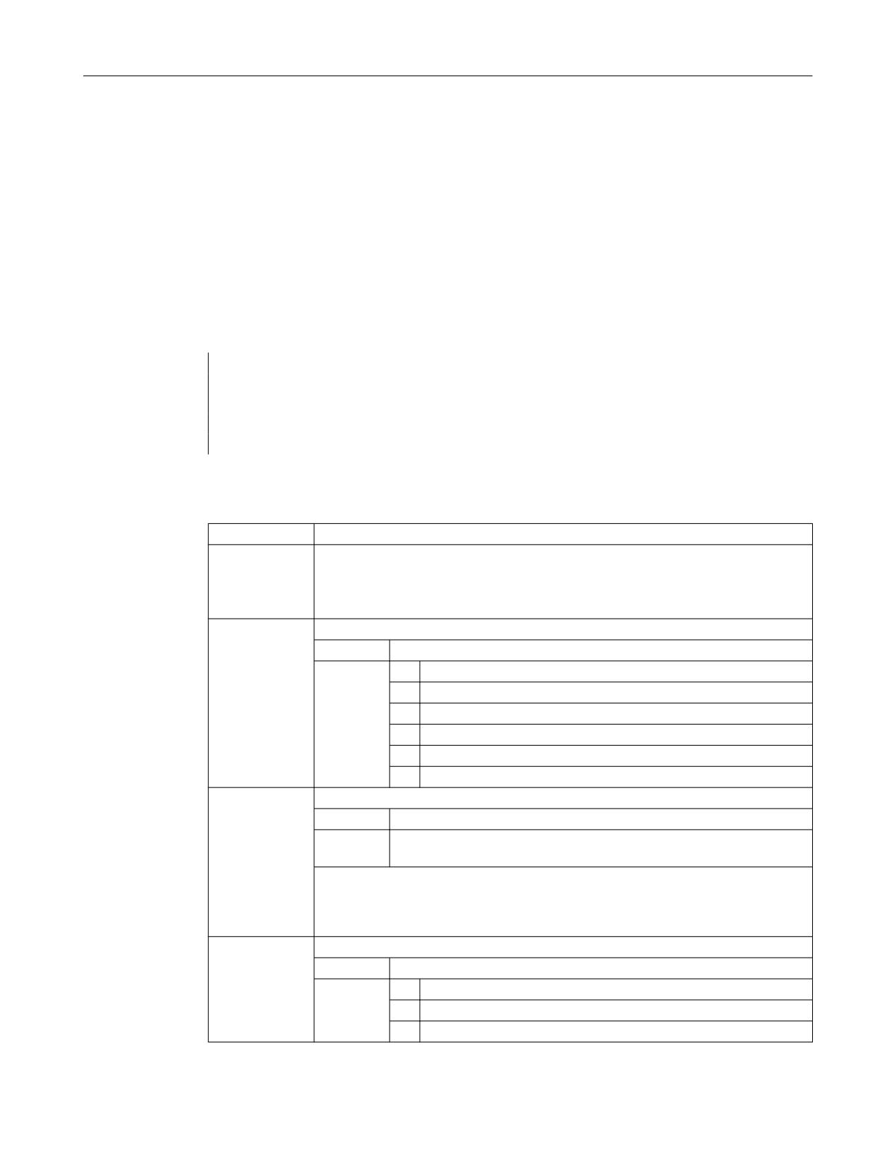
25.2 Parameterization
where <n> = number of the adaptation (0 ... 99)
Value
Meaning
0
Adaptation is not active (default setting)
1
Adaptation is permanently active
2
Adaptation can be activated temporarily
Input variable
The input variable of an adaptation is specified in machine data:
MD16502 $MN_CADAPT_INPUT[<n>]
where <n> = number of the adaptation (0 ... 99)
Value
Input variable
2
Axis position
3
Axis velocity or speed
Output variable
The selection of the output value of an adaptation is done via the machine data:
MD16503 $MN_CADAPT_OUTPUT[<n>]
where <n> = number of the adaptation (0 ... 99)
Value
Meaning
0
No output variable, no adaptation active (default setting)
11
Position controller gain (servo gain factor)
12
Moment of inertia for torque feedforward control
21
Drive adaptation factor 1
22
Drive adaptation factor 2
23
Drive adaptation factor 3
24
Drive adaptation factor 4
Drive adaptation factor 1 ... 4
A maximum of 4 drive variables from parameter p2782[0...3] "Mode adaptation" can be
adapted:
• Kp speed controller P gain adaptation speed
• Tn speed controller integral time adaptation speed
• Current setpoint filter 1 denominator and numerator
• Current setpoint filter 2 denominator and numerator
• Speed setpoint filter 1 denominator and numerator
• Speed controller reference model natural frequency and damping
Axes and spindles
Function Manual, 10/2020, 6FC5397-4GP40-0BA1
987

Intelligent dynamic control (option)
25.2 Parameterization
• APC / APC ECO Tv (p3769)
• APC / APC ECO filter (p3766)
Note
The adaptation of drive variables requires use of telegram 146, 148, or 149.
More information:
• For information about adapting drive variables, see "SINAMICS S120 Drive Functions
Function Manual".
• For information about telegram 146/148/149, see "SINAMICS S120 Function Manual,
Communication".
Machine axis number of the input variable
The input variable of an adaptation is assigned to a machine axis using machine data:
MD16504 $MN_CADAPT_INPUT_AX[<n>]
where <n> = number of the adaptation (0 ... 99)
Value
Meaning
0
No machine axis assigned, adaptation is not active (default setting)
1 ... 31
Number of the assigned machine axis
Machine axis number of the output variable
The output variable of an adaptation is assigned to a machine axis using machine data:
MD16505 $MN_CADAPT_OUTPUT_AX[<n>]
where <n> = number of the adaptation (0 ... 99)
Value
Meaning
0
No machine axis assigned, adaptation is not active (default setting)
1 ... 31
Number of the assigned machine axis
Adaptation characteristic
The characteristic curve of an adaptation is defined by interpolation points, which result from
specifying fixed position or speed values and the associated scaling factors (0% ... 3000%) for the
output value. The values between the interpolation points are interpolated linearly.
Two interpolation points are sufficient for a simple adaptation:
• MD16506 $MN_CADAPT_INPUT_VALUE_1[<n>] (input value 1 of the adaptation)
• MD16507 $MN_CADAPT_INPUT_VALUE_2[<n>] (input value 2 of adaptation)
• MD16508 $MN_CADAPT_OUTPUT_VALUE_1[<n>] (output value 1 of the adaptation)
• MD16509 $MN_CADAPT_OUTPUT_VALUE_2[<n>] (output value 2 of adaptation)
Axes and spindles
988
Function Manual, 10/2020, 6FC5397-4GP40-0BA1
Intelligent dynamic control (option)
25.3 Programming
25.3
Programming
25.3.1
Activate/deactivate adaptation (CADAPTON, CADAPTOF)
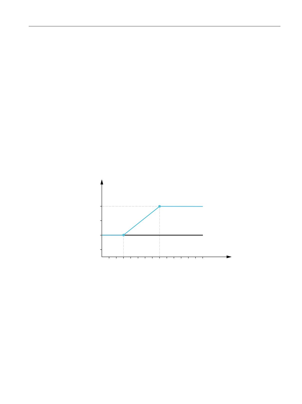
Using the predefined CADAPTON() and CADAPTOF() procedures, predefined adaptations for
adjusting the dynamic response or control parameters can be activated, updated and
deactivated from the part program. They are also used in CYCLE782 (Page 979).
Syntax
CADAPTON(<Result>,<Axis>,<InVar>[,<InValue>])
CADAPTOF(<Result>,<Axis>,<InVar>)
Meaning
CADAPTON():
Activates adaptation relationship
CADAPTOF():
Deactivates adaptation relationship
Note:
Ignore active adaptation relationship (MD16501 = 1) CADAPTOF(), a previously pro-
grammed input value (<InVal>) remains active.
<Result>:
Result variable: Return value for the status (called by reference parameter)
Data type:
INT
Value:
0
No error
1
No valid adaptation table parameterized
2
<Axis> parameter invalid
3
<InVar> parameter invalid
4
Reserved
5
<InVal> parameter invalid
<Axis>:
Machine axis name of the input axis of the adaptation relationship
Data type:
AXIS
Range of
Machine axis names defined in the channel
values:
Note:
Using this parameter, those adaptations are addressed, which, in MD16504 $MN_CA-
DAPT_INPUT_AX, entered a value corresponding to parameter <Axis>. The
other <InVar> and <InVal> parameters are assigned to this axis.
<InVar>:
Input variable of the adaptation relationship
Data type:
INT
Value:
1
Inertia of the axis
2
Axis position:
3
Axis speed
Axes and spindles
Function Manual, 10/2020, 6FC5397-4GP40-0BA1
989

Intelligent dynamic control (option)
25.3 Programming
<InVal>:
Input value of the adaptation relationship
Optional parameter for intelligent load adjustment (<InVar>=1).
Data type:
REAL
Value:
> 0
Actual moment of inertia
= 0
Load/loading is not defined or is not known. In this particular case,
the assigned adaptations supply substitute value 1.0 as output var-
iable.
< 0
The call is exited with <Status> = 5 (parameter <InVal> invalid).
The last input value activated remains active.
Note:
If an input value is not programmed, the last programmed value or the default value
(= 0) after the control system has run up is active.
Example
Program code
Comment
DEF INT RESULT
; Definition of result variables
CADAPTON(RESULT,MX1,2)
; Activate adaptation
IF RESULT <> 0
; Evaluate the result variables (this is
required after each CADAPTON/CADAPTOF in-
struction)
MSG("CADAPT-RESULT=" << RESULT)
STOPRE
SETAL(61000)
ENDIF
CADAPTOF(RESULT,MX1,2)
; Deactivate adaptation
; Evaluate result variables
Further information
Link axes
The function cannot be applied to link axes (NCU-Link function). In this case, the result variable
would supply return value 2 ("Parameter <Axis> invalid").
Axes and spindles
990
Function Manual, 10/2020, 6FC5397-4GP40-0BA1
Intelligent dynamic control (option)
25.4 Example
Block search
• Block search without calculation
CADAPTON/CADAPTOF instructions that are programmed between the beginning of the
program and target block are ignored. Users must select the search target so that the
adaptations relevant for the machining section are selected.
• Block search with calculation at the contour or at block end point
The activation and/or deactivation commands - as well as possible programmed input values
- are collected, and the actual status at the end of the search is output with the search action
blocks.
• Block search with calculation in Program test (SERUPRO) mode
When SERUPRO is deactivated, the status of the adaptations achieved using the CADAPTON/
CADAPTOF instructions is transitioned into real operation.
25.4
Example
The position controller gain of a linear axis should be temporarily adapted to the position using
the "Intelligent Dynamic Control" function. The following characteristic curve should be the
basis of the adaptation:
3RVLWLRQ
FRQWUROOHU JDLQ
>
@
ZLWK DGDSWDWLRQ
ZLWKRXW DGDSWDWLRQ
3
3
3RVLWLRQ >PP@
Configuration
MD16501 $MN_CADAPT_MODE[0] = 2 ; The 1st adaptation should be temporarily activatable.
MD16502 $MN_CADAPT_INPUT[0] = 2 ; The input value of the 1st adaptation is the axis position.
MD16503 $MN_CADAPT_OUTPUT[0] = 11 ; The output value of the 1st adaptation is the
position controller gain.
MD16504 $MN_CADAPT_INPUT_AX[0] = 3 ; The input value of the 1st adaptation is assigned to
the 3rd machine axis (AX3).
MD16505 $MN_CADAPT_OUTPUT_AX[0] = 3 ; The output value of the 1st adaptation is assigned
to the 3rd machine axis (AX3).
MD16506 $MN_CADAPT_INPUT_VALUE_1[0] = 300 ; The input value 1 of the 1st adaptation is
the position 300 mm of axis AX3.
Axes and spindles
Function Manual, 10/2020, 6FC5397-4GP40-0BA1
991
Intelligent dynamic control (option)
25.4 Example
MD16507 $MN_CADAPT_INPUT_VALUE_2[0] = 800 ; Input value 2 of the 1st adaptation is the
position 800 mm of axis AX3.
MD16508 $MN_CADAPT_OUTPUT_VALUE_1[0] = 100 ; The output value 1 of the 1st adaptation
is 100%.
MD16509 $MN_CADAPT_OUTPUT_VALUE_2[0] = 120 ; The output value 2 of the 1st adaptation
is 200%.
Activation / deactivation
Program code
Comment
DEF INT RESULT
; Definition of result variables
CADAPTON(RESULT,AX3,2)
; Activate position adaptations for the
axis AX3.
IF RESULT <> 0
; Evaluate result variables.
MSG("CADAPT-RESULT=" << RESULT)
STOPRE
SETAL(61000)
ENDIF
CADAPTOF(RESULT,AX3,2)
; Deactivate position adaptations for the
axis AX3.
; Evaluate result variables
Axes and spindles
992
Function Manual, 10/2020, 6FC5397-4GP40-0BA1

Preface
Fundamental safety
1
instructions
2
Introduction
Mode group, channel,
SINUMERIK
program operation, reset
3
response
Axes, coordinate systems,
SINUMERIK 840D sl
4
frames
Basic functions
5
Kinematic chain
Continuous-path mode,
6
exact stop, LookAhead
Function Manual
Cross-channel program
coordination and channel-
7
by-channel running-in
Cross-channel axis
8
interchange
9
Preprocessing
10
Measurement
11
Emergency stop
Various NC/PLC interface
12
signals and functions
Auxiliary function outputs
13
to PLC
14
Digital and analog NC I/O
15
Distributed systems
16
Memory configuration
A
Appendix
Valid for
control system
SINUMERIK 840D sl / 840DE sl
CNC software Version 4.94
10/2020
6FC5397-2GP40-0BA1
Table of contents
Preface
3
1
Fundamental safety instructions
21
1.1
General safety instructions
21
1.2
Warranty and liability for application examples
21
1.3
Security information
21
2
Introduction
23
2.1
About this documentation
23
3
Mode group, channel, program operation, reset response
25
3.1
Product brief
25
3.2
Mode group
27
3.2.1
Mode group stop
30
3.2.2
Mode group reset
30
3.3
Mode types and mode type change
31
3.3.1
Monitoring functions and interlocks of the individual modes
36
3.3.2
Mode change
36
3.4
Channel
37
3.4.1
Properties
37
3.4.2
Start inhibit, global and channel-specific
40
3.5
Program operation
41
3.5.1
Program operation mode
41
3.5.2
Initial settings
41
3.5.2.1
Machine data
42
3.5.2.2
Programming
43
3.5.3
Selection and start of an NC program
46
3.5.4
Program interruption
48
3.5.5
Channel reset
49
3.5.6
Program status
50
3.5.7
Channel status
51
3.5.8
Responses to operator and program actions
52
3.5.9
Example of a timing diagram for a program run
53
3.5.10
Program jumps
54
3.5.10.1
Return jump to the start of the program (GOTOS)
54
3.5.11
Program section repetitions
56
3.5.11.1
Programming
56
3.5.12
Event-driven program call (PROG_EVENT)
62
3.5.12.1
Function
62
3.5.12.2
Parameterization
66
3.5.12.3
Programming
70
3.5.12.4
Boundary conditions
71
3.5.12.5
Examples
71
Basic functions
Function Manual, 10/2020, 6FC5397-2GP40-0BA1
5
Table of contents
3.5.13
Influencing the stop events by stop delay areas
73
3.5.13.1
Function
73
3.5.13.2
Parameterization
75
3.5.13.3
Programming
76
3.5.13.4
Supplementary conditions
78
3.5.14
Adapting the size of the interpolation buffer
79
3.5.15
Basic block display (only for ShopMill/ShopTurn)
81
3.5.15.1
Function
81
3.5.15.2
Parameterization
81
3.5.15.3
Structure for a DIN block
84
3.6
Program control
87
3.6.1
Overview
87
3.6.2
Program test
89
3.6.3
Dry run feedrate
92
3.6.4
Reduced rapid traverse
94
3.6.5
Programmed stop
94
3.6.6
Handwheel offset
95
3.6.7
Skipping program blocks
96
3.6.8
Single block
99
3.6.8.1
Function
99
3.6.8.2
Selecting and activating
100
3.6.8.3
Parameterization
100
3.6.8.4
Programming
101
3.6.8.5
Constraints
106
3.6.9
Mode group-specific single block type A / B
106
3.6.10
Configured stop
108
3.6.10.1
Function
108
3.6.10.2
Selecting and activating
109
3.6.10.3
Parameter assignment
110
3.6.10.4
Programming
112
3.6.10.5
Constraints
112
3.6.10.6
Examples
113
3.6.11
Status
117
3.7
Block search, types 1, 2, and 4:
117
3.7.1
Description of the function
119
3.7.2
Block search in connection with other NCK functions
121
3.7.2.1
ASUB after and during block search
121
3.7.2.2
PLC actions after block search
122
3.7.2.3
Spindle functions after block search
123
3.7.2.4
Reading system variables for a block search
124
3.7.3
Automatic start of an ASUB after a block search
124
3.7.4
Cascaded block search
126
3.7.5
Examples for block search with calculation
127
3.7.6
Constraints
131
3.8
Block search Type 5 (SERUPRO)
131
3.8.1
Description of the function
131
3.8.2
Repositioning to the contour (REPOS)
135
3.8.2.1
Repositioning with controlled REPOS
142
3.8.3
Accelerate block search
143
3.8.4
SERUPRO ASUB
145
3.8.5
Selfacting SERUPRO
148
Basic functions
6
Function Manual, 10/2020, 6FC5397-2GP40-0BA1
Table of contents
3.8.6
Locking a program section for "Continue machining at the contour"
149
3.8.7
Behavior during POWER ON, mode change and RESET
152
3.8.8
Supplementary conditions
153
3.8.8.1
STOPRE in the target block
153
3.8.8.2
SPOS in target block
154
3.8.8.3
Travel to fixed stop (FXS)
154
3.8.8.4
Travel with limited torque/force (FOC)
155
3.8.8.5
Synchronous spindle
155
3.8.8.6
Couplings and master-slave
156
3.8.8.7
Axis functions
159
3.8.8.8
Gear stage change
160
3.8.8.9
Superimposed motion
161
3.8.8.10
NC/PLC interface signals
161
3.8.8.11
Making the initial settings more flexible
162
3.8.8.12
Compressor functions
162
3.8.9
System variable
162
3.9
Asynchronous subprograms (ASUPs)
163
3.9.1
Function
163
3.9.1.1
Execution sequence of an ASUP in program mode
165
3.9.1.2
ASUP with REPOSA
165
3.9.1.3
NC response
166
3.9.2
Commissioning: Machine data
167
3.9.2.1
NC-spec.: Mode-group-specific NC/PLC interface signals and operating mode switchover... 167
3.9.2.2
NC-spec.: ASUP start enable
168
3.9.2.3
NC-spec.: Effectiveness of the parameterized start enables
169
3.9.2.4
Channel-spec.: Start enable despite non-referenced axes
170
3.9.2.5
Channel-spec.: Start enable despite read-in disable
170
3.9.2.6
Channel-spec.: Continuous execution despite single block
170
3.9.2.7
Channel-spec.: Refreshing the display
171
3.9.3
Programming: System variables
172
3.9.3.1
REPOS option ($P_REPINF)
172
3.9.3.2
Activation event ($AC_ASUP)
172
3.9.4
Programming (SETINT, PRIO)
172
3.9.5
Restrictions
174
3.9.6
Examples
175
3.10
User-specific ASUB for RET and REPOS
176
3.10.1
Function
176
3.10.2
Parameter assignment
176
3.10.3
Programming
177
3.11
Perform ASUB start for user alarms
178
3.11.1
Function
178
3.11.2
Activation
179
3.11.3
Examples
180
3.11.3.1
User ASUB from reset - example 1
180
3.11.3.2
User ASUB from reset - example 2
181
3.11.3.3
User ASUB with M0
182
3.11.3.4
User ASUB with stop
183
3.11.3.5
User ASUB from stopped
184
3.12
Execution from external
185
3.13
Executing external subprograms (EXTCALL)
187
Basic functions
Function Manual, 10/2020, 6FC5397-2GP40-0BA1
7
Table of contents
3.14
Execution from external storage (EES) (option)
190
3.14.1
Function
190
3.14.2
Commissioning
193
3.14.2.1
Configuring the drives
193
3.14.2.2
Global part program memory (GDIR)
195
3.14.2.3
Settings for file handling in the part program for EES
197
3.14.2.4
Memory configuration
198
3.14.3
Supplementary conditions
199
3.15
Process Datashare - output to an external device/file
199
3.15.1
Function
199
3.15.2
Commissioning
200
3.15.3
Programming
203
3.15.4
Supplementary conditions
207
3.16
System settings for power-up, RESET / part program end and part program start
207
3.16.1
System settings for power-up, RESET / part program end and part program start
207
3.16.2
Tool withdrawal after POWER ON with orientation transformation
212
3.17
Replacing functions by subprograms
215
3.17.1
Overview
215
3.17.2
Replacement of M, T/TCA and D/DL functions
216
3.17.2.1
Replacement of M functions
216
3.17.2.2
Replacing T/TCA and D/DL functions
218
3.17.2.3
System variable
220
3.17.2.4
Example: Replacement of an M function
222
3.17.2.5
Example: Replacement of a T and D function
224
3.17.2.6
Behavior in the event of a conflict
226
3.17.3
Replacement of spindle functions
227
3.17.3.1
General information
227
3.17.3.2
Replacement of M40 - M45 (gear stage change)
228
3.17.3.3
Replacement of SPOS, SPOSA, M19 (spindle positioning)
229
3.17.3.4
System variable
230
3.17.3.5
Example: Gear stage change
231
3.17.3.6
Example: Spindle positioning
233
3.17.4
Properties of the subprograms
236
3.17.5
Restrictions
237
3.18
Renaming/locking NC commands
238
3.19
Program runtime / part counter
239
3.19.1
Program runtime
239
3.19.1.1
Function
239
3.19.1.2
Commissioning
242
3.19.1.3
Supplementary conditions
244
3.19.1.4
Examples
244
3.19.2
Workpiece counter
245
3.19.2.1
Function
245
3.19.2.2
Commissioning
246
3.19.2.3
Supplementary conditions
247
3.19.2.4
Examples
248
3.20
Program simulation
249
3.20.1
Function
249
3.20.2
Program simulation in conjunction with compile cycles
250
Basic functions
8
Function Manual, 10/2020, 6FC5397-2GP40-0BA1
Table of contents
3.21
Data lists
251
3.21.1
Machine data
251
3.21.1.1
General machine data
251
3.21.1.2
Channel-specific machine data
252
3.21.1.3
Axis/spindlespecific machine data
255
3.21.2
Setting data
256
3.21.2.1
Channelspecific setting data
256
4
Axes, coordinate systems, frames
257
4.1
Brief description
257
4.1.1
Axes
257
4.1.2
Coordinate systems
259
4.1.3
Frames
260
4.2
Axes
263
4.2.1
Overview
263
4.2.2
Machine axes
264
4.2.3
Channel axes
265
4.2.4
Geometry axes
265
4.2.5
Special axes
265
4.2.6
Path axes
266
4.2.7
Positioning axes
266
4.2.8
Main axes
267
4.2.9
Synchronized axes
268
4.2.10
Axis configuration
270
4.2.11
Link axes
272
4.3
Zero points and reference points
273
4.3.1
Reference points in working space
273
4.3.2
Position of coordinate systems and reference points
275
4.4
Coordinate systems
276
4.4.1
Overview
276
4.4.2
Machine coordinate system (MCS)
278
4.4.2.1
Actual value setting with loss of the referencing status (PRESETON)
279
4.4.2.2
Actual value setting without loss of the referencing status (PRESETONS)
284
4.4.3
Basic coordinate system (BCS)
289
4.4.4
Basic zero system (BZS)
291
4.4.5
Settable zero system (SZS)
293
4.4.6
Workpiece coordinate system (WCS)
294
4.4.7
Additive offsets
295
4.4.7.1
External work offsets
295
4.4.7.2
DRF offset
296
4.4.7.3
Reset behavior
296
4.4.8
Axis-specific overlay ($AA_OFF)
297
4.4.8.1
Function
297
4.4.8.2
Commissioning
297
4.4.8.3
Programming: Deselecting overlays axis-specifically (CORROF)
298
4.5
Frames
301
4.5.1
Frame types
301
4.5.2
Frame components
302
4.5.2.1
Translation
302
4.5.2.2
Fine offset
303
Basic functions
Function Manual, 10/2020, 6FC5397-2GP40-0BA1
9
Table of contents
4.5.2.3
Rotation Overview (geometry axes only)
304
4.5.2.4
Rotation with a Euler angles: ZY'X" convention (RPY angles)
305
4.5.2.5
Rotation with a Euler angles: ZX'Z" convention
310
4.5.2.6
Rotation in any plane
311
4.5.2.7
Scaling
312
4.5.2.8
Mirroring
312
4.5.2.9
Chain operator
313
4.5.2.10
Programmable axis name
313
4.5.2.11
Coordinate transformation
314
4.5.3
Data management frames and active frames
314
4.5.3.1
Overview
314
4.5.3.2
Activating data management frames
316
4.5.3.3
NCU-global and channel-specific frames
317
4.5.4
Frame chain and coordinate systems
318
4.5.4.1
Overview
318
4.5.4.2
Relative coordinate systems
319
4.5.4.3
Selectable SZS
321
4.5.4.4
Manual traversing of geometry axes either in the WCS or in the SZS ($AC_JOG_COORD) ...
321
4.5.4.5
Suppression of frames
322
4.5.5
Frames of the frame chain
323
4.5.5.1
Overview
323
4.5.5.2
Settable frames ($P_UIFR[<n>])
324
4.5.5.3
Grinding frames $P_GFR[<n>]
326
4.5.5.4
Channel-specific basic frames[<n>]
330
4.5.5.5
NCU-global basic frames $P_NCBFR[<n>]
331
4.5.5.6
Active complete basic frame $P_ACTBFRAME
332
4.5.5.7
Programmable frame $P_PFRAME
333
4.5.5.8
Channelspecific system frames
335
4.5.6
Implicit frame changes
337
4.5.6.1
Switching geometry axes
337
4.5.6.2
Selecting and deselecting transformations: General
340
4.5.6.3
Selecting and deselecting transformations: TRANSMIT
341
4.5.6.4
Selecting and deselecting transformations: TRACYL
347
4.5.6.5
Selecting and deselecting transformations: TRAANG
352
4.5.6.6
Adapting active frames
358
4.5.6.7
Mapped Frames
358
4.5.6.8
Mapped Frames
363
4.5.7
Predefined frame functions
366
4.5.7.1
Inverse frame
366
4.5.7.2
Additive frame in frame chain
369
4.5.8
Functions
370
4.5.8.1
Setting zeros, workpiece measuring and tool measuring
370
4.5.8.2
Axis-specific external work offset
370
4.5.8.3
Toolholder
371
4.5.9
Subprograms with SAVE attribute (SAVE)
381
4.5.10
Data backup
382
4.5.11
Positions in the coordinate system
383
4.5.12
Control system response
383
4.5.12.1
POWER ON
383
4.5.12.2
Mode change
384
4.5.12.3
Channel reset / part program end
384
4.5.12.4
Part program start
388
Basic functions
10
Function Manual, 10/2020, 6FC5397-2GP40-0BA1
Table of contents
4.5.12.5
Block search
388
4.5.12.6
REPOS
388
4.6
Workpiece-related actual-value system
389
4.6.1
Overview
389
4.6.2
Use of the workpiece-related actual value system
389
4.6.3
Special reactions
391
4.7
Boundary conditions
392
4.8
Examples
393
4.8.1
Axes
393
4.8.2
Coordinate systems
395
4.8.3
Frames
396
4.9
Data lists
398
4.9.1
Machine data
398
4.9.1.1
Displaying machine data
398
4.9.1.2
NC-specific machine data
399
4.9.1.3
Channel-specific machine data
399
4.9.1.4
Axis/spindlespecific machine data
400
4.9.2
Setting data
400
4.9.2.1
Channelspecific setting data
400
4.9.3
System variables
401
5
Kinematic chain
403
5.1
Function description
403
5.1.1
Characteristics
403
5.2
Commissioning
407
5.2.1
General
407
5.2.1.1
Overview
407
5.2.1.2
Structure of the system variables
408
5.2.2
Machine data
409
5.2.2.1
Maximum number of elements
409
5.2.2.2
Root element
409
5.2.2.3
Maximum number of switches
409
5.2.3
System variables
410
5.2.3.1
Overview
410
5.2.3.2
$NK_NAME
411
5.2.3.3
$NK_NEXT
412
5.2.3.4
$NK_PARALLEL
413
5.2.3.5
$NK_TYPE
414
5.2.3.6
Type-dependent variables for $NK_TYPE = "AXIS_LIN"
415
5.2.3.7
Type-dependent variables for $NK_TYPE = "AXIS_ROT"
418
5.2.3.8
Type-dependent variables for $NK_TYPE = "ROT_CONST"
421
5.2.3.9
Type-dependent variables for $NK_TYPE = "OFFSET"
423
5.2.3.10
Type-dependent variables for $NK_TYPE = "SWITCH"
425
5.2.3.11
$NK_SWITCH
427
5.3
Programming
428
5.3.1
Deletion of components (DELOBJ)
428
5.3.2
Index determination by means of names (NAMETOINT)
431
5.4
Example
432
5.4.1
Specifications
432
Basic functions
Function Manual, 10/2020, 6FC5397-2GP40-0BA1
11
Table of contents
5.4.2
Part program of the machine model
434
5.5
Data lists
437
5.5.1
Machine data
437
5.5.1.1
NC-specific machine data
437
5.5.2
System variables
437
6
Continuous-path mode, exact stop, LookAhead
439
6.1
Brief Description
439
6.2
Exact stop mode
441
6.3
Continuous-path mode
446
6.3.1
General functionality
446
6.3.2
Velocity reduction according to overload factor
447
6.3.3
Rounding
449
6.3.3.1
Rounding according to a path criterion (G641)
452
6.3.3.2
Rounding in compliance with defined tolerances (G642/G643)
454
6.3.3.3
Rounding with maximum possible axial dynamic response (G644)
457
6.3.3.4
Rounding of tangential block transitions (G645)
459
6.3.3.5
Rounding and repositioning (REPOS)
461
6.3.4
LookAhead
462
6.3.4.1
Standard functionality
462
6.3.4.2
Free-form surface mode: Extension function
468
6.4
Dynamic adaptations
472
6.4.1
Smoothing of the path velocity
472
6.4.2
Adaptation of the dynamic path response
475
6.4.3
Determination of the dynamic response limiting values
480
6.4.4
Interaction between the "smoothing of the path velocity" and "adaptation of the path
dynamic response" functions
481
6.4.5
Dynamic response mode for path interpolation
484
6.4.6
Free-form surface mode: Basic functions
486
6.5
Compressor functions
490
6.5.1
Compression of linear, circular and rapid traverse blocks
490
6.5.1.1
Function
490
6.5.1.2
Commissioning
492
6.5.1.3
Programming
494
6.5.1.4
Supplementary conditions
495
6.5.2
Compression of short spline blocks
495
6.6
Contour/Orientation tolerance
497
6.6.1
Commissioning
497
6.6.1.1
Parameter assignment
497
6.6.2
Programming
498
6.6.2.1
Programming contour/orientation tolerance (CTOL, OTOL, ATOL)
498
6.6.2.2
Programming contour/orientation tolerance (CTOL, OTOL, ATOL) Additional information...
501
6.7
Rapid traverse movements
502
6.7.1
Function
502
6.7.1.1
Rapid traverse
502
6.7.1.2
Interpolation response of path axes for rapid traversing movements
504
6.7.1.3
Tolerances for rapid traverse movements
505
6.7.1.4
Rapid traverse override
506
6.7.2
Commissioning
506
Basic functions
12
Function Manual, 10/2020, 6FC5397-2GP40-0BA1
Table of contents
6.7.2.1
Parameter assignment
506
6.7.3
Programming
508
6.7.3.1
Activating rapid traverse (G0)
508
6.7.3.2
Switch on/off linear interpolation for rapid traverse movements (RTLION, RTLIOF)
509
6.7.3.3
Adapt tolerances for rapid traverse motion (STOLF, CTOLG0, OTOLG0)
511
6.8
RESET behavior
514
6.9
Supplementary conditions
515
6.9.1
Block change and positioning axes
515
6.9.2
Block change delay
515
6.10
Data lists
516
6.10.1
Machine data
516
6.10.1.1
General machine data
516
6.10.1.2
Channelspecific machine data
516
6.10.1.3
Axis/spindlespecific machine data
517
6.10.2
Setting data
518
6.10.2.1
Channelspecific setting data
518
7
Cross-channel program coordination and channel-by-channel running-in
519
7.1
Cross-channel program coordination
519
7.1.1
Cross-channel program coordination (INIT, START, WAITM, WAITMC, WAITE, SETM,
CLEARM)
519
7.1.2
Conditional wait (WAITMC) in the continuous path mode
524
7.2
Running-in channel-by-channel
528
7.2.1
Function
528
7.2.2
Sequence
529
7.2.3
Single-channel view
529
7.2.4
Multi-channel view
531
7.2.5
System variables
534
7.2.6
Supplementary conditions
534
7.2.7
Examples
535
7.3
Supplementary conditions
536
7.3.1
MDI mode: Path control mode and WAITMC
536
7.3.2
Non-synchronous start of traversing motion after WAIT commands
537
8
Cross-channel axis interchange
539
8.1
Overview
539
8.2
Commissioning
539
8.3
Programming: Releasing an axis (RELEASE)
540
8.4
Programming: Fetching an axis (GET, GETD)
541
8.5
Automatic axis replacement
543
8.6
Axis replacement via PLC
544
8.7
Axis interchange via axis container rotation
547
8.8
Axis replacement with and without preprocessing stop
547
8.9
Axis exclusively controlled from the PLC
549
8.10
Axis permanently assigned to the PLC
550
Basic functions
Function Manual, 10/2020, 6FC5397-2GP40-0BA1
13
Table of contents
8.11
Geometry axis in rotated frame and axis replacement
551
8.12
Axis replacement from synchronized actions
552
8.13
Axis interchange for leading axes (gantry)
555
8.14
State diagram
555
8.15
Boundary conditions
556
8.15.1
Axis replacement by PLC
557
8.15.2
Block search with calculation
557
8.16
Example
557
8.17
Data lists
559
8.17.1
Machine data
559
8.17.1.1
General machine data
559
8.17.1.2
Channel-specific machine data
559
8.17.1.3
Axis/spindlespecific machine data
561
8.17.2
Setting data
562
8.17.2.1
Channelspecific setting data
562
9
Preprocessing
563
9.1
Brief description
563
9.2
Program handling
565
9.3
Program call
567
9.4
Constraints
569
9.5
Examples
570
9.5.1
Preprocessing individual files
570
9.5.2
Preprocessing in the dynamic NC memory
572
9.6
Data lists
572
9.6.1
Machine data
572
9.6.1.1
General machine data
572
9.6.1.2
Channelspecific machine data
573
10
Measurement
575
10.1
Brief description
575
10.2
Probes that can be used
577
10.3
Measurement level 1: Channel-specific measurement
578
10.4
Measurement level 2: Axis-specific measurement (option)
581
10.5
Workpiece and tool measurement
589
10.5.1
Fundamentals
589
10.5.1.1
Introduction
589
10.5.1.2
Input variables
590
10.5.1.3
Selecting the measurement type
598
10.5.1.4
Activating the calculation
599
10.5.1.5
Output variables
600
10.5.1.6
System of units
601
10.5.1.7
Diagnostics
603
10.5.2
Types of workpiece measurement
604
Basic functions
14
Function Manual, 10/2020, 6FC5397-2GP40-0BA1
Table of contents
10.5.2.1
Measurement type 1, 2, 3: Measurement of an edge
604
10.5.2.2
Measurement type 4, 5, 6, 7: Measurement of a corner
609
10.5.2.3
Measurement type 8: Measurement of a hole
613
10.5.2.4
Measurement type 9: Measurement of a shaft
616
10.5.2.5
Measurement type 12: Measurement of a groove
617
10.5.2.6
Measurement type 13: Measurement of a web
620
10.5.2.7
Measurement type 14: Preset actual value for geometry and special axes
621
10.5.2.8
Measurement type 15: Preset actual value for special axes only
622
10.5.2.9
Measurement type 16: Measurement of an inclined edge
623
10.5.2.10
Measurement type 17: Measurement of an angle in an inclined plane
625
10.5.2.11
Measurement type 18: Redefining the WCS on the inclined plane
628
10.5.2.12
Measurement type 19: 1-dimensional setpoint specification
631
10.5.2.13
Measurement type 20: 2-dimensional setpoint specification
633
10.5.2.14
Measurement type 21: 3-dimensional setpoint specification
634
10.5.2.15
Measurement type 24: Coordinate transformation of a measuring point
635
10.5.2.16
Measurement type 25: Measurement of a rectangle
639
10.5.2.17
Measurement type 26: Backup of data management frames
640
10.5.2.18
Measurement type 27: Restoration of backed up data management data
641
10.5.2.19
Measurement type 28: Specification of an additive rotation for taper turning
642
10.5.3
Measuring types of the tool measurement
643
10.5.3.1
Overview
643
10.5.3.2
Measurement type 10: Measurement of the tool length
643
10.5.3.3
Measurement type 11: Measurement of the tool diameter
645
10.5.3.4
Measurement type 22: Measurement of tool lengths with zoom-in function
647
10.5.3.5
Measurement type 23: Measurement of a tool length with a stored or actual position
648
10.5.3.6
Measurement type 23: Measurement of a tool length of two tools with the following
orientation:
649
10.6
Measurement accuracy and functional testing
661
10.6.1
Measurement accuracy
661
10.6.2
Probe function test
661
10.6.3
Repeat accuracy
662
10.7
Simulated measuring
663
10.7.1
General functionality
663
10.7.2
Position-related switch request
664
10.7.3
External switch request
665
10.7.4
System variable
666
10.8
Data lists
667
10.8.1
Machine data
667
10.8.1.1
General machine data
667
10.8.1.2
Channel-specific machine data
667
10.8.2
System variables
667
11
Emergency stop
671
11.1
Brief Description
671
11.2
Relevant standards
671
11.3
Emergency stop control elements
672
11.4
Emergency stop sequence
673
11.5
Emergency stop acknowledgement
674
Basic functions
Function Manual, 10/2020, 6FC5397-2GP40-0BA1
15
Table of contents
11.6
Data lists
676
11.6.1
Machine data
676
11.6.1.1
Axis/spindlespecific machine data
676
12
Various NC/PLC interface signals and functions
677
12.1
Brief description
677
12.2
Functions
677
12.2.1
Screen refresh behavior for overload
677
12.2.2
Activate DEFAULT memory
678
12.2.3
Read/write PLC variable
678
12.2.4
Access protection via password and keyswitch
681
12.2.4.1
Password
683
12.2.4.2
Keyswitch
686
12.2.4.3
Parameterizable protection levels
686
12.2.5
Switching over motor/drive data sets
687
12.2.5.1
General Information
687
12.2.5.2
Formatting interfaces
688
12.2.5.3
Request interface
688
12.2.5.4
Display interface
689
12.2.5.5
Example
689
12.2.5.6
Overview of the interfaces
690
12.2.5.7
Supplementary conditions
691
12.3
Examples
692
12.3.1
Parameter set changeover
692
12.4
Data lists
694
12.4.1
Machine data
694
12.4.1.1
Display machine data
694
12.4.1.2
NC-specific machine data
694
12.4.1.3
Channelspecific machine data
694
12.4.1.4
Axis/spindlespecific machine data
695
12.4.2
System variables
696
13
Auxiliary function outputs to PLC
697
13.1
Brief description
697
13.1.1
Function
697
13.1.2
Definition of an auxiliary function
698
13.1.3
Overview of the auxiliary functions
698
13.2
Predefined auxiliary functions
704
13.2.1
Overview: Predefined auxiliary functions
704
13.2.2
Overview: Output behavior
715
13.2.3
Parameterization
718
13.2.3.1
Group assignment
718
13.2.3.2
Type, address extension and value
719
13.2.3.3
Output behavior
720
13.3
Userdefined auxiliary functions
724
13.3.1
Parameterization
726
13.3.1.1
Maximum number of user-defined auxiliary functions
726
13.3.1.2
Group assignment
726
13.3.1.3
Type, address extension and value
726
Basic functions
16
Function Manual, 10/2020, 6FC5397-2GP40-0BA1
Table of contents
13.3.1.4
Output behavior
728
13.4
Associated auxiliary functions
728
13.5
Type-specific output behavior
730
13.6
Priorities of the output behavior for which parameters have been assigned
731
13.7
Programming an auxiliary function
732
13.8
Programmable output duration
734
13.9
Auxiliary function output to the PLC
735
13.10
Auxiliary functions without block change delay
736
13.11
M function with an implicit preprocessing stop
737
13.12
Response to overstore
737
13.13
Behavior during block search
738
13.13.1
Auxiliary function output during type 1, 2, and 4 block searches
738
13.13.2
Assignment of an auxiliary function to a number of groups
740
13.13.3
Time stamp of the active M auxiliary function
741
13.13.4
Determining the output sequence
741
13.13.5
Output suppression of spindle-specific auxiliary functions
743
13.13.6
Auxiliary function output with a type 5 block search (SERUPRO)
746
13.13.7
ASUB at the end of the SERUPRO
751
13.14
Implicitly output auxiliary functions
757
13.15
Information options
758
13.15.1
Group-specific modal M auxiliary function display
759
13.15.2
Querying system variables
760
13.16
Supplementary conditions
762
13.16.1
General constraints
762
13.16.2
Output behavior
763
13.17
Examples
764
13.17.1
Extension of predefined auxiliary functions
764
13.17.2
Defining auxiliary functions
766
13.18
Data lists
770
13.18.1
Machine data
770
13.18.1.1
NC-specific machine data
770
13.18.1.2
Channelspecific machine data
771
14
Digital and analog NC I/O
773
14.1
Introduction
773
14.2
Indirect I/O access via PLC
774
14.2.1
Brief description
774
14.2.2
Parameterization
775
14.2.3
System variables
778
14.2.4
Comparator inputs
778
14.2.5
Digital NC I/Os
778
14.2.5.1
Digital NC inputs
778
14.2.5.2
Digital NC outputs
780
14.2.5.3
Connection and logic operations of fast digital I/Os
782
Basic functions
Function Manual, 10/2020, 6FC5397-2GP40-0BA1
17
Table of contents
14.2.6
Analog NC I/Os
784
14.2.6.1
Analog NC inputs
784
14.2.6.2
Analog NC outputs
786
14.2.6.3
Representation of the analog I/O values
789
14.2.7
Comparator inputs
791
14.3
Direct I/O access via PLC
795
14.3.1
Parameterization
795
14.3.2
Reading/writing: System variables
797
14.3.3
Supplementary conditions
797
14.3.4
Examples
798
14.3.4.1
Writing to PLC-I/Os
798
14.3.4.2
Reading from PLC-I/Os
799
14.4
Direct I/O access without PLC
800
14.4.1
Brief description
800
14.4.2
Parameter assignment
802
14.4.3
Reading/writing
803
14.4.3.1
System variables
803
14.4.4
Supplementary conditions
805
14.4.5
Examples
806
14.4.5.1
Writing to the NC I/O
806
14.4.5.2
Reading from the NC I/O
807
14.4.5.3
Writing of the NC I/O with status query
809
14.5
Data lists
810
14.5.1
Machine data
810
14.5.1.1
General machine data
810
14.5.1.2
Channelspecific machine data
811
14.5.2
Setting data
811
14.5.2.1
General setting data
811
14.5.3
System variable
811
14.5.4
Signals
812
14.5.4.1
Signals to NC
812
14.5.4.2
Signals from NC
813
15
Distributed systems
815
15.1
Brief description
815
15.1.1
Several operator panels on several NCUs (T:M:N)
815
15.1.2
NCU link
817
15.1.2.1
Link communication
817
15.1.2.2
Link variables
818
15.1.2.3
Link axes
818
15.1.2.4
Lead link axes
819
15.1.2.5
Dependencies
819
15.1.2.6
Application example: Rotary indexing machine
820
15.2
NCU link
822
15.2.1
Link communication
822
15.2.1.1
General information
822
15.2.1.2
Link module
826
15.2.1.3
Parameter assignment: NC system cycles
827
15.2.1.4
Parameter assignment: Link communication
829
15.2.1.5
Configuration
829
Basic functions
18
Function Manual, 10/2020, 6FC5397-2GP40-0BA1
Table of contents
15.2.1.6
Wiring the NCUs
830
15.2.1.7
Activation
830
15.2.2
Link variables
831
15.2.2.1
Properties of the link variables memory
831
15.2.2.2
Properties of the link variables
832
15.2.2.3
Write elements
833
15.2.2.4
Dynamic response during write
833
15.2.2.5
System variable
833
15.2.2.6
Synchronization of a write request
834
15.2.2.7
Example: Structure of the link variables memory
835
15.2.2.8
Example: Read drive data
836
15.2.3
Link axes
837
15.2.3.1
General information
837
15.2.3.2
Name of a link axis
839
15.2.3.3
Parameterization
839
15.2.3.4
Auxiliary function output for spindles
840
15.2.3.5
Supplementary conditions
841
15.2.4
Axis container
843
15.2.4.1
General information
843
15.2.4.2
Parameterization
846
15.2.4.3
Programming
852
15.2.4.4
System variable
854
15.2.4.5
Machining with axis container (schematic)
855
15.2.4.6
Behavior in different operating states
855
15.2.4.7
Behavior when withdrawing the release for axis container rotation
856
15.2.4.8
Supplementary conditions
858
15.2.5
Lead link axes
860
15.2.5.1
General information
860
15.2.5.2
Parameterization
861
15.2.5.3
System variables to enter a leading value
862
15.2.5.4
Supplementary conditions
863
15.2.5.5
Example
863
15.2.6
System of units within a link group
863
15.3
Examples
864
15.3.1
Link axis
864
15.3.2
Axis container coordination
865
15.3.2.1
Axis container rotation without a part program wait
865
15.3.2.2
Axis container rotation with an implicit part program wait
866
15.3.2.3
Axis container rotation by one channel only (e.g. during power up)
866
15.3.3
Evaluating axis container system variables
866
15.3.3.1
Conditional branch
866
15.3.3.2
Static synchronized action with $AN_AXCTSWA
867
15.3.3.3
Wait for certain completion of axis container rotation
867
15.3.4
Configuration of a multi-spindle turning machine
868
15.3.5
Lead link axis
877
15.3.5.1
Configuration
877
15.3.5.2
Programming
878
15.4
Data lists
880
15.4.1
Machine data
880
15.4.1.1
General machine data
880
15.4.1.2
Channelspecific machine data
880
Basic functions
Function Manual, 10/2020, 6FC5397-2GP40-0BA1
19
Table of contents
15.4.1.3
Axis/spindlespecific machine data
880
15.4.2
Setting data
881
15.4.2.1
General setting data
881
15.4.2.2
Axis/spindle-specific setting data
881
15.4.3
Signals
881
15.4.3.1
Signals from NC
881
15.4.3.2
Signals from HMI/PLC
881
15.4.3.3
General online interface
882
15.4.3.4
Signals from axis/spindle
883
15.4.4
System variables
883
16
Memory configuration
885
16.1
Introduction
885
16.2
Active and passive file system
885
16.3
Commissioning
887
16.3.1
Configuration
887
16.3.2
Reconfiguration
887
16.4
Configuration of the static user memory
888
16.4.1
Division of the static NC memory
888
16.4.2
Commissioning
890
16.5
Configuration of the dynamic user memory
891
16.5.1
Division of the dynamic NC memory
891
16.5.2
Commissioning
893
16.6
Boundary conditions
893
16.6.1
Depending on the number of channels and tool carriers
893
16.6.2
Subsequent reduction of the number of channels and/or axes
894
16.7
Data lists
894
16.7.1
Machine data
894
16.7.1.1
General machine data
894
16.7.1.2
Channelspecific machine data
898
16.7.1.3
Axis/spindlespecific machine data
899
A
Appendix
901
A.1
List of abbreviations
901
A.2
Documentation overview
906
A.3
Available IPCs
906
Index
909
Basic functions
20
Function Manual, 10/2020, 6FC5397-2GP40-0BA1

Fundamental safety instructions
1
1.1
General safety instructions
WARNING
Danger to life if the safety instructions and residual risks are not observed
If the safety instructions and residual risks in the associated hardware documentation are not
observed, accidents involving severe injuries or death can occur.
• Observe the safety instructions given in the hardware documentation.
• Consider the residual risks for the risk evaluation.
WARNING
Malfunctions of the machine as a result of incorrect or changed parameter settings
As a result of incorrect or changed parameterization, machines can malfunction, which in turn
can lead to injuries or death.
• Protect the parameterization against unauthorized access.
• Handle possible malfunctions by taking suitable measures, e.g. emergency stop or
emergency off.
1.2
Warranty and liability for application examples
Application examples are not binding and do not claim to be complete regarding configuration,
equipment or any eventuality which may arise. Application examples do not represent specific
customer solutions, but are only intended to provide support for typical tasks.
As the user you yourself are responsible for ensuring that the products described are operated
correctly. Application examples do not relieve you of your responsibility for safe handling when
using, installing, operating and maintaining the equipment.
1.3
Security information
Siemens provides products and solutions with industrial security functions that support the
secure operation of plants, systems, machines and networks.
In order to protect plants, systems, machines and networks against cyber threats, it is necessary
to implement - and continuously maintain - a holistic, state-of-the-art industrial security
concept. Siemens’ products and solutions constitute one element of such a concept.
Customers are responsible for preventing unauthorized access to their plants, systems,
machines and networks. Such systems, machines and components should only be connected to
Basic functions
Function Manual, 10/2020, 6FC5397-2GP40-0BA1
21
Fundamental safety instructions
1.3 Security information
an enterprise network or the internet if and to the extent such a connection is necessary and only
when appropriate security measures (e.g. firewalls and/or network segmentation) are in place.
For additional information on industrial security measures that may be implemented, please
visit
Siemens’ products and solutions undergo continuous development to make them more secure.
Siemens strongly recommends that product updates are applied as soon as they are available
and that the latest product versions are used. Use of product versions that are no longer
supported, and failure to apply the latest updates may increase customer’s exposure to cyber
threats.
To stay informed about product updates, subscribe to the Siemens Industrial Security RSS Feed
under
services/cert.html#Subscriptions).
Further information is provided on the Internet:
Industrial Security Configuration Manual (https://support.industry.siemens.com/cs/ww/en/
view/108862708)
WARNING
Unsafe operating states resulting from software manipulation
Software manipulations, e.g. viruses, Trojans, or worms, can cause unsafe operating states in
your system that may lead to death, serious injury, and property damage.
• Keep the software up to date.
• Incorporate the automation and drive components into a holistic, state-of-the-art industrial
security concept for the installation or machine.
• Make sure that you include all installed products into the holistic industrial security concept.
• Protect files stored on exchangeable storage media from malicious software by with suitable
protection measures, e.g. virus scanners.
• On completion of commissioning, check all security-related settings.
Basic functions
22
Function Manual, 10/2020, 6FC5397-2GP40-0BA1

Introduction
2
2.1
About this documentation
This documentation is part of the documentation category of SINUMERIK Function Manuals.
SINUMERIK Function Manuals
The SINUMERIK Function Manuals describe the NC functions of a SINUMERIK control.
The target group are configuring engineers, technologists, commissioning engineers and
programmers.
Each Function Manual covers a specific topic and contains all the function descriptions for this
topic.
The following table shows which Function Manuals are available for your SINUMERIK control and
which topics a Function Manual covers:
Function Manual
Topic
Basic functions
Basic functions of a CNC control
Axes and spindles
Axis and spindle functions, axis couplings
Transformations
Transformation functions
Monitoring and compensating
Axis monitoring and compensation functions, collision avoid-
ance
Tools
Functions for selection, correction and monitoring of tools
Synchronized actions
Functionality of synchronized actions
PLC
Structure and functions of the PLC
Tool management
Function, commissioning and programming of tool manage-
ment
Technologies (for SINUMERIK ONE
Extended technological functionalities
and SINUMERIK 840D sl only)
Overview of contents
You will find an overview of the main chapters of the descriptions of functions that are contained
in a Function Manual on the title page.
Validity
The title page also contains all data about the validity of a document, i.e. for which SINUMERIK
control and for which software version this edition of the Function Manual is valid.
Basic functions
Function Manual, 10/2020, 6FC5397-2GP40-0BA1
23

Introduction
2.1 About this documentation
System data
In the descriptions of functions, the system data relevant for a function (machine data, setting
data, system variables, interface signals and alarms) are only described with the level of detail
that is strictly necessary to understand the function. You will find detailed information on this
data in the relevant List Manuals and for alarms in the Diagnostics Manual.
PLC blocks
The descriptions of functions often refer to the PLC function blocks (FB) and functions (FC). The
descriptions of these blocks apply to the SINUMERIK 840D sl and can only be applied in part to
other SINUMERIK controls.
Interface signals
In this document, only the absolute address valid for the SINUMERIK 840D sl is used to address
interface signals.
General graphical conventions
Examples
<signal address> (<signal name>)
DB31, ... DBX16.0-2 (actual gear stage A to C)
DB31, ... DBX16.3 (gear is changed)
Note
Quantity structure
Explanations concerning the NC/PLC interface are based on the absolute maximum number of
the following components:
• Mode groups (DB11)
• Channels (DB21, etc.)
• Axes/spindles (DB31, etc.)
Basic functions
24
Function Manual, 10/2020, 6FC5397-2GP40-0BA1
Mode group, channel, program operation, reset
response
3
3.1
Product brief
Channel
An NC channel represents the smallest unit for manual traversing of axes and automatic
processing of part programs. At any one time, a channel will always be in a particular mode, e.g.
AUTOMATIC, MDI, or JOG. A channel can be regarded as an independent NC.
Mode group
A channel always belongs to a mode group. A mode group can also consist of several channels.
A mode group can be identified by the fact that all channels of the mode group are always in the
same mode at a particular time, e.g. AUTOMATIC, MDI, or JOG. This is ensured through the NC
internal mode logic.
A mode group can be regarded as an independent multi-channel NC.
Channel gaps
When channels are configured, placeholder channels can be provided in order to create as
uniform a configuration as possible over machines in a series. Only the channels that are actually
used are then activated.
Program test
The following options are available for testing or moving in position a new part program.
• Program execution without setpoint outputs
• Program execution in singleblock mode
• Program execution with dry run feedrate
• Skip part program blocks
• Block search with or without calculation.
Block search
The block search function enables the following program simulations for locating specific
program points:
• Type 1 without calculation at contour
• Type 2 with calculation at contour
Basic functions
Function Manual, 10/2020, 6FC5397-2GP40-0BA1
25
Mode group, channel, program operation, reset response
3.1 Product brief
• Type 4 with calculation at block end point
• Type 5 automatic start of the selected program point with calculation of all required data
from history
• Automatic start of an ASUP after a block search
• Cascaded block search
• Cross-channel block search in "Program test" mode
Program operation
The execution of part programs or part program blocks in AUTOMATIC or MDI modes is referred
to as program operation. During execution, the program sequence can be controlled by PLC
interface signals and commands.
For each channel, basic settings or channel-specific machine data can be specified. These basic
settings affect, for example, G groups and auxiliary function output.
A part program can be selected only if the relevant channel is in the Reset state.
Furthermore, all further program runs are handled by PLC interface signals and the
corresponding commands.
• Start of part program or part program block
• Part program calculation and program control
• RESET command, program status, and channel status
• Responses to operator and program actions
• Eventdriven program calls
Asynchronous subprograms (ASUPs), interrupt routines
Interrupt inputs allow the NC to interrupt the the current part program execution so that it can
react to more urgent events in interrupt routines or ASUPs.
Single block
With the single-block function, the user can execute a part program block-by-block.
There are 3 types of setting for the single-block function:
• SLB1: = IPO single block
• SLB2: = decode single block
• SLB3: = stop in cycle
Basic block display
A second basic block display can be used with the existing block display to display all blocks that
produce an action on the machine.
The actually approached end positions are shown as an absolute position. The position values
refer either to the workpiece coordinate system (WCS) or the settable zero system (SZS).
Basic functions
26
Function Manual, 10/2020, 6FC5397-2GP40-0BA1
Mode group, channel, program operation, reset response
3.2 Mode group
Program execution from external source
When complex workpieces are machined, the NC may not have enough memory for the
programs. Using the function "Execution from external source" or "EES (execution from external
storage) enables part programs to be called and executed from an external memory (e.g. from
the hard disk).
Behavior after POWER ON, Reset, ...
The control-system response after:
• Power up (POWER ON)
• Reset/part program end
• Part program start
can be modified for functions, such as G commands, tool length compensation, transformation,
coupled axis groupings, tangential follow-up, programmable synchronous spindle for certain
system settings through machine data.
Subprogram call with M, T and D functions
For certain applications, it may be advantageous to replace M, T or D functions as well as a few
NC language commandsSPOS, SPOSA, by a subprogram call. This can be used, for example, to
call the tool change routine.
Relevant machine data can be used to define and control subprograms having M, T or D
functions. For example, for a gear stage change.
Program runtime/part counter
Information on the program runtime and the part count is provided to assist the machine tool
operator.
The functions defined for this purpose are not identical to the functions of tool management
and are intended primarily for systems without tool management.
3.2
Mode group
Mode group
In a mode group, multiple channels of an NC are grouped together to form one processing unit.
In principle, it is an independent "NC" within an NC.
Basic functions
Function Manual, 10/2020, 6FC5397-2GP40-0BA1
27
Mode group, channel, program operation, reset response
3.2 Mode group
A mode group is essentially characterized by the fact that all channels assigned to it at any
instant are always in the same mode (AUTOMATIC, JOG, MDI).
Note
This description continues on the assumption that there is one mode group and one channel.
Functions that require multiple channels (e.g. "Axis interchange" function) are described in:
Further information:
Further information can be found at Cross-channel program coordination and channel-by-
channel running-in (Page 519).
Further information can be found under Parameterization
A channel is assigned to a mode group in the machine data:
MD10010 $MN_ASSIGN_CHAN_TO_MODE_GROUP[<channel index>] = mode group number
All channels with the same mode group number form one mode group.
Note
A NC always comprises one mode group with one channel by default. It is not possible to
parameterize an NC without a channel.
Mode-group-specific NC/PLC interface signals
The mode-group-specific NC/PLC interface signals are in data block DB11.
Basic functions
28
Function Manual, 10/2020, 6FC5397-2GP40-0BA1
Mode group, channel, program operation, reset response
3.2 Mode group
The mode-group-specific NC/PLC interface essentially comprises the following interface signals:
• Request signals PLC → NC
- Mode group reset
- Mode group stop axes plus spindles
- Mode group stop
- Mode changeover inhibit
- Mode: JOG, MDI, AUTOM.
- Single block: Type A, Type B
- Machine function: REF, REPOS, TEACH IN, INC x
• NC → PLC status signals
- Mode strobe: JOG, MDI, AUTOMATIC
- Machine function strobe: REF, REPOS, TEACH IN
- All channels in the reset state
- Mode group has been reset
- Mode group ready
- Active mode: JOG, MDI, AUTOMATIC
- Active machine function: REF, REPOS, TEACH, INC x
Activated and non-activated channels, channel gaps
Activated channel
A channel with a mode group number ≠ 0 is an active channel.
Non-activated channel
A channel with a mode group number 0 is a non-activated channel. It does not take up any
memory internally in the control.
Channel gaps
A channel with a mode group number 0 is not only a non-activated channel. It is also a so-called
channel gap in the sequence of the channels.
The advantage of channel gaps is that the configuration data can be kept largely identical in a
series of similar machines. For the specific commissioning, only those channels are activated
Basic functions
Function Manual, 10/2020, 6FC5397-2GP40-0BA1
29

Mode group, channel, program operation, reset response
3.2 Mode group
that are required for the machine in question. The unoccupied memory can be freely used as
additional user memory.
Table 3-1
Example
Machine data
Meaning
MD10010 $MN_AS-
Channel 1, mode group 1
SIGN_CHAN_TO_MODE_GROUP[0] = 1
MD10010 $MN_AS-
Channel 2, mode group 2
SIGN_CHAN_TO_MODE_GROUP[1] = 2
MD10010 $MN_AS-
Channel 3, not used
SIGN_CHAN_TO_MODE_GROUP[2] = 0
MD10010 $MN_AS-
Channel 4, mode group 1
SIGN_CHAN_TO_MODE_GROUP[3] = 1
MD10010 $MN_AS-
Channel 5, mode group 2
SIGN_CHAN_TO_MODE_GROUP[4] = 2
3.2.1
Mode group stop
Function
The following NC/PLC interface signals are used to stop the traversing motions of the axes or of
the axes and spindles in all mode group channels and to interrupt part program execution:
DB11 DBX0.5 (mode group stop)
DB11 DBX0.6 (mode group stop, axes plus spindles)
3.2.2
Mode group reset
Function
A mode group reset is requested via a mode group-specific NC/PLC interface signal:
DB11 DBX0.7 = 1 (mode group reset)
Effect
Effect on the channels of mode group:
• Part program preparation (preprocessing) is stopped.
• All axes and spindles are decelerated to zero speed according to their acceleration curves
without contour violation.
• Any auxiliary functions not yet output to the PLC are no longer output.
• The preprocessing pointers are set to the interruption point, and the block pointers are set to
the beginning of the appropriate part programs.
Basic functions
30
Function Manual, 10/2020, 6FC5397-2GP40-0BA1
Mode group, channel, program operation, reset response
3.3 Mode types and mode type change
• All initial settings (e.g. the G commands) are set to the parameterized values.
• All alarms with "Channel reset" criterion are canceled.
If all the channels of the mode group are in reset state, then:
• All alarms with "Mode group reset" cancel criterion are canceled.
• The NC/PLC interface indicates completion of the mode group reset and the mode group's
readiness to operate:
DB11 DBX6.7 (all channels in the reset state)
DB11 DBX6.3 = 1 (mode group ready)
3.3
Mode types and mode type change
Unique mode
All channels of a mode group are always in the same mode:
• AUTOMATIC
• JOG
• MDI
If individual channels are assigned to different mode groups, a channel switchover activates the
corresponding mode group. This allows mode changes to be initiated via a channel switchover.
Modes
The following modes are available:
• AUTOMATIC
Automatic execution of part programs:
- Part program test
- All channels of the mode group can be active at the same time.
• JOG in Automatic
JOG in AUTOMATIC is an extension of AUTOMATIC mode intended to simplify use. JOG can be
executed without leaving AUTOMATIC mode if boundary conditions so permit.
Basic functions
Function Manual, 10/2020, 6FC5397-2GP40-0BA1
31

Mode group, channel, program operation, reset response
3.3 Mode types and mode type change
• JOG
Manual traversing of axes via traversing keys of the machine control panel or via a handwheel
connected to the machine control panel:
- Channel-specific signals and interlocks are taken into account for motions executed by
means of an ASUP or via static synchronized actions.
- Couplings are taken into account.
- Every channel in the mode group can be active.
• MDI
Manual Data Automatic (the blocks are entered via the user interface)
- Restricted execution of part programs and part program sections.
- Part program test
- A maximum of 1 channel per mode group can be active (applies only to TEACH IN).
- Axes can only be traversed manually in subordinate machine functions such as JOG,
REPOS or TEACH IN.
Applies to all modes
Cross-mode synchronized actions
Modal synchronized actions can be executed by means of IDS in all modes for the following
functions parallel to the channel:
• Command axis functions
• Spindle functions
• Technology cycles
Selection
The user can select the desired mode by means of softkeys on the user interface.
This selection (AUTOMATIC, MDI, or JOG) is forwarded to the PLC on the NC/PLC interface, but is
not activated:
DB11 DBX4.0, 0.1, 0.2 (strobe mode)
Activation and priorities
The mode of the mode group is activated via the NC/PLC interface:
DB11 DBX0.0, 0.1, 0.2 (mode)
If several modes are selected at the same time, the following priority applies:
Priority
Mode
Mode group signal (NC → PLC)
1st priority, high
JOG
DB11 DBX0.2
2nd priority, medium
MDI
DB11 DBX0.1
3rd priority, low
AUTOMATIC
DB11 DBX0.0
Basic functions
32
Function Manual, 10/2020, 6FC5397-2GP40-0BA1

Mode group, channel, program operation, reset response
3.3 Mode types and mode type change
Display
The current mode of the mode group is displayed via the NC/PLC interface:
DB11 DBX6.0, 0.1, 0.2 (active mode)
Mode group signal (NC → PLC)
Active operating mode
DB11 DBX6.2
JOG
DB11 DBX6.1
MDI
DB11 DBX6.0
AUTOMATIC
Machine functions
Machine functions can be selected within a mode that also apply within the mode group:
• Machine functions within the JOG mode
- REF (reference point approach)
- REPOS (repositioning)
- JOG retract (retraction motion in the tool direction)
• Machine functions within the MDI mode
- REF (reference point approach)
- REPOS (repositioning)
- TEACHIN (teach-in of axis positions)
NC/PLC interface signals
• DB11 DBX5.0, 0.1, 0.2 (machine function strobe): Requirement
• DB11 DBX1.0, 0.1, 0.2 (machine function): Activation
• DB11 DBX7.0-2 (active machine function): Feedback signal
Channel states
• Channel reset
The machine is in its initial state. This is defined by the machine manufacturer's PLC program,
e.g. after POWER ON or at the end of the program.
• Channel active
A program has been started, and the program is being executed or a reference point
approach is in progress.
• Channel interrupted
The running program or reference point approach has been interrupted.
Functions within modes
Modes are supplemented through user-specific functions. The individual functions are
technology- and machine-independent and can be started and/or executed from the three
channel states "Channel reset", "Channel active" or "Channel interrupted".
Basic functions
Function Manual, 10/2020, 6FC5397-2GP40-0BA1
33
Mode group, channel, program operation, reset response
3.3 Mode types and mode type change
Boundary condition for the TEACH IN machine function
TEACH IN is not permissible for leading or following axes of an active axis grouping, e.g. for:
• Gantry-axis grouping or a gantry axis pair
• Coupled-axis grouping of master and slave axis
JOG in Automatic
JOG in AUTOMATIC mode is permitted if the mode group is in "RESET" state and the axis is jog-
capable. "RESET" state for the mode group means:
• All channels are in the "RESET" state
• All programs are canceled
• DRF is not active in any channel
An axis is JOG-capable if it is not in any of the following states:
• PLC axis as concurrent positioning axis (request of the axis from the PLC)
• Command axis (the axis has been programmed by a synchronized action and the motion has
not been completed yet)
• Rotating spindle (spindle rotating despite RESET)
• An asynchronous reciprocating axis
Note: The "jog-capable" property is independent of the "JOG in AUTOMATIC" function.
Activation
The function "JOG in AUTOMATIC" can be activated with the machine data:
MD10735 $MN_JOG_MODE_MASK
• Before POWER ON, the following machine data must be set:
MD10735 $MN_JOG_MODE_MASK, bit 0 = 1
• The user switches to AUTO (PLC user interface DB11 DBX0.0 = 0→1 edge). "JOG in
AUTOMATIC" is then active if the NC previously had channel state "RESET" and program state
"Aborted" in all mode group channels. The axis in question must also be "jog-capable". DRF
must be deactivated (if not already deactivated).
• RESET is initiated or the running program is finished with M30/M2 in all mode group channels
that do not have channel state "Reset" and program state "Aborted".
• The relevant axis is automatically made "JOG-capable" (e.g. axis interchange: PLC → NC).
Note: In most applications, the axes to be traversed are "JOG-capable" and with the switchover
to AUTOMATIC, "JOG in AUTOMATIC" is also active.
Characteristics
• The +/- keys cause a JOG motion, and the mode group is switched internally to JOG. (i.e.
"Internal JOG").
• Moving the handwheels causes a JOG motion, and the mode group is switched internally to
JOG, unless DRF is active.
Basic functions
34
Function Manual, 10/2020, 6FC5397-2GP40-0BA1
Mode group, channel, program operation, reset response
3.3 Mode types and mode type change
•
An ongoing JOG motion is not complete until the end position of the increment has been
reached (if this has been set) or the motion has been aborted with "Delete distance-to-go".
In this way an increment can be stopped using Stop and then moved to the end using Start.
The NC remains in "Internal JOG" during this time. A partial increment is possible, but it must
not be interrupted using Stop. There is a mode in which releasing the travel key causes
interruption within an increment.
•
Without any JOG motion, "JOG in AUTOMATIC" responds in the same way as "Automatic". In
particular, the Start key starts the selected part program and the appropriate HMI softkey
initiates a block search.
•
If JOG motion is active, the NC is internally in JOG mode, and, thus, a block search request is
refused and a Start cannot start the part program. Start starts any remaining increment or
has no effect.
•
While a mode group axis is being traversed in JOG mode, the mode group remains internally
in JOG mode.
Comment: This phase can begin with the JOG motion of an axis and end with the end of the
JOG motion of another axis.
•
Axis interchange is not possible for an axis with active JOG movement (the axis might change
the mode group). The NC blocks any axis interchange attempt.
•
The PLC user interface indicates "Automatic" mode:
- DB11 DBX6.0, 6.1, 6.2 = 1
- DB11 DBX7.0, 7.1, 7.2 = 0
•
In "JOG in AUTOMATIC", the NC/PLC interface displays whether the mode group is in "Mode
group RESET".
- DB11 DBX6.4 (mode group has been reset, mode group 1)
- DB11 DBX26.4 (mode group has been reset, mode group 2)
- DB11 DBX46.4 (mode group has been reset, mode group 3)
•
In "JOG in AUTOMATIC", the NC/PLC interface displays whether the NC has automatically
switched to "Internal JOG".
- DB11 DBX6.5 (NC internal JOG active, mode group 1)
- DB11 DBX26.5 (NC internal JOG active, mode group 2)
- DB11 DBX46.5 (NC internal JOG active, mode group 3)
Boundary conditions
"JOG in AUTOMATIC" can only switch internally to JOG if the mode group is in the "mode group
reset" status, i.e. it is not possible to jog immediately in the middle of a stopped program. The
user can jog in this situation by pressing the JOG key or the Reset key in all channels of the mode
group.
Selecting AUTOMATIC disables the INC keys and the user can/must press the INC keys again to
select the desired increment. If the NC switches to "Internal JOG", the selected increment is
retained.
If the user attempts to jog the geometry or orientation axes, the NC switches to "Internal JOG"
and the movement executed. Several axes can be physically moved in this way; they must all be
"JOG-capable".
Basic functions
Function Manual, 10/2020, 6FC5397-2GP40-0BA1
35
Mode group, channel, program operation, reset response
3.3 Mode types and mode type change
Following the JOG motion, the NC deactivates "Internal JOG" again and selects AUTO mode
again. The internal mode change is delayed until the movement is complete. This avoids
unnecessary multiple switching operations, e.g. when using the handwheel. The PLC can only
rely on the "Internal JOG active" PLC signal.
The NC will then switch to "Internal JOG" even if the axis is not enabled.
3.3.1
Monitoring functions and interlocks of the individual modes
Channel status determines monitoring functions
Monitoring functions in operating modes
Different monitoring functions are active in individual operating modes. These monitoring
functions are not related to any particular technology or machine.
In a particular mode only some of the monitoring functions are active depending on the
operating status. The channel status determines which monitoring functions are active in which
mode and and in which operating state.
Interlocking functions in operating modes
Different interlocks can be active in the different operating modes. These interlocking functions
are not related to any particular technology or machine.
Almost all the interlocks can be activated in every mode, depending on the operating status.
3.3.2
Mode change
Introduction
A mode change is requested and activated via the mode group interface (DB11). A mode group
will either be in AUTOMATIC, JOG, or MDI mode, i.e. it is not possible for several channels of a
mode group to take on different modes at the same time.
What mode transitions are possible and how these are executed can be configured in the PLC
program on a machine-specific basis.
Note
The mode is not changed internally until the signal "Channel status active" is no longer pending.
For error-free mode change however, all channels must assume a permissible operating mode.
Basic functions
36
Function Manual, 10/2020, 6FC5397-2GP40-0BA1

Mode group, channel, program operation, reset response
3.4 Channel
Possible mode changes
The following table shows possible mode changes for a channel:
AUTOMATIC
JOG
MDI
AUTO
MDI
Manual traversing
AUTO
Reset
Inter-
Reset
Inter-
Inter-
Reset
Inter-
Active
Inter-
rupted
rupted
rupted
rupted
rupted
AUTOMATIC
X
X
X
JOG
X
X
X
X
X
MDI
X
X
X
X
Possible mode changes are indicated by an "X".
Special cases
• Error during mode change
If a mode change request is rejected by the system, the error message "Operating mode
cannot be changed until after NC Stop" is output. This error message can be cleared without
changing the channel status.
• Mode change disable
A mode change can be prevented by means of interface signal:
DB11, DBX0.4 (mode change disable).
This suppresses the mode change request.
The user must configure a message to the operator indicating that mode change is disabled.
No signal is issued for this by the system.
• Mode change from MDI to JOG
If all channels of the mode group are in Reset state after a mode change from MDI to JOG, the
NC switches from JOG to AUTO. In this state, part program commands START or INIT can
be executed.
If a channel of the mode group is no longer in Reset state after a mode change, the part
program command START is rejected and Alarm 16952 is issued.
3.4
Channel
3.4.1
Properties
In a channel of the NC, the part programs defined by the user are executed.
The following properties characterize a channel:
• A channel is always assigned to a mode group (Page 27).
• A channel can only execute one part program at any point in time.
• Machine, geometry and special axes and spindles are assigned to a channel. Only these can
be traversed via the part programs executed in the channel.
Basic functions
Function Manual, 10/2020, 6FC5397-2GP40-0BA1
37
Mode group, channel, program operation, reset response
3.4 Channel
• A channel consists of the internal units:
- Preprocessing (program decoding and block preparation)
- Main run (path and axis interpolation)
• A channel has an interface with the PLC. Via this NC/PLC interface, the PLC user program can
read various channel-specific status data and write requests to the channel.
• In a channel, channel-specific tool offsets are active (see Function Manual Tools under Tool
offset).
• Channel-specific coordinate systems (Page 276) are active in a channel.
• Each channel has a unique channel name by default. The defined channel name can be
changed via machine data:
MD20000 $MC_CHAN_NAME = "<channel name>"
Multiple channels can be combined to form a mode group. The channels of a mode group are
always in the same mode (AUTOMATIC, JOG, MDI).
Channel configuration
Channels can be filled with their own channel name via the following machine data:
MD20000 $MC_CHAN_NAME (channel name)
The various axes are then assigned to the available channels via machine data. There can be only
one setpoint-issuing channel at a time for an axis/spindle. The axis/spindle actual value can be
read by several channels at the same time. The axis/spindle must be registered with the relevant
channel.
The following channel-specific settings can also be made using machine data:
• Position of deletions or the basic program settings of G groups via the machine data:
MD20150 $MC_GCODE_RESET_VALUES (reset setting of the G groups)
• Auxiliary function groups regarding the combination and the output time
• Transformation conditions between machine axes and geometry axes
• Other settings for the execution of a part program
Change in the channel assignment
An online change in the channel configuration cannot be programmed in a part program or PLC
user program. Changes in the configuration must be made via the machine data. The changes
become effective only after a new POWER ON.
Container axes and link axes
An axis container combines a group of axes in a container. These axes are referred to as container
axes. This involves assigning a pointer to a container slot (ring buffer location within the relevant
container) to a channel axis. One of the axes in the container is located temporarily in this slot.
Each machine axis in the axis container must be assigned at all times to exactly one channel axis.
Link axes can be assigned permanently to one channel or dynamically (by means of an axis
container switch) to several channels of the local NCU or the other NCU. A link axis is a non-local
Basic functions
38
Function Manual, 10/2020, 6FC5397-2GP40-0BA1
Mode group, channel, program operation, reset response
3.4 Channel
axis from the perspective of one of the channels belonging to the NCU to which the axis is not
physically connected.
The assignment between the link axes and a channel is implemented as follows:
• For permanent assignment using machine data:
Allow the direct logic machine axis image to show link axes.
• For dynamic assignment:
Allow the axis container slot machine data to show link axes.
For further information on link and container axes, see the Basic Functions Function Manual.
Interface signals
The signals of the 1st channel are located in the NC/PLC interface in DB21, the signals from
channel 2 are located in DB22. The channel or channels can be monitored and controlled from
the PLC or NC.
Channel-specific technology specification
The technology used can be specified for each channel:
MD27800 $MC_TECHNOLOGY_MODE
In the delivery state, machine data is active for milling as standard.
Spindle functions using a PLC
In addition to function block FC18, spindle functions can also be started and stopped via the axial
NC/PLC interface signals concurrently with part programs that are running.
Requirements:
• Channel status: "Interrupted" or "RESET"
• Program status: "Interrupted" or "canceled"
The following functions can be controlled from the PLC via interface signals:
• Stop (corresponds to M5)
• Start with clockwise direction of rotation (corresponds to M3)
• Start with counterclockwise direction of rotation (corresponds to M4)
• Select gear stage
• Positioning (corresponds to M19)
For several channels, the spindle started by the PLC is active in the channel to which it is assigned
at the start.
For more information about the special spindle interface, see Function Manual Axes and
Spindles under Spindles.
Basic functions
Function Manual, 10/2020, 6FC5397-2GP40-0BA1
39
Mode group, channel, program operation, reset response
3.4 Channel
PLC-controlled single-axis operations
An axis can also be controlled from the PLC instead of from a channel. For this purpose, the PLC
requests the axis from the NC via the NC/PLC interface:
DB31, ... DBX28.7 = 1 (PLC controls axis)
The following functions can be controlled from the PLC:
• Cancel axis/spindle sequence (equivalent to delete distance-to-go)
• Stop or interrupt axis/spindle
• Resume axis/spindle operation (continue the motion sequence)
• Reset axis/spindle to the initial state
For more information on channel-specific signal exchange (PLC → NC), see Function Manual
PLC.
For further information on autonomous single-axis operations, see Function Manual Axes and
Spindles under Positioning axes.
The exact functionality of independent single-axis operations is described in:
3.4.2
Start inhibit, global and channel-specific
Function
The start-up of NC programs can be disabled with a global or channel-specific start lock (PI
service).
Global start lock
If the global start lock is set, then the start of an NC program is locked in all channels. An already
running NC program is not affected. Only the next start of an NC program is locked.
Channel-specific start lock
As a result of the channel-specific start lock, the start of an NC program is only locked in the
AUTOMATIC mode and in the "Reset" channel status.
PI services
Setting the start lock (_N_STRTLK)
The start lock can be set either globally or channel-specifically using the PI service _N_STRTLK.
Resetting the start lock (_N_STRTUL)
With the PI service _N_STRTUL, the global or channel-specific start lock can be reset.
NC/PLC interface signals
The start lock can be deactivated using an NC/PLC interface signal:
Basic functions
40
Function Manual, 10/2020, 6FC5397-2GP40-0BA1

Mode group, channel, program operation, reset response
3.5 Program operation
DB21, ... DBX7.5 (deactivate start lock)
Machine data
The machine data is used to set an alarm if a start is requested with the start lock set:
MD11411 $MN_ENABLE_ALARM_MASK, bit 6
OPI variables
Variable
Description
startLockState
Status of the global start lock
chanStartLockState
Status of the channel-specific start lock
startRejectCounter
Start counter for a global start lock
startLockCounter
Start counter for channel-specific start lock
3.5
Program operation
3.5.1
Program operation mode
Definition
Program mode is present when in the AUTOMATIC or MDI operating modes, NC programs or PC
program blocks are processed.
NC/PLC interface signals
The program mode can be influenced by the PLC user program via mode group- and channel-
specific NC/PLC interface signals or returns the appropriate feedbacks to the PLC user program.
Further information
An overview of the NC/PLC interface signals can be obtained in the Function Manual PLC;
Interface signals
3.5.2
Initial settings
Basic settings can be programmed in channel-specific machine data for each channel. These
basic settings affect, for example, G groups and auxiliary function output.
Basic functions
Function Manual, 10/2020, 6FC5397-2GP40-0BA1
41

Mode group, channel, program operation, reset response
3.5 Program operation
Auxiliary function output
The timing for output of auxiliary functions can be predefined via machine data
AUXFU_x_SYNC_TYPE (MD22200, 22210, 22220, 22230, 22240, 22250, 22260), (output
timing for M, S, T, H, F, D, E functions). For more detailed explanations, see Section "Auxiliary
function outputs to PLC (Page 697)".
G groups
An initial programming setting can be specified for each of the available G groups using
MD20150 $MC_GCODE_RESET_VALUES (reset state of G groups). This basic setting is
automatically active during program start or in Reset until it is deselected by a G command from
the same G group.
Via MD22510 $MC_GCODE_GROUPS_TO_PLC (G commands which are output to interface NC-
PLC after block change / RESET), the output of the G commands to the PLC interface can be
activated.
Further information
A list of G groups with the associated G commands can be found in the "NC Programming"
Programming Manual.
Basic configuration of the NC language scope
Certain basic configurations of the NC language scope can be generated (configurable) via
machine data. The options and functions of the NC language scope is specially tailored
(configured) to the needs of the user.
3.5.2.1
Machine data
NC language scope
The way that non-active options and functions should be handled with language commands can
be set with the following machine data:
MD10711 $MN_NC_LANGUAGE_CONFIGURATION = <value>
Value
Meaning
0
All language commands are available. Whether or not the needed function is activated can only be recognized
upon execution.
1
All language commands are available.
Language commands for non-enabled options are recognized during the program interpretation ⇒ Alarm 12553
"Option/function is not active".
2
Only the language commands of the enabled options are available.
Language commands for non-enabled options are recognized during the program interpretation ⇒ Alarm 12550
"Name not defined or option/function available".
Basic functions
42
Function Manual, 10/2020, 6FC5397-2GP40-0BA1

Mode group, channel, program operation, reset response
3.5 Program operation
Value
Meaning
3
All language commands are available.
Language commands of not activated functions are recognized during the program interpretation ⇒ Alarm 12553
"Option/function is not active".
Example:
1. Option set for the cylinder surface transformation.
2. The cylinder surface transformation in the machine data MD24100 $MC_TRAOF_TYPE_1 is not activated
3. Alarm 12553 is issued already when programming the TRACYL command.
4
Only the language commands of the active functions are available.
Language commands of non-active functions are not recognized ⇒ Alarm 12550 "Name not defined or option/
function not available".
Note
Whether the associated language commands are generally unavailable in the Siemens language or whether this
is true only on the corresponding system cannot be distinguished in this scenario.
3.5.2.2
Programming
The function "STRINGIS(...)" checks whether the specified character string is available as element
of the NC programming language in the actual language scope.
The following elements of the NC programming language can be checked:
• G commands of all existing G groups
• DIN or NC addresses
• Functions
• Procedures
• Keywords
• System data, such as machine data $M... , setting data $S... or option data $O...
• System variables $A... , $V... , $P...
• Arithmetic parameters R...
• Cycle names of activated cycles
• GUD and LUD variables
• Macro names
• Label names
Definition
INT STRINGIS(STRING <name>)
Syntax
<return value> = STRINGIS(<name>)
Basic functions
Function Manual, 10/2020, 6FC5397-2GP40-0BA1
43

Mode group, channel, program operation, reset response
3.5 Program operation
Meaning
STRINGIS():
Test function with return value
<name>:
Character string to be tested
<return
The return value is coded in the first three decimal places yxx
value>:
000
The specified string is not an element of the current language scope 1).
100
The specified string is an element of the NC programming language, but
currently cannot be programmed (option/function is inactive).
2xx
The specified string is a programmable element of the current language
scope (option/function is active).
Detailed information is contained in the first and second decimal places:
xx
Meaning
01
DIN address or NC address2)
02
G command (e.g. G04, INVCW)
03
Function with return value
04
Function without return value
05
Keyword, e.g. DEFINE
06
Machine ($M...), setting ($S...) or option data ($O...)
07
System parameter, e.g. system variable ($...) or arithmetic parame-
ter (R...)
08
Cycle (the cycle must be loaded to the NC and the cycle program
must be active 3) )
09
GUD variable (the GUD variable must be defined in the GUD defini-
tion files and the GUD variables activated)
10
Macro name (the macro must be defined in the macro definition files
and macros activated) 4)
11
LUD variable of the actual part program
12
ISO G command (ISO language mode must be active)
400
The specified string is an NC address that was not identified as DIN address
or NC address (xx==01) or macro name (xx==10), and is not G or R 2)
y00
No specific assignment possible
1) Depending on the control, under certain circumstances, only a subset of the Siemens NC language
commands are known, e.g. SINUMERIK 802D sl. For these controls, for strings that are principally Sie-
mens NC language commands, a value of 0 is returned. This behavior can be changed using MD10711
$MN_NC_LANGUAGE_CONFIGURATION. If MD10711 = 1, then a value of 100 is always returned for
Siemens NC language commands.
2) NC addresses are the following letters: A, B, C, E, I, J, K, Q, U, V, W, X, Y, Z. These NC addresses can also
be programmed with an address extension. The address extension can be specified when checking with
STRINGIS. Example: 201 == STRINGIS("A1").
The letters: D, F, H, L, M, N, O, P, S, T are NC addresses or auxiliary functions that are defined by the user.
A value of 400 is always returned for these. Example: 400 == STRINGIS("D"). These NC addresses cannot
be specified with address extension when checking with STRINGIS.
Example: 000 == STRINGIS("M02"), but 400 == STRINGIS("M").
3) Names for cycle parameters cannot be checked with STRINGIS.
4) Address defined as macro, e.g. G, H, M, L, is identified as macro.
Basic functions
44
Function Manual, 10/2020, 6FC5397-2GP40-0BA1
Mode group, channel, program operation, reset response
3.5 Program operation
Examples
In the following examples it is assumed that the specified NC language element, unless noted
otherwise, can in principle be programmed in the control.
1. String "T" is defined as auxiliary function:
400 == STRINGIS("T")
000 == STRINGIS ("T3")
2. String "X" is defined as axis:
201 == STRINGIS("X")
201 == STRINGIS("X1")
3. String "A2" is defined as NC address with extension:
201 == STRINGIS("A")
201 == STRINGIS("A2")
4. String "INVCW" is defined as named G command:
202 == STRINGIS("INVCW")
5. String "$MC_GCODE_RESET_VALUES" is defined as machine data:
206 == STRINGIS("$MC_GCODE_RESET_VALUES")
6. String "GETMDACT" is an NC language function:
203 == STRINGIS("GETMDACT ")
7. String "DEFINE" is a keyword:
205 == STRINGIS("DEFINE")
8. String "$TC_DP3" is a system parameter (tool length component):
207 == STRINGIS("$TC_DP3")
9. String "$TC_TP4" is a system parameter (tool size):
207 == STRINGIS("$TC_TP4")
10.String "$TC_MPP4" is a system parameter (magazine location status):
- Tool magazine management is active: 207 == STRINGIS("$TC_MPP4") ;
- Tool magazine management is not active: 000 == STRINGIS("$TC_MPP4")
See also the paragraph below: Tool magazine management.
11.String "MACHINERY_NAME" is defined as GUD variable:
209 == STRINGIS("MACHINERY_NAME")
12.String "LONGMACRO" is defined as macro:
210 == STRINGIS("LONGMACRO")
13.String "MYVAR" is defined as LUD variable:
211 == STRINGIS("MYVAR")
14.String "XYZ" is a command that is not known in the NC, GUD variable, macro or cycle name:
000 == STRINGIS("XYZ")
Basic functions
Function Manual, 10/2020, 6FC5397-2GP40-0BA1
45
Mode group, channel, program operation, reset response
3.5 Program operation
Supplementary conditions
Tool magazine management
If the tool magazine management function is not active, STRINGIS() supplies the system
parameters of the tool magazine management, independent of the machine data
• MD10711 $MN_NC_LANGUAGE_CONFIGURATION
always a value of 000.
ISO Mode
If the "ISO Mode" function is active:
STRINGIS() checks the specified string initially as SINUMERIK G command:
• MD18800 $MN_MM_EXTERN_LANGUAGE (activation of external NC languages)
• MD10880 $MN_ MM_EXTERN_CNC_SYSTEM (control system to be adapted)
For active "ISO Mode", STRINGIS() checks the specified character string first whether it
belongs to the SINUMERIK G command.
If the string is not a SINUMERIK G command, it is subsequently checked whether it is an ISO G
command.
Programmed switchover of the ISO Mode
Programmed switchovers with the G290 (SINUMERIK mode) and G291 (ISO Mode) commands
have no effect on STRINGIS().
3.5.3
Selection and start of an NC program
NC/PLC interface signals
Selection
An NC program can be selected only if the relevant channel is in the reset status.
• DB21, ... DBX35.7 == 1 (reset)
Start
An NC program is started by two different events:
1. DB21, ... DBX7.1 = 1 (NC start), the signal is normally initiated by pressing the "NC start" key
on the machine control panel.
2. START command in an NC program of another active channel. The channel must be in the
AUTOMATIC or MDI mode and in the "reset" or "interrupted" status.
- DB21, ... DBX35.7 == 1 (reset)
- DB21, ... DBX35.6 == 1 (interrupted)
Basic functions
46
Function Manual, 10/2020, 6FC5397-2GP40-0BA1
Mode group, channel, program operation, reset response
3.5 Program operation
Initial conditions
An NC program can be started only when the following initial conditions are satisfied.
• DB11 DBX4.4 == 1 (mode group ready)
• DB11 DBX0.7 == 0 (mode group reset)
• DB21, ... DBX1.7 == 0 (activate program test)
• DB21, ... DBX7.0 == 0 (NC start lock)
• DB21, ... DBX7.2 == 0 (NC stop at block limit)
• DB21, ... DBX7.3 == 0 (NC stop)
• DB21, ... DBX7.4 == 0 (NC stop, axes plus spindles)
• DB21, ... DBX7. 7 == 0 (reset)
• DB10 DBX56.1 == 0 (emergency stop)
• No axis or NC-specific alarm may be pending
Execution of command
The part program or the part program block is automatically executed and the following
interface signals are set:
• DB21, ... DBX35.5 (channel status reset)
• DB21, ... DBX35.0 (program status running)
The program is processed until the end of the program has been reached or the channel is
interrupted or aborted by a STOP or RESET command.
Further information
A detailed description of the interface signals can be found in the Function Manual PLC.
A detailed description of the NC variables is provided in the List Manual NC Variables
Alarms
Under certain conditions the START command will have no effect and one of the following
alarms will be triggered:
•
10200 "No NC Start permitted with active alarm"
•
10202 "No NC Start permitted with active command"
•
10203 "No NC Start permitted for non-referenced axes"
Further information
Diagnostics Manual Alarms
Basic functions
Function Manual, 10/2020, 6FC5397-2GP40-0BA1
47
Mode group, channel, program operation, reset response
3.5 Program operation
3.5.4
Program interruption
NC/PLC interface signals
Prerequisites
A program interruption is performed only when the channel and the NC program are active:
• DB21, ... D35.5 == 1 (channel: active)
• DB21, ... D35.0 == 1 (program: running)
Program interruption
The program processing can be interrupted by the following events:
• DB21, ... DBX7.2 == 1 (NC stop at block limit)
• DB21, ... DBX7.3 == 1 (NC stop)
• DB21, ... DBX7.4 == 1 (NC stop, axes plus spindles)
• DB21, ... DBX2.0 == 1 (single block)
• Programmed M00 or M01 command in the processed NC program
The channel and the NC program are then in the "interrupted" status:
• DB21, ... D35.6 == 1 (channel interrupted)
• DB21, ... D35.3 == 1 (program interrupted)
Further information
A detailed description of the interface signals can be found in the Function Manual PLC
Sequence
The following actions are performed when a program interruption is detected:
• Interrupt the program processing:
- At the next block limit for the following events: "NC stop at block limit", M00, M01 or
single block
- Immediately: All other events
• The traversing axes of the channel are stopped via a braking ramp. The braking of the axes
can extend over several blocks.
• The block indicator shows the current block at the point of interruption.
• The auxiliary functions that have not been output before the point of interruption are no
longer output.
Basic functions
48
Function Manual, 10/2020, 6FC5397-2GP40-0BA1
Mode group, channel, program operation, reset response
3.5 Program operation
Possible actions in the interrupt state
Various functions can be performed in the channel during a part program interruption, for
example:
• Overstore
• Block search
Further information can be found at Block search, types 1, 2, and 4: (Page 117).
• Repositioning (REPOS)
Further information can be obtained at User-specific ASUB for RET and REPOS (Page 176).
• Oriented tool retraction
Further information
- "NC Programming" Programming Manual
- "Tools" Function Manual
• ASUB (see Section "Asynchronous subprograms (ASUPs) (Page 163)")
• DRF function, shifting the workpiece zero point
Further information
"Axes and Spindles" Function Manual; Manual traversing
• Continue the interrupted NC program
- START command from another channel
Further information
"NC Programming" Programming Manual
- NC/PLC interface:
DB21, ... DBX7.1 = 1 (NC start)
See also
Block search Type 5 (SERUPRO) (Page 131)
3.5.5
Channel reset
Function
A channel reset causes an NC program being processed in automatic mode or program block
being processed in the MDI mode to be terminated.
The NC program or the program block cannot be continued at the point of interruption. After
completion of the channel reset, all axes and spindles of the channel are in the "exact stop" status
(exception: follow-up mode).
Sequence
The NC reset causes the following actions to be performed in the channel:
• The program preparation is stopped immediately.
• Axes and spindles are braked via their parameterized braking ramps to standstill.
Basic functions
Function Manual, 10/2020, 6FC5397-2GP40-0BA1
49
Mode group, channel, program operation, reset response
3.5 Program operation
• Any auxiliary functions of the current block not yet output are no longer output to the PLC.
• The block indicator is reset to the start of the selected NC program.
• All reset alarms of the channel are cleared from the display.
Rules
• A channel reset is performed in any channel state.
• A channel reset is not aborted by any other command.
NC/PLC interface signals
Request: Channel reset
A channel reset is requested via the following NC/PLC interface signals:
• DB21, … DBX7.7 = 1 (reset)
Request: Mode group reset
A mode group reset initiates a channel reset in all channels of a mode group.
A mode group reset is requested via the following NC/PLC interface signals:
• DB11, ... DBX0.7 = 1 (mode group reset)
Feedback: Channel reset completed
• DB21, … DBX35.7 == 1 (channel state reset)
Feedback: Mode group reset completed
• DB11, ... DBX6.5 == 1 (mode group reset)
Further information
A detailed description of the interface signals can be found in the Function Manual PLC.
3.5.6
Program status
The status of the selected NC program is displayed in the interface for each channel.
All program states can occur in the AUTOMATIC and MDI modes. In all other modes or machine
functions, the program status is aborted or interrupted.
NC/PLC interface signals
The following program states are displayed at the NC/PLC interface (DB21, ... ):
• DB21, ... DBX35.4 ("aborted")
• DB21, ... DBX35.3 ("interrupted")
• DB21, ... DBX35.2 ("stopped")
Basic functions
50
Function Manual, 10/2020, 6FC5397-2GP40-0BA1

Mode group, channel, program operation, reset response
3.5 Program operation
• DB21, ... DBX35.1 ("waiting")
• DB21, ... DBX35.0 ("running")
A detailed description of the interface signals can be found in the NC Variables and Interface
Signals List Manual.
Status changes
The program status is influenced by commands, NC/PLC interface and alarms. Starting at the
"running" program status, the table shows the following status based on the associated event.
Initial status of the program: "running"
Event
Following status of the program
Abor-
Inter-
Stop-
Wait-
Run-
ted
rupted
ped
ing
ning
DB21, ... DBX7.7 (reset)
x
DB21, ... DBX7.3 (NC stop)
x
DB21, ... DBX7.2 (NC stop at the block limit)
x
DB21, ... DBX7.4 (NC stop, axes and spindles)
x
DB21, ... DBX6.1 (read-in disable)
x
DB21, ... DBX6.0 (feedrate stop)
x
DB21, ... DBX12.3 / 16.3 / 20.3 (feedrate stop, geo axis 1 /
x
2 / 3)
DB21, ... DBB4; feedrate override = 0%
x
DB31, ... DBX4.3 (feed/spindle stop)
x
DB21, ... DBX194.2 / DBX197.6 (M02 / M30 in the block)
x
DB21, ... DBX194.0 / DBX194.1 (M00 / M01 in the block)
x
DB21, ... DBX0.4 (single block)
x
DB21, ... DBX6.2 (delete distance-to-go)
x
Auxiliary functions output to PLC but not yet acknowl-
x
edged
WAIT command in the program
x
Alarm with "NOREADY" system response
x
3.5.7
Channel status
The channel status for each channel is displayed in all operating modes at the NC/PLC interface
(DB21, ...).
NC/PLC interface signals
The channel states are indicated by the following signals in the NC/PLC interface:
• DB21, ... DBX35.7 ("reset")
• DB21, ... DBX35.6 ("interrupted")
• DB21, ... DBX35.5 ("active")
Basic functions
Function Manual, 10/2020, 6FC5397-2GP40-0BA1
51

Mode group, channel, program operation, reset response
3.5 Program operation
A detailed description of the interface signals can be found in the NC Variables and Interface
Signals List Manual.
Status changes
The channel status is influenced by commands and NC/PLC interface signals. Starting at the
"active" channel status, the table shows the following status based on the associated event.
Initial status of the channel: "active"
Event
Following status of the channel
"Reset"
"Interrupted"
"Active"
DB21, ... DBX7.7 (reset)
x
DB21, ... DBX7.3 (NC stop)
x
DB21, ... DBX7.2 (NC stop at the block limit)
x
DB21, ... DBX7.4 (NC stop, axes and spindles)
x
DB21, ... DBX6.1 (read-in disable)
x
DB21, ... DBX6.0 (feedrate stop)
x
DB21, ... DBX12/16/20.3 (feedrate stop, geometry axis
x
1/2/3)
DB21, ... DBB4; feedrate override = 0%
x
DB31, ... DBX4.3 (feed/spindle stop)
x
DB21, ... DBX194.2/DBX197.6 (M02/M30 in the block)
x
DB21, ... DBX194.0/DBX194.1 (M00/M01 in the block)
x
DB21, ... DBX0.4 (single block)
x
DB21, ... DBX6.2 (delete distance-to-go)
x
Auxiliary functions output to PLC but not yet acknowl-
x
edged
WAIT command in the program
x
The "active" channel status is achieved when an NC program or NC program block is being
executed or when axes are traversed in JOG mode.
3.5.8
Responses to operator and program actions
Status transitions
The following table shows the channel and program states that result after certain operator and
program actions.
The left-hand part of the table lists the various states of the channel and of the program selected
in the channel, and the active operating mode.
Basic functions
52
Function Manual, 10/2020, 6FC5397-2GP40-0BA1

Mode group, channel, program operation, reset response
3.5 Program operation
The right-hand part of the table lists the operating/program actions and the following status.
Status
Channel sta-
Program status
Operating
Operating or program action => following status
tus
mode
R
U
A
R
U
S
W
A
A
M
J
1
x
x
x
RESET ⇒ 4
2
x
x
x
RESET ⇒ 5
3
x
x
x
RESET ⇒ 6
4
x
x
x
NC start ⇒ 13; mode change ⇒ 5 or 6
5
x
x
x
NC start ⇒ 14; mode change ⇒ 4 or 6
6
x
x
x
Direction key ⇒ 15; mode change ⇒ 4 or 5
7
x
x
x
NC start ⇒ 14
8
x
x
x
NC start ⇒ 15
9
x
x
x
NC start ⇒ 13; mode change ⇒ 10 or 11
10
x
x
x
NC start ⇒ 16; mode change ⇒ 9 or 11
11
x
x
x
Direction key ⇒ 17; mode change ⇒ 9 or 10
12
x
x
x
NC start ⇒ 13; mode change ⇒ 10 or 11
13
x
x
x
NC stop ⇒ 12
14
x
x
x
NC stop ⇒ 7; for block end ⇒ 5
15
x
x
x
NC stop ⇒ 8; for JOG end ⇒ 6
16
x
x
x
NC stop ⇒ 10; for block end ⇒ 10
17
x
x
x
NC stop ⇒ 11; for JOG end ⇒ 11
18
x
x
x
Reset ⇒ 4; wait for other channel ⇒ 18
Channel status
Program status
Modes
R → aborted
R → aborted
A → automatic
U → interrupted
U → interrupted
M → MDI
A → running
S → stopped
J → JOG
W → waiting
A → running
3.5.9
Example of a timing diagram for a program run
Program code
N10 G01 G90 X100 M3 S1000 F1000 M170
N20 M0
Basic functions
Function Manual, 10/2020, 6FC5397-2GP40-0BA1
53
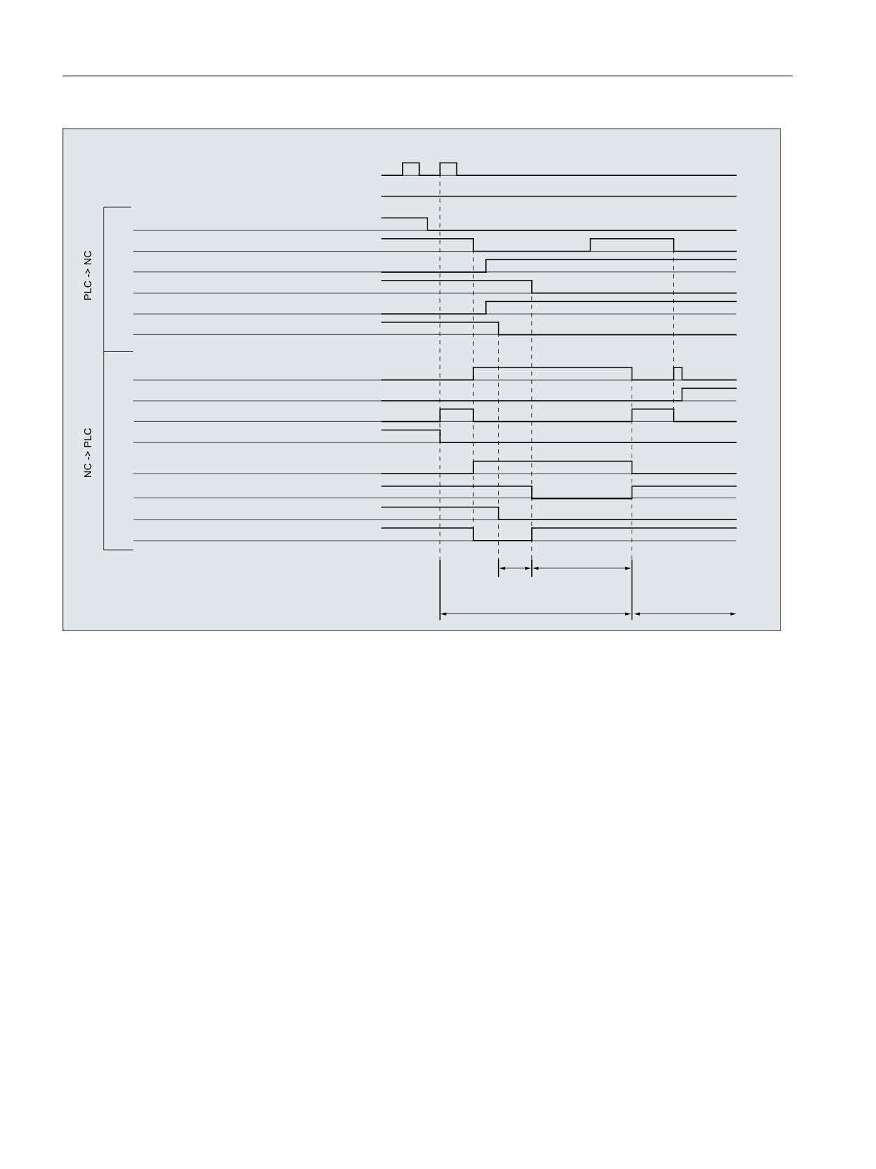
Mode group, channel, program operation, reset response
3.5 Program operation
1& VWDUW IURP 3/& +0, XVHU ODQJXDJH
1& VWRS IURP 3/& +0, XVHU ODQJXDJH
'%
'%;
1& VWDUW GLVDEOH
'%
'%;
UHDG LQ GLVDEOH
'%
'%;
FRQWUROOHU HQDEOH ; D[LV
'%
'%;
IHHGUDWH VWRS
'%
'%;
FRQWUROOHU HQDEOH VSLQGOH
'%
'%;
VSLQGOH VWRS
'%
'%;
SURJUDP VWDWH UXQQLQJ
'%
'%;
SURJUDP VWDWH LQWHUUXSWHG
'%
'%;
SURJUDP VWDWH VWRSSHG
'%
'%;
SURJUDP VWDWH FDQFHOHG
'%
'%%
WUDYHO FRPPDQG ; D[LV
'%
'%;
H[DFW VWRS ILQH
'%
'%;
VSLQGOH VWDWLRQDU\
'%
'%;
VSLQGOH LQ VHWSRLQW UDQJH
6SLQGOH
$[LV ; WUDYHUVHV
SRZHU XS
1
1
Figure 3-1
Signal characteristics during the program
3.5.10
Program jumps
3.5.10.1
Return jump to the start of the program (GOTOS)
Function
With the function "Jump back to start of the program" the control jumps back from a part
program to the beginning of the program. The program is then processed again.
As compared to the function "Program jumps to jump marks", with which a repeated processing
of the program can also be implemented, the function "Jump back to the start of the program"
offers the following advantages:
• The programming of a jump mark at the start of the program is not necessary.
• The program restart can be controlled through the NC/PLC interface signal:
DB21, ... DBX384.0 (control program branching)
Basic functions
54
Function Manual, 10/2020, 6FC5397-2GP40-0BA1

Mode group, channel, program operation, reset response
3.5 Program operation
• The timer for the program runtime can be reset to "0" at the restart of the program.
• The timer for workpiece counting can be incremented by "1" at program restart.
Application example
The function is used, if the processing of subsequent workpieces is to be done through an
automatic program restart, e.g. in case of turning machine with bar loader/changer.
NC/PLC interface signals
The jump back takes place only when the following NC/PLC interface signal is set:
DB21, ... DBX384.0 (control program branching) = 1
Parameterization
Program runtime
The runtime of the selected NC program is stored in the system variable $AC_CYCLE_TIME. When
starting a new program, the system variable is automatically reset to "0" (see Section " Program
runtime (Page 239) ")
Via the following machine data it can be set that the system variable $AC_CYCLE_TIME is reset
to "0" even in case of a program restart through the function "jump back to start of program":
MD27860 $MC_PROCESSTIMER_MODE.Bit 8 = <value> (activate the program runtime
measurement)
Bit
Value
Meaning
8
0
$AC_CYCLE_TIME is not reset to "0" by the function "jump back to start of program".
1
$AC_CYCLE_TIME is reset to "0" by the function "jump back to start of program".
Note
In order that the setting of bit 8 can become effective, the measurement of the current program
runtime must be active (MD27860 bit 1 = 1).
Workpiece count
After the part program end (M02 / M30) has been attained, the activated workpiece counters
($AC_TOTAL_PARTS / $AC_ACTUAL_PARTS / $AC_SPECIAL_PARTS) are incremented by "1" (see
Section "Workpiece Counter").
Via the following machine data it can be set that the activated workpiece counter is incremented
even in case of a program restart through the function "jump back to start of program":
MD27880 $MC_PART_COUNTER.Bit <n> = <value> (activating the workpiece counter)
Bit
Value
Meaning: In case of a program restart through the function "jump back to start
of program", the workpiece counter:
7
0
$AC_TOTAL_PARTS is not incremented.
1
$AC_TOTAL_PARTS is incremented.
Basic functions
Function Manual, 10/2020, 6FC5397-2GP40-0BA1
55

Mode group, channel, program operation, reset response
3.5 Program operation
Bit
Value
Meaning: In case of a program restart through the function "jump back to start
of program", the workpiece counter:
11
0
$AC_ACT_PARTS is not incremented.
1
$AC_ACT_PARTS is incremented.
15
0
$AC_SPECIAL_PARTS is not incremented.
1
$AC_SPECIAL_PARTS is incremented.
Programming
Syntax
GOTOS
Meaning
GOTOS:
Return to the start of the current program
Preprocessing stop:
Yes
Effective:
Non-modal
Example:
Programming
Comment
N10 ...
; Start of the program
IF ...
N100 GOTOS
Return to the program start (N10)
ENDIF
RET
3.5.11
Program section repetitions
3.5.11.1
Programming
The program section repetition permits the repetition of program sections within an NC
program.
Basic functions
56
Function Manual, 10/2020, 6FC5397-2GP40-0BA1
Mode group, channel, program operation, reset response
3.5 Program operation
The program lines or program sections to be repeated are identified by jump markers (labels).
Note
Jump markers (labels)
Jump markers are always located at the beginning of a block. If a program number exists, the
jump marker is located immediately after the block number.
The following rules apply when naming jump markers:
• Number of characters:
- Minimum 2
- Maximum 32
• Permissible characters are:
- Letters
- Digits
- Underscores
• The first two characters must be letters or underscores.
• The name of the jump marker is followed by a colon (":").
Syntax
1. REPEATB: Repeat single program line
<jump marker>: ...
REPEATB <jump marker> P=<n>
2. REPEAT + jump marker: Repeat program section between jump marker and REPEAT
statement
<jump marker>: ...
REPEAT <jump marker> P=<n>
3. REPEAT + jump marker_1 + jump marker_2: Repeat section between two jump markers
<start jump marker>: ...
<end jump marker>: ...
REPEAT <start jump marker> <end jump marker> P=<n>
Basic functions
Function Manual, 10/2020, 6FC5397-2GP40-0BA1
57

Mode group, channel, program operation, reset response
3.5 Program operation
Note
It is not possible to nest the REPEAT statement with the two jump markers in parentheses. If
the <start jump marker> appears before the REPEAT statement and the <end jump
marker> is not reached before the REPEAT statement, the section between the <start
jump marker> and the REPEAT statement will be repeated.
4. REPEAT + jump marker + ENDLABEL: Repeat section between jump marker and
ENDLABEL:
<jump marker>: ...
ENDLABEL: ...
REPEAT <jump marker> P=<n>
Note
It is not possible to nest the REPEAT statement with the <jump marker> and the ENDLABEL in
parentheses. If the <jump marker> appears before the REPEAT statement and the ENDLABEL
is not reached before the REPEAT statement, the section between the <jump marker> and
the REPEAT statement will be repeated.
Meaning
REPEATB:
Command for repeating a program line
REPEAT:
Command for repeating a program section
<jump marker>:
The <jump marker> identifies:
• REPEATB: The program line to be repeated
• REPEAT: The start of the program section to be repeated
The program line identified by the <jump marker> can appear before or after
the REPEAT/REPEATB statement. The search initially commences towards the
start of the program. If the jump marker is not found in this direction, the search
continues in the direction towards the end of the program.
Exception:
If the program section between the jump marker and the REPEAT statement
needs to be repeated (see 2. under Syntax), the program line identified by
the <jump marker> has to appear before the REPEAT statement, since in
this case the search runs only towards the beginning of the program.
If the line with the <jump marker> contains further statements, they are
executed again on each repetition.
ENDLABEL:
Keyword that marks the end of a program section to be repeated.
If the line with the ENDLABEL contains further statements, they are executed
again on each repetition.
ENDLABEL can be used more than once in the program.
Basic functions
58
Function Manual, 10/2020, 6FC5397-2GP40-0BA1

Mode group, channel, program operation, reset response
3.5 Program operation
P:
Address for specifying the number of repetitions
Note:
If no number is specified for P=<n>, the program section is repeated just once.
<n>:
Number of repetitions
Type:
INT
The program section to be repeated is repeated <n> times. After the last rep-
etition, the program is resumed at the program line following the REPEAT/
REPEATB command.
Examples
Example 1: Repeat individual program line
Program code
Comment
N10 POSITION1: X10 Y20
N20 POSITION2: CYCLE(0,,9,8)
;Position cycle
N30 ...
N40 REPEATB POSITION1 P=5
; Execute block N10 five times.
N50 REPEATB POSITION2
; Execute block N20 once.
N60 ...
N70 M30
Example 2: Repeat program section between jump marker and REPEAT statement:
Program code
Comment
N5 R10=15
N10 Begin: R10=R10+1
; Start of the program section
N20 Z=10-R10
N30 G1 X=R10 F200
N40 Y=R10
N50 X=-R10
N60 Y=-R10
N70 Z=10+R10
N80 REPEAT BEGIN P=4
; Execute section from N10 to N70 four times.
N90 Z10
N100 M30
Example 3: Repeat section between two jump markers
Program code
Comment
N5 R10=15
N10 Begin: R10=R10+1
; Start of the program section
N20 Z=10-R10
N30 G1 X=R10 F200
N40 Y=R10
N50 X=-R10
N60 Y=-R10
Basic functions
Function Manual, 10/2020, 6FC5397-2GP40-0BA1
59

Mode group, channel, program operation, reset response
3.5 Program operation
Program code
Comment
N70 END: Z=10
; End of the program section
N80 Z10
N90 CYCLE(10,20,30)
N100 REPEAT BEGIN END P=3
; Execute section from N10 to N70 three times.
N110 Z10
N120 M30
Example 4: Repeat section between jump marker and ENDLABEL
Program code
Comment
N10 G1 F300 Z-10
N20 BEGIN1:
; Start program section 1
N30 X10
N40 Y10
N50 BEGIN2:
; Start program section 2
N60 X20
N70 Y30
N80 ENDLABEL: Z10
N90 X0 Y0 Z0
N100 Z-10
N110 BEGIN3: X20
; Start program section 3
N120 Y30
N130 REPEAT BEGIN3 P=3
; Execute section from N110 to N120 three times.
N140 REPEAT BEGIN2 P=2
; Execute section from N50 to N80 twice.
N150 M100
N160 REPEAT BEGIN1 P=2
; Execute section from N20 to N80 twice.
N170 Z10
N180 X0 Y0
N190 M30
Example 5: Milling, drilling position with different technologies
Program code
Comment
N10 CENTER DRILL()
; Load centering drill.
N20 POS_1:
; Start program section 1; drilling position 1
N30 X1 Y1
N40 X2
N50 Y2
N60 X3 Y3
N70 ENDLABEL:
N80 POS_2:
; Start program section 2; drilling position 2
N90 X10 Y5
N100 X9 Y-5
N110 X3 Y3
N120 ENDLABEL:
; End program sections 1 and 2
Basic functions
60
Function Manual, 10/2020, 6FC5397-2GP40-0BA1
Mode group, channel, program operation, reset response
3.5 Program operation
Program code
Comment
N130 DRILL()
; Drilling cycle
N140 THREAD(6)
; Threading cycle
N150 REPEAT POS_1
; Repeat program section once from POS_1 up to ENDLABEL.
N160 DRILL()
; Drilling cycle
N170 THREAD(8)
; Threading cycle
N180 REPEAT POS_2
; Repeat program section once from POS_2 up to ENDLABEL.
N190 M30
Further information
• Program section repetitions can be nested. Each call uses a subprogram level.
• If M17 or RET is programmed while processing a program section repetition, the program
section repetition is canceled. The program is resumed at the block following the REPEAT
line.
• In the actual program display, the program section repetition is displayed as a separate
subprogram level.
• If the level is canceled during the program section processing, the program resumes at the
point after the program section repetition call.
Example:
Program code
Comment
N5 R10=15
N10 BEGIN: R10=R10+1
;Width
N20 Z=10-R10
N30 G1 X=R10 F200
N40 Y=R10
; Interrupt level
N50 X=-R10
N60 Y=-R10
N70 END: Z10
N80 Z10
N90 CYCLE(10,20,30)
N100 REPEAT BEGIN END P=3
N120 Z10
; Resume program execution.
N130 M30
• Check structures and program section repetitions can be used in combination. There should
be no overlap between the two, however. A program section repetition should appear within
a check structure branch or a check structure should appear within a program section
repetition.
• If jumps and program section repetitions are mixed, the blocks are executed purely
sequentially. For example, if a jump is performed from a program section repetition,
processing continues until the programmed end of the program section is found.
Example:
Basic functions
Function Manual, 10/2020, 6FC5397-2GP40-0BA1
61
Mode group, channel, program operation, reset response
3.5 Program operation
Program code
N10 G1 F300 Z-10
N20 BEGIN1:
N30 X=10
N40 Y=10
N50 GOTOF BEGIN2
N60 ENDLABEL:
N70 BEGIN2:
N80 X20
N90 Y30
N100 ENDLABEL: Z10
N110 X0 Y0 Z0
N120 Z-10
N130 REPEAT BEGIN1 P=2
N140 Z10
N150 X0 Y0
N160 M30
Note
The REPEAT statement should appear after the traversing block.
3.5.12
Event-driven program call (PROG_EVENT)
3.5.12.1
Function
Function
The "Event-driven program call" (PROG_EVENT) function starts, for the occurrence of a selected
event in the NC, a user-specific NC program (PROG_EVENT-program).
Application examples
Initial setting for functions or initialization of system or user variables.
Events
The triggering events are selected with the machine data MD20108 $MC_PROG_EVENT_MASK
(see Section "Parameterization (Page 66)").
PROG_EVENT program
The name of the PROG_EVENT program is set with the machine data
MD11620 $MN_PROG_EVENT_NAME up (see Section "Parameterization (Page 66)").
The PROG_EVENT program is executed in the channel in which the event occurred.
Basic functions
62
Function Manual, 10/2020, 6FC5397-2GP40-0BA1
Mode group, channel, program operation, reset response
3.5 Program operation
The PROG_EVENT program is executed with the lowest priority and so can be interrupted by a
user ASUP.
Processing sequences
Processing sequence when activated by an event: Program start
Initial state:
Channel:
Reset status
Mode:
AUTOMATIC (optional: Overstore (active)
MDI
TEACH IN
1. A program starts in the channel
2. Initialization sequence with evaluation of:
- MD20112 $MC_START_MODE_MASK
3. Implicit call of the PROG_EVENT program as a subprogram
4. Processing of the data part of the main program
5. Processing of the program part of the main program
Processing sequence when activated by an event: Program end
Initial state
Channel:
Active
Mode:
AUTOMATIC (optional: Overstore (active)
MDI
TEACH IN
1. In the channel, the end of program block is exchanged in the executed program.
2. End of program is executed, evaluation of the following machine data:
- MD20110 $MC_RESET_MODE_MASK
- MD20150 $MC_GCODE_RESET_VALUES
- MD20152 $MC_GCODE_RESET_MODE
3. Implicit call of the PROG_EVENT program as ASUP
4. A reset is executed in the channel, evaluation of the following machine data:
- MD20110 $MC_RESET_MODE_MASK
- MD20150 $MC_GCODE_RESET_VALUES
- MD20152 $MC_GCODE_RESET_MODE
Basic functions
Function Manual, 10/2020, 6FC5397-2GP40-0BA1
63
Mode group, channel, program operation, reset response
3.5 Program operation
Sequence when activated by an event: Channel reset
Initial state:
Channel:
Any
Mode:
Any
1. Control activates reset-sequence with evaluation of machine data:
- MD20110 $MC_RESET_MODE_MASK
- MD20150 $MC_GCODE_RESET_VALUES
- MD20152 $MC_GCODE_RESET_MODE
2. Implicit call of the PROG_EVENT program as ASUP
3. Control activates reset-sequence with evaluation of machine data:
- MD20110 $MC_RESET_MODE_MASK
- MD20150 $MC_GCODE_RESET_VALUES
- MD20152 $MC_GCODE_RESET_MODE
Sequence when activated by an event: Power-up of the NC
1. Control activates after power-up reset-sequence with evaluation of machine data:
- MD20110 $MC_RESET_MODE_MASK
- MD20150 $MC_GCODE_RESET_VALUES
- MD20152 $MC_GCODE_RESET_MODE
2. Implicit call of the PROG_EVENT program as ASUP
3. Control activates reset-sequence with evaluation of machine data:
- MD20110 $MC_RESET_MODE_MASK
- MD20150 $MC_GCODE_RESET_VALUES
- MD20152 $MC_GCODE_RESET_MODE
NC/PLC interface signals Change of "program status" and "channel status"
The following diagrams show the changes of the various NC/PLC interface signals for "program
status" and "channel status" during the event-driven program call sequence.
Basic functions
64
Function Manual, 10/2020, 6FC5397-2GP40-0BA1
Mode group, channel, program operation, reset response
3.5 Program operation
Signal sequence when activated by program start and program end
'%
'%;
3URJUDP VWDWXV UXQQLQJ
'%
'%;
3URJUDP VWDWXV VWRSSHG
'%
'%;
3URJUDP VWDWXV FDQFHOHG
'%
'%;
&KDQQHO VWDWXV DFWLYH
'%
'%;
&KDQQHO VWDWXV LQWHUUXSWHG
'%
'%;
&KDQQHO VWDWXV UHVHW
Signal sequence when activated by a channel reset
'%
'%;
3URJUDP VWDWXV UXQQLQJ
'%
'%;
3URJUDP VWDWXV VWRSSHG
'%
'%;
3URJUDP VWDWXV FDQFHOHG
'%
'%;
&KDQQHO VWDWXV DFWLYH
'%
'%;
&KDQQHO VWDWXV LQWHUUXSWHG
'%
'%;
&KDQQHO VWDWXV UHVHW
NC/PLC interface signals: DB21, ... DBX35.4 (program status aborted) and DB21, ... DBX35.7
(channel status reset)
• The interface signals are set only when the PROG_EVENT program has completed again.
• The interface signals are not set between:
- Program end and PROG_EVENT program start
- Channel reset and PROG_EVENT program start
Basic functions
Function Manual, 10/2020, 6FC5397-2GP40-0BA1
65

Mode group, channel, program operation, reset response
3.5 Program operation
NC/PLC interface signals DB21, ... DBX376.0 ... 4 (triggering events)
The initiating event is displayed using interface signals DB21, ... DBX376.0 ... 4:
Bit
Value
Event
0
1
Program start from channel state "Reset"
1
1
End of program
2
1
Channel reset
3
1
Powering-up of the NC
4
1
1. Program start after block search (see "Automatic start of an ASUP after block search
(Page 124)")
If the PROG_EVENT program has completed or been canceled with a channel reset, the interface
signals are cleared again.
The interface signals are available for at least the duration of a PLC cycle.
3.5.12.2
Parameterization
Event selection
The events that start the PROG_EVENT program are set channel-specific using the machine data:
MD20108 $MC_PROG_EVENT_MASK.Bit <n> = 1
Bit
<value>
Meaning: Event
0
1
Part program start
1
1
Part program end
2
1
Channel reset
3
1
Run-up
Note
MD20108 $MC_PROG_EVENT_MASK is not evaluated in the simulation.
PROG_EVENT program
The PROG_EVENT program (default: _N_PROG_EVENT_SPF) must be loaded and enabled.
Default setting
As default setting, when an event occurs, user program _N_CMA_DIR/_N_PROG_EVENT_SPF is
executed.
The PROG_EVENT program must be loaded and enabled.
User-specific setting
If, for an event, a different PROG_EVENT program than the default setting is to be executed, the
NC program name must be entered into the following machine data:
MD11620 $MN_PROG_EVENT_NAME = <program name>
Basic functions
66
Function Manual, 10/2020, 6FC5397-2GP40-0BA1