SINUMERIK 840D sl. Service - Functions. Manual (2018-2020) - page 22
Axes, coordinate systems, frames
4.3 Zero points and reference points
4.3.2
Position of coordinate systems and reference points
Switching on the control
For incremental measuring encoders, the reference point must be approached after each switch-
on of the controller to ensure the controller can transfer all of the position values to the
coordinate system.
;
;
0DFKLQH ]HUR
:RUNSLHFH ]HUR
:RUNSLHFH OHQJWK
==
0
:
6SLQGOH
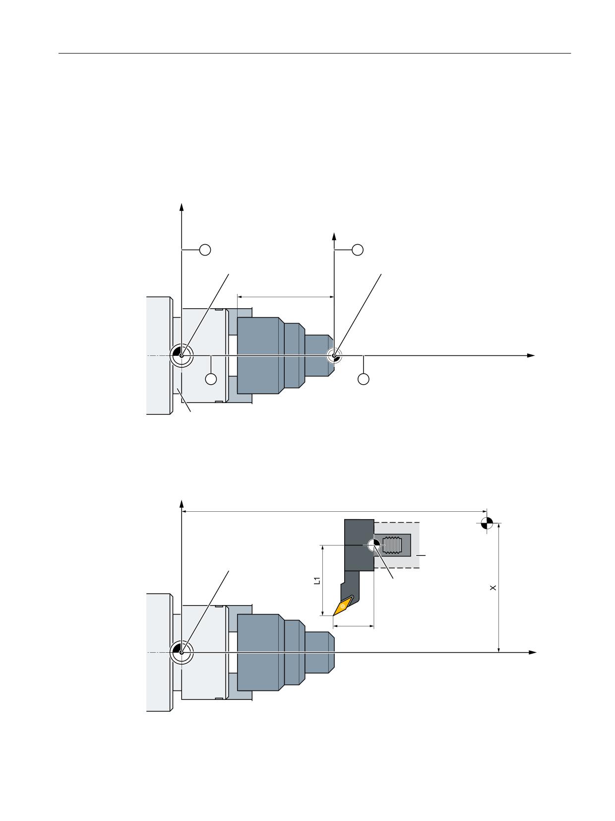
① Machine coordinate system (MCS)
② Workpiece coordinate system (WCS)
Figure 4-8
Position of the coordinate systems through machine zero point M and workpiece zero point
W
;
=
5HIHUHQFH SRLQW
7
5
7RROKROGHU
0DFKLQH ]HUR
7RRO FDUULHU
UHIHUHQFH SRLQW
/
=
0
Figure 4-9
Position of the reference point to the machine zero point
Basic functions
Function Manual, 10/2020, 6FC5397-2GP40-0BA1
275
Axes, coordinate systems, frames
4.4 Coordinate systems
4.4
Coordinate systems
4.4.1
Overview
Definitions
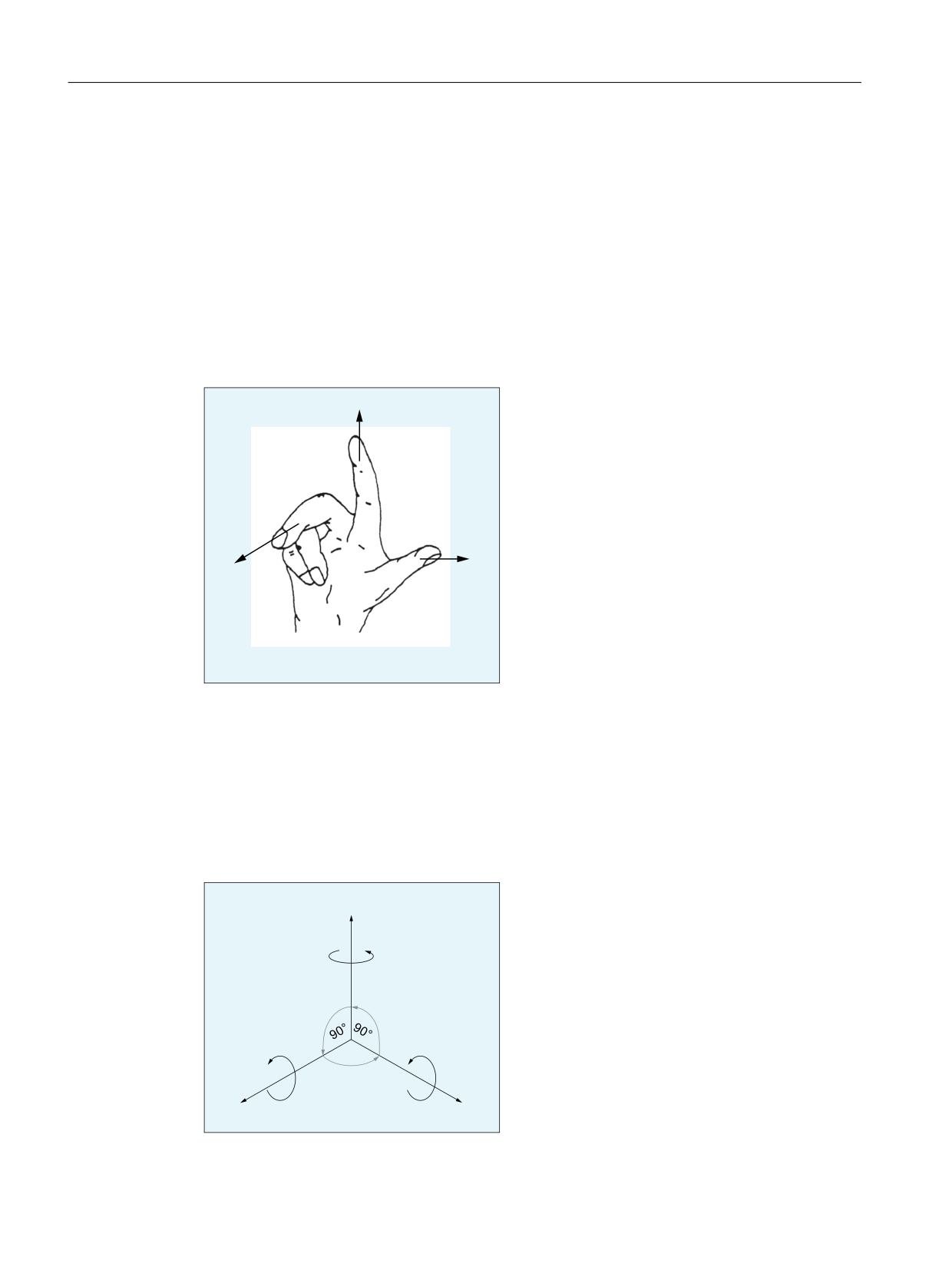
DIN 66217 stipulates that when programming machine tools, right-angled, rectangular
(Cartesian) coordinate systems must be used. The positive directions of the coordinate axes can
be determined using the "right-hand rule".
<
;
=
Figure 4-10
Right_hand_rule
The coordinate system used when programming is referred to the workpiece. Programming is
realized independent of whether the tool or the workpiece is moved. When programming, it is
always assumed that the tool traverses relative to the coordinate system of the workpiece, which
is intended to be stationary.
Positive (clockwise) rotation of rotary axes can also be defined using the "right-hand rule". If the
thumb of the right hand points towards the positive direction of a coordinate axis (linear axis),
then the fingers point in the positive direction of rotation of the associated rotary axis.
=
&
$
%
r
;
<
Basic functions
276
Function Manual, 10/2020, 6FC5397-2GP40-0BA1
Axes, coordinate systems, frames
4.4 Coordinate systems
Figure 4-11
Clockwise, rectangular Cartesian coordinate system
Coordinate systems
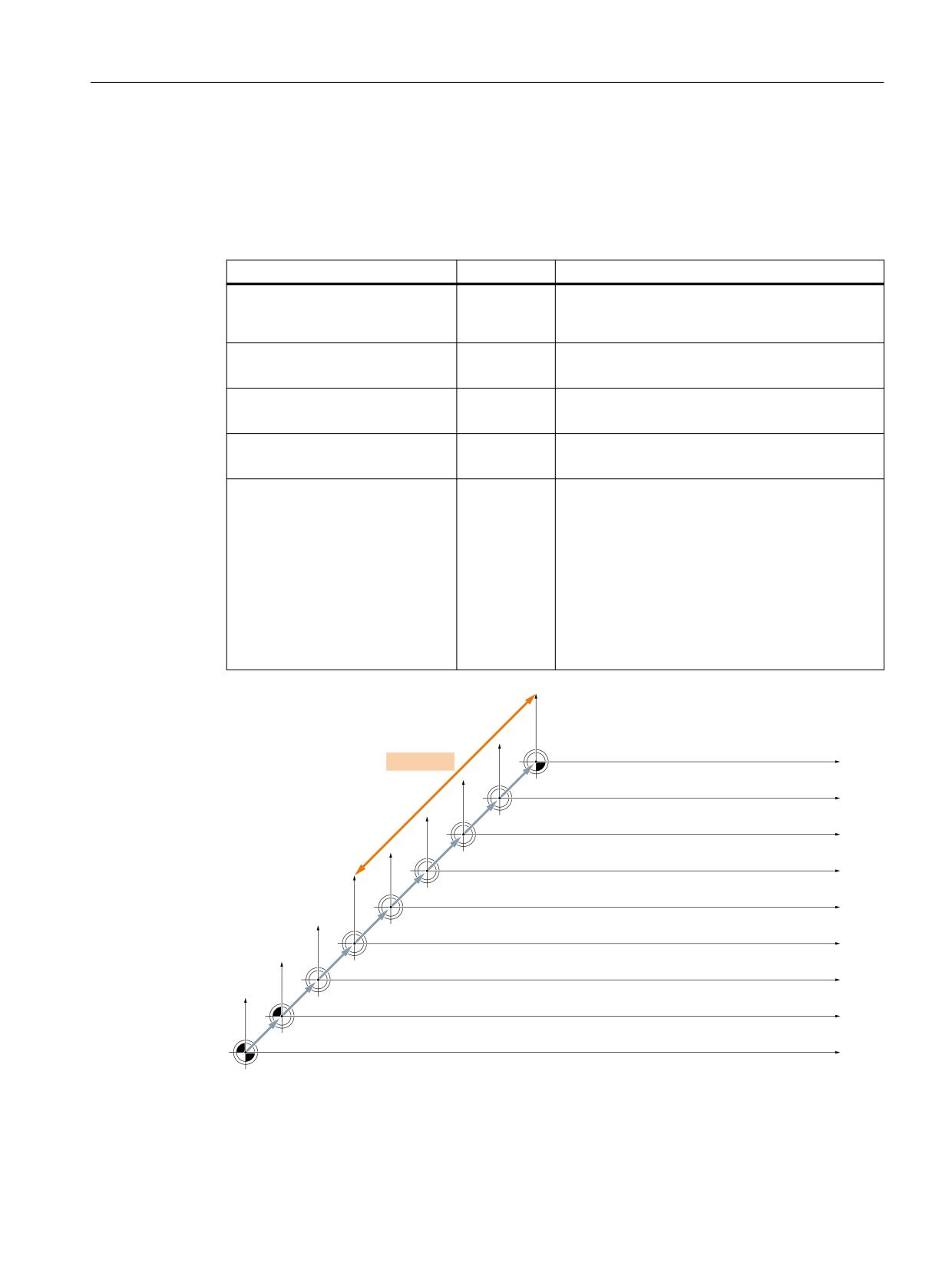
The following coordinate systems are defined for machine tools:
Coordinate system
Abbreviation
Remark
Workpiece Coordinate System
WCS
Programming the traversing motion of the geome-
try axes for machining the workpiece is written in
the WCS.
Settable Zero System
SZS
Coordinate transformation using frames:
WCS ⇒ SZS
Basic Zero System
BZS
Coordinate transformation using frames:
SZS ⇒ BZS:
Basic Coordinate System
BCS
Coordinate transformation using frames:
BZS ⇒ BCS:
Machine Coordinate System
MCS
Coordinate transformation using frames and kine-
matic transformation:
BCS ⇒ MCS:
The programmed traversing motion of the geome-
try axes in WCS is mapped to the machine axes of
MCS using frames and kinematic transformations.
A kinematic transformation is used to derive the
BCS from the MCS. In this way, functions such as
manual traverse, for example, are effective not in
the MCS but in the BCS.
Frame chain
)UDPH IRU F\FOHV SURJUDPPHG IUDPH
:.6
WUDQVIRUPDWLRQV
6\VWHP IUDPH IRU 72527 72)5$0(
(16
ZRUNSLHFHV
* ಹ*
VHWWDEOH IUDPH
FKDQQHO VSHFLILF RU 1&8 JOREDO
&KDLQHG ILHOG RI EDVLF IUDPHV
%16
FKDQQHO VSHFLILF DQG RU 1&8 JOREDO
&KDLQHG V\VWHP IUDPHV IRU 3$527 DFWXDO YDOXH VHWWLQJ
VFUDWFKLQJ H[W ZRUN RIIVHW
+DQGZKHHO '5) RIIVHW RYHUODLG PRYHPHQW H[WHUQDO
ZRUN RIIVHW
%.6
.LQHPDWLF WUDQVIRUPDWLRQ
0.6
5HIHUHQFH SRLQW RIIVHW
Figure 4-12
Coordinate systems, frames, and kinematic transformations
Basic functions
Function Manual, 10/2020, 6FC5397-2GP40-0BA1
277
Axes, coordinate systems, frames
4.4 Coordinate systems
4.4.2
Machine coordinate system (MCS)
Machine coordinate system (MCS)
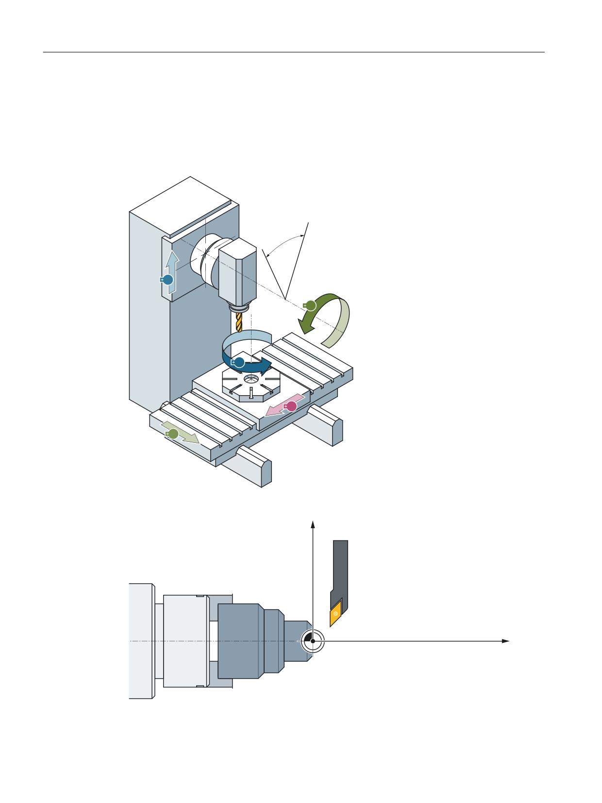
The machine coordinate system (MCS) is made up of all physically available machine axes.
=
%
&
;
<
Figure 4-13
MCS with machine axes X, Y, Z, B, C (5-axis milling machine)
;
=
0
Figure 4-14
MCS with machine axes X, Z (turning machine)
Basic functions
278
Function Manual, 10/2020, 6FC5397-2GP40-0BA1

Axes, coordinate systems, frames
4.4 Coordinate systems
Axial preset offset
The reference point of the control in the machine coordinate system (machine zero) can be reset
via the "Preset offset (PRESETON)" function.
CAUTION
Loss of the encoder adjustment
After a preset offset, the appropriate machine axis is in the "Not referenced" state! This means
that when using absolute encoders, the encoder adjustment is lost and must be performed
again (e.g. by calibration with a laser interferometer ). The use of PRESETON in combination
with absolute encoders is therefore not recommended.
Note
We recommend that the function is only used for machine axes that do not require a reference
point.
In order to restore the original machine coordinate system, the machine axis must be re-
referenced, e.g. with G74 (reference point approach).
The machine axes are not moved with the preset offset.
Further information
• "NC Programming" Programming Manual, supplemental commands
• "NC Programming" Programming Manual, coordinate transformations (FRAMES)
4.4.2.1
Actual value setting with loss of the referencing status (PRESETON)
Function
The PRESETON() procedure sets a new actual value for one or more axes in the machine
coordinate system (MCS). This corresponds to work offset of the axis MCS. The axis is not
traversed.
A preprocessing stop with synchronization is triggered by PRESETON. The actual position is not
assigned until the axis is at standstill.
If the axis is not assigned to the channel for PRESETON, the next steps depend on the
replacement behavior parameterized in the following machine data:
MD30552 $MA_AUTO_GET_TYPE
Referencing status
By setting a new actual value in the machine coordinate system, the referencing status of the
machine axis is reset.
DB31, ... DBX60.4/.5 = 0 (referenced/synchronized measuring system 1/2)
It is recommended that PRESETON only be used for axes that do not require a reference point.
Basic functions
Function Manual, 10/2020, 6FC5397-2GP40-0BA1
279
Axes, coordinate systems, frames
4.4 Coordinate systems
To restore the original machine coordinate system, the measuring system of the machine axis
must be referenced again, e.g. through active referencing from the part program (G74).
CAUTION
Loss of the referencing status
By setting a new actual value in the machine coordinate system with PRESETON, the
referencing status of the machine axis is reset to "not referenced/synchronized".
Programming
Syntax
PRESETON(<axis_1>, <value_1> [, <axis_2>, <value_2>, ... <axis_8>,
<value_8>])
Meaning
PRESETON:
Actual value setting with loss of the referencing status
Preprocessing
Yes
stop:
Alone in the block: Yes
<axis_x>:
Machine axis name
Type:
AXIS
Value range:
Machine axis names defined in the channel
<value_x>:
New actual value of the machine axis in the machine coordinate system
(MCS)
The input is made in the current valid system of units (inch/metric)
An active diameter programming (DIAMON) is taken into account
Type:
REAL
System variable
$AC_PRESET
The axis-specific system variable $AC_PRESET provides the vector from the zero point of the
currently offset MCS' to the zero point of the original MCS0 after the referencing of the machine
axis.
$AC_PRESET<axis> = $AC_PRESET<axis> + "current actual position of the axis in the MCS" -
"PRESETON actual position"
The work offset can be undone with the system variables:
PRESETON(<axis>, $VA_IM + $AC_PRESET[<axis>]) ; "current actual
position of the axis in the MCS'" + "offsets"
Basic functions
280
Function Manual, 10/2020, 6FC5397-2GP40-0BA1
Axes, coordinate systems, frames
4.4 Coordinate systems
Example
Program code
N10 G1 X10 F5000
N20 PRESETON(X, $AA_IM[X]+70) ; actual value = 10 + 70 = 80 =>
; $AC_PRESET = $AC_PRESET - 70
Supplementary conditions
Axes for which PRESETON must not be used
• Traversing path axes
• Traversing positioning axes
• Traversing command axes in spindle mode
• Traversing concurrent positioning axes
• Axes involved in a transformation
• Axes on which one or more of the following safety Safety Integrated functions are active:
- Enable "Safe software limit switch"
MD36901 $MA_SAFE_FUNCTION_ENABLE[<SafeAxis>], bit 1 = 1
- Enable "Safe software cams", pair 1 ... 4, cam +/-
MD36901 $MA_SAFE_FUNCTION_ENABLE[<SafeAxis>], bits 8 ... 15 = 1
or
Enable "Safe cam track", cam 1 ... 30
MD36903 $MA_SAFE_CAM_ENABLE[<SafeAxis>], bit 0 ... 29 = 1
• Reciprocating axes
• Hirth axes
• Synchronized axes of a gantry grouping
• Axes for which the reference point approach from the part program (G74) is active
• Slave axis of a speed/torque coupling (master-slave)
Basic functions
Function Manual, 10/2020, 6FC5397-2GP40-0BA1
281
Axes, coordinate systems, frames
4.4 Coordinate systems
Geometry axes
• PRESETON can be used on a stationary geometry axis when a further geometry axis is not
being traversed in the channel at the same time.
• PRESETON can be used on a stationary geometry axis even when a further geometry axis is
being traversed in the channel at the same time, but this axis is in the "neutral axis" state or
traversing as a command axis.
Program code
Comment
N10 G0 X0 Y0
; X, Y: Geometry axes
N15 RELEASE(Y)
; Neutral axis
N20 PRESETON(Y,20)
; Actual position Y in the MCS =
20
N30 G0 X40
; Geometry axis X traverses
N40 M30
Example: A further geometry (X) is traversing at the same time in the "neutral axis" state
Program code
Comment
N10 G0 X0 Y0
; X, Y: Geometry axes
N20 POS[X]=40 FA[X]=1000
; X command axis
N30 DO PRESETON(Y,20)
; Actual position Y in the MCS =
20
N40 M30
Example: Geometry axis (X) traverses simultaneously as command axis
PLC-controlled axes
PRESETON can be used on PLC-controlled axes according to their current type.
Spindle states
The following table shows the reactions that occur when PRESETON is used on a spindle in a
synchronized action:
PRESETON in the NC program
Spindle mode
Traversing sta-
Assigned to the NC
Main axis
tus
program
Speed control mode
In motion
Alarm 22324
Alarm 22324
Stationary
+/-
+/-
Positioning mode SPOS
In motion
-
+/-
Stationary
+/-
+/-
Positioning across block bounda-
In motion
Alarm 10610
-
ries SPOSA
Axis mode
In motion
-
+/-
Stationary
+/-
+/-
+: Possible
-: Not possible
Basic functions
282
Function Manual, 10/2020, 6FC5397-2GP40-0BA1
Axes, coordinate systems, frames
4.4 Coordinate systems
Axis couplings
• Leading axes: The sudden change of the leading axis position caused by PRESETON is not
traversed in the following axes. The coupling is not changed.
• Following axes: Only the overlaid position component of the following axis is affected
by PRESETON.
Gantry grouping
If PRESETON is used on the guide axis of a gantry grouping, the work offset is also performed in
all synchronized axes of the gantry grouping.
Indexing axes
PRESETON can be used on indexing axes.
Software limit switches, operating range limit, protection areas
If the axis position is outside the specified limits after a work offset by PRESETON, an alarm is not
displayed until an attempt is made to traverse the axis.
Block search with calculation
PRESETON commands are collected during the block search and executed with the NC start to
continue the NC program.
Position-dependent NC/PLC interface signals
The status of the position-dependent NC/PLC interface signals is redetermined based on the new
actual position.
Example: Fixed point positions
• Parameterized fixed point positions: MD30600 $MA_FIX_POINT_POS[0...3] = <fixed point
position 1...4>
• NC/PLC interface signals DB31, ... DBX75.3 ... 5 (JOG approach fixed point: reached)
If the axis is at a fixed point position with the exact stop tolerance, the associated NC/PLC
interface signal is set. The NC/PLC interface signal is reset when the actual value is set by
PRESETON to a different value outside the exact stop tolerance around the fixed point position.
DRF offset
A DRF offset of the axis is deleted by PRESETON.
Overlaid movement $AA_OFF
An overlaid movement from a synchronized action with $AA_OFF is not affected by PRESETON.
Online tool offset FTOC
An active online tool offset from a synchronized action with FTOC remains active even after
PRESETON.
Axis-specific compensations
Axis-specific compensations remain active after PRESETON.
Basic functions
Function Manual, 10/2020, 6FC5397-2GP40-0BA1
283
Axes, coordinate systems, frames
4.4 Coordinate systems
JOG mode
PRESETON must only be used on a stationary axis.
JOG mode, REF machine function
PRESETON must not be used.
4.4.2.2
Actual value setting without loss of the referencing status (PRESETONS)
Function
The PRESETONS() procedure sets a new actual value for one or more axes in the machine
coordinate system (MCS). This corresponds to work offset of the axis MCS. The axis is not
traversed.
A preprocessing stop with synchronization is triggered by PRESETONS. The actual position is not
assigned until the axis is at standstill.
If the axis for PRESETONS is not assigned to the channel, the next steps depend on the axis-
specific configuring of the axis interchange behavior:
MD30552 $MA_AUTO_GET_TYPE
Referencing status
By setting a new actual value in the machine coordinate system (MCS) with PRESETONS, the
referencing status of the machine axis is not changed.
Requirements
• Encoder type
PRESETONS is only possible with the following encoder types of the active measuring
system:
- MD30240 $MA_ENC_TYPE[<measuring system>] = 0 (simulated encoder)
- MD30240 $MA_ENC_TYPE[<measuring system>] = 1 (raw signal encoder)
• Referencing mode
PRESETONS is only possible with the following referencing modes of the active measuring
system:
- MD34200 $MA_ENC_REFP_MODE[<measuring system>] = 0 (reference point approach
not possible)
- MD34200 $MA_ENC_REFP_MODE[<measuring system>] = 1 (referencing of
incremental, rotary or linear measuring systems: zero pulse on the encoder track)
Commissioning
Axis-specific machine data
Actual value setting without loss of the referencing status (PRESETONS) must be set axis-
specifically:
Basic functions
284
Function Manual, 10/2020, 6FC5397-2GP40-0BA1
Axes, coordinate systems, frames
4.4 Coordinate systems
MD30455 $MA_MISC_FUNCTION_MASK, bit 9 = 1
Note
PRESETON deactivated
Activation of the "Actual value setting without loss of the referencing status PRESETONS"
function deactivates the "Actual value setting with loss of the referencing status PRESETON"
function. The options mutually exclude each other.
Programming
Syntax
PRESETONS(<axis_1>, <value_1> [, <axis_2>, <value_2>, ... <axis_8>,
<value_8>])
Meaning
PRESETONS:
Actual value setting with loss of the referencing status
Preprocessing
Yes
stop:
Alone in the block: Yes
<axis_x>:
Machine axis name
Type:
AXIS
Value range:
Machine axis names defined in the channel
<value_x>:
New current actual value of the machine axis in the machine coordinate
system (MCS)
The value refers to the active system of units (inch / metric)
An active diameter programming (DIAMON) is taken into account
Type:
REAL
System variable
$AC_PRESET
The axis-specific system variable $AC_PRESET provides the vector from the zero point of the
currently offset MCS' to the zero point of the original MCS0 after the referencing of the machine
axis.
$AC_PRESET<axis> = $AC_PRESET<axis> + "current actual position of the axis in the MCS" -
"PRESETONS actual position"
The work offset can be undone with the system variables:
PRESETONS(<axis>, $VA_IM + $AC_PRESET[<axis>]) ; "current actual
position of the axis in the MCS'" + "offsets"
Example
Work offset of the X axis MCS by 70 units.
Basic functions
Function Manual, 10/2020, 6FC5397-2GP40-0BA1
285
Axes, coordinate systems, frames
4.4 Coordinate systems
The programmed end position of the X axis (command axis) is transformed to the new MCS with
PRESETONS.
Program code
N10 G1 X10 F5000
N20 PRESETONS(X, $AA_IM[X]+70) ; actual value = 10 + 70 = 80 =>
; $AC_PRESET = $AC_PRESET - 70
Supplementary conditions
Axes for which PRESETONS must not be used
• Traversing positioning axes
• Traversing command axes in spindle mode
• Traversing concurrent positioning axes
• Axes involved in a transformation
• Traversing path axes
• Reciprocating axes
• Axes on which one or more of the following safety Safety Integrated functions are active:
- Enable "Safe software limit switch"
MD36901 $MA_SAFE_FUNCTION_ENABLE[<SafeAxis>], bit 1 = 1
- Enable "Safe software cams", pair 1 ... 4, cam +/-
MD36901 $MA_SAFE_FUNCTION_ENABLE[<SafeAxis>], bits 8 ... 15 = 1
or
Enable "Safe cam track", cam 1 ... 30
MD36903 $MA_SAFE_CAM_ENABLE[<SafeAxis>], bit 0 ... 29 = 1
• Hirth axes
• Synchronized axes of a gantry grouping
• Axes for which the reference point approach from the part program (G74) is active
• Slave axis of a speed/torque coupling (master-slave)
Basic functions
286
Function Manual, 10/2020, 6FC5397-2GP40-0BA1
Axes, coordinate systems, frames
4.4 Coordinate systems
Geometry axes
• PRESETONS can be used on a stationary geometry axis when a further geometry axis is not
being traversed in the channel at the same time.
• PRESETONS can be used on a stationary geometry axis even when a further geometry axis
is being traversed in the channel at the same time, but this axis is in the "neutral axis" state
or traversing as a command axis.
Example: A further geometry (X) is traversing at the same time in the "neutral axis" state
Program code
Comment
N10 G0 X0 Y0
; X, Y: Geometry axes
N15 RELEASE(Y) 1)
; Neutral axis
N20 PRESETONS(Y,20)
; Actual position Y in the MCS =
20
N30 G0 X40
; Geometry axis X traverses
N40 M30
1) Note
The release of an axis in the action part of a synchronized action does not ensure that the release is
on time.
N20 ID=1 WHEN 20.0 < $AA_IM[X] DO RELEASE(Y) PRESETONS(Y,20) ; NOT
recommended!
Example: Another geometry axis (X) is traversing at the same time as command axis
Program code
Comment
N10 G0 X0 Y0
; X, Y: Geometry axes
N20 POS[X]=40 FA[X]=1000
; X command axis
N30 PRESETONS(Y,20)
; Actual position Y in the MCS =
20
N40 M30
PLC-controlled axes
PRESETONS can be used on PLC-controlled axes according to their current type.
Spindle states
The following table shows the reactions that occur when PRESETONS is used on a spindle in a
synchronized action:
PRESETONS in the NC program
Spindle mode
Traversing sta-
Assigned to the NC
Main axis
tus
program
Speed control mode
In motion
Alarm 22324
Alarm 22324
Stationary
+/-
+/-
Positioning mode SPOS
In motion
-
+/-
Stationary
+/-
+/-
Positioning across block bounda-
In motion
Alarm 10610
-
ries SPOSA
Basic functions
Function Manual, 10/2020, 6FC5397-2GP40-0BA1
287

Axes, coordinate systems, frames
4.4 Coordinate systems
PRESETONS in the NC program
Spindle mode
Traversing sta-
Assigned to the NC
Main axis
tus
program
Axis mode
In motion
-
+/-
Stationary
+/-
+/-
+: Possible
-: Not possible
Axis couplings
• Leading axes: The sudden change of the leading axis position caused by PRESETONS is not
traversed in the following axes. The coupling is not changed.
• Following axes: Only the overlaid position component of the following axis is affected
by PRESETONS.
Gantry grouping
If PRESETONS is used on the guide axis of a gantry grouping, the work offset is also performed
in all synchronized axes of the gantry grouping.
Indexing axes
PRESETONS can be used on indexing axes.
Software limit switches, operating range limit, protection areas
If the axis position is outside the specified limits after a work offset by PRESETONS, an alarm is
not displayed until an attempt is made to traverse the axis.
Block search with calculation
PRESETONS commands are collected during the block search and executed with the NC start to
continue the NC program.
Position-dependent NC/PLC interface signals
The status of the position-dependent NC/PLC interface signals is redetermined based on the new
actual position.
Example: Fixed point positions
• Parameterized fixed point positions: MD30600 $MA_FIX_POINT_POS[0...3] = <fixed point
position 1...4>
• NC/PLC interface signals DB31, ... DBX75.3 ... 5 (JOG approach fixed point: reached)
If the axis is at a fixed point position with the exact stop tolerance, the associated NC/PLC
interface signal is set. The NC/PLC interface signal is reset when the actual value is set by
PRESETONS to a different value outside the exact stop tolerance around the fixed point position.
DRF offset
A DRF offset of the axis is deleted by PRESETONS.
Overlaid movement $AA_OFF
An overlaid movement from a synchronized action with $AA_OFF is not affected by
PRESETONS.
Basic functions
288
Function Manual, 10/2020, 6FC5397-2GP40-0BA1
Axes, coordinate systems, frames
4.4 Coordinate systems
Online tool offset FTOC
An active online tool offset from a synchronized action with FTOC remains active even after
PRESETONS.
Axis-specific compensations
Axis-specific compensations remain active after PRESETONS.
JOG mode
PRESETONS must only be used on a stationary axis.
JOG mode, REF machine function
PRESETONS must not be used.
Synchronized actions
In a synchronized action for an axis, if several PRESETONS instructions are included, then only
the last instruction in the sequence from left to right is actually executed.
Example:
Program code
N10 ID=1 WHEN TRUE DO PRESETONS(X,40) PRESETONS(X,39) PRESETONS(X,38)
; This is equivalent to:
N10 ID=1 WHEN TRUE DO PRESETONS(X,38)
4.4.3
Basic coordinate system (BCS)
Basic coordinate system (BCS)
The basic coordinate system (BCS) consists of three mutually perpendicular axes (geometry
axes) as well as other special axes, which are not interrelated geometrically.
Machine tools without kinematic transformation
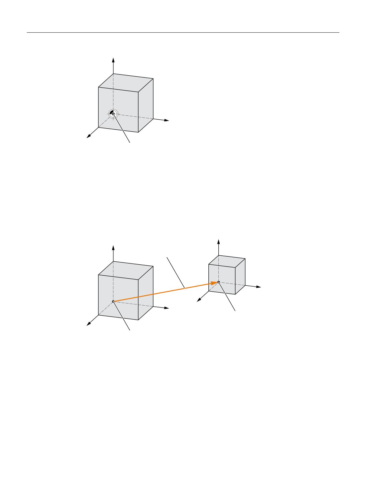
BCS and MCS always coincide when the BCS can be mapped onto the MCS without kinematic
transformation (e.g. TRANSMIT / face transformation, 5-axis transformation and up to three
machine axes).
On such machines, machine axes and geometry axes can have the same names.
Basic functions
Function Manual, 10/2020, 6FC5397-2GP40-0BA1
289
Axes, coordinate systems, frames
4.4 Coordinate systems
<
0&6
%&6
;
=
0DFKLQH ]HUR
Figure 4-15
MCS=BCS without kinematic transformation
Machine tools with kinematic transformation
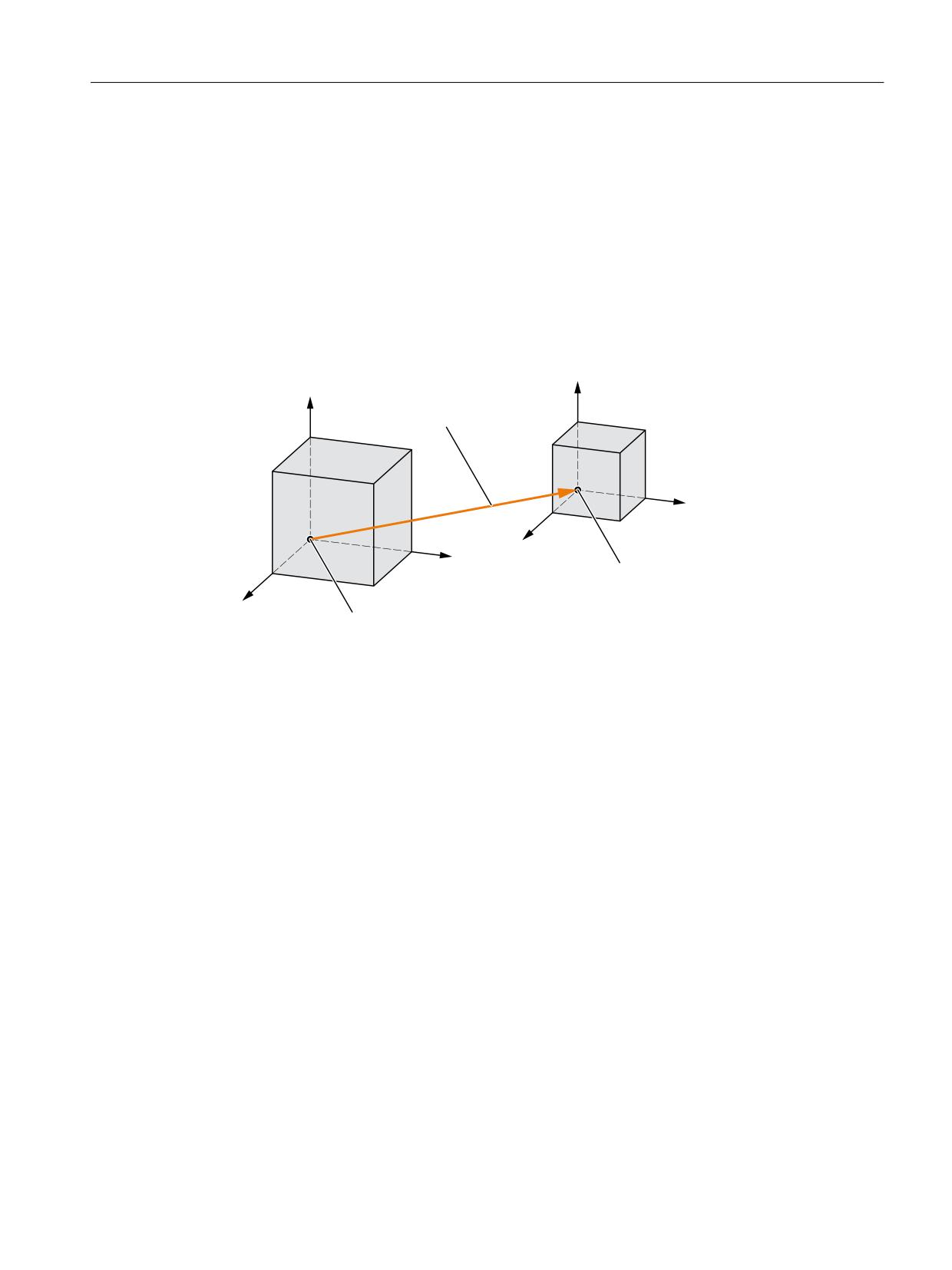
The BCS and MCS do not coincide when the BCS is mapped onto the MCS with kinematic
transformation (e.g. TRANSMIT / face transformation, 5-axis transformation or more than
three axes).
On such machines the machine axes and geometry axes must have different names.
<
%.6
\
.LQHPDWLF
0.6
WUDQVIRUPDWLRQ
;
%.6
=
%.6
;
%DVLF FRRUGLQDWH V\VWHP %&6
0.6
=
0.6
0DFKLQH FRRUGLQDWH
V\VWHP 0&6
Figure 4-16
Kinematic transformation between the MCS and BCS
Machine kinematics
The workpiece is always programmed in a two- or three-dimensional, right-angled coordinate
system (WCS). However, such workpieces are being programmed ever more frequently on
machine tools with rotary axes or linear axes not perpendicular to one another. Kinematic
transformation is used to represent coordinates programmed in the workpiece coordinate
system (rectangular) in real machine movements.
Basic functions
290
Function Manual, 10/2020, 6FC5397-2GP40-0BA1
Axes, coordinate systems, frames
4.4 Coordinate systems
Further information
Function Manual Transformations, Multi-axis transformations
4.4.4
Basic zero system (BZS)
Basic zero system (BZS)
The basic zero system (BZS) is the basic coordinate system with a basic offset.
<
<
%DVLF RIIVHW
;
=
;
%DVLF ]HUR V\VWHP %=6
=
%DVLF FRRUGLQDWH V\VWHP
%&6
Figure 4-17
Basic offset between BCS and BZS
Basic offset
The basic offset describes the coordinate transformation between BCS and BZS. It can be used,
for example, to define the palette zero.
The basic offset comprises:
• External work offset
• DRF offset
• Superimposed motion
Basic functions
Function Manual, 10/2020, 6FC5397-2GP40-0BA1
291
Axes, coordinate systems, frames
4.4 Coordinate systems
• Chained system frames
• Chained basic frames
=
<
0
;
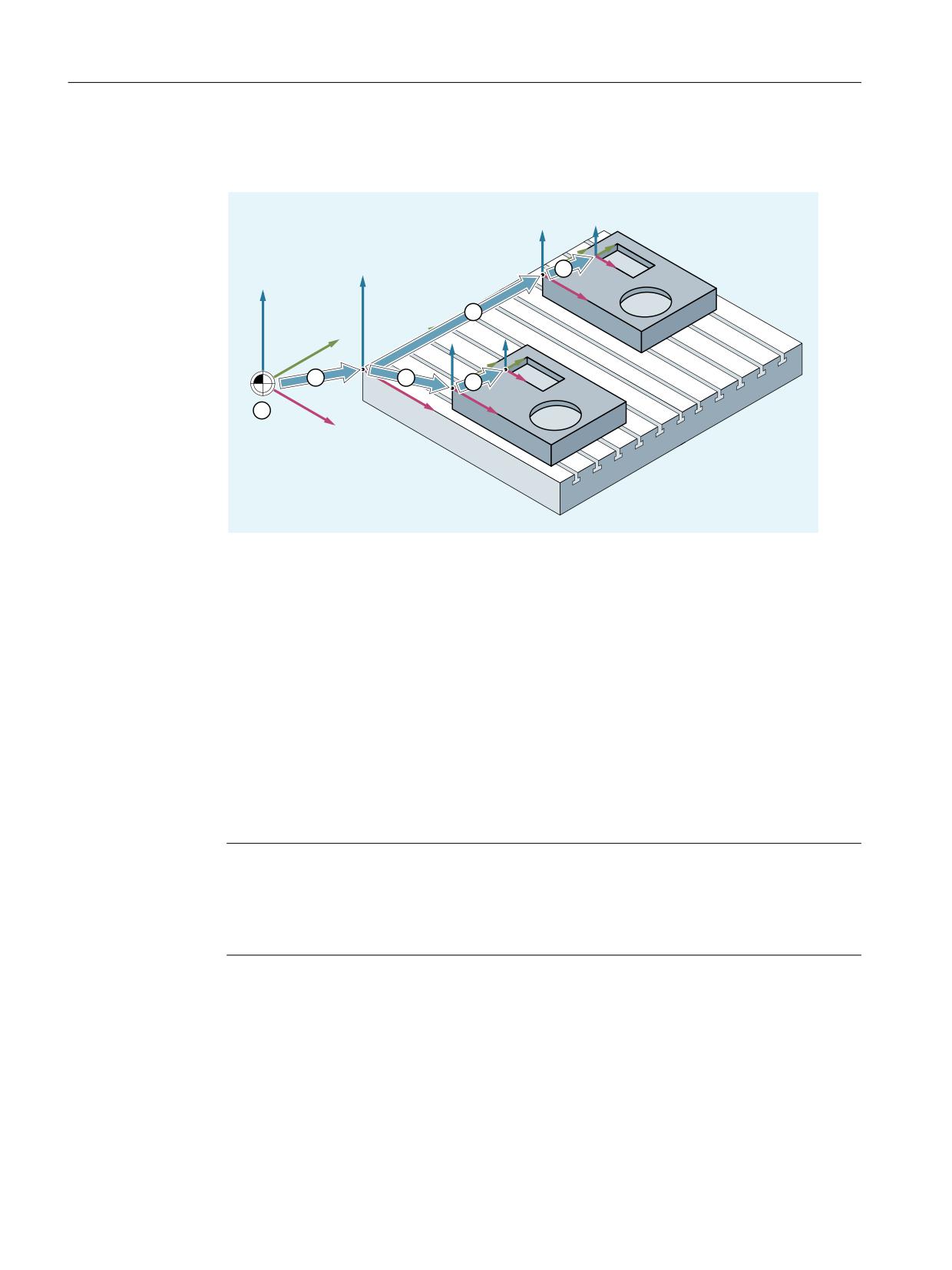
① A kinematic transformation is not active. This means that the machine coordinate system and
the basic coordinate system coincide.
② The basic zero system (BZS) with the pallet zero are obtained from the basic offset.
③ The settable work offset G54 or G55 specifies the "settable zero system" (SZS) for workpiece 1
or workpiece 2 respectively.
④ The workpiece coordinate system (WCS) results from the programmable coordinate transfor-
mation.
Figure 4-18
Example for coordinate systems on machine tool
The following applies:
• The user can change the basic offset from the part program, by means of an operator action
and from the PLC.
• If the basic offset is to take effect immediately, an ASUB can be started via the PLC using FC9
in order to execute the appropriate G command.
Note
Recommendation to the machine manufacturer
Use the 3rd basic offset onwards for your own applications.
The 1st and 2nd basic offset are reserved for "PRESET" and the "Zero offset external".
Basic functions
292
Function Manual, 10/2020, 6FC5397-2GP40-0BA1
Axes, coordinate systems, frames
4.4 Coordinate systems
4.4.5
Settable zero system (SZS)
Settable zero system (SZS)
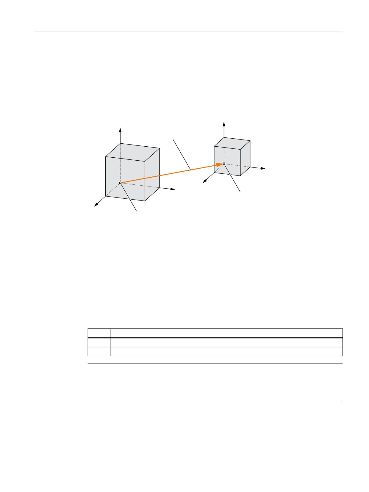
The "settable zero system" (SZS) is the workpiece coordinate system WCS with a programmable
frame (viewed from the perspective of the WCS). The workpiece zero is defined by the settable
FRAMES G54 to G599.
<
<
* ಹ*
;
=
;
6HWWDEOH ]HUR V\VWHP 6=6
=
%DVLF ]HUR V\VWHP
%=6
Figure 4-19
Settable FRAME G54 ... G599 between BZS and SZS
Programmable offsets act on the "settable zero system". All programmable offsets refer to the
"settable zero system".
WCS actual-value display in WCS or SZS
The actual values of the axes in the machine coordinate system (MCS) or the WCS can be
displayed on the HMI operator interface. For displays in WCS, the actual values can also be
displayed in relation to the SZS. The corresponding parameterization takes place through the
machine data:
MD9424 $MM_MA_COORDINATE_SYSTEM (coordinate system for actual value display)
Value
Meaning
0
Actual value display in relation to the WCS
1
Actual value display in relation to the SZS
Note
Display of the current coordinate system
When "Actual-value display in relation to the SZS" is active, the WCS is still displayed on the HMI
operator interface as the coordinate system to which the actual-value display relates.
Basic functions
Function Manual, 10/2020, 6FC5397-2GP40-0BA1
293
Axes, coordinate systems, frames
4.4 Coordinate systems
Example
Actual value display in relation to the WCS or SZS
Code (excerpt)
Actual value display:
Actual value display:
Axis X (WCS)
Axis X (SZS)
N10 X100
100
100
N20 X0
0
0
N30 $P_PFRAME = CTRANS(X,10)
0
10
N40 X100
100
110
4.4.6
Workpiece coordinate system (WCS)
Workpiece coordinate system (WCS)
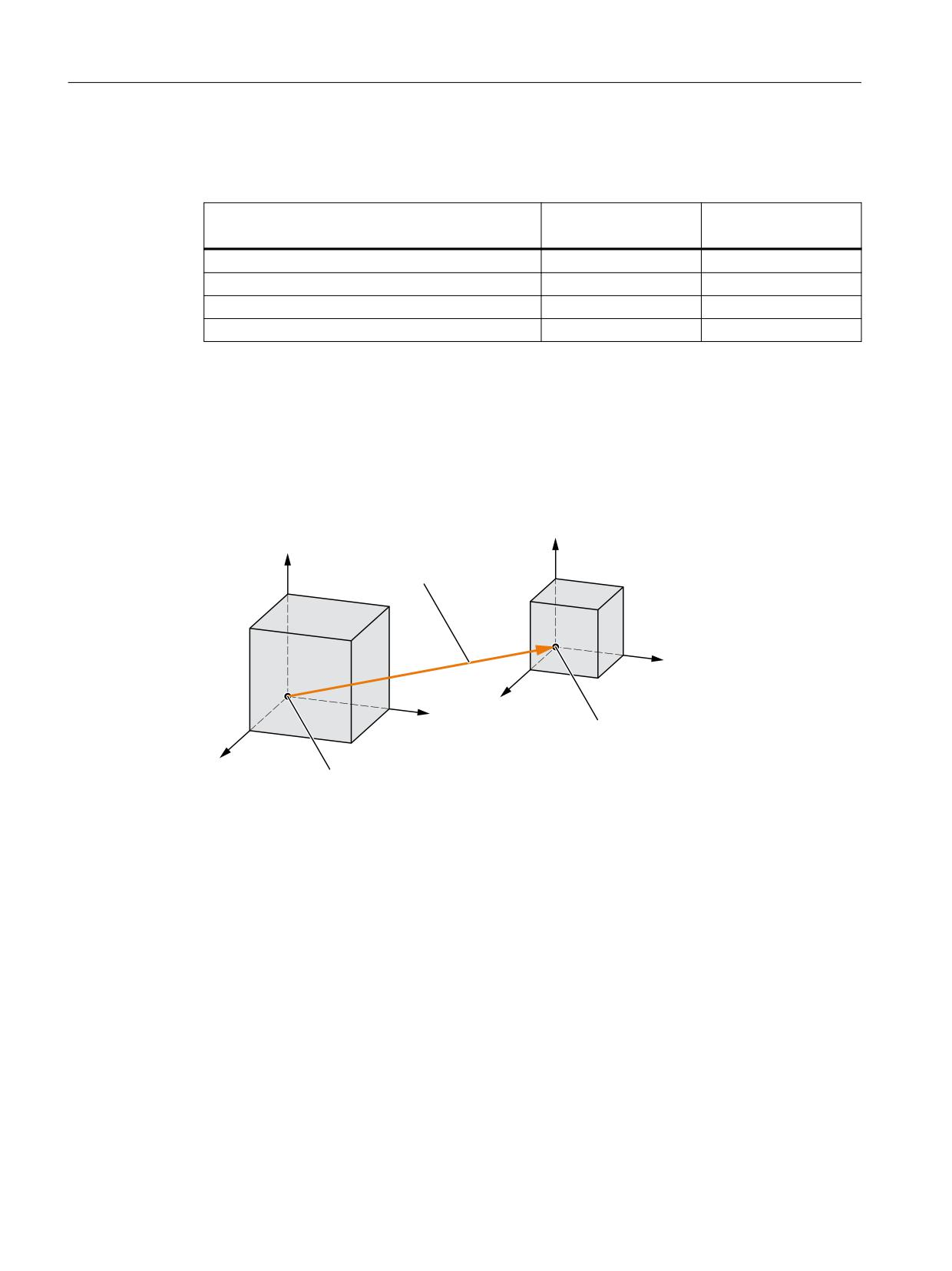
The workpiece coordinate system (WCS) is the programming basis.
<
<
3URJUDPPDEOH )5$0( ZLWK
3B3)5$0(
;
=
;
:RUNSLHFH FRRUGLQDWH V\VWHP
:&6
=
6HWWDEOH ]HUR V\VWHP
6=6
Figure 4-20
Programmable FRAME between SZS and WCS
Basic functions
294
Function Manual, 10/2020, 6FC5397-2GP40-0BA1
Axes, coordinate systems, frames
4.4 Coordinate systems
4.4.7
Additive offsets
4.4.7.1
External work offsets
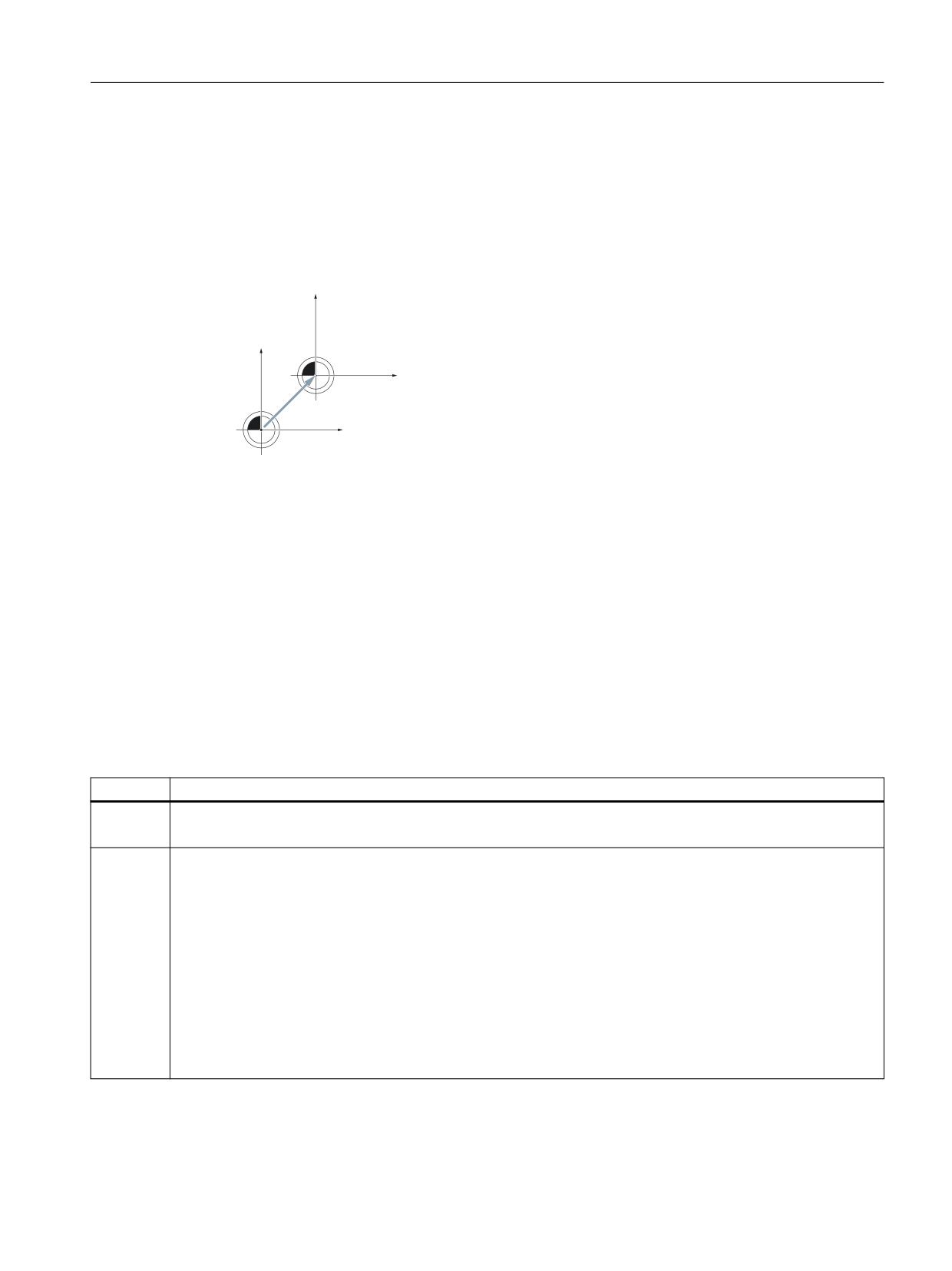
The external work offset is a linear offset between the basic coordinate system (BCS) and the
basic zero system (BZS).
=%16
=%.6
;%16
B(75$16
3B(;7)5$0(
;%.6
The external work offset $AA_ETRANS is effective in two ways depending on the machine data
parameterization:
1. The $AA_ETRANS system variable has a direct effect as offset value after activation by the NC/
PLC interface signal.
2. The value of the $AA_ETRANS system variable is taken into the system frame $P:EXTFRAME
and the data management frame $P_EXTFR after activation by the NC/PLC interface signal.
The active complete frame $P_ACTFRAME is then recalculated.
Machine data
In conjunction with the $AA_ETRANS system variable, a distinction is made between two
procedures which are selected via the following machine data:
MD28082 $MC_MM_SYSTEM_FRAME_MASK, bit1 = <value>
<Value>
Meaning
0
Function: Direct writing of $AA_ETRANS[<axis>] by the PLC, HMI or NC program.
Enable to traverse the work offset of $AA_ETRANS[<axis>] in the next possible traversing block: DB31, ... DBX3.0
1
Function: Activation of the active system frame $P:EXTFRAME and the data management frame $P_EXTFR
Enable to traverse the work offset of $AA_ETRANS[<axis>] through: DB31, ... DBX3.0. The following is performed
in the channel:
• Stop of all traversing movements in the channel (except command and PLC axes)
• Preprocessing stop with subsequent reorganization (STOPRE)
• Coarse offset of the active frame $P_EXTFRAME[<axis>] = $AA_ETRANS[<axis>]
• Coarse offset of the data management frame $P_EXTFR[<axis>] = $AA_ETRANS[<axis>]
• Recalculation of the active complete frame $P_ACTFRAME
• Traversing of the offset in the programmed axes.
• Continuation of the interrupted traversing movement or the NC program
Basic functions
Function Manual, 10/2020, 6FC5397-2GP40-0BA1
295
Axes, coordinate systems, frames
4.4 Coordinate systems
Programming
Syntax
$AA_ETRANS[<axis>] = <value>
Meaning
$AA_ETRANS:
System variable to buffer the external work offset
<axis>:
Channel axis
<value>:
Offset value
NC/PLC interface signal
Activation of the external work offset:
DB31, ... DBX3.0 = 0 → 1 ⇒ $P_EXTFRAME[<axis>] = $P_EXTFR[<axis>] = $AA_ETRANS[<axis>]
Suppression: External work offset
• The SUPA command suppresses the external work offset while the block is being processed.
• Active external work offsets are suppressed for the duration of the reference point approach
through the G74 command (reference point approach) and the equivalent operator actions
in the reference point approach mode.
• With G74, i.e. "Automatic" or "MDI" mode, the previously active external work offset
automatically becomes active again with the next traversing movement in the block.
• After a mode change from the reference point approach mode, the NC/PLC interface signal
for the referenced axes must be set for reactivation.
4.4.7.2
DRF offset
The DRF offset enables the adjustment of an additive incremental work offset for geometry and
additional axes in the basic coordinate system through handwheel.
System variable
The DRF offset can be read from the axis-specific system variable:
$AC_DRF[<Axis>]
Further information
Function Manual Axes and Spindles; Manual traversing
4.4.7.3
Reset behavior
The reset and Power On behavior of the $P_EXTFRAME active frame and of the $P_EXTFR data
management frame can be set with machine data:
Basic functions
296
Function Manual, 10/2020, 6FC5397-2GP40-0BA1

Axes, coordinate systems, frames
4.4 Coordinate systems
Machine data
• The reset behavior for the system frame active of the $P_EXTFRAME external work offset in
the channel is set with the following machine data:
• MD24006 $MC_CHSFRAME_RESET_MASK, bit 1 = <value>
Value
Meaning
The active system frame of the external work offset after channel/program end reset
is:
0
Not active
1
Active
• The Power On behavior of the channel-specific system frame of the $P_EXTFR external work
offset of the data management is set with the following machine data:
MD24008 $MC_CHSFRAME_POWERON_MASK, bit 1 = <value>
Value
Meaning
The $P_EXTFR system frame of the external work offset for Power On
0
Not deleted
1
Deleted
4.4.8
Axis-specific overlay ($AA_OFF)
4.4.8.1
Function
Axis-specific system variable $AA_OFF[<axis>] can specify an absolute position or an
incremental distance of the specified axis in a synchronous action, for example. The resulting
traversing motion is then executed in parallel with the traversing motions of the channel of the
axis.
$AA_OFF[<axis>] = <value>
4.4.8.2
Commissioning
Machine data
Parameterization of the overlaid motion
The following settings for the overlaid movement are made in the axis-specific machine data:
36750 $MA_AA_OFF_MODE, bit<n> = <value>
Bit
Value
Meaning
0
0
Interpretation of the value of $AA_OFF as the absolute position
1
Interpretation of the value of $AA_OFF as the incremental path
1
0
The overlaid movement is deselected for channel reset.
1
The overlaid movement maintained beyond channel reset.
Basic functions
Function Manual, 10/2020, 6FC5397-2GP40-0BA1
297

Axes, coordinate systems, frames
4.4 Coordinate systems
Bit
Value
Meaning
2
0
In JOG mode, an overlaid movement is not retracted.
1
In JOG mode, an overlaid movement is retracted.
3
0
A superimposed motion is interrupted for NC stop.
1
A superimposed motion is not interrupted for NC stop.
System variable
Integrated path of the axis overlay
The integrated value of the overlaid movement can be read from the axis-specific system
variable.
<value> = $AA_OFF_VAL[<axis>]
4.4.8.3
Programming: Deselecting overlays axis-specifically (CORROF)
The following axis-specific overlays (overrides) are deleted with the CORROF procedure:
• Additive work offsets (DRF offsets) set via handwheel traversal
• Position offsets programmed via the $AA_OFF system variable
A preprocessing stop is initiated through the deletion of an overlay (override) value and the
position component of the deselected overlaid movement is transferred to the position in the
basic coordinate system. Whereby, no axis is traversed.
The position value that can be read via the $AA_IM system variable (current MCS setpoint of the
axis) does not change in the machine coordinate system.
The position value that can be read via the $AA_IW system variable (current WCS setpoint of the
axis) changes in the workpiece coordinate system because it now contains the deselected
component of the overlaid movement.
Note
CORROF can be programmed in an NC program.
CORROF must not be programmed in a synchronized action.
Syntax
CORROF(<Axis>,"<String>"[,<Axis>,"<String>"])
Meaning
CORROF:
Procedure for the deselection of the following offsets and overlays of an axis:
• DRF offset
• Position offsets ($AA_OFF)
Effectiveness:
Modal
Basic functions
298
Function Manual, 10/2020, 6FC5397-2GP40-0BA1

Axes, coordinate systems, frames
4.4 Coordinate systems
<Axis>:
Axis identifier (channel, geometry or machine axis identifier)
Data type:
AXIS
<String>:
Character string for the definition of the overlay type
Data type:
BOOL
Value
Meaning
DRF
DRF offset
AA_OFF
Position offset ($AA_OFF)
Examples
Example 1: Axis-specific deselection of a DRF offset (1)
A DRF offset is generated in the X axis by DRF handwheel traversal. No DRF offsets are operative
for any other axes in the channel.
Program code
Comment
N10 CORROF(X,"DRF")
; CORROF has the same effect as DRFOF here.
Example 2: Axis-specific deselection of a DRF offset (2)
A DRF offset is generated in the X and Y axes by DRF handwheel traversal. No DRF offsets are
operative for any other axes in the channel.
Program code
Comment
; Only the DRF offset of the X axis is deselected; the DRF offset of the Y axis is
retained.
; With DRFOF, both offsets would have been deselected.
N10 CORROF(X,"DRF")
Example 3: Axis-specific deselection of a $AA_OFF position offset
Program code
Comment
; A position offset == 10 is interpolated for the X axis.
N10 WHEN TRUE DO $AA_OFF[X]=10 G4 F5
; The position offset of the X axis is deselected: $AA_OFF[X]=0
; The X axis is not traversed.
; The position offset is added to the current position of the X axis.
N80 CORROF(X,"AA_OFF")
Basic functions
Function Manual, 10/2020, 6FC5397-2GP40-0BA1
299
Axes, coordinate systems, frames
4.4 Coordinate systems
Example 4: Axis-specific deselection of a DRF offset and a $AA_OFF position offset (1)
A DRF offset is generated in the X axis by DRF handwheel traversal. No DRF offsets are operative
for any other axes in the channel.
Program code
Comment
; A position offset of 10 is interpolated for the X axis.
N10 WHEN TRUE DO $AA_OFF[X]=10 G4 F5
; Only the DRF offset and the position offset of the X axis are deselected.
; The DRF offset of the Y axis is retained.
N70 CORROF(X,"DRF",X,"AA_OFF")
Example 5: Axis-specific deselection of a DRF offset and a $AA_OFF position offset (2)
A DRF offset is generated in the X and Y axes by DRF handwheel traversal. No DRF offsets are
operative for any other axes in the channel.
Program code
Comment
; A position offset == 10 is interpolated for the X axis.
N10 WHEN TRUE DO $AA_OFF[X]=10 G4 F5
; The DRF offset of the Y axis and the position offset of the X axis are deselected.
; The DRF offset of the X axis is retained.
N70 CORROF(Y,"DRF",X,"AA_OFF")
Further information
$AA_OFF_VAL
Once the position offset has been deselected by means of $AA_OFF, system variable
$AA_OFF_VAL (integrated distance of axis overlay) for the corresponding axis will equal zero.
$AA_OFF in JOG mode
Also in JOG mode, if $AA_OFF changes, the position offset will be interpolated as an overlaid
movement if this function has been enabled via machine data MD 36750 $MA_AA_OFF_MODE.
$AA_OFF in synchronized action
If a synchronized action which immediately resets $AA_OFF
(DO $AA_OFF[<axis>]=<value>) is active when the position offset is deselected using the
CORROF(<axis>,"AA_OFF"), then $AA_OFF will be deselected and not reset, and alarm
21660 will be displayed. However, if the synchronized action becomes active later, e.g. in the
block after CORROF, $AA_OFF will remain set and a position offset will be interpolated.
Automatic channel axis exchange
If an axis that is active in another channel has been programmed for a CORROF, it will be fetched
into the channel with an axis exchange (requirement: MD30552 $MA_AUTO_GET_TYPE > 0) and
the position offset and/or the DRF offset deselected.
Basic functions
300
Function Manual, 10/2020, 6FC5397-2GP40-0BA1
Axes, coordinate systems, frames
4.5 Frames
4.5
Frames
4.5.1
Frame types
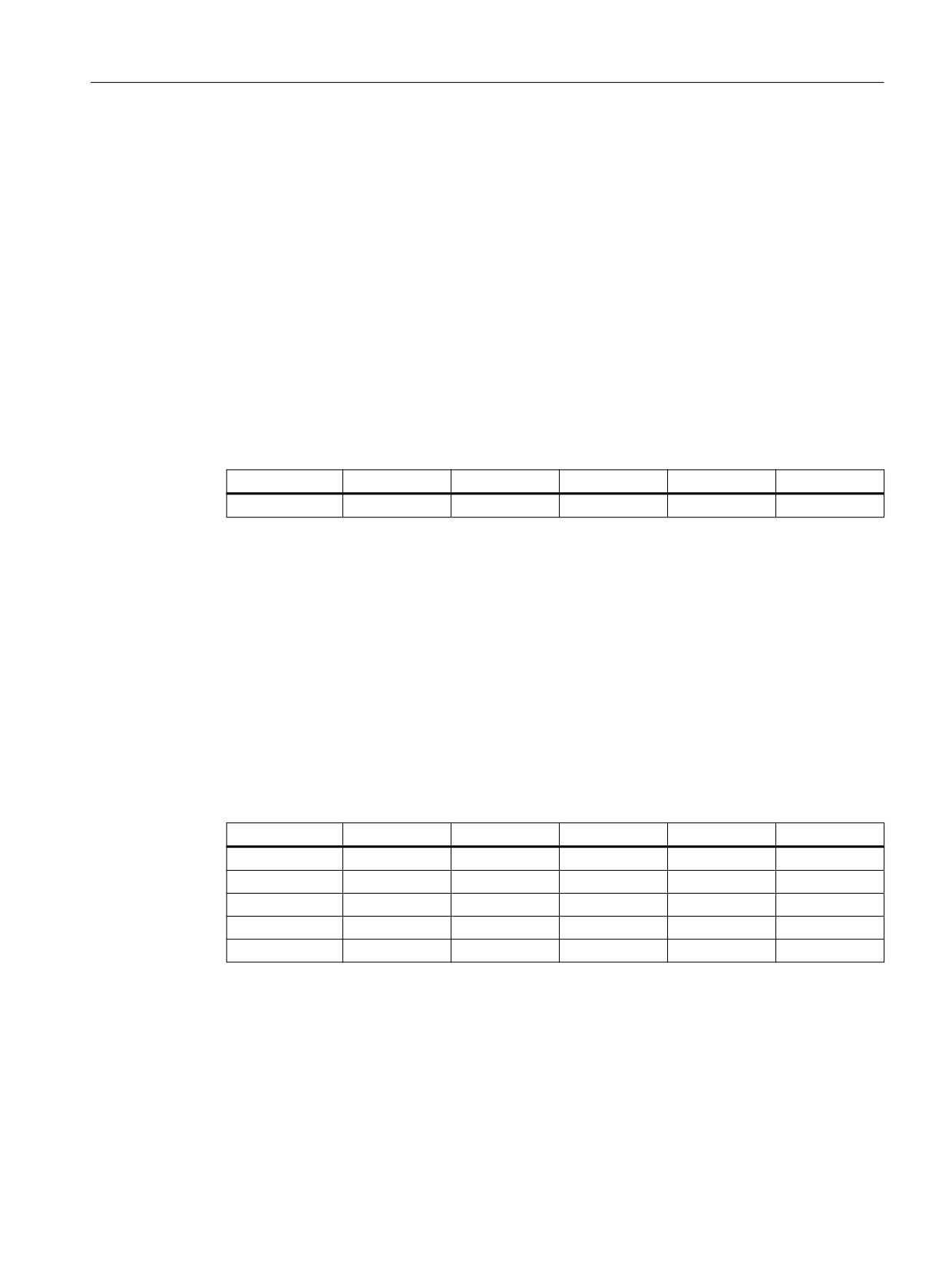
A frame is a data structure that contains values for offset (TRANS), fine offset (FINE), rotation
(ROT), mirroring (MIRROR) and scaling (SCALE) for axes.
When activating the frame, using the frame values, a static coordinate transformation for the
axes contained in the frame is performed using a defined algorithm.
Axis-specific frame
An axis-specific frame contains the frame values of an axis.
Example data structure of an axis-specific frame for geometry axis X:
Axis
TRANS
FINE
ROT
MIRROR
SCALE
X
10.0
0.1
0.0
0
1
Channel-specific frame
A channel-specific frame contains frame values for all channel axes (geometry, special and
machine axes).
Rotations (ROT) are only included in the calculation for geometry axes.
A channel-specific frame is only active in the channel in which the frame is defined.
Example of the data structure of a channel-specific frame:
• Geometry axes: X, Y, Z
• Special axes: A
• Machine axes: AX1
Axis
TRANS
FINE
ROT
MIRROR
SCALE
X
10.0
0.1
0.0
0
1
Y
0.0
0.0
0.0
1
1
Z
0.0
0.0
45.0
0
1
A
2.0
0.1
0.0
0
2
AX1
0.0
0.0
0.0
0
0
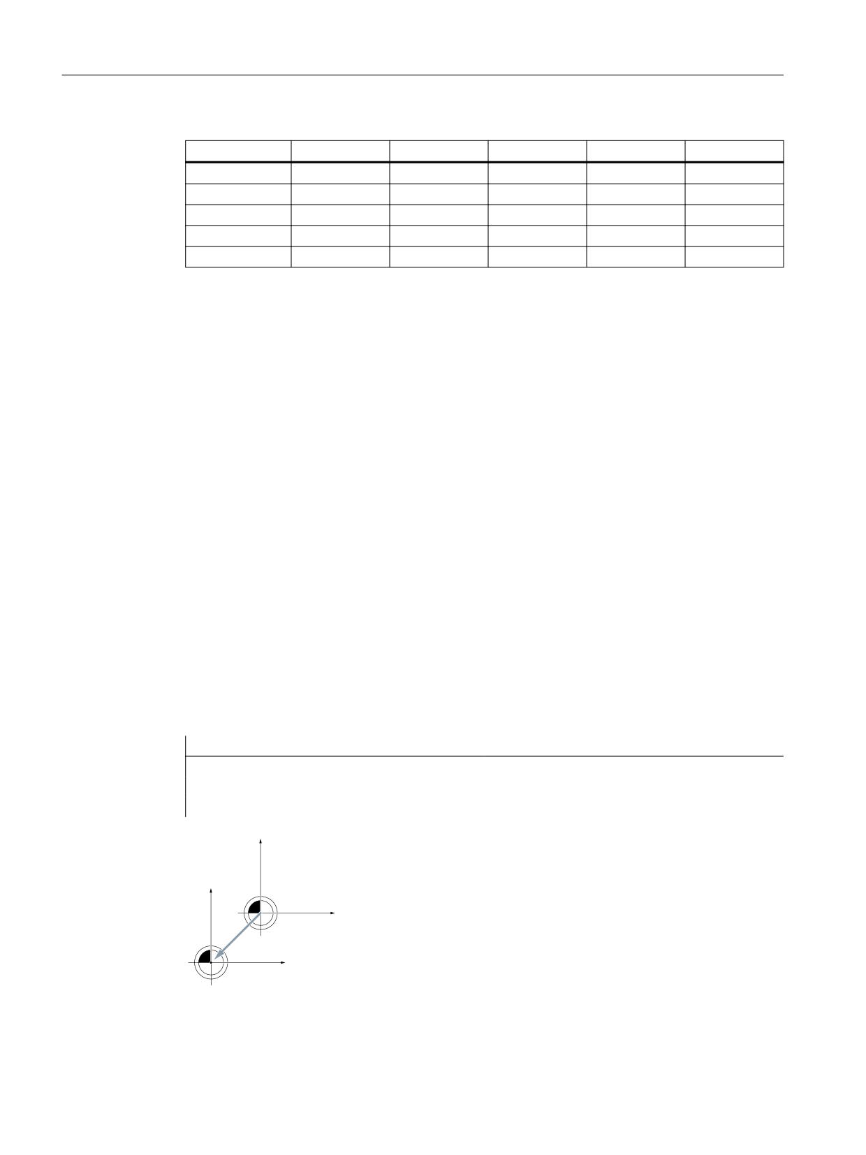
Global frame
A global frame contains the frame values for all machine axes.
A global frame is active in all channels of the NC.
Example data structure of global frame:
• Machine axes: AX1, ... AX5
Basic functions
Function Manual, 10/2020, 6FC5397-2GP40-0BA1
301
Axes, coordinate systems, frames
4.5 Frames
Axis
TRANS
FINE
ROT
MIRROR
SCALE
AX1
10.0
0.1
-
0
1
AX2
0.0
0.0
-
1
1
AX3
0.0
0.0
-
0
1
AX4
2.0
0.1
-
0
2
AX5
0.0
0.0
-
1
1
4.5.2
Frame components
4.5.2.1
Translation
Programming
The programming of the translation or coarse offset can be performed via the following
commands:
• Example of data management frames $P_UIFR
- Complete frame: $P_UIFR[<n>] = CTRANS(<K1>,<V1>[,<K2>,<V2>]
[,<K3>,<V3>])
with Km = coordinate x, y or z and Vm = offset m
- Frame component: $P_UIFR[<n>,<k>,TR] = <V>
with K = coordinate x, y or z and V = offset
• Example of programmable frame
- TRANS <K1> <V1> [<K2> <V2>][<K3> <V3>]
with Km = coordinate x, y or z and Vm = offset m
Programs examples:
Program code
Remark
$P_UIFR[1] = CTRANS(X,10,Y,10)
Complete frame
$P_UIFR[1,X,TR] = 10
Frame components
TRANS X=10 Y=10
Programmable frame
<
7UDQVODWLRQ ILQH GLVSODFHPHQW
<v
;
;v
Figure 4-21
Offset in the Z direction
Basic functions
302
Function Manual, 10/2020, 6FC5397-2GP40-0BA1

Axes, coordinate systems, frames
4.5 Frames
4.5.2.2
Fine offset
Parameterization
The fine offset is enabled via the machine data:
MD18600 $MN_MM_FRAME_FINE_TRANS = <value>
Value
Meaning
0
The fine offset cannot be entered or programmed.
1
Fine offset is possible for settable frames, basic frames and the programmable frame via com-
mand or program.
Programming
The programming of the translation or coarse offset can be performed via the following
commands:
• Example of data management frames $P_UIFR
- Complete frame: $P_UIFR[<n>] = CFINE(<K1>,<V1>[,<K2>,<V2>]
[,<K3>,<V3>])
with Km = coordinate x, y or z and Vm = offset m
- Frame component: $P_UIFR[<n>,<K>,FI] = <V>
with K = coordinate x, y or z and V = offset
• Example of programmable frame
- TRANS <K1> <V1> [<K2> <V2>][<K3> <V3>]
with Km = coordinate x, y or z and Vm = offset m
Programming examples:
Program code
Remark
$P_UIFR[1] = CTRANS(X,10,Y,10)
Complete frame
$P_UIFR[1,X,TR] = 10
Frame components
TRANS X=10 Y=10
Programmable frame
Basic functions
Function Manual, 10/2020, 6FC5397-2GP40-0BA1
303
Axes, coordinate systems, frames
4.5 Frames
4.5.2.3
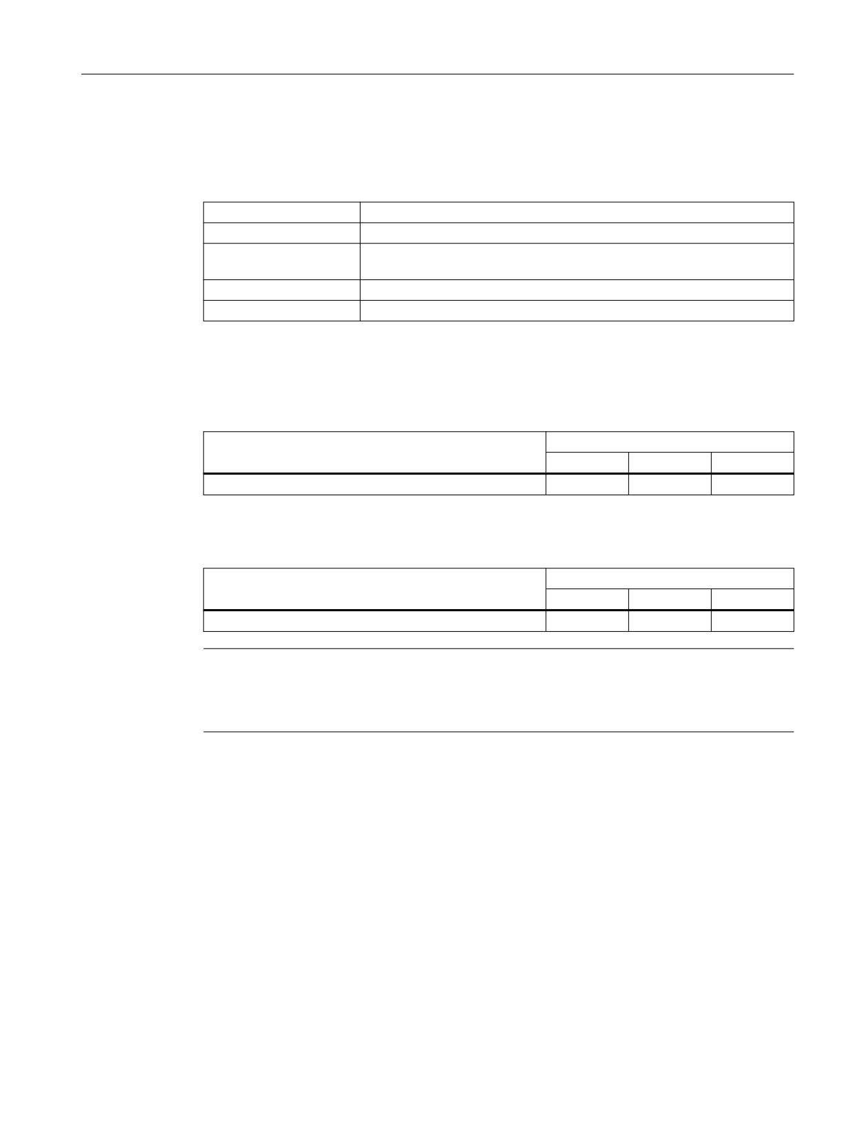
Rotation Overview (geometry axes only)
Function
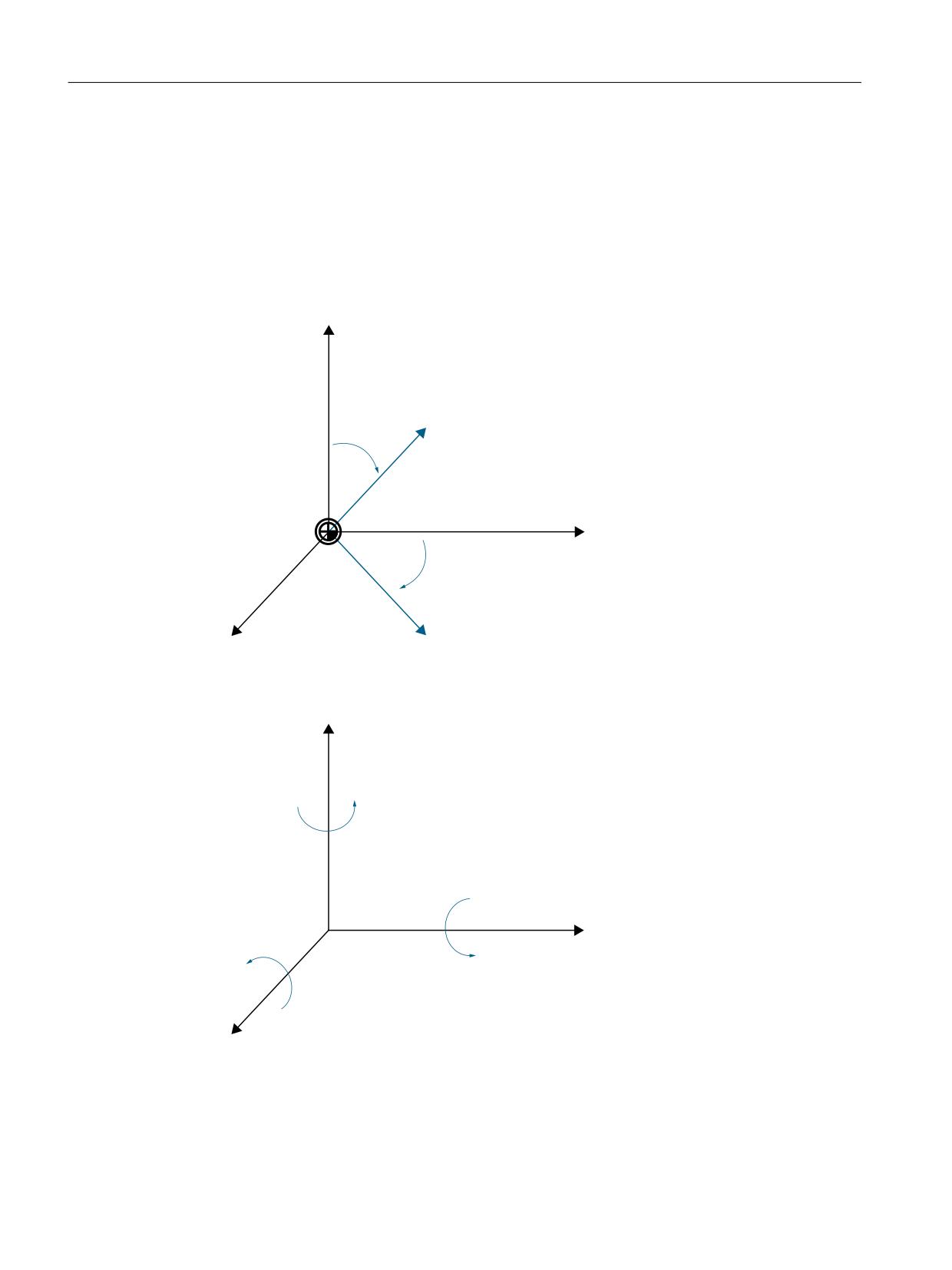
The direction of rotation around the coordinate axes is determined by means of a right-hand,
rectangular coordinate system with axes x, y and z. If the rotary motion is in a clockwise direction
when looking in the positive direction of the coordinate axis, the direction of rotation is positive.
A, B and C designate rotations whose axes are parallel to the coordinate axes.
\
\
<
[
<
]
]
[
The following figure shows the new position of the coordinate system x', y' and z' after the
rotation around z with γ = -45°
\
%
$
[
&
]
Parameterization of the rotation sequence
The following machine data is used to set around which coordinate axes and in which order the
rotations are performed when more than one angle of rotation is programmed:
Basic functions
304
Function Manual, 10/2020, 6FC5397-2GP40-0BA1
Axes, coordinate systems, frames
4.5 Frames
MD10600 $MN_FRAME_ANGLE_INPUT_MODE = <value>
Value
Meaning
1
Euler angles in zy'x'' convention (RPY angles)
2
Euler angles in zx'z" convention
Note
For historical reasons, Euler angles in zx'z" convention can be used. However, it is strongly
recommended that only Euler angles in zy'x" convention (RPY angles) be used (see
Section Rotation with a Euler angles: ZY'X" convention (RPY angles) (Page 305)).
4.5.2.4
Rotation with a Euler angles: ZY'X" convention (RPY angles)
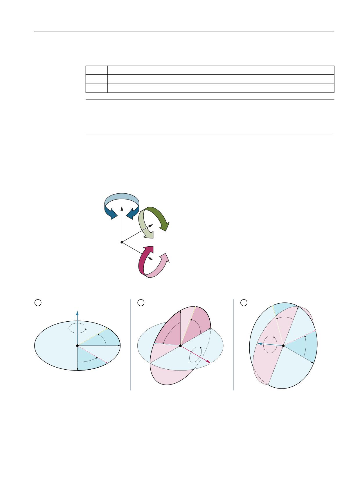
Euler angles in the ZY'X" convention are also called RPY angles. RPY is derived from rolling,
pitching and yawing:
<DZ
=
3LWFK
<
;
5ROO
For the ZY'X'' convention, the rotations are carried out in the following sequence:
\ೀ
\ು
\ೀ
]
]ಿ
]ಿ
\ಿ
\ಿ
[ು
]ೀ
]ೀ
]ು
\
[ಿ
[ಿ
[ೀ
[ೀ
[
Basic functions
Function Manual, 10/2020, 6FC5397-2GP40-0BA1
305

Axes, coordinate systems, frames
4.5 Frames
Value range
With RPY angles, programmed values can only be unambiguously calculated back within the
following value ranges:
-180
≤
x
≤
180
-90
y
90
<
<
-180
z
180
≤
≤
Programming: Writing all rotation components
When programming the rotating components of a frame usingCROT, ROT or AROT, all rotating
components are always written to. Rotating components not explicitly programmed are
assigned a value of 0°.
Syntax
<frame> = CROT([<1st GAx>,<angle>,][<2nd GAx>,<angle>,][<3rd
GAx>,<angle>])
ROT [<1st GAx> <Angle>] [<2. GAx> <Angle>] [<3. GAx> <Angle>]
AROT [<1st GAx> <Angle>] [<2. GAx> <Angle>] [<3. GAx> <Angle>]
Meaning
CROT:
Absolute rotation
<Frame>:
Arbitrary active or data management frame
ROT:
Absolute rotation
Reference frame: Programmable frame $P_PFRAME,
reference point: Zero point of the current workpiece coordinate system set
with G54 ... G57, G505 ... G599
AROT:
Additive rotation
Reference frame: Programmable frame $P_PFRAME,
reference point: Zero point of the current workpiece coordinate system set
with G54 ... G57, G505 ... G599
<nth GAx>:
Name of the nth geometry axis around which rotation is to be performed
with the specified angle. The value 0° is implicitly set as angle of rotation for
a geometry axis that has not been programmed.
Assignment of geometry axis to rotary axis:
Geometry axis
Rotary axis
1st geometry axis
x''
2nd geometry axis
y'
3rd geometry axis
z
<angle>:
Angle specification in degrees.
[...]:
The data in square brackets are optional.
Programming: Writing to a rotation component
When explicitly programming a rotation component of a frame, only the programmed rotation
component is written. Rotation components that have not been programmed remain
unchanged.
Basic functions
306
Function Manual, 10/2020, 6FC5397-2GP40-0BA1
Axes, coordinate systems, frames
4.5 Frames
Syntax
<frame>[<index>,<GAx>,RT] = <angle>
Meaning
<Frame>:
Arbitrary active frame or data management frame
<Index>:
Array index of the frame, e.g. $P_UIFR[0 ... n]
<GAx>:
Name of the geometry axis around which rotation is to be performed with
the specified angle.
RT:
Keyword for rotation "RoTation"
<Angle>
Angle specification in degrees.
Reading back the rotation components
In general, the same values are obtained when reading back the rotation components of a frame
as those that were programmed:
Programmed
Values when reading back
x, RT
y, RT
z, RT
<Frame> = CROT(X,45,Y,30,Z,-20)
45
30
-20
Values outside the value range
Programmed values outside a value range are mapped on the range limits:
Programmed
Values when reading back
x, RT
y, RT
z, RT
<Frame> = CROT(X,190,Y,0,Z,-200)
-170
0
160
Note
It is recommended that when writing the rotation components of the frame, the specified value
ranges are observed so that the same values are obtained when reading back the rotation
components.
Gimbal lock
Gimbal lock designates a geometric problem in which the rotation components can no longer be
unambiguously calculated back from the position vector. Gimbal lock occurs in RPY angles with
an angular position of the rotation component y = 90°. In this case, the rotation components are
converted by the control system after being written so that the following applies:
• Rotation component z = rotation component z - rotation component x
• Rotation component x = 0°
• Rotation component y = 90°
Basic functions
Function Manual, 10/2020, 6FC5397-2GP40-0BA1
307

Axes, coordinate systems, frames
4.5 Frames
Programmed
Values when reading back
x, RT
y, RT
z, RT
<Frame> = CROT(X,30,Y,90,Z,40)
0
90
40 - 30 = 10
CAUTION
Different values for reading back the rotation component z
Because of the different conversion times after writing the complete frame or the writing
of individual rotation components of a data management frame and the writing
of individual rotation components of an active frame, different values can be read back for
rotation component z.
Differences when writing the complete frame and frame components
Two cases must be distinguished when writing the rotation components of a frame:
1. Writing the complete frame: <Frame> = CROT(X,a,Y,b,Z,c)
When writing the complete frame, the conversion is immediately at the time of writing.
2. Writing individual rotation components, e.g. rotation around X: <Frame>[0,X,RT]= <a>
When writing individual rotation components, the conversion depends on the storage
location of the frame:
- Data management frames
With data management frames, the conversion is at the time of activation of the frame
based on the rotation components written by this time. With regard to the conversion of
a data management frame, a data management frame therefore behaves in the same
way after writing individual rotation components as when writing the complete frame.
- Active frames
In the case of active frames, the conversion is immediately at the time of writing of the
rotation component.
Basic functions
308
Function Manual, 10/2020, 6FC5397-2GP40-0BA1

Axes, coordinate systems, frames
4.5 Frames
Example
•
Writing the complete frame
The conversion is made in each block after the complete frame has been written.
Programmed
Values when reading back
x, RT
y, RT
z, RT
N10 <Frame> = CROT(X,0,Y,90,Z,90)
0
90
90
N20 <Frame> = CROT(X,90,Y,90)
0
90
-90 1)
N30 <Frame> = CROT(X,90,Y,90,Z,90)
0
90
0 1)
1) Different values compared to the writing of individual rotation components of an active frame
•
Writing individual rotation components of a data management frame
The conversion is performed on the activation of the data management frame. In the
example, at any time after N30.
Programmed
Values when reading back
x, RT
y, RT
z, RT
N10 <Data management frame>[0,X,RT] = 0
0
90
90
N20 <Data management frame>[0,Y,RT] = 90
N30 <Data management frame>[0,Z,RT] = 90
N10 <Data management frame>[0,X,RT] = 90
0
90
-90 1)
N20 <Data management frame>[0,Y,RT] = 90
N30 <Data management frame>[0,Z,RT] = 0
N10 <Data management frame>[0,X,RT] = 90
0
90
0 1)
N20 <Data management frame>[0,Y,RT] = 90
N30 <Data management frame>[0,Z,RT] = 90
1) Different values compared to the writing of individual rotation components of an active frame
•
Writing individual rotation components of an active frame
Any required conversion is performed immediately on writing the rotation component.
The stored initial values of the active frame are: x = 0, y = 0, z = 0.
Programmed
Values when reading back
x, RT
y, RT
z, RT
N10 <Active frame>[0,X,RT] = 0
0
90
90
N20 <Active frame>[0,Y,RT] = 90
N30 <Active frame>[0,Y,RT] = 90
N10 <Active frame>[0,X,RT] = 90
0
90
0 1)
N20 <Active frame>[0,Y,RT] = 90
N30 <Active frame>[0,Y,RT] = 0
N10 <Active frame>[0,X,RT] = 90
0
90
90 1)
N20 <Active frame>[0,Y,RT] = 90
N30 <Active frame>[0,Y,RT] = 90
1) Different values compared to the writing of the complete frame or the writing of individual
rotation components of a data management frame
Basic functions
Function Manual, 10/2020, 6FC5397-2GP40-0BA1
309
Axes, coordinate systems, frames
4.5 Frames
4.5.2.5
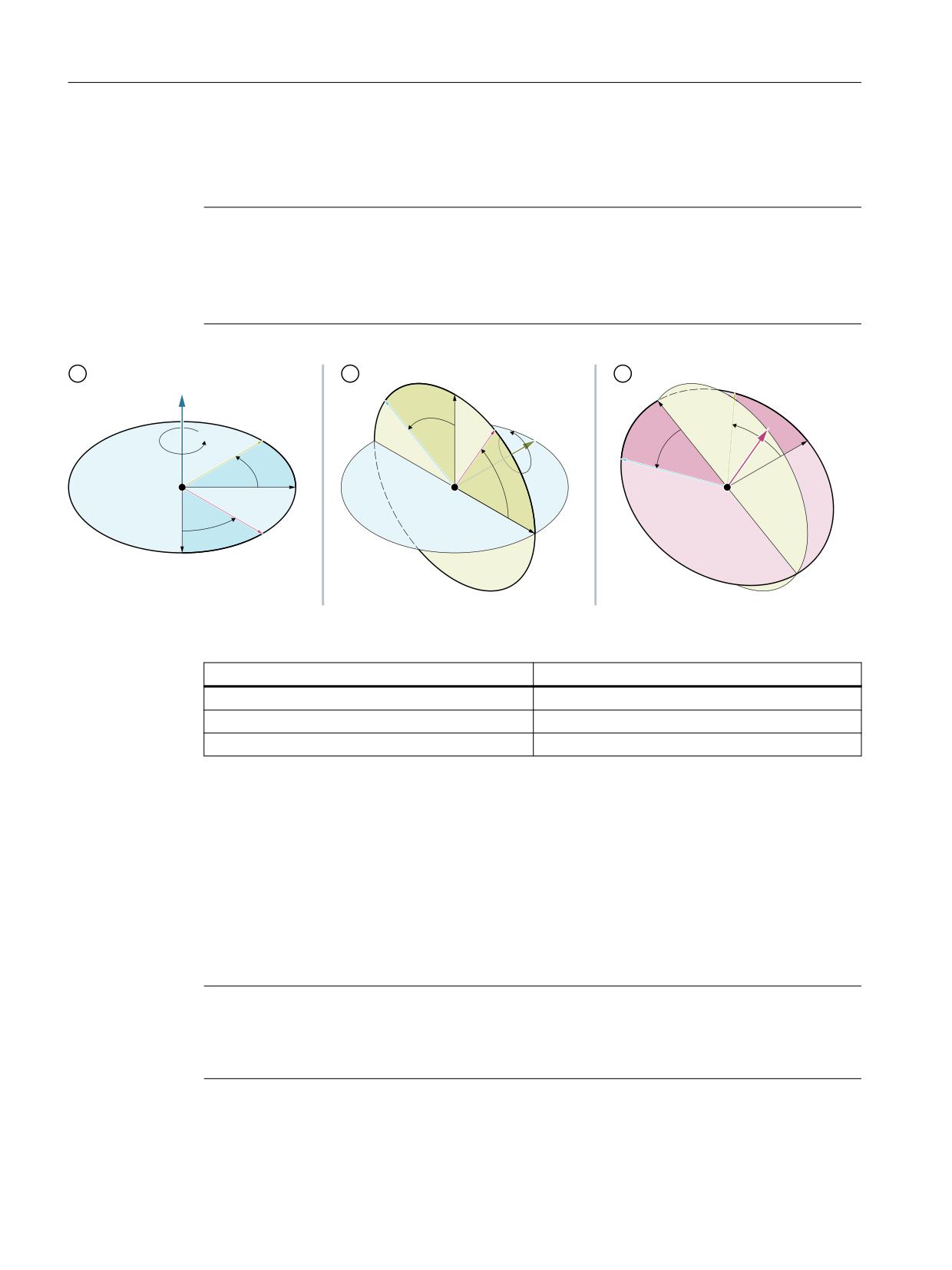
Rotation with a Euler angles: ZX'Z" convention
With Euler angles, the rotations are in the order z, x', z".
Note
Recommended use
For historical reasons, Euler angles in zx'z" convention can be used. However, it is strongly
recommended that only Euler angles in zy'x" convention (RPY angles) be used (see
Section Rotation with a Euler angles: ZY'X" convention (RPY angles) (Page 305)).
\ು
]
]ಿ
]ಿ
]ೀ
]ೀ
[ೀ
[ೀ
[ು
\ೀ
\ಿ
\ಿ
\ೀ
]ು
\
[ಿ
[ಿ
[
Assignment of rotary axis to geometry axis
Rotary axis
Geometry axis in channel
z
3rd geometry axis
x'
1st geometry axis
z''
3rd geometry axis
Value range
Data from Euler angles can only be unambiguously calculated back within the following value
ranges:
0
<=
x
<
180
-180
<=
y
<=
180
-180
<=
z
<=
180
For data outside the specified value ranges, a modulo conversion is made referred to the value
of the particular range limit.
Note
It is recommended that when writing the rotation components of the frame, the specified value
ranges are observed so that the same values are obtained when reading back the rotation
components.
Basic functions
310
Function Manual, 10/2020, 6FC5397-2GP40-0BA1
Axes, coordinate systems, frames
4.5 Frames
4.5.2.6
Rotation in any plane
CRPL - Constant Rotation Plane
The predefined function "Constant Rotation Plane" enables a rotation to be programmed for a
frame in an arbitrary plane (G17, G18, G19) without specifying the name of a geometry axis.
This enables rotations to be programmed in the third plane when only two geometry axes are
present in the channel due to the specific machine constellation.
Syntax
CRPL(<rotary axis>,<angle of rotation>)
Meaning
CRPL:
Rotation in any plane
<rotary
Axis around which the rotation is performed
axis>:
Type:
INT
Value
Meaning
0
Rotation in the active plane
1
Rotation around Z
2
Rotation around Y
3
Rotation around X
<angle of
Angle in degrees through which the rotation is performed
rotation>:
Type:
REAL
It is strongly recommended to observe the specified angular ranges. If the
limits are not observed, then an unambiguous reverse calculation is not
possible. Angles outside the limits are not rejected.
RPY angle:
X
-180 <= <angle of rotation> <= 180
Y
-90 <= <angle of rotation> <= 90
Z
-180 <= <angle of rotation> <= 180
ZX'Z" convention:
X
-180 <= <angle of rotation> <= 180
Y
0 <= <angle of rotation> <= 180
Z
-180 <= <angle of rotation> <= 180
Chaining with frames
CRPL() can be chained with frames and known frame functions such as CTRANS(), CROT(),
CMIRROR(), CSCALE(), CFINE() etc.
Examples:
$P_PFRAME = $P_PFRAME : CRPL(0,30.0)
$P_PFRAME = CTRANS(X,10) : CRPL(1,30.0)
$P_PFRAME = CROT(X,10) : CRPL(2,30.0)
$P_PFRAME = CRPL(3,30.0) : CMIRROR(Y)
Basic functions
Function Manual, 10/2020, 6FC5397-2GP40-0BA1
311
Axes, coordinate systems, frames
4.5 Frames
4.5.2.7
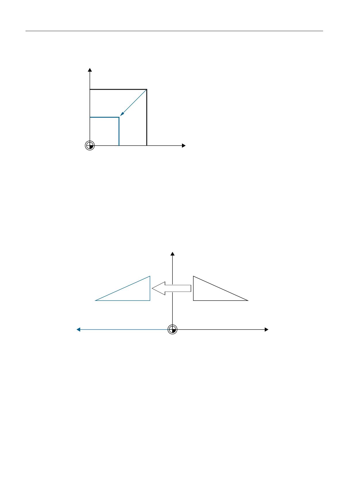
Scaling
\
6FDOLQJ
[
Programming
The program commands below are used to program the scaling:
$P_UIFR[1] = CSCALE(x,1,y,1)
SCALE x = 1y = 1
$P_UIFR[1,x,sc] = 1
4.5.2.8
Mirroring
\
0LUURULQJ
[
Programming
The program commands below are used to program a mirroring:
$P_UIFR[1] = CMIRROR(x,1,y,1)
MIRROR x = 1y = 1
$P_UIFR[1,x,mi] = 1
Basic functions
312
Function Manual, 10/2020, 6FC5397-2GP40-0BA1
Axes, coordinate systems, frames
4.5 Frames
4.5.2.9
Chain operator
Frame components or complete frames can be combined into a complete frame using the chain
operator ( : ).
4.5.2.10
Programmable axis name
Geometry, channel and machine axis names can be used in the frame commands. The
programmed axis must be known to the channel-specific frames in the channel.
SPI
When programming frame commands, the SPI(<spindle number>) axis function can be
used in place of an axis name.
SPI(<spindle number>) forms the reference of the spindle to the channel axis.
→ refer to MD35000 $MA_SPIND_ASSIGN_TO_MACHAX[ ] (assignment of spindle to machine
axis)
The following frame commands can be programmed with SPI(spino):
CTRANS()
CFINE()
CMIRROR()
CSCALE()
A spindle can only be assigned to one rotary axis at a time. The CROT(..) function can therefore
not be programmed withSPI(), as only geometry axes are permitted forCROT().
The channel axis name or machine axis name of the axis belonging to the spindle is always
output when decompiling frames, even when axis names have been programmed in the part
program with SPI(..).
If the spindle is assigned e.g., to the Channel Axis A then the programming:
N10 $P_UIFR[1] =
CTRANS(SPI(1),33.33,X,1):CSCALE(SPI(1),33.33):CMIRROR(SPI(1))
during recompilation:
$P_UIFR[1]=CTRANS(X,1,A,33.33):CSCALE(A,33.33):CMIRROR(A)
If a spindle and an assigned axis are programmed in a frame command, then Alarm 16420 "Axis
% multiply programmed" is output.
Example:
$P_UIFR[1] = CTRANS(SPI(1),33.33,X,1,A,44)
(The spindle is assigned to Axis A.)
Programming examples
$P_PFRAME[SPI(1),TR]=22.22
$P_PFRAME=CTRANS(X, axis value,Y,axis value,SPI(1),axis value)
Basic functions
Function Manual, 10/2020, 6FC5397-2GP40-0BA1
313
Axes, coordinate systems, frames
4.5 Frames
$P_PFRAME=CSCALE(X,Scale,Y,scale,SPI(2),scale)
$P_PFRAME=CMIRROR(S1,Y,Z)
$P_UBFR=CTRANS(A,10):CFINE(SPI(1),0.1)
4.5.2.11
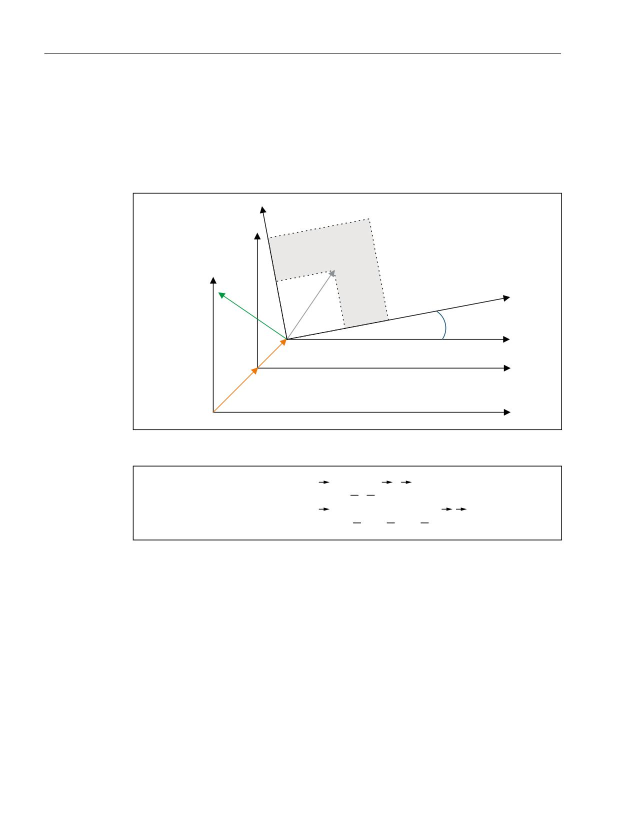
Coordinate transformation
6FDOLQJ
0LUURULQJ
5RWDWLRQ
)LQH RIIVHW
&RDUVH RIIVHW
The formulae below are used to discover the coordinate transformation for geometry axes:
:&6 ᪸ %&6
Y
5
6
0 Y W
%&6 ᪸ :&6
Y LQY 0
LQY 6
LQY 5
Y W
V:
Position vector in BCS
V':
Position vector in WCS
4.5.3
Data management frames and active frames
4.5.3.1
Overview
Frame types
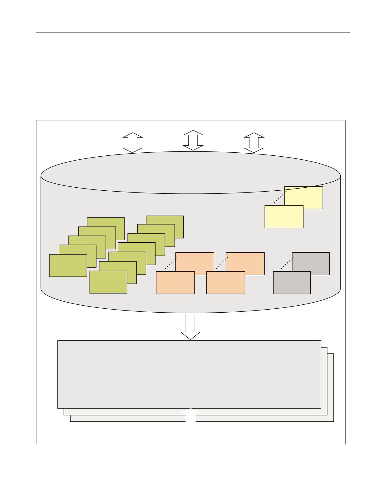
The following frame types are available:
• System frames ($P_PARTFR, ... see figure)
• Basic frames ($P_NCBFR[<n>], $P_CHBFR[<n>])
Basic functions
314
Function Manual, 10/2020, 6FC5397-2GP40-0BA1
Axes, coordinate systems, frames
4.5 Frames
• Grinding frames ($P_GFR[<n>])
• Settable frames ($P_UIFR[<n>])
• Programmable frame ($P_PFRAME)
For all frame types except the programmable frame, one or more frames exist in the data
management (data management frames) in addition to the frame active in the channel. For the
programmable frame, only the frame active in the channel exists.
3DUW SURJUDP
$UFKLYLQJ
8VHU LQWHUIDFH
*ULQGLQJ IUDPHV
1&8 RGHU &+$1
3B*)5>Q@
6\VWHP IUDPHV
3B*)5> @
&+$1
3B&<&)5
3B5(/)5
3B75$)5
3B,62 )5
3B:3)5
%DVLF IUDPHV
6HWWDEOH IUDPHV
3B,62 )5
3B722/)5
1&8
&+$1
1&8 RGHU &+$1
3B,62 )5
3B(;7)5
3B1&%)5>Q@
3B&+%)5>Q@
3B8,)5>Q@
3B,62 )5
3B6(7)5
3B3$57)5
3B1&%)5> @
3B&+%)5> @
3B8,)5> @
*
*
*
3,B6(78'7
*)5$0(
*)5$0(
5HVHW
$FWLYDWLRQ RI GDWD VWRUDJH IUDPHV WKURXJK
7UDQVIRUPDWLRQVZHFKVHO *(2$;
&KDQQHO
$FWLYH IUDPHV
3B$&7)5$0(
3B3$57)5$0( 3B6(7)5$0( 3B(;7)5$0(
DFWLYH FRPSOHWH IUDPH WKURXJK FKDLQLQJ
3B,62 )5$0(
3B,62 )5$0( 3B,62 )5$0(
RI DOO DFWLYH IUDPHV LQ WKH VSHFLILHG RUGHU
3B$&7%)5$0(
3B,)5$0( 3B*)5$0(
3B722/)5$0(
3B:3)5$0( 3B75$)5$0(
3B3)5$0( 3B,62 )5$0( 3B&<&)5$0(
3DUW SURJUDP
Basic functions
Function Manual, 10/2020, 6FC5397-2GP40-0BA1
315
Axes, coordinate systems, frames
4.5 Frames
Writing frames
Data management frames and active frames can be written from the part program. Only data
management frames can be written via the user interface.
Archiving frames
Only data management frames can be archived.
4.5.3.2
Activating data management frames
Data management frames become active frames as a result of the following actions:
• "Settable frames" G group: G54 ... G57, G500, G505 ... G599
• "Grinding frames" G group: GFRAME0 ... GFRAME100
• RESET and MD20110 $MC_RESET_MODE_MASK, bit14 == 1 (the current setting of the basic
frame is retained)
• Transformation changeover
• Changing the geometry axis assignment GEOAX
• From the HMI with PI service "_N_SETUDT"
Activation from the HMI
The activation of a data management frame from the HMI with PI service "_N_SETUDT" only
becomes active in the channel after a hot restart for the current part program.
The activation is effective in the reset state if the following machine data is set:
MD9440 $MM_ACTIVATE_SEL_USER_DATA (set active offset immediately)
Activating system frames
System frames are activated by:
• Programming the corresponding system function in the part program
• Operator control at SINUMERIK Operate
Note
Modifying system frames of the data management
In principle, system frames of the data management can be modified by the cycle
programmer and activated using a G500, G54...G599 command. However, this option
should only be used with reservation.
Activating data management frames
The behavior when activating data management frames is set using the following machine data:
Basic functions
316
Function Manual, 10/2020, 6FC5397-2GP40-0BA1

Axes, coordinate systems, frames
4.5 Frames
MD24050 $MC_FRAME_SAA_MODE (save and activate data management frames)
Bit
Val-
Meaning
ue
0
0
@@@
1
• Data management frames are only activated by programming the system variables
$P_CHBFRMASK, $P_NCBFRMASK and $P_CHSFRMASK.
• G500...G599 activates the appropriate settable frame.
1
0
Data management frames are implicitly described by functions, such as TOROT, PAROT,
external work offset and transformations.
1
Data management frames are not implicitly described by functions, such as TOROT,
PAROT, external work offset and transformations.
Activation of system frames via system variable $P_CHSFRMASK
The system frames of the data management can be activated using system variable
$P_CHSFRMASK. The value of the variables is specified as bit coded according to the machine
data:
MD28082 $MC_MM_SYSTEM_FRAME_MASK (system frames of the data management)
The corresponding system frame of the data management in the channel is activated by setting
a bit of system variable $P_CHSFRMASK to 1. For a value of 0, the currently active system frame
in the channel remains active.
Activating system frames after RESET
After RESET, the system frames in the channel are activated whose bits are set in the following
machine data:
MD24006 $MC_CHSFRAME_RESET_MASK (active system frames after Reset)
Activating system frames for TCARR, PAROT and TOROT, TOFRAME
The system frames for TCARR, PAROT and TOROT, TOFRAME are activated according to the
setting in the following machine data:
MD20150 $MC_GCODE_RESET_VALUES (reset setting of the G groups)
When changing over geometry axes using transformation selection/deselection or the GEOAX
command, the actual total frame $P_ACTFRAME is either deleted or is re-calculated using the
new geometry axis constellation and activated. The system frames and all other frames are
conditioned again in relation to the geometry axes.
4.5.3.3
NCU-global and channel-specific frames
• Settable frames and grinding frames can only be configured as NCU-global or channel-
specific frames.
• Basic frames can be configured as NCU-global and channel-specific frames.
• An NCU-global frame has the same effect in all channels of the NCU.
Basic functions
Function Manual, 10/2020, 6FC5397-2GP40-0BA1
317
Axes, coordinate systems, frames
4.5 Frames
• All channels of an NCU can read and write NCU-global frames equally.
• As the assignment of machine axes to channel axes and, in particular, to geometry axes, can
be different in all channels, there is consequently no unique cross-channel geometric
relationship between the channel axes. Therefore, only offset, scaling and mirroring is
possible for NCU-global frames. Rotations are not possible.
Note
Program coordination
The coordination of channel-specific accesses to NCU-global frames is the sole responsibility of
the user. It is recommended that the commands for the program coordination be used.
Further information
"NC Programming" Programming Manual
4.5.4
Frame chain and coordinate systems
4.5.4.1
Overview
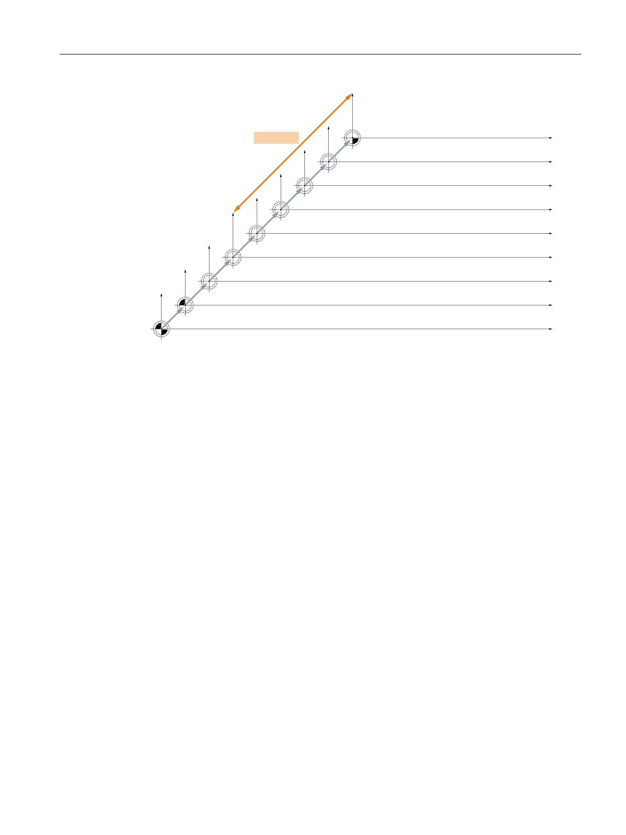
The figure below shows the frame chain for the current complete frame. The frame chain is
located between the basic coordinate system (BCS) and the workpiece coordinate system (WCS).
The settable zero system (SZS) corresponds to the WCS transformed by the programmable
frame. The basic zero system (BZS) still includes the current settable frame. The system frame
for the external work offset exists only if it has been configured. Otherwise, the external work
offset is traversed as overlaid movement of the axis.
Basic functions
318
Function Manual, 10/2020, 6FC5397-2GP40-0BA1
Axes, coordinate systems, frames
4.5 Frames
Frame chain
)UDPH IRU F\FOHV SURJUDPPHG IUDPH
:.6
WUDQVIRUPDWLRQV
6\VWHP IUDPH IRU 72527 72)5$0(
(16
ZRUNSLHFHV
* ಹ*
VHWWDEOH IUDPH
FKDQQHO VSHFLILF RU 1&8 JOREDO
&KDLQHG ILHOG RI EDVLF IUDPHV
%16
FKDQQHO VSHFLILF DQG RU 1&8 JOREDO
&KDLQHG V\VWHP IUDPHV IRU 3$527 DFWXDO YDOXH VHWWLQJ
VFUDWFKLQJ H[W ZRUN RIIVHW
+DQGZKHHO '5) RIIVHW RYHUODLG PRYHPHQW H[WHUQDO
ZRUN RIIVHW
%.6
.LQHPDWLF WUDQVIRUPDWLRQ
0.6
5HIHUHQFH SRLQW RIIVHW
WCS: Workpiece Coordinate System
SZS:
Settable Zero System
BZS:
Basic Zero System
BCS:
Basic Coordinate System
MCS: Machine Coordinate System
Complete frame
The current complete frame $P_ACTFRAME results from the chaining of all active frames of the
frame chain:
$P_ACTFRAME =
$P_PARTFRAME : $P_SETFRAME : $P_EXTFRAME :
$P_ISO1FRAME : $P_ISO2FRAME : $P_ISO3FRAME :
$P_ACTBFRAME : $P_IFRAME : $P_GFRAME :
$P_TOOLFRAME :$P_WPFRAME : $P_TRAFRAME :
$P_PFRAME :$P_ISO4FRAME : $P_CYCFRAME
4.5.4.2
Relative coordinate systems
Relative coordinate systems display the current setpoint positions of the axes which lie relative
to a specified reference point in the active displayed coordinate system. No programming can be
done regarding the relative coordinate systems. Only the axis positions in these systems can be
read via the system variables.
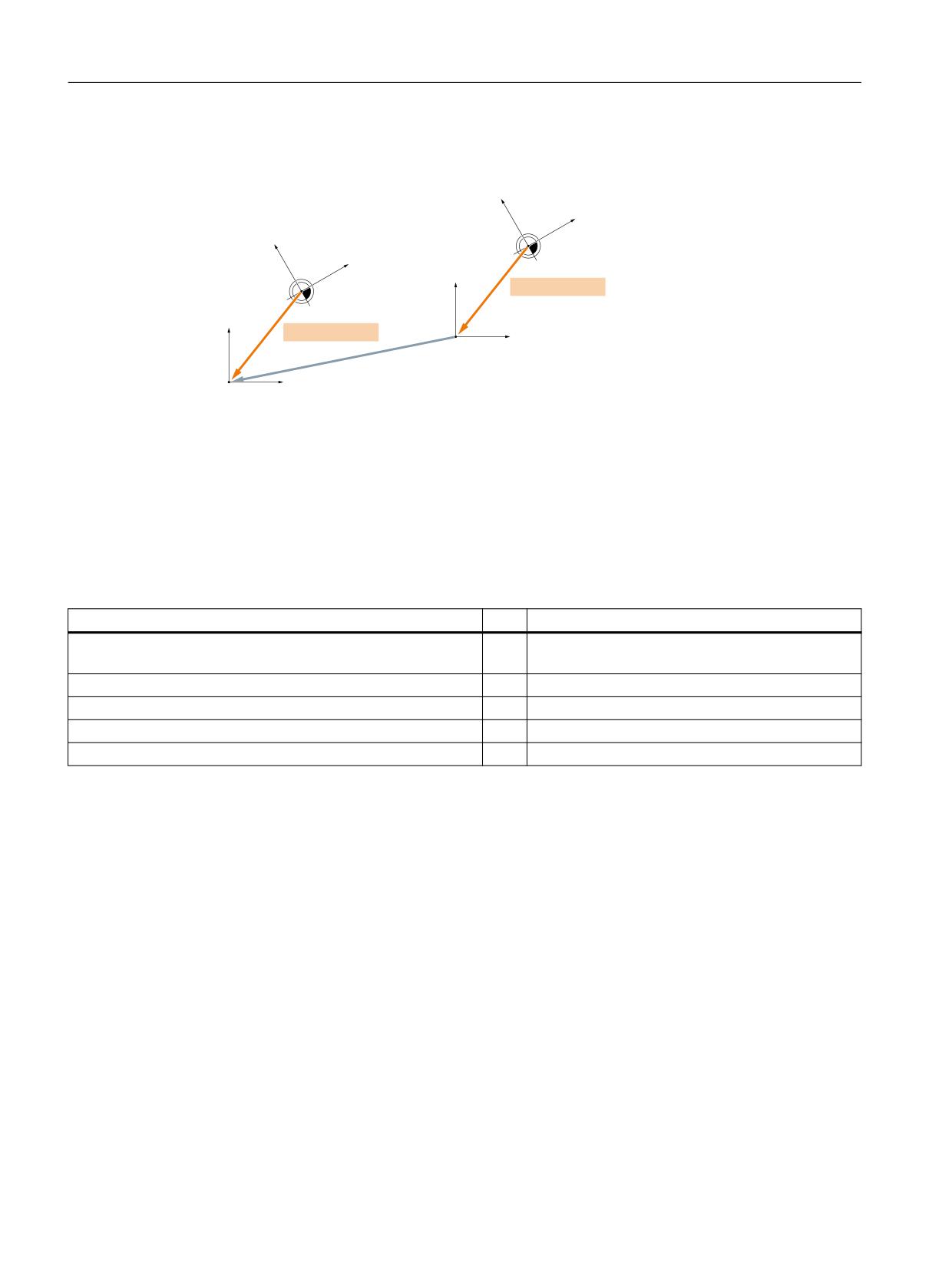
The new display coordinate systems lie relative to WCS and SZS coordinate system and result
through transformation of the WCS or SZS axis positions with the active system frame
$P_RELFRAME. The relative coordinate systems can not only be displaced linearly, but also
rotated, mirrored, compressed or expanded.
The position indicator for axis setpoints is done in WCS or in SZS. The configuring is done via HMI
machine data. Always only one display-coordinate system is active in the channel. For this
Basic functions
Function Manual, 10/2020, 6FC5397-2GP40-0BA1
319
Axes, coordinate systems, frames
4.5 Frames
reason only one relative frame is provided which generates both relative coordinate systems in
the same ratio. The HMI displays the relative coordinates according to the configuration.
:&65(/
$P_RELFRAME
6=65(/
$P_RELFRAME
:&6
6=6
Figure 4-22
Relative coordinate systems
The "Relative coordinate systems" function is activated with MD51036
$MNS_ENABLE_COORDINATE_REL=1.
The data maintenance frame $P_RELFR can be written in the part program and via BTSS. All the
frame components can be modified.
The active system frame $P_RELFRAME can be written in the part program and via BTSS.
The configuring of the system frame $P_RELFR is done via the following machine data:
Machine data
Bit
Meaning
MD28082 $MC_MM_SYSTEM_FRAME_MASK
11
Creation of $P_RELFR; with this, relative coordinate
systems become existent.
MD28083 $MC_MM_SYSTEM_DATAFRAME_MASK
11
Data maintenance frame $P_RELFR
MD24006 $MC_CHSFRAME_RESET_MASK.
11
$P_RELFR becomes active at Reset
MD24007 $MC_CHSFRAME_RESET_CLEAR_MASK
11
$P_RELFR is deleted at Reset
MD24008 $MC_CHSFRAME_POWERON_MASK
11
$P_RELFR is deleted at PowerOn
The axis position in the relative coordinate system WCSRel can be read via the variable
$AA_PCS_REL[ax]. The variable can be read in part program, BTSS and via synchronized actions.
The axis position in the relative coordinate system SZSRel can be read via the variable
$AA_ACS_REL[ax]. The variable can be read in part program, BTSS and via synchronized actions.
The setting of a relative reference point via the operator panel is done via the general command
interface for the workpiece and tool measuring. The system frame $P_RELFR for relative
coordinate systems is calculated and activated as follows:
• $AC_MEAS_TYPE = 14
• PI-services _N_SETUDT(6, 7)
An example of setting the relative axis positions can be found in:
Further information
Function Manual Technologies; Measurement (M5)
Basic functions
320
Function Manual, 10/2020, 6FC5397-2GP40-0BA1
Axes, coordinate systems, frames
4.5 Frames
4.5.4.3
Selectable SZS
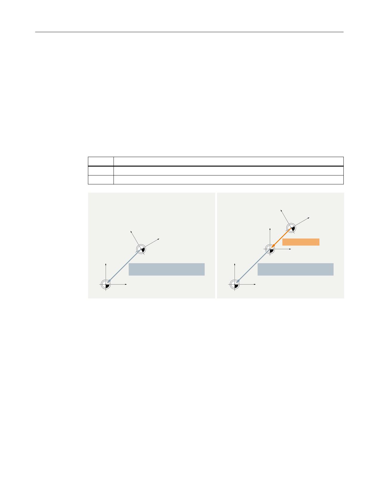
Within a cycle, machining is performed in a cycle-specific workpiece coordinate system (WCS).
The cycle-specific WCS results from SZS transformed by the programmable frame $P_PFRAME
and/or cycle frame $P_CYCFRAME programmed for the cycle.
If a cycle is interrupted by a machine operator, e.g. through an NC stop, traversing should then
be performed in the original coordinate system (SZS) valid before the activation of the cycle.
Machine data
The specification how the SZS is to be calculated from the cycle-specific WCS is set via the
following machine data.
MD24030 $MC_FRAME_ACS_SET = <value>
<value>
Meaning
0
SZS = WCS transformed with $P_TRAFRAME, $P_PFRAME, $P_ISO4FRAME and $P_CYCFRAME
1
SZS = WCS transformed only with $P_CYCFRAME
0'
0&B)5$0(B$&6B6(7
0'
0&B)5$0(B$&6B6(7
<:.6
;:.6
<:.6
<(16
:&6
$P_CYCFRAME
;:.6
:&6
;(16
6=6
<(16
$P_TRAFRAME : $P_PFRAME :
$P_TRAFRAME : $P_PFRAME :
$P_ISO4FRAME : $P_CYCFRAME
$P_ISO4FRAME :
;(16
6=6
① SZS = WCS transformed with $P_TRAFRAME, $P_PFRAME, $P_ISO4FRAME and $P_CYCFRAME
② SZS = WCS transformed only with $P_CYCFRAME
Effects
The reconfiguration of the SZS has an effect on:
• SZS-related actual values: Actual-value displays, system variables, e.g. $AA_IEN, etc.
• Manual traversing (JOG) of geometry axes in the SZS
4.5.4.4
Manual traversing of geometry axes either in the WCS or in the SZS
($AC_JOG_COORD)
Previously, geometry axes have been traversed manually in JOG mode in the WCS. In addition,
there is also the option to carry out this manual traversing in the SZS coordinate system. The
$AC_JOG_COORD variable enables the user to switch between manual traversing in the WCS and
SZS. The user can now select if he wants to traverse in the SZS or the WCS.
Basic functions
Function Manual, 10/2020, 6FC5397-2GP40-0BA1
321
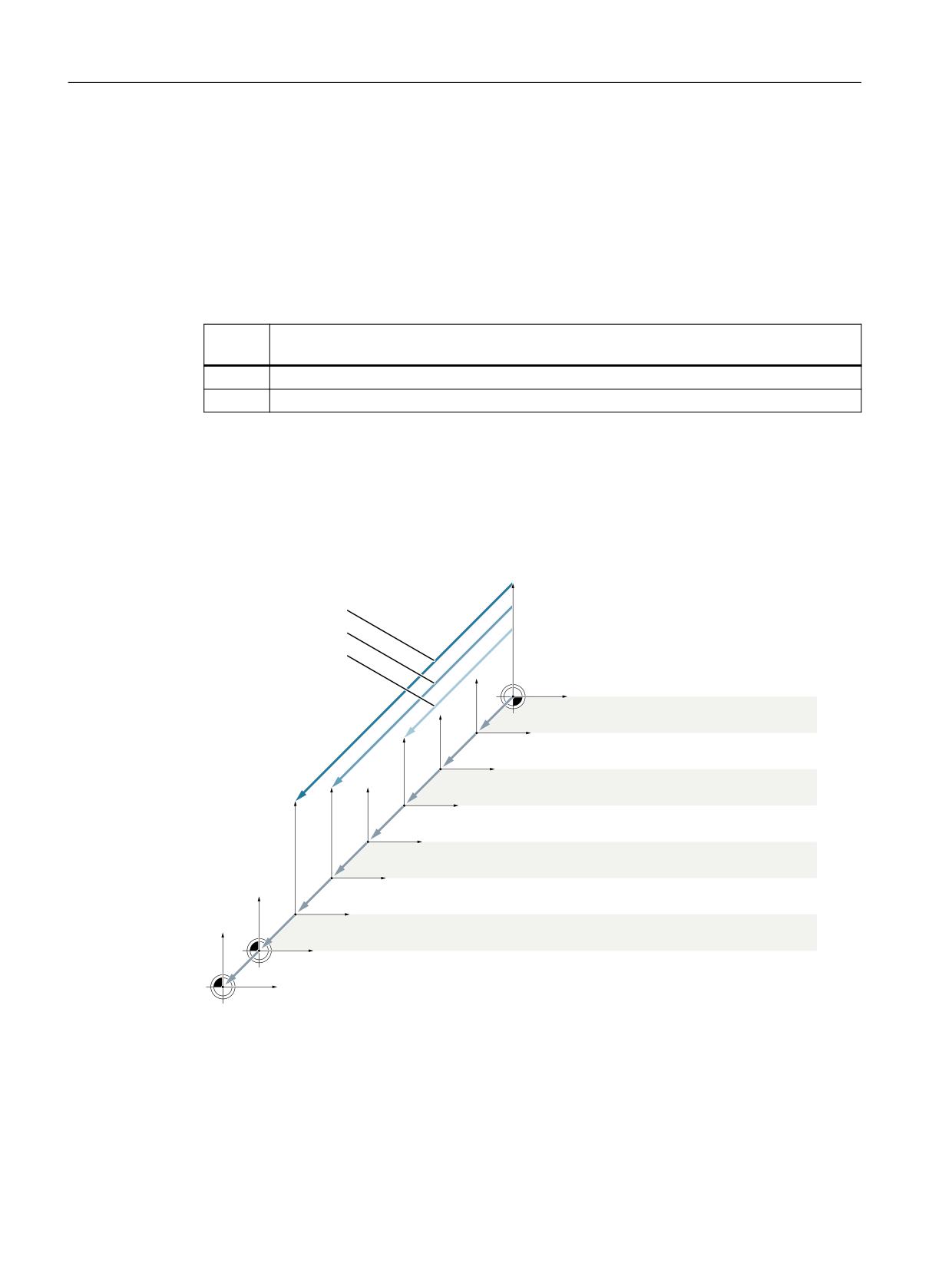
Axes, coordinate systems, frames
4.5 Frames
During manual traversing in the JOG mode, the geometry axes can be traversed either in the
workpiece coordinate system (WCS) or in the settable zero system (SZS).
System variables
During manual traversing in the JOG mode, the geometry axes can be traversed either in the
workpiece coordinate system (WCS) or in the settable zero system (SZS). The selection is made
via the system variable $AC_JOG_COORD:
$AC_JOG_COORD = <value>
<Val-
Meaning
ue>
0
Workpiece coordinate system (WCS)
1
Settable zero system (SZS)
4.5.4.5
Suppression of frames
Suppression of frames is performed channel-specifically via the commands G53, G135
and SUPA described in the following. Activation of the frame suppression results in jumps in the
position display (HMI) as well as in the position values in system variables that refer to the WCS,
SZS or BZS. The behavior can be set via machine data.
SUPA
G153
G53
:.6
3B75$)5$0( 3B3)5$0(
3B,62 )5$0( 3B&<&)5$0(
(16
3B722/)5$0( 3B:3)5$0(
3B,)5$0( 3B*)5$0(
%16
3B$&7%)5$0(
3B3$57)5$0( 3B6(7)5$0( 3B(;7)5$0(
B,62 )5$0( 3B,62 )5$0( 3B,62 )5$0(
%.6
+DQGZKHHO '5) RIIVHW RYHUODLG PRYHPHQW H[WHUQDO
ZRUN RIIVHW
.LQHPDWLF WUDQVIRUPDWLRQ
0.6
5HIHUHQFH SRLQW RIIVHW
Machine data
The behavior of position displays (HMI) and position values in system variables is specified via
the following machine data:
Basic functions
322
Function Manual, 10/2020, 6FC5397-2GP40-0BA1

Axes, coordinate systems, frames
4.5 Frames
MD24020 $MC_FRAME_SUPPRESS_MODE, bit<n> = <value> (positions during frame
suppression)
Bit
Val-
Meaning
ue
0
0
Position values (OPI) with frame suppression 1)
1
Position values (OPI) without frame suppression 2)
1
0
Position values in system variables with frame suppression 1)
1
Position values in system variables without frame suppression 2)
1) Jump of the position value
2) No jump of the position value
Programming
Com-
Meaning
mand
G53:
Nonmodal suppression of the following frames:
$P_TRAFRAME : $P_PFRAME : $P_ISO4FRAME : $P_CYCFRAME
$P_IFRAME : $P_GFRAME : $P_TOOLFRAME : $P_WPFRAME :
G153:
Non-modal suppression of the frames as for G53 plus following frames:
$P_PARTFRAME : $P_SETFRAME : $P_EXTFRAME : $P_ACTBFRAME
$P_ISO1FRAME : $P_ISO2FRAME : $P_ISO3FRAME :
SUPA:
Implicit preprocessing stop and non-modal suppression of the frames as for G53 and G135
plus following frames:
• Handwheel offsets (DRF)
• Overlaid movement
• External work offset
G500:
Modal activation of the G500 frame. The G500 frame should normally be a zero frame.
DRFOF:
Deactivation (deletion) of the handwheel offsets (DRF)
4.5.5
Frames of the frame chain
4.5.5.1
Overview
The following frames are available:
• Settable frames (G500, G54 ... G57, G505 ... G599)
• Grinding frames (GFRAME0 ... GFRAME100)
• Basic frames
• Programmable frame
• System frames
Basic functions
Function Manual, 10/2020, 6FC5397-2GP40-0BA1
323

Axes, coordinate systems, frames
4.5 Frames
4.5.5.2
Settable frames ($P_UIFR[<n>])
Machine data
Channel-specific settable frames
The number of channel-specific settable frames is set with the following machine data:
MD28080 $MC_MM_NUM_USER_FRAMES = <number>
System variable index n = 0, 1, 2, ... <number> - 1
NCU-global settable frames
The number of NCU-global settable frames is set with the following machine data:
MD18601 $MN_MM_NUM_GLOBAL_USER_FRAMES = <number>
System variable index n = 0, 1, 2, ... <number> - 1
If the machine data has a value > 0, there are no channel-specific settable frames. The machine
data to set the channel-specific settable frames is then not evaluated.
Reset position of the G group of the settable frames
The reset position or which of the G commands of the settable frame-specific 8th G group take
effect after channel reset or Power On is set in:
MD20150 $MC_GCODE_RESET_VALUES[7] = <value>
Value
G command
1
G500
2
G54
3
G55
4
G56
5
G57
6
G505
100
G599
Reset behavior of the grinding-specific G group
The reset behavior of the settable frame-specific 8th G group is set in:
MD20152 $MC_GCODE_RESET_MODE[7] = <value>
Value
Meaning
After channel reset or part program end:
0
The settable frame-specific G command in accordance with MD20150 is active.
1
The currently active settable frame-specific G command remains active.
Basic functions
324
Function Manual, 10/2020, 6FC5397-2GP40-0BA1

Axes, coordinate systems, frames
4.5 Frames
Note
MD20110 $MC_RESET_MODE_MASK
The MD20152 $MC_GCODE_RESET_MODE machine data is evaluated only for:
MD20110 $MC_RESET_MODE_MASK, bit 0 == 1
System variables
$P_UIFR[<n>] (settable frames of the data management)
System variable $P_UIFR[<n>] can be used to read and write the settable frames of the data
management. The new values are not immediately active in the channel when writing a settable
frame of the data management. The activation in the channel only takes effect with the
programming of a work offset G500, G54...G599.
For NCU-global frames, the changed settable frame of the data management is active in each
channel of the NCU which executes a G500, G54..G599 command.
The settable frames in the data management are also stored during a data backup.
$P_IFRAME (active settable frame)
System variable $P_IFRAME can be used to read and write the settable frame active in the
channel. The new values are immediately active in the channel when writing the settable frame.
In the case of NCU-global settable frames, the changed active frame acts only in the channel in
which the new values were programmed. If the changed NCU-global settable frame is to be
active in all channels of the NCU, the settable frame active in the channel and the corresponding
settable frame of the data management must be written together:
$P_UIFR[<n>] = $P_IFRAME = <new value>
• $P_UIFR[<n>] (settable frame in the data management)
• $P_IFRAME (settable frame active in the channel)
For the changed settable frame to take effect in another channel, it must be activated in this
channel with the appropriate command, e.g. G54.
$P_UIFRNUM (number of active settable frame)
System variable $P_UIFRNUM can be used to read the index <n> of the settable frame of the data
management active in the channel:
Settable frame active in the channel $P_IFRAME == $P_UIFR[ $P_UIFRNUM ]
$P_UIFRNUM
$P_IFRAME == $P_UIFR[<n>], where n =
0
0
1
1
2
2
99
99
Basic functions
Function Manual, 10/2020, 6FC5397-2GP40-0BA1
325
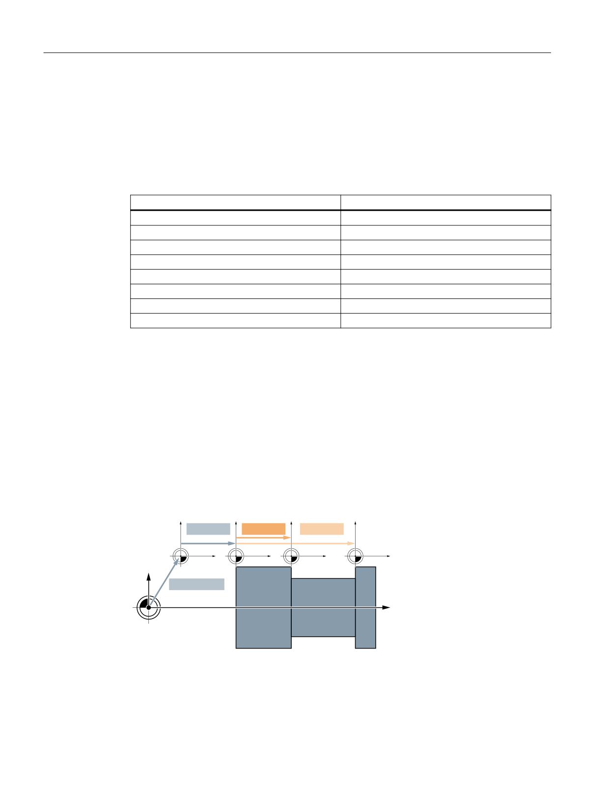
Axes, coordinate systems, frames
4.5 Frames
Programming
Commands for activating a settable frame in the channel
The programming of a G500, G54...G599 command activates the settable frame of the
$P_UIFR[<n>] data management in the channel or the active $P_IFRAME settable frame set
identical to the settable frame of the $P_UIFR[<n>] data management:
G<x> ⇒ $P_IFRAME = $P_UIFR[<n>]
Command
Active settable frame $P_IFRAME
G500
$P_UIFR[0]
G54
$P_UIFR[1]
G55
$P_UIFR[2]
G56
$P_UIFR[3]
G57
$P_UIFR[4]
G505
$P_UIFR[5]
G599
$P_UIFR[99]
Supplementary conditions
Writing of settable frames through HMI/PLC
Only the settable frames of the data management can be written from the HMI or the PLC user
program.
4.5.5.3
Grinding frames $P_GFR[<n>]
Grinding frames are additional work offsets or "fit-dependent corrections" available particularly
for the grinding technology. They are added to the work offset of the adjustable frames
(Page 324).
$P_FRAME
$P_GFR[1]
$P_GFR[2]
%16
(16
(16*
(16*
$P_ACTFRAME
%.6
0.6
Figure 4-23
Grinding frames
Based on the base zero system (BZS), the settable zero system (SZS) results from the chaining of
the frames active in the channel:
$P_IFRAME: $P_GFRAME : $P_TOOLFRAME :$P_WPFRAME
Basic functions
326
Function Manual, 10/2020, 6FC5397-2GP40-0BA1

Axes, coordinate systems, frames
4.5 Frames
Machine data
Number of channel-specific grinding frames
The number of channel-specific grinding frames is set in:
MD28079 $MN_MM_NUM_G_FRAMES = <number>
with <number> = 0, 1, 2, ... maximum number
Number of NCU-global grinding frames
The number of NCU-global grinding frames is set in:
MD18603 $MN_MM_NUM_GLOBAL_G_FRAMES = <number>
with <number> = 0, 1, 2, ... maximum number
If the machine data has a value > 0, there are no channel-specific grinding frames. The machine
data to set the channel-specific grinding frames is then not evaluated.
Reset position of the grinding-specific G group (64)
The reset position or which of the G commands of the grinding-specific 64th G group take
effect after channel reset or Power On is set in:
MD20150 $MC_GCODE_RESET_VALUES[63] = <value>
Value
G command
1
GFRAME0 (zero frame)
2
GFRAME1
3
GFRAME2
101
GFRAME100
Reset behavior of the grinding-specific G group
The reset behavior of the grinding-specific 64th G group is set in:
MD20152 $MC_GCODE_RESET_MODE[63] = <value>
Value
Meaning
After channel reset or part program end:
0
The grinding-specific G command in accordance with MD20150 is active.
1
The currently active grinding-specific G command remains active.
Note
MD20110 $MC_RESET_MODE_MASK
The MD20152 $MC_GCODE_RESET_MODE machine data is evaluated only for:
MD20110 $MC_RESET_MODE_MASK, bit 0 == 1
Basic functions
Function Manual, 10/2020, 6FC5397-2GP40-0BA1
327
Axes, coordinate systems, frames
4.5 Frames
System variables
$P_GFR[<n>] (grinding frames of the data management)
System variable $P_GFR[n] can be used to read and write the grinding frames of the data
management. The new values are not immediately active in the channel when writing a
grinding frame. The activation in the channel only takes effect with the programming of the
appropriate command GFRAME0...GFRAME100. For NCU-global frames, the changed frame
only becomes active in those channels of the NCU, which execute a GFRAME0 ... GFRAME100
command.
The grinding frames in the data management are also stored during a data backup.
Note
Display (SINUMERIK Operate)
The grinding frames of the data management are displayed in a separate window of the
SINUMERIK Operate user interface.
• Further information
Operating Manual Grinding; Section "Setting up the machine" > "Work offsets" > "Displaying
and editing seat-related fine offset"
Delete (SINUMERIK Operate)
The grinding frames of the data management can be deleted individually or, for example, after
a workpiece change, all together via the SINUMERIK Operate user interface.
• Further information
Operating Manual Grinding; Section "Setting up the machine" > "Work offsets" > "Displaying
and editing seat-related fine offset"
$P_GFRAME (active grinding frame)
The grinding frame active in the channel can be read from and written to the $P_GFRAME
system variable. The new values are immediately active in the channel when writing the active
grinding frame.
In the case of NCU-global grinding frames, the changed frame acts only in the channel in which
the new frame values were programmed.
If the changed NCU-global grinding frame is to be active in all channels of the NCU starting from
one channel, the $P_GFRAME grinding frame active in the grinding frame and the grinding
frame in the $P_GFR[<n>] data management must be written together:
$P_GFRAME = $P_GFR[<n>] = <new value>
For the changed grinding frame in the $P_GFR[<n>] data management to take effect in another
channel, it must be activated in this channel with the appropriate command GFRAME<n>.
$P_GFRNUM (number of the active grinding frame)
System variable $P_GFRNUM can be used to read the index <n> of the grinding frame of the data
management active in the channel:
Basic functions
328
Function Manual, 10/2020, 6FC5397-2GP40-0BA1
Axes, coordinate systems, frames
4.5 Frames
Grinding frame active in the channel $P_GFRAME == $P_GFR[ $P_GFRNUM ]
$P_GFRAME grinding frame activated with the
$P_GFRNUM
G command GFRAME<n>:
GFRAME0
0
GFRAME1
1
GFRAME2
2
GFRAME100
100
Programming
Command for activating a grinding frame in the channel
The programming of the GFRAME<n> command makes the associated grinding frame of the
$P_GFR[<n>] data management active in the channel. This sets the active $P_GFRAME grinding
frame identical to the $P_GFR[<n>] grinding frame of the data management:
GFRAME<n> ⇒ $P_GFRAME = $P_GFR[<n>]
Command
Grinding frame activated in the channel
GFRAME0
$P_GFR[0] (null frame)
GFRAME1
$P_GFR[1]
GFRAME100
$P_GFR[100]
Syntax
GFRAME<n>
Meaning
GFRAME<n>:
Activation of the grinding frame <n> of the data management
G group:
64
Basic position:
MD20150 $MC_GCODE_RESET_VALUES[63]
Effectiveness:
Modal
<n>:
Number of the grinding frame
Range of values:
0, 1, 2, ... 100
Supplementary conditions
Writing of grinding frames through HMI/PLC
Only the grinding frames of the data management can be written from the HMI or the PLC user
program.
Basic functions
Function Manual, 10/2020, 6FC5397-2GP40-0BA1
329
Axes, coordinate systems, frames
4.5 Frames
4.5.5.4
Channel-specific basic frames[<n>]
Machine data
Number of channel-specific basic frames
The number of channel-specific basic frames is set with the following machine data:
MD28081 $MC_MM_NUM_BASE_FRAMES = <number>
System variable index n = 0, 1, 2, ... <number> - 1
System variables
$P_CHBFR[<n>] (channel-specific basic frames of the data management)
System variable $P_CHBFR[<n>] can be used to read and write the channel-specific basic frames
of the data management. The new values are not immediately active in the channel when
writing a channel-specific basic frame. The activation in the channel only takes effect with the
programming of the appropriate command G500, G54...G599.
The channel-specific basic frames in the data management are also stored during a data backup.
$P_CHBFRAME[<n>] (active channel-specific basic frames)
System variable $P_CHBFRAME[<n>] can be used to read and write the active channel-specific
basic frames. When writing an active channel-specific basic frame, the new values take effect
immediately through the recalculation of the active complete basic frame $P_ACTBFRAME.
System variables for compatibility reasons
$P_UBFR (first channel-specific basic frame of the data management)
The system variable is retained for reasons of compatibility, although it is redundant for the
$P_CHBFR[0] variables.
The basic frame with array index 0 is not activated simultaneously when writing to the
predefined $P_UBFR variable, but rather activation only takes place on execution of a G500,
G54,.G599 statement. For NCU-global frames, the changed frame only becomes active in those
channels of the NCU, which execute a G500, G54..G599 command. The variable is used
primarily for storing write operations to the basic frame on HMI or PLC. The variable can also be
read and written in the program.
$P_UBFR is identical to $P_CHBFR[0]. One basic frame always exists in the channel by default,
so that the system variable is compatible with older versions. If there is no channel-specific basic
frame, an alarm: "Frame: Statement not permitted" is output on a read or write access.
$P_BFRAME (first active channel-specific basic frame)
The system variable is retained for reasons of compatibility, although it is redundant for the
$P_CHBFRAME[0] variables.
The predefined frame variable $P_BFRAME can be used to read and write the current basic frame
with the array index 0, which is valid in the channel, in the part program. The written basic frame
is immediately included in the calculation. In the case of NCU-global settable frames, the
Basic functions
330
Function Manual, 10/2020, 6FC5397-2GP40-0BA1
Axes, coordinate systems, frames
4.5 Frames
modified frame acts only in the channel in which the frame was programmed. If the frame is to
be modified for all channels of an NCU, $P_UBFR and $P_BFRAME must be written
simultaneously. The other channels must then activate the corresponding frame, e.g. with G54.
$P_BFRAME is identical to $P_CHBFRAME[0]. The system variable always has a valid default
value. If there is no channel-specific basic frame, an alarm: "Frame: Statement not permitted" is
output on a read or write access.
Supplementary conditions
Writing of basic frames from HMI/PLC
Only the basic frames of the data management can be written from the HMI or the PLC user
program.
4.5.5.5
NCU-global basic frames $P_NCBFR[<n>]
Machine data
Number of NCU-global basic frames
The number of NCU-global basic frames is set with the following machine data:
MD18602 $MN_MM_NUM_GLOBAL_BASE_FRAMES = <number>
System variable index n = 0, 1, 2, ... <number> - 1
System variables
$P_NCBFR[<n>] (NCU-global basic frames of the data management)
System variable $P_NCBFR[<n>] can be used to read and write the NCU-global basic frames of
the data management. The new values are not immediately active in the channel when writing
an NCU-global basic frame. The activation in the channel only takes effect with the programming
of the appropriate command G500, G54...G599.
The NCU-global basic frames in the data management are also stored during a data backup.
$P_NCBFRAME[<n>] (current NCU-global basic frames)
System variable $P_NCBFRAME[<n>] can be used to read and write the active NCU-global basic
frames. When writing an active NCU-global basic frame, the new values take effect immediately
through the recalculation of the active complete basic frame $P_ACTBFRAME.
If the changed NCU-global basic frame is to be active in all channels of the NCU starting from one
channel, the NCU-global basic frame active in the channel and the NCU-global frame in the data
management must be written together:
$P_NCBFR[<n>] = $P_NCBFRAME = <new value>
• $P_NCBFR[<n>] (NCU-global basic frame of the data management)
• $P_NCBFRAME (NCU-global basic frame active in the channel)
Basic functions
Function Manual, 10/2020, 6FC5397-2GP40-0BA1
331
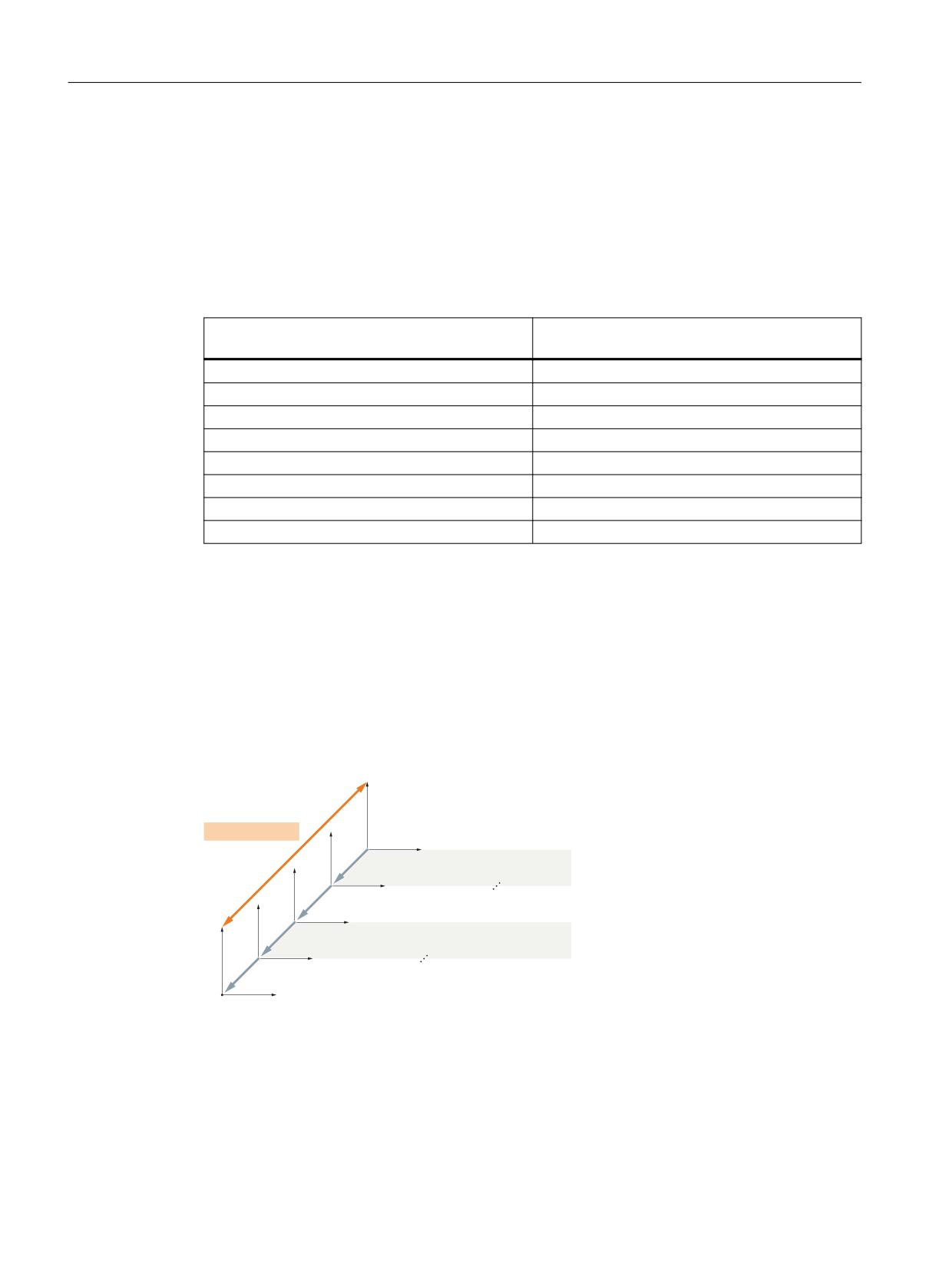
Axes, coordinate systems, frames
4.5 Frames
For the changed NCU-global frame to take effect in another channel, it must be activated in this
channel with the appropriate command G500, G54..G599.
Programming
A channel-specific settable frame of the data management $P_UIFR[<n>] becomes the settable
frame $P_IFRAME active in the channel through the appropriate command (G54 ... G57, G505 ...
G599 and G500).
Command
Activation of the NCU-global and channel-spe-
cific basic frames of the data management
G500
$P_CHBFR[ 0 ] : $P_NCBFR[0]
G54
$P_CHBFR[ 1 ] : $P_NCBFR[1]
G55
$P_CHBFR[ 2 ] : $P_NCBFR[2]
G56
$P_CHBFR[ 3 ] : $P_NCBFR[3]
G57
$P_CHBFR[ 4 ] : $P_NCBFR[4]
G505
$P_CHBFR[ 5 ] : $P_NCBFR[5]
G599
$P_CHBFR[ 99 ] : $P_NCBFR[99]
4.5.5.6
Active complete basic frame $P_ACTBFRAME
Function
All active NCU-global and channel-specific basic frames are combined into the complete basic
frame $P_ACTBFRAME:
$P_ACTBFRAME = $P_NCBFRAME[0] : ... : $P_NCBFRAME[<n>] :
$P_CHBFRAME[0] : ... : $P_CHBFRAME[<n>]
$P_ACTBFRAME
%16
3B&+%)5$0(>Q@
3B&+%)5$0(> @
3B1&%)5$0(>Q@
3B1&%)5$0(> @
%.6
Figure 4-24
Complete basic frame
Basic functions
332
Function Manual, 10/2020, 6FC5397-2GP40-0BA1

Axes, coordinate systems, frames
4.5 Frames
Machine data
Reset response
Which basic frames are active after a reset (channel reset, end of program reset or Power On) is
set via the machine data:
MD20110 $MC_RESET_MODE_MASK, bit0 = 1 and bit14 = 1
• Bit 1 = 0: Default value ⇒ reset behavior corresponding to the setting of the further bits
• Bit14 = 0: The basic frames are completely deselected with reset.
• Bit14 = 1: With reset, the machine data settings are taken over in the system variables and the
basic frames selected therein become active:
- $P_NCBFRMASK = MD10613 $MN_NCBFRAME_RESET_MASK
- $P_CHBFRMASK = MD24002 $MC_CHBFRAME_RESET_MASK
Example
Machine data setting
Active basic frames
$P_NCBFRMASK = MD10613 $MN_NCBFRAME_RE-
$P_NCBFRAME[0] : $P_NCBFRAME[7]
SET_MASK = 'H81'
Programming
Basic frame masks
The basic frames that are linked to form the complete basic frame are selected via the basic
frame masks $P_NCBFRMASK and $P_CHBFRMASK.
The appropriate basic frame is selected by setting a bit in the basic frame mask:
• $P_NCBFRMASK, bit 0, 1, 2, ... n
⇒ $P_NCBFRAME[0, 1, 2, ... n]
• $P_CHBFRMASK, bit 0, 1, 2, ... n
⇒ $P_NCHFRAME[0, 1, 2, ... n]
The basic frame masks $P_NCBFRMASK and $P_CHBFRMASK can only be read/written in the NC
program. The basic frame masks can be read via the OPI.
After writing a basic frame mask, the active complete basic frame $P_ACTBFRAME and
complete frame $P_ACTFRAME are recalculated.
Example
Program code
Comment
$P_NCBFRMASK = 'H81'
; Active NCU-global basic frames: $P_NCBFRAME[0] :
$P_NCBFRAME[7]
4.5.5.7
Programmable frame $P_PFRAME
Programmable frames are available only as active frames.
This frame is reserved for the programmer.
The programmable frame remains at RESET, if:
MD24010 $MC_PFRAME_RESET_MODE (reset mode for programmable frame) = 1
Basic functions
Function Manual, 10/2020, 6FC5397-2GP40-0BA1
333
Axes, coordinate systems, frames
4.5 Frames
This functionality is especially important after a RESET if one still wants to retract out of an
oblique hole.
MIRROR
Mirrorings of a geometry axis were previously (up to SW-P4) related to a defined reference axis
only using the machine data:
MD10610 $MN_MIRROR_REF_AX
(reference axis for the mirroring).
From the user's point of view, this definition is difficult to understand. When mirroring the z axis,
the display showed that the x axis was mirrored and the y axis had been rotated through 180
degrees. When mirroring two axes this became even more complex and it was no longer easy to
understand, which axes had been mirrored and, which had not.
As of SW P5, there is the option to clearly display the mirroring of an axis. Mirroring is then not
mapped to mirroring of a reference axis and rotations of other axes.
This setting can be configured using:
MD10610 $MN_MIRROR_REF_AX = 0
MIRROR and AMIRROR are used to expand the programming of the programmable frame.
Previously, the specified value of the coordinate axis, e.g. the value 0 for MIRROR X0 was not
evaluated, but rather the AMIRROR had a toggle function, i.e. MIRROR X0 activates mirroring
and an additional AMIRROR X0 deactivates it. MIRROR always has an absolute effect and
AMIRROR an additive effect.
The
MD10612 $MN_MIRROR_TOGGLE = 0 ("Mirror Toggle")
machine data setting can be used to define that the programmed values are evaluated.
A value of 0, as inAMIRROR X0, deactivates the mirroring of the axis, and values not equal to 0
cause the axis to be mirrored if it is not already mirrored.
Reading or writing mirroring component-by-component is independent of the machine data:
MD10612 $MN_MIRROR_TOGGLE
A value = 0 means that the axis is not mirrored and a value = 1 means that the axis will always
be mirrored, irrespective of whether it has already been mirrored or not.
$P_NCBFR[0,x,mi]=1
; x axis is always mirrored.
$P_NCBFR[0,x,mi]=0
; x axis mirroring is OFF.
Axis-specific replacement G58, G59
The translation component of the programmable frame is split into an absolute component and
a component for the total of all additively programmed translations. The absolute component
can be changed using TRANS, CTRANS or by writing the translation components, in which the
additive component is set to zero. G58 changes only the absolute translation component for the
specified axis; the total of additively programmed translations is retained.
G58 X... Y... Z... A
G59 is used for axis-specific overwriting of the additively programmed translations for the
specified axes which were programmed with ATRANS.
Basic functions
334
Function Manual, 10/2020, 6FC5397-2GP40-0BA1

Axes, coordinate systems, frames
4.5 Frames
G59 X... Y... Z... A
Example
TRANS X10 Y10 Z10
ATRANS X5 Y5
; Total translations X15 Y15 Z10
G58 X20
; Total translations X25 Y15 Z10
G59 X10 Y10
; Total translations X30 Y20 Z10
G58 and G59 can only be used if:
MD24000 $MC_FRAME_ADD_COMPONENTS (frame components for G58 / G59) == TRUE
The table below shows the effect of various program commands on the absolute and additive
translation.
Coarse or absolute offset
Fine or additive offset
TRANS X10
10
0
ATRANS X10
Unchanged
alt_fine + 10
CTRANS(X,10)
10
0
CTRANS()
0
0
CFINE(X,10)
0
10
$P_PFRAME[X,TR] = 10
10
Unchanged
$P_PFRAME[X,FI] = 10
Unchanged
10
G58 X10
10
Unchanged
G59 X10
Unchanged
10
4.5.5.8
Channelspecific system frames
Channel-specific system frames are only written by system functions, such as actual value
setting, scratching, external work offset and inclined machining.
Machine data
Parameterization of the channel-specific system frames
Only channel-specific system frames whose system functions are actually used should be
configured for memory space reasons.
Per channel, each system frame occupies approx. 1 KB static and approx. 6 KB dynamic memory.
The channel-specific system frames are parameterized in the following machine data:
MD28082 $MC_MM_SYSTEM_FRAME_MASK, bit<n>
Bit
Value
System frame available:
0
1
$P_SETFR: Actual value setting and scratching
1
1
$P_EXTFR: External work offset via system frames
2
1
$P_PARTFR: TCARR and PAROT with an orientable toolholder
3
1
$P_TOOLFR: TOROT and TOFRAME
4
1
$P_WPFR: Frame for workpiece reference points
Basic functions
Function Manual, 10/2020, 6FC5397-2GP40-0BA1
335

Axes, coordinate systems, frames
4.5 Frames
Bit
Value
System frame available:
5
1
$P_CYCFR: Frame for cycles
6
1
$P_TRAFR: Frame for selection and deselection of transformations
7
1
$P_ISO1FRAME : Frame for G51.1 mirroring (ISO)
8
1
$P_ISO2FRAME : Frame for G68 2DROT (ISO)
9
1
$P_ISO3FRAME : Frame for G68 3DROT (ISO)
10
1
$P_ISO4FRAME: Frame for G51 scale (ISO)
11
1
$P_RELFR: Frame for relative coordinate systems
Parameterization of the SZS (ACS) coordinate system
The following machine data is used to specify which system frames form the SZS (ACS)
coordinate system
MD24030 $MC_FRAME_ACS_SET = <value>
<value>
Meaning: The SZS (ACS) coordinate system comprises
0
$P_PARTFRAME : $P_SETFRAME : $P_EXTFRAME :$P_ISO1FRAME : $P_ISO2FRAME :
$P_ISO3FRAME :$P_ACTBFRAME : $P_IFRAME : $P_GFRAME : $P_TOOLFRAME :
$P_WPFRAME
1
$P_PARTFRAME : $P_SETFRAME : $P_EXTFRAME :$P_ISO1FRAME : $P_ISO2FRAME :
$P_ISO3FRAME :$P_ACTBFRAME : $P_IFRAME : $P_GFRAME : $P_TOOLFRAME :
$P_WPFRAME : $P_TRAFRAME :$P_PFRAME : $P_ISO4FRAME
System variables
Channel-specific system frames of the data management
The channel-specific system frames of the data management can be read and written via the
following frame variables:
System variable
Meaning: System frame of the data management for
$P_SETFR
Actual value setting and scratching (Set Frame)
$P_EXTFR
External work offset (Ext Frame)
$P_PARTFR
TCARR and PAROT for orientable toolholder (Part Frame)
$P_TOOLFR
TOROT and TOFRAME (Tool Frame)
$P_WPFR
Workpiece reference points (WorkPiece Frame)
$P_CYCFR
Cycles (Cycle Frame)
$P_TRAFRAME
Transformations (Transformation Frame)
$P_ISO1FR
G51.1 mirroring (ISO)
$P_ISO2FR
G68 2DROT (ISO)
$P_ISO3FR
G68 3DROT (ISO)
$P_ISO4FR
G51 scale (ISO)
$P_RELFR
Relative coordinate systems
Basic functions
336
Function Manual, 10/2020, 6FC5397-2GP40-0BA1

Axes, coordinate systems, frames
4.5 Frames
Note
Cycle programming
The frame variables of the system frames are only for the cycle programming. Therefore, in NC
programs the system frames should not be written directly by the user, but rather only via system
functions such as TOROT, PAROT, etc.
Channelspecific active system frames
System variables of the active channel-specific system frames:
System variable
Meaning: Active system frame for
$P_SETFRAME
Actual value setting and scratching (Set Frame)
$P_EXTFRAME
External work offset (Ext Frame)
$P_PARTFRAME
TCARR and PAROT for orientable toolholder (Part Frame)
$P_TOOLFRAME
TOROT and TOFRAME (Tool Frame)
$P_WPFRAME
Workpiece reference points (WorkPiece Frame)
$P_CYCFRAME
Cycles (Cycle Frame)
$P_TRAFRAME
Transformations (Transformation Frame)
$P_ISO1FRAME
G51.1 mirroring (ISO)
$P_ISO2FRAME
G68 2DROT (ISO)
$P_ISO3FRAME
G68 3DROT (ISO)
$P_ISO4FRAME
G51 scale (ISO)
$P_RELFRAME
Relative coordinate systems
If a channel-specific system frame of the data management is not parameterized, the following
applies for the corresponding active system frame: $P_<system frame> == null frame.
Channel-specific active SZS (ACS) complete frame
The system variable $P_ACSFRAME is used to read which system frames form the SZS (ACS)
coordinate system. The specification is made via the MD24030 $MC_FRAME_ACS_SET machine
data described above. See Subsection "Machine data" > "Parameterization of the SZS (ACS)
coordinate system"
System variable
Meaning: Active system frame for
$P_ACSFRAME
System frames that form the SZS (ACS) coordinate system in accordance with the
parameterization in MD24030 $MC_FRAME_ACS_SET
4.5.6
Implicit frame changes
4.5.6.1
Switching geometry axes
Which channel axes are the geometry axis of the channel can change by activating/deactivating
a transformation and with the GEOAX() command.
Basic functions
Function Manual, 10/2020, 6FC5397-2GP40-0BA1
337

Axes, coordinate systems, frames
4.5 Frames
Four different settings for handling the current $P_ACTFRAME complete frame can be made with
the following machine data:
MD10602 $MN_FRAME_GEOAX_CHANGE_MODE = <value>
<value>
Meaning
0
Delete
The current complete frame is deleted when geometry axes are switched over, when trans-
formations are selected and deselected, and on GEOAX().
The modified geometry axis configuration is not used until a new frame is activated.
1
New calculation on receipt of the rotations
The current complete frame is calculated again when the geometry axes are switched over,
whereby the frame components of the new geometry axes are effective. The rotations of the
geometry axes which were programmed before the switchover remain effective for the new
geometry axes.
For TRANSMIT, TRACYL and TRAANG, see Section "Selecting and deselecting transforma-
tions: General (Page 340)".
2
New calculation only when no rotations were active
The current complete frame is calculated again when the geometry axes are switched over,
whereby the frame components of the new geometry axes are effective. If rotations are active
in the current basic frames, the current settable frame or the programmable frame before the
switchover, it is aborted with the alarm "Frame: Geometry axis switchover not allowed".
For TRANSMIT, TRACYL and TRAANG, see Section "Selecting and deselecting transforma-
tions: General (Page 340)".
3
Transformation: Reset / GEOAX(): New calculation on receipt of the rotations
• Transformation: The current frame is deleted when selecting and deselecting transforma-
tions.
• GEOAX(): With GEOAX(), the current complete frame is calculated again and the trans-
lations, scalings and mirrorings of the new geometry axes come into effect. The rotations
of the geometry axes which were programmed before the switchover remain effective for
the new geometry axes.
The workpiece geometry is described by a coordinate system that is formed by the geometry
axes. A channel axis is assigned to each geometry axis and a machine axis is assigned to each
channel axis. An axis-specific frame exists for each machine axis (system frame, basic frame,
settable frame, programmable frame). If a different machine axis is assigned to a geometry axis,
the machine axis provides its own axis-specific frame components. The new geometry in the
channel is then generated by the new contour frames resulting from the new geometry axes (up
to three).
The current valid frames are calculated again on the geometry axis switchover and a resulting
complete frame is generated. The data management frames are not included unless they are
activated.
Example:
The channel axis A is to become a geometry axis X through geo axis substitution. The
substitution is to give the programmable frame a translation component of 10 in the X axis. The
current settable frame is to be retained.
MD10602 $MN_FRAME_GEOAX_CHANGE_MODE = 1
Program code
Comment
$P_UIFR[1] = CROT(X,10,Y,20,Z,30)
; Frame is retained after geo axis substitution.
Basic functions
338
Function Manual, 10/2020, 6FC5397-2GP40-0BA1
Axes, coordinate systems, frames
4.5 Frames
Program code
Comment
G54
; Settable frame becomes active.
TRANS A10
; Axial offset of A is also substituted.
GEOAX(1, A)
; A becomes the X axis
; $P_ACTFRAME = CROT(X,10,Y,20,Z,30) :
CTRANS(X10)
Several channel axes can become geometry axes on a transformation change.
Example:
Channel axes 4, 5 and 6 become the geometry axes of a 5axis transformation. The geometry
axes are thus all substituted before the transformation. The current frames are changed when
the transformation is activated. The axial frame components of the channel axes which become
geometry axes are taken into account when calculating the new WCS. Rotations programmed
before the transformation are retained. The old WCS is restored when the transformation is
deactivated. The most common application is probably that the geometry axes do not change
before and after the transformation and that the frames are to stay as they were before the
transformation.
Machine data
Program code
$MC_AXCONF_CHANAX_NAME_TAB[0] = "CAX"
$MC_AXCONF_CHANAX_NAME_TAB[1] = "CAY"
$MC_AXCONF_CHANAX_NAME_TAB[2] = "CAZ"
$MC_AXCONF_CHANAX_NAME_TAB[3] = "A"
$MC_AXCONF_CHANAX_NAME_TAB[4] = "B"
$MC_AXCONF_CHANAX_NAME_TAB[5] = "C"
$MC_AXCONF_GEOAX_ASSIGN_TAB[0] = 1
$MC_AXCONF_GEOAX_ASSIGN_TAB[1] = 2
$MC_AXCONF_GEOAX_ASSIGN_TAB[2] = 3
$MC_AXCONF_GEOAX_NAME_TAB[0] = "X"
$MC_AXCONF_GEOAX_NAME_TAB[1]="Y"
$MC_AXCONF_GEOAX_NAME_TAB[2] = "Z"
$MC_TRAFO_GEOAX_ASSIGN_TAB_1[0]=4
$MC_TRAFO_GEOAX_ASSIGN_TAB_1[1]=5
$MC_TRAFO_GEOAX_ASSIGN_TAB_1[2]=6
$MC_TRAFO_AXES_IN_1[0] = 4
$MC_TRAFO_AXES_IN_1[1] = 5
$MC_TRAFO_AXES_IN_1[2] = 6
$MC_TRAFO_AXES_IN_1[3] = 1
$MC_TRAFO_AXES_IN_1[4] = 2
Basic functions
Function Manual, 10/2020, 6FC5397-2GP40-0BA1
339
Axes, coordinate systems, frames
4.5 Frames
Program:
Program code
$P_NCBFRAME[0] = CTRANS(X,1,Y,2,Z,3,A,4,B,5,C,6)
$P_CHBFRAME[0] = CTRANS(X,1,Y,2,Z,3,A,4,B,5,C,6)
$P_IFRAME = CTRANS(X,1,Y,2,Z,3,A,4,B,5,C,6):CROT(Z,45)
$P_PFRAME = CTRANS(X,1,Y,2,Z,3,A,4,B,5,C,6):CROT(X,10,Y,20,Z,30)
Program code
Comment
TRAORI
; Transformation sets GEOAX(4,5,6)
; $P_NCBFRAME[0] = CTRANS(X,4,Y,5,Z,6,CAX,1,CAY,2,CAZ,3)
; $P_ACTBFRAME =CTRANS(X,8,Y,10,Z,12,CAX,2,CAY,4,CAZ,6)
; $P_PFRAME =
CTRANS(X,4,Y,5,Z,6,CAX,1,CAY,2,CAZ,3):CROT(X,10,Y,20,Z,30)
; $P_IFRAME = CTRANS(X,4,Y,5,Z,6,CAX,1,CAY,2,CAZ,3):CROT(Z,45)
TRAFOOF
; Deactivation of the transformation sets GEOAX(1,2,3)
; $P_NCBFRAME[0] = CTRANS(X,1,Y,2,Z,3,A,4,B,5,C,6)
; $P_CHBFRAME[0] = CTRANS(X,1,Y,2,Z,3,A,4,B,5,C,6)
; $P_IFRAME = CTRANS(X,1,Y,2,Z,3,A,4,B,5,C,6):CROT(Z,45)
; $P_PFRAME =
CTRANS(X,1,Y,2,Z,3,A,4,B,5,C,6):CROT(X,10,Y,20,Z,30)
4.5.6.2
Selecting and deselecting transformations: General
As a rule, the assignment of geometry axes to the channel axes changes when selecting and
deselecting transformations. It is not possible to uniquely assign axis-specific frame components
to geometric contour frame components when carrying out transformations, in which rotary
axes become linear axes and vice versa. The contour frame must be conditioned using special
treatment for such non-linear transformations.
The mode, set with MD10602 $MN_FRAME_GEOAX_CHANGE_MODE = 1 and 2, is expanded in
such a way as to take the above transformations into account.
When selecting transformations, the contour frame is connected to the axis-specific frames. The
virtual geometry axis of the TRANSMIT, TRACYL and TRAANG transformations is subject to
special treatment.
Note
Transformations with virtual axes
When selecting TRANSMIT or TRACYL, offsets, scaling and mirroring of the real Y axis are not
accepted in the virtual Y axis. Offsets, scaling and mirroring of the virtual Y axis are deleted for
TRAFOOF.
Basic functions
340
Function Manual, 10/2020, 6FC5397-2GP40-0BA1
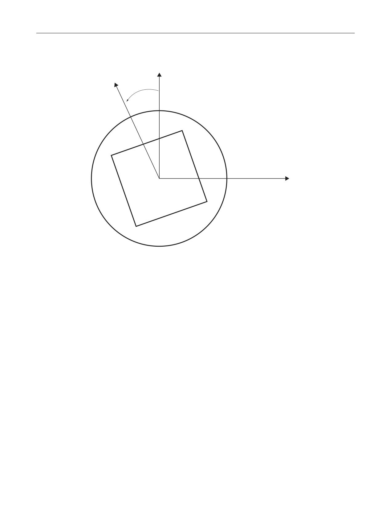
Axes, coordinate systems, frames
4.5 Frames
4.5.6.3
Selecting and deselecting transformations: TRANSMIT
\
F
[
Transmit expansions
The machine data below can be used to take the axis-specific complete frame of the TRANSMIT
rotary axis, i.e. translation, mirroring and scaling, into account in the transformation:
• MD24905 $MC_TRANSMIT_ROT_AX_FRAME_1 = 1
• MD24955 $MC_TRANSMIT_ROT_AX_FRAME_2 = 1
A rotary axis offset can, for example, be entered by compensating the oblique position of a
workpiece in a frame within a frame chain. As a rule, this offset can also be included in the
transformation as an offset in the rotary axis. A C axis offset, as in the figure above, then leads
to corresponding X and Y values.
• MD24905 $MC_TRANSMIT_ROT_AX_FRAME_1 = 2
• MD24955 $MC_TRANSMIT_ROT_AX_FRAME_2 = 2
With this setting, the axis-specific offset of the rotary axis is taken account of in the
transformation up to the SZS. The axis-specific offsets of the rotary axis included in the SZS
frames are entered into the transformation frame as rotation. This setting is only effective if the
transformation frame has been configured.
Frame expansions:
The expansions described below are only valid for the following machine data settings:
• MD10602 $MN_FRAME_GEOAX_CHANGE_MODE = 1
• MD10602 $MN_FRAME_GEOAX_CHANGE_MODE = 2
Basic functions
Function Manual, 10/2020, 6FC5397-2GP40-0BA1
341
Axes, coordinate systems, frames
4.5 Frames
The selection of transformation TRANSMIT produces a virtual geometry axis, coupled by way of
the rotary axis, which is merely included in the contour frame but does not have a reference to an
axis-specific frame. The geometric value results from the rotation of a rotary axis. All other
geometry axes accept their axis-specific components when the transformation is selected.
Components:
• Translations
When selecting TRANSMIT, translations of the virtual axis are deleted. Translations of the
rotary axis can be taken into account in the transformation.
• Rotations
Rotations before the transformation are accepted.
• Mirrorings
Mirroring of the virtual axis is deleted. Mirroring of the rotary axis can be taken into account
in the transformation.
• Scalings
Scaling of the virtual axis is deleted. Scaling of the rotary axis can be taken into account in the
transformation.
Example: Machine data
; FRAME configurations
$MC_MM_SYSTEM_FRAME_MASK='H41'
; TRAFRAME, SETFRAME
$MC_CHSFRAME_RESET_MASK='H41'
; Frames are active after Reset.
$MC_CHSFRAME_POWERON_MASK='H41'
; Frames are deleted for Power On.
$MN_FRAME_GEOAX_CHANGE_MODE=1
; Frames are calculated after switchover
of the geo axis.
$MC_RESET_MODE_MASK='H4041'
; Basic frame is not deselected after Re-
set.
;$MC_RESET_MODE_MASK='H41'
; Basic frame is deselected after Reset.
;$MC_GCODE_RESET_VALUES[7]=2
; G54 is the default setting.
$MC_GCODE_RESET_VALUES[7]=1
; G500 is the default setting.
$MN_MM_NUM_GLOBAL_USER_FRAMES=0
$MN_MM_NUM_GLOBAL_BASE_FRAMES=3
$MC_MM_NUM_USER_FRAMES=10
; From 5 to 100
$MC_MM_NUM_BASE_FRAMES=3
; From 0 to 8
$MN_NCBFRAME_RESET_MASK='HFF'
$MC_CHBFRAME_RESET_MASK='HFF'
$MN_MIRROR_REF_AX=0
; No scaling when mirroring.
$MN_MIRROR_TOGGLE=0
$MN_MM_FRAME_FINE_TRANS=1
; Fine offset
Basic functions
342
Function Manual, 10/2020, 6FC5397-2GP40-0BA1