SINUMERIK 840D sl. Service - Functions. Manual (2018-2020) - page 29
Auxiliary function outputs to PLC
13.14 Implicitly output auxiliary functions
Program code
Comment
N1480
ASSEMBLED="G4 F0.001"
N1490
WRITE(ERROR,FILENAME,ASSEMBLED)
N1500
ENDIF
N1510
N1520
ELSE
N1540
WRITE(ERROR,FILENAME,ASSEMBLED)
; Write an auxiliary function block to a file.
N1550
ENDIF
N1560
N1570 ENDLOOP
N1580
N1590 LABEL1:
N1600
N1620 CALL FILENAME
; Execute a generated subprogram.
N1630
N1650 DELETE(ERROR,FILENAME)
; Delete the file again after execution.
N1660 IF (ERROR<>0)
N1670
SETAL(61000+ERROR)
N1680 ENDIF
N1690
N1700 M17
13.14
Implicitly output auxiliary functions
Function
Implicitly output auxiliary functions are auxiliary functions which have not been programmed
explicitly and which are also output by other system functions (e.g. transformation selection,
tool selection, etc.). These implicit auxiliary functions do not lead to any system function;
instead, the M codes are collected according to output behavior parameters assigned to them
and/or are output to the PLC.
Basic functions
Function Manual, 10/2020, 6FC5397-2GP40-0BA1
757
Auxiliary function outputs to PLC
13.15 Information options
Parameterization
The M codes for auxiliary functions to be output implicitly are defined with the machine data:
• MD22530 $MC_TOCARR_CHANGE_M_CODE (M code at toolholder change)
This machine data value indicates the number of the M code which is output when a
toolholder is activated at the NC/PLC interface.
If the value is positive, the unchanged M code is always output.
If the value is negative, the number of the toolholder is added to the machine data value, and
this number is output.
• MD22532 $MC_GEOAX_CHANGE_M_CODE (M code when switching the geometry axes)
Number of the M code which is output when the geometry axes on the NC/PLC interface are
switched.
• MD22534 $MC_TRAFO_CHANGE_M_CODE (M code in the case of transformation changes)
Number of the M code which is output during a transformation switch of the geometry axes
at the NC/PLC interface.
Note
No M code is output if the number of the M code being output or the MD22530/MD22532/
MD22534 value is between 0 and 6, or is either 17 or 30. Whether or not an M code which
is generated in this manner leads to conflicts with other functions is not monitored.
Output behavior
In the case of implicitly output auxiliary functions, bit 13 is set in machine data MD22080 or
MD22035 (output behavior of predefined or user-defined auxiliary functions).
This bit can be queried via the system variable $AC_AUXFU_SPEC[<n>].
Implicitly output auxiliary function M19
To achieve uniformity in terms of how M19 and SPOS or SPOSA behave at the NC/PLC interface,
auxiliary function M19 can be output to the NC/PLC interface in the event of SPOS and SPOSA
(see Function Manual Axes and Spindles, Section Spindles).
The implicitly output auxiliary function M19 is collected during the block search.
13.15
Information options
Information about auxiliary functions (e.g. about the output status) is possible via:
• The group-specific modal M auxiliary function display on the user interface
• Querying system variables in part programs and synchronized actions
Basic functions
758
Function Manual, 10/2020, 6FC5397-2GP40-0BA1

Auxiliary function outputs to PLC
13.15 Information options
13.15.1
Group-specific modal M auxiliary function display
Function
The output status and acknowledgment status of M auxiliary functions can be displayed on the
user interface on a group-specific basis.
Requirements
To implement function-oriented acknowledgment and display of M auxiliary functions, the
auxiliary functions must be managed in the PLC and, thus, in the user program itself. Therefore,
it is up to the PLC programmer to program the acknowledgment of these auxiliary functions. The
programmer must know which auxiliary functions in which group have to be acknowledged.
Standard
M auxiliary functions that are not managed by means of the PLC are identified by the NC as
"transferred" and output to the PLC. There is no functional acknowledgment for these auxiliary
functions. All M-auxiliary functions collected after a block search are also displayed so that the
operator knows which auxiliary functions will be output after a start following a block search.
PLC activities
In the case of auxiliary function groups that are managed by the PLC itself, the PLC user program
must acknowledge all auxiliary functions of this group at Transfer and End of function. The PLC
programmer must know all the auxiliary functions of these groups.
Miscellaneous
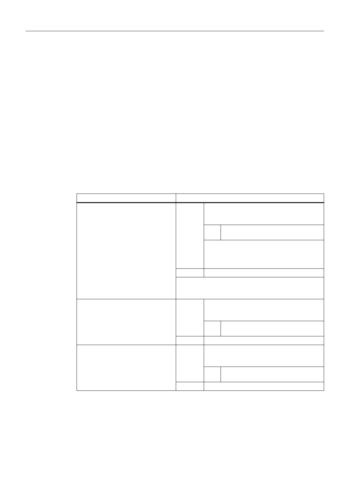
Only the group-specific M auxiliary functions are displayed. The block-by-block display is also
retained. Up to 15 groups can be displayed, whereby only the last M function of a group that
was either collected or output to the PLC is displayed for each group. The M functions are
presented in various display modes depending on their status:
Status
Display mode
Auxiliary function is collected
Inverted with yellow font
Auxiliary function is output from NC to PLC
Inverted
Auxiliary function has been transferred from NC to PLC and
Black font on gray backg16round
transport acknowledgment has taken place
Auxiliary function is managed by the PLC and has been taken
Black font on gray backg16round
over directly by the PLC
Auxiliary function is managed by the PLC and the function
Black font on gray backg16round
acknowledgment has taken place
Basic functions
Function Manual, 10/2020, 6FC5397-2GP40-0BA1
759
Auxiliary function outputs to PLC
13.15 Information options
Display update
The display is organized in such a way that the collected auxiliary functions are always output
first, before those managed by the PLC and before those managed by the NC. A collected
auxiliary function is marked as collected until it has been output from the NC to the PLC. PLC-
managed auxiliary functions are retained until they are substituted by another auxiliary
function. At a reset, only the collected auxiliary functions and the NC-managed auxiliary
functions are deleted.
13.15.2
Querying system variables
Function
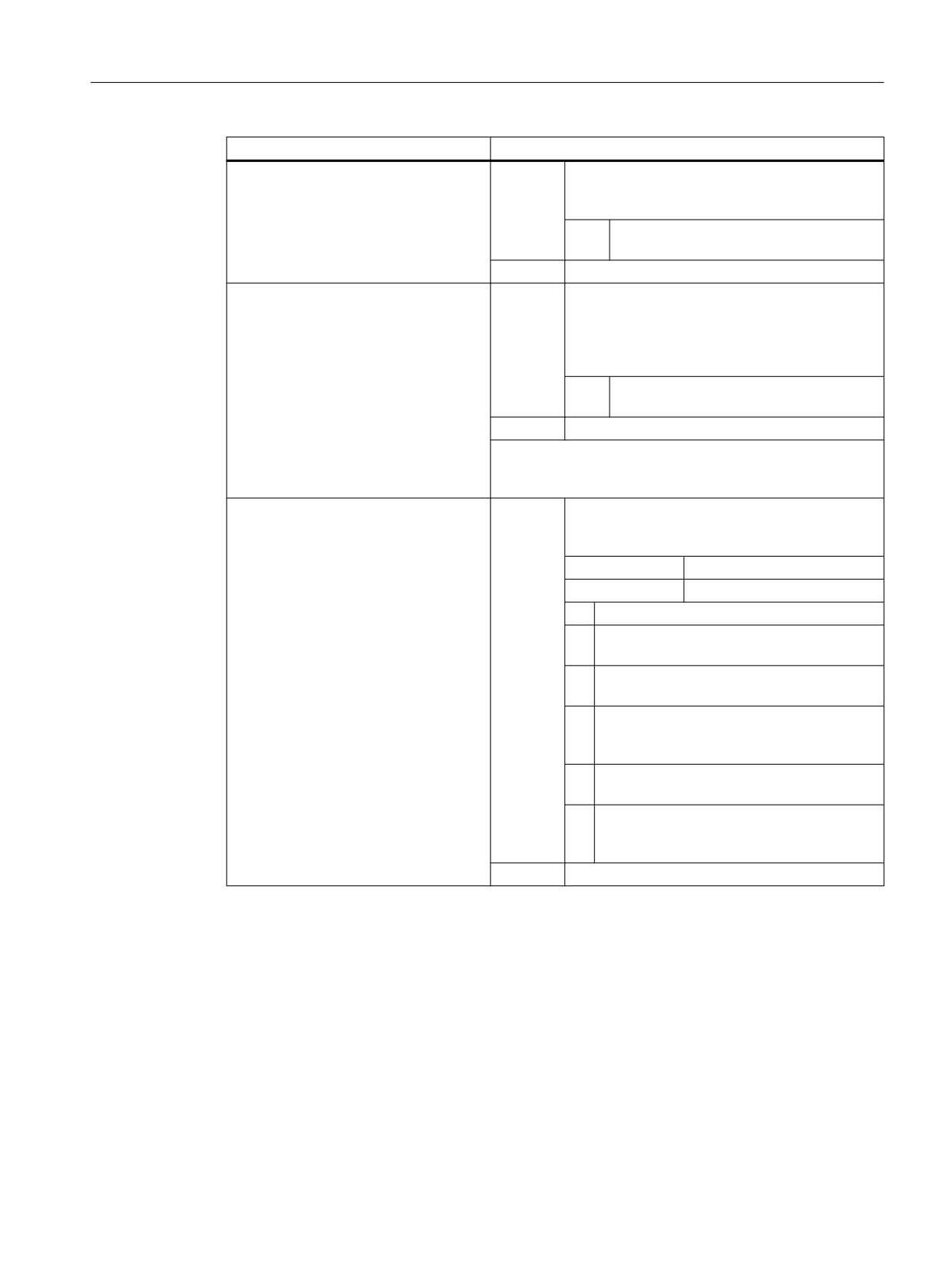
Auxiliary functions can be queried on a group-specific basis via system variables in the part
program and via synchronized actions:
$AC_AUXFU_... [<n>] = <Value>
System variable
Meaning
$AC_AUXFU_PREDEF_INDEX[<n>]
<Value>:
Index of the last auxiliary function collected for an
auxiliary function group (block search) or the last
predefined auxiliary function to be output
Type
INT
:
If no auxiliary function has been output yet for the
specified group or if the auxiliary function is a
user-defined auxiliary function, the variable sup-
plies the value "-1".
<n>:
Group index (0 … 63)
Note:
A predefined auxiliary function can be uniquely identified via
this variable.
$AC_AUXFU_TYPE[<n>]
<Value>:
Type of the last auxiliary function collected for an
auxiliary function group (block search) or the last
auxiliary function to be output
Type
CHAR
:
<n>:
Group index (0 … 63)
$AC_AUXFU_EXT[<n>]
<Value>:
Address extension of the last auxiliary function
collected for an auxiliary function group (block
or or M function-specific:
search) or the last auxiliary function to be output
$AC_AUXFU_M_EXT[<n>]
Type
INT
:
<n>:
Group index (0 … 63)
Basic functions
760
Function Manual, 10/2020, 6FC5397-2GP40-0BA1
Auxiliary function outputs to PLC
13.15 Information options
System variable
Meaning
$AC_AUXFU_VALUE[<n>]
<Value>:
Value of the last auxiliary function collected for an
auxiliary function group (block search) or the last
or or M function-specific:
auxiliary function to be output
$AC_AUXFU_M_VALUE[<n>]
Type
REAL
:
<n>:
Group index (0 … 63)
$AC_AUXFU_SPEC[<n>]
Value:
Bit-encoded output behavior according to
MD22080/MD22035 (or QU programming) of the
last auxiliary function collected for an auxiliary
function group (block search) or the last auxiliary
function to be output
Type
INT
:
<n>:
Group index (0 … 63)
Note:
This variable can be used to determine whether the auxiliary
function should be output with a fast acknowledgment.
$AC_AUXFU_STATE[<n>]
<Value>:
Output state of the last auxiliary function collec-
ted for an auxiliary function group (block search)
or or M function-specific:
or the last auxiliary function to be output
$AC_AUXFU_M_STATE[<n>]
Type:
INT
Range of values:
0 ... 5
0:
Auxiliary function does not exist
1:
M-auxiliary function was collected via a
block search
2:
M-auxiliary function has been output to the
PLC
3:
M-auxiliary function has been output to the
PLC and the transport acknowledgment has
taken place
4:
M-auxiliary function is managed by the PLC
and has been taken over by the PLC
5:
M-auxiliary function is managed by the PLC,
and the function acknowledgment has taken
place
<n>:
Group index (0 … 63)
Example
All M-auxiliary functions of the 1st group will be stored in the order they are output
id=1 every $AC_AUXFU_M_STATE[0]==2 do $AC_FIFO[0,0]=
$AC_AUXFU_M_VALUE[0]
Further information
List Manual System Variables
Basic functions
Function Manual, 10/2020, 6FC5397-2GP40-0BA1
761
Auxiliary function outputs to PLC
13.16 Supplementary conditions
13.16
Supplementary conditions
13.16.1
General constraints
Spindle replacement
Because the auxiliary functions are parameterized channel-specifically, if function: "spindle
replacement" is used, the spindle-specific auxiliary function must be parameterized immediately
in all channels that use the spindles.
Tool management
If tool management is active, the following constraints apply:
• T and M<k> functions are not output to the PLC.
Note
k is the parameterized value of the auxiliary function for the tool change (default: 6):
MD22560 $MC_TOOL_CHANGE_M_CODE (auxiliary function for tool change)
• If no address extension is programmed, the auxiliary function refers to the master spindle or
the master tool holder of the channel.
Definition of the master spindle:
- MD20090 $MC_SPIND_DEF_MASTER_SPIND
- Part program instruction: SETMS
Definition of the master tool holder
- MD20124 $MC_TOOL_MANAGEMENT_TOOLHOLDER
- Part program instruction: SETMTH
Maximum number of auxiliary functions per part program block
A maximum of 10 auxiliary functions may be programmed in one part program block.
DL (additive tool offset)
The following restrictions apply to the DL function:
• Only one DL function can be programmed per part program block.
• If DL functions are used in synchronous actions, parameter: "Value" is not output to the PLC.
Basic functions
762
Function Manual, 10/2020, 6FC5397-2GP40-0BA1

Auxiliary function outputs to PLC
13.16 Supplementary conditions
13.16.2
Output behavior
Thread cutting
During active thread cutting G33, G34 and G35, the following output behavior is always active
for the spindle-specific auxiliary functions:
• M3 (spindle right)
• M4 (spindle left)
• Output duration of one OB40 cycle (quick acknowledgement)
• Output during motion
The spindle-specific auxiliary function M5 (spindle stop) is always output at the end of the block.
The part program block that contains M5 is always ended with exact stop, i.e. even during active
continuous-path mode.
Synchronized actions
With output auxiliary functions from synchronized actions, the parameterized output behavior
is ignored except for the following parameters:
• Bit0: Output duration of one OB1 cycle (normal acknowledgement)
• Bit1: Output duration of one OB40 cycle (quick acknowledgement)
Auxiliary functions: M17 or M2/M30 (end of subprogram)
In its own part program block
If one of the auxiliary functions M17, M2 or M30 is programmed as the only auxiliary function in
a part program block and an axis is still in motion, the auxiliary function is not output to the PLC
until after the axis has stopped.
Overriding the parameterized output behavior
The parameterized output behavior of the auxiliary functions M17 or M2/M30 is overridden by the
output behavior that is determined in the following machine data:
MD20800 $MC_SPF_END_TO_VDI, bit 0 (subprogram end / stop to PLC)
Bi
Value
Meaning
t
0
0
The auxiliary functions M17 or M2/M30 (subprogram end) are not output to the PLC. Con-
tinuous-path mode is not interrupted at the end of the subprogram
1
The auxiliary functions M17 or M2/M30 (subprogram end) are output to the PLC.
Auxiliary function: M1 (conditional stop)
Overriding the parameterized output behavior
Basic functions
Function Manual, 10/2020, 6FC5397-2GP40-0BA1
763

Auxiliary function outputs to PLC
13.17 Examples
The parameterized output behavior of the auxiliary function M1 is overridden by the output
behavior defined in the following machine data:
MD20800 $MC_SPF_END_TO_VDI, bit 1 (subprogram end / stop to PLC)
Bi
Value
Meaning
t
1
0
The auxiliary function M01 (conditional stop) is always output to the PLC. A quick acknowl-
edgement is ineffective, because M01 is permanently assigned to the first auxiliary function
group and is therefore always output at the end of the block.
1
The auxiliary function M01 (conditional stop) is only output to the PLC, if the function:
"Programmed stop" is activated via the HMI user interface.
In the case of a quick acknowledgement, the M1 is output to the PLC during the motion.
While the function is not active, this does not interrupt continuous-path mode.
Part program blocks without traversing motion
In a part program block without a traversing motion, all auxiliary functions are output in a block
immediately, irrespective of their parameterized output behavior.
Spindle-specific auxiliary function output only as information for the PLC user program
In certain controller situations, e.g. at the end of a block search, the collected spindle-specific
auxiliary functions (e.g. M3, M4, M5, M19, M40...M45, M70) is output to the NC/PLC interface only
for information purposes for the PLC user program. The controller generates a part program
block (action block) in which the collected auxiliary functions are entered with a negative
address extension. The corresponding system functions are then not executed.
Example: M(-2) = 41 request gear stage change for the 2nd spindle
13.17
Examples
13.17.1
Extension of predefined auxiliary functions
Task
Parameter assignment of auxiliary functions M3, M4, and M5 for the second spindle of the
channel
Parameter assignment: M3
Requirements:
• Machine data index: 0 (first user-defined auxiliary function)
• auxiliary function group: 5
• Type and value: M3 (spindle right)
Basic functions
764
Function Manual, 10/2020, 6FC5397-2GP40-0BA1
Auxiliary function outputs to PLC
13.17 Examples
• Address extension: 2 as appropriate for the 2nd spindle of the channel
• Output behavior:
- Output duration one OB1 cycle (normal acknowledgment)
- Output prior to motion
Parameter assignment:
MD22000 $MC_AUXFU_ASSIGN_GROUP[ 0 ]
= 5
MD22010 $MC_AUXFU_ASSIGN_TYPE [ 0 ]
= "M"
MD22020 $MC_AUXFU_ASSIGN_EXTENSION [ 0 ]
= 2
MD22030 $MC_AUXFU_ASSIGN_VALUE [ 0 ]
= 3
MD22035 $MC_AUXFU_ASSIGN_SPEC [ 0 ]
= 'H21'
Parameter assignment: M4
Requirements:
• Machine data index: 1 (second user-defined auxiliary function)
• auxiliary function group: 5
• Type and value: M4 (spindle left)
• Address extension: 2 as appropriate for the 2nd spindle of the channel
• Output behavior:
- Output duration one OB1 cycle (normal acknowledgment)
- Spindle response following acknowledgment
- Output during motion
Parameter assignment:
MD22000 $MC_AUXFU_ASSIGN_GROUP [ 1 ]
= 5
MD22010 $MC_AUXFU_ASSIGN_TYPE [ 1 ]
= "M"
MD22020 $MC_AUXFU_ASSIGN_EXTENSION [ 1 ]
= 2
MD22030 $MC_AUXFU_ASSIGN_VALUE [ 1 ]
= 4
MD22035 $MC_AUXFU_ASSIGN_SPEC [ 1 ]
= 'H51'
Parameter assignment: M5
Requirements:
• Machine data index: 2 (third user-defined auxiliary function)
• auxiliary function group: 5
• Type and value: M5 (spindle stop)
Basic functions
Function Manual, 10/2020, 6FC5397-2GP40-0BA1
765
Auxiliary function outputs to PLC
13.17 Examples
• Address extension: 2 as appropriate for the 2nd spindle of the channel
• Output behavior:
- Output duration one OB1 cycle (normal acknowledgment)
- Spindle response following acknowledgment
- Output at block end
Parameter assignment:
MD22000 $MC_AUXFU_ASSIGN_GROUP [ 2 ]
= 5
MD22010 $MC_AUXFU_ASSIGN_TYPE [ 2 ]
= "M"
MD22020 $MC_AUXFU_ASSIGN_EXTENSION [ 2 ]
= 2
MD22030 $MC_AUXFU_ASSIGN_VALUE [ 2 ]
= 5
MD22035 $MC_AUXFU_ASSIGN_SPEC [ 2 ]
= 'H91'
13.17.2
Defining auxiliary functions
Task
Parameterization of the auxiliary function-specific machine data for a machine with the
following configuration:
Spindles
• Spindle 1: Master spindle
• Spindle 2: Second spindle
Gear stages
• Spindle 1: 5 gear stages
• Spindle 2: No gear stages
Switching functions for cooling water on/off
• Spindle 1
- "On" = M50
- "Off" = M51
• Spindle 2
- "On" = M52
- "Off" = M53
Basic functions
766
Function Manual, 10/2020, 6FC5397-2GP40-0BA1
Auxiliary function outputs to PLC
13.17 Examples
Requirements
Spindle 1 (master spindle)
Note
Default assignments
• The auxiliary functions M3, M4, M5, M70 and M1=3, M1=4, M1=5, M1=70 of spindle 1
(master spindle) are assigned as standard to the 2nd auxiliary function group.
• All S and S1 values of spindle 1 (master spindle) are assigned as standard to the 3rd auxiliary
function group.
• The gear stage last programmed is to be output after block search. The following auxiliary
functions are assigned for this reason to the 9th auxiliary function group:
- M40, M41, M42, M43, M44, M45
- M1=40, M1=41, M1=42, M1=43, M1=44, M1=45
• The auxiliary functions M3, M4, M5, M70 and M1=3, M1=4, M1=5, M1=70 (2nd auxiliary
function group) and S and S1 values (3rd auxiliary function group) should possess the
following output behavior:
- Output duration one OB40 cycle (quick acknowledgment)
- Output prior to motion
• The auxiliary functions for gear changeover M40 to M45 and M1=40 to M1=45 (9th auxiliary
function group) should have the following output behavior:
- Output duration of one OB1 cycle (normal acknowledgment)
- Output prior to motion
Spindle 2
• Only one M function for directional reversal may be programmed in one block. The direction
of rotation last programmed is to be output after block search. The following auxiliary
functions are assigned for this reason to the 10th auxiliary function group:
- M2=3, M2=4, M2=5, M2=70
• All S2 values are assigned to the 11th auxiliary function group.
• The auxiliary functions M2=3, M2=4, M2=5, M2=70 (10th auxiliary function group) and S2
values (11th auxiliary function group) should have the following output behavior:
- Output duration one OB40 cycle (quick acknowledgment)
- Output prior to motion
Basic functions
Function Manual, 10/2020, 6FC5397-2GP40-0BA1
767
Auxiliary function outputs to PLC
13.17 Examples
Cooling water
• It is not permissible to switch the cooling water on and off in one part program block. After
a block search, the cooling water will be switched on or off. The following auxiliary functions
are assigned for this reason, e.g. to the 12th or 13th auxiliary function group:
-
12th auxiliary function group: M50, M51
–
13th auxiliary function group: M52, M53
• The auxiliary functions M50, M51 (12th auxiliary function group) and M52, M53
(13th auxiliary function group) should have the following output behavior:
- Output duration of one OB1 cycle (normal acknowledgment)
- Output prior to motion
Parameterization of the machine data
The machine data is parameterized by appropriate programming within a part program.
Program code
Comment
$MN_AUXFU_MAXNUM_GROUP_ASSIGN=21
; Number of user-defined auxiliary functions
per channel
$MN_AUXFU_GROUP_SPEC[1]='H22'
; Output behavior of the 2nd auxiliary func-
tion group
$MN_AUXFU_GROUP_SPEC[2]='H22'
; Output behavior of the 3rd auxiliary func-
tion group
$MN_AUXFU_GROUP_SPEC[8]='H21'
; Output behavior of the 9th auxiliary func-
tion group
$MC_AUXFU_ASSIGN_TYPE[0]="M"
; Description of the 1st auxiliary function:
M40
$MC_AUXFU_ASSIGN_EXTENSION[0]=0
$MC_AUXFU_ASSIGN_VALUE[0]=40
$MC_AUXFU_ASSIGN_GROUP[0]=9
; ... (and analogously for the 2nd - 5th auxil-
iary functions)
$MC_AUXFU_ASSIGN_TYPE[5]="M"
; Description of the 6th auxiliary function:
M45
$MC_AUXFU_ASSIGN_EXTENSION[5]=0
$MC_AUXFU_ASSIGN_VALUE[5]=45
$MC_AUXFU_ASSIGN_GROUP[5]=9
$MC_AUXFU_ASSIGN_TYPE[6]="M"
; Description of the 7th auxiliary function:
M1=40
$MC_AUXFU_ASSIGN_EXTENSION[6]=1
$MC_AUXFU_ASSIGN_VALUE[6]=40
$MC_AUXFU_ASSIGN_GROUP[6]=9
; . . . (and analogously for the 8th - 11th
auxiliary functions)
Basic functions
768
Function Manual, 10/2020, 6FC5397-2GP40-0BA1
Auxiliary function outputs to PLC
13.17 Examples
Program code
Comment
$MC_AUXFU_ASSIGN_TYPE[11]="M"
; Description of the
12th auxiliary function:
M1=45
$MC_AUXFU_ASSIGN_EXTENSION[11]=1
$MC_AUXFU_ASSIGN_VALUE[11]=45
$MC_AUXFU_ASSIGN_GROUP[11]=9
$MN_AUXFU_GROUP_SPEC[9] = 'H22'
; Output behavior of
the 10th auxiliary func-
tion group
$MC_AUXFU_ASSIGN_TYPE[12]="M"
; Description of the
13th auxiliary function:
M2=3
$MC_AUXFU_ASSIGN_EXTENSION[12]=2
$MC_AUXFU_ASSIGN_VALUE[12]=3
$MC_AUXFU_ASSIGN_GROUP[12]=10
$MC_AUXFU_ASSIGN_TYPE[13]="M"
; Description of the
14th auxiliary function:
M2=4
$MC_AUXFU_ASSIGN_EXTENSION[13]=2
$MC_AUXFU_ASSIGN_VALUE[13]=4
$MC_AUXFU_ASSIGN_GROUP[13]=10
$MC_AUXFU_ASSIGN_TYPE[14]="M"
; Description of the
15th auxiliary function:
M2=5
$MC_AUXFU_ASSIGN_EXTENSION[14]=2
$MC_AUXFU_ASSIGN_VALUE[14]=5
$MC_AUXFU_ASSIGN_GROUP[14]=10
$MC_AUXFU_ASSIGN_TYPE[15]="M"
; Description of the
16th auxiliary function:
M2=70
$MC_AUXFU_ASSIGN_EXTENSION[15]=2
$MC_AUXFU_ASSIGN_VALUE[15]=70
$MC_AUXFU_ASSIGN_GROUP[15]=10
$MN_AUXFU_GROUP_SPEC[10]='H22'
; Specification of the 11th auxiliary function
group
$MC_AUXFU_ASSIGN_TYPE[16]="S"
; Description of the 17th auxiliary function:
S2=<all values>
$MC_AUXFU_ASSIGN_EXTENSION[16]=2
$MC_AUXFU_ASSIGN_VALUE[16]=-1
$MC_AUXFU_ASSIGN_GROUP[16]=11
$MN_AUXFU_GROUP_SPEC[11]='H21'
; Specification of the 12th auxiliary function
group
Basic functions
Function Manual, 10/2020, 6FC5397-2GP40-0BA1
769

Auxiliary function outputs to PLC
13.18 Data lists
Program code
Comment
$MC_AUXFU_ASSIGN_TYPE[17]="M"
; Description of the 18th auxiliary function:
M50
$MC_AUXFU_ASSIGN_EXTENSION[17]=0
$MC_AUXFU_ASSIGN_VALUE[17]=50
$MC_AUXFU_ASSIGN_GROUP[17]=12
$MC_AUXFU_ASSIGN_TYPE[18]="M"
; Description of the 19th auxiliary function:
M51
$MC_AUXFU_ASSIGN_EXTENSION[18]=0
$MC_AUXFU_ASSIGN_VALUE[18]=51
$MC_AUXFU_ASSIGN_GROUP[18]=12
$MN_AUXFU_GROUP_SPEC[12]='H21'
; Specification of the 13th auxiliary function
group
$MC_AUXFU_ASSIGN_TYPE[19]="M"
; Description of the 20th auxiliary function:
M52
$MC_AUXFU_ASSIGN_EXTENSION[19]=0
$MC_AUXFU_ASSIGN_VALUE[19]=52
$MC_AUXFU_ASSIGN_GROUP[19]=13
$MC_AUXFU_ASSIGN_TYPE[20]="M"
; Description of the 21st auxiliary function:
M53
$MC_AUXFU_ASSIGN_EXTENSION[20]=0
$MC_AUXFU_ASSIGN_VALUE[20]=53
$MC_AUXFU_ASSIGN_GROUP[20]=13
13.18
Data lists
13.18.1
Machine data
13.18.1.1
NC-specific machine data
Number
Identifier: $MN_
Description
10713
M_NO_FCT_STOPRE
M function with preprocessing stop
10714
M_NO_FCT_EOP
M function for spindle active after NC RESET
10715
M_NO_FCT_CYCLE
M function to be replaced by subroutine
11100
AUXFU_MAXNUM_GROUP_ASSIGN
Maximum number of user-defined auxiliary functions
per channel
Basic functions
770
Function Manual, 10/2020, 6FC5397-2GP40-0BA1

Auxiliary function outputs to PLC
13.18 Data lists
Number
Identifier: $MN_
Description
11110
AUXFU_GROUP_SPEC
Group-specific output behavior
11450
SEARCH_RUN_MODE
Behavior after a block search
13.18.1.2
Channelspecific machine data
Number
Identifier: $MC_
Description
20110
RESET_MODE_MASK
Definition of control initial setting after part program
start.
20112
START_MODE_MASK
Definition of control initial setting after powerup and on
RESET or at end of part program
20270
CUTTING_EDGE_DEFAULT
Basic setting of tool cutting edge without programming
20800
SPF_END_TO_VDI
Subroutine end / Stop at PLC
22000
AUXFU_ASSIGN_GROUP
Group assignment of user-defined auxiliary functions
22010
AUXFU_ASSIGN_TYPE
Type of user-defined auxiliary functions
22020
AUXFU_ASSIGN_EXTENSION
Address extension for user-defined auxiliary functions
22030
AUXFU_ASSIGN_VALUE
Value of user-defined auxiliary functions
22035
AUXFU_ASSIGN_SPEC
Output behavior of user-defined auxiliary functions
22040
AUXFU_PREDEF_GROUP
Group assignment of predefined auxiliary functions
22050
AUXFU_PREDEF_TYPE
Type of predefined auxiliary functions
22060
AUXFU_PREDEF_EXTENSION
Address extension for predefined auxiliary functions
22070
AUXFU_PREDEF_VALUE
Value of predefined auxiliary functions
22080
AUXFU_PREDEF_SPEC
Output behavior of predefined auxiliary functions
22100
AUXFU_QUICK_BLOCKCHANGE
Block change delay with quick auxiliary functions
22110
AUXFU_H_TYPE_INT
Type of H auxiliary functions
22200
AUXFU_M_SYNC_TYPE
M functions output time
22210
AUXFU_S_SYNC_TYPE
S functions output time
22220
AUXFU_T_SYNC_TYPE
T functions output time
22230
AUXFU_H_SYNC_TYPE
H functions output time
22240
AUXFU_F_SYNC_TYPE
F functions output time
22250
AUXFU_D_SYNC_TYPE
D functions output time
22252
AUXFU_DL_SYNC_TYPE
DL functions output time
22254
AUXFU_ASSOC_M0_VALUE
Additional M function for program stop
22256
AUXFU_ASSOC_M1_VALUE
Additional M function for conditional stop
22530
TOCARR_CHANGE_M_CODE
M code for change of tool holder
22532
GEOAX_CHANGE_M_CODE
M code for replacement of geometry axes
22534
TRAFO_CHANGE_M_CODE
M code for change of tool holder
22560
TOOL_CHANGE_M_CODE
Auxiliary function for tool change
Basic functions
Function Manual, 10/2020, 6FC5397-2GP40-0BA1
771
Auxiliary function outputs to PLC
13.18 Data lists
Basic functions
772
Function Manual, 10/2020, 6FC5397-2GP40-0BA1
Digital and analog NC I/O
14
14.1
Introduction
Functions
I/O modules can be connected to a SINUMERIK 840D sl via PROFIBUS or PROFINET. Normally, the
PLC user program uses the appropriate digital or analog inputs and outputs for access. The
"Digital and analog NC I/O for SINUMERIK 840D sl" function enables access to the inputs/outputs
of the I/O modules via system variables of compile cycles directly from the NC (part programs,
synchronized actions and compile cycles). This I/O is referred to as the NC I/O in the following.
Three different functions are available for compatibility reasons:
1. Indirect I/O access via PLC (Page 774)
The read and write requests of the inputs/outputs of the I/O modules are written from the NC
via the interface to the PLC. The requests are processed cyclically in the OB1 cycle.
This function has the lowest performance with regard to the quantity structure and response
time.
2. Direct I/O access via PLC (Page 795)
The read and write requests of the inputs/outputs of the I/O modules are written from the NC
via the interface to the PLC. An interrupt is then triggered on the PLC. The requests from the
PLC are processed as part of the interrupt processing.
From the quantity structure, the function is equivalent to that described above. However, the
response time is not as good.
3. Direct I/O access without PLC (Page 800)
Avoiding the PLC, the control internal images of the inputs/outputs of the I/O modules can be
accessed directly from the NC.
This is currently the function with the highest performance with regard to the quantity
structure and response time.
Prerequisites
• The PROFIBUS/PROFINET I/O modules of the NC I/O must be connected and ready to use.
• The HW configuration of the PROFIBUS/PROFINET I/O modules of the NC I/O has been
performed with the SIMATIC S7 Manager or HW Config and loaded to the PLC.
Basic functions
Function Manual, 10/2020, 6FC5397-2GP40-0BA1
773
Digital and analog NC I/O
14.2 Indirect I/O access via PLC
Monitoring
The following monitoring functions are active for the NC I/Os:
• Run-up:
- Check for consistency of the I/Os detected on the PLC and the NC I/O parameterized in the
machine data.
• Cyclic operation:
- Sign-of-life monitoring in interpolation cycles
- Module monitoring in interpolation cycles
- Temperature monitoring
In the event of an error, the DB10.DBX104.7 "NC ready" signal is reset and an alarm is displayed.
Response to faults
The digital and analog outputs of the NC I/O are switched to a safe status (0 V) in the event of
faults (e.g. NC ready = 0), for errors in the NCU or power failures.
Application
The NC I/O is used, for example, by the following NC functions:
• Several feedrate values or auxiliary functions in one block
• Rapid retraction on final dimension
• Axis-specific delete distance-to-go
• Program branches
• Rapid NC Start
• Analog calipers
• Position switching signals
• Punching/nibbling functions
• Analog-value control
14.2
Indirect I/O access via PLC
14.2.1
Brief description
There are three I/O interfaces (X122, X132 and X142) on the SINUMERIK 840D sl NCU.
Four digital inputs and outputs of the X142 interface are available as so-called fast NC I/O. They
can be read or written via the first address byte and via the $A_IN[1...4] and $A_OUT[1...4]
system variables.
Basic functions
774
Function Manual, 10/2020, 6FC5397-2GP40-0BA1

Digital and analog NC I/O
14.2 Indirect I/O access via PLC
I/O modules can also be connected to the PROFIBUS DP/MPI interfaces X126 and X136. This
enables the number of digital and analog NC inputs/outputs to be expanded by 32 digital and 8
analog inputs and outputs respectively. These NC inputs/outputs are called external NC I/Os in
the following.
Table 14-1
Maximum number of digital and analog NC I/Os
Onboard
NC I/O
Total
Digital inputs
4
32
36
Digital outputs
4
32
36
Analog inputs
-
8
8
Analog outputs
-
8
8
Further information
• Manual SINUMERIK 840D sl
• Operating instructions for SIMATIC ET 200S FC
See also
Direct I/O access via PLC (Page 795)
14.2.2
Parameterization
Machine data
Number of active NC I/Os
The number of active or from the NC usable digital NC I/O bytes are set in the following machine
data:
• Number of digital NC input bytes
MD10350 $MN_FASTIO_DIG_NUM_INPUTS = <number>
• Number of digital NC output bytes
MD10360 $MN_FASTIO_DIG_NUM_OUTPUTS = <number>
The number of active or from the NC usable analog I/Os are set in the following machine data:
• Number of analog NC inputs
MD10300 $MN_FASTIO_ANA_NUM_INPUTS = <number>
• Number of the analog NC outputs
MD10310 $MN_FASTIO_ANA_NUM_OUTPUTS = <number>
The I/Os do not have to actually exist in the hardware. In this case, the signal states or the analog
values are set to "zero" in a defined way inside the NC.
The values present at the I/O inputs can be changed from the PLC user program before they are
read by the NC.
Basic functions
Function Manual, 10/2020, 6FC5397-2GP40-0BA1
775
Digital and analog NC I/O
14.2 Indirect I/O access via PLC
Slot addresses
Addressing of the digital I/Os:
• HW assignment for external digital inputs
MD10366 $MN_HW_ASSIGN_DIG_FASTIN[ <n> ] = <addressH>
• HW assignment for external digital outputs
MD10368 $MN_HW_ASSIGN_DIG_FASTOUT[ <n> ] = <addressH>
Addressing of the analog I/Os:
• HW assignment for external analog inputs
MD10362 $MN_HW_ASSIGN_ANA_FASTIN[ <n> ] = <addressH>
• HW assignment for external analog outputs
MD10364 $MN_HW_ASSIGN_ANA_FASTOUT[ <n> ] = <addressH>
<n>:
Index for addressing the external digital I/O bytes (0 ... 3) or the external analog
I/Os (0 ... 7)
<address>: Slot address of the PROFIBUS/PROFINET module with 05 00 xxxx
05
Identifier for PROFIBUS/PROFINET module
00
Permanently assigned
xxxxH
Hexadecimal logical start address of the slot
0000 = no active slot
The following must be taken into account for logical start addresses
within the PLC process image:
• Input slots: Reading from the NC also possible
• Output slots: Writing from the NC not permitted ⇒ alarm after run-
up of the NC
Further information
Equipment Manual NCU 7x0.3 PN, NCU 7x0.3B PN; Technical data > PLC
> Process image size
Detailed information can be obtained under Address (http://
support.automation.siemens.com/WW/view/de/54058408)
Weighting factors for analog inputs/outputs
The weighting factor can be used to adapt each individual analog NC I/O to the AD or DA
converter of the analog I/O module used:
• Weighting factor for the analog NC inputs (see "Analog NC inputs (Page 784)"):
MD10320 $MN_FASTIO_ANA_INPUT_WEIGHT[<n>]
• Weighting factor for the analog NC outputs (see "Analog NC outputs (Page 786)"):
MD10330 $MN_FASTIO_ANA_OUTPUT_WEIGHT[<n>]
<n>:
Index for addressing the external analog I/Os (0 ... 7)
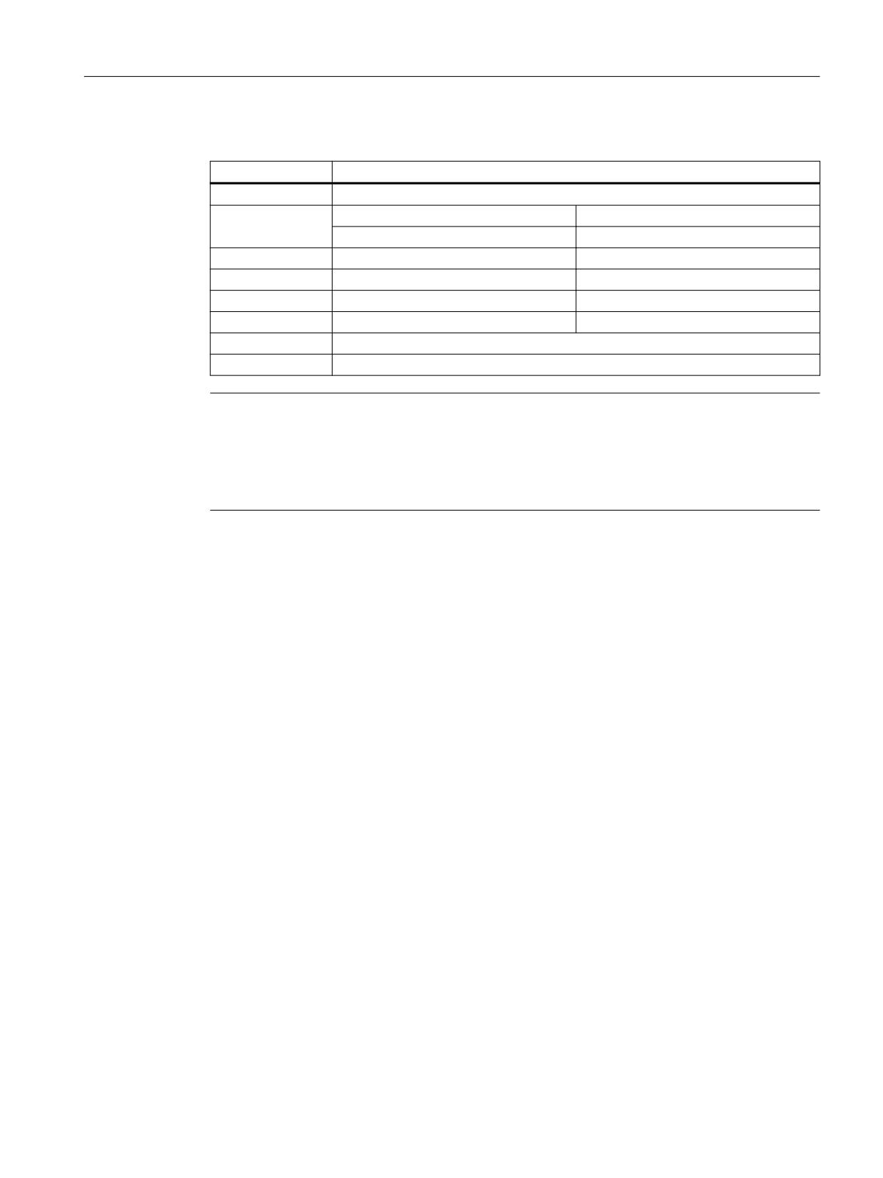
Assignment to NC functions
The I/Os are required by several NC functions. The assignment of the I/Os used is performed
function-specifically via machine data, e.g. for the "Multiple feedrates in one block" function via
the machine data:
Basic functions
776
Function Manual, 10/2020, 6FC5397-2GP40-0BA1
Digital and analog NC I/O
14.2 Indirect I/O access via PLC
MD21220 $MC_MULTFEED_ASSIGN_FASTIN = <byte address>
<byte address>
Digital NC I/Os
0
None
1
1 ... 4
Onboard inputs/outputs
5 ... 8
NC output without hardware
2
9 ... 16
External NC I/O
3
17 ... 24
External NC I/O
4
25 ... 32
External NC I/O
5
33 ... 40
External NC I/O
128
Inputs 1 to 8 of comparator byte 1
129
Inputs 9 to 16 of comparator byte 2
Note
Multiple assignments
Multiple assignments of inputs are not considered to be incorrect parameterization.
Multiple assignments of outputs are considered to be incorrect parameterization, are checked
during run-up and indicated by an alarm.
Example: Hardware assignment of external I/Os
Two input bytes and one output byte are parameterized for the reading/writing of digital I/Os of
a PROFIBUS module.
Number of active NC I/O bytes
MD10350 $MN_FASTIO_DIG_NUM_INPUTS =
; 2 digital input bytes + 1 onboard byte
2 + 1 = 3
MD10360 $MN_FASTIO_DIG_NUM_OUTPUTS
; 1 digital output byte + 1 onboard byte
= 1 + 1 = 2
Hardware assignment
MD10366 $MN_HW_ASSIGN_DIG_FASTIN[ 0 ] ; $A_IN[ 9 ] ... [ 16 ] from 1st I/O input byte
= 'H5000200'
MD10366 $MN_HW_ASSIGN_DIG_FASTIN[ 1 ] ; $A_IN[ 17 ] ... [ 24 ] from 2nd I/O input byte
= 'H5000201'
MD10368 $MN_HW_ASSIGN_DIG_FAST-
; $A_OUT[ 9 ] ... [ 16 ] in 1st I/O output byte
OUT[ 0 ] = 'H5000200'
The hexadecimal addresses 200H and 201H entered in the machine data correspond to those
assigned during the configuration in the SIMATIC S7 Manager, decimal logical start addresses
512D and 513D
Basic functions
Function Manual, 10/2020, 6FC5397-2GP40-0BA1
777

Digital and analog NC I/O
14.2 Indirect I/O access via PLC
14.2.3
System variables
Input data
System variable
Index or input number <n>
$A_IN[ <n> ]
1 ... 4 and 9 ... 40, see Digital NC inputs (Page 778)
$A_INA [<n>]
1 ... 8, see Analog NC inputs (Page 784)
A preprocessing stop is triggered in the channel when reading input data from a part program.
Output data
System variable
Index or output number <n>
$A_OUT [<n>]
1 ... 4 and 9 ... 40, see Digital NC outputs (Page 780)
$A_OUTA [<n>]
1 ... 8, see Analog NC outputs (Page 786)
A preprocessing stop is triggered in the channel when reading output data from a part program.
14.2.4
Comparator inputs
In addition to the I/O inputs, 16 control-internal comparator inputs are available.
The current signal state of a comparator input results from the comparison of an analog I/O input
with a threshold value specified in the setting data.
See "Comparator inputs (Page 791)".
14.2.5
Digital NC I/Os
14.2.5.1
Digital NC inputs
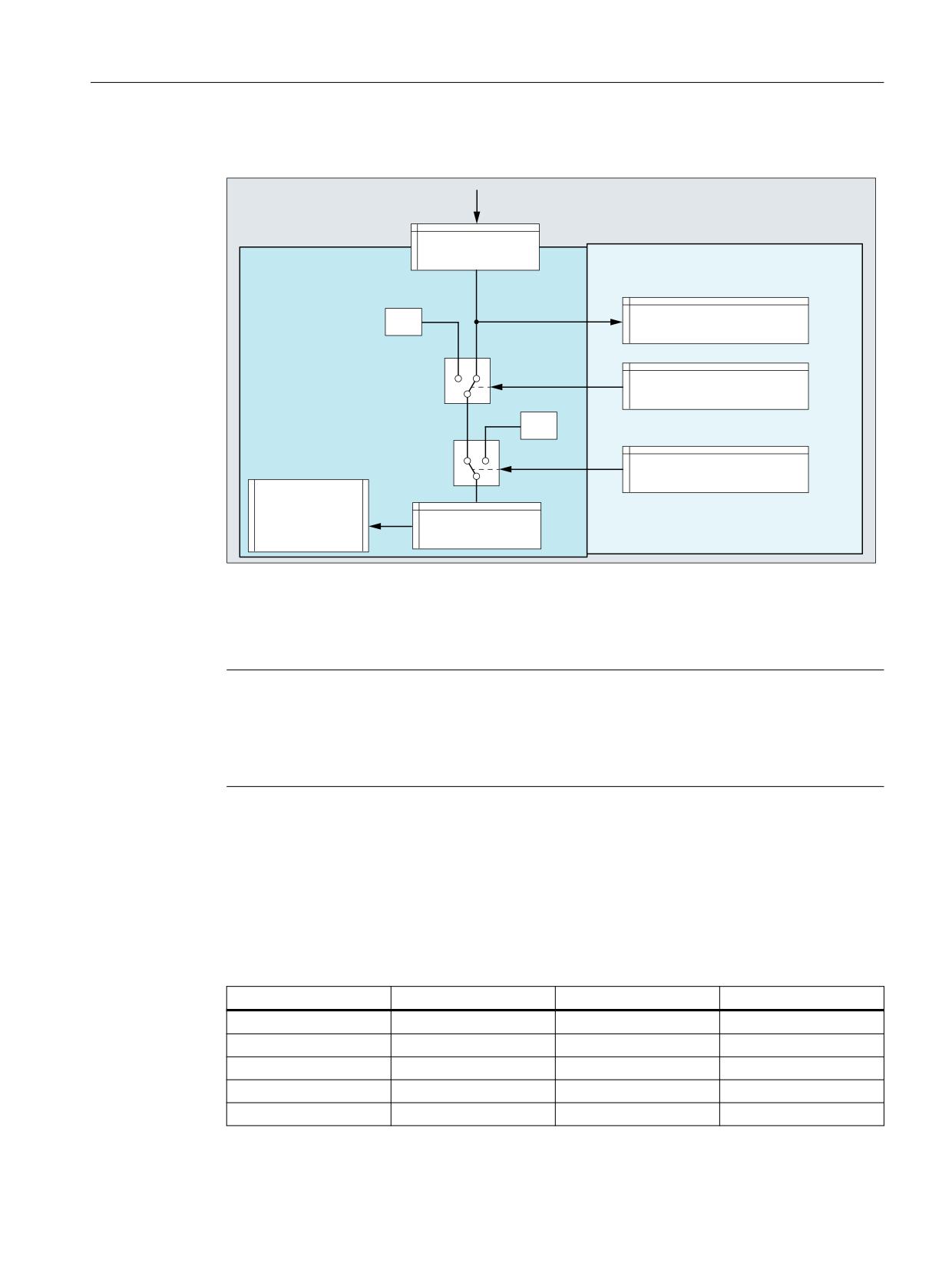
Function
Using system variables $A_IN, values of digital NC inputs can be read into an NC program or
synchronized action. The read value can be influenced via NC/PLC interface signals.
Application examples
Digital NC inputs are used, for example, for the following NC functions:
• Delete distance-to-go with positioning axes
• Fast program branching at the end of block
• Programmed read-in disable
• Several feedrates in one block
Further information
Function Manual Synchronized Actions
Basic functions
778
Function Manual, 10/2020, 6FC5397-2GP40-0BA1
Digital and analog NC I/O
14.2 Indirect I/O access via PLC
NC/PLC interface signals
1& LQSXW
1&
3/&
$FWXDO YDOXH
'% '%%
'%%
/RFN
'% '%% '%%
6HW
'% '%% '%%
1& SURJUDP
$B,1>
@
1& LQSXW YDOXH
Actual value
The actual value of the NC input can be read in the PLC user program via the actual value
interface.
Note
Different values
The value in the "Actual value" interface can, as a result of the various subsequent influencing
possibilities, have a different value than that available at the NC input, which is read using system
variable $A_IN.
Lock
If a bit is set in the interface, for the corresponding input, a value of 0 is transferred.
Set
If a bit is set in the interface, for the corresponding input, a value of 1 is transferred.
Overview
Lock
Set
Actual value
NC input
DBX0.0 - 7
DBX1.0 - 7
DBX60.0 - 7
1 - 8
DBX122.0 - 7
DBX123.0 - 7
DBX186.0 - 7
9 - 16
DBX124.0 - 7
DBX125.0 - 7
DBX187.0 - 7
17 - 24
DBX126.0 - 7
DBX127.0 - 7
DBX188.0 - 7
25 - 32
DBX128.0 - 7
DBX129.0 - 7
DBX189.0 - 7
33 - 40
Basic functions
Function Manual, 10/2020, 6FC5397-2GP40-0BA1
779
Digital and analog NC I/O
14.2 Indirect I/O access via PLC
Boundary conditions
Response after a warm restart and channel reset
The value at the hardware input is transferred, unchanged after a warm restart and channel
reset.
14.2.5.2
Digital NC outputs
Function
Using system variables $A_OUT, values of digital NC outputs can be written to an NC program
or synchronized action. The written value can be influenced using NC/PLC interface signals.
Application examples
• Positioning switching signals (see Function Manual Axes and Spindles, Section Software
cams)
• Output of comparator signals
Further information
Function Manual Synchronized Actions
NC/PLC interface signals
1&
3/&
1& SURJUDP
6HWWLQJ YDOXH
$B287>
@
'% '%% '%%
2YHUZULWH
'% '%% '%%
6HWSRLQW
1& RXWSXW YDOXH
'% '%%
'%%
7DUJHW
'% '%% '%%
/RFN
'% '%% '%%
1& RXWSXW
Basic functions
780
Function Manual, 10/2020, 6FC5397-2GP40-0BA1

Digital and analog NC I/O
14.2 Indirect I/O access via PLC
Overwrite
If, in the interface, a bit is set, then for the corresponding output, instead of the value written
using system variables $A_OUT, the setting value specified from the PLC user program is used.
The value written via system variables $A_OUT is then lost.
If the bit in the interface is reset, then the actual value is kept at the hardware output.
Setting value
Using the setting value, the PLC user program can specify a defined output value. In order that
the setting value becomes active, it must be activated via the interfaces for "Overwrite" or
"Target".
Setpoint
The actual NC output value can be read in the PLC user program via the setpoint.
Note
Different values
The value in the "Setpoint" interface can, as a result of the various subsequent influencing
possibilities, have a different value than that available at the NC output.
Target
If, in the interface, a bit is set, then for the corresponding output, instead of the NC output value,
the setting value specified by the PLC user program is used. The actual NC output value is kept.
If a bit is reset in the interface, then the last NC output value becomes active again.
Lock
If a bit is set in the interface, for the corresponding output, a value of 0 is output.
Overview
Lock
Overwrite
Setting value
Target
Setpoint
NC output
DBX4.0 - 7
DBX5.0 - 7
DBX6.0 - 7
DBX7.0 - 7
DBX64.0 - 7
1 - 8
DBX130.0 - 7
DBX131.0 - 7
DBX132.0 - 7
DBX133.0 - 7
DBX190.0 - 7
9 - 16
DBX134.0 - 7
DBX135.0 - 7
DBX136.0 - 7
DBX137.0 - 7
DBX191.0 - 7
17 - 24
DBX138.0 - 7
DBX139.0 - 7
DBX140.0 - 7
DBX141.0 - 7
DBX192.0 - 7
25 - 32
DBX142.0 - 7
DBX143.0 - 7
DBX144.0 - 7
DBX145.0 - 7
DBX193.0 - 7
33 - 40
Boundary conditions
NC outputs without hardware
An alarm is not displayed if NC outputs are written to, which were defined (MD10360
$MN_FASTIO_DIG_NUM_OUTPUTS), but the corresponding hardware is not available. The
setpoint can be read via the PLC user program.
Basic functions
Function Manual, 10/2020, 6FC5397-2GP40-0BA1
781

Digital and analog NC I/O
14.2 Indirect I/O access via PLC
Behavior at end of program reset/channel reset
From the PLC user program, via the interfaces for "Overwrite", "Target" or "Lock", at the end of
program or for a channel reset, every NC output can be set in defined fashion as a function of the
specific application.
Behavior for a warm restart
All NC outputs are set to "0" after a warm restart. From the PLC user program, using the overwrite
or setting screen form, every NC output can be set as a function of the specific application.
14.2.5.3
Connection and logic operations of fast digital I/Os
Function
Fast NC I/O inputs can be set via the software depending on the fast-output signal states.
Overview:
2XWSXW
,QSXW
%\WH
%\WH
%LW
%LW
$OWHUQDWLYHV
,QWHUFRQQHFW
25 ORJLF RSHUDWLRQ
$1' ORJLF RSHUDWLRQ
Connecting
The NC I/O fast input is set to the signal state of the assigned fast output.
OR operation
The NC I/O fast input adopts the signal state as a result of the ORing of the output signal with the
assigned input signal.
AND operation
The NC I/O fast input adopts the signal state as a result of the ANDing of the output signal with
the assigned input signal.
Basic functions
782
Function Manual, 10/2020, 6FC5397-2GP40-0BA1

Digital and analog NC I/O
14.2 Indirect I/O access via PLC
Special cases
• If several output bits are assigned to the same input bit, then the one with the highest MD
index becomes effective.
• If inputs or outputs are specified which do not exist or are not activated, then the assignment
is ignored without an alarm. Checking of the active bytes of the NC I/Os is performed via the
entries in machine data:
MD10350 $MN_FASTIO_DIG_NUM_INPUTS
MD10360 $MN_FASTIO_DIG_NUM_OUTPUTS
Defining assignments
The assignments are specified via machine data:
MD10361 $MN_FASTIO_DIG_SHORT_CIRCUIT[n]
n: can accept values 0 to 9, so up to 10 assignments can be specified.
Two hexadecimal characters are provided for specifying the byte and bit of an output and an
input.
Specifying 0, A and B in input bits 12 - 15 results in the following logic operations:
0
Connecting
A
AND operation
B
OR operation
)$67,2B',*B6+257B&,5&8,7>Q@
2XWSXW
,QSXW
%LW
%\WH
%LW
%\WH
൹ 7\SH RI ORJLF RS
%LW
Examples
Connect:
MD10361 $MN_FASTIO_DIG_SHORT_CIRCUIT = '04010302H'
Output 4, byte 1, connect to
Input 3, byte 2
AND operation:
MD10361 $MN_FASTIO_DIG_SHORT_CIRCUIT = '0705A201H'
Output 7, byte 5 AND operation with
Input 2, byte 1
OR operation:
Basic functions
Function Manual, 10/2020, 6FC5397-2GP40-0BA1
783
Digital and analog NC I/O
14.2 Indirect I/O access via PLC
MD10361 $MN_FASTIO_DIG_SHORT_CIRCUIT = '0103B502H'
Output 1, byte 3 OR operation with
Input 5, byte 2
14.2.6
Analog NC I/Os
14.2.6.1
Analog NC inputs
Function
Using system variables $A_INA, values of analog NC inputs can be read into an NC program or
synchronized action. The read value can be influenced via NC/PLC interface signals.
Binary analog value display
NC/PLC interface signals
1& LQSXW
1&
3/&
$FWXDO YDOXH
'% '%:
'%:
/RFN
'% '%%
6HWWLQJ YDOXH
'% '%:
'%:
7DUJHW
'% '%%
1& SURJUDP
$B,1>
@
1& LQSXW YDOXH
Actual value
The actual value of the NC input can be read in the PLC user program via the actual value
interface.
Basic functions
784
Function Manual, 10/2020, 6FC5397-2GP40-0BA1

Digital and analog NC I/O
14.2 Indirect I/O access via PLC
The actual value is represented as a fixed point number (16 bit value including sign) in a 2's
complement.
See "Representation of the analog I/O values (Page 789)".
Note
Different values
The value in the "Actual value" interface can, as a result of the various subsequent influencing
possibilities, have a different value than that available at the NC input, which is read using system
variable $A_INA.
Lock
If a bit is set in the interface, for the corresponding input, a value of 0 is transferred.
Setting value
Using the setting value, the PLC user program can specify a defined input value. In order that the
setting value becomes active, it must be activated via the "Overwrite" interface.
The setting value must be specified as a fixed point number (16 bit value including sign) in 2's
complement.
See "Representation of the analog I/O values (Page 789)".
Target
If a bit is set in the interface, for the corresponding input, the associated "Setting value" is
transferred.
Overview
Lock
Target
Setting value
Actual value
NC input
DBX146.0 - 7
DBX147.0 - 7
DBW148 - 162
DBW194 - 209
1 - 8
Machine data
Weighting factor
Using the weighting factor, for each analog NC input, the DA converter of the I/O module being
used can be adapted by appropriately parameterizing it.
MD10320 $MN_FASTIO_ANAINTPUT_WEIGHT[<Output>]
Note
Analog NC inputs without hardware
With a weighting factor of 32767, the digitized analog values for the NC program and PLC user
program are identical. As a consequence, the NC output can be used for 1:1 communication
between the NC program and PLC user program.
Basic functions
Function Manual, 10/2020, 6FC5397-2GP40-0BA1
785
Digital and analog NC I/O
14.2 Indirect I/O access via PLC
Supplementary conditions
Analog NC inputs without hardware
An alarm is not displayed if NC outputs are written to, which were defined (MD10300
$MN_FASTIO_ANA_NUM_INPUTS), but the corresponding hardware is not available. The actual
value can be read via the PLC user program.
Behavior for a warm restart, end of program reset and channel reset
After a warm restart, end of program reset or channel reset, for all NC inputs, the analog value
present is transferred. Every NC input can be set as a function of the specific application from the
PLC user program.
14.2.6.2
Analog NC outputs
Function
Using system variables $A_OUTA, values of analog NC outputs can be written to an NC program
or synchronized action. The written value can be influenced using machine data and NC/PLC
interface signals.
Further information
Function Manual Synchronized Actions
Basic functions
786
Function Manual, 10/2020, 6FC5397-2GP40-0BA1
Digital and analog NC I/O
14.2 Indirect I/O access via PLC
NC/PLC interface signals
1&
3/&
1& SURJUDP
$B287$>
@
(YDOXDWLRQ
6HWWLQJ YDOXH IURP WKH 3/&
'% '%:
'%:
2YHUZULWH
'% '%%
6HWSRLQW
1& RXWSXW YDOXH
'% '%:
'%:
7DUJHW
'% '%%
/RFN
'% '%%
1& RXWSXW
1)
MD10330 $MN_FASTIO_ANA_OUTPUT_WEIGHT[<Output>]
Setting value
Using the setting value, the PLC user program can specify a defined output value. In order that
the setting value becomes active, it must be activated via the interfaces for "Overwrite" or
"Target".
The setting value must be specified as a fixed point number (16 bit value including sign) in 2's
complement.
See "Representation of the analog I/O values (Page 789)".
Overwrite
If a bit is set, then for the corresponding output, instead of the value written using system
variables $A_OUTA, the setting value specified from the PLC user program is used. The value
written via system variables $A_OUTA is then lost.
Basic functions
Function Manual, 10/2020, 6FC5397-2GP40-0BA1
787

Digital and analog NC I/O
14.2 Indirect I/O access via PLC
If a bit is reset, for the corresponding output, the actual value at the hardware output is kept.
Target
If a bit is set, then for the corresponding output, instead of the NC output value, the setting value
specified by the PLC user program is used. The actual NC output value is kept.
If a bit is reset, then for the corresponding output, the last NC output value becomes active again.
Lock
If a bit is set in the interface, a value of 0 is output at the corresponding NC output.
Setpoint
The actual NC output value can be read in the PLC user program via the setpoint.
The setpoint is represented as a fixed point number (16 bit value including sign) in a 2's
complement.
See "Representation of the analog I/O values (Page 789)".
Note
Different values
The value in the "Setpoint" interface can, as a result of the various subsequent influencing
possibilities, have a different value than that available at the NC output.
Overview
Lock
Overwrite
Setting value
Target
Setpoint
NC output
DBX168.0 - 7
DBX166.0 - 7
DBW170 - 184
DBX167.0 - 7
DBW210 - 225
1 - 8
Machine data
Weighting factor
Using the weighting factor, for each analog NC output, the DA converter of the I/O module being
used can be adapted by appropriately parameterizing it.
MD10330 $MN_FASTIO_ANA_OUTPUT_WEIGHT[<Output>]
Program code
Comment
; Assumption: Analog value range
±10 V
; Parameterization: MD10330 $MN_FASTIO_ANA_OUTPUT_WEIGHT[<output>] = 10000
$A_OUTA[<output>] =
9500
; NC output: 9.5 V
$A_OUTA[<output>] = -4120
; NC output: -4.12 V
Basic functions
788
Function Manual, 10/2020, 6FC5397-2GP40-0BA1

Digital and analog NC I/O
14.2 Indirect I/O access via PLC
Note
Analog NC outputs without hardware
With a weighting factor of 32767, the digitized analog values for the NC program and PLC user
program are identical. As a consequence, the NC output can be used for 1:1 communication
between the NC program and PLC user program.
Boundary conditions
Analog NC outputs without hardware
An alarm is not displayed if NC outputs are written to, which were defined (MD10310
$MN_FASTIO_ANA_NUM_OUTPUTS), but the corresponding hardware is not available. The
setpoint can be read via the PLC user program.
Behavior for a warm restart
All NC outputs are set to "0" after a warm restart. Every NC input can be set as a function of the
specific application from the PLC user program.
Behavior at end of program reset/channel reset
From the PLC user program, via the interfaces for "Overwrite", "Target" or "Lock", at the end of
program or for a channel reset, every NC output can be set in defined fashion as a function of the
specific application.
14.2.6.3
Representation of the analog I/O values
The digitized analog values are represented at the NC/PLC interface as fixed-point numbers (16
bits including sign) in the two's complement.
Bit number
15
14
13
12
11
10
9
8
7
6
5
4
3
2
1
0
Signifi-
SG
214
213
212
211
210
29
28
27
26
25
24
23
22
21
20
cance
SG: Sign
Minimum value
Maximum value
-32768D
32767D
8000H
7FFFH
Increment
For a resolution of 16 bits and a nominal range of ±10 V, the increment is:
20 V / 216 = 20 V / 65536 ≈ 0.305 mV
Basic functions
Function Manual, 10/2020, 6FC5397-2GP40-0BA1
789

Digital and analog NC I/O
14.2 Indirect I/O access via PLC
Resolutions < 16 bits
If the resolution of an analog module is less than 16 bits including sign, then the digitized analog
value is entered in the interface starting from bit 14. The unused least significant bit positions
are filled with "0".
14-bit resolution
For a resolution of 14 bits including sign and a nominal range of ±10 V, the increment is:
20 V / 214 = 20 V / 16384 ≈ 1.22 mV
Bit 0 ... 1 are always "0".
12-bit resolution
For a resolution of 12 bits including sign and a nominal range of ±10 V, the increment is:
20 V / 212 = 20 V / 4096 ≈ 4.88 mV
Bit 0 ... 3 are always "0".
Representation of the maximum value for different resolutions
Bit number
15
14
13
12
11
10
9
8
7
6
5
4
3
2
1
0
Significance of the bits
SG
214
213
212
211
210
29
28
27
26
25
24
23
22
21
20
16-bit resolution: 32767D = 7FFFH
0
1
1
1
1
1
1
1
1
1
1
1
1
1
1
1
14-bit resolution: 8191D = 1FFFH
0
1
1
1
1
1
1
1
1
1
1
1
1
1
0
0
12-bit resolution: 2047D = 7FFH
0
1
1
1
1
1
1
1
1
1
1
1
0
0
0
0
Note
The data (resolution, nominal range) of the analog input/output module used can be taken from
the documentation of the particular module.
Examples
Digital representation of analog values at a resolution of 14 bits including sign and a nominal
range of ±10 V.
Example 1: Analog value = 9.5 V
Digitized analog value (decimal):
9.5 V / 20 V * 16384 = 7782
Digitized analog value 14-bit (binary):
01 1110 0110 0110
Digitized analog value 16-bit (binary):
0111 1001 1001 1000
Digitized analog value 16-bit (hex):
7998H
Example 2: Analog value = -4.12 V
Digitized analog value (decimal):
-4.12 V / 20 V * 16384 = -3375
Digitized analog value 14-bit (binary):
11 0010 1101 0001
Digitized analog value 16-bit (binary):
1100 1011 0100 0100
Digitized analog value 16-bit (hex):
CB44 H
Basic functions
790
Function Manual, 10/2020, 6FC5397-2GP40-0BA1
Digital and analog NC I/O
14.2 Indirect I/O access via PLC
14.2.7
Comparator inputs
Function
Two internal comparator input bytes, each with eight comparator inputs, are available in
addition to the digital and analog NC inputs. The signal state of the comparator inputs is
generated on the basis of a comparison between the analog values present at the fast analog
inputs and the threshold values parameterized in setting data.
The $A_INCO[<n>] system variable allows the signal state (i.e. the result of the comparison) of
comparator input [<n>] to be scanned directly in the part program.
Applies for index <n>:
<n> = 1 ... 8
For comparator byte 1
<n> = 9 ... 16
For comparator byte 2
Terms
In this description, the terms comparator inputs (with index <n>; value range of <n>: 1 ... 8 or
9 ... 16) and comparator input bits (with index <b>; value range of <b>: 0 ... 7) are used.
They are related as follows:
For <n> = 1 ... 8:
Comparator input <n> is equivalent to comparator input bit
<b> = <n> - 1.
For <n> = 9 ... 16:
Comparator input <n> is equivalent to comparator input bit
<b> = <n> - 9.
Example: Comparator input 1 is equivalent to comparator input bit 0.
Assignment of the analog inputs
The following machine data is used to assign an analog input to input bit <b> of comparator byte
1:
MD10530 $MN_COMPAR_ASSIGN_ANA_INPUT_1[<b>]
Example:
MD10530 $MN_COMPAR_ASSIGN_ANA_INPUT_1[0] = 1
MD10530 $MN_COMPAR_ASSIGN_ANA_INPUT_1[1] = 1
MD10530 $MN_COMPAR_ASSIGN_ANA_INPUT_1[7] = 7
Analog input 1 acts on input bits 0 and 1 of comparator byte 1.
Analog input 7 acts on input bit 7 of comparator byte 1.
The analog inputs for comparator byte 2 are assigned with the machine data:
MD10531 $MN_COMPAR_ASSIGN_ANA_INPUT_2[<b>]
Basic functions
Function Manual, 10/2020, 6FC5397-2GP40-0BA1
791
Digital and analog NC I/O
14.2 Indirect I/O access via PLC
Comparator settings
The settings for the individual bits (0 to 7) of comparator byte 1 or 2 are parameterized via the
machine data:
MD10540 $MN_COMPAR_TYPE_1 (parameter assignment for comparator byte 1)
or
MD10541 $MN_COMPAR_TYPE_2 (parameter assignment for comparator byte 2)
The following settings are possible:
• Comparison type mask (bits 0 … 7)
The type of comparison condition is defined for each comparator input bit:
Bit = 1:
Associated comparator input bit is set to "1" if:
Analog value ≥ threshold value
Bit = 0:
Associated comparator input bit is set to "0" if:
Analog value < threshold value
• Output of the comparator input byte via digital NC outputs (bits 16 … 23)
The comparator bits can also be output directly via the digital NC outputs byte-by-byte. This
requires specification in this byte (bits 16 … 23) of the digital NC output byte to be used.
Byte = 0:
No output via digital NC outputs
Byte = 1:
Output via digital onboard NC outputs 9 … 16
Byte = 2:
Output via external digital NC outputs 17 … 24
Byte = 3:
Output via external digital NC outputs 25 … 32
Byte = 4:
Output via external digital NC outputs 33 … 40
• Inversion mask for output of the comparator input byte (bits 24 … 31)
For every comparator signal it is also possible to define whether the signal state to be output
at the digital NC output is to be inverted or not.
Bit = 1:
Associated comparator input bit is not inverted.
Bit = 0:
Associated comparator input bit is inverted.
Threshold values
The threshold values used for comparisons on comparator byte 1 or 2 must be stored as setting
data. A separate threshold value must be entered for each comparator input bit <b> (with <b>
= 0 … 7):
SD41600 $SN_COMPAR_THRESHOLD_1[<b>]
or
SD41601 $SN_COMPAR_THRESHOLD_2[<b>]
Basic functions
792
Function Manual, 10/2020, 6FC5397-2GP40-0BA1
Digital and analog NC I/O
14.2 Indirect I/O access via PLC
Comparator signals as digital NC inputs
All NC functions that are processed as a function of digital NC inputs can also be controlled by
the signal states of the comparators. The byte address for comparator byte 1 (HW byte 128) or
2 (HW byte 129) must be entered in the machine data associated with the NC function
("Assignment of hardware byte used").
Example:
"Multiple feedrates in one block" NC function
Entry in channel-specific machine data:
MD21220 $MC_MULTFEED_ASSIGN_FASTIN = 129
This activates various feedrate values as a function of the status of comparator byte 2.
Basic functions
Function Manual, 10/2020, 6FC5397-2GP40-0BA1
793
Digital and analog NC I/O
14.2 Indirect I/O access via PLC
Functional sequence
The functional sequence for comparator input byte 1 is represented schematically in the
following figure.
'LJLWDO
$QDORJ LQSXW
2XWSXW E\WH
$QDORJ LQSXW
0'
> E!@
Q!
$VVLJQPHQW RI DQDORJ LQSXW
'LJLWDO RXWSXWV
0'
%LW
Q! WR FRPSDUDWRU ELW
%\WH VSHFLILFDWLRQ
&RPSDULVRQ
0'
%LW
ELW
$QDORJ YDOXH WKUHVKROG YDOXH
,QYHUVLRQ PDVN
0'
%LW
RU
%LW
$QDORJ YDOXH ุ WKUHVKROG YDOXH
7KUHVKROG YDOXH
7KUHVKROG YDOXH
6'
&RPSDUDWRU LQSXW E\WH
&RPSDUDWRU LQSXW E\WH
&RPSDUDWRU LQSXW ELW
&RPSDUDWRU LQSXW
3DUW SURJUDP
$B,1&2 > Q!@
1& IXQFWLRQV
5HDGLQJ RI FRPSDUDWRU
$FFHVV WR FRPSDUDWRU LQSXW E\WH
LQSXW Q! Q!
b b
RU RI 1& IXQFWLRQV
)URP WKH SDUW SURJUDP
Basic functions
794
Function Manual, 10/2020, 6FC5397-2GP40-0BA1
Digital and analog NC I/O
14.3 Direct I/O access via PLC
14.3
Direct I/O access via PLC
14.3.1
Parameterization
Machine data
Length of the I/O ranges
• Number of PLC I/O input bytes that are read directly by the NC:
MD10394 $MN_PLCIO_NUM_BYTES_IN
• Number of PLC I/O output bytes that are written directly by the NC:
MD10396 $MN_PLCIO_NUM_BYTES_OUT
Logical start addresses
• Logical start address as of which the data is read from the PLC input I/O. The offset used for
the subsequent addressing, e.g. $A_PBB_IN[< offset >] refers to the start address specified in
the machine data:
MD10395 $MN_PLCIO_LOGIC_ADDRESS_IN
• Logical start address as of which the data is written to the PLC input I/O. The offset used for
the subsequent addressing, e.g. $A_PBB_OUT[< offset >] refers to the start address specified
in the machine data:
MD10397 $MN_PLCIO_LOGIC_ADDRESS_OUT
Update time
• Time within which the data that can be read by means of $A_PBx_IN is updated (see
Subsection "Transfer times" below).
MD10398 $MN_PLCIO_IN_UPDATE_TIME
Format display
• Format display of system variables $A_PBx_OUT and $A_PBx_IN (see Subsection "Selection
of the storage format (little/big endian)" below).
MD10399 $MN_PLCIO_TYPE_REPRESENTATION
Note
The logical PLC I/O addresses entered in the machine data and the number of bytes to be
transferred must be consistent with the PLC hardware configuration. In the configured areas,
there must not be any "address gaps" in the PLC I/O expanded configuration.
Basic functions
Function Manual, 10/2020, 6FC5397-2GP40-0BA1
795
Digital and analog NC I/O
14.3 Direct I/O access via PLC
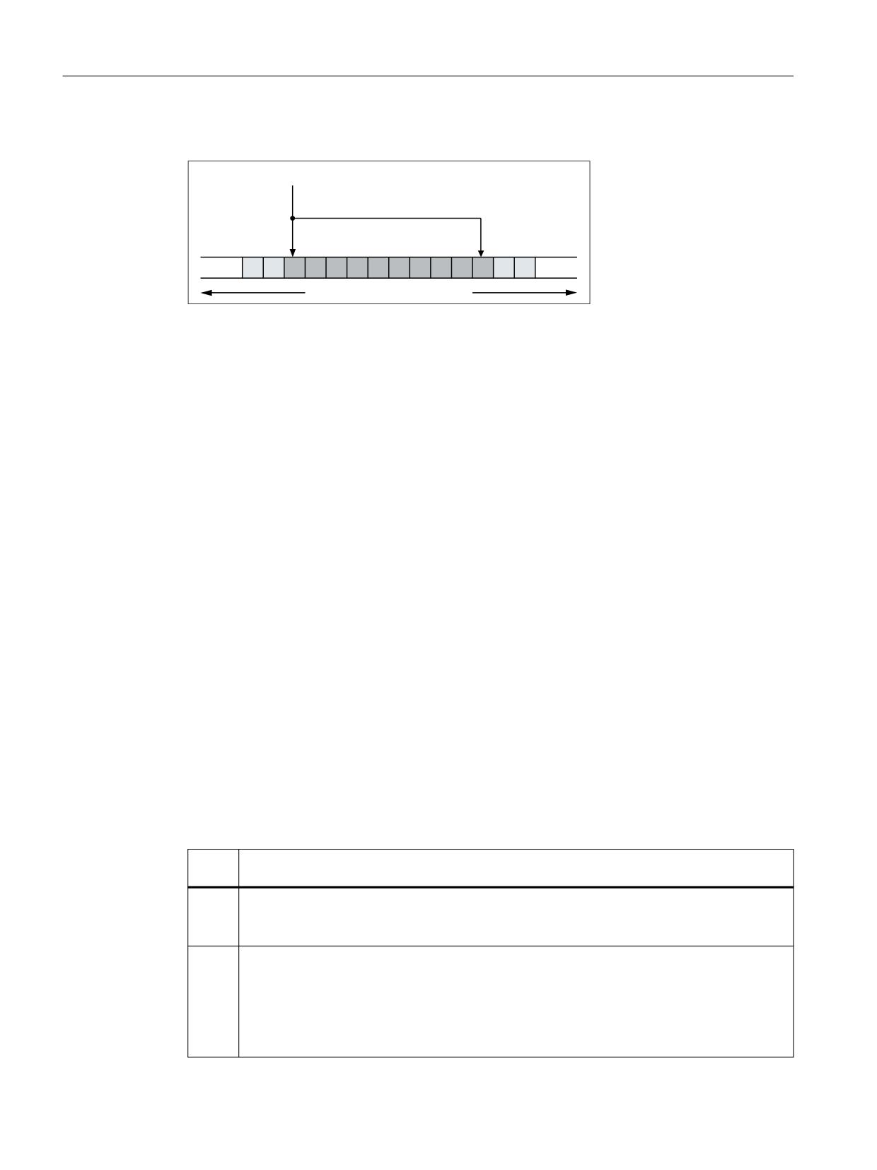
Principle of the parameterization of the NC I/O in the input area
0'
01B3/&,2B/2*,&B$''5(66B,1
0'
01B3/&,2B180B%<7(6B,1
3/& LQSXW LPDJH
Transfer times
• Transfer of the output data from the NC to the output modules
- The output data is transferred from the NC to the output modules at the end of the current
interpolator cycle.
- The transfer is only performed when at least one output data item has been written in the
current interpolator cycle.
• Transfer of the input data from the input modules to the NC
- Time within which the cyclic request for the update of the input data (input image of the
modules → NC input data) from the NC to the PLC is sent, can be set via the machine data:
- MD10398 $MN_PLCIO_IN_UPDATE_TIME = <update time>
- The parameterized update time is rounded up internally to the next highest multiple of an
interpolator cycle. With update time = 0, the request is transferred to the PLC in each
interpolation cycle.
- The request for the update of the input data is sent to the PLC at the end of the
parameterized interpolation cycle.
- The updated input data is available at the earliest in the following interpolation cycle.
Selection of the storage format (little/big endian)
A total of 16 KB is available for the data transfer between the NC and PLC for all NC channels.
These areas have to be managed by the user (i.e. no overlapping of the variables, not even across
channel borders).
The display of the variables within these areas depends on the setting in the machine data:
MD10399 $MN_PLCIO_TYPE_REPRESENTATION = <value>
<val-
Meaning
ue>
0
Little endian format (default setting)
System variables are displayed in little endian format ⇒ least significant byte at least significant
address
1
Big endian format (PLC standard format, recommended)
System variables are displayed in big endian format ⇒ most significant byte at least significant
address
Note
The big endian format is the format usually used in the PLC and PLC I/O. Therefore, it is recom-
mended that you use this setting.
Basic functions
796
Function Manual, 10/2020, 6FC5397-2GP40-0BA1
Digital and analog NC I/O
14.3 Direct I/O access via PLC
14.3.2
Reading/writing: System variables
Input data
System variable
Type
Offset <n>
$A_PBB_IN[<n>]
Byte
0, 1, 2, ... (MD10394 $MN_PLCIO_NUM_BYTES_IN -1)
$A_PBW_IN[<n>]
Word
0, 2, 4, ... (MD10394 $MN_PLCIO_NUM_BYTES_IN - 2)
$A_PBD_IN[<n>]
Double
0, 4, 8, ... (MD10394 $MN_PLCIO_NUM_BYTES_IN - 4)
$A_PBR_IN[<n>]
Real
0, 4, 8, ... (MD10394 $MN_PLCIO_NUM_BYTES_IN - 4)
A preprocessing stop is triggered in the channel when reading from a part program.
Output data
System variable
Type
Offset <n>
$A_PBB_OUT[<n>]
Byte
0, 1, 2, ... (MD10396 $MN_PLCIO_NUM_BYTES_OUT - 1)
$A_PBW_OUT[<n>]
Word
0, 2, 4, ... (MD10396 $MN_PLCIO_NUM_BYTES_OUT - 2)
$A_PBD_OUT[<n>]
Double
0, 4, 8, ... (MD10396 $MN_PLCIO_NUM_BYTES_OUT - 4)
$A_PBR_OUT[<n>]
Real
0, 4, 8, ... (MD10396 $MN_PLCIO_NUM_BYTES_OUT - 4)
A preprocessing stop is triggered in the channel when reading output data from a part program.
Value ranges of the output data
Type
Value range
Byte
With sign:
-128 ... +127
Without sign:
0 ... 255
Word
With sign:
-32768 ... +32767
Without sign:
0 ... 65535
Double
With sign:
-2147483648 ... +2147483647
Without sign:
0 ... 4294967295
Real
-3.402823466*10+38 ... +3.402823466*10+38
14.3.3
Supplementary conditions
Several slots
If several slots form an input or output range of the PLC I/O used directly by the NC, the address
range of the slots must be configured as a continuous range without gaps.
Parallel writing of the NC and PLC
Parallel writing of I/O outputs by the NC via direct access over the PLC and from the PLC user
program results in a random, mutual overwriting of the output values. The application is
therefore not permitted, but cannot be prevented on the control.
Time response
The time when the data is read in from the PLC I/Os is not synchronized with the time when the
data is made available to the part program via system variables!
Basic functions
Function Manual, 10/2020, 6FC5397-2GP40-0BA1
797
Digital and analog NC I/O
14.3 Direct I/O access via PLC
Data transfer
• The output of the output data on the PLC I/O is always for all parameterized output data, even
when only one output data item was written for each system variable.
• If several system variables are assigned values simultaneously, it is not certain that they are
transferred in the same interpolation cycle.
14.3.4
Examples
14.3.4.1
Writing to PLC-I/Os
Specifications
• Decimal logical addresses of the output data to be written within the PLC I/O
-
521: 1-byte integer value
-
522: 2-byte integer value
• The output data is written to a part program via the R parameters R10 - R11.
• In order to only slow down the execution of the PLC user program (OB1) slightly, the update
cycle for write access should be 3-times the interpolator cycle of 12 ms.
• Data is to be output directly to the following PLC I/Os:
Parameterization
The machine data should be set as follows:
• Length of the NC I/O output data area: 2 + 1 = 3 bytes
MD10396 $MN_PLCIO_NUM_BYTES_OUT= 3
• Logical start address of the input data area: 521
MD10397 $MN_PLCIO_LOGIC_ADDRESS_OUT = 521
• Update cycle: I/O input data → system variables = 3 * interpolator cycle= 3 * 12 ms = 36 ms
MD10398 $MN_PLCIO_OUT_UPDATE_TIME = 3 * 0.012 = 0.036
• Data format: Big endian
MD10399 $MN_PLCIO_TYPE_REPRESENTATION = 1
Refreshing
The transfer of the system data to the PLC I/O is not performed until the PLC has detected the
PROFIBUS/PROFINET I/O error-free after the control startup. The transfer is then performed in
every third interpolation cycle.
Programming
Writing the NC I/O to synchronized actions with R parameters:
Program code
Comment
R10=123
R11='Habcd'
ID=1 WHENEVER TRUE DO $A_PBB_OUT[0]=R10
; 1-byte integer value
Basic functions
798
Function Manual, 10/2020, 6FC5397-2GP40-0BA1
Digital and analog NC I/O
14.3 Direct I/O access via PLC
Program code
Comment
ID=2 WHEN $AA_IW[x] >= 5 DO $A_PBW_OUT[1]=R11
; 2-byte integer value
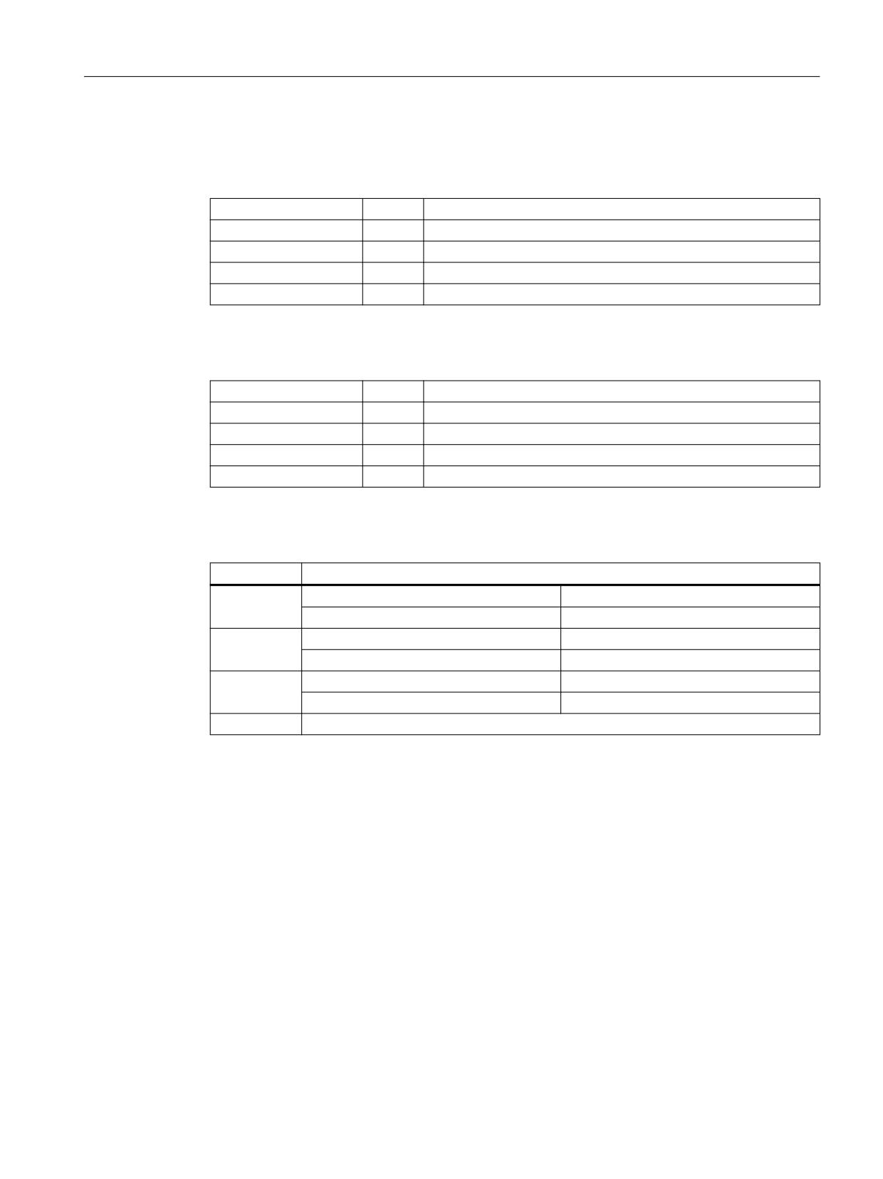
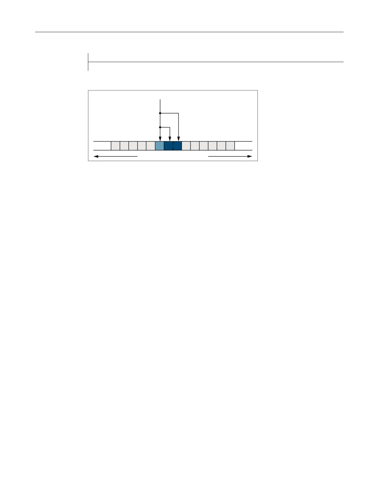
Addressing example: $PBW_OUT[ 1 ] = R11
0'
01B3/&,2B/2*,&B$''5(66B287
0'
01B3/&,2B180B%<7(6B287
$B3%
:B287>
@
3/& RXWSXW LPDJH
14.3.4.2
Reading from PLC-I/Os
Specifications
• Decimal logical addresses of the input data to be read within the PLC I/O
-
420: 2-byte integer value
-
422: 4-byte integer value
-
426: 4-byte real value
-
430: 1-byte integer value
• The input data should be stored in a part program in the R parameters R1 - R4.
• In order to only slow down the execution of the PLC user program (OB1) slightly, the update
cycle for read access should be 3-times the interpolator cycle of 12 ms.
Parameterization
• Length of the NC I/O input data area: 2 + 4 + 4 + 1 = 11 bytes
MD10394 $MN_PLCIO_NUM_BYTES_IN = 11
• Logical start address of the input data area: 420
MD10395 $MN_PLCIO_LOGIC_ADRESS_IN = 420
• Update cycle: I/O input data → system variables = 3 * interpolator cycle= 3 * 12 ms = 36 ms
MD10398 $MN_PLCIO_IN_UPDATE_TIME = 3 * 0.012 = 0.036
• Data format: Big endian
MD10399 $MN_PLCIO_TYPE_REPRESENTATION = 1
Refreshing
The system variables are updated in every third interpolation cycle after the NC and PLC startup.
Basic functions
Function Manual, 10/2020, 6FC5397-2GP40-0BA1
799
Digital and analog NC I/O
14.4 Direct I/O access without PLC
Programming
Reading in the NC I/O in R parameters:
Program code
Comment
R1=$A_PBW_IN[0]
; 2-byte integer value
R2=$A_PBD_IN[2]
; 4-byte integer value
R3=$A_PBR_IN[6]
; 4-byte real value
R4=$A_PBB_IN[10]
; 1-byte integer value
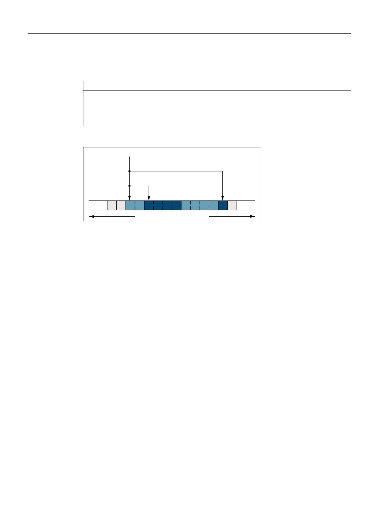
Addressing example: R2 = $PBD_IN[ 2 ]
0'
01B3/&,2B/2*,&B$''5(66B,1
0'
01B3/&,2B180B%<7(6B,1
$B3%'B,1>
@
3/& LQSXW LPDJH
14.4
Direct I/O access without PLC
14.4.1
Brief description
Isochronous and non-isochronous PROFINET
Reading / writing of the PROFINET I/O is possible with both isochronous and non-isochronous
PROFINET configuration.
I/O range
If slots are configured for a PROFINET slave used for the NC I/O in such a way that they are in
ascending order without gaps, they are called the I/O range in the following.
An I/O range is therefore characterized by:
• Logical start address: Logical start address of the first slot of the PROFINET slave
• Length: Total length of all slots used for the PROFINET slave
The parameterization of the logical start address and the length of the I/O range is performed in
the NC via machine data (see "Parameter assignment (Page 802)").
Basic functions
800
Function Manual, 10/2020, 6FC5397-2GP40-0BA1
Digital and analog NC I/O
14.4 Direct I/O access without PLC
Reading/writing
Part programs / synchronized actions: System variables
The reading/writing of the NC I/O is performed in the NC via system variables in the interpolator
cycle. The writing on the NC I/O is performed after the interpolation cycle.
Data consistency: Interpolator cycle
See "System variables (Page 803)".
Parallel reading/writing
Reading
Parallel reading through compile cycles and part programs / synchronized actions on input data
of the same I/O range is possible. Write access to the NC I/O is performed in different ways.
• The data consistency is ensured.
• The data equality during an interpolator cycle is not ensured.
Writing
Parallel writing through compile cycles and part programs / synchronized actions on output data
of the same I/O range is not possible.
Basic functions
Function Manual, 10/2020, 6FC5397-2GP40-0BA1
801
Digital and analog NC I/O
14.4 Direct I/O access without PLC
14.4.2
Parameter assignment
Machine data
Logical start addresses of the I/O ranges
The logical start addresses of the I/O ranges used are set via the following machine data:
• Logical start addresses of the input range 1, 2, ... m:
MD10500 $MN_DPIO_LOGIC_ADDRESS_IN[ <n>] = <logical start address> ; with <n> = 0, 1,
2, ... (m - 1)
• Logical start addresses of the output range 1, 2, ... m:
MD10510 $MN_DPIO_LOGIC_ADDRESS_OUT[ <n>] = <logical start address> ; with <n> = 0,
1, 2, ... (m - 1)
The following must be taken into account for logical start addresses within the PLC process
image:
- Input slots: Reading from the NC also possible
- Output slots: Writing from the NC not permitted ⇒ alarm after run-up of the NC
Further information
Equipment Manual NCU 7x0.3 PN, NCU 7x0.3B PN; Technical data > PLC > Process image size
Detailed information can be obtained under Address (http://
support.automation.siemens.com/WW/view/de/54058408)
Note
I/O ranges for the write access (MD10510) on the PROFIBUS I/O must not be in the range of
the process image, e.g. PLC 317-3, output addresses 0 - 1023.
For PROFINET I/O, these I/O ranges must be assigned in the process image to "TPA 2"; the
configuration is realized using the synchronous cycle interrupt "NC".
Lengths of the I/O ranges
The lengths of the I/O ranges used are set via the following machine data:
• Length of the input range 1, 2, ... m:
MD10501 $MN_DPIO_RANGE_LENGTH_IN[ <n> ] = <length>; with <n> = 0, 1, 2, ... (m - 1)
• Length of the output range 1, 2, ... m:
MD10511 $MN_DPIO_RANGE_LENGTH_OUT[ <n> ] = <length>; with <n> = 0, 1, 2, ... (m - 1)
If the value 0 is entered as length, the length of the first user data slot found under the specified
start address (MD10500/MD10510) is set internally as the length of the I/O range.
Basic functions
802
Function Manual, 10/2020, 6FC5397-2GP40-0BA1
Digital and analog NC I/O
14.4 Direct I/O access without PLC
I/O range attributes
• Attribute of the input range 1, 2, ... m:
MD10502 $MN_DPIO_RANGE_ATTRIBUTE_IN[ <n> ] ; with <n> = 0, 1, 2, ... (m - 1)
Bit
Val-
Meaning
ue
0
Format display of system variables $A_DPx_IN[<n>,<m>]
0
Little endian format
1
Big endian format
2
Reading of input data
0
Reading possible via system variables and CC-binding
1
Reading possible only for CC-binding
3
Output of slot sign-of-life alarms
0
Slot sign-of-life alarms are issued
1
Slot sign-of-life alarms are suppressed
• Attribute of the output range 1, 2, ... m:
MD10512 $MN_DPIO_RANGE_ATTRIBUTE_OUT[ <n> ] ; with <n> = 0, 1, 2, ... (m - 1)
Bit
Value
Meaning
0
Format display of system variables $A_DPx_OUT[<n>,<m>]
0
Little endian format
1
Big endian format
1
Writing of output data
0
Writing only via system variable
1
Writing only via CC-binding
3
Output of slot sign-of-life alarms
0
Slot sign-of-life alarms are issued
1
Slot sign-of-life alarms are suppressed
14.4.3
Reading/writing
14.4.3.1
System variables
Input data
System variable
Type
Meaning
$A_DPB_IN[<n>,<b>]
8-bit unsigned
Reads a data byte (8-bit)
$A_DPW_IN[<n>,<b>]
16-bit unsigned
Reads a data word (16-bit)
$A_DPSB_IN[<n>,<b>]
8-bit signed
Reads a data byte (8-bit)
$A_DPSW_IN[<n>,<b>]
16-bit signed
Reads a data word (16-bit)
Basic functions
Function Manual, 10/2020, 6FC5397-2GP40-0BA1
803
Digital and analog NC I/O
14.4 Direct I/O access without PLC
System variable
Type
Meaning
$A_DPSD_IN[<n>,<b>]
32-bit signed
Reads a data double word (32-bit)
$A_DPR_IN[<n>,<b>]
32-bit REAL
Reads input data (32-bit REAL)
<n> = input range 1, 2, ... m; <b> = byte index within the input range: 0, 1, ... (length - 1)
Output data
System variable
Type
Meaning
$A_DPB_OUT[<n>,<b>]
8-bit unsigned
Writes a data byte (8-bit)
$A_DPW_OUT[<n>,<b>]
16-bit unsigned
Writes a data word (16-bit)
$A_DPSB_OUT[<n>,<b>]
8-bit signed
Writes a data byte (8-bit)
$A_DPSW_OUT[<n>,<b>]
16-bit signed
Writes a data word (16-bit)
$A_DPSD_OUT[<n>,<b>]
32-bit signed
Writes a data double word (32-bit)
$A_DPR_OUT[<n>,<b>]
32-bit REAL
Writes output data (32-bit REAL)
<n> = output range 1, 2, ... m; <b> = byte index within the output range: 0, 1, ... (length - 1)
Configured and parameterized I/O ranges for part programs / synchronized actions
Each system variable is a 32-bit bit array. Each bit is assigned to an I/O range.
Bit <n> ≙ machine data index <n> ≙ I/O range <n+1>
Bit <n> == 1 ⇒ The I/O range <n+1> is configured/parameterized.
System variable
Type
Meaning
$A_DP_IN_CONF
32-bit bit array
Reads all configured input ranges
$A_DP_OUT_CONF
32-bit bit array
Reads all configured output ranges
Valid I/O ranges for part programs / synchronized actions
Each system variable is a 32-bit bit array. Each bit is assigned to an I/O range.
Bit <n> ≙ machine data index <n> ≙ I/O range <n+1>
Bit <n> == 1 ⇒ The I/O range <n+1> is valid. Reading/writing via part programs / synchronized
actions.
System variable
Type
Meaning
$A_DP_IN_VALID
32-bit bit array
Reads all valid input ranges
$A_DP_OUT_VALID
32-bit bit array
Reads all valid output ranges
State of an I/O range
The state of an I/O range can be read via the following system variables.
System variable
Type
Meaning
$A_DP_IN_STATE[<n>]
INT
Reads the state of the input range
$A_DP_OUT_STATE[<n>]
Reads the state of the output range
Basic functions
804
Function Manual, 10/2020, 6FC5397-2GP40-0BA1

Digital and analog NC I/O
14.4 Direct I/O access without PLC
System variable
Type
Meaning
<n> = index of the I/O range
State
0: I/O range has not been configured
1: I/O range could not be activated
2: I/O range is available
3: I/O range is currently not available
Length of an I/O range
The configured length of an I/O range can be read via the following system variables.
System variable
Meaning
$A_DP_IN_LENGTH[<n>]
Reading the length of the input data range
$A_DP_OUT_LENGTH[<n>]
Reading the length of the output data range
<n> = index of the I/O range
Constraints
• A preprocessing stop is triggered in the channel when reading/writing from a part program.
• To ensure data consistency during programming from the part program and the
synchronized actions, the PROFINET I/O data is accessed which is kept consistent for the
respective IPO cycle.
• If the same PROFINET I/O data is to be write-accessed several times within an interpolation
cycle (e.g. synchronized actions, access from different channels, etc.), then the data of the
last write access is valid.
• The PROFINET I/O data to be written is output at the PROFI I/O only after the corresponding
IPO cycle.
• The <b> (RangeOffset) indicates the place (byte offset) within the I/O range as of which the
data access is to be started. Data types can be read/written at any byte offset within the I/O
range. Read/write accesses which exceed the configured limits of the respective I/O range are
rejected with the generation of an alarm (17030).
• Via the machine data MD10502 $MN_DPIO_RANGE_ATTRIBUTE_IN or MD10512
$MN_DPIO_RANGE_ATTRIBUTE_OUT (see "Parameter assignment (Page 802)"), the display
format (little/big endian) for $A_DPx_IN[<n>,<b>] or $A_DPx_OUT[<n>,<b>] system
variables can be defined for the read/write direction as well as for each individual I/O range.
14.4.4
Supplementary conditions
Parallel writing of the NC and PLC
Parallel writing of I/O outputs by the NC via direct access and from the PLC user program results
in a random, mutual overwriting of the output values. The application is therefore not
permitted, but cannot be prevented on the control.
Basic functions
Function Manual, 10/2020, 6FC5397-2GP40-0BA1
805
Digital and analog NC I/O
14.4 Direct I/O access without PLC
Life beat monitoring
At the start of an interpolator cycle, a check is made for each I/O range whether the sign-of-life
of the associated slot or I/O range has failed. If this is the case, alarm 9050 or 9052 is displayed.
Effects:
• The part program processing is not stopped.
• When the sign-of-life returns, the alarm is cleared automatically.
14.4.5
Examples
14.4.5.1
Writing to the NC I/O
Requirement
A valid configuration must already have been loaded to the PLC.
Parameterization for part programs / synchronized actions
Specifications
• Parameterization of the 6th data record: Machine data / system variable index = 5
• Configuration data:
- Logical start address = 334
- Slot length = 8 bytes
• Representation: Little endian format
Parameterization in the machine data
• MD10510 $MN_DPIO_LOGIC_ADDRESS_OUT[ 5 ] = 334 (logical start address)
• MD10511 $MN_DPIO_LENGTH_OUT[ 5 ] = 8 (length of the I/O-range in bytes)
• MD10512 $MN_DPIO_ATTRIBUTE_OUT[ 5 ]
- Bit0 = 0 (little endian format)
- Bit1 = 0 (writing only via system variable)
- Bit3 = 0 (issue slot sign-of-life alarms)
Examples
Program code
Comment
$A_DPB_OUT[5,6]=128
; Byte ≙ 8 bits, index=5, offset=6
$A_DPW_OUT[5,5]='B0110'
; Word ≙ 16 bits, index=5, offset=5
; Caution: Data on offset 6 will be overwritten
$A_DPSD_OUT[5,3]=’H8F’
; Double ≙ 32 bits, index=5, offset=3
; Caution: Data on offsets 4, 5, 6 will be overwritten
Basic functions
806
Function Manual, 10/2020, 6FC5397-2GP40-0BA1
Digital and analog NC I/O
14.4 Direct I/O access without PLC
Program code
Comment
$AC_MARKER[0]=5
; Index=5
$AC_MARKER[1]=3
; Offset=3
$A_DPSD_OUT[$AC_MARKER[0],$AC_MARKER[1]]=’H8F’ ; indirect addressing
; Double ≙ 32 bits, on index=5, offset=3
R1 = $A_DPB_OUT[5,6]
; Assignment to R parameter, byte ≙ 8 bits, index=5,
offset=6
;Result: R1 == 'HFF'
ID=1 WHENEVER TRUE DO $A_DPB_OUT[5,0]=123 ; cyclic writing per IPO cycle
; Byte ≙ 8 bits, index=5, offset=0
; Faulty programming
$A_DPB_OUT[5.255]=128
; ⇒ Alarm 17030: Offset 255 > I/O range
$A_DPB_OUT[6.10]=128
; ⇒ Alarm 17020: Index 6 reserved for compile cycle,
see below
$A_DPB_OUT[7.10]=128
; ⇒ Alarm 17020: Index 7 not defined in the machine data
$A_DPB_OUT[16.6]=128
; ⇒ Alarm 17020: Index 16 outside the value range
Configuration for programming via CompileCycles
Specifications
• Parameterization of the 7th data record: Machine data / system variable index = 6
• Configuration data:
- Logical start address = 444
- Slot length = 10 bytes
• Representation: Little endian format
Parameterization in the machine data
• MD10510 $MN_DPIO_LOGIC_ADDRESS_OUT[ 6 ] = 444 (logical start address)
• MD10511 $MN_DPIO_LENGTH_OUT[ 6 ] = 0 (only the first user data slot is used)
• MD10512 $MN_DPIO_ATTRIBUTE_OUT[ 6 ]
- Bit0 = 0 (little endian format)
- Bit1 = 1 (writing only via CC-binding)
- Bit3 = 1 (slot sign-of-life alarms are suppressed)
14.4.5.2
Reading from the NC I/O
Requirement
A valid configuration must already have been loaded to the PLC.
Basic functions
Function Manual, 10/2020, 6FC5397-2GP40-0BA1
807
Digital and analog NC I/O
14.4 Direct I/O access without PLC
Parameterization for part programs / synchronized actions
Specifications
• Parameterization of the 1st data record: Machine data / system variable index = 0
• Configuration data:
- Logical start address = 456
- Slot length = 32 bytes
• Representation: Big endian format
Parameterization in the machine data
• MD10500 $MN_DPIO_LOGIC_ADDRESS_IN[ 0 ] = 456 (logical start address)
• MD10501 $MN_DPIO_LENGTH_IN[ 0 ] = 32 (length of the I/O-range in bytes)
• MD1050ß2 $MN_DPIO_ATTRIBUTE_IN[ 0 ]
- Bit0 = 1 (big endian format)
- Bit2 = 0 (reading possible via system variables and CC-binding)
- Bit3 = 0 (slot sign-of-life alarms are issued)
Examples
Program code
Comment
$AC_MARKER[0]=
; Byte ≙ 8 bits, index=0, offset=0
$A_DPW_IN[0,0]
$AC_MARKER[1]=
; Signed double ≙ 32 bits, index=0, offset=1
$A_DPSD_IN[0,1]
$AC_MARKER[1]=
; Signed double ≙ 32 bits, index=0, offset=8
$A_DPSD_IN[0.8]
$AC_MARKER[2]=0
; Index=0
$AC_MARKER[3]=8
; Offset=8
$AC_MARKER[1]=$A_DPSD_IN[$AC_MARKER[2],$AC_MARKER[3]] ; indirect addressing
; Signed double ≙ 32 bits, index=0, offset=8
ID=2 WHEN $A_DPB_IN[0,11]>=5 DO $AC_MARKER[2]=$A_DPSD_IN[0,8]
; IF index 0, offset 11 >= 5
; THEN signed double ≙ 32 bits, index=0, offset=8
; Faulty programming
R1=$A_DPB_IN[0,255]
; ⇒ Alarm 17030: Offset 255 > I/O range
R1=$A_DPB_IN[2.6]
; ⇒ Alarm 17020: Index 2 not defined in the machine data
R1=$A_DPB_IN[1.10]
; ⇒ Alarm 17020: Index 1 reserved for compile cycle,
see below
R1=$A_DPB_IN[16.6]
; ⇒ Alarm 17020: Index 16 outside the value range
Basic functions
808
Function Manual, 10/2020, 6FC5397-2GP40-0BA1
Digital and analog NC I/O
14.4 Direct I/O access without PLC
Parameterization for programming via CompileCycles
Specifications
• Parameterization of the 2nd data record: Machine data / system variable index = 1
• Configuration data:
- Logical start address = 312
- Slot length = 32 bytes
• Representation: Big endian format
Parameterization in the machine data
• MD10500 $MN_DPIO_LOGIC_ADDRESS_IN[ 01 ] = 312 (logical start address)
• MD10501 $MN_DPIO_LENGTH_IN[ 1 ] = 32 (length of the I/O-range in bytes)
• MD10502 $MN_DPIO_ATTRIBUTE_IN[ 1 ]
- Bit0 = 1 (big endian format)
- Bit2 = 1 (reading possible only for CC-binding)
- Bit3 = 1 (suppress slot sign-of-life alarms)
14.4.5.3
Writing of the NC I/O with status query
Requirement
A valid configuration must already have been loaded to the PLC.
Parameterization for part programs / synchronized actions
Specifications
• Parameterization of the 6th data record: Machine data / system variable index = 5
• Configuration data:
- Logical start address = 1200
- Slot length = 32 bytes
• Representation: Big endian format
Parameterization in the machine data
• MD10510 $MN_DPIO_LOGIC_ADDRESS_OUT[ 5 ] = 1200 (logical start address)
• MD10511 $MN_DPIO_LENGTH_OUT[ 5 ] = 0 (length of the I/O-range in bytes)
• MD10512 $MN_DPIO_ATTRIBUTE_OUT[ 5 ]
- Bit0 = 1 (little endian format)
- Bit1 = 0 (writing only via system variable)
- Bit3 = 0 (issue slot sign-of-life alarms)
Basic functions
Function Manual, 10/2020, 6FC5397-2GP40-0BA1
809

Digital and analog NC I/O
14.5 Data lists
Examples
check:
; Jump marker
IF $A_DP_OUT_STATE[5]==2 GOTOF write
; If data range valid; => jump to
N15
GOTOB check
; Jump back to check
write:
; Jump marker
$A_DPB_OUT[5,6]=128
; Writing the data byte
check:
; Jump marker
IF $A_DP_OUT_CONF==$A_DP_OUT_VALID GOTOF write
; If data range valid
; => jump to N15
SETAL(61000)
; Set alarm no. 61000
write:
; Jump marker
$A_DPB_OUT[5,6]=128
; Writing the data byte
check:
; Jump marker
IF $A_DP_OUT_VALID B_AND ’B100000’ GOTOF write
; If data range valid
; => jump to N15
SETAL(61000)
; Set alarm no. 61000
write:
; Jump marker
$A_DPB_OUT[5,6]=128
; Writing the data byte
R1=$A_DP_OUT_LENGTH[5]
; Length of the I/O-range (slot) in bytes
;Result: R1 = 32
14.5
Data lists
14.5.1
Machine data
14.5.1.1
General machine data
Number
Identifier: $MN_
Description
10300
FASTIO_ANA_NUM_INPUTS
Number of active analog NC inputs
10310
FASTIO_ANA_NUM_OUTPUTS
Number of active analog NC outputs
10320
FASTIO_ANA_INPUT_WEIGHT
Weighting factor for analog NC inputs
10330
FASTIO_ANA_OUTPUT_WEIGHT
Weighting factor for analog NC outputs
10350
FASTIO_DIG_NUM_INPUTS
Number of active digital NC input bytes
10360
FASTIO_DIG_NUM_OUTPUTS
Number of active digital NC output bytes
Basic functions
810
Function Manual, 10/2020, 6FC5397-2GP40-0BA1

Digital and analog NC I/O
14.5 Data lists
Number
Identifier: $MN_
Description
10362
HW_ASSIGN_ANA_FASTIN
Hardware assignment of external analog NC inputs
10364
HW_ASSIGN_ANA_FASTOUT
Hardware assignment of external analog NC outputs
10366
HW_ASSIGN_DIG_FASTIN
Hardware assignment of external digital NC inputs
10368
HW_ASSIGN_DIG_FASTOUT
Hardware assignment of external digital NC outputs
10500
DPIO_LOGIC_ADDRESS_IN
Logical slot address of the PROFIBUS I/O
10501
DPIO_RANGE_LENGTH_IN
Length of the PROFIBUS I/O range
10502
DPIO_RANGE_ATTRIBUTE_IN
Attributes of the PROFIBUS I/O
10510
DPIO_LOGIC_ADDRESS_OUT
Logical slot address of the PROFIBUS I/O
10511
DPIO_RANGE_LENGTH_OUT
Length of the PROFIBUS I/O range
10512
DPIO_RANGE_ATTRIBUTE_OUT
Attributes of the PROFIBUS I/O
10530
COMPAR_ASSIGN_ANA_INPUT_1
Hardware assignment of NC analog inputs for comparator byte 1
10531
COMPAR_ASSIGN_ANA_INPUT_2
Hardware assignment of NC analog inputs for comparator byte 2
10540
COMPAR_TYPE_1
Parameterization for comparator byte 1
10541
COMPAR_TYPE_2
Parameterization for comparator byte 2
14.5.1.2
Channelspecific machine data
Number
Identifier: $MC_
Description
21220
MULTFEED_ASSIGN_FASTIN
Assignment of input bytes of NC I/Os for "multiple fee-
drates in one block"
14.5.2
Setting data
14.5.2.1
General setting data
Number
Identifier: $SN_
Description
41600
COMPAR_THRESHOLD_1
Threshold values for comparator byte 1
41601
COMPAR_THRESHOLD_2
Threshold values for comparator byte 2
14.5.3
System variable
Identifier
Description
$A_IN
Digital NC input
$A_OUT
Digital NC output
$A_INA
Analog NC input
$A_OUTA
Analog NC output
$A_DPB_IN
Reads a data byte (8 bit)
Basic functions
Function Manual, 10/2020, 6FC5397-2GP40-0BA1
811

Digital and analog NC I/O
14.5 Data lists
Identifier
Description
$A_DPW_IN
Reads a data word (16 bit)
$A_DPSB_IN
Reads a data byte (8 bit)
$A_DPSW_IN
Reads a data word (16 bit)
$A_DPSD_IN
Reads a double word (32 bit)
$A_DPR_IN
Reads input data (32 bit REAL)
$A_DPB_OUT
Writes a data byte (8 bit)
$A_DPW_OUT
Writes a data word (16 bit)
$A_DPSB_OUT
Writes a data byte (8 bit)
$A_DPSW_OUT
Writes a data word (16 bit)
$A_DPSD_OUT
Writes a double word (32 bit)
$A_DP_IN_VALID
Reads all valid input ranges
$A_DP_OUT_VALID
Reads all valid output ranges
$A_DP_IN_STATE[<n>]
Reads the state of the input range
$A_DP_OUT_STATE[<n>]
Reads the state of the output range
$A_DP_IN_LENGTH[<n>]
Reads the length of the input data range
$A_DP_OUT_LENGTH[<n>]
Reads the length of the output data range
14.5.4
Signals
14.5.4.1
Signals to NC
Signal name
SINUMERIK 840D sl
SINUMERIK 828D
Disable of the digital NC inputs
DB10.DBB0/122/124/126/128
DB2800.DBB0/1000
Setting of the digital NC inputs from the PLC
DB10.DBB1/123/125/127/129
DB2800.DBB1/1001
Disable of the digital NC outputs
DB10.DBB4/130/134/138/142
DB2800.DBB4/1008
Overwrite mask of the digital NC outputs
DB10.DBB5/131/135/139/143
DB2800.DBB5/1009
Setting value of the digital NC outputs from the PLC
DB10.DBB6/132/136/140/144
DB2800.DBB6/1010
Input mask of the digital NC outputs
DB10.DBB7/133/137/141/145
DB2800.DBB7/1011
Disable of analog NC inputs
DB10.DBB146
-
Input mask for analog NC inputs
DB10.DBB147
-
Setting value from PLC for the analog NC inputs
DB10.DBB148-163
-
Overwrite mask for the analog NC outputs
DB10.DBB166
-
Input mask for analog NC outputs
DB10.DBB167
-
Disable of NC outputs
DB10.DBB168
-
Setting value from PLC for the analog NC outputs
DB10.DBB170-185
-
Basic functions
812
Function Manual, 10/2020, 6FC5397-2GP40-0BA1

Digital and analog NC I/O
14.5 Data lists
14.5.4.2
Signals from NC
Signal name
SINUMERIK 840D sl
SINUMERIK 828D
Actual value for digital NCK inputs
DB10.DBB60/186-189
DB2900.DBB0/1000
Setpoint for digital NCK outputs
DB10.DBB64/190-193
DB2900.DBB4/1004
Actual value for analog NCK inputs
DB10.DBB194-209
-
Setpoint for analog NCK outputs
DB10.DBB210-225
-
Basic functions
Function Manual, 10/2020, 6FC5397-2GP40-0BA1
813
Digital and analog NC I/O
14.5 Data lists
Basic functions
814
Function Manual, 10/2020, 6FC5397-2GP40-0BA1
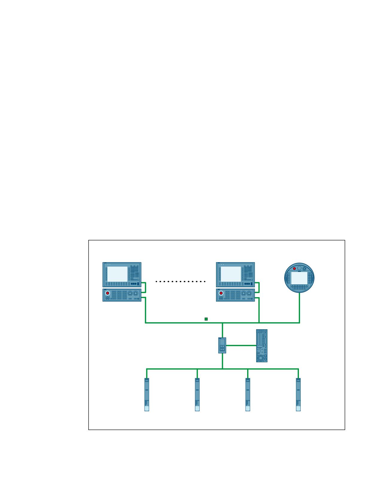
Distributed systems
15
15.1
Brief description
15.1.1
Several operator panels on several NCUs (T:M:N)
Under certain circumstances, a single operator control and monitoring station may not be
sufficient for complex plants and machines. Therefore, several operator control and monitoring
stations in a SINUMERIK system network (Ethernet) can be connected to several numerical
controls (NCU) via a PCU in such a way that they enable flexible and distributed operation and
monitoring of the entire system.
The following figure provides an overview of the components that currently can be connected
in a system network to form an operator control and monitoring system T:1:N. Meanings:
• T: Thin Client Unit (TCU) or handheld unit HT8/HT10 (connected with the PCU)
• M: Man Machine Control (MMC), e.g. PCU 50.x with SINUMERIK Operate
• N: Numeric Control Unit (NCU), e.g. NCU 7x0.3 PN
2SHUDWRU SDQHO IURQW 23 [[[
2SHUDWRU SDQHO IURQW 23 [[[
+DQGKHOG XQLW
ZLWK
ZLWK
+7
7KLQ &OLHQW 8QLW 7&8
7KLQ &OLHQW 8QLW 7&8
0DFKLQH FRQWURO
0DFKLQH FRQWURO SDQHO
SDQHO
0&3 [[[
,QGXVWULDO (WKHUQHW
0&3 [[[
3& XQLW 3&8
[
,( 6ZLWFK
ZLWK
6&$/$1&( [[[
8VHU LQWHUIDFH
6,180(5,. 2SHUDWH
6,180(5,.
'
6,180(5,.
'
6,180(5,.
'
6,180(5,.
'
VO
VO
VO
VO
1&8 [
31
1&8 [
31
1&8 [
31
1&8 [
31
Basic functions
Function Manual, 10/2020, 6FC5397-2GP40-0BA1
815
Distributed systems
15.1 Brief description
Figure 15-1
Example of a T:1:N network
T: Thin Client Unit (TCU) or HT8 handheld unit
The graphic information of the PCU user interface is transferred via the TCU to the operator panel
front (OP) and displayed there. TCU and operator panel front together form an operator station.
• Maximum number
In principle, any number of operator stations, only limited by the amount of available address
space, can be operated in the system network.
• Online
A maximum of four operator stations per PCU can be online simultaneously.
• Operating focus
At any one time, only one of the operator stations on the PCU that are online, can have the
operating focus. Entries with regard to the user interface can only be made via this operator
station. The user interfaces on the other online operator stations are darkened to indicate
that they do not have operating focus. Only a message is displayed on operator stations that
are not online.
The operating focus can be switched between the online operator stations.
• HT8 handheld unit
A HT8 handheld unit combines a TCU, an operator panel front and a machine control panel
in a single device.
M: PCU/IPC with SINUMERIK Operate
Several operator stations and several NCUs can be connected to a PCU with SINUMERIK Operate
user interface. The data of the channels of different NCUs can be displayed on the operator
stations through suitable configuring of the channel menu.
N: SINUMERIK 840D sl
• Internal SINUMERIK Operate user interface
Because of the existing external SINUMERIK Operate user interface on the PCU in the system
network, the NCU-integrated internal SINUMERIK Operate user interface must be switched
off. The internal SINUMERIK Operate user interface must not be switched off only when it is
used with a limited range of functions, exclusively within the scope of tool management.
Detailed information on this can be found in the Commissioning Manual "Operator
Components and Networking (IM5)", Section "Network configuration" > "Application
example"
• Machine control panel (MCP)
For a flexible switchover of the machine control panels, only one MCP can be connected to
one NCU. The switchover of the MCPs is user-specifically via the PLC user program (function
block FB 9).
Installation and connection
Further information
• TCU, MCP, PCU:
SINUMERIK 840D sl Operator Components and Networking Manual
• NCU:
Equipment Manual SINUMERIK Control
Basic functions
816
Function Manual, 10/2020, 6FC5397-2GP40-0BA1
Distributed systems
15.1 Brief description
• Machine control panel (MCP)
FB 9: MtoN Control Unit Switchover
• Switch SCALANCE:
System Manual Communication with SIMATIC
• Industry PCs compatible with PCU-Basesoftware
Commissioning Manual SINUMERIK 840D sl PCU-Basesoftware
Configuration, commissioning and parameter assignment
Further information
• Structure of the system network and commissioning of a TCU:
Operator Components and Networking Commissioning Manual (IM5)
• Configuration of the channel menu
SINUMERIK Operate Commissioning Manual (IM9), Section "Channel menu"
Programming
You can find further information in the PLC Function Manual.
Constraints
Currently, only one PCU (M) can be configured for each T:M:N network ⇒ T:1:N
15.1.2
NCU link
15.1.2.1
Link communication
The NCU-link communication allows an interpolator clock-synchronous cross-NCU data
exchange for the following applications:
• Cross-NCU data exchange via link variables $A_DLx
• Cross-NCU traversing of axes and spindles using link axes and container link axes
• Cross-NCU master value coupling of axes and spindles using lead link axes
Safety Integrated
If axis-specific Safety Integrated Functions are active for a link axis, data that is not safety-related
is exchanged between the local safety axis (link axis on NCUx) and the channel that is traversing
it (NCUy) via the NCU link. This also enables Safety Integrated-supporting functions for link axes,
such as velocity/speed monitoring-dependent setpoint limiting and higher-order stop functions
(STOP D/E).
Basic functions
Function Manual, 10/2020, 6FC5397-2GP40-0BA1
817
Distributed systems
15.1 Brief description
Link module
The link communication requires optional link modules. A link module is an optional PROFINET
module for isochronous real-time communication (IRT) via Ethernet. The link module occupies
the option slot of the NCU.
Quantity structure
As standard, a maximum of three NCUs can be interconnected to form a link group.
Note
For a specific project, on request to your local regional Siemens representative, further NCUs can
be integrated to form a link group.
15.1.2.2
Link variables
Link variables are global system user variables that for configured link communication can be
used by all NCUs of the network. Link variables can read and written in part programs, cycles and
synchronized actions.
The reading and writing of link variables is performed in the main run. A channel
synchronization is therefore performed implicitly with regard to the link variables so that all
channels read the same value in the same interpolator cycle. By comparison, global user data
(GUD) can also be used cross-channel like the link variables. However, as GUD variables are
preprocessed, no implicit channel synchronization is performed here. If necessary, GUD
variables must therefore be synchronized by the user through specific programming.
Note
On systems without an NCU link, link variables can also be used as additional NCU global user
data alongside standard global user data (GUD).
15.1.2.3
Link axes
Link axes enable the creation of distributed control systems, in which the setpoints of the
machine axes are not created by channels of the NCU to which the machine axes are physically
connected, but by channels of an arbitrary NCU of the link group.
Fixed assignment for link axes
The assignment, on which NCU the setpoints for which machine axis are created, is fixed for link
axes through the machine data configuration.
Variable assignment for container link axes
The assignment, on which NCU the setpoints for which machine axis are created, is variable for
container link axes. A container link axis can therefore be traversed alternatively by each NCU of
the link group. See Section "Axis container (Page 843)".
Irrespective of the assignment described above, the logical machine axis can be made known to
the link axis of several channels on the NCU generating the setpoint and then functionally
Basic functions
818
Function Manual, 10/2020, 6FC5397-2GP40-0BA1

Distributed systems
15.1 Brief description
handled as a local logical machine axis, e.g. master value for position/feed couplings, NCU-local
axis interchange.
15.1.2.4
Lead link axes
If in conjunction with the coupling functions of the generic coupling, all interpolators, i.e. the
setpoint-creating/processing channels, the leading and following axes/spindles, are on the same
NCU, the use of a lead link axis is not required. The machine axes of the leading and/or following
axes/spindles can also be connected link axes to different NCUs.
Application
A lead link axis is always required when not all interpolators of a coupling group are on the same
NCU. The lead link axis provides an image of the leading axis/spindle or the master value for the
local interpolators, on another NCU. Starting from this master value, the setpoints of the
following axes/spindles are then generated by the interpolators on this NCU.
Further application
A lead link axis is also used if more machine axes are involved in a coupling than are available
absolutely or relatively on an NCU for the coupling.
Further information
Function Manual Axes and Spindles, Axis couplings
15.1.2.5
Dependencies
In order that several axes can be traversed in an interpolatary relationship, it is essential that the
setpoints generated by the interpolator of the traversing channel be transferred to the position
control at the same time.
During the transfer of the setpoints via the NCU link, for example, for a link axis there is a delay
of one interpolator cycle in relation to the setpoint of a local axis. The delay must be
compensated by a suitable increase of the buffer between the interpolator and the position
controller :
MD18720 $MN_MM_SERVO_FIFO_SIZE = <value> = <default value + compensation value>
Function
Compensation value
Link axis
One interpolator cycle must be compensated on all NCUs with axes that inter-
polate with a link or container link axis.
Container-link axis
Compensation value = 1
Lead-link axis
Two interpolator cycles must be compensated on the NCU of the leading axis
that generates the setpoints for the lead link axis.
Compensation value = 2
Basic functions
Function Manual, 10/2020, 6FC5397-2GP40-0BA1
819
Distributed systems
15.1 Brief description
Note
In contrast to lead link axes, link and container link axes require another compensation value
(MD18720 $MN_MM_SERVO_FIFO_SIZE). With simultaneous use of link or container link axes
and lead link axes within a link group, the delays cannot be compensated.
15.1.2.6
Application example: Rotary indexing machine
On the basis of rotary cycle machine with two NCUs, the application of the "NCU Link" function
is shown as example. The principal units of the rotary indexing machine are:
• MTR rotary axis for the rotary table
• MS1 - MS4 spindles
• Machining stations 1 and 2, each with the X1 and Z1 linear axes
• Loading and unloading station
All of the machine axes remain permanently assigned to their particular NCU. The same axes (X
and Z) and spindles (S1) are always addressed in the machining program of the relevant NCU.
The workpiece status is represented schematically after each machining step.
For each machining step, the rotary table (MTR) advances one position counter-clockwise. This
so assigns the spindles to another station for each machining step. The changing relationships
of the spindles defined in the channels to the machine axes are represented as an axis container
in the NCU.
If the machine axis of a spindle is not contained on its own NCU, the spindle setpoints are
transferred by link communication to the associated NCU and output there at the machine axis.
Basic functions
820
Function Manual, 10/2020, 6FC5397-2GP40-0BA1
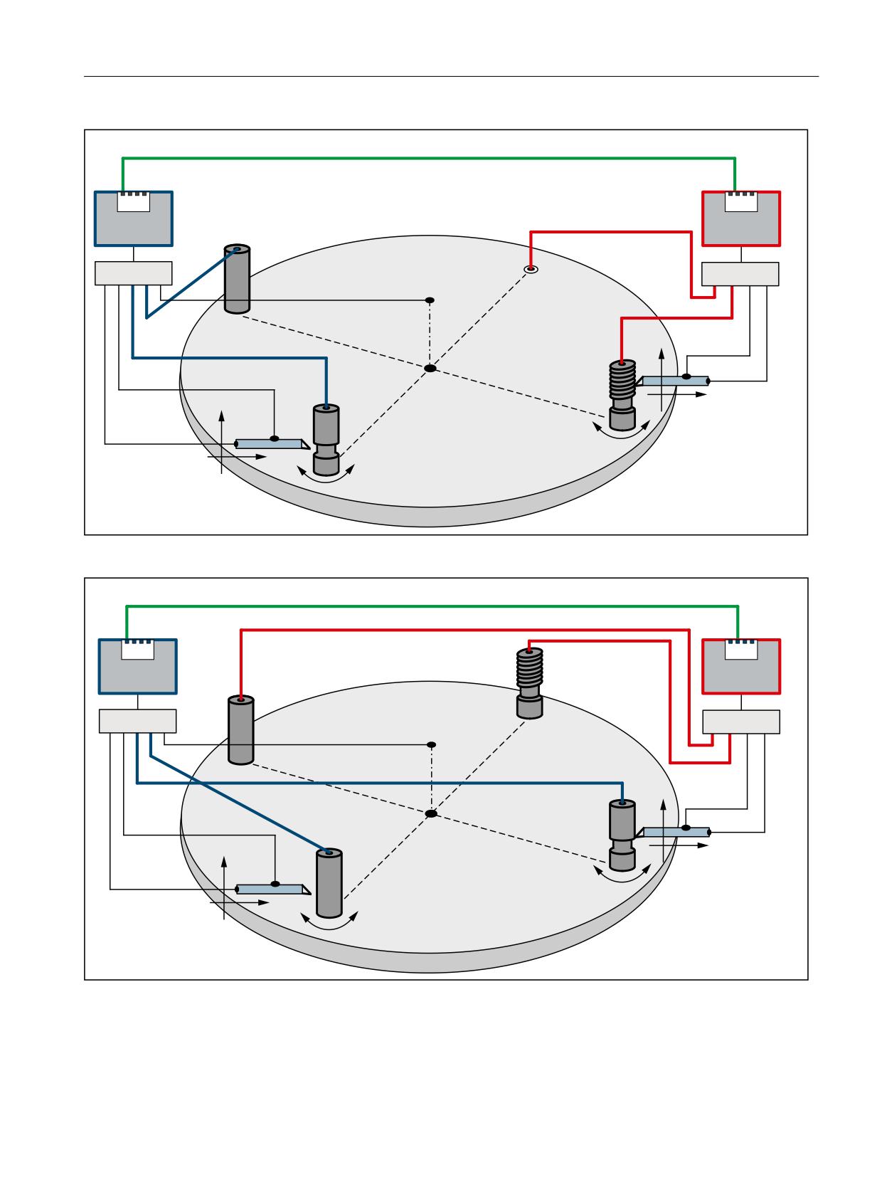
Distributed systems
15.1 Brief description
1&8 /LQN YLD 352),1(7
1&8
6HWSRLQW WUDQVIHU LV QRW FXUUHQWO\ UHTXLUHG
1&8
/LQN PRGXOH
/LQN PRGXOH
6SLQGOH 06
1&8
6SLQGOH 06
1&8
5RWDU\ WDEOH
'ULYH
075
'ULYH
8QORDGLQJ VWDWLRQ
/RDGLQJ VWDWLRQ
6SLQGOH
06
=
6SLQGOH
06
;
=
0DFKLQLQJ VWDWLRQ
;
0DFKLQLQJ VWDWLRQ
Figure 15-2
Fig. 1: Initial situation
1&8 /LQN YLD 352),1(7
1&8
6HWSRLQW WUDQVIHU 1&8
! 1&8
VSLQGOH 06
1&8
/
LQN PRGXOH
/
LQN PRGXOH
6SLQGOH 06
1&8
6SLQG
OH 06
1&8
5RWDU\ D[LV 075
'ULYH
'ULYH
/RDGLQJ VWDWLRQ
8QORDGLQJ VWDWLRQ
6SLQGOH 06
=
6SLQGOH 06
;
=
0DFKLQLQJ VWDWLRQ
;
0DFKLQLQJ VWDWLRQ
Figure 15-3
Fig. 2: Location after rotation by one position
Basic functions
Function Manual, 10/2020, 6FC5397-2GP40-0BA1
821
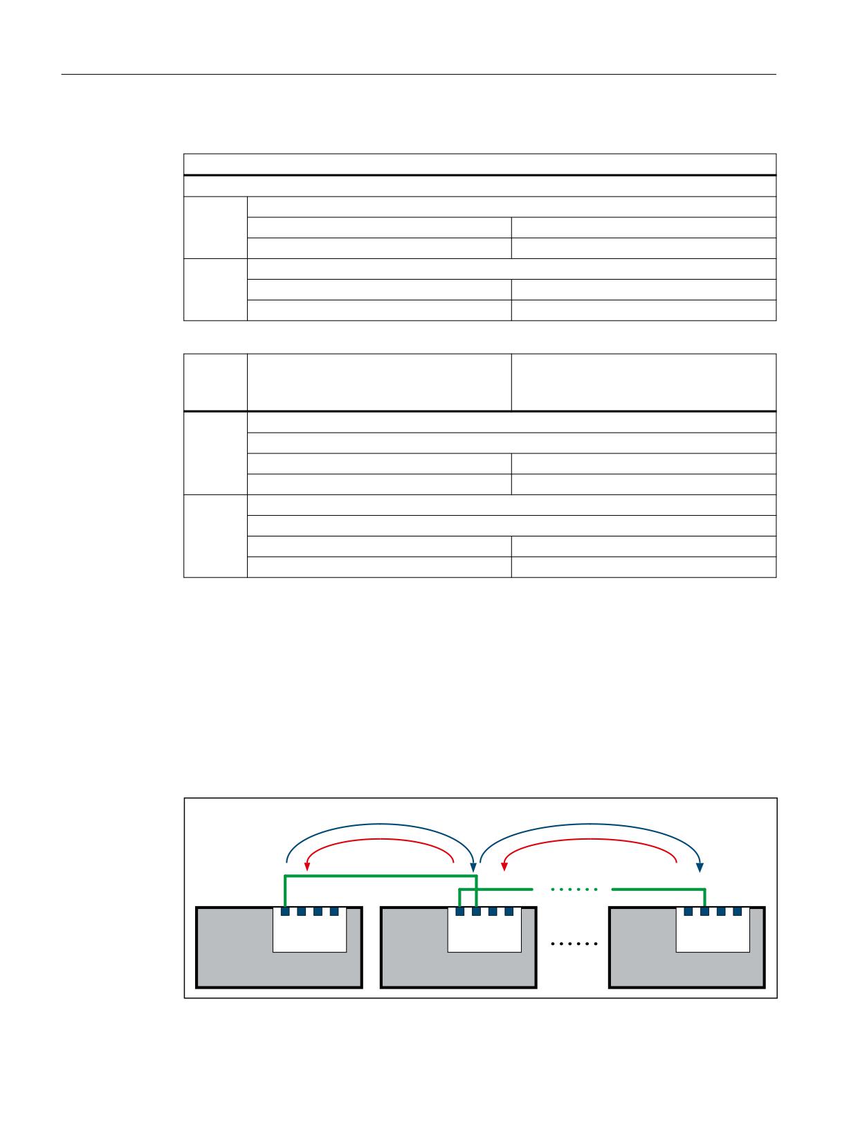
Distributed systems
15.2 NCU link
Parameterization (schematic)
General
Programmed channel axes in the part programs of both NCUs: X, Z, S1
NCU1
Machine axes defined in the NCU:
Local:
X1, Z1
Axis container:
MS1, MS2
NCU2
Machine axes defined in the NCU:
Local:
X1, Z1
Axis container:
MS3, MS4
Initial setting
Rotation of the MTR (rotary table) rotary
axis by one position
(Fig. 1)
(Fig. 2)
NCU1
Machining station 1: X1, Z1, MS2
Diagram showing the channel axes programmed in the part program:
X → X1 and Z → Z1
X → X1 and Z → Z1
S1 → MS2
S1 → MS1
NCU2
Machining station 2: X1, Z1, MS2
Diagram showing the channel axes programmed in the part program:
X → X1 and Z → Z1
X → X1 and Z → Z1
S1 → MS3
S1 → MS2 (link axis)
15.2
NCU link
15.2.1
Link communication
15.2.1.1
General information
'DWD H[FKDQJH E\ 1&8 /LQN YLD 352),1(7
1&8
1&8
1&8Q
1&8
1&8
1&8
/LQN PRGXOH
/LQN PRGXOH
/LQN PRGXOH
Figure 15-4
Link communication (principle)
Basic functions
822
Function Manual, 10/2020, 6FC5397-2GP40-0BA1
Distributed systems
15.2 NCU link
The NCU-link communication cycle allows an interpolator clock-synchronous cross-NCU data
exchange for the following applications:
• Cross-NCU link variables $A_DLx
All the NCUs involved with the NCU-link communication have a common view of the link
variables because they are exchanged via the NCU link interpolator cycle clock-synchronous
between the NCU of the link group.
• Cross-NCU traversing of axes and spindles using link axes and container-link axes
If single or interpolation axis traversal is made from a channel of an NCU, NCU-link setpoints
can also be transferred to axes physically connected to another NCU of the link group. These
axes are designated as link axes.
• Cross-NCU master value coupling of axes and spindles using lead-link axes
NCU1 traverses axis X1 (leading axis), the setpoints are transferred to a link axis of NCU2
(lead-link axis) via the NCU link. Coupling of axis X2 is realized in NCU2 on this lead-link axis.
This means axis X2 is indirectly the following axis of X1.
Data transfer
Depending on the active functions, the following cyclic and non-cyclical data transmissions
occur between the NCUs involved with the link communication:
• High-priority, cyclic data transfer:
- Setpoints, actual values and status signals of the axes
- NCU status signals
• High-priority, non-cyclic, non-displaceable data transfer:
- Non-safety-related data as part of the Safety Integrated function
- States of the container axes during an axis container rotation
• Low-priority, non-cyclic, displaceable data transfer (listed in order of decreasing priority):
- Link variables
- Warm restart requirements
- Activation of axis container rotations
- Changes in NCU-global machine and setting data
- Activation of the axial machine data for link axes
- Alarms
Displacement
If for low-priority, non-cyclic, displaceable data transmission not all requirements can be sent in
a single interpolator cycle, the request with higher priority displaces that with a lower priority.
The requirements with lower priority are then sent at a later point in time.
Basic functions
Function Manual, 10/2020, 6FC5397-2GP40-0BA1
823
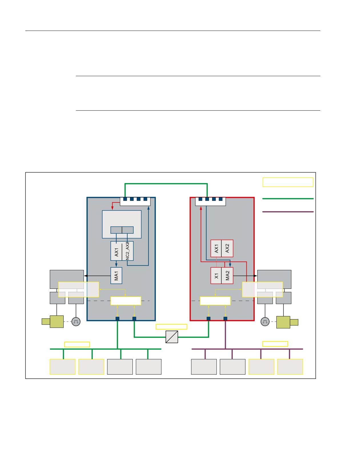
Distributed systems
15.2 NCU link
Quantity structure: NCU 7x0.3 PN
As standard, a maximum of three NCUs can be interconnected to form a link group.
Note
For a specific project, on request to your local regional Siemens representative an NCU-link group
with more than three NCUs is possible. Without project-specific supplements, more than three
NCUs are rejected with Alarm 380020.
NCU link and Safety Integrated
The following figure shows a constellation with two NCUs and two machine axes, of which the
MA2 machine axis of the NCU2 is traversed as link axis for NCU1. The Safety Integrated function
monitors the safety-related aspects of both axes.
1&8 /LQN YLD 352),1(7
6DIHW\ ,QWHJUDWHG
(WKHUQHW
352),1(7
1&8
1&8
352),%86
1&.
1&.
&KDQQHO
1
*
)
1
;
=
&KDQQHO D[HV
;
=
0'
/RJ 0DFKLQH D[LV LPDJH
0'
0DFKLQH D[HV
0'
&RQWURO8QLW
&RQWURO8QLW
0RWLRQ
0
RWLRQ
0RQLWRU
0RQLWRU
00
60
60
0
0
63/
63/
3/&
3/&
;
;
;
;
3
3
3
0
0
)6HQG )5HFY
1&8 ORFDO D[LV
31
/LQN D[LV
31
352),VDIH
352),VDIH
)B',
)B'2
',
'2
',
'2
)B',
)B'2
Figure 15-5
NCU link and Safety Integrated
The safety-related input signals (F_DI) of both NCUs can be acquired, linked via the safe
programmable logic (SPL) and exchanged using the safety-related CPU-CPU communication
(FSend/FRecv).
Basic functions
824
Function Manual, 10/2020, 6FC5397-2GP40-0BA1
Distributed systems
15.2 NCU link
As part of the Safety Integrated function, the NCU-link communication permits the single-
channel non-safety-related transfer of link axis data for Safety Integrated-supporting
functions.
Examples:
• Interpolatory braking for an implicit Stop D of all traversing axes, including the link axes, in
the channel.
• Reduce the speed of all axes traversing in the channel, including link axes, for a change of the
safe speed.
Safety Integrated acceptance test and NCU link
The Acceptance Test wizard (ATW) is generally used to perform the acceptance test separately
for each NCU. Only alarms on the home NCU of the axis are displayed for link axes. To make the
ATW also check alarms for link axes, the ATW must be told the safety-relevant NCU connected via
the NCU link. For this purpose, these must be entered in the NETNAMES.INI file on the PG/PCU
on which the ATW runs.
Example: Entries in the NETNAMES.INI file for NCU link with two safety-relevant NCUs
Adapt file: NETNAMES.INI (excerpt)
[own]
owner = HMI_1
[conn HMI_1]
conn_1= NCU_1
conn_2= NCU_2
[param HMI_1]
mmc_address = 1
[param network]
[param NCU_1]
nck_address= 192.168.214.2,LINE=10,NAME=/NC,SAP=030d,PROFILE=CLT1__CP_L4_INT
plc_address= 192.168.214.2,LINE=10,NAME=/PLC,SAP=0201,PROFILE=CLT1__CP_L4_INT
ADDRESS2=
192.168.214.2,LINE=10,NAME=/CP,SAP=0501,PROFILE=CLT2__CP_L4_INT
ADDRESS10=
192.168.214.2,LINE=10,NAME=/
DRIVE_00_000,SAP=0201,SUBNET=0000-00000000:000,PROFILE=CLT2__CP_L4_INT
ADDRESS11=
192.168.214.2,LINE=10,NAME=/DRIVE_03_003,SAP=0900,PROFILE=CLT2__CP_L4_INT
ADDRESS12=
192.168.214.2,LINE=10,NAME=/DRIVE_03_011,SAP=0B00,PROFILE=CLT2__CP_L4_INT
ADDRESS13=
192.168.214.2,LINE=10,NAME=/DRIVE_03_012,SAP=0C00,PROFILE=CLT2__CP_L4_INT
ADDRESS14=
192.168.214.2,LINE=10,NAME=/DRIVE_03_013,SAP=0D00,PROFILE=CLT2__CP_L4_INT
ADDRESS15=
192.168.214.2,LINE=10,NAME=/DRIVE_03_014,SAP=0E00,PROFILE=CLT2__CP_L4_INT
ADDRESS16=
192.168.214.2,LINE=10,NAME=/DRIVE_03_015,SAP=0F00,PROFILE=CLT2__CP_L4_INT
name=Machine_1
Basic functions
Function Manual, 10/2020, 6FC5397-2GP40-0BA1
825
Distributed systems
15.2 NCU link
Adapt file: NETNAMES.INI (excerpt)
[param NCU_2]
nck_address= 192.168.214.1,LINE=10,NAME=/NC,SAP=030d,PROFILE=CLT1__CP_L4_INT
plc_address= 192.168.214.1,LINE=10,NAME=/PLC,SAP=0201,PROFILE=CLT1__CP_L4_INT
ADDRESS2=
192.168.214.1,LINE=10,NAME=/CP,SAP=0501,PROFILE=CLT2__CP_L4_INT
ADDRESS10=
192.168.214.1,LINE=10,NAME=/
DRIVE_00_000,SAP=0201,SUBNET=0000-00000000:000,PROFILE=CLT2__CP_L4_INT
ADDRESS11=
192.168.214.1,LINE=10,NAME=/DRIVE_03_003,SAP=0900,PROFILE=CLT2__CP_L4_INT
ADDRESS12=
192.168.214.1,LINE=10,NAME=/DRIVE_03_011,SAP=0B00,PROFILE=CLT2__CP_L4_INT
ADDRESS13=
192.168.214.1,LINE=10,NAME=/DRIVE_03_012,SAP=0C00,PROFILE=CLT2__CP_L4_INT
ADDRESS14=
192.168.214.1,LINE=10,NAME=/DRIVE_03_013,SAP=0D00,PROFILE=CLT2__CP_L4_INT
ADDRESS15=
192.168.214.1,LINE=10,NAME=/DRIVE_03_014,SAP=0E00,PROFILE=CLT2__CP_L4_INT
ADDRESS16=
192.168.214.1,LINE=10,NAME=/DRIVE_03_015,SAP=0F00,PROFILE=CLT2__CP_L4_INT
name=Machine_2
Further information
The "Safety Integrated" function is described in detail in:
SINAMICS S120 Safety Integrated Function Manual
15.2.1.2
Link module
The NCU-link communication takes place via link modules A link module is an optional PROFINET
module for isochronous real-time communication (IRT) via Ethernet. The link module can be
used only for the NCU-link communication. It is not possible to use a link module for general
PROFINET communication.
The option slot is required on the NCU module for the link module.
Note
There is only one option slot on the NCU module. This prevents the parallel use of an NCU-link
module and other optional modules.
Link module and NCU modules
The Communication Board Ethernet CBE30-2 is available as link module for the "NCU710.3 PN",
"NCU720.3 PN" and "NCU730.3 PN" NCU modules. The option slot is required on the NCU module
for the link module.
Further information
Equipment Manual NCU7x0.3 PN; Connectable components > CBE30-2
Basic functions
826
Function Manual, 10/2020, 6FC5397-2GP40-0BA1