SINUMERIK 840D sl. Service - Functions. Manual (2018-2020) - page 43
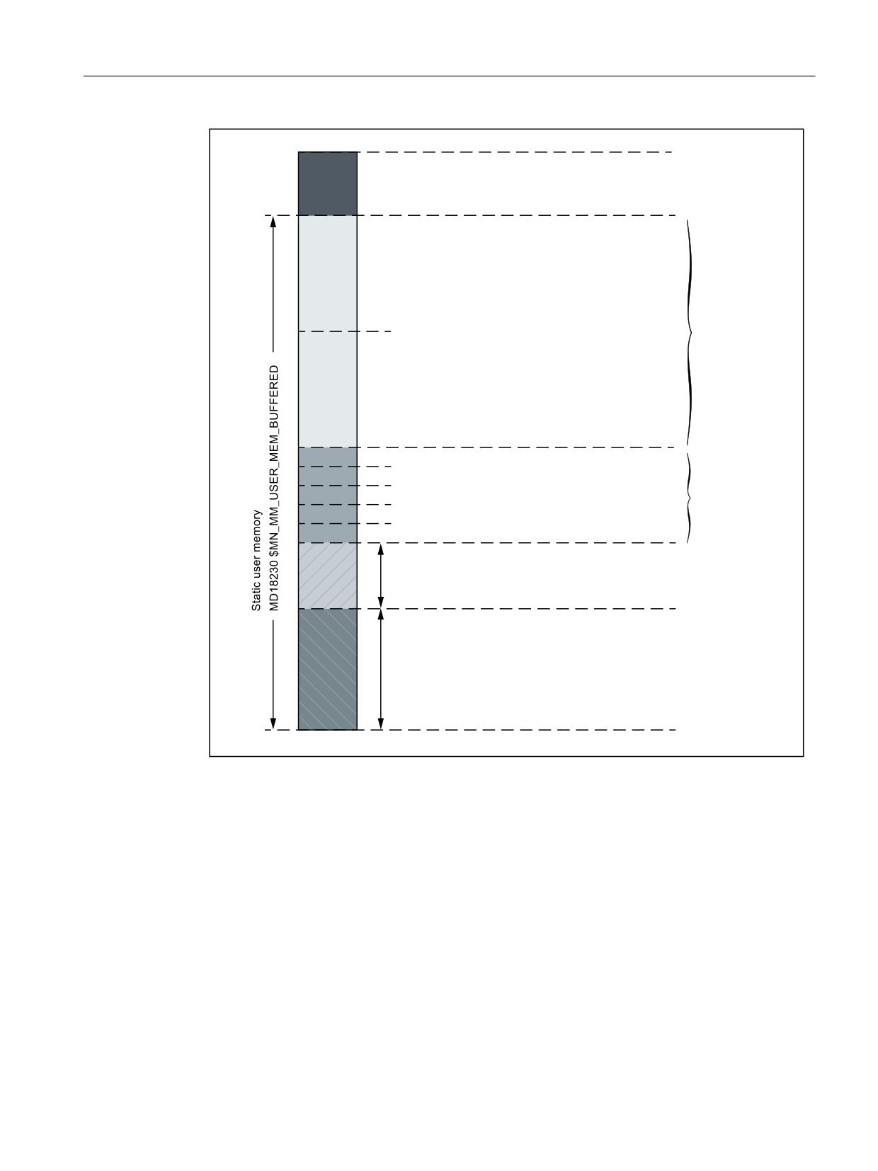
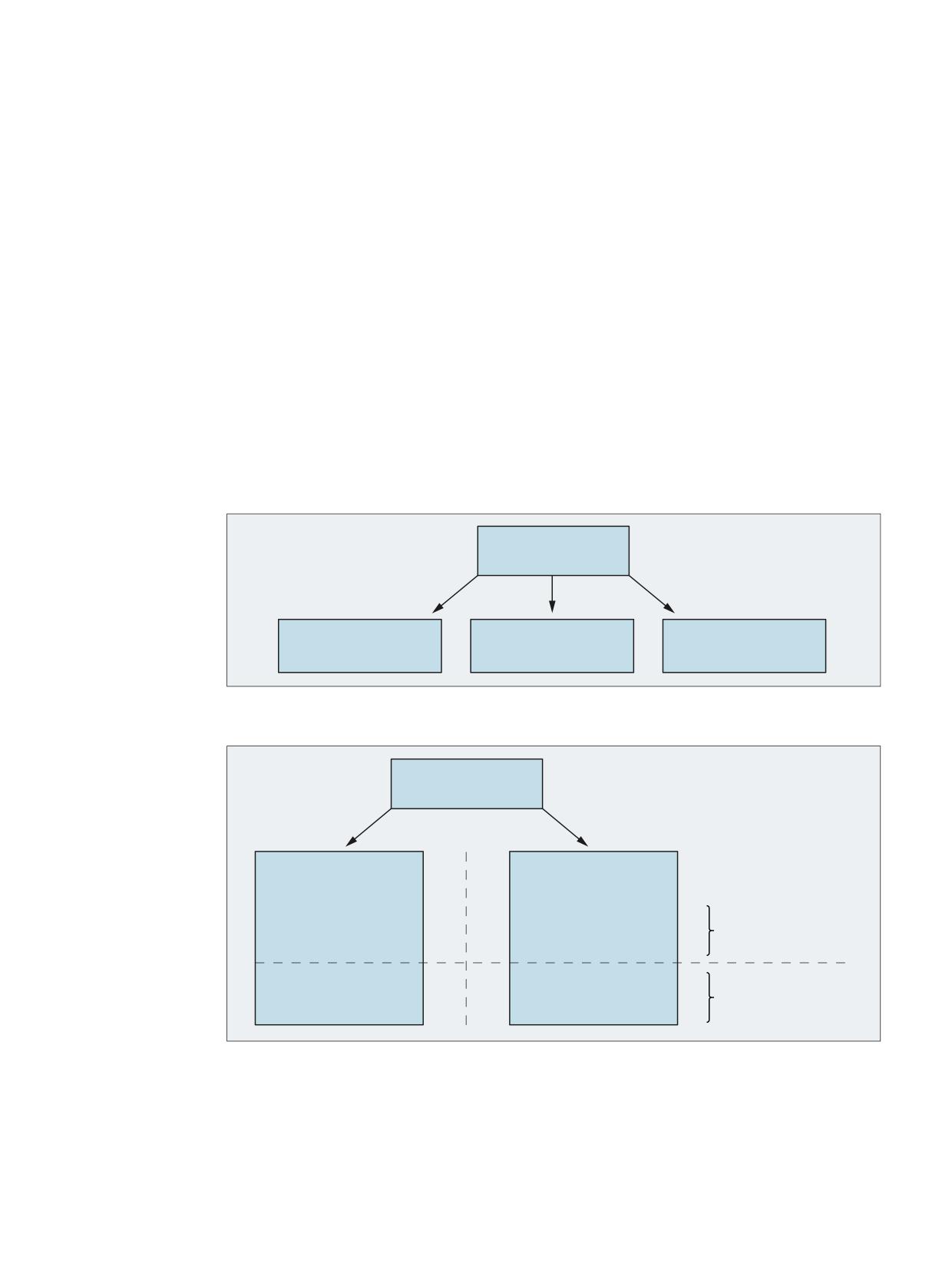
S7: Memory configuration
16.4 Configuration of the static user memory
0HPRU\ XVHG E\ WKH V\VWHP
8VHU F\FOHV SDUW SURJUDPV ZRUNSLHFHV
8
0'
01B00B8B),/(B0(0B6,=(
3DVVLYH ILOH
V\VWHP
0DFKLQH PDQXIDFWXUHU F\FOHV
0
0'
01B00B0B),/(B0(0B6,=(
7RRO PDQDJHPHQW
*OREDO XVHU GDWD
$FWLYH ILOH
V\VWHP
4XDGUDQW HUURU FRPSHQVDWLRQ
)UHH PHPRU\
0'
01B,1)2B)5((B0(0B67$7,&
0HPRU\ H[SDQVLRQ RSWLRQ
Figure 16-1
Static NC memory for SINUMERIK 840D sl
Static-user-memory size
The size of the static user memory is displayed in machine data:
MD18230 $MN_MM_USER_MEM_BUFFERED
Extended Functions
Function Manual, 12/2018, A5E40874029B AB
831

S7: Memory configuration
16.4 Configuration of the static user memory
Parts of the static user memory
Passive file system
The following partitions of the passive file system are present in the static user memory:
Partition
Storage of:
U (User)
● Files from the _N_CUS_DIR directory (user cycles)
● Part programs
● Workpieces
M (Manufacturer = Machine manufacturer)
Files from the _N_CMA_DIR directory (Machine-manufac-
turer cycles)
The free memory of the passive file system displayed in MD18060
$MN_INFO_FREE_MEM_STATIC can be divided among the partitions U and M. The setting
is made via the machine data:
● MD18352 $MN_MM_U_FILE_MEM_SIZE = <memory size for user data>
● MD18353 $MN_MM_M_FILE_MEM_SIZE = <memory size for machine manufacturer data>
Note
Partition S
Partition S (Siemens = Control manufacturer) of the passive file systems is in the dynamic
memory (Page 833).
Active file system
The memory of the active file system is divided into different areas (tool management, global
user data, ...). The size can be set for each area in the machine data that configures memory
(...MM_...).
Free capacity
The size of the free memory is displayed in the machine data:
MD18060 $MN_INFO_FREE_MEM_STATIC
Note
The memory required to expand the memory areas is displayed in the "Startup" area of the
user interface. This information enables the system startup engineer to estimate the actual
memory requirements for the planned expansion.
Memory expansion (option)
If additional static user memory is required, a memory expansion can be purchased as an
option.
You can use the additional memory as required to expand partitions U and/or M or to expand
the memory area of the active file system.
Extended Functions
832
Function Manual, 12/2018, A5E40874029B AB
S7: Memory configuration
16.5 Configuration of the dynamic user memory
16.4.2
Commissioning
You can adjust the default memory division by increasing/decreasing individual memory areas
for each user.
Basic procedure:
1. Load standard machine data.
References:
Commissioning the CNC: NC, PLC, Drive; section "Requirements for commissioning" >
"Power-on and startup"
2. Determining the maximum possible size of the static user memory (including the optional
memory expansion):
MD18230 $MN_MM_USER_MEM_BUFFERED
3. Optional: modifying the size of the static user memory:
- MD19250 $ON_USER_MEM_BUFFERED
- Perform a power-on reset.
4. Optional: setting the size partitions U and M:
- MD18352 $MN_MM_U_FILE_MEM_SIZE
- MD18353 $MN_MM_M_FILE_MEM_SIZE
5. Optional: setting up additional channels of the control:
MD10010 $MC_ASSIGN_CHAN_TO_MODE_GROUP
6. Optional: setting the size of the memory areas of the active file system (tool management,
global user data, ...):
- Determining the free static user memory:
MD18060 $MN_INFO_FREE_MEM_STATIC
- Setting the size of the memory areas of the active file system in the machine data that
configure memory (...MM_...).
7. Perform a power-on reset.
The memory will be reconfigured the next time the control starts up.
References:
For a detailed description of machine data, refer to:
● List Manual Machine Data and Parameters
16.5
Configuration of the dynamic user memory
16.5.1
Division of the dynamic NC memory
The dynamic NC memory is used jointly by the system and by the user. The area available to
the user is defined as the dynamic user memory.
Extended Functions
Function Manual, 12/2018, A5E40874029B AB
833
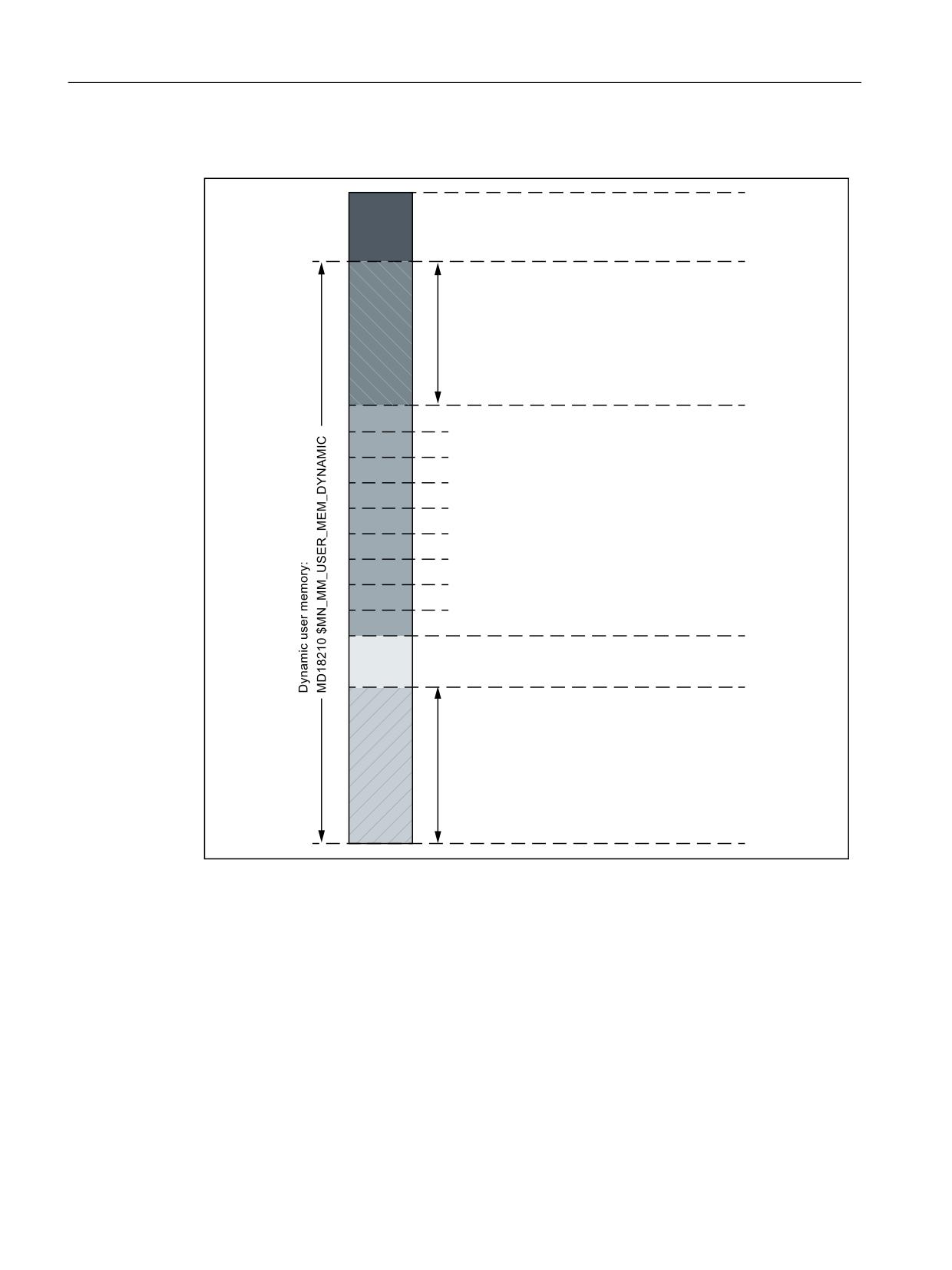
S7: Memory configuration
16.5 Configuration of the dynamic user memory
The figure below shows the principle division of the dynamic NC memory:
'\QDPLF PHPRU\ XVHG E\ WKH V\VWHP
0HPRU\ H[SDQVLRQ
0'
21B86(5B0(0B'<1$0,&
0DFURV
0LVFHOODQHRXV IXQFWLRQV DQG SDUDPHWHUV
/RFDO XVHU GDWD
+DVK WDEOHV
7DVNV
5HRUJ IXQFWLRQ
,QWHUSRODWLRQ EXIIHU
&RPSLOH F\FOHV
3URWHFWLRQ ]RQHV
6
6LHPHQV F\FOHV
)UHH PHPRU\
0'
01B,1)2B)5((B0(0B'<1$0,&
Figure 16-2
Dynamic NC memory
Dynamic-user-memory size
The size of the dynamic user memory is displayed in machine data:
MD18210 $MN_MM_USER_MEM_DYNAMIC
Free user memory
The user memory still available is shown in the machine data:
MD18050 $MN_INFO_FREE_MEM_DYNAMIC
Extended Functions
834
Function Manual, 12/2018, A5E40874029B AB

S7: Memory configuration
16.5 Configuration of the dynamic user memory
The value of the machine data indicates how much memory is available to expand the user
data areas (local user data, IPO buffer, etc.) for each channel.
Parts of the dynamic user memory
Passive file system
Partition S of the passive file system is in the dynamic user memory:
Partition
Storage of:
S (Siemens = Control manufacturer)
Files from the _N_CST_DIR directory (Siemens cycles)
The size of partition S is preset and cannot be modified.
Memory expansion
If an NCU is used with at least 2 GB of working memory, it is possible to use part of the working
memory to expand the dynamic user memory.
The expansion of the additional dynamic user memory is defined in 4 MB steps in machine
data:
OD19240 $ON_USER_MEM_DYNAMIC
Total size of the dynamic user memory
"Total size of the dynamic user memory" = basic expansion + OD19240
$ON_USER_MEM_DYNAMIC * 4MB
Display
The dynamic user memory currently available is shown in machine data:
MD18210 $MN_MM_USER_MEM_DYNAMIC
16.5.2
Commissioning
You can adjust the default memory division by increasing/decreasing individual memory areas
for each user.
Basic procedure:
1. Determining the size of the free dynamic user memory:
MD18050 $MN_INFO_FREE_MEM_DYNAMIC
2. Optional: enlarging the dynamic user memory:
- MD18210 $MN_MM_USER_MEM_DYNAMIC
- Perform a power-on reset.
3. Optional: Setting the size of the memory areas of the dynamic user memory in the machine
data that configure memory (...MM_...):
4. Perform a power-on reset.
The memory will be reconfigured the next time the control starts up.
Extended Functions
Function Manual, 12/2018, A5E40874029B AB
835
S7: Memory configuration
16.6 Boundary conditions
References:
For a detailed description of machine data, refer to:
● List Manual Machine Data and Parameters
16.6
Boundary conditions
16.6.1
Depending on the number of channels and tool carriers
If the number of channels is increased, then it may also be necessary to increase the number
of tool carriers.
The number of tool carriers available in the control has to be set according to the following rule:
MD18088 $MN_NUM_TOOL_CARRIER =
<Highest number of tool carriers in one channel> *
<Number of parameterized channels>
The tool carriers are distributed in the control equally among the available channels.
Example
3 channels are parameterized in the NC. The number of tool carriers required in the channels
is:
1. Channel: 3 ⇒ maximum value
2. Channel: 2
3. Channel: 1
MD18088 = <Highest number of tool carriers in one channel> * <Number of
channels> = 3 * 3 = 9
3 tool carriers are thus assigned to each channel
16.6.2
Subsequent reduction of the number of channels and/or axes
Once an increase in the number of channels and/or axes has been made effective in the control
by a warm restart, it cannot then be reversed if a setup archive is to be created for this control.
If such a setup archive is loaded into a control, the process is interrupted by an alarm.
Differences between the dynamic and static memory of the NC
● Dynamic memory: The internal memory requirement increases if the numbers of channels
and axes are increased.
● Static memory: The internal memory requirement increases only if the number of
channels is increased.
Extended Functions
836
Function Manual, 12/2018, A5E40874029B AB

S7: Memory configuration
16.7 Data lists
16.7
Data lists
16.7.1
Machine data
16.7.1.1
General machine data
Number
Identifier: $MN_
Description
10134
MM_NUM_MMC_UNITS
Number of simultaneous HMI communication partners
10850
MM_EXTERN_MAXNUM_OEM_GCODES
Maximum number of OEM-G commands
10880
MM_EXTERN_CNC_SYSTEM
Definition of the control system to be adapted
10881
MM_EXTERN_GCODE_SYSTEM
ISO_3 Mode: GCodeSystem
18050
INFO_FREE_MEM_DYNAMIC
Free-dynamic-memory display data
18060
INFO_FREE_MEM_STATIC
Free-static-memory display data
18070
INFO_FREE_MEM_DPR
Display data for free memory in
dual-port RAM
18072
INFO_FREE_MEM_CC_MD
Displays memory available in the CC-MD memory
18078
MM_MAX_NUM_OF_HIERARCHIES
Maximum number of definable magazine-location-type
hierarchies
18079
MM_MAX_HIERARCHY_ENTRIES
Maximum permissible number of entries in a magazine-
location-type hierarchy
18080
MM_TOOL_MANAGEMENT_MASK
Mask for reserving memory for tool management
18082
MM_NUM_TOOL
Number of tools managed by NC
18084
MM_NUM_MAGAZINE
Number of magazines managed by NC
18086
MM_NUM_MAGAZINE_LOCATION
Number of magazine locations
18088
MM_NUM_TOOL_CARRIER
Maximum number of definable toolholders
18090
MM_NUM_CC_MAGAZINE_PARAM
Compile-cycle tool management:
quantity of magazine data
18092
MM_NUM_CC_MAGLOC_PARAM
Compile-cycle tool management:
quantity of magazine-location data
18094
MM_NUM_CC_TDA_PARAM
Compile-cycle tool management: quantity of TDA data
18096
MM_NUM_CC_TOA_PARAM
Compile-cycle tool management: quantity of TOA data
18098
MM_NUM_CC_MON_PARAM
Compile-cycle tool management:
quantity of monitor data
18100
MM_NUM_CUTTING_EDGES_IN_TOA
Number of tool offsets in NC
18102
MM_TYPE_OF_CUTTING_EDGE
Type of D-number programming
18104
MM_NUM_TOOL_ADAPTER
Tool adapter in TO area
18105
MM_MAX_CUTTING_EDGE_NO
Maximum value of D number
18106
MM_MAX_CUTTING_EDGE_PERTOOL
Maximum number of D numbers per tool
18108
MM_NUM_SUMCORR
Additive offsets in the TO area
18110
MM_MAX_SUMCORR_PER_CUTTEDGE
Maximum number of sum offsets per cutting edge
18112
MM_KIND_OF_SUMCORR
Properties of additive offsets in the TO area
18114
MM_ENABLE_TOOL_ORIENT
Assign orientation to cutting edges
Extended Functions
Function Manual, 12/2018, A5E40874029B AB
837

S7: Memory configuration
16.7 Data lists
Number
Identifier: $MN_
Description
18116
MM_NUM_TOOL_ENV
Number of tool environments in TO area
18118
MM_NUM_GUD_MODULES
Number of GUD modules
18120
MM_NUM_GUD_NAMES_NCK
Number of global user variables
18130
MM_NUM_GUD_NAMES_CHAN
Number of channel-specific user variables
18140
MM_NUM_GUD_NAMES_AXIS
Number of axis-specific user variables
18150
MM_GUD_VALUES_MEM
Memory space for global user variables
18160
MM_NUM_USER_MACROS
Number of macros
18170
MM_NUM_MAX_FUNC_NAMES
Number of miscellaneous functions
18180
MM_NUM_MAX_FUNC_PARAM
Number of additional parameters
18190
MM_NUM_PROTECT_AREA_NCK
Number of protection zones in NC
18200
MM_NUM_CCS_MAGAZINE_PARAM
Number of Siemens OEM magazine data
18201
MM_TYPE_CCS_MAGAZINE_PARAM
Siemens OEM magazine data type
18202
MM_NUM_CCS_MAGLOC_PARAM
Number of Siemens OEM magazine location data
18203
MM_TYPE_CCS_MAGLOC_PARAM
Siemens OEM magazine location data type
18204
MM_NUM_CCS_TDA_PARAM
Number of Siemens OEM tool data
18205
MM_TYPE_CCS_TDA_PARAM
Siemens OEM tool data type
18206
MM_NUM_CCS_TOA_PARAM
Number of Siemens OEM data per cutting edge
18207
MM_TYPE_CCS_TOA_PARAM
Siemens OEM data type per cutting edge
18208
MM_NUM_CCS_MON_PARAM
Number of Siemens OEM monitor data
18209
MM_TYPE_CCS_MON_PARAM
Siemens OEM monitor data type
18210
MM_USER_MEM_DYNAMIC
User memory for non-persistent data
18220
MM_USER_MEM_DPR
User memory in dual-port RAM
18230
MM_USER_MEM_BUFFERED
User memory for persistent data
18231
MM_USER_MEM_BUFFERED_TYPEOF
Data-buffer technology
18232
MM_ACTFILESYS_LOG_FILE_MEM
System: Log-file size
18238
MM_CC_MD_MEM_SIZE
Memory size for compile cycle machine data
18240
MM_LUD_HASH_TABLE_SIZE
Hash-table size for user variables
18242
MM_MAX_SIZE_OF_LUD_VALUE
Maximum LUD-variable array size
18250
MM_CHAN_HASH_TABLE_SIZE
Hash-table size for channel-specific data
18260
MM_NCK_HASH_TABLE_SIZE
Hash-table size for global data
18270
MM_NUM_SUBDIR_PER_DIR
Number of subdirectories
18280
MM_NUM_FILES_PER_DIR
Number of files per directory
18290
MM_FILE_HASH_TABLE_SIZE
Hash-table size for files in a directory
18300
MM_DIR_HASH_TABLE_SIZE
Hash-table size for subdirectories
18310
MM_NUM_DIR_IN_FILESYSTEM
Number of directories in passive file system
18320
MM_NUM_FILES_IN_FILESYSTEM
Number of files in passive file system
18332
MM_FLASH_FILE_SYSTEM_SIZE
Size of flash file system on PCNC
18342
MM_CEC_MAX_POINTS
Maximum table size for sag compensation
18350
MM_USER_FILE_MEM_MINIMUM
Minimum part-program memory
18352
MM_U_FILE_MEM_SIZE
End-user memory for part programs/cycles/files
Extended Functions
838
Function Manual, 12/2018, A5E40874029B AB

S7: Memory configuration
16.7 Data lists
Number
Identifier: $MN_
Description
18353
MM_M_FILE_MEM_SIZE
Memory size for cycles/files of the machine manufac-
turer
18354
MM_S_FILE_MEM_SIZE
Memory size for cycles/files of the NC manufacturer
18355
MM_T_FILE_MEM_SIZE
Memory size for temporary files
18356
MM_E_FILE_MEM_SIZE
Memory size for external files
18360
MM_EXT_PROG_BUFFER_SIZE
FIFO buffer size for execution from an external source
18362
MM_EXT_PROG_NUM
Number of program levels that can be processed si-
multaneously from external
18370
MM_PROTOC_NUM_FILES
Maximum number of log files
18371
MM_PROTOC_NUM_ETPD_STD_LIST
Number of standard ETPD data lists
18372
MM_PROTOC_NUM_ETPD_OEM_LIST
Number of ETPD OEM data lists
18373
MM_PROTOC_NUM_SERVO_DATA
Number of servo data for log
18374
MM_PROTOC_FILE_BUFFER_SIZE
Log-file buffer size
18375
MM_PROTOC_SESS_ENAB_USER
User-enabled for sessions
18390
MM_COM_COMPRESS_METHOD
Supported compression method
18400
MM_NUM_CURVE_TABS
Number of curve tables (persistent)
18402
MM_NUM_CURVE_SEGMENTS
Number of curve segments (persistent)
18403
MM_NUM_CURVE_SEG_LIN
Number of linear curve segments (persistent)
18404
MM_NUM_CURVE_POLYNOMS
Number of curve table polynomials (persistent)
18406
MM_NUM_CURVE_TABS_DRAM
Number of curve tables (non-persistent)
18408
MM_NUM_CURVE_SEGMENTS_DRAM
Number of curve segments (non-persistent)
18409
MM_NUM_CURVE_SEG_LIN_DRAM
Number of linear curve segments (non-persistent)
18410
MM_NUM_CURVE_POLYNOMS_DRAM
Number of curve table polynomials (non-persistent)
18450
MM_NUM_CP_MODULES
Maximum number of CP modules
18452
MM_NUM_CP_MODUL_LEAD
Maximum number of leading values per CP coupling
module
18500
MM_EXTCOM_TASK_STACK_SIZE
Stack size of external communication task (non-persis-
tent)
18502
MM_COM_TASK_STACK_SIZE
Stack size in Kbytes of communication task (non-per-
sistent)
18510
MM_SERVO_TASK_STACK_SIZE
Stack size of servo task (non-persistent)
18512
MM_IPO_TASK_STACK_SIZE
Stack size of IPO task (non-persistent)
18520
MM_DRIVE_TASK_STACK_SIZE
Stack size of drive task (non-persistent)
18540
MM_PLC_TASK_STACK_SIZE
Stack size of the PLC task (non-persistent)
18600
MM_FRAME_FINE_TRANS
Fine offset for FRAME (persistent)
18601
MM_NUM_GLOBAL_USER_FRAMES
Number of globally predefined user frames (persistent)
18602
MM_NUM_GLOBAL_BASE_FRAMES
Number of global basic frames (persistent)
18660
MM_NUM_SYNACT_GUD_REAL
Number of configurable real-type GUD variables
18661
MM_NUM_SYNACT_GUD_INT
Number of configurable integer-type GUD variables
18662
MM_NUM_SYNACT_GUD_BOOL
Number of configurable Boolean-type GUD variables
18663
MM_NUM_SYNACT_GUD_AXIS
Number of configurable axis-type GUD variables
18664
MM_NUM_SYNACT_GUD_CHAR
Configurable char-type GUD variable
Extended Functions
Function Manual, 12/2018, A5E40874029B AB
839

S7: Memory configuration
16.7 Data lists
Number
Identifier: $MN_
Description
18665
MM_NUM_SYNACT_GUD_STRING
Configurable STRING-type GUD variable
18700
MM_SIZEOF_LINKVAR_DATA
Size of the NCU link variable memory
18710
MM_NUM_AN_TIMER
Number of global time variables for synchronized ac-
tions
18720
MM_SERVO_FIFO_SIZE
Setpoint for buffer size between IPO and closed-loop
position control
18780
MM_NCU_LINK_MASK
Activation of NCU link communication
18781
NCU_LINK_CONNECTIONS
Number of internal link connections
18782
MM_LINK_NUM_OF_MODULES
Number of NCU link modules
18790
MM_MAX_TRACE_LINK_POINTS
Size of trace data buffer for NCU link
18792
MM_TRACE_LINK_DATA_FUNCTION
Specifies the contents of NCU link files
18794
MM_TRACE_VDI_SIGNAL
Trace specification of VDI signals
18800
MM_EXTERN_LANGUAGE
Activation of external NC languages
18860
MM_MAINTENANCE_MON
Activate recording of maintenance data
18870
MM_MAXNUM_KIN_CHAINS
Maximum number of trains
18880
MM_MAXNUM_KIN_CHAIN_ELEM
Maximum number of train elements
18890
MM_MAXNUM_3D_PROT_AREAS
Maximum number of elements in 3D protection zones
18892
MM_MAXNUM_3D_PROT_AREA_ELEM
Maximum number of protection-zone elements
18894
MM_MAXNUM_3D_PROT_GROUPS
Maximum number of protection-zone groups
18896
MM_MAXNUM_3D_COLLISION
Maximum number of temporary memory locations for
collision check
16.7.1.2
Channelspecific machine data
Number
Identifier: $MC_
Description
20096
T_M_ADDRESS_EXIT_SPINO
Spindle number as address extension
27900
REORG_LOG_LIMIT
Percentage of IPO buffer for log-file enable
28000
MM_REORG_LOG_FILE_MEM
Memory size for REORG
28010
MM_NUM_REORG_LUD_MODULES
Number of modules for local user variables with RE-
ORG
28020
MM_NUM_LUD_NAMES_TOTAL
Number of local user variables
28040
MM_LUD_VALUES_MEM
Memory size for local user variables
28050
MM_NUM_R_PARAM
Number of channel-specific R parameters
28060
MM_IPO_BUFFER_SIZE
Number of NC blocks in the IPO buffer
28070
MM_NUM_BLOCKS_IN_PREP
Number of blocks for block preparation
28080
MM_NUM_USER_FRAMES
Number of settable frames
28081
MM_NUM_BASE_FRAMES
Number of basic frames (persistent)
28082
MM_SYSTEM_FRAME_MASK
System frames (persistent)
28083
MM_SYSTEM_DATAFRAME_MASK
System frames (persistent)
28085
MM_LINK_TOA_UNIT
Allocation of a TO unit to a channel
28090
MM_NUM_CC_BLOCK_ELEMENTS
Number of block elements for compile cycles
Extended Functions
840
Function Manual, 12/2018, A5E40874029B AB

S7: Memory configuration
16.7 Data lists
Number
Identifier: $MC_
Description
28100
MM_NUM_CC_BLOCK_USER_MEM
Size of block memory for compile cycles
28105
MM_NUM_CC_HEAP_MEM
Heap memory in KB for compile cycle applications (non-
persistent)
28150
MM_NUM_VDIVAR_ELEMENTS
Number of elements for writing PLC variables
28160
MM_NUM_LINKVAR_ELEMENTS
Number of write elements for the NCU link variables
28180
MM_MAX_TRACE_DATAPOINTS
Size of trace data buffer
28200
MM_NUM_PROTECT_AREA_CHAN
Number of modules for channel-specific protection
zones
28210
MM_NUM_PROTECT_AREA_ACTIVE
Number of simultaneously active protection zones
28212
MM_NUM_PROTECT_AREA_CONTOUR
Elements for active protection zones (non-persistent)
28250
MM_NUM_SYNC_ELEMENTS
Number of elements for expressions in synchronized
actions
28252
MM_NUM_FCTDEF_ELEMENTS
Number of FCTDEF elements
28254
MM_NUM_AC_PARAM
Dimension of $AC_PARAM.
28255
MM_BUFFERED_AC_PARAM
$AC_PARAM[...] (persistent)
28256
MM_NUM_AC_MARKER
Dimension of $AC_MARKER
28257
MM_BUFFERED_AC_MARKER
$AC_MARKER[...] (persistent)
28258
MM_NUM_AC_TIMER
Number of $AC_TIMER time variables (non-persistent)
28274
MM_NUM_AC_SYSTEM_PARAM
Number of $AC_SYSTEM_ PARAM for motion-syn-
chronous actions
28276
MM_NUM_AC_SYSTEM_MARKER
Number of $AC_SYSTEM_ MARKER for motion-syn-
chronous actions
28290
MM_SHAPED_TOOLS_ENABLE
Enable tool-radius compensation for contour tools
28300
MM_PROTOC_USER_ACTIVE
Activate logging for a user
28301
MM_PROTOC_NUM_ETP_OEM_TYP
Number of ETP OEM event types
28302
MM_PROTOC_NUM_ETP_STD_TYP
Number of ETP standard event types
28400
MM_ABSBLOCK
Activate block display with absolute values
28402
MM_ABSBLOCK_BUFFER_CONF
Dimension size of upload buffer
28450
MM_TOOL_DATA_CHG_BUFF_SIZE
Buffer for tool data changes (non-persistent)
28500
MM_PREP_TASK_STACK_SIZE
Stack size of preparatory task
28520
MM_MAX_AXISPOLY_PER_BLOCK
Maximum number of axis polynomials per block
28530
MM_PATH_VELO_SEGMENTS
Number of memory chips for limiting the tool-path ve-
locity
28535
MM_FEED_PROFILE_SEGMENTS
Number of memory chips for feed profiles
28540
MM_ARCLENGTH_SEGMENTS
Number of memory chips for displaying the arc length
function
28560
MM_SEARCH_RUN_RESTORE_MODE
Restore data after a simulation
28580
MM_ORIPATH_CONFIG
Setting for ORIPATH tool orientation trajectory referred
to path
Extended Functions
Function Manual, 12/2018, A5E40874029B AB
841

S7: Memory configuration
16.7 Data lists
16.7.1.3
Axis/spindlespecific machine data
Number
Identifier: $MA_
Description
38000
MM_ENC_COMP_MAX_POINTS
Number of interpolation points with interpolatory com-
pensation
38010
MM_QEC_MAX_POINTS
Number of values for quadrant-error compensation
38020
MM_CPREC_FIR_POINTS
Number of points for characteristic approximation of
FIR filters for CPRECON
Extended Functions
842
Function Manual, 12/2018, A5E40874029B AB
T1: Indexing axes
17
17.1
Brief Description
When machine axes only traverse between a certain number of fixed positions, these positions
can be parameterized as indexing positions. In NC programs, these machine axes, then known
as indexing axes, can be traversed with reference to indexing positions using special
commands.
Typical applications for indexing axes include tool magazines, for example (tool revolver, tool
chain magazines or tool cartridge magazines). The magazine locations of the tools are
parameterized as indexing positions.
It is possible to traverse an indexing axis in the following operating modes:
● AUTOMATIC
● MDI
● JOG
● JOG / INC1, INC10, ... INCvar
17.2
Detailed description
17.2.1
Traversing of indexing axes in the AUTOMATIC mode
Traversal to selected positions
Using the general traversing commands ( G90, G91, AC, IC, ...) an indexing axis can be
traversed to any position within the traversing range of the machine axis.
Traversing to indexing positions
Using the specific traversing commands for indexing axes, it is ensured that only the
parameterized indexing positions are approached. See Chapter "Programming (Page 852)".
17.2.2
Traversing of indexing axes in the JOG mode
In the JOG mode, the indexing positions are only taken into account after referencing/
synchronizing the active measuring system of the indexing axis.
References
Function Manual Basic Functions; Chapter "R1: Referencing"
Extended Functions
Function Manual, 12/2018, A5E40874029B AB
843
T1: Indexing axes
17.2 Detailed description
Continuous traversing (JOG CONT)
Jog mode
In the jog mode (SD41050 $SN_JOG_CONT_MODE_LEVELTRIGGRD = 1) the indexing axis
traverses in the selected direction after the traversing key has been actuated. The indexing
axis is stopped at the next possible indexing position after releasing the traversing key. The
indexing position where the axis stops is dependent on:
● Distance to the indexing position
● Traversing velocity
● Axis dynamic response
Continuous operation
In continuous operation (SD41050 $SN_JOG_CONT_MODE_LEVELTRIGGRD = 0), after
actuating the traversing key (first rising edge), the indexing axis is traversed as usual. The
indexing axis is stopped at the next possible indexing position when the traversing key is
actuated again (second rising edge). The indexing position where the axis stops is dependent
on:
● Distance to the indexing position
● Traversing velocity
● Axis dynamic response
Generally, indexing axes are traversed in the jog mode.
Direction change
If, before reaching the indexing position, the operator changes the direction by actuating the
traversing key for the opposite direction, the indexing axis continues to traverse to the next
possible indexing position where it can then be stopped. The traversing motion must then be
started in the opposite direction by again actuating the traversing key.
References
You can find detailed information on the traversing axes in the JOG mode in:
Function Manual Extended Functions, Chapter "H1: Manual traversing (Page 143)"
Incremental traversing (INC)
Independent of the active technology function (INC1, INC10, ... , INCvar), the indexing axis
always moves in the selected direction to the next indexing position after the traversing key
has been pressed.
Jog mode
In the jog mode (SD41050 $SN_JOG_CONT_MODE_LEVELTRIGGRD = 1), the indexing axis
is immediately stopped after releasing the traversing key. Under certain circumstances, the
indexing axis is then notlocated at an indexing position. Traversing motion is continued at the
indexing position by again actuating the traversing key.
Extended Functions
844
Function Manual, 12/2018, A5E40874029B AB

T1: Indexing axes
17.2 Detailed description
Continuous operation
In continuous operation (SD41050 $SN_JOG_CONT_MODE_LEVELTRIGGRD = 0), after
actuating the traversing key (first rising edge), the indexing axis is traversed as usual. The
indexing axis is immediately stopped when the traversing key is actuated again (second rising
edge). Under certain circumstances, the indexing axis is then notlocated at an indexing
position. Traversing motion is continued at the indexing position by again actuating the
traversing key.
Revolutional feedrate
The revolution feedrate with which the indexing axis is traversed in the JOG mode is dependent
on:
SD41100 $SN_JOG_REV_IS_ACTIVE, bit 0 = <value>
<Value>
Meaning
0
Depending on the traversing mode, the revolutional feed rate is defined by the following
setting data:
● The indexing axis traverses as positioning axis:
SD43300 $SA_ASSIGN_FEED_PER_REV_SOURCE (revolutional feedrate for
positioning axes)
● The indexing axis traverses as geometry axis, on which a frame with rotation acts:
SD42600 $SC_JOG_FEED_PER_REV_SOURCE (revolutional feedrate in JOG)
1
The indexing axis is traversed with a rotational feedrate derived from the master spindle:
Corresponding machine data:
● MD32050 $MA_JOG_REV_VELO (revolutional feed rate for JOG mode)
● MD32040 $MA_JOG_REV_VELO_RAPID (revolutional feed rate for JOG with rapid
traverse override)
References
● Function Manual Basic Functions; Chapter "V1: Feedrates"
● Function Manual Extended Functions, Chapter "H1: Manual and handwheel travel"
● Programming Manual, Fundamentals, Chapter "Feedrate control".
17.2.3
Traversing of indexing axes by PLC
Indexing axes can be traversed from the PLC user program.
● Competing positioning axes, see Chapter "P2: Positioning axes (Page 683)"
● Asynchronous subprograms (ASUBs)
Reference:
Function Manual Basic Functions; K1: Mode group, channel, program operation, reset
response (K1)
Extended Functions
Function Manual, 12/2018, A5E40874029B AB
845

T1: Indexing axes
17.3 Commissioning
17.3
Commissioning
17.3.1
Machine data for indexing axes
Indexing axis
An axis is defined as indexing axis by assigning an indexing position table to this axis, using
the following axis-specific machine data:
MD30500 $MA_INDEX_AX_ASSIGN_POS_TAB = <value>
<Value>
Meaning
1
The axis is assigned indexing position table 1.
2
The axis is assigned indexing position table 2.
3
Equidistant indexing intervals (Page 849)
First indexing position for indexing axes with equidistant positions
For an indexing axis with equidistantpositions, the absolute position of the first indexing position
is set using the following axes-specific machine data:
MD30503 $MA_INDEX_AX_OFFSET
Indexing position tables
In the indexing position tables, the indexing positions are saved in mm, inches or degrees.
Presently, two indexing position tables are available.
MD10910 $MN_INDEX_AX_POS_TAB_1 [ <n> ] (indexing position table 1)
MD10930 $MN_INDEX_AX_POS_TAB_2 [ <n> ] (indexing position table 2)
with <n> = 0 ... (maximum number - 1)
Multiple table assignment
Several axes can be assigned to an indexing position table.
Precondition: the axes are of the same type (linear axis, rotary axis, modulo 360° function)
General supplementary conditions
● The indexing positions must be listed in the indexing position table without gaps in an
ascending order.
● Indexing positions that follow one another must not be identical.
● The indexing positions must be specified in the basic coordinate system.
Extended Functions
846
Function Manual, 12/2018, A5E40874029B AB

T1: Indexing axes
17.3 Commissioning
Additional secondary conditions for modulo rotary axes
● Permissible range: 0° ≤ indexing position < 360°
● If the indexing axis is at the last indexing position in the indexing position table, when
traversing to the next indexing position in the positive direction of rotation, the first indexing
position is approached.
● If the indexing axis is at the first indexing position in the indexing position table, when
traversing to the next indexing position in the negative direction of rotation, the last indexing
position is approached.
No. of indexing positions
A maximum of 60 indexing positions can be entered in an indexing position table. The actual
number of indexing positions that is used or the programmable number is defined using
machine data:
MD10900 $MN_INDEX_AX_LENGTH_POS_TAB_1 (number of indexing positions of indexing
position table 1)
MD10920 $MN_INDEX_AX_LENGTH_POS_TAB_2 (number of indexing positions of indexing
position table 2)
Note
Entries in the indexing positions table that exceed the parameterized number of indexing
positions are not considered.
System of units for indexing positions
The system of units of indexing positions is defined on an NC-specific basis:
MD10270 $MN_POS_TAB_SCALING_SYSTEM = <value>
<Value>
System of units
0
Metric
1
inch
Note
The machine data is only evaluated if the following applies: MD10260
$MN_CONVERT_SCALING_SYSTEM == 1
Displaying the actual indexing position
When traversing indexing axes, the machine data is used to define at which actual position
the display of the actual indexing position changes in the system variable
$AA_ACT_INDEX_AX_POS_NO:
Extended Functions
Function Manual, 12/2018, A5E40874029B AB
847
T1: Indexing axes
17.3 Commissioning
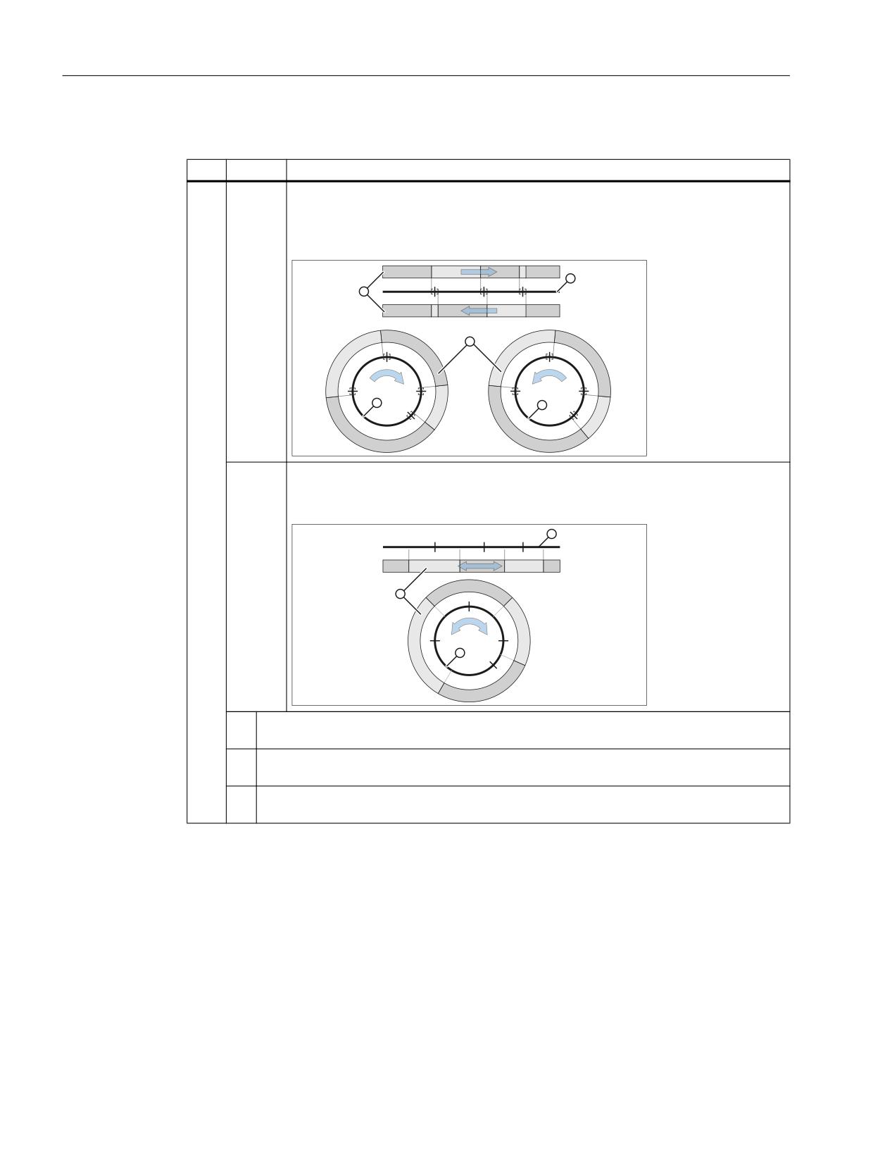
MD10940 $MN_INDEX_AX_MODE, bit 0 = <value>
Bit
<Value>
Meaning
0
0
The actual indexing position, indicated in system variable $AA_ACT_IN-
DEX_AX_POS_NO, changes when reaching/passing the exact stop window fine
(MD36010 $MA_STOP_LIMIT_FINE) of the next indexing position in the traversing
direction.
1
The actual indexing position indicated in system variable $AA_ACT_IN-
DEX_AX_POS_NO changes when reaching/passing half the traversing distance to
the next indexing position in the traversing direction.
①
Traversing range of the indexing axis (linear axes or rotary modulo axis) with indexing
positions and exact stop windows fine
②
Traversing direction-dependent indexing position indicated in the system variable
$AA_ACT_INDEX_AX_POS_NO
③
Traversing range of the indexing axis (linear axes or rotary modulo axis) with indexing
positions
Example
Assumptions:
● MD10940 $MN_INDEX_AX_MODE, bit 0 == 1
● The axis is located in front of an indexing position outside the tolerance window "exact stop
fine" (DB31,
DBX60.7 == 0)
Although system variable $AA_ACT_INDEX_AX_POS_NO indicates indexing position 2, with
the "Traverse to next position" command, indexing position 3 is not approached, but first
precisely to indexing position 2. Only when the axis is precisely at (DB31,
DBX60.7 == 1)
- or is located after the displayed indexing position, using the "Traverse to next position"
command, the next indexing position is approached, in the example, indexing position 3. This
Extended Functions
848
Function Manual, 12/2018, A5E40874029B AB
T1: Indexing axes
17.3 Commissioning
means that the indexing position is approached that is the closest in the traversing direction !
Under certain circumstances, it is therefore necessary to issue the "traverse to next position"
command twice to move from the currently displayed indexing position to the next indexing
position.
17.3.2
Machine data for equidistant indexing intervals
17.3.2.1
Features
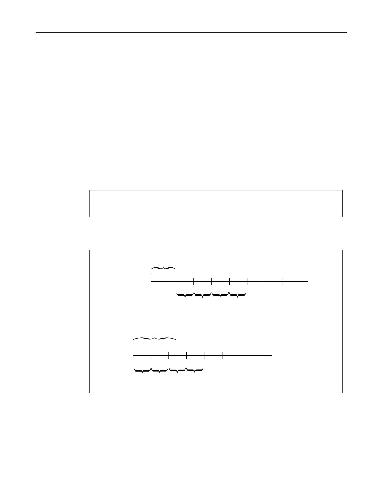
Distance between indexes
The index distance is determined for equidistant index intervals according to the following
formula:
1XPHUDWRU 0'
0$B,1'(;B$;B180(5$725
'LVWDQFH
'HQRPLQDWRU 0'
0$B,1'(;B$;B'(120,1$725
Linear axes
0'
0$B,1'(;B$;B2))6(7 VW GLVWDQFH IURP ]HUR SRLQW SRVLWLYH
'LVWDQFH VWDQGDUG IRU DOO LQGH[LQJ SRVLWLRQV VHH DERYH
0'
0$B,1'(;B$;B2))6(7 VW GLVWDQFH IURP ]HUR SRLQW QHJDWLYH
'LVWDQFH VWDQGDUG IRU DOO LQGH[LQJ SRVLWLRQV VHH DERYH
Extended Functions
Function Manual, 12/2018, A5E40874029B AB
849

T1: Indexing axes
17.3 Commissioning
Modulo rotary axes
1XPHUDWRU 0'
0$B02'8/2B5$1*(
,QGH[
'HQRPLQDWRU 0'
0$B,1'(;B$;B'(120,1$725
0'
0$B,1'(;B$;B2))6(7
r
6SDFLQJ
6L]H RI PRGXOR UDQJH 0'
0$B02'8/2B5$1*(
,QGH[
1XPEHU RI LQGH[HV LQ PRGXOR UDQJH 0'
0$B,1'(;B$;B'(120,1$725
17.3.2.2
Hirth axis
Function
For a "Hirth axis", using a special gearing (Hirth gearing) the rotary axis is interlocked when
reaching an indexing position. In this case, a locking bolt or a gearwheel is engaged using a
linear axis. In order that the mechanical system of the machine is not damaged, the interlock
can only be engaged at an indexing position. For a Hirth axis, all of the indexing positions must
have the same the distance between one another (equidistant indexing positions).
Preconditions
● The "Hirth axis" must be a rotary axis.
● The "Hirth axis" must be an indexing axis. See Chapter "Commissioning (Page 846)"
● The active measuring system of the indexing axis must be synchronized or referenced:
DB31, ... DBX60.4/.5 == 1 (referenced/synchronized, encoder 1/2)
References: Function Manual Basic Functions; reference point approach (R1)
Extended Functions
850
Function Manual, 12/2018, A5E40874029B AB

T1: Indexing axes
17.3 Commissioning
Commissioning
Machine data
● MD30300 $MA_IS_ROT_AX = 1 (rotary axis)
● MD30505 $MA_HIRTH_IS_ACTIVE[ <axis> ] = 1 (indexing axis with Hirth gearing)
● MD30500 $MA_INDEX_AX_ASSIGN_POS_TAB[ <axis> ] = 3 (indexing axis with
equidistant indexing positions)
17.3.3
Axis-specific system variables
$AA_PROG_INDEX_AX_POS_NO
Function
The system variable includes the number of the indexing position programmed for the indexing
axis.
Syntax
$AA_PROG_INDEX_AX_POS_NO[<axis>]
Meaning
$AA_PROG_INDEX_AX_POS_NO
0
The axis is not an indexing axis, or presently the indexing axis is not traversing to an indexing
position
> 0
Number of programmed indexing position
$AA_ACT_INDEX_AX_POS_NO
Function
The system variable includes the number of the indexing position last reached by the indexing
axis, or indexing position that was passed by the indexing axis.
Syntax
$AA_ACT_INDEX_AX_POS_NO[<axis>]
Meaning
$AA_ACT_INDEX_AX_POS_NO
0
The axis is not an indexing axis.
> 0
Number of the last indexing position reached or passed
Extended Functions
Function Manual, 12/2018, A5E40874029B AB
851

T1: Indexing axes
17.4 Programming
17.3.4
NC/PLC interface signals
Axis-specific interface signals
When stopping the indexing axis at an indexing position ± exact stop window fine (MD36010
$MA_STOP_LIMIT_FINE), then the axis-specific interface signal is set:
DB31, ... DBX76.6 = 1 (indexing axis in position)
17.4
Programming
Coded position
To allow indexing axes to be positioned from the NC part program, special instructions are
provided with which the indexing numbers (e.g. location numbers) are programmed instead of
axis positions in mm or degrees. The availability of a special instruction depends on the axis
type (linear or rotary axis):
Statement
Effect
Availability
CAC(i)
Traverse coded position in absolute terms
Linear axis, rotary axis
CACP(i)
Traverse coded position ain absolute terms in
Rotary axis
the positive direction
CACN(i)
Traverse coded position ain absolute terms in
Rotary axis
the negative direction
CDC(i)
Traverse coded position along the direct
Rotary axis
(shortest) path
CIC(i)
Traverse coded position incrementally
Linear axis, rotary axis
i:
Coded position (indexing position)
Value range of i:
0 ... 59; whole number (positive and negative values are possible
in CIC)
Examples
Program code
Comment
POS[B]=CAC(20)
Indexing axis B approaches the coded position (indexing) 20
in absolute mode. The direction of traversing depends on
the current actual position.
POS[B]=CACP(10)
Indexing axis B approaches the coded position (index posi-
tion ) 10 in absolute mode with positive direction of rota-
tion (possible only for rotary axes).
POS[B]=CACN(10)
Indexing axis B approaches the coded position (index posi-
tion ) 10 in absolute mode with negative direction of rota-
tion (possible only for rotary axes).
POS[B]=CDC(50)
Indexing axis B approaches indexing position 50 directly
along the shortest path (possible only for rotary axes).
Extended Functions
852
Function Manual, 12/2018, A5E40874029B AB

T1: Indexing axes
17.4 Programming
Program code
Comment
POS[B]=CIC(-4)
Indexing axis B traverses four indexing positions incremen-
tally from its current position. in a negative direction.
POS[B]=CIC(35)
Indexing axis B traverses 35 indexing positions incremen-
tally from its present position in a positive direction.
Special features
● Modulo rotary axis as indexing axis
On modulo rotary axes, the indexing positions are divided in factors of 360° and approached
directly.
● Indexing axis is between two indexing positions
The specified position instructions have the following effect in the AUTOMATIC mode.
POS[B]=CIC(1)
The next higher indexing position is approached.
POS[B]=CIC(-1)
The next lower indexing position is approached.
POS[B]=CIC(0)
The indexing axis is not traversed.
System variables
The number of the indexing position programmed last can be read with the following system
variables:
$AA_PROG_INDEX_AX_POS_NO
The number of the indexing position traversed last can be displayed with the following system
variables:
$AA_ACT_INDEX_AX_POS_NO
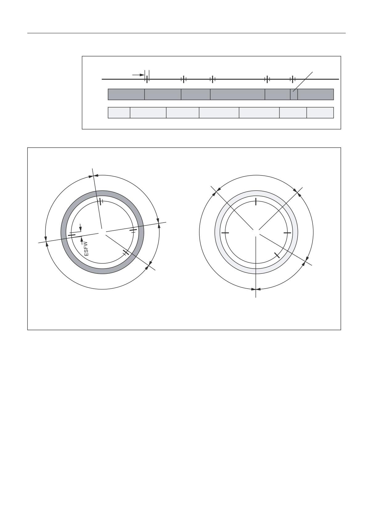
The display depends on the setting in machine data:
MD10940 $MN_INDEX_AX_MODE (settings for indexing position)
Bit
Value
Meaning
0
0
The indexing position changes when the indexing position is reached ("exact stop fine"
window) and remains unchanged until the next indexing position is reached. The in-
dexing area thus begins at one indexing position and ends in front of the next indexing
position.
1
The indexing position changes when half the indexing position is reached.
A quasi-symmetrical indexing area is thus applied around the indexing position (sym-
metrical only on linear axes with equidistant indexing or modulo rotary axes on which
the indexing area is an integer multiple of the modulo range (MD30330 $MA_MODU-
LO_RANGE), otherwise proportional to the distances between the indexing positions).
On modulo rotary axes, the area between the last indexing position and the first index-
ing position is divided proportionally based on the lengths of the first indexing area and
the last indexing area.
The following graphics will illustrate the difference between Bit 0 = 0 and Bit 0 = 1:
Extended Functions
Function Manual, 12/2018, A5E40874029B AB
853
T1: Indexing axes
17.4 Programming
33
73$
(6):
%LW
73$
73$
73$
73$
73$
73$
%LW
73$
73$
73$
73$
73$
73$
73$
Figure 17-1
Indexing position displays: Linear axis
73$
73$
73$
73$
73$
73$
73$
73$
%LW
%LW
TP
Indexing position
TPA
Displayed indexing position
ESFW
"Exact stop fine" window
Figure 17-2
Indexing position displays: Modulo rotary axis
Extended Functions
854
Function Manual, 12/2018, A5E40874029B AB
T1: Indexing axes
17.5 Supplementary conditions
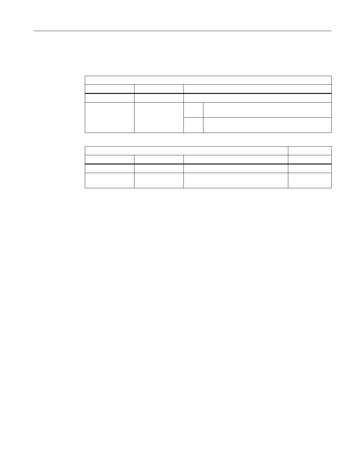
System variable $AA_ACT_INDEX_AX_POS_NO
$AA_ACT_INDEX_AX_POS_NO: Number of the last indexing position reached or passed
Indexing positions
For axis type
Values
Description
Modulo rotary axis
1, ... n
n = number of indexing positions (Page 846)
Linear axis
0, 1, 2, 3, ... 59, 60,
0
The actual position lies below the lowest indexing
61
position
61
The actual position lies above the highest indexing
position
Equidistant indexing positions
For axis type
Values
Description
Modulo rotary axis
1 ... m
m = denominator (counter)
Linear axis
... -3, -2, -1, 0, 1, 2,
3, ...
17.5
Supplementary conditions
Indexing axes
Various channel and axis-specific NC/PLC interface signals
If, while an indexing axis is traversed, at least one of the following signals occurs, then the axis
stops immediately. The indexing positions are not taken into account.
● Channel-specific signals
- DB21, ... DBB4 == 0 (feedrate override)
- DB21, ... DBX6.2 == 1 (delete distance-to-go)
- DB21, ... DBX7.3 == 1 (NC Stop)
- DB21, ... DBX7.4 == 1 (NC Stop axes plus spindles)
- DB21, ... DBX7.7 == 1 (reset)
● Axisspecific signals
- DB31, ... DBX4.3 == 1 (feedrate stop)
Synchronized actions
● Stop (MOV=0)
If an indexing axis is stopped with a synchronized action using MOV=0, then the axis stops
in the traversing direction at the next possible indexing position
● Delete distance to go (DELDTG)
If, for an indexing axis, the distance to go is deleted with a synchronized action using
DELDTG, then the axis is immediately stopped without stopping at an indexing position
Extended Functions
Function Manual, 12/2018, A5E40874029B AB
855
T1: Indexing axes
17.5 Supplementary conditions
References: Function Manual Synchronized Actions
Frames and work offsets
In conjunction with indexing axes, generally frames are not necessary. As a consequence, we
recommend that frames and work offsets for indexing axes are suppressed in NC programs.
Software limit switch
When manually traversing an indexing axis in the JOG or JOG/INC operating mode, the
indexing axis traverses - as a maximum up - to the last indexing position before the software
limit switch.
Manual traversing using a handwheel (DRF)
When traversing an indexing axis using the handwheel, the indexing positions are not taken
into account. This means that the indexing axis stops immediately, also between two indexing
positions, with the end of the handwheel pulse.
"Hirth axes"
In addition to the secondary conditions mentioned above, for "Hirth axes" the following
additional secondary conditions must be observed.
Various channel and axis-specific NC/PLC interface signals
If, while a "Hirth axis" is being traversed, at least one of the following signals occurs, then the
axis stops immediately at the next possible indexing position in the traversing direction.
● Channel-specific signals
- DB21, ... DBB4 == 0 (feedrate override)
- DB21, ... DBX6.2 == 1 (delete distance-to-go)
- DB21, ... DBX7.3 == 1 (NC Stop)
- DB21, ... DBX7.4 == 1 (NC Stop axes plus spindles)
- DB21, ... DBX7.7 == 1 (reset)
● Axisspecific signals
- DB31, ... DBX4.3 == 1 (feedrate stop)
Emergency Stop
If, while a "Hirth axis" is being traversed, an Emergency Stop is initiated then the axis is
immediately stopped:
DB10 DBX56.1 == 1 (Emergency Stop)
Extended Functions
856
Function Manual, 12/2018, A5E40874029B AB
T1: Indexing axes
17.5 Supplementary conditions
References: Function Manual Basic Functions; Chapter "N2: Emergency Stop"
NOTICE
Approaching the indexing position
After an Emergency Stop, before the interlocking of the Hirth gearing at the machine is
reactivated, either the PLC user program or the operator (manually) must first move the "Hirth
axis" to an indexing position in the JOG mode.
Synchronized actions
● Delete distance to go (DELDTG)
If, for a "Hirth axis", the distance to go is deleted with a synchronized action using
DELDTG, then the axis is stopped at the next possible indexing position in the traversing
direction
References: Function Manual Synchronized Actions, Chapter "Detailed description" >
"Actions in synchronized actions" > "Delete distance to go (DELDTG)"
Various axis-specific functions
"Hirth axes" may not be used in conjunction with the following functions:
● Kinematic transformation
References: Function Manual Extended Functions, Chapter "M1: Kinematic transformation"
● Work offset by setting the actual value: PRESETON
References: Programming Manual, Job Planning, Chapter "Coordinate transformations
(frames)"
● Revolutional feedrate (G95, FPRAON)
● Manual traversing using a handwheel as well as distance or velocity overlay using the
handwheel (DFR)
References: Function Manual Extended Functions, Chapter "H1: Manual traversing and
manual traversing using a handwheel"
● Frames
References: Function Manual Basic Functions, Chapter "K2: Axes, coordinate systems,
frames" > "Frames"
● Interpolatory corrections, for example external work offset, DRF offset
● Couplings
It is not permissible that a "Hirth axis" is a following axis of one of the following couplings:
- following axis with master value coupling
References: Function Manual Special Functions, Chapter "M3: Axis couplings" >
"Leading value coupling" or "Generic couplings"
- Coupled motion axis
References: Function Manual Special Functions, Chapter "M3: Axis couplings" >
"Coupled motion" or "Generic couplings"
- gantry following axis
References: Function Manual Special Functions, Chapter "G1: Gantry axes"
Extended Functions
Function Manual, 12/2018, A5E40874029B AB
857
T1: Indexing axes
17.6 Examples
17.6
Examples
17.6.1
Example 1: Rotary axis as indexing axis
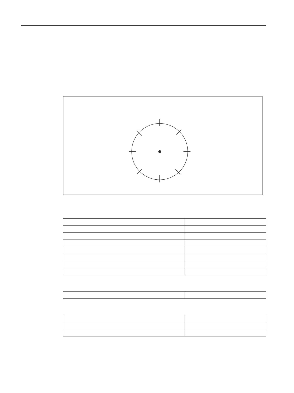
Machine axes AX5 is a tool revolver, with 8 revolver locations (endlessly rotating rotary axis).
The distances between the revolver locations are constant (equidistant indexing positions).
,QGH[LQJ
SRVLWLRQ
r
r
r
$[LV SRVLWLRQ
r
r
r
r
r
Figure 17-3
Tool turret with 8 locations
Indexing position table 1
MD10910 $MN_INDEX_AX_POS_TAB_1[ 0 ] = 0
1st indexing position = 0°
MD10910 $MN_INDEX_AX_POS_TAB_1[ 1 ] = 45
2nd indexing position = 45°
MD10910 $MN_INDEX_AX_POS_TAB_1[ 2 ] = 90
3rd indexing position = 90°
MD10910 $MN_INDEX_AX_POS_TAB_1[ 3 ] = 135
4th indexing position = 135°
MD10910 $MN_INDEX_AX_POS_TAB_1[ 4 ] = 180
5th indexing position = 180°
MD10910 $MN_INDEX_AX_POS_TAB_1[ 5 ] = 225
6th indexing position = 225°
MD10910 $MN_INDEX_AX_POS_TAB_1[ 6 ] = 270
7th indexing position = 270°
MD10910 $MN_INDEX_AX_POS_TAB_1[ 7 ] = 315
8th indexing position = 315°
Length of the indexing position table (1)
MD10900 $MN_INDEX_AX_LENGTH_POS_TAB_1= 8
8 indexing positions in table 1
Defining machine axis AX5 as rotary modulo axis and indexing axis
MD30300 $MA_IS_ROT_AX[ AX5 ] = 1
Rotary axis
MD30310 $MA_ ROT_IS_MODULO [AX5] = 1
Modulo rotary axis
MD30500 $MA_INDEX_AX_ASSIGN_POS_TAB [AX5] = 1
Indexing axis, indexing position table 1
Extended Functions
858
Function Manual, 12/2018, A5E40874029B AB
T1: Indexing axes
17.6 Examples
17.6.2
Example 2: Indexing axis as linear axis
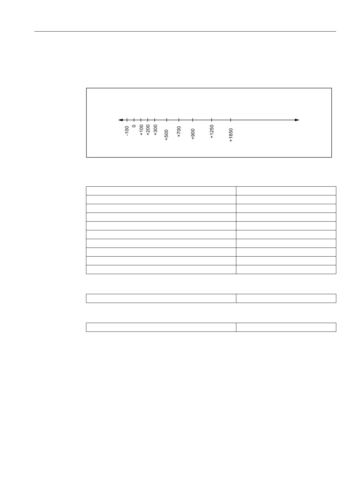
Machine axis AX6 is a workholder with 10 locations. The distances between the 10 locations
are different. The first location is at position -100 mm. Machine axis is AX6.
,QGH[LQJ SRVLWLRQ
$[LV SRVLWLRQ >PP@
Figure 17-4
Indexing positions for a workholder
Indexing position table 2
MD10930 $MN_INDEX_AX_POS_TAB_2[ 0 ] = -100
1st indexing position = -100 mm
MD10930 $MN_INDEX_AX_POS_TAB_2[ 1 ] = 0
2nd indexing position = 0 mm
MD10930 $MN_INDEX_AX_POS_TAB_2[ 2 ] = 100
3rd indexing position = 100 mm
MD10930 $MN_INDEX_AX_POS_TAB_2[ 3 ] = 200
4th indexing position = 200 mm
MD10930 $MN_INDEX_AX_POS_TAB_2[ 4 ] = 300
5th indexing position = 300 mm
MD10930 $MN_INDEX_AX_POS_TAB_2[ 5 ] = 500
6th indexing position = 500 mm
MD10930 $MN_INDEX_AX_POS_TAB_2[ 6 ] = 700
7th indexing position = 700 mm
MD10930 $MN_INDEX_AX_POS_TAB_2[ 7 ] = 900
8th indexing position = 900 mm
MD10930 $MN_INDEX_AX_POS_TAB_2[ 8 ] = 1250
9th indexing position = 1250 mm
MD10930 $MN_INDEX_AX_POS_TAB_2[ 9 ] = 1650
10. Indexing position = 1650 mm
Length of the indexing position table (1)
MD10920 $MN_INDEX_AX_LENGTH_POS_TAB_2 = 10
10 indexing positions in table 2
Defining machine axis AX5 as indexing axis
MD30500 $MA_INDEX_AX_ASSIGN_POS_TAB [AX6] = 2
Indexing axis, indexing position table 2
17.6.3
Example 3: Rotary modulo axis as equidistant indexing axis
Machine axis AX4 is rotary modulo axis with equidistant indexing. Indexing starts at 5°. The
difference between the indexing positions is 20°.
The following indexing positions are obtained:
5, 25, 45, 65, 85, 105, 125, 145, 165, 185, 205, 225, 245, 265, 285, 305, 325, 245 [Degrees]
Extended Functions
Function Manual, 12/2018, A5E40874029B AB
859

T1: Indexing axes
17.6 Examples
Indexing data
MD30501 $MA_INDEX_AX_NUMERATOR[ AX4 ] ⇒
This value is ignored for rotary modulo
axes, and MD30330 $MA_MODU-
MD30330 $MA_MODULO_RANGE[ AX4 ] = 360.0
LO_RANGE (default value: 360°) is
used instead.
MD30502 $MA_INDEX_AX_DENOMINATOR[ AX4 ] = 18
Number of indexing positions = 360° /
20° = 18
MD30503 $MA_INDEX_AX_OFFSET[ AX4 ] = 5.0
First indexing position = 5.0°
MD30505 $MA_HIRTH_IS_ACTIVE[ AX4 ] = 0
No Hirth gearing
Defining machine axis AX4 as rotary modulo axis and equidistant indexing axis
MD30300 $MA_IS_ROT_AX[ AX4 ] = 1
Rotary axis
MD30310 $MA_ ROT_IS_MODULO[ AX4 ] = 1
Modulo function active
MD30500 $MA_INDEX_AX_ASSIGN_POS_TAB[ AX4 ] = 3
Equidistant indexing axis
17.6.4
Example 4: Rotary axes as equidistant indexing axis with restricted traversing
range
Machine axis AX4 is a rotary axis with equidistant indexing. The equidistant indexing positions
are every 20°, starting at 100°. Positions less than 100° and greater than 260° should not be
approached.
The following indexing positions are obtained:
100, 120, 140, 160, 180, 200, 220, 240, 260 [degrees]
Indexing data
MD30501 $MA_INDEX_AX_NUMERATOR[ AX4 ] = 360.0
Numerator = 360°
MD30502 $MA_INDEX_AX_DENOMINATOR[ AX4 ] = 18
Number of indexing positions = 360° /
20° = 18
MD30503 $MA_INDEX_AX_OFFSET[ AX4 ] = 100.0
First indexing position = 100.0°
MD30505 $MA_HIRTH_IS_ACTIVE[ AX4 ] = 0
No Hirth gearing
Defining machine axis AX4 as rotary modulo axis and equidistant indexing axis
MD30300 $MA_IS_ROT_AX[ AX4 ] = 1
Rotary axis
MD30310 $MA_ ROT_IS_MODULO[ AX4 ] = 1
Modulo function active
MD30500 $MA_INDEX_AX_ASSIGN_POS_TAB[ AX4 ] = 3
Equidistant indexing axis
MD36100 $MA_POS_LIMIT_MINUS[ AX4 ] = 100.0
1st software limit switch minus = 100.0°
MD36110 $MA_POS_LIMIT_PLUS[ AX4 ] = 260.0
1st software limit switch plus = 260.0°
17.6.5
Example 5: Linear axis as equidistant indexing axis
Machine axis AX4 is a linear axis with equidistant indexing. The equidistant indexing positions
are every 10 mm, starting at -200 mm.
Extended Functions
860
Function Manual, 12/2018, A5E40874029B AB

T1: Indexing axes
17.6 Examples
The following indexing positions are obtained:
-200, -190, -180, ... 180, 190, 200 [mm]
Indexing data
MD30501 $MA_INDEX_AX_NUMERATOR[ AX4 ] = 10.0
Numerator = 10
MD30502 $MA_INDEX_AX_DENOMINATOR[ AX4 ] = 1
Denominator = 1
MD30503 $MA_INDEX_AX_OFFSET[ AX4 ] = -200.0
First indexing position = -200.0°
MD30505 $MA_HIRTH_IS_ACTIVE[ AX4 ] = 0
No Hirth gearing
Defining machine axis AX4 as linear axis and equidistant indexing axis
MD30300 $MA_IS_ROT_AX[ AX4 ] = 0
Linear axis
MD30310 $MA_ ROT_IS_MODULO[ AX4 ] = 0
Modulo function is not active
MD30500 $MA_INDEX_AX_ASSIGN_POS_TAB[ AX4 ] = 3
Equidistant indexing axis
MD36100 $MA_POS_LIMIT_MINUS[ AX4 ] = -200.0
1st software limit switch minus = -200.0
mm
MD36110 $MA_POS_LIMIT_PLUS[ AX4 ] = 200.0
1st software limit switch plus = 200.0
mm
17.6.6
Example 6: "Hirth axis"
Machine axis AX4 is a "Hirth axis" (rotary modulo axis with equidistant indexing and Hirth
gearing). The equidistant indexing positions are every 1°, starting at 0°.
Indexing data
MD30501 $MA_INDEX_AX_NUMERATOR[ AX4 ] ⇒
This value is ignored for rotary modulo
axes, and MD30330 $MA_MODU-
MD30330 $MA_MODULO_RANGE[ AX4 ] = 360.0
LO_RANGE (default value: 360°) is
used instead.
MD30502 $MA_INDEX_AX_DENOMINATOR[ AX4 ] = 360
Number of indexing positions = 360° /
1° = 360
MD30503 $MA_INDEX_AX_OFFSET[ AX4 ] = 0.0
First indexing position = 0.0°
MD30505 $MA_HIRTH_IS_ACTIVE[ AX4 ] = 1
Hirth gearing
Defining machine axis AX4 as linear axis and equidistant indexing axis
MD30300 $MA_IS_ROT_AX[ AX4 ] = 1
Rotary axis
MD30310 $MA_ ROT_IS_MODULO[ AX4 ] = 1
Modulo function active
MD30500 $MA_INDEX_AX_ASSIGN_POS_TAB[ AX4 ] = 3
Equidistant indexing axis
MD36100 $MA_POS_LIMIT_MINUS[ AX4 ] = -200.0
1st software limit switch minus = -200.0
mm
MD36110 $MA_POS_LIMIT_PLUS[ AX4 ] = 200.0
1st software limit switch plus = 200.0
mm
Extended Functions
Function Manual, 12/2018, A5E40874029B AB
861

T1: Indexing axes
17.7 Data lists
17.7
Data lists
17.7.1
Machine data
17.7.1.1
General machine data
Number
Identifier: $MN_
Description
10260
CONVERT_SCALING_SYSTEM
Basic system switchover active
10270
POS_TAB_SCALING_SYSTEM
System of measurement of position tables
10900
INDEX_AX_LENGTH_POS_TAB_1
Number of positions for indexing axis table 1
10910
INDEX_AX_POS_TAB_1[n]
Indexing position table 1
10920
INDEX_AX_LENGTH_POS_TAB_2
Number of positions for indexing axis table 2
10930
INDEX_AX_POS_TAB_2[n]
Indexing position table 2
10940
INDEX_AX_MODE
Options for indexing positions
17.7.1.2
Axis/spindlespecific machine data
Number
Identifier: $MA_
Description
30300
IS_ROT_AX
Rotary axis
30310
ROT_IS_MODULO
Modulo conversion for rotary axis
30320
DISPLAY_IS_MODULO
Position display is modulo 360°
30500
INDEX_AX_ASSIGN_POS_TAB
Axis is indexing axis
30501
INDEX_AX_NUMERATOR
Numerator for indexing axes with equidistant positions
30502
INDEX_AX_DENOMINATOR
Denominator for indexing axes with equidistant posi-
tions
30503
INDEX_AX_OFFSET
Indexing position for indexing axes with equidistant po-
sitions
30505
HIRTH_IS_ACTIVE
Hirth tooth system is active
17.7.2
Setting data
17.7.2.1
General setting data
Number
Identifier: $SN_
Description
41050
JOG_CONT_MODE_LEVELTRIGGRD
JOG continuous in inching mode
Extended Functions
862
Function Manual, 12/2018, A5E40874029B AB

T1: Indexing axes
17.7 Data lists
17.7.3
Signals
17.7.3.1
Signals from axis/spindle
Signal name
SINUMERIK 840D sl
SINUMERIK 828D
Referenced/synchronized 1, referenced/synchronized 2
DB31,
DBX60.4/5
DB390x.DBX0.4/5
Indexing axis in position
DB31,
DBX76.6
DB390x.DBX1002.6
17.7.4
System variables
Identifier
Description
$AA_ACT_INDEX_AX_POS_NO[axis]
Number of last indexing position reached or overtraveled
$AA_PROG_INDEX_AX_POS_NO[axis]
Number of programmed indexing position
Extended Functions
Function Manual, 12/2018, A5E40874029B AB
863
T1: Indexing axes
17.7 Data lists
Extended Functions
864
Function Manual, 12/2018, A5E40874029B AB
W4: Grinding-specific tool offset and tool monitoring
18
18.1
Grinding-specific tool data
18.1.1
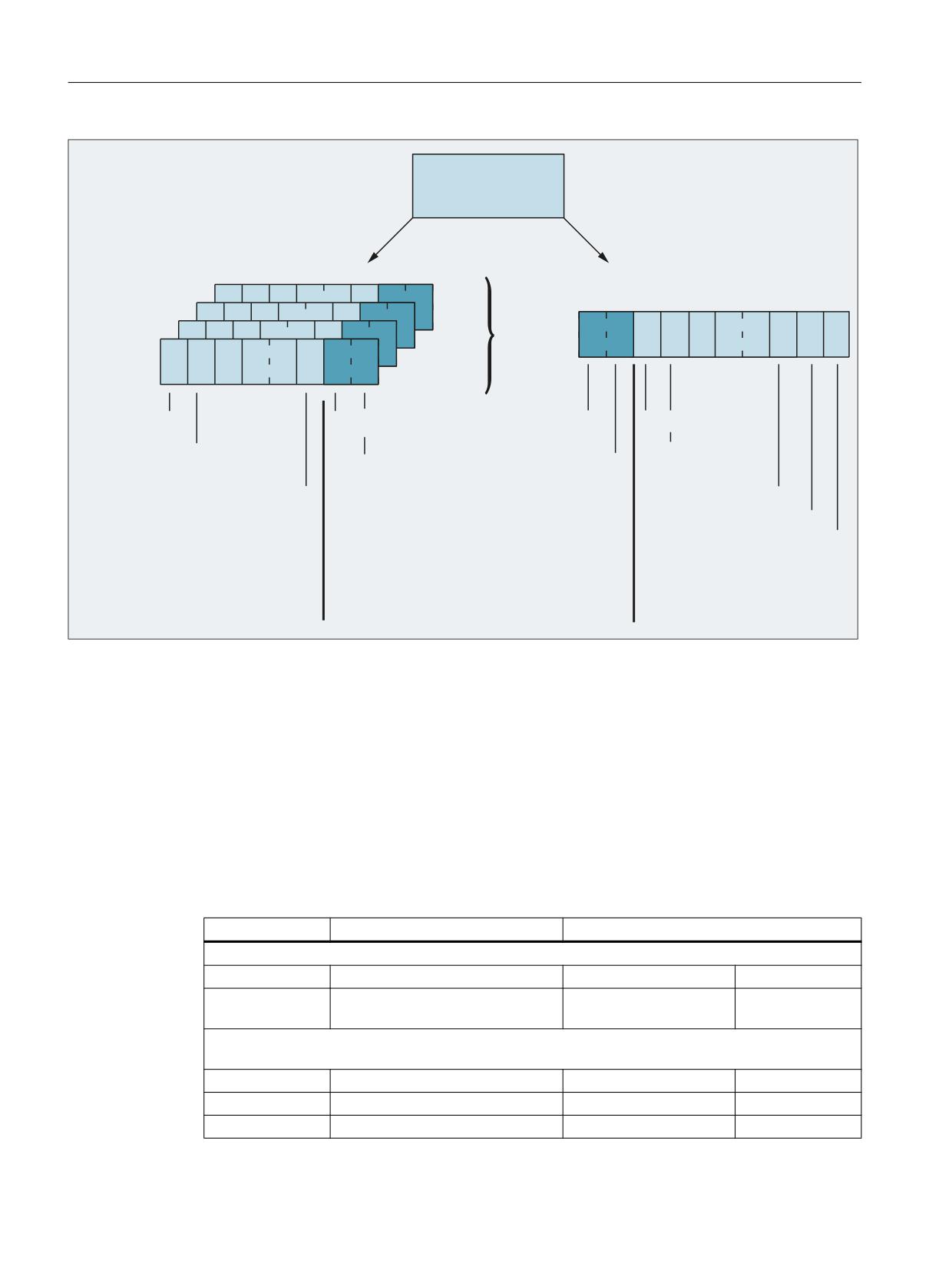
Structure of tool data
Grinding tools (tool type: 400 to 499) normally have specific tool and dresser data in addition
to cutting edge data.
The grinding wheel-specific data for the left and right wheel geometry can be stored under a
T number in the tool cutting edges D1 and D2.
If data is needed for the dresser geometry, it can be stored as follows:
● In the tool cutting edges from D3 of a T number
7 QXPEHU
*ULQGLQJ GLVN
'
'
DE '
/HIW GLVN JHRPHWU\
5LJKW GLVN JHRPHWU\
$GGLWLRQDO GDWD
● In additional cutting edge-specific parameters (see MD18096
$MN_MM_NUM_CC_TOA_PARAM)
7 QXPEHU
*ULQGLQJ GLVN
'
'
/HIW GLVN JHRPHWU\
5LJKW GLVN JHRPHWU\
7&B'3 > W! G!@
7&B'3 > W! G!@
&XWWLQJ HGJH VSHFLILF
7&B'3
> W! G!@
7&B'3
> W! G!@
SDUDPHWHUV
7&B'3& > W! G!@
7&B'3& > W! G!@
$GGLWLRQDO
SDUDPHWHUV
7&B'3& > W! G!@
7&B'3& > W! G!@
ᇆ 0'
<t>: T number
<d>: D number
The following figure provides an overview of the (possible) storage structure of the tool data
for grinding tools:
Extended Functions
Function Manual, 12/2018, A5E40874029B AB
865
W4: Grinding-specific tool offset and tool monitoring
18.1 Grinding-specific tool data
7 QXPEHU
*ULQGLQJ ZKHHO
'
'
'
'
7&B'3 > W! G!@
7&B'3& > W! G!@
7&B73& > W!@
7&B73* > W!@
7&B'3 > W! G!@
7&B73* > W!@
7&B'3& > W! G!@
7&B73& > W!@
7&B'3
> W! G!@
7&B73* > W!@
7&B73*B'563$7+> W!@
7&B73*B'56352*> W!@
&XWWLQJ HGJH VSHFLILF
$GGLWLRQDO
$GGLWLRQDO
7RRO VSHFLILF SDUDPHWHUV
SDUDPHWHUV
SDUDPHWHUV
SDUDPHWHUV
ᇆ 0'
ᇆ 0'
<t>:
T number
<d>:
D number
Figure 18-1
Structure of the tool data for grinding tools
18.1.2
Cutting edge-specific parameters
18.1.2.1
List of cutting edge-specific parameters
The cutting edge-specific tool parameters for grinding tools have the same meaning as those
for turning and milling tools.
Tool parameter
Meaning
Comment
$TC_DP1
Tool type
$TC_DP2
Cutting edge position
For turning and grinding
tools only
Geometry - tool length compensation
$TC_DP3
Length 1
$TC_DP4
Length 2
$TC_DP5
Length 3
Extended Functions
866
Function Manual, 12/2018, A5E40874029B AB

W4: Grinding-specific tool offset and tool monitoring
18.1 Grinding-specific tool data
Tool parameter
Meaning
Comment
Geometry - tool radius compensation
$TC_DP6
Radius 1
$TC_DP7
Reserved
$TC_DP8
Reserved
$TC_DP9
Reserved
$TC_DP10
Reserved
$TC_DP11
Reserved
Wear - tool length compensation
$TC_DP12
Length 1
$TC_DP13
Length 2
$TC_DP14
Length 3
Wear - tool radius compensation
$TC_DP15
Radius 1
$TC_DP16
Reserved
$TC_DP17
Reserved
$TC_DP18
Reserved
$TC_DP19
Reserved
$TC_DP20
Reserved
Base dimension/adapter dimension - tool length compensation
$TC_DP21
Basic length 1
$TC_DP22
Basic length 2
$TC_DP23
Basic length 3
Technology
$TC_DP24
Undercut angle
For turning tools only
$TC_DP25
Reserved
Note
The cutting edge data for D1 and D2 of a selected grinding tool can be chained, i.e. if a
parameter in D1 or D2 is modified, then the same parameter in D1 or D2 is automatically
overwritten with the new value (see $TC_TPG2 (Page 870)).
Extended Functions
Function Manual, 12/2018, A5E40874029B AB
867
W4: Grinding-specific tool offset and tool monitoring
18.1 Grinding-specific tool data
18.1.2.2
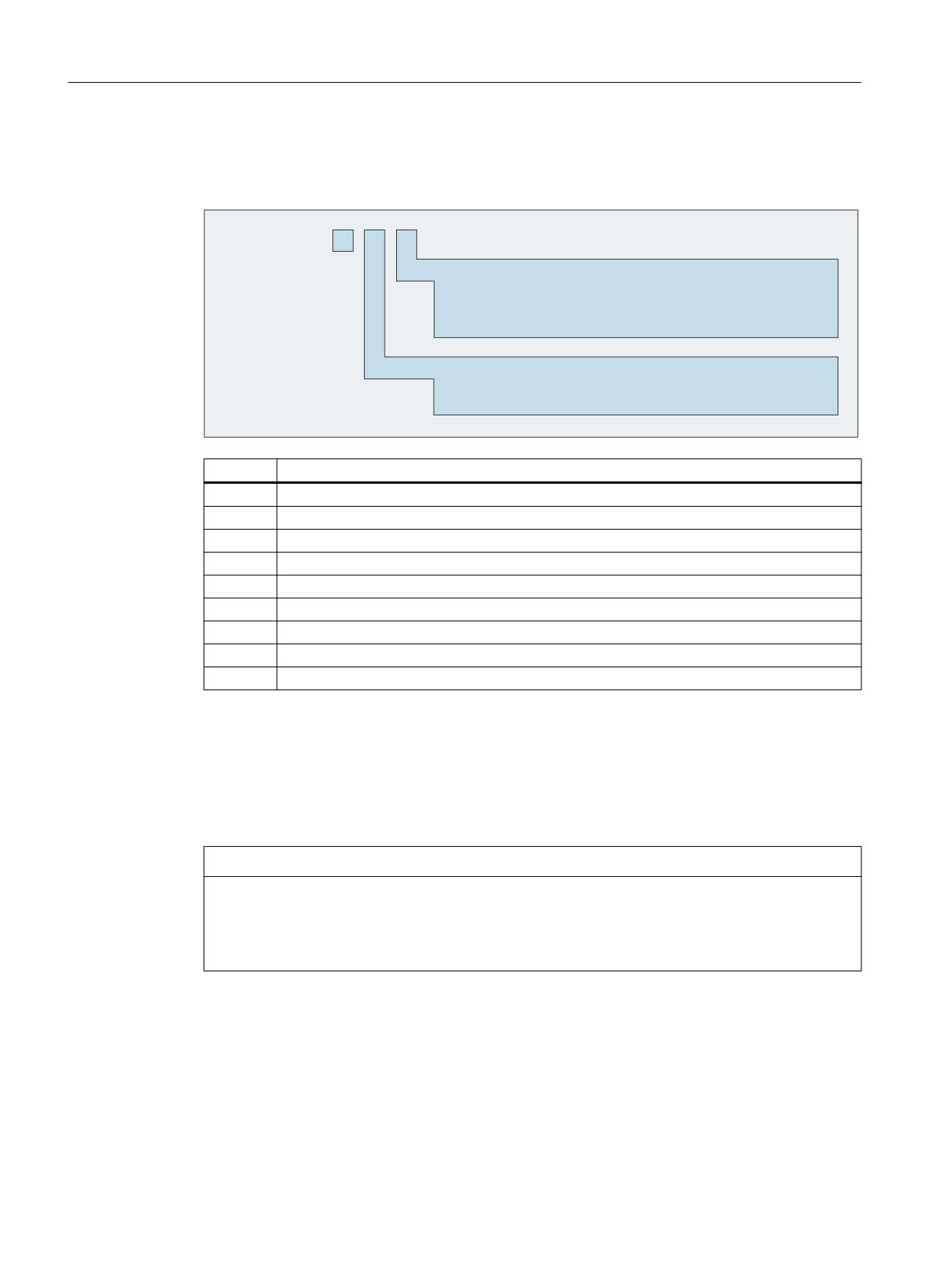
$TC_DP1
The parameter $TC_DP1 contains the 3-digit number of the grinding tool type:
7RRO W\SH
;
<
:LWKRXW PRQLWRULQJ ZLWK EDVH GLPHQVLRQ IRU *:36
:LWK PRQLWRULQJ ZLWK EDVH GLPHQVLRQ IRU *:36
:LWKRXW PRQLWRULQJ ZLWKRXW EDVH GLPHQVLRQ IRU *:36
:LWK PRQLWRULQJ ZLWKRXW EDVH GLPHQVLRQ IRU *:36
6XUIDFH JULQGLQJ ZKHHO
)DFLQJ ZKHHO
'UHVVHU
Number
Grinding tool type
400
Surface grinding wheel
401
Surface grinding wheel with monitoring with tool base dimension for GWPS
402
Surface grinding wheel without monitoring without tool base dimension for GWPS
403
Surface grinding wheel with monitoring without tool base dimension for GWPS
410
Facing wheel
411
Facing wheel with monitoring with tool base dimension for GWPS
412
Facing grinding wheel without monitoring without tool base dimension for GWPS
413
Facing wheel with monitoring without tool base dimension for GWPS
490
Dresser
18.1.2.3
Definition of additional parameters $TC_DPC1 ... 10
For user-specific cutting edge data, the additional parameters $TC_DPC1 to $TC_DPC10 can
be set up independent of the tool type via the following memory-configuring machine data:
MD18096 $MN_MM_NUM_CC_TOA_PARAM
NOTICE
Loss of data due to reconfiguration
Reconfiguration of the local static NC memory results in a loss of data on the active and
passive file system. We therefore urgently recommend archiving or backing up all relevant
data by creating a commissioning archive before activating a modified memory configuration.
Extended Functions
868
Function Manual, 12/2018, A5E40874029B AB

W4: Grinding-specific tool offset and tool monitoring
18.1 Grinding-specific tool data
18.1.3
Tool-specific parameters
18.1.3.1
List of tool-specific parameters
The tool-specific parameters are automatically set up with every new grinding tool (tool type:
400 to 499).
Note
Tool-specific parameters have the same characteristics as a cutting edge.
This is to be taken into account when the number of cutting edges is specified:
MD18100 $MN_MM_NUM_CUTTING_EDGES_IN_TOA
When all the cutting edges of a tool are deleted, the associated tool-specific parameters are
deleted at the same time.
Parameters
The parameters are assigned as follows:
Parameter
Meaning
Data type
$TC_TPG1 (Page 870)
Spindle number
INT
$TC_TPG2 (Page 870)
Chaining rule
INT
$TC_TPG3 (Page 871)
Minimum wheel radius
REAL
$TC_TPG4 (Page 871)
Minimum wheel width
REAL
$TC_TPG5 (Page 871)
Current wheel width
REAL
$TC_TPG6 (Page 872)
Maximum speed
REAL
$TC_TPG7 (Page 872)
Maximum peripheral speed
REAL
$TC_TPG8 (Page 872)
Angle of inclined wheel
REAL
$TC_TPG9 (Page 873)
Parameter number for radius calculation
INT
$TC_TPG_DRSPATH (Page 873)
Directory path to the dressing program
STRING
$TC_TPG_DRSPROG (Page 873)
Dressing program name
STRING
Note
The monitoring data applies to both the left-hand and the right-hand cutting edge of the grinding
wheel.
The tool-specific parameters take effect:
● when switching on the grinding-specific tool monitoring (Page 888)
● when switching on the constant grinding wheel peripheral speed (GWPS) (Page 891)
If a changed date is to take effect, these functions must be switched on again.
The length compensations always specify the distances between the tool carrier reference
point and the tool tip in the Cartesian coordinates (must be noted for inclined grinding wheel).
Extended Functions
Function Manual, 12/2018, A5E40874029B AB
869

W4: Grinding-specific tool offset and tool monitoring
18.1 Grinding-specific tool data
18.1.3.2
$TC_TPG1
The spindle number is entered in parameter $TC_TPG1. The grinding wheel circumferential
velocity is then monitored for this spindle.
18.1.3.3
$TC_TPG2
The tool parameters of the two cutting edges D1 and D2 are entered in parameter $TC_TPG2,
their values must always be the same. If, for a cutting edge, the value of one of these
parameters is changed, then the corresponding parameter of the other cutting edge is
automatically set to the same value.
The tool parameters are coded in parameter $TC_TPG2:
Tool parameter
Meaning
Coding
Bit
Hex
Dec
$TC_DP1
Tool type
0
0001
1
$TC_DP2
Length of cutting
1
0002
2
edge
Geometry - tool length compensation
$TC_DP3
Length 1
2
0004
4
$TC_DP4
Length 2
3
0008
8
$TC_DP5
Length 3
4
0010
16
$TC_DP6
Radius
5
0020
32
$TC_DP7
Reserved
6
0040
64
$TC_DP8
Length 4
7
0080
128
$TC_DP9
Length 5
8
0100
256
$TC_DP10
Angle 1 etc.
9
0200
512
$TC_DP11
Reserved
10
0400
1 024
Wear - tool length compensation
$TC_DP12
Length 1
11
0800
2 048
$TC_DP13
Length 2
12
1000
4 096
$TC_DP14
Length 3
13
2000
8 192
$TC_DP15
Radius
14
4000
16 384
$TC_DP16
Reserved
15
8000
32 768
$TC_DP17
Wear length 4
16
1 0000
65 536
$TC_DP18
Wear length 5
17
2 0000
131 072
$TC_DP19
Wear angle 1 etc.
18
4 0000
262 144
$TC_DP20
Reserved
19
8 0000
524 288
Base dimension/adapter dimension - tool length compensation
$TC_DP21
Basic length 1
20
10 0000
1 048 576
$TC_DP22
Basic length 2
21
20 0000
2 097 152
$TC_DP23
Basic length 3
22
40 0000
4 194 304
Technology
$TC_DP24
Reserved
23
80 0000
8 388 608
$TC_DP25
Reserved
24
100 0000
16 777 216
Extended Functions
870
Function Manual, 12/2018, A5E40874029B AB

W4: Grinding-specific tool offset and tool monitoring
18.1 Grinding-specific tool data
Change becomes effective
If parameter $TC_TPG2 becomes effective at a later point in time, the values of the tool
parameters of the cutting edges are not automatically aligned immediately. The alignment is
only made the next time that a tool parameter of both cutting edges is changed.
Example
For a grinding tool (T1), the following parameters should be kept the same for cutting edges
D1 and D2:
Tool parameter
Meaning
Coding: Hex
Coding: Decimal
$TC_DP1
Tool type
0001
1
Geometry - tool length compensation
$TC_DP3
Length 1
0004
4
$TC_DP4
Length 2
0008
8
$TC_DP5
Length 3
0010
16
Wear - tool length compensation
$TC_DP12
Length 1
0800
2 048
$TC_DP13
Length 2
1000
4 096
$TC_DP14
Length 3
2000
8 192
Base dimension/adapter dimension - tool length compensation
$TC_DP21
Basic length 1
10 0000
1 048 576
$TC_DP22
Basic length 2
20 0000
2 097 152
$TC_DP23
Basic length 3
40 0000
4 194 304
The sum of all parameter codings is entered in parameter $TC_TPG2:
$TC_TPG2 =
'H70381D'
'D7354397'
18.1.3.4
$TC_TPG3, $TC_TPG4
For grinding-specific tool monitoring (Page 888), thelower limit values of the grinding wheel
are entered in the parameters:
● Parameter $TC_TPG3: Radius [mm] or [inch]
● Parameter $TC_TPG4: Width [mm] or [inch]
Note
For inclined grinding wheels, the minimum radius must be entered in Cartesian coordinates.
18.1.3.5
$TC_TPG5
The actual width of the grinding wheel - e.g. after dressing - is entered in parameter $TC_TPG5.
Extended Functions
Function Manual, 12/2018, A5E40874029B AB
871
W4: Grinding-specific tool offset and tool monitoring
18.1 Grinding-specific tool data
18.1.3.6
$TC_TPG6 and $TC_TPG7
For grinding-specific tool monitoring (Page 888), theupper limit values of the grinding wheel
are entered in the parameters:
● Parameter $TC_TPG6: Speed [rpm]
● Parameter $TC_TPG7: Circumferential/peripheral speed [m*s-1] or [inch*s-1]
18.1.3.7
$TC_TPG8
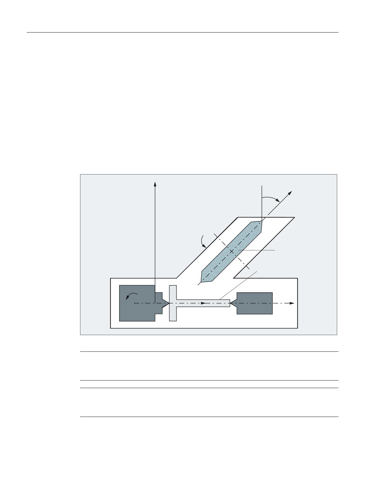
For function "Constant grinding wheel peripheral speed (GWPS). (Page 891)", for an inclined
grinding wheel, the inclination angle α referred to the actual active plane (work plane G17, G18,
G19) is entered in parameter $TC_TPG8.
The permissible range of inclination angle α is: -90° ≤ α < +90°
;
08
˞
$6
*ULQGLQJ GLVN
:RUNSLHFH
&
=
0=
Figure 18-2
Inclined grinding wheel
Note
The tool length is not automatically compensated when the angle in parameter $TC_TPG8 is
changed.
Note
For machines with inclined axis, the same angle must be entered for the inclined axis as for
the inclined grinding wheel.
Extended Functions
872
Function Manual, 12/2018, A5E40874029B AB

W4: Grinding-specific tool offset and tool monitoring
18.1 Grinding-specific tool data
18.1.3.8
$TC_TPG9
Parameter $TC_TPG9 is used to define to which tool parameters the following functions should
refer:
● Grinding-specific tool monitoring (Page 888)
● Constant grinding wheel peripheral speed (GWPS). (Page 891)
Examples:
$TC_TPG9 = <value>
<Value>
Reference variable
3
Length 1 (geometry + wear + base, depending on tool type)
4
Length 2 (geometry + wear + base, depending on tool type)
5
Length 3 (geometry + wear + base, depending on tool type)
6
Radius
18.1.3.9
$TC_TPG_DRSPATH and $TC_TPG_DRSPROG
Parameter $TC_TPG_DRSPATH (directory path to the dressing program) and
$TC_TPG_DRSPROG (dressing program) allow a dressing program to be assigned to a
grinding wheel. In turn, this allows a generally valid dressing procedure to be created, in which
the dressing program is executed using an indirect program call.
Example:
Program code
Comment
; Enter absolute dressing amount in $TC_DP12:
$TC_DP12[GETT("GRINDING_WHEEL",0),1]= $TC_DP12[GETT("GRINDING_WHEEL",0),1] - 0.01
G500
CYCLE435("GRINDING_WHEEL",1,"DRESSER",1)
; Calculate dressing tool position
T="DRESSER" D1
; Activate dressing tool.
; Indirectly call dressing program:
CALL "/"<<$TC_TPG_DRSPATH[GETT("GRINDING_WHEEL",0)]<<"/"<<$ TC_TPG_DRSPROG[GETT("GRINDING_WHEEL",0)]
M17
18.1.3.10
Definition of additional parameters $TC_TPC1 ... 10
For user-specific tool data, the additional parameters $TC_TPC1 to $TC_TPC10 can be set
up independent of the tool type via the following memory-configuring machine data:
Extended Functions
Function Manual, 12/2018, A5E40874029B AB
873

W4: Grinding-specific tool offset and tool monitoring
18.1 Grinding-specific tool data
MD18096 $MN_MM_NUM_CC_TDA_PARAM
NOTICE
Loss of data due to reconfiguration
Reconfiguration of the local static NC memory results in a loss of data on the active and
passive file system. We therefore urgently recommend archiving or backing up all relevant
data by creating a commissioning archive before activating a modified memory configuration.
18.1.3.11
Access to tool-specific parameters
Tool-specific parameters can be read and written from the part program.
Examples:
Program code
Comment
R10=$TC_TPG5[2]
; read the current width of tool 2 and store in R10
$TC_TPG6[3]=2000
; write value 2000 to the maximum speed of tool 3.
The following system variable allows the tool-specific parameters for the current tool to be
accessed:
$P_ATPG[<m>]
<m> = parameter numbewr (data type: REAL)
Example:
Parameter 3 ($TPG3[<t>])
Program code
Comment
$P_ATPG[3]=R10
; read the minimum wheel radius of the current tool and store
in R10.
18.1.4
Planes and axis assignments
Tool length compensations for the geometry axes or radius compensation in the plane are
assigned on the basis of the current machining plane.
The following planes and axis assignments are possible (abscissa, ordinate, applicate for 1st,
2nd and 3rd geometry axis):
Command
Plane
Axis perpendicular to plane
(abscissa/ordinate)
(applicate)
G17
X / Y
Z
G18
Z / X
Y
G19
Y / Z
X
Extended Functions
874
Function Manual, 12/2018, A5E40874029B AB
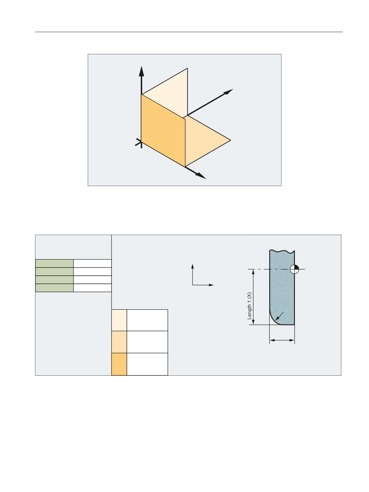
W4: Grinding-specific tool offset and tool monitoring
18.1 Grinding-specific tool data
<
*HRPHWULHDFKVH
;
*
*HRPHWULHDFKVH
*
*
*HRPHWULHDFKVH
=
18.1.5
Examples
(QWULHV LQ
)RU H[DPSOH
WRRO SDUDPHWHUV
*
= ; SODQH
7&B'3
;
)
7&B'3
/HQJWK
7&B'3
/HQJWK
7&B'3
5DGLXV
=
(IIHFW
5DGLXV
/HQJWK LQ <
*
/HQJWK LQ ;
5DGLXV LQ ;
<
/HQJWK LQ ;
*
/HQJWK LQ =
7KH SDUDPHWHUV WKDW
5DGLXV LQ =
;
/HQJWK
=
DUH QRW XVHG PXVW EH
VHW WR
/HQJWK LQ =
*
/HQJWK LQ <
) 7RROKROGHU UHIHUHQFH SRLQW
5DGLXV LQ <
=
Figure 18-3
Required offset data of a surface grinding wheel
Extended Functions
Function Manual, 12/2018, A5E40874029B AB
875
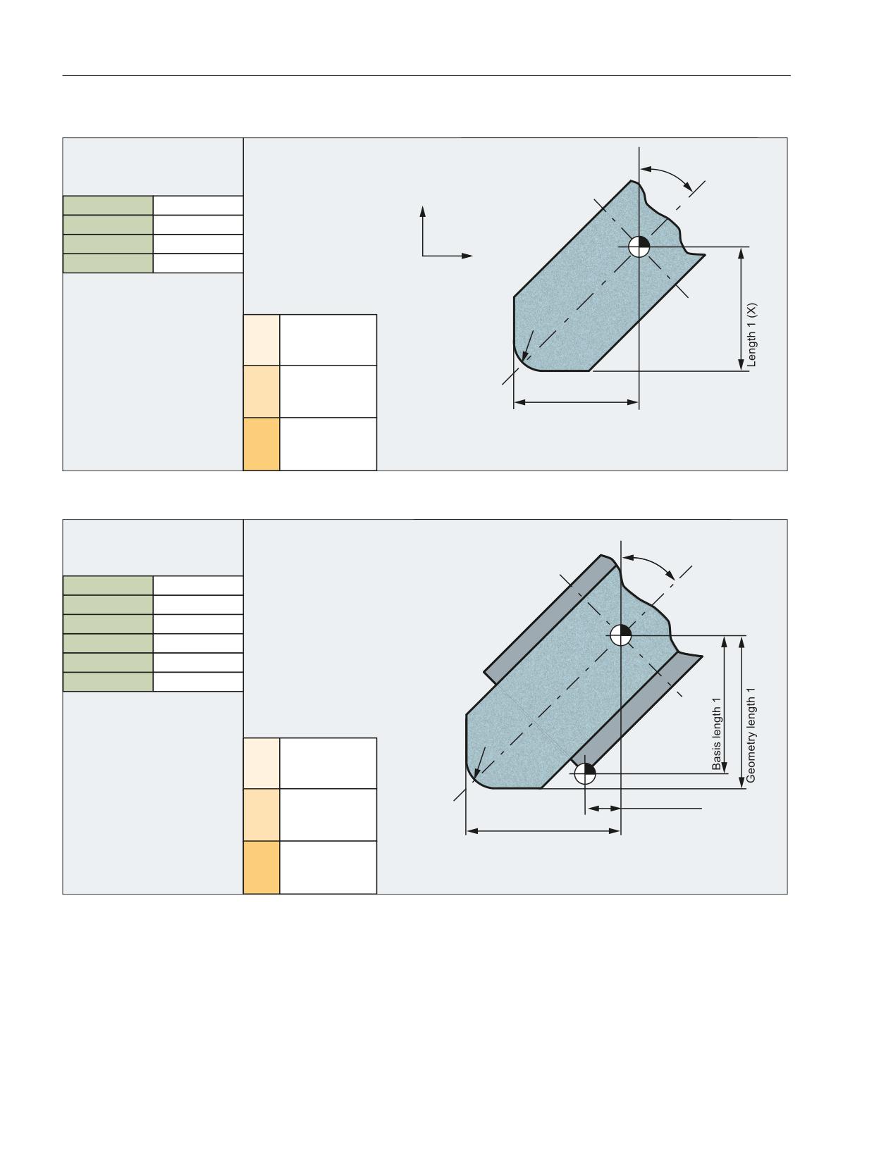
W4: Grinding-specific tool offset and tool monitoring
18.1 Grinding-specific tool data
(QWULHV LQ
)RU H[DPSOH
WRRO SDUDPHWHUV
*
= ; SODQH
˞
7&B'3
;
7&B'3
/HQJWK
7&B'3
/HQJWK
)
7&B'3
5DGLXV
=
(IIHFW
5DGLXV
/HQJWK LQ <
*
/HQJWK LQ ;
5DGLXV LQ ;
<
/HQJWK LQ ;
*
/HQJWK LQ =
/HQJWK
=
7KH SDUDPHWHUV WKDW
5DGLXV LQ =
;
DUH QRW XVHG PXVW EH
VHW WR
/HQJWK LQ =
*
/HQJWK LQ <
) 7RROKROGHU UHIHUHQFH SRLQW
5DGLXV LQ <
=
Figure 18-4
Required offset data for inclined wheel with implicit monitoring selection and without base dimension for GWPS
(QWULHV LQ
WRRO SDUDPHWHUV
˞
7&B'3
7&B'3
/HQJWK
)
7&B'3
/HQJWK
7&B'3
5DGLXV
7&B'3
/ EDVLV
7&B'3
/ EDVLV
(IIHFW
5DGLXV
$EUDVLRQ YDOXHV DV
/HQJWK LQ <
UHTXLUHG
*
/HQJWK LQ ;
5DGLXV LQ ;
<
)
/HQJWK LQ ;
%DVLV OHQJWK
7KH SDUDPHWHUV WKDW
*
/HQJWK LQ =
*HRPHWU\ OHQJWK
DUH QRW XVHG PXVW EH
5DGLXV LQ =
;
VHW WR
/HQJWK LQ =
*
/HQJWK LQ <
) 7RROKROGHU UHIHUHQFH SRLQW
5DGLXV LQ <
=
Figure 18-5
Required offset data for inclined wheel with implicit monitoring selection and with base dimension for GWPS
Extended Functions
876
Function Manual, 12/2018, A5E40874029B AB
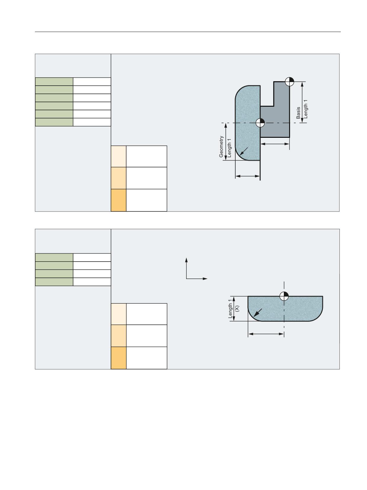
W4: Grinding-specific tool offset and tool monitoring
18.1 Grinding-specific tool data
(QWULHV LQ
WRRO SDUDPHWHUV
)
7&B'3
7&B'3
/HQJWK
7&B'3
/HQJWK
7&B'3
5DGLXV
7&B'3
/ EDVLV
)
7&B'3
/ EDVLV
%DVLV
(IIHFW
5DGLXV
/HQJWK
$EUDVLRQ YDOXHV DV
/HQJWK LQ <
UHTXLUHG
*
/HQJWK LQ ;
5DGLXV LQ ;
<
*HRPHWU\
/HQJWK LQ ;
7KH SDUDPHWHUV WKDW
*
/HQJWK LQ =
/HQJWK
DUH QRW XVHG PXVW EH
5DGLXV LQ =
;
VHW WR
/HQJWK LQ =
*
/HQJWK LQ <
) 7RROKROGHU UHIHUHQFH SRLQW
5DGLXV LQ <
=
Figure 18-6
Required offset data of a surface grinding wheel without base dimension for GWPS
(QWULHV LQ
)RU H[DPSOH
WRRO SDUDPHWHUV
*
= ; SODQH
7&B'3
;
7&B'3
/HQJWK
7&B'3
/HQJWK
7&B'3
5DGLXV
=
)
(IIHFW
5DGLXV
/HQJWK LQ <
$EUDVLRQ YDOXHV DV
*
/HQJWK LQ ;
UHTXLUHG
5DGLXV LQ ;
<
/HQJWK LQ ;
/HQJWK
*
/HQJWK LQ =
=
7KH SDUDPHWHUV WKDW
5DGLXV LQ =
;
DUH QRW XVHG PXVW EH
VHW WR
/HQJWK LQ =
*
/HQJWK LQ <
) 7RROKROGHU UHIHUHQFH SRLQW
5DGLXV LQ <
=
Figure 18-7
Required offset data of a facing wheel with monitoring parameters
Extended Functions
Function Manual, 12/2018, A5E40874029B AB
877
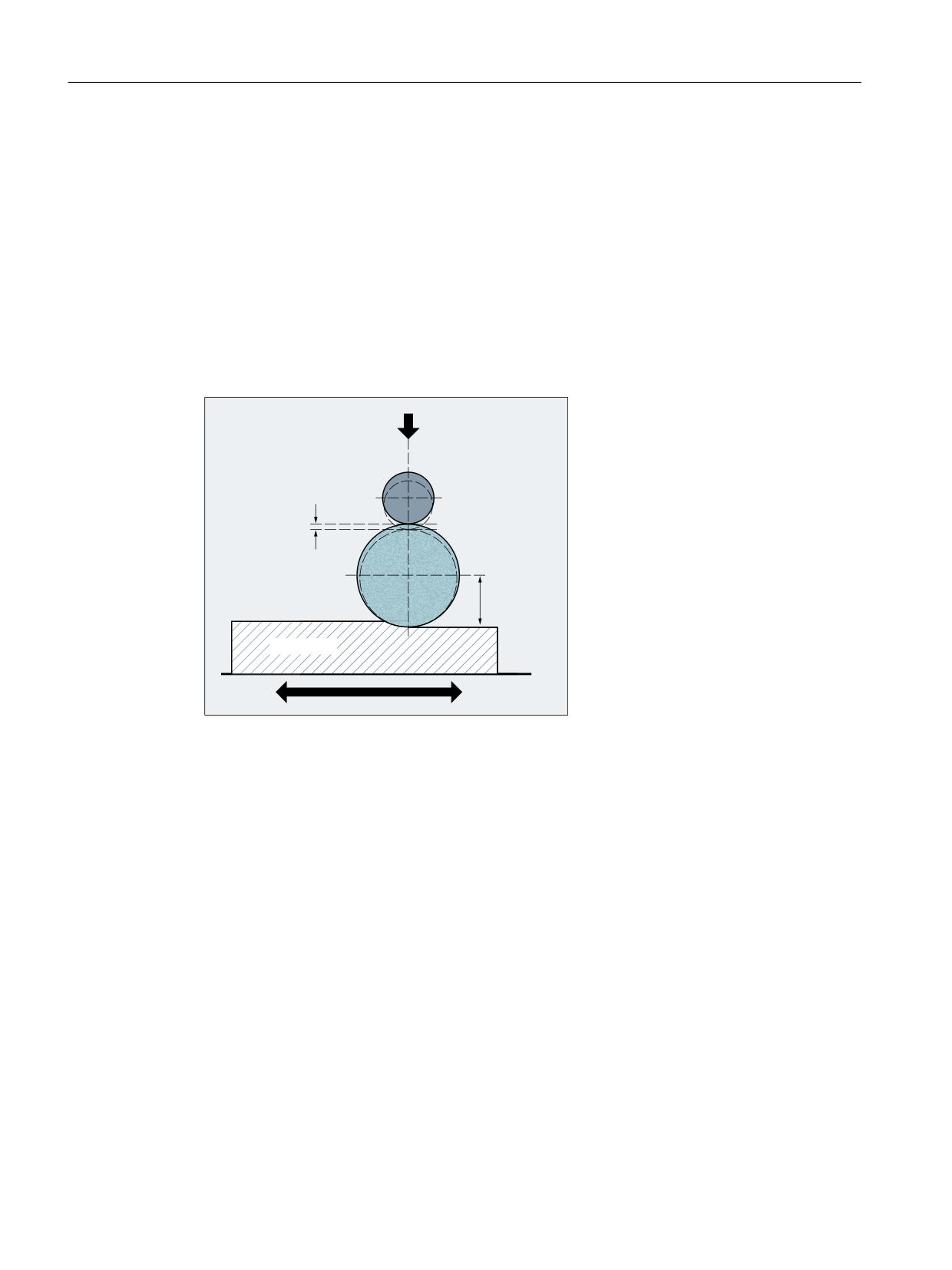
W4: Grinding-specific tool offset and tool monitoring
18.2 Online tool offset
18.2
Online tool offset
18.2.1
Function
A grinding operation involves both machining of a workpiece and dressing of the grinding
wheel. These processes can take place in the same channel or in separate channels.
To allow machining to continue while the grinding wheel is being dressed, the reduction in the
size of the grinding wheel caused by dressing must be transferred to the current tool in the
machining channel as a tool offset that is applied immediately. This can be implemented by
means of the "Online tool offset" function.
'UHVVLQJ UROO
'UHVVLQJ DPRXQW
*ULQGLQJ GLVN
/HQJWK WR
EH FRUUHFWHG
:RUNSLHFH
Figure 18-8
Dressing during machining using a dressing roller
The function supports the following methods of writing the tool offset:
● Continuous write, non-modal (PUTFTOCF (Page 881))
With PUTFTOCF, dressing is carried out at the same time as machining.
The tool offset is changed continuously in the machining channel according to a polynomial
function of the first, second or third order, which must have been defined previously with
FCTDEF (Page 880).
PUTFTOCF is always non-modal; in other words, it takes effect in the subsequent traversing
block.
● Continuous write, modal: ID=1 DO FTOC (for further information, see Function Manual
Synchronized Actions)
● Discrete write (PUTFTOC (Page 882))
With PUTFTOC, dressing is not carried out at the same time as machining from a parallel
channel. The correction value specified with PUTFTOC takes effect immediately in the
destination channel.
Activation / deactivation
The online tool offset in the part program is activated/deactivated by means of the G command
FTOCON/FTOCOF (Page 883).
Extended Functions
878
Function Manual, 12/2018, A5E40874029B AB
W4: Grinding-specific tool offset and tool monitoring
18.2 Online tool offset
Additional properties
● An online tool offset can be activated for every grinding tool (tool type: 400 to 499) in each
channel.
● The online tool offset is generally applied as a length compensation. Like geometry and
wear data, lengths are assigned to geometry axes on the basis of the current plane as a
function of the tool type.
● The grinding spindle monitoring function remains active when an online tool offset is
selected.
Note
The online tool offset may only be used for grinding tools.
The offset always corrects the wear parameters of the selected length. If the length
compensation is identical for several cutting edges, then a chaining specification must be used
to ensure that the values for the 2nd cutting edge are automatically corrected as well.
If online tool offset is active in the machining channel, then the wear values for the active tool
in this channel may not be changed from the machining program or via operator inputs.
Modifications to the radius wear (P15) are not taken into account until the tool is reselected.
The online tool offset is also applied to the constant grinding wheel peripheral speed (GWPS),
i.e. the spindle speed is corrected by the corresponding value.
18.2.2
Commissioning
Number of tool holders that can be defined
Function "Online tool offset" cannot be simultaneously used with the function “Orientable
toolholder".
When using the "Online tool offset" function, the maximum number of tool holders that can be
defined in the TO area should be set to "0":
MD18075 $MN_MM_NUM_TOOLHOLDERS = 0
Note
For SINUMERIK 828D, the value of MD18075 can only be set in "Grinding" technology.
Enable online tool radius compensation
Online tool radius compensation (Page 887) must also be additionally enabled using machine
data:
MD20254 $MC_ONLINE_CUTCOM_ENABLE = 1
Extended Functions
Function Manual, 12/2018, A5E40874029B AB
879
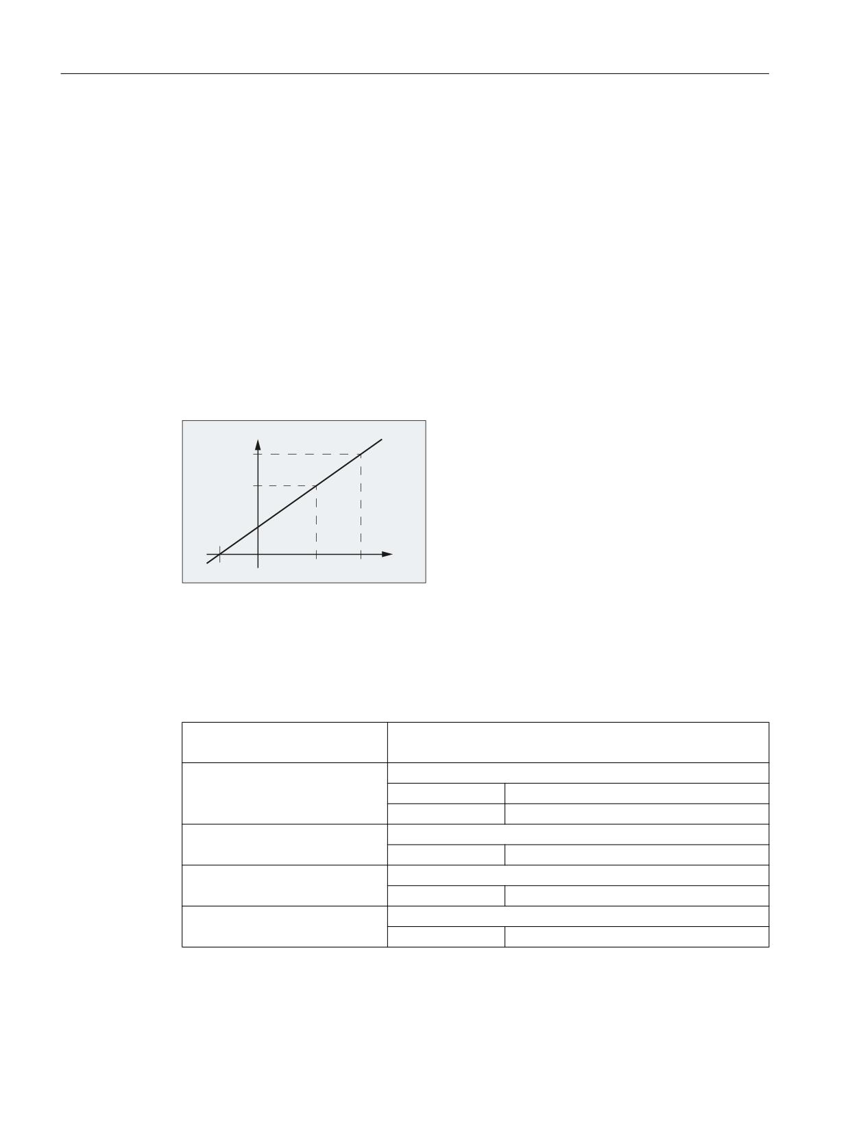
W4: Grinding-specific tool offset and tool monitoring
18.2 Online tool offset
18.2.3
Programming
18.2.3.1
Defining a polynomial function (FCTDEF)
Certain dressing strategies (e.g. dressing roller) are characterized by the fact that the grinding
wheel radius is continuously (linearly) reduced as the dressing roller is fed in. This strategy
requires a linear function between infeed of the dressing roller and writing the wear value of
each length. The linear function is defined using the predefined procedure FCTDEF(...) for up
to third order polynomial functions.
Straight line equation
y = f(x) = a0 + a1*x1
a1: Gradient of the straight line, with a1= Δx / Δy
a0: Shift of the straight line along the X axis with a0 = -a1 * XV
<
˂\
˂[
;
;9
Syntax
FCTDEF(<Func>,<LLimit>,<ULimit>,<a0>,<a1>,<a2>,<a3>)
Meaning
FCTDEF(...):
Defining a polynomial function for PUTFTOCF(...):
y = f(x) = a0 + a1*x + a2*x2 + a3*x3
<Func>:
Function number
Data type:
INT
Range of values:
1, 2, 3
<LLimit>:
Lower limit value
Data type:
REAL
<ULimit>:
Upper limit value
Data type:
REAL
<a0>,<a1>,<a2>,<a3>:
Coefficients of polynomial function
Data type:
REAL
Extended Functions
880
Function Manual, 12/2018, A5E40874029B AB
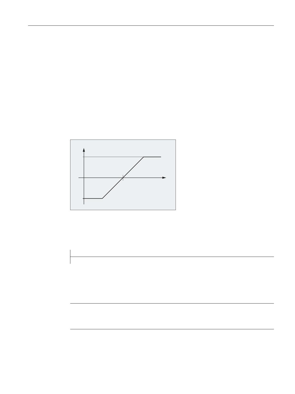
W4: Grinding-specific tool offset and tool monitoring
18.2 Online tool offset
Example
Definitions
● Function number: 1
● Lower and upper limit value: -100, 100
● Gradient of the characteristic: a1 = 1
● The operating point should be located at the center of the characteristic. Based on the
setpoint position of axis XA in the WCS at the instant that the function is defined in the NC
program, the characteristic must be shifted in the negative Y direction: a0 = -a1 * XAD = -1
* $AA_IW
● a2 = a3 = 0
Characteristic
<
8/
;$'
;$
//
UL
Upper limit value
LL
Lower limit value
XAD
Setpoint of axis XA at the time that the function is defined in the NC program
Programming
Program code
Comment
FCTDEF(1,-100,100,-$AA_IW[XA],1)
; Function definition
18.2.3.2
Write online tool offset continuously (PUTFTOCF)
Using the predefined procedure PUTFTOCF(...), an online tool offset is executed based on a
polynomial function previously defined with FCTDEF(...) (Page 880).
Note
The online tool offset can also be realized using a synchronized action.
For further information, see Function Manual Synchronized Actions.
Extended Functions
Function Manual, 12/2018, A5E40874029B AB
881

W4: Grinding-specific tool offset and tool monitoring
18.2 Online tool offset
Syntax
PUTFTOCF(<Func>,<RefVal>,<ToolPar>,<Chan>,<Sp>)
Meaning
PUTFTOCF(...):
Write online tool offset, continuously block-by-block using the polynomial function
defined with FCTDEF(...)
<Func>:
Function number, defined in the function definition with FCTDEF(...)
Data type:
INT
Range of val-
1, 2, 3
ues:
<RefVal>:
Reference value, from which the offset is to be derived (e.g. setpoint of an axis).
Data type:
VAR REAL
<ToolPar>:
Number of the wear parameter (length 1, 2 or 3) in which the offset value is to be
included.
Data type:
INT
<Chan>:
Number of the channel in which the online tool offset is to take effect.
Note:
Only required if the offset is not to take effect in the active channel.
Data type:
INT
<Sp>:
Number of the spindle for which the online tool offset is to take effect.
Note:
Only required if the offset is to be applied to a non-active grinding wheel rather
than the active tool that is currently in use.
Data type:
INT
18.2.3.3
Write online tool offset, discrete (PUTFTOC)
Function
Using the predefined procedurePUTFTOC(...), an online tool offset is executed based on a
fixed offset value.
Syntax
PUTFTOC(<CorrVal>,<ToolPar>,<Chan>,<Sp>)
Meaning
PUTFTOC(...):
Write online tool offset
<CorrVal>:
Offset value, which is added to the wear parameter.
Data type:
REAL
<ToolPar>:
Number of the wear parameter (length 1, 2 or 3) in which the offset value is to be
included.
Data type:
INT
Extended Functions
882
Function Manual, 12/2018, A5E40874029B AB

W4: Grinding-specific tool offset and tool monitoring
18.2 Online tool offset
<Chan>:
Number of the channel in which the online tool offset is to take effect.
Note:
Only required if the offset is not to take effect in the active channel.
Data type:
INT
<Sp>:
Number of the spindle for which the online tool offset is to take effect.
Note:
Only required if the offset is to be applied to a non-active grinding wheel rather
than the active tool that is currently in use.
Data type:
INT
18.2.3.4
Activate/deactivate online tool offset (FTOCON/FTOCOF)
The online tool offset is activated or deactivated using the G commands FTOCON and
FTOCOF.
Syntax
FTOCON
FTOCOF
Meaning
FTOCON:
Activate online tool offset
The command must be programmed in the channel in which the online tool offset
is to be activated.
FTOCOF:
Deactivate online tool offset
The command must be programmed in the channel in which the online tool offset
is to be deactivated.
Note:
On FTOCOF, the axis does not move further out for the tool offset. However, the
value calculated with PUTFTOC/PUTFTOCF remains in the cutting-specific offset
data.
To finally deactivate the online tool offset, the tool (T...) must again be selected/
deselected after FTOCOF.
18.2.4
Supplementary conditions
DRF offset
The online tool offset is superimposed on the programmed axis motion, allowing for the defined
limit values (e.g. velocity).
If a DRF offset and online offset are active simultaneously for an axis, the DRF offset is
considered first.
Extended Functions
Function Manual, 12/2018, A5E40874029B AB
883
W4: Grinding-specific tool offset and tool monitoring
18.2 Online tool offset
Acceleration margin
The active online tool offset is traversed through at JOG velocity, allowing for the maximum
acceleration.
In case of FTOCON the following channel-specific machine data is taken into account:
MD20610 $MC_ADD_MOVE_ACCEL_RESERVE
An acceleration margin can thus be reserved for the movement which means that the overlaid
movement can be executed immediately.
Reference point approach
The valid online offset is deleted on reference point approach with G74.
Tool change
In cases where FTOCON has been active since the last tool or cutting edge change,
preprocessing stop with resynchronization is initiated in the control when a tool is changed.
Cutting edge changes can be implemented without preprocessing stop.
Note
Tool changes can be executed in conjunction with the online tool offset through the selection
of T numbers.
Tool changes with M6 cannot be executed in conjunction with the online tool offset function.
Machining plane and transformation
● FTOCON can be used only in conjunction with the "Inclined axis" transformation.
● It is not possible to change transformations or planes (e.g. G17 to G18) when FTOCON is
active, except in the FTOCOF state.
Resets and operating mode changes
● When online offset is active, NC-Stop and program end with M2/M30 are delayed until the
amount of compensation has been traversed.
● The online tool offset is immediately deselected in response to NC-Reset.
● Online tool offsets can be activated in AUTOMATIC mode and when the program is active.
Extended Functions
884
Function Manual, 12/2018, A5E40874029B AB
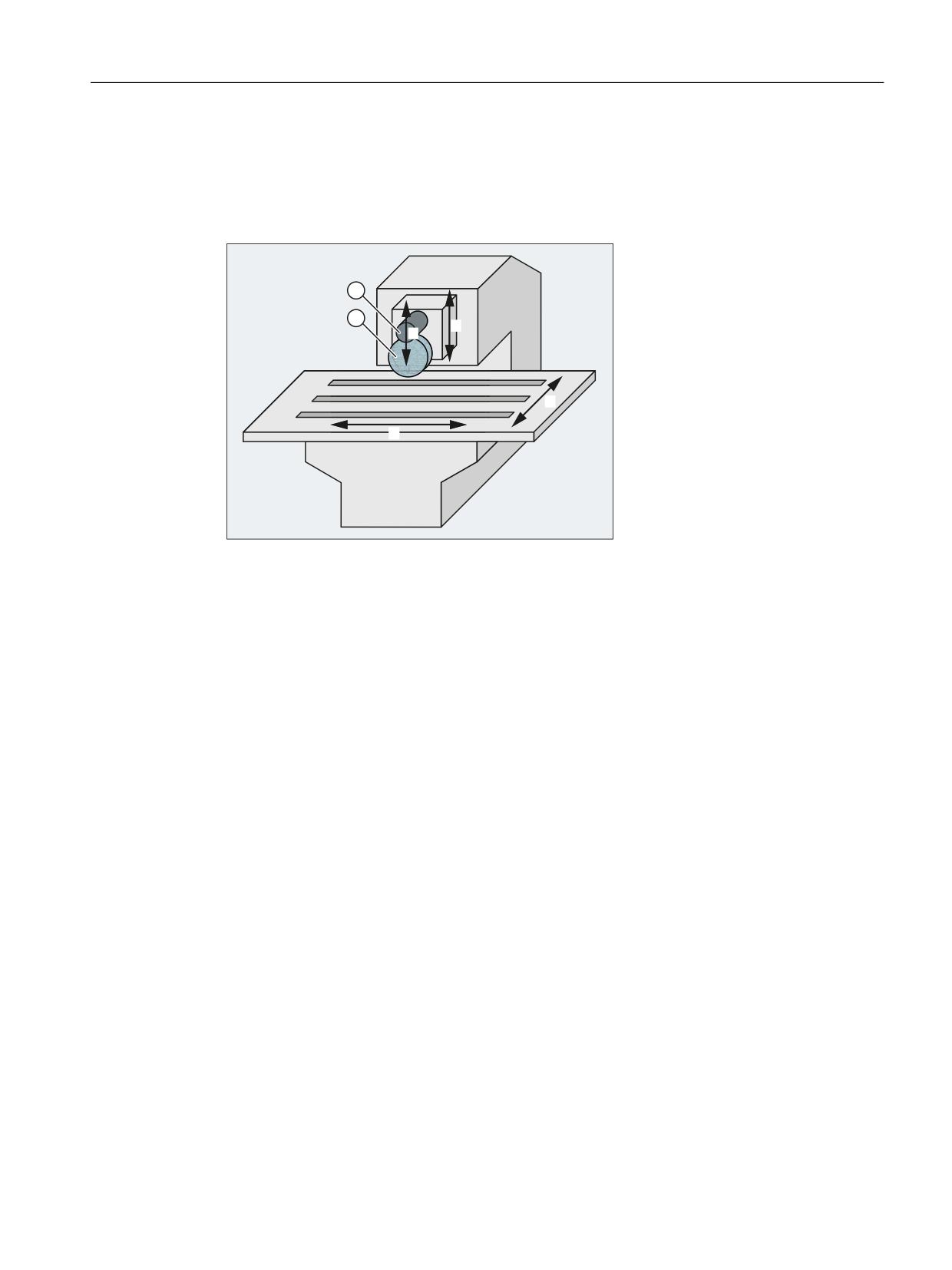
W4: Grinding-specific tool offset and tool monitoring
18.2 Online tool offset
18.2.5
Examples
18.2.5.1
Example: Write online tool offset continuously
<
9
=
;
① Grinding disk
② Dressing roller
X:
Oscillating axis
Y:
Infeed axis: Grinding disk
Z:
Table axis
V:
Infeed axis: Dressing roller
Figure 18-9
Surface grinding machine
Specifications
● Tool offset
- Machining plane: Y/Z plane (G19)
- Tool type: 401 (length 1 acts in Z, length 2 acts in Y)
● Channel 1: Machining channel, axes X, Y, Z
● Channel 2: Dressing channel, axis V
After the grinding operation has started at Y100, the grinding wheel must be dressed by 0.05
(in V direction). The dressing amount must be compensated continuously by means of an
online offset.
Extended Functions
Function Manual, 12/2018, A5E40874029B AB
885
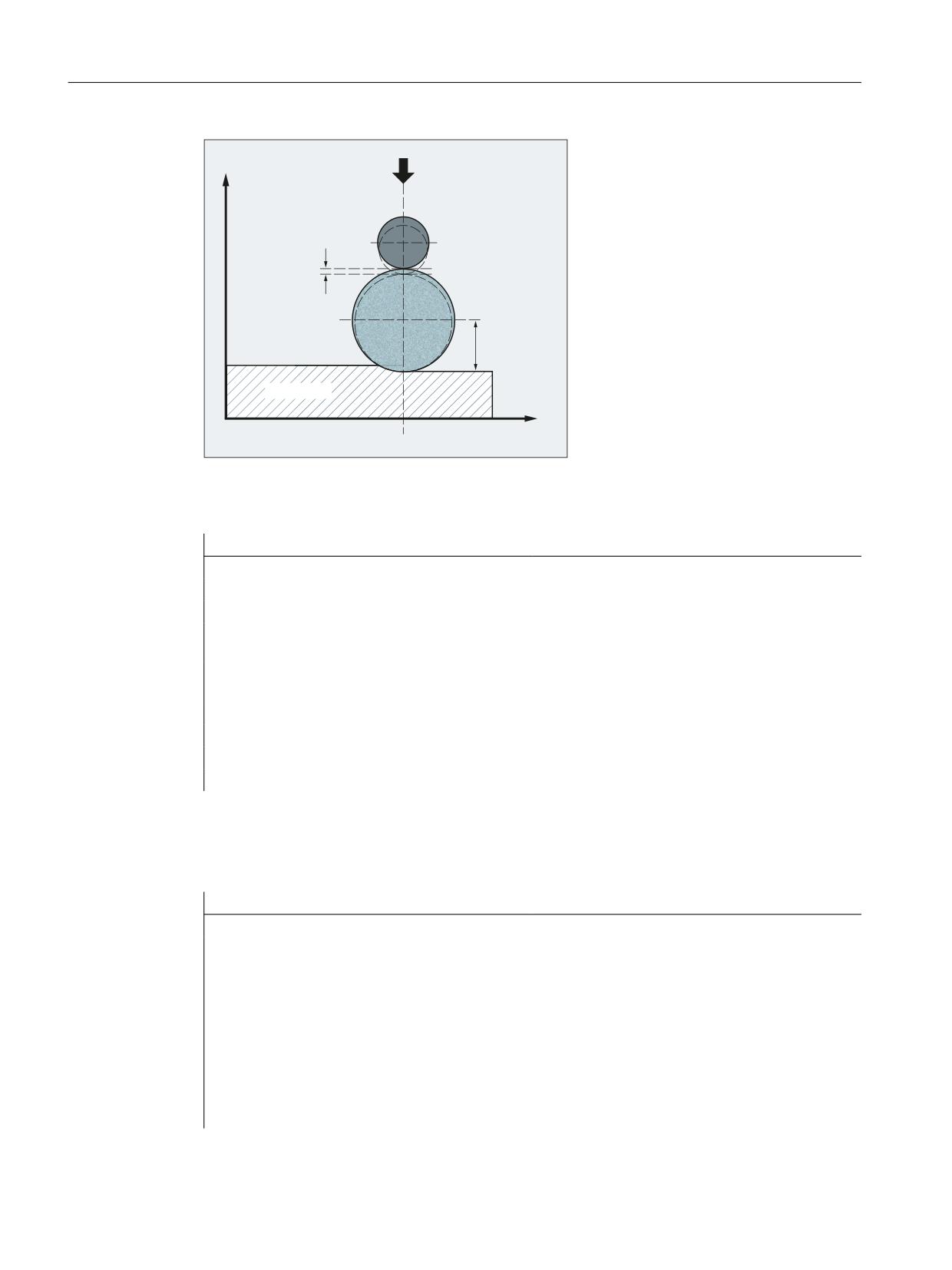
W4: Grinding-specific tool offset and tool monitoring
18.2 Online tool offset
<
'UHVVLQJ UROOHU
'UHVVLQJ
DPRXQW
*ULQGLQJ GLVN
/HQJWK
WR EH
FRPSHQVDWHG
:RUNSLHFH
;
Figure 18-10
Tool offset
Program (section) for channel 1: Machining channel
Program code
Comment
G1 G18 F10 G90
; initial setting
T1 D1
; select actual tool
S100 M3 X100
; switch-on spindle, X axis to initial po-
sition
INIT (2, "/_N_MPF_DIR/_N_ABRICHT_MPF",
; select: program "DRESS" in channel 2:
"S")
START (2)
; start: Channel 2
X200
; X axis at target position
FTOCON
; activate online offset
Program for channel 2: Dressing channel
The V axis traverses parallel to the Y axis, i.e. length 3 of the tool offset acts in the direction
of the Y axis, and must therefore be compensated..
Program code
Comment
PROC ABRICHT
FCTDEF(1, -1000, 1000, -$AA_IW[V], 1)
; function definition
PUTFTOCF(1, $AA_IW[V], 3, 1)
; continuously write online tool offset:
;
- Function number: 1
;
- Reference value: Setpoint position
in the WCS of the V axis
;
- Tool parameters: Length 3 of the
grinding disk
;
- Channel: 1
;
- Spindle: active grinding disk
Extended Functions
886
Function Manual, 12/2018, A5E40874029B AB
W4: Grinding-specific tool offset and tool monitoring
18.3 Online tool radius compensation
Program code
Comment
V-0.05 G1 F0.01 G91
; infeed motion of the V axis for dressing
M30
18.3
Online tool radius compensation
Function
When the longitudinal axis of the tool and the contour are perpendicular to each other, the
offset can be applied as a length compensation to one of the three geometry axes (online tool
length compensation).
If this condition is not fulfilled, then the offset quantity can be entered as a real radius
compensation value (online tool radius compensation).
Enable
Online tool radius compensation must be enabled using machine data:
MD20254 $MC_ONLINE_CUTCOM_ENABLE = 1
Activation / deactivation
An online tool radius compensation is activated and deactivated using G commands FTOCON
and FTOCOF (Page 883) (in the same way as an online tool length compensation).
Parameter assignment
Online tool offset is parameterized using PUTFTOCF (Page 881) or PUTFTOC (Page 882).
The parameter <ToolPar> (wear parameter in which the correction value is to be calculated)
must be set for the online tool radius compensation as follows:
<ToolPar> = 4
Extended Functions
Function Manual, 12/2018, A5E40874029B AB
887

W4: Grinding-specific tool offset and tool monitoring
18.4 Grinding-specific tool monitoring
Boundary conditions
● A tool radius compensation, and thus also an online tool radius compensation, can be
activated only when the selected tool has a radius other than "0". This means that machining
operations cannot be implemented solely with a tool radius compensation.
● The online correction values should be low in comparison to the original radius to prevent
the permitted dynamic tolerance range from being exceeded when the offset is overlaid on
the axis movement.
● For grinding and turning tools (types 400 - 599), the correction value is applied as a function
of the cutting edge position, i.e. it acts as a radius compensation when tool radius
compensation is active and as a length compensation when tool radius compensation is
deactivated in the axes specified by the cutting edge position.
On all other tool types, the correction value is applied only when tool radius compensation
has been activated with G41 or G42. The correction value is canceled when tool radius
compensation is deactivated with G40.
18.4
Grinding-specific tool monitoring
18.4.1
Function
Grinding-specific tool monitoring is a combination of geometry and speed monitoring. It can
be activated for every grinding tool (tool type: 400 to 499).
Note
Monitoring of one tool is not deselected if the monitoring function is selected for another tool
provided the two tools are referred to different spindles.
One tool and thus also one tool monitor can be active for every spindle at any point in time.
Activated monitors remain active after a reset.
Geometry monitoring
The actual wheel radius and the actual wheel width are monitored.
The compensation value of the first cutting edge (D1) of a grinding tool which is referenced in
the parameter $TC_TPG9 is used as the current wheel radius. If monitoring is active, this value
is compared to the value in parameter $TC_TPG3 (minimum wheel radius).
Note
The monitoring function for the wheel radius remains active if an online tool offset is selected:
● when the monitoring function is activated
● when the current radius (online tool offset, wear parameter) or the current width
($TC_TPG5) is altered
Extended Functions
888
Function Manual, 12/2018, A5E40874029B AB

W4: Grinding-specific tool offset and tool monitoring
18.4 Grinding-specific tool monitoring
The current wheel width is usually determined through the dressing cycle and can be entered
in parameter $TC_TPG5 of a grinding tool. If monitoring is active, this entered value is
compared to the value in parameter $TC_TPG4 (minimum wheel width).
If the current wheel radius falls below the value specified in the parameter $TC_TPG3 or the
current wheel width ($TC_TPG5) falls below the value defined in the parameter $TC_TPG4,
the control sets the following NC/PLC interface signal to "1":
DB31, ... DBX83.3 (geometry monitoring) == 1
Note
There is no controller-internal error response.
Speed monitoring
The speed monitor checks the grinding wheel peripheral speed in m/s (parameter $TC_TPG7)
as well as the maximum spindle speed in rpm (parameter $TC_TPG6).
The speed setpoint is monitored against the speed limitation cyclically with allowance for the
spindle override.
The speed limit is the smaller value resulting from the comparison of the maximum spindle
speed with the speed calculated from the maximum wheel peripheral speed and the current
wheel radius.
The speed limit value is recalculated:
● if monitoring is switched on
● if online correction values (wear parameters) are changed
When the speed limit value is reached, it is restricted to the speed limit value and the following
NC/PLC interface signal is set to "1":
DB31, ... DBX83.6 (speed monitoring) == 1
Note
There is no controller-internal error response.
Activation / deactivation
Activation/deactivation of grinding-specific tool monitoring is done by programming of
TMON(...)/TMOF(...) (Page 890) in the part program.
Extended Functions
Function Manual, 12/2018, A5E40874029B AB
889

W4: Grinding-specific tool offset and tool monitoring
18.4 Grinding-specific tool monitoring
18.4.2
Commissioning
Automatic activation
If, when selecting the tool length compensation of a grinding tool with an odd tool type number,
the grinding-specific tool monitoring is to be automatically activated, the following machine
data must be set to "1":
MD20350 $MC_TOOL_GRIND_AUTO_TMON (activation of tool monitoring) = 1
18.4.3
Programming
18.4.3.1
Activate/deactivate grinding-specific tool monitoring (TMON, TMOF)
With the predefined procedures TMON(...) and TMOF(...), the grinding-specific tool monitoring
is activated or deactivated (geometry and speed monitoring).
Requirement
The tool-specific parameters $TC_TPG1 to $TC_TPG9 must be set.
Syntax
TMON(<TNo>)
TMOF(<TNo>)
Meaning
TMON(...):
Activate grinding-specific tool monitoring
The command must be programmed in the channel in which the grinding-specific tool
monitoring is to be activated.
TMOF(...):
Deactivate grinding-specific tool monitoring
The command must be programmed in the channel in which the grinding-specific tool
monitoring is to be deactivated.
<TNo>:
T number
Note:
Only required if the monitoring is to be switched on or off for an inactive grinding wheel
rather than the active grinding wheel that is currently in use.
TMOF(0):
Deactivate monitoring for all tools
Extended Functions
890
Function Manual, 12/2018, A5E40874029B AB
W4: Grinding-specific tool offset and tool monitoring
18.5 Constant grinding wheel peripheral speed (GWPS).
18.5
Constant grinding wheel peripheral speed (GWPS).
18.5.1
Function
For grinding wheels, generally the wheel peripheral speed is used instead of the spindle speed.
The value to be set is determined by technological process parameters (e.g. grinding wheel
characteristic, material combination).
To be able to specify the wheel peripheral speed in the part program, the tool-specific
parameters $TC_TPG1 (Page 870), $TC_TPG8 (Page 872) and $TC_TPG9 (Page 873) must
be set and the function "Constant grinding wheel peripheral speed (GWPS)" must be activated.
Note
Activation of GWPS does not cause the automatic activation of tool length compensation or
grinding-specific tool monitoring!
As soon as the function is active, any subsequent S value for the spindle that is assigned to
the grinding wheel via $TC_TPG1 will be interpreted as grinding wheel peripheral speed. The
grinding wheel speed is set such that, taking account of the current wheel radius, the grinding
wheel peripheral speed remains constant.
The formula for calculating the speed is as follows:
68* >P V @
Q>PLQ @
˭
5>P@
The correction value to be used for calculation is defined in the tool-specific parameter
$TC_TPG9. The associated wear and the base dimension as a function of the tool type are
added to this correction value. The sum total is divided by "cos" ($TC_TPG8) when the value
of parameter $TC_TPG8 (angle of inclined wheel) is positive, and is divided by "sin"
($TC_TPG8) when the value is negative.
The speed is recalculated in response to the following events:
● Specification a new grinding wheel peripheral speed, e.g. by:
- programming in the part program/overstoring
- assignment to the address "S" in MDI
- spindle speed control via PLC (FC18).
● Changing the online correction values (wear parameters)
Activation / deactivation
Activation/deactivation of GWPS is implemented by programming GWPSON(...)/GWPSOF(...)
in the part program (see "Programming (Page 893)").
Extended Functions
Function Manual, 12/2018, A5E40874029B AB
891
W4: Grinding-specific tool offset and tool monitoring
18.5 Constant grinding wheel peripheral speed (GWPS).
Status
The following interface signal can be used to determine whether or not the GWPS is active:
DB31, ... DBX84.1 (GWPS active)
New tool
If GWPS is to be selected with a new tool for a spindle for which GWPS is already active, the
active GWPS must first be deselected (otherwise an alarm is output).
Response to reset/part program end
In the basic setting, GWPS is deactivated for a reset or end of part program and the spindle
is stopped. The machine data settings behind this behavior can be changed as needed (see
"Commissioning (Page 892)").
Additional properties
● GWPS can be activated for every grinding tool (tool type: 400 to 499) in each channel.
● GWPS can be active simultaneously for several spindles, each with a different grinding
tool, in the same channel.
18.5.2
Commissioning
Automatic activation
If the constant grinding wheel peripheral speed (GWPS) is to be automatically selected for a
spindle after Power On, and remain selected during mode switch, reset or end of the part
program, the following machine data bit must be set to "1":
MD35032 $MA_SPIND_FUNC_RESET_MODE Bit 0 = 1
Note
The prerequisite is that the tool be a grinding tool (tool type 400 to 499), the tool-specific
parameters $TC_TPG1, $TC_TPG8 and $TC_TPG9 are set, and $TC_TPG1 refers to a valid
spindle.
Behavior of spindle after reset/part program end
If the spindle is not to stop after a reset or end of part program, but is to continue rotating at
the current speed, the following machine data must be set to "1":
Extended Functions
892
Function Manual, 12/2018, A5E40874029B AB
W4: Grinding-specific tool offset and tool monitoring
18.5 Constant grinding wheel peripheral speed (GWPS).
MD35040 $MA_SPIND_ACTIVE_AFTER_RESET = 1
Note
MD35040 only takes effect in the spindle mode open-loop control operation.
18.5.3
Programming
18.5.3.1
Switching constant grinding wheel peripheral speed (GWPSON, GWPSOF) on/off:
With the predefined procedures GWPSON(...) and GWPSOF(...), the constant grinding wheel
peripheral speed (GWPS) for grinding tools (tool type: 400 to 499) is switched on and off.
Syntax
GWPSON(<TNo>)
S<n>=... :
GWPSOF(<TNo>)
Meaning
GWPSON(...):
Switch on the constant grinding wheel peripheral speed
GWPSOF(...):
Switch off the constant grinding wheel peripheral speed
<TNo>:
T number
Note:
Only required if the constant grinding wheel peripheral speed is to be switch-
ed on or off for an inactive grinding wheel rather than the active grinding
wheel that is currently in use.
S<n>=…:
Grinding wheel peripheral speed in m/s or ft/s for spindle <n>
S0=... or S... :
Grinding wheel peripheral speed for the master spindle
Query status
The following system variable can be used to query from the part program whether the constant
grinding wheel peripheral speed is active for a specific spindle.
$P_GWPS[<n>] ; where <n> = spindle number
Value
Meaning
0 (= FALSE)
GWPS is inactive.
1 (= TRUE)
GWPS is active.
Extended Functions
Function Manual, 12/2018, A5E40874029B AB
893
W4: Grinding-specific tool offset and tool monitoring
18.5 Constant grinding wheel peripheral speed (GWPS).
18.5.4
Example
A constant grinding wheel peripheral speed is to be used for grinding tools T1 and T5. T1 is
the active tool.
Data of tool T1 (peripheral grinding wheel)
$TC_DP1[1,1] = 403
;tool type
$TC_DP3[1,1] = 300
;length1
$TC_DP4[1,1] = 50
;length2
$TC_DP12[1,1] = 0
;wear length 1
$TC_DP13[1.1] =0
;wear length 2
$TC_DP21[1.1] =300
;base length 1
$TC_DP22[1.1] =400
;base length 2
$TC_TPG1[1] = 1
;spindle number
$TC_TPG8[1] = 0
;angle of inclined wheel
$TC_TPG9[1] = 3
;parameter no. for radius calculation
Data of tool T5 (inclined grinding wheel)
$TC_DP1[5,1] = 401
;tool type
$TC_DP3[5,1] = 120
;length1
$TC_DP4[5,1] = 30
;length2
$TC_DP12[5,1] = 0
;wear length 1
$TC_DP13[5,1] =0
;wear length 2
$TC_DP21[5,1] =100
;base length 1
$TC_DP22[5,1] =150
;base length 2
$TC_TPG1[5] = 2
;spindle number
$TC_TPG8[5] = 45
;angle of inclined wheel
$TC_TPG9[5] = 3
;parameter no. for radius calculation
Programming
Program code
Comment
N20 T1 D1
; select T1 and D1
N25 S1=1000 M1=3
; 1000 rpm for spindle 1
N30 S2=1500 M2=3
; 1500 rpm for spindle 2
N40 GWPSON
; activate GWPS for active tool T1
N45 S[$P_ATPG[1]]=60
; set GWPS for active tool to 60 m/s
→ n=1909.85 rpm
N50 GWPSON(5)
; activate GWPS for tool 5 (spindle 2)
N55 S[$TC_TPG1[5]]=40
; set GWPS for spindle 2 to 40 m/s
→ n=1909.85 rpm
N60 GWPSOF
; deactivate GWPS for active tool
Extended Functions
894
Function Manual, 12/2018, A5E40874029B AB

W4: Grinding-specific tool offset and tool monitoring
18.6 Data lists
Program code
Comment
N65 GWPSOF(5)
; deactivate GWPS for tool 5 (spindle 2)
See also
P5: Oscillation (Page 721)
18.6
Data lists
18.6.1
Machine data
18.6.1.1
General machine data
Number
Identifier: $MN_
Description
18075
MM_NUM_TOOLHOLDERS
Maximum number of tool holders that can be defined
18094
MM_NUM_CC_TDA_PARAM
Number of TDA
18096
MM_NUM_CC_TOA_PARAM
Number of TOA
18100
MM_NUM_CUTTING_EDGES_IN_TOA
Tool offsets per TOA
18.6.1.2
Channelspecific machine data
Number
Identifier: $MC_
Description
20254
ONLINE_CUTCOM_ENABLE
Enable online tool radius compensation
20350
TOOL_GRIND_AUTO_TMON
Automatic tool monitoring
20610
ADD_MOVE_ACCEL_RESERVE
Acceleration reserve for overlaid movements
18.6.1.3
Axis/spindlespecific machine data
Number
Identifier: $MA_
Description
32020
JOG_VELO
Jog axis velocity
35032
SPIND_FUNC_RESET_MODE
Reset behavior of individual spindle functions
35040
SPIND_ACTIVE_AFTER_RESET
Independent spindle reset
Extended Functions
Function Manual, 12/2018, A5E40874029B AB
895

W4: Grinding-specific tool offset and tool monitoring
18.6 Data lists
18.6.2
Signals
18.6.2.1
Signals from axis/spindle
Signal name
SINUMERIK 840D sl
SINUMERIK 828D
Geometry monitoring
DB31,
DBX83.3
DB390x.DBX2001.3
Speed monitoring
DB31,
DBX83.6
DB390x.DBX2001.6
GWPS active
DB31,
DBX84.1
DB390x.DBX2002.1
Extended Functions
896
Function Manual, 12/2018, A5E40874029B AB
Z2: NC/PLC interface signals
19
From Edition 05/2017, a detailed description of the NC/PLC interface signals is provided in the
NC Variables and Interface Signals List Manual.
Extended Functions
Function Manual, 12/2018, A5E40874029B AB
897
Z2: NC/PLC interface signals
Extended Functions
898
Function Manual, 12/2018, A5E40874029B AB

Appendix
A
A.1
List of abbreviations
A
O
Output
ADI4
(Analog drive interface for 4 axes)
AC
Adaptive Control
ALM
Active Line Module
ARM
Rotating induction motor
AS
Automation system
ASCII
American Standard Code for Information Interchange: American coding standard for
the exchange of information
ASIC
Application-Specific Integrated Circuit: User switching circuit
ASUB
Asynchronous subprogram
AUXFU
Auxiliary function: Auxiliary function
STL
Statement List
UP
User Program
B
OP
Operating Mode
BAG
Mode group
BCD
Binary Coded Decimals: Decimal numbers encoded in binary code
BERO
Contact-less proximity switch
BI
Binector Input
BICO
Binector Connector
BIN
BINary files: Binary files
BIOS
Basic Input Output System
BCS
Basic Coordinate System
BO
Binector Output
OPI
Operator Panel Interface
C
CAD
Computer-Aided Design
CAM
Computer-Aided Manufacturing
CC
Compile Cycle: Compile cycles
CEC
Cross Error Compensation
CI
Connector Input
CF Card
Compact Flash Card
Extended Functions
Function Manual, 12/2018, A5E40874029B AB
899

Appendix
A.1 List of abbreviations
C
CNC
Computerized Numerical Control: Computer-Supported Numerical Control
CO
Connector Output
CoL
Certificate of License
COM
Communication
CPA
Compiler Projecting Data: Configuring data of the compiler
CRT
Cathode Ray Tube: picture tube
CSB
Central Service Board: PLC module
CU
Control Unit
CP
Communication Processor
CPU
Central Processing Unit: Central processing unit
CR
Carriage Return
CTS
Clear To Send: Ready to send signal for serial data interfaces
CUTCOM
Cutter radius Compensation: Tool radius compensation
D
DAC
Digital-to-Analog Converter
DB
Data Block (PLC)
DBB
Data Block Byte (PLC)
DBD
Data Block Double word (PLC)
DBW
Data Block Word (PLC)
DBX
Data block bit (PLC)
DDE
Dynamic Data Exchange
DDS
Drive Data Set: Drive data set
DIN
Deutsche Industrie Norm
DIO
Data Input/Output: Data transfer display
DIR
Directory: Directory
DLL
Dynamic Link Library
DO
Drive Object
DPM
Dual Port Memory
DPR
Dual Port RAM
DRAM
Dynamic memory (non-buffered)
DRF
Differential Resolver Function: Differential revolver function (handwheel)
DRIVE-CLiQ
Drive Component Link with IQ
DRY
Dry Run: Dry run feedrate
DSB
Decoding Single Block: Decoding single block
DSC
Dynamic Servo Control / Dynamic Stiffness Control
DW
Data Word
DWORD
Double Word (currently 32 bits)
Extended Functions
900
Function Manual, 12/2018, A5E40874029B AB