SINUMERIK 840D sl. Service - Functions. Manual (2018-2020) - page 51
PLC functions for HMI (DB19)
13.6 HMI monitor
Example
Assumptions
• Current operating area: "Machine", number: 201
• Actual screen: "AUTOMATIC" start screen, number: 200
• PLC data area: DB60.DBB10
Parameterization
• MD9032 $MM_HMI_MONITOR = "DB60.DBB10"
Values in the data area
• DB60.DBB10: 201
• DB60.DBW12: 200
PLC
130
Function Manual, 10/2020, 6FC5397-0HP40-0BA1
PLC functions for drive components on the
integrated PROFIBUS
14
14.1
Overview
Using the function described below, input and output data from drive components on the
integrated PROFIBUS can be consistently, cyclically read and written from the PLC user program
of the hardware PLC. The following boundary conditions must be observed:
• For reading / writing input/output data, the system functions SFC14 / SFC15 must be used.
• The reading / writing of input/output data is always over the entire slot length.
• The function only supports cyclical, non-equidistant data transfer.
• An output slot may not already be occupied on the NC side; (e.g. output slots of drives).
14.2
Performing a start-up
Preconditions
Before the function is put into operation on the NC side, the following preconditions must be
satisfied:
• The drive components on the integrated PROFIBUS of the NCU must be fully configured using
SIMATIC STEP 7, HW Config.
• The configuration is loaded into the PLC.
NC machine data
The start addresses of the slots to be transferred cyclically are to be entered into the following
machine data:
• Input slots:
MD10520 $MN_PLCINTERN_LOGIC_ADDRESS_IN[<Index>] = <Slot address>
• Output slots:
MD10525 $MN_PLCINTERN_LOGIC_ADDRESS_OUT[<Index>] = <Slot address>
<Index>: 0, 1, 2, ... (Max no. of slots) - 1
<Slot address>: The slot address parameterized in HW Config
Note
Maximum quantity of data
The sum of all data to be cyclically transferred in inward and outward directions may not
currently exceed 2,048 bytes.
PLC
Function Manual, 10/2020, 6FC5397-0HP40-0BA1
131
PLC functions for drive components on the integrated PROFIBUS
14.3 Example
14.3
Example
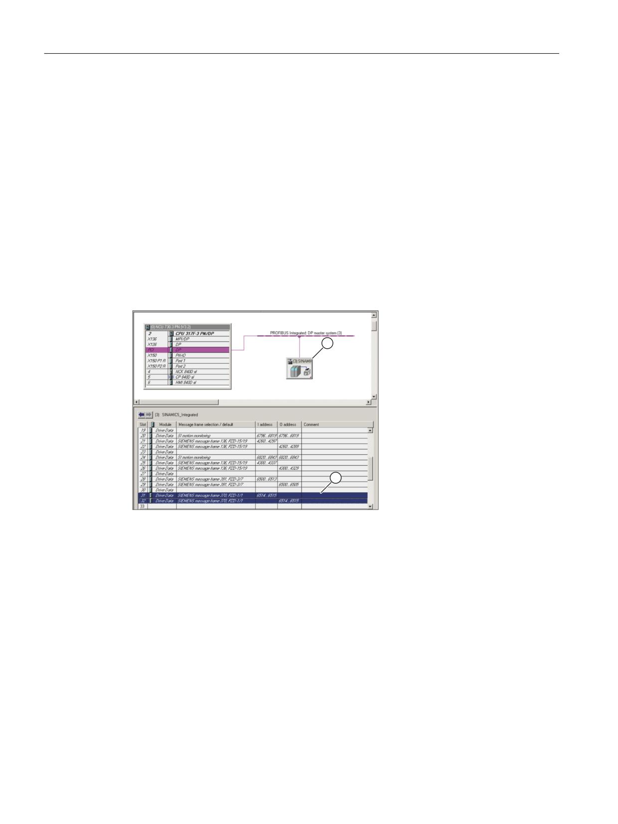
Determining slot addresses
After selecting the DP Slave "SINAMICS_Integrated" on the integrated PROFIBUS "PROFIBUS
Integrated: DP master system (3)" in the station window of HW Config, its PROFIdrive message
frame and associated slot addresses are displayed in the detailed view.
• Message frame 136: Drive
• Message frame 391: Control Unit
• Message frame 370: Infeed
The infeed slot addresses required for parameterization in the NC machines are:
• Input slot: Slot 31, address 6514
• Output slot: Slot 32, address 6514
Figure 14-1
Infeed PROFIBUS message frames
Setting NC machine data
• Input slots:
MD10520 $MN_PLCINTERN_LOGIC_ADDRESS_IN[ 0 ] = 6514
• Output slots:
MD10525 $MN_PLCINTERN_LOGIC_ADDRESS_OUT[ 0 ] = 6514
Controlling the ALM using FB390 "ALM_Control"
The SINUMERIK hardware PLC is connected to the CU320 of SINAMICS S120 through the internal
PROFIBUS. The ALM is connected to the CU via DRIVE-CLiQ.
In SINAMICS S120, a control and status message frame can be defined for each module (the CU,
ALM, motor modules, etc.). If this is performed for an ALM, this can be switched on and off from
the PLC user program.
PLC
132
Function Manual, 10/2020, 6FC5397-0HP40-0BA1
PLC functions for drive components on the integrated PROFIBUS
14.3 Example
The SIMATIC S7 block FB390 "ALM_Control" checks the status of the ALM and enables the user
to switch it on or off.
A description of the block and an example project are available for download under the following
link to Industry Online Support:
PLC
Function Manual, 10/2020, 6FC5397-0HP40-0BA1
133
PLC functions for drive components on the integrated PROFIBUS
14.3 Example
PLC
134
Function Manual, 10/2020, 6FC5397-0HP40-0BA1

Memory requirements of the basic PLC program
15
The basic program consists of basic and optional functions. The basic functions include cyclic
signal exchange between the NC and PLC. The Options include e.g. the FCs, which can be used,
if needed.
The table below lists the memory requirements for the basic functions and the options. The data
quoted represent guide values, the actual values depend on the current software version.
Memory requirements of blocks for SINUMERIK 840D sl
Block
Function
Remark
Block size (bytes)
Type, No.
Working memory
Basic functions in basic program
FB1, FB15
Must be loaded /
52182
on CompactFlash Card
FC2, 3, 5, 12
Must be loaded
470
DB4, 5, 7, 8
Must be loaded
1006
DB2, 3, 17
Are generated by the BP
632
OB1, 40, 100, 82, 86
Must be loaded
398
Total
55698
PLC/NC, PLC/HMI interface
DB10
PLC/NC signals
Must be loaded
262
DB11
PLC / mode group signals
Is generated by BP
56
DB19
PLC/HMI signals
Is generated by BP
434
DB21 to 30
PLC/channel signals
Are generated by BP as a function of NCMD: for
416
each DB
DB31 to 61
PLC / axis or spindle
Are generated by BP as a function of NCMD: for
148
signals
each DB
Basic program options
Machine control panel
FC19
Transfer of MCP signals,
Must be loaded when M variant of MCP is installed
92
M variant
FC25
Transfer of MCP signals,
Must be loaded when T variant of MCP is installed
92
T variant
FC24
Transfer of MCP signals,
Must be loaded when slim variant of MCP is in-
100
slim variant
stalled
FC26
Transfer of MCP signals,
Must be loaded for HT8
68
HT8 variant
PLC
Function Manual, 10/2020, 6FC5397-0HP40-0BA1
135

Memory requirements of the basic PLC program
Basic program options
Handheld unit
FC13
Display control HHU
Can be loaded for handheld units
144
Error/operating messages
FC10
Acquisition FM/BM
Load when FM / BM is used
66
ASUP
FC9
ASUP start
Load when PLC ASUPs are used
128
Basic program options
Star/delta changeover
FC17
Star/delta switchover of
Load for star/delta switchover
114
MSD
Spindle control
FC18
Spindle control
Load for spindle control from PLC
132
PLC/NC communication
FB2
Read NC variable
Load for Read NC variable
76
DBn
Read NC variable
One instance DB per FB2 call:
270
FB3
Write NC variable
Load for Write NC variable
76
DBm
Write NC variable
One instance DB per FB3 call:
270
FB4
PI services
Load for PI services
76
DBo
PI services
One instance DB per FB4 call:
130
DB16
PI services description
Load for PI services
618
FB5
Read GUD variables
Load for PI services
76
DBp
Read GUD variables
One instance DB per FB5 call:
166
DB15
General communication
Global data block for communication
146
FB7
PI services 2
Load for PI services
76
DBo
PI services 2
One instance DB per FB4 call: every
144
FC21
Transfer
Load with dual-port RAM, ...
164
M to N
FB9
Switchover M to N
Load with M to N
58
Safety Integrated
FB10
Safety relay
Load with Safety option
74
FB11
Brake test
Load with Safety option
76
DB18
Safety data
DB for Safety
308
Tool management
FC7
Transfer function
Load for tool management option
84
turret
FC8
Transfer function
Load for tool management option
132
FC22
Direction selection
Load, when direction selection is needed
138
DB71
Loading locations
Generated by BP as a function of NC MD
40+30*B
DB72
Spindles
Generated by BP as a function of NC MD
40+48*Sp
PLC
136
Function Manual, 10/2020, 6FC5397-0HP40-0BA1

Memory requirements of the basic PLC program
Basic program options
DB73
Revolver
Generated by BP as a function of NC MD
40+44*R
DB74
Basic function
Generated by BP as a function of NC MD
100+(B+
Sp+R)*22
Compile cycles
DB9
Interface
Is generated by BP as a function of NC option
436
PLC compile cycles
Example:
Based on the memory requirements in the table above, the memory requirements have been
determined for two sample configurations (see table below).
Block
Function
Remark
Block size (bytes)
Type, No.
Working memory
Minimum configuration (1 spindle, 2 axes and T MCP)
see above
Basic program, base
54688
Interface DBs
1612
MCP
92
Total
56392
Block
Function
Remark
Block size (bytes)
Type, No.
Working memory
Maximum configuration (2 channels, 4 spindles, 4 axes, T MCP)
see above
Basic program, base
54688
see above
Interface DBs
2768
see above
MCP
92
see above
Error/operating messages
66
see above
ASUPs
1 ASUP initiation
128
see above
Concurrent axis
For 2 turrets
132
see above
PLC/NC communication
1 x read variable and 1 x write variable
838
see above
Tool management
2 turrets with one loading point each
674
see above
Compile cycles
436
Total
59822
PLC
Function Manual, 10/2020, 6FC5397-0HP40-0BA1
137
Memory requirements of the basic PLC program
PLC
138
Function Manual, 10/2020, 6FC5397-0HP40-0BA1
NC VAR selector
16
16.1
Overview
General
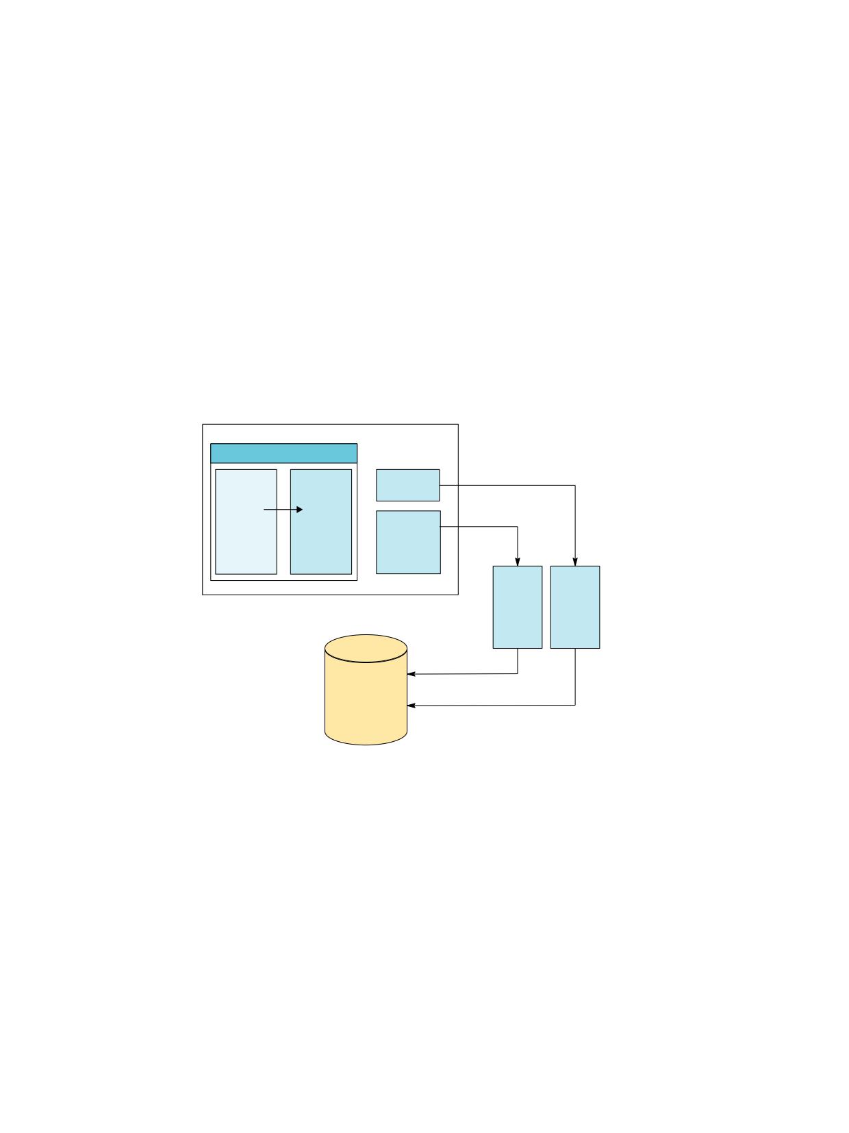
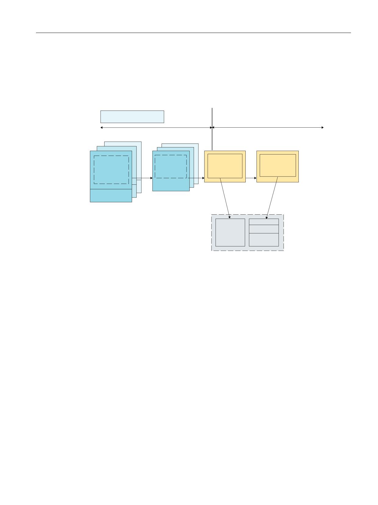
The PC application "NC VAR selector" retrieves the addresses of required NC variables and
prepares them for access in the PLC program (FB2/FB3). This enables the PLC programmer to
select NC and drive variables from the entire range of NC and drive variables, to store this
selection of variables, and to prepare them with a code generator for the STEP 7 compiler. The
data is then stored as ASCII file (*.awl) in the machine CPU program. The "NC VAR Selector"
graphic shows this process.
3URMHFW
&RPSOHWH
6HOHFWHG
*HQHUDWH
OLVW
OLVW
FRGH
YDUB
YDUB
6DYH
YDUB
VHOHFWHG
YDUB
OLVW
YDUB
YDU
DZO
+DUG GLVN
Figure 16-1
NC VAR selector
To store the files created by NC VAR selector, create via Windows Explorer an arbitrary folder
where the selected data of NC VAR selector can be stored (data.VAR and data.AWL files). Then
transfer and compile the data in a STEP 7 project with "Code - in STEP 7 project". As alternative,
insert the "data.awl" file into the STEP 7 machine project via SIMATIC Manager - Program LAD/STL/
PLC
Function Manual, 10/2020, 6FC5397-0HP40-0BA1
139
NC VAR selector
16.1 Overview
FBD blocks with "Insert - External source". The file is stored in the project structure. Once the file
has been transferred, compile the AWL (STL) files with STEP 7.
Note
The latest NC VAR selector can be used for each NC software release (even older versions). For
older NC software releases, the variables can also be selected from the latest complete list. The
data content in DB120 (default DB for variables) does not depend on the software version. This
means, variables selected in an older software release need not be reselected when the software
is upgraded.
After starting the "NC VAR selector" application, the variables of the current software version are
displayed.
Transfer the variables to the project list (another window). These selected variables can then be
stored in an ASCII file, prepared as a STEP 7 source file (.awl) and stored.
After creating a PLC data block by means of the STEP 7 compiler, the PLC programmer is able to
read or write NC variables via the basic program function blocks "PUT" and "GET" using the
created STEP 7 file.
The project list is also stored as an ASCII file (file extension .var).
The variable list supplied with the "NC VAR selector" tool is adapted to the current software
release. This list does not contain any variables (GUD variables) defined by the user. These
variables are processed by the function block FB5 in the basic program.
System features, supplementary conditions
The PC application "NC VAR selector" requires Windows XP or a later operating system.
The assignment of names to variables is described in:
Further information:
/List sl (Book1); Section: Variables
and also in the variables help file (integrated in NC VAR selector)
PLC
140
Function Manual, 10/2020, 6FC5397-0HP40-0BA1
NC VAR selector
16.2 Using NC VAR selector
16.2
Using NC VAR selector
16.2.1
NC VAR selector user interface
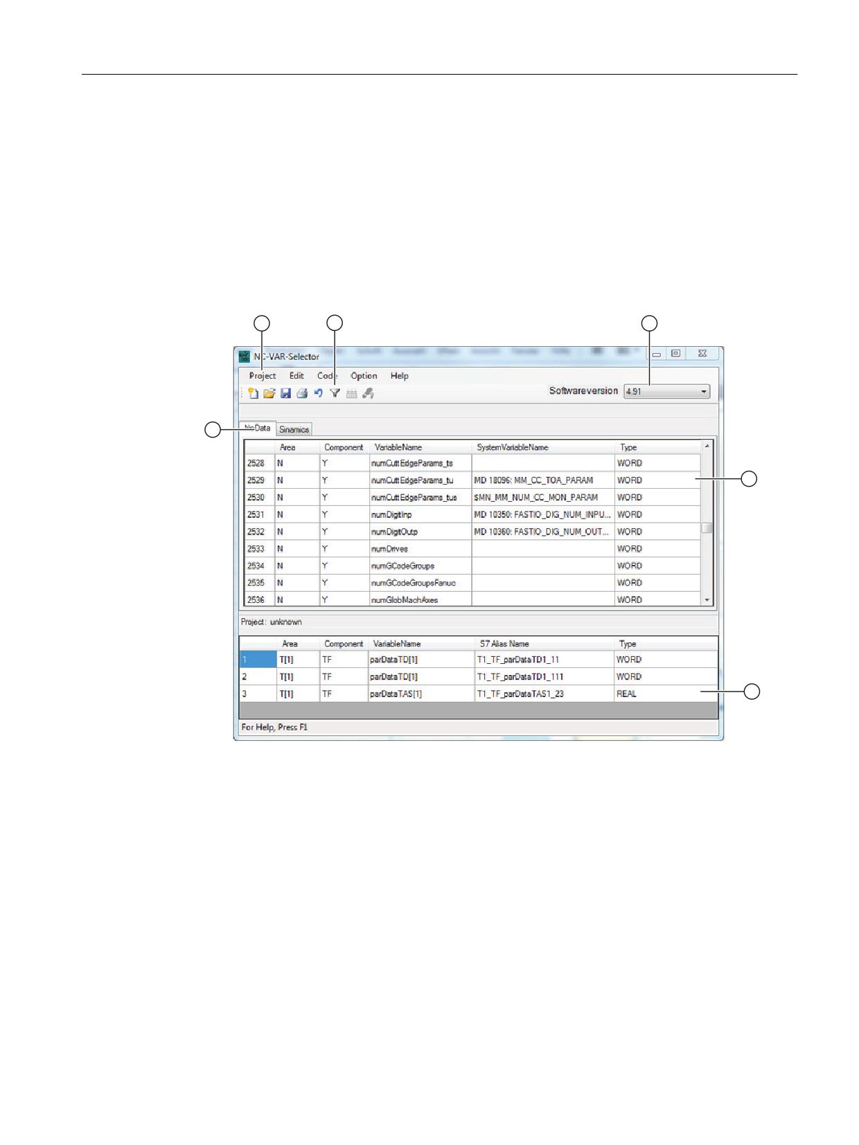
Software user interface structure
The user interface is structured as follows:
① Menu bar
② Available buttons
③ Drop-down list with the available software versions
④ Tab for switching between NC variables and SINAMICS parameters
⑤ List of the NC variables (variable list)
⑥ List of the selected NC variables (project list)
Figure 16-2
Software user interface
PLC
Function Manual, 10/2020, 6FC5397-0HP40-0BA1
141
NC VAR selector
16.2 Using NC VAR selector
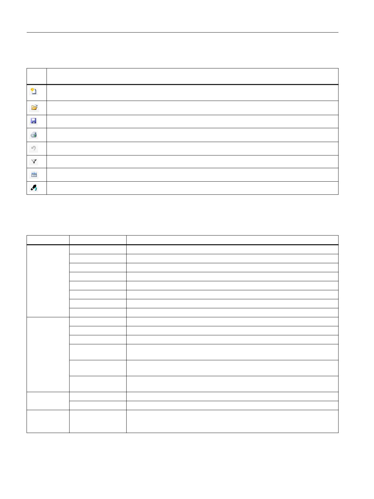
Buttons
Sym-
bol
Creates a new project. The file selection for the NC variable list opens (applies only when the NC variable list is not
already open).
Opens an existing project (*.var). The project already contains a stored list of selected variables
Stores the list of selected variables as project in the *.var format.
Prints the project list.
Undoes the last edit step.
Opens the filter dialog to filter the available variables.
Generated STL code with the set properties.
Transfers the generated NCVar data blocks to a STEP 7 project.
Main menu
The main menu contains the following entries:
Menu entry
Menu item
Description
Project
New
Creates a new project and closes a previously opened project.
Open
Opens an existing project.
Save
Saves a project in *.var format.
Save as
Saves a project with a new name, with the option of changing the path.
Open database
Opens an NC variable list in "mdb" database format.
Print preview
Shows the print preview of the selected NC variables.
Print
Prints the selected NC variables as list.
Exit
Exits NC VAR selector.
Edit
Undo
Undoes the last edit step.
Transfer NC variables
Transfers the selected NC variables to the project list.
Delete in project
Deletes selected NC variables from the project.
Change alias name in
Opens a dialog for changing the alias name of the selected variable in the project list.
the project
Change variable pa-
Opens a dialog for changing the parameters of a variable in the project list.
rameters
Search for / filter NC
Opens a dialog for searching for / filtering variables.
variables
Code
Settings
Opens a dialog with which the code generation can be configured.
Generate
Initiates the generation of STL code.
Help
Online helps for vari-
Contains a list of online help for various SINUMERIK data and drive data.
ous SINUMERIK data
and drive data.
PLC
142
Function Manual, 10/2020, 6FC5397-0HP40-0BA1
NC VAR selector
16.2 Using NC VAR selector
16.2.2
Description of functions
Overview
The figure below illustrates how NC VAR selector is used within the STEP 7 environment.
1& 9$5 VHOHFWRU
67(3
6HOHFWLRQ
)LOH DZO
)LOH '%
1& YDULDEOHV
OLVW
YDU
9DULDEOHV
9DULDEOHV
OLVW
1DPH
1DPH YDOXH!
1DPH
1DPH
YDOXH!
XVHU GDWD
8(
9DU ,'
&DOO )% 9DU
$UHD XQLW
9DU 1DPH
&ROXPQ
Figure 16-3
Application of NC VAR selector in the STEP 7 environment
NC VAR selector generates a list of selected variables from a list of variables and then creates
an .awl file that can be compiled by the STEP 7 compiler.
• An *.awl file contains the names and alias names of the NC variables, as well as information
about their address parameters. A data block created from this file only contains the address
parameters (10 bytes per parameter).
• The created data blocks must always be stored in the machine-specific file storage according
to STEP 7 specifications.
• To ensure that the parameterization of the FB2 and FB3 blocks with regard to NC addresses
can be implemented with symbols, the freely assignable, symbolic name of the created data
block must be included in the STEP 7 symbol list.
PLC
Function Manual, 10/2020, 6FC5397-0HP40-0BA1
143
NC VAR selector
16.2 Using NC VAR selector
16.2.3
Editing projects
Create a project
The data relevant for a project is stored in *.var file format. When the NC VAR selector is opened
a project is created implicitly and an empty variable list is shown.
1. Perform "Project - New" to create a new project and to close any currently open project.
2. If a project with a variable list already exists, a query opens:
- Discard the settings of the opened project; all settings are deleted.
- Save the project settings. The "Save as" dialog opens.
Enter a name for the project
The open project closes. The newly created project does not have any name. To do this, save the
project with a new name with "Project - Save as".
Save project
After creating a project, only the "Save as" menu item is active.
1. Perform "Project - Save as" to save the project with a new name.
2. If the data of a project has been changed, perform "Project - Save" to save the changes.
Open project
Existing projects can be opened in NC VAR selector.
1. Perform "Project - Open". The "Open" dialog opens.
2. Navigate to the path of the project to be opened.
3. Select the project (*.var) and click "Open".
The project with the stored variable list opens, the open project closes.
Print project
The selected variables can be printed. The layout of the printed documents can be adapted with
the print preview.
1. Perform "Project - Print" to send the variable list to the selected printer.
2. Perform "Project - Print preview" to check the print-out before printing and to adapt the layout.
PLC
144
Function Manual, 10/2020, 6FC5397-0HP40-0BA1
NC VAR selector
16.2 Using NC VAR selector
16.2.4
Filtering the variable list
Structure of the variable list
The variable list is created as table. The structure of the table is oriented on the structure of the
NC variables:
• Area; the scope of the NC variables is subdivided into areas similar to machines:
- [A]; axis-specific basic settings
- [B]; operating mode groups
- [C]; channels
- [M]; HMI data
- [N]; NC data
- [T]; tool data
- [V]; drive parameters
• Blocks; each area contains several blocks to which the NC variables are assigned.
• Variable name; shows the name of the NC variable.
• System variable / machine data item; shows the name of the corresponding system variable /
machine data item.
• Type; shows the data type of the variable.
Select software version
The available NC variables differ for each software version. The "Software version" drop-down list
lists all versions contained in NC VAR selector.
1. Select in the "Software version" drop-down list, the software version to be used for the
project.
After the selection, a query opens to make the decision whether the currently selected
variables should be discarded.
2. Click "Yes" to discard the settings and to display the variables for the specified version.
PLC
Function Manual, 10/2020, 6FC5397-0HP40-0BA1
145
NC VAR selector
16.2 Using NC VAR selector
Filtering the variable list
To restrict the number of displayed variables, the variables can be filtered:
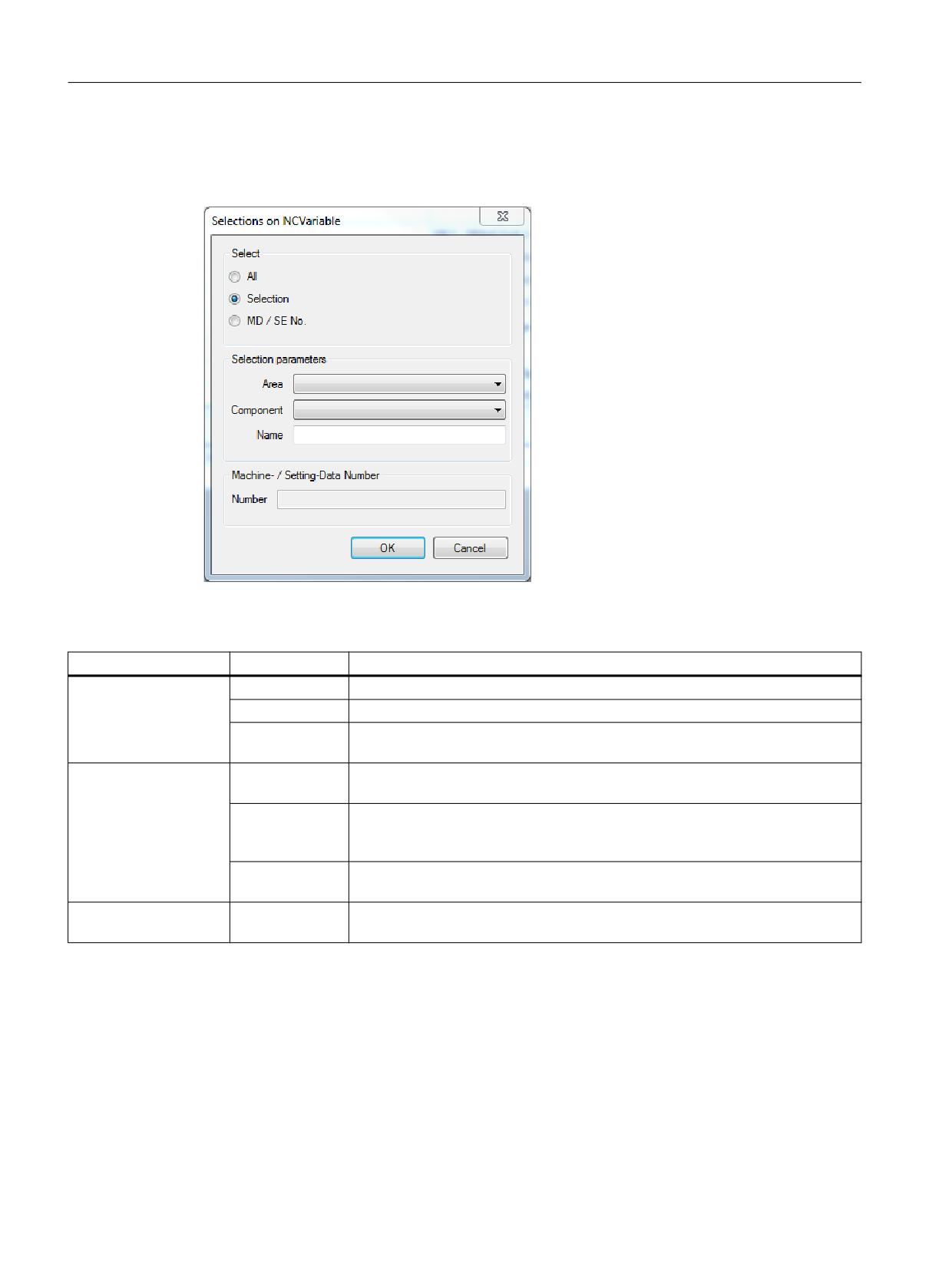
To display the subsets of NC variables, filter criteria can be defined in the "Select NC variables"
dialog:
Filter area
Filter criterion
Description
Selection
All
Displays all variables/parameters
Filter
Activates the filter criteria
MD / SE No.
Activates the "Number" input field in order to enter the number of a variable /
system variable / machine data item. For drive data, this is the parameter number
Filter criteria
Area
Permits the selection of the area for NC variables and the display of all variables
of the area.
Block
Permits the selection of the block and the display of all variables of the block. If
the area is already selected, but the selected block is not available there, no result
is returned.
Name
Full text search for variables. Fragments of the variable name can also be entered.
All hits with this fragment are displayed.
Machine / setting data
Number
Input field for the number of the variable / system variable / machine data item.
number
Only the variable with this number is displayed.
To reset the filters, the new filter setting must be performed.
Example search criteria
Name search criterion: CHAN* Found:
CHAN_NAME
chanAlarm
chanStatus
PLC
146
Function Manual, 10/2020, 6FC5397-0HP40-0BA1
NC VAR selector
16.2 Using NC VAR selector
channelName
chanAssignment
16.2.5
Specifying the project list
Structure of the project list
The project list table has the following structure:
• Area; the scope of the NC variables is subdivided into areas similar to machines.
• Blocks; each area contains several blocks to which the NC variables are assigned.
• Variable name; shows the name of the NC variable.
• S7 alias name; the name that can be used in STEP 7 instead of the variable name.
• Type; shows the data type of the variable.
Transferring variables to the project list
All variables required for creating the data block must be added to the project list.
1. Search for the variables to be added to the project list.
2. Double-click the variable.
- OR -
3. Perform "Transfer NC variables" via the context menu.
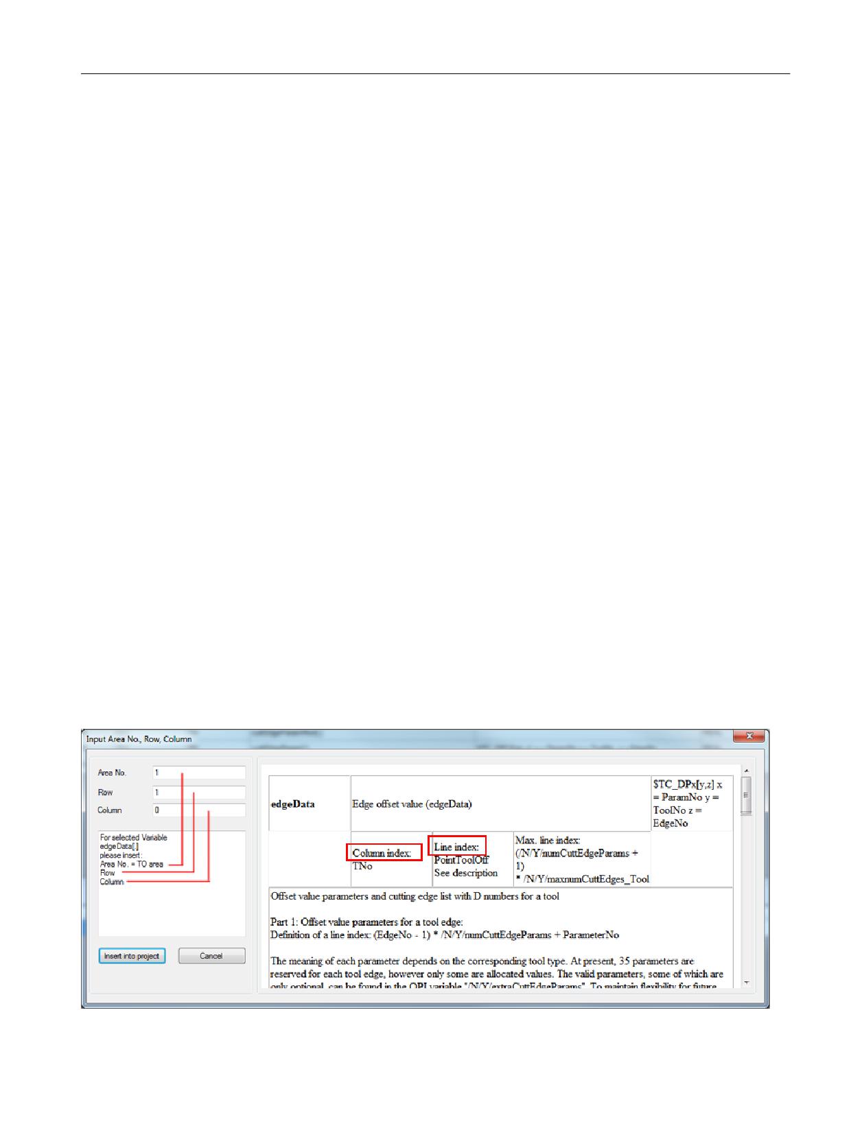
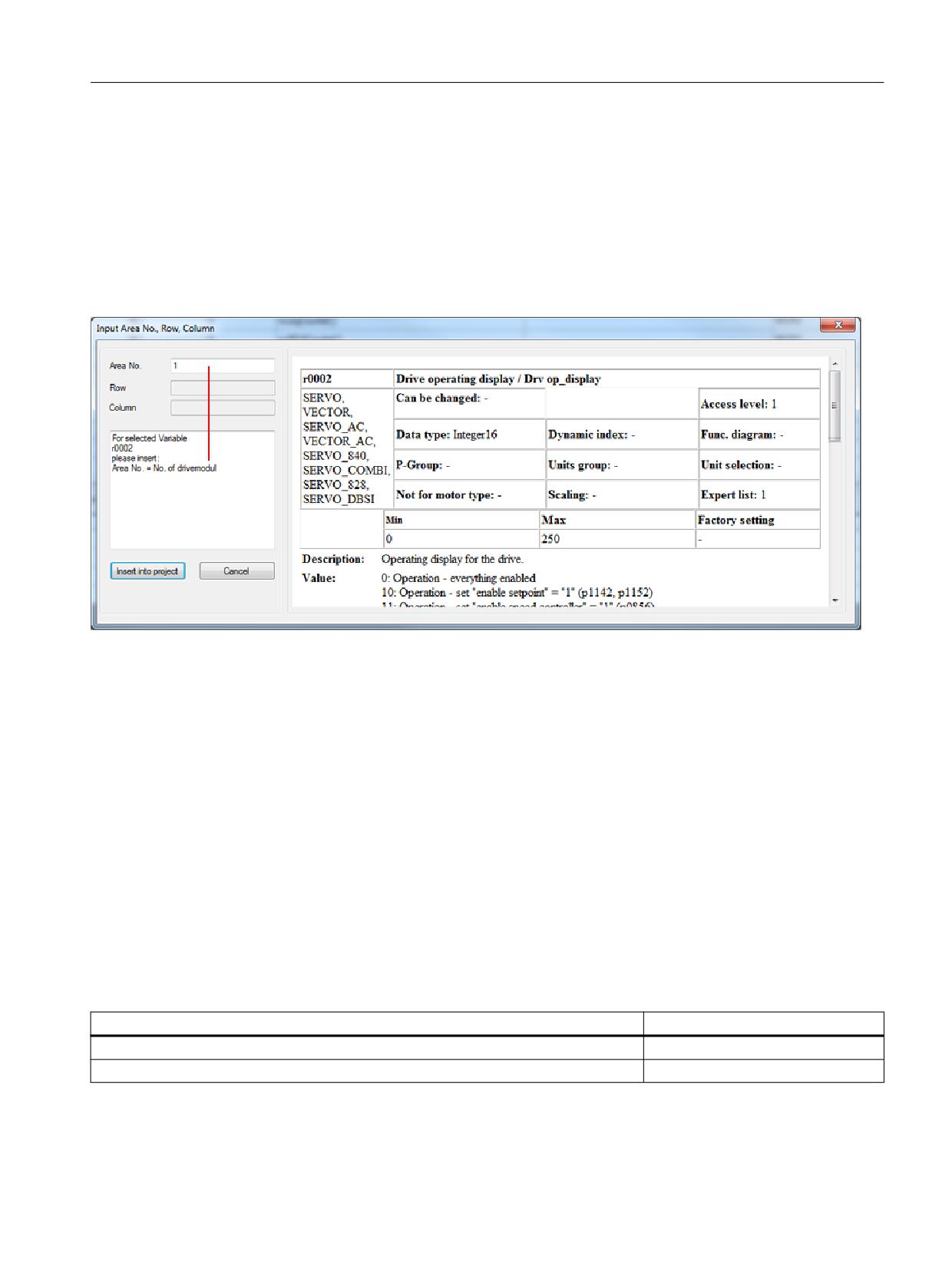
The "Input Area No., Row, Column" dialog opens.
"Input Area No., Row, Column" dialog
The variable parameters are entered in the "Input Area No., Row, Column" dialog
PLC
Function Manual, 10/2020, 6FC5397-0HP40-0BA1
147
NC VAR selector
16.2 Using NC VAR selector
Figure 16-4
Rows, columns and area numbers
The dialog shows an excerpt from the variable description. Fields in which parameters can be
entered are active. The description how the various parameters can be entered correctly is
shown below the input fields.
• The value that can be entered in the "Area number" field to control the correct variable is
described in this field.
• The meaning of row and column is contained in the variable description. The "Column index"
and "Row index" fields there describe the associated inputs.
Parameterizing variables
The associated required parameters must be entered for the various variable types:
• Single-line variable; only the area number must be entered to access variables of this type.
If this is also fixed, the variable can be used without further parameterization.
• Multi-line variable: A variable of this type is a one-dimensional field. The "area number" and
a "line" must be entered for access.
• Multi-line and multi-column NC variables: A variable of this type is a two-dimensional field.
The "area number", a "line" and a "column number" must be entered for access.
Special case "pointer"
By entering a zero (0) as area number, row or column index, it is possible to use the variable in
the S7 context as a pointer to this data. When reading or writing this data via the functions "PUT"
and "GET", the optional parameters "UnitX", "ColumnX" and "LineX" must be filled with the
necessary information.
16.2.6
Deleting a variable from the project list
Delete variable
To delete a variable from the project list, proceed as follows:
1. Select the variable.
2. Perform "Delete in the project" via the context menu.
The variable is deleted from the list.
This action can also be undone with the "Edit" menu item.
Note
Deleting of variables results in a change of the absolute addresses of the pointer structures to the
variables. When changing the variable selection, it is absolutely necessary to create one or
more text files of all user blocks prior to the change. This is the only way to ensure that the
assignment of the variables in FB "GET" or FB "PUT" remains correct, even after recompilation.
PLC
148
Function Manual, 10/2020, 6FC5397-0HP40-0BA1
NC VAR selector
16.2 Using NC VAR selector
16.2.7
Alias name
Description
The variable names provided can be up to 32 characters in length. To make variables unique in
the data block to be generated, several ASCII characters are added to the selected name.
However, the STEP 7 compiler recognizes maximum 24 ASCII characters as a unique S7 variable.
Since it cannot be precluded that variable names can only be differentiated by the last 8
character positions, ALIAS names are used for names that are too long. Consequently, the
length of the S7 name to be used is checked when a variable is selected. If the name is longer
than 24 characters, the user must enter an additional name, which is then used as the alias
name.
In this case, the user must ensure that the alias name is unique.
Configuring alias input
1. Activate the adaptation of the alias name for the transfer of the variables to the project list:
- "Specify the alias name only when the name is longer than 24 characters"; adapt the alias
name only when necessary.
- "Always specify the alias name"; this allows the alias name always to be adapted.
2. An alias name can then be entered every time a variable is transferred.
Editing alias names
To edit the alias name subsequently, perform "Change alias name in the project" in the context
menu of the project list. This action can also be undone with the "Edit" menu item.
16.2.8
Generating code
Generating STL code
To use the block in STEP 7, the project list must be converted to STL. To do this, generate the STL
code with the following settings.
PLC
Function Manual, 10/2020, 6FC5397-0HP40-0BA1
149
NC VAR selector
16.2 Using NC VAR selector
Perform settings
Enter in the "Code - Settings" menu item, the DB number and the symbol for the DB number for
which the code is generated.
• Select in the "Measuring system" tab how the measuring system variables are processed in
the PLC.
• The creation for the associated target system is specified in the "Generate" tab.
Perform generation
Generate the STEP 7 file from the selected variable list with extension *.awl:
1. Save the project list as project (*.var).
2. Perform "Code - Generate". The "Save as" dialog opens.
3. Enter a name for the file and specify the path for the *.awl file to be created.
The *.awl file is stored with this name.
PLC
150
Function Manual, 10/2020, 6FC5397-0HP40-0BA1
NC VAR selector
16.2 Using NC VAR selector
16.2.9
Transfer to STEP 7
Transferring a project list to STEP 7
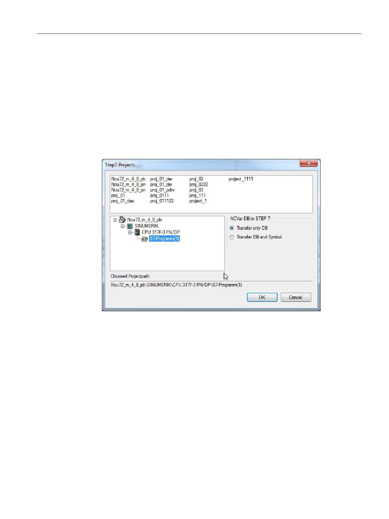
The generated AWL file is transferred to a selectable SIMATIC project (program path) and
compiled. Furthermore, the symbol can also be transferred. This function is available as of STEP
7 Version 5.1. Before transferring a new AWL file, the file window of the AWL file must be closed
in the LAD/FBD/STL editor.
1. First save the project list.
2. Perform "Code - In STEP 7 project".
The "STEP 7 projects" dialog opens.
Figure 16-5
Transfer to STEP 7
3. Select the STEP 7 project that contains your program.
4. Activate the "Transfer only DB" checkbox when only the data block should be transferred.
5. Activate the "Transfer DB and Symbol" checkbox when not only the data block, but also
symbols should be transferred. Symbols allow the symbolic addressing of variables.
6. Click "OK" to start the operation.
SIMATIC Manager opens and the block is stored at "Sources".
The data block can be displayed in the "LAD/FBD/STL" program editor.
7. Double-click the data block at "Blocks" in SIMATIC Manager, e.g. DB120.
The program editor opens and displays the variables.
PLC
Function Manual, 10/2020, 6FC5397-0HP40-0BA1
151
NC VAR selector
16.2 Using NC VAR selector
Importing a generated AWL file into STEP 7
As alternative to the method described above, the stored STL source can be inserted in a project
in SIMATIC Manager.
1. Open the project in SIMATIC Manager and navigate to the "Sources" folder.
2. Perform "Insert - External source".
The "Insert external source" dialog opens.
3. Select the AWL file and click "Open".
The file is added to the sources of the project.
4. Compile the file so it can be used as block. The block is then displayed in the "Blocks" folder.
16.2.10
Using TIA Portal
STL source for TIA Portal
If TIA Portal is used rather than SIMATIC Manager, the "in STEP 7 project" function can be used.
The procedure for TIA Portal follows:
1. Specify the project list.
2. Save the list.
3. Generate an AWL file.
4. Import the AWL file into TIA Portal.
For more information on this topic, refer to the online help of TIA Portal.
16.2.11
Using SINAMICS parameters
SINAMICS parameters
In addition to the "NCData" tab and the variable list of the NC variables, a list of SINAMICS
parameters can also be shown.
The list contains the parameters of the "Servo" drive object:
• r parameters: display parameters with which values of the drive axis can be displayed.
• p parameters: read and write parameters with which values can be transferred to the drive
axis.
Similar to NC variables, SINAMICS parameters can also be added to the project list and
transferred to STEP 7.
PLC
152
Function Manual, 10/2020, 6FC5397-0HP40-0BA1
NC VAR selector
16.2 Using NC VAR selector
Selecting parameters
To select drive parameters, proceed as follows:
1. Search for the variables to be added to the project list.
2. Double-click the variable.
- OR -
3. Perform "Transfer NC variables" via the context menu.
The "Input Area No., Row, Column" dialog opens.
Figure 16-6
Drive parameters
4. Enter the number of the drive module that corresponds to the deployed drive.
For drives, the area number is the number of the drive module. This corresponds to the
component number.
The component number can be found in the topology view (SINUMERIK Operate).
16.2.12
Importing variables and parameters
Importing variable and parameter database files
For older versions of NC VAR selector, the variable lists of an NC variant exist as ncv*.mdb files.
When the lists are opened, all available NC variables / SINAMICS parameters are displayed in the
variable list in separate tabs.
The following ncv*.mdb variable list is available:
Variables
List
NC variables including machine and setting data:
ncv_NcData.mdb
Parameters of the drive:
ncv_SinamicsServo.mdb
PLC
Function Manual, 10/2020, 6FC5397-0HP40-0BA1
153
NC VAR selector
16.2 Using NC VAR selector
1. Perform "Project - Open database".
The "Select NC Variable List" dialog opens.
2. Select the appropriate file (ncv*.mdb) and confirm with "Open".
3. The list opens in NC VAR selector.
16.2.13
Startup, installation
The "NC VAR selector" Windows application is installed by the supplied SETUP program.
The system prerequisites depend on the deployed SIMATIC Manager.
PLC
154
Function Manual, 10/2020, 6FC5397-0HP40-0BA1
Block descriptions
17
17.1
Available blocks
FB1 RUN_UP (Page 156)
FB2 GET (Page 164)
FB3 PUT (Page 172)
FB4 PI_SERV (Page 180)
FB5 GETGUD (Page 210)
FB7 PI_SERV2 (Page 218)
FB9 MzuN (Page 219)
FB10 SI relay (Page 224)
FB11 Brake test (Page 227)
FB21 Pwrride (Page 232)
FB29 Diagnostics (Page 240)
FC2 GP_HP (Page 243)
FC3 GP_PRAL (Page 245)
FC5 GP_DIAG (Page 247)
FC6 TM_TRANS2 (Page 249)
FC7 TM_REV (Page 250)
FC8 TM_TRANS (Page 253)
FC9 ASUB (Page 259)
FC10 AL_MSG (Page 262)
FC12 AUXFU (Page 264)
FC13 BHGDisp (Page 265)
FC17 Star-delta (Page 269)
FC18 SpinCtrl (Page 272)
FC19 MCP_IFM (Page 282)
FC21 Transfer (Page 292)
FC22 TM_DIR (Page 299)
FC24 MCP_IFM2 (Page 302)
FC25 MCP_IFT (Page 305)
FC26 HPU_MCP (Page 308)
FC27 OpUWrRec (Page 316)
PLC
Function Manual, 10/2020, 6FC5397-0HP40-0BA1
155
Block descriptions
17.2 FB1: RUN_UP - basic program, start section
FC1005 AG_SEND (Page 318)
FC1006 AG_RECV (Page 319)
17.2
FB1: RUN_UP - basic program, start section
Function
The synchronization of NC and PLC is performed during start-up. The data blocks for the NC/PLC
user interface are created based on the NC configuration defined via machine data, and the basic
program parameters are verified for plausibility. In the event of an error, FB1 transfers an error
identifier to the diagnostic buffer and switches the PLC to the stop state.
"Restart" startup mode
The integrated PLC only supports the startup mode "Restart". After the basic system
initialization, the organization block OB100 "Restart" is always run through first, followed by OB1
"Cyclic mode".
Input parameters
Only the respectively relevant parameters of function block FB1 must be described with user-
specific values for parameterization of the basic program. The preset values in the instance data
block DB7 of the FB1 do not need to be assigned. The function block FB1 must only be called in
the organization block OB100.
Output parameters
The output parameters of function block FB1 can also be read from the cyclical part of the basic
program. Two options are available for this purpose:
1. Direct access to the instance data block DB7 of FB1 in symbolic form.
Example: "L gp_par.MaxChan", with "gp_par" as the symbolic name of DB7
2. A bit memory is assigned to an output parameter when FB1 is parameterized. The bit
memory is then read in the basic program in order to determine the value of the output
parameter.
Example: "MaxChan":= MW 20
Note
For assigning the FB1 parameters for MCP and HHU, see PLC manual "Configuration of machine
control panel, handheld unit, direct keys".
Declaration of the function
FUNCTION_BLOCK FB1
VAR_INPUT
MCPNum:
INT:=1;
// 0: No MCP
// 1: 1 MCP (default)
// 2: 2 MCPs
PLC
156
Function Manual, 10/2020, 6FC5397-0HP40-0BA1
Block descriptions
17.2 FB1: RUN_UP - basic program, start section
MCP1In:
POINTER;
// Start addr. MCP1 input signals
MCP1Out:
POINTER;
// Start addr. MCP1 output signals
MCP1StatSend:
POINTER;
// Status DW for sending MCP1
MCP1StatRec:
POINTER;
// Status DW for receiving MCP1
MCP1BusAdr:
INT:=6;
// default
MCP1Timeout:
S5TIME:= S5T#700MS;
MCP1Cycl:
S5TIME:= S5T#200MS;
MCP2In:
POINTER;
// Start addr. MCP2 input signals
MCP2Out:
POINTER;
// Start addr. MCP2 output signals
MCP2StatSend:
POINTER;
// Status DW for sending MCP2
MCP2StatRec:
POINTER;
// Status DW for receiving MCP2
MCP2BusAdr:
INT;
MCP2Timeout:
S5TIME:= S5T#700MS;
MCP2Cycl:
S5TIME:= S5T#200MS;
MCPMPI:
BOOL:= FALSE;
MCP1Stop:
BOOL:= FALSE;
MCP2Stop:
BOOL:= FALSE;
MCP1NotSend:
BOOL:= FALSE;
MCP2NotSend:
BOOL:= FALSE;
MCPSDB210:
BOOL:= FALSE;
MCPCopyDB77:
BOOL:= FALSE;
MCPBusType:
BYTE=B#16#0;
HHU:
INT:=0;
// Handheld unit interface
// 0: No HHU
// 1: HHU on MPI
// 2: HHU on OPI
BHGIn :
POINTER;
// Transmit data of the handheld
unit
BHGOut :
POINTER;
// Receive data of the handheld
unit
BHGStatSend :
POINTER;
// Status DW for sending HHU
BHGStatRec :
POINTER;
// Status DW for receiving HHU
BHGInLen :
BYTE:= B#16#6;
// Input 6 bytes
BHGOutLen :
BYTE:= B#16#14;
// Output 20 bytes
BHGTimeout :
S5TIME:= S5T#700MS;
BHGCycl :
S5TIME:= S5T#100MS;
BHGRecGDNo :
INT:=2;
BHGRecGBZNo :
INT:=2;
BHGRecObjNo :
INT:=1;
BHGSendGDNo :
INT:=2;
BHGSendGBZNo :
INT:=1;
BHGSendObjNo :
INT:=1;
BHGMPI :
BOOL:= FALSE;
BHGStop :
BOOL:= FALSE;
BHGNotSend :
BOOL:= FALSE;
NCCyclTimeout :
S5TIME:= S5T#200MS;
PLC
Function Manual, 10/2020, 6FC5397-0HP40-0BA1
157
Block descriptions
17.2 FB1: RUN_UP - basic program, start section
NCRunupTimeout :
S5TIME:= S5T#50S;
ListMDecGrp :
INT:=0;
NCKomm:
BOOL:= FALSE;
MMCToIF:
BOOL:=TRUE;
HWheelMMC:
BOOL:=TRUE;
// Handwheel selection via HMI
ExtendAlMsg :
BOOL;
MCP_IF_TCS:
BOOL;
ExtendChanAxMsg :
BOOL:= FALSE;
HMIAxisSel:
BOOL:= FALSE;
// Activates the axis selection
from HMI Operate (when using a
SmartOperate/HT10)
DeactivateCtrlEne
BOOL:= FALSE;
// Deactivates Ctrl-Energy
rgy:
(energy-saving profiles), DB1000
an end user can use this in his
user project
MsgUser :
INT:=10;
// Number of user areas in DB 2
UserIR:
BOOL:= FALSE;
// User programs in OB40,
IRAuxfuT:
BOOL:= FALSE;
// Evaluate T function in OB40
IRAuxfuH:
BOOL:= FALSE;
// Evaluate H function in OB40
IRAuxfuE:
BOOL:= FALSE;
// Evaluate DL function in OB40
UserVersion:
POINTER;
// Pointer to string variable,
which is displayed in the version
display of the user interface
OpKeyNum :
INT;
Op1KeyIn :
POINTER;
Op1KeyOut :
POINTER;
Op1KeyBusAdr :
INT;
Op2KeyIn :
POINTER;
Op2KeyOut :
POINTER;
Op2KeyBusAdr :
INT;
Op1KeyStop :
BOOL;
Op2KeyStop :
BOOL;
Op1KeyNotSend :
BOOL;
Op2KeyNotSend :
BOOL;
OpKeyBusType :
BYTE ;
IdentMcpBusAdr :
INT;
IdentMcpProfilNo
BYTE ;
:
IdentMcpBusType :
BYTE ;
IdentMcpStrobe :
BOOL;
END_VAR
VAR_OUTPUT
MaxBAG:
INT;
MaxChan:
INT;
MaxAxis:
INT;
PLC
158
Function Manual, 10/2020, 6FC5397-0HP40-0BA1

Block descriptions
17.2 FB1: RUN_UP - basic program, start section
ActivChan:
ARRAY[1..10] OF
BOOL;
ActivAxis:
ARRAY[1..31] OF
BOOL;
UDInt :
INT;
UDHex:
INT;
UDReal :
INT;
IdentMcpType :
BYTE ;
IdentMcpLengthIn BYTE ;
:
IdentMcpLengthOut BYTE ;
:
END_VAR
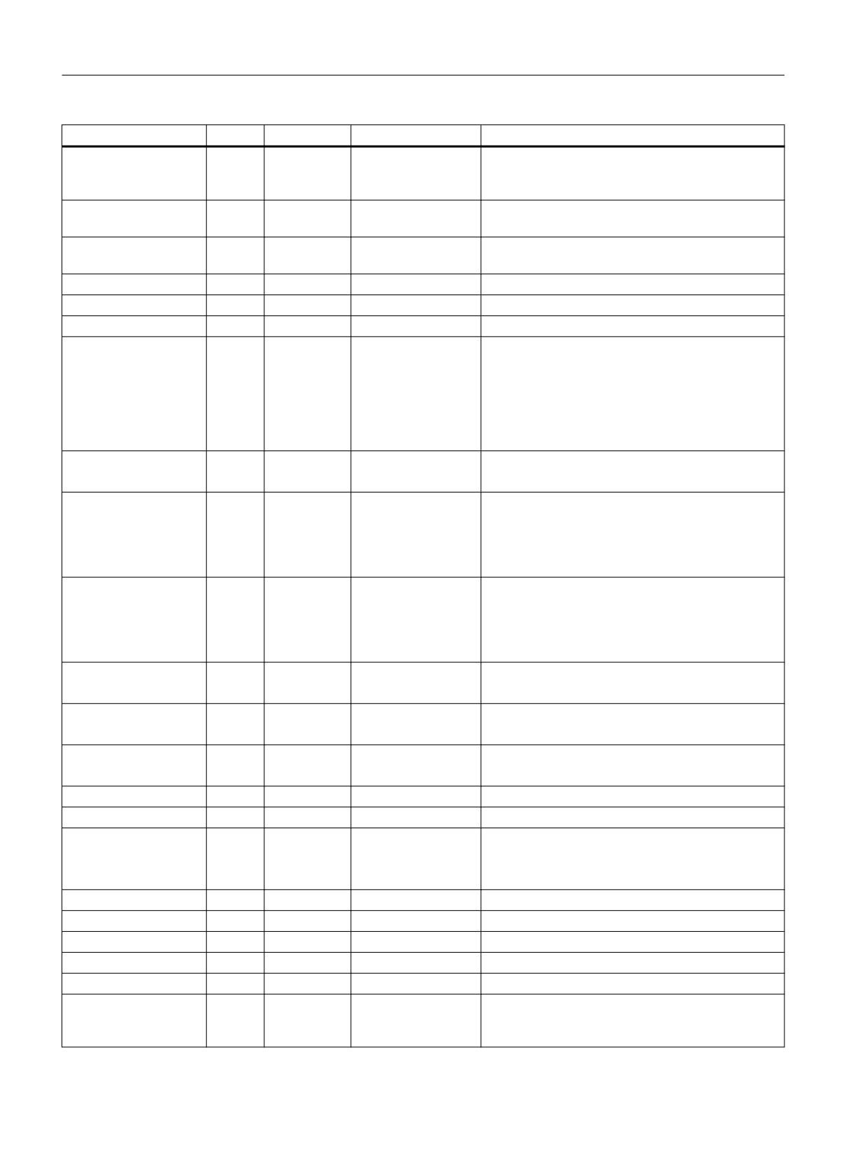
Description of formal parameters
Signal
Type
Type
Value range
Meaning
MCPNum:
I
INT
0, 1, 2
Number of active MCPs
0: No MCPs available
MCP1In:
I
POINTER
E0.0 ... E120.0
Start address for the input signals of the relevant
or
machine control panel
MCP2In:
M0.0 ... M248.0
or
DBn DBX0.0 ...
DBXm.0
MCP1Out:
I
POINTER
A0.0 ... A120.0
Start address for the output signals of the relevant
or
machine control panel
MCP2Out:
M0.0 ... M248.0
or
DBn DBX0.0 ...
DBXm.0
MCP1StatSend:
I
POINTER
A0.0 ... A124.0
Only for Ethernet MCP:
or
MCP2StatSend:
Switch off flashing (see PLC manual, Chapter
M0.0 ... M252.0
"Switchover of the machine control panel, handheld
or
unit")
DBn DBX0.0 ...
DBXm.0
MCP1StatRec:
I
POINTER
A0.0 ... A124.0
Currently no significance
or
MCP2StatRec:
M0.0 ... M252.0
or
DBn DBX0.0 ...
DBXm.0
MCP1BusAdr:
I
INT
1, 2, 3 ... 126
DP slave: PROFIBUS address
MCP2BusAdr:
192, 193, 194 .. 223
Ethernet MCP: DIP setting
MCP1Timeout:
I
S5time
Recommendation:
Cyclic sign-of-life monitoring for machine control
700 ms
panel
MCP2Timeout:
MCP1Cycl:
I
S5time
Recommendation:
Relevant only for PROFIBUS
200 ms
MCP2Cycl:
PLC
Function Manual, 10/2020, 6FC5397-0HP40-0BA1
159

Block descriptions
17.2 FB1: RUN_UP - basic program, start section
Signal
Type
Type
Value range
Meaning
MCPMPI:
I
BOOL
FALSE
Available owing to compatibility
MCP1Stop:
I
BOOL
0 (FALSE), 1 (TRUE)
0: Start transfer of machine control panel signals
MCP2Stop:
1: Stop transfer of machine control panel signals
DP slave: Slave deactivated
MCP1NotSend :
I
BOOL
0 (FALSE), 1 (TRUE)
0: Send and receive operation activated
MCP2NotSend:
1: Receive machine control panel signals only
MCPSDB210:
I
BOOL
false
Available owing to compatibility
MCPCopyDB77:
I
BOOL
false
Available owing to compatibility
MCPBusType:
I
BYTE
3, 4, 5, 6
b#16#yx:
• Bus type MCP1: lower nibble (x)
• Bus type MCP2: upper nibble (y)
3: PROFIBUS
4: PROFIBUS on the MPI/DP port
5: Ethernet
6: PROFINET
Mixed operation is possible (see PLC manual, Chap-
ter "Configuration of machine control panel, hand-
held unit, direct keys")
HHU:
I
INT
0, 5
Handheld unit interface:
0: No HHU
5: HHU on Ethernet
BHGIn:
I
POINTER
E0.0 ... E124.0
Start address PLC receive data from handheld unit
or
M0.0 ... M252.0
or
DBn DBX0.0 ...
DBXm.0
BHGOut:
I
POINTER
A0.0 ... A124.0
Start address PLC transmit data to handheld unit
or
M0.0 ... M252.0
or
DBn DBX0.0 ...
DBXm.0
BHGStatSend:
I
POINTER
A0.0 ... A124.0
Available owing to compatibility
or
M0.0 ... M252.0
or
DBn DBX0.0 ...
DBXm.0
BHGStatRec:
I
POINTER
A0.0 ... A124.0
Available owing to compatibility
or
M0.0 ... M252.0
or
DBn DBX0.0 ...
DBXm.0
BHGInLen:
I
BYTE
HHU default:
Available owing to compatibility
B#16#6 (6 Byte)
PLC
160
Function Manual, 10/2020, 6FC5397-0HP40-0BA1

Block descriptions
17.2 FB1: RUN_UP - basic program, start section
Signal
Type
Type
Value range
Meaning
BHGOutLen:
I
BYTE
HHU default:
Available owing to compatibility
B#16#14 (20 byte)
BHGTimeout:
I
S5time
Recommendation:
Available owing to compatibility
700 ms
BHGCycl:
I
S5time
Recommendation:
Available owing to compatibility
100 ms
BHGRecGDNo:
I
INT
HHU default: 2
Ethernet DIP switch
BHGRecGBZNo:
I
INT
HHU default: 2
Available owing to compatibility
BHGRecObjNo:
I
INT
HHU default: 1
Available owing to compatibility
BHGSendGDNo:
I
INT
HHU default: 2
Available owing to compatibility
BHGSendGBZNo:
I
Int
HHU default: 1
Available owing to compatibility
BHGSendObjNo:
I
INT
HHU default: 1
Available owing to compatibility
BHGMPI:
I
BOOL
0 (FALSE)
Available owing to compatibility
BHGStop:
I
BOOL
0 (FALSE), 1 (TRUE)
0: Start transmission of handheld unit signals
1: Stop transmission of handheld unit signals
BHGNotSend:
I
BOOL
0 (FALSE), 1 (TRUE)
0: Send and receive operation activated
1: Receive handheld unit signals only
NCCyclTimeout:
I
S5time
Recommendation:
Cyclic sign-of-life monitoring NC
200 ms
NCRunupTimeout:
I
S5time
Recommendation:
Power-up monitoring NC
50 s
ListMDecGrp:
I
INT
0, 1, 2 ... 16
Activation of the expanded M group decoding
0: Not active
1...16: Number of M groups
NCKomm:
I
BOOL
0 (FALSE), 1 (TRUE)
PLC NC communication services FB2, 3, 4, 5, 7
1: Active
MMCToIF:
I
BOOL
0 (FALSE), 1 (TRUE)
Transmission of HMI signals to interface (modes,
program control, etc.)
1: Active
HWheelMMC:
I
BOOL
0 (FALSE), 1 (TRUE)
0: Handwheel selection via HMI
1: Handwheel selection via user program
ExtendAlMsg :
I
BOOL
0 (FALSE), 1 (TRUE)
Activation of extensions, error and operational mes-
sages of the FC10 (see Section "Extensions of the
PLC alarms via block FC10" in the PLC manual, Chap-
ter "PLC/HMI interface")
MCP_IF_TCS:
I
BOOL
0 (FALSE), 1 (TRUE)
FC19: Evaluation R11 key
0: No evaluation
1: R11 key acts as manual traversing in tool orien-
tation (see Section "Cartesian manual travel" in Sec-
tion "FC19: MCP_IFM - transfer of MCP signals to
interface (Page 282)")
ExtendChanAxMsg:
I
BOOL
0 (FALSE), 1 (TRUE)
Activation of all areas for error- and operational
messages of the FC10 (see Section "FC10: AL_MSG
- error and operating messages (Page 262)")
HMIAxisSel:
I
BOOL
0 (FALSE), 1 (TRUE)
Activates the axis selection from HMI Operate
(when using a SmartOperate/HT10)
PLC
Function Manual, 10/2020, 6FC5397-0HP40-0BA1
161
Block descriptions
17.2 FB1: RUN_UP - basic program, start section
Signal
Type
Type
Value range
Meaning
DeactivateCtrlEnergy:
I
BOOL
0 (FALSE), 1 (TRUE)
Deactivates Ctrl-Energy (energy-saving profiles),
DB1000 can be used by end users in their own
projects
MsgUser:
I
INT
0, 1, 2 ... 64
Number of user areas (DB2) - depends on parame-
ter "ExtendAIMsg"
UserIR:
I
BOOL
0 (FALSE), 1 (TRUE)
Local data extension OB40 required for processing
of signals from the user
IRAuxfuT:
I
BOOL
0 (FALSE), 1 (TRUE)
Evaluate T function in OB40
IRAuxfuH:
I
BOOL
0 (FALSE), 1 (TRUE)
Evaluate H function in OB40
IRAuxfuE:
I
BOOL
0 (FALSE), 1 (TRUE)
Evaluate DL function in OB40
UserVersion:
I
POINTER
P#DBn.DBXx.0
Pointer to string variable, which is displayed in the
version display of the user interface
The string variable has the following notation (max.
41 characters):
"<Name> <version xx.xx.xx> <date yy/mm/dd>"
Example: "Test version 07.06.02 13/06/04"
OpKeyNum :
I
INT
0, 1, 2
Number of active direct key modules
0: No Ethernet direct control keys available
Op1KeyIn:
I
POINTER
P#Ex.0
Start address for the input signals of the affected
Op2KeyIn:
or
direct control key modules
P#Mx.0
or
P#DBn.DBXx.0.
Op1KeyOut :
I
POINTER
P#Ax.0
Start address for the output signals of the affected
or
direct control key modules
Op2KeyOut:
P#Mx.0
or
P#DBn.DBXx.0.
Op1KeyBusAdr :
I
INT
1, 2, 3 ... 254
Direct keys via Ethernet: TCU index
Op2KeyBusAdr:
Op1KeyStop :
I
BOOL
0 (FALSE), 1 (TRUE)
0: Start transmission of direct control key signals
Op2KeyStop:
1: Stop transmission of the direct key signals
Op1KeyNotSend:
I
BOOL
0 (FALSE), 1 (TRUE)
0: Send and receive operation activated
Op2KeyNotSend:
1: Receive direct control key signals only
OpKeyBusType :
I
BYTE
b#16#55
Ethernet
IdentMcpBusAdr :
I
INT
1, 2, 3 ... 254
Only IE devices
IdentMcpProfilNo :
I
BYTE
0, 1
Profile of a device
0: Complete device
1: Only direct keys
IdentMcpBusType:
I
BYTE
b#16#5
Only IE devices
IdentMcpStrobe:
I
BOOL
0 (FALSE), 1 (TRUE)
1: Activate query
MaxBAG:
O
INT
1, 2, 3 ... 10
Number of mode groups
MaxChan:
O
INT
1, 2, 3 ... 10
Number of channels
MaxAxis:
O
INT
1, 2, 3 ... 31
Number of axes
ActivChan:
O
AR-
0 (FALSE), 1 (TRUE)
Bit string for active channels
RAY[1..10]
OF BOOL
PLC
162
Function Manual, 10/2020, 6FC5397-0HP40-0BA1

Block descriptions
17.2 FB1: RUN_UP - basic program, start section
Signal
Type
Type
Value range
Meaning
ActivAxis:
O
ARRAY
0 (FALSE), 1 (TRUE)
Bit string for active axes
[1..31] OF
BOOL
UDInt :
O
INT
0,
Quantity of INTEGER machine data in DB20
UDHex:
O
INT
---
Quantity of hexadecimal machine data in DB2,
where applicable including the filler byte
UDReal :
O
INT
---
Quantity of REAL machine data in DB20
IdentMcpType :
O
BYTE
0, B#16#80,
MCP type
B#16#81,
B#16#82 ...
B#16#89
IdentMcpLengthIn:
O
BYTE
---
Length of MCP input data (MCP → PLC)
IdentMcpLengthOut :
O
BYTE
---
Length of MCP output data (PLC → MCP)
If an error occurs during communication with a machine control panel (MCP) or handheld unit
(HHU), the following alarm is displayed at the HMI and the input signals (MCP1In, MCP2In or
BHGIn) are set to the zero value:
Error case: MCP/HHU
• Alarm 400260: "MCP 1 failure"
• Alarm 400261: "MCP 2 failure"
• Alarm 400262: "HHU failure"
If a resynchronization is possible between PLC and MCP/HHU, communication is resumed, the
error message at the HMI is deleted by the basic program, and process values transferred into the
input signals (MCP1In, MCP2In or BHGIn) once again.
Example: FB1 call in the OB100
ORGANIZATION_BLOCK OB100
VAR_TEMP
OB100_EV_CLASS :
BYTE ;
OB100_STRTUP :
BYTE ;
OB100_PRIORITY :
BYTE ;
OB100_OB_NUMBR :
BYTE ;
OB100_RESERVED_1 :
BYTE ;
OB100_RESERVED_2 :
BYTE ;
OB100_STOP :
WORD;
OB100_RESERVED_3 :
WORD;
OB100_RESERVED_4 :
WORD;
OB100_DATE_TIME :
DATE_AND_TIME;
END_VAR
BEGIN
CALL FB1, DB7(
// FB1 call, instance DB: DB7
MCPNum :=
1,
PLC
Function Manual, 10/2020, 6FC5397-0HP40-0BA1
163
Block descriptions
17.3 FB2: GET - read NC variable
MCP1In :=
P#E0.0,
MCP1Out :=
P#A0.0,
MCP1StatSend :=
P#A8.0,
MCP1StatRec :=
P#A12.0,
MCP1BusAdr :=
6,
MCP1Timeout :=
S5T#700MS,
MCP1Cycl :=
S5T#200MS,
NC-CyclTimeout :=
S5T#200MS,
NC-RunupTimeout :=
S5T#50S);
// INSERT USER PROGRAM HERE
END_ORGANIZATION_BLOCK
See also
Configuration machine control panel, handheld unit, direct keys (Page 93)
Switchover of machine control panel, handheld unit (Page 102)
Interface PLC/HMI (Page 64)
17.3
FB2: GET - read NC variable
Function
The FB2 "GET" function block is used to read variables from the NC area.
In order to reference the NC variables, they are first selected with the "NC VAR selector" tool and
generated as STL source in a data block. A name must then be assigned to this data block in the
S7 symbol table. When calling FB2, the variable addresses are transferred in the following form:
Parameter "Addr1" to "Addr8" = "<DB name>.<S7 name>"
Request for reading NC variables
Call of FB2 with positive edge change, parameter "Req" = 0 → 1
S7 names of the NC variables: Parameter "Addr1" to "Addr8" = "NCVAR".<S7 name>"
Pointer for writing the variable values: Parameters "RD1" to "RD8" = "P#<Address>"
Completion of the read request
Read request successfully completed: Parameter "Done" == 1.
Read request terminated with error: Parameter "Error" == 1, error cause in parameter "State"
Requirements
• Release of the NC/PLC communication by OB100, FB1 parameter "NCKomm" = 1
• For the data block DB120 (data interface), the S7 Symbol Editor must be used to assign a
symbol (default: NCVAR) in the S7 symbol table of the S7 project. Via this icon you then
specify the NC variable e.g. "ADDR1: = "NCVAR".<NC-Variable>" in the FB2 parameters
"Addr<x>"
PLC
164
Function Manual, 10/2020, 6FC5397-0HP40-0BA1

Block descriptions
17.3 FB2: GET - read NC variable
General conditions
• FB2 has multi-instance capability.
• A separate instance or separate instance DB must be assigned from the user area to each call
of the FB2.
• When channel-specific variables are read, only variables from exactly one channel may be
addressed via "Addr1" to "Addr8" if FB2 is called.
• When drive-specific variables are read, only variables from exactly one SERVO drive object
may be addressed via "Addr1" to "Addr8" if FB2 is called. The SERVO drive object must be
assigned to a machine axis of the NC. The line index corresponds to the logical drive number.
• In a read job, only variables from the same area, channel, or drive object can be read.
Note
Error case
When reading variables from different channels or drive objects, or simultaneously from a
channel and a drive object, an error message is output:
• "Error" == TRUE
• "State" == W#16#02
Variable addressing
For some NC variables, it is necessary to select "Area no." and/or "Line" or "Column" from the NC
VAR selector. It is possible to select a basic type, i.e. "Area no.", "Line" and "Column" are
preassigned "0". The values of the "Area no.", "Line" and "Column" specified by the NC VAR
selector are checked for a "0" in FB2. If an NC-VAR selector value == "0", the corresponding value
of the FB2 parameter is adopted. To do this, the FB2 parameters "Unit<x>", "Column<x>" and
"Line<x>", with <x> = 1 - 8, must be written before FB2 is called.
Table 17-1
Parameter match
FB2 parameter
NC VAR selector
Unit
Area no.
Column
Column
Line
Line
Variables within one group can be combined in a job:
Group
Area
1
C[1]
N
B
A
T
2
C[2]
N
B
A
T
3
V[.]
H[.]
---
---
---
The same rules apply for channels 3 to 10 as for group 1 and group 2 shown in the example.
PLC
Function Manual, 10/2020, 6FC5397-0HP40-0BA1
165
Block descriptions
17.3 FB2: GET - read NC variable
Note
The number of usable variables can be less than eight when simultaneously reading several
variables of the "String" type.
Declaration of the function
FUNCTION_BLOCK FB2
VAR_INPUT
Req :
BOOL;
NumVar :
INT;
Addr1 :
ANY;
Unit1 :
BYTE ;
Column1
:
WORD;
Line1 :
WORD;
Addr2 :
ANY;
Unit2 :
BYTE ;
Column2
:
WORD;
Line2 :
WORD;
Addr3 :
ANY;
Unit3 :
BYTE ;
Column3
:
WORD;
Line3 :
WORD;
Addr4 :
ANY;
Unit4 :
BYTE ;
Column4
:
WORD;
Line4 :
WORD;
Addr5 :
ANY;
Unit5 :
BYTE ;
Column5
:
WORD;
Line5 :
WORD;
Addr6 :
ANY;
Unit6 :
BYTE ;
Column6
:
WORD;
Line6 :
WORD;
Addr7 :
ANY;
Unit7 :
BYTE ;
Column7
:
WORD;
Line7 :
WORD;
Addr8 :
ANY;
Unit8 :
BYTE ;
Column8
:
WORD;
Line8 :
WORD;
END_VAR
PLC
166
Function Manual, 10/2020, 6FC5397-0HP40-0BA1

Block descriptions
17.3 FB2: GET - read NC variable
VAR_OUTPUT
Error :
BOOL;
NDR :
BOOL;
State :
WORD;
END_VAR
VAR_IN_OUT
RD1 :
ANY;
RD2 :
ANY;
RD3 :
ANY;
RD4 :
ANY;
RD5 :
ANY;
RD6 :
ANY;
RD7 :
ANY;
RD8 :
ANY;
END_VAR
Description of formal parameters
Parameter
Type
Type
Value range
Meaning
Req:
I
BOOL
---
Job start with positive signal edge
NumVar:
I
INT
1 ... 8
Number of variables to be read: "Addr1" -
"Addr8"
Addr1 - Addr8:
I
ANY
"DBName".<Var-
Variable identifiers from NC Var selector
Name>
Unit1 - Unit8:
I
BYTE
---
Area address, optional for variable address-
ing
Column1 -
I
WORD
---
Column address, optional for variable ad-
Column8:
dressing
Line1 - Line8:
I
WORD
---
Line address, optional for variable address-
ing
Error:
O
BOOL
0 (FALSE), 1
1: Negative acknowledgement of job or
(TRUE)
execution of job impossible
NDR :
O
BOOL
0 (FALSE), 1
1: Job successfully executed. Data is avail-
(TRUE)
able
State:
O
WORD
---
See paragraph "Error identifiers"
RD1 - RD8:
I/O
ANY
P#Mm.n BYTE
Target area for read data
x ...
P#DBnr.dbxm.n
BYTE x
PLC
Function Manual, 10/2020, 6FC5397-0HP40-0BA1
167
Block descriptions
17.3 FB2: GET - read NC variable
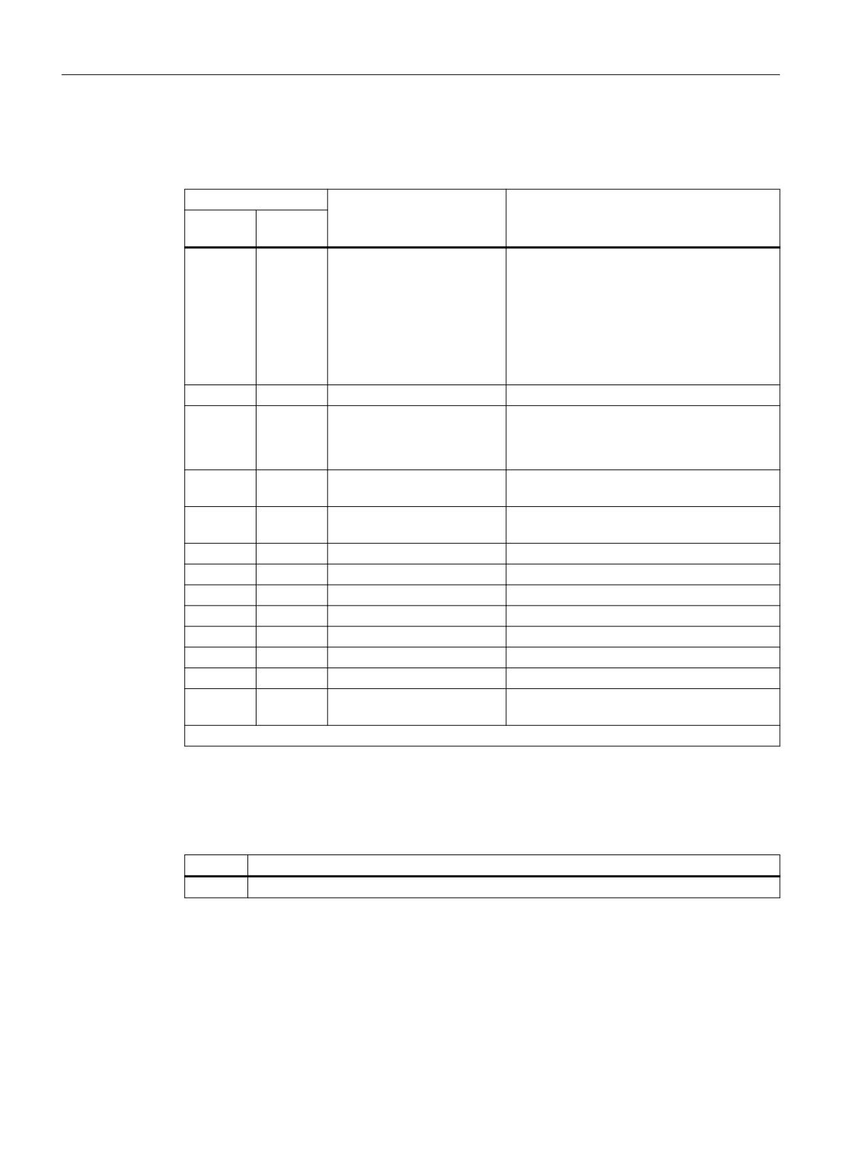
Error identifiers
NC variables
State
Meaning
Note
High
Low byte
byte 1)
1 - 8
1
Access error
The variable cannot be accessed.
Possible causes:
• Variable does not exist in the NCK (possibly
machine data must first be set)
• The "Line" parameter is wrong (0 is only
allowed for certain variables, for Word var-
iables the parameter must be even)
0
2
Error in job
Incorrect compilation of variables in a job
0
3
Negative acknowledgment,
Internal error, possible remedy:
job not executable
• Check job data
• NC reset
1 - 8
4
Insufficient local user memo-
Data type of the read variable is greater than
ry available
specified in "RD1" - "RD8"
0
5
Format conversion error
Error on conversion of var. type double: Varia-
ble is not within the S7 REAL area
0
6
FIFO full
Job must be repeated since queue is full
0
7
Option not set
FB1 parameter "NCKomm" is not set
1 - 8
8
Incorrect target area (RD)
"RD1" - "RD8" must not be local data
0
9
Transmission occupied
Job must be repeated
1 - 8
10
Error in variable addressing
"Unit" or "Column"/"Line" contains value 0
0
11
Address of variable invalid
Check "Addr" (or variable name), "Area", "Unit"
0
12
NumVar == 0
Check parameter "NumVar"
1 - 8
13
ANY data reference incorrect
Requested "NcVar" data has not been parame-
terized
1) High byte > 0 ⇒ Number of the variable in which the error occurred
Drive-specific variables
If an error occurs while reading/writing a drive-specific variable (DB1200.DBX3000.1 == 1), an
error number is displayed in the access result which is based on the error numbers defined in the
PROFIdrive profile.
State
Meaning
x
<Error number of PROFIdrive profile> + 20H or 36D
PLC
168
Function Manual, 10/2020, 6FC5397-0HP40-0BA1
Block descriptions
17.3 FB2: GET - read NC variable
Determining the significance of the access result:
1. Calculation of the error number of the PROFIdrive profile
<Error number of PROFIdrive profile> = result of access - 20H or 36D.
2. Determining the significance of the error number of the PROFIdrive profile
The error numbers of the PROFIdrive profile are described in:
Further information
Function Manual, SINAMICS S120 Drive Functions; Section "Communication" >
"Communication according to PROFIdrive" > "Acyclic communication" > "Structure of the
requests and responses" > Subsection "Error values in parameter responses"
Configuration steps
Proceed as follows to read NC variables:
• Select variables with the NC VAR selector
• Save selected variables in a *.VAR file
• Generate a STEP 7 *.STL source file
• Generate a DB with the associated address data
• Enter the symbol for the generated DB in the symbol table so that it is possible to access the
address parameters symbolically in the user program
• Parameterizing the FB2
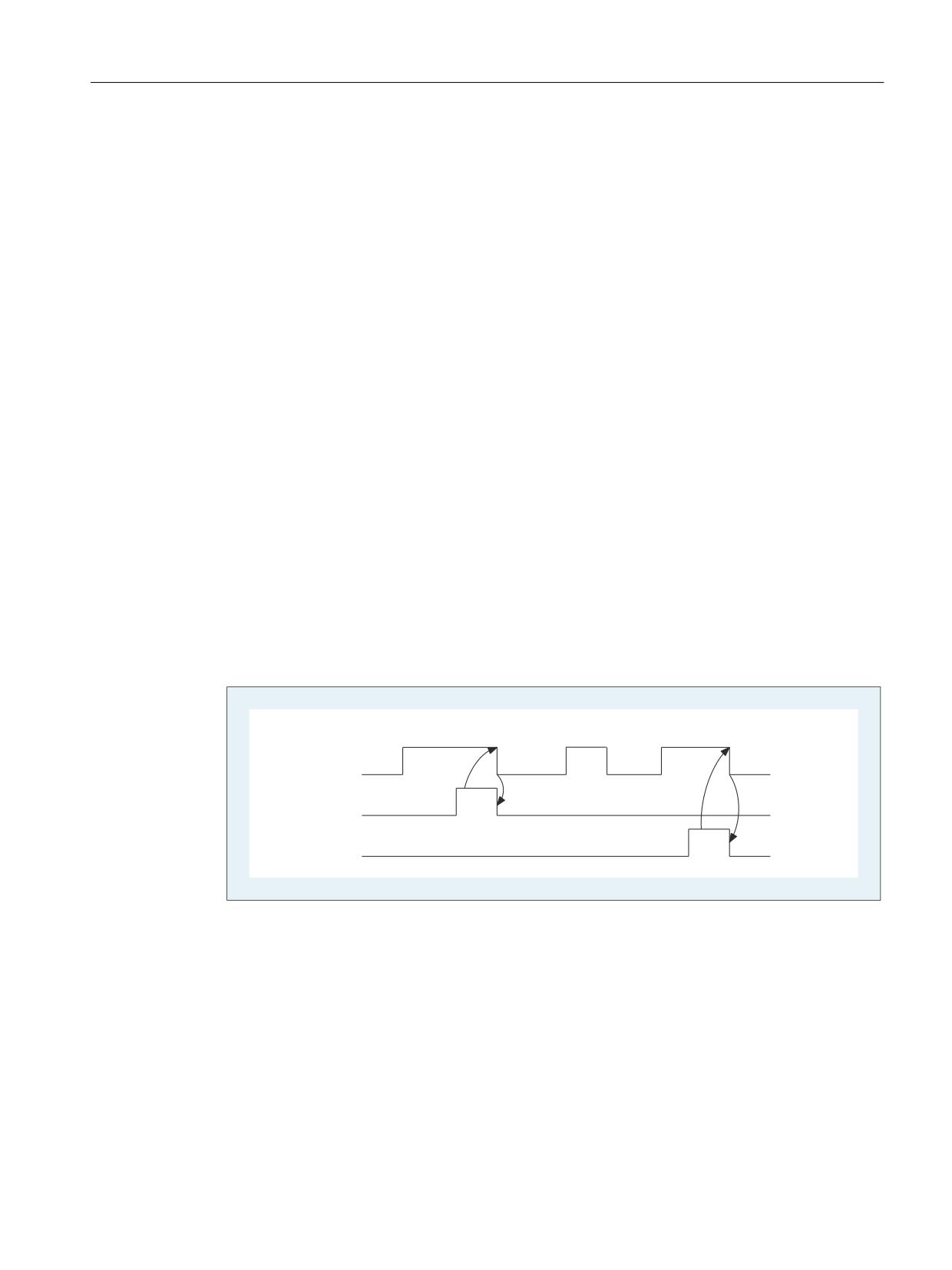
Pulse diagram
5HT
1'5
(UURU
① User: Set request, Req = 0 → 1
② FB2 successfully completed, NDR = 1
User: Reset request, IF NDR == 1 THEN Req = 0
③ User: IF NDR == 1 THEN reset request: 1 → 0
④ FB2 reset job confirmation, NDR = 0
⑤ User: IF NDR == 0 AND Error == 0 THEN reset request Req = 1 → 0 not permissible
⑥ FB2 completed with errors, Error = 1
User: Reset request, IF NDR == 1 OR Error == 1 THEN Req = 0, possible further error handling
PLC
Function Manual, 10/2020, 6FC5397-0HP40-0BA1
169

Block descriptions
17.3 FB2: GET - read NC variable
Call example
Reading three channel-specific machine data from channel 1, whose address specifications are
stored in DB120.
Specification of data
The data is selected with the NC VAR selector and saved in the DB120.VAR file. Then the
DB120.AWL file is created from this.
S7 (ALIAS) names are selected.
To adopt the channel designation into the variable name and to delete the characters "[" and "]",
which are not permitted in a STEP 7 symbol, new S7 names are selected:
Area
Block
Name
Type
No.
Byte
S7 Name
C[1]
M
MD20070 $MC_AXCONF_MACHAX_USED[1]
CHAR
20070
1
C1AxConfMachAxUsed1
C[1]
M
MD20070 $MC_AXCONF_MACHAX_USED[2]
CHAR
20070
1
C1AxConfMachAxUsed2
C[1]
M
MD20090 $MC_SPIND_DEF_MASTER_SPIND
INT
20090
1
C1SpindDefMasterSpind
S7 symbol table
"NCVAR" is entered in the S7 symbol table as a symbolic name for the data block DB120:
Symbol
Operand
Data type
NCVAR
DB120
DB120
File DB120.AWL must be compiled and transferred to the PLC.
Parameterization of FB2 with instance DB110:
DATA_BLOCK DB110
// Unassigned user DB, as instance for FB2
FB2
BEGIN
END_DATA_BLOCK
Function FC "VariablenCall" : VOID
PLC
170
Function Manual, 10/2020, 6FC5397-0HP40-0BA1
Block descriptions
17.3 FB2: GET - read NC variable
U
I 7.7;
// Unassigned machine control panel key
S
M 100.0;
// Activate req.
U
M 100.1;
// NDR completed message
R
M 100.0;
// Terminate job
U
I 7.6;
// Manual error acknowledgment
U
M 102.0;
// Error pending
R
M 100.0;
// Terminate job
CALL FB2, DB110(
Req :=
M 100.0,
NumVar :=
3,
// Read three variables
Addr1 :=
"NCVAR".C1AxConfMachAxUsed1,
Addr2 :=
"NCVAR".C1AxConfMachAxUsed2,
Addr3 :=
"NCVAR".C1SpindDefMasterSpind,
Error :=
M102.0,
NDR :=
M100.1,
State :=
MW104,
RD1 :=
P#DB99.DBX0.0 BYTE 1,
RD2 :=
P#DB99.DBX1.0 BYTE 1,
RD3 :=
P#M110.0 INT 1);
Example: Variable addressing
Reading two R parameters from channel 1, whose address specifications are stored in DB120 as
the basic type. The R parameter number is parameterized via parameter "Line<x>".
DATA_BLOCK DB120
VERSION : 0.0
STRUCT
C1_RP_rpa0_0:
STRUCT
SYNTAX_ID :
BYTE := B#16#82;
area_and_unit :
BYTE := B#16#41;
column :
WORD := W#16#1;
line :
WORD := W#16#0;
block type :
BYTE := B#16#15;
NO. OF LINES :
BYTE := B#16#1;
type :
BYTE := B#16#F;
length :
BYTE := B#16#8;
END_STRUCT;
END_STRUCT;
BEGIN
END_DATA_BLOCK
CALL FB2, DB110(
PLC
Function Manual, 10/2020, 6FC5397-0HP40-0BA1
171

Block descriptions
17.4 FB3: PUT - write NC variables
Req :=
M 0.0,
NumVar :=
2,
Addr1 :=
"NCVAR".C1_RP_rpa0_0,
Line1 :=
W#16#1,
Addr2 :=
"NCVAR".C1_RP_rpa0_0,
Line2 :=
W#16#2,
Error :=
M 1.0,
NDR :=
M 1.1,
State :=
MW 2,
RD1 :=
P#M 4.0 REAL 1,
RD2 :=
P#M 24.0 REAL 1);
Classification of data types
Table 17-2
Classification of data types
NC-internal or OPI data type
S7 data type
DOUBLE
REAL
DOUBLE
REAL2
REAL
REAL
LONG
DINT
INTEGER
DINT
UINT_32
DWORD
INT_16
INT
UINT_16
WORD
UNSIGNED
WORD
CHAR
CHAR or BYTE
STRING
STRING
BOOL
BOOL
DATETIME
DATE_AND_TIME
Example
For example, to be able to read an NC variable of the type DOUBLE without adapting the format,
an ANY pointer with REAL2 type must be specified in the destination area "RDx" (e.g.: P#M100.0
REAL2). If the basic PLC program identifies a variable of the type DOUBLE as REAL2 target type
when reading, the data is adopted as a 64 bit floating point number in the PLC data area.
17.4
FB3: PUT - write NC variables
Function
The FB3 "PUT" function block is used to write variables from the NC area.
PLC
172
Function Manual, 10/2020, 6FC5397-0HP40-0BA1
Block descriptions
17.4 FB3: PUT - write NC variables
In order to reference the NC variables, they are first selected with the "NC VAR selector" tool and
generated as STL source in a data block. A name must then be assigned to this data block in the
S7 symbol table. When calling FB3, the variable addresses are transferred in the following form:
Parameter "Addr1" to "Addr8" = "<DB name>".<S7 name>
Request for writing NC variables
Call of FB3 with positive edge change, parameter "Req" = 0 → 1
S7 names of the NC variables: Parameter "Addr1" to "Addr8" = "NCVAR".<S7 name>"
Pointer for writing the variable values: Parameters "RD1" to "RD8" = "P#<Address>"
Completion of the write request
Write request successfully completed: Parameter "Done" == 1.
Write request completed with error: Parameter "Error" == 1, error cause in parameter "State"
Requirements
• Release of the NC/PLC communication by OB100, FB1 parameter "NCKomm" = 1
• For the data block DB120 (data interface), the S7 Symbol Editor must be used to assign a
symbol (default: NCVAR) in the S7 symbol table of the S7 project. Via this symbol, the NC
variable is then specified in the FB3 parameters "Addr<x>", e.g. "ADDR1":= "NCVAR".<NC-
Variable>"
General conditions
• FB3 has multi-instance capability.
• A separate instance or a separate instance DB must be assigned from the user area to each
call of the FB3.
• In order to define machine data and GUD without a password, the protection level of the data
you want to access must be redefined to the lowest level.
Further information
- SINUMERIK Operate Commissioning Manual; chapter: "Protection levels concept"
- Programming Manual NC Programming; Section: "Attribute: Access rights (APR, APW,
APRP, APWP, APRB, APWB)"
• When channel-specific variables are written, only variables from exactly one channel may
be addressed via "Addr1" to "Addr8" if FB2 is called.
• When drive-specific variables are written, only variables from exactly one SERVO drive
object may be addressed via "Addr1" to "Addr8" if FB2 is called. The SERVO drive object must
be assigned to a machine axis of the NC. The line index corresponds to the logical drive
number.
• In a write job, only variables from the same area, channel, or drive object can be written.
PLC
Function Manual, 10/2020, 6FC5397-0HP40-0BA1
173

Block descriptions
17.4 FB3: PUT - write NC variables
Note
Error case
When writing variables from different channels or drive objects, or simultaneously from a
channel and a drive object, an error message is output:
• "Error" == TRUE
• "State" == W#16#02
Variable addressing
For some NC variables, it is necessary to select "Area no." and/or "Line" or "Column" from the NC
VAR selector. It is possible to select a basic type, i.e. "Area no.", "Line" and "Column" are
preassigned "0". The values of the "Area no.", "Line" and "Column" specified by the NC VAR
selector are checked for a "0" in FB2. If an NC-VAR selector value == "0", the corresponding value
of the FB3 parameter is adopted. To do this, the FB3 parameters "Unit<x>", "Column<x>" and
"Line<x>", with <x> = 1 - 8, must be written before FB3 is called.
FB3 parameter
NC VAR selector
Unit<x>
Area no.
Column<x>
Column
Line<x>
Line
NC variables within one group can be combined in a job:
Group
Area
1
C[1]
N
B
A
T
2
C[2]
N
B
A
T
3
V[.]
H[.]
---
---
---
The same rules apply for channels 3 to 10 as for group 1 and group 2 shown in the example.
Note
The number of usable variables can be less than eight when simultaneously writing several
variables of the "String" type.
Declaration of the function
FUNCTION_BLOCK FB3
VAR_INPUT
PLC
174
Function Manual, 10/2020, 6FC5397-0HP40-0BA1
Block descriptions
17.4 FB3: PUT - write NC variables
Req :
BOOL;
NumVar :
INT;
Addr1 :
ANY;
Unit1 :
BYTE ;
Column1
:
WORD;
Line1 :
WORD;
Addr2 :
ANY;
Unit2 :
BYTE ;
Column2
:
WORD;
Line2 :
WORD;
Addr3 :
ANY;
Unit3 :
BYTE ;
Column3
:
WORD;
Line3 :
WORD;
Addr4 :
ANY;
Unit4 :
BYTE ;
Column4
:
WORD;
Line4 :
WORD;
Addr5 :
ANY;
Unit5 :
BYTE ;
Column5
:
WORD;
Line5 :
WORD;
Addr6 :
ANY;
Unit6 :
BYTE ;
Column6
:
WORD;
Line6 :
WORD;
Addr7 :
ANY;
Unit7 :
BYTE ;
Column7
:
WORD;
Line7 :
WORD;
Addr8 :
ANY;
Unit8 :
BYTE ;
Column8
:
WORD;
Line8 :
WORD;
END_VAR
VAR_OUTPUT
Error :
BOOL;
Done :
BOOL;
State :
WORD;
END_VAR
VAR_IN_OUT
PLC
Function Manual, 10/2020, 6FC5397-0HP40-0BA1
175

Block descriptions
17.4 FB3: PUT - write NC variables
SD1 :
ANY;
SD2 :
ANY;
SD3 :
ANY;
SD4 :
ANY;
SD5 :
ANY;
SD6 :
ANY;
SD7 :
ANY;
SD8 :
ANY;
END_VAR
Description of formal parameters
Signal
Type
Type
Value range
Meaning
Req:
I
BOOL
-
Job start with positive signal edge
NumVar:
I
INT
1 ... 8
Number of variables to be written: "Addr1"
- "Addr8"
Addr1 - Addr8:
I
ANY
"DBName".<Var-
Variable identifiers from NC Var selector
Name>
Unit1 - Unit8:
I
BYTE
-
Area address, optional for variable address-
ing
Column1 - Col-
I
WORD
-
Column address, optional for variable ad-
umn8:
dressing
Line1 - Line8:
I
WORD
-
Line address, optional for variable address-
ing
Error:
O
BOOL
0 (FALSE), 1
Negative acknowledgment of job or exe-
(TRUE)
cution of job impossible
Done:
O
BOOL
0 (FALSE), 1
Job successfully executed.
(TRUE)
State:
O
WORD
-
See paragraph "Error identifiers"
SD1 - SD8:
I/O
ANY
P#Mm.n BYTE
Data to be written
x...
P#DBnr.dbxm.n
BYTE x
PLC
176
Function Manual, 10/2020, 6FC5397-0HP40-0BA1
Block descriptions
17.4 FB3: PUT - write NC variables
Error identifiers
NC variables
State
Meaning
Note
High
Low byte
byte 1)
1 - 8
1
Access error
The variable cannot be accessed.
Possible causes:
• Variable does not exist in the NCK (possibly
machine data must first be set)
• The "Line" parameter is wrong (0 is only
allowed for certain variables, for Word var-
iables the parameter must be even)
• An attempt is made to write an invalid value
0
2
Error in job
Incorrect compilation of variables in a job
0
3
Negative acknowledgment,
Internal error, poss. remedy:
job not executable
• Check job
• NC reset
1 - 8
4
Data areas or data types do
Check data in "SD1" - "SD8"
not match or string is empty
0
6
FIFO full
Job must be repeated since queue is full
0
7
Option not set
FB1 parameter "NCKomm" is not set
1 - 8
8
Incorrect target area (SD)
"SD1" - "SD8" must not be local data
0
9
Transmission occupied
Job must be repeated
1 - 8
10
Error in variable addressing
"Unit" or "Column"/"Line" contains value 0
0
11
Variable address invalid or
Check "Addr" (or variable name), "Area", "Unit"
variable is read-only
0
12
NumVar == 0
Check parameter "NumVar"
1 - 8
13
ANY data reference incorrect
Requested "NcVar" data has not been parame-
terized
1 - 8
15
User data too long
Remedy: Write fewer variables per job or use
shorter string variables
1) High byte > 0 ⇒ Number of the variable in which the error occurred
Drive-specific variables
If an error occurs while reading/writing a drive-specific variable (DB1200.DBX3000.1 == 1), an
error number is displayed in the access result which is based on the error numbers defined in the
PROFIdrive profile.
State
Meaning
x
<Error number of PROFIdrive profile> + 20H or 36D
PLC
Function Manual, 10/2020, 6FC5397-0HP40-0BA1
177
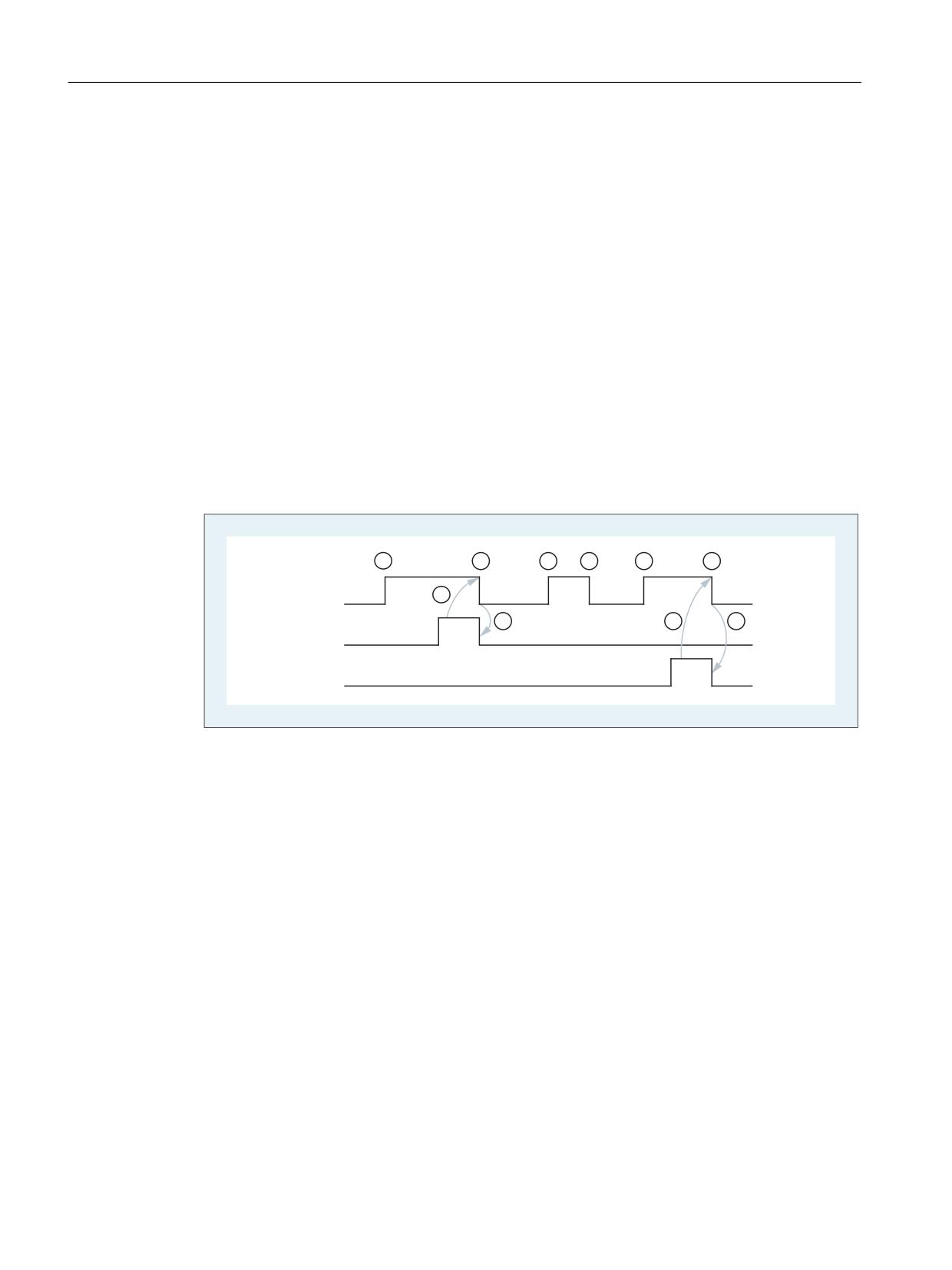
Block descriptions
17.4 FB3: PUT - write NC variables
Determining the significance of the access result:
1. Calculation of the error number of the PROFIdrive profile
<Error number of PROFIdrive profile> = result of access - 20H or 36D.
2. Determining the significance of the error number of the PROFIdrive profile
The error numbers of the PROFIdrive profile are described in:
Further information
Function Manual, SINAMICS S120 Drive Functions; Section "Communication" >
"Communication according to PROFIdrive" > "Acyclic communication" > "Structure of the
requests and responses" > Subsection "Error values in parameter responses"
Configuration steps
To write NC variables, the same configuration steps are required as for reading NC variables. It
is useful to store the address data of all NC variables to be read or written in a DB.
Pulse diagram
5HT
'RQH
(UURU
① User: Set request, Req = 0 → 1
② FB3 successfully completed, Done = 1
User: Reset request, IF Done == 1 THEN Req = 0
③ User: IF Done == 1 THEN reset request: 1 → 0
④ FB3 reset job confirmation, Done = 0
⑤ User: IF Done == 0 AND Error == 0 THEN reset request Req = 1 → 0 not permissible
⑥ FB3 completed with errors, Error = 1
User: Reset request, IF Done == 1 OR Error == 1 THEN Req = 0, possible further error handling
Call example
Writing of three channel-specific machine data items of channel 1:
PLC
178
Function Manual, 10/2020, 6FC5397-0HP40-0BA1

Block descriptions
17.4 FB3: PUT - write NC variables
Selection of the three data items with NC VAR selector and storage in file DB120.VAR
S7 (ALIAS) names are selected in order to adopt the block designation into the name and to
remove the characters [ ], which are not permitted in a STEP 7 symbol.
Area
Block
Name
Type
Byte
S7 Name
C[1]
RP
rpa[5]
DOUBLE
4
rpa_5C1RP
C[1]
RP
rpa[11]
DOUBLE
4
rpa_11C1RP
C[1]
RP
rpa[14)
DOUBLE
4
rpa_14C1RP
Entry NCVAR for DB120 with the S7 SYMBOL Editor
Symbol
Operand
Data type
NCVAR
DB120
DB120
File DB120.AWL must be compiled and transferred to the PLC.
Calling and parameterizing the FB3 with instance DB111
DATA_BLOCK DB111
// Unassigned user DB, as instance for FB3
FB3
BEGIN
Function FC "VariablenCall" : VOID
END_DATA_BLOCK
U
I 7.7;
// Unassigned machine control panel key
S
M 100.0;
// Activate req.
U
M 100.1;
// Done completed message
R
M 100.0;
// Terminate job
U
I 7.6;
// Manual error acknowledgment
U
M 102.0;
// Error pending
R
M 100.0;
// Terminate job
CALL FB3, DB111(
Req :=
M 100.0,
NumVar :=
3,
// Write three variables
Addr1 :=
"NCVAR".rpa_5C1RP,
Addr2 :=
"NCVAR".rpa_11C1RP,
Addr3 :=
"NCVAR".rpa_14C1RP,
Error :=
M102.0,
Done :=
M100.1,
State :=
MW104,
SD1 :=
P#DB99.DBX0.0 REAL 1,
SD2 :=
P#DB99.DBX4.0 REAL 1,
SD3 :=
P#M110.0 REAL 1);
PLC
Function Manual, 10/2020, 6FC5397-0HP40-0BA1
179
Block descriptions
17.5 FB4: PI_SERV - request PI service
Example: Variable addressing
Writing two R parameters from channel 1, whose address specifications are stored in DB120 as
the basic type. The R parameter number is parameterized via parameter LineX.
DATA_BLOCK DB120
VERSION : 0.0
STRUCT
C1_RP_rpa0_0:
STRUCT
SYNTAX_ID :
BYTE := B#16#82;
area_and_unit :
BYTE := B#16#41;
column :
WORD := W#16#1;
line :
WORD := W#16#0;
block type :
BYTE := B#16#15;
NO. OF LINES :
BYTE := B#16#1;
type :
BYTE := B#16#F;
length :
BYTE := B#16#8;
END_STRUCT;
END_STRUCT;
BEGIN
END_DATA_BLOCK
CALL FB3, DB122(
Req :=
M 10.0,
NumVar :=
2,
Addr1 :=
"NCVAR".C1_RP_rpa0_0,
Line1 :=
W#16#1,
Addr2 :=
"NCVAR".C1_RP_rpa0_0,
Line3 :=
W#16#2
Error :=
M 11.0,
Done :=
M 11.1,
State :=
MW 12,
SD1 :=
P#M 4.0 REAL 1,
SD2 :=
P#M 24.0 REAL 1);
Classification of data types
See table "Assignment of the data types" in the PLC manual, Chapter "FB2: GET - read NC variable
(Page 164)".
17.5
FB4: PI_SERV - request PI service
Function
The function block FB4 "PI_SERV" is used to start PI services.
PLC
180
Function Manual, 10/2020, 6FC5397-0HP40-0BA1
Block descriptions
17.5 FB4: PI_SERV - request PI service
The available PI services are described in the following chapters with their specific parameters.
An overview of the available PI services can be found in: List of available Pl services (Page 185)
Note
Due to the large number of "WVar" parameters, it is recommended that you use the function
block FB7 instead of FB4. See Section "FB7: PI_SERV2 - request PI service (Page 218)".
Start of a PI service
Request to start a PI service: Call of the FB4 with positive edge, parameter "Req" = 0 → 1
Completion of a PI service
PI service successfully completed: Parameter "Done" == 1.
PI service completed with error: Parameter "Error" == 1, error cause in parameter "State"
Requirements
• Release of the NC/PLC communication by OB100, FB1 parameter "NCKomm" = 1
• For the data block DB16 (data interface of the PI services), the S7 Symbol Editor must be used
to assign a symbol (default: PI) in the S7 symbol table of the S7 project. The requested PI
service is then specified via this symbol in the FB4 parameter "PIService", e.g. "PIService:=
"PI".<PI service>"
Boundary conditions
• A separate instance or a separate instance DB must be assigned from the user area to each
call of the FB4.
• The start of a PI service (FB4 call with "Req" = 1) is only permitted in the cyclic part of the PLC
basic program (OB1).
If the PI service is not started (FB4 call with "Req" = 0), the parameters can also be written in
the start-up part of the PLC basic program (OB100). The PI service can then be started using
the already written parameters in the cyclic part of the PLC basic program (OB1) by calling
FB4 with "Req" = 1.
• The execution of a PI service generally extends over several PLC cycles.
Declaration of the function
FUNCTION_BLOCK FB4
VAR_INPUT
PLC
Function Manual, 10/2020, 6FC5397-0HP40-0BA1
181

Block descriptions
17.5 FB4: PI_SERV - request PI service
Req :
BOOL;
PIService:
ANY;
Unit:
INT;
Addr1 :
ANY;
Addr2 :
ANY;
Addr3 :
ANY;
Addr4 :
ANY;
WVar1:
WORD;
WVar2:
WORD;
WVar3:
WORD;
WVar4:
WORD;
WVar5:
WORD;
WVar6:
WORD;
WVar7:
WORD;
WVar8:
WORD;
WVar9:
WORD;
WVar10:
WORD;
END_VAR
VAR_OUTPUT
Error :
BOOL;
Done :
BOOL;
State :
WORD;
END_VAR
Description of formal parameters
Signal
Ty
Type
Value range
Meaning
pe
Req:
I
BOOL
0 (FALSE), 1 (TRUE)
Job request
PIService:
I
ANY
"<DBName>".<PI serv-
Requested PI service
ice>
• <DBName>: symbol name for DB16,
default: "PI"
• <PI service>: List of available Pl serv-
ices (Page 185)
Unit:
I
INT
1, 2, 3, ...
Area number
Addr1 to Addr4:
I
ANY
"<DBName>".<Var-
Reference to a string
Name>
Significance depends on selected PI
service
WVar1 to WVar10:
I
WORD
-32768 ... 32767
INTEGER or WORD variable
8000H ... 7FFFH
Significance depends on selected PI
service
Error:
O
BOOL
0 (FALSE), 1 (TRUE)
Error status
1: Negative acknowledgment of job or
job could not be executed (see the
"State" parameter for the cause of the
error)
PLC
182
Function Manual, 10/2020, 6FC5397-0HP40-0BA1
Block descriptions
17.5 FB4: PI_SERV - request PI service
Signal
Ty
Type
Value range
Meaning
pe
Done:
O
BOOL
0 (FALSE), 1 (TRUE)
Job status
1: Job successfully executed
1)
State:
O
WORD
Error code
Only relevant if "Error" == 1
1)
State
Meaning
Note
3
Negative acknowledgement, job not ex-
Internal error, possibly remedied by an
ecutable
NC RESET
6
FIFO full
Repeat the command
7
Option not set
FB1 parameter "NCKomm" is not set
13
Addr1 ... Addr4: Reference invalid
Specify missing string
14
PI service is unknown
The PI service specified in the "PIService"
parameter is unknown. → check the no-
tation/spelling.
15
Addr1 ... Addr4: String too long
Check the string lengths
Call example
Function: Program selection in channel 1 (main program and workpiece program)
Entry of PI service for DB16 and STR for DB124 using the S7 SYMBOL editor:
Parameterization
Symbol
Operand
Data type
PI
DB16
DB16
STR
DB124
DB124
DATA_BLOCK DB126
// Instance for FB4, unassigned user DB
FB4
BEGIN
END_DATA_BLOCK
// ------------------------------------------------------------------------
DATA_BLOCK DB124
STRUCT
PName:
string[32]:= '_N_TEST_MPF
// Main program
';
Path:
string[32]:= '/
// Main program path
_N_MPF_DIR/';
PName_WST:
string[32]:= '_N_ABC_MPF';
// Workpiece program
Path_WST:
string[32]:= '/_N_WCS_DIR/
// Workpiece program path
_N_ZYL_WPD';
END_STRUCT
BEGIN
END_DATA_BLOCK
PLC
Function Manual, 10/2020, 6FC5397-0HP40-0BA1
183
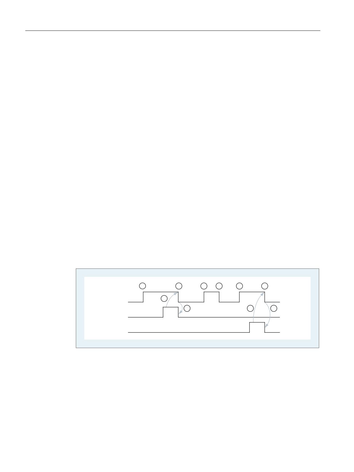
Block descriptions
17.5 FB4: PI_SERV - request PI service
//
-------------------------------------------------------------------------
Function FC "PICall": VOID
U I 7.7;
// Unassigned machine control panel key
S M 0.0;
// Activate req.
U M 1.1;
// Done completed message
R M 0.0;
// Terminate job
U I 7.6;
// Manual error acknowledgment
U M 1.0;
// Error pending
R M 0.0;
// Terminate job
CALL FB4, DB126 (
Req:=
M0.0,
PIService:=
"PI".SELECT
// PI service: SELECT
Unit:=
1,
// Channel 1
Addr1:=
"STR".Path,
// Main program: Path
Addr2:=
"STR".PName,
// Main program: Program
// Addr1:=
"STR".Path_WST,
// Workpiece: Path
// Addr2:=
"STR".PName_WST,
// Workpiece: Program
Error:=
M1.0,
Done:=
M1.1,
State:=
MW2
);
Flow diagram
5HT
'RQH
(UURU
① User: Set request, Req = 0 → 1
② FB4: PI service successfully completed, Done = 1
User: Reset request, IF Done == 1 THEN Req = 0
③ User: IF Done == 1 THEN reset request: 1 → 0
④ FB4: Reset job confirmation, Done = 0
⑤ User: IF Done == 0 AND Error == 0 THEN reset request Req = 1 → 0 not permissible
⑥ FB4: PI service completed with errors, Error = 1
User: Reset request, IF Done == 1 OR Error == 1 THEN Req = 0, possible further error handling
PLC
184
Function Manual, 10/2020, 6FC5397-0HP40-0BA1

Block descriptions
17.5 FB4: PI_SERV - request PI service
17.5.1
List of available Pl services
General PI services
PI service
Function
ASUP (Page 186)
Assign interrupt
CANCEL (Page 187)
Execute cancel
CONFIG (Page 187)
Reconfiguration of tagged machine data
DIGION (Page 187)
Digitizing on
DIGIOF (Page 187)
Digitizing off
FINDBL (Page 188)
Activate block search
LOGIN (Page 188)
Activate password
LOGOUT (Page 189)
Reset password
NCRES (Page 189)
Trigger NC-RESET
SELECT (Page 189)
Select program for processing for one channel
SETUDT (Page 190)
Sets the current user data to active
SETUFR (Page 190)
Activate user frame
RETRAC (Page 191)
Retraction of the tool in the tool direction
PI services of tool management
PI service
Function
CRCEDN (Page 192)
Create a tool cutting edge with specification of the T number
CREACE (Page 192)
Create a tool cutting edge with the next higher/free D number
CREATO (Page 193)
Create a tool with specification of a T number.
DELECE (Page 193)
Delete a tool cutting edge
DELETO (Page 194)
Delete tool
MMCSEM (Page 194)
Semaphores for various PI services
TMCRAD (Page 195)
Create an adapter
TMCRTO (Page 196)
Create a tool with specification of a name, a duplo number
TMDLAD (Page 196)
Delete an adapter
TMFDPL (Page 197)
Empty location search for loading
TMFPBP (Page 198)
Empty location search
TMGETT (Page 199)
T number for the specified tool name with duplo number
TMMVTL (Page 200)
Prepare magazine location for loading, unload tool
TMPOSM (Page 201)
Position magazine location or tool
TMPCIT (Page 202)
Set increment value for workpiece counter
TMRASS (Page 203)
Reset active status
TRESMO (Page 203)
Reset monitoring values
TSEARC (Page 204)
Complex search using search screen forms
TMCRMT (Page 207)
Create multitool
TMDLMT (Page 208)
Delete multitool
POSMT (Page 208)
Position multitool
FDPLMT (Page 209)
Search/check an empty location within the multitool
PLC
Function Manual, 10/2020, 6FC5397-0HP40-0BA1
185
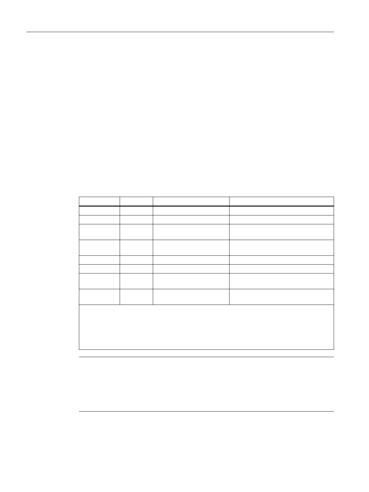
Block descriptions
17.5 FB4: PI_SERV - request PI service
17.5.2
PI service: ASUP
Function: Assign interrupt
An interrupt number is assigned in the specified channel to a part program that is present in the
control and is identified by path and program name.
The PI service ASUP (ASUB) the same effect as the program instruction SETINT (or CLRINT if the
PI service was called without specifying the path name).
Unlike SETINT (or CLRINT), the PI service ASUP remains active even after the end of the program
(M30 or channel reset). An assignment activated by the PI service ASUP is not cleared until after
a warm restart.
For detailed information about program management, path and file names, see:
Further information
Programming Manual NC Programming; Work preparation; Section: "File and Program
Management" > "Program memory"
Description of formal parameters
Signal
Type
Value range
Meaning
PIService:
ANY
"PI".ASUP
Assign interrupt
Unit:
INT
1, 2, 3 ... 10
Channel number
Addr1:
STRING
Path name,
e.g. "/_N_MPF_DIR/"
Addr2
STRING
Program name,
e.g. "_N_TST_FC9ASUP_MPF"
WVar1:
WORD
1, 2, 3, ... 8
Interrupt number
WVar2:
WORD
1, 2, 3, ... 8
Priority
WVar3:
WORD
0, 1
LIFTFAST 1) Fast retraction from the con-
tour
WVar4:
WORD
0, 1
BLSYNC 2) Processing of interrupt routine
is only to start with the next block change
1) Additional information
Programming Manual NC Programming; Chapter: "Work preparation" > "Interrupt routine (ASUB)" > "Fast
retraction from the contour (SETINT, LIFTFAST, ALF)"
2) Additional information
Programming Manual NC Programming; Chapter: "Work preparation" > "Interrupt routine (ASUB)" >
"Assign and start interrupt routine (SETINT, PRIO, BLSYNC)"
Note
The ASUP (ASUB) PI service must only ever be executed when the specified channel is in the reset
state. An ASUB prepared with FB7 can be subsequently initiated with FC9.
Additional information
Programming Manual NC Programming; Chapter: "Work preparation" > "Interrupt routine
(ASUB)"
PLC
186
Function Manual, 10/2020, 6FC5397-0HP40-0BA1

Block descriptions
17.5 FB4: PI_SERV - request PI service
17.5.3
PI service: CANCEL
Function: Execute cancel
Triggers the "Cancel" function equivalent to the corresponding "Cancel alarm" button on the user
interface (operator panel front).
Description of formal parameters
Signal
Type
Value range
Description
PIService:
ANY
"PI".CANCEL
Cancel
17.5.4
PI service: CONFIG
Function: Reconfiguration
The reconfiguration command activates machine data which has been entered sequentially by
the operator or the PLC, almost in parallel.
The command can only be activated when the controller is in RESET state or the program is
interrupted (NC stop at block limit). An FB4 error checkback signal is output if this condition is
not fulfilled (state = 3).
Description of formal parameters
Signal
Type
Value range
Description
PIService:
ANY
"PI".CONFIG
Reconfiguration
Unit:
INT
1
WVar1:
INT
1
Classification
17.5.5
PI service: DIGION
Function: Digitizing on
Selecting digitizing in the parameterized channel.
Description of formal parameters
Signal
Type
Value range
Description
PIService:
ANY
"PI".DIGION
Digitizing on
Unit:
INT
1, 2, 3 ... 10
Channel
17.5.6
PI service: DIGIOF
Function: Digitizing off
Deactivating digitizing in the parameterized channel.
PLC
Function Manual, 10/2020, 6FC5397-0HP40-0BA1
187

Block descriptions
17.5 FB4: PI_SERV - request PI service
Description of formal parameters
Signal
Type
Value range
Description
PIService:
ANY
"PI".DIGIOF
Digitizing off
Unit:
INT
1, 2, 3 ... 10
Channel
17.5.7
PI service: FINDBL
Function: Activate block search
A channel is switched to block search mode and the appropriate acknowledgment is then
transmitted. The block search is then executed immediately by the NC. The block search pointer
must already be in the NC at this point in time. The block search can be interrupted at any time
by an NC RESET. Once the block search is successfully completed, the normal processing mode
is reactivated automatically. NC start then takes effect from the located search target.
It is the sole responsibility of the operator to ensure a collision-free approach path.
Description of formal parameters
Signal
Type
Range of values
Meaning
PIService:
ANY
"PI".FINDBL
Block search
Unit:
INT
1 ... 10
Channel
WVar1:
WORD
1, 2
Preprocessing mode
1: Without calculation
2: With calculation
17.5.8
PI service: LOGIN
Function: Create password
Transfers the parameterized password to the NC. The password consists of up to 32 characters.
For shorter passwords, the string can be supplemented with empty spaces to attain 8 characters
Note
Visibility of the password in the PLC project
To use the PI service LOGIN, the password for the NCK access level must be stored in the PLC user
program. This ensures that the password for the NCK access level is visible to everyone who has
access to the PLC user program.
Example
Password: String[32]:= 'SafePassword.123';
PLC
188
Function Manual, 10/2020, 6FC5397-0HP40-0BA1
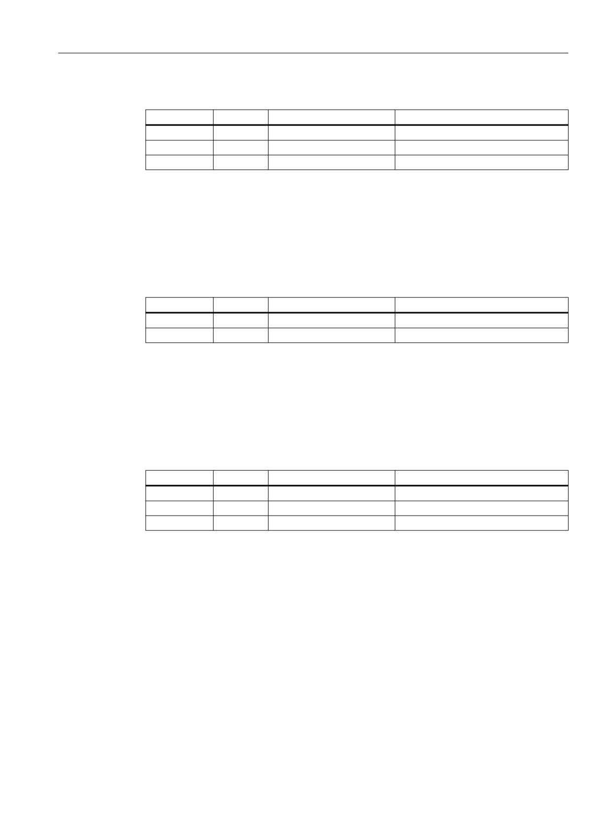
Block descriptions
17.5 FB4: PI_SERV - request PI service
Description of formal parameters
Signal
Type
Value range
Meaning
PIService:
ANY
"PI".LOGIN
Create password
Unit:
INT
1
NC
Addr1:
STRING
8 ... 32 characters
Password
17.5.9
PI service: LOGOUT
Function: Reset password
The password last transferred to the NC is reset.
Description of formal parameters
Signal
Type
Value range
Description
PIService:
ANY
"PI".LOGOUT
Reset password
Unit:
INT
1
NC
17.5.10
PI service: NCRES
Function: Trigger NC-RESET
Triggers an NC-RESET. Parameters "Unit" and "WVar1" must always be set to 0.
Description of formal parameters
Signal
Type
Value range
Description
PIService:
ANY
"PI".NCRES
Trigger NC-RESET
Unit:
INT
0
-
WVar1:
WORD
0
-
17.5.11
PI service: SELECT
Function: Select processing for a channel
A program stored on the NC is selected for one channel for execution. The program must be
executable. The path and program name must be stated in full.
For detailed information, please refer to:
Further information
Programming Manual NC Programming; Job Preparation; Section: "File and Program
Management" > "Program Memory"
PLC
Function Manual, 10/2020, 6FC5397-0HP40-0BA1
189
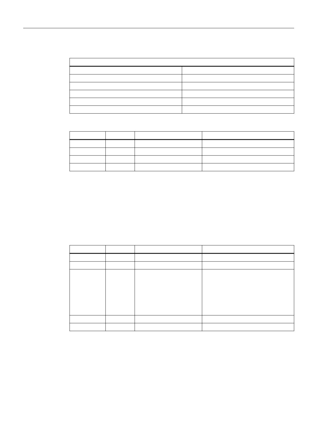
Block descriptions
17.5 FB4: PI_SERV - request PI service
Possible block types
Block types
Workpiece directory
WPD
Main program
MPF
Subprogram
SPF
Cycles
CYC
Asynchronous subprograms
ASP
Binary files
BIN
Description of formal parameters
Signal
Type
Value range
Meaning
PIService:
ANY
"PI".SELECT
Program selection
Unit:
INT
1, 2, 3 ... 10
Channel
Addr1:
STRING
-
Path name
Addr2:
STRING
-
Program name
17.5.12
PI service: SETUDT
Function: Set current user data active
The current user data, such as tool offsets, basic frames and settable frames are set to active in
the next NC block (only in stop state).
Description of formal parameters
Signal
Type
Value range
Description
PIService:
ANY
"PI".SETUDT
Activate user data
Unit:
INT
1, 2, 3 ... 10
Channel
WVar1:
WORD
1, 2, 3, 4, 5
User Data Type
1: Active tool offset
2: Active basic frame
3: Active settable frame
4: Active global basic frame
5: Active global settable frame
WVar2:
WORD
0
Reserved
Wvar3:
WORD
0
Reserved
17.5.13
PI service: SETUFR
Function: Activate user frames
User frames are loaded to the NC. All necessary frame values must be transferred to the NC first
with FB3 "Write variables".
PLC
190
Function Manual, 10/2020, 6FC5397-0HP40-0BA1
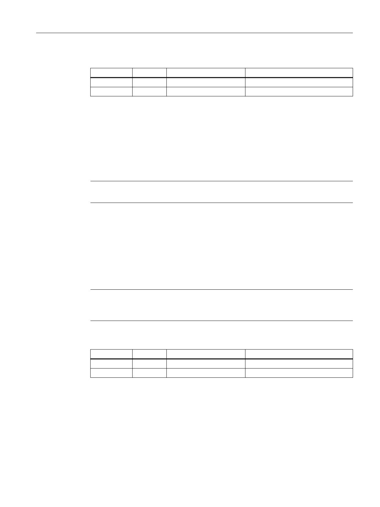
Block descriptions
17.5 FB4: PI_SERV - request PI service
Description of formal parameters
Signal
Type
Value range
Description
PIService:
ANY
"PI".SETUFR
Activate user frames
Unit:
INT
1, 2, 3 ... 10
Channel
17.5.14
PI service: RETRAC
Function: Select JOG retract
Selects the JOG retract mode. The retraction axis, i.e. the geometry axis, with which the
retraction is executed can be determined by the NC automatically or specified explicitly.
The mode remains active until it is ended with RESET.
Note
The RETRAC PI service can only be activated in JOG mode in the "Reset" state.
Automatic determination
For automatic determination, the geometric axis is selected as a retraction axis, which is
perpendicular (orthogonal) to the currently selected working plane:
• G17: Retraction axis ⇒ 3rd geometry axis (Z)
• G18: Retraction axis ⇒ 2nd geometry axis (Y)
• G19: Retraction axis ⇒ 1st Geometry axis (X)
Note
OPI variable retractState
The active retraction axis can be read via the OPI variable retractState.Bit 2/3.
Description of formal parameters
Signal
Type
Value range
Description
PIService:
ANY
"PI".RETRAC
Select JOG retract mode
Unit:
INT
1, 2, 3 ... 10
Channel
PLC
Function Manual, 10/2020, 6FC5397-0HP40-0BA1
191

Block descriptions
17.5 FB4: PI_SERV - request PI service
Signal
Type
Value range
Description
WVar1:
WORD
0, 1, 2, 3
Retraction axis
0: Automatic determination of the retrac-
tion axis by the NC.
1: Retraction axis is the 1st geometry axis
of the WCS
2: Retraction axis is the 2nd geometry ax-
is of the WCS
3: Retraction axis is the 3rd geometry axis
of the WCS
WVar2:
WORD
0
Reserved. The value must be pre-as-
signed with 0.
17.5.15
PI service: CRCEDN
Function: Creates new cutting edge
If the T number of an existing tool is entered in the "T number" parameter of the PI service, then
a tool cutting edge with the stated D number is created for this tool.
If a T number is specified as a parameter and the tool for the entered T number does not exist,
the PI service is aborted.
Description of formal parameters
Signal
Type
Range of values
Meaning
PIService:
ANY
"PI".CRCEDN
Create new cutting edge
Unit:
INT
1 … 10
TOA
WVar1:
INT
T number of the tool for which the tool
cutting edge must be created.
WVar2:
INT
0, 1, 2, 3, ...
Edge number of tool cutting edge
0: D number is assigned by the NC
17.5.16
PI service: CREACE
Function: Create tool cutting edge
Creation of the cutting edge with the next higher / next unassigned D number for the tool with
the transferred T number in TO, TS (if present). The cutting edge for the OEM cutting edge data
is set up simultaneously in the TUE block (if one is present). If the tool for the stated T number
does not exist, the PI service is aborted.
PLC
192
Function Manual, 10/2020, 6FC5397-0HP40-0BA1
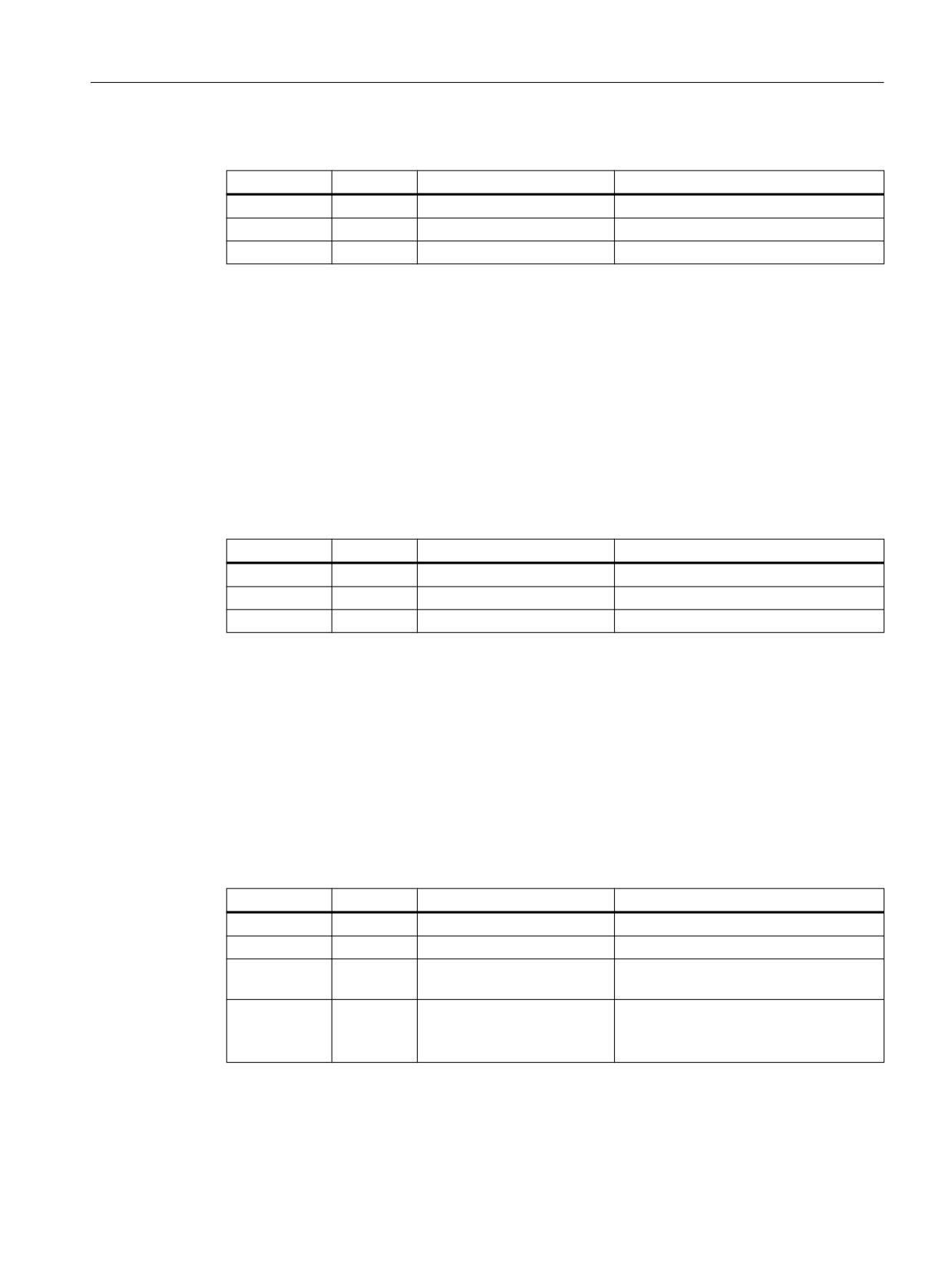
Block descriptions
17.5 FB4: PI_SERV - request PI service
Description of formal parameters
Signal
Type
Range of values
Meaning
PIService:
ANY
"PI".CREACE
Create tool cutting edge
Unit:
INT
1, 2, 3 ... 10
TOA
WVar1:
INT
T number
17.5.17
PI service: CREATO
Function: Create tool
Create a tool with specification of a T number. The tool is entered as existing in the tool directory
area (TV). The first cutting edge "D1" (with zero content) is created for tool offsets in the TO block.
The first "D1" (with zero content) is also created for the OEM cutting edge data in the TUE block
(if present). If a TU block exists, it will contain the data set for the tool. If a tool with the stated
T number already exists, the PI service is aborted.
Description of formal parameters
Signal
Type
Range of values
Meaning
PIService:
ANY
"PI".CREATO
Create tool
Unit:
INT
1, 2, 3 ... 10
TOA
WVar1:
INT
T number
17.5.18
PI service: DELECE
Function: Deleting a tool cutting edge
If the T number of an existing tool is entered in the "T number" parameter of the PI service, the
cutting edge with the specified D number is deleted from this tool. If a T number is entered as a
parameter and the tool for the specified T number does not exist, the PI service is aborted. If the
specified cutting edge does not exist, the PI service is aborted.
Description of formal parameters
Signal
Type
Range of values
Meaning
PIService:
ANY
"PI".DELECE
Delete cutting edge
Unit:
INT
1, 2, 3 ... 10
TOA
WVar1:
INT
T number of the tool from which the cut-
ting edge is to be deleted.
WVar2:
INT
0, 1, 2, 3, ...
D number of the tool cutting edge that
must be deleted
0: The tool is deleted
PLC
Function Manual, 10/2020, 6FC5397-0HP40-0BA1
193

Block descriptions
17.5 FB4: PI_SERV - request PI service
17.5.19
PI service: DELETO
Function: Delete tool
Deletes the tool assigned to the transferred T number with all cutting edges (in TO, in some cases
TU, TUE and TG (type 4xx), TD and TS blocks). If the tool for the stated T number does not exist,
the PI service is aborted.
Description of formal parameters
Signal
Type
Range of values
Meaning
PIService:
ANY
"PI".DELETO
Delete tool
Unit:
INT
1, 2, 3 ... 10
TOA
WVar1:
INT
T number
17.5.20
PI service: MMCSEM
Function
The PI service is used for testing, setting and resetting of channel-specific semaphores from HMI
through the PLC. 10 semaphores are available per channel for protecting critical data areas.
Functions (PI services) are assigned to semaphores 1 to 6. The semaphores 7 to 10 can be freely
used.
FB4 return values
• "Done" == TRUE
The semaphore was set, the critical function can be called.
• "Error" == TRUE AND "State" == 3
The semaphore was already set, currently the critical function cannot be called.
Schematic sequence for free semaphore
Testing and setting the semaphore
IF semaphore == FREE
THEN
Writing/reading of critical data
Resetting the semaphore
ELSE // Semaphore is blocked
ENDIF
NOTICE
Resetting the semaphore
After blocking the critical data area by setting the semaphore and subsequent reading or
writing of the data, the critical data area must be enabled once again by resetting the
semaphore, otherwise subsequent blocking will not be possible.
PLC
194
Function Manual, 10/2020, 6FC5397-0HP40-0BA1
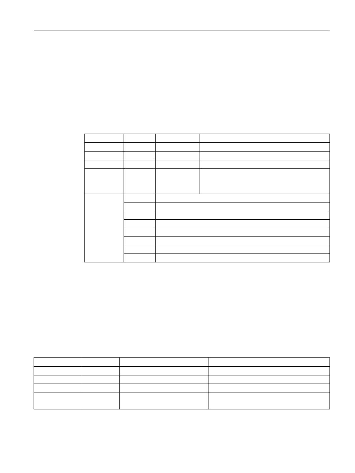
Block descriptions
17.5 FB4: PI_SERV - request PI service
Schematic sequence for blocked semaphore
Testing and setting the semaphore
IF semaphore == FREE
THEN
ELSE // Semaphore is blocked
Set bit memory for "Function could not be executed, repeat
necessary"
ENDIF
Description of formal parameters
Signal
Type
Value range
Description
PIService:
ANY
"PI".MMCSEM
Edit semaphore
Unit:
INT
1, 2, 3 ... 10
Channel
1)
WVar1:
INT
PI service-specific number of the semaphore
WVar2:
WORD
0, 1
Job type
0: Reset semaphore
1: Test and set semaphore
1)
Number
PI service
1
TMCRTO (create tool)
2
TMFDPL (search for empty location for loading)
3
TMMVTL (prepare magazine location for loading, unload tool)
4
TMFPBP (search for location)
5
TMGETT (search for tool number)
6
TSEARC (search for tool)
7 ... 10
Freely usable
17.5.21
PI service: TMCRAD
Function: Create adapter
Creates a tool adapter of the following types:
•
01: Adapter of type 1
•
02: Adapter of type 2 (angle head adapter)
Description of formal parameters
Signal
Type
Value range
Meaning
PIService:
ANY
"PI".TMCRAD
Create adapter
Unit
INT
1, 2, 3, ... 10
TOA
AdapterNumber
INT
0001 ... 32000
Number of the adapter created
AdaptType
INT
01: Adapter type 1
Adapter type of the adapter created
02: Adapter type 2 (angle head)
PLC
Function Manual, 10/2020, 6FC5397-0HP40-0BA1
195
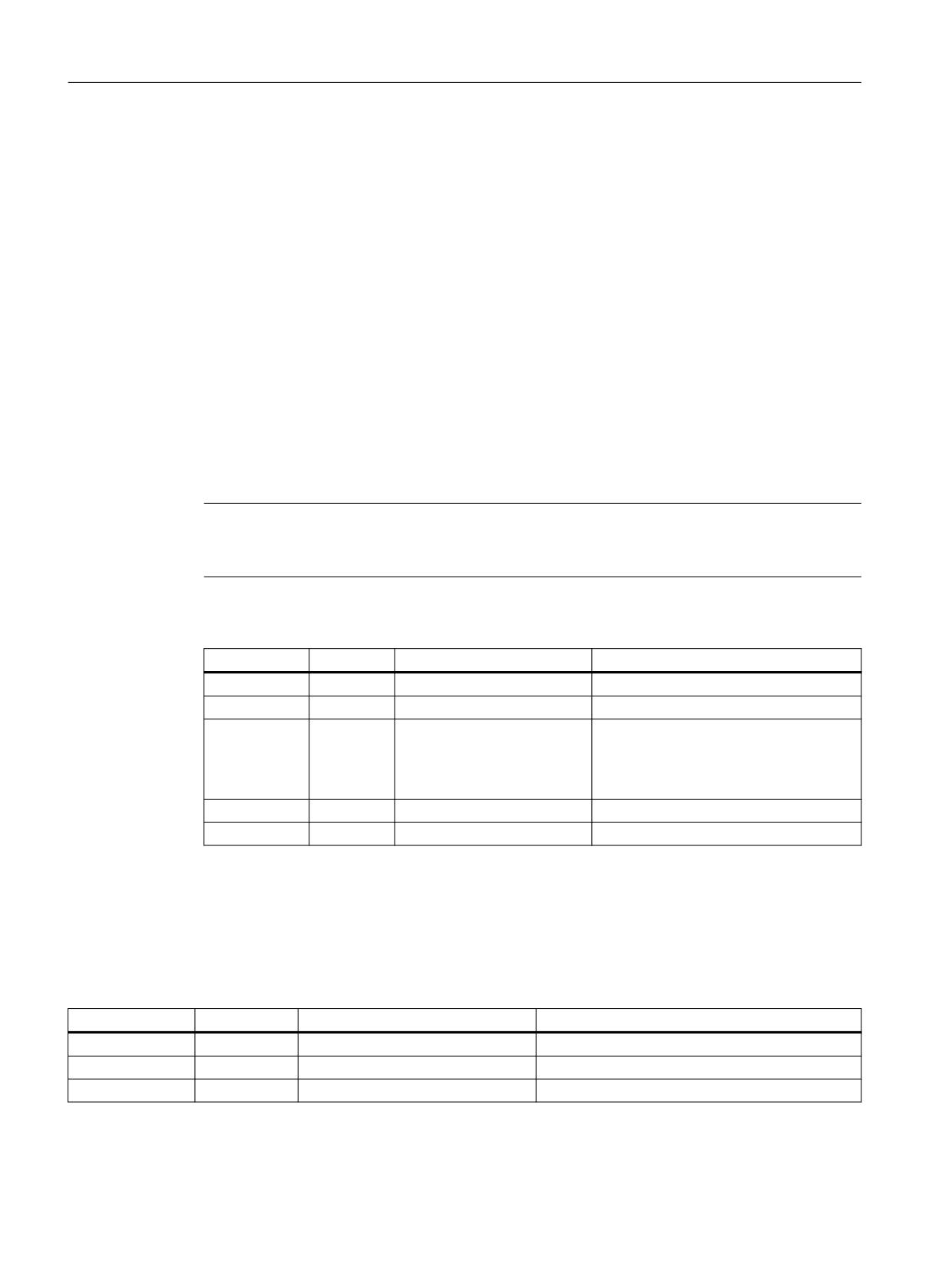
Block descriptions
17.5 FB4: PI_SERV - request PI service
17.5.22
PI service: TMCRTO
Function: Create tool
Creation of a tool by specifying a name, a duplo number, e.g. with $TC_TP1[y] = <Duplo
number> or $TC_TP2[y] = "<Tool name>". Or optionally by a T number, e.g. with y = <T number>.
The tool is entered in the tool directory area as available.
The first cutting edge D1 (with zero content) is created in the TO block for offsets.
The first cutting edge D1 (with zero content) is created in the TS block for monitoring data.
In the TUE block, if it is available, the cutting edge D1 is created for the OEM cutting edge data.
The TD block contains identifiers, duplo numbers, and the number of cutting edges (=1) for the
T number that is optionally specified or assigned by the NC.
If a TU block exists, it will contain the data block for the tool.
After execution of the PI service, the T number of the tool created is available in the TV block
under TnumWZV.
Note
Before and after this PI service, the PI service MMCSEM with parameter "WVar1" must be called
with function number 1 for TMCRTO. See Chapter "PI service: MMCSEM (Page 194)".
Description of formal parameters
Signal
Type
Range of values
Meaning
PIService:
ANY
"PI".TMCRTO
Create tool
Unit:
INT
1, 2, 3 ... 10
TOA
WVar1:
INT
>0 → the stated T number is
T number
specified
-1 → the NC assigns the T
number
WVar2:
INT
Duplo number
Addr1:
STRING
Max. 31 characters
Tool name
17.5.23
PI service: TMDLAD
Function: Delete adapter
Deletes an adapter with a given number
Signal
Type
Value range
Meaning
PIService:
ANY
"PI".TMDLAD
Create adapter
Unit
INT
1, 2, 3, ... 10
TOA
AdapterNumber
INT
0001 ... 32000
Number of the adapter created
PLC
196
Function Manual, 10/2020, 6FC5397-0HP40-0BA1
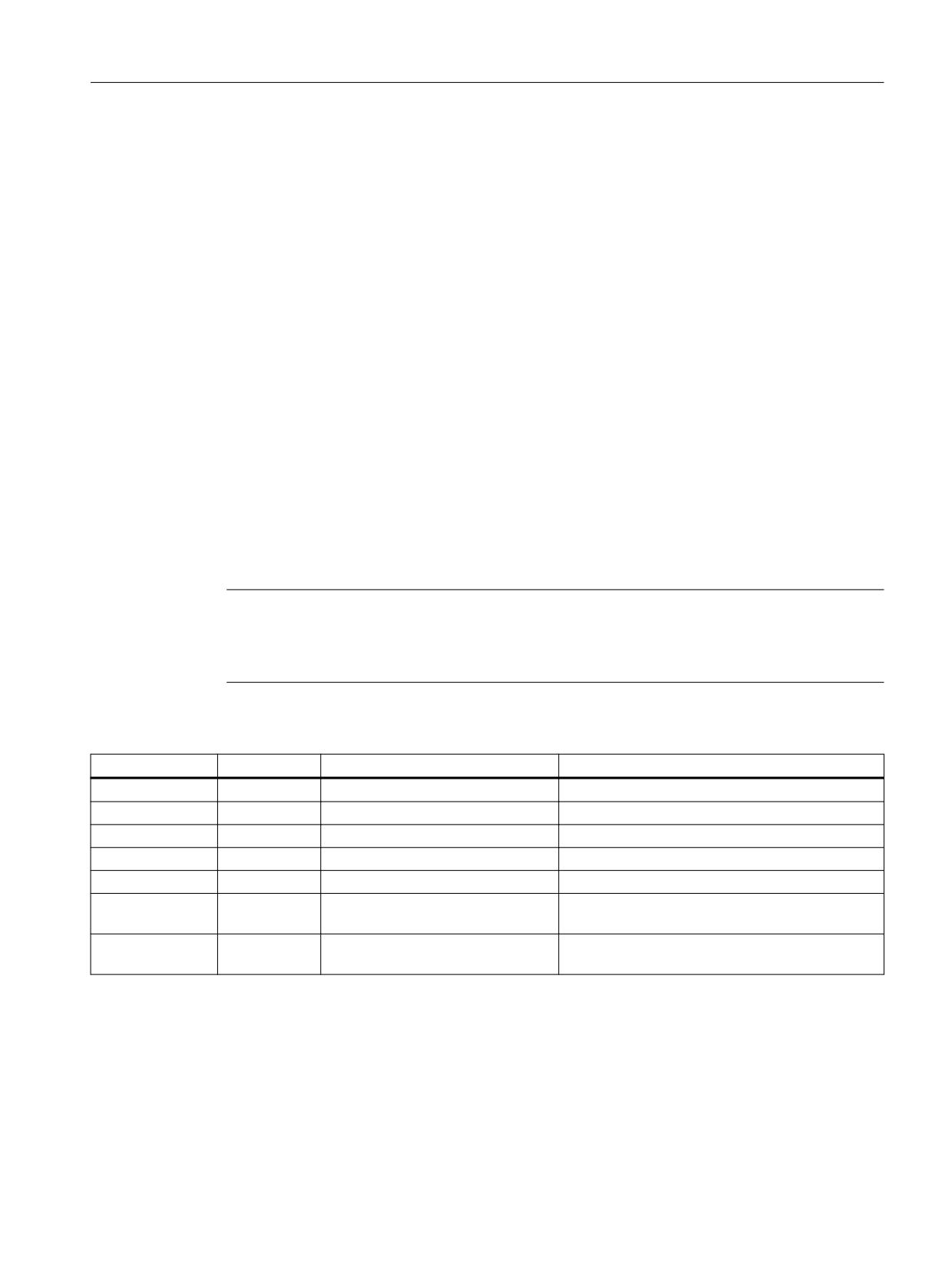
Block descriptions
17.5 FB4: PI_SERV - request PI service
17.5.24
PI service: TMFDPL
Function
Search for empty location for loading according to the parameter assignment:
• LocationNumber_To = -1 AND MagazineNumber_To = -1
Searches all magazines in the specified area (= channel) for an empty location for the tool
specified by a T number. After execution of the PI service, the magazine and locations
numbers found during the search are listed in the configuration block of the channel
(component magCMCmdPar1 (magazine number) and magCMCmdPar2 (location
number)). LocationNumber_ID and MagazineNumber_ID can be set as search criteria or not
(= -1). The PI service is positively or negatively acknowledged according to the search result.
• LocationNumber_To = -1 AND MagazineNumber_To = magazine number
An empty location for the tool specified with a T number is searched for in the specified
magazine. Location number (reference) and MagazineNumber_Ref can be allocated as
search criteria or with -1. The PI service is positively or negatively acknowledged according
to the search result.
• LocationNumber_To = location number AND MagazineNumber_To = magazine number
The specified location is checked to ensure that it is free for loading the tool.
LocationNumber_ID and MagazineNumber_ID can be set as search criteria or -1. The PI
service is acknowledged positively or negatively according to the search result.
Note
Before and after this PI service, the PI service MMCSEM with parameter "WVar1" must be called
with function number 2 for TMFDPL.
See Chapter "PI service: MMCSEM (Page 194)".
Description of formal parameters
Signal
Type
Range of values
Meaning
PIService:
ANY
"PI".TMFDPL
Empty location for loading
Unit:
INT
1, 2, 3 ... 10
TOA
WVar1:
INT
T number
WVar2:
INT
LocationNumber_To (target)
WVar3:
INT
MagazineNumber_To (target)
WVar4:
INT
Location_number_ID; Number of the reference lo-
cation (opt.).1)
WVar5:
INT
Magazine_number_ID; Number of the reference
magazine (opt.).1)
1)
: The reference location/reference magazine is a buffer location/buffer store, i.e. a tool location from the buffer magazine or
from the internal loading magazine, e.g. swapping station, gripper, loading station.
PLC
Function Manual, 10/2020, 6FC5397-0HP40-0BA1
197
Block descriptions
17.5 FB4: PI_SERV - request PI service
17.5.25
PI service: TMFPBP
Function: Empty location search
The PI service searches the specified magazine(s) for an empty location which meets the
specified criteria such as tool size and location type.
If the search is successful, the result can be read from the following OPI variables:
• magCMCmdPar1 (magazine number)
• magCMCmdPar2 (location number)
Note
The PI service can only be requested using FB7. See Chapter "FB7: PI_SERV2 - request PI
service (Page 218)".
Note
Before and after this PI service, the PI service MMCSEM with parameter "WVar1" must be
called with function number 4 for TMFPBP. See Chapter "PI service: MMCSEM (Page 194)".
Description of formal parameters
Signal
Type
Value range
Description
PIService:
ANY
"PI".TMFPBP
Empty location search
Unit:
INT
1, 2, 3 ... 10
TOA
WVar1:
INT
Magazine number of the magazine from which the
search is to be performed
WVar2:
INT
Location number of the location in the magazine
from "WVar1"
WVar3:
INT
Magazine number of the magazine up to which the
search is to be performed
WVar4:
INT
Location number of the location in the magazine
from "WVar3"
WVar5:
INT
Location_number_des; Number of the reference lo-
cation (opt.).1)
WVar6:
INT
Magazine_number_des; Number of the reference
magazine (opt.).1)
WVar7:
INT
0, 1, 2 ... 7
Number of required half locations to left
WVar8:
INT
0, 1, 2 ... 7
Number of required half locations to right
WVar9:
INT
0, 1, 2 ... 7
Number of required half locations in upward direc-
tion
WVar10:
INT
0, 1, 2 ... 7
Number of required half locations in downward di-
rection
PLC
198
Function Manual, 10/2020, 6FC5397-0HP40-0BA1