SINUMERIK 840D sl. Service - Functions. Manual (2018-2020) - page 55
Interface signals
19.1 Interface signals - overview
DB2
Signals for PLC events (PLC → HMI)
FB1 parameter "ExtendAIMsg" = FALSE
Byte
Bit 7
Bit 6
Bit 5
Bit 4
Bit 3
Bit 2
Bit 1
Bit 0
(message
type)
44 (OM)
Read-in disable, byte 3 (event no.: 530216-530223)
45 (OM)
Read-in disable, byte 4 (event no.: 530224-530231)
46 (FM)
NC start disable, byte 1 (event no.: 530300-530307)
47 (OM)
NC start disable, byte 2 (event no.: 530308-530315)
48 (FM)
Feedrate stop, geo axis 1, byte 1 (event no.: 531100-531107)
49 (OM)
Feedrate stop, geo axis 1, byte 2 (event no.: 531108-531115)
50 (FM)
Feedrate stop, geo axis 2, byte 1 (event no.: 531200-531207)
51 (OM)
Feedrate stop, geo axis 2, byte 2 (event no.: 531208-531215)
52 (FM)
Feedrate stop, geo axis 3, byte 1 (event no.: 531300-531307)
53 (OM)
Feedrate stop, geo axis 3, byte 2 (event no.: 531308-531315)
Table 19-21
DB2, channel range 4
DB2
Signals for PLC events (PLC → HMI)
FB1 parameter "ExtendAIMsg" = FALSE
Byte
Bit 7
Bit 6
Bit 5
Bit 4
Bit 3
Bit 2
Bit 1
Bit 0
(message
type)
Channel 4
Feedrate disable (event no.: 540000-540015)
54 (FM)
540007
540006
540005
540004
540003
540002
540001
540000
55 (OM)
540015
540014
540013
540012
540011
540010
540009
540008
56 (FM)
Feedrate and read-in disable, byte 1 (event no.: 540100-540107)
57 (FM)
Feedrate and read-in disable, byte 2 (event no.: 540108-540115)
58 (OM)
Feedrate and read-in disable, byte 3 (event no.: 540116-540123)
59 (OM)
Feedrate and read-in disable, byte 4 (event no.: 540124-540131)
60 (FM)
Read-in disable, byte 1 (event no.: 540200-540207)
61 (FM)
Read-in disable, byte 2 (event no.: 540208-540215)
62 (OM)
Read-in disable, byte 3 (event no.: 540216-540223)
63 (OM)
Read-in disable, byte 4 (event no.: 540224-540231)
64 (FM)
NC start disable, byte 1 (event no.: 540300-540307)
65 (FM)
NC start disable, byte 2 (event no.: 540308-540315)
66 (FM)
Feedrate stop, geo axis 1, byte 1 (event no.: 541100-541107)
67 (OM)
Feedrate stop, geo axis 1, byte 2 (event no.: 541108-541115)
68 (FM)
Feedrate stop, geo axis 2, byte 1 (event no.: 541200-541207)
69 (OM)
Feedrate stop, geo axis 2, byte 2 (event no.: 541208-541215)
70 (FM)
Feedrate stop, geo axis 3, byte 1 (event no.: 541300-541307)
71 (OM)
Feedrate stop, geo axis 3, byte 2 (event no.: 541308-541315)
PLC
Function Manual, 10/2020, 6FC5397-0HP40-0BA1
337
Interface signals
19.1 Interface signals - overview
Table 19-22
DB2, channel range 5
DB2
Signals for PLC events (PLC → HMI)
FB1 parameter "ExtendAIMsg" = FALSE
Byte
Bit 7
Bit 6
Bit 5
Bit 4
Bit 3
Bit 2
Bit 1
Bit 0
(message
type)
Channel 5
Feedrate disable (event no.: 550000-550015)
72 (FM)
550007
550006
550005
550004
550003
550002
550001
550000
73 (OM)
550015
550014
550013
550012
550011
550010
550009
550008
74 (FM)
Feedrate and read-in disable, byte 1 (event no.: 550100-550107)
75 (OM)
Feedrate and read-in disable, byte 2 (event no.: 550108-550115)
76 (OM)
Feedrate and read-in disable, byte 3 (event no.: 550116-550123)
77 (OM)
Feedrate and read-in disable, byte 4 (event no.: 550124-550131)
78 (FM)
Read-in disable, byte 1 (event no.: 550200-550207)
79 (FM)
Read-in disable, byte 2 (event no.: 550208-550315)
80 (OM)
Read-in disable, byte 3 (event no.: 550216-550223)
81 (OM)
Read-in disable, byte 4 (event no.: 550224-550231)
82 (FM)
NC start disable, byte 1 (event no.: 550300-550307)
83 (OM)
NC start disable, byte 2 (event no.: 550308-550315)
84 (FM)
Feedrate stop, geo axis 1, byte 1 (event no.: 551100-551107)
85 (OM)
Feedrate stop, geo axis 1, byte 2 (event no.: 551108-551115)
86 (FM)
Feedrate stop, geo axis 2, byte 1 (event no.: 551200-551207)
87 (OM)
Feedrate stop, geo axis 2, byte 2 (event no.: 551208-551215)
88 (FM)
Feedrate stop, geo axis 3, byte 1 (event no.: 551300-551307)
89 (OM)
Feedrate stop, geo axis 3, byte 2 (event no.: 551308-551315)
Table 19-23
DB2, channel range 6
DB2
Signals for PLC events (PLC → HMI)
FB1 parameter "ExtendAIMsg" = FALSE
Byte
Bit 7
Bit 6
Bit 5
Bit 4
Bit 3
Bit 2
Bit 1
Bit 0
(message
type)
Channel 6
Feedrate disable (event no.: 560000-560015)
90 (FM)
560007
560006
560005
560004
560003
560002
560001
560000
91 (OM)
560015
560014
560013
560012
560011
560010
560009
560008
92 (FM)
Feedrate and read-in disable, byte 1 (event no.: 560100-560107)
93 (FM)
Feedrate and read-in disable, byte 2 (event no.: 560108-560115)
94 (OM)
Feedrate and read-in disable, byte 3 (event no.: 560116-560123)
95 (OM)
Feedrate and read-in disable, byte 4 (event no.: 560124-560131)
96 (FM)
Read-in disable, byte 1 (event no.: 560200-560207)
97 (FM)
Read-in disable, byte 2 (event no.: 560208-560315)
PLC
338
Function Manual, 10/2020, 6FC5397-0HP40-0BA1
Interface signals
19.1 Interface signals - overview
DB2
Signals for PLC events (PLC → HMI)
FB1 parameter "ExtendAIMsg" = FALSE
Byte
Bit 7
Bit 6
Bit 5
Bit 4
Bit 3
Bit 2
Bit 1
Bit 0
(message
type)
98 (OM)
Read-in disable, byte 3 (event no.: 560216-560223)
99 (OM)
Read-in disable, byte 4 (event no.: 560224-560231)
100 (FM)
NC start disable, byte 1 (event no.: 560300-560307)
101 (OM)
NC start disable, byte 2 (event no.: 560308-560315)
102 (FM)
Feedrate stop, geo axis 1, byte 1 (event no.: 561100-561107)
103 (OM)
Feedrate stop, geo axis 1, byte 2 (event no.: 561108-561115)
104 (FM)
Feedrate stop, geo axis 2, byte 1 (event no.: 561200-561207)
105 (OM)
Feedrate stop, geo axis 2, byte 2 (event no.: 561208-561215)
106 (FM)
Feedrate stop, geo axis 3, byte 1 (event no.: 561300-561307)
107 (OM)
Feedrate stop, geo axis 3, byte 2 (event no.: 561308-561315)
Table 19-24
DB2, channel range 7
DB2
Signals for PLC events (PLC → HMI)
FB1 parameter "ExtendAIMsg" = FALSE
Byte
Bit 7
Bit 6
Bit 5
Bit 4
Bit 3
Bit 2
Bit 1
Bit 0
(message
type)
Channel 7
Feedrate disable (event no.: 570000-570015)
108 (FM)
570007
570006
570005
570004
570003
570002
570001
570000
109 (OM)
570015
570014
570013
570012
570011
570010
570009
570008
110 (FM)
Feedrate and read-in disable, byte 1 (event no.: 570100-570107)
111 (FM)
Feedrate and read-in disable, byte 2 (event no.: 570108-570115)
112 (OM)
Feedrate and read-in disable, byte 3 (event no.: 570116-570123)
113 (OM)
Feedrate and read-in disable, byte 4 (event no.: 570124-570131)
114 (FM)
Read-in disable, byte 1 (event no.: 570200-570207)
115 (FM)
Read-in disable, byte 2 (event no.: 570208-570315)
116 (OM)
Read-in disable, byte 3 (event no.: 570216-570223)
117 (OM)
Read-in disable, byte 4 (event no.: 570224-570231)
118 (FM)
NC start disable, byte 1 (event no.: 570300-570307)
119 (OM)
NC start disable, byte 2 (event no.: 570308-570315)
120 (FM)
Feedrate stop, geo axis 1, byte 1 (event no.: 571100-571107)
121 (OM)
Feedrate stop, geo axis 1, byte 2 (event no.: 571108-571115)
122 (FM)
Feedrate stop, geo axis 2, byte 1 (event no.: 571200-571207)
123 (OM)
Feedrate stop, geo axis 2, byte 2 (event no.: 571208-571215)
124 (FM)
Feedrate stop, geo axis 3, byte 1 (event no.: 571300-571307)
125 (OM)
Feedrate stop, geo axis 3, byte 2 (event no.: 571308-571315)
PLC
Function Manual, 10/2020, 6FC5397-0HP40-0BA1
339
Interface signals
19.1 Interface signals - overview
Table 19-25
DB2, channel range 8
DB2
Signals for PLC events (PLC → HMI)
FB1 parameter "ExtendAIMsg" = FALSE
Byte
Bit 7
Bit 6
Bit 5
Bit 4
Bit 3
Bit 2
Bit 1
Bit 0
(message
type)
Channel 8
Feedrate disable (event no.: 580000-580015)
126 (FM)
580007
580006
580005
580004
580003
580002
580001
580000
127 (OM)
580015
580014
580013
580012
580011
580010
580009
580008
128 (FM)
Feedrate and read-in disable, byte 1 (event no.: 580100-580107)
129 (FM)
Feedrate and read-in disable, byte 2 (event no.: 580108-580115)
130 (OM)
Feedrate and read-in disable, byte 3 (event no.: 580116-580123)
131 (OM)
Feedrate and read-in disable, byte 4 (event no.: 580124-580131)
132 (FM)
Read-in disable, byte 1 (event no.: 580200-580207)
133 (FM)
Read-in disable, byte 2 (event no.: 580208-580315)
134 (OM)
Read-in disable, byte 3 (event no.: 580216-580223)
135 (OM)
Read-in disable, byte 4 (event no.: 580224-580231)
136 (FM)
NC start disable, byte 1 (event no.: 580300-580307)
137 (OM)
NC start disable, byte 2 (event no.: 580308-580315)
138 (FM)
Feedrate stop, geo axis 1, byte 1 (event no.: 581100-581107)
139 (OM)
Feedrate stop, geo axis 1, byte 2 (event no.: 581108-581115)
140 (FM)
Feedrate stop, geo axis 2, byte 1 (event no.: 581200-581207)
141 (OM)
Feedrate stop, geo axis 2, byte 2 (event no.: 581208-581215)
142 (FM)
Feedrate stop, geo axis 3, byte 1 (event no.: 581300-581307)
143 (OM)
Feedrate stop, geo axis 3, byte 2 (event no.: 581308-581315)
Channels 9 and 10 not implemented
Table 19-26
DB2, axis ranges
DB2
Signals for PLC events (PLC → HMI)
FB1 parameter "ExtendAIMsg" = FALSE
Byte
Bit 7
Bit 6
Bit 5
Bit 4
Bit 3
Bit 2
Bit 1
Bit 0
(message
type)
Axis/spindle
Feedrate stop / spindle stop for axis/spindle 1 (event no.: 600100-600115)
144 (FM)
600107
600106
600105
600104
600103
600102
600101
600100
145 (OM)
600115
600114
600113
600112
600111
600110
600109
600108
146 (FM)
Feedrate stop / spindle stop for axis/spindle 2, byte 1 (event no.: 600200-600207)
147 (OM)
Feedrate stop / spindle stop for axis/spindle 2, byte 2 (event no.: 600208-600215)
148 (FM)
Feedrate stop / spindle stop for axis/spindle 3, byte 1 (event no.: 600300-600307)
149 (OM)
Feedrate stop / spindle stop for axis/spindle 3, byte 2 (event no.: 600308-600315)
150 (FM)
Feedrate stop / spindle stop for axis/spindle 4, byte 1 (event no.: 600400-600407)
PLC
340
Function Manual, 10/2020, 6FC5397-0HP40-0BA1

Interface signals
19.1 Interface signals - overview
DB2
Signals for PLC events (PLC → HMI)
FB1 parameter "ExtendAIMsg" = FALSE
Byte
Bit 7
Bit 6
Bit 5
Bit 4
Bit 3
Bit 2
Bit 1
Bit 0
(message
type)
151 (OM)
Feedrate stop / spindle stop for axis/spindle 4, byte 2 (event no.: 600408-600415)
152 (FM)
Feedrate stop / spindle stop for axis/spindle 5, byte 1 (event no.: 600500-600507)
153 (OM)
Feedrate stop / spindle stop for axis/spindle 5, byte 2 (event no.: 600508-600515)
154 (FM)
Feedrate stop / spindle stop for axis/spindle 6, byte 1 (event no.: 600600-600607)
155 (OM)
Feedrate stop / spindle stop for axis/spindle 6, byte 2 (event no.: 600608-600615)
156 (FM)
Feedrate stop / spindle stop for axis/spindle 7, byte 1 (event no.: 600700-600707)
157 (OM)
Feedrate stop / spindle stop for axis/spindle 7, byte 2 (event no.: 600708-600715)
158 (FM)
Feedrate stop / spindle stop for axis/spindle 8, byte 1 (event no.: 600800-600807)
159 (OM)
Feedrate stop / spindle stop for axis/spindle 8, byte 2 (event no.: 600808-600815)
160 (FM)
Feedrate stop / spindle stop for axis/spindle 9, byte 1 (event no.: 600900-600907)
161 (OM)
Feedrate stop / spindle stop for axis/spindle 9, byte 2 (event no.: 600908-600915)
162 (FM)
Feedrate stop/spindle stop for axis/spindle 10 byte 1 (event no.: 601000-601007)
163 (OM)
Feedrate stop/spindle stop for axis/spindle 10 byte 2 (event no.: 601008-601015)
164 (FM)
Feedrate stop/spindle stop for axis/spindle 11 byte 1 (event no.: 601100-601107)
165 (OM)
Feedrate stop/spindle stop for axis/spindle 11 byte 2 (event no.: 601108-601115)
166 (FM)
Feedrate stop/spindle stop for axis/spindle 12 byte 1 (event no.: 601200-601207)
167 (OM)
Feedrate stop/spindle stop for axis/spindle 12 byte 2 (event no.: 601208-601215)
168 (FM)
Feedrate stop/spindle stop for axis/spindle 13 byte 1 (event no.: 601300-601307)
169 (OM)
Feedrate stop/spindle stop for axis/spindle 13 byte 2 (event no.: 601308-601315)
170 (FM)
Feedrate stop/spindle stop for axis/spindle 14 byte 1 (event no.: 601400-601407)
171 (OM)
Feedrate stop/spindle stop for axis/spindle 14 byte 2 (event no.: 601408-601415)
172 (FM)
Feedrate stop/spindle stop for axis/spindle 15 byte 1 (event no.: 601500-601507)
173 (OM)
Feedrate stop/spindle stop for axis/spindle 15 byte 2 (event no.: 601508-601515)
174 (FM)
Feedrate stop/spindle stop for axis/spindle 16 byte 1 (event no.: 601600-601607)
175 (OM)
Feedrate stop/spindle stop for axis/spindle 16 byte 2 (event no.: 601608-601615)
176 (FM)
Feedrate stop/spindle stop for axis/spindle 17 byte 1 (event no.: 601700-601707)
177 (OM)
Feedrate stop/spindle stop for axis/spindle 17 byte 2 (event no.: 601708-601715)
178 (FM)
Feedrate stop/spindle stop for axis/spindle 18 byte 1 (event no.: 601800-601807)
179 (OM)
Feedrate stop/spindle stop for axis/spindle 18 byte 2 (event no.: 601808-601815)
Axes 19 - 31 not realized
Table 19-27 DB2, user ranges
DB2
Signals for PLC events (PLC → HMI)
FB1 parameter "ExtendAIMsg" = FALSE
Byte
Bit 7
Bit 6
Bit 5
Bit 4
Bit 3
Bit 2
Bit 1
Bit 0
(message
type)
User ranges
User range 0 (event no.: 700000-700015)
PLC
Function Manual, 10/2020, 6FC5397-0HP40-0BA1
341

Interface signals
19.1 Interface signals - overview
DB2
Signals for PLC events (PLC → HMI)
FB1 parameter "ExtendAIMsg" = FALSE
Byte
Bit 7
Bit 6
Bit 5
Bit 4
Bit 3
Bit 2
Bit 1
Bit 0
(message
type)
180 (FM)
700007
700006
700005
700004
700003
700002
700001
700000
181 (FM)
700015
700014
700013
700012
700011
700010
700009
700008
182 (FM)
User range 0: Byte 3 (event no.: 700016-700023)
183 (FM)
User range 0: Byte 4 (event no.: 700024-700031)
184 (OM)
User range 0: Byte 5 (event no.: 700032-700039)
185 (OM)
User range 0: Byte 6 (event no.: 700040-700047)
186 (OM)
User range 0: Byte 7 (event no.: 700048-700055)
187 (OM)
User range 0: Byte 8 (event no.: 700056-700063)
188 - 191 (FM)
User range 1: Byte 1 - 4 (event no.: 700100-700131)
192 - 195 (OM)
User range 1, bytes 5 - 8 (event no.: 700132-700163)
196 - 199 (FM)
User range 2: Byte 1 - 4 (event no.: 700200-700231)
200 - 203 (OM)
User range 2: Byte 5 - 8 (event no.: 700232-700263)
204 - 207 (FM)
User range 3: Byte 1 - 4 (event no.: 700300-700331)
208 - 211 (OM)
User range 3: Byte 5 - 8 (event no.: 700332-700363)
212 - 215 (FM)
User range 4: Byte 1 - 4 (event no.: 700400-700431)
216 - 219 (OM)
User range 4: Byte 5 - 8 (event no.: 700432-700463)
220 - 223 (FM)
User range 5: Byte 1 - 4 (event no.: 700500-700531)
224 - 227 (OM)
User range 5: Byte 5 - 8 (event no.: 700532-700563)
228 - 231 (FM)
User range 6: Byte 1 - 4 (event no.: 700600-700631)
232 - 235 (OM)
User range 6: Byte 5 - 8 (event no.: 700632-700663)
236 - 239 (FM)
User range 7: Byte 1 - 4 (event no.: 700700-700731)
240 - 243 (OM)
User range 7: Byte 5 - 8 (event no.: 700732-700763)
244 - 247 (FM)
User range 8: Byte 1 - 4 (event no.: 700800-700831)
248 - 251 (OM)
User range 8: Byte 5 - 8 (event no.: 700832-700863)
252 - 255 (FM)
User range 9: Byte 1 - 4 (event no.: 700900-700931)
256 - 259 (OM)
User range 9: Byte 5 - 8 (event no.: 700932-700963)
260 - 263 (FM)
User range 10: Byte 1 - 4 (event no.: 701000-701031)
264 - 267 (OM)
User range 10: Byte 5 - 8 (event no.: 701032-701063)
268 - 271 (FM)
User range 11: Byte 1 - 4 (event no.: 701100-701131)
272 - 275 (OM)
User range 11: Byte 5 - 8 (event no.: 701132-701163)
276 - 279 (FM)
User range 12: Byte 1 - 4 (event no.: 701200-701231)
280 - 283 (OM)
User range 12: Byte 5 - 8 (event no.: 701232-701263)
284 - 287 (FM)
User range 13: Byte 1 - 4 (event no.: 701300-701331)
288 - 291 (OM)
User range 13: Byte 5 - 8 (event no.: 701332-701363)
292 - 295 (FM)
User range 14: Byte 1 - 4 (event no.: 701400-701431)
296 - 299 (OM)
User range 14: Byte 5 - 8 (event no.: 701432-701463)
300 - 303 (FM)
User range 15: Byte 1 - 4 (event no.: 701500-701531)
304 - 307 (OM)
User range 15: Byte 5 - 8 (event no.: 701532-701563)
308 - 311 (FM)
User range 16: Byte 1 - 4 (event no.: 701600-701631)
PLC
342
Function Manual, 10/2020, 6FC5397-0HP40-0BA1

Interface signals
19.1 Interface signals - overview
DB2
Signals for PLC events (PLC → HMI)
FB1 parameter "ExtendAIMsg" = FALSE
Byte
Bit 7
Bit 6
Bit 5
Bit 4
Bit 3
Bit 2
Bit 1
Bit 0
(message
type)
312 - 315 (OM)
User range 16: Byte 5 - 8 (event no.: 701632-701663)
316 - 319 (FM)
User range 17: Byte 1 - 4 (event no.: 701700-701731)
320 - 323 (OM)
User range 17: Byte 5 - 8 (event no.: 701732-701763)
324 - 327 (FM)
User range 18: Byte 1 - 4 (event no.: 701800-701831)
328 - 331 (OM)
User range 18: Byte 5 - 8 (event no.: 701832-701863)
332 - 335 (FM)
User range 19: Byte 1 - 4 (event no.: 701900-701931)
336 - 339 (OM)
User range 19: Byte 5 - 8 (event no.: 701932-701963)
340 - 343 (FM)
User range 20: Byte 1 - 4 (event no.: 702000-702031)
344 - 347 (OM)
User range 20: Byte 5 - 8 (event no.: 702032-702063)
348 - 351 (FM)
User range 21: Byte 1 - 4 (event no.: 702100-702131)
352 - 355 (OM)
User range 21: Byte 5 - 8 (event no.: 702132-702163)
356 - 359 (FM)
User range 22: Byte 1 - 4 (event no.: 702200-702231)
360 - 363 (OM)
User range 22: Byte 5 - 8 (event no.: 702232-702263)
364 - 367 (FM)
User range 23: Byte 1 - 4 (event no.: 702300-702331)
368 - 371 (OM)
User range 23: Byte 5 - 8 (event no.: 702332-702363)
372 - 375 (FM)
User range 24: Byte 1 - 4 (event no.: 702400-702431)
376 - 379 (OM)
User range 24: Byte 5 - 8 (event no.: 702432-702463)
380 - 383 (FM)
User range 25: Byte 1 - 4 (event no.: 702500-702531)
384 - 387 (OM)
User range 25: Byte 5 - 8 (event no.: 702532-702563)
388 - 391 (FM)
User range 26: Byte 1 - 4 (event no.: 702600-702631)
392 - 395 (OM)
User range 26: Byte 5 - 8 (event no.: 702632-702663)
396 - 399 (FM)
User range 27: Byte 1 - 4 (event no.: 702700-702731)
400 - 403 (OM)
User range 27: Byte 5 - 8 (event no.: 702732-702763)
404 - 407 (FM)
User range 28: Byte 1 - 4 (event no.: 702800-702831)
408 - 411 (OM)
User range 28: Byte 5 - 8 (event no.: 702832-702863)
412 - 415 (FM)
User range 29: Byte 1 - 4 (event no.: 702900-702931)
416 - 419 (OM)
User range 29: Byte 5 - 8 (event no.: 702932-702963)
420 - 423 (FM)
User range 30: Byte 1 - 4 (event no.: 703000-703031)
424 - 427 (OM)
User range 30: Byte 5 - 8 (event no.: 703032-703063)
428 - 431 (FM)
User range 31: Byte 1 - 4 (event no.: 703100-703131)
432 - 435 (OM)
User range 31: Byte 5 - 8 (event no.: 703132-703163)
Note
Parameterizing user ranges
The number of user ranges (maximum of 32) can be parameterized using FB 1 "MsgUser".
PLC
Function Manual, 10/2020, 6FC5397-0HP40-0BA1
343

Interface signals
19.1 Interface signals - overview
19.1.6.2
FC 10 alarms in the DB2 (FB1: "ExtendAIMsg" = TRUE)
Description
Message type
• FM: A fault message with the associated event number as fault number is triggered by the
signal.
• OM: An operating message with the associated event number as message number is
triggered by the signal.
Further information
FC10: AL_MSG - error and operating messages (Page 262)
Table 19-28 DB2, channel range 1
DB2
Signals for PLC events (PLC → HMI)
FB1 parameter "ExtendAIMsg" = TRUE
Byte
Bit 7
Bit 6
Bit 5
Bit 4
Bit 3
Bit 2
Bit 1
Bit 0
(message
type)
Signals WITHOUT the display of a fault/operating message (DBB0 - 309)
Channel 1
0
Feedrate disable
1
Feedrate disable
2
Read-in disable
3
Read-in disable
4
Start disable
5
Start disable
6
Feedrate stop, geo axis 1, byte 1
7
Feedrate stop, geo axis 1, byte 2
8
Feedrate stop, geo axis 2, byte 1
9
Feedrate stop, geo axis 2, byte 2
10
Feedrate stop, geo axis 3, byte 1
11
Feedrate stop, geo axis 3, byte 2
12 - 119
Channel 2 - channel 10, see above "Channel 1"
Axis/spindle 1
120
Feedrate stop / spindle stop, byte 1
121
Feedrate stop / spindle stop, byte 2
122 - 181
Axis / spindle 2 - 31, see above "Axis /spindle 1"
Additional values for user range 0
182
Additional value for event number 700000
184
Additional value for event number 700001
308
Additional value for event number 700063
PLC
344
Function Manual, 10/2020, 6FC5397-0HP40-0BA1
Interface signals
19.1 Interface signals - overview
DB2
Signals for PLC events (PLC → HMI)
FB1 parameter "ExtendAIMsg" = TRUE
Byte
Bit 7
Bit 6
Bit 5
Bit 4
Bit 3
Bit 2
Bit 1
Bit 0
(message
type)
Signals WITH the display of a fault/operating message (from DBB 310)
Channel 1
Feedrate disable (event no.: 510000-510015)
310 (FM)
510007
510006
510005
510004
510003
510002
510001
510000
311 (OM)
510015
510014
510013
510012
510011
510010
510009
510008
312 (FM)
Feedrate and read-in disable: Byte 1 (event no.: 510100-510107)
313 (FM)
Feedrate and read-in disable: Byte 2 (event no.: 510108-510115)
314 (OM)
Feedrate and read-in disable: Byte 3 (event no.: 510116-510123)
315 (OM)
Feedrate and read-in disable: Byte 4 (event no.: 510124-510131)
316 (FM)
Read-in disable: Byte 1 (event no.: 510200-510207)
317 (FM)
Read-in disable: Byte 2 (event no.: 510208-510215)
318 (OM)
Read-in disable: Byte 3 (event no.: 510216-510223)
319 (OM)
Read-in disable: Byte 4 (event no.: 510224-510231)
320 (FM)
NC start disable: Byte 1 (event no.: 510300-510307)
321 (OM)
NC start disable: Byte 2 (event no.: 510308-510315)
322 (FM)
Feedrate stop, geo axis 1: Byte 1 (event no.: 511100-511107)
323 (OM)
Feedrate stop, geo axis 1: Byte 2 (event no.: 511108-511115)
324 (FM)
Feedrate stop, geo axis 2: Byte 1 (event no.: 511200-511207)
325 (OM)
Feedrate stop, geo axis 2: Byte 2 (event no.: 511208-511215)
326 (FM)
Feedrate stop, geo axis 3: Byte 1 (event no.: 511300-511307)
327 (OM)
Feedrate stop, geo axis 3: Byte 2 (event no.: 511308-511315)
Table 19-29
DB2, channel range 2
DB2
Signals for PLC events (PLC → HMI)
FB1 parameter "ExtendAIMsg" = TRUE
Byte
Bit 7
Bit 6
Bit 5
Bit 4
Bit 3
Bit 2
Bit 1
Bit 0
(message
type)
Channel 2
Feedrate disable (event no.: 510000-520015)
328 (FM)
520007
520006
520005
520004
520003
520002
520001
520000
329 (OM)
520015
520014
520013
520012
520011
520010
520009
520008
330 (FM)
Feedrate and read-in disable, byte 1 (event no.: 520100-520107)
331 (FM)
Feedrate and read-in disable, byte 2 (event no.: 520108-520115)
332 (OM)
Feedrate and read-in disable, byte 3 (event no.: 520116-520123)
333 (OM)
Feedrate and read-in disable, byte 4 (event no.: 520124-520131)
334 (FM)
Read-in disable, byte 1 (event no.: 520200-520207)
PLC
Function Manual, 10/2020, 6FC5397-0HP40-0BA1
345

Interface signals
19.1 Interface signals - overview
DB2
Signals for PLC events (PLC → HMI)
FB1 parameter "ExtendAIMsg" = TRUE
Byte
Bit 7
Bit 6
Bit 5
Bit 4
Bit 3
Bit 2
Bit 1
Bit 0
(message
type)
335 (FM)
Read-in disable, byte 2 (event no.: 520208-520215)
336 (OM)
Read-in disable, byte 3 (event no.: 520216-520223)
337 (OM)
Read-in disable, byte 4 (event no.: 520224-520231)
338 (FM)
NC start disable, byte 1 (event no.: 520300-520307)
339 (OM)
NC start disable, byte 2 (event no.: 520308-520315)
340 (FM)
Feedrate stop, geo axis 1, byte 1 (event no.: 521100-521107)
341 (OM)
Feedrate stop, geo axis 1, byte 2 (event no.: 521108-521115)
342 (FM)
Feedrate stop, geo axis 2, byte 1 (event no.: 521200-521207)
343 (OM)
Feedrate stop, geo axis 2, byte 2 (event no.: 521208-521215)
344 (FM)
Feedrate stop, geo axis 3, byte 1 (event no.: 521300-521307)
345 (OM)
Feedrate stop, geo axis 3, byte 2 (event no.: 521308-521315)
Table 19-30
DB2, channel range 3
DB2
Signals for PLC events (PLC → HMI)
FB1 parameter "ExtendAIMsg" = TRUE
Byte
Bit 7
Bit 6
Bit 5
Bit 4
Bit 3
Bit 2
Bit 1
Bit 0
(message
type)
Channel 3
Feedrate disable (event no.: 530000-530015)
346 (FM)
530007
530006
530005
530004
530003
530002
530001
530000
347 (OM)
530015
530014
530013
530012
530011
530010
530009
530008
348 (FM)
Feedrate and read-in disable, byte 1 (event no.: 530100-530107)
349 (FM)
Feedrate and read-in disable, byte 2 (event no.: 530108-530115)
350 (OM)
Feedrate and read-in disable, byte 2 (event no.: 530108-530115)
351 (OM)
Feedrate and read-in disable, byte 4 (event no.: 530124-530131)
352 (FM)
Read-in disable, byte 1 (event no.: 530200-530207)
353 (FM)
Read-in disable, byte 2 (event no.: 530208-530215)
354 (OM)
Read-in disable, byte 3 (event no.: 530216-530223)
355 (OM)
Read-in disable, byte 4 (event no.: 530224-530231)
356 (FM)
NC start disable, byte 1 (event no.: 530300-530307)
357 (OM)
NC start disable, byte 2 (event no.: 530308-530315)
358 (FM)
Feedrate stop, geo axis 1, byte 1 (event no.: 531100-531107)
359 (OM)
Feedrate stop, geo axis 1, byte 2 (event no.: 531108-531115)
360 (FM)
Feedrate stop, geo axis 2, byte 1 (event no.: 531200-531207)
361 (OM)
Feedrate stop, geo axis 2, byte 2 (event no.: 531208-531215)
362 (FM)
Feedrate stop, geo axis 3, byte 1 (event no.: 531300-531307)
363 (OM)
Feedrate stop, geo axis 3, byte 2 (event no.: 531308-531315)
PLC
346
Function Manual, 10/2020, 6FC5397-0HP40-0BA1
Interface signals
19.1 Interface signals - overview
Table 19-31
DB2, channel range 4
DB2
Signals for PLC events (PLC → HMI)
FB1 parameter "ExtendAIMsg" = TRUE
Byte
Bit 7
Bit 6
Bit 5
Bit 4
Bit 3
Bit 2
Bit 1
Bit 0
(message
type)
Channel 4
Feedrate disable (event no.: 540000-540015)
364 (FM)
540007
540006
540005
540004
540003
540002
540001
540000
365 (OM)
540015
540014
540013
540012
540011
540010
540009
540008
366 (FM)
Feedrate and read-in disable, byte 1 (event no.: 540100-540107)
367 (FM)
Feedrate and read-in disable, byte 2 (event no.: 540108-540115)
368 (OM)
Feedrate and read-in disable, byte 3 (event no.: 540116-540123)
369 (OM)
Feedrate and read-in disable, byte 4 (event no.: 540124-540131)
370 (FM)
Read-in disable, byte 1 (event no.: 540200-540207)
371 (FM)
Read-in disable, byte 2 (event no.: 540208-540215)
372 (OM)
Read-in disable, byte 3 (event no.: 540216-540223)
373 (OM)
Read-in disable, byte 4 (event no.: 540224-540231)
374 (FM)
NC start disable, byte 1 (event no.: 540300-540307)
375 (OM)
NC start disable, byte 2 (event no.: 540308-540315)
376 (FM)
Feedrate stop, geo axis 1, byte 1 (event no.: 541100-541107)
377 (OM)
Feedrate stop, geo axis 1, byte 2 (event no.: 541108-541115)
378 (FM)
Feedrate stop, geo axis 2, byte 1 (event no.: 541200-541207)
379 (OM)
Feedrate stop, geo axis 2, byte 2 (event no.: 541208-541215)
380 (FM)
Feedrate stop, geo axis 3, byte 1 (event no.: 541300-541307)
381 (OM)
Feedrate stop, geo axis 3, byte 2 (event no.: 541308-541315)
Table 19-32
DB2, channel range 5
DB2
Signals for PLC events (PLC → HMI)
FB1 parameter "ExtendAIMsg" = TRUE
Byte
Bit 7
Bit 6
Bit 5
Bit 4
Bit 3
Bit 2
Bit 1
Bit 0
(message
type)
Channel 5
Feedrate disable (event no.: 550000-550015)
382 (FM)
550007
550006
550005
550004
550003
550002
550001
550000
383 (OM)
550015
550014
550013
550012
550011
550010
550009
550008
384 (FM)
Feedrate and read-in disable, byte 1 (event no.: 550100-550107)
385 (FM)
Feedrate and read-in disable, byte 2 (event no.: 550108-550115)
386 (OM)
Feedrate and read-in disable, byte 3 (event no.: 550116-550123)
387 (OM)
Feedrate and read-in disable, byte 4 (event no.: 550124-550131)
388 (FM)
Read-in disable, byte 1 (event no.: 550200-550207)
389 (FM)
Read-in disable, byte 2 (event no.: 550208-550215)
PLC
Function Manual, 10/2020, 6FC5397-0HP40-0BA1
347
Interface signals
19.1 Interface signals - overview
DB2
Signals for PLC events (PLC → HMI)
FB1 parameter "ExtendAIMsg" = TRUE
Byte
Bit 7
Bit 6
Bit 5
Bit 4
Bit 3
Bit 2
Bit 1
Bit 0
(message
type)
390 (OM)
Read-in disable, byte 3 (event no.: 550216-550223)
391 (OM)
Read-in disable, byte 4 (event no.: 550224-550231)
392 (FM)
NC start disable, byte 1 (event no.: 550300-550307)
393 (OM)
NC start disable, byte 2 (event no.: 550308-550315)
394 (FM)
Feedrate stop, geo axis 1, byte 1 (event no.: 551100-551107)
395 (OM)
Feedrate stop, geo axis 1, byte 2 (event no.: 551108-551115)
396 (FM)
Feedrate stop, geo axis 2, byte 1 (event no.: 551200-551207)
397 (OM)
Feedrate stop, geo axis 2, byte 2 (event no.: 551208-551215)
398 (FM)
Feedrate stop, geo axis 3, byte 1 (event no.: 551300-551307)
399 (OM)
Feedrate stop, geo axis 3, byte 2 (event no.: 551308-551315)
Table 19-33
DB2, channel range 6
DB2
Signals for PLC events (PLC → HMI)
FB1 parameter "ExtendAIMsg" = TRUE
Byte
Bit 7
Bit 6
Bit 5
Bit 4
Bit 3
Bit 2
Bit 1
Bit 0
(message
type)
Channel 6
Feedrate disable (event no.: 560000-560015)
400 (FM)
560007
560006
560005
560004
560003
560002
560001
560000
401 (OM)
560015
560014
560013
560012
560011
560010
560009
560008
402 (FM)
Feedrate and read-in disable, byte 1 (event no.: 560100-560107)
403 (FM)
Feedrate and read-in disable, byte 2 (event no.: 560108-560115)
404 (OM)
Feedrate and read-in disable, byte 3 (event no.: 560116-560123)
405 (OM)
Feedrate and read-in disable, byte 4 (event no.: 560124-560131)
406 (FM)
Read-in disable, byte 1 (event no.: 560200-560207)
407 (FM)
Read-in disable, byte 2 (event no.: 560208-560215)
408 (OM)
Read-in disable, byte 3 (event no.: 560216-560223)
409 (OM)
Read-in disable, byte 4 (event no.: 560224-560231)
410 (FM)
NC start disable, byte 1 (event no.: 560300-560307)
411 (OM)
NC start disable, byte 2 (event no.: 560308-560315)
412 (FM)
Feedrate stop, geo axis 1, byte 1 (event no.: 561100-561107)
413 (OM)
Feedrate stop, geo axis 1, byte 2 (event no.: 561108-561115)
414 (FM)
Feedrate stop, geo axis 2, byte 1 (event no.: 561200-561207)
415 (OM)
Feedrate stop, geo axis 2, byte 2 (event no.: 561208-561215)
416 (FM)
Feedrate stop, geo axis 3, byte 1 (event no.: 561300-561307)
417 (OM)
Feedrate stop, geo axis 3, byte 2 (event no.: 561308-561315)
PLC
348
Function Manual, 10/2020, 6FC5397-0HP40-0BA1
Interface signals
19.1 Interface signals - overview
Table 19-34
DB2, channel range 7
DB2
Signals for PLC events (PLC → HMI)
FB1 parameter "ExtendAIMsg" = TRUE
Byte
Bit 7
Bit 6
Bit 5
Bit 4
Bit 3
Bit 2
Bit 1
Bit 0
(message
type)
Channel 7
Feedrate disable (event no.: 570000-570015)
418 (FM)
570007
570006
570005
570004
570003
570002
570001
570000
419 (OM)
570015
570014
570013
570012
570011
570010
570009
570008
420 (FM)
Feedrate and read-in disable, byte 1 (event no.: 570100-570107)
421 (FM)
Feedrate and read-in disable, byte 2 (event no.: 570108-570115)
422 (OM)
Feedrate and read-in disable, byte 3 (event no.: 570116-570123)
423 (OM)
Feedrate and read-in disable, byte 4 (event no.: 570124-570131)
424 (FM)
Read-in disable, byte 1 (event no.: 570200-570207)
425 (FM)
Read-in disable, byte 2 (event no.: 570208-570215)
426 (OM)
Read-in disable, byte 3 (event no.: 570216-570223)
427 (OM)
Read-in disable, byte 4 (event no.: 570224-570231)
428 (FM)
NC start disable, byte 1 (event no.: 570300-570307)
429 (OM)
NC start disable, byte 2 (event no.: 570308-570315)
430 (FM)
Feedrate stop, geo axis 1, byte 1 (event no.: 571100-571107)
431 (OM)
Feedrate stop, geo axis 1, byte 2 (event no.: 571108-571115)
432 (FM)
Feedrate stop, geo axis 2, byte 1 (event no.: 571200-571207)
433 (OM)
Feedrate stop, geo axis 2, byte 2 (event no.: 571208-571215)
434 (FM)
Feedrate stop, geo axis 3, byte 1 (event no.: 571300-571307)
435 (OM)
Feedrate stop, geo axis 3, byte 2 (event no.: 571308-571315)
Table 19-35
DB2, channel range 8
DB2
Signals for PLC events (PLC → HMI)
FB1 parameter "ExtendAIMsg" = TRUE
Byte
Bit 7
Bit 6
Bit 5
Bit 4
Bit 3
Bit 2
Bit 1
Bit 0
(message
type)
Channel 8
Feedrate disable (event no.: 580000-580015)
436 (FM)
580007
580006
580005
580004
580003
580002
580001
580000
437 (OM)
580015
580014
580013
580012
580011
580010
580009
580008
438 (FM)
Feedrate and read-in disable, byte 1 (event no.: 580100-580107)
439 (FM)
Feedrate and read-in disable, byte 2 (event no.: 580108-580115)
440 (OM)
Feedrate and read-in disable, byte 3 (event no.: 580116-580123)
441 (OM)
Feedrate and read-in disable, byte 4 (event no.: 580124-580131)
442 (FM)
Read-in disable, byte 1 (event no.: 580200-580207)
443 (FM)
Read-in disable, byte 2 (event no.: 580208-580215)
PLC
Function Manual, 10/2020, 6FC5397-0HP40-0BA1
349
Interface signals
19.1 Interface signals - overview
DB2
Signals for PLC events (PLC → HMI)
FB1 parameter "ExtendAIMsg" = TRUE
Byte
Bit 7
Bit 6
Bit 5
Bit 4
Bit 3
Bit 2
Bit 1
Bit 0
(message
type)
444 (OM)
Read-in disable, byte 3 (event no.: 580216-580223)
445 (OM)
Read-in disable, byte 4 (event no.: 580224-580231)
446 (FM)
NC start disable, byte 1 (event no.: 580300-580307)
447 (OM)
NC start disable, byte 2 (event no.: 580308-580315)
448 (FM)
Feedrate stop, geo axis 1, byte 1 (event no.: 581100-581107)
449 (OM)
Feedrate stop, geo axis 1, byte 2 (event no.: 581108-581115)
450 (FM)
Feedrate stop, geo axis 2, byte 1 (event no.: 581200-581207)
451 (OM)
Feedrate stop, geo axis 2, byte 2 (event no.: 581208-581215)
452 (FM)
Feedrate stop, geo axis 3, byte 1 (event no.: 581300-581307)
453 (OM)
Feedrate stop, geo axis 3, byte 2 (event no.: 581308-581315)
Table 19-36
DB2, channel range 9
DB2
Signals for PLC events (PLC → HMI)
FB1 parameter "ExtendAIMsg" = TRUE
Byte
Bit 7
Bit 6
Bit 5
Bit 4
Bit 3
Bit 2
Bit 1
Bit 0
(message
type)
Channel 9
Feedrate disable (event no.: 590000-590015)
454 (FM)
590007
590006
590005
590004
590003
590002
590001
590000
455 (OM)
590015
590014
590013
590012
590011
590010
590009
590008
456 (FM)
Feedrate and read-in disable, byte 1 (event no.: 590100-590107)
457 (FM)
Feedrate and read-in disable, byte 2 (event no.: 590108-590115)
458 (OM)
Feedrate and read-in disable, byte 3 (event no.: 590116-590123)
459 (OM)
Feedrate and read-in disable, byte 4 (event no.: 590124-590131)
460 (FM)
Read-in disable, byte 1 (event no.: 590200-590207)
461 (FM)
Read-in disable, byte 2 (event no.: 590208-590215)
462 (OM)
Read-in disable, byte 3 (event no.: 590216-590223)
463 (OM)
Read-in disable, byte 4 (event no.: 590224-590231)
464 (FM)
NC start disable, byte 1 (event no.: 590300-590307)
465 (OM)
NC start disable, byte 2 (event no.: 590308-590315)
466 (FM)
Feedrate stop, geo axis 1, byte 1 (event no.: 591100-591107)
467 (OM)
Feedrate stop, geo axis 1, byte 2 (event no.: 591108-591115)
468 (FM)
Feedrate stop, geo axis 2, byte 1 (event no.: 591200-591207)
469 (OM)
Feedrate stop, geo axis 2, byte 2 (event no.: 591208-591215)
470 (FM)
Feedrate stop, geo axis 3, byte 1 (event no.: 591300-591307)
471 (OM)
Feedrate stop, geo axis 3, byte 2 (event no.: 591308-591315)
PLC
350
Function Manual, 10/2020, 6FC5397-0HP40-0BA1
Interface signals
19.1 Interface signals - overview
Table 19-37
DB2, channel range 10
DB2
Signals for PLC events (PLC → HMI)
FB1 parameter "ExtendAIMsg" = TRUE
Byte
Bit 7
Bit 6
Bit 5
Bit 4
Bit 3
Bit 2
Bit 1
Bit 0
(message
type)
Channel 10
Feedrate disable (event no.: 500000-500015)
472 (FM)
500007
500006
500005
500004
500003
500002
500001
500000
473 (OM)
500015
500014
500013
500012
500011
500010
500009
500008
474 (FM)
Feedrate and read-in disable, byte 1 (event no.: 500100-500107)
475 (FM)
Feedrate and read-in disable, byte 2 (event no.: 500108-500115)
476 (OM)
Feedrate and read-in disable, byte 3 (event no.: 500116-500123)
477 (OM)
Feedrate and read-in disable, byte 4 (event no.: 500124-500131)
478 (FM)
Read-in disable, byte 1 (event no.: 500200-500207)
479 (FM)
Read-in disable, byte 2 (event no.: 500208-500215)
480 (OM)
Read-in disable, byte 3 (event no.: 500216-500223)
481 (OM)
Read-in disable, byte 4 (event no.: 500224-500231)
482 (FM)
NC start disable, byte 1 (event no.: 500300-500307)
483 (OM)
NC start disable, byte 2 (event no.: 500308-500315)
484 (FM)
Feedrate stop, geo axis 1, byte 1 (event no.: 501100-501107)
485 (OM)
Feedrate stop, geo axis 1, byte 2 (event no.: 501108-501115)
486 (FM)
Feedrate stop, geo axis 2, byte 1 (event no.: 501200-501207)
487 (OM)
Feedrate stop, geo axis 2, byte 2 (event no.: 501208-501215)
488 (FM)
Feedrate stop, geo axis 3, byte 1 (event no.: 501300-501307)
489 (OM)
Feedrate stop, geo axis 3, byte 2 (event no.: 501308-501315)
Table 19-38
DB2, axis ranges
DB2
Signals for PLC events (PLC → HMI)
FB1 parameter "ExtendAIMsg" = TRUE
Byte
Bit 7
Bit 6
Bit 5
Bit 4
Bit 3
Bit 2
Bit 1
Bit 0
(message
type)
Axis/spindle
Feedrate stop / spindle stop for axis/spindle 1 (event no.: 600100-600115)
490 (FM)
600107
600106
600105
600104
600103
600102
600101
600100
491 (OM)
600115
600114
600113
600112
600111
600110
600109
600108
492 (FM)
Feedrate stop/spindle stop for axis/spindle 2 (event no.: 600200-600207)
493 (OM)
Feedrate stop/spindle stop for axis/spindle 2 (event no.: 600208-600215)
494 (FM)
Feedrate stop/spindle stop for axis/spindle 3 (event no.: 600300-600307)
495 (OM)
Feedrate stop/spindle stop for axis/spindle 3 (event no.: 600308-600315)
496 (FM)
Feedrate stop/spindle stop for axis/spindle 4 (event no.: 600400-600407)
497 (OM)
Feedrate stop/spindle stop for axis/spindle 4 (event no.: 600408-600415)
PLC
Function Manual, 10/2020, 6FC5397-0HP40-0BA1
351

Interface signals
19.1 Interface signals - overview
DB2
Signals for PLC events (PLC → HMI)
FB1 parameter "ExtendAIMsg" = TRUE
Byte
Bit 7
Bit 6
Bit 5
Bit 4
Bit 3
Bit 2
Bit 1
Bit 0
(message
type)
498 (FM)
Feedrate stop/spindle stop for axis/spindle 5 (event no.: 600500-600507)
499 (OM)
Feedrate stop/spindle stop for axis/spindle 5 (event no.: 600508-600515)
500 (FM)
Feedrate stop/spindle stop for axis/spindle 6 (event no.: 600600-600607)
501 (OM)
Feedrate stop/spindle stop for axis/spindle 6 (event no.: 600608-600615)
502 (FM)
Feedrate stop/spindle stop for axis/spindle 7 (event no.: 600700-600707)
503 (OM)
Feedrate stop/spindle stop for axis/spindle 7 (event no.: 600708-600715)
504 (FM)
Feedrate stop/spindle stop for axis/spindle 8 (event no.: 600800-600807)
505 (OM)
Feedrate stop/spindle stop for axis/spindle 8 (event no.: 600808-600815)
506 (FM)
Feedrate stop/spindle stop for axis/spindle 9 (event no.: 600900-600907)
507 (OM)
Feedrate stop/spindle stop for axis/spindle 9 (event no.: 600908-600915)
508 (FM)
Feedrate stop/spindle stop for axis/spindle 10 (event no.: 601000-601007)
509 (OM)
Feedrate stop/spindle stop for axis/spindle 10 (event no.: 601008-601015)
510 (FM)
Feedrate stop/spindle stop for axis/spindle 11 (event no.: 601100-601107)
511 (OM)
Feedrate stop/spindle stop for axis/spindle 11 (event no.: 601108-601115)
512 (FM)
Feedrate stop/spindle stop for axis/spindle 12 (event no.: 601200-601207)
513 (OM)
Feedrate stop/spindle stop for axis/spindle 12 (event no.: 601208-601215)
514 (FM)
Feedrate stop/spindle stop for axis/spindle 13 (event no.: 601300-601307)
515 (OM)
Feedrate stop/spindle stop for axis/spindle 13 (event no.: 601308-601315)
516 (FM)
Feedrate stop/spindle stop for axis/spindle 14 (event no.: 601400-601407)
517 (OM)
Feedrate stop/spindle stop for axis/spindle 14 (event no.: 601408-601415)
518 (FM)
Feedrate stop/spindle stop for axis/spindle 15 (event no.: 601500-601507)
519 (OM)
Feedrate stop/spindle stop for axis/spindle 15 (event no.: 601508-601515)
520 (FM)
Feedrate stop/spindle stop for axis/spindle 16 (event no.: 601600-601607)
521 (OM)
Feedrate stop/spindle stop for axis/spindle 16 (event no.: 601608-601615)
522 (FM)
Feedrate stop/spindle stop for axis/spindle 17 (event no.: 601700-601707)
523 (OM)
Feedrate stop/spindle stop for axis/spindle 17 (event no.: 601708-601715)
524 (FM)
Feedrate stop/spindle stop for axis/spindle 18 (event no.: 601800-601807)
525 (OM)
Feedrate stop/spindle stop for axis/spindle 18 (event no.: 601808-601815)
526 (FM)
Feedrate stop/spindle stop for axis/spindle 19 (event no.: 601900-601907)
527 (OM)
Feedrate stop/spindle stop for axis/spindle 19 (event no.: 601908-601915)
528 (FM)
Feedrate stop/spindle stop for axis/spindle 20 (event no.: 602000-602007)
529 (OM)
Feedrate stop/spindle stop for axis/spindle 20 (event no.: 602008-602015)
530 (FM)
Feedrate stop/spindle stop for axis/spindle 21 (event no.: 602100-602107)
531 (OM)
Feedrate stop/spindle stop for axis/spindle 21 (event no.: 602108-602115)
532 (FM)
Feedrate stop/spindle stop for axis/spindle 22 (event no.: 602200-602207)
533 (OM)
Feedrate stop/spindle stop for axis/spindle 22 (event no.: 602208-602215)
534 (FM)
Feedrate stop/spindle stop for axis/spindle 23 (event no.: 602300-602307)
535 (OM)
Feedrate stop/spindle stop for axis/spindle 23 (event no.: 602308-602315)
536 (FM)
Feedrate stop/spindle stop for axis/spindle 24 (event no.: 602400-602407)
PLC
352
Function Manual, 10/2020, 6FC5397-0HP40-0BA1

Interface signals
19.1 Interface signals - overview
DB2
Signals for PLC events (PLC → HMI)
FB1 parameter "ExtendAIMsg" = TRUE
Byte
Bit 7
Bit 6
Bit 5
Bit 4
Bit 3
Bit 2
Bit 1
Bit 0
(message
type)
537 (OM)
Feedrate stop/spindle stop for axis/spindle 24 (event no.: 602408-602415)
538 (FM)
Feedrate stop/spindle stop for axis/spindle 25 (event no.: 602500-602507)
539 (OM)
Feedrate stop/spindle stop for axis/spindle 25 (event no.: 602508-602515)
540 (FM)
Feedrate stop/spindle stop for axis/spindle 26 (event no.: 602600-602607)
541 (OM)
Feedrate stop/spindle stop for axis/spindle 26 (event no.: 602608-602615)
542 (FM)
Feedrate stop/spindle stop for axis/spindle 27 (event no.: 602700-602707)
543 (OM)
Feedrate stop/spindle stop for axis/spindle 27 (event no.: 602708-602715)
544 (FM)
Feedrate stop/spindle stop for axis/spindle 28 (event no.: 602800-602807)
545 (OM)
Feedrate stop/spindle stop for axis/spindle 28 (event no.: 602808-602815)
546 (FM)
Feedrate stop/spindle stop for axis/spindle 29 (event no.: 602900-602907)
547 (OM)
Feedrate stop/spindle stop for axis/spindle 29 (event no.: 602908-602915)
548 (FM)
Feedrate stop/spindle stop for axis/spindle 30 (event no.: 603000-603007)
549 (OM)
Feedrate stop/spindle stop for axis/spindle 30 (event no.: 603008-603015)
550 (FM)
Feedrate stop/spindle stop for axis/spindle 31 (event no.: 603100-603107)
551 (OM)
Feedrate stop/spindle stop for axis/spindle 31 (event no.: 603108-603115)
Table 19-39 DB2, user ranges
DB2
Signals for PLC events (PLC → HMI)
FB1 parameter "ExtendAIMsg" = TRUE
Byte
Bit 7
Bit 6
Bit 5
Bit 4
Bit 3
Bit 2
Bit 1
Bit 0
(message type)
User ranges
User range 0 (event no.: 700000-700015)
554 (FM)
700007
700006
700005
700004
700003
700002
700001
700000
555 (FM)
700015
700014
700013
700012
700011
700010
700009
700008
556 (FM)
User range 0: Byte 3 (event no.: 700016-700023)
557 (FM)
User range 0: Byte 4 (event no.: 700024-700031)
558 (OM)
User range 0: Byte 5 (event no.: 700032-700039)
559 (OM)
User range 0: Byte 6 (event no.: 700040-700047)
560 (OM)
User range 0: Byte 7 (event no.: 700048-700055)
561 (OM)
User range 0: Byte 8 (event no.: 700056-700063)
562 - 565 (FM)
User range 1: Byte 1 - 4 (event no.: 700100-700131)
566 - 569 (OM)
User range 1: Byte 5 - 8 (event no.: 700132-700163)
570 - 573 (FM)
User range 2: Byte 1 - 4 (event no.: 700200-700231)
574 - 577 (OM)
User range 2: Byte 5 - 8 (event no.: 700232-700263)
578 - 581 (FM)
User range 3: Byte 1 - 4 (event no.: 700300-700331)
582 - 585 (OM)
User range 3: Byte 5 - 8 (event no.: 700332-700363)
586 - 589 (FM)
User range 4: Byte 1 - 4 (event no.: 700400-700431)
PLC
Function Manual, 10/2020, 6FC5397-0HP40-0BA1
353

Interface signals
19.1 Interface signals - overview
DB2
Signals for PLC events (PLC → HMI)
FB1 parameter "ExtendAIMsg" = TRUE
Byte
Bit 7
Bit 6
Bit 5
Bit 4
Bit 3
Bit 2
Bit 1
Bit 0
(message type)
590 - 593 (OM)
User range 4: Byte 5 - 8 (event no.: 700432-700463)
594 - 597 (FM)
User range 5: Byte 1 - 4 (event no.: 700500-700531)
598 - 601 (OM)
User range 5: Byte 5 - 8 (event no.: 700532-700563)
602 - 605 (FM)
User range 6: Byte 1 - 4 (event no.: 700600-700631)
606 - 609 (OM)
User range 6: Byte 5 - 8 (event no.: 700632-700663)
610 - 613 (FM)
User range 7: Byte 1 - 4 (event no.: 700700-700731)
614 - 617 (OM)
User range 7: Byte 5 - 8 (event no.: 700732-700763)
618 - 621 (FM)
User range 8: Byte 1 - 4 (event no.: 700800-700831)
622 - 625 (OM)
User range 8: Byte 5 - 8 (event no.: 700832-700863)
626 - 629 (FM)
User range 9: Byte 1 - 4 (event no.: 700900-700931)
630 - 633 (OM)
User range 9: Byte 5 - 8 (event no.: 700932-700963)
634 - 637 (FM)
User range 10: Byte 1 - 4 (event no.: 701000-701031)
638 - 641 (OM)
User range 10: Byte 5 - 8 (event no.: 701032-701063)
642 - 645 (FM)
User range 11: Byte 1 - 4 (event no.: 701100-701131)
646 - 649 (OM)
User range 11: Byte 5 - 8 (event no.: 701132-701163)
650 - 653 (FM)
User range 12: Byte 1 - 4 (event no.: 701200-701231)
654 - 657 (OM)
User range 12: Byte 5 - 8 (event no.: 701232-701263)
658 - 661 (FM)
User range 13: Byte 1 - 4 (event no.: 701300-701331)
662 - 665 (OM)
User range 13: Byte 5 - 8 (event no.: 701332-701363)
666 - 669 (FM)
User range 14: Byte 1 - 4 (event no.: 701400-701431)
670 - 673 (OM)
User range 14: Byte 5 - 8 (event no.: 701432-701463)
674 - 677 (FM)
User range 15: Byte 1 - 4 (event no.: 701500-701531)
678 - 681 (OM)
User range 15: Byte 5 - 8 (event no.: 701532-701563)
682 - 685 (FM)
User range 16: Byte 1 - 4 (event no.: 701600-701631)
686 - 689 (OM)
User range 16: Byte 5 - 8 (event no.: 701632-701663)
690 - 693 (FM)
User range 17: Byte 1 - 4 (event no.: 701700-701731)
694 - 697 (OM)
User range 17: Byte 5 - 8 (event no.: 701732-701763)
698 - 701 (FM)
User range 18: Byte 1 - 4 (event no.: 701800-701831)
702 - 705 (OM)
User range 18: Byte 5 - 8 (event no.: 701832-701863)
706 - 709 (FM)
User range 19: Byte 1 - 4 (event no.: 701900-701931)
710 - 713 (OM)
User range 19: Byte 5 - 8 (event no.: 701932-701963)
714 - 717 (FM)
User range 20: Byte 1 - 4 (event no.: 702000-702031)
718 - 721 (OM)
User range 20: Byte 5 - 8 (event no.: 702032-702063)
722 - 725 (FM)
User range 21: Byte 1 - 4 (event no.: 702100-702131)
726 - 729 (OM)
User range 21: Byte 5 - 8 (event no.: 702132-702163)
730 - 733 (FM)
User range 22: Byte 1 - 4 (event no.: 702200-702231)
734 - 737 (OM)
User range 22: Byte 5 - 8 (event no.: 702232-702263)
738 - 741 (FM)
User range 23: Byte 1 - 4 (event no.: 702300-702331)
742 - 745 (OM)
User range 23: Byte 5 - 8 (event no.: 702332-702363)
746 - 749 (FM)
User range 24: Byte 1 - 4 (event no.: 702400-702431)
PLC
354
Function Manual, 10/2020, 6FC5397-0HP40-0BA1

Interface signals
19.1 Interface signals - overview
DB2
Signals for PLC events (PLC → HMI)
FB1 parameter "ExtendAIMsg" = TRUE
Byte
Bit 7
Bit 6
Bit 5
Bit 4
Bit 3
Bit 2
Bit 1
Bit 0
(message type)
750 - 753 (OM)
User range 24: Byte 5 - 8 (event no.: 702432-702463)
754 - 757 (FM)
User range 25: Byte 1 - 4 (event no.: 702500-702531)
758 - 761 (OM)
User range 25: Byte 5 - 8 (event no.: 702532-702563)
762 - 765 (FM)
User range 26: Byte 1 - 4 (event no.: 702600-702631)
766 - 769 (OM)
User range 26: Byte 5 - 8 (event no.: 702632-702663)
770 - 773 (FM)
User range 27: Byte 1 - 4 (event no.: 702700-702731)
774 - 777 (OM)
User range 27: Byte 5 - 8 (event no.: 702732-702763)
778 - 781 (FM)
User range 28: Byte 1 - 4 (event no.: 702800-702831)
782 - 785 (OM)
User range 28: Byte 5 - 8 (event no.: 702832-702863)
786 - 789 (FM)
User range 29: Byte 1 - 4 (event no.: 702900-702931)
790 - 793 (OM)
User range 29: Byte 5 - 8 (event no.: 702932-702963)
794 - 797 (FM)
User range 30: Byte 1 - 4 (event no.: 703000-703031)
798 - 801 (OM)
User range 30: Byte 5 - 8 (event no.: 703032-703063)
802 - 805 (FM)
User range 31: Byte 1 - 4 (event no.: 703100-703131)
806 - 809 (OM)
User range 31: Byte 5 - 8 (event no.: 703132-703163)
810 - 813 (FM)
User area 32: Byte 1 - 4 (event no.: 703200 - 703231)
814 - 817 (BM)
User area 32: Byte 5 - 8 (event no.: 703232 - 703263)
818 - 821 (FM)
User area 33: Byte 1 - 4 (event no.: 703300 - 703331)
822 - 825 (OM)
User area 33: Byte 5 - 8 (event no.: 703332 - 703363)
826 - 829 (FM)
User area 34: Byte 1 - 4 (event no.: 703400 - 703431)
830 - 833 (OM)
User area 34: Byte 5 - 8 (event no.: 703432 - 703463)
834 - 837 (FM)
User area 35: Byte 1 - 4 (event no.: 703500 - 703531)
838 - 841 (OM)
User area 35: Byte 5 - 8 (event no.: 703532 - 703563)
842 - 845 (FM)
User area 36: Byte 1 - 4 (event no.: 703600 - 703631)
846 - 789 (OM)
User area 36: Byte 5 - 8 (event no.: 703632 - 703663)
850 - 853 (FM)
User area 37: Byte 1 - 4 (event no.: 703700 - 703731)
854 - 857 (OM)
User area 37: Byte 5 - 8 (event no.: 703732 - 703763)
858 - 861 (FM)
User area 38: Byte 5 - 8 (event no.: 703800 -703831)
862 - 865 (OM)
User area 38: Byte 1 - 4 (event no.: 703832 -703863)
866 - 869 (FM)
User area 39: Byte 5 - 8 (event no.: 703900 -703931)
870 - 873 (OM)
User area 39: Byte 1 - 4 (event no.: 703932 -703963)
874 - 877 (FM)
User area 40: Byte 1 - 4 (event no.: 704000-704031)
878 - 881 (OM)
User area 40: Byte 5 - 8 (event no.: 704032-704063)
882 - 885 (FM)
User area 41: Byte 1 - 4 (event no.: 704100-704131)
886 - 889 (OM)
User area 41: Byte 5 - 8 (event no.: 704132-704163)
890 - 893 (FM)
User area 42: Byte 1 - 4 (event no.: 704200-704231)
894 - 897 (OM)
User area 42: Byte 5 - 8 (event no.: 704232-704263)
898 - 901 (FM)
User area 43: Byte 1 - 4 (event no.: 704300-704331)
902 - 905 (OM)
User area 43: Byte 5 - 8 (event no.: 704332-704363)
906 - 909 (FM)
User area 44: Byte 1 - 4 (event no.: 704400-704431)
PLC
Function Manual, 10/2020, 6FC5397-0HP40-0BA1
355

Interface signals
19.1 Interface signals - overview
DB2
Signals for PLC events (PLC → HMI)
FB1 parameter "ExtendAIMsg" = TRUE
Byte
Bit 7
Bit 6
Bit 5
Bit 4
Bit 3
Bit 2
Bit 1
Bit 0
(message type)
910 - 913 (OM)
User area 44: Byte 5 - 8 (event no.: 704432-704463)
914 - 917 (FM)
User area 45: Byte 1 - 4 (event no.: 704500-704531)
918 - 921 (OM)
User area 45: Byte 5 - 8 (event no.: 704532-704563)
922 - 925 (FM)
User area 46: Byte 1 - 4 (event no.: 704600-704631)
926 - 929 (OM)
User area 46: Byte 5 - 8 (event no.: 704632-704663)
930 - 933 (FM)
User area 47: Byte 1 - 4 (event no.: 704700-704731)
934 - 937 (OM)
User area 47: Byte 5 - 8 (event no.: 704732-704763)
938 - 941 (FM)
User area 48: Byte 1 - 4 (event no.: 704800-704831)
942 - 945 (OM)
User area 48: Byte 5 - 8 (event no.: 704832-704863)
946 - 989 (FM)
User area 49: Byte 1 - 4 (event no.: 704900-704931)
950 - 953 (OM)
User area 49: Byte 5 - 8 (event no.: 704932-704963)
954 - 957 (FM)
User area 50: Byte 1 - 4 (event no.: 705000-705031)
958 - 961 (OM)
User area 50: Byte 5 - 8 (event no.: 705032-705063)
962 -965 (FM)
User area 51: Byte 1 - 4 (event no.: 705100-705131)
966 - 969 (OM)
User area 51: Byte 5 - 8 (event no.: 705132-705163)
970 - 973 (FM)
User area 52: Byte 1 - 4 (event no.: 705200-705231)
974 - 977 (OM)
User area 52: Byte 5 - 8 (event no.: 705232-705263)
978 - 981 (FM)
User area 53: Byte 1 - 4 (event no.: 705300-705331)
982 - 985 (OM)
User area 53: Byte 5 - 8 (event no.: 705332-705363)
986 - 989 (FM)
User area 54: Byte 1 - 4 (event no.: 705400-705431)
990 - 993 (OM)
User area 54: Byte 5 - 8 (event no.: 705432-705463)
994 - 997 (FM)
User area 55: Byte 1 - 4 (event no.: 705500-705531)
998 - 1001 (OM)
User area 55: Byte 5 - 8 (event no.: 705532-705563)
1002 - 1005 (FM)
User area 56: Byte 1 - 4 (event no.: 705600-705631)
1006 - 1009
User area 56: Byte 5 - 8 (event no.: 705632-705663)
(OM)
1010 -1013 (FM)
User area 57: Byte 1 - 4 (event no.: 705700-705731)
1014 - 1017
User area 57: Byte 5 - 8 (event no.: 705732-705763)
(OM)
1018 - 1021 (FM)
User area 58: Byte 1 - 4 (event no.: 705800-705831)
1022 - 1025
User area 58: Byte 5 - 8 (event no.: 705832-705863)
(OM)
1026 - 1029 (FM)
User area 59: Byte 1 - 4 (event no.: 705900-705931)
1030 - 1033
User area 59: Byte 5 - 8 (event no.: 705932-705963)
(OM)
1034 - 1037 (FM)
User area 60: Byte 1 - 4 (event no.: 706000-706031)
1038 - 941 (OM)
User area 60: Byte 5 - 8 (event no.: 706032-706063)
1042 - 1045 (FM)
User area 61: Byte 1 - 4 (event no.: 706100-706131)
1046 - 1089
User area 61: Byte 5 - 8 (event no.: 706132-706163)
(OM)
1050 - 1053 (FM)
User area 62: Byte 1 - 4 (event no.: 706200-706231)
PLC
356
Function Manual, 10/2020, 6FC5397-0HP40-0BA1
Interface signals
19.1 Interface signals - overview
DB2
Signals for PLC events (PLC → HMI)
FB1 parameter "ExtendAIMsg" = TRUE
Byte
Bit 7
Bit 6
Bit 5
Bit 4
Bit 3
Bit 2
Bit 1
Bit 0
(message type)
1054 - 1057
User area 62: Byte 5 - 8 (event no.: 706232-706263)
(OM)
1058 - 1061 (FM)
User area 63: Byte 1 - 4 (event no.: 706300-706331)
1062 -1065 (BM)
User area 63: Byte 5 - 8 (event no.: 706332-706363)
Note
Parameterizing user ranges
The number of user ranges (maximum of 64) can be parameterized using FB 1 "MsgUser".
19.1.7
Signals from/to the NC, PLC and operating software
19.1.7.1
DB10, onboard inputs and outputs of the NC
Table 19-40 DB10, onboard inputs and outputs of the NC
DB10
Signals to the NC (PLC → NC)
Byte
Bit 7
Bit 6
Bit 5
Bit 4
Bit 3
Bit 2
Bit 1
Bit 0
DBB0
Disable of the digital NC inputs
see also (Page 454)
Input without hardware
Input onboard
8
7
6
5
4
3
2
1
DBB1
Setting of the digital NC inputs from the PLC
see also (Page 454)
Input without hardware
Input onboard
8
7
6
5
4
3
2
1
DBB2 -
Not assigned
DBB3
DBB4
Disable of the digital NC outputs
see also (Page 455)
Output without hardware
Output onboard
8
7
6
5
4
3
2
1
DBB5
Overwrite mask of the digital NC outputs
see also (Page 455)
Output without hardware
Output onboard
8
7
6
5
4
3
2
1
PLC
Function Manual, 10/2020, 6FC5397-0HP40-0BA1
357

Interface signals
19.1 Interface signals - overview
DB10
Signals to the NC (PLC → NC)
Byte
Bit 7
Bit 6
Bit 5
Bit 4
Bit 3
Bit 2
Bit 1
Bit 0
DBB6
Setting value of the digital NC outputs from the PLC
see also (Page 456)
Output without hardware
Output onboard
8
7
6
5
4
3
2
1
DBB7
Input mask of the digital NC outputs
see also (Page 456)
Output without hardware
Output onboard
8
7
6
5
4
3
2
1
DBB8 -
Machine axis numbers table for FC 19, FC 24, FC 25, FC 26 (1st MCP)
DBB29
DBW30
Upper limit of the machine axis numbers for FC 19, FC 24 (1st MCP)
With 0, the maximum number of machine axis numbers applies
DBB32 -
Machine axis numbers table for FC 19, FB 24, FB 25, FB 26 (2nd MCP)
DBB53
DBW54
Upper limit of the machine axis numbers for FC 19, FC 24 (2nd MCP)
With 0, the maximum number of machine axis numbers applies
19.1.7.2
DB10, general signals to the NC
Table 19-41 DB10, general signals to the NC
DB10
Signals to the NC (PLC → NC)
Byte
Bit 7
Bit 6
Bit 5
Bit 4
Bit 3
Bit 2
Bit 1
Bit 0
DBB56
Key-operated switch position
Acknowl-
Emergency
edge Emer-
Stop
see also (Page 458)
gency Stop
see al-
Bit 3
Bit 2
Bit 1
Bit 0
see al-
so
so
(Page 457)
(Page 457)
DBB57
Reserved
INC inputs
in the mode
group
range active
PLC
358
Function Manual, 10/2020, 6FC5397-0HP40-0BA1
Interface signals
19.1 Interface signals - overview
DB10
Signals to the NC (PLC → NC)
Byte
Bit 7
Bit 6
Bit 5
Bit 4
Bit 3
Bit 2
Bit 1
Bit 0
DBB58
Collision avoidance: Deactivate protection area group
see also (Page 458)
For operating mode: JOG
For operating mode: AUTOMATIC
Workpieces
Workholder
Tools
Machine
Workpieces
Workholder
Tools
Machine
DBB59
19.1.7.3
DB10, onboard inputs and outputs from the NC/operating software
Table 19-42
DB10, onboard inputs and outputs from the NC/operating software
DB10
Signals from the NC (NC → PLC)
Byte
Bit 7
Bit 6
Bit 5
Bit 4
Bit 3
Bit 2
Bit 1
Bit 0
DBB60
Actual value of the digital NC inputs
Actual value of the digital onboard inputs of the NC
see also (Page 459)
Input 8
Input 7
Input 6
Input 5
Input 4
Input 3
Input 2
Input 1
DBB61 -
DBB63
DBB64
Setpoint for the digital outputs of the NC without hard-
Setpoint for the digital onboard outputs of the NC
ware
see also (Page 460)
Output 8
Output 7
Output 6
Output 5
Output 4
Output 3
Output 2
Output 1
DBB65 -
DBB67
DBB68
Handwheel 1 is operated
DBB69
Handwheel 2 is operated
DBB70
Handwheel 3 is operated
DBB71
Change counter, inch/metric system of units
DBB72
Status of the displayed actual value screen (1st MCP)
HT 8 → op-
Traversing
MCS / WCS
Display val-
erating soft-
keys shown
id
ware
DBB73
Status of the displayed actual value screen (2nd MCP)
HT 8 → op-
Traversing
MCS / WCS
Display val-
erating soft-
keys shown
id
ware
DBB74 -
Machine axis numbers of the displayed axes (1st MCP)
DBB79
MCPT1AxisFromHMI
HT 8 → op-
erating soft-
ware
DBB80 -
Machine axis numbers of the displayed axes (2nd MCP)
DBB85
MCP2AxisFromHMI
HT 8 → op-
erating soft-
ware
PLC
Function Manual, 10/2020, 6FC5397-0HP40-0BA1
359

Interface signals
19.1 Interface signals - overview
DB10
Signals from the NC (NC → PLC)
Byte
Bit 7
Bit 6
Bit 5
Bit 4
Bit 3
Bit 2
Bit 1
Bit 0
DBW86
Reserved
DBB88
Reserved
19.1.7.4
DB10, selection and status signals from the operating software
Table 19-43
DB10, selection and status signals from the operating software
DB10
Signals from the NC (NC → PLC)
Byte
Bit 7
Bit 6
Bit 5
Bit 4
Bit 3
Bit 2
Bit 1
Bit 0
DBB90
SINUMERIK
Inte-
grate → PLC
DBB91
PLC → SINU-
MERIK Inte-
grate
DBB92
Suppress fault message in case of failure
Slave OK
GP → PLC
PN bus
DP1 bus
MPI/DP bus
PN bus
DP1 bus
MPI/DP bus
DBB93
Deactivate collision avoidance
Operating
JOG mode
AUTO mode
soft-
Workpieces
Workholder
Tools
Machine
Workpieces
Workholder
Tools
Machine
ware → PLC
DBB94
Alarm
Alarm, di-
rect keys 1
Direct
keys 2
Communi-
cation error
Communi-
cation error
DBB95
DBB96
Set language ID of the operating software
Operating
soft-
ware → PLC
DBB97
Channel number for handwheel 1
Operating
see also (Page 461)
soft-
D
C
B
A
ware → PLC
DBB98
Channel number for handwheel 2
Operating
see also (Page 462)
soft-
D
C
B
A
ware → PLC
PLC
360
Function Manual, 10/2020, 6FC5397-0HP40-0BA1
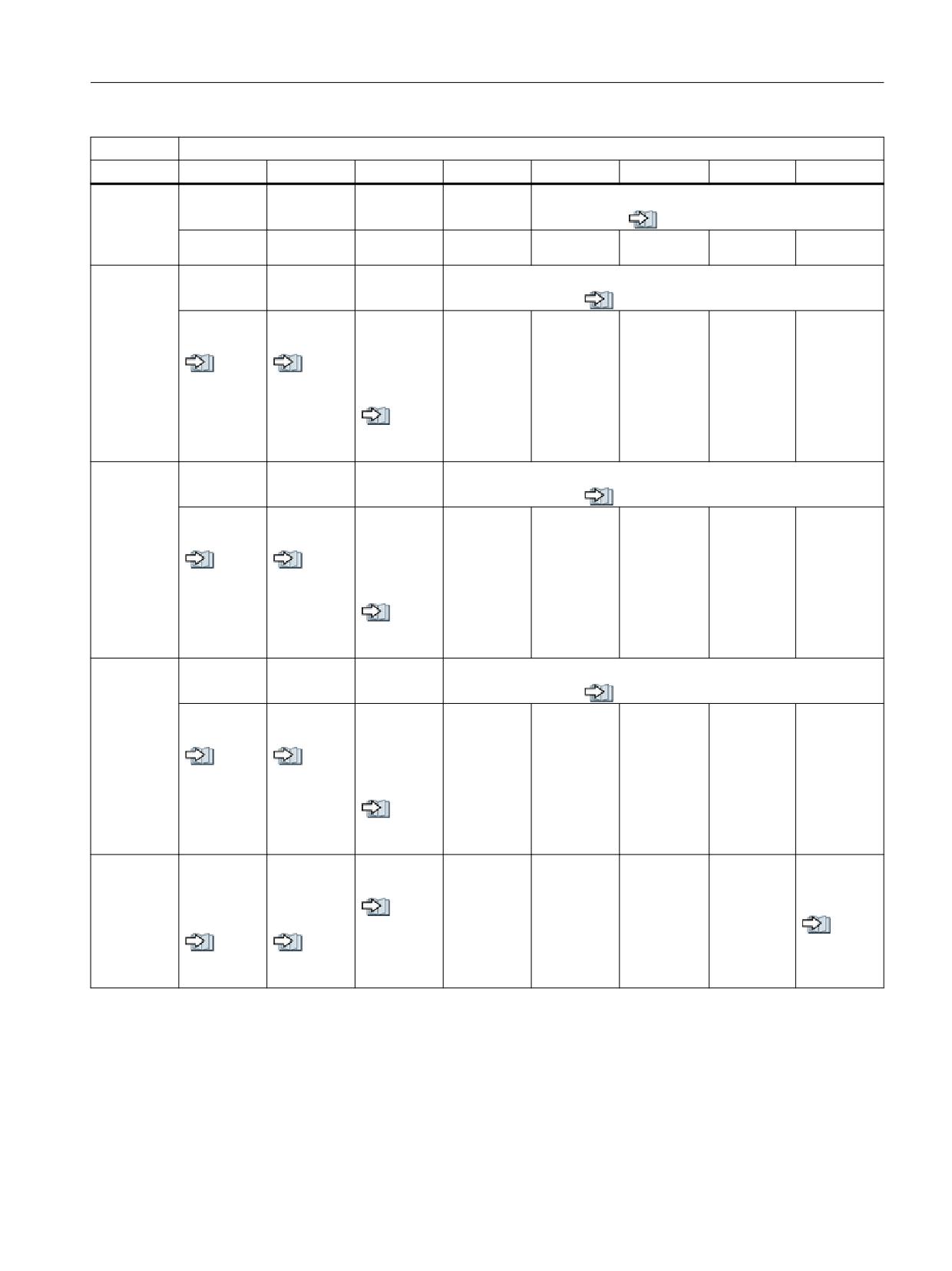
Interface signals
19.1 Interface signals - overview
DB10
Signals from the NC (NC → PLC)
Byte
Bit 7
Bit 6
Bit 5
Bit 4
Bit 3
Bit 2
Bit 1
Bit 0
DBB99
Channel number for handwheel 3
Operating
see also (Page 462)
soft-
D
C
B
A
ware → PLC
DBB100
Axis number for handwheel 1
Operating
see also (Page 463)
soft-
Machine ax-
Handwheel
Define
E
D
C
B
A
ware → PLC
is
1 selected
handwheel
1 as con-
see al-
see al-
tour hand-
so
so
wheel
(Page 465)
(Page 464)
see al-
so
(Page 463)
DBB101
Axis number for handwheel 2
Operating
see also (Page 465)
soft-
Machine ax-
Handwheel
Define
E
D
C
B
A
ware → PLC
is
2 selected
handwheel
2 as con-
see al-
see al-
tour hand-
so
so
wheel
(Page 466)
(Page 465)
see al-
so
(Page 465)
DBB102
Axis number for handwheel 3
Operating
see also (Page 466)
soft-
Machine ax-
Handwheel
Define
E
D
C
B
A
ware → PLC
is
3 selected
handwheel
3 as con-
see al-
see al-
tour hand-
so
so
wheel
(Page 466)
(Page 466)
see al-
so
(Page 466)
DBB103
Operating
Operating
AT box
Operating
Operating
Remote di-
software
software
ready
software
software
agnostics
Operating
battery
tempera-
fan moni-
monitor
active
soft-
see al-
alarm
ture limit
toring
hard disk
ware → PLC
so
see al-
see al-
see al-
(Page 466)
so
so
so
(Page 466)
(Page 467)
(Page 467)
PLC
Function Manual, 10/2020, 6FC5397-0HP40-0BA1
361
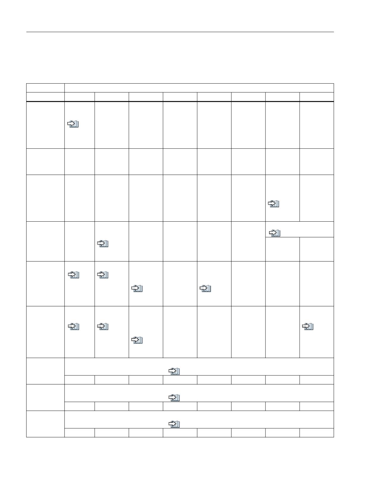
Interface signals
19.1 Interface signals - overview
19.1.7.5
DB10, general signals from the NC
Table 19-44
DB10, general signals to the PLC
DB10
Signals to the PLC
Byte
Bit 7
Bit 6
Bit 5
Bit 4
Bit 3
Bit 2
Bit 1
Bit 0
DBB104
NC CPU:
1st OB1 cy-
Op2Key
Op1Key
HHU ready
MCP 2 ready
MCP 1 ready
cle
ready
ready
GP → PLC
Ready1)
see
also
(Page
467)
DBB105
TOOLMAN:
GP → PLC
Command
Cancel
DBB106
Emergency
Collision
Stop:
avoidance:
NC → PLC
Active
Protection
area moni-
see al-
toring ac-
so
tive
(Page 468)
DBB107
Inch sys-
NCU link:
Measuring input activated
tem of
see also (Page 468)
NC → PLC
Active
units
see al-
Pushbutton
Pushbutton
so
2
1
(Page 468)
DBB108
NC ready
Drive ready
Drives in cy-
Operating
Operator
Operator
clic opera-
software
panel at
panel 2:
NC → PLC
see
see al-
tion
ready
MPI: "ready"
"ready"
also
so
(Page
(Page 469)
see al-
see al-
469)
so
so
(Page 469)
(Page 469)
DBB109
NC bat-
Air temper-
Heat sink
PC operat-
NC alarm is
tery alarm
ature alarm
tempera-
ing system
active
NC → PLC
ture NCU
error
see
see al-
see al-
alarm
also
so
so
(Page
(Page 471)
see al-
(Page 470)
471)
so
(Page 470)
DBB110
Software cam minus
NC → PLC
see also (Page 471)
7
8
5
4
3
2
1
0
DBB111
Software cam minus
NC → PLC
see also (Page 471)
15
14
13
12
11
10
9
8
DBB112
Software cam minus
NC → PLC
see also (Page 471)
23
22
21
20
19
18
17
16
PLC
362
Function Manual, 10/2020, 6FC5397-0HP40-0BA1

Interface signals
19.1 Interface signals - overview
DB10
Signals to the PLC
Byte
Bit 7
Bit 6
Bit 5
Bit 4
Bit 3
Bit 2
Bit 1
Bit 0
DBB113
Software cam minus
NC → PLC
see also (Page 471)
31
30
29
28
27
26
25
24
DBB114
Software cam plus
NC → PLC
see also (Page 472)
7
6
5
4
3
2
1
0
DBB115
Software cam plus
NC → PLC
see also (Page 472)
15
14
13
12
11
10
9
8
DBB116
Software cam plus
NC → PLC
see also (Page 472)
23
22
21
20
19
18
17
16
DBB117
Software cam plus
NC → PLC
see also (Page 472)
31
30
29
28
27
26
25
24
DBB118-
SINUMERIK Integrate data
DBB121
SINUMERIK
Integrate →
PLC
1)
DB10 DBX104.7 (NC CPU: ready) The signal should be included in the machine safety circuit.
19.1.7.6
DB10, external digital NC inputs
Table 19-45 DB10, external digital NC inputs
DB10
Signals to the NC (PLC → NC)
Byte
Bit 7
Bit 6
Bit 5
Bit 4
Bit 3
Bit 2
Bit 1
Bit 0
DBB122
Disable of the external digital NC inputs
see also (Page 473)
16
15
14
13
12
11
10
9
DBB123
Values from the PLC for the external digital NC inputs
see also (Page 473)
16
15
14
13
12
11
10
9
DBB124
Disable of the external digital NC inputs
see also (Page 473)
24
23
22
21
20
19
18
17
DBB125
Values from the PLC for the external digital NC inputs
see also (Page 474)
24
23
22
21
20
19
18
17
PLC
Function Manual, 10/2020, 6FC5397-0HP40-0BA1
363

Interface signals
19.1 Interface signals - overview
DB10
Signals to the NC (PLC → NC)
Byte
Bit 7
Bit 6
Bit 5
Bit 4
Bit 3
Bit 2
Bit 1
Bit 0
DBB126
Disable of the external digital NC inputs
see also (Page 474)
32
31
30
29
28
27
26
25
DBB127
Values from the PLC for the external digital NC inputs
see also (Page 475)
32
31
30
29
28
27
26
25
DBB128
Disable of the external digital NC inputs
see also (Page 475)
40
39
38
37
36
35
34
33
DBB129
Values from the PLC for the external digital NC inputs
see also (Page 475)
40
39
38
37
36
35
34
33
19.1.7.7
DB10, external digital NC outputs
Table 19-46 DB10, external digital NC outputs
DB10
Signals to the NC (PLC → NC)
Byte
Bit 7
Bit 6
Bit 5
Bit 4
Bit 3
Bit 2
Bit 1
Bit 0
DBB130
Disable of the external digital NC outputs
see also (Page 476)
16
15
14
13
12
11
10
9
DBB131
Overwrite mask for the external digital NC outputs
see also (Page 476)
16
15
14
13
12
11
10
9
DBB132
Value from the PLC for the external digital NC outputs
see also (Page 477)
16
15
14
13
12
11
10
9
DBB133
Input mask for the external digital NC outputs
see also (Page 478)
16
15
14
13
12
11
10
9
DBB134
Disable of the external digital NC outputs
see also (Page 478)
24
23
22
21
20
19
18
17
DBB135
Overwrite mask for the external digital NC outputs
see also (Page 479)
24
23
22
21
20
19
18
17
DBB136
Value from the PLC for the external digital NC outputs
see also (Page 479)
24
23
22
21
20
19
18
17
PLC
364
Function Manual, 10/2020, 6FC5397-0HP40-0BA1

Interface signals
19.1 Interface signals - overview
DB10
Signals to the NC (PLC → NC)
Byte
Bit 7
Bit 6
Bit 5
Bit 4
Bit 3
Bit 2
Bit 1
Bit 0
DBB137
Input mask for the external digital NC outputs
see also (Page 480)
24
23
22
21
20
19
18
17
DBB138
Disable of the external digital NC outputs
see also (Page 480)
32
31
30
29
28
27
26
25
DBB139
Overwrite mask for the external digital NC outputs
see also (Page 481)
32
31
30
29
28
27
26
25
DBB140
Value from the PLC for the external digital NC outputs
see also (Page 482)
32
31
30
29
28
27
26
25
DBB141
Input mask for the external digital NC outputs
see also (Page 482)
32
31
30
29
28
27
26
25
DBB142
Disable of the external digital NC outputs
see also (Page 483)
40
39
38
37
36
35
34
33
DBB143
Overwrite mask for the external digital NC outputs
see also (Page 483)
40
39
38
37
36
35
34
33
DBB144
Value from the PLC for the external digital NC outputs
see also (Page 484)
40
39
38
37
36
35
34
33
DBB145
Input mask for the external digital NC outputs
see also (Page 485)
40
39
38
37
36
35
34
33
19.1.7.8
DB10, external analog NC inputs
Table 19-47 DB10, external analog NC inputs
DB10
Signals to the NC (PLC → NC)
Byte
Bit 7
Bit 6
Bit 5
Bit 4
Bit 3
Bit 2
Bit 1
Bit 0
DBB146
Analog NC inputs disabled
see also (Page 485)
Bit 8
Bit 7
Bit 6
Bit 5
Bit 4
Bit 3
Bit 2
Bit 1
DBB147
Input analog value input for the NC from the PLC
see also (Page 486)
Bit 8
Bit 7
Bit 6
Bit 5
Bit 4
Bit 3
Bit 2
Bit 1
DBW148
Setpoint from the PLC for analog input 1 of the NC
PLC
Function Manual, 10/2020, 6FC5397-0HP40-0BA1
365

Interface signals
19.1 Interface signals - overview
DB10
Signals to the NC (PLC → NC)
Byte
Bit 7
Bit 6
Bit 5
Bit 4
Bit 3
Bit 2
Bit 1
Bit 0
DBW150
Setpoint from the PLC for analog input 2 of the NC
see also (Page 486)
DBW152
Setpoint from the PLC for analog input 3 of the NC
see also (Page 486)
DBW154
Setpoint from the PLC for analog input 4 of the NC
see also (Page 486)
DBW156
Setpoint from the PLC for analog input 5 of the NC
see also (Page 486)
DBW158
Setpoint from the PLC for analog input 6 of the NC
see also (Page 486)
DBW160
Setpoint from the PLC for analog input 7 of the NC
see also (Page 486)
DBW162
Setpoint from the PLC for analog input 8 of the NC
see also (Page 486)
DBW164
19.1.7.9
DB10, external analog NC outputs
Table 19-48 DB10, external analog NC outputs
DB10
Signals to the NC (PLC → NC)
Byte
Bit 7
Bit 6
Bit 5
Bit 4
Bit 3
Bit 2
Bit 1
Bit 0
DBB166
Overwrite mask for the analog NC outputs
see also (Page 486)
8
7
6
5
4
3
2
1
DBB167
Input mask for the analog NC outputs
see also (Page 487)
8
7
6
5
4
3
2
1
DBB168
Analog NC outputs disabled
see also (Page 488)
8
7
6
5
4
3
2
1
DBB169
Reserved
DBW170
Setpoint from the PLC for analog output 1 of the NC
see also (Page 488)
DBW172
Setpoint from the PLC for analog output 2 of the NC
see also (Page 488)
DBW174
Setpoint from the PLC for analog output 3 of the NC
see also (Page 488)
DBW176
Setpoint from the PLC for analog output 4 of the NC
see also (Page 488)
PLC
366
Function Manual, 10/2020, 6FC5397-0HP40-0BA1

Interface signals
19.1 Interface signals - overview
DB10
Signals to the NC (PLC → NC)
Byte
Bit 7
Bit 6
Bit 5
Bit 4
Bit 3
Bit 2
Bit 1
Bit 0
DBW178
Setpoint from the PLC for analog output 5 of the NC
see also (Page 488)
DBW180
Setpoint from the PLC for analog output 6 of the NC
see also (Page 488)
DBW182
Setpoint from the PLC for analog output 7 of the NC
see also (Page 488)
DBW184
Setpoint from the PLC for analog output 8 of the NC
see also (Page 488)
19.1.7.10
DB10, external digital NC inputs and outputs
Table 19-49 DB10, external digital NC inputs and outputs
DB10
Signals from the NC (NC → PLC)
Byte
Bit 7
Bit 6
Bit 5
Bit 4
Bit 3
Bit 2
Bit 1
Bit 0
DBB186
Actual value of the external digital NC inputs
see also (Page 489)
16
15
14
13
12
11
10
9
DBB187
Actual value of the external digital NC inputs
see also (Page 489)
24
23
22
21
20
19
18
17
DBB188
Actual value of the external digital NC inputs
see also (Page 490)
32
31
30
29
28
27
26
25
DBB189
Actual value of the external digital NC inputs
see also (Page 490)
40
39
38
37
36
35
34
33
DBB190
NC setpoint for the external digital NC outputs
see also (Page 491)
16
15
14
13
12
11
10
9
DBB191
NC setpoint for the external digital NC outputs
see also (Page 491)
24
23
22
21
20
19
18
17
DBB192
NC setpoint for the external digital NC outputs
see also (Page 492)
32
31
30
29
28
27
26
25
DBB193
NC setpoint for the external digital NC outputs
see also (Page 492)
40
39
38
37
36
35
34
33
PLC
Function Manual, 10/2020, 6FC5397-0HP40-0BA1
367

Interface signals
19.1 Interface signals - overview
19.1.7.11
DB10, analog NC inputs and outputs
Table 19-50 DB10, analog NC inputs and outputs
DB10
Signals from the NC (NC → PLC)
Byte
Bit 7
Bit 6
Bit 5
Bit 4
Bit 3
Bit 2
Bit 1
Bit 0
DBW194
Actual value of analog input 1 of the NC
see also (Page 493)
DBW196
Actual value of analog input 2 of the NC
see also (Page 493)
DBW198
Actual value of analog input 3 of the NC
see also (Page 493)
DBW200
Actual value of analog input 4 of the NC
see also (Page 493)
DBW202
Actual value of analog input 5 of the NC
see also (Page 493)
DBW204
Actual value of analog input 6 of the NC
see also (Page 493)
DBW206
Actual value of analog input 7 of the NC
see also (Page 493)
DBW208
Actual value of analog input 8 of the NC
see also (Page 493)
DBW210
Setpoint of analog output 1 of the NC
see also (Page 493)
DBW212
Setpoint of analog output 2 of the NC
see also (Page 493)
DBW214
Setpoint of analog output 3 of the NC
see also (Page 493)
DBW216
Setpoint of analog output 4 of the NC
see also (Page 493)
DBW218
Setpoint of analog output 5 of the NC
see also (Page 493)
DBW220
Setpoint of analog output 6 of the NC
see also (Page 493)
DBW222
Setpoint of analog output 7 of the NC
see also (Page 493)
DBW224
Setpoint of analog output 8 of the NC
see also (Page 493)
PLC
368
Function Manual, 10/2020, 6FC5397-0HP40-0BA1

Interface signals
19.1 Interface signals - overview
19.1.7.12
DB10, collision avoidance: Protection area active
Table 19-51 DB10, collision avoidance: Protection zone active
DB10
Signals from the NC (NC → PLC)
Byte
Bit 7
Bit 6
Bit 5
Bit 4
Bit 3
Bit 2
Bit 1
Bit 0
DBB226
Collision avoidance: Protection zone active (bit)
see also (Page 494)
7
6
5
4
3
2
1
0
DBB227
Collision avoidance: Protection zone active (bit)
see also (Page 494)
15
14
13
12
11
10
9
8
DBB228
Collision avoidance: Protection zone active (bit)
see also (Page 494)
23
22
21
20
19
18
17
16
DBB229
Collision avoidance: Protection zone active (bit)
see also (Page 494)
31
30
29
28
27
26
25
24
DBB230
Collision avoidance: Protection zone active (bit)
see also (Page 494)
39
38
37
36
35
34
33
32
DBB231
Collision avoidance: Protection zone active (bit)
see also (Page 494)
47
46
45
44
43
42
41
40
DBB232
Collision avoidance: Protection zone active (bit)
see also (Page 494)
55
54
53
52
51
50
49
48
DBB233
Collision avoidance: Protection zone active (bit)
see also (Page 494)
63
62
61
60
59
58
57
56
19.1.7.13
DB10, collision avoidance: Activate protection area
Table 19-52 DB10, collision avoidance: Activate protection zone
DB10
Signals from the PLC (PLC → NC)
Byte
Bit 7
Bit 6
Bit 5
Bit 4
Bit 3
Bit 2
Bit 1
Bit 0
DBB234
Collision avoidance: Activate protection zone (bit)
see also (Page 494)
7
6
5
4
3
2
1
0
DBB235
Collision avoidance: Activate protection zone (bit)
see also (Page 494)
15
14
13
12
11
10
9
8
PLC
Function Manual, 10/2020, 6FC5397-0HP40-0BA1
369
Interface signals
19.1 Interface signals - overview
DB10
Signals from the PLC (PLC → NC)
Byte
Bit 7
Bit 6
Bit 5
Bit 4
Bit 3
Bit 2
Bit 1
Bit 0
DBB236
Collision avoidance: Activate protection zone (bit)
see also (Page 494)
23
22
21
20
19
18
17
16
DBB237
Collision avoidance: Activate protection zone (bit)
see also (Page 494)
31
30
29
28
27
26
25
24
DBB238
Collision avoidance: Activate protection zone (bit)
see also (Page 494)
39
38
37
36
35
34
33
32
DBB239
Collision avoidance: Activate protection zone (bit)
see also (Page 494)
47
46
45
44
43
42
41
40
DBB240
Collision avoidance: Activate protection zone (bit)
see also (Page 494)
55
54
53
52
51
50
49
48
DBB241
Collision avoidance: Activate protection zone (bit)
see also (Page 494)
63
62
61
60
59
58
57
56
19.1.7.14
DB10, extension, handwheel signals from the NC
Table 19-53 DB10, extension, handwheel signals from the NC
DB10
Signals from the NC (NC → PLC)
Byte
Bit 7
Bit 6
Bit 5
Bit 4
Bit 3
Bit 2
Bit 1
Bit 0
DBB242
Handwheel 4 is moved
DBB243
Handwheel 5 is moved
DBB244
Handwheel 6 is moved
DBB245
Ethernet handwheel is stationary
see also (Page 495)
Handwheel
Handwheel
Handwheel
Handwheel
Handwheel
Handwheel
6
5
4
3
2
1
PLC
370
Function Manual, 10/2020, 6FC5397-0HP40-0BA1
Interface signals
19.1 Interface signals - overview
19.1.7.15
DB10, extension, handwheel signals from the HMI
Table 19-54 DB10, extension, handwheel signals from the NC
DB10
Signals from HMI (HMI → PLC)
Byte
Bit 7
Bit 6
Bit 5
Bit 4
Bit 3
Bit 2
Bit 1
Bit 0
DBB246
Handwheel active
see also (Page 496)
Handwheel
Handwheel
Handwheel
Handwheel
Handwheel
Handwheel
6
5
4
3
2
1
19.1.7.16
DB10, interface robot status.
Table 19-55 DB10, signals from the robot
DB10
Signals from the PLC (PLC → NC)
Byte
Bit 7
Bit 6
Bit 5
Bit 4
Bit 3
Bit 2
Bit 1
Bit 0
DBB248
Robot status byte 0
DBB249
Robot status byte 1
DBB250
Robot status byte 2
DBB251
Robot status byte 3
DBB252
Robot status byte 4
DBB253
Robot status byte 5
DBB254
Robot status byte 6
DBB255
Robot status byte 7
19.1.7.17
DB10, interface robot status
Table 19-56 DB10, signals to the robot
DB10
Signals from the NC (NC → PLC)
Byte
Bit 7
Bit 6
Bit 5
Bit 4
Bit 3
Bit 2
Bit 1
Bit 0
DBB256
Robot control byte 0
DBB257
Robot control byte 1
DBB258
Robot control byte 2
DBB259
Robot control byte 3
DBB260
Robot control byte 4
DBB261
Robot control byte 5
DBB262
Robot control byte 6
DBB263
Robot control byte 7
PLC
Function Manual, 10/2020, 6FC5397-0HP40-0BA1
371
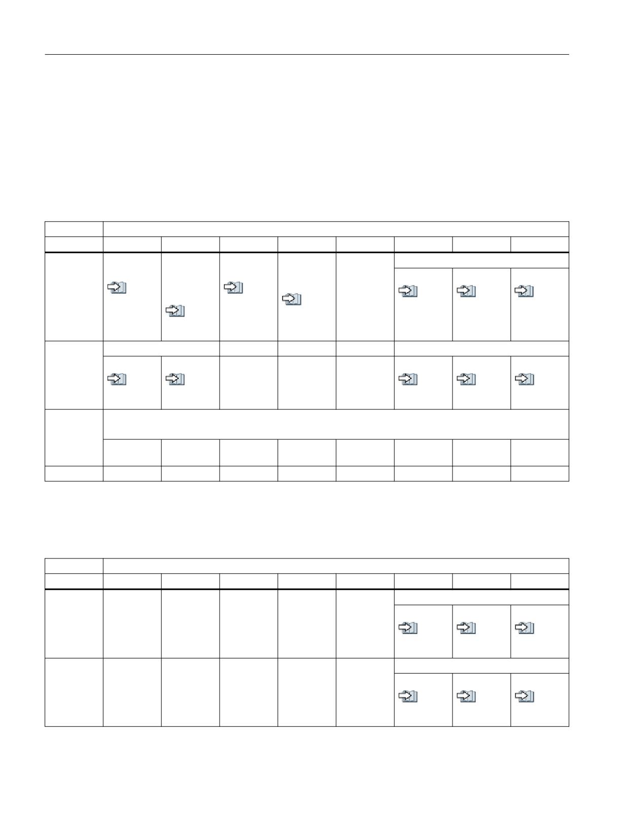
Interface signals
19.1 Interface signals - overview
19.1.8
Mode group-specific signals
19.1.8.1
DB11, mode signals 1 to the NC
The start address of a mode group interface can be calculated as follows:
Start address = 20 * (n - 1), with n = mode group number = 1, 2, 3, ...
Table 19-57 DB11, mode signals mode group 1 to NC
DB11
Signals to mode group 1 (PLC → NC)
Byte
Bit 7
Bit 6
Bit 5
Bit 4
Bit 3
Bit 2
Bit 1
Bit 0
DBB0
Mode
Mode
Mode
Mode
Mode: Requirement
group reset
group stop
group Stop
change dis-
JOG
MDI
AUTO
axes plus
able
see al-
see al-
see al-
see al-
see al-
spindles
so
so
see al-
so
so
so
(Page 499)
see al-
(Page 497)
so
(Page 497)
(Page 496)
(Page 496)
so
(Page 497)
(Page 498)
DBB1
Single block
Machine function: Requirement
Type A
Type B
REF
REPOS
TEACH IN
see al-
see al-
see al-
see al-
see al-
so
so
so
so
so
(Page 501)
(Page 500)
(Page 500)
(Page 500)
(Page 499)
DBB2
Machine function: Requirement
Note: The interface must be enabled explicitly: DB10 DBX57.0 (Page 358) = 1
Continuous
INCvar
INC10000
INC1000
INC100
INC10
INC1
traversing
DBB3
19.1.8.2
DB11, mode signals 1 from the NC
Table 19-58 DB11, mode signals mode group 1 from NC
DB11
Signals from mode group 1 (NC → PLC)
Byte
Bit 7
Bit 6
Bit 5
Bit 4
Bit 3
Bit 2
Bit 1
Bit 0
DBB4
Mode strobe
Operating
JOG
MDI
AUTO
software →
see al-
see al-
see al-
PLC
so
so
so
(Page 502)
(Page 502)
(Page 502)
DBB5
Machine function strobe
Operating
REF
REPOS
TEACH IN
software →
see al-
see al-
see al-
PLC
so
so
so
(Page 503)
(Page 503)
(Page 502)
PLC
372
Function Manual, 10/2020, 6FC5397-0HP40-0BA1
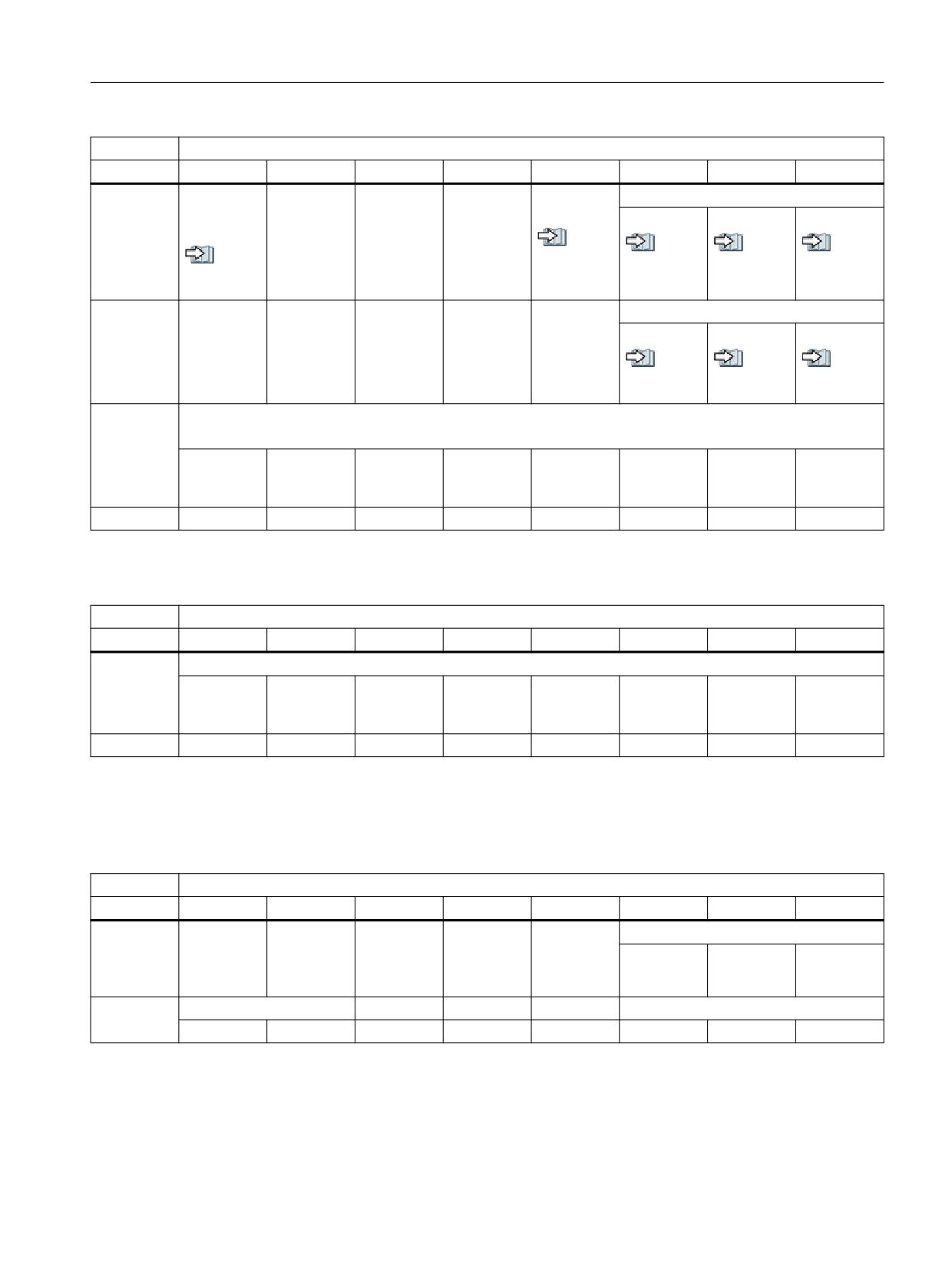
Interface signals
19.1 Interface signals - overview
DB11
Signals from mode group 1 (NC → PLC)
Byte
Bit 7
Bit 6
Bit 5
Bit 4
Bit 3
Bit 2
Bit 1
Bit 0
DBB6
All chan-
NC internal
Mode
Mode
Active operating mode
nels in the
JOG active
group reset
group ready
JOG
MDI
AUTO
reset state
performed
/FB-K1/
see al-
see al-
see al-
see al-
see al-
/FB-K1/
so
so
so
so
so
(Page 504) (Page 504)
(Page 503)
(Page 503)
(Page 504)
DBB7
Active machine function
REF
REPOS
TEACH IN
see al-
see al-
see al-
so
so
so
(Page 505)
(Page 505)
(Page 505)
DBB8
Machine functions: Selection
Note: The interface must be enabled explicitly: DB10 DBX57.0 (Page 358)= 1
Continuous
INCvar
INC10000
INC1000
INC100
INC10
INC1
traversing
active
DBB9
Table 19-59 DB11, mode signals mode group 1 from the HMI
DB11
Signals to mode group 1 (HMI → PLC)
Byte
Bit 7
Bit 6
Bit 5
Bit 4
Bit 3
Bit 2
Bit 1
Bit 0
DBB10
Machine functions
Operating
Continuous
INCvar
INC10000
INC1000
INC100
INC10
INC1
software →
traversing
PLC
active
DBB11
19.1.8.3
DB11, mode signals 2 to the NC
Table 19-60 DB11, mode signals mode group 2 to NC
DB11
Signals to mode group 2 (PLC → NC)
Byte
Bit 7
Bit 6
Bit 5
Bit 4
Bit 3
Bit 2
Bit 1
Bit 0
DBB20
Mode
Mode
Mode
Mode
Mode: Requirement
group reset
group Stop
group Stop
change dis-
JOG
MDI
AUTO
axes plus
able
spindles
DBB21
Single block
Machine function: Requirement
Type A
Type B
REF
REPOS
TEACH IN
PLC
Function Manual, 10/2020, 6FC5397-0HP40-0BA1
373
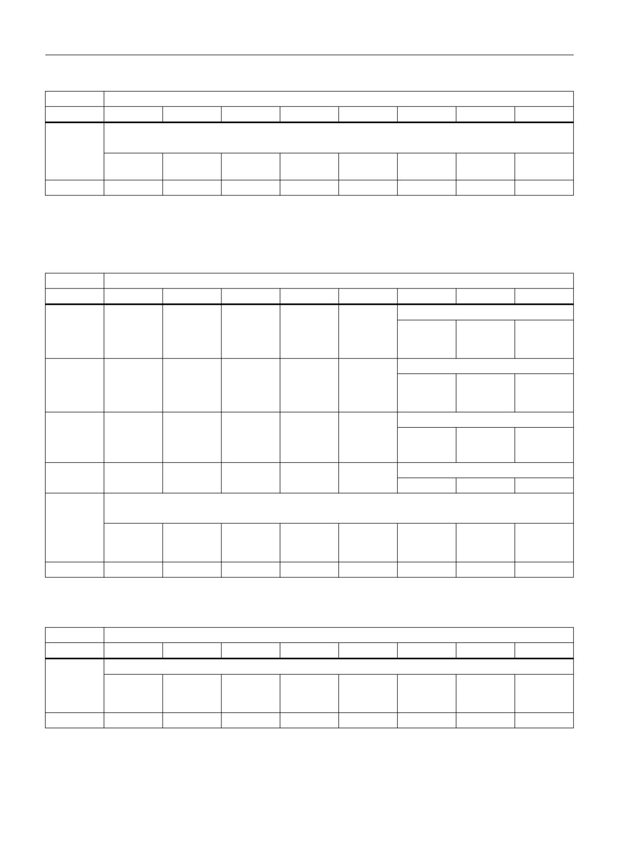
Interface signals
19.1 Interface signals - overview
DB11
Signals to mode group 2 (PLC → NC)
Byte
Bit 7
Bit 6
Bit 5
Bit 4
Bit 3
Bit 2
Bit 1
Bit 0
DBB22
Machine function: Requirement
Note: The interface must be enabled explicitly: DB10 DBX57.0 = (Page 358) 1
Continuous
INCvar
INC10000
INC1000
INC100
INC10
INC1
traversing
DBB23
19.1.8.4
DB11, mode signals 2 from NC
Table 19-61 DB11, mode signals mode group 2 from NC
DB11
Signals from mode group 2 (NC → PLC)
Byte
Bit 7
Bit 6
Bit 5
Bit 4
Bit 3
Bit 2
Bit 1
Bit 0
DBB24
Mode strobe
Operating
JOG
MDI
AUTO
software →
PLC
DBB25
Machine function strobe
Operating
REF
REPOS
TEACH IN
software →
PLC
DBB26
All chan-
JOG is ac-
Mode
Mode
Active operating mode
nels in
tive inter-
group reset
group ready
JOG
MDI
AUTO
state: Reset
nally in the
performed
NC
DBB27
Active machine function
REF
REPOS
TEACH IN
DBB28
Active machine function
Note: The interface must be enabled explicitly: DB10 DBX57.0 (Page 362) = 1
Continuous
INCvar
INC10000
INC1000
INC100
INC10
INC1
traversing
active
DBB29
Table 19-62 DB11, mode signals mode group 2 from the HMI
DB11
Signals to mode group 2 (HMI → PLC)
Byte
Bit 7
Bit 6
Bit 5
Bit 4
Bit 3
Bit 2
Bit 1
Bit 0
DBB30
Machine functions
Operating
Continuous
INCvar
INC10000
INC1000
INC100
INC10
INC1
software →
traversing
PLC
DBB31
PLC
374
Function Manual, 10/2020, 6FC5397-0HP40-0BA1

Interface signals
19.1 Interface signals - overview
19.1.9
Safety Integrated (SPL)
19.1.9.1
DB18, parameterization part
Table 19-63 DB18, parameterization part
DB18
SPL signals (PLC → PLC)
Byte
Bit 7
Bit 6
Bit 5
Bit 4
Bit 3
Bit 2
Bit 1
Bit 0
DBB0 -
DBB34
DBB36
Stop E
SPL ready
see al-
see al-
so
so
(Page 506)
(Page 506)
DBB37
19.1.9.2
DB18, data area / errors
Table 19-64 DB18, data area / errors
DB18
SPL signals (PLC ←→ NC)
/FBSsl/
Byte
Bit 7
Bit 6
Bit 5
Bit 4
Bit 3
Bit 2
Bit 1
Bit 0
Data area of the SPL inputs/outputs
DBB38 -
SPL_DATA.INSEP [1..32]
DBB41
see also (Page 506)
DBB42 -
SPL_DATA.INSEP [33..64]
DBB45
see also (Page 507)
DBB46 -
SPL_DATA.OUTSEP [1..32]
DBB49
see also (Page 507)
DBB50 -
SPL_DATA.OUTSEP [33..64]
DBB53
Data area for user SPL
DBB54 -
SPL_DATA.INSIP [1..32]
DBB57
DBB58 -
SPL_DATA.INSIP [33..64]
DBB61
DBB62 -
SPL_DATA.OUTSIP [1..32]
DBB65
DBB66 -
SPL_DATA.OUTSIP [33..64]
DBB69
PLC
Function Manual, 10/2020, 6FC5397-0HP40-0BA1
375

Interface signals
19.1 Interface signals - overview
DB18
SPL signals (PLC ←→ NC)
/FBSsl/
Byte
Bit 7
Bit 6
Bit 5
Bit 4
Bit 3
Bit 2
Bit 1
Bit 0
DBB70 -
SPL_DATA.MARKERSIP [1..32]
DBB73
DBB74 -
SPL_DATA.MARKERSIP [33..64]
DBB77
Difference in signal level NC - PLC for diagnostics
DBB78 -
-DBB81 SPL_DELTA.INSEP [1..32]
DBB81
DBB82 -
SPL_DELTA.INSEP [33..64]
DBB85
DBB86 -
SPL_DELTA.OUTSEP [1..32]
DBB89
DBB90 -
SPL_DELTA.OUTSEP [33..64]
DBB93
DBB94 -
SPL_DELTA.INSIP [1..32]
DBB97
DBB98 -
SPL_DELTA.INSIP [33..64]
DBB101
DBB102-
SPL_DELTA.OUTSIP [1..32]
DBB105
DBB106 -
SPL_DELTA.OUTSIP [33..64]
DBB109
DBB110 -
SPL_DELTA.MARKERSIP [1..32]
DBB113
DBB114 -
SPL_DELTA.MARKERSIP [33..64]
DBB117
DBB118
CMDSI
DBB119
NC signals a
Systemer-
Crosswise
PROFIsafe
stop to the
ror CDC
data com-
communi-
PLC
parison er-
cation error
ror, SPL pro-
tection sta-
tus
DBD120
STATSI
0 = no error
Crosswise data comparison error tripped
DBD124
CDC stack level display
(diagnostics capability: How many SPL signals currently have a different level)
PLC
376
Function Manual, 10/2020, 6FC5397-0HP40-0BA1
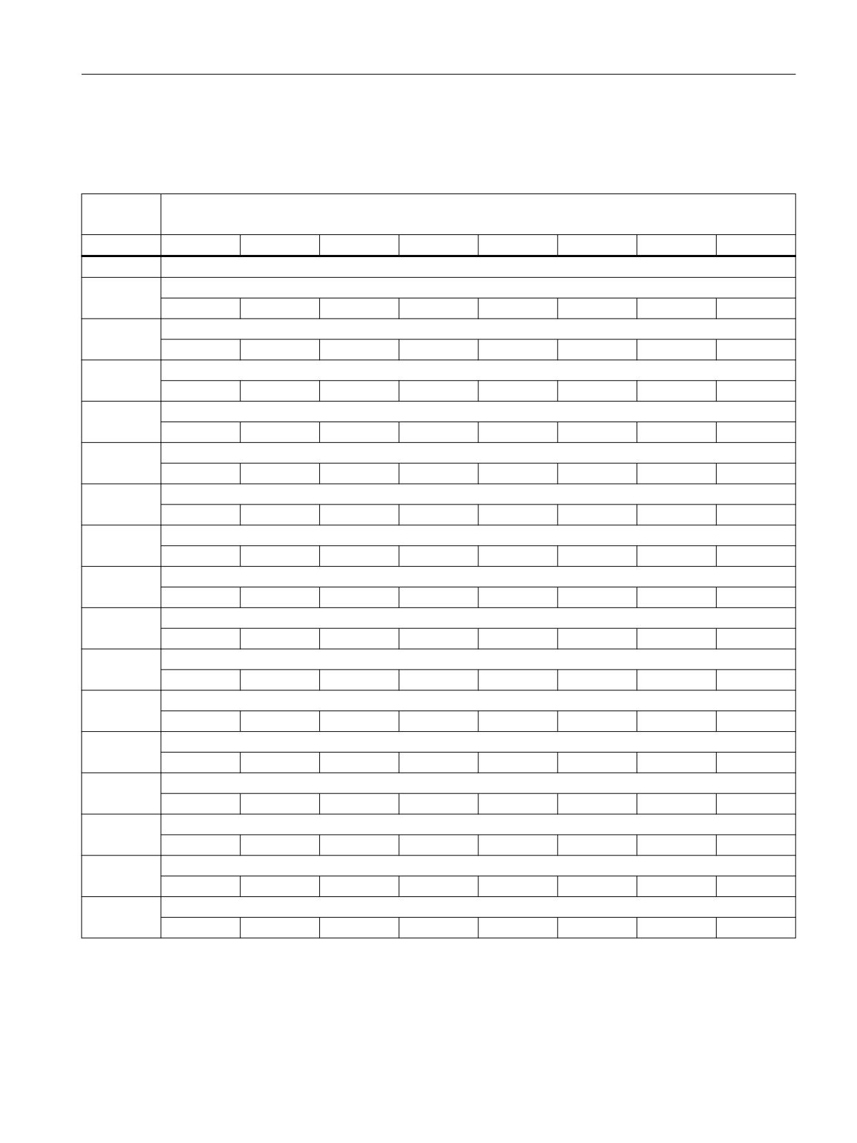
Interface signals
19.1 Interface signals - overview
19.1.9.3
DB18, additional data areas
Table 19-65
DB18, additional data areas
DB18
SPL signals (PLC ←→ NC)
/FBSIsl/
Byte
Bit 7
Bit 6
Bit 5
Bit 4
Bit 3
Bit 2
Bit 1
Bit 0
Data area of the single-channel inputs/outputs
DBB128
PLC_SI_OUT [1..8]
NC → PLC
DBB129
PLC_SI_OUT [9..16]
NC → PLC
DBB130
PLC_SI_OUT [17..24]
NC → PLC
DBB131
PLC_SI_OUT [25..32]
NC → PLC
DBB132
PLC_SI_IN [1..8]
NC → PLC
DBB133
PLC_SI_IN [9..16]
NC → PLC
DBB134
PLC_SI_IN [17..24]
NC → PLC
DBB135
PLC_SI_IN [25..32]
NC → PLC
DBB136-
SPL status
DBB137
DBB138
PROFIsafe module(s) for input byte
8
7
6
5
4
3
2
1
DBB139
DBB140
PROFIsafe module(s) for output byte
8
7
6
5
4
3
2
1
DBB141
DBB142 -
DBB149
DBB150 -
DBB157
DBB158 -
DBB188
PLC
Function Manual, 10/2020, 6FC5397-0HP40-0BA1
377
Interface signals
19.1 Interface signals - overview
19.1.9.4
DB18, F_SENDDP sender
Table 19-66
DB18, F_SENDDP sender
DB18
SPL signals (PLC ←→ NC)
/FBSIsl/
Byte
Bit 7
Bit 6
Bit 5
Bit 4
Bit 3
Bit 2
Bit 1
Bit 0
1st F_SENDDP interface: FSDP[1]
DBW190
ERR_REAC
DBB192
SUBS_ON
ERROR
DBB193
DBW194
DIAG
DBW196
RETVAL14
DBW198
RETVAL15
2nd F_SENDDP interface: FSDP[2]
DBW200
ERR_REAC
DBB202
SUBS_ON
ERROR
DBB203
DBW204
DIAG
DBW206
RETVAL14
DBW208
RETVAL15
3rd F_SENDDP interface: FSDP[3]
DBW210
ERR_REAC
DBB212
SUBS_ON
ERROR
DBB213
DBW214
DIAG
DBW216
RETVAL14
DBW218
RETVAL15
19.1.9.5
DB18, F_SENDDP receiver
Table 19-67 DB18, F_SENDDP receiver
DB18
SPL signals (PLC ←→ NC)
/FBSIsl/
Byte
Bit 7
Bit 6
Bit 5
Bit 4
Bit 3
Bit 2
Bit 1
Bit 0
1st F_RECVDP interface: FRDP[1]
(SUBS)
DBB220
7
6
5
4
3
2
1
0
DBB221
15
14
13
12
11
10
9
8
DBB222
REAC
DBB224
ACK_REI
DBB225
SEND MODE
ACK_REQ
SUBS_ON
ERROR
DBW226
DIAG
PLC
378
Function Manual, 10/2020, 6FC5397-0HP40-0BA1
Interface signals
19.1 Interface signals - overview
DB18
SPL signals (PLC ←→ NC)
/FBSIsl/
Byte
Bit 7
Bit 6
Bit 5
Bit 4
Bit 3
Bit 2
Bit 1
Bit 0
DBW228
RETVAL14
DBW230
RETVAL15
2nd F_RECVDP interface: FRDP[2]
(SUBS)
DBB232
7
6
5
4
3
2
1
0
DBB233
15
14
13
12
11
10
9
8
DBW234
DBB236
ACK_REI
DBB237
SEND MODE
ACK_REQ
SUBS_ON
ERROR
DBW238
DIAG
DBW240
RETVAL14
DBW242
RETVAL15
3rd F_RECVDP interface: FRDP[3]
(SUBS)
DBB244
7
6
5
4
3
2
1
0
DBB245
15
14
13
12
11
10
9
8
DBW246
REAC
DBB248
ACK_REI
DBB249
SEND MODE
ACK_REQ
SUBS_ON
ERROR
DBW250
DIAG
DBW252
RETVAL14
DBW254
RETVAL15
19.1.9.6
DB18, SPL user data
Table 19-68 DB18, SPL user data
DB18
SPL signals (PLC ←→ NC)
/FBSsl/
Byte
Bit 7
Bit 6
Bit 5
Bit 4
Bit 3
Bit 2
Bit 1
Bit 0
DBD256
SPL_USER_DATA[0]
DBD260
SPL_USER_DATA[1]
DBD264
SPL_USER_DATA[2]
DBD268
SPL_USER_DATA[3]
PLC
Function Manual, 10/2020, 6FC5397-0HP40-0BA1
379

Interface signals
19.1 Interface signals - overview
19.1.9.7
DB18, data area / errors: Extended data area
Table 19-69 DB18, data area / errors: Extended data area
DB18
Signals for the safety SPL (PLC ←→ NC)
/FBSIsl/
Byte
Bit 7
Bit 6
Bit 5
Bit 4
Bit 3
Bit 2
Bit 1
Bit 0
Data area of the SPL inputs/outputs
DBD272
SPL_DATA_HF.INSEP [65..96]
DBD276
SPL_DATA_HF.INSEP [97..128]
DBD280
SPL_DATA_HF.INSEP [129..160]
DBD284
SPL_DATA_HF.INSEP [161..192]
DBD288
SPL_DATA_HF.OUTSEP [65..96]
DBD292
SPL_DATA_HF.OUTSEP [97..128]
DBD296
SPL_DATA_HF.OUTSEP [129..160]
DBD300
SPL_DATA_HF.OUTSEP [161..192]
Data area for user SPL
DBD304
SPL_DATA_HF.INSIP [65..96]
DBD308
SPL_DATA_HF.INSIP [97..128]
DBD312
SPL_DATA_HF.INSIP [129..160]
DBD316
SPL_DATA_HF.INSIP [161..192]
DBD320
SPL_DATA_HF.OUTSIP [65..96]
DBD324
SPL_DATA_HF.OUTSIP [97..128]
DBD328
SPL_DATA_HF.OUTSIP [129..160]
DBD332
SPL_DATA_HF.OUTSIP [161..192]
DBD336
SPL_DATA_HF. MARKERSIP [65..96]
PLC
380
Function Manual, 10/2020, 6FC5397-0HP40-0BA1
Interface signals
19.1 Interface signals - overview
DB18
Signals for the safety SPL (PLC ←→ NC)
/FBSIsl/
Byte
Bit 7
Bit 6
Bit 5
Bit 4
Bit 3
Bit 2
Bit 1
Bit 0
DBD340
SPL_DATA_HF. MARKERSIP [97..128]
DBD344
SPL_DATA_HF. MARKERSIP [129..160]
DBD348
SPL_DATA_HF. MARKERSIP [161..192]
Difference in signal level NC - PLC for diagnostics
DBD352
SPL_DELTA_HF.INSEP [65..96]
DBD356
SPL_DELTA_HF.INSEP [97..128]
DBD360
SPL_DELTA_HF.INSEP [129..160]
DBD364
SPL_DELTA_HF.INSEP [161..192]
DBD368
SPL_DELTA_HF.OUTSEP [65..96]
DBD372
SPL_DELTA_HF.OUTSEP [97..128]
DBD376
SPL_DELTA_HF.OUTSEP [129..160]
DBD380
SPL_DELTA_HF.OUTSEP [161..192]
DBD384
SPL_DELTA_HF. INSIP [65..96]
DBD388
SPL_DELTA_HF.INSIP [97..128]
DBD392
SPL_DELTA_HF.INSIP [129..160]
DBD396
SPL_DATA_HF.INSIP [161..192]
DBD400
SPL_DELTA_HF.OUTSIP [65..96]
DBD404
SPL_DELTA_HF.OUTSIP [97..128]
DBD408
SPL_DELTA_HF.OUTSIP [129..160]
DBD412
SPL_DELTA_HF.OUTSIP [161..192]
DBD416
SPL_DELTA_HF.MARKERSIP [65..96]
PLC
Function Manual, 10/2020, 6FC5397-0HP40-0BA1
381

Interface signals
19.1 Interface signals - overview
DB18
Signals for the safety SPL (PLC ←→ NC)
/FBSIsl/
Byte
Bit 7
Bit 6
Bit 5
Bit 4
Bit 3
Bit 2
Bit 1
Bit 0
DBD420
SPL_DELTA_HF. MARKERSIP [97..128]
DBD424
SPL_DELTA_HF. MARKERSIP [129..160]
DBD428
SPL_DELTA_HF. MARKERSIP [161..192]
19.1.9.8
DB18, additional data areas: Extended data area
Table 19-70 DB18, additional data areas: Extended data area
DB18
Signals for the safety SPL (PLC ←→ NC)
/FBSIsl/
Byte
Bit 7
Bit 6
Bit 5
Bit 4
Bit 3
Bit 2
Bit 1
Bit 0
Data area of the single-channel inputs/outputs
DBB432
PLCSIOUT_HF [33..40]
von NC
DBB433
PLCSIOUT_HF [41..48]
von NC
DBB434
PLCSIOUT_HF [49..56]
von NC
DBB435
PLCSIOUT_HF [57..64]
von NC
DBB436
PLCSIOUT_HF [65..72]
von NC
DBB437
PLCSIOUT_HF [73..80]
von NC
DBB438
PLCSIOUT_HF [81..88]
von NC
DBB439
PLCSIOUT_HF [89..96]
von NC
DBB440
PLCSIIN_HF [33..40]
an NC
DBB441
PLCSIIN_HF [41..48]
an NC
DBB442
PLCSIIN_HF [49..56]
an NC
DBB443
PLCSIIN_HF [57..64]
an NC
PLC
382
Function Manual, 10/2020, 6FC5397-0HP40-0BA1

Interface signals
19.1 Interface signals - overview
DB18
Signals for the safety SPL (PLC ←→ NC)
/FBSIsl/
Byte
Bit 7
Bit 6
Bit 5
Bit 4
Bit 3
Bit 2
Bit 1
Bit 0
DBB444
PLCSIIN_HF [65..72]
an NC
DBB445
PLCSIIN_HF [73..80]
an NC
DBB446
PLCSIIN_HF [81..88]
an NC
DBB447
PLCSIIN_HF [89..96]
an NC
19.1.9.9
DB18, F_SENDDP sender
Table 19-71
DB18, F_SENDDP sender
DB18
Signals for the safety SPL (PLC ←→ NC)
/FBSIsl/
Byte
Bit 7
Bit 6
Bit 5
Bit 4
Bit 3
Bit 2
Bit 1
Bit 0
4th F_SENDDP interface: FSDP[4]
DBW448
ERR_REAC
DBB450
SUBS_ON
ERROR
DBB451
DBW452
DIAG
DBW454
RETVAL14
DBW456
RETVAL15
5th F_SENDDP interface: FSDP[5]
DBW458
ERR_REAC
DBB460
SUBS_ON
ERROR
DBB461
DBW462
DIAG
DBW464
RETVAL14
DBW466
RETVAL15
6th F_SENDDP interface: FSDP[6]
DBW468
ERR_REAC
DBB470
SUBS_ON
ERROR
DBB471
DBW472
DIAG
DBW474
RETVAL14
DBW476
RETVAL15
7th F_SENDDP interface: FSDP[7]
DBW478
ERR_REAC
DBB480
SUBS_ON
ERROR
PLC
Function Manual, 10/2020, 6FC5397-0HP40-0BA1
383

Interface signals
19.1 Interface signals - overview
DB18
Signals for the safety SPL (PLC ←→ NC)
/FBSIsl/
Byte
Bit 7
Bit 6
Bit 5
Bit 4
Bit 3
Bit 2
Bit 1
Bit 0
DBB481
DBW482
DIAG
DBW484
RETVAL14
DBW486
RETVAL15
8th F_SENDDP interface: FSDP[8]
DBW488
ERR_REAC
DBB490
SUBS_ON
ERROR
DBB491
DBW492
DIAG
DBW494
RETVAL14
DBW496
RETVAL15
9th F_SENDDP interface: FSDP[9]
DBW498
ERR_REAC
DBB500
SUBS_ON
ERROR
DBB501
DBW502
DIAG
DBW504
RETVAL14
DBW506
RETVAL15
10th F_SENDDP interface: FSDP[10]
DBW508
ERR_REAC
DBB510
SUBS_ON
ERROR
DBB511
DBW512
DIAG
DBW514
RETVAL14
DBW516
RETVAL15
11th F_SENDDP interface: FSDP[11]
DBW518
ERR_REAC
DBB520
SUBS_ON
ERROR
DBB521
DBW522
DIAG
DBW524
RETVAL14
DBW526
RETVAL15
12th F_SENDDP interface: FSDP[12]
DBW528
ERR_REAC
DBB530
SUBS_ON
ERROR
DBB531
DBW532
DIAG
DBW534
RETVAL14
DBW536
RETVAL15
13th F_SENDDP interface: FSDP[13]
DBW538
ERR_REAC
PLC
384
Function Manual, 10/2020, 6FC5397-0HP40-0BA1

Interface signals
19.1 Interface signals - overview
DB18
Signals for the safety SPL (PLC ←→ NC)
/FBSIsl/
Byte
Bit 7
Bit 6
Bit 5
Bit 4
Bit 3
Bit 2
Bit 1
Bit 0
DBB540
SUBS_ON
ERROR
DBB541
DBW542
DIAG
DBW544
RETVAL14
DBW546
RETVAL15
14th F_SENDDP interface: FSDP[14]
DBW548
ERR_REAC
DBB550
SUBS_ON
ERROR
DBB551
DBW552
DIAG
DBW554
RETVAL14
DBW556
RETVAL15
15th F_SENDDP interface: FSDP[15]
DBW558
ERR_REAC
DBB560
SUBS_ON
ERROR
DBB561
DBW562
DIAG
DBW564
RETVAL14
DBW566
RETVAL15
16th F_SENDDP interface: FSDP[16]
DBW568
ERR_REAC
DBB570
SUBS_ON
ERROR
DBB571
DBW572
DIAG
DBW574
RETVAL14
DBW576
RETVAL15
19.1.9.10
DB18, F_RECDP receiver
Table 19-72 DB18, F_SENDDP receiver
DB18
Signals for the safety SPL (PLC ←→ NC)
/FBSIsl/
Byte
Bit 7
Bit 6
Bit 5
Bit 4
Bit 3
Bit 2
Bit 1
Bit 0
4th F_RECVDP interface: FRDP_HF[4]
(SUBS)
DBB578
7
6
5
4
3
2
1
0
DBB579
15
14
13
12
11
10
9
8
DBW580
ERR_REAC
DBB582
ACK_REI
PLC
Function Manual, 10/2020, 6FC5397-0HP40-0BA1
385
Interface signals
19.1 Interface signals - overview
DB18
Signals for the safety SPL (PLC ←→ NC)
/FBSIsl/
Byte
Bit 7
Bit 6
Bit 5
Bit 4
Bit 3
Bit 2
Bit 1
Bit 0
DBB583
SENDMODE
ACK_REQ
SUBS_ON
ERROR
DBW584
DIAG
DBW586
RETVAL14
DBW588
RETVAL15
5th F_RECVDP interface: FRDP_HF[5]
(SUBS)
DBB590
7
6
5
4
3
2
1
0
DBB591
15
14
13
12
11
10
9
8
DBW592
ERR_REAC
DBB594
ACK_REI
DBB595
SENDMODE
ACK_REQ
SUBS_ON
ERROR
DBW596
DIAG
DBW598
RETVAL14
DBW600
RETVAL15
6th F_RECVDP interface: FRDP_HF[6]
(SUBS)
DBB602
7
6
5
4
3
2
1
0
DBB603
15
14
13
12
11
10
9
8
DBW604
ERR_REAC
DBB606
ACK_REI
DBB607
SENDMODE
ACK_REQ
SUBS_ON
ERROR
DBW608
DIAG
DBW610
RETVAL14
DBW612
RETVAL15
7th F_RECVDP interface: FRDP_HF[7]
(SUBS)
DBB614
7
6
5
4
3
2
1
0
DBB615
15
14
13
12
11
10
9
8
DBW616
ERR_REAC
DBB618
ACK_REI
DBB619
SENDMODE
ACK_REQ
SUBS_ON
ERROR
DBW620
DIAG
DBW622
RETVAL14
DBW624
RETVAL15
8th F_RECVDP interface: FRDP_HF[8]
(SUBS)
DBB626
7
6
5
4
3
2
1
0
DBB627
15
14
13
12
11
10
9
8
DBW628
ERR_REAC
DBB630
ACK_REI
DBB631
SENDMODE
ACK_REQ
SUBS_ON
ERROR
PLC
386
Function Manual, 10/2020, 6FC5397-0HP40-0BA1
Interface signals
19.1 Interface signals - overview
DB18
Signals for the safety SPL (PLC ←→ NC)
/FBSIsl/
Byte
Bit 7
Bit 6
Bit 5
Bit 4
Bit 3
Bit 2
Bit 1
Bit 0
DBW632
DIAG
DBW634
RETVAL14
DBW636
RETVAL15
9th F_RECVDP interface: FRDP_HF[9]
(SUBS)
DBB638
7
6
5
4
3
2
1
0
DBB639
15
14
13
12
11
10
9
8
DBW640
ERR_REAC
DBB642
ACK_REI
DBB643
SENDMODE
ACK_REQ
SUBS_ON
ERROR
DBW644
DIAG
DBW646
RETVAL14
DBW648
RETVAL15
10th F_RECVDP interface: FRDP_HF[10]
(SUBS)
DBB650
7
6
5
4
3
2
1
0
DBB651
15
14
13
12
11
10
9
8
DBW652
ERR_REAC
DBB654
ACK_REI
DBB655
SENDMODE
ACK_REQ
SUBS_ON
ERROR
DBW656
DIAG
DBW658
RETVAL14
DBW660
RETVAL15
11th F_RECVDP interface: FRDP_HF[11]
(SUBS)
DBB662
7
6
5
4
3
2
1
0
DBB663
15
14
13
12
11
10
9
8
DBW664
ERR_REAC
DBB666
ACK_REI
DBB667
SENDMODE
ACK_REQ
SUBS_ON
ERROR
DBW668
DIAG
DBW670
RETVAL14
DBW672
RETVAL15
12th F_RECVDP interface: FRDP_HF[12]
(SUBS)
DBB674
7
6
5
4
3
2
1
0
DBB675
15
14
13
12
11
10
9
8
DBW676
ERR_REAC
PLC
Function Manual, 10/2020, 6FC5397-0HP40-0BA1
387

Interface signals
19.1 Interface signals - overview
DB18
Signals for the safety SPL (PLC ←→ NC)
/FBSIsl/
Byte
Bit 7
Bit 6
Bit 5
Bit 4
Bit 3
Bit 2
Bit 1
Bit 0
DBB678
ACK_REI
DBB679
SENDMODE
ACK_REQ
SUBS_ON
ERROR
DBW680
DIAG
DBW682
RETVAL14
DBW684
RETVAL15
13th F_RECVDP interface: FRDP_HF[13]
(SUBS)
DBB686
7
6
5
4
3
2
1
0
DBB687
15
14
13
12
11
10
9
8
DBW688
ERR_REAC
DBB690
ACK_REI
DBB691
SENDMODE
ACK_REQ
SUBS_ON
ERROR
DBW692
DIAG
DBW694
RETVAL14
DBW696
RETVAL15
14th F_RECVDP interface: FRDP_HF[14]
(SUBS)
DBB698
7
6
5
4
3
2
1
0
DBB699
15
14
13
12
11
10
9
8
DBW700
ERR_REAC
DBB702
ACK_REI
DBB703
SENDMODE
ACK_REQ
SUBS_ON
ERROR
DBW704
DIAG
DBW706
RETVAL14
DBW708
RETVAL15
15th F_RECVDP interface: FRDP_HF[15]
(SUBS)
DBB710
7
6
5
4
3
2
1
0
DBB711
15
14
13
12
11
10
9
8
DBW712
ERR_REAC
DBB714
ACK_REI
DBB715
SENDMODE
ACK_REQ
SUBS_ON
ERROR
DBW716
DIAG
DBW718
RETVAL14
DBW720
RETVAL15
16th F_RECVDP interface: FRDP_HF[16]
(SUBS)
DBB722
7
6
5
4
3
2
1
0
DBB723
15
14
13
12
11
10
9
8
DBW724
ERR_REAC
DBB726
ACK_REI
PLC
388
Function Manual, 10/2020, 6FC5397-0HP40-0BA1
Interface signals
19.1 Interface signals - overview
DB18
Signals for the safety SPL (PLC ←→ NC)
/FBSIsl/
Byte
Bit 7
Bit 6
Bit 5
Bit 4
Bit 3
Bit 2
Bit 1
Bit 0
DBB727
SENDMODE
ACK_REQ
SUBS_ON
ERROR
DBW728
DIAG
DBW730
RETVAL14
DBW732
RETVAL15
19.1.10
Control/status signals to/from operator panel (OP)
19.1.10.1
DB19, signals to the operator panel (OP)
Table 19-73
DB19, signals to the operator panel (OP)
DB19
Signals from the operator panel (OP)
(PLC → operating software)
Byte
Bit 7
Bit 6
Bit 5
Bit 4
Bit 3
Bit 2
Bit 1
Bit 0
DBB0
Interface of 1st Control (DBB0 - DBB49)
Actual val-
Save to ac-
HMI Ad-
Delete re-
Delete can-
Key lock
Darken
Brighten
ue in the
tion log
vanced:
call alarms
cel alarms
screen
screen
see al-
WCS, (1) /
Shutdown
see al-
see al-
so
see al-
see al-
MCS (0)
so
so
(Page 508)
so
so
see al-
(Page 509)
(Page 509)
(Page 508)
(Page 508)
so
(Page 509)
DBB1
Rights for
External
the external
viewer
viewer
DBB2
DBB4
DBB6
Analog spindle 1: Utilization as a percentage
see also (Page 510)
DBB7
Analog spindle 2: Utilization as a percentage
see also (Page 510)
DBB8
Channel number of the machine control panel to the control
see also (Page 510)
DBB9
Reserved selection
Autotool
OEM2
OEM1
measure
DBB10
Hardkeys
see also (Page 510)
DBB11
Reserved
DBB12
PLC
Function Manual, 10/2020, 6FC5397-0HP40-0BA1
389
Interface signals
19.1 Interface signals - overview
DB19
Signals from the operator panel (OP)
(PLC → operating software)
Byte
Bit 7
Bit 6
Bit 5
Bit 4
Bit 3
Bit 2
Bit 1
Bit 0
DBB13
Part program
Reserved
Disable
teach in
Selection
Load
Unload
transfer
see al-
see al-
see al-
/IHsl-IM9/
so
so
so
(Page 511)
(Page 511)
(Page 511)
DBB14
Active (0) /
V24 active file system: Index of the file to be transferred from the standard list.
passive (1)
V24 passive file system: Number of the control file for user file names.
file system
see also (Page 511)
see al-
so
(Page 512)
DBB15
V24 active file system: Index which specifies the axis, channel or TO No.
V24 passive file system: Index of the file to be transferred from the user list.
see also (Page 512)
DBB16
Always 1
Program selection from the PLC: Index of the program list
see also (Page 512)
DBB17
Program selection from the PLC: Program index in the program list
see also (Page 513)
DBB18
DBB19
Reserved (message counter)
19.1.10.2
DB19, signals from the operator panel (OP)
Table 19-74 DB19, signals from the operator panel (OP)
DB19
Signals from the operator panel (OP)
(Operating software → PLC)
Byte
Bit 7
Bit 6
Bit 5
Bit 4
Bit 3
Bit 2
Bit 1
Bit 0
DBB20
Switch over
Simulation
Language 2
Recall
Cancel
Cancel key
Screen is
MCS/WCS
active
switched
alarm de-
alarm de-
actuated
dark
over
leted
leted
see al-
see al-
see al-
see al-
so
so
/IHsl-IM9/
see al-
see al-
so
so
(Page 515)
(Page 514)
so
so
(Page 514)
(Page 513)
(Page 514)
(Page 514)
/FB-A2/
DBB21
Current number of the active operating range
/FB-P3/; /FB-A2/
DBB22
Current channel number
see also (Page 515)
DBB23
Control 1
Screen
Data trans-
Keyboard
change ac-
fer active
has been
tive
used
DBW24
Current screen number
see also (Page 515)
PLC
390
Function Manual, 10/2020, 6FC5397-0HP40-0BA1
Interface signals
19.1 Interface signals - overview
DB19
Signals from the operator panel (OP)
(Operating software → PLC)
Byte
Bit 7
Bit 6
Bit 5
Bit 4
Bit 3
Bit 2
Bit 1
Bit 0
DBB25
DBB26
Program selection from the PLC: Status signals
Selection
Load
Unload
Active
Error
Job comple-
Reserved
ted
see al-
see al-
see al-
see al-
see al-
so
so
so
so
so
see al-
(Page 518)
(Page 517)
(Page 517)
(Page 516)
(Page 516)
so
(Page 515)
DBB27
Program selection from the PLC: Error code
see also (Page 518)
DBW28
Screen number for "Supplement user interface" /IHsl-BE2/
DBB30
Screen selection from the PLC: Control signals
PLC → OP
Screen de-
Screen se-
selection
lection
DBB31
Screen selection from the PLC: Status signals
Operating
Inactive
Error,
Screen is
Screen ac-
Screen is se-
Screen se-
software →
screen se-
deselected
tive
lected
lection ac-
PLC
lection not
cepted
possible
DBB32
Busy func-
Strobe func-
Function selection No. from the PLC
tion
tion
PLC → oper-
see also (Page 519)
ating soft-
see al-
see al-
ware
so
so
(Page 520)
(Page 520)
DBB33
Parameter 1 for function selection No. (function selection from DBB32)
PLC → oper-
see also (Page 520)
ating soft-
ware
DBB34
Parameter 2 for function selection No. (function selection from DBB32)
PLC → oper-
ating soft-
ware
DBB35
Parameter 3 for function selection No. (function selection from DBB32)
PLC → oper-
ating soft-
ware
DBB36
Error code for function selection No. (function selection from DBB32)
Operating
see also (Page 521)
software →
PLC
DBB37
Parameter 1 for function selection No. (function selection from DBB48)
Operating
software →
PLC
PLC
Function Manual, 10/2020, 6FC5397-0HP40-0BA1
391

Interface signals
19.1 Interface signals - overview
DB19
Signals from the operator panel (OP)
(Operating software → PLC)
Byte
Bit 7
Bit 6
Bit 5
Bit 4
Bit 3
Bit 2
Bit 1
Bit 0
DBB38
Parameter 2 for function selection No. (function selection from DBB48)
Operating
software →
PLC
DBB39
Parameter 3 for function selection No. (function selection from DBB48)
Operating
software →
PLC
DBB40 -
Reserved
DBB47
DBB48
PLC busy
Operating
Function selection No. from the operating software
software
Operating
Function
strobe
software →
PLC
Function
DBB49
Error code for function selection No. (function selection from DBB48)
PLC → oper-
ating soft-
ware
DBB50 -
Interface of 2nd Control (assignment the same as DBB0 - DBB49)
DBB99
DBB100
Switchover interface to the operating software
Call waiting interface (operating software announces itself to the NC)
ONL_REQUEST (online request from operating software) /FB-B3/
Operating software writes its client identification as online request (bits 8-15: bus type, bits 0-7: bus address)
DBB102
ONL_CONFIRM (acknowledgment from PLC after online request) /FB-B3/
PLC writes as acknowledgment the operating software client identification (bus type, bus address; such as
DBB100)
DBB104
PAR_CLIENT_IDENT /FB-B3/
Operating software writes its client identification (bus type, bus address; such as DBB100).
DBB106
PAR_MMC_TYP /FB-B3/
Type of operating software acc. to NETNAMES.INI: Main/secondary operator panel / server /...
DBB107
PAR_MCP_ADR /FB-B3/
Operating software writes address of the MCP to be activated; 255, if no MCP activation
DBB108
PAR_STATUS /FB-B3/
PLC writes the online enable for the operating software
DBB109
PAR_Z_INFO /FB-B3/
PLC writes additional info on the status
DBB110
M_TO_N_ALIVE
Sign-of-life from the PLC to the operating software using the M to N block
DBB112
Res. Bus type MCP
DBB113
ParOpKeyAdr
Direct key index call waiting interface
DBB114
ParTcuIndex
TCU index call waiting interface
PLC
392
Function Manual, 10/2020, 6FC5397-0HP40-0BA1
Interface signals
19.1 Interface signals - overview
DB19
Signals from the operator panel (OP)
(Operating software → PLC)
Byte
Bit 7
Bit 6
Bit 5
Bit 4
Bit 3
Bit 2
Bit 1
Bit 0
DBB115
ParHt2Index
Ht2 index logon interface
DBB116
Direct key address of 1st Online interface
DBB117
Direct key address of 2nd Online interface
DBB118
TCU index of 1st Online interface
DBB119
TCU index of 2nd Online interface
DBB120
Online interface OP 1 (user)
MMC1_CLIENT_IDENT /FB-B3/
PLC writes PAR_CLIENT_IDENT to MMCx_CLIENT_IDENT, if operating software goes online.
DBB122
MMC1_TYP /FB-B3/
PLC writes PAR_MMC_TYP to MMCx_TYP, if operating software goes online.
DBB123
MMC1_MCP_ADR /FB-B3/
PLC writes PAR_MCP_ADR to MMCx_MCP_ADR, if operating software goes online.
DBB124
MMC1_STATUS /FB-B3/
Connection state, operating software and PLC write alternating their requests/acknowledgments.
DBB125
MMC1_Z_INFO /FB-B3/
Additional information, connection state (pos./neg. acknowledgment, error messages, etc.)
DBB126
Reserved
TCU1_
MMC1_
MMC1_
MMC1_
MMC1_
MMC1_
MMC1_
SHIFT_
CHANGE_
ACTIVE_
ACTIVE_
ACTIVE_
MCP_
SHIFT_
LOCK
DENIED
CHANGED
PERM
REQ
SHIFT-
LOCK
LOCK
/FB-B3/
/FB2B3/
/FB-B3/
/FB-B3/
/FB-B3/
/FB-B3/
DBB127
Reserved bus type MCP
DBB128 -
Reserved Transline (Transline DB number)
DBB129
DBB130
Online interface OP 2 (user)
MMC2_CLIENT_IDENT /FB-B3/
PLC writes PAR_CLIENT_IDENT to MMCx_CLIENT_IDENT, if operating software goes online.
DBB132
MMC2_TYP /FB-B3/
PLC writes PAR_MMC_TYP to MMCx_TYP, if operating software goes online.
DBB133
MMC2_MCP_ADR /FB-B3/
PLC writes PAR_MCP_ADR to MMCx_MCP_ADR, if operating software goes online.
DBB134
MMC2_STATUS /FB-B3/
Connection state, operating software and PLC write alternating their requests/acknowledgments.
DBB135
MMC2_Z_INFO /FB-B3/
Additional information, connection state (pos./neg. acknowledgment, error messages, etc.)
DBB136
Reserved
TCU2_
MMC2_
MMC2_
MMC2_
MMC2_
MMC2_
MMC2_
SHIFT_
CHANGE_
ACTIVE_
ACTIVE_
ACTIVE_
MCP_
SHIFT_
LOCK
DENIED
CHANGED
PERM
REQ
SHIFT_
LOCK
LOCK
/FB-B3/
/FB-B3/
/FB-B3/
/FB-B3/
/FB-B3/
/FB-B3/
PLC
Function Manual, 10/2020, 6FC5397-0HP40-0BA1
393
Interface signals
19.1 Interface signals - overview
DB19
Signals from the operator panel (OP)
(Operating software → PLC)
Byte
Bit 7
Bit 6
Bit 5
Bit 4
Bit 3
Bit 2
Bit 1
Bit 0
DBB137
Reserved bus type MCP
DBB138 -
Reserved Transline (Transline DB number)
DBB139
DBB140 -
Assignment of the PLC for transfer parameters
DBB197
These data blocks are reserved for the "Tool Ident Connection" option.
/FBWsl/
DBB198 -
Assignment of the PLC for return values
DBB249
These data blocks are reserved for the "Tool Ident Connection" option.
/FBWsl/
DBB250 -
Function call of the PLC interface
DBB255
These data blocks are reserved for the "Tool Ident Connection" option.
/FBWsl/
DBB256 -
Commands for Paramtm.exe
DBB267
DBB268
Traffic light status
DBD270 -
Counter [1...32]
DBD394
DBB398
Handwheel number for simulation override
DBW400
Simulation override
DBW402
Simulation state
19.1.10.3
DB19, sidescreen - interface for the MCP function
Table 19-75 DB19, sidescreen - interface for the MCP function
DB19
Signals to/from the operator panel
Signal from the operating software → PLC
Byte
Bit 7
Bit 6
Bit 5
Bit 4
Bit 3
Bit 2
Bit 1
Bit 0
DBB404
Customer keys
8
7
6
5
4
3
2
1
DBB405
Customer keys
16
15
14
13
12
11
10
9
DBB406
Customer keys
24
23
22
21
20
19
18
17
DBB407
Customer keys
32
31
30
29
28
27
26
25
DBB408
Customer keys
40
39
38
37
36
35
34
33
DBB409
Customer keys
48
47
46
45
44
43
42
41
PLC
394
Function Manual, 10/2020, 6FC5397-0HP40-0BA1
Interface signals
19.1 Interface signals - overview
DB19
Signals to/from the operator panel
Signal from the operating software → PLC
Byte
Bit 7
Bit 6
Bit 5
Bit 4
Bit 3
Bit 2
Bit 1
Bit 0
DBB410
Customer keys
56
55
54
53
52
51
50
49
DBB411
Customer keys
64
63
62
61
60
59
58
57
19.1.10.4
DB19, sidescreen - interface for the MCP function
Table 19-76 DB19, sidescreen - interface for the MCP function signals to/from the operator panel
DB19
Signals to/from the operator panel [r/w]
Signal from PLC → operating software
Byte
Bit 7
Bit 6
Bit 5
Bit 4
Bit 3
Bit 2
Bit 1
Bit 0
DBB412
Customer LED
8
7
6
5
4
3
2
1
DBB413
Customer LED
16
15
14
13
12
11
10
9
DBB414
Customer LED
24
23
22
21
20
19
18
17
DBB415
Customer LED
32
31
30
29
28
27
26
25
DBB416
Customer LED
40
39
38
37
36
35
34
33
DBB417
Customer LED
48
47
46
45
44
43
42
41
DBB418
Customer LED
56
55
54
53
52
51
50
49
DBB419
Customer LED
64
63
62
61
60
59
58
57
DBB420
Customer key deactivated
8
7
6
5
4
3
2
1
DBB421
Customer key deactivated
16
15
14
13
12
11
10
9
DBB422
Customer key deactivated
24
23
22
21
20
19
18
17
DBB423
Customer key deactivated
32
31
30
29
28
27
26
25
DBB424
Customer key deactivated
40
39
38
37
36
35
34
33
DBB425
Customer key deactivated
48
47
46
45
44
43
42
41
PLC
Function Manual, 10/2020, 6FC5397-0HP40-0BA1
395
Interface signals
19.1 Interface signals - overview
DB19
Signals to/from the operator panel [r/w]
Signal from PLC → operating software
Byte
Bit 7
Bit 6
Bit 5
Bit 4
Bit 3
Bit 2
Bit 1
Bit 0
DBB426
Customer key deactivated
56
55
54
53
52
51
50
49
DBB427
Customer key deactivated
64
63
62
61
60
59
58
57
19.1.11
Defining PLC alarms
19.1.11.1
DB20, NC machine data
Table 19-77 DB20, NC machine data
DB20
NC machine data (PLC → user)
Byte
Bit 7
Bit 6
Bit 5
Bit 4
Bit 3
Bit 2
Bit 1
Bit 0
DBW0
INT values
DBW
DBW
INT values
DBB
Bit arrays
DBB
DBB
DBB
Bit arrays
DBD
REAL values
DBD
DBD
REAL values
PLC
396
Function Manual, 10/2020, 6FC5397-0HP40-0BA1
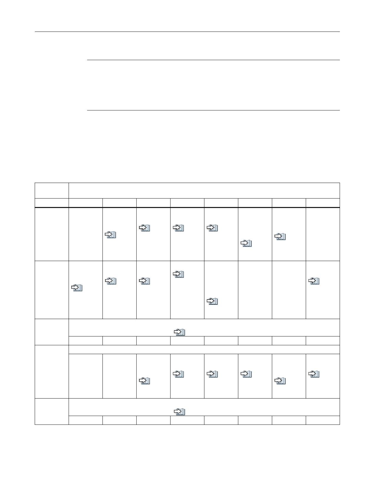
Interface signals
19.1 Interface signals - overview
Note
The start and end addresses of the PLC machine data areas are dependent on the particular
length data of the partial areas. The range of INTEGER values always starts with data byte 0. The
upper limit is defined by the associated length data. The range of the bit arrays starts after the
range of the INTEGER values at the next even address. The range of REAL values starts after the
range of the bit arrays at the next even address.
19.1.12
Channel-specific signals
19.1.12.1
DB21 - DB30, control signals to the channel (1)
DB21 -
Signals to the channel (PLC → NC)
DB30
Byte
Bit 7
Bit 6
Bit 5
Bit 4
Bit 3
Bit 2
Bit 1
Bit 0
DBB0
Activate dry
Activate
Activate sin-
Activate
RESU:
RESU:
run fee-
M01
gle block
DRF
Start re-
Backward/
drate
see al-
see al-
see al-
trace sup-
forward
see al-
so
so
so
port
see al-
so
(Page 523)
(Page 522)
(Page 522)
see al-
so
(Page 523)
so
(Page 521)
(Page 522)
DBB1
Activate
PLC action
CLC correc-
CLC stop
Time moni-
Disable all
Enable pro-
Activate ref-
program
completed
tion
toring ac-
synchron-
tection
erencing
see al-
test
tive (tool
ized actions
zones
see al-
see al-
so
see al-
manage-
see al-
so
so
(Page 525)
/FBSY/
/FB-A5/
so
ment)
so
(Page 526)
(Page 526)
(Page 524)
(Page 527)
see al-
so
(Page 525)
DBB2
Activate skip block
see also (Page 527)
/7
/6
/5
/4
/3
/2
/1
/0
DBB3
Nibbling and punching
Manual
Stroke inop-
Delayed
Stroke sup-
Manual
Stroke ena-
stroke initia-
erative
stroke
pression
stroke initia-
ble
tion
tion
see al-
see al-
see al-
see al-
see al-
so
so
so
see al-
so
so
(Page 529)
(Page 529)
(Page 529)
so
(Page 528)
(Page 530)
(Page 528)
DBB4
Path feedrate override
see also (Page 530)
H
G
F
E
D
C
B
A
PLC
Function Manual, 10/2020, 6FC5397-0HP40-0BA1
397
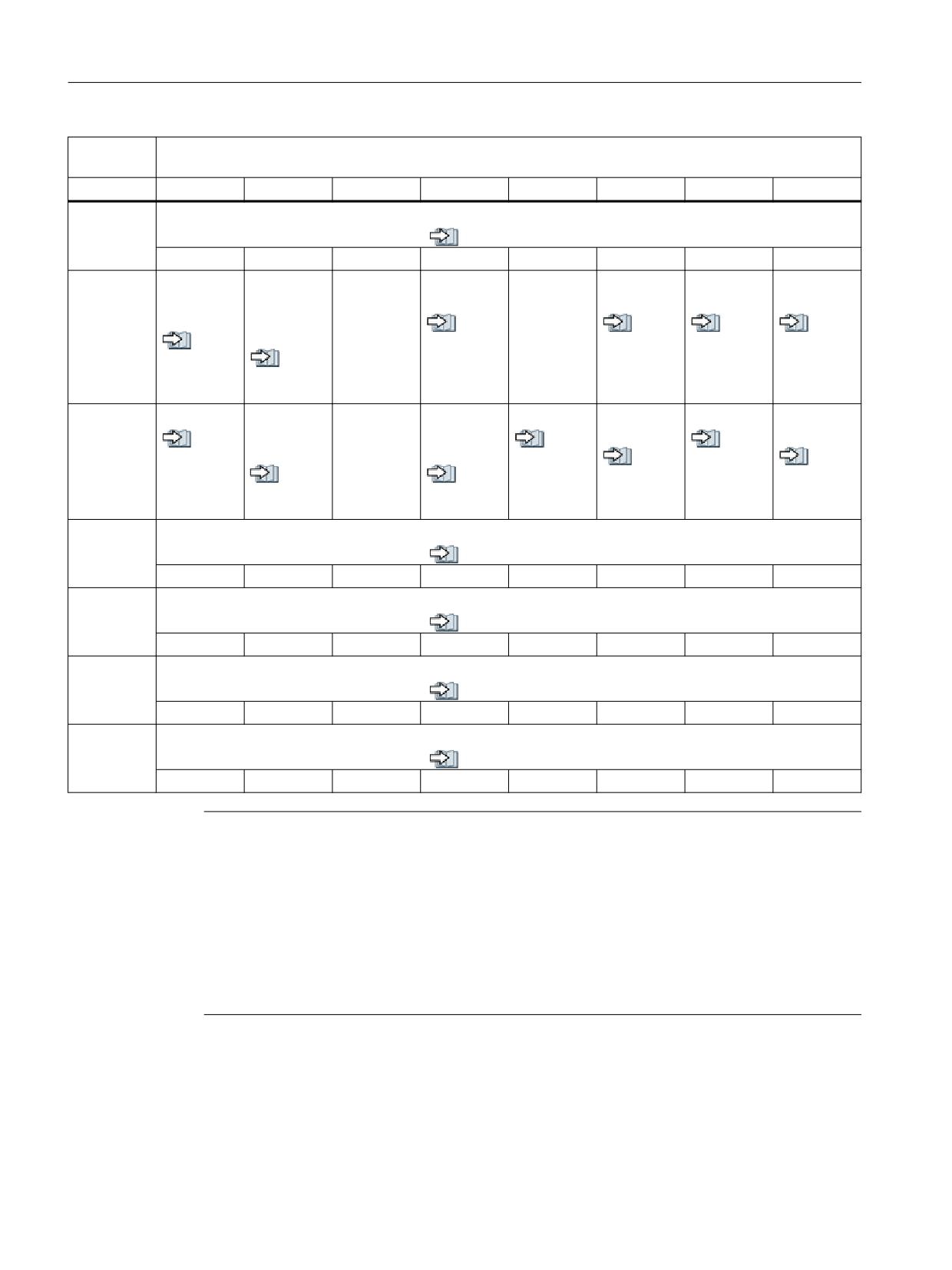
Interface signals
19.1 Interface signals - overview
DB21 -
Signals to the channel (PLC → NC)
DB30
Byte
Bit 7
Bit 6
Bit 5
Bit 4
Bit 3
Bit 2
Bit 1
Bit 0
DBB5
Path rapid traverse override
see also (Page 532)
H
G
F
E
D
C
B
A
DBB6
Path fee-
Path rapid
Program
Delete UP
Delete dis-
Read-in dis-
Feedrate
drate over-
traverse
level abort
number of
tance-to-go
able
disable
ride active
override ac-
passes
see al-
see al-
see al-
see al-
tive
see al-
so
so
so
so
so
see al-
(Page 536)
(Page 535)
(Page 535)
(Page 534)
(Page 537)
so
(Page 536)
DBB7
Reset
Activate
Deactivate
NC Stop ax-
NC stop
NC Stop at
NC start
NC start dis-
configured
start disable
es plus spin-
block limit
able
see al-
see al-
see al-
STOP
dle
so
so
see al-
so
see al-
(Page 540)
see al-
see al-
(Page 539)
so
(Page 538)
so
so
so
(Page 538)
(Page 537)
(Page 540)
(Page 539)
DBB8
Activate machine-related protection area
see also (Page 541)
8
7
6
5
4
3
2
1
DBB9
Activate machine-related protection area
see also (Page 541)
10
9
DBB10
Activate channel-specific protection area
see also (Page 541)
8
7
6
5
4
3
2
1
DBB11
Activate channel-specific protection area
see also (Page 541)
10
9
Note
• Feedrate override active: Even if the feedrate override is not active (= 100%), the 0% position
is still effective.
• Feedrate override: Either 31 positions (Gray code) with 31 MD for % evaluation, or 0% to
200% corresponding to the dual value in the byte (201 to 255 = max. 200%)
• Rapid traverse override: Either 31 positions (Gray code) with 31 MD for % evaluation, or 0%
to 100% corresponding to the dual value in the byte (101 to 255 = max. 100%)
• Single block: Select the version using "Write variable"
• Delete distance-to-go: Is only active for path axes and not for positioning axes
PLC
398
Function Manual, 10/2020, 6FC5397-0HP40-0BA1
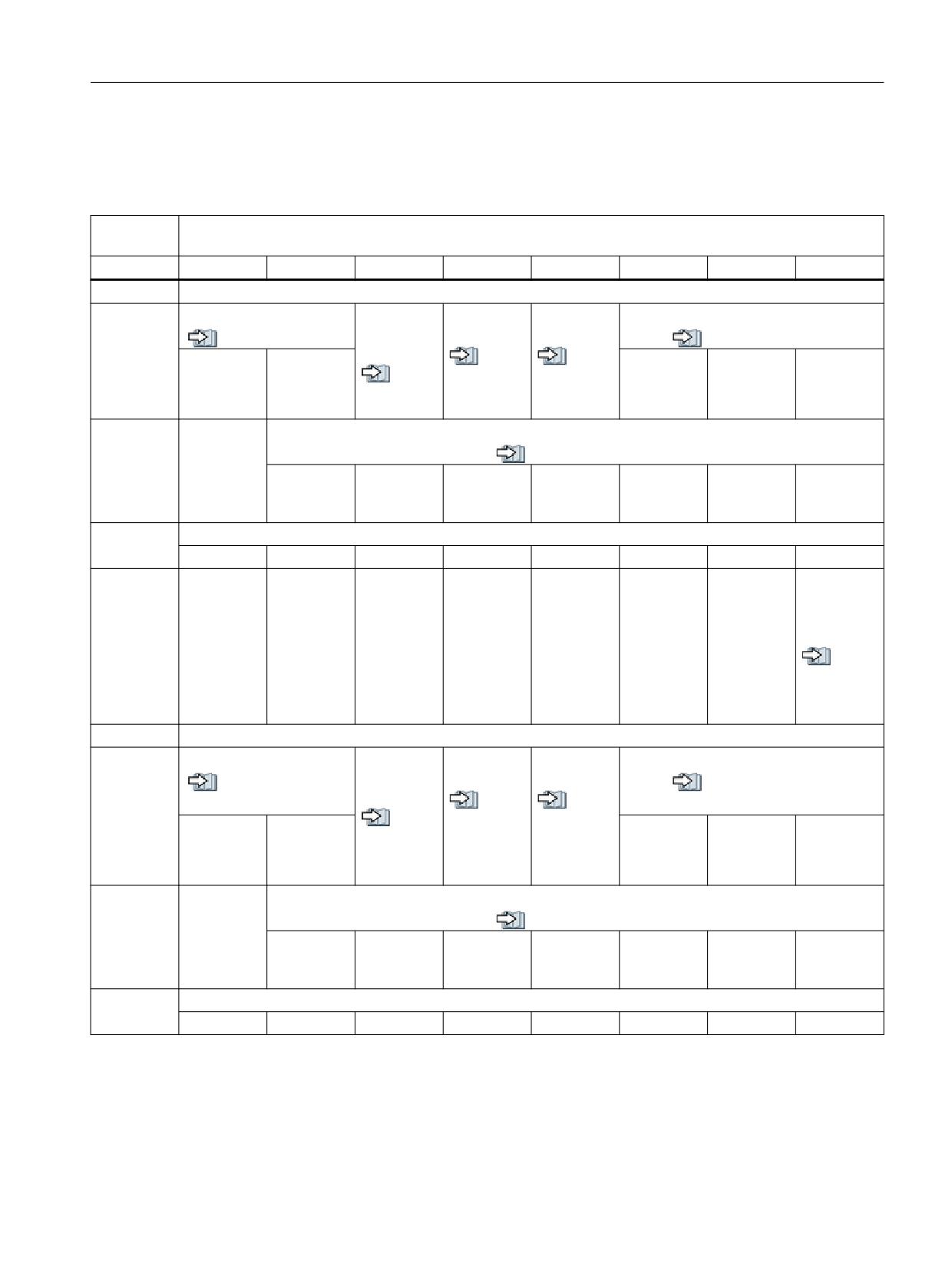
Interface signals
19.1 Interface signals - overview
19.1.12.2
DB21 - DB30, control signals to the geometry axes
Table 19-78
DB21 - DB30, control signals to the geometry axes
DB21 -
Signals to the channel (PLC → NC)
DB30
Byte
Bit 7
Bit 6
Bit 5
Bit 4
Bit 3
Bit 2
Bit 1
Bit 0
Geometry axis 1
DBB12
Traversing keys
Rapid tra-
Traversing
Feedrate
Activate handwheel
verse over-
key lock
stop
see also (Page 544)
see also (Page 542)
ride
see al-
see al-
Plus
Minus
C
B
A
see al-
so
so
so
(Page 543)
(Page 543)
(Page 544)
DBB13
Requested machine function
see also (Page 546)
Continuous
INCvar
INC10000
INC1000
INC100
INC10
INC1
manual
travel
DBB14
OEM signals
DBB15
Invert hand-
wheel direc-
tion of rota-
tion
see al-
so
(Page 547)
Geometry axis 2
DBB16
Traversing keys
Rapid tra-
Traversing
Feedrate
Activate handwheel
verse over-
key lock
stop
see also (Page 548)
see also (Page 547)
ride
see al-
see al-
see al-
so
so
Plus
Minus
C
B
A
so
(Page 548)
(Page 543)
(Page 548)
DBB17
Requested machine function
see also (Page 548)
Continuous
INCvar
INC10000
INC1000
INC100
INC10
INC1
manual
travel
DBB18
OEM signals
PLC
Function Manual, 10/2020, 6FC5397-0HP40-0BA1
399
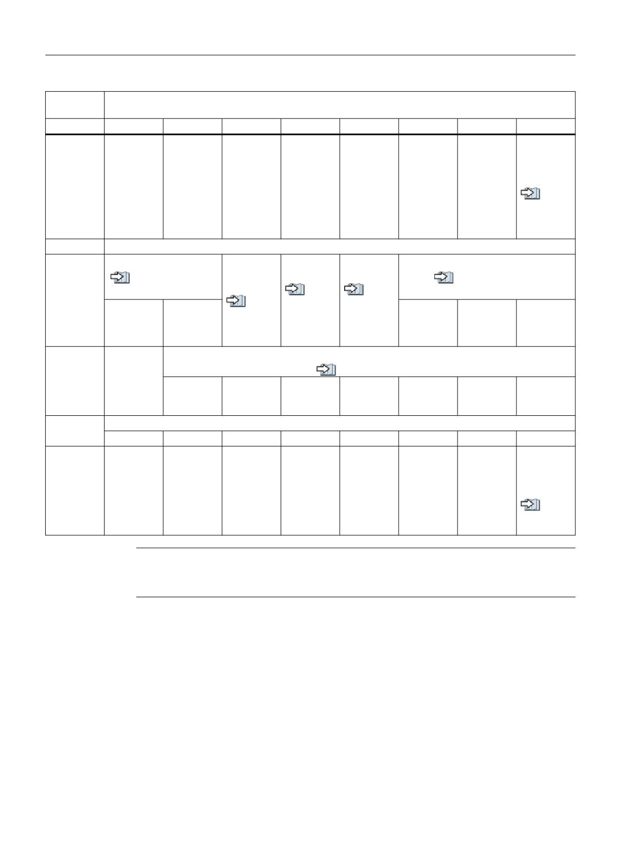
Interface signals
19.1 Interface signals - overview
DB21 -
Signals to the channel (PLC → NC)
DB30
Byte
Bit 7
Bit 6
Bit 5
Bit 4
Bit 3
Bit 2
Bit 1
Bit 0
DBB19
Invert hand-
wheel direc-
tion of rota-
tion
see al-
so
(Page 548)
Geometry axis 3
DBB20
Traversing keys
Rapid tra-
Traversing
Feedrate
Activate handwheel
verse over-
key lock
stop
see also (Page 549)
see also (Page 548)
ride
see al-
see al-
see al-
so
so
Plus
Minus
C
B
A
so
(Page 548)
(Page 543)
(Page 549)
DBB21
Requested machine function
see also (Page 549)
Continuous
INCvar
INC10000
INC1000
INC100
INC10
INC1
manual
travel
DBB22
OEM signals
DBB23
Invert hand-
wheel direc-
tion of rota-
tion
see al-
so
(Page 549)
Note
The NC only evaluates the machine function signals if the signal DB10 DBX57.0 (Page 358)"INC
inputs in mode group area active" is not set.
PLC
400
Function Manual, 10/2020, 6FC5397-0HP40-0BA1
Interface signals
19.1 Interface signals - overview
19.1.12.3
DB21 - DB30, HMI signals to channel / OEM signals from/to channel
Table 19-79
DB21 - DB30, control signals from the operating software to the PLC, PLC to the NC and status signal from channel
to the PLC
DB21 -
Signals from the channel/PLC/operating software (operating software → PLC, PLC → NC, NC → PLC)
DB30
Byte
Bit 7
Bit 6
Bit 5
Bit 4
Bit 3
Bit 2
Bit 1
Bit 0
DBB24
Dry run fee-
M01 selec-
M01 associ-
DRF selec-
Activate
drate selec-
ted
ated with
ted
configured
Operating
ted
NC selected
STOP
software →
see al-
see al-
PLC
see al-
so
see al-
so
see al-
so
(Page 551)
so
(Page 550)
so
(Page 551)
(Page 550)
(Page 549)
DBB25
Program
REPOS
Feedrate
REPOS mode /FB-K1/
test selec-
mode
override se-
Operating
C
B
A
ted
change
lected for
software →
rapid tra-
PLC
/FB-K1/
/FB-K1/
verse
see al-
so
(Page 552)
DBB26
Skip block requested, level/x
Operating
/FB-K1/
software →
/7
/6
/5
/4
/3
/2
/1
/0
PLC
DBB27
Skip block requested, lev-
el/x
Operating
software →
/9
/8
PLC
DBB28
OEM signals: Requirement
PLC → NC
DBB29
Tool
Deactivate
Deactivate
Activate
Activate fixed feedrate
wear moni-
workpiece
PTP traver-
PLC → NC
do not lock
see also (Page 554)
toring
counter
sal
see al-
4
3
2
1
see al-
see al-
see al-
so
so
so
so
(Page 556)
(Page 555)
(Page 555)
(Page 555)
DBB30
No tool
Jog circles
Activate NC-
Contour
Contour
Activate contour handwheel
change
associated
handwheel
handwheel
PLC → NC
see al-
see also (Page 556)
commands
M0/1
simulation,
simulation
so
C
B
A
negative di-
on
(Page 558)
see al-
rection
so
see al-
(Page 558)
see al-
so
so
(Page 557)
(Page 558)
PLC
Function Manual, 10/2020, 6FC5397-0HP40-0BA1
401
Interface signals
19.1 Interface signals - overview
DB21 -
Signals from the channel/PLC/operating software (operating software → PLC, PLC → NC, NC → PLC)
DB30
Byte
Bit 7
Bit 6
Bit 5
Bit 4
Bit 3
Bit 2
Bit 1
Bit 0
DBB31
Activate skip block
Invert con-
REPOS
REPOS mode
tour hand-
mode
PLC → NC
see also (Page 559)
wheel direc-
change
/9
/8
C
B
A
tion of rota-
see al-
tion
so
see al-
(Page 560)
so
(Page 560)
DBB32
Last action
M00/M01
Approach
Action
RESU:
RESU:
Execution
block active
active
block active
block active
from exter-
NC → PLC
Retrace sup-
Retrace
nal active
see al-
see al-
see al-
see al-
port active
mode active
so
so
so
so
see al-
see al-
(Page 562)
(Page 562)
(Page 561)
(Page 561)
so
so
(Page 561)
(Page 560)
DBB33
Program
Transforma-
M02/M30
Block
Handwheel
Revolution-
Orientable
Referenc-
test active
tion active
active
search ac-
override ac-
al feedrate
tool carrier
ing active
NC → PLC
tive
tive
active
active
see al-
see al-
see al-
see al-
so
so
so
see al-
see al-
/FB-V1/
so
(Page 565)
(Page 565)
(Page 564)
so
so
(Page 563)
(Page 564)
(Page 563)
DBB34
OEM signals: Feedback signal
NC → PLC
DBB35
Channel state
Program status
NC → PLC
Reset
Interrupted
Active
Canceled
Interrupted
Stopped
Waiting
Running
see al-
see al-
see al-
see al-
see al-
see al-
see al-
see al-
so
so
so
so
so
so
so
so
(Page 571)
(Page 570)
(Page 570)
(Page 569)
(Page 568)
(Page 568)
(Page 567)
(Page 566)
DBB36
NC alarm
Channel-
Channel is
Interrupt
All axes sta-
All axes that
with ma-
specific NC
ready
handling
tionary
have to be
NC → PLC
chining
alarm is ac-
active
referenced
see al-
see al-
stop is ac-
tive
are refer-
so
see al-
so
tive
enced
see al-
(Page 572)
so
(Page 572)
see al-
so
(Page 572)
see al-
so
(Page 573)
so
(Page 573)
(Page 571)
DBB37
"Stop at the
Read-in dis-
CLC stopped
CLC stopped
CLC active
Contour handwheel active
end of
able is ig-
NC → PLC
Upper limit
Lower limit
see al-
see also (Page 573)
block for
nored
so
see al-
see al-
C
B
A
single block
see al-
(Page 574)
so
so
(SBL)" is
so
(Page 575)
(Page 575)
suppressed
(Page 576)
see al-
so
(Page 576)
PLC
402
Function Manual, 10/2020, 6FC5397-0HP40-0BA1
Interface signals
19.1 Interface signals - overview
DB21 -
Signals from the channel/PLC/operating software (operating software → PLC, PLC → NC, NC → PLC)
DB30
Byte
Bit 7
Bit 6
Bit 5
Bit 4
Bit 3
Bit 2
Bit 1
Bit 0
DBB38
Nibbling and punching /FB-N4/
NC → PLC
Manual
Stroke ini-
stroke initia-
tiation ac-
tion: Ac-
tive
knowledg-
see al-
ment
so
see al-
(Page 577)
so
(Page 577)
DBB39
Stop at end
Configured
Contour
Stop at end
NC alarm
Protection
of block
stop is acti-
handwheel
of block
with pro-
zone moni-
NC → PLC
due to con-
vated
direction of
due to sin-
gram stop
toring not
figured stop
rotation in-
gle block
guaranteed
see al-
see al-
verted ac-
see al-
so
see al-
so
/FB-A5/
tive
so
(Page 579)
so
(Page 578)
(Page 579)
see al-
(Page 578)
so
(Page 578)
19.1.12.4
DB21 - DB30, control signals from the geometry axes
Table 19-80 DB21 - DB30, control signals from the geometry axes
DB21 -
Signals from the channel (NC → PLC)
DB30
Byte
Bit 7
Bit 6
Bit 5
Bit 4
Bit 3
Bit 2
Bit 1
Bit 0
Geometry axis 1
DBB40
Travel command
Traversing requests
Handwheel active
see also (Page 581)
see also (Page 580)
see also (Page 579)
Plus
Minus
Plus
Minus
C
B
A
DBB41
Active machine function
see also (Page 582)
Continuous
INCvar
INC10000
INC1000
INC100
INC10
INC1
manual
travel
DBB42
OEM signals
DBB43
Handwheel
direction of
rotation in-
verted
see al-
so
(Page 582)
PLC
Function Manual, 10/2020, 6FC5397-0HP40-0BA1
403
Interface signals
19.1 Interface signals - overview
DB21 -
Signals from the channel (NC → PLC)
DB30
Byte
Bit 7
Bit 6
Bit 5
Bit 4
Bit 3
Bit 2
Bit 1
Bit 0
DBB44
Operating
soft-
ware → PLC
Geometry axis 2
DBB46
Travel command
Traversing requests
Handwheel active
see also (Page 583)
see also (Page 583)
see also (Page 583)
Plus
Minus
Plus
Minus
C
B
A
DBB47
Active machine function
see also (Page 583)
Continuous
INCvar
INC10000
INC1000
INC100
INC10
INC1
manual
travel
DBB48
OEM signals
DBB49
Handwheel
direction of
rotation in-
verted
see al-
so
(Page 583)
DBB50
Operating
soft-
ware → PLC
Geometry axis 3
DBB52
Travel command
Traversing requests
Handwheel active
see also (Page 584)
see also (Page 584)
see also (Page 584)
C
B
A
DBB53
Active machine function
see also (Page 584)
Continuous
INCvar
INC10000
INC1000
INC100
INC10
INC1
manual
travel
DBB54
OEM signals
DBB55
Handwheel
direction of
rotation in-
verted
see al-
so
(Page 584)
PLC
404
Function Manual, 10/2020, 6FC5397-0HP40-0BA1
Interface signals
19.1 Interface signals - overview
DB21 -
Signals from the channel (NC → PLC)
DB30
Byte
Bit 7
Bit 6
Bit 5
Bit 4
Bit 3
Bit 2
Bit 1
Bit 0
DBB56
Operating
soft-
ware → PLC
19.1.12.5
DB21 - DB30, change signals for auxiliary function transfer from the channel
Table 19-81
DB21 - DB30, change signals for auxiliary function transfer from the channel
DB21 -
Signals from the channel (NC → PLC)
DB30
Byte
Bit 7
Bit 6
Bit 5
Bit 4
Bit 3
Bit 2
Bit 1
Bit 0
DBB58
change
see also (Page 584)
M fct. 5
M fct. 4
M fct. 3
M fct. 2
M fct. 1
DBB59
Not decoded
see also (Page 585)
M fct. 5
M fct. 4
M fct. 3
M fct. 2
M fct. 1
DBB60
Quick
change
see also (Page 585)
see also (Page 584)
S fct. 3
S fct. 2
S fct. 1
S fct. 3
S fct. 2
S fct. 1
DBB61
Quick
change
see also (Page 585)
see also (Page 584)
T fct. 3
T fct. 2
T fct. 1
T fct. 3
T fct. 2
T fct. 1
DBB62
Quick
change
see also (Page 585)
see also (Page 584)
D fct. 3
D fct. 2
D fct. 1
D fct. 3
D fct. 2
D fct. 1
DBB63
DL fct.
DL
Quick
fct.change
DBB64
Quick
change
see also (Page 585)
see also (Page 584)
H fct. 3
H fct. 2
H fct. 1
H fct. 3
H fct. 2
H fct. 1
DBB65
change
see also (Page 584)
F fct. 6
F fct. 5
F fct. 4
F fct. 3
F fct. 2
F fct. 1
DBB66
Quick
see also (Page 585)
M fct. 5
M fct. 4
M fct. 3
M fct. 2
M fct. 1
DBB67
Quick
see also (Page 585)
F fct. 6
F fct. 5
F fct. 4
F fct. 3
F fct. 2
F fct. 1
PLC
Function Manual, 10/2020, 6FC5397-0HP40-0BA1
405