SINUMERIK 840D sl. Service - Functions. Manual (2018-2020) - page 57
Interface signals
19.2 Interface signals - detailed description
19.2.1.52
DB10 DBX127.0 - 7 (digital NC inputs 25 - 32: Set)
DB10 DBX127.0 - 7
Digital NC inputs 25 - 32: Set
Signal flow
PLC → NC
Update
Cyclic
Signal state 1
Set NC input value to a defined value of 1.
Signal state 0
Do not influence NC input value.
Further information
Bit 7
Bit 6
Bit 5
Bit 4
Bit 3
Bit 2
Bit 1
Bit 0
Input 32
Input 31
Input 30
Input 29
Input 28
Input 27
Input 26
Input 25
If the PLC user program sets the NC input to a value of 1, then the signal state at the onboard
input of the NCU - as well as the lock of the NC input - have no effect.
Corresponds to
DB10 DBX0, 122, 124, 126, 128 (digital NC inputs 1 - 8: Lock)
DB10 DBB1, 123, 125, 127, 129 (digital NC inputs 1 - 8: Set)
DB10 DBB60, 186, 187, 188, 189 (digital NC inputs 1 - 8: Actual value)
MD10350 $MN_FASTIO_DIG_NUM_INPUTS
Further information
Function Manual Basic Functions
19.2.1.53
DB10 DBX128.0 - 7 (digital NC inputs 33 - 40: Lock)
DB10 DBX128.0 - 7
Digital NC inputs 33 - 40: Lock
Signal flow
PLC → NC
Update
Cyclic
Signal state 1
The digital NC input is locked.
Signal state 0
The digital NC input is enabled.
Further information
Bit 7
Bit 6
Bit 5
Bit 4
Bit 3
Bit 2
Bit 1
Bit 0
Input 40
Input 39
Input 38
Input 37
Input 36
Input 35
Input 34
Input 33
Note
When read, a locked input supplies a value of 0.
Corresponds to
DB10 DBB1, 123, 125, 127, 129 (digital NC inputs set from the PLC)
DB10 DBB60, 186, 187, 188, 189 (actual value of the digital NC inputs)
MD10350 $MN_FASTIO_DIG_NUM_INPUTS
Further information
Function Manual Basic Functions
19.2.1.54
DB10 DBX129.0 - 7 (digital NC inputs 33 - 40: Set)
DB10 DBX129.0 - 7
Digital NC inputs 33 - 40: Set
Signal flow
PLC → NC
Update
Cyclic
Signal state 1
Set NC input value to a defined value of 1.
Signal state 0
Do not influence NC input value.
PLC
Function Manual, 10/2020, 6FC5397-0HP40-0BA1
475
Interface signals
19.2 Interface signals - detailed description
DB10 DBX129.0 - 7
Digital NC inputs 33 - 40: Set
Further information
Bit 7
Bit 6
Bit 5
Bit 4
Bit 3
Bit 2
Bit 1
Bit 0
Input 40
Input 39
Input 38
Input 37
Input 36
Input 35
Input 34
Input 33
If the PLC user program sets the NC input to a value of 1, then the signal state at the onboard
input of the NCU - as well as the lock of the NC input - have no effect.
Corresponds to
DB10 DBX0, 122, 124, 126, 128 (digital NC inputs 1 - 8: Lock)
DB10 DBB1, 123, 125, 127, 129 (digital NC inputs 1 - 8: Set)
DB10 DBB60, 186, 187, 188, 189 (digital NC inputs 1 - 8: Actual value)
MD10350 $MN_FASTIO_DIG_NUM_INPUTS
Further information
Function Manual Basic Functions
19.2.1.55
DB10 DBX130.0 - 7 (digital NC outputs 9 - 16: Lock)
DB10 DBX130.0 - 7
Digital NC outputs 9 - 16: Lock
Signal flow
PLC → NC
Update
Cyclic
Signal state 1
The digital NC output is locked.
Signal state 0
The digital NC output is enabled.
Additional information
Bit 7
Bit 6
Bit 5
Bit 4
Bit 3
Bit 2
Bit 1
Bit 0
Output
Output
Output
Output
Output
Output
Output
Output 9
16
15
14
13
12
11
10
If the digital NC output is locked, then 0 V (defined) is output at the hardware output.
If the digital NC output is not locked, then the value specified in the NC program or by the PLC
program is output at the hardware output.
Corresponds with
DB10 DBB5, 131, 135, 139, 143 (digital NC outputs 1 - 8: Overwrite screen form)
DB10 DBB6, 132, 136, 140, 144 (digital NC outputs: Setting value from the PLC)
DB10 DBB7, 133, 137, 141, 145 (digital NC outputs: Target screen form)
MD10360 $MN_FASTIO_DIG_NUM_OUTPUTS
Additional information
Function Manual Basic Functions
19.2.1.56
DB10 DBX131.0 - 7 (digital NC outputs 9 - 16: Overwrite)
DB10 DBX131.0 - 7
Digital NC outputs 9 - 16: Overwrite
Signal flow
PLC → NC
Update
Cyclic
Edge change 0 → 1
The associated "setting value" is activated.
Edge change 1 → 0
No effect.
PLC
476
Function Manual, 10/2020, 6FC5397-0HP40-0BA1
Interface signals
19.2 Interface signals - detailed description
DB10 DBX131.0 - 7
Digital NC outputs 9 - 16: Overwrite
Further information
Bit 7
Bit 6
Bit 5
Bit 4
Bit 3
Bit 2
Bit 1
Bit 0
Output
Output
Output
Output
Output
Output
Output
Output 9
16
15
14
13
12
11
10
For a positive edge change 0 → 1, then for the corresponding output, instead of the value
written using system variables $A_OUT, the setting value specified from the PLC user program
is used. The value written via system variables $A_OUT is then lost.
For a negative edge change 1 → 0, for the corresponding output, the actual value at the
hardware output is kept.
Note
The NC/PLC interface DBB6, ... (Digital NC outputs: setting value) is jointly used by:
• DB10 DBB5, ... (overwrite) for edge change 0 → 1
• DB10 DBB7, ... (target) for signal state 1
Activating the two interfaces simultaneously should be avoided.
Corresponds to
DB10 DBB4, 130, 134, 138, 142 (digital NC outputs: Lock)
DB10 DBB5, 131, 135, 139, 143 (digital NC outputs 1 - 8: Overwrite)
DB10 DBB6, 132, 136, 140, 144 (digital NC outputs: Setting value from the PLC)
MD10360 $MN_FASTIO_DIG_NUM_OUTPUTS
Further information
Function Manual Basic Functions
19.2.1.57
DB10 DBX132.0 - 7 (digital NC outputs 9 - 16: Setting value)
DB10 DBX132.0 - 7
Digital NC outputs 9 - 16: Setting value
Signal flow
PLC → NC
Update
Cyclic
Signal state 1
Value of the setting value is 1.
Signal state 0
Value of the setting value is 0.
Further information
Bit 7
Bit 6
Bit 5
Bit 4
Bit 3
Bit 2
Bit 1
Bit 0
Output
Output
Output
Output
Output
Output
Output
Output 9
16
15
14
13
12
11
10
Using the setting value, the PLC user program can specify a defined output value. In order that
the setting value becomes active, it must be activated from the overwrite screen form or the
setting screen form.
Note
The NC/PLC interface DBB6, ... (Digital NC outputs: setting value) is jointly used by:
• DB10 DBB5, ... (overwrite) for edge change 0 → 1
• DB10 DBB7, ... (target) for signal state 1
Activating the two interfaces simultaneously should be avoided.
Corresponds to
DB10 DBB4, 130, 134, 138, 142 (digital NC outputs: Lock)
DB10 DBB5, 131, 135, 139, 143 (digital NC outputs 1 - 8: Overwrite)
DB10 DBB6, 132, 136, 140, 144 (digital NC outputs: Setting value from the PLC)
MD10360 $MN_FASTIO_DIG_NUM_OUTPUTS
Further information
Function Manual Basic Functions
PLC
Function Manual, 10/2020, 6FC5397-0HP40-0BA1
477
Interface signals
19.2 Interface signals - detailed description
19.2.1.58
DB10 DBX133.0 - 7 (digital NC outputs 9 - 16: Target)
DB10 DBX133.0 - 7
Digital NC outputs 9 - 16: Target
Signal flow
PLC → NC
Update
Cyclic
Signal state 1
The target is active.
Signal state 0
The target is not active.
Further information
Bit 7
Bit 6
Bit 5
Bit 4
Bit 3
Bit 2
Bit 1
Bit 0
Output
Output
Output
Output
Output
Output
Output
Output 9
16
15
14
13
12
11
10
If a bit is set, then for the corresponding output, instead of the NC output value, the setting
value specified by the PLC user program is used. The actual NC output value is kept.
If a bit is reset, then for the corresponding output, the last NC output value becomes active
again.
Note
The NC/PLC interface DBB6, ... (Digital NC outputs: setting value) is jointly used by:
• DB10 DBB5, ... (overwrite) for edge change 0 → 1
• DB10 DBB7, ... (target) for signal state 1
Activating the two interfaces simultaneously should be avoided.
Corresponds to
DB10 DBB4, 130, 134, 138, 142 (digital NC outputs: Lock)
DB10 DBB5, 131, 135, 139, 143 (digital NC outputs 1 - 8: Overwrite)
DB10 DBB6, 132, 136, 140, 144 (digital NC outputs: Setting value from the PLC)
MD10360 $MN_FASTIO_DIG_NUM_OUTPUTS
Further information
Function Manual Basic Functions
19.2.1.59
DB10 DBX134.0 - 7 (digital NC outputs 17 - 24: Lock)
DB10 DBX134.0 - 7
Digital NC outputs 17 - 24: Lock
Signal flow
PLC → NC
Update
Cyclic
Signal state 1
The digital NC output is locked.
Signal state 0
The digital NC output is enabled.
Further information
Bit 7
Bit 6
Bit 5
Bit 4
Bit 3
Bit 2
Bit 1
Bit 0
Output
Output
Output
Output
Output
Output
Output
Output
24
23
22
21
20
19
18
17
If the digital NC output is locked, then 0 V (defined) is output at the hardware output.
If the digital NC output is not locked, then the value specified in the NC program or by the PLC
program is output at the hardware output.
Corresponds to
DB10 DBB5, 131, 135, 139, 143 (digital NC outputs 1 - 8: Overwrite screen form)
DB10 DBB6, 132, 136, 140, 144 (digital NC outputs: Setting value from the PLC)
DB10 DBB7, 133, 137, 141, 145 (digital NC outputs: Target screen form)
MD10360 $MN_FASTIO_DIG_NUM_OUTPUTS
Further information
Function Manual Basic Functions
PLC
478
Function Manual, 10/2020, 6FC5397-0HP40-0BA1
Interface signals
19.2 Interface signals - detailed description
19.2.1.60
DB10 DBX135.0 - 7 (digital NC outputs 17 - 24: Overwrite)
DB10 DBX135.0 - 7
Digital NC outputs 17 - 24: Overwrite
Signal flow
PLC → NC
Update
Cyclic
Edge change 0 → 1
The associated "setting value" is activated.
Edge change 1 → 0
No effect.
Further information
Bit 7
Bit 6
Bit 5
Bit 4
Bit 3
Bit 2
Bit 1
Bit 0
Output
Output
Output
Output
Output
Output
Output
Output
24
23
22
21
20
19
18
17
For a positive edge change 0 → 1, then for the corresponding output, instead of the value
written using system variables $A_OUT, the setting value specified from the PLC user program
is used. The value written via system variables $A_OUT is then lost.
For a negative edge change 1 → 0, for the corresponding output, the actual value at the
hardware output is kept.
Note
The NC/PLC interface DBB6, ... (Digital NC outputs: setting value) is jointly used by:
• DB10 DBB5, ... (overwrite) for edge change 0 → 1
• DB10 DBB7, ... (target) for signal state 1
Activating the two interfaces simultaneously should be avoided.
Corresponds to
DB10 DBB4, 130, 134, 138, 142 (digital NC outputs: Lock)
DB10 DBB5, 131, 135, 139, 143 (digital NC outputs 1 - 8: Overwrite)
DB10 DBB6, 132, 136, 140, 144 (digital NC outputs: Setting value from the PLC)
MD10360 $MN_FASTIO_DIG_NUM_OUTPUTS
Further information
Function Manual Basic Functions
19.2.1.61
DB10 DBX136.0 - 7 (digital NC outputs 17 - 24: Setting value)
DB10 DBX136.0 - 7
Digital NC outputs 17 - 24: Setting value
Signal flow
PLC → NC
Update
Cyclic
Signal state 1
Value of the setting value is 1.
Signal state 0
Value of the setting value is 0.
Further information
Bit 7
Bit 6
Bit 5
Bit 4
Bit 3
Bit 2
Bit 1
Bit 0
Output
Output
Output
Output
Output
Output
Output
Output
24
23
22
21
20
19
18
17
Using the setting value, the PLC user program can specify a defined output value. In order that
the setting value becomes active, it must be activated from the overwrite screen form or the
setting screen form.
Note
The NC/PLC interface DBB6, ... (Digital NC outputs: setting value) is jointly used by:
• DB10 DBB5, ... (overwrite) for edge change 0 → 1
• DB10 DBB7, ... (target) for signal state 1
Activating the two interfaces simultaneously should be avoided.
PLC
Function Manual, 10/2020, 6FC5397-0HP40-0BA1
479
Interface signals
19.2 Interface signals - detailed description
DB10 DBX136.0 - 7
Digital NC outputs 17 - 24: Setting value
Corresponds to
DB10 DBB4, 130, 134, 138, 142 (digital NC outputs: Lock)
DB10 DBB5, 131, 135, 139, 143 (digital NC outputs 1 - 8: Overwrite)
DB10 DBB6, 132, 136, 140, 144 (digital NC outputs: Setting value from the PLC)
MD10360 $MN_FASTIO_DIG_NUM_OUTPUTS
Further information
Function Manual Basic Functions
19.2.1.62
DB10 DBX137.0 - 7 (digital NC outputs 17 - 24: Target)
DB10 DBX137.0 - 7
Digital NC outputs 17 - 24: Target
Signal flow
PLC → NC
Update
Cyclic
Signal state 1
The target is active.
Signal state 0
The target is not active.
Further information
Bit 7
Bit 6
Bit 5
Bit 4
Bit 3
Bit 2
Bit 1
Bit 0
Output
Output
Output
Output
Output
Output
Output
Output
24
23
22
21
20
19
18
17
If a bit is set, then for the corresponding output, instead of the NC output value, the setting
value specified by the PLC user program is used. The actual NC output value is kept.
If a bit is reset, then for the corresponding output, the last NC output value becomes active
again.
Note
The NC/PLC interface DBB6, ... (Digital NC outputs: setting value) is jointly used by:
• DB10 DBB5, ... (overwrite) for edge change 0 → 1
• DB10 DBB7, ... (target) for signal state 1
Activating the two interfaces simultaneously should be avoided.
Corresponds to
DB10 DBB4, 130, 134, 138, 142 (digital NC outputs: Lock)
DB10 DBB5, 131, 135, 139, 143 (digital NC outputs 1 - 8: Overwrite)
DB10 DBB6, 132, 136, 140, 144 (digital NC outputs: Setting value from the PLC)
MD10360 $MN_FASTIO_DIG_NUM_OUTPUTS
Further information
Function Manual Basic Functions
19.2.1.63
DB10 DBX138.0 - 7 (digital NC outputs 25 - 32: Lock)
DB10 DBX138.0 - 7
Digital NC outputs 25 - 32: Lock
Signal flow
PLC → NC
Update
Cyclic
Signal state 1
The digital NC output is locked.
Signal state 0
The digital NC output is enabled.
PLC
480
Function Manual, 10/2020, 6FC5397-0HP40-0BA1
Interface signals
19.2 Interface signals - detailed description
DB10 DBX138.0 - 7
Digital NC outputs 25 - 32: Lock
Further information
Bit 7
Bit 6
Bit 5
Bit 4
Bit 3
Bit 2
Bit 1
Bit 0
Output
Output
Output
Output
Output
Output
Output
Output
32
31
30
29
28
27
26
25
If the digital NC output is locked, then 0 V (defined) is output at the hardware output.
If the digital NC output is not locked, then the value specified in the NC program or by the PLC
program is output at the hardware output.
Corresponds to
DB10 DBB5, 131, 135, 139, 143 (digital NC outputs 1 - 8: Overwrite screen form)
DB10 DBB6, 132, 136, 140, 144 (digital NC outputs: Setting value from the PLC)
DB10 DBB7, 133, 137, 141, 145 (digital NC outputs: Target screen form)
MD10360 $MN_FASTIO_DIG_NUM_OUTPUTS
Further information
Function Manual Basic Functions
19.2.1.64
DB10 DBX139.0 - 7 (digital NC outputs 25 - 32: Overwrite)
DB10 DBX139.0 - 7
Digital NC outputs 25 - 32: Overwrite
Signal flow
PLC → NC
Update
Cyclic
Edge change 0 → 1
The associated "setting value" is activated.
Edge change 1 → 0
No effect.
Further information
Bit 7
Bit 6
Bit 5
Bit 4
Bit 3
Bit 2
Bit 1
Bit 0
Output
Output
Output
Output
Output
Output
Output
Output
32
31
30
29
28
27
26
25
For a positive edge change 0 → 1, then for the corresponding output, instead of the value
written using system variables $A_OUT, the setting value specified from the PLC user program
is used. The value written via system variables $A_OUT is then lost.
For a negative edge change 1 → 0, for the corresponding output, the actual value at the
hardware output is kept.
Note
The NC/PLC interface DBB6, ... (Digital NC outputs: setting value) is jointly used by:
• DB10 DBB5, ... (overwrite) for edge change 0 → 1
• DB10 DBB7, ... (target) for signal state 1
Activating the two interfaces simultaneously should be avoided.
Corresponds to
DB10 DBB4, 130, 134, 138, 142 (digital NC outputs: Lock)
DB10 DBB5, 131, 135, 139, 143 (digital NC outputs 1 - 8: Overwrite)
DB10 DBB6, 132, 136, 140, 144 (digital NC outputs: Setting value from the PLC)
MD10360 $MN_FASTIO_DIG_NUM_OUTPUTS
Further information
Function Manual Basic Functions
PLC
Function Manual, 10/2020, 6FC5397-0HP40-0BA1
481
Interface signals
19.2 Interface signals - detailed description
19.2.1.65
DB10 DBX140.0 - 7 (digital NC outputs 25 - 32: Setting value)
DB10 DBX140.0 - 7
Digital NC outputs 25 - 32: Setting value
Signal flow
PLC → NC
Update
Cyclic
Signal state 1
Value of the setting value is 1.
Signal state 0
Value of the setting value is 0.
Further information
Bit 7
Bit 6
Bit 5
Bit 4
Bit 3
Bit 2
Bit 1
Bit 0
Output
Output
Output
Output
Output
Output
Output
Output
32
31
30
29
28
27
26
25
Using the setting value, the PLC user program can specify a defined output value. In order that
the setting value becomes active, it must be activated from the overwrite screen form or the
setting screen form.
Note
The NC/PLC interface DBB6, ... (Digital NC outputs: setting value) is jointly used by:
• DB10 DBB5, ... (overwrite) for edge change 0 → 1
• DB10 DBB7, ... (target) for signal state 1
Activating the two interfaces simultaneously should be avoided.
Corresponds to
DB10 DBB4, 130, 134, 138, 142 (digital NC outputs: Lock)
DB10 DBB5, 131, 135, 139, 143 (digital NC outputs 1 - 8: Overwrite)
DB10 DBB6, 132, 136, 140, 144 (digital NC outputs: Setting value from the PLC)
MD10360 $MN_FASTIO_DIG_NUM_OUTPUTS
Further information
Function Manual Basic Functions
19.2.1.66
DB10 DBX141.0 - 7 (digital NC outputs 25 - 32: Target)
DB10 DBX141.0 - 7
Digital NC outputs 25 - 32: Target
Signal flow
PLC → NC
Update
Cyclic
Signal state 1
The target is active.
Signal state 0
The target is not active.
Further information
Bit 7
Bit 6
Bit 5
Bit 4
Bit 3
Bit 2
Bit 1
Bit 0
Output
Output
Output
Output
Output
Output
Output
Output
32
31
30
29
28
27
26
25
If a bit is set, then for the corresponding output, instead of the NC output value, the setting
value specified by the PLC user program is used. The actual NC output value is kept.
If a bit is reset, then for the corresponding output, the last NC output value becomes active
again.
Note
The NC/PLC interface DBB6, ... (Digital NC outputs: setting value) is jointly used by:
• DB10 DBB5, ... (overwrite) for edge change 0 → 1
• DB10 DBB7, ... (target) for signal state 1
Activating the two interfaces simultaneously should be avoided.
PLC
482
Function Manual, 10/2020, 6FC5397-0HP40-0BA1
Interface signals
19.2 Interface signals - detailed description
DB10 DBX141.0 - 7
Digital NC outputs 25 - 32: Target
Corresponds to
DB10 DBB4, 130, 134, 138, 142 (digital NC outputs: Lock)
DB10 DBB5, 131, 135, 139, 143 (digital NC outputs 1 - 8: Overwrite)
DB10 DBB6, 132, 136, 140, 144 (digital NC outputs: Setting value from the PLC)
MD10360 $MN_FASTIO_DIG_NUM_OUTPUTS
Further information
Function Manual Basic Functions
19.2.1.67
DB10 DBX142.0 - 7 (digital NC outputs 33 - 40: Lock)
DB10 DBX142.0 - 7
Digital NC outputs 33 - 40: Lock
Signal flow
PLC → NC
Update
Cyclic
Signal state 1
The digital NC output is locked.
Signal state 0
The digital NC output is enabled.
Further information
Bit 7
Bit 6
Bit 5
Bit 4
Bit 3
Bit 2
Bit 1
Bit 0
Output
Output
Output
Output
Output
Output
Output
Output
40
39
38
37
36
35
34
33
If the digital NC output is locked, then 0 V (defined) is output at the hardware output.
If the digital NC output is not locked, then the value specified in the NC program or by the PLC
program is output at the hardware output.
Corresponds to
DB10 DBB5, 131, 135, 139, 143 (digital NC outputs 1 - 8: Overwrite screen form)
DB10 DBB6, 132, 136, 140, 144 (digital NC outputs: Setting value from the PLC)
DB10 DBB7, 133, 137, 141, 145 (digital NC outputs: Target screen form)
MD10360 $MN_FASTIO_DIG_NUM_OUTPUTS
Further information
Function Manual Basic Functions
19.2.1.68
DB10 DBX143.0 - 7 (digital NC outputs 33 - 40: Overwrite)
DB10 DBX143.0 - 7
Digital NC outputs 33 - 40: Overwrite
Signal flow
PLC → NC
Update
Cyclic
Edge change 0 → 1
The associated "setting value" is activated.
Edge change 1 → 0
No effect.
PLC
Function Manual, 10/2020, 6FC5397-0HP40-0BA1
483
Interface signals
19.2 Interface signals - detailed description
DB10 DBX143.0 - 7
Digital NC outputs 33 - 40: Overwrite
Further information
Bit 7
Bit 6
Bit 5
Bit 4
Bit 3
Bit 2
Bit 1
Bit 0
Output
Output
Output
Output
Output
Output
Output
Output
40
39
38
37
36
35
34
33
For a positive edge change 0 → 1, then for the corresponding output, instead of the value
written using system variables $A_OUT, the setting value specified from the PLC user program
is used. The value written via system variables $A_OUT is then lost.
For a negative edge change 1 → 0, for the corresponding output, the actual value at the
hardware output is kept.
Note
The NC/PLC interface DBB6, ... (Digital NC outputs: setting value) is jointly used by:
• DB10 DBB5, ... (overwrite) for edge change 0 → 1
• DB10 DBB7, ... (target) for signal state 1
Activating the two interfaces simultaneously should be avoided.
Corresponds to
DB10 DBB4, 130, 134, 138, 142 (digital NC outputs: Lock)
DB10 DBB5, 131, 135, 139, 143 (digital NC outputs 1 - 8: Overwrite)
DB10 DBB6, 132, 136, 140, 144 (digital NC outputs: Setting value from the PLC)
MD10360 $MN_FASTIO_DIG_NUM_OUTPUTS
Further information
Function Manual Basic Functions
19.2.1.69
DB10 DBX144.0 - 7 (digital NC outputs 33 - 40: Setting value)
DB10 DBX144.0 - 7
Digital NC outputs 33 - 40: Setting value
Signal flow
PLC → NC
Update
Cyclic
Signal state 1
Value of the setting value is 1.
Signal state 0
Value of the setting value is 0.
Further information
Bit 7
Bit 6
Bit 5
Bit 4
Bit 3
Bit 2
Bit 1
Bit 0
Output
Output
Output
Output
Output
Output
Output
Output
40
39
38
37
36
35
34
33
Using the setting value, the PLC user program can specify a defined output value. In order that
the setting value becomes active, it must be activated from the overwrite screen form or the
setting screen form.
Note
The NC/PLC interface DBB6, ... (Digital NC outputs: setting value) is jointly used by:
• DB10 DBB5, ... (overwrite) for edge change 0 → 1
• DB10 DBB7, ... (target) for signal state 1
Activating the two interfaces simultaneously should be avoided.
Corresponds to
DB10 DBB4, 130, 134, 138, 142 (digital NC outputs: Lock)
DB10 DBB5, 131, 135, 139, 143 (digital NC outputs 1 - 8: Overwrite)
DB10 DBB6, 132, 136, 140, 144 (digital NC outputs: Setting value from the PLC)
MD10360 $MN_FASTIO_DIG_NUM_OUTPUTS
Further information
Function Manual Basic Functions
PLC
484
Function Manual, 10/2020, 6FC5397-0HP40-0BA1
Interface signals
19.2 Interface signals - detailed description
19.2.1.70
DB10 DBX145.0 - 7 (digital NC outputs 33 - 40: Target)
DB10 DBX145.0 - 7
Digital NC outputs 33 - 40: Target
Signal flow
PLC → NC
Update
Cyclic
Signal state 1
The target is active.
Signal state 0
The target is not active.
Further information
Bit 7
Bit 6
Bit 5
Bit 4
Bit 3
Bit 2
Bit 1
Bit 0
Output
Output
Output
Output
Output
Output
Output
Output
40
39
38
37
36
35
34
33
If a bit is set, then for the corresponding output, instead of the NC output value, the setting
value specified by the PLC user program is used. The actual NC output value is kept.
If a bit is reset, then for the corresponding output, the last NC output value becomes active
again.
Note
The NC/PLC interface DBB6, ... (Digital NC outputs: setting value) is jointly used by:
• DB10 DBB5, ... (overwrite) for edge change 0 → 1
• DB10 DBB7, ... (target) for signal state 1
Activating the two interfaces simultaneously should be avoided.
Corresponds to
DB10 DBB4, 130, 134, 138, 142 (digital NC outputs: Lock)
DB10 DBB5, 131, 135, 139, 143 (digital NC outputs 1 - 8: Overwrite)
DB10 DBB6, 132, 136, 140, 144 (digital NC outputs: Setting value from the PLC)
MD10360 $MN_FASTIO_DIG_NUM_OUTPUTS
Further information
Function Manual Basic Functions
19.2.1.71
DB10 DBX146.0 - 7 (analog NC inputs 1 - 8: Lock)
DB10 DBX146.0 - 7
Analog NC inputs 1 - 8: Lock
Signal flow
PLC → NC
Update
Cyclic
Signal state 1
The analog NC input is locked.
Signal state 0
The analog NC input is enabled.
Further information
Bit 7
Bit 6
Bit 5
Bit 4
Bit 3
Bit 2
Bit 1
Bit 0
Input 8
Input 7
Input 6
Input 5
Input 4
Input 3
Input 2
Input 1
When read, a locked input supplies a value of 0.
Corresponds to
DB10 DBB147 (analog NC inputs 1 - 8: Target)
DB10 DBW148 - 162 (analog NC outputs 1 - 8: Setting value)
DB10 DBB194 - 208 (analog NC outputs 1 - 8: Actual value)
MD10300 $MN_FASTIO_ANA_NUM_INPUTS
Further information
Function Manual Basic Functions
PLC
Function Manual, 10/2020, 6FC5397-0HP40-0BA1
485
Interface signals
19.2 Interface signals - detailed description
19.2.1.72
DB10 DBX147.0 - 7 (analog NC inputs 1 - 8: Target)
DB10 DBX147.0 - 7
Analog NC inputs 1 - 8: Target
Signal flow
PLC → NC
Update
Cyclic
Signal state 1
The target of the setting value is activated.
Signal state 0
The target of the setting value is notactivated.
Further information
Bit 7
Bit 6
Bit 5
Bit 4
Bit 3
Bit 2
Bit 1
Bit 0
Input 8
Input 7
Input 6
Input 5
Input 4
Input 3
Input 2
Input 1
If the target of the setting value is activated, then the setting value is active as NC input value.
If the setting value target is de-activated, then as NC input value, the analog value available at
the NC input is active or for an active lock, the value of 0.
Corresponds to
DBX146.0 - 7 (analog NC inputs 1 - 8: Lock)
DB10 DBB147 (analog NC inputs 1 - 8: Target)
DB10 DBW148 - 162 (analog NC outputs 1 - 8: Setting value)
DB10 DBB194 - 208 (analog NC outputs 1 - 8: Actual value)
MD10300 $MN_FASTIO_ANA_NUM_INPUTS
Further information
Function Manual Basic Functions
19.2.1.73
DB10 DBW148 - 162 (analog NC outputs 1 - 8: Setting value)
DB10 DBW148 - 162
Analog NC inputs 1 - 8: Setting value
Signal flow
PLC → NC
Update
Cyclic
Further information
DBW162
DBW160
DBW158
DBW156
DBW154
DBW152
DBW150
DBW148
Input 8
Input 7
Input 6
Input 5
Input 4
Input 3
Input 2
Input 1
The setting value is transferred as NC input value if input "Target" (DB10 DBB147) was set
The setting value must be specified as a fixed point number (16 bit value including sign) in 2's
complement.
Corresponds to
DBX146.0 - 7 (analog NC inputs 1 - 8: Lock)
DB10 DBB147 (analog NC inputs 1 - 8: Target)
DB10 DBW148 - 162 (analog NC outputs 1 - 8: Setting value)
DB10 DBB194 - 209 (analog NC inputs 1 - 8: Actual value)
MD10300 $MN_FASTIO_ANA_NUM_INPUTS
Further information
Function Manual Basic Functions
19.2.1.74
DB10 DBX166.0 - 7 (analog NC outputs 1 - 8: Overwrite)
DB10 DBX166.0 - 7
Analog NC outputs 1 - 8: Overwrite
Signal flow
PLC → NC
Update
Cyclic
Edge change 0 → 1
The associated "setting value" is activated.
PLC
486
Function Manual, 10/2020, 6FC5397-0HP40-0BA1
Interface signals
19.2 Interface signals - detailed description
DB10 DBX166.0 - 7
Analog NC outputs 1 - 8: Overwrite
Edge change 1 → 0
No effect.
Further information
Bit 7
Bit 6
Bit 5
Bit 4
Bit 3
Bit 2
Bit 1
Bit 0
Output 8
Output 7
Output 6
Output 5
Output 4
Output 3
Output 2
Output 1
For a positive edge change 0 → 1, then for the corresponding output, instead of the value
written using system variables $A_OUTA, the setting value specified from the PLC user program
is used. The value written via system variables $A_OUTA is then lost.
For a negative edge change 1 → 0, for the corresponding output, the actual value at the
hardware output is kept.
Note
The NC/PLC interface DBW170, ... (Analog NC output 1 - 8: setting value) is jointly used by:
• DB10 DBB166, ... (overwrite) for edge change 0 → 1
• DB10 DBB167, ... (target) for signal state 1
Activating the two interfaces simultaneously should be avoided.
Corresponds to
DB10 DBX167.0 - 7 (analog NC outputs 1 - 8: Target)
DB10 DBX168.0 - 7 (analog NC outputs 1 - 8: Lock)
DB10 DBW170 - 184 (analog NC outputs 1 - 8: Setting value)
DB10 DBW210 - 224 (analog NC outputs 1 - 8: Setpoint)
MD10310 $MN_FASTIO_ANA_NUM_OUTPUTS
Further information
Function Manual Basic Functions
19.2.1.75
DB10 DBX167.0 - 7 (analog NC outputs 1 - 8: Target)
DB10 DBX167.0 - 7
Analog NC outputs 1 - 8: Target
Signal flow
PLC → NC
Update
Cyclic
Signal state 1
The target is active.
Signal state 0
The target is not active.
Further information
Bit 7
Bit 6
Bit 5
Bit 4
Bit 3
Bit 2
Bit 1
Bit 0
Output 8
Output 7
Output 6
Output 5
Output 4
Output 3
Output 2
Output 1
If a bit is set, then for the corresponding output, instead of the NC output value, the setting
value specified by the PLC user program is used. The actual NC output value is kept.
If a bit is reset, then for the corresponding output, the last NC output value becomes active
again.
Note
The NC/PLC interface DBW170, ... (Analog NC output 1 - 8: setting value) is jointly used by:
• DB10 DBB166, ... (overwrite) for edge change 0 → 1
• DB10 DBB167, ... (target) for signal state 1
Activating the two interfaces simultaneously should be avoided.
PLC
Function Manual, 10/2020, 6FC5397-0HP40-0BA1
487
Interface signals
19.2 Interface signals - detailed description
DB10 DBX167.0 - 7
Analog NC outputs 1 - 8: Target
Corresponds to
DB10 DBX166.0 - 7 (analog NC outputs 1 - 8: Overwrite)
DB10 DBX168.0 - 7 (analog NC outputs 1 - 8: Lock)
DB10 DBW170 - 184 (analog NC outputs 1 - 8: Setting value)
DB10 DBW210 - 224 (analog NC outputs 1 - 8: Setpoint)
MD10310 $MN_FASTIO_ANA_NUM_OUTPUTS
Further information
Function Manual Basic Functions
19.2.1.76
DB10 DBX168.0 - 7 (analog NC outputs 1 - 8: Lock)
DB10 DBX168.0 - 7
Analog NC outputs 1 - 8: Target
Signal flow
PLC → NC
Update
Cyclic
Signal state 1
The target is active.
Signal state 0
The target is not active.
Additional information
Bit 7
Bit 6
Bit 5
Bit 4
Bit 3
Bit 2
Bit 1
Bit 0
Output 8
Output 7
Output 6
Output 5
Output 4
Output 3
Output 2
Output 1
If a bit is set, then for the corresponding output, instead of the NC output value, the setting
value specified by the PLC user program is used. The actual NC output value is kept.
If a bit is reset, then for the corresponding output, the last NC output value becomes active
again.
Corresponds with
DB10 DBX166.0 - 7 (analog NC outputs 1 - 8: Overwrite)
DB10 DBX167.0 - 7 (analog NC outputs 1 - 8: Target)
DB10 DBW170 - 184 (analog NC outputs 1 - 8: Setting value)
DB10 DBW210 - 224 (analog NC outputs 1 - 8: Setpoint)
MD10310 $MN_FASTIO_ANA_NUM_OUTPUTS
Additional information
Function Manual Basic Functions
19.2.1.77
DB10 DBW170 - 184 (analog NC outputs 1 - 8: Setting value)
DB10 DBW170 - 184
Analog NC outputs 1 - 8: Setting value
Signal flow
PLC → NC
Update
Cyclic
Further information
DBW184
DBW182
DBW180
DBW178
DBW176
DBW174
DBW172
DBW170
Output 8
Output 7
Output 6
Output 5
Output 4
Output 3
Output 2
Output 1
Using the setting value, the PLC user program can specify a defined output value. In order that
the setting value becomes active, it must be activated via the interface for "Override" or "Target".
Note
The NC/PLC interface DBW170, ... (Analog NC output 1 - 8: setting value) is jointly used by:
• DB10 DBB166, ... (overwrite) for edge change 0 → 1
• DB10 DBB167, ... (target) for signal state 1
Activating the two interfaces simultaneously should be avoided.
PLC
488
Function Manual, 10/2020, 6FC5397-0HP40-0BA1
Interface signals
19.2 Interface signals - detailed description
DB10 DBW170 - 184
Analog NC outputs 1 - 8: Setting value
Corresponds to
DB10 DBX166.0 - 7 (analog NC outputs 1 - 8: Overwrite)
DB10 DBX167.0 - 7 (analog NC outputs 1 - 8: Target)
DB10 DBX168.0 - 7 (analog NC outputs 1 - 8: Lock)
DB10 DBW210 - 224 (analog NC outputs 1 - 8: Setpoint)
MD10310 $MN_FASTIO_ANA_NUM_OUTPUTS
Further information
Function Manual Basic Functions
19.2.1.78
DB10 DBX186.0 - 7 (digital NC inputs 9 - 16: Actual value)
DB10 DBX186.0 - 7
Digital NC inputs 9 - 16: Actual value
Signal flow
NC → PLC
Update
Cyclic
Signal state 1
The actual value is 1.
Signal state 0
The actual value is 0.
Additional information
Bit 7
Bit 6
Bit 5
Bit 4
Bit 3
Bit 2
Bit 1
Bit 0
Input 16
Input 15
Input 14
Input 13
Input 12
Input 11
Input 10
Input 9
The actual NC output value can be read in the PLC user program via the actual value.
Note
The value in the "Actual value" interface can, as a result of the various subsequent influencing
possibilities "Lock" and "Set", have a different value than that available at the NC output.
Corresponds with
DB10 DBX0, 122, 124, 126, 128 (digital NC inputs 1 - 8: Lock)
DB10 DBB1, 123, 125, 127, 129 (digital NC inputs 1 - 8: Set)
DB10 DBB60, 186, 187, 188, 189 (digital NC inputs 1 - 8: Actual value)
MD10350 $MN_FASTIO_DIG_NUM_INPUTS
Additional information
Function Manual Basic Functions
19.2.1.79
DB10 DBX187.0 - 7 (digital NC inputs 17 - 24: Actual value)
DB10 DBX187.0 - 7
Digital NC inputs 17 - 24: Actual value
Signal flow
NC → PLC
Update
Cyclic
Signal state 1
The actual value is 1.
Signal state 0
The actual value is 0.
Further information
Bit 7
Bit 6
Bit 5
Bit 4
Bit 3
Bit 2
Bit 1
Bit 0
Input 24
Input 23
Input 22
Input 21
Input 20
Input 19
Input 18
Input 17
The actual NC output value can be read in the PLC user program via the actual value.
Note
The value in the "Actual value" interface can, as a result of the various subsequent influencing
possibilities "Lock" and "Set", have a different value than that available at the NC output.
PLC
Function Manual, 10/2020, 6FC5397-0HP40-0BA1
489
Interface signals
19.2 Interface signals - detailed description
DB10 DBX187.0 - 7
Digital NC inputs 17 - 24: Actual value
Corresponds to
DB10 DBX0, 122, 124, 126, 128 (digital NC inputs 1 - 8: Lock)
DB10 DBB1, 123, 125, 127, 129 (digital NC inputs 1 - 8: Set)
DB10 DBB60, 186, 187, 188, 189 (digital NC inputs 1 - 8: Actual value)
MD10350 $MN_FASTIO_DIG_NUM_INPUTS
Further information
Function Manual Basic Functions
19.2.1.80
DB10 DBX188.0 - 7 (digital NC inputs 25 - 32: Actual value)
DB10 DBX188.0 - 7
Digital NC inputs 25 - 32: Actual value
Signal flow
NC → PLC
Update
Cyclic
Signal state 1
The actual value is 1.
Signal state 0
The actual value is 0.
Further information
Bit 7
Bit 6
Bit 5
Bit 4
Bit 3
Bit 2
Bit 1
Bit 0
Input 32
Input 31
Input 30
Input 29
Input 28
Input 27
Input 26
Input 25
The actual NC output value can be read in the PLC user program via the actual value.
Note
The value in the "Actual value" interface can, as a result of the various subsequent influencing
possibilities "Lock" and "Set", have a different value than that available at the NC output.
Corresponds to
DB10 DBX0, 122, 124, 126, 128 (digital NC inputs 1 - 8: Lock)
DB10 DBB1, 123, 125, 127, 129 (digital NC inputs 1 - 8: Set)
DB10 DBB60, 186, 187, 188, 189 (digital NC inputs 1 - 8: Actual value)
MD10350 $MN_FASTIO_DIG_NUM_INPUTS
Further information
Function Manual Basic Functions
19.2.1.81
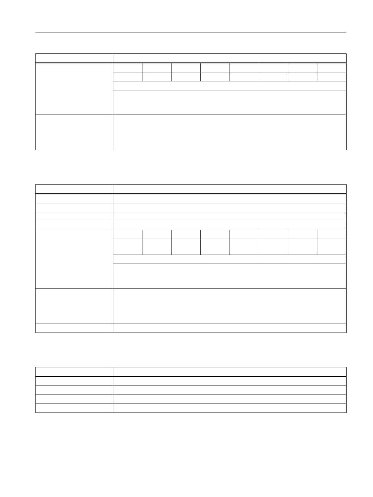
DB10 DBX189.0 - 7 (digital NC inputs 33 - 40: Actual value)
DB10 DBX189.0 - 7
Digital NC inputs 33 - 40: Actual value
Signal flow
NC → PLC
Update
Cyclic
Signal state 1
The actual value is 1.
Signal state 0
The actual value is 0.
PLC
490
Function Manual, 10/2020, 6FC5397-0HP40-0BA1
Interface signals
19.2 Interface signals - detailed description
DB10 DBX189.0 - 7
Digital NC inputs 33 - 40: Actual value
Further information
Bit 7
Bit 6
Bit 5
Bit 4
Bit 3
Bit 2
Bit 1
Bit 0
Input 40
Input 39
Input 38
Input 37
Input 36
Input 35
Input 34
Input 33
The actual NC output value can be read in the PLC user program via the actual value.
Note
The value in the "Actual value" interface can, as a result of the various subsequent influencing
possibilities "Lock" and "Set", have a different value than that available at the NC output.
Corresponds to
DB10 DBX0, 122, 124, 126, 128 (digital NC inputs 1 - 8: Lock)
DB10 DBB1, 123, 125, 127, 129 (digital NC inputs 1 - 8: Set)
DB10 DBB60, 186, 187, 188, 189 (digital NC inputs 1 - 8: Actual value)
MD10350 $MN_FASTIO_DIG_NUM_INPUTS
19.2.1.82
DB10 DBX190.0 - 7 (digital NC outputs 9 - 16: Setpoint)
DB10 DBX190.0 - 7
Digital NC outputs 9 - 16: Setpoint
Signal flow
NC → PLC
Update
Cyclic
Signal state 1
The setpoint is 1.
Signal state 0
The setpoint is 0.
Further information
Bit 7
Bit 6
Bit 5
Bit 4
Bit 3
Bit 2
Bit 1
Bit 0
Output
Output
Output
Output
Output
Output
Output
Output 9
16
15
14
13
12
11
10
The actual NC output value can be read in the PLC user program via the setpoint.
Note
The value in the "Setpoint" interface can, as a result of the various subsequent influencing
possibilities "Target" and "Lock", have a different value than that available at the NC output.
Corresponds to
DB10 DBB4, 130, 134, 138, 142 (digital NC outputs: Lock)
DB10 DBB5, 131, 135, 139, 143 (digital NC outputs 1 - 8: Overwrite)
DB10 DBB6, 132, 136, 140, 144 (digital NC outputs: Setting value from the PLC)
MD10360 $MN_FASTIO_DIG_NUM_OUTPUTS
Further information
Function Manual Basic Functions
19.2.1.83
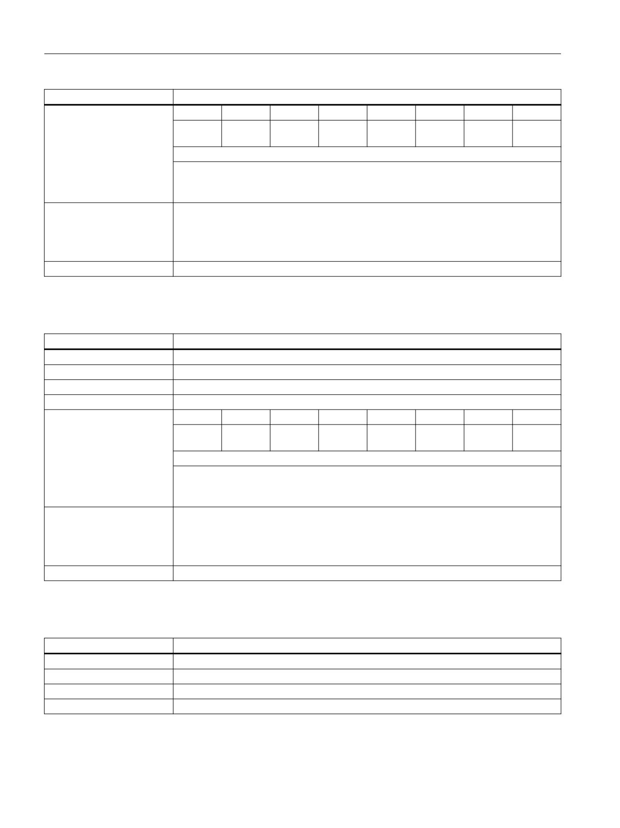
DB10 DBX191.0 - 7 (digital NC outputs 17 - 24: Setpoint)
DB10 DBX191.0 - 7
Digital NC outputs 17 - 24: Setpoint
Signal flow
NC → PLC
Update
Cyclic
Signal state 1
The setpoint is 1.
Signal state 0
The setpoint is 0.
PLC
Function Manual, 10/2020, 6FC5397-0HP40-0BA1
491
Interface signals
19.2 Interface signals - detailed description
DB10 DBX191.0 - 7
Digital NC outputs 17 - 24: Setpoint
Further information
Bit 7
Bit 6
Bit 5
Bit 4
Bit 3
Bit 2
Bit 1
Bit 0
Output
Output
Output
Output
Output
Output
Output
Output
24
23
22
21
20
19
18
17
The actual NC output value can be read in the PLC user program via the setpoint.
Note
The value in the "Setpoint" interface can, as a result of the various subsequent influencing
possibilities "Target" and "Lock", have a different value than that available at the NC output.
Corresponds to
DB10 DBB4, 130, 134, 138, 142 (digital NC outputs: Lock)
DB10 DBB5, 131, 135, 139, 143 (digital NC outputs 1 - 8: Overwrite)
DB10 DBB6, 132, 136, 140, 144 (digital NC outputs: Setting value from the PLC)
MD10360 $MN_FASTIO_DIG_NUM_OUTPUTS
Further information
Function Manual Basic Functions
19.2.1.84
DB10 DBX192.0 - 7 (digital NC outputs 25 - 32: Setpoint)
DB10 DBX192.0 - 7
Digital NC outputs 25 - 32: Setpoint
Signal flow
NC → PLC
Update
Cyclic
Signal state 1
The setpoint is 1.
Signal state 0
The setpoint is 0.
Further information
Bit 7
Bit 6
Bit 5
Bit 4
Bit 3
Bit 2
Bit 1
Bit 0
Output
Output
Output
Output
Output
Output
Output
Output
32
31
30
29
28
27
26
25
The actual NC output value can be read in the PLC user program via the setpoint.
Note
The value in the "Setpoint" interface can, as a result of the various subsequent influencing
possibilities "Target" and "Lock", have a different value than that available at the NC output.
Corresponds to
DB10 DBB4, 130, 134, 138, 142 (digital NC outputs: Lock)
DB10 DBB5, 131, 135, 139, 143 (digital NC outputs 1 - 8: Overwrite)
DB10 DBB6, 132, 136, 140, 144 (digital NC outputs: Setting value from the PLC)
MD10360 $MN_FASTIO_DIG_NUM_OUTPUTS
Further information
Function Manual Basic Functions
19.2.1.85
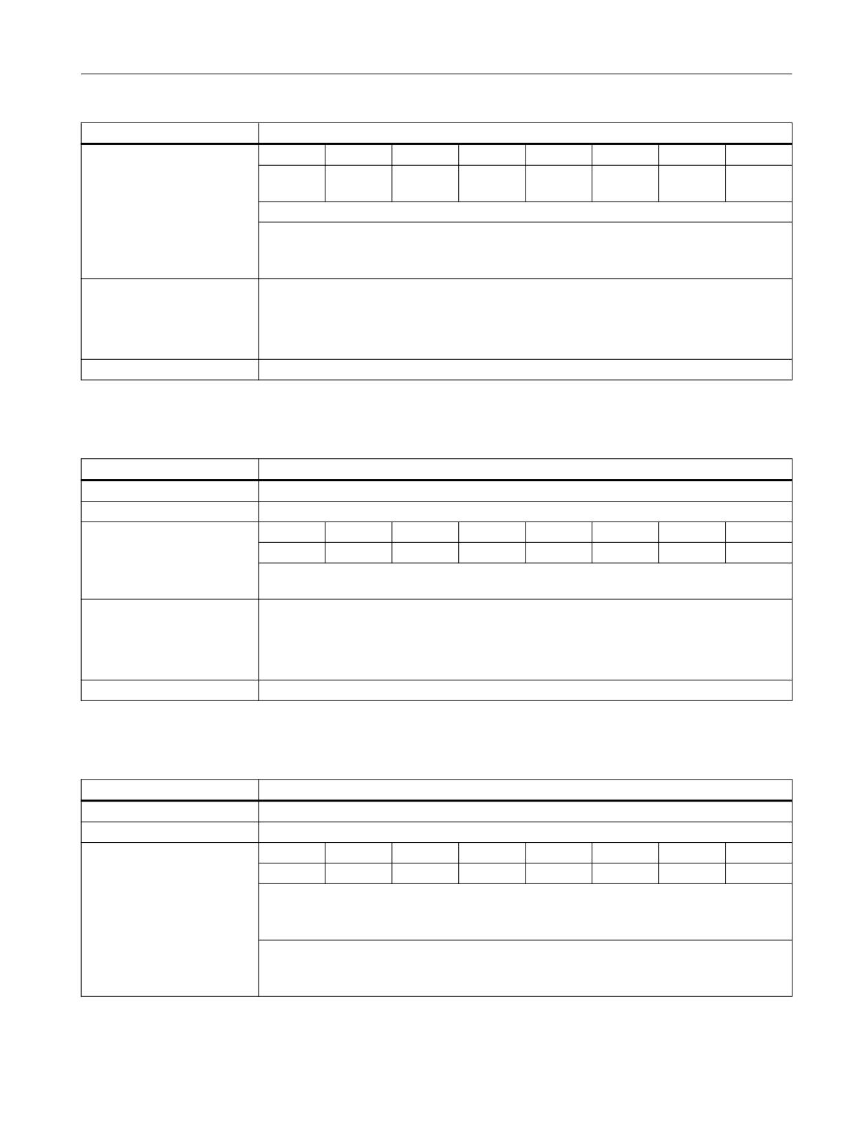
DB10 DBX193.0 - 7 (digital NC outputs 33 - 40: Setpoint)
DB10 DBX193.0 - 7
Digital NC outputs 33 - 40: Setpoint
Signal flow
NC → PLC
Update
Cyclic
Signal state 1
The setpoint is 1.
Signal state 0
The setpoint is 0.
PLC
492
Function Manual, 10/2020, 6FC5397-0HP40-0BA1
Interface signals
19.2 Interface signals - detailed description
DB10 DBX193.0 - 7
Digital NC outputs 33 - 40: Setpoint
Further information
Bit 7
Bit 6
Bit 5
Bit 4
Bit 3
Bit 2
Bit 1
Bit 0
Output
Output
Output
Output
Output
Output
Output
Output
40
39
38
37
36
35
34
33
The actual NC output value can be read in the PLC user program via the setpoint.
Note
The value in the "Setpoint" interface can, as a result of the various subsequent influencing
possibilities "Target" and "Lock", have a different value than that available at the NC output.
Corresponds to
DB10 DBB4, 130, 134, 138, 142 (digital NC outputs: Lock)
DB10 DBB5, 131, 135, 139, 143 (digital NC outputs 1 - 8: Overwrite)
DB10 DBB6, 132, 136, 140, 144 (digital NC outputs: Setting value from the PLC)
MD10360 $MN_FASTIO_DIG_NUM_OUTPUTS
Further information
Function Manual Basic Functions
19.2.1.86
DB10 DBW194 - 208 (analog NC inputs 1 - 8: Actual value)
DB10 DBW194 - 208
Analog NC inputs 1 - 8: Actual value
Signal flow
NC → PLC
Update
Cyclic
Further information
DBW208
DBW206
DBW204
DBW202
DBW200
DBW198
DBW196
DBW194
Input 8
Input 7
Input 6
Input 5
Input 4
Input 3
Input 2
Input 1
The actual value must be specified as a fixed point number (16 bit value including sign) in a 2's
complement.
Corresponds to
DBX146.0 - 7 (analog NC inputs 1 - 8: Lock)
DB10 DBB147 (analog NC inputs 1 - 8: Target)
DB10 DBW148 - 162 (analog NC outputs 1 - 8: Setting value)
MD10300 $MN_FASTIO_ANA_NUM_INPUTS
Further information
Function Manual Basic Functions
19.2.1.87
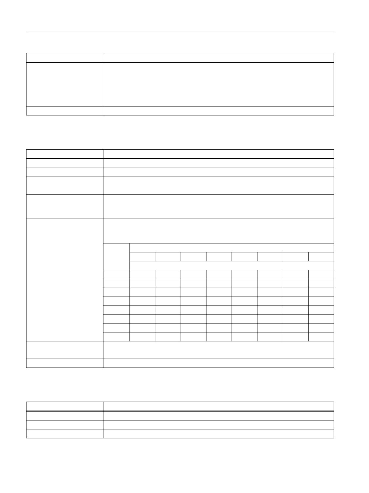
DB10 DBW210 - 224 (analog NC outputs 1 - 8: Setpoint)
DB10 DBW210 - 224
Analog NC outputs 1 - 8: Setpoint
Signal flow
NC → PLC
Update
Cyclic
Further information
DBW224
DBW222
DBW220
DBW218
DBW216
DBW214
DBW212
DBW210
Output 8
Output 7
Output 6
Output 5
Output 4
Output 3
Output 2
Output 1
The actual NC output value can be read in the PLC user program via the setpoint.
The setpoint is represented as a fixed point number (16 bit value including sign) in a 2's com-
plement.
Note
The value in the "Setpoint" interface can, as a result of the various subsequent influencing
possibilities, have a different value than that available at the NC output.
PLC
Function Manual, 10/2020, 6FC5397-0HP40-0BA1
493
Interface signals
19.2 Interface signals - detailed description
DB10 DBW210 - 224
Analog NC outputs 1 - 8: Setpoint
Corresponds to
DB10 DBX166.0 - 7 (analog NC outputs 1 - 8: Overwrite)
DB10 DBX167.0 - 7 (analog NC outputs 1 - 8: Target)
DB10 DBX168.0 - 7 (analog NC outputs 1 - 8: Lock)
DB10 DBW170 - 184 (analog NC outputs 1 - 8: Setting value)
MD10310 $MN_FASTIO_ANA_NUM_OUTPUTS
Further information
Function Manual Basic Functions
19.2.1.88
DB10 DBX226.0 - 233.7 (collision avoidance: Protection area active)
DB10 DBX226.0 - 233.7
Collision avoidance: Protection area active
Signal flow
NC → PLC
Update
Cyclic
Signal state 1
The protection area connected to the interface signal is active.
If several protection areas are connected to the interface signal: All protection areas are active.
Signal state 0
The protection area connected to the interface signal is not active.
If several protection areas are connected to the interface signal: At least one protection area
is not active.
Further information
The assignment protection area ↔ interface signal (<byte>.<bit>) is realized by appropriately
parameterizing system variables $NP_BIT_NO:
$NP_BIT_NO[<protection area>] = <bit number>
Byte
Bit
7
6
5
4
3
2
1
0
Bit number
226
7
6
5
4
3
2
1
0
227
15
14
13
12
11
10
9
8
228
23
22
21
20
19
18
17
16
229
31
30
29
28
27
26
25
24
230
39
38
37
36
35
34
33
32
231
47
46
45
44
43
42
41
40
232
55
54
53
52
51
50
49
48
233
63
62
61
60
59
58
57
56
Corresponds to
DB10 DBX234.0 - 241.7 (collision avoidance: Activate protection area)
System variable $NP_BIT_NO (number of the interface bit for switchover activated)
Further information
Function Manual Monitoring and Compensating
19.2.1.89
DB10 DBX234.0 - 241.7 (collision avoidance: Activate protection area)
DB10 DBX234.0 - 241.7
Collision avoidance: Activate protection zone
Signal flow
PLC → NC
Update
Cyclic
Signal state 1
Request to activate the protection areas that are connected with the interface signal.
PLC
494
Function Manual, 10/2020, 6FC5397-0HP40-0BA1
Interface signals
19.2 Interface signals - detailed description
DB10 DBX234.0 - 241.7
Collision avoidance: Activate protection zone
Signal state 0
Request to deactivate the protection areas that are connected with the interface signal.
Further information
The assignment protection area ↔ interface signal (<byte>.<bit>) is realized by appropriately
parameterizing system variables $NP_BIT_NO:
$NP_BIT_NO[<protection area>] = <bit number>
Byte
Bit
7
6
5
4
3
2
1
0
Bit number
234
7
6
5
4
3
2
1
0
235
15
14
13
12
11
10
9
8
236
23
22
21
20
19
18
17
16
237
31
30
29
28
27
26
25
24
238
39
38
37
36
35
34
33
32
239
47
46
45
44
43
42
41
40
240
55
54
53
52
51
50
49
48
241
63
62
61
60
59
58
57
56
Corresponds to
DB10 DBX226.0 - 233.7 (collision avoidance: Protection area active)
System variable $NP_BIT_NO (number of the interface bit for switchover activated)
Further information
Function Manual Monitoring and Compensating
19.2.1.90
DB10 DBX245.0 - 5 (Ethernet handwheel stationary)
DB10 DBX245.0 - 5
Ethernet handwheel is stationary
Signal flow
NC → PLC
Update
Cyclic
Signal state 1
Ethernet handwheel is stationary.
Signal state 0
Ethernet handwheel is moved.
Further information
A stationary state is detected by the Ethernet modules to which the handwheel is connected.
If a handwheel does not transfer any handwheel pulses for a defined period of time, the
module detects this to be a stationary state and transfers it to the NC/PLC interface. A signal is
available for every handwheel for this purpose:
Bit 0
Handwheel 1
Bit 1
Handwheel 2
Bit 2
Handwheel 3
Bit 3
Handwheel 4
Bit 4
Handwheel 5
Bit 5
Handwheel 6
Further information
Function Manual Axes and Spindles
PLC
Function Manual, 10/2020, 6FC5397-0HP40-0BA1
495
Interface signals
19.2 Interface signals - detailed description
19.2.1.91
DB10 DBX246.0 - 5 (handwheel active)
DB10 DBX246.0 - 5
Handwheel active
Signal flow
HMI → PLC
Update
Cyclic
Signal state 1
The button for the handwheel in the HMI is operated on the HT10.
Signal state 0
The button for the handwheel in the HMI is not operated on the HT10.
Further information
A signal is available for every handwheel for this purpose:
Bit 0
Handwheel 1
Bit 1
Handwheel 2
Bit 2
Handwheel 3
Bit 3
Handwheel 4
Bit 4
Handwheel 5
Bit 5
Handwheel 6
Further information
Function Manual Axes and Spindles
19.2.2
DB11: Mode group
19.2.2.1
DB11 DBX0.0 (AUTOMATIC mode)
DB11 DBX0.0
AUTOMATIC mode
Signal flow
PLC → NC
Update
Cyclic
Signal state 1
There is an active request to switch over into the AUTOMATIC mode.
Signal state 0
There is no active request to switch over into the AUTOMATIC mode.
Further information
Irrelevant for: DB11 DBX0.4 (operating mode, changeover inhibit) == 1
Corresponds to
DB11 DBX0.2 (JOG mode)
DB11 DBX0.1 (MDI mode)
DB11 DBX0.4 (mode change inhibit)
DB11 DBX6.0 AUTOMATIC mode active)
Further information
Function Manual Basic Functions
19.2.2.2
DB11 DBX0.1 (MDI mode)
DB11 DBX0.1
MDI mode
Signal flow
PLC → NC
Update
Cyclic
Signal state 1
There is an active request to switch over into the MDI mode.
Signal state 0
There is no active request to switch over into the MDI mode.
Additional information
Irrelevant for: DB11 DBX0.4 (operating mode, changeover inhibit) == 1
PLC
496
Function Manual, 10/2020, 6FC5397-0HP40-0BA1

Interface signals
19.2 Interface signals - detailed description
DB11 DBX0.1
MDI mode
Corresponds with
DB11 DBX0.0 (AUTOMATIC mode)
DB11 DBX0.2 (JOG mode)
DB11 DBX0.4 (mode change inhibit)
DB11 DBX6.1 (active MDI mode)
Additional information
Function Manual Basic Functions
19.2.2.3
DB11 DBX0.2 (JOG mode)
DB11 DBX0.2
JOG mode
Signal flow
PLC → NC
Update
Cyclic
Signal state 1
There is an active request to switch over into the JOG mode.
Signal state 0
There is no active request to switch over into the JOG mode.
Further information
Irrelevant for: DB11 DBX0.4 (operating mode, changeover inhibit) == 1
Corresponds to
DB11 DBX0.0 (AUTOMATIC mode)
DB11 DBX0.1 (MDI mode)
DB11 DBX0.4 (mode change inhibit)
DB11 DBX6.2 (JOG mode active)
Further information
Function Manual Basic Functions
19.2.2.4
DB11 DBX0.4 (mode change inhibit)
DB11 DBX0.4
Mode change inhibit
Signal flow
PLC → NC
Update
Cyclic
Signal state 1
The active mode of the mode group cannot be changed.
Note
The machine functions that can be selected within a mode group can be changed.
Signal state 0
The mode of the mode group can be changed.
Corresponds to
DB11 DBX0.0 (AUTOMATIC mode)
DB11 DBX0.1 (MDI mode)
DB11 DBX0.2 (JOG mode)
Further information
Function Manual Basic Functions
19.2.2.5
DB11 DBX0.5 (mode group stop)
DB11 DBX0.5
Mode group stop
Signal flow
PLC → NC
Update
Cyclic
PLC
Function Manual, 10/2020, 6FC5397-0HP40-0BA1
497

Interface signals
19.2 Interface signals - detailed description
DB11 DBX0.5
Mode group stop
Signal state 1
There is an active request for "Mode group stop".
Responses:
• An "NC Stop" is initiated for all the channels of the mode group.
• Channel state change as a result of the mode group stop:
- "Active" → "Interrupted"
- "Reset" → "Reset"
• Program state change as a result of the mode group stop
- "Running" → "Stopped"
• All traversing axes of the mode group are braked without contour violation to zero speed
along their acceleration curves
Programs that have been stopped can be restarted with "NC Start".
The spindles of the mode group are not influenced.
Signal state 0
There is no active request for "Mode group stop".
Corresponds to
DB21,
DBX7.2 (NC start)
DB21,
DBX7.3 (NC stop)
Further information
Function Manual Basic Functions
19.2.2.6
DB11 DBX0.6 (mode group stop, axes plus spindles)
DB11 DBX0.6
Mode group stop axes plus spindles
Signal flow
PLC → NC
Update
Cyclic
Signal state 1
There is an active request for "Mode group stop axes plus spindles".
Responses:
• An "NC Stop" is initiated for all the channels of the mode group.
• Channel state change as a result of the mode group stop:
- "Active" → "Interrupted"
- "Reset" → "Reset"
• Program state change as a result of the mode group stop
- "Running" → "Stopped"
• All traversing axes and spindles of the mode group are braked without contour violation to
zero speed along their acceleration curves
Programs that have been stopped can be restarted with "NC Start".
Signal state 0
There is no active request for "Mode group stop axes plus spindles".
Corresponds to
DB21,
DBX7.2 (NC start)
DB21,
DBX7.3 (NC stop)
Further information
Function Manual Basic Functions
PLC
498
Function Manual, 10/2020, 6FC5397-0HP40-0BA1

Interface signals
19.2 Interface signals - detailed description
19.2.2.7
DB11 DBX0.7 (mode group reset)
DB11 DBX0.7
Mode group reset
Signal flow
PLC → NC
Update
Cyclic
Edge change 0 → 1
A request was initiated for a "Mode group reset".
Responses:
• In all channels of the mode group, a "channel reset" is initiated in the control system
corresponding to DB21, ... DBX 7.7 = 1.
• All the channels are then in the channel state "reset" (DB21, ... DBX35.7 == 1)
• All active NC programs are then in the "canceled" program state (DB21, ... DBX35.4 == 1)
• All traversing axes and spindles are decelerated without contour violation to zero speed
according to their acceleration curves.
• The channel-specific reset positions become active.
• All alarms of the mode group are cleared - with the exception of power on alarms.
Edge change 1 → 0
Reset of the last request for a "Mode group reset".
Starting at this time, a new "Mode group reset" can be requested.
Further information
Special case
If an alarm resets the interface signal DB11 DBX6.3 (mode group ready), all channels of the
mode group are no longer in the "reset" channel state. In order that the mode of the mode
group can be switched over, initially, a "Mode group reset" must be initiated using DB11
DBX0.7.
Note
Before a new action can be requested in a channel of the mode group from the PLC user
program after a mode group reset (e.g. NC start or axis interchange), the system must first wait
for either the mode group state "All channels of the mode group in the reset state" (DB11
DBX6.7 == 1) - or the channel state "Reset" (DB21, ... DBX35.7 == 1) of the channel involved.
Corresponds to
DB21, ... DBX7.7 (channel reset)
DB11 DBX6.7 (all channels in the reset state)
Further information
Function Manual Basic Functions
19.2.2.8
DB11 DBX1.0 (TEACH IN machine function)
DB11 DBX1.0
TEACH IN machine function
Signal flow
PLC → NC
Update
Cyclic
Signal state 1
There is an active request to activate the TEACH IN machine function.
Signal state 0
There is no active request to activate the TEACH IN machine function.
Further information
Note
Only active in the JOG mode.
Corresponds to
DB11 DBX6.2 (JOG mode active)
DB11 DBX7.1 (TEACH IN machine function active)
Further information
Function Manual Basic Functions
PLC
Function Manual, 10/2020, 6FC5397-0HP40-0BA1
499

Interface signals
19.2 Interface signals - detailed description
19.2.2.9
DB11 DBX1.1 (REPOS machine function)
DB11 DBX1.1
REPOS machine function
Signal flow
PLC → NC
Update
Cyclic
Signal state 1
There is an active request to activate the REPOS machine function.
Signal state 0
There is no active request to activate the REPOS machine function.
Further information
Note
Only active in the JOG mode.
Corresponds to
DB11 DBX6.2 (JOG mode active)
DB11 DBX7.2 (REPOS machine function active)
Further information
Function Manual Basic Functions
19.2.2.10
DB11 DBX1.2 (REF machine function)
DB11 DBX1.2
REF machine function
Signal flow
PLC → NC
Update
Cyclic
Signal state 1
There is an active request to activate the REF machine function.
Signal state 0
There is no active request to activate the REF machine function.
Further information
Note
Only active in the JOG mode.
Corresponds to
DB11 DBX6.2 (JOG mode active)
DB11 DBX7.3 (REF machine function active)
Further information
Function Manual Basic Functions
19.2.2.11
DB11 DBX1.6 (single block, type B)
DB11 DBX1.6
Single block, type B
Signal flow
PLC → NC
Update
Cyclic
Signal state 1
There is an active request to activate the "Single block, type B".
Signal state 0
There is no active request to activate the "Single block, type B".
PLC
500
Function Manual, 10/2020, 6FC5397-0HP40-0BA1
Interface signals
19.2 Interface signals - detailed description
DB11 DBX1.6
Single block, type B
Further information
Cross mode group response when activating "Single block, type B":
• All channels are stopped
• All channels receive a start command
• Channel KS stops at the end of the block
• The KA channels receive the STOPATEND instruction, comparable with DB21, ... DBX7.2 (NC
Stop at the block limit)
• All channels are stopped at a block limit (at some point in time).
Note
• DB11 DBX1.6 == 1 AND DBX1.7 == 0 ⇒ single block type B
• DB11 DBX1.6 == 0 AND DBX1.7 == 1 ⇒ single block type A
• DB11 DBX1.6 == 1 AND DBX1.7 == 1 OR
DB11 DBX1.6 == 0 AND DBX1.7 == 0 ⇒ No mode group-specific single block selected
Corresponds to
DB11 DBX1.7 (single block, type A)
Further information
Function Manual Basic Functions
19.2.2.12
DB11 DBX1.7 (single block, type A)
DB11 DBX1.7
Single block, type A
Signal flow
PLC → NC
Update
Cyclic
Signal state 1
There is an active request to activate the "Single block, type A".
Signal state 0
There is no active request to activate the "Single block, type A".
Further information
Cross mode group response when activating "Single block, type A":
• All channels are stopped
• All channels receive a start command
• Channel KS stops at the end of the block
• The KA channels receive the STOPATEND instruction, comparable with DB21, ... DBX7.2 (NC
Stop at the block limit)
• All channels are stopped at a block limit (at some point in time).
Note
• DB11 DBX1.6 == 1 AND DBX1.7 == 0 ⇒ single block type B
• DB11 DBX1.6 == 0 AND DBX1.7 == 1 ⇒ single block type A
• DB11 DBX1.6 == 1 AND DBX1.7 == 1 OR
DB11 DBX1.6 == 0 AND DBX1.7 == 0 ⇒ No mode group-specific single block selected
Corresponds to
DB11 DBX1.6 (single block, type B)
Further information
Function Manual Basic Functions
PLC
Function Manual, 10/2020, 6FC5397-0HP40-0BA1
501

Interface signals
19.2 Interface signals - detailed description
19.2.2.13
DB11 DBX4.0 (AUTOMATIC mode selected)
DB11 DBX4.0
AUTOMATIC mode selected
Signal flow
HMI → PLC
Update
Cyclic
Signal state 1
There is an active HMI request to select the AUTOMATIC mode.
Signal state 0
There is no active HMI request to select the AUTOMATIC mode.
Corresponds to
DB11 DBX0.0 (AUTOMATIC mode)
Further information
Function Manual Basic Functions
19.2.2.14
DB11 DBX4.1 (MDI mode selected)
DB11 DBX4.1
MDI mode selected
Signal flow
HMI → PLC
Update
Cyclic
Signal state 1
There is an active HMI request to select the MDI mode.
Signal state 0
There is no active HMI request to select the MDI mode.
Corresponds to
DB11 DBX0.1 (MDI mode)
Further information
Function Manual Basic Functions
19.2.2.15
DB11 DBX4.2 (JOG mode selected)
DB11 DBX4.2
JOG mode selected
Signal flow
HMI → PLC
Update
Cyclic
Signal state 1
There is an active HMI request to select the JOG mode.
Signal state 0
There is no active HMI request to select the JOG mode.
Corresponds to
DB11 DBX0.2 (JOG mode)
Further information
Function Manual Basic Functions
19.2.2.16
DB11 DBX5.0 (TEACH IN machine function selected)
DB11 DBX5.0
TEACH IN machine function selected
Signal flow
HMI → PLC
Update
Cyclic
Signal state 1
There is an active HMI request to select the TEACH IN machine function.
Signal state 0
There is no active HMI request to select the TEACH IN machine function.
Corresponds to
DB11 DBX7.1 (active TEACH IN machine function)
Further information
Function Manual Basic Functions
PLC
502
Function Manual, 10/2020, 6FC5397-0HP40-0BA1

Interface signals
19.2 Interface signals - detailed description
19.2.2.17
DB11 DBX5.1 (REPOS machine function selected)
DB11 DBX5.1
REPOS machine function selected
Signal flow
HMI → PLC
Update
Cyclic
Signal state 1
There is an active HMI request to select the REPOS machine function.
Signal state 0
There is no active HMI request to select the REPOS machine function.
Corresponds to
DB11 DBX7.2 (active REPOS machine function)
Further information
Function Manual Basic Functions
19.2.2.18
DB11 DBX5.2 (REF machine function selected)
DB11 DBX5.2
REF machine function selected
Signal flow
HMI → PLC
Update
Cyclic
Signal state 1
There is an active HMI request to select the REF machine function.
Signal state 0
There is no active HMI request to select the REF machine function.
Corresponds to
DB11 DBX7.3 (active REF machine function)
Further information
Function Manual Basic Functions
19.2.2.19
DB11 DBX6.0 (AUTOMATIC mode active)
DB11 DBX6.0
AUTOMATIC mode active
Signal flow
NC → PLC
Update
Cyclic
Signal state 1
The AUTOMATIC mode is active.
Signal state 0
The AUTOMATIC mode is not active.
Corresponds to
DB11 DBX0.0 (AUTOMATIC mode)
Further information
Function Manual Basic Functions
19.2.2.20
DB11 DBX6.1 (active MDI mode)
DB11 DBX6.1
Active MDI mode
Signal flow
NC → PLC
Update
Cyclic
Signal state 1
The MDI mode is active.
Signal state 0
The MDI mode is not active.
Corresponds to
DB11 DBX0.1 (MDI mode)
Further information
Function Manual Basic Functions
PLC
Function Manual, 10/2020, 6FC5397-0HP40-0BA1
503
Interface signals
19.2 Interface signals - detailed description
19.2.2.21
DB11 DBX6.2 (JOG mode active)
DB11 DBX6.2
Active JOG mode
Signal flow
NC → PLC
Update
Cyclic
Signal state 1
The JOG mode is active.
Signal state 0
The JOG mode is not active.
Corresponds to
DB11 DBX0.2 (JOG mode)
Further information
Function Manual Basic Functions
19.2.2.22
DB11 DBX6.3 (mode group ready)
DB11 DBX6.3
Mode group ready
Signal flow
NC → PLC
Update
Cyclic
Signal state 1
The mode group is ready.
Signal state 0
The mode group is ready.
Further information
Response when the signal changes from 0 → 1:
• Traversing axes and spindles are braked down to standstill with setpoint 0 or maximum
braking current.
• The interface signals from the PLC to the NC are brought into an inactive state (reset
position).
Note
If an alarm occurs that clears "Mode group ready", before switching over the mode, a mode
group reset (DB11 DBX 0.7) must first be initiated.
Corresponds to
DB11 DBX0.7 (mode group reset)
Further information
Function Manual Basic Functions
19.2.2.23
DB11 DBX6.7 (all channels in the "Reset" state)
DB11 DBX6.7
All channels in the "Reset" state
Signal flow
NC → PLC
Update
Cyclic
Signal state 1
All mode group channels are in the "Reset" state.
Signal state 0
At least one channel of the mode group is not in the "Reset" state.
Corresponds to
DB21, ... DBX7.7 (channel state, "Reset")
Further information
Function Manual Basic Functions
PLC
504
Function Manual, 10/2020, 6FC5397-0HP40-0BA1

Interface signals
19.2 Interface signals - detailed description
19.2.2.24
DB11 DBX7.0 (TEACH IN machine function active)
DB11 DBX7.0
TEACH IN machine function active
Signal flow
NC → PLC
Update
Cyclic
Signal state 1
The TEACH IN machine function is active.
Signal state 0
The TEACH IN machine function is not active.
Corresponds to
DB11 DBX1.0 (TEACH IN machine function)
DB11 DBX5.0 (TEACH IN machine function selected)
Further information
Function Manual Basic Functions
19.2.2.25
DB11 DBX7.1 (REPOS machine function active)
DB11 DBX7.1
REPOS machine function active
Signal flow
NC → PLC
Update
Cyclic
Signal state 1
Machine function REPOS is active.
Signal state 0
Machine function REPOS is not active.
Corresponds to
DB11 DBX1.1 (REPOS machine function)
DB11 DBX5.1 (REPOS machine function selected)
Further information
Function Manual Basic Functions
19.2.2.26
DB11 DBX7.2 (REF machine function active)
DB11 DBX7.2
REF machine function active
Signal flow
NC → PLC
Update
Cyclic
Signal state 1
Machine function REF is active.
Signal state 0
Machine function REF is not active.
Corresponds with
DB11 DBX1.2 (REF machine function)
DB11 DBX5.2 (REF machine function selected)
Additional information
Function Manual Basic Functions
PLC
Function Manual, 10/2020, 6FC5397-0HP40-0BA1
505
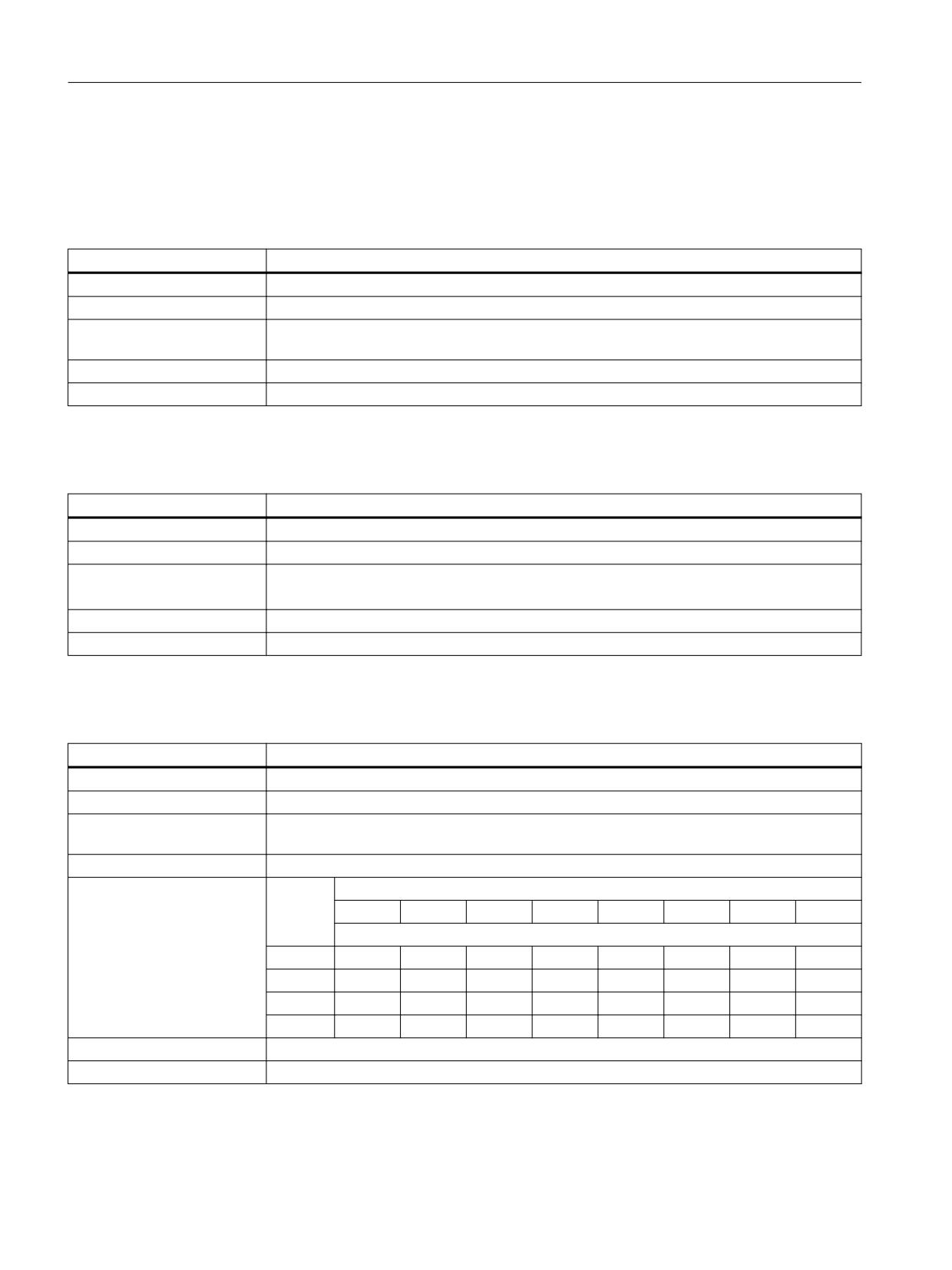
Interface signals
19.2 Interface signals - detailed description
19.2.3
DB18: Safety Integrated, SPL
19.2.3.1
DB18 DBB36.0 (SPL_READY)
DB18 DBB36.0
SPL_READY
Signal flow
PLC → PLC
Update
Job-controlled
Signal state 1
The SPL_READY = TRUE signal indicates that the commissioning phase has been completed, i.e.
if a CDC error has occurred, the basic program signals a "STOP D/E" to all the axes.
Signal state 0
SPL_READY = FALSE
Further information
Function Manual, SINUMERIK Safety Integrated
19.2.3.2
DB18 DBB36.1 (STOP_E)
DB18 DBB36.1
STOP_E
Signal flow
PLC → PLC
Update
Job-controlled
Signal state 1
STOP E is active.
The signal must be used for the forced checking procedure for external STOPs.
Signal state 0
STOP E is active.
Further information
Function Manual, SINUMERIK Safety Integrated
19.2.3.3
DB18 DBB38 - 41 (SPL inputs, SPL_DATA.INSEP[1...32])
DB18 DBB38.0 - 41.7
Data area of the SPL inputs
Signal flow
PLC → NC
Update
Cyclic
Signal state 1
When cyclic F communication is established, the process values received from F_SENDDP are
output at the SPL inputs SPL_DATA.INSEP.
Signal state 0
The process values received from F_SENDDP are not output at the SPL inputs SPL_DATA.INSEP.
Further information
Byte
Bit
7
6
5
4
3
2
1
0
Bit number
38
7
6
5
4
3
2
1
0
39
15
14
13
12
11
10
9
8
40
23
22
21
20
19
18
17
16
41
31
30
29
28
27
26
25
24
Corresponds to
$A_INSE
Further information
Function Manual, Safety Integrated
PLC
506
Function Manual, 10/2020, 6FC5397-0HP40-0BA1
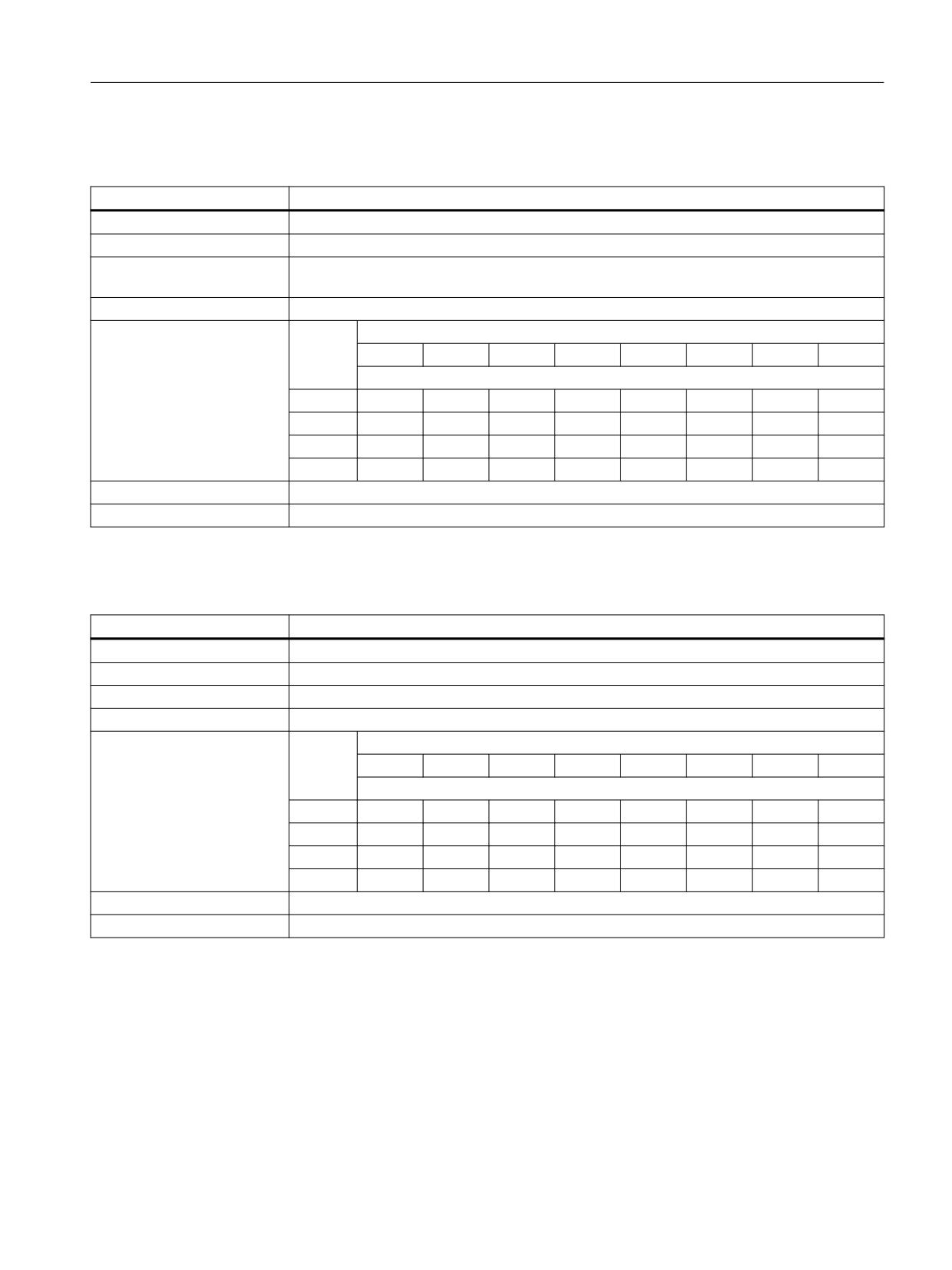
Interface signals
19.2 Interface signals - detailed description
19.2.3.4
DB18 DBB42.0 - 45.7 (SPL inputs, SPL_DATA.INSEP[33...64])
DB18 DBB42.0 - 45.7
Data area of the SPL inputs
Signal flow
PLC → NC
Update
Cyclic
Signal state 1
When cyclic F communication is established, the process values received from F_SENDDP are
output at the SPL inputs SPL_DATA.INSEP.
Signal state 0
The process values received from F_SENDDP are not output at the SPL inputs SPL_DATA.INSEP.
Further information
Byte
Bit
7
6
5
4
3
2
1
0
Bit number
42
39
38
37
36
35
34
33
32
43
47
46
45
44
43
42
41
40
44
55
54
53
52
51
50
49
48
45
63
62
61
60
59
58
57
56
Corresponds to
$A_INSE
Further information
Function Manual, Safety Integrated
19.2.3.5
DB18 DBB46.0 - 49.7 (SPL outputs, SPL_DATA.OUTSEP[1...32]
DB18 DBB46.0 - 49.7
Data area of the SPL outputs
Signal flow
PLC → NC
Update
Cyclic
Signal state 1
The received process values are output at the SPL outputs SPL_DATA.OUTSEP.
Signal state 0
The received process values are not output at the SPL outputs SPL_DATA.OUTSEP.
Further information
Byte
Bit
7
6
5
4
3
2
1
0
Bit number
38
7
6
5
4
3
2
1
0
39
15
14
13
12
11
10
9
8
40
23
22
21
20
19
18
17
16
41
31
30
29
28
27
26
25
24
Corresponds to
$A_OUTSE
Further information
Function Manual, Safety Integrated
PLC
Function Manual, 10/2020, 6FC5397-0HP40-0BA1
507
Interface signals
19.2 Interface signals - detailed description
19.2.4
DB19: Operator panel
19.2.4.1
DB19 DBX0.0 (brighten screen)
DB19 DBX0.0
Brighten screen
Signal flow
PLC → OP
Update
Cyclic
Signal state 1
The screen content is displayed. Screen darkening is ignored.
Signal state 0
Screen darkening is active.
Corresponds with
DB19 DBX0.1 (darken screen)
19.2.4.2
DB19 DBX0.1 (darken screen)
DB19 DBX0.1
Darken screen
Signal flow
PLC → OP
Update
Cyclic
Signal state 1
The screen is darkened.
The automatic screen brightening/darkening is therefore inactive. The screen does not auto-
matically become bright when a key on the keyboard is pressed.
Notice
If the interface signal is set, and the screen is darkened, then the keyboard of the operator panel
front still remains active. It is therefore recommended that the keyboard of the operator panel
front is also locked:
DB19 DBX0.2 = 1 (key lock)
Signal state 0
The screen is brightened.
In this state, the control automatically brightens/darkens the screen:
• The screen is darkened if no keystroke is made at the keyboard for a time that is defined
using the following machine data:
MD9006 $MM_DISPLAY_SWITCH_OFF_INTERVAL (time to darken the screen) The default
setting is 15 minutes.
• The screen is brightened the next time a key on the operator panel front is pressed.
Corresponds with
DB19 DBX0.0 (brighten screen)
DB19 DBX0.2 (key lock)
MD9006 $MM_DISPLAY_SWITCH_OFF_INTERVAL (time to darken the screen)
19.2.4.3
DB19 DBX0.2 (key lock)
DB19 DBX0.2
Key lock
Signal flow
PLC → OP
Update
Cyclic
Signal state 1
The keyboard is locked for the user.
Signal state 0
The keyboard is enabled for the user.
PLC
508
Function Manual, 10/2020, 6FC5397-0HP40-0BA1
Interface signals
19.2 Interface signals - detailed description
DB19 DBX0.2
Key lock
Additional information
If the screen is darkened with the interface signal: DB19 DBX0.1 (darken screen), the keyboard
should be locked simultaneously with the interface signal: DB19 DBX0.2 (key lock) to avoid an
unintended operation.
Notice
If the screen is darkened with (DB19 DBX0.1 = 1), the operator panel front keyboard still
remains functional. It is therefore recommended that the keyboard of the operator panel front
is also locked:
DB19 DBX0.2 = 1 (key lock)
Corresponds with
DB19 DBX0.0 (brighten screen)
DB19 DBX0.1 (darken screen)
19.2.4.4
DB19 DBX0.3 (delete cancel alarms)
DB19 DBX0.3
Delete cancel alarms
Signal flow
PLC → OP
Update
Cyclic
Signal state 1
The delete error key on the operator panel is pressed ⇒
Request to acknowledge all cancel alarms of the NC and operator panel.
Signal state 0
The delete error key is not pressed on the operator panel.
Corresponds with
DB19 DBX20.3 (cancel alarms deleted)
19.2.4.5
DB19 DBX0.4 (delete recall alarms)
DB19 DBX0.4
Delete recall alarms
Signal flow
PLC → OP
Update
Cyclic
Signal state 1
The delete error key is pressed on the operator panel.
Request to acknowledge all recall alarms of the NC and operator panel.
Signal state 0
The delete error key is not pressed on the operator panel.
Corresponds with
DB19 DBX20.4 (recall alarms deleted)
19.2.4.6
DB19 DBX0.7 (actual values in the WCS)
DB19 DBX0.7
Actual values in the WCS
Signal flow
PLC → OP
Update
Cyclic
Signal state 1
If the "machine" operating area is selected on the user interface, the axis-specific positions and
distance-to-go are displayed in the workpiece coordinate system (WCS).
Signal state 0
If the "machine" operating area is selected on the user interface, the axis-specific positions and
distance-to-go are displayed in the previous active coordinate system.
PLC
Function Manual, 10/2020, 6FC5397-0HP40-0BA1
509

Interface signals
19.2 Interface signals - detailed description
DB19 DBX0.7
Actual values in the WCS
Additional information
Within the "machine" operating area, the coordinate system can be displayed in which the axis-
specific positions and distances-to-go are switched via the "MCS actual values" and "WCS actual
values" softkeys:
Corresponds with
DB19 DBX20.7 (switch MCS/WCS)
19.2.4.7
DB19 DBB6 (analog spindle 1, utilization as a percentage)
DB19 DBB6
Analog spindle 1, utilization in percent
Signal flow
PLC → OP
Update
Cyclic
Additional information
Format: UINT (unsigned, 0 ... 255D or 0 ... FFH)
19.2.4.8
DB19 DBB7 (analog spindle 2, utilization as a percentage)
DB19 DBB7
Analog spindle 2, utilization in percent
Signal flow
PLC → OP
Update
Cyclic
Additional information
Format: UINT (unsigned, 0 ... 255D or 0 ... FFH)
19.2.4.9
DB19 DBB8 (channel number)
DB19 DBB8
Channel number
Signal flow
PLC → OP
Update
Cyclic
Additional information
Format: UINT (unsigned, 0 ... 255D or 0 ... FFH)
Valid channel numbers: 1 ... maximum number of NC channels
19.2.4.10
DB19 DBB10 (PLC hardkeys)
DB19 DBB10
PLC hardkeys
Signal flow
PLC → OP
Update
Cyclic
Signal state ≠ 0
1 ... 255: Selects the corresponding programming area
Signal state == 0
0: No selection
Additional information
Format: UINT (unsigned, 0 ... 255D or 0 ... FFH)
PLC
510
Function Manual, 10/2020, 6FC5397-0HP40-0BA1
Interface signals
19.2 Interface signals - detailed description
19.2.4.11
DB19 DBX13.5 (NC program: unload)
DB19 DBX13.5
NC program: Unload
Signal flow
PLC → OP
Update
Cyclic
Signal state 1
Unload active
Signal state 0
Unload not active
19.2.4.12
DB19DBX13.6 (NC program: load)
DB19 DBX13.6
NC program: Load
Signal flow
PLC → OP
Update
Cyclic
Signal state 1
Load active
Signal state 0
Load not active
19.2.4.13
DB19 DBX13.7 (NC program: selection)
DB19 DBX13.7
NC program: Selection
Signal flow
PLC → OP
Update
Cyclic
Signal state 1
Selection active
Signal state 0
Selection not active
19.2.4.14
DB19 DBX14.0 - 6 (PLC index)
DB19 DBX14.0 - 6
PLC index
Signal flow
PLC → OP
Update
Cyclic
Additional information
The V24 interface is controlled with bits 0 - 6. They specify the PLC index for the standard
control file, which specifies the axis, channel or TO number.
The file system is selected via:
• DB19 DBX14.7 == 1 ⇒ passive file system: PLC index for the user control file
• DB19 DBX14.7 == 0 ⇒ active file system: PLC index, which specifies the axis, channel or TO
number.
Format: UINT (unsigned, 0 ... 127D or 0 ... 7FH)
Corresponds with
DB19 DBX14.7 (selects the file system)
PLC
Function Manual, 10/2020, 6FC5397-0HP40-0BA1
511
Interface signals
19.2 Interface signals - detailed description
19.2.4.15
DB19 DBX14.7 (selects the file system)
DB19 DBX14.7
Selects the file system
Signal flow
PLC → OP
Update
Cyclic
Signal state 1
Passive file system
Signal state 0
Active file system
Corresponds with
DB19 DBX14.0 - 6 (PLC index)
19.2.4.16
DB19 DBB15 (PLC line offset)
DB19 DBB15
PLC line offset
Signal flow
PLC → OP
Update
Cyclic
Additional information
The byte to control the V24 interface defines the line of the standard or user control file in which
the control file to be transferred is specified.
The control file is selected using:
• DB19 DBX14.7 == 1 ⇒ passive file system: PLC line offset in a user control file
• DB19 DBX14.7 == 0 ⇒ active file system: PLC line offset in a standard control file
Format: UINT (unsigned, 0 ... 255D or 0 ... FFH)
Corresponds with
DB19 DBX14.7 (selects the file system)
19.2.4.17
DB19 DBB16 (program selection from the PLC: Index of the program list)
DB19 DBB16
Program selection from the PLC: Index of the program list
Signal flow
PLC → OP
Update
Cyclic
Further information
Preselected programs/workpieces in the PLC program lists can be selected for machining by the
NC via the PLC/HMI interface.
To specify the program list, its number (index) is output in binary code via control byte DB19
DBB16:
Bit 7
Bit 6
Bit 5
Bit 4
Bit 3
Bit 2
Bit 1
Bit 0
Always 1
DB19 DBB16 = <number of the program list>
Number
Number
Program list
(binary-coded)
(decimal)
1000 0001
129
User program list (/user/sinumerik/hmi/plc/
programlist/plc_proglist_user.ppl)
1000 0011
131
Manufacturer program list (/oem/
sinumerik/hmi/plc/programlist/plc_prog-
list_manufacturer.ppl)
PLC
512
Function Manual, 10/2020, 6FC5397-0HP40-0BA1
Interface signals
19.2 Interface signals - detailed description
DB19 DBB16
Program selection from the PLC: Index of the program list
Corresponds to
DB19.DBX13.7 (NC program: Selection)
DB19.DBB17 (program selection from the PLC: program index in the program list)
DB19.DBB26 (program selection from the PLC: Status signals)
DB19.DBB27 (program selection from the PLC: Error detection)
MD9106 $MM_SERVE_EXTCALL_PROGRAMS (editing EXTCALL calls)
MD51041 $MN_ENABLE_PROGLIST_USER (activation of PLC program list USER area)
MD51043 $MN_ENABLE_PROGLIST_MANUFACT (activation of PLC program list MANUFACTUR-
ER area)
Further information
Program selection (Page 116)
19.2.4.18
DB19 DBB17 (program selection from the PLC: Program index in the program list)
DB19 DBB17
Program selection from the PLC: Program index in the program list
Signal flow
PLC → OP
Update
Cyclic
Further information
Preselected programs/workpieces in the PLC program lists can be selected for machining by the
NC via the PLC/HMI interface.
To specify the program within the program list selected via DB19 DBB16, the program number
is output in binary code via control byte DB19 DBB17.
Area
Program number
user
1 - 100
oem
201 - 255
Corresponds to
DB19.DBX13.7 (NC program: Selection)
DB19.DBB16 (program selection from the PLC: index of the program list)
DB19.DBB26 (program selection from the PLC: Status signals)
DB19.DBB27 (program selection from the PLC: Error detection)
MD9106 $MM_SERVE_EXTCALL_PROGRAMS (editing EXTCALL calls)
MD51041 $MN_ENABLE_PROGLIST_USER (activation of PLC program list USER area)
MD51043 $MN_ENABLE_PROGLIST_MANUFACT (activation of PLC program list MANUFACTUR-
ER area)
Further information
Program selection (Page 116)
19.2.4.19
DB19 DBX20.1 (screen is dark)
DB19 DBX20.1
Screen is dark
Signal flow
OP → PLC
Update
Cyclic
Signal state 1
The screen is darkened.
Signal state 0
The screen is not darkened.
Corresponds with
DB19 DBX0.1 (darken screen)
MD9006 $MM_DISPLAY_SWITCH_OFF_INTERVAL (time for the screen darkening)
PLC
Function Manual, 10/2020, 6FC5397-0HP40-0BA1
513

Interface signals
19.2 Interface signals - detailed description
19.2.4.20
DB19 DBX20.2 (Cancel key actuated)
DB19 DBX20.2
Cancel key actuated
Signal flow
OP → PLC
Update
Cyclic
Signal state 1
Cancel key is actuated
Signal state 0
Note
The interface signal must be reset in the PLC user program.
19.2.4.21
DB19 DBX20.3 (cancel alarms deleted)
DB19 DBX20.3
Cancel alarm deleted
Signal flow
OP → PLC
Update
Cyclic
Signal state 1
Feedback: Cancel alarms were deleted.
Signal state 0
Note
The interface signal must be reset in the PLC user program.
Corresponds with
DB19 DBX0.3 (delete cancel alarms)
19.2.4.22
DB19 DBX20.4 (recall alarms deleted)
DB19 DBX20.4
Recall alarms deleted
Signal flow
OP → PLC
Update
Cyclic
Signal state 1
Feedback: Recall alarms were deleted
Signal state 0
Note
The interface signal must be reset in the PLC user program.
Corresponds with
DB19 DBX0.4 (delete recall alarms)
19.2.4.23
DB19 DBX20.6 (simulation active)
DB19 DBX20.6
Simulation active
Signal flow
OP → PLC
Update
Cyclic
Signal state 1
An NC program has been selected at the user interface and the "Simulation" function activated
for this program.
Signal state 0
The "Simulation" function is not active.
Further information
• SINUMERIK Operate Commissioning Manual
• Operating Manuals "Turning", "Milling" and "Universal"
PLC
514
Function Manual, 10/2020, 6FC5397-0HP40-0BA1
Interface signals
19.2 Interface signals - detailed description
19.2.4.24
DB19 DBX20.7 (switch MCS/WCS)
DB19 DBX20.7
Switch over MCS/WCS
Signal flow
OP → PLC
Update
Cyclic
Signal state 1
Request to switch over the display of the axis-specific positions and residual distances to go on
the user interface of the workpiece coordinate system (WCS) into the machine coordinate
system (MCS) or from MCS to WCS.
The signal is active for one PLC cycle.
Signal state 0
No effect
Corresponds with
DB19, DBX0.7 (actual value in WCS)
19.2.4.25
DB19 DBB22 (actual channel number)
DB19 DBB22
Actual channel number
Signal flow
OP → PLC
Update
Cyclic
Additional information
Format: UINT (unsigned, 0 ... 255D or 0 ... FFH)
Valid channel numbers: 1 ... maximum number of NC channels
19.2.4.26
DB19 DBW24 (current screen number)
DB19 DBW24
Actual screen number
Signal flow
OP → PLC
Update
Cyclic
Additional information
Format: UINT (unsigned, 0 ... 255D or 0 ... FFH)
Valid channel numbers: 1 ... maximum number of NC channels
19.2.4.27
DB19 DBX26.1 (program selection from the PLC: Job completed)
DB19 DBX26.1
Program selection from the PLC: Job completed
Signal flow
OP → PLC
Update
Cyclic
Signal state 1
Program selection from the PLC: Job completed
Signal state 0
Program selection from the PLC: Job not completed
PLC
Function Manual, 10/2020, 6FC5397-0HP40-0BA1
515

Interface signals
19.2 Interface signals - detailed description
DB19 DBX26.1
Program selection from the PLC: Job completed
Corresponds to
DB19.DBX13.7 (NC program: Selection)
DB19.DBB16 (program selection from the PLC: index of the program list)
DB19.DBB17 (program selection from the PLC: program index in the program list)
DB19.DBB26 (program selection from the PLC: Status signals)
DB19.DBB27 (program selection from the PLC: Error detection)
MD9106 $MM_SERVE_EXTCALL_PROGRAMS (editing EXTCALL calls)
MD51041 $MN_ENABLE_PROGLIST_USER (activation of PLC program list USER area)
MD51043 $MN_ENABLE_PROGLIST_MANUFACT (activation of PLC program list MANUFACTUR-
ER area)
Further information
Program selection (Page 116)
19.2.4.28
DB19 DBX26.2 (program selection from the PLC: Error)
DB19 DBX26.2
Program selection from the PLC: Error
Signal flow
OP → PLC
Update
Cyclic
Signal state 1
Program selection from the PLC: Job completed with errors
Signal state 0
Program selection from the PLC: Job completed correctly
Corresponds to
DB19.DBX13.7 (NC program: Selection)
DB19.DBB16 (program selection from the PLC: index of the program list)
DB19.DBB17 (program selection from the PLC: program index in the program list)
DB19.DBB26 (program selection from the PLC: Status signals)
DB19.DBB27 (program selection from the PLC: Error detection)
MD9106 $MM_SERVE_EXTCALL_PROGRAMS (editing EXTCALL calls)
MD51041 $MN_ENABLE_PROGLIST_USER (activation of PLC program list USER area)
MD51043 $MN_ENABLE_PROGLIST_MANUFACT (activation of PLC program list MANUFACTUR-
ER area)
Further information
Program selection (Page 116)
19.2.4.29
DB19 DBX26.3 (program selection from the PLC: Active)
DB19 DBX26.3
Program selection from the PLC: Active
Signal flow
OP → PLC
Update
Cyclic
Signal state 1
Program selection from the PLC: Job active
Signal state 0
Program selection from the PLC: No job active
PLC
516
Function Manual, 10/2020, 6FC5397-0HP40-0BA1

Interface signals
19.2 Interface signals - detailed description
DB19 DBX26.3
Program selection from the PLC: Active
Corresponds to
DB19.DBX13.7 (NC program: Selection)
DB19.DBB16 (program selection from the PLC: index of the program list)
DB19.DBB17 (program selection from the PLC: program index in the program list)
DB19.DBB26 (program selection from the PLC: Status signals)
DB19.DBB27 (program selection from the PLC: Error detection)
MD9106 $MM_SERVE_EXTCALL_PROGRAMS (editing EXTCALL calls)
MD51041 $MN_ENABLE_PROGLIST_USER (activation of PLC program list USER area)
MD51043 $MN_ENABLE_PROGLIST_MANUFACT (activation of PLC program list MANUFACTUR-
ER area)
Further information
Program selection (Page 116)
19.2.4.30
DB19 DBX26.5 (program selection from the PLC: Unload)
DB19 DBX26.5
Program selection from the PLC: Unload
Signal flow
OP → PLC
Update
Cyclic
Signal state 1
Program selection from the PLC: Unload active
Signal state 0
Program selection from the PLC: Unload inactive
Corresponds to
DB19.DBX13.7 (NC program: Selection)
DB19.DBB16 (program selection from the PLC: index of the program list)
DB19.DBB17 (program selection from the PLC: program index in the program list)
DB19.DBB26 (program selection from the PLC: Status signals)
DB19.DBB27 (program selection from the PLC: Error detection)
MD9106 $MM_SERVE_EXTCALL_PROGRAMS (editing EXTCALL calls)
MD51041 $MN_ENABLE_PROGLIST_USER (activation of PLC program list USER area)
MD51043 $MN_ENABLE_PROGLIST_MANUFACT (activation of PLC program list MANUFACTUR-
ER area)
Further information
Program selection (Page 116)
19.2.4.31
DB19 DBX26.6 (program selection from the PLC: Load)
DB19 DBX26.6
Program selection from the PLC: Load
Signal flow
OP → PLC
Update
Cyclic
Signal state 1
Program selection from the PLC: Load active
Signal state 0
Program selection from the PLC: Load inactive
PLC
Function Manual, 10/2020, 6FC5397-0HP40-0BA1
517

Interface signals
19.2 Interface signals - detailed description
DB19 DBX26.6
Program selection from the PLC: Load
Corresponds to
DB19.DBX13.7 (NC program: Selection)
DB19.DBB16 (program selection from the PLC: index of the program list)
DB19.DBB17 (program selection from the PLC: program index in the program list)
DB19.DBB26 (program selection from the PLC: Status signals)
DB19.DBB27 (program selection from the PLC: Error detection)
MD9106 $MM_SERVE_EXTCALL_PROGRAMS (editing EXTCALL calls)
MD51041 $MN_ENABLE_PROGLIST_USER (activation of PLC program list USER area)
MD51043 $MN_ENABLE_PROGLIST_MANUFACT (activation of PLC program list MANUFACTUR-
ER area)
Further information
Program selection (Page 116)
19.2.4.32
DB19 DBX26.7 (program selection from the PLC: Selection)
DB19 DBX26.7
Program selection from the PLC: Selection
Signal flow
OP → PLC
Update
Cyclic
Signal state 1
Program selection from the PLC: Selection active
Signal state 0
Program selection from the PLC: Selection inactive
Corresponds to
DB19.DBX13.7 (NC program: Selection)
DB19.DBB16 (program selection from the PLC: index of the program list)
DB19.DBB17 (program selection from the PLC: program index in the program list)
DB19.DBB26 (program selection from the PLC: Status signals)
DB19.DBB27 (program selection from the PLC: Error detection)
MD9106 $MM_SERVE_EXTCALL_PROGRAMS (editing EXTCALL calls)
MD51041 $MN_ENABLE_PROGLIST_USER (activation of PLC program list USER area)
MD51043 $MN_ENABLE_PROGLIST_MANUFACT (activation of PLC program list MANUFACTUR-
ER area)
Further information
Program selection (Page 116)
19.2.4.33
DB19 DBB27 (program selection from the PLC: Error detection)
DB19 DBB27
Program selection from the PLC: Error code
Signal flow
OP → PLC
Update
Cyclic
PLC
518
Function Manual, 10/2020, 6FC5397-0HP40-0BA1
Interface signals
19.2 Interface signals - detailed description
DB19 DBB27
Program selection from the PLC: Error code
Further information
Output byte for the error values of the data transfer.
Value
Meaning
0
No error
1
Invalid program list number (DB19.DBB16)
3
User-specific program list plc_proglist_main.ppl not found (for DB19.DBB16 ≠
129, 131 only)
4
Invalid program number (DB19.DBB17)
5
The job list in the selected workpiece could not be opened
6
Error in job list (Job list Interpreter returns error)
7
No instructions were found in the job list
8
HMI could not execute the selection (SELECT)
9
An error with no further details occurred upon selection
10
An error occurred during analysis of the job list
11
The instruction is not available
12
Invalid instruction (LOAD, UNLOAD, SELECT only)
13
Not all channels have the Reset status
14
The channel number is invalid
Corresponds to
DB19.DBX13.7 (NC program: Selection)
DB19.DBB16 (program selection from the PLC: index of the program list)
DB19.DBB17 (program selection from the PLC: program index in the program list)
DB19.DBB26 (program selection from the PLC: Status signals)
MD9106 $MM_SERVE_EXTCALL_PROGRAMS (editing EXTCALL calls)
MD51041 $MN_ENABLE_PROGLIST_USER (activation of PLC program list USER area)
MD51043 $MN_ENABLE_PROGLIST_MANUFACT (activation of PLC program list MANUFACTUR-
ER area)
Further information
Program selection (Page 116)
19.2.4.34
DB19 DBX32.0 - 5 (function number)
DB19 DBX32.0 - 5
Function selection from the PLC: Function number
Signal flow
PLC → OP
Update
Cyclic
Further information
The function number is entered in DB19 DBX32.0 - 5, which after setting the requesting strobe
in DB19 DBX32.6, is executed:
Function num-
Function
ber
0
No function
1
Channel selection
Corresponds to
DB19 DBX32.6 (requesting strobe)
DB19 DBX32.7 (status)
DB19 DBB33 - 35 (parameter 1 - 3)
DB19 DBB36 (error detection)
Further information
Channel selection (Page 115)
PLC
Function Manual, 10/2020, 6FC5397-0HP40-0BA1
519
Interface signals
19.2 Interface signals - detailed description
19.2.4.35
DB19 DBX32.6 (function request)
DB19 DBX32.6
Function selection from the PLC: Request strobe
Signal flow
PLC → OP
Update
Cyclic
Signal state 1
Execution of the set function by the NC is requested
Signal state 0
The function was executed by the NC or no function execution is requested
Corresponds to
DB19 DBX32.0 - 5 (function number)
DB19 DBX32.7 (status)
DB19 DBB33 - 35 (parameter 1 - 3)
DB19 DBB36 - 35 (error detection)
Further information
Channel selection (Page 115)
19.2.4.36
DB19 DBX32.7 (status)
DB19 DBX32.7
Function selection from the PLC: Status
Signal flow
PLC → OP
Update
Cyclic
Signal state 1
The requested function is currently being processed by the NC.
Signal state 0
The processing of the requested function has been completed.
Corresponds to
DB19 DBX32.0 - 5 (function number)
DB19 DBX32.6 (requesting strobe)
DB19 DBB33 - 35 (parameter 1 - 3)
DB19 DBB36 - 35 (error detection)
Further information
Channel selection (Page 115)
19.2.4.37
DB19 DBB33 - 35 (parameter 1 - 3)
DB19 DBB33 - 35
Function selection from the PLC: Parameter 1 - 3
Signal flow
PLC → OP
Update
Cyclic
Further information
Parameters can be specified for the function requested in DB19 DBB32:
• Parameter 1: DB19 DBB33
• Parameter 2: DB19 DBB34
• Parameter 3: DB19 DBB35
The number and value range of the parameters depends on the associated function.
Corresponds to
DB19 DBX32.0 - 5 (function number)
DB19 DBX32.6 (requesting strobe)
DB19 DBX32.7 (status)
DB19 DBB36 (error detection)
Further information
Channel selection (Page 115)
PLC
520
Function Manual, 10/2020, 6FC5397-0HP40-0BA1

Interface signals
19.2 Interface signals - detailed description
19.2.4.38
DB19 DBB36 (error identification)
DB19 DBB36
Error code
Signal flow
OP → PLC
Update
Cyclic
Further information
Error identification after completion of the function execution by the NC:
•
0: No error
•
1: Invalid function number (DBX32.0 - .5)
•
2: Invalid parameter (DBB33 - DBB35)
•
3: Error when writing the HMI-internal variable.
•
10: Channel not present (DBB33)
Corresponds to
DB19 DBX32.0 - 5 (function number)
DB19 DBX32.6 (function request)
DB19 DBX32.7 (status)
DB19 DBB33 - 35 (parameter 1 - 3)
Further information
Channel selection (Page 115)
19.2.5
DB21, ...: Channel
19.2.5.1
DB21, ... DBX0.1 (RESU: backward/forward)
DB21, ... DBX0.1
RESU: Backward/forward
Signal flow
PLC → NC
Update
Cyclic
Signal state 1
Requirement: Reverse travel
Signal state 0
Requirement: Forward travel
Additional information
Precise retracing of contours is possible on all programmed contours comprising straight and
circular elements. During retracing, other contour elements such as splines or automatically
inserted non-linear contour elements (circle, parable, etc. e.g. through tool radius compensa-
tion) are mapped as straight lines between the start and end points of the corresponding
contour element, thereby preventing precise retracing of contours.
The main RESU program (CC_RESU.MPF) is generated from the logged traversing blocks of the
RESU internal block buffer, so corresponding to the interface signal, the next time that the NC
starts, the contour can be traversed either backward or forward.
Corresponds with
DB21, ... DBX0.1 (RESU: backward/forward)
DB21, ... DBX0.2 (RESU: start retrace support)
DB21, ... DBX32.1 (RESU: retrace mode active)
DB21, ... DBX32.2 (RESU: retrace support active)
Additional information
Function Manual Technologies
PLC
Function Manual, 10/2020, 6FC5397-0HP40-0BA1
521
Interface signals
19.2 Interface signals - detailed description
19.2.5.2
DB21, ... DBX0.2 (RESU: start retrace support)
DB21, ... DBX0.2
RESU: Start retrace support
Signal flow
PLC → NC
Update
Cyclic
Edge change 0 → 1
"Start retrace support" is requested.
Edge change 1 → 0
No effect.
Additional information
For retrace support, RESU automatically reselects the original machining program and launch-
es a block search with calculation as far as the program continuation point.
Corresponds with
DB21, ... DBX0.1 (RESU: backward/forward)
DB21, ... DBX32.1 (RESU: retrace mode active)
DB21, ... DBX32.2 (RESU: retrace support active)
Additional information
Function Manual Technologies
19.2.5.3
DB21, ... DBX0.3 (activate handwheel offset (DRF))
DB21, ... DBX0.3
Activate handwheel offset (DRF)
Signal flow
PLC → NC
Update
Cyclic
Signal state 1
Activation of handwheel offset (DRF) is requested.
Signal state 0
Activation of handwheel offset (DRF) is not requested.
Additional information
With the handwheel offset (DRF) an axis-specific offset can be performed in the AUTOMATIC
and MDI modes using a handwheel.
Note
Handwheel offset (DRF) is selected from the SINUMERIK Operate user interface in the operating
area "Automatic" > "Program control" by setting the HMI/PLC interface signal DB21, ... DBX24.3.
The interface signal is transferred according to the value of the FB1 parameter MMCToIf by the
basic PLC program into the NC/PLC interface signal DB21, ... DBX0.3:
• "TRUE": Transmission
• "FALSE": No transmission
The default value of the parameter is "TRUE".
Corresponds with
DB21, ... DBX24.3 (handwheel offset (DRF) selected)
Additional information
Function Manual Axes and Spindles
19.2.5.4
DB21, ... DBX0.4 (activate single block)
DB21, ... DBX0.4
Activate single block
Signal flow
PLC → NC
Update
Cyclic
Signal state 1
A request has been made to activate the "single block" function:
Signal state 0
A request has not been made to activate the "single block" function.
PLC
522
Function Manual, 10/2020, 6FC5397-0HP40-0BA1
Interface signals
19.2 Interface signals - detailed description
DB21, ... DBX0.4
Activate single block
Additional information
In AUTOMATIC and MDI modes, the operator must enable processing of each individual part
program block of the part program selected in the channel by reactivating NC Start.
Additional information
Function Manual Basic Functions
19.2.5.5
DB21, ... DBX0.5 (activate M01)
DB21, ... DBX0.5
Activate M01
Signal flow
PLC → NC
Update
Cyclic
Signal state 1
Activation of program control "Conditional stop" M01 is requested.
Signal state 0
Activation of program control "Conditional stop" M01 is not requested.
Additional information
Program control "Conditional stop" M01 is selected from the SINUMERIK Operate user inter-
face: Operating area "Automatic" > "Program control" by setting the HMI/PLC interface signal
DB21, ... DBX24.5.
The interface signal is then transferred according to the value of the FB1 parameter MMCToIf
by the basic PLC program into the NC/PLC interface signal DB21, ... DBX0.5:
• "TRUE": Transmission
• "FALSE": No transmission
The default value of the parameter is "TRUE".
Corresponds with
DB21, ... DBX24.5 (M01 selected)
DB21, ... DBX32.5 (M0/M01 active)
Additional information
Function Manual Basic Functions
19.2.5.6
DB21, ... DBX0.6 (activate dry run feedrate)
DB21, ... DBX0.6
Activate dry run feedrate (DRY)
Signal flow
PLC → NC
Update
Cyclic
Edge change 0 → 1
Activation of dry run feedrate (DRY) is requested.
Edge change 1 → 0
Activation of dry run feedrate (DRY) is not requested.
PLC
Function Manual, 10/2020, 6FC5397-0HP40-0BA1
523
Interface signals
19.2 Interface signals - detailed description
DB21, ... DBX0.6
Activate dry run feedrate (DRY)
Additional information
If the channel is in the "Reset" state, for active G function G01, G02, G03 the currently effective
feedrate is used with the next NC start:
• Edge change 0 → 1: Dry run feedrate
• Edge change 1 → 0: Programmed feedrate
Note
If the programmed feed rate within a G33 block is requested, then the programmed fee-
drate is not activated until the end of the block is reached. No NC stop is executed within
a G33 block.
Note
Dry run feedrate (DRY) is selected from the SINUMERIK Operate user interface in the operating
area "Automatic" > "Program control" by setting the HMI/PLC interface signal DB21, ... DBX24.6.
The interface signal is transferred according to the value of the FB1 parameter MMCToIf by the
basic PLC program into the NC/PLC interface signal DB21, ... DBX0.6:
• "TRUE": Transmission
• "FALSE": No transmission
The default value of the parameter is "TRUE".
Corresponds with
DB21, ... DBX24.6 (dry run feedrate (DRY) selected)
SD42100 $SC_DRY_RUN_FEED (dry run feedrate)
Additional information
Function Manual Basic Functions
Function Manual Axes and Spindles
19.2.5.7
DB21, ... DBX1.0 (activate referencing)
DB21, ... DBX1.0
Activate referencing
Signal flow
PLC → NC
Update
Cyclic
Edge change 0 → 1
The "referencing" function is requested.
Edge change 1 → 0
No effect
Additional information
Acknowledgment signal: DB21, ... DBX33.0 (referencing active)
Note
Using the axis-specific machine data, the sequence in which the machine axes are referenced
for channel-specific referencing can be defined:
MD34110 $MA_REFP_CYCLE_NR
For channel-specific referencing, when all axes entered in machine data MD34110
$MA_REFP_CYCLE_NR have reached their reference point, then interface signal DB21, ...
DBX36.3 (all axes stationary) is set.
Corresponds with
DB21, ... DBX33.0 (referencing active)
DB21, ... DBX36.3 (all axes stationary)
MD34110 $MA_REFP_CYCLE_NR (Axis sequence for channel-specific referencing)
Additional information
Function Manual Axes and Spindles
PLC
524
Function Manual, 10/2020, 6FC5397-0HP40-0BA1

Interface signals
19.2 Interface signals - detailed description
19.2.5.8
DB21, ... DBX2.1 (disable all synchronized actions)
DB21, ... DBX1.3
Disable all synchronized actions
Signal flow
PLC → NC
Update
Cyclic
Signal state 1
All synchronized actions in the channel are locked. No synchronized action is therefore exe-
cuted.
Signal state 0
Synchronized actions are executed in the channel.
Additional information
Function Manual Synchronized Actions
19.2.5.9
DB21, ... DBX1.3 (time monitoring active)
DB21, ... DBX1.3
Time monitoring active
Signal flow
PLC → NC
Update
Job-controlled
Signal state 1
Acquire tool life.
Signal state 0
Do not acquire tool life.
Additional information
The tool life is always acquired as standard, if the geometry axes are not traversed with rapid
traverse (G0).
With the interface signal, acquiring the tool life is deactivated and then activated again.
Precondition
Enable the functionality with MD20310 TOOL_MANAGEMENT_MASK, bit 17 = 1
Corresponds with
$A_MONIFACT (factor for reading tool life monitoring)
$TC_MOP1 (prewarning limit for tool life)
MD18080 $MN_MM_TOOL_MANAGEMENT_MASK (memory reserved for the tool manage-
ment)
MD20124 $MC_TOOL_MANAGEMENT_TOOLHOLDER (tool holder number)
MD20310 TOOL_MANAGEMENT_MASK bit 17 (activation of the tool management functions)
MD20320 $MC_TOOL_TIME_MONITOR_MASK (time monitoring for tool in the tool holder)
Additional information
Function Manual Tool Management
19.2.5.10
DB21, ... DBX1.4 (clearance control (CLC): stop)
DB21, ... DBX1.4
Clearance control (CLC): Stop
Signal flow
PLC → NC
Update
Cyclic
Signal state 1
Activating clearance control (CLC) is requested (analogous to the program
instruction CLC_GAIN=0.0).
Signal state 0
Activating clearance control (CLC) is not requested.
Corresponds with
CLC_GAIN=0.0 ; deactivate control loop gain
DB21, ... DBX37.3 (clearance control (CLC) active)
Additional information
Function Manual Technologies
PLC
Function Manual, 10/2020, 6FC5397-0HP40-0BA1
525

Interface signals
19.2 Interface signals - detailed description
19.2.5.11
DB21, ... DBX1.5 (clearance control (CLC): Override)
DB21, ... DBX1.5
Clearance control (CLC): Override
Signal flow
PLC → NC
Update
Cyclic
Signal state 1
The channel-specific feedrate override (DB21, … DBB4) should be active for clearance control
(CLC).
Signal state 0
The channel-specific feedrate override (DB21, … DBB4) should not be active for clearance
control (CLC).
Additional information
For signal state 1, the channel-specific feedrate override acts on the maximum velocity of the
clearance control motion (MD62516):
• Override settings < 100%
The velocity limit set in MD62516 for clearance control is appropriately reduced.
• Override settings > 100%
The limit value from MD62516 is active.
Signal state 0 is the maximum velocity of the clearance control motion, independent of the
override setting.
Corresponds with
DB21, ... DBB4 (feed rate override)
DB21, ... DBX6.7 (feed override active)
DB21, ... DBX37.3 (clearance control (CLC) active)
MD62516 $MC_CLC_SENSOR_VELO_LIMIT (velocity of clearance control motion)
Additional information
Function Manual Technologies
19.2.5.12
DB21, ... DBX1.6 (PLC action completed)
DB21, ... DBX1.6
PLC action completed
Signal flow
PLC → NC
Update
Cyclic
Signal state 1
PLC action completed.
Signal state 0
PLC action is not yet completed.
Additional information
Note
At the end of the block search, concluding action blocks are executed:
DB21, ... DBX32.3 (action block active) == 1 AND
DB21, ... DBX32.6 (last action block active) == 1
Alarm "10208 Channel <Channel Number> Issue NC Start to continue program" notifies that a
new NC Start is required to continue the NC program from the target block.
If other actions are to be executed by the PLC user program prior to the NC Start (e.g. tool
change), by parameterizing the search mode, the output of the alarm can be delayed until the
signal is set again:
MD11450 $MN_SEARCH_RUN_MODE = 1
Corresponds with
DB21, ... DBX7.1 (NC Start)
DB21, ... DBX32.3 (action block active)
DB21, ... DBX32.6 (last action block active)
DB21, ... DBX33.4 (block search active)
Additional information
Function Manual Basic Functions
PLC
526
Function Manual, 10/2020, 6FC5397-0HP40-0BA1
Interface signals
19.2 Interface signals - detailed description
19.2.5.13
DB21, ... DBX1.7 (activate program test (PRT))
DB21, ... DBX1.7
Activate program test (PRT)
Signal flow
PLC → NC
Update
Cyclic
Signal state 1
Activation of program test (PRT) is requested.
Signal state 0
Activation of program test (PRT) is not requested.
Additional information
If program test (PRT) is active, the machine axes do not move during the execution of a block
or NC program. However, the axis movements are displayed on the user interface with chang-
ing setpoint position values.
Note
While program test (PRT) is active, all traversing motions of the axes, but not the spindles, take
place under "Axis disable."
Note
PRT (Program test) is selected from the SINUMERIK Operate user interface in the operating area
"Automatic" > "Program control" by setting the HMI/PLC interface signal DB21, ... DBX25.7.
The interface signal is transferred according to the value of the FB1 parameter MMCToIf by the
basic PLC program into the NC/PLC interface signal DB21, ... DBX1.7:
• "TRUE": Transmission
• "FALSE": No transmission
The default value of the parameter is "TRUE".
Notice
Because of the axis disable, the assignment of a tool magazine is not changed while the
program is being tested. The user / machine manufacturer must utilize a suitable PLC user
program to ensure that the NC-internal tool management and the actual assignment of the tool
magazine remain consistent.
Corresponds with
DB21, ... DBX25.7 (program test (PRT) requested)
DB21, ... DBX33.7 (program test (PRT) active)
Additional information
Function Manual Basic Functions
19.2.5.14
DB21, ... DBX2.0 ... 7 (activate "skip block" (SKP))
DB21, ... DBX2.0 ... 7
Activate "skip block" (SKP)
Signal flow
PLC → NC
Update
Cyclic
Signal state 1
Activation of "Skip block" (SKP) of the skip level is requested.
Signal state 0
Activation of "Skip block" (SKP) of the skip level is not requested.
PLC
Function Manual, 10/2020, 6FC5397-0HP40-0BA1
527

Interface signals
19.2 Interface signals - detailed description
DB21, ... DBX2.0 ... 7
Activate "skip block" (SKP)
Additional information
Bit 0 ... bit 7 are assigned to the skip levels 0 ... 7.
Note
We recommend that the interface signal is already set before the NC program starts.
Note
For multiple consecutive skip blocks, the blocks are only skipped if the interface signal was
already present before the first skip block of the block sequence was decoded.
Note
"Skip block" (SKP) is selected from the SINUMERIK Operate user interface in the operating area
"Automatic" > "Program control" by setting the HMI/PLC interface signal DB21, ... DBX26.0 ...7.
The interface signal is transferred according to the value of the FB1 parameter MMCToIf by the
basic PLC program into the NC/PLC interface signal DB21, ... DBX2.0 ... 7:
• "TRUE": Transmission
• "FALSE": No transmission
The default value of the parameter is "TRUE".
Corresponds with
DB21, ... DBX26.0 - 7 ("Skip block" (SKP) selected)
Additional information
Function Manual Basic Functions
19.2.5.15
DB21, ... DBX3.0 (stroke enable)
DB21, ... DBX3.0
Stroke enable
Signal flow
PLC → NC
Signal state 1
Execution of punch strokes is enabled.
Signal state 0
Execution of punch strokes is locked.
Additional information
This signal releases the punching strokes via the PLC. It is not permissible that the NC initiates
a punch stroke if the signal is not set. The NC waits until the enable signal is available before
continuing the part program.
Additional information
Function Manual Technologies
19.2.5.16
DB21, ... DBX3.1 (punch interface 1: Manual stroke initiation)
DB21, ... DBX3.1
Punch interface 1: Manual stroke initiation
Signal flow
PLC → NC
Signal state 1
Execute a manual punch stroke at the 1st punch interface.
Signal state 0
There is no request to execute a manual punch stroke at the 1st punch interface.
Additional information
This signal enables a single stroke to be initiated at the 1st punch interface in the manual mode.
In principle, this is possible in every operating mode, assuming that the axes do not move. The
signal is ignored if the axes are moved during the manual stroke initiation. During the stroke,
the axes are inhibited, i.e. they can only be moved again after the "Stroke initiation active"
signal has been withdrawn.
PLC
528
Function Manual, 10/2020, 6FC5397-0HP40-0BA1

Interface signals
19.2 Interface signals - detailed description
DB21, ... DBX3.1
Punch interface 1: Manual stroke initiation
Corresponds with
DB21, ... DBX3.0 (stroke enable)
DB21, ... DBX3.5 (punch interface 2: Manual stroke initiation)
DB21, ... DBX38.0 (stroke initiation active)
DB21, ... DBX38.1 (manual stroke initiation: Acknowledgment)
Additional information
Function Manual Technologies
19.2.5.17
DB21, ... DBX3.2 (stroke suppression)
DB21, ... DBX3.2
Stroke suppression
Signal flow
PLC → NC
Signal state 1
Activate stroke suppression.
Signal state 0
There is no request to activate stroke suppression.
Additional information
The interface signal suppresses the fast "Initiate stroke" signal. This allows the part program to
be processed without initiating a punching operation (dry run). With active path segmenta-
tion, the axes traverse in the "Stop and go" mode.
Corresponds with
DB21, ... DBX3.0 (stroke enable)
Additional information
Function Manual Technologies
19.2.5.18
DB21, ... DBX3.3 (delayed stroke)
DB21, ... DBX3.3
Delayed stroke
Signal flow
PLC → NC
Signal state 1
Activate "Delayed stroke" option.
Signal state 0
There is no request to activate option "Delayed stroke".
Additional information
A "delayed stroke" can be activated using this signal. This functionally corresponds to pro-
gramming PDELAYON.
Corresponds with
DB21, ... DBX3.0 (stroke enable)
Additional information
Function Manual Technologies
19.2.5.19
DB21, ... DBX3.4 (stroke inoperative)
DB21, ... DBX3.4
Stroke inoperative
Signal flow
PLC → NC
Signal state 1
Stroke inoperative
Signal state 0
Stroke operative.
Additional information
The NC responds to this interface signal by immediately stopping motion. An alarm is output
if motion or another action is to be interrupted due to this signal.
In physical terms, the interface signal is identical to the fast signal "Stroke active" for the NC, i.e.
the system is wired in such a way that the two signals are taken to the same NC input via an AND
gate.
PLC
Function Manual, 10/2020, 6FC5397-0HP40-0BA1
529
Interface signals
19.2 Interface signals - detailed description
DB21, ... DBX3.4
Stroke inoperative
Corresponds with
DB21, ... DBX3.0 (stroke enable)
Additional information
Function Manual Technologies
19.2.5.20
DB21, ... DBX3.5 (punch interface 2: Manual stroke initiation)
DB21, ... DBX3.5
Punch interface 2: Manual stroke initiation
Signal flow
PLC → NC
Signal state 1
Perform manual punch stroke at the 2nd punch interface.
Signal state 0
There is no request to initiate a manual punch stroke at the 2nd punch interface.
Additional information
This signal enables a single stroke to be initiated at the 2nd punch interface in manual mode.
In principle, this is possible in every operating mode, assuming that the axes do not move. The
signal is ignored if the axes are moved during the manual stroke initiation. During the stroke,
the axes are inhibited, i.e. they can only be moved again after the "Stroke initiation active"
signal has been withdrawn.
Corresponds with
DB21, ... DBX3.0 (stroke enable)
DB21, ... DBX3.1 (punch interface 1: Manual stroke initiation)
DB21, ... DBX38.0 (stroke initiation active)
DB21, ... DBX38.1 (manual stroke initiation: Acknowledgment)
Additional information
Function Manual Technologies
19.2.5.21
DB21, ... DBB4 (path feedrate override)
DB21, ... DBB4
Path feedrate override
Signal flow
PLC → NC
Update
Cyclic
PLC
530
Function Manual, 10/2020, 6FC5397-0HP40-0BA1
Interface signals
19.2 Interface signals - detailed description
DB21, ... DBB4
Path feedrate override
Additional information
Binary/Gray coding
The override factors can be specified in the binary or Gray-coded format. The control must be
informed of the used format via the following machine data:
MD12020 $MN_OVR_FEED_IS_GRAY_CODE = <Coding>
Binary coding
With binary coding, the value in the interface corresponds to the override factor.
Binary code
Decimal
Override factor
0000 0000
0
0.00
0000 0001
1
0.01
0000 0010
2
0.02
0000 0011
3
0.03
000 0100
4
0.04
0110 0100
100
1.00
1100 1000
200
2.00
Gray coding
The Gray-coded values of the interface are assigned the override factors via the following
machine data:
MD12030 $MN_OVR_FACTOR_FEEDRATE[ <Switch position> - 1 ] = <Override factor>
Switch position
Gray code
Override factor 1)
1
00001
0.00
2
00011
0.01
3
00010
0.02
4
00110
0.04
5
00111
0.06
6
00101
0.08
7
00100
0.10
8
01100
0.20
9
01101
0.30
10
01111
0.40
11
01110
0.50
12
01010
0.60
13
01011
0.70
14
01001
0.75
15
01000
0.80
16
11000
0.85
17
11001
0.90
18
11011
0.95
19
11010
1.00
20
11110
1.05
21
11111
1.10
22
11101
1.15
PLC
Function Manual, 10/2020, 6FC5397-0HP40-0BA1
531
Interface signals
19.2 Interface signals - detailed description
DB21, ... DBB4
Path feedrate override
23
11100
1.20
24
10100
1.20
25
10101
1.20
26
10111
1.20
27
10110
1.20
28
10010
1.20
29
10011
1.20
30
10001
1.20
31
10000
1.20
Limitations
• The active override factor is limited internally in the control to 2.00 or 200%.
• The maximum possible override factor can be limited to a value less than 200% with the
following machine data:
MD12100 $MN_OVR_FACTOR_LIMIT_BIN
Corresponds to
DB21, ... DBX6.7 (path feedrate override active)
Additional information
Function Manual Axes and Spindles
1) Default values
19.2.5.22
DB21, ... DBB5 (path rapid traverse override)
DB21, ... DBB5
Path rapid traverse override
Signal flow
PLC → NC
Update
Cyclic
PLC
532
Function Manual, 10/2020, 6FC5397-0HP40-0BA1
Interface signals
19.2 Interface signals - detailed description
DB21, ... DBB5
Path rapid traverse override
Additional information
Binary coding
With binary coding, the value in the interface corresponds to the override factor.
Binary-co-
Decimal
Override factor
ded
0000 0000
0
0.00
0000 0001
1
0.01
0000 0010
2
0.02
0000 0011
3
0.03
000 0100
4
0.04
0110 0100
100
1.00
1100 1000
200
2.00
Gray coding
The Gray-coded values of the interface are assigned the override factors via the following
machine data:
MD12050 $MN_OVR_FACTOR_RAPID_TRA[ <Switch position> - 1 ] = <Override factor>
Switch posi-
Gray code
Override factor 1)
tion
1
00001
0.00
2
00011
0.01
3
00010
0.02
4
00110
0.04
5
00111
0.06
6
00101
0.08
7
00100
0.10
8
01100
0.20
9
01101
0.30
10
01111
0.40
11
01110
0.50
12
01010
0.60
13
01011
0.70
14
01001
0.75
15
01000
0.80
16
11000
0.85
17
11001
0.90
18
11011
0.95
19
11010
1.00
20
11110
1.00
21
11111
1.00
22
11101
1.00
23
11100
1.00
24
10100
1.00
PLC
Function Manual, 10/2020, 6FC5397-0HP40-0BA1
533
Interface signals
19.2 Interface signals - detailed description
DB21, ... DBB5
Path rapid traverse override
25
10101
1.00
26
10111
1.00
27
10110
1.00
28
10010
1.00
29
10011
1.00
30
10001
1.00
31
10000
1.00
Limitations
• The active override factor is limited internally in the control to 2.00 or 200%.
• The maximum possible override factor can be limited to a value less than 200% with the
following machine data:
MD12100 $MN_OVR_FACTOR_LIMIT_BIN
Note
The path rapid traverse override is not effective with the following functions when cutting
threads: G33, G331, G332, G63
Corresponds to
DB21, ... DBX6.6 (path rapid traverse override active)
Additional information
Function Manual Axes and Spindles
1) Default values
19.2.5.23
DB21, ... DBX6.0 (feedrate disable)
DB21, ... DBX6.0
Feedrate disable
Signal flow
PLC → NC
Update
Cyclic
Signal state 1
Feedrate disable is active in the channel.
Signal state 0
Feedrate disable is not active in the channel.
PLC
534
Function Manual, 10/2020, 6FC5397-0HP40-0BA1
Interface signals
19.2 Interface signals - detailed description
DB21, ... DBX6.0
Feedrate disable
Additional information
• The interface signal is active for all of the geometry, synchronized and positioning axes
traversing in the channel.
• If the interface signal is set while traversing an axis, then the axis is braked down to stand-
still along its braking characteristic. For geometry axes, the axes are braked so that they
follow the contour.
• After the interface signal has been reset, traversing motion that was stopped is continued.
• The position control is retained and the following error is eliminated.
• If the interface signal is set, and a request is issued to traverse an axis, then the axis is not
traversed. However, the traverse request is kept. When the interface signal is reset, the
traverse request is immediately executed, i.e. the axis is traversed.
• The interface signal is active in all modes.
Thread cutting
During various thread cutting operations, the interface signal is not effective:
Thread cutting
Effectiveness
G33, G34, G35
Not effective
G331, G332
Effective
G63
Effective
Additional information
Function Manual Axes and Spindles
19.2.5.24
DB21, ... DBX6.1 (read-in disable)
DB21, ... DBX6.1
Read-in disable
Signal flow
PLC → NC
Update
Cyclic
Signal state 1
A request has been made to activate the "read-in disable" function.
Signal state 0
A request has not been made to activate the "read-in disable" function.
Additional information
If the read-in disable is set, then the data transfer for the next block is enabled in the interpo-
lator.
Note
Only active in the AUTOMATIC and MDI modes.
Application
If the auxiliary functions must be completed (e.g. for the tool change) before the next NC block
can be processed, then the automatic block change must be prevented through the read-in
disable.
Corresponds with
DB21, ... DBX35.0 (program state running)
Additional information
Function Manual Basic Functions
19.2.5.25
DB21, ... DBX6.2 (delete distance-to-go, channel-specific)
DB21, ... DBX6.2
Delete distance-to-go (channel-specific)
Signal flow
PLC→ NC
Update
Cyclic
PLC
Function Manual, 10/2020, 6FC5397-0HP40-0BA1
535

Interface signals
19.2 Interface signals - detailed description
DB21, ... DBX6.2
Delete distance-to-go (channel-specific)
Edge change 0 → 1
Delete distance-to-go (channel-specific) is requested.
Geometry axes
For a rising edge of the signal, the geometry axes currently traversing in the block are brought
to a standstill along a braking ramp and then the distance-to-go is deleted. Any remaining
following error is still corrected. The next traversing block is then loaded.
Path axes
"Delete distance-to-go" for path axes acts only in the AUTOMATIC mode.
Note
"Delete distance-to-go" causes the next traversing block to be prepared with the new positions.
After a "Delete distance-to-go", the geometry axes thus follow a different contour to the one
originally programmed in the NC program.
Traversal to absolute positions (G90) in the block after "Delete distance-to-go" causes at least
exact approach to the block end position. For incremental traversing (G91), the position speci-
fied in the NC program is not approached in the following block.
Edge change 1 → 0
No effect
Additional information
Signal irrelevant for
• Positioning axes
• Dwell time
Application example
Termination of the traversing motion on account of an external signal (e.g. probe)
Corresponds with
DB31, ... DBX2.2 (delete distance-to-go (axis-specific))
19.2.5.26
DB21, ... DBX6.4 (program level abort)
DB21, ... DBX6.4
Program level abort
Signal flow
PLC → NC
Update
Cyclic
Signal state 0 → 1
Request to abort program processing of the actual program level (subprogram level, ASUB
level, data save routine).
Signal state 1 → 0
Reset of the last request.
Additional information
After a program level abort, the calling program of the next higher program level is processed
further from the call location.
The main program level cannot be aborted with the program level abort, but only with a
channel reset.
Corresponds with
DB21, ... DBX7.7 (reset)
Additional information
Function Manual Basic Functions
19.2.5.27
DB21, ... DBX6.6 (path rapid traverse override active)
DB21, ... DBX6.6
Path rapid traverse override active
Signal flow
PLC → NC
Update
Cyclic
Signal state 1
The path rapid traverse override (DB21, ... DBB5) is active.
PLC
536
Function Manual, 10/2020, 6FC5397-0HP40-0BA1

Interface signals
19.2 Interface signals - detailed description
DB21, ... DBX6.6
Path rapid traverse override active
Signal state 0
The path rapid traverse override is not active.
Additional information
If the path rapid traverse override is not active, then irrespective of the current switch position,
a value of 1.0 ≙ 100% is used as factor in the control. The first switch position is an exception.
Depending on the selected coding, the following factor is active for the first switch position:
• Binary coding: 0
• Gray coding: MD12050 $MN_OVR_FACTOR_RAPID_TRA[ 0 ]
Corresponds to
DB21, ... DBB5 (path rapid traverse override)
MD12020 $MN_OVR_FEED_IS_GRAY_CODE (path feed override switch Gray-coded)
MD12030 $MN_OVR_FACTOR_FEEDRATE (evaluation of the path feedrate override switch)
Additional information
Function Manual Axes and Spindles
19.2.5.28
DB21, ... DBX6.7 (path feedrate override active)
DB21, ... DBX6.7
Path feedrate override active
Signal flow
PLC → NC
Update
Cyclic
Signal state 1
The path feedrate override (DB21, ... DBB4) is active.
Signal state 0
The path feedrate override is not active.
Additional information
If the path feedrate override is not active, then irrespective of the current switch position, a
value of 1.0 ≙ 100% is used as override factor in the control. The first switch position is an
exception. Depending on the selected coding, for the first switch position the following applies:
• Binary coding: Override factor = 0
• Gray coding: Override factor = MD12030 $MN_OVR_FACTOR_FEEDRATE[ 0 ]
Corresponds to
DB21, ... DBB4 (path feedrate override)
MD12020 $MN_OVR_FEED_IS_GRAY_CODE (path feed override switch Gray-coded)
MD12030 $MN_OVR_FACTOR_FEEDRATE (evaluation of the path feedrate override switch)
Additional information
Function Manual Axes and Spindles
19.2.5.29
DB21, ... DBX7.0 (NC start disable)
DB21, ... DBX7.0
NC start disable
Signal flow
PLC → NC
Update
Cyclic
Signal state 1
A request has been made to activate the "NC start disable" function.
Signal state 0
A request has not been made to activate the "NC start disable" function.
Additional information
If the NC start disable is set, then the start (DB21, ... DBX7.1) of the NC program selected in the
channel is ignored.
Note
The NC start inhibit is not active if the part program is started by the part program com-
mand START in another channel of the mode group.
Application
e.g. to suppress new program execution because there is no lubricant.
PLC
Function Manual, 10/2020, 6FC5397-0HP40-0BA1
537

Interface signals
19.2 Interface signals - detailed description
DB21, ... DBX7.0
NC start disable
Corresponds with
DB21, ... DBX7.1 (NC Start)
Additional information
Function Manual Basic Functions
19.2.5.30
DB21, ... DBX7.1 (NC Start)
DB21, ... DBX7.1
NC start
Signal flow
PLC → NC
Update
Cyclic
Signal state 0 → 1
Request to start the program selected in the channel.
Signal state 1 → 0
Reset of the last request.
Additional information
AUTOMATIC mode: The selected NC program is started or continued, or the auxiliary functions
that were saved during the program interruption are output.
If data is transferred from the PLC to the NC during program state "Program interrupted," then
this data is immediately cleared at NC Start.
MDI mode:
The blocks in the MDI block memory are executed.
Corresponds with
DB21, ... DBX7.0 (NC Start disable)
DB21, ... DBX7.3 (NC Stop)
DB21, ... DBX7.7 (reset)
Additional information
Function Manual Basic Functions
19.2.5.31
DB21, ... DBX7.2 (NC Stop at the block limit)
DB21, ... DBX7.2
NC Stop at block limit
Signal flow
PLC → NC
Update
Cyclic
Signal state 1
NC stop at the end of the actual block is requested.
Signal state 0
NC stop at the end of the actual block is not requested.
Additional information
The actual block is executed to the end of the block. Program execution is then stopped:
• Channel state: "Interrupted"
• Program state: "Stopped"
Corresponds with
DB21, ... DBX7.1 (NC Start)
DB21, ... DBX7.3 (NC Stop)
DB21, ... DBX7.4 (NC Stop axes plus spindles)
DB21, ... DBX35.2 (program state stopped)
DB21, ... DBX35.6 (interrupted channel state)
Additional information
Function Manual Basic Functions
PLC
538
Function Manual, 10/2020, 6FC5397-0HP40-0BA1

Interface signals
19.2 Interface signals - detailed description
19.2.5.32
DB21, ... DBX7.3 (NC Stop)
DB21, ... DBX7.3
NC stop
Signal flow
PLC → NC
Update
Cyclic
Signal state 1
NC Stop is requested.
Signal state 0
NC Stop is not requested.
Additional information
AUTOMATIC or MDI mode
Execution of the active part program in the channel is stopped.
The traversing axes (not spindles) are braked down to standstill with the parameterized accel-
eration rates.
• Channel state: Interrupted
• Program state: Stopped
JOG mode
In the JOG mode, incompletely traversed incremental paths (INC...) are executed at the next NC
Start (DB21, ... DBX7.1).
Note
If data is transferred to the NC after "NC Stop" (e.g. tool offset), the data is taken into account
with the next "NC start".
Corresponds with
DB21, ... DBX7.1 (NC Start)
DB21, ... DBX7.4 (NC Stop axes plus spindles)
DB21, ... DBX35.2 (program state stopped)
DB21, ... DBX35.6 (interrupted channel state)
Additional information
Function Manual Basic Functions
19.2.5.33
DB21, ... DBX7.4 (NC Stop axes plus spindles)
DB21, ... DBX7.4
NC Stop axes plus spindles
Signal flow
PLC → NC
Update
Cyclic
Signal state 1
NC Stop is requested.
Signal state 0
NC Stop is not requested.
Additional information
AUTOMATIC or MDI mode
Execution of the active part program in the channel is stopped.
The traversing axes and spindles are braked down to standstill with the parameterized accel-
eration rates.
• Channel state: Interrupted
• Program state: Stopped
JOG mode
In the JOG mode, incompletely traversed incremental paths (INC...) are executed at the next NC
Start (DB21, ... DBX7.1).
Note
If data is transferred to the NC after "NC Stop" (e.g. tool offset), the data is taken into account
with the next "NC start".
PLC
Function Manual, 10/2020, 6FC5397-0HP40-0BA1
539
Interface signals
19.2 Interface signals - detailed description
DB21, ... DBX7.4
NC Stop axes plus spindles
Corresponds with
DB21, ... DBX7.1 (NC Start)
DB21, ... DBX7.3 (NC Stop)
DB21, ... DBX35.2 (program state stopped)
DB21, ... DBX35.6 (interrupted channel state)
Additional information
Function Manual Basic Functions
19.2.5.34
DB21, ... DBX7.6 (activate configured stop)
DB21, ... DBX7.6
Activate configured stop
Signal flow
PLC → NC
Update
Cyclic
Signal state 1
Activation of the configured stop is requested.
Signal state 0
Activation of the configured stop is not requested.
Additional information
"Activate configured stop" (CST) can also be selected via the SINUMERIK Operate user interface
in the operating area "Automatic" > "Program control" by setting the HMI/PLC interface signal
DB21, … DBX24.1.
Depending on the value of FB1 parameter MMCToIf, the interface signal is transferred from the
basic PLC program to the NC/PLC interface signal DB21, … DBX7.6:
• "TRUE": Transmission
• "FALSE": No transmission
The default value of the parameter is "TRUE".
Corresponds with
DB21, … DBX24.1 (activate configured stop)
19.2.5.35
DB21, ... DBX7.7 (reset)
DB21, ... DBX7.7
Reset
Signal flow
PLC → NC
Update
Cyclic
Signal state 1
Channel reset is requested.
Signal state 0
Channel reset is not requested.
Additional information
Responses:
• All traversing axes and spindles are decelerated without contour violation to zero speed
according to their acceleration curves.
• All channel-specific reset positions become active.
• All alarms of the channel, other than Power On alarms, are deleted.
• Channel state: "Reset" (DB21, ... DBX35.7 == 1)
• Program state of an active NC program: "Aborted" (DB21, ... DBX35.4 == 1)
Note
After a channel reset from the PLC user program, before a new action can be requested in the
channel (e.g. NC start or axis interchange), the system must wait for the channel state "reset"
to be indicated at the NC/PLC interface.
DB21, ... DBX35.7 == 1
PLC
540
Function Manual, 10/2020, 6FC5397-0HP40-0BA1

Interface signals
19.2 Interface signals - detailed description
DB21, ... DBX7.7
Reset
Corresponds with
DB11, ... DBX0.7 (mode group reset)
DB21, ... DBX7.1 (NC Start)
DB21, ... DBX7.3 (NC Stop)
DB21, ... DBX35.4 (program state "aborted")
DB21, ... DBX35.7 (channel state "reset")
Additional information
Function Manual Basic Functions
19.2.5.36
DB21, ... DBX8.0 - 9.1 (activate machine-related protection zone 1 - 10)
DB21, ... DBX8.0 - 9.1
Activate machine-related protection zone 1 - 10
Signal flow
PLC → NC
Update
Cyclic
Signal state 1
Request to activate the machine-related protection zone
The protection zone is immediately active.
Note
Activating the protection zone is only effective if it was already preactivated via an NC program.
Signal state 0
Request to deactivate the active machine-related protection zone.
The protection zone is immediately inactive.
Note
Deactivating the protection zone is only active if it was preactivated via an NC program and was
activated via the interface signal.
Corresponds with
DB21, ... DBX1.1 (enable protection zones)
DB21, ... DBX8.0 - 9.1 (activate machine-related protection zone 1 - 10)
DB21, ... DBX10.0 - 11.1 (activate channel-specific protection zone 1 - 10)
DB21, ... DBX272.0 - 273.1 (machine-related protection zone 1 - 10 preactivated)
DB21, ... DBX274.0 - 275.1 (channel-specific protection zone 1 - 10 preactivated)
DB21, ... DBX276.0 - 277.1 (machine-related protection zone 1 - 10 violated)
DB21, ... DBX278.0 - 279.1 (channel-specific protection zone 1 - 10 violated)
Additional information
Function Manual Monitoring and Compensating
19.2.5.37
DB21, ... DBX10.0 - 11.1 (activate channel-specific protection zone 1 - 10)
DB21, ... DBX10.0 - 11.1
Activate machine-related protection zone 1 - 10
Signal flow
PLC → NC
Update
Cyclic
Signal state 1
Request to activate the machine-related protection zone.
The protection zone is immediately active.
Note
Activating the protection zone is only effective if it was already preactivated via an NC program.
PLC
Function Manual, 10/2020, 6FC5397-0HP40-0BA1
541
Interface signals
19.2 Interface signals - detailed description
DB21, ... DBX10.0 - 11.1
Activate machine-related protection zone 1 - 10
Signal state 0
Request to deactivate the machine-related protection zone.
The protection zone is immediately inactive.
Note
Deactivating the protection zone is only active if it was preactivated via an NC program and was
activated via the interface signal.
Corresponds with
DB21, ... DBX1.1 (enable protection zones)
DB21, ... DBX8.0 - 9.1 (activate machine-related protection zone 1 - 10)
DB21, ... DBX10.0 - 11.1 (activate channel-specific protection zone 1 - 10)
DB21, ... DBX272.0 - 273.1 (machine-related protection zone 1 - 10 preactivated)
DB21, ... DBX274.0 - 275.1 (channel-specific protection zone 1 - 10 preactivated)
DB21, ... DBX276.0 - 277.1 (machine-related protection zone 1 - 10 violated)
DB21, ... DBX278.0 - 279.1 (channel-specific protection zone 1 - 10 violated)
Additional information
Function Manual Monitoring and Compensating
19.2.5.38
DB21, ... DBX12.0 - 2 (geometry axis 1: activate handwheel)
DB21, ... DBX12.0 - 2
Geometry axis 1: Activate handwheel
Signal flow
PLC → NC
Update
Cyclic
Additional information
The interface can be interpreted either bit or binary-coded. The definition is realized using
machine data MD11324.
Bit coded: maximum 3 handwheels
Bit 2
Bit 1
Bit 0
Number of the assigned handwheel
0
0
0
No handwheel assignment
0
0
1
1
0
1
0
2
1
0
0
3
Binary coded: maximum 6 handwheels
Bit 2
Bit 1
Bit 0
Number of the assigned handwheel
0
0
0
No handwheel assignment
0
0
1
1
0
1
0
2
0
1
1
3
1
0
0
4
1
0
1
5
1
1
0
6
Note
At any one time, an axis can only be assigned to one handwheel. If, for bit coding, several
interface signals are set simultaneously, then the following priority applies: "Handwheel 1"
before "Handwheel 2" before "Handwheel 3".
PLC
542
Function Manual, 10/2020, 6FC5397-0HP40-0BA1
Interface signals
19.2 Interface signals - detailed description
DB21, ... DBX12.0 - 2
Geometry axis 1: Activate handwheel
Corresponds with
DB21, ... DBX16.0 - 2 (geometry axis 2: activate handwheel)
DB21, ... DBX20.0 - 2 (geometry axis 3: activate handwheel)
DB21, ... DBX40.0 - 2 (geometry axis 1: handwheel active)
DB21, ... DBX46.0 - 2 (geometry axis 2: handwheel active)
DB21, ... DBX52.0 - 2 (geometry axis 3: handwheel active)
MD11324 $MN_HANDWH_VDI_REPRESENTATION (representation of the handwheel number
at the VDI interface)
Additional information
Function Manual Axes and Spindles
19.2.5.39
DB21, ... DBX12.3, 16.3, 20.3 (feedrate stop, geometry axes 1 / 2 / 3)
DB21, ... DBX12.3
Feedrate stop, geometry axis 1, 2, 3
DB21, ... DBX16.3
DB21, ... DBX20.3
Signal flow
PLC → NC
Update
Cyclic
Signal state 1
Feedrate disable for geometry axis is active.
Signal state 0
Feedrate disable for geometry axis is not active.
Additional information
• If the interface signal is set while traversing a geometry axis, then the geometry axis is
braked down to standstill along its braking characteristic.
• After the interface signal has been reset, traversing motion that was stopped is continued.
• The position control is retained and the following error is eliminated.
• If the interface signal is set, and a request is issued to traverse an axis, then the axis is not
traversed. However, the traverse request is kept. When the interface signal is reset, the
traverse request is immediately executed, i.e. the axis is traversed.
• The interface signal is only active in the JOG mode.
19.2.5.40
DB21, ... DBX12.4 (geometry axis 1: traversing key lock)
DB21, ... DBX12.4
Geometry axis 1: Traversing key lock
Signal flow
PLC → NC
Update
Cyclic
Signal state 1
The traversing key lock for the geometry axis is active.
Signal state 0
The traversing key lock for the geometry axis is not active.
Additional information
Note
When the traversing key disable is activated while traversing, then traversing is canceled.
Corresponds with
DB21, ... DBX16.4 (geometry axis 2: traversing key lock)
DB21, ... DBX20.4 (geometry axis 3: traversing key lock)
DB21, ... DBX12.6 - 7 (geometry axis 1: traversing keys "Plus" / "Minus")
DB21, ... DBX16.6 - 7 (geometry axis 2: traversing keys "Plus" / "Minus")
DB21, ... DBX20.6 - 7 (geometry axis 3: traversing keys "Plus" / "Minus")
Additional information
Function Manual Axes and Spindles
PLC
Function Manual, 10/2020, 6FC5397-0HP40-0BA1
543