SINUMERIK 840D sl. Service - Functions. Manual (2018-2020) - page 62
F2: Multi-axis transformations
2.5 Cardan milling head
Tool orientation
Tool orientation at zero position can be specified as follows:
● parallel to the first rotary axis or
● perpendicular to it, and in the plane of the specified axis sequence
Types of kinematics
The axis sequence of the rotary axes and the orientation direction of the tool at zero position
are set for the different types of kinematics using the following machine data:
$MC_TRAFO_TYPE_1 ... $MC_TRAFO_TYPE_10
Axis designation scheme
As for the other 5-axis transformations, the following applies:
the rotary axis
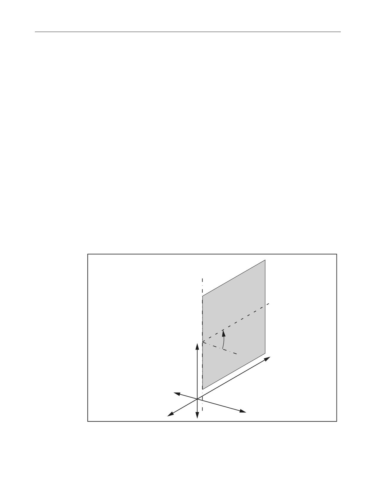
...A is parallel to X: A' is below the angle φ to the X axis
...B is parallel to Y: B' is below angle φ to the Y axis
...C is parallel to Z: C' is below angle φ to the Z axis
Angle definition
&
$
ϕ
=
$
;
<
Figure 2-20
Position of axis A'
Special functions
Function Manual, 12/2018, A5E40874099B AB
65
F2: Multi-axis transformations
2.5 Cardan milling head
Axis A' is positioned in the plane spanned by the rectangular axes of the designated axis
sequence. If, for example, the axis sequence is CA', then axis A' is positioned in plane Z-X.
The angle φ then is the angle between axis A' and the X axis.
2.5.2
Parameterization
Setting the type of transformation
The transformation type is set with the machine data of the corresponding transformation data
block:
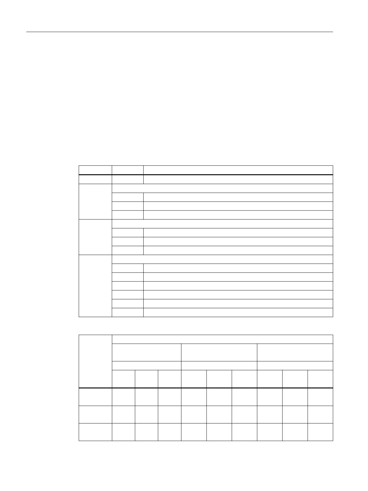
MD24100, ... MD25190 $MC_TRAFO_TYP_n, with n = 1, 2, 3, ...
Bit
<value>
Description
7
1
Activation of the transformation for cardan milling head
6 - 5
Moving component
00
Movable tool
01
Movingworkpiece
10
movable tool and workpiece
4 - 3
Direction of orientation of tool in position zero
00
X direction
01
Y direction
10
Z direction
2 - 0
Axis sequence
000
AB' or A'B
001
AC' or A'C
010
BA' or B'A
011
BC' or B'C
100
CA' or C'A
101
CB' or C'B
The following transformation types can be set:
Axis se-
Moving component: Bits 6 - 5
quence:
Tool
Workpiece
Tool/workpiece
Bits 0 - 2
00
01
10
Zero position 1)
Zero position 1)
Zero position 1)
X
Y
Z
X
Y
Z
X
Y
Z
00
01
10
00
01
10
00
01
10
AB' / A'B
x
x
-
-
-
-
-
-
-
000
AC' / A'C
x
-
x
-
-
-
-
-
-
001
BA' / B'A
x
x
-
-
-
-
x
x
010
Special functions
66
Function Manual, 12/2018, A5E40874099B AB

F2: Multi-axis transformations
2.5 Cardan milling head
Axis se-
Moving component: Bits 6 - 5
quence:
Tool
Workpiece
Tool/workpiece
Bits 0 - 2
00
01
10
Zero position 1)
Zero position 1)
Zero position 1)
X
Y
Z
X
Y
Z
X
Y
Z
00
01
10
00
01
10
00
01
10
BC' / B'C
-
x
x
-
x
x
-
-
-
011
CA' / C'A
x
-
x
-
-
-
-
-
-
100
CB' / C'B
-
x
x
-
-
-
-
-
-
101
1) Orientation of the tool in the zero position: Bits 3 - 4
x: Transformation type can be set
-: Transformation type cannot be set
Active machining plane
The tool orientation at the zero position can be set not only in the Z direction. For this reason,
ensure that the active working plane is set so that the tool length compensation acts in the tool
orientation direction.
The active machining plane should always be the plane according to which the tool orientation
is set in position zero.
Other settings
The geometry information used by the cardan milling head transformation for calculation of
the axis values is set in the same way as that of the other 5-axis transformations.
2.5.3
Traverse of the cardan milling head in JOG mode
JOG
In JOG mode, the linear axes can be traversed normally. It is, however, difficult to set the
orientation correctly by traversing these axes.
Special functions
Function Manual, 12/2018, A5E40874099B AB
67

F2: Multi-axis transformations
2.6 Programming of the 3- to 5-axis transformation
2.6
Programming of the 3- to 5-axis transformation
Switch on
The 3- to 5-axis transformations, including the transformations with swiveled linear axis and
cardan milling head, are enabled with the TRAORI(<transformation-no.>) command.
The enable of the transformation sets the NC/PLC interface signal:
DB21, ... DBX33.6 = 1 (transformation active)
Deactivation
With the TRAFOOF command disables the currently active 3- to 5-axis transformation. The
disable of the transformation resets the NC/PLC interface signal:
DB21, ... DBX33.6 = 0 (transformation inactive)
Switch-over
If a transformation is already active in the channel, the TRAORI(<transformation-no.>)
with a new transformation number command can be used to switch to another transformation.
Reset / program end
The control behavior after startup, program end or NC reset is set in the machine data:
MD20110 $MC_RESET_MODE_MASK, bit 7 = <value>
<value>
Meaning
0
Initial setting for active transformation after reset / program end according to $MC_TRA-
FO_RESET_VALUE
1
The active transformation remains active over reset / program end
Option
The "5-axis transformation" function, together with its special forms, is an option.
References
A detailed description of the machine data can be found in:
Parameter Manual, Detailed Machine Data Description
Special functions
68
Function Manual, 12/2018, A5E40874099B AB
F2: Multi-axis transformations
2.7 Generic 5-axis transformation and variants
2.7
Generic 5-axis transformation and variants
2.7.1
Functionality
Scope of functions
The scope of functions of generic 5-axis transformation covers implemented 5-axis
transformations (see Section "5-axis transformation (Page 43)") for perpendicular rotary axes
as well as transformations for the cardan milling head (one rotary axis parallel to a linear axis,
the second rotary axis at any angle to it, see Section "Cardan milling head (Page 64)").
Applications
In certain cases, it may not be possible to compensate the conventional transformation
machine accuracy, e.g. if:
● the rotary axes are not exactly mutually perpendicular or
● one of the two rotary axes is not positioned exactly parallel to the linear axes
In such cases, generic 5-axis transformation can produce better results.
Programming example
for generic 5-axis transformation is shown in Section "Example for Generic 5-axis
Transformation".
Activation
Generic 5-axis transformation can also be activated like any other orientation transformation
using the TRAORI() or TRAORI(n) command (where n is the number of the transformation).
Furthermore, the basic transformation can be transferred in the call in three other parameters,
e.g. TRAORI(1, 1.1, 1.5, 8.9).
A transformation can be deselected implicitly by selecting another transformation or explicitly
with TRAFOOF.
Special functions
Function Manual, 12/2018, A5E40874099B AB
69

F2: Multi-axis transformations
2.7 Generic 5-axis transformation and variants
2.7.2
Description of machine kinematics
Machine types
Like the existing 5-axis transformations, there are three different variants of generic 5-axis
transformation:
1. Machine type: Rotatable tool
Both rotary axes change the orientation of the workpiece. The orientation of the workpiece
is fixed.
2. Machine type: Rotatable workpiece
Both rotary axes change the orientation of the workpiece. The orientation of the tool is fixed.
3. Machine type: Rotatable tool and rotatable workpiece - one rotary axis changes the tool
orientation and the other the workpiece orientation.
Configurations
As previously, the machine configurations are defined in the following machine data (see
Section "Configuration of a machine for 5-axis transformation (Page 45)"):
$MC_TRAFO_TYPE_1, ..., _8
Additional types have been introduced for generic 5-axis transformation:
Table 2-1
Overview of machine types for the generic 5-axis transformation
Machine type
1
2
3
Swivel/rotatable:
tool
workpiece
Tool/workpiece
Transformation types
24
40
56
Rotary axis direction
The direction of the rotary axis is defined by the following machine data:
$MC_TRAFO5_AXIS1_n (1st rotary axis) and
$MC_TRAFO5_AXIS2_n (2nd rotary axis)
where n is 1 or 2 for the first or second 5-axis transformation in the system respectively. The
machine data specified above are fields with three values, which describe that axis direction
vectorially (similar to the description of rotary axes for orientable toolholder). The absolute
value of the vectors is insignificant; only the defined direction is relevant.
Example:
1. A-axis is the rotary axis (parallel to the x direction):
MD24570 $MC_TRAFO5_AXIS1_1[0] = 1.0 (direction first rotary axis)
MD24570 $MC_TRAFO5_AXIS1_1[1] = 0.0
MD24570 $MC_TRAFO5_AXIS1_1[2] = 0.0
2. B-axis is the rotary axis (parallel to the y direction):
Special functions
70
Function Manual, 12/2018, A5E40874099B AB
F2: Multi-axis transformations
2.7 Generic 5-axis transformation and variants
MD24572 $MC_TRAFO5_AXIS2_1[0] = 0.0 (direction 2nd rotary axis)
MD24572 $MC_TRAFO5_AXIS2_1[1] = 1.0
MD24572 $MC_TRAFO5_AXIS2_1[2] = 0,0
2.7.3
Generic orientation transformation variants
Extension
Generic orientation transformation for 5-axis transformation has been extended with the
following variants for 3-and 4-axis transformation:
Variant 1
4-axis transformations
A 4-axis transformation is characterized by the exclusive use of the first rotary axis as an entry
axis of the transformation. The following applies:
MD24110 $MC_TRAFO_AXES_IN_1[4] = 0 (axis assignment for transformation 1) or
MD24210 $MC_TRAFO_AXES_IN_2[4] = 0 (axis assignment for transformation 2)
Variant 2
3-axis transformations
In a 3-axis transformation, one of the geometry axes is not present, by entering a zero in the
field:
MD24120 $MC_TRAFO_GEOAX_ASSIGN_TAB_1[n] (assignment between geometry axis
and channel axis for transformation 1)
MD24220 $MC_TRAFO_GEOAX_ASSIGN_TAB_2[n] (assignment between geometry axis
and channel axis for transformation 2)
Transformation types
Both variants of generic 3- or 4-axis transformation are described by the following
transformation types:
●
3- or 4-axis transformation with rotatable tool
$MC_TRAFO_TYPE_n = 24
●
3- or 4-axis transformation with rotatable workpiece
$MC_TRAFO_TYPE_n = 40
In conventional 3-axis or 4-axis transformations, the transformation type also defined the basic
tool orientation in addition to the position of the rotary axis, which could then no longer be
influenced.
Special functions
Function Manual, 12/2018, A5E40874099B AB
71
F2: Multi-axis transformations
2.7 Generic 5-axis transformation and variants
Effects on orientations
Generic 3-axis or 4-axis transformation has the following effect on the various orientations:
The resulting tool orientation is defined according to the hierarchy specified for generic 5-axis
transformation.
Priority:
● high: programmed orientation,
● medium: tool orientation and
● low: basic orientation
Allowance is made, in particular, for the following orientations:
● A programmed tool orientation
● A basic tool orientation, modified by orientable toolholders.
Note
Further information on programmable tool orientation and on basic tool orientation can be
found in:
Reference:
Function Manual, Basic Machine; Tool Offset; Orientable Toolholders (W1)
Programming Manual, Fundamentals
Comparison
Besides the 3- and 4-axis transformations mentioned in Section "3- and 4-axis
Transformations", the following differences should be noted:
● Position of the rotary axis:
- can be arbitrary
- need not be parallel to a linear axis
● Direction of the rotary axis
- Must be defined by the following machine data:
MD24570 $MC_TRAFO5_AXIS1_1[n] (direction first rotary axis) or
MD24670 $MC_TRAFO5_AXIS1_2[n] (direction first rotary axis)
● Basic tool orientation
- Must be defined by the following machine data:
MD24574 $MC_TRAFO5_BASE_ORIENT_1[n] (workpiece orientation) or
MD24674 $MC_TRAFO5_BASE_ORIENT_2[n] (workpiece orientation)
● Selection of a generic 3-/4-axis transformation
- Optional tool orientation can be transferred as in the case of a generic 5-axis
transformation.
Special functions
72
Function Manual, 12/2018, A5E40874099B AB

F2: Multi-axis transformations
2.7 Generic 5-axis transformation and variants
2.7.4
Parameterization of orientable toolholder data
Application
Machine types for which the table or tool can be rotated, can either be operated as true 5-axis
machines or as conventional machines with orientable toolholders. In both cases, machine
kinematics is determined by the same data, which, due to different parameters, previously had
to be entered twice - for toolholder via system variables and for transformations via machine
data. The new transformation type 72 can be used to specify that these two machine types
access identical data.
Transformation type 72
The following machine data can be used to define a generic 5-axis transformation for
transformation type 72 with kinematic data read from the data for an orientable toolholder.
MD24100 $MC_TRAFO_TYPE_1 (definition of transformation 1 in the channel) or
MD24200 $MC_TRAFO_TYPE_2 (definition of transformation 2 in the channel)
From this number data is made available via machine data MD24582
$MC_TRAFO5_TCARR_NO_1 (TCARR-Number for the first 5-axis transformation) for the first
or MD24682 $MC_TRAFO5_TCARR_NO_2 (TCARR-Number for the second 5-axis
transformation) for the second orientation transformation. The corresponding transformation
type can then be derived from the content of kinematic type with parameter $TC_CARR23 -
see following table.
Table 2-2
Machine types for generic 5-axis transformation
Machine type
1
2
3
4
Swivel/
tool
workpiece
Tool/workpiece
Type 3 or orienta-
rotatable:
ble toolholder
Kinematic type:
T
P
M
T, P, M
Transformation
24
40
56
72 from content of
type:
$TC_CARR23
Special functions
Function Manual, 12/2018, A5E40874099B AB
73
F2: Multi-axis transformations
2.7 Generic 5-axis transformation and variants
Note
The transformation only takes place if the orientable toolholder concerned is available and the
value of $TC_CARR23 contains a valid entry for type M, P or T kinematics in lower or upper
case.
Transformation machine data for the first orientation transformation listed in the tables below
are equally valid for the second orientation transformation. All other machine data that may
affect the transformation characteristics and do not appear in the tables below, remain valid
and effective:
MD24110/MD24210 $MC_TRAFO_AXES_IN_1/2 (axis assignment for transformation) or
MD24574/MD24674 $MC_TRAFO5_BASE_ORIENT_1/2 (basic tool orientation)
If in the tables below a second additive parameter appears in brackets for the parameters of
the orientable toolholder (e.g. $TC_CARR24 (+ $TC_TCARR64)), the sum of both values will
only be effective if the fine offset specified in setting data is active when the data is transferred
from the orientable toolholder.
SD42974 $SC_TOCARR_FINE_CORRECTION = TRUE (fine offset TCARR on/off)
Activation
The most significant parameter values of an orientable toolholder for a transformation can be
activated in the part program with NEWCONF. Alternatively, the machine data concerned for
transformation type 72 can be activated via the HMI user interface.
Assignment for all types of transformation
The assignments between the toolholder data for writing the linear offsets and the
corresponding machine data for kinematic transformations are determined by the
transformation type. The following assignment of all other parameters is identical for all three
possible types of transformation:
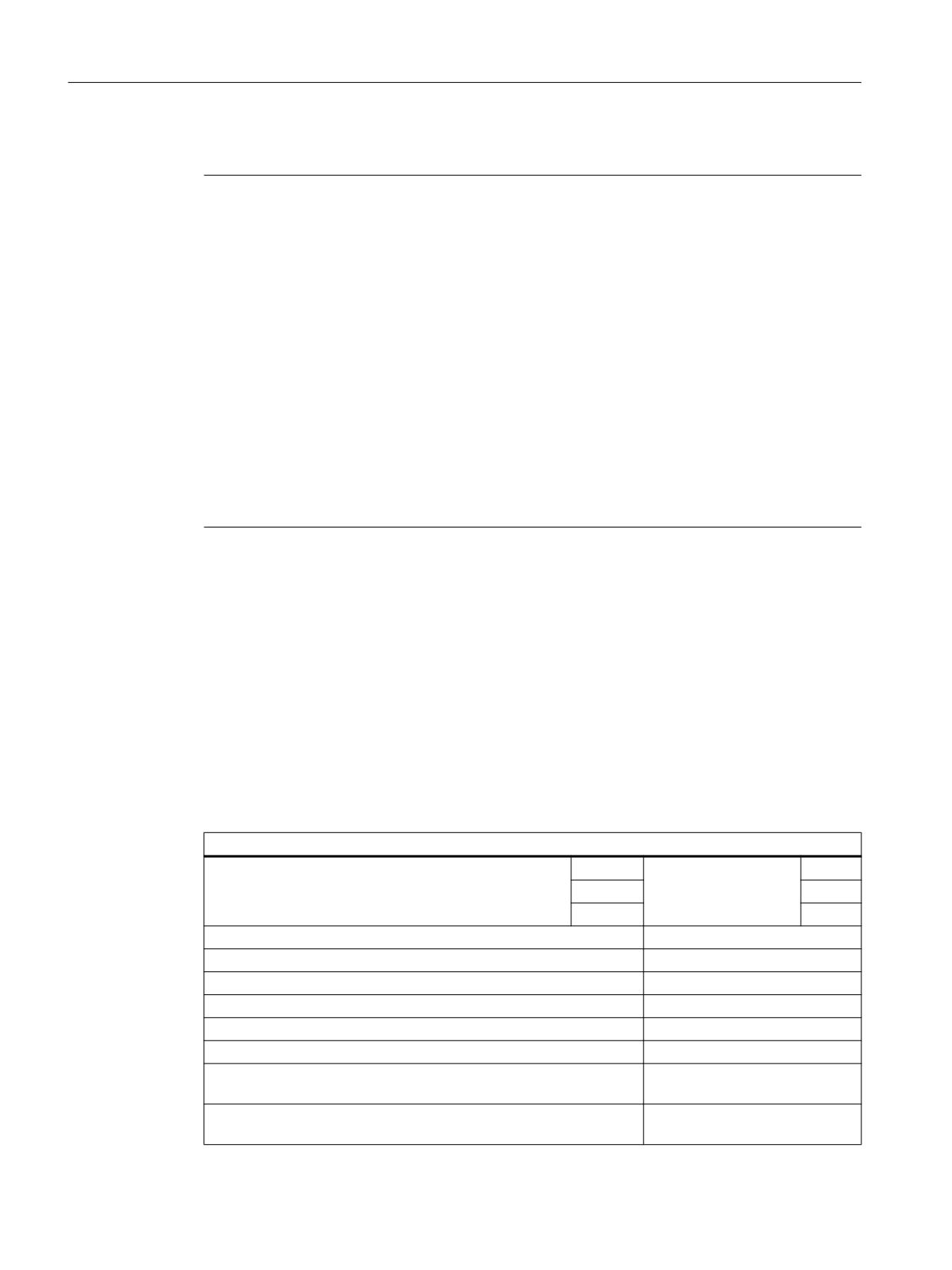
Assignment for all types of transformation together identical
MD24100 $MC_TRAFO_TYPE_1 (definition of transfor-
24
$TC_CARR23 =
T
mation 1 in the channel)
40
P
56
M
MD24570 $MC_TRAFO5_AXIS1_1[0] (direction 1st rotary axis)
$TC_CARR7
MD24570 $MC_TRAFO5_AXIS1_1[1]
$TC_CARR8
MD24570 $MC_TRAFO5_AXIS1_1[2]
$TC_CARR9
MD24572 $MC_TRAFO5_AXIS2_1[0] (direction 2nd rotary axis)
$TC_CARR10
MD24572 $MC_TRAFO5_AXIS2_1[1]
$TC_CARR11
MD24572 $MC_TRAFO5_AXIS2_1[2]
$TC_CARR12
MD24510 $MC_TRAFO5_ROT_AX_OFFSET_1[0] (position offset
$TC_CARR24 (+
of rotary axes 1/2/3 for 5-axis transformation) 1)
$TC_TCARR64)
MD24510 $MC_TRAFO5_ROT_AX_OFFSET_1[1]
$TC_CARR25 (+
$TC_TCARR65)
Special functions
74
Function Manual, 12/2018, A5E40874099B AB
F2: Multi-axis transformations
2.7 Generic 5-axis transformation and variants
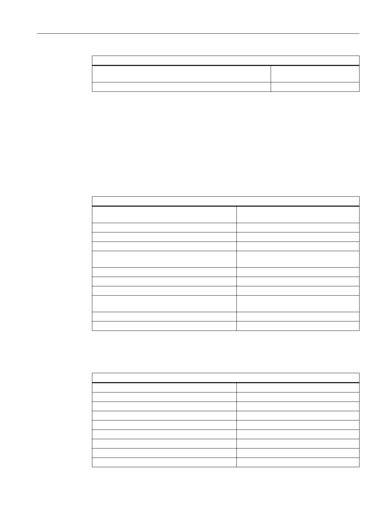
Assignment for all types of transformation together identical
MD24520 $MC_TRAFO5_ROT_SIGN_IS_PLUS_1[0] (sign of rotary
TRUE*
axis 1/2/3 for 5-axis transformation 1)
MD24520 $MC_TRAFO5_ROT_SIGN_IS_PLUS_1[1]
TRUE*
*) Machine data MD24520/MD24620 $MC_TRAFO5_ROT_SIGN_IS_PLUS_1/2 are
redundant. They are used to invert the direction of rotation of the assigned rotary axis.
However, this can also be achieved by inverting the direction of axis vector
$MC_TRAFO5_AXIS1/2_1/2. It is for this reason that there is no corresponding parameter for
the orientable toolholder. For the purpose of absolute clarity, the following machine data must
be ignored:
MD24520/MD24620 TRAFO5_ROT_SIGN_IS_PLUS_1/2
Assignments for transformation type 24
Toolholder data assignments dependent on transformation type 24
Transformation type "T" (in accordance with MD24100 $MC_TRAFO_TYPE_1 = 24)
MD24500 $MC_TRAFO5_PART_OFFSET_1[0]
$TC_CARR1 (+$TC_TCARR41)
(translation vector of 5-axis transformation 1)
MD24500 $MC_TRAFO5_PART_OFFSET_1[1]
$TC_CARR2 (+$TC_TCARR42)
MD24500 $MC_TRAFO5_PART_OFFSET_1[2]
$TC_CARR3 (+$TC_TCARR43)
MD24560 $MC_TRAFO5_JOINT_OFFSET_1[0] (vec-
$TC_CARR4 (+$TC_TCARR44)
tor of the kinematic offset of 5-axis transformation 1)
MD24560 $MC_TRAFO5_JOINT_OFFSET_1[1]
$TC_CARR5 (+$TC_TCARR45)
MD24560 $MC_TRAFO5_JOINT_OFFSET_1[2]
$TC_CARR6 (+$TC_TCARR46)
MD24550 $MC_TRAFO5_BASE_TOOL_1[0] (vector
$TC_CARR15 (+$TC_TCARR55)
of basic tool when 5-axis transformation is active) 1)
MD24550 $MC_TRAFO5_BASE_TOOL_1[1]
$TC_CARR16 (+$TC_TCARR56)
MD24550 $MC TRAFO5_BASE_TOOL_1[2]
$TC_CARR17 (+$TC_TCARR57)
Assignments for transformation type 40
Toolholder data assignments dependent on transformation type 40
Transformation type "P" (in accordance with MD24100 $MC_TRAFO_TYPE_1 = 40)
MD24550 $MC_TRAFO5_BASE_TOOL_1[0]
$TC_CARR4 (+$TC_TCARR44)
MD24550 $MC_TRAFO5_BASE_TOOL_1[1]
$TC_CARR5 (+$TC_TCARR45)
MD24550 $MC_TRAFO5_BASE_TOOL_1[2]
$TC_CARR6 (+$TC_TCARR46)
MD24560 $MC_TRAFO5_JOINT_OFFSET_1[0]
$TC_CARR15 (+$TC_TCARR55)
MD24560 $MC_TRAFO5_JOINT_OFFSET_1[1]
$TC_CARR16 (+$TC_TCARR56)
MD24560 $MC_TRAFO5_JOINT_OFFSET_1[2]
$TC_CARR17 (+$TC_TCARR57)
MD24500 $MC_TRAFO5_PART_OFFSET_1[0]
$TC_CARR18 (+$TC_TCARR58)
Special functions
Function Manual, 12/2018, A5E40874099B AB
75
F2: Multi-axis transformations
2.7 Generic 5-axis transformation and variants
Transformation type "P" (in accordance with MD24100 $MC_TRAFO_TYPE_1 = 40)
MD24500 $MC_TRAFO5_PART_OFFSET_1[1]
$TC_CARR19 (+$TC_TCARR59)
MD24500 $MC_TRAFO5_PART_OFFSET_1[2]
$TC_CARR20 (+$TC_TCARR60)
Assignments for transformation type 56
Toolholder data assignments dependent on transformation type 56
Transformation type "M" (in accordance with MD24100 $MC_TRAFO_TYPE_1 = 56)
MD24560 $MC_TRAFO5_JOINT_OFFSET_1[0] (vector
$TC_CARR1 (+$TC_TCARR41)
of the kinematic offset of 5-axis transformation 1)
MD24560 $MC_TRAFO5_JOINT_OFFSET_1[1]
$TC_CARR2 (+$TC_TCARR42)
MD24560: TRAFO5_JOINT_OFFSET_1[2]
$TC_CARR3 (+$TC_TCARR43)
MD24550 $MC_TRAFO5_BASE_TOOL_1[0]
$TC_CARR4 (+$TC_TCARR44)
MD24550 $MC_TRAFO5_BASE_TOOL_1[1]
$TC_CARR5 (+$TC_TCARR45)
MD24550 $MC_TRAFO5_BASE_TOOL_1[2]
$TC_CARR6 (+$TC_TCARR46)
MD24558 $MC_TRAFO5_JOINT_OFFSET_PART_1[0]
$TC_CARR15 (+$TC_TCARR55)
MD24558 $MC_TRAFO5_JOINT_OFFSET_PART_1[1]
$TC_CARR16 (+$TC_TCARR56)
MD24558 $MC_TRAFO5_JOINT_OFFSET_PART_1[2]
$TC_CARR17 (+$TC_TCARR57)
MD24500 $MC_TRAFO5_PART_OFFSET_1[0]
$TC_CARR18 (+$TC_TCARR58)
MD24500 $MC_TRAFO5_PART_OFFSET_1[1]
$TC_CARR19 (+$TC_TCARR59)
MD24500 $MC_TRAFO5_PART_OFFSET_1[2]
$TC_CARR20 (+$TC_TCARR60)
Example of parameterization
The first 5-axis transformation is to obtain its data from machine data and the second, in
contrast, is to be parameterized using the data from the 3rd orientable toolholder.
MD24100 $MC_TRAFO_TYPE_1 = 24
; first 5-axis transformation
MD24200 $MC_TRAFO_TYPE_2 = 72
; second 5-axis transformation
MD24682 $MC_TRAFO5_TCARR_NO_2 =
; parameterize data of the third orientable
3;
; toolholder
2.7.5
Extension of the generic transformation to six axes - 840D sl only
6-axis transformation is an extension of the generic 5-axis transformation to include an
additional rotary axis. This allows rotation of the tool around itself to be defined.
In addition to the machine data for 5-axis transformation, to parameterize 6-axis
transformation, additional settings must be made in the subsequently listed machine data.
Special functions
76
Function Manual, 12/2018, A5E40874099B AB

F2: Multi-axis transformations
2.7 Generic 5-axis transformation and variants
Parameter assignment: Transformation type
The transformation type is set on a channel-for-channel basis using:
$MC_TRAFO_TYPE_<x> = <transformation type>
The transformation type to be set is obtained from the machine type and/or the allocation of
the three rotary axes regarding tool and workpiece orientation:
<Transformation type>
24 1)
40 1)
56 2)
57 3)
Machine type
1
2
3
4
Toolorientation
3 rotary axes
---
2 rotary axes
1 rotary axis
Workpieceorientation
---
3 rotary axes
1 rotary axis
2 rotary axes
1)
The first rotary axis of the transformation is the rotary axis that in the kinematic chain is located next
for the workpiece.
The third rotary axis of the transformation is the rotary axis that in the kinematic chain is located next
for the tool.
When the second rotary axis traverses, then the third rotary axis is also moved.
2)
The second rotary axis of the transformation is the rotary axis that in the kinematic chain is located
next for the workpiece.
The third rotary axis of the transformation is the rotary axis that in the kinematic chain is located next
for the tool.
When the first rotary axis traverses, then the third rotary axis is also moved.
3)
The first rotary axis of the transformation is the rotary axis that in the kinematic chain is located next
for the tool.
The third rotary axis of the transformation is the rotary axis that in the kinematic chain is located next
for the workpiece.
When the second rotary axis traverses, then the third rotary axis is also moved.
Note
Using transformation types 24, 40, 56 and 57, only those kinematics are formed, where the
three linear axes of the transformation form a right-handed Cartesian coordinate system - and,
there is no rotary axis between the linear axes in the kinematic chain.
Parameter assignment: Offset vectors for transformation type 57
For transformation type 57, the same as for rotary axes, the offset vectors are to be specified
starting from the tool to the workpiece zero:
Offset
Machine data
Tool tip → rotary axis 1
$MC_TRAFO5_BASE_TOOL_<x>[ 0 ... 2 ]
Rotary axis 1 → rotary axis 2
$MC_TRAFO5_JOINT_OFFSET_<x>[ 0 ... 2 ]
Rotary axis 2 → rotary axis 3
$MC_TRAFO6_JOINT_OFFSET_2_3_<x>[ 0 ... 2 ]
Rotary axis 3 → workpiece zero
$MC_TRAFO5_PART_OFFSET_<x>[ 0 ... 2 ]
Parameter assignment: Channel axis number of the 3rd rotary axis
The channel axis number of the third rotary axis is set in:
$MC_TRAFO_AXES_IN_<x>[ 5 ] = <channel axis number of the third rotary axis>
Special functions
Function Manual, 12/2018, A5E40874099B AB
77
F2: Multi-axis transformations
2.7 Generic 5-axis transformation and variants
Parameter assignment: Direction vector of the 3rd rotary axis
The direction vector of the third rotary axis is set in:
$MC_TRAFO5_AXIS3_<x>[ 0 ... 2 ] = <direction vector component>
Parameter assignment: Tool normal vector
It is not permissible that the tool normal vector is in parallel or is antiparallel to the basic tool
orientation vector (MD24574 $MC_TRAFO5_BASE_ORIENT_<x>). It is set in:
$MC_TRAFO6_BASE_ORIENT_NORMAL_<x>[ 0 ... 2 ] = <component of the tool normal
vector>
Parameter assignment: Offset vector between the second and third rotary axes
The offset vector between the second and third rotary axes is set in:
$MC_TRAFO6_JOINT_OFFSET_2_3_<x>[ 0 ... 2 ] = <component of the offset vector>
Orientation
With the extension of the generic orientation transformation to six axes, all three degrees of
freedom of the orientation can be freely selected. They can be uniquely defined through the
position of a rectangular Cartesian coordinate system. The axis direction of the third axis
defines the orientation.
Two degrees of freedom are required to specify this axis direction. The third degree of freedom
is defined via a rotation around this axis direction, e.g. by specifying an angle THETA or a
direction vector for one of the two other axes of the coordinate system (see Chapter "Rotations
of orientation vector (Page 119)").
Addresses AN3, BN3, CN3 define the direction of the second axis of the coordinate system,
i.e. the orientation normal vector. The orientation normal vector, programmed with addresses
AN3, BN3, CN3, should be perpendicular to the orientation. If this is not the case, then the
programmed orientation normal vector is internally modified to achieve this. Then, the modified
orientation normal vector lies in the plane formed by the programmed orientation and
orientation normal vector - and is perpendicular to the orientation vector. This orthogonalization
is only possible if the two programmed vectors are neither parallel nor antiparallel. Alarm 4342
is output if this condition is not satisfied.
Direction vectors in the tool data
Orientation vector
Vector components (x,y,z) of the orientation vector of a tool can be defined in the tool data
using $TC_DPV or $TC_DPV3 - $TC_DPV5.
References: Function Manual, Basic Machine; tool offsets (W1), Chapter Sum and setup
offsets.
Special functions
78
Function Manual, 12/2018, A5E40874099B AB

F2: Multi-axis transformations
2.7 Generic 5-axis transformation and variants
Orientation normal vector
Vector components (x,y,z) of the orientation normal vector of a tool can be defined in the tool
data using $TC_DPVN3 - $TC_DPVN5. The significance of the vector components is
analogous to the vector components of the orientation vector:
● $TC_DPVN3: Component in the direction of the tool length L1,
● $TC_DPVN4: Component in the direction of the tool length L2
● $TC_DPVN5: Component in the direction of the tool length L3.
The following settings must be made so that the tool data for the orientation normal vector can
be used:
MD18114 $MN_MM_ENABLE_TOOL_ORIENT = 3 (assign tool cutting edges orientation)
The coordinate system is not rotated by rotating the tool with AN3, BN3, CN3 or THETA.
Default setting of the orientation normal vector
The initial state of the orientation normal vector is defined when activating the transformation
in one of the following ways:
1. For a TRAORI function call, vector components (x,y,z) are transferred as parameters 8 -
10:
TRAORI(p1, p2, p3, p4, p5, p6, p7, p8, p9, p10)
2. If, when calling the TRAORI function, no orientation normal vector is specified, and one
tool is active, then vector components (x,y,z) are taken from the tool data:
$TC_DPVN3, $TC_DPVN4, $TC_DPVN5
3. If, when calling the TRAORI function, no orientation normal vector is specified, and no tool
is active, then vector components (x,y,z) are taken from the following machine data:
MD24567 $MC_TRAFO6_BASE_ORIENT_NORMAL_<x>[ 0 ... 2 ] (tool normal vector)
The position of the orientation coordinate system of a standard tool depends on the active
plane (G17, G18, G19) corresponding to the following table:
G17
G18
G19
Direction of the orientation vector
Z
Y
X
Direction of the orientation normal vector
Y
X
Z
See also
Example of a generic 6-axis transformation (Page 141)
2.7.6
Extension of the generic transformation to 7 axes - 840D sl only
Application
The generic 5-/6-axis transformation with transformation type 24 is extended by a 7th or
6th axis, which rotates the workpiece. The work space of the transformation can be expanded
in this way.
Special functions
Function Manual, 12/2018, A5E40874099B AB
79
F2: Multi-axis transformations
2.7 Generic 5-axis transformation and variants
Requirement
For generic 7-axis transformation there must be at least 6 or 7 axes.
Function
Another 7th axis is required in connection with the generic 6-axis transformation which rotates
the workpiece. This 7th Axis is considered only along with transformation type 24 (generic 6-
axis transformation having 3 rotary axes that move the tool ).
The position of the 7th axis is specified according to a strategy of the CAD system and settled
with the Cartesian position (X, Y, Z) by the generic transformation in such a way that the axes
always approach the TCP position programmed with reference to the workpiece, independently
of the position of the 7th axis. If ORIWKS is active, the end orientation programmed with
reference to the workpiece is also rotated by the 7th axis. This way it is possible to program
the orientation in relation to the workpiece.
The transformation uses the 7th axis as the observed input variable.
To configure the 7th axis, the channel machine data of the 5-/6-axis transformation is extended
by one field containing the 3 components of the direction vector of the 7th axis and an axis
offset.
This gives the following advantages:
● The contour and the orientation at the workpiece can be programmed in relation to the
workpiece.
● The programmed feed is maintained in the contour, even if the 7th axis also moves.
● All the contour-related control functions can be used.
● The displayed WCS position corresponds to the programmed position.
● The transformation is configured as in generic 6-axis transformation. One can switch
between a 6-axis and a 7-axis transformation smoothly.
● In case of large radius circular interpolation, the release of singularities incorporating the
7th axis.
Notations
Dedicated machine data exist for each general transformation and for each orientation
transformation that are differentiated by the suffixes _1, _2 etc. (e.g. $MC_TRAFO_TYPE_1,
$MC_TRAFO_TYPE_2 etc.). In the following, only the names for the first transformation are
specified, i.e. those with the suffix _1. If a transformation other than the first is parameterized,
the correspondingly modified names must be used.
Special functions
80
Function Manual, 12/2018, A5E40874099B AB

F2: Multi-axis transformations
2.7 Generic 5-axis transformation and variants
Description of the kinematics
The 7-axis transformation builds on the generic 5-/6-axis transformation.
Note
The 7-axis transformation also covers kinematics in which the 6th axis is not available. In the
following, we speak exclusively about a 7th axis or about a 7-axis transformation, even when
it is actually the 6th axis in connection with a 5-axis kinematics.
The 7-axis transformation types only cover those kinematics in which the three linear axes
form a rectangular Cartesian coordinate system, i.e. no kinematics are covered in which at
least one rotary axis lies between two linear axes in the kinematic chain.
There is only one machine kinematics for which a 7th axis can be configured. It is designated
by the Transformation Type 24:
$MC_TRAFO_TYPE_1 = 24 Rotary tool: Three (or two) axes rotate the tool; the 7th axis rotates
the workpiece.
The extensions of the following machine data are required to configure a generic 7-axis
transformation:
Machine data
extension
$MC_TRAFO_AXES_IN_1[9]
The channel axis index of the 4th rotary axis is recor-
ded here.
$MC_TRAFO_AXES_IN_1[10] and $MC_TRA-
This machine data is to be assigned with default val-
FO_AXES_IN_1[11]
ue of 0. (default setting)
$MC_TRAFO_AXES_IN_1[6..8]
This machine data is not evaluated by the generic 7-
axis transformation.
$MC_TRAFO7_EXT_AXIS1_1[0..2]
The direction of the 4th rotary axis is specified here.
$MC_TRAFO7_EXT_AX_OFFSET_1[0..2]
A position offset of the 4th rotary axis is entered
here.
Special functions
Function Manual, 12/2018, A5E40874099B AB
81
F2: Multi-axis transformations
2.7 Generic 5-axis transformation and variants
MR
$
&
MR
&
PR
WR
W
;
(
7RRO UHODWHG
SR
]HUR SRLQW
0DFKLQH ]HUR
mo:
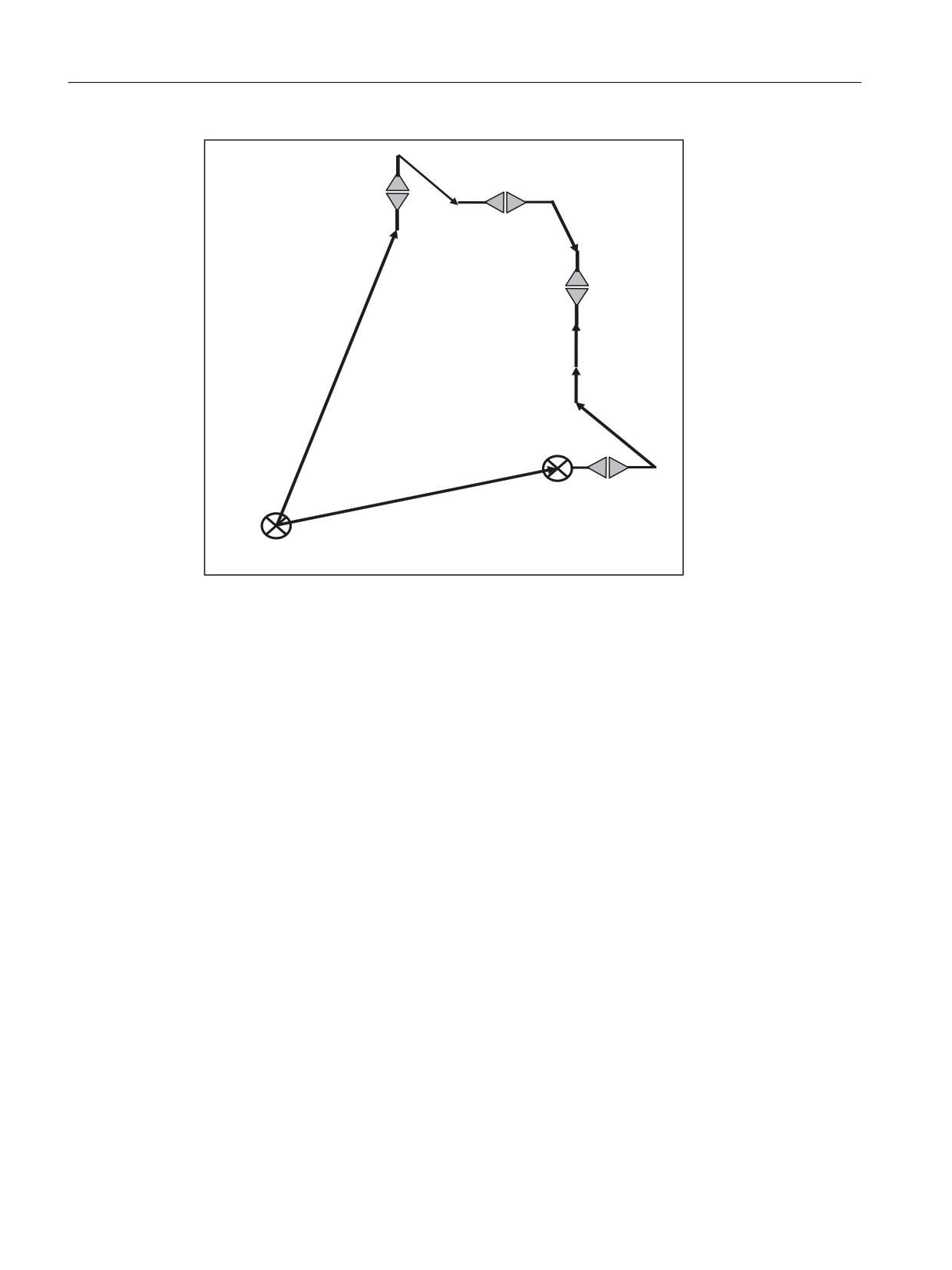
Position vector in MCS
po:
$MC_TRAFO5_PART_OFFSET_n[0..2]
x.
Vector of programmed position in the WCS
t:
Tool correction vector
to:
$MC_TRAFO5_BASE_TOOL_n[0..2]
jo:
$MC_TRAFO5_JOINT_OFFSET_n[0..2]
jo23:
$MC_TRAFO6_JOINT_OFFSET_2_3_n[0..2]
Figure 2-21
Schematic diagram of 7-axis kinematics
Programming
1. Programming the Cartesian position
The position of the 7th axis must be programmed in the workpiece coordination system in
addition to the Cartesian position. The Cartesian position is thus programmed in relation
to the constant workpiece. The 7-axis transformation converts the WCS position via the
rotation of the 7th axis in the basic coordinate system. Possibly programmed or set frames
are normally settled before the 7-axis transformation.
2. Programming of orientation
All programming options of the generic 5/6-axis transformation are available while
programming the orientation. The 7th axis must always be programmed additionally.
Two different response types can be set in this context via the G command.
- The position of the 7th axis does not influence the programmed orientation.
- The programmed end orientation is rotated with the 7th axis.
Special functions
82
Function Manual, 12/2018, A5E40874099B AB
F2: Multi-axis transformations
2.7 Generic 5-axis transformation and variants
Orientation
1. Orientation with axis interpolation
If the 7th axis should have no influence on the programmed orientation, the G commands
of groups 25 and 51 must be set accordingly:
G group 25: ORIMKS
G group 51: ORIAXES (if MD21104 $MC_ORI_IPO_WITH_G_CODE = 1 is set).
The programmed positions of the rotary axes are not changed by the position of the 7th
axis in this case, but are approached directly. The orientation is programmed in relation to
the machine.
Example
Program code
TRAORI(1)
ORIAXES
ORIMKS
G1 X500 Y300 Z800 C15 A5 C1=10 E1=120
1. Orientation and large circle interpolation
If traversing is to be done with large radius circular interpolation, the end orientation is
rotated with the 7th axis.
G command group 25: ORIWKS
G command group 51: ORIVECT (if MD21104 $MC_ORI_IPO_WITH_G_CODE = 1 is set).
In this case the orientation must be programmed in relation to the workpiece. The
programmed orientation is thus related to the fixed workpiece. The position of the 7th axis
is thus not contained in the programmed orientation.
Example
Program code
TRAORI(1)
ORIVECT
ORIWKS
G1 X500 Y800 Z100 A3=0 B3=1 C3=0 AN3=0 BN3=0 CN3=-1 E1=-90
Frames
The basic coordinate system sits on the 7th axis. It is also rotated when the 7th axis rotates.
This way the workpiece coordinate system (WCS) does not remain stationary when the
workpiece is rotated over the 7th axis. A workpiece position rotated to the zero position of the
7th axis can be compensated by an axial frame offset of the 7th axis.
Traversing with the 7th axis in JOG mode
Only the compensatory movements for the linear axes are created if the 7th axis is traversed
in the JOG mode with active 7-axis transformation. The position at the workpiece is kept
constant in this way. As the rotary axes go into the transformation only as input axes, they are
not influenced by the 7th axis during the JOG travel. The orientation at the workpiece is thus
kept variable.
Special functions
Function Manual, 12/2018, A5E40874099B AB
83

F2: Multi-axis transformations
2.7 Generic 5-axis transformation and variants
2.7.7
Cartesian manual travel with generic transformation
Note
Option
The "Handling transformation package" option is necessary for the function.
Functionality
With function "Cartesian manual travel", the following Cartesian coordinate system can be set
for traversing geometry and orientation axis in the JOG mode:
● Basic coordinate system (BCS)
● Workpiece coordinate system (WCS)
● Tool coordinate system (TCS)
Traversing motion of linear and rotary axes is realized via the NC/PLC interface signals of the
geometry and/or orientation axes.
Note
For further information about the representation of the translations for the Cartesian manual
travel in the corresponding coordinate systems, see:
Reference:
Function Manual Extension Functions; Kinematic Transformation (M1)
Parameter assignment: Machine data
Coordinate systems
The following machine data not only activates the function, but also sets the permitted
coordinate systems, which can be toggled between.
MD21106 $MC_CART_JOG_SYSTEM, bit n = <value>
Bit n
Value
Meaning
0
1
Function active: Basic coordinate system (BCS)
1
1
Function active: Workpiece coordinate system (WCS)
2
1
Function active: Tool coordinate system (TCS)
Parameter assignment: Setting data
Defining the virtual kinematics for the orientation axes
The active virtual kinematics for manually traversing the orientation axes is defined using the
following setting data. Here, only kinematics can be set, where the rotary axes are
perpendicular to one another.
Special functions
84
Function Manual, 12/2018, A5E40874099B AB

F2: Multi-axis transformations
2.8 Restrictions for kinematics and interpolation
SD42660 $SC_ORI_JOG_MODE = <value>
Value
Meaning
0
The virtual kinematics are defined using transformation
1
Rotation with Euler angles: Rotation sequence, ZX'Z'' convention:
2
Rotation with Euler angles: XY'Z'' convention (RPY angle)
3
Rotation with Euler angles: Rotation sequence ZY'X'' convention (RPY angles)
4
Defining the rotation sequence using: MD21120 $MC_ORIAX_TURN_TAB_1
5
Defining the rotation sequence using: MD21130 $MC_ORIAX_TURN_TAB_2
For further explanations regarding orientation motion (see Chapter "Orientation (Page 88)"
and "Orientation axes (Page 108)").
Note
For further information about the programming of rotations please refer to:
References:
Programming Manual, Job Planning; Chapter: "Transformations"
2.8
Restrictions for kinematics and interpolation
For systems where there are less than six axes available for transformation, the following
restrictions must be taken into account.
5-axis kinematics
For 5-axis kinematics there are two degrees of freedom for orientation. The assignment of
orientation axes and tool vector direction must be selected so that there is no rotation around
the tool vector. As a result, only two orientation angles are required to describe the orientation.
If the axis is traversed using ORIVECT, the tool vector performs pure swiveling motion.
3-and 4-axis kinematics
For 3- and 4-axis kinematics, only one degree of freedom is available for orientation. The
respective transformation determines the relevant orientation angle. In this case, it only makes
sense to traverse the orientation axis using ORIAXES. In this case, the orientation axis is
directly and linearly interpolated.
Interpolation of the tool orientation over several blocks by means of orientation vectors
If the orientation of a tool is programmed over several consecutive part program blocks by
directly entering the appropriate rotary axis positions, then undesirable discontinuous changes
of the orientation vector are obtained at the block transitions. This results in discontinuous
velocity and acceleration changes of the rotary axes. This means that no continuous velocity
and acceleration of the orientation axes over several blocks can be achieved using large circle
interpolation.
Special functions
Function Manual, 12/2018, A5E40874099B AB
85
F2: Multi-axis transformations
2.8 Restrictions for kinematics and interpolation
Continuous block transitions
As long as only linear blocks (G1) are programmed, then the orientation axes also behave just
like linear axes. In this case, motion with continuous acceleration is achieved through
polynomial interpolation. Significantly better results can be achieved by programming the
orientation in space using orientation vectors (see Section "Polynomial interpolation of
orientation vectors (Page 115)").
2.8.1
Singularities of orientation
Description of problem
As described in Section "Singularities and how to treat them", singularities (poles) are
constellations in which the tool is orientated becomes parallel to the first rotary axis. If the
orientation is changed when the tool is in or close to a singularity (as is the case with large-
circle interpolation ORIWKS ), the rotary axis positions must change by large amounts to
achieve small changes in orientation. In extreme cases, a jump in the rotary axis position would
be needed.
Such a situation would be treated as follows:
There is only one relevant machine data, which circles the pole as usual:
MD24540 $MC_TRAFO5_POLE_LIMIT_1 (closing angle tolerance for interpolation by pole for
5-axis transformation)
or
MD24640 $MC_TRAFO5_POLE_LIMIT_2 (closing angle tolerance for interpolation by pole for
5-xis transformation)
For further information about the handling of singular positions, see:
References:
Programming Manual, Job Planning, Transformations; Section: Cartesian PTP travel
Example for machine type 1
Rotatable tool
Both rotary axes change the orientation of the workpiece. The orientation of the workpiece is
fixed.
2-axis swivel head with rotary axis RA 1 (4th transformation axis) and rotary axis RA 2 (5th
transformation axis)
Special functions
86
Function Manual, 12/2018, A5E40874099B AB
F2: Multi-axis transformations
2.8 Restrictions for kinematics and interpolation
7ROHUDQFH
&RQVWDQW
FLUFOH
SRVLWLRQ RI
3ROH
QG URWDU\ D[LV
6WDUW SRLQW
3URJUDPPHG
HQG SRLQW
3DWK
5HDFKHG
HQG SRLQW
&RQVWDQW
SRVLWLRQ RI
VW URWDU\ D[LV
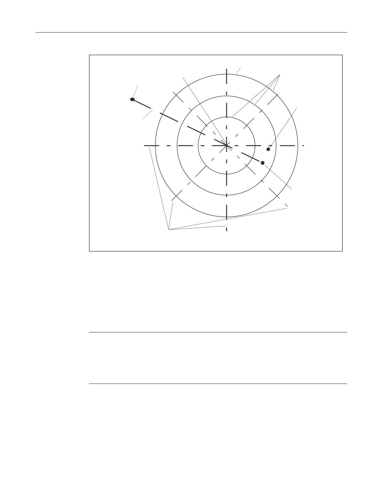
Figure 2-22
Generic 5-axis transformation; end point of orientation inside tolerance circle.
End point within the circle
If the end point is within the circle, the first axis comes to a standstill and the second axis moves
until the difference between target and actual orientation is minimal. However, since the first
rotary axis does not move, the orientation will generally deviate from the programmed value
(see previous figure). However, the programmed orientation can at least be reached exactly
if the first rotary axis happens to be positioned correctly.
Note
In the previous Figure the resulting path is a straight line because the position of the first rotary
axis is constant on that path. This representation is always correct, irrespective of the angle
between the two rotary axes. The orientation vector only moves in a plane, however, if the two
rotary axes and the basic orientation are all mutually perpendicular. In all other cases, the
orientation vector describes the outside of a cone.
End point outside the circle
If the orientation interpolation describes a path through the circle, while the end point is outside
the circle, the end point is approached with axis interpolation. This applies in particular if the
interpolation starting point is located inside the circle. Path deviations from the programmed
setpoint orientation are thus unavoidable.
Special functions
Function Manual, 12/2018, A5E40874099B AB
87
F2: Multi-axis transformations
2.9 Orientation
2.9
Orientation
2.9.1
Basic orientation
Differences to the previous 5-axis transformations
In the 5-axis transformations implemented to date, basic orientation of the tool was defined by
the type of transformation.
Generic 5-axis transformation can be used to enable any basic tool orientation, i.e. space
orientation of the tool is arbitrary, with axes in their initial positions.
If an orientation is programmed by means of Euler angles, RPY angles (A2, B2, C2) or vectors
(A3, B3, C3), basic orientation is taken into consideration, i.e. the rotary axes are positioned
so that a tool positioned in basic orientation is traversed to the programmed orientation.
If the rotary axes are programmed directly, basic orientation has no effect.
Definition
The basic orientation can be defined in three different ways:
● Definition by calling the transformation
● Definition by the orientation of the active tool
● Definition using a machine data
Definition by calling the transformation
When the transformation is called, the direction vector of the basic orientation can be specified
in the call, e.g. TRAORI(0, 0., 1., 5.). The direction vector is defined by parameters 2
to 4. This is the reason that in the example it has the value (0., 1., 5.).
The first parameter specifies the transformation number. The number can be omitted if the first
transformation is to be activated. To enable the parameters to be identified correctly when
specifying an orientation, a blank space has to be inserted instead of the transformation
number, e.g. TRAORI(, 0., 1., 5.).
Note
The orientation data is absolute. It is not modified by a frame that is possibly active.
The absolute value of the vector is insignificant, only the direction is relevant. Non-programmed
vector elements can be set to zero.
Please note that if all three vector components are zero (because they have been set explicitly
so or not specified at all), the basic orientation is not defined by data in the TRAORI(...) call,
but by one of the two other options.
If a basic orientation is defined by calling the transformation, it cannot be altered while a
transformation is active. The orientation can be changed only by selecting the transformation
again.
Special functions
88
Function Manual, 12/2018, A5E40874099B AB
F2: Multi-axis transformations
2.9 Orientation
Definition by the orientation of the active tool
The basic orientation is determined by the tool, if:
● it has not been defined by specifying a direction vector in the transformation call
and
● a tool is already active.
The orientation of a tool is dependent on the selected plane. It is parallel to Z at G17, parallel
to Y at G18 and parallel to X at G19.
It can be modified arbitrarily by orientable toolholders, see:
Reference:
Function Manual, Basic Functions; Tool Offset (W1), Chapter: "Orientable tool carrier"
If the tool is changed when a transformation is active, the basic orientation is also updated.
The same applies if the orientation of a tool changes as the result of a change in plane (plane
changes are equivalent to tool changes, as they also alter the assignment between tool length
components and individual axes).
If the tool is de-selected, thereby canceling the definition of tool orientation, the basic
orientation programmed in machine data becomes operative.
Definition using a machine data
If the basic orientation is not defined by either of the two variants described above, it is specified
with reference to the following machine data:
$MC_TRAFO5_BASE_ORIENT_n (basic tool orientation)
This machine data must not be set to a zero vector or else an alarm will be generated during
control run-up when a transformation is active.
If a basic orientation is programmed in machine data $MC_TRAFO5_BASE_ORIENT_n when
a transformation is active and a tool is subsequently activated, the basic orientation is re-
defined by the tool.
Note
The range of settable orientations depends on the directions of the rotary axes involved and
the basic orientation. The rotary axes must be mutually perpendicular if all possible orientations
are to be used. If this condition is not met, "dead" ranges will occur.
Examples:
1. Extreme example: A machine with rotatable tool has a C axis as its first rotary axis and an
A axis as its second. If the basic orientation is defined in parallel to the A axis, the orientation
can only be changed in the X-Y plane (when the C axis is rotating), i.e. orientation with a
Z component unequal to zero is not possible in this instance. The orientation does not
change when the A axis rotates.
2. Realistic example: A machine with nutator kinematics (cardan head) with an axis inclined
at less than 45o in a basic orientation parallel to the Z axis can only assume orientations
within a semi-circle: The top semi-circle with basic orientation towards +Z and the bottom
with basic orientation towards -Z.
Special functions
Function Manual, 12/2018, A5E40874099B AB
89

F2: Multi-axis transformations
2.9 Orientation
2.9.2
Orientation movements with axis limits
Calculate rotary axis position
If the final orientation in a 5-axis transformation is programmed indirectly in an NC block by
means of a Euler, RPY angle or direction vector, it is necessary to calculate the rotary axis
positions that produce the desired orientation. This calculation has no unique result.
There are always at least two essentially different solutions. In addition, any number of
solutions can result from a modification to the rotary axis positions by any multiple of 360
degrees.
The control system chooses the solution which represents the shortest distance from the
current starting point, allowing for the programmed interpolation type.
Determining permissible axis limits
The control system attempts to define another permissible solution if the axis limits are violated,
by approaching the desired axis position along the shortest path. The second solution is then
verified, and if this solution also violates the axis limits, the axis positions for both solutions
are modified by multiples of 360 until a valid position is found.
The following conditions must be met in order to monitor the axis limits of a rotary axis and
modify the calculated end positions:
● A generic 5-axis transformation of type 24, 40 or 56 must be active.
● The axis must be referenced.
● The axis must not be a modulo rotary axis.
● The following machine data may not be equal to zero:
MD21180 $MC_ROT_AX_SWL_CHECK_MODE (check software limits for orientation axes)
MD21180 $MC_ROT_AX_SWL_CHECK_MODE specifies the conditions under which the
rotary axis positions may be modified:
Value
Meaning
0
No modification permitted (default, equivalent to previous behavior).
1
Modification is only permitted if axis interpolation is active (ORIAXES or ORIMKS).
2
Modification is always permitted, even if vector interpolation (large circle interpolation, conical
interpolation, etc.) was active originally.
Switch-over to axis interpolation
If the axis positions have to be changed from the originally determined value, the system
switches to rotary axis interpolation because the original interpolation path, e.g. large circle
interpolation or conical interpolation, can no longer be maintained.
Example
An example for modifying the rotary axis motion of a 5-axis machine with a rotatable tool is
shown in Chapter "Examples for generic axis transformations (Page 139)".
Special functions
90
Function Manual, 12/2018, A5E40874099B AB
F2: Multi-axis transformations
2.9 Orientation
2.9.3
Orientation compression
Function
Using compressor functions COMPON, COMPCURV, COMPCAD and COMPSURF, NC
programs, in which the orientation is programmed using direction vectors, can be compressed,
but still maintaining a specifiable tolerance.
Requirement
An orientation motion is only compressed under the following conditions:
● Orientation transformation (TRAORI) is active.
● Large-radius circular interpolation is active.
I.e. tool orientation is changed in the plane that is determined by start and end orientation.
Large-radius circular interpolation is performed under the following conditions:
- MD21104 $MC_ORI_IPO_WITH_G_CODE = 0
+ ORIWKS is active.
+ orientation is programmed using vectors (with A3, B3, C3 or A2, B2, C2).
- MD21104 $MC_ORI_IPO_WITH_G_CODE = 1
+ ORIVECT or ORIPLANE is active.
The tool orientation can be programmed either as a direction vector or with rotary axis
positions. Large-radius circular interpolation is not executed if G command ORICONxx
or ORICURVE is active or if polynomials for orientation angle (PO[PHI] and PO[PSI])
are programmed.
Parameterization
NC blocks can only be compressed if deviations are allowed between the programmed contour
and interpolated contour or between the programmed orientation and interpolated orientation.
Compression tolerances can be used to set the maximum permissible deviation. The higher
the tolerances, the more blocks can be compressed. However, the higher the tolerances, the
more the interpolated contour or orientation can deviate from the programmed values.
Axis accuracy
For each programmed path, the compressor generates a spline curve such that, for the axes
involved, the maximum tolerance set with the machine data is complied with in the endpoints:
MD33100 $MA_COMPRESS_POS_TOL = <maximum deviation with compression>
Special functions
Function Manual, 12/2018, A5E40874099B AB
91
F2: Multi-axis transformations
2.9 Orientation
Contour accuracy
The maximum deviation from the programmed contour and tool orientation permitted during
compression is set with the following setting data:
● SD42475 $SC_COMPRESS_CONTUR_TOL = <maximum contour deviation>
● SD42476 $SC_COMPRESS_ORI_TOL = <maximum angular deviation of the tool
orientation>
Only effective with orientation transformation.
● SD42477 $SC_COMPRESS_ORI_ROT_TOL = <maximum angular deviation of the tool
orientation>
Only effective with orientation transformation in conjunction with 6-axis transformation.
Note
A maximum deviation of tool orientation can only be specified if an orientation transformation
is active (TRAORI).
Compression mode
With the machine data, the following decimal-coded functions are parameterized:
● Units digit: Taking into account tolerances
● Tens digit: Compression of blocks with programmed tool orientation and / or value
assignments.
● Hundreds digit: Compression of blocks, except linear blocks (G1).
● Thousands digit: Compression for specific applications.
MD20482 $MC_COMPRESSOR_MODE = <value>
Val-
Meaning
ue
Units digit
(Effective tolerance specifications)
xxx0
Geometry and orientation axes
MD33100 $MA_COMPRESS_POS_TOL
xxx1
Geometry axes
SD42475 $SC_COMPRESS_CONTUR_TOL
Orientation axes
MD33100 $MA_COMPRESS_POS_TOL
xxx2
Geometry axes
MD33100 $MA_COMPRESS_POS_TOL
Orientation axes
SD42476 $SC_COMPRESS_ORI_TOL
SD42477 $SC_COMPRESS_ORI_ROT_TOL
xxx3
Geometry axes
SD42475 $SC_COMPRESS_CONTUR_TOL
Orientation axes
SD42476 $SC_COMPRESS_ORI_TOL
SD42477 $SC_COMPRESS_ORI_ROT_TOL
Tens digit
(Compression of blocks with programmed tool orientation and / or value assignments)
xx0x
Blocks with programmed tool orientation and/or value assignments are compressed.
xx1x
Blocks with programmed tool orientation are compressed.
Blocks with value assignments are not compressed.
Special functions
92
Function Manual, 12/2018, A5E40874099B AB

F2: Multi-axis transformations
2.9 Orientation
xx2x
Blocks with value assignments are compressed.
Blocks with programmed tool orientation are not compressed.
xx3x
Blocks with programmed tool orientation and / or value assignments are not compressed.
Hundreds digit
(Compression of blocks, except linear blocks (G1))
x0xx
Circular blocks and G0 blocks are not compressed.
x1xx
Circular blocks are linearized and compressed by COMPCAD.
x2xx
G0 blocks 1) are compressed.
x3xx
Circular blocks and G0 blocks 1) are compressed.
Thousands digit
(Compression for specific applications)
0xxx
Optimization regarding the surface quality in tool and mold making.
1xxx
Optimization regarding smooth and quick traversal.
Relevant for applications such as, for example, tape laying.
1) Another tolerance can be specified for compression with MD20560 $MC_G0_TOLERANCE_FAC-
TOR or NC command STOLF.
Programming
Tool orientation
If orientation transformation (TRAORI) is active, for 5-axis machines, tool orientation can be
programmed in the following way (independent of the kinematics):
● Programming of the direction vector via:
A3=<...> B3=<...> C3=<...>
● Programming of the Eulerangles or RPY-angles via:
A2=<...> B2=<...> C2=<...>
Rotation of the tool
For 6-axis machines you can program the tool rotation in addition to the tool orientation.
The angle of rotation is programmed with:
THETA=<...>
Note
NC blocks, in which rotation is also programmed, can only be compressed if the angle of
rotation changes linearly. I.e., an angle of rotation must not be programmed with a polynomial
PO[THT]=(...).
General structure of a compressible NC block
The general structure of an NC block that can be compressed can therefore look like this:
N... X=<...> Y=<...> Z=<...> A3=<...> B3=<...> C3=<...> THETA=<...> F=<...>
or
N... X=<...> Y=<...> Z=<...> A2=<...> B2=<...> C2=<...> THETA=<...> F=<...>
Special functions
Function Manual, 12/2018, A5E40874099B AB
93
F2: Multi-axis transformations
2.9 Orientation
Programming tool orientation using rotary axis positions
Tool orientation can be also specified using rotary axis positions, e.g. with the following
structure:
N... X=<...> Y=<...> Z=<...> A=<...> B=<...> C=<...> THETA=<...> F=<...>
In this case, compression is executed in two different ways, depending on whether large-radius
circular interpolation is executed. If no large-radius circular interpolation takes place, then the
compressed change in orientation is represented in the usual way by axial polynomials for the
rotary axes.
Activate compressor function
Compressor functions are activated by modal G commands COMPON, COMPCURV, COMPCAD
or COMPSURF.
Deactivate compressor function
COMPOF terminates the compressor function.
Example
In the example program below, a circle approximated by a polygon definition is compressed.
The tool orientation moves on the outside of the taper at the same time. Although the
programmed orientation changes are executed one after the other, but discontinuously, the
compressor function generates a smooth motion of the orientation.
Program code
Comment
DEF INT NUMBER=60
DEF REAL RADIUS=20
DEF INT COUNTER
DEF REAL ANGLE
N10 G1 X0 Y0 F5000 G64 //sort match
rate lower first
$SC_COMPRESS_CONTUR_TOL=0.05
; Maximum deviation of the contour = 0.05 mm
$SC_COMPRESS_ORI_TOL=5
; Maximum deviation of the orientation
= 5 degrees
TRAORI
COMPCURV
; The movement describes a circle generated
from polygons. The orientation moves on a
taper around the Z axis with an opening an-
gle of 45 degrees.
N100 X0 Y0 A3=0 B3=-1 C3=1
N110 FOR COUNTER=0 TO NUMBER
N120 ANGLE=360*COUNTER/NUMBER
N130 X=RADIUS*cos(angle) Y=RADIUS*sin(angle)
A3=sin(angle) B3=-cos(angle) C3=1
N140 ENDFOR
Special functions
94
Function Manual, 12/2018, A5E40874099B AB
F2: Multi-axis transformations
2.9 Orientation
References
Function Manual, Basic Functions; Chapter "B1: Continuous-path mode, Exact stop, Look
Ahead" > "Compressor functions"
2.9.4
Smoothing of the orientation characteristic
2.9.4.1
Function
With many of the NC programs for 5-axis machining created with CAD/CAM systems it
happens that although the contour characteristic is sufficiently smooth in accordance with the
underlying geometry the orientation characteristic contains fluctuations it to one extent or the
other. These fluctuations in orientation result in very unsmooth running of the orientation axes
with permanent acceleration and braking. The compensating motion that the linear axes then
have to carry out requires that they also have to be continually accelerated and braked. Due
to this unnecessary acceleration, the possible path velocity is significantly limited and
consequently the machining time unnecessarily lengthened.
The "Smoothing the orientation characteristic" function can be used to smooth oscillations
affecting orientation over several blocks. The aim is to achieve a smooth characteristic for both
the orientation and the contour.
Preconditions
The following preconditions apply when using the function:
● The function is only available in systems with 5/6-axis transformation.
● It can only be used in conjunction with the COMPCAD compressor function.
2.9.4.2
Commissioning
Parameterization
Number of blocks
Smoothing of the orientation characteristic is carried out by means of an adjustable number
of blocks:
MD28590 $MC_MM_ORISON_BLOCKS = <value>
For most applications, 10 blocks should be sufficient. The minimum value that should be
entered is 4.
Note
If smoothing of the orientation characteristic is activated without sufficient block memory having
been configured for it (MD28590 < 4), an alarm message will be output and the function cannot
be executed.
Special functions
Function Manual, 12/2018, A5E40874099B AB
95

F2: Multi-axis transformations
2.9 Orientation
Maximum block path length
The orientation characteristic is only smoothed in blocks whose traversing distance is shorter
than the settable maximum block path length:
MD20178 $MC_ORISON_BLOCK_PATH_LIMIT
Blocks with longer traversing distances interrupt smoothing and are traversed as programmed.
Maximum tolerance
Smoothing of the orientation characteristic is carried out with the specified maximum tolerance
being observed (maximum angular displacement of tool orientation in degrees):
SD42678 $SC_ORISON_TOL
Maximum path distance
The maximum distance over which smoothing is carried is the specified path distance:
SD42680 $SC_ORISON_DIST
2.9.4.3
Activating/deactivating the orientation characteristic (ORISON, ORISOF)
The "Smoothing of the orientation characteristic" is activated/deactivated in the part program
using the commands of G group 61. The commands are modal.
Preconditions
● System with 5/6-axis transformation.
● Compressor function COMPCAD is active.
Syntax
ORISON
ORISOF
Meaning
ORISON:
Activating the orientation characteristic smoothing
ORISOF:
Deactivating the orientation characteristic smoothing
Example
Program code
Comment
TRAORI()
; Activation of orientation transformation.
COMPCAD
; Activating the COMPCAD compressor function.
ORISON
; Activating orientation smoothing.
Special functions
96
Function Manual, 12/2018, A5E40874099B AB
F2: Multi-axis transformations
2.9 Orientation
Program code
Comment
$SC_ORISON_TOL=1.0
; Maximum angular deviation of the tool orientation
= 1.0 degrees.
G91
X10 A3=1 B3=0 C3=1
X10 A3=-1 B3=0 C3=1
X10 A3=1 B3=0 C3=1
X10 A3=-1 B3=0 C3=1
X10 A3=1 B3=0 C3=1
X10 A3=-1 B3=0 C3=1
X10 A3=1 B3=0 C3=1
X10 A3=-1 B3=0 C3=1
X10 A3=1 B3=0 C3=1
X10 A3=-1 B3=0 C3=1
ORISOF
; Deactivation of orientation smoothing.
The orientation is pivoted through 90 degrees on the XZ plane from -45 to +45 degrees. Due
to the smoothing of the orientation characteristic the orientation is no longer able to reach the
maximum angle values of -45 or +45 degrees.
2.9.5
Path-relative orientation (ORIPATH, ORIPATHS, ORIROTC)
Functionality
Irrespective of certain technological applications, the previous programming of tool orientation
is improved in that the programmed relative orientation in relation to the total path is maintained.
The required deviations from the ideal orientation path can be specified if, for example, a corner
occurs in the contour.
Tool orientation can be modified not only via configurable machine data, but also via new
language commands in the part program. In this way, it is possible to maintain the relative
Special functions
Function Manual, 12/2018, A5E40874099B AB
97
F2: Multi-axis transformations
2.9 Orientation
orientation not only at the block end, but also throughout the entire trajectory. The desired
orientation is achieved:
● By settable orientation methods with ORIPATH, specifying how interpolation is to be
performed relative to the path.
● Whether the tool orientation should either always run continuously with specifiable
deviations from the orientation relative to the path at a block transition, or whether the
orientation jump should be smoothed in a dedicated, inserted intermediate block. In this
case, path motion is stopped in the contour corner.
● There are two options of 6-axis transformations:
- Like tool rotation, tool orientation is interpolated relative to the path (ORIPATH,
ORIPATHS).
- The orientation vector is programmed and interpolated in the usual manner. The rotation
of the orientation vector is initiated relative to the path tangent using ORIROTC.
Note
Orientation relative to the path interpolation with ORIPATH or ORIPATHS and
ORIROTC, cannot be used in conjunction with the function "Orientation smoothing". For
this OSOF must be active in the part program. Otherwise alarm 10980 "Orientation
smoothing not possible" is generated.
Deviation from the desired orientation
During the interpolation of the block, the orientation may deviate more or less from the desired
relative orientation. The orientation achieved in the previous block is transferred to the
programmed end orientation using large circular interpolation. The resulting deviation from the
desired relative orientation has two main causes:
1. The end orientation of the previous block refers to the tangent and the surface normal vector
at the end of the previous block. Both can differ from this at the start of the current block.
Therefore, the start orientation in the current block does not have the same alignment with
respect to the tangent and the surface normal vector as at the end of the previous block.
2. Not only the tangent, but also the surface normal vector can change throughout the entire
block. This is the case, when circles, splines or polynomials are programmed for the
geometry axes, or when not only a start, but also an end value is programmed for the
surface normal vector. In this case, the tool orientation must change accordingly during the
interpolation of the block, in order to have the same reference to the path tangent and to
the surface normal vector in each path point.
Parameterization: Machine data
Setting for path relative orientation
With the machine data, the following decimal-coded functions are parameterized:
● Units digit: Orientation relative to the path
● Tens digit: Interpretation of the angle of rotation LEAD and TILT
Special functions
98
Function Manual, 12/2018, A5E40874099B AB
F2: Multi-axis transformations
2.9 Orientation
● Hundred digit: Activation and definition of the direction of the lift motion for reorientation
during an active ORIPATH
● Thousands digit: Behavior of the path-relative orientation in the activation/deactivation
blocks of the tool offset
MD21094 $MC_ORIPATH_MODE = <value>
Val-
Meaning
ue
Units digit
(Orientation relative to the path)
xxx0
The tool orientation only has the reference to the path tangent and to the surface normal vector
programmed with LEAD and TILT, at the end of the block. During the block, the orientation does
not follow the path tangent.
xxx1
In the complete block, the tool orientation has the reference to the path tangent and surface
normal vector programmed with LEAD and TILT.
Tens digit
(Interpretation of the angles of rotation LEAD and TILT)
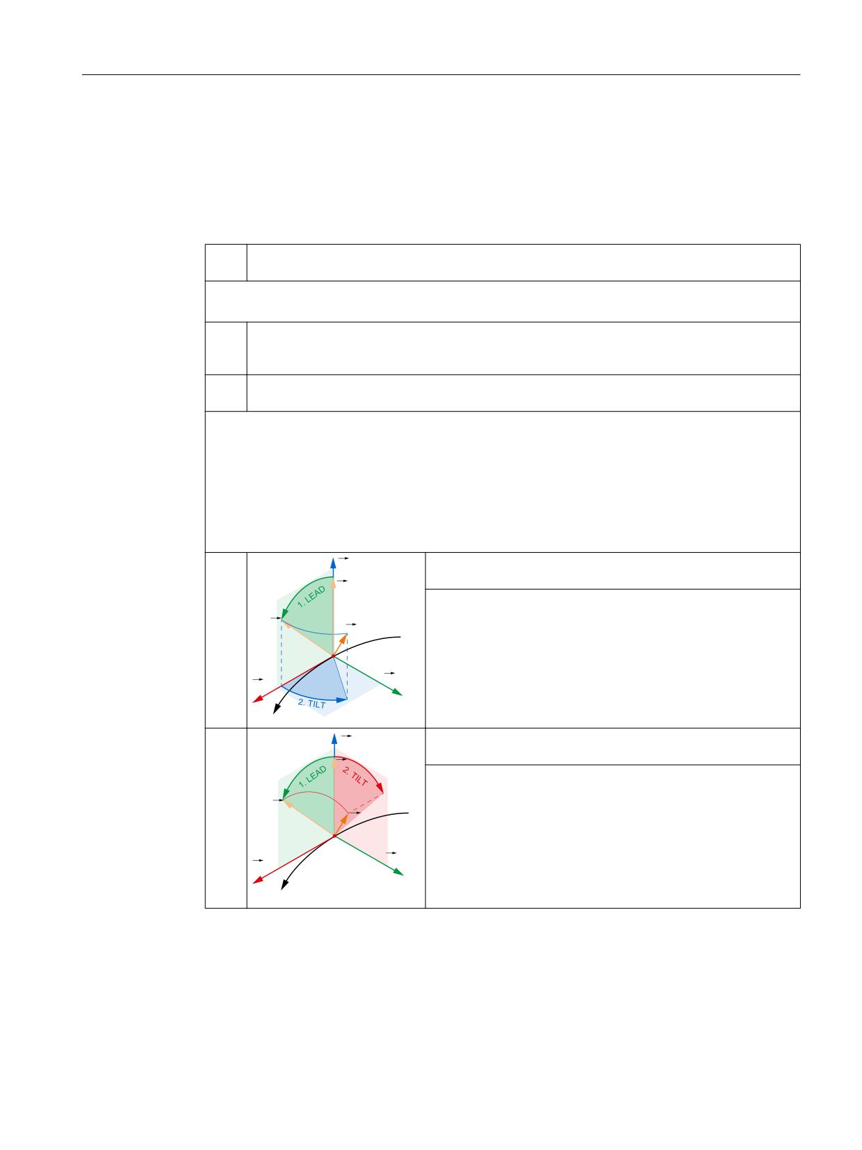
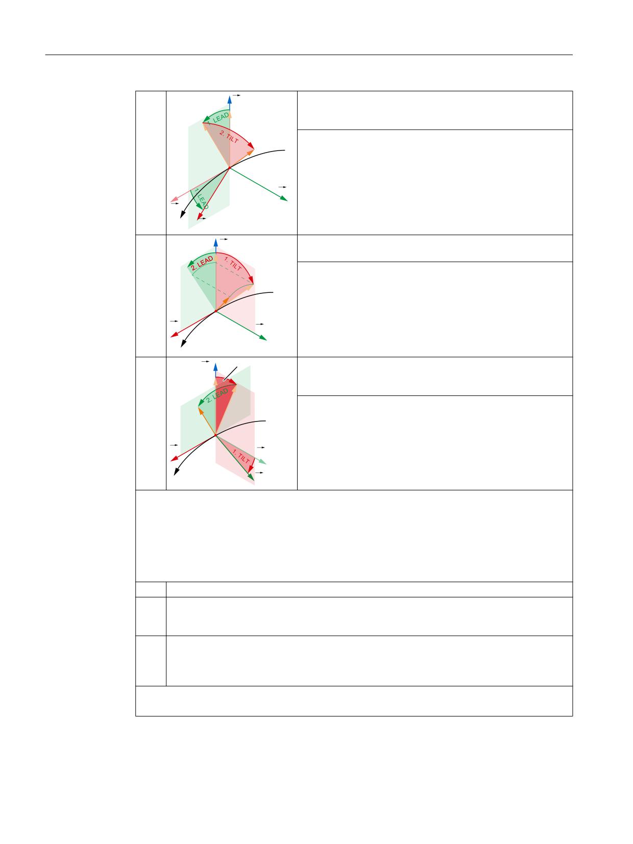
For path-relative orientation, the coordinate system is formed by the vectors path tangent T and pro-
grammed surface normal vector N.
Note 1: Programming the surface normal vector N
● at the block start: A4=… B4=… C4=…
● at the block end: A5=… B5=… C5=…
xx0x
)1
1st rotation LEAD: Rotation of the orientation vector O around
the path normal vector BN
⇒ O'
2
2nd rotation TILT: Rotation of the new orientation vector O'
around the surface normal vector FN ⇒ O''
2
2
7&3
%1
%7
%
xx1x
1st rotation LEAD: Rotation of the orientation vector O around
)1
⇒ O'
the path normal vector BN
2
2nd rotation TILT: Rotation of the new orientation vector O'
around the path tangent vector BT ⇒ O''
2
2
7&3
%1
%7
%
Special functions
Function Manual, 12/2018, A5E40874099B AB
99
F2: Multi-axis transformations
2.9 Orientation
xx2x
)1
1st rotation LEAD: Rotation of the orientation vector O and the
2
path tangent vector BT around the path normal vector BN ⇒ O'
2
and B'T
2nd rotation TILT: Rotation of the new orientation vector O'
2
around the new path tangent vector B'T ⇒ O''
7&3
%1
%7
%
%7
xx3x
)1
1st rotation TILT: Rotation of the new orientation vector O
2
around the path tangent vector BT ⇒ O'
2nd rotation LEAD: Rotation of the new orientation vector O'
2
around the path normal vector BN ⇒ O"
2
7&3
%
7
%1
%
xx4x
)
7,/7
1st rotation TILT: Rotation of the orientation vector O and the
1
2
path normal vector BN around the path tangent vector BT ⇒ O'
2
and B'N
2nd rotation LEAD: Rotation of the new orientation vector O'
2
around the new path normal vector B'N ⇒ O"
7&3
%7
%1
%
%1
Hundreds digit
(Activation and definition of the direction of the lift motion for reorientation during an active ORIPATH)
Note
A programmed retraction/lift motion is only executed, for:
● Once digit == 1 AND
● Length of the lift vector ≠ 0.0
x0xx
No lift motion is executed.
x1xx
Lift motion is executed in the direction of the programmed lift vector in the toolcoordinate system.
The lift vector refers to the coordinate system defined by the actual tool direction (z coordinate)
and the orientation change (x coordinate).
x2xx
Lift motion is executed in the direction of the programmed lift vector in the workpiececoordinate
system. The lift vector refers to the coordinate system that is defined by the active plane (z
coordinate is the surface normal vector of the active plane) and the orientation change (x coor-
dinate).
Thousands digit
(Behavior of the path-relative orientation in the activation/deactivation blocks of the tool offset)
Special functions
100
Function Manual, 12/2018, A5E40874099B AB

F2: Multi-axis transformations
2.9 Orientation
0xxx
The path-relative orientation is also maintained in activation or deactivation blocks of the tool
offset.
1xxx
The path-relative orientation is not maintained in activation or deactivation blocks of the tool
offset.
Note
The tool orientation normally remains constant in the activation or deactivation blocks of the tool
offset. However, in these blocks it is permitted to program a tool orientation, which is then
traversed through in these blocks. However, programming the orientation in these blocks is only
possible with vectors; it is not permitted to program rotary axis positions.
Address names for the lift vector components
The address names for the lift vector components are defined using machine data:
MD10624 $MN_ORIPATH_LIFT_VECTOR_TAB[ <vector component> ] = <name>
Example with standard data
Machine data
$MN_ORIPATH_LIFT_VECTOR_TAB[ 0 ] = "A8" ; x coordinate
$MN_ORIPATH_LIFT_VECTOR_TAB[ 1 ] = "B8" ; y coordinate
$MN_ORIPATH_LIFT_VECTOR_TAB[ 2 ] = "C8" ; z coordinate
Programming
ORIPATHS A8=X_KOORD B8=Y_KOORD C8=Z_KOORD
Note
Naming convention
The rules defined by MD20080 $MC_AXCONF_CHANAX_NAME_TAB should be complied
with for axis identifiers.
Address names for the safety factor for orientation change
Normally the retracting movement is performed simultaneously to the orientation change. The
address name for safety factor R can be defined using machine data:
MD10626 $MN_ORIPATH_LIFT_FACTOR_NAME = "<name>"
If safety factor R is greater than 0.0, then the orientation is only changed if the tool is traversed
by safety clearance S in the direction of the lift vector. Safety clearance S is calculated as
follows:
S = R * lift vector amount; definition range of factor R: 0 ≤ R < 1
Example with standard data
Machine data
$MN_ORIPATH_LIFT_FACTOR_NAME = "ORIPLF"
Programming
ORIPATHS A8=X_KOORD B8=Y_KOORD C8=Z_KOORD
; lift vector
ORIPLF=0.1
; safety clearance = 0.1 * lift vector amount (A8, B8,
C8)
Special functions
Function Manual, 12/2018, A5E40874099B AB
101
F2: Multi-axis transformations
2.9 Orientation
Note
Naming convention
The rules defined by MD20080 $MC_AXCONF_CHANAX_NAME_TAB should be complied
with for axis identifiers.
Parameterization: Setting data SD42670 (path section to the orientation smoothing)
Using the setting data, a path section is specified, within which, for a tool orientation step at a
block transition, it is possible to deviate from the programmed orientation path in order to
smooth the orientation path. If this path section is set too low, then it is possible that the path
velocity must be significantly reduced.
SD42670 $SC_ORIPATH_SMOOTH_DIST = <path length>
Response for path length 0.0
If a value of 0.0 is set as path length, then a dedicated intermediate block is inserted if
necessary to smooth the orientation path. The path is maintained until the orientation change
was executed in the intermediate block. However, the orientation change is then only
performed with continuous acceleration when ORIPATHS is active. Otherwise, from the start
to the end orientation, the orientation change is realized using linear large circle interpolation.
The tool can be lifted while the orientation axes are traversed to execute the orientation change.
The lift motion is activated via the hundreds digit of MD21094 $MC_ORIPATH_MODE (see
the paragraph above: "Parameterization: Machine data" > "Setting for path-relevant
orientation").
The direction and path length of the lift motion is defined by the programmed lift vector (see
paragraph above: "Parameterization: Machine data" > "Address names for the lift vector
components"). If the length of this vector is exactly zero, no retracting movement is executed.
Normally the retracting movement is performed simultaneously to the orientation change.
However, a "Safety clearance" can also be programmed (see paragraph above:
"Parameterization: Machine data" > "Address names for the safety factor for orientation
change")
Parameterization: Setting data SD42672 (tolerance for orientation smoothing)
If just the path and the path velocity are continuous at a block transition but not the path
acceleration (e.g. tangential transition, straight line/circle), then regarding the orientation, only
the orientation path is continuous, not the orientation change. This results in a generally
undesirable velocity step in the orientation axes. In the setting data, a tolerance window can
be parameterized; within this tolerance window it is permissible that the traversed orientation
path deviates from the programmed orientation path in order to smooth the orientation path.
SD42672 $SC_ORIPATH_SMOOTH_TOL = <tolerance>
This type of orientation smoothing is only executed if the following applies:
● ORIPATHS is active AND
● SD42672 $SC_ORIPATH_SMOOTH_TOL > 0.0
Special functions
102
Function Manual, 12/2018, A5E40874099B AB
F2: Multi-axis transformations
2.9 Orientation
Path-relative interpolation of the rotation (ORIROTC)
For 6-axis transformations, in addition to the path-relative interpolation of all of the components
of the tool orientation (rotation around each of the three axes of rotation), using ORIROTC it is
possible that only the rotation of the tool around the orientation vector relative to the path
tangent is interpolated.
The orientation vector can still be programmed with direction components or via Euler or RPY
angle - and the interpolation type defined using ORIVECT, ORIAXES, ORICONxx, ORICURVE
(see Chapter "Rotations of orientation vector (Page 119)").
2.9.6
Programming of orientation polynominals
Function
Orientation polynomials and even axis polynomials can be programmed with different types
of polynomials regardless of the type of polynomial interpolation currently active. This can be
applied to:
● Linear interpolation with G command G01
● Polynomial interpolation with G command TERMINAL
● Circular interpolation with G command G02, G03 or CIP
● Involute interpolation with G command INVCW or INVCCW
This enables a number of polynomials to be programmed for one contour at the same time.
Note
For additional information about programming axis polynomials with PO[X], PO[Y], PO[Z] and
orientation polynomials such as PO[PHI], PO[PSI], PO[THT] and PO[XH], PO[YH], PO[ZH],
see:
Reference:
Programming Manual Production Planning
Two different types of orientation polynomials are defined:
● Polynomials for angles with reference to the plane defined by the start and end orientation
(type 1 orientation polynomials)
● Polynomials for coordinates in space of a reference point on the tool (type 2 orientation
polynomials).
Type 1 polynomials
Orientation polynomials of type 1 are polynomials for angles
PO[PHI]:
Angle in the plane between start and end orientation
PO[PSI]:
Angle describing the tilt of the orientation from the plane between start and end
orientation
Special functions
Function Manual, 12/2018, A5E40874099B AB
103
F2: Multi-axis transformations
2.9 Orientation
Type 2 polynomials
Orientation polynomials of type 2 are polynomials for coordinates
PO[XH]:
x coordinate of the reference point on the tool
PO[YH]:
y coordinate of the reference point on the tool
PO[ZH]:
z coordinate of the reference point on the tool
Polynomials for angle of rotation and rotation vectors
For 6-axis transformations, the rotation of the tool around itself can be programmed for tool
orientation. This rotation of a third rotary axis is described either by an angle of rotation or by
a rotation vector, which is perpendicular to the tool direction in the plane.
In addition, a polynomial for rotation with PO[THT} of the orientation vector can be programmed
in these three cases. This is always possible if the kinematic transformation applied, supports
rotary angles.
Angle of rotation with ORIPATH and ORIPATHS
With orientation interpolation relative to the path with ORIPATH or ORIPATHS, the additional
rotation can be programmed with the angle THETA=<...>. In addition, for this angle of
rotation, with PO[THT]=(...) as a maximum, a 5th degree polynomial angles.
The 3 possible angles, i.e. lead angle, tilt angle and angle of rotation, have the following
meaning with respect to the rotation effect:
LEAD: Angle relative to the surface normal vector in the plane put up by the path tangent and
the surface normal vector.
TILT: Rotation of orientation in the z direction or rotation about the path tangent.
THETA: Rotation around the tool direction. This is only possible when the tool orientation has
a total of 3 degrees of freedom (see Section "Extension of the generic transformation
to six axes - 840D sl only (Page 76)").
How the angles LEAD and TILT are to be interpreted, can be set with the following machine
data:
MD21094 $MC_ORIPATH_MODE (setting for path relative orientation ORIPATH)
In addition to the constant angles programmed with LEAD and TILT, polynomials can be
programmed for lead angle and tilt angle. The polynomials are programmed using the angles
PHI and PSI:
PO[PHI]=(a2,a3,a4Polynomial for the LEAD angle
,a5):
PO[PSI]=(b2,b3,b4Polynomial for the TILT angle
,b5):
For both angles, as a maximum, 5th degree polynomial angles can be programmed. The angle
values at the block end are programmed with the NC addresses LEAD=<...> or
TILT=<...>.
The higher polynomial coefficients, which are zero, can be omitted when programming. For
eexample PO[PHI] = (a2) programs a parabola for the lead angle LEAD.
Special functions
104
Function Manual, 12/2018, A5E40874099B AB
F2: Multi-axis transformations
2.9 Orientation
Rotations of rotation vectors with ORIROTC
The rotation vector is interpolated relative to the path tangent with an offset that can be
programmed using the THETA angle.
For the offset angle, with PO[THT]=(c2,c3,c4,c5), as a maximum, a 5th degree
polynomial angle can be programmed.
Note
If ORIAXES is active, i.e. the tool orientation is interpolated via axis interpolation, the orientation
of the rotation vector relative to the path is only fulfilled at the end of the block.
For further information about programming, see:
References:
Programming Manual Production Planning; Transformations, Interpolation type (ORIPATH,
ORIPATHS)
Boundary conditions
It is only useful to program orientation polynomials for specific interpolation types, which affect
both contour and orientation. A number of supplementary conditions must be met to avoid
illegal programming settings:
Orientation polynomials cannot be programmed,
● if ASPLINE, BSPLINE, CSPLINE spline interpolations are active.
Polynomials for type 1 orientation anglesare possible for every type of interpolation except
spline interpolation, i.e.linear interpolation with rapid traverse G00 or with feedrate G01 and
polynomial POLY and circular/involute interpolation G02, G03, CIP, CT, INVCW and
INVCCW.
In contrast, type 2 orientation polynomials are only possible iflinear interpolation with rapid
traverse G00 or with feedrate G01 or polynomial interpolation POLY is active.
● if the orientation is interpolated using ORIAXES axis interpolation.
In this case, polynomials can be programmed directly with PO[A] and PO[B] for orientation
axes A and B.
If ORICURVE is active, the Cartesian components of the orientation vector are interpolated
and only type 2 orientation polynomials are possible. However, type 1 orientation polynomials
are not permitted.
Only type 1 orientation polynomials are possible for large circle interpolation and taper
interpolation with ORIVECT, ORIPLANE, ORICONxxx. However, type 2 orientation
polynomials are not permitted.
Alarms
An illegally programmed polynomial is signaled with the following alarms:
Alarm 14136:
Oreintation polynomial is generally not allowed.
Alarm 14137:
Polynomials PO[PHI] and PO[PSI] are not permitted.
Alarm 14138:
Polynomials PO[XH], PO[YH], PO[ZH] are not permitted.
Alarm 14139:
Polynomial for angle of rotation PO[THT] is not permitted.
Special functions
Function Manual, 12/2018, A5E40874099B AB
105
F2: Multi-axis transformations
2.9 Orientation
2.9.7
System variable for tool orientation
The tool orientation can be read in various coordinate systems (BCS, WCS, SZS) via system
variables as well as also via OPI variables.
Tool orientation in BCS
System variable
Meaning
$AC_TOOLO_ACT[<i>]
; <i> = 1, 2, 3
i-th component of the vector of the actual reference
orientation
$AC_TOOLO_END[<i>]
; <i> = 1, 2, 3
i-th component of the vector of the end orientation
of the actual block
$AC_TOOLO_DIFF
Residual angle in degrees, i.e. this is the angle be-
tween vectors $AC_TOOLO_END[<i>] and
$AC_TOOLO_ACT[<i>]
$VC_TOOLO[<i>]
; <i> = 1, 2, 3
i-th component of the vector of the actual orientation
$VC_TOOLO_DIFF
Angle in degrees between reference and actual val-
ue orientation
$VC_TOOLO_STAT
Status variable for actual orientation
Indicates whether the actual orientation can be cal-
culated. The following values are possible:
0
Actual orientation can be calculated.
-1
Actual orientation cannot be calculated, as the
presently active transformation cannot calcu-
late these values in real time.
These system variables can always be read by the part program as well as in synchronized
actions. Write access operations are not permitted.
Note
The components of vectors $AC_TOOLO_ACT[<i>], $AC_TOOLO_END[<i>] and
$VC_TOOLO[<i>] of the orientation are scaled so that the orientation vector has the absolute
value of 1.
Rotation vector in the BCS
For a 6-axis kinematics, in addition to the orientation of the tool, there is also a rotation of the
tool, which can be changed.
System variable
Meaning
$P_TOOLROT[<i>]
; <i> = 1, 2, 3
i-th component of the actual rotation vector in the
NC program
$AC_TOOLR_ACT[<i>]
; <i> = 1, 2, 3
i-th component of the vector of the actual setpoint
of the orientation rotation
$AC_TOOLR_END[<i>]
; <i> = 1, 2, 3
i-th component of the vector of the setpoint of the
rotation at the end of the actual block
Special functions
106
Function Manual, 12/2018, A5E40874099B AB
F2: Multi-axis transformations
2.9 Orientation
System variable
Meaning
$AC_TOOLR_DIFF
Residual angle in degrees, i.e. this is the angle be-
tween vectors $AC_TOOLR_END[<i>] and
$AC_TOOLR_ACT[<i>]
$VC_TOOLR[<i>]
; <i> = 1, 2, 3
i-th component of the vector of the actual value of
the orientation rotation
$VC_TOOLR_DIFF
Angle in degrees between the setpoint and actual
value of the orientation rotation
$VC_TOOLR_STAT
Status variable for the actual value of the rotation
vector
Indicates whether the actual value of the rotation
vector can be calculated. The following values are
possible:
0
The actual value of the rotation vector can be
calculated.
-1
Actual value of the rotation vector cannot be
calculated, as the presently active transforma-
tion cannot calculate these values in real time.
Orientation and rotation of the tool in the various coordinate systems (BCS, WCS, SZS)
Tool orientation
System variable
Meaning
$P_TOOL_O[<i>,<j>]
; <i> =1, 2, 3
i-th component of the actual orientation vector in the
NC program in the coordinate system <j>
; <j> = 0, 1, 2
<j> = 0:
BCS
<j> = 1:
WCS
<j> = 2:
SZS
$AC_TOOL_O_ACT[<i>,< j>]
; <i> =1, 2, 3
i-th component of the actual orientation vector in the
coordinate system <j>
; <j> = 0, 1, 2
$AC_TOOL_O_END[<i>,< j>]
; <i> =1, 2, 3
i-th component of the end orientation of the actual
block in the coordinate system <j>
; <j> = 0, 1, 2
$AC_TOOL_O_DIFF[<j>]
; <j> = 0, 1, 2
Residual angle of the orientation vector in degrees
in various coordinate systems <j>
$VC_TOOL_O[<i>,<j>]
; <i> =1, 2, 3
i-th component of the vector of the actual orientation
in various coordinate systems <j>
; <j> = 0, 1, 2
$VC_TOOL_O_DIFF[<j>]
; <j> = 0, 1, 2
Angle in degrees between reference and actual val-
ue orientation in various coordinate systems <j>
Rotation vector (only for 6-axis kinematics)
System variable
$P_TOOL_R[<i>,<j>]
; <i> =1, 2, 3
i-th component of the actual rotation vector in the
NC program in the coordinate system <j>
; <j> = 0, 1, 2
<j> = 0:
BCS
<j> = 1:
WCS
<j> = 2:
SZS
Special functions
Function Manual, 12/2018, A5E40874099B AB
107

F2: Multi-axis transformations
2.10 Orientation axes
System variable
$AC_TOOL_R_ACT[<i>,<j>]
; <i> =1, 2, 3
i-th component of the actual rotation vector in the
coordinate system <j>
; <j> = 0, 1, 2
$AC_TOOL_R_END[<i>,<j>]
; <i> =1, 2, 3
i-th component of the rotation vector at the end of
the actual block in the coordinate system <j>
; <j> = 0, 1, 2
$AC_TOOL_R_DIFF[<j>]
; <j> = 0, 1, 2
Residual angle of the rotation vector in degrees in
various coordinate systems <j>
$VC_TOOL_R[<i>,<j>]
; <i> =1, 2, 3
i-th component of the actual value of the rotation
vector in various coordinate systems <j>
; <j> = 0, 1, 2
$VC_TOOL_R_DIFF[<j>]
; <j> = 0, 1, 2
Angle in degrees between reference and actual val-
ue of the rotation vector in various coordinate sys-
tems <j>
Boundary conditions
Not all transformations provide the actual value of the tool orientation in real time. In this case,
variables $VC_TOOLO[<i>] or VC_TOOL_O[<i>] and $VC_TOOLO_DIFF or
$VC_TOOL_O_DIFF cannot be calculated. The components of $VC_TOOLO[<i>] or
$VC_TOOL_O[<i>] are all zero, and status variable $VC_TOOLO_STAT supplies the value
"-1". The same is true for the actual values of the rotation vector $VC_TOOLR[<i>] or
$VC_TOOL_R[<i>,<j>].
2.10
Orientation axes
Directions of rotation
The directions around which axes are rotated are defined by the axes of the reference system.
In turn, the reference system is defined by ORIMKS and ORIWKS commands:
● ORIMKS : Reference system = Basic coordinate system
● ORIWKS: Reference system = Workpiece coordinate system
Order of rotation
The order of rotation for the orientation axes is defined by the following machine data:
MD21120 $MC_ORIAX_TURN_TAB_1[0..2] (definition of reference axes for ORI axes)
1. First rotation around the axis of the reference system, defined in the following machine data:
MD21120 $MC_ORIAX_TURN_TAB_1[0]
2. Second rotation around the axis of the reference system, defined in the following machine
data:
MD21120 $MC_ORIAX_TURN_TAB_1[1]
3. Third rotation around the axis of the reference system, defined in the following machine
data:
MD21120 $MC_ORIAX_TURN_TAB_1[2]
Special functions
108
Function Manual, 12/2018, A5E40874099B AB
F2: Multi-axis transformations
2.10 Orientation axes
Direction of the tool vector
The direction of the tool vector in the initial machine setting is defined in the following machine
data:
MD24580 $MC_TRAFO5_TOOL_VECTOR_1 (orientation vector direction) or
MD24680 $MC_TRAFO5_TOOL_VECTOR_2 (orientation vector direction)
Assignment to channel axes
Machine data MD24585 $MC_TRAFO5_ORIAX_ASSIGN_TAB_1[0..2] (ORI/channel
assignment Transformation 1) are used to assign up to a total of 3 virtual orientation axes to
the channel, which are set as input variables in machine data $MC_TRAFO_AXES_IN_n[4..6]
(axis assignment for Transformation n).
For assigning channel axes to orientation axes, the following applies:
● $MC_TRAFO5_ORIAX_ASSIGN_TAB_n[0] = $MC_TRAFO_AXES_IN_n[4]
● $MC_TRAFO5_ORIAX_ASSIGN_TAB_n[1] = $MC_TRAFO_AXES_IN_n[5]
● $MC_TRAFO5_ORIAX_ASSIGN_TAB_n[2] = $MC_TRAFO_AXES_IN_n[6]
Orientation transformation 1:
MD24585 $MC_TRAFO5_ORIAX_ASSIGN_TAB_1[n]
n = channel axis [0..2]
Orientation transformation 2:
MD24685 $MC_TRAFO5_ORIAX_ASSIGN_TAB_2[n]
n = channel axis [0..2]
transformation [1..4]
MD24110 $MC_TRAFO5_AXES_IN_1[n] (axis assignment
n = channel axis [0..7]
for transformation)
to
MD24410 $MC_TRAFO5_AXES_IN_4[n] (axis assignment
for transformation 4)
transformation [5..8]
MD24432 $MC_TRAFO5_AXES_IN_5[n] (axis assignment
n = channel axis [0..7]
for transformation 5)
to
MD24462 MC_TRAFO5_AXES_IN_8[n] (axis assignment
for transformation 8)
Example
For orientation axes, see Chapter "Example for orientation axes (Page 136)".
Special functions
Function Manual, 12/2018, A5E40874099B AB
109
F2: Multi-axis transformations
2.10 Orientation axes
2.10.1
JOG mode
Preconditions
Orientation axes can only be traversed in the jog operating mode when the following
preconditions are satisfied:
● The orientation axis must be defined as such, that is, a value must be set in the following
machine data:
MD24585 $MC_TRAFO5_ORIAX_ASSIGN_TAB (ORI/channel axis assignment
Transformation 1)
● A transformation must be active (TRAORI).
Traversing using traverse keys
When using the traverse keys to move an axis continuously or incrementally, it must be noted
that only one orientation axis can be moved at a time.
Alarm 20062 "Channel 1 axis 2 already active" is output if more than one orientation axis is
traversed.
Traversing using handwheels
More than one orientation axis can be moved simultaneously using handwheels.
Velocity
When orientation axes are traversed manually, the channel-specific feedrate override switch
or the rapid traverse override switch in rapid traverse override applies.
Normally, velocities when traversing in the jog mode have always been derived from the
machine axis velocities. However, for geometry and orientation axes, there is not necessarily
a direct assignment to a particular machine axis. This is the reason that dedicated machine
data exist for geometry axes and orientation axes, which allow velocities to be separately
specified:
● MD21150 $MC_JOG_VELO_RAPID_ORI[n] (conventional rapid traverse for ORI axes)
● MD21155 $MC_JOG_VELO_ORI[n] (conventional ORI axis velocity)
● MD21160 $MC_JOG_VELO_RAPID_GEO[n] (conventional rapid traverse for GEO axes)
● MD21165 $MC_JOG_VELO_GEO[n] (conventional GEO axis velocity)
Acceleration
The acceleration for orientation axes is set in machine data:
MD21170 $MC_ACCEL_ORI[n] (acceleration for orientation axes)
Special functions
110
Function Manual, 12/2018, A5E40874099B AB
F2: Multi-axis transformations
2.10 Orientation axes
2.10.2
Programming for orientation transformation
The values can only be programmed in conjunction with an orientation transformation.
Programming of orientation
Orientation axes are programmed by means of axis names A2, B2 and C2.
Euler and RPY values are distinguished on the basis of G-group 50:
● ORIEULER:
Orientation programming on the basis of Euler angles (default)
● ORIRPY:
Orientation programming via RPY angles
● ORIVIRT1:
Orientation programming on the basis of virtual orientation axes (definition 1)
● ORIVIRT2:
Orientation programming on the basis of virtual orientation axes (definition 2)
The type of interpolation is distinguished on the basis of G-group 51:
● ORIAXES:
Orientation programming of linear interpolation of orientation axes or machine axes
● ORIVECT:
Orientation programming of large circle interpolation of orientation axes (interpolation of
the orientation vector)
Machine data MD21102 $MC_ORI_DEF_WITH_G_CODE (definition of ORI axes via G
command) is used to specify whether MD21100 $MC_ORIENTATION_IS_EULER (angle
definition for orientation programming) is active (default) or G group 50.
The following four variants are available for programming orientation:
1. A, B, C:
Machine axis parameter designation
2. A2, B2, C2:
Angle programming of virtual axes
3. A3, B3, C3:
Vector component designation
4. LEAD, TILT:
Specification of lead and side angles with reference to path and surface
Special functions
Function Manual, 12/2018, A5E40874099B AB
111
F2: Multi-axis transformations
2.10 Orientation axes
References:
Programming Manual Fundamentals
Note
The four variants of orientation programming are mutually exclusive. If mixed values are
programmed, alarm 14130 or alarm 14131 is generated.
Exception:
For 6 axis kinematics with a 3rd degree of freedom for orientation, C2 may also be programmed
for variants 3 and 4. C2 in this case describes the rotation of the orientation vector about its
own axis.
Example
For orientation axes for kinematics with 6 or 5 transformed axes, see Section "Example for
orientation axes (Page 136)".
Interpolation type
The following machine data is used to specify which interpolation type is used:
MD21104 $MC_ORI_IPO_WITH_G_CODE (G command for orientation interpolation):
● ORIMKS or ORIWKS (for description, see Section "Tool orientation (Page 50)")
● G group 51 with the commands ORIAXES or ORIVECT
- ORIAXES:
Linear interpolation of machine axes or orientation axes.
- ORIVECT:
Orientation is controlled by the orientation vector being swivelled in the plane spanned
by the start and end vectors (large circle interpolation). With 6 transformation axes a
rotation around the orientation vector is excuted in addition to the swivel movement.
With ORIVECT the orientation axes are always traversed on the shortest possible path.
Range of values
Value range for orientation axes:
●
180 degrees < A2 < 180 degrees
●
90 degrees < B2 < 90 degrees
●
180 degrees < C2 < 180 degrees
All possible rotations can be represented with this value range. Values outside the range are
normalized by the control system to within the range specified above.
Feedrate when programming ORIAXES
Feedrate for an orientation axis can be limited via the FL[ ] instruction (feed limit).
Special functions
112
Function Manual, 12/2018, A5E40874099B AB
F2: Multi-axis transformations
2.10 Orientation axes
2.10.3
Programmable offset for orientation axes
How the programmable offset works
The additional programmable offset for orientation axes acts in addition to the existing offset
and is specified when transformation is activated. Once transformation has been activated, it
is no longer possible to change this additive offset and no zero offset will be applied to the
orientation axes in the event of an orientation transformation.
The programmable offset can be specified in two ways.
1. Direct programming of the offset with TRAORI() when transformation is activated.
2. Automatic transfer of the offset from the zero offset active for the orientation axes when
transformation is activated. This automatic transfer is configured via machine data.
Programming offset directly
When transformation is activated, the offset can be programmed directly as TRAORI(n, x, y,
z, a, b) TRAORI(n, x, y, z, a, b) . The following parameters are available as an option:
n:
Number of transformation n = 1 or 2
x, y, z
Components of the vector for the basic orientation of thetool (generic 5-axis
transformation only).
a, b:
Offset for rotary axes
These optional parameters can be omitted. However, if they are used for programming
purposes, the correct sequence must be observed. If for example only one rotary axis offset
is to be entered, TRAORI(,,,, a, b) is to be programmed.
For further information about programming, please see:
Reference:
Programming Manual, Production Planning; Transformations
Programming offset automatically
As the offset is transferred automatically from the currently active zero offset on the orientation
axes, the effects of zero offset on rotary axes are always the same, both with and without active
transformation. Automatic take-over of offset from zero offset is possible via machine data
MD24590 $MC_TRAFO5_ROT_OFFSET_FROM_FR_1 = TRUE (Offset of rotary
transformation axes from NPV) for the first machine data, or MD24690
$MC_TRAFO5_ROT_OFFSET_FROM_FR_2 = TRUE (Offset of rotary transformation axes
from NPV) for the second transformation in the channel.
Note
There is no difference between a zero offset on the orientation axes programmed during active
transformation and the previous offset.
If automatic transfer of offset has been activated and a rotary axis offset is programmed at the
same time, the programmed offset value takes priority.
Special functions
Function Manual, 12/2018, A5E40874099B AB
113

F2: Multi-axis transformations
2.10 Orientation axes
Orientable toolholder with additive offset
On an orientable toolholder, the offset for both rotary axes can be programmed with the system
variables $TC_CARR24 and $TC_CARR25. This rotary axis offset can be transferred
automatically from the zero offset effective at the time the orientable toolholder was activated.
Automatic transfer of offset from zero offset is made possible via the following machine data:
MD21186 $MC_TOCARR_ROT_OFFSET_FROM_FR = TRUE (offset of TOCARR rotary axes
from NPV)
Note
For more information about orientable toolholders, please see:
Reference:
Function Manual, Basic Machine; Tool Offset (W1)
2.10.4
Orientation transformation and orientable tool holders
Note
Orientation transformation and orientable tool holders can becombined.
The resulting orientation of the tool is produced by linking the orientation transformation and
the orientable tool holder.
2.10.5
Modulo display of orientation axes
Function
The positions of orientation axes can be displayed for the BCS and WCS display in a settable
modulo area. Whether the machine axes are linear or rotary is not relevant in this context. This
means that this display option can be enabled even for normal generic 5/6-axis transformation.
Requirements
● Orientation axes must be available. This is the case if an orientation transformation is active
(e.g. generic 5-/6-axis transformation).
● The following machine data must also be set for OEM transformations:
MD24585 $MC_TRAFO5_ORIAX_ASSIGN_TAB_1[0..2]
Parameterization
The modulo display of orientation axes is activated as follows:
MD21132 $MC_ORI_DISP_IS_MODULO[0...2] = TRUE
Special functions
114
Function Manual, 12/2018, A5E40874099B AB
F2: Multi-axis transformations
2.11 Orientation vectors
The modulo range is defined with the help of the following machine data:
● MD21134 $MC_ORI_MODULO_RANGE[0...2]
(Size of the modulo range for the display of the orientation axes)
● MD21136 $MC_ORI_MODULO_RANGE_START[0...2]
(Starting position of the modulo range for the display of the orientation axes)
Please note the following:
● The machine data become effective with NEWCONF.
● The machine data does not have any influence or effects on:
- any axis positions that can be programmed for these axes.
- The traversing movements of these axes.
- The display of the MCS values of these axes
2.11
Orientation vectors
2.11.1
Polynomial interpolation of orientation vectors
Programming of polynomials for axis motions
The rotary axes are normally subjected to linear interpolation in case of orientation changes
with the help of rotary axis interpolation. However, it is also possible to program the polynomials
as usual for the rotary axes. This allows a generally more homogeneous axis motion to be
produced.
Note
Further information about programming polynomial interpolation with POLY and on
interpolation of orientation vectors is given in:
Reference:
Programming Manual; Production Planning
A block with POLY is used to program polynomial interpolation. Whether the programmed
polynomials are then interpolated as polynomial, depends on whether the G command POLY
is active or not:
● The G command is not active: The programmed axis end points are traversed linearly.
● The G command is active: The programmed polynomials are interpolated as polynomials.
Special functions
Function Manual, 12/2018, A5E40874099B AB
115
F2: Multi-axis transformations
2.11 Orientation vectors
MD10674
Using machine data MD10674 $MN_PO_WITHOUT_POLY = FALSE
(polynomial can be programmed without G command POLY), it can be set as to whether the
following programming is possible:
● PO[...] or PO(...) is possible only if POLY is active, or
● PO[ ] or PO( ) polynomials are also possible without active G command POLY.
As default, MD10674: PO_WITHOUT_POLY = FALSE set and with MD10674
$MN_PO_WITHOUT_POLY = TRUE the following programming is always possible:
● PO[...] = (...), regardless of whether POLY is active or not.
Orientation polynomials can be programmed in conjunction with different interpolation types
and are described in Section "Programming of Orientation Polynomials".
POLYPATH:
In addition to the modal G command POLY, with the predefined subprogram
POLYPATH(argument), polynomial interpolation can be selectively activated for various axis
groups. The following arguments are allowed for the activation of polynomial interpolation
("AXES"):
For all path axes and supplementary axes
("VECT"):
For orientation axes
("AXES", "VECT"):
For path axes, supplementary axes and orientation axes
(without argument):
deactivates polynomial interpolation for all axis groups
Normally, the polynomial interpolation is activated for all axis groups.
Programming of orientation vectors
An orientation vector can be programmed in each block. If polynomials are programmed for
the orientation, the interpolated orientation vector is generally turned not in the plane between
start and end vector, but it can be rotated at random from this plane.
Orientation vectors can be programmed as follows:
1. Programming of rotary axis positions with A, B and C or with the actual rotary axis names.
2. Programming in Euler angle or RPY angle via A2, B2, C2.
3. Programming of the direction vector via A3, B3, C3.
4. Programming using lead angle LEAD and tilt angle TILT.
Selection of type of interpolation
The type of interpolation of orientation axes is selected with G command of group 51 and is
independent of the programming type of the end vector:
● ORIAXES: Linear interpolation of the machine axes or using polynomials for active POLY
or
● ORIVECT: Interpolation of the orientation vector using large circle interpolation
Special functions
116
Function Manual, 12/2018, A5E40874099B AB
F2: Multi-axis transformations
2.11 Orientation vectors
If ORIAXES is active, the interpolation of the rotary axis can also take place using polynomials
like polynomial interpolation of axes with POLY .
On the other hand, if ORIVECT is active, "normal" large circle interpolation is carried out
through linear interpolation of the angle of the orientation vector in the plane that is defined by
the start and end vector.
Polynomials for 2 angles
Additional programming of polynomials for 2 angles that span the start vector and end vector
can also be programmed as complex changes in orientation with ORIVECT .
The two PHI and PSI angles are specified in degrees.
POLY
Activation of polynomial interpolation for all axis groups.
POLYPATH ( )
Activation of polynomial interpolation for all axis groups. "AXES" and
"VECT" are possible groups.
The coefficients an and bn are specified in degrees.
PO[PHI]=(a2, a3, a4,
The angle PHI is interpolated according to PHI(u) = a0 + a1*u + a2*u2 +
a5)
a3*u3+ a4*u4 + a5*u5.
PO[PSI]=(b2, b3, b4,
The angle PHI is interpolated according to PSI(u) = b0 + b1*u + b2*u2 +
b5)
b3*u3+ b4*u4 + b5*u5.
PL
Length of the parameter interval where polynomials are defined. The
interval always starts at 0.
Theoretical value range for PL: 0.0001 ... 99999.9999
The PL value applies to the block that contains it. PL = 1 is applied if no
PL value is programmed.
Rotation of the orientation vector
Changes in orientation are possible with ORIVECT independent of the type of end vector
programming. The following situations apply:
Example 1: Components of end vectors are programmed directly.
N... POLY A3=a B3=b C3=c PO[PHI] = (a2, a3, a4, a5) PO[PSI] = (b2, b3, b4, b5)
Example 2: The end vector is determined by the position of the rotary axes.
N... POLY Aa Bb Cc PO[PHI] = (a2, a3, a4, a5) PO[PSI] = (b2, b3, b4, b5)
The angle PHI describes the rotation of the orientation vector in the plane between start and
end vectors (large circle interpolation, see figure below). The orientation is interpolated exactly
as in Example 1.
Special functions
Function Manual, 12/2018, A5E40874099B AB
117
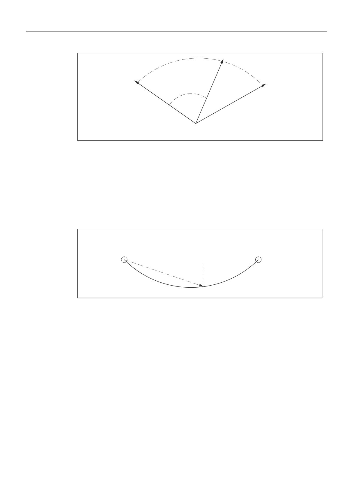
F2: Multi-axis transformations
2.11 Orientation vectors
3+,
6WDUW YHFWRU
(QG YHFWRU
Figure 2-23
Rotation of the orientation vector in the plane between start and end vector
PHI and PSI angle
Programming of polynomials for the two angles PO[PHI] and PO[PSI] is always possible.
Whether the programmed polynomials are actually interpolated for PHI and PSI depends on:
● POLYPATH("VECT") and ORIVECT are active, then the polynomials will be interpolated.
● If POLYPATH("VECT") and ORIVECT are not active, the programmed orientation vectors
are traversed at the end of the block by a "normal" large circle interpolation. This means
that the polynomials for the two angles PHI and PSI are ignored in this case.
6WDUW
(QG
3+,
36,
Figure 2-24
Movement of the orientation vector in plan view
The angle PSI can be used to generate movements of the orientation vector perpendicular to
large circle interpolation plane (see previous figure).
Maximum polynomials of the 5th degree permitted
As a maximum, 5th degree polynomials can be programmed for the PHI and PSI angles. Here
the constants and linear coefficient are defined by the initial value or end value of the orientation
vector.
Higher degree coefficients can be omitted from the coefficient list (...,
) if these are all equal
to zero.
The length of the parameter interval in which the polynomials are defined can also be
programmed with PL.
Special functions
118
Function Manual, 12/2018, A5E40874099B AB
F2: Multi-axis transformations
2.11 Orientation vectors
Special situations
If no polynomial for angle PSI is programmed, the orientation vector is always interpolated in
the plane defined by the start and end vector.
The PHI angle in this plane is interpolated according to the programmed polynomial for PHI.
As a result the orientation vector moves through a "normal" large circle interpolation in the
plane between the start and end vector and the movement is more or less irregular depending
on the programmed polynomial.
In this way, the velocity and acceleration curve of the orientation axes can be influenced within
a block, for example.
Note
Further information on polynomial interpolation for axis motion and general programming is
given in:
Reference:
Programming Manual; Production Planning
Boundary conditions
Polynomial interpolation of orientation vectors is only possible for control variants in which the
following functions are included in the functional scope:
● Orientation transformation
● Polynomial interpolation
2.11.2
Rotations of orientation vector
Functionality
Changes in tool orientation are programmed by specifying an orientation vector in each block,
which is to be reached at the end of the block. The end orientation of each block can be
programmed in the following way:
1. Programming the vector directly, or
2. Programming the rotary axis positions.
The second option depends on the machine kinematics. Interpolation of the orientation vector
between the start and end values can also be modified by programming polynomials.
Programming of orientation directions
The following options are available for programming tool orientation:
1. Direct programming of rotary axis positions (the orientation vector is derived from machine
kinematics).
2. Programming in Euler angles via A2, B2, C2 (angle C2 is irrelevant).
Special functions
Function Manual, 12/2018, A5E40874099B AB
119
F2: Multi-axis transformations
2.11 Orientation vectors
3. Programming in RPY angles via A2, B2, C2.
4. Programming the direction vector via A3, B3, C3 (the length of the vector is irrelevant).
Switching between Euler and RPY angle programming can be selected via the following
machine data or via the G commands ORIEULER and ORIRPY :
MD21100 $MC_ORIENTATION_IS_EULER (angle definition for orientation programming)
Programming of orientation direction and rotation
While the direction of rotation is already defined when you program the orientation with RPY
angles, additional parameters are needed to specify the direction of rotation for the other
orientations:
1. Direct programming of the rotary axes
A supplementary rotary axis for direction of rotation has to be defined.
2. Programming in Euler angles via A2, B2, C2
Angle C2 must be programmed additionally. The complete orientation is thus defined,
including tool rotation.
3. Programming in RPY angles via A2, B2, C2
Additional settings are not required.
4. Programming of the direction vector via A3, B3, C3
The rotation angle is programmed with THETA=<value>.
Note
The following cases do not allow for a programmed rotation:
Multiple programming of the direction of rotation is not allowed and results in an alarm. If
the Euler angle C2 and the angle of rotation THETA are programmed simultaneously, the
programmed rotation is not executed.
If machine kinematics are such that the tool cannot be rotated, any programmed rotation
is ignored. This is the case with a normal 5-axis machine, for example.
Rotation of the orientation vector
The following options are available for interpolating rotation of the orientation vector by
programming the vector directly:
● Linear interpolation, i.e. the angle between the current rotation vector and the start vector
is a linear function of the path parameter.
● Non-linear due to additional programming of a polynomial for the angle of rotation q of
maximum 5th degree, in the form:
PO[THT] = (d2, d3, d4, d5)
Interpolation of the angle of rotation
Higher degree coefficients can be omitted from the coefficient list (...,
) if these are all equal
to zero.
Special functions
120
Function Manual, 12/2018, A5E40874099B AB
F2: Multi-axis transformations
2.11 Orientation vectors
In such cases, the end value of the angle and the constant and linear coefficient d
n
of the
polynomial cannot be directly programmed.
Linear coefficient dn is defined by the end angle qe, and is specified in degrees.
End angle qe is derived from the programming of the rotation vector.
Start angle qs is defined from the start value of the rotation vector, resulting from the end value
of the previous block. The constant coefficient of the polynomial is defined by the start angle
of the polynomial.
The rotation vector is always perpendicular to the actual tool orientation and forms the angle
THETA in conjunction with the basic rotation vector.
Note
When configuring the machine, the direction in space in which the rotation vector points at a
specific angle of rotation can be defined, when the tool is in the basic orientation.
Formula
In general, the angle of rotation is interpolated with a 5th degree polynomial:
θu=θs+d1u+d2u2+d3u3+d4u4+d5u5
(14)
For parameter interval 0 ... 1, this produces the following values for linear coefficients:
d1=θe -θs -d2-d3-d4-d5
(15)
Interpolation of the rotation vector
The programmed rotation vector can be interpolated in the following way, using modal G
commands:
● ORIROTA (orientation rotation absolute):
The angle of rotation THETA is interpreted with reference to an absolute direction in space.
The basic direction of rotation is defined by machine data.
● ORIROTR (orientation rotation relative):
Angle of rotation THETA is interpreted relative to the plane defined by the start and end
orientation.
● ORIROTT (orientation rotation tangential):
Angle of rotation THETA is interpreted relative to the change in orientation. This means the
rotation vector interpolation is tangential to the change in orientation for THETA=0.
This is only different to ORIROTR, if the change in orientation does not take place in one
plane. This is the case if, for the orientation, at least one polynomial was programmed for
"tilt angle" PSI. An additionally programmed angle of rotation THETA can then be used to
interpolate the rotation vector such that it always forms a specific angle referred to the
change in orientation.
Special functions
Function Manual, 12/2018, A5E40874099B AB
121
F2: Multi-axis transformations
2.11 Orientation vectors
Activating rotation
A rotation of the orientation vector is programmed with identifier THETA. The following
programming options are available:
THETA=<value>:
Programming an angle of rotation that is reached at the end of the
block.
THETA = qe
Programmed angle qe can be interpreted as absolute angle (G90 is
active) - as well as also relative angle (G91 is active incremental
dimension).
THETA = AC(...)
Non-modal switchover to absolute dimensions
THETA = IC(...)
Non-modal switchover to incremental dimensions
PO[THT] = (...)
Programming a polynomial for rotation angle THETA.
Angle THETA is programmed in degrees.
Interpolation of the rotation vector is defined by modal G commands:
ORIROTA
Angle of rotation to an absolute direction of rotation
ORIROTR
Angle of rotation relative to the plane between the start and end
orientation
ORIROTT
Angle of rotation relative to the change of the orientation vector tan-
gential rotation vector to the orientation change
ORIROTC
Angle of rotation relative to the change of the orientation vector tan-
gential rotation vector to the path tangent
PL
Length of the parameter interval on which the polynomials are de-
fined. The interval always starts at 0. PL = 1 is active, if no PL value
is programmed.
These G commands define the reference direction of the angle of rotation. The meaning of the
programmed angle of rotation changes accordingly.
Supplementary conditions
The angle of rotation or rotation vector can only be programmed in all four modes if the
interpolation type ORIROTA is active.
1. Rotary axis positions
2. Euler angle via A2, B2, C2
3. RPY angle via A2, B2, C2
4. Direction vector via A3, B3, C3
If ORIROTR or ORIROTT is active, the angle of rotation can only be programmed directly with
THETA.
The other programming options must be excluded in this case, since the definition of an
absolute direction of rotation conflicts with the interpretation of the angle of rotation in these
cases. Possible programming combinations are monitored and an alarm is output if applicable.
A rotation can also be programmed in a separate block without an orientation change taking
place. In this case, ORIROTR and ORIROTT are irrelevant. In this case, the angle of rotation
is always interpreted with reference to the absolute direction (ORIROTA).
Special functions
122
Function Manual, 12/2018, A5E40874099B AB
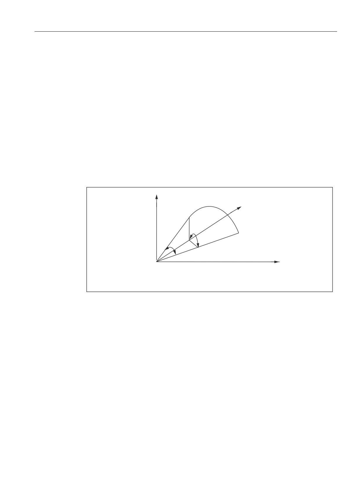
F2: Multi-axis transformations
2.11 Orientation vectors
A programmable rotation of the orientation vector is only possible when an orientation
transformation (TRAORI) is active.
A programmed orientation rotation is only interpolated if the machine kinematics allow rotation
of the tool orientation (e.g. 6-axis machines).
2.11.3
Extended interpolation of orientation axes
Functionality
To execute a change in orientation along the peripheral surface of a cone located in space, it
is necessary to perform an extended interpolation of the orientation vector. The vector around
which the tool orientation is to be rotated must be known. The start and end orientation must
also be specified. The start orientation is given by the previous block and the en orientation
must either be programmed or defined by other conditions.
2XWVLGH VXUIDFH RI D WDSHU
'LUHFWLRQ D[LV
6WDUW YHFWRU
(QG YHFWRU
3+,
36,
36, RSHQLQJ DQJOH RI WKH WDSHU
3+, DQJOH RI URWDWLRQ IRU RULHQWDWLRQ DERXW WKH GLUHFWLRQ D[LV
Figure 2-25
Change in orientation of the peripheral surface of a cone located in space
Required definitions
Generally, the following data is required:
● The start orientation is defined by the end orientation of the previous block.
● The end orientation is defined either by specifying the vector (with A3, B3, C3), the Euler
angles or RPY angles (with A2, B2, C2) or by programming the positions of the rotary axis
(with A, B, C).
● The rotary axis of the taper is programmed as a (normalized) vector with A6, B6, C6.
Special functions
Function Manual, 12/2018, A5E40874099B AB
123
F2: Multi-axis transformations
2.11 Orientation vectors
● The opening angle of the cone is programmed degrees with the identifier (nutation angle).
The value range of this angle is limited to the interval between 0 degrees and 180 degrees.
The values 0 degrees and 180 degrees must not be programmed. If an angle is
programmed outside the valid interval, an alarm is generated.
In the special case where NUT = 90 degrees, the orientation vector in the plane is
interpolated perpendicular to the direction vector (large circle interpolation).
The sign of the programmed opening angle specifies whether the traversing angle is to be
greater or less than 180 degrees.
In order to define the cone, the direction vector or its opening angle must be programmed.
Both may not be specified at the same time.
● A further option is to program an intermediate orientation that lies between the start and
end orientation.
Programming
ORIPLANE
orientation interpolation in a plane: Interpolation in a plane
(large circle interpolation)
ORICONCW
orientation interpolation on a cone clockwise: Interpolation on
the peripheral surface of a cone in the clockwise direction
ORICONCCW
orientation interpolation on a cone counter clockwise: Interpo-
lation on the peripheral surface of a cone in the counter-clock-
wise direction.
Programming of the direction vector is carried out using the identifiers A6, B6, C6 and is
specified as a (normalized) vector.
Note
Programming of an end orientation is not absolutely necessary. If no end orientation is
specified, a full outside cone with 360 degrees is interpolated.
The opening angle of the taper is programmed with NUT= <angle>, where the angle is specified
in degrees.
Note
An end orientation must be specified. A complete outside cone with 360 degrees cannot be
interpolated in this way. The sign of the opening angle defines whether the traversing angle is
to be greater or less than 180 degrees.
The identifiers have the following meanings:
NUT = +...
Traverse angle smaller than or equal to 180 degrees
NUT = -...
Traverse angle greater than or equal to 180 degrees
A positive sign can be omitted when programming.
Special functions
124
Function Manual, 12/2018, A5E40874099B AB
F2: Multi-axis transformations
2.11 Orientation vectors
Settings for intermediate orientation
ORICONIO
orientation interpolation on a cone with intermediate orienta-
tion: Interpolation on a conical peripheral surface with inter-
mediate orientation setting
If this G command is active, it is necessary to specify an intermediate orientation with A7, B7,
C7 which is specified as a (normalized) vector.
Note
Programming of the end orientation is absolutely necessary in this case.
The change in orientation and the direction of rotation is defined uniquely by the three vectors
Start, End and Intermediate orientation.
All three vectors must be different from each other. If the programmed intermediate orientation
is parallel to the start or end orientation, a linear large circle interpolation of the orientation is
executed in the plane that is defined by the start and end vector.
Angle of rotation and opening angle
The following may be programmed additionally for the angle of the cone:
PHI
angle of rotation for orientation about the direction axis
PSI
Opening angle of the cone
Besides this polynomials of the 5th degree (max.) can be programmed as follows:
PO[PHI] = (a2, a3, a4, a5) Constant and linear coefficients are defined by start and end ori-
entation respectively.
PO[PSI] = (b2, b3, b4, b5)
Further interpolation options
It is possible to interpolate the oreintation on a cone which connects tangentially to the previous
change of orientation. This orientation interpolation is achieved by programming the G
command ORICONTO.
ORICONTO
orientation interpolation on a cone with tangential orientation:
Interpolation on a peripheral surface of the cone with tangential
transition
A further option for orientation interpolation is to describe the change in orientation through
the path of a 2nd contact point on the tool.
ORICURVE
orientation interpolation with a second curve: Interpolation of
orientation with specification of motion of two contact points of
the tool.
The coordinates for the movement of the 2nd contact point of the tool must be specified. This
additional curve in space is programmed with XH, YH, ZH.
Besides the two end values, additional polynomials can be programmed in the following form:
Special functions
Function Manual, 12/2018, A5E40874099B AB
125
F2: Multi-axis transformations
2.11 Orientation vectors
PO[XH] = (xe, x2, x3, x4, x5): (xe, ye, ze) of the end point of the curve, and
PO[YH] = (ye, y2, y3, y4, y5): xi, yi, zi the coefficients of the polynomials
PO[ZH] = (ze, z2, z3, z4, z5): of the 5th degree maximum.
This type of interpolation can be used to program points (G1) or polynomials (POLY) for the
two curves in space.
Note
Circles or involutes are specificaly not allowed. It is also possible to activate a spindle
interpolation with BSPLINE. The programmed end points of both curves in space are then
interpreted as nodes.
Other types of splines (ASPLINE and CSPLINE) and the activation of a compressor
(COMPON, COMPCURV, COMPCAD) are not permitted here.
Supplementary conditions
The extended interpolation of orientations requires that all necessary orientation
transformations be considered, since these belong to the functional scope.
Activation
A change in orientation on any peripheral surface of a cone in space is activated with the G
command of group 51 through extended interpolation of the orientation vector, using the
following commands:
ORIPLANE
Interpolation in a plane with specification of the end orientation
(same as ORIVECT)
ORICONCW
Interpolation on a peripheral surface of a taper in clockwise
directionwith specification of the end orientation and taper di-
rection or opening angle of the cone.
ORICONCCW
Interpolation on the peripheral surface of a cone in the counter-
clockwise direction. Specification of the end orientation andt
cone direction or opening angle of the taper.
ORICONIO
Interpolation on a peripheral surface of a cone with specifica-
tion of end orientation and an intermediate orientation.
ORICONTO
Interpolation on a peripheral surface of a cone with tangential
transition and specification of end orientation.
ORICURVE
Interpolation of orientation with specification of motion of two
contact points of the tool.
ORIPATH
Tool orientation in relation to the path
ORIPATHS
Tool orientation in relation to the path, when, for example, a
kink in the orientation path, e.g. at a corner in the contour, is
to be smoothed (see Section "Path-relative orientation (ORI-
PATH, ORIPATHS, ORIROTC) (Page 97)").
Special functions
126
Function Manual, 12/2018, A5E40874099B AB
F2: Multi-axis transformations
2.12 Online tool length offset
Examples
Various changes in orientation are programmed in the following program example:
Program code
Comment
N10 G1 X0 Y0 F5000
N20 TRAORI
; orientation transformation active.
N30 ORIVECT
; interpolate tool orientation as vector
N40 ORIPLANE
; select large circle interpolation.
N50 A3=0 B3=0 C3=1
N60 A3=0 B3=1 C3=1
; orientation in the Y/Z plane by 45
; degrees rotated, at the block end the
; orientation (0, 1 / (root of 2),
; 1 / (root of 2) is reached.
N70 ORICONCW
; the orientation vector is interpolated on a
; conical surface with direction
N80 A6=0 B6=0 C6=1 A3=1 B3=0 C3=1; (0, 0, 1) to the orientation
; (1 / (root of 2), 0, 1 / (root of 2)
; in the clockwise direction,
; the angle of rotation is 270 degrees.
; The tool orientation traverses a complete
N90 A6=0 B6=0 C6=1
; rotation on the same peripheral surface of the
cone
2.12
Online tool length offset
Functionality
Effective tool length can be changed in real time so that the length changes are also considered
for changes in orientation of the tool. The system variable $AA_TOFF[<geometry axis name>]
includes tool length compensations in 3-D according to the three tool directions.
None of the tool parameters are changed. The actual compensation is performed internally by
means of transformations using an orientable tool length compensation.
The number of active compensation directions must be the same as the number of active
geometry axes. All offsets can be active at the same time.
Special functions
Function Manual, 12/2018, A5E40874099B AB
127

F2: Multi-axis transformations
2.12 Online tool length offset
Application
The online tool length compensation function can be used for:
● Orientation transformations (TRAORI)
● Orientable tool carriers (TCARR)
Note
The online tool length offset is an option. This function is only practical in conjunction with
an active orientation transformation or an active orientable toolholder.
Reference:
Function Manual, Basic Functions; Tool Offset, Section: Orientable toolholders (W1)
Block preparation
In the case of block preparation in run-in, the tool length offset currently active in the main run
is considered. In order to utilize the maximum permissible axis velocities as far as possible, it
is necessary to halt the block preparation with a stop preprocessing command (STOPRE) while
a tool offset is being generated.
The tool offset is always known at the time of run-in when the tool length offsets are not changed
after program start or if more blocks have been processed after changing the tool length offsets
than the IPO buffer can accommodate between run-in and main run. This ensures that correct
axis velocities are applied quickly.
The dimension for the difference between the currently active compensation in the interpolator
and the compensation that was active at the time of block preparation can be polled in the
system variable $AA_TOFF_PREP_DIFF[ ].
Note
Changing the effective tool length using online tool length offset produces changes in the
compensatory movements of the axes involved in the transformation in the event of changes
in orientation. The resulting velocities can be higher or lower depending on machine kinematics
and the current axis position.
MD21190 $MC_TOFF_MODE (operation of tool offset)
The following machine data can be used to set whether the content of the synchronization
variable $AA_TOFF[ ] is to be approached as an absolute value or whether an integrating
behavior is to take place:
MD21190 $MC_TOFF_MODE
The integrating behavior of $AA_TOFF[ ] allows 3D remote control. The integrated value is
available via the system variable $AA_TOFF_VAL[ ].
Special functions
128
Function Manual, 12/2018, A5E40874099B AB

F2: Multi-axis transformations
2.12 Online tool length offset
The following machine data and setting data are available for configuring online tool length
compensation:
Machine data / setting data
Meaning for online tool length offset
MD21190 $MC_TOFF_MODE
The contents of $AA_TOFF[ ] are traversed as an
absolute value or integrated
MD21194 $MC_TOFF_VELO (speed online tool
Speed of online tool length offset
offset)
MD21194 $MC_TOFF_ACCEL (acceleration on-
Acceleration of online tool length offset
line tool offset)
SD42970 $SC_TOFF_LIMIT (upper limit of off-
Upper limit of tool length offset value
set value $AA_TOFF)
With the acceleration margin, 20% is reserved for the overlaid movement of online tool length
offset, which can be changed via the following machine data:
MD20610 $MC_ADD_MOVE_ACCEL_RESERVE(acceleration margin for overlaid
movements)
Activation
The TOFFON instruction can be used to activate online tool length offset from the part program
for at least one tool direction, if the option is available. During activation an offset value can
be specified for the relevant direction of compensation and this is immediately traversed.
Example: TOFFON(Z, 25).
Repeated programming of the instruction TOFFON( ) with an offset causes the new offset to
be applied. The offset value is added to variables $AA_TOFF[ ] as an absolute value.
Note
For further information about programming plus programming examples, please see:
Reference:
Programming Manual, Job Planning; Transformations
As long as online tool length offset is active, the VDI signal at the NC → PLC interface in the
following interface signal is set to 1:
DB21, ... DBX318.2 (TOFF active)
While a correction movement is active, the VDI → signal in the following interface signal is set
to 1:
DB21, ... DBX318.3 (TOFF movement active)
Reset
Compensation values can be reset with the TOFFOF( ) command. This instruction triggers a
preprocessing stop.
Accumulated tool length compensations are cleared and incorporated in the basic coordinate
system. The run-in is synchronized with the current position in main run. Since no axes can
be traversed here, the values of $AA_IM[ ] do not change. Only the values of the variables
Special functions
Function Manual, 12/2018, A5E40874099B AB
129

F2: Multi-axis transformations
2.12 Online tool length offset
$AA_IW[ ] and $AA_IB[ ] are changed. These variables now contain the deselected share of
tool length compensation.
Once "Online tool length offset" has been deselected for a tool direction, the value of system
variable $AA_TOFF[ ] or $AA_TOFF_VAL[ ] is zero for this tool direction. The following interface
signal is set to 0:
DB21, ... DBX318.2 (TOFF active)
Alarm 21670
An existing tool length offset must be deleted via TOFFOF( ) so that alarm 21670 "Channel
%1 block %2, illegal change of tool direction active due to $AA_TOFF active" is suppressed:
● When the transformation is deactivated with TRAFOOF
● On switch-over from CP to PTP travel.
● If a tool length offset exists in the direction of the geometry axis during geometry
replacement.
● If a tool length offset is present during change of plane.
● When changing from axis-specific manual travel in the JOG mode to PTP as long as a tool
length offset is active. There is no switchover to PTP.
Mode change
Tool length compensation remains active even if the mode is changed and can be executed
in any mode.
If a tool length compensation is interpolated on account of $AA_TOFF[ ] during mode change,
the mode change cannot take place until the interpolation of the tool length compensation has
been completed. Alarm 16907 "Channel %1 action %2 ALNX possible only in stop state" is
issued.
Behavior with REF and block search
Tool length offset is not considered during reference point approach REF in JOG mode.
The instructions TOFFON( ) and TOFFOF( ) are not collected and output in an action block
during block search.
System variable
In the case of online tool length offset, the following system variables are available to the user:
System variable
Meaning for online tool length offset
$AA_TOFF[ ]
Position offset in the tool coordinate system
$AA_TOFF_VAL[ ]
Integrated position offset in the WCS
$AA_TOFF_LIMIT[ ]
Query whether the tool length offset value is close to the limit
$AA_TOFF_PREP_DIFF[ ]
Magnitude of the difference between the currently active value of
$AA_TOFF[ ] and the value prepared as the current motion block.
Special functions
130
Function Manual, 12/2018, A5E40874099B AB
F2: Multi-axis transformations
2.13 Examples
Reference:
Parameter Manual, System Variables
Boundary conditions
The online tool length offset function is an option and is available during "generic 5-axis
transformation" by default and for "orientable toolholders".
If the tool is not perpendicular to the workpiece surface during machining or the contour
contains curvatures whose radius is smaller than the compensation dimension, deviations
compared to the actual offset surface are produced. It is not possible to produce exact offset
surfaces with one tool length compensation alone.
2.13
Examples
2.13.1
Example of a 5-axis transformation
CHANDATA(1)
$MA_IS_ROT_AX[AX5] = TRUE
$MA_SPIND_ASSIGN_TO_MACHAX[AX5] = 0
$MA_ROT_IS_MODULO[AX5]=0
;-----------------------------------------------------------------------------------------------------
; general 5-axis transformation
;
; kinematics:
1. rotary axis is parallel to Z
;
2. rotary axis is parallel to X
;
Movable tool
;-----------------------------------------------------------------------------------------------------
$MC_TRAFO_TYPE_1 = 20
$MC_ORIENTATION_IS_EULER = TRUE
$MC_TRAFO_AXES_IN_1[0] = 1
$MC_TRAFO_AXES_IN_1[1] = 2
$MC_TRAFO_AXES_IN_1[2] = 3
$MC_TRAFO_AXES_IN_1[3] = 4
$MC_TRAFO_AXES_IN_1[4] = 5
Special functions
Function Manual, 12/2018, A5E40874099B AB
131
F2: Multi-axis transformations
2.13 Examples
$MC_TRAFO_GEOAX_ASSIGN_TAB_1[0]=1
$MC_TRAFO_GEOAX_ASSIGN_TAB_1[1]=2
$MC_TRAFO_GEOAX_ASSIGN_TAB_1[2]=3
$MC_TRAFO5_PART_OFFSET_1[0] = 0
$MC_TRAFO5_PART_OFFSET_1[1] = 0
$MC_TRAFO5_PART_OFFSET_1[2] = 0
$MC_TRAFO5_ROT_AX_OFFSET_1[0] = 0
$MC_TRAFO5_ROT_AX_OFFSET_1[1] = 0
$MC_TRAFO5_ROT_SIGN_IS_PLUS_1[0] = TRUE
$MC_TRAFO5_ROT_SIGN_IS_PLUS_1[1] = TRUE
$MC_TRAFO5_NON_POLE_LIMIT_1 = 2.0
$MC_TRAFO5_POLE_LIMIT_1 = 2.0
$MC_TRAFO5_BASE_TOOL_1[0] = 0.0
$MC_TRAFO5_BASE_TOOL_1[1] = 0.0
$MC_TRAFO5_BASE_TOOL_1[2] = 5,0
$MC_TRAFO5_JOINT_OFFSET_1[0] = 0.0
$MC_TRAFO5_JOINT_OFFSET_1[1] = 0.0
$MC_TRAFO5_JOINT_OFFSET_1[2] = 0.0
CHANDATA(1)
M17
Program example for general 5-axis transformation:
Program code
Comment
; Definition of tool T1
$TC_DP1[1,1] = 10
; Type
$TC_DP2[1,1] = 0
$TC_DP3[1,1] = ;z length compensation vector G17
$TC_DP4[1,1] = 0.
; y
$TC_DP5[1,1] = 0.
; x
$TC_DP6[1,1] = 0.
; Radius
$TC_DP7[1,1] = 0
$TC_DP8[1,1] = 0
$TC_DP9[1,1] = 0
$TC_DP10[1,1] = 0
$TC_DP11[1,1] = 0
$TC_DP12[1,1] = 0
Special functions
132
Function Manual, 12/2018, A5E40874099B AB
F2: Multi-axis transformations
2.13 Examples
Approach initial position:
N100 G1 x1 y0 z0 a0 b0 F20000 G90 G64 T1 D1 G17 ADIS=.5 ADISPOS=3
Orientation vector programming:
N110 TRAORI(1)
N120 ORIWKS
N130 G1 G90
N140 a3 = 0 b3 = 0 c3 = 1 x0
N150 a3 = 0 b3 =-1 c3 = 0
N160 a3 = 1 b3 = 0 c3 = 0
N170 a3 = 1 b3 = 0 c3 = 1
N180 a3 = 0 b3 = 1 c3 = 0
N190 a3 = 0 b3 = 0 c3 = 1
Euler angles program:
N200 ORIMKS
N210 G1 G90
N220 a2 = 0 b2 = 0 x0
N230 a2 = 0 b2 = 90
N240 a2 = 90 b2 = 90
N250 a2 = 90 b2 = 45
N260 a2 = 0 b2 =-90
N270 a2 = 0 b2 = 0
Axis programming:
N300 a0 b0 x0
N310 a45
N320 b30
TOFRAME:
N400 G0 a90 b90 x0 G90
N410 TOFRAME
N420 z5
N430 x3 y5
N440 G0 a0 b0 x1 y0 z0 G90
N500 TRAFOOF
m30
Special functions
Function Manual, 12/2018, A5E40874099B AB
133
F2: Multi-axis transformations
2.13 Examples
2.13.2
Example of a 3-axis and 4-axis transformation
2.13.2.1
Example of a 3-axis transformation
Example: For the schematically represented machine (see "Figure 2-1 Schematic diagram of
3-axis transformation (Page 38)"), the 3-axis transformation can be projected as follows:
Program code
Comment
$MC_TRAFO_TYPE_n = 18
$MC_TRAFO_GEOAX_ASSIGN_TAB_n[0] = 1
; Assignment of channel axes to geometry
axes
$MC_TRAFO_GEOAX_ASSIGN_TAB_n[1] = 0
$MC_TRAFO_GEOAX_ASSIGN_TAB_n[2] = 3
$MC_TRAFO_AXES_IN_n[0] = 1
; X axis is channel axis 1
$MC_TRAFO_AXES_IN_n[1] = 0
; Y axis is not used
$MC_TRAFO_AXES_IN_n[2] = 3
; Z axis is channel axis 3
$MC_TRAFO_AXES_IN_n[4] = 0
; There is no second rotary axis
2.13.2.2
Example of a 4-axis transformation
Example: For the schematically represented machine (see "Figure 2-2 Schematic diagram of
a 4-axis transformation with moveable workpiece (Page 38)"), however, with an additional axis
(Y), the 4-axis transformation can be configured as follows:
Program code
Comment
$MC_TRAFO_TYPE_n = 18
$MC_TRAFO_GEOAX_ASSIGN_TAB_n[0] = 1
$MC_TRAFO_GEOAX_ASSIGN_TAB_n[1] = 2
$MC_TRAFO_GEOAX_ASSIGN_TAB_n[2] = 3
$MC_TRAFO_AXES_IN_n[0] = 1
; X axis is channel axis 1
$MC_TRAFO_AXES_IN_n[1] = 2
; Y axis is channel axis 2
$MC_TRAFO_AXES_IN_n[2] = 3
; Z axis is channel axis 3
$MC_TRAFO_AXES_IN_n[4] = 0
; There is no second rotary axis
2.13.3
Example of a universal milling head
General
The following two subsections show the main steps which need to be taken in order to activate
a transformation for the universal milling head.
Special functions
134
Function Manual, 12/2018, A5E40874099B AB